capacitor esr and c monitoring in modular multilevel
TRANSCRIPT
Aalborg Universitet
Capacitor ESR and C Monitoring in Modular Multilevel Converters
Deng, Fujin; Heng, Qian; Liu, Chengkai; Cai, Xu; Zhu, Rongwu; Chen, Zhe; Chen, Wu
Published in:IEEE Transactions on Power Electronics
DOI (link to publication from Publisher):10.1109/TPEL.2019.2939185
Creative Commons LicenseCC BY 4.0
Publication date:2020
Document VersionAccepted author manuscript, peer reviewed version
Link to publication from Aalborg University
Citation for published version (APA):Deng, F., Heng, Q., Liu, C., Cai, X., Zhu, R., Chen, Z., & Chen, W. (2020). Capacitor ESR and C Monitoring inModular Multilevel Converters. IEEE Transactions on Power Electronics , 35(4), 4063-4075. [8823058].https://doi.org/10.1109/TPEL.2019.2939185
General rightsCopyright and moral rights for the publications made accessible in the public portal are retained by the authors and/or other copyright ownersand it is a condition of accessing publications that users recognise and abide by the legal requirements associated with these rights.
- Users may download and print one copy of any publication from the public portal for the purpose of private study or research. - You may not further distribute the material or use it for any profit-making activity or commercial gain - You may freely distribute the URL identifying the publication in the public portal -
Take down policyIf you believe that this document breaches copyright please contact us at [email protected] providing details, and we will remove access tothe work immediately and investigate your claim.
Downloaded from vbn.aau.dk on: January 18, 2022

0885-8993 (c) 2019 IEEE. Personal use is permitted, but republication/redistribution requires IEEE permission. See http://www.ieee.org/publications_standards/publications/rights/index.html for more information.
This article has been accepted for publication in a future issue of this journal, but has not been fully edited. Content may change prior to final publication. Citation information: DOI 10.1109/TPEL.2019.2939185, IEEETransactions on Power Electronics
IEEE POWER ELECTRONICS REGULAR PAPER
Capacitor ESR and C Monitoring in Modular
Multilevel Converters
Fujin Deng, Senior Member, IEEE, Qian Heng, Chengkai Liu, Xu Cai, Rongwu Zhu, Member, IEEE, Zhe Chen,
Fellow, IEEE and Wu Chen, Senior Member, IEEE
Abstract- The capacitor is one of the weakest components in
the module multilevel converter (MMC). The rise of equivalent
series resistance (ESR) is a prominent character to monitor the
lapsed capacitor, but current researches only focus on
capacitance and neglect ESR of capacitors in the MMC. This
paper proposed a sorting-based monitoring strategy for
capacitors in the MMC, which monitors not only the capacitance
but also the ESR of capacitor. This paper reveals the relationship
among the capacitor’s ESR, capacitance, current and energy.
Based on the relationship, the ESRs and capacitances of
submodule (SM) capacitors in the arm are indirectly sorted,
respectively, and only the capacitor with biggest ESR and the
capacitor with smallest capacitance in the arm are monitored.
The proposed strategy not only realizes both ESR and
capacitance monitoring in the MMC, but also proposes a
simplified monitoring algorithm for MMCs with large number of
capacitors. The simulation and experimental results confirm the
effectiveness of the proposed monitoring strategy for MMCs. 1
Index Terms- Capacitance, monitoring, equivalent series
resistance, modular multilevel converter.
I. INTRODUCTION
The modular multilevel converter (MMC) has become an
attractive topology for medium/high-voltage and high-power
applications due to its modularity and scalability [1, 2]. The
MMC not only produces a multilevel voltage with the flexible
operation but also reduces average switching frequency
without depressing the power quality [3]. Owing to the easy
construction, assembling and flexibility, the MMC becomes
promising for motor drives [4], energy storage [5], electric
railway supplies [6] and microgrid [7], etc.
Manuscript received March 6, 2019; revised May 25, 2019 and July 7,
2019; accepted August 23, 2019. This work was supported in part by the
Natural Science Foundation of Jiangsu Province under Project BK20180395 and in part by the National Natural Science Foundation of China under Project
61873062. (Corresponding author: Fujin Deng.)
F. Deng is with the School of Electrical Engineering, Southeast University, and Jiangsu Key Laboratory of Smart Grid Technology and Equipment,
Nanjing 210096, China (e-mail: [email protected]).
Q. Heng, C. Liu and W. Chen are with School of Electrical Engineering, Southeast University, Nanjing 210096, China (e-mail: [email protected];
[email protected], [email protected]).
X. Cai is with the Wind Power Research Center, Shanghai Jiao Tong University, Shanghai 200240, China (e-mail: [email protected]).
R. Zhu is with the Department of Power Electronics, Christian-Albrechts-
University of Kiel, Kiel 2D-24142, Germany (e-mail: [email protected]). Z. Chen is with the Department of Energy Technology, Aalborg
University, Aalborg 9220, Denmark (e-mail: [email protected]).
The capacitor is one of the weakest components in the
MMC [8]. Due to the advantages of high energy density and
low cost [9], the electrolytic capacitor is popular for MMCs in
some applications, such as microgrid and motor drives [10-12].
Owing to chemical process, aging, etc., the capacitor would
gradually deteriorate and the capacitor’s parameters would be
changed [13]. Normally, the capacitor is needed to be replaced
with the new one when its capacitance drops below 80% of
rated value or its equivalent series resistance (ESR) is over 2
times of rated value [14]. Therefore, the condition monitoring
for capacitors in the MMC is essential.
To date, several studies have paid attention to the capacitor
monitoring in the MMC. Reference [15] presents a monitoring
scheme for the submodule (SM) capacitors in the MMC,
where each SM capacitance is estimated by a recursive least
square algorithm based on the information of capacitor voltage,
arm current and SM switching state. However, an ac current is
injected into the circulating current, which increases the
capacitor voltage ripple and affects the MMC performance.
Reference [16] presents a Kalman filter algorithm to estimate
the SM capacitance in the MMC, where each SM capacitance
is estimated based on the capacitor voltage and current.
Reference [14] presents a simplified condition monitoring
algorithm to estimate the capacitance based on the relationship
between the arm average capacitance and the capacitance of
each SM. Reference [17] proposes the reference SMs for
capacitor condition monitoring in the MMC, where the SM
capacitance can be estimated based on the relationship
between the monitoring SM capacitor voltage and the
reference SM capacitor voltage. The above capacitor
monitoring methods still have some limitations as 1) the
capacitor is seen as an ideal one, which only considers the
capacitance without considering another important parameter,
ESR; 2) all SM capacitors in the MMC are monitored, which
occupies a large amount of computing resources, especially
for the MMC with a large amount of SMs.
Capacitance
monitoring range
ESR=f1(t)
C=f2(t)
C/ESR
C0
0.8C0
ESR0
2ESR0
Lapse t (years)
ESR
monitoring range
Fig. 1 Capacitor deterioration curve.
0885-8993 (c) 2019 IEEE. Personal use is permitted, but republication/redistribution requires IEEE permission. See http://www.ieee.org/publications_standards/publications/rights/index.html for more information.
This article has been accepted for publication in a future issue of this journal, but has not been fully edited. Content may change prior to final publication. Citation information: DOI 10.1109/TPEL.2019.2939185, IEEETransactions on Power Electronics
IEEE POWER ELECTRONICS REGULAR PAPER
The ESR is an important parameter in the capacitor. In
comparison with the reduction of capacitance, the increase of
ESR is normally more pronounced in the deteriorated
capacitor [18-20], as shown in Fig. 1, because the ESR
normally has already increased to over 2 times of its rated
value when the capacitance declines to 80% of its rated value,
which means that the existing methods cannot detect the
lapsed capacitor in time. To make up this gap, the capacitor
monitoring method considering not only the capacitance but
also the ESR is needed urgently, which can improve the
reliability of the MMC. To date, several ESR monitoring
methods have been reported such as recursive least square
algorithm [21], discrete Fourier transform algorithm [22],
Newton-Raphson algorithm [23], short time least square
Prony’s algorithm [24] and the artificial neural network
algorithm [25], etc. However, the above methods are suitable
for the converters with few capacitors, which are not suitable
for the MMC with large number of capacitors because of
complicated computation.
In this paper, a sorting-based condition monitoring strategy
is proposed for the MMC to estimate capacitor’s ESR and
capacitance. The ESRs and capacitances of SM capacitors in
the arm are indirectly sorted based on the relationship among
capacitor’s ESR, capacitance, current and energy, and only the
capacitor with biggest ESR and the capacitor with smallest
capacitance in the arm are estimated. The advantages of the
proposed strategy are 1) estimating not only the capacitance
but also the ESR of capacitors, which has not been considered
in [14-17]; 2) studying the characteristics of ESR, capacitance,
voltage, current, and energy variety of capacitors in the MMC;
3) simplifying monitoring algorithm.
This paper is organized as follows. Section II introduces the
characteristics of capacitors in the MMC. Section III
introduces the operation principles of the MMC. Section IV
analyzes the capacitor characteristics of the MMC. Section V
proposes the sorting-based condition monitoring strategy for
capacitors in the MMC. Sections VI and VII present the
system simulation and experimental tests, respectively, to
verify the effectiveness of the proposed monitoring strategy.
Finally, the conclusions are presented in Section VIII.
II. CAPACITORS IN MMCS
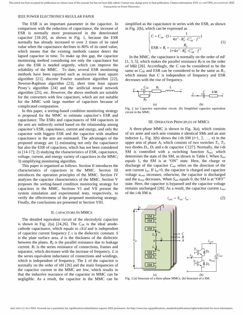
The detailed equivalent circuit of the electrolytic capacitor
is shown in Fig. 2(a) [24,26]. The CAK is the ideal anode-
cathode capacitance, which equals to εS/d and is independent
of capacitor current frequency f. ε is the dielectric constant. S
is the plate surface area. d is the thickness of the dielectric
between the plates. Rp is the parallel resistance due to leakage
current. R1 is the series resistance of connections, frames and
separator, which decreases with the increase of frequency. L is
the series equivalent inductance of connections and windings,
which is independent of frequency. The L of the capacitor is
normally on the order of nH [26] and the main frequencies of
the capacitor current in the MMC are low, which results in
that the inductive reactance of the capacitor in MMC can be
negligible. As a result, the capacitor in the MMC can be
simplified as the capacitance in series with the ESR, as shown
in Fig. 2(b), which can be expressed as
2 2 2 2
1 2 2 2 2
1(1 )
4
ESR1+4
AK
P AK
P
P AK
C CR C f
RR
R C f
= +
= +
(1)
In the MMC, the capacitance is normally on the order of mF
[1, 3, 5], which makes the parallel resistance RP is on the order
of MΩ [26]. Accordingly, the C can be considered to be the
same as CAK and ESR can be considered to be the same as R1,
which means that C is independent of frequency and ESR
decreases with the rise of frequency.
R1CAK++ -L
RP
ESRC++ -
(a) (b)
Fig. 2 (a) Capacitor equivalent circuit. (b) Simplified capacitor equivalent
circuit in the MMC.
III. OPERATION PRINCIPLES OF MMCS
A three-phase MMC is shown in Fig. 3(a), which consists
of six arms and each arm contains n identical SMs and an arm
inductor Ls. Fig. 3(b) shows the i-th SM (i=1, 2, …, n) in the
upper arm of phase A, which consists of two switches T1, T2,
two diodes D1, D2 and a dc capacitor C [27]. Normally, the i-th
SM is controlled with a switching function Saui, which
determines the state of the SM, as shown in Table I. When Saui
equals 1, the SM is at “ON” state. Here, the charge or
discharge of the capacitor Caui relies on the direction of the
arm current iau. If iau>0, the capacitor is charged and capacitor
voltage ucaui increases; otherwise, the capacitor is discharged
and the ucaui decreases. When Saui equals 0, the SM is at “OFF”
state. Here, the capacitor is bypassed and the capacitor voltage
remains unchanged [28]. As a result, the capacitor current icaui
of the i-th SM is
caui aui aui S i= . (2)
SM
SM
SM
Vdc
idc
ia
Ls
Ls
iau
ialSM
SM
SM
a A
+
_
BC
T1
T2
+
D1
D2
Caui
ucaui
icaui
iau
(a) (b) Fig. 3 (a) Structure of a three-phase MMCs. (b) Structure of a SM.
0885-8993 (c) 2019 IEEE. Personal use is permitted, but republication/redistribution requires IEEE permission. See http://www.ieee.org/publications_standards/publications/rights/index.html for more information.
This article has been accepted for publication in a future issue of this journal, but has not been fully edited. Content may change prior to final publication. Citation information: DOI 10.1109/TPEL.2019.2939185, IEEETransactions on Power Electronics
IEEE POWER ELECTRONICS REGULAR PAPER
TABLE I
TWO OPERATION STATES OF SMS
SM state Saui iau Caui ucaui
On 1 ≥0 Charge Increased
<0 discharge Decreased
Off 0 ≥0 or <0 Bypass Unchanged
IV. MMC CAPACITOR CHARACTERISTICS
BASED ON ESR AND C
The chemical process, aging, etc. would cause capacitor
deterioration, which results in not only the drop of capacitance
but also the increase of ESR [13]. The ESR is one of the
important capacitor parameters, while the current researches
on the capacitor monitoring of MMCs [14-17] only consider
the capacitance and neglect the ESR in the capacitor, which
cannot distinguish the lapsed capacitor in time.
A. Capacitor Current Characteristics
Fig. 4 shows the upper arm of phase A in the MMC, where
both ESRs Rau1~Raun and capacitances Cau1~Caun are
considered.
ucau1
+Cau1
icau1
icau2
icaun
iau
yer_au1
yau yer_au2
yer_aun
Rau1
+Cau2
Rau2
+Caun
Raun
ucau2
ucaun
Fig. 4 Upper arm of phase A based on ESR and C.
Suppose the second-order harmonic circulating current is
suppressed, the upper arm current iau is
1
1sin
2 3
dc
au m
ii I t= + . (3)
where Im is the amplitude of the ac current ia. ω1 is the
fundamental angular frequency and ω1=2πf1. f1 is the
fundamental frequency. idc is the dc-link current of the MMC.
The reference yau for the upper arm of phase A is
( )1sinauy m t = + . (4)
where m is modulation index. ϕ is the phase angle.
Suppose that the capacitor voltages ucau1~ucaun shown in Fig.
4 are kept the same with the voltage-balancing control [2], the
equivalent reference yer_aui for the i-th SMs in the arm is
mainly related to Cau1~Caun as shown in (5) [16], because the
capacitor’s ESR is much smaller than its capacitive reactance
at lower frequency [26] and the voltage of the ESR is much
smaller than that of the capacitive reactance.
_
1 1
=( 1)1 1
aui aui
er aui aun n
aui aui
i i
C Cy y
C Cn n= =
− +
(5)
According to (3) ~ (5), the capacitor current icaui of the i-th
SM can be obtained as
_
1 1
1 _ 1 1_ 2 _ 1 2 _
_1 _2
DC Component
Fundamental Component 2nd-order harmonic Component
1= = ( )+ cos
2 68
sin( ) + sin(2 )
er aui dc aui aui m
caui au n n
aui aui
i i
m i i m i i
caui f caui fi i
y i nC nmC Ii i
C C
I t I t
= =
+
+ + +
Fundamental component icaui_1f
2nd
-order harmonic component icaui_2f
.
(6)
with
2 2
1 _
1
1_
2 _
1
2 _
= ( ) ( ) + cos2 3 3
2
2 sin=arctan
3 +2 cos
1=
8
=2
aui m dc dc m
m i n
aui
i
dc
i
m dc
m aui
m i n
aui
i
i
nC I mi mi II
C
mi
I mI
nmI CI
C
=
=
= +
− +
( )
(7)
where I1m_i and β1_i are the amplitude and angle of the
fundamental component icaui_1f of the capacitor current in the i-
th SM. I2m_i and β2_i are the amplitude and angle of the 2nd-
order harmonic component icaui_2f of the capacitor current in
the i-th SM. In the steady state, the dc component in the
capacitor current is zero and icaui=icaui_1f+icaui_2f.
Fig. 5 shows the amplitudes I1m_1, I2m_1, I3m_1, I4m_1 and I5m_1
of the fundamental component, 2nd-, 3rd-, 4th- and 5th-order
harmonic component, respectively, in the capacitor current
under various power, which is derived from the simulation in
Section VI. It can be observed that the I1m_1 and I2m_1 drop
along with the decrease of active power and the I3m_1, I4m_1 and
I5m_1 are quite small and can be neglectable.
1 0.9 0.8 0.7 0.6 0.5
Active power(p.u.)
Am
plit
ude
s o
f S
M1
cap
acit
or
curr
ent
(p.u
.)
0
0.2
0.4
0.6
0.8
1
1.2I1m_1 I2m_1 I3m_1 I4m_1 I5m_1
Fig. 5 Amplitudes of fundamental component, 2nd-, 3rd-, 4th- and 5th-order
harmonic component in capacitor current under various power.
0885-8993 (c) 2019 IEEE. Personal use is permitted, but republication/redistribution requires IEEE permission. See http://www.ieee.org/publications_standards/publications/rights/index.html for more information.
This article has been accepted for publication in a future issue of this journal, but has not been fully edited. Content may change prior to final publication. Citation information: DOI 10.1109/TPEL.2019.2939185, IEEETransactions on Power Electronics
IEEE POWER ELECTRONICS REGULAR PAPER
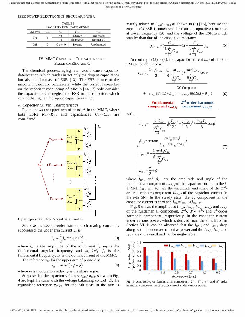
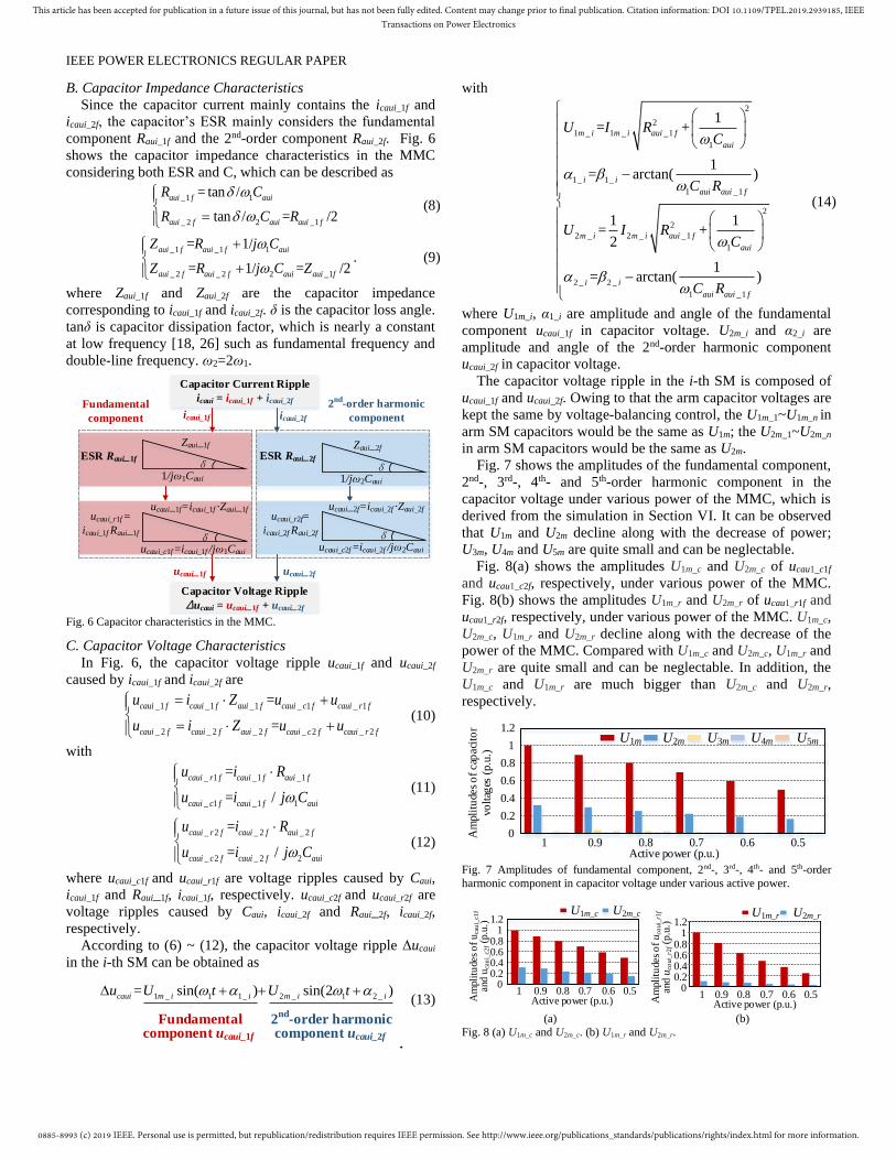
B. Capacitor Impedance Characteristics
Since the capacitor current mainly contains the icaui_1f and
icaui_2f, the capacitor’s ESR mainly considers the fundamental
component Raui_1f and the 2nd-order component Raui_2f. Fig. 6
shows the capacitor impedance characteristics in the MMC
considering both ESR and C, which can be described as
_1 1
_ 2 2 _1
= tan /
tan / = /2
aui f aui
aui f aui aui f
R C
R C R
= (8)
_1 _1 1
_ 2 _ 2 2 _1
= 1/
= 1/ = /2
aui f aui f aui
aui f aui f aui aui f
Z R j C
Z R j C Z
+
+. (9)
where Zaui_1f and Zaui_2f are the capacitor impedance
corresponding to icaui_1f and icaui_2f. δ is the capacitor loss angle.
tanδ is capacitor dissipation factor, which is nearly a constant
at low frequency [18, 26] such as fundamental frequency and
double-line frequency. ω2=2ω1.
ESR Raui_1f
1/jω1Caui
Zaui_1f
ESR Raui_2f
1/jω2Caui
Zaui_2f
icaui_1f icaui_2f
ucaui_r1f =
icaui_1f Raui_1f
ucaui_c1f =icaui_1f /jω1Caui
ucaui_1f=icaui_1f Zaui_1f
δ
ucaui_r2f=
icaui_2f Raui_2f
ucaui_c2f =icaui_2f /jω2Caui
ucaui_2f=icaui_2f Zaui_2f
ucaui_1f ucaui_2f
Fundamental
component
2nd
-order harmonic
component
δ δ
δ
Capacitor Voltage Ripple
ucaui = ucaui_1f + ucaui_2f
Capacitor Current Ripple
icaui = icaui_1f + icaui_2f
Fig. 6 Capacitor characteristics in the MMC.
C. Capacitor Voltage Characteristics
In Fig. 6, the capacitor voltage ripple ucaui_1f and ucaui_2f
caused by icaui_1f and icaui_2f are
_1 _1 _1 _ 1 _ 1
_ 2 _ 2 _ 2 _ 2 _ 2
=
=
caui f caui f aui f caui c f caui r f
caui f caui f aui f caui c f caui r f
u i Z u u
u i Z u u
= +
= + (10)
with
_ 1 _1 _1
_ 1 _1 1
=
= /
caui r f caui f aui f
caui c f caui f aui
u i R
u i j C
(11)
_ 2 _ 2 _ 2
_ 2 _ 2 2
=
= /
caui r f caui f aui f
caui c f caui f aui
u i R
u i j C
(12)
where ucaui_c1f and ucaui_r1f are voltage ripples caused by Caui,
icaui_1f and Raui_1f, icaui_1f, respectively. ucaui_c2f and ucaui_r2f are
voltage ripples caused by Caui, icaui_2f and Raui_2f, icaui_2f,
respectively.
According to (6) ~ (12), the capacitor voltage ripple Δucaui
in the i-th SM can be obtained as
1 _ 1 1_ 2 _ 1 2 _
Fundamental 2nd-order harmonic Component Component
= sin( ) sin(2 )caui m i i m i iu U t U t + + +
Fundamental component ucaui_1f
2nd
-order harmonic component ucaui_2f
.
(13)
with
2
2
1 _ 1 _ _1
1
1_ 1_
1 _1
2
2
2 _ 2 _ _1
1
2 _ 2 _
1 _1
1= +
1= arctan( )
1 1= +
2
1= arctan( )
m i m i aui f
aui
i i
aui aui f
m i m i aui f
aui
i i
aui aui f
U I RC
C R
U I RC
C R
− −
(14)
where U1m_i, α1_i are amplitude and angle of the fundamental
component ucaui_1f in capacitor voltage. U2m_i and α2_i are
amplitude and angle of the 2nd-order harmonic component
ucaui_2f in capacitor voltage.
The capacitor voltage ripple in the i-th SM is composed of
ucaui_1f and ucaui_2f. Owing to that the arm capacitor voltages are
kept the same by voltage-balancing control, the U1m_1~U1m_n in
arm SM capacitors would be the same as U1m; the U2m_1~U2m_n
in arm SM capacitors would be the same as U2m.
Fig. 7 shows the amplitudes of the fundamental component,
2nd-, 3rd-, 4th- and 5th-order harmonic component in the
capacitor voltage under various power of the MMC, which is
derived from the simulation in Section VI. It can be observed
that U1m and U2m decline along with the decrease of power;
U3m, U4m and U5m are quite small and can be neglectable.
Fig. 8(a) shows the amplitudes U1m_c and U2m_c of ucau1_c1f
and ucau1_c2f, respectively, under various power of the MMC.
Fig. 8(b) shows the amplitudes U1m_r and U2m_r of ucau1_r1f and
ucau1_r2f, respectively, under various power of the MMC. U1m_c,
U2m_c, U1m_r and U2m_r decline along with the decrease of the
power of the MMC. Compared with U1m_c and U2m_c, U1m_r and
U2m_r are quite small and can be neglectable. In addition, the
U1m_c and U1m_r are much bigger than U2m_c and U2m_r,
respectively.
0
0.2
0.4
0.6
0.8
1
1.2
1 0.9 0.8 0.7 0.6 0.5Active power (p.u.)
Am
plit
ude
s o
f ca
pac
ito
r
volt
ages
(p.u
.)
U1m U2m U3m U4m U5m
Fig. 7 Amplitudes of fundamental component, 2nd-, 3rd-, 4th- and 5th-order
harmonic component in capacitor voltage under various active power.
00.20.40.60.8
11.2
Am
pli
tudes
of
uca
ui_
c1f
and u
cau
i_c2
f (p.u
.)
1 0.9 0.8 0.7 0.6 0.5Active power (p.u.)
U1m_c U2m_c
Am
plit
ude
s o
f u
caui
_r1
f an
d u
caui
_r2
f (p.u
.)
1 0.9 0.8 0.7 0.6 0.5Active power (p.u.)
U1m_r U2m_r
00.20.40.60.8
11.2
(a) (b)
Fig. 8 (a) U1m_c and U2m_c. (b) U1m_r and U2m_r.
0885-8993 (c) 2019 IEEE. Personal use is permitted, but republication/redistribution requires IEEE permission. See http://www.ieee.org/publications_standards/publications/rights/index.html for more information.
This article has been accepted for publication in a future issue of this journal, but has not been fully edited. Content may change prior to final publication. Citation information: DOI 10.1109/TPEL.2019.2939185, IEEETransactions on Power Electronics
IEEE POWER ELECTRONICS REGULAR PAPER
V. PROPOSED CAPACITOR ESR AND C MONITORING
STRATEGY FOR MMCS
The ESR is one of the important capacitor parameters. A
sorting-based monitoring strategy is proposed in this Section
to estimate capacitor’s ESR and Capacitance in the MMC.
A. Capacitor Energy Characteristics
According to (6) ~ (9), (13) and [16], the capacitor energy
variety Waui of the i-th SM within a fundamental period T1
(T1=2π/ω1) can be obtained as
1
_ 1 _ 20
( ) =T
dc
aui caui caui aui r f aui r f
VW u i dt W W
n= + + . (15)
with
1
1
2
1 1
_ 1 _1 _1 20_1 1 _1
2
2 2
_ 2 _ 2 _ 2 20_ 2 2 _ 2
2 /
1/ ( ) /
4 /
1/ ( ) /
Tm
aui r f caui f caui f
aui f aui aui f
Tm
aui r f caui f caui f
aui f aui aui f
UW u i dt
R C R
UW u i dt
R C R
= =
+ = = +
(16)
where Waui represents the energy consumption of ESR in the
capacitor. Waui_r1f and Waui_r2f are the energy consumption
caused by Raui_1f and Raui_2f, respectively.
Fig. 9 shows the capacitor energy variety Wau1_r1f and
Wau1_r2f, respectively, under various power of the MMC, where
Wau1_r1f and Wau1_r2f decline with the decrease of power. In
addition, Wau1_r1f is much bigger than Wau1_r2f, which means
that Raui_1f results in the main energy consumption in the
capacitor and is the main cause of accelerating the aging
process in comparison with Raui_2f.
Cap
acit
or e
nerg
y va
riet
y
cau
sed
by E
SR (
p.u
.)
1 0.9 0.8 0.7 0.6 0.5Active power (p.u.)
Wau1_r1f Wau1_r2f
0
0.2
0.4
0.6
0.8
1
1.2
Fig. 9 Waui_r1f and Waui_r2f under various active power.
Substituting (8), (16) into (15), the Waui can be rewritten as
( )2 2
1 2 2
1 _1 1 _1
2 12
1/ ( ) /aui m m
aui f aui aui f
W U UR C R
= +
+. (17)
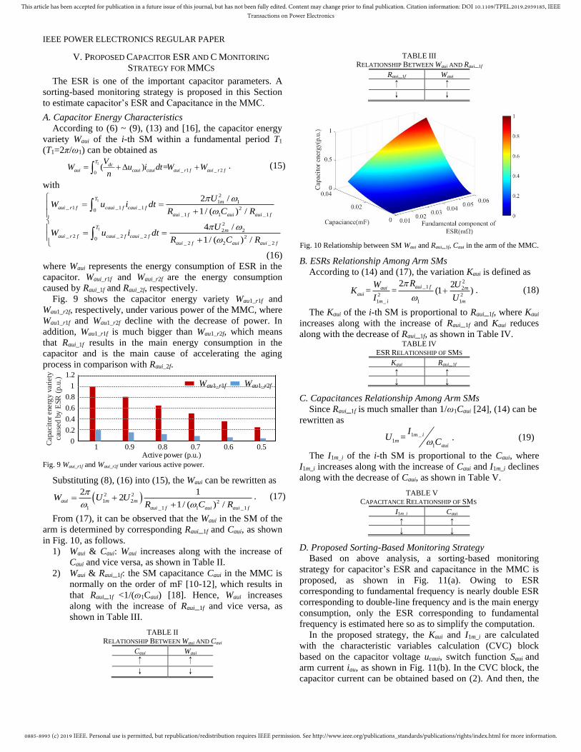
From (17), it can be observed that the Waui in the SM of the
arm is determined by corresponding Raui_1f and Caui, as shown
in Fig. 10, as follows.
1) Waui & Caui: Waui increases along with the increase of
Caui and vice versa, as shown in Table II.
2) Waui & Raui_1f: the SM capacitance Caui in the MMC is
normally on the order of mF [10-12], which results in
that Raui_1f <1/(ɷ1Caui) [18]. Hence, Waui increases
along with the increase of Raui_1f and vice versa, as
shown in Table III.
TABLE II
RELATIONSHIP BETWEEN Waui AND Caui
Caui Waui
↑ ↑
↓ ↓
TABLE III RELATIONSHIP BETWEEN Waui AND Raui_1f
Raui_1f Waui
↑ ↑
↓ ↓
Fig. 10 Relationship between SM Waui and Raui_1f, Caui in the arm of the MMC.
B. ESRs Relationship Among Arm SMs
According to (14) and (17), the variation Kaui is defined as 2
_1 2
_
2 2
11 1
2 2= = (1 )
aui faui m
aui
m i m
RW UK
I U
+ . (18)
The Kaui of the i-th SM is proportional to Raui_1f, where Kaui
increases along with the increase of Raui_1f and Kaui reduces
along with the decrease of Raui_1f, as shown in Table IV. TABLE IV
ESR RELATIONSHIP OF SMS
Kaui Raui_1f
↑ ↑
↓ ↓
C. Capacitances Relationship Among Arm SMs
Since Raui_1f is much smaller than 1/ω1Caui [24], (14) can be
rewritten as
1 _1
1
= m im
aui
IU
C. (19)
The I1m_i of the i-th SM is proportional to the Caui, where
I1m_i increases along with the increase of Caui and I1m_i declines
along with the decrease of Caui, as shown in Table V.
TABLE V CAPACITANCE RELATIONSHIP OF SMS
I1m_i Caui
↑ ↑
↓ ↓
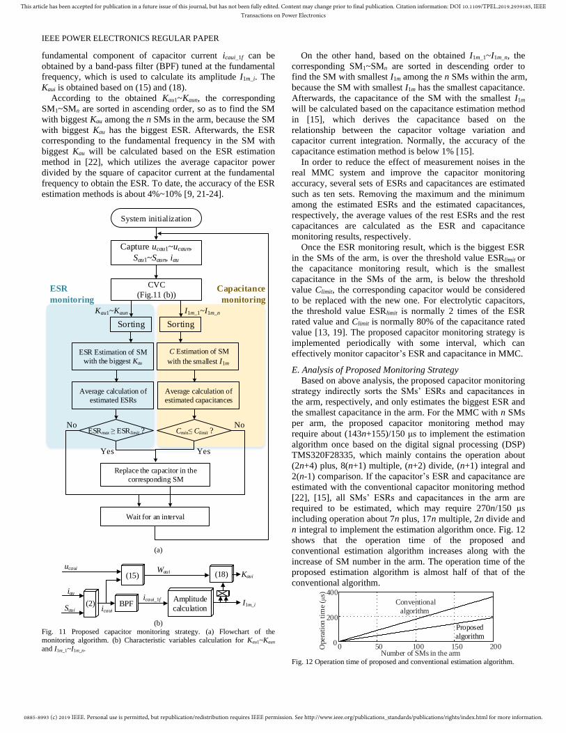
D. Proposed Sorting-Based Monitoring Strategy
Based on above analysis, a sorting-based monitoring
strategy for capacitor’s ESR and capacitance in the MMC is
proposed, as shown in Fig. 11(a). Owing to ESR
corresponding to fundamental frequency is nearly double ESR
corresponding to double-line frequency and is the main energy
consumption, only the ESR corresponding to fundamental
frequency is estimated here so as to simplify the computation.
In the proposed strategy, the Kaui and I1m_i are calculated
with the characteristic variables calculation (CVC) block
based on the capacitor voltage ucaui, switch function Saui and
arm current iau, as shown in Fig. 11(b). In the CVC block, the
capacitor current can be obtained based on (2). And then, the
0885-8993 (c) 2019 IEEE. Personal use is permitted, but republication/redistribution requires IEEE permission. See http://www.ieee.org/publications_standards/publications/rights/index.html for more information.
This article has been accepted for publication in a future issue of this journal, but has not been fully edited. Content may change prior to final publication. Citation information: DOI 10.1109/TPEL.2019.2939185, IEEETransactions on Power Electronics
IEEE POWER ELECTRONICS REGULAR PAPER
fundamental component of capacitor current icaui_1f can be
obtained by a band-pass filter (BPF) tuned at the fundamental
frequency, which is used to calculate its amplitude I1m_i. The
Kaui is obtained based on (15) and (18).
According to the obtained Kau1~Kaun, the corresponding
SM1~SMn are sorted in ascending order, so as to find the SM
with biggest Kau among the n SMs in the arm, because the SM
with biggest Kau has the biggest ESR. Afterwards, the ESR
corresponding to the fundamental frequency in the SM with
biggest Kau will be calculated based on the ESR estimation
method in [22], which utilizes the average capacitor power
divided by the square of capacitor current at the fundamental
frequency to obtain the ESR. To date, the accuracy of the ESR
estimation methods is about 4%~10% [9, 21-24].
System initialization
Capture ucau1~ucaun,
Sau1~Saun, iau
CVC
(Fig.11 (b))
Sorting
Yes
No No
Sorting
Kau1~Kaun I1m_1~I1m_n
ESR Estimation of SM
with the biggest Kau
C Estimation of SM
with the smallest I1m
ESRmax ESRlimit ? Cmin Climit ?
Yes
ESR
monitoring
Capacitance
monitoring
Replace the capacitor in the
corresponding SM
Wait for an interval
Average calculation of
estimated ESRs
Average calculation of
estimated capacitances
(a)
iau
ucaui
icaui_1fI1m_iBPF
Saui
Amplitude
calculation
(18) Kaui
icaui
Waui
(2)
(15)
(b)
Fig. 11 Proposed capacitor monitoring strategy. (a) Flowchart of the
monitoring algorithm. (b) Characteristic variables calculation for Kau1~Kaun
and I1m_1~I1m_n.
On the other hand, based on the obtained I1m_1~I1m_n, the
corresponding SM1~SMn are sorted in descending order to
find the SM with smallest I1m among the n SMs within the arm,
because the SM with smallest I1m has the smallest capacitance.
Afterwards, the capacitance of the SM with the smallest I1m
will be calculated based on the capacitance estimation method
in [15], which derives the capacitance based on the
relationship between the capacitor voltage variation and
capacitor current integration. Normally, the accuracy of the
capacitance estimation method is below 1% [15].
In order to reduce the effect of measurement noises in the
real MMC system and improve the capacitor monitoring
accuracy, several sets of ESRs and capacitances are estimated
such as ten sets. Removing the maximum and the minimum
among the estimated ESRs and the estimated capacitances,
respectively, the average values of the rest ESRs and the rest
capacitances are calculated as the ESR and capacitance
monitoring results, respectively.
Once the ESR monitoring result, which is the biggest ESR
in the SMs of the arm, is over the threshold value ESRlimit or
the capacitance monitoring result, which is the smallest
capacitance in the SMs of the arm, is below the threshold
value Climit, the corresponding capacitor would be considered
to be replaced with the new one. For electrolytic capacitors,
the threshold value ESRlimit is normally 2 times of the ESR
rated value and Climit is normally 80% of the capacitance rated
value [13, 19]. The proposed capacitor monitoring strategy is
implemented periodically with some interval, which can
effectively monitor capacitor’s ESR and capacitance in MMC.
E. Analysis of Proposed Monitoring Strategy
Based on above analysis, the proposed capacitor monitoring
strategy indirectly sorts the SMs’ ESRs and capacitances in
the arm, respectively, and only estimates the biggest ESR and
the smallest capacitance in the arm. For the MMC with n SMs
per arm, the proposed capacitor monitoring method may
require about (143n+155)/150 μs to implement the estimation
algorithm once based on the digital signal processing (DSP)
TMS320F28335, which mainly contains the operation about
(2n+4) plus, 8(n+1) multiple, (n+2) divide, (n+1) integral and
2(n-1) comparison. If the capacitor’s ESR and capacitance are
estimated with the conventional capacitor monitoring method
[22], [15], all SMs’ ESRs and capacitances in the arm are
required to be estimated, which may require 270n/150 μs
including operation about 7n plus, 17n multiple, 2n divide and
n integral to implement the estimation algorithm once. Fig. 12
shows that the operation time of the proposed and
conventional estimation algorithm increases along with the
increase of SM number in the arm. The operation time of the
proposed estimation algorithm is almost half of that of the
conventional algorithm.
0 50 100 150 2000
200
400
Number of SMs in the arm
Ope
rati
on tim
e (μ
s)
Conventional
algorithm
Proposed
algorithm
Fig. 12 Operation time of proposed and conventional estimation algorithm.
0885-8993 (c) 2019 IEEE. Personal use is permitted, but republication/redistribution requires IEEE permission. See http://www.ieee.org/publications_standards/publications/rights/index.html for more information.
This article has been accepted for publication in a future issue of this journal, but has not been fully edited. Content may change prior to final publication. Citation information: DOI 10.1109/TPEL.2019.2939185, IEEETransactions on Power Electronics
IEEE POWER ELECTRONICS REGULAR PAPER
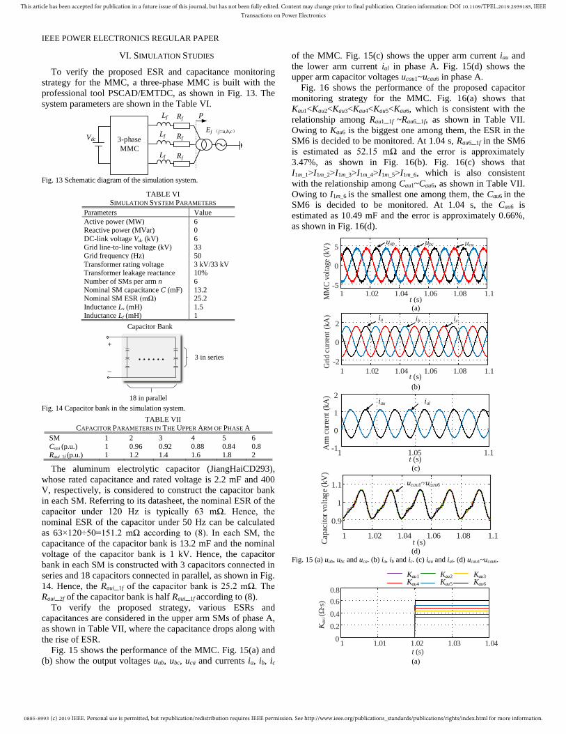
VI. SIMULATION STUDIES
To verify the proposed ESR and capacitance monitoring
strategy for the MMC, a three-phase MMC is built with the
professional tool PSCAD/EMTDC, as shown in Fig. 13. The
system parameters are shown in the Table VI.
Vdc
Lf
Lf
Lf
Rf
Rf
Rf
P
Ej (j=a,b,c)
3-phase
MMC
Fig. 13 Schematic diagram of the simulation system.
TABLE VI SIMULATION SYSTEM PARAMETERS
Parameters Value
Active power (MW) 6
Reactive power (MVar) 0
DC-link voltage Vdc (kV) 6 Grid line-to-line voltage (kV) 33
Grid frequency (Hz) 50
Transformer rating voltage 3 kV/33 kV Transformer leakage reactance 10%
Number of SMs per arm n 6
Nominal SM capacitance C (mF) 13.2 Nominal SM ESR (mΩ) 25.2
Inductance Ls (mH) 1.5
Inductance Lf (mH) 1
+
_
18 in parallel
3 in series
Capacitor Bank
Fig. 14 Capacitor bank in the simulation system.
TABLE VII
CAPACITOR PARAMETERS IN THE UPPER ARM OF PHASE A
SM 1 2 3 4 5 6
Caui (p.u.) 1 0.96 0.92 0.88 0.84 0.8 Raui_1f (p.u.) 1 1.2 1.4 1.6 1.8 2
The aluminum electrolytic capacitor (JiangHaiCD293),
whose rated capacitance and rated voltage is 2.2 mF and 400
V, respectively, is considered to construct the capacitor bank
in each SM. Referring to its datasheet, the nominal ESR of the
capacitor under 120 Hz is typically 63 mΩ. Hence, the
nominal ESR of the capacitor under 50 Hz can be calculated
as 63×120÷50=151.2 mΩ according to (8). In each SM, the
capacitance of the capacitor bank is 13.2 mF and the nominal
voltage of the capacitor bank is 1 kV. Hence, the capacitor
bank in each SM is constructed with 3 capacitors connected in
series and 18 capacitors connected in parallel, as shown in Fig.
14. Hence, the Raui_1f of the capacitor bank is 25.2 mΩ. The
Raui_2f of the capacitor bank is half Raui_1f according to (8).
To verify the proposed strategy, various ESRs and
capacitances are considered in the upper arm SMs of phase A,
as shown in Table VII, where the capacitance drops along with
the rise of ESR.
Fig. 15 shows the performance of the MMC. Fig. 15(a) and
(b) show the output voltages uab, ubc, uca and currents ia, ib, ic
of the MMC. Fig. 15(c) shows the upper arm current iau and
the lower arm current ial in phase A. Fig. 15(d) shows the
upper arm capacitor voltages ucau1~ucau6 in phase A.
Fig. 16 shows the performance of the proposed capacitor
monitoring strategy for the MMC. Fig. 16(a) shows that
Kau1<Kau2<Kau3<Kau4<Kau5<Kau6, which is consistent with the
relationship among Rau1_1f ~Rau6_1f, as shown in Table VII.
Owing to Kau6 is the biggest one among them, the ESR in the
SM6 is decided to be monitored. At 1.04 s, Rau6_1f in the SM6
is estimated as 52.15 mΩ and the error is approximately
3.47%, as shown in Fig. 16(b). Fig. 16(c) shows that
I1m_1>I1m_2>I1m_3>I1m_4>I1m_5>I1m_6, which is also consistent
with the relationship among Cau1~Cau6, as shown in Table VII.
Owing to I1m_6 is the smallest one among them, the Cau6 in the
SM6 is decided to be monitored. At 1.04 s, the Cau6 is
estimated as 10.49 mF and the error is approximately 0.66%,
as shown in Fig. 16(d).
1 1.02 1.04 1.06 1.08 1.1t (s)
-5
0
5
MM
C v
olta
ge (
kV) uab ubc uca
(a)
1 1.02 1.04 1.06 1.08 1.1t (s)
-2
0
2ia ib ic
Gri
d c
urre
nt (
kA)
(b)
1 1.05 1.1t (s)
-1
0
1
2
Arm
cur
rent
(kA
)
iau ial
(c)
1 1.02 1.04 1.06 1.08 1.1t (s)
0.9
1
1.1
Cap
acit
or v
olt
age
(kV
)
ucau1~ucau6
(d)
Fig. 15 (a) uab, ubc and uca. (b) ia, ib and ic. (c) iau and ial. (d) ucau1~ucau6.
Kau1 Kau2 Kau3
Kau4 Kau5 Kau6
1 1.01 1.02 1.03 1.040
0.2
0.4
0.6
0.8
t (s)
Kau
i (Ω
s)
(a)
0885-8993 (c) 2019 IEEE. Personal use is permitted, but republication/redistribution requires IEEE permission. See http://www.ieee.org/publications_standards/publications/rights/index.html for more information.
This article has been accepted for publication in a future issue of this journal, but has not been fully edited. Content may change prior to final publication. Citation information: DOI 10.1109/TPEL.2019.2939185, IEEETransactions on Power Electronics
IEEE POWER ELECTRONICS REGULAR PAPER
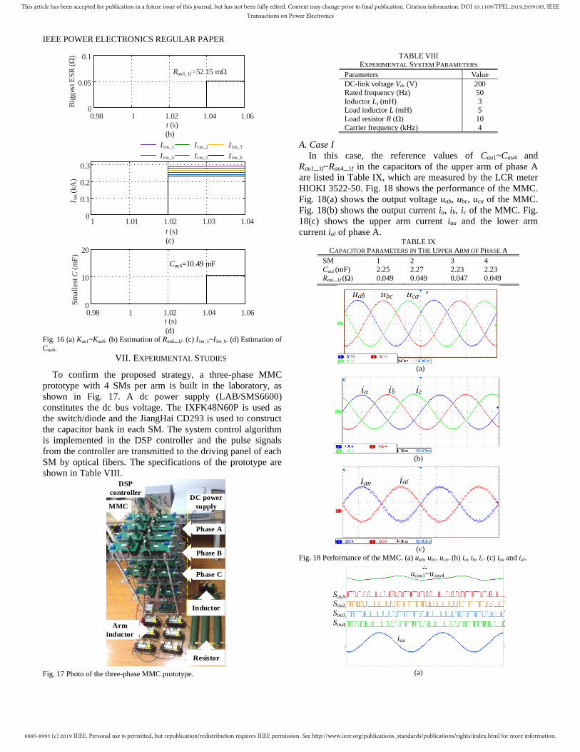
0.98 1 1.02 1.04 1.060
0.05
0.1
t (s)
Big
ges
t E
SR
(Ω
)Rau6_1f =52.15 mΩ
(b)
1 1.01 1.02 1.03 1.040
0.1
0.2
0.3
t (s)
I 1m
(kA
)
I1m_1 I1m_2 I1m_3
I1m_4 I1m_5 I1m_6
(c)
0.98 1 1.02 1.04 1.060
10
20
t (s)
Sm
all
est
C (
mF
)
Cau6=10.49 mF
(d)
Fig. 16 (a) Kau1~Kau6. (b) Estimation of Rau6_1f. (c) I1m_1~I1m_6. (d) Estimation of Cau6.
VII. EXPERIMENTAL STUDIES
To confirm the proposed strategy, a three-phase MMC
prototype with 4 SMs per arm is built in the laboratory, as
shown in Fig. 17. A dc power supply (LAB/SMS6600)
constitutes the dc bus voltage. The IXFK48N60P is used as
the switch/diode and the JiangHai CD293 is used to construct
the capacitor bank in each SM. The system control algorithm
is implemented in the DSP controller and the pulse signals
from the controller are transmitted to the driving panel of each
SM by optical fibers. The specifications of the prototype are
shown in Table VIII.
Arm
inductor
DC power
supply
Inductor
Resistor
DSP
controller
MMC
Phase A
Phase B
Phase C
Fig. 17 Photo of the three-phase MMC prototype.
TABLE VIII EXPERIMENTAL SYSTEM PARAMETERS
Parameters Value
DC-link voltage Vdc (V) 200
Rated frequency (Hz) 50
Inductor Ls (mH) 3 Load inductor L (mH) 5
Load resistor R (Ω) 10
Carrier frequency (kHz) 4
A. Case I
In this case, the reference values of Cau1~Cau4 and
Rau1_1f~Rau4_1f in the capacitors of the upper arm of phase A
are listed in Table IX, which are measured by the LCR meter
HIOKI 3522-50. Fig. 18 shows the performance of the MMC.
Fig. 18(a) shows the output voltage uab, ubc, uca of the MMC.
Fig. 18(b) shows the output current ia, ib, ic of the MMC. Fig.
18(c) shows the upper arm current iau and the lower arm
current ial of phase A. TABLE IX
CAPACITOR PARAMETERS IN THE UPPER ARM OF PHASE A
SM 1 2 3 4
Caui (mF) 2.25 2.27 2.23 2.23 Raui_1f (Ω) 0.049 0.049 0.047 0.049
(a)
(b)
(c)
Fig. 18 Performance of the MMC. (a) uab, ubc, uca. (b) ia, ib, ic. (c) iau and ial.
ucau1~ucau4
Sau1
Sau2
Sau3
Sau4
iau
(a)
0885-8993 (c) 2019 IEEE. Personal use is permitted, but republication/redistribution requires IEEE permission. See http://www.ieee.org/publications_standards/publications/rights/index.html for more information.
This article has been accepted for publication in a future issue of this journal, but has not been fully edited. Content may change prior to final publication. Citation information: DOI 10.1109/TPEL.2019.2939185, IEEETransactions on Power Electronics
IEEE POWER ELECTRONICS REGULAR PAPER
0 0.01 0.02 0.03 0.040
1
2
310-3
t (s)
Kau
i (Ω
s)
Kau1 Kau4Kau2 Kau3
(b)
0 0.01 0.02 0.03 0.040
1
2
I 1m
_i (A
)
t (s)
I1m_1 I1m_4I1m_2 I1m_3
(c)
Fig. 19 (a) ucau1, ucau2, ucau3, ucau4 (10V/div), Sau1, Sau2, Sau3, Sau4 (30V/div), iau and ial (4A/div). Time base is 5 ms. (b) Kau1~Kau4. (c) I1m_1~I1m_4.
Average values
40
50
60
70
80
90
0 0.04 0.08 0.12 0.16 0.20
Case II
Average values Average valuesEstimated values Estimated values Estimated values
Case I Case III
Big
gest
ES
R (
mΩ
)
Reference values Reference values Reference values
t (s) (a)
Sm
all
est
C (
mF
)
1.0
1.2
1.4
1.6
1.8
2.0
2.2
2.4
0 0.04 0.08 0.12 0.16 0.20
t (s)
Case II
Average values Average values Average valuesEstimated values Estimated values Estimated values
Case I Case III
Reference values Reference values Reference values
(b)
Fig. 20 (a) Distributions of ESRs estimation values in the three cases. (b)
Distributions of capacitances estimation values in the three cases.
020406080
100
Case I Case II Case IIIBig
ges
t E
SR
(m
Ω)
Average
values
Reference
values
Case I Case II Case III
ESR
err
or (
%)
0.01.02.03.04.05.0
(a) (b)
Fig. 21 (a) Estimated value and measured value of biggest ESR in Case I, II
and III. (b) Estimation error of ESR.
Case I Case II Case III0
0.51.01.52.02.5
Sm
alle
st C
(m
F)
Average
values
Reference
values
Case I Case II Case III
Cap
acit
ance
erro
r (%
)
0.00.20.40.60.81.0
(a) (b)
Fig. 22 (a) Estimated value and measured value of smallest capacitance in
Case I, II and III. (b) Estimation error of capacitance.
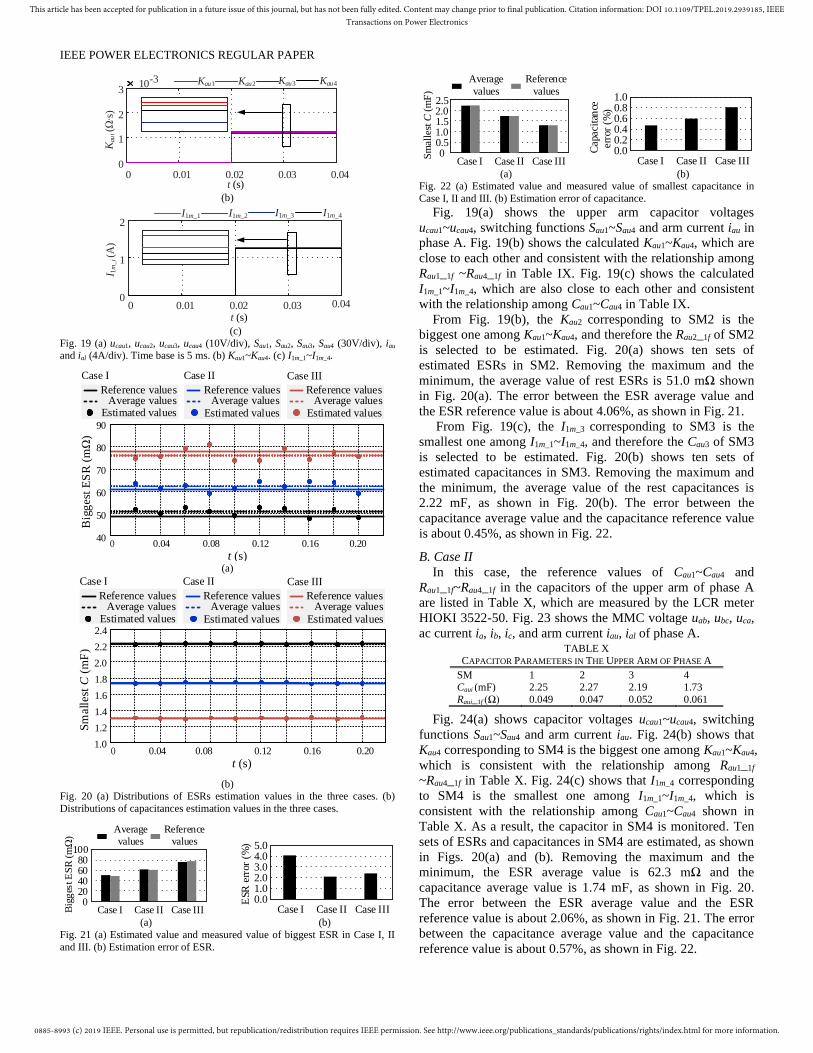
Fig. 19(a) shows the upper arm capacitor voltages
ucau1~ucau4, switching functions Sau1~Sau4 and arm current iau in
phase A. Fig. 19(b) shows the calculated Kau1~Kau4, which are
close to each other and consistent with the relationship among
Rau1_1f ~Rau4_1f in Table IX. Fig. 19(c) shows the calculated
I1m_1~I1m_4, which are also close to each other and consistent
with the relationship among Cau1~Cau4 in Table IX.
From Fig. 19(b), the Kau2 corresponding to SM2 is the
biggest one among Kau1~Kau4, and therefore the Rau2_1f of SM2
is selected to be estimated. Fig. 20(a) shows ten sets of
estimated ESRs in SM2. Removing the maximum and the
minimum, the average value of rest ESRs is 51.0 mΩ shown
in Fig. 20(a). The error between the ESR average value and
the ESR reference value is about 4.06%, as shown in Fig. 21.
From Fig. 19(c), the I1m_3 corresponding to SM3 is the
smallest one among I1m_1~I1m_4, and therefore the Cau3 of SM3
is selected to be estimated. Fig. 20(b) shows ten sets of
estimated capacitances in SM3. Removing the maximum and
the minimum, the average value of the rest capacitances is
2.22 mF, as shown in Fig. 20(b). The error between the
capacitance average value and the capacitance reference value
is about 0.45%, as shown in Fig. 22.
B. Case II
In this case, the reference values of Cau1~Cau4 and
Rau1_1f~Rau4_1f in the capacitors of the upper arm of phase A
are listed in Table X, which are measured by the LCR meter
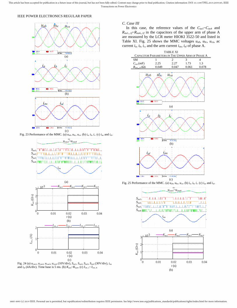
HIOKI 3522-50. Fig. 23 shows the MMC voltage uab, ubc, uca,
ac current ia, ib, ic, and arm current iau, ial of phase A. TABLE X
CAPACITOR PARAMETERS IN THE UPPER ARM OF PHASE A
SM 1 2 3 4 Caui (mF) 2.25 2.27 2.19 1.73
Raui_1f (Ω) 0.049 0.047 0.052 0.061
Fig. 24(a) shows capacitor voltages ucau1~ucau4, switching
functions Sau1~Sau4 and arm current iau. Fig. 24(b) shows that
Kau4 corresponding to SM4 is the biggest one among Kau1~Kau4,
which is consistent with the relationship among Rau1_1f
~Rau4_1f in Table X. Fig. 24(c) shows that I1m_4 corresponding
to SM4 is the smallest one among I1m_1~I1m_4, which is
consistent with the relationship among Cau1~Cau4 shown in
Table X. As a result, the capacitor in SM4 is monitored. Ten
sets of ESRs and capacitances in SM4 are estimated, as shown
in Figs. 20(a) and (b). Removing the maximum and the
minimum, the ESR average value is 62.3 mΩ and the
capacitance average value is 1.74 mF, as shown in Fig. 20.
The error between the ESR average value and the ESR
reference value is about 2.06%, as shown in Fig. 21. The error
between the capacitance average value and the capacitance
reference value is about 0.57%, as shown in Fig. 22.
0885-8993 (c) 2019 IEEE. Personal use is permitted, but republication/redistribution requires IEEE permission. See http://www.ieee.org/publications_standards/publications/rights/index.html for more information.
This article has been accepted for publication in a future issue of this journal, but has not been fully edited. Content may change prior to final publication. Citation information: DOI 10.1109/TPEL.2019.2939185, IEEETransactions on Power Electronics
IEEE POWER ELECTRONICS REGULAR PAPER
(a)
(b)
(c)
Fig. 23 Performance of the MMC. (a) uab, ubc, uca. (b) ia, ib, ic. (c) iau and ial.
ucau1~ucau4
Sau1
Sau2
Sau3
Sau4
iau
(a)
0 0.01 0.02 0.03 0.040
1
2
3 10-3
t (s)
Kau
i (Ω
s)
Kau1 Kau4Kau2 Kau3
(b)
I 1m
_i (A
)
t (s)
I1m_1 I1m_4I1m_2 I1m_3
0 0.01 0.02 0.03 0.040
1
2
(c)
Fig. 24 (a) ucau1, ucau2, ucau3, ucau4 (10V/div), Sau1, Sau2, Sau3, Sau4 (30V/div), iau
and ial (4A/div). Time base is 5 ms. (b) Kau1~Kau4. (c) I1m_1~ I1m_4.
C. Case III
In this case, the reference values of the Cau1~Cau4 and
Rau1_1f~Rau4_1f in the capacitors of the upper arm of phase A
are measured by the LCR meter HIOKI 3522-50 and listed in
Table XI. Fig. 25 shows the MMC voltages uab, ubc, uca, ac
current ia, ib, ic, and the arm current iau, ial of phase A.
TABLE XI CAPACITOR PARAMETERS IN THE UPPER ARM OF PHASE A
SM 1 2 3 4
Caui (mF) 2.25 2.27 1.73 1.3
Raui_1f (Ω) 0.049 0.047 0.061 0.078
(a)
(b)
(c)
Fig. 25 Performance of the MMC. (a) uab, ubc, uca. (b) ia, ib, ic. (c) iau and ial.
ucau1~ucau4
Sau1
Sau2
Sau3
Sau4
iau
(a)
Kau1 Kau4Kau2 Kau3
0 0.01 0.02 0.03 0.040
1
2
3 10-3
t (s)
Kau
i (Ω
s)
(b)
0885-8993 (c) 2019 IEEE. Personal use is permitted, but republication/redistribution requires IEEE permission. See http://www.ieee.org/publications_standards/publications/rights/index.html for more information.
This article has been accepted for publication in a future issue of this journal, but has not been fully edited. Content may change prior to final publication. Citation information: DOI 10.1109/TPEL.2019.2939185, IEEETransactions on Power Electronics
IEEE POWER ELECTRONICS REGULAR PAPER
0 0.01 0.02 0.03 0.040
1
2
I 1m
_i (A
)
t (s)
I1m_1 I1m_4I1m_2 I1m_3
(c)
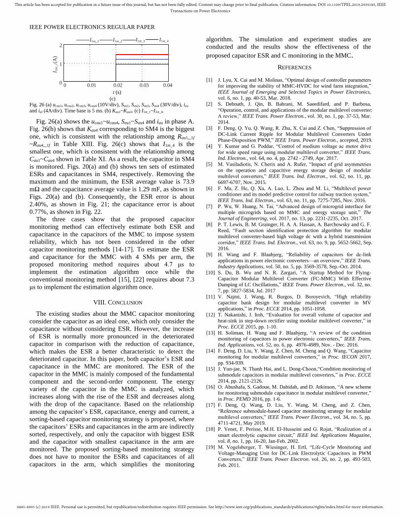
Fig. 26 (a) ucau1, ucau2, ucau3, ucau4 (10V/div), Sau1, Sau2, Sau3, Sau4 (30V/div), iau
and ial (4A/div). Time base is 5 ms. (b) Kau1~Kau4. (c) I1m_1~I1m_4.
Fig. 26(a) shows the ucau1~ucau4, Sau1~Sau4 and iau in phase A.
Fig. 26(b) shows that Kau4 corresponding to SM4 is the biggest
one, which is consistent with the relationship among Rau1_1f
~Rau4_1f in Table XIII. Fig. 26(c) shows that I1m_4 is the
smallest one, which is consistent with the relationship among
Cau1~Cau4 shown in Table XI. As a result, the capacitor in SM4
is monitored. Figs. 20(a) and (b) shows ten sets of estimated
ESRs and capacitances in SM4, respectively. Removing the
maximum and the minimum, the ESR average value is 73.9
mΩ and the capacitance average value is 1.29 mF, as shown in
Figs. 20(a) and (b). Consequently, the ESR error is about
2.40%, as shown in Fig. 21; the capacitance error is about
0.77%, as shown in Fig. 22.
The three cases show that the proposed capacitor
monitoring method can effectively estimate both ESR and
capacitance in the capacitors of the MMC to impose system
reliability, which has not been considered in the other
capacitor monitoring methods [14-17]. To estimate the ESR
and capacitance for the MMC with 4 SMs per arm, the
proposed monitoring method requires about 4.7 μs to
implement the estimation algorithm once while the
conventional monitoring method [15], [22] requires about 7.3
μs to implement the estimation algorithm once.
VIII. CONCLUSION
The existing studies about the MMC capacitor monitoring
consider the capacitor as an ideal one, which only consider the
capacitance without considering ESR. However, the increase
of ESR is normally more pronounced in the deteriorated
capacitor in comparison with the reduction of capacitance,
which makes the ESR a better characteristic to detect the
deteriorated capacitor. In this paper, both capacitor’s ESR and
capacitance in the MMC are monitored. The ESR of the
capacitor in the MMC is mainly composed of the fundamental
component and the second-order component. The energy
variety of the capacitor in the MMC is analyzed, which
increases along with the rise of the ESR and decreases along
with the drop of the capacitance. Based on the relationship
among the capacitor’s ESR, capacitance, energy and current, a
sorting-based capacitor monitoring strategy is proposed, where
the capacitors’ ESRs and capacitances in the arm are indirectly
sorted, respectively, and only the capacitor with biggest ESR
and the capacitor with smallest capacitance in the arm are
monitored. The proposed sorting-based monitoring strategy
does not have to monitor the ESRs and capacitances of all
capacitors in the arm, which simplifies the monitoring
algorithm. The simulation and experiment studies are
conducted and the results show the effectiveness of the
proposed capacitor ESR and C monitoring in the MMC.
REFERENCES
[1] J. Lyu, X. Cai and M. Molinas, “Optimal design of controller parameters for improving the stability of MMC-HVDC for wind farm integration,”
IEEE Journal of Emerging and Selected Topics in Power Electronics,
vol. 6, no. 1, pp. 40-53, Mar. 2018. [2] S. Debnath, J. Qin, B. Bahrani, M. Saeedifard, and P. Barbosa,
“Operation, control, and applications of the modular multilevel converter:
A review,” IEEE Trans. Power Electron., vol. 30, no. 1, pp. 37-53, Mar. 2014.
[3] F. Deng, Q. Yu, Q. Wang, R. Zhu, X. Cai and Z. Chen, “Suppression of
DC-Link Current Ripple for Modular Multilevel Converters Under Phase-Disposition PWM,” IEEE Trans. Power Electron., accepted, 2019.
[4] Y. Kumar and G. Poddar, “Control of medium voltage ac motor drive
for wide speed range using modular multilevel converter,” IEEE Trans. Ind. Electron., vol. 64, no. 4, pp. 2742 - 2749, Apr. 2017.
[5] M. Vasiladiotis, N. Cherix and A. Rufer, “Impact of grid asymmetries
on the operation and capacitive energy storage design of modular multilevel converters,” IEEE Trans. Ind. Electron., vol. 62, no. 11, pp.
6697-6707, Nov. 2015.
[6] F. Ma, Z. He, Q. Xu, A. Luo, L. Zhou and M. Li, “Multilevel power conditioner and its model predictive control for railway traction system,”
IEEE Trans. Ind. Electron., vol. 63, no. 11, pp. 7275-7285, Nov. 2016.
[7] P. Wu, W. Huang, N. Tai, “Advanced design of microgrid interface for multiple microgrids based on MMC and energy storage unit,” The
Journal of Engineering, vol. 2017, no. 13, pp. 2231-2235, Oct. 2017.
[8] P. T. Lewis, B. M. Grainger, H. A. A. Hassan, A. Barchowsky and G. F. Reed, “Fault section identification protection algorithm for modular
multilevel converter-based high voltage dc with a hybrid transmission
corridor,” IEEE Trans. Ind. Electron., vol. 63, no. 9, pp. 5652-5662, Sep. 2016.
[9] H. Wang and F. Blaabjerg, “Reliability of capacitors for dc-link
applications in power electronic converters—an overview,” IEEE Trans. Industry Applications, vol. 50, no. 5, pp. 3569-3578, Sep.-Oct. 2014.
[10] S. Du, B. Wu and N. R. Zargari, “A Startup Method for Flying-
Capacitor Modular Multilevel Converter (FC-MMC) With Effective
Damping of LC Oscillations,” IEEE Trans. Power Electron., vol. 32, no.
7, pp. 5827-5834, Jul. 2017
[11] V. Najmi, J. Wang, R. Burgos, D. Boroyevich, “High reliability capacitor bank design for modular multilevel converter in MV
applications,” in Proc. ECCE 2014, pp. 1051-1058.
[12] T. Nakanishi, J. Itoh, “Evaluation for overall volume of capacitor and heat-sink in step-down rectifier using modular multilevel converter,” in
Proc. ECCE 2015, pp. 1-10.
[13] H. Soliman, H. Wang and F. Blaabjerg, “A review of the condition monitoring of capacitors in power electronic converters,” IEEE Trans.
Ind. Applications, vol. 52, no. 6, pp. 4976-4989, Nov. - Dec. 2016. [14] F. Deng, D. Liu, Y. Wang, Z. Chen, M. Cheng and Q. Wang, “Capacitor
monitoring for modular multilevel converters,” in Proc. IECON 2017,
pp. 934-939. [15] J. Yun-jae, N. Thanh Hai, and L. Dong-Choon,“Condition monitoring of
submodule capacitors in modular multilevel converters,” in Proc. ECCE
2014, pp. 2121-2126. [16] O. Abushafa, S. Gadoue, M. Dahidah, and D. Atkinson, “A new scheme
for monitoring submodule capacitance in modular multilevel converter,”
in Proc. PEMD 2016, pp. 1-6. [17] F. Deng, Q. Wang, D. Liu, Y. Wang, M. Cheng, and Z. Chen,
“Reference submodule-based capacitor monitoring strategy for modular
multilevel converters,” IEEE Trans. Power Electron., vol. 34, no. 5, pp. 4711-4721, May 2019.
[18] P. Venet, F. Perisse, M.H. El-Husseini and G. Rojat, “Realization of a
smart electrolytic capacitor circuit,” IEEE Ind. Applications Magazine, vol. 8, no. 1, pp. 16-20, Jan-Feb. 2002.
[19] M. Vogelsberger, T. Wiesinger, H. Ertl, “Life-Cycle Monitoring and
Voltage-Managing Unit for DC-Link Electrolytic Capacitors in PWM Converters,” IEEE Trans. Power Electron. vol. 26, no. 2, pp. 493-503,
Feb. 2011.
0885-8993 (c) 2019 IEEE. Personal use is permitted, but republication/redistribution requires IEEE permission. See http://www.ieee.org/publications_standards/publications/rights/index.html for more information.
This article has been accepted for publication in a future issue of this journal, but has not been fully edited. Content may change prior to final publication. Citation information: DOI 10.1109/TPEL.2019.2939185, IEEETransactions on Power Electronics
IEEE POWER ELECTRONICS REGULAR PAPER
[20] A. Amaral and A. Cardoso, “An experimental technique for estimating the ESR and reactance intrinsic values of aluminum electrolytic
capacitors,” in Proc. IEEE Instrum. Meas. Technol. Conf., Apr. 2006, pp.
1820–1825. [21] X. S. Pu, T. H. Nguyen, D. C. Lee, K. B. Lee and J. M. Kim, “Fault
diagnosis of dc-link capacitors in three-phase ac/dc PWM converters by
online estimation of equivalent series resistance,” IEEE Trans. Ind. Electron., vol. 60, no. 9, pp. 4118-4127, Sep. 2013.
[22] A. M. R. Amaral and A. J. M. Cardoso, “A simple offline technique for
evaluating the condition of aluminum–electrolytic–capacitors,” IEEE Trans. Ind. Electron., vol. 56, no. 8, pp. 3230-3237, Aug. 2009.
[23] AcÁcio M. R. Amaral and A. J. M Cardoso, “An economic offline
technique for estimating the equivalent circuit of aluminum electrolytic capacitors,” IEEE Trans. Instrumentation & Measurement, vol. 57, no.
12, pp. 2697-2710, Dec. 2008.
[24] K. Laadjal, M. Sahraoui, A. J. M. Cardoso and A. M. R. Amaral, “Online estimation of aluminum electrolytic-capacitors parameters using
a modified Prony's method.” IEEE Trans. Ind. Applications, vol. 54, no.
5, pp. 4764 -4774, Sept.-Oct. 2018. [25] H. Soliman, H. Wang, B. Gadalla, and F. Blaabjerg, “Condition
monitoring of dc-link capacitors based on artificial neural network
algorithm,” in Proc. IEEE 5th Int. Conf. Power Eng., Energy Elect.
Drives, May 2015, pp. 587–591.
[26] Aluminum Electrolytic Capacitor Application Guide, 2018. [Online].
Available: http://www.cde.com/resources/catalogs/AEappGUIDE.pdf [27] F. Deng, R. Zhu, D. Liu, Y. Wang, H. Wang, Z. Chen, M. Cheng,
“Protection Scheme for Modular Multilevel Converters under Diode Open-Circuit Faults,” IEEE Transactions on Power Electronics, vol. 33,
no. 4, pp. 2866-2877, Apr. 2018.
[28] F. Deng, Q. Heng, C. Liu, Q. Wang, R. Zhu, X. Cai and Z. Chen, "Power Losses Control for Modular Multilevel Converters Under
Capacitor Deterioration," IEEE J. Emerg. Sel. Topics Power Electron.,
early access, 2019.
Fujin Deng (SM’19) received the B.Eng. degree in
electrical engineering from China University of Mining and Technology, Jiangsu, China, in 2005, the M.Sc.
Degree in electrical engineering from Shanghai Jiao
Tong University, Shanghai, China, in 2008, and the Ph.D. degree in energy technology from the
Department of Energy Technology, Aalborg University,
Aalborg, Denmark, in 2012. He joined the Southeast University in 2017 and is
currently a Professor in the School of Electrical
Engineering, Southeast University, Nanjing, China. From 2013 to 2015 and from 2015 to 2017, he was a Postdoctoral Researcher
and an Assistant Professor, respectively, in the Department of Energy
Technology, Aalborg University, Aalborg, Denmark. His main research interests include wind power generation, multilevel converters, high-voltage
direct-current technology, DC grid and offshore wind farm-power systems
dynamics.
Qian Heng received the B.Eng. from Nanjing
University of Aeronautics and Astronautics, Jiangsu, China, in 2017. Currently, she is working towards the
M.Sc. degrees in the School of Electrical Engineering,
Southeast University, Nanjing, China. Her main research interests include multilevel converters and
high-voltage direct-current technology.
Chengkai Liu received the B.Eng. degree from Chien-
Shiung Wu College of Southeast University, Nanjing,
China, in 2018, majoring in electrical engineering. He is currently working toward the Ph.D. degree in the
School of Electrical Engineering, Southeast University,
Nanjing, China. His main research interests include multilevel converters and dc grid.
Xu Cai received the B.Eng. degree from Southeast University, Nanjing, China, in 1983, and the M.Eng.
and Ph.D. degrees from China University of Mining
and Technology, Jiangsu, China, in 1988 and 2000, respectively, all in electrical engineering.
He was with the Department of Electrical
Engineering, China University of Mining and
Technology, as an Associate Professor from 1989 to
2001. Since 2002, he has been a Professor with
Shanghai Jiao Tong University, Shanghai, where he
has also been the Director of the Wind Power Research Center since 2008. He
was the Vice Director of the State Energy Smart Grid R&D Center, Shanghai,
China, from 2010 to 2013. His current research interests include power
electronics and renewable energy exploitation and utilization, including wind
power converters, wind turbine control system, large power battery storage
systems, clustering of wind farms and its control system, and grid integration.
Rongwu Zhu (S’2-M’5) received the B.Eng. in
Electrical Engineering from Nanjing Normal University, Nanjing, China, in 2007 and Ph.D.
degree in energy technology from Department of
Energy Technology, Aalborg University, Aalborg, Denmark, in 2015. From 2011-2012, he was a guest
researcher with Aalborg University. He is currently a
Senior Researcher with Chair of power electronics, at Christian-Albrechts-University of Kiel (Germany).
He has published over 60 technical papers (over
20 of them in international peer-review). His
research interests include high-power multilevel modular converters, DC-grid
and wind-farm power systems, smart transformer-fed distribution system,
reliability and lifetime of power converters, modelling and stability of the
power electronics-based electric grid.
Zhe Chen (M’95-SM’98-F’18) received the B.Eng.
and M.Sc. degrees all in Electrical Engineering from
Northeast China Institute of Electric Power
Engineering, Jilin City, China, MPhil in Power
Electronic, f r o m Staffordshire University, England
and the Ph.D. degree in Power and Control, from
University of Durham, England.
Dr Chen is a full Professor with the Department of
Energy Technology, Aalborg University, Denmark. He
is the leader of Wind Power System Research program at the Department of
Energy Technology, Aalborg University and the Danish Principle Investigator
for Wind Energy of Sino-Danish Centre for Education and Research.
His research areas are power systems, power electronics and electric
machines; and his main current research interests are wind energy and modern
power systems. He has led many research projects and has more than 400
technical publications with more than 10000 citations and h-index of 44
(Google Scholar).
Dr Chen is an Associate Editor of the IEEE Transactions on Power
Electronics, a Fellow of the Institution of Engineering and Technology
(London, U.K.), and a Chartered Engineer in the U.K.
Wu Chen (SM’17) was born in Jiangsu, China, in
1981. He received the B.S., M.S., and Ph.D. degrees in electrical engineering from the Nanjing University of
Aeronautics and Astronautics (NUAA), Nanjing,
China, in 2003, 2006, and 2009, respectively. From 2009 to 2010, he was a Senior Research
Assistant in the Department of Electronic Engineering,
City University of Hong Kong, Kowloon, Hong Kong.
In 2010–2011, he was a Postdoctoral Researcher in
Future Electric Energy Delivery and Management
Systems Center, North Carolina State University, Raleigh. Since September
2011, he has been an Associate Research Fellow with the School of Electrical
Engineering, Southeast University, Nanjing, China, where he has been a
Professor since 2016. His main research interests include soft-switching
converters, power delivery, and power electronic system integration. He
serves as an Associate Editor for IEEE TRANSACTIONS ON INDUSTRIAL

0885-8993 (c) 2019 IEEE. Personal use is permitted, but republication/redistribution requires IEEE permission. See http://www.ieee.org/publications_standards/publications/rights/index.html for more information.
This article has been accepted for publication in a future issue of this journal, but has not been fully edited. Content may change prior to final publication. Citation information: DOI 10.1109/TPEL.2019.2939185, IEEETransactions on Power Electronics
IEEE POWER ELECTRONICS REGULAR PAPER
ELECTRONICS, JOURNAL OF POWER ELECTRONICS, AND CPSS TRANSACTIONS
ON POWER ELECTRONICS AND APPLICATIONS.