a generative-oriented model-driven design environment for customizable video surveillance systems
TRANSCRIPT
Cardoso et al. EURASIP Journal on Embedded Systems 2012, 2012:7http://jes.eurasipjournals.com/content/2012/1/7
RESEARCH Open Access
A generative-oriented model-driven designenvironment for customizable videosurveillance systemsNuno Cardoso1*, Pedro Rodrigues1, Joao Vale1, Paulo Garcia1, Paulo Cardoso1, Joao Monteiro1,Jorge Cabral1, Jose Mendes1, Mongkol Ekpanyapong2 and Adriano Tavares1
Abstract
To tackle the growing complexity and huge demand for tailored domestic video surveillance systems along with ahigh demanding time-to-market expectation, engineers at IVV Automacao, LDAa are exploiting video surveillancedomain as families of systems that can be developed following a pay-as-you-go fashion rather than developing an ex-nihilo new product. Several and different new functionalities are required for each new product’s hardware platforms(e.g., ranging from mobile phone, PDA to desktop PC) and operating systems (e.g., flavors of Linux, Windows and MACOS X). Some of these functionalities have special economical constraints of development time and memory footprint.To better accommodate all the above listing requirements, a model-driven generative software developmentparadigm supported by mainstream tools is proposed to offer a significant leverage in hiding commonalities andconfiguring variabilities across families of video surveillance products while maintaining the new product quality.
1 IntroductionNowadays there is a growing demand for video surveil-lance systems [1]. The development of these systemsis increasingly complex since there is a high demandfor new products with a rising number of differentrequirements [2].However, it can be noticed that the increasing com-
plexity is induced by the variability in tasks related toimage capturing, image processing, communications andcomputer vision [3]. Furthermore, it is now expected thatthe system runs in different hardware platforms, rangingfrom desktop PCs to low cost embedded boards, mobilephones, etc.The majority of system designers use modular archi-
tectures based on Microsoft DirectShow implementation[4,5] in order to address the growing complexity of novelproducts and the ever increasing time-to-market pres-sure. In this implementation, all system functionalitiesare implemented as individual plug-ins or filters. Later,these plug-ins will be connected following the pipeline
*Correspondence: [email protected] of Industrial Electronics, Centro Algoritmi, University of Minho,Braga, PortugalFull list of author information is available at the end of the article
execution model (filter graph) through a generic interface.In this way, higher flexibility, customizability and reusabil-ity can be achieved for video surveillance oriented design.Furthermore, at run time, only the required plug-ins fora given configuration will be loaded and a new systemconfiguration can be implemented by simply defining newplug-ins to be loaded and the connections among them.In the case of embedded systems, such an implemen-
tation incurs a huge abstraction penalty [6-9], since itis based on weighty language’s dialects (i.e., featuresthat increase overhead in space and performance), likedynamic polymorphism.In order to tackle these embedded systems constraints
[6], video surveillance systems can be implemented as asoftware product line (SPL) [2,10] by designing plug-inswhich fit all possible video surveillance system’s configu-rations and simply reusing the common features of severalconfigurations while considering the variable features thatidentify each system specific configuration.Based on practical experience at IVV in tackling the
design challenges of video surveillance systems, newsoftware technologies such as model driven develop-ment [11] and generative programming [12], should be
© 2012 Cardoso et al.; licensee Springer. This is an Open Access article distributed under the terms of the Creative CommonsAttribution License (http://creativecommons.org/licenses/by/2.0), which permits unrestricted use, distribution, and reproductionin any medium, provided the original work is properly cited.
Cardoso et al. EURASIP Journal on Embedded Systems 2012, 2012:7 Page 2 of 24http://jes.eurasipjournals.com/content/2012/1/7
combined with SPL engineering to bridge the abstractiongap between domain modeling and feature modeling.The remainder of this article is structured as follows.
The following section deliberates related works. Next, inSection 3, Microsoft DirectShow is reviewed, togetherwith brief discussion on how to reverse engineer it.Section 4 focuses on video surveillance domain engi-neering by implementing the feature modeling. Section 5presents the details of video surveillance applicationengineering, showing how model-driven engineeringtechniques are employed to establish the relationshipsbetween video surveillance feature models and videosurveillance domain model. It also describes how offlineand online partial evaluators [13] will be applied, respec-tively, at whole system and filter designs. In Section 6, theimplementation of a SDK for video surveillance productline development is described. Section 7 presents someresults. Finally, in Section 8 we conclude the article andpresent some directions of future study.
2 Related workThe amount of research works in this field is very large,so this short literature survey describes related worksthat apply similar software technologies, describes videosurveillance systems design and/or manages variability.In [2], a mixture of model-driven and generative pro-
gramming techniques are proposed to support variabilityconfiguration of video surveillance systems. In order tobetter manage features combination at runtime, it sepa-rates the variability in domain and code representationspaces.In [14], Aspect-Oriented Programming (AOP) is
employed in order to avoid crosscutting concerns by man-aging the existing variability in operating systems domain.Even though the use of AOP enables higher levels of gran-ularity when compared with other variability managementstrategies, it incurs in higher overhead depending on theapplied type of advice and the inability to manage variabil-ity in systems with several instances of the same class eachwith different requirements.In [15], to better tackle the time-to-market pressure
during the developing of digital games the use of genera-tive programming was proposed. In [16], a Fujaba plug-infor SPL development was described using model-driventechniques. The main focus is on how to bridge the gapbetween feature modeling and domain modeling withannotations.In [17], new mechanisms are explored in order to better
specify and understand the relationship between systemvariability and requirements by combining SPL, Aspect-orientation and model-driven techniques. The Ampleproject, presents two complementary languages, RDL andVML4RE, to allow specifying and reasoning about cross-cutting relationships between features and requirements.
In [18], Matilda is described. Matilda is a model-drivendevelopment framework that allows automatic code gen-eration through transformations using UMLmodels whileaddresses the abstraction gap and lack of traceabilityrelated to current model-driven development practice. Inthis way, the developer analyses, designs and executesapplications in modeling layer, abstracting it from theprogramming layer.In [19], generative programming as an automatic selec-
tion and assembly of components based on configurationknowledge and a set of construction rules is proposed. Alayered architecture, called GenVoca is used and the con-figuration knowledge is implemented using C++ templatemetaprogramming as generator.
3 Microsoft directshow and its reverseengineering
DirectShow is a pipeline-basedmedia-streaming architec-ture and API based on component object model (COM)framework that provides a common interface for mediaacross several programming languages. It’s a filter-basedframework that implements a complex multimedia appli-cation by connecting several filters of three main kinds(i.e., source, transform and renderer filters) through theirinput and output pins using filters graphs to providespecific functionality [5].Since DirectShow SDK only offers partial code of the
framework, we run a reverse engineering process usingIDA Pro [20] on quartz.dll to figure out its real architec-ture, starting with the CFilterGraph class.Due to the limited space, we’ll only present how the
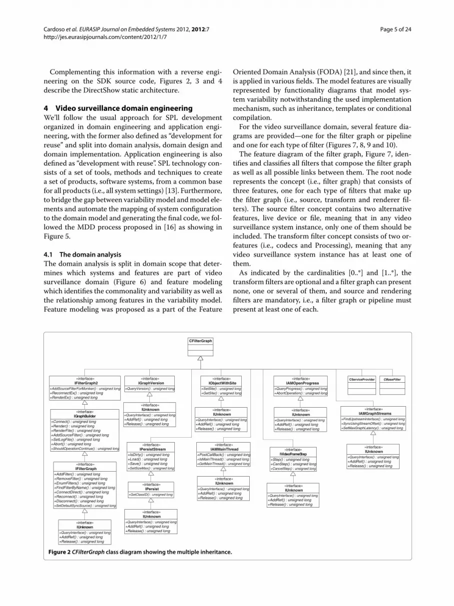
implemented interfaces at CFilterGraph class were identi-fied as well as the overhead of a filter class likeCMjpegDec.Listing 1 partially shows the assembly code of the CFilter-Graph constructor where the initialization of the virtualtables for each defined interface is visible. The register esipoints to the data member of the class (i.e., this pointer)while the first memory addresses point to the interfacesvirtual tables implemented byCFilterGraph class. Figure 1presents CFilterGraph class layout with special focus onits thirteen direct and ten indirect interfaces through thepointer, m pFGControl, to an object of CFGControl classthat encapsulates all filter graph control functionalities.
3.1 Listing 1 Partial Assembly code of CFilterGraph classconstructor
1 ??0CFilterGraph@@AAE@PAGPAUIUnknown@@-PAJ@Z proc near
23 ... mov esi, ecx ; esi = this... call4 CBaseFilter::CBaseFilter(ushort const ∗,IUnknown
∗,CCritSec ∗, GUID5 const &) push [ebp+cbData]mov dword ptr
[ebx], offset

Cardoso et al. EURASIP Journal on Embedded Systems 2012, 2012:7 Page 3 of 24http://jes.eurasipjournals.com/content/2012/1/7
QueryVersion
QueryInterface
AddRef
Release
[00]
[04]
[08]
[0C]
SetSite
QueryInterface
AddRef
Release
GetSite
[00]
[04]
[08]
[0C]
[10]
QueryProgress
QueryInterface
AddRef
Release
AbortOperation
[00]
[04]
[08]
[0C]
[10]
CancelStep
Step
QueryInterface
AddRef
Release
CanStep
[00]
[04]
[08]
[0C]
[10]
[14]
RegisterService
QueryInterface
AddRef
Release
[00]
[04]
[08]
[0C]
QueryService
QueryInterface
AddRef
Release
[00]
[04]
[08]
[0C]
SetMaxGraphLatency
FindUpstreamInterface
QueryInterface
AddRef
Release
SyncUsingStreamOffset
[00]
[04]
[08]
[0C]
[10]
[14]
GetMainThread
PostCallBack
QueryInterface
AddRef
Release
IsMainThread
[00]
[04]
[08]
[0C]
[10]
[14]
GetClassID
QueryInterface
AddRef
Release
IsDirty
Load
Save
GetSizeMax
[00]
[04]
[08]
[0C]
[10]
[14]
[18]
[1C]
AddFilter
RemoveFilter
EnumFilters
FindFilterByName
ConnectDirect
Reconnect
Disconnect
SetDefaultSyncSource
Connect
Render
RenderFile
AddSourceFilter
SetLogFile
Abort
ShouldOperationContinue
AddSourceFilterMoniker
ReconnectEx
RenderEx
QueryInterface
AddRef
Release
[00]
[04]
[08]
[0C]
[10]
[14]
[18]
[1C]
[20]
[24]
[28]
[2C]
[30]
[34]
[38]
[3C]
[40]
[44]
[48]
[4C]
[50]
Reconfigure
GetFilterFlags
RemoveFilterEx
[00]
[04]
[08]
[0C]
[10]
[14]
[18]
[1C]
[20]
[24]
[28]
[2C]
[30]
Reconnect
AddFilterToCache
EnumCacheFilter
RemoveFilterFromCache
GetStartTime
PushThroughData
SetFilterFlags
QueryInterface
AddRef
ReleaseRegister
QueryInterface
AddRef
Release
Unregister
[00]
[04]
[08]
[0C]
[10]
JoinFilterGraph
QueryVendorInfo
GetClassID
Stop
Pause
Run
GetState
SetSyncSource
GetSyncSource
EnumPins
FindPin
QueryFilterInfo
QueryInterface
AddRef
Release
[00]
[04]
[08]
[0C]
[10]
[14]
[18]
[1C]
[20]
[24]
[28]
[2C]
[30]
[34]
[38]
CFGControlObject
IFilterGraph2
IGraphVersion
IPersistStream
IObjectWithSite
IAMMainThread
IAMOpenProgress
IAMGraphStreams
IVideoFrameStep
IServiceProvider
IRegisterServiceProvider
…
[00]
[04]
[08]
[0C]
[10]
[14]
[18]
[1C]
[20]
[24]
IBaseFilter
IAMovieSetup
...
CFGControl *m_pCtrl
...
…
[54]
[58]
[198] IGraphConfig
…
[98]
CFilterGraphObject
Figure 1 CFilterGraph class layout and its implemented interfaces.
6 CFilterGraph::‘vftable’{for ‘CUnknown’} xor ebx,ebx lea ecx,
7 [esi+9Ch] mov dword ptr [esi], offset8 CFilterGraph::‘vftable’{for ‘IFilterGraph2’} mov
dword ptr9 [esi+4], offset CFilterGraph::‘vftable’{for
‘IGraphVersion’} mov10 dword ptr [esi+8], offset CFilterGraph::‘vftable’{for11 ‘IPersistStream’} mov dword ptr [esi+0Ch], offset12 CFilterGraph::‘vftable’{for ‘IObjectWithSite’} mov
dword ptr
13 [esi+10h], offset CFilterGraph::‘vftable’{for‘IAMMainThread’} mov
14 dword ptr [esi+14h], offsetCFilterGraph::‘vftable’{for
15 ‘IAMOpenProgress’}mov dword ptr [esi+18h],offset
16 CFilterGraph::‘vftable’{for ‘IAMGraphStreams’} movdword ptr
17 [esi+1Ch], offset CFilterGraph::‘vftable’{for‘IVideoFrameStep’} mov
18 dword ptr [edi], offset CFilterGraph::‘vftable’{for

Cardoso et al. EURASIP Journal on Embedded Systems 2012, 2012:7 Page 4 of 24http://jes.eurasipjournals.com/content/2012/1/7
19 ‘IServiceProvider’} mov dword ptr [esi+24h], offset20 CFilterGraph::‘vftable’{for ‘IRegisterServiceProvider’}
mov dword21 ptr [esi+54h], offset CFilterGraph::‘vftable’{for
‘IBaseFilter’} mov22 dword ptr [esi+58h], offset
CFilterGraph::‘vftable’{for23 ‘IAMovieSetup’} mov [esi+98h], ebx...
From the CMjpegDec class constructor analysis, List-ing 2, the following code segments were identified,informing us that it inherits from CVideoTransform-Filter class and implements IUnknown, IBaseFilter andIAMovieSetup interfaces:
i. Initialization of the stack frame from line 1 to 3;ii. Calling of CVideoTransformFilter constructor as a
base class from line 6 to 10;iii. Registering of virtual tables addresses for each
implemented interface from line 15 to 17;iv. Initialization of class variable members from line 18
to 24;v. Returning to the caller with stack restoring from line
25 to 31.
3.2 Listing 2 CMjpegDec class constructor assembly code1 mov edi, edi push ebp ; save ebp mov ebp, esp ;2 save stack frame push esi ; save esi push edi ;3 save edi push offset CLSID MjpegDec ; push
CLSID MjpegDec4 (REFCLSID) push [ebp+arg 4] ; push pUnk
(LPUNKNOWN) mov5 esi, ecx ; esi = this push [ebp+arg 0] ; push pName
(TCHAR6 *) call
CVideoTransformFilter::CVideoTransformFilter(...) ;call
7 the base class xor edi, edi ; edi = 0 push edi8 ; push nDefault (INT) push offset aMjpegnoskip ;
push9 “MJPEGNoSkip” (LPCTSTR lpKeyName) push
offset AppName ; push10 “Quartz” (LPCTSTR lpAppName)mov dword ptr
[esi], offset11 CMjpegDec::‘vftable’{for ‘CUnknown’} mov dword
ptr [esi+0Ch],12 offset CMjpegDec::‘vftable’{for ‘IBaseFilter’} mov
dword ptr13 [esi+10h], offset CMpegAudioCodec::‘vftable’ for
‘IAMovieSetup’mov14 [esi+0C0h], edi mov [esi+0C8h], edi mov
[esi+0CCh], edi mov15 [esi+0D0h], edi mov [esi+0D4h], edi call16 GetProfileIntW(x,x,x) ; GetProfileInt(“Quartz”,
“MJPEGNoSkip”, 0);
17 mov [esi+0B0h], eax mov eax, [ebp+arg 8] ; eax =phr;
18 (HRESULT ∗phr)mov [eax], edi ; ∗phr =NOERROR; pop
19 edi ; restore edi mov eax, esi ; ret = this pop20 esi ; restore esi pop ebp ; restore ebp retn21 0Ch ; return and clean stack
Listing 3 shows the assembly code of CMjpegDec::-Transform method that receives a media sample (i.e.,IMediaSample *pIn) and outputs another media sample(i.e., IMediaSample *pOut), with the image decompres-sion carried out at line 7 by the functionDecompressBeginthat receives as arguments an output YCbCr buffer, aninput JPEG image buffer and an image header info.
3.3 Listing 3 CMjpegDec::Transformmethod partialassembly code
1 mov [ebp+ms exc.disabled], 1 push dword ptr[esi+0C0h] call
2 DecompressEnd@4 ; DecompressEnd(x) push[ebp+pInfoHeader] ;
3 image header push edi ; image src buffer push4 dword ptr [esi+0C0h] ; image dst buffer call
DecompressBegin@125 ; DecompressBegin(x,x,x) ; decompress frame or6 [ebp+ms exc.disabled], 0FFFFFFFFh and
[ebp+var 6C], 0
Listing 3 shows the assembly code of CMjpegDec::-Transformmethod that receives amedia sample (i.e., IMe-diaSample ∗pIn) and outputs another media sample (i.e.,IMediaSample ∗pOut), with the image decompressioncarried out at line 7 by the function DecompressBegin thatreceives as arguments an output YCbCr buffer, an inputJPEG image buffer and an image header info.Listing 4 partially shows the disassembling of Decom-
pressBegin function indicating that MJpegDec filter usesIJG JPEG library during decompression process. Deeperanalysis of this function revealed through the C routinesinto the library that it’s a generic JPEG decompressorimplementation full of variations and consequently with asevere dead code overhead.
3.4 Listing 4 Partial disassembling of DecompressBeginfunction
1 lea edi, [esi+1F8h] lea eax, [esi+8] push eax call2 jpeg exception error@4 ; jpeg exception error(x)
mov [edi], eax3 push edi call jpeg create decompress@4 ;4 jpeg create decompress(x)mov byte ptr [esi+399h],
1mov5 eax, [ebx+10h] test eax, eax jnz loc 74823996
Cardoso et al. EURASIP Journal on Embedded Systems 2012, 2012:7 Page 5 of 24http://jes.eurasipjournals.com/content/2012/1/7
Complementing this information with a reverse engi-neering on the SDK source code, Figures 2, 3 and 4describe the DirectShow static architecture.
4 Video surveillance domain engineeringWe’ll follow the usual approach for SPL developmentorganized in domain engineering and application engi-neering, with the former also defined as “development forreuse” and split into domain analysis, domain design anddomain implementation. Application engineering is alsodefined as “development with reuse”. SPL technology con-sists of a set of tools, methods and techniques to createa set of products, software systems, from a common basefor all products (i.e., all system settings) [13]. Furthermore,to bridge the gap between variabilitymodel andmodel ele-ments and automate the mapping of system configurationto the domain model and generating the final code, we fol-lowed the MDD process proposed in [16] as showing inFigure 5.
4.1 The domain analysisThe domain analysis is split in domain scope that deter-mines which systems and features are part of videosurveillance domain (Figure 6) and feature modelingwhich identifies the commonality and variability as well asthe relationship among features in the variability model.Feature modeling was proposed as a part of the Feature
Oriented Domain Analysis (FODA) [21], and since then, itis applied in various fields. The model features are visuallyrepresented by functionality diagrams that model sys-tem variability notwithstanding the used implementationmechanism, such as inheritance, templates or conditionalcompilation.For the video surveillance domain, several feature dia-
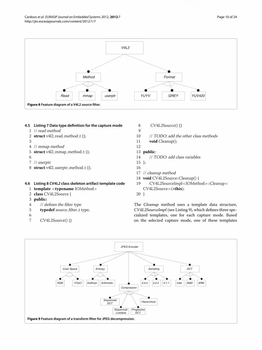
grams are provided—one for the filter graph or pipelineand one for each type of filter (Figures 7, 8, 9 and 10).The feature diagram of the filter graph, Figure 7, iden-
tifies and classifies all filters that compose the filter graphas well as all possible links between them. The root noderepresents the concept (i.e., filter graph) that consists ofthree features, one for each type of filters that make upthe filter graph (i.e., source, transform and renderer fil-ters). The source filter concept contains two alternativefeatures, live device or file, meaning that in any videosurveillance system instance, only one of them should beincluded. The transform filter concept consists of two or-features (i.e., codecs and Processing), meaning that anyvideo surveillance system instance has at least one ofthem.As indicated by the cardinalities [0..*] and [1..*], the
transform filters are optional and a filter graph can presentnone, one or several of them, and source and renderingfilters are mandatory, i.e., a filter graph or pipeline mustpresent at least one of each.
+AddSourceFilterForMoniker() : unsigned long +ReconnectEx() : unsigned long+RenderEx() : unsigned long
«interface»IFilterGraph2
+Connect() : unsigned long+Render() : unsigned long+RenderFile() : unsigned long+AddSourceFilter() : unsigned long+SetLogFile() : unsigned long+Abort() : unsigned long+ShouldOperationContinue() : unsigned long
«interface»IGraphBuilder
+AddFilter() : unsigned long+RemoveFilter() : unsigned long+EnumFilters() : unsigned long+FindFilterByName() : unsigned long+ConnectDirect() : unsigned long+Reconnect() : unsigned long+Disconnect() : unsigned long+SetDefaultSyncSource() : unsigned long
«interface»IFilterGraph
+QueryInterface() : unsigned long+AddRef() : unsigned long+Release() : unsigned long
«interface»IUnknown
+QueryInterface() : unsigned long+AddRef() : unsigned long+Release() : unsigned long
«interface»IUnknown
+QueryInterface() : unsigned long+AddRef() : unsigned long+Release() : unsigned long
«interface»IUnknown
+QueryVersion() : unsigned long
«interface»IGraphVersion
+IsDirty() : unsigned long+Load() : unsigned long+Save() : unsigned long+GetSizeMax() : unsigned long
«interface»IPersistStream
+GetClassID() : unsigned long
«interface»IPersist
+QueryInterface() : unsigned long+AddRef() : unsigned long+Release() : unsigned long
+QueryInterface() : unsigned long+AddRef() : unsigned long+Release() : unsigned long
«interface»IUnknown
+QueryInterface() : unsigned long+AddRef() : unsigned long+Release() : unsigned long
«interface»IUnknown
+QueryInterface() : unsigned long+AddRef() : unsigned long+Release() : unsigned long
«interface»IUnknown
«interface»IUnknown
«interface»IUnknown
+SetSite() : unsigned long+GetSite() : unsigned long
«interface»IObjectWithSite
+PostCallBack() : unsigned long+IsMainThread() : unsigned long+GetMainThread() : unsigned long
«interface»IAMMainThread
+QueryProgress() : unsigned long+AbortOperation() : unsigned long
«interface»IAMOpenProgress
+FindUpstreamInterface() : unsigned long+SyncUsingStreamOffset() : unsigned long+SetMaxGraphLatency() : unsigned long
«interface»IAMGraphStreams
+Step() : unsigned long+CanStep() : unsigned long+CancelStep() : unsigned long
«interface»IVideoFrameStep
CFilterGraph
CServiceProvider CBaseFilter
+QueryInterface() : unsigned long+AddRef() : unsigned long+Release() : unsigned long
Figure 2 CFilterGraph class diagram showing the multiple inheritance.

Cardoso et al. EURASIP Journal on Embedded Systems 2012, 2012:7 Page 6 of 24http://jes.eurasipjournals.com/content/2012/1/7
+EnumPins() : unsigned long+FindPin() : unsigned long+QueryFilterInfo() : unsigned long+JoinFilterGraph() : unsigned long+QueryVendorInfo() : unsigned long
«interface»IBaseFilter
+Stop() : unsigned long+Pause() : unsigned long+Run() : unsigned long+GetState() : unsigned long+SetSyncSource() : unsigned long+GetSyncSource() : unsigned long
«interface»IMediaFilter
+GetClassID() : unsigned long
«interface»IPersist
+QueryInterface() : unigned long+AddRef() : unsigned long+Release() : unsigned long
«interface»IUnknown
+QueryInterface() : unsigned long+AddRef() : unsigned long+Release() : unsigned long
«interface»IUnknown
+GetState() : unsigned long+SetSyncSource() : unsigned long+GetSyncSource() : unsigned long+...()
-m_State : FILTER_STATE-m_pClock : IReference Clock-...
CBaseFilter
+Register() : unsigned long+Unregister() : unsigned long
«interface»IAMovieSetup
+GetOwner() : CUnknown+NonDelegatingQueryInterface() : unsigned long+NonDelegatingAddRef() : unsigned long+NonDelegatingRelease() : unsigned long
-m_pUnknown : CUnknown#m_cRef : long
CUnknown
+NonDelegatingQueryInterface() : unsigned long+NonDelegatingAddRef() : unsigned long+NonDelegatingRelease() : unsigned long
«interface»INonDelegatingUnknown
+ObjectsActive() : long
-m_cObjects : long
CBaseObject
Figure 3 CBaseFilter class diagram.
All the above feature diagrams are internally repre-sented using XML notation as can be shown in Listings 5and 6 for the description of the File renderer filter andfilter graph, respectively.
4.2 Listing 5 XML Feature diagram of a renderer filterdesigned File
1 <?xml version=“1.0” ?> <feature name=“File”>2 <feature name=“Localization” type=“Mandatory”>3 <featureGroup type=“Alternative”>4 <feature name=“Local” type=“Mandatory”/>5 <feature name=“Remote” type=“Mandatory”>6 <featureGroup type=“Alternative”>7 <feature name=“SMB” type=“Mandatory”/>8 <feature name=“FTP” type=“Mandatory”/>9 </featureGroup>10 </feature>11 </featureGroup>12 </feature>13 <feature name=“Format” type=“Mandatory”>14 <featureGroup type=“Alternative”>15 <feature name=“AVI” type=“Mandatory”/>16 <feature name=“WAV” type=“Mandatory”/>17 <feature name=“OWN” type=“Mandatory”/>18 </featureGroup>
19 </feature>20 </feature>
4.3 Listing 6 Filter graph XML Feature diagram1 <?xml version=“1.0” ?> <feature name=“Filter Graph”>2 <feature min=“1”max=“∗”name=“Source Filter”type=“Mandatory”>3 <featureGroup type=“Alternative”>4 <feature name=“Live Device” type=“Mandatory”>5 <featureGroup type=“Alternative”>6 <feature name=“Analogic Camera” type=“Mandatory”/>7 <feature name=“Microphone” type=“Mandatory”/>8 <feature name=“IP Camera” type=“Mandatory”/>9 </featureGroup>10 </feature>11 ...12 </featureGroup>13 </feature>14 ...15 <feature min=“1”max=“∗”name=“Renderer Filter”
type=“Mandatory”>16 <featureGroup type=“Or”>17 <feature name=“Transmission” type=“Mandatory”>18 <featureGroup type=“Alternative”>19 <feature name=“HTTP” type=“Mandatory”/>20 <feature name=“RTSP” type=“Mandatory”/>21 </featureGroup>22 </feature>23 ...24 </featureGroup>

Cardoso et al. EURASIP Journal on Embedded Systems 2012, 2012:7 Page 7 of 24http://jes.eurasipjournals.com/content/2012/1/7
+AttemptConnection() : unsigned long+TryMediaTypes() : unsigned long+...()
-m_pName : wchar_t-m_Connected : IPin-...
CBasePin
+Notify() : unsigned long+SetSink() : unsigned long
«interface»IQualityControl
«interface»IUnknown
+GetOwner() : CUnknown+NonDelegatingQueryInterface() : unsigned long+NonDelegatingAddRef() : unsigned long+NonDelegatingRelease() : unsigned long
-m_pUnknown : CUnknown#m_cRef : long
CUnknown
+NonDelegatingQueryInterface() : unsigned long+NonDelegatingAddRef() : unsigned long+NonDelegatingRelease() : unsigned long
«interface»INonDelegatingUnknown
+ObjectsActive() : long
-m_cObjects : long
CBaseObject
+Connect() : unsigned long+ReceiveConnection() : unsigned long+Disconnect() : unsigned long+ConnectedTo() : unsigned long+ConnectionMediaType() : unsigned long+QueryPinInfo() : unsigned long+QueryDirection() : unsigned long+QueryId() : unsigned long+QueryAccept() : unsigned long+EnumMediaTypes() : unsigned long+QueryInternalConnections() : unsigned long+EndOfStream() : unsigned long+BeginFlush() : unsigned long+EndFlush() : unsigned long+NewSegment() : unsigned long
«interface»IPin
+QueryInterface() : unsigned long+AddRef() : unsigned long+Release() : unsigned long
+QueryInterface() : unsigned long+AddRef() : unsigned long+Release() : unsigned long
«interface»IUnknown
Figure 4 CBasePin class diagram.
25 </feature>26 </feature>
4.4 The domain design and implementationDomain design is the next step after the specificationof applications and components in video surveillancedomain and its main goal is developing a common archi-tecture for the video surveillance family of products.Having defined the common architecture, the imple-mentation domain proposes developing configurable andcustomizable components to support the implementa-tion of the video surveillance system domain architecture[22]. The implemented generative-friendly framework forvideo surveillance software product family, basically, han-dles variability at two levels of granularity (intra-filter andinter-filter) and consists of:
(i) Several and different artifact templates encoded inC++ template metaprogramming for each type offilter that is generated;
(ii) A filter graph artifact template describing thepipeline as a confederation of filters based oncomponent technology and encoded in C++template metaprogramming;
(iii) A set of meta-expressions and presence conditionswith direct correspondence to the artifact templates
and their variability points, and expressed in terms offeatures used to map features in feature models tothe artifact templates, and so, giving semantics tothose features [23];
(iv) A set of implicit rules for filters connection andvalidation, are internal and implicitly defined as partof filter graph within its built-in IntelligentConnector. These rules are also encoded in C++metaprogramming artifact templates.
4.4.1 The filter artifact templateThe filter artifact template does not implement an arti-fact template for each filter type, in opposition to otherfilter implementations that classify each filter by cate-gory using specific classes for the purpose. Instead, all thefilters follow the same implementation that allows the rep-resentation of artifact filters in a more flexible manner.This methodology was used to allow easier refactoring oflegacy code from external libraries that implements somefilters functionalities. The framework allows exploring thegranularity at two levels: coarse-grained and fine-grained.A coarse-grained granularity allows changing betweenfilters; as an example, changing a JPEG transformationfilter by a H.264 transformation filter. A fine-grainedgranularity allows having different instances of the same

Cardoso et al. EURASIP Journal on Embedded Systems 2012, 2012:7 Page 8 of 24http://jes.eurasipjournals.com/content/2012/1/7
DefineFeature Model
FeatureModel
DefineVSS Model
VSSModel
InstantiateConfiguration
Configuration
ConfigurationValidator
Feature toModel Mapper
MappedVSS Model
C++ ApplicationInstantiator
ConfiguredC++ Code
FeatureModel
DomainModel
Figure 5MDD process which combines Feature models and domain models in VSS.
filter to satisfy the system requirements, e.g., the JPEGtransformation filter can have a generic implementationand an optimized implementation.To develop a new filter artifact template, the unique
requisites that the filter needs to implement are:
(i) Define the data type named type that informs what isthe type of the filter (source, transform, renderer);
(ii) The Initialize and Cleanup methods that initializeand cleanup all the filter resources;
(iii) The Connect method that allows connecting otherfilter to this filter;
(iv) The Start, Stop and Pause methods that control theexecution data flow;
(iv) The Process method that process data.
Most of the artifact templates related to different kindof filters are automatically generated running an onlinepartial evaluator on legacy codes from previous video
surveillance projects (external libraries). Such refactoringprocess was implemented based on an automatic partialevaluation for the C++ language named transformer [13]on a first stage and then the output was adapted to ourfilter template architecture.In the following sub-section, two filter artifact imple-
mentations are presented, one for an input filter and theother for a transformation filter.
4.4.2 The input filter artifact templateNow let’s take the input filter V4L2 as represented bythe feature diagram in Figure 8 to partially describe theartifact template of such kind of filters. Due to huge exten-sion of the code we’ll focus on the filter Cleanup methodneeded to free all allocated resource by the filter. Threecreated structures, one for each capture method and askeleton artifact template for CV4L2Source along with theCleanup method are created as shown by Listings 7 and8, respectively.

Cardoso et al. EURASIP Journal on Embedded Systems 2012, 2012:7 Page 9 of 24http://jes.eurasipjournals.com/content/2012/1/7
Video Surveillance System
CodecSystem
Encoder System
Decoder System
Image ProcessingSystem
Server System
Consult and RegisterSystem
Visualization System
Storage System
CaptureSystem
AnalogicalCapture
DigitalCapture
Variations
Variations
Variations
Variations
Variations
Variations
Variations
Variations
Variations
Variations
Variations
Variations
Variations
Variations
Variations
Variations
Variations
Variations
Variations
Variations
Variations
Variations
Variations
Variations
Figure 6 Video Surveillance Domain Scoping.
Filter Graph
Source Filter
Transform Filter
Renderer Filter
Visualization
StorageTransmission
Database File
DirectShow XVideo
HTTP RTSP
codecs Processing
JPEG MPEG-4 H.264Motion
DetectionFace
Recognition
LiveDevice
File
AVI WAVAnalogicCamera
IPCamera
Microphone
[0..* ]
[1..* ][1..* ]
Figure 7 Filter graph feature diagram.
Cardoso et al. EURASIP Journal on Embedded Systems 2012, 2012:7 Page 10 of 24http://jes.eurasipjournals.com/content/2012/1/7
V4L2
Method Format
GREY YUV420YUYVRead userptrmmap
Figure 8 Feature diagram of a V4L2 source filter.
4.5 Listing 7 Data type definition for the capture mode1 // read method2 struct v4l2 read method t {};34 // mmap method5 struct v4l2 mmap method t {};67 // userptr8 struct v4l2 userptr method t {};
4.6 Listing 8 CV4L2 class skeleton artifact template code1 template <typename IOMethod>2 class CV4L2Source {3 public:4 // defines the filter type5 typedef source filter t type;67 CV4L2Source() {}
8 CV4L2Source() {}910 // TODO: add the other class methods11 void Cleanup();1213 public:14 // TODO: add class variables15 };1617 // cleanup method18 void CV4L2Source::Cleanup() {19 CV4L2SourceImpl<IOMethod>::Cleanup<
CV4L2Source>(∗this);20 }
The Cleanup method uses a template data structure,CV4L2SourceImpl (see Listing 9), which defines three spe-cialized templates, one for each capture mode. Basedon the selected capture mode, one of these templates
JPEG Encoder
Compression
SequencialDCT
SequencialLossless
ProgessiveDCT
Hierarchical
Color Space
RGB YCbCr
Sampling
4:4:4 4:2:2 4:1:1
DCT
Intel AMD ARM
Entropy
Huffman Arithmetic
Figure 9 Feature diagram of a transform filter for JPEG decompression.

Cardoso et al. EURASIP Journal on Embedded Systems 2012, 2012:7 Page 11 of 24http://jes.eurasipjournals.com/content/2012/1/7
File
Localization Format
WAV OWNAVILocal Remote
SMB FTP
Figure 10 Graphical Feature diagram of a renderer filter designed File.
is instantiated with an inline Cleanup function whosebody is statically patched into the place where Cleanup issupposed to be called.
4.7 Listing 9 CV4L2SourceImpl template code structure1 template <typename IOMethod> struct
CV4L2SourceImpl;23 template<>
4 struct CV4L2SourceImpl<v4l2 read method t> {5 template<typename T>
6 static inline void Cleanup(T &t) {7 // TODO: insert the code to cleanup using read
method8 }9 };1011 template<>
12 struct CV4L2SourceImpl<v4l2 mmap method t> {13 template<typename T>
14 static inline void Cleanup(T &t) {15 // TODO: insert the code to cleanup using
mmap method16 }17 };181929 template<>
21 struct CV4L2SourceImpl<v4l2 userptr method t>{
22 template<typename T>
23 static inline void Cleanup(T &t) {
24 // TODO: insert the code to cleanup usinguserptr method
25 }26 };Finally, a concrete instance of the CV4L2Source arti-
fact template using one of the capture modes (i.e.,read method) is given in Listing 10.
4.8 Listing 10 Instantiation of CV4L2Source class withread capture mode
1 CV4L2Source<v4l2 read method t> v4l2;2 V4l2.Cleanup();
4.8.1 The transform filter artifact templateTaking the diagram in Figure 9 let’s partially describethe artifact template related to the concept JPEG Decoderthat decompresses images streaming in JPEG format toraw format (e.g., YCbCr or RGB). Again due to the codehuge extension we’ll only discuss the implementation ofsampling and color Space features. Three data type willbe defined, one for each JPEG’s sampling, 4:4:4. 4:2:2and 4:1:1 (Listing 11) as well as their associated special-ized template structure CJPEGSamplingImpl as shown inListing 12.
4.9 Listing 11 JPEG’s sampling data type definition1 // 4:4:4 sampling2 struct jpeg 444 sampling t {};34 // 4:2:2 sampling5 struct jpeg 422 sampling t {};67 // 4:1:1 sampling8 struct jpeg 411 sampling t {};

Cardoso et al. EURASIP Journal on Embedded Systems 2012, 2012:7 Page 12 of 24http://jes.eurasipjournals.com/content/2012/1/7
4.10 Listing 12 Template struct code forCJPEGSamplingImpl
1 template <typename SamplingType> structCJPEGSamplingImpl;
23 template<>
4 struct CJPEGSamplingImpl<jpeg 444 sampling t>{
5 template<typename T>
6 static inline void apply(T &t) {7 // TODO: insert the code for sampling 4:4:48 }9 };1011 template<>
12 struct CJPEGSamplingImpl<jpeg 422 sampling t>{
13 template<typename T>
14 static inline void apply(T &t) {15 // TODO: insert the code for sampling 4:2:216 }17 };1819 template<>
20 struct CJPEGSamplingImpl<jpeg 411 sampling t>{
21 template<typename T>
22 static inline void apply(T &t) {23 // TODO: insert the code for sampling 1:1:124 }25 };Each specialized template defines an inline function
apply that implements the related sampling functionality.Upon instantiation, only one of the specialized templatesis instantiated by the compiler, depending on the type ofdata SamplingType. The Color Space concept implemen-tation follows similar steps (Listings 13 and 14) but as itincludes alternative features, YCbCr and RGB, two dif-ferent types of data should be created as illustrated inListing 13.
4.11 Listing 13 Definition of data types for JPEG’s Colorimplementation
1 // YCbCr color space2 struct jpeg ycbcr colorspace t {};34 // RGB color space5 struct jpeg rgb colorspace t {};
4.12 Listing 14 CJPEGColorSpaceImpl template structurecode
1 template <typename ColorSpaceType> structCJPEGColorSpaceImpl;
23 template<>
4 structCJPEGColorSpaceImpl<jpeg ycbcr colorspace t> {
5 template<typename T>
6 static inline void apply(T &t) {7 // TODO: insert the code for color space YCbCr8 }9 };1011 template<>
12 structCJPEGColorSpaceImpl<jpeg rgb colorspace t> {
13 template<typename T>
14 static inline void apply(T &t) {15 // TODO: insert the code for color space RGB16 }17 };Now the CJPEGDec artifact template can be pre-
sented (see Listing 15) and should be later instanti-ated with two template input parameters given by thedata types of SamplingType and Color Space features.CJPEGDec::Decode( ) takes as input parameter a buffercontaining the image information stored in JPEG format.In Listing 16 sampling 4:4:4 and RGB color space arechosen.
4.13 Listing 15 CJPEGDec is the template artifact relatedto JPEGDecoder concept
1 template <typename SamplingType, typenameColorSpaceType>
2 class CJPEGDec3 {4 public:5 // defines the filter type6 typedef transform filter t type;78 CJPEGDec() {}9 ∼CJPEGDec() {}1011 // TODO: add the other class methods1213 void Decode(CBuffer ∗pBuffer);1415 public:16 // TODO: add class variables17 };1819 // decode method20 template <typename SamplingType, typename
ColorSpaceType>21 void CJPEGDec::Decode(CBuffer ∗pBuffer)22 {
Cardoso et al. EURASIP Journal on Embedded Systems 2012, 2012:7 Page 13 of 24http://jes.eurasipjournals.com/content/2012/1/7
23 //...2425 CJPEGSamplingImpl<ColorSpaceType>::apply<
CJPEGDec>(∗this);2627 CJPEGColorSpaceImpl<SamplingType>::apply<
CJPEGDec>(∗this);28 }
4.14 Listing 16 Instantiation example of the artifacttemplate CJPEGDec
1 // image buffer2 CBuffer buffer;34 CJPEGDec<jpeg 444 sampling t,
jpeg rgb colorspace t> dec;5 dec.Decode(&buffer);
4.14.1 The filter graph artifact templateTo implement the CFilterGraph class, specialized tem-plates are used to instantiate an appropriate artifact tem-plate which creates an instance of filter graph with apredefined number of filters. The CFilterGraph artifacttemplate receives a Boost MPL [24,25] vector with thedata types of all filters and the number of filters as itsinput parameters. The number and data type of each filterdepends on the configuration required to implement thedesired functionality and the simplest filter graph config-uration contains at least two types of filters: a source filterand a renderer filter (see Listing 17).
4.15 Listing 17 Creating a CFilterGraph instance using adata type, Types, representing a vector with 2 filters:CV4L2Source and CXVRenderer
1 typedefmpl::vector<CV4L2Source, CXVRenderer>Types;
2 CFilterGraph<Types, mpl::size<Types>::value> fg;
By default nineteen specialized templates are created,allowing at least the instantiation of a CFilterGraphwith at least two and at most twenty filters withthe number of specialized templates reconfigured bychanging the compilation variable MAX FILTER-GRAPH SPECIALIZATIONS (see Listing 18).
4.16 Listing 18 A snippet of CFilterGraph C++ templatemetaprogramming artifact template
1 template <typename FilterTypes, int N> classCFilterGraph;
23 template <typename FilterTypes>4 class CFilterGraph<FilterTypes, 2> {5 typedef typenamempl::at<FilterTypes,
mpl::long <0> >::type Filter0;
6 typedef typenamempl::at<FilterTypes,mpl::long <1> >::type Filter1;
78 Filter0 f0;9 Filter1 f1;10 public:11 Filter0& const GetFilter(mpl::int <0>)
{return f0;}12 Filter1& const GetFilter(mpl::int <1>)
{return f1;}13 };1415 template <typename FilterTypes>16 class CFilterGraph<FilterTypes, 3> {17 typedef typenamempl::at<FilterTypes,
mpl::long <0> >::type Filter0;18 typedef typenamempl::at<FilterTypes,
mpl::long <1> >::type Filter1;19 typedef typenamempl::at<FilterTypes,
mpl::long <2> >::type Filter2;2021 Filter0 f0;22 Filter1 f1;23 Filter2 f2;24 public:25 Filter0& const GetFilter(mpl::int <0>)
{return f0;}26 Filter1& const GetFilter(mpl::int <1>)
{return f1;}27 Filter2& const GetFilter(mpl::int <2>)
{return f2;}28 };29 ...
To access each type of filters that make up thefilter graph, the CFilterGraph class implements themethod GetFilter which receives as input parameterthe Boost MPL data type int with the index ofthe filter and returns the data type of the filter. Tosimplify and also offer some flexibility to the imple-mentation of each CFilterGraph template specializa-tions, a few macros based on the token past operatorare used, such as DEFINE FILTER TYPE(n), and CRE-ATE FILTER GRAPH(n) to define the data types of eachfilter at index n in the vector of types and create eachspecialization with n filters, respectively (Listings 19and 20.
4.17 Listing 19 Macro that defines the type of filters: n isthe index in the vector of types
1 #define DEFINE FILTER TYPE(n)\2 typedef typenamempl::at<TList,
mpl::long <n> >::type Filter##n;
Cardoso et al. EURASIP Journal on Embedded Systems 2012, 2012:7 Page 14 of 24http://jes.eurasipjournals.com/content/2012/1/7
3 #define DEFINE FILTER TYPE 1(TList)DEFINE FILTER TYPE(0)
4 #define DEFINE FILTER TYPE 2(TList)DEFINE FILTER TYPE 1(TList)\
5 DEFINE FILTER TYPE(1)6 #define DEFINE FILTER TYPE 3(TList)
DEFINE FILTER TYPE 2(TList)\7 DEFINE FILTER TYPE(2)8 ...
4.18 Listing 20 Macro that creates specialized templatesof CFilterGraph: n is the number of filters
1 #define CREATE FILTER GRAPH(n)\2 template <typename FilterTypes>\3 class CFilterGraph<FilterTypes, n>\4 {\5 DEFINE FILTER TYPE ##n(FilterTypes);\6 FILTER TYPE ##n;\7 public:\8 GET FILTER ##n;\9 };
To create the class variables of each filters and the filtergraphGetFiltermethods, similar macros are also used andthe final implementation ofCFilterGraph artifact templatewill be as shown in Listing 21.
4.19 Listing 21 Final implementation of the CFilterGraphartifact template
1 template <typename FilterTypes, int N> classCFilterGraph;
23 CREATE FILTER GRAPH(2);4 CREATE FILTER GRAPH(3);5 ...6 CREATE FILTER GRAPH(20);
Listing 22 shows an example of video image capturefrom an ONVIF compliant IP camera. To capture theimages from the IP camera, the input filter RTSP (CRTSP-Source) is used, as the IP camera sends images using theJPEG compressed video format, the JPEG transform filter(CJPEGDec) is used and the xvideo renderer filter allowsseeing the images on the screen (CXVRenderer. To controland receive camera events a filter that implements webservices is used. For that purpose several auxiliary arti-fact templates were implemented to validate and connectall the filters following a pipeline of streams that composea filter graph artifact template. The connection betweenfilters is represented by a vector of connections, Connec-tions, in which each link is an ordered pair consisting ofthe index into the vector of filter types and the respectivefilter type.
4.20 Listing 22 Ordered pair vector specifyingconnections between CRTSPSource, CJPEGDec andCXVRenderer filters
1 // filter types vector2 typedefmpl::vector<CRTSPSource, CJPEGDec,
CXVRenderer> Types;34 ...5 // pair that represents the link between
CRTSPSource and CJPEGDec filter6 typedefmpl::pair<mpl::int <0>,mpl::int <1>> c1;7 // pair that represents the link between CJPEGDec
and CXVRenderer filter8 typedefmpl::pair<mpl::int <1>,mpl::int <2>> c2;910 // filter connections vector11 typedefmpl::vector<c1, c2> Connections;
Listings 23, 24 and 25 specify how the links described bythe Connections vector are applied during the filter graphconstruction by an auxiliary function template, Connect-Filters (see Listing 24), which receives a Connection vectoras input parameter. At the instantiation time, a special-ized or concrete CFilterGraph class should implementsthe ConnectFilters function template which uses the inlineConnectFilters of the FilterGraphManager structure givenby Listing 25.
4.21 Listing 23 Building a filter graph stream byconnecting a set of filters
1 // filter graph variable2 CFilterGraph<Types, mpl::size<Types>::value> fg;3 // connect filters4 fg.ConnectFilters<Connections>();
4.22 Listing 24 CFilterGraph::ConnectFilters(...)implementation
1 template <typename FilterTypes>2 class CFilterGraph<FilterTypes, 2>3 {4 ...5 public:6 template <typename FilterConnections>7 void ConnectFilters() {8 FilterGraphManager<mpl::size<FilterConnec-
tions>::value>::template9 ConnectFilters<FilterTypes,
FilterConnections,CFilterGraph>(∗this);10 }11 };
4.23 Listing 25 Template struct FilterGraphManagerimplemented as a filter graphmanager
1 template <int N> struct FilterGraphManager;
Cardoso et al. EURASIP Journal on Embedded Systems 2012, 2012:7 Page 15 of 24http://jes.eurasipjournals.com/content/2012/1/7
23 template <int N>
4 struct FilterGraphManager {5 template <typename Types, typename
Connections, typename FilterGraph>
6 inline static void ConnectFilters(FilterGraph&fg) {
7 // TODO: add code to connect filters recursivelly8 }910 template <typename FilterGraph>
11 inline static void StartFilters(FilterGraph& fg) {12 // TODO: add code to start filters recursivelly13 }1415 template <typename FilterGraph>
16 inline static void StopFilters(FilterGraph& fg) {17 // TODO: add code to stop filters recursivelly18 }1920 template <typename FilterGraph>
21 inline static void PauseFilters(FilterGraph& fg) {22 // TODO: add code to pause filters recursivelly23 }24 };2526 template<>
27 struct FilterGraphManager <0> {28 template <typename Types, typename
Connections, typename FilterGraph>
29 inline static void ConnectFilters(FilterGraph&fg) { }
3031 template <typename FilterGraph>
32 inline static void StartFilters(FilterGraph& fg){}3334 template <typename FilterGraph>
35 inline static void StopFilters(FilterGraph& fg) { }3637 template <typename FilterGraph>
38 inline static void PauseFilters(FilterGraph& fg){}39 };
The FilterGraphManager template structure in List-ing 25 implements the management of certain filtergraph operations, such as, filter connections and start,stop, and pause of the filter streams execution. Theinline functions ConnectFilter, StartFilters, StopFiltersand PauseFilters connects two filters of a given fil-ter graph, starts the filters execution flow, stops thefilters execution flow and pauses the filters executionflow, respectively.
Since the management operations are applied recur-sively with the number of operations given by N, the Fil-terGraphManager structure is implemented by a generictemplate (line 05 to 28) and a specialized one with inputparameter zero (line 31 to 45) to indicate the terminationcondition. When N is zero, all inline functions definedinside the specialized template will present an empty bodyand the C++ compiler patches no code at all.The ConnectFilter inline function of FilterGraphMan-
ager structure accepts three template parameters (i.e.,Types, Connections, FilterGraph) and a filter graph refer-ence as input parameter to connect the filters composinga filter graph as shown by its implementation in Listing 26.
4.24 Listing 26 Inline ConnectFilters function code1 template <int N> struct FilterGraphManager;23 template <int N>
4 struct FilterGraphManager {5 template <typename Types, typename
Connections, typename FilterGraph>
6 inline static void ConnectFilters(FilterGraph&fg) {
7 // call ConnectFilters for N-1 index8 FilterGraphManager<N-1>::ConnectFilters
<Types,Connections,FilterGraph>(fg);910 // aux data types11 typedef typename
mpl::at<Connections,mpl::long <N-1> >::typeelem;
12 typedef typenamempl::at<Types,mpl::first<elem>::type >::type
13 out filter type;14 typedef typenamempl::at<Types,
mpl::second<elem>::type >::type15 in filter type;1617 CheckErrorOnConnection<AllowConnection<
out filter type,18 in filter type>::value, out filter type,
in filter type>;1920 // connect filter first<elem> to second<elem>
; elem<A,B>
21 fg.GetFilter(mpl::first<elem>::type()).Connect(&fg.GetFilter(mpl::second<elem>::type()),
22 fg.GetFilter(mpl::second<elem>
::type()).Process);23 }2425 // more inline functions26 };

Cardoso et al. EURASIP Journal on Embedded Systems 2012, 2012:7 Page 16 of 24http://jes.eurasipjournals.com/content/2012/1/7
2728 template<>
29 struct FilterGraphManager <0> {30 template <typename Types, typename
Connections, typename FilterGraph>
31 inline static void ConnectFilters(FilterGraph&fg) { }
3233 // more inline empty functions34 };In each iteration is called first the same function recur-
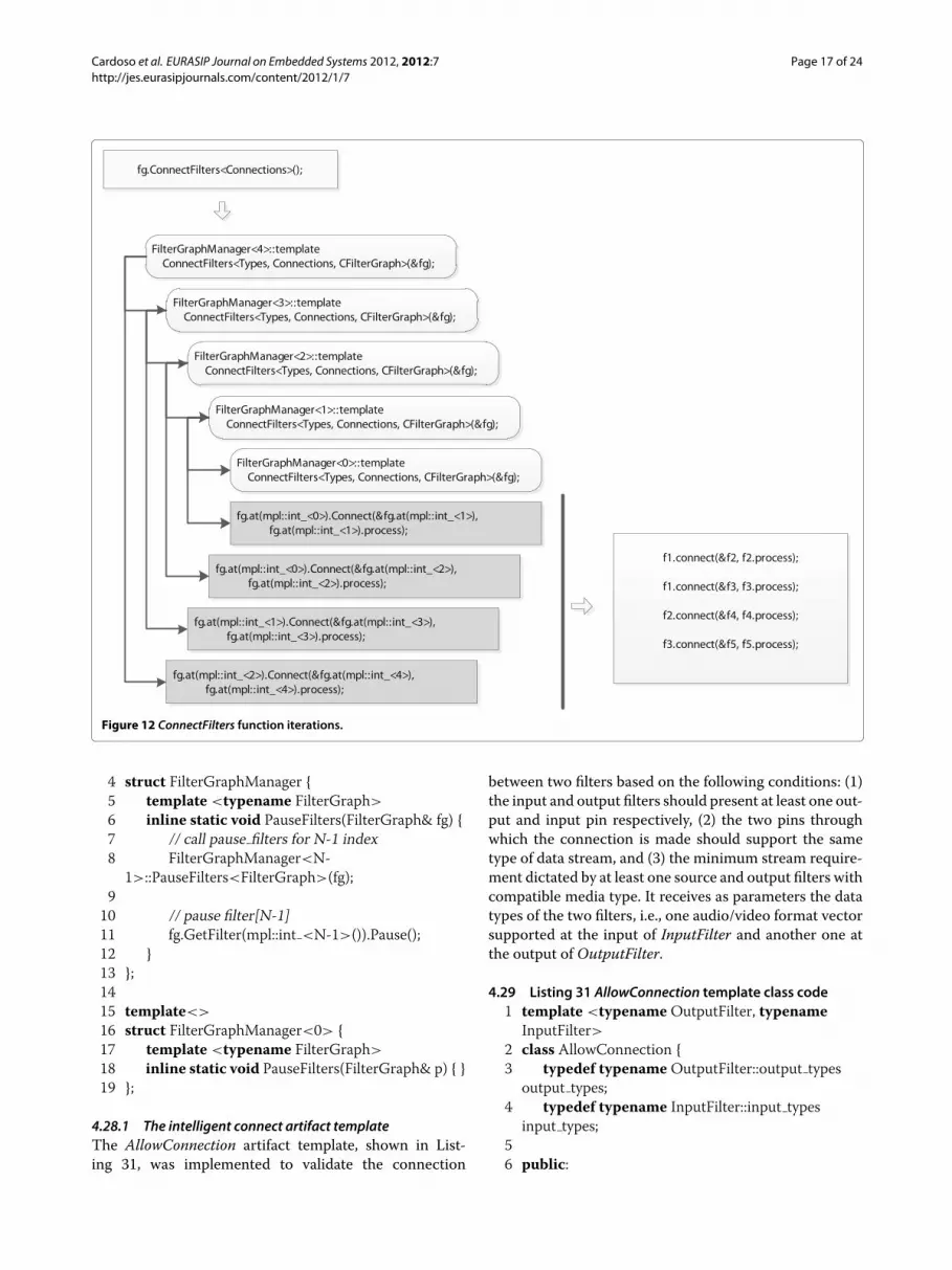
sively with valueN-1 (line 11), then a test is run to validatethe connection between two filters (lines 20 to 21) andfinally the connection is made (line 24 to 25). As an exam-ple, consider the filter graph, the code to create it and therecursive iteration inside ConnectFilters method for thefilter graph fg as shown in Figures 11, 12 and Listing 27,respectively.
4.25 Listing 27 Filter graph code builder for Figure 111 // filter types vector2 typedefmpl::vector<f1, f2, f3, f4, f5> Types;34 // links between filters5 typedefmpl::pair<mpl::int < 0 >,mpl::int < 1 > >
c12;6 typedefmpl::pair<mpl::int < 0 >,mpl::int < 2 > >
c13;7 typedefmpl::pair<mpl::int < 1 >,mpl::int < 3 > >
c24;8 typedefmpl::pair<mpl::int < 2 >,mpl::int < 4 > >
c35;910 // filter connections vector11 typedefmpl::vector< c12, c13, c24, c35 >
Connections;1213 // filter graph variable14 CFilterGraph<Types, mpl::size<Types>::value> fg;15 // connect filters16 fg.ConnectFilters<Connections>();
Figure 11 Filter graph with five filters.
The StartFilters, StopFilters or PauseFilters inline func-tions template of the FilterGraphManager structure givenby Listings 28, Listing 29 Inline StopFilters function codeand 30, performs only two operations. The first one willrecursively call the Start, Stop or Pause methods of filtersat indexes lower than N-1 and greater than zero while thesecond one executes the Start, Stop or Pause methods ofthe filter at index N-1.
4.26 Listing 28 Inline StartFilters function code1 template <int N> struct FilterGraphManager;23 template <int N>
4 struct FilterGraphManager {5 template <typename FilterGraph>
6 inline static void StartFilters(FilterGraph& fg) {7 // call StartFilters for N-1 index8 FilterGraphManager<N-
1>::StartFilters<FilterGraph>(fg);910 // start filter[N-1]11 fg.GetFilter(mpl::int <N-1>()).Start();12 }13 };1415 template<>
16 struct FilterGraphManager< 0 > {17 template <typename FilterGraph>
18 inline static void StartFilters(FilterGraph& p) { }19 };
4.27 Listing 29 Inline StopFilters function code1 template <int N>
2 struct FilterGraphManager {3 template <typename FilterGraph>
4 inline static void StopFilters(FilterGraph& fg) {5 // call stop filters for N-1 index6 FilterGraphManager<N-
1>::StopFilters<FilterGraph>(fg);78 // stop filter[N-1]9 fg.GetFilter(mpl::int <N-1>()).Stop();10 }11 };1213 template<>
14 struct FilterGraphManager<0> {15 template <typename FilterGraph>
16 inline static void StopFilters(FilterGraph& p) { }17 };
4.28 Listing 30 Inline PauseFilters function code1 template <int N> struct FilterGraphManager;23 template <int N>
Cardoso et al. EURASIP Journal on Embedded Systems 2012, 2012:7 Page 17 of 24http://jes.eurasipjournals.com/content/2012/1/7
Figure 12 ConnectFilters function iterations.
4 struct FilterGraphManager {5 template <typename FilterGraph>
6 inline static void PauseFilters(FilterGraph& fg) {7 // call pause filters for N-1 index8 FilterGraphManager<N-
1>::PauseFilters<FilterGraph>(fg);910 // pause filter[N-1]11 fg.GetFilter(mpl::int <N-1>()).Pause();12 }13 };1415 template<>
16 struct FilterGraphManager<0> {17 template <typename FilterGraph>
18 inline static void PauseFilters(FilterGraph& p) { }19 };
4.28.1 The intelligent connect artifact templateThe AllowConnection artifact template, shown in List-ing 31, was implemented to validate the connection
between two filters based on the following conditions: (1)the input and output filters should present at least one out-put and input pin respectively, (2) the two pins throughwhich the connection is made should support the sametype of data stream, and (3) the minimum stream require-ment dictated by at least one source and output filters withcompatible media type. It receives as parameters the datatypes of the two filters, i.e., one audio/video format vectorsupported at the input of InputFilter and another one atthe output of OutputFilter.
4.29 Listing 31 AllowConnection template class code1 template <typename OutputFilter, typename
InputFilter>2 class AllowConnection {3 typedef typename OutputFilter::output types
output types;4 typedef typename InputFilter::input types
input types;56 public:

Cardoso et al. EURASIP Journal on Embedded Systems 2012, 2012:7 Page 18 of 24http://jes.eurasipjournals.com/content/2012/1/7
7 enum { value = AllowConnectionImpl<mpl::size<output types>::value>
8 ::template apply<output types,input types>::value };
9 };Listing 32 partially presents the implementation of
AllowConnectionImpl template structure that registers theresult of connecting two filters into the enumeration vari-able value. This structure template is implemented bya specialized and a generic template, both receiving astemplate input parameter the number of elements of theoutput types vector related to theOutputFilter. Also, bothtemplates define a metafunction, apply, that takes theaudio/video vectors supported by each filters as inputparameters. For each element in the output types vectorit uses a boost MPL library metafunction named containsto check if the same element exists in the input type vec-tor. Any denied connection is verified and notified with anerror message by the CheckErrorOnConnection templatestructure shown in Listing 33.
4.30 Listing 32 AllowConnectionImpl template structurecode
1 template <int N> struct AllowConnectionImpl;23 template <int N>
4 struct AllowConnectionImpl {5 template <typename T, typename U>
6 struct apply {7 typedef typename
mpl::at<T,mpl::long <N-1> >::type ftype;8 enum { value =
mpl::contains<U,ftype>::value —9 AllowConnectionImpl<N-1>::template
apply<T,U>::value };10 };11 };1213 template <>
14 struct AllowConnectionImpl<0> {15 template <typename T, typename U>
16 struct apply {17 enum { value = 0 };18 };19 };
4.31 Listing 33 CheckErrorOnConnection templatestructure code
1 // forward declaration2 template <bool C, typename T, typename U>
struct CheckErrorOnConnection;34 // generic implementation
5 template <bool C, typename T, typename U>
6 struct CheckErrorOnConnection7 {8 static assert(C, “cannot connect the two filters.”);9 };1011 // template specialization for filters v4l2 and xvideo12 template <bool C>
13 struct CheckErrorOnConnection<C,CV4L2Source,CXVRenderer>
14 {15 static assert(C, “cannot connect v4l2 filter to
xvideo filter.”);16 };1718 // specializations for the other filters combinations19 ...
A denied connection occurrence is indicated by one ofthe three template parameters received by CheckErrorOn-Connection template structure, i.e., the first one that hasa boolean type. If denied, the value of C will be falseas well as the input parameter of static assert functionand so, forcing a compilation error with our predefinedmessage. For a more complete notification of a deniedconnection, specialized templates are defined, combiningall participating filters.The domain model will be concluded with the
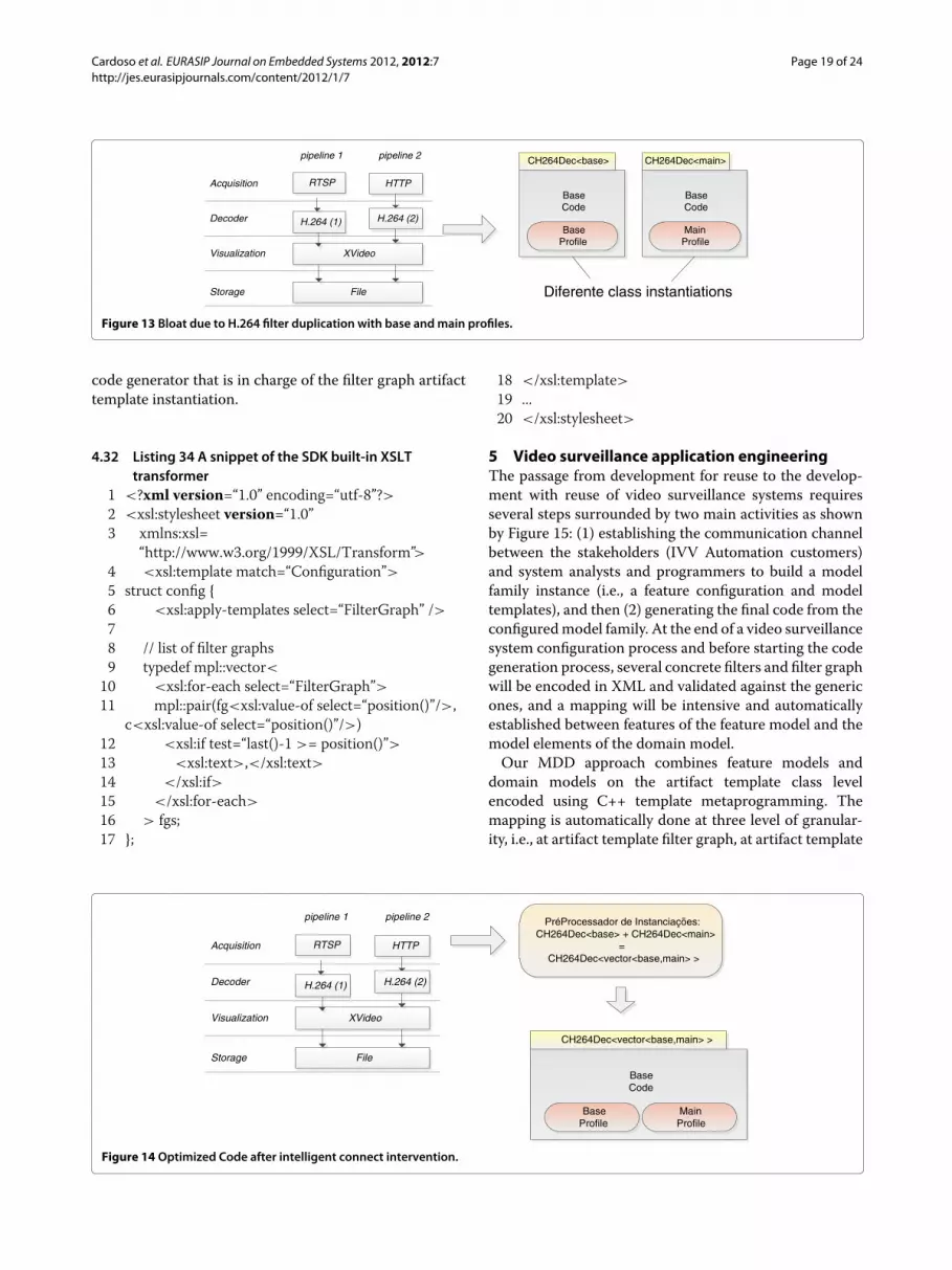
built-in intelligent connect feature of the filter graphcomposition and validation that is in charge of the fol-lowing three tasks: (1) trying combinations of interme-diate transform filters to satisfy the required matchingbetween a pair of output and source pins, (2) special-izing some partially configured filter that failed to befully mapped to a model, and (3) avoiding code bloatby exploring any possible cross-silo synergy among sim-ilar filters. Possible code bloat may happen with a videosurveillance system consisting of more than one filtergraph using the same filter but with different config-urations. In such case, several different classes will beinstantiated, one for each configuration as illustrated inFigure 13.To tackle the code bloat phenomenon, intelligent con-
nect initially analyzes the type of filters and their settingsfor each pipelines and create a list of setting for anyrepeated filter among different pipelines but with differ-ent settings. Based on the collected settings, a unique classwill be created, instantiated and shared among pipelines,as shown in Figure 14.To conclude the domain engineering stage of the video
surveillance systems development environment, a XSLTcode transformer, shown in Listing 34, was implementedto generate a Config.h file from the configuration. Thisfile will be used later by the offline partial evaluator C++
Cardoso et al. EURASIP Journal on Embedded Systems 2012, 2012:7 Page 19 of 24http://jes.eurasipjournals.com/content/2012/1/7
RTSP
XVideo
File
pipeline 1
Acquisition
Decoder
Visualization
HTTP
Storage
H.264 (2)
pipeline 2
H.264 (1)
BaseCode
CH264Dec<base>
BaseProfile
BaseCode
CH264Dec<main>
MainProfile
Diferente class instantiations
Figure 13 Bloat due to H.264 filter duplication with base andmain profiles.
code generator that is in charge of the filter graph artifacttemplate instantiation.
4.32 Listing 34 A snippet of the SDK built-in XSLTtransformer
1 <?xml version=“1.0” encoding=“utf-8”?>2 <xsl:stylesheet version=“1.0”3 xmlns:xsl=
“http://www.w3.org/1999/XSL/Transform”>4 <xsl:template match=“Configuration”>5 struct config {6 <xsl:apply-templates select=“FilterGraph” />78 // list of filter graphs9 typedef mpl::vector<10 <xsl:for-each select=“FilterGraph”>11 mpl::pair(fg<xsl:value-of select=“position()”/>,
c<xsl:value-of select=“position()”/>)12 <xsl:if test=“last()-1 >= position()”>13 <xsl:text>,</xsl:text>14 </xsl:if>15 </xsl:for-each>
16 > fgs;17 };
18 </xsl:template>19 ...20 </xsl:stylesheet>
5 Video surveillance application engineeringThe passage from development for reuse to the develop-ment with reuse of video surveillance systems requiresseveral steps surrounded by two main activities as shownby Figure 15: (1) establishing the communication channelbetween the stakeholders (IVV Automation customers)and system analysts and programmers to build a modelfamily instance (i.e., a feature configuration and modeltemplates), and then (2) generating the final code from theconfiguredmodel family. At the end of a video surveillancesystem configuration process and before starting the codegeneration process, several concrete filters and filter graphwill be encoded in XML and validated against the genericones, and a mapping will be intensive and automaticallyestablished between features of the feature model and themodel elements of the domain model.Our MDD approach combines feature models and
domain models on the artifact template class levelencoded using C++ template metaprogramming. Themapping is automatically done at three level of granular-ity, i.e., at artifact template filter graph, at artifact template
RTSP
XVideo
File
pipeline 1
Acquisition
Decoder
Visualization
HTTP
Storage
H.264 (2)
pipeline 2
H.264 (1)
BaseCode
CH264Dec<vector<base,main> >
BaseProfile
PréProcessador de Instanciações:CH264Dec<base> + CH264Dec<main>
=CH264Dec<vector<base,main> >
MainProfile
Figure 14 Optimized Code after intelligent connect intervention.

Cardoso et al. EURASIP Journal on Embedded Systems 2012, 2012:7 Page 20 of 24http://jes.eurasipjournals.com/content/2012/1/7
Select theIntendeedProperties
FeatureModel
Mapped VSSModel
ValidateConfiguration
Feature2 ModelMapping
C++ ApplicationInstantiat or
ConfiguredC++ Code
Stackholderstransmit theapplication
Requirements
Figure 15 Communication among stakeholders and Video surveillance systems developers.
filter and internally to the artifact template filter at sev-eral variability points, such as attributes and methodswhen in the sync mode is selected or semi-automaticallyotherwise. Selected features of a filter will be successivecollected till the moment that the filter can be evaluatedby a meta-expression to a particular artifact template fil-ter and the mapping realized. Any other selected featureswill be mapped to internal variability points or attributesof the previously mapped artifact template filter by meta-expressions or presence conditions, respectively, indicat-ing whether they should be patched or removed from thespecialized template instance. Mapping at template filtergraph level will be triggered by a meta-expression when atlist two filters are linked in a stream.Missing or unmapped
feature in the domain model forces the extension of thedomain model and so, be carefully analyzed. By now, theonline partial evaluator based on C++ template metapro-gramming solved it successfully, after refactoring somefilter legacy code. Figure 16 shows a simple example of ourFeature2ModelMapping activity.Listings 35, 36 and 37 shows the second step of a two
step video surveillance system generator, as the first one isa SDK built-in functionality. First, the XSLT transformer isfed with a video surveillance system configuration to gen-erate the Config.h and then calling an offline partial eval-uator based on C++ template metaprogramming (i.e., theCApplicationInstantiator), some of the previously arti-fact templates produced during domain engineering will
Figure 16 Exemplifying the SDK built-in feature to model mapping.

Cardoso et al. EURASIP Journal on Embedded Systems 2012, 2012:7 Page 21 of 24http://jes.eurasipjournals.com/content/2012/1/7
be customized into specialized application-specific com-ponents and linked together to construct the final videosurveillance system that addresses the need of specificcustomers. Basically, the offline partial evaluator carriesout the instantiation process at several levels of granu-larity by translating the video surveillance system con-figuration into an ordered sequence of finer instantiationoperations which when executed will instantiate the newvideo surveillance system.
5.1 Listing 35 Offline Partial Evaluator: theCApplicationInstantiator class
1 template <typename Config>2 class CApplicationInstantiator3 : CApplicationInstantiatorImpl<
IntelligentConnect<Config::fgs>::value,mpl::size<IntelligentConnect<Config::fgs>::value>> { };
5.2 Listing 36 A snippet of the Offline Partial Evaluator:the CApplicationInstantiatorImpl class
1 template <typename FilterTypes, int N> classCApplicationInstantiatorImpl;
23 template <typename Vector>4 class CApplicationInstantiatorImpl<Vector, 1> {5 typedef typenamempl::at<Vector,
mpl::long <0>>::type item0;6 typedef typenamempl::first<item0>::type
Filters0;7 typedef typenamempl::second<item0>::type
Connections0;89 CFilterGraph<Filters0, mpl::size<Filters0>>
fg0;10 public:11 void Initialize() {
Figure 17 SDK class diagram.

Cardoso et al. EURASIP Journal on Embedded Systems 2012, 2012:7 Page 22 of 24http://jes.eurasipjournals.com/content/2012/1/7
Figure 18 Screenshot of the SDK exemplifying the design of two filter graphs.
12 fg0.ConnectFilters<Connections0>();13 }14 };1516 template <typename Vector>17 class CApplicationInstantiatorImpl<Vector, 2> {18 typedef typenamempl::at<Vector,
mpl::long <0>>::type item0;19 typedef typenamempl::at<Vector,
mpl::long <1>>::type item1;20 typedef typenamempl::first<item0>::type
Filters0;21 typedef typenamempl::second<item0>::type
Connections0;22 typedef typenamempl::first<item1>::type
Filters1;23 typedef typenamempl::second<item1>::type
Connections1;24
25 CFilterGraph<Filters0, mpl::size<Filters0>>
fg0;26 CFilterGraph<Filters1, mpl::size<Filters1>>
fg1;27 public:28 void Initialize() {29 fg0.ConnectFilters<Connections0>();30 fg1.ConnectFilters<Connections1>();31 }32 };33 ...
5.3 Listing 37 Offline Partial Evaluator: C++ final codegeneration
1 #include <config.h>
23 intmain(int argc, char ∗argv[])4 {5 CApplicationInstantiator app<Config>;
Raw video Segmentation Tracking IdentificationPattern
RecognitionAlert
and Visualization
Figure 19 Activities sequence of the early drowning detection at domestic swimming pools.

Cardoso et al. EURASIP Journal on Embedded Systems 2012, 2012:7 Page 23 of 24http://jes.eurasipjournals.com/content/2012/1/7
Raw videoCompressed video Motion DetectionAlert
and Visualization
Figure 20Motion detection at domestic swimming pools.
6 app.Initialize();78 return 0;9 }
6 Video surveillance product line SDKA Qt-based video surveillance system SDK that allowsgraphical instantiation of a feature model configurationsimilar to DirectShow graphEdit was designed using sev-eral design patterns, such as singleton, strategy, factoryand composite, as shown in Figure 17. After a configura-tion instantiation all the previously described steps will beexecuted till the generation of final C++ configured codefor the new video surveillance system. Figure 17 presentsa screenshot of the design of an early drowning detectionat domestic swimming pools consisting of two pipelines:the first one with six filters:
(i) An analog input filter, V4L2, for image capture;(ii) Three transform filters for motion segmentation,
object tracking, and object recognition and analysisbehavior;
(iii) Two output filter for alarm and visualization.
The second pipeline has the following five filters:
(i) A digital input filter, RTSP, that captures imageframes from an IP camera using RTSP/RTP fortransmission;
(ii) Two transformation filters for JPEG decoding andmotion detection;
(iii) Two output filter for alarm and visualization.
Figure 18 illustrates two of several possible functionalityscenarios supported by the generated system of Figures 19and 20.
7 MethodsAs previously mentioned, the video surveillance ecosys-tem is divided in two stages: the implementation domain,developed envisioning the system evolution, followed bythe application engineering stage.During the application engineering stage, a specific
pipeline was created in order to meet the client imposedapplication requirements. In the pipeline creation process,
several alternatives were explored, both at low levels (e.g.,platform selection) and at high levels (e.g., filter selectionaccording to context aware strategies.)In this specific case, to make the comparison study
between the two implementations, a video surveillancesystem based on DirectShow using C++, with virtual func-tions and inheritance, and a video surveillance systemusing the proposed framework were used on two kindsof machines. 1) First, a general purpose PC was used, anIntel Core 2 Duo CPU T9550 at 2.66GHz with 2,83 GBof RAM with Ubuntu 10.04 and secondly an embeddedsystem based on a BeagleBoard-xM with an ARMCortex-A8 MHz at 1GHz and extra memory with 512MB oflow-power DDR RAM with Angstrom Embedded Linux.For the two configurations, a pipeline composed by an
RTSP source filter, a JPEG decoder transform filter anda File output filter was created. The pipeline was com-piled with the GNU C++ compiler (g++) with the -O3optimization option.
8 Conclusion and future workTo meet the embedded systems constraints and tacklethe growing complexity of new video surveillance systemsand time-to-market pressure, we abandoned our previousproduct-centric perspective and shifted to the multitudeof products. In doing so, we promote the integration ofMDD, SPL and generative technologies to create softwarefor a portfolio of video surveillance systems in a pay-as-you-go fashion rather than an ex-nihilo development. Thesynergistic convergence of those technologies improvedour ability to meet product quality demands while reduc-ing the development effort and expanding the scale andscope of our video surveillance systems portfolio. One ofthe unique features of the proposed video surveillance sys-tems design environment compared to existing ones, isits simplicity and higher integration level of mainstreamtools and technologies such as, XML, XSLT, C++ tem-plate metaprogramming, generative programming, MDD,and SPL. Acher’s et al. proposal didn’t discuss the codegeneration process, i.e., it seems to us like an underdevelopment work. The proposed system supports theeasy integration of external libraries that implement well-known standards and functionalities, e.g., ONVIF and

Cardoso et al. EURASIP Journal on Embedded Systems 2012, 2012:7 Page 24 of 24http://jes.eurasipjournals.com/content/2012/1/7
PSIA, developed as a filter that is integrated on the videosurveillance system. The system was tested on a BeagleBoard. The core processor of this embedded platform isthe Texas OMAP that includes a DSP capable of decom-pressing HD frames in H.264 format, for which an encod-ing/decoding filter was developed. When the hardwaresystem doesn’t support SIMD instructions for video pro-cessing (MMX, SSE2, etc) or is not equipped with a DSP,then the video surveillance system performance will bedegraded.However, this project is still under development and
next steps will be focused on: (1) automating the simula-tion and verification of the generated code, (2) automatingthe test cases generation and testing of the generated fil-ters and video surveillance systems, (3) the integration ofexternal modules, developed in other programming lan-guages such as Python or Java (i.e., JNI-aware C++ wrap-per), that implement video surveillance functionalities,and (4) study of the variability management of functional-ity related to playback application, e.g., playback, jump toabsolute timestamp and find nearest I-Frame.
Endnoteahttp://www.ivv-aut.com/.
Competing interestsThe authors declare that they have no competing interests. This work wasfunded by the Science and Technology Foundation (FCT) and developed incooperation with IVV Automation, but none pose any objection to thepublication of results.
AcknowledgementsThis work was funded through the Competitive Factors Operational Program -COMPETE and through national funds though the Science and TechnologyFoundation - FCT, within the project: FCOMP-01-0124-FEDER-022674. Thiswork was developed in cooperation with IVV Automation; all support andmeans provided by the company is acknowledged.
Author details1Department of Industrial Electronics, Centro Algoritmi, University of Minho,Braga, Portugal. 2School of Engineering and Technology, Asian Institute ofTechnology, Khlong Luang, Thailand.
Received: 23 January 2012 Accepted: 5 June 2012Published: 31 July 2012
References1. L Marcenaro, L Marchesotti, C Regazzoni, in Proceedings of the Fifth
International Conference on Information Fusion. vol. 2. A multi-resolutionoutdoor dual camera system for robust video-event metadata extraction,(Annapolis, MD, Washington DC Area, USA, 2002), pp. 1184–1189
2. M Acher, P Lahire, S Moisan, JP Rigault, inModeling in SoftwareEngineering, 2009. ICSEWorkshop onMISE ’09. Tackling high variability invideo surveillance systems through a model transformation approach,(Vancouver, Canada, 2009), pp. 44–49
3. I Ahmad, Z He, M Liao, F Pereira, MT Sun, Special issue on videosurveillance, IEEE Trans. Circ. Syst. Video Technol. 18(8), 1001–1005 (2008)
4. Y Hongyu, X Lixia, X Feng, in IEEE International Conference on IndustrialInformatics. Research on cluster remote video surveillance system,(Singapore, 2006), pp. 1171–1174
5. MD Pesce, ProgrammingMicrosoft DirectShow for Digital Video andTelevision. (Microsoft Press, Redmond, Washington, 2003)
6. PL Plauger, Embedded C++: An Overview. Embedded Systems Programming,(1997). [http://www.dsi.fceia.unr.edu.ar/downloads/informatica/info II/c++/ec++.pdf]
7. S Meyers, Effective C++ in an embedded environment. [http://www.aristeia.com/c++-in-embedded.html]
8. D Saks, in Embedded Systems Conference. Reducing run-time overhead inC++ programs, (San Francisco, USA, p. 2002
9. 9. Technical Report on C++ Performance. [www2.research.att.com/bs/performanceTR.pdf]
10. I McRitchie, TJ Brown, ITA Spence, Managing component variabilitywithin embedded software product lines via transformational codegeneration, Softw. Product Family Eng. 3014/2004, 98–110 (2004)
11. A Kleppe, J Warmer, W Bast,MDA Explained: The Model Driven Architecture:Practice and Promise. Addison-Wesley Professional, Boston, 2003)
12. K Czarnecki, U Eisenecker, Generative Programming: Methods, Tools, andApplications. (Addison-Wesley Professional, Boston, 2003)
13. R Anisko, Towards automatic partial evaluation for the C++ language, inCSI Seminar (2002)
14. D Lohmann, W Hofer, W Schroder-Preikschat, O Spinczyk, in AOSD ’11Proceedings of the tenth international conference on Aspect-orientedsoftware development. Aspect-aware operating system development,(Porto de Galinhas, Pernambuco, Brasil, 2011), pp. 69–80
15. V Sarinho, A Apolinario, in SBGAMES ’09 Proceedings of the 2009 VIII BrazilianSymposium on Games and Digital Entertainment. A generativeprogramming approach for game development, (Rio de Janeiro, Brazil,2009), pp. 83–92
16. T Buchmann, A Dotor, in Pieter van Gorp, Hrsg., Proceedings of the 7thInternational Fujaba Days. Mapping features to domain models in Fujaba,(Seiten 20–24, Eindhoven, The Netherlands, 2009)
17. AMPLE: Aspect-Oriented, Model-Driven, Product Line Engineering.[http://cordis.europa.eu/search/index.cfm?fuseaction=proj.document&PJ RCN=8724342]
18. H Wada, EMM Babu, A Malinowski, J Suzuki, K Oba, in IASTED Int’l Conf. onSoftware Engineering and Applications. Design and implementation of thematilda distributed UML virtual machine, (Dallas, TX, USA), p. 2006
19. K Czarnecki, U Eisenecker, in Proceedings of the European SoftwareEngineering Conference. Components and generative programming,(Toulouse, France, 1999), pp. 2–19
20. IDA: About. [http://www.hex-rays.com/products/ida/index.shtml]21. K Kang, S Cohen, J Hess, W Nowak, S Peterson, Feature-Oriented Domain
Analysis (FODA) Feasibility Study, (CMU/SEI- 90-TR-21). (SoftwareEngineering Institute, Carnegie Mellon University, Pittsburgh, PA, 1990).[http://www.sei.cmu.edu/library/abstracts/reports/90tr021.cfm]
22. V Cechticky, P Chevalley, A Pasetti, W Schaufelberger, in GPCE ’03Proceedings of the 2nd international conference on Generative programmingand component engineering. A generative approach to frameworkinstantiation, (Erfurt, Germany, 2003), pp. 267–286
23. K Czarnecki, M Antkiewicz, in ACM SIGSOFT/SIGPLAN InternationalConference on Generative Programming and Component Engineering(GPCE’05). Mapping features to models: a template approach based onsuperimposed variants, (Tallinn, Estonia, 2005), pp. 422–437
24. A Gurtovoy, D Abrahams, The boost MPL library. [http://www.boost.org/doc/libs/1 48 0/libs/mpl/doc/index.html]
25. D Abrahams, A Gurtovoy, C++ Template Metaprogramming: Concepts,Tools, and Techniques from Boost and Beyond. (Addison-WesleyProfessional, Boston, 2004)
doi:10.1186/1687-3963-2012-7Cite this article as: Cardoso et al.: A generative-oriented model-drivendesign environment for customizable video surveillance systems. EURASIPJournal on Embedded Systems 2012 2012:7.