a generation flow for self-reconfiguration controllers customization
TRANSCRIPT

A Generation Flow for Self-Reconfiguration Controllers Customization
Andrea Cuoccio, Paolo R. Grassi, Vincenzo Rana, Marco D. Santambrogio and Donatella SciutoPolitecnico di Milano - Dipartimento di Elettronica e Informazione
Via Ponzio 34/5 - 20133 Milano, Italy{andrea.cuoccio,paolo.grassi}@dresd.org{rana, santambr, sciuto}@elet.polimi.it
Abstract
Partial dynamic self-reconfiguration can be obtained, inXilinx’s Virtex families of FPGAs, through the Internal Con-figuration Access Port (ICAP). Reconfiguration time is thusbounded to the ICAP rate. Different techniques have beenproposed to speedup the reconfiguration process and oneof the most promising one uses a memory to store the bit-stream inside the IP-Core that controls the ICAP port. Thesize of this memory can be chosen during the implementa-tion phase in order to find a trade off between resource’srequirement and reconfiguration throughput. Moreover, agood level of customization can be achieved by choosingboth the bus interface used by the ICAP controller andthe implementation type, Slices or BRAMs, of its internalmemory. This paper describes a framework used to createthe most suitable controller according to the reconfigura-tion scenario where it will be used. To set all the param-eters used to create the controller, a set of metrics, usedto describe the reconfiguration scenario, has been defined.These metrics are used in the proposed flow to find the set-ting of the ICAP controller that best suits the scenario inwhich it will operate.
1 Introduction and related works
One of the main features of reconfigurable systems istheir ability to dynamically change their structure and func-tionality, in order to adapt themselves to the required task.These systems consist of elements that can be replaced atrun-time by others that have a different functionalities. Thisprocess is called Partial Dynamic Reconfiguration, since itcan be performed at run-time and involves just a part andnot the whole reconfigurable device. By exploiting this fea-ture, it is possible to increase both their flexibility and theirperformance.
As previously hinted, in partial reconfigurations onlyportions of the reconfigurable device are involved by re-
configuration processes; on the other hand, dynamic re-configurations make it possible, for the portions of the de-vice that are not directly involved in the reconfigurationprocess, to continue the computation without any interrup-tion, even while the reconfiguration is performed. Further-more, in order to perform self-reconfigurations, a deviceneeds an internal component that has to be able to recon-figure the device itself. It is important to notice that in self-reconfigurations, the portion of the device that contains thiscomponent cannot be reconfigured, due to a possible lost ofthe functionality of the entire system.
Example of devices that can perform partial dynamicself-reconfiguration are represented by some of Xilinx Vir-tex FPGA families such as Virtex II, Virtex II-Pro and Vir-tex4. These devices can modify their configuration throughthe Internal Configuration Access Port (ICAP) [15] [11]. Itis important to notice that a configuration is specified in abinary file called Bitstream[12]. The ICAP cannot be di-rectly connected to the system bus, since it requires a con-troller that can manage the data flow coming from the, pro-viding also a sort of memory mechanism if it is necessary.In order to achieve one the main goals of a reconfigurablesystem, that is the reduction of the reconfiguration time, itis possible to follow different ways, such as using bitstreamcompression[3] or exploiting the maximum throughput ofthe ICAP. A classical ICAP controller is represented byOPB HWICAP [13], that can be found in the EDK library.Another version of this controller is the PLB ICAP, devel-oped at the Technische Universitat Munchen [3]. This paperwill be mainly focused on the latter.
Our specific contribution in this paper are as follows. Wepropose,
• a set of metrics used to characterized and to describedthe runtime scenario where the reconfigurable systemwill be used;
• an accurate description for the creation of a customizedICAP controller;

• a flow that use the description to generate a the mostpromising controller for the specific scenario in whichit will operate.
Finally, section 2 analyze the different problematics thatthe speed-up process carry. In section 3 it’s showed the mainstructure of the ICAP controller called DRC (Dynamic Re-configuration Controller). Section 4 describes the model ofthe DRC in order to create a flow for the automatic creationof the customized controller. Section 5 includes the exper-imental results about some DRC configurations. The lastsection contains conclusion and future works.
2 Problem description
In the partial dynamic self-reconfiguration scenario, a re-configurable system can be divided in two different parts:one that contains the functionality that can be reconfiguredand another one that contains a static part that includes thecomponent that will perform the self-reconfiguration. Fig-ure 1 shows the reference reconfigurable architecture and itsphysical implementation in three different layers.
Figure 1. Reference Architecture: FPGA Lay-ers
Starting from the bottom, Figure 1 shows the referencereconfigurable architecture implemented over a Virtex IIPro VP7 (the layer containing the BRAM memories andPower-PC 405 has not been depicted), the first layer isthe clock level that is, according to Xilinx Documentation[1, 7, 2], routed at a different level with respect to the othersignals. The second layer contains the communication in-frastructure layer between the static and the reconfigurableside, while the last one contains CLBs and Switch Matricesand consequently all user logic, but also the CoreConnectcomponents are implemented at this level. The architectureforesees a static and a reconfigurable portion; the static one
is typically designed using standard tools, such as EDK [8],or manually fully described in VHDL. It is composed of aprocessor (that can be hardcore, i.e., a PowerPC, or softcore,i.e., a Xilinx Microblaze [16]) and a set of cores used toimplement an appropriate bridge to the reconfigurable por-tion. We need to create different versions of the architectureusing both the PowerPC and the Microblaze because of thedifference in the Xilinx FPGAs, i.e. a PowerPC architecturecan be used with VirtexIIPro FPGAs but it is not availablein the majority of the Virtex4 and Virtex5 devices. The IBMCoreConnect [4] has been chosen as main communicationinfrastructure and both its OPB and PLB buses will be usedto interface the hardware relocation filter proposed in thiswork, whenever a PowerPC-based architecture will be usedthe PLB version of the core will be plugged into the sys-tem, while in a Microblaze solution the OPB version of thecore will be used. The processor will be used to execute thesoftware side of the application and to correctly manage thenecessary calls to the hardware components (with the corre-sponding reconfiguration, if necessary) designed to speedupthe overall computation. The reconfigurable part of the pro-posed architecture is a portion of the FPGA area on whichdifferent functionalities can be mapped, with only the re-quirement to implement an appropriate bus interface. Allthe necessary configuration bitstreams can be either storedin an internal memory or eventually loaded by external de-vices. In any case, these files have to be be sent on the busfor being used by the reconfiguration controller. In this wayan overhead is created on the bus that can become slowerthan the component that manage the reconfiguration pro-cess. This scenario can bring to a slow down of the entireprocess. Thus it is necessary introduce some sort of mecha-nism that can manage to accelerate it.
2.1 Internal Configuration Access Port(ICAP)
In Xilinx Virtex FPGA families such as Virtex II, Vir-tex II-Pro [15] and Virtex4 [10, 9], the ICAP allows the ac-cess to configuration registers that specify the functionalityof the device. Through this port it is possible to read thepresent configuration, and also to rewrite it with another onedescribed in a bitstream. The ICAP interface has a clock in-put, write and chip enable, a busy signal, a 8-bit data portfor reading and another one for writing (in Virtex4 these twoports can be 32-bit wide. The width can be chosen between8 and 32 bits)[9]. The protocol used by this port is a subsetof the SelectMAP one. More details can be found in [11],[14].

Figure 2. Incoming data are 32-bit wide andare sent to the ICAP one byte at the time
2.2 Reconfiguration time considerations
Reconfiguration time is directly bounded to the averagethroughput of the ICAP. So the lowest reconfiguration timecan only be reached if the ICAP works at the maximumavailable speed. If it would be possible to directly access thebitstreams stored in the local memory, the problem wouldnot exist, because the ICAP could access directly to the datarequired without wasting time with bus transfers. Thus it isnecessary to have an ICAP controller connected to the samebus which the memory is connected. In this way it becomespossible to avoid bridges between bus that can slow downthe data transfer process.
The ICAP can manage data transfer with a rate of onebyte at a time, but this is at least four time less than datatransferred on the bus. Thus, a way to decrease the time re-quired for the bitstream transfer is to use data blocks of 32bits. This choice makes it necessary to include in the con-troller a buffer with a FIFO mechanism due to the ICAP in-terface, since incoming data consists of four bytes, that haveto be sent to the ICAP one by one (see Figure 2). Finally,it is important to notice that in a scenario where the proces-sor has the burden of transferring bitstreams from memoryto the ICAP controller, this transfer will have a throughputthat will be lower than the ICAP’s one. Thus, before startingthe reconfiguration process, it can be useful to load a part ofthe bitstream into a memory internal to the controller, sothat the ICAP can start to process data while the remainingpart of the bitstream is retrieved from the memory.
3 A customized ICAP controller : DRC
As showed in Figure 3, the controller consists of threeparts:
• a bus interface,
• the controller itself that manages the flow of data to-wards the ICAP and towards the bus,
• the ICAP itself.
Figure 3. DRC shcematization
The controller is a slave component and its interface is32 bits wide. Furthermore, since during the implementationphase it is possible to choose between the PLB bus [6] andthe OPB bus [5], the problem of having the memory on a busand the ICAP controller on another one no longer exists. Inaddition to this, also a couple of different memory imple-mentations have been developed. During the design phaseit is thus possible to choose if the memory will be imple-mented using Slice or BRAM. The underlying mechanismof these two implementations is the same, while the maindifference between them can be found in the amount of re-quested resources. Moreover, it is also possible to specifythe size of the memory during the implementation process.By combining in different ways these features of the DRC,the designer can obtain the configuration of that componentthat best suits his/her needs.
4 Model and Metrics
The complete independence to the reconfiguration sce-nario is one of the main limits of controllers described inSection 1. Furthermore, they both show mid performancein several reconfiguration scenarios and require, in order tobe correctly implemented, an amount of resources that canbe either too large or too small with respect to the initialperformance and area usage requirements.
To cope with this problem, a set of metrics have beendefined in order to allow the design of the best configurationof the DRC for a given system. Before explaining the DRCdesign flow, it is necessary to introduce the DRC model andits metrics.
4.1 DRC model
The main feature of the DRC is its buffer, that is used toincrease bus performance. Defining with Tbus the through-put of the bus and with Ticap the throughput of the ICAP,experimental results show that:
Tbus < Ticap (1)
Formula 1 means that the reconfiguration throughput(from now identified with TDRC) is tightly bound to Tbus.Without a buffer, TDRC becomes equal to Tbus. Thus, in or-der to increase the reconfiguration throughput, it is possibleto follow two different ways:
• it is possible to try to raise Tbus, or
• it is possible to use a buffer in order to decouple Tbus
from TDRC .
Since it is not possible to increase Tbus without im-pacting on the underlying system architecture, the secondchoice seems to be the best one.
Beyond throughput definition, there is another parame-ter that has to be considered: area occupation. DRC area isrelated to the buffer size by the Formula 2 where Af rep-resents the occupation of the fix part (in slices), Av is thearea occupied by the buffer (in slices per byte) and L is thebuffer size (in bytes).
A = Af + AvL (2)
As previously hinted, the DRC mainly consists of twoparts: a fix and a variable part. The fix part includes bus andICAP interfaces logic that is independent from the buffersize, while the variable part comprises both the buffer andthe control logic. Experimental results show a linear depen-dence of the variable part with respect to the buffer size.
The reconfiguration throughput improvement is deter-mined by the size of the buffer and of the bitstream. Ticap
represent the limit of TDRC growth, as shown in Formula 3,where B represents the bitstream size (in bytes) and L thebuffer size (in bytes).
TDRC ={ B
B−LTbus, if L < B(1− Tbus
Ticap)
Ticap, otherwise(3)
BB−L represents the improvement ratio introduced by the
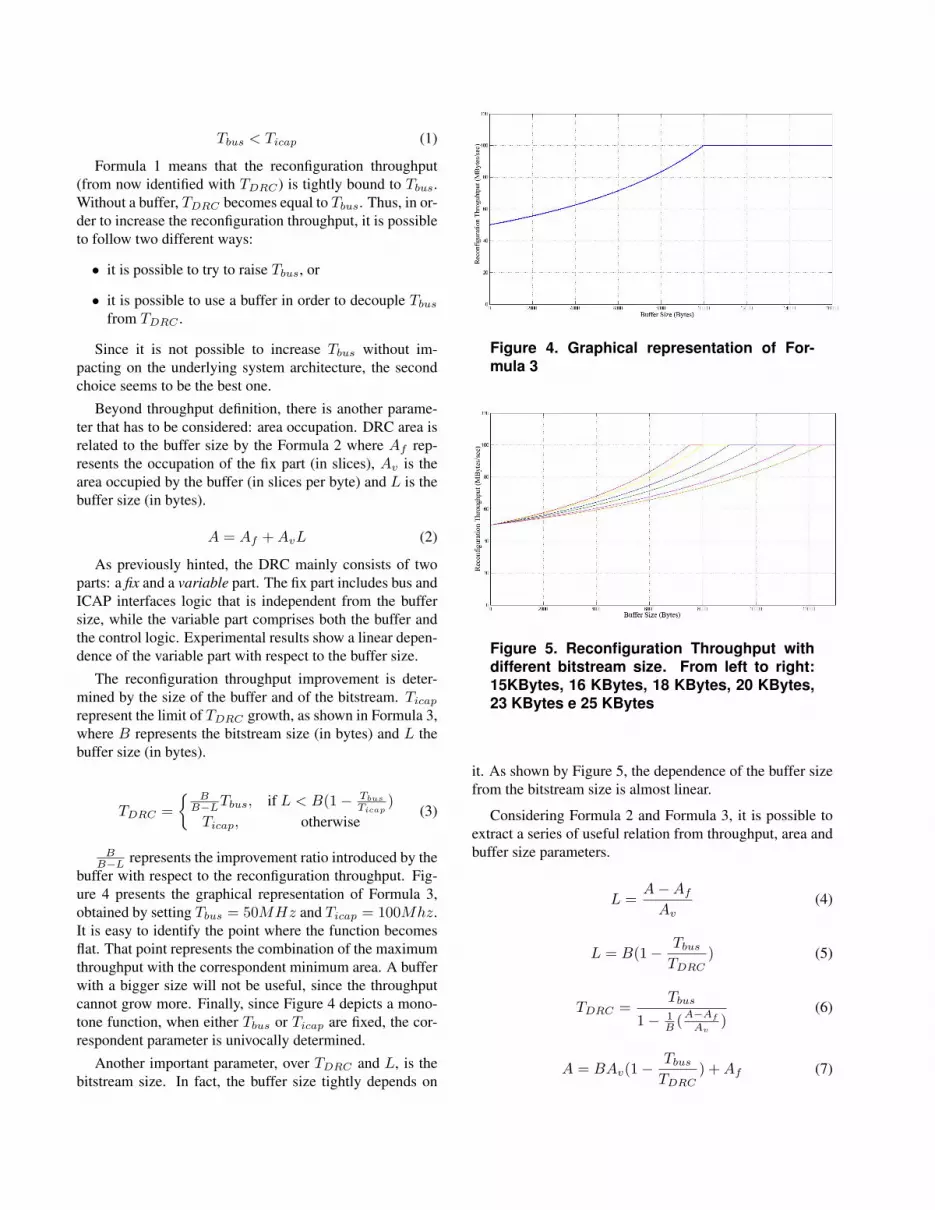
buffer with respect to the reconfiguration throughput. Fig-ure 4 presents the graphical representation of Formula 3,obtained by setting Tbus = 50MHz and Ticap = 100Mhz.It is easy to identify the point where the function becomesflat. That point represents the combination of the maximumthroughput with the correspondent minimum area. A bufferwith a bigger size will not be useful, since the throughputcannot grow more. Finally, since Figure 4 depicts a mono-tone function, when either Tbus or Ticap are fixed, the cor-respondent parameter is univocally determined.
Another important parameter, over TDRC and L, is thebitstream size. In fact, the buffer size tightly depends on
Figure 4. Graphical representation of For-mula 3
Figure 5. Reconfiguration Throughput withdifferent bitstream size. From left to right:15KBytes, 16 KBytes, 18 KBytes, 20 KBytes,23 KBytes e 25 KBytes
it. As shown by Figure 5, the dependence of the buffer sizefrom the bitstream size is almost linear.
Considering Formula 2 and Formula 3, it is possible toextract a series of useful relation from throughput, area andbuffer size parameters.
L =A−Af
Av(4)
L = B(1− Tbus
TDRC) (5)
TDRC =Tbus
1− 1B (A−Af
Av)
(6)
A = BAv(1− Tbus
TDRC) + Af (7)

4.2 Flow Description
DRCgen is a software written in C that is based on theDRC model (described in Section 4.1) and that is able togenerate different implementations of that model. Aim ofthis application is the automatic development of a specificDRC that is based on the particular scenario in which it willbe used. In order to define this application scenario it isnecessary to define a set of constraints that will identify themain parameters of the DRC itself. These constraints canbe classified as:
• Area Constraints, useful to specify both the desiredand the maximum area that the DRC will need to beincluded in the system, and
• Throughput Constraints, that define both the desiredand the minimum allowable reconfiguration through-put that the DRC has to guarantee.
Beyond area and throughput constraints, the scenario canbe further specified by using the following parameters:
• Bus Throguhtput in MBytessec ;
• ICAP Throughput in MBytessec ;
• Bitstream Size in KBytes;
• Bus Type, OPB or PLB;
• FPGA Family, Virtex-II VP7 or VP20.
Solution Space: if the application scenario has not beendefined with both area and throughput constraints, solutionspace exploration can be approached by using either For-mula 3, if only area constraints have been defined, or For-mula 5, if only throughput constraints have been defined.
Figure 6. Solution’s Space of Formula 3 withthree possible constraints assignments
On the other hand, if both area and throughput con-straints have been defined, the situation becomes more com-plex, since constraints define a point in the space Through-put/Buffer Size that describe a desidered DRC configura-tion (Buffer Size and Area Occupation are directly related,as shown in Formula 2 and in Formula 4). Figure 6 showsthree different categories of couple of constraints, character-ized by the kind of final solutions. In case B of Figure 6, forinstance, the final solution is univocally determined. On theother hand, in case A, there are no feasible solutions that al-low to satisfy area and throughput requirements. Finally, incase C, there are several solutions that satisfy the assignedconstraints, so it is possible either to minimize the occu-pied area, keeping constant the throughput, or to improvethe overall throughput, keeping constant the area usage.
After the definition of the final solution, DRCgen is ableto validate it, in order to be sure that it can be implementedon the target FPGA. In particular, DRCgen controls thatthe target FPGA has the required amount of both slices andBRAMs. Afterwards, DRCgen generates the output file thatdescribes the VHDL implementation of the required DRC.
5 Experimental Results
Aim of this section is to present some experimentalresults related to the analysis and the comparison of fourdifferent DRC implementations. These different versionsof the DRC have been obtained by following the approachproposed in this paper, selecting different combinations ofconstraints.
Buffer Size DRC with DRC with(Bytes) PLB interface OPB interface
(slices) (slices)4 95 798 130 119
16 179 16132 300 27564 543 525
128 990 981
Table 1. Slice-based DRC area usage
Table 1 and Table 2 present the area occupied by eachDRC version. In particular, Table 1 refers to DRCs that in-clude slice-based buffers, while Table 2 refers to DRCs in-cluding BRAM-based buffers. It is important to notice thatbuffers implemented by using slices rapidly lead to a hugearea usage, while buffers implemented by using BRAMscale very well with respect to the number of slices usedto implement the DRC.
Applying Formula 2 of Section 4.1 to the results pre-sented in Table 1 and in Table 2, it is possible to evaluate

Buffer Size DRC with DRC with(Bytes) PLB interface OPB interface
(slices) (slices)512 (1 BRAM) 120 106
1024 (2 BRAMs) 131 1162048 (4 BRAMs) 141 1204096 (8 BRAMs) 144 129
Table 2. BRAM-based DRC area usage
Tbus B L T simDRC T theor
DRC
(MBytes/sec) (Bytes) (Bytes) (MBytes/sec) (MBytes/sec)50 4000 400 55,7 55,6250 4000 1000 66,76 66,7050 8000 400 52,62 52,6350 8000 2500 72,74 72,7250 16000 400 51,29 51,2850 16000 5000 72,74 72,7250 16000 10000 100 100
Table 3. DRC complete test
the following values:
• Slice Buffer, PLB interface: Af = 71,2 , Av = 7,4
• Slice Buffer, OPB interface: Af = 44,33 , Av = 7,46
• BRAM Buffer, PLB interface: Af = 113 , Av = 0,011
• BRAM Buffer, OPB interface: Af = 100 , Av = 0,01
The knowledge of all Af and Av values cannot beenough for a complete validation of the model, of the met-rics and of the design flow. This goal can be achieved onlywith a complete system simulation.
Table 3 presents a set of simulation results obtained byusing the ModelSim simulator. As shown from Table 3,simulated throughput is very close to theorical throughput.According to this consideration, it is possible to assume thatthe theoretical model presented in the previous sections iscorrect.
6 Concluding Remarks
The DRCgen’s approach paves the way to a stablemethodology for creating controller of reconfiguration pro-cesses based on a specific reconfiguration scenario. The re-configuration process, in fact, cannot be considered as thefinal goal of an embedded system, but just a mechanism thatallows to improve system performance and flexibility. Theattention has thus to be oriented towards the simplificationand the speed-up of the reconfiguration process, in order tolet the designer work on the functional aspect of the systemrather than on reconfiguration processes management.
This objective can be achieved by exploiting the designflow presented in this paper and by using a DRC specificallydesigned for the particular scenario in which the system hasto be deployed. This has been proved to be a solution thatis able to improve the throughput of reconfiguration pro-cesses and thus of the overall system. In addition to this,the proposed approach simplify the design phase of the re-configuration controller and decrease the time required forits development.
One of the possible extensions of this work can be rep-resented by the development of a Direct Memory Access(DMA) mechanism for the DRC. This would increase Tbus
performance, causing the reduction of the buffer size, of thearea usage and of the processor utilization. Finally, it isimportant to notice that this modification will not requireto modify the whole design flow (such as the sizing of thebuffer), since it will be introduced simply as a new featureof the DRCgen design flow.
References
[1] Virtex-II Pro Data Sheet Virtex-II ProTM Platform FPGAData Sheet. Xilinx Inc., 2003.
[2] Virtex-II Pro and Virtex-II ProX Virtex-II Pro and Virtex-IIPro X FPGA User Guide. Xilinx Inc., 28 March 2007.
[3] J. Z. Christopher Claus, Florian H. Muller and W. Stechele.A new framework to accelerate virtex-ii pro and dynamicpartial self-reconfiguration. March 2007.
[4] I. corporation. The CoreConnect Bus Architecture, white pa-per. International Business Machines Corporation., 2004.
[5] IBM. Opb architecture specifications. Technical report.[6] IBM. Plb architecture specifications. Technical report.[7] X. Inc. Two Flows of Partial Reconfiguration: Module
Based or Difference Based. Technical Report XAPP290,Xilinx Inc., November 2003.
[8] X. Inc. Embedded Development Kit EDK 8.2i. Xilinx Inc.,2006.
[9] X. Inc. Virtex-4 configuration user guide. Technical Reportug71, Xilinx Inc., January 2007.
[10] X. Inc. Virtex-4 user guide. Technical Report ug70, XilinxInc., March 2007.
[11] R. L. Vince Eck, Punit Kalra and J. McManus. In-circuitpartial reconfiguration of rocketio attributes. Technical Re-port XAPP662, Xilinx, May 2004.
[12] R. L. Vince Eck, Punit Kalra and J. McManus. Virtex se-ries configuration architecture user guide. Technical ReportXAPP151, Xilinx, October 2004.
[13] Xilinx. Opb hwicap product specification. Technical report,March 2004.
[14] Xilinx. Virtex fpga series configuration and readback. Tech-nical Report XAPP138, March 2005.
[15] Xilinx. Virtex-ii pro and virtex-ii pro x fpga user guide.Technical Report UG012, March 2007.
[16] I. Xilinx. Microblaze processor reference guide. EmbeddedDevelopment Kit, EDK 8.2i. Xilinx User Guide v6.0, June2006.