915 kf ti-touch - k'(prime) technologies
TRANSCRIPT

915 KF Ti-Touch
Manual8.915.8005EN


Metrohm AGCH-9100 HerisauSwitzerlandPhone +41 71 353 85 85Fax +41 71 353 89 [email protected]
915 KF Ti-Touch
Program version 5.915.0020
Manual
8.915.8005EN 04.2013 ebe

TeachwareMetrohm AGCH-9100 [email protected]
This documentation is protected by copyright. All rights reserved.
Although all the information given in this documentation has beenchecked with great care, errors cannot be entirely excluded. Should younotice any mistakes please send us your comments using the addressgiven above.
Documentation in additional languages can be found onhttp://documents.metrohm.com.
Melody for the BEEP command: excerpt from "En Altfrentsche", with kindpermission of the Laseyer Quartett, Appenzell.

■■■■■■■■■■■■■■■■■■■■■■ Table of contents
915 KF Ti-Touch ■■■■■■■■ III
Table of contents
1 Introduction 1
1.1 Instrument description ......................................................... 11.1.1 Titration and measuring modes ................................................ 11.1.2 Connectors .............................................................................. 21.1.3 Intended use ........................................................................... 2
1.2 About the documentation ................................................... 31.2.1 Symbols and conventions ........................................................ 3
2 Safety instructions 5
2.1 General notes on safety ....................................................... 5
2.2 Electrical safety ..................................................................... 5
2.3 Tubing and capillary connections ....................................... 6
2.4 Flammable solvents and chemicals ..................................... 6
2.5 Recycling and disposal ......................................................... 7
3 Overview of the instrument 8
3.1 Front of the instrument ........................................................ 8
3.2 Rear of the instrument ......................................................... 9
4 Installation 10
4.1 Setting up the instrument .................................................. 104.1.1 Packaging .............................................................................. 104.1.2 Checks .................................................................................. 104.1.3 Location ................................................................................ 10
4.2 Connecting the power supply unit .................................... 10
4.3 Connecting MSB devices .................................................... 124.3.1 Connecting dosing devices .................................................... 134.3.2 Connecting an additional stirrer or titration stand .................. 144.3.3 Connecting a Remote Box ..................................................... 14
4.4 Connecting USB devices ..................................................... 154.4.1 General ................................................................................. 154.4.2 Connecting a USB hub ........................................................... 154.4.3 Connecting a printer .............................................................. 154.4.4 Connecting a balance ............................................................ 164.4.5 Connecting a PC keyboard ..................................................... 174.4.6 Connecting a barcode reader ................................................. 174.4.7 Connecting a Sample Processor ............................................. 18
4.5 Setting up the titration vessel ........................................... 19

Table of contents ■■■■■■■■■■■■■■■■■■■■■■
IV ■■■■■■■■ 915 KF Ti-Touch
4.6 Connecting sensors ............................................................ 194.6.1 General ................................................................................. 194.6.2 Connecting a polarizable electrode ........................................ 194.6.3 Connecting a temperature sensor .......................................... 20
4.7 Connecting the Ti-Touch to a network ............................ 21
5 Titrations 23
5.1 Water determination according to Karl Fischer (KFT) ..... 23
6 Operation 24
6.1 Switching the instrument on and off ............................... 24
6.2 Fundamentals of operation ............................................... 266.2.1 Touch-sensitive screen ........................................................... 266.2.2 Display and operating elements ............................................. 266.2.3 Status display ........................................................................ 276.2.4 Entering text and numbers ..................................................... 28
7 System settings 31
7.1 General system settings ..................................................... 317.1.1 Selecting the dialog language ................................................ 317.1.2 Setting the date, time and local time ..................................... 32
7.2 System-specific dialog options .......................................... 33
7.3 User administration ............................................................ 377.3.1 Editing the user configuration ................................................ 387.3.2 Creating an identification profile ............................................ 407.3.3 Defining login options ........................................................... 417.3.4 Password options .................................................................. 42
7.4 Measured value display ..................................................... 45
7.5 Acoustic signals .................................................................. 45
8 Titrants 46
8.1 Adding a new titrant .......................................................... 47
8.2 Editing titrant data ............................................................. 48
8.3 Monitoring the working life .............................................. 50
8.4 Dosing unit .......................................................................... 518.4.1 Parameters for preparing (PREP) and emptying (EMPTY) ......... 528.4.2 Tubing parameters ................................................................. 538.4.3 Shift direction of the valve disk .............................................. 56
8.5 Exchange unit ..................................................................... 578.5.1 Parameters for the preparation (PREP) .................................... 588.5.2 Tubing parameters ................................................................. 59
8.6 GLP test for exchange unit and dosing unit .................... 61

■■■■■■■■■■■■■■■■■■■■■■ Table of contents
915 KF Ti-Touch ■■■■■■■■ V
8.7 Titer determination options and data .............................. 638.7.1 Titer validity ........................................................................... 638.7.2 Properties of the previous titer determinations ....................... 64
9 Reagents 66
9.1 Editing reagent data .......................................................... 66
9.2 Reagent monitoring ........................................................... 67
10 Sensors 70
10.1 Adding a new sensor ......................................................... 71
10.2 Editing the sensor data ...................................................... 71
10.3 Monitoring the working life .............................................. 72
11 Device manager 74
11.1 Adding a new device .......................................................... 75
11.2 Configuring the instrument ............................................... 75
11.3 Ti-Touch ............................................................................... 7611.3.1 E-mail .................................................................................... 7711.3.2 PC/LIMS report ...................................................................... 7811.3.3 Shared memory ..................................................................... 7911.3.4 TCP/IP settings ....................................................................... 81
11.4 Metrohm control devices ................................................... 8211.4.1 Properties – Measuring input ................................................. 8311.4.2 Properties – MSB connector ................................................... 8411.4.3 Properties – Peripheral devices ............................................... 85
11.5 USB Sample Processor ....................................................... 8511.5.1 Properties – Sample Processor ............................................... 8611.5.2 Properties – Tower ................................................................ 8711.5.3 Properties – Swing Head ........................................................ 89
11.6 Sample racks ....................................................................... 9311.6.1 Editing rack data .................................................................... 9511.6.2 Rack adjustment .................................................................. 100
11.7 Printer ................................................................................ 10111.7.1 PDF settings ......................................................................... 10311.7.2 Network printer ................................................................... 10411.7.3 More options ....................................................................... 105
11.8 Balance .............................................................................. 106
11.9 USB/RS-232 adapter ......................................................... 107
11.10 PC keyboard ...................................................................... 109
11.11 Barcode reader ................................................................. 110

Table of contents ■■■■■■■■■■■■■■■■■■■■■■
VI ■■■■■■■■ 915 KF Ti-Touch
12 File manager 113
12.1 Managing files .................................................................. 11312.1.1 Copying a file ...................................................................... 11512.1.2 Renaming a file ................................................................... 11512.1.3 File properties ...................................................................... 116
12.2 External storage medium ................................................ 117
12.3 Creating backups / Restoring data ................................. 11912.3.1 Restoring data ..................................................................... 119
13 GLP manager 121
13.1 Automatic system test ..................................................... 122
13.2 Test tools .......................................................................... 122
13.3 GLP tests for measurement and titration ...................... 12313.3.1 Parameter description .......................................................... 124
13.4 System validation ............................................................. 12713.4.1 Parameter description .......................................................... 128
13.5 System monitoring ........................................................... 13113.5.1 Service interval .................................................................... 13113.5.2 Backup interval .................................................................... 132
14 Common variables 133
14.1 Editing common variables ............................................... 134
14.2 Properties of common variables ..................................... 135
14.3 Monitoring validity ........................................................... 136
14.4 Assigning a result automatically to a common varia-ble ...................................................................................... 137
15 Templates 139
15.1 Sample data ...................................................................... 13915.1.1 Sample identification list ...................................................... 14015.1.2 Sample assignment table ..................................................... 141
15.2 Custom result templates .................................................. 14315.2.1 Editing result templates ....................................................... 144
15.3 Input lines ......................................................................... 14715.3.1 Editing the input signal ........................................................ 148
15.4 Output lines ...................................................................... 14915.4.1 Editing the output signal ...................................................... 151
15.5 Report header ................................................................... 152
16 Methods 154
16.1 Creating a new method ................................................... 154

■■■■■■■■■■■■■■■■■■■■■■ Table of contents
915 KF Ti-Touch ■■■■■■■■ VII
16.2 Saving a method ............................................................... 155
16.3 Loading a method ............................................................ 156
16.4 Editing a method .............................................................. 15716.4.1 Inserting a command ........................................................... 158
16.5 Method options ................................................................ 15916.5.1 Start options ........................................................................ 16016.5.2 Stop options ........................................................................ 16216.5.3 Sample data ........................................................................ 16316.5.4 Method properties ............................................................... 16716.5.5 Note .................................................................................... 16716.5.6 Saving a determination automatically ................................... 167
17 Control 170
18 Favorites 174
18.1 Creating favorites ............................................................. 17518.1.1 Editing favorites ................................................................... 175
19 Sample data 178
19.1 Entering sample data in the main dialog ....................... 178
19.2 Requesting sample data at the start of the determina-tion .................................................................................... 179
20 Sample table 181
20.1 General .............................................................................. 181
20.2 Edit the sample data ........................................................ 184
20.3 Properties .......................................................................... 186
21 Determination run 189
21.1 Carrying out a single determination ............................... 189
21.2 Performing a sample series ............................................. 190
21.3 Canceling determinations manually ............................... 191
22 Live modifications 192
22.1 Editing the sample data of the running determina-tion .................................................................................... 192
22.2 Editing the sample table while a determination is run-ning .................................................................................... 193
22.3 Live display ....................................................................... 194
22.4 Live parameters ................................................................ 196

Table of contents ■■■■■■■■■■■■■■■■■■■■■■
VIII ■■■■■■■■ 915 KF Ti-Touch
23 Results and more determination data 198
23.1 More determination data ................................................ 19923.1.1 Details ................................................................................. 200
23.2 Messages ........................................................................... 202
23.3 Local common variables .................................................. 202
23.4 Determination properties ................................................ 203
23.5 Loading a determination ................................................. 20423.5.1 Determination list ................................................................ 205
23.6 Saving a determination .................................................... 210
23.7 Curves ................................................................................ 210
23.8 Recalculation and reevaluation ....................................... 212
24 Statistics 214
24.1 Displaying details for a result .......................................... 216
24.2 Deleting statistical data ................................................... 217
24.3 Adding a determination to a determination series ....... 217
25 Result table 219
25.1 Properties .......................................................................... 220
25.2 Saving the result table ..................................................... 224
25.3 Loading the result table ................................................... 224
26 Printing 225
26.1 General report options ..................................................... 227
26.2 Settings of the individual reports ................................... 228
26.3 List of all printable reports .............................................. 229
27 Manual control 232
27.1 Opening and closing the manual control ....................... 233
27.2 Measuring ......................................................................... 23427.2.1 Parameter description .......................................................... 235
27.3 Dosing ............................................................................... 23627.3.1 Continuous dosing .............................................................. 23827.3.2 Dosing fixed volumes ........................................................... 24027.3.3 Preparing ............................................................................. 24327.3.4 Emptying ............................................................................. 24427.3.5 Filling .................................................................................. 24427.3.6 Replacing reagent ................................................................ 245
27.4 Stirring ............................................................................... 245

■■■■■■■■■■■■■■■■■■■■■■ Table of contents
915 KF Ti-Touch ■■■■■■■■ IX
27.5 Remote .............................................................................. 247
27.6 USB Sample Processor ..................................................... 24827.6.1 Moving the lift ..................................................................... 25027.6.2 Moving to a rack position .................................................... 25227.6.3 External positions ................................................................ 253
28 Parameters 258
28.1 Volumetric Karl Fischer titrations (KFT) ......................... 25828.1.1 Start conditions ................................................................... 25828.1.2 Control parameters .............................................................. 26028.1.3 Titration parameters ............................................................ 26328.1.4 Stop conditions ................................................................... 26428.1.5 Conditioning ....................................................................... 26528.1.6 Cell ...................................................................................... 26728.1.7 Control device ..................................................................... 26728.1.8 Sensor ................................................................................. 26828.1.9 Dosing device ...................................................................... 26928.1.10 Stirrer .................................................................................. 270
28.2 Measurements (MEAS) ..................................................... 27128.2.1 Measuring parameters ......................................................... 27128.2.2 Control device ..................................................................... 27328.2.3 Sensor ................................................................................. 27328.2.4 Stirrer .................................................................................. 275
28.3 Evaluations (EVAL) ........................................................... 27628.3.1 Fixed endpoint evaluation (EVAL FIX-EP) .............................. 27628.3.2 Minimum and maximum evaluation (EVAL MIN/MAX) .......... 27828.3.3 Break point evaluation (EVAL BREAK) ................................... 27928.3.4 Rate evaluation (EVAL RATE) ................................................ 281
28.4 Calculations ....................................................................... 28228.4.1 Calculations (CALC) ............................................................. 28228.4.2 Calculations (CALC LIVE) ...................................................... 29028.4.3 Formula editor ..................................................................... 292
28.5 Reports (REPORT) ............................................................. 29828.5.1 General report options ......................................................... 29828.5.2 Settings of the individual reports .......................................... 29928.5.3 List of reports ...................................................................... 300
28.6 Dosing and Liquid Handling ............................................ 30228.6.1 Preparing an exchange or dosing unit (PREP) ........................ 30328.6.2 Emptying a dosing unit (EMPTY) .......................................... 30428.6.3 Dosing a specified volume (ADD) ......................................... 30528.6.4 Liquid Handling (LQH) .......................................................... 309
28.7 Communication ................................................................ 31328.7.1 Scanning remote lines (SCAN) .............................................. 31328.7.2 Setting remote lines (CTRL) .................................................. 31528.7.3 Scanning the RS-232 interface (SCAN RS) ............................. 31628.7.4 Defining RS-232 commands (CONTROL RS) .......................... 317

Table of contents ■■■■■■■■■■■■■■■■■■■■■■
X ■■■■■■■■ 915 KF Ti-Touch
28.8 Automation ....................................................................... 31828.8.1 Rotating sample rack (MOVE) .............................................. 31828.8.2 Moving the lift (LIFT) ............................................................ 32028.8.3 Controlling pumps (PUMP) ................................................... 32128.8.4 Resetting the rack (RACK) .................................................... 32228.8.5 Defining the sample variable (SAMPLE) ................................ 32228.8.6 Creating a subsequence (SUBSEQ) ....................................... 323
28.9 Miscellaneous commands ................................................ 32628.9.1 Controlling a stirrer (STIR) .................................................... 32628.9.2 Pausing the method run (WAIT) ........................................... 32728.9.3 Scan data (REQUEST) ........................................................... 32828.9.4 Defining an acoustic signal (BEEP) ........................................ 32928.9.5 Canceling the method run (END) ......................................... 329
29 Operation and maintenance 330
29.1 System initialization ......................................................... 330
29.2 Quality Management and qualification with Metrohm 331
30 Troubleshooting 332
30.1 Editing methods ............................................................... 332
30.2 Sample table ..................................................................... 332
30.3 Results/Statistics ............................................................... 332
30.4 Printing .............................................................................. 333
30.5 Manual control ................................................................. 333
30.6 Titration stand with pump .............................................. 334
30.7 Karl Fischer titration ........................................................ 334
31 Appendix 337
31.1 Dosing unit ........................................................................ 33731.1.1 Maximum dosing and filling rate .......................................... 33731.1.2 Default parameters for preparing (PREP) and emptying
(EMPTY) ............................................................................... 337
31.2 Exchange unit ................................................................... 33831.2.1 Maximum dosing and filling rate .......................................... 33831.2.2 Default parameters for preparing (PREP) .............................. 338
31.3 Stirring rate ....................................................................... 338
31.4 Balance .............................................................................. 339
31.5 Remote interface .............................................................. 34031.5.1 Pin assignment of the remote interface ................................ 340
31.6 Result variables as parameter setting ............................ 343
31.7 Diagnosis ........................................................................... 34431.7.1 LCD test .............................................................................. 345

■■■■■■■■■■■■■■■■■■■■■■ Table of contents
915 KF Ti-Touch ■■■■■■■■ XI
31.7.2 Formatting an external storage medium ............................... 34631.7.3 Removing an external storage medium ................................ 34631.7.4 Adjusting the touch screen .................................................. 34631.7.5 Testing the touch screen ...................................................... 34731.7.6 Software update (loading program versions and language
files) .................................................................................... 34831.7.7 Service ................................................................................. 351
31.8 Arithmetic algorithms in the Ti-Touch ........................... 352
32 Technical specifications 354
32.1 Touch screen ..................................................................... 354
32.2 Measuring inputs .............................................................. 35532.2.1 Polarizer .............................................................................. 35532.2.2 Temperature ........................................................................ 355
32.3 Internal stirrer ................................................................... 356
32.4 Pump ................................................................................. 356
32.5 Interfaces .......................................................................... 356
32.6 Power supply .................................................................... 357
32.7 Safety specifications ........................................................ 357
32.8 Electromagnetic compatibility (EMC) ............................. 357
32.9 Ambient temperature ...................................................... 358
32.10 Reference conditions ........................................................ 358
32.11 Dimensions ........................................................................ 358
33 Warranty (Guarantee) 359
34 Accessories 361
34.1 Scope of delivery .............................................................. 361
34.2 Optional accessories ........................................................ 372
Index 376

Table of figures ■■■■■■■■■■■■■■■■■■■■■■
XII ■■■■■■■■ 915 KF Ti-Touch
Table of figures
Figure 1 Front 915 KF Ti-Touch ....................................................................... 8Figure 2 Rear 915 KF Ti-Touch ........................................................................ 9Figure 3 Connecting the power supply unit ................................................... 11Figure 4 MSB connections ............................................................................ 12Figure 5 MSB connector ............................................................................... 13Figure 6 Connecting a polarizable electrode .................................................. 20Figure 7 Connecting a temperature sensor .................................................... 21Figure 8 Connecting the Ti-Touch to a network ............................................ 22Figure 9 Reagent dosing for KFT ................................................................... 23Figure 10 Dosing unit – port assignment ......................................................... 56Figure 11 Exchange unit – tubing connections ................................................ 61Figure 12 Live display "Preparing the dosing unit" ......................................... 243Figure 13 Live display "Preparing the exchange unit" ..................................... 244Figure 14 Evaluation of minimum and maximum ........................................... 278Figure 15 Evaluation of a break point ............................................................ 279Figure 16 Rotational speed depending on stirring rate .................................. 339Figure 17 Connectors of the Remote Box ...................................................... 340Figure 18 Pin assignment of remote socket and plug .................................... 340

■■■■■■■■■■■■■■■■■■■■■■ 1 Introduction
915 KF Ti-Touch ■■■■■■■■ 1
1 Introduction
1.1 Instrument description
The 915 KF Ti-Touch is a compact titration system for volumetric KarlFischer titration. This newly designed titrator combines in a single devicethe touch-sensitive color monitor for convenient and efficient operation,the titration unit, the magnetic stirrer and the integrated membrane pumpfor adding and aspirating solvents. The upper side of the housing offersspace for the titrant and the titration cell. The titrator is standard-equip-ped for operation with an external dosing drive of the 800 Dosino typewith a dosing unit. You can however also use a 805 Dosimat with anexchange unit. Thanks to its compact construction, you can use the915 KF Ti-Touch in a small space as a stand-alone titrator.
You manage titrants, sensors, methods, etc. conveniently in the internalmemory of the 915 KF Ti-Touch. You can also save your files externallythrough the USB connector, e.g. on a USB flash drive. On this storagemedium you can not only store your methods and determinations, butalso create a backup together with all of the data and settings of your sys-tem.
The integrated Ethernet connection is available to you should you wish toconnect your 915 KF Ti-Touch to a network. The network connectionoffers you the following advantages:
■ Saving data to a PC within the network■ Printing reports on a network printer■ Sending displayed messages as e-mails
1.1.1 Titration and measuring modesThe 915 KF Ti-Touch supports the following titration and measuringmodes.
■ KFTVolumetric water content determination according to Karl Fischer.Measuring modes:
– Ipol (voltametric measurement with selectable polarization cur-rent)
– Upol (amperometric measurement with selectable polarizationvoltage)

1.1 Instrument description ■■■■■■■■■■■■■■■■■■■■■■
2 ■■■■■■■■ 915 KF Ti-Touch
■ MEASMeasuring modes:
– Ipol (voltametric measurement with selectable polarization cur-rent)
– Upol (amperometric measurement with selectable polarizationvoltage)
– T (temperature measurement)
1.1.2 ConnectorsThe 915 KF Ti-Touch is equipped with the following connectors:
■ Mains connectionFor connecting to the mains supply with the aid of the power supplyunit provided.
■ Two MSB connectors (Metrohm Serial Bus)For connecting dosing devices, stirrers or a Remote Box.
■ USB connectorFor connecting peripheral devices (printer, PC keyboard, etc.), a USBSample Processor, a USB flash drive or a USB hub.
■ Sensor connectorsOne connection each for:
– polarizable electrodes– temperature sensors (Pt1000 or NTC)
■ Ethernet connectorFor connecting the Ti-Touch to a network.
■ Two connection nipplesFor connecting tubing for aspirating solvent and extracting the con-tents of the titration cell.
1.1.3 Intended useThe 915 KF Ti-Touch is designed for usage as a titrator in analytical labora-tories. Its main application field is volumetric Karl Fischer titration.
This instrument is suitable for processing chemicals and flammable sam-ples. The usage of the 915 KF Ti-Touch therefore requires that the userhas basic knowledge and experience in the handling of toxic and causticsubstances. Knowledge with respect to the application of the fire preven-tion measures prescribed for laboratories is also mandatory.
■■■■■■■■■■■■■■■■■■■■■■ 1 Introduction
915 KF Ti-Touch ■■■■■■■■ 3
1.2 About the documentation
CAUTION
Please read through this documentation carefully before putting theinstrument into operation. The documentation contains informationand warnings which the user must follow in order to ensure safe opera-tion of the instrument.
1.2.1 Symbols and conventionsThe following symbols and formatting may appear in this documentation:
Cross-reference to figure legend
The first number refers to the figure number, the sec-ond to the instrument part in the figure.
Instruction step
Carry out these steps in the sequence shown.
Method Dialog text, parameter in the software
File ▶ New Menu or menu item
[Next] Button or key
WARNING
This symbol draws attention to a possible life-threat-ening hazard or risk of injury.
WARNING
This symbol draws attention to a possible hazard dueto electrical current.
WARNING
This symbol draws attention to a possible hazard dueto heat or hot instrument parts.
WARNING
This symbol draws attention to a possible biologicalhazard.
CAUTION
This symbol draws attention to possible damage toinstruments or instrument parts.

1.2 About the documentation ■■■■■■■■■■■■■■■■■■■■■■
4 ■■■■■■■■ 915 KF Ti-Touch
NOTE
This symbol highlights additional information andtips.

■■■■■■■■■■■■■■■■■■■■■■ 2 Safety instructions
915 KF Ti-Touch ■■■■■■■■ 5
2 Safety instructions
2.1 General notes on safety
WARNING
This instrument may only be operated in accordance with the specifica-tions in this documentation.
This instrument has left the factory in a flawless state in terms of technicalsafety. To maintain this state and ensure non-hazardous operation of theinstrument, the following instructions must be observed carefully.
2.2 Electrical safety
The electrical safety when working with the instrument is ensured as partof the international standard IEC 61010.
WARNING
Only personnel qualified by Metrohm are authorized to carry out servicework on electronic components.
WARNING
Never open the housing of the instrument. The instrument could bedamaged by this. There is also a risk of serious injury if live componentsare touched.
There are no parts inside the housing which can be serviced or replacedby the user.
Mains voltage
WARNING
An incorrect mains voltage can damage the instrument.
Only operate this instrument with a mains voltage specified for it (seerear panel of the instrument).

2.3 Tubing and capillary connections ■■■■■■■■■■■■■■■■■■■■■■
6 ■■■■■■■■ 915 KF Ti-Touch
Protection against electrostatic charges
WARNING
Electronic components are sensitive to electrostatic charges and can bedestroyed by discharges.
Do not fail to pull the mains cable out of the mains connection socketbefore you set up or disconnect electrical plug connections at the rearof the instrument.
2.3 Tubing and capillary connections
CAUTION
Leaks in tubing and capillary connections are a safety risk. Tighten allconnections well by hand. Avoid applying excessive force to tubingconnections. Damaged tubing ends lead to leakage. Appropriate toolscan be used to loosen connections.
Check the connections regularly for leakage. If the instrument is usedmainly in unattended operation, then weekly inspections are manda-tory.
2.4 Flammable solvents and chemicals
WARNING
All relevant safety measures are to be observed when working withflammable solvents and chemicals.
■ Set up the instrument in a well-ventilated location (e.g. fume cup-board).
■ Keep all sources of flame far from the workplace.■ Clean up spilled liquids and solids immediately.■ Follow the safety instructions of the chemical manufacturer.

■■■■■■■■■■■■■■■■■■■■■■ 2 Safety instructions
915 KF Ti-Touch ■■■■■■■■ 7
2.5 Recycling and disposal
This product is covered by European Directive 2002/96/EC, WEEE – Wastefrom Electrical and Electronic Equipment.
The correct disposal of your old equipment will help to prevent negativeeffects on the environment and public health.
More details about the disposal of your old equipment can be obtainedfrom your local authorities, from waste disposal companies or from yourlocal dealer.

3.1 Front of the instrument ■■■■■■■■■■■■■■■■■■■■■■
8 ■■■■■■■■ 915 KF Ti-Touch
3 Overview of the instrument
3.1 Front of the instrument
12 13
11
2 3 4 5
1
6 7
8 9 10
Figure 1 Front 915 KF Ti-Touch
1 DisplayTouch-sensitive screen.
2 Fixed key [Home]Opens the main dialog.
3 Fixed key [Back]Saves the entry and opens the next-higherdialog page.
4 Fixed key [Help]Opens the online help for the dialog dis-played.
5 Fixed key [Print]Opens the print dialog.
6 KeyPressing the key pumps air into the solventbottle. The overpressure in the solvent bottlepushes solvent into the KF titration cell.
7 KeyPressing the key aspirates air out of the aspi-ration bottle. The vacuum in the aspirationbottle suctions the liquid out of the KF titra-tion cell and into the aspiration bottle.
8 Fixed key [Manual]Opens the manual control.
9 Fixed key [STOP]Cancels the running determination.
10 Fixed key [START]Starts a determination.

■■■■■■■■■■■■■■■■■■■■■■ 3 Overview of the instrument
915 KF Ti-Touch ■■■■■■■■ 9
11 Bottle holderWith holding clips, for reagent bottle.
12 Support rod (lower part)For mounting the support rod (upper part).
13 Titration standWith built-in magnetic stirrer and membranepump for placement of the titration cell.
3.2 Rear of the instrument
8 9
1 2 3 4 5 6 7
10
Figure 2 Rear 915 KF Ti-Touch
1 USB connector (type A)For connecting a printer, USB flash drive,USB hub, USB Sample Processor etc.
2 Ethernet connector (RJ-45)For connecting to a network.
3 Temperature sensor connector (Temp.)For connecting temperature sensors (Pt1000or NTC). Two B sockets, 2 mm.
4 Electrode connector (Pol.)For connecting polarizable electrodes, e.g.double Pt electrodes. Socket F.
5 MSB connector (MSB 1 and MSB 2)Metrohm Serial Bus. For connecting externaldosing devices, stirrers or a Remote Box.Mini DIN, 8-pin.
6 Mains connection socket (Power)For connecting the external power supplyunit.
7 Mains switchSwitch the instrument on/off.
8 Connection nipple for PVC tubingFor aspiration of the contents of the titrationcell.
9 Connection nipple for PVC tubingFor aspirating solvent.
10 Type plateContains the serial number.

4.1 Setting up the instrument ■■■■■■■■■■■■■■■■■■■■■■
10 ■■■■■■■■ 915 KF Ti-Touch
4 Installation
4.1 Setting up the instrument
4.1.1 PackagingThe instrument is supplied in highly protective special packaging togetherwith the separately packed accessories. Keep this packaging, as only thisensures safe transportation of the instrument.
4.1.2 ChecksImmediately after receipt, check whether the shipment has arrived com-plete and without damage by comparing it with the delivery note.
4.1.3 LocationThe instrument has been developed for operation indoors and may not beused in explosive environments.
Place the instrument in a location of the laboratory which is suitable foroperation, free of vibrations, protected from corrosive atmosphere, andcontamination by chemicals.
The instrument should be protected against excessive temperature fluctu-ations and direct sunlight.
4.2 Connecting the power supply unit
The 915 KF Ti-Touch has an external power supply unit for a 24 V powersupply (DC). This is connected to the mains connection of the Ti-Touch.
WARNING
An incorrect mains voltage can damage the device.
Operate the device only with the mains voltage specified for it. Use thesupplied power supply unit exclusively.

■■■■■■■■■■■■■■■■■■■■■■ 4 Installation
915 KF Ti-Touch ■■■■■■■■ 11
Figure 3 Connecting the power supply unit
Proceed as follows:
1 Connect the plug of the external power supply unit with the mainsconnection of the Ti-Touch (see Figure 3, page 11).
NOTE
The plug of the power supply unit is protected against accidentaldisconnection of the cable by means of a pull-out protection fea-ture. If you wish to pull out the plug, you will first need to pullback the outer plug sleeve marked with arrows.
2 Connect the mains cable with the external power supply unit of theTi-Touch and with the mains supply.
CAUTION
Switch off the Ti-Touch correctly by pressing the mains switch beforeyou disconnect the electricity supply. If this is not done, then there is adanger of data loss.

4.3 Connecting MSB devices ■■■■■■■■■■■■■■■■■■■■■■
12 ■■■■■■■■ 915 KF Ti-Touch
4.3 Connecting MSB devices
In order to connect MSB devices, e.g. dosing device or Remote-Box, theTi-Touch has two connectors at what is referred to as the Metrohm SerialBus (MSB). Various peripheral devices can be connected in sequence(Daisy Chain) at a single MSB connector (8-pin Mini DIN socket) and becontrolled simultaneously by the Ti-Touch. In addition to the connectioncable, stirrers and the Remote Box are each equipped with their own MSBsocket for this purpose.
The following figure provides an overview of the devices that can be con-nected to an MSB socket, along with a number of different cabling varia-tions.
MSB
Stirrer / Ti Stand
Dosimat / Dosino
Dosimat
Remote Box
Dosino
Ti Stand / Stirrer
Figure 4 MSB connections
NOTE
When connecting MSB devices together, the following must beobserved:
■ Only one device of the same type can be used at a single MSB con-nector at one time.
■ When making the connection, take care to ensure that the flat partof the MSB plug marked with arrows is pointing in the direction ofthe marking on the MSB connector (see Figure 5, page 13).

■■■■■■■■■■■■■■■■■■■■■■ 4 Installation
915 KF Ti-Touch ■■■■■■■■ 13
Figure 5 MSB connector
CAUTION
Switch off the Ti-Touch before you plug in MSB devices. When it isswitched on, the Ti-Touch automatically recognizes which device is con-nected to which MSB connector. The connected MSB devices areentered automatically in the device manager.
MSB connections can be extended with the 6.2151.010 cable. The maxi-mum connection length permitted is 6 m.
4.3.1 Connecting dosing devicesYou can connect two dosing devices to the Ti-Touch.
The types of dosing devices that are supported are:
■ 800 Dosino■ 805 Dosimat
Proceed as follows:
1 Switch off the Ti-Touch.
2 Connect the dosing device connection cable to an MSB connector(2-5) on the rear side of the Ti-Touch.
3 Switch on the Ti-Touch.

4.3 Connecting MSB devices ■■■■■■■■■■■■■■■■■■■■■■
14 ■■■■■■■■ 915 KF Ti-Touch
4.3.2 Connecting an additional stirrer or titration standIn addition to the built-in magnetic stirrer, you can also use the magneticstirrers 801 Stirrer, 803 Ti Stand or the 804 Ti Stand with the propeller stir-rer 802 Stirrer.
Proceed as follows:
1 Switch off the Ti-Touch.
2 Connect the connection cable of the magnetic stirrer or of the titra-tion stand to MSB 2 (2-5) on the rear of the Ti-Touch.
3 Connect the propeller stirrer, if desired, to the stirrer connector ofthe titration stand.
4 Switch on the Ti-Touch.
4.3.3 Connecting a Remote BoxInstruments that are controlled via remote lines and/or which send controlsignals via remote lines can be connected using the 6.2148.010 RemoteBox. In addition to Metrohm, other instrument manufacturers also usesimilar connectors that make it possible to connect different instrumentstogether. These interfaces are also frequently given the designations "TTLLogic", "I/O Control" or "Relay Control" and generally have a signal levelof 5 volts.
Control signals are understood to be electrical line statuses or brief(> 200 ms) electrical pulses which display the operational state of aninstrument or which trigger or report an event. Sequences on a variety ofinstruments can thus be coordinated in a single complex automation sys-tem. No exchange of data is possible, however.
Proceed as follows:
1 Switch off the Ti-Touch.
2 Connect the Remote Box connection cable to an MSB connector(2-5) on the rear side of the Ti-Touch.
3 Switch on the Ti-Touch.
You can connect an 885 Compact Oven SC. The Remote Box also has anMSB socket at which a further MSB device, e.g. a dosing device, can beconnected.

■■■■■■■■■■■■■■■■■■■■■■ 4 Installation
915 KF Ti-Touch ■■■■■■■■ 15
You will find precise information concerning the pin assignment of theinterface on the Remote Box in Appendix (see Chapter 31.5, page 340).
4.4 Connecting USB devices
4.4.1 GeneralThe 915 KF Ti-Touch has a USB connector (Type A socket) for peripheraldevices with USB interface and for USB Sample Processors. If you wish toconnect more than one device to the USB, you can also use an additionalcommercially available USB hub.
NOTE
We recommend that the Ti-Touch be switched off while you set up ordisconnect connections between the devices.
4.4.2 Connecting a USB hubUse a USB hub with its own power supply.
Connect the USB hub as follows:
1 With the help of the 6.2151.030 cable (length 0.6 m) or the6.2151.020 cable (length 1.8 m), connect the USB connector of theTi-Touch (Type A) with the USB connector of the hub (Type B, seemanual for the USB hub).
The USB hub is recognized automatically.
4.4.3 Connecting a printerPrinters that are connected to the 915 KF Ti-Touch must meet the follow-ing requirements:
■ Printer languages: HP-PCL, HP-PCL-GUI, Canon BJL Commands orEpson ESC P/2
■ Paper format: A4 or Letter, single-sheet feed.
Connect the printer as follows:
1 With the aid of the 6.2151.020 cable, connect the USB connector ofthe Ti-Touch (type A) with the USB connector of the printer (type B,see manual for the printer).
2 Configure the printer in the device manager of the Ti-Touch (seeChapter 11.7, page 101).

4.4 Connecting USB devices ■■■■■■■■■■■■■■■■■■■■■■
16 ■■■■■■■■ 915 KF Ti-Touch
4.4.4 Connecting a balanceIf you wish to connect a balance to the Ti-Touch, you will require a USB/RS-232 adapter (6.2148.050).
The following table offers an overview of the balances that you can usetogether with the Ti-Touch and of which cable you will need for connec-tion to the RS-232 interface:
Balance Cable
AND ER, FR, FX with RS-232 inter-face (OP-03)
6.2125.020 + 6.2125.010
Mettler AB, AG, PR (LC-RS9) In the scope of delivery for thebalance
Mettler AM, PM, PE with interfaceoption 016
or
Mettler AJ, PJ with interfaceoption 018
6.2146.020 + 6.2125.010
also from Mettler: ME 47473adapter and either ME 42500hand switch or ME 46278 footswitch
Mettler AT 6.2146.020 + 6.2125.010
also from Mettler: ME 42500hand switch or ME 46278 footswitch
Mettler AX, MX, UMX, PG, AB-S,PB-S, XP, XS
6.2134.120
Mettler AE with interface option011 or 012
6.2125.020 + 6.2125.010
also from Mettler: ME 42500hand switch or ME 46278 footswitch
Ohaus Voyager, Explorer, Analyti-cal Plus
Cable AS017-09 from Ohaus
Precisa balances with RS-232-Cinterface
6.2125.080 + 6.2125.010
Sartorius MP8, MC, LA, Genius,Cubis
6.2134.060
Shimadzu BX, BW 6.2125.080 + 6.2125.010

■■■■■■■■■■■■■■■■■■■■■■ 4 Installation
915 KF Ti-Touch ■■■■■■■■ 17
Connect the balance as follows:
1 Connect the USB plug of the USB/RS-232 adapter with the USB con-nector of the Ti-Touch (Type A).
The USB/RS-232 adapter will be recognized automatically andentered in the device manager of the Ti-Touch.
2 Connect the RS-232 interface of the USB/RS-232 adapter with theRS-232 interface of the balance (see table for cable).
3 Switch on the balance.
4 If necessary, switch on the RS-232 interface of the balance.
5 Configure the RS-232 interface of the USB/RS-232 adapter in thedevice manager of the Ti-Touch (see Chapter 11.9, page 107).
6 Enter and configure the balance in the device manager of theTi-Touch (see Chapter 11.8, page 106).
7 Make sure that the parameters of the USB/RS-232 adapter config-ured in the device manager match those of the balance.
4.4.5 Connecting a PC keyboardThe PC keyboard is used as an aid for text and numerical input.
Connect the PC keyboard as follows:
1 Connect the USB plug of the keyboard with the USB connector ofthe Ti-Touch (Type A).
2 Enter and configure the keyboard in the device manager of theTi-Touch (see Chapter 11.10, page 109).
4.4.6 Connecting a barcode readerThe barcode reader is used as an aid for text and numerical input. You canconnect a barcode reader with USB interface.
Connect the barcode reader as follows:
1 Connect the USB plug of the barcode reader with the USB connectorof the Ti-Touch (Type A).

4.4 Connecting USB devices ■■■■■■■■■■■■■■■■■■■■■■
18 ■■■■■■■■ 915 KF Ti-Touch
2 Enter and configure the barcode reader in the device manager of the(see Chapter 11.11, page 110).
Settings on the barcode reader:
Program the barcode reader as follows (also see manual for the barcodereader):
1 Switch the barcode reader to programming mode.
2 Specify the desired layout for the keyboard (USA, Germany, France,Spain, German-speaking Switzerland).
This setting must match the setting in the device manager.
3 Make sure that the barcode reader is set in such a way that Ctrl char-acters (ASCII 00 to 31) can be sent.
4 Program the barcode reader in such a way that the ASCII character02 (STX or Ctrl B) is sent as the first character. This first character isnormally referred to as the "Preamble" or "Prefix Code".
5 Program the barcode reader in such a way that the ASCII character04 (EOT or Ctrl D) is sent as the last character. This last character isnormally referred to as the "Postamble", "Record Suffix" or "PostfixCode".
6 Exit the programming mode.
4.4.7 Connecting a Sample ProcessorIf you wish to integrate your Ti-Touch in an automation system, then youcan connect the following Sample Processors to the USB connector:
■ 814 USB Sample Processor■ 815 Robotic USB Sample Processor XL
The 6.2151.000 controller cable is required for connecting a USB SampleProcessor.
Connect the USB Sample Processor as follows:
1 Connect the USB Sample Processor to the mains supply.
2 Connect the USB Sample Processor to the Ti-Touch with the control-ler cable.

■■■■■■■■■■■■■■■■■■■■■■ 4 Installation
915 KF Ti-Touch ■■■■■■■■ 19
The USB Sample Processor will be recognized automatically andentered in the device manager of the Ti-Touch.
NOTE
The plug on the controller cable is protected against accidentaldisconnection by means of a pull-out protection feature. If youwish to pull out the plug, you will first need to pull back the outerplug sleeve marked with arrows.
3 Configure the USB Sample Processor in the device manager (seeChapter 11.11, page 110).
4.5 Setting up the titration vessel
The tutorial for the 915 KF Ti-Touch includes a detailed description of howto set up the Karl Fischer titration cell and what needs to be taken intoaccount while doing so.
4.6 Connecting sensors
4.6.1 GeneralThe measuring interface includes one measuring input (Pol.) for a polariz-able electrode and one measuring input (Temp.) for a temperature sensor(Pt1000 or NTC).
4.6.2 Connecting a polarizable electrodeConnect the polarizable electrode as follows:
1 Plug the electrode plug into the Pol. socket of the Ti-Touch.

4.6 Connecting sensors ■■■■■■■■■■■■■■■■■■■■■■
20 ■■■■■■■■ 915 KF Ti-Touch
Figure 6 Connecting a polarizable electrode
NOTE
The electrode cable is protected against accidental disconnectionof the cable by means of a pull-out protection. If you wish toremove the plug, you will first need to pull back the outer plugsleeve.
4.6.3 Connecting a temperature sensorA temperature sensor of the Pt1000 or NTC type can be connected to theTemp. connector.
Connect the temperature sensor as follows:
1 Plug the temperature sensor plugs into the Temp. sockets of theTi-Touch.

■■■■■■■■■■■■■■■■■■■■■■ 4 Installation
915 KF Ti-Touch ■■■■■■■■ 21
Figure 7 Connecting a temperature sensor
NOTE
The red plug must always be plugged into the red socket for thepurpose of shielding against disruptions.
4.7 Connecting the Ti-Touch to a network
The 915 KF Ti-Touch has a network connection (Ethernet). This can beused to integrate your Ti-Touch in your network. You can, for example,store data on a PC within the network or print reports on a networkprinter. In Chapter 11, page 74, you will find information as to whichsettings are necessary for the network connection.

4.7 Connecting the Ti-Touch to a network ■■■■■■■■■■■■■■■■■■■■■■
22 ■■■■■■■■ 915 KF Ti-Touch
Figure 8 Connecting the Ti-Touch to a network

■■■■■■■■■■■■■■■■■■■■■■ 5 Titrations
915 KF Ti-Touch ■■■■■■■■ 23
5 Titrations
5.1 Water determination according to Karl Fischer (KFT)
Karl Fischer Titration is a method for volumetric water determination. Con-ditioning is carried out automatically both before and after the actual titra-tion. The reagent dosing is controlled in such a way that a predefinedendpoint is reached as quickly and as accurately as possible. The volumesteps and the rate of reagent dosing are regulated by the differencebetween the current measured value and the predefined endpoint. Thismeans that titration is performed more slowly in the control range andthat smaller volumes are added. The titration is stopped at the endpointeither drift-controlled or after a waiting time. The volume dosed until theendpoint is used to calculate the water content of the sample.
EP
KFT Ipol
KFT UpolEP
V/mL
Continuousdosing
Initialdosing
V/mL
V/mL
U/mV
t/s
I/µA
Control range
Control range
Figure 9 Reagent dosing for KFT

6.1 Switching the instrument on and off ■■■■■■■■■■■■■■■■■■■■■■
24 ■■■■■■■■ 915 KF Ti-Touch
6 Operation
6.1 Switching the instrument on and off
Switching on the instrument
CAUTION
Peripheral devices (e.g. printers) must be switched on before you switchon the 915 KF Ti-Touch.
Proceed as follows:
1 ■ Press the mains switch on the left-hand side of the rear panel ofthe 915 KF Ti-Touch.The 915 KF Ti-Touch is initialized. A system test is performed. Thisprocess takes some time.
■ If a buret unit is attached, then a request appears to carry out thePrepare function:
All tubings and the cylinder are rinsed with the Prepare function.The preparing of the buret unit is described in chapter 27.3.3,page 243.
■ Confirm the message with [OK].
The main dialog is displayed:

■■■■■■■■■■■■■■■■■■■■■■ 6 Operation
915 KF Ti-Touch ■■■■■■■■ 25
Switching off the instrument
CAUTION
The 915 KF Ti-Touch must be switched off by pressing the mains switchon the rear of the instrument before the electricity supply is interrupted.If this is not done, then there is a danger of data loss.
Proceed as follows:
1 ■ Press the mains switch on the left-hand side of the rear panel ofthe 915 KF Ti-Touch.
The current data is saved and the system is shut down. This processtakes just a short time. At the same time, all other devices connectedto the 915 KF Ti-Touch via a USB cable are also being switched off.

6.2 Fundamentals of operation ■■■■■■■■■■■■■■■■■■■■■■
26 ■■■■■■■■ 915 KF Ti-Touch
6.2 Fundamentals of operation
6.2.1 Touch-sensitive screenThe entire Ti-Touch user interface is touch-sensitive. Simply touch a few ofthe buttons on the interface to learn how a touch-sensitive screen reacts.
You can always return to the main dialog by touching [ ].
In order to activate an element on the Ti-Touch user interface, just touchthe screen with your fingertip, finger nail, the eraser of a pencil or a stylus(special tool for operating instruments with touch-sensitive screens).
CAUTION
Never touch the touch screen with a pointed or sharp object such as aballpoint pen.
In the default setting, the software is configured in such a way that anacoustic signal will be generated every time an active operating element istouched. This setting can be deactivated in the system settings (see Chap-ter 7.5, page 45).
6.2.2 Display and operating elements
The following display and operating elements are available:
Table 1 Fixed keys which are always available
[Home] always opens the main dialog.

■■■■■■■■■■■■■■■■■■■■■■ 6 Operation
915 KF Ti-Touch ■■■■■■■■ 27
[Back] saves the entry and opens the next-higher dialogpage.
[Help] opens the online help feature for the dialog dis-played.
[Print] opens the printing dialog.
[Manual] opens the manual control.
[Stop] cancels the ongoing determination.
[Start] starts a determination.
The method loaded, the time and the system status are displayed in themain dialog in the Title bar.
In the other dialogs, the title bar shows the headings of the next upperlevel and of the displayed dialog. This is an aid for orientation during navi-gation through the user dialog.
Table 2 Screen elements
Buttons open a new dialog when they are tap-ped.
Inactive buttons with gray lettering indicatethat the respective function is not available at themoment.
Input fields open an input dialog when tappedwith the finger.
Tapping on the selection symbol opens a selec-tion list.
A check box can also be activated or deactiva-ted by tapping on it.
6.2.3 Status displayThe current status of the system is displayed in the upper right-hand cor-ner of the title bar:
The instrument is in normal status.

6.2 Fundamentals of operation ■■■■■■■■■■■■■■■■■■■■■■
28 ■■■■■■■■ 915 KF Ti-Touch
The working medium is being conditioned.
Conditioning has been paused.
The working medium is conditioned.
A method has been started.
A method has been paused.
An action has been started in manual control.
6.2.4 Entering text and numbersIn the editing dialog for text or numerical input, enter the individual char-acters by tapping in the input field. The following functions are available:
Text editor

■■■■■■■■■■■■■■■■■■■■■■ 6 Operation
915 KF Ti-Touch ■■■■■■■■ 29
Editing function Description
[OK] The modification is applied and the editing dialogis exited.
[Cancel] The editing dialog is exited without applying themodification.
[Delete entry] The content of the input field is deleted com-pletely.
[⌫] The character in front of the cursor is deleted.
[⇦] The cursor within the input field is shifted to theleft by one character.
[⇨] The cursor within the input field is shifted to theright by one character.
[a…z] The lower-case letters are displayed. The labelchanges to [A…Z]. The upper case letters aredisplayed by tapping again.
[0…9] Numbers and mathematical characters are dis-played.
[Special charac-ters]
Special characters are displayed. You can use thebutton [More] to navigate through all availablecharacters.
Number editor
Editing function Description
[OK] The modification is applied and the editing dialogis exited.

6.2 Fundamentals of operation ■■■■■■■■■■■■■■■■■■■■■■
30 ■■■■■■■■ 915 KF Ti-Touch
Editing function Description
[Cancel] The editing dialog is exited without applying themodification.
[Delete entry] The content of the input field is deleted com-pletely.
[off] If not only numbers but also special values (e.g.off) can be entered, then the corresponding but-tons will be shown to the right of the numericalkeypad.
[R1] For many parameters, a result previously definedin the method can also be entered in place of anumber (see Chapter 31.6, page 343). You canselect the result variable by touching [R1].
NOTE
A commercially available USB keyboard can be connected to make iteasier to enter text and numbers. The key assignment is described inChapter 11.10, page 109.

■■■■■■■■■■■■■■■■■■■■■■ 7 System settings
915 KF Ti-Touch ■■■■■■■■ 31
7 System settings
Main dialog: System ▶ System settings
This chapter describes the various system settings and configurations.
■ Selecting the dialog language (see Chapter 7.1.1, page 31).■ Setting the date and time (see Chapter 7.1.2, page 32).■ Defining system-specific dialog options (see Chapter 7.2, page 33).■ User administration (see Chapter 7.3, page 37).■ Defining settings for the measured value display (see Chapter 7.4,
page 45).■ Configuring settings for acoustic signals (see Chapter 7.5, page 45).
7.1 General system settings
7.1.1 Selecting the dialog languageThe user interface is available in several languages. In addition to the twodefault dialog languages English and German, additional languages canbe selected.
Proceed as follows to select the dialog language:
1 Open the system settings
■ In the main dialog, tap on [System].■ Tap on [System settings].
The dialog System / System settings is displayed.

7.1 General system settings ■■■■■■■■■■■■■■■■■■■■■■
32 ■■■■■■■■ 915 KF Ti-Touch
2 Select the dialog language
■ Tap on the list box Dialog language and select the desired lan-guage.
3 Save the settings
Tap on the fixed keys [ ] or [ ].
The main dialog is displayed in the respective dialog language.
7.1.2 Setting the date, time and local timeThe Ti-Touch displays the date and time in accordance with ISO standard8601.
Proceed as follows to set the date and time:
1 Open the system settings
■ In the main dialog, tap on [System].■ Tap on [System settings].
The dialog System / System settings is displayed.
2 Enter the date
■ Tap on the input field for the date.The editor opens.
■ Enter the current date in the format YYYY-MM-DD and confirmwith [OK].The arrow keys [⇦] and [⇨] are used to move the cursor to theleft or to the right by one character.
The input is saved and the editor is closed.
3 Enter the time
■ Tap on the input field for the time.The editor opens.
■ Enter the current time in the format hh:mm:ss (24-hour format)and confirm with [OK].The arrow keys [⇦] and [⇨] are used to move the cursor to theleft or to the right by one character.
The input is saved and the editor is closed.

■■■■■■■■■■■■■■■■■■■■■■ 7 System settings
915 KF Ti-Touch ■■■■■■■■ 33
4 Enter the local time
■ Tap on the list box Local time - UTC and select the differencefrom the UTC (Coordinated Universal Time).The selection off means that the time is saved with no differencefrom the UTC.
5 Save the settings
Tap on the fixed keys [ ] or [ ].
The time settings are saved.
7.2 System-specific dialog options
Main dialog: System ▶ System settings ▶ Dialog options
If you work without a login function, in this dialog you can definewhether the system should generally be operated in expert mode or inroutine mode. If you work with the login function activated, you mustdefine this setting separately for each user (see Chapter 7.3.1, page 38).
Dialog
Dialog mode in which the user may operate the system.
Selection Expert dialog | Routine dialog
Expert dialogAll functions that are supported by the system are available.
Routine dialogThe user dialog can be limited for routine operations. Only selectedfunctions are available (see Configuring the routine dialog, page 35).

7.2 System-specific dialog options ■■■■■■■■■■■■■■■■■■■■■■
34 ■■■■■■■■ 915 KF Ti-Touch
[Command list]
Block unneeded method commands (see "Blocking unneeded commandsand fixed keys", page 34).
[Fixed keys]
Block unneeded fixed keys (see "Blocking unneeded commands and fixedkeys", page 34).
[Routine dialog]
Configure functions for the routine dialog (see "Configuring the routinedialog", page 35).
Selecting the dialog mode
Proceed as follows to change the dialog mode:
1 Select the dialog mode
Open the selection list Dialog and select either Expert dialog orRoutine dialog.
2 Save the settings
Tap on the fixed keys [ ] or [ ].
The setting will apply to all dialogs.
NOTE
If you have selected Routine dialog and if the routine dialog wasconfigured in such a way that the dialog System settings / Dia-log options is blocked, then you can switch back over to theexpert dialog as follows:
■ Operation without login function:In the main dialog, enter User = Metrohm.
■ Operation with login function:A user who works with expert dialog must log in.
Blocking unneeded commands and fixed keys
This following configurations apply for both dialog modes: routine dialogand expert dialog.

■■■■■■■■■■■■■■■■■■■■■■ 7 System settings
915 KF Ti-Touch ■■■■■■■■ 35
Blocking commands
Proceed as follows to block unneeded commands:
1 Display the command list
Tap on the button [Command list].
The list of all command groups is displayed.
2 Deactivate command groups
Deactivate those command groups which are not permitted to beused.
3 Save the settings
Tap on the fixed keys [ ] or [ ].
All deactivated commands appear grayed out in the method editorand cannot be used for creating methods.
Blocking fixed keys
Proceed as follows to block unneeded fixed keys:
1 Display fixed keys which can be blocked
Tap on the button [Fixed keys].
All fixed keys which can be blocked are displayed.
2 Deactivate fixed keys
Deactivate those fixed keys which are not permitted to be used.
3 Save the settings
Tap on the fixed keys [ ] or [ ].
Deactivated fixed keys cannot be used.
Configuring the routine dialog
A suitable Standard configuration has already been saved for routineoperations.
■ Methods can only be loaded, but not modified or created.■ Determinations cannot be recalculated.
You can readjust this standard configuration by disabling additional func-tions or re-enabling disabled functions.

7.2 System-specific dialog options ■■■■■■■■■■■■■■■■■■■■■■
36 ■■■■■■■■ 915 KF Ti-Touch
NOTE
The configuration of the routine dialog applies for all routine users. Youalso have the option of defining user-specific routine settings. To dothis, you must work with the login function activated and create anidentification profile for each user (see Chapter 7.3.2, page 40).
Proceed as follows to modify the configuration for the routine dialog:
1 Open the dialog
Tap on the button [Routine dialog].
The list of all buttons in the main dialog, in the manual control, etc. isdisplayed:
2 Deactivate buttons
Deactivate those buttons which are not permitted to be used.
All deactivated buttons will appear grayed-out, i.e. they are inactive.
3 Deactivate other functions
Many additional buttons and parameters can be disabled in the dia-logs of [System], [Load method], [Control], [Edit parameters]and [Results]. The corresponding option must be activated in orderto enable these buttons.
4 Save the settings
Tap on the fixed keys [ ] or [ ].

■■■■■■■■■■■■■■■■■■■■■■ 7 System settings
915 KF Ti-Touch ■■■■■■■■ 37
All deactivated functions will appear grayed-out, i.e. they are inac-tive.
7.3 User administration
Main dialog: System ▶ System settings ▶ User admin.
All of the functions of the user administration are described in this chap-ter. No user administration is mandatory for the simple operation of atitration system.
NOTE
If you work with the login function activated, then the user administra-tion is accessible only for users with administrator rights. This meansthat you must ensure that at least two users have administrator rightsso at least one of them will be available. Keep the access rights for auser with administrator rights in a safe place so that they are accessiblein an emergency.
The following data is displayed in the user list for each user:
■ Name■ Dialog mode in which the user may operate the system.■ Status
You can use the user list two different ways:
■ Operation with login function:If you work with the login function activated, i.e. if each user must loginto the system before starting work, then only those users entered inthe list can log in. The user who is currently logged in is shown in themain dialog.

7.3 User administration ■■■■■■■■■■■■■■■■■■■■■■
38 ■■■■■■■■ 915 KF Ti-Touch
■ Operation without login function:If you work without the login function, the users whose names areentered in the list can be selected in the main dialog or a user namecan be entered. This makes it possible to document who has operatedthe titration system.
[Login options]
Define the settings for the login (see Chapter 7.3.3, page 41).
[Create ID profile]
Create an identification profile for the selected user on a storage medium(see Chapter 7.3.2, page 40).
[New]
Add a new user to the list (see Chapter 7.3.1, page 38).
[Delete]
Delete the selected user from the list.
NOTE
Once you have worked with the login function and password protec-tion, users can no longer be deleted, even if the password protection isdisabled again. The status of these users must be set to inactive.
The last user with administrator rights cannot be deleted.
[Edit]
Edit the data of the selected user (see Chapter 7.3.1, page 38).
7.3.1 Editing the user configurationUser list: User ▶ New / Edit

■■■■■■■■■■■■■■■■■■■■■■ 7 System settings
915 KF Ti-Touch ■■■■■■■■ 39
User
The designation of the user is used for unambiguous identification, e.g.the company internal shorthand symbol or the personal number. The username is printed out in all reports containing determination data andstored in the determination file. Each file always contains the name of theuser who created it and the name of the last user to edit it.
Entry 24 characters maximumDefault value empty
Full name
Complete name of the user.
Entry 24 characters maximumDefault value empty
Dialog
Dialog mode in which the user may operate the system.
Selection Expert dialog | Routine dialog
Expert dialogAll functions that are supported by the system are available.
Routine dialogThe user dialog can be limited for routine operations. Only selectedfunctions are available (see Configuring the routine dialog, page 35).
Status
Status of the user. Users can be deactivated. This function is useful, forinstance, if the user is no longer authorized to operate the system or nolonger works for the company.
Selection active | inactiveDefault value active
activeThe user is authorized to operate the system.
inactiveThe user is not authorized to operate the system and can no longer login.
Admin. rights
on | off (Default value: off)
If this option is activated, then the user has administrator rights.

7.3 User administration ■■■■■■■■■■■■■■■■■■■■■■
40 ■■■■■■■■ 915 KF Ti-Touch
NOTE
The last user with administrator rights cannot be deleted anymore.
[Favorites]
Save methods and sample tables as user specific favorites (see Chapter 18,page 174).
7.3.2 Creating an identification profileUser list: User ▶ Create ID profile
If you plan to carry out the login with an identification profile (see Chapter7.3.3, page 41), then you must first create an identification profile on astorage medium for each user. A check can then be made at the time oflogin as to whether or not the user does exist and whether or not he orshe is working in the expert dialog or in the routine dialog. After a suc-cessful login the routine dialog settings stored on the card are loaded.
NOTE
In addition to the user name, the current routine dialog settings arealso stored in this identification profile. This means you can define user-specific routine dialog settings for each user. However, you must con-figure them (see "Configuring the routine dialog", page 35), beforeyou create the identification profile.
Before you create the identification profile, check whether the desiredroutine dialog settings are active.
1 Plug in a storage medium
Plug in the USB storage medium.
2 Select a user
In the user list, select the user for whom the profile is to be created.
3 Create the identification profile
Tap on [Create ID profile].
The user configuration and the current routine dialog settings aresaved.
■■■■■■■■■■■■■■■■■■■■■■ 7 System settings
915 KF Ti-Touch ■■■■■■■■ 41
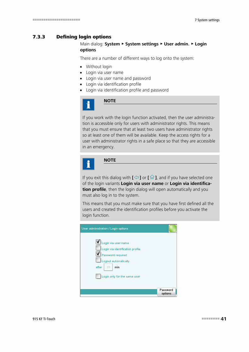
7.3.3 Defining login optionsMain dialog: System ▶ System settings ▶ User admin. ▶ Loginoptions
There are a number of different ways to log onto the system:
■ Without login■ Login via user name■ Login via user name and password■ Login via identification profile■ Login via identification profile and password
NOTE
If you work with the login function activated, then the user administra-tion is accessible only for users with administrator rights. This meansthat you must ensure that at least two users have administrator rightsso at least one of them will be available. Keep the access rights for auser with administrator rights in a safe place so that they are accessiblein an emergency.
NOTE
If you exit this dialog with [ ] or [ ], and if you have selected oneof the login variants Login via user name or Login via identifica-tion profile, then the login dialog will open automatically and youmust also log in to the system.
This means that you must make sure that you have first defined all theusers and created the identification profiles before you activate thelogin function.

7.3 User administration ■■■■■■■■■■■■■■■■■■■■■■
42 ■■■■■■■■ 915 KF Ti-Touch
Login via user name
on | off (Default value: off)
If this option is activated, then the user must log in with his or her unam-biguous identification.
Login via identification profile
on | off (Default value: off)
If this option is activated, then the login will take place via USB storagemedium with the identification profile stored on it.
Password required
on | off (Default value: off)
If this option is activated, then the user must enter a password in additionto his or her user name or identification profile.
Logout automatically
on | off (Default value: off)
If this option is activated, then the user will be logged out automaticallyafter the specified time.
Input range 1 - 60 min
Login only for the same user
on | off (Default value: off)
If this option is activated, then only the same user may log in again afterhe or she has logged out. Users with administrator rights can, however,log in at any time.
[Password options]
Define the settings for the password, see following chapter.
7.3.4 Password optionsMain dialog: System ▶ System settings ▶ User admin. ▶ Loginoptions ▶ Password options
You can make various settings for password entry in the passwordoptions.

■■■■■■■■■■■■■■■■■■■■■■ 7 System settings
915 KF Ti-Touch ■■■■■■■■ 43
Minimum password length
Minimum number of characters of the passwords.
Input range 1 - 10 Default value 1
No. of entry attempts
If the user has logged in incorrectly this many times, then it will automati-cally be deactivated. It can only be reactivated by a user with administra-tor rights.
Input range 2 - 5 Selection offDefault value off
Special characters required
on | off (Default value: off)
If this option is activated, then the password must contain one of the fol-lowing special characters: ° § + ¦ @ * # ç % & ¬ ( ) = ' ^ ` ~ ] [ } { - _ : . ; , >< £ !
Password expires
on | off (Default value: off)
If this option is activated, then the user must define a new password afterthe time specified. A password that has already been used cannot be usedagain.
Input range 1 - 999 daysDefault value 365 days

7.3 User administration ■■■■■■■■■■■■■■■■■■■■■■
44 ■■■■■■■■ 915 KF Ti-Touch
Forgotten password
CAUTION
If a user has forgotten his password, a new user name must be defined.The same user name can only be used again after a re-installation andre-creating the user list.
Proceed as follows:
1 Create a backup
Create a backup (see Chapter 12.3, page 119).
2 Initialize the system
Switch off the Ti-Touch and carry out a system initialization (seeChapter 29.1, page 330).
3 Restore backed-up data
Use the function Restore to reload the data from the backup intoyour system (see Chapter 12.3.1, page 119).
Deactivate the options User list and System settings / Useradmin..
4 Switch on the Ti-Touch
Switch the Ti-Touch back on again after a few seconds.
5 Restore the user list
Create the user list again and redefine the login options.

■■■■■■■■■■■■■■■■■■■■■■ 7 System settings
915 KF Ti-Touch ■■■■■■■■ 45
7.4 Measured value display
Main dialog: System ▶ System settings ▶ Meas. value display
The number of decimal places can be defined for pH values and voltages.This setting refers exclusively to the display of the measured values in thelive display and in the manual control. The values will, however, always bestored with their full accuracy.
7.5 Acoustic signals
Main dialog: System ▶ System settings ▶ Acoustic signals
You can define acoustic signals in order to direct attention to particularevents. You can define signals for the following events:
■ Wrong manipulationAn acoustic signal will sound each time an invalid action is attempted(e.g. pressing [ ] again when Help is open).
■ Display a messageA short beep will sound each time a message appears on the display.This informs the user that the message must be confirmed.
■ Button contactEach time a button is touched on the touch screen, this will be con-firmed by an acoustic signal.
■ External data inputAn acoustic signal will provide confirmation each time data is receivedfrom external devices (e.g. balance, barcode reader).

■■■■■■■■■■■■■■■■■■■■■■
46 ■■■■■■■■ 915 KF Ti-Touch
8 Titrants
Main dialog: System ▶ Titrants
This chapter describes how you can create a list of titrants used in the sys-tem. Titrants can be used in intelligent buret units or in non-intelligentburet units. Intelligent buret units have a built-in data chip on which thedata for the titrant is stored. This data is automatically read out duringattachment and entered in the titrant list.
The titrant list can contain a maximum of 30 titrants. The following data isspecified for each titrant:
■ Designation■ Cylinder volume■ Type
– IDU: dosing unit with integrated data chip– IEU: exchange unit with integrated data chip– EU: exchange unit without data chip
■ MSB connector of the dosing device/control device (only whenexchange unit/dosing unit is attached)
Titrants in exchange units/dosing units with integrated data chips aredepicted in green lettering.
The following titrant data is stored in the titrant list:
■ NameEach titrant in the system is identified by its unambiguous name.
■ Current titer■ Working life

■■■■■■■■■■■■■■■■■■■■■■ 8 Titrants
915 KF Ti-Touch ■■■■■■■■ 47
■ Data on exchange/dosing unit:– Parameters for the function PREP– Length and diameter of the tubings– Port assignment of the dosing unit– Cylinder volume– Serial number– etc.
■ etc.
NOTE
If data is read out from the data chip, then a check is made whetherthe titrant list already contains a titrant of the same type with the iden-tical serial number. If this is the case, then the older data set willalways be overwritten by the new data set, no matter whether thedata set in the titrant list or the data set on the data chip is the mostrecent one.
[New]
Add a new titrant to the list (see Chapter 8.1, page 47).
[Delete]
Delete the selected titrant from the list.
[Edit]
Edit the data of the selected titrant (see Chapter 8.2, page 48).
8.1 Adding a new titrant
Before you can use a titrant, you must add it to the titrant list. To do this,use the button [New].
■ Exchange unit/dosing unit with data chip:The exchange unit or dosing unit must be attached. All dosing deviceson which non-configured exchange or dosing units have been detec-ted are included in a selection list. Tapping on the button [Edit] opensthe properties dialog, see following chapter.
■ Exchange unit without data chip:The properties dialog is opened after the dosing unit type has beenselected, see following chapter.

8.2 Editing titrant data ■■■■■■■■■■■■■■■■■■■■■■
48 ■■■■■■■■ 915 KF Ti-Touch
8.2 Editing titrant data
Titrant list: Titrants ▶ New / Edit
All of the data for the selected titrant is displayed in the dialog Titrants /Edit.
Titrant
The designation of the titrant is used for unambiguous identification.
Entry 24 characters maximumSelection Selection of frequently used titrants
Concentration
Concentration of the titrant.
Input range –999999999 - 9999999999 Default value 1.000
Unit of the concentration.
Entry 10 characters maximumSelection µmol/mL | mmol/L | mol/L | g/L | mg/L | mg/mL |
µg/L | ppm | % | mEq/LDefault value mol/L
The concentration of the titrant is not relevant with Karl Fischer titration(KFT)
Comment
Entry 24 characters maximum
Titer
Titer of the titrant.

■■■■■■■■■■■■■■■■■■■■■■ 8 Titrants
915 KF Ti-Touch ■■■■■■■■ 49
Input range –999999999 - 9999999999 Default value 1.000
Unit of the titer.
Entry 10 characters maximumDefault value emptySelection µmol/mL | mmol/L | mol/L | g/L | mg/L | mg/mL |
µg/L | ppm | % | mEq/L
NOTE
If you modify the titer of the titrant in a loaded determination at a laterdate and would then like to recalculate the determination with the cor-rected value, then you must modify the value in the determination dataunder View data / Titrant data (see "Titrant data", page 201).
Date titer det.
Date and time of the last titer determination. For new titrants, the timethe preparation was made is specified until after the first time a titer deter-mination has been carried out.
[Working life]
Define the working life of the sensor (see Chapter 8.3, page 50).
[Dosing unit]
This button is only displayed for Type = IDU.
Define the properties of the dosing unit used (see Chapter 8.4, page51).
[Exchange unit]
This button is only displayed with Type = IEU or EU.
Define the properties of the exchange unit used (see Chapter 8.5, page57).
[Titer options]
Display the properties for the titer determination (see Chapter 8.7, page63).

8.3 Monitoring the working life ■■■■■■■■■■■■■■■■■■■■■■
50 ■■■■■■■■ 915 KF Ti-Touch
8.3 Monitoring the working life
Titrant: Edit ▶ Working life
In the dialog Edit titrant / Working life, you can define the time inter-val after which the titrant must be replaced. This is particularly important ifyour titrant has a limited working life. If you do not wish to monitor theworking life, then you can enter only the date of manufacture for docu-mentation purposes.
Preparation date
Date on which the reagent was manufactured or the bottle was opened.For new titrants, the time the preparation was made will be specified.
Format: YYYY:MM:DD
Monitoring
on | off (Default value: off)
If this parameter is activated, then the working life will be monitored.
Working life
If you define a time interval for the working life, then the Expiry date willbe tracked automatically.
Input range 1 - 999 daysDefault value 999 days
Expiry date
If you define an expiry date, then the Working life will be tracked auto-matically.
Format: YYYY:MM:DD
Action
Selection of the action which is carried out when the time interval hasexpired.
Selection Display message | Document message | Canceldetermination
Default value Display messageFor all three options it is documented in the deter-mination data (see dialog More determinationdata / Messages), that the time interval has beenexpired.

■■■■■■■■■■■■■■■■■■■■■■ 8 Titrants
915 KF Ti-Touch ■■■■■■■■ 51
Display messageA message is displayed. You can select whether you want to continuewith the determination or cancel the run.
Document messageIn the determination data it will be documented, that the time intervalhas been expired.
Cancel determinationThe determination is stopped.
8.4 Dosing unit
Titrant: Edit ▶ Dosing unit
You can edit data for the dosing unit of the titrant in this dialog.
Name
Designation of the exchange or dosing unit.
Entry 24 characters maximumDefault value empty
Order number
Order number of the exchange or dosing unit. It will be read out automat-ically on units with integrated data chips.
Entry 24 characters maximumDefault value empty
Serial number
Serial number of the exchange or dosing unit. It will be read out automati-cally on units with integrated data chips.
Entry 8 digits maximum

8.4 Dosing unit ■■■■■■■■■■■■■■■■■■■■■■
52 ■■■■■■■■ 915 KF Ti-Touch
Cylinder volume
Cylinder volume of the dosing unit. It will be read out automatically ondosing units with integrated data chips.
Selection 2 | 5 | 10 | 20 | 50Default value 20
Serial no. cyl.
Serial number of the dosing cylinder. It will be read out automatically onexchange or dosing units with integrated data chips. The number can bechanged manually at any time, e.g. when a cylinder is replaced.
Entry 8 digits maximum
[Valve disk]
Specify the shift direction of the valve disc (see Chapter 8.4.3, page 56).
[GLP test]
Define the time interval for the GLP test (see Chapter 8.6, page 61).
[PREP param.]
Enter the parameters for the preparation (see Chapter 8.4.1, page 52).
[Tubing param.]
Enter the parameters for the connected tubings (see Chapter 8.4.2, page53).
8.4.1 Parameters for preparing (PREP) and emptying (EMPTY)Titrant: Edit ▶ Dosing unit ▶ PREP param.
In the dialog Dosing unit / PREP parameters, you can adjust theparameters for the execution of the Prepare (command PREP) andEmpty (command EMPTY) functions. The Prepare function is used torinse the cylinder and tubing of the dosing unit and fill it air bubble-free.You should carry out this function before the first determination or onceper day. The EMPTY function empties the cylinder and the tubings of thedosing unit.
Dosing port PREP/EMPTY
Dosing port through which the cylinder contents are ejected.
Selection Dosing port 1 | Dosing port 2 | Fill port | Spe-cial port
Default value Dosing port 1
Dosing rate Dos. port 1
Rate used for the aspiration and ejection of the reagent via dosing port 1.
Input range 0.01 - 166.00 mL/min

■■■■■■■■■■■■■■■■■■■■■■ 8 Titrants
915 KF Ti-Touch ■■■■■■■■ 53
Selection maximumDefault value maximum
maximumThe maximum dosing rate depends on the cylinder volume (see Chap-ter 31.1, page 337).
Dosing rate Dos. port 2
Rate used for the aspiration and ejection of the reagent via dosing port 2.
Input range 0.01 - 166.00 mL/minSelection maximumDefault value maximum
maximumThe maximum dosing rate depends on the cylinder volume (see Chap-ter 31.1, page 337).
Dosing rate Fill port
Rate used for the aspiration and ejection of the reagent via fill port.
Input range 0.01 - 166.00 mL/minSelection maximumDefault value maximum
maximumThe maximum dosing rate depends on the cylinder volume (see Chap-ter 31.1, page 337).
Dosing rate Spec.port
Rate used for the aspiration and ejection of the reagent via the specialport.
Input range 0.01 - 166.00 mL/minSelection maximumDefault value maximum
maximumThe maximum dosing rate depends on the cylinder volume (see Chap-ter 31.1, page 337).
8.4.2 Tubing parametersTitrant: Edit ▶ Dosing unit ▶ Tubing param.
You can enter the length and diameter of the connected tubings in thedialog Dosing unit / Tubing parameters. The values which havealready been entered correspond to the dimensions of the supplied stand-ard tubings. In addition, the port assignment can be modified.

8.4 Dosing unit ■■■■■■■■■■■■■■■■■■■■■■
54 ■■■■■■■■ 915 KF Ti-Touch
NOTE
These parameters are important for the correct execution of the Pre-paring (PREP command) and Emptying (EMPTY command) functions,because the volumes of the tubing connections are taken into account.
Dosing port 1
Port
Port to be used as dosing port 1 for the PREP and EMPTY (see Figure10, page 56) functions.
Selection Port 1 | Port 2 | Port 3 | Port 4Default value Port 1
Length
Length of the tubing.
Input range 0.0 - 999.9 cmDefault value 40.0 cm
The setting 0.0 means that this tubing will neitherbe rinsed nor emptied.
Diameter
Diameter of the tubing.
Input range 0.0 - 9.9 mmDefault value 2.0 mm
Dosing port 2
Port
Port to be used as dosing port 2 for the PREP and EMPTY functions (seeFigure 10, page 56).
Selection Port 1 | Port 2 | Port 3 | Port 4Default value Port 3
Length
Length of the tubing.
Input range 0.0 - 999.9 cmDefault value 0.0 cm
The setting 0.0 means that this tubing will neitherbe rinsed nor emptied.

■■■■■■■■■■■■■■■■■■■■■■ 8 Titrants
915 KF Ti-Touch ■■■■■■■■ 55
Diameter
Diameter of the tubing.
Input range 0.0 - 9.9 mmDefault value 2.0 mm
Fill port
Port
Port to be used as fill port for the PREP and EMPTY functions (see Figure10, page 56).
Selection Port 1 | Port 2 | Port 3 | Port 4Default value Port 2
Length
Length of the tubing.
Input range 0.0 - 999.9 cmDefault value 25.0 cm
The setting 0.0 means that this tubing will neitherbe rinsed nor emptied.
Diameter
Diameter of the tubing.
Input range 0.0 - 9.9 mmDefault value 2.0 mm
Special port
Port
Port to be used as special port for the PREP and EMPTY functions (seeFigure 10, page 56).
Selection Port 1 | Port 2 | Port 3 | Port 4Default value Port 4
Length
Length of the tubing.
Input range 0.0 - 999.9 cmDefault value 0.0 cm
The setting 0.0 means that this tubing will neitherbe rinsed nor emptied.
Diameter
Diameter of the tubing.

8.4 Dosing unit ■■■■■■■■■■■■■■■■■■■■■■
56 ■■■■■■■■ 915 KF Ti-Touch
Input range 0.0 - 9.9 mmDefault value 2.0 mm
5
4
3
2
1
Figure 10 Dosing unit – port assignment
1 VENTThis port is set up for the deaeration of thereagent bottle. An adsorber tube (filled withdesiccant) is usually mounted here.
2 Port 1The default definition of this port is dosingport 1.
3 Port 2The default definition of this port is the fill-ing port. A riser tube is usually mounted toit.
4 Port 4Air is suctioned through this port during theEmptying function.
5 Port 3The default definition of this port is dosingport 2.
8.4.3 Shift direction of the valve diskTitrant: Edit ▶ Dosing unit ▶ Valve disk
In this dialog, you can specify the shift direction of the valve disc.
Direction
Shift direction of the valve disc.
Selection descending | ascending | automatic | not overDefault value automatic
descendingThe ports are moved to in descending order.

■■■■■■■■■■■■■■■■■■■■■■ 8 Titrants
915 KF Ti-Touch ■■■■■■■■ 57
ascendingThe ports are moved to in ascending order.
automaticThe ports are moved to by the shortest path.
not overDefine a protected port.
Not over port
This parameter can only be edited with Direction = not over.
Define a protected port if the valve disc is not to be rotated over this port(useful with pipetting functions). The protected port can, however, bemoved to directly.
Selection 1 | 2 | 3 | 4Default value 4
8.5 Exchange unit
Titrant: Edit ▶ Exchange unit
You can edit data for the exchange unit of the titrant in this dialog.
Name
Designation of the exchange or dosing unit.
Entry 24 characters maximumDefault value empty
Order number
Order number of the exchange or dosing unit. It will be read out automat-ically on units with integrated data chips.

8.5 Exchange unit ■■■■■■■■■■■■■■■■■■■■■■
58 ■■■■■■■■ 915 KF Ti-Touch
Entry 24 characters maximumDefault value empty
Serial number
Serial number of the exchange or dosing unit. It will be read out automati-cally on units with integrated data chips.
Entry 8 digits maximum
Cylinder volume
Cylinder volume of the exchange unit. It will be read out automatically onexchange units with integrated data chips.
Selection 1 | 5 | 10 | 20 | 50Default value 20
Serial no. cyl.
Serial number of the dosing cylinder. It will be read out automatically onexchange or dosing units with integrated data chips. The number can bechanged manually at any time, e.g. when a cylinder is replaced.
Entry 8 digits maximum
[GLP test]
Define the time interval for the GLP test (see Chapter 8.6, page 61).
[PREP param.]
Enter the parameters for the preparation (see Chapter 8.5.1, page 58).
[Tubing param.]
Enter the parameters for the connected tubings (see Chapter 8.5.2, page59).
8.5.1 Parameters for the preparation (PREP)Titrant: Edit ▶ Exchange unit ▶ PREP param.
In the dialog Exchange unit / PREP parameters, you can adjust theparameters for the execution of the Prepare function (command PREP).This function is used to rinse the cylinder and tubings of the exchange unitand fill it air bubble-free. You should carry out this function before thefirst determination or once per day.
Volume
Volume of titrant dosed during a rinsing cycle.
Input range 0.00000 - 99999.9 mLSelection Cylinder volumeDefault value Cylinder volume

■■■■■■■■■■■■■■■■■■■■■■ 8 Titrants
915 KF Ti-Touch ■■■■■■■■ 59
Cylinder volumeThe entire cylinder volume is being dosed.
Cycles
Number of rinsing cycles. We recommend carrying out at least two rinsingcycles in order to remove all air bubbles.
Selection 1 | 2 | 3 | 4 | 5 | 6 | 7 | 8 | 9Default value 2
Dosing rate
Rate at which it is dosed.
Input range 0.01 - 166.00 mL/minSelection maximumDefault value maximum
maximumThe maximum dosing rate depends on the cylinder volume (see Chap-ter 31, page 337).
Filling rate
Rate at which the dosing cylinder is filled.
Input range 0.01 - 166.00 mL/minSelection maximumDefault value maximum
maximumThe maximum filling rate depends on the cylinder volume (see Chapter31, page 337).
8.5.2 Tubing parametersTitrant: Edit ▶ Exchange unit ▶ Tubing param.
You can enter the length and diameter of the connected tubings in thedialog Exchange unit / Tubing parameters. The values which havealready been entered correspond to the dimensions of the supplied stand-ard tubings.
Dosing tip
Tubing to the dosing tip (11-2).
Length
Length of the tubing.
Input range 0.0 - 999.9 cmDefault value 40.0 cm

8.5 Exchange unit ■■■■■■■■■■■■■■■■■■■■■■
60 ■■■■■■■■ 915 KF Ti-Touch
Diameter
Diameter of the tubing.
Input range 0.0 - 9.9 mmDefault value 2.0 mm
Dosing cylinder
Tubing to the dosing cylinder (11-3).
Length
Length of the tubing.
Input range 0.0 - 999.9 cmDefault value 13.0 cm
Diameter
Diameter of the tubing.
Input range 0.0 - 9.9 mmDefault value 2.0 mm
Reagent bottle
Tubing to the reagent bottle (11-1).
Length
Length of the tubing.
Input range 0.0 - 999.9 cmDefault value 25.0 cm
Diameter
Diameter of the tubing.
Input range 0.0 - 9.9 mmDefault value 2.0 mm

■■■■■■■■■■■■■■■■■■■■■■ 8 Titrants
915 KF Ti-Touch ■■■■■■■■ 61
1
2
3
Figure 11 Exchange unit – tubing connections
1 Tubing to the reagent bottle 2 Tubing to the dosing tip
3 Tubing to the dosing cylinder
8.6 GLP test for exchange unit and dosing unit
Titrant: Edit ▶ Dosing unit / Exchange unit ▶ GLP test
In the dialog Exchange unit / GLP test or Dosing unit / GLP test,respectively, you can define the time interval after which a GLP test mustbe carried out again for the exchange unit or dosing unit.
GLP test date
Date on which the last GLP test was carried out.
Format: YYYY:MM:DD
Monitoring
on | off (Default value: off)
If this parameter is activated, then the time interval after which a GLP testhas to be carried out again will be monitored.

8.6 GLP test for exchange unit and dosing unit ■■■■■■■■■■■■■■■■■■■■■■
62 ■■■■■■■■ 915 KF Ti-Touch
GLP test interval
If you define a time interval for the GLP test, then the date in Next GLPtest will be tracked automatically.
Input range 1 - 999 daysDefault value 999 days
Next GLP test
If you define a date for the next GLP test, then the GLP test interval willbe tracked automatically.
Format: YYYY:MM:DD
Action
Selection of the action which is carried out when the time interval hasexpired.
Selection Display message | Document message | Canceldetermination
Default value Display messageFor all three options it is documented in the deter-mination data (see dialog More determinationdata / Messages), that the time interval has beenexpired.
Display messageA message is displayed. You can select whether you want to continuewith the determination or cancel the run.
Document messageIn the determination data it will be documented, that the time intervalhas been expired.
Cancel determinationThe determination is stopped.

■■■■■■■■■■■■■■■■■■■■■■ 8 Titrants
915 KF Ti-Touch ■■■■■■■■ 63
8.7 Titer determination options and data
Titrant: Edit ▶ Titer options
Detailed information concerning the titer determination is displayed in thedialog Edit titrant / Titer options:
■ Titer methodMethod by which the titer was determined. If the titer was enteredmanually, then manual will be displayed.
■ UserUser who carried out the titer determination.
■ Statistical dataThe following information is also displayed for automatically assignedtiters if the mean value of the results has been saved as the titer (see"Save as titer", page 145):
– n (titer det.)Number of titer determinations.
– s absAbsolute standard deviation
– s relRelative standard deviation
[Validity]
Define the time interval for the titer validity (see Chapter 8.7.1, page63).
[History]
Display information about the last ten titer determinations (see Chapter8.7.2, page 64).
8.7.1 Titer validityTitrant: Edit ▶ Titer options ▶ Validity
In the dialog Titer options / Validity, you can define the time intervalafter which the titer must be determined again.
Date titer det.
Date and time of the last titer determination. For new titrants, the timethe preparation was made is specified until after the first time a titer deter-mination has been carried out.
Monitoring
on | off (Default value: off)
If this parameter is activated, then the titer validity will be monitored.

8.7 Titer determination options and data ■■■■■■■■■■■■■■■■■■■■■■
64 ■■■■■■■■ 915 KF Ti-Touch
Titer validity
If you define a time interval for the validity of the titer, then the date inNext titer determ. will be tracked automatically.
Input range 1 - 999 daysDefault value 999 days
Next titer determ.
If you define a date for the next titer determination, then the time intervalfor the Titer validity will be tracked automatically.
Format: YYYY:MM:DD
Action
Selection of the action which is carried out when the time interval hasexpired.
Selection Display message | Document message | Canceldetermination
Default value Display messageFor all three options it is documented in the deter-mination data (see dialog More determinationdata / Messages), that the time interval has beenexpired.
Display messageA message is displayed. You can select whether you want to continuewith the determination or cancel the run.
Document messageIn the determination data it will be documented, that the time intervalhas been expired.
Cancel determinationThe determination is stopped.
8.7.2 Properties of the previous titer determinations
Dialog "Titer options / History"
Titrant: Edit ▶ Titer options ▶ History
The date, time and titer of the last ten titer determinations are displayed intabular form in the dialog Titer options / History. Titers that weredetermined automatically will be displayed in green; manually entered titervalues will be displayed in black with the designation (m). You can deletethese entries, e.g. if you have opened a new bottle.

■■■■■■■■■■■■■■■■■■■■■■ 8 Titrants
915 KF Ti-Touch ■■■■■■■■ 65
NOTE
If multiple determinations have been carried out in order to determinethe titer, then only one entry will be made in the history.
[Delete History]
Delete the entire history.
[Graph]
Open the diagram of the titer values, see following chapter.
Dialog "History / Graph"
Titrant: Edit ▶ Titer options ▶ History ▶ Graph
In this diagram, titer values are plotted against the date of the titer deter-mination. You can define warning limits (blue dashed lines) and interven-tion limits (red dashed lines). These limits will not, however, be monitored.
[Limits]
Define warning and intervention limits.

9.1 Editing reagent data ■■■■■■■■■■■■■■■■■■■■■■
66 ■■■■■■■■ 915 KF Ti-Touch
9 Reagents
Main dialog: System ▶ Reagents
This chapter describes how you can create a list of the reagents used inthe system.
The list of reagents gives the designation and type of each reagent.
[New]
Add a new reagent to the list, see following chapter.
[Delete]
Delete the selected reagent from the list.
[Edit]
Edit the data of the selected reagent, see following chapter.
9.1 Editing reagent data
Main dialog: System ▶ Reagents ▶ New / Edit

■■■■■■■■■■■■■■■■■■■■■■ 9 Reagents
915 KF Ti-Touch ■■■■■■■■ 67
Reagent
The designation of the reagent is used for unambiguous identification.
Entry 24 characters maximum
Comment
Entry 24 characters maximum
[Reagent monitoring]
Set the parameters for the reagent monitoring, see following chapter.
9.2 Reagent monitoring
The conditions for the monitoring of the reagent are defined in the dialogEdit reagent / Reagent monitoring.
If one of the following values is reached, then the reagent must bereplaced. The values are checked in the following cases:
■ at the start of the determination.

9.2 Reagent monitoring ■■■■■■■■■■■■■■■■■■■■■■
68 ■■■■■■■■ 915 KF Ti-Touch
■ at the end of the determination.
Number of determ.
The number of determinations to be carried out with a certain amount ofreagent depends on the type of sample and its amount.
Input range 1 - 999 Selection offDefault value off
Working life
Working life of the reagent.
Input range 1 - 999 daysSelection offDefault value off
Volume
Volume of titrant dosed.
Input range 1.0 - 999.9 mLSelection offDefault value off
[Status]
Display the status overview of the current values of the reagent monitor-ing.
[Reagent replacement]
Edit the parameters for the reagent exchange.
Dialog "Reagent monitoring / Status"
The current reagent monitoring values are displayed in this dialog.
[Reset]
Reset the values to zero.
Dialog "Reagent monitoring / Reagent replacement"
The parameters for the reagent exchange are defined in this dialog.
Reagent replacement
The reagent can either be exchanged manually or automatically.
Selection manual | autoDefault value manual
manualIf a monitored parameter has reached the limit set, a message is beingdisplayed. Then the reagent has to be exchanged manually.

■■■■■■■■■■■■■■■■■■■■■■ 9 Reagents
915 KF Ti-Touch ■■■■■■■■ 69
autoIf a monitored parameter has reached the limit set, the method definedbelow is started automatically.
Memory
This parameter can only be edited with Reagent replacement = auto.
Memory location the method is loaded from. All memory locations areselectable, even if they are currently not accessible.
Selection Internal memory | External memory 1 | Exter-nal memory 2 | Shared memory
Default value Internal memory
Shared memoryShared directory in the network.
Method
This parameter can only be edited with Reagent replacement = auto.
Method used for emptying the titration cell.
NOTE
Make sure that the memory is accessible.
Entry 32 characters maximumSelection Selection of stored methods

■■■■■■■■■■■■■■■■■■■■■■
70 ■■■■■■■■ 915 KF Ti-Touch
10 Sensors
Main dialog: System ▶ Sensors
This chapter describes how you can create a list of the sensors used in thesystem.
Two standard sensors are defined in the sensor list: Metal electrode andTemperature sensor. These sensors cannot be deleted or renamed. Amaximum of 25 additional sensors can be added to these sensors.
For each sensor, the following data is displayed in the sensor list:
■ Designation■ Type
– Metal: Metal electrode– Temp.: Temperature sensor
The following sensor data is stored in the list of sensors:
■ NameEach sensor in the system is identified by its unambiguous name.
■ Working life■ etc.
[New]
Add a new sensor to the list (see Chapter 10.1, page 71).
[Delete]
Delete the selected sensor from the list.
[Edit]
Edit the data of the selected sensor (see Chapter 10.2, page 71).

■■■■■■■■■■■■■■■■■■■■■■ 10 Sensors
915 KF Ti-Touch ■■■■■■■■ 71
10.1 Adding a new sensor
Before you can use a sensor, you must add it to the sensor list. To do this,use the button [New].
■ The properties dialog is opened after the sensor type has beenselected, see following chapter. The following sensor types can beselected:
– Metal electrode (Pt electrode)– Other sensor– Temperature sensor
10.2 Editing the sensor data
Sensor list: Sensor ▶ New / Edit
All of the data for the selected sensor is displayed in the dialog Sensors /Edit.
Sensor
The designation of the sensor is used for unambiguous identification.
Entry 24 characters maximum
Order number
Order number of the sensor.
Entry 24 characters maximumDefault value empty
Serial number
Serial number of the sensor.

10.3 Monitoring the working life ■■■■■■■■■■■■■■■■■■■■■■
72 ■■■■■■■■ 915 KF Ti-Touch
Entry 8 digits maximum
Comment
Entry 24 characters maximum
[Working life]
Define the working life of the sensor (see Chapter 10.3, page 72).
10.3 Monitoring the working life
Sensor: Edit ▶ Working life
In the dialog Edit sensor / Working life, you can define the time inter-val after which the sensor must be replaced. If you do not wish to monitorthe working life, then you can enter only the date of manufacture for doc-umentation purposes.
Start-up
Date on which the sensor was used for the first time.
Format: YYYY:MM:DD
Monitoring
on | off (Default value: off)
If this parameter is activated, then the working life will be monitored.
Working life
If you define a time interval for the working life, then the Expiry date willbe tracked automatically.
Input range 1 - 999 daysDefault value 999 days
Expiry date
If you define an expiry date, then the Working life will be tracked auto-matically.
Format: YYYY:MM:DD
Action
Selection of the action which is carried out when the time interval hasexpired.

■■■■■■■■■■■■■■■■■■■■■■ 10 Sensors
915 KF Ti-Touch ■■■■■■■■ 73
Selection Display message | Document message | Canceldetermination
Default value Display messageFor all three options it is documented in the deter-mination data (see dialog More determinationdata / Messages), that the time interval has beenexpired.
Display messageA message is displayed. You can select whether you want to continuewith the determination or cancel the run.
Document messageIn the determination data it will be documented, that the time intervalhas been expired.
Cancel determinationThe determination is stopped.

■■■■■■■■■■■■■■■■■■■■■■
74 ■■■■■■■■ 915 KF Ti-Touch
11 Device manager
Main dialog: System ▶ Device manager
This chapter describes how you can configure the Ti-Touch, the USB Sam-ple Processor and the connected peripheral devices. A detailed descriptionof the hardware installation of the USB Sample Processor can be found inthe corresponding installation manual.
The instrument list gives the name and type of every instrument. The Ti-Touch titrator is a component of the 915 KF Ti-Touch and therefore per-manently entered as control device in the device manager. A connectedUSB Sample Processor with the peripheral devices (dosing devices, stirrers,etc.) connected to the MSB connector is entered in the list automatically.A USB/RS-232 adapter will also be automatically recognized and enteredin the instrument list with default settings. A printer is entered in theinstrument list in the default settings. You must enter a PC keyboard, abarcode reader or a balance in the instrument list yourself.
[New]
Add a new device to the list (see Chapter 11.1, page 75).
[Delete]
Delete the selected device from the list.
NOTE
Devices which are recognized automatically cannot be deleted from thelist while they are still connected.
[Edit]
Configure the selected device (see Chapter 11.2, page 75).

■■■■■■■■■■■■■■■■■■■■■■ 11 Device manager
915 KF Ti-Touch ■■■■■■■■ 75
11.1 Adding a new device
Of the following device types, you can enter one device each in the instru-ment list, even if it is not yet connected:
■ USB Sample Processor■ Balance■ Barcode reader■ USB/RS-232 adapter■ PC keyboard
Proceed as follows:
1 Displaying the device selection
Tap on [New].
2 Selecting the device
Tap on the button for the desired device.
The new device is entered in the list.
11.2 Configuring the instrument
Instrument list: Instrument ▶ Edit
The data stored for an instrument depends on the type of instrument. Youcan define an instrument name and a comment for each instrument. Theinstrument name of the Ti-Touch is printed out in the standard reportheader.
The description of the individual instruments can be found in the follow-ing specific chapters:
■ Ti-Touch (see Chapter 11.3, page 76)■ Metrohm control devices (see Chapter 11.4, page 82)■ USB Sample Processor (see Chapter 11.5, page 85)■ Printer (see Chapter 11.7, page 101)■ Balance (see Chapter 11.8, page 106)■ PC keyboard (see Chapter 11.10, page 109)■ USB/RS-232 adapter (see Chapter 11.9, page 107)■ Barcode reader (see Chapter 11.11, page 110)

11.3 Ti-Touch ■■■■■■■■■■■■■■■■■■■■■■
76 ■■■■■■■■ 915 KF Ti-Touch
11.3 Ti-Touch
Instrument list: 915 KF Ti-Touch ▶ Edit
Device name
This designation is used for identification purposes when selecting controldevices (command, manual control).
Entry 24 characters maximum
Comment
Entry 24 characters maximum
Switch off display
If this time interval has expired without the Ti-Touch having been oper-ated, then the display will be switched off. Touching the display willswitch it back on again at any time.
Input range 1 - 999 minDefault value 60 minSelection off
Program version
Program version of the software.
Serial number
Shows the serial number of the device.
Control Remote Box
Shows to which control device and MSB connector the Remote Box isconnected.

■■■■■■■■■■■■■■■■■■■■■■ 11 Device manager
915 KF Ti-Touch ■■■■■■■■ 77
The "Control Remote Box" is the interface via which the system can bestarted and stopped externally. If multiple Remote Boxes are connected,then the one that is recognized first when the program starts will be usedas the "Control Remote Box."
Selection Name of the control device / Number of theMSB connector | Not available
11.3.1 E-mail915 KF Ti-Touch: Edit ▶ E-mail
The system allows you to send displayed messages as e-mails. TheTi-Touch must be connected to a network for this to function. The follow-ing types of messages can be sent:
■ : general warning messages
■ : error messages
Configuring e-mail dispatch
Proceed as follows so that messages can be sent as e-mails:
1 Activating the option
■ In the instrument properties of the 915 KF Ti-Touch, tap on the[E-mail] button.
■ In the Edit device / E-mail dialog, activate the Send the fol-lowing messages as e-mail: option.
2 Configuring e-mail addresses
■ Tap on the [E-mail settings] button.The E-mail / Settings dialog is displayed.
■ Enter the addresses of the mail server, the sender and the desiredrecipient.
Parameter description
Send the following messages as e-mail:
on | off (Default value: off)
If this parameter is activated, then messages with the following symbolswill be sent as e-mails:
■ : General warning messages
■ : Error messages

11.3 Ti-Touch ■■■■■■■■■■■■■■■■■■■■■■
78 ■■■■■■■■ 915 KF Ti-Touch
Send only during running determination
on | off (Default value: on)
If this parameter is activated, then messages will be sent as e-mails only ifa determination is running. Deactivate this parameter if messages are alsoto be sent in normal status.
Mail server
Address of the mail server for outgoing mail, e.g. mail.metrohm.ch. Youcan find the address of the mail server either in your e-mail program set-tings or obtain it from your IT department.
Entry 24 characters maximumDefault value empty
Sender
E-mail address of the sender. This address must be formatted as an e-mailaddress, but need not necessarily correspond to an existing e-mailaccount, e.g. [email protected].
Entry 24 characters maximumDefault value empty
Recipient
The messages will be sent to this e-mail address.
Entry 24 characters maximumDefault value empty
11.3.2 PC/LIMS report915 KF Ti-Touch: Edit ▶ PC/LIMS report
You can generate a machine-readable report with all of the importantdata concerning a determination, which is referred to as a PC/LIMS report.This report can be saved as a TXT file or sent to a terminal program or aLIMS via an RS-232 interface:
■ manually with the [ ] fixed key (see Chapter 26, page 225).■ automatically at the end of a determination (see Chapter 16.5.6, page
167).
The file name of the TXT file is constructed as follows: PC_LIMS_Report-ID1-YYYYMMDD-hhmmss.txt. A detailed description of the contents ofthe PC/LIMS report can be found in the PC/LIMS Report Guide.
Memory
Memory location where the PC/LIMS report is stored as a TXT file. Thereport will be saved in the directory pc_lims_report. This directory will be

■■■■■■■■■■■■■■■■■■■■■■ 11 Device manager
915 KF Ti-Touch ■■■■■■■■ 79
created the first time a PC/LIMS report is generated. All three memorylocations are listed as possible selections, even if they cannot be accessedat the moment.
Selection off | External memory 1 | External memory 2 | Shared memory
Default value off
offThe report will not be saved as a TXT file.
Shared memoryThe report will be saved in a shared directory on the network. Theshared directory is selected in the Edit device / Shared memory dia-log (see Chapter 11.3.3, page 79).
RS-232
The RS-232 interface via which the PC/LIMS report is sent. The interfaceparameters are adjusted in the Edit device / Port parameters dialog(see Chapter 11.9, page 107).
Selection off | COM 1 | COM 2Default value off
offThe report will not be sent via an RS-232 interface.
COM 2This interface is inactive.
Coding
Format in which the PC/LIMS report is coded and stored.
Selection ISO 8859-1 | UTF-8Default value ISO 8859-1
ISO 8859-1This format is recommended for all languages that use the extendedASCII code (e.g. German, English, Spanish, etc.).
UTF-8This format is required for all languages that do not use the extendedASCII code (e.g. Russian, Chinese, Korean, etc.).
11.3.3 Shared memory915 KF Ti-Touch: Edit ▶ Shared memory
If you have your Ti-Touch connected to your network, then you can spec-ify in this dialog a shared memory location on a PC within your networkfor the purpose of saving data (methods, determinations, etc.).

11.3 Ti-Touch ■■■■■■■■■■■■■■■■■■■■■■
80 ■■■■■■■■ 915 KF Ti-Touch
CAUTION
If the computer on which you share a memory location does not havethe same subnet mask as the Ti-Touch, then a WINS server must bepresent. The computer must be entered in this server.
Computer
Host name of the computer on which a memory location is to be shared.If you are working with Windows, then you will find the host name of thecomputer as follows: In the Windows command prompt window, enterthe command ipconfig -all. The host name is listed together with otherparameters of the computer.
Do not under any circumstances enter an IP address in this input field.
Entry max. 32 charactersDefault value empty
Share name
Share name of the shared memory location (file directory) on the above-specified computer. Please note that the Share name of a file directoryoften does not match the name of the file directory. The share name canbe found on the Release tab in the Properties dialog of the shared filedirectory.
Entry max. 32 charactersDefault value empty
Domain
Network domain in which the above-specified computer is located. If youare working with Windows, then you will find the domain name as fol-lows: In the Windows command window, enter the command ipconfig-all. The domain is listed together with other parameters of the computer.Leave the field empty if the computer is not located within a domain.
Entry max. 32 charactersDefault value empty
User
User name of the user authorized to access the shared memory location.
Entry max. 32 charactersDefault value empty
Password
Password of the user configured on the computer.

■■■■■■■■■■■■■■■■■■■■■■ 11 Device manager
915 KF Ti-Touch ■■■■■■■■ 81
Entry max. 32 charactersDefault value empty
[Connect]
Establish the network connection. If the connection has been set up cor-rectly, then all of the input fields will become inactive and the labelswitches to [Disconnect]. The network connection can be disconnectedwith this.
11.3.4 TCP/IP settings915 KF Ti-Touch: Edit ▶ TCP/IP settings
If you have your Ti-Touch connected to your network, then you have todefine the network-relevant settings in this dialog. The Ti-Touch requiresan IP address so that it is identifiable on the network. The Ti-Touch canacquire the IP address either dynamically from a DHCP server or you canenter the address directly.
Get IP address automatically (DHCP)
on | off (Default value: on)
If this parameter is activated, then the Ti-Touch will obtain its IP addressdirectly from a DHCP server. In this case, the remaining parameters can nolonger be edited.
IP address
IP address for the Ti-Touch. IP addresses are 32-bit numbers and are writ-ten as sequences of four decimals, each separated by a period, e.g."10.157.212.8".
Entry x.x.x.xDefault value empty
"x" is a decimal between 0 and 255.
Subnet mask
The net mask or subnet mask, together with the IP address, indicates towhich network the device to be connected belongs. Subnet masks are 32-bit numbers and are written as sequences of four decimals, each separa-ted by a period.
Entry x.x.x.xDefault value 255.255.255.0
Default gateway
IP address for the standard gateway. A gateway sets up connections toseveral networks. It is located in the same subnet as the device to be con-figured.

11.4 Metrohm control devices ■■■■■■■■■■■■■■■■■■■■■■
82 ■■■■■■■■ 915 KF Ti-Touch
Entry x.x.x.xDefault value empty
MAC address
Unambiguous address of the network adaptor for identification within anetwork. This parameter cannot be edited.
NetBIOS name
Unambiguous designation of the device within the network. This parame-ter cannot be edited.
11.4 Metrohm control devices
The following Metrohm devices can be used as control devices:
■ Ti-Touch Titrator (permanently entered as control device in the devicemanager)
■ USB Sample Processors
The following specifications apply for all of the control devices mentionedabove. Additional device configurations for the USB Sample Processor aredescribed in a separate chapter (see Chapter 11.5, page 85).
The dialog shows the control device with its measuring inputs, the MSBconnectors and connected peripheral devices (dosing device, stirrer,Remote Box).
[Properties]
Open the properties dialog of the highlighted entry.
The following properties can be displayed and edited to a certain extent:
■ Properties of the measuring inputs (see Chapter 11.4.1, page 83)■ Properties of the MSB connectors (see Chapter 11.4.2, page 84)

■■■■■■■■■■■■■■■■■■■■■■ 11 Device manager
915 KF Ti-Touch ■■■■■■■■ 83
■ Properties of the peripheral devices on the MSB connector (see Chap-ter 11.4.3, page 85)
11.4.1 Properties – Measuring inputList of devices: Control device ▶ Edit ▶ Measuring input 1 ▶ Proper-ties
In this dialog, you define the type of temperature sensor you have con-nected to the selected measuring input.
ADC type
Type of analog-digital converter.
Serial number
Serial number of the measuring interface.
Thick film type
Type of the thick film.
Temperature sensor
Type
The instrument supports the use of two different temperature measure-ment techniques:
■ NTC (Negative Temperature Coefficient)■ Pt1000 (Platinum resistance)
Select here the type that has been connected to the instrument. If an NTCsensor is used, then it is also necessary to enter two sensor characteristics.These characteristics are listed in the specifications of the sensor.
Selection Pt1000 | NTCDefault value Pt1000

11.4 Metrohm control devices ■■■■■■■■■■■■■■■■■■■■■■
84 ■■■■■■■■ 915 KF Ti-Touch
R (25 °C)
This parameter can only be edited with Type = NTC.
Nominal resistance of the NTC sensor at 25 °C.
Input range 1000 - 99999 ohmDefault value 30000 ohm
The default value applies to Metrohm sensors withan NTC sensor.
B value
This parameter can only be edited with Type = NTC.
Material constant of the NTC sensor. B values of NTC sensors are fre-quently based on different reference temperatures (usually 25 °C and50…100 °C). When entering the B value the influence of the second ref-erence temperature is negligible in comparison with the measuring accu-racy of an NTC sensor.
Input range 1000 - 9999 KDefault value 4100 K
The default value applies to Metrohm sensors withan NTC sensor. If no B value is given for your sensorthen you can retain the default value.
11.4.2 Properties – MSB connectorList of devices: Control device ▶ Edit ▶ MSB connector 1/2 ▶ Prop-erties
In this dialog, you can define when the request to carry out the Preparefunction for connected dosing devices is to be displayed. This settingapplies for all dosing devices of the selected MSB connector. The manualcontrol contains a description of how to prepare the exchange unit and/orthe dosing unit (see Chapter 27.3.3, page 243).

■■■■■■■■■■■■■■■■■■■■■■ 11 Device manager
915 KF Ti-Touch ■■■■■■■■ 85
Switch on
on | off (Default value: on)
If this parameter is activated, then you will be requested to prepare thedosing device when the Ti-Touch is switched on.
Attach an exchange or dosing unit
on | off (Default value: on)
If this parameter is activated, then you will be requested to prepare thedosing device when the exchange/dosing unit is attached.
Time interval
on | off (Default value: off)
Activate this parameter if you wish to receive a regular request to preparethe dosing unit.
Input range 0.1 - 999.9 hDefault value 12.0 h
11.4.3 Properties – Peripheral devicesList of devices: Control device ▶ Edit ▶ Peripheral device ▶ Proper-ties
The following data is displayed for the connected dosing devices and stir-rers:
■ TypeThe display includes the device number, e.g. "800" (Dosino)
■ Serial number
11.5 USB Sample Processor
NOTE
The following settings apply to all USB Sample Processors.

11.5 USB Sample Processor ■■■■■■■■■■■■■■■■■■■■■■
86 ■■■■■■■■ 915 KF Ti-Touch
The dialog shows the USB Sample Processor with its tower (or towers), theMSB connectors and connected peripheral devices (dosing unit, stirrer,Remote Box). If the control device is not connected, then the propertiesdialog of the control device will be displayed directly (see Chapter 11.5.1,page 86).
The settings of the MSB connectors and the connected peripheral devicesare described in Chapter "Properties – MSB connector", page 84.
[Racks]
Configure sample racks (see Chapter 11.6, page 93).
[Running time]
Configure the running time meter.
The running time meter adds together the time while the USB Sample Pro-cessor is "busy" i.e. when a single action is being carried out. A messagewith the prompt to service the device is displayed after expiry of the timelimit set here. We recommend to carry out a service after 1000 operatinghours. A reset of the running time meter can only be carried out by aMetrohm service technician.
[Properties]
Open the properties dialog of the highlighted entry.
11.5.1 Properties – Sample ProcessorList of devices: Sample Processor ▶ Edit ▶ Properties
Device name
This designation is used for identification purposes when selecting controldevices (command, manual control).
Entry 24 characters maximum

■■■■■■■■■■■■■■■■■■■■■■ 11 Device manager
915 KF Ti-Touch ■■■■■■■■ 87
Comment
Entry 24 characters maximum
Program version
Program version of the instrument software.
Serial number
Shows the serial number of the device.
Rack name
Name of the currently attached sample rack.
[Adjustment data]
Display the internal adjustment data (EEPROM data) of the USB SampleProcessor.
CAUTION
Do not modify and save these settings under any circumstances. Thisdata is required by the service technician in case of positioning prob-lems.
11.5.2 Properties – TowerList of devices: Sample Processor ▶ Edit ▶ Tower 1/2 ▶ Properties

11.5 USB Sample Processor ■■■■■■■■■■■■■■■■■■■■■■
88 ■■■■■■■■ 915 KF Ti-Touch
NOTE
In the case of a USB Sample Processor with 2 towers, Tower 1 is thetower on the right and Tower 2 is the tower on the left, when viewedfrom the front.
Maximum stroke path
Lowest permissible lift position for automatic and manual operation.
This is a safety setting. A correct specification of this value can prevent theglass of an electrode from breaking, because a titration head can not bemoved below the position specified.
Input range 1 - 235 mmDefault value 235 mm
Min. beaker radius
Smallest permissible radius of the sample vessels for automatic and man-ual operation.
This is a safety setting. It is intended to prevent a completely loaded, widetitration head from being moved into a narrow sample vessel.
Input range 1.0 - 100.0 mm (Increment: 0.1)If the lift is to be moved to the work position, acheck is made to see whether the beaker radiusdefined for the attached rack (see "Beaker radiussamples", page 96) is less than this value.
Selection offDefault value off
offNo check takes place.
Rotation increment
Amount by which the sample rack can be rotated forward or backwardrelative to its current position. This parameter is required in the commandMOVE for the settings Destination = rotate + and rotate -.
Input range 0 - 353.99 °Default value 5.00 °
Axial distance
Distance between the axis of rotation of the sample rack and swing axis ofthe robotic arm.

■■■■■■■■■■■■■■■■■■■■■■ 11 Device manager
915 KF Ti-Touch ■■■■■■■■ 89
for 814 USB Sample Processor XL:Input range 100.0 - 300.0 mmDefault value 166.0 mm
for 815 Robotic USB Sample Processor XL:Input range 100.0 - 300.0 mmDefault value 196.0 mm
11.5.3 Properties – Swing HeadList of devices: Sample Processor ▶ Edit ▶ Swing Head ▶ Properties
The dialog Edit device / Properties shows a list of all external positionswith the assigned swing angle and the specific work position for each.
[Ext. pos. 1-4]
Edit the settings that apply for all external positions (see "Properties –External positions 1-4", page 89).
[Robotic arm]
Edit the robotic arm settings (see "Properties – Robotic arm", page 91).
[Adjustment data]
Display the overview of the EEPROM data of the Swing Head. This dialogcannot be edited.
[Edit]
Edit specific settings of the selected external position (see "Properties –External position", page 92).
Properties – External positions 1-4
Swing Head: Properties ▶ Ext. pos. 1-4

11.5 USB Sample Processor ■■■■■■■■■■■■■■■■■■■■■■
90 ■■■■■■■■ 915 KF Ti-Touch
Properties which apply to all four external positions can be defined in thedialog Properties / Edit external positions 1-4.
Shift position
Lift position at which the robotic arm rotates to the external positions.
Input range 0 - 'Maximum stroke path' mmDefault value 0 mm
A lift position of 0 mm corresponds to the "homeposition", i.e. the lift is located at the upper stopposition. The maximum stroke path is defined in theproperties of the tower (see "Maximum strokepath", page 88).
Rinse position
Lift position used for rinsing.
Input range 0 - 'Maximum stroke path' mmDefault value 0 mm
A lift position of 0 mm corresponds to the "homeposition", i.e. the lift is located at the upper stopposition. The maximum stroke path is defined in theproperties of the tower (see "Maximum strokepath", page 88).
Swing increment
Amount by which the robotic arm can be swung relative to its currentposition. This parameter is used in the command MOVE for the settingsDestination = swing + and swing -.
Input range 0.00 - 180.00 °Default value 10.00 °

■■■■■■■■■■■■■■■■■■■■■■ 11 Device manager
915 KF Ti-Touch ■■■■■■■■ 91
Properties – Robotic arm
Swing Head: Properties ▶ Robotic arm
Properties of the robotic arm can be defined in the dialog Properties /Robotic arm.
Swing offset
The swing offset is a physical angle offset of a specific robotic arm model.The required values can be found in the leaflet for the robotic arm.
Input range –270.00 - 270.00 °Default value 0.00 °
Maximum swing angle
Useable swing range of the robotic arm. Each robotic arm model displaysa different value on the basis of its construction. The range can also bereduced if necessary. You will find the required values in the leaflet for therobotic arm.
Input range 0.00 - 330.00 °Default value 60.00 °
Swing radius
Maximum swing radius of the robotic arm. The swing radius is dependenton the length of the robotic arm and is, together with the axial distance(see "Axial distance," page 88), the most important variable for precisemovement to a rack position. You will find the required values in the leaf-let for the robotic arm.
Input range 30.00 - 300.00 mmDefault value 110.00 mm

11.5 USB Sample Processor ■■■■■■■■■■■■■■■■■■■■■■
92 ■■■■■■■■ 915 KF Ti-Touch
Rotation offset
The rotation offset is the offset from the center of the tower to the centerof the robotic arm. This value does not usually need to be changed. If aSwing Head is to be mounted on the tower with a lateral offset, then thisvalue can be determined by the service technician when the rack is adjus-ted.
Input range –270.00 - 270.00 °Default value 0.00 °
Swing direction
The swing direction of the robotic arm depends on its type. For a 2-towermodel, the robotic arm must be defined as right-swinging on Tower 1 andas left-swinging on Tower 2.
Selection + | -Default value -
+Left-swinging.
-Right-swinging.
Properties – External position
Swing Head: Properties ▶ Edit
Properties which apply only to the selected external position can bedefined in the dialog Properties / Edit external position.
Angle
Swing angle for the selected external position.

■■■■■■■■■■■■■■■■■■■■■■ 11 Device manager
915 KF Ti-Touch ■■■■■■■■ 93
Input range (Offset) - (Offset + max. swing range) °Default value 60.00 °
The offset is made up of a design-dependent angle(approx. 8…9°) together with the robotic arm off-set from the robotic arm properties. The maximumswing range is also defined under the robotic armproperties (see "Properties – Robotic arm", page91).
Work position
Work position for the selected external position.
Input range 0 - 'maximum stroke path' mmA lift position of 0 mm corresponds to the "homeposition", i.e. the lift is located at the upper stopposition. The maximum stroke path is defined in theproperties of the tower (see "Maximum strokepath", page 88).
11.6 Sample racks
List of devices: Sample Processor ▶ Edit ▶ Racks
In the dialog Edit device / Sample racks, you will find the list of config-ured racks. The attached rack is displayed in green. New racks can be loa-ded or created and existing ones can be edited or deleted in this dialogwindow.
The following data is displayed in the list:
■ RackName of the sample rack. Metrohm standard racks are designated bytheir order numbers.

11.6 Sample racks ■■■■■■■■■■■■■■■■■■■■■■
94 ■■■■■■■■ 915 KF Ti-Touch
■ PositionsNumber of positions on the rack.
■ CodeThe rack code corresponds to the alignment of magnets on the under-side of the rack and is read out by the Sample Processor for rack recog-nition.
[Load]
Load a new sample rack (see "Loading the sample rack", page 94).
[Copy]
Create a new sample rack by copying an existing rack (see "Creating anew sample rack", page 95).
[Delete]
Delete the selected sample rack from the list.
[Edit]
Edit the data of the selected sample rack (see Chapter 11.6.1, page 95).
Loading the sample rack
When you receive the file for a new sample rack from your Metrohm rep-resentative, you can easily import this file into your existing system. Pro-ceed as follows:
1 Copy file to an external storage medium
■ Copy the file to a sub-directory of "Files".
If this structure is not maintained, the new rack will not be foundbecause the software directly accesses subdirectories of "Files".
■ Plug in the external storage medium at the Ti-Touch.
2 Display the list of saved sample racks
■ In the dialog Edit device / Sample racks, tap on the button[Load].The selection of file groups on the external storage medium is dis-played. If only one group is available, then the list of the savedsample rack files will be displayed directly.
■ Select the group with the desired sample rack.

■■■■■■■■■■■■■■■■■■■■■■ 11 Device manager
915 KF Ti-Touch ■■■■■■■■ 95
■ Tap on [Show files].
The list with the saved sample rack files is opened.
3 Load the sample rack file
■ Select the desired file.■ Tap on [Load].
The new sample rack is now loaded and appears in the list of avail-able racks.
Creating a new sample rack
Own sample racks can be simply and conveniently created by copying anexisting sample rack. Proceed as follows:
1 Copy the existing rack
■ In the dialog Edit device / Sample racks, select a sample rackwhich is to be used as a template.
■ Tap on [Copy].
The dialog Sample rack / Copy is displayed.
2 Enter the rack name and rack code
■ In the field New rack name, enter a name for the new rack.■ In the field New rack code, 110000 is suggested. As a rule, this
rack code is used for special racks. Apply this code or enter a newrack code and confirm with [OK].
The new sample rack appears in the list of available racks.
11.6.1 Editing rack dataSample rack list: Rack ▶ Edit

11.6 Sample racks ■■■■■■■■■■■■■■■■■■■■■■
96 ■■■■■■■■ 915 KF Ti-Touch
You can edit the data of the selected rack in the dialog Sample rack /Edit rack data.
Beaker radius samples
Actual radius of the sample vessels at the general sample positions of therack.
This beaker radius may not be less than the minimum beaker radiusdefined in the tower properties (see "Min. beaker radius," page 88). If thelift is to be moved to the work position, then these two values will becompared with one another.
Input range 1.0 - 100.0 mmSelection offDefault value off
offNo check takes place.
Beaker sensor
Each time a sample position is to be moved to with the MOVE command,the beaker sensor checks whether a vessel is present. In the MOVE com-mand, you define the action that takes place if the beaker sensor does notdetect a vessel at the position being moved to.
Selection Tower | Robotic arm | offDefault value off
Robotic armA Swing Head with beaker sensor must be mounted. In addition, asuitable work position must be defined for the lift, so that the roboticarm touches the sample vessel. The work position is moved to for thepurpose of beaker detection.
offNo check takes place.
Rack offset
The rack offset is a production-related tolerance value between the upperand lower sections of the rack. This value is determined when the rack isadjusted and is displayed here. It can be changed if necessary.
Input range –10.00 - 10.00 °Default value 0.00 °
[Adjust rack]
Adjust the rack (see Chapter 11.6.2, page 100).
[Lift pos. tower 1]/[Lift pos. tower 2]
Define rack specific lift positions (see "Lift positions Tower 1/2", page97).

■■■■■■■■■■■■■■■■■■■■■■ 11 Device manager
915 KF Ti-Touch ■■■■■■■■ 97
[Special beakers]
Define rack positions as special beakers (see "Editing special beakers",page 98).
Lift positions Tower 1/2
Sample rack list: Rack ▶ Edit ▶ Lift pos. tower 1 / Lift pos. tower 2
You can define rack-specific lift positions in the dialog Edit rack data /Lift positions tower 1/2. These then apply for all rack positions exceptthose that have been defined as special beakers.
These positions can be moved to directly under manual control and withthe LIFT command. Only lift positions within the maximum stroke path canbe entered. This is defined in the device properties of the tower.
NOTE
These lift positions can also be assigned directly in manual control aftermoving to the desired lift height (see Chapter 27.6.1, page 250).
Work position
At this lift position the electrodes, stirrer and buret tips are optimally posi-tioned for work.
Input range 0 - 'maximum stroke path' mmA lift position of 0 mm corresponds to the "homeposition", i.e. the lift is located at the upper stopposition. The maximum stroke path is defined in theproperties of the tower (see "Maximum strokepath", page 88).
Rinse position
Lift position used for rinsing.

11.6 Sample racks ■■■■■■■■■■■■■■■■■■■■■■
98 ■■■■■■■■ 915 KF Ti-Touch
Input range 0 - 'Maximum stroke path' mmDefault value 0 mm
A lift position of 0 mm corresponds to the "homeposition", i.e. the lift is located at the upper stopposition. The maximum stroke path is defined in theproperties of the tower (see "Maximum strokepath", page 88).
Shift position
The lift is raised to this position with each rotational movement of the rackwhenever it is located at a lower lift position.
Input range 0 - 'maximum stroke path' mmA lift position of 0 mm corresponds to the "homeposition", i.e. the lift is located at the upper stopposition. The maximum stroke path is defined in theproperties of the tower (see "Maximum strokepath", page 88).
Special position
For sample positions, you can define an additional lift position for specialapplications.
Input range 0 - 'maximum stroke path' mmA lift position of 0 mm corresponds to the "homeposition", i.e. the lift is located at the upper stopposition. The maximum stroke path is defined in theproperties of the tower (see "Maximum strokepath", page 88).
Editing special beakers
Sample rack list: Rack ▶ Edit ▶ Special beakers

■■■■■■■■■■■■■■■■■■■■■■ 11 Device manager
915 KF Ti-Touch ■■■■■■■■ 99
A maximum of 16 rack positions can be defined as special beakers foreach sample rack. The dialog Edit rack data / Special beakers shows alist of all special beakers with their assigned rack positions.
[Edit]
Edit the data of the selected special beaker, see the following.
You can edit the data of the selected special beaker in the dialog Specialbeaker / Edit.
Rack position
Number of rack position for selected special beaker. Any rack position canbe defined as a special beaker. It is, however, preferable to set them athigh rack positions in order to be able to begin sample series at rack posi-tion 1. Rack positions defined as special beakers can no longer be used assample positions.
Input range 0 - 'maximum number of rack positions'
Work pos. tower 1/2
Work position for the selected special beaker. One specific work positioncan be defined for tower 1 and tower 2.
Input range 0 - 'maximum stroke path' mmA lift position of 0 mm corresponds to the "homeposition", i.e. the lift is located at the upper stopposition. The maximum stroke path is defined in theproperties of the tower (see "Maximum strokepath", page 88).
Beaker radius
Actual radius of the selected special beaker.
This beaker radius may not be less than the minimum beaker radiusdefined in the tower properties (see "Min. beaker radius," page 88). If the

11.6 Sample racks ■■■■■■■■■■■■■■■■■■■■■■
100 ■■■■■■■■ 915 KF Ti-Touch
lift is to be moved to the work position, then these two values will becompared with one another.
Input range 1.0 - 100.0 mmSelection offDefault value off
offNo check takes place.
Beaker sensor
Each time this special beaker is to be moved to with the MOVE com-mand, the beaker sensor checks whether a vessel is present. In the MOVEcommand, you define the action that takes place if the beaker sensordoes not detect a vessel at the position being moved to.
Selection Tower | Robotic arm | offDefault value off
Robotic armA Swing Head with beaker sensor must be mounted. In addition, asuitable work position must be defined for the lift, so that the roboticarm touches the sample vessel. The work position is moved to for thepurpose of beaker detection.
offNo check takes place.
11.6.2 Rack adjustmentList of devices: Sample Processor ▶ Edit ▶ Racks ▶ Edit ▶ Adjustrack
If necessary, each sample rack can be finely adjusted, i.e. the rack offset isdetermined in the direction of rotation. The adjustment of a rack is usuallynot necessary. However, if the exact positioning of a robotic arm is neces-sary for a high degree of accuracy (e.g. for very small sample beakers),then a fine adjustment can be carried out.
Proceed as follows:
1 Open the dialog for rack adjustment
■ In the device properties of the Sample Processor, open the list ofthe configured sample racks.
■ Select the attached rack and tap on [Edit].The dialog Sample rack / Edit rack data is displayed.
■ Tap on the button [Adjust rack].
The dialog Edit rack data / Adjust rack is displayed:

■■■■■■■■■■■■■■■■■■■■■■ 11 Device manager
915 KF Ti-Touch ■■■■■■■■ 101
2 Carry out the adjustment
■ Tap on the button [Start] (NOT on the fixed key [ ]).The rack is being initialized. The rack then moves to position 1and the lift is lowered to the work position.
■ If necessary, the lift position can be corrected with the arrow keys[⇧] and [⇩].
■ Now use the arrow keys [⇦] and [⇨] to rotate the rack so that therobotic arm or the center of the titration head is positionedexactly above the center of rack position 1.
■ Finish the adjustment with [OK].
The lift is moved to the uppermost stop.
11.7 Printer
List of devices: Printer ▶ Edit

11.7 Printer ■■■■■■■■■■■■■■■■■■■■■■
102 ■■■■■■■■ 915 KF Ti-Touch
The list of devices always includes a printer, even if no correspondingdevice is connected. In this dialog, you also define when you would like tohave a report generated as a PDF file.
Device name
Here you can enter a device name of your choice.
Entry 24 characters maximum
Comment
Entry 24 characters maximum
Printer
Selection of the printer type.
Selection PCL Inkjet | PCL Laser | HP | Epson | Epsonnew | Canon | off
PCL Inkjetfor HP DeskJet printers.
PCL Laserfor HP LaserJet printers.
offThe reports will not be printed out on paper.
Connector
Selection of the connection type for the printer.
Selection USB | EthernetDefault value USB
USBLocal printer at a USB interface.
EthernetNetwork printer.
NOTE
The Ti-Touch prints the reports with a fixed resolution of 300 dpi. Ifyou are using a printer with a resolution of 360 dpi (or a multiplethereof, e.g. an Epson), then the text will be printed out somewhatsmaller than with printers with a resolution of 300 dpi (or a multiplethereof, e.g. a Canon or HP).

■■■■■■■■■■■■■■■■■■■■■■ 11 Device manager
915 KF Ti-Touch ■■■■■■■■ 103
11.7.1 PDF settingsPrinter: Edit ▶ PDF settings
The settings for saving a report as a PDF file are defined in this dialog.
Memory
Memory location where the PDF file will be saved. The report will be savedin the directory PDF_Report. This directory is created when a PDF file isgenerated. All three memory locations are listed as possible selections,even if they cannot be accessed at the moment.
Selection off | External memory 1 | External memory 2 | Shared memory
Default value off
offThe report will not be saved as a PDF file.
Shared memoryThe report will be saved in a shared directory on the network. Theshared directory is selected in the Edit device / Shared memory dia-log (see Chapter 11.3.3, page 79).
Copy or extract content allowed
on | off (Default value: on)
If this option is activated, then content can be copied or deleted from thePDF file.
Printing allowed
on | off (Default value: on)
If this option is activated, then the PDF file can be printed.
Change the document allowed
on | off (Default value: off)
If this option is activated, then the PDF file can be edited.
Add or change comments allowed
on | off (Default value: on)
If this option is activated, then comments can be added to the PDF file.

11.7 Printer ■■■■■■■■■■■■■■■■■■■■■■
104 ■■■■■■■■ 915 KF Ti-Touch
11.7.2 Network printerPrinter: Edit ▶ Network printer
If you have your Ti-Touch connected to your network, then you can spec-ify a network printer for your reports in this dialog.
NOTE
If you have shared a memory location on a PC within your network andif you have configured the Ti-Touch accordingly (see Chapter 11.3.3,page 79), then the settings for the parameters Domain, User andPassword will be applied and can then no longer be modified in thisdialog.
CAUTION
If the computer on which the network printer is configured does nothave the same subnet mask as the Ti-Touch, then a WINS server mustbe present. The computer must be entered in this server.
Computer
Host name of the print server or the computer on which the networkprinter is configured. If you are working with Windows, then you will findthe host name of the computer as follows: In the Windows commandprompt window, enter the command ipconfig -all. The host name is lis-ted together with other parameters of the computer.
Do not under any circumstances enter an IP address in this input field.
Entry max. 32 charactersDefault value empty
Share name
Share name of the network printer on the above-specified computer.Please note that the Share name of a network printer often does notmatch the name of the printer. The share name can be found on theRelease tab in the Properties dialog of the released network printer.
Entry max. 32 charactersDefault value empty
Domain
Network domain in which the above-specified computer is located. If youare working with Windows, then you will find the domain name as fol-lows: In the Windows command window, enter the command ipconfig

■■■■■■■■■■■■■■■■■■■■■■ 11 Device manager
915 KF Ti-Touch ■■■■■■■■ 105
-all. The domain is listed together with other parameters of the computer.Leave the field empty if the computer is not located within a domain.
Entry max. 32 charactersDefault value empty
User
User name of the user authorized to access the shared network printer.
Entry max. 32 charactersDefault value empty
Password
Password of the user configured on the computer.
Entry max. 32 charactersDefault value empty
11.7.3 More options
Paper format
Selection of the paper format.
Selection A4 (210 mm x 297 mm) | Letter (216 mm x279 mm)
Default value A4 (210 mm x 297 mm)
Color
on | off (Default value: off)
If this option is activated, then the report will be printed out in color.
Spooler
on | off (Default value: on)
If this option is activated, then you can continue to work while the printeris printing. If this option is deactivated, then the Ti-Touch will be blockedwhile the printout is being produced.

11.8 Balance ■■■■■■■■■■■■■■■■■■■■■■
106 ■■■■■■■■ 915 KF Ti-Touch
11.8 Balance
List of devices: Balance ▶ Edit
You define the type of balance and its connector in the dialog Devicemanager / Edit.
Device name
Here you can enter a device name of your choice.
Entry 24 characters maximum
Comment
Entry 24 characters maximum
Balance type
If you have connected a balance, then you have to specify the balancetype here.
Selection AND | Mettler | Mettler AT | Mettler AX | Ohaus | Precisa | Sartorius | Shimadzu
Default value Sartorius
RS-232
RS-232 interface to which the balance is connected. The interface param-eters are adjusted in the Edit device / Port parameters dialog (seeChapter 11.9, page 107).
Selection COM 1 | COM 2Default value COM 1
COM 2The interface is disabled.

■■■■■■■■■■■■■■■■■■■■■■ 11 Device manager
915 KF Ti-Touch ■■■■■■■■ 107
The following table indicates the balance type that needs to be selectedfor the balance model:
Balance Balance type
AND AND
Mettler AB, AE, AG, AM,AJ, PE, PM, PJ, PR, XP, XS
Mettler
Mettler AT Mettler AT
Mettler AX, MX, UMX, PG,AB-S, PB-S
Mettler AX
Ohaus Voyager, Explorer,Analytical Plus
Ohaus
Precisa Precisa
Sartorius Sartorius
Shimadzu BX, BW Shimadzu
11.9 USB/RS-232 adapter
List of devices: USB/RS-232 adapter ▶ Edit ▶ COM interface ▶ Edit
As a rule, balances are equipped with a serial RS-232 interface. To con-nect a balance, you will require the 6.2148.050 cable. You can adjust theinterface parameters in the dialog Edit device / Port parameters. Thesesettings must match the settings on the connected device.
NOTE
If you make changes to parameter settings in this dialog, then you mustswitch the Ti-Touch off and back on in order for the changes to takeeffect.

11.9 USB/RS-232 adapter ■■■■■■■■■■■■■■■■■■■■■■
108 ■■■■■■■■ 915 KF Ti-Touch
Baud rate
Transfer rate in characters per second.
Selection 1200 | 2400 | 4800 | 9600 | 19200 | 38400 | 57600 | 115200
Default value 9600
Data bits
Number of data bits.
Selection 7 | 8Default value 8
Parity
Type of parity testing.
Selection even | odd | noneDefault value none
Stop bits
Number of stop bits.
Selection 1 | 2Default value 1
Handshake
Type of data transfer protocol.
NOTE
In case of communication problems, try the software handshake (Soft-ware (XON/XOFF)).

■■■■■■■■■■■■■■■■■■■■■■ 11 Device manager
915 KF Ti-Touch ■■■■■■■■ 109
Selection none | Software (XON/XOFF) | Hardware (DTR/CTS)
Default value Hardware (DTR/CTS)
Software (XON/XOFF)Use the software handshake when you send a PC/LIMS report via anRS-232 interface.
11.10 PC keyboard
List of devices: PC keyboard ▶ Edit
A commercially available USB keyboard can be connected to make it eas-ier to enter text and numbers. It will be recognized automatically andentered in the list of devices with default settings.
Device name
Here you can enter a device name of your choice.
Entry 24 characters maximum
Comment
Entry 24 characters maximum
Keyboard layout
Define the country-specific keyboard layout here.
Selection English US | German DE | French FR | SpanishES | German CH
Default value English US
To enter texts and numbers with the PC keyboard, the appropriate textand number input dialog must be opened on the Ti-Touch. Only the fol-lowing keys on the PC keyboard have a function:

11.11 Barcode reader ■■■■■■■■■■■■■■■■■■■■■■
110 ■■■■■■■■ 915 KF Ti-Touch
Table 3 Keyboard assignment
Function in the editing dialog PC keyboard key
[Cancel] [Esc]
Enter respective character Numbers, letters and special char-acters
Enter respective character Numbers, letters and special char-acters + Shift
[OK] [⇄] (Tabulator)
or
[Enter] on the numerical keypad
[⌫] [←] (backspace)
[Delete entry] [Delete]
Line break (for multi-line textinput)
[↲] (enter key)
The cursor is moved up or downby one character.
[↑] [↓]
The cursor is moved to the left orto the right by one character.
[←] [→]
NOTE
The lettering of the USB keyboard may differ from above lettering,depending on the country-specific keyboard used.
11.11 Barcode reader
List of devices: Barcode reader ▶ Edit

■■■■■■■■■■■■■■■■■■■■■■ 11 Device manager
915 KF Ti-Touch ■■■■■■■■ 111
A barcode reader can be connected to read in sample data or other texts.A connected barcode reader will be recognized automatically and enteredin the list of devices with default settings.
You will hear an acoustic signal as confirmation that a character string hasbeen transmitted by the barcode reader and accepted.
NOTE
The data will be read only if the system is in normal status, i.e. when nodetermination is running.
Device name
Here you can enter a device name of your choice.
Entry 24 characters maximum
Comment
Entry 24 characters maximum
Barcode input target
Selection of the input field for the character string read in by the barcodereader.
Selection Active input field | Method | Identification 1 | Identification 2 | Sample size
Active input fieldThe character string is entered in the input field of the opened text- ornumber-input dialog.
MethodThe character string is entered in the input field Method.

11.11 Barcode reader ■■■■■■■■■■■■■■■■■■■■■■
112 ■■■■■■■■ 915 KF Ti-Touch
Identification 1The character string is entered in the input field Identification 1.
Identification 2The character string is entered in the input field Identification 2.
Sample sizeThe character string is entered in the input field Sample size. Charac-ter strings containing characters other than numbers and decimal sepa-rators will be ignored.
Keyboard layout
Specify the country-specific keyboard layout for the emulation of the PCkeyboard. This setting must match the setting on the barcode reader (seedocumentation for the barcode reader).
Selection English US | German DE | French FR | SpanishES | German CH
Default value English US

■■■■■■■■■■■■■■■■■■■■■■ 12 File manager
915 KF Ti-Touch ■■■■■■■■ 113
12 File manager
Main dialog: System ▶ File manager
The saved methods, determinations, sample tables, etc. are managed inthe file manager. You can also create a backup of your system (all dataand settings). Similarly, an existing backup can be reloaded.
The file memory is organized as follows:
■ Internal memoryThe following files can be stored in the internal memory:
– Methods■ External memory
You can use a USB flash drive as an auxiliary storage medium, forinstance. The following files can be stored on an external memory:
– Backup– Methods– Determinations– Sample tables– Result tables
12.1 Managing files
File manager: Internal memory / External memory 1 / Externalmemory 2
The saved files can be organized into groups. These groups are compara-ble to file directories on your PC, although unlike your PC, only one level ispossible.
NOTE
The file names must be unique for each memory location, i.e. you can-not save two files with the same name, even if they are in differentgroups.

12.1 Managing files ■■■■■■■■■■■■■■■■■■■■■■
114 ■■■■■■■■ 915 KF Ti-Touch
NOTE
If you use an external storage medium with the FAT or FAT32 file sys-tem, then you can save a maximum of 999 files per group. If you find itnecessary to store more than 999 files in a single group, then you mustreformat the storage medium with the file system ExFAT (see Chapter31.7.2, page 346).
[Show all]
Display the list of all the files in the selected memory location.
[Show files]
Display the list of all the files in the selected group.
[Rename]
Rename the selected file (see Chapter 12.1.2, page 115).
[Properties]
Display the file properties (see Chapter 12.1.3, page 116).

■■■■■■■■■■■■■■■■■■■■■■ 12 File manager
915 KF Ti-Touch ■■■■■■■■ 115
[Copy]
Copy the selected file to a different memory location (see Chapter 12.1.1,page 115).
[Delete]
Delete the selected file.
[Load]
Load the selected file.
12.1.1 Copying a fileProceed as follows to copy a file:
1 Select the file
■ Select the desired file.■ Tap on [Copy].
The selection of memory locations is displayed.
2 Copy the file
■ Tap on the desired memory location.Only memory locations currently being accessible are active.
The file is copied. The file group is retained, i.e. the group will be cre-ated again in the new memory location if it does not already existthere.
12.1.2 Renaming a fileProceed as follows to rename a file:
1 Select the file
■ Select the desired file.■ Tap on [Rename].
The dialog Show files / Rename is displayed.
2 Change the file name
■ Tap on the input field File name.The text editor opens.
■ Enter a new file name (max. 32 characters) and confirm with[OK].
■ Tap on [OK].
The file is saved with the new name.

12.1 Managing files ■■■■■■■■■■■■■■■■■■■■■■
116 ■■■■■■■■ 915 KF Ti-Touch
12.1.3 File propertiesFile manager: Internal memory / External memory 1 / Externalmemory 2 ▶ Show all / Show files ▶ Properties
Detailed information concerning the file is displayed in the dialog Showfiles / Properties. They can be edited to a certain extent.
■ File nameName of the file.
■ File groupEntry or selection of the group in which the file will be saved. If youenter a new name, then the file will be moved into the new group.
■ Write protectionIf this option is activated, then the file cannot be saved, deleted,moved or renamed. This is only an internal write protection feature andis independent of the write protection of the operating system on yourcomputer.
■ Created byUser who saved the file initially.
■ Created onDate and time at which the file was saved for the first time.
■ Last saved byUser who saved the file most recently.
■ Last saved onDate and time at which the file has been saved most recently. Addi-tionally, the version of the file is displayed. The version number will beincreased by one each time the file is saved.
■ SizeFile size.
■ Program versionProgram version of the software with which the file was last saved.

■■■■■■■■■■■■■■■■■■■■■■ 12 File manager
915 KF Ti-Touch ■■■■■■■■ 117
12.2 External storage medium
[Backup]
Create a backup of all data and settings on this storage medium (seeChapter 12.3, page 119).
[Restore]
Load the backup. This function is active only if a backup is available (seeChapter 12.3, page 119).
[Memory info]
Display information on the storage medium, see following chapter.
Storage medium – Information
Detailed information about the storage medium is displayed in the dialogExternal memory 1/2 / Memory info:
■ NameDesignation of the storage medium.
■ Write protectionIf this option is activated, then the file cannot be saved, deleted,moved or renamed. This is only an internal write protection feature andis independent of the write protection of the operating system on yourcomputer.
■ Storage capacityTotal capacity of the storage medium.
■ Used memoryStorage capacity used on the storage medium.
■ Free memoryFree storage capacity on the storage medium.

12.2 External storage medium ■■■■■■■■■■■■■■■■■■■■■■
118 ■■■■■■■■ 915 KF Ti-Touch
Directory structure
The directory structure appears as follows on the external storagemedium:
Backup All of the files of the backup are stored in thisdirectory. The directory will be created the firsttime a backup is created.
Files This directory contains all of the groups as wellas the files contained in them (methods, deter-minations, etc.).
pc_lims_report PC/LIMS reports are stored in this directory asTXT files. The directory will be created the firsttime a PC/LIMS report is printed out.
PDF_Report PDF reports are stored in this directory. Thedirectory will be created the first time a report issaved as a PDF file.
Profiles The identification profile is stored in this direc-tory. The directory will be created the first timean identification profile is generated.
SwUpdates Files for software updates must be saved in thisdirectory.

■■■■■■■■■■■■■■■■■■■■■■ 12 File manager
915 KF Ti-Touch ■■■■■■■■ 119
12.3 Creating backups / Restoring data
File manager: External memory 1 / External memory 2
You can use the [Backup] function to easily create a backup containingall the data and settings of your system. You should make a backup atregular intervals in order to avoid data loss.
NOTE
Only one backup can be created on a storage medium.
If a backup has already been stored on the medium, then it will beoverwritten when this function is carried out again.
12.3.1 Restoring dataYou can use the function [Restore] to restore either a complete backupor only certain data.
CAUTION
All of the methods in the internal memory will be deleted.
Backups are not backward compatible, i.e. backups of the latest versioncannot be restored using earlier versions.
Proceed as follows to restore backed-up data:
1 Select the storage medium
■ Connect the storage medium on which the backup is located.■ Select the storage medium under System ▶ File manager.
2 Select data
■ Tap on [Backup].The selection of the data that can be restored separately is dis-played (see the following).
■ Deselect the data sets which are not to be restored.■ Tap on [Load data].
The selected data blocks are restored.
3 Complete the restoration
■ Switch the Ti-Touch off and on again.

12.3 Creating backups / Restoring data ■■■■■■■■■■■■■■■■■■■■■■
120 ■■■■■■■■ 915 KF Ti-Touch
Restorable data blocks
The following data blocks can be loaded individually:
■ MethodsAll of the methods stored in the internal memory.
■ Sample tableCurrent sample table.
■ Result tableCurrent result table.
■ Current determination dataAll the data for the current determination (including the method withwhich the determination was carried out).
■ ControlSettings in the control dialog.
■ User listSettings for each user under System settings / User administra-tion.
■ System settings / User admin.All of the system settings, including device-specific dialog configurationand dialog options for the command list and fixed keys, device-specificsettings for the user administration (login options and passwordoptions).
■ TitrantsAll titrants with all their data.
■ SensorsAll sensors with all their data.
■ Device dataAll of the devices configured in the device manager, with all of thedata.
■ GLP dataAll data from the GLP manager.Deactivate if the backup is to be loaded onto a different system.
■ Common variablesAll common variables.
■ TemplatesAll templates for sample data, result calculations, etc.
■ Routine dialog settingsCurrent routine dialog settings (see Dialog options / Routine dia-log).
■ Sample racksThe sample racks present in the properties of the USB sample pro-cessor.
■ Own subsequencesAll subsequences created and stored by the user.

■■■■■■■■■■■■■■■■■■■■■■ 13 GLP manager
915 KF Ti-Touch ■■■■■■■■ 121
13 GLP manager
Main dialog: System ▶ GLP manager
In the GLP manager you can document data for various GLP tests. Theresults of the automatic system tests carried out after switching on arealso documented.
The following tests can be documented:
■ GLP test "Measurement" (see Chapter 13.3, page 123)■ GLP test "Titration" (see Chapter 13.3, page 123)■ System validation (see Chapter 13.4, page 127)
In addition, you can also:
■ Create a list with your test tools (see Chapter 13.2, page 122).■ Define a service interval for having routine maintenance carried out by
a Metrohm service technician (see Chapter 13.5, page 131).■ Define an interval for the regular performance of backups (see Chapter
13.5, page 131).
Further information about quality management and validation is also givenin the documentation series Quality Management with Metrohm andApplication Bulletin AB 255 (Validation of Metrohm Karl Fischer titra-tors in accordance with GLP/ISO 9001).
The table shows the last time that each test was carried out and when thenext test is to be carried out. A test is entered in the list the first time thatit is documented.
[Test tools]
Configure test tools for GLP tests (see Chapter 13.2, page 122).

13.1 Automatic system test ■■■■■■■■■■■■■■■■■■■■■■
122 ■■■■■■■■ 915 KF Ti-Touch
[GLP tests HW/SW]
Document the GLP tests "Measurement" and "Titration" (see Chapter13.3, page 123).
[System validation]
Document the system validation (see Chapter 13.4, page 127).
[Monitoring]
Define time intervals for system maintenance and backups (see Chapter13.5, page 131).
[View test data]
Display the data of the selected test.
13.1 Automatic system test
The system test is carried out automatically when the Ti-Touch is switchedon. The result of each individual test is shown in green if no error hasoccurred. If a result is shown in red, then an error occurred when therespective test was carried out. Switch the Ti-Touch off and back onagain. If the error still occurs pleased notify Metrohm Service.
Print report at system start
on | off (Default value: off)
If this parameter is activated, then the result of the system test will beprinted out automatically when the Ti-Touch is switched on.
13.2 Test tools
Main dialog: System ▶ GLP manager ▶ Test tools
You can create a list of test tools to be used in the tests in the GLP man-ager.
The following test tools have already been defined:
■ 767 Calibrated Reference: Device for checking measuring inputsand electrode cable.
■ 822 Titr.Curve Simulator: Curve simulator for checking the hard-ware and software.
■ 773 pH/mV Simulator: Device for checking measuring inputs andelectrode cable.
■ 868 UR Generator: Device for checking measuring inputs and elec-trode cable.
[New]
Add a new test tool to the list.

■■■■■■■■■■■■■■■■■■■■■■ 13 GLP manager
915 KF Ti-Touch ■■■■■■■■ 123
[Delete]
Delete the selected test tool from the list.
[Edit]
Change the designation of the selected test tool.
13.3 GLP tests for measurement and titration
Main dialog: System ▶ GLP manager ▶ GLP tests HW/SW ▶ GLPtest "Measurement" / GLP test "Titration"
You can document the GLP tests for measurements and titrations in thedialog GLP manager / GLP tests Hardware/Software and its subdia-logs. The following procedure describes the GLP test "Measurement," butalso applies for the GLP test "Titration".
Proceed as follows:
1 Open the properties dialog
■ In the dialog System / GLP manager, tap on the button [GLPtests HW/SW] and then on the button [GLP test "Measure-ment"].
2 Edit data
■ Define the test method, the test results, etc. (see "Dialogs "GLPtests HW/SW / GLP test "Measurement"" and "GLP tests HW/SW /GLP test "Titration""", page 124).
3 Define the hardware used
■ Tap on [Hardware].

13.3 GLP tests for measurement and titration ■■■■■■■■■■■■■■■■■■■■■■
124 ■■■■■■■■ 915 KF Ti-Touch
■ Select the hardware used for the test (see "Dialogs "GLP test"Measurement" / Hardware" and "GLP test "Titration" / Hard-ware"", page 126).
■ Tap on the fixed key [ ].
The dialog GLP tests HW/SW / GLP test "Measurement"appears again.
4 Define the test interval
■ Tap on [GLP test interval].■ Enter the time interval or the date for the next GLP test (see "Dia-
logs "GLP test "Measurement" / Test interval" and "GLP test"Titration" / Test interval"", page 125).
■ Tap on the fixed key [ ].
13.3.1 Parameter description
Dialogs "GLP tests HW/SW / GLP test "Measurement"" and"GLP tests HW/SW / GLP test "Titration""
Method
Method the GLP test has been carried out with.
Entry 32 characters maximumSelection Selection of methods stored in the internal
memory
User
User who carried out the GLP test.
Entry 24 characters maximumSelection Selection of configured users
Test date
Date on which the GLP was carried out.
Format: YYYY:MM:DD
Test result
Result of the test.
Selection Test OK | Test not OKDefault value Test OK
Comment
Entry 24 characters maximum

■■■■■■■■■■■■■■■■■■■■■■ 13 GLP manager
915 KF Ti-Touch ■■■■■■■■ 125
[GLP test interval]
Define the time interval for the GLP test (see "Dialogs "GLP test "Measure-ment" / Test interval" and "GLP test "Titration" / Test interval"", page125).
[Hardware]
Document the hardware with which the GLP test has been carried out(see "Dialogs "GLP test "Measurement" / Hardware" and "GLP test "Titra-tion" / Hardware"", page 126).
Dialogs "GLP test "Measurement" / Test interval" and "GLPtest "Titration" / Test interval"
Test date
Date on which the GLP was carried out.
Format: YYYY:MM:DD
Monitoring
on | off (Default value: off)
If this parameter is activated, then the time interval after which a GLP testhas to be carried out again will be monitored.
GLP test interval
If you define a time interval for the GLP test, then the date in Next GLPtest will be tracked automatically.
Input range 1 - 999 daysDefault value 999 days
Next GLP test
If you define a date for the next GLP test, then the GLP test interval willbe tracked automatically.
Format: YYYY:MM:DD
Action
Selection of the action which is carried out when the time interval hasexpired.
Selection Display message | Document message | Canceldetermination
Default value Display messageFor all three options it is documented in the deter-mination data (see dialog More determinationdata / Messages), that the time interval has beenexpired.

13.3 GLP tests for measurement and titration ■■■■■■■■■■■■■■■■■■■■■■
126 ■■■■■■■■ 915 KF Ti-Touch
Display messageA message is displayed. You can select whether you want to continuewith the determination or cancel the run.
Document messageIn the determination data it will be documented, that the time intervalhas been expired.
Cancel determinationThe determination is stopped.
Dialogs "GLP test "Measurement" / Hardware" and "GLP test"Titration" / Hardware"
Test tool
Selection of the test tool. Test tools are defined at GLP manager ▶ Testtools.
Selection Selection of configured test tools
Control device
Selection of the control device with which the GLP test has been carriedout.
Selection Selection of configured control devices
Measuring input
Selection of the measuring input used for the GLP test. The selection is notdependent on whether the control device has one or two measuring inter-faces.
Selection 1 | 2Default value 1
Dosing device
Selection of the MSB connector the dosing device is connected to. Theselection does not depend on the number of MSB connectors of the con-trol device.
Selection 1 | 2 | 3 | 4Default value 1

■■■■■■■■■■■■■■■■■■■■■■ 13 GLP manager
915 KF Ti-Touch ■■■■■■■■ 127
13.4 System validation
Main dialog: System ▶ GLP manager ▶ System validation
In the dialog GLP manager / System validation and its subdialogs, youcan document the system validation results and define the time intervalafter which validation must be carried out again.
Proceed as follows:
1 Open the properties dialog
■ In the dialog System / GLP manager, tap on the button [Sys-tem validation].
2 Edit data
■ Define the method, the result, etc. (see "Dialog "GLP manager /System validation"", page 128).
3 Define the validation interval
■ Tap on [Validation interval].■ Enter the time interval or the date for the next system validation
(see "Dialog "System validation / Validation interval"", page129).
■ Tap on the fixed key [ ].
The dialog GLP manager / System validation appears again.
4 Enter statistical data
■ Tap on [Test statistics].■ Enter the statistical data for the last system validation (see "Dialog
"System validation / Test statistics"", page 130).

13.4 System validation ■■■■■■■■■■■■■■■■■■■■■■
128 ■■■■■■■■ 915 KF Ti-Touch
■ Tap on the fixed key [ ].
The dialog GLP manager / System validation appears again.
5 Insert a note
■ Tap on [Note (SOP)].■ Enter a brief description, e.g. a summary of the SOP (standard
operating procedure) according to which the system validationwas carried out (see "Dialog "System validation / Note (SOP)"",page 129).
■ Tap on the fixed key [ ].
13.4.1 Parameter description
Dialog "GLP manager / System validation"
Method
Method with which the system validation has been carried out.
Entry 32 characters maximumSelection Selection of methods stored in the internal
memory
User
User who carried out the system validation.
Entry 24 characters maximumSelection Selection of configured users
Test date
Date on which the system validation was carried out.
Format: YYYY:MM:DD
Test result
Result of the test.
Selection Test OK | Test not OKDefault value Test OK
Comment
Entry 24 characters maximum
[Note (SOP)]
Enter a brief description, e.g. a summary of the SOP (standard operatingprocedure) according to which the system validation has been carried out.

■■■■■■■■■■■■■■■■■■■■■■ 13 GLP manager
915 KF Ti-Touch ■■■■■■■■ 129
[Validation interval]
Define the time interval for the system validation (see "Dialog "System val-idation / Validation interval"", page 129).
[Test statistics]
Document the statistical data of the system validation (see "Dialog "Sys-tem validation / Test statistics"", page 130).
Dialog "System validation / Note (SOP)"
In this dialog, you can enter a brief text, e.g. a summary of the SOP(standard operating procedure) according to which the system validationwas carried out.
Dialog "System validation / Validation interval"
Last validation
Date on which the last system validation was carried out.
Format: YYYY:MM:DD
Monitoring
on | off (Default value: off)
If this parameter is activated, then the time interval after which a systemvalidation has to be carried out again will be monitored.
Validation interval
If you define a time interval for the system validation, then the date inNext validation will be tracked automatically.
Input range 1 - 999 daysDefault value 999 days
Next validation
If you define a time interval for the next system validation, then the Vali-dation interval will be tracked automatically.
Format: YYYY:MM:DD
Action
Selection of the action which is carried out when the time interval hasexpired.

13.4 System validation ■■■■■■■■■■■■■■■■■■■■■■
130 ■■■■■■■■ 915 KF Ti-Touch
Selection Display message | Document message | Canceldetermination
Default value Display messageFor all three options it is documented in the deter-mination data (see dialog More determinationdata / Messages), that the time interval has beenexpired.
Display messageA message is displayed. You can select whether you want to continuewith the determination or cancel the run.
Document messageIn the determination data it will be documented, that the time intervalhas been expired.
Cancel determinationThe determination is stopped.
Dialog "System validation / Test statistics"
In the dialog System validation / Test statistics, you can documentthe statistical data for the last system validation.
Number (n)
Number of determinations carried out.
Input range 1 - 9999999999 Default value empty
Mean value
Mean value out of single results.
Input range –999999999.00000 - 999999999.00000 Default value empty
s abs
Absolute standard deviation of the results.
Input range 0.00000 - 999999999.00000 Default value empty
s rel
Relative standard deviation of the results.
Input range 0.00000 - 100.00000 %Default value empty %
d rel
Systematic deviation of the results.

■■■■■■■■■■■■■■■■■■■■■■ 13 GLP manager
915 KF Ti-Touch ■■■■■■■■ 131
Input range 0.00000 - 100.00000 %Default value empty %
a sys
Systematic error.
Input range 0.00000 - 9999999999.00000 Default value empty
13.5 System monitoring
13.5.1 Service intervalMain dialog: System ▶ GLP manager ▶ Monitoring ▶ Service inter-val
In the dialog GLP manager / Service interval, you can define the timeinterval for the maintenance of the system by the Metrohm Servicedepartment. The service interval is checked each time the system isstarted.
Last service
Date on which the last servicing was carried out.
Format: YYYY:MM:DD
Monitoring
on | off (Default value: off)
If this parameter is activated, then the time interval after which systemmaintenance must be carried out again will be monitored.
Service interval
If you define a time interval for the system maintenance, then the date inNext service will be tracked automatically.
Input range 1 - 999 daysDefault value 999 days
Next service
If you specify a date for the next system maintenance, then the Serviceinterval will be tracked automatically.
Format: YYYY:MM:DD

13.5 System monitoring ■■■■■■■■■■■■■■■■■■■■■■
132 ■■■■■■■■ 915 KF Ti-Touch
13.5.2 Backup intervalMain dialog: System ▶ GLP manager ▶ Monitoring ▶ Backup inter-val
In the dialog GLP manager / Backup interval, you can define the timeinterval for backups. The backup interval is checked each time the systemis started.
Last backup
Date on which the last backup was created.
Format: YYYY:MM:DD
Monitoring
on | off (Default value: off)
If this parameter is activated, then the time interval after which a backuphas to be created again will be monitored.
Backup interval
If you define a time interval for the creation of backups, then the date inNext backup will be tracked automatically.
Input range 1 - 999 daysDefault value 999 days
Next backup
If you specify a date for the next backup, then the Backup interval willbe tracked automatically.
Format: YYYY:MM:DD

■■■■■■■■■■■■■■■■■■■■■■ 14 Common variables
915 KF Ti-Touch ■■■■■■■■ 133
14 Common variables
Main dialog: System ▶ Common variables
You can save 25 method-independent variables, or common varia-bles. These variables can be used in future calculations (as variablesCV01…CV25). Common variables are useful, e.g. for the following appli-cations:
■ Determination of a blank value which will be taken into account duringthe content determination of the sample.
■ Determination of the content of a standard solution, which will betaken into account during the content determination of the sample.
The designation and the value (including the unit) are displayed for everycommon variable in the list.
[Delete]
Delete the selected common variable from the list.
[Edit]
Edit the data of the selected common variable, see following chapter.

14.1 Editing common variables ■■■■■■■■■■■■■■■■■■■■■■
134 ■■■■■■■■ 915 KF Ti-Touch
14.1 Editing common variables
List of common variables: Common Variable ▶ Edit
The common variables can be modified as follows:
■ Edit manually, see the following.■ Automatic assignment from the determination run. A calculation result
must be configured accordingly for this purpose (see Chapter 14.4,page 137).
Name
Designation of the common variable.
Entry 24 characters maximumDefault value empty
Value
Value of the common variable.
Input range –999999999 - 9999999999 Default value empty
Unit of the common variable.
Entry 10 characters maximumDefault value emptySelection % | mol/L | mmol/L | g/L | mg/L | mg/mL | mg/
100 g | ppm | g | mg | µg | mL | µL | mg/piece | °C | µg/min | mL/min | µL/min
Default value %

■■■■■■■■■■■■■■■■■■■■■■ 14 Common variables
915 KF Ti-Touch ■■■■■■■■ 135
Next assignment
This parameter is displayed only if a validity has been defined for the com-mon variable.
Date on which the validity of the common variable expires.
Format: YYYY:MM:DD
[Validity]
Define the time interval for the validity of the common variable (see Chap-ter 14.3, page 136).
[Properties]
Display the properties of the common variable, see following chapter.
14.2 Properties of common variables
Common variable: Edit ▶ Properties
Detailed information concerning the common variable are displayed in thedialog Edit common variables / Properties.
■ StatusStatus of the common variable. If the time interval for the validity hasexpired, then invalid will be displayed.
■ MethodMethod with which the value has been assigned to the common varia-ble. If the value was entered manually, then manual will be displayed.
■ Method status (only for automatic assignment from the determina-tion run)
■ Determination status (only for automatic assignment from thedetermination run)
■ Last assignmentDate and time of the last assignment.
■ UserUser who assigned the value to the common variable.

14.3 Monitoring validity ■■■■■■■■■■■■■■■■■■■■■■
136 ■■■■■■■■ 915 KF Ti-Touch
14.3 Monitoring validity
Common variable: Edit ▶ Validity
In the dialog Edit common variables / Validity, you can define thetime interval after which a new value must be assigned to the commonvariable.
Last assignment
Date on which the common variable was last assigned a value.
Format: YYYY:MM:DD
Monitoring
on | off (Default value: off)
If this parameter is activated, then the time interval after which the com-mon variable must be assigned a new value will be monitored.
Validity
If you define a time interval for the validity of the common variable, thenthe date in Next assignment will be tracked automatically.
Input range 1 - 999 daysDefault value 999 days
Next assignment
If you specify a date for the next assignment, then the time interval for theValidity will be tracked automatically.
Format: YYYY:MM:DD
Action
Selection of the action which is carried out when the time interval hasexpired.
Selection Display message | Document message | Canceldetermination
Default value Display messageFor all three options it is documented in the deter-mination data (see dialog More determinationdata / Messages), that the time interval has beenexpired.
Display messageA message is displayed. You can select whether you want to continuewith the determination or cancel the run.

■■■■■■■■■■■■■■■■■■■■■■ 14 Common variables
915 KF Ti-Touch ■■■■■■■■ 137
Document messageIn the determination data it will be documented, that the time intervalhas been expired.
Cancel determinationThe determination is stopped.
14.4 Assigning a result automatically to a common varia-ble
NOTE
This instruction is based on the assumption that the method contains acalculation command with a calculation.
Proceed as follows to assign a result to a common variable:
1 Open the editing dialog of the result
■ In the command list, select the command CALC.■ Tap on the button [Edit command].■ Select the result whose value is to be assigned to a common vari-
able and tap on [Edit].
The editing dialog of the result is displayed.
2 Define result options
■ Tap on the button [Result options].
■ Activate the parameter Save as common variable.■ Define Variable = CV01…CV25.

14.4 Assigning a result automatically to a common variable ■■■■■■■■■■■■■■■■■■■■■■
138 ■■■■■■■■ 915 KF Ti-Touch
3 Save the settings
Tap on the fixed keys [ ] or [ ].
In the future, the calculated result will be assigned to the selectedcommon variable (result name, value and unit).

■■■■■■■■■■■■■■■■■■■■■■ 15 Templates
915 KF Ti-Touch ■■■■■■■■ 139
15 Templates
Main dialog: System ▶ Templates
You have the option of defining system-specific templates. You canuse these templates when editing the respective data.
You can create the following templates:
■ Sample data (see Chapter 15.1, page 139)Create sample identifications and sample assignments.
■ Custom result templates (see Chapter 15.2, page 143)Define formulas for result calculations.
■ Input lines (see Chapter 15.3, page 147)Define input signals on the remote interface.
■ Output lines (see Chapter 15.4, page 149)Define output signals on the remote interface.
■ Report header (see Chapter 15.5, page 152)Create a system-specific report header that contains information con-cerning the laboratory, for example.
15.1 Sample data
Main dialog: System ▶ Templates ▶ Sample data
You can create the following templates in the dialog Templates / Sam-ple data:
■ Sample identifications(see Chapter 15.1.1, page 140)List with sample identifications. If you must enter the sample identifica-tion before starting a determination, then you can select the entriescontained in this list.

15.1 Sample data ■■■■■■■■■■■■■■■■■■■■■■
140 ■■■■■■■■ 915 KF Ti-Touch
■ Sample assignments (see Chapter 15.1.2, page 141)You can assign a particular method to a sample identification.
Use sample identification list
on | off (Default value: off)
Activate this parameter so that the sample identifications defined in thelist will be displayed as selections.
Use sample assignment table
on | off (Default value: off)
Activating/deactivating the use of the sample assignment table.
NOTE
If this parameter is activated, the following will no longer be possible:
■ Carrying out determinations without their sample identificationbeing defined in the sample assignment table.
■ Defining a method in the sample table. Previously defined methodswill be ignored.
Assignment ident.
Identification which is used as assignment identification to load the cor-rect method.
Selection Identification 1 | Identification 2Default value Identification 1
Request assignment identification
on | off (Default value: off)
If this parameter is activated, then the sample identification will be reques-ted automatically at the start of a determination.
15.1.1 Sample identification listMain dialog: System ▶ Templates ▶ Sample data ▶ Sample identifi-cation list

■■■■■■■■■■■■■■■■■■■■■■ 15 Templates
915 KF Ti-Touch ■■■■■■■■ 141
You can create a system-specific list with sample identifications in the dia-log Sample data / Sample identification list. This list makes it easierfor you to enter frequently used sample identifications, i.e. this list is avail-able to you for entering them (main dialog, command REQUEST, etc.). Itmay be a good idea to define the unchanging part of the identification asa template and to add the variable part during sample data input.
[New]
Add a new sample identification to the list.
[Delete]
Delete the selected sample identification from the list.
[Edit]
Change the designation of the selected sample identification.
15.1.2 Sample assignment tableMain dialog: System ▶ Templates ▶ Sample data ▶ Sample assign-ment table

15.1 Sample data ■■■■■■■■■■■■■■■■■■■■■■
142 ■■■■■■■■ 915 KF Ti-Touch
In the sample assignment table, a particular method is assigned to a sam-ple identification. In this way, you ensure that your samples will be pro-cessed with the correct method; mix-ups are not longer possible. Whenyou start a determination, you need only enter the sample identification;the method is loaded automatically.
[New]
Add a new sample assignment to the list, see following chapter.
[Delete]
Delete the selected sample assignment.
[Edit]
Edit the selected sample assignment, see following chapter.
Editing the sample assignment
Identification
Identification of the sample.
NOTE
You can place an * as a wildcard at the beginning or end of the charac-ter string. Doing so allows you to prefix or suffix a sequential number,for example, to the identification, which will be ignored when methodsare being assigned.
Entry 24 characters maximumSelection Selection of defined identifications in the
sample identification list
Memory
Memory location the method is loaded from. All memory locations areselectable, even if they are currently not accessible.
Selection Internal memory | External memory 1 | Exter-nal memory 2 | Shared memory
Default value Internal memory
Shared memoryShared directory in the network.
Method
Method that is loaded when a sample with the above-specified identifica-tion is processed. You can also enter a method that does not yet exist inthe selected memory. When a determination is started there is a checkwhether the method is available.

■■■■■■■■■■■■■■■■■■■■■■ 15 Templates
915 KF Ti-Touch ■■■■■■■■ 143
Entry 32 characters maximumSelection Selection of methods stored in the selected
memory
15.2 Custom result templates
Main dialog: System ▶ Templates ▶ Custom result templates
In the dialog Templates / Custom result templates, you can definethe result calculations which can be loaded in the calculation commandCALC. With the exception of the following points, creating a result tem-plate is identical to editing a calculation in the command CALC (see Chap-ter 28.4.1.2, page 286):
■ No result variable can be assigned to the template.■ The definition of limit values is not possible.
NOTE
Up to nine wildcards can be inserted in the calculation formula, theVariables F1…F9. Use these variables, e.g. for the molar mass of youranalyte. If you have loaded a result template with these wildcards in thecalculation command, then you will automatically be prompted to enterthe numerical values.
[New]
Add a new result template to the list, see following chapter.
[Delete]
Delete the selected result template from the list.
[Edit]
Edit the data of the selected result template, see following chapter.

15.2 Custom result templates ■■■■■■■■■■■■■■■■■■■■■■
144 ■■■■■■■■ 915 KF Ti-Touch
15.2.1 Editing result templatesList of result templates: Result template ▶ New / Edit
Result name
The result name is the text which will be shown in the results display andin the report.
Entry max. 24 charactersDefault value R
Calculation formula
Display of the calculation formula. A special editor is opened for the defi-nition (see Chapter 28.4.3, page 292).
Entry max. 100 charactersDefault value empty
Decimal places
Number of decimal places used to display the result.
Input range 0 - 5 Default value 2
Result unit
The result unit is displayed and saved together with the result.
Entry max. 10 charactersSelection % | mol/L | mmol/L | g/L | mg/L | mg/mL | mg/
100 g | ppm | g | mg | µg | mL | µL | mg/piece | °C | µg/min | mL/min | µL/min
Default value %
[Note]
Entering a note on the calculation.
[Note for wizard]
Enter a note on the calculation. This note is displayed when loading theresult template.
[Result options]
Defining additional settings for the calculation.
Dialog "Edit result template / Result options"
In the dialog Edit result template / Result options, settings for how toprocess the calculated result are defined.

■■■■■■■■■■■■■■■■■■■■■■ 15 Templates
915 KF Ti-Touch ■■■■■■■■ 145
Variable for mean value
If the statistic calculations have been activated (see method options), themean value of the single results will be saved as variable SMN1 to SMN9.As default value, always the first free variable is being displayed.
Selection SMN1 … SMN9 | off
offFor the result not statistic calculations are carried out.
Save as titer
The result can be saved as titer for the selected titrant.
NOTE
The titer is assigned to the titrant defined in the last titration commandbefore the calculation. Please note that the CALC command containingthe titer assignment is inserted after the titration command with whichthe titer is determined.
Selection Single value | Mean value | offDefault value off
Single valueThe result of the current determination is saved as titer.
Mean valueIf statistic calculations are carried out for the result, the current meanvalue of the determination series is saved.
offThe result is not saved as titer.
Save as common variable
on | off (Default value: off)
The calculated result can be saved as a method-independent variable, aso-called common variable. The result is then also available in other meth-ods for calculations. In all cases, only the single value will be saved, even ifthe statistics function is enabled.
Variable
Selection of the common variable to which the result is being assigned.
Selection CV01 … CV25

15.2 Custom result templates ■■■■■■■■■■■■■■■■■■■■■■
146 ■■■■■■■■ 915 KF Ti-Touch
Display result
on | off (Default value: on)
If you deactivate this parameter, the result is neither displayed in the resultdialog nor printed in the result report. This can be advisable for intermedi-ate results.
Save result in result table
on | off (Default value: off)
The calculated result can be saved in the result table. This may be advisa-ble if e.g. the results of all determinations carried out on a particular dayare to be displayed clearly. A maximum of nine results from a determina-tion can be saved in the result table.
Precision
Setting, with which accuracy the result is used in additional calculations.
Selection Round | Truncate | Full precisionDefault value Round
RoundThe result is rounded to the defined number of decimal places (com-mercial rounding, in accordance with the US Pharmacopeia USP). If thedigit at the first dropped decimal place is 1, 2, 3 or 4, then it will berounded off; if this digit is 5, 6, 7, 8 or 9, then it will be rounded up.Negative digits will be rounded in accordance with their amount, i.e.away from zero.
TruncateThe result is cut to the number of decimal places defined.
Full precisionThe result is used with full accuracy (floating point number either in"single precision" (32 bit) or in "double precision" (64 bit), according tothe standard IEEE 754).

■■■■■■■■■■■■■■■■■■■■■■ 15 Templates
915 KF Ti-Touch ■■■■■■■■ 147
15.3 Input lines
Main dialog: System ▶ Templates ▶ Input lines
In the dialog Templates / Input lines, you can define the input signalsat the remote interface as a template. You can select these templates inthe command SCAN. The list can contain a maximum of 20 templates.
Table 4 List of predefined input signals
Signal name Input signal Function
Cond OK ******1* queries "Cond OK" condition of device.
End1 ****1*** waits for the EOD impulse from Device 1 (Titrino,Titrando).
End2 *1****** waits for the EOD impulse from Device 2.
EndMeter ***11*** waits for the EOD impulse from 780/781 pH/Ionmeter (stirrer 1 will be switched on during thewaiting period).
Ready* **1****1 queries the "Ready" condition of Devices 1 and 2(Titrino, Titrando).
The status of devices working in parallel can bescanned with this signal. In this case the "Ready"line of both devices must be statically set (i.e. con-stantly) at the end of a determination. Deviceswhich only transmit a brief impulse cannot becontrolled in parallel.
Ready1 *******1 queries the "Ready" condition of Device 1.
Ready2 **1***** queries the "Ready" condition of Device 2.

15.3 Input lines ■■■■■■■■■■■■■■■■■■■■■■
148 ■■■■■■■■ 915 KF Ti-Touch
Signal name Input signal Function
Sample ready ***1**** waits for a stepping pulse, of, for instance, a con-nected Sample Processor, as soon as it is ready.
[New]
Add a new input signal to the list, see following chapter.
[Delete]
Delete the selected input signal from the list.
[Edit]
Edit the data of the selected input signal, see following chapter.
15.3.1 Editing the input signalList of input signals: Input signal ▶ New / Edit
Signal name
Designation of the template.
Entry 24 characters maximum
Input signal
Entering the desired bit pattern:
Entering the bit pattern:
■ 0 = line inactive■ 1 = line active■ * = retain line status
The input lines are always numbered from right to left, i.e. with the signal*******1 line 0 is expected to be active.
NOTE
We recommend masking lines that are of no interest or for which nodefined condition can be predicted with an asterisk (*).
Entry Bit pattern of exactly 8 charactersDefault value ********

■■■■■■■■■■■■■■■■■■■■■■ 15 Templates
915 KF Ti-Touch ■■■■■■■■ 149
15.4 Output lines
Main dialog: System ▶ Templates ▶ Output lines
In the dialog Templates / Output lines, you can define the output sig-nals at the remote interface as a template. You can select these templatesin the command CTRL. The list can contain a maximum of 20 templates.
Table 5 List of predefined output signals
Signal name Output signal Function
Continue *********p**** sends a stepping pulse to the connected SampleProcessor.
Init 00000000000000 initializes the remote interface.
Meter Cal C *********1001* switches the 781 pH/Ion meter to concentrationcalibration.
Meter Cal pH *********0101* switches the 780/781 pH/Ion meter to pH calibra-tion and starts the calibration.
Meter enter *********1111* simulates the [Enter] key of the 780/781 pH/Ionmeter; mandatory for pH calibration in order tostart the measurement of the second buffer.
Meter Mode C *********1000* switches the 781 pH/Ion meter to concentrationmeasurement.
Meter Mode I *********0100* switches the 780/781 pH/Ion meter to voltametricmeasurement with polarization current and startsthe measurement.
Meter Mode pH *********0001* switches the 780/781 pH/Ion meter to pH mea-surement and starts the measurement.

15.4 Output lines ■■■■■■■■■■■■■■■■■■■■■■
150 ■■■■■■■■ 915 KF Ti-Touch
Signal name Output signal Function
Meter Mode T *********0010* switches the 780/781 pH/Ion meter to tempera-ture measurement and starts the measurement.
Meter Mode U *********0011* switches the 780/781 pH/Ion meter to voltagemeasurement and starts the measurement.
Start device* ********p****p starts Devices 1 and 2 (e.g. Titrino, Titrando, etc.)*).
The signal is transmitted as a short pulse of 200ms.
Start device1 *************p starts Device 1 (e.g. Titrino, Titrando, etc.) *).
The signal is transmitted as a short pulse of 200ms.
Start device2 ********p***** starts Device 2 (e.g. Titrino, Titrando, etc.) *).
The signal is transmitted as a short pulse of 200ms.
Start Dos* *****p*p****** starts Dosimat at Devices 1 and 2 (Titrino via "acti-vate").
The signal is transmitted as a short pulse of 200ms.
Start Dos1 *******p****** starts Dosimat at Device 1 (Titrino via "activate").
The signal is transmitted as a short pulse of 200ms.
Start Dos2 *****p******** starts Dosimat at Device 2 (Titrino via "activate").
The signal is transmitted as a short pulse of 200ms.
*) In the case of the 780/781 pH/Ion meter, a result report is triggered.
[New]
Add a new output signal to the list, see following chapter.
[Delete]
Delete the selected output signal from the list.
[Edit]
Edit the data of the selected output signal, see following chapter.

■■■■■■■■■■■■■■■■■■■■■■ 15 Templates
915 KF Ti-Touch ■■■■■■■■ 151
15.4.1 Editing the output signalList of input signals: Output signal ▶ New / Edit
Signal name
Designation of the template.
Entry 24 characters maximum
Output signal
Entering the desired bit pattern:
Entering the bit pattern:
■ 0 = line inactive■ 1 = line active■ * = retain line status■ p = set pulse
The output lines are always numbered from right to left, i.e. with the sig-nal *************1 line 0 is set.
NOTE
We recommend masking lines that are of no interest or for which nodefined condition can be predicted with an asterisk (*).
Entry Bit pattern of exactly 14 charactersDefault value **************
Pulse length
Duration of the sent pulses.
Input range 100 - 1000 msDefault value 200 ms

15.5 Report header ■■■■■■■■■■■■■■■■■■■■■■
152 ■■■■■■■■ 915 KF Ti-Touch
15.5 Report header
Main dialog: System ▶ Templates ▶ Report header
In the dialog Templates / Report header, you can create a system-spe-cific report header that contains information concerning the laboratory,for example. The report header can contain a maximum of four lines of 46characters each and will always be printed out in front of the standardreport header. The standard report header contains the instrument type,serial number and program version of the software, instrument name andprinting date.
Print logo
on | off (Default value: off)
If this parameter is activated, then the logo defined below will be printedout in the right margin.
Logo
Selection Metrohm logo | Custom logoDefault value Metrohm logo
Custom logoSelect this setting if your logo is to be printed out in the report header.How to create a logo is described below.
Applying the custom logo
You can create a graphics file of your own and use it as a logo in thereport header in place of the Metrohm logo.
NOTE
Observe the size of the graphics object. The maximum size of yourgraphics file is 64 kB. We recommend a maximum of 500 × 200 pixels.
Proceed as follows to create your own logo:
1 Creating the logo
■ Create a graphics file with the desired logo in an image process-ing program.
■ Save the graph as a JPG file under the file name"CustomImage.jpg".

■■■■■■■■■■■■■■■■■■■■■■ 15 Templates
915 KF Ti-Touch ■■■■■■■■ 153
2 Copying the file to an external storage medium
■ Copy the file "CustomImage.jpg" to the directory "915".If this structure is not maintained, the file will not be foundbecause the software directly accesses the "915" directory.
■ Plug in the external storage medium at the Ti-Touch.
3 Loading the graphics file
■ In the Templates / Report header dialog, tap on the [Load]button.The file is copied to the internal memory.
■ Switch the instrument off and back on again.
4 Applying the custom logo
■ In the Templates / Report header dialog, activate the Printlogo option.
■ Define Logo = Custom logo.
Your logo will now be printed in the report header of all reports inthe future.

16.1 Creating a new method ■■■■■■■■■■■■■■■■■■■■■■
154 ■■■■■■■■ 915 KF Ti-Touch
16 Methods
16.1 Creating a new method
Proceed as follows to create a new method:
1 Open the method table
■ In the main dialog, tap on [Load method].■ Tap on [New method].
The method table with the stored templates opens:
2 Load the method
■ Tap on [Empty method].
or
■ Select the desired template and tap on [Load template].
The method is now loaded. New method is displayed in the maindialog in the title line.
If a new method has been created, then the individual parameters can bemodified with [Edit parameters].

■■■■■■■■■■■■■■■■■■■■■■ 16 Methods
915 KF Ti-Touch ■■■■■■■■ 155
16.2 Saving a method
If you modify method parameters, then you can save these as your ownmethod.
To save a method, proceed as follows:
1 Open the command sequence
■ In the main dialog, tap on [Edit parameters].
The command sequence of the method is displayed:
2 Modify/apply the method name
■ Tap on [Save method].A method name will be suggested for new methods. If themethod has already been saved once, then the method name willbe displayed.
Apply the name:

16.3 Loading a method ■■■■■■■■■■■■■■■■■■■■■■
156 ■■■■■■■■ 915 KF Ti-Touch
■ Tap on [Save].
The method will be saved and the command sequence is displayed.
Enter a new name:
■ Tap on the input field File name.The text editor opens.
■ Enter a new file name (max. 32 characters) and confirm with[OK].
■ Tap on [Save].
The method will be saved and the command sequence is displayed.
16.3 Loading a method
To load a method, proceed as follows:
1 Open the method table
■ In the main dialog, tap on [Load method].The selection of memory locations is displayed. This selection willbe skipped if only the internal memory is accessible.
■ Select the memory location where the desired method is saved.The selection of file groups is displayed (see Chapter 12.1, page113). If only one group is available, then the method table will bedisplayed directly.
■ Select the group with the desired method.■ Tap on [Show files].
The method table with the stored methods opens:
2 Select a method
■ Select the desired method.

■■■■■■■■■■■■■■■■■■■■■■ 16 Methods
915 KF Ti-Touch ■■■■■■■■ 157
3 Load the method
■ Tap on [Load].
The method is now loaded. The method name is displayed in themain dialog in the title line.
NOTE
The data of the current determination will be deleted when you load amethod.
16.4 Editing a method
Main dialog: Edit parameters
In the dialog Parameters / Sequence, you can define and edit themethod commands which are executed successively during a determina-tion.
The following data is displayed in the command list for each command:
■ Line number■ Name■ Comment
You can adjust the comment in accordance with your requirements.
[Save method]
Save the current method (see Chapter 16.2, page 155).
[Method options]
Define various settings which refer to the entire method, e.g. statistics,automatic saving of determinations, settings for sample data, etc. (seeChapter 16.5, page 159).

16.4 Editing a method ■■■■■■■■■■■■■■■■■■■■■■
158 ■■■■■■■■ 915 KF Ti-Touch
[Insert command]
Insert a new method command. It is inserted before the selected com-mand.
NOTE
Not all commands are available for subsequences. Commands whichcannot be inserted into subsequences are disabled.
[Delete command]
Delete the selected method command.
[Edit command]
Edit the selected method command.
16.4.1 Inserting a commandA method is comprised of individual commands. When you start a deter-mination, the commands are executed one after the other.
The following constraints apply:
■ Maximum of 99 commands■ Maximum of nine commands for titrations and measurements
Inserting a command
To insert a command in a method, proceed as follows:
1 Open the command overview
■ In the main dialog, tap on [Edit parameters].■ Tap on the button [Insert command].

■■■■■■■■■■■■■■■■■■■■■■ 16 Methods
915 KF Ti-Touch ■■■■■■■■ 159
This dialog contains all of the commands which can be inserted intoa method run, organized into thematic groups.
2 Select a command group
■ Tap on the desired command group.
In the case of [Report], the command is inserted directly into thecommand list. For all other command groups, the available com-mands will be displayed (titration / measuring commands, etc.).
3 Insert the command
Tap on the desired command.
The dialog is closed and the command is displayed in the commandlist.
16.5 Method options
Main dialog: Edit parameters ▶ Method options
Method options are settings which apply to the method as a whole andnot to an individual command.
The following settings are available:
■ Activate/deactivate statistics calculations■ Save determination automatically■ Check the method when the determination starts■ Define a fixed sample size■ etc.

16.5 Method options ■■■■■■■■■■■■■■■■■■■■■■
160 ■■■■■■■■ 915 KF Ti-Touch
Statistics
on | off (Default value: off)
If this parameter is activated, then statistics calculations will be carried outfor all of the defined results. The prerequisite here, however, is that a vari-able for the mean value is defined in the result options (see "Dialog "Editcalculation / Result options"", page 288).
Number of determinations
The number of determinations that are carried out for the statistics calcu-lations.
If an additional determination has to be added to the determinationseries, because one determination has been incorrect, for example, thenthis can be accomplished in the statistical overview (see Chapter 24, page214).
Input range 2 - 20 Default value 3
[Save automat.]
Define the settings for automatically saving the determination (see Chap-ter 16.5.6, page 167).
[Properties]
Display the properties of the current method (see Chapter 16.5.4, page167).
[Note]
Enter a note on the method (see Chapter 16.5.5, page 167).
[Start/Stop options]
Edit functions which are carried out immediately after the method isstarted or stopped, see chapter Start options, page160 and chapter Stopoptions, page 162.
[Sample data]
Specify method-specific settings for the sample data, e.g. designation ofthe sample identifications, limits for the sample size (see Chapter 16.5.3,page 163).
16.5.1 Start optionsMain dialog: Edit parameters ▶ Method options ▶ Start/Stopoptions ▶ Start options
In the dialog Method options / Start options, you can configure thefunctions which are carried out when a determination is started.

■■■■■■■■■■■■■■■■■■■■■■ 16 Methods
915 KF Ti-Touch ■■■■■■■■ 161
Method check at start
on | off (Default value: on)
If this option is activated, then the following tests are carried out at themethod start.
■ Are the required control and peripheral devices connected?■ Are the titrant and the sensor on hand?■ Have the monitoring intervals expired?■ etc.
NOTE
We recommend that the method check only be deactivated if the titra-tion must begin immediately after the start of the determination (e.g.with very rapid reactions such as enzyme-catalyzed reactions). If themethod check is deactivated, it could happen that the determinationrun will be interrupted, e.g. because devices, titrants or sensors are noton hand.
The following settings can be implemented for a connected USB SampleProcessor:
Rack reset
on | off (Default value: off)
If this option is activated, then the sample rack is initialized at the methodstart. The following actions are carried out:
■ The lift is moved upwards.■ The sample rack is rotated to the starting position.■ The rack code of the rack attached is being read out and the corre-
sponding rack data is transferred to the Sample Processor.■ The sample variable is being reset to the value 1.
Check rack
Definition of the sample rack which must be attached at the time of themethod start. This ensures that the method will be carried out only withthis sample rack.
NOTE
The sample rack can however only be checked if theRack reset optionis activated.

16.5 Method options ■■■■■■■■■■■■■■■■■■■■■■
162 ■■■■■■■■ 915 KF Ti-Touch
Selection no | Selection of configured sample racksDefault value no
Increase sample variable automatically
on | off (Default value: on)
The sample variable describes the current position of the sample on therack of the Sample Processor. If this option is activated, then the samplevariable is automatically increased by 1 at the end of each determination.
This option must be deactivated if the sample variable is to be altered spe-cifically with a SAMPLE command.
Request rack position at start
on | off (Default value: off)
If this option is activated, then the rack position of the first sample to beprocessed is requested.
16.5.2 Stop optionsMain dialog: Edit parameters ▶ Method options ▶ Start/Stopoptions ▶ Stop options
In the dialog Method options / Stop options, you can define theactions which are carried out when a method is canceled.
The method can be canceled as follows:
■ Manual stop with the fixed key [ ]■ Stop because of an error■ Stop by remote signal via the Control Remote Box
Switch off pumps
on | off (Default value: on)
If this option is activated, then all of the connected pumps will beswitched off.
Switch off stirrers
on | off (Default value: on)
If this option is activated, then all of the connected stirrers will beswitched off.
Set remote lines
Selection of the signal out of the templates or entering the required bitpattern. Templates are defined under System ▶ Templates ▶ Outputlines.

■■■■■■■■■■■■■■■■■■■■■■ 16 Methods
915 KF Ti-Touch ■■■■■■■■ 163
NOTE
A line set active is not being reset automatically, not even at the end ofthe determination.
Entering the bit pattern:
■ 0 = line inactive■ 1 = line active■ * = retain line status■ p = set pulse
The output lines are always numbered from right to left, i.e. with the sig-nal *************1 line 0 is set. With a pulse, the length is set to 200 ms.If you wish to set pulses with other lengths, you have to define a corre-sponding template.
Entry Bit pattern containing exactly 14 charactersor a max. of 24 characters for the name ofthe template
Default value **************Selection Selection of the templates defined
16.5.3 Sample dataMain dialog: Edit parameters ▶ Method options ▶ Sample data
You can define the following method-specific settings in the dialogMethod options / Sample data:
■ Modify the designation for the sample identifications■ Define a fixed sample size■ Define limits for the sample size
If you define limits, these will be monitored at the start and at the endof the determination.
Below you will find an example demonstrating the effects on the maindialog of the settings in this dialog (see "Modifying sample data", page165).
Identification 1, Identification 2
on | off (Default value: on)
If this option is activated, then the input field for the sample identificationin the main dialog will be displayed.
Designation
A designation of your own choosing can be defined for the input field foreach method.

16.5 Method options ■■■■■■■■■■■■■■■■■■■■■■
164 ■■■■■■■■ 915 KF Ti-Touch
Entry 16 characters maximum
Fixed sample size
on | off (Default value: off)
Activate this parameter if the same sample amount is always to be usedfor all determinations. If this is case, then you can define the sample sizehere. It will be displayed in the main dialog, but it can no longer bechanged there.
Sample size
This parameter can only be edited when Fixed sample size is activated.
Input range –999999999 - 9999999999 Default value 1.0
Unit of sample size.
Selection g | mg | µg | mL | µL | piecesDefault value g
NOTE
You can also use the parameter Fixed sample size if you would like toestablish a default for the sample size.
Example: For a particular determination, you require 10 mL of sample.Now and again, however, you have too little sample available and youmust perform the determination with 5 mL, for instance. In this case,proceed as follows:
1. Activate the parameter Fixed sample size.2. Define the value and unit for the sample size, in the above exam-
ple, for instance, [10 mL].3. Deactivate the parameter Fixed sample size again.4. Save the method.
⇨ Each time you load this method, 10 mL is entered as the sample size,but in the example mentioned you can enter the lesser quantity of 5mL.
[Sample size limits]
This button is accessible only ifFixed sample size is deactivated.
Define the limit values for the sample size (see "Defining limit values forthe sample size", page 166).

■■■■■■■■■■■■■■■■■■■■■■ 16 Methods
915 KF Ti-Touch ■■■■■■■■ 165
Modifying sample data
This instruction is for the purpose of clarifying the settings which are pos-sible in this dialog. The following settings should be made:
■ Change the designation for the input field of the first sample identifica-tion.
■ Hide the input field for the second sample identification.■ Define a fixed sample size.
Proceed as follows:
1 Change the designation for the input field
■ Tap on the input field Identification 1.The text editor opens.
■ Change the designation in Batch and confirm with [OK].■ Deactivate the parameter Identification 2.
2 Define a fixed sample size
■ Activate the parameter Fixed sample size.■ Enter the value 10 mL as Sample size.
3 Display the main dialog
Tap on the fixed key [ ].
The data is saved and the adjusted main dialog appears.
Only Identification 1 is shown with the title "Batch." The fixed samplesize "10 mL" is shown, but cannot be edited.

16.5 Method options ■■■■■■■■■■■■■■■■■■■■■■
166 ■■■■■■■■ 915 KF Ti-Touch
Defining limit values for the sample size
In the dialog Sample data / Sample size limits, you can define the limitvalues for the sample size. These values are not monitored during sampledata input, but rather:
■ when the determination is started.■ when the determination is finished.■ upon automatic sample data query via the command REQUEST.■ when the determination is being recalculated.
An entry is made in the message list automatically when these limits areinfringed (see Chapter 23.2, page 202).
Monitoring sample size limits
on | off (Default value: off)
If this parameter is activated, then the sample size will be monitored.
Lower limit
Input range –999999999 - 9999999999 Default value 0
Upper limit
Input range –999999999 - 9999999999 Default value 9999999999
Display message
on | off (Default value: off)
If this parameter is activated, a message is displayed in case the limits areinfringed. You can select whether you want to continue with the determi-nation or cancel the run.
If this parameter is deactivated, then the message will be entered only inthe message list of the determination.
Timeout
The message is displayed during this time. Afterwards, the determinationis continued automatically.
Input range 0 - 999999 sDefault value 30 sSelection off
offThe determination will not be continued until after the message hasbeen confirmed.

■■■■■■■■■■■■■■■■■■■■■■ 16 Methods
915 KF Ti-Touch ■■■■■■■■ 167
16.5.4 Method propertiesMain dialog: Edit parameters ▶ Method options ▶ Properties
Detailed information concerning the method is displayed in the dialogMethod options / Properties.
■ Method statusCurrent status of the method.
– newThe method has been newly created and not yet saved.
– savedThe current method has been saved.
– modifiedThe current method has been modified.
■ Created byUser who created the method.
■ Created onDate and time at which the method was created.
■ Last saved byUser who saved the method most recently.
■ Last saved onDate and time at which the method was most recently saved. The ver-sion of the method is displayed as well. The version number will beincreased by one each time the file is saved.
16.5.5 NoteMain dialog: Edit parameters ▶ Method options ▶ Note
In this dialog, you can enter a short text, e.g. important information aboutcarrying out the determination.
[Display options]
Definition when the note is being displayed.
Automatically after loading the method
on | off (Default value: off)
If this parameter is activated, the note is displayed when loading themethod. It can otherwise only be read in this dialog.
16.5.6 Saving a determination automaticallyMain dialog: Edit parameters ▶ Method options ▶ Save automat.
In the dialog Method options / Save automatically, you can specifywhether the determination is to be saved automatically and/or whether aPC/LIMS report is to be created.

16.5 Method options ■■■■■■■■■■■■■■■■■■■■■■
168 ■■■■■■■■ 915 KF Ti-Touch
Save determination automatically
on | off (Default value: off)
If this parameter is activated, then the determination will be saved auto-matically.
Memory
Memory location where the determination will be saved.
Selection External memory 1 | External memory 2 | Shared memory
Default value External memory 1
Shared memoryThe determination will be saved in a shared directory on the network.The shared directory is selected in the Edit device / Shared memorydialog (see Chapter 11.3.3, page 79).
Group
Directory where the determination will be saved.
Entry 32 characters maximumSelection Selection of available directories | emptyDefault value empty
File name
File name of the determination. The file name is always extended toinclude the date and the time of day (YYYYMMDD-hhmmss) in order toensure that the file names are unique for all determinations.
Entry max. 16 charactersSelection Identification 1 | Identification 2 | MethodDefault value Identification 1
Identification 1The first 16 characters of the text which was entered in the main dia-log for Identification 1 + YYYYMMDD-hhmmss.
Identification 2The first 16 characters of the text which was entered in the main dia-log for Identification 2 + YYYYMMDD-hhmmss.
MethodThe first 16 characters of the text, of the method name +YYYYMMDD-hhmmss.
Write protection
on | off (Default value: on)
If this parameter is activated, then the file cannot be saved, deleted, orrenamed. This is only an internal write protection feature and is independ-

■■■■■■■■■■■■■■■■■■■■■■ 16 Methods
915 KF Ti-Touch ■■■■■■■■ 169
ent of the write protection of the operating system on your computer.This write protection feature protects the saved determination dataagainst accidental modifications or modifications by unauthorized per-sons.
Create PC/LIMS report
on | off (Default value: off)
If this parameter is activated, then a machine-readable report with all ofthe important data for the determination is created, a so-called PC/LIMSreport.
The settings are implemented in the device manager (see Chapter 11.3.2,page 78).
When you save the PC/LIMS report as a file, the file name will be gener-ated automatically as follows: PC_LIMS_Report-first 16 characters of thevalue of the parameter File name-Date-Time.txt. If the value of theparameter File name contains one or more of the following characters,then these will be automatically converted in the file name into the char-acter "_": / \ : * ? " < > |.

■■■■■■■■■■■■■■■■■■■■■■
170 ■■■■■■■■ 915 KF Ti-Touch
17 Control
Main dialog: Control
In the dialog Control, the settings for the execution of a single determi-nation or of one sample series are defined.
If you work with the login function activated, you can log off the systemin this dialog. The login dialog will then be shown immediately.
Statistics
on | off (Default value: off)
With this option, you can enable or disable the statistics calculations forindividual determinations (see "Statistics", page 172).
NOTE
The parameter Statistics in the method options will not be changed asa result. This setting here will be adjusted automatically to match theone in the method options.
Sample table
on | off (Default value: off)
If this option is activated, the sample data for a sample series can beentered in a table (see Chapter 20, page 181).

■■■■■■■■■■■■■■■■■■■■■■ 17 Control
915 KF Ti-Touch ■■■■■■■■ 171
Autostart
on | off (Default value: off)
If this option is activated, a new determination is started automatically atthe end of a determination. This continues until the number specified hasbeen reached (siehe Number of autostarts).
NOTE
If you deactivate this option while a determination is running, then thatdetermination will be ended, although the next one will however alsonot be started. This can be used to cancel a sample series.
Number of autostarts
Number of automatic starts.
Input range 1 - 9999 Selection TableDefault value Table
TableThe number of automatic starts corresponds to the number of samplesin the sample table.
Sample number
The sample number is primarily used for documentation. Each time that adetermination is started it is increased by one. The sample number canhowever also be entered manually. Each time the Ti-Touch is switched on,the value is reset to zero.
Input range 0 - 9999 Default value 0
[Logout]
User logout (visible only when work is done with activated login function).
[Favorites]
Save methods/sample tables as a favorite (see Chapter 18, page 174).Depending on whether you are working with or without login function,user-specific or common favorites can be created. On the main dialog, abutton is created for each favorite. This way, a method or a sample tablecan be started with one single mouse click.
[Delete table]
Delete the sample table completely.
[Reset autostart]
Reset the value of the autostart counter to zero.

■■■■■■■■■■■■■■■■■■■■■■
172 ■■■■■■■■ 915 KF Ti-Touch
[Delete statistics]
Delete all statistics data.
The statistics data should be deleted manually if a sample series has beencanceled and a new sample series is to be started.
The statistics data is deleted automatically in following cases:
■ when all of the determinations of the determination series have beencarried out and a new determination has been started afterwards.
■ when a new method is loaded.■ when a determination is loaded (the method with which the determi-
nation was carried out is loaded simultaneously with the determina-tion).
Statistics
In the dialog Control, you can deactivate the statistics calculations forindividual determinations. This option is required primarily in order toinsert the processing of an "urgent sample" during the processing of asample series when the urgent sample is not to be included in the statis-tics calculations.
Interrupting a determination series for an "urgent sample"
If the same method is required for the "urgent sample" as is being usedfor the sample series, then you need only deactivate the option Statisticsand then reactivate it after the determination is completed. Proceed as fol-lows if you need to process the "urgent sample" with a different method:
1 Deactivate statistics calculation
■ Deactivate the option Statistics.
2 Save the determination
■ Save the current determination of the sample series (see Chapter23.6, page 210).
3 Carry out the determination
■ Load the method for the "urgent sample".■ Carry out the determination.
4 Load the last determination of the sample series
■ Reload the previously saved last determination.
The determination, the method used for it and the current statisticaldata are loaded. The option Statistics is activated again and the
■■■■■■■■■■■■■■■■■■■■■■ 17 Control
915 KF Ti-Touch ■■■■■■■■ 173
value of the statistics counter corresponds to that in effect before theinterruption.
5 Continue the sample series
■ Carry out the remaining determinations in the sample series.

■■■■■■■■■■■■■■■■■■■■■■
174 ■■■■■■■■ 915 KF Ti-Touch
18 Favorites
Main dialog: Control ▶ Favorites
Main dialog: System ▶ System settings ▶ Useradmin. ▶ Edit ▶ Favorites
This chapter describes how you can create favorites. Favorites are compa-rable to the favorites/bookmarks in your Internet browser. In the main dia-log, a button is created for each favorite. By pressing a single key, you cantrigger an action without having to navigate through different dialogs.
The following objects can be saved as favorites:
■ Methods■ Sample tables
User-specific or common favorites can be created, depending on whetheryou are working with or without the login function.
■ Operation with login function:If you are working with the login function activated, user-specificfavorites can be created. These can only be used by a certain user.User-specific favorites are created as follows:
– in the user administration by a user with administrator rights(System ▶ System settings ▶ User admin. ▶ Edit).
– in the dialog Control for the user who is logged in.■ Operation without login function:
If you are working without the login function, common favorites canbe created. These favorites are available for all users. Common favor-ites are created in the Control dialog.

■■■■■■■■■■■■■■■■■■■■■■ 18 Favorites
915 KF Ti-Touch ■■■■■■■■ 175
18.1 Creating favorites
The list of favorites gives the designation and position of the button onthe main dialog of each favorite configured.
[New]
Add a new favorite to the list, see following chapter.
[Delete]
Delete the selected favorite from the list.
[Edit]
Edit the properties of the selected favorite, see following chapter.
18.1.1 Editing favorites

18.1 Creating favorites ■■■■■■■■■■■■■■■■■■■■■■
176 ■■■■■■■■ 915 KF Ti-Touch
Position
On the main dialog, a button is created for each favorite. These buttonsare ordered in three rows at fixed positions. The position 1 can be foundtop left.
Input range 1 - 14 Default value 1
Name
The designation of the favorite is used for unambiguous identification.
Entry 24 characters maximum
Type
Definition as to whether the favorite represents a single method or a com-plete sample table.
Selection Method | Sample tableDefault value Method
Memory
Memory location the method or the sample table is loaded from. Only thecurrently accessible memory locations are selectable.
Selection Internal memory | External memory 1 | Exter-nal memory 2 | Shared memory
Default value Internal memory
Shared memoryThe favorite will be saved in a shared directory on the network. Theshared directory is selected in the Edit device / Shared memory dia-log (see Chapter 11.3.3, page 79).
Method / Sample table
Method or sample table of the favorite.
Selection Selection of stored methods/sample tables
[More options]
Parameterize the autostart function, see following chapter.
More options
The autostart function is parameterized under [More options].

■■■■■■■■■■■■■■■■■■■■■■ 18 Favorites
915 KF Ti-Touch ■■■■■■■■ 177
Autostart
on | off (Default value: off)
If this option is activated, a new determination is started automatically atthe end of a determination. This continues until the number specified hasbeen reached (siehe Number of autostarts).
Number of autostarts
This option can only be edited when Autostart is activated.
Number of automatic starts.
Input range 1 - 9999 Default value 1 Selection Table
TableThe number of automatic starts corresponds to the number of samplesin the sample table.

19.1 Entering sample data in the main dialog ■■■■■■■■■■■■■■■■■■■■■■
178 ■■■■■■■■ 915 KF Ti-Touch
19 Sample data
You can enter the sample data (identification, sample size, etc.) in a vari-ety of ways:
■ Directly in the main dialog.■ Using the sample table. This is particularly useful with sample series.
The sample table is a table in which the sample data for up to 999samples can be entered (see Chapter 20, page 181).
■ Automatic request immediately after the start of the determination (seeChapter 19.2, page 179).
You can also send the sample size and the unit from a connected balancein any case. With some balances, the sample identification and methodcan be also sent (see Chapter 31.4, page 339).
19.1 Entering sample data in the main dialog
For a sample, you can enter the sample data directly in the main dialog,even while the determination is running (see Chapter 22, page 192).
Identification 1
Sample identification. The sample identification can be used in calculationsas the variable CI1. If you have defined a sample identification list (seeChapter 15.1.1, page 140) then the entries can be selected here.
Entry 24 characters maximumDefault value empty

■■■■■■■■■■■■■■■■■■■■■■ 19 Sample data
915 KF Ti-Touch ■■■■■■■■ 179
Identification 2
Sample identification. The sample identification can be used in calculationsas the variable CI2. If you have defined a sample identification list (seeChapter 15.1.1, page 140) then the entries can be selected here.
Entry 24 characters maximumDefault value empty
Sample size
Sample size. The value of the sample size can be used in calculations asthe variable C00.
Input range –99999999 - 9999999999 Default value 1.0
Unit of sample size.
Entry 6 characters maximumSelection g | mg | µg | mL | µL | piecesDefault value g
Unit defined in method:The unit defined in the method is ignored. The unit entered in the sampletable is used.
Balance connected and configured:Value from the connected balance.
Fixed sample size defined in method:The value will be entered in the corresponding line when the method isloaded. The existing entry will be overwritten.
19.2 Requesting sample data at the start of the determi-nation
The sample data can be automatically requested immediately after thestart of the determination in order to ensure that the sample data entry isnot forgotten. This automatic inquiry is requisite for reweighing.

19.2 Requesting sample data at the start of the determination ■■■■■■■■■■■■■■■■■■■■■■
180 ■■■■■■■■ 915 KF Ti-Touch
To accomplish this, you must insert and configure the commandREQUEST in the method (see Chapter 28.9.3, page 328).
If the Hold sequence parameter is activated, then the run will be pausedand must be continued with [Continue] after the sample data has beenentered. If the Hold sequence parameter is deactivated, then the deter-mination will continue in the background until the measured data isrequired for further processing. This dialog will be displayed until theentering of the sample data is confirmed with [Continue], even if thetitration/measurement is already completed. This ensures that the sampledata is available for calculations.
If a fixed sample size has been defined in the method (see Chapter 16.5.3,page 163), then it will be displayed at the time of the entry but it will notbe editable.

■■■■■■■■■■■■■■■■■■■■■■ 20 Sample table
915 KF Ti-Touch ■■■■■■■■ 181
20 Sample table
20.1 General
Main dialog: Sample table
The sample table is a table in which the sample data for up to 999 sam-ples can be entered. If you are processing larger-sized sample series, itmakes sense to enter the sample data in this table.
Enabling the sample table
Proceed as follows to enable the sample table:
1 Open the control dialog
■ In the main dialog, tap on [Control].
The control dialog is displayed:
2 Enable the sample table
■ Enable the option Sample table.
■ Tap on the fixed key [ ].
The main dialog is displayed:

20.1 General ■■■■■■■■■■■■■■■■■■■■■■
182 ■■■■■■■■ 915 KF Ti-Touch
The display will show the number of determinations already carriedout and the total number of sample lines containing data. The sam-ple table is still empty in this example.
The sample table contains numbered lines; each line represents one deter-mination. In the standard settings, the first sample identification and thesample size of each sample are displayed. In the properties, you define thecolumns to be displayed (see Chapter 20.3, page 186).
[Load/ Save]
Load a saved sample table (see "Loading a sample table", page 184) orsave the current sample table (see "Saving a sample table", page 183).
[Properties]
Edit the properties of the sample table (see Chapter 20.3, page 186).
[Insert line]
Insert a new line above the line selected.
[Delete]
Delete the selected line from the sample table.

■■■■■■■■■■■■■■■■■■■■■■ 20 Sample table
915 KF Ti-Touch ■■■■■■■■ 183
[Edit]
Edit the data of the selected line (see Chapter 20.2, page 184).
Saving a sample table
NOTE
Sample tables can only be saved on external storage media or on ashared file system.
Proceed as follows to save a sample table:
1 Open the dialog
■ In the dialog Sample table, tap on the button [Load/ Save].
The dialog Sample table / Load/Save is displayed.
If no external storage medium is plugged in or if no file system isshared, then [Save] is disabled.
2 Modify/apply a name
■ Tap on [Save].A name is suggested for new sample tables. If the sample tablehas already been saved, the previous name will be displayed.
Apply the name:
■ Tap on [Save].
The sample table is saved.
Enter a new name:
■ Tap on the input field File name.The text editor opens.
■ Enter a new file name (max. 32 characters) and confirm with[OK].
■ Tap on [Save].
The sample table is saved.

20.2 Edit the sample data ■■■■■■■■■■■■■■■■■■■■■■
184 ■■■■■■■■ 915 KF Ti-Touch
Loading a sample table
Proceed as follows to load a sample table:
1 Display the list of saved sample tables
■ In the dialog Sample table, tap on the button [Load/ Save].The dialog Sample table / Load/Save is displayed.If no external storage medium is plugged in or if no file system isshared, then [Load] is disabled.
■ Tap on [Load].The selection of memory locations is displayed. This selection willbe skipped if only one memory can be accessed.
■ Select the memory location where the desired sample table isstored.The selection of file groups is displayed (see Chapter 12.1, page113). If only one group is available, then the list of the saved sam-ple tables will be displayed directly.
■ Select the group with the desired sample table.■ Tap on [Show files].
The list with the saved sample table is opened.
2 Select the sample table
■ Select the desired sample table.
3 Load the sample table
■ Tap on [Load].
The sample table is now loaded.
20.2 Edit the sample data

■■■■■■■■■■■■■■■■■■■■■■ 20 Sample table
915 KF Ti-Touch ■■■■■■■■ 185
At the very top you will see the line number of the selected line. In thisexample, the sample data of the first line is displayed. You can scrollbetween individual data sets with the keys [–] and [+].
Method
Method used for processing the sample.
If you use the sample assignment table (see Chapter 15.1.2, page 141),then the method can no longer be defined here.
Selection Selection of stored methods | emptyDefault value empty
emptyThe currently loaded method is used.
Identification 1
Sample identification. The sample identification can be used in calculationsas the variable CI1. If you have defined a sample identification list (seeChapter 15.1.1, page 140) then the entries can be selected here.
Entry 24 characters maximumDefault value empty
Identification 2
Sample identification. The sample identification can be used in calculationsas the variable CI2. If you have defined a sample identification list (seeChapter 15.1.1, page 140) then the entries can be selected here.
Entry 24 characters maximumDefault value empty
Sample size
Sample size. The value of the sample size can be used in calculations asthe variable C00.
Input range –99999999 - 9999999999 Default value 1.0
Unit of sample size.
Entry 6 characters maximumSelection g | mg | µg | mL | µL | piecesDefault value g
Unit defined in method:The unit defined in the method is ignored. The unit entered in the sampletable is used.

20.3 Properties ■■■■■■■■■■■■■■■■■■■■■■
186 ■■■■■■■■ 915 KF Ti-Touch
Balance connected and configured:Value from the connected balance.
Fixed sample size defined in method:The value will be entered in the corresponding line when the method isloaded. The existing entry will be overwritten.
NOTE
The sample size limits defined in the method are not monitored whenthe sample data is being entered in the sample table.
20.3 Properties
Method memory
Memory location the method is loaded from. All memory locations areselectable, even if they are currently not accessible.
Selection Internal memory | External memory 1 | Exter-nal memory 2 | Shared memory
Default value Internal memory
Shared memoryShared directory in the network.
Display in table
Selection of the columns to be displayed in the sample table.
Selection Method | Identification 1 | Identification 2Default value Identification 1

■■■■■■■■■■■■■■■■■■■■■■ 20 Sample table
915 KF Ti-Touch ■■■■■■■■ 187
MethodOnly the assigned method is displayed for each sample.
Identification 1The first sample identification and the sample size are displayed foreach sample.
Identification 2The second sample identification and the sample size are displayed foreach sample.
Number of lines
Maximum number of lines which can be present in the sample table.
Input range 2 - 999 Default value 99
Lock editing
on | off (Default value: off)
If this option is activated, then the sample data can no longer be altered.
Display options
Configure the sample data to be displayed in the dialogSample table /Edit (see "Dialog "Properties / Display options"", page 187).
Editing options
Specify the settings for the processing of the sample data (see "Dialog"Properties / Editing options"", page 187).
Identifications
Define the designations for the input fields of Identification 1 and Identifi-cation 2 (see "Dialog "Properties / Identifications"", page 188).
Dialog "Properties / Display options"
Sample table: Properties ▶ Display options
In this dialog, you can configure which of the following sample data canbe edited in the sample table:
■ Method■ Identification 1■ Identification 2■ Sample size
Dialog "Properties / Editing options"
Sample table: Properties ▶ Editing options
In this dialog, you can define the settings so that the input of the sampledata becomes simpler and faster.

20.3 Properties ■■■■■■■■■■■■■■■■■■■■■■
188 ■■■■■■■■ 915 KF Ti-Touch
End line with
Selection as to with which input the editing dialog for the next sample isautomatically displayed.
Selection Sample size | Identification 1 | Identification2 | manual
Default value Sample size
manualThe editing dialog for the next sample can be displayed with the [Newsample] button in the editing dialog.
If, for example, you have to enter similar data for each sample, then youcan automatically copy the data which is identical for each sample intothe next line.
■ Method■ Identification 1■ Identification 2■ Sample size
Dialog "Properties / Identifications"
Sample table: Properties ▶ Identifications
In the dialog Properties / Identifications, you can alter the designationsfor the sample identifications in accordance with specific methods.

■■■■■■■■■■■■■■■■■■■■■■ 21 Determination run
915 KF Ti-Touch ■■■■■■■■ 189
21 Determination run
This chapter provides a description of how to carry out a determination,i.e. how to process a single sample or a sample series. The current sampledata is used for calculations.
21.1 Carrying out a single determination
When you carry out a determination, you can enter the sample data invarious ways (see Chapter 19, page 178). The following instructionsdescribe how to enter the sample data in the main dialog.
To carry out a single determination, proceed as follows:
1 Load the method
■ See Chapter "Loading a method", Page 156.
2 Prepare the sample
NOTE
Calculate the amount of the sample in such a way that a titrantconsumption of 10…90 % of the cylinder volume will result.
■ Weigh in or measure the sample in a sample vessel.■ Add solvent.■ Place the sample vessel on the stirrer.■ Immerse the electrode and buret tip in the solution.
3 Enter the sample size
■ In the main dialog, tap on the input field Sample size.The number editor opens.
■ Enter the sample size and confirm with [OK].
4 Start the determination
■ Tap on the fixed key [ ].

21.2 Performing a sample series ■■■■■■■■■■■■■■■■■■■■■■
190 ■■■■■■■■ 915 KF Ti-Touch
Sequence of the determination
■ After a determination is started, a check is made as to– whether all of the devices required are connected and ready for
operation.– whether all titrants and sensors are present.– whether the monitoring intervals for titrants, sensors and com-
mon variables are still valid.– if a sample assignment table is activated (see Chapter 15.1.2,
page 141):whether the entered sample identification is defined in the sam-ple assignment table. If this is the case, then the assignedmethod will be loaded automatically and the actual determina-tion will be started.
21.2 Performing a sample series
You can use the following functions with sample series:
■ Statistics for multiple determinationsThe statistics calculations are enabled in the method options (seeChapter 16.5, page 159).
■ Sample tableYou can enter the sample data for an entire sample series in the sam-ple table (see Chapter 20, page 181).
Sequence of the sample series
■ After a determination is started, a check is made as to– whether all of the devices required are connected and ready for
operation.– whether all titrants and sensors are present.– whether the monitoring intervals for titrants, sensors and com-
mon variables are still valid.– if a sample assignment table is activated (see Chapter 15.1.2,
page 141):whether the entered sample identification appears in the sampleassignment table. If this is the case, then the assigned methodwill be loaded automatically and the actual determination will bestarted. If a different method has been entered in the sampletable, then it will be ignored.
■ At the end of the determination,– the line in the sample table is deleted.– the next determination is started (if you are working with the
autostart function enabled (see Chapter 17, page 170)).

■■■■■■■■■■■■■■■■■■■■■■ 21 Determination run
915 KF Ti-Touch ■■■■■■■■ 191
21.3 Canceling determinations manually
You can cancel a determination at any time with the fixed key [ ]. Thecommand being carried out at that moment is canceled and no furthercommands are executed.
If you are working with the autostart function activated (see Chapter 17,page 170), the entire series will be canceled.
NOTE
If you do not wish to cancel the entire determination, but only a singlecommand, use the function [Skip command] in the live display. This isparticularly useful if you want to cancel a titration because the sought-after equivalence point has already been determined. All subsequentcommands, e.g. calculations and print report, will nevertheless still becarried out.

22.1 Editing the sample data of the running determination ■■■■■■■■■■■■■■■■■■■■■■
192 ■■■■■■■■ 915 KF Ti-Touch
22 Live modifications
22.1 Editing the sample data of the running determina-tion
The sample data can be entered or modified in the main dialog while adetermination is running. The sample data entered at the end of thedetermination is always used in calculations.
Proceed as follows to edit the sample data:
1 Display the main dialog
■ Tap on the fixed key [ ].
The main dialog is displayed. The determination continues to run inthe background.
2 Edit the sample data
■ Edit the sample data and apply with [OK].
3 Display the live dialog
■ Tap on [Live display].
The live dialog is displayed once again.
NOTE
Make sure that the input dialogs are closed before the determination isended. Otherwise the determination will have to be recalculated.

■■■■■■■■■■■■■■■■■■■■■■ 22 Live modifications
915 KF Ti-Touch ■■■■■■■■ 193
22.2 Editing the sample table while a determination isrunning
You can insert new lines or delete existing ones or edit sample data whilea determination is running.
NOTE
To ensure that no problems arise during the run and that the currentdata is always available for the calculation, we recommend that theinput dialogs always be closed.
Editing the sample table
Proceed as follows to edit the sample table:
1 Display the main dialog
■ Tap on the fixed key [ ].
The main dialog is displayed. The determination continues to run inthe background.
2 Select the sample data
■ Tap on Sample table.The sample table is displayed. The first line always contains thesample data of the running determination.
■ Select the desired line.■ Tap on the button [Edit].
3 Edit the sample data
■ Edit the sample data and apply with [OK].
NOTE
In addition to the sample data, the method can also be modified,except in cases where the determination is running.
4 Display the live dialog
■ Tap on the fixed key [ ].The main dialog is displayed.
■ Tap on [Live display].

22.3 Live display ■■■■■■■■■■■■■■■■■■■■■■
194 ■■■■■■■■ 915 KF Ti-Touch
The live dialog is displayed once again.
22.3 Live display
Main dialog: Live display
The current method and the system status are displayed in the title line.The currently running command is displayed directly underneath the titleline.
The following functions are available to you while a determination is run-ning:
■ [Hold]Pause the determination. The label changes to [Continue]. This can beused to continue the run.
■ [Skip command]Cancel the current method command. The next command is started.
■ [View] (only for titrations/measurements)To modify the settings for the curve and measured value display, seebelow.
■ [Sample data] (visible only if a titration or a measurement is not cur-rently running)Switch to the main dialog in order to edit the sample data.
■ [Edit parameters]Edit the method options and live parameters (see Chapter 22.4, page196).
■ [Results]Display the results dialog (see Chapter 23, page 198).
Dialog "View"
Main dialog: Live display ▶ View

■■■■■■■■■■■■■■■■■■■■■■ 22 Live modifications
915 KF Ti-Touch ■■■■■■■■ 195
View
Type of curve display.
Selection Curve | Curve & meas. values | Measured val-ues | Curve & sample data
Default value Curve & meas. values
CurveOnly the curve is displayed.
Curve & meas. valuesThe measured values are displayed to the right next to the curve.
Measured valuesOnly the measured values are displayed.
Curve & sample dataThe sample data is displayed to the right next to the curve.
[Meas. value options]
Define settings for the display of the measured values.
A maximum of three different values can be displayed at the same time.The selection depends on the titration/measuring mode. The settings aresaved separately for each mode.
[Curve options]
Define the settings for the curve display (see "Curve options", page 211).The settings are saved separately for each titration/measuring mode andapply not only for the live display but also for the curve display in theresults dialog.

22.4 Live parameters ■■■■■■■■■■■■■■■■■■■■■■
196 ■■■■■■■■ 915 KF Ti-Touch
22.4 Live parameters
Live display: Edit parameters
Certain method parameters can be edited while a determination is beingcarried out. The modified parameters are taken into account at once. Ifyou modify, for instance, the start conditions after the start volume hasbeen dosed, then these modifications will not be taken into account untilthe next determination.
NOTE
If the live modifications are also to be used in the future, then themethod must be saved after the determination has been completed.The live modifications are discarded as soon as you load a new method.
If you are working with the sample table and a different method is usedfor the next sample, then the live modifications will be discarded.
Proceed as follows to modify method parameters during an ongoingdetermination:
1 Select the method command
■ Tap on Edit parameters.The command sequence is displayed.
[Edit command] is enabled only for those commands for whichthe live parameters can be edited.All of the functions except for the method properties can beedited with [Method options].
■ Select the desired method command.■ Tap on [Edit command].

■■■■■■■■■■■■■■■■■■■■■■ 22 Live modifications
915 KF Ti-Touch ■■■■■■■■ 197
2 Edit the method parameters
■ Change the desired parameters accordingly.
3 Display the live dialog
■ Tap on the fixed key [ ].The main dialog is displayed.
■ Tap on [Live display].
The live dialog is displayed once again.

■■■■■■■■■■■■■■■■■■■■■■
198 ■■■■■■■■ 915 KF Ti-Touch
23 Results and more determination data
Main dialog: Results
Detailed specifications concerning the current determination are displayedin the Results dialog:
■ Current methodMethod with which the determination was carried out.
■ DeterminationName of the determination. Displayed only if the determination hasbeen saved.
■ Determination timeDate and time at which the determination was carried out.
■ ResultsCalculated results. If monitoring of the result limits is activated, thenthe result will be highlighted in color:
– Green lettering: The result is within the limits– Red lettering: The result is outside the limits
■ CommandsList of the data-generating commands (titrations, measurements, etc.).The most important data is displayed for each command.
[Result table]
Open result table (see Chapter 25, page 219). The result table is a table inwhich the results for several determinations can be saved.
[Statistics]
Display the statistical overview of a determination series (see Chapter 24,page 214).

■■■■■■■■■■■■■■■■■■■■■■ 23 Results and more determination data
915 KF Ti-Touch ■■■■■■■■ 199
[Recalculate]
Recalculate the determination. The procedure will be executed immedi-ately. Recalculation cannot be undone (see Chapter 23.8, page 212).
[Curve]
Display the curve of the current determination (see Chapter 23.7, page210).
[More data]
Display detailed specifications for the determination (determination prop-erties, measuring point list, endpoint details, etc.), save determination (seeChapter 23.1, page 199).
23.1 More determination data
Results dialog: More data
All of the commands for which you can display other data (titrations,measurements, evaluations, etc.) are listed in the Results / More deter-mination data dialog.
[Load/ Save]
Load saved determinations(see Chapter 23.5, page 204) and save currentdetermination (see Chapter 23.6, page 210).
[Properties]
Display the properties of the current determination (see Chapter 23.4,page 203).
[Local com. var.]
(available only with loaded determinations)
Display the list of the common variables defined at the time of the deter-mination (see Chapter 23.3, page 202).

23.1 More determination data ■■■■■■■■■■■■■■■■■■■■■■
200 ■■■■■■■■ 915 KF Ti-Touch
[Messages]
Display list with all of the messages which occurred during the determina-tion (see Chapter 23.2, page 202).
[View data]
Display all of the details for the selected command.
23.1.1 DetailsResults dialog: More data ▶ View data
All of the variables generated by the determination are listed in the Moredetermination data / View data dialog. These can be used in calcula-tions.
[Titrant data]
(available only with loaded determinations)
Display titrant data which was valid at the time of the determination (see"Titrant data", page 201).
[Endpoint details]
Display details for each endpoint found (see "Endpoint details", page201).
[Measuring point list]
Display measuring point list of titrations and measurements (see "Measur-ing point list", page 200).
Measuring point list
Results dialog: More data ▶ View data ▶ Measuring point list
Results dialog: Curve ▶ Display curve ▶ Measuring point list

■■■■■■■■■■■■■■■■■■■■■■ 23 Results and more determination data
915 KF Ti-Touch ■■■■■■■■ 201
The individual measured values are listed in the View data / Measuringpoint list dialog. You can configure which columns are displayed ([View]button). These settings are saved separately for each mode (KFT, MEAS,etc.).
Column 1 / Column 2 / Column 3
Quantity displayed in the columns 1, 2 and 3. Both the selection of thequantities and the default setting depend on the mode.
Selection Volume | Measured value | Time | Tempera-ture | Volume drift | Signal drift | Index
Endpoint details
Results dialog: More data ▶ View data ▶ Endpoint details
Results dialog: Curve ▶ Display curve ▶ Endpoint details
Detailed information concerning each equivalence point or endpointdetermined is displayed in the View data / Endpoint details dialog.
The volume, the measured value, the time and the temperature are speci-fied for each equivalence point or endpoint determined.
Titrant data
Results dialog: More data ▶ View data ▶ Titrant data
The titrant data which was current at the time the determination was per-formed is displayed in the View data / Titrant data dialog.

23.2 Messages ■■■■■■■■■■■■■■■■■■■■■■
202 ■■■■■■■■ 915 KF Ti-Touch
NOTE
Recalculation:
The titer of the titrant can be modified retroactively. The values dis-played here are used for the recalculation of a loaded determination.The values saved in the dialog System / Titrants are not changed as aresult.
23.2 Messages
Results dialog: More data ▶ Messages
If messages occurred during a determination, they will be displayed in theMore determination data / Messages dialog. The following data forthe message is indicated under [Details]:
■ Message numberUnique identification number.
■ TimeMoment that the message occurred.
■ MessageMessage text.
23.3 Local common variables
Results dialog: More data ▶ Local com. var.
The list of common variables as it existed at the time of the determinationis displayed in the More determination data / Local common varia-bles dialog.
NOTE
Recalculation:
The common variables can be modified retroactively. The values dis-played here are used for the recalculation of a loaded determination.The list of common variables in the System / Common variables dia-log is not changed as a result.

■■■■■■■■■■■■■■■■■■■■■■ 23 Results and more determination data
915 KF Ti-Touch ■■■■■■■■ 203
23.4 Determination properties
Results dialog: More data ▶ Properties
Detailed information concerning the determination is displayed in the dia-log More determination data / Properties:
■ UserUser who carried out the determination.
■ Sample numberNumber which was entered in the dialog Control at the start of thedetermination.
■ Start counterThis value, just like the sample number, is increased by one each time adetermination starts. In contrast to the sample number, this value can-not be modified by the user.
■ Duration determ.Duration of the entire determination.
■ Method statusCurrent status of the method.
– newThe method has been newly created and not yet saved.
– savedThe current method has been saved.
– modifiedThe current method has been modified.
■ DeterminationName of the determination. Displayed only with saved determinations.
■ End of determin.Way in which the determination was ended.
– Regular without errorsThe determination was automatically ended at the end of themethod.
– Manual stopThe determination has been canceled with the fixed key [ ].
– ErrorThe determination has been canceled due to an error.

23.5 Loading a determination ■■■■■■■■■■■■■■■■■■■■■■
204 ■■■■■■■■ 915 KF Ti-Touch
■ Status of deter.– original
The determination has not been recalculated.– recalculated
The determination has been recalculated.– loaded
The determination has been loaded.– saved
The determination has been saved. The version number indicateshow many times the file has been saved.
■ Used devicesHardware that was used for the determination.
– Ti-Touch with program version of the software and the serialnumber.
– Measuring inputs with ADC type und serial number.– MSB connector with peripheral devices connected to it (dosing
device, stirrer).
23.5 Loading a determination
Proceed as follows to load a determination:
1 Opening the determination list
■ In the results dialog, tap on [More data].■ Tap on [Load/ Save].■ Tap on [Load].
The selection of memory locations is displayed. This selection willbe skipped if only one external storage medium is available.
■ Select the memory location where the desired determination issaved.The selection of file groups is displayed (see Chapter 12.1, page113). If only one group is available, then the determination list willbe displayed directly.
■ Select the group with the desired determination.■ Tap on [Show files].
The determination list with the stored determination opens:

■■■■■■■■■■■■■■■■■■■■■■ 23 Results and more determination data
915 KF Ti-Touch ■■■■■■■■ 205
2 Selecting a determination
■ Select the desired determination.
3 Loading the determination
■ Tap on [Load].
The determination is now loaded. The properties are displayed in theresults dialog.
NOTE
When you load a determination, the method with which thedetermination was carried out will be loaded automatically.
For this reason, save any modifications which may have beenmade to the method currently loaded before you load a determi-nation.
23.5.1 Determination listResults dialog: More data ▶ Load/ Save ▶ Load ▶ Show files ▶ View

23.5 Loading a determination ■■■■■■■■■■■■■■■■■■■■■■
206 ■■■■■■■■ 915 KF Ti-Touch
In the Show files / View dialog you can depict the individual determina-tions in greater detail. The sorting criterion and the number of saveddeterminations are displayed at the very top. The list contains numberedlines; each line represents one determination. In the default settings, thefirst sample identification and the first calculated result of each determina-tion are displayed. In the properties, you define which data is displayed inthe columns and the criteria according to which the determinations aresorted (see "Properties", page 206). In addition, you can define search fil-ters to aid you in finding the desired determinations (see "Filter criteria",page 208).
[Previous 100]
Display the previous 100 determinations.
[Next 100]
Display the next 100 determinations.
[Properties]
Configure the display of the columns and define filter criteria.
[Delete]
Delete the selected file.
[Load]
Load the selected file.
Properties
Determination list: Properties

■■■■■■■■■■■■■■■■■■■■■■ 23 Results and more determination data
915 KF Ti-Touch ■■■■■■■■ 207
In the View / Properties dialog, you can define which data is displayedin the columns and the criteria according to which the determinations areto be sorted.
Column 1
Selection of what is to be displayed in the first column.
Selection Identification 1 | Identification 2 | Determ.time | Result name | Method | Sample size | User
Default value Identification 1
Column 2
Selection of what is to be displayed in the second column.
Selection Result 1…9The numbering of the results corresponds to theorder in which the results were calculated in thedetermination run.
Sort by
Selection according to which criterion the list is to be sorted.
Selection Identification 1 | Identification 2 | Determ.time | Result | Method | Sample size | User
Default value Determ. time
Identification 1Sort alphabetically according to the first sample identification.
Identification 2Sort alphabetically according to the second sample identification.
Determ. timeSort chronologically according to the determination time.

23.5 Loading a determination ■■■■■■■■■■■■■■■■■■■■■■
208 ■■■■■■■■ 915 KF Ti-Touch
ResultSort according to the numerical value of the result.
MethodSort alphabetically according to the method name.
Sample sizeSort according to the numerical value of the sample size.
UserSort alphabetically according to the user who carried out the determi-nation.
Sort sequence
Selection ascending | descendingDefault value descending
[Filter]
Specify the filter criteria for the list.
Filter criteria
Determination list: Properties ▶ Filter
You can set filters in the Properties / Filter dialog. A filter is a rule defin-ing what is to be displayed in the determination list. If a filter has been set,this is indicated with a corresponding symbol in the Show files / Viewdialog.
Filter
Define the criterion according to which the list is to be filtered. The onlylines which will be displayed are those which fulfil the filter criterion.
Selection no filter | Identification 1 | Identification 2 | Date | Result | Method | Sample size | User
Default value no filter

■■■■■■■■■■■■■■■■■■■■■■ 23 Results and more determination data
915 KF Ti-Touch ■■■■■■■■ 209
no filterThe list itself will not be filtered.
Identification 1In the input field is equal to, select or enter the first sample identifica-tion according to which filtering is to be carried out.
Identification 2In the input field is equal to, select or enter the second sample identi-fication according to which filtering is to be carried out.
DateIn the input fields Date from … to, specify the period of time accord-ing to which filtering is to be carried out.
ResultIn the input fields Value from … to, specify the value range accord-ing to which filtering is to be carried out.
MethodIn the field is equal to, select or enter the method name according towhich filtering is to be carried out.
Sample sizeIn the input fields Value from … to, specify the value range accord-ing to which filtering is to be carried out.
UserIn the field is equal to, select or enter the user according to whomfiltering is to be carried out.
NOTE
The filter can be applied to empty fields as well, for example, if no sam-ple identification has been entered. In this case, select only the desiredfilter criterion and leave the fields below empty.

23.6 Saving a determination ■■■■■■■■■■■■■■■■■■■■■■
210 ■■■■■■■■ 915 KF Ti-Touch
23.6 Saving a determination
Results dialog: More data ▶ Load/ Save ▶ Save
Determinations can be saved as follows:
■ Manually in this dialog.The suggested default setting for file names is the first 16 characters ofIdentification 1, followed by the determination time in the formatYYYYMMDD-hhmmss. Extending the file name with the determinationtime has the advantage that the file names of all determinations areunique.
■ Automatically at the end of the determination (see Chapter 16.5.6,page 167).
The following data is stored for each determination:
■ Calculated results■ Measuring point lists, equivalence points, curves and variables which
were generated during the determination■ Determination properties■ Statistics (if carried out)■ Method with which the determination was carried out■ Common variables (values and properties of all common variables at
the time of the determination)■ Titrant data of the titrant used
23.7 Curves
Results dialog: Curve
The curve of the current determination is displayed in the Results / Curvedialog. You can configure the curve display.

■■■■■■■■■■■■■■■■■■■■■■ 23 Results and more determination data
915 KF Ti-Touch ■■■■■■■■ 211
[Endpoint details]
Display details for each endpoint found (see "Endpoint details", page201).
[Measuring point list]
Display measuring point list of titrations and measurements (see "Measur-ing point list", page 200).
[Curve options]
Define the settings for the curve display (see "Curve options", page 211).The settings are saved separately for each titration/measuring mode andapply not only for the live display but also for the curve display in theresults dialog.
Curve options
Results dialog: Curve ▶ Curve options
You can make the settings for the curve display in the Curve / Optionsdialog. These settings are saved separately for each mode (KFT, MEAS,etc.) and also apply for the live display. Both the selection of the quantitiesand the default setting depend on the mode.
x axis
Quantity which is shown on the x axis of the graph.
Selection Volume | Measured value | Time | Tempera-ture | Volume drift | Signal drift
y1 axis
Quantity which is shown on the y1 axis of the graph.
Selection Volume | Measured value | Time | Tempera-ture | Volume drift | Signal drift

23.8 Recalculation and reevaluation ■■■■■■■■■■■■■■■■■■■■■■
212 ■■■■■■■■ 915 KF Ti-Touch
y2 axis
Quantity which is shown on the y2 axis of the graph.
Selection none | Volume | Measured value | Time | Tem-perature | Volume drift | Signal drift
Default value none
Color
Selection of a color for the curves.
Grid
on | off (Default value: on)
If this parameter is activated, grid lines are shown.
Display measuring points
on | off (Default value: off)
If this parameter is activated, the curve is shown with the single measuredvalues.
23.8 Recalculation and reevaluation
Results dialog: Recalculate
You can use the [Recalculate] function to recalculate and reevaluatedeterminations. This is necessary in the following cases:
■ If you have modified the evaluation parameters in a way that changesthe recognized endpoints or equivalence points.
■ If you have modified the calculations.■ If you have modified the variables used in calculations, e.g. sample size,
titer or common variables.
NOTE
Neither the recalculation nor the reevaluation can be undone.
We therefore recommend that the original determination be savedbeforehand (see Chapter 23.6, page 210). The best way of doing this isto use the Save determination automatically function (see Chapter16.5.6, page 167).
The following method commands are executed once again with the[Recalculate] function:

■■■■■■■■■■■■■■■■■■■■■■ 23 Results and more determination data
915 KF Ti-Touch ■■■■■■■■ 213
■ EVAL commands:All evaluations are carried out again. You can also insert new evalua-tions retroactively.
■ CALC command:All calculations are carried out again. You can also define new calcula-tions retroactively.If you subsequently modify the titrant in a method, then the variableTITER of the "new" titrant will be used. If a result is assigned to the var-iable TITER in a calculation, then the titer of the "new" titrant will alsobe overwritten.
If a determination has been recalculated, this will be documented in thedetermination properties (see Chapter 23.4, page 203).
Recalculation/reevaluation of loaded determinations
With loaded determinations, it is assumed that they were carried out along time ago and that the titrant data and common variables of thesystem no longer correspond to those of the determination. This is whythe most important titrant data of the titrants used and the list of com-mon variables are stored with each determination. This data will be used ifyou recalculate a loaded determination. If you wish to recalculate theresult with a corrected common variable or with a corrected titer, youmust therefore modify the respective values in the More determinationdata / Local common variables or More determination data / Viewdata dialog.
If a result is assigned to the variable TITER or to a common variable, thenthe titers or common variables which are currently valid in the system willnot be overwritten until after a query has been confirmed.
If you modify the titrant retroactively in the method, this will not be takeninto account.
The recalculated results of loaded determinations are not saved in theresult table.

■■■■■■■■■■■■■■■■■■■■■■
214 ■■■■■■■■ 915 KF Ti-Touch
24 Statistics
Main dialog: Results ▶ Statistics
In the dialog Results, you can use [Statistics] to display the statisticaloverview of a determination overview. You can statistically evaluate amaximum of nine results calculated in a determination. A statistical seriescan contain a maximum of 20 determinations.
Activating the statistics function
Proceed as follows to activate the statistics function:
1 Edit the method options
■ In the main dialog, tap on [Edit parameters].■ Tap on [Method options].
■ Activate the option Statistics.■ Under Number of determinations, enter the desired number of
determinations.
The results for which statistical calculations are performed aredefined in the calculation command CALC (see "Variable for meanvalue", page 145).

■■■■■■■■■■■■■■■■■■■■■■ 24 Statistics
915 KF Ti-Touch ■■■■■■■■ 215
In this dialog, the method with which the determination was carried out isdisplayed in the first line. The second line shows how many determina-tions have already been carried out and the total number of determina-tions to be carried out. The name of the result and the mean value areshown for each result.
[Add determ.]
Add a further determination to the determination series (see Chapter24.3, page 217).
[Details]
Display the statistics results for the selected result and the single resultsfrom all determinations, see next chapter.
NOTE
If you recalculate a determination, the statistics for this determinationare also recalculated.

24.1 Displaying details for a result ■■■■■■■■■■■■■■■■■■■■■■
216 ■■■■■■■■ 915 KF Ti-Touch
24.1 Displaying details for a result
Results dialog: Statistics ▶ Details
In the dialog Statistics / Details, the following details are displayed:
■ Result name■ Mean value
On the right-hand side of the dialog is displayed the number of singleresults from which the mean value was calculated. In this example, it is3.
■ Absolute standard deviation (s abs)■ Relative standard deviation (s rel)■ Result and sample size of each single determination
Results that could not be calculated are indicated with invalid andignored.
[Sample data]
Display the sample data of the selected determination.
[Determ. on/off]
Remove all of the results of the selected determination from the statistics.All of the entries of this line are marked with an asterisk (*), the statisticswill be recalculated automatically.
[Result on/off]
Remove the selected result from the statistics. The result is marked with anasterisk (*), the statistics will be recalculated automatically.

■■■■■■■■■■■■■■■■■■■■■■ 24 Statistics
915 KF Ti-Touch ■■■■■■■■ 217
NOTE
If the mean value has been assigned to a common variable or to thevariable TITER (see command CALC), then the determination must berecalculated manually (see Chapter 23.8, page 212).
24.2 Deleting statistical data
In the dialog Control, you can delete all of the statistics data manuallywith the function [Delete statistics]. The statistics data is deleted auto-matically in the following cases:
■ when all of the determinations of the determination series have beencarried out and a new determination has been started afterwards.
■ when a new method is loaded (even if it is the same method)If the sample table or the sample assignment table is used, thestatistics data is only deleted when another method is loaded.
24.3 Adding a determination to a determination series
You can use the function [Add determ.] to add an additional sample toa determination series, e.g. because a determination was faulty and hadto be removed from the statistics.
The number of determinations by which the set statistics counter has beenincreased is shown above the list in brackets. This modification is also dis-played in the main dialog and in the statistics report.

24.3 Adding a determination to a determination series ■■■■■■■■■■■■■■■■■■■■■■
218 ■■■■■■■■ 915 KF Ti-Touch
NOTE
The number of samples defined in the method options does not, how-ever, change as a result.

■■■■■■■■■■■■■■■■■■■■■■ 25 Result table
915 KF Ti-Touch ■■■■■■■■ 219
25 Result table
Main dialog: Results ▶ Result table
The result table is suitable for displaying in detail the results of all of thedeterminations performed on a single day, for instance. You can save theresults of up to 200 determinations. A maximum of 9 results from a singledetermination can be saved in the result table. You define which resultsfrom this table are to be saved using the CALC command. Because thesize of the display is not sufficient to display all of the data at the sametime, it is practical to print out the result table.
The sorting criterion and the number of determinations from which resultsare saved in the result table are displayed at the top. The list containsnumbered lines; each line represents one determination. In the defaultsettings, the first sample identification and the first calculated result ofeach determination are displayed. In the properties, you define which datais displayed in the columns and the criteria according to which the deter-minations are sorted (see Chapter 25.1, page 220). In addition, you candefine search filters to aid you in finding the desired determinations (see"Filter criteria", page 222).
[Load/ Save]
Load a saved result table (see Chapter 25.3, page 224) or save the cur-rent result table (see Chapter 25.2, page 224).
[Properties]
Configure the display of the columns and define filter criteria.
[Delete all]
Delete the result table completely.

25.1 Properties ■■■■■■■■■■■■■■■■■■■■■■
220 ■■■■■■■■ 915 KF Ti-Touch
[Delete]
Delete the selected line from the result table.
[Details]
Display details concerning the selected determination.
"Result table / Details" dialog
The following determination data is displayed in this dialog:
■ UserUser who carried out the determination.
■ MethodMethod with which the determination was carried out.
■ Determ. timeDate and time at which the determination was carried out.
■ Sample data (Identification 1 and 2 and sample size).■ All of the results of this determination saved in the result table.
25.1 Properties
Result table: Properties
In the Result table / Properties dialog, you can select the data to bedisplayed with each determination as well as the sorting criterion for thelist.
Column 1
Selection of what is to be displayed in the first column.
Selection Identification 1 | Identification 2 | Determ.time | Result name | Method | Sample size | User
Default value Identification 1

■■■■■■■■■■■■■■■■■■■■■■ 25 Result table
915 KF Ti-Touch ■■■■■■■■ 221
Column 2
Selection of what is to be displayed in the second column.
Selection Result 1…9The numbering of the results corresponds to theorder in which the results were calculated in thedetermination run.
Sort by
Selection according to which criterion the list is to be sorted.
Selection Identification 1 | Identification 2 | Determ.time | Result | Method | Sample size | User
Default value Determ. time
Identification 1Sort alphabetically according to the first sample identification.
Identification 2Sort alphabetically according to the second sample identification.
Determ. timeSort chronologically according to the determination time.
ResultSort according to the numerical value of the result.
MethodSort alphabetically according to the method name.
Sample sizeSort according to the numerical value of the sample size.
UserSort alphabetically according to the user who carried out the determi-nation.
Sort sequence
Selection ascending | descendingDefault value descending
Max. number of lines
If the result table contains the quantity of lines defined here, then no fur-ther results can be saved. If this is the case, save the result table and cre-ate a new one.
Input range 10 - 200 Default value 100
[Filter]
Specify the filter criteria for the list.

25.1 Properties ■■■■■■■■■■■■■■■■■■■■■■
222 ■■■■■■■■ 915 KF Ti-Touch
[Delete automat.]
Define the settings for the automatic deletion of the result table (see"Deleting the result table automatically", page 223).
Filter criteria
Result table: Properties ▶ Filter
You can set filters in the Properties / Filter dialog. A filter is a rule defin-ing what is to be displayed in the result table. If a filter has been set, this isindicated with a corresponding symbol in the Results / Result table dia-log.
Filter
Define the criterion according to which the list is to be filtered. The onlylines which will be displayed are those which fulfil the filter criterion.
Selection no filter | Identification 1 | Identification 2 | Date | Result | Method | Sample size | User
Default value no filter
no filterThe list itself will not be filtered.
Identification 1In the input field is equal to, select or enter the first sample identifica-tion according to which filtering is to be carried out.
Identification 2In the input field is equal to, select or enter the second sample identi-fication according to which filtering is to be carried out.
DateIn the input fields Date from … to, specify the period of time accord-ing to which filtering is to be carried out.

■■■■■■■■■■■■■■■■■■■■■■ 25 Result table
915 KF Ti-Touch ■■■■■■■■ 223
ResultIn the input fields Value from … to, specify the value range accord-ing to which filtering is to be carried out.
MethodIn the field is equal to, select or enter the method name according towhich filtering is to be carried out.
Sample sizeIn the input fields Value from … to, specify the value range accord-ing to which filtering is to be carried out.
UserIn the field is equal to, select or enter the user according to whomfiltering is to be carried out.
NOTE
The filter can be applied to empty fields as well, for example, if no sam-ple identification has been entered. In this case, select only the desiredfilter criterion and leave the fields below empty.
Deleting the result table automatically
Result table: Properties ▶ Delete automat.
In the Properties / Delete automatically dialog, you define when thecontents of the result table is to be automatically deleted.
Delete oldest line only
on | off (Default value: off)
If this option is activated at the same time that the result table is full, theoldest entry will be deleted as soon as the results of a new determinationare saved.
Time when result table is deleted:
Switch on
on | off (Default value: off)
If this option is activated, then the result table will be deleted each timeyou switch on the Ti-Touch.
Start a new sample series
on | off (Default value: off)
If this option is activated, then the result table will be deleted when youstart a new sample series (with activated autostart function!).

25.2 Saving the result table ■■■■■■■■■■■■■■■■■■■■■■
224 ■■■■■■■■ 915 KF Ti-Touch
Save result table
on | off (Default value: on)
If this option is activated, the result table will be deleted as soon as youhave saved it.
25.2 Saving the result table
NOTE
When you save the result table, the complete determination will not besaved with each entry. If you wish to save the determination data foreach determination, use the Save determination automaticallyfunction (see Chapter 16.5.6, page 167).
25.3 Loading the result table
Proceed as follows to load a result table:
1 Opening the current result table
■ In the results dialog, tap on [Result table].■ Tap on [Load/ Save].■ Tap on [Load].
The selection of memory locations is displayed. This selection willbe skipped if only one external storage medium is available.
■ Select the memory location where the desired result table issaved.The selection of file groups is displayed (see Chapter 12.1, page113). If only one group is available, then the list of the savedresult tables will be displayed directly.
■ Select the group with the desired result table.■ Tap on [Show files].
The list with the saved result tables opens.
2 Selecting the result table
■ Select the desired result table.
3 Loading the result table
■ Tap on [Load].
The result table is now loaded and will be displayed immediately.

■■■■■■■■■■■■■■■■■■■■■■ 26 Printing
915 KF Ti-Touch ■■■■■■■■ 225
26 Printing
Reports can be printed out as follows:
■ Manually with the fixed key [ ] in this dialog.The fixed key is disabled while a determination is running.
■ Automatically in the determination run with the command REPORT(see Chapter 28.5, page 298).
How to configure a printer is described in Chapter 11.7, page 101.
This screenshot shows the printing dialog associated with the main dialog.The sample data is entered in the main dialog, which is why you can printout the sample data from there in a context-sensitive manner with [Cur-rent sample data].
The following buttons are also available in the other print dialogs:
[Report seq. as def. in method]
Print out all of the reports which are defined in the loaded method.
[Print screenshot]
Activate the "Print Screen" function. The current screen contents will beprinted out the next time the fixed key[ ] is tapped on.
[Report options]
Defining the general settings for the report output.
[Clear spooler]
Delete all outstanding printing orders.
[More reports]
Open the list of available reports.

■■■■■■■■■■■■■■■■■■■■■■
226 ■■■■■■■■ 915 KF Ti-Touch
More reports
Fixed key [ ]: More reports
The dialog Print / More reports displays a list of all of the availablereports.
[System reports]
Opening the list of reports for the system settings.
[Method reports]
Opening the list of reports for the current method.
[Send]
Create a PC/LIMS report.
[Edit]
Edit the settings of the selected report.
[Print]
Print the selected report.

■■■■■■■■■■■■■■■■■■■■■■ 26 Printing
915 KF Ti-Touch ■■■■■■■■ 227
26.1 General report options
Fixed key [ ]: Report options
The settings for the report printout can be adjusted in the dialog Print /Report options to indicate, for example, whether a report header, a sig-nature line or a frame is to be printed.
Report header
Defining the output of the report header. The report header contains gen-eral information such as device type, serial number, program version andthe printing date.
NOTE
You can also define your own report header, which is printed in addi-tion to this report header (System ▶ Templates ▶ Report header).
Selection off | once | on each pageDefault value on each page
offThe report header will not be printed.
onceThe report header will only be printed on the first page.
on each pageThe report header will be printed on every page.
Signature line
Output of a special line for date and signature. This line will be printed atthe very bottom of every page.
Selection off | once | on each pageDefault value off
offNo signature line will be printed.
onceThe signature line will only be printed on the last page.
on each pageThe signature line will be printed on every page.
Frame
on | off (Default value: on)
If this parameter is activated, a frame is printed as lateral marking.

26.2 Settings of the individual reports ■■■■■■■■■■■■■■■■■■■■■■
228 ■■■■■■■■ 915 KF Ti-Touch
26.2 Settings of the individual reports
Fixed key [ ]: More reports ▶ Report ▶ Edit
Command REPORT: Report ▶ Edit
Settings can be edited for the following reports (for details, see onlinehelp):
■ Result report■ Curve
Definition of the curve size, display of the individual measuring pointsand grid lines, etc.
■ Measuring point listDefinition of the method command to which the measuring point list isto be printed.
■ CalculationsDefinition of the accuracy with which the variables used as well as theresults calculated are printed.
■ Statistics shortDefinition of the time at which the report is to be printed (with eachdetermination or only at the end of a sample series).
■ Statistics overviewDefinition of the time at which the report is to be printed (with eachdetermination or only at the end of a sample series).
■ Sample table■ Result table
Definition of the time at which the report is to be printed (with eachdetermination, at the end of a sample series or at the end of the sam-ple table).
■ Used devices■ Variables■ Monitoring

■■■■■■■■■■■■■■■■■■■■■■ 26 Printing
915 KF Ti-Touch ■■■■■■■■ 229
26.3 List of all printable reports
The following reports can be printed out with the fixed key [ ]:
Report Contents
Result report Report with determination properties, sample data, calculated results,etc. If there are multiple determinations, the statistics will also be prin-ted out.
Curve Curve report. The settings for the curve print-out are adopted fromthe curve options of the live display.
Measuring point list Measuring point list report.
Calculations Details concerning the calculations carried out (parameter settings inaccordance with the CALC command and the calculated results).
Used devices The devices used for the determination, as displayed in the Moredetermination data / Properties dialog.
Variables All determination variables, as displayed in the results dialog.
Monitoring Details for the monitored quantities (STAT, DOS only).
Statistics
Statistics short Summary of the statistics calculations. The number of determinations,the mean value, and the absolute and relative standard deviations areprinted out for each result.
Statistics overview Detailed statistical overview. The sample data and all individual resultsare printed out for each determination. The number of determina-tions, the mean value, and the absolute and relative standard devia-tions are printed out for each result.
PC/LIMS
PC/LIMS report Machine-readable report with all of the important data for a determi-nation. This report can be saved as a TXT file or sent to a terminalprogram or a LIMS via an RS-232 interface. The definition is carriedout in the device manager (see Chapter 11.3.2, page 78).
Sample data
Current sample data Sample data of the current determination, context-sensitive only fromthe main dialog.
Sample table List of all determinations in the sample table with the respective sam-ple data, as entered in the sample table.
Result table
Result table List of all determinations in the result table with results and with thedetermination data, as saved in the result table.
More reports ▶ Method reports
Method sequence Method properties and the list of all method commands.

26.3 List of all printable reports ■■■■■■■■■■■■■■■■■■■■■■
230 ■■■■■■■■ 915 KF Ti-Touch
Report Contents
Parameters full Method properties and options, all method commands with allparameters.
All parameters which no longer have their default settings will beprinted in bold. All parameters which have been modified in compari-son to the stored version of the method are indicated by an *.
Titration & measuring param. Method properties; titration and measuring commands with allparameters.
All parameters which no longer have their default settings will beprinted in bold. All parameters which have been modified in compari-son to the stored version of the method are indicated by an *.
Modified parameters Method properties, all method parameters which have been modifiedin comparison to the stored version of the method.
Non default parameters Method properties, all method parameters which no longer have anydefault settings.
More reports ▶ System reports
System settings
System settings Settings for acoustic signals and accuracy of the measured value dis-play.
Dialog options Settings for routine dialog and expert dialog.
User list List with all of the users configured in the system, together with theirdata, context-sensitive only from the user list.
Login options Login options, context-sensitive only from the respective dialog.
Titrants
Titrant list List of all the titrants configured in the system.
All titrant data short The most important titrant data of all titrants (name, concentration,titer, last titer determination).
All titrant data full All of the titrant data of all of the titrants (working life, titer options,data concerning the exchange unit/dosing unit).
Titrant data short The most important titrant data of the selected titrant, context-sensi-tive only from the editing dialog.
Titrant data full All titrant data of the selected titrant, context-sensitive only from theediting dialog.
Sensors
Sensor list List of all the sensors configured in the system.
All sensor data short The most important sensor data for all sensors.
All sensor data full All of the sensor data for all of the sensors (name, working life, etc.).
Sensor data short The most important sensor data of the selected sensor, context-sensi-tive only from the editing dialog.

■■■■■■■■■■■■■■■■■■■■■■ 26 Printing
915 KF Ti-Touch ■■■■■■■■ 231
Report Contents
Sensor data full All of the sensor data of the selected sensor, context-sensitive onlyfrom the editing dialog.
Device manager
Device list List of all devices configured in the system.
All device properties Properties of all the devices configured in the system.
Device properties Properties of the selected device, context-sensitive only from the edit-ing dialog.
GLP manager
GLP data All data stored in the GLP manager.
Common variables
Common variable list List of all the common variables defined in the system, together withtheir most important data (name, value, status).
All common variable properties Properties of all common variables (name, value, validity, status).
Common variable properties Properties of the selected common variable (name, value, validity, sta-tus), context-sensitive only from the editing dialog.
Local Common variable list List with the common variables available at the time of the determina-tion, together with their most important data (name, value, status),context-sensitive only from the dialog "More determination data /Local common variables".
Local common var. properties Properties of the selected common variable (name, value, validity, sta-tus), context-sensitive only from the dialog "More determinationdata / Local common variables".
Templates
Templates sample data Sample identification list and sample assignment table.
Result template list List with all of the user-generated result templates.
All result templates details Details of the all of the user-generated result templates (calculationformula, result options, note).
Result template details Details of the selected result template, context-sensitive only from theediting dialog.
Input/Output lines List with all of the defined input and output lines at the remote inter-face (name, bit pattern).
Rack tables
Sample rack list List with all of the sample racks configured in the system, togetherwith designation, number of positions and rack code.

■■■■■■■■■■■■■■■■■■■■■■
232 ■■■■■■■■ 915 KF Ti-Touch
27 Manual control
The following functions are available in the manual control:
[Measure]
Carrying out manual measurements (see Chapter 27.2, page 234).
Measuring modes:
■ Ipol (voltametric measurement with selectable polarization current)■ Upol (amperometric measurement with selectable polarization voltage)■ T (temperature measurement)
[Dosing]
Dosing manually (see Chapter 27.3, page 236).
The following dosing functions are available:
■ Preparing the exchange or dosing unit■ Emptying the dosing unit■ Filling the dosing cylinder of the exchange / dosing unit■ Dosing a specified volume■ Dosing continuously
[Stir]
Controlling the stirrer manually (see Chapter 27.4, page 245).
[Remote]
Scanning the input lines on the remote interface and setting the outputlines (see Chapter 27.5, page 247).
[Sample Processor]
Controlling the USB Sample Processor manually (see Chapter 27.6, page248).

■■■■■■■■■■■■■■■■■■■■■■ 27 Manual control
915 KF Ti-Touch ■■■■■■■■ 233
27.1 Opening and closing the manual control
Opening the manual control
1 Open the dialog window
■ Tap on the fixed key [ ].
Manual control opens:
2 Select the function
■ Tap on the button for the desired function.
If the function can be carried out by several devices, a dialog toselect the device will appear first; otherwise the dialog for theselected function will appear immediately.
Closing the manual control
1 ■ Tap on the fixed key [ ].
NOTE
Manual control can also be exited when a manual sequence has beenstarted but has not yet ended. The fact that a sequence has beenstarted in manual control can be recognized by the corresponding sym-bol in the title line (see Chapter 6.2.3, page 27).

27.2 Measuring ■■■■■■■■■■■■■■■■■■■■■■
234 ■■■■■■■■ 915 KF Ti-Touch
27.2 Measuring
Manual control ▶ Measure
Manual measurements can be carried out with the function [Measure].
Proceed as follows:
1 Select a sensor
■ Select the desired sensor from the sensor list.All of the sensors available in the sensor list are displayed. Sensorsare defined under System ▶ Sensors.
■ Select the measuring input at which the sensor is connected.
2 Select a measuring mode
■ Select the desired measuring mode.Only those measuring modes are displayed which are advisablefor the selected sensor.
3 Enter a measuring temperature
■ Enter the measuring temperature if no temperature sensor is con-nected. If a temperature sensor is connected, then the tempera-ture will be measured automatically.
4 Start the measurement
■ Tap on [Start].
The measured value display is opened:

■■■■■■■■■■■■■■■■■■■■■■ 27 Manual control
915 KF Ti-Touch ■■■■■■■■ 235
The ongoing measurement is canceled with [Stop]. The labelswitches once again to [Start].
27.2.1 Parameter description
Dialog "Manual control / Measure"
Sensor
Selection of the sensor from the sensor list. Sensors are defined underSystem ▶ Sensors.
Selection Selection of configured sensors
Measuring input
Selection of the measuring input the sensor is connected to. The selectiondepends on whether the control device has one or two measuring interfa-ces.
Selection 1 | 2Default value 1
Measuring mode
Selection of the measuring mode. Only those measuring modes are dis-played which are advisable for the selected sensor.
Selection Ipol | Upol | T
Ipolvoltametric measurement with selectable polarization current
Upolamperometric measurement with selectable polarization voltage
TTemperature measurement

27.3 Dosing ■■■■■■■■■■■■■■■■■■■■■■
236 ■■■■■■■■ 915 KF Ti-Touch
Temperature
Temperature entered manually. If a temperature sensor is connected thenthe temperature will be measured continuously.
Input range –20.0 - 150.0 °CDefault value 25.0 °C
[Info sensor]
Display information on the sensor.
27.3 Dosing
Manual control ▶ Dosing
The following dosing functions are available:
■ Preparing the exchange or dosing unit (see Chapter 27.3.3, page 243)■ Emptying the dosing unit (see Chapter 27.3.4, page 244)■ Filling the dosing cylinder of the exchange unit/dosing unit (see Chap-
ter 27.3.5, page 244)■ Dosing a specified volume (see Chapter 27.3.2, page 240)■ Dosing continuously (see Chapter 27.3.1, page 238)
Selecting the dosing device
If several dosing devices are connected to a control device, then the dia-log for selecting a dosing device will be opened.
[Dosing device 1…4]
Selection of the dosing device. The MSB connector and the type of theconnected dosing device are displayed.
Next to the button various information is shown:

■■■■■■■■■■■■■■■■■■■■■■ 27 Manual control
915 KF Ti-Touch ■■■■■■■■ 237
■ TitrantsFor dosing devices of the type 8XX with an intelligent exchange unit ordosing unit the titrant name is read off the data chip.
■ Cylinder volumeFor dosing devices of the type 8XX with an exchange unit without datachip the cylinder volume is displayed only.
■ ---For exchange or dosing units which are not or not correctly attached.
■ Manual busyWhen a dosing function is being carried out.
[All dosing devices]
Carrying out the functions [Prepare], [Empty] and [Fill] at the same timewith several dosing devices of the control device.
Selecting the dosing function
If only one dosing device is connected, then the properties of this dosingdevice will be shown directly. This information varies according to the typeof dosing device:
■ Type 8XX with integrated data chip:If an exchange or dosing unit with integrated data chip is attached, thedata stored on the data chip is displayed.

27.3 Dosing ■■■■■■■■■■■■■■■■■■■■■■
238 ■■■■■■■■ 915 KF Ti-Touch
■ Type 8XX without integrated data chip:If an exchange unit without integrated data chip is attached, then thetitrant can be selected from the titrant list. We recommend alwaysselecting the titrant. This ensures that the parameters defined for thetitrant for the preparing are used. Titrants are defined under Sys-tem ▶ Titrants.
[Empty]
Empty the cylinder and the tubings of the dosing unit (see Chapter 27.3.4,page 244).
[Prepare]
Rinse the cylinder and the tubings of the exchange / dosing unit (seeChapter 27.3.3, page 243).
[Fill]
Fill the cylinder of the exchange / dosing unit (see Chapter 27.3.5, page244).
[Dosing fixed vol.]
Dose a specified volume (see Chapter 27.3.2, page 240).
[Dosing]
Dose continuously (see Chapter 27.3.1, page 238).
27.3.1 Continuous dosingManual control: Dosing ▶ Dosing

■■■■■■■■■■■■■■■■■■■■■■ 27 Manual control
915 KF Ti-Touch ■■■■■■■■ 239
With the function [Dosing], dosing is continuous for as long as you holdthe button [Dose] pressed down.
Proceed as follows:
1 Configure the dosing function
NOTE
■ The dosing and filling rates should be decreased for viscous liq-uids.
■ The maximum dosing and filling rates depend on the cylindervolume (see Chapter 31, page 337).
■ Enter the dosing rate.■ Enter the filling rate.
2 Start dosing
■ Tap on [Dose].
The volume dosed is displayed. When the volume of one cylinder hasbeen dosed, the dosing cylinder will be refilled automatically.
3 Fill the cylinder
■ Tap on [Fill].
The dosing cylinder is filled. The displayed volume value will be resetto 0.0000 mL.

27.3 Dosing ■■■■■■■■■■■■■■■■■■■■■■
240 ■■■■■■■■ 915 KF Ti-Touch
NOTE
If you exit the dialog with the fixed key [ ], the dosing cylinderwill be filled automatically.
Parameter description
Dosing rate
Rate at which it is dosed.
Input range 0.01 - 166.00 mL/minSelection maximum | dynamicDefault value maximum
maximumThe maximum dosing rate depends on the cylinder volume (see Chap-ter 31, page 337).
dynamicThis setting can only be selected when the dosing cylinder is filled. Thedosing is being carried out faster and faster until the maximum dosingrate is reached (starting with 1 mL/min and then doubling the dosingrate every 1.5 s).
Filling rate
Rate at which the dosing cylinder is filled.
Input range 0.01 - 166.00 mL/minSelection maximumDefault value maximum
maximumThe maximum filling rate depends on the cylinder volume (see Chapter31, page 337).
27.3.2 Dosing fixed volumesManual control: Dosing ▶ Dosing fixed vol.

■■■■■■■■■■■■■■■■■■■■■■ 27 Manual control
915 KF Ti-Touch ■■■■■■■■ 241
You can dose a particular volume with the [Dosing fixed vol.] function.
Proceed as follows:
1 Configure the dosing function
NOTE
■ The dosing and filling rates should be decreased for viscous liq-uids.
■ The maximum dosing and filling rates depend on the cylindervolume (see Chapter 31, page 337).
■ Enter the desired volume.■ Enter the dosing rate.■ Enter the filling rate.
2 Start dosing
■ Tap on [Start].
The volume display is shown. When the volume of one cylinder hasbeen dosed, the dosing cylinder will be refilled automatically.

27.3 Dosing ■■■■■■■■■■■■■■■■■■■■■■
242 ■■■■■■■■ 915 KF Ti-Touch
Continuous dosing is paused with [Hold]. The label changes to[Continue]. This can be used to continue the run.
3 Fill the cylinder
With the default settings (see "Fill automatic.", page 243) the dos-ing cylinder is filled automatically.
Otherwise:
■ Tap on [Fill].
The dosing cylinder is filled. The displayed volume value will be resetto 0.0000 mL.
Parameter description
Volume
Volume which is dosed.
Input range 0.00000 - 99999.9 mLDefault value 0.10000 mL
Dosing rate
Rate at which it is dosed.
Input range 0.01 - 166.00 mL/minSelection maximumDefault value maximum
maximumThe maximum dosing rate depends on the cylinder volume (see Chap-ter 31, page 337).
Filling rate
Rate at which the dosing cylinder is filled.

■■■■■■■■■■■■■■■■■■■■■■ 27 Manual control
915 KF Ti-Touch ■■■■■■■■ 243
Input range 0.01 - 166.00 mL/minSelection maximumDefault value maximum
maximumThe maximum filling rate depends on the cylinder volume (see Chapter31, page 337).
Fill automatic.
on | off (Default value: on)
If this parameter is activated, then the dosing cylinder is being automati-cally filled at the end of the dosing.
27.3.3 PreparingManual control: Dosing ▶ Prepare
The Prepare function is used to rinse and fill the cylinder and tubings ofthe exchange or dosing unit air bubble-free. You should carry out thisfunction before the first determination or once per day.
If the titrant is selected (see "Selecting the dosing function", page 237),the parameters defined for the titrant for preparing/emptying and the tub-ing parameters will be used (dosing unit only). If the titrant is not selected,default parameters will be used (see Chapter 31.1.2, page 337 and Chap-ter 31.2.2, page 338).
The following two figures show the live display of an exchange unit and adosing unit:
Figure 12 Live display "Preparing the dosing unit"

27.3 Dosing ■■■■■■■■■■■■■■■■■■■■■■
244 ■■■■■■■■ 915 KF Ti-Touch
Figure 13 Live display "Preparing the exchange unit"
27.3.4 EmptyingManual control: Dosing ▶ Empty
NOTE
The function Empty is possible only with dosing units.
The cylinders and the tubings of the dosing unit are emptied with thisfunction.
If the titrant is selected (see "Selecting the dosing function", page 237),the parameters defined for the titrant for preparing/emptying and the tub-ing parameters will be used. If the titrant is not selected, default parame-ters will be used (see Chapter 31.2.2, page 338 and Chapter 31.1.2,page 337).
27.3.5 FillingManual control: Dosing ▶ Fill
You can use the function [Fill] to fill the dosing cylinder of the exchangeunit/dosing unit manually. The filling rate cannot be configured; the maxi-mum filling rate will be used.

■■■■■■■■■■■■■■■■■■■■■■ 27 Manual control
915 KF Ti-Touch ■■■■■■■■ 245
27.3.6 Replacing reagent
NOTE
You can easily change the reagent in a dosing unit without no contactwith the chemicals using the functions Prepare and Empty.
Proceed as follows:
1 Execute the function [Empty].
2 Attach the dosing unit to the bottle with a suitable solvent.
3 Execute the function [Prepare].
The last traces of the reagent in the cylinder and tubings areremoved with the solvent.
4 Execute the function [Empty] again.
5 Attach the dosing unit to the bottle with the new reagent.
6 Execute the function [Prepare].
The dosing unit can now be used.
27.4 Stirring
Manual control ▶ Stir

27.4 Stirring ■■■■■■■■■■■■■■■■■■■■■■
246 ■■■■■■■■ 915 KF Ti-Touch
The MSB connector and type of stirrer is indicated for each connected stir-rer.
You can control a connected stirrer manually with the function [Stir].
Proceed as follows:
1 Set the stirring rate
■ Tap on the button [–] or [+].Each time one of the buttons is tapped, the stirring rate isreduced or increased by one level.
2 Switch on the stirrer
■ Tap on [Start].
The stirrer is started.
3 Switch off the stirrer
■ Tap on [Stop].
The stirrer is stopped.
Parameter description
Stirring rate
Setting the stirring rate. It can be set in steps of –15 to +15. The defaultsetting 8 corresponds to 1000 rpm. The formula for calculating the rota-tional speed is specified in chapter 31.3, page 338.
The algebraic sign of the stirring rate changes the direction in which thestirring is done. When the stirrer is viewed from above, this means:
■ "+": counterclockwise rotation■ "–": clockwise rotation
Input range –15 - 15 Default value 8
NOTE
If a stirrer is used in the determination run, it can nevertheless be con-trolled manually at the same time. For example, you can use the man-ual control to reduce the stirring rate of a stirrer which has been startedin the determination run.

■■■■■■■■■■■■■■■■■■■■■■ 27 Manual control
915 KF Ti-Touch ■■■■■■■■ 247
27.5 Remote
Manual control ▶ Remote
With the function [Remote], you can define manual output signals to theremote interface of a connected Remote Box. It is not possible to defineinput signals; the current status of the input lines is, however, displayed.
Inputs
Current status of the input lines.
Outputs
Selection of the signal out of the templates or entering the required bitpattern. Templates are defined under System ▶ Templates ▶ Outputlines.
Entering the bit pattern:
■ 0 = line inactive■ 1 = line active■ * = retain line status■ p = set pulse
The output lines are always numbered from right to left, i.e. with the sig-nal 00000000000001 line 0 is set. With a pulse, the length is set to 200ms. If you wish to set pulses with other lengths, you have to define a cor-responding template.
Entry Bit pattern containing exactly 14 charactersor a max. of 24 characters for the name ofthe template
Default value 00000000000001Selection Selection of the templates defined

27.6 USB Sample Processor ■■■■■■■■■■■■■■■■■■■■■■
248 ■■■■■■■■ 915 KF Ti-Touch
[Set]
Set a defined output signal.
27.6 USB Sample Processor
Manual control ▶ Sample Processor
With the function [Sample Processor], you can control a connectedSample Processor manually. The following functions are available:
■ Moving a sample rack■ Moving the lift■ Defining specific lift positions (work position, rinse position, etc.)■ Switching pumps on and off■ Initializing the rack■ Defining external positions outside of the sample rack (only with Swing
Head)
Tower for the manual control.
Selection Tower 1 | Tower 2
Tower 1View from the front, the right tower.
Tower 2View from the front, the left tower. This selection is only available forSample Processors with two towers.
Lift position
Current lift position.
Rack position
Current rack position. If the rack is not set to a valid position, e.g. after arack reset, -- is displayed to indicate this.

■■■■■■■■■■■■■■■■■■■■■■ 27 Manual control
915 KF Ti-Touch ■■■■■■■■ 249
NOTE
Note that the rack has to be set to a valid position for all lift move-ments! Otherwise a corresponding error message will be displayed.
Move to a valid rack position with [Previous] or [Next]. Alternatively,you can carry out a MOVE command.
[Home position]
Move the lift to the home position (corresponds to lift position 0 mm).
[Work position]
Move the lift to the work position of the current rack position or theexternal position.
The work position can directly be defined here (see "Assigning lift posi-tions", page 251) or in the device manager (see "Lift positions Tower1/2", page 97).
[⇧]
Continuously move the lift upwards as long as the button is presseddown. The lift rate used is defined in the dialog Sample Processor / Lift.
[⇩]
Continuously move the lift downwards as long as the button is presseddown. The lift rate used is defined in the dialog Sample Processor / Lift.
[Previous]
Move to the previous rack position.
[Next]
Move to the next rack position.
[Reset rack]
Initialize the rack. This function is identical with the command RACK. Thefollowing actions are carried out:
■ The lift is moved upwards.■ The sample rack is rotated to the starting position.■ The rack code of the rack attached is being read out and the corre-
sponding rack data is transferred to the Sample Processor.■ The sample variable is being reset to the value 1.
[Pump]
Switch on and off the pumps mounted or connected to the tower.
[Lift]
Move the lift to any or a specific lift position and assigning lift positions(see Chapter 27.6.1, page 250).

27.6 USB Sample Processor ■■■■■■■■■■■■■■■■■■■■■■
250 ■■■■■■■■ 915 KF Ti-Touch
[Rack position]
Move the rack to any sample position or to defined positions which aredefined as special beakers (see Chapter 27.6.2, page 252).
[External position]
This button is only enabled when a Swing Head is mounted to the SampleProcessor.
Swing the robotic arm to an external position outside the sample rack andassign the swing angle and the lift position (see Chapter 27.6.3, page253).
27.6.1 Moving the liftManual control: Sample Processor ▶ Lift
In the dialog Sample Processor / Lift, you can move the lift to any liftposition. You can also define frequently used positions (work position,rinse position, etc.) as specific lift positions and then to move to them withease (see "Assigning lift positions", page 251). This definition is possiblein this dialog for the attached rack, and in the device manager for all ofthe racks in the list.
Current lift pos.
Current lift position.
Move to lift pos.
Selecting a predefined lift position or enter any lift position.

■■■■■■■■■■■■■■■■■■■■■■ 27 Manual control
915 KF Ti-Touch ■■■■■■■■ 251
Input range 0 - 'maximum stroke path' mmA lift position of 0 mm corresponds to the "homeposition", i.e. the lift is located at the upper stopposition. The maximum stroke path is defined in theproperties of the tower (see "Maximum strokepath", page 88). If a higher value is entered, anerror message will be displayed.
Selection Work position | Shift position | Rinse position | Special position
Default value Work position
Lift rate
Rate at which the lift is moved in the manual control.
Input range 5 - 25 mm/sDefault value 25 mm/s
[Assign lift pos.]
Assign the current lift position to a preset lift position.
Assigning lift positions
Specific lift positions are stored separately for each sample rack used aswell as for Tower 1 and Tower 2. The following specific lift positions areavailable:
■ General rack positionsA work position, a shift position, a rinse position and a special positioncan be defined for general rack positions.
■ Special beaker positionsAn individual specific work position can be defined for each specialbeaker. The definitions of the general rack positions are used for theshift, rinse and special positions of the affected tower.
■ External positions (only with robotic arm and mounted Swing Head,see Chapter 27.6.3, page 253)For each of the four possible external positions, a specific workingposition can be defined. Shift and rinse positions can only be definedfor all four external positions together. A special position is not possi-ble.
Proceed as follows to assign the current lift position to a specific lift posi-tion:
1 Move to lift position
■ Enter the desired lift position in mm and tap on [Start].
The lift moves to the desired lift position.

27.6 USB Sample Processor ■■■■■■■■■■■■■■■■■■■■■■
252 ■■■■■■■■ 915 KF Ti-Touch
2 Assign the lift position
■ Tap on [Assign lift pos.].The dialog Lift / Assign lift position is displayed.
■ Select the desired specific lift position and tap on [Assign].
The current lift position is assigned to the specific lift position.
27.6.2 Moving to a rack positionManual control: Sample Processor ▶ Rack position
In the dialog Sample Processor / Rack position, you can move to anyposition on the attached rack.
Current rack pos.
Current rack position. If the rack is not set to a valid position, e.g. after arack reset, -- is displayed to indicate this.
Rack position
Desired rack position.

■■■■■■■■■■■■■■■■■■■■■■ 27 Manual control
915 KF Ti-Touch ■■■■■■■■ 253
Input range 1 - Number of positions on the rackattached.
Default value 1 Selection Special beaker 1…16
Special beaker 1…16The selection depends on how many rack positions are defined as spe-cial beakers (see "Editing special beakers", page 98).
Shift rate
Rate at which the sample rack is moved.
Input range 3 - 20 °/sDefault value 20 °/s
Shift direction
Direction in which the rack is moved.
Selection auto | + | -Default value auto
autoA shift direction, with which the shorter way has to be passed, is auto-matically selected.
+Counterclockwise rotation.
-Clockwise rotation.
Swing rate
Rate at which the robotic arm is swung in the manual control.
Input range 10 - 55 °/sDefault value 55 °/s
27.6.3 External positionsManual control: Sample Processor ▶ External position

27.6 USB Sample Processor ■■■■■■■■■■■■■■■■■■■■■■
254 ■■■■■■■■ 915 KF Ti-Touch
NOTE
This dialog is accessible only if you have a Swing Head with robotic armattached to the Sample Processor.
In the dialog Sample Processor / External position, you can swivel therobotic arm to an external position outside of the sample rack. As with therack positions, here you can also define up to four frequently used exter-nal positions as specific positions. You can assign specific lift positions tothese positions, analogous to the rack positions.
External positions are required if you have, for example, a measuring ves-sel or a titration cell mounted in addition to the rack.
Lift position
Current lift position.
Angle
Current angle position of the robotic arm.
[⇧]
Only enabled, when the robotic arm has been moved to a specific externalposition with [Start].
Continuously move the lift upwards as long as the button is presseddown. The lift rate used is defined in the dialog Sample Processor / Lift.
[⇩]
Only enabled, when the robotic arm has been moved to a specific externalposition with [Start].
Continuously move the lift downwards as long as the button is presseddown. The lift rate used is defined in the dialog Sample Processor / Lift.

■■■■■■■■■■■■■■■■■■■■■■ 27 Manual control
915 KF Ti-Touch ■■■■■■■■ 255
[⇦]
Swing the robotic arm in clockwise direction as long as the button ispressed down.
[⇨]
Swing the robotic arm in counterclockwise direction as long as the buttonis pressed down.
Swing rate
Rate at which the robotic arm is swung in the manual control.
Input range 10 - 55 °/sDefault value 55 °/s
Move to ext. pos.
Selecting a predefined position or entering any swing angle.
Input range (Offset) - (Offset + max. swing range) °The offset is made up of a design-dependent angle(approx. 8...9°) together with the robotic arm offsetfrom the robotic arm properties. The maximumswing range is also defined under the robotic armproperties (see "Properties – Robotic arm", page91).
Selection External position 1…4
[Assign Ext. pos.]
Assign the current angle position of the robotic arm to an external posi-tion as swing angle.
[Assign lift pos.]
Assign the current lift position to a preset lift position.
Assigning swing angles and lift positions
For each of the four possible external positions, a specific working posi-tion can be defined. Shift and rinse positions can only be defined for allfour external positions together. A special position is not possible.
Proceed as follows to assign a swing angle to an external position and toassign the current lift position to a specific lift position:
1 Move to the external position
■ Swing the robotic arm to the desired position with the arrow keys[⇦] or [⇨].

27.6 USB Sample Processor ■■■■■■■■■■■■■■■■■■■■■■
256 ■■■■■■■■ 915 KF Ti-Touch
2 Assign the external position
■ Tap on [Assign Ext. pos.].The dialog External position / Assign swing angle is dis-played.
■ Select the desired external position and tap on [Assign].
The current angle position of the robotic arm is assigned to the exter-nal position.
3 Move to the external position
■ Tap on [ ].The next higher-level dialog is displayed.
■ Select Move to ext. pos. = External position X (X = 1…4) andtap on [Start].
The robotic arm swings to the desired position.
4 Move to lift position
■ Move the lift to the desired height with the arrow keys [⇧] or [⇩].

■■■■■■■■■■■■■■■■■■■■■■ 27 Manual control
915 KF Ti-Touch ■■■■■■■■ 257
5 Assign lift position
■ Tap on [Assign lift pos.].The dialog Lift / Assign lift position is displayed.
■ Select the desired specific lift position.■ Tap on [Assign].
The current lift position is assigned to the specific lift position.

28.1 Volumetric Karl Fischer titrations (KFT) ■■■■■■■■■■■■■■■■■■■■■■
258 ■■■■■■■■ 915 KF Ti-Touch
28 Parameters
NOTE
For most of the numerical parameters, the result of a calculation canalso be utilized in place of a number. A description of this can be foundin the appendix (see Chapter 31.6, page 343).
28.1 Volumetric Karl Fischer titrations (KFT)
28.1.1 Start conditionsThe parameters that are carried out before the start of titration aredefined under [Start conditions].
Pause 1
Waiting time, e.g. for the electrode to settle down before a start volume isadded.
Input range 0 - 999999 sDefault value 0 s
Start volume
Volume that is dosed prior to the start of the titration.
Input range 0.00000 - 9999.99 mLDefault value 0.00000 mL
Dosing rate
Rate at which the start volume is dosed.
Input range 0.01 - 166.00 mL/minSelection maximumDefault value maximum
maximumThe maximum dosing rate depends on the cylinder volume (see Chap-ter 31, page 337).
Pause 2
Waiting time, e.g. for the electrode to settle down after the start or areaction time after the dosing of a start volume.
Input range 0 - 999999 sDefault value 0 s

■■■■■■■■■■■■■■■■■■■■■■ 28 Parameters
915 KF Ti-Touch ■■■■■■■■ 259
Initial measured value
The conditions for the entry of the first measured value in the measuringpoint list are defined under [Initial meas. value].
Signal drift
Maximum permissible drift for the measured value acceptance, i.e. maxi-mum change of the measured value per minute. For this value, a suitablemaximum waiting time is automatically calculated except you already havemodified this waiting time.
Measuring mode Ipol:Input range 0.1 - 999.0 mV/minSelection offDefault value off
offMeasured value acceptance will take place after the maximum waitingtime has elapsed.
Measuring mode Upol:Input range 0.01 - 99.90 µA/minSelection offDefault value off
offMeasured value acceptance will take place after the maximum waitingtime has elapsed.
Min. waiting time
The measured value is not accepted until the minimum waiting time haselapsed, even if the signal drift has already been reached. The minimumwaiting time is only important for drift-controlled measurements.
Input range 0 - 999999 sDefault value 0 s
Max. waiting time
If the signal drift has been switched off or has not yet been reached, thenthe measured value will be accepted when the maximum waiting time haselapsed. As default value, a suitable waiting time for the signal drift isautomatically calculated.
Input range 0 - 999999 sDefault value 1 s

28.1 Volumetric Karl Fischer titrations (KFT) ■■■■■■■■■■■■■■■■■■■■■■
260 ■■■■■■■■ 915 KF Ti-Touch
28.1.2 Control parametersThe control parameters for the endpoint are defined under [Controlparameters].
Endpoint at
Measured value for the endpoint.
The values that are actually measurable may vary from the values specifiedhere, depending on the hardware. The binding measurement value rangescan be found in the 32 Technical specifications chapter, page 354.
Measuring mode Ipol:Input range –2,000.0 - 2,000.0 mVDefault value 250.0 mVSelection off
Measuring mode Upol:Input range –200.00 - 200.00 µADefault value 25.00 µASelection off
Titration rate
Three predefined sets of parameters can be selected for the titration rate.
Selection slow | optimal | fast | userDefault value optimal
slowFor samples with a low water content or samples which release theirmoisture only slowly.
optimalFor all standard titrations. The parameters have been optimized for themost frequent applications.
fastFor uncritical samples with high water content.
userThe individual titration parameters can be modified.
The settings of the individual titration rates are listed in table 6, page262.
User-defined parameters
These parameters are only accessible when Titration rate = user.
Dynamics
This parameter defines the control range before the specified endpoint.Individual volume steps are dosed in the control range, the dosing is finely

■■■■■■■■■■■■■■■■■■■■■■ 28 Parameters
915 KF Ti-Touch ■■■■■■■■ 261
controlled. The closer the endpoint, the slower the dosing until the vol-ume increment defined under Min. increment has been reached. Thelarger the control range, the slower the titration. Outside the controlrange, dosing is carried out continuously, and the dosing rate is definedunder Max. rate.
The values that are actually measurable may vary from the values specifiedhere, depending on the hardware. The binding measurement value rangescan be found in the 32 Technical specifications chapter, page 354.
Measuring mode Ipol:Input range 0.1 - 2,000.0 mVDefault value 100.0 mVSelection off
Measuring mode Upol:Input range 0.01 - 200.00 µADefault value 10.00 µASelection off
Max. rate
Rate at which dosing is carried out outside of the control range.
Input range 0.01 - 166.00 mL/minSelection maximumDefault value maximum
maximumThe maximum dosing rate depends on the cylinder volume (see Chap-ter 31, page 337).
Min. increment
Minimum volume increment that is dosed at the beginning of the titrationand in the control range at the end of the titration. This parameter has adecisive influence on the titration rate and thus also on the accuracy. Thesmaller the selected minimum increment, the slower the titration.
Input range 0.10 - 99.90 µLSelection minimumDefault value minimum

28.1 Volumetric Karl Fischer titrations (KFT) ■■■■■■■■■■■■■■■■■■■■■■
262 ■■■■■■■■ 915 KF Ti-Touch
Table 6 Default values of the predefined titration rates for KFT
Titration rate
slow optimal fast
Dynamics
– Ipol
– Upol
300.0 mV
40.00 µA
100.0 mV
10.00 µA
30.0 mV
5.00 µA
Max. rate 1.00 mL/min maximum maximum
Min. increment minimum (= cylindervolume/10,000)
minimum (= cylindervolume/10,000)
5.00 µL
Stop criterion
Stop criterion
The titration is stopped when the endpoint has been reached and thisstop criterion has been fulfilled. If no stop criterion has been selected thenthe titration will not be stopped. The stop conditions (see Chapter 28.1.4,page 264) always lead to a stop, even if the stop criterion has not beenreached.
NOTE
In older instructions the delay time was usually defined as the stop cri-terion. The same delay time may however result in different stoppingtime points – because of different smallest possible volume increments(depending on the cylinder volume). In contrast, if the stop drift is used,the titration will always be stopped at the same curve slope dV/dt.
Selection drift | time | rel. drift | offDefault value drift
driftThe titration is stopped when the stop drift has been reached.
timeThe titration is stopped if the endpoint has been exceeded during acertain time period (Delay time).
rel. driftThe titration is stopped when the sum of the drift at the start of thetitration and the relative stop drift has been reached.
offThe titration will not be stopped until the stop conditions have beenfulfilled.

■■■■■■■■■■■■■■■■■■■■■■ 28 Parameters
915 KF Ti-Touch ■■■■■■■■ 263
Stop drift
This parameter can only be edited with Stop criterion = drift.
The titration is stopped when the endpoint and the stop drift have beenreached.
Input range 1 - 999 µL/minDefault value 20 µL/min
Delay time
This parameter can only be edited with Stop criterion = time.
When the endpoint has been reached, the specified time is allowed toelapse after the last dosing and the titration is then stopped.
Input range 0 - 999 sDefault value 10 s
Relative stop drift
This parameter can only be edited with Stop criterion = rel. drift.
The titration is stopped when the endpoint and the sum of the drift at thestart of the titration and the relative stop drift have been reached.
Input range 1 - 999 µL/minDefault value 10 µL/min
28.1.3 Titration parametersUnder [Titration parameters], the parameters influencing the sequenceof the entire titration are defined.
Titration direction
Selection + | - | autoThe default value depends on the measuring mode:Ipol = -, Upol = +
+Positive measured value modification, i.e. in the direction of a greatervoltage or greater current.
-Negative measured value modification, i.e. in the direction of a lesservoltage or lesser current.
autoThe titration direction is determined automatically from the start mea-sured value and the set endpoint.

28.1 Volumetric Karl Fischer titrations (KFT) ■■■■■■■■■■■■■■■■■■■■■■
264 ■■■■■■■■ 915 KF Ti-Touch
Extraction time
Minimum duration of the titration. The titration will not be stopped duringthe extraction time, even if the endpoint has already been reached. Thetitration is however stopped if a stop condition is fulfilled during this time(see Chapter 28.1.4, page 264). The entering of an extraction time is e.g.recommended with samples that release water slowly or if a Karl Fischeroven is used.
Input range 0 - 999999 sDefault value 0 s
Temperature
Temperature entered manually. The temperature is being continuouslymeasured when a temperature sensor is connected and when Temp.measurement = automatic or continuous is defined (see sensor dialogof the command).
Input range –20.0 - 150.0 °CDefault value 25.0 °C
Time interval MP
Time interval for entering a measuring point in the measuring point list.The measuring point list is limited to 1000 measuring points.
Input range 0.1 - 999999.0 sDefault value 2.0 s
28.1.4 Stop conditionsThe conditions for canceling the titration are defined under [Stop condi-tions], if this does not occur automatically. This could be the case whenthe endpoint set is not reached or if the stop criterion (see "Stop crite-rion", page 262) is not fulfilled.
Stop volume
The titration is stopped when the specified volume has been dosed sincethe start of the titration. This volume should be adjusted to the size of thetitration vessel in order to prevent the contents from running over.
Input range 0.00000 - 9999.99 mLDefault value 100,000 mLSelection off
Stop time
The titration is stopped when the specified time has elapsed following thetermination of the start conditions.
Input range 1 - 999999 s

■■■■■■■■■■■■■■■■■■■■■■ 28 Parameters
915 KF Ti-Touch ■■■■■■■■ 265
Selection offDefault value off
Filling rate
Rate at which the dosing cylinder is filled.
Input range 0.01 - 166.00 mL/minSelection maximumDefault value maximum
maximumThe maximum filling rate depends on the cylinder volume (see Chapter31, page 337).
28.1.5 ConditioningThe conditions required for conditioning are defined under [Condition-ing].
Conditioning
on | off (Default value: on)
If this parameter is activated, then the first time the titration is started theworking medium will be titrated to the endpoint with the specified controlparameters. The status is kept stable. The actual method run does notbegin until [ ] has been pressed once more.
Start drift
Conditioning OK will be displayed as soon as this drift has been reachedand the titration can be started.
Input range 1 - 999 µL/minDefault value 20 µL/min
Drift correction
The endpoint volume can be corrected by taking the drift value intoaccount. For this, the drift is multiplied with the drift correction time andthis value is then subtracted from the endpoint volume. The drift correc-tion time is the time interval between the end of conditioning and the endof the determination.
Selection auto | manual | offDefault value off
autoThe value of the current drift is automatically applied at the start of thetitration.
manualIf the drift is known throughout a longer period of time, this can beentered manually.

28.1 Volumetric Karl Fischer titrations (KFT) ■■■■■■■■■■■■■■■■■■■■■■
266 ■■■■■■■■ 915 KF Ti-Touch
offNo drift correction takes place.
Drift value
This parameter can only be edited with Drift correction = manual.
Drift for manual drift correction.
Input range 0.0 - 99.9 µL/minDefault value 0.0 µL/min
Measured value display
on | off (Default value: off)
If this parameter is activated, the currently measured value is displayedduring the conditioning.
Conditioning options [Cond. options]
Cond. stop volume
Maximum permissible volume that can be dosed during conditioning.Conditioning is stopped when the specified volume is dosed. If condition-ing is continued by pressing [ ] once again, then the titrant volume thathas already been dosed will not be taken into account; i.e. the dosingstarts again at zero. The stop volume should be adjusted to the size of thetitration cell in order to prevent any overflow.
Input range 0.00000 - 9999.99 mLDefault value 20.0000 mLSelection off
Cond. stop time
Maximum permissible time over which conditioning may take place. Con-ditioning is stopped when the specified time has elapsed.
Input range 1 - 999999 sSelection offDefault value off
Delay reconditioning
on | off (Default value: off)
If this parameter is activated, the conditioning will not start before all themethod commands have been processed. Otherwise, the conditioning willimmediately start after the titration command.

■■■■■■■■■■■■■■■■■■■■■■ 28 Parameters
915 KF Ti-Touch ■■■■■■■■ 267
NOTE
This parameter must be activated if commands follow which must notrun simultaneously with the conditioning.
Example: Emptying the titration cell followed by adding new workingmedium.
28.1.6 CellThe monitoring of the reagent used is activated or deactivated under[Cell].
Reagent monitoring
Selection of the reagent from the list of reagents. The selection dependson the titration mode. Reagents are defined under System ▶ Reagents.
Selection Selection of configured reagents | offDefault value off
offThe reagent monitoring is not active.
28.1.7 Control deviceThe control device the determination is carried out with is selected under[Control device]. Control devices are defined under System ▶ Devicemanager.
NOTE
This button will only be shown when, in addition to the Ti-Touch, aSample Processor has been configured as control device.
Control device
Selection of the control device from the list of devices. Only those devicesare displayed which are able to carry out the command.
Selection Selection of configured control devices

28.1 Volumetric Karl Fischer titrations (KFT) ■■■■■■■■■■■■■■■■■■■■■■
268 ■■■■■■■■ 915 KF Ti-Touch
28.1.8 SensorThe parameters for the sensor are edited under [Sensor].
Measuring input
Selection of the measuring input the sensor is connected to. The selectionis not dependent on whether the control device has one or two measur-ing interfaces.
Selection 1 | 2Default value 1
Sensor
Selection of the sensor from the sensor list. The selection depends on themeasuring mode. Sensors are defined under System ▶ Sensors. You canalso enter a sensor name which is not contained in the sensor list. When adetermination is started there is a check whether the sensor is containedin the sensor list.
Selection Selection of configured sensors
I(pol)
The polarization current is the current that is applied to a polarizable elec-trode during the voltametric measurement. This parameter is availableonly with I(pol) determinations.
The values that are actually adjustable may vary from the values specifiedhere, depending on the hardware. The binding values can be found in the32 Technical specifications chapter, page 354.
Input range –125.0 - 125.0 µA (Increment: 2.5)Default value 50.0 µASelection –1.0 µA | 1.0 µA
U(pol)
The polarization voltage is the voltage applied to the polarizable electrodeduring an amperometric measurement. This parameter is available onlywith U(pol) determinations.
The values that are actually adjustable may vary from the values specifiedhere, depending on the hardware. The binding values can be found in the32 Technical specifications chapter, page 354.
Input range –1,250 - 1,250 mV (Increment: 25)Default value 400 mV

■■■■■■■■■■■■■■■■■■■■■■ 28 Parameters
915 KF Ti-Touch ■■■■■■■■ 269
Electrode check
on | off (Default value: off)
For the following electrodes, an electrode check can be carried out:
■ pH electrodes■ Metal electrodes■ Ion-selective electrodes
A check is made that the electrode is properly connected and that noshort-circuit is present. The electrode check is carried out when this com-mand is started.
Temp. measurement
Type of temperature measurement.
Selection continuous | automatic | offDefault value automatic
continuousA temperature sensor must be connected. The temperature is mea-sured continuously.
automaticIf a temperature sensor is connected then the temperature will bemeasured continuously. Otherwise, the temperature entered manuallywill be used (see dialog of the titration and measuring parameters).
offThe temperature will not be measured. The temperature entered man-ually is used (see dialog of the titration and measuring parameters).
28.1.9 Dosing deviceThe parameters for the dosing device are edited under [Dosing device].
Dosing device
Selection of the MSB connector the dosing device is connected to. Theselection does not depend on the number of MSB connectors of the con-trol device.
Selection 1 | 2 | 3 | 4Default value 1
Titrant
Selection of the titrant from the titrant list. We recommend always select-ing the titrant. This ensures that the correct data (titer, etc.) is always usedfor the calculation. Titrants are defined under System ▶ Titrants. Youcan also enter a name which is not contained in the titrant list. When adetermination is started there is a check whether the solution is containedin the list.

28.1 Volumetric Karl Fischer titrations (KFT) ■■■■■■■■■■■■■■■■■■■■■■
270 ■■■■■■■■ 915 KF Ti-Touch
For buret units with integrated data chip, a check is made in the methodrun to verify whether the correct titrant has been attached and whetherthe type of dosing drive matches. For buret units without integrated datachip, the cylinder volume and the type of dosing drive are checked. Forthe selected titrant, the validity of the titer, the working life of the titrantand the time interval for the GLP test of the buret unit are checked at thestart of the determination.
Selection Selection of configured titrants | not definedDefault value not defined
not definedNo check takes place.
28.1.10 StirrerThe parameters for the stirrer are edited under [Stirrer].
Stirrer
Selection of the MSB connector the stirrer is connected to. The selectiondoes not depend on the number of MSB connectors of the control device.
Selection 1 | 2 | 3 | 4 | offDefault value 1
offNo stirrer will be used.
Stirring rate
Setting the stirring rate. It can be set in steps of –15 to +15. The defaultsetting 8 corresponds to 1000 rpm. The formula for calculating the rota-tional speed is specified in chapter 31.3, page 338. The optimum stirringrate can be tested in the manual control.
The algebraic sign of the stirring rate changes the direction in which thestirring is done. When the stirrer is viewed from above, this means:
■ "+": counterclockwise rotation■ "–": clockwise rotation
Input range –15 - 15 Default value 8
Switch off automatically
on | off (Default value: on)
If this parameter is activated, the stirrer will be switched off automaticallyat the end of the titration, measurement, etc.

■■■■■■■■■■■■■■■■■■■■■■ 28 Parameters
915 KF Ti-Touch ■■■■■■■■ 271
28.2 Measurements (MEAS)
28.2.1 Measuring parametersUnder [Measuring parameters], the parameters influencing thesequence of the entire measurement are defined.
Signal drift
Maximum permissible drift for the measured value acceptance, i.e. maxi-mum change of the measured value per minute. For this value, a suitablemaximum waiting time is automatically calculated except you already havemodified this waiting time.
NOTE
A constant measured value is often only reached after a certain time, asmixing and the reaction itself require a certain time. The response timeof an electrode can also increase with time, i.e. reaching a constantmeasured value takes longer and longer. Drift-controlled measuredvalue acceptance is particularly advisable in such cases, as the measuredvalues are only accepted when equilibrium has almost been reached.
Measuring mode Ipol:Input range 0.1 - 999.0 mV/minDefault value 10.0 mV/minSelection off
offMeasured value acceptance will take place after the maximum waitingtime has elapsed.
Measuring mode Upol:Input range 0.01 - 99.90 µA/minDefault value 10.00 µA/minSelection off
offMeasured value acceptance will take place after the maximum waitingtime has elapsed.
Measuring mode T:Input range 0.1 - 999.0 °C/minDefault value 0.5 °C/minSelection off

28.2 Measurements (MEAS) ■■■■■■■■■■■■■■■■■■■■■■
272 ■■■■■■■■ 915 KF Ti-Touch
offMeasured value acceptance will take place after the maximum waitingtime has elapsed.
Min. waiting time
The measured value is not accepted until the minimum waiting time haselapsed, even if the signal drift has already been reached. The minimumwaiting time is only important for drift-controlled measurements.
Input range 0 - 999999 sDefault value 0 s
Max. waiting time
If the signal drift has been switched off or has not yet been reached, thenthe measured value will be accepted when the maximum waiting time haselapsed. As default value, a suitable waiting time for the signal drift isautomatically calculated.
Input range 0 - 999999 sThe default value depends on the measuring mode.
Selection off
offThe measurement is continued endlessly.
Stop meas. value
The measurement is canceled when the specified measured value hasbeen reached since the start of the measurement.
The values that are actually measurable may vary from the values specifiedhere, depending on the hardware. The binding measurement value rangescan be found in the 32 Technical specifications chapter, page 354.
Measuring mode Ipol:Input range –2,000.0 - 2,000.0 mVSelection offDefault value off
Measuring mode Upol:Input range –200.00 - 200.00 µASelection offDefault value off
Measuring mode T:Input range –20.0 - 150.0 °CSelection offDefault value off

■■■■■■■■■■■■■■■■■■■■■■ 28 Parameters
915 KF Ti-Touch ■■■■■■■■ 273
Temperature
This parameter is not available with the command MEAS T (temperaturemeasurement).
Temperature entered manually. The temperature is being continuouslymeasured when a temperature sensor is connected and when Temp.measurement = automatic or continuous is defined (see sensor dialogof the command).
Input range –20.0 - 150.0 °CDefault value 25.0 °C
Time interval MP
Time interval for entering a measuring point in the measuring point list.The measuring point list is limited to 1000 measuring points.
Input range 0.1 - 999999.0 sDefault value 2.0 s
28.2.2 Control deviceThe control device the determination is carried out with is selected under[Control device]. Control devices are defined under System ▶ Devicemanager.
NOTE
This button will only be shown when, in addition to the Ti-Touch, aSample Processor has been configured as control device.
Control device
Selection of the control device from the list of devices. Only those devicesare displayed which are able to carry out the command.
Selection Selection of configured control devices
28.2.3 SensorThe parameters for the sensor are edited under [Sensor].
The parameters are valid for all measuring modes except for Temp. mea-surement. This parameter is not available with the MEAS T command(temperature measurement).
Measuring input
Selection of the measuring input the sensor is connected to. The selectionis not dependent on whether the control device has one or two measur-ing interfaces.

28.2 Measurements (MEAS) ■■■■■■■■■■■■■■■■■■■■■■
274 ■■■■■■■■ 915 KF Ti-Touch
Selection 1 | 2Default value 1
Sensor
Selection of the sensor from the sensor list. The selection depends on themeasuring mode. Sensors are defined under System ▶ Sensors. You canalso enter a sensor name which is not contained in the sensor list. When adetermination is started there is a check whether the sensor is containedin the sensor list.
Selection Selection of configured sensors
I(pol)
The polarization current is the current that is applied to a polarizable elec-trode during the voltametric measurement. This parameter is availableonly with I(pol) determinations.
The values that are actually adjustable may vary from the values specifiedhere, depending on the hardware. The binding values can be found in the32 Technical specifications chapter, page 354.
Input range –125.0 - 125.0 µA (Increment: 2.5)Default value 5.0 µASelection –1.0 µA | 1.0 µA
U(pol)
The polarization voltage is the voltage applied to the polarizable electrodeduring an amperometric measurement. This parameter is available onlywith U(pol) determinations.
The values that are actually adjustable may vary from the values specifiedhere, depending on the hardware. The binding values can be found in the32 Technical specifications chapter, page 354.
Input range –1,250 - 1,250 mV (Increment: 25)Default value 400 mV
Electrode check
on | off (Default value: off)
For the following electrodes, an electrode check can be carried out:
■ pH electrodes■ Metal electrodes■ Ion-selective electrodes
A check is made that the electrode is properly connected and that noshort-circuit is present. The electrode check is carried out when this com-mand is started.

■■■■■■■■■■■■■■■■■■■■■■ 28 Parameters
915 KF Ti-Touch ■■■■■■■■ 275
Temp. measurement
Type of temperature measurement.
Selection continuous | automatic | offDefault value automatic
continuousA temperature sensor must be connected. The temperature is mea-sured continuously.
automaticIf a temperature sensor is connected then the temperature will bemeasured continuously. Otherwise, the temperature entered manuallywill be used (see dialog of the titration and measuring parameters).
offThe temperature will not be measured. The temperature entered man-ually is used (see dialog of the titration and measuring parameters).
28.2.4 StirrerThe parameters for the stirrer are edited under [Stirrer].
Stirrer
Selection of the MSB connector the stirrer is connected to. The selectiondoes not depend on the number of MSB connectors of the control device.
Selection 1 | 2 | 3 | 4 | offDefault value 1
offNo stirrer will be used.
Stirring rate
Setting the stirring rate. It can be set in steps of –15 to +15. The defaultsetting 8 corresponds to 1000 rpm. The formula for calculating the rota-tional speed is specified in chapter 31.3, page 338. The optimum stirringrate can be tested in the manual control.
The algebraic sign of the stirring rate changes the direction in which thestirring is done. When the stirrer is viewed from above, this means:
■ "+": counterclockwise rotation■ "–": clockwise rotation
Input range –15 - 15 Default value 8

28.3 Evaluations (EVAL) ■■■■■■■■■■■■■■■■■■■■■■
276 ■■■■■■■■ 915 KF Ti-Touch
Switch off automatically
on | off (Default value: on)
If this parameter is activated, the stirrer will be switched off automaticallyat the end of the titration, measurement, etc.
28.3 Evaluations (EVAL)
Various additional evaluations (EVAL commands) can be carried out fortitrations and measurements. The evaluation always refers to the last titra-tion or measurement prior to the EVAL command. Only those evaluationcommands which are available for the last titration or measurement priorto the EVAL command can be inserted in the list of commands. If a titra-tion or measuring command is deleted before the EVAL command, then itwill be shown in red in the list of commands, as the reference is missing.
EVAL commands can also be inserted in the method run at a later timeand the determination can be reevaluated ([Recalculate] function in theresults dialog).
Additional evaluations for KFT titrations
The following additional evaluations are possible:
■ EVAL FIX-EP (fixed endpoints)Measured quantities:
– Measured value– Time– Volume
■ EVAL MIN/MAX (minimum/maximum)■ EVAL RATE (average dosing rate)
Additional evaluations for measurements
The following additional evaluations are possible:
■ EVAL FIX-EP (fixed endpoints)Measured quantities:
– Measured value– Time
■ EVAL MIN/MAX (minimum/maximum)■ EVAL BREAK (break points)
28.3.1 Fixed endpoint evaluation (EVAL FIX-EP)For the fixed endpoint evaluation, the associated values are interpolatedfrom the measuring point list for one quantity (measured value, volume,etc.). Up to nine fixed endpoints can be evaluated with one command.

■■■■■■■■■■■■■■■■■■■■■■ 28 Parameters
915 KF Ti-Touch ■■■■■■■■ 277
Fixed quantity
Selection of the quantity to which the associated value is interpolatedfrom the measuring point list.
Selection Measured value | Time | VolumeDefault value Measured value
Fixed EP1 at
The fixed endpoint must lie between the first and the final entry in themeasuring point list.
The values that are actually measurable may vary from the values specifiedhere, depending on the hardware. The binding measurement value rangescan be found in the 32 Technical specifications chapter, page 354.
Measured value (measuring mode Ipol):Input range –2,000.0 - 2,000.0 mVSelection offDefault value off
Measured value (measuring mode Upol):Input range –200.00 - 200.00 µASelection offDefault value off
Measured value (measuring mode T):Input range –20.0 - 150.0 °CSelection offDefault value off
Time:Input range 0.0 - 999,999.9 sSelection offDefault value off
Volume:Input range 0.00000 - 9,999.99 mLSelection offDefault value off
Fixed EP2 at…Fixed EP9 at
See Fixed EP1 at.

28.3 Evaluations (EVAL) ■■■■■■■■■■■■■■■■■■■■■■
278 ■■■■■■■■ 915 KF Ti-Touch
28.3.2 Minimum and maximum evaluation (EVAL MIN/MAX)For the minimum or maximum measured value the associated volume,time and temperature are interpolated from the measuring point list. Theevaluation begins as soon as the slope of the curve exceeds a particularthreshold value.
Threshold value
Minimum
Maximum
Measured value
Volume / Time
Figure 14 Evaluation of minimum and maximum
Evaluation
Selection whether the minimum or the maximum of the titration curve isbeing evaluated. With a command either the minimum or the maximumcan be evaluated. If both values are needed, a second command has to bedefined in the method.
Selection Minimum | MaximumDefault value Maximum
Threshold value
The evaluation of the minimum or maximum begins as soon as the slopeof the curve exceeds the set threshold value. Use a lower threshold valueif the minimum or maximum is not found.
Measuring mode Ipol:Input range 1.0 - 2000.0 Default value 25.0
With titrations the unit is mV/mL, with measure-ments mV/s.
Measuring mode Upol:Input range 0.5 - 10.0 Default value 5.0
With titrations the unit is µA/mL, with measure-ments µA/s.

■■■■■■■■■■■■■■■■■■■■■■ 28 Parameters
915 KF Ti-Touch ■■■■■■■■ 279
Measuring mode T:Input range 0.1 - 20.0 °C/sDefault value 1.0 °C/s
28.3.3 Break point evaluation (EVAL BREAK)A break point evaluation is used to determine sharp changes of directionin the titration curve. This evaluation is primarily used for photometric andconductivity titrations. The method is based on the search for extremes inthe second derivative of the curve.
2nd derivative
Break point
Measured value
Volume / Time
Figure 15 Evaluation of a break point
EP criterion
Measure of the minimum sharpness of the break point. The smaller the EPcriterion set, the more break points will be found. As this is a relative valuerelated to the total measured value modification, even small changes inthe measured value can be evaluated as a break point for a small mea-sured value range.
Input range 0.0 - 1.0 Default value 0.3
Slope
Minimum difference between the slope before and after the break point.The smaller the difference, the more break points will be found.
Input range 0.0 - 10.0 Default value 0.9
Smoothing factor
The higher the smoothing factor, the fewer break points will be found.
Input range 2 - 20 Default value 5

28.3 Evaluations (EVAL) ■■■■■■■■■■■■■■■■■■■■■■
280 ■■■■■■■■ 915 KF Ti-Touch
Set windows
This parameter allows to evaluate break points only in a certain range (so-called window) of the curve. Break points outside this window will not beevaluated. Only one window can be defined. Within this window how-ever, all break points are evaluated.
Selection off | Measured value | Time | VolumeDefault value off
offThe entire titration curve is being evaluated.
Measured valueThe window is defined on the measured value axis.
TimeThe window is defined on the time axis.
VolumeThe window is defined on the volume axis.
Setting windows
The lower and upper limit of the window is defined under [Set window].
Lower limit
Measured value, time or volume for the lower limit.
The values that are actually measurable may vary from the values specifiedhere, depending on the hardware. The binding measurement value rangescan be found in the 32 Technical specifications chapter, page 354.
Measured value (measuring mode Ipol):Input range –2,000.0 - 2,000.0 mVDefault value –2,000.0 mV
Measured value (measuring mode Upol):Input range –200.00 - 200.00 µADefault value –200.00 µA
Measured value (measuring mode T):Input range –20.0 - 150.0 °CDefault value –20.0 °C
Time:Input range 0.0 - 999,999.9 sDefault value 0.0 s
Volume:Input range 0.00000 - 9,999.99 mLDefault value 0.00000 mL
■■■■■■■■■■■■■■■■■■■■■■ 28 Parameters
915 KF Ti-Touch ■■■■■■■■ 281
Upper limit
Measured value, time or volume for the upper limit.
The values that are actually measurable may vary from the values specifiedhere, depending on the hardware. The binding measurement value rangescan be found in the 32 Technical specifications chapter, page 354.
Measured value (measuring mode Ipol):Input range –2,000.0 - 2,000.0 mVDefault value 2,000.0 mV
Measured value (measuring mode Upol):Input range –200.00 - 200.00 µADefault value 200.00 µA
Measured value (measuring mode T):Input range –20.0 - 150.0 °CDefault value 150.0 °C
Time:Input range 0.0 - 999,999.9 sDefault value 999,999.9 s
Volume:Input range 0.00000 - 9,999.99 mLDefault value 9,999.99 mL
28.3.4 Rate evaluation (EVAL RATE)The rate evaluation provides the median dosing rate in a defined range(so-called window). The median dosing rate is determined by means of lin-ear regression through a minimum of three measuring points. If the dos-ing is carried out with only one dosing device and if more than one cylin-der volume is dosed, then the median dosing rate will be reduced as aresult of the filling time.
When the command is opened for the first time, a window over the entiretime range is already defined. In contrary to the potentiometric evaluationof a DET/MET titration the individual windows may overlap. A maximumof 9 windows can be defined.
[New]
Define a new window.
[Delete]
Delete the selected window.

28.4 Calculations ■■■■■■■■■■■■■■■■■■■■■■
282 ■■■■■■■■ 915 KF Ti-Touch
[Edit]
Edit the settings of the selected window.
Lower limit
Time for the lower limit.
Input range 0 - 999999 sDefault value 0 s
Upper limit
Time for the upper limit.
Input range 0 - 999999 sDefault value 999999 s
28.4 Calculations
The following calculation commands are available:
CALC Defining calculations of a determination.
CALC LIVE Defining the calculation whose result will be dis-played in the live display (so-called live result)during a titration or measurement.
28.4.1 Calculations (CALC)Calculations are defined with the command CALC. A method may containa maximum of nine calculation commands. A maximum of nine calcula-tions can be defined per command. A series of variables (raw data fromthe determination, previously calculated results, etc.) is available for thecalculations.
The command contains the following options, among others:
■ Save result as titer■ Save result as common variable■ Save result in result table■ Define result limits

■■■■■■■■■■■■■■■■■■■■■■ 28 Parameters
915 KF Ti-Touch ■■■■■■■■ 283
The result name is specified in the list for each calculation.
[New]
Define a new calculation or load an existing template, see following chap-ter.
[Delete]
Delete the selected calculation from the list.
[Edit]
Edit the data of the selected calculation (see Chapter 28.4.1.2, page286).

28.4 Calculations ■■■■■■■■■■■■■■■■■■■■■■
284 ■■■■■■■■ 915 KF Ti-Touch
28.4.1.1 Loading a result template
The most common calculations are already available, the so-called resulttemplates, in order to facilitate the definition of a new calculation. Youalso have the option, however, of defining templates of your own (seedialog System / Templates).
Proceed as follows to load an existing template:
1 Select a result template
■ In the dialog Sequence / Edit command, tap on the button[New].The list of Metrohm result templates is displayed:
■ Select the desired Metrohm result template and tap on [Loadtemplate].orTap on [Custom templates] and select a template you gener-ated yourself.
If a statistic variable SMN# (# = 1…9) is defined in the templatewhich is already used in another calculation, then the following mes-sage will be displayed:

■■■■■■■■■■■■■■■■■■■■■■ 28 Parameters
915 KF Ti-Touch ■■■■■■■■ 285
2 Confirm the message
■ Tap on [OK].
The Note dialog is displayed. This note is defined in the dialog Editresult template / Note for wizard.
3 Enter the numerical values of the wildcards
■ Tap on [Next].The list of wildcards is displayed:
■ Enter the numerical values of the wildcards.■ Tap on [Next].
The editing dialog of the new calculation is displayed:

28.4 Calculations ■■■■■■■■■■■■■■■■■■■■■■
286 ■■■■■■■■ 915 KF Ti-Touch
The calculation can now be edited further, e.g. define result limits,see following chapter.
28.4.1.2 Editing a calculation
Result name
The result name is the text which will be shown in the result display and inthe report. The default name corresponds to the result variable.
Entry max. 24 charactersDefault value R1…R9
Calc. formula R1...R9
Shows the calculation formula. A special editor is opened for the defini-tion (see Chapter 28.4.3, page 292). The designation R1...R9 corre-sponds to the result variable. Under [Result variable] this can later bemodified.
Entry max. 100 charactersDefault value empty
Decimal places
Number of decimal places used to display the result.
Input range 0 - 5 Default value 2
Result unit
The result unit is displayed and saved together with the result.
Entry max. 10 charactersSelection % | mol/L | mmol/L | g/L | mg/L | mg/mL | mg/
100 g | ppm | g | mg | µg | mL | µL | mg/piece | °C | µg/min | mL/min | µL/min
Default value %

■■■■■■■■■■■■■■■■■■■■■■ 28 Parameters
915 KF Ti-Touch ■■■■■■■■ 287
[Note]
Entering a note on the calculation.
[Result variable]
Modifying the result variable.
[Result limits]
Defining the limits for the monitoring of the result.
[Result options]
Defining additional settings for the calculation.
Dialog "Edit calculation / Note"
In this dialog you can enter a short text, e.g. to describe the variablesused.
Dialog "Edit calculation / Result variable"
When a new calculation is created, the result variable will be automaticallyissued. In this dialog however, it can be modified at any time.
Result variable
To each calculation belongs an unambiguous result variable. With thisresult variable you can use this result in additional calculations.
Selection R1 | R2 | R3 | R4 | R5 | R6 | R7 | R8 | R9The selection contains only those result variableswhich are not issued in this calculation commandyet.
Dialog "Edit calculation / Result limits"
For each result, limit values can be defined. These result limits are moni-tored when the calculation is carried out. If monitoring is activated, theresults are shown as follows in the result display:
■ Green, if the result falls within the limit values■ Red, if the result lies outside the limit values
Monitoring result limits
on | off (Default value: off)
Enabling and disabling the monitoring function.
Lower limit
When the monitored quantity falls below this value, the action defined inthe following is triggered.
Input range 0 - 9999999999 Default value 0

28.4 Calculations ■■■■■■■■■■■■■■■■■■■■■■
288 ■■■■■■■■ 915 KF Ti-Touch
Upper limit
When this value is exceeded, the action defined in the following is trig-gered.
Input range 0 - 9999999999 Default value 9999999999
Action
Selection of the action, which is carried out when the result limits areexceeded.
Selection Display message | Document message | Canceldetermination
Default value Display message
Display messageA message is displayed. You can select whether you want to continuewith the determination or cancel the run.
Document messageIn the determination data it will be documented, that the result limitshave been exceeded.
Cancel determinationThe determination is stopped.
Dialog "Edit calculation / Result options"
In the dialog Edit calculation / Result options, settings for how toprocess the calculated result are defined.
Variable for mean value
If the statistic calculations have been activated (see method options), themean value of the single results will be saved as variable SMN1 to SMN9.As default value, always the first free variable is being displayed.
Selection SMN1 … SMN9 | off
offFor the result not statistic calculations are carried out.
Save as titer
The result can be saved as titer for the selected titrant.

■■■■■■■■■■■■■■■■■■■■■■ 28 Parameters
915 KF Ti-Touch ■■■■■■■■ 289
NOTE
The titer is assigned to the titrant defined in the last titration commandbefore the calculation. Please note that the CALC command containingthe titer assignment is inserted after the titration command with whichthe titer is determined.
Selection Single value | Mean value | offDefault value off
Single valueThe result of the current determination is saved as titer.
Mean valueIf statistic calculations are carried out for the result, the current meanvalue of the determination series is saved.
offThe result is not saved as titer.
Save as common variable
on | off (Default value: off)
The calculated result can be saved as a method-independent variable, aso-called common variable. The result is then also available in other meth-ods for calculations. In all cases, only the single value will be saved, even ifthe statistics function is enabled.
Variable
Selection of the common variable to which the result is being assigned.
Selection CV01 … CV25
Display result
on | off (Default value: on)
If you deactivate this parameter, the result is neither displayed in the resultdialog nor printed in the result report. This can be advisable for intermedi-ate results.
Save result in result table
on | off (Default value: off)
The calculated result can be saved in the result table. This may be advisa-ble if e.g. the results of all determinations carried out on a particular dayare to be displayed clearly. A maximum of nine results from a determina-tion can be saved in the result table.

28.4 Calculations ■■■■■■■■■■■■■■■■■■■■■■
290 ■■■■■■■■ 915 KF Ti-Touch
Precision
Setting, with which accuracy the result is used in additional calculations.
Selection Round | Truncate | Full precisionDefault value Round
RoundThe result is rounded to the defined number of decimal places (com-mercial rounding, in accordance with the US Pharmacopeia USP). If thedigit at the first dropped decimal place is 1, 2, 3 or 4, then it will berounded off; if this digit is 5, 6, 7, 8 or 9, then it will be rounded up.Negative digits will be rounded in accordance with their amount, i.e.away from zero.
TruncateThe result is cut to the number of decimal places defined.
Full precisionThe result is used with full accuracy (floating point number either in"single precision" (32 bit) or in "double precision" (64 bit), according tothe standard IEEE 754).
28.4.2 Calculations (CALC LIVE)The command CALC LIVE can be used to define a calculation, the resultof which will be shown in the live display during a titration or measure-ment. The current volume or measured value, respectively, is used for thispurpose. This is helpful, e.g. for Karl Fischer titrations, in order to be ableto track the water content directly during the titration.
CAUTION
The command must be inserted directly before the corresponding titra-tion or measuring command.
This command is identical with the CALC command except for the follow-ing differences:
■ The number of variables is limited.■ There are no result options.■ The result cannot be monitored.■ The result variable cannot be modified.■ The result will only be displayed in the live display. It appears neither in
the results dialog nor in a report.
Result name
With live calculations no custom result name can be defined, the designa-tion LR cannot be modified.

■■■■■■■■■■■■■■■■■■■■■■ 28 Parameters
915 KF Ti-Touch ■■■■■■■■ 291
Calculation formula
Shows the calculation formula. A special editor is opened for the defini-tion (see Chapter 28.4.3, page 292).
Entry max. 100 charactersDefault value empty
Decimal places
Number of decimal places used to display the result.
Input range 0 - 5 Default value 2
Result unit
The result unit is displayed and saved together with the result.
Entry max. 10 charactersSelection % | mol/L | mmol/L | g/L | mg/L | mg/mL | mg/
100 g | ppm | g | mg | µg | mL | µL | mg/piece | °C | µg/min | mL/min | µL/min
Default value %
[Note]
Entering a note on the calculation.
Dialog "Edit calculation / Note"
In this dialog you can enter a short text, e.g. to describe the variablesused.
Displaying the live result
Proceed as follows to display the live result in the live display:
1 Start the determination
■ Tap on [ ].
The determination starts and the live display is shown:
2 Define the display options
■ Tap on the button [View].■ Tap on the button [Meas. value options].
A maximum of three measured values can be shown in the livedisplay.
■ Select the option Live result at one of the three parameters.

28.4 Calculations ■■■■■■■■■■■■■■■■■■■■■■
292 ■■■■■■■■ 915 KF Ti-Touch
3 Display the live display
■ Tap twice on [ ].
The current result is displayed,
28.4.3 Formula editorThe formulas for the calculations are entered with the formula editor. Themaximum formula length is 100 characters.
The formula editor contains buttons for entering numbers, mathematicaloperators and variables. The variables can be selected from lists. This isadvisable in order to avoid spelling mistakes. The formula editor is equip-ped with an automatic syntax check, which is activated when applying theformula. The standard rules of priority apply for the calculation operations.
Key Description
C00 Sample size
CI Sample identification CI# (# = 1…2)
EP Volume of endpoint EP# (# = 1…9)
CV Common Variable CV# (# = 1…25)
R Result R# (# = 1…9)
TITER Titer of the titrant selected in the previous command
CONC Concentration of the titrant selected in the previouscommand
⌫ The character in front of the cursor is deleted.
Delete entry The content of the input field is deleted completely.

■■■■■■■■■■■■■■■■■■■■■■ 28 Parameters
915 KF Ti-Touch ■■■■■■■■ 293
Key Description
⇦ The cursor within the input field is shifted to the left byone character.
⇨ The cursor within the input field is shifted to the right byone character.
If the method contains more than one data-generating command (titra-tion, measurement etc.) before the calculation command, then you willhave to indicate the command identification in front of the variable:
Variable Description
#M. Titration or measuring command
#C. Calculation command
#E. Evaluation command
"#" stands for a sequential number that you must enter manually. Thenumber for each command identification will be counted separately anddoes not necessarily correspond to the number of the command line.
Example: The variable 1M.TITER corresponds to the titer of the titrantselected in the first titration command.
CAUTION
The command identifications are not adjusted automatically when addi-tional commands are subsequently inserted into the method. Check theformula for correctness in such cases.
[Variables]
Opening the list of additional variables (see Chapter 28.4.3.1, page 293).
[Math. functions]
Opening the list with mathematical functions (see Chapter 28.4.3.2, page294).
28.4.3.1 Variables
All of the variables which can be used for calculations are divided upaccording to subject in the dialog Calculation formula / Variables.
■ System variablesList of the system-specific variables. These variables describe the cur-rent status of the system.
■ Result and statistics variablesList of the variables which are required for calculating results and statis-tics for the current determination.

28.4 Calculations ■■■■■■■■■■■■■■■■■■■■■■
294 ■■■■■■■■ 915 KF Ti-Touch
■ Common variablesList of common variables. All of the common variables are listed, nomatter whether they possess a value or not.
You will find a detailed description of all of the variables in chapter28.4.3.3, page 295.
28.4.3.2 Mathematical functions
The following mathematical functions can be utilized in a calculation for-mula:
Function Description
y^z Power function
Example: 4^2 = 16
SQRT(X) square root of X
Example: √(EP1)
ABS(X) absolute value of X
Example: ABS(C00); in order, e.g. with reweighings, toconvert the negative sample size to a positive value forlater calculations
LN(X) natural logarithm of X
LOG(X) decimal logarithm of X
FRAC(X) Fraction of X
Example: FRAC(2.5971) = 0.5971
INT(X) integer part of X
Example: INT(2.5971) = 2
TST(X,Y) Test function
If invalid variables (e.g. missing endpoints) occur in a cal-culation, then these can be replaced with a valid valueby using this function. In this way invalid results can beavoided.
■ Syntax:– X = variable to be tested– Y = replacement value

■■■■■■■■■■■■■■■■■■■■■■ 28 Parameters
915 KF Ti-Touch ■■■■■■■■ 295
28.4.3.3 Variable list
The following table contains all of the variables which can be used for cal-culations. For variables having an index (e.g. 'EP1'), the index must beentered manually. In the following table, this index is characterized withthe character "#".
Variable Description
C00 Sample size
CI1, CI2 Sample identifications
The sample identifications can be used in calculations only if numerical values are entered.
DD Duration of the entire determination
Titrants
TITER Titer of the titrant selected in the titration command
CONC Concentration of the titrant selected in the titration command
Titrations, measurements, calibrations
EP# Volume/quantity of endpoint EP# (# = 1…9)
EC# Charge at endpoint EP# (# = 1…9)
EM# Measured value of endpoint EP# (# = 1…9)
EF# ERC of endpoint EP# (# = 1…9)
ET# Temperature at endpoint EP# (# = 1…9)
ED# Time at endpoint EP# (# = 1…9)
ESI# Recognition of endpoint EP# (# = 1…9)
Endpoint found = 1, no endpoint = 0
MIM Initial measured value, i.e. measured value prior to the processing of the start conditions
MIT Initial temperature, i.e. temperature prior to the processing of the start conditions
MSA Volume for start volume
MSP Volume for start measured value
MSS Volume for start slope
MSV Volume for all the start conditions
MSD Duration of start conditions
MSM Start measured value, i.e. measured value after the processing of the start conditions
MST Start temperature, i.e. temperature after the processing of the start conditions
MCD Total duration of the titration, measurement or calibration
MTM Type of temperature measurement (Pt1000, NTC or manually)
Format = Text
MDD Duration of effective dosing, i.e. without filling times, pauses.

28.4 Calculations ■■■■■■■■■■■■■■■■■■■■■■
296 ■■■■■■■■ 915 KF Ti-Touch
Variable Description
MDC Drift for drift correction
DDC Time for drift correction
MCV End volume, i.e. total dosed volume at the end of the titration
MCQ End quantity, i.e. total amount of removed water or of generated bromine, respectively, at the endof the titration (in µg)
MCC Final charge, i.e. total charge in mAs at the end of the titration
MCM End measured value
MCT End temperature
MMP Number of measuring points in measuring point list
MTS Stop type
Format = Text
LV Currently dosed volume of the ongoing determination
LM Current measured value of the ongoing determination
LD Current duration of the ongoing titration or measuring command
LT Current temperature of the ongoing determination
Sensor
MEN Electrode zero point pH(0) or E(0)
MSL Electrode slope
MVA Electrode variance (mathematically only defined for three standards or more); CAL Conc: calculatedonly if calibration is carried out with a minimum of four standards
MCL Cell constant of conductivity measuring cell
Evaluations
FP# Volume of fixed endpoint FP# (# = 1…9)
FM# Measured value of fixed endpoint FP# (# = 1…9)
FT# Temperature at fixed endpoint FP# (# = 1…9)
FD# Time at fixed endpoint FP# (# = 1…9)
HP# Volume of pK value / half neutralization potential HP#
HM# Measured value of pK value / half neutralization potential HP#
HT# Temperature at pK value / half neutralization potential HP#
HD# Time at pK value / half neutralization potential HP#
XIP Volume/quantity of minimum measured value
XIM Minimum measured value
XIT Temperature at minimum measured value
XID Time at minimum measured value

■■■■■■■■■■■■■■■■■■■■■■ 28 Parameters
915 KF Ti-Touch ■■■■■■■■ 297
Variable Description
XAP Volume/quantity of maximum measured value
XAM Maximum measured value
XAT Temperature at maximum measured value
XAD Time at maximum measured value
BP# Volume of break point BP# (# = 1…9)
BM# Measured value of break point BP# (# = 1…9)
BT# Temperature at break point BP# (# = 1…9)
BD# Time at break point BP# (# = 1…9)
RD# Mean rate in time slot # (# = 1…9)
RDS# Standard deviation for RD# (# = 1…9)
RDC# Correlation coefficient for RD# (# = 1…9)
RM Mean rate for whole range
RMS Standard deviation for RM
RMC Correlation coefficient for RM
Results, statistics
R# Result (# = 1…9)
SMN# Mean value of result R# (# = 1…9)
SSA# Absolute standard deviation of SMN# (# = 1…9)
SSR# Relative standard deviation of SMN# in % (# = 1…9)
SNR# Number of results from which the mean value SMN# was calculated (# = 1…9)
SSD Number of determinations that are carried out for the statistics calculations
SNT Statistics status (statistics activated = 1, statistics deactivated = 0)
Common variables
CV# Common variable (# = 1…25)
System variables
%RN Sample number, i.e. number that is increased by one at each start of a determination
%SC Start counter, see dialog More determination data / Properties
%AS Autostart status (autostart activated = 1, autostart deactivated = 0)
%AC Autostart counter, i.e. number of autostarts already carried out
%AD Autostart setpoint counter, i.e. number of autostarts to be carried out
%SS Status of the sample table (sample table activated = 1, sample table deactivated = 0)
%SL Number of the current sample table line
%SE Last sample in the sample table processed (yes = 1, no = 0)

28.5 Reports (REPORT) ■■■■■■■■■■■■■■■■■■■■■■
298 ■■■■■■■■ 915 KF Ti-Touch
28.5 Reports (REPORT)
The reports to be printed out are defined with the command REPORT. Amaximum of ten reports can be defined for each command. The followingreports can be inserted, among others:
■ Result report■ Calculation report■ Parameter report■ System reports (system settings, sensor list, GLP data etc.)■ Method reports (method run, method parameters etc.)
[Report options]
Defining the general settings for the report output.
[Insert]
Add a new report to the list.
[Delete]
Delete the selected report from the list.
[Edit]
Edit the settings of the selected report.
28.5.1 General report optionsThe settings for the report printout can be adjusted in the dialog Editcommand / Report options to indicate, for example, whether a reportheader, a signature line or a frame is to be printed.
Report header
Defining the output of the report header. The report header contains gen-eral information such as device type, serial number, program version andthe printing date.

■■■■■■■■■■■■■■■■■■■■■■ 28 Parameters
915 KF Ti-Touch ■■■■■■■■ 299
NOTE
You can also define your own report header, which is printed in addi-tion to this report header (System ▶ Templates ▶ Report header).
Selection off | once | on each pageDefault value on each page
offThe report header will not be printed.
onceThe report header will only be printed on the first page.
on each pageThe report header will be printed on every page.
Signature line
Output of a special line for date and signature. This line will be printed atthe very bottom of every page.
Selection off | once | on each pageDefault value off
offNo signature line will be printed.
onceThe signature line will only be printed on the last page.
on each pageThe signature line will be printed on every page.
Frame
on | off (Default value: on)
If this parameter is activated, a frame is printed as lateral marking.
28.5.2 Settings of the individual reports
Fixed key [ ]: More reports ▶ Report ▶ Edit
Command REPORT: Report ▶ Edit
Settings can be edited for the following reports (for details, see onlinehelp):
■ Result report■ Curve
Definition of the curve size, display of the individual measuring pointsand grid lines, etc.

28.5 Reports (REPORT) ■■■■■■■■■■■■■■■■■■■■■■
300 ■■■■■■■■ 915 KF Ti-Touch
■ Measuring point listDefinition of the method command to which the measuring point list isto be printed.
■ CalculationsDefinition of the accuracy with which the variables used as well as theresults calculated are printed.
■ Statistics shortDefinition of the time at which the report is to be printed (with eachdetermination or only at the end of a sample series).
■ Statistics overviewDefinition of the time at which the report is to be printed (with eachdetermination or only at the end of a sample series).
■ Sample table■ Result table
Definition of the time at which the report is to be printed (with eachdetermination, at the end of a sample series or at the end of the sam-ple table).
■ Used devices■ Variables■ Monitoring
28.5.3 List of reportsThe following reports can be inserted in the command REPORT.
Report Contents
Result report Report with determination properties, sample data, calculated results,etc. If there are multiple determinations, the statistics will also be prin-ted out.
Curve Curve report.
Measuring point list Measuring point list report.
Calculations Details concerning the calculations carried out (parameter settings inaccordance with the CALC command and the calculated results).
Used devices The devices used for the determination, as displayed in the Moredetermination data / Properties dialog.
Variables All determination variables, as displayed in the results dialog.
Monitoring Details for the monitored quantities (STAT, DOS only).
Statistics
Statistics short Summary of the statistics calculations. The number of determinations,the mean value, and the absolute and relative standard deviations areprinted out for each result.
Statistics overview Detailed statistical overview. The sample data and all individual resultsare printed out for each determination. The number of determina-tions, the mean value, and the absolute and relative standard devia-tions are printed out for each result.

■■■■■■■■■■■■■■■■■■■■■■ 28 Parameters
915 KF Ti-Touch ■■■■■■■■ 301
Report Contents
Sample data
Sample table List of all determinations in the sample table with the respective sam-ple data, as entered in the sample table.
Result table
Result table List of all determinations in the result table with results and with thedetermination data, as saved in the result table.
More reports ▶ Method reports
Method sequence Method properties and the list of all method commands.
Parameters full Method properties and options, all method commands with allparameters.
All parameters which no longer have their default settings will beprinted in bold. All parameters which have been modified in compari-son to the stored version of the method are indicated by an *.
Titration & measuring param. Method properties; titration and measuring commands with allparameters.
All parameters which no longer have their default settings will beprinted in bold. All parameters which have been modified in compari-son to the stored version of the method are indicated by an *.
Modified parameters Method properties, all method parameters which have been modifiedin comparison to the stored version of the method.
Non default parameters Method properties, all method parameters which no longer have anydefault settings.
More reports ▶ System reports
System settings
System settings Settings for acoustic signals and accuracy of the measured value dis-play.
Dialog options Settings for routine dialog and expert dialog.
Titrants
Titrant list List of all the titrants configured in the system.
All titrant data short The most important titrant data of all titrants (name, concentration,titer, last titer determination).
All titrant data full All of the titrant data of all of the titrants (working life, titer options,data concerning the exchange unit/dosing unit).
Sensors
Sensor list List of all the sensors configured in the system.
All sensor data short The most important sensor data for all sensors.
All sensor data full All of the sensor data for all of the sensors (name, working life, etc.).
Device manager

28.6 Dosing and Liquid Handling ■■■■■■■■■■■■■■■■■■■■■■
302 ■■■■■■■■ 915 KF Ti-Touch
Report Contents
Device list List of all devices configured in the system.
All device properties Properties of all the devices configured in the system.
GLP manager
GLP data All data stored in the GLP manager.
Common variables
Common variable list List of all the common variables defined in the system, together withtheir most important data (name, value, status).
All common variable properties Properties of all common variables (name, value, validity, status).
Templates
Templates sample data Sample identification list and sample assignment table.
Result template list List with all of the user-generated result templates.
All result templates details Details of the all of the user-generated result templates (calculationformula, result options, note).
Input/Output lines List with all of the defined input and output lines at the remote inter-face (name, bit pattern).
Rack tables
Sample rack list List with all of the sample racks configured in the system, togetherwith designation, number of positions and rack code.
Miscellaneous
Form feed If this entry is inserted between two reports, then these will each beprinted out on a separate page.
28.6 Dosing and Liquid Handling
The following dosing commands are available:
Preparing theexchange unit ordosing unit (PREP)
Rinsing the cylinder and the tubings of theexchange unit / dosing unit.
Emptying the dos-ing unit (EMPTY)
Emptying the cylinder and the tubings of thedosing unit.
Dosing a fixed vol-ume (ADD)
Dosing a specified volume.
Liquid Handling(LQH)
Carrying out complex dosing tasks with a Dos-ino.

■■■■■■■■■■■■■■■■■■■■■■ 28 Parameters
915 KF Ti-Touch ■■■■■■■■ 303
28.6.1 Preparing an exchange or dosing unit (PREP)The PREP command is used to rinse and fill air bubble-free the cylinderand tubings of the exchange or dosing unit. You should carry out thisfunction before the first determination or once per day.
Control device
This parameter will only be shown when, in addition to the Ti-Touch, aSample Processor has been configured as control device. Control devicesare defined under System ▶ Device manager.
Selection of the control device from the list of devices.
Selection Selection of configured control devices
Dosing device
Selection of the MSB connector the dosing device is connected to. Theselection does not depend on the number of MSB connectors of the con-trol device.
Selection 1 | 2 | 3 | 4Default value 1
Titrant
Selection of the titrant from the titrant list. We recommend always select-ing the titrant. This ensures that the parameters defined for the titrant forthe preparing as well as the tubing parameters (dosing unit only) are used.Titrants are defined under System ▶ Titrants. You can also enter a namewhich is not contained in the titrant list. When a determination is startedthere is a check whether the solution is contained in the list.
For buret units with integrated data chip, a check is made in the methodrun to verify whether the correct titrant has been attached and whetherthe type of dosing drive matches. For buret units without integrated datachip, the cylinder volume and the type of dosing drive are checked. Forthe selected titrant, the validity of the titer, the working life of the titrantand the time interval for the GLP test of the buret unit are checked at thestart of the determination.
Selection Selection of configured titrants | not definedDefault value not defined
not definedNo check takes place. The command is carried out with default param-eters (see Chapter 31.1.2, page 337 and Chapter 31.2.2, page 338).
Cylinder volume to
This parameter can only be edited with Titrant = not defined.

28.6 Dosing and Liquid Handling ■■■■■■■■■■■■■■■■■■■■■■
304 ■■■■■■■■ 915 KF Ti-Touch
Selection of the port via which the titrant is ejected. This setting is only rel-evant for dosing units, in case of preparing an exchange unit, this settingis ignored.
Selection Port 1 | Port 2 | Port 3 | Port 4Default value Port 1
28.6.2 Emptying a dosing unit (EMPTY)The EMPTY command is used to empty the cylinder and tubings of thedosing unit.
Control device
This parameter will only be shown when, in addition to the Ti-Touch, aSample Processor has been configured as control device. Control devicesare defined under System ▶ Device manager.
Selection of the control device from the list of devices.
Selection Selection of configured control devices
Dosing device
Selection of the MSB connector the dosing device is connected to. Theselection does not depend on the number of MSB connectors of the con-trol device.
Selection 1 | 2 | 3 | 4Default value 1
Titrant
Selection of the titrant from the titrant list. We recommend always select-ing the titrant. This ensures that the parameters defined for the titrant forthe preparing as well as the tubing parameters (dosing unit only) are used.Titrants are defined under System ▶ Titrants. You can also enter a namewhich is not contained in the titrant list. When a determination is startedthere is a check whether the solution is contained in the list.
For buret units with integrated data chip, a check is made in the methodrun to verify whether the correct titrant has been attached and whetherthe type of dosing drive matches. For buret units without integrated datachip, the cylinder volume and the type of dosing drive are checked. Forthe selected titrant, the validity of the titer, the working life of the titrantand the time interval for the GLP test of the buret unit are checked at thestart of the determination.
Selection Selection of configured titrants | not definedDefault value not defined
■■■■■■■■■■■■■■■■■■■■■■ 28 Parameters
915 KF Ti-Touch ■■■■■■■■ 305
not definedNo check takes place. The command is carried out with default param-eters (see Chapter 31.1.2, page 337 and Chapter 31.2.2, page 338).
Air inlet
This parameter can only be edited with Titrant = not defined.
Selection of the port via which air is aspirated. This setting is only relevantfor dosing units, in case of preparing an exchange unit, this setting isignored.
Selection Port 1 | Port 2 | Port 3 | Port 4Default value Port 4
28.6.3 Dosing a specified volume (ADD)You can dose a specified volume with the command ADD.
28.6.3.1 Dosing parameters
The parameters for the dosing are defined under [Dosing parameters].
Volume
Volume which is dosed.
Input range 0.00000 - 99999.9 mLDefault value 10.0000 mL
Dosing rate
Rate at which it is dosed.
Input range 0.01 - 166.00 mL/minSelection maximumDefault value maximum
maximumThe maximum dosing rate depends on the cylinder volume (see Chap-ter 31, page 337).
Filling rate
Rate at which the dosing cylinder is filled.
Input range 0.01 - 166.00 mL/minSelection maximumDefault value maximum
maximumThe maximum filling rate depends on the cylinder volume (see Chapter31, page 337).

28.6 Dosing and Liquid Handling ■■■■■■■■■■■■■■■■■■■■■■
306 ■■■■■■■■ 915 KF Ti-Touch
28.6.3.2 Control device
The control device the determination is carried out with is selected under[Control device]. Control devices are defined under System ▶ Devicemanager.
NOTE
This button will only be shown when, in addition to the Ti-Touch, aSample Processor has been configured as control device.
Control device
Selection of the control device from the list of devices. Only those devicesare displayed which are able to carry out the command.
Selection Selection of configured control devices
28.6.3.3 Dosing device
The parameters for the dosing device are edited under [Dosing device].
Dosing device
Selection of the MSB connector the dosing device is connected to. Theselection does not depend on the number of MSB connectors of the con-trol device.
Selection 1 | 2 | 3 | 4Default value 1
Titrant
Selection of the titrant from the titrant list. We recommend always select-ing the titrant. This ensures that the correct data (titer, etc.) is always usedfor the calculation. Titrants are defined under System ▶ Titrants. Youcan also enter a name which is not contained in the titrant list. When adetermination is started there is a check whether the solution is containedin the list.
For buret units with integrated data chip, a check is made in the methodrun to verify whether the correct titrant has been attached and whetherthe type of dosing drive matches. For buret units without integrated datachip, the cylinder volume and the type of dosing drive are checked. Forthe selected titrant, the validity of the titer, the working life of the titrantand the time interval for the GLP test of the buret unit are checked at thestart of the determination.
Selection Selection of configured titrants | not definedDefault value not defined

■■■■■■■■■■■■■■■■■■■■■■ 28 Parameters
915 KF Ti-Touch ■■■■■■■■ 307
not definedNo check takes place.
Tandem dosing
A second dosing device can be defined under [Tandem dosing] in orderto enable uninterrupted dosing. Dosing is carried out with a combinationof two dosing devices so that the second dosing device is dosing whilethe first one is being filled and vice-versa.
Dosing device
Selection of the MSB connector the dosing device is connected to. Theselection does not depend on the number of MSB connectors of the con-trol device.
Selection 1 | 2 | 3 | 4 | offDefault value off
Titrant
Selection of the titrant from the titrant list. We recommend always select-ing the titrant. Titrants are defined under System ▶ Titrants. You canalso enter a name which is not contained in the titrant list. When a deter-mination is started there is a check whether the solution is contained inlist.
For buret units with integrated data chip, a check is made in the methodrun to verify whether the correct titrant has been attached and whetherthe type of dosing drive matches. For buret units without integrated datachip, the cylinder volume and the type of dosing drive are checked. Forthe selected titrant, only the time interval for the GLP test of the buret unitis checked at the start of the determination.
NOTE
The concentration, validity of the titer and the working life of the titrantare ignored.
Selection Selection of configured titrants | not definedDefault value not defined
not definedNo check takes place.
Filling rate
Rate at which the dosing cylinder is filled.
Input range 0.01 - 166.00 mL/min

28.6 Dosing and Liquid Handling ■■■■■■■■■■■■■■■■■■■■■■
308 ■■■■■■■■ 915 KF Ti-Touch
Selection maximumDefault value maximum
maximumThe maximum filling rate depends on the cylinder volume (see Chapter31, page 337).
However, in order to ensure uninterrupted dosing, the following pointsmust be taken into account:
■ Use the highest possible filling rate in order to keep the filling times asshort as possible. The filling rate should be decreased for viscous liq-uids.
■ When you use two buret units with different dosing cylinders, the fill-ing rate for the larger sized cylinder must be at the minimum:
= filling rate in mL/min for the larger sized cylinder
= filling rate in mL/min for the smaller cylinder
= cylinder volume in mL of the buret unit of the second dosingdevice
= cylinder volume in mL of the buret unit of the first dosingdevice
Example:
Dosing device 1: volume = 20 mL, filling rate = 50 mL/min
Dosing device 2: volume = 50 mL
Filling rate 2 ≥ 50 mL/min · 50 mL / 20 mL ≥ 125 mL/min
■ The dosing rate must not exceed 75 % of the filling rate of the smallercylinder. These values are listed in the following table, valid at maxi-mum filling rate:
Table 7 Maximum dosing rate for different dosing cylinders
Cylinder volume maximum dosing rate
Exchange unit Dosing unit
1 mL 2.25 mL/min –
2 mL – 5.00 mL/min
5 mL 11.25 mL/min 12.50 mL/min
10 mL 22.50 mL/min 25.00 mL/min

■■■■■■■■■■■■■■■■■■■■■■ 28 Parameters
915 KF Ti-Touch ■■■■■■■■ 309
Cylinder volume maximum dosing rate
Exchange unit Dosing unit
20 mL 45.00 mL/min 50.00 mL/min
50 mL 112.50 mL/min 124.50 mL/min
28.6.3.4 Stirrer
The parameters for the stirrer are edited under [Stirrer].
Stirrer
Selection of the MSB connector the stirrer is connected to. The selectiondoes not depend on the number of MSB connectors of the control device.
Selection 1 | 2 | 3 | 4 | offDefault value 1
offNo stirrer will be used.
Stirring rate
Setting the stirring rate. It can be set in steps of –15 to +15. The defaultsetting 8 corresponds to 1000 rpm. The formula for calculating the rota-tional speed is specified in chapter 31.3, page 338. The optimum stirringrate can be tested in the manual control.
The algebraic sign of the stirring rate changes the direction in which thestirring is done. When the stirrer is viewed from above, this means:
■ "+": counterclockwise rotation■ "–": clockwise rotation
Input range –15 - 15 Default value 8
Switch off automatically
on | off (Default value: on)
If this parameter is activated, the stirrer will be switched off automaticallyat the end of the titration, measurement, etc.
28.6.4 Liquid Handling (LQH)The command LQH can be used to carry out Liquid Handling tasks with adosing device of the type Dosino 800. The manifold options of the Dos-ino can be exploited in full in combination with a USB Sample Processor.The four ports of the dosing units can be used at will as output or inputports. This means that not only simple dosing and filling procedures arepossible. Complex Liquid Handling tasks such as pipetting or sample trans-fers can be carried out without difficulty. Several LQH and automation

28.6 Dosing and Liquid Handling ■■■■■■■■■■■■■■■■■■■■■■
310 ■■■■■■■■ 915 KF Ti-Touch
commands are required for this purpose which are best combined intosubsequences.
28.6.4.1 Liquid Handling parameters
The parameters for the Liquid Handling function are defined under [Liq-uid Handling param.].
Function
Type of Liquid Handling function.
Selection Dose | Fill | Aspirate | Eject | Exchange posi-tion | Change port | Compensate | End volume
DoseThe given volume is dosed. The dosing cylinder neither is automaticallyfilled before nor afterwards.
FillThe dosing cylinder is filled. The valve disc then remains at the selectedport.
AspirateLiquid is aspirated. The dosing cylinder neither is automatically filledbefore nor afterwards. The aspirating volume has to be aspirated witha single piston stroke.
EjectThe whole cylinder content is ejected. The piston is, in contrast to thefunction End volume, lowered to the stop point, i.e. past the maxi-mum volume mark. This function should only be carried out for prepar-ing a dosing unit before the pipetting procedure.
Exchange positionThe dosing cylinder is filled. This means that, for example, air can beaspirated via Port 4. The valve disc is then rotated to Port 2 and thedosing drive can be removed from the dosing unit.
Change portThe stopcock is moved to the given port, but no piston movementtakes place.
CompensateBecause of the fact that the dosing units are interchangeable, the cou-pling of the Dosino piston rod (spindle) exhibits a low mechanical toler-ance that can be noticed when the piston changes its direction ofmovement. This tolerance can be compensated with this function. Ashort piston movement is first made in the same direction as the previ-ous movement, which is then followed by a piston movement in thereverse direction.

■■■■■■■■■■■■■■■■■■■■■■ 28 Parameters
915 KF Ti-Touch ■■■■■■■■ 311
End volumeThe whole cylinder content is ejected. The piston is lowered to themaximum volume mark i.e. until 10'000 pulses have been dosed. Thiscommand should be used for pipetting functions for emptying the cyl-inder.
In-/Outlet
Selection of the port via which the Liquid Handling command is carriedout.
Selection Port 1 | Port 2 | Port 3 | Port 4
Port 1Default value, when Function = Dose, Aspirate and End volume.
Port 2Default value, when Function = Fill, Exchange position andChange port.
Port 4Default value, when Function = Eject and Compensate.
Volume
This parameter can only be edited with Function = Dose and Aspirate.
Volume which is dosed or aspirated.
Function = Dose:Input range 0.00000 - 99999.9 mLDefault value 1.00000 mL
Function = Aspirate:Input range 0.00000 - 50.0000 mLDefault value 1.00000 mL
Flow rate
This parameter can only be edited with Function = Dose, Fill, Aspirate,Eject, Exchange position and End volume.
Rate at which it is dosed or filled.
Input range 0.01 - 166.00 mL/minSelection maximumDefault value maximum
maximumThe maximum dosing and filling rates depend on the cylinder volume(see Chapter 31, page 337).

28.6 Dosing and Liquid Handling ■■■■■■■■■■■■■■■■■■■■■■
312 ■■■■■■■■ 915 KF Ti-Touch
28.6.4.2 Control device
The control device the determination is carried out with is selected under[Control device]. Control devices are defined under System ▶ Devicemanager.
NOTE
This button will only be shown when, in addition to the Ti-Touch, aSample Processor has been configured as control device.
Control device
Selection of the control device from the list of devices. Only those devicesare displayed which are able to carry out the command.
Selection Selection of configured control devices
28.6.4.3 Dosing device
The parameters for the dosing device are edited under [Dosing device].
Dosing device
Selection of the MSB connector the dosing device is connected to. Theselection does not depend on the number of MSB connectors of the con-trol device.
Selection 1 | 2 | 3 | 4Default value 1
Titrant
Selection of the titrant from the titrant list. We recommend always select-ing the titrant. This ensures that the correct data (titer, etc.) is always usedfor the calculation. Titrants are defined under System ▶ Titrants. Youcan also enter a name which is not contained in the titrant list. When adetermination is started there is a check whether the solution is containedin the list.
For buret units with integrated data chip, a check is made in the methodrun to verify whether the correct titrant has been attached and whetherthe type of dosing drive matches. For buret units without integrated datachip, the cylinder volume and the type of dosing drive are checked. Forthe selected titrant, the validity of the titer, the working life of the titrantand the time interval for the GLP test of the buret unit are checked at thestart of the determination.
Selection Selection of configured titrants | not definedDefault value not defined

■■■■■■■■■■■■■■■■■■■■■■ 28 Parameters
915 KF Ti-Touch ■■■■■■■■ 313
not definedNo check takes place.
28.7 Communication
The following communications commands are available:
Scanning remotelines (SCAN)
Defining remote signals which are awaitedbefore the next method command is started.
Setting remotelines (CTRL)
Defining remote signals.
Receiving RS-232commands (SCANRS)
Defining RS-232 commands which are awaitedbefore the next method command is started.
Sending RS-232commands (CTRLRS)
Defining the RS-232 commands which are sent.
28.7.1 Scanning remote lines (SCAN)The command SCAN can be used to define input signals at the remoteinterface which are awaited before the next method command is started.
Control device
This parameter will only be shown when, in addition to the Ti-Touch, aSample Processor has been configured as control device. Control devicesare defined under System ▶ Device manager.
Selection of the control device from the list of devices.
Selection Selection of configured control devices
Remote Box
Selection of the MSB connector the Remote Box is connected to. Theselection does not depend on the number of MSB connectors of the con-trol device. The remote signal defined is requested on this Remote Box.
Selection 1 | 2 | 3 | 4Default value 1
Input signal
Selection of the signal out of the templates or entering the required bitpattern. Templates are defined under System ▶ Templates ▶ Inputlines.
Entering a bit pattern:
■ 0 = line inactive

28.7 Communication ■■■■■■■■■■■■■■■■■■■■■■
314 ■■■■■■■■ 915 KF Ti-Touch
■ 1 = line active■ * = retain line status
The input lines are always numbered from right to left, i.e. with the signal*******1 line 0 is expected to be active.
NOTE
We recommend masking lines that are of no interest or for which nodefined condition can be predicted with an asterisk (*).
Entry Bit patterns containing exactly 8 charactersor a max. of 24 characters for the name ofthe template
Default value ********Selection Selection of the templates defined
Timeout
When this time interval has expired without recognizing the remote signal,the action defined in the following is triggered.
Input range 0 - 999 sDefault value 0 s
Action
Selection of the action which is carried out when the time interval hasexpired.
Selection Display message | Document message | Canceldetermination
Default value Display messageFor all three options it is documented in the deter-mination data (see dialog More determinationdata / Messages), that the time interval has beenexpired.
Display messageA message is displayed. You can select whether you want to continuewith the determination or cancel the run.
Document messageIn the determination data it will be documented, that the time intervalhas been expired.
Cancel determinationThe determination is stopped.

■■■■■■■■■■■■■■■■■■■■■■ 28 Parameters
915 KF Ti-Touch ■■■■■■■■ 315
28.7.2 Setting remote lines (CTRL)The command CTRL can be used to define output signals at the remoteinterface.
Control device
This parameter will only be shown when, in addition to the Ti-Touch, aSample Processor has been configured as control device. Control devicesare defined under System ▶ Device manager.
Selection of the control device from the list of devices.
Selection Selection of configured control devices
Remote Box
Selection of the MSB connector the Remote Box is connected to. Theselection does not depend on the number of MSB connectors of the con-trol device. The remote signal defined is sent via this Remote Box.
Selection 1 | 2 | 3 | 4Default value 1
Output signal
Selection of the signal out of the templates or entering the required bitpattern. Templates are defined under System ▶ Templates ▶ Outputlines.
NOTE
A line set active is not being reset automatically, not even at the end ofthe determination.
Entering a bit pattern:
■ 0 = line inactive■ 1 = line active■ * = retain line status■ p = set pulse
The output lines are always numbered from right to left, i.e. with the sig-nal *************1 line 0 is set. With a pulse, the length is set to 200 ms.If it is required to set pulses with other lengths, you have to define a cor-responding template.

28.7 Communication ■■■■■■■■■■■■■■■■■■■■■■
316 ■■■■■■■■ 915 KF Ti-Touch
NOTE
We recommend masking lines that are of no interest or for which nodefined condition can be predicted with an asterisk (*).
Entry Bit patterns containing exactly 14 charactersor a max. of 24 characters for the name ofthe template
Default value **************Selection Selection of the templates defined
28.7.3 Scanning the RS-232 interface (SCAN RS)The command SCAN RS can be used to define RS-232 commands whichare awaited before the next method command is started.
Serial port
Selection of the serial interface the peripheral device is connected to. TheRS-232 command defined is requested on this interface.
Selection COM1 | COM2 | COM3 | COM4 | COM5 | COM6 | COM7 | COM8
Default value COM1
Character string
Input of the RS-232 command as character string. All characters of theASCII code page can be used. Control characters (Esc, FF etc.) have to beentered as a three-place, decimal ASCII code, starting with a slash. Eachcommand is automatically terminated with the ASCII characters CR andLF. The * can be used for one or more characters.
Entry ASCII string with a max. of 24 charactersDefault value !*.R
Timeout
When this time interval has expired without recognizing the RS-232 com-mand, the action defined in the following is triggered.
Input range 0 - 999 sDefault value 0 s
Action
Selection of the action which is carried out when the time interval hasexpired.

■■■■■■■■■■■■■■■■■■■■■■ 28 Parameters
915 KF Ti-Touch ■■■■■■■■ 317
Selection Display message | Document message | Canceldetermination
Default value Display messageFor all three options it is documented in the deter-mination data (see dialog More determinationdata / Messages), that the time interval has beenexpired.
Display messageA message is displayed. You can select whether you want to continuewith the determination or cancel the run.
Document messageIn the determination data it will be documented, that the time intervalhas been expired.
Cancel determinationThe determination is stopped.
28.7.4 Defining RS-232 commands (CONTROL RS)The command CONTROL RS can be used to define the RS-232 com-mands which are sent.
Serial port
Selection of the serial interface the peripheral device is connected to. TheRS-232 command defined is sent via this interface.
Selection COM1 | COM2 | COM3 | COM4 | COM5 | COM6 | COM7 | COM8
Default value COM1
Character string
Input of the RS-232 command as character string. All characters of theASCII code page can be used. Control characters (Esc, FF etc.) have to beentered as a three-place, decimal ASCII code, starting with a slash. Eachcommand is automatically terminated with the ASCII characters CR andLF.
Entry ASCII string with a max. of 24 charactersDefault value &M;$G

28.8 Automation ■■■■■■■■■■■■■■■■■■■■■■
318 ■■■■■■■■ 915 KF Ti-Touch
28.8 Automation
28.8.1 Rotating sample rack (MOVE)The command MOVE is used to move to a rack position or an externalposition.
Tower
Selection of the tower, with which the command is carried out. BothTower 1 and Tower 2 can always be selected, even if your Sample Pro-cessor has only one tower.
Selection 1 | 2Default value 1
1View from the front, the right tower.
2View from the front, the left tower.
Destination
Selection of the required target position.
Selection Sample | Ext. position | Special beaker | Rackposition | Current sample + | Current sample - | Next position | Prev. position | Calibrationpos. | rotate + | rotate - | swing + | swing -
Default value Sample
SampleRack position, which is defined by the sample variable. The sample vari-able is automatically increased by 1 after every method run or it canselectively be modified with the command SAMPLE.
Ext. positionOne of the four external positions which can be moved to with theSwing Head. Enter the number of the external position (1…4) in thefield to the right.
Special beakerSpecial beakers, which are defined in the rack table, can be directlymoved to. Enter the number of the special beaker (1…16) in field tothe right.
Rack positionAny rack position. Enter the number of the rack position (1…999) inthe field to the right.

■■■■■■■■■■■■■■■■■■■■■■ 28 Parameters
915 KF Ti-Touch ■■■■■■■■ 319
Current sample +Starting from the current sample (defined by the sample variable) therack is moved forward by the number of rack positions (1…999)entered in the field to the right.
Current sample -Starting from the current sample (defined by the sample variable) therack is moved backward by the number of rack positions (1…999)entered in the field to the right.
Next positionStarting from the current rack position, the rack is moved forward byone position.
Prev. positionStarting from the current rack position, the rack is moved backward byone position.
Calibration pos.For automatic calibrations with a USB Sample Processor (relevant onlyif the Ti-Touch supports calibrations).
rotate +Moving the rack forward by a certain increment. The rotation incre-ment is defined in the properties of the tower.
rotate -Moving the rack backward by a certain increment. The rotation incre-ment is defined in the properties of the tower.
swing +Swinging the robotic arm outward by a certain increment (towardshigher angular degrees). The swing increment is defined in the proper-ties of the Swing Head.
swing -Swinging the robotic arm towards the center of the rack by a certainincrement (towards lower angular degrees). The swing increment isdefined in the properties of the Swing Head.
Beaker test action
This parameter can only be edited with Destination = Sample, Nextposition or Prev. position.
Selection of the action which is carried out, when the beaker sensor doesnot detect any vessel at the sample position moved to. Additionally, ena-ble the beaker sensor in the rack table.
Selection Rotate rack | Display messageDefault value Display message

28.8 Automation ■■■■■■■■■■■■■■■■■■■■■■
320 ■■■■■■■■ 915 KF Ti-Touch
Rotate rackThe rack is moved to the next vessel on a sample position. Exception:If the sample variable is newly defined in the method before this com-mand (command SAMPLE), then the option Display message isautomatically valid.
Display messageA message is displayed. You can select whether you want to continuewith the determination or cancel the run.
Options
Shift rate
Rate at which the sample rack is moved.
Input range 3 - 20 °/sDefault value 20 °/s
Shift direction
Direction in which the rack is moved.
Selection auto | + | -Default value auto
autoA shift direction, with which the shorter way has to be passed, is auto-matically selected.
+Counterclockwise rotation.
-Clockwise rotation.
Swing rate
Rate at which the robotic arm is swung.
Input range 10 - 55 °/sDefault value 55 °/s
28.8.2 Moving the lift (LIFT)The lift of a Sample Processor is moved with the command LIFT. Themovement can however only be carried out if the Sample Processor islocated at a valid rack position. This will not be the case, for example,after a Rack Reset.
Tower
Selection of the tower, with which the command is carried out. BothTower 1 and Tower 2 can always be selected, even if your Sample Pro-cessor has only one tower.

■■■■■■■■■■■■■■■■■■■■■■ 28 Parameters
915 KF Ti-Touch ■■■■■■■■ 321
Selection 1 | 2Default value 1
1View from the front, the right tower.
2View from the front, the left tower.
Lift position
Selecting a predefined lift position or enter any lift position. The prede-fined lift positions are defined in the device properties of the Sample Pro-cessor. They can however also be assigned in the manual control.
Input range 0 - 235 mmSelection Work position | Shift position | Rinse position |
Special position | Home positionDefault value Work position
Home positionThe lift is being located at the upper stop position, i.e. at the position 0mm.
Lift rate
Rate at which the lift is moved.
Input range 5 - 25 mm/sDefault value 20 mm/s
28.8.3 Controlling pumps (PUMP)The PUMP command is used to control the pumps mounted on or con-nected to the tower of the sample changer.
Tower
Selection of the tower, with which the command is carried out. BothTower 1 and Tower 2 can always be selected, even if your Sample Pro-cessor has only one tower.
Selection 1 | 2Default value 1
1View from the front, the right tower.
2View from the front, the left tower.
Pump
Selection of the pump.

28.8 Automation ■■■■■■■■■■■■■■■■■■■■■■
322 ■■■■■■■■ 915 KF Ti-Touch
Selection 1 | 2 | 1 + 2Default value 1
1Pump 1 of the selected tower is switched.
2Pump 2 of the selected tower is switched.
1 + 2Both pumps of the selected tower are switched at the same time.
Status/Duration
Switching the pump(s) on and off.
Input range 0 - 999 s (Increment: 1)The pump is running during this time.
Selection on | offDefault value on
onThe pump is switched on. The pump is running until it is explicitlyswitched off. If the determination is canceled with the key [ ], thepump is also switched off.
offThe pump is switched off.
28.8.4 Resetting the rack (RACK)The following actions are carried out with the command RACK:
■ Rack, lift and robotic arm are being reset.■ The rack code of the rack attached is being read out and the corre-
sponding rack data is transferred to the Sample Processor.■ The sample variable is being reset to the value 1.
Check rack
on | off (Default value: off)
Activate this parameter when the rack attached is to be checked. For thisyou however have to additionally select the rack in the dialog Methodoptions / Start options at the option Check rack.
28.8.5 Defining the sample variable (SAMPLE)The sample variable describes the current position of the sample on therack of the Sample Processor. It is automatically increased by 1 after theend of a method run. In the following cases, the sample variable is auto-matically reset to the value 1:
■ if the autostart counter is reset.■ if the sample rack is reset.

■■■■■■■■■■■■■■■■■■■■■■ 28 Parameters
915 KF Ti-Touch ■■■■■■■■ 323
The sample variable can be altered specifically with the command SAM-PLE.
Sample variable
Modifying the sample variable.
Selection = | + | -Default value +
=The sample variable corresponds to the number entered in the fieldValue.
+The sample variable corresponds to the current value plus the numberentered in the field Value.
-The sample variable corresponds to the current value minus the num-ber entered in the field Value.
Value
Value by which the current sample variable is to be modified.
NOTE
The sample variable can only be set on rack positions which are notdefined as special beakers.
Input range 1 - 999 Default value 1
28.8.6 Creating a subsequence (SUBSEQ)It is useful, particularly with more complex tasks, e.g. rinsing sequences orLiquid Handling, to combine individual command sequences into a singlesubsequence. Subsequences are managed the same as method com-mands. A maximum of 99 commands can be combined to form a singlesubsequence. There is no limit to the number of subsequences within onemethod.
[Load/ Save]
Loading a saved subsequence or saving the current subsequence.
[Subseq. options]
Defining various settings which correspond to the entire subsequence.
[Insert command]
Insert a new method command. It is inserted before the selected com-mand.

28.8 Automation ■■■■■■■■■■■■■■■■■■■■■■
324 ■■■■■■■■ 915 KF Ti-Touch
NOTE
Not all commands are available for subsequences. Commands whichcannot be inserted into subsequences are disabled.
[Delete command]
Delete the selected method command.
[Edit command]
Edit the selected method command.
28.8.6.1 Loading / saving a subsequence
[Load/ Save] is used to load stored subsequences or to save new subse-quences. This means that they are available for all methods and only haveto be created once.
Loading a subsequence
[Own subseq.]
Opening the list of own subsequences.
[Load]
Loading the selected subsequence.
Saving a subsequence
Custom-made subsequences are saved in the internal memory.

■■■■■■■■■■■■■■■■■■■■■■ 28 Parameters
915 KF Ti-Touch ■■■■■■■■ 325
NOTE
In order to be able to use the subsequences also for other titration sys-tems, you have to create a backup. You can only restore the subse-quences from this backup on another system.
File name
File name of the subsequence.
Entry max. 32 characters
[Save]
Saving the subsequence to the internal memory.
28.8.6.2 Subsequence options
In this dialog, the settings can be defined which correspond to the entiresubsequence.
Subsequence type
Selection Sample sequence | Start sequence | Endsequence | Stop sequence | Cond. sequence
Default value Sample sequence
Sample sequenceThe subsequence is carried out with every determination.
Start sequenceThis subsequence is only carried out at the start of a sample serieswhen the autostart counter = 1.
End sequenceThis subsequence is only carried out at the last sample of a series whenthe autostart counter has reached the setpoint value (number of autos-tarts).
Stop sequenceThe stop sequence is only carried out when canceling a methodbecause of one of the following cases: Manual stop with [ ], stopbecause of an error, stop via remote signal.
Cond. sequenceThis subsequence is carried out directly before the conditioning. Thisgives you the possibility to start e.g. a connected Polytron® high-fre-quency homogenizer before the conditioning as well as to set its stir-ring rate. Use the command CONTROL RS for this.
Cycles
Number of directly consecutive repetitions of the subsequence.

28.9 Miscellaneous commands ■■■■■■■■■■■■■■■■■■■■■■
326 ■■■■■■■■ 915 KF Ti-Touch
Input range 0 - 999 Default value 1 Selection Calibration
CalibrationFor automatic calibrations with a USB Sample Processor (relevant onlyif the Ti-Touch supports calibrations).
[Note]
Entering a note on the subsequence.
Dialog "Subsequence options / Note"
A short text can be entered in this dialog, e.g. for the description of thesubsequence commands or for the application purpose.
[Display options]
Definition when the note is being displayed.
Automatically after loading the subsequence
on | off (Default value: off)
If this parameter is activated, the note is displayed when loading the sub-sequence. It can otherwise only be read in this dialog.
28.9 Miscellaneous commands
28.9.1 Controlling a stirrer (STIR)A stirrer is controlled with the command STIR.
Control device
This parameter will only be shown when, in addition to the Ti-Touch, aSample Processor has been configured as control device. Control devicesare defined under System ▶ Device manager.
Selection of the control device from the list of devices.
Selection Selection of configured control devices
Stirrer
Selection of the MSB connector the stirrer is connected to. The selectiondoes not depend on the number of MSB connectors of the control device.
Selection 1 | 2 | 3 | 4Default value 1
Status/Duration
Switching the stirrer on or off.

■■■■■■■■■■■■■■■■■■■■■■ 28 Parameters
915 KF Ti-Touch ■■■■■■■■ 327
Input range 0 - 999 s (Increment: 1)During this time the stirrer is running.
Selection on | offDefault value on
onThe stirrer is switched on. The stirrer runs until it is explicitly switchedoff. If the determination is canceled with the key [ ], the stirrer isalso switched off.
offThe stirrer is switched off.
Stirring rate
Setting the stirring rate. It can be set in steps of –15 to +15. The defaultsetting 8 corresponds to 1000 rpm. The formula for calculating the rota-tional speed is specified in chapter 31.3, page 338. The optimum stirringrate can be tested in the manual control.
The algebraic sign of the stirring rate changes the direction in which thestirring is done. When the stirrer is viewed from above, this means:
■ "+": counterclockwise rotation■ "–": clockwise rotation
Input range –15 - 15 Default value 8
28.9.2 Pausing the method run (WAIT)The method run can be paused with the command WAIT.
Hold sequence
on | off (Default value: off)
If this parameter is activated, then the method run is paused until it is con-tinued manually.
Waiting time
This parameter can only be edited when Hold sequence is deactivated.
The method run is automatically continued after this waiting time.
Input range 0 - 99999 sDefault value 30 s
Message
on | off (Default value: off)
If this parameter is activated, the text message defined in the following isdisplayed during the waiting time.

28.9 Miscellaneous commands ■■■■■■■■■■■■■■■■■■■■■■
328 ■■■■■■■■ 915 KF Ti-Touch
Message text
This parameter can only be edited when Message is activated.
Text which is displayed during the waiting time.
Entry max. 28 charactersDefault value empty
28.9.3 Scan data (REQUEST)The following data can be scanned in the method run with the commandREQUEST:
■ Sample data– Sample identification 1– Sample identification 2– Sample size (value and unit)
■ Common variable
You can select thereby whether the sequence should be paused orresumed in the background.
Sample ident.
Selection of the sample identification that is queried in the method run.
Selection off | Identification 1 | Identification 2 | ID1 &ID2
Default value off
Sample size
on | off (Default value: on)
If this parameter is activated, then the value for the sample size will berequested.
Sample size unit
on | off (Default value: off)
If this parameter is activated, then the unit for the sample size will berequested.
Common variable
Selection of the common variable which is queried in the method run.
Selection CV01…CV25 | offDefault value off

■■■■■■■■■■■■■■■■■■■■■■ 28 Parameters
915 KF Ti-Touch ■■■■■■■■ 329
Hold sequence
on | off (Default value: on)
If this parameter is activated, then the run will be paused during therequest. If this parameter is deactivated, then the method continues in thebackground until the following measurement or titration has been com-pleted.
28.9.4 Defining an acoustic signal (BEEP)The BEEP command can be used to produce an acoustic signal.
Duration
Approximate playing time in seconds of the permanently stored melody.
Input range 1 - 9 Default value 1
28.9.5 Canceling the method run (END)The method run will cancel as soon as the command END is reached. Thisis a good idea if you wish to test only the first part of a method. Noparameters can be edited for this command.

29.1 System initialization ■■■■■■■■■■■■■■■■■■■■■■
330 ■■■■■■■■ 915 KF Ti-Touch
29 Operation and maintenance
29.1 System initialization
In very rare instances, a faulty file system (e.g. because of a programcrash) may lead to an impairment of program functioning. The internal filesystem must be initialized in such cases.
CAUTION
All user data (methods, solutions, etc.) are deleted if a system initializa-tion is carried out. Afterwards, the instrument will have the factory set-tings again.
We recommend creating a backup of the system at regular intervals inorder to avoid data losses.
Proceed as follows for system initialization:
1 Switch off the instrument
■ Press the mains switch at the rear.
2 Switch on the instrument
■ Press the mains switch at the rear.An image with a frog will be displayed after a couple of seconds.
■ While the image is being displayed, press the mains switch againand hold it down.
■ Do not release the mains switch until an acoustic signal sounds.
A system message is displayed.
3 Confirm system initialization
■ Confirm the message with [Yes].A second safety prompt is displayed.
■ Confirm this message with [Yes] as well.
Initialization is started. After the initialization has been completed,the 915 KF Ti-Touch is started automatically.

■■■■■■■■■■■■■■■■■■■■■■ 29 Operation and maintenance
915 KF Ti-Touch ■■■■■■■■ 331
29.2 Quality Management and qualification withMetrohm
Quality management
Metrohm offers you comprehensive support in implementing quality man-agement measures for instruments and software. Further information onthis can be found in the brochure "Metrohm Quality Management"available from your local Metrohm representative.
Qualification
Please contact your local Metrohm representative for support in qualifica-tion of instruments and software. The Installation Qualification (IQ)and Operational Qualification (OQ) are offered by Metrohm represen-tatives as a service. They are carried out by trained employees using stan-dardized qualification documents and in accordance with the currentlyapplicable requirements of the regulated industry. Further information onthis can be found in the brochure "Analytical Instrument Qualifica-tion – Confidence in quality with IQ/OQ".
Maintenance
The electronic and mechanical functional groups of Metrohm instrumentscan and should be checked by specialist personnel from Metrohm as partof a regular preventive maintenance schedule. Please ask your localMetrohm representative regarding the precise terms and conditionsinvolved in concluding a corresponding maintenance agreement. Furtherinformation on this can be found in the brochure "Metrohm Care Con-tracts – Protect your investment the smart way" available from yourlocal Metrohm representative.

30.1 Editing methods ■■■■■■■■■■■■■■■■■■■■■■
332 ■■■■■■■■ 915 KF Ti-Touch
30 Troubleshooting
30.1 Editing methods
Problem Cause Remedy
The method com-
mand cannot be
inserted.
The method command is
disabled.
In the dialog Dialog options / Command
list, activate the desired command (see "Block-
ing unneeded commands and fixed keys",
page 34).
No control device which
supports the method com-
mand is configured in the
device manager.
Add a control device which supports the
desired method command to the list of devices
(see Chapter 11, page 74).
The additional eval-
uations (EVAL com-
mands) cannot be
inserted.
A titration or measuring
command to which the
evaluation can be applied
is missing.
1. Insert a titration or measuring command.
2. Insert the EVAL command directly after it.
An EVAL command
is depicted in red in
the command list.
The associated titration or
measuring command has
been deleted or replaced
by a different one.
1. Delete the EVAL command.
2. Insert a titration or measuring command.
3. Insert the EVAL command directly after it.
30.2 Sample table
Problem Cause Remedy
The method cannot
be entered in the
sample table.
The option Use sample
assignment table is acti-
vated. The method
assigned to the sample
identification will be loa-
ded automatically at the
start of the determination.
Deactivate the option (see Chapter 15.1, page
139).
30.3 Results/Statistics
Problem Cause Remedy
No statistics are car-
ried out for a result.
Statistics is not activated. In the method options, activate the option
Statistics (see Chapter 16.5, page 159).

■■■■■■■■■■■■■■■■■■■■■■ 30 Troubleshooting
915 KF Ti-Touch ■■■■■■■■ 333
Problem Cause Remedy
No statistics variable has
been assigned to the cal-
culation.
In the result options (command CALC), define
a variable for the mean value (see "Variable for
mean value", page 145).
Statistics is not activated. In the control dialog, activate the option Sta-
tistics (see Chapter 17, page 170).
A result has been
removed from the
statistics, the mean
value has not been
reassigned to the
common variable or
to the TITER varia-
ble.
Assignment is not carried
out automatically with ret-
roactive modifications.
Recalculate the determination manually (see
Chapter 23, page 198).
The result is not dis-
played in the result
table.
The column display in the
result table is incorrectly
configured.
Modify the settings for the display accordingly
(see Chapter 25.1, page 220).
The parameter Save
result in result table is
not activated.
In the result options (command CALC), acti-
vate the parameter (see "Save result in result
table", page 146).
30.4 Printing
Problem Cause Remedy
Tapping on the fixed
key [ ] has no
effect.
The fixed key is disabled. In the dialog Dialog options / Fixed keys,
activate the option Print (see "Blocking
unneeded commands and fixed keys", page
34).
A determination is running. Wait until the determination is finished.
30.5 Manual control
Problem Cause Remedy
Tapping on the fixed
key [ ] has no
effect.
The fixed key is disabled. In the dialog Dialog options / Fixed keys,
activate the option Manual control (see
"Blocking unneeded commands and fixed
keys", page 34).

30.6 Titration stand with pump ■■■■■■■■■■■■■■■■■■■■■■
334 ■■■■■■■■ 915 KF Ti-Touch
Problem Cause Remedy
A button in the
manual control is
disabled.
The required hardware is
either not connected or
incorrectly connected.
1. Switch off the 915 KF Ti-Touch.
2. Connect the hardware correctly.
3. Switch the 915 KF Ti-Touch back on.
The required hardware is
being used in the ongoing
determination.
Wait until the determination is finished.
30.6 Titration stand with pump
Problem Cause Remedy
Solvent is added at
the same time dur-
ing aspiration.
The drying tube is blocked. ■ Enlarge the hole of the drying tube cover
to 2 mm at least.
■ Refill the drying tube, pack not too tightly,
perhaps remove some of the molecular
sieve.
The pump conveys
no liquid.
The add/aspirate key is not
pressed tightly enough.
■ Usually the bottle attachments are not
screwed tightly enough to the reagent and
waste bottles.
■ Check all connections for leak-tightness.
The solvent flows on
into the titration
vessel after the
addition, without
the add key being
pressed.
The solvent bottle is not
positioned correctly.
Position the solvent bottle in such a way that
the liquid level in the bottle is lower than that
in the titration vessel.
30.7 Karl Fischer titration
Problem Cause Remedy
The drift is very high
during conditioning.
The titration cell is leaking. ■ Check seals and septum. If necessary,
replace.
■ Replace the molecular sieve.
The drift becomes
greater after each
titration.
The sample releases water
very slowly.
■ Adjust the method.
■ Add solubility promoter.
■ Increase the temperature (possibly using a
KF oven).
■ See technical literature.

■■■■■■■■■■■■■■■■■■■■■■ 30 Troubleshooting
915 KF Ti-Touch ■■■■■■■■ 335
Problem Cause Remedy
A side reaction is taking
place.
■ Use special reagents.
■ Adjust the method (increase/decrease the
temperature, external extraction).
■ See technical literature.
The pH value is not in the
optimum range anymore.
Add buffer, see technical literature.
The titration will not
be finished.
The titration cell is leaking. ■ Check seals and septum. If necessary,
replace.
■ Replace the molecular sieve.
The minimum increment is
too low.
Define Titration rate = user and increase the
minimum volume increment (Min. incre-
ment) (see Chapter 28.1.2, page 260).
The stop criterion is unsuit-
able.
Adjust the control parameters (see Chapter
28.1.2, page 260):
■ Increase the stop drift.
■ Select a short delay time.
See also: The drift becomes
greater after each titration.
The sample is over-
titrated.
The increments at the end
of the titration are too
high.
■ Define Titration rate = user and reduce
the dosing rate (Max. rate) (see Chapter
28.1.2, page 260).
The following experiment provides a clue
for the optimum dosing rate: During condi-
tioning, display the drift and add sample
without starting the titration. Select a value
below the highest drift as dosing rate.
■ Stir faster.
The amount of methanol in
the working medium is too
low.
■ Replace the working medium.
■ Reduce the amount of solubility promoter,
if working with solvent mixtures, see tech-
nical literature.
The electrode may be cov-
ered.
Wipe off the electrode with ethanol or a suita-
ble solvent.
The solution
becomes darker
after each titration.
Replace the working medium.
The electrode may be cov-
ered.
Wipe off the electrode with ethanol or a suita-
ble solvent.

30.7 Karl Fischer titration ■■■■■■■■■■■■■■■■■■■■■■
336 ■■■■■■■■ 915 KF Ti-Touch
Problem Cause Remedy
The electrode has a short
circuit.
1. Check the Pt wires.
2. Activate the electrode check.
The endpoint is
reached too quickly.
The dosing rate outside the
control range is too high.
Define Titration rate = user and reduce the
dosing rate (Max. rate) (see Chapter 28.1.2,
page 260).
The titration times
with volumetric
titration are con-
stantly longer.
With two-component
reagents the buffer
capacity of the solvent can
be exhausted.
Replace the working medium.

■■■■■■■■■■■■■■■■■■■■■■ 31 Appendix
915 KF Ti-Touch ■■■■■■■■ 337
31 Appendix
31.1 Dosing unit
31.1.1 Maximum dosing and filling rateThe maximum dosing rate and maximum filling rate for the dosing unitdepend on the cylinder volume:
Cylinder volume Maximum rate
2 mL 6.67 mL/min
5 mL 16.67 mL/min
10 mL 33.33 mL/min
20 mL 66.67 mL/min
50 mL 166.00 mL/min
Independent of the cylinder volume, values ranging from 0.01 to 166.00mL/min can always be entered. When the function is carried out the ratewill be, if necessary, decreased automatically to the highest possible value.
31.1.2 Default parameters for preparing (PREP) and emptying (EMPTY)The PREP command is used to rinse and fill the cylinder and tubings ofthe dosing unit air bubble-free. You should carry out this function beforethe first determination or once per day.
The command EMPTY is used to empty the cylinders and the tubings ofthe dosing unit.
If no titrant is selected in the command, preparing and emptying will becarried out with the following default parameters:
■ The entire cylinder volume is dosed at the maximum dosing ratethrough Port 1.
■ The cylinder is filled at the maximum filling rate through Port 2.■ The following dimensions apply for the tubings:
– Tubing at Port 1: length = 40.0 cm, diameter = 2 mm– Tubing at Port 2: length = 25.0 cm, diameter = 2 mm

31.2 Exchange unit ■■■■■■■■■■■■■■■■■■■■■■
338 ■■■■■■■■ 915 KF Ti-Touch
31.2 Exchange unit
31.2.1 Maximum dosing and filling rateThe maximum dosing rate and maximum filling rate for the exchange unitdepend on the cylinder volume:
Cylinder volume Maximum rate
1 mL 3.00 mL/min
5 mL 15.00 mL/min
10 mL 30.00 mL/min
20 mL 60.00 mL/min
50 mL 150.00 mL/min
Independent of the cylinder volume, values ranging from 0.01 to 166.00mL/min can always be entered. When the function is carried out the ratewill be, if necessary, decreased automatically to the highest possible value.
31.2.2 Default parameters for preparing (PREP)The PREP command is used to rinse and fill the cylinder and tubings ofthe exchange unit air bubble-free. You should carry out this functionbefore the first determination or once per day.
If no titrant is selected in the command, preparing will be carried out withthe following default parameters:
■ The entire cylinder volume is dosed twice at the maximum dosing rate.■ The cylinder is filled at the maximum filling rate.
31.3 Stirring rate
The stirring rate can be adjusted in steps of –15 to +15.
The approximate rotational speed can be calculated with the followingformula:
Rotational speed/min (r/min) = 125 · stirring rate
Example:
Stirring rate set: 8
Rotational speed in rpm = 125 · 8 = 1000

■■■■■■■■■■■■■■■■■■■■■■ 31 Appendix
915 KF Ti-Touch ■■■■■■■■ 339
2000
1500
1000
500
-15 -10 -5 0 5 10 15
r/min
Figure 16 Rotational speed depending on stirring rate
31.4 Balance
The sample size and the associated unit can be sent from a connected bal-ance. The sample size is transmitted as a number with up to ten charac-ters (including algebraic sign and decimal point).
Sample size and unit are sent as a single character string. They are separa-ted by a space character. The string is terminated with the ASCII charac-ters CR and LF.
If the balance sends a negative sample size (e.g. when you are reweighinga sample), then the algebraic sign is adopted. The algebraic sign is, how-ever, ignored for the calculations.
NOTE
With some balances, the sample identification and the method can besent in addition to the sample size.
Make sure that the balance does not send the sample size until the end.
Mettler AX
For the Mettler AX balance, the fields that contain the sample identifica-tion or the method must be designated as follows:
■ Designation for the field with the method name: METHOD■ Designation for the field with sample identification 1: ID1■ Designation for the field with sample identification 2: ID2

31.5 Remote interface ■■■■■■■■■■■■■■■■■■■■■■
340 ■■■■■■■■ 915 KF Ti-Touch
31.5 Remote interface
The 6.2148.010 Remote Box allows devices to be controlled which cannotbe connected directly to the MSB interface of the Ti-Touch.
1
2
3
Figure 17 Connectors of the Remote Box
1 CableFor connecting to the Ti-Touch.
2 MSB connectorMetrohm Serial Bus. For connecting externaldosing devices or stirrers.
3 Remote connectorFor connecting instruments with a remoteinterface.
31.5.1 Pin assignment of the remote interface13
1
1425
113
1425
Figure 18 Pin assignment of remote socket and plug
The above figure of the pin assignment of a Metrohm remote interfaceapplies not only for the Remote Box, but also for all Metrohm devices with25-pin D-Sub remote connector.
Inputs
+5 V approx. 50 kΩ Pull-up
tp tp > 20 ms
active = low, inactive = high

■■■■■■■■■■■■■■■■■■■■■■ 31 Appendix
915 KF Ti-Touch ■■■■■■■■ 341
Outputs
Open Collector
tp tp > 200 ms
active = low, inactive = high
IC = 20 mA, VCEO = 40 V
+5 V: maximum load = 20 mA
The following tables offer information concerning the assignment of theindividual pins and their function.
Table 8 Inputs and outputs of the remote interface
Assignment Pin No. Function
Input 0 21 Start
Input 1 9 Stop
Input 2 22
Input 3 10 Quit
Input 4 23 -
Input 5 11
Input 6 24
Input 7 12
Output 0 5 Ready
Output 1 18 Conditioning OK
Output 2 4 Determination
Output 3 17 EOD
Output 4 3
Output 5 16 Error
Output 6 1
Output 7 2 Warning
Output 8 6
Output 9 7
Output 10 8
Output 11 13
Output 12 19

31.5 Remote interface ■■■■■■■■■■■■■■■■■■■■■■
342 ■■■■■■■■ 915 KF Ti-Touch
Assignment Pin No. Function
Output 13 20
0 volts / GND 14
+5 volts 15
0 volts / GND 25
Table 9 Explanation of the individual functions
Function Explanation
Start The current method is started at the time of acti-vation.
tpulse > 100 ms
Stop The current method is canceled (Stop) at the timeof activation.
tpulse > 100 ms
Quit The current command in the determination runwill be canceled at the time of activation.
tpulse > 100 ms
Ready The instrument is ready to receive a start signal.
Conditioning OK The line is set when Conditioning with KFT titra-tion is at OK. The line remains set until the deter-mination is started with [START].
Determination The instrument performs a data-generatingdetermination.
EOD End of Determination.
Pulse (tpulse = 200 ms) after a determination.
Error The line is set for error message display.
Warning The line is set for warning message display.

■■■■■■■■■■■■■■■■■■■■■■ 31 Appendix
915 KF Ti-Touch ■■■■■■■■ 343
31.6 Result variables as parameter setting
For most of the numerical parameters, the result of a calculation can alsobe utilized in place of a number. This result must be calculated in a pre-ceding calculation command (command CALC). A typical application isthe use of a relative start volume.
The following example is used to explain how this method is used todefine a sample size-dependent start volume for a titration. Proceed asfollows:
1 Create a new calculation
■ Insert the calculation command CALC in front of the titrationcommand.
■ Enter the calculation formula, e.g. R1 = C00*3.
2 Define a result variable as parameter setting
■ In the titration command, enter the variable R1 as the start vol-ume.

31.7 Diagnosis ■■■■■■■■■■■■■■■■■■■■■■
344 ■■■■■■■■ 915 KF Ti-Touch
The selection of the result variables is displayed in the number editor.
NOTE
If the method before the command with the result variables appliedcontains more than one calculation commands (possibly with result var-iables bearing the same name), then the result variable of the precedingcalculation command will always be used.
Please note that the result must be within the input range of the para-meter, as otherwise the determination run will be stopped when theparameter is accessed.
31.7 Diagnosis
System ▶ Diagnosis
The electronic and mechanical functional groups of Metrohm instrumentscan and should be checked by specialist personnel from Metrohm as partof a regular maintenance schedule. Please ask your local Metrohm repre-sentative regarding the precise terms and conditions involved in conclud-ing a corresponding maintenance agreement.
The following functions are available:
■ LCD testCheck the display for faulty pixels (see Chapter 31.7.1, page 345).
■ Format storage mediumFormat the external storage medium (see Chapter 31.7.2, page 346).
■ Remove storage mediumRemove the external storage medium safely (see Chapter 31.7.3, page346).

■■■■■■■■■■■■■■■■■■■■■■ 31 Appendix
915 KF Ti-Touch ■■■■■■■■ 345
■ Touch adjustmentAdjust the touch-sensitive screen (see Chapter 31.7.4, page 346).
■ Touch screen testTest the function of the touch-sensitive screen (see Chapter 31.7.5,page 347).
■ Software updateUpdate the software of Ti-Touch and of the control devices (see Chap-ter 31.7.6, page 348).
■ ServiceSpecial functions for the service technician (see Chapter 31.7.7, page351).
31.7.1 LCD testSystem ▶ Diagnosis ▶ LCD test
You can use the LCD test to check the display for faulty pixels. To do this,various test images are displayed one after the other.
NOTE
The [ ] fixed key is used to display the preceding test picture; the test
can be stopped at any time with the [ ] fixed key.
Proceed as follows:
1 ■ Tap on [LCD test].
The entire display turns white.
2 ■ Check the display for pixel errors and other irregularities.■ Continue the test with [ ].
Other colors and patterns will be displayed one after the other.
3 ■ Repeat step 2 until the System / Diagnosis dialog is displayedagain.
4 ■ Contact your Metrohm representative in the event of faults orirregularities.

31.7 Diagnosis ■■■■■■■■■■■■■■■■■■■■■■
346 ■■■■■■■■ 915 KF Ti-Touch
31.7.2 Formatting an external storage mediumSystem ▶ Diagnosis ▶ Format storage medium
With this function, you have the option of formatting an external storagemedium directly on the 915 KF Ti-Touch (quick formatting).
The following file systems can be selected:
■ FAT■ FAT32■ ExFAT
CAUTION
If you format the storage medium with the ExFAT file system, it is pos-sible that it will no longer be recognized by a PC. Read the pertinentinformation from Microsoft Support at http://support.microsoft.com.
Do not use this file system unless you need to be able to save morethan 999 files in a single group.
31.7.3 Removing an external storage mediumSystem ▶ Diagnosis ▶ Remove storage medium
As long as the stored data is not being accessed (reading/saving data), youcan plug in and disconnect the storage medium without difficulty at anytime. The [Remove storage medium] function offers additional protec-tion. This ensures that the storage medium cannot be removed while anydata is being transferred.
31.7.4 Adjusting the touch screenSystem ▶ Diagnosis ▶ Touch adjustment
With time the touch-sensitive screen may not register touches at their pre-cise position. You can readjust the screen in this dialog.
Proceed as follows:
1 In the main dialog, tap on [System].
2 Tap on [Diagnosis].
3 Tap on [Touch adjustment].
A message in English and a cross hair will appear in the center of thescreen.

■■■■■■■■■■■■■■■■■■■■■■ 31 Appendix
915 KF Ti-Touch ■■■■■■■■ 347
4 Touch a stylus (a special pen-shaped instrument for operating deviceswith touch screens) to the center of the cross hair and maintain thisposition until the cross hair moves to a new position on the screen.
5 Repeat this process as long as the cross hair continues to be reposi-tioned on the screen.
A message in English will appear.
6 Tap at any location on the screen to confirm the adjustment.
7 Press [ ] to finish the adjustment.
31.7.5 Testing the touch screenSystem ▶ Diagnosis ▶ Touch screen test
You can use this test to check the function of the touch-sensitive monitorscreen.
A calibration is not possible with this test. If the Touch screen does notwork correctly anymore, it will need to be replaced. For that please con-tact your Metrohm representative.
NOTE
You can use the [ ] fixed key to stop the test at any time.
Proceed as follows:
1 Tap on [Touch screen test].
A red square is displayed at the upper left.
2 Tap on the square as close to the center as possible.
The actual detected point of contact will be displayed by a cross hair,and the deviation from the center will also be displayed on the loweredge of the image.
The next red square will also be displayed.

31.7 Diagnosis ■■■■■■■■■■■■■■■■■■■■■■
348 ■■■■■■■■ 915 KF Ti-Touch
3 Repeat step 2 until all of the areas in the display have been tested.
A list with fixed keys will appear.
4 Tap on all of the fixed keys one after the other in any sequence.
The result is displayed in each case with a short information text, e.g.[Print] key OK.
5 Finish Touch screen test with [ ].
31.7.6 Software update (loading program versions and language files)System ▶ Diagnosis ▶ Software update
New program versions or language files can be loaded from an externalstorage medium (e.g. USB flash drive). The corresponding files must bestored on the storage medium in the 915/SwUpdates directory (see"Directory structure", page 118).
NOTE
If you wish to update a connected Sample Processor together with theTi-Touch, then do not fail to update the control software of theTi-Touch first and then afterwards the device program (firmware) of theSample Processor.
NOTE
Before carrying out the software update, make a backup in order tosave your data and the system settings (see Chapter 12.3, page 119).

■■■■■■■■■■■■■■■■■■■■■■ 31 Appendix
915 KF Ti-Touch ■■■■■■■■ 349
Program files
The files are instrument-specific. The file names are structured as follows:
■ Control software for 915 KF Ti-Touch:5XXXyyyy.BIN5XXXyyyy.MBIN
– XXX = instrument type (i.e. "915" for the 915 KF Ti-Touch)– yyyy = program version
■ Firmware of the control device:5XXXyyyy.BIN
– XXX = instrument type (e.g. 814 for the 814 USB Sample Pro-cessor)
– yyyy = program version
Language files
Language files may have the following content:
■ one or more additional dialog languages■ the online help for one or more additional dialog languages■ supplements for existing dialog languages/online help documents
They can be recognized by means of the two-digit language code in thefile name. The file name has the following structure:
■ 5XXXyZZZML.BIN5XXXyZZZML.MBIN
– XXX = instrument type (i.e. "915" for the 915 KF Ti-Touch)– y = version number of the language package– ZZZ = program version

31.7 Diagnosis ■■■■■■■■■■■■■■■■■■■■■■
350 ■■■■■■■■ 915 KF Ti-Touch
31.7.6.1 Carrying out a software update
CAUTION
Make sure that the power supply is guaranteed during the entireupdate process. Otherwise there is the chance that the instrument willno longer be able to be switched on and that it will need to be sent infor repair.
Proceed as follows:
1 Copying files to an external storage medium
NOTE
In the case of the program versions and language files for theTi-Touch, it is imperative that both the BIN file and the associatedMBIN file be copied.
■ Copy the files to the "SwUpdates" directory.■ Copy also the "MetrohmTools" folder with the "MUpdate-
Tool.exe" file to the external storage medium.Make sure that the file is stored at the top level of the externalstorage medium. This also applies to the "915" folder.
If this structure is not maintained, then the files will not be found,because the directories are accessed directly during the updateprocess.
■ Plug in the external storage medium at the Ti-Touch.
2 Opening the update dialog
■ Under System ▶ Diagnosis, tap on the button Softwareupdate.

■■■■■■■■■■■■■■■■■■■■■■ 31 Appendix
915 KF Ti-Touch ■■■■■■■■ 351
3 Selecting the instrument
■ Tap on the Control device list box and select the instrument tobe updated.
4 Selecting the file
■ Tap on the Binary file list box.The selection list with the BIN files saved in the "SwUpdates"directory is opened.
■ Select the required file.■ Tap on [Select].■ Update of the Ti-Touch: Continue with Step 5.
Update of the Sample Processor: Continue with Step 6.
5 Starting the update (915 KF Ti-Touch)
■ Tap on the [Start] button (NOT on the [ ] fixed key).■ The message 023-102 Program update is displayed.■ Confirm the message with [Yes].
The update process is started, it runs automatically. The device isautomatically switched off and back on during this process, possiblyseveral times. No user intervention is required.
6 Starting the update (control devices)
■ Tap on the [Start] button (NOT on the [ ] fixed key).If Result = No errors is displayed, then the update has been suc-cessful.
■ Switch the 915 KF Ti-Touch off and then back on again.
31.7.7 ServiceSystem ▶ Diagnosis ▶ Service
Access to the service functions is password-protected and only accessibleto Metrohm service technicians. We recommend that you have mainte-nance performed on the system regularly by the Metrohm Service Depart-ment. You can automatically monitor the time interval after which thenext service visit is due (see Chapter 13.5.1, page 131).
31.8 Arithmetic algorithms in the Ti-Touch ■■■■■■■■■■■■■■■■■■■■■■
352 ■■■■■■■■ 915 KF Ti-Touch
31.8 Arithmetic algorithms in the Ti-Touch
Some of the algorithms and numerical formats used in the device soft-ware are explained in this chapter.
Numerical format
All floating point calculations use the IEEE 754 (1985) numerical format,either in "single precision" (32 Bit) or "double precision" (64 Bit).
Rounding off process
Measured values and results are rounded to the defined number of deci-mal places (commercial rounding, in accordance with the US Pharmaco-peia USP). If the digit at the first dropped decimal place is 1, 2, 3 or 4,then it will be rounded off; if this digit is 5, 6, 7, 8 or 9, then it will berounded up. Negative digits will be rounded in accordance with theiramount, i.e. away from zero.
Examples:
2.33 yields 2.3
2.35 yields 2.4
2.47 yields 2.5
–2.38 yields –2.4
–2.45 yields –2.5
Statistics
The arithmetic mean value and the absolute and relative standard devia-tions of results R, endpoints EP and variable C are calculated:
You can statistically evaluate a maximum of nine results (1 ≤ k ≤ 9) calcu-lated in a determination. A statistical series can contain a maximum of 20determinations (1 ≤ n ≤ 20).
The following convention applies to the subsequent formulas:
1 ≤ n ≤ 20 and 1 ≤ k ≤ 9.
Mean value:
Absolute standard deviation:
Relative standard deviation (in %):
■■■■■■■■■■■■■■■■■■■■■■ 31 Appendix
915 KF Ti-Touch ■■■■■■■■ 353
Explanations
The individual values are incorporated in the statistics in the selected Preci-sion (Round, Truncate or Full precision).
7 significant places are yielded when the 32 bit numerical format isapplied for the floating point number in decimal presentation. For the 64bit numerical format, there are 15 significant places.
The accuracy can be controlled by the selection of the prefix of the unit(milli, micro) and the number of decimal places.
Example (64-bit numerical format):
The result displayed, 1234.56789158763 mg/L, has 15 significant pla-ces. It should be rounded off to three decimal places according to theabove rounding-off process:
■ 1234.568 mg/L.
If the same result is expressed in "g/L" (1.23456789158763 g/L), and isalso rounded off to three decimal place, this yields
■ 1.235 g/L.
I.e. you obtain the lowest losses in accuracy with rounding when youselect the application and the numerical format in such a way that thenumbers displayed have as many places before the decimal point as possi-ble.
A complete recalculation of the statistics using a pocket calculator or PCcalculation programs may exhibit deviations. This can be explained by thedifferent binary numerical formats used by these computers.
NOTE
The above losses of accuracy by rounding off in the range of significantplaces are only relevant theoretically. Most of the time they are lowerby several orders of magnitude than – as an example – the uncertaintiesresulting from weighing out the sample.

32.1 Touch screen ■■■■■■■■■■■■■■■■■■■■■■
354 ■■■■■■■■ 915 KF Ti-Touch
32 Technical specifications
32.1 Touch screen
Display VGA color display (640 pixels x 320 pixels), diagonal ca. 5.7"
Touch panel resistive
Resistance tochemicals
Resistant to the following chemicals (no visible changes after 24 h ofduration of action):■ without protective foil:
– Methanol– Toluene– Ethyl acetate– Acetone– Dichloromethane– Hydrochloric acid c(HCl) = 2 mol/L
■ with protective foil (order number 6.2723.300):– Methanol– Propanol– Toluene– Xylene– Acetone– Chloroform– Formamide– Sulfuric acid c(H2SO4) = 2 mol/L– Hydrochloric acid c(HCl) = 2 mol/L– Caustic soda c(NaOH) = 2 mol/L– Composite 5– 1-butanol– 1-hexanol– Decanol

■■■■■■■■■■■■■■■■■■■■■■ 32 Technical specifications
915 KF Ti-Touch ■■■■■■■■ 355
32.2 Measuring inputs
The measuring cycle is 100 ms for all measuring modes.
32.2.1 PolarizerA measuring input (Pol.) for polarizable electrodes.
Measuring modeIpol
Determination with adjustable polarization current.
Polarizationcurrent
–120 - +120 µA (increment: 1 µA)–125 - –121 µA / +121 - +125 µA: non-guaranteed values, dependenton reference voltage +2.5 V
Measuringrange
–1,200 - +1,200 mV
Resolution 0.1 mV
Measuringaccuracy
±0.2 mV(±1 digit, without sensor error, under reference conditions)
Measuring modeUpol
Determination with adjustable polarization voltage.
Polarizationvoltage
–1,200 - +1,200 mV (increment: 10 mV)–1,250 - –1,210 mV / +1,210 - +1,250 mV: non-guaranteed values,dependent on reference voltage +2.5 V
Measuringrange
–120 - +120 µA
Resolution 0.01 µA
Measuringaccuracy
–
32.2.2 TemperatureA measuring input (Temp.) for temperature sensors of the Pt1000 or NTCtype with automatic temperature compensation.
R (25 °C) and B value can be configured for NTC sensors.
Measuring range
Pt1000 –150 - +250 °C
NTC –5 - +250 °C(For an NTC sensor with R (25 °C) = 30,000 Ω and B (25/50) = 4,100 K)
Resolution
Pt1000 0.1 °C
NTC 0.1 °C

32.3 Internal stirrer ■■■■■■■■■■■■■■■■■■■■■■
356 ■■■■■■■■ 915 KF Ti-Touch
Measuring accu-racy
Pt1000 ±0.2 °C(applies for measuring range –20 - +150 °C)
NTC ±0.6 °C(applies for measuring range +10 - +40 °C)
32.3 Internal stirrer
Rotational speed
Maximum rota-tional speed
±(1,700 - 1,900) rpm
Setting of therotationalspeed
±15 steps
Change in rota-tional speed perstep
±(115 - 125) rpm
Power consump-tion
4 W
Fuse Electronic overload protection
32.4 Pump
Add > 600 mL/min (at 25 °C; standard accessories)
Aspirate > 400 mL/min (at 25 °C; standard accessories)
32.5 Interfaces
USB connector Type A, for connecting USB devices.
MSB connector For connecting dosing devices, stirrers or a Remote Box.
Ethernet connec-tor
For connection to a data network (LAN).

■■■■■■■■■■■■■■■■■■■■■■ 32 Technical specifications
915 KF Ti-Touch ■■■■■■■■ 357
32.6 Power supply
External powersupply unit
24 V, 65 W
Input voltagerange
100 - 240 V, 50 - 60 Hz
Power consump-tion
10 W (with stirrer On, without other external power consumers)
32.7 Safety specifications
This instrument fulfills the following electrical safety requirements:
CE marking in accordance with the EU directives:■ 2006/95/EC (Low Voltage Directive, LVD)■ 2004/108/EC (EMC Directive, EMC)
Design and testing According to EN/IEC/UL 61010-1, CSA-C22.2 No. 61010-1, protectionclass III (external power supply unit).
Safety instructions This document contains safety instructions which have to be followedby the user in order to ensure safe operation of the instrument.
32.8 Electromagnetic compatibility (EMC)
Emission Standards fulfilled:■ EN/IEC 61326-1■ EN/IEC 61000-6-3■ EN 55011
Immunity Standards fulfilled:■ EN/IEC 61326-1■ EN/IEC 61000-6-2■ EN/IEC 61000-4-2■ EN/IEC 61000-4-3■ EN/IEC 61000-4-4■ EN/IEC 61000-4-5■ EN/IEC 61000-4-6

32.9 Ambient temperature ■■■■■■■■■■■■■■■■■■■■■■
358 ■■■■■■■■ 915 KF Ti-Touch
32.9 Ambient temperature
Nominal functionrange
+5 - +45 °C(at a maximum of 85% humidity)
Storage –20 - +60 °C
Transport –40 - +60 °C
32.10 Reference conditions
Ambient tempera-ture
+25 °C (± 3 °C)
Relative humidity ≤ 60%
Operating temper-ature status
Instrument in operation at least 30 min
Validity of thedata
After adjustment
32.11 Dimensions
Width 193 mm
Height
without supportrod
135 mm
with supportrod
430 mm
Depth 438 mm
Weight (includingpower supply unit)
5,650 g
Material (Housing) Polybutylene terephthalate (PBT)

■■■■■■■■■■■■■■■■■■■■■■ 33 Warranty (Guarantee)
915 KF Ti-Touch ■■■■■■■■ 359
33 Warranty (Guarantee)
Metrohm guarantees that the deliveries and services it provides are free oferrors in materials, design or manufacturing.
The general warranty period is 36 months (exclusions below) from thedate of delivery or 18 months in the event of continuous operation. Thewarranty remains valid on the condition that the servicing is provided by aService Organization authorized by Metrohm at defined intervals and witha defined scope.
The warranty period for anion suppressors is 120 months from the date ofdelivery or 60 months in the event of continuous operation.
The warranty period for IC separation columns is 90 days after start-up.
For third-party components that are recognizable as such, the manufac-turer's warranty regulations apply.
Consumables and materials with limited storage life and glass breakage inthe case of electrodes or other glass parts are excluded from the warranty.
Warranty claims cannot be asserted if the customer has failed to meet hispayment obligations according to schedule.
During the warranty period, Metrohm undertakes either to replace free ofcharge or to credit the purchaser for any assemblies or components thatcan be shown to be faulty. Any transport or customs fees that may applyare the ordering party’s responsibility.
The precondition for this is that the ordering party must use the ReturnMaterial Authorization (RMA) to report the faulty part, along with specifi-cation of the article number, the article designation, an adequate errordescription, the delivery date and (if applicable) the serial number or thechip data, respectively. In addition, the ordering party undertakes to storethe faulty part for at least 24 months in accordance with current storagedirectives (in compliance with ESD guidelines) and to hold it in readinessfor onsite inspection or for return shipment to Metrohm. Metrohmreserves the right to invoice the ordering party for these articles, includingretroactively, in the event of noncompliance with these pre-conditions.
The original warranty periods for the original part apply to parts that arereplaced or repaired under the above-referenced warranties (no extensionof the warranty period).
Deficiencies arising from circumstances that are not the responsibility ofMetrohm, such as improper storage or improper use, etc., are expresslyexcluded from the warranty.

■■■■■■■■■■■■■■■■■■■■■■
360 ■■■■■■■■ 915 KF Ti-Touch
Metrohm also offers a 120-month spare parts availability guarantee and a60-month PC software support warranty, calculated from the date onwhich the product is withdrawn from the market. The content of this war-ranty is the ability of the customer to obtain functioning spare parts orappropriate software support at market prices during the time of the war-ranty period.
If Metrohm AG is unable to meet this obligation due to circumstancesbeyond the control of Metrohm AG, then the ordering party shall beoffered alternative solutions at preferential conditions.

■■■■■■■■■■■■■■■■■■■■■■ 34 Accessories
915 KF Ti-Touch ■■■■■■■■ 361
34 Accessories
NOTE
Subject to change without notice.
34.1 Scope of delivery
2.915.0110
Qty. Order no. Description
1 1.800.0020 800 Dosino (cable 0.65 m)
1 1.915.0010 915 KF Ti-Touch
1 6.0338.100 Double Pt-wire electrode for volumetry
Double Pt-wire electrode, Metrohm plug-in head G, for volumetricKarl Fischer titration and 684/737 Coulometer (cell with diaphragm).
Shaft material: Glass
Measuring range: –2000 … 2000
Measuring unit: mV
Temperature range, long-term (°C):
–20 … 70
Temperature range, short-term (°C):
–20 … 70
Shaft diameter top (mm): 8
Shaft diameter bottom (mm): 8
Shaft length to head (mm): 96
Min. immersion depth (mm): 5
Electrode plug-in head: Metrohm plug-in head G
Indicator electrode type : Pt
Indicator electrode shape: Wire
SGJ sleeve: No
Plug for filling opening: No
Pressure tolerance: > 0
1 6.1244.040 Set of seals

34.1 Scope of delivery ■■■■■■■■■■■■■■■■■■■■■■
362 ■■■■■■■■ 915 KF Ti-Touch
Qty. Order no. Description
1 6.1403.040 KF Adsorber tube
Used with KF equipment. Including cover and O-ring.
Height (mm): 113
Outer diameter (mm): 8
1 6.1414.030 KF titration vessel lid
For volumetric KF titrations.
Material: PTFE
Material remark: Insert
1 6.1415.220 Titration vessel / 20-90 mL
Material: Clear glass
Height (mm): 80
Outer diameter (mm): 78
Volume (mL): 20 … 90
1 6.1415.250 Titration vessel / 50-150 mL
Material: Clear glass
Height (mm): 80
Outer diameter (mm): 78
Volume (mL): 50 … 150

■■■■■■■■■■■■■■■■■■■■■■ 34 Accessories
915 KF Ti-Touch ■■■■■■■■ 363
Qty. Order no. Description
2 6.1446.040 Threaded stopper / M6
Material: PVDF
Height (mm): 21.5
Outer diameter (mm): 4.9
1 6.1446.090 Stopper / B-14/15 / M8
Material: PP
Height (mm): 23
SGJ size: B-14/15
2 6.1448.010 Septum 12 mm, 5 pieces
Set of 5 items.
Material: Silicone rubber
Height (mm): 2
Outer diameter (mm): 12
1 6.1543.110 Dosing tip / M8 thread
Transfer tip with M8 thread
Material: ETFE/PTFE
Length (mm): 151

34.1 Scope of delivery ■■■■■■■■■■■■■■■■■■■■■■
364 ■■■■■■■■ 915 KF Ti-Touch
Qty. Order no. Description
1 6.1546.030 Extractor rod
For PTFE piston of dosing unit.
2 6.1602.105 Bottle neck attachment / GL 45 / green
For direct dosing from reagent bottles with GL 45 thread.
Material: PFA/PP
Opening ground joint: A-14/15
1 6.1602.115 Bottle neck attachment / S 40 / green
For direct dosing from reagent bottles with S 40 thread (Merck…).
Material: PFA/PP
1 6.1608.023 Amber glass bottle / 1000 mL / GL 45
For Exchange Units. Bottle for auxiliary solutions.
Material: Amber glass
Width (mm): 96
Height (mm): 223
Volume (mL): 1000

■■■■■■■■■■■■■■■■■■■■■■ 34 Accessories
915 KF Ti-Touch ■■■■■■■■ 365
Qty. Order no. Description
1 6.1608.030 Round glass bottle / 1000 mL / GL 45
Material: Clear glass
Height (mm): 223
Volume (mL): 1000
1 6.1609.010 Adsorber tube with tubing connection
Cover with tubing connection.
Height (mm): 155
Inner diameter (mm): 32
SGJ size: B-14/15
1 6.1623.000 Overflow protection for Ti Stand
For 803 Ti Stand
1 6.1801.120 PVC tubing / 4 mm / 6 mm / 2 m
Material: PVC (transparent)
Outer diameter (mm): 6
Inner diameter (mm): 4
Length (m): 2

34.1 Scope of delivery ■■■■■■■■■■■■■■■■■■■■■■
366 ■■■■■■■■ 915 KF Ti-Touch
Qty. Order no. Description
2 6.1805.200 PTFE tubing / M8 / 0.5 m
Material: PTFE
Outer diameter (mm): 4
Inner diameter (mm): 3
Length (mm): 500
1 6.1808.050 Tubing adapter olive / M8 outer
1 M8 outer thread and 1 tubing olive. E.g. for thermostat jacket ofexchange units and stability measuring instruments.
Material: PVDF
Length (mm): 31.5
1 6.1819.030 Tube
For M8 threaded holes. For 6.1602.1XX bottle attachments and6.1608.0XX bottles.
Material: PTFE
Outer diameter (mm): 4
Inner diameter (mm): 3
Length (mm): 250

■■■■■■■■■■■■■■■■■■■■■■ 34 Accessories
915 KF Ti-Touch ■■■■■■■■ 367
Qty. Order no. Description
1 6.1819.050 Tube
For M8 threaded holes of 6.1602.10X Bottle attachments with6.1608.030 Aspiration bottle. For 703 and 803 Ti Stand, 681 PumpUnit and 679 Rancimat.
Material: PTFE
Outer diameter (mm): 4
Inner diameter (mm): 3
Length (mm): 88
1 6.1821.070 Aspiration tube with M10 screw nipple
For aspirating reagent in combination with 803 Ti Stand and volu-metric Karl Fischer cell The aspiration tube fits tubing with an M8thread. The attached tubing nipple has an M10 thread.
Length (mm): 120
2 6.1903.020 Stirring bar / 16 mm
Stirring Bar with magnetic core, PTFE coated, length 16 mm.
Material: PTFE
Outer diameter (mm): 4
Length (mm): 16

34.1 Scope of delivery ■■■■■■■■■■■■■■■■■■■■■■
368 ■■■■■■■■ 915 KF Ti-Touch
Qty. Order no. Description
2 6.1903.030 Stirring bar / 25 mm
Stirring Bar with magnetic core, PTFE coated, length 25 mm.
Material: PTFE
Outer diameter (mm): 5
Length (mm): 25
1 6.2013.010 Clamping ring
For stand rods of 10 mm diameter.
Material: Metal
Width (mm): 20
Height (mm): 16
1 6.2016.050 Support rod / 300 mm
Material: Stainless steel 18/9
Outer diameter (mm): 10
Length (mm): 300
1 6.2023.020 Clip for SGJ 14/15
Clip for SGJ 14/16
Material: POM
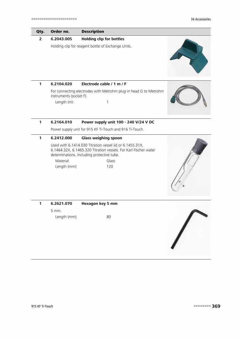
■■■■■■■■■■■■■■■■■■■■■■ 34 Accessories
915 KF Ti-Touch ■■■■■■■■ 369
Qty. Order no. Description
2 6.2043.005 Holding clip for bottles
Holding clip for reagent bottle of Exchange Units.
1 6.2104.020 Electrode cable / 1 m / F
For connecting electrodes with Metrohm plug-in head G to Metrohminstruments (socket F).
Length (m): 1
1 6.2164.010 Power supply unit 100 - 240 V/24 V DC
Power supply unit for 915 KF Ti-Touch and 916 Ti-Touch.
1 6.2412.000 Glass weighing spoon
Used with 6.1414.030 Titration vessel lid or 6.1455.31X,6.1464.32X, 6.1465.320 Titration vessels. For Karl Fischer waterdeterminations. Including protective tube.
Material: Glass
Length (mm): 120
1 6.2621.070 Hexagon key 5 mm
5 mm.
Length (mm): 80

34.1 Scope of delivery ■■■■■■■■■■■■■■■■■■■■■■
370 ■■■■■■■■ 915 KF Ti-Touch
Qty. Order no. Description
2 6.2730.010 Screw nipple
Made of PP. For 6.1448.010 Septum or for mounting 6.1403.040Drying tube or 6.0338.100 Electrode in 6.1414.030 and 6.1414.040KF Titration vessel lids. Used for KF titrations.
Material: PP
Inner diameter (mm): 11.5
Length (mm): 23.5
1 6.2730.020 Septum stopper
With E.301.0041 O-ring. For 6.1448.010 Septum and 6.1414.030Titration vessel lid. Used for KF applications.
Outer diameter (mm): 18
Length (mm): 30
3 6.2730.030 Stopper
Nipple and E.301.0043 O-ring included. For 6.1414.030 Titrationvessel lid. Used with KF Titrators, VA Stands, VA Computrace and ICDilution technique.
Length (mm): 38
1 6.2739.000 Wrench
For tightening connectors.
Length (mm): 68

■■■■■■■■■■■■■■■■■■■■■■ 34 Accessories
915 KF Ti-Touch ■■■■■■■■ 371
Qty. Order no. Description
1 6.2811.000 Molecular sieve
Molecular sieve. Bottle containing 250 g. Pore size: 0.3 nm. Withoutmoisture indicator. For Rancimats and Karl Fischer instruments.
1 6.3032.210 Dosing Unit 10 mL
Dosing unit with integrated data chip with 10 mL glass cylinder andlight protection, mountable on reagent bottle with ISO/DIN GL45thread. FEP tubing connection, anti-diffusion buret tip.
Volume (mL): 10
1 6.6066.000 USB flash drive for Ti-Touch
USB flash drive for 915 KF Ti-Touch and 916 Ti-Touch.
1 A.716.0001 TiBase CD-ROM Rel. 1
1 6.2122.0x0 Mains cable with C13 line socketIEC-60320-C13
Cable plug according to customer requirements.
Switzerland: Type SEV 126.2122.020
Germany, …: Type CEE(7), VII6.2122.040
USA, …: Type NEMA/ASA6.2122.070
1 8.915.8005EN Manual 915 KF Ti-Touch
as PDF file on USB flash drive for Ti-Touch (6.6066.000).
1 8.915.8004EN Manual - Short Instructions 915 KF Ti-Touch
1 8.915.8002EN Tutorial 915 KF Ti-Touch

34.2 Optional accessories ■■■■■■■■■■■■■■■■■■■■■■
372 ■■■■■■■■ 915 KF Ti-Touch
34.2 Optional accessories
2.915.0110
Order no. Description
2.136.0100 Polytron PT 1300 D
Polytron PT 1300 D - Metrohm version Homogenizer with digital display; theinstrument can be directly controlled by tiamo or Touch Control.
2.800.0010 800 Dosino
Drive with write/read hardware for intelligent Dosing Units. With fixed cable(length 150 cm).
2.805.0010 805 Dosimat
Dosing device for the Titrando and Sample Processors with read/write hardwarefor intelligent Exchange Units. With permanently attached cable. WithoutExchange Unit.
6.2047.110 Holder for Polytron
Holder to fix the Polytron at the stand rod.

■■■■■■■■■■■■■■■■■■■■■■ 34 Accessories
915 KF Ti-Touch ■■■■■■■■ 373
Order no. Description
6.3026.110 Exchange Unit 1 mL
Exchange Unit with integrated data chip with 1 mL glass cylinder and light pro-tection. PCTFE/PTFE flat stopcock, FEP tubing connection, antidiffusion buret tipand standard amber glass reagent bottle.
Volume (mL): 1
6.3026.150 Exchange Unit 5 mL
Exchange Unit with integrated data chip with 5 mL glass cylinder and light pro-tection. PCTFE/PTFE flat stopcock, FEP tubing connection, anti-diffusion buret tipand standard amber glass reagent bottle.
Volume (mL): 5
6.3026.210 Exchange Unit 10 mL
Exchange unit with integrated data chip with 10 mL glass cylinder and light pro-tection. PCTFE/PTFE flat stopcock, FEP tubing connection, anti-diffusion buret tipand standard amber glass reagent bottle.
Volume (mL): 10

34.2 Optional accessories ■■■■■■■■■■■■■■■■■■■■■■
374 ■■■■■■■■ 915 KF Ti-Touch
Order no. Description
6.3026.220 Exchange Unit 20 mL
Exchange unit with integrated data chip with 20 mL glass cylinder and light pro-tection. PCTFE/PTFE flat stopcock, FEP tubing connection, anti-diffusion buret tipand standard amber glass reagent bottle.
Volume (mL): 20
6.3026.250 Exchange Unit 50 mL
Exchange unit with integrated data chip with 50 mL glass cylinder and light pro-tection. PCTFE/PTFE flat stopcock, FEP tubing connection, anti-diffusion buret tipand standard amber glass reagent bottle.
Volume (mL): 50
6.3032.120 Dosing Unit 2 mL
Dosing unit with integrated data chip with 2 mL glass cylinder and light protec-tion, mountable on reagent bottle with ISO/DIN GL45 glass thread. FEP tubingconnection, anti-diffusion buret tip.
Volume (mL): 2
6.3032.150 Dosing Unit 5 mL
Dosing unit with integrated data chip with 5 mL glass cylinder and light protec-tion, mountable on reagent bottle with ISO/DIN GL45 thread. FEP tubing con-nection, anti-diffusion buret tip.
Volume (mL): 5
6.3032.220 Dosing Unit 20 mL
Dosing unit with integrated data chip with 20 mL glass cylinder and light protec-tion, mountable on reagent bottle with ISO/DIN GL45 thread. FEP tubing con-nection, anti-diffusion buret tip.
Volume (mL): 20

■■■■■■■■■■■■■■■■■■■■■■ 34 Accessories
915 KF Ti-Touch ■■■■■■■■ 375
Order no. Description
6.3032.250 Dosing Unit 50 mL
Dosing unit with integrated data chip with 50 mL glass cylinder and light protec-tion, mountable on reagent bottle with ISO/DIN GL45 thread. FEP tubing con-nection, anti-diffusion buret tip.
Volume (mL): 50

Index ■■■■■■■■■■■■■■■■■■■■■■
376 ■■■■■■■■ 915 KF Ti-Touch
Index
Numbers/Symbols800 Dosino .............................. 13801 Stirrer ................................ 14803 Ti Stand ............................. 14804 Ti Stand ............................. 14805 Dosimat ............................ 13
AAcoustic signals ........................ 45ADD ....................................... 305Automatic system test ............ 122Automation ............................ 318Axial distance ........................... 88
BBackup ................................... 119
Interval ............................. 132Balance .................... 16, 106, 339Barcode reader
Connect ............................. 17Beaker radius
Sample vessel ..................... 96Special beaker .................... 99
Beaker sensorSample vessel ..................... 96Special beaker .................. 100
BEEP ....................................... 329Break point
Evaluation ........................ 279
CCALC ...................................... 282CALC LIVE .............................. 290Calculation ............................. 282
Add .................................. 283Delete .............................. 283Edit .................................. 283Load template .................. 284Note ................................. 287Result options ................... 288
CellKFT ................................... 267
CommandADD ................................. 305BEEP ................................. 329CALC ................................ 282CALC LIVE ........................ 290CONTROL RS .................... 317CTRL ................................. 315EMPTY ............................. 304
END ................................. 329EVAL BREAK ..................... 279EVAL FIX-EP ...................... 276EVAL MIN/MAX ................ 278EVAL RATE ....................... 281Insert ................................ 158KFT ................................... 258LIFT .................................. 320LQH ................................. 309MEAS ............................... 271MOVE .............................. 318PREP ................................. 303PUMP ............................... 321RACK ............................... 322REPORT ............................ 298REQUEST .......................... 328SAMPLE ............................ 322SCAN ............................... 313SCAN RS ........................... 316STIR .................................. 326SUBSEQ ............................ 323WAIT ................................ 327
Command list ......................... 157Common variable
Delete .............................. 133Edit .................................. 133Properties ......................... 135Validity ............................. 136
Communication ...................... 313Conditioning
KFT ................................... 265Connect
Balance .............................. 16Barcode reader ................... 17Dosing devices ................... 13MSB devices ....................... 12PC keyboard ....................... 17Power supply unit ............... 10Printer ................................ 15Remote Box ........................ 14Sample Processor ............... 18Stirrer or titration stand ...... 14USB devices ........................ 15USB hub ............................. 15
Control ................................... 170Control device .......................... 82
Parameters 267, 273, 306,312
Control parametersKFT ................................... 260
Control Remote Box ................. 76CONTROL RS .......................... 317CTRL ...................................... 315Curve options ......................... 211Curves .................................... 210Custom logo .......................... 152
DDelete
Statistics data ................... 172Determination
Cancel .............................. 191Carry out .......................... 189Data ................................. 198Define filters ..................... 208Endpoint details ................ 201List of saved determinations......................................... 205Load ................................. 204Measuring point list .......... 200Message ........................... 202Properties ......................... 203Recalculate ....................... 212Reevaluate ........................ 212Save ................................. 210Save automatically ............ 167Send PC/LIMS report ......... 167Titrant data ...................... 201
Determination run .................. 189Device
Add .................................... 75Balance ............................ 106Delete ................................ 74Edit .................................... 74New ................................... 74Printer .............................. 101Ti-Touch titrator ................. 82USB Sample Processor ........ 85USB/RS-232 adapter ......... 107
Device manager ....................... 74Diagnosis ............................... 344Dialog language ....................... 31Dialog options .......................... 33Dialog settings
System-specific ................... 33Directory structure .................. 118

■■■■■■■■■■■■■■■■■■■■■■ Index
915 KF Ti-Touch ■■■■■■■■ 377
Dosing ................................... 236Continuous ....................... 238Fixed volume .................... 240
Dosing curve .......................... 210Dosing device
Parameters ....... 269, 306, 312Dosing devices
Connect ............................. 13Dosing parameters
ADD ................................. 305Dosing port .............................. 52Dosing rate
Maximum ................. 337, 338Dosing unit
Data ................................... 51GLP test .............................. 61Preparing parameters ......... 52Replace reagent ................ 245Tubing parameters ............. 53
EE-mail ....................................... 77Electrode .................................. 70
Parameters ............... 268, 273Electrostatic charge .................... 6EMPTY ................................... 304
Default parameters ........... 337Emptying ................................ 244
Default parameters ........... 337END ....................................... 329Endpoint details ...................... 201Ethernet connector ................... 21EVAL BREAK ........................... 279EVAL FIX-EP ............................ 276EVAL MIN/MAX ...................... 278EVAL RATE ............................. 281Evaluation
Break point ....................... 279Fixed endpoint ................. 276Maximum ......................... 278Minimum ......................... 278Rate ................................. 281Set windows .................... 280
Evaluations ............................. 276Exchange unit
Data ................................... 57GLP test .............................. 61Preparing parameters ......... 58Tubing parameters ............. 59
Expiry dateSensor ................................ 72Titrant ................................ 50
External positionSwing angle ....................... 92
FFavorite .................................. 174
Add .................................. 175Delete .............................. 175Edit .................................. 175
FileCopy ................................ 115Properties ......................... 116Rename ............................ 115
File manager .......................... 113Filling ..................................... 244Filling rate
Maximum ................. 337, 338Filter
Determination .................. 208Result table ...................... 222
Fixed endpointEvaluation ........................ 276
Fixed key .................................... 8Format storage medium ......... 346Formula editor ........................ 292
GGLP ........................................ 331GLP manager .......................... 121
GLP test "Measurement" . . 123GLP test "Titration" ........... 123System validation .............. 127Test tool ........................... 122
GLP testDosing unit ......................... 61Exchange unit ..................... 61
Guarantee .............................. 359
IID profile
Create ................................ 40Identification profile
Create ................................ 40Initialization ............................ 330Input line
Template .......................... 147Installation
Set up instrument ............... 10Instrument
Configure ........................... 75Switch off ........................... 25Switch on ........................... 24Ti-Touch ............................. 76
Intervention limitTiter ................................... 65
KKey functions ......................... 109
KeyboardConnect ............................. 17
KFT .............................. 1, 23, 258
LLCD test ................................. 345LIFT ........................................ 320Lift rate .................................. 251Limit values
Sample size ...................... 166Liquid Handling parameters .... 310Live display ............................. 194Live modifications ................... 192Live parameters ...................... 196Live result
Note ................................. 291Load
Determination .................. 204Sample table .................... 184
Load result template ............... 284Login
Options .............................. 41Logout automatically ................ 42LQH ....................................... 309
MMagnetic stirrer
Connect ............................. 14Mains voltage ............................. 5Maintenance Agreement ........ 331Manual control ....................... 232
Continuous dosing ........... 238Dosing ............................. 236Dosing fixed volume ......... 240Emptying .......................... 244Filling ............................... 244Measuring ........................ 234Preparing .......................... 243Remote lines ..................... 247Stirring ............................. 245Troubleshooting ............... 333USB Sample Processor ...... 248
Max. swing angle ..................... 91Maximum evaluation .............. 278Maximum stroke path .............. 88MEAS ..................................... 271Measured value
Display resolution ............... 45Measurement curve ................ 210Measuring .............................. 234Measuring parameters
MEAS ............................... 271Measuring point list ................ 200

Index ■■■■■■■■■■■■■■■■■■■■■■
378 ■■■■■■■■ 915 KF Ti-Touch
MessageDetermination .................. 202Send e-mail ........................ 77
Method .................................. 154Command list ................... 157Create .............................. 154Edit .................................. 157Insert command ............... 158Loading ............................ 156Note ................................. 167Options ............................ 159Properties ......................... 167Sample data ..................... 163Save ................................. 155Save as favorite ................ 174Start options ..................... 160Stop options ..................... 162Troubleshooting ............... 332
Metrohm Serial Bus MSB, see also"MSB" ...................................... 12Min. beaker radius .................... 88Minimum evaluation ............... 278Miscellaneous commands ....... 326Monitoring
Limit values sample size .... 166MOVE .................................... 318MSB
Connect devices ................. 12
NNetwork connection ................. 21Note
Method ............................ 167Numerical input ........................ 28
OOperation
General .............................. 26Output line
Template .......................... 149
PPaper format .......................... 105Parameters
ADD ................................. 305BEEP ................................. 329CALC ................................ 282CALC LIVE ........................ 290CONTROL RS .................... 317CTRL ................................. 315EMPTY ............................. 304END ................................. 329EVAL BREAK ..................... 279EVAL FIX-EP ...................... 276EVAL MIN/MAX ................ 278
EVAL RATE ....................... 281KFT ................................... 258LIFT .................................. 320LQH ................................. 309MEAS ............................... 271Modify live ....................... 196MOVE .............................. 318PREP ................................. 303PUMP ............................... 321RACK ............................... 322REPORT ............................ 298REQUEST .......................... 328SAMPLE ............................ 322SCAN ............................... 313SCAN RS ........................... 316STIR .................................. 326SUBSEQ ............................ 323WAIT ................................ 327
PasswordForgotten ........................... 44Options .............................. 42
PC keyboardConnect ............................. 17
PC/LIMS reportSave ................................... 78Send ................................. 167
PDF settings ........................... 103Peripheral devices ..................... 74Pins ........................................ 340Power supply unit
Connect ............................. 10PREP ....................................... 303
Default parameters ... 337, 338Parameters for the dosing unit........................................... 52Parameters for the exchangeunit .................................... 58
Preparing ................................ 243Default parameters ... 337, 338Parameters for the dosing unit........................................... 52Parameters for the exchangeunit .................................... 58
Printer .............................. 15, 101PDF settings ..................... 103
Printing .................................. 225Troubleshooting ............... 333
Program versionTi-Touch ............................. 76
PropertiesDetermination .................. 203File ................................... 116Method ............................ 167Swing Head ........................ 89
Tower ................................ 87Pump
Troubleshooting ............... 334PUMP ..................................... 321
QQuality Management .............. 331
RRack
Copy .................................. 94Delete ................................ 94Edit .................................... 94Load ................................... 94
RACK ..................................... 322Rack adjustment ..................... 100Rack name ............................... 87Rack offset ............................... 96Rate evaluation ....................... 281Reagent ................................... 66
Add .................................... 66Delete ................................ 66Edit .................................... 66Replace ............................ 245
Reagent exchange .................... 68Reagent monitoring .................. 67Recalculation .......................... 212Reevaluation ........................... 212Remote
Input ................................ 340Interface ........................... 340Output ............................. 341
Remote BoxConnect ............................. 14Pin assignment ................. 340
Remote linesManual control ................. 247
Report .................................... 225Print ................................. 225
REPORT .................................. 298Report header ........................ 152REQUEST ................................ 328Resolution
Measured value display ....... 45Result ..................................... 198
Calculation formula .......... 286Limits ............................... 287Save as a common variable......................................... 137Template .......................... 143
Result table ............................ 219Define filters ..................... 222Delete automatically ......... 223Save ................................. 224

■■■■■■■■■■■■■■■■■■■■■■ Index
915 KF Ti-Touch ■■■■■■■■ 379
Result variable ........................ 287As parameter setting ........ 343
Robotic arm ............................. 91Max. swing angle ............... 91Rotation offset ................... 92Swing direction .................. 92Swing increment ................ 90Swing offset ....................... 91Swing radius ....................... 91Swing rate ........ 253, 255, 320
Rotation increment ................... 88Rotation offset ......................... 92Routine dialog .......................... 35
Standard configuration ....... 35
SSafety instructions ...................... 5SAMPLE .................................. 322Sample assignment table ........ 139Sample data ........................... 178
Modify live ....................... 192Settings ............................ 163
Sample identificationModify designation ........... 163Modify the designation ..... 188
Sample identification list ......... 139Sample Processor
Connect ............................. 18Sample rack .............................. 93Sample series
Perform ............................ 190Sample size
Fixed ................................ 163Limit value ........................ 166Limits ............................... 163Send from a balance ......... 339
Sample table .......................... 181Save as favorite ................ 174Troubleshooting ............... 332
SaveDetermination .................. 210Result table ...................... 224Sample table .................... 183
SCAN ..................................... 313SCAN RS ................................. 316Sensor ...................................... 70
Add .................................... 70Delete ................................ 70Edit .................................... 70Expiry date ......................... 72Parameters ............... 268, 273Working life ....................... 72
Sensor list ................................. 70
Serial numberDosing cylinder ............. 52, 58Dosing unit ......................... 51Exchange unit ..................... 57
Service ............................... 5, 351Set the date .............................. 32Set the time .............................. 32Set up instrument ..................... 10Software update ..................... 348Special beakers
Edit .................................... 98Spooler .................................. 105Start conditions
KFT ................................... 258Start options ........................... 160Statistics ......................... 172, 214
Delete .............................. 172Troubleshooting ............... 332
STIR ........................................ 326Stirrer
Connect ............................. 14Parameters ....... 270, 275, 309
Stirring ................................... 245Stirring rate ............................ 338Stop conditions
KFT ................................... 264Stop criterion
KFT ................................... 262Stop options ........................... 162SUBSEQ .................................. 323Subsequence .......................... 323
Load ................................. 324Note ................................. 326Options ............................ 325Save ................................. 324
Swing direction ........................ 92Swing Head
Properties ........................... 89Swing increment ...................... 90Swing offset ............................. 91Swing radius ............................. 91Swing rate .............. 253, 255, 320Switch off ................................. 25Switch on ................................. 24System initialization ................ 330System settings ......................... 31System test ............................. 122System validation .................... 127
TTandem dosing ...................... 307Template
Input line .......................... 147Output line ....................... 149
Report header .................. 152Result template ................ 143Sample assignment table . . 139Sample identification list ... 139
Templates .............................. 139Text input ................................. 28Ti-Touch ................................... 76Time zone ................................ 32Titer
History ............................... 64Intervention limit ................ 65Properties ........................... 63Warning limit ..................... 65
Titrant ...................................... 46Add .................................... 47Delete ................................ 47Edit .................................... 47Expiry date ......................... 50Working life ....................... 50
Titrant data ............................ 201Titrant list ................................. 46Titration curve ........................ 210Titration mode
KFT ....................................... 1Titration parameters
KFT ................................... 263Titration stand .......................... 14
Connect ............................. 14Troubleshooting ............... 334
Touch screen ............................ 26Test .................................. 347
TowerProperties ........................... 87
Tubing parametersDosing unit ......................... 53Exchange unit ..................... 59
UUninterrupted dosing ............. 307Update ................................... 348USB
Connect devices ................. 15USB hub
Connect ............................. 15USB Sample Processor ............ 248USB/RS-232 adapter ............... 107User profile
Create ................................ 40
VValidation ............................... 331Validation interval ................... 129Validity
Common variable ............. 136

Index ■■■■■■■■■■■■■■■■■■■■■■
380 ■■■■■■■■ 915 KF Ti-Touch
Titer ................................... 63Valve disc
Shift direction ..................... 56
WWAIT ...................................... 327
Warning limitTiter ................................... 65
Warranty ................................ 359Water determination according toKarl Fischer ............................... 23
Working lifeSensor ................................ 72Titrant ................................ 50
Write protectionExternal memory .............. 117