g3x touch - garmin
TRANSCRIPT

G3X Touch ™
Pilot's Guide


SYSTEM OVERVIEW
FLIGHT INSTRUMENTS
EIS
CNS INTERFACE
GPS NAVIGATION
FLIGHT PLANNING
HAZARD AVOIDANCE
ADDITIONAL FEATURES
AFCS
ANNUNCIATIONS & ALERTS
APPENDIX
INDEX


© 2016, 2018-2022 Garmin Ltd. or its subsidiaries. All rights reserved.This manual reflects the operation of System Software version 8.91 or later. Some differences in operation may be observed when comparing the information in this manual to earlier or later soft-ware versions.
Garmin International, Inc., 1200 East 151st Street, Olathe, Kansas 66062, U.S.A. Garmin AT, Inc., 2345 Turner Road SE, Salem, OR 97302, U.S.A.
Garmin (Europe) Ltd, Liberty House, Hounsdown Business Park, Southampton, Hampshire SO40 9LR, U.K.
Garmin Corporation, No. 68, Zhangshu 2nd Road, Xizhi District, New Taipei City, Taiwan
Web Site Address: flygarmin.com
Except as expressly provided herein, no part of this manual may be reproduced, copied, transmitted, disseminated, downloaded or stored in any storage medium, for any purpose without the express written permission of Garmin. Garmin hereby grants permission to download a single copy of this manual and of any revision to this manual onto a hard drive or other electronic storage medium to be viewed for personal use, provided that such electronic or printed copy of this manual or revision must contain the complete text of this copyright notice and provided further that any unauthorized commercial distribution of this manual or any revision hereto is strictly prohibited.
Garmin, FliteCharts, SafeTaxi, and MapSource are registered trademarks of Garmin Ltd. or its sub-sidiaries. ANT+, Smart Glide , and G3X are trademarks of Garmin Ltd. or its subsidiaries. These trademarks may not be used without the express permission of Garmin.Jeppesen is a registered trademark of Jeppesen, Inc.NavData is a trademark of Jeppesen, Inc.SiriusXM Weather is provided by SiriusXM Satellite Radio, Inc.SiriusXM Radio is provided by SiriusXM Satellite Radio, Inc.The Bluetooth word mark and logos are registered trademarks owned by Bluetooth SIG, Inc. and any use of such marks by Garmin is under licenseThis product is ANT+™ certified. Visit www.thisisant.com/directory for a list of compatible products and apps.
June, 2022 190-01754-00 Rev. T Printed in the U.S.A.

Garmin G3X Touch Pilot’s Guide 190-01754-00 Rev. T
Warnings, Cautions & Notes
WARNING: Navigation and terrain separation must NOT be predicated upon the use of the terrain function. The G3X Touch™ Terrain Proximity feature is NOT intended to be used as a primary reference for terrain avoidance and does not relieve the pilot from the responsibility of being aware of surround-ings during flight. The Terrain Proximity feature is only to be used as an aid for terrain avoidance and is not certified for use in applications requiring a certified terrain awareness system. Terrain data is obtained from third party sources. Garmin® is not able to independently verify the accuracy of the terrain data.
WARNING: To reduce the risk of unsafe operation, carefully review and understand all aspects of the G3X Touch Pilot’s Guide documentation and the Pilot’s Operating Handbook of the aircraft. Thoroughly practice basic operation prior to actual use. During flight operations, carefully compare indications from the G3X Touch to all available navigation sources, including the information from other NAVAIDs, visual sightings, charts, etc. For safety purposes, always resolve any discrepancies before continuing navigation.
WARNING: The displayed minimum safe altitudes (MSAs) are only advisory in nature and should not be relied upon as the sole source of obstacle and terrain avoidance information. Always refer to current aeronautical charts for appropriate minimum clearance altitudes.
WARNING: The altitude calculated by G3X Touch internal GPS receivers is geometric height above Mean Sea Level and could vary significantly from the altitude displayed by pressure altimeters. Always use pressure altitude displayed by the G3X Touch PFD when determining or selecting aircraft alti-tude.
WARNING: Do not use outdated database information. Databases used in the G3X Touch system must be updated regularly in order to ensure the informa-tion remains current. Pilots using any outdated database do so entirely at their own risk.
WARNING: Do not use data link weather information for maneuvering in, near, or around areas of hazardous weather. Information contained within data link weather products may not accurately depict current weather condi-tions.

Garmin G3X Touch Pilot’s Guide190-01754-00 Rev. T
Warnings, Cautions & Notes
WARNING: Do not use the indicated data link weather product age to deter-mine the age of the weather information shown by the data link weather product. Due to time delays inherent in gathering and processing weather data for data link transmission, the weather information shown by the data link weather product may be significantly older than the indicated weather product age.
WARNING: The data contained in the terrain and obstacle databases comes from government agencies. Garmin accurately processes and cross-validates the data, but cannot guarantee the accuracy and completeness of the data.
WARNING: The illustrations in this guide are only examples. Never use the G3X Touch to attempt to penetrate a thunderstorm. Both the FAA Advisory Circular, Subject: Thunderstorms, and the Aeronautical Information Manual (AIM) recommend avoiding “by at least 20 miles any thunderstorm identified as severe or giving an intense radar echo.”
WARNING: Because of variation in the earth’s magnetic field, operating the G3X Touch within the following areas could result in loss of reliable heading indications. North of 72° North latitude at all longitudes; South of 70° South latitude at all longitudes; North of 65° North latitude between longitude 75° W and 120° W. (Northern Canada); North of 70° North latitude between longitude 70° W and 128° W. (Northern Canada); North of 70° North latitude between longitude 85° E and 114° E. (Northern Russia); South of 55° South latitude between longitude 120° E and 165° E. (Region south of Australia and New Zealand)
WARNING: The United States government operates the Global Positioning System and is solely responsible for its accuracy and maintenance. The GPS system is subject to changes which could affect the accuracy and performance of all GPS equipment. Portions of the Garmin G3X Touch utilize GPS as a precision electronic NAVigation AID (NAVAID). Therefore, as with all NAVAIDs, information presented by the G3X Touch can be misused or misinterpreted and, therefore, become unsafe.

Garmin G3X Touch Pilot’s Guide 190-01754-00 Rev. T
Warnings, Cautions & Notes
WARNING: Do not use basemap (land and water data) information for primary navigation. Basemap data is intended only to supplement other approved navigation data sources and should be considered as an aid to enhance situational awareness.
WARNING: Do not use the approach information provided by the VFR navi-gation database residing within the G3X Touch as a means of navigating any instrument approach. The G3X Touch VFR navigation database is limited to present only the waypoints for the final approach leg of a published procedure. These waypoints and associated course line are made available for monitoring purposes only.
WARNING: Do not rely solely upon the display of traffic information for col-lision avoidance maneuvering. The traffic display does not provide collision avoidance resolution advisories and does not under any circumstances or conditions relieve the pilot’s responsibility to see and avoid other aircraft.
WARNING: Do not rely solely upon the display of traffic information to accurately depict all of the traffic within range of the aircraft. Due to lack of equipment, poor signal reception, and/or inaccurate information from aircraft or ground stations, traffic may be present that is not represented on the display.
WARNING: Do not rely solely upon the fuel quantity indications or calculated fuel quantity. It is the responsibility of the pilot to perform proper flight plan-ning and verify that indicated fuel quantity values are accurate prior to each flight.
WARNING: For safety reasons, G3X Touch operational procedures must be learned on the ground.
CAUTION: The display uses a lens with a special coating that may be sensitive to abrasive cleaners, etc. CLEANERS CONTAINING AMMONIA OR SOLVENTS MAY HARM THIS COATING. It is very important to clean the lens using a clean, lint-free cloth (such as the Garmin cleaning cloth). Avoid any chemical cleaners or solvents that can damage plastic components.

Garmin G3X Touch Pilot’s Guide190-01754-00 Rev. T
Warnings, Cautions & Notes
CAUTION: The Garmin G3X Touch does not contain any user-serviceable parts. Repairs should only be made by an authorized Garmin service center. Unauthorized repairs or modifications could void both the warranty and the pilot’s authority to operate this device under FAA/FCC regulations.
NOTE: The Garmin G3X Touch has a very high degree of functional integrity. However, the pilot must recognize that providing monitoring and/or self-test capability for all conceivable system failures is not practical. Although unlikely, it may be possible for erroneous operation to occur without a fault indication shown by the G3X Touch. It is thus the responsibility of the pilot to detect such an occurrence by means of cross-checking with all redundant or correlated information available in the cockpit.
NOTE: All visual depictions contained within this document, including screen images of the G3X Touch panel and displays, are subject to change and may not reflect the most current G3X Touch system and aviation databases. Depic-tions of equipment may differ slightly from the actual equipment.
NOTE: This product, its packaging, and its components contain chemicals known to the State of California to cause cancer, birth defects, or reproductive harm. This notice is being provided in accordance with California’s Proposition 65. If you have any questions or would like additional information, please refer to our web site at flygarmin.com/prop65.
NOTE: Interference from GPS repeaters operating inside nearby hangars can cause an intermittent loss of attitude and heading displays while the aircraft is on the ground. Moving the aircraft more than 100 yards away from the source of the interference should alleviate the condition.
NOTE: Use of polarized eyewear may cause the flight displays to appear dim or blank.
NOTE: Temporary Flight Restriction (TFR) data is provided by the FAA and may not be updated outside of normal business hours. Confirm data currency through alternate sources and contact your local FSS for interpretation of TFR data.

Garmin G3X Touch Pilot’s Guide 190-01754-00 Rev. T
Warnings, Cautions & Notes
NOTE: The Garmin G3X Touch system includes products like the GDU 45X, GDU 46X, GDU 470, and the GSU 73 that are not TSO-certified products and have not received FAA approval or endorsement. Consequently, the G3X Touch system is not suitable for installation in type-certificated aircraft.
NOTE: Unless otherwise specified, all screen images contained within this document are taken from the GDU 46X display. The GDU 45X and GDU 470 screen images will vary slightly from the GDU 46X.
NOTE: The GDU 4XX automatically logs flight data including, but not limited to, primary flight data, engine parameters, and system status information. This data can be downloaded to an SD card, when the aircraft is on the ground. The downloaded data can be viewed using common computer software. It is not possible to disable the logging of this data or to manually delete logged data. Logged data will be stored only on the GDU 4XX and will not be transmitted or transferred to Garmin or to any other third party, with the exception of government agencies investigating an accident or incident involving your aircraft and/or the parties to any resulting legal proceedings that may be related to the aircraft accident or incident.
NOTE: The Bluetooth® word mark and logos are registered trademarks owned by Bluetooth SIG, Inc. and any use of such marks by Garmin is under license.

Garmin G3X Touch Pilot’s Guide190-01754-00 Rev. T
1. FCCContains FCC ID: QOQWT32INOTEThe GMA 245 and GMA 245R complies with Part 15 of the FCC Rules. Operation is subject
to the following two conditions: (1) this device may not cause harmful interference, and (2) this device must accept any interference received, including interference that may cause undesired operation.
2. ICContains IC: 5123A-BGTWT32INOTEThis device complies with Industry Canada license-exempt RSS standard(s). Operation is
subject to the following two conditions: (1) this device may not cause interference, and (2) this device must accept any interference, including interference that may cause undesired operation of the device.
Cet appareil est conforme aux normes RSS sans licence d’Industrie Canada. Son fonctionnement est soumis aux conditions suivantes : (1) cet appareil ne doit pas causer d’interférences et (2) doit accepter toute interférence,y compris les interférences pouvant entraîner un fonctionnement indésirable de l’appareil.
RF Radiation Exposure Statement:This equipment complies with FCC radiation exposure limits set forth for an uncontrolled
environment. End users must follow the specific operating instructions for satisfying RF exposure compliance. This transmitter meets both portable and mobile limits as demonstrated in the RF Exposure Analysis. This transmitter must not be co-located or operating in conjunction with any other antenna or transmitter except in accordance with FCC multi-transmitter product procedures.
Énoncé sur l'exposition aux rayonnements RFCet appareil est conforme à la réglementation FCC relative aux limites d'exposition aux
radiations applicables en environnement non contrôlé. L’utilisateur doit suivre les directives d’opération spécifique à la conformité sur l’évitement de l’exposition aux rayonnements RF. Cet émetteur répond aux limites d’émission pour les appareils portables et mobiles, comme démontré dans l’analyse d’exposition RF. Cet émetteur ne doit pas être placé ou utilisé en conjonction avec d'autres antennes ou émetteurs, sauf en conformité aux procédures de produits multiémetteurs de la FCC.
Anatel Warning (GMA 245/245R)Este equipamento não tem direito ã proteção contra interferência prejudicial e não pode
causar interferência em sistemas devidamente autorizados.

Garmin G3X Touch Pilot’s Guide 190-01754-00 Rev. T
Blank Page

Garmin G3X Touch Pilot’s Guide190-01754-00 Rev. T
Part Number Change Summary190-001754-00 Initial release
Rev Date DescriptionA March, 2014 Production Release
B December, 2014
Added GDU 45X, VIRB Video Input, Ant+, Connext.
C December, 2014
Fixed tabs.
D March, 2015 Added Electronic Stability Protection, Connext updates, Bluetooth Limitations, Carbon Monoxide Detector, Pulse Oximeter, Glide Range Ring, Best Airport Bearing Pointer.
E May, 2015 Added Flight Director Configuration.
F April, 2016 Added GMA 245/245R info, miscellaneous updates.
G September, 2016
Added G5 AHRS redundancy Added new Data Bar fields Create Waypoints from current position using Info page Added on-screen volume controls for COM radios, intercom, Bluetooth audio, and music input Round Gauges available for PFD instruments Bluetooth on GMA 245R rackmount radios can be disabled remotely Added Best Airport Line Added Target Trend on Moving Map Revised description of ESP arming altitudes and use of AFCS Level mode
H December, 2016
Added enhanced engine monitoring capabilitiesAdded airspace altitude overlaysUpdated Appendix A. Changed DST data field to DISTUpdated Appendix A. Added DISTD data field.
J March, 2017 Added GDU 470 functionality, miscellaneous updates.

Garmin G3X Touch Pilot’s Guide 190-01754-00 Rev. T
Rev Date DescriptionK May, 2018 Added Anatel Statement
Added GMC 507 autopilot mode controller supportAdded QWERTY keyboard optionAdded Standard Rate Turn Bank Angle PointersAdded GDL 51/51R and GDL 52/52R supportAdded display of AFCS preflight test (PFT) status
L March, 2019 Updated CAS messagesUpdated Lightning Detector informationUpdated TRK mode informationClarified Connext informationClarified LVL mode informationVNAV configuration updatesVNAV deviation indicator updatedVFR annunciation for HSIAdded note regarding disengagement of autopilot when MET switch is usedAdded note regarding IAS mode engagement while on groundAdded note regarding TAWS suppressed warnings at marked user waypointsVRP symbology updatedAdded flight plan transfer to GNS/GTNAdded FIS-B Cloud Tops Forecast, Icing Forecast, Lightning, and TurbulenceUpdated colors for Icing ForecastUpdated 'Satellite Mosaic' text to 'Cloud Tops'Updated 'Severe' icing level text to 'Heavy'Miscellaneous updates for software v. 8.20

Garmin G3X Touch Pilot’s Guide190-01754-00 Rev. T
Rev Date DescriptionM August,
2019Updated for software version 8.30 and 8.40Added remote NAV tuningAdded standalone MFD and EIS supportAdded Connext Flight Data LoggingUpdated 'CO LEVEL' CAS message to CautionAdded 'CO FAIL' CAS messageAdded access to the autopilot interface from the Main MenuAdded Main Menu LRU controls (COM, Audio Panel, and XPDR) Updated terrain options menuAdded flight plan information to the Map/Charts pagesAdded user configurable Checklists (Chk) Main Page
N March, 2020 Updated for software version 8.50 and 8.60Added Automatic Sharing of G3X Touch Flight Plans with External IFR NavigatorsAdded importing/exporting user waypointsUpdated NAV find procedureUpdates to support GTX integration with TAS/TCASAdded note about Glide Range Ring requiring OATUpdated PFD wind speed/direction to a toggle button also displaying headwind/crosswind componentsAdded Weight & Balance envelope as Moment vs Weight
P November, 2020
Updated ILS Auto Switching procedure to specify type of equipment neededAdded Center Weather Advisory FIS-B weather productAdded Graphical AIRMET FIS-B weather product
Q November, 2020
Updated Transponder Mode SelectionUpdated color active COM frequencies are displayed in when no audio panel is configured
R May, 2021 Added Fuel Flow CalibrationUpdated Flight Director Lateral Modes tableUpdated baro sync procedureAdded NOTE regarding formatting an SD Card using Mac OSAdded/updated information regarding miscompares

Garmin G3X Touch Pilot’s Guide 190-01754-00 Rev. T
Rev Date DescriptionS September,
2021Added Smart GlideTM
Added Emergency PageAdded ability to view TOD/BOD from G3X TouchAdded ability to arm the approach at any timeUpdated AOA aural alert operationAdded 'Time Over Target' and 'Vertical Speed' data field optionsUpdated information regarding miscompares
T June, 2022 Updated the ability to view TOD/BOD from G3X Touch is only available when configured with a GTN XiAdded Engine SetupUpdated Fuel Tank Reminder AlarmAdded Density AltitudeUpdated Vertical Speed definitionAdded Trim/Flap Position to PFD OptionsAdded Note to Fuel Flow CalibrationAdded LP+V to the HSI Annunciations diagram

Garmin G3X Touch Pilot’s Guide190-01754-00 Rev. T i
Table of Contents
Section 1 System Overview .................................................................................................. 11.1 Line Replaceable Units ..................................................................................................... 1
G3X Touch System.............................................................................................................. 14External Navigators (Optional) ........................................................................................... 15ADS-B Devices (Optional) ................................................................................................... 17Automatic Flight Control System (Optional) ......................................................................... 17
1.2 Display Overview ............................................................................................................ 181.3 Secure Digital (SD) Cards............................................................................................... 201.4 System Initialization ....................................................................................................... 201.5 System Operation ........................................................................................................... 21
Split Mode ......................................................................................................................... 21PFD/MFD Display Configuration .......................................................................................... 23G3X Touch System Annunciations ....................................................................................... 28AHRS Operation ................................................................................................................. 28
1.6 Accessing System Functionality ................................................................................... 30Menus ............................................................................................................................... 30Data Entry .......................................................................................................................... 31Pages ................................................................................................................................. 32
1.7 Accessing Additional Information ............................................................................... 35Viewing GPS Receiver Status .............................................................................................. 35
1.8 System Settings ................................................................................................................ 38Transponder ....................................................................................................................... 39Data Bar Setup ................................................................................................................... 40General Display information ............................................................................................... 42Display setup ..................................................................................................................... 44Sound Setup ...................................................................................................................... 47Units Setup ........................................................................................................................ 48Time Setup ......................................................................................................................... 49Map Setup ......................................................................................................................... 49Position Setup .................................................................................................................... 49Alarms Setup ..................................................................................................................... 50Airspace Setup ................................................................................................................... 51Bluetooth Setup ................................................................................................................. 51PFD Setup .......................................................................................................................... 51Navigation Setup ............................................................................................................... 52Keyboard Setup .................................................................................................................. 52ENGINE Setup .................................................................................................................... 52
Section 2 Flight Instruments .............................................................................................. 552.1 Flight Instruments ........................................................................................................... 55
Airspeed Indicator .............................................................................................................. 58Attitude Indicator ............................................................................................................... 60Altimeter ............................................................................................................................ 62

Garmin G3X Touch Pilot’s Guide 190-01754-00 Rev. Tii
Table of Contents
Vertical Speed Indicator (VSI) .............................................................................................. 68Vertical Deviation Indicator and VNAV Indicator .................................................................. 68Horizontal Situation Indicator (HSI) ..................................................................................... 71Trim and Flap Position Indicators (Optional) ........................................................................ 83Turn Rate Indicator ............................................................................................................. 84OBS Mode ......................................................................................................................... 85
2.2 Supplemental Flight Data ............................................................................................. 86Outside Air Temperature ..................................................................................................... 86Wind Data ......................................................................................................................... 87User Timer .......................................................................................................................... 88Angle of Attack (AOA) ........................................................................................................ 89
2.3 Vertical Navigation (VNAV) ............................................................................................ 91Using the VNAV Feature ..................................................................................................... 92VNAV Paired With GTN....................................................................................................... 94
Section 3 EIS.................................................................................................................................. 973.1 EIS Display & ENG Page ................................................................................................. 973.2 Multi-Engine Indications (Optional) .......................................................................... 100
Propeller Sync Indicator .................................................................................................... 1003.3 Lean Assist Mode (Optional) ....................................................................................... 1013.4 Fuel Calculator (Optional) ........................................................................................... 1053.5 Fuel Flow Calibration (Optional)................................................................................ 1063.6 CAS Messages (Optional) ............................................................................................ 107
Section 4 CNS Interface (Optional) ................................................................................ 1094.1 CNS Data Bar .................................................................................................................. 1094.2 COM Annunciations....................................................................................................... 1104.3 COM Window .................................................................................................................. 110
COM Radio Volume Shortcut (GDU 45X or GDU 46X only) ................................................ 112COM Frequency Finding ................................................................................................... 112Automatic Squelch ........................................................................................................... 113
4.4 COM Error Messages .................................................................................................... 1134.5 NAV Annunciations........................................................................................................ 1154.6 NAV Window ................................................................................................................... 115
NAV Frequency Finding .................................................................................................... 1164.7 NAV Error Messages ..................................................................................................... 1174.8 Auto-Tuning Frequencies ............................................................................................. 1184.9 User Frequencies ........................................................................................................... 1204.10 Audio Panel .................................................................................................................. 121
Audio/Intercom Page ........................................................................................................ 122Radios Tab ....................................................................................................................... 123Intercom Tab .................................................................................................................... 128

Garmin G3X Touch Pilot’s Guide190-01754-00 Rev. T iii
Table of Contents
Phone and Media Tab ....................................................................................................... 1304.11 Remote Transponder Interface (Optional) ............................................................ 141
Transponder CODE and Mode Selection ............................................................................ 142ADS-B Out ....................................................................................................................... 145Flight ID Reporting ........................................................................................................... 145Additional Transponder Messages ..................................................................................... 145
Section 5 GPS Navigation .................................................................................................. 1475.1 Introduction .................................................................................................................... 147
Compass Arc .................................................................................................................... 1475.2 Using Map Displays ....................................................................................................... 148
Map Page Setup ............................................................................................................... 149Map Range ...................................................................................................................... 153Map Panning ................................................................................................................... 154Fuel Range Ring ............................................................................................................... 156Glide Range Ring ............................................................................................................. 157Best Airport Bearing Pointer .............................................................................................. 159Best Airport Line............................................................................................................... 160Selected Altitude Intercept Arc .......................................................................................... 161Measuring Bearing and Distance ...................................................................................... 161Topography ...................................................................................................................... 162Map Page Traffic ............................................................................................................... 162Map Symbols ................................................................................................................... 163
5.3 Airways ............................................................................................................................ 1655.4 Waypoints ....................................................................................................................... 166
Automatic Waypoint Selection .......................................................................................... 169Nearest Information ......................................................................................................... 170Weather Information ........................................................................................................ 171Intersections .................................................................................................................... 172NDBs ............................................................................................................................... 172VORs ............................................................................................................................... 173User Waypoints ................................................................................................................ 173
5.5 Airspace ........................................................................................................................... 176Airspace Alert Messages ................................................................................................... 176Smart Airspace™ and Altitude Overlays .............................................................................. 177
5.6 Direct-to Navigation Using the G3X Touch .............................................................. 179
Section 6 Flight Planning ..................................................................................................... 1816.1 Introduction .................................................................................................................... 181
Flight Plan Data Fields ...................................................................................................... 182Manually Switching Between Internal and External Flight Plan Sources .............................. 182Failure of the External GPS Navigation Source ................................................................... 182

Garmin G3X Touch Pilot’s Guide 190-01754-00 Rev. Tiv
Table of Contents
6.2 Flight Plan Creation Using the G3X Touch ............................................................... 1836.3 Automatic Sharing of G3X Touch Flight Plans with External IFR Navigators .. 186
External IFR Navigator Crossfill Configuration (GPS 175, GNC 355, GNX 375, and GTN 6XX/7XX (version 6.62 and newer only)) .......................................................................... 187
6.4 Flight Plan Storage Using the G3X Touch ................................................................ 1886.5 Flight Plan Activation Using the G3X Touch ............................................................ 1886.6 Flight Plan Editing ......................................................................................................... 190
Adding Waypoints to an Existing Flight Plan ...................................................................... 190Editing Flight Plan Speed, Fuel, and/or Name .................................................................... 192Copying Flight Plans ......................................................................................................... 193Deleting Flight Plans ........................................................................................................ 194Inverting a Flight Plan ...................................................................................................... 195Importing/Exporting Flight Plans ....................................................................................... 196Sending Flight Plans to a GNS/GTN .................................................................................. 196
6.7 Approaches (Without External Navigator Configured) ........................................ 197Selecting an Approach ...................................................................................................... 198Activating Vectors-to-Final ................................................................................................ 200
Section 7 Hazard Avoidance............................................................................................... 2037.1 Weather Information .................................................................................................... 203
Weather Sources .............................................................................................................. 203Data Link Weather (Optional) ........................................................................................... 204
7.2 Terrain .............................................................................................................................. 229Synthetic Vision ................................................................................................................ 230Terrain Information ........................................................................................................... 230Terrain Views .................................................................................................................... 231Obstacle Information ........................................................................................................ 232Terrain Settings ................................................................................................................ 233Terrain Alerts .................................................................................................................... 234
7.3 Traffic Systems ............................................................................................................... 236Traffic Source ................................................................................................................... 236Traffic Prioritization .......................................................................................................... 237Traffic Information Service (TIS-A) (Optional) ..................................................................... 238Garmin GTS 8XX Traffic (Optional) .................................................................................... 243Data Link Traffic (Optional) ............................................................................................... 250
Section 8 Additional Features ........................................................................................... 2638.1 Synthetic Vision (SVX) .................................................................................................. 264
Synthetic Vision Operation ................................................................................................ 2658.2 SafeTaxi .......................................................................................................................... 275
SafeTaxi Cycle Number and Revision ................................................................................. 2768.3 ChartView ....................................................................................................................... 276
Aircraft Symbol................................................................................................................. 278Chart Range ..................................................................................................................... 278

Garmin G3X Touch Pilot’s Guide190-01754-00 Rev. T v
Table of Contents
Navigation Database-published NOTAMs .......................................................................... 2798.4 FliteCharts® .................................................................................................................... 280
Aircraft Symbol................................................................................................................. 283Chart Range ..................................................................................................................... 283FliteCharts Cycle Number and Expiration Date .................................................................. 283
8.5 Airport Directory Data ................................................................................................. 2838.6 SiriusXM Radio Entertainment (Optional) ................................................................ 285
Activating SiriusXM Satellite Radio Services ...................................................................... 285Using SiriusXM Radio ........................................................................................................ 285
8.7 Vertical Power (Optional) ............................................................................................ 2878.8 Electronic Checklists (Optional) ................................................................................. 2898.9 Flight Data Logging Using the SD Card .................................................................... 2908.10 VIRB Video Input.......................................................................................................... 2918.11 Connext Cockpit Connectivity .................................................................................. 297
Pairing the G3X Touch with a Bluetooth Device ................................................................. 298Transferring a Flight Plan .................................................................................................. 300Flight Data Logging in Garmin Pilot .................................................................................. 301
8.12 Electronic Stability & Protection (ESP-X) .................................................................. 306Roll Engagement .............................................................................................................. 308Pitch Engagement ............................................................................................................ 310Airspeed Protection .......................................................................................................... 311
8.13 Carbon Monoxide (CO) Detector (Optional) ......................................................... 3128.14 Pulse Oximeter (Optional) ........................................................................................ 313
Section 9 Automatic Flight Control System (Optional) ...................................... 3159.1 AFCS System Architecture ........................................................................................... 315
AFCS and Yaw Damper Operation ..................................................................................... 316Flight Control ................................................................................................................... 316Pitch Axis and Trim ........................................................................................................... 316Roll Axis ........................................................................................................................... 316Yaw Axis .......................................................................................................................... 316G3X Touch AFCS Installations Options .............................................................................. 317Control Wheel Steering (CWS) (Optional) .......................................................................... 317G3X Touch AFCS Status Box ............................................................................................. 318
9.2 AFCS Operation .............................................................................................................. 319AFCS PRE-FLIGHT Actions ................................................................................................. 320AFCS Controls .................................................................................................................. 321Flight Director Operation .................................................................................................. 327
9.3 Vertical Modes ................................................................................................................ 334Pitch Hold Mode (PIT)....................................................................................................... 336Selected Altitude Capture Mode (ALTS) ............................................................................. 337Altitude Hold Mode (ALT) ................................................................................................. 339Vertical Speed Mode (VS) ................................................................................................. 340

Garmin G3X Touch Pilot’s Guide 190-01754-00 Rev. Tvi
Table of Contents
Indicated Airspeed Mode (IAS) .......................................................................................... 341Vertical Navigation Mode (VNAV) ..................................................................................... 342VNAV Target Altitude Capture Mode (ALTV) ...................................................................... 343Glidepath Mode (GP) (with external WAAS enabled IFR navigator ONLY) ........................... 344Glideslope Mode (GS)....................................................................................................... 346Go Around (GA) and Takeoff (TO) Modes .......................................................................... 347
9.4 Lateral Modes ................................................................................................................. 347Roll Hold Mode (ROL) ....................................................................................................... 349Heading Select Mode (HDG) ............................................................................................. 349Track Select Mode (TRK) ................................................................................................... 350Navigation Modes (GPS, VOR, LOC, BC) ............................................................................ 351Approaches without Vertical Guidance .............................................................................. 355Approaches with Lateral + Vertical Guidance .................................................................... 359
9.5 Non-Garmin Autopilots ................................................................................................ 362GPS Steering (GPSS) ......................................................................................................... 363
Section 10 Annunciations & Alerts ................................................................................. 36510.1 Miscellaneous Message Advisories ......................................................................... 36510.2 Airspace Messages ...................................................................................................... 36610.3 System Status Messages ........................................................................................... 367
System Status Messages ................................................................................................... 36810.4 Audio Alerts .................................................................................................................. 372
Voice Alerts ...................................................................................................................... 372AOA Aural Alert ................................................................................................................ 372
10.5 PFD Annunciations and Alerting Functions ........................................................... 373Marker Beacon Annunciation ............................................................................................ 373CAS Messages (Optional) ................................................................................................. 374Terrain Annunciations ....................................................................................................... 375Traffic Annunciations ........................................................................................................ 375AHRS Alerts (Optional) ..................................................................................................... 375AFCS Alerts (Optional) ...................................................................................................... 376
Section 11 Appendices ......................................................................................................... 381Appendix A: Data Field Options ....................................................................................... 381
Data Bar Field Options ..................................................................................................... 381INFO Page data Field Options ........................................................................................... 384
Appendix B: Utilities ........................................................................................................... 389Flight Log ......................................................................................................................... 389Track log .......................................................................................................................... 391

Garmin G3X Touch Pilot’s Guide190-01754-00 Rev. T vii
Table of Contents
Track Vector ..................................................................................................................... 395Weight and Balance ......................................................................................................... 397Proximity Waypoints and Alarms ....................................................................................... 401
Appendix C: SD Card Use and Database ......................................................................... 405Installing and Removing SD Cards .................................................................................... 405G3X Touch Databases ...................................................................................................... 406Updating G3X Touch Databases ....................................................................................... 409Importing/Exporting Flight Plans To/From the SD Card ....................................................... 412Flight Data Logging .......................................................................................................... 412
Appendix D: Map Datum and Location Formats ........................................................... 413Map Datums .................................................................................................................... 413Location Formats .............................................................................................................. 413
Appendix E: General TIS-A Information ......................................................................... 415TIS-A vs. TAS/TCAS ........................................................................................................... 416TIS-A Limitations .............................................................................................................. 416
Appendix F: Abnormal Operation .................................................................................... 419Loss of GPS Position ......................................................................................................... 419Hazard Display with Loss of GPS Position .......................................................................... 419G3X Touch System Failure Annunciations .......................................................................... 420Unusual Attitudes ............................................................................................................. 420Reversionary Mode (Full-Screen) ....................................................................................... 421AFCS Reversionary Mode .................................................................................................. 422Failure of the External GPS Navigation Source ................................................................... 422Synthetic Vision Troubleshooting ....................................................................................... 422Emergency Page ............................................................................................................... 423Smart Glide Emergency Operations .................................................................................. 424
Appendix G: Display Symbols ........................................................................................... 433VFR Symbols .................................................................................................................... 433IFR Symbols ..................................................................................................................... 434Airspace Symbols ............................................................................................................. 436
Appendix H: Glossary .......................................................................................................... 438Appendix I: License Agreemet and Warranty ................................................................. 445
Contact Garmin® .............................................................................................................. 445Software License Agreement ............................................................................................. 445Limited Warranty for G3X Touch Products ......................................................................... 445AOPA Airport Directory Notice .......................................................................................... 446AC-U-KWIK LICENSE AGREEMENT .................................................................................... 446SiriusXM Satellite Radio Service Agreement ....................................................................... 447Weather Data Warranty .................................................................................................... 447
Index ................................................................................................................................... Index-1

Garmin G3X Touch Pilot’s Guide 190-01754-00 Rev. Tviii
Table of Contents
Blank Page

Garmin G3X Touch Pilot’s Guide190-01754-00 Rev. T 1
System Overview
System
Overview
Flight Instrum
entsEIS
CNS
InterfaceG
PS N
avigationFlight
PlanningH
azard Avoidance
AdditionalFeatures
AFCS
Annun/A
lertsA
ppendixIndex
SECTION 1 SYSTEM OVERVIEW
1.1 LINE REPLACEABLE UNITS
The G3X Touch™ system may consist of the following Line Replaceable Units (LRUs):
• Garmin® Display Unit (GDU) 460 or 465 (with SiriusXM) – Single Display: Split Primary Flight Display (PFD) & Multi Function Display (MFD),
standalone Multi Function Display (MFD) – Multiple Displays: PFD, MFD, or split-screen – Landscape orientation
GDU 46X (10.6 inch)(Landscape Orientation)

Garmin G3X Touch Pilot’s Guide 190-01754-00 Rev. T2
System Overview
Syst
em
Ove
rvie
wFl
ight
In
stru
men
tsEI
SCN
SIn
terf
ace
GPS
N
avig
atio
nFl
ight
Plan
ning
Haz
ard
Avoi
danc
eA
dditi
onal
Fe
atur
esA
FCS
Ann
un/A
lert
sA
ppen
dix
Inde
x
• GDU 450 or 455 (with SiriusXM) – Single Display: Split Primary Flight Display (PFD) & Multi Function Display (MFD),
standalone Multi Function Display (MFD) – Multiple Displays: MFD, PFD, or split-screen – Landscape Orientation
GDU 45X (7 inch) (Landscape Orientation)
• GDU 470 – Single Display: Split Primary Flight Display (PFD) & Multi Function Display (MFD),
standalone Multi Function Display (MFD) – Multiple Displays: MFD, PFD, or split-screen – Portrait Orientation
GDU 470 (7 inch) (Portrait Orientation)

Garmin G3X Touch Pilot’s Guide190-01754-00 Rev. T 3
System Overview
System
Overview
Flight Instrum
entsEIS
CNS
InterfaceG
PS N
avigationFlight
PlanningH
azard Avoidance
AdditionalFeatures
AFCS
Annun/A
lertsA
ppendixIndex
• GSU 25 – Garmin Sensor Unit sub-system for the G3X Touch (Air Data Computer (ADC), and
the Attitude and Heading Reference System (AHRS)) – ADC: Processes data from the pitot-static system and outside air tem-
perature (OAT) sensor. – AHRS: Provides aircraft attitude and heading information to the PFD.
The AHRS contains advanced sensors (including accelerometers and rate sensors) and interfaces with the magnetometer to obtain magnetic field information, with the ADC to obtain air data, and with the GDU to obtain GPS information. AHRS operation is discussed later in this section.
GSU 25D
• GMU 44/GMU 22 and GMU 11 – Magnetometer: Measures the local magnetic field and sends data to the AHRS for
processing to determine aircraft magnetic heading.
GMU 44/GMU 22 GMU 11

Garmin G3X Touch Pilot’s Guide 190-01754-00 Rev. T4
System Overview
Syst
em
Ove
rvie
wFl
ight
In
stru
men
tsEI
SCN
SIn
terf
ace
GPS
N
avig
atio
nFl
ight
Plan
ning
Haz
ard
Avoi
danc
eA
dditi
onal
Fe
atur
esA
FCS
Ann
un/A
lert
sA
ppen
dix
Inde
x
• GTP 59 – Temperature Probe: Provides raw air temperature data.
GTP 59
• GAP 26 – Pitot/AOA Probe: Sends dynamic air pressure for airspeed and angle of attack
(AOA), when paired with a GSU 25.
GAP 26
• GSA 28 – Auto Pilot Servo: Used for automatic control of pitch, roll, yaw, and trim.
GSA 28

Garmin G3X Touch Pilot’s Guide190-01754-00 Rev. T 5
System Overview
System
Overview
Flight Instrum
entsEIS
CNS
InterfaceG
PS N
avigationFlight
PlanningH
azard Avoidance
AdditionalFeatures
AFCS
Annun/A
lertsA
ppendixIndex
• GEA 24 – Engine and Airframe Unit: Receives and processes signals from the engine and
airframe sensors.
GEA 24
• GAD 27 – Provides a power source to keep essential avionics online during engine start (14V
airframes only).
GAD 27

Garmin G3X Touch Pilot’s Guide 190-01754-00 Rev. T6
System Overview
Syst
em
Ove
rvie
wFl
ight
In
stru
men
tsEI
SCN
SIn
terf
ace
GPS
N
avig
atio
nFl
ight
Plan
ning
Haz
ard
Avoi
danc
eA
dditi
onal
Fe
atur
esA
FCS
Ann
un/A
lert
sA
ppen
dix
Inde
x
• GAD 29/29B – ARINC 429 interface: Transmits and receives ARINC 429 signals for interface to
panel-mount IFR GPS navigators.
GAD 29B
• GSU 73 – Garmin Sensor Unit sub-system for the G3X Touch (Air Data Computer (ADC),
Engine/Airframe Unit, and the Attitude and Heading Reference System (AHRS)) – ADC: Processes data from the pitot-static system and outside air tem-
perature (OAT) sensor. – Engine/Airframe Unit: Receives and processes signals from the engine
and airframe sensors. – AHRS: Provides aircraft attitude and heading information to the PFD.
The AHRS contains advanced sensors (including accelerometers and rate sensors) and interfaces with the magnetometer to obtain magnetic field information, with the ADC to obtain air data, and with the GDU to obtain GPS information. AHRS operation is discussed later in this section.
– ARINC 429 interface: Transmits and receives ARINC 429 signals for inter-face to panel-mount IFR GPS navigators.

Garmin G3X Touch Pilot’s Guide190-01754-00 Rev. T 7
System Overview
System
Overview
Flight Instrum
entsEIS
CNS
InterfaceG
PS N
avigationFlight
PlanningH
azard Avoidance
AdditionalFeatures
AFCS
Annun/A
lertsA
ppendixIndex
GSU 73
• GI 260 (AOA Indicator) – Remote mount Angle of Attack (AOA) indicator.
GI 260

Garmin G3X Touch Pilot’s Guide 190-01754-00 Rev. T8
System Overview
Syst
em
Ove
rvie
wFl
ight
In
stru
men
tsEI
SCN
SIn
terf
ace
GPS
N
avig
atio
nFl
ight
Plan
ning
Haz
ard
Avoi
danc
eA
dditi
onal
Fe
atur
esA
FCS
Ann
un/A
lert
sA
ppen
dix
Inde
x
• GMC 305/GMC 307 (AFCS Mode Controllers) – Automatic Flight Control System (AFCS) Mode Controller. The GMC 305/GMC 307
provides an additional user interface for the autopilot and flight director functions of the G3X system. The GMC 307 is available with or without the Yaw Damper 'YD' feature.
GMC 305
GMC 307
• GMC 507 (AFCS Mode Controller) – Automatic Flight Control System (AFCS) Mode Controller. The GMC 507 provides a
user interface for the autopilot and flight director function of the G3X system.
GMC 507

Garmin G3X Touch Pilot’s Guide190-01754-00 Rev. T 9
System Overview
System
Overview
Flight Instrum
entsEIS
CNS
InterfaceG
PS N
avigationFlight
PlanningH
azard Avoidance
AdditionalFeatures
AFCS
Annun/A
lertsA
ppendixIndex
• GPS 20A (WAAS GPS Position Source) – Provides an ADS-B Out position source. The WAAS/SBAS position information
is compatible with a wide range of 1090 ES transponders to meet the position requirements of 14 CFR 91.227.
GPS 20A
• GTR 20/200 (VHF Communications Radio) – A remote-mounted VHF COM transceiver that operates in the 118.000 to 136.975
MHz frequency range with a 25 kHz channel spacing. The GTR 20 features a built-in two-place stereo intercom with alert audio, 3D audio, and stereo music inputs.
– Fully controlled by G3X Touch displays.
GTR 20

Garmin G3X Touch Pilot’s Guide 190-01754-00 Rev. T10
System Overview
Syst
em
Ove
rvie
wFl
ight
In
stru
men
tsEI
SCN
SIn
terf
ace
GPS
N
avig
atio
nFl
ight
Plan
ning
Haz
ard
Avoi
danc
eA
dditi
onal
Fe
atur
esA
FCS
Ann
un/A
lert
sA
ppen
dix
Inde
x
• GTR 200B (VHF Communications Radio) – A panel-mounted VHF COM transceiver that operates in the 118.000 to 136.975
MHz frequency range with a 25 kHz channel spacing. The GTR 200B features a built-in two-place stereo intercom with alert audio, 3D audio, Bluetooth, and stereo music inputs.
– For detailed operating information, reference the GTR 200/200B Pilot's Guide p/n 190-01553-01.
GTR 200B
• GSU 73 – Garmin Sensor Unit sub-system for the G3X Touch (Air Data Computer (ADC),
Engine/Airframe Unit, and the Attitude and Heading Reference System (AHRS)) – ADC: Processes data from the pitot-static system and outside air tem-
perature (OAT) sensor. – Engine/Airframe Unit: Receives and processes signals from the engine
and airframe sensors. – AHRS: Provides aircraft attitude and heading information to the PFD.
The AHRS contains advanced sensors (including accelerometers and rate sensors) and interfaces with the magnetometer to obtain magnetic field information, with the ADC to obtain air data, and with the GDU to obtain GPS information. AHRS operation is discussed later in this section.
– ARINC 429 interface: Transmits and receives ARINC 429 signals for inter-face to panel-mount IFR GPS navigators.

Garmin G3X Touch Pilot’s Guide190-01754-00 Rev. T 11
System Overview
System
Overview
Flight Instrum
entsEIS
CNS
InterfaceG
PS N
avigationFlight
PlanningH
azard Avoidance
AdditionalFeatures
AFCS
Annun/A
lertsA
ppendixIndex
GSU 73
• GI 260 (AOA Indicator) – Remote mount Angle of Attack (AOA) indicator.
GI 260

Garmin G3X Touch Pilot’s Guide 190-01754-00 Rev. T12
System Overview
Syst
em
Ove
rvie
wFl
ight
In
stru
men
tsEI
SCN
SIn
terf
ace
GPS
N
avig
atio
nFl
ight
Plan
ning
Haz
ard
Avoi
danc
eA
dditi
onal
Fe
atur
esA
FCS
Ann
un/A
lert
sA
ppen
dix
Inde
x
• GMC 305/GMC 307 (AFCS Mode Controllers) – Automatic Flight Control System (AFCS) Mode Controller. The GMC 305/GMC 307
provides an additional user interface for the autopilot and flight director functions of the G3X system. The GMC 307 is available with or without the Yaw Damper 'YD' feature.
GMC 305
GMC 307

Garmin G3X Touch Pilot’s Guide190-01754-00 Rev. T 13
System Overview
System
Overview
Flight Instrum
entsEIS
CNS
InterfaceG
PS N
avigationFlight
PlanningH
azard Avoidance
AdditionalFeatures
AFCS
Annun/A
lertsA
ppendixIndex
• GMA 245/245R – Provides the traditional audio selector functions of microphone, receiver audio
selection, intercom system (ICS), and speaker output. – Contains a COM clearance recorder, USB power jack and Bluetooth® audio.
GMA 245
• GDL 5XR – GDL 50R: ADS-B receiver – GDL 51R: SXM receiver – GDL 52R: ADS-B/SXM combination receiver
GDL 50R

Garmin G3X Touch Pilot’s Guide 190-01754-00 Rev. T14
System Overview
Syst
em
Ove
rvie
wFl
ight
In
stru
men
tsEI
SCN
SIn
terf
ace
GPS
N
avig
atio
nFl
ight
Plan
ning
Haz
ard
Avoi
danc
eA
dditi
onal
Fe
atur
esA
FCS
Ann
un/A
lert
sA
ppen
dix
Inde
x
G3X TOUCH SYSTEMThe G3X Touch System can be configured with one, two, three, or four displays
(GDU 46X shown below, four display system not shown).
GDU 46X Single Display System
GDU 46X Double Display System
GDU 46X Triple Display System

Garmin G3X Touch Pilot’s Guide190-01754-00 Rev. T 15
System Overview
System
Overview
Flight Instrum
entsEIS
CNS
InterfaceG
PS N
avigationFlight
PlanningH
azard Avoidance
AdditionalFeatures
AFCS
Annun/A
lertsA
ppendixIndex
G3X Touch System (Example)
GDU 4XXPFD1
GAD 29Data
Concentrator(Optional)
GDU 4XXPFD2
(Optional)
GSU 25ADAHRS 1
GDU 4XXMFD1
(Optional)
GMC 305/307A/P Controller
(Optional)
GEA 24Engine Analyzer
GTXTransponder
(Optional)
No. 2 GPS/Com(Optional*)
No. 1 GPS/Com(Optional*)
GARMIN COM OR NAV/COM(Optional*)
Third-partyAutopilot(Optional)
A429(Autopilot)
A429(NAV)A429(GPS)
A429(NAV)
RS-232
A429(GPS)
GAP 26Pitot/AOA(Optional)
StaticSource GTP 59
Temp Probe
GMU 22Magnetometer
RS-232/RS-485
GSA 28Pitch Servo(Optional)
Engine #1/Airframe Sensors
RS-232
Notes:*Maximum of two (2) COM/NAV units installed.
AOAPitot
RS-232
RS-232
A429(Air Data)
Static
CAN BUS
RS-232(Optional)
RS-232
RS-232(ADS-B)
GDLADS-B Traffic and Weather Receiver
(Optional)
GSU 25ADAHRS 2(Optional)
RS-232
GSA 28Roll Servo(Optional)
GTR 20/200COM Radio(Optional)
GTR 20/200COM Radio(Optional)
GI 260AOA Indicator
(Optional)
GDU 4XXMFD2
(Optional)
GAD 27Elec System
Controller(Optional)RS-232
RS-232 (Connext)RS-232 (GPS/COM)
GPS 20APositionSource
(Optional)
G5 StandbyFlight Display
(Optional)
(Optional)
GEA 24Engine Analyzer
Engine #2Sensors
(Optional)
GSU 25ADAHRS 3(Optional)
GSA 28Yaw Servo(Optional)
GMA 245/245RAudio Panel(Optional)
GMU 11Magnetometer
(Optional)
EXTERNAL NAVIGATORS (OPTIONAL) The G3X Touch can also communicate with the following optional external navigators:
• SL30 Nav/Comm Transceiver
• GNC series Nav/Comm Transceiver
• GTN or GNS Series Units
• GPS 175
• GNX 375

Garmin G3X Touch Pilot’s Guide 190-01754-00 Rev. T16
System Overview
Syst
em
Ove
rvie
wFl
ight
In
stru
men
tsEI
SCN
SIn
terf
ace
GPS
N
avig
atio
nFl
ight
Plan
ning
Haz
ard
Avoi
danc
eA
dditi
onal
Fe
atur
esA
FCS
Ann
un/A
lert
sA
ppen
dix
Inde
x
USING THE G3X TOUCH WITH AN EXTERNAL GPS NAVIGATOR
WARNING: Do not use the approach information provided by the VFR naviga-tion database residing within the G3X Touch as a means of navigating any instrument approach. The G3X Touch VFR navigation database is limited to present only the waypoints for the final approach leg of a published procedure. These waypoints and associated course line are made available for monitoring purposes only.
In a configuration which includes one or more external GPS navigators (i.e., GTN or GNS Series), the G3X Touch displays the selected external GPS Navigator’s flight plan and guidance information.
When an external navigator is configured the internal GPS can still be used for VFR navigation. When using an external GPS navigator with the G3X Touch, touch FPL Source > Internal to switch to the internal GPS navigation. Touch FPL Source > External to return to the external GPS navigation.
NOTE: The G3X Touch internal GPS flight plan is only for VFR use.
Changing the navigation SourCe
When an external navigator that supports both GPS and VOR/ILS capabilities (i.e., GTN or GNS Series) is selected, the external navigator’s CDI Key is used to switch the G3X Touch HSI between GPS and VOR/ILS navigation.
SeleCtion Between Multiple navigatorS
NOTE: On a standalone MFD, touch 'GPS' in the lower left corner of the display to switch between 'Internal' and 'External' navigation sources.
The G3X Touch CDI Source button in the PFD Options Window becomes available when more than one source of navigation data is configured. The CDI Source button toggles between the available navigation sources (e.g., between the internal G3X Touch GPS and external SL30 VLOC sources, between an SL30 and a GNS 430, or between two GNS 430s, etc.). Refer to the Flight Instruments section for more information.

Garmin G3X Touch Pilot’s Guide190-01754-00 Rev. T 17
System Overview
System
Overview
Flight Instrum
entsEIS
CNS
InterfaceG
PS N
avigationFlight
PlanningH
azard Avoidance
AdditionalFeatures
AFCS
Annun/A
lertsA
ppendixIndex
uSing MapMX Serial Data input ForMat
When using a WAAS enabled external GPS navigator (i.e., GNS 430W/530W, GNS 480 or any GTN Series navigator), and configuring an RS-232 input for ‘MapMX’ instead of ‘Aviation In’, a more accurate depiction of the flight plan legs are displayed on the moving map (i.e., holds, procedure turns, etc.). Non-WAAS external navigators do not support MapMX. Refer to the G3X Touch Installation Manual for more information.
eXternal gpS navigator Failure
In the event that all configured external GPS navigators fail, the G3X Touch reverts to its internal VFR GPS for navigation and flight plan modifications.
ADS-B DEVICES (OPTIONAL)The G3X Touch is also compatible with the following ADS-B devices:
• GDL 39/39R
• GDL 39-3D
• GDL 50/50R
• GDL 52/52R
• GTX 345(/345R/45R)
• GNX 375
• GNX 375
AUTOMATIC FLIGHT CONTROL SYSTEM (OPTIONAL)The G3X Touch can also communicate with Garmin GSA 28, Garmin GMC control
unit, and various third-party autopilot units. With the AFCS configured, the G3X Touch issues pitch and roll steering commands to the autopilot. Refer to Section 9 (AFCS) for more information.

Garmin G3X Touch Pilot’s Guide 190-01754-00 Rev. T18
System Overview
Syst
em
Ove
rvie
wFl
ight
In
stru
men
tsEI
SCN
SIn
terf
ace
GPS
N
avig
atio
nFl
ight
Plan
ning
Haz
ard
Avoi
danc
eA
dditi
onal
Fe
atur
esA
FCS
Ann
un/A
lert
sA
ppen
dix
Inde
x
1.2 DISPLAY OVERVIEW
Left Knob Right KnobNearest Button
Direct-to Button
SD Card Slot Menu Button
Back Button
Bezel Overview (GDU 46X)
Left Knob Right KnobNearest Button
Direct-to Button
SD Card Slot
Menu Button
Back Button
Bezel Overview (GDU 45X)

Garmin G3X Touch Pilot’s Guide190-01754-00 Rev. T 19
System Overview
System
Overview
Flight Instrum
entsEIS
CNS
InterfaceG
PS N
avigationFlight
PlanningH
azard Avoidance
AdditionalFeatures
AFCS
Annun/A
lertsA
ppendixIndex
Knob
Bezel Overview (GDU 470)
Back Button
Menu Button
Direct-to Button
Nearest Button
SD Card Slot
NRST Key Press to display the Nearest Page for viewing the nearest airports, intersections, NDBs, VORs, waypoints, frequencies, and airspaces
Direct-To Key Press to activate the Direct-To function, enter a destination waypoint and establish a direct-to course to the selected destination
MENU Key Press once to view the Page MenuPress twice to view the Main MenuPress a third time to clear the Main MenuPress and hold to save a screenshot to the SD Card (if screenshot functionality is enabled)
BACK Key Press to return to the previous screenPress and hold to return to the default MFD PagePress and hold to toggle between full-screen and split-screen modes(When configured, display layout can be toggled with a BACK key press (no hold))

Garmin G3X Touch Pilot’s Guide 190-01754-00 Rev. T20
System Overview
Syst
em
Ove
rvie
wFl
ight
In
stru
men
tsEI
SCN
SIn
terf
ace
GPS
N
avig
atio
nFl
ight
Plan
ning
Haz
ard
Avoi
danc
eA
dditi
onal
Fe
atur
esA
FCS
Ann
un/A
lert
sA
ppen
dix
Inde
x
1.3 SECURE DIGITAL (SD) CARDS
NOTE: Refer to Appendix C for more information on SD Card use and data-bases.
The G3X Touch data card slot uses Secure Digital (SD) cards. The SD card can be used for software updates, checklist files, flight data logging, exporting Track Logs/User Waypoints, and Importing/Exporting Flight Plans.
Installing an SD Card:1) Insert the SD card in the SD card slot with the card contacts facing down
(or facing right on the GDU 470). The card should be flush with the face of the bezel.
2) To eject the card, gently press on the SD card to release the spring latch.
1.4 SYSTEM INITIALIZATION
During system initialization, the AHRS displays the message ‘AHRS ALIGN’ over the attitude indicator. The AHRS should display valid attitude and heading fields typically within the first minute of starting the system. The AHRS can align itself both while taxiing and during level flight.
AHRS Align Message
The data link weather advisory and current database information are displayed when starting the system including valid operating dates, cycle number, and database type. When this information has been reviewed for currency (to ensure that no databases have expired), the pilot is prompted to continue.

Garmin G3X Touch Pilot’s Guide190-01754-00 Rev. T 21
System Overview
System
Overview
Flight Instrum
entsEIS
CNS
InterfaceG
PS N
avigationFlight
PlanningH
azard Avoidance
AdditionalFeatures
AFCS
Annun/A
lertsA
ppendixIndex
Database Information
Touch Press To Accept to acknowledge the information.
1.5 SYSTEM OPERATION
NOTE: Refer to the G3X Touch Installation Manual for information on configuring the displays).
SPLIT MODE Press Split or Full in the upper left or right hand corner of the display
to toggle between split and full screen.
Or:
Press and hold the BACK Key to toggle between split and full screen.(When configured, display layout can be toggled with a BACK key press (no hold))

Garmin G3X Touch Pilot’s Guide 190-01754-00 Rev. T22
System Overview
Syst
em
Ove
rvie
wFl
ight
In
stru
men
tsEI
SCN
SIn
terf
ace
GPS
N
avig
atio
nFl
ight
Plan
ning
Haz
ard
Avoi
danc
eA
dditi
onal
Fe
atur
esA
FCS
Ann
un/A
lert
sA
ppen
dix
Inde
x
Split Mode - GDU 45X
Touch To Swap MFD With PFD
Touch To Access Engine Page
Split Mode - GDU 46XTouch To Access Engine Page

Garmin G3X Touch Pilot’s Guide190-01754-00 Rev. T 23
System Overview
System
Overview
Flight Instrum
entsEIS
CNS
InterfaceG
PS N
avigationFlight
PlanningH
azard Avoidance
AdditionalFeatures
AFCS
Annun/A
lertsA
ppendixIndex
Split Mode - GDU 470
Touch To Swap SPLIT and FULL Mode
Touch To Access The Engine Page
PFD/MFD DISPLAY CONFIGURATIONChanging the PFD/MFD Startup Page:1) Press the MENU Key twice to display the Main Menu.
2) Touch Setup > Display.
3) In the PFD/MFD Startup Page field, touch 'Auto' (selecting 'Auto' allows selection of 'Auto', 'Map', 'Charts', 'Active FPL', 'Weather', 'Terrain', or 'Info') or 'Split'.
NOTE: MFD's are configured during installation to only allow 'Auto' selec-tions. The 'Split' selection is not allowed as the default MFD Startup Page. The pilot must manually select the 'Split' touchscreen button in the upper corner of the display after each power cycle.

Garmin G3X Touch Pilot’s Guide 190-01754-00 Rev. T24
System Overview
Syst
em
Ove
rvie
wFl
ight
In
stru
men
tsEI
SCN
SIn
terf
ace
GPS
N
avig
atio
nFl
ight
Plan
ning
Haz
ard
Avoi
danc
eA
dditi
onal
Fe
atur
esA
FCS
Ann
un/A
lert
sA
ppen
dix
Inde
x
Changing the PFD/MFD Split-Screen Side (GDU 46X only):1) Press the MENU Key twice to display the Main Menu.
2) Touch Setup > Display.
3) In the PFD/MFD Split Screen Side field, touch 'Left' or 'Right'.
PFD OPTIONS
Pressing the MENU Key while the PFD is in Full screen mode or pressing on the HSI in any screen mode displays options for several navigation tools. While the PFD Options menu is open, pressing the MENU Key again will open the Main Menu. The PFD Options menu also has a More Options... button to enter PFD Setup to customize the PFD itself.
inSet winDowS
Each Inset Window can be configured to display one of a variety of information alongside the PFD. Inset Windows are available on the GDU 460 and GDU 465 display units.
MapTouch the magnification buttons to zoom in or out of the map. Touch anywhere else to show the split-screen map.
TrafficTouch the magnification buttons to zoom in or out of the map. Touch anywhere else to show the split-screen traffic display.
Flight PlanTouch and drag to scroll through the flight plan. Touch to show the split-screen flight plan display.
Nearest Airports
Touch and drag to scroll through the list of nearest airports. Touch to select a nearest airport.
Video Input Touch to show the split-screen video display.G Meter Touch to reset the G Meter to zero.

Garmin G3X Touch Pilot’s Guide190-01754-00 Rev. T 25
System Overview
System
Overview
Flight Instrum
entsEIS
CNS
InterfaceG
PS N
avigationFlight
PlanningH
azard Avoidance
AdditionalFeatures
AFCS
Annun/A
lertsA
ppendixIndex
Bearing pointerS
Two Bearing Pointers for the HSI can be enabled or disabled in the PFD Options menu. Touch to set each Bearing Pointer to Off, GPS, VLOC (1/2) (when configured), Best Airport (when configured), or Nearest Airport. Each Bearing Pointer is accompanied by an info box below the HSI indicating its target.
While the G3X Touch has an active flight plan, setting a Bearing Pointer to GPS will indicate the heading of the next waypoint on the active flight plan. Without an active flight plan, setting a Bearing Pointer to GPS will not display a Bearing Pointer.
tiMer
A simple timer for measuring arbitrary periods of time, separately from the Flight Timer. Tap Start to start the Timer. While the Timer is running, the Start button becomes a Stop button which pauses the Timer. Reset will set the Timer to zero and stop the Timer. The Timer is visible at the left-center of the status bar at the bottom of the screen, labeled as 'TMR'. The Timer can also be configured to display in the Data Bar. Pressing the Back Key to close the PFD Options menu will not interrupt the Timer.
MiniMuMS
The Minimums option sets a minimum barometric altitude. If the G3X Touch detects the aircraft descending to this altitude, the Minimums Alert will sound and the text on the minimums button is displayed in amber.
GDU 45X AND GDU 46X KNOB OPERATION
The display unit knobs are highly customizable and can be configured for a variety of functions, especially for PFD functions. The two options that configure the PFD knobs are found in the PFD Setup menu. On the PFD display unit, press the MENU button and touch the More Options... on-screen button.

Garmin G3X Touch Pilot’s Guide 190-01754-00 Rev. T26
System Overview
Syst
em
Ove
rvie
wFl
ight
In
stru
men
tsEI
SCN
SIn
terf
ace
GPS
N
avig
atio
nFl
ight
Plan
ning
Haz
ard
Avoi
danc
eA
dditi
onal
Fe
atur
esA
FCS
Ann
un/A
lert
sA
ppen
dix
Inde
x
The "main" PFD knobs are by default on the left-hand side of the display, and "alternate" knobs on the right. This can be changed by pressing the MENU key twice and touching the PFD icon, then changing PFD Split Screen Side from Right to Left.
By default the main inner knob will adjust the HSI's heading bug, and the main outer knob will adjust the altitude bug. The alternate inner knob will adjust the HSI course selection (in OBS mode) or the VLOC course, depending on the current CDI source. The alternate outer knob will adjust the local barometric pressure setting.
The functionality of the alternate knobs can be changed through the Right Side Knob Action option in the PFD Setup menu. Note that this setting's name can change to Left Side Knob Action if the split screen is set to Left instead of the default Right.
The other settings available for the alternate knobs are FD Bug/Baro and Heading/Altitude. FD Bug/Baro will set the alternate inner knob to adjust the flight director bug if the flight director is active, and outer knob for local barometric pressure. Setting the alternate knobs to Heading/Altitude will mirror the functions of the main knobs.
Additionally, the option to Press To Toggle Knob Action is available to get more functionality out of the PFD knobs. When enabled, pressing either inner knob will change the knobs between main knob functions and alternate knob functions. This feature is intended for cockpits that frequently use Split Screen features, since the split screen will reserve a knob for MFD functions. "Main" functions will always be Heading/Altitude, and "alternate" functions will be specified in the Right Side Knob Action setting (also known as Left Side Knob Action).
GDU 470 KNOB OPERATION
The GDU 470 has a single knob which is used for the PFD when in full-screen PFD mode, and is used for the MFD for all other display modes. For the full-screen PFD, the "Press To Toggle Knob Action" setting is always enabled (in order to always have access to the Baro setting via the knob), and the "Toggle Knob Action" setting provides the same knob action selections as the GDU 45X and GDU 46X (Course/Baro, FD Bug/Baro, or Heading/Altitude).

Garmin G3X Touch Pilot’s Guide190-01754-00 Rev. T 27
System Overview
System
Overview
Flight Instrum
entsEIS
CNS
InterfaceG
PS N
avigationFlight
PlanningH
azard Avoidance
AdditionalFeatures
AFCS
Annun/A
lertsA
ppendixIndex
MORE OPTIONS...
Touching More Options... opens the PFD Setup menu that allows customization of PFD appearance and functionality. Changing both PFD Presentation and Attitude Presentation to Round Gauges will configure the PFD to resemble a "six-pack" style panel of mechanical gauges.
Option Setting DescriptionPFD Presentation (GDU 46X only)
Changes the PFD indicators for airspeed, altitude, vertical speed, and turn coordinator between linear Tapes and circular Round Gauges.
Attitude Presentation
(GDU 46X only)
Changes attitude indicator between Full Screen where the artificial horizon spans the whole screen, and Round Gauge.
Angle of Attack Alerts
Toggles graphical and audible angle-of-attack alerts.
Wind VectorOff Disables wind display.Speed/Dir Displays winds as a single arrow and speed.Head/X-wind Displays winds as head and crosswind components.
HSI OrientationHeading HSI will always display magnetic heading
Auto Trk/HdgHSI will display ground track instead of magnetic heading when airborne and GPS data is available
CDI Scale Toggles the CDI Scale between 0.25 nm, 1.25 nm, 5.00 nm.
Pitch OffsetNumerical entry for manually adjusting the G3X Touch's detection of aircraft's pitch.
Left/Right Side Knob Action
(GDU 45X and GDU 46X only)
Left/Right inner knob Left/Right outer knob
Course/Baro CRS value Local barometric pressure
FD Bug/Baro Flight Director bug Local barometric pressureToggle Knob
Action(GDU 470 only) Heading/Altitude Heading bug Altitude bug
NOTE: If the PFD Split Screen Side is set to Right in Display Settings, this option will appear as "Left Side Knob Action."

Garmin G3X Touch Pilot’s Guide 190-01754-00 Rev. T28
System Overview
Syst
em
Ove
rvie
wFl
ight
In
stru
men
tsEI
SCN
SIn
terf
ace
GPS
N
avig
atio
nFl
ight
Plan
ning
Haz
ard
Avoi
danc
eA
dditi
onal
Fe
atur
esA
FCS
Ann
un/A
lert
sA
ppen
dix
Inde
x
Press To Toggle Knob Action
(GDU 45X and GDU 46X only)
When enabled, pressing an inner knob will toggle the functionality of inner and outer knobs. Knobs revert to previous functions after 10 seconds. Useful for situations where the split-screen is frequently used.
NOTE: This setting is always enabled on the GDU 470.
G Meter
Off Disables G Meter.
Auto DisplayG Meter appears in place of HSI when G3X Touch detects G load above +2.1G or below -0.5G.
On (Replace HSI) G Meter replaces HSI.Lateral Deviation Toggles lateral deviation indicator.
Trim/Flap PositionThis switch allows the pilot to manually show/hide the trim and flap position indicators on the PFD. Installer can configure this ON/OFF user selectable, so it may not be present on all installations.
Synthetic Vision Overlays 3D-rendered terrain on full-screen attitude presentation.
Flt. Path Marker Overlays a marker on full-screen attitude presentation indicating aircraft bearing relative to heading, as affected by winds.
PathwaysOverlays 3D magenta flight path boxes on full-screen attitude presentation, indicating path to next waypoint.
TrafficOverlays indications of specific aircraft on full-screen attitude presentation.
More PFD Options
G3X TOUCH SYSTEM ANNUNCIATIONSWhen an LRU or an LRU function fails, a large red ‘X’ is typically displayed over
the instrument(s) or data experiencing the failure. After starting the system, certain instruments remain invalid as equipment begins to initialize. All instruments should be operational within one minute of starting the system. If any instrument remains flagged, and it is not likely an installation related problem, the G3X Touch should be serviced by a Garmin-authorized repair facility.
AHRS OPERATIONThe Attitude and Heading Reference System (AHRS) performs attitude, heading,
and vertical acceleration calculations for the G3X Touch System, utilizing GPS, magnetometer, and air data, in addition to information from its internal sensors. Attitude and heading information are updated on the PFD while the AHRS receives appropriate combinations of information from the external sensor inputs.

Garmin G3X Touch Pilot’s Guide190-01754-00 Rev. T 29
System Overview
System
Overview
Flight Instrum
entsEIS
CNS
InterfaceG
PS N
avigationFlight
PlanningH
azard Avoidance
AdditionalFeatures
AFCS
Annun/A
lertsA
ppendixIndex
The AHRS (GSU 25) corrects for shifts and variations in the Earth’s magnetic field by applying the Magnetic Field Variation Database. The Magnetic Field Variation Database is derived from the International Geomagnetic Reference Field (IGRF). The IGRF is a mathematical model that describes the Earth’s main magnetic field and its annual rate of change. The database is updated approximately every 5 years via a GDU software update. Failure to update this database could lead to erroneous heading information being displayed to the pilot.
Attitude/Heading Invalid
AHRS no-GPS Mode
AHRS Normal Operation
AHRS no- Mag Mode
AHRS no-Mag/ no-Air Mode
Heading Invalid
avai
labl
e
avai
labl
e
unav
aila
ble
unavailable
avai
labl
e
unav
aila
ble
unav
aila
ble
avai
labl
e
leee llbeeee
Air Data
le eee lblbe eeee
Magnetometer Data
unav
aila
ble
avai
labl
e lblbeeeee
leeee
GPS Data
lble eeee
le ee
Magnetometer Data leeee uu
Air Data
Loss of GPS, magnetometer, or air data inputs is communicated to the pilot by message advisory alerts. Any failure of the internal AHRS inertial sensors results in loss of attitude and heading information (indicated by red ‘X’ flags over the corresponding flight instruments). If the G3X Touch senses the magnetic heading measurement is valid, but possibly outside of the internal accuracy limits, the numeric heading value on the PFD is displayed in yellow.
If GPS input fails, the AHRS can continue to provide attitude and heading information to the PFD as long as magnetometer and airspeed data are available and valid.
If the magnetometer input fails, the AHRS continues to output valid attitude information; however, the heading output on the PFD Page is flagged as invalid with a red ‘X’.
Failure of the air data input has no effect on the AHRS output while AHRS is receiving valid GPS information. Invalid/unavailable airspeed data in addition to GPS failure results in loss of all attitude and heading information. Likewise, loss of magnetometer (heading) data, in combination with loss of GPS data, results in a loss of all attitude and heading information.

Garmin G3X Touch Pilot’s Guide 190-01754-00 Rev. T30
System Overview
Syst
em
Ove
rvie
wFl
ight
In
stru
men
tsEI
SCN
SIn
terf
ace
GPS
N
avig
atio
nFl
ight
Plan
ning
Haz
ard
Avoi
danc
eA
dditi
onal
Fe
atur
esA
FCS
Ann
un/A
lert
sA
ppen
dix
Inde
x
In installations that include multiple AHRS units (G3X Touch supports up to three AHRS sources), if data from an AHRS source is lost, the G3X Touch will automatically switch sources when a failure is detected. Reversionary sensor selection is annunciated in a window on the right side of the PFD. These annunciations reflect reversionary sensors selected on the PFD. Press the Menu Key while on the PFD page to access the PFD Options page and change the desired ADAHRS source (AUTO, ADAHRS1, or ADAHRS2). This allows for manual switching of the ADAHRS sensors being viewed on the PFD. The GPS sensor cannot be switched manually.
In installations that include multiple AHRS units (G3X Touch supports up to three AHRS sources), if data from an AHRS source is lost, the G3X Touch will automatically switch sources when a failure is detected. Reversionary sensor selection is annunciated in a window on the right side of the PFD. These annunciations reflect reversionary sensors selected on the PFD. Press the Menu Key while on the PFD page to access the PFD Options page and change the desired ADAHRS source (AUTO, ADAHRS1, or ADAHRS2). This allows for manual switching of the ADAHRS sensors being viewed on the PFD. The GPS sensor cannot be switched manually.
If a Garmin G5 Electronic Flight Instrument is installed, it will also provide a redundant source of attitude and air data in addition to that provided by the dedicated ADAHRS units (GSU 25 or GSU 73). If the sensor source selection is AUTO and attitude or air data is unavailable from any dedicated ADAHRS unit, the PFD will automatically revert to displaying data from the standby display. This will be annunciated on the PFD with an ‘AHRS REVERT’ or ‘ADC REVERT’ message.
1.6 ACCESSING SYSTEM FUNCTIONALITY
MENUS
The G3X Touch has a dedicated MENU Key. Press MENU once to display a context-sensitive list of options for the page or the dedicated PFD. Press MENU twice to display the Main Menu.
The Page Menu allows the user to access additional features or make setting changes which specifically relate to the currently displayed page. The menu will display ‘No Options’ when there are no options for the page selected.

Garmin G3X Touch Pilot’s Guide190-01754-00 Rev. T 31
System Overview
System
Overview
Flight Instrum
entsEIS
CNS
InterfaceG
PS N
avigationFlight
PlanningH
azard Avoidance
AdditionalFeatures
AFCS
Annun/A
lertsA
ppendixIndex
DATA ENTRYData can be entered by using the touchscreen or the knob. In some instances, such
as when entering an identifier, the G3X Touch tries to predict the desired identifier based on the characters being entered. In this case, if the desired identifier appears, touch Enter to confirm the entry without entering the rest of the identifier manually. This can save the pilot from having to enter all the characters of the identifier.
Instead of using character-by-character data entry, touch Find to search by recent waypoints, nearest waypoints, flight plan waypoints, user waypoints, name, or city.
Entering data:1) With the keypad displayed, begin entering data.
a) Touch the desired letters and/or numbers. Touch Numeric to access the numbers on a GDU 45X or GDU 470.
b) Touch Enter. Or:
a) Touch Find.b) Touch the Recent, Nearest Airports, Flight Plan, User, Search
Name, or Search City Tab.c) Touch the desired waypoint from the list.
Or:a) Turn the small Knob below the keypad to activate the cursor and enter
the first letter and/or number.b) Turn the large Knob below the keypad to move the cursor to the next
character position.c) Repeat steps ‘b’ and ‘c‘ as necessary.d) Touch Enter or press the Knob below the keypad.

Garmin G3X Touch Pilot’s Guide 190-01754-00 Rev. T32
System Overview
Syst
em
Ove
rvie
wFl
ight
In
stru
men
tsEI
SCN
SIn
terf
ace
GPS
N
avig
atio
nFl
ight
Plan
ning
Haz
ard
Avoi
danc
eA
dditi
onal
Fe
atur
esA
FCS
Ann
un/A
lert
sA
ppen
dix
Inde
x
Data Entry
PAGESA page navigation bar is displayed on the lower portion of the MFD. The right side
shows a list of abbreviated names for each of the pages, and the left side shows the name of the current page.
Touch the page navigation bar to select the desired page or turn the large Knob associated with the MFD to cycle through the pages.
Page Navigation (Example)
MAIN PAGES
Selecting a main page:1) Touch the Page Navigation Bar on the MFD.
2) Touch the desired page from the Select Page menu.

Garmin G3X Touch Pilot’s Guide190-01754-00 Rev. T 33
System Overview
System
Overview
Flight Instrum
entsEIS
CNS
InterfaceG
PS N
avigationFlight
PlanningH
azard Avoidance
AdditionalFeatures
AFCS
Annun/A
lertsA
ppendixIndex
Or:
Turn the large Knob associated with the MFD.
• Main PagesMap Page (Map) Video In Page (Vid)*Charts Page (Cht) SiriusXM Page (SXM)*
Waypoint Page (Wpt) Vertical Power Page (VP-X)*Active Flight Plan Page (FPL) Info Page (Info)
Weather Page (Wx) * Checklists (Chk)*Terrain Page (Ter) Engine Page (Eng)*Traffic Page (Trf)* Emergency Page**May not be available, dependent upon configuration
Main Pages (Example)
uSer enaBleD Main pageS
In Display Setup the user can add or remove the Checklists, Video, and/or SiriusXM Audio page to/from the Main Pages.
Displaying/removing a user enabled main page:1) From the Main Menu, touch Setup > Display.

Garmin G3X Touch Pilot’s Guide 190-01754-00 Rev. T34
System Overview
Syst
em
Ove
rvie
wFl
ight
In
stru
men
tsEI
SCN
SIn
terf
ace
GPS
N
avig
atio
nFl
ight
Plan
ning
Haz
ard
Avoi
danc
eA
dditi
onal
Fe
atur
esA
FCS
Ann
un/A
lert
sA
ppen
dix
Inde
x
2) Touch in the Checklists Main Page, Video Main Page, or SiriusXM Audio Main Page field.
3) Touch Show or Hide.
neareSt pageS
The Nearest Pages are selected by pressing the NRST Key.
Selecting the NRST pages:1) Touch the NRST Key.
2) Turn the large Knob associated with the MFD.
Or:
1) Touch the Page Navigation Bar.
2) Touch the desired page from the Select Page menu.
The Nearest Pages contain the following information:
• Apt (Airport)—identifier, bearing, distance, length of the longest runway, and common traffic advisory (CTAF) or tower frequency.
• Wx (Airport Weather) (GDU 455/465 only or GDU 4XX with FIS-B weather receiver)—identifier, bearing, distance, METAR text, and ATIS, AWOS, or ASOS frequency.
• VOR (VHF Omnidirectional Radio Beacon)—identifier, facility type (symbol), bearing, distance, and frequency.
• NDB (Non Directional Beacons)—identifier, facility, type (symbol), bearing, distance, and frequency.
• INT (Intersection)—identifier, bearing, and distance.
• VRP (Visual Reporting Point) (Atlantic)—identifier, bearing, and distance.
• USR (User Waypoints)—name, bearing, and distance.
• CTY (City)—name, bearing, and distance.
• ATC (Air Route Traffic Control Center)—name, bearing, distance, and frequency.
• FSS (Flight Service Station)—name, bearing, distance, frequency, and VOR (if applicable).
• ASPC (Airspace)—name, time to entry (when applicable), and status.

Garmin G3X Touch Pilot’s Guide190-01754-00 Rev. T 35
System Overview
System
Overview
Flight Instrum
entsEIS
CNS
InterfaceG
PS N
avigationFlight
PlanningH
azard Avoidance
AdditionalFeatures
AFCS
Annun/A
lertsA
ppendixIndex
1.7 ACCESSING ADDITIONAL INFORMATION
NOTE: A System Status Message and the word ‘External’ appearing next to the GPS Status indicates the display connected to the GPS antenna is unavailable and the remaining display(s) are using the external GPS navigator for 2D GPS position data. In this case, the data collected from the external navigator is not considered a sufficient source of GPS data by the AHRS.
VIEWING GPS RECEIVER STATUSInternal system checking is performed to ensure the GPS receiver is providing
accurate data to the GDU(s).
The G3X Touch GDUs can be configured to share GPS information (refer to the G3X Touch Installation Manual for configuration information). For example, a GDU can be configured to share its GPS position, velocity, and time data with another GDU. If a GDU is not using its own GPS receiver, the name of the GDU providing the data (i.e., ‘3D GPS Location (PFD)’ or ‘3D GPS Location (MFD)’) is displayed on the INFO Page.
GPS Status

Garmin G3X Touch Pilot’s Guide 190-01754-00 Rev. T36
System Overview
Syst
em
Ove
rvie
wFl
ight
In
stru
men
tsEI
SCN
SIn
terf
ace
GPS
N
avig
atio
nFl
ight
Plan
ning
Haz
ard
Avoi
danc
eA
dditi
onal
Fe
atur
esA
FCS
Ann
un/A
lert
sA
ppen
dix
Inde
x
The GPS Status will display one of the following conditions:
• Autolocate—Receiver is looking for any satellite whose almanac has been collected, which can take up to 5 minutes
• Searching the Sky—Receiver is looking for satellites
• Acquiring Satellites—Receiver is looking for and collecting data from satellites visible at its last known or initialized location, but has not acquired a fix
• 2D GPS Location—At least three satellites have been acquired and a two-dimensional location fix has been calculated. “2D Differential” appears when you are receiving DGPS corrections in 2D mode
• 3D GPS Location—At least four satellites have been acquired and a three-dimensional fix has been calculated. “3D Differential” appears when you are receiving DGPS corrections in 3D mode
• Lost Satellite Reception—the receiver is no longer tracking enough satellites for a 2D or 3D fix
Viewing GPS receiver status information: Turn the large Knob associated with the MFD to select the Info Page.
Or:
1) Touch the Page Navigation Bar on the MFD.
2) Touch the Info Page from the Select Page menu.
NEW LOCATION
The ‘New Location’ menu option on the Info Page is used when the GPS Receiver is having trouble finding the satellites it expects to be there.
Entering a new location:
1) From the Info Page, while the unit is searching for satellites, press the MENU Key.
2) Touch New Location.
3) Touch Automatic, Use Map, or Use Identifier.
4) After selecting your approximate position using the map or entering an identifier, touch Enter.
5) The GPS Receiver will begin a new search based on the location entered.

Garmin G3X Touch Pilot’s Guide190-01754-00 Rev. T 37
System Overview
System
Overview
Flight Instrum
entsEIS
CNS
InterfaceG
PS N
avigationFlight
PlanningH
azard Avoidance
AdditionalFeatures
AFCS
Annun/A
lertsA
ppendixIndex
ACQUIRING SATELLITES
When the receiver is in the process of acquiring enough satellite signals for navigation, the receiver uses satellite orbital data (collected continuously from the satellites) and last known position to determine the satellites that should be in view. “Acquiring Satellites” is indicated as the solution until a sufficient number of satellites have been acquired for computing a solution.
When the receiver is in the process of acquiring a 3D differential GPS solution, “3D GPS Location” is indicated as the solution until the 3D differential fix has finished acquisition.
SATELLITE INFORMATION
Satellites currently in view are shown at their respective positions on a satellite constellation diagram. The outer circle of the constellation diagram represents the horizon, the inner circle represents 45° above the horizon, and the center point shows the position directly overhead. Each satellite is represented by a square containing the Pseudo-Random Noise (PRN) number (i.e., satellite identification number).
The Info Page can be helpful in troubleshooting weak (or missing) signal levels due to poor satellite coverage or installation problems. As the GPS receiver locks onto satellites, a signal strength bar is displayed for each satellite in view, with the appropriate satellite PRN number (01-32 or 33-64 for WAAS) below each bar. The progress of satellite acquisition is shown in three stages, as indicated by signal bar appearance:
- No bar—Receiver is looking for the indicated satellite
- Gray bar—Receiver has collected the necessary data and the satellite signal can be used
- Green bar—Satellite is being used for the GPS solution
POSITION
The Position box on the Info Page displays latitude, longitude, accuracy (in feet), reference waypoint, type, distance, direction, and bearing. The current position can be marked as a user waypoint by touching the latitude and longitude button. The reference waypoint is designed to display the current position in relation to a

Garmin G3X Touch Pilot’s Guide 190-01754-00 Rev. T38
System Overview
Syst
em
Ove
rvie
wFl
ight
In
stru
men
tsEI
SCN
SIn
terf
ace
GPS
N
avig
atio
nFl
ight
Plan
ning
Haz
ard
Avoi
danc
eA
dditi
onal
Fe
atur
esA
FCS
Ann
un/A
lert
sA
ppen
dix
Inde
x
prominent landmark. The pilot can change the reference waypoint ‘Nearest Type’ using the ‘Change Nearest Type’ page menu option. By default the Nearest Type is set to ‘Automatic’, which will display the nearest large airport, enroute VOR, or city (in that order).
Changing the Nearest Type:1) From the Info Page, press the MENU Key.
2) Touch Change Nearest Type.
3) Touch Automatic, Airport, VOR, NDB, Intersection, City, or Waypoint.
Marking Current Location as a Waypoint:1) From the Info Page, touch the latitude and longitude.
Or:
1) From the Info Page, press the MENU Key, and touch Mark Waypoint.
2) Touch Yes on the confirmation dialog box.
3) Optionally touch the Name field to rename the waypoint.
4) Touch Back.
1.8 SYSTEM SETTINGS
The Setup option in the Main Menu allows management of the following system parameters:

Garmin G3X Touch Pilot’s Guide190-01754-00 Rev. T 39
System Overview
System
Overview
Flight Instrum
entsEIS
CNS
InterfaceG
PS N
avigationFlight
PlanningH
azard Avoidance
AdditionalFeatures
AFCS
Annun/A
lertsA
ppendixIndex
• Data Bar
• Display
• Sound
• Units
• Time
• Map
• Position
• Alarms
• Airspace
• Connext (optional)
• Weather (optional)
• Bluetooth
• PFD (optional)
• XPDR
• Angle of Attack (optional)
• Autopilot (optional)
• Flight Director (optional)
• Trim (optional)
• Navigation
• Keyboard
• Engine (Optional)
Accessing system settings:1) Press the MENU Key twice.
2) Touch Setup.
3) Touch the desired option on the Setup Page.
TRANSPONDERIf configured to ‘Set By Pilot’ in configuration mode, (refer to the Installation Manual
for configuration information) the pilot can change the Flight ID and enable/disable ADS-B Transmit from the Transponder Setup Page and the Transponder Pop-up Window.
Setting the Flight ID:1) Press the MENU Key twice.
2) Touch Setup > XPDR.
3) Touch the ‘Flight ID’ Field.
4) Enter the Flight ID and touch Enter.
Or:
1) Touch the Transponder on the PFD.
2) Touch the ‘Flight ID’ Field.
3) Enter the Flight ID and touch Enter.

Garmin G3X Touch Pilot’s Guide 190-01754-00 Rev. T40
System Overview
Syst
em
Ove
rvie
wFl
ight
In
stru
men
tsEI
SCN
SIn
terf
ace
GPS
N
avig
atio
nFl
ight
Plan
ning
Haz
ard
Avoi
danc
eA
dditi
onal
Fe
atur
esA
FCS
Ann
un/A
lert
sA
ppen
dix
Inde
x
Enabling/disabling ADS-B Transmit:1) Press the MENU Key twice.
2) Touch Setup > XPDR.
3) Touch the ‘ADS-B Transmit’ Field.
4) Touch Enabled or Disabled.
DATA BAR SETUP
Data Bar - GDU 465 with COM radio
Displaying the Data Bar Setup Page:1) Press the MENU Key twice.
2) Touch Setup > Data Bar.
MODE BUTTON SCREEN SIDEDetermines which side of the display the Mode Button is shown. Settings
are Auto, Left, and Right.
COM RADIO SCREEN SIDEAdjusts the position of the COM Radio control to either the Left or Right side of
the Data Bar. This setting is only allowed for single COM radio installations (with dual COM radio installations, COM 1 is always on the left and COM 2 is always on the right).
COM RADIO VOLUME INDICATORUsed to display (temporarily) volume indicator on the Data Bar, settings are
Show and Hide.

Garmin G3X Touch Pilot’s Guide190-01754-00 Rev. T 41
System Overview
System
Overview
Flight Instrum
entsEIS
CNS
InterfaceG
PS N
avigationFlight
PlanningH
azard Avoidance
AdditionalFeatures
AFCS
Annun/A
lertsA
ppendixIndex
COM RADIO VOLUME SHORTCUT (GDU 45X OR GDU 46X ONLY)
When enabled, this option to provides quick access to the selected COM radio volume control by dedicating one of the GDU knobs to volume and squelch when the tune radio page is the active page ( annunciated on screen just above knob). When disabled, the tune radio page dedicates all available knobs to setting and tuning the standby frequency (i.e., a single knob in split-screen display mode, or both knobs in full-screen display mode).
AUDIO PANEL SCREEN SIDEAdjusts the position of the audio panel control to either the Left or Right side of
the Data Bar.
AUDIO PANEL CONTROLSDisplays the audio panel control as either Normal or Minimized on the Data Bar.
AUDIO PANEL VOLUME SHORTCUT (GDU 45X OR GDU 46X ONLY)
When enabled, this option to provides quick access to the intercom, music and Bluetooth audio volume control by dedicating one of the GDU knobs to volume when the audio panel page is the active page ( annunciated on screen just above knob).
TRANSPONDER SCREEN SIDEAdjusts the position of the transponder control to either the Left or Right side of
the Data Bar.
AUDIO PANEL SCREEN SIDEAdjusts the position of the audio panel control to either the Left or Right side of
the Data Bar.
AUDIO PANEL CONTROLSDisplays either Normal or Minimized audio panel controls on the Data Bar.

Garmin G3X Touch Pilot’s Guide 190-01754-00 Rev. T42
System Overview
Syst
em
Ove
rvie
wFl
ight
In
stru
men
tsEI
SCN
SIn
terf
ace
GPS
N
avig
atio
nFl
ight
Plan
ning
Haz
ard
Avoi
danc
eA
dditi
onal
Fe
atur
esA
FCS
Ann
un/A
lert
sA
ppen
dix
Inde
x
AUDIO PANEL VOLUME SHORT-CUT (GDU 460 ONLY)Enables or Disables the audio panel volume short-cut.
USER TIMER BUTTON
Used to change the display of the User Timer Button on the Data Bar. Selections are: Hide, Show on Left, and Show on Right. The User Timer can also be accessed from the User Timer icon on the Main Menu, from the PFD Option Menu, and by pressing "TMR 00:00" on the PFD status bar (when visible - GDU 45X/470). Press the User Timer Button to start/stop the timer, press Reset to reset the timer.
MAX DISPLAYED FIELD COUNT (GDU 45X OR GDU 46X ONLY)
Used to select the maximum number (1-8) of available data boxes shown on the Data Bar.
DATA BAR FIELDSRefer to the Appendix A for a list of available Data Bar Field options.
Changing the information shown in the Data Bar fields:1) Press the MENU Key twice.
2) Touch Setup > Data Bar > Data Fields.
3) Touch one of the Data Bar fields.
4) Touch a new data field from the list.
GENERAL DISPLAY INFORMATION
BACKLIGHT SETTINGS
The Backlight Intensity (display brightness) can be set to ‘Manual’, ‘Light Bus’, or ‘Photo Cell’. With ‘Manual’ selected, the pilot can manually adjust the desired backlight intensity. After each power cycle the Backlight Intensity is set to the default, which is configurable. Refer to the G3X Touch Installation Manual for more information.

Garmin G3X Touch Pilot’s Guide190-01754-00 Rev. T 43
System Overview
System
Overview
Flight Instrum
entsEIS
CNS
InterfaceG
PS N
avigationFlight
PlanningH
azard Avoidance
AdditionalFeatures
AFCS
Annun/A
lertsA
ppendixIndex
EIS DISPLAY LOCATION (OPTIONAL)
In Configuration Mode the ‘EIS Display Location’ setting can be set to one of the following:
• AUTO—Displays the EIS Strip on the MFD, or on the PFD1 (and PFD2 if applicable) if the MFD is not displayed.
• PFD—Always displays the EIS Strip on PFD1 (and PFD2 if applicable).
• User Selected—Enables the user to choose between ‘AUTO’ and ‘PFD’ via the Display Setup menu.
For more information on how to enable the ‘EIS Display Location’ setting in Configuration Mode refer to the G3X Touch Installation Manual.
SCREENSHOT
Saving a Screenshot to the SD Card (if Screenshot function is enabled):1) Navigate to the desired screen.
2) Press and hold the MENU Key. A ‘Screenshot saved to card’ message will appear.
SCREEN CLEANING
Cleaning the display:1) Press the MENU Key twice.
2) Touch Tools > Screen Cleaning.
3) Clean screen with a clean, lint-free cloth (such as the Garmin cleaning cloth). Avoid any chemical cleaners or solvents that can damage plastic components.
4) Per the on-screen instructions, press the MENU Key to swap sides of the display, or press the BACK Key to return to Tools.
NOTE: Make sure that no dust or grit accumulates at the bottom of the display glass. The GDU displays use invisible infrared beams for touch detection, this makes it very important to keep the screen clean, especially along the edges.

Garmin G3X Touch Pilot’s Guide 190-01754-00 Rev. T44
System Overview
Syst
em
Ove
rvie
wFl
ight
In
stru
men
tsEI
SCN
SIn
terf
ace
GPS
N
avig
atio
nFl
ight
Plan
ning
Haz
ard
Avoi
danc
eA
dditi
onal
Fe
atur
esA
FCS
Ann
un/A
lert
sA
ppen
dix
Inde
x
DISPLAY SETUPAccessing Display Setup Options:1) Press the MENU Key twice.
2) Touch Setup > Display.
Setting Options Description Notes
Backlight Control
Manual Provides configurable manual control
Light BusAdjusts backlight according to external cockpit control, if connected
Photo Cell
Uses bezel light sensor to automatically adjust backlight to complement ambient light level
Backlight Intensity
Slider Control
Directly sets backlight level if Backlight Control is set to Manual
Startup Page PageList of specific pages to display on startup. Selecting 'Auto' allows the GDU to determine which page to display on startup
All GDUs excluding GDU 45X
PFD
Startup Page
Full
Enables or disables Split Screen on startup
All GDUs excluding GDU 45X MFD and GDU 470
MFDSplit
Toggle Split Screen with BACK key
DisableEnables/Disables Split Screen operation using the BACK keyEnable
PFD Split Screen Side
Left Specifies the screen side the PFD page appears on
GDU 46X PFD onlyRight
Display Setup Options

Garmin G3X Touch Pilot’s Guide190-01754-00 Rev. T 45
System Overview
System
Overview
Flight Instrum
entsEIS
CNS
InterfaceG
PS N
avigationFlight
PlanningH
azard Avoidance
AdditionalFeatures
AFCS
Annun/A
lertsA
ppendixIndex
Setting Options Description Notes
PFD Inset Page
Flight Plan
Specifies the page to display in Inset section after switching to Split Screen
GDU 45X PFD only
Video InputTrafficMap
Nearest AirportsG Meter
PFD Inset Page Screen
Side
Left Specifies location of inset screen while in Split Screen
GDU 45X PFD onlyRight
Full MFD/PFD Toggle
Enable
Shows or hides MFD/PFD toggle button
GDU 45X MFD or
GDU 470 MFD only
Disable
MFD Split Screen Page
MapSpecifies page to display after switch MFD to Split Screen
GDU 46X MFD only
ChartPFD
MFD Split Screen Side
Left Specifies which side the MFD Split Screen appears on
GDU 46X MFD onlyRight
PFD Split Screen Ratio
Narrow Narrower PFD, wider Split ScreenGDU
46X PFD only (not available
when PFD is
displaying the engine
bar)
Normal Equal PFD and Split Screen areas
Wide Wider PFD, narrower Split Screen
Display Setup Options

Garmin G3X Touch Pilot’s Guide 190-01754-00 Rev. T46
System Overview
Syst
em
Ove
rvie
wFl
ight
In
stru
men
tsEI
SCN
SIn
terf
ace
GPS
N
avig
atio
nFl
ight
Plan
ning
Haz
ard
Avoi
danc
eA
dditi
onal
Fe
atur
esA
FCS
Ann
un/A
lert
sA
ppen
dix
Inde
x
Setting Options Description Notes
EIS Display Location
MFDSpecifies which displays show the Engine Indication System strip
PFDBoth
EIS Screen Side
LeftSpecifies which side of the screen the EIS strip appears on
GDU 45X or GDU
46X onlyRight
COM Radio Display
Location
MFDSpecifies which displays show the COM Radio buttons
PFDBoth
NAV Radio Display
Location
MFDSpecifies which displays show the NAV Radio buttons
PFDBoth
Audio Panel Display
Location
MFDSpecifies which displays show the Audio Panel buttons
PFDBoth
Transponder Display
Location
MFDSpecifies which displays show the Transponder buttons
PFDBoth
On-Screen Zoom
Buttons
ShowShows or hides zoom buttons
Hide
Knob Zoom Action
Normal Clockwise zooms in, in Maps and ChartsReverse Clockwise zooms out, in Maps and Charts
Map Color Mode
Day Full color map featuresNight High-contrast modeAuto Change depending on local time
Display Setup Options

Garmin G3X Touch Pilot’s Guide190-01754-00 Rev. T 47
System Overview
System
Overview
Flight Instrum
entsEIS
CNS
InterfaceG
PS N
avigationFlight
PlanningH
azard Avoidance
AdditionalFeatures
AFCS
Annun/A
lertsA
ppendixIndex
Setting Options Description Notes
Chart Color Mode
Day Full color chart featuresNight High-contrast modeAuto Change depending on local time
Checklists Main Page
ShowChecklists (CHK) page is available through the MFD page navigation bar
HideChecklists page is available through the Tools item in the main menu
Video Main Page
ShowVideo Input (VID) page is available through the MFD page navigation bar
HideVideo Input page is available through the Tools item in the main menu
Sirius Audio Main Page
Show SXM Information page is available through the Tools item in the main menuHide
ScreenshotDisabled Allows capturing of screenshots. Field is
available immediately when an SD card is inserted. See Appendix C.Enabled
Display Setup Options
SOUND SETUPThe pilot can manually adjust the desired SXM Volume, Message Volume, Traffic N/A
Alert, Altitude Alert (On/Off), and Minimums Alert (On/Off). Message Volume controls the banner message tones (e.g., “Approaching Airspace” or “Arriving at Waypoint”). Alert Volume (e.g., terrain, traffic, autopilot, etc.) is set in configuration mode (refer to the G3X Touch Installation Manual for more information).
Adjusting SXM and/or Message Volume:1) Press the MENU Key twice.
2) Touch Setup > Sound.
3) Touch the ‘SXM Volume’ or ‘Message Volume’ Field.
4) Touch and drag the slider to the desired percentage.

Garmin G3X Touch Pilot’s Guide 190-01754-00 Rev. T48
System Overview
Syst
em
Ove
rvie
wFl
ight
In
stru
men
tsEI
SCN
SIn
terf
ace
GPS
N
avig
atio
nFl
ight
Plan
ning
Haz
ard
Avoi
danc
eA
dditi
onal
Fe
atur
esA
FCS
Ann
un/A
lert
sA
ppen
dix
Inde
x
Enabling/disabling the ‘Traffic Not Available’ audio alert:
NOTE: Refer to the Hazard Avoidance section for more information regarding the ‘Traffic Not Available’ audio alert.
1) Press the MENU Key twice.
2) Touch Setup > Sound.
3) Touch Enabled or Disabled in the ‘Traffic N/A Alert’ Field.
Turning the altitude alert tone on/off:
NOTE: Refer to the Flight Instruments section for more information regarding the Altitude Alert Tone.
1) Press the MENU Key twice.
2) Touch Setup > Sound.
3) Touch Enabled or Disabled in the ‘Altitude Alert’ Field.
Turning the minimums alert tone on/off:
NOTE: Refer to the Flight Instruments section for more information regarding the Minimums Alert Tone.
1) Press the MENU Key twice.
2) Touch Setup > Sound.
3) Touch Enabled or Disabled in the ‘Minimums Alert’ Field.
UNITS SETUPChanging unit settings:1) Press the MENU Key twice.
2) Touch Setup > Units.
3) Touch the desired field.
4) Touch the desired units.

Garmin G3X Touch Pilot’s Guide190-01754-00 Rev. T 49
System Overview
System
Overview
Flight Instrum
entsEIS
CNS
InterfaceG
PS N
avigationFlight
PlanningH
azard Avoidance
AdditionalFeatures
AFCS
Annun/A
lertsA
ppendixIndex
Setting Options
Air TemperatureFahrenheit (°F)
Celsius (°C)
Baro PressureInches (Hg)
Millibars (Mb)Hectopascals (HPa)
WeightPounds (lbs)
Kilograms (kg)
Units Setup Options
TIME SETUPChanging the time zone settings:1) Press the MENU Key twice.
2) Touch Setup > Time.
3) Touch Auto or Manual in the ‘Time Zone’ Field. Manual allows the pilot to adjust the UTC offset in 15 minute increments (HH:MM).
Changing the time format:1) Press the MENU Key twice.
2) Touch Setup > Time.
3) Touch the ‘Time Format’ Field.
4) Touch 12 Hour, 24 Hour, or UTC.
MAP SETUPRefer to section 5.2.
POSITION SETUP
NOTE: Refer to Appendix D for more information on Map Datums and Loca-tion Formats.
Changing position settings:1) Press the MENU Key twice.

Garmin G3X Touch Pilot’s Guide 190-01754-00 Rev. T50
System Overview
Syst
em
Ove
rvie
wFl
ight
In
stru
men
tsEI
SCN
SIn
terf
ace
GPS
N
avig
atio
nFl
ight
Plan
ning
Haz
ard
Avoi
danc
eA
dditi
onal
Fe
atur
esA
FCS
Ann
un/A
lert
sA
ppen
dix
Inde
x
2) Touch Setup > Position.
3) Touch the desired field to change.
4) Touch the desired setting from the list.
ALARMS SETUPThe Airspace Page allows the pilot to turn airspace alarms On/Off. The Alarms Page
allows the pilot to enable/disable the Arrival Alarm, Next Waypoint Alarm, Proximity Alarm, and Fuel Tank Reminder Alarm.
Enabling/disabling the arrival alarm:1) Press the MENU Key twice.
2) Touch Setup > Alarms.
3) Touch On or Off in the ‘Arrival’ Field.
4) If necessary, touch the arrival distance value.
5) Enter the desired distance using the keypad and touch Enter.
Changing the next waypoint alarm settings:1) Press the MENU Key twice.
2) Touch Setup > Alarms.
3) Touch to display the next waypoint alarm options.
4) Touch Off, Distance, or Time.
5) If Time is selected, touch + or - to adjust the time (MM:SS).
6) If Distance is selected, touch the distance value and enter the desired distance using the keypad.
Enabling/disabling the proximity waypoint alarm:1) Press the MENU Key twice.
2) Touch Setup > Alarms.
3) Touch On or Off in the ‘Proximity Waypoint’ Field.
Enabling/disabling the fuel tank reminder alarm:1) Press the MENU Key twice.
2) Touch Setup > Alarms.
3) Touch Amount or Time in the ‘Fuel Tank Reminder’ Field.
4) With Time selected in the 'Fuel Tank Reminder' Field, touch '+' or '-' to adjust the time interval in 5 minute increments.

Garmin G3X Touch Pilot’s Guide190-01754-00 Rev. T 51
System Overview
System
Overview
Flight Instrum
entsEIS
CNS
InterfaceG
PS N
avigationFlight
PlanningH
azard Avoidance
AdditionalFeatures
AFCS
Annun/A
lertsA
ppendixIndex
5) With Amount selected in the 'Fuel Tank Reminder' Field, touch the 'Volume' Field to manually adjust the amount interval in 0.1 gallon increments.
FUEL TANK REMINDER ALARM AND FUEL TANK TIMER
The ‘Fuel Tank’ Reminder alarm is used as a reminder to switch fuel tanks. The reminder message repeats at the specified interval after the beginning of each trip. The Fuel Tank Timer (FUEL TIMER) data field option is the elapsed time since the ‘Fuel Tank’ Reminder alarm was last issued (MM:SS). There is also an option for an amount based fuel tank reminder alarm, which will alert the pilot when a specified fuel used interval has been met.
NOTE: If 'Fuel Used Reset' in the Engine Setup Menu is set to Auto, the amount based fuel tank reminder will reset on each power cycle. If set to Manual, the fuel used at the time of the last shutdown is retained through the next power cycle..
AIRSPACE SETUPThe Airspace Alarms Setup page allows the pilot to enable/disable airspace alarms
for the following airspace: ClassB/TMA, Class C/TCA, Class D, Restricted, MOA (Military), Other/ADIZ, or Euro Airway.
Enabling/disabling airspace alarms:1) Press the MENU Key twice.
2) Touch Setup > Airspace.
3) Touch On or Off to enable/disable the desired airspace alarms.
BLUETOOTH SETUPRefer to Section 8.11.
PFD SETUPRefer to Section 1.5.

Garmin G3X Touch Pilot’s Guide 190-01754-00 Rev. T52
System Overview
Syst
em
Ove
rvie
wFl
ight
In
stru
men
tsEI
SCN
SIn
terf
ace
GPS
N
avig
atio
nFl
ight
Plan
ning
Haz
ard
Avoi
danc
eA
dditi
onal
Fe
atur
esA
FCS
Ann
un/A
lert
sA
ppen
dix
Inde
x
NAVIGATION SETUPWaypoint Transition Mode can be set to 'Auto' or 'Distance'. In 'Auto' mode the
G3X Touch selects the "best" next waypoint based on the aircraft's present position. 'Distance' mode allows the pilot to enter a radius around the active leg destination so that when the aircraft is within the entered distance, the G3X Touch transitions to the next waypoint in the route.
Changing the waypoint transition mode:1) Press the MENU Key twice.
2) Touch Setup > Navigation.
3) Touch to display the waypoint transition mode options.
4) When selecting Distance, touch the distance value, enter the desired distance using the keypad, and touch Enter.
KEYBOARD SETUPChanging keyboard settings:1) Press the MENU Key twice.
2) Touch Setup > Keyboard.
3) Touch ABCDE or QWERTY in the ‘Keyboard Format’ Field.
ENGINE SETUP
FUEL USED RESET
The ‘Fuel Used Reset' setting is used to select what resets the fuel calculator 'Fuel Used' value to zero. If 'Manual' is selected, the 'Fuel Used' value is reset manually by the pilot via the Engine page. If 'Auto' is selected, the 'Fuel Used' value is reset automatically at the start of a new flight. When set to 'Auto', the quantity based fuel tank reminder alarm will reset between power cycles. When set to 'Manual', the quantity based fuel tank reminder alarm will NOT reset between power cycles.
FADEC
Touch to display detailed FADEC engine information.

Garmin G3X Touch Pilot’s Guide190-01754-00 Rev. T 53
System Overview
System
Overview
Flight Instrum
entsEIS
CNS
InterfaceG
PS N
avigationFlight
PlanningH
azard Avoidance
AdditionalFeatures
AFCS
Annun/A
lertsA
ppendixIndex
FUEL FLOW
Touch to display the Fuel Flow Calculator.

Garmin G3X Touch Pilot’s Guide 190-01754-00 Rev. T54
System Overview
Syst
em
Ove
rvie
wFl
ight
In
stru
men
tsEI
SCN
SIn
terf
ace
GPS
N
avig
atio
nFl
ight
Plan
ning
Haz
ard
Avoi
danc
eA
dditi
onal
Fe
atur
esA
FCS
Ann
un/A
lert
sA
ppen
dix
Inde
x
Blank Page

Garmin G3X Touch Pilot’s Guide190-01754-00 Rev. T 55
Flight Instruments
System
Overview
Flight Instrum
entsEIS
CNS
InterfaceG
PS N
avigationFlight
PlanningH
azard Avoidance
AdditionalFeatures
AFCS
Annun/A
lertsA
ppendixIndex
SECTION 2 FLIGHT INSTRUMENTS
2.1 FLIGHT INSTRUMENTS
NOTE: Refer to Section 9 for Autopilot information.
Increased situational awareness is provided by replacing the traditional instruments on the panel with an easy-to-scan Primary Flight Display (PFD) that features a horizon, airspeed, attitude, altitude, vertical speed, heading, and course deviation information.
PFD (Full Screen)
PFD (Full Screen) (Round Gauges)

Garmin G3X Touch Pilot’s Guide 190-01754-00 Rev. T56
Flight Instruments
Syst
em
Ove
rvie
wFl
ight
In
stru
men
tsEI
SCN
SIn
terf
ace
GPS
N
avig
atio
nFl
ight
Plan
ning
Haz
ard
Avoi
danc
eA
dditi
onal
Fe
atur
esA
FCS
Ann
un/A
lert
sA
ppen
dix
Inde
x
The following flight instruments and supplemental flight data are displayed on the PFD.
4
1
2
3
8
9
5
7
12
16
15
13
14
21
17
18
19
20
27
30
33
34
35
40
39
36
42
44
11
4547
29
6
22 23 28262524
32
31
41
37
4348 46
10
38
NOTE: GDU 46X displays can present the primary flight instruments in round gauge format. Access this setting via the "PFD Presentation" item on the PFD Setup page from the Main Menu and select "Round Gauges."

Garmin G3X Touch Pilot’s Guide190-01754-00 Rev. T 57
Flight Instruments
System
Overview
Flight Instrum
entsEIS
CNS
InterfaceG
PS N
avigationFlight
PlanningH
azard Avoidance
AdditionalFeatures
AFCS
Annun/A
lertsA
ppendixIndex
1 AFCS Status Box
2 True Airspeed (TAS)
3 Airspeed Indicator
4 Attitude Indicator
5 Pitch Scale
6 Airspeed Trend Indicator
7 Flight Director Command Bars
8 Aircraft Symbol
9 Slip/Skid Indicator
10 Lateral Deviation Scale & Course Deviation
11 Vspeed Reference
12 Ground Speed (GS)
13 Selected Heading
14 Wind Speed/Crosswind Component (Toggle)
15 Wind Direction/Head Wind Component (Toggle)
16 Current Heading/Track Indicator
17 Course Pointer
18 Bearing 1 Pointer
19 Navigation Source
20 Horizontal Situation Indicator (HSI)
21 Bearing 1 Information
22 Flap Position
23 Trim Position
24 Standard Rate Turn Indicator
25 Half-standard Rate Turn Indicator
26 Bearing 2 Pointer
27 Selected Heading Bug
28 Bearing 2 Information
29 Course Deviation Indicator (CDI)
30 CDI Scale
31 CAS Message Window
32 Baro Minimums Box
33 Selected Course
34 Altimeter Barometric Setting
35 Altimeter
36 Baro Minimums Bug
37 Required Vertical Speed
38 Selected Vertical Speed Bug
39 Current Vertical Speed
40 Vertical Speed Indicator (VSI)
41 Selected Altitude Bug
42 Reference Altitude
43 VNAV Target Altitude
44 VNAV Indicator or Vertical Deviation Indicator
45 Zero Pitch Line
46 Standard Rate Turn Triangle
47 Flight Path Marker
48 ESP Limits

Garmin G3X Touch Pilot’s Guide 190-01754-00 Rev. T58
Flight Instruments
Syst
em
Ove
rvie
wFl
ight
In
stru
men
tsEI
SCN
SIn
terf
ace
GPS
N
avig
atio
nFl
ight
Plan
ning
Haz
ard
Avoi
danc
eA
dditi
onal
Fe
atur
esA
FCS
Ann
un/A
lert
sA
ppen
dix
Inde
x
AIRSPEED INDICATOR
NOTE: The G3X Touch™ Vspeed Reference values and Flaps Tick Mark values depend upon the aircraft’s specific system configuration and may vary from the examples discussed in this section.
The Airspeed Indicator displays airspeed on a rolling number gauge using a moving tape. The true airspeed (TAS) is displayed in knots above the Airspeed Indicator. The numeric labels and major tick marks on the moving tape are marked at intervals of 10 knots, miles per hour, or kilometers (depending on system configuration). Speed indication starts at 30 knots. The actual airspeed is displayed inside the black pointer. The pointer remains black until reaching never-exceed speed (VNE), at which point it turns red.
A color-coded (red, white, green, yellow, and red/white “barber pole”) speed range strip is located on the moving tape. The colors denote flaps operating range, normal operating range, caution range, and never-exceed speed (VNE). A red range is also present for low speed awareness.
The Airspeed Trend Vector is a vertical, magenta line, extending up or down on the airspeed scale, shown to the right of the color-coded speed range strip. The end of the trend vector corresponds to the predicted airspeed in 6 seconds if the current rate of acceleration is maintained. If the trend vector crosses VNE, the text of the actual airspeed changes to yellow. The trend vector is absent if the speed remains constant or if any data needed to calculate airspeed is not available due to a system failure.
Airspeed Indicator
Ground Speed
True Airspeed
Actual Airspeed Airspeed Trend Vector
Airspeed Color Ranges
Vspeed References

Garmin G3X Touch Pilot’s Guide190-01754-00 Rev. T 59
Flight Instruments
System
Overview
Flight Instrum
entsEIS
CNS
InterfaceG
PS N
avigationFlight
PlanningH
azard Avoidance
AdditionalFeatures
AFCS
Annun/A
lertsA
ppendixIndex
VNE ADJUSTED FOR TRUE AIRSPEED OR MACH NUMBER (OPTIONAL)
The airspeed indicator can optionally be configured to display VNE adjusted for true airspeed or maximum Mach number (MMO). This is useful in aircraft where true airspeed or Mach number must be kept below a certain limit. If configured, the G3X Touch PFD can calculate an adjusted VNE based on TAS or Mach in addition to IAS, which will cause the displayed value for VNE to be reduced at high altitudes. A solid red band is used between the TAS or Mach limit and the actual indicated value for VNE.
Vne Adjusted for True Airspeed
TAS or Mach limit
Vne (indicated
airspeed)
VSPEED REFERENCE
Vspeed references including VNE, Vno, Vso, Vs1, Vfe, Va, Vx, Vy, VYse, Vg, Vr, as well as several custom Vspeeds can be configured from the Aircraft Configuration Page, refer to the G3X Touch Installation Manual for more information.
When airspeed is present, the Vspeeds configured are also displayed at their respective locations to the right of the airspeed scale, otherwise the Vspeeds are displayed at the bottom of the airspeed indicator.

Garmin G3X Touch Pilot’s Guide 190-01754-00 Rev. T60
Flight Instruments
Syst
em
Ove
rvie
wFl
ight
In
stru
men
tsEI
SCN
SIn
terf
ace
GPS
N
avig
atio
nFl
ight
Plan
ning
Haz
ard
Avoi
danc
eA
dditi
onal
Fe
atur
esA
FCS
Ann
un/A
lert
sA
ppen
dix
Inde
x
Vspeed References (with airspeed)
Vspeed References
Vspeed References
Vspeed References (without airspeed)
ATTITUDE INDICATORAttitude information is displayed over a virtual blue sky and brown ground with a
white horizon line. The Attitude Indicator displays the pitch (indicated by the yellow symbolic aircraft on the pitch scale), roll, and slip/skid information.
The horizon line is part of the pitch scale. Pitch markings occur at 2.5˚ intervals through all pitch ranges.
The inverted white triangle indicates zero on the roll scale. Major tick marks at 30˚ and 60˚ and minor tick marks at 10˚, 20˚, and 45˚ are shown to the left and right of the zero. Angle of bank is indicated by the position of the pointer on the roll scale.
Slip/skid is indicated by the location of the ball.
Attitude Indicator
1 Roll Pointer
2 Roll Scale
3 Horizon Line
4 Aircraft Symbol
5 Slip/Skid Indicator
6 Land Representation
7 Pitch Scale
8 Sky Representation
9 Roll Scale Zero
5
6
8
72
4
3
9
1

Garmin G3X Touch Pilot’s Guide190-01754-00 Rev. T 61
Flight Instruments
System
Overview
Flight Instrum
entsEIS
CNS
InterfaceG
PS N
avigationFlight
PlanningH
azard Avoidance
AdditionalFeatures
AFCS
Annun/A
lertsA
ppendixIndex
Attitude Indicator W/AFCS and SVX
1 Roll Pointer
2 Roll Scale
3 Horizon Line
4 Aircraft Symbol
5 Slip/Skid Indicator
6 Land Representation
7 Pitch Scale
8 Sky Representation
9 Roll Scale Zero
10 Flight Director Command Bars
5
6
8
72
4
3
9
1
10
STANDARD RATE TURN BANK ANGLE POINTERS
The Standard Rate Turn Bank Angle Pointers are green pointers displayed on the roll scale that shows the bank angle that is needed for a standard rate turn.
Standard Rate Turn Bank Angle Pointers
Displaying the standard rate turn bank angle pointers:1) With the full screen PFD displayed, press the MENU Key.
2) Touch More Options....
3) Touch in the Standard Rate Turn Bank Angle Pointers group to display the Standard Rate Turn Bank Angle Pointers options.
4) Touch Show.
ATTITUDE CONFIGURATION
The roll (bank angle) indication may be configured to be a Ground Pointer (default) or a Sky Pointer. Refer to the G3X Touch Installation Manual for configuration information.

Garmin G3X Touch Pilot’s Guide 190-01754-00 Rev. T62
Flight Instruments
Syst
em
Ove
rvie
wFl
ight
In
stru
men
tsEI
SCN
SIn
terf
ace
GPS
N
avig
atio
nFl
ight
Plan
ning
Haz
ard
Avoi
danc
eA
dditi
onal
Fe
atur
esA
FCS
Ann
un/A
lert
sA
ppen
dix
Inde
x
The Ground Pointer configuration displays both the roll arc and the pitch scale anchored to the horizon and the roll pointer beneath the roll arc pointing to the present roll angle.
Ground Pointer Configuration
The Sky Pointer configuration displays the pitch scale moving with the horizon, but the roll arc remains fixed and centered in the display. The roll pointer beneath the roll arc moves with the horizon and in the opposite direction of aircraft roll.
Sky Pointer Configuration
ALTIMETERThe Altimeter displays 400 feet of barometric altitude values at a time on a rolling
number gauge using a moving tape. Numeric labels and major tick marks are shown at intervals of 100 feet. Minor tick marks are at intervals of 20 feet. The current altitude is displayed in the black pointer.

Garmin G3X Touch Pilot’s Guide190-01754-00 Rev. T 63
Flight Instruments
System
Overview
Flight Instrum
entsEIS
CNS
InterfaceG
PS N
avigationFlight
PlanningH
azard Avoidance
AdditionalFeatures
AFCS
Annun/A
lertsA
ppendixIndex
The Selected Altitude is displayed above the Altimeter in the box indicated by a selection bug symbol. A bug corresponding to this altitude is shown on the tape; if the Selected Altitude exceeds the range shown on the tape, the bug appears at the corresponding edge of the tape.
Setting the selected altitude: Turn the large Knob associated with the PFD to set the Selected Altitude in
100-ft increments.
Or:
1) Touch the Selected Altitude.
2) Enter the desired altitude using the keypad and touch Enter.
Syncing to the current altitude:1) Touch the Selected Altitude.
2) Touch Set to Current and touch Enter.
NOTE: 'Set For Field' is only available when aircraft is on ground.
Altimeter
Selected Altitude
Selected Altitude Bug
Barometric Setting

Garmin G3X Touch Pilot’s Guide 190-01754-00 Rev. T64
Flight Instruments
Syst
em
Ove
rvie
wFl
ight
In
stru
men
tsEI
SCN
SIn
terf
ace
GPS
N
avig
atio
nFl
ight
Plan
ning
Haz
ard
Avoi
danc
eA
dditi
onal
Fe
atur
esA
FCS
Ann
un/A
lert
sA
ppen
dix
Inde
x
BAROMETRIC PRESSURE
The barometric pressure setting is displayed below the Altimeter in inches of mercury (in Hg) or hectopascals (hPa) when metric units are selected.
Selecting the altimeter barometric pressure setting: Turn the Knob associated with the PFD to set the barometric pressure.
Or:
1) Touch the Barometric Pressure on the PFD.
2) Touch the Set For Field button if aircraft is on the ground.
Or:
Touch the Set To Standard button if aircraft is in the air.
Or:
Enter the desired pressure using the keypad and touch Enter.
Syncing to the local barometric pressure setting:1) From the PFD Page, touch the barometic pressure.
2) Touch 'Set For Field'.
3) Verify indicated altitude matches local field elevation.
BaroMetriC SynC Between pFD anD g5 StanDBy Flight inStruMent
If a G5 Standby Flight Instrument is installed, the barometric pressure setting can be synchronized between the G5 and the G3X Touch PFD. When the barometric setting is changed on one of them, the barometic setting on the other turns inverse video cyan while the value is changing.
Enabling/disabling G5/G3X Touch baro synchronization:1) Press Menu twice.
2) Touch Setup.
3) Touch PFD
4) Touch SFD Baro Sync.
5) Touch Enabled or Disabled.

Garmin G3X Touch Pilot’s Guide190-01754-00 Rev. T 65
Flight Instruments
System
Overview
Flight Instrum
entsEIS
CNS
InterfaceG
PS N
avigationFlight
PlanningH
azard Avoidance
AdditionalFeatures
AFCS
Annun/A
lertsA
ppendixIndex
BaroMetriC MiniMuM alert
NOTE: The pilot must update the Barometric Minimum if a new approach is loaded. Previous approach minimums are not automatically cleared when loading a new approach.
For altitude awareness, a barometric Minimum Descent Altitude (MDA) or Decision Height (DH) can be set by the user and is reset when the power is cycled. Once the user-defined altitude is within the range of the tape, a cyan bug appears at the reference altitude on the Altimeter. Once the aircraft reaches the user-defined MDA/DH, the bug and text turn yellow and the aural alert, “Minimums Minimums”, is heard.
Barometric Minimum Visual Annunciations
Barometric Minimum Box
Cyan Within Range Yellow When Altitude Reached
Barometric Minimum Bug
Setting the barometric minimum alert bug:1) With the full screen PFD displayed, press the MENU Key.
2) Touch Set... in the Minimums Field.
3) Enter the minimum altitude using the keypad and touch Enter.

Garmin G3X Touch Pilot’s Guide 190-01754-00 Rev. T66
Flight Instruments
Syst
em
Ove
rvie
wFl
ight
In
stru
men
tsEI
SCN
SIn
terf
ace
GPS
N
avig
atio
nFl
ight
Plan
ning
Haz
ard
Avoi
danc
eA
dditi
onal
Fe
atur
esA
FCS
Ann
un/A
lert
sA
ppen
dix
Inde
x
Turning the minimums alert tone on/off:1) Press the MENU Key twice.
2) Touch Setup > Sound.
3) Touch Disabled or Enabled in the Minimums Alert field.
DENSITY ALTITUDE
Density Altitude is displayed at the bottom of the Altitude Tape when the aircraft is determined to be on the ground.
Density Altitude
ALTITUDE ALERTING
The Altitude Alerting function provides the pilot with visual and aural alerts when approaching the Selected Altitude. Whenever the Selected Altitude is changed, the Altitude Alerter is reset. The following will occur when approaching the Selected Altitude:
• Passing within 1000 feet of the Selected Altitude, the Selected Altitude (shown above the Altimeter) flashes for 5 seconds and an aural tone is generated.
• When the aircraft passes within 200 ft of the Selected Altitude, the Selected Altitude flashes for 5 seconds and an aural tone is generated to indicate the aircraft is approaching the selected altitude.
• After reaching the Selected Altitude, if the pilot flies outside the deviation band (±200 Feet of the Selected Altitude), the Selected Altitude changes to yellow text, flashes for 5 seconds, and an aural tone is generated.

Garmin G3X Touch Pilot’s Guide190-01754-00 Rev. T 67
Flight Instruments
System
Overview
Flight Instrum
entsEIS
CNS
InterfaceG
PS N
avigationFlight
PlanningH
azard Avoidance
AdditionalFeatures
AFCS
Annun/A
lertsA
ppendixIndex
Altitude Alerting Visual Annunciation
Deviation of ±200 ft
Turning the altitude alert tone on/off:1) Press the MENU Key twice.
2) Touch Setup > Sound.
3) Touch Disabled or Enabled in the Altitude Alert field.

Garmin G3X Touch Pilot’s Guide 190-01754-00 Rev. T68
Flight Instruments
Syst
em
Ove
rvie
wFl
ight
In
stru
men
tsEI
SCN
SIn
terf
ace
GPS
N
avig
atio
nFl
ight
Plan
ning
Haz
ard
Avoi
danc
eA
dditi
onal
Fe
atur
esA
FCS
Ann
un/A
lert
sA
ppen
dix
Inde
x
VERTICAL SPEED INDICATOR (VSI)The Vertical Speed Indicator displays the aircraft vertical speed using a non-moving
tape labeled in fpm with minor tick marks every 100 feet up to 1000 fpm and major tick marks every 500 feet. The current vertical speed is displayed using a white arrow along the tape.
Vertical Speed Indicator
Current Vertical Speed
VERTICAL DEVIATION INDICATOR AND VNAV INDICATOR
NOTE: An external navigator (i.e., GPS 175, GNX 375, SL30 Nav/Comm Transceiver or the GTN or GNS Series Units) must be configured to receive glideslope and/or glidepath vertical deviation indications.

Garmin G3X Touch Pilot’s Guide190-01754-00 Rev. T 69
Flight Instruments
System
Overview
Flight Instrum
entsEIS
CNS
InterfaceG
PS N
avigationFlight
PlanningH
azard Avoidance
AdditionalFeatures
AFCS
Annun/A
lertsA
ppendixIndex
GLIDESLOPE - ILS SOURCE
The Vertical Deviation (Glideslope) Indicator (VDI) appears to the left of the altimeter whenever an ILS frequency is tuned in the active NAV field of an external navigator. A green diamond acts as the VDI Indicator, like a glideslope needle on a conventional indicator. The green 'G' indicates a external glideslope source. If a localizer frequency is tuned and there is no glideslope signal, “NO GS” is annunciated.
Vertical Deviation Indicator (Glideslope-ILS Source)
Vertical Deviation Indicator
Vertical Deviation
Source

Garmin G3X Touch Pilot’s Guide 190-01754-00 Rev. T70
Flight Instruments
Syst
em
Ove
rvie
wFl
ight
In
stru
men
tsEI
SCN
SIn
terf
ace
GPS
N
avig
atio
nFl
ight
Plan
ning
Haz
ard
Avoi
danc
eA
dditi
onal
Fe
atur
esA
FCS
Ann
un/A
lert
sA
ppen
dix
Inde
x
GLIDEPATH - GPS SOURCE
The Vertical Deviation (Glidepath) Indicator (VDI) also appears to the left of the altimeter during a GPS approach. The glidepath is analogous to the glideslope for GPS approaches supporting WAAS vertical guidance (LNAV+V, L/VNAV, LPV). The Glidepath Indicator appears on the G3X Touch as a magenta diamond. The magenta 'G' indicates a external GPS source. If the approach type downgrades past the final approach fix (FAF), “NO GP” is annunciated.
Vertical Deviation Indicator (Glidepath-GPS Source)
Vertical Deviation Indicator
Vertical Deviation
Source

Garmin G3X Touch Pilot’s Guide190-01754-00 Rev. T 71
Flight Instruments
System
Overview
Flight Instrum
entsEIS
CNS
InterfaceG
PS N
avigationFlight
PlanningH
azard Avoidance
AdditionalFeatures
AFCS
Annun/A
lertsA
ppendixIndex
VNAV INDICATOR
An external navigation source is not required to receive VNAV indications (although if an external navigator is used, VNAV settings are hidden on the PFD with the exception of vertical deviation which is received from the external navigator). When the VNAV profile is defined, the pilot may be informed of the progress by message alerts, if configured. A magenta chevron (VNAV Indicator) to the left of the altimeter on the Vertical Deviation Scale shows the VNAV profile, and a magenta chevron (Required Vertical Speed Indicator (RVSI)) on the Vertical Speed Indicator indicates the required vertical speed to reach the target altitude. The magenta 'V' indicates a VNAV profile is active. Refer to Section 2.3 for more information. The VNAV deviation indicator and the glideslope/glidepath deviation indicators may be shown simultaneously when applicable.
RVSI Indicator
VNAV Indicator
VNAV Indicator
Vertical Deviation
Source
HORIZONTAL SITUATION INDICATOR (HSI)The Horizontal Situation Indicator (HSI) displays a rotating compass card in a
heading-up orientation at the bottom of the page. Letters indicate the cardinal points and numeric labels occur every 30˚. Major tick marks are at 10˚ intervals and minor tick marks at 5˚ intervals. The current track is represented on the HSI by a magenta triangle and dashed line. The HSI also presents course deviation, bearing, and navigation source information.
The Selected Heading is shown to the left of the HSI The cyan bug on the compass rose corresponds to the Selected Heading.

Garmin G3X Touch Pilot’s Guide 190-01754-00 Rev. T72
Flight Instruments
Syst
em
Ove
rvie
wFl
ight
In
stru
men
tsEI
SCN
SIn
terf
ace
GPS
N
avig
atio
nFl
ight
Plan
ning
Haz
ard
Avoi
danc
eA
dditi
onal
Fe
atur
esA
FCS
Ann
un/A
lert
sA
ppen
dix
Inde
x
Adjusting the selected heading: Turn the small left Knob associated with the PFD to adjust the selected
heading.
Or:
1) Touch the selected heading on the PFD.
2) Enter the desired heading using the keypad and touch Enter.
Syncing to the current heading:1) Touch the selected heading on the PFD.
2) Touch Set To Current and touch Enter.
Or:
1) If necessary, press the PFD Knob to toggle from Baro to Heading.
2) Press the PFD Knob to sync to current heading.

Garmin G3X Touch Pilot’s Guide190-01754-00 Rev. T 73
Flight Instruments
System
Overview
Flight Instrum
entsEIS
CNS
InterfaceG
PS N
avigationFlight
PlanningH
azard Avoidance
AdditionalFeatures
AFCS
Annun/A
lertsA
ppendixIndex
Horizontal Situation Indicator (HSI)
97
6
4
3
1
5
1 Course Deviation & To/From Indicator
2 Selected Heading
3 Current Heading
4 Turn Rate Indicator
5 Navigation Source
6 Course Deviation Indicator (CDI)
7 Rotating Compass Rose
8 Selected Heading Bug
9 Aircraft Symbol
10 To/From Indicator
11 Lateral Deviation Scales
12 Selected Course
2
11
8
10
12

Garmin G3X Touch Pilot’s Guide 190-01754-00 Rev. T74
Flight Instruments
Syst
em
Ove
rvie
wFl
ight
In
stru
men
tsEI
SCN
SIn
terf
ace
GPS
N
avig
atio
nFl
ight
Plan
ning
Haz
ard
Avoi
danc
eA
dditi
onal
Fe
atur
esA
FCS
Ann
un/A
lert
sA
ppen
dix
Inde
x
HSI ANNUNCIATIONS
NOTE: Some or all HSI annunciations may appear in the four quadrants of the G3X Touch HSI depending on the external navigator(s) configured.
HSI Annunciations
Navigation Source: GPS or NAV (VOR, Localizer)
LOI, VFR, REV, MSG, or INT
VFR CDI scaleFlight Phase
OBS
‘1’ or ‘2’ will appear after the Naviga-
tion Source if more than one external
navigation source is configured.
LOI: Loss of GPS integrity.VFR: An external GPS source is
configured but there is not enough guidance data for IFR use or the
pilot has elected to use the internal VFR GPS for navigation. Refer to
color explanations below.REV: External Navigation Source
failed. Reverted to internal VFR GPS for navigation.
MSG: External navigation source has a pending message
INT: The pilot has elected to use the internal GPS navigation
source instead of the external GPS navigation source.
VFR CDI Scales: 0.25nm, 1.25nm, 5.00nm
Flight Phase (IFR): APR, TERM, ENR, OCN, LNAV, L/VNAV, LNAV+V, LPV, or LP+V
XTK x.xx NMCross Track Value: 'XTK x.xx NM' or similar
eXternal gpS navigator ConFigureD
External GPS Navigator Failure
If the external GPS navigator fails and the system reverts to the internal GPS, the REV and VFR annunciations are displayed in yellow.

Garmin G3X Touch Pilot’s Guide190-01754-00 Rev. T 75
Flight Instruments
System
Overview
Flight Instrum
entsEIS
CNS
InterfaceG
PS N
avigationFlight
PlanningH
azard Avoidance
AdditionalFeatures
AFCS
Annun/A
lertsA
ppendixIndex
External GPS Navigator Failure
VFR (Yellow)
REV (Yellow): External Naviga-tion Source failed. Reverted to inter-nal VFR GPS for
navigation
Intentional Pilot Selection of Internal GPS Navigation
If the external GPS navigator is configured (and functioning), however the pilot has elected to use the internal GPS navigation source, the INT annunciation is displayed in cyan and the VFR annunciation is displayed in magenta.
Intentional Pilot Selection of Internal GPS Navigation
VFR (Magenta)
INT (Cyan): The pilot has elected to use
the internal GPS navigation source
instead of the external GPS
navigation.

Garmin G3X Touch Pilot’s Guide 190-01754-00 Rev. T76
Flight Instruments
Syst
em
Ove
rvie
wFl
ight
In
stru
men
tsEI
SCN
SIn
terf
ace
GPS
N
avig
atio
nFl
ight
Plan
ning
Haz
ard
Avoi
danc
eA
dditi
onal
Fe
atur
esA
FCS
Ann
un/A
lert
sA
ppen
dix
Inde
x
BEARING POINTERS AND INFORMATION WINDOWS
Two bearing pointers and associated information can be displayed on the HSI for NAV (VOR, Localizer) and GPS sources as well as nearest or best airports. The bearing pointers are cyan and are single-line (Bearing Pointer 1) or double-line (Bearing Pointer 2). A pointer symbol is shown in the information windows to indicate the navigation source. The bearing pointers never override the CDI and are visually separated from the CDI by a white ring (shown when the bearing pointers are selected but not necessarily visible due to data unavailability).
When a bearing pointer is displayed, its associated information window is also displayed. The Bearing Information Windows are displayed at the lower sides of the HSI. The following information may be displayed in the Bearing Information Windows:
• Bearing source (NAV, GPS)
• Pointer icon (single lined or double lined)
• Frequency (NAV)
• Station/waypoint identifier (NAV, GPS)
• GPS-derived great circle distance to bearing source
If an external NAV radio is the bearing source and it is tuned to an ILS frequency, the bearing source and the bearing pointer are removed from the HSI and the frequency is replaced with “ILS”. If VLOC1 or VLOC2 is the bearing source and it is tuned to a VOR frequency, the frequency is replaced with the station identifier. If GPS is the bearing source, the active waypoint identifier is displayed in lieu of a frequency.
The bearing pointer is removed from the HSI and “NO DATA” is displayed in the information window if:
• The NAV radio is not receiving the tuned VOR station
• GPS is the bearing source and an active waypoint is not selected

Garmin G3X Touch Pilot’s Guide190-01754-00 Rev. T 77
Flight Instruments
System
Overview
Flight Instrum
entsEIS
CNS
InterfaceG
PS N
avigationFlight
PlanningH
azard Avoidance
AdditionalFeatures
AFCS
Annun/A
lertsA
ppendixIndex
HSI with Bearing Pointers
Bearing Pointer 1
Bearing Pointer 2
Bearing Source
Bearing 2 Info Window
Bearing 1 Info
Window
Bearing Identifier
Bearing Identifier
Bearing Source
Enabling/disabling the bearing pointer and changing sources:1) With the full screen PFD displayed, press the MENU Key.
2) Touch next to a bearing pointer to display the bearing pointer options.
3) Touch one of the available options or touch Off.
COURSE DEVIATION INDICATOR (CDI)
The HSI contains a Course Deviation Indicator (CDI), with a Course Pointer, To/From Indicator, and a sliding deviation bar and scale. The course pointer is a single line arrow (GPS1, VOR1, and LOC1) or a double line arrow (GPS2, VOR2, and LOC2) which points in the direction of the set course. The To/From arrow rotates with the course pointer and is displayed when the active NAVAID is received.
The Course Deviation Indicator (CDI) moves left or right from the course pointer along a lateral deviation scale to display aircraft position relative to the course. If the course deviation data is not valid, the CDI is not displayed.
Another Lateral Deviation Scale and combination Course Deviation and To/From Indicator is optionally located below the slip/skid indicator.

Garmin G3X Touch Pilot’s Guide 190-01754-00 Rev. T78
Flight Instruments
Syst
em
Ove
rvie
wFl
ight
In
stru
men
tsEI
SCN
SIn
terf
ace
GPS
N
avig
atio
nFl
ight
Plan
ning
Haz
ard
Avoi
danc
eA
dditi
onal
Fe
atur
esA
FCS
Ann
un/A
lert
sA
ppen
dix
Inde
x
Lateral Deviation Scale
Course Deviation To/From Indicator
Lateral Deviation Scale
The CDI is capable of displaying two sources of navigation: GPS or NAV (VOR, localizer) depending on the external navigator(s) configured (refer to the G3X Touch Installation Manual for more information). Color indicates the current navigation source: magenta (for GPS) or green (for VOR and LOC). The full-scale limits for the CDI are defined by a GPS-derived distance when coupled to GPS. When coupled to a VOR or localizer (LOC), the CDI has the same angular limits as a mechanical CDI. If the CDI exceeds the maximum deviation on the scale (two dots) while coupled to GPS, the crosstrack error (XTK) is displayed below the white aircraft symbol.
Changing the navigation SourCe
Changing the navigation source (GPS, VOR, LOC, or VLOC):
NOTE: On a Standalone MFD, touch 'GPS' in the lower left corner of the touchscreen to switch between 'Internal' and 'External' navigation sources.
Use the associated external navigator to toggle between GPS and VOR/LOC source types. Refer to the appropriate external navigator Pilot’s Guide (e.g., SL30 Nav/Comm Transceiver Pilot’s Guide, or the GTN or GNS Series Pilot’s Guides) for more information. When an external navigator is configured the internal GPS can still be used for VFR navigation.
NOTE: The G3X Touch internal GPS flight plan is only for VFR use.

Garmin G3X Touch Pilot’s Guide190-01754-00 Rev. T 79
Flight Instruments
System
Overview
Flight Instrum
entsEIS
CNS
InterfaceG
PS N
avigationFlight
PlanningH
azard Avoidance
AdditionalFeatures
AFCS
Annun/A
lertsA
ppendixIndex
CDI Source
LOC Navigator 1
LOC Navigator 2
GPS Navigator 1
GPS Navigator 2
Toggle the External
Navigator
Toggle the External
Navigator
(e.g., if the external navigator is a GNS 430, press the CDI
Key on the GNS 430 to toggle between GPS1 and LOC1 or
GPS2 and LOC2)
Toggle External Navigator CDI Source
Toggle External Navigator CDI Source

Garmin G3X Touch Pilot’s Guide 190-01754-00 Rev. T80
Flight Instruments
Syst
em
Ove
rvie
wFl
ight
In
stru
men
tsEI
SCN
SIn
terf
ace
GPS
N
avig
atio
nFl
ight
Plan
ning
Haz
ard
Avoi
danc
eA
dditi
onal
Fe
atur
esA
FCS
Ann
un/A
lert
sA
ppen
dix
Inde
x
G-METER
Whenever the G load on the airplane goes above +2.1G or below -0.5G, the HSI is temporarily replaced with a large graphical G-meter. To remove the G-meter, touch the displayed G-meter. Regardless of the current G load, the HSI can be replaced with a G-meter by changing the ‘G METER’ setting on the PFD setup page. The G-meter will be displayed until the setting is changed to auto or the power is cycled. Small white triangles are used to indicate the minimum and maximum recorded G loads. When in the auto display mode, the G-meter will automatically be displayed when an unusual attitude is sensed (i.e., greater than +/- 65° roll or +30°/-20° pitch). Refer to the G3X Touch installation manual for more information on configuring the G-meter.
Manually displaying the G-meter:1) With the full screen PFD displayed, press the MENU Key.
2) Touch More Options....
3) Touch in the G Meter group to display the G-meter options.
4) Touch On (Replace HSI).
Resetting the G-meter minimum and maximum markers:1) With the full screen PFD displayed, or the split screen MFD on a base page,
touch the HSI.
2) Touch More Options....
3) Touch Reset G Meter.
G-meter
Maximum Recorded
G load
Minimum Recorded
G load
G-meter Pointer

Garmin G3X Touch Pilot’s Guide190-01754-00 Rev. T 81
Flight Instruments
System
Overview
Flight Instrum
entsEIS
CNS
InterfaceG
PS N
avigationFlight
PlanningH
azard Avoidance
AdditionalFeatures
AFCS
Annun/A
lertsA
ppendixIndex
HSI ORIENTATION
The HSI may be configured to provide directional information in either ‘Heading’ or ‘Auto Trk/Hdg’ “Track-up” modes. Selecting Heading Mode orients the HSI to display aircraft heading in a conventional manner with heading shown at the top of the compass card as indicated by the lubber line. In ‘Auto Trk/Hdg’ “Track-up” mode, the aircraft symbol and lubber line move to indicate heading and wind correction while ground track is shown at the top of the compass card. While in ‘Auto Trk/Hdg’ the HSI will remain heading-based when the aircraft is on the ground or when the flight director is in HDG mode. Refer to the G3X Touch installation manual for more information on configuring the HSI Orientation.
Changing HSI orientation:1) With the full screen PFD displayed, press the MENU Key.
2) Touch More Options.
3) Touch in the HSI Orientation field to display the HSI Orientation options.
4) Touch Heading or Auto Trk/Hdg.
Track up HSI
Current Ground
Track
Aircraft Symbol Showing Wind Correction
Heading Pointer

Garmin G3X Touch Pilot’s Guide 190-01754-00 Rev. T82
Flight Instruments
Syst
em
Ove
rvie
wFl
ight
In
stru
men
tsEI
SCN
SIn
terf
ace
GPS
N
avig
atio
nFl
ight
Plan
ning
Haz
ard
Avoi
danc
eA
dditi
onal
Fe
atur
esA
FCS
Ann
un/A
lert
sA
ppen
dix
Inde
x
PFD PITCH ATTITUDE OFFSET
The Pitch attitude offset function allows the yellow aircraft symbol on the attitude indicator to be adjusted up or down much like the aircraft on a mechanical attitude indicator. The pitch attitude can be adjusted as much as +/- 2.5°.
Changing the PFD Pitch Attitude Offset:1) With the full screen PFD displayed, press the MENU Key.
2) Touch More Options.
3) Touch the Pitch Offset value.
4) Enter the desired pitch offset using the keypad and touch Enter.
MANUALLY SWITCHING BETWEEN INTERNAL AND EXTERNAL FLIGHT PLAN SOURCES
CAUTION: When switching from a 'external' to a 'internal' flight plan source a loss of information can occur. Information for full approaches, holds, altitude contraints, etc. will be lost. What was once a procedure in the flight plan is converted to a series of waypoints. Additionally, previously curved paths become straight, point-to-point lines.
NOTE: When no external navigator is configured, the system will always operate in 'Internal' flight plan mode.
NOTE: On a Standalone MFD, touch 'GPS' in the lower left corner of the touchscreen to switch between 'Internal' and 'External' navigation sources.
Touch FPL Source > Internal on the Active Flight Plan Page, to temporarily allow flight planning through the G3X Touch using the internal GPS flight plan when an external GPS Navigator is configured. Touch FPL Source > External GPS to return to the external GPS navigator’s flight plan.
When manually selecting the internal GPS flight plan, ‘INT’ is displayed in cyan in the lower left quadrant of the HSI. Refer to Section 2.1 'HSI Annunciations' for more information.

Garmin G3X Touch Pilot’s Guide190-01754-00 Rev. T 83
Flight Instruments
System
Overview
Flight Instrum
entsEIS
CNS
InterfaceG
PS N
avigationFlight
PlanningH
azard Avoidance
AdditionalFeatures
AFCS
Annun/A
lertsA
ppendixIndex
FAILURE OF THE EXTERNAL GPS NAVIGATION SOURCE
If the system automatically reverts to using the internal GPS navigation source due to unavailablity of the external GPS navigation data, 'REV' is display in the lower left quadrant of the HSI and 'VFR' is displayed in the lower right quadrant. In addition, a system status message 'Using internal GPS flight plan for navigation' is displayed.
CDI SCALE SELECTION (INTERNAL GPS ONLY)
NOTE: When an external GPS navigator is in use, the CDI scale is determined by the navigator.
Three factors determine the default distance from the center of the CDI to full left or right limits:
• CDI scale = 1.25 nm - within 30 nm of any airport in the active route.
• CDI scale = 0.25 nm - on an approach leg or within 2 nm of the FAF or MAP.
• CDI scale = 5.0 nm - if the previous two conditions do not exist.
NOTE: If the CDI scale has been manually adjusted, it will not resume "auto" scale until the auto scale aligns with the manual scale.
CDI AUTO-SWITCHING
Some external navigators have the ability to automatically switch CDI sources from GPS to VLOC when flying a ILS, LOC, LDA, or SDF approach. This is indicated on the HSI by a change in course pointer color from magenta to green. Additionally, the external navigator may have the ability to automatically switch the LOC course pointer when the CDI source change occurs. Reference the appropriate external navigator documentation for more information.
TRIM AND FLAP POSITION INDICATORS (OPTIONAL)
When Elevator Trim, Aileron Trim, Rudder Trim, or Flap Position indicators are configured, the indications can be optionally displayed on the PFD in addition to the EIS Page. Refer to the G3X Touch Installation Manual for more information.

Garmin G3X Touch Pilot’s Guide 190-01754-00 Rev. T84
Flight Instruments
Syst
em
Ove
rvie
wFl
ight
In
stru
men
tsEI
SCN
SIn
terf
ace
GPS
N
avig
atio
nFl
ight
Plan
ning
Haz
ard
Avoi
danc
eA
dditi
onal
Fe
atur
esA
FCS
Ann
un/A
lert
sA
ppen
dix
Inde
x
Trim and Flap Position Indicators
Flap Position Indicator
Elevator Trim Indicator
Aileron Trim Indicator
Rudder Trim Indicator
Manually displaying the trim/flap position indicators:1) With the full screen PFD displayed, press the MENU Key.
2) Touch More Options....
3) Touch Trim/Flap Position.
TURN RATE INDICATORThe Turn Rate Indicator is located above the HSI. Tick marks to the left and right of
the displayed heading denote 1/2 standard turn and standard turn rates (3 deg/sec). A magenta Turn Rate Indicator shows the current turn rate. The end of the trend vector gives the heading predicted in 6 seconds, based on the present turn rate. A standard-rate turn is shown on the indicator by the trend vector stopping at the standard turn rate tick mark, corresponding to a predicted heading of 18˚ from the current heading. At rates greater than 4 deg/sec, an arrowhead appears at the end of the magenta trend vector and the prediction is no longer valid.
Turn Rate Indicator
Turn Rate Indicator(Standard Rate Tick Marks)
Turn Rate Trend VectorCurrent Track Indicator
Current Heading

Garmin G3X Touch Pilot’s Guide190-01754-00 Rev. T 85
Flight Instruments
System
Overview
Flight Instrum
entsEIS
CNS
InterfaceG
PS N
avigationFlight
PlanningH
azard Avoidance
AdditionalFeatures
AFCS
Annun/A
lertsA
ppendixIndex
OBS MODE
NOTE: If configured, the selected external GPS navigator (i.e., GTN or GNS Series Units) is used to set the OBS Mode.
Enabling Omni-bearing Selector (OBS) Mode suspends the automatic sequencing of waypoints in a GPS flight plan, but retains the current “active-to” waypoint as the navigation reference even after passing the waypoint. ‘OBS’ is annunciated to the left of the aircraft symbol when OBS Mode is selected.
While OBS Mode is enabled, a course line is drawn through the “active-to” waypoint on the moving map. If desired, the course to/from the waypoint can now be adjusted. When OBS Mode is disabled, the GPS flight plan returns to normal operation with automatic sequencing of waypoints, following the course set in OBS Mode. The flight path on the moving map retains the modified course line.
Enabling/disabling OBS Mode (without external GPS navigator):1) While navigating a flight plan or Direct-to, touch CRS on the PFD.
2) Touch Yes on the 'Set OBS and hold?' window.
3) Touch Sync Course or enter the desired course to/from the waypoint using the keypad and touch Enter.
4) To cancel OBS Mode and return to automatic waypoint sequencing, touch OBS on the PFD.
5) Touch Release OBS Hold.
Or:
1) From the Active Flight Plan Page, press the MENU Key
2) Touch Set OBS and Hold.
3) Touch Sync Course or enter the desired course to/from the waypoint using the keypad and touch Enter.
4) To cancel OBS Mode and return to automatic waypoint sequencing, press the MENU Key.
5) Touch OBS Course.
6) Touch Release OBS Hold.

Garmin G3X Touch Pilot’s Guide 190-01754-00 Rev. T86
Flight Instruments
Syst
em
Ove
rvie
wFl
ight
In
stru
men
tsEI
SCN
SIn
terf
ace
GPS
N
avig
atio
nFl
ight
Plan
ning
Haz
ard
Avoi
danc
eA
dditi
onal
Fe
atur
esA
FCS
Ann
un/A
lert
sA
ppen
dix
Inde
x
Adjusting the OBS course: Press OBS on the PFD, enter the desired course using the keypad, and
touch Enter.
Or:
1) If necessary, press the PFD Knob to toggle from Heading to Course.
2) Turn the PFD Knob associated with the Course.
2.2 SUPPLEMENTAL FLIGHT DATA
In addition to the flight instruments, the PFD also displays various supplemental information, including the Outside Air Temperature (OAT), wind data, Angle of Attack, and Vertical Navigation (VNAV) indications.
OUTSIDE AIR TEMPERATUREThe Outside Air Temperature (OAT) is displayed in degrees Fahrenheit (°F) or degrees
Celsius (°C) on the PFD (GDU 45X and GDU 470) or on the PFD Status Bar (GDU 46X).
Outside Air Temperature on PFD (GDU 45X and GDU 470)
Outside Air Temperature
Outside Air Temperature on PFD Status Bar (GDU 46X)
Outside Air Temperature

Garmin G3X Touch Pilot’s Guide190-01754-00 Rev. T 87
Flight Instruments
System
Overview
Flight Instrum
entsEIS
CNS
InterfaceG
PS N
avigationFlight
PlanningH
azard Avoidance
AdditionalFeatures
AFCS
Annun/A
lertsA
ppendixIndex
Changing the outside air temperature setting:1) Press the MENU Key twice to display the Main Menu.
2) Touch Setup > Units.
3) Touch in the Air Temperature field to display the Air Temperature options.
4) Touch Fahrenheit (°F) or Celsius (°C).
WIND DATAWind direction/speed or headwind/Crosswind information can be displayed in a
window to the upper left of the HSI. When the window is selected for display, but wind information is invalid or unavailable, the window displays “No Wind Data”.
Showing/hiding wind data:1) From the full-screen PFD, press the MENU Key.
2) Touch More Options.
3) Touch in the Wind Vector field to display the Air Temperature options.
4) Touch Speed/Dir, Head/X-wind, or Off.
Wind Data
Wind Speed
HeadwindWind Direction
Crosswind

Garmin G3X Touch Pilot’s Guide 190-01754-00 Rev. T88
Flight Instruments
Syst
em
Ove
rvie
wFl
ight
In
stru
men
tsEI
SCN
SIn
terf
ace
GPS
N
avig
atio
nFl
ight
Plan
ning
Haz
ard
Avoi
danc
eA
dditi
onal
Fe
atur
esA
FCS
Ann
un/A
lert
sA
ppen
dix
Inde
x
USER TIMERThe G3X Touch provides a simple stopwatch for measuring periods of time separately
from the Flight Timer. The User Timer can be accessed from the Main Menu or by touching the field labeled 'TMR' in the PFD Status Bar. Additionally, the User Timer can be optionally configured to appear in the Data Bar at the top of all screens.
Using the User Timer:1) From any screen, press the MENU key twice.
2) Touch User Timer.
Or: Touch the TMR field, if present, in the Status Bar at the bottom of the display.
Or: Touch the Timer field, if present, in the Data Bar at the top of the display.
Touch Start to start the Timer. While the Timer is running, the Start button becomes a Stop button which pauses the Timer. Reset will set the Timer to zero and stop the Timer. Pressing the Back Key to close the User Timer box will not interrupt the Timer.
User Timer
User Timer on Status Bar
Adding User Timer to Data Bar:1) From any screen, press the MENU key twice.
2) Touch Setup.
3) Touch Data Bar.
4) Find User Timer Button in the list. Touch to set the User Timer to Show On Left, Show On Right, or Hide.
5) Touch the Timer button on the Data Bar to access the User Timer dialog box.
User Timer on Data Bar

Garmin G3X Touch Pilot’s Guide190-01754-00 Rev. T 89
Flight Instruments
System
Overview
Flight Instrum
entsEIS
CNS
InterfaceG
PS N
avigationFlight
PlanningH
azard Avoidance
AdditionalFeatures
AFCS
Annun/A
lertsA
ppendixIndex
ANGLE OF ATTACK (AOA)
CAUTION: The Angle of Attack display and stall warning is for reference only, the aircraft's original stall warning system is the primary means of alerting the pilot of an impending stall. Stall warning AOA may not provide the same alert margin at different flap settings. AOA indication and the stall warning function are only supported for positive G flight.
For G3X Touch installations that include a GAP 26 and a GSU 25, Angle of Attack information can be displayed on the PFD. Refer to the G3X Touch Installation Manual for the Angle of Attack Calibration procedure. During Angle of Attack Calibration Stall Warning AOA, Caution Alert AOA, Minimum Visible AOA, and Approach Target AOA (optional) settings are defined.
When AOA exceeds the calibrated Caution Alert threshold (AOA gauge , an intermittent audible tone will be heard. The tone will increase in frequency until the Stall Warning AOA, when it will play continuously.
When AOA is below the calibrated Minimum Visible AOA threshold, the angle of attack gauge is not displayed.
When the GAP 26 and GSU 25 are paired with the GI 260 AOA Indicator, the Angle of Attack information can also be displayed on the glare shield.
Angle of Attack (AOA) System
GDU(Display Unit)
GI 260AOA Indicator
Pneumatic CAN Bus
GSU 25Air Data Sensor Unit
GAP 26Air Data Probe AOA
Pressure
PitotPressure
StaticPressure
AOA
AOA

Garmin G3X Touch Pilot’s Guide 190-01754-00 Rev. T90
Flight Instruments
Syst
em
Ove
rvie
wFl
ight
In
stru
men
tsEI
SCN
SIn
terf
ace
GPS
N
avig
atio
nFl
ight
Plan
ning
Haz
ard
Avoi
danc
eA
dditi
onal
Fe
atur
esA
FCS
Ann
un/A
lert
sA
ppen
dix
Inde
x
When the GAP 26 and GSU 25 are paired with the GI 260 AOA Indicator, the Angle of Attack information can also be displayed on the glare shield.
Stall Warning AOA (Flashes)
Caution Alert AOA
Approach Target AOA
Minimum Visible AOA
Angle of Attack Display (AOA)Angle of Attack (AOA)
Angle of Attack
Stall Warning AOA (Flashes)
Caution Alert AOA
Approach Target AOA
Minimum Visible AOA
Angle of Attack Display (AOA)Angle of Attack (AOA)
Angle of Attack

Garmin G3X Touch Pilot’s Guide190-01754-00 Rev. T 91
Flight Instruments
System
Overview
Flight Instrum
entsEIS
CNS
InterfaceG
PS N
avigationFlight
PlanningH
azard Avoidance
AdditionalFeatures
AFCS
Annun/A
lertsA
ppendixIndex
2.3 VERTICAL NAVIGATION (VNAV)
CAUTION: Internal VNAV is only a VFR navigation aid and is not intended for instrument approaches.
NOTE: The VNAV function may be inhibited when FPL Source is set to 'External' with some external navigators. Refer to the external navigators pilot's guide for more information.
The Vertical Navigation Page provides settings for the vertical navigation feature. These settings create a three-dimensional profile from the present location and altitude to a final (target) altitude at a specified location.
When the VNAV profile is defined, the pilot is informed of the progress by message alerts. A magenta chevron (VNAV Indicator) to the left of the altimeter on the Vertical Deviation Scale shows the VNAV profile, and a magenta chevron (Required Vertical Speed Indicator (RVSI)) on the Vertical Speed Indicator indicates the required vertical speed to reach the target altitude.
NOTE: The Vertical Navigation feature is only available when navigating a Direct-to or flight plan, and the ground speed is greater than 35 knots.
One minute prior to the initial descent point the “Approaching VNAV Profile” message appears and the ‘Estimated Time to VNAV’ (on Active Flight Plan Page) goes blank. The descent angle locks to prevent changes in speed from altering the profile. The VNAV feature does not take into account any changes in ground speed that occur during the transition from level flight to descent.
At 200 ft above the target altitude, the “Approaching Target Altitude” message appears, and the VNAV indicator disappears from the PFD.

Garmin G3X Touch Pilot’s Guide 190-01754-00 Rev. T92
Flight Instruments
Syst
em
Ove
rvie
wFl
ight
In
stru
men
tsEI
SCN
SIn
terf
ace
GPS
N
avig
atio
nFl
ight
Plan
ning
Haz
ard
Avoi
danc
eA
dditi
onal
Fe
atur
esA
FCS
Ann
un/A
lert
sA
ppen
dix
Inde
x
VNAV Profile
Distance to Target
Distance to Profile
Target Altitude
Airport
Visual Representation of VNAV
USING THE VNAV FEATUREUse the VNAV (Vertical Navigation) feature to ensure the aircraft is at the proper
altitude. The magenta VNAV Indicator appears on the PFD. A message appears when approaching the VNAV Profile. When the VNAV Indicator is in the vertical center of the Vertical Deviation Scale, the aircraft is at the proper altitude for the VNAV Profile.
VNAV Indications
Vertical Deviation Scale
VNAV Indicator
Required Vertical Speed Indicator
VNAV Target Altitude

Garmin G3X Touch Pilot’s Guide190-01754-00 Rev. T 93
Flight Instruments
System
Overview
Flight Instrum
entsEIS
CNS
InterfaceG
PS N
avigationFlight
PlanningH
azard Avoidance
AdditionalFeatures
AFCS
Annun/A
lertsA
ppendixIndex
Configuring a VNAV profile:1) Press the MENU Key twice.
2) Touch VNAV.
3) Touch the Waypoint field and choose the desired VNAV waypoint.
4) Touch the Profile value.
5) Enter the desired descent rate in fpm using the keypad and touch Enter.
6) Touch the Altitude value.
7) Enter the desired altitude using the keypad and touch Enter.
8) Touch Above WPT or MSL.
9) Touch the By value.
10) Enter the desired distance using the keypad and touch Enter.
11) Touch Before or After.
12) Touch On or Off to enable or disable VNAV Messages.
• Waypoint—Enter any waypoint along the currently active route as the reference waypoint. The reference waypoint defines the target location.
• Profile—Enter the descent rate.
• Altitude—Enter the desired reference waypoint altitude. Select ‘Above Waypoint’ to use field elevation for airports in the navigation database or ‘MSL’ to specify an exact MSL altitude target.
NOTE: Some waypoints such as intersections do not have an altitude in the database and thus only the VNAV altitude in MSL (not Above Waypoint) may be specified for these waypoints.
• By—Enter the target location with settings of distance ‘Before’ or ‘After’ a reference waypoint. To set a target location at a reference waypoint, enter a distance of zero.
• VNAV Messages—Select ‘On’ or ‘Off’ to enable/disable VNAV alert messages.

Garmin G3X Touch Pilot’s Guide 190-01754-00 Rev. T94
Flight Instruments
Syst
em
Ove
rvie
wFl
ight
In
stru
men
tsEI
SCN
SIn
terf
ace
GPS
N
avig
atio
nFl
ight
Plan
ning
Haz
ard
Avoi
danc
eA
dditi
onal
Fe
atur
esA
FCS
Ann
un/A
lert
sA
ppen
dix
Inde
x
Forcing capture of the VNAV profile:1) While navigating a flight plan or Direct-to, press the MENU Key twice.
2) Touch VNAV and enter a valid VNAV profile and begin navigation.
3) From the Vertical Navigation Page, press the MENU Key.
4) Touch Capture VNAV Profile. Selecting Capture VNAV Profile centers the VNAV indicator.
Canceling the VNAV profile:1) While navigating a flight plan or Direct-to with a valid VNAV profile, press
the MENU Key twice.
2) Touch VNAV.
3) Press the MENU Key.
4) Touch Cancel VNAV Profile.
VNAV PAIRED WITH GTNVertical Navigation may also be used on the G3X in concert with a GTN (when
equipped). With the G3X Touch and GTN combination, the VNAV flight director mode is designed to be used with vertical guidance for a descent from cruise into an approach or on an arrival. The G3X Touch flight director will typically be in ALT mode prior to intercepting the glideslope or glidepath.
The GTN's VNAV guidance will end prior to the FAF waypoint. Typically, this will result in the flight director capturing the final VNAV target altitude, with the aircraft in a position to subsequently intercept the glidepath. GP mode should be armed prior to intercepting the glidepath. Flight director GPS mode must be active before VNAV mode can be activated. If another lateral mode such as HDG is active, VNAV mode will not be available. VNAV will descend away from the altitude preselector if you are in ALT mode and have VNAV armed.
Setting up GTN for use:1) Boot the associated GTN in configuration mode.
2) Select GTN Setup > Navigation Features > Vertical Navigation.
3) Select VNAV.
4) Ensure Transition to Approach is selected.

Garmin G3X Touch Pilot’s Guide190-01754-00 Rev. T 95
Flight Instruments
System
Overview
Flight Instrum
entsEIS
CNS
InterfaceG
PS N
avigationFlight
PlanningH
azard Avoidance
AdditionalFeatures
AFCS
Annun/A
lertsA
ppendixIndex
VNAV Configuration
An altitude constraint in the GTN flight plan is necessary to utilize GTN VNAV. Altitude constraints are set and changed only on the GTN by pressing the altitude constraint field next to the waypoint on the flight plan page. Only the GTN Xi is able to provide TOD (Top of Descent) / BOD (Bottom of Descent) data to the G3X Touch display. When configured with a GTN Xi, this can be verified by looking at the map on the G3X Touch to see the TOD (Top of Descent) indicated on the map (see first image below). As you approach this point, the magenta arrow on the vertical deviation indicator on the PFD will start to come down and the VNAV altitude constraint should be displayed. As you reach TOD, the magenta arrow will center up on the vertical deviation indicator.
Top of Descent Indication (Available when Configured with a GTN Xi Only)

Garmin G3X Touch Pilot’s Guide 190-01754-00 Rev. T96
Flight Instruments
Syst
em
Ove
rvie
wFl
ight
In
stru
men
tsEI
SCN
SIn
terf
ace
GPS
N
avig
atio
nFl
ight
Plan
ning
Haz
ard
Avoi
danc
eA
dditi
onal
Fe
atur
esA
FCS
Ann
un/A
lert
sA
ppen
dix
Inde
x
Changing VNAV default descent angle:1) From Home screen, select Utilities.
2) Select VNAV.
3) Select Menu to change the default descent angle.

Garmin G3X Touch Pilot’s Guide190-01754-00 Rev. T 97
EIS
System
Overview
Flight Instrum
entsEIS
CNS
InterfaceG
PS N
avigationFlight
PlanningH
azard Avoidance
AdditionalFeatures
AFCS
Annun/A
lertsA
ppendixIndex
SECTION 3 EIS
3.1 EIS DISPLAY & ENG PAGE
NOTE: The display of the G3X Touch™ Engine Indication System depends upon the current configuration and may vary from the examples discussed in this section.
The G3X Touch EIS displays engine, electrical, and other system parameters. Additional EIS information can be viewed by selecting the Eng Page on the MFD.
Example Engine Indication System
3
1
2
4
5
6
8
9
7

Garmin G3X Touch Pilot’s Guide 190-01754-00 Rev. T98
EIS
Syst
em
Ove
rvie
wFl
ight
In
stru
men
tsEI
SCN
SIn
terf
ace
GPS
N
avig
atio
nFl
ight
Plan
ning
Haz
ard
Avoi
danc
eA
dditi
onal
Fe
atur
esA
FCS
Ann
un/A
lert
sA
ppen
dix
Inde
x
1
Example Main Tab on the Eng Page
8
6
7 9 11 10
3
2
4
5
12
13
14
15
Example Fuel Calculator Tab on the Eng Page
16
11
4
9
Green bands on the instruments indicate normal ranges of operation; yellow and red bands indicate caution and warning, respectively. When unsafe operating conditions occur, the corresponding caution indication will display solid yellow and the warning indication will flash red. If sensor data to an instrument becomes invalid or unavailable, a red “X” is displayed across the instrument.

Garmin G3X Touch Pilot’s Guide190-01754-00 Rev. T 99
EIS
System
Overview
Flight Instrum
entsEIS
CNS
InterfaceG
PS N
avigationFlight
PlanningH
azard Avoidance
AdditionalFeatures
AFCS
Annun/A
lertsA
ppendixIndex
1 Engine Manifold Pressure Displays manifold pressure to indicate engine power
2 Engine Power Estimated engine power output expressed as a percentage
3 Tachometer (RPM) Displays propeller speed in revolutions per minute (rpm)
4 Fuel Flow Displays fuel flow
5 Oil Pressure Displays oil pressure
6 Oil Temperature Displays oil temperature
7 Cylinder Head Temperature Displays the cylinder head temperature
8 Exhaust Gas Temperature Displays the Exhaust Gas Temperature
9 Fuel Quantity Displays the amount of fuel. Capable of displaying up to four fuel tank readings.
10 Voltmeter Displays bus voltage
11 Fuel Pressure Displays fuel pressure
12 Lean Assist Activates/deactivates Lean Assist (optional)
13 Engine Hours (Tach) Counted whenever a valid RPM is detected.
14 Ammeter Displays bus amps
15 Total Hours Displays aircraft total hours similar to a Hobbs meter
16 Fuel Calculator Calculates fuel endurance, range, and economy
Engine Power will display as a percentage for most typical Lycoming/Continental style engines.
For the Lycoming iE2 FADEC engine, the Engine Power indication can additionally show "PFT" while the FADEC is performing a pre-flight test.
For the Rotax 912iS FADEC engine, the Engine Power indication doesn't show a percentage. Instead this indication has one of two functions. If the FADEC is operating in economy mode, the Engine Power indication shows "ECO." Alternatively, while the aircraft is on ground and the engine is not running, the Engine Power indication instead shows the throttle position, noted as a two-digit value preceded by a "T", such as "T10" for 10% throttle. This is used for the aircraft's pre-flight checklist. Otherwise, the Engine Power indication will be blank.
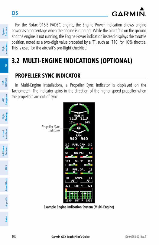
Garmin G3X Touch Pilot’s Guide 190-01754-00 Rev. T100
EIS
Syst
em
Ove
rvie
wFl
ight
In
stru
men
tsEI
SCN
SIn
terf
ace
GPS
N
avig
atio
nFl
ight
Plan
ning
Haz
ard
Avoi
danc
eA
dditi
onal
Fe
atur
esA
FCS
Ann
un/A
lert
sA
ppen
dix
Inde
x
For the Rotax 915iS FADEC engine, the Engine Power indication shows engine power as a percentage when the engine is running. While the aircraft is on the ground and the engine is not running, the Engine Power indication instead displays the throttle position, noted as a two-digit value preceded by a 'T', such as 'T10' for 10% throttle. This is used for the aircraft's pre-flight checklist.
3.2 MULTI-ENGINE INDICATIONS (OPTIONAL)
PROPELLER SYNC INDICATOR
In Multi-Engine installations, a Propeller Sync Indicator is displayed on the Tachometer. The indicator spins in the direction of the higher-speed propeller when the propellers are out of sync.
Example Engine Indication System (Multi-Engine)
Propeller Sync Indicator

Garmin G3X Touch Pilot’s Guide190-01754-00 Rev. T 101
EIS
System
Overview
Flight Instrum
entsEIS
CNS
InterfaceG
PS N
avigationFlight
PlanningH
azard Avoidance
AdditionalFeatures
AFCS
Annun/A
lertsA
ppendixIndex
Example Main Tab on the Eng Page (Multi-Engine)
Propeller Sync Indicator
3.3 LEAN ASSIST MODE (OPTIONAL)
NOTE: The pilot should follow the engine manufacturer’s recommended leaning procedures as described in the Pilot’s Operating Handbook (POH).
A Lean Assist Button is displayed on the Eng Page when Lean Assist Mode is enabled and at least one Exhaust Gas Temperature (EGT) or Turbine Inlet Temperature (TIT) input is configured (refer to the G3X Touch Installation Manual for more information).
Using Lean Assist Mode:
From the Main Tab of the Eng Page, touch Lean Assist. As the mixture is leaned, one of the cylinders’ exhaust temperature will peak. Continuing to lean the mixture will cause each additional cylinder to peak (if applicable) until the last of the cylinders peaks. To cancel Lean Assist Mode, touch Lean Assist again.
When the Lean Assist is selected, the Lean Assist Mode waits for a cylinder’s EGT to reach a peak temperature and decrease by at least 7°F. To prevent detection of false peaks, the system waits for a cylinder’s EGT to increase by at least 15°F before detecting a peak. In addition, if the cylinder temperature rises above a previously detected peak by more than 100°F, the previous peak is considered false.

Garmin G3X Touch Pilot’s Guide 190-01754-00 Rev. T102
EIS
Syst
em
Ove
rvie
wFl
ight
In
stru
men
tsEI
SCN
SIn
terf
ace
GPS
N
avig
atio
nFl
ight
Plan
ning
Haz
ard
Avoi
danc
eA
dditi
onal
Fe
atur
esA
FCS
Ann
un/A
lert
sA
ppen
dix
Inde
x
The following bar graph is displayed when four or more EGT cylinders are configured and the same number of EGT and CHT probes are configured. When each cylinder peaks, its bar changes from green to blue, and the white EGT number changes to a blue delta number. The blue delta number is the difference between current EGT and peak EGT for each cylinder. The first cylinder to peak is identified with a solid blue box around the delta number, and the last cylinder to peak is identified with a hollow blue box. The outline and grey number above each bar displays the actual peak EGT value.
Lean Assist (Same Number Of EGT And CHT Probes Configured And Four Or More Cylinders Configured)
Indicates Difference Between Current and Peak EGT
Cylinder Peak EGT Value
CHT
Indicates First Cylinder to Peak
Indicates Last Cylinder to Peak
The following graph is displayed if EGT data is configured on less than four cylinders and a different number of EGT and CHT probes are configured. The temperature deviation between the current temperature and the peak temperature for the cylinder currently closest to its peak is displayed in cyan. A cyan hollow triangle appears on the EGT gauge at the temperature where the first cylinder peaked.
Lean Assist (Different Number Of EGT And CHT Probes Configured And Less Than Four Cylinders Configured)
Difference Between Current & Peak
Cylinder Peak TemperatureCHT

Garmin G3X Touch Pilot’s Guide190-01754-00 Rev. T 103
EIS
System
Overview
Flight Instrum
entsEIS
CNS
InterfaceG
PS N
avigationFlight
PlanningH
azard Avoidance
AdditionalFeatures
AFCS
Annun/A
lertsA
ppendixIndex
The following dual-pointer gauge is displayed when exactly two cylinders of EGT are configured. Each cylinder has its own peak temperature triangle.
Lean Assist (Two EGT Cylinders Configured)
Difference Between Current and Peak Temperature
Cylinder Two Peak Tem-perature
Cylinder One Peak Tem-
perature
The following gauge is displayed when TIT is configured instead of EGT.
Lean Assist (TIT Configured)
Difference Between Current and Peak Temperature
Peak Temperature
NOTE: A ‘+’ (∆EGT) value indicates the current temperature is greater than the previously detected peak.

Garmin G3X Touch Pilot’s Guide 190-01754-00 Rev. T104
EIS
Syst
em
Ove
rvie
wFl
ight
In
stru
men
tsEI
SCN
SIn
terf
ace
GPS
N
avig
atio
nFl
ight
Plan
ning
Haz
ard
Avoi
danc
eA
dditi
onal
Fe
atur
esA
FCS
Ann
un/A
lert
sA
ppen
dix
Inde
x
If a fuel flow sensor is configured, the fuel flow value detected as the first cylinder peaks is saved. The fuel flow corresponding to peak EGT is drawn on the fuel flow gauge as a hollow blue pointer. This can be used to determine if you are on the rich side of peak (ROP) or the lean side of peak (LOP). Rich of Peak (ROP) if the fuel flow pointer is above the blue triangle, or Lean of Peak (LOP) if the fuel flow pointer is below the blue triangle.
Fuel Flow Gauge - Lean Assist (Fuel Flow Sensor Configured)
Fuel Flow Corresponding to Peak EGT
The EIS displays the cylinder whose temperature is currently closest to its own peak value (when Lean Assist Mode is active) as a white pointer with the cylinder number. The peak temperature is depicted by a hollow blue pointer, and the temperature deviation from peak (∆EGT or ∆TIT) is displayed in place of the normal temperature number in cyan text.
Lean Assist (EIS) (Example)
Cylinder With Temperature Closest to Its Peak Value
Difference Between Current and Peak Temperature
Cylinder Peak Temperature

Garmin G3X Touch Pilot’s Guide190-01754-00 Rev. T 105
EIS
System
Overview
Flight Instrum
entsEIS
CNS
InterfaceG
PS N
avigationFlight
PlanningH
azard Avoidance
AdditionalFeatures
AFCS
Annun/A
lertsA
ppendixIndex
3.4 FUEL CALCULATOR (OPTIONAL)
WARNING: The G3X Touch Fuel Calculator and/or Fuel Range Rings are NOT intended to be relied upon as the primary fuel indicator(s), and does not relieve the pilot from the responsibility of proper flight planning. G3X Touch fuel calculations do not use the aircraft fuel quantity indicators and are calculated from the last time the fuel was reset.
Refer to the Section 5.2, Using Map Displays, for information on displaying fuel range rings on the Navigation Map.
Adjusting the Fuel Remaining or Fuel Used quantity:1) From the ENG Page, touch the Fuel Calculator Tab.
2) Touch ‘+’ or ‘-’ to adjust the desired quantity.
Or:
Touch the value to enter the fuel quantity using the keypad and touch Enter.
Or:
Touch the pre-configured preset value and touch Enter.
Resetting the Fuel Used to zero:1) From the ENG Page, touch the Fuel Calculator Tab.
2) Touch Reset.
Fuel Calculator

Garmin G3X Touch Pilot’s Guide 190-01754-00 Rev. T106
EIS
Syst
em
Ove
rvie
wFl
ight
In
stru
men
tsEI
SCN
SIn
terf
ace
GPS
N
avig
atio
nFl
ight
Plan
ning
Haz
ard
Avoi
danc
eA
dditi
onal
Fe
atur
esA
FCS
Ann
un/A
lert
sA
ppen
dix
Inde
x
3.5 FUEL FLOW CALIBRATION (OPTIONAL)
NOTE: It is recommended to avoid using small quantities of 'Fuel Used' in this tool. If only a few gallons are used on a flight, it will not help dial in the fuel flow calibration.
The K-Factor represents the number of electrical pulses output by the fuel flow sensor per gallon of fuel. Aspects unique to each installation will affect the accuracy of the initial K-Factor, and as a result, the K-Factor must generally be adjusted up or down to increase the accuracy of the fuel flow calibration.
If the fuel usage reported by the G3X Touch differs from the actual fuel usage (as measured at the fuel pump or other trusted method of measurement), the K-Factor can be adjusted either in Configuration Mode (as described in the G3X Touch Installation Manual) or by using the Fuel Flow Calibration Menu in Normal Mode.
Adjusting the K-Factor:1) From the ENG Page, touch the Fuel Calculator Tab.
2) Press the MENU Key.
3) Touch Calibrate Fuel Flow.
4) Touch Actual to enter the 'Actual' amount of fuel used and touch Enter. The system automatically adjusts the K-Factor for the fuel flow sensor to match the observed fuel used.
Once an 'Actual -Fuel Used' value is entered, the corresponding 'Adjustment - Fuel Flow' percentage is displayed. It is also possible to adjust the fuel flow using the 'Adjustment - Fuel Flow' field directly. Entering an adjustment percentage will adjust the 'Actual - Fuel Used' value accordingly. However, this is not the method used to adjust the K-Factor to increase the accuracy of the fuel flow calibration.
Fuel Flow Calibration

Garmin G3X Touch Pilot’s Guide190-01754-00 Rev. T 107
EIS
System
Overview
Flight Instrum
entsEIS
CNS
InterfaceG
PS N
avigationFlight
PlanningH
azard Avoidance
AdditionalFeatures
AFCS
Annun/A
lertsA
ppendixIndex
3.6 CAS MESSAGES (OPTIONAL)
NOTE: A standalone MFD does not support CAS messages.
The Crew Alerting System (CAS) messages displayed depend upon the current configuration, and will vary from the examples listed below. Refer to the G3X Touch Installation Manual for more information on configuring CAS messages (if applicable).
CAS Messages are grouped by criticality (warning, caution, advisory). The color of the message is based on its urgency and on required action:
• WARNING (red): Requires immediate attention.
• CAUTION (yellow): Requires pilot awareness and possible future corrective action.
• ADVISORY (white): Provides general information.
Warning annunciation text is shown in red in the CAS Annunciation Window on the PFD. The CAS Annunciation Window location is dependent on screen size. Touch an active CAS message or press the BACK Key to acknowledge it.
CAS Warning Example
When more CAS messages are present than can be displayed in the available window space, an upside-down triangle will appear in the CAS Annunciation Window. Touch the CAS Annunciation Window to display the MFD CAS Messages Window.

Garmin G3X Touch Pilot’s Guide 190-01754-00 Rev. T108
EIS
Syst
em
Ove
rvie
wFl
ight
In
stru
men
tsEI
SCN
SIn
terf
ace
GPS
N
avig
atio
nFl
ight
Plan
ning
Haz
ard
Avoi
danc
eA
dditi
onal
Fe
atur
esA
FCS
Ann
un/A
lert
sA
ppen
dix
Inde
x
Blank Page

Garmin G3X Touch Pilot’s Guide190-01754-00 Rev. T 109
CNS Interface
System
Overview
Flight Instrum
entsEIS
CNS
InterfaceG
PS N
avigationFlight
PlanningH
azard Avoidance
AdditionalFeatures
AFCS
Annun/A
lertsA
ppendixIndex
SECTION 4 CNS INTERFACE (OPTIONAL)
4.1 CNS DATA BAR
The Communication/Navigation/Surveillance (CNS) system includes the audio interface, communication radios, navigation radios, and Mode S transponder. These functions can be accessed from the Main Menu and from the boxes that make up the CNS Data Bar located at the top of the PFD and/or MFD.
1 2 3 4 5 6 7 8 9 10
CNS Data Bar
1 COM1 - Transfers the standby and active COM1 frequencies. *
2 STBY - Displays/removes the COM1 Standby Page. The COM1 Standby Page is used to enter and transfer COM1 frequencies.
3 NAV1 - Transfers the standby and active NAV1 frequencies.
4 STBY - Displays/removes the NAV1 Standby Page. The NAV1 Standby Page is used to enter and transfer NAV1 frequencies.
5 MIC / COM - Displays/removes the Audio/Intercom Page.
6 XPDR - Displays/removes the Transponder Page. The Transponder Page is used to select Transponder functions
7 NAV2 - Transfers the standby and active NAV2 frequencies.
8 STBY - Displays/removes the NAV2 Standby Page. The NAV2 Standby Page is used to enter and transfer NAV2 frequencies.
9 COM 2 - Transfers the standby and active COM2 frequencies.
10 STBY - Displays/removes the COM2 Standby Page. The COM2 Standby Page is used to enter and transfer COM2 frequencies.
* When an audio panel is configured, an active COM frequency displayed in green indicates the COM transceiver is selected. If an audio panel is not configured in the system, all COM active frequencies are always displayed in white (since the GDU has no knowledge which radio(s) are selected).

Garmin G3X Touch Pilot’s Guide 190-01754-00 Rev. T110
CNS Interface
Syst
em
Ove
rvie
wFl
ight
In
stru
men
tsEI
SCN
SIn
terf
ace
GPS
N
avig
atio
nFl
ight
Plan
ning
Haz
ard
Avoi
danc
eA
dditi
onal
Fe
atur
esA
FCS
Ann
un/A
lert
sA
ppen
dix
Inde
x
4.2 COM ANNUNCIATIONS
When receiving a transmission, 'RX' is displayed on the COM button. 'TX' is also displayed on the COM button while transmitting.
Transmit Annunciation
COM Annunciations (TX/RX)
Receive Annunciation
'SQ' is displayed on the COM button when automatic squelch is overridden.
COM Annunciations (SQ)
Squelch Annunciation
The frequency monitoring function allows the pilot to listen to the Standby frequency while monitoring the Active frequency for activity.
COM Annunciations (M)
Monitor Annunciation
4.3 COM WINDOW
Displaying the COM window: Touch the STBY COM button on the CNS Data Bar.
Or:
From the Main Menu, touch COM 1 Radio or COM 2 Radio (if configured).

Garmin G3X Touch Pilot’s Guide190-01754-00 Rev. T 111
CNS Interface
System
Overview
Flight Instrum
entsEIS
CNS
InterfaceG
PS N
avigationFlight
PlanningH
azard Avoidance
AdditionalFeatures
AFCS
Annun/A
lertsA
ppendixIndex
COM Window
Manually tuning a COM frequency:1) Touch STBY on CNS Data Bar.
2) Enter the frequency using the keypad and touch Enter.
Adjusting COM Volume:1) Touch STBY on CNS Data Bar.
2) Touch Volume.
3) Touch the slider to adjust the percentage.
Monitoring the Standby COM:1) Touch STBY on CNS Data Bar.
2) Touch Monitor. A green 'M' is displayed in the Standby Field. Repeating steps 1 and 2 will stop monitoring the frequency.
Transferring Standby to Active: From the CNS Data Bar, touch the COM 1 or COM 2 frequency field.
Or:
1) Press the STBY on the CNS Data Bar.
2) Touch XFER.

Garmin G3X Touch Pilot’s Guide 190-01754-00 Rev. T112
CNS Interface
Syst
em
Ove
rvie
wFl
ight
In
stru
men
tsEI
SCN
SIn
terf
ace
GPS
N
avig
atio
nFl
ight
Plan
ning
Haz
ard
Avoi
danc
eA
dditi
onal
Fe
atur
esA
FCS
Ann
un/A
lert
sA
ppen
dix
Inde
x
COM RADIO VOLUME SHORTCUT (GDU 45X OR GDU 46X ONLY)The Data Bar Setup page can enable a COM Radio Volume Shortcut panel that
appears while a COM panel is active. This shortcut panel displays touchscreen controls for volume and toggle on/off squelch for the currently displayed COM radio. The shortcut panel appears at the bottom of the PFD.
COM Radio Volume Shortcut
COM Radio Volume
COM Squelch
COM FREQUENCY FINDINGThe frequency finding feature allows the pilot to quickly select any displayed
database COM frequency as the standby frequency.
Using COM frequency finding:1) Touch COM STBY on CNS Data Bar.
2) Touch Find.
3) Touch the Recent, Nearest Airports, or Flight Plan Tab.
4) Touch the frequency or touch Select Frequency... for a list of available frequencies.
Or:

Garmin G3X Touch Pilot’s Guide190-01754-00 Rev. T 113
CNS Interface
System
Overview
Flight Instrum
entsEIS
CNS
InterfaceG
PS N
avigationFlight
PlanningH
azard Avoidance
AdditionalFeatures
AFCS
Annun/A
lertsA
ppendixIndex
a) Touch Select an Airport.
b) Enter the four letter ICAO identifier for the desired airport.
c) Touch the frequency.
Or:
1) Touch COM STBY on CNS Data Bar.
2) Touch Find.
3) Touch the User Tab.
4) Touch the frequency or touch Select Frequency... for a list of available frequencies.
AUTOMATIC SQUELCHAutomatic Squelch quiets unwanted static noise when no audio signal is received,
while still providing good sensitivity to weak COM signals. To disable Automatic Squelch, touch STBY > Squelch. When Automatic Squelch is disabled, COM audio reception is always on. Continuous static noise may be heard over the headsets and speaker, if selected. Touching STBY > Squelch again enables Automatic Squelch.
When Automatic Squelch is disabled, the COM frequency and the Squelch on the COM tuning page is highlighted green.
4.4 COM ERROR MESSAGES
Copilot Push-to-Talk Stuck
COM Error Messages on CNS Bar

Garmin G3X Touch Pilot’s Guide 190-01754-00 Rev. T114
CNS Interface
Syst
em
Ove
rvie
wFl
ight
In
stru
men
tsEI
SCN
SIn
terf
ace
GPS
N
avig
atio
nFl
ight
Plan
ning
Haz
ard
Avoi
danc
eA
dditi
onal
Fe
atur
esA
FCS
Ann
un/A
lert
sA
ppen
dix
Inde
x
The following COM error messages may appear in the COM Radio Field on the CNS Bar:
Message Description Action
PILOT PTT STUCK
The Pilot Push To Talk key has been in the pressed position for at least 35 seconds. This key will now be ignored.
Verify Push To Talk key is not stuck. Refer to the installation manual for installation wiring tests. Contact Garmin® for service if this message persists.
COPILOT PTT STUCK
The Copilot Push To Talk key has been in the pressed position for at least 35 seconds. This key will now be ignored.
Verify Push To Talk key is not stuck. Refer to the installation manual for installation wiring tests. Contact Garmin for service if this message persists.
BOTH PTT STUCK
Both Push To Talk keys have been in the pressed position for at least 35 seconds. This key will now be ignored.
Verify Push To Talk keys are not stuck. Refer to the installation manual for installation wiring tests. Contact Garmin for service if this message persists.
TX HARDWARE
FAULT
An internal hardware problem is preventing COM transmission.
Contact Garmin for service if this message persists.
TEMP TOO HIGH
Internal temperature is too high.
Wait for unit to cool. Add supplemental cooling if problem persists.
SUPPLY VOLTAGE LOW
Supply voltage is too low.
Verify supply voltage meets minimum requirement identified in installation manual. Contact Garmin for service if message persists.

Garmin G3X Touch Pilot’s Guide190-01754-00 Rev. T 115
CNS Interface
System
Overview
Flight Instrum
entsEIS
CNS
InterfaceG
PS N
avigationFlight
PlanningH
azard Avoidance
AdditionalFeatures
AFCS
Annun/A
lertsA
ppendixIndex
4.5 NAV ANNUNCIATIONS
When NAV ident is enabled, 'ID' is displayed on the NAV button and the Morse code tone is played.
NAV Ident Annunciation
NAV Ident Annunciation
4.6 NAV WINDOW
Displaying the NAV window: Touch the STBY NAV button on the CNS Data Bar.
Or:
From the Main Menu, touch NAV 1 Radio or NAV 2 Radio (if configured).
NAV Window

Garmin G3X Touch Pilot’s Guide 190-01754-00 Rev. T116
CNS Interface
Syst
em
Ove
rvie
wFl
ight
In
stru
men
tsEI
SCN
SIn
terf
ace
GPS
N
avig
atio
nFl
ight
Plan
ning
Haz
ard
Avoi
danc
eA
dditi
onal
Fe
atur
esA
FCS
Ann
un/A
lert
sA
ppen
dix
Inde
x
Manually tuning a NAV frequency:1) Touch STBY on CNS Data Bar.
2) Enter the frequency using the keypad and touch Enter.
Transferring Standby to Active: From the CNS Data Bar, touch the NAV 1 or NAV 2 frequency field.
Or:
1) Press the STBY on the CNS Data Bar.
2) Touch XFER.
NAV FREQUENCY FINDINGThe frequency finding feature allows the pilot to quickly select any displayed
database NAV frequency as the standby frequency.
Using NAV frequency finding:1) Touch STBY on CNS Data Bar.
2) Touch Find.
3) Touch the Recent, Nearest Navaids, Flight Plan, or User Tab.
4) Touch the frequency or touch Select Frequency... for a list of available frequencies.

Garmin G3X Touch Pilot’s Guide190-01754-00 Rev. T 117
CNS Interface
System
Overview
Flight Instrum
entsEIS
CNS
InterfaceG
PS N
avigationFlight
PlanningH
azard Avoidance
AdditionalFeatures
AFCS
Annun/A
lertsA
ppendixIndex
4.7 NAV ERROR MESSAGES
The following NAV error messages may appear in the NAV Radio Field on the CNS Bar:
Message Description Action
VLOC NEEDS SERVICE
The nav radio is reporting that it needs service. The nav radio may continue to function.
Use GPS based navigation. Contact Garmin for service.
VLOC FAILThe nav radio is not communicating properly with the system.
Use GPS based navigation. Contact Garmin for service.
GS NEEDS SERVICE
The glideslope receiver is indicating that it needs service. The glideslope receiver may continue to function.
Verify glideslope deviation indications with another source and crosscheck final approach fix crossing altitude. If another glideslope source is not available for verification, fly a GPS based approach. Contact Garmin for service.
GS FAILThe glideslope receiver is not communicating properly with the system.
Fly an approach that does not use the glideslope receiver (VOR, LOC, GPS). Contact Garmin for service.
RMT TRANSFER
STUCK
Nav remote transfer key is stuck.
Verify the NAV RMT XFR key/switch is not stuck. Contact Garmin for service if this message persists.

Garmin G3X Touch Pilot’s Guide 190-01754-00 Rev. T118
CNS Interface
Syst
em
Ove
rvie
wFl
ight
In
stru
men
tsEI
SCN
SIn
terf
ace
GPS
N
avig
atio
nFl
ight
Plan
ning
Haz
ard
Avoi
danc
eA
dditi
onal
Fe
atur
esA
FCS
Ann
un/A
lert
sA
ppen
dix
Inde
x
4.8 AUTO-TUNING FREQUENCIES
NOTE: Refer to the G3X Touch Installation Manual for more information on the G3X Touch optional communication interfaces.
Frequencies can be automatically tuned from the following:• Map Page
• Weather Page
• Waypoint Page
• Nearest Airports Page
• Nearest Airport Weather Page
• Nearest Air Traffic Control Page
• Nearest Flight Service Station Page
• Airway Review Page
• Select Approach Page (no external navigator configured)
Auto-tuning a frequency:1) Touch the page navigation bar on the MFD.
2) Touch Waypoint.
3) Touch the waypoint identifier field at the top of the page.
4) Enter the desired waypoint and touch Enter.
5) Touch the Freq tab.
6) Touch the desired frequency to tune.
7) OPTIONAL: Touch the desired COM or NAV radio if configured with more than one.
Select COM Radio

Garmin G3X Touch Pilot’s Guide190-01754-00 Rev. T 119
CNS Interface
System
Overview
Flight Instrum
entsEIS
CNS
InterfaceG
PS N
avigationFlight
PlanningH
azard Avoidance
AdditionalFeatures
AFCS
Annun/A
lertsA
ppendixIndex
Or:
1) Touch the page navigation bar on the MFD
2) Touch Map or SXM Weather.
3) Touch the desired waypoint or airport on the map.
4) Touch the selected waypoint identifier name below the map.
5) Touch the Freq tab.
6) Touch the desired frequency to tune.
7) OPTIONAL: Touch the desired COM or NAV radio if configured with more than one.
Or:
1) Press the NRST Key.
2) Touch the page navigation bar.
3) Touch Airports, Airport Weather, VORs, ARTCC, or FSS.
4) Touch the desired frequency to tune.
5) OPTIONAL: Touch the desired COM or NAV radio if configured with more than one.
Or:
1) Press the NRST Key.
2) Touch the page navigation bar.
3) Touch Airspace.
4) Touch the desired airspace.
5) Touch Frequencies.
6) Touch the desired frequency to tune.
7) OPTIONAL: Touch the desired COM or NAV radio if configured with more than one.

Garmin G3X Touch Pilot’s Guide 190-01754-00 Rev. T120
CNS Interface
Syst
em
Ove
rvie
wFl
ight
In
stru
men
tsEI
SCN
SIn
terf
ace
GPS
N
avig
atio
nFl
ight
Plan
ning
Haz
ard
Avoi
danc
eA
dditi
onal
Fe
atur
esA
FCS
Ann
un/A
lert
sA
ppen
dix
Inde
x
4.9 USER FREQUENCIES
Adding a User Frequency:1) Touch STBY on CNS Data Bar.
2) Touch Find.
3) Touch the User Tab.
4) Touch Edit User Frequencies.
5) Touch Add User Frequency.
6) Touch Name or Frequency.
7) Enter the name/frequency using the keypad and touch Enter.
Editing a User Frequency:1) Touch STBY on CNS Data Bar.
2) Touch Find.
3) Touch the User Tab.
4) Touch Edit User Frequencies.
5) Touch the Name or Frequency to edit.
6) Enter the name/frequency using the keypad and touch Enter.
Deleting a User Frequency:1) Touch STBY on CNS Data Bar.
2) Touch Find.
3) Touch the User Tab.
4) Touch Edit User Frequencies.
5) Touch Delete.
6) Touch Yes.

Garmin G3X Touch Pilot’s Guide190-01754-00 Rev. T 121
CNS Interface
System
Overview
Flight Instrum
entsEIS
CNS
InterfaceG
PS N
avigationFlight
PlanningH
azard Avoidance
AdditionalFeatures
AFCS
Annun/A
lertsA
ppendixIndex
4.10 AUDIO PANEL
NOTE: The audio panel information in this section pertains only to G3X sys-tems configured with a GMA 245/245R. Screenshots and descriptions may differ from actual display function depending upon configuration.
When configured with a compatible audio panel, touching the Audio Box on the CNS Data Bar will display the Audio/Intercom Page. The Audio/Intercom Page allows selection of four separate tabs, these are the Radios, Intercom, Phone & Media, and Music Input tabs. The Audio Box can be configured for Normal or Minimized display format, (Audio Only format may be displayed as determined by available space on the CNS Data Bar).
Audio/Intercom Page Select
Audio Box on CNS Data Bar
MIC/COM Select
Audio Box
There are three different formats of the Audio Box that may be displayed:
Audio Box Format Description
Normal - Provides access to the Audio/Intercom Page and MIC/COM settings.
Minimized - Provides access to the Audio/Intercom Page and displays the current MIC/COM settings (cannot change the MIC/COM settings in this format)Audio Only - Provides access to the Audio/Intercom Page. Displayed only when COM 2 is disabled via the audio panel configuration, or there's not enough room for the Minimized control to be displayed.

Garmin G3X Touch Pilot’s Guide 190-01754-00 Rev. T122
CNS Interface
Syst
em
Ove
rvie
wFl
ight
In
stru
men
tsEI
SCN
SIn
terf
ace
GPS
N
avig
atio
nFl
ight
Plan
ning
Haz
ard
Avoi
danc
eA
dditi
onal
Fe
atur
esA
FCS
Ann
un/A
lert
sA
ppen
dix
Inde
x
The preceding examples all indicate that no Bluetooth phone call is in progress. When a phone call is incoming or in progress, a “TEL” indicator is displayed (flashing to indicate incoming call, non-flashing to indicate call is active), see Phone & Media Tab section for more information.
Note the Audio Box can be configured to display square or triangle indicators.
Several status indications can be selected/shown in the Audio Box per the following table.
Audio Box (Normal) Description
MIC 1 selected, monitoring COM 1
MIC 2 selected, monitoring COM 2
MIC 1 selected, monitoring COM 1 and COM 2
MIC 2 selected, monitoring COM 1 and COM 2
Split COM selected. Isolates the COM 1 radio to the pilot and the COM 2 radio to the copilot.
AUDIO/INTERCOM PAGESelecting Audio/Intercom Page Touch Audio on the CNS Data Bar.
Or:
1) Press the MENU Key twice.
2) Touch the Audio Panel button to display the Audio/Intercom Page.

Garmin G3X Touch Pilot’s Guide190-01754-00 Rev. T 123
CNS Interface
System
Overview
Flight Instrum
entsEIS
CNS
InterfaceG
PS N
avigationFlight
PlanningH
azard Avoidance
AdditionalFeatures
AFCS
Annun/A
lertsA
ppendixIndex
RADIOS TABThe following paragraphs describe the functions accessible from the Radios Tab.
Selecting the Radios tab:1) Touch Audio on the CNS Data Bar.
2) Touch the Radios tab (if needed.)
Or:
1) Press the MENU Key twice.
2) Touch the Audio Panel button to display the Audio/Intercom Page.
3) Touch the Radios tab (if needed.)
Audio/Intercom Page - Radios Tab
Selecting the Monitored Radio: Touch the 'Audio' COM button on the CNS Data Bar to select/deselect a
monitored radio.

Garmin G3X Touch Pilot’s Guide 190-01754-00 Rev. T124
CNS Interface
Syst
em
Ove
rvie
wFl
ight
In
stru
men
tsEI
SCN
SIn
terf
ace
GPS
N
avig
atio
nFl
ight
Plan
ning
Haz
ard
Avoi
danc
eA
dditi
onal
Fe
atur
esA
FCS
Ann
un/A
lert
sA
ppen
dix
Inde
x
Or:
From the Main Menu, touch Audio Panel > Radios Tab and touch the desired COM radios.
Selecting the Radio to transmit from: Touch the MIC box on the CNS Data Bar to change the radio used to
transmit (talk) from.
Or:
From the Main Menu, touch Audio Panel > Radios Tab and touch the desired COM MIC radios.
Selecting/Deselecting Split COM mode:1) Touch Audio on the CNS Data Bar.
Or:
From the Main Menu, touch Audio Panel.
2) Touch the Radios tab if needed.
3) Touch the Split COM button to select (green) or deselect Split COM mode.
COM RADIOS
The COM 1/COM 2 buttons select the monitored radio. The COM 1 MIC/COM 2 MIC buttons selects the radio used to transmit from.
Selecting "Split COM" overrides the current MIC/COM selections and enables MIC1/COM1 for the pilot, and MIC2/COM2 for the copilot (i.e., “Split COM” isolates the COM 1 radio to the pilot and the COM 2 radio to the copilot).
NAV RADIOSThe NAV Radios section allows selection of NAV 1 and NAV 2 functions.
MARKER BEACONThe marker beacon receiver is used as part of the ILS. The marker beacon receiver
is always on and detects any marker beacon signals within the reception range of the aircraft. The receiver detects the three tones - outer, middle, and inner - and illuminates the marker beacon annunciations located to the left of the altimeter on the PFD.
Touch Marker Beacon on the Audio/Intercom Page (Radios Tab) to select/deselect the marker beacon audio. The Marker Beacon Button annunciator indicates when marker beacon audio is selected.

Garmin G3X Touch Pilot’s Guide190-01754-00 Rev. T 125
CNS Interface
System
Overview
Flight Instrum
entsEIS
CNS
InterfaceG
PS N
avigationFlight
PlanningH
azard Avoidance
AdditionalFeatures
AFCS
Annun/A
lertsA
ppendixIndex
NOTE: The Speaker Button is moved under 'More Options...' when both Marker Beacon and Speaker are enabled.
Marker Beacon Audio
Marker Beacon Audio
Touch Marker Sensitivity on the Audio/Intercom Page (Radios Tab) > More Options... to switch between High and Low marker beacon receiver sensitivity. High is used to provide an earlier indication when nearing a marker during an approach. Low results in a narrower marker dwell while over a station.
Marker Sensitivity (Radios Tab > More Options)
Marker Sensitivity

Garmin G3X Touch Pilot’s Guide 190-01754-00 Rev. T126
CNS Interface
Syst
em
Ove
rvie
wFl
ight
In
stru
men
tsEI
SCN
SIn
terf
ace
GPS
N
avig
atio
nFl
ight
Plan
ning
Haz
ard
Avoi
danc
eA
dditi
onal
Fe
atur
esA
FCS
Ann
un/A
lert
sA
ppen
dix
Inde
x
SPEAKERThe Speaker function enables audio to be played through a connected speaker.
Alert audio is always played over the speaker, regardless of the speaker button state.
PLAY BUTTONThis button is used to play back the last received radio transmission(s), and is not
associated with audio/video.
• The playback recording is only for the mic selected radio.
• Pressing the play button again while a recording is playing skips that recording and starts playing the previous recording. After repeatedly pressing this button until all recordings have been played, a double-beep will sound and the playback will reset to the start. The playback function also resets to the start after listening to a selected recording.
• The playback function retains approximately the last 60 seconds of received audio from the MIC selected COM radio.
VOLUME SHORTCUT (GDU 45X OR GDU 46X ONLY)The Data Bar Setup page can enable a Volume Shortcut panel that appears while
the Audio/Intercom panel is active. This shortcut panel displays touchscreen volume controls for pilot and copilot intercom, music, and Bluetooth audio. When a tab in the Audio/Intercom panel is selected, the Volume Shortcut panel changes to the volume controls for that source - i.e., when the Phone & Media tab is selected, the Volume Shortcut panel adjusts the volume for the Bluetooth audio. The shortcut panel's source can also be changed by pressing either of the knobs. The shortcut panel appears on the opposite side of the screen as the Audio/Intercom panel.

Garmin G3X Touch Pilot’s Guide190-01754-00 Rev. T 127
CNS Interface
System
Overview
Flight Instrum
entsEIS
CNS
InterfaceG
PS N
avigationFlight
PlanningH
azard Avoidance
AdditionalFeatures
AFCS
Annun/A
lertsA
ppendixIndex
Audio Intercom Volume Shortcut (GDU 45X or GDU 46X only)
Pilot and Copilot
Intercom Volume
Levels
MORE OPTIONS
NOTE: The Speaker Button is moved under 'More Options...' when both Marker Beacon and Speaker are enabled.
The More Options... Button allows access to the AUX Radios, Marker Sensitivity, and Active COM Receive Monitor Mute functions. Selecting Monitor Mute, mutes the monitored COM radio when audio from the MIC selected COM radio is heard.
Radios Tab, More Options Button Selected

Garmin G3X Touch Pilot’s Guide 190-01754-00 Rev. T128
CNS Interface
Syst
em
Ove
rvie
wFl
ight
In
stru
men
tsEI
SCN
SIn
terf
ace
GPS
N
avig
atio
nFl
ight
Plan
ning
Haz
ard
Avoi
danc
eA
dditi
onal
Fe
atur
esA
FCS
Ann
un/A
lert
sA
ppen
dix
Inde
x
INTERCOM TABThe following paragraphs describe the functions accessible from the Intercom Tab.
Selecting the Intercom tab:1) Touch Audio on the CNS Data Bar.
Or:
From the Main Menu, touch Audio Panel.
2) Touch the Intercom tab.
Audio/Intercom Page, Intercom Tab
ICS VOLUME
The ICS Volume section allows selection of Pilot, Copilot, and Passenger intercom volume. A volume adjust slider is used to set the selected volume on G3X Touch systems with a GMA 245R.
Adjusting Volume:1) Touch Pilot, Copilot, or Passengers on Intercom Tab.
2) Touch the slider to adjust the percentage.

Garmin G3X Touch Pilot’s Guide190-01754-00 Rev. T 129
CNS Interface
System
Overview
Flight Instrum
entsEIS
CNS
InterfaceG
PS N
avigationFlight
PlanningH
azard Avoidance
AdditionalFeatures
AFCS
Annun/A
lertsA
ppendixIndex
ICS ISOLATION
The ICS Isolation section allows selection of Pilot and Crew Isolate functions. These functions are annunciated in the Audio Box on the CNS Data Bar when active.
Pilot Isolation mode isolates the Pilot from other ICS positions (Copilot and Passengers). The Copilot and Passengers share communication between themselves but cannot communicate with the Pilot or hear the pilot's selected radios.
Crew Isolation mode places the Pilot and Copilot on a common ICS communication channel. The Passengers are on their own intercom channel and can communicate with each other, but cannot communicate with the Pilot and Copilot or hear the pilot's selected radios.
MORE OPTIONS...
The More Options button allows access to the 3D Audio and Muting functions.
Intercom Tab, More Options Button Selected

Garmin G3X Touch Pilot’s Guide 190-01754-00 Rev. T130
CNS Interface
Syst
em
Ove
rvie
wFl
ight
In
stru
men
tsEI
SCN
SIn
terf
ace
GPS
N
avig
atio
nFl
ight
Plan
ning
Haz
ard
Avoi
danc
eA
dditi
onal
Fe
atur
esA
FCS
Ann
un/A
lert
sA
ppen
dix
Inde
x
3D AUDIO3D Audio is useful when multiple audio sources are present. 3D audio processing
creates the illusion that each audio source is coming from a unique location or seat position by using different responses in each ear. Because this feature uses different signals for left and right channels, it requires wiring for stereo intercom and stereo headsets. If 3D audio is activated when mono headsets are in use, the listener will still hear all audio sources; however, there is no benefit from location separation. With a single COM selected and Radio 3D Audio enabled, the listener hears the audio source at the 12 o’clock position. If both COMs are selected, the listener hears COM1 at 11 o’clock and COM2 at the 1 o’clock position. When ICS 3D Audio is selected, all intercom positions are processed to sound like their relative seat location. By default, the GMA 245/245R assumes the pilot sits in the left seat.
Selecting Radio/ICS 3D Audio:1) Touch More Options button on the Intercom tab.
2) Touch the Radio 3D Audio or ICS 3D Audio button to select/deselect the desired 3D Audio function.
MUTING
• Radio Mutes ICS – When Radio Mutes ICS is enabled, intercom audio from passengers to crew is muted when audio from the COM selected for transmission is heard.
• Radio Mutes Music – When Radio Mutes Music is enabled, music audio is muted when radio audio is heard.
• ICS Mutes Music – When ICS Mutes Music is enabled, music audio is muted when intercom audio is heard.
PHONE AND MEDIA TABSelecting the Phone & Media tab:1) Touch Audio on the CNS Data Bar.
Or:
From the Main Menu, touch Audio Panel.
2) Touch the Phone & Media tab.
The Phone & Media Tab on the Audio-Intercom Page, provides access to the telephone controls, enables media playback, and connects to a Bluetooth device.

Garmin G3X Touch Pilot’s Guide190-01754-00 Rev. T 131
CNS Interface
System
Overview
Flight Instrum
entsEIS
CNS
InterfaceG
PS N
avigationFlight
PlanningH
azard Avoidance
AdditionalFeatures
AFCS
Annun/A
lertsA
ppendixIndex
Audio/Intercom Page, Phone & Media Tab
MEDIA
The Media Controls enable playback of the current media (i.e., music, movie, etc.). The buttons are subdued when media is unavailable.
Media Controls

Garmin G3X Touch Pilot’s Guide 190-01754-00 Rev. T132
CNS Interface
Syst
em
Ove
rvie
wFl
ight
In
stru
men
tsEI
SCN
SIn
terf
ace
GPS
N
avig
atio
nFl
ight
Plan
ning
Haz
ard
Avoi
danc
eA
dditi
onal
Fe
atur
esA
FCS
Ann
un/A
lert
sA
ppen
dix
Inde
x
BLUETOOTH
The Bluetooth “Pair Device” button with a toggle indicates when the “pairing mode” is currently active. Pressing this button initiates the pairing operation and indicates when pairing is in progress. The toggle is displayed as green until the GMA reports that pairing mode is no longer active. When pairing is not allowed, pressing this button performs no action.
When pairing mode is enabled, the GMA 245/245R is able to be paired to other Bluetooth enabled devices. Refer to the device's user manual for instructions on how to pair to a Bluetooth device. The GMA 245/245R will remember the ten most recently paired devices, if the list is full and a new device is paired, the device with the oldest connection date/time is removed from the list.
The GMA 245/245R supports Bluetooth wireless delivery of pilot headphone audio to versions of the Garmin VIRB action camera that support Bluetooth mic audio input for recording.
Pairing a Garmin VIRB to the GMA 245/245R works like pairing other Bluetooth audio devices. Once connected, pilot headphone audio will be delivered to the VIRB via Bluetooth. In a connection to the Garmin VIRB, the GMA is the source. Therefore, selecting an entertainment key is not required.
Bluetooth ConneCtion StatuS
The Bluetooth connection status is either displayed with a single checkbox for “No Connection”, or with 1 or 2 checkboxes for each item connected (i.e., a single checkbox for media only, phone only, and output only, or 2 checkboxes for media and phone, or media and output).
Bluetooth/Media Indication Description
No Bluetooth connection, pairing mode disabled.

Garmin G3X Touch Pilot’s Guide190-01754-00 Rev. T 133
CNS Interface
System
Overview
Flight Instrum
entsEIS
CNS
InterfaceG
PS N
avigationFlight
PlanningH
azard Avoidance
AdditionalFeatures
AFCS
Annun/A
lertsA
ppendixIndex
Bluetooth/Media Indication Description
No Bluetooth connection, pairing mode enabled.
Bluetooth is connected with a VIRB Action camera that supports Bluetooth audio.
Bluetooth is connected with telephone and media functions.When connected to the telephone, the Bluetooth title is replaced with the phone's ID (if provided by phone).
Bluetooth is connected with telephone function only.
Bluetooth is connected with media functions only.

Garmin G3X Touch Pilot’s Guide 190-01754-00 Rev. T134
CNS Interface
Syst
em
Ove
rvie
wFl
ight
In
stru
men
tsEI
SCN
SIn
terf
ace
GPS
N
avig
atio
nFl
ight
Plan
ning
Haz
ard
Avoi
danc
eA
dditi
onal
Fe
atur
esA
FCS
Ann
un/A
lert
sA
ppen
dix
Inde
x
Bluetooth/Media Indication Description
Bluetooth is connected with media, but the connected device does not support media controls. In this instance, the media controls are disabled.The audio is audible via the intercom but may only be controlled via the external device.
When the audio is playing with the media controls enabled, the Play button is replaced with the Pause button.If provided by the external device, the album/artist/title/track number is displayed above the media controls. The external device may provide all, none, or only a part of this information.
Bluetooth interface is disabled. The GMA’s Bluetooth interface may be enabled/disabled as described below.
DiSaBling Bluetooth on gMa 245r
To aid in troubleshooting, the G3X Touch can be used to disable the Bluetooth functionality on the GMA 245R devices. Bluetooth on the GMA 245R can be re-enabled with the same process as disabling it. The GMA 245R will also re-enable Bluetooth when the power is cycled. GMA 245 devices have physical controls to perform this procedure as well, refer to the GMA 245 Pilot's Guide.

Garmin G3X Touch Pilot’s Guide190-01754-00 Rev. T 135
CNS Interface
System
Overview
Flight Instrum
entsEIS
CNS
InterfaceG
PS N
avigationFlight
PlanningH
azard Avoidance
AdditionalFeatures
AFCS
Annun/A
lertsA
ppendixIndex
Enabling/disabling GMA 245R Bluetooth:1) Press the MENU Key twice.2) Touch the Audio Panel button to display the Audio/Intercom Page.3) Touch the Phone & Media tab.4) Press the MENU Key.5) Touch Disable/Enable.
TELEPHONE OPERATIONS
When the Bluetooth connection status indicates “Telephone” is connected, the Phone & Media Tab on the Audio/Intercom Page provides the ability to answer, ignore (do not answer), and end Bluetooth phone calls and the Data Bar’s audio panel controls provide indications of the status of a Bluetooth phone call.
telephone auDio
The Telephone Audio button allows enables/disables the telephone's audio to the intercom system for both the wired and Bluetooth telephone connections.
Button Status Description Connection Description
Enabled (Green)
Telephone audio is
active (i.e., connected
to the intercom).
Wired Connection: The audio of the telephone is connected to the intercom and the pilot may participate in existing calls. Controlling the call (i.e., answer/hang up) is not supported, the ringing of an incoming call may be heard but the actual phone must be used to answer (and end) the call.Bluetooth Connection: The ringing of an incoming call may be heard via the intercom, and the pilot may ignore/answer/end the call via the provided GDU controls.

Garmin G3X Touch Pilot’s Guide 190-01754-00 Rev. T136
CNS Interface
Syst
em
Ove
rvie
wFl
ight
In
stru
men
tsEI
SCN
SIn
terf
ace
GPS
N
avig
atio
nFl
ight
Plan
ning
Haz
ard
Avoi
danc
eA
dditi
onal
Fe
atur
esA
FCS
Ann
un/A
lert
sA
ppen
dix
Inde
x
Button Status Description Connection Description
Disabled (Gray)
Telephone audio is not active (i.e., connected
to the intercom).
Wired Connection: Telephone operations are not supported via the intercom, and there are no indications of incoming or existing calls.Bluetooth Connection: The ringing of an incoming call and the audio of an existing call are not heard via the intercom. The GDU provides an indication of an incoming call via the Data Bar’s audio panel button (flashing “TEL” indicator) and the Audio Panel page to allow the pilot to answer it - which automatically transitions “Telephone Audio” to enabled.Also, the Audio Panel page provides an indication of an existing call (via “Call Active”) allowing the pilot to join in the call via the intercom by enabling “Telephone Audio”.
telephone Data Bar ControlS
To provide an immediate indication of the state of a Bluetooth phone call at all times (without having to access the Audio/Intercom page), the Audio Box on the Data Bar provides the status of a Bluetooth phone call to indicate:
• No call is active
• A call is incoming (i.e., phone is ringing)
• A call is active
These controls also display the intercom isolation states per the following table.
Audio Box FormatDescription
Normal Minimized Audio Only
Call active, no intercom isolation
Call active, with intercom isolation

Garmin G3X Touch Pilot’s Guide190-01754-00 Rev. T 137
CNS Interface
System
Overview
Flight Instrum
entsEIS
CNS
InterfaceG
PS N
avigationFlight
PlanningH
azard Avoidance
AdditionalFeatures
AFCS
Annun/A
lertsA
ppendixIndex
Touch Audio on the Data Bar when a Bluetooth phone call is “incoming” or “active” to directly access the Phone/Media tab on the Audio/Intercom page and provide instant access to the phone controls.
telephone ControlS
The Phone & Media Tab on the Audio/Intercom Page provides the ability to answer, ignore (i.e., do not answer), and end Bluetooth phone calls.
At the top of the tab, the Media title and controls are replaced with the phone call status and controls. The “Media” title is replaced with “Incoming Call” or “Call Active” and the media buttons are replaced with the phone’s call volume control and the ability to set the external device’s phone volume and ignore/answer/end the call.
Also, the caller’s phone number is displayed above the phone controls if provided by the external device.
Incoming Call (Phone is Ringing)

Garmin G3X Touch Pilot’s Guide 190-01754-00 Rev. T138
CNS Interface
Syst
em
Ove
rvie
wFl
ight
In
stru
men
tsEI
SCN
SIn
terf
ace
GPS
N
avig
atio
nFl
ight
Plan
ning
Haz
ard
Avoi
danc
eA
dditi
onal
Fe
atur
esA
FCS
Ann
un/A
lert
sA
ppen
dix
Inde
x
Active Call (Call is in Progress)
Telephone Volume Slider
MUSIC INPUT TAB
The following paragraphs describe the functions accessible from the Music Input Tab.
Selecting the Music Input tab:1) Touch Audio on the CNS Data Bar.
Or:
From the Main Menu, touch Audio Panel.
2) Touch the Music Input tab.

Garmin G3X Touch Pilot’s Guide190-01754-00 Rev. T 139
CNS Interface
System
Overview
Flight Instrum
entsEIS
CNS
InterfaceG
PS N
avigationFlight
PlanningH
azard Avoidance
AdditionalFeatures
AFCS
Annun/A
lertsA
ppendixIndex
Audio/Intercom Page, Music Input Tab
PILOT MUSIC/COPILOT MUSIC/PASSENGERS MUSIC
These buttons enable/disable the individual music source for the separate intercom stations. The supported music sources are two (wired) inputs and one (wireless) Bluetooth input. Note the Source names for the Music 1 and Music 2 (wired) inputs are defined in configuration mode (SXM, DVD, etc., as shown in preceding figure), the Bluetooth input Source name is Bluetooth and cannot be changed.
Selecting Source:1) Touch Source for Pilot, Copilot, or Passengers on Music Input Tab.
2) Touch Music 1, Music 2, or Bluetooth to select the audio source.
Adjusting Volume:
A volume adjust slider is used to set the selected volume on G3X Touch systems with a GMA 245R. Volume controls are not present on G3X Touch systems with a GMA 245, volume is controlled using the knobs on the GMA 245 instead.
1) Touch Volume for Pilot, Copilot, or Passengers on Music Input Tab (Volume is displayed for Pilot or Copilot for GMA 245R units only).
2) Touch the slider to adjust the percentage.

Garmin G3X Touch Pilot’s Guide 190-01754-00 Rev. T140
CNS Interface
Syst
em
Ove
rvie
wFl
ight
In
stru
men
tsEI
SCN
SIn
terf
ace
GPS
N
avig
atio
nFl
ight
Plan
ning
Haz
ard
Avoi
danc
eA
dditi
onal
Fe
atur
esA
FCS
Ann
un/A
lert
sA
ppen
dix
Inde
x
MUSIC DISTRIBUTION
Selecting Normal using the Distribution button overrides the individual music controls for the copilot and passengers intercom stations. Normal sets all music selections (enable/disable, source, and volume) for the specified intercom station to the same settings as the currently selected pilot settings. With Normal selected, the system behaves as if it has only a single music interface.
The Advanced selection allows the individual selection of separate music interfaces for pilot, copilot, and passengers.
Distribution Button Selections
MUSIC EFFECTS
NOTE: Refer to the GMA 245 Pilot's Guide for more information about Music Effects.
The Music 1, Music 2, and Bluetooth sections have music effect selections as follows:
• Bass Boost - Available settings are None, Medium, and High
• Equalizer - Available settings are None, Rock, Classical, and Pop

Garmin G3X Touch Pilot’s Guide190-01754-00 Rev. T 141
CNS Interface
System
Overview
Flight Instrum
entsEIS
CNS
InterfaceG
PS N
avigationFlight
PlanningH
azard Avoidance
AdditionalFeatures
AFCS
Annun/A
lertsA
ppendixIndex
4.11 REMOTE TRANSPONDER INTERFACE (OPTIONAL)
The G3X Touch is capable of interfacing with several remote transponders providing Mode S interrogation and reply capabilities. Selective addressing or Mode Select (Mode S) capability includes the following features:
• Level-2 reply data link capability (used to exchange information between aircraft and ATC facilities)
• Surveillance identifier capability
• Flight ID (Flight Identification) reporting - The Mode S Transponder reports identification as either the aircraft registration or a unique Flight ID.
• Altitude Reporting
• Airborne status determination
• Transponder capability reporting
• Mode S Enhanced Surveillance (EHS) requirements
• Acquisition squitter - Acquisition squitter, or short squitter, is the transponder 24 bit identification address. The transmission is sent periodically, regardless of the presence of interrogations. The purpose of the acquisition squitter is to enable Mode S ground stations and aircraft equipped with a Traffic Avoidance System (TAS) to recognize the presence of Mode S-equipped aircraft for selective interrogation.
Transponder Code Mode
Reply Status
Touch to Ident
Touch to Enter Code or Change Mode
Transponder Data Box on CNS Bar
Transponder tuning for panel mount transponders like GTX 327 (Mode C) is also supported.

Garmin G3X Touch Pilot’s Guide 190-01754-00 Rev. T142
CNS Interface
Syst
em
Ove
rvie
wFl
ight
In
stru
men
tsEI
SCN
SIn
terf
ace
GPS
N
avig
atio
nFl
ight
Plan
ning
Haz
ard
Avoi
danc
eA
dditi
onal
Fe
atur
esA
FCS
Ann
un/A
lert
sA
ppen
dix
Inde
x
NOTE: A standalone MFD cannot support the remote transponder interface.
NOTE: This guidance provides a broad overview of transponder mode selection and annunciations on the G3X Touch. Depending on the specific transponder model, and the software version present on the transponder, there may be some exceptions to this guidance. Please refer to the appropriate documen-tation for your transponder for further information on mode selection and annunciations for panel mounted units.
TRANSPONDER CODE AND MODE SELECTIONThe available transponder mode selections displayed on the G3X Touch automatically
switch between Ground (GND) Mode and Altitude (ALT) Mode, based upon the current state of the Automatic Airborne Determination Logic.
Selecting a transponder code or mode:1) Touch the transponder data box on the PFD.
Or:
From the Main Menu, touch XPDR.
2) Use the keypad to enter a code and touch Enter.
Or:
Touch STBY, GND/ALT, or ON to change the mode, and touch Enter.

Garmin G3X Touch Pilot’s Guide190-01754-00 Rev. T 143
CNS Interface
System
Overview
Flight Instrum
entsEIS
CNS
InterfaceG
PS N
avigationFlight
PlanningH
azard Avoidance
AdditionalFeatures
AFCS
Annun/A
lertsA
ppendixIndex
Transponder Code, Mode, and Flight ID Entry
GROUND AND ALTITUDE MODES
Most Garmin transponders automatically transition between on-ground and in-air and operate in the appropriate mode at all times. No pilot action is required to manage modes unless there is a need to manually select STBY or ON modes.
The G3X Touch displays a green GND indication and transponder code in the Transponder Data Box while on-ground, and a green ALT indication when in-air, when not set to STBY or ON.

Garmin G3X Touch Pilot’s Guide 190-01754-00 Rev. T144
CNS Interface
Syst
em
Ove
rvie
wFl
ight
In
stru
men
tsEI
SCN
SIn
terf
ace
GPS
N
avig
atio
nFl
ight
Plan
ning
Haz
ard
Avoi
danc
eA
dditi
onal
Fe
atur
esA
FCS
Ann
un/A
lert
sA
ppen
dix
Inde
x
NOTE: Some panel mount transponders may indicate ALT on their dedicated display at all time, even while on-ground. As a result, in some installations, the transponder display and the G3X Touch display will indicate different modes while on the ground, although they are functionally equivalent.
STANDBY MODE (MANUAL)
In Standby Mode, the transponder does not reply to interrogations, but new codes can be entered. When Standby Mode is selected, a white STBY indication and transponder code appear in the Transponder Data Box.
ON MODE (MANUAL)
On Mode can be selected at any time. ON Mode generates Mode A and Mode S replies, but Mode C altitude reporting is inhibited. In ON Mode, a green ON indication and transponder code appear in the Transponder Data Box.
REPLY STATUS
When the transponder sends replies to interrogations, a green R indication appears momentarily in the Transponder Data Box.
VFR CODE
The VFR code can be entered either manually or by touching VFR on the Transponder Page. The pre-programmed VFR code is automatically displayed in the code field of the Transponder Data Box.
IDENT FUNCTION
NOTE: The Ident function on the GDU 45X is displayed on the Transponder Page when touching the Transponder Data Box on the PFD.

Garmin G3X Touch Pilot’s Guide190-01754-00 Rev. T 145
CNS Interface
System
Overview
Flight Instrum
entsEIS
CNS
InterfaceG
PS N
avigationFlight
PlanningH
azard Avoidance
AdditionalFeatures
AFCS
Annun/A
lertsA
ppendixIndex
Touching IDENT sends a distinct identity indication to Air Traffic Control (ATC). The indication distinguishes the identing transponder from all the others on the air traffic controller’s screen. After touching IDENT the bar on the button turns green momentarily.
ADS-B OUTWhen configured with an ADS-B Out capable transponder, ‘NO ADSB’ is displayed
in yellow, in the Transponder Data Box, if the ADS-B Out broadcast has been manually disabled or if the transponder does not have the required GPS data.
FLIGHT ID REPORTING
NOTE: The Flight ID must be configured to ‘Set By Pilot’ in Configuration Mode for the Flight ID option to appear on the Transponder Page. Refer to the G3X Touch Installation Manual for more information.
Entering a Flight ID:1) Touch the transponder data box on the CNS Bar.
Or:
From the Main Menu, touch XPDR.
2) Enter the Flight ID using the keypad and touch Enter.
Flight ID (Transponder Data Box)
ADDITIONAL TRANSPONDER MESSAGES
Annunciation Description Action
XPDR FAULTGeneric message for faults received from the transponder.
Contact Garmin if the message persists.
XPDR CONFIG ERROR
The transponder is configured incorrectly. Consult the installation manual or Garmin dealer (as appropriate).
Consult the installation manual to verify configuration.

Garmin G3X Touch Pilot’s Guide 190-01754-00 Rev. T146
CNS Interface
Syst
em
Ove
rvie
wFl
ight
In
stru
men
tsEI
SCN
SIn
terf
ace
GPS
N
avig
atio
nFl
ight
Plan
ning
Haz
ard
Avoi
danc
eA
dditi
onal
Fe
atur
esA
FCS
Ann
un/A
lert
sA
ppen
dix
Inde
x
Blank Page

Garmin G3X Touch Pilot’s Guide190-01754-00 Rev. T 147
GPS Navigation
System
Overview
Flight Instrum
entsEIS
CNS
InterfaceG
PS N
avigationFlight
PlanningH
azard Avoidance
AdditionalFeatures
AFCS
Annun/A
lertsA
ppendixIndex
SECTION 5 GPS NAVIGATION
5.1 INTRODUCTION
The Map Page displays aviation data (e.g., airports, VORs, airways, airspaces), geographic data (e.g., cities, lakes, highways, borders), and topographic data (map shading indicating elevation) to be used for situational awareness only.
An aircraft icon is placed on the Navigation Map at the location corresponding to the calculated present position. The aircraft's current location is depicted as the center of the aircraft icon. The aircraft position and the flight plan legs are accurately based on GPS calculations. The basemap upon which these are placed is from a source with less resolution, therefore the relative position of the aircraft to map features is not exact. The leg of the active flight plan currently being flown is shown as a magenta line on the navigation map. The other legs are shown in white.
The Direct-to Window and the Nearest Pages can be displayed by pressing the corresponding buttons.
COMPASS ARC
NOTE: The compass arc is not available in ‘North Up’ map orientation.
A compass arc representing the aircraft’s ground track, appears by default on the Map Page. The route line represents the course.
Compass Arc
Compass Arc

Garmin G3X Touch Pilot’s Guide 190-01754-00 Rev. T148
GPS Navigation
Syst
em
Ove
rvie
wFl
ight
In
stru
men
tsEI
SCN
SIn
terf
ace
GPS
N
avig
atio
nFl
ight
Plan
ning
Haz
ard
Avoi
danc
eA
dditi
onal
Fe
atur
esA
FCS
Ann
un/A
lert
sA
ppen
dix
Inde
x
Enabling/disabling the Compass Arc:1) With the Map Page displayed, press the MENU Key.
2) Touch Set Up Map.
3) Under the ‘General’ Tab, touch and drag to scroll down to the Compass Arc field.
4) Touch .
5) Touch On or Off.
When using the compass arc on the map display, the heading reference will be shown as a dashed line for several seconds. If a cross wind is present, the ownship symbol will rotate slightly to show the difference between the aircraft’s heading (if available) and ground track.
5.2 USING MAP DISPLAYS
WARNING: The G3X Touch map displays are to be used for situational aware-ness only.
Map displays are used extensively in the G3X Touch to provide situational awareness in flight. Most G3X Touch maps can display the following information:
• Airports, NAVAIDs, airspaces, airways, land data (highways, cities, lakes, rivers, borders, etc.) with names
• Map Pointer information (distance and bearing to pointer, location of pointer, name, and other pertinent information)
• Map range
• Aircraft icon (representing present position)
• Flight plan legs
• User waypoints
• Track vector
• Topography data
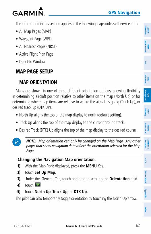
Garmin G3X Touch Pilot’s Guide190-01754-00 Rev. T 149
GPS Navigation
System
Overview
Flight Instrum
entsEIS
CNS
InterfaceG
PS N
avigationFlight
PlanningH
azard Avoidance
AdditionalFeatures
AFCS
Annun/A
lertsA
ppendixIndex
The information in this section applies to the following maps unless otherwise noted:
• All Map Pages (MAP)
• Waypoint Page (WPT)
• All Nearest Pages (NRST)
• Active Flight Plan Page
• Direct-to Window
MAP PAGE SETUP
MAP ORIENTATION
Maps are shown in one of three different orientation options, allowing flexibility in determining aircraft position relative to other items on the map (North Up) or for determining where map items are relative to where the aircraft is going (Track Up), or desired track up (DTK UP).
• North Up aligns the top of the map display to north (default setting).
• Track Up aligns the top of the map display to the current ground track.
• Desired Track (DTK) Up aligns the top of the map display to the desired course.
NOTE: Map orientation can only be changed on the Map Page. Any other pages that show navigation data reflect the orientation selected for the Map Page.
Changing the Navigation Map orientation:1) With the Map Page displayed, press the MENU Key.
2) Touch Set Up Map.
3) Under the ‘General’ Tab, touch and drag to scroll to the Orientation field.
4) Touch .
5) Touch North Up, Track Up, or DTK Up.
The pilot can also temporarily toggle orientation by touching the North Up arrow.

Garmin G3X Touch Pilot’s Guide 190-01754-00 Rev. T150
GPS Navigation
Syst
em
Ove
rvie
wFl
ight
In
stru
men
tsEI
SCN
SIn
terf
ace
GPS
N
avig
atio
nFl
ight
Plan
ning
Haz
ard
Avoi
danc
eA
dditi
onal
Fe
atur
esA
FCS
Ann
un/A
lert
sA
ppen
dix
Inde
x
The North Up toggle button behavior is dependant on the selected Map Orientation:
Map Orientation Toggle ActionNorth Up Track UpTrack Up North UpDTK Up North Up
North Up Arrow Button
North Up Arrow Button
Setting the range above which to display North Up orientation:1) With the Map Page displayed, press the MENU Key.
2) Touch Set Up Map.
3) Under the ‘General’ Tab, touch and drag to scroll to the North Up Above field.
4) Touch .
5) Touch the desired range.
Enabling/disabling North Up orientation on the ground:1) With the Map Page displayed, press the MENU Key.
2) Touch Set Up Map.
3) Under the ‘General’ Tab, touch and drag to scroll to the North Up On Ground field.
4) Touch .
5) Touch On or Off.

Garmin G3X Touch Pilot’s Guide190-01754-00 Rev. T 151
GPS Navigation
System
Overview
Flight Instrum
entsEIS
CNS
InterfaceG
PS N
avigationFlight
PlanningH
azard Avoidance
AdditionalFeatures
AFCS
Annun/A
lertsA
ppendixIndex
DISPLAY FLIGHT PLAN INFORMATION ON MAP/CHARTS PAGE
With the flight plan information displayed on the Map/Charts Page (see procedure below), touch the flight plan to quickly access the Active Flight Plan Page.
Flight Plan Displayed on Map Page
Touch to Display Flight Plan Page
Displaying/removing flight plan information on the map/charts page:1) With the Map Page displayed, press the MENU Key.
2) Touch Set Up Map.
3) Under the ‘General’ Tab, touch and drag to scroll to the Flight Plan Info field.
4) Touch .
5) Touch On or Off.

Garmin G3X Touch Pilot’s Guide 190-01754-00 Rev. T152
GPS Navigation
Syst
em
Ove
rvie
wFl
ight
In
stru
men
tsEI
SCN
SIn
terf
ace
GPS
N
avig
atio
nFl
ight
Plan
ning
Haz
ard
Avoi
danc
eA
dditi
onal
Fe
atur
esA
FCS
Ann
un/A
lert
sA
ppen
dix
Inde
x
AIRPORTS & NAVAIDS
Airport and NAVAID information can be customized to display a variety of information including: runway extension lines, runway numbers and visual reporting points (VRP). Runway extension lines show runway orientation relative to other landmarks and terrain features and are intended to aid in planning traffic pattern entry and/or departure routing.
Runway Extensions and Numbers (Map Page)
Runway Number
Runway Extension
Line
Setting up and customizing airports and NAVAIDs for the map page:1) With the Map Page displayed, press the MENU Key.
2) Touch Set Up Map.
3) Touch and drag the tabs left or right to find the desired tab.
4) Touch the ‘Airport’ or ‘Navaid’ Tab.
5) Touch the to display a list of options.
6) Touch the desired settings for each feature (on, off, auto, range, text size, etc.).
MAP TYPE
From the Map Setup Page the pilot can display either VFR or IFR maps. Refer to Section 5.4 for information on displaying/removing IFR airways.
Changing the Map Type (VFR/IFR):1) With the Map Page displayed, press the MENU Key.
2) Touch Set Up Map.
3) Touch the ‘Map’ Tab.

Garmin G3X Touch Pilot’s Guide190-01754-00 Rev. T 153
GPS Navigation
System
Overview
Flight Instrum
entsEIS
CNS
InterfaceG
PS N
avigationFlight
PlanningH
azard Avoidance
AdditionalFeatures
AFCS
Annun/A
lertsA
ppendixIndex
4) Touch .
5) Touch VFR or IFR.
AIRSPACE
Setting up and customizing airspace for the map page:1) With the Map Page displayed, press the MENU Key.
2) Touch Set Up Map.
3) Touch and drag the tabs left or right to find the desired tab.
4) Touch the ‘Airspace’ Tab.
5) Touch the to display a list of options.
6) Touch the desired option for each airspace (on, off, auto, range, all (Atlantic), or below (Atlantic)).
MAP RANGE
NOTE: Refer to the Additional Features section for information on changing the FliteCharts® or ChartView range.
There are 23 different map ranges available (distances are dependant on configuration). The current range is indicated in the lower right corner of the map. The scale bar represents the map scale. To change the map range on any map, use the knob or touch the ‘+’ (decrease visible range) or the ‘-’ (increase visible range).
Map Range
Scale Bar Rep-resenting a Map Scale of 20 nm Per Scale Width.

Garmin G3X Touch Pilot’s Guide 190-01754-00 Rev. T154
GPS Navigation
Syst
em
Ove
rvie
wFl
ight
In
stru
men
tsEI
SCN
SIn
terf
ace
GPS
N
avig
atio
nFl
ight
Plan
ning
Haz
ard
Avoi
danc
eA
dditi
onal
Fe
atur
esA
FCS
Ann
un/A
lert
sA
ppen
dix
Inde
x
AUTO ZOOM
Auto Zoom allows the G3X Touch to change the map display range to the smallest range clearly showing the active waypoint. Auto Zoom can be overridden by adjusting the range and remains that way until the active waypoint changes, a terrain or traffic alert occurs, or the aircraft takes off.
Safe Taxi also affects Auto Zoom. When the aircraft has landed at the destination airport, the navigation map automatically zooms in to display the Safe Taxi diagram.
Enabling/disabling Auto Zoom:1) With the Map Page displayed, press the MENU Key.
2) Touch Set Up Map.
3) Under the ‘General’ Tab, find the Autozoom field.
4) Touch .
5) Touch On or Off.
MAP PANNINGMap panning allows the pilot to:
• View parts of the map outside the displayed range without adjusting the map range
• Highlight and select locations on the map
• Review information for a selected airport, NAVAID or user waypoint
• Designate locations for use in flight planning
• View airspace and airway information
To pan the map, touch and drag the map. Touch a map feature to get additional information. The map feature button shows not only the feature name (such as airport designation or waypoint name) but also shows the type (airport, waypoint, etc.). If multiple features are present at the map feature position, a green arrow will appear on the map feature button. Touch or to cycle through the list of map features present at that position.

Garmin G3X Touch Pilot’s Guide190-01754-00 Rev. T 155
GPS Navigation
System
Overview
Flight Instrum
entsEIS
CNS
InterfaceG
PS N
avigationFlight
PlanningH
azard Avoidance
AdditionalFeatures
AFCS
Annun/A
lertsA
ppendixIndex
Map Panning (Map Page)
Information Box
Green Arrow Indicating
Multiple Features are
Present at the Location.
Elevation of the Selected Map Feature
Bearing and Distance to the Selected Map Feature from the Aircraft’s Present PositionLatitude/Longitude Position of the Selected Map Feature
Map Feature (Type and
Name)
Center on Aircraft’s Current Location
Time to selected waypoint at the aircraft's current speed
Press button to create a User Waypoint at this location
Panning the map:1) From any map, touch and drag.
2) Touch to re-center the map on the aircraft’s current position.
Or:
Touch the Back button.
Reviewing information for a map feature:1) From any map, touch a map feature.
2) If multiple map features are present, touch to cycle through the list.
3) Touch the Map Feature button to display additional information.

Garmin G3X Touch Pilot’s Guide 190-01754-00 Rev. T156
GPS Navigation
Syst
em
Ove
rvie
wFl
ight
In
stru
men
tsEI
SCN
SIn
terf
ace
GPS
N
avig
atio
nFl
ight
Plan
ning
Haz
ard
Avoi
danc
eA
dditi
onal
Fe
atur
esA
FCS
Ann
un/A
lert
sA
ppen
dix
Inde
x
FUEL RANGE RING
WARNING: The G3X Touch Fuel Calculator and/or Fuel Range Rings are NOT intended to be relied upon as the primary fuel indicator(s), and does not relieve the pilot from the responsibility of proper flight planning. G3X Touch fuel calculations do not use the aircraft fuel quantity indicators and are calculated from the last time the fuel was reset.
The Navigation Map can display fuel range rings which show the remaining flight distance. If current fuel endurance is greater than reserve, range-to-empty is shown as a solid green circle and range-to-reserve is a dashed green circle. If current endurance is less than reserve, range-to-empty is shown as a solid yellow circle. Fuel range rings are offset to show the effects of the wind at the current location (e.g., does not account for wind variations throughout the range).
Displaying/removing the fuel range rings and selecting a fuel reserve time:1) With the Map Page displayed, press the MENU Key.
2) Touch Set Up Map.
3) Touch and drag the tabs left or right to find the desired tab.
4) Touch the ‘Map’ Tab.
5) Touch the in the Fuel Range (RSV) field, and touch On or Off.
6) Touch ‘+’ or ‘-’ to adjust the fuel range reserve time (HH:MM).
Range to Empty
Navigation Map
Range to Reserve

Garmin G3X Touch Pilot’s Guide190-01754-00 Rev. T 157
GPS Navigation
System
Overview
Flight Instrum
entsEIS
CNS
InterfaceG
PS N
avigationFlight
PlanningH
azard Avoidance
AdditionalFeatures
AFCS
Annun/A
lertsA
ppendixIndex
GLIDE RANGE RING
NOTE: The Glide Range Ring behavior changes when Smart Glide™ is enabled. Refer to the Smart Glide section in the Appendices for more information.
NOTE: Glide Range Ring options are disabled when Outside Air Temperature (OAT) is not available.
NOTE: In order for the Glide Range Ring to display on the map, Best Glide Speed (VG) and Sink Rate (at VG) must be configured on the Aircraft Con-figuration Page in Configuration Mode. Refer to the G3X Touch Installation Manual for more information.
NOTE: Many factors, such as winds at various altitudes, terrain, aircraft configuration, and pilot actions affect the ability to accurately estimate the gliding range of an aircraft. The Glide Range Ring is for reference only and is not a substitute for the Emergency Procedures and glide distance information in the aircraft Pilot's Operating Handbook.
The Glide Range Ring is displayed as a cyan ring around the estimated area that can be reached by the aircraft in the best glide range configuration. The Glide Range Ring fades into view on the map as the aircraft climbs through 500 feet AGL. The range is based on the Best Glide Speed (VG) and Sink Rate (at VG) entered by the pilot. Best Glide and Sink Rate are combined with the aircraft's height (AGL), wind, and bank angle to determine the distance the aircraft can travel.
Navigation Map - Glide Range Ring(Ideal Descent Profile - No Wind)
Glide Range Ring
Navigation Map - Glide Range Ring(Ideal Descent Profile - Wind 245˚ at 25 kts)

Garmin G3X Touch Pilot’s Guide 190-01754-00 Rev. T158
GPS Navigation
Syst
em
Ove
rvie
wFl
ight
In
stru
men
tsEI
SCN
SIn
terf
ace
GPS
N
avig
atio
nFl
ight
Plan
ning
Haz
ard
Avoi
danc
eA
dditi
onal
Fe
atur
esA
FCS
Ann
un/A
lert
sA
ppen
dix
Inde
x
When the aircraft is not being flown in an ideal best glide descent, the range of the cyan circle decreases and arrows are displayed depicting how far the aircraft is from an ideal descent profile.
Navigation Map - Glide Range Ring (NOT Ideal Descent)
Glide Range Ring
Enabling/disabling the Glide Range Ring:1) With the Map Page displayed, press the MENU Key.
2) Touch Set Up Map....
3) Touch and drag the tabs left or right to find the desired tab.
4) Touch the ‘Map’ Tab.
5) Touch and drag the page up or down to find the Glide Range Ring field.
6) Touch the in the Glide Range Ring field, and touch On or Off.
Map Setup Page
Touch to Enable / Disable Glide Range Ring

Garmin G3X Touch Pilot’s Guide190-01754-00 Rev. T 159
GPS Navigation
System
Overview
Flight Instrum
entsEIS
CNS
InterfaceG
PS N
avigationFlight
PlanningH
azard Avoidance
AdditionalFeatures
AFCS
Annun/A
lertsA
ppendixIndex
BEST AIRPORT BEARING POINTER
NOTE: In order to display the Best Airport Bearing Pointer, Best Glide Speed and Sink Rate (at VG) must be configured on the Aircraft Configuration Page in Configuration Mode. Refer to the G3X Touch Installation Manual for more information.
The Best Airport Bearing Pointer points to the airport within the Glide Range Ring that is considered the best option for a landing based on the following criteria:
1) The airport must be within glide range as determined by the following:
a) User entered glide performance (Sink Rate and Best Glide Speed).
b) Aircraft altitude and direction of flight.
c) Airport elevation.
d) Wind velocity.
2) The expected flyover altitude (i.e., airports with 1000' or greater margin take precedence).
3) Hard surface runways (i.e., paved runways take precedence over grass runways).
4) Runway lengths.
5) Runway alignment with the wind (if known).
Enabling/disabling the Best Airport Bearing Pointer:1) With the full screen PFD displayed, press the MENU Key.
2) Touch next to a bearing pointer to display the bearing pointer options.
3) Touch Best Airport.
PFD Options
Touch to Display the
Best Airport Bearing Pointer

Garmin G3X Touch Pilot’s Guide 190-01754-00 Rev. T160
GPS Navigation
Syst
em
Ove
rvie
wFl
ight
In
stru
men
tsEI
SCN
SIn
terf
ace
GPS
N
avig
atio
nFl
ight
Plan
ning
Haz
ard
Avoi
danc
eA
dditi
onal
Fe
atur
esA
FCS
Ann
un/A
lert
sA
ppen
dix
Inde
x
HSI with Bearing Pointers
Bearing Pointer 2(Nearest Airport)
Bearing Pointer 1
(Best Airport)
Bearing 1 Information Window(Identifier, Distance)
Bearing 2 Information Window (Identifier, Distance)
BEST AIRPORT LINEThe Best Airport Line points to the same airport as the Best Airport Bearing Pointer
but is available on the MFD and Split Screen Map displays instead of the HSI. The line appears as a series of cyan chevrons between the aircraft marker and the recommended glide-to airport.
Displaying/removing the Best Airport Line:1) With the Map Page displayed, press the MENU Key.
2) Touch Set Up Map.
3) Touch and drag the tabs left or right to find the desired tab.
4) Touch the ‘Line’ Tab.
5) In the Best Airport Line field, touch On or Off.

Garmin G3X Touch Pilot’s Guide190-01754-00 Rev. T 161
GPS Navigation
System
Overview
Flight Instrum
entsEIS
CNS
InterfaceG
PS N
avigationFlight
PlanningH
azard Avoidance
AdditionalFeatures
AFCS
Annun/A
lertsA
ppendixIndex
Navigation Map
Selected Altitude Intercept Arc
Navigation Map
Best Airport
Line
Glide Range
Ring
SELECTED ALTITUDE INTERCEPT ARCThe map can display the location along the current track where the aircraft will
intercept the selected altitude. The location will be shown as a cyan arc when the aircraft is climbing or descending.
Displaying/removing the selected altitude intercept arc:1) With the Map Page displayed, press the MENU Key.
2) Touch Set Up Map.
3) Touch and drag the tabs left or right to find the desired tab.
4) Touch the ‘Map’ Tab.
5) In the Selected Altitude Intercept Arc field, touch On or Off.
MEASURING BEARING AND DISTANCEThe ‘Measure Distance’ option on Map Page menu is useful for measuring the distance
between two points on the map. The distance tool displays a dashed Measurement Line and a Map Pointer to aid in graphically identifying points to measure. Lat/Long, bearing, distance, and elevation data is provided.
Measuring bearing and distance between any two points:1) From the Map Page, press the MENU Key.2) Touch Measure Distance.3) Touch any point on the viewable navigation map to select the first reference
point.4) Touch Set Ref to select the second reference point to receive distance and
bearing information from the first reference point to the second reference point.

Garmin G3X Touch Pilot’s Guide 190-01754-00 Rev. T162
GPS Navigation
Syst
em
Ove
rvie
wFl
ight
In
stru
men
tsEI
SCN
SIn
terf
ace
GPS
N
avig
atio
nFl
ight
Plan
ning
Haz
ard
Avoi
danc
eA
dditi
onal
Fe
atur
esA
FCS
Ann
un/A
lert
sA
ppen
dix
Inde
x
Map Page (Measure Distance)
Measurement Line
Reference Point
TOPOGRAPHYTopographic data can be displayed or removed as described in the following
procedures.Displaying/removing topographic data:1) From the Map Page, press the MENU Key.2) Touch Topo Shading.
Topographic Shading (Map Page)
MAP PAGE TRAFFICEnabling/disabling traffic on the Map Page:1) From the Map Page, press the MENU Key.
2) Touch Traffic.
Enabling/disabling TargetTrend Overlay:1) From the Map Page, press the MENU Key.
2) Touch Set Up Map.

Garmin G3X Touch Pilot’s Guide190-01754-00 Rev. T 163
GPS Navigation
System
Overview
Flight Instrum
entsEIS
CNS
InterfaceG
PS N
avigationFlight
PlanningH
azard Avoidance
AdditionalFeatures
AFCS
Annun/A
lertsA
ppendixIndex
3) Under the ‘Traffic’ Tab, touch and drag to scroll to the TargetTrend field.
4) Touch .
5) Touch On or Off.
MAP SYMBOLSRefer to Appendix G for a list of map symbols.
MAP DECLUTTER
The pilot can remove (declutter) unwanted items, such as highways from the map.
Decluttering the Map Page:1) From the Map Page, press the MENU Key.
2) Touch -1, -2, or -3 under Map Detail.
MAP DETAIL
The map detail can also be adjusted. Map detail changes the amount of detail with respect to the zoom scale.
1) From the Map Page, press the MENU Key.
2) Touch Set Up Map.
3) Touch and drag the tabs left or right to find the desired tab.
4) Touch the ‘General’ Tab.
5) Touch the in the Detail Level field.
6) Touch Least, Less, Normal, More, or Most.

Garmin G3X Touch Pilot’s Guide 190-01754-00 Rev. T164
GPS Navigation
Syst
em
Ove
rvie
wFl
ight
In
stru
men
tsEI
SCN
SIn
terf
ace
GPS
N
avig
atio
nFl
ight
Plan
ning
Haz
ard
Avoi
danc
eA
dditi
onal
Fe
atur
esA
FCS
Ann
un/A
lert
sA
ppen
dix
Inde
x
FeatureS DiSplayeD at eaCh Map Detail level
Feature 0 1 2 3 Feature 0 1 2 3
River/Lake Names • Danger Areas • •
Land/Country Text • Warning Areas • •
Large City • Large Airports • • •
Medium City • Medium Airports • • •
Small City • Restricted Areas • •
Small Town • Prohibited Areas • • • •
Freeways • MOAs • •
Highways • Runway Labels • • •
Roads • Lightning Strike Data • • •
Railroads • NEXRAD Data • • • •
Political Boundaries • • • • Traffic Symbols • • • •
User Waypoints • • Traffic Labels • • • •
VORs • • • Lakes/Major Rivers • • • •
NDBs • • • Minor Rivers •
Intersections • • • Active FPL Legs • • • •
Class B Airspace • • Airways • • •
Class C Airspace • • Proximity Circles • • •
Class D Airspace • • Storm Cells • •
Tower • • • • Fronts • • •
TRSA • • AIRMET • •
ADIZ • • SIGMET • •
Alert Areas • • TFR • • • •
Caution Areas • •
Features Displayed at Each Map Detail Level

Garmin G3X Touch Pilot’s Guide190-01754-00 Rev. T 165
GPS Navigation
System
Overview
Flight Instrum
entsEIS
CNS
InterfaceG
PS N
avigationFlight
PlanningH
azard Avoidance
AdditionalFeatures
AFCS
Annun/A
lertsA
ppendixIndex
5.3 AIRWAYS
Low Altitude Airways (or Victor Airways) primarily serve smaller piston-engine, propeller-driven airplanes on shorter routes and at lower altitudes. Airways are eight nautical miles wide and start 1,200 feet above ground level (AGL) and extend up to but not including 18,000 feet mean sea level (MSL). Low Altitude Airways are designated with a “V” before the airway number (hence the name “Victor Airways”) since they run primarily between VORs.
High Altitude Airways (or Jet Routes) primarily serve airliners, jets, turboprops, and turbocharged piston aircraft operating above 18,000 feet MSL. Jet Routes start at 18,000 feet MSL and extend upward to 45,000 feet MSL (altitudes above 18,000 feet are called “flight levels” and are described as FL450 for 45,000 feet MSL). Jet Routes are designated with a "J" before the route number.
Low Altitude Airways are drawn in gray. High Altitude Airways are drawn in green. When both types of airways are displayed, high altitude airways are drawn on top of Low Altitude Airways.
When airways are selected for display on the map, the airway waypoints (VORs, NDBs, and Intersections) are also displayed.
IFR Map
Airways may be displayed on the map at the pilot’s discretion.
Displaying/removing airways:1) Press the MENU Key twice.
2) Touch Setup.
3) Touch Map.

Garmin G3X Touch Pilot’s Guide 190-01754-00 Rev. T166
GPS Navigation
Syst
em
Ove
rvie
wFl
ight
In
stru
men
tsEI
SCN
SIn
terf
ace
GPS
N
avig
atio
nFl
ight
Plan
ning
Haz
ard
Avoi
danc
eA
dditi
onal
Fe
atur
esA
FCS
Ann
un/A
lert
sA
ppen
dix
Inde
x
4) Touch and drag the tabs left or right to find the desired tab or turn the large Knob associated with the MFD.
5) Touch the ‘Navaid’ Tab.
6) Touch the in the Airways field.
7) Touch Off, Low, High, or Both.
Reviewing information for an airway:1) With the IFR map displayed on the Map Page (see procedure above), touch
a map feature.
2) If multiple map features are present, touch or to cycle through the list.
3) With the airway selected, touch the Map Feature button to display additional information.
Low Altitude Airway Review Page
5.4 WAYPOINTS
The Waypoint (Wpt) Page provides airport and waypoint information.
Waypoints are predetermined geographical positions (internal database) or pilot-entered positions, and are used for all phases of flight planning and navigation.

Garmin G3X Touch Pilot’s Guide190-01754-00 Rev. T 167
GPS Navigation
System
Overview
Flight Instrum
entsEIS
CNS
InterfaceG
PS N
avigationFlight
PlanningH
azard Avoidance
AdditionalFeatures
AFCS
Annun/A
lertsA
ppendixIndex
Waypoints can be changed by entering the ICAO identifier, entering the name of the facility, or by entering the city name. As a waypoint identifier, facility name, or location is entered, the G3X Touch’s Spell’N’Find™ feature scrolls through the data-base, displaying those waypoints matching the characters which have been entered up to that point. A direct-to navigation leg to the selected waypoint can be initiated by pressing the Direct-to Key from the Waypoint Page.
The following descriptions and abbreviations are used:
• Usage type: Public, Military, or Private
• Runway surface type: Hard, Turf, Sealed, Gravel, Dirt, Soft, Unknown, or Water
• Runway lighting type: No Lights, Part Time, Full Time, Unknown, or PCL Freq (for pilot-controlled lighting)
• COM Availability: TX (transmit only), RX (receive only), PT (part time), * (additional information available)
Waypoint Page - Info Tab
Facility Name and Location
Map Showing Selected
Waypoint
Airport Info
COM/NAV Freq. Info
Runway Info

Garmin G3X Touch Pilot’s Guide 190-01754-00 Rev. T168
GPS Navigation
Syst
em
Ove
rvie
wFl
ight
In
stru
men
tsEI
SCN
SIn
terf
ace
GPS
N
avig
atio
nFl
ight
Plan
ning
Haz
ard
Avoi
danc
eA
dditi
onal
Fe
atur
esA
FCS
Ann
un/A
lert
sA
ppen
dix
Inde
x
Selecting an airport for review by identifier, facility name, or loca-tion:1) From the Waypoint (Wpt) Page, touch the waypoint identifier at the top of
the page.
2) Enter the waypoint identifier using the keypad and touch Enter.
Or:
Touch Find > Search Name > Search by Facility Name. Enter the facility name using the keypad and touch Enter.
Or:
Touch Find > Search City > Search by City. Enter the city name using the keypad and touch Enter.
If duplicate entries exist for an identifier, a Duplicates Found Window is displayed. Touch the desired options from the Duplicates Found Window.
Selecting a runway:1) From the Waypoint (Wpt) Page, touch the Runway Tab if necessary.
2) Touch the waypoint identifier at the top of the page.
3) Enter the waypoint identifier using the keypad and touch Enter.
4) If necessary, touch the to display additional runways. Touch the desired runway.
Runway Selection
Touch to Tune Runway Lights Frequency

Garmin G3X Touch Pilot’s Guide190-01754-00 Rev. T 169
GPS Navigation
System
Overview
Flight Instrum
entsEIS
CNS
InterfaceG
PS N
avigationFlight
PlanningH
azard Avoidance
AdditionalFeatures
AFCS
Annun/A
lertsA
ppendixIndex
Viewing additional information for a frequency:
The Freq Tab uses the descriptions and abbreviations listed in the following table:
Communication Frequencies Navigation Frequencies
Approach *Arrival *ASOSATISAWOSCenterClass B *Class C *Clearance
ControlCTA *Departure *GateGroundHelicopterMulticomOther
Pre-TaxiRadarRampTerminal*TMA *TowerTRSA *Unicom
ILSLOC
* May include Additional Information
Frequency Abbreviations
1) With the Waypoint (WPT) Page displayed, touch the Freq Tab.
2) Touch the desired frequency to tune.
3) Touch the (i) button to view addional information.
AUTOMATIC WAYPOINT SELECTIONAutomatic waypoint selection is the system’s attempt to deduce what Waypoint
to display based on the aircraft’s location in relation to the departure airport and/or the waypoints in the Flight Plan.
The pilot can override Automatic Waypoint Selection by manually entering a way-point. The automatic selection will not resume until such time the manually entered waypoint and the automatically selected waypoint coincide.

Garmin G3X Touch Pilot’s Guide 190-01754-00 Rev. T170
GPS Navigation
Syst
em
Ove
rvie
wFl
ight
In
stru
men
tsEI
SCN
SIn
terf
ace
GPS
N
avig
atio
nFl
ight
Plan
ning
Haz
ard
Avoi
danc
eA
dditi
onal
Fe
atur
esA
FCS
Ann
un/A
lert
sA
ppen
dix
Inde
x
NEAREST INFORMATIONThe G3X Touch provides a NRST Key which gives the pilot quick access to nearest
airport, weather, VOR, NDB, intersection, user waypoint, city, ARTCC, FSS, VRPs, and airspace information. If none are available, “None Within 200 NM” is displayed. "No Immediate Airspace" is displayed if airspace is not within 10 minutes based on current speed, track, and altitude.
Viewing nearest information:1) Press the NRST Key.
2) Touch the Page Navigation Bar.
3) Touch Airports, Airport Weather, VORs, NDBs, Intersections, User Waypoints, Cities, ARTCC, FSS, VRPs, or Airspace.
4) Touch the desired option from the list.
NEAREST AIRPORT CRITERIA
From the Menu on the Nearest Airports Page the pilot can define the minimum runway length and surface type used when determining the 15 nearest airports to display on the Nearest Airports Page. A minimum runway length and/or surface type can be entered to prevent airports with small runways or runways that are not appropriately surfaced from being displayed. Default settings are 0 feet (or meters) for runway length and “Any” for runway surface type. Private airports and Heliports can also be included.
The Page Menu also allows the pilot to choose between displaying the facility names and city names.
• Runway Surface: Allows the pilot to set criteria for the type of surface on the runway. – Any: Shows any runway, regardless of surface type, including water landing facili-
ties. – Hard only: Shows only runways with a concrete, asphalt, or similar sealed surface. – Hard or Soft: Shows all runways except water landing facilities. – Water only: Shows only water landing facilities.

Garmin G3X Touch Pilot’s Guide190-01754-00 Rev. T 171
GPS Navigation
System
Overview
Flight Instrum
entsEIS
CNS
InterfaceG
PS N
avigationFlight
PlanningH
azard Avoidance
AdditionalFeatures
AFCS
Annun/A
lertsA
ppendixIndex
• Minimum Runway Length: Allows the pilot to enter a specific length for the shortest runway allowed.
• Include Private Airports: Allows the pilot to include Private Airports in the search criteria.
Entering airport/heliport criteria:1) Press the NRST Key.
2) Press the MENU Key.
3) Touch the Runway Surface field and touch Hard only, Hard/Soft, Water only, or Any.
Or:
Touch the Min Runway Length value and enter the value using the keypad.
Or:
Touch Private Airports.
Or:
Touch Heliports.
Or:
Touch City Names: Displays city names below the airport identifier on the Nearest APT Page.
Or:
Touch Facility Names: Displays facility names below the airport identifier on the Nearest APT Page.
WEATHER INFORMATIONTextual weather information can be viewed from the Waypoint Page.
Selecting airport weather information: From the Waypoint Page, touch the Weather Tab.
Or:
From the Nearest Airport Weather Page, touch the desired airport and touch the Weather Tab.

Garmin G3X Touch Pilot’s Guide 190-01754-00 Rev. T172
GPS Navigation
Syst
em
Ove
rvie
wFl
ight
In
stru
men
tsEI
SCN
SIn
terf
ace
GPS
N
avig
atio
nFl
ight
Plan
ning
Haz
ard
Avoi
danc
eA
dditi
onal
Fe
atur
esA
FCS
Ann
un/A
lert
sA
ppen
dix
Inde
x
INTERSECTIONSIntersections can be viewed from the Waypoint Page or the Nearest Intersections
Page. In addition to displaying a map of the currently selected intersection and surrounding area, the Intersection Information Page displays the region, bearing, distance, latitude, and longitude.
Selecting an intersection:1) From the Waypoint (Wpt) Page.
2) Touch the waypoint identifier at the top of the page.
3) Enter the intersection using the keypad and touch Enter.
Or:
1) Press the NRST Key.
2) Touch the Page Navigation Bar.
3) Touch Intersections.
4) Touch the desired intersection from the list.
NDBS
NDBs can be viewed from the Waypoint Page or the Nearest NDBs Page. In addition to displaying a map of the currently selected NDB and surrounding area, the page displays the region, bearing, distance, latitude, longitude, frequency, identifier, name, city, state, NDB type, and More Code identification.
The Nearest NDB Page can be used to quickly find a NDB close to the flight path. The list only includes NDBs that are within 200nm. If there are no NDBs in the list, text indicating that there are no nearest NDBs is displayed. If there are no nearest NDBs in the list, the information and frequency fields are dashed.
Selecting a NDB:1) From the Waypoint (Wpt) Page.
2) Touch the waypoint identifier at the top of the page.
3) Enter the NDB identifier using the keypad and touch Enter.
Or:
1) Press the NRST Key.

Garmin G3X Touch Pilot’s Guide190-01754-00 Rev. T 173
GPS Navigation
System
Overview
Flight Instrum
entsEIS
CNS
InterfaceG
PS N
avigationFlight
PlanningH
azard Avoidance
AdditionalFeatures
AFCS
Annun/A
lertsA
ppendixIndex
2) Touch the Page Navigation Bar.
3) Touch NDBs.
4) Touch the desired NDB from the list.
VORS
VORs can be viewed from the Waypoint Page or the Nearest VORs Page. In addition to displaying a map of the currently selected VOR and surrounding area, the page displays the region, city, state, bearing, distance, latitude, longitude, frequency, class (High, Low, or Terminal VOR), facility name, and aircraft's current radial from the VOR.
The Nearest VOR Page can be used to quickly find a VOR close to the flight path. The list only includes VORs that are within 200nm. If there are no VORs in the list, "None Within 200nm" is displayed.
Selecting a VOR:1) From the Waypoint (Wpt) Page.
2) Touch the waypoint identifier at the top of the page.
3) Enter the VOR identifier using the keypad and touch Enter.
Or:
1) Press the NRST Key.
2) Touch the Page Navigation Bar.
3) Touch VORs.
4) Touch the desired VOR from the list.
USER WAYPOINTSThe G3X Touch can create and store up to 3,000 user-defined waypoints. Once a
waypoint has been created, it can be renamed, deleted, or moved.
NOTE: Most terrain and obstacle warnings will be suppressed when the aircraft is determined to be taking off or landing at an airport - including an airport that's defined by a user waypoint (that has been saved as an airport symbol) instead of the navigation database.

Garmin G3X Touch Pilot’s Guide 190-01754-00 Rev. T174
GPS Navigation
Syst
em
Ove
rvie
wFl
ight
In
stru
men
tsEI
SCN
SIn
terf
ace
GPS
N
avig
atio
nFl
ight
Plan
ning
Haz
ard
Avoi
danc
eA
dditi
onal
Fe
atur
esA
FCS
Ann
un/A
lert
sA
ppen
dix
Inde
x
Creating user waypoints:1) Touch anywhere on the map.
Or:
1) Touch aircraft symbol on the map.
2) Touch the Latitude/Longitude Location Button.
3) Optionally, touch the Name field to enter the new waypoint name and touch Enter.
4) Touch the default symbol.
5) Touch the desired symbol.
6) If desired touch the Altitude value.
7) Enter the desired altitude and touch Enter.
8) If desired touch the Location value.
9) Touch the arrows to change the location and touch Enter.
Marking Current Location as a Waypoint:1) From the Info Page, touch the latitude and longitude.
Or:
1) From the Info Page, press the MENU Key, and touch Mark Waypoint.
2) Touch Yes on the confirmation dialog box.
3) Optionally touch the Name field to rename the waypoint.
4) Touch Back.
Creating a proximity waypoint:1) Press the MENU Key twice.
2) Touch User Waypoints.
3) Touch the Proximity Tab.
4) Press the Menu Key.
5) Touch New Proximity Waypoint.
a) Touch Use Identifier.
b) Enter the desired identifier using the keypad.
Or:
a) Touch Use Map.

Garmin G3X Touch Pilot’s Guide190-01754-00 Rev. T 175
GPS Navigation
System
Overview
Flight Instrum
entsEIS
CNS
InterfaceG
PS N
avigationFlight
PlanningH
azard Avoidance
AdditionalFeatures
AFCS
Annun/A
lertsA
ppendixIndex
b) Touch anywhere on the map. If the location does not correspond to a waypoint, a user waypoint will be created at that location.
6) Touch Enter.
Selecting and viewing nearest user waypoints:1) Press the NRST Key.
2) Touch User Waypoints.
3) Touch the desired user waypoint.
Editing or renaming a user waypoint:1) Press the NRST Key.
2) Touch User Waypoints.
3) Touch the desired user waypoint.
4) Press the MENU Key.
5) Touch Edit Waypoint.
6) Touch the desired field to edit.
7) Make the necessary changes and touch Back.
Deleting user waypoints:1) Press the NRST Key.
2) Touch User WPTs.
3) Touch the desired user waypoint.
4) Press the MENU Key.
5) Touch Delete Waypoint.
6) Touch Yes.
IMPORTING/EXPORTING USER WAYPOINTS
G3X Touch supports importing/exporting user waypoints to/from a GPX file on the SD Card via the User Waypoints Page. However FPL files may also contain user waypoints. Through the process of importing these files via the Flight Plan List Page, any user waypoints in the imported flight plan are saved to the internal database and are displayed on the User Waypoints Page. Garmin® Basecamp is an option for creating an applicable GPX file.

Garmin G3X Touch Pilot’s Guide 190-01754-00 Rev. T176
GPS Navigation
Syst
em
Ove
rvie
wFl
ight
In
stru
men
tsEI
SCN
SIn
terf
ace
GPS
N
avig
atio
nFl
ight
Plan
ning
Haz
ard
Avoi
danc
eA
dditi
onal
Fe
atur
esA
FCS
Ann
un/A
lert
sA
ppen
dix
Inde
x
Importing user waypoints:1) Press the MENU Key twice.
2) Touch User Waypoints.
3) Press the Menu Key.
4) Touch Import.
5) Touch Yes.
Exporting user waypoints:1) Press the MENU Key twice.
2) Touch User Waypoints.
3) Press the Menu Key.
4) Touch Export.
5) Touch Yes.
5.5 AIRSPACE
The Nearest Airspace Page and Airspace Alerts provide information about airspaces and the location of the aircraft in relationship to them. The Nearest Airspace Page can be used to quickly find airspaces close to the flight path.
The Nearest Airspace Page displays the class of airspace, controlling agency, vertical boundaries, and status.
Selecting and viewing nearest airspaces:1) Press the NRST Key.
2) Touch the Page Navigation Bar.
3) Touch Airspace.
4) Touch the desired airspace.
AIRSPACE ALERT MESSAGESWhen an airspace alert appears, press the NRST Key to automatically show nearby
airspace information on the Nearest Airspace Page. This information includes name, time to entry (if applicable), and status.

Garmin G3X Touch Pilot’s Guide190-01754-00 Rev. T 177
GPS Navigation
System
Overview
Flight Instrum
entsEIS
CNS
InterfaceG
PS N
avigationFlight
PlanningH
azard Avoidance
AdditionalFeatures
AFCS
Annun/A
lertsA
ppendixIndex
There are four types of status information:
• Ahead—Projected to enter the airspace within the next 10 minutes or less
• Near—Within two nautical miles of an airspace but not projected to enter it
• Near & Ahead—Projected to enter the airspace within two nautical miles
• Inside Airspace—Within the boundaries of the airspace
SMART AIRSPACE™ AND ALTITUDE OVERLAYSSmart Airspace™ integration makes it easier for pilots to identify what airspace lies
ahead. This feature conveniently highlights the airspace nearest to the aircraft’s current altitude and de-emphasizes non-pertinent airspace so pilots can quickly distinguish their location to the relevant airspace around them.
Smart Airspace™
De-emphasized Airspace
Bold Airspace
Enabling/disabling Smart Airspace:
NOTE: Smart Airspace selection is not available if the Map Type is set to IFR instead of VFR since IFR flights do not have the same operational concerns with airspace.
1) Press the MENU Key twice.
2) Touch Setup.
3) Touch Map.
4) Touch and drag the tabs left or right to find the desired tab.
5) Touch the ‘Airspace’ Tab.
6) Touch and drag to display the 'Smart Airspace' field.
7) Touch the to display a list of options.
8) Touch On or Off.

Garmin G3X Touch Pilot’s Guide 190-01754-00 Rev. T178
GPS Navigation
Syst
em
Ove
rvie
wFl
ight
In
stru
men
tsEI
SCN
SIn
terf
ace
GPS
N
avig
atio
nFl
ight
Plan
ning
Haz
ard
Avoi
danc
eA
dditi
onal
Fe
atur
esA
FCS
Ann
un/A
lert
sA
ppen
dix
Inde
x
Additionally, airspace altitude overlays can be depicted on the moving map and reduce pilot workload, particularly in congested airspace. With airspace altitude overlays, pilots can easily view airspace maximum and minimum altitudes, so it’s easier to identify airspace altitude limitations at a glance.
Smart Airspace™ with Altitude Overlays
De-emphasized Altitude Overlay
Altitude Overlay
Enabling/disabling Altitude Overlays:1) Press the MENU Key twice.
2) Touch Setup.
3) Touch Map.
4) Touch and drag the tabs left or right to find the desired tab.
5) Touch the ‘Airspace’ Tab.
6) Touch and drag to display the 'Altitude Labels' field.
7) Touch the to display a list of options.
8) Touch Off, Auto, 2nm, 3nm, 5nm, 8nm, 12nm, 20nm, 30nm, 50nm, 80nm, or 120nm.

Garmin G3X Touch Pilot’s Guide190-01754-00 Rev. T 179
GPS Navigation
System
Overview
Flight Instrum
entsEIS
CNS
InterfaceG
PS N
avigationFlight
PlanningH
azard Avoidance
AdditionalFeatures
AFCS
Annun/A
lertsA
ppendixIndex
5.6 DIRECT-TO NAVIGATION USING THE G3X TOUCH
The Direct-to method of navigation, initiated by pressing the Direct-to Key is quicker to use than a flight plan when the desire is to navigate to a single point such as a nearby airport.
Once a direct-to is activated, the G3X Touch establishes a point-to-point course line from the present position to the selected direct-to destination. Course guidance is provided until the direct-to is replaced with a new direct-to or flight plan, or canceled.
Entering a waypoint identifier, facility name, or city as a direct-to destination:1) Press the Direct-to Key. The Direct-to Window is displayed (with the active
flight plan waypoint as the default selection or a blank waypoint field if no flight plan is active).
2) If an external navigator is configured, touch FPL Source > Internal from the FPL Page.
3) Touch the waypoint identifier.
4) Enter the waypoint identifier using the keypad and touch Enter.
Or:
Touch Find > Search Name > Search by Facility Name. Enter the facility name using the keypad and touch Enter.
Or:
Touch Find > Search City > Search by City. Enter the city name using the keypad and touch Enter.
5) Touch Activate.
Entering latitude and longitude coordinates as a direct-to destina-tion:1) Press the Direct-to Key. The Direct-to Window is displayed
2) Press the MENU Key.
3) Touch Enter Coordinates.
4) Specify coordinates, and touch Enter.
5) Touch Activate.

Garmin G3X Touch Pilot’s Guide 190-01754-00 Rev. T180
GPS Navigation
Syst
em
Ove
rvie
wFl
ight
In
stru
men
tsEI
SCN
SIn
terf
ace
GPS
N
avig
atio
nFl
ight
Plan
ning
Haz
ard
Avoi
danc
eA
dditi
onal
Fe
atur
esA
FCS
Ann
un/A
lert
sA
ppen
dix
Inde
x
Selecting Recent Waypoints, Nearest Airports, Flight Plan Way-points, or User Waypoints as a direct-to destination:1) Press the Direct-to Key. The Direct-to Window is displayed (with the active
flight plan waypoint as the default selection or a blank waypoint field if no flight plan is active).
2) If an external navigator is configured, touch FPL Source > Internal from the FPL Page.
3) Touch the waypoint identifier.
4) Touch Find
5) Touch the Recent Tab.
Or:
Touch the Nearest Airports Tab. When properly configured, the Best Glide Airport is displayed above the Nearest Airport List.
Or:
Touch the Flight Plan Tab.
Or:
Touch the User Tab.
6) Touch the desired waypoint.
7) Touch Activate.
Selecting a waypoint as a direct-to destination using the pointer:1) Touch anywhere on the map.
2) Press the Direct-to Key.
3) If an external navigator is configured, touch FPL Source > Internal from the FPL Page.
4) Touch Activate.
Canceling or resuming a direct-to:1) Press the Direct-to Key.
2) If an external navigator is configured, touch FPL Source > Internal from the FPL Page.
3) Touch Stop Navigation or Resume Flight.

Garmin G3X Touch Pilot’s Guide190-01754-00 Rev. T 181
Flight Planning
System
Overview
Flight Instrum
entsEIS
CNS
InterfaceG
PS N
avigationFlight
PlanningH
azard Avoidance
AdditionalFeatures
AFCS
Annun/A
lertsA
ppendixIndex
SECTION 6 FLIGHT PLANNING
6.1 INTRODUCTION
CAUTION: Only the final course segment (usually from the final approach fix to the missed approach point) of the published approach is available if an external navigator (i.e., GPS 175, GNX 375, GTN or GNS Series) is NOT configured.
NOTE: In order to add, delete, or change flight plan waypoints from the G3X Touch when an external GPS navigator is configured, touch FPL Source > Internal from the Active Flight Plan Page or Direct-to Page. Press the FPL Source > External to return to the external GPS navigator’s flight plan.
NOTE: While navigating using an external GPS navigation source, the ability to edit/invert/delete the Active Flight Plan or activate a Saved Flight Plan is disabled.
NOTE: Refer to section 8.11 (Connext Cockpit Connectivity) for information on wirelessly transferring flight plans from a mobile device (using Garmin® Pilot or Garmin Portables) to the G3X Touch or external navigator (if configured).
Flight planning on the G3X Touch consists of building a flight plan by entering waypoints one at a time and inserting approaches as needed. The flight plan is displayed on maps using different line widths, colors, and types, based on the type of leg and the segment of the flight plan currently being flown.
Up to 50 flight plans with up to 300 waypoints each can be created and stored in memory. One flight plan can be activated at a time and becomes the active flight plan. The active flight plan is erased when the destination is reached and the system is turned off. When storing flight plans with an approach, the G3X Touch uses the waypoint information from the current database to define the waypoints. If the database is changed or updated, the G3X Touch automatically updates the information. If an approach is no longer available, the procedure is deleted from the affected stored flight plan(s), and an alert is displayed.

Garmin G3X Touch Pilot’s Guide 190-01754-00 Rev. T182
Flight Planning
Syst
em
Ove
rvie
wFl
ight
In
stru
men
tsEI
SCN
SIn
terf
ace
GPS
N
avig
atio
nFl
ight
Plan
ning
Haz
ard
Avoi
danc
eA
dditi
onal
Fe
atur
esA
FCS
Ann
un/A
lert
sA
ppen
dix
Inde
x
Whenever an approach is loaded into the active flight plan it replaces the destination airport with a sequence of waypoints for the selected approach. The airport must have a published instrument approach and only the final course segment (usually from final approach fix to missed approach point) of the published approach is available if an external navigator (i.e., GPS 175, GNX 375, GTN or GNS Series) is not configured.
FLIGHT PLAN DATA FIELDS
Changing the information shown in the flight plan data fields:1) With a flight plan displayed, touch FPL Source > Internal if an external
navigator is configured (Active Flight Plan only).
2) Touch one of the data fields to change.
3) Touch the desired data field.
MANUALLY SWITCHING BETWEEN INTERNAL AND EXTERNAL FLIGHT PLAN SOURCES
NOTE: The selection of the GPS navigation source to persist through power cycles or reset to the external GPS navigation source is dependent on the configuration. Refer to the G3X Touch Installation Manual for more informa-tion.
NOTE: On a standalone MFD, touch 'GPS' in the lower left corner of the touchscreen to switch between 'Internal' and 'External' navigation sources.
Touch FPL Source > Internal on the Active Flight Plan Page or the Direct-to Page, to temporarily allow flight planning through the G3X Touch using the internal GPS flight plan when an external GPS Navigator is configured. Press the FPL Source > External to return to the external GPS navigator’s flight plan.
When manually selecting the internal GPS flight plan, ‘INT’ is displayed in cyan in the lower left quadrant of the HSI.
FAILURE OF THE EXTERNAL GPS NAVIGATION SOURCEIf the external GPS navigation source fails, the system reverts to the internal GPS
navigation source and ‘REV’ is shown in yellow in the lower left quadrant of the HSI.

Garmin G3X Touch Pilot’s Guide190-01754-00 Rev. T 183
Flight Planning
System
Overview
Flight Instrum
entsEIS
CNS
InterfaceG
PS N
avigationFlight
PlanningH
azard Avoidance
AdditionalFeatures
AFCS
Annun/A
lertsA
ppendixIndex
6.2 FLIGHT PLAN CREATION USING THE G3X TOUCH
The active flight plan is listed on the Active Flight Plan Page. It is the flight plan to which the G3X Touch is currently providing guidance, and is shown on the navigation maps. Stored flight plans are listed on the Flight Plan List Page, and are available for activation (becomes the active flight plan).
Active Flight Plan Page

Garmin G3X Touch Pilot’s Guide 190-01754-00 Rev. T184
Flight Planning
Syst
em
Ove
rvie
wFl
ight
In
stru
men
tsEI
SCN
SIn
terf
ace
GPS
N
avig
atio
nFl
ight
Plan
ning
Haz
ard
Avoi
danc
eA
dditi
onal
Fe
atur
esA
FCS
Ann
un/A
lert
sA
ppen
dix
Inde
x
Creating an active flight plan using the G3X Touch:1) Touch the Page Navigation Bar.
2) Touch Active FPL.
3) If an external navigator is configured, touch FPL Source > Internal.
4) Touch Add Waypoint.
5) Enter the waypoint using the keypad.
Or:
Touch Find > Recent Tab.
Or:
Touch Find > Nearest Airports Tab.
Or:
Touch Find > Flight Plan Tab.
Or:
Touch Find > User Tab.
Or:
Touch Find > Search Name > Search by Facility Name. Enter the facility name using the keypad.
Or:
Touch Find > Search City > Search by City. Enter the city name using the keypad.
6) Touch Enter.
7) Repeat steps 4-6 for each additional waypoint.
Creating a stored flight plan using the G3X Touch:1) Press the MENU Key twice.
2) Touch Flight Plan List.
3) Press MENU.
4) Touch New Flight Plan.
5) Touch Add Waypoint.

Garmin G3X Touch Pilot’s Guide190-01754-00 Rev. T 185
Flight Planning
System
Overview
Flight Instrum
entsEIS
CNS
InterfaceG
PS N
avigationFlight
PlanningH
azard Avoidance
AdditionalFeatures
AFCS
Annun/A
lertsA
ppendixIndex
6) Enter the waypoint using the keypad.
Or:
Touch Find > Recent Tab.
Or:
Touch Find > Nearest Airports Tab.
Or:
Touch Find > Flight Plan Tab.
Or:
Touch Find > User Tab.
Or:
Touch Find > Search Name > Search by Facility Name. Enter the facility name using the keypad.
Or:
Touch Find > Search City > Search by City. Enter the city name using the keypad.
7) Touch Enter.
8) Repeat steps 4-6 for each additional waypoint.
9) The new flight plan is now in the list.

Garmin G3X Touch Pilot’s Guide 190-01754-00 Rev. T186
Flight Planning
Syst
em
Ove
rvie
wFl
ight
In
stru
men
tsEI
SCN
SIn
terf
ace
GPS
N
avig
atio
nFl
ight
Plan
ning
Haz
ard
Avoi
danc
eA
dditi
onal
Fe
atur
esA
FCS
Ann
un/A
lert
sA
ppen
dix
Inde
x
6.3 AUTOMATIC SHARING OF G3X TOUCH FLIGHT PLANS WITH EXTERNAL IFR NAVIGATORS
The G3X Touch system has the ability to share (crossfill) flight plans created/edited on the G3X Touch (using internal flight planning) with compatible external IFR navigators. The IFR navigator must be correctly configured and wired to perform this function. To access the internal flight plan on the G3X Touch, touch FPL Source > Internal from the Active Flight Plan Page.
Once configured/wired correctly, when an internal flight plan is created using the G3X Touch, that flight plan is automatically shared (crossfilled) to the external IFR navigator.
If the G3X Touch is using internal flight planning during a VFR flight, the IFR navigator stays synchronized with any changes in the G3X Touch flight plan (this is useful if there is a need to switch to the IFR navigator during flight).
SIDs, STARs, and approaches cannot be loaded/activated from the G3X Touch display. Alternatively, a multi-point flight plan may be created/edited by switching to the external navigator. Touch FPL Source > External from the Active Flight Plan Page, to switch to the external IFR navigator, which does allow loading/activating an approach if needed.
NOTE: The G3X Touch system only crossfills multi-point flight plans with the external IFR navigator when using internal flight planning on the G3X Touch. Direct-To operations and single point flight plans are not crossfilled between the systems.
NOTE: Any Direct-To operation must be commanded on the active flight plan source (G3X Touch or IFR navigator) being used.
NOTE: Switch the G3X Touch system to external flight planning to use the IFR navigator for normal flight planning (including enroute, SIDs, STARs, and approaches).

Garmin G3X Touch Pilot’s Guide190-01754-00 Rev. T 187
Flight Planning
System
Overview
Flight Instrum
entsEIS
CNS
InterfaceG
PS N
avigationFlight
PlanningH
azard Avoidance
AdditionalFeatures
AFCS
Annun/A
lertsA
ppendixIndex
EXTERNAL IFR NAVIGATOR CROSSFILL CONFIGURATION (GPS 175, GNC 355, GNX 375, AND GTN 6XX/7XX (VERSION 6.62 AND NEWER ONLY))Two configuration changes are required to enable the crossfill function:
In normal mode, External FPL Crossfill must be enabled on the System Setup page.
External Flight Plan Crossfill Enabled (Normal Mode)
Enable External Flight Plan Crossfill
In configuration mode, External FPL must be enabled on the Main System configuration page.
External Flight Plan Enabled (Configuration Mode)
Enable External Flight Plan
Refer to the appropriate installation manual for instructions on entering configuration mode.

Garmin G3X Touch Pilot’s Guide 190-01754-00 Rev. T188
Flight Planning
Syst
em
Ove
rvie
wFl
ight
In
stru
men
tsEI
SCN
SIn
terf
ace
GPS
N
avig
atio
nFl
ight
Plan
ning
Haz
ard
Avoi
danc
eA
dditi
onal
Fe
atur
esA
FCS
Ann
un/A
lert
sA
ppen
dix
Inde
x
6.4 FLIGHT PLAN STORAGE USING THE G3X TOUCH
The G3X Touch can store up to 50 flight plans. The active flight plan is erased when another flight plan is activated. Details about each stored flight plan can be viewed on the Flight Plan List Page
Viewing information about a stored flight plan:1) Press the MENU Key twice.
2) Touch Flight Plan List.
3) Touch the desired flight plan.
4) Touch Edit.
Storing an active flight plan from the Active Flight Plan Page:1) From the Active Flight Plan, touch FPL Source > Internal if an external
navigator is configured.
2) Press the MENU Key.
3) Touch Save Copy.
6.5 FLIGHT PLAN ACTIVATION USING THE G3X TOUCH
Activating a stored flight plan erases the active flight plan and replaces it with a copy of the flight plan being activated. A saved approach will be moved to 'loaded' when activating a flight plan.
Inverting a stored flight plan reverses the waypoint order. Touching 'Invert' on a saved flight plan will invert the flight plan in place without activating it. The original flight plan is overwritten by the inverted flight plan. A flight plan cannot be inverted if it has an associated approach.

Garmin G3X Touch Pilot’s Guide190-01754-00 Rev. T 189
Flight Planning
System
Overview
Flight Instrum
entsEIS
CNS
InterfaceG
PS N
avigationFlight
PlanningH
azard Avoidance
AdditionalFeatures
AFCS
Annun/A
lertsA
ppendixIndex
Activating a stored flight plan:1) Press the MENU Key twice.
2) Touch Flight Plan List.
3) Touch the desired flight plan.
4) Touch Activate.
5) Touch Yes.
Or:
1) When editing a saved flight plan, press the MENU Key.
2) Touch Activate.
3) Touch Yes.
Activating a Flight Plan Leg:1) From the Active Flight Plan, touch FPL Source > Internal if an external
navigator is configured.
2) Touch the waypoint leg to be activated.
3) Touch Activate Leg.
4) Touch Yes.
Canceling an On Route Direct-To or Active Leg:1) Press the MENU Key.
2) Touch Resume Flight Plan.
Or:
1) Press the Direct-To Key.
2) Touch Resume Flight Plan.

Garmin G3X Touch Pilot’s Guide 190-01754-00 Rev. T190
Flight Planning
Syst
em
Ove
rvie
wFl
ight
In
stru
men
tsEI
SCN
SIn
terf
ace
GPS
N
avig
atio
nFl
ight
Plan
ning
Haz
ard
Avoi
danc
eA
dditi
onal
Fe
atur
esA
FCS
Ann
un/A
lert
sA
ppen
dix
Inde
x
6.6 FLIGHT PLAN EDITING
ADDING WAYPOINTS TO AN EXISTING FLIGHT PLANWaypoints can be added to the active internal flight plan or any stored flight plan.
Choose the flight plan, select the desired point of insertion, enter the waypoint, and it is added before or after the selected waypoint. Flight plans are limited to 300 waypoints (including approach waypoints).
Adding a waypoint to a flight plan:1) With a flight plan displayed, touch FPL Source > Internal if an external
navigator is configured (Active Flight Plan only).
2) Touch the point in the flight plan to add the new waypoint.
3) Touch Insert Before or Insert After.
4) Enter the waypoint using the keypad.
Or:
Touch Find > Recent Tab.
Or:
Touch Find > Nearest Airports Tab.
Or:
Touch Find > Flight Plan Tab.
Or:
Touch Find > User Tab.
Or:
Touch Find > Search Name > Search by Facility Name. Enter the facility name using the keypad.
Or:
Touch Find > Search City > Search by City. Enter the city name using the keypad.

Garmin G3X Touch Pilot’s Guide190-01754-00 Rev. T 191
Flight Planning
System
Overview
Flight Instrum
entsEIS
CNS
InterfaceG
PS N
avigationFlight
PlanningH
azard Avoidance
AdditionalFeatures
AFCS
Annun/A
lertsA
ppendixIndex
5) Touch Enter.
Adding a waypoint to a flight plan using the map:1) With a flight plan displayed, touch FPL Source > Internal if an external
navigator is configured (Active Flight Plan only).
2) Press Menu.
3) Touch Edit on Map.
4) Touch the desired leg on the map. Leg will transition from cyan to white to indicate that it is the selected leg.
5) With the flight plan leg selected, touch the waypoint to insert. If multiple waypoints are available at the selected location, they are displayed in boxes next to the selected location.
Note: If no waypoints exist at the location, the pilot will be promted to create a User Waypoint.
Note: A leg can also be dragged and dropped onto the new location.
Note: Without selecting a desired leg, touching a waypoint (empty location, etc.) will add that waypoint to the end of the flight plan.
6) Touch Save.
Removing a waypoint from a flight plan:1) With a flight plan displayed, touch FPL Source > Internal if an external
navigator is configured (Active Flight Plan only).
2) Touch waypoint to remove.
3) Touch Remove.

Garmin G3X Touch Pilot’s Guide 190-01754-00 Rev. T192
Flight Planning
Syst
em
Ove
rvie
wFl
ight
In
stru
men
tsEI
SCN
SIn
terf
ace
GPS
N
avig
atio
nFl
ight
Plan
ning
Haz
ard
Avoi
danc
eA
dditi
onal
Fe
atur
esA
FCS
Ann
un/A
lert
sA
ppen
dix
Inde
x
EDITING FLIGHT PLAN SPEED, FUEL, AND/OR NAME
NOTE: If a fuel flow sensor is configured, the user-entered ‘Plan Fuel’ value is used while on the ground. In the air, the ‘Plan Fuel’ field is hidden and the fuel calculations are based on the actual measured fuel flow.
On the ground, regardless of fuel input, Plan Fuel and Plan Speed data fields are used to source information for data fields (such as 'Leg ETE' or 'Fuel Reqd') to help the pilot in flight planning. Without fuel input, the 'specified' fuel burn value and 'actual' speed are used for the Plan Fuel and Plan Speed data fields. With fuel input, the 'actual' fuel burn and speed are used to populate these data fields.
Adjusting the Active Flight Plan fuel:1) From the Active Flight Plan, touch FPL Source > Internal if an external
navigator is configured.
2) Touch Plan Fuel.
3) Enter the desired value using the keypad and touch Enter.
Plan Fuel

Garmin G3X Touch Pilot’s Guide190-01754-00 Rev. T 193
Flight Planning
System
Overview
Flight Instrum
entsEIS
CNS
InterfaceG
PS N
avigationFlight
PlanningH
azard Avoidance
AdditionalFeatures
AFCS
Annun/A
lertsA
ppendixIndex
Adjusting the Saved Flight Plan speed and fuel:1) Press the MENU Key twice.
2) Touch Flight Plan List.
3) Touch the desired saved flight plan.
4) Touch Edit.
5) Touch Plan Fuel.
6) Enter the desired value using the keypad and touch Enter.
7) Touch Plan Spd.
8) Enter the desired value using the keypad and touch Enter.
Editing the Saved Flight Plan Name:1) Press the MENU Key twice.
2) Touch Flight Plan List
3) Touch the desired saved flight plan.
4) Touch Edit.
5) Press the MENU Key.
6) Touch the Name field.
7) Enter the desired name using the keypad and touch Enter.
Or:
Touch the name field at the top of the window.
Enter the desired name using the keypad and touch Enter.
COPYING FLIGHT PLANSThe G3X Touch allows copying a flight plan into a new flight plan memory slot,
allowing editing, etc., without affecting the original flight plan. This can be used to duplicate an existing stored flight plan for use in creating a modified version of the original stored flight plan.
Copying a stored flight plan:1) Press the MENU Key twice.
2) Touch Flight Plan List.
3) Touch the desired saved flight plan to copy.
4) Touch Copy.

Garmin G3X Touch Pilot’s Guide 190-01754-00 Rev. T194
Flight Planning
Syst
em
Ove
rvie
wFl
ight
In
stru
men
tsEI
SCN
SIn
terf
ace
GPS
N
avig
atio
nFl
ight
Plan
ning
Haz
ard
Avoi
danc
eA
dditi
onal
Fe
atur
esA
FCS
Ann
un/A
lert
sA
ppen
dix
Inde
x
DELETING FLIGHT PLANSIndividual or all stored flight plans can be deleted from the G3X Touch memory.
Deleting a stored flight plan:1) Press the MENU Key twice.
2) Touch Flight Plan List.
3) Touch the desired saved flight plan to delete.
4) Touch Delete.
5) Touch Yes.
Deleting all stored flight plans:1) Press the MENU Key twice.
2) Touch Flight Plan List.
3) Press the MENU Key.
4) Touch Delete All.
5) Touch Yes.
NOTE: The changes made to the active flight plan affect navigation as soon as they are entered. Editing the active flight plan does not affect any saved flight plans. Waypoints in the final approach segment (such as the FAF or MAP) can not be deleted individually.
Deleting the Active Flight Plan:1) From the Active Flight Plan, touch FPL Source > Internal if an external
navigator is configured.
2) Press the MENU Key.
3) Touch Stop Navigation.
Deleting an individual waypoint from the active flight plan:1) From the Active Flight Plan, touch FPL Source > Internal if an external
navigator is configured.
2) Touch the desired waypoint to delete.
3) Touch Remove.
4) Touch Yes.

Garmin G3X Touch Pilot’s Guide190-01754-00 Rev. T 195
Flight Planning
System
Overview
Flight Instrum
entsEIS
CNS
InterfaceG
PS N
avigationFlight
PlanningH
azard Avoidance
AdditionalFeatures
AFCS
Annun/A
lertsA
ppendixIndex
Deleting an individual waypoint from a saved flight plan:1) Press the MENU Key twice.
2) Touch Flight Plan List.
3) Touch the desired saved flight plan.
4) Touch Edit.
5) Touch the desired waypoint to delete.
6) Touch Remove.
7) Touch Yes.
INVERTING A FLIGHT PLANAny flight plan may be inverted (reversed) for navigation back to the original
departure point.
Inverting the active flight plan:1) From the Active Flight Plan, touch FPL Source > Internal if an external
navigator is configured.
2) Press the MENU Key.
3) Touch Invert.
4) Touch Yes.
Inverting a saved flight plan:1) Press the MENU Key twice.
2) Touch Flight Plan List.
3) Touch the desired saved flight plan.
4) Press the Menu Key.
5) Touch Invert.
6) Touch Yes.

Garmin G3X Touch Pilot’s Guide 190-01754-00 Rev. T196
Flight Planning
Syst
em
Ove
rvie
wFl
ight
In
stru
men
tsEI
SCN
SIn
terf
ace
GPS
N
avig
atio
nFl
ight
Plan
ning
Haz
ard
Avoi
danc
eA
dditi
onal
Fe
atur
esA
FCS
Ann
un/A
lert
sA
ppen
dix
Inde
x
IMPORTING/EXPORTING FLIGHT PLANSImporting/exporting flight plans requires an SD card to be inserted in the unit.
Importing flight plans:1) Press the MENU Key twice.
2) Touch Flight Plan List.
3) Press the Menu Key.
4) Touch Import.
5) Touch the desired flight plan.
6) Acknowledge flight plan import success or failure by touching OK.
Exporting flight plans:1) Press the MENU Key twice.
2) Touch Flight Plan List.
3) Touch the desired saved flight plan.
4) Touch Export.
5) Acknowledge flight plan export success/failure by touching OK.
SENDING FLIGHT PLANS TO A GNS/GTNAny flight plan may be sent to a properly connected GNS/GTN device so that it can
track the same flight plan.
Sending flight plans:1) From the Active Flight Plan, touch FPL Source > Internal if an external
navigator is configured.
2) Press the MENU Key.
3) Touch Send to Navigator.

Garmin G3X Touch Pilot’s Guide190-01754-00 Rev. T 197
Flight Planning
System
Overview
Flight Instrum
entsEIS
CNS
InterfaceG
PS N
avigationFlight
PlanningH
azard Avoidance
AdditionalFeatures
AFCS
Annun/A
lertsA
ppendixIndex
6.7 APPROACHES (WITHOUT EXTERNAL NAVIGATOR CONFIGURED)
WARNING: Do not use the approach information provided by the VFR naviga-tion database residing within the G3X Touch as a means of navigating any instrument approach. The G3X Touch VFR navigation database is limited to present only the waypoints for the final approach leg of a published procedure. These waypoints and associated course line are made available for monitoring purposes only.
NOTE: This section is not applicable if an external GPS navigator is configured. Approach selection is handled via the external GPS navigator’s controls only. Refer to the external GPS navigator’s Pilot’s Guide for more information.
An approach can be loaded at any airport that has one available, and provides situational awareness for non-precision and precision approaches to airports with published instrument approach procedures. Only one approach can be loaded at a time in a flight plan. If an approach is loaded when another approach is already in the active flight plan, the new approach replaces the previous approach.
Whenever an approach is selected, the choice to either “Load Approach” or “Activate Approach” is given. “Load Approach” adds the approach to the end of the flight plan without immediately using it for navigation guidance. This allows continued navigation via the intermediate waypoints in the original flight plan, but keeps the procedure available on the Active Flight Plan Page for quick activation when needed. “Activate Approach” also adds the procedure to the end of the flight plan but immediately begins to navigate to the first waypoint in the approach.

Garmin G3X Touch Pilot’s Guide 190-01754-00 Rev. T198
Flight Planning
Syst
em
Ove
rvie
wFl
ight
In
stru
men
tsEI
SCN
SIn
terf
ace
GPS
N
avig
atio
nFl
ight
Plan
ning
Haz
ard
Avoi
danc
eA
dditi
onal
Fe
atur
esA
FCS
Ann
un/A
lert
sA
ppen
dix
Inde
x
SELECTING AN APPROACHWhen selecting an approach, it replaces the destination airport with the sequence of
waypoints for the selected approach. Keep in mind the airport must have a published approach (GPS, RNAV, VOR, NDB, localizer, or ILS) and only the final course segment (final approach fix to missed approach point) of the published approach is available (unless an external navigator is configured).
An approach can be selected from the Saved Flight Plan Page, Active Flight Plan Page, and Direct-to Window, Waypoint (WPT) Page.
NOTE: The approach airport can be modified from the Select Approach Window (Active Flight Plan Page > MENU > Approach). When this is done, the approach is added but the destination airport is not. When removing an approach (any active or loaded approach to an airport other than the destination airport), the destination airport will be inserted at the end of the flight plan.
Loading an approach from the saved flight plan page:1) Press the MENU Key Twice.
2) Touch Flight Plan List.
3) Touch the desired saved flight plan.
4) Touch Edit.
5) Press the MENU Key.
6) Touch Select Approach.
7) Touch to view a list of approaches.
8) Touch the desired approach.
9) Touch Select Approach.

Garmin G3X Touch Pilot’s Guide190-01754-00 Rev. T 199
Flight Planning
System
Overview
Flight Instrum
entsEIS
CNS
InterfaceG
PS N
avigationFlight
PlanningH
azard Avoidance
AdditionalFeatures
AFCS
Annun/A
lertsA
ppendixIndex
Loading/Activating an approach from the active flight plan page:1) Press the MENU Key.
2) Touch Select Approach.
3) Touch to view a list of approaches.
4) Touch the desired approach.
5) Touch Load Approach.
Or:
Touch Activate Approach.
Viewing a chart for the selected approach: From the Waypoint Page, touch the Charts Tab.
Activating an loaded approach on the Active Flight Plan Page:1) Touch any leg of the loaded approach.
2) Touch Activate Approach.
Loading/Activating an approach from the Direct-to Window:1) Press the Direct-to Key.
2) Press the MENU Key.
3) Touch Select Approach.
4) If necessary, touch the identifier name.
5) Enter the identifier and touch Enter.
6) Touch to view a list of approaches.
7) Touch the desired approach.

Garmin G3X Touch Pilot’s Guide 190-01754-00 Rev. T200
Flight Planning
Syst
em
Ove
rvie
wFl
ight
In
stru
men
tsEI
SCN
SIn
terf
ace
GPS
N
avig
atio
nFl
ight
Plan
ning
Haz
ard
Avoi
danc
eA
dditi
onal
Fe
atur
esA
FCS
Ann
un/A
lert
sA
ppen
dix
Inde
x
8) Touch Load Approach.
Or:
Touch Activate Approach.
Removing an approach from the Active Flight Plan:1) Press the MENU Key.
2) Touch Remove Approach.
ACTIVATING VECTORS-TO-FINALActivate Vectors-to-Final is used when being vectored to the final approach course
by Air Traffic Control (ATC).
The G3X Touch creates an extension of the final course, beyond the final approach waypoint in the database (final approach fix [FAF]). On the Active Flight Plan Page, a Vector to Final symbol appears beside the first approach waypoint.
Vectors-to-Final
Vectors-to-Final Symbol
Vectors-to-Final
Final Course Extension

Garmin G3X Touch Pilot’s Guide190-01754-00 Rev. T 201
Flight Planning
System
Overview
Flight Instrum
entsEIS
CNS
InterfaceG
PS N
avigationFlight
PlanningH
azard Avoidance
AdditionalFeatures
AFCS
Annun/A
lertsA
ppendixIndex
The G3X Touch does not provide guidance to the inbound course. The course deviation needle on the graphic HSI remains off-center until established on the final approach course. The map shows an extension of the final approach course using a bold magenta line.
If Activate Vectors-to-Final is not selected, the G3X Touch creates a straight-line course directly to the first waypoint in the approach.
Loading the approach cancels the Direct-to and initiates a route to the FAF.
Activating Vectors-to-Final (Active Approach):1) With an approach 'active' in the Active Flight Plan, press the MENU key.
2) Touch Vectors.
Activating Vectors-to-Final (Loaded Approach):1) With an approach 'loaded' in the Active Flight Plan, touch the MENU key.
2) Touch the desired approach button (Example: KMCI ILS 01L).
3) Touch Activate Vectors-to-Final.
Canceling Vectors-to-Final:1) With Vectors-to-Final activated, press the MENU Key.
2) Touch Cancel Vectors-to-Final. Verify the green indicator clears.

Garmin G3X Touch Pilot’s Guide 190-01754-00 Rev. T202
Flight Planning
Syst
em
Ove
rvie
wFl
ight
In
stru
men
tsEI
SCN
SIn
terf
ace
GPS
N
avig
atio
nFl
ight
Plan
ning
Haz
ard
Avoi
danc
eA
dditi
onal
Fe
atur
esA
FCS
Ann
un/A
lert
sA
ppen
dix
Inde
x
Blank Page

Garmin G3X Touch Pilot’s Guide190-01754-00 Rev. T 203
Hazard Avoidance
System
Overview
Flight Instrum
entsEIS
CNS
InterfaceG
PS N
avigationFlight
PlanningH
azard Avoidance
AdditionalFeatures
AFCS
Annun/A
lertsA
ppendixIndex
SECTION 7 HAZARD AVOIDANCE
7.1 WEATHER INFORMATION
The G3X Touch is capable of increasing in-flight situational awareness when considering weather by displaying pertinent information in a variety of locations throughout the system (e.g., Weather Page, Waypoint Information Page, Data Fields, etc.). The G3X Touch system is capable of receiving weather information from a variety of sources and seamlessly switching the displayed information for comparison.
WEATHER SOURCESOn installations that include the capability to receive both SiriusXM and FIS-B weather
information, there are three options available for selection through the Main Menu or Weather Page; AUTO, SXM (SiriusXM), and FIS-B. The default selection is ‘AUTO.’ With AUTO selected, and a SiriusXM subscription, SiriusXM weather information is displayed. If SiriusXM service is unavailable with AUTO selected, FIS-B weather information is displayed, if available. If either SiriusXM or FIS-B source is selected, only the selected source is used to display weather information and no automatic source-switching will occur. Data from the selected weather source will apply to all weather shown on the Map Page, Waypoint Page, Weather Page, Nearest Page, and configurable data fields.
Switching Weather Sources:1) Press the MENU Key twice.
2) Touch Setup > Weather.
3) Touch the Weather Data Source.
4) Touch Auto, SiriusXM, or FIS-B.
Or
1) From the Weather Page, press the MENU Key.
2) Touch Data Source.
3) Touch Auto, SiriusXM, or FIS-B.
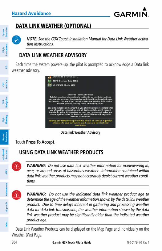
Garmin G3X Touch Pilot’s Guide 190-01754-00 Rev. T204
Hazard Avoidance
Syst
em
Ove
rvie
wFl
ight
In
stru
men
tsEI
SCN
SIn
terf
ace
GPS
N
avig
atio
nFl
ight
Plan
ning
Haz
ard
Avoi
danc
eA
dditi
onal
Fe
atur
esA
FCS
Ann
un/A
lert
sA
ppen
dix
Inde
x
DATA LINK WEATHER (OPTIONAL)
NOTE: See the G3X Touch Installation Manual for Data Link Weather activa-tion instructions.
DATA LINK WEATHER ADVISORY
Each time the system powers-up, the pilot is prompted to acknowledge a Data link weather advisory.
Data link Weather Advisory
Touch Press To Accept.
USING DATA LINK WEATHER PRODUCTS
WARNING: Do not use data link weather information for maneuvering in, near, or around areas of hazardous weather. Information contained within data link weather products may not accurately depict current weather condi-tions.
WARNING: Do not use the indicated data link weather product age to determine the age of the weather information shown by the data link weather product. Due to time delays inherent in gathering and processing weather data for data link transmission, the weather information shown by the data link weather product may be significantly older than the indicated weather product age.
Data Link Weather Products can be displayed on the Map Page and individually on the Weather (Wx) Page.

Garmin G3X Touch Pilot’s Guide190-01754-00 Rev. T 205
Hazard Avoidance
System
Overview
Flight Instrum
entsEIS
CNS
InterfaceG
PS N
avigationFlight
PlanningH
azard Avoidance
AdditionalFeatures
AFCS
Annun/A
lertsA
ppendixIndex
FiS-B
The supported FIS-B radios are designed to receive, process, and output traffic (ADS-B air-to-air, and TIS-B traffic information), and weather (Flight Information Service-Broadcast (FIS-B)) information to the G3X Touch system through an RS-232 serial connection or Bluetooth connection. As a UAT receiver, the FIS-B radios can receive and, when connected to the G3X Touch, display Flight Information Service-Broadcast (FIS-B) weather products as well as traffic.
FIS-B is a subscription-free weather service that is broadcast by Ground Based Transceivers (GBTs) over the 978 MHz UAT frequency band as part of the FAA’s Next Generation Air Transportation System (NextGen). To receive FIS-B weather information, the radio must be within range and line-of-sight of an operating GBT. Reception may be affected by altitude, terrain, and other factors.
FiS-B eXpiration tiMe
FIS-B weather broadcasts are updated regularly and may take approximately ten minutes to transmit all available weather data. Therefore, weather data is not immediately available. No pilot action is required to receive FIS-B weather information. Weather product status can be viewed on the dedicated Weather Page,or the Data Link Page from the Tools menu.
When a FIS-B weather product is active on a map, the age of the data is displayed on the screen in the lower left corner. The age of the product is based on the time difference between when the data was assembled on the ground and the current GPS time. Weather products are broadcast at specific intervals (see broadcast interval in the table below).
If, for any reason, a weather product is not refreshed within the Expiration Time intervals (see table), the data is considered expired and is removed from the display. This ensures that only data that is consistent with FIS-B broadcast data is displayed. If more than half of the expiration time has elapsed, the color of the product age displayed changes to yellow. The system displays dashes instead of a product age when a product has expired.
The table below shows the FIS-B weather expiration time and the broadcast interval. The broadcast interval represents the interval at which FIS-B GBTs broadcast new signals that may or may not contain new weather data. It does not represent the rate at which weather data is updated or new content is received.

Garmin G3X Touch Pilot’s Guide 190-01754-00 Rev. T206
Hazard Avoidance
Syst
em
Ove
rvie
wFl
ight
In
stru
men
tsEI
SCN
SIn
terf
ace
GPS
N
avig
atio
nFl
ight
Plan
ning
Haz
ard
Avoi
danc
eA
dditi
onal
Fe
atur
esA
FCS
Ann
un/A
lert
sA
ppen
dix
Inde
x
FIS-B ProductsExpiration
Time Update Interval
(Minutes)
Broadcast Interval
(Minutes)
NEXRAD Composite Reflectivity (CONUS)
75 minutes~5 minutes precipitation mode
10 minutes for clear air15
NEXRAD Composite Reflectivity (Regional)
75 minutes As Available 2.5
Cloud Tops Forecast 105 minutes 1 hour 15
Winds and Temperatures Aloft
12 hours 12 hours 10
Lightning 75 minutes 5 minutes 5
METAR 8 hours1 minute (where available), As
Available otherwise5
TAF 12 hours 8 hours 10
CWA (Center Weather Advisory)
2 hours 6 hours 10
G-AIRMET (Graphical AIRMET)
12 hours As Necessary 5
SIGMET 12 hoursAs Available, then at 15 minute
intervals for 1 hour5
PIREP 4 hours As Available 10
NOTAM (D)/FDC (Including TFRs)
12 hours As Available 10
Turbulence Forecast 105 minutes 1 hour 15
Icing Forecast 105 minutes 1 hour 15
Weather Product Timing

Garmin G3X Touch Pilot’s Guide190-01754-00 Rev. T 207
Hazard Avoidance
System
Overview
Flight Instrum
entsEIS
CNS
InterfaceG
PS N
avigationFlight
PlanningH
azard Avoidance
AdditionalFeatures
AFCS
Annun/A
lertsA
ppendixIndex
Viewing Ground Station Status:1) Press the MENU Key twice to display the Main Menu.
2) Touch Data Link.
3) Press the MENU Key.
4) Touch Ground Stations.
aCtivating SiriuSXM
Before SiriusXM Weather can be used, the service must be activated. Service is activated by providing SiriusXM Satellite Radio with a Radio ID.
SiriusXM Satellite Radio uses the Radio ID to send an activation signal that allows the G3X Touch to display weather data and/or entertainment programming.
SXM Weather Information
• Radio ID—Eight-digit ID number used for activation.
• Service Level—SiriusXM Weather subscription plan purchased.
• Weather Products—List of weather features and age of weather data in minutes.
Accessing Data Link Weather information: From the Weather (Wx) Page, press the MENU Key and touch More
Info....
DATA LINK WEATHER SETUP
The setup menu for the Map Page controls the map range settings above which weather products are decluttered from the display. If a map range larger than the weather product map range setting is selected, the weather product data is removed from the map. For weather products such as Lightning, and Storm Cells, the weather product is displayed when a map range “smaller” than the weather product map range setting is selected (Cloud Tops works inversely). The menu also provides a means for enabling/disabling display of weather products on the Map Page.
Additional information about many of the weather products can be displayed by touching the weather product on the Weather Page or the Map Page:

Garmin G3X Touch Pilot’s Guide 190-01754-00 Rev. T208
Hazard Avoidance
Syst
em
Ove
rvie
wFl
ight
In
stru
men
tsEI
SCN
SIn
terf
ace
GPS
N
avig
atio
nFl
ight
Plan
ning
Haz
ard
Avoi
danc
eA
dditi
onal
Fe
atur
esA
FCS
Ann
un/A
lert
sA
ppen
dix
Inde
x
Viewing Data Link Weather products on the Map Page:1) From the Map Page, press the MENU Key.
2) Touch Weather.
3) Touch the desired weather product on the map.
4) With the weather product selected, touch the Map Feature Button to display additional information.
Viewing Data Link Weather products on the Weather (Wx) Page:1) From the Wx Page, touch the desired weather product on the map.
2) With the weather product selected, touch the Map Feature Button to display additional information.
Setting up and customizing weather data for the Map Page:1) From the Map Page, press the MENU Key.
2) Touch Set Up Map.
3) Scroll the tabs left/right or up/down if necessary.
4) Touch the Weather Tab.
5) Touch to view a list of options (On, Off, Auto, range settings, etc.).
6) Touch the desired option for each weather product.
Restoring default weather data for the Map Page:1) From the Map Page, press the MENU Key.
2) Touch Set Up Map.
3) Touch the Weather Tab.
4) Press the MENU Key.
5) Touch Restore Category Defaults.
Viewing legends for displayed weather products:1) From the Wx Page, press the MENU Key.
2) Touch Weather Legend.
3) Touch to cycle through the weather products.
Or
1) From the Map Page, press the MENU Key.

Garmin G3X Touch Pilot’s Guide190-01754-00 Rev. T 209
Hazard Avoidance
System
Overview
Flight Instrum
entsEIS
CNS
InterfaceG
PS N
avigationFlight
PlanningH
azard Avoidance
AdditionalFeatures
AFCS
Annun/A
lertsA
ppendixIndex
2) Touch More.
3) Touch Weather Legend.
4) Touch to cycle through the weather products.
Animating weather:1) From the Map Page or the Wx Page, press the MENU Key.
2) Touch Animate Weather.
WEATHER PRODUCTS
Weather ProductSiriusXM Weather (products vary by
subscription)
FIS-B Weather(Subscription-free)
NEXRAD Radar (CONUS) Base and Composite Reflectivity
+
NEXRAD Radar (CONUS low resolution)
+
NEXRAD Radar (Regional high resolution)
+
NEXRAD Radar (Canada) +
Cloud Tops +Cloud Tops Forecast +Surface Precipitation +Surface Analysis +Sea Surface Temperatures +Echo Tops +Surface Pressure +Lightning + +Storm Cells +METAR (US) + +METAR (Canada) +TAF (US) * + +TAF (Canada) +

Garmin G3X Touch Pilot’s Guide 190-01754-00 Rev. T210
Hazard Avoidance
Syst
em
Ove
rvie
wFl
ight
In
stru
men
tsEI
SCN
SIn
terf
ace
GPS
N
avig
atio
nFl
ight
Plan
ning
Haz
ard
Avoi
danc
eA
dditi
onal
Fe
atur
esA
FCS
Ann
un/A
lert
sA
ppen
dix
Inde
x
Weather ProductSiriusXM Weather (products vary by
subscription)
FIS-B Weather(Subscription-free)
CWA (Center Weather Advisories)
+
AIRMET +G-AIRMETs (Graphical AIRMETs)
+
SIGMET + +PIREP + +Winds Aloft + +Temperatures Aloft + +NOTAMs * +Temporary Flight Restrictions
+ +
Freezing Level +Turbulence Forecast + +Icing Forecast + +* Only available from the Waypoint Page
Supported Weather Products by Source
neXraD raDar
NEXRAD (NEXt-generation RADar), is a network of multiple high-resolution Doppler radar sites that are operated by the National Weather Service (NWS). NEXRAD data provides centralized meteorological information for the continental United States and selected overseas locations. The maximum range of a single NEXRAD radar site is 250 nm. In addition to a wide array of services, the NEXRAD network provides important information about severe weather and air traffic safety.
NEXRAD data is not real-time. The lapsed time between collection, processing, and dissemination of NEXRAD images can be significant and may not reflect the current radar synopsis. Due to the inherent delays and the relative age of the data, it should be used for long-range planning purposes only. Never use NEXRAD data or any radar data to penetrate hazardous weather. Rather, use it in an early-warning capacity of pre-departure and enroute evaluation.

Garmin G3X Touch Pilot’s Guide190-01754-00 Rev. T 211
Hazard Avoidance
System
Overview
Flight Instrum
entsEIS
CNS
InterfaceG
PS N
avigationFlight
PlanningH
azard Avoidance
AdditionalFeatures
AFCS
Annun/A
lertsA
ppendixIndex
Composite data from all the NEXRAD radar sites in the United States is shown. This data is composed of the maximum reflectivity from the individual radar sweeps. The display of the information is color-coded to indicate the weather severity level.
The display of radar coverage is always active when NEXRAD is selected. Areas where NEXRAD radar coverage is not currently available or is not being collected are indicated in grayish-purple.
NEXRAD Weather Legend (SiriusXM) NEXRAD Weather Legend (FIS-B)
NEXRAD No Radar Coverage
No Radar Coverage
NEXRAD Abnormalities
There are possible abnormalities regarding displayed NEXRAD images. Some, but not all, of those include:
• Ground clutter
• Strobes and spurious radar data
• Sun strobes, when the radar antenna points directly at the sun
• Military aircraft deploy metallic dust (chaff) which can cause alterations in radar scans

Garmin G3X Touch Pilot’s Guide 190-01754-00 Rev. T212
Hazard Avoidance
Syst
em
Ove
rvie
wFl
ight
In
stru
men
tsEI
SCN
SIn
terf
ace
GPS
N
avig
atio
nFl
ight
Plan
ning
Haz
ard
Avoi
danc
eA
dditi
onal
Fe
atur
esA
FCS
Ann
un/A
lert
sA
ppen
dix
Inde
x
• Interference from buildings or mountains, which may cause shadows
NEXRAD Limitations
Certain limitations exist regarding the NEXRAD radar displays. Some, but not all, are listed for the user’s awareness:
• NEXRAD base reflectivity does not provide sufficient information to determine cloud layers or precipitation characteristics (hail vs. rain). For example, it is not possible to distinguish between wet snow, wet hail, and rain.
• NEXRAD base reflectivity is sampled at the minimum antenna elevation angle. An individual NEXRAD site cannot depict high altitude storms at close ranges, and has no information about storms directly over the site.
• Radar coverage only extends to 55°N.
• Any precipitation displayed between 52°N and 55°N is unknown.
NEXRAD Radar Coverage Limitations
No Radar Coverage Above
55°N
Reflectivity
Reflectivity is the amount of transmitted power returned to the radar receiver. Colors on the NEXRAD display directly correlate to the level of detected reflectivity. Reflectivity as it relates to hazardous weather can be very complex. The role of radar is essentially to detect moisture in the atmosphere. Simply put, certain types of weather reflect radar better than others. The intensity of a radar reflection is not necessarily an indication of the weather hazard level. For instance, wet hail returns a strong radar reflection, while dry hail does not. Both wet and dry hail can be extremely hazardous.

Garmin G3X Touch Pilot’s Guide190-01754-00 Rev. T 213
Hazard Avoidance
System
Overview
Flight Instrum
entsEIS
CNS
InterfaceG
PS N
avigationFlight
PlanningH
azard Avoidance
AdditionalFeatures
AFCS
Annun/A
lertsA
ppendixIndex
NEXRAD Intensity
Colors are used to identify the different NEXRAD echo intensities (reflectivity) measured in dBZ (decibels of Z). “Reflectivity” (designated by the letter Z) is the amount of transmitted power returned to the radar receiver. The dBZ values increase as returned signal strength increases. Precipitation intensity is displayed using colors corresponding to the dBZ values.
NEXRAD Data (SiriusXM) NEXRAD Data (FIS-B)
FIS-B Radar Products
FIS-B weather provides two different Radar products, CONUS and Regional. The system can display each individually or a composite (COMBINED). When Regional Radar is displayed, only precipitation for your current region is displayed. The subdued (grayish-purple colored) area represents the area not covered by the regional radar product. When Combined radar data is viewed, Regional Radar data is displayed on top of CONUS data and the time shown in the lower left corner is associated with Regional Radar data only.

Garmin G3X Touch Pilot’s Guide 190-01754-00 Rev. T214
Hazard Avoidance
Syst
em
Ove
rvie
wFl
ight
In
stru
men
tsEI
SCN
SIn
terf
ace
GPS
N
avig
atio
nFl
ight
Plan
ning
Haz
ard
Avoi
danc
eA
dditi
onal
Fe
atur
esA
FCS
Ann
un/A
lert
sA
ppen
dix
Inde
x
ClouD topS
Satellite observation of clouds is represented as temperature data, where colder tops are typically found at higher altitudes. This temperature data is transformed into cloud top height contours, indicating the height of the cloud top in 5,000 foot increments.
Cloud Tops Data
ClouD topS ForeCaSt
Cloud Tops Forecast data displays forecasted cloud top heights. Heights are indicated in 1,500 foot increments from 1,500 feet up to 15,000 feet and in 3,000 foot increments from 15,000 feet up to 24,000 feet.
Cloud Tops Forecast Data

Garmin G3X Touch Pilot’s Guide190-01754-00 Rev. T 215
Hazard Avoidance
System
Overview
Flight Instrum
entsEIS
CNS
InterfaceG
PS N
avigationFlight
PlanningH
azard Avoidance
AdditionalFeatures
AFCS
Annun/A
lertsA
ppendixIndex
eCho topS
Echo Tops are derived from NEXRAD radar and indicate the highest altitude at which precipitation is falling. Echo Tops at or above the altitude you select are displayed, in 5,000 foot increments up to 70,000 ft. Echo Tops can be helpful in determining the severity of thunderstorms.
Echo Tops Data
winDS aloFt
Winds Aloft data shows the forecasted wind speed and direction at the surface and at selected altitudes. Altitudes can be displayed in 3,000-foot increments up to 42,000 feet MSL.
Winds Aloft are displayed using wind barbs or a wind streamline depending on the selected range. The wind barbs indicate wind speed and direction. The wind streamline indicates wind direction with arrows.

Garmin G3X Touch Pilot’s Guide 190-01754-00 Rev. T216
Hazard Avoidance
Syst
em
Ove
rvie
wFl
ight
In
stru
men
tsEI
SCN
SIn
terf
ace
GPS
N
avig
atio
nFl
ight
Plan
ning
Haz
ard
Avoi
danc
eA
dditi
onal
Fe
atur
esA
FCS
Ann
un/A
lert
sA
ppen
dix
Inde
x
The wind barbs always point in the direction the wind is coming from. The wind speed is depicted using flags at the end of the wind barb. A short wind flag is 5 knots, a long wind flag is 10 knots, and a triangle flag is 50 knots.
Winds Aloft Data
Winds Aloft Legend

Garmin G3X Touch Pilot’s Guide190-01754-00 Rev. T 217
Hazard Avoidance
System
Overview
Flight Instrum
entsEIS
CNS
InterfaceG
PS N
avigationFlight
PlanningH
azard Avoidance
AdditionalFeatures
AFCS
Annun/A
lertsA
ppendixIndex
When winds aloft data is zoomed out, the wind barbs are displayed as general wind trend lines. This removes the magnitude of the wind speed, but shows general trends.
Wind Lines
SurFaCe preSSure
This feature displays pressure isobars and pressure centers. The isobars connect points of equal pressure. Pressure readings can help determine weather and wind conditions. High pressure areas are generally associated with fair weather. Low pressure areas are generally associated with clouds and the chance of precipitation. Isobars that are packed closely together show a strong pressure gradient. Strong gradients are associated with areas of stronger winds. Pressure units can be displayed in Millibars (mb) or Inches of Mercury (in).
Surface Pressure Data

Garmin G3X Touch Pilot’s Guide 190-01754-00 Rev. T218
Hazard Avoidance
Syst
em
Ove
rvie
wFl
ight
In
stru
men
tsEI
SCN
SIn
terf
ace
GPS
N
avig
atio
nFl
ight
Plan
ning
Haz
ard
Avoi
danc
eA
dditi
onal
Fe
atur
esA
FCS
Ann
un/A
lert
sA
ppen
dix
Inde
x
lightning
Lightning data shows the approximate location of cloud-to-ground lightning strikes. A strike icon represents a strike that has occurred within a two-kilometer region and within the last seven minutes. The exact location of the lightning strike is not displayed.
Lightning Data
StorM CellS
The Storm Cells feature displays storms as well as the storm’s projected path in the immediate future.
The direction of the storm is displays by an arrow (at a range of 20 nm or less). The tip of the arrow indicates where the storm should be in 15 minutes. Critical information about the storm cell (tops and intensity) can be viewed by touching the storm cell.
Storm Cell Data

Garmin G3X Touch Pilot’s Guide190-01754-00 Rev. T 219
Hazard Avoidance
System
Overview
Flight Instrum
entsEIS
CNS
InterfaceG
PS N
avigationFlight
PlanningH
azard Avoidance
AdditionalFeatures
AFCS
Annun/A
lertsA
ppendixIndex
MetarS anD taFS
NOTE: METAR information is only displayed within the installed aviation database service area.
METAR (METeorological Aerodrome Report) is an international code used for reporting weather observations. METARs are updated hourly or as needed. METARs typically contain information about the temperature, dewpoint, wind, precipitation, cloud cover, cloud heights, visibility, and barometric pressure. They can also contain information on precipitation amounts, lightning, and other critical data. If METAR data is available for an airport, a color-coded flag is shown next to the airport.
TAF (Terminal Area Forecast) is the standard format for 24-hour weather forecasts. TAFs may contain some of the same code as METAR data. It typically forecasts significant weather changes, temporary changes, probable changes, and expected changes in weather conditions. TAF information is only available from the Waypoint Page.
METAR data is displayed on the Map Page and the Weather (WX) Page. An abbreviated version can be viewed by touching the METAR flag. Touching the identifier name displays additional information.
The METAR flag color is determined by the information in the METAR text.
VFR (ceiling greater than 3000 feet AGL and visibility greater than 5 miles)
Marginal VFR (ceiling 1000-3000 feet AGL and/or visibility 3-5 miles)
IFR (ceiling 500 to below 1000 feet AGL and/or visibility 1 mile to less than 3 miles)
Low IFR (ceiling below 500 feet AGL or visibility less than 1 mile)
METAR text does not contain adequate information to determine flight conditions

Garmin G3X Touch Pilot’s Guide 190-01754-00 Rev. T220
Hazard Avoidance
Syst
em
Ove
rvie
wFl
ight
In
stru
men
tsEI
SCN
SIn
terf
ace
GPS
N
avig
atio
nFl
ight
Plan
ning
Haz
ard
Avoi
danc
eA
dditi
onal
Fe
atur
esA
FCS
Ann
un/A
lert
sA
ppen
dix
Inde
x
METAR Data
Center weather aDviSorieS (CwaS)
Center Weather Advisories are unscheduled bulletins to warn pilots of conditions that meet or are approaching not previously forecast AIRMET, SIGMET, or Convective SIGMET criteria. CWAs are valid for up to two hours and if a forecaster determines it's warranted, they may be issued hourly for convective activity.
Center Weather Advisory Data

Garmin G3X Touch Pilot’s Guide190-01754-00 Rev. T 221
Hazard Avoidance
System
Overview
Flight Instrum
entsEIS
CNS
InterfaceG
PS N
avigationFlight
PlanningH
azard Avoidance
AdditionalFeatures
AFCS
Annun/A
lertsA
ppendixIndex
airMetS
NOTE: AIRMETs are only available when using the SiriusXM weather source.
An AIRMET (AIRmen’s METeorological Information) can be especially helpful for pilots of light aircraft that have limited flight capability or instrumentation. An AIRMET must affect or be forecast to affect an area of at least 3,000 square miles at any one time. AIRMETs are routinely issued for six-hour periods and are amended as necessary due to changing weather conditions. AIRMETs are displayed as colored, dashed lines.
AIRMET Data
graphiCal airMetS
NOTE: Graphical AIRMETs are only available when using the FIS-B weather source.
A Graphical AIRMET (AIRmen’s METeorological Information) can be especially helpful for pilots of light aircraft that have limited flight capability or instrumentation. A Graphical AIRMET must affect or be forecast to affect an area of at least 3,000 square miles at any one time. Graphical AIRMETs are routinely issued for six-hour periods and are amended as necessary due to changing weather conditions. Graphical AIRMETs are displayed as colored, dashed lines.

Garmin G3X Touch Pilot’s Guide 190-01754-00 Rev. T222
Hazard Avoidance
Syst
em
Ove
rvie
wFl
ight
In
stru
men
tsEI
SCN
SIn
terf
ace
GPS
N
avig
atio
nFl
ight
Plan
ning
Haz
ard
Avoi
danc
eA
dditi
onal
Fe
atur
esA
FCS
Ann
un/A
lert
sA
ppen
dix
Inde
x
Graphical AIRMET Data
SigMetS
A SIGMET (SIGnificant METeorological Information) advises of weather that is potentially hazardous to all aircraft. In the contiguous United States, the following items are covered: severe icing, severe or extreme turbulence, volcanic ash, dust storms, and sandstorms that lower visibility to less than three statute miles.
A Convective SIGMET is issued for the following conditions: thunderstorms, isolated severe thunderstorms, embedded thunderstorms, hail at the surface, and tornadoes.
A SIGMET is widespread and must affect or be forecast to affect an area of at least 3,000 square miles. SIGMETs are displayed as a yellow-dashed line.
teMporary Flight reStriCtionS (tFr)
NOTE: Do not rely solely upon data link services to provide Temporary Flight Restriction (TFR) information. Always confirm TFR information through official sources such as Flight Service Stations or Air Traffic Control.
Temporary Flight Restrictions, or TFRs, temporarily restrict all aircraft from entering the selected airspace unless a waiver has been issued. TFRs are routinely issued for activities such as sporting events, dignitary visits, military depots, and forest fires. TFRs are represented as an area highlighted by red (active) or yellow (not yet active).

Garmin G3X Touch Pilot’s Guide190-01754-00 Rev. T 223
Hazard Avoidance
System
Overview
Flight Instrum
entsEIS
CNS
InterfaceG
PS N
avigationFlight
PlanningH
azard Avoidance
AdditionalFeatures
AFCS
Annun/A
lertsA
ppendixIndex
TFR Data
pirepS
Pilot Weather Reports (PIREPs) provide timely weather information for a particular route of flight. When significant weather conditions are reported or forecast, Air Traffic Control (ATC) facilities are required to solicit PIREPs. A PIREP may contain unforecast adverse weather conditions, such as low in-flight visibility, icing conditions, wind shear, and turbulence. PIREPs are issued as either Routine (UA) or Urgent (UUA).
PIREP Data

Garmin G3X Touch Pilot’s Guide 190-01754-00 Rev. T224
Hazard Avoidance
Syst
em
Ove
rvie
wFl
ight
In
stru
men
tsEI
SCN
SIn
terf
ace
GPS
N
avig
atio
nFl
ight
Plan
ning
Haz
ard
Avoi
danc
eA
dditi
onal
Fe
atur
esA
FCS
Ann
un/A
lert
sA
ppen
dix
Inde
x
PIREP TYPE Icons Description
Icing
Negligible Icing
Trace Icing
Trace to Light Icing
Light Icing
Light to Moderate Icing
Moderate Icing
Moderate to Severe Icing
Severe Icing
Sky Conditions
Unknown Sky Condition
Sky Clear
Few Clouds
Scattered Clouds
Broken Clouds
Overcast
IMC
Turbulence
Turbulence Negligible or Smooth
Light Turbulence
Light to Moderate Turbulence
Moderate Turbulence
Moderate to Severe Turbulence
Severe Turbulence
Extreme Turbulence
PIREP Icons

Garmin G3X Touch Pilot’s Guide190-01754-00 Rev. T 225
Hazard Avoidance
System
Overview
Flight Instrum
entsEIS
CNS
InterfaceG
PS N
avigationFlight
PlanningH
azard Avoidance
AdditionalFeatures
AFCS
Annun/A
lertsA
ppendixIndex
Freezing levelS
Freezing Level shows contours for the lowest forecast altitude where icing conditions are likely to occur.
Freezing Level Data
turBulenCe ForeCaSt
Turbulence data identifies the potential for erratic movement of high-altitude air mass associated winds. Turbulence is classified as light, moderate, severe, or extreme. Turbulence data is intended to supplement AIRMETs and SIGMETs.
Turbulence Data

Garmin G3X Touch Pilot’s Guide 190-01754-00 Rev. T226
Hazard Avoidance
Syst
em
Ove
rvie
wFl
ight
In
stru
men
tsEI
SCN
SIn
terf
ace
GPS
N
avig
atio
nFl
ight
Plan
ning
Haz
ard
Avoi
danc
eA
dditi
onal
Fe
atur
esA
FCS
Ann
un/A
lert
sA
ppen
dix
Inde
x
iCing ForeCaSt (Cip & SlD)
Current Icing Product (CIP) data shows a graphical view of the current icing environment. SiriusXM icing severity is displayed in three categories: light, moderate, and heavy (not specific to aircraft type). FIS-B icing severity is displayed in four categories: trace, light, moderate, and heavy (not specific to aircraft type). The CIP product is not a forecast, but a representation of the current conditions at the time of the analysis.
Supercooled Large Droplet (SLD) icing conditions are characterized by the presence of relatively large, super cooled water droplets indicative of freezing drizzle and freezing rain aloft. SLD threat areas are depicted as magenta dots over the CIP colors.
Icing Data
lightning DeteCtor
WARNING: Do not rely on information from the lightning detection system display as the sole basis for hazardous weather avoidance. Range limitations and interference may cause the system to display inaccurate or incomplete information. Refer to documentation from the lightning detection system manufacturer for detailed information about the system.
NOTE: Lightning detector data cannot be displayed simultaneously with data link lightning weather products on the same map.

Garmin G3X Touch Pilot’s Guide190-01754-00 Rev. T 227
Hazard Avoidance
System
Overview
Flight Instrum
entsEIS
CNS
InterfaceG
PS N
avigationFlight
PlanningH
azard Avoidance
AdditionalFeatures
AFCS
Annun/A
lertsA
ppendixIndex
Lightning Detector data provides lightning cell and strike information on the PFD inset map (GDU 46X only) and navigation map using the lightning symbology. Lightning strike symbols appear the same size for the first minute and gradually fade away over the following two minutes.
The Lightning Detector operates in either Cell Mode or Strike Mode. When operating in Cell Mode, the system displays clusters or cells of electrical activity. When operating in Strike Mode, the system displays the approximate location of individual lightning strikes.
NOTE: Lightning Detection settings made on the Map Page are similarly reflected for the PFD inset map (GDU 46X only) if enabled.
Enabling/disabling Lightning Detection:1) From the Map Page press the MENU Key.
2) Touch Set Up Map.
3) Scroll the tabs left or right if necessary.
4) Touch the Lightning Tab.
5) Touch under Lightning Detector Data On or Off as desired.
Or
1) From the Map Page, press the MENU Key.
2) Touch Lightning Detector to toggle on or off as desired.
Selecting a Lightning Detection mode:1) From the Map Page press the MENU Key.
2) Touch Set Up Map.
3) Scroll the tabs left or right if necessary.
4) Touch the Lightning Tab.
5) Touch under Lightning Detector Mode and select Strike or Cell as desired.
Selecting a Lightning Detection map range:1) From the Map Page press the MENU Key.
2) Touch Set Up Map.

Garmin G3X Touch Pilot’s Guide 190-01754-00 Rev. T228
Hazard Avoidance
Syst
em
Ove
rvie
wFl
ight
In
stru
men
tsEI
SCN
SIn
terf
ace
GPS
N
avig
atio
nFl
ight
Plan
ning
Haz
ard
Avoi
danc
eA
dditi
onal
Fe
atur
esA
FCS
Ann
un/A
lert
sA
ppen
dix
Inde
x
3) Scroll the tabs left or right if necessary.
4) Touch the Lightning Tab.
5) Touch under Lightning Detector Symbol and select a desired map range setting from the list.
Clearing the Navigation Map removes any previously displayed cell or lightning strike information from the navigation maps.
Clearing Lightning Detection information from Navigation Map:1) From the Map Page press the MENU Key.
2) Touch Set Up Map.
3) Scroll the tabs left or right if necessary.
4) Touch the Lightning Tab.
5) Touch Clear Strikes.
SurFaCe analySiS
Surface Analysis data is available for current and forecast weather conditions. Forecasts are available for intervals of 12, 24, 36, 48, 72, and 96 hours.
Surface Analysis Data Selected

Garmin G3X Touch Pilot’s Guide190-01754-00 Rev. T 229
Hazard Avoidance
System
Overview
Flight Instrum
entsEIS
CNS
InterfaceG
PS N
avigationFlight
PlanningH
azard Avoidance
AdditionalFeatures
AFCS
Annun/A
lertsA
ppendixIndex
Surface Analysis Legend
7.2 TERRAIN
WARNING: Do not use Terrain information for primary terrain avoidance. Terrain information is intended only to enhance situational awareness.
NOTE: Terrain data is not displayed when the aircraft is outside the installed terrain database coverage area.
NOTE: Terrain depicted in the Profile View is always “ahead” of the aircraft, and will change as ground track changes.
The Terrain Page displays altitudes of terrain and obstructions relative to the aircraft position and altitude with reference to a database that may contain inaccuracies. Terrain and obstructions are shown only if they are in the database. Terrain and obstacle information should be used as an aid to situational awareness. They should never be used to navigate or maneuver around terrain.
Note that all obstructions may not be available in the terrain and obstacle database. No terrain and obstacle information is shown without a valid 3-D GPS position.

Garmin G3X Touch Pilot’s Guide 190-01754-00 Rev. T230
Hazard Avoidance
Syst
em
Ove
rvie
wFl
ight
In
stru
men
tsEI
SCN
SIn
terf
ace
GPS
N
avig
atio
nFl
ight
Plan
ning
Haz
ard
Avoi
danc
eA
dditi
onal
Fe
atur
esA
FCS
Ann
un/A
lert
sA
ppen
dix
Inde
x
The G3X Touch GPS receiver provides the horizontal position and altitude of the aircraft. Aircraft GPS altitude is derived from satellite position. GPS altitude is then converted to a mean sea level (MSL)-based altitude (GPS-MSL altitude) and is used to determine terrain and obstacle proximity. GPS-MSL altitude accuracy is affected by satellite geometry, but is not subject to variations in pressure and temperature that normally affect pressure altitude sensors. GPS-MSL altitude does not require local altimeter settings to determine MSL altitude. It is a widely-used MSL altitude source.
Terrain and obstacle databases are referenced to MSL. Using the GPS position and altitude, the Terrain feature portrays a 2-D picture of the surrounding terrain and obstacles relative to the position and altitude of the aircraft. GPS position and GPS-MSL altitude are used to calculate and predict the aircraft’s flight path in relation to the surrounding terrain and obstacles. In this way, the pilot can view predicted dangerous terrain and obstacle conditions.
Alert windows appear on all pages (except the Terrain (Ter) Page) to inform the pilot of proximity to the terrain and obstacles, as well as an unsafe descent rate. These alerts depend on user-defined parameters in the Terrain Page setup.
SYNTHETIC VISIONTerrain is integrated within Synthetic Vision (when active) to provide land contours
(colors are consistent with those of the topographical map display), large water features, towers, obstacles over 200’ AGL, as well as visual and auditory alerts to indicate the presence of terrain and obstacle threats relevant to the projected flight path. Synthetic Vision terrain information is displayed in red and yellow shading on the PFD. Refer to Section 8.1 (Synthetic Vision) for more information.
TERRAIN INFORMATIONThe areas of the terrain shaded red are predicted to be within 100 feet below or
above the aircraft. The yellow terrain areas are between the user-defined Caution Elevation and 100 feet below the aircraft. By default, the Caution Elevation is 1,000 feet; therefore, the areas in yellow are between 1,000 feet and 100 feet below the aircraft. The black areas are further than the Caution Elevation. A projected point of impact is marked with an “X” symbol.

Garmin G3X Touch Pilot’s Guide190-01754-00 Rev. T 231
Hazard Avoidance
System
Overview
Flight Instrum
entsEIS
CNS
InterfaceG
PS N
avigationFlight
PlanningH
azard Avoidance
AdditionalFeatures
AFCS
Annun/A
lertsA
ppendixIndex
Enabling/disabling Terrain Shading on the Map Page: From the Map Page, press MENU, then touch Terrain.
TERRAIN VIEWSTwo views are displayed on the Terrain (Ter) Page: the Map View, and the Profile
View.Yellow Terrain is
Between the User-defined Caution
Elevation and 100 ft Below the
Aircraft
Terrain Legend
Red Terrain is above the aircraft, or within 100 ft below the aircraft.
Terrain (Ter) Page
Map View
Profile View
Obstacle
NOTE: When on the ground, the terrain color scale changes so no yellow is shown, and the red band starts at 400 feet above the aircraft. This allows the pilot to quickly identify threatening terrain while on the ground. After the aircraft is airborne, the terrain display reverts to normal.

Garmin G3X Touch Pilot’s Guide 190-01754-00 Rev. T232
Hazard Avoidance
Syst
em
Ove
rvie
wFl
ight
In
stru
men
tsEI
SCN
SIn
terf
ace
GPS
N
avig
atio
nFl
ight
Plan
ning
Haz
ard
Avoi
danc
eA
dditi
onal
Fe
atur
esA
FCS
Ann
un/A
lert
sA
ppen
dix
Inde
x
OBSTACLE INFORMATIONObstacles are shown on the Terrain Page at or below the map range of 12 nm.
Obstacles are also shown on the Map Page when the map range is set to 3 nm or below.
Standard aeronautical chart symbols are used for lighted or unlighted obstacles taller than 200 feet Above Ground Level (AGL). Refer to the Obstacle Icons legend below.
Each obstacle is labeled with the altitude of the top of the obstacle, or Mean Sea Level (MSL). Each obstacle also lists, in parentheses, the actual height of the obstacle, or Above Ground Level (AGL).
Unlighted Obstacle
Lighted ObstaclePotential Impact Points
Obstacle Location< 1000’
AGL> 1000’
AGL< 1000’
AGL> 1000’
AGLWARNING: Red obstacle is above or within 100’ below current aircraft altitudeCAUTION: Yellow obstacle is between 100’ and 1000’ (default) below current aircraft altitude
Terrain Obstacle Colors and Symbology

Garmin G3X Touch Pilot’s Guide190-01754-00 Rev. T 233
Hazard Avoidance
System
Overview
Flight Instrum
entsEIS
CNS
InterfaceG
PS N
avigationFlight
PlanningH
azard Avoidance
AdditionalFeatures
AFCS
Annun/A
lertsA
ppendixIndex
TERRAIN SETTINGSUse the terrain settings to set levels for terrain alerts as well as obstacles in or
near your flight path.
• Caution Elevation—The G3X Touch will provide an alert if the terrain or obstacle is within the default Caution Elevation or user-defined Caution Elevation.
• Look Ahead Time—Determines the maximum time when an alert annunciation occurs. For example, if 120 seconds is selected, the G3X Touch provides an alert up to 120 seconds before you reach the terrain or obstacle.
• Alert Sensitivity—The three Alert Sensitivity settings (Terrain, Obstacles, and Descent Rate) determine what level of alerts are annunciated. The G3X Touch defaults to ‘High’ sensitivity, which annunciates all red and yellow alerts at the time set in Look Ahead Time. ‘Medium’ sensitivity annunciates all of the red and the highest priority of yellow alerts. ‘Low’ only annunciates red alerts. ‘Off’ disables the alert.
Accessing the terrain settings:1) From the Terrain Page, press the MENU Key.
2) Touch Caution Elevation and touch 500ft Below, 750ft Below, or 1000ft Below.
Or:
Touch Look Ahead Time and touch 60 Seconds, 90 Seconds, or 120 Seconds.
Or:
Touch Alert Sensitivity... > Terrain, Obstacles, or Descent Rate > Off, Low, Medium, or High.
Or:
Touch Alerts to toggle between Enabled and Inhibited.
Or:
Touch Profile View to toggle on and off.

Garmin G3X Touch Pilot’s Guide 190-01754-00 Rev. T234
Hazard Avoidance
Syst
em
Ove
rvie
wFl
ight
In
stru
men
tsEI
SCN
SIn
terf
ace
GPS
N
avig
atio
nFl
ight
Plan
ning
Haz
ard
Avoi
danc
eA
dditi
onal
Fe
atur
esA
FCS
Ann
un/A
lert
sA
ppen
dix
Inde
x
TERRAIN ALERTSTerrain, Obstacle, and Descent Rate Alerts are issued when flight conditions meet
parameters that are set within the software algorithms. Terrain alerts typically employ a CAUTION or a WARNING alert severity level, or both. When an alert is issued, visual annunciations are displayed and aural alerts are simultaneously issued. When the aircraft descends through 500 feet above the destination airport or user waypoint (saved as an airport symbol) an audible “Five Hundred” altitude reminder occurs.
If the Terrain Page is not displayed, a pop-up alert appears in the lower left corner of the page. The Range Rings on the pop-up alert are spaced every whole mile/kilometer/nautical mile. Touch the alert to acknowledge the pop-up and/or aural alert.
Terrain and obstacle annunciations appear on the PFD in the upper left corner of the Attitude Indicator. Arrows are depicted on the terrain and obstacle annunciations if terrain is outside the Synthetic Vision field of view.
Terrain Annunciation on PFD
Arrow Indicates Terrain is Outside Synthetic Vision Field of View.
Enabling/disabling terrain alerts:1) From the Terrain Page, press the MENU Key.
2) Touch Alerts to toggle between Enabled and Inhibited.
AURAL ALERTS
• “Five Hundred”—when the aircraft descends through 500 feet above the destina-tion airport or user waypoint (saved as an airport symbol).
The following aural terrain alerts are issued when flight conditions meet parameters that are set within the software algorithms, and are dependent on the sensitivity level set in the Terrain Setup Menu.

Garmin G3X Touch Pilot’s Guide190-01754-00 Rev. T 235
Hazard Avoidance
System
Overview
Flight Instrum
entsEIS
CNS
InterfaceG
PS N
avigationFlight
PlanningH
azard Avoidance
AdditionalFeatures
AFCS
Annun/A
lertsA
ppendixIndex
Alert Severity Terrain Obstacle Descent Rate
Caution“caution, terrain”“caution, terrain
ahead”
“caution, obstacle”“caution, obstacle
ahead”
“caution, sink rate”
Warning
“terrain ahead! pull up!”
“terrain! terrain! pull up! pull up!”
“obstacle ahead! pull up!”
“obstacle! obstacle! pull up! pull up!”
“sink rate, pull up!”
“pull up!”
Aural Alerts Summary
PFD Terrain Alert
Terain Warning Window
MFD Terrain Alerts
Terrain Alert

Garmin G3X Touch Pilot’s Guide 190-01754-00 Rev. T236
Hazard Avoidance
Syst
em
Ove
rvie
wFl
ight
In
stru
men
tsEI
SCN
SIn
terf
ace
GPS
N
avig
atio
nFl
ight
Plan
ning
Haz
ard
Avoi
danc
eA
dditi
onal
Fe
atur
esA
FCS
Ann
un/A
lert
sA
ppen
dix
Inde
x
7.3 TRAFFIC SYSTEMS
TRAFFIC SOURCEThe G3X Touch is compatible with three different traffic sources; TIS-A traffic via a
Garmin® Mode S Transponder, TAS/TCAS I via a GTS 8XX, or ADS-B/TIS-B traffic via a compatible ADS-B device. When the G3X Touch system is configured with both a Mode S transponder capable of receiving TIS-A traffic and a compatible device capable of receiving ADS-B/TIS-B traffic the G3X Touch will automatically switch between traffic sources. The following conditions describe the traffic display logic.
• If the GTX is not receiving TIS-A traffic data, GDL ADS-B traffic will be displayed.
• If the GDL is receiving both air-to-air ADS-B traffic data and ground uplink TIS-B traffic, then the GDL ADS-B traffic will be displayed.
• If the GTX is receiving TIS-A traffic, and the GDL is not receiving ground uplink TIS-B traffic, then GTX TIS-A traffic will be displayed.
The current traffic source and altitude filter is annunciated in the upper left hand corner of the Traffic Page (TRF).
ADS-B Status
Traffic Source Annunciations
TAS/TCAS Status Altitude Filter
Traffic Source Name

Garmin G3X Touch Pilot’s Guide190-01754-00 Rev. T 237
Hazard Avoidance
System
Overview
Flight Instrum
entsEIS
CNS
InterfaceG
PS N
avigationFlight
PlanningH
azard Avoidance
AdditionalFeatures
AFCS
Annun/A
lertsA
ppendixIndex
Traffic Source* States Description
ADS:
TAS/TCAS**:
FAIL FailedSTBY Standby
UNAVL Unavailable
TEST Self-TestOPER Operating
*ADS and TAS/TCAS are dynamically displayed depending on wether the active traffic device is capable of reporting a state for it.**The TCAS prefix will always be displayed, except in the case where the traffic device can be specifically identified as a TAS model.
Traffic Source (ADS, TAS/TCAS) States
Altitude Filtering Mode Description
ALT:
UNR UnrestrictedNORM NormalABV AboveBLW Below
Altitude Filtering Modes
TRAFFIC PRIORITIZATIONThe G3X Touch supports multiple traffic receivers and automatically prioritizes these
devices.
The following are the traffic receivers in order of priority:
- TAS/TCAS I (e.g., GTS or non-Garmin) configured with a GTX 345/345R/45R device.
- GTS 8XX device
- GTX 345/345R/45R, GNX 375 devices
- GDL device receiving both air-to-air and TIS-B
- GTX 23ES/GTX 330ES device receiving TIS-A
- GDL device receiving only air-to-air

Garmin G3X Touch Pilot’s Guide 190-01754-00 Rev. T238
Hazard Avoidance
Syst
em
Ove
rvie
wFl
ight
In
stru
men
tsEI
SCN
SIn
terf
ace
GPS
N
avig
atio
nFl
ight
Plan
ning
Haz
ard
Avoi
danc
eA
dditi
onal
Fe
atur
esA
FCS
Ann
un/A
lert
sA
ppen
dix
Inde
x
The G3X Touch is capable of device switching in the event that a device becomes unavailable.
TRAFFIC INFORMATION SERVICE (TIS-A) (OPTIONAL)
NOTE: Refer to Appendix E for general information regarding Traffic Informa-tion Service (TIS-A).
SYSTEM STATUS
The traffic system status is annunciated in the upper right corner of the Map Page.
System Status Traffic Icon
Operating
No Traffic Data Available
If a Traffic Icon is not displayed, check the Map Page range and/or the Traffic Display Range on the Map Set Up menu.
Traffic Modes
TRAFFIC SYMBOLOGY
Traffic is shown on the G3X Touch according to TCAS symbology, graphically shown on the Traffic Page (Optional), Map Page, in the Traffic Warning Window, and Synthetic Vision.
A Proximity Advisory (PA) indicates the intruding aircraft is within ±1200 feet and is within a 5 nm range, but is still not considered a threat.
A Traffic Advisory (TA) symbol appears as a solid yellow circle. All other traffic within range is shown as a hollow white diamond. Altitude deviation from own aircraft altitude is shown above the target symbol if traffic is above own aircraft altitude, and below the symbol if they are below own aircraft altitude. Altitude trend is shown as an up arrow (>+500 ft/min), down arrow (<-500 ft/min), or no symbol if less than 500 ft/min rate in either direction.

Garmin G3X Touch Pilot’s Guide190-01754-00 Rev. T 239
Hazard Avoidance
System
Overview
Flight Instrum
entsEIS
CNS
InterfaceG
PS N
avigationFlight
PlanningH
azard Avoidance
AdditionalFeatures
AFCS
Annun/A
lertsA
ppendixIndex
TIS-A Symbol Description
Non-Threat Traffic
Proximity Advisory (PA)
Traffic Advisory (TA)
Traffic Symbols
TRAFFIC ANNUNCIATIONS
The G3X Touch displays traffic symbolically on the Map Page, and the Traffic Warning Window (Inset Map) in the lower left corner of the GDU 46X MFD display.
When a traffic advisory (TA) is detected, the following automatically occur:
• The Traffic Warning Window (Inset Map) is enabled and displays traffic (GDU 46X Only).
• A flashing black-on-yellow ‘TRAFFIC’ annunciation will appear in the upper right corner of the Attitude Indicator for five seconds and remains displayed until no TAs are detected in the area.
• A single “Traffic” voice alert is generated
Traffic Alerts

Garmin G3X Touch Pilot’s Guide 190-01754-00 Rev. T240
Hazard Avoidance
Syst
em
Ove
rvie
wFl
ight
In
stru
men
tsEI
SCN
SIn
terf
ace
GPS
N
avig
atio
nFl
ight
Plan
ning
Haz
ard
Avoi
danc
eA
dditi
onal
Fe
atur
esA
FCS
Ann
un/A
lert
sA
ppen
dix
Inde
x
Arrows are depicted on the traffic message if traffic is outside the Synthetic Vision field of view. The arrow points in the direction of the traffic.
Traffic Outside the Synthetic Vision Field of View (PFD)
traFFiC voiCe alertS
A traffic voice alert is generated whenever the number of Traffic Advisories on the G3X Touch screen increases from one scan to the next. Limiting Traffic Advisories only reduces the “nuisance” alerting due to proximate aircraft. For example, when the first Traffic Advisories appear on the TIS-A display, the user is alerted audibly. So long as a single aircraft remains on the traffic display, no further voice alert is generated. If a second (or more) aircraft appears on the screen, a new voice alert is sounded.
If the number of Traffic Advisories on the traffic display decreases and then increases, a new voice alert is sounded. The traffic voice alert is also generated whenever traffic becomes available. The following traffic voice alerts are available:
• “Traffic”— Traffic alert received.
• “Traffic Not Available”—Traffic service is not available or out of range.
Enabling/disabling traffic alerts:1) Touch the Page Navigation Bar.
2) Touch Traffic.
3) Press the MENU Key.
4) Touch Alerts to toggle between Enabled and Inhibited.

Garmin G3X Touch Pilot’s Guide190-01754-00 Rev. T 241
Hazard Avoidance
System
Overview
Flight Instrum
entsEIS
CNS
InterfaceG
PS N
avigationFlight
PlanningH
azard Avoidance
AdditionalFeatures
AFCS
Annun/A
lertsA
ppendixIndex
traFFiC warning winDow
When a traffic threat is imminent, the Traffic Warning Window is shown. The Traffic Warning Window shows a small pop-up map in the lower left corner. The Range Rings on the pop-up alert are spaced every whole mile/kilometer/nautical mile.
Traffic Warning Window
Traffic Warning Window
NOTE: The Traffic Warning Window is disabled when the aircraft ground speed is less than 30 knots or when on the approach leg of a route.
TRAFFIC GROUND TRACK
Traffic ground track is indicated on the G3X Touch screen by a “target track vector,” a short line shown in 45-degree increments, extending in the direction of target movement.
DISPLAYING TRAFFIC DATA
Traffic is displayed by default on the Map Page and the Traffic Warning Window.
Traffic information is also displayed on the PFD when Synthetic Vision is enabled. See the ‘Additional Features’ Section for more information.
Displaying Traffic information: Touch the traffic on the map to display range and altitude separation
information.

Garmin G3X Touch Pilot’s Guide 190-01754-00 Rev. T242
Hazard Avoidance
Syst
em
Ove
rvie
wFl
ight
In
stru
men
tsEI
SCN
SIn
terf
ace
GPS
N
avig
atio
nFl
ight
Plan
ning
Haz
ard
Avoi
danc
eA
dditi
onal
Fe
atur
esA
FCS
Ann
un/A
lert
sA
ppen
dix
Inde
x
Traffic (Map Page)
Traffic Ground Track
Traffic Range, Altitude Sepa-ration
Enabling/disabling traffic data on the Map Page:1) From the Map Page, press the MENU Key.
2) Touch Traffic.
Enabling/disabling traffic on the Synthetic Vision display:1) Touch the HSI or Attitude Indicator.
2) Touch More Options.
3) Touch and drag to scroll down.
4) Touch Traffic to deselect it.
DEDICATED TRAFFIC PAGE (TRF)
Enabling/disabling the traffic alerts:
NOTE: Traffic alerts are reset to ‘enabled’ on the next power cycle.
1) From the Traffic (Trf) Page, press the MENU Key.
2) Touch Alerts to toggle between Inhibit and Enable.

Garmin G3X Touch Pilot’s Guide190-01754-00 Rev. T 243
Hazard Avoidance
System
Overview
Flight Instrum
entsEIS
CNS
InterfaceG
PS N
avigationFlight
PlanningH
azard Avoidance
AdditionalFeatures
AFCS
Annun/A
lertsA
ppendixIndex
Traffic Page
GARMIN GTS 8XX TRAFFIC (OPTIONAL)
WARNING: Do not rely solely upon the display of traffic information for traf-fic avoidance maneuvering. The GTS 8XX Traffic Advisory System (TAS) and Traffic Collision Avoidance System (TCAS I) is intended for advisory use only to aid the pilot in visually acquiring traffic. No avoidance maneuvers should be based solely upon TAS/TCAS I traffic information. It is the responsibility of the pilot in command to see and maneuver to avoid traffic.
NOTE: Pilots should be aware of TAS/TCAS I system limitations. TAS/TCAS 1 systems require transponders of other aircraft to respond to system interroga-tions. If the transponders do not respond to interrogations due to phenomena such as antenna shading or marginal transponder performance, traffic may be displayed intermittently, or not at all. Aircraft without altitude reporting capability are shown without altitude separation data or climb descent indi-cation. Pilots should remain vigilant for traffic at all times.
NOTE: TIS-A is disabled when TAS/TCAS I installed.

Garmin G3X Touch Pilot’s Guide 190-01754-00 Rev. T244
Hazard Avoidance
Syst
em
Ove
rvie
wFl
ight
In
stru
men
tsEI
SCN
SIn
terf
ace
GPS
N
avig
atio
nFl
ight
Plan
ning
Haz
ard
Avoi
danc
eA
dditi
onal
Fe
atur
esA
FCS
Ann
un/A
lert
sA
ppen
dix
Inde
x
The optional Garmin GTS 8XX is a Traffic Advisory System (TAS) and Traffic Collision Avoidance System (TCAS I). It enhances flight crew situational awareness by displaying traffic information for transponder-equipped aircraft. The system also provides visual and aural traffic alerts including voice announcements to assist in visually acquiring traffic.
The GTS 8XX is capable of tracking up to 45 intruding aircraft equipped with Mode A or C transponders, and up to 30 intruding aircraft equipped with Mode S transponders. A maximum of 30 aircraft with the highest threat potential can be displayed simultaneously. No TAS/TCAS I surveillance is provided for aircraft without operating transponders.
THEORY OF OPERATION
When the GTS 8XX is in Operating Mode, the unit interrogates the transponders of intruding aircraft while monitoring transponder replies. The system uses this information to derive the distance, relative bearing, and if reported, the altitude and vertical trend for each aircraft within its surveillance range. The GTS 8XX then calculates a closure rate to each intruder based on the projected Closest Point of Approach (CPA). If the closure rate meets the threat criteria for a Traffic Advisory (TA), visual and aural alerting is provided.
TAS/TCAS I SURVEILLANCE VOLUME
The GTS 8XX surveillance system monitors the airspace within ±10,000 feet of own altitude. Under ideal conditions, the GTS 8XX unit scans transponder traffic up to 12 nm in the forward direction. The range is somewhat reduced to the sides and aft of own aircraft due to the directional interrogation signal patterns. In areas of greater transponder traffic density or when TCAS II (Traffic Alert and Collision Avoidance System II) systems are detected, the GTS 8XX automatically reduces its interrogation transmitter power (and therefore range) in order to limit potential interference from other signals.
TAS/TCAS I SYMBOLOGY
The GTS 8XX uses symbology to depict intruding traffic using the symbols shown below.

Garmin G3X Touch Pilot’s Guide190-01754-00 Rev. T 245
Hazard Avoidance
System
Overview
Flight Instrum
entsEIS
CNS
InterfaceG
PS N
avigationFlight
PlanningH
azard Avoidance
AdditionalFeatures
AFCS
Annun/A
lertsA
ppendixIndex
Symbol Description
Traffic Advisory.
Traffic Advisory out of the selected display range. Displayed at outer range ring at proper bearing.
Proximity Advisory.
Non-Threat Traffic.
GTS 8XX Traffic Symbols
A Traffic Advisory (TA), displayed as a yellow circle or triangle, alerts the crew to a potentially hazardous intruding aircraft, if the closing rate, distance, and vertical separation meet TA criteria. A Traffic Advisory that is beyond the selected display range (off scale) is indicated by a half TA symbol at the edge of the screen at the relative bearing of the intruder.
A Proximity Advisory (PA), displayed as a solid white diamond or triangle, indicates the intruding aircraft is within ±1200 feet and is within a 6 nm range, but is still not considered a TA threat.
A Non-threat Advisory, shown as an open white diamond or triangle, is displayed for traffic beyond 6 nm that is neither a TA or PA.
Relative altitude, when available, is displayed above or below the corresponding intruder symbol in hundreds of feet. When this altitude is above own aircraft, it is preceded by a ‘+’ symbol; a minus sign ‘-’ indicates traffic is below own aircraft.
A vertical trend arrow to the right of the intruder symbol indicates climbing or descending traffic with an upward or downward-pointing arrow respectively.
Relative Altitude
Vertical Trend Arrow
Intruder Altitude and Vertical Trend Arrow

Garmin G3X Touch Pilot’s Guide 190-01754-00 Rev. T246
Hazard Avoidance
Syst
em
Ove
rvie
wFl
ight
In
stru
men
tsEI
SCN
SIn
terf
ace
GPS
N
avig
atio
nFl
ight
Plan
ning
Haz
ard
Avoi
danc
eA
dditi
onal
Fe
atur
esA
FCS
Ann
un/A
lert
sA
ppen
dix
Inde
x
Flight IDs may also be displayed with traffic symbols; see the Flight IDs discussion in this section for more information.
TAS/TCAS I ALERTS
When the GTS 8XX detects a new TA, the following occur:
• A single “Traffic!” voice alert is generated, followed by additional voice information about the bearing, relative altitude, and approximate distance from the intruder that triggered the TA. The announcement “Traffic! 12 o’clock, high, four miles,” would indicate the traffic is in front of own aircraft, above own altitude, and approximately four nautical miles away.
• A TRAFFIC Annunciation appears at the top right of the airspeed on the PFD, flashing for five seconds and remains displayed until no TAs are detected in the area.
If the bearing of TA traffic cannot be determined, a yellow text banner will be displayed in the center of the Traffic Page and in the lower-left of the PFD inset map (GDU 46X only) instead of a TA symbol. The text will indicate “TA” followed by the distance, relative altitude, and vertical trend arrow for the TA traffic, if known.
Bearing Relative Altitude Distance (nm)
“One o’clock” through “Twelve o’clock”or “No Bearing”
“High”, “Low”, “Same Altitude” (if within 200 feet of own altitude), or “Altitude not available”
“Less than one mile”, “One Mile” through “Ten Miles”, or “More than ten
miles”
TA Descriptive Voice Announcements
ta alerting ConDitionS
The GTS 8XX automatically adjusts its TA sensitivity level to reduce the likelihood of nuisance TA alerting during flight phases likely to be near airports. The system uses Level A TA sensitivity when the groundspeed is less than 120 knots; Level B TA sensitivity applies in all other conditions.

Garmin G3X Touch Pilot’s Guide190-01754-00 Rev. T 247
Hazard Avoidance
System
Overview
Flight Instrum
entsEIS
CNS
InterfaceG
PS N
avigationFlight
PlanningH
azard Avoidance
AdditionalFeatures
AFCS
Annun/A
lertsA
ppendixIndex
Sensitivity Level
Intruder Altitude Available
TA Alerting Conditions
A Yes
Intruder closing rate provides less than 20 seconds of vertical and horizontal separation.Or:Intruder closing rate provides less than 20 seconds of horizontal separation and vertical separation is within 600 feet.Or:Intruder range is within 0.2 nm and vertical separation is within 600 feet.
A NoIntruder closing rate provides less than 15 seconds of separation or intruder range is within 0.2 NM.
B NoIntruder closing rate provides less than 20 seconds of separation or intruder range is within 0.55 NM.
B Yes
Intruder closing rate provides less than 30 seconds of vertical and horizontal separation.Or:Intruder closing rate provides less than 30 seconds of horizontal separation and vertical separation is within 800 feet.Or:Intruder range is within 0.55 nm and vertical separation is within 800 feet.
TA Sensitivity Level and TA Alerting Criteria

Garmin G3X Touch Pilot’s Guide 190-01754-00 Rev. T248
Hazard Avoidance
Syst
em
Ove
rvie
wFl
ight
In
stru
men
tsEI
SCN
SIn
terf
ace
GPS
N
avig
atio
nFl
ight
Plan
ning
Haz
ard
Avoi
danc
eA
dditi
onal
Fe
atur
esA
FCS
Ann
un/A
lert
sA
ppen
dix
Inde
x
SYSTEM TEST
NOTE: Traffic surveillance is not available during the system test. Use cau-tion when performing a system test during flight.
The GTS 8XX provides a system test mode to verify the TAS/TCAS I system is operating normally. The test takes ten seconds to complete. When the system test is initiated, a test pattern of traffic symbols is displayed on the Traffic Page. If the system test passes, the aural announcement “TAS/TCAS 1 System Test Passed” is heard, otherwise the system announces “TAS/TCAS 1 System Test Failed.” When the system test is complete, the traffic system enters Standby Mode.
1) From the Traffic Page, touch + or - to set the range to 2/6 nm to allow the full test pattern to be displayed during test.
2) Press the MENU Key.
3) Touch Self-test.
OPERATION
NOTE: The GTS 8XX automatically transitions from Standby to Operate mode eight seconds after takeoff. The unit also automatically transitions from Operate to Standby mode 24 seconds after landing.
After starting the system, the GTS 8XX is in Standby Mode. The GTS 8XX must be in Operating Mode for traffic to be displayed and for TAs to be issued.
Touching Operate on the Traffic Page Options Menu, allows the traffic unit to switch from Standby Mode to Operating Mode as necessary. Touching Standby, forces the unit into Standby Mode.
Switching from operating mode to standby mode:1) From the Traffic Page, press the MENU Key.
2) Touch Standby.
Switching from standby mode to operating mode:1) From the Traffic Page, press the MENU Key.
2) Touch Operate.

Garmin G3X Touch Pilot’s Guide190-01754-00 Rev. T 249
Hazard Avoidance
System
Overview
Flight Instrum
entsEIS
CNS
InterfaceG
PS N
avigationFlight
PlanningH
azard Avoidance
AdditionalFeatures
AFCS
Annun/A
lertsA
ppendixIndex
Changing the altitude range:1) From the Traffic Page, press the MENU Key.
2) Touch Alt Mode.
3) Touch one of the following:
• Above: Displays non-threat and proximity traffic from 9000 feet above the aircraft to 2700 feet below the aircraft. Typically used during climb phase of flight.
• Normal: Displays non-threat and proximity traffic from 2700 feet above the aircraft to 2700 feet below the aircraft. Typically used during enroute phase of flight.
• Below: Displays non-threat and proximity traffic from 2700 feet above the aircraft to 9000 feet below the aircraft. Typically used during descent phase of flight.
• Unrestricted: All traffic is displayed from 9900 feet above and 9900 feet below the aircraft.
FLIGHT ID DISPLAY
The Flight IDs of other aircraft (when available) can be enabled for display on the Traffic Page. When a flight ID is received, it will appear above or below the corresponding traffic symbol on the Traffic Page when this option is enabled.
Enabling/disabling Flight ID Display:1) From the Traffic (Trf) Page, press the MENU Key.
2) Touch Flight ID to toggle the Flight ID on and off.
TRAFFIC PAGE
The Traffic Page shows surrounding TAS/TCAS I traffic data in relation to the aircraft’s current position and altitude, without basemap clutter. It is the primary page for viewing traffic information. Aircraft orientation is always heading up unless there is no valid heading. Map range is adjustable by touching + and -, as indicated by the map range rings.
The traffic mode and altitude display mode are annunciated in the upper left corner of the page.

Garmin G3X Touch Pilot’s Guide 190-01754-00 Rev. T250
Hazard Avoidance
Syst
em
Ove
rvie
wFl
ight
In
stru
men
tsEI
SCN
SIn
terf
ace
GPS
N
avig
atio
nFl
ight
Plan
ning
Haz
ard
Avoi
danc
eA
dditi
onal
Fe
atur
esA
FCS
Ann
un/A
lert
sA
ppen
dix
Inde
x
Traffic Page (GTS 8XX)
Traffic Advisory,
700’ above
Traffic Display Range Rings
Non-Threat Traffic,
500’ above
Traffic Advisory,
300’ below
DATA LINK TRAFFIC (OPTIONAL)The ADS-B receiver is a receive-only data link radio with on-board GPS, 978 MHz
(Universal Access Transceiver frequency band), and 1090 MHz Extended Squitter (1090 ES) receivers. It is designed to receive, process, and output traffic (ADS-B air-to-air, and TIS-B traffic information), and weather (Flight Information Service-Broadcast (FIS-B)) information to the G3X Touch system through an RS-232 serial connection or Bluetooth connection.
ADS-B (Automatic Dependent Surveillance-Broadcast) is a surveillance technology deployed across the United States as the cornerstone of the FAA’s Next Generation Air Transportation System (NextGen). ADS-B enables improved surveillance services, both air-to-air and air-to-ground, especially in areas where radar is ineffective due to terrain or where it is impractical or cost prohibitive. Initial applications of air-to-air ADS-B are for “advisory” use only, enhancing a pilot’s visual acquisition of other nearby ADS-B equipped aircraft either when airborne or on the airport surface.

Garmin G3X Touch Pilot’s Guide190-01754-00 Rev. T 251
Hazard Avoidance
System
Overview
Flight Instrum
entsEIS
CNS
InterfaceG
PS N
avigationFlight
PlanningH
azard Avoidance
AdditionalFeatures
AFCS
Annun/A
lertsA
ppendixIndex
18,000 FT
10,000 FT
GPS
RADAR ATC
1090 ESUAT
RADARComposite
ADS-BGround Station
Mode A/C
1090 ES
1090 ES
UATUAT
UAT
ADS-B System
For the purpose of distinguishing between levels of ADS-B service, there are three classifications of aircraft or system capability; ADS-B In, ADS-B Out, and ADS-B participating. ADS-B In refers to the capability to receive ADS-B information. ADS-B Out refers to the capability to transmit ADS-B information. ADS-B participating refers to the capability to both send and receive ADS-B information. Aircraft lacking either ADS-In, ADS-B Out, or both ADS-B capabilities may also be referred to as ADS-B non-participating aircraft.
Currently, rule-compliant ADS-B Out capability in the United States requires a TSO’ed SBAS-enabled GPS, such as a Garmin GPS 400W or similar, and one of two possible data links: 1090 ES transponder or a 978 MHz UAT. Either data link system is capable of transmitting the aircraft’s position, velocity, identification, and other information every second to compatible aircraft and ground stations called Ground Based Transceivers (GBTs).
Because 1090 ES transponders and UATs operate on different frequencies, aircraft not similarly equipped cannot transmit/receive data link information directly to/from each other. Instead, operation within range of a GBT is required to receive data link information on both frequencies. The ADS-B receiver is unique in its ADS-B In capability since it can receive data link information from both 1090 ES transponders and UATs.

Garmin G3X Touch Pilot’s Guide 190-01754-00 Rev. T252
Hazard Avoidance
Syst
em
Ove
rvie
wFl
ight
In
stru
men
tsEI
SCN
SIn
terf
ace
GPS
N
avig
atio
nFl
ight
Plan
ning
Haz
ard
Avoi
danc
eA
dditi
onal
Fe
atur
esA
FCS
Ann
un/A
lert
sA
ppen
dix
Inde
x
Thus, the ADS-B receiver receives traffic information directly from any ADS-B Out aircraft within range as well as the rebroadcast of ADS-B information from any nearby GBT. This rebroadcast is called Automatic Dependent Surveillance-Rebroadcast (ADS-R) and is automatically triggered by the detection of an ADS-B participating aircraft within the service volume of the GBT. As a 978 MHz (UAT frequency) receiver, the ADS-B receiver can receive both the Traffic Information Service-Broadcast (TIS-B) and Flight Information Service-Broadcast (FIS-B) provided in conjunction with ADS-R services when in range of a GBT.
FIS-B service is provided continuously, but ADS-R including TIS-B will only be broadcast by a GBT when an ADS-B participating aircraft is within the GBT’s defined service volume. In this case, a GBT will only rebroadcast TIS-B information relative to the ADS-B participating aircraft. Only traffic that is within 15 nm lateral and 3,500’ vertical of the ADS-B participating aircraft is provided in the broadcast. Non-participating traffic aircraft located farther than 15 nm laterally and 3,500’ vertically from the participating aircraft is are excluded from the information transmitted by the GBT.
TIS-B traffic information includes non-participating aircraft detected by ATC surveillance radar. As TIS-B data is derived from ATC surveillance radar data, TIS-B traffic position updates typically occur every three to thirteen seconds. Therefore, TIS-B traffic may be displayed with degraded positional accuracy. Aircraft without operating transponders are invisible to TIS-B. Aircraft operating outside of the ATC radar coverage area are also not displayed.
Since the ADS-B receiver is a receive-only device, even when used onboard an aircraft equipped with a qualifying GPS and 1090 ES transponder, a GBT may not identify it as an ADS-B participating aircraft. The squitter of some 1090 ES transponders must be configured to communicate the aircraft has 978 MHz receive capability in order to be identified as an ADS-B participating aircraft.
WARNING: Do not rely solely upon the display of traffic information for col-lision avoidance maneuvering. The traffic display does not provide collision avoidance resolution advisories and does not, under any circumstances or conditions, relieve the pilot’s responsibility to see and avoid other aircraft.

Garmin G3X Touch Pilot’s Guide190-01754-00 Rev. T 253
Hazard Avoidance
System
Overview
Flight Instrum
entsEIS
CNS
InterfaceG
PS N
avigationFlight
PlanningH
azard Avoidance
AdditionalFeatures
AFCS
Annun/A
lertsA
ppendixIndex
WARNING: Do not rely solely upon the display of traffic information to accurately depict all of the traffic within range of the aircraft. Due to lack of equipment, poor signal reception, and/or inaccurate information from aircraft or ground stations, traffic may be present that is not represented on the display.
Viewing the ADS-B Receiver Traffic and Weather Status:1) Press the MENU Key twice.
2) Touch Data Link.
SYSTEM STATUSThe traffic system status is annunciated in the upper right corner of the Map Page
as well as the lower left corner of the dedicated Traffic Page.
Traffic Icon System StatusFull traffic services available for an ADS-B participating aircraft (ground linked TIS-B, FIS-B and ADS-R, and Air-to-Air ADS-B). If you are using the ADS-B receiver on a non-participating aircraft you may still see this when you are within the service area of any participating aircraft. As a non-participating aircraft you are only receiving TIS-B traffic information for traffic within 15 nm and 3,500’ of a participating aircraft.
Limited traffic services available (may be limited to Air-to-Air ADS-B)
No Traffic Data Available
Traffic Modes

Garmin G3X Touch Pilot’s Guide 190-01754-00 Rev. T254
Hazard Avoidance
Syst
em
Ove
rvie
wFl
ight
In
stru
men
tsEI
SCN
SIn
terf
ace
GPS
N
avig
atio
nFl
ight
Plan
ning
Haz
ard
Avoi
danc
eA
dditi
onal
Fe
atur
esA
FCS
Ann
un/A
lert
sA
ppen
dix
Inde
x
TRAFFIC DESCRIPTIONADS-B traffic operation is similar to the TAS/TCAS I systems discussed previously, but ADS-B adds
additional symbology. The symbols used to display ADS-B traffic are shown in the table below. The traffic identifier and altitude are displayed below the traffic symbol. A small up or down arrow next to the traffic symbol indicates the traffic is climbing or descending at a rate of at least 500 feet per minute. The vector line that extends from the traffic symbol is an indication of the intruder aircraft track. For directional traffic symbols, the arrow head points in the direction of aircraft’s ground track.
Symbol Description
Non-threat, non-directional airborne traffic
Non-threat directional airborne Traffic with absolute vector. Points in the direction of the aircraft track.
Non-directional airborne Proximity Advisory (PA). Proximity Advisories are issued for any traffic within 6 nautical miles and +/- 1,200’.
Directional airborne Proximity Advisory (PA) with absolute vector. Points in the direction of the aircraft track. Proximity Advisories are issued for any traffic within 6 nautical miles and +/- 1,200’.
Non-directional airborne Traffic Advisory (TA)
Non-directional off-scale airborne Traffic Advisory (TA). Displayed at outer range ring at proper bearing.
Directional airborne Traffic Advisory (TA) with absolute vector. Points in the direction of the aircraft track.
Directional off-scale airborne Traffic Advisory (TA). Points in the direction of the aircraft track.
*Ground traffic without directional information. Ground traffic is only displayed when own aircraft is below 1,500 feet AGL or on the ground.
*Directional surface traffic. Ground traffic is only displayed when own aircraft is below 1,500 feet AGL or on the ground.
*Non-directional non-aircraft ground traffic. Ground traffic is only displayed when own aircraft is below 1,500 feet AGL or on the ground.
*Directional non-aircraft ground traffic. Ground traffic is only displayed when own aircraft is below 1,500 feet AGL or on the ground.
*Ground traffic is only displayed on the Map Page when the aircraft is on the ground or below 1,500 feet AGL. Ground traffic is always displayed on the dedicated traffic page.
ADS-B Traffic Symbology

Garmin G3X Touch Pilot’s Guide190-01754-00 Rev. T 255
Hazard Avoidance
System
Overview
Flight Instrum
entsEIS
CNS
InterfaceG
PS N
avigationFlight
PlanningH
azard Avoidance
AdditionalFeatures
AFCS
Annun/A
lertsA
ppendixIndex
TRAFFIC ADVISORIES (TA)
ADS-B traffic devices automatically adjust the Traffic Advisory (TA) sensitivity level to reduce the likelihood of nuisance TA alerts during various phases of flight. TAs are issued for traffic when they are predicted to be within a specified volume of airspace around your aircraft in a specified amount of time. The protected volume and time interval varies based on the current geodetic altitude and groundspeed. Thus, the protected volume of airspace increases with altitude and ground speed. Refer to the following table for details.
The following Traffic symbols are displayed on the display when Synthetic Vision is installed and enabled. See the Additional Features Section for more information about Synthetic Vision.
ADS-B Symbol on the PFD (Synthetic Vision Only)
Description
Proximity Advisory (PA)
Traffic Advisory (TA)
Non-threat traffic
PFD ADS-B Symbology (Synthetic Vision Only)
TRAFFIC ALERTS (ADS-B TIS-B)
A traffic voice alert is generated whenever the number of Traffic Advisories on the G3X Touch display increases. Limiting Traffic Advisories only reduces the “nuisance” alerting due to proximate aircraft. For example, when the first Traffic Advisories appear on the display, the user is alerted audibly. So long as a single aircraft remains on the display, no further voice alert is generated. If a second (or more) aircraft appears on the screen, a new voice alert is sounded. Traffic Advisories can only be issued when the GDL 39/39R knows its own altitude and the altitude of the intruder aircraft.

Garmin G3X Touch Pilot’s Guide 190-01754-00 Rev. T256
Hazard Avoidance
Syst
em
Ove
rvie
wFl
ight
In
stru
men
tsEI
SCN
SIn
terf
ace
GPS
N
avig
atio
nFl
ight
Plan
ning
Haz
ard
Avoi
danc
eA
dditi
onal
Fe
atur
esA
FCS
Ann
un/A
lert
sA
ppen
dix
Inde
x
If the number of Traffic Advisories on the traffic display decreases and then increases, a new voice alert is sounded. The traffic voice alert is also generated whenever TIS-B service becomes available. The traffic voice alerts are as follows:
• “Traffic”—TIS-B/ADS-B traffic alert received.• “Traffic Not Available”—TIS-B/ADS-B service is not available or out of range.
Enabling/disabling the traffic alerts:
NOTE: Traffic alerts are reset to ‘enabled’ on the next power cycle.
1) From the Traffic Page, press the MENU Key.
2) Touch Alerts to toggle between Enabled and Inhibited.
traFFiC warning winDow
The Traffic Warning Window is shown, when the ADS-B receiver issues a traffic advisory (TA). The Traffic Warning Window shows a small pop-up map in the lower left corner. The Range Rings on the pop-up alert are spaced every whole mile/kilometer/nautical mile.
DISPLAYING TRAFFIC DATA
Traffic is displayed by default on the Map Page and in the Traffic Warning Window. Traffic Symbol and Traffic Label (i.e., relative altitude, altitude trend and absolute motion vectors) settings selects the maximum range at which traffic labels or symbols are shown. Traffic Labels can also be turned off.
Traffic information is also displayed on the PFD when Synthetic Vision is enabled. See the ‘Additional Features’ Section for more information.
Enabling/disabling traffic data on the Map Page:1) From the Map Page, press the MENU Key.
2) Touch Traffic.
Customizing traffic data on the Map Page:1) From the Map Page, press the MENU Key.
2) Touch Set Up Map.
3) Touch and swipe the tabs to find the Traffic Tab.

Garmin G3X Touch Pilot’s Guide190-01754-00 Rev. T 257
Hazard Avoidance
System
Overview
Flight Instrum
entsEIS
CNS
InterfaceG
PS N
avigationFlight
PlanningH
azard Avoidance
AdditionalFeatures
AFCS
Annun/A
lertsA
ppendixIndex
4) Touch the Traffic Tab.
5) Touch the Traffic Data to view a list of options.
6) Touch On or Off.
7) Touch the Traffic Symbol to view a list of options.
8) Touch Auto or a range option.
9) Touch the Traffic Label to view a list of options.
10) Touch Off, Auto, or a range.
11) Touch the Traffic Identifier to view a list of options.
12) Touch Off, Auto, or a range.
Enabling/disabling traffic on the Synthetic Vision display:1) Touch the HSI or Attitude Indicator on the PFD.
2) Touch More Options.
3) Touch Traffic to toggle traffic on and off.
Displaying Traffic information: Touch the traffic on the map to display range and altitude separation
information.
Traffic (Map Page)
Traffic Ground Track
Traffic Range, Altitude Separation

Garmin G3X Touch Pilot’s Guide 190-01754-00 Rev. T258
Hazard Avoidance
Syst
em
Ove
rvie
wFl
ight
In
stru
men
tsEI
SCN
SIn
terf
ace
GPS
N
avig
atio
nFl
ight
Plan
ning
Haz
ard
Avoi
danc
eA
dditi
onal
Fe
atur
esA
FCS
Ann
un/A
lert
sA
ppen
dix
Inde
x
DeDiCateD traFFiC page (trF)
NOTE: Traffic alerts and altitude filters can only be changed on the dedicated Traffic Page (Trf). If the Traffic Page (Trf) is configured off, voice alerts are enabled and the altitude filter is automatically set to ‘Normal’
Displaying/removing the Traffic Page:1) From the Traffic Page, press the MENU Key.
2) Touch the Traffic Page .
3) Touch Show or Hide.
Changing the altitude range:1) From the Traffic Page, press the MENU Key.
2) Touch Alt Mode.
3) Touch one of the following:
• Above: Displays non-threat and proximity traffic from 9,000 feet above the aircraft to 2,700 feet below the aircraft. Typically used during climb phase of flight.
• Normal: Displays non-threat and proximity traffic from 2,700 feet above the aircraft to 2,700 feet below the aircraft. Typically used during enroute phase of flight.
• Below: Displays non-threat and proximity traffic from 2,700 feet above the aircraft to 9,000 feet below the aircraft. Typically used during descent phase of flight.
• Unrestricted: All traffic is displayed.

Garmin G3X Touch Pilot’s Guide190-01754-00 Rev. T 259
Hazard Avoidance
System
Overview
Flight Instrum
entsEIS
CNS
InterfaceG
PS N
avigationFlight
PlanningH
azard Avoidance
AdditionalFeatures
AFCS
Annun/A
lertsA
ppendixIndex
Traffic Page (Traffic Target Selected)
Traffic Display Range Rings
Air-to-Air, TIS-B Uplink
Directional Traffic (Selected) 1800 Feet Below
ADS-B, TAS/TCAS Status,
Altitude Filter
Traffic Source
Selected Traffic Target Details
Touch to View Additional Traffic
When a traffic target is selected, a decluttering scheme is applied to direct the pilot's attention to the seleted target. Traffic targets not selected (except active TAs) temporarily display decluttered symbology.
Flight iD DiSplay
The Flight IDs of other aircraft (when available) can be displayed on the Traffic Page. When a Flight ID or call sign is received, it will appear below the corresponding traffic symbol when enabled.
Aircraft Identification
(Tail Number or Flight Number)
ADS-B Traffic Symbol
Traffic Absolute Motion Vector
Relative Altitude (500 Feet Above)
Altitude Trend (Descending)

Garmin G3X Touch Pilot’s Guide 190-01754-00 Rev. T260
Hazard Avoidance
Syst
em
Ove
rvie
wFl
ight
In
stru
men
tsEI
SCN
SIn
terf
ace
GPS
N
avig
atio
nFl
ight
Plan
ning
Haz
ard
Avoi
danc
eA
dditi
onal
Fe
atur
esA
FCS
Ann
un/A
lert
sA
ppen
dix
Inde
x
Enabling/disabling Flight ID Display:1) From the Traffic Page, press the MENU Key.
2) Touch the Flight ID.
Motion veCtorS
There are two pilot-selectable and mutually exclusive types of motion vectors, Absolute and TargetTrend, which are differentiated by color and function. Absolute vectors are white and indicate ground track as reported by the traffic. TargetTrend vectors are green and indicate the flight path and position, relative to your aircraft, at which the traffic will be after the passing of one of four predetermined look-ahead intervals. The end of the TargetTrend vector indicates the traffic’s predicted location relative to your predicted location at the end of the look-ahead time. For example, if traffic is ahead of you and traveling along the same track but at a slower rate, the motion vector would point opposite of its indicated direction of flight showing that you are overtaking the traffic.
The TargetTrend look-ahead time interval is automatically adjusted from 30 seconds to five minutes and corresponds to the traffic display range setting. The greater the range setting, the longer the time interval and vise versa. Refer to the table below for more details.
Traffic Page Range Ring Settings TargetTrend Look-ahead.5nm to 2nm 30 seconds2nm to 6nm 60 seconds6nm to 12nm 2 minutes12nm to 40nm 5 minutes
TargetTrend Look-ahead
Motion vector selection is made from the Traffic Page Menu by enabling/disabling TargetTrend. Absolute vectors are selected by default and are replaced when TargetTrend is enabled.
Enabling/disabling TargetTrend:1) From the Traffic Page, press the MENU Key.
2) Touch the TargetTrend.

Garmin G3X Touch Pilot’s Guide190-01754-00 Rev. T 261
Hazard Avoidance
System
Overview
Flight Instrum
entsEIS
CNS
InterfaceG
PS N
avigationFlight
PlanningH
azard Avoidance
AdditionalFeatures
AFCS
Annun/A
lertsA
ppendixIndex
targettrenD on Map
In addition to the Traffic Page, the Map Page can show TargetTrend vectors of nearby traffic. These indications are overlaid on top of regular topographic maps and VFR/IFR charts, showing how nearby traffic relates to surrounding waypoints, airspaces and ground features.
TargetTrend Overlaid on Moving Map
TargetTrend Motion Vector
TargetTrend Motion Vector
Traffic Direction, Relative Altitude
Traffic Direction With Relative
Altitude, Altitude Trend
Enabling/disabling TargetTrend Overlay:1) With the Map Page displayed, press the MENU Key.
2) Touch Set Up Map.
3) Under the ‘Traffic’ Tab, touch and drag to scroll to the TargetTrend field.
4) Touch On or Off.

Garmin G3X Touch Pilot’s Guide 190-01754-00 Rev. T262
Hazard Avoidance
Syst
em
Ove
rvie
wFl
ight
In
stru
men
tsEI
SCN
SIn
terf
ace
GPS
N
avig
atio
nFl
ight
Plan
ning
Haz
ard
Avoi
danc
eA
dditi
onal
Fe
atur
esA
FCS
Ann
un/A
lert
sA
ppen
dix
Inde
x
Blank Page

Garmin G3X Touch Pilot’s Guide190-01754-00 Rev. T 263
Additional Features
System
Overview
Flight Instrum
entsEIS
CNS
InterfaceG
PS N
avigationFlight
PlanningH
azard Avoidance
AdditionalFeatures
AFCS
Annun/A
lertsA
ppendixIndex
SECTION 8 ADDITIONAL FEATURES
NOTE: With the availability of SafeTaxi®, FliteCharts®, and ChartView in electronic form, it is still advisable to carry another source of charts on board the aircraft.
Additional features of the system include the following:
• Synthetic Vision (SVX)
• SafeTaxi
• ChartView and FliteCharts electronic charts
• Airport Directory Data (AOPA , AC-U-KWIK, etc.)
• SiriusXM Radio entertainment (Optional)
• Electronic Checklists (Optional)
• Flight Data Logging
Synthetic Vision provides a three-dimensional forward view of terrain features on the PFD. Synthetic Vision imagery shows the pilot’s view of relevant features in relation to the aircraft attitude, as well as the flight path pertaining to the active flight plan.
SafeTaxi diagrams provide detailed taxiway, runway, and ramp information.
ChartView and FlightCharts provide on-board electronic terminal procedure charts. Electronic charts offer the convenience of rapid access to essential information. Either ChartView or FliteCharts may be used at one time, but not both.
The Airport Directory contains airport statistics such as pattern altitudes, noise abatement information, FBO phone numbers, hours of operation, local attractions, ground transportation, lodging, and services.
The optional SiriusXM Radio entertainment audio feature offers more than 170 channels of music, news, and sports.
Optional checklists help to quickly find the proper procedure on the ground or during flight.
The Flight Data Logging feature automatically stores critical flight and engine data on an SD data card. A 2 GB SD card can store over 1,000 hours of flight data or up to 1,000 files (whichever comes first).

Garmin G3X Touch Pilot’s Guide 190-01754-00 Rev. T264
Additional Features
Syst
em
Ove
rvie
wFl
ight
In
stru
men
tsEI
SCN
SIn
terf
ace
GPS
N
avig
atio
nFl
ight
Plan
ning
Haz
ard
Avoi
danc
eA
dditi
onal
Fe
atur
esA
FCS
Ann
un/A
lert
sA
ppen
dix
Inde
x
8.1 SYNTHETIC VISION (SVX)
WARNING: Use appropriate primary systems for navigation, and for terrain, obstacle, and traffic avoidance. Synthetic Vision is intended as an aid to situ-ational awareness only and may not provide either the accuracy or reliability upon which to solely base decisions and/or plan maneuvers to avoid terrain, obstacles, or traffic.
Synthetic Vision is a visual enhancement to the G3X Touch. Synthetic Vision depicts a forward-looking attitude display of the topography immediately in front of the aircraft. Synthetic Vision information is shown on the Primary Flight Display (PFD). The depicted imagery is derived from the aircraft attitude, heading, GPS three-dimensional position, and databases of terrain, obstacles, and other relevant features. Loss of any of the required data, including temporary loss of the GPS signal, will cause Synthetic Vision to be disabled until the required data is restored.
The Synthetic Vision terrain display shows land contours (colors are consistent with those of the topographical map display), large water features, towers, and other obstacles over 200’ AGL that are included in the obstacle database. Cultural features on the ground such as roads, highways, railroad tracks, cities, and state boundaries are not displayed even if those features are found on the Navigation Map. The terrain display also includes a north-south east-west grid with lines oriented with true north.
Terrain is integrated within Synthetic Vision to provide visual and auditory alerts to indicate the presence of terrain and obstacle threats relevant to the projected flight path. Terrain alerts are displayed in red and yellow shading on the PFD.
The terrain display is intended for situational awareness only. It may not provide the accuracy or fidelity on which to base decisions and plan maneuvers to avoid terrain or obstacles. Navigation must not be predicated solely upon the use of the terrain or obstacle data displayed by Synthetic Vision.
The following Synthetic Vision enhancements appear on the PFD:• Pathways
• Flight Path Marker
• Traffic Display
• Airport Signs
• Runway Display
• Terrain Alerting
• Obstacle Alerting
• Zero-Pitch Line

Garmin G3X Touch Pilot’s Guide190-01754-00 Rev. T 265
Additional Features
System
Overview
Flight Instrum
entsEIS
CNS
InterfaceG
PS N
avigationFlight
PlanningH
azard Avoidance
AdditionalFeatures
AFCS
Annun/A
lertsA
ppendixIndex
Synthetic Vision
Zero Pitch Line (ZPL)
Flight Path
Marker
Airport Runway
Pathways
SYNTHETIC VISION OPERATIONSynthetic Vision is activated from the PFD Setup Page.Activating and deactivating synthetic vision:1) Touch the Attitude Indicator or HSI to display the PFD Options.
2) Touch More Options.
3) Touch and drag to scroll down.
4) Touch Synthetic Vision to toggle on and off.

Garmin G3X Touch Pilot’s Guide 190-01754-00 Rev. T266
Additional Features
Syst
em
Ove
rvie
wFl
ight
In
stru
men
tsEI
SCN
SIn
terf
ace
GPS
N
avig
atio
nFl
ight
Plan
ning
Haz
ard
Avoi
danc
eA
dditi
onal
Fe
atur
esA
FCS
Ann
un/A
lert
sA
ppen
dix
Inde
x
PATHWAYS
NOTE: Pathways and terrain features are not a substitute for standard course and altitude deviation information provided by the CDI, VSI, and VDI.
NOTE: Pathways boxes may not be displayed for holding patterns, procedure turns and certain portions of the flight plan being received from an external GPS navigator.
Pathways provide a three-dimensional perspective view of the selected route of flight shown as colored rectangular boxes representing the horizontal and vertical flight path of the active flight plan. The box size represents 700 feet wide by 200 feet tall during enroute, oceanic, and terminal flight phases. During an approach, the box width is 700 feet or one half full scale deviation on the HSI, whichever is less. Other than the descending portion of an ILS or WAAS GPS approach (starting from the leg leading into the FAF), pathways boxes are shown at the level of the altitude bug.
The color of the rectangular boxes may be magenta, green, or white depending on the route of flight and navigation source selected. The active GPS or GPS overlay flight plan leg is represented by magenta boxes that correspond to the Magenta CDI. A localizer course is represented by green boxes that correspond to a green CDI. An inactive leg of an active flight plan is represented by white boxes corresponding to a white line drawn on the Navigation Map indicating an inactive leg.
Pathways provide supplemental glidepath information on an active ILS, LPV, LNAV/VNAV, and some LNAV approaches. Pathways are intended as an aid to situational awareness and should not be used independent of the CDI, VDI, glide path indicator, and glide slope indicator. They are removed from the display when the selected navigation information is not available. Pathways are not displayed beyond the active leg when leg sequencing is suspended and are not displayed on any portion of the flight plan leg that would lead to intercepting a leg in the wrong direction.
Activating and deactivating pathways:1) Touch the Attitude Indicator or HSI to display the PFD Options.
2) Touch More Options....
3) Touch and drag to scroll down.
4) Touch Pathways to toggle on and off.

Garmin G3X Touch Pilot’s Guide190-01754-00 Rev. T 267
Additional Features
System
Overview
Flight Instrum
entsEIS
CNS
InterfaceG
PS N
avigationFlight
PlanningH
azard Avoidance
AdditionalFeatures
AFCS
Annun/A
lertsA
ppendixIndex
Departure anD enroute
Prior to intercepting an active flight plan leg, pathways are displayed as a series of boxes with pointers at each corner that point in the direction of the active waypoint. Pathways are not displayed for the first leg of the flight plan if that segment is a Heading-to-Altitude leg. The first segment displaying pathways is the first active GPS leg or active leg with a GPS overlay. If this leg of the flight plan route is outside the SVX field of view, pathways will not be visible until the aircraft has turned toward this leg. While approaching the center of the active leg and prescribed altitude, the number of pathway boxes decreases to a minimum of four.
Pathways are displayed along the flight plan route at the selected altitude for the leg. Climb profiles cannot be displayed due to the variables associated with aircraft performance. Flight plan legs requiring a climb are indicated by pathways displayed at a level above the aircraft at the altitude selected.
DeSCent anD approaCh
NOTE: During the final segment of an ILS or WAAS GPS approach, the path-ways boxes automatically adjust to correspond with the localizer/glideslope (ILS) or horizontal/vertical (GPS) deviation signals received from the external navigator.
When an approach providing vertical guidance is activated, Pathways are shown level at the selected altitude. Pathways are shown level at the selected altitude up to the point along the final approach course where the altitude intercepts the extended vertical descent path or glideslope. From the vertical path descent or glideslope intercept point, the pathways are shown inbound to the Missed Approach Point (MAP) along the published lateral and vertical descent path.
During an ILS approach, the initial approach segment is displayed in magenta at the segment altitudes if GPS is selected as the navigation source on the CDI. When switching to the localizer inbound with LOC selected as the navigation source on the CDI, pathways are displayed in green along the localizer and glideslope.
If GPS is the selected navigation source on the HSI, the pathways boxes are magenta. If LOC is the selected navigation source on the HSI, the pathways boxes are green for the ILS. Pathways boxes are not displayed for segments such as heading legs or VOR radials.

Garmin G3X Touch Pilot’s Guide 190-01754-00 Rev. T268
Additional Features
Syst
em
Ove
rvie
wFl
ight
In
stru
men
tsEI
SCN
SIn
terf
ace
GPS
N
avig
atio
nFl
ight
Plan
ning
Haz
ard
Avoi
danc
eA
dditi
onal
Fe
atur
esA
FCS
Ann
un/A
lert
sA
ppen
dix
Inde
x
Pathways - Enroute, Descent, and Approach
Climbs NOTdisplayed
by pathway
Descending finalapproach segment
displayed by pathway
Selected Altitudeset for Departure
Selected Altitudeset for Enroute
Selected Altitudefor Step Down
Non-approach descents NOT displayed by pathway
MiSSeD approaCh
Pathways are displayed at the selected altitude upon activating the missed approach on the external GPS navigator.
FLIGHT PATH MARKER
The Flight Path Marker (FPM), also known as a Velocity Vector, is displayed on the PFD at groundspeeds above 30 knots. The FPM depicts the approximate projected path of the aircraft accounting for wind speed and direction relative to the three-dimensional terrain display.
The FPM is always available when the Synthetic Vision feature is in operation. The FPM represents the direction of the flight path as it relates to the terrain and obstacles on the display, while the airplane symbol represents the aircraft heading and attitude.
The FPM may be used to identify a possible conflict with the aircraft flight path and distant terrain or obstacles. Displayed terrain or obstacles in the aircraft’s flight path extending above the FPM could indicate a potential conflict, even before a terrain alert is issued. However, decisions regarding terrain and/or obstacle avoidance should not be made using only the FPM.

Garmin G3X Touch Pilot’s Guide190-01754-00 Rev. T 269
Additional Features
System
Overview
Flight Instrum
entsEIS
CNS
InterfaceG
PS N
avigationFlight
PlanningH
azard Avoidance
AdditionalFeatures
AFCS
Annun/A
lertsA
ppendixIndex
Activating and deactivating the flight path marker:1) Touch the Attitude Indicator or HSI to display the PFD Options.
2) Touch More Options.
3) Touch and drag to scroll down.
4) Touch Flt. Path Marker to toggle the flight path marker on and off.
ZERO PITCH LINE
The Zero Pitch Line is drawn completely across the display and represents the aircraft attitude with respect to the horizon. It may not align with the terrain horizon, particularly when the terrain is mountainous or when the aircraft is flown at high altitudes.
TRAFFIC
WARNING: Intruder aircraft at or below 500 ft. AGL may not appear on the Synthetic Vision display or may appear as a partial symbol.
Traffic symbols are displayed in their approximate locations. Traffic symbols are displayed in three dimensions, appearing larger as they are getting closer, and smaller when they are further away. Traffic within 250 feet laterally of the aircraft will not be displayed on the Synthetic Vision display. Traffic symbols and coloring are consistent with that used for traffic displayed on the Inset Map or Map Page. If the traffic altitude is unknown, the traffic will not be displayed on the Synthetic Vision display. For more details refer to the Traffic Information Service (TIS-A) discussion in the Hazard Avoidance section. Arrows are depicted on the traffic message if traffic is outside the Synthetic Vision field of view.
Enabling/disabling traffic on the Synthetic Vision display:1) Touch the Attitude Indicator or HSI to display the PFD Options.
2) Touch More Options.
3) Touch and drag to scroll down.
4) Touch Traffic to toggle synthetic vision traffic on and off.

Garmin G3X Touch Pilot’s Guide 190-01754-00 Rev. T270
Additional Features
Syst
em
Ove
rvie
wFl
ight
In
stru
men
tsEI
SCN
SIn
terf
ace
GPS
N
avig
atio
nFl
ight
Plan
ning
Haz
ard
Avoi
danc
eA
dditi
onal
Fe
atur
esA
FCS
Ann
un/A
lert
sA
ppen
dix
Inde
x
Synthetic Vision Traffic
Traffic
AIRPORT SIGNS
Airport Signs provide a visual representation of airport location and identification on the synthetic vision display. Airport Signs appear on the display when the aircraft is approximately 15 nm from and airport and disappear at approximately 4.5 nm. Airport signs are shown without the identifier until the aircraft is approximately eight nautical miles from the airport.
Airport Signs
Airport Sign With Identifier

Garmin G3X Touch Pilot’s Guide190-01754-00 Rev. T 271
Additional Features
System
Overview
Flight Instrum
entsEIS
CNS
InterfaceG
PS N
avigationFlight
PlanningH
azard Avoidance
AdditionalFeatures
AFCS
Annun/A
lertsA
ppendixIndex
RUNWAYS
WARNING: Do not use Synthetic Vision runway depictions as the sole means for determining the proximity of the aircraft to the runway or for maintaining the proper approach path angle during landing.
NOTE: Not all airports have runways with endpoint data in the database, therefore, these runways are not displayed.
Runway data provides improved awareness of runway location with respect to the surrounding terrain. All runway thresholds are depicted at their respective elevations as defined in the database. In some situations, where threshold elevations differ significantly, crossing runways may appear to be layered. As runways are displayed, those within 45 degrees of the aircraft heading are outlined in white. Other runways (those NOT aligned with the aircraft heading) are outlined in gray When an approach for a specific runway is active, that runway appears brighter and is outlined with a white box, regardless of the runway orientation as related to aircraft heading. As the aircraft gets closer to the runway, more detail such as runway numbers and centerlines are displayed.
Airport Runways
Other Runway on
Airport
Runway Selected for Approach

Garmin G3X Touch Pilot’s Guide 190-01754-00 Rev. T272
Additional Features
Syst
em
Ove
rvie
wFl
ight
In
stru
men
tsEI
SCN
SIn
terf
ace
GPS
N
avig
atio
nFl
ight
Plan
ning
Haz
ard
Avoi
danc
eA
dditi
onal
Fe
atur
esA
FCS
Ann
un/A
lert
sA
ppen
dix
Inde
x
SYNTHETIC VISION TERRAIN AND OBSTACLE DATA
Terrain alerting on the synthetic vision display corresponds to the red and yellow X symbols on the Inset Map (GDU 46X only) and Navigation Map. For more detailed information regarding Synthetic Vision Terrain and Obstacle Data, refer to the Hazard Avoidance Section.
In some instances, a terrain or obstacle alert may be issued with no conflict shading displayed on the synthetic vision. In these cases, the conflict is outside the Synthetic Vision field of view and the alert will have arrows indicating the direction of the alert.
PFD Terrain Alert
Warning Window
MFD Terrain Alerts
Potential Impact Points
Terrain Warning
Terrain Annunciation
Obstacles are represented on the synthetic vision display by standard two-dimensional tower symbols found on the Inset Map (GDU 46X Only) and Navigation Map. Obstacle symbols appear in the perspective view with relative height above terrain and distance from the aircraft. Unlike the Inset Map and Navigation Map display, obstacles on the synthetic vision display do not change colors to warn of potential conflict with the aircraft’s flight path until the obstacle is associated with an actual terrain alert. Obstacles greater than 1000 feet below the aircraft altitude are not shown. Obstacles are shown behind the airspeed and altitude displays.

Garmin G3X Touch Pilot’s Guide190-01754-00 Rev. T 273
Additional Features
System
Overview
Flight Instrum
entsEIS
CNS
InterfaceG
PS N
avigationFlight
PlanningH
azard Avoidance
AdditionalFeatures
AFCS
Annun/A
lertsA
ppendixIndex
Arrows Indicate Obstacle is Outside Synthetic Vision Field of View.
Obstacle Outside the Synthetic Vision Field of View
Synthetic Vision Obstacle Alerts
During unusual attitude conditions or when the terrain gradient is great enough to completely fill the display, a brown (earth) or blue (sky) colored bar at the top or bottom of the screen is displayed to prevent the pilot from losing sight of the horizon.
Blue Sky Bar With Full Display Terrain
Blue Band
Terrain Completely Fills Display

Garmin G3X Touch Pilot’s Guide 190-01754-00 Rev. T274
Additional Features
Syst
em
Ove
rvie
wFl
ight
In
stru
men
tsEI
SCN
SIn
terf
ace
GPS
N
avig
atio
nFl
ight
Plan
ning
Haz
ard
Avoi
danc
eA
dditi
onal
Fe
atur
esA
FCS
Ann
un/A
lert
sA
ppen
dix
Inde
x
SYNTHETIC VISION FIELD OF VIEW
The PFD field of view can be represented on the MFD Navigation Map Page. Two dashed lines forming a V-shape in front of the aircraft symbol on the map, represent the forward viewing area shown on the PFD.
Synthetic Vision Field of View
Lines Depict PFD Field of View
Configuring field of view:1) With Synthetic Vision enabled, from the Map Page press the MENU Key.
2) Touch Set Up Map.
3) Touch and drag the tabs to scroll.
4) Touch the Miscellaneous Tab.
5) Touch the Field of View .
6) Touch On or Off.

Garmin G3X Touch Pilot’s Guide190-01754-00 Rev. T 275
Additional Features
System
Overview
Flight Instrum
entsEIS
CNS
InterfaceG
PS N
avigationFlight
PlanningH
azard Avoidance
AdditionalFeatures
AFCS
Annun/A
lertsA
ppendixIndex
8.2 SAFETAXI SafeTaxi is an enhanced feature that gives greater map detail when viewing airports
at close range. When viewing at ranges close enough to show the airport detail, the map reveals taxiways with identifying letters/numbers, runway incursion “Hot Spots”, and airport landmarks including ramps, buildings, control towers, and other prominent features. Resolution is greater at lower map ranges. The SafeTaxi feature can be seen on the Map Page and the Waypoint Page
Designated Hot Spots are recognized at airports with many intersecting taxiways and runways, and/or complex ramp areas. Airport Hot Spots are outlined to caution pilots of areas on an airport surface where positional awareness confusion or runway incursions happen most often. Hot Spots are defined by magenta outlines.
During ground operations the aircraft’s position is displayed in reference to taxiways, runways, and airport features. When panning over the airport, features such as runway holding lines and taxiways are shown at the cursor.
SafeTaxi Depiction - Map Page
Airport Hot Spot Outline
Taxiway Identification

Garmin G3X Touch Pilot’s Guide 190-01754-00 Rev. T276
Additional Features
Syst
em
Ove
rvie
wFl
ight
In
stru
men
tsEI
SCN
SIn
terf
ace
GPS
N
avig
atio
nFl
ight
Plan
ning
Haz
ard
Avoi
danc
eA
dditi
onal
Fe
atur
esA
FCS
Ann
un/A
lert
sA
ppen
dix
Inde
x
Enabling/disabling SafeTaxi:1) From the Map Page press the MENU Key.
2) Touch Set Up Map.
3) Touch and drag the tabs to scroll.
4) Touch the Airport Tab.
5) Touch and drag to scroll down
6) Touch the SafeTaxi .
7) Touch On or Off.
SAFETAXI CYCLE NUMBER AND REVISIONThe SafeTaxi database is provided by Garmin. Refer to Appendix C for instructions
on updating the SafeTaxi database.
8.3 CHARTVIEW
WARNING: Do not use the approach information provided by the VFR naviga-tion database residing within the G3X Touch as a means of navigating any instrument approach. The G3X Touch VFR navigation database is limited to present only the waypoints for the final approach leg of a published procedure. These waypoints and associated course line are made available for monitoring purposes only.
ChartView resembles the paper version of Jeppesen terminal procedure charts. The MFD depiction displays the aircraft position on the moving map in the plan view of the approach charts and on airport diagrams.
ChartView database is revised every 14 days. Charts are still viewable during a period that extends from the cycle expiration date to the disabled date. ChartView is disabled 70 days after the expiration date and is no longer available for viewing. When turning on the system, the initial page displays the current status of the ChartView database.
The ChartView database subscription is available from Jeppesen, Inc. Available data includes:

Garmin G3X Touch Pilot’s Guide190-01754-00 Rev. T 277
Additional Features
System
Overview
Flight Instrum
entsEIS
CNS
InterfaceG
PS N
avigationFlight
PlanningH
azard Avoidance
AdditionalFeatures
AFCS
Annun/A
lertsA
ppendixIndex
• Arrivals (STAR)
• Departure Procedures (DP)
• Approaches
• Airport Diagrams
• NOTAMs
The geo-referenced aircraft position is indicated by an aircraft symbol displayed on the chart when the current position is within the boundaries of the chart. Inset boxes are not considered within the chart boundaries. Therefore, when the aircraft symbol reaches a chart boundary line, or inset box, the aircraft symbol is removed from the display.
The figure below, shows examples of off-scale areas, indicated by the grey shading. Note, the grey shading is for illustrative purposes only and will not appear on the published chart or display. These off-scale areas appear on the chart to convey supplemental information. However, the depicted geographical position of this information, as it relates to the chart planview, is not the actual geographic position. Therefore, when the aircraft symbol appears within one of these areas, the aircraft position indicated is relative to the chart planview, not to the off-scale area.
Sample Chart Indicating Off-Scale Areas
Off-Scale Area
Off-Scale Areas

Garmin G3X Touch Pilot’s Guide 190-01754-00 Rev. T278
Additional Features
Syst
em
Ove
rvie
wFl
ight
In
stru
men
tsEI
SCN
SIn
terf
ace
GPS
N
avig
atio
nFl
ight
Plan
ning
Haz
ard
Avoi
danc
eA
dditi
onal
Fe
atur
esA
FCS
Ann
un/A
lert
sA
ppen
dix
Inde
x
Displaying ChartView:1) From the Waypoint Page, touch the Charts Tab.
2) If necessary, touch the Waypoint Identifier Field at the top of the page.
3) Enter the desired airport using the keypad or the Find option.
4) Touch to display a list of charts.
5) Touch the desired chart from the list.
When a terminal procedure chart is not available for the requested airport or there is an error rendering the data, the banner “Chart Not Available” appears on the screen. The “Chart Not Available” banner does not refer to the ChartView subscription, but rather the availability of a particular airport chart selection or procedure for a selected airport.
Chart Not Available Banner
AIRCRAFT SYMBOLThe aircraft symbol is shown in magenta on the chart when the chart is to scale and
the aircraft position is within the boundaries of the chart.
CHART RANGEChanging the chart range: From the Waypoint Page with the Charts Tab selected, touch - or + to
change the range.
CHART EXPAND BUTTON
The Chart Expand Button in the lower left hand corner of the chart (Waypoint Page > Charts Tab) quickly expands the chart.
Expanding the chart: From the Waypoint Page with the Charts Tab selected, touch the Chart
Expand Button. Touch the Chart Expand Button again to resume normal viewing.

Garmin G3X Touch Pilot’s Guide190-01754-00 Rev. T 279
Additional Features
System
Overview
Flight Instrum
entsEIS
CNS
InterfaceG
PS N
avigationFlight
PlanningH
azard Avoidance
AdditionalFeatures
AFCS
Annun/A
lertsA
ppendixIndex
Chart Expand Button
Touch to
Expand Chart
NAVIGATION DATABASE-PUBLISHED NOTAMS
NOTE: Only NOTAMs for the selected airport is shown (when available). There may be other NOTAMs available pertaining to the flight that may not be displayed. Contact Jeppesen for more information regarding Jeppesen database-published NOTAMs.
Recent NOTAMs applicable to the current ChartView cycle are included in the ChartView database. If NOTAMs are available for the selected airport, a ‘Chart NOTAMs’ option will be displayed at the bottom of the drop-down menu of available charts. Select the ‘Chart NOTAMs’ option from the chart menu to display the applicable NOTAM information.

Garmin G3X Touch Pilot’s Guide 190-01754-00 Rev. T280
Additional Features
Syst
em
Ove
rvie
wFl
ight
In
stru
men
tsEI
SCN
SIn
terf
ace
GPS
N
avig
atio
nFl
ight
Plan
ning
Haz
ard
Avoi
danc
eA
dditi
onal
Fe
atur
esA
FCS
Ann
un/A
lert
sA
ppen
dix
Inde
x
8.4 FLITECHARTS®
WARNING: Do not use the approach information provided by the VFR naviga-tion database residing within the G3X Touch as a means of navigating any instrument approach. The G3X Touch VFR navigation database is limited to present only the waypoints for the final approach leg of a published procedure. These waypoints and associated course line are made available for monitoring purposes only.
FliteCharts resemble the paper version of National Aeronautical Charting Office (NACO) terminal procedures charts. The charts are displayed with high-resolution and in color for applicable charts. FliteCharts database subscription is available from Garmin®. Available data includes:• Arrivals (STAR)
• Departure Procedures (DP)
• Approaches
• Airport Diagrams
• Takeoff Minimums
• Alternate Minimums
The geo-referenced aircraft position is indicated by an aircraft symbol displayed on the chart when the current position is within the boundaries of the chart. An aircraft symbol may be displayed within an off-scale area depicted on some charts.
The figure below shows examples of off-scale areas, indicated by the grey shading. Note, these areas are not shaded on the published chart. These off-scale areas appear on the chart to convey supplemental information. However, the depicted geographical position of this information, as it relates to the chart planview, is not the actual geographic position. Therefore, when the aircraft symbol appears within one of these areas, the aircraft position indicated is relative to the chart planview, not to the off-scale area.

Garmin G3X Touch Pilot’s Guide190-01754-00 Rev. T 281
Additional Features
System
Overview
Flight Instrum
entsEIS
CNS
InterfaceG
PS N
avigationFlight
PlanningH
azard Avoidance
AdditionalFeatures
AFCS
Annun/A
lertsA
ppendixIndex
Sample Chart Indicating Off-Scale Areas
Off-Scale Area
Off-Scale Areas
Off-Scale Area
Off-Scale Areas
NOTE: Do not maneuver the aircraft based solely upon the geo-referenced aircraft symbol.

Garmin G3X Touch Pilot’s Guide 190-01754-00 Rev. T282
Additional Features
Syst
em
Ove
rvie
wFl
ight
In
stru
men
tsEI
SCN
SIn
terf
ace
GPS
N
avig
atio
nFl
ight
Plan
ning
Haz
ard
Avoi
danc
eA
dditi
onal
Fe
atur
esA
FCS
Ann
un/A
lert
sA
ppen
dix
Inde
x
Displaying FliteCharts:1) From the Waypoint Page, touch the Charts Tab.
2) If necessary, touch the Waypoint Identifier Field at the top of the page.
3) Enter the desired airport using the keypad or the Find option.
4) Touch to display a list of charts.
5) Touch the desired chart from the list.
FliteCharts
Touch to View Available Approaches
When a terminal procedure chart is not available for the requested airport or there is an error rendering the data, the banner “Chart Not Available” appears on the screen. The “Chart Not Available” banner does not refer to the FliteCharts subscription, but rather the availability of a particular airport chart selection or procedure for a selected airport.
Chart Not Available Banner

Garmin G3X Touch Pilot’s Guide190-01754-00 Rev. T 283
Additional Features
System
Overview
Flight Instrum
entsEIS
CNS
InterfaceG
PS N
avigationFlight
PlanningH
azard Avoidance
AdditionalFeatures
AFCS
Annun/A
lertsA
ppendixIndex
AIRCRAFT SYMBOLThe aircraft symbol is shown in magenta on the chart only if the chart is to scale and
the aircraft position is within the boundaries of the chart. The aircraft symbol is not displayed when the Aircraft Not Shown Icon appears. The Aircraft Not Shown Icon may appear at certain times, even if the chart is displayed to scale.
CHART RANGEChanging the chart range: From the Waypoint Page with the TERPs Tab selected, touch - or + to
change the range.
FLITECHARTS CYCLE NUMBER AND EXPIRATION DATEFliteCharts data is revised every 28 days. FliteCharts do not expire and will remain
viewable after the expiration date. There are four different possible criteria for chart availability. These indications are whether the databases are not configured, not available, current or out of date.
8.5 AIRPORT DIRECTORY DATA
The Airport Directory contains airport statistics such as pattern altitudes, noise abatement information, FBO phone numbers, hours of operation, local attractions, ground transportation, lodging, and services.
The AOPA Airport Directory provides data on airports and heliports throughout the U.S. and it is updated on a 56-day cycle. Detailed information for over 5,300 U.S. airports, along with the names and phone numbers of thousands of FBOs can be viewed. This service allows the pilot to plan an overnight, choose fuel stops, find ground transportation, etc.
Optional airport directory databases such as AC-U-KWIK are also supported. AC-U-KWIK provides complete listings of FBOs, charter companies, fuel suppliers, ground transportation, maintenance and catering services at public airports across the world.

Garmin G3X Touch Pilot’s Guide 190-01754-00 Rev. T284
Additional Features
Syst
em
Ove
rvie
wFl
ight
In
stru
men
tsEI
SCN
SIn
terf
ace
GPS
N
avig
atio
nFl
ight
Plan
ning
Haz
ard
Avoi
danc
eA
dditi
onal
Fe
atur
esA
FCS
Ann
un/A
lert
sA
ppen
dix
Inde
x
If the AOPA database is in use, the AOPA Tab is displayed on the Waypoint (Wpt) Page. If another airport directory database is in use, such as AC-U-KWIK, the DIRECTORY Tab is displayed on the Waypoint (Wpt) Page.
Viewing Airport Directory information: From the Waypoint (WPT) Page, touch the AOPA or DIRECTORY Tab.
Airport Directory Information
Airport Identifier
Service Icon
Icon Description
Restaurant on Field
Self Serve Fuel
Courtesy Car
Airport Directory Service Icons

Garmin G3X Touch Pilot’s Guide190-01754-00 Rev. T 285
Additional Features
System
Overview
Flight Instrum
entsEIS
CNS
InterfaceG
PS N
avigationFlight
PlanningH
azard Avoidance
AdditionalFeatures
AFCS
Annun/A
lertsA
ppendixIndex
8.6 SiriusXM RADIO ENTERTAINMENT (OPTIONAL)
NOTE: See the G3X Touch Installation Manual for SiriusXM activation instruc-tions.
NOTE: SiriusXM Radio is only available with the an optional SiriusXM capable radio.
NOTE: Refer to the Hazard Avoidance Section for information about Weather products.
SiriusXM Satellite Radio offers a variety of radio programming over long distances without having to constantly search for new stations. Based on signals from satellites, coverage far exceeds land-based transmissions. SiriusXM Satellite Radio services are subscription-based.
ACTIVATING SIRIUSXM SATELLITE RADIO SERVICESThe service is activated by providing SiriusXM Satellite Radio with a coded ID (Radio
ID).
Accessing the Radio ID: View on the Data Link Information Page from the tab of the appropriate
device (GDU, GDL).
USING SiriusXM RADIOThe SXM Page provides information and control of the audio entertainment features
of the SiriusXM Satellite Radio.

Garmin G3X Touch Pilot’s Guide 190-01754-00 Rev. T286
Additional Features
Syst
em
Ove
rvie
wFl
ight
In
stru
men
tsEI
SCN
SIn
terf
ace
GPS
N
avig
atio
nFl
ight
Plan
ning
Haz
ard
Avoi
danc
eA
dditi
onal
Fe
atur
esA
FCS
Ann
un/A
lert
sA
ppen
dix
Inde
x
Selecting the SXM Page:1) Touch the Page Navigation Bar.
2) Touch SiriusXM Audio.
Selected Channel
SXM Page
Volume
Signal Strength3 or 4 bars
Categories
Selecting a category:
From the SXM Page, touch to cycle through the categories or select from the drop down list.
Selecting a channel: From the SXM Page, touch a Channel to select it.
Or:
Touch the Now Playing Channel Button and enter the desired channel number.

Garmin G3X Touch Pilot’s Guide190-01754-00 Rev. T 287
Additional Features
System
Overview
Flight Instrum
entsEIS
CNS
InterfaceG
PS N
avigationFlight
PlanningH
azard Avoidance
AdditionalFeatures
AFCS
Annun/A
lertsA
ppendixIndex
Adding a channel to Favorites:1) From the SXM Page, touch a Channel to select it.
2) Press the MENU Key.
3) Touch Add to Favorites.
Selecting Favorites:
From the SXM Page, touch to cycle through the categories until you see the Favorites Category.
Deleting a channel from Favorites:1) With a Favorite Channel selected, press the MENU Key.
2) Touch Remove Favorite.
3) Touch Yes.
VOLUME
Adjusting the volume: From the SXM Page, touch the volume, and touch the volume slider to
adjust the volume.
Or:
Use the Knobs.
8.7 VERTICAL POWER (OPTIONAL)
The Vertical Power electronic circuit breaker (VP-X) integrates with the G3X Touch system to provide a visual display of the aircraft’s electrical system. From the Vertical Power (VP-X) Page pilots control, view and respond to electrical faults. The Vertical Power (VP-X) Page only appears when a VP-X is connected, configured and operational.
When an electrical device is selected, device sensitive menu options appear, which provide the pilot with control of the device from the GDU. Devices connected to the VP-X can be controlled via dedicated switches. The Vertical Power system can be connected to the PFD or MFD.

Garmin G3X Touch Pilot’s Guide 190-01754-00 Rev. T288
Additional Features
Syst
em
Ove
rvie
wFl
ight
In
stru
men
tsEI
SCN
SIn
terf
ace
GPS
N
avig
atio
nFl
ight
Plan
ning
Haz
ard
Avoi
danc
eA
dditi
onal
Fe
atur
esA
FCS
Ann
un/A
lert
sA
ppen
dix
Inde
x
Device ON
System Schematic
Vertical Power (VP-X) Page
Device Fault
Device OFF
Fault Description
Device Controls Description
ON/OFFDevice sensitive controls for devices such as; Fuel Pump, Landing light, or anything else that would have an on/off type function.
TRIM UP/TRIM DN Device sensitive controls for Pitch Trim devices.
TRIM L/TRIM R Device sensitive controls for Roll Trim devices.
FLAPS UP/FLAP DN Device sensitive controls for a Flap motor.
AUTO
Only appears when the landing light(s) have been configured to ‘wig-wag’. When AUTO (default) is selected the VP-X will automatically pulse (wig-wag) the landing lights based on the current phase of flight. When AUTO is not selected the landing lights will remain steady-on (no wig-wag).
RESET Only appears when the selected device is in a fault condition. By selecting ‘RESET’ the VP-X will attempt to clear the fault (similar to resetting the circuit breaker).
Device Sensitive Controls

Garmin G3X Touch Pilot’s Guide190-01754-00 Rev. T 289
Additional Features
System
Overview
Flight Instrum
entsEIS
CNS
InterfaceG
PS N
avigationFlight
PlanningH
azard Avoidance
AdditionalFeatures
AFCS
Annun/A
lertsA
ppendixIndex
Selecting and controlling an electrical device from the list:1) With the VP-X Page displayed, touch the desired device.
2) Press the MENU Key.
3) Touch the desired function from the list.
Or:
Select touch Reset, to reset a faulted device.
8.8 ELECTRONIC CHECKLISTS (OPTIONAL)
NOTE: The information described in this section is not intended to replace the checklist information described in the AFM.
NOTE: Garmin does not create, modify, or update G3X Touch checklists and thus cannot be responsible for the availability and/or content.
NOTE: Checklists cannot be edited from within the system.
The G3X Touch is capable of displaying checklists (if available from the aircraft manufacturer) which allow a pilot to quickly find the proper procedure on the ground and during each phase of flight. The G3X Touch accesses the checklist file (*.ace) from the root directory (/*.ace) of the SD card. If a checklist file is available on the SD card, the user can choose to show or hide the ‘Checklists’ Main Page in Settings. The Checklist Editor may be downloaded from the Updates & Downloads page which can be accessed via the G3X or G3X Touch webpage.
Displaying/removing the Checklists main page:
1) From the Main Menu, touch Setup > Display.
2) Touch in the Checklists Main Page field.
3) Touch Show or Hide.

Garmin G3X Touch Pilot’s Guide 190-01754-00 Rev. T290
Additional Features
Syst
em
Ove
rvie
wFl
ight
In
stru
men
tsEI
SCN
SIn
terf
ace
GPS
N
avig
atio
nFl
ight
Plan
ning
Haz
ard
Avoi
danc
eA
dditi
onal
Fe
atur
esA
FCS
Ann
un/A
lert
sA
ppen
dix
Inde
x
Checklists Page
Checklists Main Page
Clearing check marks from the current checklist:1) From the main menu, touch Checklists.
2) Touch Menu > Clear Current Checklist.
Clearing check marks from all checklists:1) From the main menu, touch Checklists.
2) Touch Menu > Clear All Checklists.
8.9 FLIGHT DATA LOGGING USING THE SD CARD
The flight data logging feature automatically stores flight and engine data to an SD card. Data is recorded to the SD card every second. A data file is created each time the system is powered on with an SD card inserted, or each time an SD card is inserted after starting the system. A 2 GB SD card can store over 1,000 hours of flight data or up to 1,000 files (whichever comes first). The data files stored on the SD card have an extension of .csv. This file format can be opened using a spread sheet application. Garmin recommends using a 8 GB SanDisk® or Toshiba® SD card. Data Logging must be enabled in Configuration Mode.

Garmin G3X Touch Pilot’s Guide190-01754-00 Rev. T 291
Additional Features
System
Overview
Flight Instrum
entsEIS
CNS
InterfaceG
PS N
avigationFlight
PlanningH
azard Avoidance
AdditionalFeatures
AFCS
Annun/A
lertsA
ppendixIndex
8.10 VIRB VIDEO INPUT
NOTE: Configuring this feature allows the camera to be controlled wirelessly. Viewing the video on the display requires a wired connection to the video input on the back of the display.
The Video In Page is available from Menu > Tools > Video In, until it is setup to display on the Page Navigation Bar.
Displaying/removing the Video In Page on the Page Navigation Bar:1) Press the MENU Key twice.
2) Touch Setup > Display.
3) In the Video Main Page field, touch Show or Hide.
Display Setup
Touch to Toggle Display

Garmin G3X Touch Pilot’s Guide 190-01754-00 Rev. T292
Additional Features
Syst
em
Ove
rvie
wFl
ight
In
stru
men
tsEI
SCN
SIn
terf
ace
GPS
N
avig
atio
nFl
ight
Plan
ning
Haz
ard
Avoi
danc
eA
dditi
onal
Fe
atur
esA
FCS
Ann
un/A
lert
sA
ppen
dix
Inde
x
Displaying the Video In Page:1) Touch the page navigation bar.
2) Touch Video In
Or:
Touch the Video Input PFD inset Window.
Video In Page
Video In Page
Displaying the VIRB Video Input in the PFD inset window:1) From the full screen PFD, touch the MENU Key.
2) Touch the left or right Inset Window Button.
3) Touch Video Input.
PFD Options - Video Input
Displays Video Input in PFD Inset Window

Garmin G3X Touch Pilot’s Guide190-01754-00 Rev. T 293
Additional Features
System
Overview
Flight Instrum
entsEIS
CNS
InterfaceG
PS N
avigationFlight
PlanningH
azard Avoidance
AdditionalFeatures
AFCS
Annun/A
lertsA
ppendixIndex
PFD Inset Windows
Video Input in PFD Inset Window
Pairing the VIRB to the G3X Touch:
Pairing the VIRB to the G3X Touch is a 2-part procedure which involves first selecting settings on the VIRB, then selecting settings on the GDU.
NOTE: Stay 10 m away from other ANT+™ sensors while pairing.
1) Setting up the VIRB for pairing.
a) On a VIRB/VIRB Elite, select MODE > SETUP. On a VIRB X/VIRB XE, use the Menu button to access SETUP mode.
b) Use the arrow keys to highlight REMOTE, then press OK.
c) Use the arrow keys to turn REMOTE ON/OFF field to ON.
d) Use the arrow keys to highlight VIRB TYPE and select MAIN VIRB.
e) Bring the VIRB within range (3m) of the G3X Touch.

Garmin G3X Touch Pilot’s Guide 190-01754-00 Rev. T294
Additional Features
Syst
em
Ove
rvie
wFl
ight
In
stru
men
tsEI
SCN
SIn
terf
ace
GPS
N
avig
atio
nFl
ight
Plan
ning
Haz
ard
Avoi
danc
eA
dditi
onal
Fe
atur
esA
FCS
Ann
un/A
lert
sA
ppen
dix
Inde
x
2) Setting up the GDU for pairing.
a) Press the MENU Key twice.
b) Touch Tools > VIRB.
c) For initial pairing with a new camera, touch Search For VIRB.
d) When connecting to a VIRB that has previously been paired, touch CONNECT. The VIRB should quickly be found and added to the GDU pairing list.
e) After the VIRB is paired with the G3X Touch, the VIRB status displays Connected in green.
VIRB Remote
Searching for new VIRB video input:1) Press the MENU Key twice.
2) Touch Tools > VIRB.
3) Touch Search For New VIRB.
Displaying/removing video page controls:1) Press the MENU Key twice.
2) Touch Tools > VIRB.
3) In the Video Page Controls field, touch Show or Hide.

Garmin G3X Touch Pilot’s Guide190-01754-00 Rev. T 295
Additional Features
System
Overview
Flight Instrum
entsEIS
CNS
InterfaceG
PS N
avigationFlight
PlanningH
azard Avoidance
AdditionalFeatures
AFCS
Annun/A
lertsA
ppendixIndex
Or:
1) Press the MENU Key twice.
2) Touch Tools > Video In. Video In will not appear in the Tools Menu if it has been moved to the Page Navigation Bar. Refer to the first procedure in this section.
3) Press the MENU Key.
4) Touch Show/Hide VIRB Controls.
Capturing a photo using the VIRB video input:1) With the video recording, press the MENU Key twice.
2) Touch Tools > VIRB > Capture.
Or:
Touch Tools > Video In > Capture. Video In will not appear in the Tools Menu if it has been moved to the Page Navigation Bar. Refer to the first procedure in this section.
Video In
Recording video using the VIRB video input:1) With the VIRB connected, press the MENU Key twice.
2) Touch Tools > VIRB > Record.
Or:
Touch Tools > Video In > Record. Video In will not appear in the Tools Menu if it has been moved to the Page Navigation Bar. Refer to the first procedure in this section.
Stop recording video using the VIRB video input:1) With the VIRB connected and recording video, press the MENU Key twice.
2) Touch Tools > VIRB > Stop.

Garmin G3X Touch Pilot’s Guide 190-01754-00 Rev. T296
Additional Features
Syst
em
Ove
rvie
wFl
ight
In
stru
men
tsEI
SCN
SIn
terf
ace
GPS
N
avig
atio
nFl
ight
Plan
ning
Haz
ard
Avoi
danc
eA
dditi
onal
Fe
atur
esA
FCS
Ann
un/A
lert
sA
ppen
dix
Inde
x
Or:
Touch Tools > Video In > Stop. Video In will not appear in the Tools Menu if it has been moved to the Page Navigation Bar. Refer to the first procedure in this section.
Scale VIRB video input:1) With the video recording, press the MENU Key twice.
2) Touch Tools > Video In. Video In will not appear in the Tools Menu if it has been moved to the Page Navigation Bar. Refer to the first procedure in this section.
3) Press the MENU Key.
4) Touch Scale to fit width, Scale to fit height, Scale to best fit (maintain aspect), or Scale to screen (stretch).
Video In Page Menu

Garmin G3X Touch Pilot’s Guide190-01754-00 Rev. T 297
Additional Features
System
Overview
Flight Instrum
entsEIS
CNS
InterfaceG
PS N
avigationFlight
PlanningH
azard Avoidance
AdditionalFeatures
AFCS
Annun/A
lertsA
ppendixIndex
8.11 CONNEXT COCKPIT CONNECTIVITY
NOTE: Interfacing with iOS devices requires a Connext config module for proper Bluetooth operation. Without this config module the G3X Touch/Garmin
Pilot authentication will not complete. Refer to the G3X Touch Installation Manual for more information.
NOTE: In a multiple display G3X Touch system, Connext Bluetooth connec-tions to Garmin Pilot devices should only be made to the PFD1 display.
Connext allows the sharing of data between devices via Bluetooth® or serial connection. For example:
• Flight plans are wirelessly transferred from a mobile device to the G3X Touch or external navigator (if configured).
• An iOS or Android device (with Garmin Pilot™) paired with both a G3X Touch and another compatible device, shares GPS, attitude, traffic and weather data.
Visit flygarmin.com for a list of platforms that support Connext.
Connext Bluetooth pairing recommendations:
Only use the Bluetooth interface on PFD1 for Connext data sharing with iOS or Android devices using Garmin Pilot.
Do not attempt to pair the displays to each other in a multiple display installation.
• Turn off the Bluetooth transceiver for any display which is not using it.
NOTE: In general one or two iOS or Android devices running Garmin Pilot may be connected as shown below. Due to the wide variability of these devices, the best user experience may, in some cases, be limited to a single mobile device connected to the system components.

Garmin G3X Touch Pilot’s Guide 190-01754-00 Rev. T298
Additional Features
Syst
em
Ove
rvie
wFl
ight
In
stru
men
tsEI
SCN
SIn
terf
ace
GPS
N
avig
atio
nFl
ight
Plan
ning
Haz
ard
Avoi
danc
eA
dditi
onal
Fe
atur
esA
FCS
Ann
un/A
lert
sA
ppen
dix
Inde
x
Connext Bluetooth Supported Configurations
One or two Android or iOS devices may be connected to the G3X Touch
iOS or Android
iOS or Android
G3X Touch
One Android or iOS device may be con-nected to both a GDL and a G3X Touch.
A second Android or iOS device may be connected to either a GDL or the G3X
Touch, but not both.
iOS or Android
G3X Touch
GDL
GDL
iOS* or Android
iOS or Android
G3X Touch
iOS* or Android
iOS or Android
G3X Touch
GDL
PAIRING THE G3X TOUCH WITH A BLUETOOTH DEVICEPairing the G3X Touch with a Bluetooth device:
NOTE: For iOS and Android devices, the Bluetooth pairing to the G3X Touch may be established from the iOS or Android Bluetooth settings page with the G3X touch Bluetooth Setup Page selected and visible.

Garmin G3X Touch Pilot’s Guide190-01754-00 Rev. T 299
Additional Features
System
Overview
Flight Instrum
entsEIS
CNS
InterfaceG
PS N
avigationFlight
PlanningH
azard Avoidance
AdditionalFeatures
AFCS
Annun/A
lertsA
ppendixIndex
1) Power on the Bluetooth device and ensure Bluetooth is turned on in Settings.
2) Refer to the iOS or Android device’s documentation for instructions on making the device discoverable.
3) Refer to the iOS or Android device’s documentation for instructions on finding the device name. Take note of the device name as it is the name you will want to select in step 8.
4) Press the MENU Key twice.
5) Touch Setup > Bluetooth.
6) Touch On. The G3X Touch will begin searching for devices.
7) When the G3X Touch has completed the search for available devices, touch Not Paired next to the iOS or Android device to be paired.
Bluetooth Setup
8) The first time a device is paired, a Bluetooth Passkey Window may be displayed to confirm what device you are attempting to pair with. Touch OK to confirm the passkey. When the device is paired, Connected is displayed next to the device.

Garmin G3X Touch Pilot’s Guide 190-01754-00 Rev. T300
Additional Features
Syst
em
Ove
rvie
wFl
ight
In
stru
men
tsEI
SCN
SIn
terf
ace
GPS
N
avig
atio
nFl
ight
Plan
ning
Haz
ard
Avoi
danc
eA
dditi
onal
Fe
atur
esA
FCS
Ann
un/A
lert
sA
ppen
dix
Inde
x
Bluetooth Passkey Window
TRANSFERRING A FLIGHT PLANTransferring a flight plan from a Bluetooth device to the G3X Touch:1) If not already paired, pair the iOS or Android device to the G3X Touch.
Refer to the previous procedure. NOTE: Previously paired devices can be set to make future connections automatic.
2) Install (if not already installed) and open the Garmin Pilot App on the iOS/Android device.
3) If an external navigator is configured, touch FPL Source > Internal or FPL Source > External on the Flight Plan Page of the G3X Touch.
4) Send a flight plan to the G3X Touch from the Garmin Pilot App on the device. Refer to the Garmin Pilot Help File for more information on sending a flight plan to a navigator.
5) Tell the G3X Touch or external navigator what to do with the transferred flight plan:
If FPL Source > Internal is selected on the Flight Plan Page, a Flight Plan Received notification is displayed on the G3X Touch. Touch one of the following:
Ignore: Discard the flight plan.
Store: Save the flight plan to the Flight Plan List.
Activate: Activate the flight plan without saving it to the Flight Plan List.

Garmin G3X Touch Pilot’s Guide190-01754-00 Rev. T 301
Additional Features
System
Overview
Flight Instrum
entsEIS
CNS
InterfaceG
PS N
avigationFlight
PlanningH
azard Avoidance
AdditionalFeatures
AFCS
Annun/A
lertsA
ppendixIndex
Flight Plan Received Notification
Or:
If FPL Source > External is selected on the Flight Plan Page, the flight plan is automatically pushed to the external navigator. A message flashes on the external navigator to prompt the pilot to review and accept the flight plan. The pilot can then choose to save or activate the transferred flight plan on the external navigator.
FLIGHT DATA LOGGING IN GARMIN PILOT
NOTE: Previous flights' data logs will NOT be synced to Garmin Pilot or flygarmin.
Flight Data Logging sends the CSV file to Garmin Pilot on an iOS device. When transferred to the iOS device the Flight Data Log is attached to an appropriate logbook entry, or a new one is created. The logbook entry with the Flight Data Log is also synced to flyGarmin.

Garmin G3X Touch Pilot’s Guide 190-01754-00 Rev. T302
Additional Features
Syst
em
Ove
rvie
wFl
ight
In
stru
men
tsEI
SCN
SIn
terf
ace
GPS
N
avig
atio
nFl
ight
Plan
ning
Haz
ard
Avoi
danc
eA
dditi
onal
Fe
atur
esA
FCS
Ann
un/A
lert
sA
ppen
dix
Inde
x
Transferring the flight data log (CSV file) to Garmin Pilot via Con-next:1) If not already paired, pair the iOS device to the G3X Touch. Refer to the
"Pairing the G3X Touch with a Bluetooth device" procedure above. NOTE: Previously paired devices can be set to make future connections automatic.
2) Install (if not already installed) and open the Garmin Pilot App on the iOS device.
3) If this is the first time using Flight Data Logging with Garmin Pilot, an alert to consent to collection of flight data will appear. Tap Enable Data Log Transfer on Garmin Pilot.
Flight Data Logging on Garmin PilotTap to enable data log transfer
4) Tap the blue Connext icon in the app's bezel to display the status of the flight data collection.

Garmin G3X Touch Pilot’s Guide190-01754-00 Rev. T 303
Additional Features
System
Overview
Flight Instrum
entsEIS
CNS
InterfaceG
PS N
avigationFlight
PlanningH
azard Avoidance
AdditionalFeatures
AFCS
Annun/A
lertsA
ppendixIndex
Flight Data Log Status on Garmin Pilot
Tap to Display Flight Data Collection Status
Flight Data Log status
5) After the flight, disconnect from the avionics (power off the G3X Touch or disable Bluetooth on the iOS device). The app will attach the flight log to an existing logbook entry that matches the flight, or create a new one.
NOTE: Tap to confirm the entire flight log is downloaded before turning off the avionics.
6) From Garmin Pilot, tap Home > Logbook > Entries > Auto-Generated Flight Logs to view the Flight Log.
7) Tap the Auto-Generated Flight Log and tap Accept to add the entry to the logbook.
Flight Data Log on Garmin Pilot
Tap to Share Flight Log
Auto-Generated Flight Logs
Tap to Add Flight Log to Logbook
8) Optional: From the logbook entry in Garmin Pilot, tap to share the Flight Data Log.

Garmin G3X Touch Pilot’s Guide 190-01754-00 Rev. T304
Additional Features
Syst
em
Ove
rvie
wFl
ight
In
stru
men
tsEI
SCN
SIn
terf
ace
GPS
N
avig
atio
nFl
ight
Plan
ning
Haz
ard
Avoi
danc
eA
dditi
onal
Fe
atur
esA
FCS
Ann
un/A
lert
sA
ppen
dix
Inde
x
Pairing the G3X Touch to a GDL:
NOTE: Lightning, Cloud Tops Forecast, Turbulence Forecast, and Icing Forecast FIS-B weather products are only available over a Bluetooth connection. Even if the G3X Touch is connected via RS-232 to the ADS-B receiver, it is recom-mended to add a Bluetooth connection to receive these weather products.
1) Power on the GDL. The GDL will automatically enter Bluetooth pairing mode.
2) Press the MENU Key twice.
3) Touch Setup > Bluetooth.
4) If Bluetooth is set to Off, touch the Bluetooth .
5) Touch On. The G3X Touch will begin searching for devices.
6) When the G3X Touch has completed the search for available devices, touch Not Paired next to the GDL.
7) The first time a device is paired, a Bluetooth Passkey Screen will be displayed to confirm what device you are attempting to pair with. Touch OK to confirm the passkey. When the device is paired, Connected is displayed next to the device.
Bluetooth Setup
8) Press the BACK Key twice and touch Data Link to display the device information.

Garmin G3X Touch Pilot’s Guide190-01754-00 Rev. T 305
Additional Features
System
Overview
Flight Instrum
entsEIS
CNS
InterfaceG
PS N
avigationFlight
PlanningH
azard Avoidance
AdditionalFeatures
AFCS
Annun/A
lertsA
ppendixIndex
Data Link Information
The Bluetooth Setup Menu provides several options for connecting to Bluetooth devices. Manage Paired Devices can enable Automatic Reconnect and remove connections on a per-device basis. Forget all devices will remove all Bluetooth connections. Edit GDU Name is used to change the name the G3X Touch shows other devices while pairing. Restore Default will disable Bluetooth and remove all Bluetooth connections.
Managing Connected Bluetooth Devices: From the Main Menu, touch Setup > Bluetooth > Menu.

Garmin G3X Touch Pilot’s Guide 190-01754-00 Rev. T306
Additional Features
Syst
em
Ove
rvie
wFl
ight
In
stru
men
tsEI
SCN
SIn
terf
ace
GPS
N
avig
atio
nFl
ight
Plan
ning
Haz
ard
Avoi
danc
eA
dditi
onal
Fe
atur
esA
FCS
Ann
un/A
lert
sA
ppen
dix
Inde
x
8.12 ELECTRONIC STABILITY & PROTECTION (ESP-X)
WARNING: Do not assume ESP-X will provide stability protection in all circumstances. There are in-flight situations that can exceed the capabilities of ESP-X technology.
NOTE: Non-Garmin autopilot installations are not supported for ESP-X. ESP-X requires the optional GFC 500 autopilot.
Electronic Stability and Protection (ESP) is an optional feature that is intended to monitor the aircraft and provide control input feedback when necessary to discourage operating the aircraft at potentially unsafe attitudes and/or airspeeds. If enabled, this feature will automatically arm when the aircraft is above 500 feet AGL and the autopilot is not engaged, and disarm when below 200 feet AGL.
When selected, ESP engages automatically when the aircraft approaches or exceeds one or more predetermined airspeed or attitude limitations. Stability protection for each flight axis is provided by the autopilot servos, which apply force to the appropriate control surface(s) to discourage pilot control inputs that would cause the aircraft to exceed the normal or "protected" flight envelope. This is perceived by the pilot as resistance to control movement in the undesired direction when the aircraft approaches a steep attitude, and/or the airspeed is below the minimum or above the maximum configured airspeed.
As the aircraft deviates further from the normal attitude and/or airspeed, the force increases proportionally (up to an established maximum) to encourage control movement in the direction necessary to return to the normal attitude and/or airspeed range.
When ESP has been engaged for more than ten seconds (cumulative; not necessarily consecutive seconds) of a 20-second interval, the autopilot can be configured to engage with the flight director in Level Mode, bringing the aircraft into level flight. An aural “Engaging Autopilot” alert is played and the flight director mode annunciation will indicate ‘LVL’ for vertical and lateral modes.

Garmin G3X Touch Pilot’s Guide190-01754-00 Rev. T 307
Additional Features
System
Overview
Flight Instrum
entsEIS
CNS
InterfaceG
PS N
avigationFlight
PlanningH
azard Avoidance
AdditionalFeatures
AFCS
Annun/A
lertsA
ppendixIndex
Level mode as activated by ESP is limited by altitude. ESP will not be able to activate Level mode until the aircraft climbs above 2000 feet AGL. ESP will be locked out of automatically activating Level mode after the aircraft descends below 1500 feet AGL as well. Also note that Level mode as activated by ESP is different than manually selected Level mode. Manually selected Level mode is not limited by altitude at all.
NOTE: If AGL height data is unavailable (i.e., GPS altitude or terrain data is unavailable), automatic engagement of Level mode is not supported.
The pilot can interrupt ESP by pressing and holding the Autopilot Disconnect / Control Wheel Steering (AP DISC/CWS) switch. Upon releasing the AP DISC/CWS switch, ESP force will again be applied. ESP can also be overridden by overpowering the servo’s torque limit.
If ADAHRS source selection is set to 'AUTO', ESP is inhibited if an attitude miscompare condition is detected. If an airspeed miscompare condition exists, airspeed ESP is inhibited; all other ESP modes remain active. If ADAHRS source selection is not set to 'AUTO', ESP will not be inhibited due to an attitude miscompare condition.
ESP is configured on the Electronic Stability Configuration page in Configuration Mode. Refer to the Installation Manual for more information on configuring ESP.
ESP is enabled or disabled from the Automatic Flight Control System (AFCS) page or using an externally wired ESP discrete switch.
Enabling/disabling ESP using the G3X Touch Autopilot Interface:1) From the PFD, touch the Autopilot Status Box. The Automatic Flight Control
System page is displayed.
Or:
From the Main Menu, touch Flight Controls.
2) Touch the ESP button on the Automatic Flight Control System page to enable/disable ESP.
ESP can be configured to be automatically enabled when starting the system.

Garmin G3X Touch Pilot’s Guide 190-01754-00 Rev. T308
Additional Features
Syst
em
Ove
rvie
wFl
ight
In
stru
men
tsEI
SCN
SIn
terf
ace
GPS
N
avig
atio
nFl
ight
Plan
ning
Haz
ard
Avoi
danc
eA
dditi
onal
Fe
atur
esA
FCS
Ann
un/A
lert
sA
ppen
dix
Inde
x
AFCS (ESP Enabled)
ESP Roll Engage-ment Indication
(ESP NOT Engaged)
Autopilot Status Box - Touch To
Display the G3X Touch Autopilot Interface
G3X Touch Autopilot Interface
Touch To Enable/
Disable ESP
ROLL ENGAGEMENTRoll Limit Indicators displayed on the roll scale are configurable between 45º and
60º right and left, indicating where ESP will engage. As roll attitude exceeds the configured limit, ESP will engage and the Roll Limit Indicators will move to 15º less than the configured ESP bank limit. The Roll Limit Indicator now indicates where ESP will disengage as roll attitude decreases.

Garmin G3X Touch Pilot’s Guide190-01754-00 Rev. T 309
Additional Features
System
Overview
Flight Instrum
entsEIS
CNS
InterfaceG
PS N
avigationFlight
PlanningH
azard Avoidance
AdditionalFeatures
AFCS
Annun/A
lertsA
ppendixIndex
ESP Roll Engagement Indication (ESP Enabled but NOT Engaged)
Roll Limit IndicatorESP Engage (45º)
(Configurable)
ESP Engage (45º)(Configurable)Aircraft Roll Attitude = 35º
Roll Increasing to ESP Engagement
ESP Disengage (30º)(15º < Configured Bank Limit)
Once engaged, the torque applied by ESP is at its maximum when bank angle is 15º more than the configured bank limit, and tapers to the minimum applied torque when the bank angle is 15º less than the configured bank limit. The force increases as roll attitude increases and decreases as roll attitude decreases. The applied force is intended to encourage pilot input to return the airplane to a more normal roll attitude. When beyond 15º of the configured bank limit, the maximum torque is held until the aircraft returns inside the protected envelope.

Garmin G3X Touch Pilot’s Guide 190-01754-00 Rev. T310
Additional Features
Syst
em
Ove
rvie
wFl
ight
In
stru
men
tsEI
SCN
SIn
terf
ace
GPS
N
avig
atio
nFl
ight
Plan
ning
Haz
ard
Avoi
danc
eA
dditi
onal
Fe
atur
esA
FCS
Ann
un/A
lert
sA
ppen
dix
Inde
x
PITCH ENGAGEMENTESP pitch engagement is configurable between 10º and 25º nose-up and between
5º and 25º nose-down. Once engaged, the torque applied by ESP is at its maximum when pitch is 5º more than the configured nose-up and nose-down pitch limits, and tapers to the minimum applied torque when pitch is 5º less than the configured nose-up and nose-down pitch limits. When beyond 5º of the configured pitch limit, the maximum torque is held until the aircraft returns inside the protected envelope.
The opposing force increases or decreases depending on the pitch angle and the direction of pitch travel. This force is intended to encourage movement in the pitch axis in the direction of the normal pitch attitude range for the aircraft.
The presence of yellow chevrons indicate that ESP is engaged in these nose-up/nose-down conditions.
ESP Engaged (Nose-Low) ESP Engaged (Nose-High)
ESP Roll Operating Range When Engaged(Force Increases as Roll Increases & Decreases as Roll Decreases)
0º 10º10º 20º20º30º30º
45º45º
60º60º
75º75º
90º90º
Configured Bank Limit
(45º)
Minimum ESP Torque
(30º)
Maximum ESP Torque
(60º)
Maximum ESP Torque
(60º)
Minimum ESP
Torque (30º)Configured Bank Limit
(45º)

Garmin G3X Touch Pilot’s Guide190-01754-00 Rev. T 311
Additional Features
System
Overview
Flight Instrum
entsEIS
CNS
InterfaceG
PS N
avigationFlight
PlanningH
azard Avoidance
AdditionalFeatures
AFCS
Annun/A
lertsA
ppendixIndex
ESP Pitch Operating Range When Engaged(Force Increases as Pitch Increases & Decreases as Pitch Decreases)
30˚
25˚
20˚
15˚
10˚
5˚
0˚
5˚
10˚
15˚
20˚
25˚
30˚
30˚
25˚
20˚
15˚
10˚
5˚
0˚
5˚
10˚
15˚
20˚
25˚
30˚
35˚
40˚
45˚
50˚
35˚
40˚
45˚
50˚
50˚
45˚
40˚
35˚
50˚
45˚
40˚
35˚
ESP
ESP
Minimum ESP Torque
(-12.5º)
Maximum ESP Torque
(25º)Minimum ESP Torque
(15º)
Maximum ESP Torque
(-22.5º)
Configured Roll Limit (20º)
Configured Roll Limit (-17.5º)
AIRSPEED PROTECTION
NOTE: If AGL height data is unavailable (i.e., GPS altitude or terrain data is unavailable), low-airspeed protection is not supported.
An airspeed below the minimum configured airspeed or above maximum configured airspeed will result in ESP applying force to raise or lower the nose of the aircraft. When the high or low airspeed condition is remedied, ESP force is no longer applied. An audible "Airspeed" alert may be configured.

Garmin G3X Touch Pilot’s Guide 190-01754-00 Rev. T312
Additional Features
Syst
em
Ove
rvie
wFl
ight
In
stru
men
tsEI
SCN
SIn
terf
ace
GPS
N
avig
atio
nFl
ight
Plan
ning
Haz
ard
Avoi
danc
eA
dditi
onal
Fe
atur
esA
FCS
Ann
un/A
lert
sA
ppen
dix
Inde
x
8.13 CARBON MONOXIDE (CO) DETECTOR (OPTIONAL)
NOTE: Refer to the approved Pilot’s Operating Handbook (POH) for emergency procedures.
If a carbon monoxide (CO) detector is installed, the current CO measurement in parts per million (ppm) can be displayed in the Data Bar.
Displaying the current CO measurement in the Data Bar field:1) Press the MENU Key twice.
2) Touch Setup > Data Fields > Change....
3) Touch one of the Data Bar fields.
4) Touch CO PPM from the list of data fields.
Carbon monoxide levels are recorded in the G3X Touch data log file as well.
Data Bar
CO Measurement In PPM
In the event high CO levels are detected, the CO data field will flash yellow (if displayed) and a CO LEVEL CAS Message is displayed.
CO Data Bar Field (High CO) High CO CAS Message (PFD)
If the carbon monoxide (CO) detector is inoperative, a CO FAIL CAS Message is displayed.
CO Detector is Inoperative

Garmin G3X Touch Pilot’s Guide190-01754-00 Rev. T 313
Additional Features
System
Overview
Flight Instrum
entsEIS
CNS
InterfaceG
PS N
avigationFlight
PlanningH
azard Avoidance
AdditionalFeatures
AFCS
Annun/A
lertsA
ppendixIndex
8.14 PULSE OXIMETER (OPTIONAL)
NOTE: Refer to the approved Pilot’s Operating Handbook (POH) for emergency procedures.
If a pulse oximeter is installed, a CAS message reminder to check blood oxygen saturation (CHECK SPO2) will periodically appear on the PFD during flight at high altitudes.
Pulse Oximeter CAS Message (PFD)
When blood oxygen saturation (SpO2) levels and pulse rate are being measured, the values are displayed in a CAS message displayed on the PFD.
Pulse Oximeter CAS Message (PFD) Blood Oxygen Saturation and Pulse Rate Measurements

Garmin G3X Touch Pilot’s Guide 190-01754-00 Rev. T314
Additional Features
Syst
em
Ove
rvie
wFl
ight
In
stru
men
tsEI
SCN
SIn
terf
ace
GPS
N
avig
atio
nFl
ight
Plan
ning
Haz
ard
Avoi
danc
eA
dditi
onal
Fe
atur
esA
FCS
Ann
un/A
lert
sA
ppen
dix
Inde
x
Blank Page

Garmin G3X Touch Pilot’s Guide190-01754-00 Rev. T 315
AFCS
System
Overview
Flight Instrum
entsEIS
CNS
GPS
Navigation
FlightPlanning
Hazard
AvoidanceA
dditionalFeatures
AFCS
Annun/A
lertsA
ppendixIndex
SECTION 9 AUTOMATIC FLIGHT CONTROL SYSTEM (OPTIONAL)
NOTE: This section describes capabilities and functions of the optional Garmin® GFC 500 autopilot system unless otherwise noted.
NOTE: The approved Pilot’s Operating Handbook (POH) always supersedes the information in this Pilot’s Guide.
NOTE: Refer to the approved Pilot’s Operating Handbook (POH) for emergency procedures.
NOTE: VOR, LOC, and GS modes are all GPS-aided. You must have a GPS position to use VOR, LOC, or GS modes.
9.1 AFCS SYSTEM ARCHITECTURE
An Automatic Flight Control System (AFCS) is typically comprised of two major components: A Flight Director (FD) and Autopilot servos. The flight director provides pitch and roll commands to the autopilot servos. These pitch and rolls commands are displayed on the PFD as Command Bars. When the flight director is active the pitch and roll commands can be hand-flown by the pilot or when coupled with the flight director, the autopilot servos drive the flight controls to follow the commands issued by the flight director. The flight director operates independently of the autopilot servos, but in most cases the autopilot servos can not operate independent of the flight director. On G3X Touch installations that do not have a separate and independent flight director, the flight director is always coupled to the autopilot. The autopilot and optional yaw damper operate the flight control surface servos to provide automatic flight control.

Garmin G3X Touch Pilot’s Guide 190-01754-00 Rev. T316
AFCS
Syst
em
Ove
rvie
wFl
ight
In
stru
men
tsEI
SCN
Sce
GPS
N
avig
atio
nFl
ight
Plan
ning
Haz
ard
Avoi
danc
eA
dditi
onal
Fe
atur
esA
FCS
Ann
un/A
lert
sA
ppen
dix
Inde
x
AFCS AND YAW DAMPER OPERATIONThe optional yaw damper reduces Dutch roll tendencies, coordinates turns, and
provides a steady force to maintain directional trim. It can operate independently of the autopilot and may be used during normal hand-flight maneuvers. Yaw rate commands are limited to 6 deg/sec by the yaw damper.
FLIGHT CONTROLPitch and roll commands are provided to the servos based on the active flight director
modes. Yaw commands are provided by the yaw servo. Servo motor control limits the maximum servo speed and torque. Torque values are set at installation. This allows the servos to be overridden in case of an emergency. Non-Garmin autopilot systems may not allow servos to be overridden, consult the non-Garmin autopilot documents for limitations.
PITCH AXIS AND TRIMThe autopilot pitch axis uses pitch rate to stabilize the aircraft pitch attitude during
flight director maneuvers. Flight director pitch commands are rate and attitude-limited, combined with pitch damper control, and sent to the pitch servo motor. The pitch servo measures the output effort (torque) and optionally provides this signal to the pitch trim motor. The pitch servo commands the pitch trim motor to reduce the average pitch servo effort.
ROLL AXISThe autopilot roll axis uses roll rate to stabilize aircraft roll attitude during flight
director maneuvers. The flight director roll commands are rate- and attitude-limited, combined with roll damper control, and sent to the roll servo motor.
YAW AXISThe optional yaw damper uses yaw rate and roll attitude to dampen the aircraft’s
natural Dutch roll response. It also uses lateral acceleration to coordinate turns and reduce or eliminate the need for the pilot to use rudder pedal force to maintain coordinated flight during climbs and descents.

Garmin G3X Touch Pilot’s Guide190-01754-00 Rev. T 317
AFCS
System
Overview
Flight Instrum
entsEIS
CNS
GPS
Navigation
FlightPlanning
Hazard
AvoidanceA
dditionalFeatures
AFCS
Annun/A
lertsA
ppendixIndex
G3X TOUCH AFCS INSTALLATIONS OPTIONSThe G3X Touch offers multiple Automatic Flight Control System installation options.
The following options are discussed in this section:
• GDU 4XX Primary Flight Display (PFD), plus a third party autopilot unit. Selecting a FD mode engages the autopilot.
• GDU 4XX Primary Flight Display (PFD), plus GSA 28 servos. This option includes a separate FD.
• GDU 4XX Primary Flight Display (PFD), plus third party autopilot, plus GMC 305/307/507 Mode Controller. This option includes a separate FD. The FD can be on independent of the autopilot. Selecting a FD mode does not engage the autopilot. This option does not support a Yaw Damper (YD).
• GDU 4XX Primary Flight Display (PFD), plus GSA 28 servos, plus GMC 305/307/507 Mode Controller. This option includes a separate FD. The FD can be on independent of the autopilot. Selecting a FD mode does not engage the autopilot. This option supports a Yaw Damper (YD).
CONTROL WHEEL STEERING (CWS) (OPTIONAL)
NOTE: Not all third party autopilot units support Control Wheel Steering (CWS).
Control Wheel Steering allows the aircraft to be hand-flown without disengaging the AFCS. Press and hold the autopilot unit’s CWS Button (if equipped) to temporarily disengage the pitch and roll servos from the flight control surfaces and hand-fly the aircraft. The G3X Touch AFCS control is synchronized to the aircraft attitude during Control Wheel Steering. The green ‘AP’ annunciation is temporarily replaced by a white ‘CW’ for the duration of Control Wheel Steering maneuvers.
In most scenarios, releasing the CWS Button reengages the Autopilot with a new reference. Refer to (Vertical Modes) and (Lateral Modes) for Control Wheel Steering behavior in each mode.

Garmin G3X Touch Pilot’s Guide 190-01754-00 Rev. T318
AFCS
Syst
em
Ove
rvie
wFl
ight
In
stru
men
tsEI
SCN
Sce
GPS
N
avig
atio
nFl
ight
Plan
ning
Haz
ard
Avoi
danc
eA
dditi
onal
Fe
atur
esA
FCS
Ann
un/A
lert
sA
ppen
dix
Inde
x
G3X TOUCH AFCS STATUS BOXThe AFCS status box displays Autopilot (AP), Optional Yaw Damper (YD), Flight
Director (FD) mode annunciations on the PFD, and Autopilot Preflight Test (PFT).
Autopilot Preflight Test
Autopilot Preflight Test
Autopilot (AP) status is displayed on the far left of the G3X Touch Autopilot Status Box. Lateral modes are displayed in the center, and vertical modes are displayed on the right. Armed modes are displayed in white and active in green.
Autopilot Status Box
Autopilot Display
Selected Altitude
Lateral Modes
Vertical Speed (Active)
Autopilot Status
(Active) Vertical Modes
Heading (Active)
Armed
Flight Director ModesYaw
Damper (Active)

Garmin G3X Touch Pilot’s Guide190-01754-00 Rev. T 319
AFCS
System
Overview
Flight Instrum
entsEIS
CNS
GPS
Navigation
FlightPlanning
Hazard
AvoidanceA
dditionalFeatures
AFCS
Annun/A
lertsA
ppendixIndex
9.2 AFCS OPERATION
When a GMC AFCS Mode Control Unit is installed AFCS functionality is distributed across the following Line Replaceable Units (LRUs):
• GDU 4XX Display Units
• GSU 73/25 ADAHRS Unit
• GMC AFCS Mode Control Unit
• GSA 28 AFCS Pitch/Roll/Yaw Damper/Pitch Trim servos
The AFCS system can be divided into these main operating functions:
• Flight Director (FD) — Flight director operation takes place within the GDU 460/465. Flight director commands are displayed on the PFD. The flight director provides:
– Command Bars showing pitch/roll guidance
– Vertical/lateral mode selection and processing
– Autopilot communication
• Autopilot (AP) — Autopilot operation occurs within the pitch, roll, and yaw servos. It also provides servo monitoring and automatic flight control in response to flight director steering commands, Air Data and Attitude and Heading Reference System (ADAHRS) attitude, rate information, and airspeed.
• Yaw Damper (YD) — The yaw servo (optional), is self-monitoring and provides Dutch roll damping and turn coordination in response to yaw rate, roll angle, lateral acceleration, and airspeed. If installed the YD comes on when the autopilot is engaged and stays on after disengaging the autopilot. The YD can be turned on/off independent of the autopilot using the YD Key.
• Manual Electric Trim (MET) — Manual electric trim provides trim capability for any properly configured axis (pitch, roll, or yaw) when the autopilot is not engaged.

Garmin G3X Touch Pilot’s Guide 190-01754-00 Rev. T320
AFCS
Syst
em
Ove
rvie
wFl
ight
In
stru
men
tsEI
SCN
Sce
GPS
N
avig
atio
nFl
ight
Plan
ning
Haz
ard
Avoi
danc
eA
dditi
onal
Fe
atur
esA
FCS
Ann
un/A
lert
sA
ppen
dix
Inde
x
The G3X Touch can also communicate with various non-Garmin autopilot units. With an appropriate non-Garmin autopilot installed and the G3X Touch Analog Autopilot Interface is configured (refer to the G3X Touch Installation Manual), the G3X Touch issues course and heading information to the autopilot unit. The autopilot unit is then responsible for moving the flight controls. The G3X Touch system will not display flight director, modes, or annunciations for a non-Garmin autopilot system.
NOTE: Refer to the G3X Touch Installation Manual and the non-Garmin autopilot vendor documentation for information on installing and configuring the G3X Touch Analog Autopilot Interface.
NOTE: Refer to the non-Garmin autopilot vendor documentation for stand-alone autopilot functionality and control features.
NOTE: When the autopilot is engaged with auto trim enabled, moving the MET Switch will disengage the autopilot.
AFCS PRE-FLIGHT ACTIONSTo ensure the Automatic Flight Control System (AFCS) is operating properly prior to
flight, perform the following Garmin recommended preflight checks.
Before takeoff checklist - Garmin GFC 500:1) Autopilot - ENGAGE (using AP/CWS button, or AP button on mode
controller)
2) Flight controls - CHECK (verify autopilot can be overpowered in both pitch and roll)
3) AP DISC button - PRESS (verify autopilot disengages and audio alert is heard)
4) Verify yaw damper - OFF (if installed) (verify yaw damper disengages and audio alert is heard)
5) Flight director - SET FOR TAKEOFF (select TO or VS mode or push FD Button to turn off the flight director)
6) Flight controls - CHECK (verify autopilot servos are disengaged from pitch, roll, and yaw controls, and all controls move freely)
7) Elevator trim control - SET FOR TAKEOFF

Garmin G3X Touch Pilot’s Guide190-01754-00 Rev. T 321
AFCS
System
Overview
Flight Instrum
entsEIS
CNS
GPS
Navigation
FlightPlanning
Hazard
AvoidanceA
dditionalFeatures
AFCS
Annun/A
lertsA
ppendixIndex
AFCS CONTROLS
GMC 305/307/507 AFCS CONTROLS
The GMC 305/307/507 AFCS Control Units have the following controls:
1 HDG Key Selects/deselects Heading Select Mode2 NAV Key Selects/deselects Navigation Mode. Cancels GS
Mode if LOC Mode is either active or armed. Cancels GP Mode if GPS Mode is either active or armed. Cancels LOC Mode if GPS Mode is active and LOC Mode is armed.
3 AP Key Engages/disengages the autopilot4 LVL Key Engages the autopilot (if the autopilot is
disengaged) in level vertical and lateral modes5 NOSE UP/DN Wheel Adjusts the vertical mode reference in Pitch Hold,
Vertical Speed, Indicated Airspeed, and Altitude Hold modes
6 IAS Key Selects/deselects Indicated Airspeed Mode7 ALT Key Selects/deselects Altitude Hold Mode8 VNV Key Selects/deselects Vertical Path Tracking Mode for
Vertical Navigation flight control9 VS Key Selects/deselects Vertical Speed Mode10 YD Key (if installed) Engages/disengages the yaw damper11 FD Key Activates/deactivates the flight director only
Pressing once turns on the director in the default vertical and lateral modes. Pressing again deactivates the flight director and removes the Command Bars. If the autopilot is engaged, the key is disabled.
12 APR Key Selects/deselects Approach Mode13 HDG or HDG/TRK Knob Selects the desired Heading/Track*14 ALT SEL Knob Selects the desired Altitude setting*15 TRK Key Selects/deselects Track (TRK) Mode**
*GMC 307 and 507 only **GMC 507 only

Garmin G3X Touch Pilot’s Guide 190-01754-00 Rev. T322
AFCS
Syst
em
Ove
rvie
wFl
ight
In
stru
men
tsEI
SCN
Sce
GPS
N
avig
atio
nFl
ight
Plan
ning
Haz
ard
Avoi
danc
eA
dditi
onal
Fe
atur
esA
FCS
Ann
un/A
lert
sA
ppen
dix
Inde
x
1 2 3 4 5 6 7
810 912 11
GMC 305 AFCS Control Unit
Active Mode
13 12 3 4 5 6 14
710 91 11
GMC 307 AFCS Control Unit
982
13 12 3 4 5 6 14
710 91 11
GMC 507 AFCS Control Unit
98152

Garmin G3X Touch Pilot’s Guide190-01754-00 Rev. T 323
AFCS
System
Overview
Flight Instrum
entsEIS
CNS
GPS
Navigation
FlightPlanning
Hazard
AvoidanceA
dditionalFeatures
AFCS
Annun/A
lertsA
ppendixIndex
G3X TOUCH AUTOPILOT INTERFACE
Accessing the G3X Touch AFCS interface: Touch the AFCS Status Box on the PFD.
Or:
1) Press the MENU Key twice.
2) Touch the Flight Controls button.
See figure on following page to view on screen controls.
HDG Selects/deselects heading modeNAV Selects/deselects navigation mode. Cancels GS Mode if LOC
Mode is either active or armed. Cancels GP Mode if GPS Mode is either active or armed. Cancels LOC Mode if GPS Mode is active and LOC Mode is armed.
TRK Selects/deselects track modeAP Engages/disengages the autopilot.LVL Engages the autopilot (if the autopilot is disengaged) in level
vertical and lateral modesNose Up / Nose Down
Adjusts the vertical mode reference in Pitch Hold, Vertical Speed, Indicated Airspeed, and Altitude Hold modes
IAS Selects/deselects Indicated Airspeed ModeALT Selects/deselects Altitude Hold ModeVNAV
or
APPR
Selects/deselects vertical navigation
Selects/deselects approach mode
VS Selects/deselects Vertical Speed ModeFD Activates/deactivates the flight director only

Garmin G3X Touch Pilot’s Guide 190-01754-00 Rev. T324
AFCS
Syst
em
Ove
rvie
wFl
ight
In
stru
men
tsEI
SCN
Sce
GPS
N
avig
atio
nFl
ight
Plan
ning
Haz
ard
Avoi
danc
eA
dditi
onal
Fe
atur
esA
FCS
Ann
un/A
lert
sA
ppen
dix
Inde
x
G3X Touch AFCS Controls

Garmin G3X Touch Pilot’s Guide190-01754-00 Rev. T 325
AFCS
System
Overview
Flight Instrum
entsEIS
CNS
GPS
Navigation
FlightPlanning
Hazard
AvoidanceA
dditionalFeatures
AFCS
Annun/A
lertsA
ppendixIndex
The following AFCS controls are located separately from the GDU and GMC 305/307/507 AFCS Control Unit:
CWS/AP DISC Button (Autopilot Disconnect)
Press and release the AP DISC/CWS Button to disengage the autopilot. Pressing and releasing the button again will acknowledge an autopilot disconnect alert and mute the associated aural tone. Pressing and holding the AP DISC/CWS Button will also interrupt Manual Electric Trim.
TO/GA Button (Takeoff/Go Around)
Selects flight director Takeoff (on ground) or Go Around (in air) ModeWhen properly configured with a GTN, if an approach procedure is loaded, this switch also activates the missed approach when the selected navigation source is GPS or when the navigation source is VOR/LOC and a valid frequency has been tuned.
MET Switch (Manual Electric Trim)
Used to command manual electric trim for any properly configured servo (pitch, roll, or yaw).
ENGAGING THE AUTOPILOT
An initial press of the AP Key on the GMC control unit will activate the flight director and engage the autopilot in the default PIT and ROL modes.
DISENGAGING THE AUTOPILOT
NOTE: When the autopilot is engaged with auto trim enabled, moving the MET Switch will disengage the AP.
The Autopilot is manually disengaged by pushing the autopilot disconnect button on the pilot's flight controls or by pressing the AP Key on the GMC control unit. Manual disengagement is indicated by a five-second flashing yellow ‘AP’ annunciation and an aural alert. Cancel the aural alert by pressing and releasing the AP/CWS Button again or by touching the 'AP' annunciation in the Autopilot Status Box at the top of the PFD(GSA 28 autopilot only).

Garmin G3X Touch Pilot’s Guide 190-01754-00 Rev. T326
AFCS
Syst
em
Ove
rvie
wFl
ight
In
stru
men
tsEI
SCN
Sce
GPS
N
avig
atio
nFl
ight
Plan
ning
Haz
ard
Avoi
danc
eA
dditi
onal
Fe
atur
esA
FCS
Ann
un/A
lert
sA
ppen
dix
Inde
x
Automatic disengagement is indicated by a flashing red ‘AP’ annunciation and an aural alert. Touch to acknowledge or touch Back to acknowledge. Automatic disengagement occurs due to:
• System failure
• Invalid sensor data
• Inability to compute default autopilot modes
DiSengaging the autopilot when a MalFunCtion iS SuSpeCteD
If an autopilot failure or trim failure is suspected to have occurred, perform the following steps:
1) Firmly grasp the control wheel.
2) Press and hold the AP DISC Switch. The autopilot will disconnect and power is removed from the trim motor. Power is also removed from all primary servo motors and engaged solenoids. Note the visual and aural alerting indicating autopilot disconnect.
3) Retrim the aircraft as needed. Substantial trim adjustment may be needed.
4) Pull the appropriate Autopilot and Trim Switch (if installed) circuit breaker(s) to electrically isolate the servo and solenoid components.
5) Release the AP DISC Switch.
overpowering autopilot ServoS
In the context of this discussion, “overpowering” refers to any pressure or force applied to the pitch controls when the autopilot is engaged. A small amount of pressure or force on the pitch controls can cause the autopilot automatic trim to run to an out-of-trim condition. Therefore, any application of pressure or force to the controls should be avoided when the autopilot is engaged.
Overpowering the autopilot during flight will cause the autopilot’s automatic trim to run, resulting in an out-of-trim condition or cause the trim to hit the stop if the action is prolonged. In this case, larger than anticipated control forces are required after the autopilot is disengaged.

Garmin G3X Touch Pilot’s Guide190-01754-00 Rev. T 327
AFCS
System
Overview
Flight Instrum
entsEIS
CNS
GPS
Navigation
FlightPlanning
Hazard
AvoidanceA
dditionalFeatures
AFCS
Annun/A
lertsA
ppendixIndex
The following steps should be added to the preflight check:
1) Check for proper autopilot operation and ensure the autopilot can be overpowered.
2) Note the forces required to overpower the autopilot servo clutches.
FLIGHT DIRECTOR OPERATIONThe flight director function provides pitch and roll commands to the pilot and
autopilot, which are displayed on the PFD. With the flight director active, the aircraft can be hand-flown to follow the path shown by the Command Bars. The flight director has the following maximum commands: pitch (-15°, +20°) and roll (30°) angles.
FLIGHT DIRECTOR SETUP
The Flight Director Setup Page allows the user to set the indicator type, TO/GA Pitch, and simplified flight director operation for certain modes.
Flight Director Setup Page

Garmin G3X Touch Pilot’s Guide 190-01754-00 Rev. T328
AFCS
Syst
em
Ove
rvie
wFl
ight
In
stru
men
tsEI
SCN
Sce
GPS
N
avig
atio
nFl
ight
Plan
ning
Haz
ard
Avoi
danc
eA
dditi
onal
Fe
atur
esA
FCS
Ann
un/A
lert
sA
ppen
dix
Inde
x
FLIGHT DIRECTOR INDICATOR TYPE
The Flight Director Indicator Type controls whether the flight director command indicator on the PFD uses a single-cue or dual-cue presentation.
Setting the Flight Director Indicator Type:1) From the PFD1, press the MENU Key twice to display the Main Menu.
2) Touch Setup > Flight Director.
3) In the Indicator Type field, touch Single Cue or Dual Cue.
TO/GA TAKEOFF AND GO-AROUND PITCH
NOTE: TO/GA must be configured for the settings to appear. Refer to the G3X Touch Installation Manual for more information.
The TO/GA Takeoff and Go-Around Pitch settings control the pitch attitude targets used for TO and GA modes.
Setting the TO/GA Takeoff and Go-Around Pitch:1) From the PFD1, press the MENU Key twice to display the Main Menu.
2) Touch Setup > Flight Director.
3) In the TO/GA Takeoff Pitch or TO/GA Go-Around Pitch field, touch the desired pitch value.
FLIGHT DIRECTOR ALTITUDE CONTROLS
CAUTION: The following settings change the flight director operation. Before changing these settings become familiar with how these changes affect the use of the flight director.
The Flight Director Altitude Controls allow the user to select Normal or Simplified.

Garmin G3X Touch Pilot’s Guide190-01754-00 Rev. T 329
AFCS
System
Overview
Flight Instrum
entsEIS
CNS
GPS
Navigation
FlightPlanning
Hazard
AvoidanceA
dditionalFeatures
AFCS
Annun/A
lertsA
ppendixIndex
When Altitude Controls are set to Normal, the following additional selections appear:
Altitude Controls (Normal)
• ALT Mode User Select Action: Determines the behavior of the flight director when the user selects Altitude Hold Mode by pressing the ALT key on the GMC control unit, or touching the ALT button on the display. The following two options are available:
• Normal: The flight director enters Altitude Hold (ALT) Mode.
• Sync Selected Altitude: The flight director enters Altitude Hold (ALT) Mode and the Selected Altitude (Altitude Bug) changes to the current aircraft altitude.
• ALT Mode User Up/Down Action: Determines the behavior of the flight director when the flight director is in Altitude Hold (ALT) Mode and the user moves the pitch wheel on the GMC control unit, or touches Nose Up or Nose Down on the AFCS Display. The following two options are available:
• Normal: Adjusts the Target Altitude in 10-foot increments, up to +/-200 feet from the original Target Altitude.
• Select VS Mode: The flight director changes from Altitude Hold (ALT) Mode to Vertical Speed (VS) Mode and initiates a climb or descent. Subsequent vertical speed adjustments are in increments of 100 fpm. The Default Vertical Speed that is used for the initial climb or descent is set using a pair of fields that appear when Select VS Mode is selected.

Garmin G3X Touch Pilot’s Guide 190-01754-00 Rev. T330
AFCS
Syst
em
Ove
rvie
wFl
ight
In
stru
men
tsEI
SCN
Sce
GPS
N
avig
atio
nFl
ight
Plan
ning
Haz
ard
Avoi
danc
eA
dditi
onal
Fe
atur
esA
FCS
Ann
un/A
lert
sA
ppen
dix
Inde
x
ALT Mode User Up/Down Action (Select VS Mode)
When Altitude Controls are set to Simplified, Altitude Hold (ALT) Mode behavior differs in the following ways:
NOTE: With Altitude Controls set to Simplified, the user will not be able to pre-select a new altitude while ALT mode is already active.
• Selecting Altitude Hold (ALT) Mode causes the Selected Altitude (Altitude Bug) to change to the current aircraft altitude.
• There is no longer a difference between the Selected Altitude (Altitude Bug) and the Target Altitude for Altitude Hold (ALT) Mode.
• After Altitude Hold (ALT) Mode captures the Selected Altitude, subsequent changes to the Selected Altitude will cause ALT Mode to climb or descend towards the new Selected Altitude.
• Subsequent vertical speed adjustments are in increments of 100 fpm, with the exception the user cannot adjust the target vertical speed to a value that would cause the aircraft to fly away from the Selected Altitude.
• Unlike Select VS Mode described previously, this option does not switch to VS mode. Instead, it displays a vertical speed bug.
• The initial vertical speed used for climb or descent towards the new altitude is determined by the Default Vertical Speed fields as described previously.
• When Altitude Hold (ALT) Mode has captured the Selected Altitude, the vertical speed bug is removed and vertical speed adjustments have no effect.
Setting the Flight Director Altitude Controls:
NOTE: Flight Director Altitude Control settings cannot be changed when ALT mode is engaged. Turn off the flight director or switch to another vertical mode before attempting to set the Altitude Controls.

Garmin G3X Touch Pilot’s Guide190-01754-00 Rev. T 331
AFCS
System
Overview
Flight Instrum
entsEIS
CNS
GPS
Navigation
FlightPlanning
Hazard
AvoidanceA
dditionalFeatures
AFCS
Annun/A
lertsA
ppendixIndex
1) From the PFD1, press the MENU Key twice to display the Main Menu.
2) Touch Setup > Flight Director.
3) In the Altitude Controls field, touch Simplified and enter the Default Vertical Speed value.
Or:
In the Altitude Controls field, touch Normal.
a) In the ALT Mode User Select Action field, touch Normal or Sync Selected Altitude.
b) In the ALT Mode User Up/Down Action field, touch Normal.
Or:
Touch Select VS Mode and enter the Default Vertical Speed value.
ACTIVATING THE FLIGHT DIRECTOR USING THE GMC 305/307/507
An initial press of a key listed in the table below (when the flight director is not active) activates the flight director in the listed modes. The flight director may be turned off and the Command Bars removed from the display by pressing the FD Key again. The FD Key is disabled when the autopilot is engaged.
Control PressedModes Selected
Lateral VerticalFD Key Roll Hold (default) ROL Pitch Hold (default) PIT
AP Key Roll Hold (default) ROL Pitch Hold (default) PIT
TO/GA ButtonTakeoff (on ground)Go
Around (in air)TO GA
Takeoff (on ground)Go Around (in air)
TO GA
ALT Key Roll Hold (default) ROL Altitude Hold ALT
VS Key Roll Hold (default) ROL Vertical Speed VS
VNV Key Roll Hold (default) ROL Vertical Navigation* VNAV
IAS Key Roll Hold (default) ROL Indicated Airspeed IAS
APR Key Approach**GPS VOR LOC
Pitch Hold (default) PIT

Garmin G3X Touch Pilot’s Guide 190-01754-00 Rev. T332
AFCS
Syst
em
Ove
rvie
wFl
ight
In
stru
men
tsEI
SCN
Sce
GPS
N
avig
atio
nFl
ight
Plan
ning
Haz
ard
Avoi
danc
eA
dditi
onal
Fe
atur
esA
FCS
Ann
un/A
lert
sA
ppen
dix
Inde
x
Control PressedModes Selected
Lateral Vertical
NAV Key Navigation**
GPS VOR LOCBC
Pitch Hold (default) PIT
HDG Key Heading Select HDG Pitch Hold (default) PIT
TRK Key (GMC 507 Only)
Track Select TRK Pitch Hold (default) PIT
LVL Key Level Hold LVL Level Hold LVL
*Valid VNV flight plan must be entered before VNV Key press activates flight director.
**The selected navigation receiver must have a valid VOR or LOC signal or active GPS course before NAV or APR Key press activates flight director.
Flight Director Activation (GMC 305/307/507)
FLIGHT DIRECTOR MODES
Flight director modes are normally selected independently for the pitch and roll axes. Unless otherwise specified, all mode keys are alternate action (i.e., press on, press off). In the absence of specific mode selection, the flight director reverts to the default pitch and/or roll modes.
Armed modes are annunciated in white and active in green in the AFCS Status Box. Under normal operation, when the control for the active flight director mode is pressed, the flight director reverts to the default mode(s) for the axis(es). Automatic transition from armed to active mode is indicated by the white armed mode annunciation moving to the green active mode field and flashing for 10 seconds.
If the information required to compute a flight director mode becomes invalid or unavailable, the flight director automatically reverts to the default mode for that axis. A flashing yellow mode annunciation and annunciator light indicate loss of sensor (ADC) or navigation data (VOR, LOC, GPS, VNAV) required to compute commands. When such a loss occurs, the system automatically begins to roll the wings level (enters Roll Hold Mode) or maintain the pitch angle (enters Pitch Hold Mode), depending on the affected axis. The flashing annunciation stops when the affected mode key is pressed or another mode for the axis is selected. If after 10 seconds no action is taken, the flashing annunciation stops.

Garmin G3X Touch Pilot’s Guide190-01754-00 Rev. T 333
AFCS
System
Overview
Flight Instrum
entsEIS
CNS
GPS
Navigation
FlightPlanning
Hazard
AvoidanceA
dditionalFeatures
AFCS
Annun/A
lertsA
ppendixIndex
The flight director is automatically disabled if the attitude information required to compute the default flight director modes becomes invalid or unavailable.
Autopilot Manually Disengaged
Autopilot Status
COMMAND BARS
Single Cue
Upon activation of the flight director, Command Bars are displayed in magenta on the PFD. If the aircraft is being flown by hand, the command bars are displayed hollow. The Command Bars do not override the Aircraft Symbol. The Command Bars move together vertically to indicate pitch commands and bank left or right to indicate roll commands.
Command Bars (Single Cue)
Aircraft Symbol
Solid Single Cue Command Bars (Autopilot Engaged)
Hollow Single Cue Command Bars (Pilot Hand Flying Aircraft, FD Only)

Garmin G3X Touch Pilot’s Guide 190-01754-00 Rev. T334
AFCS
Syst
em
Ove
rvie
wFl
ight
In
stru
men
tsEI
SCN
Sce
GPS
N
avig
atio
nFl
ight
Plan
ning
Haz
ard
Avoi
danc
eA
dditi
onal
Fe
atur
esA
FCS
Ann
un/A
lert
sA
ppen
dix
Inde
x
Dual Cue
The Dual Cue Command Bars are useful to visually separate pitch from roll when flying the aircraft by hand.
Command Bars (Dual Cue)
Dual Cue Command Bars Dual Cue Command Bars
If the attitude information being sent to the flight director becomes invalid or unavailable, the Command Bars are removed from the display.
9.3 VERTICAL MODES
The table lists the vertical modes with their corresponding controls and annunciations. The mode reference is displayed next to the active mode annunciation for Altitude Hold, Vertical Speed, and Indicated Airspeed modes. The NOSE UP/DN Wheel (GMC control unit) or the on-screen VS MODE can be used to change the vertical mode reference while operating under Pitch Hold, Vertical Speed, Indicated Airspeed, or Altitude Hold modes. Increments of change of values for each of these references using the NOSE UP/DN Wheel, are also listed in the table.

Garmin G3X Touch Pilot’s Guide190-01754-00 Rev. T 335
AFCS
System
Overview
Flight Instrum
entsEIS
CNS
GPS
Navigation
FlightPlanning
Hazard
AvoidanceA
dditionalFeatures
AFCS
Annun/A
lertsA
ppendixIndex
Vertical Mode
Description Control Annunciation Reference
Change Increment
Pitch Hold
Holds the current aircraft pitch attitude; may be used to climb/descend to the Selected Altitude
(default) PIT 0.5°
Selected Altitude Capture
Captures the Selected Altitude * ALTs
10 ftAltitude Hold
Holds the current Altitude
ALT Key (GMC
305/307/507) or
ALT G3X Touch
ALT nnnnn fT
Vertical Speed
Maintains the current aircraft vertical speed; may be used to climb/descend to the Selected Altitude
VS Key (GMC
305/307/507)or
VS G3X Touch
VS nnnn fpm 100 fpm
Indicated Airspeed (IAS)
Maintains the current aircraft airspeed in IAS while the aircraft is climbing/descending to the Selected Altitude
IAS Key IAS nnn kT 1 kt
Vertical Navigation
Captures and tracks descent legs of an active vertical profile
VNV Key (GMC
305) orVNAV G3X
Touch/ GMC 507
VNAV

Garmin G3X Touch Pilot’s Guide 190-01754-00 Rev. T336
AFCS
Syst
em
Ove
rvie
wFl
ight
In
stru
men
tsEI
SCN
Sce
GPS
N
avig
atio
nFl
ight
Plan
ning
Haz
ard
Avoi
danc
eA
dditi
onal
Fe
atur
esA
FCS
Ann
un/A
lert
sA
ppen
dix
Inde
x
Vertical Mode
Description Control Annunciation Reference
Change Increment
VNV Target Altitude Capture
Captures the Vertical Navigation (VNV) Target Altitude
** ALTV
GlidepathCaptures and tracks the SBAS glidepath on approach
APR Key(GMC
305/307/507)or
APPR G3X
Touch
GP
GlideslopeCaptures and tracks the ILS glideslope on approach
GS
Takeoff
Commands a constant pitch angle and wings level on ground in preparation for takeoff
TO/GA Button
TO
Go AroundCommands a constant pitch angle and wings level in the air
GA
* ALTS armed automatically when PIT, VS, IAS, or GA active, and under VNAV when Selected Altitude is to be captured instead of VNV Target Altitude
** ALTV armed automatically under VNAV when VNV Target Altitude is to be captured instead of Selected Altitude
Flight Director Vertical Modes
PITCH HOLD MODE (PIT)When the flight director is activated (FD touched) or when the Autopilot is activated,
Pitch Hold Mode is selected by default. Pitch Hold Mode is indicated as the active vertical mode by the green ‘PIT’ annunciation. This mode may be used for climb or descent to the Selected Altitude (shown above the Altimeter), since Selected Altitude Capture Mode is automatically armed when Pitch Hold Mode is activated.

Garmin G3X Touch Pilot’s Guide190-01754-00 Rev. T 337
AFCS
System
Overview
Flight Instrum
entsEIS
CNS
GPS
Navigation
FlightPlanning
Hazard
AvoidanceA
dditionalFeatures
AFCS
Annun/A
lertsA
ppendixIndex
In Pitch Hold Mode, the flight director maintains a constant pitch attitude. The pitch reference is set to the aircraft pitch attitude at the moment of mode selection. If the aircraft pitch attitude exceeds the flight director pitch command limitations, the flight director commands a pitch angle equal to the nose-up/down limit.
CHANGING THE PITCH REFERENCE: When operating in Pitch Hold Mode, the pitch reference can be adjusted by
using the NOSE UP/DN Wheel (GMC control unit) or by touching Nose Up or Nose Down on the G3X Touch.
Or: Hold the Control Wheel Steering (CWS) Button (if equipped, and the
autopilot unit supports CWS), establish the desired pitch attitude, then release the CWS Button.
Pitch Hold & Selected Altitude Capture Modes
Pitch HoldMode (Active)
SelectedAltitude
Selected AltitudeCapture Mode (Armed)
SELECTED ALTITUDE CAPTURE MODE (ALTS)Selected Altitude Capture Mode is automatically armed with activation of the
following modes:

Garmin G3X Touch Pilot’s Guide 190-01754-00 Rev. T338
AFCS
Syst
em
Ove
rvie
wFl
ight
In
stru
men
tsEI
SCN
Sce
GPS
N
avig
atio
nFl
ight
Plan
ning
Haz
ard
Avoi
danc
eA
dditi
onal
Fe
atur
esA
FCS
Ann
un/A
lert
sA
ppen
dix
Inde
x
• Pitch Hold
• Vertical Speed
• Indicated Airspeed
• TO/GA (GMC control unit)
• Vertical Path Tracking (if the Selected Altitude is to be captured instead of the VNV Target Altitude)
The white ‘ALTS’ annunciation indicates Selected Altitude Capture Mode is armed. Touch the autopilot on the PFD and touch ALT. Use the large knob associated with the PFD and adjust the Selected Altitude until the Selected Altitude Capture Mode becomes active.
As the aircraft nears the Selected Altitude, the flight director automatically transitions to Selected Altitude Capture Mode with Altitude Hold Mode armed. This automatic transition is indicated by the green ‘ALTS’ annunciation flashing for up to 10 seconds and the appearance of the white ‘ALTS’ annunciation. The Selected Altitude is shown as the Altitude Reference beside the ‘ALTS’ annunciation.
Automatic Transition to ALTS Mode with ALT Mode Armed
At 50 feet from the Selected Altitude, the flight director automatically transitions from Selected Altitude Capture to Altitude Hold Mode and holds the reference altitude. As Altitude Hold Mode becomes active, the white ‘ALTS’ annunciation moves to the active vertical mode field and flashes green for 10 seconds to indicate the automatic transition.
Automatic Transition to ALTS Mode with ALT Mode Armed
Setting the selected altitude (Integrated Autopilot Interface): Touch the Autopilot Status Box, and use the Altitude knob on the PFD to
select the desired Selected Altitude.
Or:

Garmin G3X Touch Pilot’s Guide190-01754-00 Rev. T 339
AFCS
System
Overview
Flight Instrum
entsEIS
CNS
GPS
Navigation
FlightPlanning
Hazard
AvoidanceA
dditionalFeatures
AFCS
Annun/A
lertsA
ppendixIndex
Touch the Selected Altitude on the PFD, and use the keypad to enter the desired Selected Altitude.
Setting the selected altitude (GMC 305/307/507): Press the AP key, and use the ALT SEL Knob, GMC 307 or GMC 507 only).
Or:
Touch the Selected Altitude on the PFD, and use the keypad to enter the desired Selected Altitude.
Changing the Selected Altitude while Selected Altitude Capture Mode is active causes the autopilot to revert to Pitch Hold Mode with Selected Altitude Capture Mode armed for the new Selected Altitude.
ALTITUDE HOLD MODE (ALT)Altitude Hold Mode can be activated by touching ALT or ALT Key (GMC
control unit); the AFCS maintains the current aircraft altitude (to the nearest 10 feet) as the Altitude Reference. The Altitude Reference, shown in the G3X Touch Autopilot Status Box, is independent of the Selected Altitude, displayed above the Altimeter. Altitude Hold Mode active is indicated by a green ‘ALT’ annunciation in the G3X Touch Autopilot Status Box.
Altitude Hold Mode is automatically armed when in Selected Altitude Capture Mode. Selected Altitude Capture Mode automatically transitions to Altitude Hold Mode when within 50 feet of the Selected Altitude. In this case, the Selected Altitude becomes the Altitude Reference.
CHANGING THE ALTITUDE REFERENCE
When operating in Altitude Hold Mode, the Altitude Reference can be adjusted in the following ways:
• The Altitude Reference can be adjusted up or down in 10-foot increments by Higher Alt or Lower Alt or rolling the NOSE UP/DN Wheel (GMC control unit). Using this method, up to 200 feet of altitude change can be commanded. To change the Altitude Reference by more the 200 feet, use the CWS button (if equipped) as described below, or climb/descend using another vertical mode (PIT, VS) to capture the desired Selected Altitude.

Garmin G3X Touch Pilot’s Guide 190-01754-00 Rev. T340
AFCS
Syst
em
Ove
rvie
wFl
ight
In
stru
men
tsEI
SCN
Sce
GPS
N
avig
atio
nFl
ight
Plan
ning
Haz
ard
Avoi
danc
eA
dditi
onal
Fe
atur
esA
FCS
Ann
un/A
lert
sA
ppen
dix
Inde
x
• If the aircraft is equipped with a CWS Button, pressing the CWS Button allows the aircraft to be hand-flown to a new Altitude Reference. When the CWS Button is released at the desired altitude, the new altitude is established as the Altitude Reference.
Altitude Hold Mode
Altitude HoldMode Active
AltitudeReference
VERTICAL SPEED MODE (VS)In Vertical Speed Mode, the flight director acquires and maintains a Vertical Speed
Reference. Current aircraft vertical speed (to the nearest 100 fpm) becomes the Vertical Speed Reference at the moment of Vertical Speed Mode activation. This mode may be used for climb or descent to the Selected Altitude (shown above the Altimeter) since Selected Altitude Capture Mode is automatically armed when Vertical Speed Mode is selected.
When Vertical Speed Mode is activated by pressing the VS Key (GMC control unit) or touching VS, ‘VS’ is annunciated in green in the Autopilot Status Box along with the Vertical Speed Reference. The Vertical Speed Reference is also displayed above the Vertical Speed Indicator. A Vertical Speed Reference Bug corresponding to the Vertical Speed Reference is shown on the indicator.
CHANGING THE VERTICAL SPEED REFERENCE
The Vertical Speed Reference may be adjusted in the following ways:
• Use the NOSE UP/DN Wheel (GMC control unit) or touch the autopilot, touch VS, and touch Nose Up or Nose Down to adjust the Vertical Speed Reference in increments of 100 fpm. The current Vertical Speed Reference is displayed in the G3X Touch Autopilot Status Box for 10 seconds after a change is made and as a reference bug on the Vertical Speed Indicator.
• Press the CWS Button (if equipped) and hand-fly the aircraft to a new Vertical Speed Reference. When the CWS Button is released, the aircraft’s vertical speed (to the nearest 100 fpm) is established as the new Vertical Speed Reference.

Garmin G3X Touch Pilot’s Guide190-01754-00 Rev. T 341
AFCS
System
Overview
Flight Instrum
entsEIS
CNS
GPS
Navigation
FlightPlanning
Hazard
AvoidanceA
dditionalFeatures
AFCS
Annun/A
lertsA
ppendixIndex
Vertical Speed Mode
Vertical Speed Mode Active
Vertical SpeedReference
INDICATED AIRSPEED MODE (IAS)Indicated Airspeed Mode is selected by touching IAS on the PFD and selecting either
Faster or Slower, or by pressing the IAS button on the GMC control unit and adjusting the Nose UP/DN Wheel. This mode acquires and maintains the Airspeed Reference (IAS) while climbing or descending. When Indicated Airspeed Mode is active, the flight director continuously monitors Selected Altitude, airspeed and altitude.
The Airspeed Reference is set to the current airspeed upon mode activation. Indicated Airspeed Mode is indicated by a green ‘IAS’ annunciation beside the Airspeed Reference in the Autopilot Status Box. The Airspeed Reference is also displayed as a cyan bug corresponding to the Airspeed Reference along the airspeed tape.
Engine power must be adjusted to allow the autopilot to fly the aircraft at a pitch attitude corresponding to the desired flight profile (climb or descent) while maintaining the Airspeed Reference.
NOTE: If IAS Mode is selected while aircraft is stopped on ground, airspeed is set to Vy.
CHANGING THE AIRSPEED REFERENCE
The Airspeed Reference (shown in both the Autopilot Status Box and above the Airspeed Indicator) may be adjusted by using the NOSE UP/DN Wheel or by touching Nose Up or Nose Down in the AFCS Window.
Indicated Airspeed Mode
IAS Speed Mode Active
AirspeedReference

Garmin G3X Touch Pilot’s Guide 190-01754-00 Rev. T342
AFCS
Syst
em
Ove
rvie
wFl
ight
In
stru
men
tsEI
SCN
Sce
GPS
N
avig
atio
nFl
ight
Plan
ning
Haz
ard
Avoi
danc
eA
dditi
onal
Fe
atur
esA
FCS
Ann
un/A
lert
sA
ppen
dix
Inde
x
VERTICAL NAVIGATION MODE (VNAV)
NOTE: If another vertical mode is touched while VNAV Mode is selected, VNAV Mode reverts to armed.
NOTE: Pressing the CWS Button (if equipped) while VNAV Mode is active does not cancel the mode. The flight director guides the aircraft back to the descent path upon release of the CWS Button.
Vertical Navigation (VNAV) Mode is available for enroute/terminal cruise and descent operations any time that VNAV flight planning is available. Refer to Section 2.3 (Vertical Navigation) for more information.
Vertical Navigation Mode
Vertical Navigation Mode Active
Vertical Navigation Target Altitude Capture
Mode (Armed)
Activating Vertical Navigation Mode:
When a flight plan is active, VNAV data is valid, and the VNV Key (GMC 305) or VNAV is selected on the GMC 307/507 or G3X Touch, VNAV mode is armed in preparation for descent path capture. ‘VNAV’ is annunciated in white in the G3X Touch Autopilot Status Box. If applicable, the appropriate altitude capture mode is armed for capture of the VNAV Target Altitude (ALTV) or the Selected Altitude (ALTS), whichever is greater.
When a descent leg is captured (i.e., vertical deviation becomes valid), VNAV Mode is activated and tracks the descent profile. An altitude capture mode (ALTS or ALTV) is armed as appropriate.
When approaching the VNAV Target Altitude (or Selected Altitude) the system automatically transitions to ALTS or ALTV Mode with ALT Mode armed.

Garmin G3X Touch Pilot’s Guide190-01754-00 Rev. T 343
AFCS
System
Overview
Flight Instrum
entsEIS
CNS
GPS
Navigation
FlightPlanning
Hazard
AvoidanceA
dditionalFeatures
AFCS
Annun/A
lertsA
ppendixIndex
If the altimeter’s barometric setting is adjusted while VNAV mode is active, the autopilot increases/decreases the descent rate by up to 500 fpm to re-establish the aircraft on the descent path (without commanding a climb). For large changes, it may take several minutes for the aircraft to reestablish on the descent path. If the change is made while nearing the VNAV waypoint, the aircraft may not reestablish on the descent path in time to level off at the VNAV Target Altitude. In this case, the autopilot will revert to Pitch Hold mode upon passing the VNAV waypoint, and Selected Altitude Capture (ALTV) mode will be automatically armed.
AUTOMATIC REVERSION TO PITCH HOLD MODE
Several situations can occur while VNAV Mode is active which cause the AFCS to revert to Pitch Hold Mode:
• Vertical deviation exceeds 200 feet during an overspeed condition.
• Vertical deviation becomes invalid (the Deviation Indicator is removed from the PFD).
Following a reversion to Pitch Hold Mode, VNAV Mode and the appropriate altitude capture mode become armed to allow for possible profile recapture.
VNAV TARGET ALTITUDE CAPTURE MODE (ALTV)VNAV Target Altitude Capture is analogous to Selected Altitude Capture
Mode and is armed automatically after the VNV Key (GMC 305) or VNAV (GMC 307/507) is selected if the VNAV Target Altitude is to be intercepted before the Selected Altitude. The annunciation ‘ALTV’ indicates the VNAV Target Altitude is to be captured. Refer to Section 2.3 (Vertical Navigation) for more information on setting up the VNAV target altitude.

Garmin G3X Touch Pilot’s Guide 190-01754-00 Rev. T344
AFCS
Syst
em
Ove
rvie
wFl
ight
In
stru
men
tsEI
SCN
Sce
GPS
N
avig
atio
nFl
ight
Plan
ning
Haz
ard
Avoi
danc
eA
dditi
onal
Fe
atur
esA
FCS
Ann
un/A
lert
sA
ppen
dix
Inde
x
As the aircraft nears the VNAV Target Altitude, AFCS automatically transitions to VNAV Target Altitude Capture Mode with Altitude Hold Mode armed. This automatic transition is indicated by the green ‘ALTV’ annunciation flashing for up to 10 seconds and the appearance of the white ‘ALT’ annunciation.
At 50 feet from the VNAV Target Altitude, the AFCS automatically transitions from VNAV Target Altitude Capture to Altitude Hold Mode and selects the VNAV target altitude as the new Autopilot Altitude Reference. As Altitude Hold Mode becomes active, the white ‘ALT’ annunciation moves to the active vertical mode field and flashes green for 10 seconds to indicate the automatic transition.
Automatic Mode Transitions During Altitude Capture
Automatic Transition From ALTV to ALT Mode
Automatic Transition to ALTV Mode with ALT Mode Armed
Altitude Reference
GLIDEPATH MODE (GP) (WITH EXTERNAL WAAS ENABLED IFR NAVIGATOR ONLY)Glidepath Mode is used to track a WAAS or other satellite-based augmentation
system SBAS generated glidepath. When Glidepath Mode is armed, ‘GP’ is annunciated in white in the Autopilot Status Box.
Selecting Glidepath Mode:1) EXTERNAL NAVIGATOR: Ensure a GPS approach with vertical guidance
(LPV, LNAV/VNAV, LNAV +V) is loaded into the active flight plan. The active waypoint must be part of the flight plan (cannot be a direct-to a waypoint not in the flight plan).

Garmin G3X Touch Pilot’s Guide190-01754-00 Rev. T 345
AFCS
System
Overview
Flight Instrum
entsEIS
CNS
GPS
Navigation
FlightPlanning
Hazard
AvoidanceA
dditionalFeatures
AFCS
Annun/A
lertsA
ppendixIndex
2) Ensure that GPS is the selected navigation source.
3) Press the APR Key (GMC control unit) or touch the autopilot, then touch APPR (only available when an external GPS navigation source (i.e., GTN or GNS Series) is configured).
NOTE: Some RNAV (GPS) approaches provide a vertical descent angle as an aid in flying a stabilized approach. These approaches are NOT considered Approaches with Vertical Guidance (APV). Approaches that are annunciated on the HSI as LNAV or LNAV+V are considered Nonprecision Approaches (NPA) and are flown to an MDA even though vertical glidepath (GP) information may be provided.
WARNING: When flying an LNAV approach (with vertical descent angle) with the autopilot coupled, the aircraft will not level off at the MDA even if the MDA is set in the altitude preselect.
Upon reaching the glidepath, the flight director transitions to Glidepath Mode and begins to capture and track the glidepath.
Once the following conditions have been met, the glidepath can be captured:
• The active waypoint is at or after the final approach fix (FAF).
• Vertical deviation is valid.
• The CDI is at less than full-scale deviation.
• Automatic sequencing of waypoints has not been suspended (no ‘SUSP’ annunciation on the HSI).
Glidepath Mode
Glidepath Mode Active

Garmin G3X Touch Pilot’s Guide 190-01754-00 Rev. T346
AFCS
Syst
em
Ove
rvie
wFl
ight
In
stru
men
tsEI
SCN
Sce
GPS
N
avig
atio
nFl
ight
Plan
ning
Haz
ard
Avoi
danc
eA
dditi
onal
Fe
atur
esA
FCS
Ann
un/A
lert
sA
ppen
dix
Inde
x
GLIDESLOPE MODE (GS)
NOTE: Glideslope Mode requires a valid GPS position.
Glideslope Mode is available for LOC/ILS approaches to capture and track the glideslope. When Glideslope Mode is armed (annunciated as ‘GS’ in white), LOC Approach Mode is armed as the lateral flight director mode.
Selecting Glideslope Mode:1) EXTERNAL NAVIGATOR: Tune and activate the desired localizer frequency.
2) EXTERNAL NAVIGATOR: Ensure that LOC is the selected navigation source.
3) Press the APR Key (GMC control unit) or touch the autopilot and touch APPR. This simultaneously selects LOC and GS (Glideslope) Modes.
Or:
1) EXTERNAL NAVIGATOR: Tune and activate the desired localizer frequency.
2) EXTERNAL NAVIGATOR: Load the approach (LOC, ILS, LDA, SDF, etc.) into the flight plan.
3) Press the APR Key (GMC control unit) or touch the autopilot and touch APPR. This simultaneously selects LOC and GS (Glideslope) Modes.
Once LOC is the navigation source, the localizer and glideslope can be captured. Upon reaching the glideslope, the flight director transitions to Glideslope Mode and begins to capture and track the glideslope.
Glideslope Mode Armed

Garmin G3X Touch Pilot’s Guide190-01754-00 Rev. T 347
AFCS
System
Overview
Flight Instrum
entsEIS
CNS
GPS
Navigation
FlightPlanning
Hazard
AvoidanceA
dditionalFeatures
AFCS
Annun/A
lertsA
ppendixIndex
GO AROUND (GA) AND TAKEOFF (TO) MODESGo Around and Takeoff modes are coupled pitch and roll modes and are annunciated
as both the vertical and lateral modes when active. In these modes, the flight director commands a constant set pitch attitude and keeps the wings level. The GA Switch is used to activate both modes. The mode entered by the flight director depends on whether the aircraft is on the ground or in the air.
Takeoff Mode provides an attitude reference during rotation and takeoff. This mode can be selected only while on the ground by pushing the TO/GA Button. The flight director Command Bars assume a wings-level, pitch-up attitude.
Pressing the TO/GA Button while in the air activates the flight director in a wings-level, pitch-up attitude, allowing the execution of a missed approach or a go around.
9.4 LATERAL MODES
The following table lists the lateral modes and respective control(s) and annunciation. Refer to the vertical modes section for information regarding Takeoff and Go Around Modes.
Lateral Mode Description Control Annunciation
Roll Hold
Holds the current aircraft roll attitude or rolls the wings level, depending on the commanded bank angle
(default) ROL
Heading SelectCaptures and tracks the Selected Heading
HDG Key (GMC
305/307/507) or
HDG
HDG
TrackCaptures and tracks the Selected Ground Track
TRK Key (GMC 507)
or TRK
TRK

Garmin G3X Touch Pilot’s Guide 190-01754-00 Rev. T348
AFCS
Syst
em
Ove
rvie
wFl
ight
In
stru
men
tsEI
SCN
Sce
GPS
N
avig
atio
nFl
ight
Plan
ning
Haz
ard
Avoi
danc
eA
dditi
onal
Fe
atur
esA
FCS
Ann
un/A
lert
sA
ppen
dix
Inde
x
Lateral Mode Description Control Annunciation Navigation, GPS
Captures and tracks the selected navigation source (GPS, VOR, LOC)
NAV Key (GMC
305/307/507)or
NAV
GPS
Navigation, VOR Enroute Capture/Track
VOR
Navigation, LOC Capture/Track (No Glideslope)
LOC
Navigation, Backcourse Capture/Track
Captures and tracks a localizer signal for backcourse approaches
BC
Approach, GPS
Captures and tracks the selected navigation source (GPS and LOC)
APR Key (GMC
305/307/507)or
APPR
GPS
Approach, LOC Capture/Track (Glideslope Mode automatically armed)
LOC
TakeoffCommands a constant pitch angle and wings level on ground in preparation for takeoff TO/GA
Button
TO
Go AroundCommands a constant pitch angle and wings level in the air
GA
The AFCS limits the turn rate to a standard rate turn (3 degs/sec) except in cases when the AFCS is following an external navigator providing GPS (bank angle) steering. In this case the turn rate is limited by the flight director maximum bank angle configuration setting.
Flight Director Lateral Modes
The CWS Button (if equipped) does not change lateral references for HDG or NAV modes. The flight director guides the aircraft back to the Selected Heading/Course upon release of the CWS Button.

Garmin G3X Touch Pilot’s Guide190-01754-00 Rev. T 349
AFCS
System
Overview
Flight Instrum
entsEIS
CNS
GPS
Navigation
FlightPlanning
Hazard
AvoidanceA
dditionalFeatures
AFCS
Annun/A
lertsA
ppendixIndex
ROLL HOLD MODE (ROL)
NOTE: If Roll Hold Mode is activated as a result of a mode reversion, the flight director rolls the wings level.
When the flight director is activated or switched, Roll Hold Mode is selected by default. This mode is annunciated as ‘ROL’ in the Autopilot Status Box. The current aircraft bank angle is held, subject to the bank angle condition.
Roll Hold Mode Annunciation
Bank Angle Flight Director Response< 6° Rolls wings level
6 to 20° Maintains current aircraft roll attitude>20° Limits bank to 20°
Roll Hold Mode Responses
Changing the roll reFerenCe
When operating in Roll Hold Mode, the roll reference can be adjusted in the following ways:
• To decrease the roll reference, turn the inner knob associated with the PFD right. The AFCS slowly decreases the bank angle. The current bank angle is held (if the bank angle exceeds 6°). If the bank angle is less than 6°, the AFCS will roll the aircraft wings level.
• Hold the CWS Button (if equipped), establish the desired bank angle, then release the CWS Button.
HEADING SELECT MODE (HDG)Heading Select Mode is activated by touching the autopilot, then touching HDG or
the HDG Key (GMC control unit). Heading Select Mode acquires and maintains the Selected Heading. The Selected Heading is shown by a cyan bug on the HSI and in the box to the upper left of the HSI.

Garmin G3X Touch Pilot’s Guide 190-01754-00 Rev. T350
AFCS
Syst
em
Ove
rvie
wFl
ight
In
stru
men
tsEI
SCN
Sce
GPS
N
avig
atio
nFl
ight
Plan
ning
Haz
ard
Avoi
danc
eA
dditi
onal
Fe
atur
esA
FCS
Ann
un/A
lert
sA
ppen
dix
Inde
x
CHANGING THE SELECTED HEADING
Changing the selected heading (Integrated Autopilot Interface):1) Touch the Selected Heading on the PFD.
2) Enter the selected heading using the keypad and touch Enter.
Changing the selected heading (GMC 305/307/507):1) Turn the HDG Knob to select the desired heading.
2) Press the HDG Key on the GMC control unit to activate HDG Mode.
Holding the CWS Button (if equipped) and hand-flying the aircraft does not change the Selected Heading. The flight director guides the aircraft back to the Selected Heading upon release of the CWS Button.
Turns are commanded in the same direction as Selected Heading Bug movement, even if the Bug is turned more than 180˚ from the present heading (e.g., a 270˚ turn to the right). However, Selected Heading changes of more than 330˚ at a time result in turn reversals.
Heading Mode Annunciation
TRACK SELECT MODE (TRK)The Track Select Mode is activated by touching the autopilot, then touching TRK
on the PFD or pressing the TRK Key (GMC 507 only). Track Mode acquires and maintains the Selected Ground Track.
Changing the selected track:1) Use the HDG/TRK Knob (GMC 507 only) to select the desired ground
track.
Or:
Touch the Selected Track on the PFD, Enter the selected track using the keypad and touch Enter.
2) Select TRK to activate TRK Mode.

Garmin G3X Touch Pilot’s Guide190-01754-00 Rev. T 351
AFCS
System
Overview
Flight Instrum
entsEIS
CNS
GPS
Navigation
FlightPlanning
Hazard
AvoidanceA
dditionalFeatures
AFCS
Annun/A
lertsA
ppendixIndex
Track Mode Annunciation
NAVIGATION MODES (GPS, VOR, LOC, BC)
NOTE: When making a VOR or LOC approach, a valid GPS position is required.
NOTE: The selected navigation receiver must have a valid VOR or LOC signal or active GPS course for the flight director to enter Navigation Mode.
NOTE: When intercepting a flight plan leg, the flight director gives com-mands to capture the active leg at approximately a 45° angle to the track between the waypoints defining the active leg. The flight director does not give commands fly to the starting waypoint of the active leg.
NOTE: When making a backcourse approach, set the Selected Course to the localizer front course.
Pressing the NAV Key or touching NAV on the G3X Touch selects Navigation Mode. Navigation Mode acquires and tracks the selected navigation source (GPS, VOR, LOC). The flight director follows GPS roll steering commands when GPS is the selected navigation source. When the navigation source is VOR or LOC, the flight director creates roll steering commands from the Selected Course and deviation. Navigation Mode can also be used to fly non-precision GPS and LOC approaches where vertical guidance is not required.
Backcourse Navigation Mode is selected when the localizer front course is greater than 105° from the aircraft heading. Backcourse Navigation Mode captures and tracks a localizer signal in the backcourse direction. The annunciation ‘BC’ in the Autopilot Status Box indicates Backcourse Navigation Mode.

Garmin G3X Touch Pilot’s Guide 190-01754-00 Rev. T352
AFCS
Syst
em
Ove
rvie
wFl
ight
In
stru
men
tsEI
SCN
Sce
GPS
N
avig
atio
nFl
ight
Plan
ning
Haz
ard
Avoi
danc
eA
dditi
onal
Fe
atur
esA
FCS
Ann
un/A
lert
sA
ppen
dix
Inde
x
If the Course Deviation Indicator (CDI) shows greater than one dot when the NAV Key is pressed or NAV is touched, the selected mode is armed. If the CDI is less than one dot, Navigation Mode is automatically captured when the NAV Key is pressed or NAV is touched. The armed annunciation appears in white to the left of the active roll mode.
Navigation Mode Annunciation
When the CDI has automatically switched from GPS to LOC during a LOC/ILS approach, GPS Navigation Mode remains active, providing GPS steering guidance until the localizer signal is captured. LOC Navigation Mode is armed when the automatic navigation source switch takes place. If the APR Key is pressed or NAV is touched prior to the automatic navigation source switch, LOC Navigation Mode is armed.
If Navigation Mode is active and either of the following occur, the flight director reverts to Roll Hold Mode (wings rolled level):
• Different VOR tuned while in VOR Navigation Mode (VOR Navigation Mode reverts to armed)
• Navigation source manually switched
• During a LOC/ILS approach, the FAF is crossed while in GPS Navigation Mode after the automatic navigation source switch from GPS to LOC
LOC Mode is activated when the automatic navigation source switch takes place. If the APR Key is pressed or APPR is touched prior to the automatic navigation source switch, LOC Mode is armed.
In the right circumstances, LOC and GS Modes can be armed while GPS Mode is still active and the external navigator (GTN X50, GTN X50 Xi, or GNS X30 WAAS only) is set to GPS (not VLOC).
Arming LOC & GS Modes while GPS Mode is still active:1) EXTERNAL NAVIGATOR: Tune and activate the desired localizer frequency.
2) EXTERNAL NAVIGATOR: Load the approach (LOC, ILS, LDA, SDF, etc.) into the flight plan.

Garmin G3X Touch Pilot’s Guide190-01754-00 Rev. T 353
AFCS
System
Overview
Flight Instrum
entsEIS
CNS
GPS
Navigation
FlightPlanning
Hazard
AvoidanceA
dditionalFeatures
AFCS
Annun/A
lertsA
ppendixIndex
3) G3X Touch: While GPS is still the selected navigation source on the external navigator, press the APR Key (GMC control unit) or touch APPR to arm LOC and GS (Glideslope) Modes even with GPS Mode still active. The external navigator will switch from GPS to VLOC automatically and the G3X Touch will capture the localizer and then the glideslope.
If Navigation Mode is active and either of the following occur, the AFCS reverts to Roll Hold Mode (wings rolled level):
• Different VOR tuned while in VOR Navigation Mode (VOR Navigation Mode reverts to armed)
• Active navigation source manually switched
• Active flight plan is deleted (only GPS-based modes)
• GPS reception is lost
If VOR Navigation Mode is active and the VOR signal is lost, the autopilot reverts to Roll Hold Mode (wings rolled level) and reverts VOR Mode to armed in the event the VOR signal is reestablished.
OBS MODE
Enabling/disabling OBS Mode (without external GPS navigator):1) While navigating a flight plan or Direct-to, touch CRS on the PFD.
2) Touch Yes on the 'Set OBS and hold?' window.
3) Enter the desired course to/from the waypoint using the keypad and touch Enter.
4) To cancel OBS Mode and return to automatic waypoint sequencing, touch OBS on the PFD.
5) Touch Release OBS Hold.
Or:
1) From the Active Flight Plan Page press the MENU Key while navigating a flight plan or Direct-to.
2) Touch Set OBS and Hold.
3) Touch Sync Course or enter the desired course to/from the waypoint using the keypad and touch Enter.
4) To cancel OBS Mode and return to automatic waypoint sequencing, press the MENU Key.

Garmin G3X Touch Pilot’s Guide 190-01754-00 Rev. T354
AFCS
Syst
em
Ove
rvie
wFl
ight
In
stru
men
tsEI
SCN
Sce
GPS
N
avig
atio
nFl
ight
Plan
ning
Haz
ard
Avoi
danc
eA
dditi
onal
Fe
atur
esA
FCS
Ann
un/A
lert
sA
ppen
dix
Inde
x
5) Touch Release Hold.
Enabling/disabling OBS Mode (with external GPS navigator config-ured):1) Press the OBS Key on the external navigator. The ‘Set OBS and Hold’ Active
Flight Plan Page menu option is now available.
2) From the Active Flight Plan Page press the MENU Key while navigating a flight plan or Direct-to.
3) Touch Set OBS and Hold.
4) Touch Sync Course or enter the desired course to/from the waypoint using the keypad and touch Enter.
5) To cancel OBS Mode and return to automatic waypoint sequencing, press the MENU Key.
6) Touch Release Hold.
VOR MODE FOR NAVIGATION
VOR Mode can be used for navigation when an external navigation receiver is configured.
Tracking Direct-to a VOR:
1) EXTERNAL NAVIGATOR: Tune and activate the desired VOR frequency. If a GTN or GNS series unit is not configured skip to Step 3.
2) EXTERNAL NAVIGATOR (GTN or GNS series units only): Ensure the ‘VLOC’ indication is showing in the lower-left corner. If not, press the CDI Key.
3) G3X Touch: Ensure that VOR1 or VOR2 is the selected navigation source. It should say ‘VOR1’ or ‘VOR2’ on the HSI and the needle should be green.
4) G3X Touch: From the PFD, touch the course on the PFD and touch Sync Course.
5) G3X Touch: Touch the autopilot on the PFD, then touch NAV to activate VOR Mode.
Or:
Press the NAV Key on the GMC control unit.

Garmin G3X Touch Pilot’s Guide190-01754-00 Rev. T 355
AFCS
System
Overview
Flight Instrum
entsEIS
CNS
GPS
Navigation
FlightPlanning
Hazard
AvoidanceA
dditionalFeatures
AFCS
Annun/A
lertsA
ppendixIndex
A green ‘VOR’ indication is displayed in the autopilot status bar and the flight director tracks the selected course to the VOR.
Intercepting and tracking a VOR radial:
1) EXTERNAL NAVIGATOR: Tune and activate the desired VOR frequency. If a GTN or GNS series unit is not configured skip to Step 3.
2) EXTERNAL NAVIGATOR (GTN or GNS series units only): Ensure the ‘VLOC’ indication is showing in the lower-left corner of the. If not, press the CDI Key.
3) G3X Touch: Ensure that VOR1 or VOR2 is the selected navigation source. It should say ‘VOR1’ or ‘VOR2’ on the HSI and the needle should be green.
4) G3X Touch: From the PFD, touch the course on the PFD and touch Sync Course.
5) G3X Touch: From the PFD, touch the autopilot and touch NAV.
Or:
Press the NAV Key on the GMC control unit.
If there is less than half-scale deviation when NAV is touched or the NAV Key is pressed, VOR Mode will activate (green text), intercept, and track the selected radial. If there is more than half-scale deviation when NAV is touched, VOR Mode will arm (white text) first, then activate when closer to the radial.
APPROACHES WITHOUT VERTICAL GUIDANCE
NOTE: The selected navigation receiver must have a valid VOR or LOC signal or active GPS course for the flight director to enter Approach Mode.
NOTE: For the autopilot to enter a VLOC mode, the G3X Touch must have GPS reception, a valid navigation database, and the external navigation receiver must have a valid signal (VOR or LOC).

Garmin G3X Touch Pilot’s Guide 190-01754-00 Rev. T356
AFCS
Syst
em
Ove
rvie
wFl
ight
In
stru
men
tsEI
SCN
Sce
GPS
N
avig
atio
nFl
ight
Plan
ning
Haz
ard
Avoi
danc
eA
dditi
onal
Fe
atur
esA
FCS
Ann
un/A
lert
sA
ppen
dix
Inde
x
Touch NAV or press the NAV Key (GMC control unit) to arm/activate VOR, LOC/BC, and GPS (LNAV only) lateral modes. Lateral modes acquire and track the selected navigation source (GPS, VOR, or LOC), depending on the loaded approach. These modes use the selected navigation receiver deviation and desired course inputs to fly the approach. Touch NAV when the CDI is greater than one dot to arm the selected modes (annunciated in white). Touch NAV when the CDI deviation is less than one dot to activate, capture and track the selected navigation source (GPS, VOR, or LOC).
Example Control Lateral Mode Annunciation DescriptionLNAV
NAV Key (GMC
305/307/507)or
NAV
Approach, GPS GPSCaptures and tracks the selected navigation source (GPS, VOR, LOC)
VORVOR Approach Capture/Track
VOR
LOCLOC Capture/Track (No Glideslope)
LOC
BCBackcourse Capture/Track
BCCaptures and tracks a localizer signal for backcourse approaches
Approaches without Vertical Guidance
GPS APPROACH WITHOUT VERTICAL GUIDANCE
A GPS approach without vertical guidance (LNAV) is flown using GPS NAV Mode.
Selecting a GPS Approach without vertical guidance:1) EXTERNAL NAVIGATOR: Ensure a GPS approach without vertical guidance
(LNAV) is loaded into the active flight plan.
2) EXTERNAL NAVIGATOR: Ensure the ‘GPS’ indication is showing in the lower-left corner. If not, press the CDI Key.
3) G3X Touch: Ensure that GPS1 is the selected navigation source on the PFD.
4) EXTERNAL NAVIGATOR: Select and activate the GPS approach using the PROC Key.
5) G3X Touch: From the PFD touch the autopilot and touch NAV to activate GPS Mode.
Or:

Garmin G3X Touch Pilot’s Guide190-01754-00 Rev. T 357
AFCS
System
Overview
Flight Instrum
entsEIS
CNS
GPS
Navigation
FlightPlanning
Hazard
AvoidanceA
dditionalFeatures
AFCS
Annun/A
lertsA
ppendixIndex
Press the NAV Key on the GMC control unit.
6) Adjust the aircraft’s pitch axis as required.
VOR APPROACH
A VOR approach is flown using VOR Mode.
Selecting a VOR Approach:
1) EXTERNAL NAVIGATOR: Tune and activate the desired VOR frequency. If a GTN or GNS series unit is not configured skip to Step 3.
2) EXTERNAL NAVIGATOR (GTN or GNS series units only): Ensure the ‘VLOC’ indication is showing in the lower-left corner of the. If not, press the CDI Key.
3) G3X Touch: Ensure that VOR1 or VOR2 is the selected navigation source. It should say ‘VOR1’ or ‘VOR2’ on the HSI and the needle should be green.
4) G3X Touch: From the PFD touch the autopilot and touch CRS. Select the inbound approach course (radial).
5) G3X Touch: From the PFD, touch the autopilot and touch NAV.
Or:
Press the NAV Key on the GMC control unit.
If there is less than half-scale deviation when touching NAV or when the NAV Key is pressed, VOR Mode will activate (green text), intercept, and track the selected radial. If there is more than half-scale deviation when NAV is touched or when the NAV Key is pressed, VOR Mode will arm (white text) first, then activate when closer to the radial.
6) Adjust the aircraft’s pitch axis as required.
LOCALIZER APPROACH (NO GS)
LOC Mode is used to fly a localizer only approach (no glideslope).
Selecting LOC Mode for a localizer only approach:1) EXTERNAL NAVIGATOR: Tune and activate the desired LOC frequency,
2) G3X Touch: Ensure that LOC1 is the selected navigation source. The HSI should automatically slew the needle to the correct course.

Garmin G3X Touch Pilot’s Guide 190-01754-00 Rev. T358
AFCS
Syst
em
Ove
rvie
wFl
ight
In
stru
men
tsEI
SCN
Sce
GPS
N
avig
atio
nFl
ight
Plan
ning
Haz
ard
Avoi
danc
eA
dditi
onal
Fe
atur
esA
FCS
Ann
un/A
lert
sA
ppen
dix
Inde
x
3) G3X Touch: From the PFD, touch the autopilot and touch NAV to activate LOC Mode.
Or: Press or the NAV Key on the GMC control unit.
If the localizer deviation is less than half-scale when NAV is touched or when the NAV Key is pressed, the autopilot will activate LOC Mode and track the localizer, otherwise LOC Mode is armed and the pilot is responsible for intercepting the localizer. In some cases it may be necessary to use HDG Mode with LOC Mode armed to follow a vector to the localizer.
BACKCOURSE APPROACH
NOTE: When making a backcourse approach, set the Selected Course to the localizer front course.
NOTE: ‘BC’ will not be displayed on the G3X Touch HSI.
Backcourse Mode captures and tracks a localizer signal in the backcourse direction. Backcourse is indicated by ‘BC’ in the autopilot status box.
If GS and LOC Mode are armed, the flight director can only capture the localizer front course, indicated by ‘LOC’ in the autopilot status box. If only LOC Mode is armed (not GS Mode), the flight director will capture either the front course or the backcourse based on the angle at which the aircraft intercepts the localizer.
Selecting BC Mode:1) EXTERNAL NAVIGATOR: Tune and activate the desired LOC frequency.
2) G3X Touch: Ensure that LOC1 is the selected navigation source on the. The HSI should automatically slew the needle to the correct course.
3) G3X Touch: From the PFD touch the autopilot then touch NAV.
Or:
Press the NAV Key on the GMC control unit.
If the aircraft heading is within 75˚ of the localizer backcourse then BC Mode will be armed. If the aircraft heading is within 105˚ of the localizer front course, LOC Mode will be armed.

Garmin G3X Touch Pilot’s Guide190-01754-00 Rev. T 359
AFCS
System
Overview
Flight Instrum
entsEIS
CNS
GPS
Navigation
FlightPlanning
Hazard
AvoidanceA
dditionalFeatures
AFCS
Annun/A
lertsA
ppendixIndex
APPROACHES WITH LATERAL + VERTICAL GUIDANCETouch APPR or press the APR Key (GMC control unit) to arm/activate both lateral
and vertical modes for approach. When Glidepath (GP) Mode is armed for a GPS approach with vertical guidance, GPS Mode is automatically armed. When Glideslope (GS) Mode is armed for an ILS approach, LOC Mode is automatically armed. Touch APPR or press the APR Key (GMC control unit) when the CDI is greater than one dot to arm the selected modes (annunciated in white). Touch APPR or press the APR Key (GMC control unit) when the CDI deviation is less than one dot to activate, capture and track the selected navigation source.
Example Control Modes Annunciation Description
LPV, LNAV/VNAV, LNAV+V
APR Key (GMC
305/307/507)or
APPR
Lateral: GPS
GPSCaptures and tracks the lateral portion of a GPS approach
Vertical: Glidepath
GPCaptures and tracks a WAAS approach glidepath
LOC, ILS, LDA, SDF
APR Key (GMC
305/307/507)or
APPR
Lateral: Localizer
LOCCaptures and tracks the localizer
Vertical: Glideslope
GSCaptures and tracks the glideslope
Lateral + Vertical Approaches
GPS APPROACH WITH VERTICAL GUIDANCE
NOTE: To cancel Glidepath (GP) Mode without canceling GPS Mode, touch NAV once. Pressing it a second time cancels GPS Mode.
When Glidepath (GP) Mode is armed for a GPS approach with vertical guidance, GPS Mode is automatically armed.
Selecting a GPS approach with vertical guidance:1) EXTERNAL NAVIGATOR: Ensure a GPS approach with vertical guidance
(LPV, LNAV/VNAV, LNAV+V) is loaded into the active flight plan.

Garmin G3X Touch Pilot’s Guide 190-01754-00 Rev. T360
AFCS
Syst
em
Ove
rvie
wFl
ight
In
stru
men
tsEI
SCN
Sce
GPS
N
avig
atio
nFl
ight
Plan
ning
Haz
ard
Avoi
danc
eA
dditi
onal
Fe
atur
esA
FCS
Ann
un/A
lert
sA
ppen
dix
Inde
x
2) EXTERNAL NAVIGATOR: Ensure the ‘GPS’ indication is showing in the lower-left corner. If not, press the CDI Key.
3) G3X Touch: Ensure that GPS1 is the selected navigation source on the PFD.
4) EXTERNAL NAVIGATOR: Select and activate the GPS approach using the PROC Key.
5) G3X Touch: From the PFD touch the autopilot then touch APPR.
Or:
Press the APR Key on the GMC control unit.
LOCALIZER WITH GLIDESLOPE
LOC Mode (lateral) and GS Mode (vertical) are both armed by touching APPR from the G3X Touch PFD or by pressing the APR Key on the GMC control unit. LOC/ILS approach captures are inhibited if the difference between aircraft heading and localizer course exceeds 105˚.
NOTE: To cancel Glideslope (GS) Mode without canceling LOC Mode, touch NAV once. Pressing it a second time cancels LOC Mode.
Selecting LOC Mode with GS Mode:1) EXTERNAL NAVIGATOR: Tune and activate the desired LOC frequency.
2) G3X Touch: Ensure that LOC1 is the selected navigation source. The HSI should automatically slew the needle to the correct course.
3) G3X Touch: From the PFD touch the autopilot then touch APPR.
Or:
Press the APR Key on the GMC control unit.
This simultaneously selects LOC Mode and GS (Glideslope) Mode. If the localizer deviation is less than half-scale when touching APPR or the APR Key is pressed, the autopilot will activate LOC Mode and track the localizer, otherwise LOC Mode is armed and the pilot is responsible for intercepting the localizer.
If the following occurs, the autopilot reverts to Roll Hold Mode (wings rolled level):• Approach Mode is active and the Navigation source is manually
switched

Garmin G3X Touch Pilot’s Guide190-01754-00 Rev. T 361
AFCS
System
Overview
Flight Instrum
entsEIS
CNS
GPS
Navigation
FlightPlanning
Hazard
AvoidanceA
dditionalFeatures
AFCS
Annun/A
lertsA
ppendixIndex
• The localizer signal is lost
If the Glideslope signal is lost , GS Mode will revert to Pitch Hold Mode and hold the last pitch attitude.
COUPLED ILS APPROACH WITH PROCEDURE TURN
NOTE: Configuration of a combination GPS/VLOC external navigator (GPS 175, GNX 375, GTN, or GNS) is required for a coupled ILS approach.
The combination GPS/VLOC external navigator (GPS 175, GNX 375, GTN, or GNS), G3X Touch, and autopilot can be used to fly a full ILS approach with procedure turn, from the enroute environment to the missed approach point.
Setting up a coupled ILS approach:1) EXTERNAL NAVIGATOR: Ensure the ‘GPS’ indication is showing in the
lower-left corner. If not, use the CDI Key.2) G3X Touch: Ensure that GPS1 is the selected navigation source on the PFD.
3) EXTERNAL NAVIGATOR: Select and activate the ILS approach using the PROC Key.
4) G3X Touch: From the PFD touch the autopilot and touch NAV to activate GPS Mode. The flight director should start navigating to the IAF (Initial Approach Fix).
Or:
Press the NAV Key on the GMC control unit.5) EXTERNAL NAVIGATOR: Tune and identify the localizer frequency by
pressing the VLOC Flip-flop Key. (Note: The external navigator should have automatically loaded the localizer frequency into the standby VLOC slot.)
6) G3X Touch: From the PFD touch the autopilot and touch APPR to arm LOC and GS modes. Touch ALT.
Or:
Press the APR Key on the GMC control unit. GPS Mode is now active and LOC Mode is armed in the roll axis. ALT Mode
is active and GS is armed in the pitch axis. The flight director should now navigate the entire approach from the IAF (Initial Approach Fix) to the MAP (Missed Approach Point) with the only adjustment being the throttle.

Garmin G3X Touch Pilot’s Guide 190-01754-00 Rev. T362
AFCS
Syst
em
Ove
rvie
wFl
ight
In
stru
men
tsEI
SCN
Sce
GPS
N
avig
atio
nFl
ight
Plan
ning
Haz
ard
Avoi
danc
eA
dditi
onal
Fe
atur
esA
FCS
Ann
un/A
lert
sA
ppen
dix
Inde
x
NOTE: Check step #5 if the external navigator doesn’t automatically switch from GPS to VLOC Mode shortly after turning inbound on the final approach course.
LEVEL MODE
Level Mode is coupled in pitch and roll modes and is annunciated as both the vertical and lateral modes when active. Pressing the LVL Key engages the autopilot in Level vertical and lateral modes. Level Mode does not track altitude or heading. When the LVL Key is pressed all armed and active modes are canceled and the autopilot and flight director revert to LVL mode for pitch and roll. While in level mode, all other modes are available by pressing the corresponding button.
9.5 NON-GARMIN AUTOPILOTS
When interfacing the G3X Touch with a non-Garmin autopilot, the following applies:
• The PFD can be used to select 'Course' and 'Heading' for non-Garmin autopilots.
• G3X Touch cannot support NAV source selection between two external navigators for a non-Garmin autopilot, therefore installations with a non-Garmin autopilot are limited to one external navigator interface.
• The PFD supports GPS Steering (GPSS) mode which converts GPS roll steering commands into heading commands for non-Garmin autopilots that lack a GPS Navigation interface. GPSS mode is selected/deselected directly on the PFD. Either the internal G3X Touch flight plan can be used or the external flight plan from a compatible Garmin navigator. While GPSS mode is active on the G3X Touch PFD, the pilot must select 'GPS' as the active NAV source and 'Heading' mode on the non-Garmin autopilot.

Garmin G3X Touch Pilot’s Guide190-01754-00 Rev. T 363
AFCS
System
Overview
Flight Instrum
entsEIS
CNS
GPS
Navigation
FlightPlanning
Hazard
AvoidanceA
dditionalFeatures
AFCS
Annun/A
lertsA
ppendixIndex
GPS STEERING (GPSS)
NOTE: GPS Steering is only applicable to non-Garmin autopilots.
GPS Steering (GPSS) provides roll command signals calculated by the GPS navigator to the non-Garmin autopilot in order to allow the aircraft to anticipate turns, make smooth transitions when passing waypoints, and fly leg types such as procedure turns and holding patterns.
GPS Steering is enabled by selecting 'GPS' as the active navigation source, HDG mode on the non-Garmin autopilot, and touching GPSS on the PFD Options menu.
Enabling GPSS Mode:1) From the PFD, touch the HSI to display the PFD Options menu.
2) Touch GPS from the 'CDI Source' options.
3) Touch GPSS.
When GPSS is enabled, the heading bug will change to a hollow outline, and a crossed-out heading bug symbol is displayed indicating the autopilot is not coupled to the heading bug. The heading bug is still controllable and may still be used for reference.
GPSS Enabled (PFD)
Hollow Heading
Bug
GPSS Enabled
GPSS Enabled (PFD Options Menu)
GPS Active Navigation
Source
GPSS Selected

Garmin G3X Touch Pilot’s Guide 190-01754-00 Rev. T364
AFCS
Syst
em
Ove
rvie
wFl
ight
In
stru
men
tsEI
SCN
Sce
GPS
N
avig
atio
nFl
ight
Plan
ning
Haz
ard
Avoi
danc
eA
dditi
onal
Fe
atur
esA
FCS
Ann
un/A
lert
sA
ppen
dix
Inde
x
If the GPSS data is invalid (for example, if there is not an active GPS leg) or the selected HSI source on the G3X Touch is not GPS, the annunciated "GPSS" text will turn yellow and a zero turn command will be sent to the autopilot.
GPSS Invalid (PFD)
Yellow 'GPSS' Text

Garmin G3X Touch Pilot’s Guide190-01754-00 Rev. T 365
Annunciations & Alerts
System
Overview
Flight Instrum
entsEIS
CNS
InterfaceG
PS N
avigationFlight
PlanningH
azard Avoidance
AdditionalFeatures
AFCS
Annun/A
lertsA
ppendixIndex
SECTION 10 ANNUNCIATIONS & ALERTS
10.1 MISCELLANEOUS MESSAGE ADVISORIES
Message CommentsApproaching Target Altitude Within 200 feet of final VNAV target altitude.Approaching VNAV Profile The aircraft is within one minute of reaching the
initial VNAV descent point.Arriving at XXX The aircraft is nearing the destination.Can’t Unlock Maps No applicable unlock code for one or more
maps was found. All MapSource® maps are not accessible.
Database Error Internal problem with the system. Contact your dealer.
Switch Fuel Tanks A reminder for switching fuel tanks. The reminder message repeats at the specified interval after the beginning of each trip.
Lost Satellite Reception The system is unable to receive satellite signals.Memory Full System memory is full, no further data can be saved.Proximity Alarm XXXXX You have reached the distance set for a proximity
waypoint.Next DTK XXX The aircraft is nearing a turn in a route.No SXM Signal The SXM antenna is not receiving a signal.Proximity Alarm Memory Full No additional proximity waypoints can be saved.Proximity Waypoints Overlap The radius of two proximity waypoints overlap.Route Already Exists A route name that already exists has been entered.Route Memory Full No additional routes can be saved.Route Truncated Uploaded route from another device has more than
300 waypoints.Route Waypoint Memory Full No additional route waypoints can be saved.

Garmin G3X Touch Pilot’s Guide 190-01754-00 Rev. T366
Annunciations & Alerts
Syst
em
Ove
rvie
wFl
ight
In
stru
men
tsEI
SCN
SIn
terf
ace
GPS
N
avig
atio
nFl
ight
Plan
ning
Haz
ard
Avoi
danc
eA
dditi
onal
Fe
atur
esA
FCS
Ann
un A
lert
sA
ppen
dix
Inde
x
Message CommentsSaving SXM Program Information
An SXM Radio channel lineup change has occurred and the unit is saving the channel lineup to memory.
Steep Turn Ahead Approaching a turn that requires a bank angle in excess of 25 degrees to stay on course.
Track Already Exists A saved track with the same name already exists.Track Log Full The track log is full and track recording was turned
off. To record more track points, you need to clear the track log and turn track recording on.
Track Memory Full No more track data can be stored. Delete the old track data to store the new data.
Transfer Complete Data transfer was completed.VNAV Cancelled VNAV function has been cancelled due to a change
in the active route.Waypoint Already Exists A waypoint with the same name already exists.Waypoint Memory Full The unit has stored the maximum number of
waypoints.
Miscellaneous Message Advisories
10.2 AIRSPACE MESSAGES
Message CommentsInside Airspace Inside the boundaries of the airspace.Airspace Near and Ahead Within two nautical miles of an airspace
and your current course takes you inside the airspace.
Airspace Ahead, Within 10 Minutes
The projected course takes you inside an airspace within the next 10 minutes or less.
Airspace Near, Within 2 nm Within two nautical miles of an airspace but not projected to enter it.

Garmin G3X Touch Pilot’s Guide190-01754-00 Rev. T 367
Annunciations & Alerts
System
Overview
Flight Instrum
entsEIS
CNS
InterfaceG
PS N
avigationFlight
PlanningH
azard Avoidance
AdditionalFeatures
AFCS
Annun/A
lertsA
ppendixIndex
10.3 SYSTEM STATUS MESSAGES
A yellow (Messages) alert will flash at the bottom of the display. Messages are removed when they no longer apply. Flashing stops when all messages have been viewed.
Message Alert
Accessing messages: Touch Messages at the bottom of the screen to view.
Or:
Touch Main Menu > Tools > Messages.

Garmin G3X Touch Pilot’s Guide 190-01754-00 Rev. T368
Annunciations & Alerts
Syst
em
Ove
rvie
wFl
ight
In
stru
men
tsEI
SCN
SIn
terf
ace
GPS
N
avig
atio
nFl
ight
Plan
ning
Haz
ard
Avoi
danc
eA
dditi
onal
Fe
atur
esA
FCS
Ann
un A
lert
sA
ppen
dix
Inde
x
SYSTEM STATUS MESSAGES
Message Comments[LRU name] hardware fault The specified LRU has a hardware fault and
requires service. Config module error The GDU has encountered a problem writing to/
from the config module The G3X Touch system should be serviced.
Config module missing The PFD1 config module is not connected.[LRU name] using backup RS-232 interface
The specified LRU was wired for both CAN and RS-232 communication paths, and the device is not communicating via CAN.
[LRU name] temperature out of spec
The specified LRU is either too hot or too cold. Check installation and/or hardware for cause.
[LRU name] power supply fault The specified LRU’s internal power supply has a problem or the input voltage is out of the required specifications.
AHRS [number] not calibrated The specified AHRS is either not calibrated or requires the post installation calibration procedure. See G3X Touch installation manual for calibration instructions.
AHRS [number] magnetometer not calibrated
The specified AHRS is either not calibrated or requires the magnetometer post installation calibration procedure. See G3X Touch installation manual for calibration instructions.
AHRS [number] not receiving magnetometer data
The specified AHRS is not receiving magnetometer data. Check installation and configuration.
AHRS [number] not receiving air data
The specified AHRS is not receiving air data. Check installation and configuration.
AHRS [number] not receiving GPS data
The specified AHRS is not receiving any or any useful GPS information. Check installation and configuration.

Garmin G3X Touch Pilot’s Guide190-01754-00 Rev. T 369
Annunciations & Alerts
System
Overview
Flight Instrum
entsEIS
CNS
InterfaceG
PS N
avigationFlight
PlanningH
azard Avoidance
AdditionalFeatures
AFCS
Annun/A
lertsA
ppendixIndex
Message CommentsAHRS [number] magnetic anomaly - check mag installation
An anomaly has been detected in the magnetometer data. Heading may or may not be flagged invalid.
AHRS [number] magnetic field model invalid
The data being communicated by the GMU to the specified AHRS is invalid. Heading is flagged invalid and the AHRS will use GPS for backup mode operation.
AHRS [number] model out of date
The specified AHRS Earth magnetic field model is out of date. Update magnetic field model when practical.
Network communication error Two or more LRUs may have the same network address. Check wiring and configuration.
[LRU name] Network address changed
One or more LRUs on the CAN bus have an indeterminate network address. This likely indicates a wiring issue or an intermittent connector pin. If the problem persists, the G3X Touch system should be serviced.
[GDU name] software version mismatch
The PFD and MFD do not have the same software version installed. Display crosstalk is disabled. Ensure all installed display software matches.
[GDU name] obstacle database mismatch
The PFD and MFD have different obstacle database versions installed. Install the correct obstacle database on all displays for proper terrain/obstacle alerting.
[GDU name] obstacle database missing
The obstacle database is missing. Install the correct obstacle database on all displays for proper terrain/obstacle alerting.
[GDU name] terrain database mismatch
The PFD and MFD have different terrain database versions installed. Install the correct terrain database on all displays for proper terrain/obstacle alerting.

Garmin G3X Touch Pilot’s Guide 190-01754-00 Rev. T370
Annunciations & Alerts
Syst
em
Ove
rvie
wFl
ight
In
stru
men
tsEI
SCN
SIn
terf
ace
GPS
N
avig
atio
nFl
ight
Plan
ning
Haz
ard
Avoi
danc
eA
dditi
onal
Fe
atur
esA
FCS
Ann
un A
lert
sA
ppen
dix
Inde
x
Message Comments[GDU name] terrain database missing
The terrain database is missing. Install the correct terrain database on all displays for proper terrain/obstacle alerting.
[GDU name] navigation database mismatch
The PFD and MFD have different navigation database versions installed. Install the correct navigation database on all displays for proper navigation.
[GDU name] navigation database missing
The navigation database is missing. Install the correct navigation database on all displays for proper navigation.
[GDU name] audio database missing.
The audio database is missing. Return unit for service
[GDU name] audio database incompatible
The audio database is incompatible. Return unit for service
Using external GPS position data The display that is configured for a GPS antenna connection is not available; the remaining displays are using 2D GPS position data from an external GPS navigator.
[GDU name] GPS antenna not connected
The display that is configured for a GPS antenna connection does not detect any antenna current draw from the GPS antenna RF connector.
[GDU name] GPS antenna shorted to ground
The display that is configured for a GPS antenna connection detects the GPS antenna RF connector is shorted to ground.
[GDU name] GPS receiver needs service
The internal GPS receiver in the specified GDU is not responding. The affected GDU should be serviced.
SXM receiver needs service The display should be serviced when possible.Not receiving external GPS [number] RS-232 Aviation data
Not receiving RS-232 data from the specified external GPS navigator.
Not receiving GTX TIS-A RS-232 data
Not receiving RS-232 data from the GTX.

Garmin G3X Touch Pilot’s Guide190-01754-00 Rev. T 371
Annunciations & Alerts
System
Overview
Flight Instrum
entsEIS
CNS
InterfaceG
PS N
avigationFlight
PlanningH
azard Avoidance
AdditionalFeatures
AFCS
Annun/A
lertsA
ppendixIndex
Message CommentsNot receiving nav/comm [number] RS-232 data
Not receiving RS-232 data from the nav/comm.
Not receiving autopilot RS-232 data
Not receiving RS-232 data from the external third-party autopilot unit.
Autopilot fault detected The third-party autopilot unit is reporting a fault and needs service.
VHF nav/comm communication error
Incorrect OBS value received from nav/comm. Check nav/comm OBS resolver setup (see Installation Manual guidance).
Not receiving data on ARINC 429 channel [number]
Data is not being received on the specified ARINC 429 input (port number can be 1-4).
ARINC 429 receiver error Data received on an ARINC 429 input does not match the expected configuration.
Not receiving Vertical Power RS-232 data
Not receiving RS-232 data from the Vertical Power unit.
Using internal GPS flight plan for navigation
Communication with the external GPS navigation source has failed. The G3X Touch internal flight plan is being used for navigation.
Aviation waypoint was deleted A waypoint that was part of a stored flight plan was deleted from the latest navigation database. Check stored flight plans
Aviation waypoint has moved A waypoint that was part of a stored flight plan was moved. Check stored flight plans.
Demo Mode - Do not use for navigation
The system is in demo mode, do not use for navigation.
Point no longer in navigation database
Displayed when the user attempts to activate a flight plan with invalid waypoints.
Software update in progress - Do not remove power
A remote LRU's software is being updated.

Garmin G3X Touch Pilot’s Guide 190-01754-00 Rev. T372
Annunciations & Alerts
Syst
em
Ove
rvie
wFl
ight
In
stru
men
tsEI
SCN
SIn
terf
ace
GPS
N
avig
atio
nFl
ight
Plan
ning
Haz
ard
Avoi
danc
eA
dditi
onal
Fe
atur
esA
FCS
Ann
un A
lert
sA
ppen
dix
Inde
x
10.4 AUDIO ALERTS
VOICE ALERTS• “Five Hundred”—when the aircraft descends through 500 feet above the destina-
tion airport.
The following voice terrain alerts are issued when flight conditions meet parameters that are set within the software algorithms, and are dependent on the sensitivity level set in the Terrain Setup Menu.
Alert Severity Terrain Obstacle Descent Rate
Caution“caution, terrain”“caution, terrain
ahead”
“caution, obstacle”“caution, obstacle
ahead”
“caution, sink rate”
Warning
“terrain ahead! pull up!”
“terrain! terrain! pull up! pull up!”
“obstacle ahead! pull up!”
“obstacle! obstacle! pull up! pull up!”
“sink rate, pull up!”“pull up!”
Voice Alerts Summary
AOA AURAL ALERTWhen a G3X Touch is configured with a GSU 25, a GAP 26, and AOA is configured,
the G3X Touch will issue an aural alert when the aircraft’s pitch attitude approaches a stall. A persistent beeping will begin at the first red chevron and will become progressively faster as the AOA is increased. A constant tone will be heard at the second red chevron indicating a stall condition. The aural alerts are muted by touching the AOA field. The system automatically unmutes once normalized AOA has been below the top of the green range for at least five seconds, and 15 seconds have passed since the last AOA mute command was received.

Garmin G3X Touch Pilot’s Guide190-01754-00 Rev. T 373
Annunciations & Alerts
System
Overview
Flight Instrum
entsEIS
CNS
InterfaceG
PS N
avigationFlight
PlanningH
azard Avoidance
AdditionalFeatures
AFCS
Annun/A
lertsA
ppendixIndex
Stall Warning AOA (Flashes) (Constant
Aural Tone)
Angle of Attack Display (AOA)
Aural Beeping Begins
10.5 PFD ANNUNCIATIONS AND ALERTING FUNCTIONS
The following annunciations and alerting functions are displayed on the PFD.
MARKER BEACON ANNUNCIATIONMarker Beacon annunciations are displayed on the PFD to the left of the Selected
Altitude. Outer marker reception is indicated in blue, middle in amber, and inner in white. Refer to the CNS Interface Section for more information regarding Marker Beacons.
Marker Beacon Annunciations
O M IOuter Marker Inner MarkerMiddle Marker
Altimeter

Garmin G3X Touch Pilot’s Guide 190-01754-00 Rev. T374
Annunciations & Alerts
Syst
em
Ove
rvie
wFl
ight
In
stru
men
tsEI
SCN
SIn
terf
ace
GPS
N
avig
atio
nFl
ight
Plan
ning
Haz
ard
Avoi
danc
eA
dditi
onal
Fe
atur
esA
FCS
Ann
un A
lert
sA
ppen
dix
Inde
x
CAS MESSAGES (OPTIONAL)
NOTE: A standalone MFD does not display CAS messages.
The CAS messages displayed depend upon the current configuration, and will vary from the examples listed below. Refer to the G3X Touch Installation Manual for more information on configuring CAS messages (if applicable).
CAS Messages are grouped by criticality (warning, caution, advisory, and safe):
• WARNING (red): Requires immediate attention. Warning messages will flash until acknowledged by pressing the BACK Key or touching the on-screen message.
• CAUTION (yellow): Requires pilot awareness and possible future corrective action.
• ADVISORY (white): Provides general information.
• SAFE (green): Indicates a safe condition (i.e., GEAR DOWN).
Warning annunciation text is shown in red in the CAS Annunciation Window on the full-screen PFD and/or split-screen PFD Page.
Touch on an active CAS message to acknowledge it.
When in split-screen mode on the GDU 450/470, the CAS Window is hidden. A yellow or red warning symbol is depicted on the PFD indicating the presence of a CAS message. To view the CAS message(s) return to full screen PFD mode.
Caution & Warning CAS Message Symbol (Split-Screen GDU 450/470)
Caution CAS Message Symbol Warning CAS Message Symbol

Garmin G3X Touch Pilot’s Guide190-01754-00 Rev. T 375
Annunciations & Alerts
System
Overview
Flight Instrum
entsEIS
CNS
InterfaceG
PS N
avigationFlight
PlanningH
azard Avoidance
AdditionalFeatures
AFCS
Annun/A
lertsA
ppendixIndex
TERRAIN ANNUNCIATIONSIn addition to the Terrain Pop-up Alert in the lower left corner of the page, terrain
and obstacle annunciations appear on the PFD in the upper left corner of the Attitude Indicator. Refer to the Hazard Avoidance Section for more details.
TRAFFIC ANNUNCIATIONSThe G3X Touch displays traffic symbolically on the Map Page, and the Traffic Warning
Window (Inset Map). Refer to the Hazard Avoidance Section and the Annunciations and Alerts section for more details.
AHRS ALERTS (OPTIONAL)
REVERSION ALERTS
Multiple ADAHRS units may be installed to provide redundancy for critical flight data. If the PFD ADAHRS source selection is set to Auto, and attitude or air data from the default ADAHRS source becomes unavailable, the PFD will automatically switch to using attitude and air data from another valid ADAHRS source. The selected ADAHRS source can also be manually changed by the pilot. In either case, a message appears on the PFD to indicate that an alternate source of attitude and air data is being used (e.g. ‘USING AHRS2’).
CAS Messages (Reversion Alerts)
If a standby flight display is present and the primary ADAHRS source is unavailable, the messages ‘AHRS REVERT’ and ‘ADC REVERT’ will appear. These messages indicate the PFD has reverted to using attitude and air data from the standby flight display instead of a dedicated ADAHRS unit.

Garmin G3X Touch Pilot’s Guide 190-01754-00 Rev. T376
Annunciations & Alerts
Syst
em
Ove
rvie
wFl
ight
In
stru
men
tsEI
SCN
SIn
terf
ace
GPS
N
avig
atio
nFl
ight
Plan
ning
Haz
ard
Avoi
danc
eA
dditi
onal
Fe
atur
esA
FCS
Ann
un A
lert
sA
ppen
dix
Inde
x
ADAHRS LRU COMPARISON ALERTS
Critical values generated by redundant ADAHRS LRU's (GSU 25 or GSU 73) are monitored by comparators. If differences in the sensors exceed a specified amount, the Comparator Window appears in the lower right corner of the PFD and the discrepancy is annunciated in the Comparator Window as a ‘MISCOMP’ (miscompare). If one or both of the sensed values are unavailable, it will be annunciated as a ‘NO COMP’ (no compare).
CAS Messages (Comparison Alerts)
If the ADAHRS source selection is set to Auto and an attitude miscompare condition is detected, the flight director cannot be engaged until the pilot determines which source of attitude data should be used. When the pilot selects a specific ADAHRS source other than Auto, the flight director and autopilot may be used (or re-engaged) even if the miscompare condition persists.
AFCS ALERTS (OPTIONAL)
AFCS Alerts

Garmin G3X Touch Pilot’s Guide190-01754-00 Rev. T 377
Annunciations & Alerts
System
Overview
Flight Instrum
entsEIS
CNS
InterfaceG
PS N
avigationFlight
PlanningH
azard Avoidance
AdditionalFeatures
AFCS
Annun/A
lertsA
ppendixIndex
SFD COMPARISON ALERTS
The miscompare monitoring selection in the Primary Flight Display configuration settings allows the installer to enable miscompare monitoring between Standby Flight Displays (one or more G5s) and an ADAHRS LRU (GSU 25 or GSU 73).
In a system with a single ADAHRS LRU, selecting "ADAHRS + SFD" will always perform miscompare monitoring between the Standby Flight Display and the ADAHRS. In a system with multiple ADAHRS LRUs, selecting "ADAHRS + SFD" will only perform miscompare monitoring when the system has been degraded to the equivalent of a single ADAHRS due to the loss of all other ADAHRS LRUs.
A miscompare condition between the Standby Flight Display and the ADAHRS displays a CAS message characterizing the miscompare condition. An attitude miscompare inhibits ESP and displays the CAS message 'ESP INHIBIT'. The autopilot will remain usable during this condition.
An airspeed miscompare inhibits airspeed ESP and displays the CAS message 'NO ASPD ESP'. Other ESP modes will operate normally.
STATUS ALERTS
If the commanded operation cannot be achieved due to the limitations configured, the following messages can be displayed over the pitch scale. The annunciation is removed once the condition is resolved.
Alert Condition Annunciation Description
Up-elevator Trim Required TRIM UP The autopilot does not have the required elevator authority to reach the desired flight condition.Down-elevator Trim Required TRIM DOWN
Pitch Trim PTRIMManual Electric Pitch Trim is inoperative.
Status Alerts

Garmin G3X Touch Pilot’s Guide 190-01754-00 Rev. T378
Annunciations & Alerts
Syst
em
Ove
rvie
wFl
ight
In
stru
men
tsEI
SCN
SIn
terf
ace
GPS
N
avig
atio
nFl
ight
Plan
ning
Haz
ard
Avoi
danc
eA
dditi
onal
Fe
atur
esA
FCS
Ann
un A
lert
sA
ppen
dix
Inde
x
The following messages are displayed in the AFCS Status Field.
Alert Condition Annunciation Description
Autopilot Failure AP Autopilot inoperative
Manual Autopilot Disengagement
AP Autopilot Disengaged
Yaw Damper Failure YD Yaw Damper inoperative
Yaw Damper Manual Disengagement
YD Yaw Damper Disengaged
Flight Director and Autopilot Failure
AFCSFlight Director and Autopilot inoperative
Autopilot FailureAutopilot inoperative, Flight Director operative
Autopilot Preflight TestAutopilot preflight test is in progress.
AFCS System Alerts
A flashing yellow mode annunciation (ROL, GPS, etc.) and annunciator light indicate loss of sensor (ADC, AHRS) or navigation data (VOR, LOC, GPS, VNAV) required to compute commands.

Garmin G3X Touch Pilot’s Guide190-01754-00 Rev. T 379
Annunciations & Alerts
System
Overview
Flight Instrum
entsEIS
CNS
InterfaceG
PS N
avigationFlight
PlanningH
azard Avoidance
AdditionalFeatures
AFCS
Annun/A
lertsA
ppendixIndex
SPEED ALERTS
If the remote autopilot unit supports speed alerts and the airspeed limitations configured have been reached, the following messages can be displayed over the pitch scale. The annunciation is removed once the condition is resolved.
Alert Condition Annunciation DescriptionHigh speed Protection
MAX SPEEDAutopilot unit will raise the nose to limit the aircraft’s speed.
Low speed Protection
MIN SPEEDAutopilot unit will lower the nose to prevent the aircraft’s speed from decreasing.
Speed Alerts
AFCS AURAL ALERT
Manual disengagement of the autopilot is indicated by a five-second flashing yellow ‘AP’ annunciation and an aural (bee-boop) alert. Cancel the aural alert by pressing and releasing the AP/CWS Button again.
The aural alert can also be canceled by touching the 'AP' annunciation in the Autopilot Status Box at the top of the PFD. Note that if the AP circuit breaker is pulled, touching the 'AP' annunciation is the only means of canceling the aural alert.

Garmin G3X Touch Pilot’s Guide 190-01754-00 Rev. T380
Annunciations & Alerts
Syst
em
Ove
rvie
wFl
ight
In
stru
men
tsEI
SCN
SIn
terf
ace
GPS
N
avig
atio
nFl
ight
Plan
ning
Haz
ard
Avoi
danc
eA
dditi
onal
Fe
atur
esA
FCS
Ann
un A
lert
sA
ppen
dix
Inde
x
VERTICAL POWER FAULT INDICATIONS
Device Fault DescriptionOver vOltage Voltage too high (only appears for alternator devices).
Over Current Device current too high.
nO Current Device not drawing current (possible open circuit.
shOrt CirCuit Short circuit detected.
runaway Flap or trim runaway condition detected.
switCh DisableD Flap or trim switch disabled.
Fault CODe XX XX indicates an internal VP-X fault code.
errOr Unable to clear fault or other error occurred.
Device Faults

Garmin G3X Touch Pilot’s Guide190-01754-00 Rev. T
Appendix A
381
System
Overview
Flight Instrum
entsEIS
CNS
InterfaceG
PS N
avigationFlight
PlanningH
azard Avoidance
AdditionalFeatures
AFCS
Annun/A
lertsA
ppendixIndex
SECTION 11 APPENDICES
APPENDIX A: DATA FIELD OPTIONS
DATA BAR FIELD OPTIONSData Bar Field Definition
AGL - Height Above Ground Level Height Above Ground Level. This field will display dashes when below a specified AGL.
BRG - Bearing to Waypoint The compass direction from the present position to the next waypoint.
CABIN - Cabin Altitude Current pressure altitude of aircraft cabin (Requires a compatible CO detector)
CLG - Climb Gradient Current climb gradient (climb rate divided by groundspeed) in percent.
CLM - Climb Gradient (ALT/NM) Current climb gradient (climb rate divided by groundspeed) in altitude per nautical mile.
CO -Carbon Monoxide (PPM) Displays current carbon monoxide level in parts per million. (Requires a compatible CO detector.)
DA - Density Altitude Pressure Altitude adjusted for non-standard temperature.
DIST - Distance to Waypoint The distance to the next waypoint in the Active Flight Plan.
DISTD - Distance to Destination Waypoint
The distance to the destination waypoint in the Active Flight Plan.
DTK - Desired Track The desired course between the active “from” and “to” waypoints.
ECO - Fuel Economy This value is calculated by dividing the current ground speed by the current fuel flow.
EDR - Fuel Endurance This value is obtained by dividing the amount of fuel on board by the current fuel flow (endurance to empty - no reserve included).

Garmin G3X Touch Pilot’s Guide 190-01754-00 Rev. T
Appendix A
382
Syst
em
Ove
rvie
wFl
ight
In
stru
men
tsEI
SCN
SIn
terf
ace
GPS
N
avig
atio
nFl
ight
Plan
ning
Haz
ard
Avoi
danc
eA
dditi
onal
Fe
atur
esA
FCS
Ann
un/A
lert
sA
ppen
dix
Inde
x
DATA BAR FIELD OPTIONSData Bar Field Definition
EMERG - Emergency Page Touch to quickly access the Emergency Page.ESA - En Route Safe Altitude The recommended minimum altitude within ten
miles left or right of the desired course on an active flight plan or direct-to.
ETA - Estimated Time of Arrival The estimated time at which the aircraft should reach the next waypoint, based upon current ground speed and track.
ETAD - Estimated Time of Arrival The estimated time at which the aircraft should reach the destination waypoint, based upon current ground speed and track.
ETE - Estimated Time En Route The estimated time it takes to reach the next waypoint from the present position, based upon current ground speed.
ETED - Estimated Time Enroute to Destination
The estimated time it takes to reach the destination waypoint from the present position, based upon current ground speed.
ETV - Estimated Time to VNAV The estimated time it takes to reach the VNAV waypoint form the present position, based upon current ground speed.
FOD - Fuel Over Destination The estimated amount of fuel remaining when the aircraft reaches the destination waypoint. Calculated by multiplying fuel flow times estimated time enroute (ETED) and subtracting from fuel remaining (REM).
FL - Flight Level Altitude in hundreds of feet (regardless of system set altitude units).
FLT - Flight Time The total time in flight.FF - Fuel Flow The current fuel flow.G - G-Meter The amount of positive or negative G’s.GPS ALT - GPS Altitude The current altitude in geometric height above
Mean Sea Level (MSL).

Garmin G3X Touch Pilot’s Guide190-01754-00 Rev. T
Appendix A
383
System
Overview
Flight Instrum
entsEIS
CNS
InterfaceG
PS N
avigationFlight
PlanningH
azard Avoidance
AdditionalFeatures
AFCS
Annun/A
lertsA
ppendixIndex
DATA BAR FIELD OPTIONSData Bar Field Definition
GR - Glide Ratio The ratio of horizontal distance (distance traveled over the ground) to vertical distance traveled (nn.n:1).
GS - Ground Speed The velocity the aircraft is traveling relative to a ground position.
ISA - ISA Temperature Deviation The difference between OAT and the standard atmospheric temperature at the current altitude.
LCL - Time of Day (Local) The current time and date in 12-hour or 24-hour format.
MACH - Mach Number A unit of speed that measures the ratio of the speed of an airplane to the speed of sound in the same atmospheric conditions.
MSA - Minimum Safe Altitude Uses Grid MORAs to determine a safe altitude within ten miles of the aircraft’s present position.
OAT - Outside Air Temperature The static air temperature outside the aircraft. This is the temperature measured by the OAT probe, with correction for ram temperature rise.
RAT - Ram Air Temperature The temperature measured by the OAT probe, without correction for ram temperature rise.
REM - Fuel Remaining The current fuel remaining adjusted for fuel burn and based on fuel flow.
Time Over Target (Next) The estimated time at which the aircraft should reach the next waypoint, based upon current speed and track. Accurate to one second.
TRK - Ground Track Direction of aircraft movement relative to a ground position.
USD - Fuel Used The quantity of fuel used based on fuel flow.UTC - Time The current time in Universal (UTC) time.Vertical Speed (VS) The rate of climb or descent (airdata).

Garmin G3X Touch Pilot’s Guide 190-01754-00 Rev. T
Appendix A
384
Syst
em
Ove
rvie
wFl
ight
In
stru
men
tsEI
SCN
SIn
terf
ace
GPS
N
avig
atio
nFl
ight
Plan
ning
Haz
ard
Avoi
danc
eA
dditi
onal
Fe
atur
esA
FCS
Ann
un/A
lert
sA
ppen
dix
Inde
x
DATA BAR FIELD OPTIONSData Bar Field Definition
VSR - Vertical Speed Required The vertical speed necessary to descend/climb from the current position and altitude to the previously selected VNAV position and altitude, based upon current ground speed.
WPT - Next Waypoint The next waypoint in the flight plan or direct-to route.
WX ALTIM The altimeter setting at the nearest METAR reporting station.
WX WIND The surface wind at the nearest METAR reporting station.
XTK - Crosstrack Error The distance the aircraft is from a desired course in either direction, left or right.
INFO PAGE DATA FIELD OPTIONSInfo Page Data Field
OptionDefinition
Accuracy (ACCURACY) The current accuracy of the GPS determined location.Bearing (BRG) The compass direction from the present position to a
destination waypoint.Cabin Altitude (CABIN ALT)
Current pressure altitude of aircraft cabin (Requires a compatible CO detector)
Climb Gradient (Percent) (CLIMB GRAD)
Current climb gradient in (climb rate divided by groundspeed) in percent.
Climb Gradient (ALT/NM) (CLIMB/NM)
Current climb gradient (climb rate divided by groundspeed) in altitude per nautical mile.
Course to Steer (CTS) The recommended direction to steer in order to reduce cross-track error and return to the course line.
Crosstrack Error (XTK) The distance the aircraft is off a desired course in either direction, left or right.
Density Altitude (DENSITY ALT)
Pressure Altitude adjusted for non-standard temperature.

Garmin G3X Touch Pilot’s Guide190-01754-00 Rev. T
Appendix A
385
System
Overview
Flight Instrum
entsEIS
CNS
InterfaceG
PS N
avigationFlight
PlanningH
azard Avoidance
AdditionalFeatures
AFCS
Annun/A
lertsA
ppendixIndex
INFO PAGE DATA FIELD OPTIONSInfo Page Data Field
OptionDefinition
Desired Track (DTK) The desired course between the active “from” and “to” waypoints.
Distance (Destination) (DIST DEST)
The distance to the destination waypoint in the Active Flight Plan.
Distance (Next Waypoint) (DIST NEXT)
The distance to the next waypoint in the Active Flight Plan.
Enroute Safe Altitude (ESA)
The recommended minimum altitude within ten miles left or right of the desired course on a active flight plan or direct-to.
FL - Flight Level Altitude in hundreds of feet (regardless of system set altitude units).
Flight Timer (FLT TIMER) Total time in-flight (HH:MM).Fuel Economy (ECONOMY)
Current Mile Per Gallon (MPG), based upon ground speed and fuel flow.
Fuel Endurance (ENDURANCE)
This value is obtained by dividing the amount of fuel on board by the current fuel flow (endurance to empty - no reserve included).
Fuel Flow (FUEL FLOW) The current fuel flow.Fuel Remaining (FUEL REM)
The current fuel remaining adjusted for fuel burn and based on fuel flow.
Fuel Timer (FUEL TIMER) Elapsed time since the Fuel Tank Reminder Alarm was last issued (HH:MM).
Fuel Used (FUEL USED) The quantity of fuel used based on fuel flow.Fuel Over Destination (FOD)
The estimated amount of fuel remaining when the aircraft reaches the destination waypoint. This value is calculated by multiplying fuel flow times estimated time enroute (ETED) and subtracting from fuel remaining (REM).
Glide Ratio (G/R) The ratio of horizontal distance (distance traveled over the ground) to vertical distance traveled (nn.n:1).
GPS ALT - GPS Altitude The current altitude in geometric height above Mean Sea Level (MSL).

Garmin G3X Touch Pilot’s Guide 190-01754-00 Rev. T
Appendix A
386
Syst
em
Ove
rvie
wFl
ight
In
stru
men
tsEI
SCN
SIn
terf
ace
GPS
N
avig
atio
nFl
ight
Plan
ning
Haz
ard
Avoi
danc
eA
dditi
onal
Fe
atur
esA
FCS
Ann
un/A
lert
sA
ppen
dix
Inde
x
INFO PAGE DATA FIELD OPTIONSInfo Page Data Field
OptionDefinition
Ground Speed (GS) The velocity the aircraft is traveling relative to a ground position.
Ground Track (TRK) The direction of aircraft movement relative to a ground position.
Height Above Ground Level (AGL)
Height Above Ground Level. This field will display dashes when below a specified AGL.
ISA Temp Deviation (ISA) The difference between OAT and the standard atmospheric temperature at the current altitude.
Mach Number (MACH) A unit of speed that measures the ratio of the speed of an airplane to the speed of sound in the same atmospheric conditions.
Minimum Safe Altitude (MSA)
Uses Grid MORAs to determine a safe altitude within ten miles of the aircraft’s present position.
Next Waypoint (Next Waypoint)
The next waypoint in the flight plan or direct-to route.
Outside Air Temperature (OAT)
The static air temperature outside the aircraft. This is the temperature measured by the OAT probe, with correction for ram temperature rise.
Ram Air Temperature (RAT)
The temperature measured by the OAT probe, without correction for ram temperature rise.
Sunrise (SUNRISE) The time at which the sun rises on this day (current location).
Sunset (SUNSET) The time at which the sun sets on this day (current location).
SXM (Now Playing) (SXM)
The selection now playing on SiriusXM Radio.
Time En Route (Destination) (ETE DEST)
The estimated time it takes to reach the destination waypoint from the present position, based upon current ground speed.

Garmin G3X Touch Pilot’s Guide190-01754-00 Rev. T
Appendix A
387
System
Overview
Flight Instrum
entsEIS
CNS
InterfaceG
PS N
avigationFlight
PlanningH
azard Avoidance
AdditionalFeatures
AFCS
Annun/A
lertsA
ppendixIndex
INFO PAGE DATA FIELD OPTIONSInfo Page Data Field
OptionDefinition
Time En Route (Next) (ETE NEXT)
The estimated time it takes to reach the next waypoint form the present position, based upon current ground speed.
Time of Arrival (Destination) (ETA DEST)
The estimated time at which the aircraft should reach the destination waypoint, based upon current speed and track.
Time of Arrival (Next Waypoint) (ETA NEXT)
The estimated time at which the aircraft should reach the next waypoint, based upon current speed and track. Accurate to one minute.
Time Over Target (Next) The estimated time at which the aircraft should reach the next waypoint, based upon current speed and track. Accurate to one second.
Time to VNAV (VNAV TIME)
The estimated time it takes to reach the VNAV waypoint form the present position, based upon current ground speed.
Time (Local) (TIME) The current time and date in 12-hour or 24-hour format.Time (UTC) (TIME) The current time and date in Universal (UTC) time.Vertical Speed (VS) The rate of climb or descent (GPS-derived).Vertical Speed Required (VSR)
The vertical speed necessary to descend/climb from the current position and altitude to the previously selected VNAV position and altitude, based upon current ground speed.
Wx (Altimeter) (WX ALTIM)
The altimeter setting at the nearest METAR reporting station.

Garmin G3X Touch Pilot’s Guide 190-01754-00 Rev. T
Appendix A
388
Syst
em
Ove
rvie
wFl
ight
In
stru
men
tsEI
SCN
SIn
terf
ace
GPS
N
avig
atio
nFl
ight
Plan
ning
Haz
ard
Avoi
danc
eA
dditi
onal
Fe
atur
esA
FCS
Ann
un/A
lert
sA
ppen
dix
Inde
x
INFO PAGE DATA FIELD OPTIONSInfo Page Data Field
OptionDefinition
Wx (Dew Point) (WX DEW PT)
The dew point at the nearest weather reporting station.
Wx (Rel. Humidity) (WX HUMIDITY)
The relative humidity at the nearest weather reporting station.
Wx (Temperature) (WX TEMP)
The temperature at the nearest weather reporting station.
Wx (Wind) (WX WIND) The surface wind at the nearest METAR reporting station.

Garmin G3X Touch Pilot’s Guide190-01754-00 Rev. T
Appendix B
389
System
Overview
Flight Instrum
entsEIS
CNS
InterfaceG
PS N
avigationFlight
PlanningH
azard Avoidance
AdditionalFeatures
AFCS
Annun/A
lertsA
ppendixIndex
APPENDIX B: UTILITIES
NOTE: In a multi-display system, the Flight Log page is available on the PFD1 display only.
FLIGHT LOGThe Flight Log shows a list of any recorded flights, including date, route of flight,
and flight time. The G3X Touch saves up to 50 recorded flights. Entries on this list are automatically created for each flight.
With EIS items configured, recording begins when the engine hours timer or airframe total hours is running. This allows recording of time spent on ground before takeoff and after landing while the engine is running.
With no EIS items configured, recording begins when the aircraft reaches 250 feet of altitude. When the aircraft’s groundspeed drops below 30 knots, the flight entry is saved and a new entry is recorded when departing the airport. A touch-and-go or brief stop of less than 10 minutes appends to the current flight record, rather than starting a new entry.
VIEWING THE FLIGHT LOG
Select any listed entry in the log to view additional information, including a map displaying the actual path flown.
Viewing details for a flight:1) From the split-screen or standalone MFD, press the MENU Key twice to
display the Main Menu.
2) Touch the Flight Log Button. The Flight Log Page is displayed. (Hours and minutes can be displayed by pressing the MENU Key and touching the Show Hours and Minutes Button). Tenths of hours is the default.
3) Touch the desired flight log in the list. The Flight Log Map Window is displayed. Date, start/stop times, route, hours, distance, and actual flight path are displayed.
4) Press the Back Key, or touch the Flight Log Page beside the Flight Log Map Window, to return to the Flight Log Page.

Garmin G3X Touch Pilot’s Guide 190-01754-00 Rev. T
Appendix B
390
Syst
em
Ove
rvie
wFl
ight
In
stru
men
tsEI
SCN
SIn
terf
ace
GPS
N
avig
atio
nFl
ight
Plan
ning
Haz
ard
Avoi
danc
eA
dditi
onal
Fe
atur
esA
FCS
Ann
un/A
lert
sA
ppen
dix
Inde
x
Flight Log List
Flight Log Map

Garmin G3X Touch Pilot’s Guide190-01754-00 Rev. T
Appendix B
391
System
Overview
Flight Instrum
entsEIS
CNS
InterfaceG
PS N
avigationFlight
PlanningH
azard Avoidance
AdditionalFeatures
AFCS
Annun/A
lertsA
ppendixIndex
DELETING FLIGHT LOGS
You can delete a single flight log or delete all flight logs from the Flight Log.
Deleting a single flight log:1) From the split-screen and/or full-screen MFD, press the MENU Key twice to
display the Main Menu. (The ‘Flight Log’ option is not available from the full-screen PFD Main Menu).
2) Touch the Flight Log Button. The Flight Log Page is displayed.
3) Touch the desired flight log in the list. The Flight Log Map Window is displayed.
4) Press the MENU Key to display the flight log map menu.
5) Touch the Delete Flight Button.
6) Touch the Yes Button to delete the flight log.
Deleting all flight records:1) From the split-screen and/or full-screen MFD, press the MENU Key twice to
display the Main Menu. (The ‘Flight Log’ option is not available from the full-screen PFD Main Menu).
2) Touch the Flight Log Button. The Flight Log Page is displayed.
3) Press the MENU Key to display the flight log menu.
4) Touch the Delete All Button.
5) Touch the Yes Button to delete the flight log.
TRACK LOGThe G3X Touch draws an electronic breadcrumb trail or “track log” on the Map Page.
The track log contains points along its path, including time and location for each point.
Track Log (Map Page)
Track Log

Garmin G3X Touch Pilot’s Guide 190-01754-00 Rev. T
Appendix B
392
Syst
em
Ove
rvie
wFl
ight
In
stru
men
tsEI
SCN
SIn
terf
ace
GPS
N
avig
atio
nFl
ight
Plan
ning
Haz
ard
Avoi
danc
eA
dditi
onal
Fe
atur
esA
FCS
Ann
un/A
lert
sA
ppen
dix
Inde
x
The track log starts recording as soon as the G3X Touch gets a location fix. For the best results, clear the track log before each flight.
The percentage of memory used by the current track log appears at the top of the Track Log Window. After the track log is cleared, it shows zero percent. When the screen reaches 100%, the most recent track points start to overwrite the least recent track points (if ‘Wrap’ is selected in the Record Mode Field).
The Save feature allows storage of up to 15 track logs.
Displaying/removing the track log on the Map Page:1) From the Map Page, press the MENU Key. The Map Options Window is
displayed.
2) Touch the Set Up Map... Button to display the Map Setup Page.
3) Touch the Line Tab to display the track log setup options.
4) Touch the Track Log Show/Hide Button.
5) Touch the Show Button to display the track log. Touch the Hide Button to remove the track log.
Map Page Menu Map Setup Page - Line Tab

Garmin G3X Touch Pilot’s Guide190-01754-00 Rev. T
Appendix B
393
System
Overview
Flight Instrum
entsEIS
CNS
InterfaceG
PS N
avigationFlight
PlanningH
azard Avoidance
AdditionalFeatures
AFCS
Annun/A
lertsA
ppendixIndex
Changing track log settings:1) From the Map Page, press the MENU Key. The Map Page Menu is
displayed.
2) Touch the Set Up Map... Button to display the Map Setup Page.
3) Touch the Line Tab to display the track log setup options.
4) Touch the button associated with the desired setting.
5) Touch the button to select the desired option. Repeat step for each setting to be changed.
6) Press the BACK Key to return to the Map Page.
• Track Record Mode - ’Wrap’ records over the oldest tracks when the track log reaches 100%. ‘Fill’ records a track log until the track log is full (100%).
• Track Interval - ’Distance’ records track points after a specified distance has been traveled. ‘Time’ creates track points after a specified time has elapsed. 'Auto' records track points only when necessary to recreate the track (this has the benefit of saving memory on long straight flights).
• Track Color - Select a color for the track when it appears on the map.
Track Log Window (Split-Screen)

Garmin G3X Touch Pilot’s Guide 190-01754-00 Rev. T
Appendix B
394
Syst
em
Ove
rvie
wFl
ight
In
stru
men
tsEI
SCN
SIn
terf
ace
GPS
N
avig
atio
nFl
ight
Plan
ning
Haz
ard
Avoi
danc
eA
dditi
onal
Fe
atur
esA
FCS
Ann
un/A
lert
sA
ppen
dix
Inde
x
Saving a track log:1) From the split-screen or full-screen MFD, press the MENU Key twice. (The
‘Track Log’ option is not available from the full-screen PFD Main Menu).
2) Touch the Track Log Button. The Track Log Page is displayed.
3) Press the MENU Key to display the track log menu.
4) Touch the Save Active Track Button.
5) Touch the track selection button to choose what will be saved.
Entire Active Track, Past 24 Hours, Past 7 Days, Selected Flight, or Selected Dates
6) If Selected Flight or Selected Dates are chosen, select the flight or dates using the buttons.
7) Touch the OK Button to save the track, or touch the Cancel Button to cancel the save.
Editing a track log:1) From the split-screen and/or full-screen MFD, press the MENU Key twice to
display the Main Menu. (The ‘Flight Log’ option is not available from the full-screen PFD Main Menu).
2) Touch the Track Log Button. The Track Log Page is displayed.
3) Touch the desired track log in the list. The Saved Track Window is displayed.
4) Touch the Name Button to display the keypad. Use the keypad to select the name, then touch the Enter Button. Touch the Cancel Button to exit without changing the name.
5) Touch the Color Button to display a list of color choices. Touch the button for the desired color
6) Touch the Show on Map Button to show the track on the map.
Deleting a single saved track log:1) From the split-screen and/or full-screen MFD, press the MENU Key twice to
display the Main Menu. (The ‘Flight Log’ option is not available from the full-screen PFD Main Menu).
2) Touch the Track Log Button. The Track Log Page is displayed.
3) Touch the desired track log in the list. The Saved Track Window is displayed.
4) Press the MENU Key to display the saved track menu.

Garmin G3X Touch Pilot’s Guide190-01754-00 Rev. T
Appendix B
395
System
Overview
Flight Instrum
entsEIS
CNS
InterfaceG
PS N
avigationFlight
PlanningH
azard Avoidance
AdditionalFeatures
AFCS
Annun/A
lertsA
ppendixIndex
5) Touch the Delete Saved Track Button.
6) Touch the Yes Button to delete the saved track, or touch the No Button to cancel the deletion.
Deleting all saved track logs:1) From the split-screen and/or full-screen MFD, press the MENU Key twice to
display the Main Menu. (The ‘Flight Log’ option is not available from the full-screen PFD Main Menu).
2) Touch the Track Log Button. The Track Log Page is displayed.
3) Press the MENU Key to display the track log menu.
4) Touch the Delete All Saved Tracks Button.
5) Touch the Yes Button to delete all saved tracks, or touch the No Button to cancel the deletion.
TRACK VECTORThe G3X Touch draws an electronic “Track Vector” on the Map Page. The horizontal
marks on the Track Vector can be set to 'time' or 'distance'. The entire length of the track is set to the specified time or distance and the lines are 'whole' values. When configured to 'time', the tick marks will always be on the whole minute, even if the total distance is set to XX:30 (mm:ss). When configured to 'distance' and the units are miles, the tick marks will always be on the whole mile, even if the total distance is a fraction (in this case, there would not be a tick mark at the end of the line).
Track Vector (Map Page)
Track Vector
Changing the Track Vector settings on the Map Page:1) From the Map Page, press the MENU Key. The Map Page Menu is
displayed.
2) Touch the Set Up Map... Button to display the Map Setup Page.

Garmin G3X Touch Pilot’s Guide 190-01754-00 Rev. T
Appendix B
396
Syst
em
Ove
rvie
wFl
ight
In
stru
men
tsEI
SCN
SIn
terf
ace
GPS
N
avig
atio
nFl
ight
Plan
ning
Haz
ard
Avoi
danc
eA
dditi
onal
Fe
atur
esA
FCS
Ann
un/A
lert
sA
ppen
dix
Inde
x
3) Touch the Line Tab to display the Track Vector setup options.
4) Touch the Track Vector Off/Distance/Time Button.
5) Touch the Off Button to turn the Track Vector On or Off.
Or:
Touch the Distance Button to define the length of the Track Vector by distance. Touch the distance value button to bring up the keypad to select the distance, and touch the Enter Button.
Or:
Touch the Time Button to define the length of the Track Vector by time. Touch the + Button or - Button to select the time. (Time is displayed in MM:SS)
6) Press the BACK Key to return to the Map Page.
Track Vector Settings (Map Setup Page)

Garmin G3X Touch Pilot’s Guide190-01754-00 Rev. T
Appendix B
397
System
Overview
Flight Instrum
entsEIS
CNS
InterfaceG
PS N
avigationFlight
PlanningH
azard Avoidance
AdditionalFeatures
AFCS
Annun/A
lertsA
ppendixIndex
WEIGHT AND BALANCE
NOTE: Refer to the G3X Touch Installation Manual for information on con-figuring the Weight & Balance Page.
Weight & Balance may be used during pre-flight preparations to verify the weight and balance conditions of the aircraft. By entering the weight values on this page, the G3X Touch can calculate the total weight, moment, and center of gravity (CG).
NOTE: This information is only for flight planning purposes. Consult the aircraft’s pilot operating handbook for the official weight and balance data.
Weight and Balance Page - Weight vs C.G. (C.G. in Range)
Stations
C.G. Location(in range)

Garmin G3X Touch Pilot’s Guide 190-01754-00 Rev. T
Appendix B
398
Syst
em
Ove
rvie
wFl
ight
In
stru
men
tsEI
SCN
SIn
terf
ace
GPS
N
avig
atio
nFl
ight
Plan
ning
Haz
ard
Avoi
danc
eA
dditi
onal
Fe
atur
esA
FCS
Ann
un/A
lert
sA
ppen
dix
Inde
x
Weight and Balance Page - Weight vs C.G. (C.G. Out of Range)
C.G. Location(out of range)
Performing weight and balance calculations:1) Press the MENU Key twice to display the Main Menu.
2) Touch the Weight & Balance Button. The Weight & Balance Page is displayed. (Kilograms can be displayed by pressing the MENU Key and touching the Show Kilograms Button)
3) Touch the desired station button. The FUEL keypad is displayed.
4) Use the keypad to select the desired weight, then touch the Enter Button. The calculated moment, weight, and CG figures are calculated and appear at the top of the page. Touch the Cancel Button to exit without changing the weight.
5) Repeat Steps 3 and 4 to enter the weights for each station.

Garmin G3X Touch Pilot’s Guide190-01754-00 Rev. T
Appendix B
399
System
Overview
Flight Instrum
entsEIS
CNS
InterfaceG
PS N
avigationFlight
PlanningH
azard Avoidance
AdditionalFeatures
AFCS
Annun/A
lertsA
ppendixIndex
Resetting weight & balance page:1) From the Weight & Balance page, press the MENU Key.
2) Touch the Empty Aircraft Button.
3) Touch the Yes Button to empty the aircraft, or touch the No Button to cancel the action.
Weight & Balance Page Menu
If the Loading Limit for a particular station is exceeded, the station data will turn yellow.
Loading Limit Exceeded

Garmin G3X Touch Pilot’s Guide 190-01754-00 Rev. T
Appendix B
400
Syst
em
Ove
rvie
wFl
ight
In
stru
men
tsEI
SCN
SIn
terf
ace
GPS
N
avig
atio
nFl
ight
Plan
ning
Haz
ard
Avoi
danc
eA
dditi
onal
Fe
atur
esA
FCS
Ann
un/A
lert
sA
ppen
dix
Inde
x
DISPLAYING WEIGHT VS MOMENT
When configured, the Weight & Balance page can also display Weight vs Moment instead of Weight vs C.G.. Refer to the G3X Touch Installation Manual for more information on configuring the Weight & Balance page.
Displaying Weight vs Moment:1) Press the MENU Key twice to display the Main Menu.
2) Touch the Weight & Balance Button. The Weight & Balance Page is displayed.
3) Press the MENU Key.
4) Touch Show Weight vs Moment.
Weight and Balance Page - Weight vs Moment

Garmin G3X Touch Pilot’s Guide190-01754-00 Rev. T
Appendix B
401
System
Overview
Flight Instrum
entsEIS
CNS
InterfaceG
PS N
avigationFlight
PlanningH
azard Avoidance
AdditionalFeatures
AFCS
Annun/A
lertsA
ppendixIndex
PROXIMITY WAYPOINTS AND ALARMSThe Proximity Waypoints Page allows the pilot to define an alarm circle around a
waypoint location. The Proximity Alarm will alert the pilot when the aircraft enters the boundary of the defined radius, however does not alert the pilot when leaving the radius.
Proximity Waypoint Alarms must be 'On' for alerting to occur, otherwise the Proximity Waypoint is simply a red circle on the navigation map.
Creating proximity waypoints:1) Press the MENU Key twice to open the Main Menu.
2) Touch the User Waypoints Button. The User Waypoints Page is displayed.
3) Touch the Proximity Tab. The Proximity Waypoints List is displayed.
4) Press the MENU Key. The Proximity Waypoint Menu is displayed.
5) Touch the New Proximity Waypoint Button.
6) Touch the Use Map Button or the Use Identifier Button.
7) If using an identifier, select the desired waypoint using the Waypoint Identifier Window. Touch the Enter Key to create the proximity waypoint. Touch the Cancel Key to exit without creating a proximity waypoint.

Garmin G3X Touch Pilot’s Guide 190-01754-00 Rev. T
Appendix B
402
Syst
em
Ove
rvie
wFl
ight
In
stru
men
tsEI
SCN
SIn
terf
ace
GPS
N
avig
atio
nFl
ight
Plan
ning
Haz
ard
Avoi
danc
eA
dditi
onal
Fe
atur
esA
FCS
Ann
un/A
lert
sA
ppen
dix
Inde
x
Proximity Waypoint Alarm
Proximity Alarm
Proximity Circle
Enabling/disabling proximity waypoint alarms:1) Press the MENU Key twice to open the Main Menu.
2) Touch the User Waypoints Button. The User Waypoints Page is displayed.
3) Touch the Proximity Tab. The Proximity Waypoints List is displayed.
4) Press the MENU Key. The Proximity Waypoint Menu is displayed.
5) Touch the Enable Proximity Alarms Button, or the Disable Proximity Alarms Button, to enable/disable proximity alarms.
Or:
1) Press the MENU Key twice to open the Main Menu.
2) Touch the Setup Button. The Setup Page is displayed.
3) Touch the Alarms Button. The Alarms Setup Page is displayed.
4) Touch the Proximity Waypoint On Button or Off Button, to enable/disable proximity alarms.

Garmin G3X Touch Pilot’s Guide190-01754-00 Rev. T
Appendix B
403
System
Overview
Flight Instrum
entsEIS
CNS
InterfaceG
PS N
avigationFlight
PlanningH
azard Avoidance
AdditionalFeatures
AFCS
Annun/A
lertsA
ppendixIndex
Deleting a single proximity waypoint:1) Press the MENU Key twice to open the Main Menu.
2) Touch the User Waypoints Button. The User Waypoints Page is displayed.
3) Touch the PROXIMITY Tab. The Proximity Waypoints List is displayed.
4) Touch the desired proximity waypoint in the list. The Proximity Waypoint Menu is displayed.
5) Touch the Delete Proximity Waypoint Button.
6) Touch the Yes Button to delete the proximity waypoint, or touch the No Button to cancel the deletion.
Deleting all proximity waypoints:1) Press the MENU Key twice to open the Main Menu.
2) Touch the User Waypoints Button. The User Waypoints Page is displayed.
3) Touch the PROXIMITY Tab. The Proximity Waypoints List is displayed.
4) Press the MENU Key. The Proximity Waypoint Menu is displayed.
5) Touch the Delete All Button.
6) Touch the Yes Button to delete all proximity waypoints, or touch the No Button to cancel the deletion.Appendix C: SD Card Use and Databases
NOTE: It is recommended to maintain three SD cards for the G3X system. One SD card should be used exclusively for loading software, another SD card should be used exclusively for loading databases, and a third card should be used exclusively for flight purposes.
NOTE: When flying the G3X system, any SD card(s) used in the GDU(s) should contain only files which are necessary for the flight of the aircraft. Non-essential files may have a negative effect on display performance.
NOTE: When database files are loaded to the SD card, any previously loaded database files of the same type residing on the SD card will be overwritten. This includes loading a database of a different coverage area or data cycle than that currently residing on the SD card.

Garmin G3X Touch Pilot’s Guide 190-01754-00 Rev. T
Appendix B
404
Syst
em
Ove
rvie
wFl
ight
In
stru
men
tsEI
SCN
SIn
terf
ace
GPS
N
avig
atio
nFl
ight
Plan
ning
Haz
ard
Avoi
danc
eA
dditi
onal
Fe
atur
esA
FCS
Ann
un/A
lert
sA
ppen
dix
Inde
x
The G3X Touch uses an SD Card for software updates, database updates, MapSource® data, checklist files, Chartview, Flight Data Logging, exporting Track Logs/User Waypoints, importing/exporting Flight Plans and user-downloaded vehicles. Garmin®
recommends using a 8 GB SanDisk® or Toshiba® SD Card.
MapSource detailed maps are available from FlyGarmin.com. Refer to the Garmin website (flygarmin.com) for instructions on downloading software updates. Refer to the latest revision of the G3X Touch Installation Manual for software update instructions.

Garmin G3X Touch Pilot’s Guide190-01754-00 Rev. T
Appendix C
405
System
Overview
Flight Instrum
entsEIS
CNS
InterfaceG
PS N
avigationFlight
PlanningH
azard Avoidance
AdditionalFeatures
AFCS
Annun/A
lertsA
ppendixIndex
APPENDIX C: SD CARD USE AND DATABASE
INSTALLING AND REMOVING SD CARDS
NOTE: SD Cards are not waterproof. They should not be exposed to moisture or excessive static charges, and should be stored in the case supplied with the card.
NOTE: In the event there is a file corruption problem with the SD card, it may be necessary to reformat the card. This can cause an issue when format-ting the SD card using Mac OS, where the newly formatted card will not be recognized by the G3X Touch. When using a Macintosh computer to format the SD card, Garmin® recommends using the SD Memory Card Formatter application available as a download from SDcard.org. When running the application, use the Quick Format option.
SD Card Slot - GDU 46X (10.6 inch)
SD Card Slot
Installing an SD Card:1) Insert the card into the slot at the lower, center, front of the bezel. Be sure
the SD Card contacts are facing downwards. (GDU 470: Insert card in the slot at the upper right, with the contacts facing right).
2) Firmly push the card into the unit. It is not necessary to force the card.
If you insert an SD Card and get a card format not recognized message, try removing the card and reinserting it. If the card is still not recognized, contact Garmin Product Support or your Garmin dealer.

Garmin G3X Touch Pilot’s Guide 190-01754-00 Rev. T
Appendix C
406
Syst
em
Ove
rvie
wFl
ight
In
stru
men
tsEI
SCN
SIn
terf
ace
GPS
N
avig
atio
nFl
ight
Plan
ning
Haz
ard
Avoi
danc
eA
dditi
onal
Fe
atur
esA
FCS
Ann
un/A
lert
sA
ppen
dix
Inde
x
Removing an SD Card:1) Push the card into the unit until it stops.
2) Release the card. The card should eject for easy removal.
3) With the card ejected, pull the card out of the slot.
G3X TOUCH DATABASESThe following databases are available with the G3X Touch. See the Additional
Feature section for information on Airport Directories, FliteCharts®, and SafeTaxi®. See the Hazard Avoidance section for information on Obstacles and Terrain.
Refer to flygarmin.com for available databases.
Database
Worldwide Basemap
Airport Directory (AOPA or AC-U-KWIK)
Navigation Database (Jeppesen® or by Garmin)
FliteCharts
SafeTaxi
Obstacle
Terrain
VFR Sectionals
IFR Charts
Available Databases
BASEMAP
The basemap database contains data for the topography and land features, such as river, lakes, and towns. It is updated only periodically, with no set schedule. There is no expiration date.

Garmin G3X Touch Pilot’s Guide190-01754-00 Rev. T
Appendix C
407
System
Overview
Flight Instrum
entsEIS
CNS
InterfaceG
PS N
avigationFlight
PlanningH
azard Avoidance
AdditionalFeatures
AFCS
Annun/A
lertsA
ppendixIndex
AIRPORT DIRECTORY DATABASES
The AOPA Airport Directory provides data on airports and heliports throughout the U.S. and it is updated on a 56-day cycle. Detailed information for over 5,300 U.S. airports, along with the names and phone numbers of thousands of FBOs can be viewed. This service allows the pilot to plan an overnight, choose fuel stops, find ground transportation, etc.
Optional airport directory databases such as AC-U-KWIK are also supported. AC-U-KWIK provides complete listings of FBOs, charter companies, fuel suppliers, ground transportation, maintenance and catering services at public airports across the world.
NAVIGATION DATABASE
The G3X Touch includes an internal navigation database that provides location and facility information for thousands of airports, VORs, NDBs, and more. Updates to the navigation database are available every 28 days online. There are two navigation database products available: the Jeppesen Navigation Database, which is sourced by Jeppesen, and Navigation Databases sourced by Garmin.
NOTE: Although the Jeppesen Navigation Database and the US VFR Navi-gation Database contain much of the same information, pilots may notice differences in behavior, nearest list functionality, direct-to functionality, and map page display due to data content variations. The Navigation Databases do not contain any approach data.
• *Airport—identifier, facility name, city/state/country, latitude/longitude, field elevation, available fuel types, runway designations and layout, runway surface, runway length, runway width, runway lighting, communication frequencies, and published approaches.
• Weather—frequencies associated with an airport (ASOS, ATIS, and AWOS).
• *VORs—identifier, facility name, city/state/country, location (latitude/longitude), frequency, service volume (high, low, terminal), and type (such as VOR-DME, TACAN, and VORTAC).
• *NDBs—identifier, facility name, city/state/country, location (latitude/longitude), and frequency.

Garmin G3X Touch Pilot’s Guide 190-01754-00 Rev. T
Appendix C
408
Syst
em
Ove
rvie
wFl
ight
In
stru
men
tsEI
SCN
SIn
terf
ace
GPS
N
avig
atio
nFl
ight
Plan
ning
Haz
ard
Avoi
danc
eA
dditi
onal
Fe
atur
esA
FCS
Ann
un/A
lert
sA
ppen
dix
Inde
x
• Intersections—identifier, nearest VOR, radial and distance from nearest VOR, location (latitude/longitude), and region/country.
• ARTCC—Air Route Traffic Control Centers.
• Airspace—boundaries (Class B, Class C, Control Zones, SUAs, and MOAs), controlling agency, and vertical boundaries.
• FSS—Flight Service Stations.
* Symbology used for NDBs, VORs, and airports is consistent with those used on a sectional chart.
NOTE: After performing a navigation database update, verify all flight plan(s) (routes) are current. If there is an obsolete aviation point in a saved route, the flight plan cannot be activated until the obsolete points are removed.
FLITECHARTS
The FliteCharts database contains procedure charts. This database is updated on a 28-day cycle. FliteCharts will not longer function 180 days after the expiration date.
CHARTVIEW
Chartview is Jeppesen's version of FliteCharts. The two versions of charts have the same basic information.
ChartView database is revised every 14 days. Charts are still viewable during a period that extends from the cycle expiration date to the disables date. ChartView is disabled 70 days after the expiration date and is no longer available for viewing. The ChartView database is always on the SD Card and is not copied to the GDU’s internal memory.
A Chartview Key is available for purchase from FlyGarmin.com, but Chartview displays Jepp Charts available only from Jeppesen.
SAFETAXI
The SafeTaxi database contains detailed airport diagrams for selected airports. These diagrams aid in following ground control instructions by accurately displaying the aircraft position on the map in relation to taxiways, ramps, runways, terminals, and services. This database is updated on a 56-day cycle.

Garmin G3X Touch Pilot’s Guide190-01754-00 Rev. T
Appendix C
409
System
Overview
Flight Instrum
entsEIS
CNS
InterfaceG
PS N
avigationFlight
PlanningH
azard Avoidance
AdditionalFeatures
AFCS
Annun/A
lertsA
ppendixIndex
OBSTACLE
The obstacle database contains data for obstacles, such as towers, that pose a potential hazard to aircraft. Obstacles 200 feet and higher are included in the obstacle database. It is very important to note that not all obstacles are necessarily charted and therefore may not be contained in the obstacle database. This database is updated on a 56-day cycle.
TERRAIN
The terrain database is updated periodically and has no expiration date.
NOTE: The data contained in the terrain and obstacle databases comes from government agencies. Garmin accurately processes and cross-validates the data, but cannot guarantee the accuracy and completeness of the data.
UPDATING G3X TOUCH DATABASESThe G3X Touch database updates can be obtained by visiting the ‘flyGarmin’ website
(flygarmin.com). The ‘flyGarmin’ website requires the unit’s System ID to update databases. This allows the databases to be encrypted with the unit’s unique System ID when copied to the SD Card.
Obtaining the System ID:1) Press the MENU Key twice to access the Main Menu.
2) Touch the Tools Button.
3) Touch the Database Information Button. The Database Information Page is displayed. Scroll down if necessary to see the System ID.

Garmin G3X Touch Pilot’s Guide 190-01754-00 Rev. T
Appendix C
410
Syst
em
Ove
rvie
wFl
ight
In
stru
men
tsEI
SCN
SIn
terf
ace
GPS
N
avig
atio
nFl
ight
Plan
ning
Haz
ard
Avoi
danc
eA
dditi
onal
Fe
atur
esA
FCS
Ann
un/A
lert
sA
ppen
dix
Inde
x
Database Information Page
System ID
Updating G3X Touch Databases:
Equipment required to perform the update:
• Windows-compatible PC computer
• Verbatim 96504 SD Card Reader or equivalent
• Updated database obtained from the flyGarmin website
• SD Card, 8 GB recommended (Garmin recommends SanDisk® or Toshiba® SD cards)

Garmin G3X Touch Pilot’s Guide190-01754-00 Rev. T
Appendix C
411
System
Overview
Flight Instrum
entsEIS
CNS
InterfaceG
PS N
avigationFlight
PlanningH
azard Avoidance
AdditionalFeatures
AFCS
Annun/A
lertsA
ppendixIndex
1) After the data has been copied to the SD Card, insert the SD card in the SD card slot of the display.
2) Power on the display. The Update Databases Page is displayed. A green checkbox indicates the database installed on the G3X Touch is up to date. An empty checkbox indicates the database on the SD card is more current and should be installed.
Update Databases Page
3) Touch the Update All Button. The database status is updated.
Or:
Touch a single database, and touch NO/YES on the 'Update selected database?' window. The selected database status is updated.

Garmin G3X Touch Pilot’s Guide 190-01754-00 Rev. T
Appendix C
412
Syst
em
Ove
rvie
wFl
ight
In
stru
men
tsEI
SCN
SIn
terf
ace
GPS
N
avig
atio
nFl
ight
Plan
ning
Haz
ard
Avoi
danc
eA
dditi
onal
Fe
atur
esA
FCS
Ann
un/A
lert
sA
ppen
dix
Inde
x
Update Databases Page (Database Status Updated)
4) Once the database(s) have been successfully updated, the SD Card can be removed from the unit.
5) Repeat steps 1-4 for the remaining GDUs if applicable.
Reloading G3X Touch Databases:1) Insert the SD card containing the data to be reloaded into the SD card slot
of the display.
2) Power on the display.
3) Press the MENU Key twice to open the Main Menu.
4) Touch Tools.
5) Touch Database Information.
6) Press the MENU Key.
7) Proceed with step 1-4 above.
IMPORTING/EXPORTING FLIGHT PLANS TO/FROM THE SD CARDRefer to Section 6.1 for information on importing/exporting/renaming flight plans.
FLIGHT DATA LOGGINGThe G3X Touch also has the ability to log flight data. Refer to the Additional Features
section for more information.

Garmin G3X Touch Pilot’s Guide190-01754-00 Rev. T
Appendix D
413
System
Overview
Flight Instrum
entsEIS
CNS
InterfaceG
PS N
avigationFlight
PlanningH
azard Avoidance
AdditionalFeatures
AFCS
Annun/A
lertsA
ppendixIndex
APPENDIX D: MAP DATUM AND LOCATION FORMATS
MAP DATUMSA datum is a mathematical model of the Earth that approximates the shape of the
Earth and enables calculations to be carried out in a consistent and accurate manner. The datum is physically represented by a framework of ground monuments (such as trig. stations) whose locations have been accurately measured and calculated on this reference surface. Lines of latitude and longitude on a chart are referenced to a specific map datum. Every chart has a map datum reference and the G3X Touch can be set to match most of those commonly used.
LOCATION FORMATSYour current location can be viewed on the GPS in the form of coordinates. Since
different charts use different location formats, Garmin® GPS units allow you to choose the correct coordinate system for the type of chart you are using. The most common format is latitude and longitude, which is used by all Garmin units. You can change the location format to use with other coordinate systems.
Map Datum and Location Format selection can be performed on the Position Setup Page.
Changing position settings:1) Press the MENU Key twice to display the Main Menu.
2) Touch the Setup Button. The Setup Page is displayed.
3) Touch the Position Button. The Position Setup Page is displayed.
4) Touch the Location Format button. The Location Format choices are displayed. Touch the button with the desired format.
5) Touch the Map Datum button. The Map Datum choices are displayed. Touch the button with the desired format.
6) Press the MENU Key to display the Position Menu. Touch the Restore Defaults Button to restore the default settings for all the position items.

Garmin G3X Touch Pilot’s Guide 190-01754-00 Rev. T
Appendix D
414
Syst
em
Ove
rvie
wFl
ight
In
stru
men
tsEI
SCN
SIn
terf
ace
GPS
N
avig
atio
nFl
ight
Plan
ning
Haz
ard
Avoi
danc
eA
dditi
onal
Fe
atur
esA
FCS
Ann
un/A
lert
sA
ppen
dix
Inde
x
Position Setup Page

Garmin G3X Touch Pilot’s Guide190-01754-00 Rev. T
Appendix E
415
System
Overview
Flight Instrum
entsEIS
CNS
InterfaceG
PS N
avigationFlight
PlanningH
azard Avoidance
AdditionalFeatures
AFCS
Annun/A
lertsA
ppendixIndex
APPENDIX E: GENERAL TIS-A INFORMATION
NOTE: Aircraft without an operational transponder are invisible to TIS-A.
WARNING: Do not rely solely upon the display of traffic information for col-lision avoidance maneuvering. The traffic display does not provide collision avoidance resolution advisories and does not, under any circumstances or conditions, relieve the pilot’s responsibility to see and avoid other aircraft.
WARNING: Do not rely solely upon the display of traffic information to accurately depict all of the traffic within range of the aircraft. Due to lack of equipment, poor signal reception, and/or inaccurate information from aircraft or ground stations, traffic may be present that is not represented on the display.
The Traffic Information Service (TIS-A) provides traffic advisory information to non-TAS/TCAS-equipped aircraft. TIS-A is a ground-based service providing the relative locations of all ATCRBS (Air Traffic Control Radar Beacon System) Mode-A and Mode-C transponder equipped aircraft within a specified service volume. The TIS-A ground sensor uses real-time track reports to generate traffic notification. The G3X Touch displays TIS-A traffic information on the Navigation Map. Surveillance data includes all transponder-equipped aircraft within the coverage volume. The G3X Touch displays up to eight traffic targets within a 7.5-nm radius, from 3,000 feet below, to 3,500 feet above the requesting aircraft.

Garmin G3X Touch Pilot’s Guide 190-01754-00 Rev. T
Appendix E
416
Syst
em
Ove
rvie
wFl
ight
In
stru
men
tsEI
SCN
SIn
terf
ace
GPS
N
avig
atio
nFl
ight
Plan
ning
Haz
ard
Avoi
danc
eA
dditi
onal
Fe
atur
esA
FCS
Ann
un/A
lert
sA
ppen
dix
Inde
x
TIS-A VS. TAS/TCASThe main difference between the Traffic Information System (TIS-A) and Traffic
Advisory (TAS) or Traffic Collision Avoidance Systems (TCAS) is the source of surveillance data. TAS/TCAS uses an airborne interrogator with a half-second update rate, while TIS-A utilizes the terminal Mode-S ground interrogator and accompanying data link to provide a five-second update rate. TIS-A and TAS/TCAS have similar ranges.
TIS-A LIMITATIONSTIS-A relies on surveillance of the Mode-S radar system, which is a “secondary
surveillance” radar system similar to that used by ATCRBS. Many limitations are inherent in secondary radar surveillance. Information provided by TIS-A is neither better nor more accurate than the information used by ATC. TIS-A is intended only to assist in visual acquisition of other aircraft in visual meteorological conditions (VMC). While TIS-A is a useful aid for visual traffic avoidance, system limitations must be considered to ensure proper use. No recommended avoidance maneuvers are given, nor authorized, as a direct result of a TIS-A intruder display or TIS-A advisory.
• TIS-A operation may be intermittent during turns or other maneuvering.
• TIS-A is dependent on two-way, line-of-sight communications between the aircraft and the Mode-S radar antenna. Whenever the structure of the aircraft comes between the transponder antenna and the ground-based radar antenna, the signal may be temporarily interrupted.
NOTE: Refer to the TIS-A Limitations section of the Aeronautical Informa-tion Manual (AIM) for a more comprehensive explanation of limitations and anomalies associated with TIS-A.

Garmin G3X Touch Pilot’s Guide190-01754-00 Rev. T
Appendix E
417
System
Overview
Flight Instrum
entsEIS
CNS
InterfaceG
PS N
avigationFlight
PlanningH
azard Avoidance
AdditionalFeatures
AFCS
Annun/A
lertsA
ppendixIndex
NOTE: TIS-A is unavailable at low altitudes in many area of the United States. This is often the case in mountainous regions.
NOTE: Garmin® is not responsible for Mode S geographical coverage. Opera-tion of the ground stations is the responsibility of the FAA. Refer to the AIM for a Terminal Mode S radar site map.
TIS-A information is collected during a single radar sweep. Collected information is then sent through the Mode S uplink on the next radar sweep. Because of this, the surveillance information is approximately five seconds old. TIS-A ground station tracking software uses prediction algorithms to compensate for this delay. These algorithms use track history data to calculate expected intruder positions consistent with the time of display. Occasionally, aircraft maneuvering may cause variations in this calculation and create slight errors on the Map Page which affect relative bearing information and the target track vector and may delay display of the intruder information. However, intruder distance and altitude typically remain relatively accurate and may be used to assist in spotting traffic. The following errors are common examples:
• When the client or intruder aircraft maneuvers excessively or abruptly, the tracking algorithm may report incorrect horizontal position until the maneuvering aircraft stabilizes.
• When a rapidly closing intruder is on a course that intercepts the client aircraft course at a shallow angle (either overtaking or head-on) and either aircraft abruptly changes course within 0.25 nm, TIS-A may display the intruder aircraft on the incorrect side of the client aircraft.
These are rare occurrences and are typically resolved within a few radar sweeps once the client/intruder aircraft course stabilizes.

Garmin G3X Touch Pilot’s Guide 190-01754-00 Rev. T
Appendix E
418
Syst
em
Ove
rvie
wFl
ight
In
stru
men
tsEI
SCN
SIn
terf
ace
GPS
N
avig
atio
nFl
ight
Plan
ning
Haz
ard
Avoi
danc
eA
dditi
onal
Fe
atur
esA
FCS
Ann
un/A
lert
sA
ppen
dix
Inde
x
Pilots using TIS-A can provide valuable assistance in the correction of malfunctions by reporting observations of undesirable performance. Reports should identify the time of observation, location, type and identity of the aircraft, and describe the condition observed. Reports should also include the type of transponder and transponder software version. Since TIS-A performance is monitored by maintenance personnel, not ATC, malfunctions should be reported in the following ways:
• By telephone to the nearest Flight Service Station (FSS) facility
• By FAA Form 8000-7, Safety Improvement Report (postage-paid card can be obtained at FAA FSSs, General Aviation District Offices, Flight Standards District Offices, and General Aviation Fixed Base Operators)

Garmin G3X Touch Pilot’s Guide190-01754-00 Rev. T
Appendix F
419
System
Overview
Flight Instrum
entsEIS
CNS
InterfaceG
PS N
avigationFlight
PlanningH
azard Avoidance
AdditionalFeatures
AFCS
Annun/A
lertsA
ppendixIndex
APPENDIX F: ABNORMAL OPERATION
LOSS OF GPS POSITIONWhen the G3X Touch loses the GPS signal for any reason, the following will occur:
• A red 'X' will appear over the airplane icon on the map.
• Any GPS dependent data fields will not be available.
GPS Signal Lost
HAZARD DISPLAY WITH LOSS OF GPS POSITIONIf the Terrain Page doesn’t have at least a 3D fix (i.e. altitude unknown), a
Red X will be displayed.
Terrain Page Red X(Split-Screen)
Map Page Red X (Terrain)(Split-Screen)

Garmin G3X Touch Pilot’s Guide 190-01754-00 Rev. T
Appendix F
420
Syst
em
Ove
rvie
wFl
ight
In
stru
men
tsEI
SCN
SIn
terf
ace
GPS
N
avig
atio
nFl
ight
Plan
ning
Haz
ard
Avoi
danc
eA
dditi
onal
Fe
atur
esA
FCS
Ann
un/A
lert
sA
ppen
dix
Inde
x
G3X TOUCH SYSTEM FAILURE ANNUNCIATIONSWhen an LRU or an LRU function fails, a large red ‘X’ is typically displayed over
the instrument(s) or data experiencing the failure. After starting the system, certain instruments remain invalid as equipment begins to initialize. All instruments should be operational within one minute of starting the system. If any instrument remains flagged, the G3X Touch should be serviced.
NOTE: Refer to the Pilot’s Operating Handbook for additional information regarding pilot responses to these annunciations.
G3X Touch System Failure Annunciations
UNUSUAL ATTITUDESThe Attitude Indicator includes permanent red warning chevrons to indicate extreme
pitch angles. A series of downward-pointing chevrons appear at 50˚ above the horizon line, and upward-pointing chevrons at 30˚ below the horizon line.
By default, the PFD will also declutter non-essential information when the G3X Touch detects unusual attitude. The declutter is triggered if the aircraft exceeds 30˚ nose up, OR 20˚ nose down, OR˚ 65 of bank in either direction. This can be disabled in the G3X Touch Configuration Mode; refer to the Installation Manual for more information.

Garmin G3X Touch Pilot’s Guide190-01754-00 Rev. T
Appendix F
421
System
Overview
Flight Instrum
entsEIS
CNS
InterfaceG
PS N
avigationFlight
PlanningH
azard Avoidance
AdditionalFeatures
AFCS
Annun/A
lertsA
ppendixIndex
Pitch Attitude Warnings
REVERSIONARY MODE (FULL-SCREEN)In the event of a display failure, the G3X Touch System automatically switches to
reversionary (backup) mode. In reversionary mode, the information is presented on the remaining display in the split-screen configuration.
If a display failure occurs with the GDU 455/465, the WX and SXM Pages will no longer be available (if the reversionary display is not a 455/465) since the SXM receiver resides in the GDU 455/465.
G3X Touch Full-Screen Reversionary Mode (Failed PFD)
The G3X Touch will revert to showing ADAHRS data from a standby flight display (such as a Garmin® G5 Electronic Flight Instrument) if no data is available from a dedicated ADAHRS unit.

Garmin G3X Touch Pilot’s Guide 190-01754-00 Rev. T
Appendix F
422
Syst
em
Ove
rvie
wFl
ight
In
stru
men
tsEI
SCN
SIn
terf
ace
GPS
N
avig
atio
nFl
ight
Plan
ning
Haz
ard
Avoi
danc
eA
dditi
onal
Fe
atur
esA
FCS
Ann
un/A
lert
sA
ppen
dix
Inde
x
AFCS REVERSIONARY MODEIn a two display system, in the event of a PFD failure, the MFD goes into reversionary
mode, and the autopilot is disengaged. If the MFD fails, the PFD goes into reversionary mode and the autopilot continues to function.
In a GMC 305/307/507 installation, in the event of display failure(s), basic autopilot functionality remains as long as a ADAHRS unit is still available. The FD is no longer available, but LVL, AP, ALT, and YD are available.
FAILURE OF THE EXTERNAL GPS NAVIGATION SOURCEIf the PFD has automatically reverted to using its own internal GPS navigation source
due to unavailability of external GPS navigation data, 'REV' is displayed in the lower left quadrant of the HSI and 'VFR' is displayed in the lower right quadrant. In addition, a "Using internal GPS flight plan for navigation" system message is displayed.
SYNTHETIC VISION TROUBLESHOOTINGSynthetic Vision is intended to be used with traditional attitude, heading,
obstacle, terrain, and traffic inputs (in most areas). Synthetic Vision is disabled when valid attitude or heading data is not available for the display. In case of invalid Synthetic Vision data, the PFD display reverts to the standard blue-over-brown attitude display.
Synthetic Vision becomes disabled without the following data resources:
• Attitude data
• Heading data
• GPS position data
• Terrain data
• The position of the aircraft exceeds the range of the terrain database
REVERSIONARY MODE WITH SYNTHETIC VISION
Synthetic Vision can be displayed on the remaining display(s) in Reversionary Mode. If it is enabled when the system switches to Reversionary Mode, Synthetic Vision may take up to 30 seconds to display. The standard display will be shown in the interim.

Garmin G3X Touch Pilot’s Guide190-01754-00 Rev. T
Appendix F
423
System
Overview
Flight Instrum
entsEIS
CNS
InterfaceG
PS N
avigationFlight
PlanningH
azard Avoidance
AdditionalFeatures
AFCS
Annun/A
lertsA
ppendixIndex
EMERGENCY PAGEThe Emergency Page provides helpful information to enhance situational
awareness in the event of an in-flight emergency. This page includes several shortcuts to aid a pilot during an emergency including:
• Squawk 7700 button - Touch to quickly enter 7700 on a connected transponder
• Tune COM 121.50 button - Touch to quickly tune the standby frequency of a connected COM radio to 121.50
• Best Glide Airport - Information related to the best glide airport from your current location and altitude, including the best runway, and wind information. Touch the Best Glide Airport button to quickly tune the Tower/CTAF frequency.
• Emergency Checklist button - Touch to quickly access the emergency checklist if available.
• Smart Glide™ button (if enabled) - Touch to activate Smart Glide. Refer to the following section for more information on Smart Glide emergency operations.
Emergency Page (without Smart Glide) Emergency Page (with Smart Glide)

Garmin G3X Touch Pilot’s Guide 190-01754-00 Rev. T
Appendix F
424
Syst
em
Ove
rvie
wFl
ight
In
stru
men
tsEI
SCN
SIn
terf
ace
GPS
N
avig
atio
nFl
ight
Plan
ning
Haz
ard
Avoi
danc
eA
dditi
onal
Fe
atur
esA
FCS
Ann
un/A
lert
sA
ppen
dix
Inde
x
Accessing the Emergency Page:From the Main Menu, touch Emergency.
Or:
Touch the Emergency Data Bar Button (if displayed).
(Refer to the following procedure to display the Emergency button on the Data Bar.)
Displaying the Emergency Button on the Data Bar:1) Press the MENU Key twice.
2) Touch Setup > Data Bar > Data Fields.
3) Touch one of the Data Bar fields.
4) Touch Emergency from the list.
SMART GLIDE EMERGENCY OPERATIONSSmart Glide is designed to assist the pilot by enhancing situational
awareness and providing helpful automation during an emergency inoperative engine event. The G3X Touch is capable of providing this assistance internally, without the need for an external navigator.
Upon activation, Smart Glide assists the pilot with three critical components of a safe recovery from an engine failure:
• If equipped with a compatible autopilot, provides flight director guidance to pitch for and hold best glide airspeed
• Identifies and provides navigation guidance, as well as optional flight director guidance to a suitable landing location (if one is available)
• Provides quick access to relevant communication channels and emergency checklists
When GSA 28 Smart Autopilot servos or other compatible autopilot is installed, the autopilot automatically couples to the flight director guidance provided by Smart Glide, if sufficient altitude is available.
When a suitable airport is estimated to be within glide range, and sufficient altitude is available, Smart Glide automatically navigates to the airport environment and continues to descend while circling the destination. Smart Glide then prompts the pilot to disconnect the autopilot and maneuver for landing.

Garmin G3X Touch Pilot’s Guide190-01754-00 Rev. T
Appendix F
425
System
Overview
Flight Instrum
entsEIS
CNS
InterfaceG
PS N
avigationFlight
PlanningH
azard Avoidance
AdditionalFeatures
AFCS
Annun/A
lertsA
ppendixIndex
In the event the system estimates there is not a suitable airport within glide range, Smart Glide provides flight director guidance to roll wings level and pitch for best glide. This allows the pilot to choose a suitable landing location. The system then prompts the pilot to disconnect the autopilot and maneuver the aircraft for landing.
Upon activation, Smart Glide automatically tunes the standby frequency of COM1 to the Tower or CTAF of the selected airport. In addition, shortcuts are provided to tune the standby frequency to 121.50 and set the transponder to 7700.
NOTE: When a CTAF or Tower frequency cannot be identified for the selected airport, the standby frequency is automatically tuned to 121.50.
ACTIVATING SMART GLIDE
NOTE: Smart Glide is armed, meaning it is available for activation, after passing through 1,000 feet above ground level (AGL) after takeoff. Up until that point Smart Glide is disarmed and may not be activated. Smart Glide remains armed and available for use throughout the remainder of the flight until the aircraft descends below 200 feet AGL. The Smart Glide Button is subdued when Smart Glide is not armed.
Activating Smart Glide:Press and hold the Direct-To Key.
Or:
From the Main Menu, touch Emergency > Smart Glide.
Or:
Touch the Emergency Data Bar Button (if displayed) > Smart Glide.
(Refer previous section to display the Emergency Data Bar button.)
Or:
Press the optional Glide Activate Switch (if equipped).
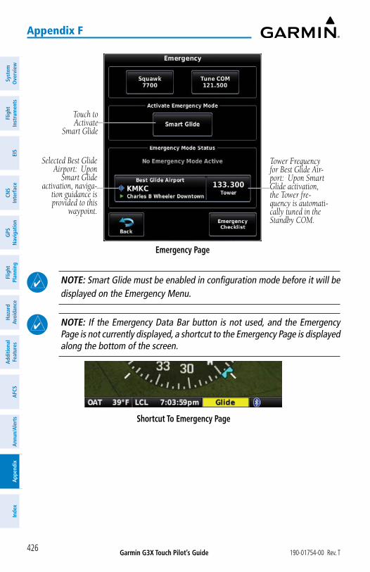
Garmin G3X Touch Pilot’s Guide 190-01754-00 Rev. T
Appendix F
426
Syst
em
Ove
rvie
wFl
ight
In
stru
men
tsEI
SCN
SIn
terf
ace
GPS
N
avig
atio
nFl
ight
Plan
ning
Haz
ard
Avoi
danc
eA
dditi
onal
Fe
atur
esA
FCS
Ann
un/A
lert
sA
ppen
dix
Inde
x
Emergency Page
Touch to Activate
Smart Glide
Selected Best Glide Airport: Upon
Smart Glide activation, naviga-
tion guidance is provided to this
waypoint.
Tower Frequency for Best Glide Air-port: Upon Smart Glide activation, the Tower fre-quency is automati-cally tuned in the Standby COM.
NOTE: Smart Glide must be enabled in configuration mode before it will be displayed on the Emergency Menu.
NOTE: If the Emergency Data Bar button is not used, and the Emergency Page is not currently displayed, a shortcut to the Emergency Page is displayed along the bottom of the screen.
Shortcut To Emergency Page

Garmin G3X Touch Pilot’s Guide190-01754-00 Rev. T
Appendix F
427
System
Overview
Flight Instrum
entsEIS
CNS
InterfaceG
PS N
avigationFlight
PlanningH
azard Avoidance
AdditionalFeatures
AFCS
Annun/A
lertsA
ppendixIndex
AIRPORT WITHIN RANGE
When the system estimates there is a suitable runway within glide distance, activating Smart Glide automatically begins navigation to the airport. When GSA 28 Smart Servos (or compatible autopilot) are installed, the flight director provides guidance to the airport at the configured best-glide airspeed, and if altitude permits the autopilot engages and follows the Smart Glide flight director guidance. In addition, the system will provide an audible annunciation of bearing and distance to the selected airport.
CAUTION: During an emergency glide, the flight director allows for 1 1/2 times standard rate turn when initiating a glide to get on course.
Smart Glide Active - Airport Within Range
Displays waypoint information for the destination airport
Smart Glide Active
Autopilot Engaged
Smart Glide Active
Cancel Smart Glide Button
NOTE: If desired, the pilot may adjust the airspeed using the pitch wheel.

Garmin G3X Touch Pilot’s Guide 190-01754-00 Rev. T
Appendix F
428
Syst
em
Ove
rvie
wFl
ight
In
stru
men
tsEI
SCN
SIn
terf
ace
GPS
N
avig
atio
nFl
ight
Plan
ning
Haz
ard
Avoi
danc
eA
dditi
onal
Fe
atur
esA
FCS
Ann
un/A
lert
sA
ppen
dix
Inde
x
Selecting an Alternate Airport using the Nearest Page:1) With Smart Glide active, press the NRST Key.
2) Touch the desired airport (within glide distance) from the NRST list. Airports within glide distance that meet the pre-configured runway criteria, display the city and state in green.
3) Press the Direct-To Key.
4) Touch Glide To. Touching this button changes the selected glide waypoint to the new airport.
Selecting an Alternate Airport(Nearest Page)
Touch Glide To to change the selected glide waypoint to the new airport.
Touch the desired airport
within glide distance.
Selecting an Alternate Airport(Direct-To Page)
Selecting an Alternate Airport using the Map Page:1) From the Map Page (with Smart Glide active) touch the desired airport
within the yellow glide range ring.
2) Press the Direct-To Key.
3) Touch Glide To. Touching this button changes the selected glide waypoint to the new airport.

Garmin G3X Touch Pilot’s Guide190-01754-00 Rev. T
Appendix F
429
System
Overview
Flight Instrum
entsEIS
CNS
InterfaceG
PS N
avigationFlight
PlanningH
azard Avoidance
AdditionalFeatures
AFCS
Annun/A
lertsA
ppendixIndex
Selecting an Alternate Airport(Map Page)
Touch Glide To to change the selected glide waypoint to the new airport.
Touch the desired airport
within glide distance.
Selecting an Alternate Airport(Direct-To Page)
Dependent upon prevailing weather conditions, the system navigates to the runway approach end with the most favorable wind speed and direction for landing. This is determined by weather information provided by current METAR information for that airport, or an adjacent airport within 5 nm. When that information is not available, the system makes this determination based on its own winds estimation. When that information is not available, the system navigates to the center of the airport.
In the event excess altitude remains once the aircraft arrives at the designated glide waypoint, the system begins a series of descending turns around the glide waypoint. The direction of the descending turns depends upon system configuration at the time of install. When set to 'AUTO', the system selects the traffic pattern direction provided from the internal Airport Directory database.
When appropriate, the system prompts the pilot to disconnect the autopilot and maneuver for landing. The autopilot does not automatically disengage; however, it continues to prompt the pilot to do so, both aurally and visually.

Garmin G3X Touch Pilot’s Guide 190-01754-00 Rev. T
Appendix F
430
Syst
em
Ove
rvie
wFl
ight
In
stru
men
tsEI
SCN
SIn
terf
ace
GPS
N
avig
atio
nFl
ight
Plan
ning
Haz
ard
Avoi
danc
eA
dditi
onal
Fe
atur
esA
FCS
Ann
un/A
lert
sA
ppen
dix
Inde
x
CAUTION: Smart Glide provides the latest appropriate time for the pilot to take control of the aircraft by issuing visual and aural "Maneuver and Land" alerts. It is the pilot's responsibility to disengage the autopilot and safely land the aircraft.
Prompt to Disengage Autopilot(Emergency Page)
The system monitors the performance of the descent throughout the glide to the airport environment. 'Airport Out of Range' is displayed during the glide when the system determines the destination airport is no longer within glide range. The system will attempt to establish a new destination airport, if a suitable airport can be located.
Airport Out of Range(Emergency Page)

Garmin G3X Touch Pilot’s Guide190-01754-00 Rev. T
Appendix F
431
System
Overview
Flight Instrum
entsEIS
CNS
InterfaceG
PS N
avigationFlight
PlanningH
azard Avoidance
AdditionalFeatures
AFCS
Annun/A
lertsA
ppendixIndex
AIRPORT NOT WITHIN RANGE
When the system determines there is not a suitable airport within glide range, initiating Smart Glide annunciates 'No Airport - Find Alternate Landing Area'. When GSA 28 Smart Servos (or compatible autopilot) are installed, the flight director provides guidance to hold a zero degree bank angle and pitch for the configured best-glide airspeed. If altitude permits, the autopilot automatically engages and follows the Smart Glide flight director guidance.
Airport Not Within Range(Smart Glide Not Active)
Airport Not Within Range(Smart Glide Active)
When determining an airport is within range, the system uses the configured Sink Rate at Vg value. When under partial power, range will be greater than expected by the system. The system monitors for suitable runways that may come into range; if one does, the system automatically provides navigation and optional flight director guidance to that airport. At any time the pilot may select a destination from the Map Page or NRST page, press the Direct-To Key, and touch Glide To.
When appropriate, the system prompts the pilot to disconnect the autopilot and maneuver for landing. The flight director and autopilot remain engaged until pilot action is taken.
NOTE: When Smart Glide is activated with insufficient altitude remaining, the system does not automatically engage the autopilot. When the autopilot is already engaged and Smart Glide is activated, the flight director modes cycle to the appropriate Smart Glide modes.

Garmin G3X Touch Pilot’s Guide 190-01754-00 Rev. T
Appendix F
432
Syst
em
Ove
rvie
wFl
ight
In
stru
men
tsEI
SCN
SIn
terf
ace
GPS
N
avig
atio
nFl
ight
Plan
ning
Haz
ard
Avoi
danc
eA
dditi
onal
Fe
atur
esA
FCS
Ann
un/A
lert
sA
ppen
dix
Inde
x
GLIDE RANGE RING
The Glide Range Ring behavior (when Smart Glide is enabled) is different than that previously discussed in the GPS Navigation section:
Autopilot WILL NOT auto-matically engage upon Smart Glide activation; insufficient
AGL remaining
Glide Range Ring (Single Cyan)
Glide Range Ring(Double Cyan)
Glide Range Ring(Double Yellow)
Autopilot WILL automati-cally engage upon Smart
Glide activation; sufficient AGL remaining Smart Glide Active
CANCELLING SMART GLIDE
In the event engine power is restored at any point, the pilot may cancel the emergency glide by touching Cancel Glide. The flight director will remain engaged in ROL and IAS modes at the previously selected airspeed, and the autopilot will remain engaged.
Canceling Smart Glide:From the Emergency Page, touch Cancel Glide.

Garmin G3X Touch Pilot’s Guide190-01754-00 Rev. T
Appendix G
433
System
Overview
Flight Instrum
entsEIS
CNS
InterfaceG
PS N
avigationFlight
PlanningH
azard Avoidance
AdditionalFeatures
AFCS
Annun/A
lertsA
ppendixIndex
APPENDIX G: DISPLAY SYMBOLS
VFR SYMBOLS
Item Symbol
Unknown
Non-towered, Non-serviced
Towered, Non-serviced
Non-towered, Serviced
Towered, Serviced
Soft Surface, Non-serviced
Soft Surface, Serviced
Soft Surface, Private
Paved, Private
Seaplane Base
Heliport
Americas/Pacific Database Airports
Item Symbol
Civilian, Non-serviced
Military, Non-serviced
Civilian, Serviced
Military, Serviced
Civilian, Soft/Unknown Surface, Non-serviced
Civilian, Soft/Unknown Surface, Serviced
Atlantic Database Airports

Garmin G3X Touch Pilot’s Guide 190-01754-00 Rev. T
Appendix G
434
Syst
em
Ove
rvie
wFl
ight
In
stru
men
tsEI
SCN
SIn
terf
ace
GPS
N
avig
atio
nFl
ight
Plan
ning
Haz
ard
Avoi
danc
eA
dditi
onal
Fe
atur
esA
FCS
Ann
un/A
lert
sA
ppen
dix
Inde
x
Item Symbol
Intersection
Visual Reporting Point
LOM (compass locator at outer marker)
NDB (non-directional radio beacon)
VOR
VOR/DME
ILS/DME or DME only
VORTAC
TACAN
Navaids
Item Symbol
Interstate Highway
US Highway
State Highway
National Highway
Small City
Medium City
Large City
Miscellaneous
IFR SYMBOLS
Item Symbol
VFR, Soft/unknown Surface, Non-serviced
VFR, Soft/unknown Surface, Serviced
Atlantic Database Airports
Item Symbol
Low-Altitude
High- Altitude
Airways

Garmin G3X Touch Pilot’s Guide190-01754-00 Rev. T
Appendix G
435
System
Overview
Flight Instrum
entsEIS
CNS
InterfaceG
PS N
avigationFlight
PlanningH
azard Avoidance
AdditionalFeatures
AFCS
Annun/A
lertsA
ppendixIndex
Item Symbol
Unknown
VFR Airport, Non-serviced
IFR Airport, Non-serviced
VFR Airport, Serviced
IFR Airport, Serviced
VFR, Soft Surface, Non-serviced
VFR, Soft Surface, Serviced
VFR, Soft Surface, Private
VFR, Paved, Private
VFR Seaplane Base
VFR Heliport
Americas/Pacific Database Airports
Item Symbol
Intersection
LOM (compass locator at outer marker)
NDB (non-directional radio beacon)
VOR
VOR/DME
ILS/DME or DME Only
VORTAC
TACAN
Navaids

Garmin G3X Touch Pilot’s Guide 190-01754-00 Rev. T
Appendix G
436
Syst
em
Ove
rvie
wFl
ight
In
stru
men
tsEI
SCN
SIn
terf
ace
GPS
N
avig
atio
nFl
ight
Plan
ning
Haz
ard
Avoi
danc
eA
dditi
onal
Fe
atur
esA
FCS
Ann
un/A
lert
sA
ppen
dix
Inde
x
AIRSPACE SYMBOLS
Item Symbol
Class B, Class E, CTA
Class A, Class C, TMA
Class D
Mode C Veil
TRSA
MOA
Danger, Alert, or Training AreaRestricted, Prohibited, or Warning Area
Radar Area
ATZ, TIZ
MATZ
ADIZ
Misc/Unknown
VFR Americas/Pacific Database
Item Symbol
Class B, Class E, CTA
Class A, Class C, TMA, TRSA
Class D
MOA
Danger, Alert, or Training AreaRestricted, Prohibited, or Warning Area
Radar Area
ATZ, TIZ
Misc/Unknown
IFR Americas/Pacific Database

Garmin G3X Touch Pilot’s Guide190-01754-00 Rev. T
Appendix G
437
System
Overview
Flight Instrum
entsEIS
CNS
InterfaceG
PS N
avigationFlight
PlanningH
azard Avoidance
AdditionalFeatures
AFCS
Annun/A
lertsA
ppendixIndex
Item Symbol
Danger or Alert AreaRestricted, Prohibited, or Warning Area
Training Area
VFR Atlantic Database Exceptions
Item Symbol
Training Area
IFR Atlantic Database Exceptions

Garmin G3X Touch Pilot’s Guide 190-01754-00 Rev. T
Appendix H
438
Syst
em
Ove
rvie
wFl
ight
In
stru
men
tsEI
SCN
SIn
terf
ace
GPS
N
avig
atio
nFl
ight
Plan
ning
Haz
ard
Avoi
danc
eA
dditi
onal
Fe
atur
esA
FCS
Ann
un/A
lert
sA
ppen
dix
Inde
x
APPENDIX H: GLOSSARYADIZ Air Defense Identification ZoneADS-B Automatic Dependant Surveillance-Broadcast
ADS-B In Ability to receive ADS-B information from other aircraft and Ground Based Transceivers (GBTs)
ADS-B Out Ability to transmit ADS-B data on 1090 ES or 978 MHzADS-B Participating Aircraft
An aircraft that has both ADS-B In and ADS-B Out capabilities.
ADS-R Automatic Dependent Surveillance-RebroadcastAGL Above Ground LevelAIM Airman’s Information ManualAIRMET Airman’s Meteorological InformationAP AutopilotAPT airportASPC airspaceARTCC Air Route Traffic Control CenterASOS Automated Surface Observing SystemATC Air Traffic ControlATIS Automatic Terminal Information ServiceAWOS Automated Weather Observing System
Bearing The compass direction from the present position to a destination waypoint.
ºC degrees Celsius

Garmin G3X Touch Pilot’s Guide190-01754-00 Rev. T
Appendix H
439
System
Overview
Flight Instrum
entsEIS
CNS
InterfaceG
PS N
avigationFlight
PlanningH
azard Avoidance
AdditionalFeatures
AFCS
Annun/A
lertsA
ppendixIndex
Calibrated Airspeed
Indicated airspeed corrected for installation and instrument errors.
cm centimeterCOM communication radioCourse The line between two points to be followed by the aircraft.
Course to Steer
The recommended direction to steer in order to reduce course error or stay on course. Provides the most efficient heading to get back to the desired course and proceed along the flight plan.
Crosstrack Error The distance the aircraft is off a desired course in either direction, left or right.
CTS Course to Steer
dBZ decibels ‘Z’ (radar return)deg degree
Desired Track The desired course between the active “from” and “to” waypoints.
DIS distance
Distance The ‘great circle’ distance from the present position to a destination waypoint.
DTK Desired Track
Enroute Safe Altitude
The recommended minimum altitude within ten miles left or right of the desired course on an active flight plan or direct-to.
ENT enterESA Enroute Safe AltitudeEstimated Time of Arrival
The estimated time at which the aircraft should reach the destination waypoint, based upon current speed and track.

Garmin G3X Touch Pilot’s Guide 190-01754-00 Rev. T
Appendix H
440
Syst
em
Ove
rvie
wFl
ight
In
stru
men
tsEI
SCN
SIn
terf
ace
GPS
N
avig
atio
nFl
ight
Plan
ning
Haz
ard
Avoi
danc
eA
dditi
onal
Fe
atur
esA
FCS
Ann
un/A
lert
sA
ppen
dix
Inde
x
Estimated Time Enroute
The estimated time it takes to reach the destination waypoint from the present position, based upon current ground speed.
ETA Estimated Time of ArrivalETE Estimated Time Enroute
ºF degrees FahrenheitFAA Federal Aviation AdministrationFAF Final Approach FixFCC Federal Communication CommissionFPL flight planfpm feet per minuteFSS Flight Service Stationft foot/feet
gal gallon(s)geodetic altitude GPS calculated altitude
Glide Ratio, G/RThe ratio of horizontal distance (distance traveled over the ground) to vertical distance traveled (nn.n:1).
GND ground gph gallons per hourGPS Global Positioning System
Grid MORA
Grid Minimum Off-Route Altitude; one degree latitude by one degree longitude in size and clears the highest elevation reference point in the grid by 1000 feet for all areas of the grid
Groundspeed The velocity the aircraft is travelling relative to a ground position.
Ground-Based Transceiver
Provides ADS-R, TIS-B and FIS-B broadcasts to ADS-B participating aircraft.
Ground Track see TrackGS Ground speed

Garmin G3X Touch Pilot’s Guide190-01754-00 Rev. T
Appendix H
441
System
Overview
Flight Instrum
entsEIS
CNS
InterfaceG
PS N
avigationFlight
PlanningH
azard Avoidance
AdditionalFeatures
AFCS
Annun/A
lertsA
ppendixIndex
Heading The direction an aircraft is pointed, based upon indications from a magnetic compass or a properly set directional gyro.
Hg mercuryhPa hectopascalhr hourHSI Horizontal Situation IndicatorHz HertzIAF Initial Approach FixIAT Indicated Air TemperatureICAO International Civil Aviation OrganizationIFR Instrument Flight RulesILS Instrument Landing SystemIMC Instrument Meteorological Conditionsin inch
Indicated Information provided by properly calibrated and set instrumentation on the aircraft panel.
in HG inches of mercury
kg kilogramkHz kilohertzkm kilometerkt knot
LAT latitudelb poundLeg The portion of a flight plan between two waypoints.LON longitude
m meter

Garmin G3X Touch Pilot’s Guide 190-01754-00 Rev. T
Appendix H
442
Syst
em
Ove
rvie
wFl
ight
In
stru
men
tsEI
SCN
SIn
terf
ace
GPS
N
avig
atio
nFl
ight
Plan
ning
Haz
ard
Avoi
danc
eA
dditi
onal
Fe
atur
esA
FCS
Ann
un/A
lert
sA
ppen
dix
Inde
x
MAP Missed Approach PointMETAR Meteorological Aviation RoutineMHz megahertzMinimum Safe Altitude
Uses Grid MORAs to determine a safe altitude within ten miles of the aircraft present position.
MOA Military Operations AreaMSA Minimum Safe AltitudeMSL Mean Sea Level
NAVAID NAVigation AIDNDB Non-directional BeaconNEXRAD Next Generation Radarnm nautical mile(s)NRST nearest
OAT Outside Air TemperatureOBS Omni Bearing Selector
psi pounds per square inch
QTY quantity
rpm revolutions per minute

Garmin G3X Touch Pilot’s Guide190-01754-00 Rev. T
Appendix H
443
System
Overview
Flight Instrum
entsEIS
CNS
InterfaceG
PS N
avigationFlight
PlanningH
azard Avoidance
AdditionalFeatures
AFCS
Annun/A
lertsA
ppendixIndex
SBAS Satellite-Based Augmentation SystemSD Secure Digitalsec second(s)SIGMET Significant Meteorological Information
TACAN Tactical Air Navigation SystemTAF Terminal Aerodrome ForecastTAS True AirspeedTER terrainTFR Temporary Flight RestrictionTOPO topographicTIS-A Traffic Information ServiceTIS-B Traffic Information Service-Broadcast
Track Direction of aircraft movement relative to a ground position; also ‘Ground Track’
TRSA Terminal Radar Service Area
UTC Coordinated Universal Time
VFR Visual Flight RulesVHF Very High FrequencyVNAV vertical navigationVOL volumeVOR VHF Omni-directional Range

Garmin G3X Touch Pilot’s Guide 190-01754-00 Rev. T
Appendix H
444
Syst
em
Ove
rvie
wFl
ight
In
stru
men
tsEI
SCN
SIn
terf
ace
GPS
N
avig
atio
nFl
ight
Plan
ning
Haz
ard
Avoi
danc
eA
dditi
onal
Fe
atur
esA
FCS
Ann
un/A
lert
sA
ppen
dix
Inde
x
VORTAC very high frequency omnidirectional range station and tactical air navigation
VSI Vertical Speed IndicatorVSR Vertical Speed RequiredVTF vector to final
WAAS Wide Area Augmentation SystemWPT waypointWX weather

Garmin G3X Touch Pilot’s Guide190-01754-00 Rev. T
Appendix I
445
System
Overview
Flight Instrum
entsEIS
CNS
InterfaceG
PS N
avigationFlight
PlanningH
azard Avoidance
AdditionalFeatures
AFCS
Annun/A
lertsA
ppendixIndex
APPENDIX I: LICENSE AGREEMET AND WARRANTY
CONTACT GARMIN®
Contact Garmin if you have any questions while using your G3X Touch. Contact Garmin Product Support at flygarmin.com.
SOFTWARE LICENSE AGREEMENTBY USING THE DEVICE, COMPONENT OR SYSTEM MANUFACTURED OR SOLD BY GARMIN (“THE GARMIN PRODUCT”), YOU AGREE TO BE BOUND BY THE TERMS AND CONDITIONS OF THE FOLLOWING SOFTWARE LICENSE AGREEMENT. PLEASE READ THIS AGREEMENT CAREFULLY. Garmin Ltd. and its subsidiaries (“Garmin”) grants you a limited license to use the software embedded in the Garmin Product (the “Software”) in binary executable form in the normal operation of the Garmin Product. Title, ownership rights, and intellectual property rights in and to the Software remain with Garmin and/or its third-party providers. You acknowledge the Software is the property of Garmin and/or its third-party providers and is protected under the United States of America copyright laws and international copyright treaties. You further acknowledge the structure, organization, and code of the Software are valuable trade secrets of Garmin and/or its third-party providers and the Software in source code form remains a valuable trade secret of Garmin and/or its third-party providers. You agree not to reproduce, decompile, disassemble, modify, reverse assemble, reverse engineer, or reduce to human readable form the Software or any part thereof or create any derivative works based on the Software. You agree not to export or re-export the Software to any country in violation of the export control laws of the United States of America.
LIMITED WARRANTY FOR G3X TOUCH PRODUCTSGarmin G3X Touch LRUs GAD 29, GAP 26, GDU 37X, GDU 45X/46X/470, GEA 24, GI 260, GMC 305, GMC 307, GMU 22, GMU 44, GPS 20A, GSA 28, GSU 25/25B, GSU 73, GTP 59, & GTR 20 are warranted to be free from defects in materials or workmanship for two years from the date of purchase. Within the applicable period, Garmin will, at its sole option, repair or replace any components that fail in normal use. Such repairs or replacement will be made at no charge to the customer for parts or labor, provided the customer shall be responsible for any transportation cost. This warranty does not apply to: (i) cosmetic damage, such as scratches, nicks and dents; (ii) consumable parts, such as batteries, unless product damage has occurred due to a defect in materials or workmanship; (iii) damage caused by accident, abuse, misuse, water, flood, fire, or other acts of nature or external causes; (iv) damage caused by service performed by anyone who is not an authorized service provider of Garmin; or (v) damage to a product that has been modified or altered without the written permission of Garmin. In addition, Garmin reserves the right to refuse warranty claims against products or services that are obtained and/or used in contravention of the laws of any country.THE WARRANTIES AND REMEDIES CONTAINED HEREIN ARE EXCLUSIVE AND IN LIEU OF ALL OTHER WARRANTIES, WHETHER EXPRESS, IMPLIED OR STATUTORY, INCLUDING ANY LIABILITY ARISING UNDER ANY WARRANTY OF MERCHANTABILITY OR FITNESS FOR A PARTICULAR PURPOSE, STATUTORY OR OTHERWISE. THIS WARRANTY GIVES YOU SPECIFIC LEGAL RIGHTS, WHICH MAY VARY FROM STATE TO STATE.IN NO EVENT SHALL GARMIN BE LIABLE FOR ANY INCIDENTAL, SPECIAL, INDIRECT OR CONSEQUENTIAL DAMAGES, WHETHER RESULTING FROM THE USE, MISUSE OR INABILITY TO USE THE PRODUCT OR FROM

Garmin G3X Touch Pilot’s Guide 190-01754-00 Rev. T
Appendix I
446
Syst
em
Ove
rvie
wFl
ight
In
stru
men
tsEI
SCN
SIn
terf
ace
GPS
N
avig
atio
nFl
ight
Plan
ning
Haz
ard
Avoi
danc
eA
dditi
onal
Fe
atur
esA
FCS
Ann
un/A
lert
sA
ppen
dix
Inde
x
DEFECTS IN THE PRODUCT. SOME STATES DO NOT ALLOW THE EXCLUSION OF INCIDENTAL OR CONSEQUENTIAL DAMAGES, SO THE ABOVE LIMITATIONS MAY NOT APPLY TO YOU.Garmin retains the exclusive right to repair or replace (with a new or newly-overhauled replacement product) the product or software or offer a full refund of the purchase price at its sole discretion. SUCH REMEDY SHALL BE YOUR SOLE AND EXCLUSIVE REMEDY FOR ANY BREACH OF WARRANTY.Online Auction Purchases: Products purchased through online auctions are not eligible for warranty coverage. Online auction confirmations are not accepted for warranty verification. To obtain warranty service, an original or copy of the sales receipt from the original retailer is required. Garmin will not replace missing components from any package purchased through an online auction.International Purchases: A separate warranty may be provided by international distributors for devices purchased outside the United States depending on the country. If applicable, this warranty is provided by the local in-country distributor and this distributor provides local service for your device. Distributor warranties are only valid in the area of intended distribution. Devices purchased in the United States or Canada must be returned to the Garmin service center in the United Kingdom, the United States, Canada, or Taiwan for service.
Garmin International, Inc.1200 East 151st StreetOlathe, Kansas 66062, U.S.A.
Garmin (Europe) Ltd. Liberty House, Hounsdown Business ParkSouthampton, Hampshire SO40 9LR, U.K.
Refer to the G3X Installation Manual for warranty registration instructions.
AOPA AIRPORT DIRECTORY NOTICEAOPA MEMBERSHIP PUBLICATIONS, INC. AND ITS RELATED ORGANIZATIONS (HEREINAFTER COLLECTIVELY “AOPA”) EXPRESSLY DISCLAIM ALL WARRANTIES, WITH RESPECT TO THE AOPA INFORMATION INCLUDED IN THIS DATA, EXPRESS OR IMPLIED, INCLUDING, BUT NOT LIMITED TO, THE IMPLIED WARRANTIES OF MERCHANTABILITY AND FITNESS FOR A PARTICULAR PURPOSE. THE INFORMATION IS PROVIDED “AS IS” AND AOPA DOES NOT WARRANT OR MAKE ANY REPRESENTATIONS REGARDING ITS ACCURACY, RELIABILITY, OR OTHERWISE. UNDER NO CIRCUMSTANCES INCLUDING NEGLIGENCE, SHALL AOPA BE LIABLE FOR ANY INCIDENTAL, SPECIAL OR CONSEQUENTIAL DAMAGES THAT RESULT FROM THE USE OR INABILITY TO USE THE SOFTWARE OR RELATED DOCUMENTATION, EVEN IF AOPA OR AN AOPA AUTHORIZED REPRESENTATIVE HAS BEEN ADVISED OF THE POSSIBILITY OF SUCH DAMAGES. USER AGREES NOT TO SUE AOPA AND, TO THE MAXIMUM EXTENT ALLOWED BY LAW, TO RELEASE AND HOLD HARMLESS AOPA FROM ANY CAUSES OF ACTION, CLAIMS OR LOSSES RELATED TO ANY ACTUAL OR ALLEGED INACCURACIES IN THE INFORMATION ARISING OUT OF GARMIN’S USE OF THE INFORMATION IN THE DATASETS. SOME JURISDICTIONS DO NOT ALLOW THE LIMITATION OR EXCLUSION OF IMPLIED WARRANTIES OR LIABILITY FOR INCIDENTAL OR CONSEQUENTIAL DAMAGES SO THE ABOVE LIMITATIONS OR EXCLUSIONS MAY NOT APPLY TO YOU.
AC-U-KWIK LICENSE AGREEMENTAC-U-KWIK AND ITS RELATED ORGANIZATIONS (HEREINAFTER COLLECTIVELY “AC-U-KWIK ORGANIZATIONS”) EXPRESSLY DISCLAIM ALL WARRANTIES WITH RESPECT TO THE AC-U-KWIK INFORMATION INCLUDED IN THIS DATA, EXPRESS OR IMPLIED, INCLUDING, BUT NOT LIMITED TO, THE IMPLIED WARRANTIES OF MERCHANTABILITY AND FITNESS FOR A PARTICULAR PURPOSE. THE INFORMATION IS PROVIDED “AS IS” AND AC-U-KWIK ORGANIZATIONS DO NOT WARRANT OR MAKE ANY REPRESENTATIONS REGARDING ITS ACCURACY, RELIABILITY, OR OTHERWISE. LICENSEE AGREES NOT TO SUE AC-U-KWIK ORGANIZATIONS AND, TO THE MAXIMUM EXTENT ALLOWED BY LAW, TO RELEASE AND HOLD HARMLESS AC-U-KWIK ORGANIZATIONS FROM ANY CAUSES OF ACTION, CLAIMS OR LOSSES RELATED TO ANY ACTUAL OR ALLEGED INACCURACIES IN THE INFORMATION ARISING OUT OF GARMIN’S USE OF

Garmin G3X Touch Pilot’s Guide190-01754-00 Rev. T
Appendix I
447
System
Overview
Flight Instrum
entsEIS
CNS
InterfaceG
PS N
avigationFlight
PlanningH
azard Avoidance
AdditionalFeatures
AFCS
Annun/A
lertsA
ppendixIndex
THE INFORMATION IN THE DATASETS. SOME JURISDICTIONS DO NOT ALLOW THE LIMITATION OR EXCLUSION OF IMPLIED WARRANTIES OR LIABILITY FOR INCIDENTAL OR CONSEQUENTIAL DAMAGES SO THE ABOVE LIMITATIONS OR EXCLUSIONS MAY NOT APPLY TO LICENSEE.
SiriusXM SATELLITE RADIO SERVICE AGREEMENTHardware and required monthly subscription sold separately. USER ACKNOWLEDGES THAT GARMIN HAS NO CONTROL OVER THE TERMS AND REQUIREMENTS OF THE SUBSCRIPTION. COMPATABILITY OF HARDWARE EQUIPMENT WITH THEN-CURRENT SUBSCRIPTION OFFERING OF SERVICE PROVIDER IS ALSO BEYOND GARMIN’S CONTROL. GARMIN SHALL HAVE NO LIABILITY IF CHANGES IN SERVICE PROVIDER’S SUBCRIPTION OFFERING NEGATIVELY IMPACTS OR RENDERS IMPOSSIBLE THE USE OF PURCHASED GARMIN HARDWARE EQUIPMENT WITH THE SERVICE PROVIDER’S OFFERING IN THE FUTURE. Subscription fee is consumer only. Other fees and taxes, including a one-time activation fee may apply. All programming fees and weather data subject to change. Sirius XM weather data and individual product availability vary by hardware equipment. Reception of the Sirius XM signal may vary depending on location. Subscriptions subject to Customer Agreement included with the Sirius XM Welcome Kit and available at www.siriusxm.com. USER ACKNOWLEDGES THAT GARMIN IS AN INTENDED THIRD PARTY BENEFICIARY OF SUCH CUSTOMER AGREEMENT, AND THAT ALL DISCLAIMERS CONTAINED THEREIN EQUALLY APPLY AS IF SUCH DISCLAIMERS WERE MADE DIRECTLY BY GARMIN. Available only in the 48 contiguous United States.
THE USER AGREES THE SIRIUS XM WEATHER SERVICE OFFERING IS PROVIDED “AS IS”, THAT YOUR GARMIN HARDWARE EQUIPMENT ONLY ALLOWS THE DISPLAY OF SUCH SERVICE OFFERING, AND THAT ANY CHANGES BY THE SERVICE PROVIDER MAY INTERFERE WITH THE ABILITY OF YOUR GARMIN HARDWARE EQUIPMENT TO RECEIVE OR DISPLAY SUCH SERVICE OFFERING. FURTHER, SUCH SERVICE OFFERING CONTAINS INFORMATION FURNISHED BY OTHERS WHO ARE NOT UNDER THE CONTROL OF GARMIN, AND THEREFORE THE SERVICE OFFERING IS ACCORDINGLY FURNISHED WITHOUT ANY WARRANTY OF GARMIN, EXPRESS OR IMPLIED, INCLUDING WITHOUT LIMITATION, IMPLIED WARRANTIES OF MERCHANTABILITY AND FITNESS FOR A PARTICULAR PURPOSE.
Contact SiriusXM Satellite Radio by phone at 800.985.9200 to subscribe to XM WX Weather and/or SiriusXM Radio.
WEATHER DATA WARRANTYTHE WEATHER DATA SOFTWARE PRODUCT IS PROVIDED “AS IS.” ALL OTHER WARRANTIES, EXPRESSED OR IMPLIED, INCLUDING ANY WARRANTY OF MERCHANTABILITY OR FITNESS FOR A PARTICULAR PURPOSE OR OF NON-INFRINGEMENT ARE HEREBY EXCLUDED.
USER SAFETY
If you use XM Services it is your responsibility to exercise prudent discretion and observe all safety measures required by law and your own common sense. You assume the entire risk related to your use of the Services. XM and Garmin assume no responsibility for accidents resulting from or associated with use of the Services. Your Radio Service includes traffic and weather information, and you acknowledge that such information is not for “safety for life”, but is merely supplemental and advisory in nature, and therefore cannot be relied upon as safety-critical in connection with any aircraft, sea craft or automobile usage. This information is provided “as is” and XM and Garmin disclaim any and all warranties, express and implied, with respect thereto or the transmission or reception thereof. XM and Garmin further do not warrant the accuracy, reliability, completeness or timeliness of the traffic and weather information disclosed on the Radio Service. In no event will XM and Garmin, their data suppliers, service providers, marketing/distribution, software or Internet partners or hardware manufacturers be

Garmin G3X Touch Pilot’s Guide 190-01754-00 Rev. T
Appendix I
448
Syst
em
Ove
rvie
wFl
ight
In
stru
men
tsEI
SCN
SIn
terf
ace
GPS
N
avig
atio
nFl
ight
Plan
ning
Haz
ard
Avoi
danc
eA
dditi
onal
Fe
atur
esA
FCS
Ann
un/A
lert
sA
ppen
dix
Inde
x
liable to you or to any third party for any direct, indirect, incidental, consequential, special, exemplary or punitive damages or lost profits resulting from use of or interruptions in the transmission or reception of the Services.
LIMITS ON OUR RESPONSIBILITY
a) DISCLAIMERS. EXCEPT AS EXPRESSLY PROVIDED HEREIN, WE MAKE NO WARRANTY OR REPRESENTATION, EITHER EXPRESS OR IMPLIED, REGARDING THE RADIO SERVICE. YOUR USE OF THE SERVICE IS AT YOUR SOLE RISK. THE CONTENT AND FUNCTIONALITY OF THE SERVICE IS PROVIDED “AS IS” WITHOUT ANY WARRANTY OF ANY KIND, EXPRESS OR IMPLIED. ALL SUCH WARRANTIES OR REPRESENTATIONS (INCLUDING, WITHOUT LIMITATION, THE IMPLIED WARRANTIES OF MERCHANTABILITY, FITNESS FOR A PARTICULAR PURPOSE, TITLE AND NON-INFRINGEMENT) ARE HEREBY DISCLAIMED.
b) LIMITATIONS OF LIABILITY. WE ARE NOT RESPONSIBLE FOR ANY SPECIAL, INCIDENTAL, OR CONSEQUENTIAL DAMAGES OR LOSSES RELATING TO THE USE OF THE RADIO SERVICE, WHETHER BASED ON NEGLIGENCE OR OTHERWISE. OUR TOTAL LIABILITY TO YOU AND ANY OTHER PERSONS RECEIVING OUR SERVICES, REGARDLESS OF THE CAUSE, WILL IN NO EVENT EXCEED THE AMOUNTS THAT YOU HAVE PAID TO US FOR THE SERVICE THAT YOU RECEIVED DURING THE SIX (6) MONTH PERIOD IMMEDIATELY PRIOR TO THE SPECIFIC EVENT THAT GAVE RISE TO THE APPLICABLE DAMAGE OR LOSS. THIS ALLOCATION OF RISK IS REFLECTED IN OUR PRICES. YOU MAY HAVE GREATER RIGHTS THAN DESCRIBED ABOVE UNDER YOUR STATE’S LAWS
This product was developed using DAFIF™, a product of the National Geospatial-Intelligence Agency.
This product has not been endorsed or otherwise approved by the National Geospatial-Intelligence Agency, or the United States Department of Defense (10 U.S.C. 425)
a. Under 10 U.S.C. 456, no civil action may be brought against the United States on the basis of the content of a navigational aid prepared or disseminated by either the former Defense Mapping Agency (DMA), National Imagery and Mapping Agency (NIMA), or the National Geospatial-Intelligence Agency (NGA).
b. The DAFIF™ product is provided “as is,” and no warranty, express or implied, including, but not limited to the implied warranties of merchantability and fitness for particular purpose or arising by statute or otherwise in law or from a course of dealing or usage in trade, is made by NGA as to the accuracy and functioning of the product.
c. Neither NGA nor its personnel will be liable for any claims, losses, or damages arising from or connected with the use of this product. The user agrees to hold harmless the United States National Geospatial-Intelligence Agency. The user’s sole and exclusive remedy is to stop using the DAFIF product.

Garmin G3X Touch Pilot’s Guide190-01754-00 Rev. T
Index
Index-1
System
Overview
Flight Instrum
entsEIS
CNS
InterfaceG
PS N
avigationFlight
PlanningH
azard Avoidance
AdditionalFeatures
AFCS
Annun/A
lertsA
ppendixIndex
A
Acquiring Satellites 37ADS-B 259ADS-B In 251ADS-B Out 251ADS-B participating 251ADS-R 252Air Data Computer (ADC) 3, 6, 10AIRMET 220, 221Airport
Review 168Weather 171
Airspace 153, 176Alerts 176Selecting and Viewing 176Smart 177
Airspeed Indicator 58Airways 165
Reviewing 166Alarms 50, 51, 52Alerts 365Altimeter 62–67Altitude Alerting 66Altitude Hold Mode (ALT) 339Altitude Reference 338AOPA 283Approach 197
Activating Vectors-to-Final 200Chart 199Loading 198, 199Removing 200Selecting 198
Approach Mode 355Attitude and Heading Reference System
(AHRS) 3, 6, 10, 28
Attitude Indicator 60Automatic Dependent Surveillance-
Broadcast 250Automatic Dependent Surveillance-
Rebroadcast 252Automatic Reversion 343Automatic squelch 113Autopilot Disconnect 325Auto-Slewing 83
B
Barometric setting, Altimeter 57, 64–65Basemap 406Bearing/Distance, Measuring 156, 157,
159, 161Bearing source 76Bluetooth 305
C
CDI source 74Chart Not Available 278, 282Cloud Tops 214Cloud Tops Forecast 214Command Bars 333Comparator Window 376Compass Arc 147Course Deviation Indicator (CDI) 74Crew Alerting System (CAS) 101, 105,
106, 107, 373, 374Current Icing Product (CIP) 226
D
Data Bar Fields 40, 381Databases 406
Updating 409

Garmin G3X Touch Pilot’s Guide 190-01754-00 Rev. T
Index
Index-2
Syst
em
Ove
rvie
wFl
ight
In
stru
men
tsEI
SCN
SIn
terf
ace
GPS
N
avig
atio
nFl
ight
Plan
ning
Haz
ard
Avoi
danc
eA
dditi
onal
Fe
atur
esA
FCS
Ann
un/A
lert
sA
ppen
dix
Inde
x
Data Entry 31–32Date & Time 47Delete
Flight Plans 192, 194Flight Records 391Individual Waypoint 194
Direct-to 179Cancelling 180
DisplayBacklighting 39Overview 18Symbols 433
E
Echo Tops 215Emergency Page 423Engine/Airframe Unit 6, 10Engine Indication System (EIS) 97Engine Manifold Pressure 99ENG Page 97Exhaust Gas Temperature 99
F
Field of View 274FIS-B 252Flight director (FD) 319
Modes, vertical 334–348Flight Information Service-Broadcast
252Flight Instruments 55Flight Level Change Mode 341Flight Log 389Flight Plan 181, 203
Activation 188
Active 184Adding Waypoints 190Approaches 197Copying 193Creation 183Data Fields 182Editing 190Fuel Flow 192Inverting 195Name 192Speed 192Waypoints, Adding 190
Flight Plan (FPL) Pages 34FliteCharts 280
Expiration 283Range 278, 283
FMS Joystick 19Freezing Levels 225Frequencies 118, 120Fuel Calculator 105Fuel Flow Indicator 99Fuel Pressure Indicator 99Fuel Quantity Indicator 99Fuel Range Ring 156, 157, 159, 161
G
Garmin Display Unit (GDU) 170Garmin Sensor Unit (GSU) 3, 6, 7, 8, 9,
10, 11, 12GBT 251GDU 370 2, 13Glidepath Mode (GP) 344Glideslope Mode 346GMC 507 8, 13

Garmin G3X Touch Pilot’s Guide190-01754-00 Rev. T
Index
Index-3
System
Overview
Flight Instrum
entsEIS
CNS
InterfaceG
PS N
avigationFlight
PlanningH
azard Avoidance
AdditionalFeatures
AFCS
Annun/A
lertsA
ppendixIndex
GMU 44 3GPS Receiver Status 35Ground Based Transceivers 251GSU 73 6, 7, 8, 10, 11, 12GTP 59 3, 4, 5, 6, 9
H
Hazard Display 419Heading 57Heading Line 395Heading Select Mode 349Heading Strip 84Horizontal Situation Indicator (HSI) 57,
71Annunciations 74
I
Icing Forecast 226Information Window 76Integrated Autopilot
Alerts 376Disengaging 325Engaging 325
Intersections 172Inverting, Flight Plan 195
K
Keyboard 52
L
Lean Assist 101Legends 208
Limited Warranty 445Line Replaceable Unit (LRU) 1Location Formats 49
M
Magnetometer 3Main Pages 32, 33Map
Airways 165Customizing 152Detail 163Displays 148Orientation 149Panning 155Range 153Satellite View 162Setup 149Symbols 163, 433
MAP PageDefaults 208XM Weather 208
Map Range 153Map Symbols 163Measuring
Bearing 161Distance 161
MENU Key 19Menus 30
Navigating 328, 330Messages
Miscellaneous 365, 366System 367
METAR 219

Garmin G3X Touch Pilot’s Guide 190-01754-00 Rev. T
Index
Index-4
Syst
em
Ove
rvie
wFl
ight
In
stru
men
tsEI
SCN
SIn
terf
ace
GPS
N
avig
atio
nFl
ight
Plan
ning
Haz
ard
Avoi
danc
eA
dditi
onal
Fe
atur
esA
FCS
Ann
un/A
lert
sA
ppen
dix
Inde
x
Flag Color 219
N
Navigation Mode 351–352Navigation Source 16, 78NDBs 172Nearest
Airport 170Airspaces 176NDB 172VORs 173
Nearest Information 170Nearest Type
Changing 38NEXRAD 210, 213NRST Key 19
O
OBS Mode 85Obstacles 231Oil Pressure Indicator 99Oil Temperature Indicator 99Outside Air Temperature (OAT) 86, 100
P
Pages 32Flight Plan (FPL) 34MAIN 32, 33
Panning 155PFD
Annunciations 373PIREP 223
Pitch Hold Mode 336Position 37
Settings 49Proximity Waypoints 401
R
Red X 28, 419Reversionary Sensor Window 30Roll Hold Mode 349Runway Extension line 152Runway Number 151, 152
S
SafeTaxi 264, 276Satellite Information 37Satellite View 162Secure Digital (SD) Cards 20, 403
Installing 20Selected Altitude 336, 337, 340Selected Altitude Capture Mode 336,
337, 340Selected Ground Track 350Selected Heading 71, 349Settings 38SIGMET 221SiriusXM 204, 207, 208, 263, 285, 447Smart Airspace 177Sound 47Standard Rate Turn Bank Angle Point-
ers 61Storm Cells 218Supercooled Large Droplet (SLD) 226

Garmin G3X Touch Pilot’s Guide190-01754-00 Rev. T
Index
Index-5
System
Overview
Flight Instrum
entsEIS
CNS
InterfaceG
PS N
avigationFlight
PlanningH
azard Avoidance
AdditionalFeatures
AFCS
Annun/A
lertsA
ppendixIndex
Surface Pressure 217Symbols 163Synthetic Vision (SVX) 263System
Annunciations 28Date & Time 48, 49Functionality 30Initialization 20Power-up 20Settings 38
System ID 409
T
Tachometer (RPM) 99TAFs 219Takeoff Mode 347TAS 416TCAS 416Temperature Probe 4Temporary Flight Restrictions (TFRS)
222Terrain 226, 227, 229
Alerts 233, 234Annunciations 375Obstacle Information 231Shading 231Views 231
TIS-B 252Topography 162Track Log 391Track Select Mode 350Traffic Information Service-Broadcast
252Traffic Information Service (TIS) 236,
415–416
Annunciations 239, 375Audio Alerts 240General Information 415Ground Track 241Limitations 416
Traffic Warning Window 240, 241Transponder
Status Box 57True Airspeed (TAS) 57, 58Turbulence Forecast 225Turn Rate Indicator 57
U
UAT 251Universal Access Transceiver 250User Waypoints 173
Creating 174, 176Deleting 175Editing 175Nearest 175Renaming 175
V
Vertical Deviation Indicator (VDI) 68Vertical Navigation Mode (VNAV) 342Vertical Navigation (VNAV)
Capturing 94Configuring 93
Vertical Power 33, 287, 288, 290Vertical Speed Indicator (VSI) 68Vertical Speed Mode 340Vertical Speed Reference 340VNAV Target Altitude Capture Mode
(ALTV) 343Voltmeter 99

Garmin G3X Touch Pilot’s Guide 190-01754-00 Rev. T
Index
Index-6
Syst
em
Ove
rvie
wFl
ight
In
stru
men
tsEI
SCN
SIn
terf
ace
GPS
N
avig
atio
nFl
ight
Plan
ning
Haz
ard
Avoi
danc
eA
dditi
onal
Fe
atur
esA
FCS
Ann
un/A
lert
sA
ppen
dix
Inde
x
VORs 173VP-X 33, 287Vspeed Reference 51, 52
W
Warranty 445Waypoints 166, 173
Creating 174, 176User 173
Weather Information 171Weight & Balance 397Wind Data 87Winds Aloft 215
X
XMAccessing 207XM Satellite Radio 285, 289
X Symbol 230


Garmin International, Inc. 1200 East 151st Street
Olathe, Kansas 66062, U.S.A. Garmin Product Support: flygarmin.com
Garmin AT, Inc. 2345 Turner Road SE
Salem, OR 97302, U.S.A. Garmin Product Support: flygarmin.com
Garmin (Europe) Ltd. Liberty House, Hounsdown Business Park Southampton, Hampshire SO40 9LR U.K. Garmin Product Support: flygarmin.com
Garmin Corporation No. 68, Zhangshu 2nd Road
Xizhi District, New Taipei City, Taiwan Garmin Product Support: flygarmin.com
flygarmin.com
190-01754-00 Rev. T© 2022 Garmin Ltd. or its subsidiaries