78 06 29 02 2q - dtic
TRANSCRIPT
S[A0 021
CONTRACTOR kEPORT ARCSL-CR-TS022
ENGINEERING DESIGN HANDBOOK
FOR
mzt AIR CLEANING FOR CHEMICAL
DEMILITARIZATION LEVEL I
by
Marvin E. S1igel (AAI Corp.)Arthur Shacter (CSL/APG)
IAAI Corporation I D D CS•_ ~ ~~~~P.O. Box 6T6T ,,p -Dn_ •Baitirnorm, Wk. 2 1 0 4 J
"March 1978 - .--
Contract No. DAAA15-T5-C-0154-Task No. 52-'U,400JM-iE200
US ARMY ARMAMENT RESEARCH AWD DEVELOPMENT COMMANDCherrical Systsmm Laboratory
Aberdeen Proving Ground, Maryland 21010
APPROVED FOR PUBLIC RELEASE; DISTRIBUTION UNLIMITED
78 06 29 02 2Q
Disclaimer
The information provided in th:.s repo,:t is ncot to be construedas an officia1 Department of the A.ray position unless so designatedby other authorized documents.
Dispo2sition
Destroy this report when it is vo longer needed. no ',:eturn it to the criginator.

UNCLASSIFIEDSECURITY CLASSIFICATION OF THIS PAGE (When Doe. B"re _______________________
REPORT DOCUMENTATION PAGE BFRIAD DISPLTERUC V K171. REPO¶ITNUMUE 2. OVT ACCESSION No.0 . RECIPIENT'S CATALOG NUMBER 1
)ARCSLOCR-780224. TITLLm~be---... r-Y61RF'kTRT 4i PERIOD COVERU'P
IENGlNSERING DESIGN HANDBOOK( FOR Final 00e1Vto Oct. 7-wAIR CLEANING FOR CHF24ICAL DEMILITARIZATION&. Mar ~n78 1
i . PERFORMING ORG. REPORT NUMBER
7. AU t)OWu)*- CONTMACT OR GRANT NUMMER(a)
2 7,1 ~in E. Siegel (MV-40vp) IAAl-5Cd5Ar.thur./Shacter (SAiA15)-75-
S. PRFOMIN ORONI~TIC NAM AN A ESS10. PROGRAM ELEMENT, PROJECT, TASKProject Manager for Chr'..cal Demilitarizatio AE OKUI UBR
And Installation..iesto-ration Task tWo. 52-7US4001M-lE200,Attn: DRCPI-DRD!ý'4, Flemi~ ProjectNo. 655tharAppn PO.nw1ing i~rIt ind12 71flij I________
11. CONTROLLING OFFICE NAME AND ADDRESS , 2W.-IEVRT ak,Director, Chemical SystemP Laboratory _MrhW8
Attn: DRMR-CIJ-R -9.1 NUJMBEROF PAGES
Aberdeen Proving Ground, Md. 21010 2$214. MONITORING AGENCY NAME & A9)ORESS(II different hema Controlling Office) 15. SECURITY CLASS. (JI Orif M~WT
Director, Chemnical1 Systems LaboratoryAttn: DRDAR-CLT-D UNCLASSIFIEDAberdeen Proving Ground, Md. 21010 150. DEckASSI FICATION/ DOWNGRADING]
(CPO Arthur Shacter 671-2806) NMAJL
is. DISTRIBUTION STATEMEN4T (of Chia ?:opowt)
App,-ro-qvd for public release; distribution unlimited.
17. DISTRI@UTION STATEMENT~o the oA batracC aniared In Weeck t011,I different from RoWovf)
It. StIPPLEMEWTAF4Y NOTES
IS. KEY WORDS (Continueaon raer**. aide it nacsr and identify bl block number) Filter ban~kActivated carbon Blower DATS Filter housingAdeorber CAMDS Demilitarization HEPA filterAdsorbent Carbon Exhaust system PrefilterAir cleaning Changeout Fano PSUtsoiberBag-in Bag-out Domper Filter Ventilat on syatam
20. ABSTRACT (Contlou' mi toe.ea, aide It nec...ey and idntity by' block nmber,)
The purpose of this handboo!- is to provide information andreferences relating to the design of an air-cleaning system forchemi~cal demilitarization operations. Tha goal. of the system is thehighly efficient removal of toxic chemical agents in the form ofminute parti~culate, aerosol, land gaseous matter.
/(cbntinued)
DD 1A? 1473 EDITINOF o1 Nov5 *aO is 9m~
?pIý a "D
.

UNCIASSIF IED0SCULTY CLASSI•ICATIoN oF TsIS PAG1E(fh. DO& ,t...i
20.. Abstract (continued)
The handbook is intended primarily for engineers and other technicalpersonnel who are responsible for designing air-cleaning systems capableof meeting the stringent requirements imposed by public law and otherregulations relating to the safeguarding of the health and safety ofworkers and the environmental quality of air discharged to the atmosphere.It is the intent of this handbook to point out the many areas of concern andto provide recommendations and precautions based on previous experiencewith such systems.
The air-cleaning system discussed here, patterned after thatextensively used in the nuclear industry, was developed by theChemical Systems Laboratory (CSL) of the U.S. Army Armament Researchand Development Command (DARCOM) and is presently installed at theChemical Agent Munitions Disposal System (CAMDS) facility located at TooeleArmy Depot, Utah. The experience gained as a result of this applicationis documented here to provide baseline data for designe,':_ of futuresystems for demilitarization operations and other siwrJ .ar applications(e.g., chemical laboratories).
-'.riteria for establishing the air volume, airf?,'- FAnid sizing ofthe air-handling equipment are presented. Considaration is given tohood locations, ductwork and damper pcrformance, !ilteT: housings,particulate filters, gas-phase adsorbers, blowe' ; and instrumentationfor testing, monitoring, detection and control.
Discussions also cover installation, testi-,, maiunteance, andoperation of the ventilation and exhaust systP-.,
Since the major hazard to be removed is tn gas or vapor form, theair-cleaning system, as designed, provides r ;1nimum exhaust gasresidence time of 0.25 second through the i. ,t of two identicaladsorber banks. The second adsorber bank prov!Jes a backup adsorptioncapacity in the event of a breakthrough of the first stage. A GB-challenge test was actually conducted on one )f the filter units in-stalled in the CAMDS facility. This test successfully confirmed theefficiency of the system in removing GB age,.c.
i f f K fl
i3
ft )
JU ST~ lIF 4 0 ....... _..... ..................
UNCLASSIFIED
SZCURITY CLASSIFICATION OF THIS PAOE(1Fho Dola Eneened)
1--
U.., p. /
B',
B"
- . 4-U
l.a6U
* Ii
'.3 .91 -- -
-'.8
p4
I
U- nfl
'U p�I I
- �•z- -
1 .. �. :�.
I
:I.ii
<I
FAD
CONTRACTOR REPORT ARCSL-CR-78022
ENGINEERING DESIGN HAMDBOOK
FOR
AIR CLEANING FOR CHEMICAL
DEMILITARIZATION
by
Marvin E. Siegel (AAI Corp.)Arthur Shacter (CSL/APG)
AAI CorporationP.O. Box 6767
Baltimore, Md. 21204
March 1978
Contract No. DAAA15-75-C-0154Task No. 52-TUS4001M-IE200
Project No. 655
US ARMY ARMAMENT RESEARCH AND DEVELOPMENT COMMAND
Chemical Systems LaboratoryAberdeen Proving Ground. Maryland 21010
APPROVED FOR PUBLIC RELEASE; DISTRIBUTION UNLIMITED
PWXJa P
ABSTRACT
The purpose of this handbook is to provide information andreferences relating to the design of an air-cleaning system forchemical demilitarization operations. The goal of the system is thehighly efficient removal of toxic chemical agents in the form ofminute particulate, aerosol, and gaseous matter.
The handbook is intended primarily for engineers and othertechnical personnel who are responsible for designing air-cleaningsystems capable of meeting the stringent requirements imposed bypublic law and other regulations relating to the safeguarding ofthe health and safety of workers and the environmental quality of airdischarged to the atmosphere. It is the intent of this handbook topoint out the many areas of concern and to provide recommendationsand precautions based on previous experience with such systems.
The air-cleaning system discussed here, patterned after thatextensively used in the nuclear industry, was developed by theChemical Systems Laboratory (CSL) of the U.S. Army Armament Researchand Development Command (DARCOM) and is presently installed at theChemical Agent Munitions Disposal System (CAMDS) facility located atTooele Army Depot, Utah. The experience gained as a result of thisapplication is documented here to provide baseline data for designersof future systems for demilitarization operations and other similarapplications (e.g., chemical laboratories).
Criteria for establishing the air volume, airflow, and sizing ofthe air-handling equipment are presented. Consideration is given tohood locations, ductwork and damper performance, filter housings,particulate filters, gas-phase adsorbers, blowers, and instrumentationfor testing, monitoring, detection and control.
Discussions also cover installation, testing, maintenance, andoperation of the ventilation and exhaust systems.
Since the major hazard to be removed is in gas or vapor form,the air-cleaning system, as designed, provides a minimum exhaust gasresidence time of 0.25 second through the first of two identicaladsorber banks. The second adsorber bank provides a backup adsorptioncapacity in the event of a breakthrough of the first stage. A GB-challenge test was actually conducted on one of the filter units in-stalled in the CAMDS facility. This test successfully confirmed theefficiency of the system in removing GB agent.
vii
4% .. ... m o.. . .w

PREFAC'E
This handbook was prepared by AAI Corporation, Cockeysville,Maryland 21204, as Task No. 52-7US4001M-IE200 of Contract No. DAAA15-75-C-6154 for the Chemical Systems Laboratory, Abeideen ProvingGround, Mary'and 21010. Funding was provided to CSL by the ProjectManager for Chemical Demilitarization and Installation Restoration(PM/CDIR) under Department of the Army Project No. 655, "EmissionStudies."
This document, which was written during the period October 1977through March 1978, is readily available to all elements of the U.S.
Army Development and Readiness Command, other Government agencies,and contractors who have a justifiable raquirement for same. Commentsand suggestions on this publication are welcome and should beaddressed to:
Commander/DirectorChemical System LaboratoryAberdeen Proving Ground, Maryland 21010Attn: DRDAR-CLT-D
The information provided here should be considered as advisoryonly. The equipment End techniques described have been successfullyapplied in CAMDS prototype operations, but this is not to imply thatthey will be equally effective in other similar applications.
Trade names and names of commercial suppliers are mentioned inthis document as a means of providing more specific identificationof the products used. However, such mention is not to be construedas advertising or as implying that the U.S. Government endorses orapproves of their use.
Permission has been granted by the U.S. Department of Energy andAmerican Conference of Governmental Induatrial Hygienists to quotematerial from their copyrighted publications "Nuclear Air-CleaningHandbook" and "Industrial Ventilation - A Manual of RecommendedPractice," respectively.
viii
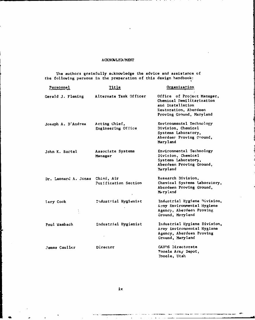
ACKNOWLEDCMENT
The authors gratefully acknowledge the advice and assistance ofthe following persons in the preparation of this design handbook:
Personnel Title Organization
Gerald J. Fleming Alternate Task Officer Office of Project Manager,Chemical Demilitarizationand InstallationRestoration, AberdeenProving Ground, Maryland
Joseph A. DrAndrea Acting Chief, Environmental TechnologyEngineering Office Division, Chemical
Systems Laboratory,Aberdeer Proving Ground,Maryland
John K. Bartel Associate Systems Environmental TechnologyManager Division, Chemical
Systems Laboratory,Aberdeen Proving Ground,Maryland
Dr. Leonard A. Jonas Chief, Air Research Division,Puti.fication Section Chevical Systems Laboratory,
Aberdeen Proving Ground,M.ryland
lary Cook ihdustrial Hygienist Industrial Hygiene nivision,Army Environmental HygieneAgency, Aberdeen ProvingGround, Maryland
Paul Wambach IndustrIal Hygienist Industrial Hygiene Division,Arvy Enviromnental HygieneAgency, Aberdeen ProvingGround, Maryland
James Cauller Director CAW')S DirectorateTooele Arnm Depot,
Tooele, Utah
Ix
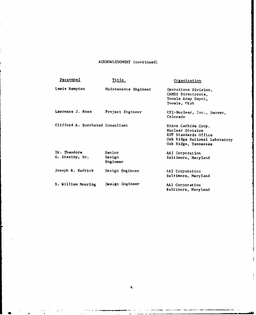
ACKNOWLEDGMENT (continued)
Personnel Title Organization
Lewis Hampton Maintenance Engineer OpArations Division,CAMDS Directorate,Tooele Army Depot,Tooele, Utah
Lawrence J. Rose Project Engineer CTI-Nuclear, Inc., Denver,Colorado
Clifford A. Burchsted Consultant Union Carbide Corp.Nuclear DivisionRDT Standards OfficeOak Ridge National LaboratoryOak Ridge, Tennessee
Dr. Theodore Senior AAI CorporationG. Stastny, Sr. Design Baltimore, Maryland
Engineer
Joseph R. Kudrick Design Engineer AAI CorporationBaltimore, Maryland
B. William Mouring Design Engineer AAI CorporationBaltimore, Maryland
x
oft- - - C - - ~-

TABLEI OF CONTENTS
Page No.
DO Form 1473- ........ ................. i
ABSTRACT ............................................ vii
PREFACE .............. viii
ACKNOWLEDGMENT ...................................... ix
LIST OF FIGURES ..................................... xvi
LIST OF TABLES ...................................... xxi
1. INTRODUCTION ........................................ 1-1
1.1. Purpose ....................................... 1-I1.2. Scope ........................................ 1-11.3. DSc ussio . .................................... 1-1
2. REQUIREMENTS FOR AIR CLEANING FILTRATION SYSTEMS .... 2-I
2.1. Positive Pressure Versus Negative Pressure .... 2-1
2.1.1. Positive Pressure ..................... 2-12.1.2. Negative Pressure ...... .............. 2-1
2.2. Atmospheric/Occupaticnal Standards ............ 2-4
2.2.1. Standards .................... ........ 2-42.2.2. Re3ulated and Nonregulaf ad Areas ...... 2-42.2.3. Laboratories .......................... 2-5
2.3. Unique Negative Pressure Systems .............. 2-52.4. Elements of Exhaust System .................... 2-6
3. BASIC DESIGN CONSIDERATIONS FOR EXHAUST SYSTP.1 ...... 3-1
3.1. Agent Vapor Removal Methods................... 3-I
3.1.1. Methids Available ..................... 3-13.1.2. Ad.ooption ...................... 3-1
3.2. Criteria for Determining Ventilation Rates .... 3-23.3. Filter Capacity ............................. 3-43.4. Safety .................................. 3-53.5. Operstiun and Description of Key Components... 3-8
3.5.1. General ........................... -. 3-83.5.2. Operation ............................. 3-9
xi
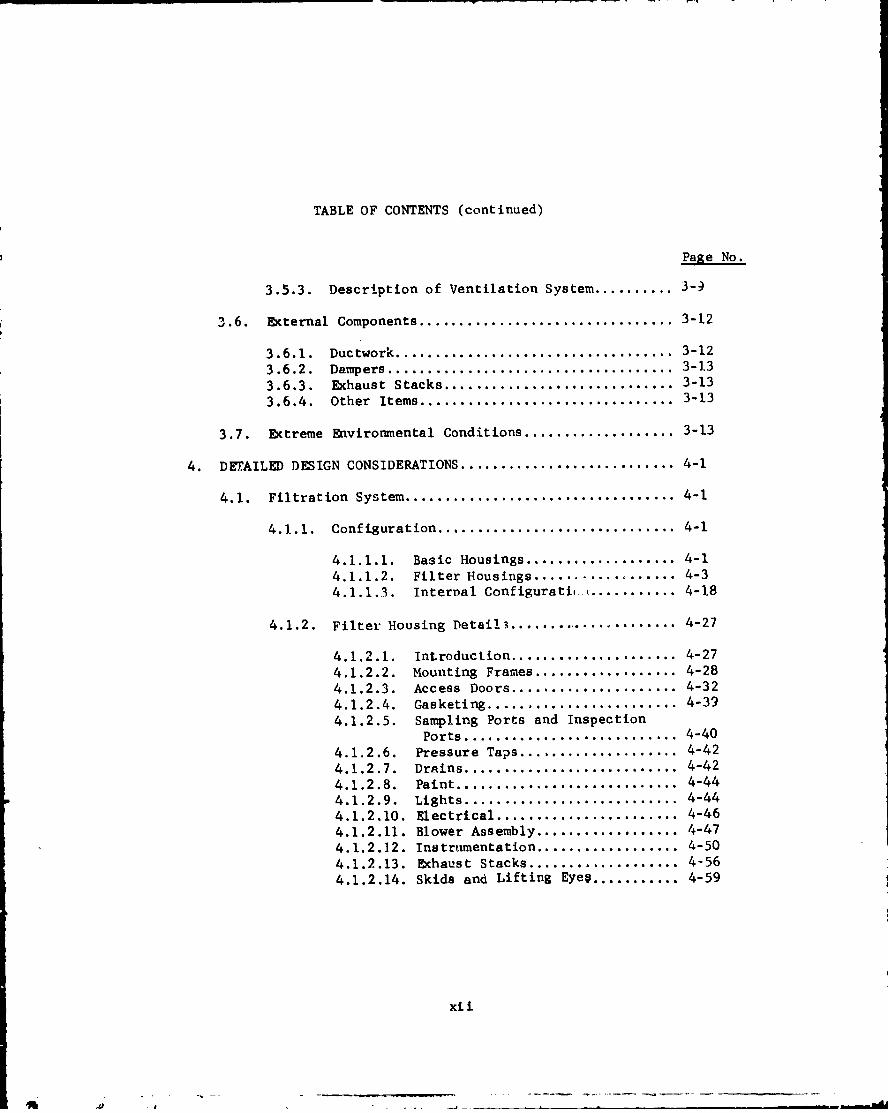
TABLE OF CONTENTS (continued)
Page No.
3.5.3. Description of Ventilation System .......... 3-9
3.6. External Components ................................ 3-12
3.6.1. Ductwork ................................... 3-12
3.6.2. Dampers .................................... 3-1.3
3.6.3. Exhaust Stacks ............................. 3-13
3.6.4. Other Items ................................ 3-13
3.7. Extreme Environmental Conditions ................... 3-13
4. DTAILED DESIGN CONSIDERATIONS ........................... 4-1
4.1. Filtration System .................................. 4-1
4.1.1. Configuration .............................. 4-1
4.1.1.1. Basic Housings ................... 4-14.1.1.2. Filter Housings .................. 4-34.1.1.3. Internal Configuratib. •........... 4-18
4.1.2. Filter Housing Detai!3 ...................... 4-27
4.1.2.1. Introduction ..................... 4-274.1.2.2. Mounting Frames .................. 4-284.1.2.3. Access Doors ..................... 4-324.1.2.4. Gasketing ........................ 4-39
4.1.2.5. Sampling Ports and InspectionPorts ........................... 4-40
4.1.2.6. Pressure Taps .................... 4-424.1.2.7. Drains ........................... 4-424.1.2.8. Paint ............................ 4-444.1.2.9. Lights ........................... 4-444.1.2.10. Electrical ....................... 4-464.1.2.11. Blower Assembly .................. 4-474.1.2.12. Instrumentation .................. 4-504.1.2.13. Exhaust Stacks ................... 4-564.1.2.14. Skids and Lifting Eyev ........... 4-59
xii

TABLE OF CONTETS (continued)
Page No.
4.1.3. Filters and Adsorbers .................. 4-59
4.1.3.1. Prefilters ............ ...... 4-594.1.3.2. HEPA Filters ................ 4-71
4.1.3.3. Adscrber Cells .............. 4-80
4.2. Ventilation System Design Criteria ............ 4-90
4.2.1. Hoods .................................... 4-91
S4.2.1.1. Enclosing Hoods ............. 4-914.2.1.2. Capturing Hoods ............. 4-92
4.2.2. Duct Design ........................... 4-96
4.2.3. Airlock Design ........................ 4-101
4.2.4. Fan Selection ......................... 4-104
4.2.5. Dampers ............................... 4-106
4.2.6. Automatic Controls .................... 4-107
4.2.7. Makeup Air ............................. 4-108
4.2.8. Heat Control ........................... 4-108
4.2.9. Redundancy And Safety Features ........ 4-115
5. OPERATIONAL CONSIDERATIONS ........................... 5-1
5.1. Controls and Instrumentation ................... 5-1
5.1.1. Controls .................................. 5-1
5.1.2. Instrumentation ........................ 5-1
5.2. Agent Monitoring Eqi-pment .................... 5-3
5.2.1. General-.............................. 5-3
5.2.2. M8 Detector/Alarm ..................... 5-6
5.2.3. Bubblers............................... 5-6
5.3. Dampers ................................ .*
5.4. Emergency Considerations ............ ..... 5-7
5.4.1. General ............................... 5-7
5.4.2. Shock and Overpressure,..............585.4.3. Fire and Hot Air...................... 5-9
5.4.4. Power and Equipment Outage ............ 5-10
5.5. Protection Requirements ........................ 5-11
5.5.1. Levels of Protection ............. 5-11
xiii

TABLE OF CONTENTS (continued)
Page No.
5.5.2. Demilitarization ProtectiveEnsemble ........................ 5-11
5.5.3. Donning and Removing ProtectiveClothing ........................ 5-14
6. BASIC MAINZTENANCE AND STORAGE CONSIDERATIONS ......... 6-1
6.1. Operator Responsibilities ........................ 6-16.2. Preventive Mainten~ance Considerations ............ 6-26.3. Inspect4.on Considerations ........................ 6-3
6. 3.1. Procedures ............................... 6-36.3.2. Storage and Handling ..................... 6-46.3.3. Replacement Parts ..................... 6-6
6.4. Replacement of Filters and Adsorbers ............. 6-7
6.4.1. When To Replace .......................... 6-7
6.4.2. Replacemrent Procedures............. 6-8
6.5. Disposal of Spent Filters ........................ 6-24
7 . TESTING .................... ................... 7-1
7.1. Initial Acceptance Testing ....................... 7-17.2. Preoperational Testing....................... 7-17.3. Air Balancing ...........................- *....... 7-27.4. Systems Integration Testing ...................... 7-37.5. In-Service Testing ............................... 7-37.6. CAMDS Test Experience .......................... -
8. APPLICATION OF AIR CLEANING CONCEPTS TO DATS ........... 8-1
8.1. Introduction ............................. 8-1
8.2. Description .................... . ... .. .. . .. ..... 8-18.3. Operation ................................. . 8-12
8.*3 .1. General....................... I........ 8-128.3.2. Low Flow............................ 8-128.3.3. Low Differential Presressur...... 8-148.3.4. Powa ............................... 8-148.3.5. Emnergency Sequence................... 8-148.3.6. Dampers.................. ... ...... 8-14
9.* LITERATURE CITED............. o...................... 9-1
xiv

TABLE OF CONTENTS (continued)
10. GLOSSARY OF TERMS ....................................... 10-1
10.1. Acronyms and Abbreviations ..................... 10-110.2. Terms and Phrases ................................ 10-5
APPENDIXES
A. PROPOSED MAXIMUM ALLOWABLE LIMITS FOR EMISSIONSOF GB, VX, AND MUSTARD FOR CHEMICALDEMILITARIZATION .................................. A-1
B. SPECIFICATION FOR CAMDS AIR CLEANING SYSTEM ....... B-1
C. DETAILED ADSORBER BED CONSIDERATIONS .............. C-1
D. GENERAL CHARACTERISTICS OF ACTIVATED CARBON ....... D-1
DISTRIBUTION LIST
xv
¶ . . --•-~-- - - |.. - - -- - . - - -
LIST OF FIGURES
Figure No. Title Page No.
2-1 Positive Pressure Filter System 2-2
2-2 Negative Pressure Filter System 2-3
3-1 Schematic Of Series Redundant System 3-7
3-2 Schematic Of Parallel Redundant System 3-7
4-1 Basic Filter Housing Configurations 4-2
4-2 Blower Arrangement In Type I housing 4-4
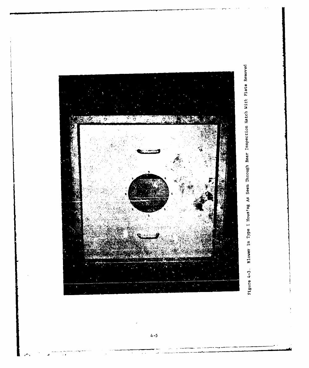
4-3 Blower In Type I Housing As Seen Through 4-5
Rear Inspection Hatch With Plate Removed
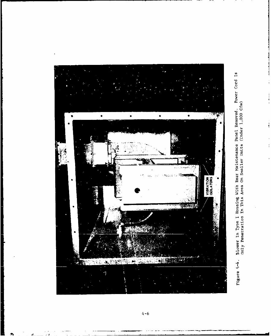
4-4 Blower In Type I Housing With Rear 4-6Maintenance Panel Removed
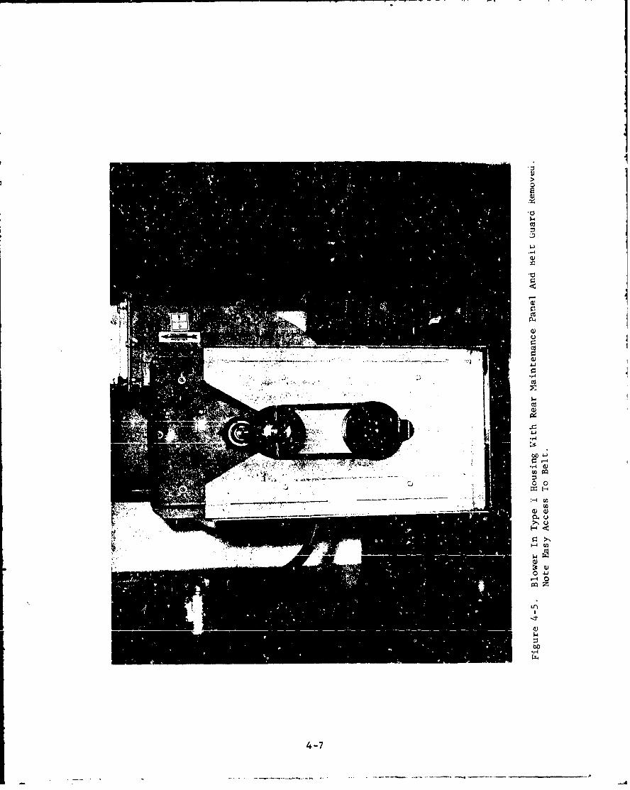
4-5 Blower In Type I Housing With Rear 4-7Maintenance Panel And Belt Guard Removed
4-6 Blower Arrangements In Type 'II Housing 4-8
4-7 Type I Filter System (333 Cfm), Bag-In, 4-9Bag-Out or Bag-Out Only
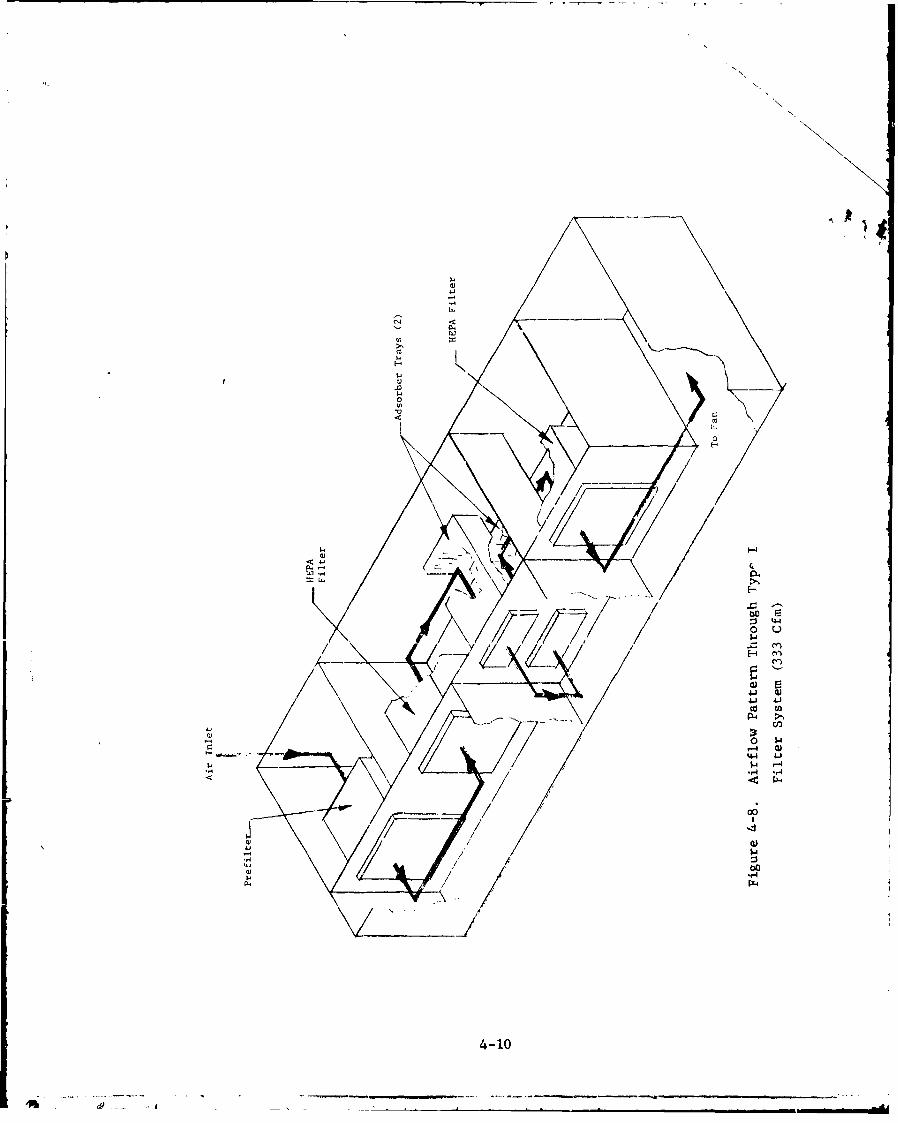
4-8 Airflow Pattern Through Type I Filter 4-10System (333 Cfm)
4-9 Type I Filter System (333 Cfm) With Access 4-11Doors Removed
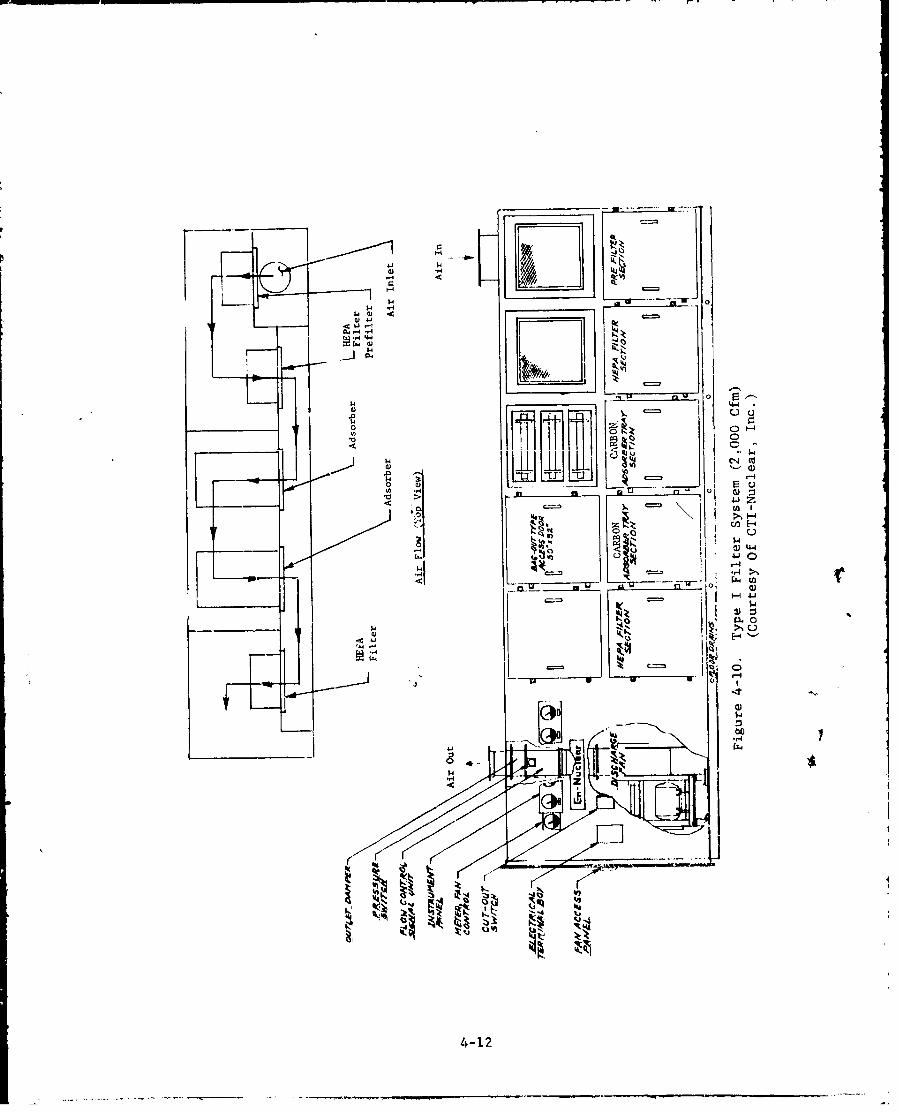
4-10 Type I Filter System (2,000 Cfm) 4-12
4-11 Type I Filter System (2,000 Cfm) On 4-13Concrete Pad At CAMDS Site Prior ToInstallation Of Ductwork And Exhaust Stack
4-12 Type II Filter System (6,000 Cfm), Walk In 4-15
4-13 • Type II Filter System (6,000 Cfm) 4-16
4-14 Type III Filter System (6,000 Cfm), Stationary 4-17Adsorber Walk-In Urit
xvi

LIST OF FIGURES (continued)
Fiwuie No. Title Page No.
4-15 CAMDS Filter System Layout 4-19
4-16 Mounting Frame In Type I Filter System 4-30(1,000 Cfm)
4-17 Mounting Frames In Type !I Filter System 4-31
(6,000 Cfm)
4-18 Quick-Release Toggle Clamps In Type 1 4-33Filter System
4-19 Type I Filter System (666 Cfm) Using Quick- 4-34
Release Toggle Clamps On Adsorber Tray and
E'ankoff Plate
4-20 Captive-Nut Clamping Arrangement For Type 11 4-35
Filter System
4-21 Bank of Adsorber Trays And Blankoff Plates 4-36
Using Captive-Nut Clamps
4-22 Bank of HET'A Filters And Blankoff Plates 4-37
Using Captive-Nut Clamps
4-23 Access Door Sealing Methods For Type I 4-38
Filter Housing
4-24 Sampling Ports And Pressure Tap On Type 1 4-43
Filter Housing
4-25 Interior View Of Light Fixture And 4-45
Sampling Port For Type 11 Filter System
4-26 Overall Flow-Control Arrangement 4-53
4-27 Damper Motor And Linkage Section Of Flow- 4-54
Control Arrangement
4-28 Remote Indoor Instrument Station for CAM4DS 4-55
Filter System
4-29 Principles Of Stack Height Design, 4-57
4-30 Vertical-)iWcharge, No-Lcss Stacl Head 4-58
Design
xvAi

LIST OF FIGURES (continued)
Figure No. Title Page No
4-31 Location Of Lifting Lugs On Top Of 4-601.000 Cfm Filter Housing
4-32 Comparison Of HEPA Filter Life With And 4-61Without Prefilter
4-33 Type Of Prcfilter (Group III) In Use At 4-66
CAMDS
4-34 Group III Prefilter Installed In Type I 4-68
Filter Housing
4-35 Construction Details Of Open-Face HEPA 4-72
Filters
4-36 Type Of HEPA Filter In Use At CAMIDS 4-74
4-37 Front View Of HEPA Filter Bank Installed 4-75In Type II Filter System At CAMDS
4-38 Rear View Pf HEPA Filter Bank Installed 4-76In Type II Filter System (12,000 Cfm)At CAMDS
4-39 General Configuration Of Type II Adsorber 4-81
Cell (Tray Type)
4-40 Configuration Of Type II Adsorber Cell 4-82(Tray Type) Used At CAMDS
4-41 Type II Adsorber Cell (Tray Type) Used 4-83
At CAMDS
4-42 Type III Stationary Adsorber 4-85
4-43 Example Of An Enclosing Hood 4-93
4-44 Principles Of Manifold Design For 4-95
Capturing Hoods
4-45 Hood Entry Loss In Duct Design 4-97
4-46 Recommended Methods To Prevent Backflow 4-102In Airlocks
xviii

LIST OF FIGURES (continued)
Figure No. Title Page No.
4-47 Console Display In CAMDS Control Room 4-109Of Filter And Isolation Damper Information
4-48 Average Winter Temperatures, December To 4-111February, Inclusively
4-49 Location of Redundant Ductwork Containing 4-116Isolation Dampers At CAMDS
4-50 Type II Filter System (3,000 Cfm) For Unpack 4-117Area At CAMDS Showing Isolation Dampers AndInterconnecting Ductwork
4-51 Type I Filter System (2,000 Cfm) For Explosive 4.118Treatment System At CAMDS Showing IsolationDampers And Interconnecting Ductwork
5-1 Environmental Monitoring Shelter At CAMDS 5-5Used To House M8 Detector/Alarm And Bubblers
5-2 Section Of Central Control Panel At CAMDS 5-12Showing Operational Status Of Signals AndAlarms
6-1 Operating Configuration With Element In 6-11Place, Bag-In Bag-Out Procedure
6-2 Access Door Removed And Bag Restraint 6-11Removed
6-3 Dirty Element Withdrawn Into Bag 6-13
6-4 Dirty Element Separated From System 6-13
6-5 New Element In New Bag Sealed To System 6-14
6-6 Old Bag Stub Removed 6-14
6-7 Element In Place With Bag Folded 6-15
6-8 Operating Configuration With New Element 6-15In Place
6-9 Operating Configuration With Element In 6-17Place, Bag-Out Procedure
xix
LIST OF FIGURES (continued)
Figure No. Title Page No.
6-10 Access Door Removed 6-17
6-11 Bag Installed Over Access Door Flange 6-19and Blower Turned Off
6-12 Dirty Element Withdrawn Into Bag 6-19
6-13 Dirty Element Sealed In Bag 6-20
6-14 B .g Containing Dirty Element Removed 6-20orom Access Door And Blower Turned Off
6-15 New Element Installed 6-21
6-16 Operating Configuration With Element In 6-21
Place
8-1 666 Cfm Glove Ventilation System For DATS 8-2
8-2 Key Components Of DATS And Airflow 8-3Measurement Locations
8-3 Primary And Emergency Blower And Fan For DATS 8-4
8-4 Damper Locations And Airflow For DATS 8-5
8-5 Operator's Console Panel 8-6
8-6 Sampling Ports And Inspection Plates 8-7On 666 Cfm Filter Housing For DATS
8-7 Front View Of 666 Cfm Glovebox Ventilation 8-8System For DATS
8-8 Rear View Of 666 Cfm Glovebox Ventilation 8-9System For DATS
8-9 Diagram Of Airflow Through DATS Filter Unit 8-10
xx

LIST OF TABLES
Table No. Title PaRe No.
IV-I. Basic Data For CAMDS Filter Systems 4-20
IV-2. Number Of Filters And Adsorbers Comprising 4-23Each Type Of Filter System Capacity At CAMDS
IV-3. Summary Of Differential Pressure Gage Readings 4-24At CAMDS Site 5-8 October 1976
IV-4. Location Of Sampling Ports And Inspection Ports 4-41In CARDS Filter Housings
IV-5. Price Indexes Of Common Air Filters Per 1000 Cfm 4-62Capacity
IV-6. Classification Of Common Prefilters 4-63
IV-7. Comparison Of Prefilters By Percent Removal 4-63Efficiency For Various Particle Sizes
IV-8. Airflow Capacity, Resistance, And Dust-Holding 4-64Capacity Of Prefilters
IV-9. Typical Characteristics Of Open-Face HEPA Filters 4-73
IV-IO. Formulas For Calculating Airflow Throufh 4-94Capturing Hoods
IV-II. Required Heat Versus Average Outside Air 4-112
Temperature
IV-12. Available Heat Per Unit Of Fuel 4-113
IV-13. Annual Degree Days 4-114
V-I. Sensitivity And Response Time Of Available 5-4Agent Detectors For Use In Filter Systems
V-2. Level Of Personnel Protection Required For 5-13Chemical Demilitarization
VI-I. Information For Procuring Filter Units Based 6-6On CARDS Experience
VI-2. Recommended Differential Pressure Values For 6-7Filter And Adsorber Changeout
xxi
-- • , i .- . ..
LIST OF TABLES (continued)
Table No. Title Page No.
VIII-I. Major Equipment For DATS Filter/Ventilation 8-11System
VIII-2. Ventilation System Balance Conditions For DATS 8-13
VIII-3. Purpose And Function Of Dampers In DATS 8-15Ventilation System
xxii
a -ad

1. INTRODUCrION
1.1. Purpose
This engineering design handbook is specifically addressed toexhaust ventilation and effluent gas air-cleaning systems for use inchemical demilitarization operations involving highly toxic chemicalagents and related munitions. Its purpose is to provide engineeringdesign information for determining the basic filter equipment andaccessory instrumentation needed for meeting environmental andoccupational air quality standards.
1.2. Scope
The scope of this document is limited to chemical demili-tarization activities; however, its general approach ir 1soapplicable to other similar operations such as chemicp' Laboratoriesand chemical agent production and processing.
A chemical demil ventilation system is concerned with removingchemical agents and reaction by-products in the form of minuteparticulates, aerosols, vapor, and gaseous matter. Consequently,this handbook places emphasis on the adsorbers (or gas filters) aswell as the high-efficiency particulate air (HEPA) filters. Theadded presence of a roughing air filter (or prefilter) assists in
prolonging the effectiveness and life of the filter system byscreening out larger extraneous materials.
1.3. Discussion
The principles and design of the chemical demil air-cleaningsystem described in this handbook Pre parallel in many respects tothose successfully employed in the nuclear industry. Both appli-cations involve highly sophisticated designs not readily amenableto the conventional design practices of standard heating and venti-lation systems.
Extensive experience has already been gained with the air-cleaning system installed in the present CAMDS* site at Tooele ArmyDepot, Utah. This facility, however, is a prototype plant and atthis writing has not yet been placed in full operation. Thus, someof the information contained in this handbook may be revised as moreoperational experience becomes available.
*Chemical Agent Munitions Disposal System
1-1
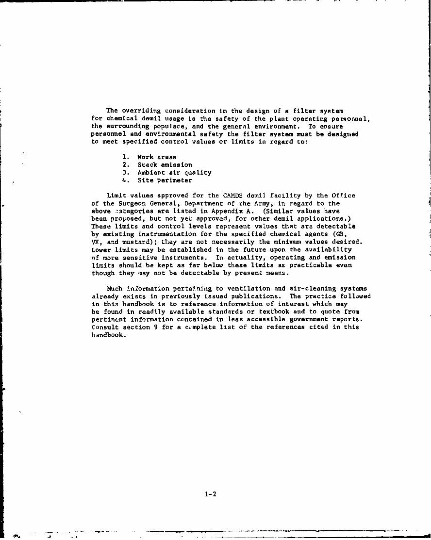
The overriding consideration in the design of a filter systemfor chemical demil usage is the safety of the plant operating personnel,the surrounding populace, and the general environment. To ensurepersonnel and environmental safety the filter system must be designedto meet specified control values or limits in regard to:
I. Work areas"2. Stack emission3. Ambient air quality4. Site perimeter
Limit values approved for the CAMDS demil facility by the Officeof the Surgeon General, Department of the Army, in regard to theabove -ategories are listed in Appendix A. (Similar values havebeen proposed, but not yeL approved, for other demil applications.)These limits and control levels represent values that are detectableby existing instrumentation for the specified chemical agents (GB,VX, and mustard); they are not necessarily the minimum values desired.Lower limits may be established in the future upon the availabilityof more sensitive instruments. In actuality, operating and emissionlimits should be kept as far below these limits as practicable eventhough they -may not be detectable by present means.
Much lnforrmation pertaining to ventilation and air-cleaning systemsalready exists in previously issued publications. The practice followedin thi3 handbook is to reference information of interest which maybe found in readily available standards or textbook and to quote frompertinent information contained in less accessible government reports.Consult section 9 for a cimplete list of the references cited in thishandbook.
1-2
---.-- A
2. REQUIREMENTS FOR AIR CLEANING FILTRATION SYSTEMS
2.1. Positive Pressure Versus Negative Pressure
F11tration systems generally considered for achieving "clean"air may operate by either of two methods - positive pressure ornegative pressure - depending upon whether the air is intended for usewithin an enclosure or for release to the atmosphere.
2.1.1. Positivc Pressure
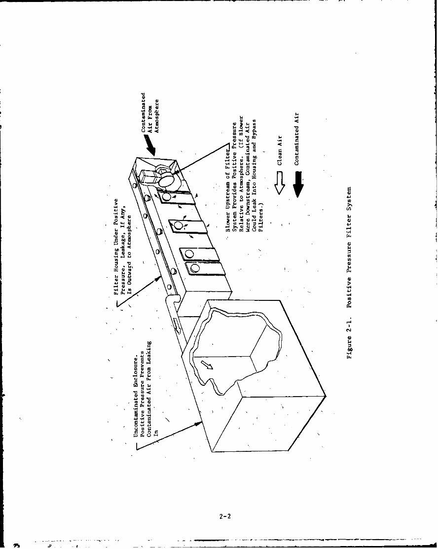
Clean-air supply systems are used to protect a sealed en-closure from outside contamination. In this type of system, thefilters are located in a contaminated area with the blower situatedupstream. This produces a positive pressure in the filter system withrespect to the surrounding atmosphere and prevents the infiltration ofcontamination. Figure 2-1 illustrates a typical positive pressuresystem.
Typical situations using this type of filtration system forprotection are clean rooms, military command posts, communicationcenters, medical facilities, etc. The positive-pressure concept,however, does not lend itself to chemical demil air-cleaning plantoperations where the desired airflow is in the opposite direction.For design handbooks dealing further with positive pressure systems,consult references 1 and 2.*
2.1.2. 'legative Pressure
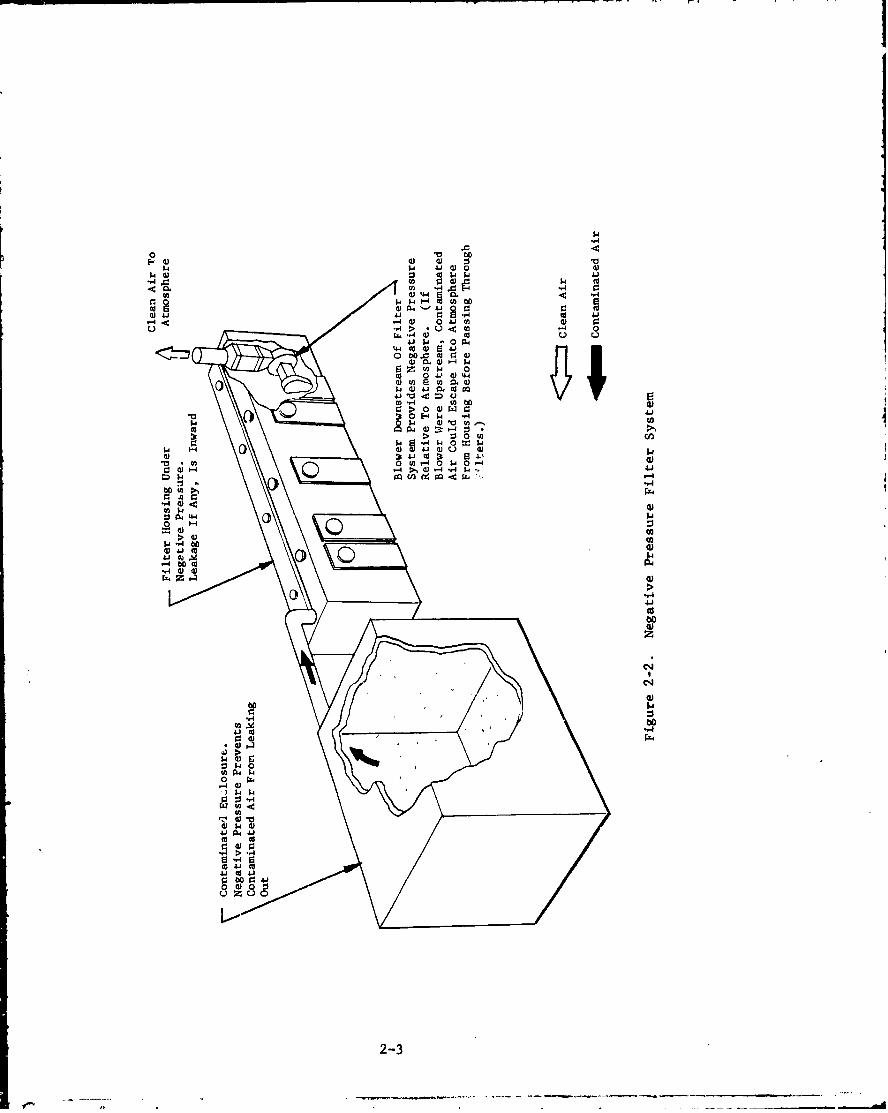
Filtered exhaust systems are used to contain contaminationwithin an enclosure or hood and prevent its release to the outside.In this type of system, the filters are located in a clean area withthe blower situated downstream. This produces a negative pressure inthe filter system with respect to the surrounding atmosphere andprevents any unfiltered P'ir in the filter system from penetratingthe surrounding area. An examp1'i of a typicail negative pressuresystem is shown in figure 2-2.
This type of exhaust air cleaning system, which is principallyfound in chemical laboratories and chemical agent/munitions loadingand manufacturing facilities, is also suitable for -hemical demiloperations and is, therefore, the only type subsequently discussed inthis handbook.
*References are listed in section 9.
2-1
4',
$4.
u -4
01 44.
'.4
04 (4)
'A)
a) 41
> 144141 04o
544
0 - 4 > % 4
0) 4;
0 144
C1 .
t2-
---. ~~~~4 M-. -- .- -
0I
d) 44$4.
td ) 4 J4)1Ai r 4 d 4
4 ý4d) 041 M4) r
U~ ~ ~ ,4>z o U2
p 9 0 N44 004) 4
p m 0
$4~
0400> 0 o
$4 -r $4 0 M: $
-,4
2-34
4-" . -
2.2. Atmospheric/Occupational Standards
2.2.1. Standards
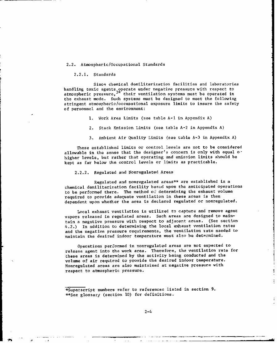
Since chemical demilitarization facilities and laboratories
handling toxic agents operate under negative pressure with respect toatmospheric pressure,3. their ventilation systems must be operated inthe exhaust mode. Such systems must be designed to meet the followingstringent atmospheric/occupational exposure limits to insure the safetyof personnel and the environment:
1. Work Area Limits (see table A-I in Appendix A)
2. Stack Emission Limits (see table A-2 in Appendix A)
3. Ambient Air Quality Limits (see table A-3 in Appendix A)
These established limits or control levels are not to be consideredallowable in the sense that the designer's concern is only with equal o-
higher levels, but rather that operating and emission limits should be
kept as far below the control levels or limits as practicable.
2.2.2. Regulated and Nonregulated Areas
Regulated and nonregulated areas** are established in achemical demilitarization facility based upon the anticipated operationsto be performed there. The method o' determining the exhaust volumerequired to provide adequate ventilation in these areas is thendependent upon whether the area is declared regulated or nonregulated.
Local exhaust ventilation is utilized to capture and remove agent
vapors released in regulated areas. Such areas are designed to main-
tain a negative pressure with respect to adjacent areas. (See section4.2.) In addition to determining the local exhaust ventilation ratesand the negative pressure requirements, the ventilation rate needed tomaintain the desired indoor temperature must also be determined.
Operations performed in nonregulated areas are not expected to
release agent into the work area. Therefore, the ventilation rate for
these areas is determined by the activity being conducted and thevolume of air required to provide the desired indoor temperature.Nonregulated areas are also maintained at negative pressure withrespect to atmospheric pressure.
*Superscript numbers refer to references listed in section 9.**See glossary (section 10) for definitions.
2-4

All openings into regulated areas through 0iich personnel enteror exit must be provided with airlocks to prevent the outward flow ofcontaminated air. Specific design guidelines for airlocks are pro-vided in section 4.2.3. The airlocks should be ventilated at a ratewhich ensures that migration does not occur from the regulated areas.This means that sufficient air should be passed through the airlocks
to provide adequate scavenging of any contaminants that might haveentered. The airflow should always be from the nonregulated (clean)area to the regulated (potentially contaminated) area.
2.2.3. Laboratories
All laboratory chemical-fume hoods in which agents areused should be ventilated at a minimum rate of 150 cubic feet perminute (cfm) per square foot of open hood area (which is equivalentto a minimum of 150 feet per minute (fpm) inward velocity whenmeasured at the open hood face). Crossdrafts can be avoided byproper placement of inlet openings. The laboratory must be maintainedat a negative pressure.
2.3. Unique Negative Pressure Systems
While extensive use has been made of negative pressure systemsin, for example, nuclear applications and chemical laboratories, most
applications involving chemical agent contamination have employed eitherchemical treatment (e.g., scrubbers) or conventional filtration equip-ment (e.g., CBR filters). Recent demilitarization operations at CAMnS,however, have employed, to a limited extent, the more efficient equip-ment used in nuclear applications.
CAMDS, an ongoing major program of the Office of Project Manager,Chemical Demilitarization and Installation Restoration (PMCDIR), is aprototype demil system for all lethal chemical agents/munitions (exceptWet Eye) now in the US inventory. To carry out its mission, PMCDIRfunded the U.S. Army Chemical Systems Laboratory (CSL) to determinethe best ventilation and filter design for demil operations. Thiseffort resulted in the exhaust-air containment and cleaning systemnow installed at the CAMDS facility. This system has been success-fully tested on site against agent GB and is judged to be a signifi-cant improvement over conventional chemical-treatment and CBR-typefilter units for handling and filtering ventilation air from chemicaldemil operations. Its principal features are:
2-5
1. Use of metal frames and housings for containing themechanical filters and adsorbers.
2. Redundant installation of adsorbers in series, with adetector between the adsorber banks to warn of agent"breakthrough" through the first bank. A second bank inreserve helps to assure that nc chemical agent escapesto the environment.
3. Limited parallel redundancy between filter systems forcontaminated areas.
4. Mechanical and electrical provisions throughout whichfacilitate maintenance and provide necessary checks on'
proper installation and in-service performance.
5. Maximum utilization of standardized, commercially avail-able components.
Another disposal system designed by CSL, relying heavily on theCAMDS experience, is DATS (Drill and Agent Transfer System). It isdiscussed in detail in section 8.
2.4. Elements of Exhaust System
The major elements of the exhaust (negative pressure) aircleaning system are:
1. Filter housing
2. Internal components:
PrefilterHEPA filterAdsorberBlower
3. External components:
DuctworkDampersExhaust stackLocal exhaust hoodsControls and instrumentation
All of these elements are necessary in each system and are dis-cussed in general terms in section 3.
2-6
3. BASIC DESIGN CONSIDERATIONS FOR EXHAUST SYSTEM
The design of an exhaust ventilation system must include pro-visions to localize and remove virtually all agent from the airstreamprior to exhausting to the outs'ide environment. Included in thesections that follow is a general discussion of the basic design con-siderations essential to an exhaust system for use in chemical agentdemil operations.
3.1. Agent Vapor Removal Methods
3.1.1. Methods Available
Most agent vapors can effectively be removed from theprocess -_i:haust air stream by one or more of the following methods:
1. Physical adsorption on a spongelike surface of attractingmaterial, such as activated carbon, alumina, or ion-exchange resin.
2. Absorption by intimate scrubbing with a stable solvent.
3. Chemical reaction, as with sodium hydroxide, in apacked gas scrubber.
4. Combustion into harmless basic oxides by incineration.
This handbook assumes that the necessary engineering evaluation andselection process has been completed and that the designer has justifiedthe use of a combination adsorption (for agent vapors) and mechanical(for particulate matter) air cleaning system as subsequently described.
3.1.2. Adsorption
Adsorption is a process whereby molecules of a fluidcontact and adhere to the microcrystalline pore structure of a solidphase material known as an adsorbent. Gases, liquids, or solids can beselectively captured and removed from a fluid stream with adsorbents.
The basic adsorbent materials are silica, alumira, and carbon.In air-pollution control applications, the most common adsorbent iscoconut-base carbon manufactured by controlled decomposition under asteam atmosphere. Carbon manufactured by this process is commonlycalled activated carbon.* Activated carbon Is usually preferred toother adsorbents in pollution control work.
*Activated carbon can also be produced from other base materials suchas wood and coal.
3-1
In the design of a pollution control system utilizing activatedcarbon, consider-ton must be given to the cleanliness and temperatureof the contaminated gas, physical parameters of the activated carbon,regeneration means, where applicable, and recovery or disposal ofwastes from the system.
An adsorption system can be combined with a separate mechanicalfiltering system (for physically removing particulate and aerosolmatter) to provide a filtration system capable of removing all typesof contaminated material.
3.2. Criteria for Determining Ventilation Rates
The ventilation systemn for a demil enclosure must provideadequate airflow to capture and exhaust agent vapors from contaminatedwork areas, provide adequate temperature control in uncontaminated workareas, provide adequate airflow between designated contaminated anduncontaminated areas, and maintain the enclosures at a specifiednegative pressure.
The first element to be determined is the type of operation tobe performed in the enclosure. If the operation is such that agentrelease to the work area is highly probable, the ventilation systemmust have sufficient capacity to capture agenit vapors at the point ofgeneration and transport them to the air-cleaning equipment. Thefollowing general rules should be followed in designing hoods for toxicmaterials:
1. Use enclosing hoods whenever feasible, otherwise,place freestanding hoods as close as possible tothe agent source.
2. Avoid crossdrafts that may spread contamination.
3. Furnish and distribute makeup air to ensure sweepiagof agent vapors toward exhaust points and precludingor minimizing stagnant area.
4. Construct contaminated area away from outside wallsto avoid wind pressure directly on walls of thetoxic enclosure.
It is only after the hood design has been sielected that exhaustvolume requirements can be determined. (Refer to Chapter 4 ofreference 4.) Detailed information on hood design is provided insection 4.2.1. With enclosures, volumes are calculated from the knownopen area of the hood and an indraft velocity of at least 150 fpm,which should be sufficient to prevent outward escapement. When free-standing hoods are used, they must be designed such that a capture
3-2
velocity of 150 fpn, is maintained in the area of generation to ensureconveying the contaminant to the hood opening.
In enclosures where the operation is not expected to releaseagent vapors, the ventilation system must be designed to provide heatcontrol. Methods for calculating these flow rates are contained inreferences 5 and 6.
When an opening between contaminated and uncontaminated areas exists,an influent velocity of at least 150 fpm through this opening isnecessary. In most instances, the volume of air required for heatcontrol or local exhaust ventilation will be sufficient to meet thiscriteria. When designing airlocks, however, the supply of makeup airmay have to be significantly increased. (See section 4.2.3 for adiscussion of airlock design.)
As previously indicated, one function of the ventilation system isto miaintain the enclosures, ductwork, and air-cleaning system housingsat negative pressure to prevent contaminated air escaping from thesystem by any path other than through the filter system. The degreeof negative pressure required is a function of several factors: (1)intended use of enclosure, (2) physical form and toxicity of chemicalagent involved, (3) location within the facility, (4) surroundingenvironment, and (5) explosive nature of munition.
When determining negative pressure, consideration of the externalpressure exerted on the building by winds must be included, unless thetoxic enclosure is housed within a protective outer enclosure. Ifthere is no outer enclosure, allowance should be made for effects dueto: (1) average wind velocity, (2) prevailing wind direction, (3)seasonal and daily variations in velocity and direction, and (4) localwind interference by nearby buildings, hills, or other obstructionsof similar nature as they relate to the building site.5 Knowin6, thetypical wirid environment in which the facility will operate, a negativepressure value can be determined for preventing outleakage from thebuilding. This value, in addition to those determined by previouslymentioned factors, must also be used in establishing the negativepressure requirements for the enclosures. in actuality, wind will bea factor only if a wall of the contaminated area is integral with theexposed wall of the building..
Doors and openings in negative pressure facilities may requirespecial opening mechanisms, i.e., hydraulic or pneumatic, to overcomethe external pressure. Louvers or dampers may have to be specified,based on the known airflow and negative pressure requirements, to pro-vide makeup air and to control the direction of airflow within thecontaminated area.
3-3
Contaminant control by air dilution is not acceptable fordemilitarization operations because of the extreme toxicity of the
chemical agents involved and the inadequacy of predicting the generation
rate of the agent. Designs based on number of air changes per hour
(dilution ventilation) or other rule-of-thumb methods are inadequate since
they generally result in unsuccessful operation or in excessive and un-necessarily high cost of installation and operation.
3.3. Filter Capacity
In designing a filter system, the capacity and efficiency required
are based upon the maximum challenge concentration anticipated and thelength of time this challenge may exist before corrective action canbe taken. To determine the worst-case (accidental) challenge condition,the designer must review all operations, devise a series of accidentscenarios, and calculate the resulting challenge to the filter foreach case. Although a determination of this nature is somewhat subjec-
tive, the calculations must reflect the worst conditions of airflow,spill size, and temperature to assure that, in fact, a worst-casesit,,ition is derived. This estimate can be refined later as more data
,es available. (The result of such a study for CAMDS is coverediL, ztion 4.1.1.3.2.).
•i.ce the worst-case challenge is determined, the reduction ratio
(and, hence, capacit,-) required by the filter housing may be computed
from th^ formula,
Co = Rmin.Ci
where:CO = concentration out (maximum allowable stack emission)
= concentration in (worst-case challenge)
Rimn. = minimum agent reduction ratio required by filter system
The minimum capacity required (in mg-min/m3 ) is obtained bymultiplying the worst-case challenge by the time required for cleanupto be significantly effective.
3-4
3.4. Safety
The overriding consideration in the design of a contamination con-tainment and filtered exhaust system is to guarantee the safety of plantoperating personnel, the surrounding populace, and the general environ-wcýnt. To meet this requirement, several safeguards must be incorporatedinto the basic ventilation package.
The design of a system meeting demil requireme'nts is not a difficulttask if one assumes that the system will always operate properly. Diffi-culty arises, however, in designing a system that continues to fulfill itsbasic requirements even if a malfunction or failure occurs. Since a mal-function or failure of any component of the system could result in contam-
ination of the environment and injury or death to personnel, the design ofthe total system must provide backup or redundant features to continueIcontainment in the event of the loss of a primary system. Two deSigIL tech-niques for incorporating redundancy into the basic filter design are seriesredundancy and parallel redundancy.
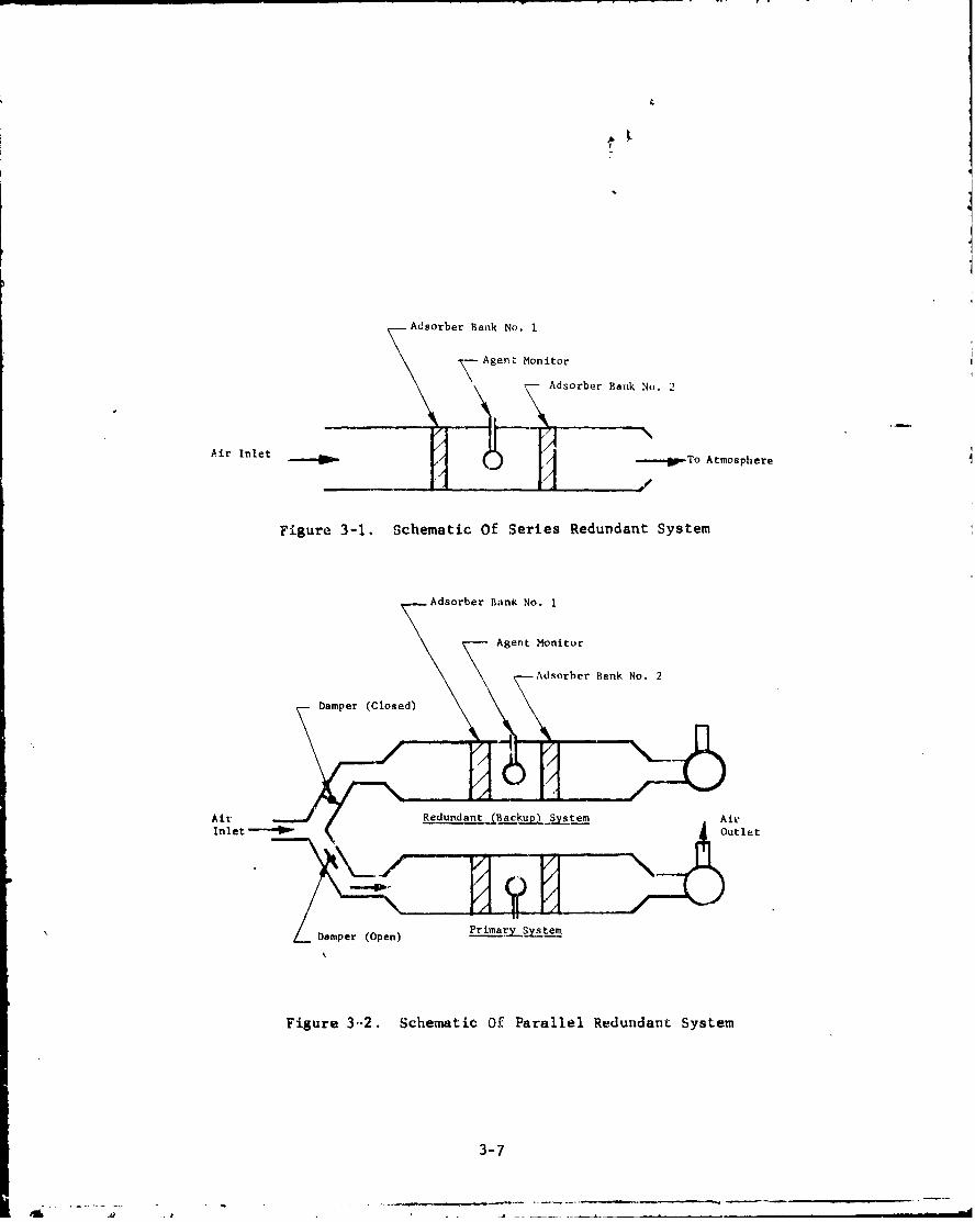
Older filter systems usually contained only one bank of sufficientcapacity of each filter and adsorber in series together with a chemicalagent monitor/alarm located downstream. When the monitor indicated abreakthrough some contamination, up to the level of the monitor's alarmsensitivity, had already leaked into the atmosphere. This concept, how-ever, is now unacceptable in view of the current stringent emissionstandards. One approach to the problem is the use of a series-redundantsystem containing two banks of the critical filtration components (i.e.,the adsorber) in series with an agent monitor between the banks, as illus-trated in figure 3-1.
With this type of redundant system, no contamination should ever reachthe atmosphere. When breakthrough of the first adsorber bank occurs andthe agent monitor activates, the second adsorber bank still provides com-plete protection until operations can be shut down and a new first bankinstalled. In theory, each of the two adsorber banks should be sized toprovide the full adsorptive capacity required for the worst case expected.Thus, if the first bank is penetrated, a second bank providing completeprotection would be already on line. However, in view of cost, space,and/or power limitations, it may not always be practical to have eachadsorber bank provide 100. protection. (See section 4.2.9.)
Both adsorber banks of a series redundant system should be the samesize and should, between them, provide the total adsorption capacity ofthe system. In case of a breakthrough by the first bank, ns announced bythe monitor, sufficient adsorption capacity remains in this bank to reducethe agent challenge concentration to the second bank until the operationcan be shut down. As a consequence, the second bank suffers minimum agentintrusion and its life (and, hence, protection) is prolonged. Another safetyfeature to be incorporated into the filtering system is parallel redundancy.
3-5
This involves a completely separate (secondary) system through which air-
flow can be diverted if a malfunction or failure occurs in the primary
filter system (see figure 3-2). The two indcpendenL systems of a parallel-
redundant filtration system contain series-redundant filters and adsorbers
together with a dampering mechanism capable of switching between the two
systems. As an added safety feature, each system must b! connected to a
different power source.
Parallel redundancy is required in mary nuclear applications. Forchemical demil uae, however, total parallel redundancy may not be practical
or necessary in view of cost, space, and power considerations. At the very
least, however, a partial parallel backup is recommended. Its purpose is
tc provide sufficient airflow capacity to safely shut down all operations
in the event of an emergency (i.e., to prevent contamination from entering
clean areas or the atmosphere), rather than to provide s'xfficiLnt capacity
for continued operatioD. (See Section 4.2.9 for parallel concept used atCANDS.)
Parallel redundancy at CAMDS is reflected by the requirement that at
least two independent sources of power be available for all critical oper-
ating components. If the primary source is commercial, an on-site genera-
tor is required in the event that this source is lost. If, on the other
hand, the primary power source is a generator - rather than commercial -a second generator is required. in the ideal situation, the backuppower source should offer the same power output as the primary source.
However, in a practical sense, the backup generator may be significantly
smaller than the primary one. The purpose of the latter backup system is
to provide sufficient power to key areas to enable the facility to be shut
down without releasing contamination.
Belt-driven blowers are required to be equipped with a minirdum of
two belts (three belts minimum on large capacity units), so that if one
belt breaks the other takes over and the blower continues operating.
In addition to redundancy, there are other safety features which can
be incorporated into the ventilation system design criteria. For instance,
in the event of a complete loss of airflow, it is essential that the
highly contaminated areas be sealed airtight. This can be accomplished by
the use of fail-safe (closed) pneumatically or electrically operated
dampers. The dampers may be progranmmed to close when a power loss occurs
or when there is no airflow through the filter. Leaktight ducts are also
necessary to prevent contamination from migrating from the ductwork in
case of airflow loss or when differential static pressure between the con-
taminated area and the outside enclosure drops below a predetermined. value.
Properly designed instrumei cation and agent monitoring systems are
highly important in order to convey to control personnel information as
3-6
&I
Adsorber Bank No. 1
Agent Monitor
Adsorber Bank No. 2
Air Inlet /-.To Atmosphere
Figure 3-1. Schematic Of Series Redundant System
Adsorber Bank No. 1
Agent Monitor
Adsorber Bank No. 2
Damper (Closed)\d
Ai = Redunda ystem Air
Inlet -O•ut•t
/__Daniper (Open))PiaySse
Figure 3-2. Schematic Of Parallel Redundant System
3-7
. -, - - - --. -_
to when and where a malfunction occurs sc, that immediate correctiveaction may be taken. If the possibility of an explosion exists in anyof the demil operations, special design Lonsiderations must be made.There must be assurance that no shock waves can penetrate the filterhousing. This can b~e provide~l for by installing (1) a snubbing system,(2) a blast gate, or (3) a capability for closing off the exhaust duictworkfrom potentially dangerous operations.
Noise control is another requirement. In general, the ventilationsystem is to be designed in compliance with OSHIA requirements for noisecontrol. Since DA regulations governing acceptable sound (noise) levelsare more restrictive than those of OSHA, the former shall apply. Thismeans that the steady-state noise level, of the system shall not exceed85 db on Scale A of a standard sound-level meter.
See also section 5.4 for emergency considerations.
3.5. Operation and Description of Key Components
3.5.1. General
The key components of the basic ventilation package consistsof air cleaning units, heating and ventilation units, and associated duct-work, dampers, hoods, controls and instrumentation. The ventilation sys-tem should be designed in accordance with the recommended practices givenin references 4 and 7 and as stated in the system specifications.
The design objectives of the basic ventilation package are asfollows:
1. Ensure total containment of all airborne contaminationwithin all toxic enclosures by maintaining appropriatedifferential pressures and airflow between enclosures.
2. Localize contamination at the soucce for the protectionof personnel by utilizing totally enclosed hoods, or ifthis is not physically possible, by utilizing capturehoods and differential pressures.
3. Remove agent from contaminated exhaust air prior to re-lease to the atmosphere by exhausting air at a prede-termined airflow rate and passing the air through a seriesof filters and adsorbers, scrubbers, or furnaces, or acombination thereof.
44 Ensure exhaust air meets stack emission requirements.
5. Ensure venti'Aation system provides work area in whichatmospheri&c concentration of agents does not exceedmaximum allowable concentrations.
3-8

I43.5.2 Operation
In the operation of the ventilntion system, all airflowmust be from uncontaminated areas to contaminated or potentially con-taminated areas, or from less-contaminated to more-cortaininated areas. Theair is drawn from contaminated enclosures at specified flow rates andvelocities to ensure adequate agent capture and control as well as nega-tive pressure within the enclosure. Differential pressures between con-taminated enclosures and ambient areas are determined by the specificdesign constraints of the system.
In its flow through the ventilation system, --he air is pulled intoan airtight filter housing. The housing contains the required banks ofair cleaning components, a blower, and provision for attaching an exhauststack. After entering the filter housing and passing through its variousstages, the decontaminated air flows out the exhaust stack to the atmosphere.At this point the formerly contaminated air should be sufficiently cleanto meet stack emission limits.
3.5.3. Description of Ventilation System
3.5 3 1 Housing
The filter housing provides a complete airtight enclo-sure from the air inlet to the air outlet connection (stack) or at leastto the blower. All necessary framing and structural supports for thefilters and adsorbers are furnished as an integral part of the housing.The filter housing is generally constructed of carbon steel coatedJ on allsurfaces with a corrosion-resistant paint; stainless steel has also beenused in small enclosures exposed to severe corrosion. The filter andadeorber mounting frames (where the potential for scratching of the mount-ing surface is minimal) are made from coated carbon steel, uncoated stain-less steel (which affords better corrosion protection than carbon steelbut is still subject to attack by certain chemicals), or, for maximum pro-tection, coated stainless steel. Because of its smooth finish, epoxy-base p~int minimizes potential agent penetration and, therefore, providesvery satisfactory corrosion protection ag3inst most acidic or alkaline-type chemical attack.
To ensure that the housing is capable of meeting structural require-ments, it must withstand without permanent deformation the pressure/vacuumtests and pressure-decay leaktest requirements stated in section 4.1.2-1.
In general, the housing configuration is dictated by the flow capacityof the filter system as well as the means for incorporatinR the adsorbermedia. For the purpose of this handbook, it is assumed that all filtersare in the form of modular cells. For adsorbers, there are two availableconfigurations, (1) a modular cell configuration, and (2) a fixed singleunit rechargeable in place. These are described it' section 4.1.3.3.
3-9
di~ ~W-
The standard Army CBR adsorber cell is of woodframe constructionnailed and glued into a wooden housing. It does not lend itself, however,to the same level of efficiency as the types of adsorber systems discussedin this handbook.
3.5.3.2. Particulate Filters and Adsorber Cells
The filter housing can contain up to three differenttypes of cells, referred to as prefilters, HEPA filters, and adsorbers.
1. Prcfiltere are low-efficiency fibrous filters forremoving heavy concentrations of coarse particulatematter from the air stream. They are installed up-stream of the REPA filter,
2. HEPA (high efficiency particulate air) filters are ex-tremely high efficiency, extended media fibrous filtersfor removing fine particulate matter and aerosols fromthe air stream.
3. Adsorbers are beds of granular material, u...ually activatedcarbon, which remove agent vapors by a chemic3l and/orphysical adsorption process; they are not mechanical filtersand their use applies to vapors and gases only.
Detailed descriptions of these elements are given in section 4.1.3.
3.5.3.3. Arrangement
The actual type and number of banks of cells requireddependu on several factors: (1) chemical composition and nature (i.e.,particulate, gas) of the contaminant, (2) initial concentration, and(3) maximum concentration allowed in the exhaust air from the stack. For ex-ample, a building in a chemical demil facility requires both particulateand vapor filtration. Therefore, its filter system will contain pre-filters, HEPA filters, and adsorbers. A clean-room facility requires onlyparticulate filtration and thus needs only prefilters and HEPA filters,
- adsorbers. The offgas filter system for a chemical agent decontamina-Lion tank filters agent vapors escaping from the munition through thedecontamination solution; therefore, it requires only adsorbers.
Detailed specifications relating to filter/adsorber types andarrangements must be stringent. This is because the HEPA filters anda"'.rbers, the critical components of the filtration system, constitutethe final barrier (or containment) between the contaminated area and theoutside environmenL.
.-.3-1o
3.5.3.4. Instrumentation
Instrumentation is required to monitor and controlthe airflow through the filter system. The instrumentation must providea means to monitor overall pressure drop as well as the pressure drop be-tween the respective filter banks. The instrumentation must also providethe control signals required to mainta n flow through the filter system atspecified levels as a function of pressure drop.
In general, the increase in resistance as dust and particulate matterare trapped by the prefilters and HEPA filters is the largest variablepressure drop that must be accommodated by the system. This chcnge inpressure (,nP) is monitored with differential pressure gages. The readingsthus obtained are used as a basis for changeout of these filters. (See sec-tion 6.4 for discussion on changeout criteria.)
Pressure buildup in adsorbers is prevented by catcbing q11 airborneparticulates (the only component of the airstream causing LP) in themechanical filters. Therefore, differential pressure gages are not re-quired to monitor pressure drop across adsorber banks. Such instrumen-tation may be installed, if desired, for information purposes (but are notused as a basis for changeout). Changeout of adsorbers is based on break-through by chemical agents,as indicated by agent detector3 (described insection 5.2).
3.5.3.5. Blower and Flow Control
The blower located at the downstream end of the filterhoising provides the driving force for air movement. It conc ists of amotor, fan, drive, and mounting frame. The blower size is based on theflow rate and total static pressure requirements for the system. Factorssuch as altituCe and temperature affect the flow rate calculation. Thefact that the total static pressure of the system is not constant but in-creases with dust loading of the prefilters and HEPA filteis is the majorvariable that must be considered.
When sizing the blower, first determine the flow rate requirements(adjusted for altitude and temperature), then calculate the anticipatedstatic pressure that the blower will be required to overcome with cleanfilter cells installed. The static pressure requirement is then increasedto allGTo for the increase in pressure drop as the prefilters and HEPAfilters -come clogged with dust. The "dirty filter" AýP may be severaltimes thu' '..:ax filter" LP. An additional pressure factor is added tocompensate for uncontrolled air infiltration, pressure surges, and windeffects ind to allow for possible future modifications of the ventilationsystem. It is possible to dampen an oversized blower, but ii the bloweris unde':sized, it cannot perform its design function and may have to bereplaced. Setting the blower capacity at a level higher than that re-quired for the initial application offers a degree of flexibility in pro-viding for increased ventilation capacity for future applications. In
3-11
• I • • .... .
addition to flow rate and static pressure, other factors that must beconsidered In selecting a blower are given in section 4.1.2.11 and sec-tion 10 of :eference 4.
Vibracions caused by the blower unit should be minimizcd by the useof vibration isolators and flexible connections wherever possible. Severevibration can cause the carbon granules in the adsorbent to break up orpowder and thus reduce the effectiveness of the adsorber cells.
Before the blower specification is finalized, the designer must de-terminc the voltage and frequency of the power source and the voltage/frequency tolerance of the motors. Motors designed for one type of volt-age rating; z.g-, 3-phase 200-volt power is not interchangealle with3-phase 230-volt power.
A flow-control system is required in conjunction with the blower.This includes a straightening 3ection in the exhaust stack above theblower in which accurate airflow readings can be made. In CAIMS a gagewith a specially calibrated scale reads velocity pressure in cfm. Theflow control unit also provides a signal to the blower damper to enablethe airflow of the system to remain constant despite variation in thetotal drop of the system.
3.6. ExternanI C0rnmponents
External components of the filter system includle ductwork, dampers,stacks, instruments and other items of the system concerned with the move-ment, control, conveying, and monitoring of airflow.
3.6.1. Ductwork
The ductwork is a ?art of the overall filtration system. Itmust meet stringent pressure and leaktightness requirements. Where poten-tially toxic exhaust is being transported, standard sheetmetal ductwork iLunacceptable. All-welded, round duct with flanged connections is recom-mended; for small diameter applications, flanged pipe may be preferred.
The incorporaw•ion of jampling and test ports in the initial ductworkdesign is essential, otherwise holes may be indiscriminately made whentesting is required,, Sampling ports are required for the insertion ofinstruments to obtain flow measurements during air balancing of the sys-tem. When not in use fcr air balancing, the sampling ports can be usedas access for instrumentation to monitor the upstream agent challenge con-centration to the filter system. The ductwork is sized and layed out tominimize the pressure loss and to ensure that sufficient transport velocityis maintained in the duct to prevent settling out of contaminants in theair stream. (See section 4.2.2 for ductwork design.)
3-12

3.6.2. Dampers
Dampers are the valves of the air cleaning and ventilationsystem and are classified in terms of function/configuration, construc-tion, and leaktightness. Clear, concise specifications must be establishedfor, (1) mechanical strength, (2) leakage rate at maximum operating con-ditions, and (3' uility to perform under required operational andemergency conditions. All dampers are flange mounted with a gasket be-tween the mating surfaces. Further information on dampers is covered insections 4.2.5 and 5.3.
3.6.3. Exhaust Stacks
The design, type, and location of exhaust stacks are im-portant to good dispersion of exhaust air to the atmosphere. Properdischarge design (e.g., stack height and location) must be followed toensure that the exhaust air (potentially at a low level of contaminationeven if below minimum environmental requirements) does not re-enter ad-jacent buildings or work areas. In cases where it may be impractical orinfLasible to construct a stack higher than an adjacent structure, it isrecommended that cognizant air-pollution control authorities (federal,state, and/or local) be consulted for acceptable solutions to this, aswell as other, types of problems. Under certain conditions, it may bebereficial to combine the filter system exhaust with inother exhaust sys-Lemn and use a CoUHuiULL s Lak. AgadlIL, 66 wli~l, uu. u~H'" ''
be incorporated into the exhaust stack. Their recommended locations,functions, and other factors are discussed further in section 4.1.2.13.
3.6.4. Other Items
Other external components required at the area being venti-lated include heaters and alarm instrumentation (to indicate an upsetin normal system operation). These items are discussed in more detailin section 4.2.
3.7. Extteme Environmental Conditions
Special or unusual environmental conditions may present problemsto either the filter system or operating personnel. Several conditionswhich must be considered during the design phase to preclude costlych, iges after the equipment is installed or contracted for are:
1. The type of environment in which the filter system willoperate. Specific design features and requirements m3yvary depending on the climate, such as cold/wet, hot/wet,cold/dry, or hot/dry, and altitude.
2. Aging and weathering of components. Materials of con-structions should ')e selected or treated to resist thecorrosion and deg lation that could result in loss ofperformance when exposed to specific environmental conditions.
3-13
S .. .. . - - -. . . .. . . - - -

3. Temperature and humidity. Gages and other instrumentation
and equipment should be designed or selected to withstandthe temperature extremes anticipated at the specific site.Temperature and humidity, unless extreme, do not normally
appreciably degrade particulate filters. Prolonged ex-posure can degrade the adsorbent with respect to certainchemical agents primarily removed by chemisorption (i.e.,by impregnated adsorbents). Physically adsorbed agents(e.g., those removed by activated carbon) are affected toa lesser extent.
4. Unusual circumstances or occurrences in the operating area.For example, painting or C. 'ning which may release sol-vents that could "poison" .he activated carbon of theadsorbers, decreasing its Life or capacity.
Intake openings for outside air should be equipped with louvers,
grills, screens, roughing filters, or similar protective devices to
minimize the effects of high winds, rain, snow, ice, trash, and other
undeeirable items that could be detrimental to the operation of the
filter system.
3-14
4. DETAILED DESIGN CONSIDERATIONS
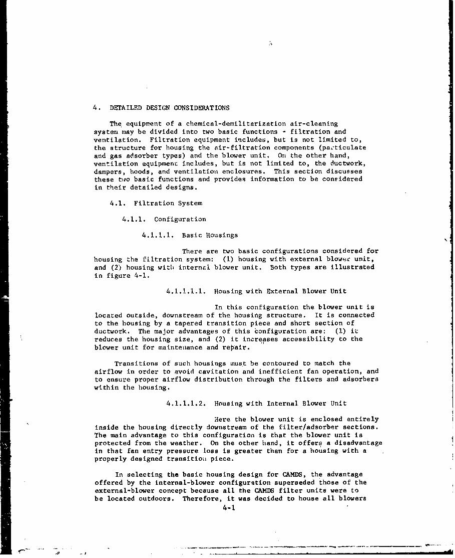
The equipment of a chemical-demilitarization air-cleaningsystem may be divided into two basic functions - filtration andventilation. Filtration equipment includes, but is not limited to,the structure for housing the air-filtration components (pazticulateand gas adsorber types) and the blower unit. On the other hand,ventilation equipment includes, but is not limited to, the ductwork,dampers, hoods, and ventilation enclosures. This section discussesthese two basic functions and provides information to be consideredin their detailed designs.
4.1. Filtration System
4.1.1. Configuration
4.1.1.1. Basic Housings
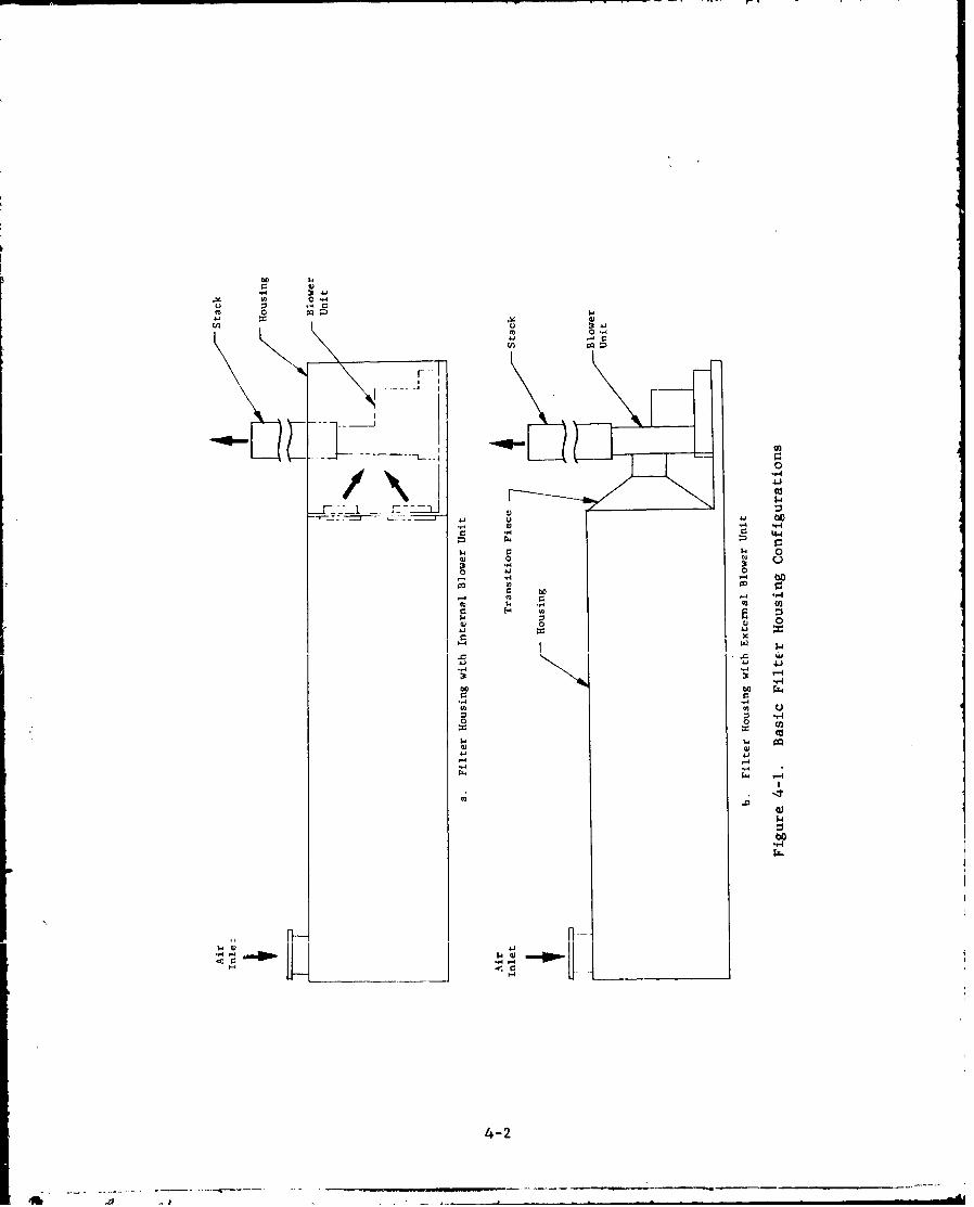
There are two basic configurations considered forhousing the filtration system: (I) housing with external blowec unit,and (2) housing with internal blower unit. Both types are illustratedin figure 4-1.
4.1.1.1.1. Housing with External Blower Unit
In this configuration the blower unit islocated outside, downstream of the housing structure. It is connectedto the housing by a tapered transition piece and short section ofductwork. The major advantages of this configuration are: (1) it
reduces the housing size, and (2) it increases accessibility to theblower unit for maintenance and repair.
Transitions of such housings must be contoured to match theairflow in order to avoid cavitation and inefficient fan operation, andto ensure proper airflow distribution through the filters and adsorberswithin the housing.
4.1.1.1.2. Housing with Internal Blower Unit
Here the blower unit is enclosed entirelyinside the housing directly downstream of the filter/adsorber sections.The main advantage to this configuration is that the blower unit isprotected from the weather. On the other hand, it offers a disadvantagein that fan entry pressure loss is greater than for a housing with aproperly designed transitiou piece.
In selecting the basic housing design for CAMDS, the advantageoffered by the internal-blower configuration superseded those of theexternal-blower concept because all the CAMDS filter units were tobe located outdoors. Therefore, it was decided to house all blowers
4-1
0 -
v 0
144 ~
5.4 ..- oC
w0 o~ 0
"-4r
:3 -,
"-4-
o 0 o
'- 4 W.
"--A
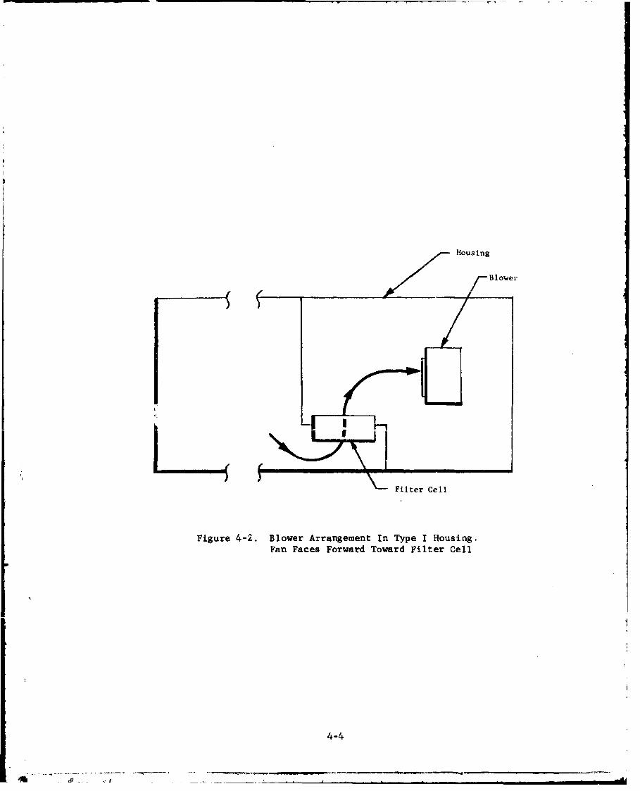
completely indoors. The orientation of the fan inlet, however,depends upon the type of housing involved. In one type of housing,*the inlet end of the blower faces forward toward the filter/adsorberbanks (see figure 4-2). This enables the drive belts mounted on theblower to be more easily observed through the inspection hatch on therear of the housing. (See figures 4-3, 4-4, and 4-5.)
In another type of housing,** where there is already sufficientaccess to the blower, the fan inlet is reversed to face rearward(see figure 4-6a). The distance between the inlet and rear wall shouldbe at least one blade-wheel diameter (i.e., tip-to-tip blade length offan). This arrangement produces a baffeing e.wff t7 ihch results inmore uniform airflow from the final filter bank to the blower, therebyincreasing fan efficiency. This configuration is particularly beneficialto the larger capacity systems. If the fan inlet faced forward, thiswould cause channeling of the air through the final filter bank,shortening its life and also causing very inefficient fan operation.(See figure 4-6b).
4.1.1.2. Filter Housings
Based on the changeout method employed and thetype of adsorber cell used, filter housings may be divided into threebasic types:
1. Type I - Bag-In Bag-Out, or Bag-Out only.
2. Type II - Walk-In, Multiple Adsorbers
3. Type/Ill - Walk-In, Single Stationary Adsorber
A discussioj of each type follows.!// 4.1.1.2.1. Type I Design (Bag-In Bag-Out or Bag-
/ Out Only), Figures 4-7 through 4-11.
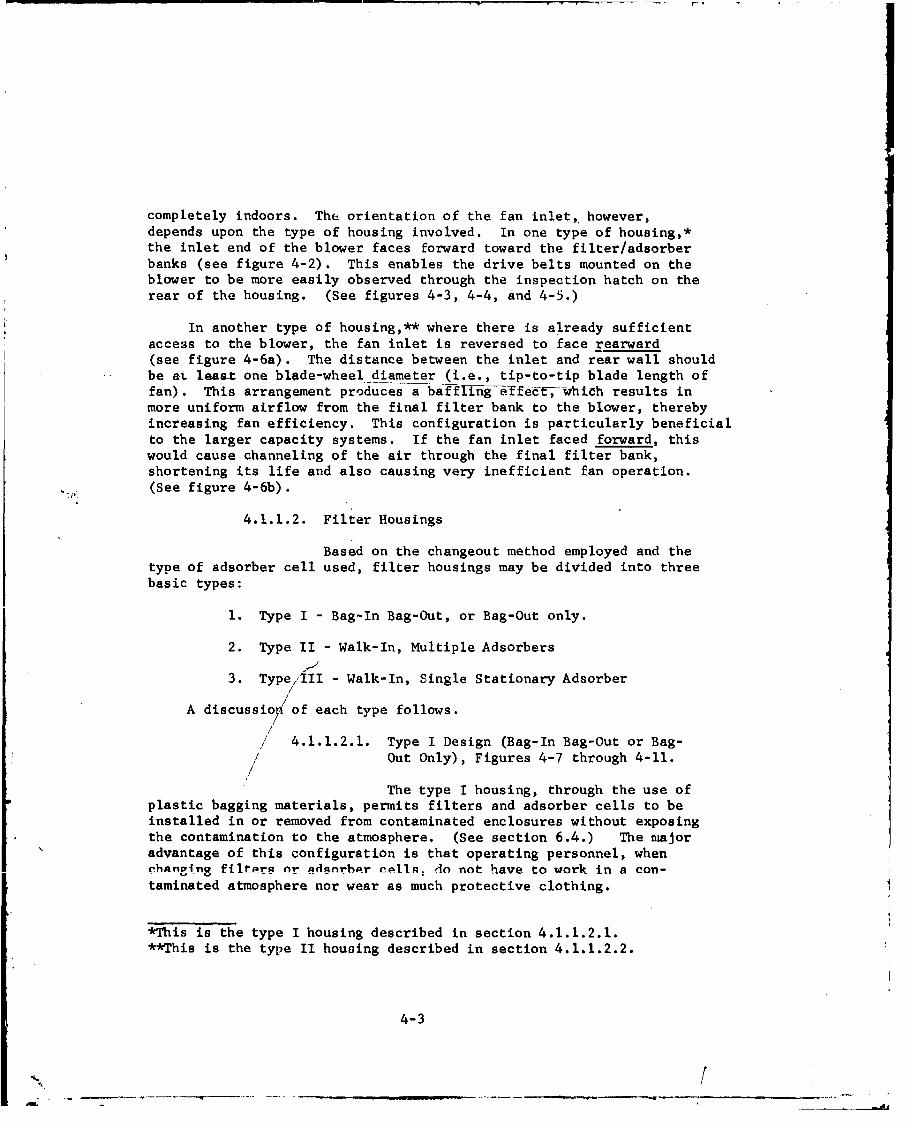
The type I housing, through the use ofplastic bagging materials, permits filters and adsorber cells to beinstalled in or removed from contaminated enclosures without exposingthe contamination to the atmosphere. (See section 6.4.) The majoradvantage of this configuration is that operating personnel, whenchanngaa filtira or AdnnrAhr cn1,; do not have to work in a con-taminated atmosphere nor wear as much protective clothing.
*This is the type I housing described in section 4.1.1.2.1.**This is the type II housing described in section 4.1.1.2.2.
4-3
/•
Housing
H Blower
Filter Cell
Figure 4-2. Blower Arrangement In Type I Housing.Fan Faces Forward Toward Filter Cell
4-4
ca
-4C
-r441i
'Td-
1-4
44
4-5-
U,
0914
' 4 a
U41
r 4
U2E4
1) .-4
Id4a)
4-6-
co1
00
d 41
*-4 0)
I-
~00
4-7

Filtur
Filter Blower
Bank --BanH lousing
---- J
77
5-77
a. Fan Faces Rearward Away From Filters Airflow
FitrAirflow Blower
Bank Filter
Pousing
( )
7/
b. Fan Faces Forward Toward Filters
Figure 4-6. Blower Arrangements In Type II Housing.
4-8
Of-

U r C
E u W
~C r Q) .;40- 0) 00 E
Q) r m(0)
oO L. m. '.4
C- 4
(v r
44
$4
4.J
4--A
0
F.
4J-
0
'-4
0 0k
-44~
P44
4-104~

Cl
4-1 z-
41
1-4 .
4-il
41J
- Eu4 4 .4 ra
toI =ý K:
'4-12
w - -- - - - -

C4-
Id-
0 c
4-4
0
r-4 r
C-,4 -
-4-
C-Ar4-
4-13,

Two disadvantages with the type I design, however, concern(1) the rate at which thecells are changed out, and (2) the spacerequirements. Since cell changeout takes place by reaching intothe housing through a plastic bag, this tends to slow down theprocedure and consume more time than with the other designs. Itis essential that each cell be accessible to the outside so thatchangeout 1,ersonnel can easily reach in and pull it ou-. This meansthat the cells must be consecutively arranged facing outward along thelength of the housing rather than in parallel rows (or banks) as in thewalk-in ',nits, thereby significantly increasing the size of the housing.
For CAMDS the type I concept was particularly appealing because iteliminates the need for personnel to enter contaminated or potentiallycontaminated areas. However, in view of space limitations, it wasdetermined that a 2,000-cfm flow rate was the maximum filter size thatthe type I design could effectively accommodate.
4 1.1.2.2. Type II Design (Walk-In Housing, MultipleAdsorbers), Figures 4-12 and 4-13.
The type II design, as its name implies,requires that protected personnel walk inside the filter housing tochange the various cells. The chief advantage of this configurationis that it is more compact and economical at the higher capacities in thatit permits a large number of cells to be efficiently installed iqparallel and thus occupy significantly less space than with the type Idesign. Its major disadvantage is that personnel must wear protectiveclothing and must enter a contaminated or potentially contaminated areato perform changeout operations.
4.1,1.2.3. Type III Design (Walk-In Housing, SingleStationary Adsorber), Figure 4-14.
The difference between the type II and typeIII adsorber designs is that the former involves installation/removal ofthe entire adsorber tray (including metal parts, gasket, and adsorbent)while the latter involves installation/removal of the adsorbent onlysince the tray is fixed in place. The fabrication cost of a type IIunit is less than for a comparable (i.e., in terms of capacity and beddepth) type III unit, although, as the number of trays in the type IIunit increases, the difference in assembled cost decreases.
The major advantage of the type III housing over the type IIdesign is that personnel do not have to enter the contaminated interiorof the type III unit to change the adsorbent since this can be donerewotely. A secondary factor to consider in comparing the two housingdesigns is the cost of adsorbent replacement. The more frequently
the adsorbent is replaced the more advantagaous the type III configurationbecomes, ai it is cheaper to replace adsorbent only rather than acomplete assembly of relatively expensive metal parts. From the labor
4-14
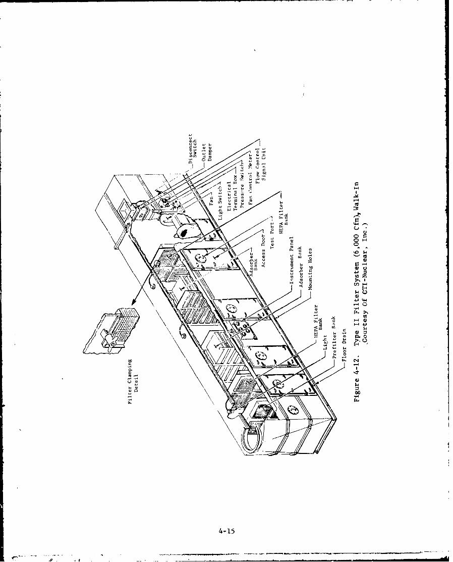
IOU
0 It, Er
m r-4
0 " o r-.
OJO.0-,4 u
4)-15 -1
A0

L4 4
-4 04
4-16
.- ----. --..- ~.-.-..-----*----a -
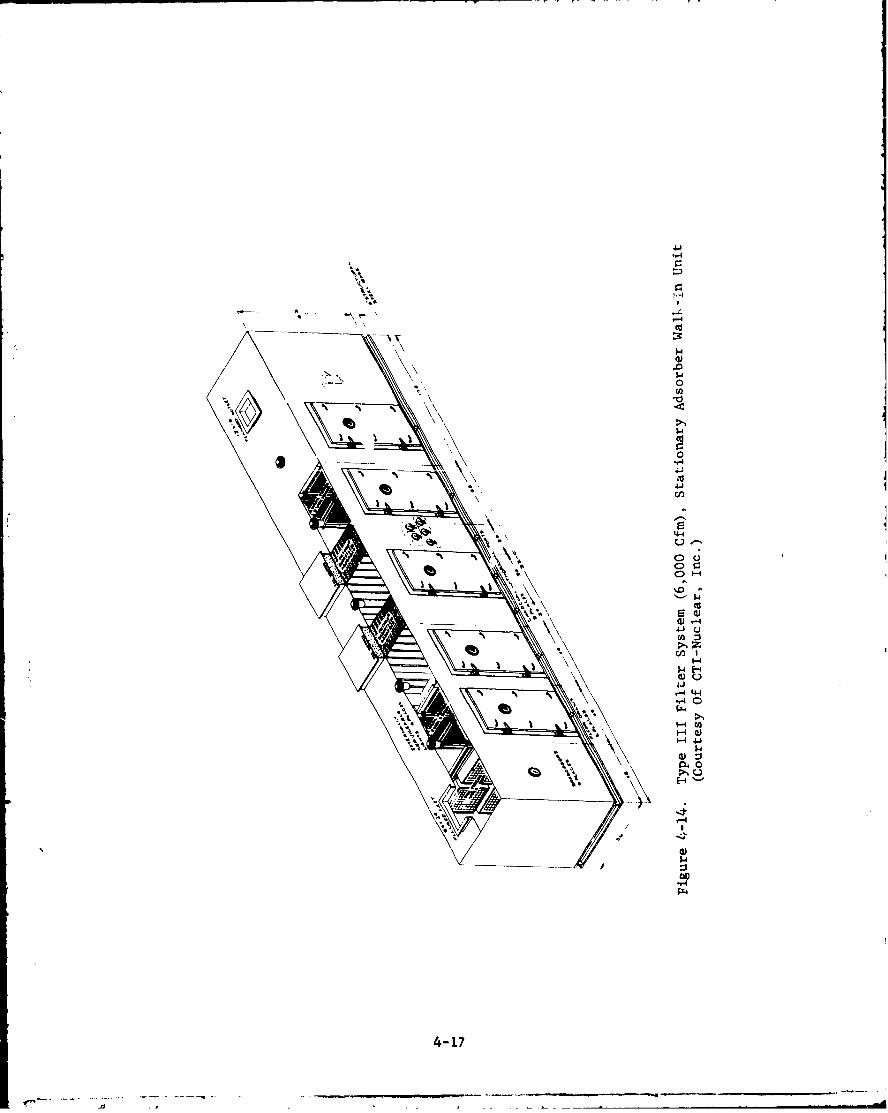
r4-
It..
r-'
.0
cd4-4
>N
I
0-4
0W u
04 44
"~4
'-.4
CL0
r-4
4-17
standpoint, emptying and filling permanently installed beds isconsiderably more economical and easier than struggling with 80-to100-pound adsorber trays.
There are, however, st" eraI potential disadvantages to the typeIII design, namely:
1. This is n new c;-eept that has been used for onlya short period of time. It has never been tested or used indemilitarization work and thus may require extensive testing befcrebeing approved for use in this application.
2. Difficulty may arise in removing the adsorbent if asignificant quantity of moisture has been adsorbed.
3. There are no applicable standards currently availablefor writing a specification. However, an ASME committee is preparing astandard establishing requirements for the stationary adsorber forpublication at & later date.
4.1.1.2.4. CAMDS Filter Systems
At CAMDS there is a total of 13 filtersystems, 12 at the CAMDS site and one at the chemical laboratory(which is located outside of the actual CAMDS compound). Importantcharacteristics cf these filter systems are shown in table IV-I.Their locations (except for the laboratory) are shown in figure 4-15.
4.1.1.3. Internal Configuration
4.1.1.3.1. Arrangement
If both filters and adsorbers are employed,one stage of particulate filter (or filters) must be positioned upstreamof the first adsorber bank. These filters remove dust and particulatematter from the airstream, while the. adsorber captures agent vaporsgenerated in the facility or desorbed from the particulate mattercollected on the filters. The reverse arrangement, i.e., adsorbersupstream of particulate filter, would not afford the same protectionsince the adsorber only stops vapors and not aerosols; the aerosolswould pass through the adsorber and be stopped by the particulate filterwhere they could conceivably produce toxic vapors capable of escaping tothe environment. In addition, the adsorbers would tend to plug up withdust.
Series-redundancy is an arrangement criterion whereby two filtersof each type (i.e., particulate and gas) are required. Since, for
most demil applications, both a particulate aerosol and vapor capabilityare mandatory, the arrangement for such filter systems is: (1) particulatefilter (including prefilter), (2) adsorber, (3) adsorber, and (4)particulate filter. This arrangement is used for all CAMDS filtersystems. 4-18

ow 0 -
rz4
-- 7--I
- !4
4'L
4-19

9i~ 40 40
a to0a 0 004~O 4NM .0 0C
WeO
000
00
00. CN 00 000 ol100Sý lo 0 0
V 0 c
00
IN IC
U4~ a 0
v 4 N 00'-' Ii A
03 W- 0
e0000 op. a c
04.20 ~

4.1.1.3.2. Sizing
Using a modular concept, the filtersystem could conceivably be any size desired. However, there arecertain limitations which apply to the individual modules. Generally,the size limit is based on space availability and the ability to(1) test the filters and advorbers, (2) provide uniform airflow, and(3) manage system upsets. Because of the requirement for externalaccess to every cell, the cype I hodsing requires more space per cfmthan the other two designs. The maximum capacity recommended for atype II or III structure, to keep it from becoming too huge, is 33,000cfm. 7 If, on the other hand, transportability is a design consideration,the dimensions of the unit must be such that it can be handled by truckor rail. This results in a recommended maximum size of 15,000 cfmfor type II or type III housings.
For the type II or type III units, as previously indicated, thefilter/adsorber banks are arranged to facilitate changeout. Eachbank should be no more than three units high to permit the top bankto be within reasonable reach. (Note: Three adsorber cells occupythe same vertical space as one l,000-cfm HEPA filter.) Recommendedstandard housing capacities are 3,000, 6,000, 9,000, 12,000 and15,000 cfm. If the desired capacity is not one of these ratings, itis recommended that the installed capacity be sized up to the nextstandard size and that unused cell openings be closed off with blankoffplates. Oversizing does not significantly inc:ease the price of thesystem since a standard unit is still being used, as opposed to theprice of a customized design for a specific, non-standard capacity.Another advantage of the oversized unit is that, by installing alarger blower and placing filters/adsorbers in the closed-off sections,filter-system capacity can be increased later at minimal cost shouldthe need arise.
At CAMDS the maximum agent challenge expected to be encounteredin any area was initially estimated at 10,000 mg/m 3 , based on asaturated solution of GB at 70 0 F. This indicated the need for afilter system providing a reduction capability on the order of 108,that is:
Concentration out = Co = 3 x 10-4 = 3 x 10⁻⁸ reductionConcentration in Ci 1 x 10⁴
With a minimum protection time of 20 minutes (before decontamination),the minimum capacity of the required filter system (i.e., maximumchallenge concentration x time to decon) is:
10,000 M x 20 min. 200,000 m .432 m1
4-21
• •, ,•, -, .. . .I

To meet this requirement, two banks of adsorbers with ademonstratable reduction ratio of 1.5 x 10- 4 each (i.e., 3 x 10⁻⁸reduction divided between the two banks) were procured for each area,with each bank providing an adsorptive capacity of 200,000 mg-min.(See section 7 for testing techniques.) 3
Subsequent to the procurement and installation of these filtersystems, and in view of greater experience with the CAMDS operatiors,a more detailed study was conducted of the probable maximum agentchallenge. 1 3 It was determined that this could result from a majorspill in the BIF area and potentially result in an agent concentrationof 300 mg/m 3 in the influent air stream of the BIF. This value, whichis felt to be more accurate and realistic than the initial estimate, isconsiderably lower and indicates a reduction requirement on the orderof 106, that is:
-4CO 1 l 0-6Z7 3 x 10²
The minimum capacity of the filter system thenecomes:
300 x 20 min. - 6,000 M.S-min
m m3
The CAMMDS site uses three basic configurations - 6,000, 9,000,and 15,000 cfm. Intervening capacitiec (e.g., 3,000, 4,000, and 3,000
cfm) are sized up to the next higher standaý:d ra':ings (in this case,6,000 and 9,000 cfm). Table IV-2 itemizes "he number of filters andadsorbers comprising each filter-system capacity at CAMDS. Althoughthe same interrncl configuration applies to all housings with the same
capacity rating, there are minor differences to accommodate the
specific capacity involved. For example, the 3,000 4,000, and 6,000-cfm systems - all utilizing the 6,000 cfm hougng - each has differentsize inlet openings, blowers, and exhaust stacks.
4-22

Table IV-2. Number of Filters and Adsorbers Comprising EachType of Filter-System Capacity at CAMDS
Quantityof No. I Bank No. 2 Bank
Filter Capacity Pre- HEPA HEPA ConfigurationSystems (cfm) Filters Filters Adsorbers Adsorbers Filters
1 333 1 1 1 1 1 Type I
3 2,000 2 2 6 6 2 Type I
2 3,000 6 6 9 9 3 Type II (3h x 2w)
1 4,000 6 6 12 12 4 Same
2 6,000 6 6 18 18 6 Same
2 (a) 8,000 9 9 24 24 8 Type HI (3h x 3w)
2 15,000 15 15 45 45 15 Type II (3h x 5w)
(a) One of thesle units is used in the chemical laboratory, which islocated oucside the actual CAMDS compound.
Instead of blanking off unneeded cells on all five banks, analternate procedure is to blankoff only the two adsorber banks and thesecond HEPA filter bank while operating all cells in the prefilter andfirst HEPA filter banks. The particulate cells in the first two banksare normally the most frequently changed elements in the filter system.The cost of these cells, however, is relatively inexpensive when com-pared to the labor expense for replacing taem. Therefore, by usingmore cells than are actually needed, the flow through each cell willbe less than the rated flow and the life of the cells will be extended,thereby reducing the number of changeouts required during the life ofthe system.
If the airflow through each cell is less than the manufacturer'srated capacity of the cell, then the AP is also reduced. This meansthat the initial AP of the bank is less and that more contaminationcan be retained before changeout is required. Actual readings,indicating these lower values, are shown in table iV-3. Since thefrequency of changeout for the second HEPA filter is low, it may notbe practical to install extra units in these locations. Extra adsorbercells also are not installed because of their high cost.
4-23
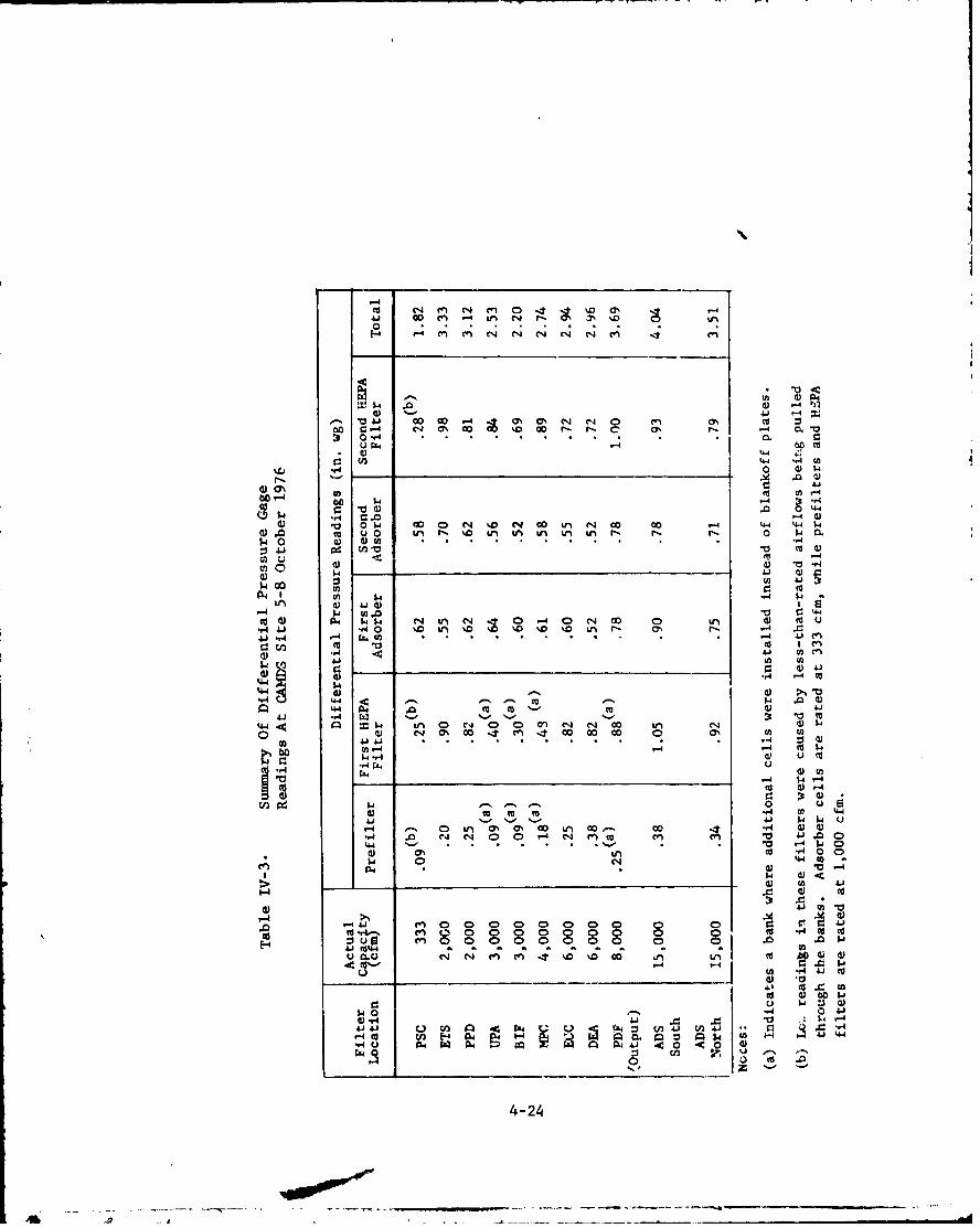
-4
Dt ý .0 .~ . .n . .- . . m. r. Ioo
0 4 -4*CC : - a) .0 9 j
.0 0.- W O' 0i 40 eq ' 00 Ln- N- Go 00 r-4 t" -4-4 $4
p3 0 4 c . . ... . . . .. ,
vi -Z . " .
I.. 4) 9
-4 V ~j.0 0-
C U 4) 0$. w 0 Ln C-4 4 00 u C 00 00 .- 4-4 44)-r4 A `4 uo %D Lr-. %0 %0 I'D in n r- r-4. 0 .O4J' -A (UC * 4 4 O
(f.) "0 10 MO.
1.ý4 CC
44 owl 44 .1.1- ca Dt -0
44I 1.. CO. C', 0 ) q 004qd0%W w -It~ m 0-4 0 w 00 0 in (U WU.
-. 0 r .0 '.0 r. . n r. ~ I-4 .0r. 4 .,444 u - J'
A) d) m. O.
CC4.4 -4 C
4.. 0 wll ' % 00N OD NA 00 00 44 Uk0f (U N C' 0040 4 00 0 0 C,4 COt n en4
44. . . . .- %- Q 1 Cas .f) co4 -r 0 0
0v. 4 C 4. M
PZ4 VUC
(U--4D 4-
C .. il, e 0 in 0' a 00 a 0 0s 0 0 C4 )00 us N 0 0 0 N 0,C aU C) a
o.a 0 N m. m 4 D %D wa
U_ _ _ _ _ _ _ _ _ _ _ _ _ - ( 4C 4 .1
co 4) bo w
44-2
-0&4

4.1.1.3.3. Spacing
Although the actual length of a filterhousing is normally determined by the manufacturer based on his overalldesign, the user may want to specify any or all of the followinggoverning dimensions:
1. The minimum distance between banks in the type II andtype III units to permit sufficient space for changeout. This valueshould represent the minimum width required by personnel in protectiveclothing (Level A) for passage plus the maximum depth of a typicalmodular cell (which must be completely removed from its mounting frame).
2. Minimum distance to prevent fire propagating from onebank of cells to another.
3. Maximum overall length available where housing is to belocated.
At CAMDS the spac .g between the prefilter and first HEr 7ilterbank is 40 in., 66 in. between the two adsorber banks, and 40 in. fromthe second adsorber bank to the second HEPA filter bank. This assumesmaximum depths of 12 in. for the prefilters and HEPA filters and 30 in.for the adsorber cell. Since it was decided at CAMDS that ventilationwould not continue in case of a fire, none of the special designfeatures mentioned here for fire protection were included in its design.
Adequate spacing to perform basic maintenance on the blowerassem'Iy should also be provided. Since this is usually a clear areain which personnel do not need protective clothing, working spacehere is not necessarily critical. The location of the blower from thefinal filter bank to obtain proper airflow should be left to thediscretion of the manufacturer. At CAMDS all spacing requirements withrespect to the blower unit, instead of being specified, were left tothe -manufaccurer.
4.1.1.3.4. Location
In determining the location of filterhousings, all airflow and negative pressure requirements must be con-sidered aa well as various ways for routing the ductwork. The designermust keep in mind when locating filter housings that adequate adjacentspade must be included for changeout and maintrniance. S1nce thelargest expense once a system has become operational is the laborinvolved in cell changeout, careful attention must be given to providingsufficient space for workers in protective clothing to move about. Fortype I units, it, Addition to access for changeout on ie door side,clearance should be allowed for personnel to observe through theinspection ports on the backside (that is, .he side away from the doors).Inspection ports on the backside of the type II and type III housings
4-25

are unnecessary, although some clearance ghould be provided there,as with the type I units, to enable personnel to attach the housingto its foundation during installation.
Unless specific safety criteria demand otherwise, it isrecommended that a path at least five-feet wide be provided on theaccess side of the housing and at the rear near the blower unit. Inaddition, there should be sufficient access for a fork-lift truck toreach the housing to assist in the changeout operations. At CAMDS afive-foot clearance path is provided at all filter units. This spaceis shown in figure 4-15 sutrounding both the rear and access sides ofeach housing. Access doors can be installed on either side of thefilter housing depending on which side offers more space and greaterconvenience at the installation site.
Space considerations determine the actual location in demilapplications. An indoor location in a ventilated area is generallypreferred because it avoids most of the disadvantages associated withoutdoor installation. Since it is unlikely in most demil cases thatsufficient space will be available for complete indoor installation,the remainder of this discussion is limited to outdoor installation.
The major problems with an outdoor location are weathering andits detrimental effects and lack of secondary containment. (Seesection 3.7.) Equipment is exposed to heat, cold, rain, snow, sand,sun, and humidity. As a result, additional requirements are placedon materials, protective finishes, construction, and personnel toenable functioning and survival. If weather conditions become toosevere, it may be -, cessary at times to provide temporary protectiveshelters during servicing.
Ground-level installation is recommended rather than on rooftops.Although a rooftop location may reduce duct length, its major dis-advantages are: (1) it requires additional structural support, (2)it presents serious logistic problems in transpcrting cells andequipment during changeout and servicing, and (3) it creates anadditional safety hazard for service personnel. At ground level,the housing should be situated on a concrete pad or other solidfoundation to which it is securely fastened (e.g., by bolting). Thehousing must be installed level and at sufficient elevation to
facilitate drainage and alignment if the ductwork.
All CAMDS filter housings are installed outdoors on concretefoundations. Although the facility is not yet completely operationalvarious housings have been in place and operating on an intermittentbasis for one to two years. None of the filter housings or ductworkshow any signs of deterioration. The severe climate, however, hasaffected the instrumentation and changeout bags, requiring certainmodifications to be made to correct these problems, as described laterin section 4.1.2.12.5.
4-26

4.1.2. Filter Housing Details
4.1.2.1. Introduction
The filter housing provides a complete, airtightprotective enclosure extending from air inlet to air outlet. It isessential that the filter components and mounting frames inside thehousing form a continuous barrier between the contaminated zone andatmosphere. Any hole, crack, or defect in a mounting frame or sealbetween the filter components and frame may result in leakage.
Penetrations through the housing skin should be mini~aized for thefollowing reasons: (1), inward flow of air into the housing willreduce flow from area to be filtered, (2) outside air may containmoisture, and (3) outward leakage of contamination may result. It Ispreferable to have all penetrations made by the manufacturer at hisfaci~lity before the housing leak tests are performed. if penetrationsare necessary after the housing has left the manu:facturer, leaktightfittings must be used. Do not rely on sealants (egRTV silicone)to stop leakage.
The CAMDS filter housings, depending on their size, containone or two leaktight penetrations aside from sampling ports, inspectionports, and pre~ssure taps. Type I units up to l,OOO-cfm capacity containone penetration only for the electric cable running between the cutoffswitch, Jun~ction box, and motor. The larger units contain thispenetration plus another one for the electric and signal lines for theflow-control system.
It is important that the following additional factors be con-sidered in the design of the filter housing. These factors are discussedin the following sections and in Chapter 4 of reference 7.
1. Structural rigidity of mounting frames.
2. Rigid and positive clamping of components to mountingframes.
3. Strict adherence to close tolerances on alignment,flatness, and surface condition of component sealingsurfaces.
4. Welded-frame construction and welded seal betweenmounting frame and housing.
5. Ability to inspect interface between components andmounting frame during installation.
4-27
6. Adequate door openings in walk-in units "type II andtype III) to allow personnel in protective clothingto enter easily.
7. Elimination of sharp projections which could causemaintenance personnel to cut themselves or tear theirprotective clothing.
8. Adequate sampling ports for leak testing and agentmonitoring.
To verify leaktightness and structural rigidity, the housingsshould be subjected to both a positive and negative pressure testand a negative-pressure decay test as described in section 2.1.3 ofAppendix B and ANSI N510. These tests were performed on each of theCAMDS filter housings at the manufacturer's plant after the unitswere completely assembled. The blower assembly was not included forsome of the tests. A value of 24 in. wg was used since it representstwice the maximum AP at which the system is designed to operate.
4.1.2.2. Mounting Frames
Mounting frames, used to support the filters andadsorbers, are critical components of the filter housing. They mustbe stringently designed to provide adequate rigidity and to withstandshock loading without exceeding the elastic limits of the framematerial. The frames should be of all-welded construction composedof carbon or stainless steel structural shapes, plates, or heavy cold-iormed sheets. Carbon steel frames should be painted or coated forcorrosion resistance. (See section 4.1.2.8.)
There are three basic types of mounting frame construction: (1)face-sealed, in which the filter seals to the outermost surfaces ofthe frame members by means of gaskets bonded to the front surface orto the flange around the face of the filter unit; (2) pocket, inwhich the filter fits into an opening of the frame and seals, by meansof a gasket bonded to the face flange of the filter unit, on aninner flange; and (3) drawer, in which the filter (or adsorber cell)fits through an opening and seals, by means of a gasket bonded to theback of the face plate of the filter or adsorber cell, to the outer-most surfaces of the frame membere. .......
4-28
Filter mounting frames should be shop fabricated because it isnearly impossible to avoid misalignment, warping, and distortion infield fabrication. Shop fabrication is less costly than fieldfabrication and permits better control over assembly, welding, anddimensional tolerances. Care must be taken to avoid twisting orbending of the completed frame during handling, shipping, and fieldinstallation. For proper performance and ease of maintenance ofinstalled filters, dimensional and surface-finish tolerances must betight and rigidly enforced. The frame should provide several inchesof clearance above the floor to prevent the filters/adsorbers fromcontacting any liquids which may collect there. (See Chapter 4 ofreference 7.)
Filter units and adsorber cells must be clamped to the mountingframe with enough pressure to enable the gasket to maintain areliable seal when subjected to vibration, thermal expansion, frameflexure, shock, overpressure, and widely varying conditions oftemperature and humidity that can be expected in service. Clampingdevices must function easily and reliably after long exposure tohostile environments and, in addition, must be capable of easyoperation by personnel dressed in bulky protective clothing whileworking in close quarters. Experience has shown that a simple nut-and-bolt system gives satisfactory service under these conditions.
The magnitude and uniformity of pressure are important factorsin clamping filters and adsorbers. At least four pressure points arerequired. While individual clamping of each element is preferred,common bolting in which the holding-clump space nut bears on two ormore adjacent filters or adsorber cells is acceptable in the demilfield. The specific clamping mecl nisrim is generally an integralpart of the mounting frame design and can vary from manufacturer tomanufacturer.
For CAMDS the filter unit manufacturer designed the mountingframes and clamping mechanism. The mounting-frame configuration isthe third or drawer type listed above. Two sections of mounting frames,one in a type I unit and the other in a type II unit, are shown infiguces 4-16 and 4-17, respectively. A more detailed discussion ofmounting Zrame design and sealing is given in Chapter 4 of reference 7.
The manufacturer used different types of clamping mechanismsfor the type I and type Il/type III housings. Toggle clamps* were
used in the type [ units. Their quick-release design permits themto be released or tightened by a simple single movement, which isideal when working through a changeout bag. The type II and type III
*Product of De Sta Co. Di,7ision, Dover Corp., Detroit, Michigan
4-29
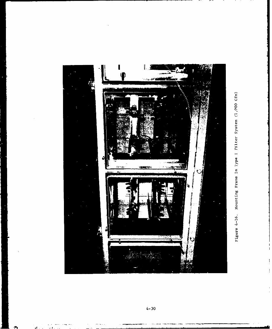
44
U)
ins
ý-4
ca
00
-,
-r4
4-30
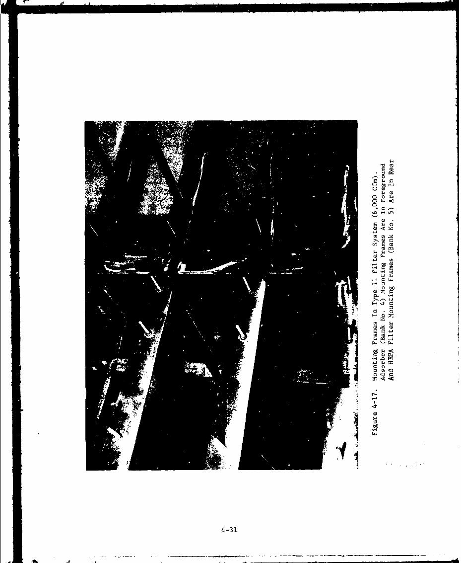
'.0 Hti~
0 <
r4b
F-4 L
--4 0W z
--4
01 W
4-3r1

units use a captive-nut clamping arrangement. Here the handle onthe nut is sufficiently large to enable personnel wearing protectivegloves to turn it tightly. See figures 4-18 through 4-22 forillustrations of both types of clamping techniques. Regardless ofwhich clamping method is used, the gasket must be sufficientlycompressed (approximately 50% for neoprene*) to assure an airtight seal.
The location of the studs on the mounting frames are determinedby the basic sizes of the face plates and outer flanged surfaces ofthe adsorber units, which are standardized by AACC CS-8 1 0 . Therefore,an adsorber cell from one manufacturer should fit another manufacturer'smounting frames. Potential problems of incompatibility were avoided atCAMDS by having the same manufacturer select the cells and mountingframes. HEPA filters, in order to mate with standardized mountingframes, must be 24 in. x 24 in., as governed by AACC CS-l. 1 8
The mounting frames for all components in type I units atCAMDS were mAde from type 316L stainless steel. In the type II units,all adsorber mounting frames were also constructed from type 316Lstainless steel, while the particulate-filter mounting frames weremade frim carbon steel coated with epoxy paint.
The gasketing surfaces required to insure a leaktight seal arean integral part of the cells and are, therefore, discussed withthose items in section 4.1.2.4.
4.1.2.3. Access Doors
There are two basic types of access doors, one fortype I housings (reach-in) and one for type lI/type III housings (walk-in). Both types must be provided with gasket seals to assure leak-tightness and to maintain a hermetic seal equal to at least the fancutoff pressure. For access to the housings, doors must be removableor open outward.
Although various types of door designs are possible, two typesconsidered at CAMDS for type I housings are illustrated in figure4-23. One method seals the door against the flange of the accessopening (figure 4.23a), while the other method seals the door againstthe housing frame (figure 4.23b). The required compression for sealin3in both cases is obtained by torquing a nut onto a stud to a specifiedvalue (120 in.-lbs. at CAMDS).
9*ASTM D1056 Grade SCE-43.
4-32
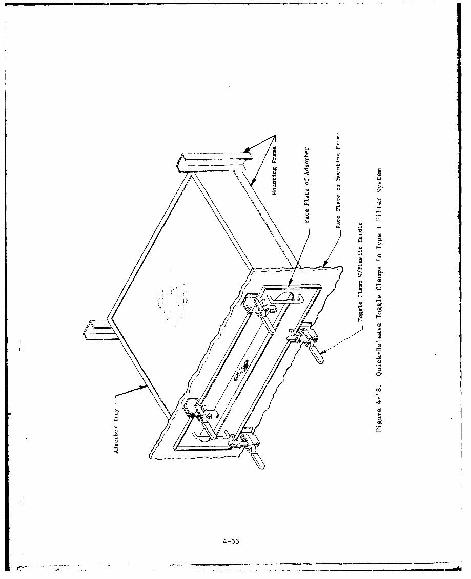
ww
A'0 F-
CCl
0 004Jr
C4)
0*
4-33)

.-A.
4-L,4
* -- --- -.-- --. ----- ,.-------------------En
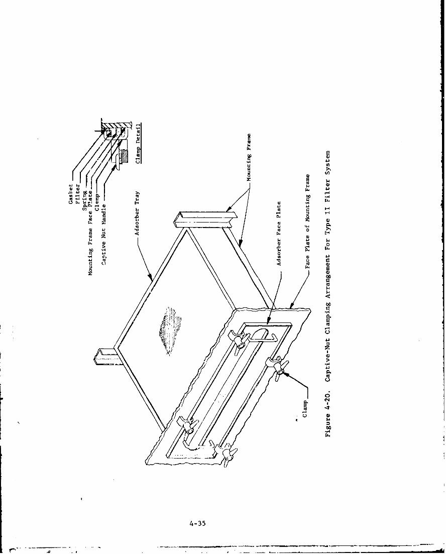
44J
II 0
C 0-4 - 0 J
I) CL () ,
4 0) 4
u . 04 0
0 >10
P4. 0) Cd 0
Pf 41)
"44
4-1
*r44.)
C-)
C.)
4-35
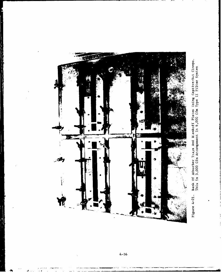
>v4 -4
r al-r4 &3.
F-4
W 4-4
PL4
C)
44 n0
co. 4 41PCI 0
co
U) cd
ý4 44
o oco C)
-ti .
cn
44 (AC) ý-4
ej)-ý4
co ZPCI H
C*4
bo-f4
4-36
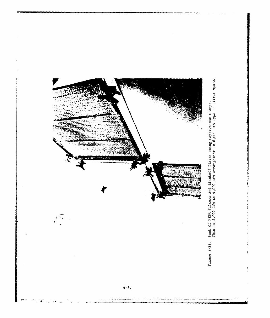
41J
two
Q)
".4
W4-1 Z
m 000C
11.71
4-4
4JQ
4--i7

orJ
ob
0 U,4
0~ 04
$4-
* aL)
ob
00
u 0
A,
b,
co'
4-38a

Based or, CAMDS experience with these door designs, the con-figtration shown ii figure 4-23b (Method B) is preferred. Twoma• 'r problems developed with Method A, namely:
1. The portion of the bag in contact with the doorgasket became rigid and cracked; this wasprobably due to an interaction between certainchemicals in the PVC bag and the neoprene rubbergasket.
2. The portion of the beg extending outside the doorand exposed to the elements began to deteriorate;this was probably caused by ultraviolet rays fromthe sun.
Both of these problems may possibly be ovezcome by a change in bagmaterial (see section 6.4.2.1), but at considerably more expense.M-1 oa B eliminates the problems entirely.
Walk-in doors, such as those of type Ii and III housings, aresimilar to marine bulkhead doors. They are of sturdy constructionwith rigid close-fitting casings and positive latches. Housing doorsshould have heavy-duty, double-pin or slip-Ain hinges, and a r ýimum
of six latching devices (called "dogs") operable from either : de or
outside. (See figures 4-12 and 4-13.) Door rigidity or stifiL,.s isImportant since flexible doors can be sprung or deformed when openedagainst negative pressure or allowed to slam shut when under load. (Amore detailed discussion of housing dnors is presented in section 4.5of reference 7.)
All walk-in access doors at CAMDS are 30 in. by 60 in. with onedoor for each compartment requiring entry, as specified by CSL safetyofficials. This is the minimum opening required for workers inprotective clothing. Each door uses six latches, three on each side,for effective sealing.
4.1.2.4. Gasketing
Gasketing is required to ensure laktight sealing ofcomponents and the filter housings. The t'hree major areas in whichgaskets are used in such applications e.e:
1. Between filter/adsorber cells and the mounting frame.The gasket is bonded to ihe cell rather than to the mounting frame,permitting it to be replaced each time the filter or adsorber ischarged. These are made of fairly soft, closed-cell, neoprene sponge,ASTM D1056, Prade SCE-43. 9
2. Between flanged connections on various sections ofduc*:work. These are a somewhat harder (less compressible) material,
4-39
as indicated in the CAMDS ductwork specification (see Appendix E ofreference 11).
3. In the filter-housing access doors, where theproperties for this gasketing material are similar to those of the latterapplication.
A neoprene gasketing material was used in the doors (application 3)of the first 12 CAMDS housings. Although the desired sealing wasobtained, it was found that the gaskets took a severe compression-setover a period of time. As a result, the final CAMDS unit and DATS unit(section 8) now employ silicone rubber gaskets. Based on preliminaryresults, the latter gaskets have performed satisfactorily.
Another factor to be considered in the selection of gasketingmaterial is its compatibility with both the contaminant of interest(chemical agent in this case), and other constituents or potentialconstituents of the air stream, including S02, N0x, and ozone. Sincethere is limited information available on this subject, it is suggestedthat CSL be consulted.
4.1.2.5. Sampling Ports and Inspection Ports
Sampling ports are penetrations through the filterhousing for the purpose of (1) connecting sampling lines to agentmonitoring equipmeait, and (2) taking upstream and downstream samplesfor DOP and freon testing of filters/adsorbers (scction 7). Foruniformity, each sampling port should consist of a one-in, diameter(minimum) NPT half-coupling welded in place to prevent leakage. Allpenetrations should be sealed with a pipe plug, using a suitable threadsealant (such as teflon "ribbon dope"), when nit in use.
An inspection port is an opening in the housing which allowspersonnel to visually examine the interior of a specific compartmentwith the aid of a flashlight or permanently installed overhead light:-(certain walk-in units only) without having to open a door or enter thearea. The inspection port is normally covered with either a bolted-onmetal plate, which is removed when observations are to be made, or aclear plas ic cover. Inspection ports can also be used for test purposesby incorporating a one-in. diameter NPT half-coupling and inserting asampling probe in the cover plate. These ports may also be used forconnecting flexible-tubing "Jumpers" to enable the testing of series banksof filters and/or adsorbers, if a flange or rim is provided to which theflexible tube may be sealed. (See figure 8.16 of reference 7.)
At CAMDS the type and locations of sampling and inspection portsvary from unit to unit as ! dicated in table WV-4. Each housing, how-ever, contains at least two sampling ports between the two adsorberbanks. The couplings are made cf type 304 stainless steel. Two samplingports are specified per housing to allow simultaneous use of twu differenttypes of agent monitors.
4-40
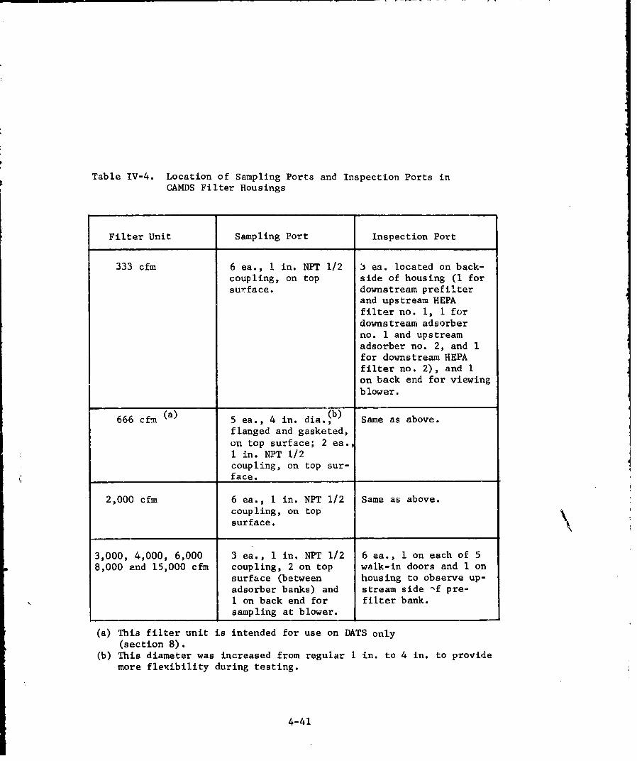
Table IV-4. Location of Sampling Ports and Inspection Ports inCAMDS Filter Housings
Filter Unit Sampling Port Inspection Port
333 cfm 6 ea., 1 in. NPT 1/2 3 ea. located on back-coupling, on top side of housing (1 forsurface, downstream prefilter
and upstream HEPAfilter no. 1, 1 fordownstream adsorberno. I and upstreamadsorber no. 2, and Ifor downstream HEPAfilter no. 2), and 1on back end for viewingblower.
666 cfrn (a) 5 ea., 4 in. dia.(b) Same as above.
flanged and gasketed,on top surface; 2 ea.I in. NPT 1/2coupling, on top sur-face.
2,000 cfm 6 ea., i in. NPT 1/2 Same as above.coupling, on topsurface.
3,000, 4,000, 6,000 3 ea., 1 in. NPT 1/2 6 ea., 1 on each of 58,000 and 15,000 cfm coupling, 2 on top walk-in doors and 1 on
surface (between housing to observe up-adsorber banks) and stream side -f pre-I on back end for filter bank.sampling at blower.
(a) This filter unit is intended for use on DATS only(section 8).
(b) This diameter was increased from regular I in. to 4 in. to providemore flexibility during testing.
4-41
The sampling lines of both monitoring devices could, if necessary,pass through a single l-in. diameter opening, but the availability of twosuch openings provides greater flexibility to sampling personnel.
Views of the sampling/inspection ports of CAMDS housings areshown in figures 4-12, 4-13, and 4-24, and later in figures 8-2 and8-9.
4.1.2.6. Pressure Taps
Provision must be included in the filter housingsfor monitoring the pressure drop across, as a minimum, each filter bank(AP measurement across adsorber banks is unnecessary). The readoutsfrom these pressure gages provide information on the buildup of solidmatter on, or leakage through, the filters. One penetration is requiredupstream and one downstream of each bank. The pressure taps are pipenipples or half couplings welded to the top or side of the housing. Thetaps should be as small as possible and flush with the inside wall of thehousing to minimize airflow turbulence. Tubing connects the pressuretaps to the differential pressure gages.
In CAMDS, the taps are located on the top of type I housings andon the side, above the access doors, of type II housings.* (Seefigures 4-12, 4-13, 4-24, and 8-2.) Pressure taps are identical on allthe CAMDS units, although a shutoff valve was added to the DATS -.nit tomaintain its integrity during the frequent relocations which it isexpected to make.
4.1.2.7. Drains
Floor drains should be provided in housings in whichdecontamination and/or deluge-type sprinkler protection provision is made.There should be a separate drain for each chamber (that is, the spacebetween each pair of filter banks) since a common drain could allowcontaminated air to bypass the filters or adsorbers. Floors must besloped towards the drain holes to permit easy runoff of liquid, andthe housing must be level to ensure proper drainage. The drains shouldflow toward the access side of the housingc and be either capped whennot in use or piped to a liquid waste facility.
*Although tbhre are no type III housings now installed at CAMDS,their pres6 re taps would be located the same as for thc type Ilhousings.
4-42
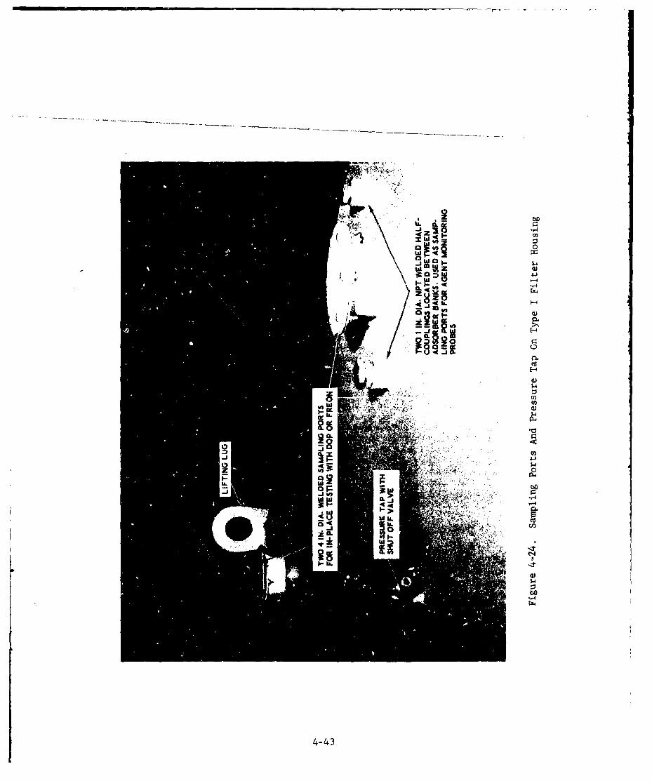
0
w -9~aa
IL -
1204
u .4 5
0 73
-,4
"-,4
4-43
Each CAMDS filter housing is equipped with six drains, each of whichis a 1-inch diameter pipe nipple for connection with outlets installed inthe housing skin. A pipe cap seals each drain outlet when not in use andis removed only when a definite requirement exists for decontaminating orflooding the housing. When used, pipe or tubing is connected from thedrain to a storage vessel or sump where the effluent liquid - probablycontaminated - is collected for disposal. A pump (or pumps) can beincorporated into the system if necessary. (See figures 4-7, 4-10,4-12, 4-13, and 8-2.)
4.1.2.8. Paint
Carbon-steel housings must be pi ed to protectagainst corros 4 ' i and to facilitate cleaning and e itamination.Mounting fraw nay be either carbon steel, which rtires painting, orstainless steel (e.g., type 316L). The paint for mounting frames shouldbe hard enough to resist scratching during filter changeout. For demilapplications an epoxy-base paint is recommended because its smooth, hardsurface is less susceptible to agent penetration than other types ofpaint. There are several suitable epoxy paints commercially available;the brand found to be least affected by chemical and decontaminatingagents is Rowe Epoloid B, a product of Rowe Products, Inc., NiagaraFalls, New York.
All CAMDS filter housings and carbon-steel frames were paintedwith the latter paint in strict accordance with the manufactu-er'srecommendations (i.e., one coat of primer 7-W-20 plus two coats ofbase 5-G-5). These units have now been in the field for one to twoyears and show no signs of deterioration and less scratching thananticipated. Proper preparation of the metal surface and strictadherence to the paint manufacturer's recommended procedures arecritical to achieving a satisfactory paint job.
4.1.2.9. Lights
Permanently installed electric lights are recommendedin all type II and type III filter housings to provide illumination forvisual inspection, in-place testing, and changeout operations. Theselights should be installed in series with an independent control switchlocated on the outside of the housing. They must be installed invapor-tight glass globes capable of withstanding the pressures en-countered and be replaceable from outside the housing through leaktightopenings in the roof of the housing. Wiring for the lights should beinstalled on the outside of the housing in metal conduit to avoidpenetrations through its skin. See figure 4-25.
4-44
4-1
,-4
r-4
I-4
0)
4-1
44C 00
-r4
41-
4-45i
For the CAMDS type II units the light-control switch is located
on the back of the housing adjacent to the disconnect switch. Thereis one light between each pair of banks of the 6,000-cfm housings andtwo lights between each pair of banks of the 9,000-cfm and 15,000-cfmunits. Lights are installed only in spaces where cell changeout occurs.That is, no lights are installed between the first HEPA filter and firstadsorber or between the second adsorber and second HEPA filter becauseno changeout is performed in these areas. No light is installed in theblower compartment because it is considered a clean area without de-contamination problems; when needed, a drop-light can be brought in.
4.1.2.10. Electrical
4.1.2.10.1. Power Requirements
Electrical power is required for the fan,interior lighting (type II and type III units only), pumps, heaters, andagent-monitoring equipment for providing signals to the control area towarn of low-flow conditions, etc. In a typical system all equipmentexcept the blower operates from a 110-volt, 60-Hz AC source. The fanusually operates on either 230 (or 208) or 460 volts AC, depending onits size and the power characteristics specified by the fan manufacturer.
All power for filter housing purposes should be connected through adisconnect switch at the housing. See figures 4-7, 4-10 and 4-12, Thisswitch is located at the housing to keep it under the control of maintenancepersonnel so that power cannot be accidentally turned on remotely when menare working inside. A central contrcol area, however, may still be wiredfor remote operation of the fans, but without the capability of overridingthe local disconnect switch.
At CAMDS the fans operate on 208-volt, 3-phase, 60-Hz power exceptthe ADS units (containing 40 hp motors) which require 460-volt, 3-phase,60-Hz power. Incoming commercial power to the facility is first steppeddown to 480-volts for the ADS fans and then stepped down to 208-voltsfor the other fans.
In case of commercial power failure, 480-volt emergency power isautomatically supplied to the ADS by a diesel-powered generator locatedin a utility building. Another emergency generator housed in a railroadcar supplies 208-volt emergency power. The latter generator operatesautomatically upon loss of commercial power; should it fail to start afterthree tries, a backup (redundant) generator automatically switches on tosupply the required 208-volt power.
4-46
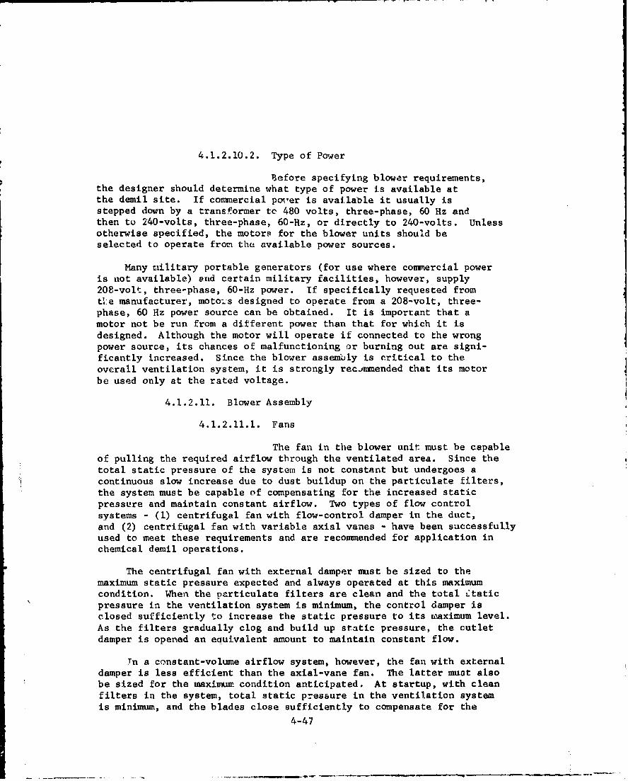
4.1.2.10.2. Type of Power
Before specifying blower requirements,the designer should determine what type of power is available atthe demil site. If commercial poN'er is availaDle it usually isstepped down by a transformer to 480 volts, three-phase, 60 Hz andthen to 240-volts, three-phase, 60-Hz, or directly to 240-volts. Unlessotherwise specified, the motors for the blower units should beselected to operate from the available power sources.
Many military portable generators (for use where commercial poweris not available) and certain military facilities, however, supply208-volt, three-phase, 60-Hz power. If specifically requested fromtie manufacturer, motoi.s designed to operate from a 208-volt, three-phase, 60 Hz power source can be obtained. It is important that amotor not be run from a different power than that for which it isdesigned. Although the motor will operate if connected to the wrongpower source, its chances of malfunctioning or burning out are signi-ficantly increased. Since the blower assembly is critical to theoverall ventilation system, it is strongly recimnended that its motorbe used only at the rated voltage.
4.1.2.11. Blower Assembly
4.1.2.11.1. Fans
The fan in the blower unit must be capableof pulling the required airflow through the ventilated area. Since thetotal static pressure of the system is not constant but undergoes acontinuous slow increase due to dust buildup on the particulate filters,the system must be capable of compensating for the increased staticpressure and maintain constant airflow. Two types of flow controlsystems - (1) centrifugal fan with flow-control damper in the duct,and (2) centrifugal fan with variable axial vanes - have been successfullyused to meet these requirements and are recommended for application inchemical demil operations.
The centrifugal fan with external damper must be sized to themaximum static pressure expected and always operated at this maximumcondition. When the Darticulate filters are clean and the total Ltaticpressure in the ventilation system is minimum, the control damper isclosed sufficiently to increase the static pressure to its nmaximum level.As the filters gradually clog and build up static pressure, the cutletdamper is opened an equivalent amount to maintain constant flow.
Tn a constant-volume airflow system, however, the fan with externaldamper is less efficient than the axial-vane fan. The latter must alsobe sized for the maximum condition anticipated. At startup, with cleanfilters in the system, total static pressure in the ventilation systemis minimum, and the blades close sufficiently to compensate for the
4-47

lower level of static pressure through the system. As the staticpressure builds up, the blades open up a corresponding amount tokeep the total static pressure at a constant value.
With both types of control, the fans accomplish the same function,but the centrifugal fan with axial vanes does less work and thusrequires less power. In order to conserve power, the CAMDS specifi-cation originally specified axial-vane fans for all blowers; however, thefan manufacturer warned that these units do not operate efficiently atlow flow rates and high pressures (5 to 6 in. wg). Therefore, in vlewof this judgment, centrifugal fans with axial vanes were selected forthe larger systems only 18,000 and 15,000 cfm). Fans with control dampersin the stack were specified for all units of 6,000 cfm or less.
To determine the maximum static pressure in the ventilation system,the CAMDS specification (Appendix B) requireG that, with a maximumnegative pressure of 1 in. wg at the filter inlet, each air filtersystem shall (1) maintain the specified volume airflow, plus 0 minus20%, as the filter system's resistance is increased by 100% over itsinitial value, and (2) maintain the specified volume airflow, plus0 minus 30%, when the filter system's resistance is increased by 1257over its initial value.
For a more general discussion of fans and flow control, consult
Chapter 5 of reference 7 and also reference 12.
4.1.2.11.2. Motors
Based on CAMDS experience, fan motorsshould be totally enclosed, fan cooled, with double-sealed pre-lubricated ball bearings designed for continuous operation. Advisethe fan manufacturer of the airflow requirements, characteristics ofavailable power (i.e., voltage, frequency, and phase), and basic typeof motor desired and let him determine the actual horsepower ratingof the motor required for driving the fan. Motor sizes in use atCAMDS range from 2 to 40 hp. (See table IV-l.)
"To expedite the lubrication of motors of smaller blower units(2,000 cfm and less), remote greaseports may be considered. Theseare, in essence, tubes connecting difficult-to-reach lubricationfittings to accessible locations. The lubricant enters the tube andflows through it to the proper lubrication point.
4-48

4.1.2.11.3. Drive
There are two basic methods ofconnecting the blower fan to the motor:
1. Direct drivie, in which motor shaft and fan shaft aredirectly coupled.
2. Belt drive, in which motor shaft is connected tofan shaft by means of a belt-driven pulley arrangement.
For CAMDS, the means of connection was left to the blower manu-facturer, who selected belt drive because of its greater versatility.It was stipulated, however, that at least two belts be used on eachpulley for redundancy, so that if one belt becomes disabled theblower system can continue operating. (See section 3.4-)
4.1.2.11.4. Capacitors
It is advisable to install capacitors
in conjunction with the larger motors in order to improve their powerIfactor. At CAMIDS each motor, 10 hp or larger, has a capacitor wiredacross it which provides a power factor of at least 0.9.
4.1.2.11.5. Vibration
Vibration created in the ventilationsystem - primarily by fans, motors, and mechanical drives - can bereduced through the use of flexible couplings between the fan andductwork and springs, or isolation-pad nountings, between the fan andits base. Excessive vibration, if not corrected, can ceu~se damageto components as well as severe noise. If the blower is hard-mounted (i.e., to a concrete pad or solid floor), thereis less chance of vibration and isolators may not be necessary.
At CAMDS flexible connections are used between the exhaust sectionof the fan and the straightening section in the stack in all unitsabove 2,000-cfm capacity. In addition, most of the fans aremounted on damping spring isolators; since recent experience has shownthat motor vibration is not extensive enough to warrant use of thesprings, some of the later units (2,000 cfm and DATS) are mountedon rubber pads (see figure 4-4).
During shipment between the manufacturer and the CANDS site, severalof the earlier motors equipped with damp~ing springs resonated orftheir mounts anL' broke the vibration isolators. To avoid thisproblem, the motcr frames were welded to their housings for shipment,and the welds were removed later after the equipment was set up atthe site,
4-49
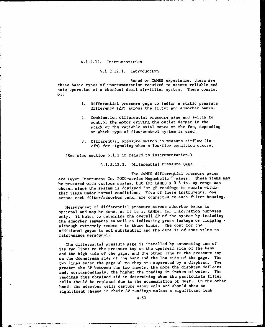
4.1.2.12. Instrumentation
4.1.2.12.1. Introduction
Based on CAMDS experience, there arethree basic types of instrumentation required to assure reliable andsafe operation of a chemical demil air-filter system. These consistof:
1. Differential pressure gage to indict e static pressuredifference (AP) across the filter and adsorber banks.
2. Combination differential pressure gage and switch tocontrol the motor driving the outlet damper in thestack or the variable axial vanes on the fan, dependingon which type of flow-control system is used.
3. Differential pressure switch to measure airflow (incfm) for signaling when a low-flow condition occurs.
(See also section 5.1.2 in regard to instrumentation.)
4.1.2.12.2. Differential Pressure Gage
The CAMDS differential pressure gages
are Dwyer Instrument Co. 2000-series Magnehelic ® gages. These items may
be procured with various scales, but for CAMDS a 0-3 in. wg range was
chosen since the system is designed for tP readings to remain within
that range under normal conditions. Five of these instruments, one
across each filter/adsorber bank, are connected to each filter housing.
Measurement of differential pressure across adsorber banks is
optional and may be done, as it is at CAMDS, for information purposesonly. it helps to determine the overall AP of the system by includingthe adsorber segments as well as indicating gross leakage or clogging -
although extremely remote - in these banks. The cost for theadditional gages is not substantial and the data is of some value tomaintenance perscnnel.
The differential pressure gage is installed by connecting cne of
its two lines to the pressure tap on the upstream side of the bank
and the high side of the gage, and the other line to the pressure tapon the downstream side of the bank and the low side of the gage. Thetwo lines enter the gage whiere they are separated by a diaphram. The
greater the AP between the two inputs, the more the diaphram deflactsand, correspondingly, the higher the reading in inches of water. The
re&dings thus obtained aid in determining when the particulate filter
cells should be replaced due to the accumulation of dust. On the otherhand, the adsorber cells capture vapor only and should show no
significant change in their AP readings unless a significant leak
4-50

develops. Therefore, the changeout criteria for the adsorber cellsdoes not depend on differential-pressure gage readings (see section4.1.3.3.5).
4.1.2.12.3. Combination Differential PressureGage and Switch
CAMDS uses another Dwyer instrumentknown as a Photohellc E gage, the 3,000-series model with lowtemperature option. It functions as both a flow indicator and motor-control device. The indicator portion of the gage operates in thesame manner as the Magnehelic gage.* In its other function as adouble-circuit pressure switch, the Phof-ohelic gage offers high andlow limit switches which are activated by separate photocells totrigger relays controlling certain equipment.
Readings are obtained by connecting the high and low sides ofthe gage to the corresponding high and low ports at the flow-measuringstation in the exhaust stack. The flow-measuring station of the stackis a flanged casing containing an air straightener and treatment section,total pressure sensors, tube manifold, static-pressure sensors, and avolume meter (in this case, the Photohelic gage). It is designed toaccurately measure airflow through the stack and, therefore, through thefilter housing. When the gage reading goes below the lower set-pointor above the upper set-point, a contact is closed and an electrical signalis sent out. This signal goes to a motorized damper in the exhauststack or, in case of the axial-vane fan unit, to a small motor connectedto the fan blades. If the signal originates from the low contact, thedamper opens or the blades rotate to decrease the resistance to the fanand increase the airflow. The damper or bladeg continue to operateuntil the airflow reading moves back, above the lower contact point.When this happens the contact opens and the signal to the motor ceases,causing the motor to stop. The reverse procedure applies if a highsigna! is transmitted. The flow-control system of DATS is gimilar (seesection 8).
4.1.2.12.4. Low-Flow Signal
For CAMDS, a Dwyer 1910-series differential-pressure switch is used to signal the control room in the event of a lowor no-flow condition. This signal actuates an alarm (audible, blinkinglight, etc.) to inform operating personnel that the airflow is eitherdangerously low or stopped. Although there is no scale on thisinstrument, its operation is similar to the switch portion of thePhotohelic gage. Its low-flow setting is adjusted by a set-screw.**
*The scales of Photohelic gages used at CAMDS in airflow control systemshave been modified to read in cfm rather than AP (in. wg).
**The Dwyer 1910-series switch, as used at CAMDS, contains only one setof contacts for use at the low-flow condition; it can be procured,however, with two sets of contacts if signaling of a high-flow condition
is also requirLd. 4-51
S. . .2_. .-

Upstream anc downstream readings from the measuring station at theexhaust stack are introduced into the high and low sides of theinstrument by air lines. These lines actually connect to T-connectionson the lines going to the Photohelic gage.
4.1.2.12.5. Location
The overall flow-control arrangement isshown schematically in figure 4-26, while figure 4-27 shows a closeupof the damper motor and linkage section.
Portions of the automatic flow-control systems in the CAMDSfilter units have been deactivated by insertion of an ON/OFF switchbetween the damper-operating motor and the flow-control gage. Thiswas done because no decrease in airflow resulted in any of the filtersto date due to increases in total LP, and an automatic flow-controluystem does not appear to be required. If large flow variations shouldoccur in the future, the automatic control system can easily be re-connected.
The instruments can be mounted outdoors directly on the filterhousing or remotely indoors, or a combination of both. CAMDSexperience recommends that all gages be mounted remotely indoors when-ever possible.
Problems at CAMDS with outdoor-mounted gages involved (I) vibration,(2) fading of the numbers on the face plates by sunlight, and (3)moisture condensation inside the instruments. All of these made readingof the dials very difficult, in addition to shortening the life of thegages. For remote -iunting of the gages, the manufacturer claims that,although short lengths are preferred, sensing lines may be extended anynecessary distance. A maximum length of 150 ft. is recommended, however,and shorter lengths are preferable. Tubing should be at least 3/16 in.ID to allow the instruments to respond quickly to rapid pressure changes..
At CAMDS all gages, except the low-flow signal, are now remotelylocated indoors with no line exceeding 100 feet in length. The Model1910 low-flow signaling switches, however, are mounted on the filterhousiL.gs. Figures 4-9, 4-11, and 4-13 show how instrument panels wereinitially mounted on the filter housings. A view of the relocatedinstriuments is shown in figure 4-28.
4-52

0 cc
0.C ,
00 4.)
gm~~ 4)m m c4
41
4 a)00
0
r4i
-,-,
E0
4.j4r44
00
-M0 0
ýt u-53

•, 0
(U
QWr.
$4
03
c'0
03-,4"
4-54
4- -
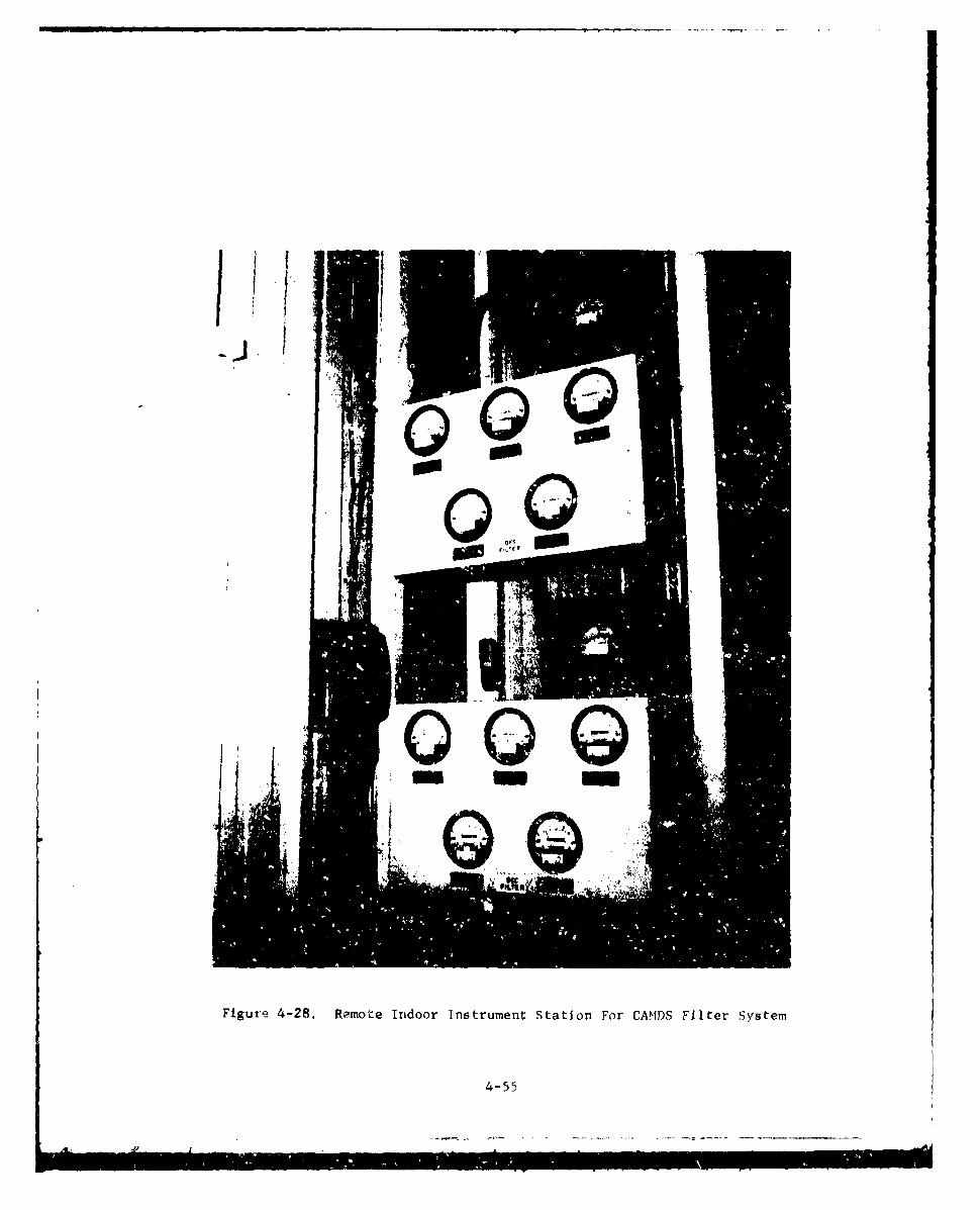
Figure 4-28. Remote Indoor Instrument Station For CAMT)S Filter System
4-55
4.1.2.13. Exhaust Stacks
There is always the possibility that some amountof contaminated air, even if undetectable, may be discharged throughthe exhaust of a chemical demil air-cleaning system. Exhaust stacksserve as the means for dispersing exhaust air to the atmosphere.Poor discharge conditions, if there is leakage through the filtersystem, can result in low-level contamination which may remain in theitmmediate area or even reenter a ventil~ated building due to windeffects. Therefore, the type and location of the stacks are key factorsin obtaining proper dispersion of exhaust air. Principles of goodstack design are illustrated in figure 4-29.
in general, the exhaust stack must be higher than adjacentstructures if possibla. It should be designed so there is no backpressure to decrease the capacity of the fan. The cross-sectional areaof the stack should be not less than the cross-sectional area of theblower's outlet. The vertical-discharge, no-loss configuration shownon the left side of figure 4-30 is recommended.
Sampling ports are provided in the stack to monitor agent con-centration in the effluent air and to measure flow rate. One-in. dia.half-couplings or pipe nipples are provided for this purpose. Thenumber of taps required is dependent on the type of sampling intended(agent mnnitoring or flow-rate determination) and the configuration ofthe exhaust stack (round or rectangular). See reference 14 and section5.5 of reference 7 for further details. The responsible USAEH~A officeshould be contacted for specific recommnendations and assistance indesigning and locating stacks, as well as to insure that all requirementshave been satisfied.
After the stack is built it can be tested with commnercial smoke-producing devices* to determine airflow patterns across adjacentbuildings and to verify that proper discharge is occurring.
The exhaust stacks at CAMDS are of the vertical-discharge, no-loss design illustrated in figures 4-30 and 4-51. All are constructedof 16-gage carbon steel and coated with epoxy paint for corrosionr'esistance.
*Smoke candles sre recommnended for low flow rates and smoke bombs forhigh flow rates. These devices should not contain titaniumtetrachloride, which is highly corrosive.
4-56
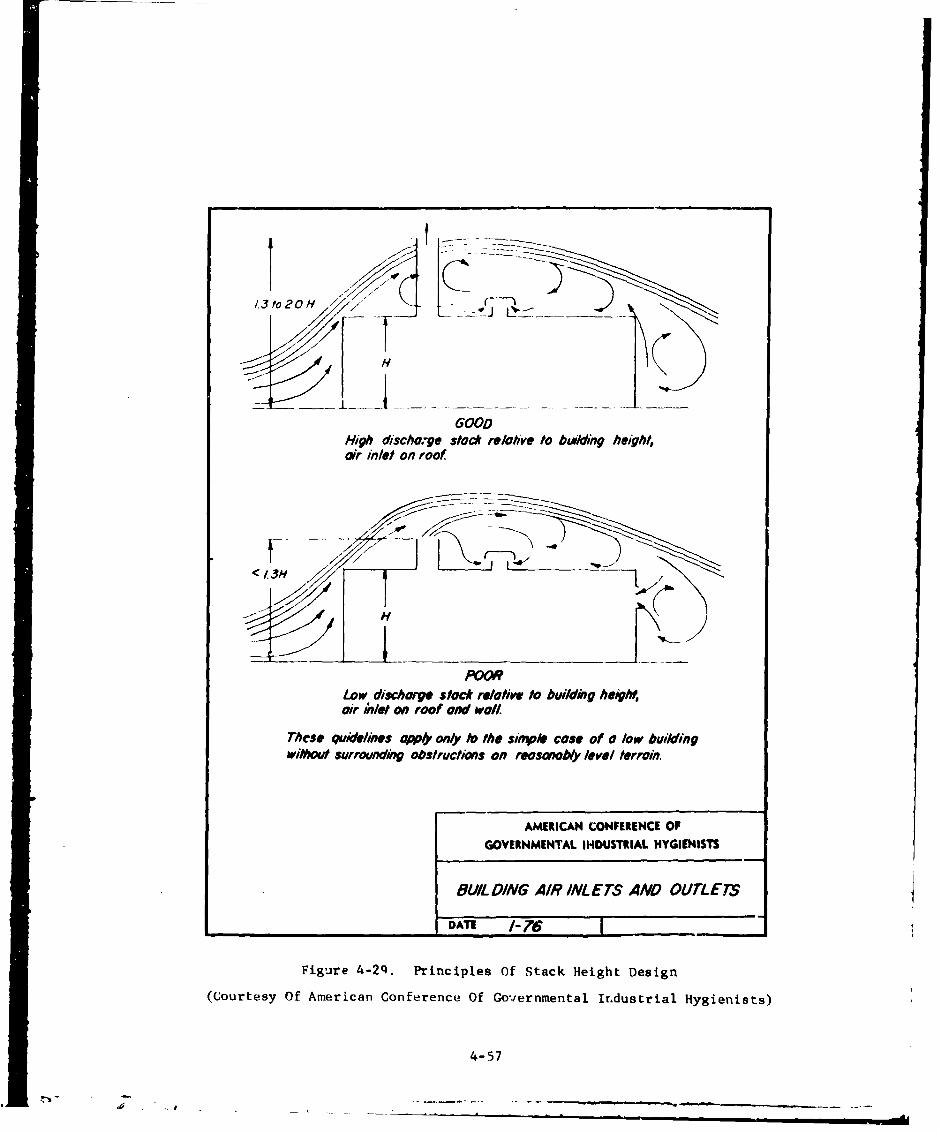
13fo2OH J<
High discho,-ge stock relative to bwlding height,arinlet on ro
< 13H 7
POORLow discharge stack relative tobuilding height,air inlet on roof and wal/
These quI*ideme tapp,) onlY t0 the siMPle Case of a low buildingWito~ surrounding oostructia'is on reasa'iobly level terrain.
AMERICAN CONFERENCE OFGOVERNMENTAL INDUSTRIAL HYGIENISTS
BUIL DING AIR INL ETS AND OUTETS
__________________ DATE 1-76 1 -
Figure 4-29. Principles Of Stack Height Design
(Courtesy Of American Conference Of Governmental In~dustrial Hygienists)
4-57

p/I
-D 1- - Sc Non A,-A
CZ,/ir/20
AADrok~ /,p
~~ A'
11120#/t-D0 Drop
rocket upper 1V4stoca todischorge duct
VERTICAL DISCHARGE,'9"I"6 OF'FSET ELzW/S~ ' OFFrSET STACK '"I
Ao loss Calculate losses due to elbows
I Rain protectdio characteristics of these cps cre sueriorto a deflecting co l/ocaed 0 750 from top of stle
2. The length of upper stack is relted to Awn protectim.Excessive oddihonal distance mOy cause "l0oWut ofeffluent ' Mhe gqp between MAW. ofd k'wwr sectiens. (a*s
AMERICAN CONFERENCE OFGOVERNMENTAL INDUSTRIAL HYGIENISTS
STACKHEAD DEIGNS
PAT[ I-76
Figure 4-30. Vertical-Discharge, No-Loss Stack Head Design
(Cctlr'csy Of American Confev'ence Of Governmental Industrial hygienists)
4-58
-f. . . l- ... . .. . .. . . - - _ _ _ _ _ _ _ _ _ _

4.1.2.14. Skids and Lifting Eyes
Filter housings should be fitted with fourexternal lifting eyes (or lugs) and mounted on skids to facilitatehandling and installation by cranes and forklifts (see figures 4-24and 4-31). The lifting eyes must be located so that the housing willbe horizontal when supported from a single crane hook. Mounting onskids also provides space for laying drainpipes under the housings.
At CAMDS the filter housings are skid-mounted and anchored with1/2 in. dia. bolts to concrete pads. Each unit is electricallygrounded to avoid lightning damage.
4.1.3. Filters and Adsorbers
This section describes in detail the heart of the filtersystem - those components which actually remove contaminants from theairstream. Included in this discussion is information on prefilters,HEPA filters, adsorbers, and adsorbent.
4.1.3.1. Prefilters
4.1.3.1.1. Function
The first bank of filters in a filtersystem is the pre- or roughing filter. This filter mechanicallyremoves coarse particulate matter from the airstream and protects thefirst bank of HEPA filters from being plugged or damaged by largeparticles. A typical increase in HEPA filter life through the use ofprefilters is illustrated in figure 4-32. The increase for a specificapplication is, of course, dependent on the efficiency of the prefilterselected and the nature and concentration of dusts and particulatematt3r in the ventilation system.
4.1.3.1.2. Cost Considerations7
The derision to use prefilters must bedetermined for each application on the basis of total air-cleaningsystem costs (including first cost, effect on power costs, andservicing) and the consequences of exposing the HEPA filters to theevivironment without protection. In general, HEPA filters should bebe protected from (1) particles larger than 1 or 2 •m in diameter,(2) lint, and (3) dust concentrations greater than 10 grains per1,000 cubic feet. Resistance (and corresponding power costs), systeminstallation costs, and filter element replacement costs generallyincrease with increasing prefilter efficiency. Table IV-5 showsrelative prices of filters usually used for prefilter purposesrelative to the current price of HEPA filters. (Refer to section4.1.3.1.7 'or descriptions of Group I, II and III prefilters.)
4-59
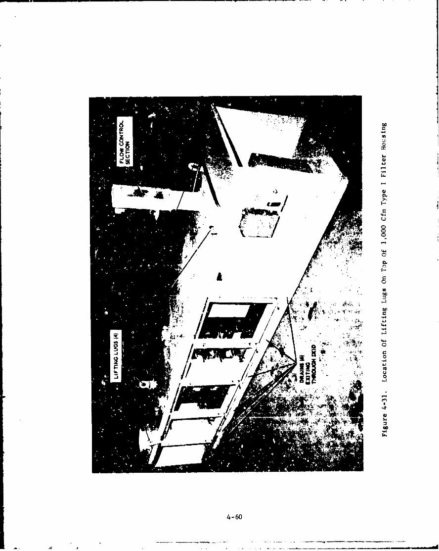
IL-
4wJ
4-4
'4 "4
94-
4-60
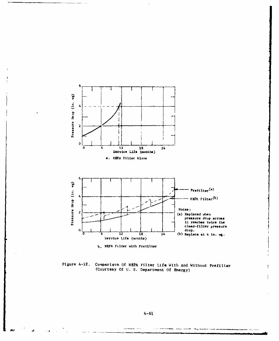
6
, Ii ... ._ _ _
1I
"* I
o~. 1 I I0 6 12 18 24
Service Life (months)
a. HEPA Filter Alone
F7.m
tic
" • Prefilteroo)4 (bM, 4 .- - HEPA Filter(b)
- - .1 Notes:
S.(a) Replaced whenSi •pressure drop across
it reaches twice thea, clean-filter pressure
0 J L l drop.0 6 12 18 24 (b) Replace at 4 in. wg.
Service Life (months)
b. HEPA Filter with Prefilter
Figure 4-32. Comparison Of HEPA Filter Life With And Without Prefilter(Courtesy Of U. S. Department Of Energy)
4-61

Table IV-5. Price Indexes of Common Air Filters Per 1000 CfmCapacity
7
PriceGroup Efficiency Type Index (a)
I Low Panel .01
II Moderate Extended Medium .02-.lO
Ili High Extended Medium .30-.70
- HEPA HEPA .80-1.00
(a) Actual cost may be estimated by multiplying price indexby current cost of a HEPA filter; for example, if curren..cost of l000-cfm HEPA filter is $130, cost of a Group Iprefilter would be .01 x $130, or about $1.30.
4.1.3.1.3. Size
It is recommended, for good airdistribution, that the face dimensions of prefilters be approximatelythe same (i.e., within + 1 inch) as the face dimensions of the HEPAfilters with which they are used.
4.1.3.1.4. lype
Common air filters used as prefilters areclassified as shown in table IV-6. The classification is based onarrestance (weight percent) and dust-spot (stain) efficiency asexplained in references 7 and 15. Because the atmospheric-aust spottest is based on the staining effect of the dust that penetratesthe filter, as compared to the staining capacity of the enteringdust, it is not a true measure of particle-removal efficiency for &nygiven particle size range. Table IV-7 givies a more meaningfulcompar iscn.
4-62

Table IV-6. Classification of Cummon Prefilters 7
Stain-Test ArrestanceGroupj Efficiency Filter Type Efficiency ( M) (7)
I Low Panel, viscous impingement <20(a) 40-80(a)
I1 Moderate Extended medium, dry 20 - 60 (a) 8 0 - 9 6 (a)
III High Extended medium, dry 6 0 - 9 8 (b) 96-99(a)
(a) Using synthetic dust.(b) Using atmospheric dust.
Table IV-7. Comparison of Prefiltcrs by Percent RemovalEfficiency for Various Particle Sizes 7
Group Efficiency Removal Efficiency (%) By Particle Size
0.3 bjn 1.0 "m 5.0 mn I0.0 4m
I Low 0-2 10-30 40-70 90-98
II Moderate 10-40 40-70 85-95 98-99
III High 45-85 75-99 99-99.9 99.9
4.1.3.1.5. Performance
Prefilter performance is defined in termsof (I) particle-removal efficiency, (2) resistance to airflow (i.e.,differential pressure), (3) airflow caoacity, and (4) dust-holdingcapacity. Table IV-6 given the comparative -:rformancaof Groups I, IT and III filters averaged over the life of the filterto the manufacturer's recommended maximum pressure drop.
4-63
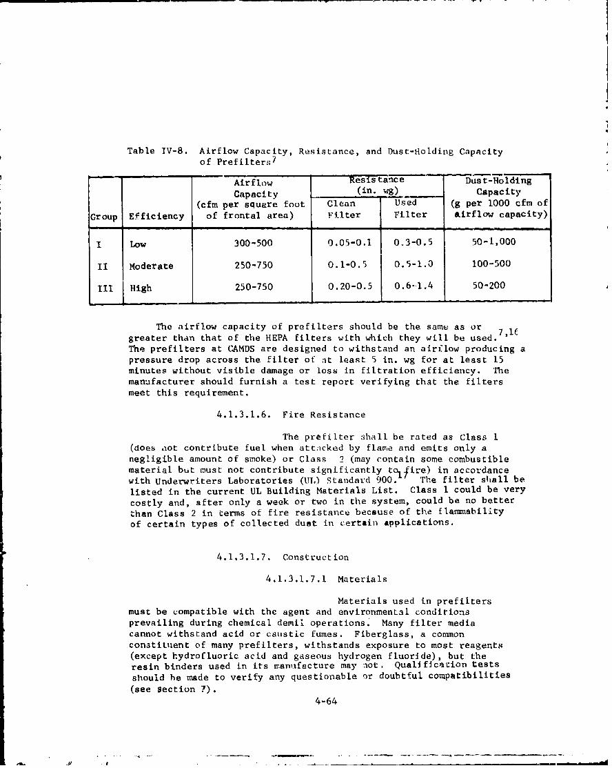
Table TV-8. Airflow Capacity, Resistance, and Dust-Holding Capacityof Prefilters7
Airflow 'Resistance Dust-Holding
Capacity (in. wg) Capacity
(cfm per square foot Clean Used (g per 1000 cfm of
Group Efficiency of frontal area) Filter Filter &irflow capacity)
Low 300-500 0.05-0.1 0.3-0.5 50-1,000
II Moderate 250-750 0.1-0.5 0.5-1.0 100-500
III High 250-750 0.20-0.5 0.6-I.4 50-200
The airflow capacity of prefilters should be the same as orgreater than that of the HEPA filters with which they will be used.The prefilters at CAMDS are designed to withstand an airflow producing apressure drop across the filter of at least 5 in. wg for at least 15minutes without visible damage or loss in filtration efficiency. Themanufacturer should furnish a test report verifying that the filtersmeet this requirement.
4.1.3.1.6. Fire Resistance
The prefilter ,dhall be rated as Class I(does aot contribute fuel when attacked by flame and emits only anegligible amount of smoke) or Class 2 (may contain some combustiblematerial but must not contribute significantly to 1 fire) in accordance
with Underwriters Laboratories (UL) Standard 900. The filter shall belisted in the current UL Building Materials List. Class 1 could be very
costly and, after only a week or two in the system, could be no better
than Class 2 in terms of fire resistance because of the flammsabilityof certain types of collected dust in certain applications.
4.1.3.1.7. Construction
4.1.3.1.7.1 Materials
Materials used in prefiltersmust be compatible with the agent and environmental conditionsprevailing during chemical demil operations. Many filter mediacannot withstand acid or caustic fumes. Fiberglass, a conunonconstituent of many prefilters, withstands exposure to most reagents(except hydrofluoric acid and gaseous hydrogen fluoride), but theresin binders used in its manufacture may aot, Qualificacion testsshould he made to verify any questionable or doubtful compatibilities(see section 7).
4-64
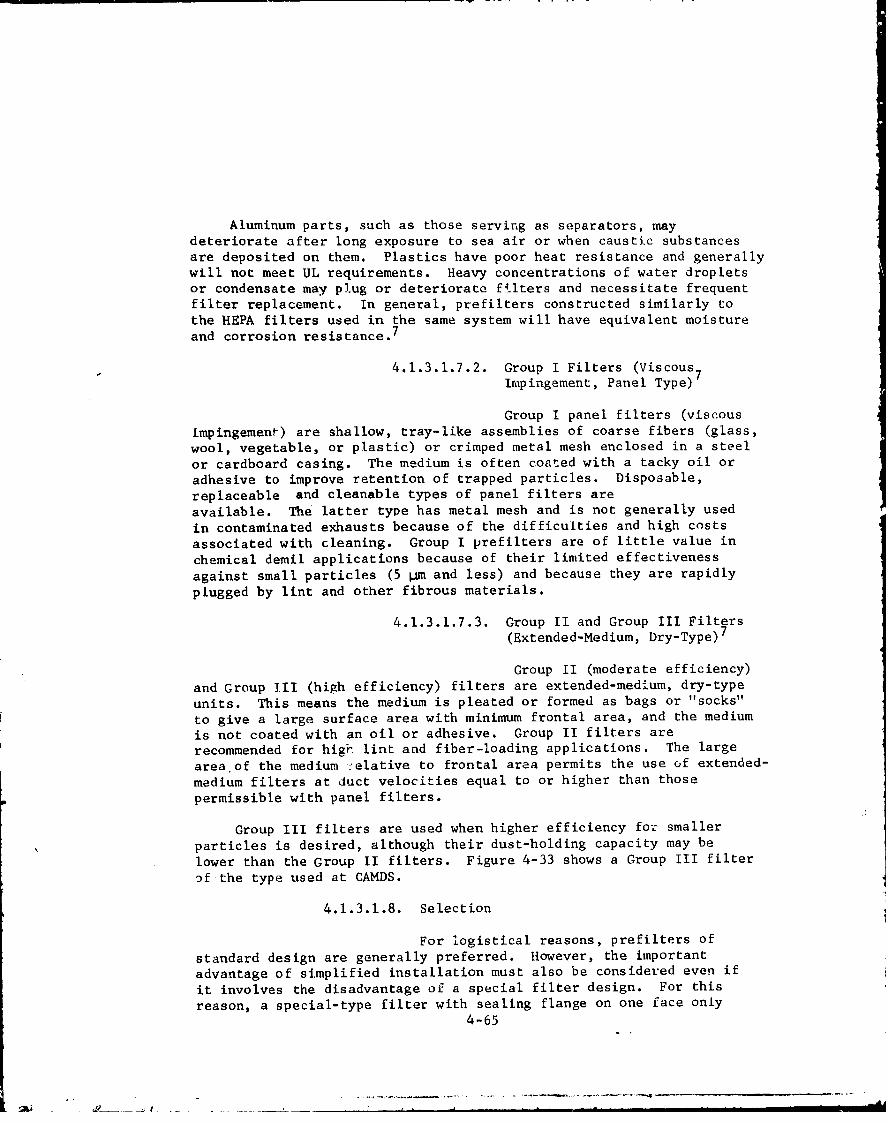
Aluminum parts, such as those serving as separators, maydeteriorate after long exposure to sea air or when caustic substancesare deposited on them. Plastics have poor heat resistance and generally
will not meet UL requirements. Heavy concentrations of water dropletsor condensate may plug or deteriorate filters and necessitate frequentfilter replacement. In general, prefilters constructed similarly to
the HEPA filters used in the same system will have equivalent moistureand corrosion resistance. 7
4.1.3.1.7.2. Group I Filters (Viscous7Impingement, Panel Type) 7
Group I panel filters (viscous
impingement) are shallow, tray-like assemblies of coarse fibers (glass,wool, vegetable, or plastic) or crimped metal mesh enclosed in a steelor cardboard casing. The medium is often coated with a tacky oil oradhesive to improve retention of trapped particles. Disposable,replaceable and cleanable types of panel filters areavailable. The latter type has metal mesh and is not generally used
in contaminated exhausts because of the difficulties and high costs
associated with cleaning. Group I prefilters are of little value in
chemical demil applications because of their limited effectiveness
against small particles (5 pm and less) and because they are rapidly
plugged by lint and other fibrous materials.
4.1.3.1.7.3. Group II and Group III Filters(Extended-Medium, Dry-Type)
7
Group II (moderate efficiency)
and Group III (high efficiency) filters are extended-medium, dry-type
units. This means the medium is pleated or formed as bags or "socks"
to give a large surface area with minimum frontal area, and the mediumis not coated with an oil or adhesive. Group II filters arerecommended for higir lint and fiber-loading applications. The large
area of the medium :elative to frontal area permits the use of extended-
medium filters at duct velocities equal to or higher than those
permissible with panel filters.
Group III filters are used when higher efficiency for smaller
particles is desired, although their dust-holding capacity may be
lower than the Group II filters. Figure 4-33 shows a Group III filter
of the type used at CAMDS.
4.1.3.1.8. Selection
For logistical reasons, prefilters of
standard design are generally preferred. However, the important
advantage of simplified installation must also be considered even if
it involves the disadvantage of a special filter design. For this
reason, a special-type filter with sealing flange on one face only4-65
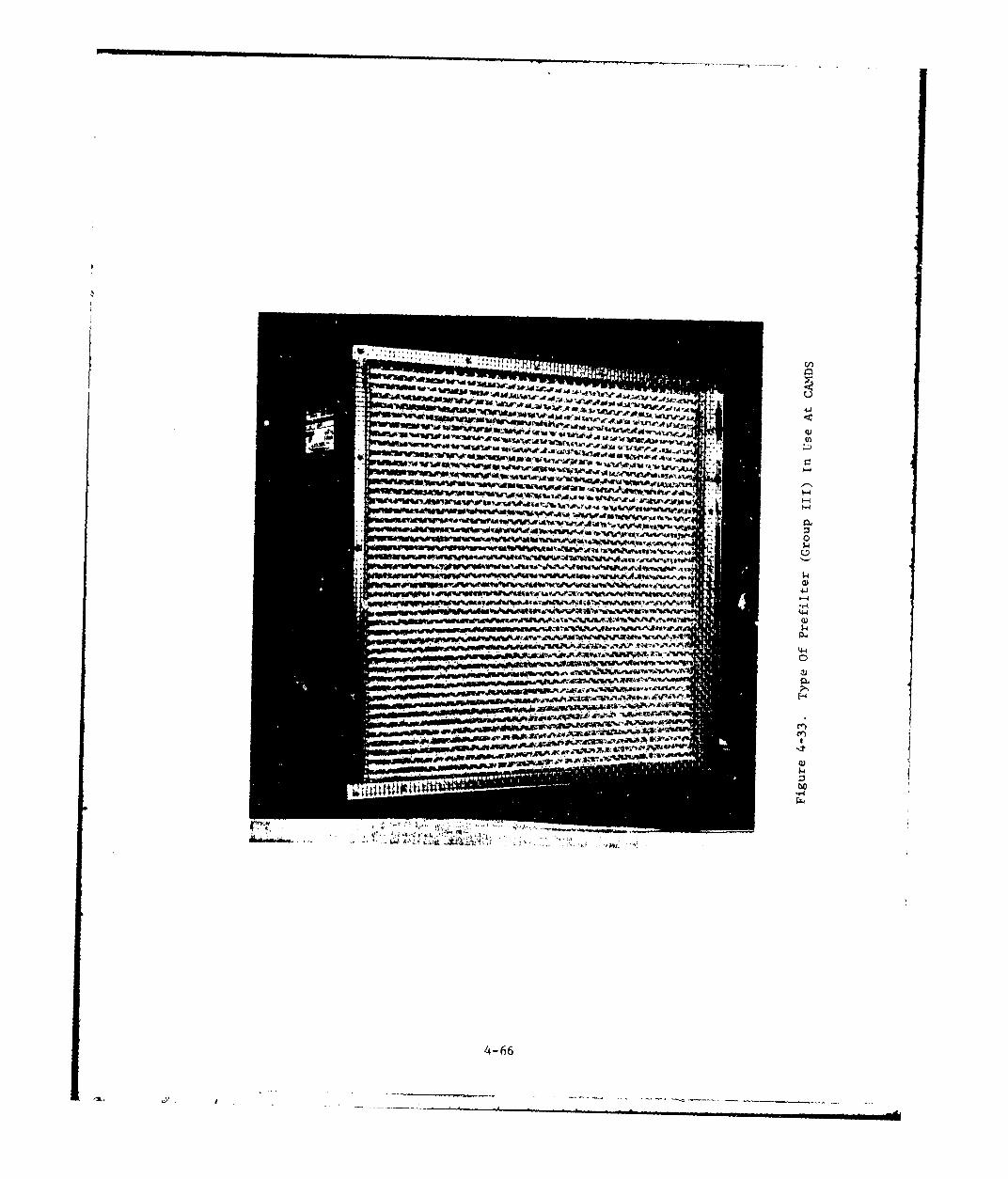
w cj~
- -0
-I - w ..- &TO
"V~r~w $4
ý04 lo I
4-66
was specified for use at CAMDS. This design permits "bayo-et" typeinstallation, with sealing at the backside of the flange as shownin figure 4-34. The prefilter meeting this requirement and finallyselected for CAMDS was the Model BC8I-NL filter manufactured byFlanders Filters, Inc., Washington, North Carolina. This specificmodel was chosen primarily because it offers the proper flangingconfigurAtion for incorporation into the clamping arrangement designedby the filter housing manufacturer.
The filter was obtained by specifying the type, class, group,and efficiency and then letting the filter housing manufacturer (CTI-Nuclear, Inc., Denver, Colorado) procure it to ensure compatibilitywith the mounting frames. The Model BC81-NL filter is classified asGroup III, dry disposable, 80% minimum efficiency1 5 , UL Class 1.17Its maximum dimensions are 24 in. x 24 in. x 11-1/2 in., and it israted at 1,000 cfm at 0.55 in. pressure drop. Critical pressure-dropvalues supplied by the manufacturer for the Model BC8I-NL prefilterare as follows:
1. Clean-filter differential pressure, 0.55 in. wg.*
2. Recommended differential pressure for changeout, 2.0in. wg.
3. Maximum differential pressure at which prefilter can besafely used, 5.0 in.
4.1.3.1.9. Installation
Prefilter framing and support equipment
in the CAMDS units were furnished by the housing manufacturer as anintegral part of the filter housing. Prefilter mounting frames aredesigned for horizontal airflow. For ease of maintenance, the mountingframes in the type II housings limit prefilter installation to amaximum height of seven feet above the walking surface. Each prefilteris independently clamped in place at a minimum of four pressure points.Cownon bolting at four pressure points is also acceptable although itwas not used at CAMDS.
The filters are mounted on the downstream side of the mountingframes since there is less contamination of the filter casing on thisside.
*Actual differential pressure experienced at CAMDS for clean prefilters
at rated airflow was 0,2 to 0.4 in. wg.
4-67

"-,4 )
COJI-
lim p -4 i
-IN 4-jO
44
4)c
04 )
s-,
73-4
"44
4-68
4.1.3.1.10. Visual Inspection
The following visual inspectionsshould be made of the prefilters before and/or after installation:
1. Prefilters
a. Damage to or deterioration of shipping carton.This is the first indication of shipping and/orstorage damage. If found, the enclosed filtersshould be closely examined for possible damage ordeterioration.
b. Damage to media, case, or gaskets.
c. Proper identification.
.d. Adherence to specification requirements.
e. installed with pleats vertical.
2. Mounting Frames
a. Squareness of members, flatness, and condition ofcomponent seating surfaces.
b. Continuous seal-weld between members of frame andbetween frame and housing. (Sealant must not be'used in these areas.)
C. Structural rigidity.
d. Damage to frames.
3. Filter Clamping Devices
a. Proper adjustment (50 to 80%. gasket
compression all around; tighten if less).
b. Sufficient number of clamping points (at leastfour per filter) and adequate size to produce uni-formity of gasket compression.
c. Proper condition of clamping devices (e.g., allnuts in place and tightened).
4-.69
d. Adequate clearance between filters to grasp them
and to tighten clamping devices on all sides.
e. High quality welds and freedom from cracks.
4.1.3.1.11. Changeout Frequency
Pressure drop (or resistance) is the
primary factor in prefilter replacement. The prefilter is instrumentedwith a differential pressure gage to measure the pressure dropacross the filter bank. A large increase in differential pressureindicates the filter cell is plugged and requires changeout. Adecrease in differential pressure indicates that the prefilter has ahole, tear or leak which also requires filter replacement. It isrecommended that the pressure drop be checked and recorded daily toprovide a history of differential pressure data as a guide for futureoperation and servicing.
Changeout should occur when the maximum allowable pressure dropsuggested by the manufacturer is reached. A key factor in determiningchangeout time is the ability of the fan to maintain the required flowat the higher AP. If the fan is sufficiently oversized and the filters
are capable of withstanding the overpressure, changeout can occur at ahigher value rather than the recommended value. The manufacturer'srecommended value is not necessarily when filter efficiency decreases,but rather the point above which the filter will clog up (i.e., increase
its AP) at a much faster rate for a given amount of contaminationretained.
As prefilters partially clog due to a buildup of contamination onsurfaces, some types (including those used in CAMDS) become moreefficient. Since the replacement cost of the prefilter itself isminimal compared to the labor cost and downtime involved in changeout,and since efficiency is actually increased, it is beneficial to useprefilters for as long as possible. They must be periodicallyinspected, however, because cell deterioration may become a problemwith prolonged usage in some cases. Any sudden large variation inpressure drop indicates a potential problem and should be investigatedimmediately.
Operation at airflow levels below the manufacturer's ratedcapacity extends filter life and reduces changeout frequency. Forthis reason an oversized housing (i.e., one designed to hold morefilters than required to obtain the system design airflow) shouldhave extra filter cells installed in the mounting frames instead ofusing blankoff plates. For example, at CAMDS, the 3,000- and6,000-cfm housings are exactly the same. The actual flow througheach prefilter in a 3,000-cfm unit is 500 cfm (50% of its rated
capacity of 1,000 cfm) which should extend its life considerably.
4-70
.'---. ------ ---777777-a -
4.1.3.2. HEPA Filters
4.1.3.2.1. Definition and Function
A HEPA fflter is defined18 as "athrow-away, extended-media, dry-type f:lter in a rigid frame havinga minimum particle-collection efficiency of 99.97% for 0.3-micron,thermally-generated particles; a maximum clean-filter pressuredrop of 1.0 in. wg when tested at its rated airflow capacity; andmaximum flow velocity of 5 fpm through any part of its medium whenoperating at its rated airflow.
The function of the HEPA filter is to remove submicron particulatesat extremely high efficiency, preventing their escape to theatmosphere and protecting downstream adsorber cells from becomingclogged or contaminated with particulate matter. Normally, thereare two banks of HEPA filters installed in each housing. The firstbank, installed between the prefilter and adsorber banks, removessolid particulates and aerosols that penetrate the prefilter. Thesecond HEPA bank, located downstream from the adsorber banks, capturescarbon dust escaping from the adsorber media and serves as a backupin case of failure of the first HEPA filter stage.
4.1.3.2.2. Performance and Construction
There are three types of HEPA filterswith respect to performance: 1 8 (1) type A, tested through the filterface for overall penetration (i.e., 100 minus percent efficiency) atrated flow only; (2) type B, tested for overall penetration at ratedflow and also at 20% of rated flow to disclose pinhole leaks that donot show up in the 100. flow test; and (3) type C, scanned filtersinvolving a special leaktest.
The most stringent performance requirements are obtained byspecifying that the filter units satisfy both types B and C. Figure4-35 shows siveral ccnstruction details of HEPA filters and tableIV-9 lists typical characteristics. 7
4-71
-_°

RIVETED OR BOLTEDCORNERS
FA£JEP LANGE
CONMER JOINTSTEEL CASED NEPA FILTER DETAIL
CONTINUOUS SHEET OF NAIL OR SCREW --.
PAPER PLEATED BACK FROM EACH FACE iAND FORTH OVER COR-RUGATED SEPARATORS
RABSETED
3'4-,T THICK _111' CORNERA.A EXTERIOR DETAILPLYWOOD OR-' " I
00OO .PARTICLE 3/4 in
bOARD
CORRUGATEDSEPARATORS
WOcCASED "EPA FILTER NOTCHED
Figure 4-35. Construction Details Of Open-Face HEPA Filters(Courtesy Of U. S. Department Of Energy)
4-72

7Table IV-9. Typical Characteristics of Open-Face HEPA Filters
ilter Size Nominal Airflow Approximate Overall Weight
(in.) Capacity (a) of Filter (lb.)(in.) (cfm) Wood Case Steel Case
8x 8 x 3-1/6 25 2 3
8x 8 x 5-7/8 50 3.6 5.8
12x 12 x5-7/8 125 4.8 7.3
24 x 24 x 5-7/8 500 17 22
24 x 24 x 11-1/2 1000 32 40
(a) These airflow capacities are recommended for design purposes only.
Some newer filters constructed to these dimensions are rated at
airflows 25 to 50% higher at a maximum pressure drop of 1.0 in. wg.
Construction grades are used to indicate a level of fireresistance and are classified as Grades 1 and 2. Grade I is comprisedof fire-resistant construction throughout meeting the requirementsof UL Standard 90017; Grade 2 is semicombusttble with noncombustiblemedia; separators, frame, or both are made from combustible material.
Consult references 7, 18, 20, and 21 for ad~itional details onthe performance and construction of HEPA filterv.
4.1.3.2.3. Selection
For logistical reasons, HEPA filtersof standard design are generally preferred However, the importantadvantage of simplified installation may be of overriding considerationeven if it involves the disadvantage of a special filter desigu. Forthis reason, a special-type filter with sealing flange on one faceonly was specified for use at CAMDS (figure 4-36). This design per-mits "bayonet" type instailation, with sealing at the backside ofthe flange as depicted in figures 4-22, 4-37, and 4-38. The HEPAfilter meet~ig this requirement and finally selected for CAMDS wasSUPER-FLOW UModel 7081-NL filter manufactured by Flanders Filters,Inc., Washington, North Carolina. This specific model was chosenprimarily because it offers the desired flanging configuration forincorporation into the clamping arrangement designed by the filterhousing manufacturer.
4-73
•: • • J I - _ ; _ _ • -

7-7
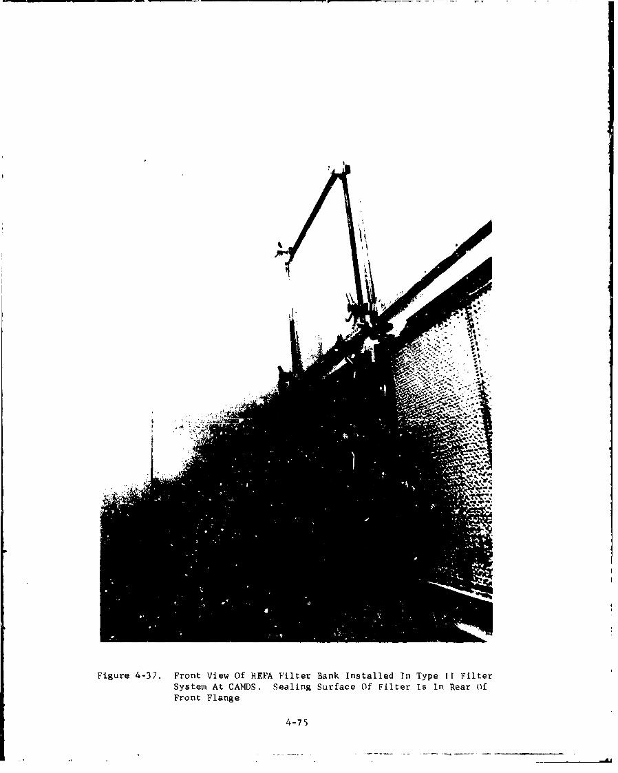
Figure 4-37. Front View Of HEPA Filter Bank installed In Type IT FilterSystem At CAMDS. Sealing Surface Of Filter Is in Rear ofFront Flange
4-75
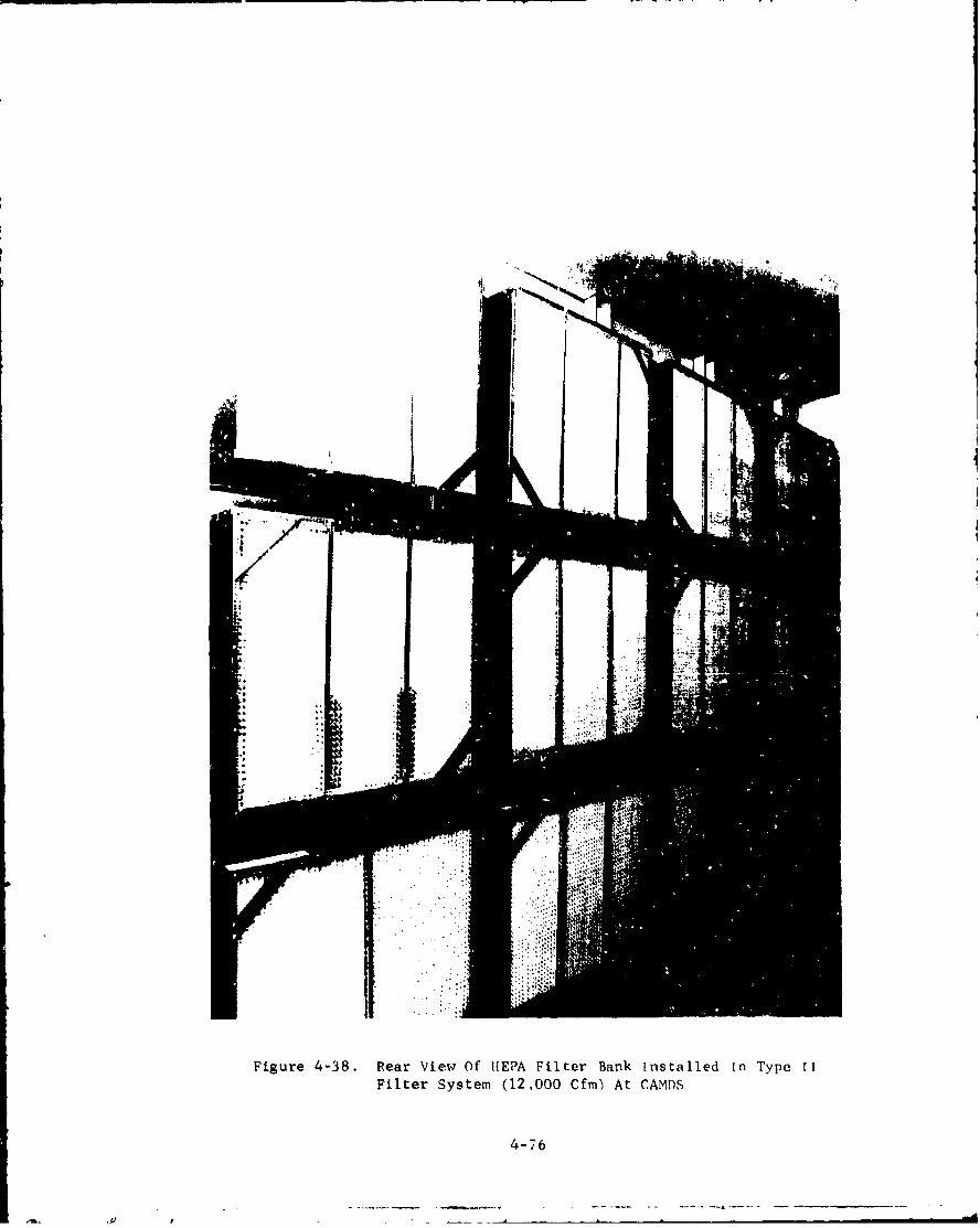
Figure 4-38. Rear View Of IIEPA Filter Bank installed in Type 11Filter System (12,000 Cfm) At CAMDS
The filter was obtained by specifying the type, class, group,and efficiency .nd then allowing the filter housing manufacturer(CTI-Nuclear, Inc., Denver, Colorado) procure it. The Model. 708-NLfilter is classified as Grade I meeting type B and type C requirementsof AACC CS-1, 1 8 with steel frames and no separators. It is rated at
1,500 cfm and measures a standard 24 in. x 24 in. x 11-1/2 in.
The SUPER-FLOW model was selected because of its advertisedcapacity of 1,500 cfm (as compared to 1,000 cfm for the regulermodel). Since the ventilation system is designed for only 1,000-cfm airflow through each filter cell, it is expected that the SUPER-FLOW units, by operating at less than capacity, will last significantlylonger than the regular model.
Critical pressure-drop values supplied by the manufacturer forthe Model 7081-NL HEPA filter are as follows:*
1. Normal operating differential pressure for 1,500 cfm,1.2 in. wg.**
2. Recommended differential pressure for changeout,3.0 to 4.0 in. wg.
3. Maximum pressure differential at which HEPA filtercan be safely used, 10.0 in. wg.
4.1.3.2.4. Installation
For HEPA filters in the CAMDS units, allframing and support equipment were furnished by UL. housing manufactureras an integral part of the filter housing (figures 4-22, 4-37, and 4-38).HEPA filter mounting frames are designed for horizontal airflow. Forease of maintenance, the mounting frames in type II housings limit allparts of the filter installation to a maximum height of seven feetabove the walking surface. Each filter is independently clamped inplace at a minimum of four pressure points with the pleats runningvertically. Common bolting at four . :essure points is also acceptablealthough it was not used at CAMDS.
Filters are mounted on the downstream side of the mountingframes since there is less contamination of the filter casing on thisside.
*Actual differential pressure experienced et CAMDS foi clean HEPA
filters at rated airflow ranged from about 0.7 to 1.0 in. wg.
**The manufacturer recently changed the applicable pressure for thisrating from 1.0 in. wg to 1.2 in. wg.
4-77
,4 - . - - -- - -. - . e .-. -- - - - - -

4.1.3.2.5. Visual Inspection
The following visual inspectionsshould be made of HEPA filters before and after installation:
1. HEPA Filter
a. Damage to or deterioration of shipping carton.This is the first indication of ihipping and/orstorage damage. if found, the enclose~d filters bhouldbe closely eXamfined for possible damage or deterioration.
b. Damage to media, case, or gaskets.
c. Proper identification.
d. Adherence to specification requirements.
e. installed with pleats vertical.
2. Mounting Frames
a. Squareness of members, flatness, and condition ofcomponent seating surfaces.
b. Continuous seal-weld between members of frame andbetween frame and housing. (Sealant must not beused in these areas.)
c. Structural rigidity.
d. Damage to frames.
3. Clamping Devices
a. Proper adjustment (50 to 80% gasket compression allaround; tighten if less).
b. Sufficient number of clamping points (at least fourper filter) and adequate size to produce uniformityof gasket compression.
c. Proper condition of clamping devices (e.g., allnuts in place and tightened).
4-78
d. Adequate clearance between filters to grasp themand to tighten clamping devices on all sides.
e. High quality welds and freedom from cracks.
4.1.3.2.6. Changeout Frequency
After installation, pressure drop (orresistance) is the primary factor in HEPA filter replacement. TheHEPA filter is instrumented with a differential pressure gage tomeasure the pressure drop across the filter bank. A large increaseir, differential pressure indicates the filter cell is becoming pluggedand requires chargeout. A decrease in differential pressure indicatesthe fitter has a hole, tear or leak which also requires corrective action.It is recommended that the pressure drop be checked and recorded dailyto provide a history of differential pressure data as a guide for futureoperation and servicing.
Changeout should occur when the maximum allowable pressure dropsuggested by the manufacturer is reached. A key factor in determiningchangeout time is the ability of the fan to maintain the required flowat the higher AP. If the fan is sufficiently oversized and the filtersare capable of withstanding the overpressure, changeout can occur at ahigher value rather than the recommended value. The manufacturer'srecommended value is not necessarily when filtur efficiency decreases,but rather the point above which the filter will clog up (i.e., increaseits AP) at a much faster rate for a given amount of contaminationretained.
As HEPA filters partially clog due to a buildup of contaminationon their surfaces, some types (including those used at CAMDS) becomemore efficient. Since the replacement cost of the filter itself isminimal compared to the labor cost and downtime involved in changeout,and since efficiency is actually increased, it is beneficial to useHEPA filters for as long as possible. They muct be periodicallyinspected, however, because cell deterioration miy become a proble'.with prolonged usage in some cases. Any sudden large variation inpressure drop indicates a potential problem and should be investigatedimmediately.
Operation at airflow levels below the manufacturer's ratedcapacity extends filter life and reduces changeout freqiiency. Forthis reason an oversized housing (i.e., one designed to hold morefilters than required to obtain the system design airflow) shouldhave extra filter cells installed in the mounting frames instead ofusing blankoff plates. For example, at CAMDS, the 3,000 and 6,000-cfmho--sings are exactly the same. The actual flow through each HEPA filterin a 3,000-cfm unit is 500 cfm (33% of its rated capacity of 1,500 cfm)which should extend its life considerably.
4-79

No excess HEPA filters are installed in the second bank, onlythe required amount (i.e., three blankoff plates are used in the3,000-cfm units) since it is anticipated that very little con-tamination will reach this bank. Therefore, changeout of the HEPAfilters in the second bank will be based on total life rather thanon level of contamination.
Refer to section 6.4 for additional irformation on filter
replacement.
4.1.3.3. Adsorber Cells
4.1.3.3.1. Description
Adsorber cells consist of two bedscontaining an adsorbent, such as activated carbon, used for removingcontaminant gases or vapors from the air.
The types of adsorber cells considered for chemical demiloperations are intended for very high-efficiency air-cleaningservice and not for common industrial applications. Adsorber cellsfor this purpose are classified as (1) type I pleated-bed units(previously used in the nuclear field but now becoming obsolete);(2) type II modular type units (now used extensively in the nuclearfield), which meet the design, dimensional, filling, and test require-ments of AACC CS-81 0 ; and (3) type III stationary gasketless adsorbers(also known as Permanent Single Units), permanently installed units inwhich only the adsorbent is changed; it is a relatively new concept.Since the type I unit is on the verge of obsolescence for high-efficiency applications, this discussion is limited to type II andtype III stationary adsorber versions.
4.1.3.3.1.1. Type II Adsorber Cell
The type II high-efficiency,gas-phase adsorber cell is defined1 0 as a modular container for anadsorbent with provisions for sealing to a mounting frame for usesingly or in multiples to construct a system of a specified airflowcapacity. It is a flat-bed or tray-type configuration as shown infigures 4-39, 4-40, and 4-41. At present, the cell is considered asdisposable for CAMDS use after removal from service, even though itis designed for refill; the economics of refill and reuse are beinginvestigated at CAMDS.
The type II adsorber cell consists of two individual paralleladsorbent beds, nominally two inches thick, spaced approximately twoinches apart, The beds are enclosed by a nonperforated casing onthree sides and a solid face plate, except for the air slot, with aneoprene gasket on the fourth side. Covering the top and bottom ofeach half are perforated screens of No. 26 US Standard gage with a 30%minimum open area. 4-80
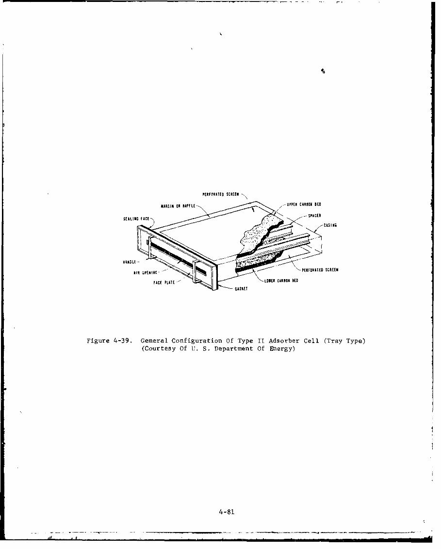
PERFORATED SCREEN N
MARGIN 01 1AFFL1--., UPPER CARSON SED
SEALNGAE SPICER•
AIR 0PENING -' PERFORATED SCREEN
FACE PLATE-- • LOWER CARSON IED
GASKET
Figure 4-39. General Configuration Of Type II Adsorber Cell (Tray-Type)(Courtesy Of U. S. Department Of Energy)
4-81
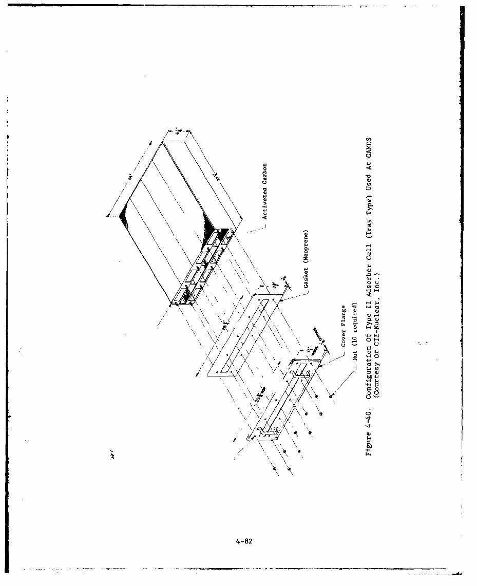
0
U4J3
'-4 $
0 Q
oCo
000
-,4
I4.4
4-82
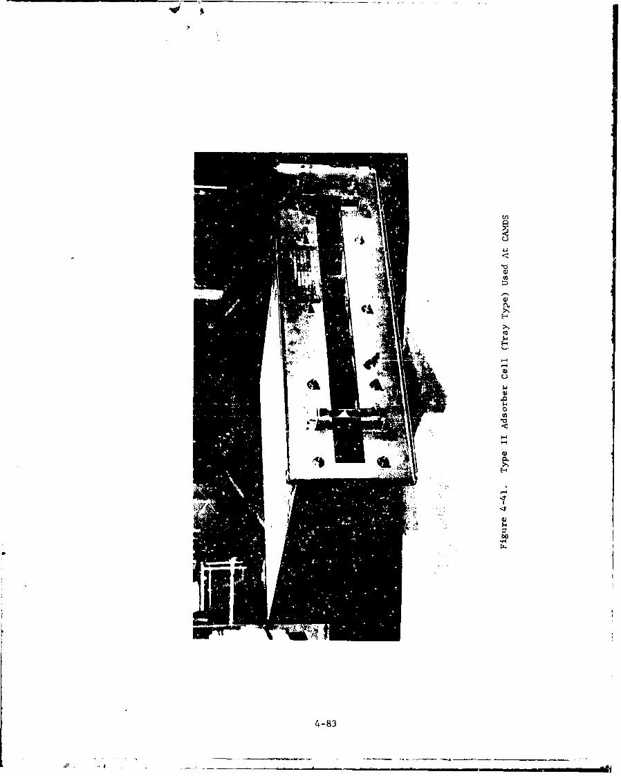
U)
4-i*1�
U,a,
4)
S..,H
CUs-IH'-S
'-4-44)U
0a,
4:
-4
a)Os
H
'-44.4
4)$4
to"-4
S
4-83
----- 4-----
-'I �- -- -a-
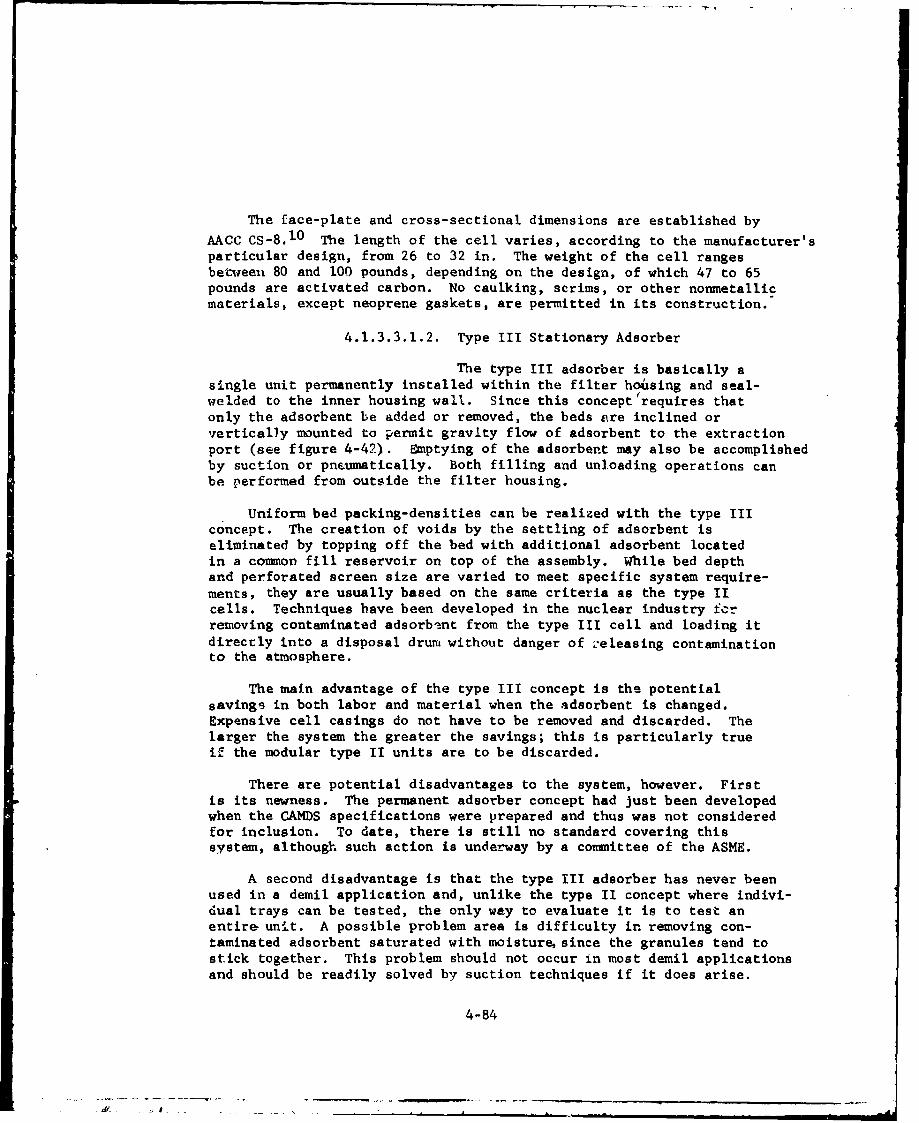
The face-plate and cross-sectional dimensions are established by
AACC CS-8. 1 0 The length of the cell varies, according to the manufacturer'sparticular design, from 26 to 32 in. The weight of the cell rangesbetween 80 and 100 pounds, depending on the design, of which 47 to 65pounds are activated carbon. No caulking, scrims, or other nonmetallicmaterials, except neoprene gaskets, are permitted in its construction.
4.1.3.3.1.2. Type III Stationary Adsorber
The type III adsorber is basically a
single unit permanently installed within the filter housing and seal-welded to the inner housing wall. Since this concept'requires thatonly the adsorbent be added or removed, the beds are inclined orvertically mounted to permit gravity flow of adsorbent to the extractionport (see figure 4-42). Emptying of the adsorbent may also be accomplishedby suction or pneumatically. Both filling and unloading operations canbe performed from outside the filter housing.
Uniform bed packing-densities can be realized with the type IIIconcept. The creation of voids by the settling of adsorbent iseliminated by topping off the bed with additional adsorbent locatedin a common fill reservoir on top of the assembly. While bed depthand perforated screen size are varied to meet specific system require-ments, they are usually based on the same criteria as the type IIcells. Techniques have been developed in the nuclear industry fcrremoving contaminated adsorbent from the type III cell and loading itdirectly into a disposal drum without danger of releasing contaminationto the atmosphere.
The main advantage of the type III concept is the potentialsavings in both labor and material when the adsorbent is changed.Expensive cell casings do not have to be removed and discarded. Thelarger the system the greater the savings; this is particularly trueif the modular type II units are to be discarded.
There are potential disadvantages to the system, however. Firstis its newness. The permanent adsorber concept had just been developedwhen the CAMDS specifications were prepared and thus was not consideredfor inclusion. To date, there is still no standard covering thissystem, although such action is underway by a committee of the ASME.
A second disadvantage is that the type III adsorber has never beenused in a demil application and, unlike the type II concept where indivi-dual trays can be tested, the only way to evaluate it is to test anentire unit. A possible problem area is difficulty in removing con-taminated adsorbent saturated with moisture since the granules tend tostick together. This problem should not occur in most demil applicationsand should be readily solved by suction techniques if it does arise.
4-84

_4
a. View of Downstream Face of Inclined-Bed pSU Adsorber
1h .....
4 1T1hsTTF!ff,.I ...~ ..
,1~~~ IL Ft~
b. Airflow Through Typical Vertical-Bed PSU Adsorber
Figure 4-42. Type III Stationary Adsorber
(Courtesy of U. S. Department of Energy)
4-85
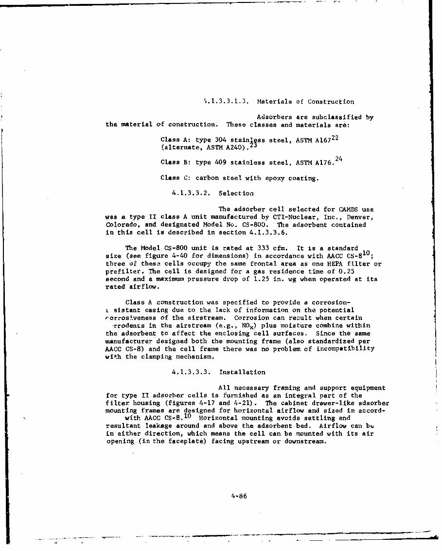
'i.l.3.3.1.3. Materials of Construction
Adsorbers are subclassified bythe material of construction. These classes and materials are:
Class A: type 304 stainlpss steel, ASTM A167 2 2
(alternate, ASTM A240).23
Class B: type 409 stainless steel, ASTM A176. 2 4
Class C: carbon steel with epoxy coating.
4.1.3.3.2. Selection
The adsorber cell selected for CAMDS usewas a type II class A unit manufactured by CTI-Nuclear, Inc., Denver,Colorado, and designated Model No. CS-800. The adsorbent containedin this cell is described in section 4.1.3.3.6.
The Model CS-800 unit Is rated at 333 cfm. It is a standardsize (see figure 4-40 for dimensions) in accordance with AACC CS-8 1 0 ;three of these cells occupy the same frontal area as one HEPA filter orprefilter. The cell is designed for a gas residence time of 0.25second and a maximum pressure drop of 1.25 in. wg when operated at itsrated airflow.
Class A construction was specified to provide a corrosion-i sistant casing due to the lack of information on the potentialrorrosiveness of the airstream. Corrosion can reoult when certain
rrodenLs in the airstream (e.g., NOx) plus moisture combine withinthe adsorbent to affect the enclosing cell surfaces. Since the samemanufacturer designed both the mounting frame (also standardized perAACC CS-8) and the cell frame there was no problem of incompatibilitywith the clamping mechanism.
4.1.3.3.3. Installation
All necessary framing and support equipmentfor type II adsorber cells is furnished as an integral part of thefilter housing (figures 4-17 and 4-21). The cabinet drawer-like adsorbermounting frames are designed for horizontal airflow and sized in accord-
with AACC CS-8.I 0 Horizontal mounting avoids settling andresultant leakage around and above the adsorbent bed. Airflow can bein either direction, which means the cell can be mounted with its airopening (in the faceplate) facing upstream or downstream.
4-86
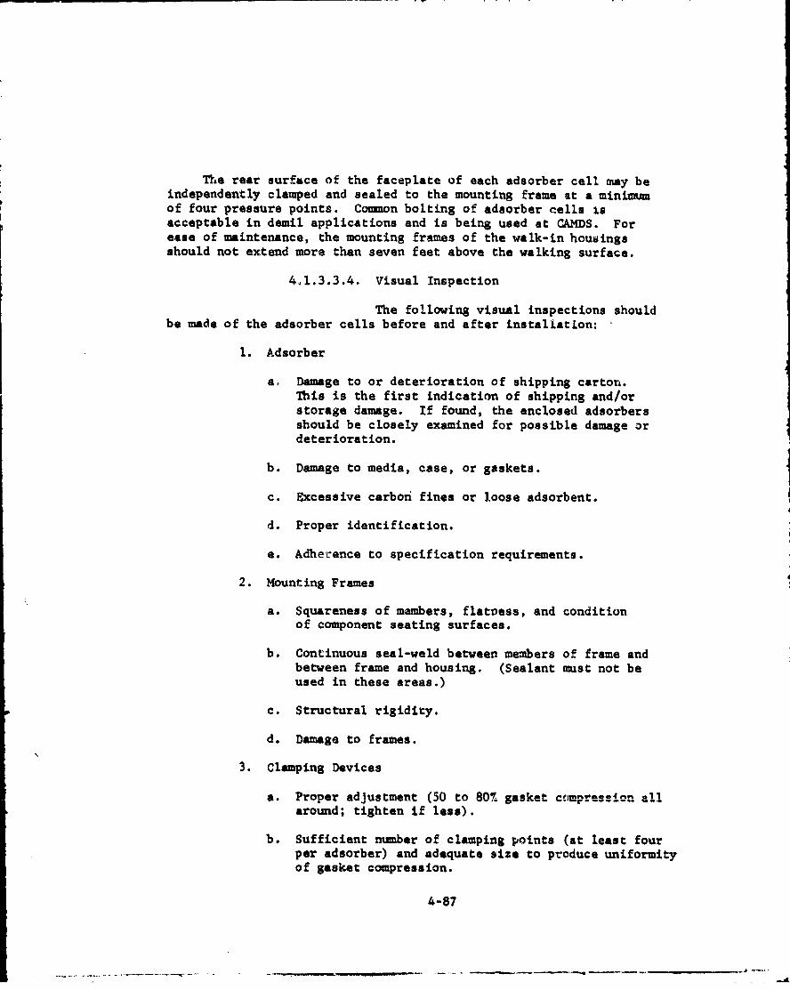
The rear surface of the faceplate of each adsorber cell may beindependently clamped and sealed to the mounting frame at a minimumof four pressure points. Common bolting of adaorber cells isacceptable in demil applications and is being used at CAMDS. Forease of maintenance, the mounting frames of the walk-in housingsshould not extend more than seven feet above the walking surface.
4.1.3.3.4. Visual Inspection
The following visual inspections shouldbe made of the adsorber cells before and after installatLon:
1. Adsorber
a. Damage to or deterioration of shipping carton.This is the first indication of shipping and/orstorage damage. If found, the enclosed adsorbersshould be closely examined for possible damage ordeterioration.
b. Damage to media, case, or gaskets.
c. Excessive carbon fines or loose adsorbent.
d. Proper identification.
e. Adherence to specification requirements.
2. Mounting Frames
a. Squareness of members, flatress, and conditionof component seating surfaces.
b. Continuous seal-weld between members of frame andbetween frame and housing. (Sealant must not beused in these areas.)
c. Structural rigidity.
d. Damage to frames.
3. Clamping Devices
a. Proper adjustment (50 to 80% gasket ctimpression allaround; tighten if less).
b. Sufficient number of clamping points (at least fourper adsorber) and adequate size to produce uniformityof gasket compression.
4-87

c. Proper condition of clamping devices (e.g., allnuts in place and tightened).
d. Adequate clearance between adsorbers to grasp themand to tighten clamping devices on all sides.
a. High quality welds and freedom from cracks
4.1.3.3.5. Changeout Frequency
Although the CAMS adsorber banks areinstrumented with differential pressure gages, pressure drop isnot a factor in adsorber replacement. The actual changeout of theadsorber cells in the first bank is based upon readout of the agentmonitor located between the two adsorber banks.
Refer to section 6.4 for additional information on adsorberreplacement.
4.1.3.3.6. Adsorbent
The adsorbent is the material in theadsorber cells which removes gases or vapors from the airstream toprevent their escape into the atmosphere. Agent capture is accomplishedby physically retaining the gaseous molecules or, if the adsorbent isimpregnated, by chemical reaction, depending upon the type of chemicalagent involved. The adsorbent shall be coal-base or coconut-baseactivated carbon meeting the specifications 14 sced below.
Specification Value Test Used
Iodine Number, Minimum* 1,000 MIL-C-1372425
Carbon Tetrachloride Adsorption,Minimum, 7, Weight* 59 ASTM D2652 2 6
Ash, Maximum, % 8.0 MIL-C-13724
Total Volatiles (150 0 C + 500 C for 4.0 MIL-C-037243 hours), %
Hardness Number, Minimum 90 MIL-C-13724
Apparent Density (Bulk Density, DensePacking), Minimum, g/cc 0.48 MIL-C-13724
Packed Column Test (To determine 0.4 CSL in-housa test planmaximum total capacity of GB agentretained on adsorbent), Mininun,grams agent/grams adsorbent.
*Both of these tests are not required. The Carbon Tetrachloride Adsorption
Test is preferred but the Iodine Number Test may be run as an alternative.
4-88
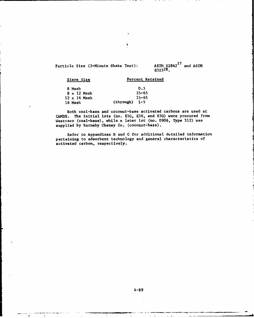
Particle Size (3-Minute Shake Test): ASTM D286227 and ASTME323 28 .
Sieve Size Percent Retained
8 Mesh 0.58 x 12 Mesh 35-65
12 x 16 Mesh 35-651.6 Mesh (through) 1-5
Both coal-base and coconut-base activated carbons are used atCAMDS. The initial lots (no. ElG, E36, and 63G) were procured fromWestvaco (coal-base), while a later lot (no. 0906, Type 512) wassupplied by Barneby Cheney Co. (coconut-base).
Refer to Appendixes B and C for additional detailed informationpertaining to adsorbent technology and general characteristics ofactivated carbon, respectively.
4-89
- - . -- -- -- -a - a..-a-- .. A
4.2. Ventilation System Design Criteria
This section presents design criteria and guidelines forplanning the air-ventilation system to be served by the filter/adeorber system described earlier. Design information is providedon hoods, ducts, airlocks, fans, dampers, ancillary equipment, andother pertinent factors.
At this point, a review of various ventilation design considerationsbased on CAMDS experience might be helpful.
1. if the demil operation is such that agent release atlow concentrations is likely in routine operationsand there is a possibility of high concentrationsuinder upset conditions, containment should beprovided by the toltowing techniques:
a. Surround the area by a toxic enclosure. Entry toand exit from the toxic enclosure should be througha double-door airlock with decontamination shower.The toxic enclosure should be constructed inside anouter enclosure to prevent wind pressure frombearing directly on the walls of the toxic enclosure.A building with coverings on both the outside andinside of the framing can simultaneously provideouter and inner enclosures. The internal surfaces of
the toxic enclosure must be free from cracks or
crevices and be easily decontaminated.
b. Toxic enclosures should be ventilated with sufficientairflow to provide at least 0.1 in. wg negativepressure with respect to the atmosphere. The amountof airflow required to obtain the specifiednegative pressure depends on how well the buildingis sealed; the greater the leakage, the greater theamount of ventilation required.
c. If any operation within a toxic enclosure is likelyto produce relatively high vapor concentrations orexpose liquid agent, localized exhaust ventilationmust be provided to contain the contamination inthe smallest area possible.
2.If the operation is such that agent release even atlow concentrations is possible but unlikely, the areashall be sufficiently ventilated to assure minimumcontinuous airflow.
4-90
At CAMDS all toxic enclosures are within an outer enclosure thatprotects against wind effects. The tox4 c enrlosure areas (work rooms)are designed for 0.10 to 0.15 in. wg negative pressure. Actualtesting by AEHA indicated that at least one area, the ECC, actuallymaintained 0.3 in. wg negative pressure. tro hydraulic or pneumaticmechanisms are required to open doors in any of the negative pressurefacilities of CAMDS.
4.2.1. Hoods
There are three major types of exhaust hoods: (1)enclosing hoods, (2) capturing hoods, and (3) receiving hoods. En-closing hoods surround toxic-gas operations as completely as possible,with openings limited to those needed to provide access to performthe operation. Capturing hoods are shaped inlets designed to capturecontaminaced air, while receiving hoods control processes that throwa stream of contaminants in a specific direction. Receiving hoodsare normally not used for highly toxic materials and therefore arenot discussed here. Since local-exhaust systems require that hoodsretain or capture contaminants, hood design and location are criticalin making the ventilation system work properly.
4.2.1.1. Enclosing Hoods
Contaminants are retained in enclosures by airflowing through the openings. Face velocity is an important parameterin this regard. The face velocity must be adequate to prevent cross-drafts or other room air currents from drawing contaminants out ofthe hood. For chemical agents a minimum inward velocity of 150 fpmis required. If enclosures are used to control processes where agentis actively generated by heat or mechanical agitation, the openingsshould be away from the path of contaminant travel, and the inwardface velocities should be 200 to 500 fpm. Enclosure openings shouldbe located away from sources of crossdrafts which have a velocitythat might exceed 20 percent of the hood-face vecocity.
The quantity of air handled is calculated by multiplying theface velocity by the area of the openings, that is:
Q = V xA (1)
where:
Q - airflow volume, cfmV - face velocity, fnmA - area of hood opening, ft 2
4-91
The more complete the enclosure, the more economical and effectivethe installation will be. Openings are kept to a minimum by
providing access to the operation through glove ports and windows forobservation. See figure 4-43.
Two other considerations in selecting airflow are: (1)temperature increase if a heat source is enclosed, and (2) maintainingthe concentration of combustible gases or aerosols below the lower
explosive limit (LEL). If air expands due to heat after it entersthe hood, a large volumg of air must be exhausted to maintain theface velocity selected. To calculate the flow necessary to maintainconcentration below LEL, use the formula:
cubic feet of air _ . 387)(100)(C) (2)pounds of material evolved (moleckilar weight)(B)(LEL)
where:C = safety factor representing excess air to dilute below
LEL; usual value is 4.
B = collection factor for high temperature= i 250°F
0.7 >250 0 F
Refer to reference 4 (pages 2-1 and 2-2) for background infor-
mation regarding the above formula.
4.2.1.2. Capturing Hoods
Capturing hoods are less effective than enclosinghoods because control is easily disrupted by crossdrafts. They are
recommended only when it is impossible to enclose the operation.Airflow through capturing hoods must be adequate to achieve the desired
capture velocity, and it must be distributed over the entire zone into
which contaminant is being generated. To be effective, capturing hoodsmust be close to the operation serviued, within at least two feet. 4
For chemical agents, the capture velocity must be at least 150 fpm,and 200 to 500 fpm if agent is being activ'ely generated. Airflow throughthe hood is based in the capture velocity selected and the distance of the
hood from the operation. The equations used are listed in table IV-IO.Proper distribution of capture velocity is achieved by adding flanges, slot3,
or splitter vanes, and by tapering the hood (see sidedraft and suspended
hoods shown in figure 4-44). Flanges improve the efficiency of hoods by
causing air to be drawn more from the front of the hood. Slots in a
pLenum chamber distribute aic uniformly if (1) slot velocity is twice
plenum velocity, and (2) slot width does not exceed 20 percent of slot
length. Splitter vanes channel airflow to different parts of the hood.A gradual taper allows air to be drawn in from the entire hood face.
4-92
-. . . . - -

441
'-r4
-'-44
44-9
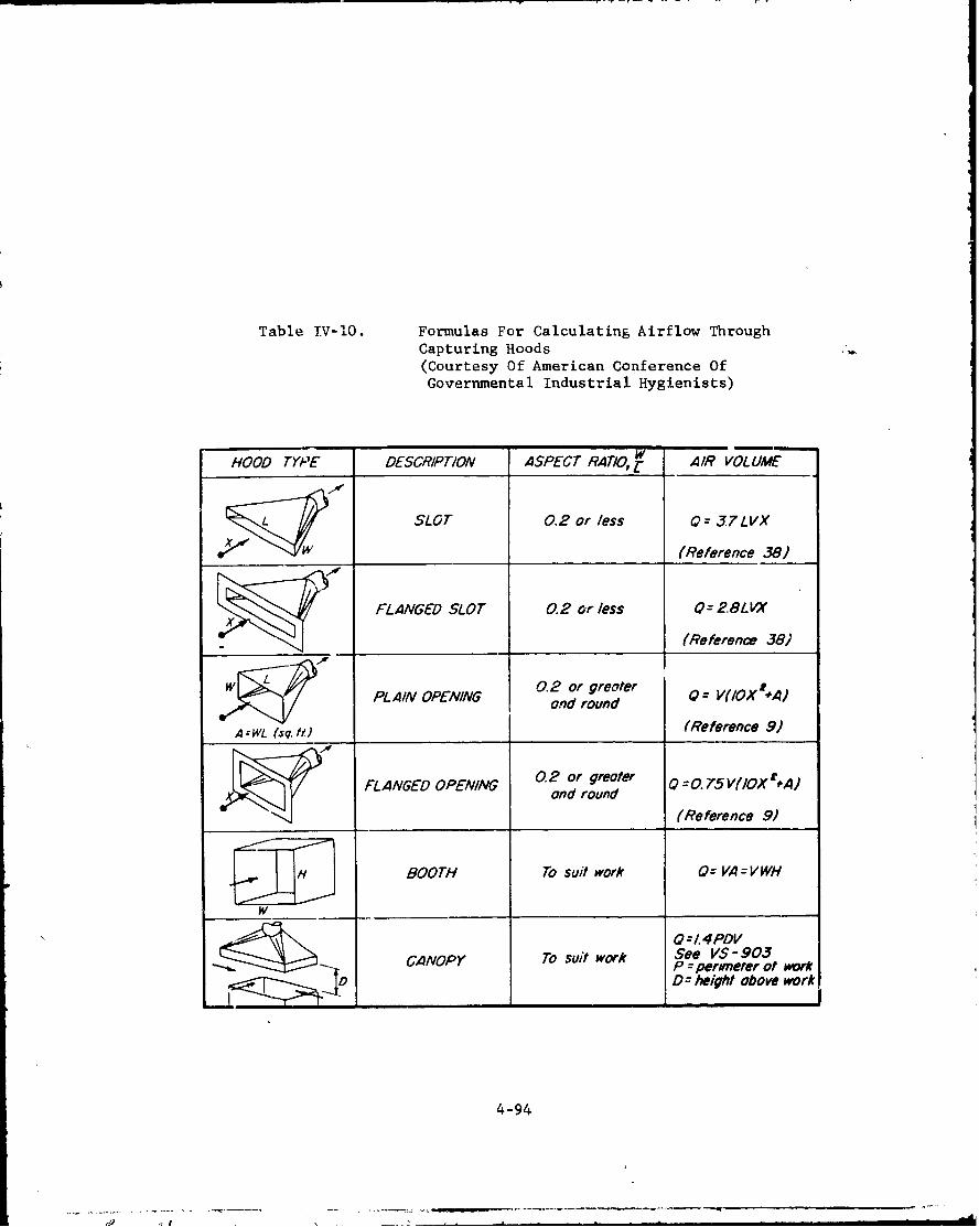
Table IV-IO. Formulas For Calculating Airflow ThroughCapturing Hoods
(Courtesy Of American Conference OfGovernmental Industrial Hygienists)
HOOD TYPE DESCRIPTION ASPECT RATIO, A IR VOLUME
SLOT 0.2 or less 0=J7LVX
(Reference 38)
FLANGED SLOT 0.2 or less 0= 2.8LVX
(Reference 38i
0 A. 2 or greater = V(IOX "'A)SPL AIN OPENING nrud
A --WL (sq. fl) (Reference 9)
FLANGED OPENING 0 or greoter Q = . 75V(IOX't A)and round(Reference 9)
BOOTH To suit work O= VA--VWH
Q:/4PDVCANOPY To suit work See VS - 903
P = perimeter of workDZ height above work
4-94

DISTRIBUTION BY BAFFLES
LONG 800 THS- DISTRIBUTION BY MUL TIPLE TAKE - OFFS and TAPERSBOO TH- TYPE HOODS
( Some principle opply to canopy fype)
Slof ve.I, /y2 AO fpm ur higher.
DISTRIBUTION BY DISTRIBUTION BY DISTRIBUTION BY TAPERSPLITTER VANES SLOT (or baffles)
SIDE-DRAFT a SUSPENDED HOODS
AMERICAN CONFERENCE OF
GOVERNMENTAL INDUSTRIAL HYGIENISTS
PRINCIPLES OF MANIFOLD DESIGNN
DATE 1-64 I
Figure 4-L4. Princip]es Of Manifold Design For Capturing Hoods
(Courtesy Of American Confc nce Of Governmental Industrial Hygienists)
4-95
The included taper angle should be about 300 but not greater than 600.
See reference 4 for a more extensive discussion of capturing hoods.
4.2.2. Duct Design
This section outlines a method for designing the ductworkfor air-ventilation systems. The first step is to lay out thoseoperations to be locally exhausted and those areas that require generalexhaust ventilation, then develop data on each hood as to airflowrequirements, entry loss, minimum duct velocity, and the negativepressure to be maintained in regulated areas. Hood entry loss has twocomponents: (1) acceleration loss an6 (2) turbulence loss (figure4-45). The acceleration loss is equ . to the velucity pressure of theair stream when it reaches duct velc ity'. Velocity pressure iscalculated using the equation:
VP2VP =(_40052 (3)
where:VP = velocity pressure, in. wgV = air velocity in duct, fpm
phIpt ve1,loci tfy is ast~blisbed -Y Rizing the dtet (V = Q!A) in accord-
ance with referencs 4. Systems that handle dusts or mists requirea minimum transport velocity to prevent material from settling in theducts. Reference 4 provides minimum duct velocities for many materials.For systems that handle gases, duct velocities between 2,000 and3,000 fpm are usually selected as a compromise between constructioncosts and fan operating costs (i.e., relative to the AP seen by the fan).Since vapor contamination is the main problem at CAMDS, a transportvelocity of 1,800 to 2,000 fpm was established as a design criterion.Turbulence losses encountered by air as it enters the hood and othersystem components are a function of velocity and directly proportionalto velocity pressure. Hood entry loss factors are listed in reference4.
The duct system consists of a number of branch ducts connected tothe main duct for conveying the air from the hoods to the filter whenlocal exhaust ventilation is used. When general ventilation is used,the duct system consists of branch ducts connected to a main duct forconveying the air from different sectors of an area to the filter.There are basically two types of duct systems: (1) balanced system with-out blast gates, and (2) balanced system with blast gates.
4-96
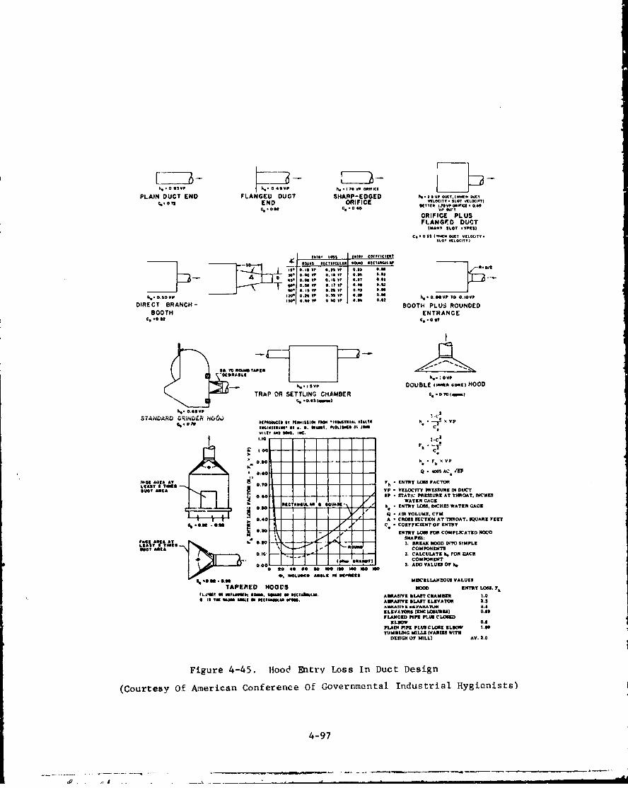
Z ZZ' 1 1 3-v r . 6 I D -v " il,.OSSVP kOSVP he .~Tv00WlCC~eK
PLAIN DUCT END FLANGEU DUCT SHARP-EDGED N- I IvP OIXT,.Iw1 0OMTC. OTT END ORIFICE VtLOCIT. $LOT VLOT)
%.oat C.ol -06 TTtR JJDP ORWN 10.
ORIFICE PLUSFLANGED DUCT
INAPT SLOT rTPts)
Co. 0 0 I?'EN 51EV VILOCITY.SLOT VELOCIYT)
[%is, toll 0I10T C00IFICIEST
5to 0.10 uI, oSOIL So., m(Y.IUO
01• 0.06 VP 0.10 VP 0.,? *.0)00 0.00 VP 0.1? VP 0.0 0.503. !.60 vp 0.21 vp i.V2 0.0-
I..~~~ 0.00 0.h.- O.0O vp 0'4 ITq~ a. Y No•t VP 4.8 0.62 0. of VP To 0. IOVP
DIRECT BRANCH- BOOTH PLUS ROUNDED
SOOTH ENTRANCE
TRAP CH BMBE
uSABL ~..ovphk. -Iv, DOUBLE lmmls 'oo')HOOD
TRAP OORl SETIGCHME .- o(OR 5 .008(m
%. P*? C* 9 IT PI[0ISS0115 P 0 -INDUSTRIAL MCOLTM a .• VP0MIi(l110 IT *. S. 6•|. POLISMS IT J CWILlT £00 1001. ISA.
tows~ D0o I c,_e
S 0 . 00 h. P h )€V P
0: so - - Q 4005 AC.P
ow -"C.A AT r. ENTRY L,061 FACTORkLfAT I TONSO
DUCT I VP V VELOCITY PhEUURC IN DUCT0.U0T '- - -- P "STATIC PALEIURE AT THROAT, INCHES
WATER GAGE- og R SCA"SOU"Aa & SoUAU) 7 " ENTRY LOIS. INCHES WATER GAGE
- QAMI VOLUME, CIFM.40 A CROSS SECTIN AT THROAT. SUARaE rEErr
%.06 .0.09 C - CORIFFCEINT OF ENTRY
I NTRY LON MR COMPLICATED HOODOtLIM T A Slt T • • / " lý_4 OU IT I. BREAK HOOD INTOI SIMPLZ
SSC? ARIA E\ COMPONENTS
o.,[ -- .- I I s. CALCULATE k, rFOR rACH•OMIOKENI"
0I3 - 3 - -- -. ADD VALUES OF 4O 0 tO 40 0 0 * IO 1i40 IO
4A.96.1•0.76 MIICNLLA•OUS VALUESTAPERED HOODS NoO ENTRY LOU. Ph
ICAl'"i? aU "I'USEIIIII 0006. COSMI 40 aStCt€LM. AORASIVE BLAST CEAMBIR 1,0I IS IN VAJ00 0505 IN t•ICINNALOA WIV0. ABIASTVE SLAT ELEVATOR .1-
ILEVATORS (DVCLOSUR) 0.5FLANCED PIPE PLUS CLOUED
ELEOW 0.8PL.AIN PIPE PLUS CLOSE ELWW I.00TUMBLING MILLS (VARIES WITH
DESIGN OF MILL) AV. 2.0
Figure 4-45. Hood Entry Loss In Duct Design
(Courtesy Of American Conference Of Governmental Industrial Hygienists)
4-97
The first system involves a procedure for achieving the desiredairflow without the use of dampers or blast gates. In this type of design,calculations begin at the branch of greatest resistance and proceed frombranch-to-main and section-of-main to section-of-main, on to the filter.At each point of juncture of two air streams, the static pressurenecessary to achieve desired flow in one stream must match the staticpressure in the joining air stream. This condition exists in anyoperating system, but if the branches are not in theoretical (calculated)balance, the desired airf lows may not be achieved. Static pressures arebalanced at the desired flow rates by the choice of suitable pipe sizes,elbow radii, etc.
The second duct system, on the other hand, depends on the use of blastgates (balancing dampers), which are adjusted after installation to achievethe desired airflow in each branch. The calculation procedure for thismethod also begins at the branch of greatest resistance. Pressure dropsare calculated through the branch and through the various sections ofthe main duct up to the filter. At each section of the main where anotherbranch or submain joins, the desired volume of that added flow is addedto the flow in the main. No attempt is made to balance the static pressurein the joining streamr. The joining branches are merely sized to give thedesired minimum transport velocity at the desired airflow.
After determining the type of system to be used (i.e., blast-gate
the branch of greatest resistance are calculated for the system. Thisinformation provides the basis for choosing the proper fan. (See section4.2.4.)
The two methods for calculating static pressure in a duct systemare: (1) the equivalent-foot method and (2) the velocity-pressuremethod. If the equivalent-foot method is used, the entry loss of the hoodor duct opening Is determined using the volume which is required to provideadequate capture velocity, adequate duct-transport velocity, or acceptablevolumes of air for general ventilation.
Equivalent-Foot Method (4).he = Fh x VP
where:
he - entry lsin. wg
F h - entry loss factor2
VP = velocity pressure in duct V
V - air velocity in duct, fpm-Q/A, where Q -volume exhausted, cfm
A -area of duct, ft. 2
4-98

The duct area (A), or pipe diameter, may be changed as requiredso that desired transport velocities are maintained. Fh may be obtainedfrom figure 4-45. After determining VP and Fh, the total length ofstraight pipe (ft(s)) in the system is determined. Using figure 6-11 ofreference 4, the number of equivalent feet of duct (ft(eq)) whichcorresponds to the elbows, angles, and entries in the system is obtained.Using figures 6-15A and 6-15B of reference 4 to convert feet of ductworkinto functional loss, the static-pressure equivalent corresponding toft(s) + ft(eq) can be found, where:
ft(s) + ft(eq) = SP(ft) (5)
The static pressure upstream of the fan is found by the equation:
VP + he + SP(ft) = total static pressure at inlet of fan (6)
By calculating the loss for each branch, sizing the ductwork toincrease or decrease the resistance, and changing the radii of elbowsand the angle of entries, a balanced system can be designed.
Velocity Pressure Method:
The velocity pressure method is an alternate method of duct design.It is based on the fact that all functional and dynamic losses inexhaust ducts and hoods are directly proportionai to the velocitypressure. Loss factors for hoods, straight ducts, elbows, branch entries,and other fittings are recognized and are established in terms ofvelocity pressure. (See figures 6-12 and 6-13 of reference 4.) Thisconcept assures that all duct branches have similar pressure losses.
Either of these approaches provides an adequate method fordetermining the pressure loss required for proper fan selection.
Additional duct design factors to be considered include: 7
1. Ductwork must be airtight to prevent escape of contaminationin case negative pressure is lost. Gage, number, and sizeof reinforcements depend on pressure in duct. All seamsand transverse joints should be welded, with, insofar aapossible, the minimum number of companion-flange gasketedJoints necessary for erection and dismantling. Gasketingbetween all welded joints must be 1/4 in. minimumthickness to provide sealing.
2. Elbows and angles should have a centerline radius of atleast tvo pipe diameters.
3. Use straight-through designs whenever possible.
4-99

4. Transitions in mains and submains should be tapered; taperat least five in. long for each ore-in. change in diameter.
5. All branches should enter the main at the large end ofa transition section and at an angle not to exceed 450a 300 angle is preferred.
6. Connect branches only to the top or sides of the mainduct with no two branches entering diametricallyopposite each other.
7. Provide sufficient support so as to place no load onthe connecting equipment, hoods, etc.
8. Prov!.de six-in. minimum clearance between ducts andceiling, wall, or floors.
9. When blast gates are used for adjustment purposes,they should be placed near the juncture of the branchand main. Dampers should be provided with a means oflocking after adjustments have beer made.
10 Use round duct whenever possible; in comparison withrectangular duct, it (a) is stronger under negativepressure. (b) provides more uniform airflow. and (c) iseasier to join in a leaktight manner. Use rectangularducts only when the available clearance prevents theuse of round ducts.
11. Protect exterior of ductwork by painting if locatedoutdoors.
Followirna are le of the specification requirements applicableto the c~~~c~
I.Material - Duct is made of carbon steel, 18 gagemin'imuim (16 gage minimum if field welded).
2. Design Construction - All longitudinal seams andtrans, -, joints are welded except that sufficientcompanion-angle transverse joints are provided forcas of arction andA d4_G--. . Al w~d W a.%zo m..z..Lc.
using procedures and operators qualified in accordancewith Government-approved specifications. (SeeAppendix D.)
4-100

3. Tranverse Joints - Gaskets of mechanical transverseJoints are at least 1/4 in. thick, flange wide, of30-40 Durometer Shore A neoprene material, and meeteither ASTM D1056 9 (Grade SCE45) or ASTM D1330. 2 9
Gasket seating surfaces are smooth (32-64 microincharithmetic average in accordance with ANSI B46.1 3 0 )and flat within 1/32 in. per foot total indicatorreading (TIR).
4. Painting - Ducts are painted on all exterior surfaceswith Rowe Epoloid epoxy paint to prevent corrosion and tosimplify dec~.mntamination. (See section 4.1.2.8.)
5. Sizing - Gage and reinforcement of ventilation ductworkis sized for a minimum negative pressure of 1.0 in. wgat the filter inlet and a minimum velocity of 1,800 fpm.The duct pressure, for design purposes, should be consideredto be no lebs than the cut-off pressure minus 3.4 in. wg.Since no contaminated particulate matter will be generatedby any of the demil processes, an air velocity of 1,800 fpmis considered sufficient to prevent aerosol r vapor fromsettling out. The ductwork at CAMDS was sized for flowsbetween 1,800 and 2,000 fpm except for two noncritical areas.The airflow was so low in these two areas that extremelysmall diameter ductwork (three in. ID or less) would berequired to achieve the desired velocity. This size wasconsidered undesireable.
4.2.3. Airlock Design
Airlocks are included in the ventilation system toassure that no agent-contaminated air migrates back into nonregulatedareas. The volume of air (Q) that should be supplied to an airlock isdetermined by multiplying the area of the entrance door (Ad) by 100fpm, i.e., Q in cfm Ad x 100 fpm. Th? resulting airflow is sufficientto provide a velocity of 100 fpm when the door to the regulated area isopened. In addition to maintutining airflow into the regulated area, theventilation-system design must assure airflow into the airlock when thedoor to the clean area is opened. Refer to figure 4-46 for clarification.Depending upon the location of the airlock, i.e., whether it opens to theoutbide, alternate designs may be considered.
4-101

0. 0 a444W4
Z44 41j 14 C x 0)
40u 4-1 -M 04
:2 4.C4i44 ) 44 -A00 90. 0 u
:3 ,0 a 4
0., 0. 0) 0
Cu . 0
4) 44)4
00 u4-1)001(
Cy 4)40 Cul40 4) -A
- C? w'-4 C4 4
40 4U r4 (d0 E
.0 0 -4
04 OOU b -00-: )3 0 A~ (
U ~Cu14 -0 0) .-)4
> .0 0 --,4 r. W0 u0
" Cu '~-4 .4.4
0C.. ...
0 .1 $ 00
-Ic~C 0 jC.4
,CCau Cu 04 Wrto 0 4
4. C
'd z0 0 04-4a
0u r) -4 C' 4,) 4'.4 .4 .4 X? 0
A .0 0
0~~ 4)4)4
bo A
-4
4-0
0~ 4

An alternate method involvec supplying tempered air to the airlockin accordance with above equation Q - Ad x 100 fpm to assure inward
flow Into the regulated area. For this purpose, a properly designed andsized damper must be provided between the airlock and the contaminatedarea. Proper sizing is required to allow the calculated volume of airto enter the regulated area and mintain the desired static pressure.(The airlock itself is under negative pressure.) The damper may bepneumatically or hydraulically controlled so that when the door to theregulated area is closed, air passes through the damper and the desireddifferential pressure is thus maintained.
When the access door to the regulated area is opened, the damper closesautomatically and all air is drawn through the opened door. To ensure thereis no migration to the outside, the supply duct must be dampered. Thisdamper is pneumatically or hydraulically controlled so that when the out-side door is opened, the supply damper closes. This should allow sufficientair volume to maintain an inward velocity of approximately 100 fpm throughthe outside door.
Another method is to place the damper in an outside wall, i.e.,between the airlock and ambient air. A damper must also be placed inthe wall between the airlock and the regulated area. Air for comfortventilation must also be supplied. In most instances this is a smallportion of the air supplied to the airlock. In this configuration theoutside damper inlet has no air-tempering capability, which could beof importance if this damper opens directly to the outside and extremetemperatures are encount:ered. The dampers are operated eitherpenumatically or hydraulically and controlled by switches on the doors.
The air inlet does not require dampering unless flow through it is
large compared to the total flow required. When the outside door isopened, the damper to the regulated area should open and then return to
the normal position when the door is closed. Upon opening the doorto the regulated area, the damper on the outside wall should open and then
return to the normal operating position when the door is closed.
Either of the methods described above may be used to providesufficient flow and the required negative pressures in the airlock.Although other designs may be used, care must be taken to ensure thatthe velocity of air into the regulated area is approximately 100 fpm.
Although this value is less than the prescribed 150-fpm inward velocityreconmmended for openings into regulated area, a lower value is-llo11 1brw. for -Is ,ec-us- th 14i,14 -,daf
affecting inward velocity is decreased in the airlock. In addition, thetotal area of a door opening is seldom experienced since personnel openthe door only wide enough to enter, thereby resulting in an inwardvelocity greater than 100 fpm. Observations and tests performed onportions of the CAMDS system have indicated that use of the 100-fpm
velocity design criteria results in an adequate airflow to prevent agentmigrr tion.
4-103
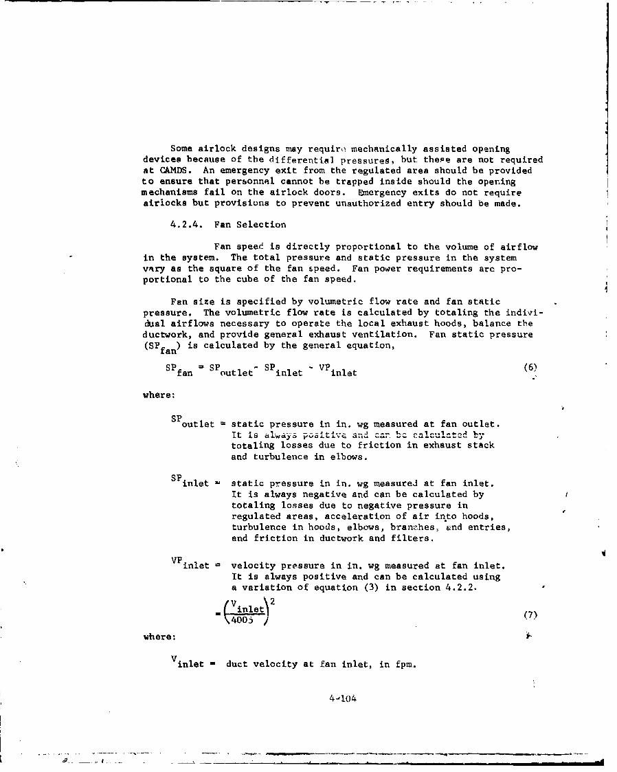
Some airlock designs may require mechanically assisted openingdevices because of the differential pressureg, but thepe are not requiredat CAMDS. An emergency exit from the regulated area should be providedto ensure that personnel cannot be trapped inside should the openingmechanisms fail on the airlock doors. Emergency exits do not requireairiocks but provisions to prevent unauthorized entry should be made.
4.2.4. Fan Selection
Fan speed is directly proportional to the volume of airflowin the system. The total pressure and static pressure in the systemvary as the square of the fan speed. Fan power requirements are pro-portional to the cube of the fan speed.
Fan size is specified by volumetric flow rate and fan staticpressure. The volumetric flow rate is calculated by totaling the indivi-dual airflows necessary to operate the local exhaust hoods, balance theductwork, and provide general exhaust ventilation. Fan static pressure(SPfan) is calculated by the general equation,
SP -SP - SP -VP (6)fan outlet inlet inlet
where:
SPoutlet static pressure in in. wg measured at fan outlet.
totaling losses due to friction in exhaust stackand turbulence in elbows.
SPinlet = static pressure in in. wg measured at fan inlet.
It is always negative and can be calculated bytotaling losses due to negative pressure inregulated areas, acceleration of air in*to hoods,turbulence in hoods, elbows, bran-rhes, and entries,and friction in ductwork and filters.
VP inlet velocity pressure in in. wg measured at fan inlet.
It is always positive and can be calculated usinga variation of equation (3) in section 4.2.2.V inlet
(7
"\400o /where:
Vinlet - duct velocity at fan inlet, in fpm.
44104
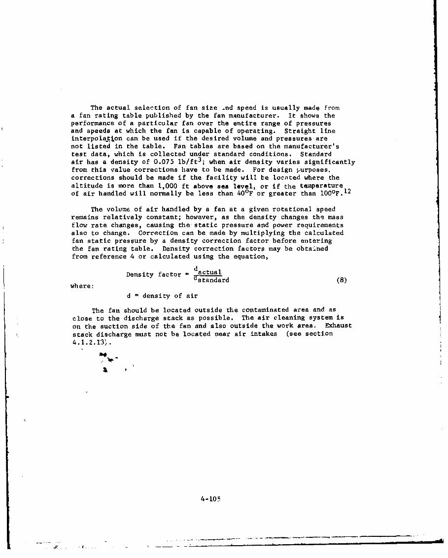
The actual selection of fan size .nd speed is usually made froma fan rating table published by the fan manufacturer. It shows theperformance of a particular fan over the entire range of pressuresand speeds at which the fan is capable of operating. Straight lineinterpolation can be used if the desired volume and pressures arenot Listed in the table. Fan tables are based on the manufacturer'stest data, which is collected under standard conditions. Standardair has a density of 0.075 lb/ft3 ; when air density varies significantlyfrom this value corrections have to be made. For design purposes,corrections should be made if the facility will be located where thealtitude is more than 1,000 ft above sea level, or if the temperatureof air handled will normally be less than 40OF or greater than 1000F.12
The volume of air handled by a fan at a given rotational speedremains relatively constant; however, as the density changes the massflow rate changes, causing the-static pressure and power requirementsalso to change. Correction can be made by multiplying the calculatedfan static pressure by a density correction factor before enteringthe fan rating table. Density correction factors may be obta-..nedfrom reference 4 or calculated using the equation,
Density factor =dactualwhre Ustandard (8)
d = density of air
The fan should be located outside the contaminated area and asclose to the discharge stack as possible. The air cleaning system is
on the suction side of the fan and also outside the work area. Exhauststack discharge must not be located near air intakes (see section4. 1.2. r3',
4-10-4

47
4.2.5. Dampers7
Dampers are the valves of the air cleaning atib ventilationsystem. By definition1 6 , a damper is any device that controls pressure,direction, or volume of airflow in a ventilation system, includ#ngthose items normally classed as valves when used in piping systems.
Clear, concise specifications must be established for mechanicalstrength, for leakage rate at maximum operating conditions, and.forthe ability to perform under required operational and emergency conz-ditions.
Operability of linkages must be assured through specification ofand requirerr,?nt for cycling at minimum torque requirements underfull load. Static testing of closed dampers should be required toverify strength and leaktightness for use in critical applications.All features important to proper operation should be stipulated indetail, including materials of construction, permissible lubricants,
bearings, blade design and edgings (if permitted), blade lockingmechanisms, supports, operator type and capability, and accessibilityof operator, linkages, blades, and bearings for maintenance.
Other factors to be considered in the design of dampers fordenil applications include function of damper; type of construct 4 on;
dimensions and space limitations; pressure drop across closeddamper; normal blade operating position; method of mounting damper;blade orientation relative to damper case; operator type and power
source; seismic requirements; requirements for position indicator,14MLL.& sw th-- -- cthc r '- - -- ll- o ftna
permissible leakage through closed damper; space required for service;
airstream temperature range; orientation of damper in duct; direction
of airflow; failure mode and blade position; maximum closing andopening times; and method of shaft sealing. (See section 5.3 ofreference 7.)
In conventional ventilation applications, procurement of dampers
is generally accomplished by specifying little more than a manufacturer'smake and model number "or approved equal." This practice. iowever, isinadequate for iemical and other potentially high-risk applications.
Therefore, a method of damper specification based on clas.ificationof important features has been developed and is included in reference
7. The classification enables the dezigner to make a rationalselection of dampees, independent of manufacturer's make and modelnumber, for a specific application. Although the classification waswritten for use in nuclear applications, it is nevertheless the bestsummation of damper information currently available. in fact itserved as the basis for the CAMDS ventilation specification,ll to
which the damper designer is also referred.
See also section 5.3 regarding dampers.
4-106
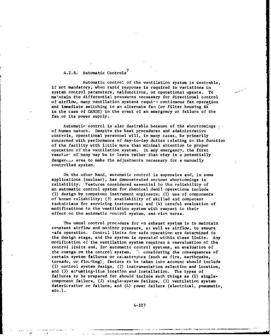
4.2.6. Automatic Controls 7
Automatic control of the ventilation system is desirable,if not mandatory, when rapid response is required to variations insystem control parameters, malfunctions, or operational upsets. Tomaintain the differential pressures necessary for directional controlof airflow, many ventilation systems require continuous fan opera onand immediate switching to an alternate fan (or filter housing 9sin the case of CAMDS) in the event of an emergency or failure of thefan or its power supply.
Automatic control is also desirable because of the shortcomingsof human nature. Despite the best procedures and administrativecontrols, operational personnel will, in many cases, be primarilyconcerned with performance of day-to-day duties relating to the functionof the facility with little more than minimal attention to properoperation of the ventilation system. In any emergencyv, the firstreactio- of many may be to leave rather than stay in a potentiallydangersL- area to make the adjustments necessary for a manuallycontrolled system.
On the other hand, automatic control is expensive and, in someapplications (nuclear), has demonstrated serious shortcomings inreliability. Features considered essential to the reliability ofan automatic control system for chemical demil operations include(1) design by competent instrument engineers; (2) use of componentsof known reliability; (3) availability of skilled and competenttechnicians for servicing instruments; and (4) careful evaluation ofmodifications to the ventilation system with respect to theireffect on the automatic control system, and vice versa.
The usual control procedure for qn exhaust system is to maintainconstant airflow and monitor pressure, a3 well as airflow, to ensuresafe operation. Contrcl limits for safe operation are determined inthe design stage, and the system is operated within these limits. Anymodification of the ventilation system requires a reevaluation of thecontrol limits and, for automatic control systems, an evaluation ofthe change on the concrol system. -h considering the consequences ofcertain system failures or caLastrophes (such as fire, earthquake,tornado, or floLdling), factors to be taken into account should include(I) control system design, (2) instrumentation selection and location,and (3) a:-uating-liue location and installation. The types offailures to be Prepared for should include such things as (I) single-component failure, (2) single-system failure, (3) ventilation systemdeterioratLor or failure, and (4) power failure (electrical, pneumatic,etc.).
4-107

p
At CAMDS, the chief example of automatic control i ýJ\e pneu-matically operated damper through which air enters a poteptiallycontaminated area. These dampers are designed to close if the APbetween the contaminated area and the area surrounding it dropsbelow a preset level of 0.05 in. wg; also, as a safety feature, thesedampers fail-close if the compressed air supply or electrical poweris lost. Although the normal AP is at least 0.1 in. wg, the valueof 0.05 in. wg was selected to allow for pressure fluctuations dueto door openings 6nd still provide sufficient negative pressure topreclude the outwaid flow of contaminated air.
A Photohelig gýe with a single set-point is used to send asignal when a lo static-pressure condition exists. The only differencesbetween this gage and thoae used to control the airflow are: (1) thedials on the latter gaees ere calibrated with two set-points represent-ing the lower and uppe:v airflow limits, and (2) the scale is in cfminstead of in. wg.
The status of the filters and the positions of the isolationdampers at CAMDS are monitored on the control room console shown infigure 4-47.
4.2.7. Makeup Air
Makeup air is required to replace the large volumes of airexhausted by hoods and the general building exhaust system. The supplyof makeup air must permit zhe control of building pressure and ofairflow from space to space. The operation of local exhaust hoods con-tributes to general building exhaust for heat control. After the amountof airflow needed to remove heat has been determined, it should be comparedto the amount of air being exhausted by the hoods, with the larger of thetwo being the amount of makeup air that must be added.
Air-supply inlets should be located away from local exhaust hoodsand general exhaust outlets. Crossdrafts caused by supply inletscan interfere with contaminant control at local exhaust hoods. Theeffectiveness of general room ventilation for heat control will bereduced if airflow is short circuited by placing inlets and outletsclose together. In regulated areas air has to be supplied throughdampers that maintain desired negative pressure in the regulatedarea over a range of flows from near zero to the flow selected.
4.2.8. Heat Control
In case of excessive heat and/or humidity, exhaust venti-lation may be used if a source of cooler air is available. In order toairive at the air volumes required, it is necessary to estimate thesummation of all sources of both sensible and latent heat, as well as
t o determine in advance the temperature rise or humidity rise which willbe acceptable. The volume of air (Q) required for sensible heat controlmay be estimated from the equation: 4
4-108

I-4
04-
040
0
S. • < •2 -. " - ' , - ,- I X
4-iw
I-o.., oI ! 4,
CA a*
• , • . , • - • . 1 -o
a a 0 40"J 3 ~
,' I+•" ; • I I
41b_
.,4
4-109
P]L +'.`+ .- . •+,• .4 . I. ----- l+ . I : Nl• " / o o +- "/ - _-/- -a I

"Total BTU/hr.Q in cfm = 1.08 x Temp. rise (OF) (9)
The total BTU's per hour represents the sensible heat relLAsed interms of sun load, lights, and motors. Personnel heat load and hotprocesses are part sensible and part latent, ond it is necessary toestimate the amounts or percentages of each. In the majority ofcases the sensible heat load far exceeds the latent heat load so thatthe design can be calculated only on the basis of sensible heat. 4 Iflatent heat loads are high, calculations should also be made todetermine which heat source requires the higher quantity of air.
In certain hot-process applications, such as furnaces, it isunnecessary and impractical to attempt to control the heat from theprocess by ventilation. If the operation is such that remote controlis possible, an air-conditioned booth or cab may be necessary to keepthe operators reasonably comfortable in an otherwise intolerableatmosphere.*
In most cases, outside air is supplied in the winter months ator slightly above desired work-area temperatures, and during thesummer at whatever outdoor temperature is available. The distributionof the air within an enclosure is vitally important in order tomaintain satisfactory environmental conditions for the personnel inthe work area. The hourly and yearly costs for the air thus providedmay be calculated as follows:
Hourly cost = 0.001 x QN x Cq (10)
Yearly cost =0.154 x D x dg x C (11)
q
where:
Q = air volume, cfmN = required heat, BTU/hr/l,000 cfm (figure 4-48 and table -V-11)D - operatlng time, hours/weekq = avnilable heat per unit of fuel (table IV-12)dg = annual degree days (table IV-13)C = cost of fuel, $/unit
*See "TLVs Threshold Limit Values for Chemical Substances andPhysical Agents in the Workroom Environment with Intended Changesfor 1977" (reference 45) for guidance in determining heat stressrequirements.
4-110

"44
$4 .)
4-Ill

Table IV-ll. Required Heat Versus Average OutsideAir Temperature(Courtesy Of American Conference OfGovernmental Industrial Hygienists)
Average Outside N, Required HeatAir Temperature (BTU/hr/1000 cfm at 700F)
(OF)
0 75,5005 70,000
10 65,00015 59,50020 54,00025 48,50030 43,00035 38.00040 32,50045 27,00050 21,50055 16,00060 11,00065 5,500
4-112
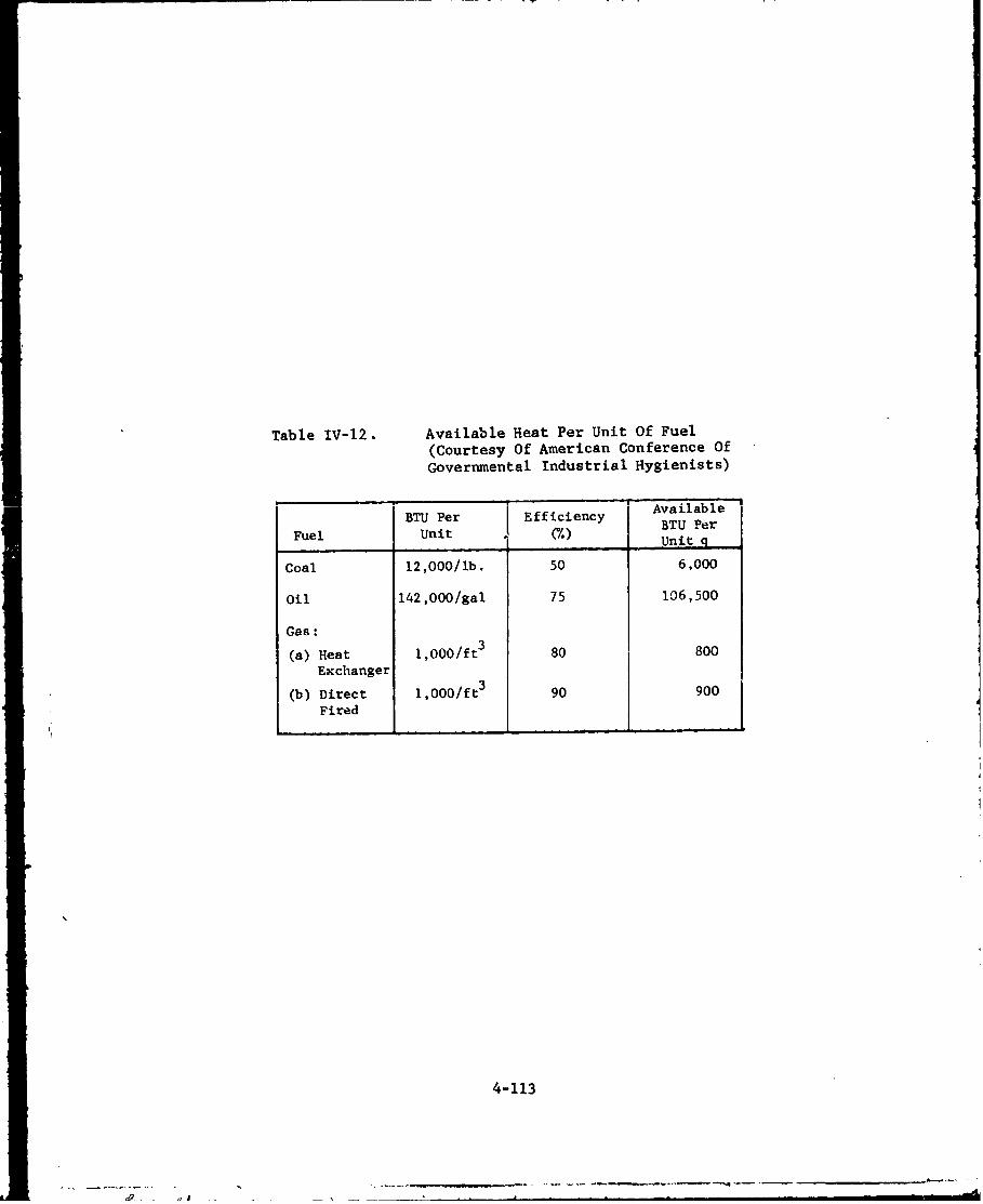
Table IV-12. Available Heat Per Unit Of Fuel
(Courtesy Of American Conference Of
Governmental Industrial Hygienists)
BT1e ffcec AvailableFuel BUni Pe0Efiiec BTU Per
UUnitq
Coal 12,000/lb. 50 6,000
Oil 142,000/gal 75 106,500
Gas:
(a) Heat 1,000/ft 3 80 800
Exchanger
i3
(b) Direct 1,000/ft 390 900
Fie
4-113
-.- - .p- -
!a
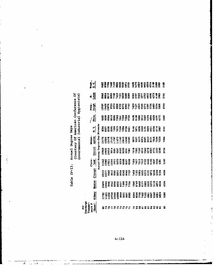
0a4 -t - ot 0V Wc 01 'r~O~ qwu i u n -WI I )
C .e4 V3c -InC - 4
0l t- I l
0C-) "4 vok t0 OICA ..- CC40 A 0co 04mwOCf
cc 04 V t-eO'Oaaw COmO, w w
in; t- 9 occ 0 cc W 0 M ý 0 tnnLCO- 0ý_ nO C, V V In N iOfc4 no-= O~ n -0
(.3 oor D0 W V V-
'-4 -"4 " n ýNt 0t )% t 0 f
vin a a m gS Q -W 1 - .0
o 0 > In .s - -0
OD (J t- t- 40 to- 0i
4.2.9. Redundancy and Safety Features
The CAMDS ventilation system provides multiple small filterunits. For a minimal additional expense, extra sections of ductwork wereincorporated into the design to join adjacent filter units to provideparallel redundancy. An isolation damper was installed in each branchto control the airflow. The exterior ductwork and locations ofisolation dampers at CAMDS are shown schematically in figure 4-49.Figures 4-50 and 4-51 show sections of ductwork containing theseisolation dampers.
The isolation dampers at CANDS are high-quality, manually-operated(by pull chain) butterfly valves. A set of limit switches is attachedto each damper to provide a signal to the control room indicating theposition of the damper (either full-open or full-closed). Under normalconditions, the isolation damper between the ventilated area and¶ thefilter unit is full-open while all other adjacent isolation dampers arefull-closed. Since these dampers are leaktight, each filter ventilatesonly its designated area with no effect on the ventilated area of anyother filter unit.
If a filter fails, however, operating personnel can open and closevarious dampers to enable a second filter unit to pull some or all ofthe needed airflow from the ventilated area designed to be serviced bythe failed filter unit.
For CANDS it was decided that manual dampers are more reliablethan automatically-operated pneumatic dampers. If the compressed-air supply is lost, the latter type dampers cannot function.Instantaneous switchover is not essential. In a well-designed leaktightarea such as the PPD shroud, the inlet dampers to the contaminated areaclose when airflow is lost. These inlet dampers fail in the closedposition due to loss of power or compressed air and close if AP betweenthe contaminated and outside areas drcps below a preset value (seesection 4.2.6.). Since these dampers close quickly and are essentiallyleaktight, some negative pressure is retained in the affectedcontaminate! arci(s) for several minutes.
As stated in section 3.4, the filter system design shouldincorporate both series and parallel redundancy. Since totalredundancy (i.e., both series and parallel) is extremely expensive,the degree of redundancy provided usually becomes a tradeoff betweencost and rink. The development oZ alarm and emergency procedures anda thorough training in these procedures are essential.
4-115

6 qContinue Code:mt point F - Filter
DC4 in Fig. D - Damper
D DDD
D3 2BD
t D a
Contiue a t
Si n
Fig. e.
point $pinnig. n
c. Filter no. 3 at UPA d. Filter no. 4 at BIF
F i l t e r n o. 5A at M I a n d F i l t e r n o . 2 B at ul.
A D
4-11
oontinued atpaipoin 0v in
Figure~ ~ ~ ~ ~ ~~~~ ~~~~~~~Fg 4-9 oaino eudn utokCnann slto a.pr t A
(N t c .e e r T F ilter n- 1. 3o atD L a y o u dh wn.L t i n O F i lte r no .s4atmB)
4-116

co
~4-
Ix 2Ž 4-JoWZ 04 U r0)
44 -
a) C0)
w0
(. H~10 w ýJ4
4-117

INFIUE -4b1A SE
FRO SIECOTINN

The CAMDS filter systems were not designed to meet fully eitherseries or parallel redundancy requirements. Although these filtersystems do contain two adsorber banks in series with agent monitorsin between, true serie8 redundancy is not realized because neither oneof the adsorber banks is guaranteed to provide more than a 104
reduction in concentration, whereas a 108 reduction is needed to meetthe emission standards under the initially estimated worst-casechallenge condition (see section 4.1.1.3.2).
Even though a 104 reduction is the maximum that can now beguaranteed for each bank, the actual reduction capability is probablysignificantly better. The 104 reduction figure is based on thesensitivity of the freon leak test of the adsorber cell; if the stateof the art for portable freon measuring equipment were to improve, it isconceivable that an order of magnitude of one to two times higher couldbe measured.
Ali but two of the 12 CAMDS filter systems are connected inp-rallel with another system. The two Fystems not connected in parallelventilate the PSC change area and medical module where the amount ofcontamination present, if any, is minimal. Even though the other filtersystems are parallel with at least one other filter system, ronemeet the basic criteria of a complete parallel system as defined insection 3.4.
Each of the CAMDS filter systems exhausts a specific area. In atrue parallel redundant system, if the primary filter fails, the backup(parallel unit) starts up. At CAMDS, the specific action takendepends on the conditions at the time of the incident. For example,if filter A fails, filter B by adjusting certain dampers may be madeto pull exclusively from the area that filter A was pulling. However,it is likely that when filter A fails, some contamination may be presentin the area served by filter B. It may be decided then to adjust thedamper to enable filter B to pull partially from both areas A and B.There is one area at CAMDS where three filter units are interconnected,*so that if one fails several possible adjustments can be made, dependingon the type and quantity of toxic materials in each area.
The function of the CAMDS parallel system is not to switch filtersand continue operations as in a truly parallel system, but to maintainsufficient negative pressure in all areas to assure no outward leakageof contamination while an orderly shutdown, including decontaminationif necessary, takes place. Once shutdown is complete, the defectivefilter system is serviced. Normal operations resume only when allfilter systems are fully operational.
*Filters no. 4, 5, and 8 in figure 4-15.
4-119
The function of the CAMDS paral! I system is not to switch filtersand continue operations as in a truly pilrallel system, but to maintainsufficient negative pressure in all areas to assure no outward leakageof contamination while an orderly shutdown, including decontaminationif necessary, takes place. Once shutdown is complete the defectivefilter system is serviced, and normal operations resume only when allfilter systems are fully operational.
4-120

5. OPERATIONAL CONSIDERATIONS
5.1. Controls and Instrumentation
5.1.1. Controls7
Monitoring and control of all but the most simple filtering/ventilation fa:ilities are desirable in both automatically controlledand manually controlled systems. Most changes that take place in a high-efficiency air cleaning system usually occur very siowly and can bemonitored by a routine check of negative pressure, differential pressureand airflow by operating personnel who are primarily responsible forother functions in the plant. Abnormal conditions are best signaled byan alarm which triggers when a monitored parameter rises above or fallsbelow some predetermined set point. A centralized control system ispreferable for this operation in that it has the advantage that suchreadings can be made, the effect of changes to the monitored parameterscan be determined, and corrective action can be taken without a tripto the field. However, sufficient local instruments at the point ofinterest should "so be provided to facilitate maintenp, i andinspection and to provide a check on the central instrume.tation.
Centralized control, particulaily if instruments and controlswitches (e.g., for fans and dampers) are laid out on a graphicdisplay panel, enables the operator (1) to rapidly assess a situation,(2) to determine the cause of an upset condiLion, (3) to determine itsinteraction with other systems and its safety ramifications, and (4) totake rapid actiun when necessary. (See figure 4-47.) The systemresponse to correztive action can be moi.;.tored, reassessec1 and modi-fied in minimum time without requiring personnel to enter potentiallycontaminated areas, Centralization of control also provides a focalpoint where operational information can be processed under normaloperating conditions for feedback purposes, and where knowledgeablepersonnel can be contacted in an emergency.
5.1.2. Instrumentation7
Safe and reliable operation of a filtration/ventilationcystem, whether automatically or manually controlled, requiresinstruments to monitor critical operating parameters. At a minimum,such instrumentation should measure pressure drop across each individualbatk of filters (not just a single instrument to read pressure dropacross the total filtration system) and tital airflow exhausted throughthe filter system. Pressures in critical operating areas of thefacility and differential pressures between areas of different potentialcontaminations may also have to be monitored.
5-1

The principal requisite for locatin~g instruments is accessibility.An instrument that is out of easy reach or is not easily readablewill not be maintained or used. Instruments should be located ateye level or only slightly above or below. Panel mounts should beprovided for fragile items and those requiring service entry from therear.
Instruments that are adversely affected by vibration, particularlythose with deli.cate electrical contacts or springs, should be installedon vibration isolators or on panels that are mounted on vibrationisolators. Where stable support is not available, the panel should bemounted nearby or remotely on its own standard. (See figure 4-4.)Instruments with related functions should be grouped on a singI'q panelor adjacent to one another so that operators can correlate relatedreadings, such as pressure drop across filters and airflow in theducts, without going to several locations. (See figure 4-28.)
Critical ventilation systems that cannot be permitted to fail orto be misunderstcod (because of erroneous instrument readings) maybe fitted with redundant instrumentation for certain critical parameters.Redundant instruments must be totally independent so that failure ofone, from a cause either internal or external to the instrument!ventilation system, cannot affect the other.
Installation of instruments out-of-doors should be avoided whenpossible but not at the expense of decreased sensitivity, reliabilityor inaccessibility. When located outside, instruments must be protec~adfrom the weather. Indicating fluids in manometers must be of a typethat eo not freez or boil at the temperatures occurring at the site.Plastic instruments, instruiri-nt cases, and instrument cover glassesshould not be used in outdoor installations because of crazing and/ordiscoloration of the plastic. (See section 4.1.2.12.5.) Raintightelectrical cabinets, NEMA class 3, are recommended; NEMA class 4 (water-
tight) or class 12 also provide acceptable protection if NEMA class 3is not available.
In low-hazard areas where easy access is possible, the require-ment for pressure drop and airflow readings for simple, noncriticalsystems can often be met by providing for temporary attachment ofportable instruments. For pres ire drop readings, a length oftubing can be attached to the pressure taps or inserted through holesin the sampling ports. A hand-held pitot tube may also be inserted,if desired, through a suitable sampling port in the duct. Forcritical systems, however, permanently installed instruments must beprovided in accessible locations as close to the monitoring point aspracticable.
5-2

Actuating fluid (e.g., instrument air) and sensing lines shouldbe large enough so that they cannot become plugged due to freezing ofcondensed water which may collect in themor from contaminants thatinadvertently get into the lines. Sensing lines should be kept asshort as possible to minimize the time response to parameter changes,and they should have a minimum number of bends and no flow restrictions.Sensing lines should be rigid to prevent expansion under pressure ortemperature extremes that could result in false readings or multipleshort-term parameter variations. Preferably, lines should be runand instruments located above the ducts to minimize condensationproblems. Because such locations are often impossible, as a minimum,lines should be sloped to low points fitted with drip legs and theinstruments themselves also fitted with drip legs.
Sensing lines located in or serving contaminated spaces orspaces containing corrosive fumes should be made of stainless steel.Instruments should be isolated from contaminated spaces so thatmigration of such contaminants to the instruments is minimized. Inparticularly critical applications, a very-low-velocity purge linemay be attached to the actuating fluid or sensing line; the putgeflow must be very low, of course, to avoid influencing operation of thedevice or affecting its readings.
See sections 4.1.2.5, 4.1.2.6, and 4.1.2.12 for a disc!ission ofinstrtimentation as applicable to CAMDS.
5.2. Agent Monitoring Equipment
5.2.1. General
Agent monitors perform two primary functions: (1) provideimmediate warning of hazardous situations, and (2) measure low-level.concentrations of agent (stack emissions and working area standards)to guard against cumulative effects over an extended period of time.To meet these requirements, relative to GB and VX, a system of dualdetectors is used in each filter system. An automatic agent monitor/detector with fast response time warns of hazardous situations, whilea bubbler absorption system collects samples which are analyzed in alaboratory for low-level agent concentrations. The sensitivitiesand response times of the two monitoring systems currently in use forthis purpose - MS detector alarm and bubblers - are shown in TableV-l. These devices may be housed, as at CAMDS, in a shelterimmediately adjacent to each filter housing (see figure 5-1).
5-3

Although a suitable faat-response monitor -aimilar to the M8b ~detector - is not now a~vailable for use with the mustard agents, such a
device is being developed. In addition, more sophisticated equipmentoffering greater sensitivity and/or faster response times wi,'h GB endVX are presently being evaluated.
Brief descriptions of the M8 detector and bubbler absorptionsystem follow.
Table V-1. Sensitivity and Response Time of Available Agent DetectorsFor Use In Filter Systems
sensitivity(aGB Detectors (mg/si3) Response Time
M8 Alarm 0.2 1 minBubbdlers 0.0001 2 hrsBubb lers 0.000003 13 hrs
VX Detectors
MB Alarm 0.4 3 minBubb lers 0.00001 2 hrsBubb lers 0.0000003 13 hrs
Mustard Detectors
Bubblers 0.003 2 hrs
(a) Response times for bubblers include one hour for analysis andremaining tVmXe for sampling.
5-4
M8 Aarm0.4 -mi
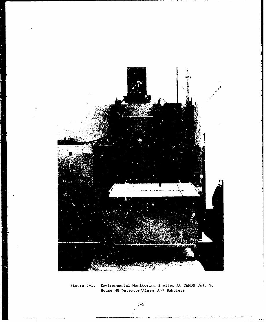
110
Figure 5-1. Environmental Monitoring Shelter At CAMDS Used ToHouse M8 Detector/Alarm And Bubblers
5-5
5.2.2. M8 Detector/Alarm
The M8 detector/alarm* is used to continuously monitor
the area between the two adsorber banks of each filter system for GB
and VX. Although located outside the filter housing, the alarm is
connected to the housing interior by means of a remote sampling
probe. When the contamination level exceeds the sensitivity threshold
of the detector, it emits an audible/visual alarm in the control room
to warn of a breakthrough of the first adsorber bank. At CAMDS, as
soon as the alarm occurs the sampling lines are manually removed from
the sampling port between the adsorber banks and reinstalled in the
exhaust stack, where the filtered air exiting the stack is sampled
until the first adsorber bank is replaced. At this time, thesampling line is returned to its original monitoring location betweenthe adsorber banks.
Operation of the M8 detector/alarm on a continuous basis requires
that certain operational checks be performed during every shift (or
at least every 12 hours). This procedure is described in detail in
TM-3-6665-225-12.3 1
5.2.3. Bubblers
Bubblers are used in conjunction with the M8 alarm to
collect air samples downstream of the first stage of adsorbers and
simultaneously in the emission stacks. Toxic gases, if any, in the
airstream are collected in the bubbler solution and chemicallyanalyzed. During monitoring, the bubblers are maintained at 1.5 + 0.5°C
to prevent vaporization of the dissolved gases. Bubblers are changed
hourly and, after sampling, are transported to the laboratory for
analysis. Handling and transportation must be done carefully to
avoid breakage and loss of the contents. Under certain conditions
(e.g., when monitoring the emission stack after breakthrough of the
first adsorber stage), it may be necessary to change the bubbler at
more frequent intervals - such as every thirty minutes - in order to
monitor contamination levels more closely.
Procedures for handling and agent-challenging of bubblers are
given in reference 13.
*This is actually the M10 alarm, which is the plant version of the
M8 alarm, but is more commonly referred to by the latter name.
5-6
5.3. Dampers 7
Damper operators should be factory-mounted by the dampermanufacturer and installed outside the airstream. The manufacturershould also establish the torque requirements for the dampers basedon operating conditions specified by the user. The damper operatorshould be capable of (1) producing a minimum of 1.5 times the torquerequired to move the blades from full-open to full-closed position, and(2) enabling the damper to meet the specified leaktightness in theclosed position under the maximum service.
After installation of thLle dampers, an acceptance test must beconducted. The following procedure, used at CAMDS, is recommended:
Cycle each damper at least 25 times through its fullrange of motion to verify the free operation of allparts and the correct adjustment, positioning, andseating of the blades. Upon completion of the 25cycles, adjust the damper as necessary. Balance andtest the ventilating system in accordance withreference 11.
Refer to section 4.2.5 for design information regarding dampers.
5.4. Emergen~cy Considerations
5.4.1. General 7
The ventilation and air filtering systems of a processin which toxic chemical agents are handled are integral parts of thecontainment of the facility. In the event of an operational upset,power outage, accident, fire, or other emergency, it is essentialthat these systems remain operational until all contamination withinoperating areas has been reduced to a safe level, at which time shut-down may occur.
Some damage to or degradation of the ventilation systemmay not be completely avoidable in the event of a serious incident.Consideration must be given to (1) the possible effects of emergencyconditions on the ventilation and air cleaning systems includingdamage to the filters and adsorbers from shock, overpressure, heat,and fire; (2) the design and arrangement of ducts and air cleaningcomponents to alleviate these conditions; (3) means of switching toa redundant air cleaning unit, fan, or alternate power supply; and(4) methods of controlling the exhaust system during failure conditions.
5-7
To provide the necessary protection to the public and to plantpersonnel, air cleaning and ventilation system components on whichcontainment leakage-control depeads must remain esbentially intact andserviceable under the upset conditions. These components must becapable of withstanding the differential pressures, heat, moisture, andstress of the most serious type of accident predicted for the fazilicy,with minimum damage and loss of integrity, and they must remain operablelong enough to satisfy system objectives.
See also section 3.3 for more information on safety and emergencyconsiderations.
5.4.2. Shock and Overpressure7
Mechanical shock in an air cleaning system might be pro-duced by explosion in an operating area of the building, by an earth-quake, or by rapid compression or decompression of the air inside C.
system caused by sudden opening or closing of a damper, enclosure, orhousing door. When pressure transients last for periods measurablein seconds, static pressure is primarily responsible for any destructiveeffect. For shocks that have a duration of only a few milliseconds withnearly instantaneous pressure rise - as occur in most chemicalexplosions - destructiveness is primarily a function of the momentumof the shock wave. Shocks produced by an earthquake or inadvertentopening or closing of a damper usually fall somewhere between thesetwo extremes.
Protection of the filters and adsorbers against failure fromshock can be accomplished by isolating them to prevent the transmissionof forces to them and by increasing the shock resistance of ducts,housings, mounting frames, and equipment supports. The shock resistanceof HEPA filters can be enhanced by face guards, and similar treatmentmay sometimes improve the shock resistance of prefilters. Most pre-filters, however, probably have low shock and overpressure resistance,and a screen installed between them and the HEPA filter is recommendedto prevent damage to the latter.
Tray-type adsorbers are generally of a robust construction andshould be relatively unaffected by shock loading if properly installed.Filter and adsorber mounting frames and housings designed in accord-ance with the reconmetidations of section 4.1.2.2 should have adequateshock resistance for most applications.
Protection of the primary filter components from explosive shockcan be achieved by providing sharp turns, heavy perforated plates. orcushion chambers in the ductwork to "snub" shock forces, and by usingfast-acting isolation dampers. Although turning vanes, dampers,moisture separators, and prefilters may be damaged by a shock wave,they may also serve to attenuate its force to some degree and thereby
5-8

provide a measure of protection to the downstream filters and adsorbers.Damage to dampers, however, can result in an inability to control flowsor isolate branch lines.
Explosion in an operating area of a building is probably the mostlikely type of shock-generating incident to be expected in a demiloperation. A chemical explosion is similar to a rapidly burning fireand, therefore, can be arrested in a confined space if a suppressantor extinguiishing agent can be introduced quickly enough.
At GAMDS the principal explosive hazard is provided for inanother manner. During the punching and sawing operations in the ECCwhen eKplosic.ns are most likely to occur, an explosion-proof door
closes off the ductwork to protect it and the ensuing filter/adsorber
banks from possible blast: damage. rhis sequence lasts for about
three minutes of every four minute cycle (assuming the ECC is at full
operation), ii•ring wlaich time no airflow occurs. No ventilation is
required d" this period since the ECC is sealed completely airtight.
5.4.3. Fire and Hot Air 7
Firc in gloveboxes and other toxic-agent containmentfacilities pose special difficulties to air cleaning and ventilationsystems bacause of the need to contain contaminated air during theemergency. The release of contaminated smoke through a tiptured HEPAfilter or other breach of the filtration system may have more seriousconsequences than any potential casualty losses from the fire itself.
Where it is possible to completely isolate and seal off thecontained space within a building in which a fire occurs, the effectof fire on the filters and other air cleaning components may not be a
serious matter. In most facilities, however, it is essential tomaintain the differential. pressure necessary to prevent backflow ofcontamination to occupied spaces of the building and to ensurefiltration of contaminated smoke. Under the latter conditions, theeffect of fire on the air cleaning systcm cnd its components becomesan important consideration. In many cases the final filters and fan,or a redundant set of filters and fan, must be operable during andfollowing an emergency. If the building is zoned to control airflowfrom areas of less hazard to areao of greater hazard, differentialpressures between zones must be preserved to prevent pressurizationof the contained space in which the fire occuirs and to prevent back-flow of contamination. Even when the ventilating system can beshut down in the event of a fire. protectiorn of the filters/adsorbersis imporcant to provide for cleanup of any contaminated air in thebuilding after the fire has been extinguished.
5-9
Hazards to air cleaning units possibly arising frcom firesituations are: (1) heat and hot air can damage filters, ignite dustaccumulaced in ducts or filters, and distort metal parts to the poritthat filte-s are bypassed or fans and dampers are made inoperable;(2) sparks and burni.ng trasF can ignite dus'. and melt holes in thefilter media; (3) smoke can plug prefilto:rz and UIEPA filters co thepoint that the airflow is seriously re:iuced and/or the filrers areruptured due to the increased resistance; (4) overpressurL due to airexpansion, coupled with smoke plugging, can lead to rupture of •hefilters; and (5) droplets of spray from fire-protectirn sprinklersor particles from other types of fire'oextinguishing agents canperforate the filter medium, plug the filters, or lead to reductionof their structural properties.
The first line of defense against duct aud filter fires is thedevelopment and enforcemeat of safe operating practices in the containedand operating spaces of the demi. facility. This means eliminatinig Uaeor tcaore of the basic fire elements - fuel, ignition source, or oxygen.It includes (1) control over the kinds and quantities of combustibleliquids and gases permitted for use in contained spaces; (2) conltrolof hot plates, burners, furnaces, and other scurces of heat or flame;and (3) possible inerting of the box or cell environment (especiallyglov.ýboxes) with nitrogen, argon, carbon dioxide, or other gas. Safeoperating practices also include (1) the development and rehearsal ofpreplanned fire and damage-control procedures in the contained andoccupied spaces of the facility, and (2) means for rapidly detectingand suppressing a fire (e..., water deluge system).
75.4.4. Power and Equipment Outage
Planning for emergency situations must provide forthe probable occurrence of power and equipment (particularly blower)failures. Such failures, if not properly planned for, can result ina contamiaation hazard, particularly in buildings with zoneventilaticn where airflow must be maintained to preserve pressuregradients between zones and prevent backflow of contamirnated air tooccupied spaces. Possible emergency measures include redundant fans,redundant fan motors (perhaps served from independent power sources),and alternate power supplies (e.g., steam turbine or emergency diesel-electric generator). See section 4.1.2.10.2 for specific methods usedat CAMDS,
5-10
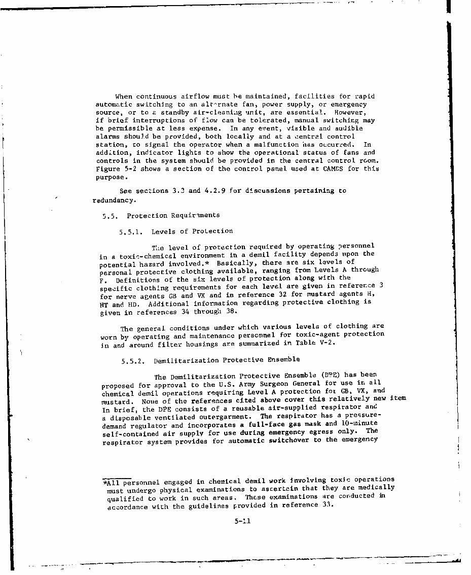
When continuous airflow must be maintained, facilities for rapid
automatic switching to an alternate fan, power supply, or emergency
source, or to a standby air-cleaniag unit, are essential. However,
if brief interruptions of flow can be tolerated, manual switching may
be permissible at less expense. In any event, visible and audible
alarms should be provided, both locally and at a central control
station, to signal the operator when a malfunction has occurred. In
addition, indicator lights to show the operational status of fans and
controls in the system shuuld be provided in the central control rGom.
Figure 5-2 shows a section of the control panel used at CAMES for this
purpose.
See sections 3.3 and 4.2.9 for discussions pertaining to
redundancy.
5.5. Protection Requirements
5.5.1. Levels of Protection
The level of protection required by operating personnel
in a toxic-chemical environment in a demil facility depends upon the
potential hazard involved.* Basically, there are six levels of
personal protective clothing available, ranging from Levels A through
F. Definitions of the six levels of protection along with the
specific clothing requirements for each level are given in reference 3
for nerve agents GB and VX and in reference 32 for mustard agents H,
HT and HD. Additional information regarding protective clothing is
given in references 34 through 38.
The general conditions under which various levels of clothing are
worn by operating and maintenance personnel for toxic-agent protection
In and around filter housings are summarized in Table V-2.
5.5.2. Demilitarization Protective Ensemble
The Demilitarization Protective Ensemble (DPE) has been
proposed for approval to the U.S. Army Surgeon General for use in all
chemical demil operations requiring Level A protection fot GB, VX, and
mustard. None of the references cited above cover this relatively new item
In brief, the DPE consists of a reusable air-supplied respirator and
a disposable ventilated outergarment. The respirator has a pressure-
demand regulator and incorporates a full-face gas mask and 10-minute
self-contained air supply for use during emergency egress only. The
respirator system provides for automatic switchover to the emergency
*All personnel engaged in chemical demil work Involving toxic operations
must undergo physical examinations to ascertain that they are medically
qualified to work in such areas. These examinations are conducted in
accordance with the guidelines provided in reference 33.
5-11

4-)
u4-
-4
IlaL I I f
~44u
I-,
5-12
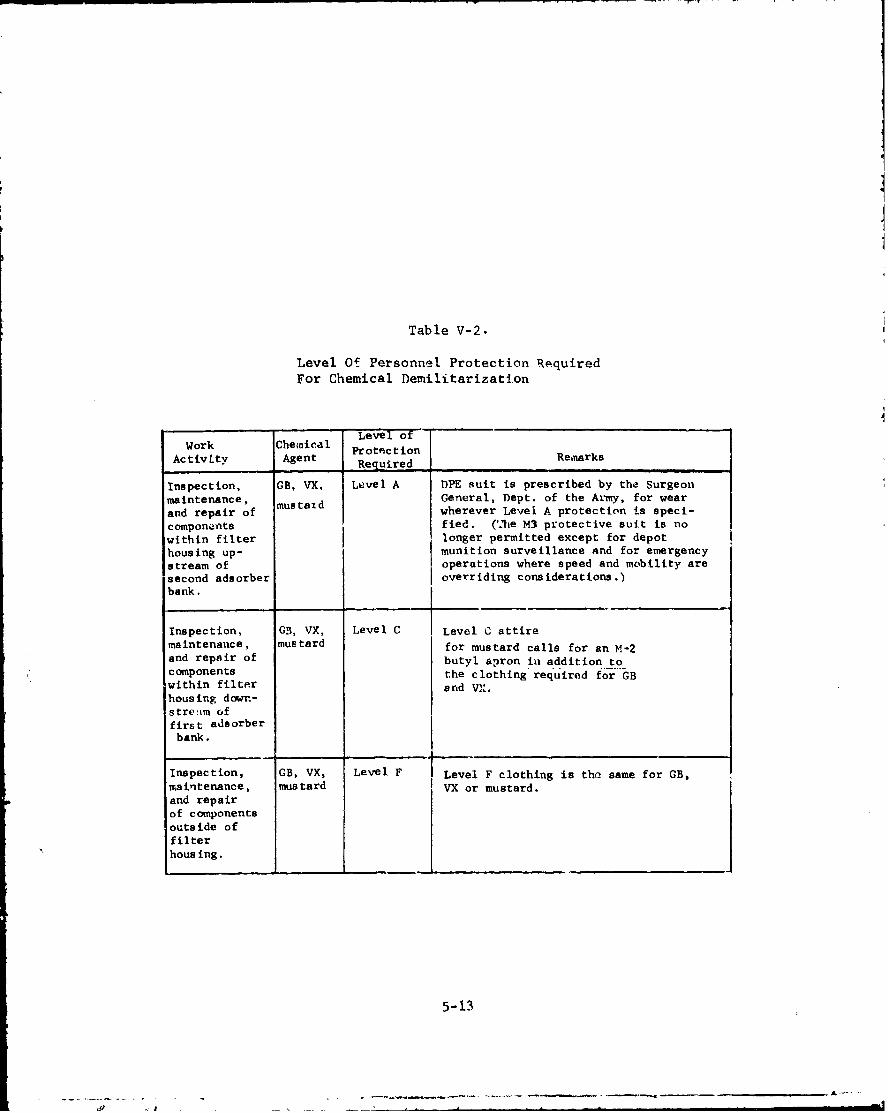
Table V-2.
Level Of Personnel Protection RequiredFor Chemical Demilitarization
Level of
Work Chemical ProtectionActivLty Agent RequiredRemarks
Inspection, GB, VX, Level A DPE suit is prescribed by the Surgeonmaintenance, mustaGd eGneral, Dept. of the Army, for wearand repair of wherever Level A protection is speci-components fied. (T2he M3 protective suit is nowithin filter longer permitted except for depothousing up- munition surveillance and for emergencystream of operations where speed and mobility aresecond adsorber overriding considerations.)bank.
Inspection, G3, VX, Level C Level C attiremaintenance, mustard for mustard calls for an M-2and repair of butyl apron in addition tocomponents the clothing required for GBwithin filter end VX.housing down-streitm offirst adsorberbank.
Inspection, GB, VX, Level F I Level F clothing is the same for GB,maintenance, mustard VX or mustard.and repairof componentsoutside offilterhousing.
5-13

air supply when the main air-' upply pressure drops f- a prescribedlevel. A warning light in the face piece informs the wearer when heis consuming emergency air supply. The outergarment is a heat-sealed,one-piece garment fabricated from a plastic material resistant toagent penetration and to the deleterious effects of oracational fluids,such as hydraulic and cutting oils and decontamination solutions.
Air from the main air supply is distributed to the outergarmentextremities to provide cooling for the wearer. The worker wears apair of M2AI butyl rubber boots and a pair of M4 butyl rubber glovesover the DPE as part of the ensemble. Breathing air is supplied bymeans of a high-pressure umbilical connected to the air supply outlet.Although the making and breaking of air-supply connections within atoxic area is minimized, an inline filter is incorporated in therespirator to protect against agent incursion during hook-up.Specialized hose-handling equipment is also available to assist theworker in movement into, within, and out of the toxic environment.Provision is also included for communication between wearers andthe command center.
5.5.3. Donning and Removing Protective Clothing
Personnel engaged in maintenance or similar activitiesmust follow existing standing operating procedures for donning protectiveclothing and moving to the work site. When the worker completes histask and is ready to exit from the filter housing, certain otherprocedures apply depending on whether there is ready access to an air-lock. (See section 4.2.3.) This is where the worker removes hiscontaminated apparel prior to returning to the point of origin. Inthe event there is ready access to an airlock system 4n an adjacentbuilding, the normal procedure is to establish a "hc 'ine" route forthe workers to travel from the contaminated area to -he airlockentrance. If an airlock is not available, use the procedure forestablishing a "hot line" in an emergency. General procedures aregiven in FM 3-2139.
5-14
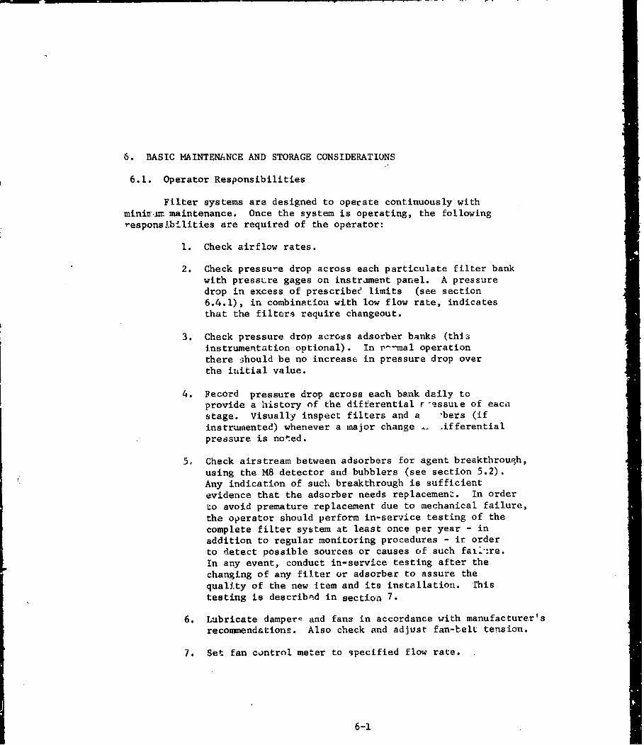
6. BASIC MAINTENANCE AND STORAGE CONSIDERATIONS
6.1. Operator Responsibilities
Filter systems are designed to operate continuously withminitn=r maintenance. Once the system is operating, the followingresponsibilities are required of the operator:
1. Check airflow rates.
2. Check pressure drop across each particulate filter bankwith pressure gages on instrament panel. A pressuredrop in excess of prescribee limits (see section6.4.1), in combination with low flow rate, indicatesthat the filters require changeout.
3. Check pressure drop across adsorber banks (thiiinstrumentation optional). In rmal operationthere should be no increase in pressure drop overthe inLitial value.
4. Record pressure drop across each bank daily toprovide a history of the differential r-_ssuie of eacihstage. Visually inspect filters and a -bers (ifinstrumented) whenever a major change _. .ifferentialpressure is noted.
5. Check airstream between adsorbers for agent breakthrough,using the M8 detector and bubblers (see section 5.2).Any indication of such breakthrough is sufficientevidence that the adsorber needs replacement. In orderto avoid premature replacement due to mechanical failure,the operator should perform in-service testing of thecomplete filter system at least once per year - inaddition to regular monitoring procedures - ir orderto detect possible sources or causes of such faill're.In any event, conduct in-service testing after thechanging of any filter or adsorber to assure thequality of the new item and its installation. Thistesting is describ"ed in section 7.
6. Lubricate damperq and fans in accordance with manufacturer'srecommendations. Also check and adjust fan-belL tension.
7. Set fan control meter to specified flow rate.
6-1
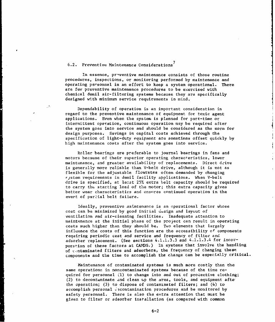
6.2. Preventive Maintenance Considerations 7
In essence, priventive maintenance consists of those routineprocedures, inspections, or monitoring performed by maintenance andoperating personnel in an effort to keep a system operational. Thereare few preventive maintenance procedures to be exercised withchemical demil air-filtering systems because they are specificallydesigned with minimum service requirements in mind.
"Dependability of operation is an important consideration inregard to the preventive maintenance of equipment for toxic agentapplications. Even when the system is planned for part-time orintermittent operation, continuous operation may be required afterthe system goes into service and should be considered as the norm fordesign purposes. Savings in capital costs achieved through thespecification of light-duty equipment are sometimes offset quickly by
high maintenance costs after the system goes into service.
Roller bearings are preferable to journal bearings in fans andmotors because of their superior operating characteristics, lowermaintenance, and greater availability of replacements. Direct dciveis generally more reliable than V-belt drive, although it is not asflexible for the adjustable flowrates often demanded by changingFsstem requirements in demil facility applications. When V-beltdrive is specified, at least 25% extra belt capacity should be requiredto carry the starting load of the motor; this extra capacity givesbetter wear characteristics and ensures continued operation in theevert of parzial belt failure.
Ideally, preventive maintenance is an operational factor whosecost can be minimized by good initial d=sign and layout ofventilation end air-cleaning facilities. Inadequate attention tomaintenance at the initial phase of the project can result in operatingcosts much higher than they should be. Two elements that largelyinfluence the costs of this function are the accessibility of componentsrequiring periodic test and service and frequency of filter andadsorber replacement. (See sections 4.1.1.3.3 and 4.1.1.3.4 for incor--
poration of these factors at CAMDS.) In systems that involve the handlingof contaminated filters and adsorbers, the frequency of changing thesecomponents and the time to accomplish the change can be especially critical.
Maintenance of contaminated systems is much more costly than thesame operationE in noncontaminated systems because of the time re-quired for personnel (1) to change into and out of proiective clothing;(2) to decontaminate and clean up the area, tools, and equipment afte°the operation; (3) to dispose of contaminated filters; and (4) toaccomplish personal 'acontamination procedures and be monitored bysafety personnel. There is also the extra attention that must begiven to filter or adsorber installation (as compared with common
6-2

air filters, for example). If the system does not meet specifiedtest requirements after the change, the work im~tst be repeated.
The fact that personnel may have to work in restrictive protectiveclothing, including full-face gas mask, also adds to the timerequired. Regardless of these inherently high time and costfactors, proper maintenance is essential to ensuring the reliabilityof the air-cleaning sybtem, and it cannot be done properly unlessappropriately designed and constructed physical facilities are avail-able.
6.3. Inspection Considerations 7
6.3.1. Procedures
6.3.1.1. Prefilters and HEPA Filters
Inspection of prefilters and HEPA filters must bemade prior to their installation into the air cleaning system. Ensurethat only the highest quality filters are used. Special care must'. taken in removing the HEPA filters from their shipping containerssince they are easily damaged by improper handling.
In visually inspecting new filters, use a light box with a stronglamp in a darkened room to examine both faces for breaks, cracks, orpinholes. Braaks or cracks in the medium usually show up on thesurface edges of the filter pleats but often are not readily detected.Minor cracks can be of major importance. If the filter unit is in-stalled with this pleat-edge damage, the cracks can be extended by airmovement through the unit. After examining each channel, the inspectorshould examine the adhesive seal around the filtar face to be surethat the seal is complete and unbroken. Each fa.;e of thae filter shouldbe examined in the same manner and with equal care.
After a thorough scrutiny of both faces, check the corner jointsof the frame for sealing and tightness. Gasketing about the flangesof the frame should be inspected fcz full adhesion and good physicalcondition.
Exterior damage to several protruding separator edges in a smallarea does not influence HEPA filter efficiency If the medium is notmashed, punctured, or broken. Even though the medium may not bebroken on one face, damage may occur at the opposite edge of the pleaton the other face. Large areas of mashed separator edges, even thoughthe medium is not damaged, may obstruct the passage of air throughthe filter unit and thus reduce its life. Filter units which havebeen improperly stored shouild be inspected particularly for cracksalong the adhesive seal,' for extreme sags in pleats and separators,and for slits or breaks in the medium.
6-3

Although minor filter damage can be repaired with siliconerubber adhesive/sealant, it is considered economically unwise to doso in view of the cost, t-Ime, and reliability involved. It is betterin most cases to reject the unit and substitute it with an acceptableone. This, of course, is a decision for the user to make as it alsodepends on the availability of acceptable filters to replace thedamaged ones. Any repaired unit, however, must be retested to ensurethat hidden damage does not exist which might reduce its filteringefficiency.
The repair of in-place or previously contaminated filters shouldnot be attempted. Such filters should be removed and disposed of inaccordance with regular procedures for handling contaminated items (seesection 6.5).
6.3.1.2. Adsorbers
As with the preiilters and HEPA filters, theadsorbers must also be visually inspected prior to installation.Major areas of inspection are:
1. Retaining screens - should contain no punctures.2.. Face plate -should be tightly affixed to casing.3. Adsorbent -should be tightly packed.4. Gasket - should be rebonded if loose.
Except for tightening the face plate, no repairs are to be made toadsorbers, whether new or installed. Damaged new units are to be setaside for disposal, return to the manufacturer, or salvaging of thecarbon adsorbent. Installed faulty adsorbers, whether contaminatedor not, should be disposed of immediately.
6.3.2. Storage and Handling
En addition to thorough inspection of newly acquiredfilter units and components, proper storage and handling techniquesmust also be exercised to keep necessary repair actions to aminimum. The following procedures are recommended for achieving highstandards of storage and handling:
1. Following receipt and inspection, each filter unit shouldbe repacked carefully in the carton in which it wasshipped and received. All packing material for internalstrengthening of the carton and for protection of thefilter unit ahould be replaced properly. Pleats of thefilter unit should be positioned to conform to theorientation marking on the carton; this should be doneroutinely whether the filter unit is to be installed atan early date or stored.
6-4

2. Cartons of filter units and adsorbers should behandled and positioned in storage to conform to theprinted directional arrows, and manufacturer'srecommendations for storage heights should be followed.When recommendations are not available, cartons shouldnormally be stacked not more than three units high.
3. Mixing other items and m -rials with filter units instorage should bd avoided in order to prevent possibledamage to the filter units. Recommended aisle widthsconsistent with good warehousing practice should beobserved to reduce damage of filter units from materials-handling equipment and other traffic. Filter units shouldnot be stored in locations where they will be exposed todampness, excessive heat or cold, or rapidly changingtemperatures.
4. Mechanical warehousing equipment is recommended forhandling large quantities of filter and adsorber units.Skids and pallets should be used for movement, withthe cartons placed on them so that their printedarrows point vertically. Chains, slings, and hooksmust not be used.
5. In physically handling a packaged filter unit, makecertain that the carton is picked up at opposite cornersand deposited caref~ully on the floor or other surface.The carton should not be dropped or Jarred. An:; filterunit dropped, whether in the carton or not, should bereexamined for damage.
6. When a filter unit is lifted, it should be grasped onlyalong the outer surface of thR case. Even slight contactof fingers at almost any point within the case canpuncture the filter medium,. To avoid such damage wheniremoving a filter unit from its carton, lift the cartonoff the filter unit rather than lifting the filter unitout of the carton.
7. Filter units should be kept in shipping cartons whenmoved from one location to another. When transferredfor installation, the units shouild be unloaded at apoint which, so far as practicable, will reduce physicalhandling. The filter units should continue to remain incartons until ready for installation.
6-5
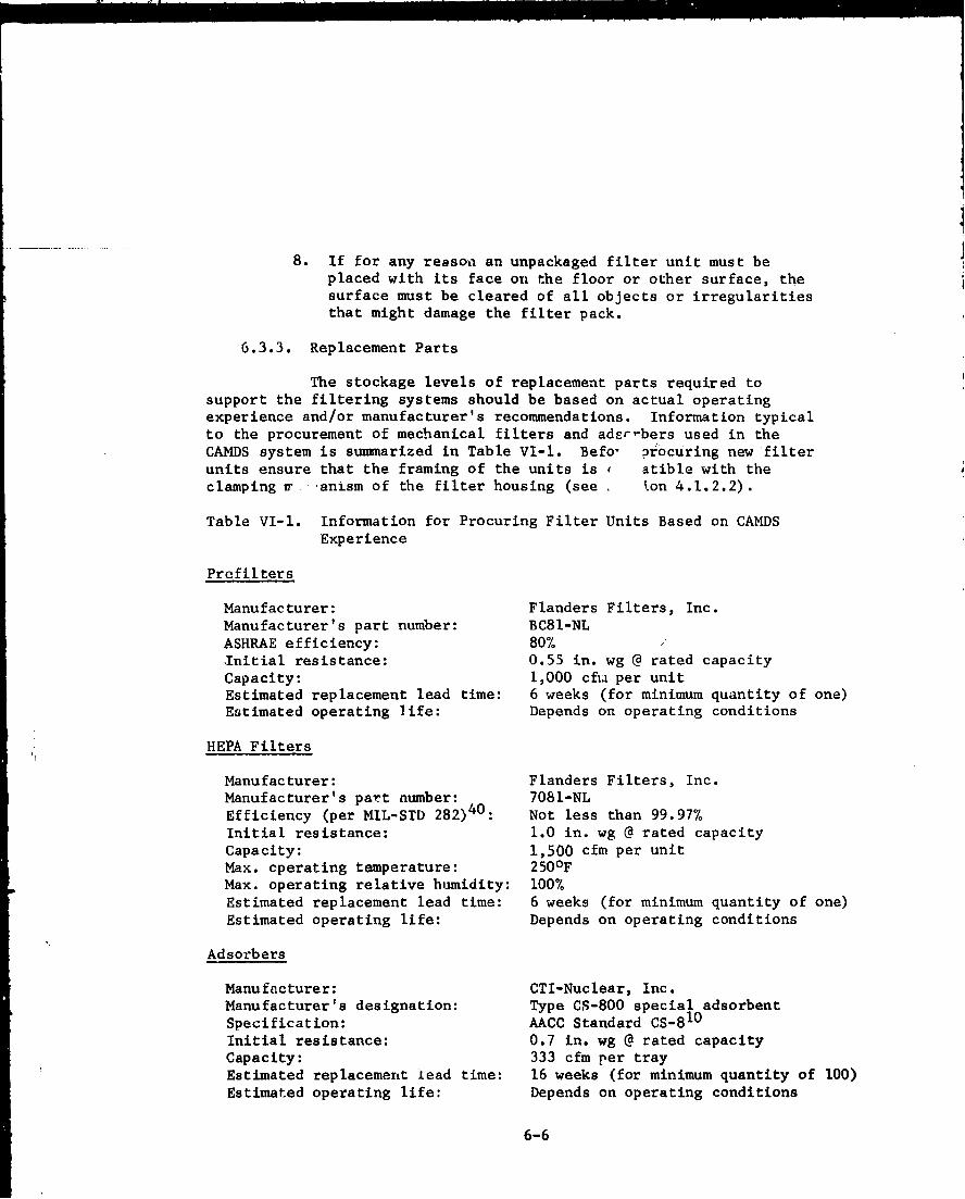
8. If for any reason an unpackaged filter unit must beplaced with its face on the floor or other surface, thesurface must be cleared of all objects or irregularitiesthat might damage the filter pack.
6.3.3. Replacement Parts
The stockage levels of replacement parts required tosupport the filtering systems should be based on actual operatingexperience and/or manufacturer's recommendations. Information typicalto the procurement of mechanical filters and ader-bers used in theCAMDS system is summarized in Table VI-I. Befo, pr6curing new filterunits ensure that the framing of the units is r atible with theclamping ir anism of the filter housing (see ton 4.1.2.2).
Table VI-l. Information for Procuring Filter Units Based on CAMDSExperience
Prefilters
Manufacturer: Flanders Filters, Inc.Manufacturer's part number: BC81-NLASHRAE efficiency: 80%.Initial resistance: 0.55 in. wg @ rated capacityCapacity: 1,000 cfia per unitEstimated replacement lead time: 6 weeks (for minimum quantity of one)EGtimated operating life: Depends on operating conditions
HEPA Filters
Manufacturer: Flanders Filters, Inc.Manufacturer's part number: 7081-NLEfficiency (per MIL-STD 282)40: Not less than 99.97%Initial resistance: 1.0 in. wg @ rated capacityCapacity: 1,500 cfm per unitMax. cperating temperature: 250°FMax. operating relative humidity: 100%Estimated replacement lead time: 6 weeks (for minimum quantity of one)Estimated operating life: Depends on operating conditions
Adsorbers
Manufacturer: CTI-Nuclear, Inc.Manufacturer's designation: Type CS-800 special adsorbentSpecification: AACC Standard CS-810Initial resistance: 0.7 in. wg @ rated capacityCapacity: 333 cfm per trayEstimated replacement lead time: 16 weeks (for minimum quantity of 100)Estimated operating life: Depends on operating conditions
6-6

6.4. Replacement of Filters and Adsorbers
6.4.1. When to Replace4
Differential pressure is a primary factor in determiningreplacement of mechanical filters, A series of five differentialpressure gages are mounted in the instrument panel of each filterhousing. Each gage indicates the differential pressure across onestage of the system. Any large increase or decrease from the initialreading indicates that the bank is functioning improperly. Valuesrecommended for replacement of CAMDS filters are given in Table VI-2.
Table VI-2. Recommended Differential Pressure Values for Filter andAdsorber Changeout
Clean Filter Normal DifferentialDifferential Pressure for Maximum Differential
Type Filter Pressure(a) Changeout Pressure for Changeout(in. wg) (in.wg) (in. wg)
Prefilter
(Type BC81-NL) 0.55 2.0 5.0
HEPA Filter 1.0 3.0 10.0(Type 7081-NL)
Adsorber 0.7 Not ApplIcabl,. Not Applicable
(Type CS-800)
(a) These are manufacturer's values. See Table IV-3 for actual valuesmeasured at CAMDS.
Operation at airflow levels below the manufacturer's ratedcapacity extends filter life and reduces filter change frequency. Whenairflow exceeds the manufacturer's recommendations by more than about15 to 20%, the dust-loading rate begins to increase exponeutially witharithmetic increases in airflow. Changeout of the filters at thisincreased level is not necessary because pressure drop increases ofup Po several times the normal value can be tolerated without affectingfilter efficiency as long as the rated airflow of the filter can bemaintained by the blower. (See also sections 4.1.3.1.11 and 4.1.3.2.6.)
A sharp decrease or increase in pressure drop may also be causedby a faulty sensing gage rather than a filter problem. The possibilityof a malfunctioning instrument should be checked before initiating
filter changeout.
6-7
Changes in differential pressure across adsorber banks, ifmonitored, are normally not a cause per se for adsorber changeout.Adsorbers should maintain a constant pressure-drop value since theadsorption by carbon of gaseous material does not produce clogging norotherwise significantly increase the differential pressure as longas the mechanical filters upstream remove all particulate matter.It is recommended, however, that any variations in pressure drop inthe adsorbers on the order of 20 percent or more be investigatedixmediately as a potential problem area.
Under normal operating conditions where agent releases areminimal, adsorbers retain their adsorptive capabilities for extendedperiods of time. Adsorber life expectancy, however, can be reducedby several factors, namely:
1. Excessive exposure to water, water vaor, and certainchemicals which, by themselves or their reactionproducts, exert a degrading affect on the carbon adsorbent.
2. Mechanical failure due to rupture, dust buildup, orformation of carbon fines,
3. Agent overload caused by equipment malfunction or grossagent spill.
First-bank adsorbers require changing (1) when the M8 detector/alarm sampling between the banks exceeds its sensitivity or thresholddetection level (see Table V-l), or (2) when the bubblers exceed theapplicable maximum allowable concentration (see Appendix A). Seesection 5.2 for the monitoring procedure to be foilowed in case of awarning of adsorber breakthrough.
6.4.2. Replacement Procedures7
6.4.2.1. Discussion
Replacement of contaminated filters and adsorbersentails many steps that must be performed sequentially. Each stepmust be carefully planned and completed in a methodical manner topreserve containment of the system. Close coordination betweenmaintenance and operating personnel is necessary (1) to establish amutually satisfactory date and time for the component change, (2) toidentify the components and systems involved, (3) to procure thenecessary materials, (4) to schedule personnel, and (5) to avoidconflicts and misunderstandings that can lead to accidents or toxicexposures.
6-8
When the necessary materials and tools are ready and all personnelhave been instructed in their specific duties, final permission mustbe secured from the responsible operator to stop or alter the airflowso changeout can be accomplished. The flow path of the exhaust system
should be thoroughly understood, and persons responsible for relatedexhaust systems that will be affected must be forewarned. For instance,if two exhaust systems manifold to the same blower, final filters, andstack, the removal of one system from service for a filter/adsorberchange will necessitate shutdown of the other system. Safety clothingand respiratory protection must be worn as directed by safety personnel.
Under normal conditions, it should be necessary tc replace onlyone filter/adsorber bank at a time within the same housing. In thosesituations where two or more banks must be simultaneously changed,the recommended procedure is to replace the most contaminated itemfirst and then the least contaminated. In most cases, the order ofchangenut - assuming all three components are involved, would be (1)prefilter, (2) HEPA filter, and (3) adsorber. If the first adsorberbank must be replaced, no action is taken regarding the second (redundant)adrorber bank, which remains undisturbed.
There are three basic procedures for replacing contaminated filtersand adsorbers, namely:
1. Method A, Bag-In Bag-Out Procedure (for type I filterhousings).
2. Method B, Bag-Out Procedure (for type I filter housings).
3. Method C, Walk-In Procedure (for type II filter housings).
These are described in the following sections. The changeout ofparticulate filters in type III filter housings (containing nonremovableadsorberb) is the same as described for Method C; an adsorbent removalmethod has been developed by the nuclear industry for these adsorbersbut is not included here since it has not yet been tried in a demilapplication.
6.4.2.2. Method A, Bag-In Bag-Out Procedure*
Type I filter housings are designed to permit filter
and adsorber replacement by reaching in from the outside, thereby
eliminating the need for personnel to enter the housing and exposing
themselves to the risk of contamination. This procedure, originated
by the nuclear industry, uses plastic bags to enclose the housing
opening and filters or adsorbers during removal and replacement. The
procedure, hereafter referred to as Method A for brevity, is described
pictorially in figures 6-1 through 6-8.
*This is the recommended procedure for use in the nuclear industry.
6-9

During this procedure, the blower is shut off; however, becauseof the redundant filter system concept (figure 4-49), it is possiblethat a reverse airflow could develop within the housing and cause thebag mounted over the access ol ening to be sucked in when the door isremoved and the bag untied. To prevent reverse flow, isolationdampers should be installed in the ductwork upstream of the filtersto block off the air and isolate the housing from the rest of theventilation system during the change.
The changeout bags should be made of clear plastic film toenable the worker to see what he is doing. Since the bags can easilytear or abrade when used with metal-cased filters or adsorbers,strong material is required. The type of bag used at CAMDS is describedin the purchase description as:
"Bag, polyvinylchoride, 11 mil, 94-96 inches longwith a butyl rubber or bungee-cord O-ring sealaround the open end. The bag shall be sized topermit the end to go over a flanged openingapproximately 124 in. in circumference. The 0-ring is to be sized to permit the bag to sealsnugly to the flange. The bag is to be fabricatedin such a manner that it shall provide a vapor-tight enclosure when the open end is heat sealed".
The specific procedure for the removal and replacement of spentfilters or adsorbers employing Method A, consisting of 15 steps,follows:
Step 1. The normal configuration of the system prior tochangeout is shown in figure 6-1. The element(filter or adsorber) is installed and held inplace by four toggle clamps. A plastic bag,sealed by an O-ring to the flange of the accessdoor, is already in place from the last elementchange. The bag is folded so as to remain outof the airflow path and within the housing doorflange space. The access door is installed onthe flange with the bag held in place betweenthe door and the flange to form a leaktightclosure inside the door.
6-10

Restraining Grommet
Elen Plastic Bag (Folded)
Access Door Cover
O-Ring Bag Seal(See figure 4-23)
Figure 6-1. Operating Configuration with Element In Place, Bag-InBag-Out Procedure
Plastic Bag
Figure 6-2. Access Door Removed And Bag Restraint Removed
6-11
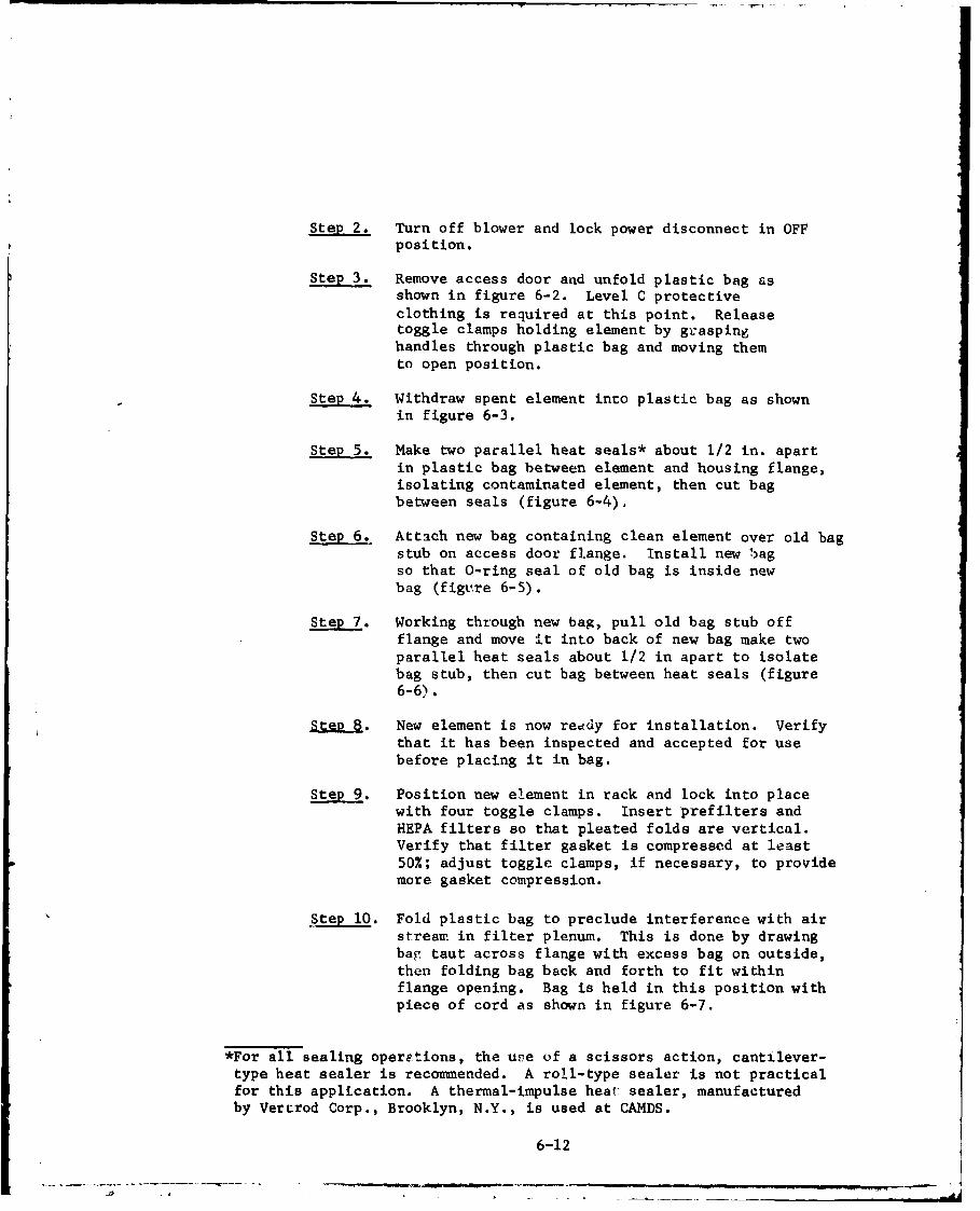
Step 2. Turn off blower and lock power disconnect in OFFposition.
Step 3. Remove access door a-ad unfold plastic bag asshown in figure 6-2. Level C protectiveclothing is required at this point. Releasetoggle clamps holding element by graspinghandles through plastic bag and moving themto open position.
Step 4. Withdraw spent element into plastic bag as shownin figure 6-3.
Step 5. Make two par~allel heat seals* about 1/2 in. apartin plastic bag between element and housing flange,isolating contaminated element, then cut bagbetween seals (figure 6-4).
Step 6. Attach new bag containing clean element over old bagstub on access door flange. Install new bagso that 0-ring seal of old bag is inside newbag (figv,,re 6-5).
Stp7 Working through new bag, pull old bag stub offflange and move it into back of new bag make twoparallel heat seals about 1/2 in apart to isolatebag stub, then cut bag between heat seals (figure6-6).
Stp8 New element is now reddy for installation. Verifythat it has been inspected and accepted for usebefore placing it in bag.
Step 9. Position new element in rack and lock into placewith four toggle clamps. insert prefilters andHEPA filters so that pleated folds are vertical.Verify that filter gasket is compressed at least50%.; adjust toggle clamps, if necessary, to prov~idemore gasket compression.
Step 10. Fold plastic bag to preclude interference with airstream in filter plenum. This is done by drawingbag taut across flange with excess bag on outside,then folding bag back and forth to fit withinflange opening. Bag is held in this position withpiece of cord as shown in figure 6-7.
*For all sealing operetions, the use of a scissors action, cantilever-type heat sealer is recommended. A roll-type sealer is not practicalfor this application. A thermal-impulse heat: sealer, manufacturedby Vercrod Corp., Brooklyn, N.Y., is used at CAMDS.
6-12
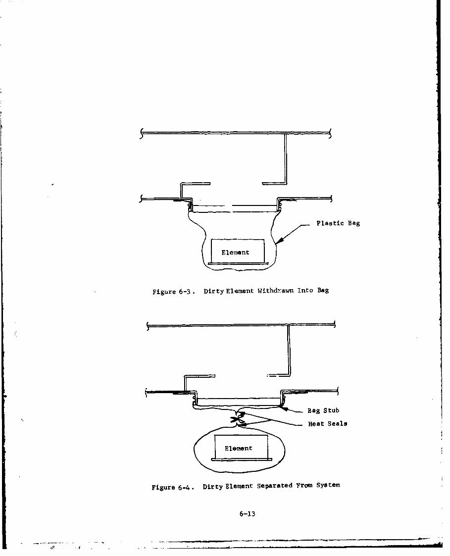
I!
Plastic Bag
(lemnt]
Figure 6-3. Dirty Eleament Withdrawn Into Bag
~Bag Stub
Heat Seals
Figure 6-4. Dirty Element Separated From Sydtem
6-13
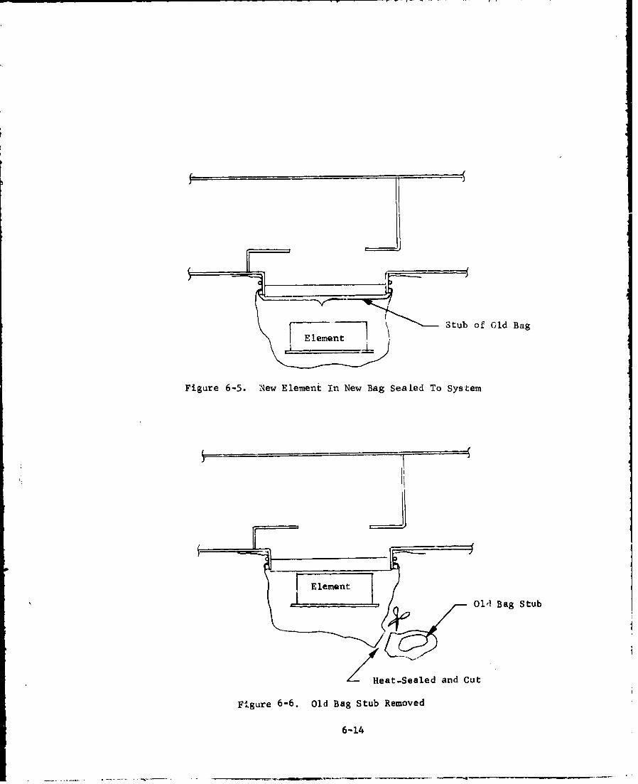
El n Stub of Old Bag
E lement
Figure 6-5. New Element In New Bag Sealed To System
I. 1
Old Bag Stub
Heat-Sealed and Cut
Figure 6-6, Old Bag Stub Removed
6-14

Element L -
,~/~'Plastic Bag Folded
Bag Restraint Tie Cord
Figure 6-7. Element In Place With Bag Folded
Figure 6-8. Operating Configuratdon With New Element In Place
6-15
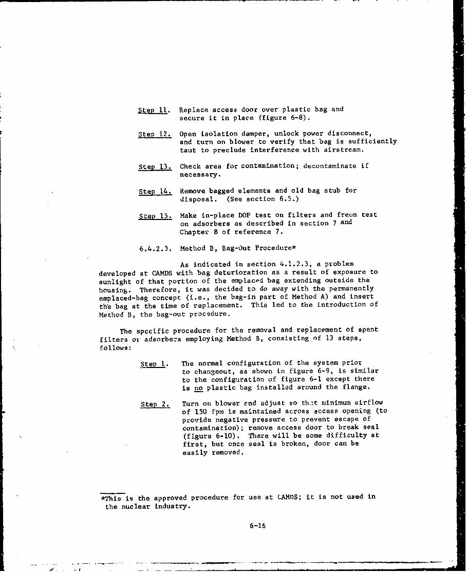
Step 11. Replace access door over plastic bag andsecure it in place (figure 6-8).
Step 12. Open isolation damper, unlock power disconnect,and turn on blower to verify that bag is sufficiently
taut to preclude interference with airstream.
Step 13. Check area for contamination; decontaminate ifnecessary.
Step 14. Remove bagged elements and old bag stub fordisposal. (See section 6.5.)
Step 15. Make in-place DOP test on filters and freun teston adsorbers as described in section 7 and
Chapter 8 of reference 7.
6.4.2.3. Method B, Bag-Out Procedure*
As indicated in section 4.1.2.3, a problem
developed at CAMDS with bag deterioration as a result of exposure to
sunlight of that portion of the emplaced bag extending outside the
housing. Therefore, it was decided to do away with the permanently
emplaced-bag concept (i.e., the bag-in part of Method A) and insert
the bag at the time of replacement. This led to the introduction of
Method B, the bag-out procedureý
The specific procedure for the removal and replacement of spent
filters or adsorbezs employing Method B, consisting of 13 steps,follows:
Step 1. The normal configuration of the system priotto changeout, as shown in figure 6-9, is similarto the configuration of figure 6-1 except thereis no plastic bag installed around the flange.
Step 2. Turn on blower £nd adjust so th:it minimum airflowof 150 fpm is maintained across access opening (toprovide negative pressure to prevent escape of
contamination); remove access door to break seal(figure 6-10). There will be some difficulty at
first, but once seal is broken, door can beeasily removed.
*This is the approved procedure for use at CAMDS; it is not used in
the nuclear industry.
6-16
E lamentNom1
Access Door Cover
Figure 6-9. Operating Configuration With Element In Place, Bag-OutProcedure
Elenent
At 150 fpm (Minimum)
Figure 6-10. Access Door Removed
6-17
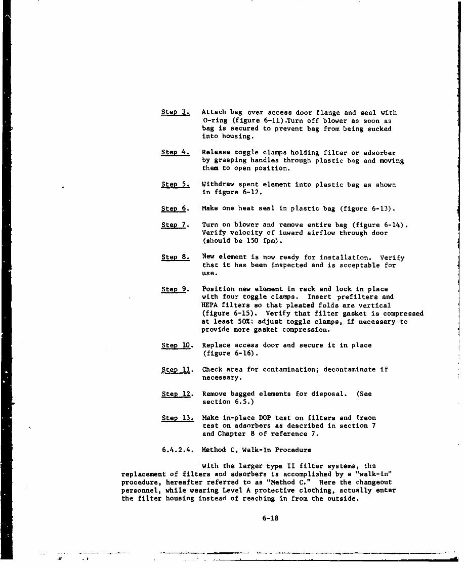
Step 3. Attach bag over access door flange and seal with0-ring (figure 6-11).Turn off blower as soon asbag is secured to prevent bag from being suckedinto housing.
Step 4. Release toggle clamps holding filter or adsorberby grasping handles through plastic bag and movingthem to open position.
Step 5. Withdraw spent element into plastic bag as shownin figure 6-12.
Step 6. Make one heat seal in plastic bag (figure 6-13).
Step 7. Turn on blower and remove entire bag (figure 6-14).Verify velocity of inward airflow through door(should be 150 fpm).
Step 8. New element is now ready for installation. Verifythat it has been inspected and is acceptable foruse.
Step 9. Position new element in rack and lock in placewith four toggle clamps. Insert prefilters andHEPA filters so that pleated folds are vertical(figure 6-15). Verify that filter gasket is compressedat least 50%; adjust toggle clamps, if necessary toprovide more gasket compression.
Step 10. Replace access door and secure it in place(figure 6-16).
Step 11. Check area for contamination; decontaminate ifnecessary.
Step 12. Remove bagged elements for disposal. (Seesection 6.5.)
Step 13. Make in-place DOP test on filters and freontest on adsorbers as described in section 7and Chapter 8 of reference 7.
6.4.2.4. Method C, Walk-In Procedure
With the larger type II filter systems, thereplacement of filters and adsorbers is accomplished by a "walk-in"procedure, hereafter referred to as "Method C." Here the changeoutpersonnel, while wearing Level A protective clothing, actually enterthe filter housing instead of reaching in from the outside.
6-18

SElement
Plasti a
Figure 6-11. Bag Installed Over Access Door Flangeand Blower Turned Off
Figure 6-12. Dirty Element Withdrawn Into Bag
6-19
S. ... . .. "S -w m• •
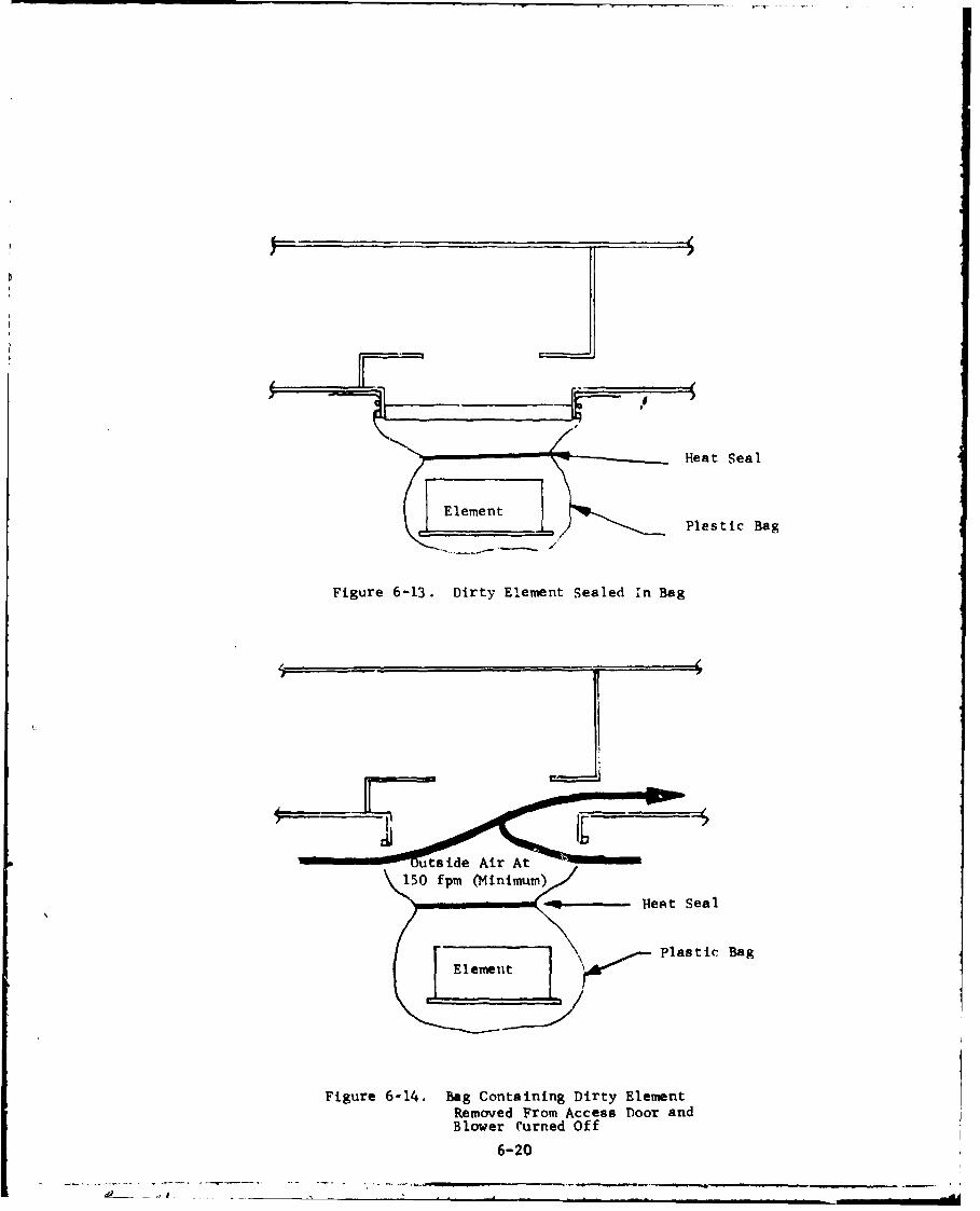
Heat Seal
. e Plastic Bag
Figure 6-13. Dirty Element Sealed in Bag
[ ~ +'~~ Plasin c Bag
Figure 6-14. Bag Containing Dirty ElementRemoved From Access Door andBlower Curned Off
6-20
a- l

At 150 fpm (Minimum)
Figure 6.15. New Element Installed
Access Door Cover
Figure 6-16. operating Configurationk With Element In Place
6-21
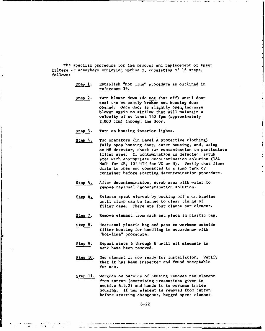
The specific procedure for the removal and replacement of spent
filters ur adsorbers employing Method C, consisting of 16 steps,follows:
Step . Establish "hot line" procedure as outlined inreference 39.
Step 2. Turn blower down (do not shut off) until doorseal can be easily broken and housing dooropened. Once door i3 slightly open9 increaseblower again to airflow that will maintain avelocity of at least 150 fpm (approximately2,000 cfm) through the door.
Step 3. Turn on housing interior lights.
Step 4. Two operators (in Level A protective clothing)fully open housing door, enter housing, and, usingan M8 detector, check ior contamination in particulatefilter area. If contamination is detected, scrubarea with appropriate decortamination solution (187.NaOH for GB, 10% HTH for VX or H). Verify that floordrain is open and connected to a sump tank orcontainer before starting decontamination procedure.
Step 5. After decontamination, scrub area with water toremove residual decontamination solution.
Step 6. Release spent element by backing off spin handles
until clamp can be turned to clear flaige offilter case. There are four clamps per element.
Ste7. Remove element from rack an" place in plastic bag.
Step 8. Heat-seal plastic bag and pass to workman outsidefilter housing for handling in accordance with"hot-line" procedure.
Step 9. Repeat steps 6 through 8 until all elements in
bank have been removed.
Step 10. New element is now ready for installation. Verifythat it has been inspected and found acceptablefor use.
Step 11, Workman on outside of housing removes new elementfrom carton (exercising precautions given insection 6.3.2) and hands it to workman insidehousing. If new element is removed from cartonbefore starting changeout, begged spent element
6-22

can be immediately placed in this carton fordisposal.
Step 12. Install new element in bank and lock in placewith four spin handles. Insert HEPA filtersso that their pleated folds are vertical.Verify that filter gasket is compressed at least50%; adjust toggle clamps, if necessary, toprovide more gasket compression.
Ste_ 13. Repeat steps 10 through 12 until all elements ina bank have been replaced,
Step 14. Secure access doors and turn off blower.
Step 15. Make in-place DOP test on filters and freon teston adsorbers as described in section 7 &ad Chapter8 of reference 7.
Step 16. Close all access doors and clear "hot-line".
6-23
.. .'. ........
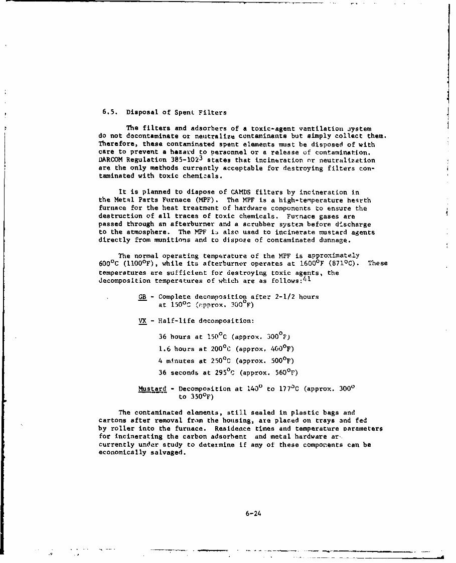
6.5. Disposal of Spen. Filters
The filters and adsorbers of a toxic-agent ventilation aystemdo not decontaminate or neutralize contaminants but simply collect them.Therefore, these contaminated spent elements must be disposed of withcare to prevent a hazard to personnel or a release of contamination.DARCOM Regulation 385-1023 states that incineration or neutralizationare the only methods currently acceptable for destroying filters con-taminated with toxic chemicals.
It is planned to dispose of CAMDS filters by incineration inthe Metal Parts Furnace (MPF). The MPF is a high-temperature hearthfurnace for the heat treatment of hardware components to ensure thedestruction of all traces of toxic chemicals. Furnace gases arepassed through an afterburner and a scrubber system before dischargeto the atmosphere. The HPF iL also used to incinerate mustard agentsdirectly from munitions and to dispose of contaminated dunnage.
The normal operating temperature of the MPF is approximately600 0 C (1100 0 F), while its afterburner operates at 1600°F (871 0 C). Thesetemperatures are sufficient for destroying toxic agents, thedecomposition temperatures of which are as follows:41
GB - Complete decomposition after 2-1/2 hours
at 150 0 C .'rpprox. 300 0 F)
VX - Half-life decomposition:
36 hours at 150 0 C (approx. 300°F)
1.6 hours at 200 0 C (approx. 4000F)
4 minutes at 250 0 C (approx. 500 0 F)
36 seconds at 295 0 C (approx. 560 0 F)
Mustard - Decomposition at 1400 to 1770C (approx. 3000to 3500 F)
The contaminated elements, still sealed in plastic bags andcartons after removal from the housing, are placed on trays and fedby roller into the furnace. Residence times and temperature oarametersfor Incinerating the carbon adsorbent and metal hardware ar,.currently under study to deteimine if any of these components can beeconomically salvaged.
6-24
A ________

7. TESTING
There are five general types of testing of interest in chemicaldemil air-cleaning and ventilation systems. An additional phase,prototype qualification testing by vendors, is beyond the scope ofthis handbook. Tests of particular interest are:
1. Initial acceptance testing2. Preoperational testing3. Air balancing4. Systems integration testing5. In-service testing
All of these test procedures, which are described in the followingsections, should be preceded with a careful visual inspection of allitems to be checked during the tests.
7.1. Initial Acceptance Testing
New HEPA filters and adsorbers cre subjected to post-installationacceptance tests. The specific objectives of these tests are:
1. Verify downstream leaktightness of the two HEPAfilter banks normally installed in each filter housing,based on an upstream challenge with DOP (dioctylphtalate)smoke.
2. Verify downstream leaktightness of the two adsorberbanks normally installed In each filter housing, basedon an upstre&m challenge with Refrigerant-12 freon gas(dichlorodi luoromethana).
WJP testing verifies the integrity (leaktightness) of the installedfilter system and of the filters thewselves. which were previouslyefficiency-tested by the manufacturer. It is conducted in accordancewith section 10 of ANSI N5108 and is discussed in detail in section8.3.1 of reference 7. Freon testing is conducted in accordance withsecticn 12 of ANSI N510 and is discussed in section 8.3.2 of reference7. It measures the overall integ'ity of the installatton and thequality of mnanufacture of the adsorbers. No specific :ests are requiredon preflIters.
The test plan used for the acceptance testing of CAMDS air filtersystems is given in reference 42.
7.2. Preoperational Testing
After completion of the initial acceptance tests, each completefilter system undergoes a series of preoperation tests to ensure thatthe entire system is ready for operation. The specific test obi'-ctives
7-1

are:
1. Verify accuracy of filter syatem flow instruments,controls, and alarms as compared to readings obtainedwith calibrated air-flow instrumeit.
'. Determine pressure drop across each bank of prefilters,HEPA filters, and adsorbers as well as across entirefilter system at initial (clean) condition and at fivesubsequent arbitrarily-selected higher static-pressurevalues.42
3. Verify the capability of the blower unit to maintainthe specified volume airflow hen the filter system'sresistance is increased by 125% over the initial (clean)pressure drop.
4. Determine amperage, rpm, discharge, and AP characteristicsof the fan motor.
7.3. Air Balancing
Once the filter system has been verified as being operational andall ductwork and dampers are instqlled, the air balancing of theventilation system for each area may be performed. The system isbalanced by adjusting airflow and differential pressures to meet thegeneral criteria given in section 3.2 for determining ventilationrates.
The specific objectives of air balancing are:
I. Adjust dampers to establish desired system flows andpressures.
2. Verify airflow and differential pressure capabilitiesof the various ventilation subsystems in both toxicand non-toxic areas.
3. Vc!ify airflow from less contaminated areas to morecontaminated areas.
4. Assess performance of the system's fail-safe features,power-off operation, interlock devices, automatic andmanual controls, annunciators, and alarms.
5. Evaluate overall performance of the system inaccordance with design specifications.
Tn,. ventilation system is generally accepted after requiredadjustments are made and the tests successfully demonstrate that allairflows and differential pressures meet design specificatiomas.
7-2
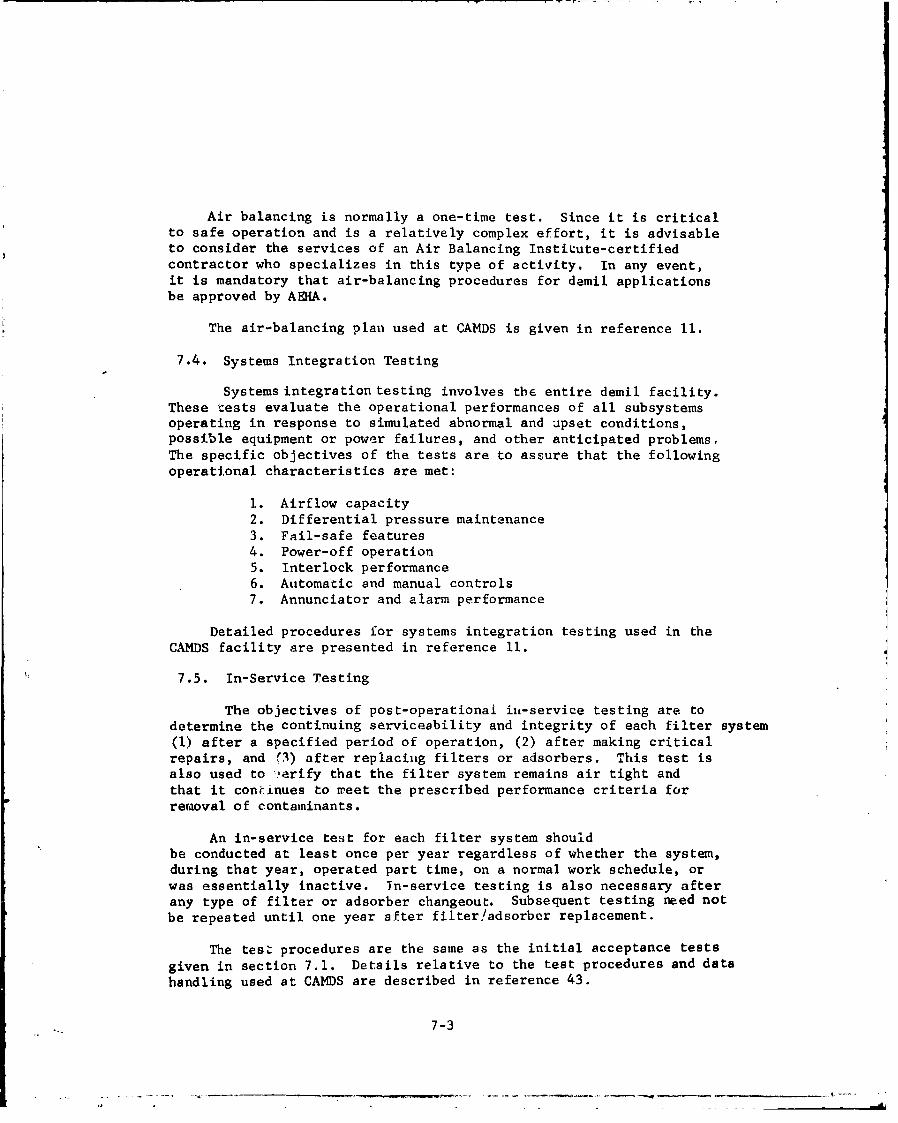
Air balancing is normally a one-time test. Since it is criticalto safe operation and is a relatively complex effort, it is advisableto consider the services of an Air Balancing Institute-certifiedcontractor who specializes in this type of activity. In any event,it is mandatory that air-balancing procedures for demil applicationsbe approved by AEHA.
The air-balancing plan used at CAMDS is given in reference 11.
7.4. Systems Integration Testing
Systems integration testing involves the entire demil facility.These tests evaluate the operational performances of all subsystemsoperating in response to simulated abnormal and upset conditions,possible equipment or power failures, and other anticipated problems,
The specific objectives of the tests are to assure that the followingoperational characteristics are met:
1. Airflow capacity2. Differential pressure maintenance3. Fail-safe features4. Power-off operation5. Interlock performance6. Automatic and manual controls7. Annunciator and alarm performance
Detailed procedures for systems integration testing used in the
CAMDS facility are presented in reference 11.
7.5. In-Service Testing
The objectives of post-operationai in-service testing are todetermine the continuing serviceability and integrity of each filter system(1) after a specified period of operation, (2) after making criticalrepairs, and r3) after replacing filters or adsorbers. This test isalso used to ".erify that the filter system remains air tight andthat it continues to n'eet the prescribed performance criteria forremoval of contaminants.
An in-service test for each filter system shouldbe conducted at least once per year regardless of whether the system,during that year, operated part time, on a normal work schedule, orwas essentially inactive. Tn-service testing is also necessary afterany type of filter or adsorber changeout. Subsequent testing need notbe repeated until one year after filter/adsorber replacement.
The test procedures are the same as the initial acceptance testsgiven in section 7.1. Details relative to the test procedures and datahandling used at CAMDS are described in reference 43.
7-3

7.6. CAMDS Test Experience
In evaluating the nuclear-concept filter system designed for CAMDSuse, it-was necessary to generate life data (i.e., capacity of the cellsto retain a specified quantity of chemical agent) since such informationwas not otherwise available from the nuclear industry. Therefore, lifetesting was initiated at CANDS to verify that the system could perform asrequired. Three separate sets of tests were conducted. The first set wasperformed on type II adsorber cells prior to the preparation of a procure-ment specification; the second set involved type II cells supplied as partof the first-article testing of the procurement specification; and thethird set pertained to a completely installed filter system at the CANDSsite.
Set No. 1
A series of six type II adsorber cells, containing coconut-baseactivated carbon, were tested with high concentrations of agent GB. Oneadditional cell was tested with a high concentration of VX in aerosol form.The XCIO-1 carbon filter cell (the basic adsorber component in the ArmyCBR filter unit) was also tested to provide a basis for comparison. Testingwas conducted at the U.S. Army Edgewood Arsenal toxic test chamber duringthe period October 1973 through May 1975. The test results indicated thatthe percentage of leakage detected was substantially iess than 0.01%. Thefilters were tested to breakthrough to obtain their protective life. The"break time" and "protective life time" determined tor the NPP-2 filtercells were both acceptable.
Set No. 2
This test, to verify adsorber efficiency, consisted of subjecting
six adsorber cells which had undergone rough handling to a high concentra-
tion of DMMP, a GB simulant. The cells were required to adsorb a minimum
of 200,000 mg-min/m 3 of DMMP with leakage not to exceed 0.01% of the up-
stream challenge concentration. A value of 200,000 mg-min/m3 was deter-
mined as the maximum challenge concentration that the adsorber might
encounter from a GB-saturated airstream passing through the cell at the
rated flow for 20 minutes. All six cells successfully passed this test
with values exceeding 300,000 mg-min/m 3 (see section 4.1.1.3.2.),
Set No. 3
An actual agent-challenge test with live GB was conducted on the
UPA filter system on 8-9 January 1977 in accordance with an approved testplan. Specific test objectives were:
Model NPP-2, manufactured by Farr Filter Co., Los Angeles, California
7-4

1. Demonstrate that a CAMDS filter system can maintain theestablished stack emission limit of 3.0 x 10- mg/m 3
for GB under the worst-case challenge condition (determinedto be 300 mg/m 3 ).
2. Determine the actual reduction ratio for GB agentchallenging a single adsorber bank.
The test results13 showed:
1. The UPA filter unit is capable of maintaining theestablished GB stack emission limit of 3.0 x 10⁻⁴
mg/m 3 under worst-case challenge conditions.
2. The reduction ratio of a single adsorber bank is smallerthan 9 x 10⁻⁸*.
3. The dosage of a single adsorber bank at breakthroughexceeds 1.2 x 10⁵ mg-min/m 3 .
Subsequent on-site tests at CAMDS have demonstrated that leakageoccurring through installed filters and adsorbers usually takes placebetween the sealing frame and mounting frame and is invariably caused bypoor clamping, All tested cells were visually examined prior to instal-
lation. Very few prefilters and HEPA filters, and no adsorber cells, werefound to be damaged. All damaged units were rejected for use cnd returnedto their manufacturers.
Several banks failed the applicable leakage tests. In all instances
but two, the problem was directly traced to inadequate clamping of a cell
or cells to the mounting frame. In the two exceptions, pin holes werediscovered in the frames of HEPA filters, and these were believed causedby overclamping considerably beyond simple hand tightness.
Supply of allocated GB agent was consumed before breakthrough ofadsorber bank could be achieved.
7-5

8. APPLICATION OF AIR CLEANING CONCEPTS TO DATS
8.1. Introduction
The basic principles of the CAMDS air filter/ventilation systemhave recently been applied to a new air-cleaning system being'developedfor DATS (Drill and Agent Transfer System). DATS is intended to serveas a portable unit at remote facilities housing small quantities ofunserviceable chemical munitions. Its puarpose is to drain and decon-taminate the munitions without exce'ýding chemical-agent emissionstandards. A detailed description of the DATS filter/ventilationsystem, designed by CSL, follows.
8.2. Description
DATS is designed to process small groups of unsetviceablemunitions, one at a time, at a rate of five items per day. The DATSsite uses a 666-cfm glovebox and ventilation system (figure 8-1) forthis purpose. The latter system includes an air filter housing,primary and emergency blowers, dampers, switches, indicator-lightgages, and sampling ports. The air-filter housing contains a pre-filter section, a HEPA filter section, two adsorber sections, and afinal HEPA filter section. All key components of the system areshown in figure 8-2.
The emergency blower is provided in case of failure of the primaryblower (figure 8-3). Seven dampers are located throughout the systemto regulate the airflow as desired (figure 8-4). The operator'sconsole panel (figure 8-5) contains two selector and four pushbuttonswitches, 13 indicator lights, and six differential pressure (Magnehelic)gages. Additional differential pressure gages are located on theloading chamber and glovebox; the latter also contains a pressureswitch/gage (PhotohelLc). Figure 8-6 depicts the locr-.ions of thevarious sampling ports and inspection plates on the rilter housing.
The 666-cfm air-filter system is designed to remove contaminantsfrom the exhaust air of the glovebox and loading chamber, both ofwhich provide containment for chemical agents. Front and rear viewsof the 666-cfm filter housing are shown in figures 8-7 and 8-8,respectively. Figure 8-9 illustrates the airflow pattern through thehousing.
Airflow through the glovebox, normally ranging from 600 to 666cfm, is maintained by a 5-hp blower (primary or emergency) and isindicated by one of the gages on the control console. The five othergages on the console indicate differential pressure across eachfilter/adtorber and are monitored for information on filter status.
A list of the major equipment associated with the DATS ventilationsystem (exclusive of filters and adsorbers) is given irt Table VIII-l.
8-1
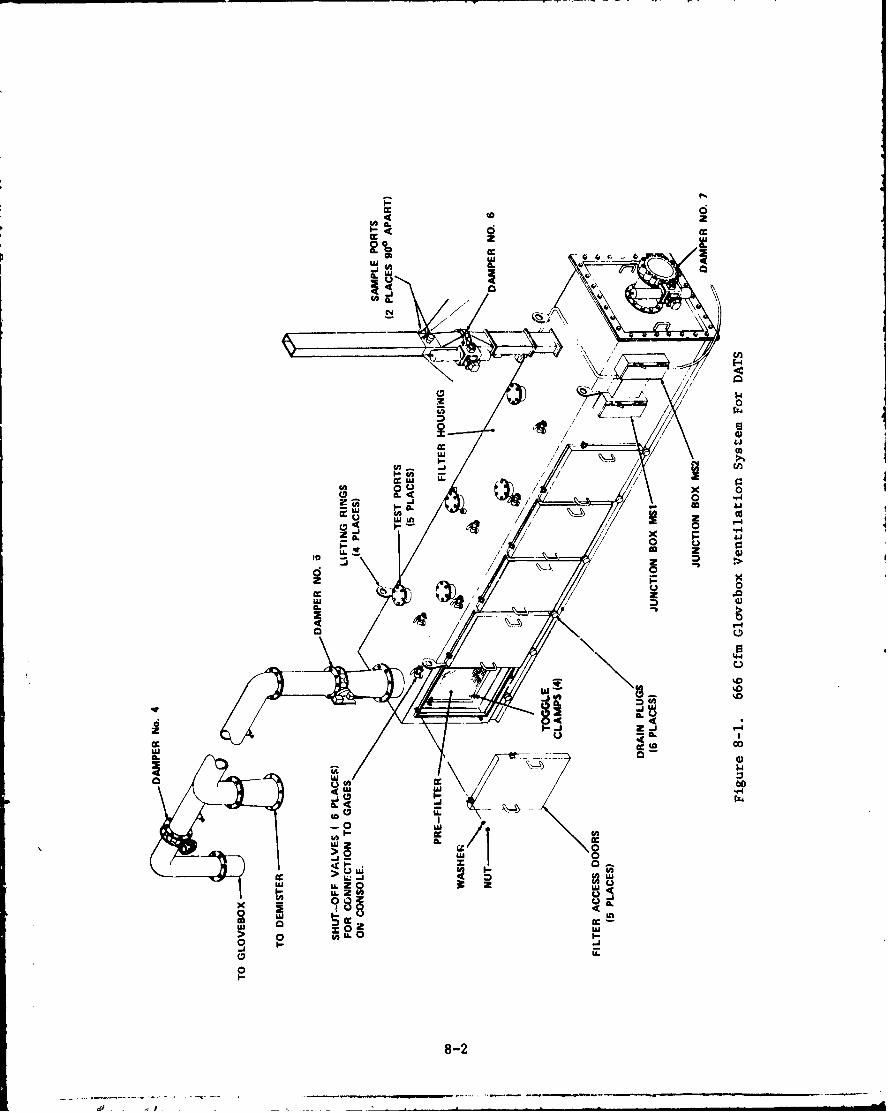
ddcc to
I cn
44.
"I4
to >
co)Mi- E
06
-0 0U
>i (J 2U
to C inLU LLZ z i
LL 0 tICOo ~ -. --A98
0I-L
8-2
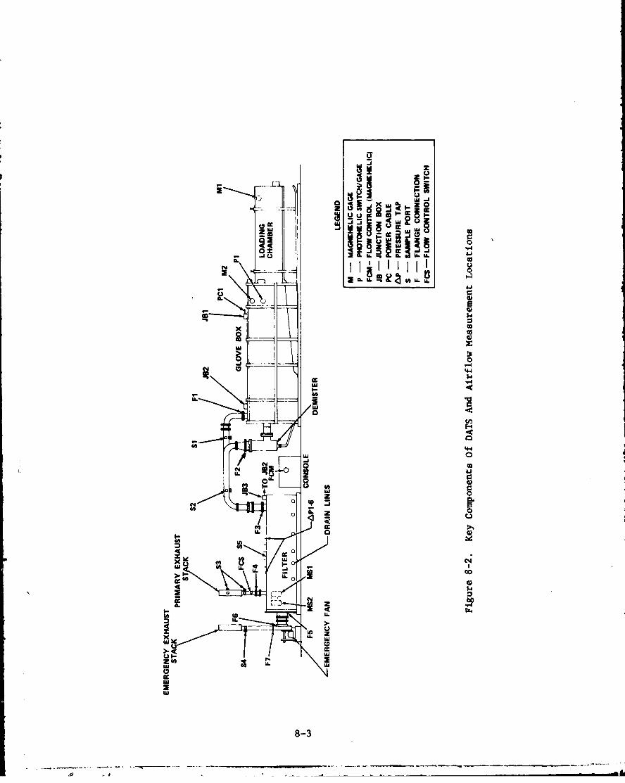
z0UAU
00
U.U
ca
00
4.4
0
S. - .60-
N7 0
LL. 3 4
IL) 8 - I- (Y
cc 0
41 142 0
a.L
08-3
LIFTING RINGS-,
PRIMARY BLOWER SAMPUNG PORTS
(INSIDE FILTER HOUSINO•
FI LTCRHOUSING
JUNCTION BOX MS1 .
{ 0.. 0TIO 0 , -LIFTING RING
0 EMERGENCY BLOWER
LIFTING RING
SINFORMATIONCOMBINATION PLATESMOTOR STARTERAND DISCONNECTSWITCH
EMERGENCYBLOWER
DAMPER NO. 6MAINTENANCE PANEL(ACCESS TO PRIMARYBLOWER) OI/
HOLD-DOWN
BOLT LOCATIONS
Figure 8-3. Primary And FRnergency Blower For DATS
8-4
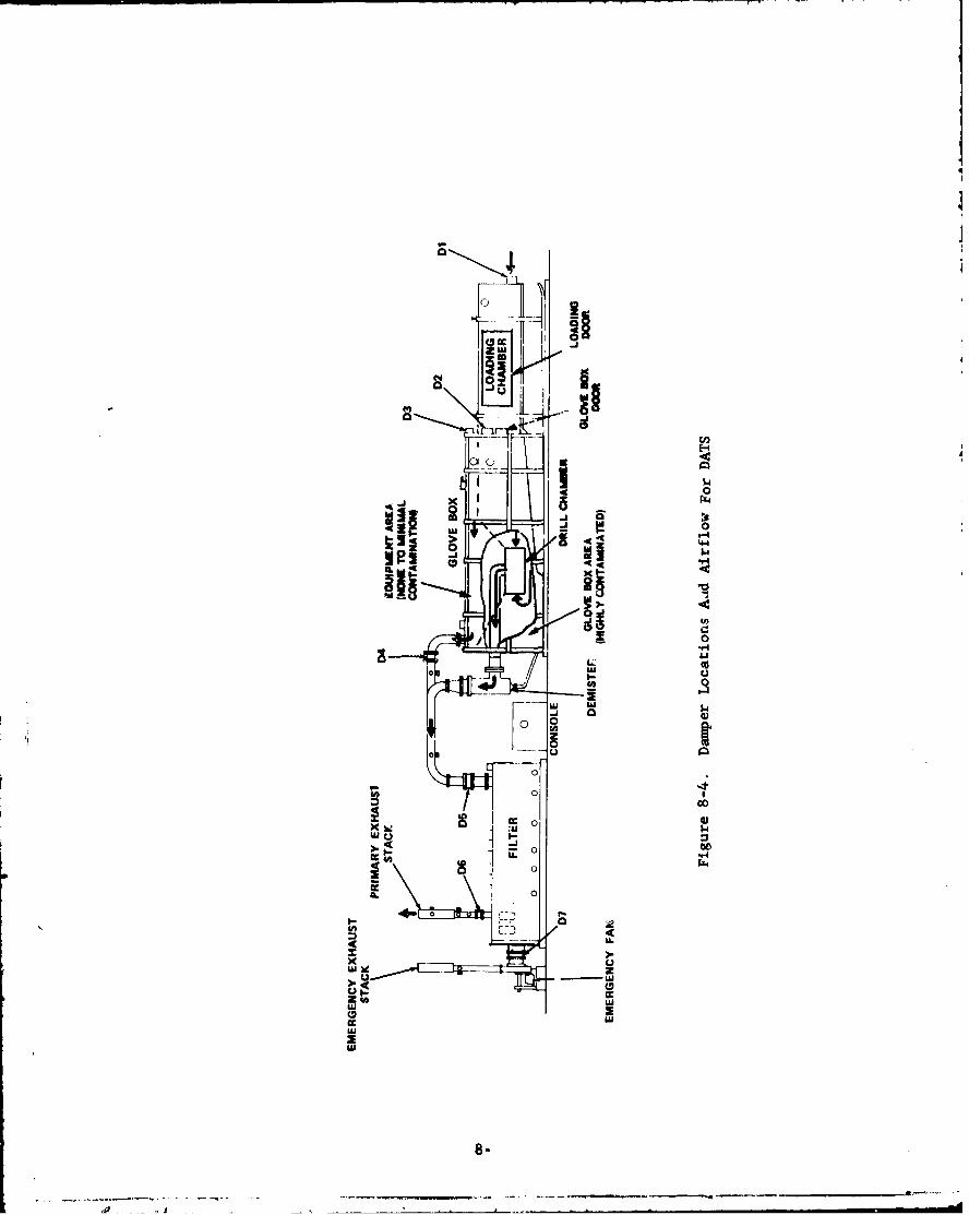
-m-
000
-4
4"
00
UlU
>.~
-w9
w0 0
C,
0 L
8-U
.4 ~ .i

01)
j4)
rOCA
n wD
8-6a~

I- r- 1
I-I II
0
".4t5 a,2
4 WI
2Si
6
Ul.a
C
a,4 0
4.)0
'-4
-I 0
4.)WI
�aSi a,
H
4.)I..'0
p.4
".4'-4
4
td
Ii 1i�1.8
WI
8-7
- -. ',-.---------.--,.-...- -- - �.---.--�-.-.---- p ---.
�-- .�l ..

4-4
00
8-8J

0 )
-,*4
00
>.4-
Ur 4
sCd
00
0f4.
8-9

IN T
MCPAA FILTERNO.. I
Figure R TO9 DigaKfAifo hogrWASFl er Ui
NO8-10

Iw 4w0.
I '4
41 C6 IL.
41 4
4144
lwl
-1 0 04
0. 4.1
01 0 000
01 AU A
to LW C 044 Aj r. 4
.4. to104.1 r14.1440
4 4~ 1.. 0 14 roCO CL
41 U-C4 04 -C
.-4 410 I' C"14 "4 0 0
01 41 44 0.
.0* ;. uc u- v
c !0 0 La 4~ CL Ca M
.14. f 0 4.1 § I 4i
0C O 0 0.14 0 U 1 .9 "1 '4CL be l. Qj -C 'D M
I-I 44 "a4 A 4 Z
I-I .4.4~ wA. -4 $ - 4>. C. *u 41 414 41 4141 14-
41~ 4 44441 44
~~~~~~t 2 o .a.- -.. - ~m .4..
41 1 " V 4.1 4l$a -A 14 41 C4r 104
4.A to 41 0 1
4,. C.n 41 a6 1
1441 W - 41 40 410u0
44 04. 44 41 to " 414 -A "
4.1 z 11~
t ~ . ~ I
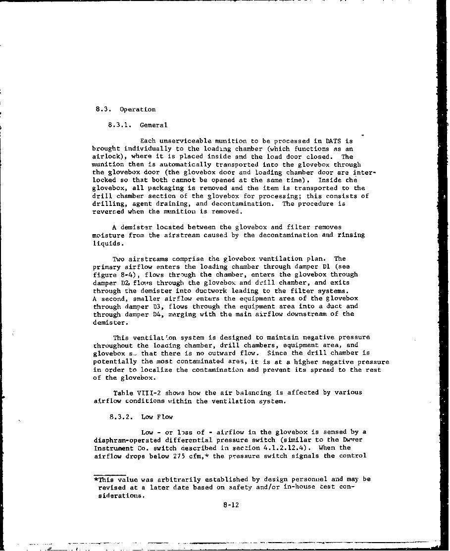
8.3. Operation
8.3.1. General
Each unserviceable munition to be processed in DATS isbrought individually to the loading chamber (which functions as anairlock), where it is placed inside and the load door closed. Themunition then is automatically transported into the glovebox throughthe glovebox door (the glovebox door and loading chamber door are inter-locked so that both cannot be opened at the same time). Inside theglovebox, all packaging is removed and the item is transported to thedrill chamber section of the glovebox for processing; this consists ofdrilling, agent draining, and decontamination. The procedure isrevereed when the munition is removed.
A demistBr located between the glovebox and filter removesmoisture from the airstream caused by the decontamination and rinsingliquids.
Two airstreams comprise the glovebox ventilation plan. Theprimary airflow enters the loading chamber through damper Dl (seefigure 8-4), flows through the chamber, enters the glovebox throughdamper D2, floiqs through the glovebox and drill chamber, and exitsthrough the demister into ductwork leading to the filter systems.A second, smaller airflow enters the equipment area of the gloveboxthrough damper D3, flows through the equipment area into a duct andthrough damper D4, merging with the main airflow downstream of thedemister.
This ventilation system is designed to maintain negative pressurethroughout the loacing chamber, drill chambers, equipment area, andglovebox s,- that there is no outward flow. Since the drill chamber ispotentially the most contaminated area, it is at a higher negative pressurein order to localize the contamination and prevent its spread to the restof the glovebox.
Table VIII-2 shows how the air balancing is affected by various
airflow conditions within the ventilation system.
8.3.2. Low Flow
Low - or liss of - airflow in the glovebox is sensed by adiaphram-operated differential pressure switch (similar to the DwvrerInstrument Co. switch described in section 4.1.2.12.4). When theairflow drops below 275 cfm,* the pressure switch signals the control
*This value was arbitrarily established by design personnel and may berevised at a later date based on safety and/or in-house test con-siderations.
8-12

Table VIII-2. Ventilation System Balance Conditions
For IDTS
Condition 1 Condition 2 Condition 3 Condition 4(Baaicl Load Door Load Door Emergency
Load Door Open & Glove- Closed & Glove- BlowerItem Closed & box Door box Doo-" On (e)No.(a) Glovebox Closed (c) Opened (d)
Door Closed(b)
Dl 600 cfm 0 600 cfm 600 cfm
D2 600 cfm 600 cfm, 0 600 cfm
D3 66 cfm 66 cfm 66 cfm 66 cfm
D4 66 cfm 66 cfm 66 cfm 66 cfm
D5 666 cfm 666 cfm 666 cfm 666 cfm
D6 666 cfm 666 cfm 666 cfm 0 cfM
D7 0 0 0 666 cfm
Si 66 cfm 66 cfm 66 cfm 66 cfm
S2 666 cfm 666 cfm 666 cfm 666 cfm
S3 666 cfm 666 cfm 666 cfm 0
S4 0 0 0 666 cfm
Ml -.1 in. wg 0 -.1 in. wg. -.1 in. wg.
M2 -.1 in. wg. -.1 in. wg. -.1 in. sg -.1 in. wg.
P1 -. 3 in. wg -. 2 in. wg. -. 3 in. wg. -. 3 in. wg.
F CM 666 cfm 666 cfm 666 ctnI 666 cfm
Notes:
(a) Legend:D - DamperS - Sampling PortM - MAGNEHELIC Differential Pressure GageP - PHOTOHELIC Pressure Switch/GageFCM - MkGNEHELIC Flow Control
(b) Load door and glovebox door are interlocked so that both cannot beopened at same time.
(c) When munition is put in or removed from loading chamber.
(d) When munition is transferred from loading chamber ?o glovebox.
(e) When primary blower fails to provide sufficieait airflow.
8-13

console of an alarm condition, actuating both an audible andvisual alarm and energizing a control relay, cau'sing the emergencyblower to start. A set of holding contacts ensures that the controlrelay remains energized once the loss of flow occurs, even if momentarily.The emergency-blower starter is controlled through a set of contactsfrom the control relay and interlocked with damper no. 7, located be-tween the back of the filter and the intake of the emergency blower.Before the emergency blower can start, the damper must be open. A redlight on the console indicates whe~n the emergency blower starts.
8.3.3. Low Differential Pressure
Differential pressure gages in the loading chamber andboth sections of the glovebox indicate the status of negative pressurein these enclosures. One of these three gages (the one in the con-taminated section of the glovebox), in addition to sensing low AP' isalso capable of signaling this condition to the control console. Thiscapability is not incorporated in the other two gages since they arenot involved with contaminated areas. Since low L~P could occur in theglovebox with the airflow through the system remaining at an acceptablelevel, the emergency blower does not actuate when the low AP alarmoccurs; it is a warning alarm only.
8.3.4. Power
Three-phase electrical power for operating the primary andemergency blowers is routed from the generator through two disconnectswitch boxes (MSl and MS2 in figure 8-3) on the filter unit. Single-phase 120-volt power to the console for operating all control functions,solenoid valves, motor starters, etc., is routed directly from thegenerator to the console.
8.3.5. Emergency Sequence
The emergency blower automatically activates upon loss ofairflow through the glovebox. If the flow drops below the presetvalue on the fan-control gage, damper no. 6 will close a~id damperno. 7 will open, energizing the mo4-or starter of the emergency blower.The primary blower will stop and cannot be restarted as long as theemergency blower is operating.
8.3.6. Dampers
The operation and purpose of the seven dampers areexplained in Table VIII-3. The positions of dampers no. 5, 6, and 7are monitored on the console. Damper no. 5 must always show OPENduring both primary and emergency blower operation. Damper no. 6indicates OPEN (green light) and damper no. 7 indicates CLOSED (greenlight) when the primary blower is operating'. both dampers indicatea red light (for CLOSED and OPEN, respectively) when the emergencyblower is running.
8-14

Table VIII-3. Purpose And Function Of Dampers InDATS Ventilation System
DamperNo. Purpose Function
To create -.1 in. wg in'load area Normally OPEN. Pneumaticallyunder all conditions except when operated. Damper required to
glovebox door is open. To create have two OPEN positions. OPEN
-. 3 in. wg in both loading chamber position of damper controlled by
and glovebox when glovebox door is pneumatic signal from glovebox
open. door received by air valve (3-way) connected to the damperactuator. Damper has manualstop to prevent damper fromfully closing during operationsdue to unscheduled loss of com-pressed air. For shutdownmanual stop retroved. Spring re-turn in pneumatic actuator willUlose damper and maintainsufficient tension on damperblade to minimize leakage.
2 To create -. 2 in. wg in glovebox. Normally OPEN. MechanicallyOperates when glovebox dc-r operated to minimize movingis closed. Closes when glovebox parts and fabricated from
door is open since opening for stainless steel since corrosive
glovebox door has greater cross- atmosphere during some oper-
sectional area. atLions probable. Mechanicaldampers cannot meet leakagerequirements of pneumatic orelectric dampers. Since damperinternally located extremely lowleakage not required.
3 To create .1 in. wg in equip- Noramlly OPEN, Pneumaticallyment area. operated with only one open
position. Pneumatic operatorcontains spring return. Whencompressed atr supply disconnected,spring return in pneumatic actuatorcloses damper and maintainssufficient tension on damper bladeto minimize leakage.
(continued)
8-15
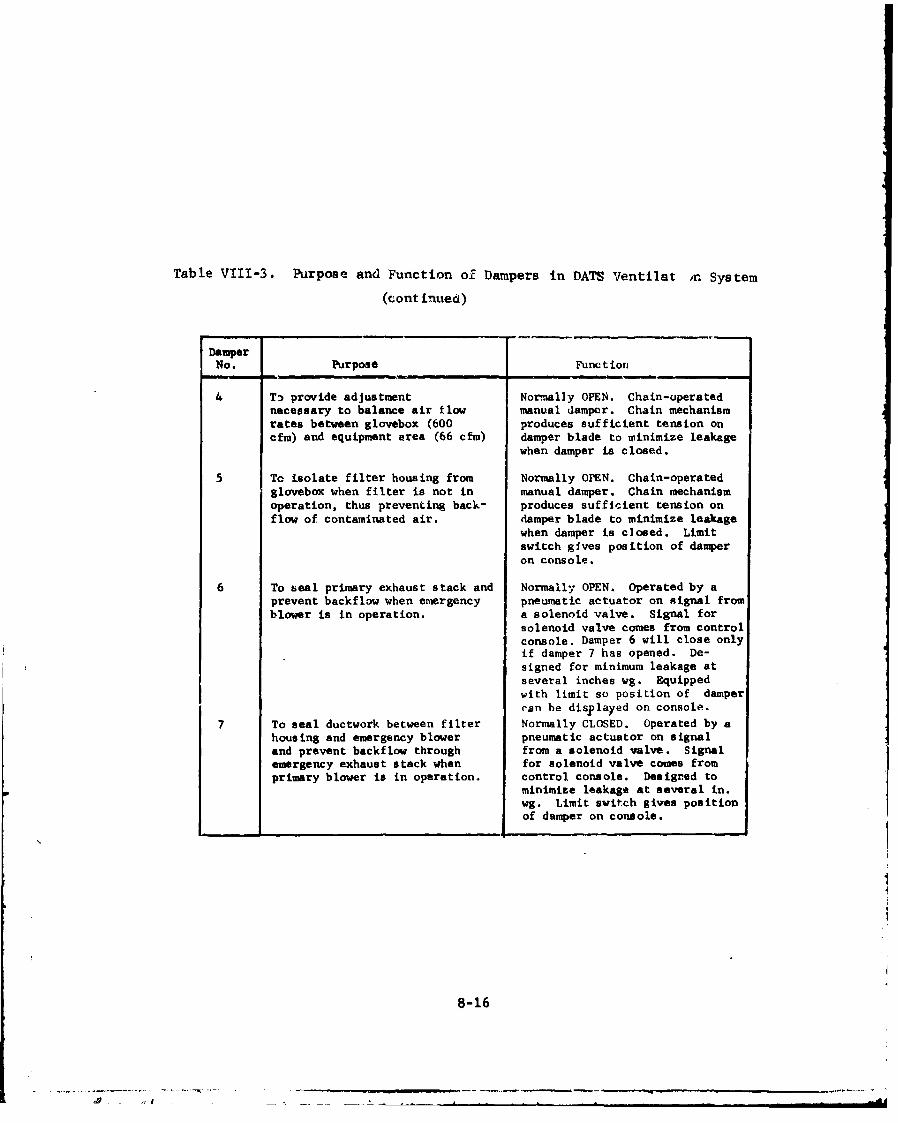
Table VIII-3. Purpose and Function of Dampers in DATS Ventilat in System
(cont inued)
DamperNo. Purpose Func t ion
4 T, provide adjustment Normally OPEN. Chain-uperatednecessary to balance air fl*w manual damper. Chain mechanismrates between glovebox (600 produces sufficient tension oncfm) and equipment area (66 cfm) damper blade to minimize leakage
when damper is closed.
5 Tc isolate filter housing from Normally OPEN. Chain-operated
glovebox when filter is not in manual damper. Chain mechanismoperation, thus preventing back- produces sufficient tension on
flow of contaminated air. damper blade to minimize leakagewhen damper is closed. Limitswitch gives position of damperon console.
6 To seal primary exhaust stack and Normally OPEN. Operated by aprevent backflow when emergency pneumatic actuator on signal fromblower is in operation. a solenoid valve. Signal for
solenoid valve comes from control
console. Damper 6 will close onlyif damper 7 has opened. De-signed for minimum leakage atseveral inches wg. Equippedwith limit so position of damperran he displayed on console.
7 To seal ductwork between filter Normally CLOSED. Operated by ahousing and emergency blower pneumatic actuator on signaland prevent backflow through from a solenoid valve. Signalemergency exhaust stack when for solenoid valve comes fromprimary blower is in operation. control console. Designed to
minimize leakage at several in.wg. Limit switch gives positionof damper on console.
8-16
S. - " I+ . ++ -. .. J . . . Li I I i I i i I I I

9. LITERATURE CITED
1. Smith, G., et al, Report No. ENCR 30, "Protection ofStructures from Chemical, Biological and Radiological (CBR)Contamination," U. S. Army Chemical Corps EngineeringCommand, June 1959 (Reprinted March 1962).
2. MIL-HDBK-753, "CB Collective Protection of Mobile Vehicles,Vans and Shelters," Dept. of Defense Military StandardizationHandbook, 31 August 1971.
3. DARCOM Regulation 385-102, "Safety Regulations for ChemicalAgents GB and VX," Dept. of Army Development and ReadinessCommand Regulation, February 1977.
4. "Industrial Ventilation, A Manual of Recommended Practice,"14th Edition, American Conference of Governmental IndustrialHygienists, 1977.
5. "ASHRAE Handbook of Fundamentals," American Society of Heating,Refrigerating and Air-Conditioning Engineers, Inc., 1972.
6. Jonas, L. A., J. A. Rehrmann, and J. M. Eskow, "Kinetics ofTrace Gas Adsorption from Contaminated Air;" reprint fromAmerican Chemical Society Symposium Series No. 17, "aemovalof Trace Contaminants from the Air," 1975.
7. Burchsted, C.,J.Kahn, and A. Fuller, ERDA Report 76-21, "NuclearAir Cleaning Handbook," Energy Research & Development Adminis-tration, July 1969.
8. ANSI N510, "Standard for Testing of Nuclear Air CleaningSystems," American National Standards Institute, 1975.
9. ASTM D1056, "Specification for Sponge and Expanded CellularRubber Products," American Society for Testing and Materials,1973.
10. AACC CS-8, "Standard for High Efficiency Gas Phase AdsorberCells," Institute of Environmental Sciences, July 1972.
11. CSL 611-21, "Test Plan for Building Block (BB) No. 23,Balancing and Testing of the CAMDS Heating and VentilatingSystem, Test No. CAMDS 23-4," Dugway Proving Grounds,Dugway, Utah, January 1977.
12. AMCA 201, "Fan Application Manual," Air Moving and ConditioningAssociation, Inc. (Date unknown.)
9-1

13. Daughdrill, D., CSL 611-19, "Detailed Test Report - GBChallenge Testing of the CAMDS Unpack Area Filter Unit,"Office of Program Manager for Chemical Demilitarization andInstallation Restoration, Aberdeen Proving Ground, Md.,February 1977.
14. "Guidelines for Air Pollution Source Sampling SitePreparations and Compliance Testing at Army Facilities,"
U. S. Army Environmental Hygiene Agency, Aberdeen ProvingGround, Md., January 1975.
15. ASHRAE Standard 52-68, "Method of Testing Air CleaningDevices Used in General Ventilation for Removing ParticulateMatter," American Society of Heating, Refrigerating andAir-Conditioning Engineers, Inc., August 1968.
16. ANSI N509, "Nuclear Power Plant Air-Cleaning Units andComponents," American National Standards Institute, 1976.
17. UL-900, "Safety Standard for Air Filter Units," Underwriters'Laboratories, 1971.
18. AACC CS-I, "Standard for HEPA Filters," Institute ofEnvironmental Sciences. (Date unknown.)
19. UL-586, "Safety Standard for High Efficiency Air FilterUnits," Underwriters' Laboratories, 1977.
20. MIL-F-51079, "Filter, Medium, Fire Resistýnt, HighEfficiency," Dept. of Defease MiliLary Specification,September 1963.
21. MIL-F-51068, "Filter, Particulate, High Efficiency, FireResistant," Dept. of Defense Military Specification,December 1970.
22. ASTM A167, "Specification for Stainless and Heat-ResistingChromium Nickel Steel Plate, Sheet, and Strip," AmericanSociety for Testing and Materials, 1974.
23. ASTM A240, "Specification for Corrosion-Resisting Chromiumand Chromium-Nickel Steel Plate, Sheet, and Strip,"American Society for Testing and Materials, 1975.
24. ASTM A176, "Specification for Stainless and Heat-ResistingChromium Steel Plate, Sheet, and Strip," American Society forTesting and Materials, 1975.
9-2

25. MIL-C-13724, "ASC, Impregnated, Activated Charcoal," Dept.of Defense Military Specification, September 1972.
26. ASTM D2652, "Definitions of Terms Relating to Activated Carbon,"
American Society for Testing and Materials, 1976.
27. ASTM D2862, "Particle Size Distribution of GranularActivated Cnrbon," American Society for Testing and
Materials, 1970.
28. ASTM E323, "Perforated Plate Sieves for Testing Purposes,"
American Society for Testing and Materials, 1970.
29. ASTM D1330, "Specification for Sheet Rubber Gaskets,"American Society for Testing and Materials, 1972.
30. ANSI B46.1, "Sufface Texture," American National StandardInstitute, 1971
31. TM 3-6665-225-12, "Alarm, Chemical Agent, Automatic:Portable," Dept. of Army Technical Manual, August 1975.
32. DARCOM Regulation 385-31, "Safety Regulations for Chemical
Agents R, HD and HT," Dept. of Army Development and Readiness
Comýand Regulation, September 1975.
33. CSL 100-26, "Medical Surveillance of Personnel Potentially
Exposed to Cholinesterase Inhibiting Substances (CIS),"
Letter AMCMM-0, Commanding General, Army Materiel Command,to Project Manager, Chemical Demilitarization and
Installation Restoration, Aberdeen Proving Ground, Md.,
11 December 1975.
34. DA Pamphlet 385-3, "Protective Clothing Equipment," Dept. ofArmy, 1968.
35. TM 750-5-15, "Chemical Weapons and Defense Equipment," Dept.of Army Technical Manual, April 1969.
36. TM 10-277, "Protective Clothing Chemical Operations," Dept.of Army Technical Manual, July 1967.
37. TM 3-4240-258-14, "Mask, CBR; Field, MI7AI and Accessories,"Dept. of Army Technical Manual, March 1968.
38. TM 3-4240-240-14, "Mask, Chemical-Biological, SpecialPurpose, M9Al; Mask, Chemical-Biological, Special Purpose,
M9; and Accessories," Dept. of the Army Technical Manual,26 October 1970.
9-3
39. FM 3-21, "Chemical-Biological Accident Contamination Control,"Dept. of Army Field Manual, August 1972.
40. MIL-STD-282, "Filter Units Performance Test Methods," Dept. of
Defense Military Standard, May 1956.
41. FM 3-9, "L:ilitary Chemistry," Dept. of Army Field Manual,October 1975.
42. CSL 611-22, "Test Plan for Building Block (BB) No. 23,
Acceptance Test of CAMDS Air Filter Systems, Test No.
CAMDS 23-3," Demilitarization/Disposai Office,EdgewoodArsenal, Aberdeen Proving Ground, Md., 20 September 1976.
43. CSL 611-20 (IM323-01-20), "Performance Test and ElementReplacement Manual for Air Filter Systems," CAMDSDirectorate, rooele Army Depot,Utah, May 1977.
44. Smith, G., Report No. ARCSL-SP-77004 (EM-SP-77005),"Performance Evaluation of Gas Filters," April 1978(Planned).
45. ,,TLVs( Threshold Limit Values for Chemical Substances and
Physical Agents in the Workroom Environment with Intended
Changes for 1977," American Conference of Governmental
Industrial Hygienists, 1977.
9-4

10. GLOSSARY OF TERMS
10.1. Acronyms and Abbreviations
A - Area
AACC - American Association for Contamination Control(now Institute of Environmental Sciences)
ACGIR - American Conference of Governmental IndustrialHygienists
ADS - Agent Destruction System, a unit of CAMPS
AEC - Atomic Energy Conmmission (see also ERDA)
AEHA - Army Environmental Hygiene Agency
AFI - Air Filter Institute
AMCA - Air Moving and Conditioning Association
ANSI - American National Standards Institute
ARI - Air-Conditioning and Refrigeration Institute
ASHRAE - American Society of Heating, Refrigerating andAir-Conditioning Engineers, Inc.
ASME - American Society of Mechanical Engineers
ASTM - American Society for Testing and Materials
AWS - American Welding Society
BET - Brunauer, Emmett, and Teller; test for surfacearea of adsorbents
bhp - brake horsepower
BIF - Bulk Item Facility, a unit of CAMDS
CAMDS - Chemical Agent Munitions Disposal System, locatedat Tooele Army Depot, Tooeie, Utah
CBR - Chemical/Biological/Radiological
cfm - cubik feet per minute, ft 3 /min.
10-1
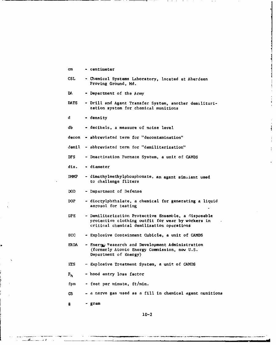
cm - centimeter
CSL - Chemical Systems Laboratory, located at AberdeenProving Ground, Md.
DA - Department of the Army
DATS - Drill and Agent Transfer System, another demilitari-zation system for chemical munitions
d - density
db - decibels, a measure of noise level
decon - abbreviated term for "decontamination"
demil - abbreviated term for "demilitarization"
DFS - Deactivation Furnace System, a unit of CAMDS
dia. - diameter
DMMP - dimethylmethylphosphonate, an agent simulant usedto challenge filters
DOD - Department of Defense
DOP - dioctylphthalate, a chemical for generating a liquidaerosol for testing
DPE - Demilitarization Protective Ensemble, a lisposableprotective clothing outfit for wear by workers incritical chemical demilization operations
ECC - Explosive Containment Cubicle, a unit of CAMDS
ERDA - Ener• Wesearch and Development Administration(formerly Atomic Energy Commission, now U.S.Department of Energy)
ETS -. Explosive Treatment System, a unit of CAMDS
Fh - hood entry loss factor
fpm - feet per minute, ft/min.
GB - a nerve gas used as a fill in chemical agent rtunitions
g - gram
10-2
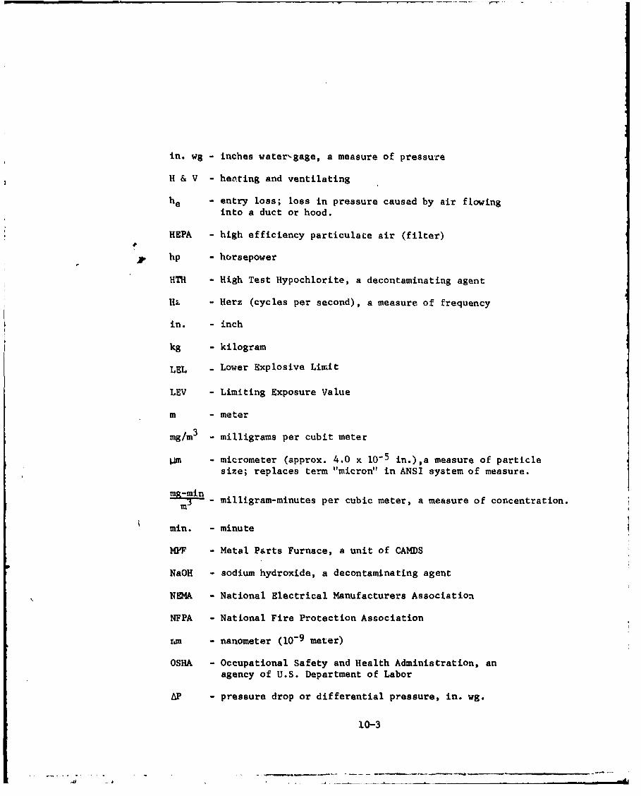
in. wg - inches water-gage, a measure of pressure
H & V - heating and ventilating
he - entry loss; loss in pressure caused by air flowinginto a duct or hood.
HEPA - high efficiency particulate air (filter)
Shp - horsepower
HTH - High Test Hypochlorite, a decontaminating agent
HL - Herz (cycles per second), a measure of frequency
in. - inch
kg - kilogram
LEL - Lower Explosive Limit
LEV - Limiting Exposure Value
m - meter
mg/m 3 - milligrams per cubit meter
Pm - micrometer (approx. 4.0 x 10"5 in.),a measure of particlesize; replaces term "micron" in ANSI system of measure.
m T - milligram-minutes per cubic meter, a measure of concentration.
min. - minute
MPF - Metal Parts Furnace, a unit of CAMDS
NaOH - sodium hydroxide, a decontaminating agent
NEMA - National Electrical Manufacturers Association
NFPA - National Fire Protection Association
ran - nanometer (10-9 meter)
OSHA - Occupational Safety and Health Administration, anagency of U.S. Department of Labor
AP - pressure drop or differential pressures in. wg.
10-3
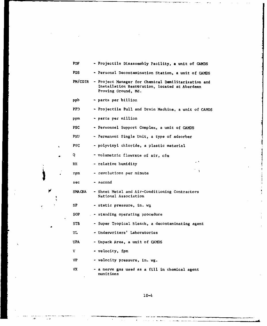
PDF - Projectile Disassembly Facility, a unit of CAMDS
PDS - Personal Decontamination Station, a unit of CAMDS
PM/CDIR - Project Manager for Chemical Demilitarization andInstallation Restoration, located at AberdeenProving Ground, Md.
ppb - parts per billion
PPD - Projectile Pull and Drain Machine, a unit of CAMDS
ppm - parts per million
PSC - Personnel Support Complex, a unit of CAMDS
PSU - Permanent Single Unit, a type of adsorber
PVC - polyvinyl chloride, a plastic material
Q - volumetric flowrate of air, cfm
RH - relative humidity
rpm - revolutions per minute
sec - second
SMACNA - Sheet Metal and Air-Conditioning Contractors¶ National Association
4SP - static pressure, in. wg
SOP - standing operating procedure
STB - Super Tropical Bleach, a decontaminating agent
UL - Underwriters' Laboratories
UPA - Unpack Area, a unit of CAMDS
V - velocity, fpm
VP - velocity pressure, in. wg.
YVX - a nerve gas used as a fill in chemical agentmunitions
10-4

10.2. Terms and Phrases
acceptance test. Test made upon completion of fabrication,installation, repair, or modification of a system, unit,component or part to verify to the user or owner that theitem meets specified requirements.
adsorbent. Material - e.g., carbon, sil.ica gel - forremoving gases or vapors from air by means of physicalcondensation and retention of molecules on a solid surface;often impregnated with chemicals to increace its ability toremove certain low molecular-weight gases.
adsorber cell. Modular replaceable element filled with anadsorbent. Terra is used interchangeably with gas filter,carbon filter, charcoal filter, gas adsorber, adsorbertray, etc.
aerosol. Dispersion of very small particles and/or dropletssuspended in air; diameter of Particles may vary from 100microns down to 0.01 micron.
bag-in, bag-out. Method of introducing and removing itemsfrom a contaminated enclosure (designated Type I filterhousing) that prevents the spread of contamination oropening of the contaminated space to the atmosphere throughthe use of plastic bagging material.
bag-out. Modified version of bag-in, bag-out procedure inwhich plastic bag is not installed beforehand in housing.
blankoff plate,. Plate used in a modular bank of HEPA filtersor adsorber cells to block off unneeded capacity.
blast Rate. Sliding damper
breakthrough. Penetration of chemical agent through anadsorber cell as determined by a sensitive detector.
case, casing. Frame or cell enclosing a modular filterelement or adsorber cell; usually constructed of metal.
changeout. Procedure used for changing damaged or spentfilters or adsorber cells.
10-5

clean-air system. Air-cleaning system designed to maintaina defined level of air cleanliness, usually in terms of a
permissible number of particles in a given size range perunit volumte within an enclosed working area.
coating. Paint or other protective surface treatment appliedby brushing, spraying, or dipping (does not include metallicplating).
contaminated exhausL system. Air-cleaning system designedto remove harmful or potentially harmful particulates,aerosols, or gases frim the air exhausted from a containedspace.
contaminated (dirty) work area. Any work area in whi-h thereis a likelihood of personnel, equipment, or the facility itselfbeing contaminated.
contamination. Presence of unwanted hazardous material inthe air, in process fluids, or on surfaces. Assumed in thishandbook to be a chemical agent.
damper. Movable plate or valve located in the ductwork of a
ventilation system for controlling the airflow or draft;may be operated manually, pneumatically, hydraulically, etc.
decontamination. Removal and/or destruction of unwantedhazardous substances from personnel, rooms, buildingsurfaces, equipment, etc., by chemical or physical means.
demilitarization. Process of rendering military hardwareunusable 'or its originally intended purpose. In this handbookthe term generally refers to the detoxification of chemicalagents and associated chemical munitions.
demister. Generic term for devices to remove entrainedmoisture from air.
differential pressure. Difference in air pressure betweentwo areas separated by some type of barrier; same as bP.
differential pressure switch. Device which usesdifferential air pressure to actuate an electric switch ata preset actuation point (see Photohelic).
DO? aerosol. Dispersion of dioctylphthalate (DOP) liquiddroplets in air; constitutes accepted test method fordetermining overall efficiency of HEPA filters.
10-6
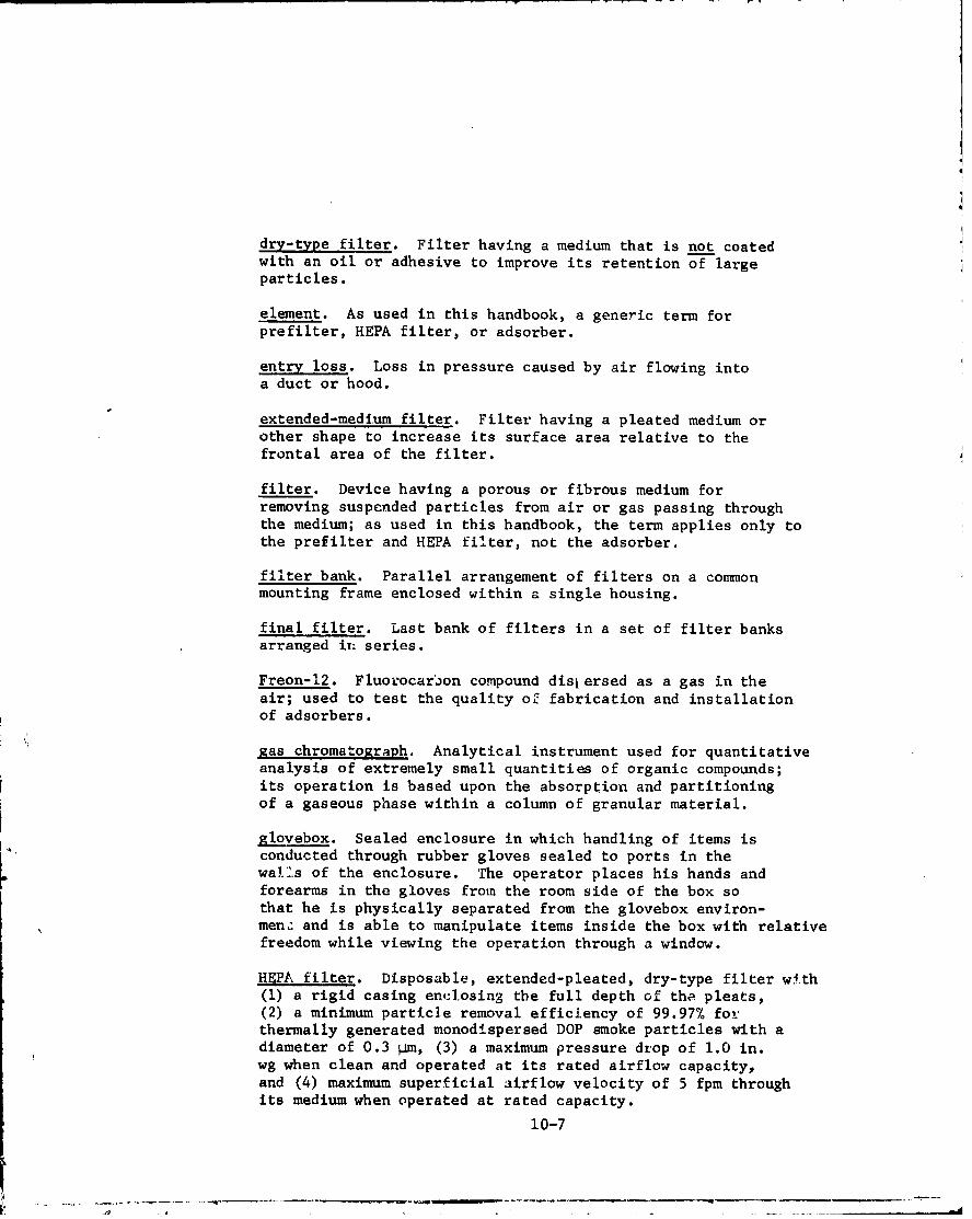
dry-type filter. Filter having a medium that is not coatedwith an oil or adhesive to improve its retention of largeparticles.
element. As used in this handbook, a generic term forprefilter, HEPA filter, or adsorber.
entry loss. Loss in pressure caused by air flowing intoa duct or hood.
extended-medium filter. Filter having a pleated medium orother shape to increase its surface area relative to thefrontal area of the filter.
filter. Device having a porous or fibrous medium forremoving suspended particles from air or gas passing throughthe medium; as used in this handbook, the term applies only tothe prefilter and HEPA filter, not the adsorber.
filter bank. Parallel arrangement of filters on a commonmounting frame enclosed within a single housing.
final filter. Last bank of filters in a set of filter banksarranged in: series.
Freon-12. Fluorocarbon compound dislersed as a gas in theair; used to test the quality of fabrication and installationof adsorbers.
gas chromatograph. Analytical instrument used for quantitativeanalysis of extremely small quantities of organic compounds;its operation is based upon the absorption and partitioningof a gaseous phase within a column of granular material.
glovebox. Sealed enclosure in which handling of items isconducted through rubber gloves sealed to ports in thewalls of the enclosure. The operator places his hands andforearms in the gloves from the room side of the box sothat he is physically separated from the glovebox environ-men. and is able to manipulate items inside the box with relativefreedom while viewing the operation through a window.
HEPA filter. Disposable, extended-pleated, dry-type filter with(1) a rigid casing enJ:losing the full depth of tha. pleats,(2) a minimum particle removal efficiency of 99.97% forthermally generated monodispersed DOP smoke particles with adiameter of 0.3 4m, (3) a maximum pressure drop of 1.0 in.wg when clean and operated at its rated airflow capacity,and (4) maximum superficial airflow velocity of 5 fpm throughits medium when operated at rated capacity.
10-7

hood. Shaped inlet designed to capture contaminated air
and conduct it into an exhaust duct system.
hot. Highly contaminated.
hot line. Limit established for safety precautions beyond
which no contaminated items or persons are allowed to pass.
inches of water. A unit of pressure (I in. wg = 0.036 psi).
latent heat. Heat that does not affect the temperature butchanges the state of • substance when added to or subtractedfrom it.
leakage. Unintentional passage of contaminated material aroundor through an installed filter or adsorber, or through apressure barrier.
local exhaust ventilation. Ventilation system for removing anycontaminated materia's likely to be generated from a localized"hot" operation.
Lower Explosive Limit. Lower limit of flammability orexplosibility of a gas or vapor at ordinary ambienttemperatures expressed in percent of the gas or vapor in airby volume. Assumed constant for temperatures up to 250°F;above this temperature it should be decreased by a factorof 0.7 since explosibility increases with higher temperatures.
4
Magnehelic. Tradename of Dwyer Instruments, Inc. for itsline of differential prissure gages.
medium (plural, media). Filtering material in. a filter.pr
mesh. Number of openi.ngs in wire cloth per lineal inch.
mounting frame. Structure to which a filter unit is clampedani sealed.
nonreaulated area. Wc•rk area in which munitions or materialscertified as agent-fite are routinely handled with minimal needfor chemical protect' n.
10-8
negative pressure. Air pressure within a space below
atmospheric pressure.
neoprene. Synthetic rubber material.
open-face filter. Filter with no restrictions over the endsor faces of the unit, as opposed to the enclosed filter havingreduced-size end connections.
particle, particulate. Minute piece of solid matter havingmeasurable dimensions.
penetration. Measure .f the quant.ty of a test agent thatleaks through or arot..s t-.n air-cleaning device when thedevice is tested with an agent of known characteristics under
specified conditions; penetration is expressed as a percentageof the challenge gas or aerosol concentration in the space up-stream of the air-cleaning device.
Photohelic. Tradename of Dwyer Instruments, Inc. for apressure switch combined with a Magnehelic pressure gage.
positive pressure. Air pressure within a space above
atmospheric pressure.
pressure drop. Same as differential pressure.
prefilter. Filter unit installed upstream or ahead ofanother filter unit (usually a HEPA filter) to protect thesecond unit from high dust c',ncentrations or other environ-mental conditions. The prefilter usually has a lowerefficiency for the finest particles present in the aerosolthan the filter it protects (see roughing filter).
PSU adsorber. Same as stationary adsorber.
redundancy. Addition of an independent back-up unit orparallel system which is capable of achieving the objectivesot the basic system and which is on-line (series) or can bebrought on-line (parallel) in the event of failure to thebasic system.
regulated area. Area in which critical chemical-agentoperations are performed and which could become accidentallycontaminated to pose a hazard. Personael in such areas
must be equipped with protective clothing and equipment.
10-9
residence time. Calculated time that a volume of contaminantor test agent theoretically remains in contact with anadsorbent, based on the active volume of adsorbent and theair or gas velocity through the adsorber bed.
rotameter. Instrument for measuring flow rates of air andliquids.
roughing filter. Prefilter with high efficiency for largeparticles and fibers but low efficiency for small particles;usually of the panel type.
scrubber. Device in which the gas stream is brought intocontact with a liquid so that undesirable components in thegas stream are removed by reacting with or dissolving inthe liquid.
sensible heat. Heat that changes the temperature of a substancewhen added to or subtracted from it.
separators. Corrugated foil or asbestos board used toseparate and strengthen the folds of a pleated filter mediumand to provide air channels between them.
stationary adsorber. Gasketless adsorber permanently installedin a system and which can be emptied of and refilled withadsorbent without removal from the system; also known as PSUadsorber, used in type III filter housing.
surveillance test. Test made periodically to establish thecurrent condition of a system or component.
type I housing. Filter housing designed to accommodate bag-in,
bag-out or bag-out procedure for removing filters and adsorbers.
type II housing. See walk-in housing.
type III housing. Walk-in filter housing designed to accommo-date replaceable filters and stationary adsorbers.
uncontaminated (clean) work area. Any work area in which thereis virtually complete assurance that there is no contamination.
upset. Accident, malfunction, or transient condition ofirregularity occurring in air-cleaning system.
walk-in housing. Contaminated enclosure (designated type IIhousing) from which filters and adsorbers are removed bypersonnel in protective clothing walking inside the unit.
10-10
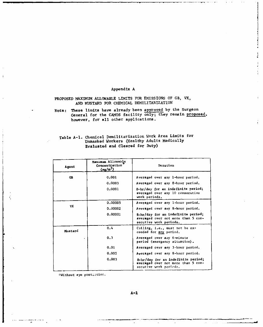
Appendix A
PROPOSED MAXIMUM ALLOWABLE LIMITS FOR EMISSIONS OF GB, VX,
AND MUSTARD FOR CHEMICAL DEMILITARIZATION
Note: These limits have already been approved by the Surgeon
General for the CAMDS facility only; they remain proposed,
however, for all other applications.
Table A-1. Chemical Demilitarization Work Area Limits for
Unmasked Workers (Healthy Adults Medically
Evaluated and Cleared for Duty)
Maximum Allowab0e
Agent Concentration Duration(mg/im 3)
GB 0.001 Averaged over any 1-hour period.
0.0003 Averaged over any 8-hour period.
0.0001 8-hr/day for an indefinite period;averaged over any 10 consecutivework periods.
0.00005 Averaged over any 1-hour period.
0.00002 Averaged over any 8-hour period.
0.00001 8-hr/day for an indefinite period;averaged over not more than 5 con-secutive work periods.
0.4 Cailing, i.e., must not be ex-Mustard ceeded for any period.
0.3 Averaged over any 6-minute
period (emergency situation).
0.01 Averaged over any 3-hour period.
0.005 Averaged over any 8-hour period.
0.003 8-hr/day for an indefinite period;averaged over not more than 5 con-secutive work periods.
*Without eye protgztion.
A-i
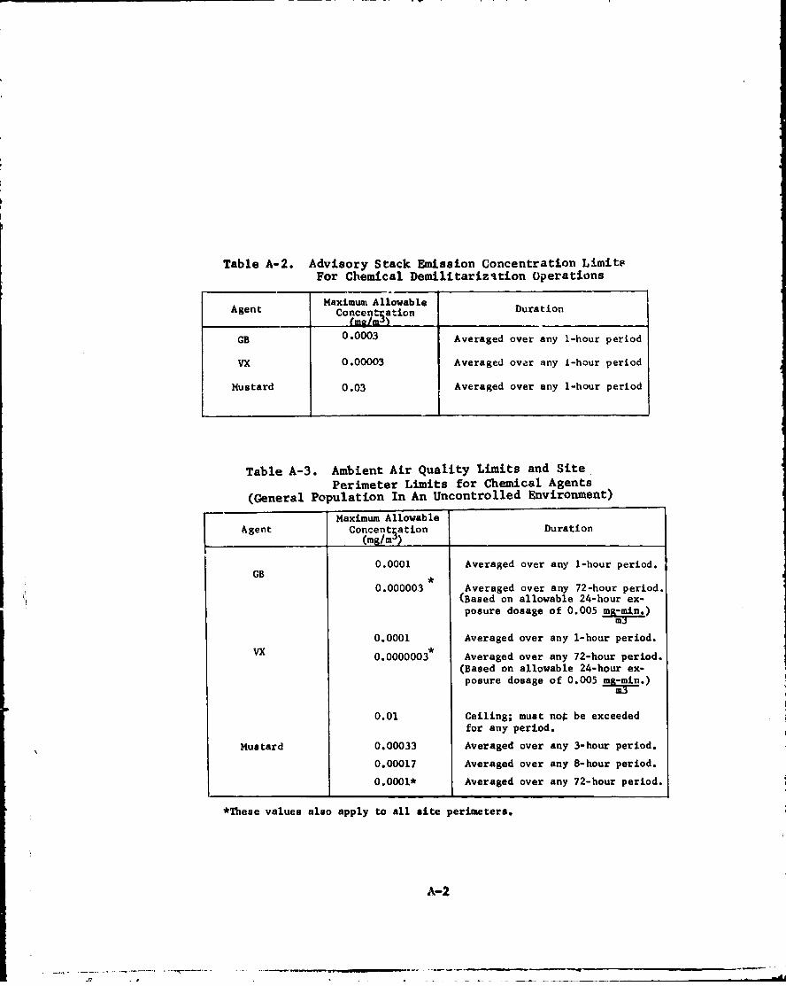
Table A-2. Advisory Stack Emission Concentration LimitsFor Chemical Demilitarizition Operations
Maximum AllowableAgent Concent ation Duration
GB 0.0003 Averaged over any 1-hour period
VX 0.00003 Averaged over any i-hour period
Mustard 0.03 Averaged over any 1-hour period
Table A-3. Ambient Air Quality Limits and SitePerimeter Limits for Chemical Agents
(General Population In An Uncontrolled Environment)
Maximum AllowableAgent Concentsation Duration
(mg/m )
0.0001 Averaged over any 1-hour period.GB .
0.000003 Averaged over any 72-hour period.(Based on allowable 24-hour ex-posure dosage of 0.005 )
0.0001 Averaged over any 1-hour period.0.0000003* Averaged over any 72-hour period.
(Based on allowable 24-hour ex-posure dosage of 0.005 .)
0.01 Ceiling; must nog be exceeded
for any period.
Mustard 0.00033 Averaged over any 3-hour period.
0.00017 Averaged over any 8-hour period.
0.0001* Averaged over any 72-hour period.
*These values also apply to all site perimeters.
A-2

Appendix B
SPECIFICATION FOR CAMDS AIR CLEANING SYSTEM
This appendix presents a compilation of the requirements pertain-ing to the air cleaning system now installed at CAMDS, Tooele ArmyDepot, Tooele, Utah. This information is intended to serve as abasis for defining the requirements of other similar air cleaningsystems.
1. General
a. Each air filter system for CAMDS shall draw air at thespecified volume flow from its associated ventilation system and passthe air through a series of filters in the following sequence: pre-filter, HEPA filter, adsorber, Second adsorber, and second HEPA filter.The filter system shall include an air-inlet flange coupling forconnection to the ventilation ductwork and a blower unit.
b. nch air filter system shall be designed to permit operation- rdoorr an altitude of 5,000 ft. above sea level and over attmpera....e range of -10 0 F to 1100 F.
c. The contractor's filter system design shall be capable ofproviding a minimum negative pressure of 1.0 in. wg at the filterinlet for the ventilation system ductwork. The ventilation systemductwork is the responsibility of the Government and is not a partof these requirements.
d. With a maximum negative pressure of 1.0 in. wg at the filterinlet, each air. Iter system shall (I) maintain the specified volumeairfl . ,.,us C t us 20%) when the filter system's resistance isincreased by uO0% over its initial value, and (2) maintain thespecified volume airflow (plus 0 minus 30%) when the filter system'sresistance is increased by 125% over its initial value. If flow-control systems are required to maintain the specified volume flow,such flow-control tems shall use the most efficient design ofeither controlle pitch fars or fixed-pitched fans with variable-inlet vanes or outlet dampers to avoid wasting electrictl power. Theair-filter system shall be designed to provide a 1 x 10 reduction inthe concentration of gaseous contaminants through each bank ofadsorbers.
e. Each complete filter system shall be mounted on a skid. Theskid shall be made of a suitable structural steel and painted inaccordance with paragraph l.g.
B-i

f. The design of this equipment shall comply with the OccupationalSafety and Health Act (OSHA) of 1970. Inasmuch as DOD regulationsgoverning acceptable sound (noise) levels are more restrictive thanthose of OSHA, the steady-state noise level shall not exceed 85decibels (db) on scale "A" of a standard sound-level meter at adistance of 20 feet in any direction from the filter system.
g. All structural carbon steel surfaces shall be paii~ed. Thesurfaces shall be prepared in accordance with MIL-STD-171 and bothprime and top coats shall be applied in strict accordance with thepaint manufacturer's directions. Paint recommended for use is RoweEpoloid paint** or an equivalent epoxy paint.
h. The contractor shall furnish one complete set of test equipmentrequired to perform the DOP and freon leak test on installed HEPAfilters and adsorbers as indicated in paragraphs 4.b and 5.b,respectively.
2. Filter Housing
a. The filter housing shall provide a complete airtight enclo-sure from air inlet to air outlet. All necess :ry framing and supportequipment for the filters and adsorbers shall be furnished as partof the housing by the contractor. The contractor shall also furnishall internal galleries, ladders, access doors, hatches, etc., re-quired for the inspection, servicing and/or removal of the equipmenthoused therein. The side on which the access doors are to be locatedis given below:
Air Capacity OfFilter System No. of Access Side for Door Location
(cfm) Doors (Facing The Air Inlet)
333 1 Right side8,000 1 Right side2,000 2 Left side3,000 2 1 each on right side &
left side4,000 1 Right side6,000 2 1 each on right side &
left side15,000 2 1 each on right side &
left side
*See references listed at end of this appendix.**Product of Rowe Products, Inc., Niagara Falls, New York.
B-2
A. . : .. . , -" mi

b. The filter housing shall be constructed of carbon steel,except for adaorber mounting frames which shall be constructed oftype 316 or 3161 stainless steel.
c. The intake transition piece shall be designed to join withventilation ducts of the following sizes:
Air Capacity OfFilter System Duct Size
((cfm) (in. D
333 121,000 122,000 163,000 204,000 226,000 288,000 28
15,000 44
d. Two sanmpling ports, located between the two adsorber banks,shall be required for each filter housing. In order to obtain areliable sample, turbulent flow shall be required upstream of thearea where the sampling probes shall be located. If turbulent flowis not present, a suitable baffle shall be installed.
e. All sharp corners, welds, weld spatter and projections in-side the housing shall be ground smooth to such an extent thatoperators' clothing shall not be torn if rubbed against any interiorsurface.
f. All welded joints within the housing shall be 100% weldedprior to paint-ing. All welding shall be in accordancd with the applicablespecifications listed in paragraph 9.
g. .The filter housine shAll be suitably reinforced and designedto withstand both a positive and negative differential pressure of atleast 24 in. wg with no visible damage or permanent deformation.
h. All structural reinforcing shall be external to the housingto facilitate decontamination. Access doors shall give completeaccessibility to all components for servicing. All doors shall beairtight at normal operating pressure.
i. Each housing section shall be equipped with a one-inchdiameter, threaded half-coupling, floor-drain connection.
J. InstrumentAtion shall be furnished for measuring thedifferential pressure across each filter bank. This instrumentationshall be sized and located so as to be easily readable by operating
B-3
personnel; in addition, it shall have a capability of being remotelylocated if necessary.
k. All housings with an airflow capacity of 3,000 cfm orlarger shall be provided with internal lights between each bank ofcomponents for visual inspection, in-place testing, and installationand removal of components. The light fixtures shall be of the vapor-tight type, sealed against leakage, adequate for the pressure en-countered, and replaceable from outside the housing.
1. The same basic housing shall be used for the 3,000, 4,000,and 6,000-cfm capacity filter systems. Regardless of the ratedcapacity, all positions for the prefilters and first bank of HEPAfilters shall have filter units installed. Positions not required
in the 3,000 and 4,000-cfm capacity systems for the adsorbers andsecond bank of HEPA filters shall remain "--filled and be blockedoff with blank plates; the fans shall be sized accordingly for therequired flow rates.
m. The housing shall be tested at the contractor's plant forstructural rigidity and leaks. All openings in the housing shall besealed; doors shall be sealed only by their normal latching devices.The housing shall be alternately subjected to a positive and negativedifferential pressure of at least 24 in. wg, holding the pressure forat least 10 minutes at each condition. The housing shall show no
damage or permanent deformation. Following the pressure cycling, avacuum source shall be connected to the housing through an integratingwet-type flowmeter. A negative pressure of six in. wg + 10% shallbe maintained for at least 8 hours. Maximum leakage shall not exceed
0.01% of the rated airflow.
3. Prefilters
a. The prefilters shall be rated at 1,000 cfm and be classifiedas dry, disposable Group III type, with all frames and separatorsconstructed of steel, as defined in ARI Standard 680.2
b. The prefilter assembly shall be rated Class I in accordancewith UL Standard 900.3
c. The prefilcers shall have an 80% minimum efficiency at 4rated flow when tested in accordance with ASTIRAE Standard 52-68.
d. The prefilters shall withstand an airflow producing apressure drop across the filter of at least 5 in. wg for at least15 minutes without visible damage or loss in filtration efficiency.
B-4
~-... .... . . .. .

4. HEPA Filters
a. The HEPA filters shall be rated at 1,000 cfm and be classi-fled as Type B or Type C, Grade I, with all frames and separatorsconstructed of steel, as defined in AACC Standard CS-l.* 5
b. After installation, each HEPA filter and its mounting assemblyshall show no leaks when tested in accordance with paragraph 4 ofAACC Standard CS-l.
5. Adsorbers
a. The adsorber shall be a Class A, type II tray-type cell inaccordance with AACC Standard CS-8 6 except as modified in paragraph5.b.
b. The following procedure in regard to filling-method quali-
ficatioxu testing shall be substituted for paragraph 7.4.2 of AACCCS-8. Six adsorber cells shall be selected at random, filled withan adsorbent of the specified mesh size and hardness by the proposedfilling method, mounted on a rough-handling machine with sharp cut-off cams oriented such that the filling port is at the top, andvibrated for 10 minutes at a frequency of 200 cycles per minute atan amplitude of 0.75 in. It shall be permissable to provide externalrestraints on the retaining screens while the adsorber cells arebeing vibrated. After rough handling, the filling port shall be openedand the level of adsorbent in the cell examined; the level shall havedropped no more than one-half of the baffle or margin width perpen-dicular to the adsorbent surface. The six adsorber cells shall thenbe removed in the same orientation taking care not to disturb thegranules of adsorbent and leak tested with freon in accordance withpara 7.5.1 of AACC CS-8, except that the cells shall be orientedwith filling ports up for the qualification leak test. A minimum offive cells shall show no leakage. Airflow resistance shall notincrease by more than 20% as a result cf this test.
c. In addition to the requirements listed above from AACCStandard CS-8, the following additional requirements shall be met:
Each regular production lot of adsorbers shall be sampled in accord-ance with MIL-STD-414, 7 Level 4, and the sample shall be subjected tothe rough handling test and freon leak test specified above in the
*The Flanders SUi •.FLOW separatorless filter is considered to be
a satisfactory item for this purpose. it is a product of FlandersFilters, Inc., Washington, North Carolina.
B-5

filling method qualificarion test. The lot shall be rejected if dnyadsorber in the sample bnall fail to meet the criteria of para 7.5.1of AACC Standard CS-8. Rework of a rejected lot shall be permittedbut a new sample will be required. A regular production lot shallconsist of an essentially continuous production run and a singlelot of adsorbent. The sample for the rough-handling test shall notbe selected until the production of the represented lot is complete.
d. Adsorber performance shall be verified after installationby a freon leak test on each adsorber bank. The leakage rate of eachbank shall not exceed 0.01% of the challenge concentration.
6. Adsorbent
The adsorbent for the adsorbers shall be coal-base or coconut-base activated charcoal meeting the specifications listed below.A 25-pound sample of each carbon lot shall be submitted to CSL forverification tests.
Specifications Test Used
Iodine Number, Minimum* 1000 MIL-C-13724 8
Carbon Tetrachloride Adsorption,*Minimum, % Weight 59 ASTM D3467 9
Ash, Maximum, % 8.0 MIL-C-13274Total Volatiles (150 0 C + 50 0 C for
3 hours), % 4.0 MIL-C-13724Hardness Number, Minimum 90 MIL-C-13724Apparent Density (Bulk Density, Dense
Packing), g/cc, Minimum 0.48 MIL-C-13724lbs/ft. J, Minimum 30.0 MIL-C-13724
Particle S.ze (3-Minute Shake Test): ASTM 1,12862I0and AS';M E323II
Sieve Size Percent Retained
8 Mesh 0-58 x 12 Mesh 35-6512 x 16 Mesh 35-6516 Mesh 1-5 (through)
7. Blower Unit
a. The blower unit for each air-filter system shall be designedfor vibration is ation by the use of flexible connections and isolationmountings and by proper balancing of components. Vibration isolationshall be required to minimize noise (see paragraph l.f) and to reducevibration to the extent that no damage shall be done to the filtersand other equipment.
*Both of these tests are not required. The Carbon TetrachlorideAdsorption Test is preferred but the Iodine Number Test may be runas an alternative.
B-6
b. The blower shall be of good commercial quality designed tomeet the specified volume airflow requirements stated in paragraphl.d.
c. The blower fan shall be enclosed in a steel casing. Itsshaft shall also be of steel and mounted on heavy-duty ball bearings.The bearings shall be sealed or contain readily accessible lubricationfittings. Both the intake and discharge openings shall be flanged.
d. The motor shall be of the totally enclosed, fan-cooled typewith double-sealed, prelubricated ball bearings designed for con-tinuous operation, and with a horsepower rating capable of drivingthe blower unit.
e. The motor, except for the 15,000-cfm air-filter system,shall be capable of operating from a 208 volt, 3 phase, 60 Hz powers ource.
f. The two motors for the 15,000-cfm air-filter system shall becapable of operating from a 460 volt, 3 phase, 60 Hz power source.
transformer-reduced voltage starter and capacitors across the motor
r4r4 ,riding a power factor of at least 0.90.
h. Exiaust stacks for the blower discharge shall be providedby the Government. The contractor shall provide a recommended con-figuration for the exhaust stack and all necessary information toenable the Government to properly join the exhaust stack to theblower discharge system.
8. Electrical
a. The contractor shall furnish one electrical contact closureon each air-filter system to provide a signal to a remote controlpanel when the specified air capacity is being pulled through thefilter unit.
b. For each filter system the Government shall furnish motorstarters and all wiring from the motor starter to the contractor-furnished disconnect switch. The disconnect switch shall be locatedin close proximity to the motor. The contractor shall provide a terminalblock (also located in close proximity to the motor) and all zontrol-function wiring for installation by the Government.
c. Provision shall be made by t'kie contractor for a Gcvernrment-furnished remote on/off switch. This switch shall allow automaticrestart of the motor for each air-filter system after the loss ofpower without marual actuation.
B-7

4
m
9. Welding
All welding shall be in accordance with Section VIII, Division 1of the ASME "Boiler and Pressure Vessel Code", 1 2 or in accordancewith the military specifications listed below. Structural weldingshall be in accordance with the ASME Code or AWS Standard DI.1,"Code for Structural Welding", 1 3 or the applicable militaryspecification. For welds in material thinner than 1/4 in., thewelder shall demonstrate his ability to make satisfactory welds insuch material by making sample ,Telds which shall be submitted toand approved by the purchaser's representative prior to the startof welding on such materials.
All welds on adsorbers and housings shall be made by personnelholding current qualification under Section IX of the ASME Code,AWS D1.1, or the applicable military specification for welding.Applicable military specifications are:
MIL-STD-12611 4
MIL-W-86111 5
MIL-W-123321 6
MIL-W-461541 7
B-8

LITERATURE CITED
1. MIL-STD-171, "Finishing of Metal and Wood Surfaces, "Dept. ofDefense Military Standard, November 1972.
2. ARI Standard 680, "Standard for Air Filter Equipment," Air-Conditioning and Refrigeration Institute, 1970.
3. UL-900, "Safety Standard for Air Filter Units,"Underwriters' Laboratories, 1971.
4. ASHRAE Standard 52-68, "Method of Testing Air CleaningDevices Used in General Ventilation for RemovingParticulate Matter", American Society of Heating,Refrigerating, and Air-Conditioning Engineers, Inc.,August 1968.
5. AACC CS-l, "Standard for HEPA Filters", Institute of
Environmental Sciences (Date unknown.)
6. AACC CS-8, "Standard for High Efficiency Gas Phase AdsorberCells", Institute of Environmental Sciences, July 1972.
7. MIL-STD-414. "Sampling Procedures and Table for Inspection byVnriables for Perceut Defective", Dept. of Defense MilitaryStandard, October 1968.
8. MIL-C-13724, "ASC, Impregnated, Activated Charcoal", Dept. ofDefense Military Specification, September 1972.
9. ASTM D3467, "Method of Test for Carbon Tetrachloride Activity ofActivated Carbon", 1976.
10. ASTM D2862, "Particle Size Distribution of Granular Activated
Carbon", American Society for Testing and Materials, 1970.
11. ASTM E323, "Perforated Plate Sieves for Testing Purposes",American Society for Testing and Materials, 1970.
12. ASME "Boiler and Pressure Vessel Code," American Society ofMechanical Engineers, 1968.
13. AWS Standard DI.1, "Code for Structural Welding," AmericanWelding Society, 1975.
14. MIL-STD-1261, "Welding Procedures for Constructional Steel,"Dept. of Defense Military Standard, September 1968.
15. MIL-W-861, "Welding, Metal Arc and Gas Steels, and Corrosionand Heat-Resistant Alloys, Process For," Dept. of DefenseMilitary Specification, July 1957.
B-9
- -. . . . .. . . . .. - - - - - - .... t

16. MIL-W-12332, "Welding, Resistance, Spot, Seam and Projection,For Fabricating Assemblies of Low Carbon Steel, " Dept. ofDefense Military Specification, October 1968.
17. MIL-W-46154, "Welding, Resistance, Spot and Projection ForFabricating Assemblies of Carbon Steel Sheets," Dept. ofDefense Military Specification, October 1970.
B-10

Appendix C
DETAILED ADSORBER BED CONSIDERATIONS
1. CAMDS Adsorber Cell
The CAMDS adsorber cell consists of a nominal charge of 50 pounds(22.7 kg) of activated carbon granules 8 x 16 mesh (0.179 cm dia) insize, having a cross-sectional area of 1,385 in.2 (8,937 cm2 ) and a beddepth of 2 in. (5.08 cm). The filter has a flowrate of 333 cfm(9.424 m3 /min) at a superficial linear velocity of 10.54 m/min(17.57 cm/sec) and a mean residence time of 0.00482 min (0.289 sec).Three of these cells are placed in parallel when used in tandem witha 1,000-cfm HEPA filter.
2. General Chacacteristics of Adsorber Beds
When carbon granules are packed in a carbon bed, either by free fallor by bed vibration, they tend to pack in a manner similar to the hexagonalclose packing of spheres. Thus, granules in the succeeding layer nest be-tween the depressions created by granules in the preceding layer. Ifgranules packed one on top of another it would be easy to show that, sincethe mean granule diameter of the 8 x 16 mesh is 0.179 cm, it would requirethe packing of 28 layers of such granules to make tip the 5.08 cm bed depth
indicated in the carbon cell. Because of the nesting characteristic of thecarbon granules, a minimum of 28 layers of carbon granules exist in the
CAMDS adsorber cell. Moreover, by knowing the internal area of the bed, its
bad depth, and the carbon weight,one can calculate the bulk or packed density
of the bed. In the CAMDS adsorber cell a charge of 22.7 kg carbon is
packed in a volume of 4.54 x 104 cm3 , resulting in a bulk density of 0.50 g/cm3 .
Since the true density of unactivated carbon is 2.15 g/cm3 one can
calculate from the relationship
bulk densitytrue density
that the fractional void volume, e, of the carbon granule bed in the CAMDS
gas filter is 0.77.
3. Bed Calculations for Flow
Conceiving the packed bed of carbon granules as a multiplicir ofnarrow parallel channels, each packed with individual carbon gra;,ules,the effect on a flow of a gas-air mixture into the bed should be tostraighten the volumetric flow into a series of parallel streamlines.Thus, it is possible to show tWat a bed area of 8,937 cm2 subjected to a
volumetric flowrate of 9.424 m /min experiences a superficial linear
velocity of airflow of 10.54 m/mmn, and that with a bed depth of 5.08 cm themean residence time of a slug of gas-air mixture, equal in volume to
C-I

the volume of the bed, is only 0.00482 mmn or 0.289 sec. Thus, the
gas protection required of the carbon bed, measured in terms of thereduction of the inlet or challenge gas concentration to the in-significantly small gas concentration (below both detectable andphysiological limits), must take place within 0.289 sec. The mechanismby which this occurs is essentially a first order process, and there-fore one can conceive of a 28-step geometric progression, eachsucceeding carbon granule layer removing the gas penetrating thepreceding layer with the same fractional gas adsorbing efficiency.
4. Concept of Gas Protection
The concept of gas adsorption by a bed of activated or impregnatedcarbon granules, resulting in protection against the gas challenge, isthat a potential for spontaneousiy adsorbing the gas molecules existsin the carbon as a result of its activation process. The activationprocess is one which, under controlled conditions of heating in aninert atmosphere, creates a large internal pore surface area in thecarbon. The effect of this large internal area, made up of manymicropores with a radius of 50 Angstroms (5 nanometers) or less, isto manifest a true spontaneous adsorption, resulting in a decreasein free energy of the pore surface. The activated carbon then actsin a physical sense to adsorb gases by physical forces, without theneed of a chemical change. This action, like other physical phenomena,can be described and quantified by ascribing both a capacity and anintensity factor to activate carbon, commonly known as its adsorptioncapacity and adsorption rate constant, respectively.
5. Adsorption Step Sequencei*
Klotz, in his manuscript on the adsorption wave in e arbon bed,showed that the process of gas adsorption occurs in a four-step sequence,rnamely,(1) bulk diffusion of the gas from its surrounding air to theouter surface of the carbon granule; (2) surface diffusion of the gason the carbon outer surface to a pore mouth; (3) intragranular diffusionof the gas in the small pores of the carbon; and (4) physical adsorptionof the gas molecule onto the active site of the micropore surface.Some authors describe step (1) as external diffusion, steps (2) and(3) as internal diffusion, and step (4) as the adsorption step. It isimportant in assessing the overall performance of a carbon bed inadsorbing gas from a flowing air stream to determine which of the abovesteps in the adsorption sequence is the slowest and, therefore, therate-controllV.ng step for the entire process. It is only by speedingup the slowest step in a sequence of steps that the overall rate ofadsorption can be improved.
*See references list ad at end of this appendix.
C-2

6. Breakthrough Characteristic of a Bed
The adsorption kinetics equation, which denotes the time at which. trace concentration exits a bed of carbon under specified testconditions, was derived by Wheeler 2 from a continuity equation of massbalance between the gas entering the bed and the sum of the gasadsorbed by the bed plus that penetrating the bed. The equation canbe shown in the form modified by Jonas as,
tb =.•e ,[ = PSQ An(Co/Cx) ] (2)coQ kv
where:
tb = gas breakthrough time, in minutes
We = kinetic adsorption capacity, in g(agent)/g(carbon)
W = adsorbent weight, in grams
Q = volumetric flow rate, in cm3 /min.
pp = bulk density of packed bed, in g/cm3
Co = inlet concentration of gas, in g/cm3
3Cx exit concentration of gas, in g/cm
kv pseudo first-order adsorption rate constant, inreciprocal minutes
By meana of this equation the activated carbon to be used in a carboncell can be characterized in the laboratory by determining its kineticadsorption capacity (We) and adsorption rate constant (kv) values.Knowing these two fundamental properties of the carbon, and insertingthe test or use conditions of the carbon cell into the equation, itthen becomes possible to calculate the protective life or break-through time of the carbon cell.
7. Bed Breakthrough Time Relations
It must be borne in mind that the breakthrough time of a bed, suchas that obtained as tb from equation (2) relates to the time at whichan arbitrarily small concentration, Cx, breaks through the bed. Thecomplete breakthrough curve of a carbon bed, when plotted againsttime, is an S-curve of the form,
C-3
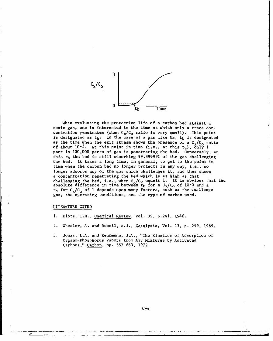
CX/C° ..
tb Time
When evaluating the protective life of a carbon bed against atoxic gas, one is interested in the time at which only a trace con-centration penetrates (when Cx/Co ratio is very small). This pointis designated as tb. In the case of a gas like GB, tb is designatedas the time when the exit stream shows the presence of a Cx/Co ratioof about 10-5. At this point in time (i.e., at this tb), only Ipart in 100,000 parts of gas is penetrating the bed. Conversely, atthis tb the bed is still adsorbing 99.99999% of the gas challengingthe bed. It takes a long time, in general, to get to the point intime when the carbon bed no longer protects in any way, i.e., nolonger adsorbs any of the gas which challenges it, and thus showsa concentration penetrating the bed which is as high as thatchallenging the bed, i.e., when Cx/Co equals 1. It is obvious that theabsolute difference in time between tb for a Cx/Co of 10-5 and atb for Cx/Co of I depends upon many factors, such as the challengegas, the operating conditions, and the type of carbon used.
LITERATURE CITED
1. Klotz, I.M., Chemical Review, Vol. 39, p.241, 1946.
2. Wheeler, A. and Robell, A.J., Catalysis, Vol. 13, p. 299, 1969.
3. Jonas, L.A. and Rehrmann, J.A., "The Kinetics of Adsorption ofOrgano-Phosphorus Vapors from Air Mixtures by ActivatedCarbons," Carbon, pp. 657-663, 1972.
c-4
Appendix D
GENERAL CHARACTERISTICS OF ACTIVATED CARBON
1. Base Material
There a..ý several different types of adsorbent used in the filtrationfield but the only type suitable for chemical demilitarization isactivated carbon.
Coconut is the most widely used base material for activated carbonused in demil operations at this time. It is also used extensivelyin the nuclear field. Coal is the base material for most CBR militaryfilters. Other base materials used with varying success in makingactivated carbons have been pecan nut, lignite, wood, and petroleumproducts.
Mary of the physical properties desired of an activated carbonresult from the type of base miterial used. A prime example of thisis the hardness property of the carbon. Although anthracite coal isharder than bituminous coal it does not activate as well, and thereforethe softer bituminous product is used. In addition, the physical andchemical composition of the base carbon material relative to, forexample, the type, percentages, and location within the granule of thevarious hyerocarbons in its core, affect the type of activated carbonwhich can be developed from the base material.
2. Activation
The base material is activated in order to develop the extremelylarge internal surface area which gives activated carbon its gas-adsorbing properties. Activation processes vary in method andprocedure but generally utilize a very mild oxidizer, under hightemperature and in an inert atmrsphere, to drive off an inner coreof carbonaceous material whicb leaves behind an internal surface a5 eawithin the carbon granule. The internal area may approach 2,000 m /g,Some examples of mild oxidizers used in activation are zinc chloride,steam, and carbon dioxide.
The process of activation creates a series of internal pores inthe carbon granules. Those pores having diameters of 100 Angstroms(10 nm) or less are called micropores and are responsibla for themajor portion of the total internal surface area of the activatedcarbon. Larger pores (macropores) are needed to provide easy accessto the micropores on whose surfaces adsordtion takes place. Both thepore size distribution and the total inteireal pore surface area of thecarbon contribute to the gas adsorption properties of the activatedcarbon.
D-1

Activated carbon is capable of retaining GB, VX, and mustard. Ithas an affinity for these agents and their vapors, which are readilyadsorbed and held on the carbon. There are chemical agents andvapors which are not readily retained on activated carbon, however,and special treatment of the carbon is required for effectiveadsorption of these agents.
3. Specialized Treatment
Although the pore size distribution and internal surface area ofan activated carbon determine its ability to adsorb gases or vaporsunder equilibrium conditions, the adsorption properties of the carbonmay be drastically altered under dynamic flow conditions. Differencesbetween potential and actual adsorption behavior are due to differencesin diffusional or other rate-controlling steps in adsorption and/ordifferences in the affinity of the carbon for various vapors.
To augment the adsorption properties of a carbon for a specificvapor under dynamic flow conditions, where the spread between thepotential and kinetic adsorption is large, a carbon may be impregnatedwith metals or metallic salts which cause chemical reactions to takeplace on the carbon surface after initial adsorption. The militaryimpregnates its activated carbon with mixtures of copper, silver, and
chromium salts (ASC whetlerite carbon) to enhance its effectivenessagainst hydrogen cyanide, phosgene, and cyanogen chloride vapors.
4. Hardness
Attrition and crushing of carbon granules under service conditionscan result in dusting and subsequent escape of contaminated carbon, orin channeling through the bed with subsequent leakage of contaminated
air or gas from the adsorber. Very hard carbons are desirable to re-sist fracture, abrasion, and crushing; a minimum ball-pan hardness of
92% is recommended. To minimize service degradation, vibration andpulsation in the air handling system must be controlled and minimized.
5. Surface Area
The internal network of pores within the carbon granule providesthe large active area which gives the carbon its potential foradsorbing gases and vapors. A measure of the size or extent of the
internal surface area or unit weight of an activated carbon is the
carbon tetrachloride test, described in ASTM Standara D3467 1 * . This
test measures the maximum amount of carbon tetrachloride that a unit
weight of the activated carbon can adsorb at tite fixed temperature of
test, 250 C, and at the vapor concentration of 250 milligrams carbon
tetracnY -ile per litey of air.
*Sce references listed at end of this appendix.
D-2
6. Mesh Size
The particle (mesh) size distribution of the adsorbent is limltrýby the open areas of the adsorber cell's perforated metal screens. inesmaller the mesh size, the higher the pressure drop through theadsorbent. However, the smallest particle size must be larger thanthe screen openings or the particles will fall through the screens.The smallest holes that can be produced in a reasonably stiff screenmaterial (26 gage) is about 18 mesh. Therefore, the smallest permissibleparticle size is 16 mesh. Adsorbent of 8 x 16 mesh is used to get goodpacking density. For some CBR applications, a fines cloth is insertedinside the screen to enable a 12 x 20 mesh adsorbent to be used.
7. Density
There are three densities associated with carbon granules. The trueor real density of carbon before activation is 2.15 g/cm3 . Afteractivation, which removes a large portion of the inner core of thecarbon and produces the large internal surface area associated with anactivated carbon, ýhe density of the activated carbon granules decreasesto about 0.85 g/cm . When activated carbon granules are packed in abed, the apprrent bulk 3r packed density of the bed is on the order of0.48 gfcm3 .because of inter-particle voids. The packed-bed densitytakes into account both the intragranular spaces in a carbon granule(due to internal surface area) and the intergranular spaces or voidvolume (due to granule packing configuration).
The effect of packed density on carbon adsorption performance iscomplex. In accord with the density parameter in the gas adsorptionkinetics equation, a decrease in packed density should decrease thecritical bed layer or tt• required weight of carbon, other thingsbeing equal, and thereby improve adsorption performance. Thissituation exists as long as diffusion remains rate-controlling in theoverall adsorption process... The underlying rationale for this isthat increasing the open space between carbon granules provides gasmolecules easier access and a longer time (increased residence time)to contact all available outer surfaces of the exposed carbon granules.
Theoretically, if the adsorption process itself becomes rate-controlling,further decrease in packed density could have a deleterious effect onthe overall adsorption performance.
8. Bed Weight
Since only a finite number of active sites can be developed withinthe micropores of an activated carbon Curing activation, the greaterthe weight of carbon for a given level of activation, the greater willbe the adsorption capacity of the carbon bed. The protective time ofa carbon bed against a vapor is normally cursidered the time a,: whicha known trace of gas or vapor breaks througih the bed when challenged
D-.d

by a high inlet gas concentration under specific test conditions.Protective time varies directly with the weight of carbon.
9. Bed Depth
The effect of bed depth on adsorption performance cannot easilybe separated from the more basic parameter of bed weight. For example,if bed area and packing density remain constant, an increase in beddepth is reflected in an increase in bed weight, thus resulting inimproved adsorption performance. Some of the early mathematicalequations of adsorption kinetics theory were developed on the basis ofbed depth. Simple interconversion between these equations is possiblethrough the relationship that the product of bed depth and bed areaequals bed volume, and the product of bed volume and packing densityequals bed weight.
10. Bed Volume
Assuming constant flowrate, the effect of bed volume on adsorptionperformance is coupled either to its relationship to bed weight of thecarbon, in which case an increase in bed volume and weight causes anincrease in adsorption performance, or to its packing density. Theeffect of changes in packing density on adsorbent performance is aseparate consideration.
11. Volumetric Flowrate
The effect of volumetric flowrate on adsorption performance waspreviously regarded as an inverse relationship; namely, that whenvolumetric flowrate is increased, performance or protective lifedecreases. The decrease was considered due to two factors: (a) theincrease in mass flux to the carbon, and (b) the increase in thecritical carbon air-film layer which decreases the size of the adsorptiveeffect layer of activated carbon. More recently, secondary effectswhich moderate this simple inverse relationship have been studied interms of the superficial lineer velocity parameter, which is directlycalculable from the volumetric flowrate. The relationship of thekinetic adsorption rate coefficient to the superficial linear velocityand its effect on performauce have been reported on by Jonas andRehrmann.
2
12. Linear Velocity
The superficial linear velocity through a carbon bed is obtainedby .ividing the cross-sectional area of the bed into the volumetricflowrate. For a fixed cross-sectional bed area, an increase involumetri: flowrate causes a corresponding increase in the superficiallinoar flow velocity. Although the effects of volumetric flowrateincrease are noted above, a moderating effect has recently been observedi-a that higher linear velocities tend to dec-rease or shear away the
D-4
thickness of the air film surrounding packed carbon granules and thuspermit a more rapid transfer of gas from the fluid air stream to theouter surface of the carbon granules. This increased transfer ratemanifests itself in an increase in the adsorption rate constant ofthe carbon. An increase in this rate constant tends to decreasethe size of the critical bed layer, thus moderating the otherwisedeleterious effect of increased flowrate.
13. Gas Residence Time
The concept of a mean residence time for a gas in the carbonbed is based on the approximation of plug flow of the air-gas mixturethrough the bed. Residence time is calculated by dividing thesuperficial linear velocity into bed depth, or by dividing thevolumetric flowrate into bed volume. The mean residence time is thattime for a voltume of gas-air mixture equal in volume to the volume ofthe carbon bed to completely pass through the bed. The adsorptionperformance of a bed is increased as residence time is increased solong as the rate-controlling process of the gas removal is a diffusionalmechanism. This has been the general result in studies of the physicaladsorption of agents GB, 'A. and HD.
A need exists, however, for a nondestructive method of determiningthe residual protective capacity of a carbon bed. The underlyingconcapt for such a method is that gas adsorption by a bed of activatedcarbon granules is an additive phenomenon, each increment of adsorptionadding to the previous one and thereby decreasing the remaining adsorptivecapacity. Recent progress has been made on a method whereby a pulseof a difficultly adsorbable gas is sent into the carbon bed, and theretention time of the gas in the bed is determined. As portions of thecarbon bed are saturated with more highly adsorbable gases, feweractive sites remain for temporarily holding the pulse gas and so theretention time of the carbon for the pulse gas decreases. Bycorrelating pulse gas retention time with the degree of prior bedsaturation, a calibration correlation can be made which relates tothe retention time of the gas pulse to the residual protective lifeof the carbon bed.
14. Challenge Gas Concentration
The effect of an increase in challenge or inlet gas concentrationis to decrease adsorption performance and protective life of the carbonbed. This occurs because the unit weight of activated carbon has afinite adsorption capacity, by weight, for a given gas. An increasein gas concentration, with volumetric flowrate constant, decreasesthe time at which the bed reaches its adsorption capacity, andtherefore decreases its protective life.
D -5
Adsorption performance of an activated carbon is dependent on thetest or use conditions under which the gas challenges tha carbon. Theeffects on the performance of an activated carbon of the variousparameters enumerated here have been incorporated into the theory ofadsorption kinetics and can be found in mathematical equationsdeveloped from the theory.
1.5. Exit Gas Concentration
An increase in permissible exit gas concentration, other parametersbeing equal, is reflected in an increase in the protective life or ad-sorption performance of the carbon bed. The increase in protectivelife increases as in the logarithm of th'i iv-rease in exit gas con-centration.
16. Temperature
Physical adsorption of a gas by ti.vated carbon is enhancedwhen the temperature is decreased. 1ihe case of an impregnatedcarbon, such as ASC whetlerite ý: , which protection is achievedby means of an initial physi r a&T,' I ,'.on followed by chemicalreaction, an increase in t'oa**1 tuiý.e decreases the physical adsorptionportion but may increase te chemical reactior portion of the overall
sorption process. The overall effect of an increased temperature,therefore, depends upont whether physical adsorption or chemical reactionare rate controlling in the gas removal procedure.
17. Altitude
Higher aii.ifides, and the accompanying decrease in barometric
pressure, decrea-e the ability of an activated carbon to adsorb agas or vapor. The same effect also pertains for any chemicalreaction occurring subsequent to the physical adsorption.
18. Water Vapor and Other Gas Contaminants
Water vapor tends to occupy adsorption sites on the carbon and,therefore, decreases the total amount of gas which can be adsorbed andthe service life of the bed. The effect of other gas contaminantsis the same, that is, they "poison" the carbon. The prior adsorptionof a contaminant gas reduces the number of active sites or adsorptionspaces which otherwise would have been available for adsorption of thegas or gases of primary interest.
19. Shelf Life
Shelf life per se has no deleterious effect on the ability ofactivated carbon to adsorb gases by physical adsorption processes.This is based on the assumption that the activated carbon car, bestored in the dry condition (less chan 2% moisture) in a closed
D-6

container. When stored in thi, condition., activated carbon has beenshown capable of adsorbing gas, without decrease in efficiency, after25 years of storage. There could be degradation of chemicallyimpregnated carbons, however, due to the deleterious effects whichnormally result when impregnated carbons (activated carbon impregnatedwith metallic salts) are stored in the presence of bigh-moisturecontent and at elevated temperatures. Conditions such as thesepromote chemical reaction between the impregnated salts, water, andcarbon.
20. Exposure to Dust
Since activated carbons cannot adsorb dust or other particulatemitter from the atmosphere, the only possible effect of the dust wouldbe to physically coat portions of the carbon granules or the spacesbetween the granules. The forces holding such dust particles arevery weak dipole-type forces, causing the dust to be easily dislodgedor shaken free. However, dust particles can plug the interstitialspaces between the carbon granules, thereby impairing the access ofgas to the active siteb on the carbon and significantly increasingthe pressure drop across the bed. In most protective systems, thegas adsorber is preceded by a prefilter and/oc HEPA filter whichare designed to prevent the passage of dust into the adsorber beds.
LITERATURE CITED
1. ASTM D3467, "Method of Test for Carbon Tetrachloride Activity ofActivated Carbon," 1976.
2. Jonas, L.R. and J.A. Rehrmann, "The Rate of Gas Adsorption byActivated Carbon," Carbon, Vol. 12, pp. 95-101, 1974.
D-7
S.. .. . .. .. . . -

DISTRIBUTION LIST
Commander/DirectorChemical Systems LaboratoryAberdeen Pro"Vng Ground, Maryland 21010
Attn: DRDAV-CLT-D/Mr. Weber 1 copyAttn: DRDAR-GLT-D/Mr. Bartel 3 copiesAttn: DRDAR-Ct\D/Mr. Shacter 3 copiesAttn: DRDAR-CLW /Mr. Gotoff 3 copiesAttn: DRDAR-CLJ-R echnical Releases / 2 copies
Attn: DRDAR-CLJ-L/ chnical Library / 3 copiesAttn: DRDAR-CLC-CR/M Moseley 1 copyAttn: DRDAR-CLB-PA/Dr. Tonas I 1 copyAttn: DRDAR-CLN-E/Mr. E haus /' I copy
Project Manager for Chemical Dern lit izationand Installation RestorationAberdeE Proving Ground, Maryland 010
Attn: DRCPM-DR-CD/Mr. Wha.n 2 copie•sAttn: DRCPM-DR-TS/Lt. Co . Hanso 2 copies
CommanderTooele Army DepotTooele, Utah 84074
Attn: SDSTE-CD/Mr Cauller 3 copies
Administrator 12 copiesDefense Doctumentatio Center
Attn: kccee'si s DivisionCameron StationAlexandria, Virgi a 22314'..
CommanderU.S. Army Envi nmental Hygiene AgencyAberdeen Prov g Ground, Maryland 21010
Attn:,,iYSE-AA-L/Library, isuilding 92100 1 copyAttn:" HSE-0I/Mr. Cook I copyAttn: HSE-3A/Mr. Bond I copy

CommanderU.S. Army Foreign Science and Technology Center
Attn: DRX ST-151220 Seventh Street, NECharlottesville, Virginia 22901 2 copies
HQDAAttn: DAMO-SSC/Col. Watson I copy
Washington, D.C. 203.0
CommanderU.,. Armry Armament Reseat' hand Development Command /
Attn: DRDAR-TS-D/Mr. M illiams / 20 copies3uilding E5028
Aberdeen Proving Grcund, ryl d 21010
Attn: DRDAR-TSS 2 copiesDover, New Jersey 07801
CommanderU.S. Army Materiel Developme and-Readiness Command5001 Eisenhower AvenueAlexandria, Virginia 2238
Attn: DRCSA-CS/Ma or K. J. Miller 1 copy
CommanderU.S. Army Dugway Pro .,ng GroundsDugway, Utah 84022
Attn: Tech cal Library 1 copy
CommanderRocky Mounth ArsenaalCommerce C ty, Colorado 80022 1 copy
CommanderPine Bluff ArsenalPine Bluff, Arkansas 71611 1 copy
CommanderNaval Explosive Ordnance Disposal Facility
Attn: Army Chemical Office 1 copyIndian Head, Maryland 20640
..- • ..

Union Carbide Corp., Nuclear Division 4 copiesRDT Standards OfficeOak Ridg lonal LaboratoryP.O. Box XBuilding 1000
Oak Ridge, Tennessee 370
Attn: C. A. Burchoted
CTI-Nuclear, Inc.A Helix Co.4955 Bannock Stree/Denver, Colorado 0216
Attn: Mr Douglas Porrey . copy