48 vdc 2.4 w-200 w - sanyo denki
TRANSCRIPT
48 VDC 2.4 W-200 W
Ver.3
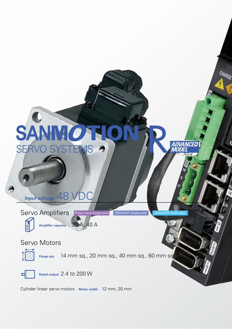
Servo Amplifiers
Amplifier capacity 25 A, 40 A
Flange size 14 mm sq., 20 mm sq., 40 mm sq., 60 mm sq.
Rated output 2.4 to 200 W
Servo Motors
Cylinder linear servo motors Motor width 12 mm, 20 mm
EtherCAT multi-axisEtherCAT single-axisPulse input single-axis
Input voltage 48 VDC
3CATALOG No.S0941B012 ‘21.11
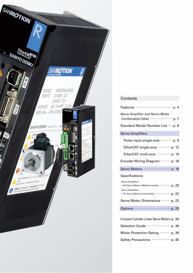
Contents
Features ・・・・・・・・・・・・・・・・・・・・・・・p. 4
Servo Amplifier and Servo Motor
Combination Table ・・・・・・・・・・・・・・p. 7
Standard Model Number List ・・・p. 8
Servo Amplifiers
Pulse input single-axis ・・・・・・・・p. 9
EtherCAT single-axis ・・・・・・・・p. 12
EtherCAT multi-axis ・・・・・・・・・p. 14
Encoder Wiring Diagram ・・・・・・・p. 18
Servo Motors ・・・・・・・・・・・・・・・・・p. 19
Specifications
Servo Amplifiers
+ R2 Servo Motors (Medium Inertia) ・・・・・・・p. 20 Servo Amplifiers
+ R1 Servo Motors (Low Inertia) ・・・・・・・・・・p. 22
Servo Motor Dimensions ・・・・・・p. 23
Options ・・・・・・・・・・・・・・・・・・・・・・・p. 25
Compact Cylinder Linear Servo Motors p. 34
Selection Guide ・・・・・・・・・・・・・・・p. 36
Motor Protection Rating ・・・・・・・p. 39
Safety Precautions ・・・・・・・・・・・・p. 40
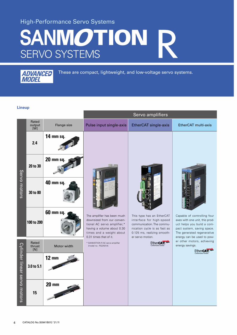
Lineup
Servo amplifiersRated output
[W]Flange size Pulse input single-axis EtherCAT single-axis EtherCAT multi-axis
Servo
mo
tors
2.414 mm sq.
20 to 3020 mm sq.
30 to 80
40 mm sq.
100 to 200
60 mm sq.C
ylind
er linear servo
mo
tors
Rated thrust
[N]Motor width
3.0 to 5.1
12 mm
15
20 mm
4 CATALOG No.S0941B012 ‘21.11
These are compact, lightweight, and low-voltage servo systems.
High-Performance Servo Systems
Capable of controlling four axes with one unit, this prod-uct helps you build a com-pact system, saving space. The generated regenerative energy can be used to pow-er other motors, achieving energy savings.
The amplifier has been much downsized from our conven-tional AC servo amplifier,* having a volume about 0.30 times and a weight about 0.31 times that of it.
* SANMOTION R AC servo amplifier (model no.: RS2A01A)
This type has an EtherCAT interface for high-speed communication. The commu-nication cycle is as fast as 0.125 ms, realizing smooth-er servo motion.
As a result of downsizing and weight reduction, the pulse input type has a volume about 0.30 times and a weight about 0.31 times that of our conventional AC servo amplifier.* The EtherCAT multi-axis type can drive 4 motor axes with a single unit, saving space.We offer small servo motors with 14 and 20 mm sq. flanges and compact cylindrical linear servo motors with 12 and 20 mm widths for use in chip mounters and other equipment with limited instal-lation space.
* SANMOTION R AC servo amplifier (model no.: RS2A01A)
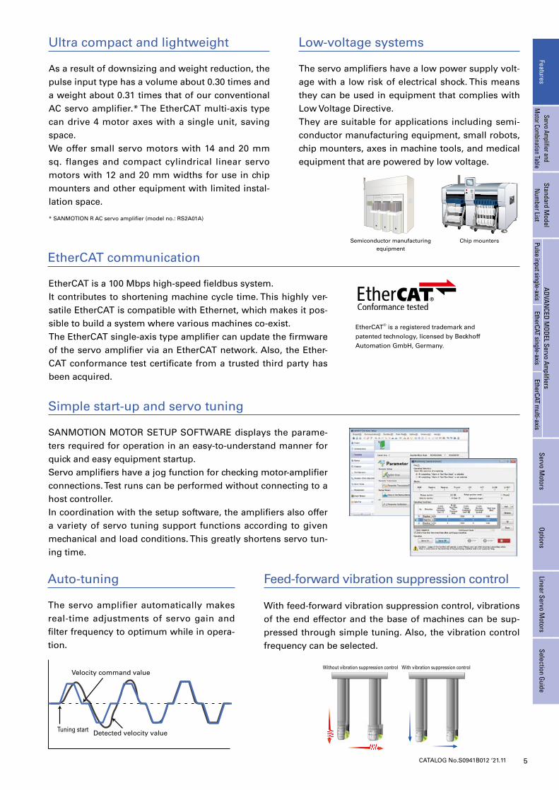
The servo amplifiers have a low power supply volt-age with a low risk of electrical shock. This means they can be used in equipment that complies with Low Voltage Directive.They are suitable for applications including semi-conductor manufacturing equipment, small robots, chip mounters, axes in machine tools, and medical equipment that are powered by low voltage.
SANMOTION MOTOR SETUP SOFTWARE displays the parame-ters required for operation in an easy-to-understand manner for quick and easy equipment startup.Servo amplifiers have a jog function for checking motor-amplifier connections. Test runs can be performed without connecting to a host controller.In coordination with the setup software, the amplifiers also offer a variety of servo tuning support functions according to given mechanical and load conditions. This greatly shortens servo tun-ing time.
The servo amplifier automatically makes real-time adjustments of servo gain and filter frequency to optimum while in opera-tion.
With feed-forward vibration suppression control, vibrations of the end effector and the base of machines can be sup-pressed through simple tuning. Also, the vibration control frequency can be selected.
Ultra compact and lightweight Low-voltage systems
Auto-tuning Feed-forward vibration suppression control
EtherCAT communication
Simple start-up and servo tuning
Semiconductor manufacturing equipment
Chip mounters
5CATALOG No.S0941B012 ‘21.11
EtherCAT is a 100 Mbps high-speed fieldbus system.It contributes to shortening machine cycle time. This highly ver-satile EtherCAT is compatible with Ethernet, which makes it pos-sible to build a system where various machines co-exist.The EtherCAT single-axis type amplifier can update the firmware of the servo amplifier via an EtherCAT network. Also, the Ether-CAT conformance test certificate from a trusted third party has been acquired.
EtherCAT® is a registered trademark and patented technology, licensed by Beckhoff Automation GmbH, Germany.
Tuning start Detected velocity value
Velocity command value
Position deviation during stop
With vibration suppression controlWithout vibration suppression control
100 ms/div
With vibration suppression controlWithout vibration suppression control
FeaturesServo Am
plifier and M
otor Combination Table
Standard Model
Num
ber ListADVAN
CED MODEL Servo Am
plifiersServo M
otorsOptions
Linear Servo Motors
Selection GuidePulse input single-axis
EtherCAT single-axisEtherCAT m
ulti-axis
Low cogging torque
High-Precision Battery-Less Absolute Encoder
Water and dust protection
6 CATALOG No.S0941B012 ‘21.11
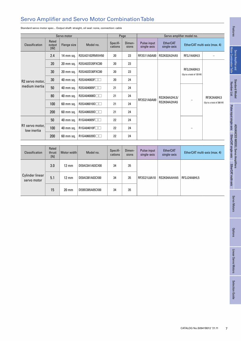
Cogging torque of 40 and 60 mm sq. motors has been reduced compared to our conventional prod-uct, achieving smoother machine operation.
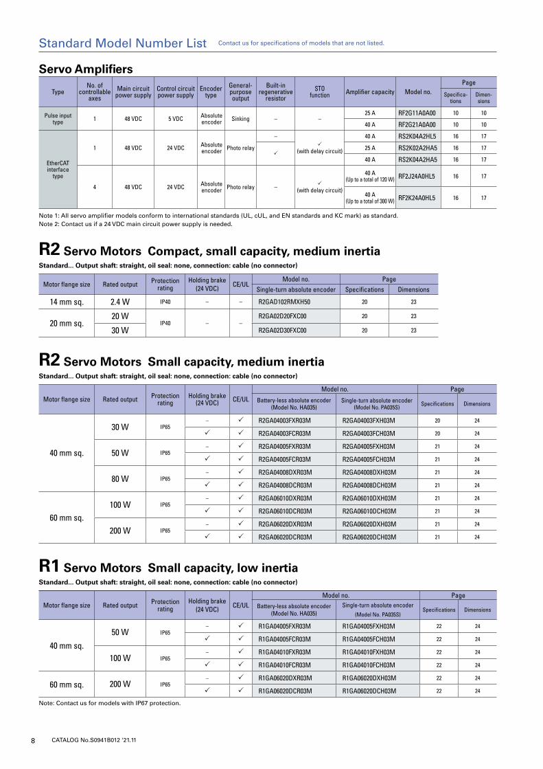
40 and 60 mm sq. servo motors are highly resis-tant to water and dust ingress with IP65 protection, ensuring normal operation even in severe environ-ments. Models with IP67 protection are available as
options. Except for shaft through-hole and cable ends.
Name Compatible motor size
Standard
Custom optionsSingle-turn resolution
Multi-turn resolution Baud rate
Absolute angular
accuracy
Single-turn absolute encoderThis is an optical single-turn encoder.
14 mm sq. 131072 (17-bit) – 2.5 Mbps Approx.
0.167°
Single-turn absolute encoder(Model No. MA018)This is a magnetic single-turn encoder.It has high environmental durability against water, oil, and dust.
20 mm sq. 8192 (13-bit) – 2.5 Mbps Approx.
0.167°
Battery-less absolute encoder(Model No. HA035)This is a high-precision battery-less optical multi-turn encoder.It reduces maintenance because it doesn't need batteries, which require maintenance.
40 mm sq.60 mm sq.
131072 (17-bit)
65536 (16-bit) 2.5 Mbps Approx.
0.167°
• Single-turn resolution: 1048576 (20-bit)• Baud rate: 4.0 Mbps• Absolute angular accuracy: Under 0.0167°
Single-turn absolute encoder(Model No. PA035S)This is a thin profile, optical single-turn encoder.It helps save wiring and downsize systems particularly for systems where incremental encoders are currently used.
40 mm sq.60 mm sq.
131072 (17-bit) – 2.5 Mbps Approx.
0.167°
• Single-turn resolution: 1048576 (20-bit)• Baud rate: 4.0 Mbps
Options
Battery-backup absolute encoder(Model No. PA035C)This is a thin profile, battery-backed optical multi-turn encoder. Be-cause the length of the motor can be shortened, it is ideal for devices with limited motor installation space. It requires an optional battery.
40 mm sq.60 mm sq.
131072 (17-bit)
65536 (16-bit) 2.5 Mbps Approx.
0.167°
• Single-turn resolution: 1048576 (20-bit)• Baud rate: 4.0 Mbps
Options
Battery-less absolute resolver encoder(Model No. RA035C)This is a multi-turn resolver encoder that doesn't require batteries.This is a resolver encoder, which features high environmental durability.
40 mm sq.60 mm sq.
131072 (17-bit)
65536 (16-bit) 2.5 Mbps Approx.
0.167° • Baud rate: 4.0 Mbps
40 and 60 mm sq. servo motors come with a high-precision battery-less absolute en-coder, Model No. HA035, as standard. Has a wide operating temperature range of -20 to +105°C. Withstands environmental vibration of up to 147 m/s2 (15 G). (When mounted
on a servo motor, the operating temperature and environmental vibration of the motor prevail.) They can be used in harsher environments than our conventional products. For even higher precision, custom options such as single-turn resolution of 1048576 (20-bit) and absolute angular accuracy of approximately 0.0167° (1 arcmin) are avail-able. We offer a variety of encoders available for use in various equipment. See the table below.
Comparison of cogging torque waveforms
(Reference waveform image)
R Motor
Current model
Water Dust
7CATALOG No.S0941B012 ‘21.11
Servo Amplifier and Servo Motor Combination Table
FeaturesServo Am
plifier and M
otor Combination Table
Standard Model
Num
ber ListADVAN
CED MODEL Servo Am
plifiersServo M
otorsOptions
Linear Servo Motors
Selection GuidePulse input single-axis
EtherCAT single-axisEtherCAT m
ulti-axis
Servo motor Page Servo amplifier model no.
ClassificationRated output
[W]Flange size Model no. Specifi-
cationsDimen-sions
Pulse input single-axis
EtherCAT single-axis EtherCAT multi-axis (max. 4)
R2 servo motor, medium inertia
2.4 14 mm sq. R2GAD102RMXH50 20 23 RF2G11A0A00 RS2K02A2HA5 RF2J14A0HL5 –
20 20 mm sq. R2GA02D20FXC00 20 23
RF2G21A0A00RS2K04A2HL5/RS2K04A2HA5
RF2J24A0HL5(Up to a total of 120 W)
RF2K24A0HL5(Up to a total of 300 W)
30 20 mm sq. R2GA02D30FXC00 20 23
30 40 mm sq. R2GA04003F□□ 20 24
50 40 mm sq. R2GA04005F□□ 21 24
–80 40 mm sq. R2GA04008D□□ 21 24
100 60 mm sq. R2GA06010D□□ 21 24
200 60 mm sq. R2GA06020D□□ 21 24
R1 servo motor, low inertia
50 40 mm sq. R1GA04005F□□ 22 24
–100 40 mm sq. R1GA04010F□□ 22 24
200 60 mm sq. R1GA06020D□□ 22 24
ClassificationRated thrust
[N]Motor width Model no. Specifi-
cationsDimen-sions
Pulse input single-axis
EtherCAT single-axis EtherCAT multi-axis (max. 4)
Cylinder linear servo motor
3.0 12 mm DE0AC0A1A03CX00 34 35
RF2G21L8A10 RS2K04AAHA5 RF2J24A8HL55.1 12 mm DE0AC001A03CX00 34 35
15 20 mm DE0BC005A05CX00 34 35
Standard servo motor spec... Output shaft: straight, oil seal: none, connection: cable
8 CATALOG No.S0941B012 ‘21.11
Servo Amplifiers
TypeNo. of
controllable axes
Main circuit power supply
Control circuit power supply
Encoder type
General-purpose output
Built-in regenerative
resistorSTO
function Amplifier capacity Model no.Page
Specifica-tions
Dimen-sions
Pulse input type 1 48 VDC 5 VDC Absolute
encoder Sinking – –25 A RF2G11A0A00 10 10
40 A RF2G21A0A00 10 10
EtherCAT interface
type
1 48 VDC 24 VDC Absolute encoder Photo relay
–
(with delay circuit)
40 A RS2K04A2HL5 16 17
25 A RS2K02A2HA5 16 17
40 A RS2K04A2HA5 16 17
4 48 VDC 24 VDC Absolute encoder Photo relay –
(with delay circuit)
40 A(Up to a total of 120 W) RF2J24A0HL5 16 17
40 A(Up to a total of 300 W) RF2K24A0HL5 16 17
Note 1: All servo amplifier models conform to international standards (UL, cUL, and EN standards and KC mark) as standard.Note 2: Contact us if a 24 VDC main circuit power supply is needed.
R2 Servo Motors Compact, small capacity, medium inertia Standard... Output shaft: straight, oil seal: none, connection: cable (no connector)
Motor flange size Rated output Protection rating
Holding brake(24 VDC) CE/UL
Model no. PageSingle-turn absolute encoder Specifications Dimensions
14 mm sq. 2.4 W IP40 – – R2GAD102RMXH50 20 23
20 mm sq.20 W
IP40 – –R2GA02D20FXC00 20 23
30 W R2GA02D30FXC00 20 23
R2 Servo Motors Small capacity, medium inertia Standard... Output shaft: straight, oil seal: none, connection: cable (no connector)
Motor flange size Rated output Protection rating
Holding brake(24 VDC) CE/UL
Model no. Page
Battery-less absolute encoder(Model No. HA035)
Single-turn absolute encoder(Model No. PA035S) Specifications Dimensions
40 mm sq.
30 W IP65– R2GA04003FXR03M R2GA04003FXH03M 20 24
R2GA04003FCR03M R2GA04003FCH03M 20 24
50 W IP65– R2GA04005FXR03M R2GA04005FXH03M 21 24
R2GA04005FCR03M R2GA04005FCH03M 21 24
80 W IP65– R2GA04008DXR03M R2GA04008DXH03M 21 24
R2GA04008DCR03M R2GA04008DCH03M 21 24
60 mm sq.100 W IP65
– R2GA06010DXR03M R2GA06010DXH03M 21 24
R2GA06010DCR03M R2GA06010DCH03M 21 24
200 W IP65– R2GA06020DXR03M R2GA06020DXH03M 21 24
R2GA06020DCR03M R2GA06020DCH03M 21 24
R1 Servo Motors Small capacity, low inertia Standard... Output shaft: straight, oil seal: none, connection: cable (no connector)
Motor flange size Rated output Protection rating
Holding brake(24 VDC) CE/UL
Model no. Page
Battery-less absolute encoder(Model No. HA035)
Single-turn absolute encoder(Model No. PA035S)
Specifications Dimensions
40 mm sq.
50 W IP65– R1GA04005FXR03M R1GA04005FXH03M 22 24
R1GA04005FCR03M R1GA04005FCH03M 22 24
100 W IP65– R1GA04010FXR03M R1GA04010FXH03M 22 24
R1GA04010FCR03M R1GA04010FCH03M 22 24
60 mm sq. 200 W IP65– R1GA06020DXR03M R1GA06020DXH03M 22 24
R1GA06020DCR03M R1GA06020DCH03M 22 24
Note: Contact us for models with IP67 protection.
Standard Model Number List Contact us for specifications of models that are not listed.
9CATALOG No.S0941B012 ‘21.11
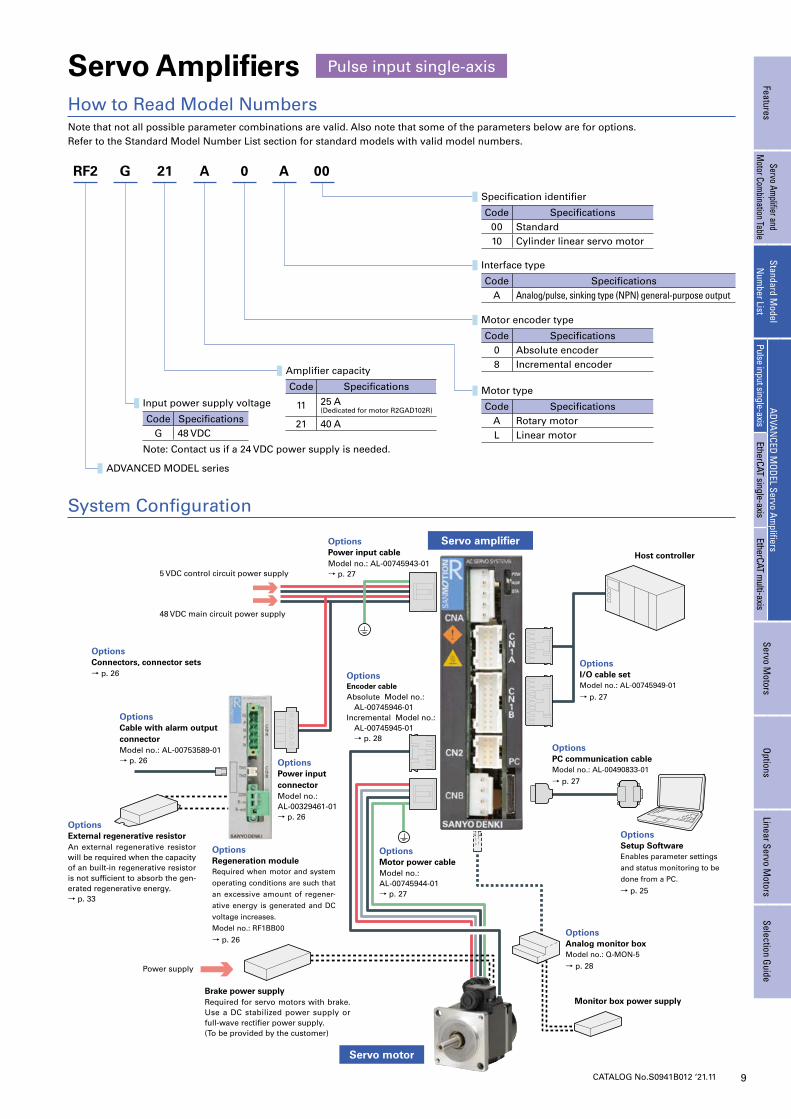
Servo Amplifiers
Note that not all possible parameter combinations are valid. Also note that some of the parameters below are for options.Refer to the Standard Model Number List section for standard models with valid model numbers.
How to Read Model Numbers
Pulse input single-axis
Servo amplifier
System Configuration
Servo motor
5 VDC control circuit power supply
OptionsPower input cableModel no.: AL-00745943-01→ p. 27
Host controller
OptionsI/O cable setModel no.: AL-00745949-01
→ p. 27
OptionsSetup SoftwareEnables parameter settings
and status monitoring to be
done from a PC.
→ p. 25
OptionsPC communication cableModel no.: AL-00490833-01
→ p. 27
OptionsAnalog monitor boxModel no.: Q-MON-5
→ p. 28
Monitor box power supply
48 VDC main circuit power supply
Power supply
OptionsConnectors, connector sets→ p. 26
Brake power supplyRequired for servo motors with brake. Use a DC stabilized power supply or full-wave rectifier power supply.(To be provided by the customer)
OptionsCable with alarm output connectorModel no.: AL-00753589-01→ p. 26
OptionsExternal regenerative resistorAn external regenerative resistor will be required when the capacity of an built-in regenerative resistor is not sufficient to absorb the gen-erated regenerative energy.→ p. 33
OptionsRegeneration moduleRequired when motor and system
operating conditions are such that
an excessive amount of regener-
ative energy is generated and DC
voltage increases.
Model no.: RF1BB00
→ p. 26
OptionsPower input connectorModel no.:AL-00329461-01→ p. 26
OptionsMotor power cableModel no.: AL-00745944-01→ p. 27
OptionsEncoder cableAbsolute Model no.: AL-00745946-01Incremental Model no.: AL-00745945-01 → p. 28
FeaturesServo Am
plifier and M
otor Combination Table
Standard Model
Num
ber ListADVAN
CED MODEL Servo Am
plifiersServo M
otorsOptions
Linear Servo Motors
Selection GuidePulse input single-axis
EtherCAT single-axisEtherCAT m
ulti-axis
RF2 G 21 A 0 A 00
Input power supply voltage
Code SpecificationsG 48 VDC
Note: Contact us if a 24 VDC power supply is needed.
ADVANCED MODEL series
Amplifier capacity
Code Specifications
11 25 A(Dedicated for motor R2GAD102R)
21 40 A
Motor type
Code SpecificationsA Rotary motorL Linear motor
Motor encoder type
Code Specifications0 Absolute encoder8 Incremental encoder
Interface type
Code SpecificationsA Analog/pulse, sinking type (NPN) general-purpose output
Specification identifier
Code Specifications00 Standard10 Cylinder linear servo motor
10 CATALOG No.S0941B012 ‘21.11
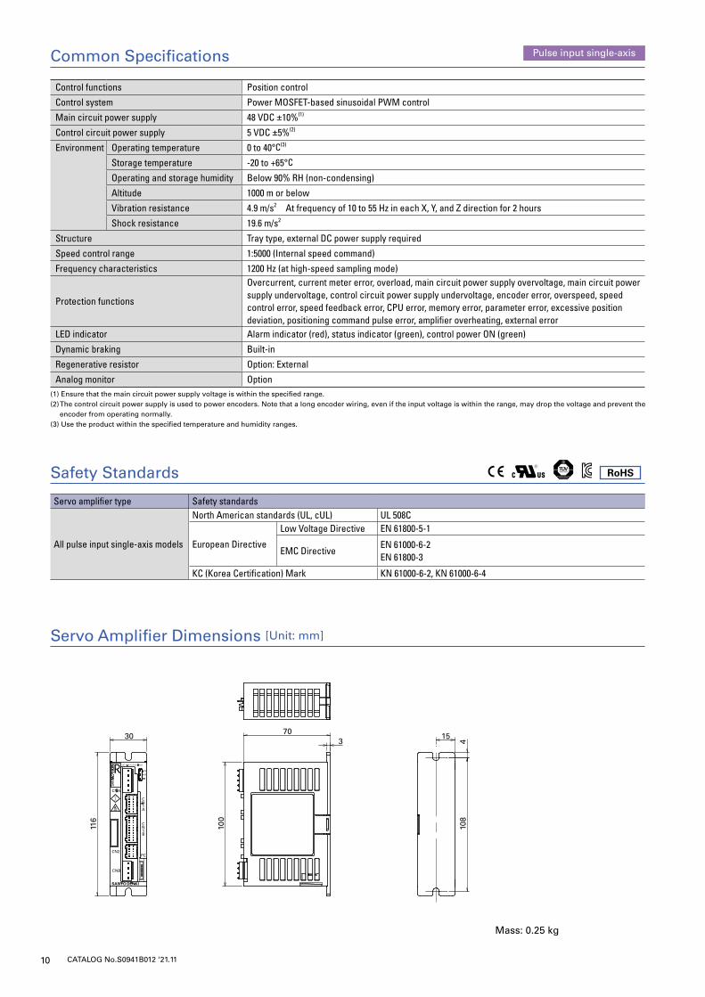
Control functions Position control
Control system Power MOSFET-based sinusoidal PWM control
Main circuit power supply 48 VDC ±10%(1)
Control circuit power supply 5 VDC ±5%(2)
Environment Operating temperature 0 to 40°C(3)
Storage temperature -20 to +65°C
Operating and storage humidity Below 90% RH (non-condensing)
Altitude 1000 m or below
Vibration resistance 4.9 m/s2 At frequency of 10 to 55 Hz in each X, Y, and Z direction for 2 hours
Shock resistance 19.6 m/s2
Structure Tray type, external DC power supply required
Speed control range 1:5000 (Internal speed command)
Frequency characteristics 1200 Hz (at high-speed sampling mode)
Protection functions
Overcurrent, current meter error, overload, main circuit power supply overvoltage, main circuit power supply undervoltage, control circuit power supply undervoltage, encoder error, overspeed, speed control error, speed feedback error, CPU error, memory error, parameter error, excessive position deviation, positioning command pulse error, amplifier overheating, external error
LED indicator Alarm indicator (red), status indicator (green), control power ON (green)
Dynamic braking Built-in
Regenerative resistor Option: External
Analog monitor Option(1) Ensure that the main circuit power supply voltage is within the specified range.(2) The control circuit power supply is used to power encoders. Note that a long encoder wiring, even if the input voltage is within the range, may drop the voltage and prevent the
encoder from operating normally.(3) Use the product within the specified temperature and humidity ranges.
Common Specifications Pulse input single-axis
108
116
100
303
70
4
15
918
220
0
50 (70) 130 519
0
10302-∅5
2-5
4.5
4.510.8
160
40
(20)
(18)(70) 85
4
5
515
2
Servo Amplifier Dimensions [Unit: mm]
Mass: 0.25 kg
RoHS
Servo amplifier type Safety standards
All pulse input single-axis models
North American standards (UL, cUL) UL 508C
European Directive
Low Voltage Directive EN 61800-5-1
EMC DirectiveEN 61000-6-2EN 61800-3
KC (Korea Certification) Mark KN 61000-6-2, KN 61000-6-4
Safety Standards
11CATALOG No.S0941B012 ‘21.11
Servo amplifier
CN1A
48 G
48 V
5 G
5 V
FG
Clockwise pulse
SG
Counterclockwise pulse
SG
F-PC
F-PC
SG
R-PC
R-PC
FG
+5 V
+5 V+5 V
+5 V
SG
SG
Servo motor
U
W
V
CN2
Red
(Green/Yellow)
White
Black
Green
RY1
Holding brake(Only for motors with brake)
Orange(Yellow)
Orange(Yellow)
Encoder
90 V(24 V)
11
12
10
13
14
2
CONT-COM
CONT15 to 24 VDC
CONT2
CONT3
CONT4
CONT5
CONT6
2 FG
9PS
8PS
7
6
ZO
ZO
5BO
4BO
3
1
AO
AO
Line driverHD26C31 equivalent
User unit
(3)
(5)
SH SH
CNBCNA
5 VDC,12 to 24 VDC
Line driverHD26C31 equivalent
Line receiverHD26C32equivalent
Position command pulse input
General-purposeinput
Shielded cable
General-purposeoutput
Encoder divided signal output
(4)
OUT8
OUT7
OUT6
OUT5
OUT4
OUT3
OUT2
OUT1 12
OUT-PWR 11
CN1A
CN1BCN1B
CONT8
CONT7
OUT-COM
1
3
4
5
6
7
8
9
10
13
14
15
16
17
18
20
19
(1)
(6)
(2)
1
2
3
41
2
3
4
5Main circuit power supply
Control power
48 VDC
5 VDC
Ana
log
mon
itor
box
Connector no.
NameHousing, plug, shellHousing Contact
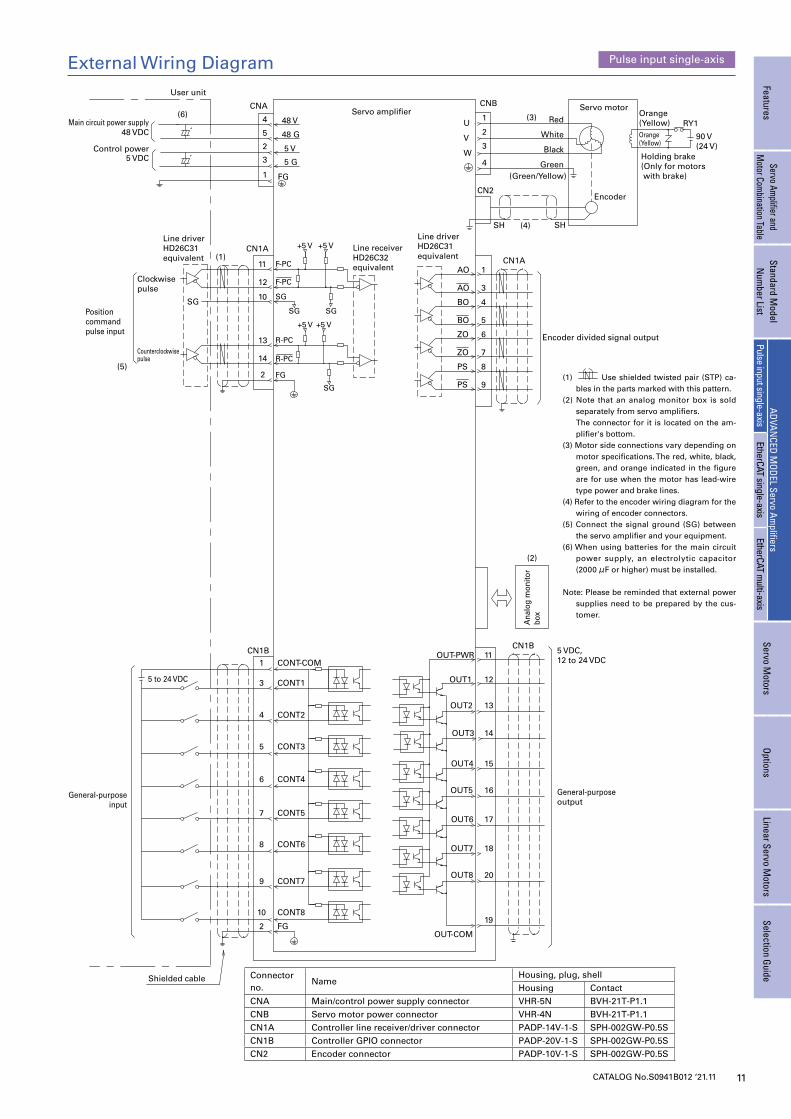
CNA Main/control power supply connector VHR-5N BVH-21T-P1.1CNB Servo motor power connector VHR-4N BVH-21T-P1.1CN1A Controller line receiver/driver connector PADP-14V-1-S SPH-002GW-P0.5SCN1B Controller GPIO connector PADP-20V-1-S SPH-002GW-P0.5SCN2 Encoder connector PADP-10V-1-S SPH-002GW-P0.5S
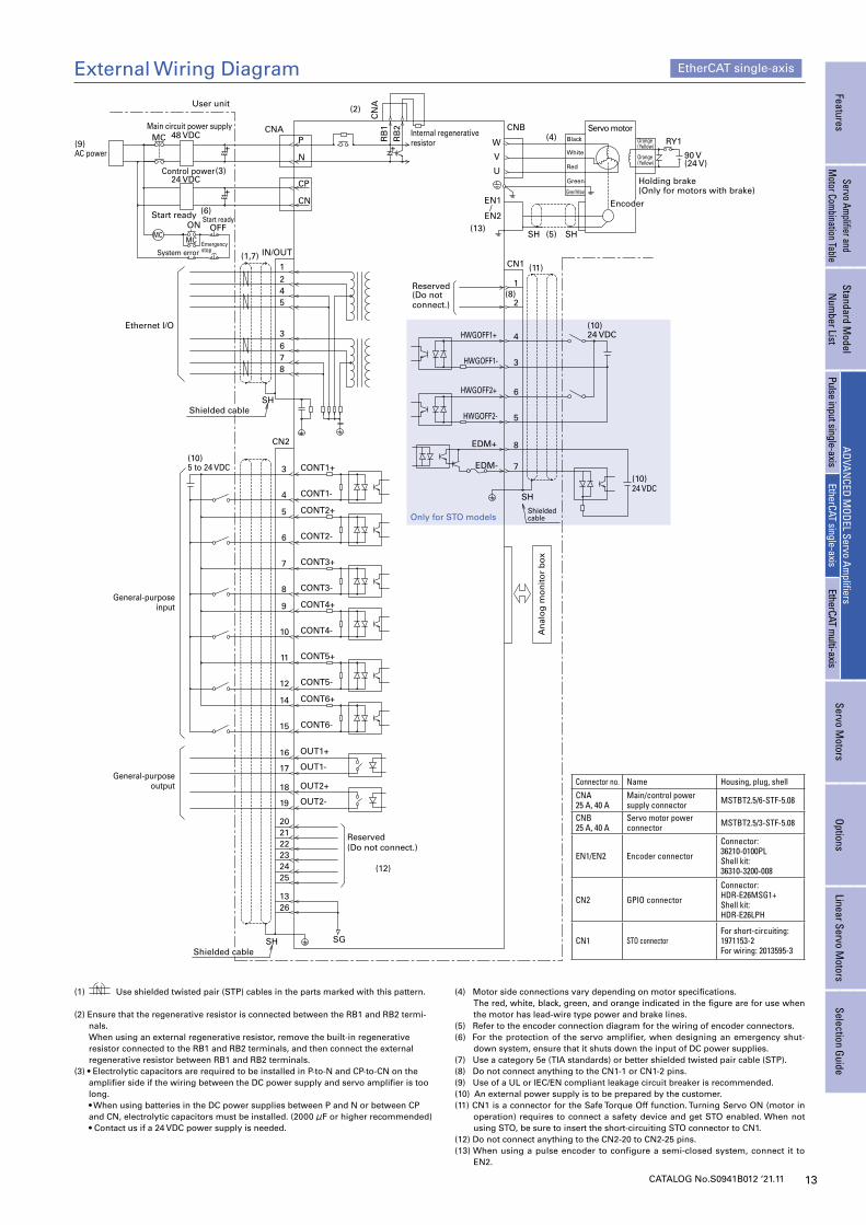
External Wiring Diagram Pulse input single-axis
FeaturesServo Am
plifier and M
otor Combination Table
Standard Model
Num
ber ListADVAN
CED MODEL Servo Am
plifiersServo M
otorsOptions
Linear Servo Motors
Selection GuidePulse input single-axis
EtherCAT single-axisEtherCAT m
ulti-axis
(1) Use shielded twisted pair (STP) ca-bles in the parts marked with this pattern.
(2) Note that an analog monitor box is sold separately from servo amplifiers.
The connector for it is located on the am-plifier's bottom.
(3) Motor side connections vary depending on motor specifications. The red, white, black, green, and orange indicated in the figure are for use when the motor has lead-wire type power and brake lines.
(4) Refer to the encoder wiring diagram for the wiring of encoder connectors.
(5) Connect the signal ground (SG) between the servo amplifier and your equipment.
(6) When using batteries for the main circuit power supply, an electrolytic capacitor (2000 μF or higher) must be installed.
Note: Please be reminded that external power
supplies need to be prepared by the cus-tomer.
12 CATALOG No.S0941B012 ‘21.11
System Configuration
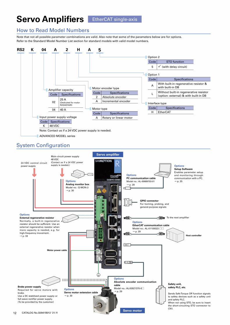
EtherCAT single-axisServo Amplifiers
Note that not all possible parameter combinations are valid. Also note that some of the parameters below are for options.Refer to the Standard Model Number List section for standard models with valid model numbers.
How to Read Model Numbers
Servo motor
Servo amplifier
Safety unit,safety PLC, etc.
Sends Safe Torque Off function signals to safety devices such as a safety unit and safety PLC.When not using STO, be sure to insert the short-circuiting STO connector to CN1.
OptionsAbsolute encoder communication cableModel no.: AL-00921370-0□→ p. 29
OptionsServo motor extension cable→ p. 30
Brake power supplyRequired for servo motors with brake.Use a DC stabilized power supply or full-wave rectifier power supply.(To be provided by the customer)
OptionsExternal regenerative resistorNormally, a built-in regenerative resistor should be sufficient. Use an external regenerative resistor when more capacity is needed, e.g. for high-frequency movement.→ p. 33
24 VDC control circuit power supply
Main circuit power supply48 VDC(Contact us if a 24 VDC power supply is needed.)
OptionsAnalog monitor boxModel no.: Q-MON-3→ p. 30
OptionsPC communication cableModel no.: AL-00689703-01
→ p. 29
OptionsSetup SoftwareEnables parameter setup and monitoring through communication with a PC.→ p. 25
GPIO connectorFor homing, probing, and general-purpose signals
To the next amplifier
Host controller
OptionsEtherCAT communication cableModel no.: AL-01109322-□□ → p. 29
Motor power cable
Input power supply voltage
Code SpecificationsK 48 VDC
Note: Contact us if a 24 VDC power supply is needed.
RS2 K 04 A 2 H A 5
ADVANCED MODEL series
Amplifier capacity
Code Specifications
0225 A(Dedicated for motor R2GAD102R)
04 40 A Motor type
Code Specifications
A Rotary or linear motor
Motor encoder type
Code Specifications2 Absolute encoderA Incremental encoder
Interface type
Code SpecificationsH EtherCAT
Option 1
Code Specifications
AWith built-in regenerative resistor & with built-in DB
LWithout built-in regenerative resistor (option: external) & with built-in DB
Option 2
Code STO function
5 (with delay circuit)
13CATALOG No.S0941B012 ‘21.11
MC
System error
Start ready
AC power
MC
IN/OUT
OFFStart ready
ON
MC
Emergency stop
P
N
Servo motor
W
U
V
EN1
Black
(Green/Yellow)
White
Red
Green
RY1
(Only for motors with brake)Holding brake
Orange(Yellow)
Orange(Yellow)
90 V(24 V)
RB
1
+
12
CONT1+
CONT1-
User unit
(4)Internal regenerative resistorR
B2
SH SH
(2)
CN
A
CNA
(5)
45
8763
CONT2-
CONT2+
SH
6
5
8
3
4HWGOFF1+
EDM+
HWGOFF1-
HWGOFF2-
HWGOFF2+
SH
Reserved(Do not connect.)
24 VDC
(10)24 VDC
Ethernet I/O
5 to 24 VDC(10)
CN1
EDM-
SH
3
4
5
6
(1,7)
CNB
(11)
(10)7
16 OUT1+
OUT1-17
CN2
OUT2-
OUT2+
19
18
General-purposeinput
General-purposeoutput
CONT4-10
CONT3-
CONT4+9
8
CONT3+7
CONT6-15
CONT6+
CONT5-
14
12
CONT5+11
2021222324
Reserved(Do not connect.)
(8)2
1
SG
1326
/EN2
(13)
25(12)
(9)
Main circuit power supply48 VDC
+
(3)CP
CN+
(6)
Control power24 VDC
Encoder
Shielded cable
Shielded cable
Shielded cable
Only for STO models
An
alo
g m
on
ito
r b
ox
External Wiring Diagram EtherCAT single-axis
FeaturesServo Am
plifier and M
otor Combination Table
Standard Model
Num
ber ListADVAN
CED MODEL Servo Am
plifiersServo M
otorsOptions
Linear Servo Motors
Selection GuidePulse input single-axis
EtherCAT single-axisEtherCAT m
ulti-axis
Connector no. Name Housing, plug, shell
CNA25 A, 40 A
Main/control power supply connector MSTBT2.5/6-STF-5.08
CNB25 A, 40 A
Servo motor power connector MSTBT2.5/3-STF-5.08
EN1/EN2 Encoder connector
Connector:36210-0100PLShell kit:36310-3200-008
CN2 GPIO connector
Connector:HDR-E26MSG1+Shell kit:HDR-E26LPH
CN1 STO connectorFor short-circuiting:1971153-2For wiring: 2013595-3
(1) Use shielded twisted pair (STP) cables in the parts marked with this pattern.
(2) Ensure that the regenerative resistor is connected between the RB1 and RB2 termi-nals.
When using an external regenerative resistor, remove the built-in regenerative resistor connected to the RB1 and RB2 terminals, and then connect the external regenerative resistor between RB1 and RB2 terminals.
(3) • Electrolytic capacitors are required to be installed in P-to-N and CP-to-CN on the amplifier side if the wiring between the DC power supply and servo amplifier is too long.
• When using batteries in the DC power supplies between P and N or between CP and CN, electrolytic capacitors must be installed. (2000 μF or higher recommended)
• Contact us if a 24 VDC power supply is needed.
(4) Motor side connections vary depending on motor specifications. The red, white, black, green, and orange indicated in the figure are for use when
the motor has lead-wire type power and brake lines.(5) Refer to the encoder connection diagram for the wiring of encoder connectors.(6) For the protection of the servo amplifier, when designing an emergency shut-
down system, ensure that it shuts down the input of DC power supplies.(7) Use a category 5e (TIA standards) or better shielded twisted pair cable (STP).(8) Do not connect anything to the CN1-1 or CN1-2 pins.(9) Use of a UL or IEC/EN compliant leakage circuit breaker is recommended.(10) An external power supply is to be prepared by the customer.(11) CN1 is a connector for the Safe Torque Off function. Turning Servo ON (motor in
operation) requires to connect a safety device and get STO enabled. When not using STO, be sure to insert the short-circuiting STO connector to CN1.
(12) Do not connect anything to the CN2-20 to CN2-25 pins.(13) When using a pulse encoder to configure a semi-closed system, connect it to
EN2.
14 CATALOG No.S0941B012 ‘21.11
System Configuration
Servo Amplifiers
Note that not all possible parameter combinations are valid. Also note that some of the parameters below are for options.Refer to the Standard Model Number List section for standard models with valid model numbers.
How to Read Model Numbers
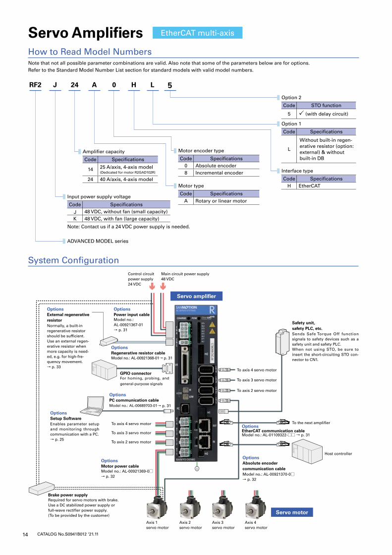
RF2 J 24 A 0 H L 5
ADVANCED MODEL series
Amplifier capacity
Code Specifications
14 25 A/axis, 4-axis model(Dedicated for motor R2GAD102R)
24 40 A/axis, 4-axis modelMotor type
Code SpecificationsA Rotary or linear motor
Motor encoder type
Code Specifications0 Absolute encoder8 Incremental encoder Interface type
Code SpecificationsH EtherCAT
Option 1
Code Specifications
L
Without built-in regen-erative resistor (option: external) & without built-in DB
Option 2
Code STO function
5 (with delay circuit)
Servo motor
Servo amplifier
EtherCAT multi-axis
Safety unit,safety PLC, etc.Sends Safe Torque Off function signals to safety devices such as a safety unit and safety PLC.When not using STO, be sure to insert the short-circuiting STO con-nector to CN1.
OptionsExternal regenerative resistorNormally, a built-in regenerative resistor should be sufficient. Use an external regen-erative resistor when more capacity is need-ed, e.g. for high-fre-quency movement.→ p. 33
Control circuit power supply 24 VDC
Main circuit power supply48 VDC
To axis 4 servo motor
To axis 4 servo motor
Axis 4 servo motor
Axis 3 servo motor
Axis 2 servo motor
Axis 1 servo motor
To axis 3 servo motor
To axis 3 servo motor
To axis 2 servo motor
To axis 2 servo motor
OptionsPower input cableModel no.: AL-00921367-01→ p. 31
OptionsRegenerative resistor cableModel no.: AL-00921368-01→ p. 31
GPIO connectorFor homing, probing, and
general-purpose signals
OptionsPC communication cableModel no.: AL-00689703-01→ p. 31
OptionsSetup SoftwareEnables parameter setup and monitoring through communication with a PC.→ p. 25
Brake power supplyRequired for servo motors with brake.Use a DC stabilized power supply or full-wave rectifier power supply.(To be provided by the customer)
OptionsMotor power cableModel no.: AL-00921369-0□→ p. 32
OptionsAbsolute encoder communication cableModel no.: AL-00921370-0□→ p. 32
Host controller
To the next amplifierOptionsEtherCAT communication cableModel no.: AL-01109322-□□ → p. 31
Input power supply voltage
Code Specifications48 VDC, without fan (small capacity)
K 48 VDC, with fan (large capacity)
Note: Contact us if a 24 VDC power supply is needed.
15CATALOG No.S0941B012 ‘21.11
MC
System error
Start ready
AC power
MC
IN/OUT
OFFStart ready
ON
MC
Emergencystop
P
NU
W
V
Red
(Green/Yellow)
White
Black
Green
RY1
(Only for motors with brake)Holding brake
Orange(Yellow)
Orange(Yellow)
90 V(24 V)
12
CONT1+
CONT1-
User unit
(4)
External regenerative resistor
SH SH
CN
C
CNA
(5)
45
8763
CONT2-
CONT2+
SH
6
5
8
3
4HWGOFF1+
EDM+
HWGOFF1-
HWGOFF2-
HWGOFF2+
SH24 VDC
(9)24 VDC
Ethernet I/O
5 to 24 VDC(9)
CN1
EDM-
SH
1
2
3
4
(1,7)
MOT1 to 4
(10)
(10)7
I/O
CONT4-8
CONT3-
CONT4+7
6
CONT3+5
CONT6-22
CONT6+
CONT5-
21
20
CONT5+19
Reserved(Do not connect.)
(8)2
1
(8)
Main circuit power supply48 VDC
+
(3)
(12)
+
(6)
Control power24 VDC
EN1 to 4
CONT8-26
CONT8+
CONT7-
25
24
CONT7+23
OUT1-
OUT1+
OUT2-
OUT2+
OUT3-
OUT3+
OUT4-
OUT4+
OUT5-
OUT5+
OUT6-
OUT6+
OUT7-
OUT7+
OUT8-
OUT8+
General-purpose output
28
Reserved(Do not connect.)
(11)
27109
P
N
CP
CN
FG
FG
General-purposeinput
4
3
8
7
6
2
1
5
11
12
13
14
15
16
17
18
29
30
31
32
33
34
35
36
4
3
2
1
1 2 (2)
Shielded cable
Shielded cable
Encoder
Shielded cable
Servo amplifier
Servo motor
Only for STO models
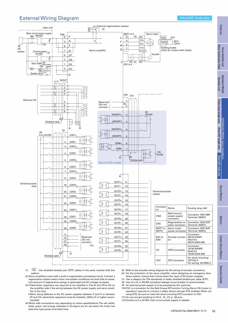
External Wiring Diagram EtherCAT multi-axis
FeaturesServo Am
plifier and M
otor Combination Table
Standard Model
Num
ber ListADVAN
CED MODEL Servo Am
plifiersServo M
otorsOptions
Linear Servo Motors
Selection GuidePulse input single-axis
EtherCAT single-axisEtherCAT m
ulti-axis
Connector no. Name Housing, plug, shell
CNAMain/control power supply connector
Connector: 5557-08RTerminal: 5556TL
CNC Regenerative re-sistor connector
Connector: 5557-02RTerminal: 5556TL
MOT1 to MOT4
Servo motor power connector
Connector: 5557-04RTerminal: 5556TL
EN1 to EN4
Encoder connec-tor
Connector:36210-0100PLShell kit:36310-3200-008
I/O GPIO connector
Connector:10136-3000PEShell kit:10336-52A0-008
CN1 STO connectorFor short-circuiting: 1971153-2For wiring: 2013595-3
(1) Use shielded twisted pair (STP) cables in the parts marked with this pattern.
(2) Servo amplifiers come with a built-in regeneration processing circuit. Connect a regenerative resistor when motor and system conditions are such that an exces-sive amount of regenerative energy is generated and DC voltage increases.
(3) • Electrolytic capacitors are required to be installed in P-to-N and CP-to-CN on the amplifier side if the wiring between the DC power supply and servo ampli-fier is too long.
• When using batteries in the DC power supplies between P and N or between CP and CN, electrolytic capacitors must be installed. (2000 μF or higher recom-mended)
(4) Motor side connections vary depending on motor specifications. The red, white, black, green, and orange indicated in the figure are for use when the motor has lead-wire type power and brake lines.
(5) Refer to the encoder wiring diagram for the wiring of encoder connectors.(6) For the protection of the servo amplifier, when designing an emergency shut-
down system, ensure that it shuts down the input of DC power supplies.(7) Use a category 5e (TIA standards) or better shielded twisted pair cable (STP).(8) Use of a UL or IEC/EN compliant leakage circuit breaker is recommended.(9) An external power supply is to be prepared by the customer.(10) CN1 is a connector for the Safe Torque Off function. Turning Servo ON (motor in
operation) requires to connect a safety device and get STO enabled. When not using STO, be sure to insert the short-circuiting STO connector to CN1.
(11) Do not connect anything to I/O-9, -10, -27, or -28 pins.(12) Contact us if a 24 VDC main circuit power supply is needed.
16 CATALOG No.S0941B012 ‘21.11
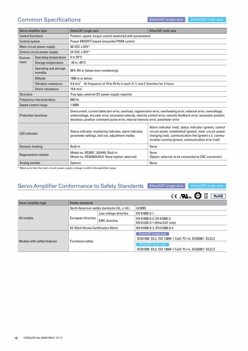
Servo amplifier type EtherCAT single-axis EtherCAT multi-axis
Control functions Position, speed, torque control (switched with parameters)
Control system Power MOSFET-based sinusoidal PWM control
Main circuit power supply 48 VDC ±10%*
Control circuit power supply 24 VDC ±10%*
Environ-ment
Operating temperature 0 to 55°C
Storage temperature -20 to +65°C
Operating and storage humidity 90% RH or below (non-condensing)
Altitude 1000 m or below
Vibration resistance 4.9 m/s2 At frequency of 10 to 55 Hz in each X, Y, and Z direction for 2 hours
Shock resistance 19.6 m/s2
Structure Tray type, external DC power supply required
Frequency characteristics 800 Hz
Speed control range 1:5000
Protection functionsOvercurrent, current detection error, overload, regenerative error, overheating error, external error, overvoltage, undervoltage, encoder error, excessive velocity, velocity control error, velocity feedback error, excessive position deviation, position command pulse error, internal memory error, parameter error
LED indicator Status indicator, monitoring indicator, alarm indicator, parameter settings, test run, adjustment modes
Alarm indicator (red), status indicator (green), control circuit power established (green), main circuit power charging (red), communication link (green) x 2, commu-nication running (green), communication error (red)
Dynamic braking Built-in None
Regenerative resistor Model no. RS2K0□A2HA5: Built-inModel no. RS2K04A2HL5: None (option: external)
None (Option: external; to be connected to CNC connector)
Analog monitor Options None* Make sure that the main circuit power supply voltage is within the specified range.
Servo amplifier type Safety standards
All models
North American safety standards (UL, c-UL) UL508C
European directiveLow-voltage directive EN 61800-5-1
EMC directive EN 61000-6-2, EN 61800-3, EN 61326-3-1 (EtherCAT only)
KC Mark (Korea Certification Mark) KN 61000-6-2, KN 61000-6-4
Models with safety features Functional safety
EtherCAT single-axis
IEC61508: SIL2, ISO 13894-1 Cat3: PL=d, IEC62061: SILCL2
EtherCAT multi-axis
IEC61508: SIL3, ISO 13894-1 Cat3: PL=e, IEC62061: SILCL3
Servo Amplifier Conformance to Safety Standards
EtherCAT single-axis
EtherCAT single-axis
EtherCAT multi-axis
EtherCAT multi-axis
Common Specifications
RoHS
17CATALOG No.S0941B012 ‘21.11
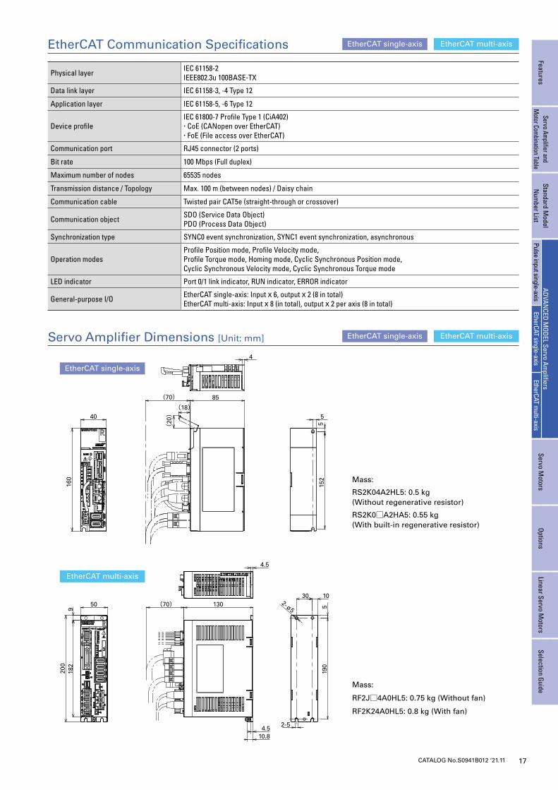
EtherCAT Communication Specifications EtherCAT single-axis
EtherCAT single-axis
EtherCAT multi-axis
EtherCAT multi-axis
918
220
0
50 (70) 130 519
0
10302-ø5
2-5
4.5
4.510.8
160
40
(20)
(18)(70) 85
4
5
515
2
Servo Amplifier Dimensions [Unit: mm]
EtherCAT single-axis
EtherCAT multi-axis
FeaturesServo Am
plifier and M
otor Combination Table
Standard Model
Num
ber ListADVAN
CED MODEL Servo Am
plifiersServo M
otorsOptions
Linear Servo Motors
Selection GuidePulse input single-axis
EtherCAT single-axisEtherCAT m
ulti-axis
Physical layer IEC 61158-2IEEE802.3u 100BASE-TX
Data link layer IEC 61158-3, -4 Type 12
Application layer IEC 61158-5, -6 Type 12
Device profileIEC 61800-7 Profile Type 1 (CiA402)・ CoE (CANopen over EtherCAT)・ FoE (File access over EtherCAT)
Communication port RJ45 connector (2 ports)
Bit rate 100 Mbps (Full duplex)
Maximum number of nodes 65535 nodes
Transmission distance / Topology Max. 100 m (between nodes) / Daisy chain
Communication cable Twisted pair CAT5e (straight-through or crossover)
Communication object SDO (Service Data Object)PDO (Process Data Object)
Synchronization type SYNC0 event synchronization, SYNC1 event synchronization, asynchronous
Operation modesProfile Position mode, Profile Velocity mode,Profile Torque mode, Homing mode, Cyclic Synchronous Position mode,Cyclic Synchronous Velocity mode, Cyclic Synchronous Torque mode
LED indicator Port 0/1 link indicator, RUN indicator, ERROR indicator
General-purpose I/O EtherCAT single-axis: Input x 6, output x 2 (8 in total)EtherCAT multi-axis: Input x 8 (in total), output x 2 per axis (8 in total)
Mass:
RS2K04A2HL5: 0.5 kg (Without regenerative resistor)
RS2K0□A2HA5: 0.55 kg (With built-in regenerative resistor)
Mass:
RF2J□4A0HL5: 0.75 kg (Without fan)
RF2K24A0HL5: 0.8 kg (With fan)
18 CATALOG No.S0941B012 ‘21.11
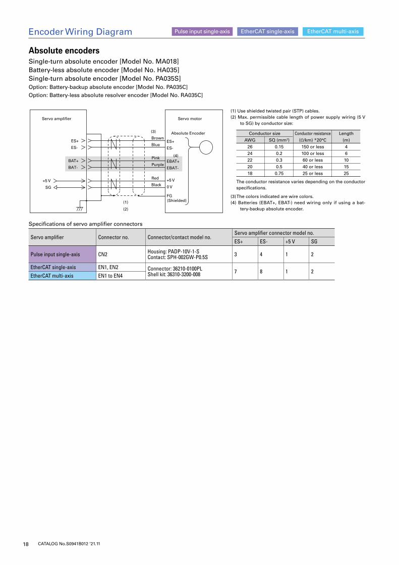
Encoder Wiring Diagram
Specifications of servo amplifier connectors
Servo amplifier Connector no. Connector/contact model no.Servo amplifier connector model no.
ES+ ES- +5 V SG
Pulse input single-axis CN2 Housing: PADP-10V-1-SContact: SPH-002GW-P0.5S 3 4 1 2
EtherCAT single-axis EN1, EN2 Connector: 36210-0100PLShell kit: 36310-3200-008 7 8 1 2
EtherCAT multi-axis EN1 to EN4
EtherCAT single-axis EtherCAT multi-axisPulse input single-axis
Absolute encodersSingle-turn absolute encoder [Model No. MA018]Battery-less absolute encoder [Model No. HA035]Single-turn absolute encoder [Model No. PA035S]Option: Battery-backup absolute encoder [Model No. PA035C]Option: Battery-less absolute resolver encoder [Model No. RA035C]
(1) Use shielded twisted pair (STP) cables.(2) Max. permissible cable length of power supply wiring (5 V
to SG) by conductor size:
(3) The colors indicated are wire colors.(4) Batteries (EBAT+, EBAT-) need wiring only if using a bat-
tery-backup absolute encoder.
The conductor resistance varies depending on the conductor specifications.
(1)
(3)
(4)
ES+
ES-
+5 V
SG
ES+
ES-
+5 V
0 V
FG
Brown
Blue
Red
Black
(Shielded)
Servo amplifier Servo motor
Absolute Encoder
(2)
BAT-
BAT+Purple
Pink
EBAT-
EBAT+
AWG2624222018
SQ (mm2)0.150.20.30.50.75
Conductor resistance(Ω/km) *20°C150 or less100 or less60 or less40 or less25 or less
Length(m)46101525
Conductor size
19CATALOG No.S0941B012 ‘21.11
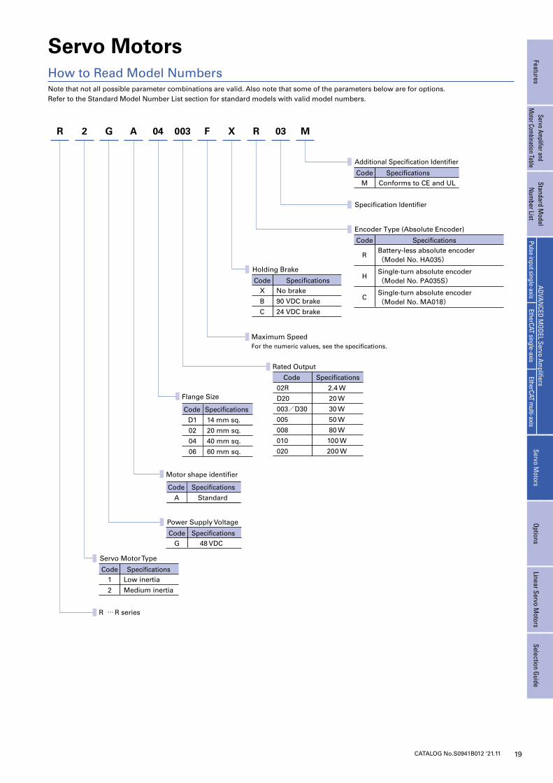
Servo Motors
Note that not all possible parameter combinations are valid. Also note that some of the parameters below are for options.Refer to the Standard Model Number List section for standard models with valid model numbers.
How to Read Model Numbers
G
R … R series
R 03R 2 A 04 003 F X M
Maximum SpeedFor the numeric values, see the specifications.
M
Additional Specification Identifier
SpecificationsCodeConforms to CE and UL
G
Power Supply Voltage
SpecificationsCode48 VDC
1
2
Servo Motor Type
SpecificationsCodeLow inertia
Medium inertia
X
B
C
Holding Brake
SpecificationsCodeNo brake
90 VDC brake
24 VDC brake
Specification Identifier
R
H
C
Encoder Type (Absolute Encoder)
SpecificationsCodeBattery-less absolute encoder (Model No. HA035)
Single-turn absolute encoder(Model No. PA035S)
Single-turn absolute encoder (Model No. MA018)
Rated Output
02R
D20
003/D30
005
008
010
020
Code Specifications
2.4 W
20 W
30 W
50 W
80 W
100 W
200 W
Flange Size
14 mm sq.
20 mm sq.
40 mm sq.
60 mm sq.
D1
02
04
06
SpecificationsCode
Motor shape identifier
StandardA
SpecificationsCode
FeaturesServo Am
plifier and M
otor Combination Table
Standard Model
Num
ber ListADVAN
CED MODEL Servo Am
plifiersServo M
otorsOptions
Linear Servo Motors
Selection GuidePulse input single-axis
EtherCAT single-axisEtherCAT m
ulti-axis
20 CATALOG No.S0941B012 ‘21.11
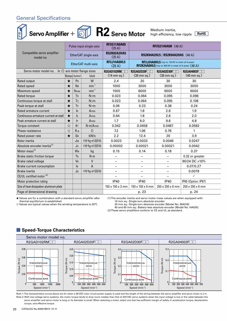
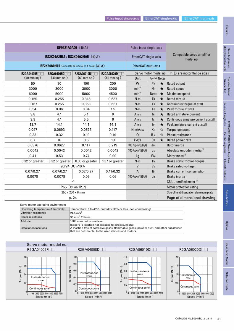
■ Speed-Torque Characteristics
Note 1: The characteristics curves above are for when a 48 VDC main circuit power supply is used and the length of the wiring between the servo amplifier and servo motor is 2 m.Note 2: With low-voltage servo systems, the motor torque tends to drop more notably than that of 200 VAC servo systems when the input voltage is low or the cable between the
servo amplifier and servo motor is long or its diameter is small. When selecting a motor, select one that has sufficient margin of safety in acceleration torque, deceleration torque, and effective torque.
Servo Amplifier + R2 Servo MotorMedium inertia, high efficiency, low ripple RoHS
General Specifications
Compatible servo amplifier model no.
Pulse input single-axis RF2G11A0A00《25 A》 RF2G21A0A00《40 A》 RF2G21A0A00《40 A》 Pulse input single-axis
Compatible servo amplifier model no.
EtherCAT single-axis RS2K02A2HA5《25 A》 RS2K04A2HL5 / RS2K04A2HA5《40 A》 RS2K04A2HL5 / RS2K04A2HA5《40 A》 EtherCAT single-axis
EtherCAT multi-axis RF2J14A0HL5《25 A》
RF2J24A0HL5 (Up to 120 W in total of 4 axes)
RF2K24A0HL5 (Up to 300 W in total of 4 axes) 《40 A》 RF2K24A0HL5 (Up to 300 W in total of 4 axes) 《40 A》 EtherCAT multi-axis
Servo motor model no. In 《》 are motor flange sizes R2GAD102RM□□《14 mm sq.》
R2GA02D20F□□《20 mm sq.》
R2GA02D30F□□《20 mm sq.》
R2GA04003F□□《40 mm sq.》
R2GA04005F□□《40 mm sq.》
R2GA04008D□□《40 mm sq.》
R2GA06010D□□《60 mm sq.》
R2GA06020D□□《60 mm sq.》
Servo motor model no. In 《》 are motor flange sizesNotes Symbol Unit Unit Symbol Notes
Rated output ★ PR W 2.4 20 30 30 50 80 100 200 W PR ★ Rated outputRated speed ★ NR min-1 1000 3000 3000 3000 3000 3000 3000 3000 min-1 NR ★ Rated speedMaximum speed ★ Nmax min-1 1500 6000 6000 6000 6000 5000 5000 4500 min-1 Nmax ★ Maximum speedRated torque ★ TR N·m 0.023 0.064 0.095 0.098 0.159 0.255 0.318 0.637 N·m TR ★ Rated torqueContinuous torque at stall ★ TS N·m 0.023 0.064 0.095 0.108 0.167 0.255 0.353 0.637 N·m TS ★ Continuous torque at stallPeak torque at stall ★ TP N·m 0.06 0.23 0.38 0.24 0.54 0.86 0.84 1.5 N·m TP ★ Peak torque at stallRated armature current ★ IR Arms 0.67 1.8 2.6 1.9 3.8 4.1 5.1 6 Arms IR ★ Rated armature currentContinuous armature current at stall ★ IS Arms 0.64 1.8 2.6 2.0 3.9 4.1 5.5 6 Arms IS ★ Continuous armature current at stallPeak armature current at stall ★ IP Arms 1.7 6.0 9.6 4.8 13.7 14.1 14.1 14.1 Arms IP ★ Peak armature current at stallTorque constant ☆ KT N·m/Arms 0.042 0.0458 0.0487 0.0582 0.047 0.0693 0.0673 0.117 N·m/Arms KT ☆ Torque constantPhase resistance ☆ Rφ Ω 7.2 1.06 0.76 1 0.33 0.32 0.19 0.19 Ω Rφ ☆ Phase resistanceRated power rate ★ QR kW/s 2.2 12.4 20 3.9 6.7 10 8.6 19 kW/s QR ★ Rated power rateRotor inertia JM ×10-4kg·m2 (GD2/4) 0.0023 0.0033 0.0046 0.0247 0.0376 0.0627 0.117 0.219 ×10⁻⁴kg·m2 (GD2/4) JM Rotor inertiaAbsolute encoder inertia(1) JS ×10-4kg·m2 (GD2/4) 0.00002 0.00021 0.00021 0.0042 0.0042 0.0042 0.0042 0.0042 ×10⁻⁴kg·m2 (GD2/4) JS Absolute encoder inertia(1)
Motor mass(1) We kg 0.15 0.14 0.18 0.37 0.41 0.53 0.74 0.99 kg We Motor mass(1)
Brake static friction torque Tb N·m – – – 0.32 or greater 0.32 or greater 0.32 or greater 0.36 or greater 1.37 or greater N·m Tb Brake static friction torqueBrake rated voltage Vb V – – – 90/24 DC ±10% 90/24 DC ±10% V Vb Brake rated voltageBrake current consumption Ib A – – – 0.07/0.27 0.07/0.27 0.07/0.27 0.07/0.27 0.11/0.32 A Ib Brake current consumptionBrake inertia Jb ×10-4kg·m2 (GD2/4) – – – 0.0078 0.0078 0.0078 0.06 0.06 ×10⁻⁴kg·m2 (GD2/4) Jb Brake inertiaCE/UL certified motor (2) – – – CE/UL certified motor (2)
Motor protection rating IP40 IP40 IP40 IP65 (Option: IP67) IP65 (Option: IP67) Motor protection ratingSize of heat dissipation aluminum plate 150 x 150 x 3 mm 150 x 150 x 6 mm 250 x 250 x 6 mm 250 x 250 x 6 mm 250 x 250 x 6 mm Size of heat dissipation aluminum platePage of dimensional drawing p. 23 p. 24 p. 24 Page of dimensional drawing
★ Values are for a combination with a standard servo amplifier after thermal equilibrium is established.
☆ Values are typical values when the winding temperature is 20°C.
(1) The encoder inertia and servo motor mass values are when equipped with: 14 mm sq.: Single-turn absolute encoder 20 mm sq.: Single-turn absolute encoder [Model No. MA018]
40 and 60 mm sq.: Battery-less absolute encoder [Model No. HA035](2) These servo amplifiers conform to CE and UL as standard.
R2GA04003F□□R2GA02D20F□□ R2GA02D30F□□ R2GA04005F□□ R2GA04008D□□ R2GA06010D□□ R2GA06020D□□
200015001000500
0.06
0.08
0.04
0.02
0
R2GAD102RM□□
Instantaneous zone
Instantaneous zone
Continuous zoneContinuous zone
Speed (min-1)
Torq
ue
(N·m
)
Speed (min-1)
Torq
ue
(N·m
)
Speed (min-1)
Torq
ue
(N·m
)
Speed (min-1)
Torq
ue
(N·m
)
Servo motor model no.
0
0.2
0.4
0.6
0.8
1.0
0
0.2
0.4
0.6
0.8
1.0
0 1000 2000 3000 4000 5000 6000 7000 0 1000 2000 3000 4000 5000 6000 70000
0.5
1.0
1.5
2.0
0 1000 2000 3000 4000 5000 6000 70000
0
0.2
0.4
0.6
0.8
1000 2000 3000 4000 5000 6000 7000
0.1
0.2
0.3
000 1000 2000 3000 4000 5000 6000 70004000 5000 6000300020001000 4000 5000 6000300020001000
0.15
0.20
0.25
0.10
0.05
0
0.2
0.3
0.4
0.1
0
Instantaneous zone
Instantaneous zone
Continuous zoneContinuous zone
Instantaneous zone
Instantaneous zone
Continuous zoneContinuous zone
Instantaneous zone
Instantaneous zone
Continuous zoneContinuous zone
Instantaneous zone
Instantaneous zone
Continuous zoneContinuous zone
Instantaneous zone
Instantaneous zone
Continuous zoneContinuous zone
Instantaneous zone
Instantaneous zone
Continuous zoneContinuous zone
Instantaneous zone
Instantaneous zone
Continuous zoneContinuous zone
Speed (min-1)
Torq
ue
(N·m
)
Speed (min-1)
Torq
ue
(N·m
)
Speed (min-1)
Torq
ue
(N·m
)
Speed (min-1)
Torq
ue
(N·m
)
Servo motor model no.
21CATALOG No.S0941B012 ‘21.11
General Specifications EtherCAT single-axis EtherCAT multi-axisPulse input single-axis
FeaturesServo Am
plifier and M
otor Combination Table
Standard Model
Num
ber ListADVAN
CED MODEL Servo Am
plifiersServo M
otorsOptions
Linear Servo Motors
Selection GuidePulse input single-axis
EtherCAT single-axisEtherCAT m
ulti-axis
Compatible servo amplifier model no.
Pulse input single-axis RF2G11A0A00《25 A》 RF2G21A0A00《40 A》 RF2G21A0A00《40 A》 Pulse input single-axis
Compatible servo amplifier model no.
EtherCAT single-axis RS2K02A2HA5《25 A》 RS2K04A2HL5 / RS2K04A2HA5《40 A》 RS2K04A2HL5 / RS2K04A2HA5《40 A》 EtherCAT single-axis
EtherCAT multi-axis RF2J14A0HL5《25 A》
RF2J24A0HL5 (Up to 120 W in total of 4 axes)
RF2K24A0HL5 (Up to 300 W in total of 4 axes) 《40 A》 RF2K24A0HL5 (Up to 300 W in total of 4 axes) 《40 A》 EtherCAT multi-axis
Servo motor model no. In 《》 are motor flange sizes R2GAD102RM□□《14 mm sq.》
R2GA02D20F□□《20 mm sq.》
R2GA02D30F□□《20 mm sq.》
R2GA04003F□□《40 mm sq.》
R2GA04005F□□《40 mm sq.》
R2GA04008D□□《40 mm sq.》
R2GA06010D□□《60 mm sq.》
R2GA06020D□□《60 mm sq.》
Servo motor model no. In 《》 are motor flange sizesNotes Symbol Unit Unit Symbol Notes
Rated output ★ PR W 2.4 20 30 30 50 80 100 200 W PR ★ Rated outputRated speed ★ NR min-1 1000 3000 3000 3000 3000 3000 3000 3000 min-1 NR ★ Rated speedMaximum speed ★ Nmax min-1 1500 6000 6000 6000 6000 5000 5000 4500 min-1 Nmax ★ Maximum speedRated torque ★ TR N·m 0.023 0.064 0.095 0.098 0.159 0.255 0.318 0.637 N·m TR ★ Rated torqueContinuous torque at stall ★ TS N·m 0.023 0.064 0.095 0.108 0.167 0.255 0.353 0.637 N·m TS ★ Continuous torque at stallPeak torque at stall ★ TP N·m 0.06 0.23 0.38 0.24 0.54 0.86 0.84 1.5 N·m TP ★ Peak torque at stallRated armature current ★ IR Arms 0.67 1.8 2.6 1.9 3.8 4.1 5.1 6 Arms IR ★ Rated armature currentContinuous armature current at stall ★ IS Arms 0.64 1.8 2.6 2.0 3.9 4.1 5.5 6 Arms IS ★ Continuous armature current at stallPeak armature current at stall ★ IP Arms 1.7 6.0 9.6 4.8 13.7 14.1 14.1 14.1 Arms IP ★ Peak armature current at stallTorque constant ☆ KT N·m/Arms 0.042 0.0458 0.0487 0.0582 0.047 0.0693 0.0673 0.117 N·m/Arms KT ☆ Torque constantPhase resistance ☆ Rφ Ω 7.2 1.06 0.76 1 0.33 0.32 0.19 0.19 Ω Rφ ☆ Phase resistanceRated power rate ★ QR kW/s 2.2 12.4 20 3.9 6.7 10 8.6 19 kW/s QR ★ Rated power rateRotor inertia JM ×10-4kg·m2 (GD2/4) 0.0023 0.0033 0.0046 0.0247 0.0376 0.0627 0.117 0.219 ×10⁻⁴kg·m2 (GD2/4) JM Rotor inertiaAbsolute encoder inertia(1) JS ×10-4kg·m2 (GD2/4) 0.00002 0.00021 0.00021 0.0042 0.0042 0.0042 0.0042 0.0042 ×10⁻⁴kg·m2 (GD2/4) JS Absolute encoder inertia(1)
Motor mass(1) We kg 0.15 0.14 0.18 0.37 0.41 0.53 0.74 0.99 kg We Motor mass(1)
Brake static friction torque Tb N·m – – – 0.32 or greater 0.32 or greater 0.32 or greater 0.36 or greater 1.37 or greater N·m Tb Brake static friction torqueBrake rated voltage Vb V – – – 90/24 DC ±10% 90/24 DC ±10% V Vb Brake rated voltageBrake current consumption Ib A – – – 0.07/0.27 0.07/0.27 0.07/0.27 0.07/0.27 0.11/0.32 A Ib Brake current consumptionBrake inertia Jb ×10-4kg·m2 (GD2/4) – – – 0.0078 0.0078 0.0078 0.06 0.06 ×10⁻⁴kg·m2 (GD2/4) Jb Brake inertiaCE/UL certified motor (2) – – – CE/UL certified motor (2)
Motor protection rating IP40 IP40 IP40 IP65 (Option: IP67) IP65 (Option: IP67) Motor protection ratingSize of heat dissipation aluminum plate 150 x 150 x 3 mm 150 x 150 x 6 mm 250 x 250 x 6 mm 250 x 250 x 6 mm 250 x 250 x 6 mm Size of heat dissipation aluminum platePage of dimensional drawing p. 23 p. 24 p. 24 Page of dimensional drawing
Servo motor operating environment
Operating temperature & humidity Temperature: 0 to 40°C, humidity: 90% or less (non-condensing)Vibration resistance 24.5 m/s2
Shock resistance 98 m/s2, 2 timesAltitude 1000 m or below sea level
Installation locationsIndoors (a location not exposed to direct sunlight).A location free of corrosive gases, flammable gases, powder dust, and other substances that are detrimental to the used devices and motors.
R2GA04003F□□R2GA02D20F□□ R2GA02D30F□□ R2GA04005F□□ R2GA04008D□□ R2GA06010D□□ R2GA06020D□□
200015001000500
0.06
0.08
0.04
0.02
0
R2GAD102RM□□
Instantaneous zone
Instantaneous zone
Continuous zoneContinuous zone
Speed (min-1)
Torq
ue
(N·m
)
Speed (min-1)
Torq
ue
(N·m
)
Speed (min-1)
Torq
ue
(N·m
)
Speed (min-1)
Torq
ue
(N·m
)
Servo motor model no.
0
0.2
0.4
0.6
0.8
1.0
0
0.2
0.4
0.6
0.8
1.0
0 1000 2000 3000 4000 5000 6000 7000 0 1000 2000 3000 4000 5000 6000 70000
0.5
1.0
1.5
2.0
0 1000 2000 3000 4000 5000 6000 70000
0
0.2
0.4
0.6
0.8
1000 2000 3000 4000 5000 6000 7000
0.1
0.2
0.3
000 1000 2000 3000 4000 5000 6000 70004000 5000 6000300020001000 4000 5000 6000300020001000
0.15
0.20
0.25
0.10
0.05
0
0.2
0.3
0.4
0.1
0
Instantaneous zone
Instantaneous zone
Continuous zoneContinuous zone
Instantaneous zone
Instantaneous zone
Continuous zoneContinuous zone
Instantaneous zone
Instantaneous zone
Continuous zoneContinuous zone
Instantaneous zone
Instantaneous zone
Continuous zoneContinuous zone
Instantaneous zone
Instantaneous zone
Continuous zoneContinuous zone
Instantaneous zone
Instantaneous zone
Continuous zoneContinuous zone
Instantaneous zone
Instantaneous zone
Continuous zoneContinuous zone
Speed (min-1)
Torq
ue
(N·m
)
Speed (min-1)
Torq
ue
(N·m
)
Speed (min-1)
Torq
ue
(N·m
)
Speed (min-1)
Torq
ue
(N·m
)
Servo motor model no.
22 CATALOG No.S0941B012 ‘21.11
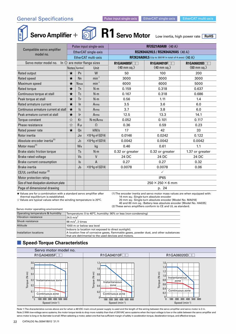
■ Speed-Torque Characteristics
Note 1: The characteristics curves above are for when a 48 VDC main circuit power supply is used and the length of the wiring between the servo amplifier and servo motor is 2 m.Note 2: With low-voltage servo systems, the motor torque tends to drop more notably than that of 200 VAC servo systems when the input voltage is low or the cable between the servo amplifier and servo motor is long or its diameter is small. When selecting a motor, select one that has sufficient margin of safety in acceleration torque, deceleration torque, and effective torque.
R1 Servo Motor Low inertia, high power rate RoHS
Compatible servo amplifier model no.
Pulse input single-axis RF2G21A0A00《40 A》EtherCAT single-axis RS2K04A2HL5 / RS2K04A2HA5 《40 A》EtherCAT multi-axis RF2K24A0HL5 (Up to 300 W in total of 4 axes) 《40 A》
Servo motor model no. In 《》 are motor flange sizes R1GA04005F□□《40 mm sq.》
R1GA04010F□□《40 mm sq.》
R1GA06020D□□《60 mm sq.》Notes Symbol Unit
Rated output ★ PR W 50 100 200Rated speed ★ NR min-1 3000 3000 3000Maximum speed ★ Nmax min-1 6000 6000 5000Rated torque ★ TR N·m 0.159 0.318 0.637Continuous torque at stall ★ TS N·m 0.167 0.318 0.686Peak torque at stall ★ TP N·m 0.56 1.11 1.4Rated armature current ★ IR Arms 3.5 3.6 6.0 Continuous armature current at stall ★ IS Arms 3.7 3.8 6.0 Peak armature current at stall ★ IP Arms 12.5 13.3 14.1Torque constant ☆ KT N·m/Arms 0.052 0.101 0.117Phase resistance ☆ Rφ Ω 0.36 0.59 0.23Rated power rate ★ QR kW/s 17 42 33Rotor inertia JM ×10-4kg·m2 (GD2/4) 0.0146 0.0242 0.122
Absolute encoder inertia(1) JS ×10-4kg·m2 (GD2/4) 0.0042 0.0042 0.0042
Motor mass(1) We kg 0.46 0.61 1.1
Brake static friction torque Tb N·m 0.32 or greater 0.32 or greater 1.37 or greaterBrake rated voltage Vb V 24 DC 24 DC 24 DCBrake current consumption Ib A 0.27 0.27 0.32Brake inertia Jb ×10-4kg·m2 (GD2/4) 0.0078 0.0078 0.06
CE/UL certified motor (2)
Motor protection rating IP65Size of heat dissipation aluminum plate 250 × 250 × 6 mmPage of dimensional drawing p. 24
Servo motor operating environment
Operating temperature & humidity Temperature: 0 to 40°C, humidity: 90% or less (non-condensing)Vibration resistance 24.5 m/s2
Shock resistance 98 m/s2, 2 timesAltitude 1000 m or below sea level
Installation locationsIndoors (a location not exposed to direct sunlight).A location free of corrosive gases, flammable gases, powder dust, and other substances that are detrimental to the used devices and motors.
R1GA06020D□□R1GA04005F□□ R1GA04010F□□
1.6
1.4
1.2
1.0
0.8
0.6
0.4
0.2000 1000 2000 3000 4000 5000 60004000 5000 6000300020001000 4000 5000 6000300020001000
0.3
0.4
0.5
0.6
0.2
0.1
0
0.6
0.8
1.0
1.2
0.4
0.2
0
Instantaneous zoneInstantaneous zone
Continuous zoneContinuous zone
Speed (min-1)
Torq
ue
(N·m
)
Instantaneous zone
Instantaneous zone
Continuous zoneContinuous zone
Speed (min-1)
Torq
ue
(N·m
)
Instantaneous zone
Instantaneous zone
Continuous zoneContinuous zone
Speed (min-1)
Torq
ue
(N·m
)
Servo motor model no.
General Specifications EtherCAT single-axis EtherCAT multi-axisPulse input single-axis
Servo Amplifier +
★ Values are for a combination with a standard servo amplifier after thermal equilibrium is established.
☆ Values are typical values when the winding temperature is 20°C.
(1) The encoder inertia and servo motor mass values are when equipped with: 14 mm sq.: Single-turn absolute encoder 20 mm sq.: Single-turn absolute encoder [Model No. MA018]
40 and 60 mm sq.: Battery-less absolute encoder [Model No. HA035](2) These servo amplifiers conform to CE and UL as standard.
23CATALOG No.S0941B012 ‘21.11
Compatible servo amplifier model no.
Pulse input single-axis RF2G21A0A00《40 A》EtherCAT single-axis RS2K04A2HL5 / RS2K04A2HA5 《40 A》EtherCAT multi-axis RF2K24A0HL5 (Up to 300 W in total of 4 axes) 《40 A》
Servo motor model no. In 《》 are motor flange sizes R1GA04005F□□《40 mm sq.》
R1GA04010F□□《40 mm sq.》
R1GA06020D□□《60 mm sq.》Notes Symbol Unit
Rated output ★ PR W 50 100 200Rated speed ★ NR min-1 3000 3000 3000Maximum speed ★ Nmax min-1 6000 6000 5000Rated torque ★ TR N·m 0.159 0.318 0.637Continuous torque at stall ★ TS N·m 0.167 0.318 0.686Peak torque at stall ★ TP N·m 0.56 1.11 1.4Rated armature current ★ IR Arms 3.5 3.6 6.0 Continuous armature current at stall ★ IS Arms 3.7 3.8 6.0 Peak armature current at stall ★ IP Arms 12.5 13.3 14.1Torque constant ☆ KT N·m/Arms 0.052 0.101 0.117Phase resistance ☆ Rφ Ω 0.36 0.59 0.23Rated power rate ★ QR kW/s 17 42 33Rotor inertia JM ×10-4kg·m2 (GD2/4) 0.0146 0.0242 0.122
Absolute encoder inertia(1) JS ×10-4kg·m2 (GD2/4) 0.0042 0.0042 0.0042
Motor mass(1) We kg 0.46 0.61 1.1
Brake static friction torque Tb N·m 0.32 or greater 0.32 or greater 1.37 or greaterBrake rated voltage Vb V 24 DC 24 DC 24 DCBrake current consumption Ib A 0.27 0.27 0.32Brake inertia Jb ×10-4kg·m2 (GD2/4) 0.0078 0.0078 0.06
CE/UL certified motor (2)
Motor protection rating IP65Size of heat dissipation aluminum plate 250 × 250 × 6 mmPage of dimensional drawing p. 24
L±12±0.3
20±0.8
Ø5
0 -0.0
08
Ø17
0 -0.0
18
0.06
0.02
0.0425
0±30
(Ø4.8)
Shielded encoder cable (fixed wiring) 26 AWG, 2 pairs
Motor lead wire (fixed wiring) 24 AWG (for power and GND)
KB
250±
30
(16)
(19.2)
(Ø1.5)
20 sq.
2-M3×0.5Effective length 6 or more
Ø22±0.2
(7.1)(16)
(6.2)(17.3)
(10)
(13.
3)
Without oil seal
M
M
M
0.02
0.02
M
M
M
0.02
86±2
2 0-0.3
Ø4-
0.00
8
15±0.5
Ø11
-0.0
18 0
290±50
(Ø4.
5)
Motor lead wire
26 AWG, 4-core(for power and GND)
250±30
(40)
Ø13.6±0.12-M2.5
14
14
19
(12)
Shielded encoder cable
28 AWG
Effective length 5 or more
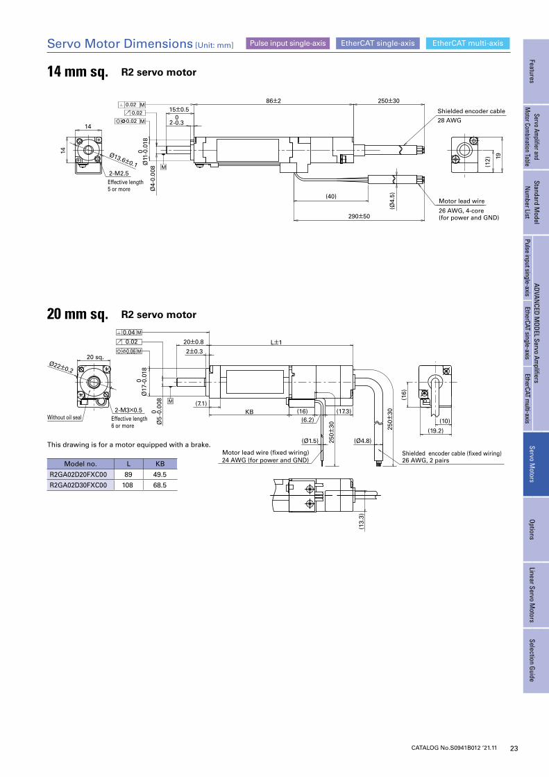
20 mm sq. R2 servo motor
14 mm sq. R2 servo motor
Model no. L KB
R2GA02D20FXC00 89 49.5
R2GA02D30FXC00 108 68.5
Servo Motor Dimensions [Unit: mm]
This drawing is for a motor equipped with a brake.
EtherCAT single-axis EtherCAT multi-axisPulse input single-axis
FeaturesServo Am
plifier and M
otor Combination Table
Standard Model
Num
ber ListADVAN
CED MODEL Servo Am
plifiersServo M
otorsOptions
Linear Servo Motors
Selection GuidePulse input single-axis
EtherCAT single-axisEtherCAT m
ulti-axis
24 CATALOG No.S0941B012 ‘21.11
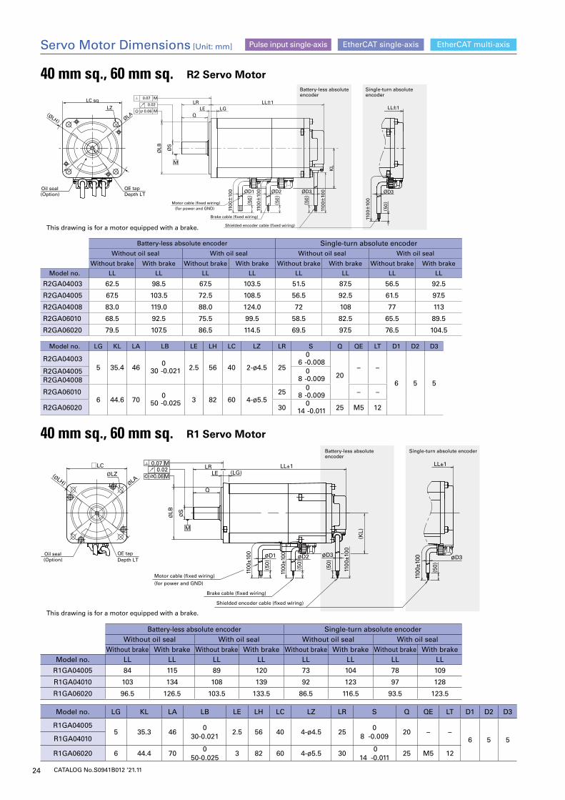
40 mm sq., 60 mm sq. R1 Servo Motor
Battery-less absolute encoder Single-turn absolute encoderWithout oil seal With oil seal Without oil seal With oil seal
Without brake With brake Without brake With brake Without brake With brake Without brake With brakeModel no. LL LL LL LL LL LL LL LL
R1GA04005 84 115 89 120 73 104 78 109
R1GA04010 103 134 108 139 92 123 97 128
R1GA06020 96.5 126.5 103.5 133.5 86.5 116.5 93.5 123.5
Model no. LG KL LA LB LE LH LC LZ LR S Q QE LT D1 D2 D3
R1GA040055 35.3 46
030-0.021
2.5 56 40 4-ø4.5 250
8 -0.00920 – –
6 5 5R1GA04010
R1GA06020 6 44.4 700
50-0.0253 82 60 4-ø5.5 30
0 14 -0.011
25 M5 12
(Option)Oil seal
Depth LTQE tap
(for power and GND)
Motor cable (fixed wiring)
Brake cable (fixed wiring)
Shielded encoder cable (fixed wiring)
LL±1
øD3
1100
±100
(50)
øD2øD1
1100
±100
ØS
ØLB
LRLE (LG)
(KL)
LL±1
Q
0.07 M0.02
0.06M
M
ØLZ□LC
(ØLH) ØLA
(50)
(50)
1100
±100 øD3
(50)
1100
±100
Single-turn absolute encoderBattery-less absolute encoder
This drawing is for a motor equipped with a brake.
This drawing is for a motor equipped with a brake.
40 mm sq., 60 mm sq. R2 Servo Motor
Battery-less absolute encoder Single-turn absolute encoderWithout oil seal With oil seal Without oil seal With oil seal
Without brake With brake Without brake With brake Without brake With brake Without brake With brake
Model no. LL LL LL LL LL LL LL LL
R2GA04003 62.5 98.5 67.5 103.5 51.5 87.5 56.5 92.5
R2GA04005 67.5 103.5 72.5 108.5 56.5 92.5 61.5 97.5
R2GA04008 83.0 119.0 88.0 124.0 72 108 77 113
R2GA06010 68.5 92.5 75.5 99.5 58.5 82.5 65.5 89.5
R2GA06020 79.5 107.5 86.5 114.5 69.5 97.5 76.5 104.5
Model no. LG KL LA LB LE LH LC LZ LR S Q QE LT D1 D2 D3
R2GA040035 35.4 46
030 -0.021 2.5 56 40 2-ø4.5 25
06 -0.008
20– –
6 5 5
R2GA04005 08 -0.009R2GA04008
R2GA060106 44.6 70
050 -0.025 3 82 60 4-ø5.5
25 0
8 -0.009 – –
R2GA06020 30 0
14 -0.011 25 M5 12
Servo Motor Dimensions [Unit: mm] EtherCAT single-axis EtherCAT multi-axisPulse input single-axis
KL
Single-turn absolute encoder
Battery-less absolute encoder
LC sq
LZ
(Option)Oil seal
Depth LTQE tap
ØLA(ØLH)
*3 (50)
(50)
(50)
0.060.02
M
φS
φLB
Q
LR
LE LG LL±1
φD2φD1 ØD3
1100±
100
1100±
100
1100±
100
M
LL±1
ØD3
1100±
100ØD1
(for power and GND)Motor cable (fixed wiring)
Brake cable (fixed wiring)
1100±
100 ØD2
1100±
100
Shielded encoder cable (fixed wiring)
ØS
ØLB
LRLE LG
0.07 M
0.02
0.06 MQ
(50)
(50)
(50)
M
25CATALOG No.S0941B012 ‘21.11
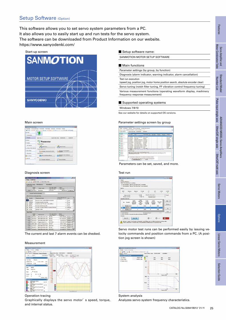
Operation tracingGraphically displays the servo motor’s speed, torque, and internal status.
Measurement
System analysisAnalyzes servo system frequency characteristics.
The current and last 7 alarm events can be checked.
Diagnosis screen
Servo motor test runs can be performed easily by issuing ve-locity commands and position commands from a PC. (A posi-tion jog screen is shown)
Test run
This software allows you to set servo system parameters from a PC.It also allows you to easily start up and run tests for the servo system.The software can be downloaded from Product Information on our website. https://www.sanyodenki.com/
Start-up screen
Main screen
Parameters can be set, saved, and more.
Parameter settings screen by group
■ Setup software name:
SANMOTION MOTOR SETUP SOFTWARE
■ Main functionsParameter settings (by group, by function)
Diagnosis (alarm indicator, warning indicator, alarm cancellation)
Test run execution (speed jog, position jog, motor home position search, absolute encoder clear)
Servo tuning (notch filter tuning, FF vibration control frequency tuning)
Various measurement functions (operating waveform display, machinery frequency response measurement)
■ Supported operating systems
Windows 7/8/10
See our website for details on supported OS versions.
Setup Software (Option)
FeaturesServo Am
plifier and M
otor Combination Table
Standard Model
Num
ber ListADVAN
CED MODEL Servo Am
plifiersServo M
otorsOptions
Linear Servo Motors
Selection GuidePulse input single-axis
EtherCAT single-axisEtherCAT m
ulti-axis
26 CATALOG No.S0941B012 ‘21.11
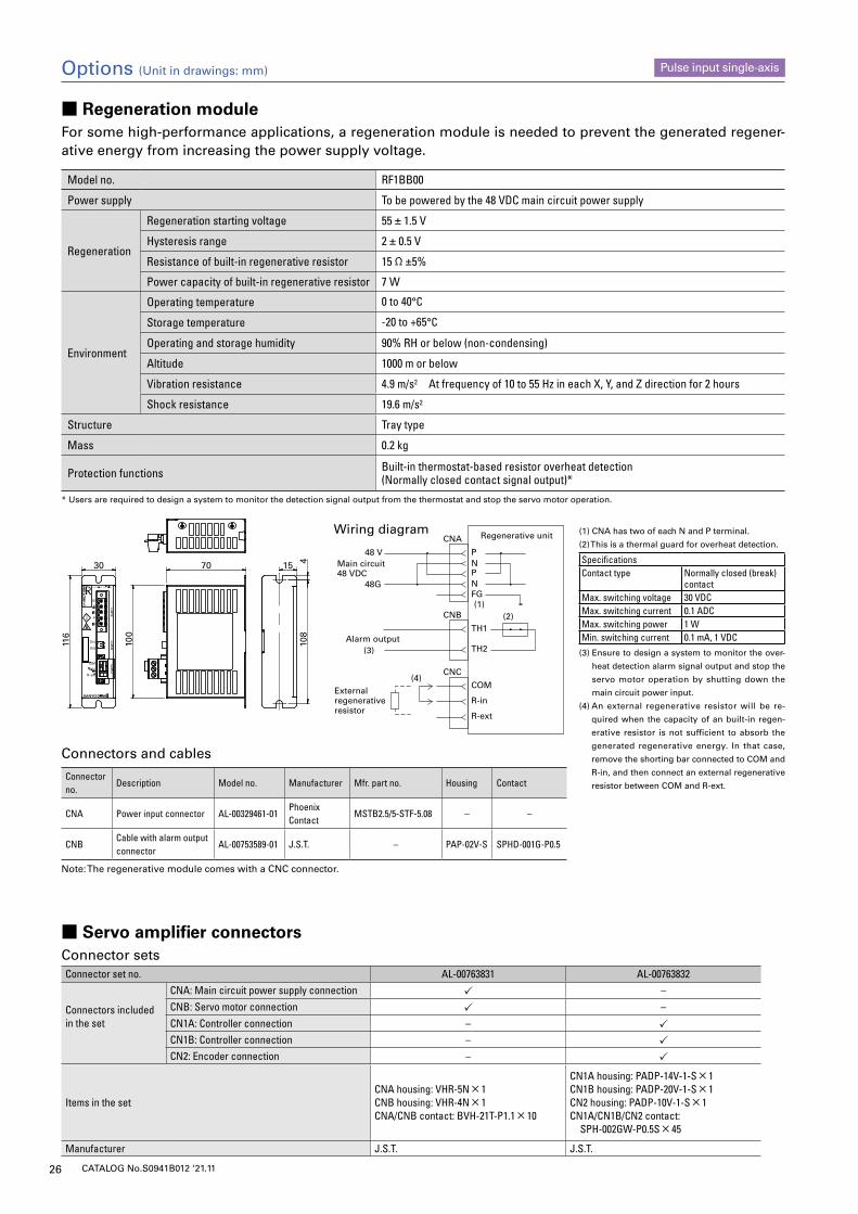
■ Regeneration moduleFor some high-performance applications, a regeneration module is needed to prevent the generated regener-ative energy from increasing the power supply voltage.
Model no. RF1BB00
Power supply To be powered by the 48 VDC main circuit power supply
Regeneration
Regeneration starting voltage 55 ± 1.5 V
Hysteresis range 2 ± 0.5 V
Resistance of built-in regenerative resistor 15 Ω ±5%
Power capacity of built-in regenerative resistor 7 W
Environment
Operating temperature 0 to 40°C
Storage temperature -20 to +65°C
Operating and storage humidity 90% RH or below (non-condensing)
Altitude 1000 m or below
Vibration resistance 4.9 m/s2 At frequency of 10 to 55 Hz in each X, Y, and Z direction for 2 hours
Shock resistance 19.6 m/s2
Structure Tray type
Mass 0.2 kg
Protection functions Built-in thermostat-based resistor overheat detection (Normally closed contact signal output)*
* Users are required to design a system to monitor the detection signal output from the thermostat and stop the servo motor operation.
15 410
8
70
100
30
116
PNPNFG
48 V
48G
Main circuit48 VDC
Alarm output
CNA
(1)(2)
External regenerative resistor
(3)
(4)
Regenerative unitWiring diagram
TH1
TH2
CNB
COM
R-in
R-ext
CNC
Connector no.
Description Model no. Manufacturer Mfr. part no. Housing Contact
CNA Power input connector AL-00329461-01Phoenix Contact
MSTB2.5/5-STF-5.08 – –
CNBCable with alarm output connector
AL-00753589-01 J.S.T. – PAP-02V-S SPHD-001G-P0.5
Note: The regenerative module comes with a CNC connector.
Connectors and cables
Options (Unit in drawings: mm) Pulse input single-axis
■ Servo amplifier connectorsConnector setsConnector set no. AL-00763831 AL-00763832
Connectors included in the set
CNA: Main circuit power supply connection –CNB: Servo motor connection –CN1A: Controller connection – CN1B: Controller connection – CN2: Encoder connection –
Items in the set CNA housing: VHR-5N × 1CNB housing: VHR-4N × 1CNA/CNB contact: BVH-21T-P1.1 × 10
CN1A housing: PADP-14V-1-S × 1CN1B housing: PADP-20V-1-S × 1CN2 housing: PADP-10V-1-S × 1CN1A/CN1B/CN2 contact: SPH-002GW-P0.5S × 45
Manufacturer J.S.T. J.S.T.
(1) CNA has two of each N and P terminal.
(2) This is a thermal guard for overheat detection.
SpecificationsContact type Normally closed (break)
contactMax. switching voltage 30 VDCMax. switching current 0.1 ADCMax. switching power 1 WMin. switching current 0.1 mA, 1 VDC
(3) Ensure to design a system to monitor the over-
heat detection alarm signal output and stop the
servo motor operation by shutting down the
main circuit power input.
(4) An external regenerative resistor will be re-
quired when the capacity of an built-in regen-
erative resistor is not sufficient to absorb the
generated regenerative energy. In that case,
remove the shorting bar connected to COM and
R-in, and then connect an external regenerative
resistor between COM and R-ext.
27CATALOG No.S0941B012 ‘21.11
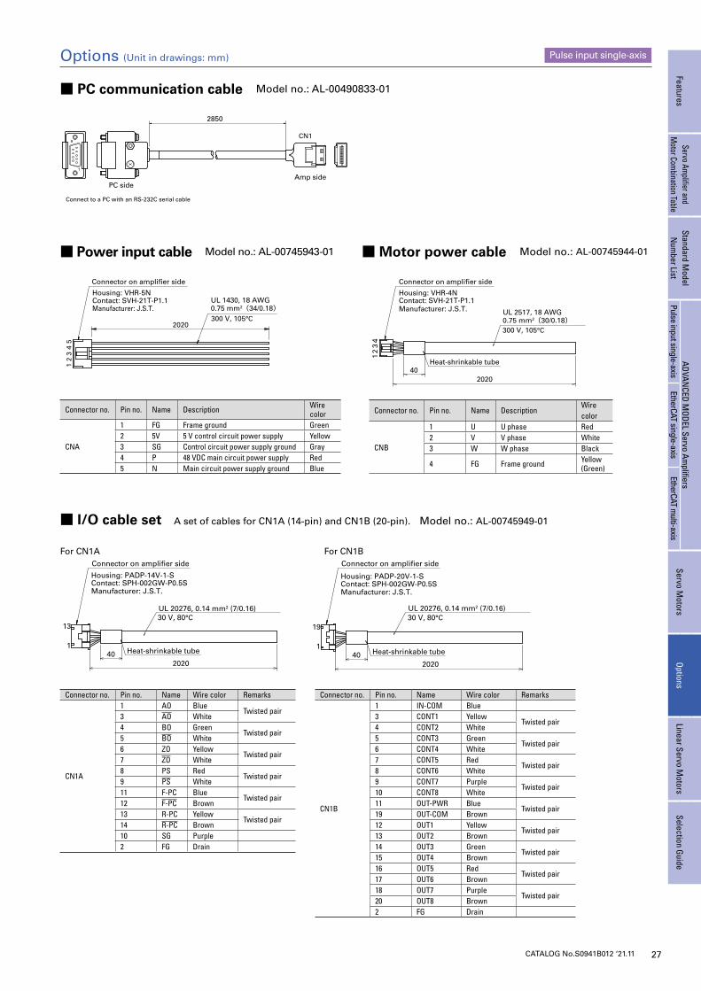
Connector on amplifier side Connector on amplifier side
UL 20276, 0.14 mm2 (7/0.16)30 V, 80°C
Housing: PADP-14V-1-SContact: SPH-002GW-P0.5SManufacturer: J.S.T.
Heat-shrinkable tube
13
140
2020
19
140
2020
Heat-shrinkable tube
UL 20276, 0.14 mm2 (7/0.16)30 V, 80°C
Manufacturer: J.S.T. Contact: SPH-002GW-P0.5SHousing: PADP-20V-1-S
■ PC communication cable Model no.: AL-00490833-01
■ Power input cable Model no.: AL-00745943-01
■ I/O cable set A set of cables for CN1A (14-pin) and CN1B (20-pin). Model no.: AL-00745949-01
For CN1A For CN1B
■ Motor power cable Model no.: AL-00745944-01
Options (Unit in drawings: mm) Pulse input single-axis
PC side
CN1
Amp side
2850
1
9
Connect to a PC with an RS-232C serial cable
UL 1430, 18 AWG0.75 mm2(34/0.18)300 V, 105°C
Connector on amplifier side
Housing: VHR-5NContact: SVH-21T-P1.1Manufacturer: J.S.T.
2020
21
34
5
UL 2517, 18 AWG0.75 mm2(30/0.18)300 V, 105°C
Connector on amplifier side
Housing: VHR-4NContact: SVH-21T-P1.1Manufacturer: J.S.T.
Heat-shrinkable tube40
43
12
2020
FeaturesServo Am
plifier and M
otor Combination Table
Standard Model
Num
ber ListADVAN
CED MODEL Servo Am
plifiersServo M
otorsOptions
Linear Servo Motors
Selection GuidePulse input single-axis
EtherCAT single-axisEtherCAT m
ulti-axis
Connector no. Pin no. Name Description Wire color
CNA
1 FG Frame ground Green2 5V 5 V control circuit power supply Yellow3 SG Control circuit power supply ground Gray4 P 48 VDC main circuit power supply Red5 N Main circuit power supply ground Blue
Connector no. Pin no. Name Wire color Remarks
CN1A
1 AO BlueTwisted pair
3 AO White4 BO Green
Twisted pair5 BO White6 ZO Yellow
Twisted pair7 ZO White8 PS Red
Twisted pair9 PS White11 F-PC Blue
Twisted pair12 F-PC Brown13 R-PC Yellow
Twisted pair14 R-PC Brown10 SG Purple2 FG Drain
Connector no. Pin no. Name Wire color Remarks
CN1B
1 IN-COM Blue3 CONT1 Yellow
Twisted pair4 CONT2 White5 CONT3 Green
Twisted pair6 CONT4 White7 CONT5 Red
Twisted pair8 CONT6 White9 CONT7 Purple
Twisted pair10 CONT8 White11 OUT-PWR Blue
Twisted pair19 OUT-COM Brown12 OUT1 Yellow
Twisted pair13 OUT2 Brown14 OUT3 Green
Twisted pair15 OUT4 Brown16 OUT5 Red
Twisted pair17 OUT6 Brown18 OUT7 Purple
Twisted pair20 OUT8 Brown2 FG Drain
Connector no. Pin no. Name DescriptionWire color
CNB
1 U U phase Red2 V V phase White3 W W phase Black
4 FG Frame ground Yellow (Green)
28 CATALOG No.S0941B012 ‘21.11
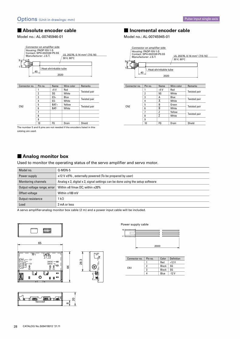
■ Analog monitor boxUsed to monitor the operating status of the servo amplifier and servo motor.
Model no. Q-MON-5
Power supply ±12 V ±5% , externally powered (To be prepared by user)
Monitoring channels Analog x 2, digital x 2, signal settings can be done using the setup software
Output voltage range; error Within ±8 Vmax DC; within ±20%
Offset voltage Within ±100 mV
Output resistance 1 kΩ
Load 2 mA or less
A servo amplifier-analog monitor box cable (2 m) and a power input cable will be included.
UL 20276, 0.14 mm2 (7/0.16)30 V, 80°C
Connector on amplifier sideHousing: PADP-10V-1-SContact: SPH-002GW-P0.5SManufacturer: J.S.T.
Heat-shrinkable tube40
9
1
2020
UL 20276, 0.14 mm2 (7/0.16)30 V, 80°C
9
1
402020
Connector on amplifier sideHousing: PADP-10V-1-SContact: SPH-002GW-P0.5SManufacturer: J.S.T.
Heat-shrinkable tube
■ Absolute encoder cable ■ Incremental encoder cableModel no.: AL-00745946-01 Model no.: AL-00745945-01
28.3
65
20
844
2000
14
Options (Unit in drawings: mm) Pulse input single-axis
Power supply cable
Connector no. Pin no. Name Wire color Remarks
CN2
1 +5 V RedTwisted pair
2 SG White3 ES+ Blue
Twisted pair4 ES- White5 BAT+ Yellow
Twisted pair6 BAT- White78910 FG Drain Shield
The number 5 and 6 pins are not needed if the encoders listed in this
catalog are used.
Connector no. Pin no. Name Wire color Remarks
CN2
1 +5 V RedTwisted pair
2 5G White3 A Blue
Twisted pair4 A White5 B Green
Twisted pair6 B White7 Z Yellow
Twisted pair8 Z White910 FG Drain Shield
Connector no. Pin no. Color Definition
CN1
1 Red +12 V2 Black SG3 Black SG4 Blue -12 V
29CATALOG No.S0941B012 ‘21.11
9
6
5
1
2850 +40- 0
NO.1NO.8
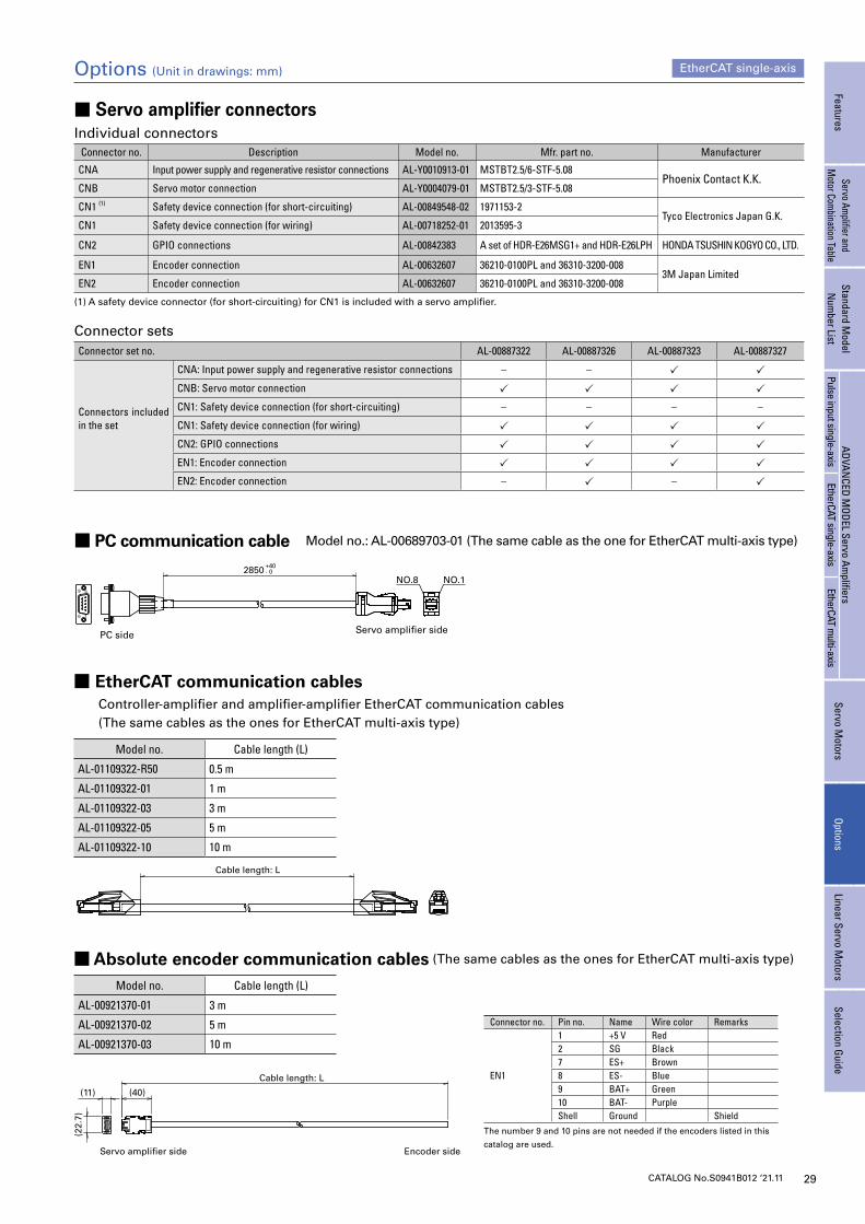
■ PC communication cable Model no.: AL-00689703-01 (The same cable as the one for EtherCAT multi-axis type)
PC side Servo amplifier side
Cable length: L
■ Absolute encoder communication cables (The same cables as the ones for EtherCAT multi-axis type)
■ EtherCAT communication cables Controller-amplifier and amplifier-amplifier EtherCAT communication cables (The same cables as the ones for EtherCAT multi-axis type)
Model no. Cable length (L)
AL-01109322-R50 0.5 m
AL-01109322-01 1 m
AL-01109322-03 3 m
AL-01109322-05 5 m
AL-01109322-10 10 m
Connector no. Pin no. Name Wire color Remarks
EN1
1 +5 V Red2 SG Black7 ES+ Brown8 ES- Blue9 BAT+ Green10 BAT- PurpleShell Ground Shield
The number 9 and 10 pins are not needed if the encoders listed in this
catalog are used.
Model no. Cable length (L)
AL-00921370-01 3 m
AL-00921370-02 5 m
AL-00921370-03 10 m
Options (Unit in drawings: mm) EtherCAT single-axis
■ Servo amplifier connectorsIndividual connectors
Connector no. Description Model no. Mfr. part no. Manufacturer
CNA Input power supply and regenerative resistor connections AL-Y0010913-01 MSTBT2.5/6-STF-5.08Phoenix Contact K.K.
CNB Servo motor connection AL-Y0004079-01 MSTBT2.5/3-STF-5.08
CN1 (1) Safety device connection (for short-circuiting) AL-00849548-02 1971153-2Tyco Electronics Japan G.K.
CN1 Safety device connection (for wiring) AL-00718252-01 2013595-3
CN2 GPIO connections AL-00842383 A set of HDR-E26MSG1+ and HDR-E26LPH HONDA TSUSHIN KOGYO CO., LTD.
EN1 Encoder connection AL-00632607 36210-0100PL and 36310-3200-0083M Japan Limited
EN2 Encoder connection AL-00632607 36210-0100PL and 36310-3200-008
(1) A safety device connector (for short-circuiting) for CN1 is included with a servo amplifier.
Connector setsConnector set no. AL-00887322 AL-00887326 AL-00887323 AL-00887327
Connectors included in the set
CNA: Input power supply and regenerative resistor connections – –
CNB: Servo motor connection
CN1: Safety device connection (for short-circuiting) – – – –
CN1: Safety device connection (for wiring)
CN2: GPIO connections
EN1: Encoder connection
EN2: Encoder connection – –
Servo ampli�er side Encoder side
(40)
Cable length: L
(22.
7)
(11)
FeaturesServo Am
plifier and M
otor Combination Table
Standard Model
Num
ber ListADVAN
CED MODEL Servo Am
plifiersServo M
otorsOptions
Linear Servo Motors
Selection GuidePulse input single-axis
EtherCAT single-axisEtherCAT m
ulti-axis
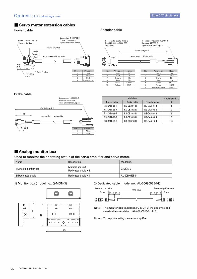
30 CATALOG No.S0941B012 ‘21.11
■ Servo motor extension cablesPower cable
Brake cable
Cable length: L
(100)
Connector: 1-480703-0Contact: 350536-3Tyco Electronics Japan
MSTBT2.5/3-STF-5.08Phoenix Contact
N1.25-4J.S.T.
Amp side Motor side
Green/yellow
Black
WhiteRed
Cable length: L
100
N1.25-4J.S.T.
Connector: 1-480699-0Contact: 350570-3Tyco Electronics Japan
Amp side← →Motor side
Encoder cable
Model no. Cable length: L[m]Power cable Brake cable Encoder cable
RS-CM4-01-R RS-CB3-01-R RS-CA4-01-R 1
RS-CM4-02-R RS-CB3-02-R RS-CA4-02-R 2
RS-CM4-03-R RS-CB3-03-R RS-CA4-03-R 3
RS-CM4-05-R RS-CB3-05-R RS-CA4-05-R 5
RS-CM4-10-R RS-CB3-10-R RS-CA4-10-R 10
Pin no. Wire color1 Red2 White3 Black4 Green/Yellow
Pin no. Wire color1 White2 Black
No. Wire color Name1 Black 0 V2 Red +5 V3 Brown ES+4 Blue ES-5 Green EBAT+6 Purple EBAT-9 White/Black (Shield) Ground
No. Wire color Name1 Red 5 V2 Black 0 V7 Brown ES+8 Blue ES-9 Green EBAT+10 Yellow EBAT-
Options (Unit in drawings: mm) EtherCAT single-axis
29
44
65
■ Analog monitor boxUsed to monitor the operating status of the servo amplifier and servo motor.
Name Description Model no.
1) Analog monitor boxMonitor box unitDedicated cable x 2
Q-MON-3
2) Dedicated cable Dedicated cable x 1 AL-00690525-01
20±520±5
421
3
2000±5020±520±5
1A2A2B
1B
Monitor box side Servo amplifier side
Brown Black
Cable length: L
Connector housing: 172161-1Contact: 170359-3Tyco Electronics Japan
Receptacle: 36210-0100PLShell kit: 36310-3200-0083M Japan
No.1234569
Lead wire colorBlackRed
BrownBlue
GreenPurple
White/Black (Shielded)
Signal name0 V
+5 VES+ES-
EBAT+EBAT-GND
No.12789
10
Lead wire colorRed
BlackBrownBlue
GreenPurple
Signal name5 V0 VES+ES-
EBAT+EBAT-
Amp side Motor side
2) Dedicated cable (model no.: AL-00690525-01)1) Monitor box (model no.: Q-MON-3)
Note 1: The monitor box (model no.: Q-MON-3) includes two dedi-cated cables (model no.: AL-00690525-01) in 2).
Note 2: To be powered by the servo amplifier.
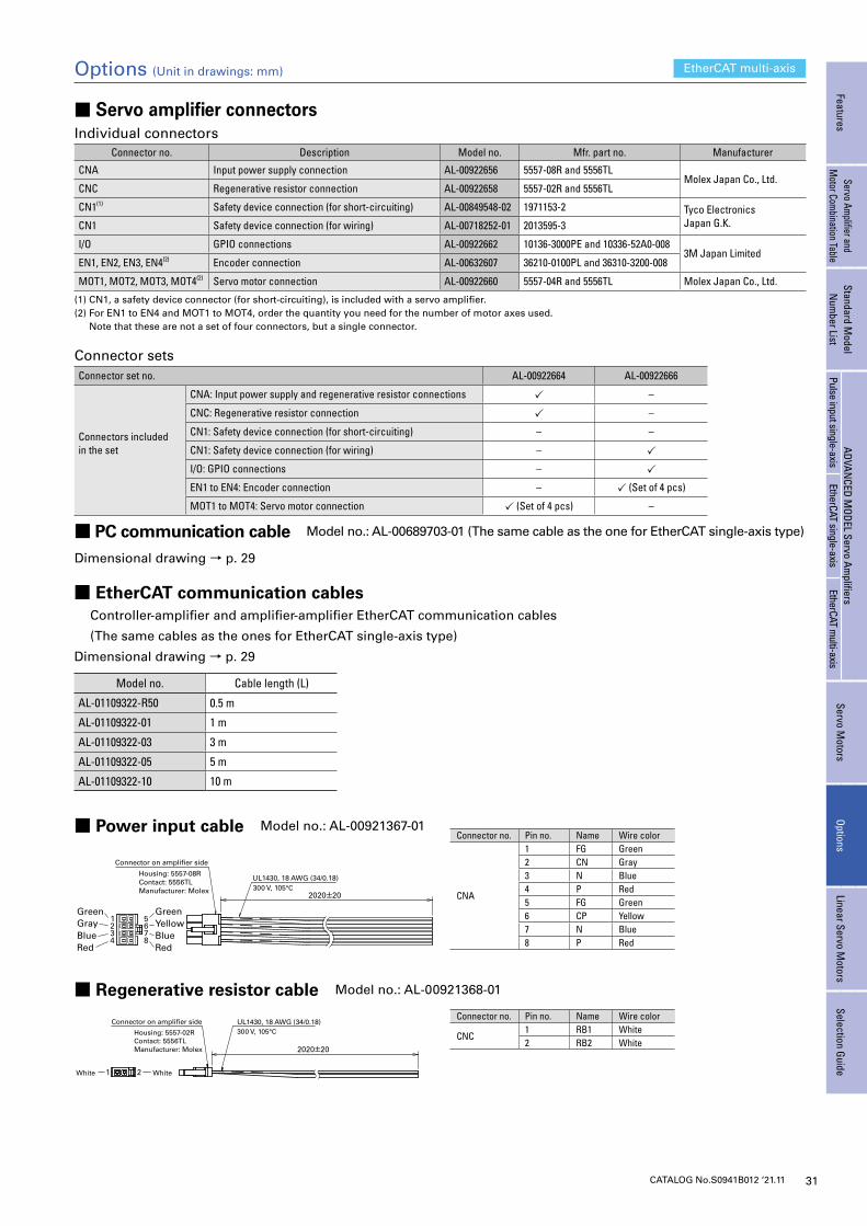
31CATALOG No.S0941B012 ‘21.11
Options (Unit in drawings: mm) EtherCAT multi-axis
■ Servo amplifier connectorsIndividual connectors
Connector no. Description Model no. Mfr. part no. Manufacturer
CNA Input power supply connection AL-00922656 5557-08R and 5556TLMolex Japan Co., Ltd.
CNC Regenerative resistor connection AL-00922658 5557-02R and 5556TL
CN1(1) Safety device connection (for short-circuiting) AL-00849548-02 1971153-2 Tyco Electronics Japan G.K.CN1 Safety device connection (for wiring) AL-00718252-01 2013595-3
I/O GPIO connections AL-00922662 10136-3000PE and 10336-52A0-0083M Japan Limited
EN1, EN2, EN3, EN4(2) Encoder connection AL-00632607 36210-0100PL and 36310-3200-008
MOT1, MOT2, MOT3, MOT4(2) Servo motor connection AL-00922660 5557-04R and 5556TL Molex Japan Co., Ltd.
(1) CN1, a safety device connector (for short-circuiting), is included with a servo amplifier.(2) For EN1 to EN4 and MOT1 to MOT4, order the quantity you need for the number of motor axes used. Note that these are not a set of four connectors, but a single connector.
Connector setsConnector set no. AL-00922664 AL-00922666
Connectors included in the set
CNA: Input power supply and regenerative resistor connections –
CNC: Regenerative resistor connection –
CN1: Safety device connection (for short-circuiting) – –
CN1: Safety device connection (for wiring) –
I/O: GPIO connections –
EN1 to EN4: Encoder connection – (Set of 4 pcs)
MOT1 to MOT4: Servo motor connection (Set of 4 pcs) –
■ PC communication cable Model no.: AL-00689703-01 (The same cable as the one for EtherCAT single-axis type)
Dimensional drawing → p. 29
Connector no. Pin no. Name Wire color
CNA
1 FG Green2 CN Gray3 N Blue4 P Red5 FG Green6 CP Yellow7 N Blue8 P Red
Connector no. Pin no. Name Wire color
CNC1 RB1 White2 RB2 White
■ Power input cable Model no.: AL-00921367-01
■ Regenerative resistor cable Model no.: AL-00921368-01
■ EtherCAT communication cables Controller-amplifier and amplifier-amplifier EtherCAT communication cables
(The same cables as the ones for EtherCAT single-axis type)
Dimensional drawing → p. 29
Model no. Cable length (L)
AL-01109322-R50 0.5 m
AL-01109322-01 1 m
AL-01109322-03 3 m
AL-01109322-05 5 m
AL-01109322-10 10 m
UL1430, 18 AWG (34/0.18)300 V, 105°C
Connector on amplifier side
Housing: 5557-08RContact: 5556TLManufacturer: Molex
Gray
RedBlue
Green
21
34
65
78
Yellow
RedBlue
Green
2020±20
UL1430, 18 AWG (34/0.18)300 V, 105°C
Connector on amplifier side
Housing: 5557-02RContact: 5556TLManufacturer: Molex
White 1 2 White
2020±20
FeaturesServo Am
plifier and M
otor Combination Table
Standard Model
Num
ber ListADVAN
CED MODEL Servo Am
plifiersServo M
otorsOptions
Linear Servo Motors
Selection GuidePulse input single-axis
EtherCAT single-axisEtherCAT m
ulti-axis
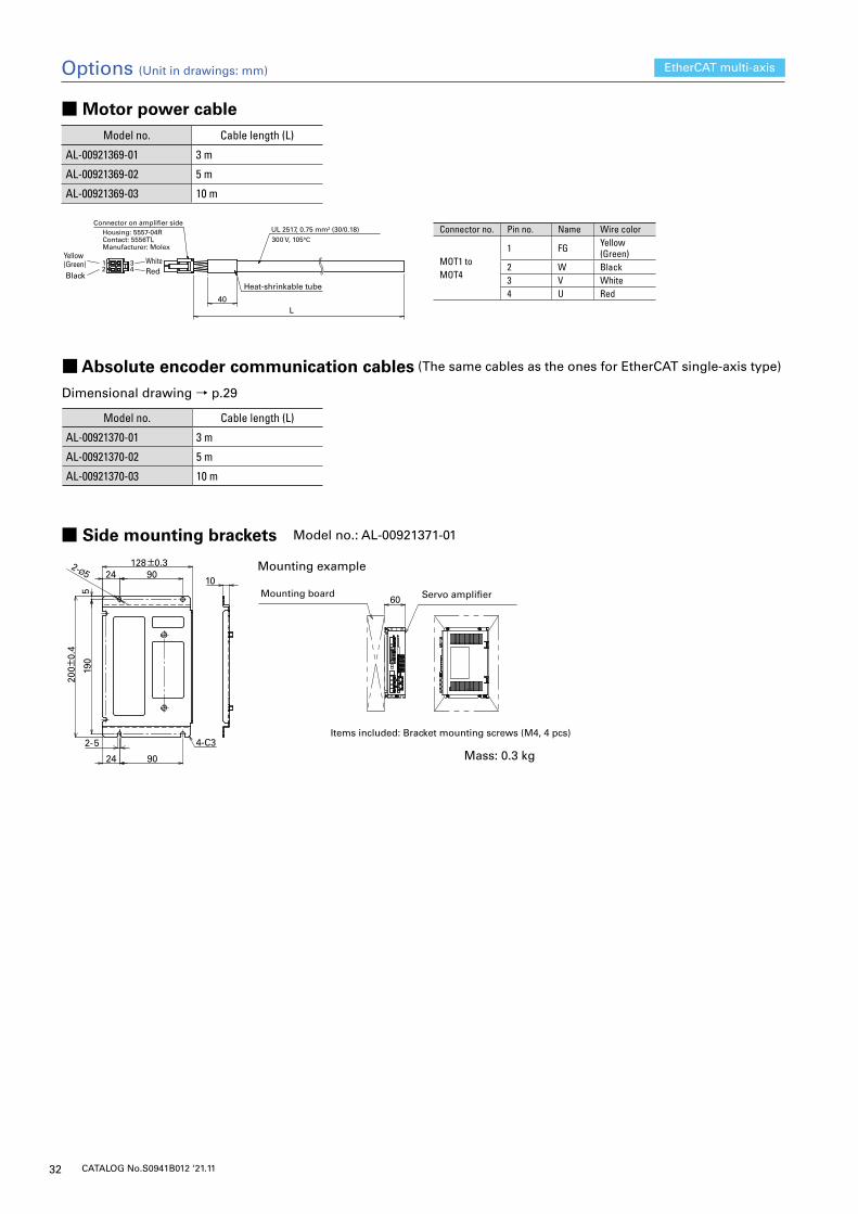
32 CATALOG No.S0941B012 ‘21.11
■ Side mounting brackets Model no.: AL-00921371-01
9024
9024
200±
0.4
519
0
2-5
2-Ø5
4-C3
128±0.3
10
60
Options (Unit in drawings: mm) EtherCAT multi-axis
■ Absolute encoder communication cables (The same cables as the ones for EtherCAT single-axis type)
Dimensional drawing → p.29
Model no. Cable length (L)
AL-00921370-01 3 m
AL-00921370-02 5 m
AL-00921370-03 10 m
Yellow(Green)Black
1 2
34
WhiteRed
UL 2517, 0.75 mm2 (30/0.18)300 V, 105°C
Connector on amplifier sideHousing: 5557-04RContact: 5556TLManufacturer: Molex
Heat-shrinkable tube
40L
■ Motor power cable
Connector no. Pin no. Name Wire color
MOT1 toMOT4
1 FG Yellow (Green)
2 W Black3 V White4 U Red
Model no. Cable length (L)
AL-00921369-01 3 m
AL-00921369-02 5 m
AL-00921369-03 10 m
Mass: 0.3 kg
Mounting example
Items included: Bracket mounting screws (M4, 4 pcs)
Mounting board Servo amplifier
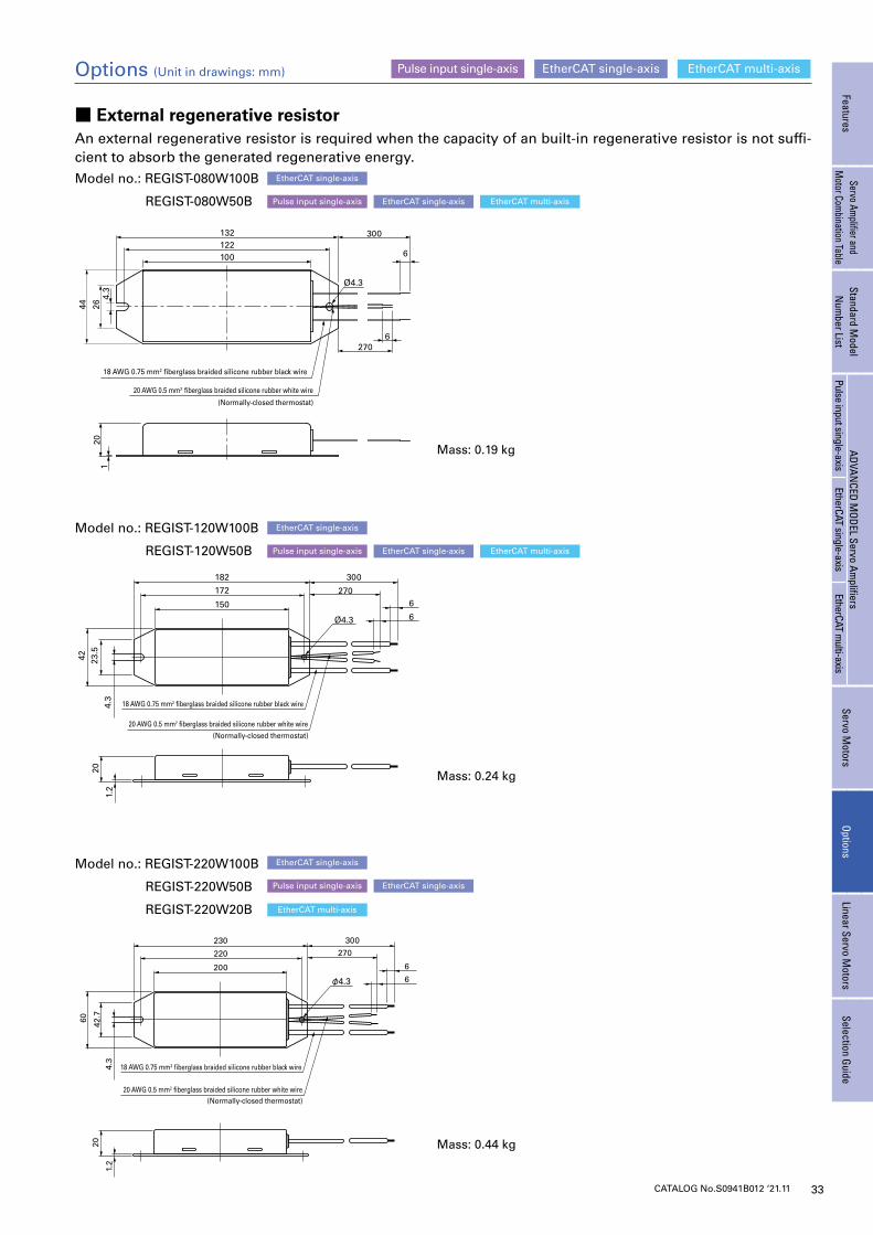
33CATALOG No.S0941B012 ‘21.11
■ External regenerative resistorAn external regenerative resistor is required when the capacity of an built-in regenerative resistor is not suffi-cient to absorb the generated regenerative energy.
Mass: 0.19 kg
Model no.: REGIST-080W100B
REGIST-080W50B
Model no.: REGIST-120W100B
REGIST-120W50B
Mass: 0.24 kg
Model no.: REGIST-220W100B
REGIST-220W50B
REGIST-220W20B
Mass: 0.44 kg
Options (Unit in drawings: mm)
EtherCAT multi-axis
EtherCAT multi-axis
EtherCAT multi-axis
EtherCAT single-axis
EtherCAT single-axis
EtherCAT single-axis
Pulse input single-axis
Pulse input single-axis
Pulse input single-axis
EtherCAT single-axis
EtherCAT single-axis
EtherCAT single-axis
EtherCAT single-axis EtherCAT multi-axisPulse input single-axis
FeaturesServo Am
plifier and M
otor Combination Table
Standard Model
Num
ber ListADVAN
CED MODEL Servo Am
plifiersServo M
otorsOptions
Linear Servo Motors
Selection GuidePulse input single-axis
EtherCAT single-axisEtherCAT m
ulti-axis
132122
300
6
Ø4.3
6270
120
100
20 AWG 0.5 mm2 fiberglass braided silicone rubber white wire
18 AWG 0.75 mm2 fiberglass braided silicone rubber black wire
(Normally-closed thermostat)
44 264.
3
150
172
182 300
270
Ø4.3
6
6
42 23.5
20
1.2
4.3
20 AWG 0.5 mm2 fiberglass braided silicone rubber white wire
18 AWG 0.75 mm2 fiberglass braided silicone rubber black wire
(Normally-closed thermostat)
200
220
230 300
270
φ4.3
6
6
60 42.7
20
1.2
4.3
20 AWG 0.5 mm2 fiberglass braided silicone rubber white wire
18 AWG 0.75 mm2 fiberglass braided silicone rubber black wire
(Normally-closed thermostat)
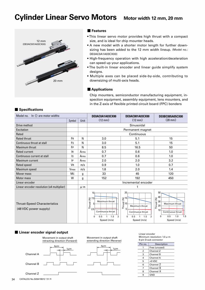
34 CATALOG No.S0941B012 ‘21.11
■ Specifications
Model no. In 《》 are motor widths DE0AC0A1A03CX00《12 mm》
DE0AC001A03CX00《12 mm》
DE0BC005A05CX00《20 mm》Symbol Unit
Drive method SinusoidalExcitation Permanent magnetRated ContinuousRated thrust FR N 3.0 5.1 15Continuous thrust at stall FS N 3.0 5.1 15Maximum thrust FP N 8.5 16.5 50Rated current IR Arms 0.7 0.6 1.0Continuous current at stall IS Arms 0.7 0.6 1.0Maximum current IP Arms 2.0 2.0 3.2Rated speed VR m/s 0.9 1.0 0.7Maximum speed Vmax m/s 1.8 2.0 1.4Mover mass MC g 33 45 120Motor mass W g 152 192 450Linear encoder Incremental encoderLinear encoder resolution (x4 multiplier) μm 1
Thrust-Speed Characteristics
(48 VDC power supply)
Cylinder Linear Servo Motors Motor width 12 mm, 20 mm
■ Features
• This linear servo motor provides high thrust with a compact size, and is ideal for chip mounter heads.
• A new model with a shorter motor length for further down-sizing has been added to the 12 mm width lineup. (Model no.:
DE0AC0A1A03CX00)
• High-frequency operation with high acceleration/deceleration can speed up your applications.
• The built-in linear encoder and linear guide simplify system designs.
• Multiple axes can be placed side-by-side, contributing to downsizing of multi-axis heads.
■ Applications
Chip mounters, semiconductor manufacturing equipment, in-spection equipment, assembly equipment, lens mounters, and in the Z-axis of flexible printed circuit board (FPC) bonders
5
10
15
20
0 0.5 1 1.5 2
Speed (m/s)
2.5
5
7.5
10
0 0.5 1 1.5 2
Speed (m/s)
0 0.5 1.0 1.5
Speed (m/s)
20
50
10
40
30
Th
rust
(N
)
Th
rust
(N
)
Th
rust
(N
)
Continuous thrustContinuous thrust
Maximum thrustMaximum thrust
Continuous thrustContinuous thrust
Maximum thrustMaximum thrust
Continuous thrustContinuous thrust
Maximum thrustMaximum thrust
■ Linear encoder signal output
20 mm
12 mm(DE0AC001A03CX00)
Movement in output shaftretracting direction (Forward)
Channel A
Channel B
Channel Z
4μm1μm
Movement in output shaftextending direction (Reverse)
4μm1μm
Linear encoderMinimum resolution: 1.0 μm9-pin D-sub connector
Pin no. Description1 Free (unused)2 Channel Z3 Channel B4 Channel A5 +5 VDC6 Channel Z7 Channel B8 Channel A9 GND
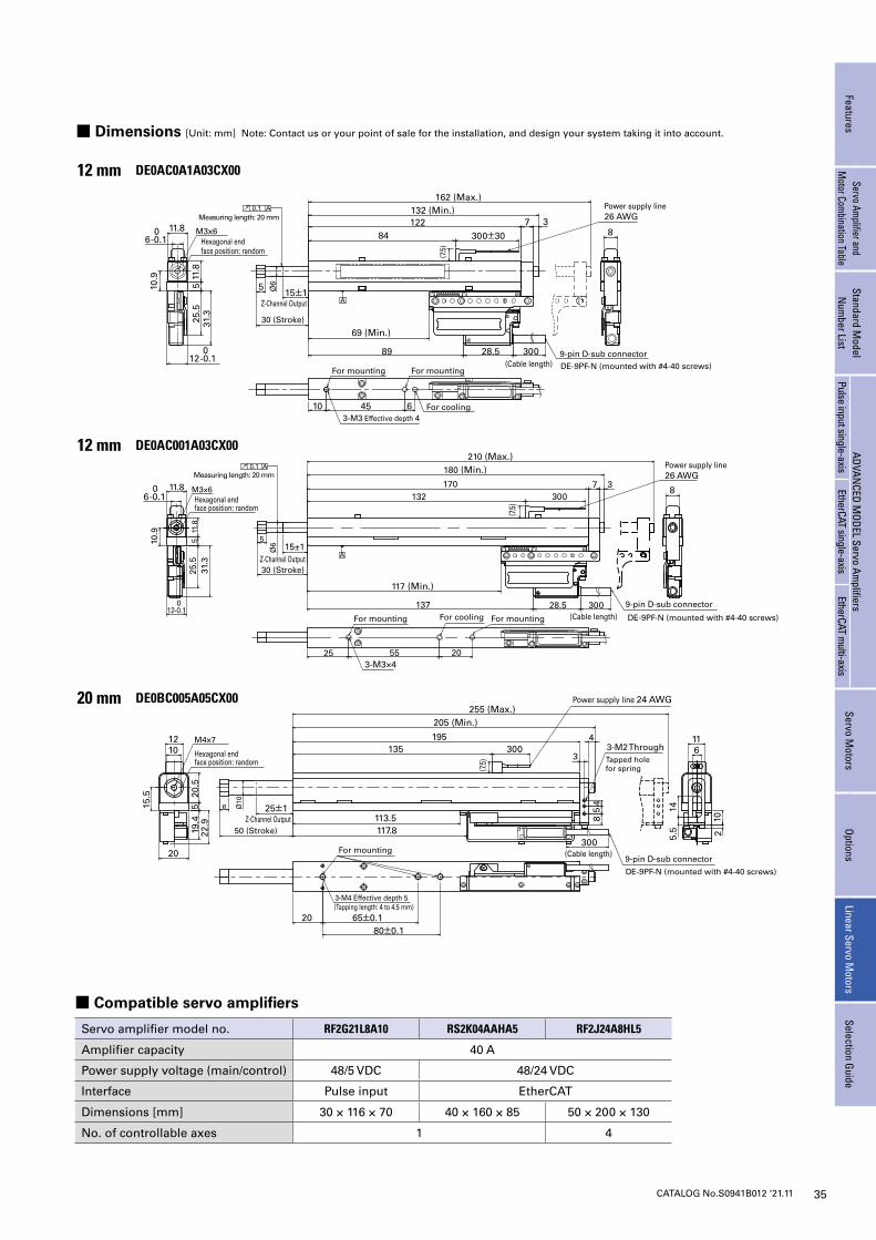
35CATALOG No.S0941B012 ‘21.11
■ Compatible servo amplifiers
Servo amplifier model no. RF2G21L8A10 RS2K04AAHA5 RF2J24A8HL5
Amplifier capacity 40 A
Power supply voltage (main/control) 48/5 VDC 48/24 VDC
Interface Pulse input EtherCAT
Dimensions [mm] 30 × 116 × 70 40 × 160 × 85 50 × 200 × 130
No. of controllable axes 1 4
12 0-0.1
11.8
11.8
531
.3
25 55 203-M3×4
Ø6 15±1
30 (Stroke)
30 (Stroke)
50 (Stroke)
137 28.5 300
132170 7 3
180 (Min.)210 (Max.)
300M3×6
25.5
A
117 (Min.)
0.1 A
10.9
5
8
(7.5)
Power supply line 26 AWG
Ø6
Power supply line 26 AWG
12 0-0.1
11.8
11.8
531
.3
10 453-M3 Effective depth 4
15±1
89 28.5 300
84122 7132 (Min.)
162 (Max.)
300±30M3x6
25.5
69 (Min.)
6 0-0.1
6 0-0.1
10.9
5
8
(7.5
)
6
A
Measuring length: 20 mm
Measuring length: 20 mm
0.1 A
3
Hexagonal end face position: random
Hexagonal end face position: random
Hexagonal end face position: random
Z-Channel Output
Z-Channel Output
Z-Channel Output
9-pin D-sub connector
9-pin D-sub connector
9-pin D-sub connector(Cable length)
(Cable length)
(Cable length)For mounting
For mounting
For mounting For mounting
For mountingFor cooling
For cooling
DE-9PF-N (mounted with #4-40 screws)
DE-9PF-N (mounted with #4-40 screws)
DE-9PF-N (mounted with #4-40 screws)
25±1Ø10
6
M4x7
20.5
519
.422
.9
15.5
20
1012
113.5117.8
300
135 300195 4
205 (Min.)
11
85
4
63-M2 Through3
5.5
14
255 (Max.)
2080±0.1
3-M4 Effective depth 5
10
65±0.1
(7.5)
2
Tapped hole for spring
(Tapping length: 4 to 4.5 mm)
Power supply line 24 AWG
■ Dimensions [Unit: mm] Note: Contact us or your point of sale for the installation, and design your system taking it into account.
12 mm DE0AC0A1A03CX00
12 mm DE0AC001A03CX00
20 mm DE0BC005A05CX00
FeaturesServo Am
plifier and M
otor Combination Table
Standard Model
Num
ber ListADVAN
CED MODEL Servo Am
plifiersServo M
otorsOptions
Linear Servo Motors
Selection GuidePulse input single-axis
EtherCAT single-axisEtherCAT m
ulti-axis
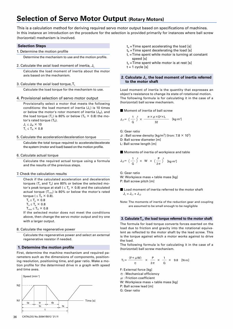
36 CATALOG No.S0941B012 ‘21.11
This is a calculation method for deriving required servo motor output based on specifications of machines.In this instance an introduction on the procedure for the selection is provided primarily for instances where ball screw (horizontal) mechanism is involved.
Selection Steps1. Determine the motion profile
Determine the mechanism to use and the motion profile.
2. Calculate the axial load moment of inertia, JL
Calculate the load moment of inertia about the motor axis based on the mechanism.
3. Calculate the axial load torque, TL
Calculate the load torque for the mechanism to use.
4. Provisional selection of servo motor outputProvisionally select a motor that meets the following conditions: the load moment of inertia (JL) is 10 times or below the motor's rotor moment of inertia (JM), and the load torque (TL) is 80% or below (TR × 0.8) the mo-tor's rated torque (TR).JL ≤ JM × 10TL ≤ TR × 0.8
5. Calculate the acceleration/deceleration torque
Calculate the total torque required to accelerate/decelerate the system (motor and load) based on the motion profile.
6. Calculate actual torque
Calculate the required actual torque using a formula and the results of the previous steps.
7. Check the calculation results
Check if the calculated acceleration and deceleration torques (Ta and Tb) are 80% or below the selected mo-tor's peak torque at stall ( ≤ Tp × 0.8) and the calculated actual torque (Trms) is 80% or below the motor's rated torque ( ≤ TR × 0.8). Ta ≤ Tp × 0.8 Tb ≤ Tp × 0.8 Trms ≤ TR × 0.8If the selected motor does not meet the conditions above, then change the servo motor output and try one with a larger output.
8. Calculate the regenerative power
Calculate the regenerative power and select an external regenerative resistor if needed.
1. Determine the motion profileFirst, determine the machine mechanism and required pa-rameters such as the dimensions of components, position-ing resolution, positioning time, and gear ratio. Make a mo-tion profile for the determined drive in a graph with speed and time axes.
Speed [min-1]
Time [s]
N2
N1ta tr
tc tst
tb
ta = Time spent accelerating the load [s]tb = Time spent decelerating the load [s]tr = Time spent while motor is turning at constant
speed [s]ts = Time spent while motor is at rest [s]t = 1 cycle [s]
2. Calculate JL, the load moment of inertia referred to the motor shaft
Load moment of inertia is the quantity that expresses an object's resistance to change its state of rotational motion.The following formula is for calculating it in the case of a (horizontal) ball screw mechanism.
■ Moment of inertia of ball screw
[kg∙m2]
[kg∙m2]
[N∙m]
[N∙m]
[N∙m]
[N∙m]
JL1=
JL2= W
1 2
G×
32
π×ρ×D4×L( )
1 2
G× ×
× × × 9.8
( )P 2
2π
TL=
Ta=
P
2π
1
G
(F+μW)
η
+ TL2π(N2-N1)×(JL+JM)
60×ta
Tb=
Trms=
EM = Ehb = × N × 3 × Keø × × tb - × 3 × Rø × tb
- TL2π(N2-N1)×(JL+JM)
60×tb
(Ta2×ta) + (TL2×tr) + (Tb2×tb)
t
( )
1
2
Tb
KT
Tb
KT
2
G: Gear ratioρ : Ball screw density [kg/m3] (Iron: 7.8 × 10³)D: Ball screw diameter [m]L: Ball screw length [m]
■ Moments of inertia of workpiece and table
[kg∙m2]
[kg∙m2]
[N∙m]
[N∙m]
[N∙m]
[N∙m]
JL1=
JL2= W
1 2
G×
32
π×ρ×D4×L( )
1 2
G× ×
× × × 9.8
( )P 2
2π
TL=
Ta=
P
2π
1
G
(F+μW)
η
+ TL2π(N2-N1)×(JL+JM)
60×ta
Tb=
Trms=
EM = Ehb = × N × 3 × Keø × × tb - × 3 × Rø × tb
- TL2π(N2-N1)×(JL+JM)
60×tb
(Ta2×ta) + (TL2×tr) + (Tb2×tb)
t
( )
1
2
Tb
KT
Tb
KT
2
G: Gear ratioW: Workpiece mass + table mass [kg]P: Ball screw pitch [m]
■ Load moment of inertia referred to the motor shaft JL = JL1 + JL2
Note: The moments of inertia of the reduction gear and coupling are assumed to be small enough to be negligible
3. Calculate TL, the load torque referred to the motor shaftThe formula for load torque converts forces exerted on the load due to friction and gravity into the rotational equiva-lent as reflected to the motor shaft by the lead screw. This is the torque against which a motor works against to drive the load.The following formula is for calculating it in the case of a (horizontal) ball screw mechanism.
[kg∙m2]
[kg∙m2]
[N∙m]
[N∙m]
[N∙m]
[N∙m]
JL1=
JL2= W
1 2
G×
32
π×ρ×D4×L( )
1 2
G× ×
× × × 9.8
( )P 2
2π
TL=
Ta=
P
2π
1
G
(F+μW)
η
+ TL2π(N2-N1)×(JL+JM)
60×ta
Tb=
Trms=
EM = Ehb = × N × 3 × Keø × × tb - × 3 × Rø × tb
- TL2π(N2-N1)×(JL+JM)
60×tb
(Ta2×ta) + (TL2×tr) + (Tb2×tb)
t
( )
1
2
Tb
KT
Tb
KT
2
F: External force [kg]η : Mechanical efficiencyμ : Friction coefficientW: Workpiece mass + table mass [kg]P: Ball screw lead [m]G: Gear ratio
Selection of Servo Motor Output (Rotary Motors)
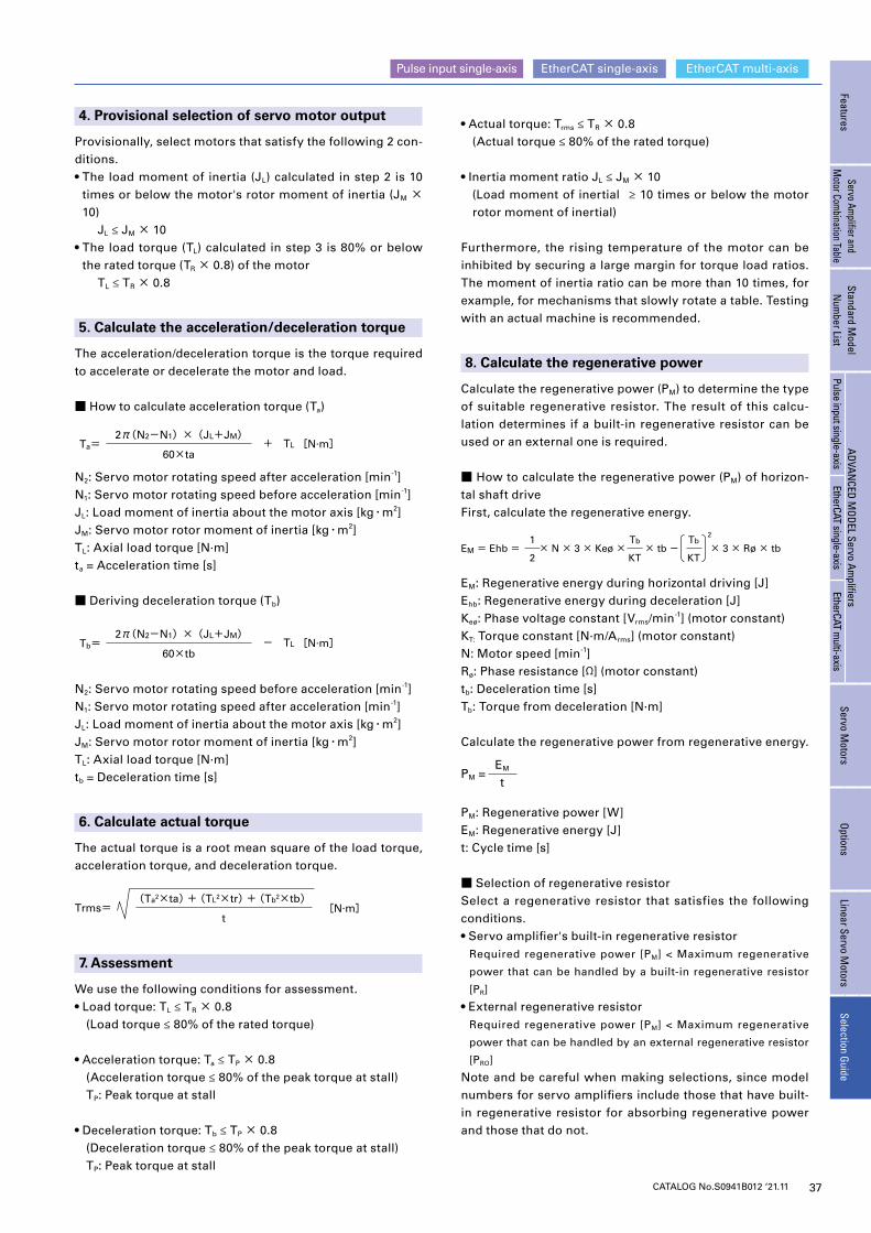
37CATALOG No.S0941B012 ‘21.11
EtherCAT single-axis EtherCAT multi-axisPulse input single-axis
FeaturesServo Am
plifier and M
otor Combination Table
Standard Model
Num
ber ListADVAN
CED MODEL Servo Am
plifiersServo M
otorsOptions
Linear Servo Motors
Selection GuidePulse input single-axis
EtherCAT single-axisEtherCAT m
ulti-axis
4. Provisional selection of servo motor output
Provisionally, select motors that satisfy the following 2 con-ditions.• The load moment of inertia (JL) calculated in step 2 is 10
times or below the motor's rotor moment of inertia (JM × 10) JL ≤ JM × 10• The load torque (TL) calculated in step 3 is 80% or below
the rated torque (TR × 0.8) of the motor TL ≤ TR × 0.8
5. Calculate the acceleration/deceleration torque
The acceleration/deceleration torque is the torque required to accelerate or decelerate the motor and load.
■ How to calculate acceleration torque (Ta)
[kg∙m2]
[kg∙m2]
[N∙m]
[N∙m]
[N∙m]
[N∙m]
JL1=
JL2= W
1 2
G×
32
π×ρ×D4×L( )
1 2
G× ×
× × × 9.8
( )P 2
2π
TL=
Ta=
P
2π
1
G
(F+μW)
η
+ TL2π(N2-N1)×(JL+JM)
60×ta
Tb=
Trms=
EM = Ehb = × N × 3 × Keø × × tb - × 3 × Rø × tb
- TL2π(N2-N1)×(JL+JM)
60×tb
(Ta2×ta) + (TL2×tr) + (Tb2×tb)
t
( )
1
2
Tb
KT
Tb
KT
2
N2: Servo motor rotating speed after acceleration [min-1]N1: Servo motor rotating speed before acceleration [min-1]JL: Load moment of inertia about the motor axis [kg・m2]JM: Servo motor rotor moment of inertia [kg・m2]TL: Axial load torque [N·m]ta = Acceleration time [s]
■ Deriving deceleration torque (Tb)
[kg∙m2]
[kg∙m2]
[N∙m]
[N∙m]
[N∙m]
[N∙m]
JL1=
JL2= W
1 2
G×
32
π×ρ×D4×L( )
1 2
G× ×
× × × 9.8
( )P 2
2π
TL=
Ta=
P
2π
1
G
(F+μW)
η
+ TL2π(N2-N1)×(JL+JM)
60×ta
Tb=
Trms=
EM = Ehb = × N × 3 × Keø × × tb - × 3 × Rø × tb
- TL2π(N2-N1)×(JL+JM)
60×tb
(Ta2×ta) + (TL2×tr) + (Tb2×tb)
t
( )
1
2
Tb
KT
Tb
KT
2
N2: Servo motor rotating speed before acceleration [min-1]N1: Servo motor rotating speed after acceleration [min-1]JL: Load moment of inertia about the motor axis [kg・m2]JM: Servo motor rotor moment of inertia [kg・m2]TL: Axial load torque [N·m]tb = Deceleration time [s]
6. Calculate actual torque
The actual torque is a root mean square of the load torque, acceleration torque, and deceleration torque.
[kg∙m2]
[kg∙m2]
[N∙m]
[N∙m]
[N∙m]
[N∙m]
JL1=
JL2= W
1 2
G×
32
π×ρ×D4×L( )
1 2
G× ×
× × × 9.8
( )P 2
2π
TL=
Ta=
P
2π
1
G
(F+μW)
η
+ TL2π(N2-N1)×(JL+JM)
60×ta
Tb=
Trms=
EM = Ehb = × N × 3 × Keø × × tb - × 3 × Rø × tb
- TL2π(N2-N1)×(JL+JM)
60×tb
(Ta2×ta) + (TL2×tr) + (Tb2×tb)
t
( )
1
2
Tb
KT
Tb
KT
27. Assessment
We use the following conditions for assessment.• Load torque: TL ≤ TR × 0.8 (Load torque ≤ 80% of the rated torque)
• Acceleration torque: Ta ≤ TP × 0.8 (Acceleration torque ≤ 80% of the peak torque at stall) TP: Peak torque at stall
• Deceleration torque: Tb ≤ TP × 0.8 (Deceleration torque ≤ 80% of the peak torque at stall) TP: Peak torque at stall
• Actual torque: Trms ≤ TR × 0.8 (Actual torque ≤ 80% of the rated torque)
• Inertia moment ratio JL ≤ JM × 10 (Load moment of inertial ≥ 10 times or below the motor
rotor moment of inertial)
Furthermore, the rising temperature of the motor can be inhibited by securing a large margin for torque load ratios. The moment of inertia ratio can be more than 10 times, for example, for mechanisms that slowly rotate a table. Testing with an actual machine is recommended.
8. Calculate the regenerative power
Calculate the regenerative power (PM) to determine the type of suitable regenerative resistor. The result of this calcu-lation determines if a built-in regenerative resistor can be used or an external one is required.
■ How to calculate the regenerative power (PM) of horizon-tal shaft driveFirst, calculate the regenerative energy.
[kg∙m2]
[kg∙m2]
[N∙m]
[N∙m]
[N∙m]
[N∙m]
JL1=
JL2= W
1 2
G×
32
π×ρ×D4×L( )
1 2
G× ×
× × × 9.8
( )P 2
2π
TL=
Ta=
P
2π
1
G
(F+μW)
η
+ TL2π(N2-N1)×(JL+JM)
60×ta
Tb=
Trms=
EM = Ehb = × N × 3 × Keø × × tb - × 3 × Rø × tb
- TL2π(N2-N1)×(JL+JM)
60×tb
(Ta2×ta) + (TL2×tr) + (Tb2×tb)
t
( )
1
2
Tb
KT
Tb
KT
2
EM: Regenerative energy during horizontal driving [J]Ehb: Regenerative energy during deceleration [J]Keø: Phase voltage constant [Vrms/min-1] (motor constant)KT: Torque constant [N·m/Arms] (motor constant)N: Motor speed [min-1]Rø: Phase resistance [Ω] (motor constant)tb: Deceleration time [s]Tb: Torque from deceleration [N·m]
Calculate the regenerative power from regenerative energy.
PM =EM
t
PM: Regenerative power [W]EM: Regenerative energy [J]t: Cycle time [s]
■ Selection of regenerative resistorSelect a regenerative resistor that satisfies the following conditions.• Servo amplifier's built-in regenerative resistor
Required regenerative power [PM] < Maximum regenerative
power that can be handled by a built-in regenerative resistor
[PR]
• External regenerative resistorRequired regenerative power [PM] < Maximum regenerative
power that can be handled by an external regenerative resistor
[PRO]
Note and be careful when making selections, since model numbers for servo amplifiers include those that have built-in regenerative resistor for absorbing regenerative power and those that do not.
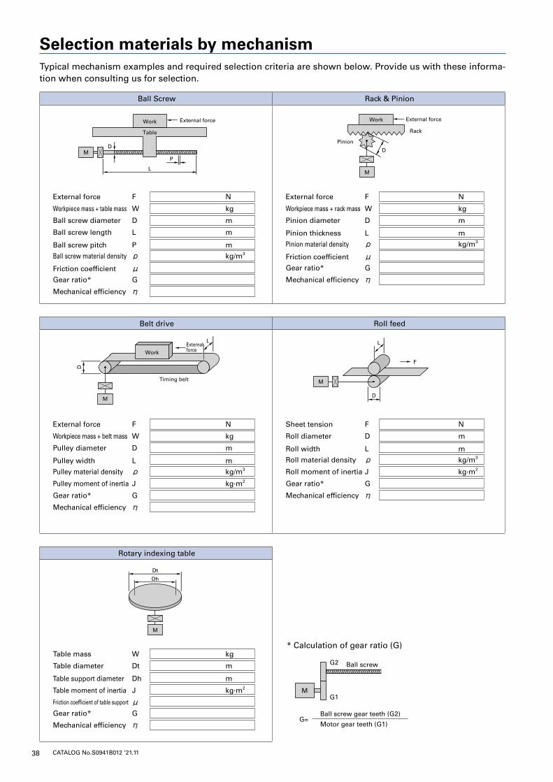
38 CATALOG No.S0941B012 ‘21.11
Ball Screw Rack & Pinion
External force F N
Workpiece mass + table mass W kg
Ball screw diameter D m
Ball screw length L m
Ball screw pitch P m
Ball screw material density ρ kg/m3
Friction coefficient μ Gear ratio* G
Mechanical efficiency η
External force F N
Workpiece mass + rack mass W kg
Pinion diameter D m
Pinion thickness L m
Pinion material density ρ kg/m3
Friction coefficient μGear ratio* G
Mechanical efficiency η
Belt drive Roll feed
External force F N
Workpiece mass + belt mass W kg
Pulley diameter D m
Pulley width L m
Pulley material density ρ kg/m3
Pulley moment of inertia J kg·m2
Gear ratio* G
Mechanical efficiency η
Sheet tension F N
Roll diameter D m
Roll width L m
Roll material density ρ kg/m3
Roll moment of inertia J kg·m2
Gear ratio* G
Mechanical efficiency η
Rotary indexing table
Table mass W kg
Table diameter Dt m
Table support diameter Dh m
Table moment of inertia J kg·m2
Friction coefficient of table support μ Gear ratio* G
Mechanical efficiency η
Selection materials by mechanism
D
Work
Work
Timing belt
L
Work
Rack
Pinion
Table
L
External force External force
F
D
PM
M
M
D
D
M
LExternal force
M
Dt
Dh
D
Work
Work
Timing belt
L
Work
Rack
Pinion
Table
L
External force External force
F
D
PM
M
M
D
D
M
LExternal force
M
Dt
Dh
D
Work
Work
Timing belt
L
Work
Rack
Pinion
Table
L
External force External force
F
D
PM
M
M
D
D
M
LExternal force
M
Dt
Dh
* Calculation of gear ratio (G)
MG1
G=Ball screw gear teeth (G2)
Motor gear teeth (G1)
G2 Ball screw
Typical mechanism examples and required selection criteria are shown below. Provide us with these informa-tion when consulting us for selection.
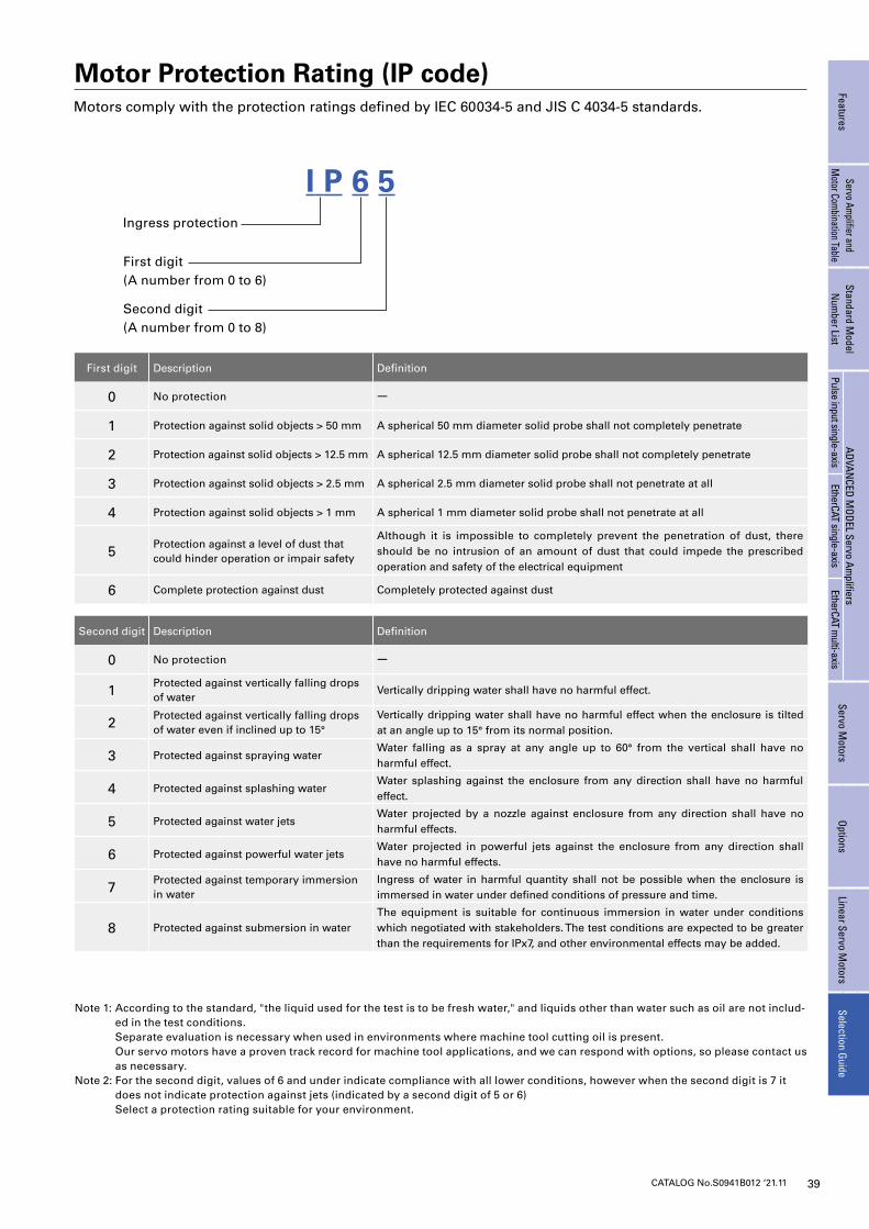
39CATALOG No.S0941B012 ‘21.11
FeaturesServo Am
plifier and M
otor Combination Table
Standard Model
Num
ber ListADVAN
CED MODEL Servo Am
plifiersServo M
otorsOptions
Linear Servo Motors
Selection GuidePulse input single-axis
EtherCAT single-axisEtherCAT m
ulti-axis
Motor Protection Rating (IP code)
Ingress protection
Second digit(A number from 0 to 8)
First digit(A number from 0 to 6)
Motors comply with the protection ratings defined by IEC 60034-5 and JIS C 4034-5 standards.
I P 6 5
First digit Description Definition
0 No protection -
1 Protection against solid objects > 50 mm A spherical 50 mm diameter solid probe shall not completely penetrate
2 Protection against solid objects > 12.5 mm A spherical 12.5 mm diameter solid probe shall not completely penetrate
3 Protection against solid objects > 2.5 mm A spherical 2.5 mm diameter solid probe shall not penetrate at all
4 Protection against solid objects > 1 mm A spherical 1 mm diameter solid probe shall not penetrate at all
5Protection against a level of dust that could hinder operation or impair safety
Although it is impossible to completely prevent the penetration of dust, there should be no intrusion of an amount of dust that could impede the prescribed operation and safety of the electrical equipment
6 Complete protection against dust Completely protected against dust
Second digit Description Definition
0 No protection -
1Protected against vertically falling drops of water
Vertically dripping water shall have no harmful effect.
2Protected against vertically falling drops of water even if inclined up to 15°
Vertically dripping water shall have no harmful effect when the enclosure is tilted at an angle up to 15° from its normal position.
3 Protected against spraying waterWater falling as a spray at any angle up to 60° from the vertical shall have no harmful effect.
4 Protected against splashing waterWater splashing against the enclosure from any direction shall have no harmful effect.
5 Protected against water jetsWater projected by a nozzle against enclosure from any direction shall have no harmful effects.
6 Protected against powerful water jetsWater projected in powerful jets against the enclosure from any direction shall have no harmful effects.
7Protected against temporary immersion in water
Ingress of water in harmful quantity shall not be possible when the enclosure is immersed in water under defined conditions of pressure and time.
8 Protected against submersion in waterThe equipment is suitable for continuous immersion in water under conditions which negotiated with stakeholders. The test conditions are expected to be greater than the requirements for IPx7, and other environmental effects may be added.
Note 1: According to the standard, "the liquid used for the test is to be fresh water," and liquids other than water such as oil are not includ-ed in the test conditions.
Separate evaluation is necessary when used in environments where machine tool cutting oil is present. Our servo motors have a proven track record for machine tool applications, and we can respond with options, so please contact us
as necessary.Note 2: For the second digit, values of 6 and under indicate compliance with all lower conditions, however when the second digit is 7 it
does not indicate protection against jets (indicated by a second digit of 5 or 6) Select a protection rating suitable for your environment.
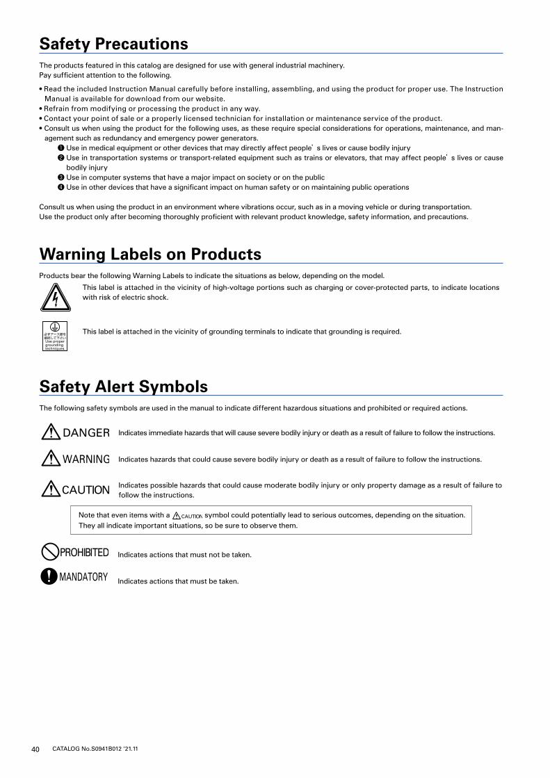
40 CATALOG No.S0941B012 ‘21.11
Safety PrecautionsThe products featured in this catalog are designed for use with general industrial machinery.Pay sufficient attention to the following.
• Read the included Instruction Manual carefully before installing, assembling, and using the product for proper use. The Instruction Manual is available for download from our website.
• Refrain from modifying or processing the product in any way.• Contact your point of sale or a properly licensed technician for installation or maintenance service of the product.• Consult us when using the product for the following uses, as these require special considerations for operations, maintenance, and man-
agement such as redundancy and emergency power generators.❶ Use in medical equipment or other devices that may directly affect people’s lives or cause bodily injury❷ Use in transportation systems or transport-related equipment such as trains or elevators, that may affect people’s lives or cause
bodily injury❸ Use in computer systems that have a major impact on society or on the public❹ Use in other devices that have a significant impact on human safety or on maintaining public operations
Consult us when using the product in an environment where vibrations occur, such as in a moving vehicle or during transportation.Use the product only after becoming thoroughly proficient with relevant product knowledge, safety information, and precautions.
Warning Labels on ProductsProducts bear the following Warning Labels to indicate the situations as below, depending on the model.
This label is attached in the vicinity of high-voltage portions such as charging or cover-protected parts, to indicate locations with risk of electric shock.
This label is attached in the vicinity of grounding terminals to indicate that grounding is required.
Safety Alert SymbolsThe following safety symbols are used in the manual to indicate different hazardous situations and prohibited or required actions.
Indicates immediate hazards that will cause severe bodily injury or death as a result of failure to follow the instructions.
Indicates hazards that could cause severe bodily injury or death as a result of failure to follow the instructions.
Indicates possible hazards that could cause moderate bodily injury or only property damage as a result of failure to follow the instructions.
Note that even items with a symbol could potentially lead to serious outcomes, depending on the situation.They all indicate important situations, so be sure to observe them.
Indicates actions that must not be taken.
Indicates actions that must be taken.
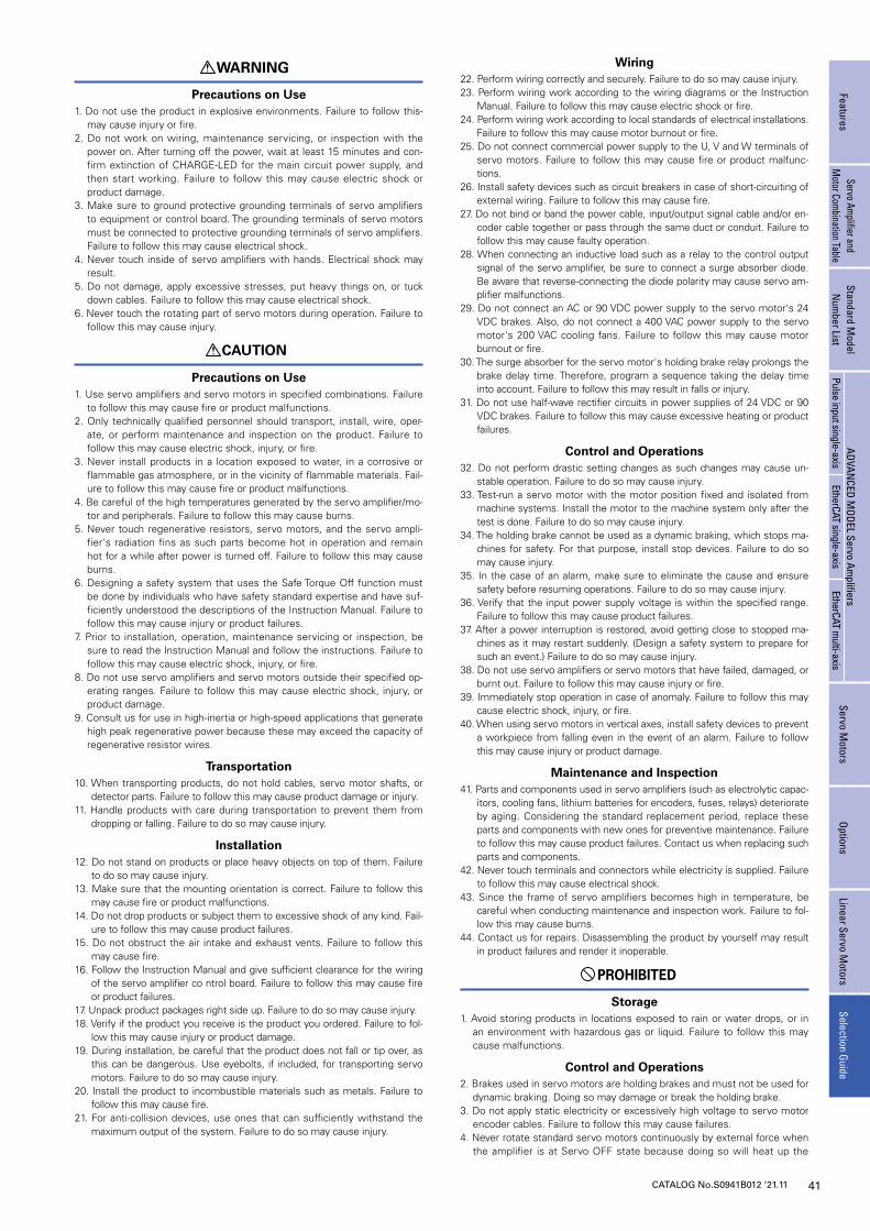
41CATALOG No.S0941B012 ‘21.11
FeaturesServo Am
plifier and M
otor Combination Table
Standard Model
Num
ber ListADVAN
CED MODEL Servo Am
plifiersServo M
otorsOptions
Linear Servo Motors
Selection GuidePulse input single-axis
EtherCAT single-axisEtherCAT m
ulti-axis
WARNING
Precautions on Use1. Do not use the product in explosive environments. Failure to follow this-
may cause injury or fire.2. Do not work on wiring, maintenance servicing, or inspection with the
power on. After turning off the power, wait at least 15 minutes and con-firm extinction of CHARGE-LED for the main circuit power supply, and then start working. Failure to follow this may cause electric shock or product damage.
3. Make sure to ground protective grounding terminals of servo amplifiers to equipment or control board. The grounding terminals of servo motors must be connected to protective grounding terminals of servo amplifiers. Failure to follow this may cause electrical shock.
4. Never touch inside of servo amplifiers with hands. Electrical shock may result.
5. Do not damage, apply excessive stresses, put heavy things on, or tuck down cables. Failure to follow this may cause electrical shock.
6. Never touch the rotating part of servo motors during operation. Failure to follow this may cause injury.
CAUTION
Precautions on Use1. Use servo amplifiers and servo motors in specified combinations. Failure
to follow this may cause fire or product malfunctions.2. Only technically qualified personnel should transport, install, wire, oper-
ate, or perform maintenance and inspection on the product. Failure to follow this may cause electric shock, injury, or fire.
3. Never install products in a location exposed to water, in a corrosive or flammable gas atmosphere, or in the vicinity of flammable materials. Fail-ure to follow this may cause fire or product malfunctions.
4. Be careful of the high temperatures generated by the servo amplifier/mo-tor and peripherals. Failure to follow this may cause burns.
5. Never touch regenerative resistors, servo motors, and the servo ampli-fier's radiation fins as such parts become hot in operation and remain hot for a while after power is turned off. Failure to follow this may cause burns.
6. Designing a safety system that uses the Safe Torque Off function must be done by individuals who have safety standard expertise and have suf-ficiently understood the descriptions of the Instruction Manual. Failure to follow this may cause injury or product failures.
7. Prior to installation, operation, maintenance servicing or inspection, be sure to read the Instruction Manual and follow the instructions. Failure to follow this may cause electric shock, injury, or fire.
8. Do not use servo amplifiers and servo motors outside their specified op-erating ranges. Failure to follow this may cause electric shock, injury, or product damage.
9. Consult us for use in high-inertia or high-speed applications that generate high peak regenerative power because these may exceed the capacity of regenerative resistor wires.
Transportation10. When transporting products, do not hold cables, servo motor shafts, or
detector parts. Failure to follow this may cause product damage or injury.11. Handle products with care during transportation to prevent them from
dropping or falling. Failure to do so may cause injury.
Installation12. Do not stand on products or place heavy objects on top of them. Failure
to do so may cause injury.13. Make sure that the mounting orientation is correct. Failure to follow this
may cause fire or product malfunctions.14. Do not drop products or subject them to excessive shock of any kind. Fail-
ure to follow this may cause product failures.15. Do not obstruct the air intake and exhaust vents. Failure to follow this
may cause fire.16. Follow the Instruction Manual and give sufficient clearance for the wiring
of the servo amplifier co ntrol board. Failure to follow this may cause fire or product failures.
17. Unpack product packages right side up. Failure to do so may cause injury.18. Verify if the product you receive is the product you ordered. Failure to fol-
low this may cause injury or product damage.19. During installation, be careful that the product does not fall or tip over, as
this can be dangerous. Use eyebolts, if included, for transporting servo motors. Failure to do so may cause injury.
20. Install the product to incombustible materials such as metals. Failure to follow this may cause fire.
21. For anti-collision devices, use ones that can sufficiently withstand the maximum output of the system. Failure to do so may cause injury.
Wiring22. Perform wiring correctly and securely. Failure to do so may cause injury.23. Perform wiring work according to the wiring diagrams or the Instruction
Manual. Failure to follow this may cause electric shock or fire.24. Perform wiring work according to local standards of electrical installations.
Failure to follow this may cause motor burnout or fire.25. Do not connect commercial power supply to the U, V and W terminals of
servo motors. Failure to follow this may cause fire or product malfunc-tions.
26. Install safety devices such as circuit breakers in case of short-circuiting of external wiring. Failure to follow this may cause fire.
27. Do not bind or band the power cable, input/output signal cable and/or en-coder cable together or pass through the same duct or conduit. Failure to follow this may cause faulty operation.
28. When connecting an inductive load such as a relay to the control output signal of the servo amplifier, be sure to connect a surge absorber diode. Be aware that reverse-connecting the diode polarity may cause servo am-plifier malfunctions.
29. Do not connect an AC or 90 VDC power supply to the servo motor's 24 VDC brakes. Also, do not connect a 400 VAC power supply to the servo motor's 200 VAC cooling fans. Failure to follow this may cause motor burnout or fire.
30. The surge absorber for the servo motor's holding brake relay prolongs the brake delay time. Therefore, program a sequence taking the delay time into account. Failure to follow this may result in falls or injury.
31. Do not use half-wave rectifier circuits in power supplies of 24 VDC or 90 VDC brakes. Failure to follow this may cause excessive heating or product failures.
Control and Operations32. Do not perform drastic setting changes as such changes may cause un-
stable operation. Failure to do so may cause injury.33. Test-run a servo motor with the motor position fixed and isolated from
machine systems. Install the motor to the machine system only after the test is done. Failure to do so may cause injury.
34. The holding brake cannot be used as a dynamic braking, which stops ma-chines for safety. For that purpose, install stop devices. Failure to do so may cause injury.
35. In the case of an alarm, make sure to eliminate the cause and ensure safety before resuming operations. Failure to do so may cause injury.
36. Verify that the input power supply voltage is within the specified range. Failure to follow this may cause product failures.
37. After a power interruption is restored, avoid getting close to stopped ma-chines as it may restart suddenly. (Design a safety system to prepare for such an event.) Failure to do so may cause injury.
38. Do not use servo amplifiers or servo motors that have failed, damaged, or burnt out. Failure to follow this may cause injury or fire.
39. Immediately stop operation in case of anomaly. Failure to follow this may cause electric shock, injury, or fire.
40. When using servo motors in vertical axes, install safety devices to prevent a workpiece from falling even in the event of an alarm. Failure to follow this may cause injury or product damage.
Maintenance and Inspection41. Parts and components used in servo amplifiers (such as electrolytic capac-
itors, cooling fans, lithium batteries for encoders, fuses, relays) deteriorate by aging. Considering the standard replacement period, replace these parts and components with new ones for preventive maintenance. Failure to follow this may cause product failures. Contact us when replacing such parts and components.
42. Never touch terminals and connectors while electricity is supplied. Failure to follow this may cause electrical shock.
43. Since the frame of servo amplifiers becomes high in temperature, be careful when conducting maintenance and inspection work. Failure to fol-low this may cause burns.
44. Contact us for repairs. Disassembling the product by yourself may result in product failures and render it inoperable.
PROHIBITED
Storage1. Avoid storing products in locations exposed to rain or water drops, or in
an environment with hazardous gas or liquid. Failure to follow this may cause malfunctions.
Control and Operations2. Brakes used in servo motors are holding brakes and must not be used for
dynamic braking. Doing so may damage or break the holding brake.3. Do not apply static electricity or excessively high voltage to servo motor
encoder cables. Failure to follow this may cause failures.4. Never rotate standard servo motors continuously by external force when
the amplifier is at Servo OFF state because doing so will heat up the
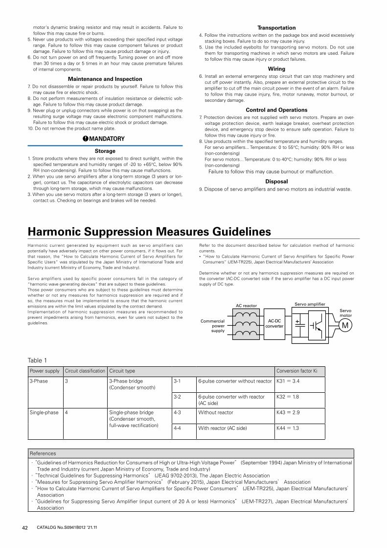
42 CATALOG No.S0941B012 ‘21.11
Harmonic Suppression Measures GuidelinesHarmonic current generated by equipment such as servo amplifiers can potentially have adversely impact on other power consumers, if it flows out. For that reason, the “How to Calculate Harmonic Current of Servo Amplifiers for Specific Users” was stipulated by the Japan Ministry of International Trade and Industry (current Ministry of Economy, Trade and Industry).
Servo amplifiers used by specific power consumers fall in the category of “harmonic wave generating devices” that are subject to these guidelines.Those power consumers who are subject to these guidelines must determine whether or not any measures for harmonics suppression are required and if so, the measures must be implemented to ensure that the harmonic current emissions are within the limit values stipulated by the contract demand.Implementation of harmonic suppression measures are recommended to prevent impediments arising from harmonics, even for users not subject to the guidelines.
Refer to the document described below for calculation method of harmonic currents. • “How to Calculate Harmonic Current of Servo Amplifiers for Specific Power Consumers” (JEM-TR225), Japan Electrical Manufacturers’ Association
Determine whether or not any harmonics suppression measures are required on the converter (AC-DC converter) side if the servo amplifier has a DC input power supply of DC type.
AC-DCconverter M
Commercial power supply
AC reactor Servo amplifier
Servo motor
References
・“ Guidelines of Harmonics Reduction for Consumers of High or Ultra-High Voltage Power” (September 1994) Japan Ministry of International Trade and Industry (current Japan Ministry of Economy, Trade and Industry)
・“Technical Guidelines for Suppressing Harmonics” (JEAG 9702-2013), The Japan Electric Association・“Measures for Suppressing Servo Amplifier Harmonics” (February 2015), Japan Electrical Manufacturers’ Association・“ How to Calculate Harmonic Current of Servo Amplifiers for Specific Power Consumers” (JEM-TR225), Japan Electrical Manufacturers’
Association・“ Guidelines for Suppressing Servo Amplifier (input current of 20 A or less) Harmonics” (JEM-TR227), Japan Electrical Manufacturers’
Association
Table 1
Power supply Circuit classification Circuit type Conversion factor Ki
3-Phase 3 3-Phase bridge(Condenser smooth)
3-1 6-pulse converter without reactor K31= 3.4
3-2 6-pulse converter with reactor (AC side)
K32= 1.8
Single-phase
4 Single-phase bridge(Condenser smooth, full-wave rectification)
4-3 Without reactor K43= 2.9
4-4 With reactor (AC side) K44= 1.3
motor's dynamic braking resistor and may result in accidents. Failure to follow this may cause fire or burns.
5. Never use products with voltages exceeding their specified input voltage range. Failure to follow this may cause component failures or product damage. Failure to follow this may cause product damage or injury.
6. Do not turn power on and off frequently. Turning power on and off more than 30 times a day or 5 times in an hour may cause premature failures of internal components.
Maintenance and Inspection7. Do not disassemble or repair products by yourself. Failure to follow this
may cause fire or electric shock.8. Do not perform measurements of insulation resistance or dielectric volt-
age. Failure to follow this may cause product damage.9. Never plug or unplug connectors while power is on (hot swapping) as the
resulting surge voltage may cause electronic component malfunctions. Failure to follow this may cause electric shock or product damage.
10. Do not remove the product name plate.
MANDATORY
Storage1. Store products where they are not exposed to direct sunlight, within the
specified temperature and humidity ranges of -20 to +65°C, below 90% RH (non-condensing). Failure to follow this may cause malfunctions.
2. When you use servo amplifiers after a long-term storage (3 years or lon-ger), contact us. The capacitance of electrolytic capacitors can decrease through long-term storage, which may cause malfunctions.
3. When you use servo motors after a long-term storage (3 years or longer), contact us. Checking on bearings and brakes will be needed.
Transportation4. Follow the instructions written on the package box and avoid excessively
stacking boxes. Failure to do so may cause injury.5. Use the included eyebolts for transporting servo motors. Do not use
them for transporting machines in which servo motors are used. Failure to follow this may cause injury or product failures.
Wiring6. Install an external emergency stop circuit that can stop machinery and
cut off power instantly. Also, prepare an external protective circuit to the amplifier to cut off the main circuit power in the event of an alarm. Failure to follow this may cause injury, fire, motor runaway, motor burnout, or secondary damage.
Control and Operations7. Protection devices are not supplied with servo motors. Prepare an over-
voltage protection device, earth leakage breaker, overheat protection device, and emergency stop device to ensure safe operation. Failure to follow this may cause injury or fire.
8. Use products within the specified temperature and humidity ranges. For servo amplifiers... Temperature: 0 to 55°C; humidity: 90% RH or less
(non-condensing) For servo motors... Temperature: 0 to 40°C; humidity: 90% RH or less (non-condensing) Failure to follow this may cause burnout or malfunction.
Disposal9. Dispose of servo amplifiers and servo motors as industrial waste.
43CATALOG No.S0941B012 ‘21.11
FeaturesServo Am
plifier and M
otor Combination Table
Standard Model
Num
ber ListADVAN
CED MODEL Servo Am
plifiersServo M
otorsOptions
Linear Servo Motors
Selection GuidePulse input single-axis
EtherCAT single-axisEtherCAT m
ulti-axis

The names of companies and/or their products specified in this document are the trade names, and/or trademarks and/or registered trademarks of such respective companies.
SANMOTION is a trademark of SANYO DENKI CO., LTD.
Specifications are subject to change without notice.
3-33-1 Minami-Otsuka, Toshima-ku, Tokyo 170-8451, Japan TEL: +81 3 5927 1020 https://www.sanyodenki.com/
Notes before PurchaseThe products in this catalog are designed to be used with general industrial devices.Always follow the following precautions.
・ Read the accompanying Instruction Manual carefully prior to using the product. ・ If applying to medical devices and other equipment affecting people’s lives,
please contact us beforehand and take appropriate safety measures.・ If applying to equipment that can have significant effects on society and the
general public, please contact us beforehand.
・ Do not use this product in an environment where vibration is present, such as in a moving vehicle or shipping vessel.・ Do not perform any retrofitting, re-engineering, or modification to this
equipment.・ The products presented in this catalog are meant to be used for general
industrial applications. If using for special applications related to aviation and space, nuclear power, electric power, submarine repeaters, and the like, please contact us beforehand.
CATALOG No.S0941B012 ‘21.11
SANYO DENKI's ECO PRODUCTS are designed with the concept of lessening impact on the environment in the process from product development to waste. The product units and packaging materials are designed for reduced environmental impact. We have established our own assessment criteria on the environmental impacts applicable to all processes, ranging from design to manufacture. Those products that satisfy the criteria are accredited as ECO PRODUCTS.
■ ECO PRODUCTS
48 VDC 2.4 W-200 W
Ver.3