twistorr 74 fs pcb 24 vdc controller | agilent
TRANSCRIPT
TwisTorr 74 FS PCB 24 Vdc Controller Model X3510-64050
Manuale di istruzioni Instruksjon manual Bedienungshandbuch Ohjekäsikirja Notice de mode d’emploi Felhasználói kézikönyv Manual de istrucciones Podrecznik instrukcji Manual de istruções Návod k použití Bedrijfshandleiding Návod na obsluhu Istrukstionsbog Priročnik za navodila Bruksanvisning User Manual
87-901-056-01 07/2018
Notices © Agilent Technologies, Inc. 2018
No part of this manual may be reproduced in any form or by any means (including electronic storage and retrieval or translation into a foreign language) without prior agreement and written consent from Agilent Technologies, Inc. as governed by United States and international copyright laws.
Manual Part Number Publication Number: 87-901-056-01
Edition Edition 07/2018
Printed in ITALY
Agilent Technologies Italia S.p.A.
Vacuum Products Division
Via F.lli Varian, 54
10040 Leinì (TO)
ITALY
Warranty The material contained in this document is provided “as is,” and is subject to being changed, without notice, in future editions. Further, to the maximum extent permitted by applicable law, Agilent disclaims all warranties, either express or implied, with regard to this manual and any information contained herein, including but not limited to the implied warranties of merchantability and fitness for a particular purpose. Agilent shall not be liable for errors or for incidental or consequential damages in connection with the furnishing, use, or performance of this document or of any information contained herein. Should Agilent and the user have a separate written agreement with warranty terms covering the material in this document that conflict with these terms, the warranty terms in the separate agreement shall control.
Technology Licenses The hardware and/or software described in this document are furnished under a license and may be used or copied only in accordance with the terms of such license.
Restricted Rights Legend If software is for use in the performance of a U.S. Government prime contract or subcontract, Software is delivered and licensed as “Commercial computer software” as defined in DFAR 252.227-7014 (June 1995), or as a “commercial item” as defined in FAR 2.101(a) or as “Restricted computer software” as defined in FAR 52.227-19 (June 1987) or any equivalent agency regulation or
contract clause. Use, duplication or disclosure of Software is subject to Agilent Technologies’ standard commercial license terms, and non-DOD Departments and Agencies of the U.S. Government will receive no greater than Restricted Rights as defined in FAR 52.227-19(c)(1-2) (June 1987). U.S. Government users will receive no greater than Limited Rights as defined in FAR 52.227-14 (June 1987) or DFAR 252.227-7015 (b)(2) (November 1995), as applicable in any technical data.
Trademarks Windows and MS Windows are U.S. registered trademarks of Microsoft Corporation.
Safety Notices
A CAUTION notice denotes a hazard. It calls attention to an operating procedure, practice, or the like that, if not correctly performed or adhered to, could result in damage to the product or loss of important data. Do not proceed beyond a CAUTION notice until the indicated conditions are fully understood and met.
A WARNING notice denotes a hazard. It calls attention to an operating procedure, practice, or the like that, if not correctly performed or adhered to, could result in personal injury or death. Do not proceed beyond a WARNING notice until the indicated conditions are fully understood and met.
CAUTION
WARNING
TwisTorr 74 FS PCB 24 Vdc Controller User Manual / 87-901-056-01
TwisTorr 74 FS PCB 24 Vdc Controller
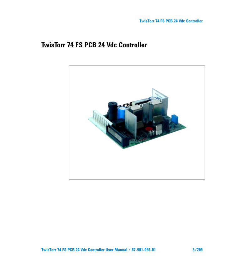
TwisTorr 74 FS PCB 24 Vdc Controller
TwisTorr 74 FS PCB 24 Vdc Controller User Manual / 87-901-056-01 3/209
TwisTorr 74 FS PCB 24 Vdc Controller
4/209 TwisTorr 74 FS PCB 24 Vdc Controller User Manual / 87-901-056-01
Contents
Contents
1 Istruzioni per l’uso 13
Informazioni Generali 14
Immagazzinamento 15
Preparazione per l’installazione 16
Installazione 18
Uso 19
Procedure di uso 19
Manutenzione 20
Smaltimento 21
2 Gebrauchsanleitung 23
Allgemeines 24
Lagerung 25
Vor der Installation 26
Installation 28
Gebrauch 29
Bedienung 29
Wartung 30
Entsorgung 31
TwisTorr 74 FS PCB 24 Vdc Controller User Manual / 87-901-056-01 5/209
Contents
3 Mode d’emploi 33
Indications Générales 34
Emmagasinage 35
Préparation pour l’installation 36
Installation 38
Utilisation 39
Procédures d’utilisation 39
Entretien 40
Mis au rebut 41
4 Manual de istrucciones 43
Informaciones de carácter general 44
Almacenamiento 45
Preparación para la instalación 46
Instalación 48
Uso 49
Procedimientos de uso 49
Mantenimiento 50
Eliminación 51
5 Manual de Istruções 53
Informações gerais 54
Armazenagem 55
Preparação para a instalação 56
6/209 TwisTorr 74 FS PCB 24 Vdc Controller User Manual / 87-901-056-01
Contents
Instalação 58
Utilização 59
Procedimentos de uso 59
Manutenção 60
Eliminação 61
6 Bedrijfshandleiding 63
Algemene informatie 64
Opslag 65
Voorbereiding voor installatie 66
Installatie 68
Gebruik 69
Gebruiksprocedures 69
Onderhoud 70
Afvalverwerking 71
7 Istruktionsbog 73
Generel Information 74
Opbevaring 75
Forberedelser før installation 76
Installation 78
Anvendelse 79
Instruktion 79
Vedligeholdelse 80
TwisTorr 74 FS PCB 24 Vdc Controller User Manual / 87-901-056-01 7/209
Contents
Bortskaffelse 81
8 Bruksanvisning 83
Allmän information 84
Förvaring 85
Förberedelser för Installation 86
Installation 88
Användning 89
Instruktioner för bruk 89
Underhåll 90
Bortskaffning 91
9 Instruksjon Manual 93
Generell informasjon 94
Lagring 95
Forberede installasjonen 96
Installasjon 98
Bruk 99
Instruksjoner for bruk 99
Vedlikehold 100
Eliminering 101
10 Ohjekäsikirja 103
Yleisiä tietoja 104
Varastointi 105
8/209 TwisTorr 74 FS PCB 24 Vdc Controller User Manual / 87-901-056-01
Contents
Valmistelut asennusta varten 106
Asennus 108
Käyttö 109
Käyttötoimenpiteet 109
Huolto 110
Hävittäminen 111
11 Felhasználói Kézikönyv 113
Általános információk 114
Tárolás 115
A telepítésre való előkészítés 116
Telepítés 118
Használat 119
Használati eljárások 119
Karbantartás 120
Megsemmisítés 121
12 Podrecznik Instrukcji 123
Informacje ogolne 124
Magazynowanie 125
Przygotowanie do instalacji 126
Instalacja 128
Uzytkowanie 129
Procedury uzytkowania 129
TwisTorr 74 FS PCB 24 Vdc Controller User Manual / 87-901-056-01 9/209
Contents
Konserwacja 130
Przetworstwo odpadow 131
13 Návod k Použití 133
Všeobecné informace 134
Uskladnění 135
Příprava k instalaci 136
Instalace 138
Použití 139
Používané procedury 139
Údržba 140
Likvidace 141
14 Návod na Obsluhu 143
Všeobecné informácie 144
Uskladňovanie 145
Príprava pre inštaláciu 146
Inštalácia 148
Použitie 149
Postup pri použití 149
Údržba 150
Likvidácia 151
15 Priročnik za Navodila 153
Splošna navodila 154
10/209 TwisTorr 74 FS PCB 24 Vdc Controller User Manual / 87-901-056-01
Contents
Skladiščenje 155
Priprava za montažo 156
Montaža 158
Uporaba 159
Postopki za uporabo 159
Vzdrževanje 160
Odlaganje opadkov 161
16 Instructions for Use 163
General Information 164
Storage 165
Preparation prior to Installation 166
Installation 168
Use 169
Operating Procedures 169
Maintenance 170
Disposal 171
17 Technical Information 173
General Description 174
TwisTorr 74 FS PCB 24 Vdc Controller Description 174
Controller Specifications 175
Controller Outline 178
Installation 179
TwisTorr 74 FS PCB 24 Vdc Controller User Manual / 87-901-056-01 11/209
Contents
Data Exchange Protocols 184
Example 194
Operation 199
Maintenance 201
Accessories and Spare Parts 202
12/209 TwisTorr 74 FS PCB 24 Vdc Controller User Manual / 87-901-056-01
TwisTorr 74 FS PCB 24 Vdc Controller User Manual
1 Istruzioni per l’uso Informazioni Generali 14 Immagazzinamento 15 Preparazione per l’installazione 16 Installazione 18 Uso 19 Procedure di uso 19 Accensione del Controller 19 Avvio della Pompa 19 Arresto della Pompa 19 Manutenzione 20 Smaltimento 21 Traduzione delle istruzioni originali
13/209
1 Istruzioni per l’uso Informazioni Generali
Informazioni Generali Questa apparecchiatura è destinata ad uso professionale. L'utilizzatore deve leggere attentamente il presente manuale di istruzioni ed ogni altra informazione addizionale fornita dalla Agilent prima dell'utilizzo dell'apparecchiatura. La Agilent si ritiene sollevata da eventuali responsabilità dovute all'inosservanza totale o parziale delle istruzioni, ad uso improprio da parte di personale non addestrato, ad interventi non autorizzati o ad uso contrario alle normative nazionali specifiche. Il controller TwisTorr 74 FS PCB è un convertitore di frequenza, controllato da un micropro-cessore, realizzato con componenti a stato solido e con capacità di autodiagnostica e autoprotezione. Esso incorpora tutta la circuiteria necessaria per il funzionamento automatico delle pompe della serie TwisTorr 74 FS.
Il controller pilota le pompe della serie TwisTorr 74 FS (con un processo suddiviso in dieci passi) durante la fase di avvio controllando la tensione e la corrente in rapporto alla velocità raggiunta dalla pompa. Tramite connettori ausiliari sono disponibili i comandi per l'avvio e l'arresto della pompa da remoto, i segnali che indicano lo stato operativo della pompa, segnali di bloccaggio (per interruttori a pressione, interruttori di controllo del flusso dell'acqua, ecc.). Il controller deve essere alimentato con una tensione continua di 24 Vdc.
Nei paragrafi seguenti sono riportate tutte le informazioni necessarie a garantire la sicurezza dell'operatore durante l'utilizzo dell'apparecchiatura. Informazioni dettagliate sono fornite nell'appendice "Technical Information".
14/209 TwisTorr 74 FS PCB 24 Vdc Controller User Manual / 87-901-056-01
Istruzioni per l’uso Immagazzinamento
1
Questo manuale utilizza le seguenti convenzioni:
ATTENZIONE! I messaggi di attenzione sono visualizzati prima di procedure che, se non osservate, potrebbero causare danni all'apparecchiatura.
AVVERTENZA!
I messaggi di avvertenza attirano l'attenzione dell'operatore su una procedura o una pratica specifica che, se non eseguita in modo corretto, potrebbe provocare gravi lesioni personali.
NOTA Le note contengono informazioni importanti estrapolate dal testo.
Immagazzinamento Durante il trasporto e l'immagazzinamento del controller devono essere soddisfatte le seguenti condizioni ambientali:
temperatura: da -20 °C a +70 °C
umidità relativa 0 – 95 % (non condensante)
TwisTorr 74 FS PCB 24 Vdc Controller User Manual / 87-901-056-01 15/209

1 Istruzioni per l’uso Preparazione per l’installazione
Preparazione per l’installazione Il controller viene fornito in un imballo protettivo speciale; se si presentano segni di danni, che potrebbero essersi verificati durante il trasporto, contattare l'ufficio vendite locale.
Figura 1 Imballo del controller
16/209 TwisTorr 74 FS PCB 24 Vdc Controller User Manual / 87-901-056-01
Istruzioni per l’uso Preparazione per l’installazione
1
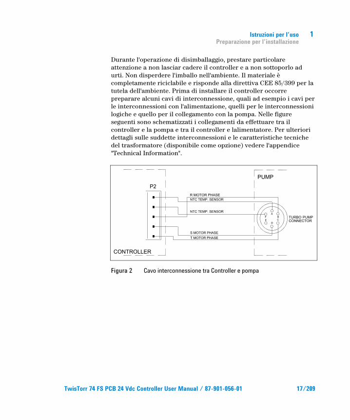
Durante l'operazione di disimballaggio, prestare particolare attenzione a non lasciar cadere il controller e a non sottoporlo ad urti. Non disperdere l'imballo nell'ambiente. Il materiale è completamente riciclabile e risponde alla direttiva CEE 85/399 per la tutela dell'ambiente. Prima di installare il controller occorre preparare alcuni cavi di interconnessione, quali ad esempio i cavi per le interconnessioni con l'alimentazione, quelli per le interconnessioni logiche e quello per il collegamento con la pompa. Nelle figure seguenti sono schematizzati i collegamenti da effettuare tra il controller e la pompa e tra il controller e lalimentatore. Per ulteriori dettagli sulle suddette interconnessioni e le caratteristiche tecniche del trasformatore (disponibile come opzione) vedere l'appendice "Technical Information".
Figura 2 Cavo interconnessione tra Controller e pompa
TwisTorr 74 FS PCB 24 Vdc Controller User Manual / 87-901-056-01 17/209
1 Istruzioni per l’uso Installazione
Installazione
AVVERTENZA!
All'interno del controller si sviluppano tensioni che possono recare gravi danni. Prima di eseguire qualsiasi operazione di installazione o manutenzione del controller scollegarlo dalla alimentazione. All'interno del controller si sviluppano elevate temperature che possono recare gravi danni. Proteggere adeguatamente il controller nella sua installazione definitiva da contatti accidentali.
NOTA Il controller installato nel sistema definitivo deve essere posizionato in modo tale che l'aria di raffreddamento possa circolare liberamente intorno all'apparato. Non installare e/o utilizzare il controller in ambienti esposti ad agenti atmosferici (pioggia, gelo, neve), polveri, gas aggressivi, in ambienti esplosivi o con elevato rischio di incendio.
Durante il funzionamento è necessario che siano rispettate le seguenti condizioni ambientali:
temperatura: da 0 °C a +40 °C
umidità relativa: 0 – 95 % (non condensante).
18/209 TwisTorr 74 FS PCB 24 Vdc Controller User Manual / 87-901-056-01
Istruzioni per l’uso Uso
1
Uso In questo paragrafo sono riportate le principali procedure operative. Per ulteriori dettagli e per procedure che coinvolgono collegamenti o particolari opzionali, fare riferimento al paragrafo "USE" dell'appendice "Technical Information". Prima di usare il controller effettuare tutti i collegamenti elettrici e pneumatici e fare riferimento al manuale della pompa collegata.
AVVERTENZA!
Fare riferimento al manuale relativo alla pompa in questione per utilizzarla in modo sicuro prima dell'avviamento.
Procedure di uso
Accensione del Controller Per accendere il controller è sufficiente fornire la tensione di alimentazione al controller stesso.
Avvio della Pompa Per avviare la pompa lasciare aperto il pin 12 del connettore J4, in modo tale che quando viene fornita la tensione di 24 Vdc al controller si ha l’avviamento della pompa.
Arresto della Pompa Per arrestare la pompa occorre cortocircuitare i pin 12 e 15 del connettore J4.
TwisTorr 74 FS PCB 24 Vdc Controller User Manual / 87-901-056-01 19/209
1 Istruzioni per l’uso Manutenzione
Manutenzione I controller della serie TwisTorr 74 FS non richiedono alcuna manutenzione. Qualsiasi intervento deve essere eseguito da personale autorizzato.
In caso di guasto è possibile usufruire del servizio di riparazione Agilent o del "Agilent advance exchange service", che permette di ottenere un controller ricondizionato in sostituzione di quello guasto.
AVVERTENZA!
Prima di effettuare qualsiasi intervento sul controller scollegare il cavo di alimentazione.
Qualora un controller dovesse essere rottamato, procedere alla sua eliminazione nel rispetto delle normative nazionali specifiche.
20/209 TwisTorr 74 FS PCB 24 Vdc Controller User Manual / 87-901-056-01
Istruzioni per l’uso Smaltimento
1
Smaltimento Significato del logo "WEEE" presente sulle etichette. Il simbolo qui sotto riportato è applicato in ottemperanza alla direttiva CE denominata "WEEE". Questo simbolo (valido solo per i paesi della Comunità Europea) indica che il prodotto sul quale è applicato, NON deve essere smaltito insieme ai comuni rifiuti domestici o industriali, ma deve essere avviato ad un sistema di raccolta differenziata. Si invita pertanto l'utente finale a contattare il fornitore del dispositivo, sia esso la casa madre o un rivenditore, per avviare il processo di raccolta e smaltimento, dopo opportuna verifica dei termini e condizioni contrattuali di vendita.
Per maggiori informazioni riferirsi a: http://www.agilent.com/environment/product/index.shtml
TwisTorr 74 FS PCB 24 Vdc Controller User Manual / 87-901-056-01 21/209

1 Istruzioni per l’uso Smaltimento
22/209 TwisTorr 74 FS PCB 24 Vdc Controller User Manual / 87-901-056-01
Gebrauchsanleitung Smaltimento
2
2Gebrauchsanleitung Allgemeines 24 Lagerung 25 Vor der Installation 26 Installation 28 Gebrauch 29 Bedienung 29
Einschalten des Controllers 29 Pumpenstart 29 Pumpenstopp 29
Wartung 30 Entsorgung 31
Übersetzung der Originalanleitungen
TwisTorr 74 FS PCB 24 Vdc Controller User Manual / 87-901-056-01 23/209
2 Gebrauchsanleitung Allgemeines
Allgemeines Dieser Apparat ist für Fachbetriebe bestimmt. Vor Gebrauch sollte der Benutzer dieses Handbuch sowie alle weiteren mitgelieferten Zusatzdokumentationen genau lesen. Bei Nichtbeachtung - auch teilweise - der enthaltenen Hinweise, unsachgemäßem Gebrauch durch ungeschultes Personal, nicht autorisierten Eingriffen und Missachtung der einheimischen, hier zur Geltung kommenden Bestimmungen übernimmt die Firma Agilent keinerlei Haftung. Der Controller der Serie TwisTorr 74 FS PCB ist ein mikroprozessorgesteuerter Frequenzwandler. Er ist aus Festkörperbauteilen gefertigt und verfügt über ein Selbstdiagnose- und ein Selbstschutzsystem. Er enthält alle für den automatischen Betrieb der Pumpenserie TwisTorr 74 FS erforderlichen Schaltungen. Der Controller steuert die Pumpen der Serie TwisTorr 74 FS (durch einen 10-Schritte-Prozess) in der Startphase, indem er die Spannung und die Stromstärke im Verhältnis zur Pumpengeschwindigkeit kontrolliert. Mittels Hilfsverbinder sind die Fernsteuerungen für Pumpenstart und -stopp, die Signale für die Betriebsanzeige der Pumpe und Sperrsignale (für Druckschalter, Wasserstrom-Kontrollschalter usw.) verfügbar. Der Controller soll mit einer Gleichstromspannung von 24 V versorgt werden. Für die Funktionskontrolle und die Visualisierung des Controllerzustandes ist ein entsprechendes Gerät (Hand Held Terminal) erhältlich; es besteht aus einer Steuertastatur und einem Display für die Visualisierung.
In den folgenden Abschnitten sind alle erforderlichen Informationen für die Sicherheit des Bedieners bei der Anwendung des Geräts aufgeführt. Detaillierte technische Informationen sind im Anhang "Technical Information" enthalten.
24/209 TwisTorr 74 FS PCB 24 Vdc Controller User Manual / 87-901-056-01
Gebrauchsanleitung Lagerung
2
In dieser Gebrauchsanleitung werden Sicherheitshinweise folgendermaßen hervorgehoben:
VORSICHT! Die Vorsichtshinweise werden vor Vorgängen angegeben, die bei Nichtbeachtung Schäden an der Anlage verursachen könnten.
WARNUNG! Die Warnhinweise lenken die Aufmerksamkeit des Bedieners auf eine bestimmte Prozedur oder Praktik, die bei unkorrekter Ausführung schwere Verletzungen hervorrufen können.
HINWEIS Die Hinweise enthalten wichtige Informationen, die aus dem Text hervorgehoben werden.
Lagerung Beim Transport und bei der Lagerung des Controllers müssen folgende klimatische Verhältnisse eingehalten werden:
Temperatur: von -20 °C bis +70 °C
Relative Luftfeuchtigkeit: 0 – 95 % (nicht kondensierend)
TwisTorr 74 FS PCB 24 Vdc Controller User Manual / 87-901-056-01 25/209
2 Gebrauchsanleitung Vor der Installation
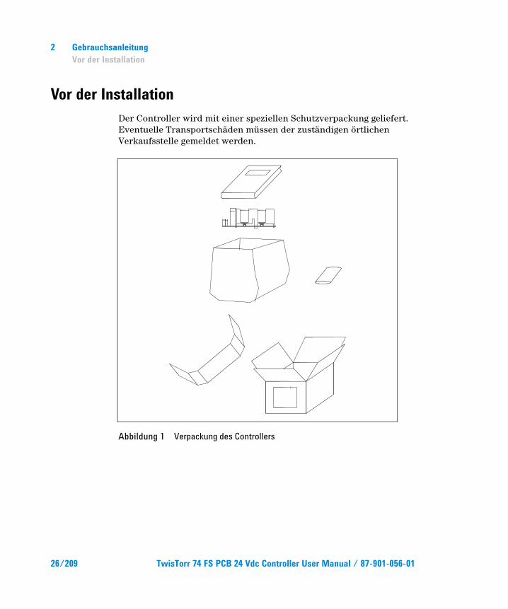
Vor der Installation Der Controller wird mit einer speziellen Schutzverpackung geliefert. Eventuelle Transportschäden müssen der zuständigen örtlichen Verkaufsstelle gemeldet werden.
Abbildung 1 Verpackung des Controllers
26/209 TwisTorr 74 FS PCB 24 Vdc Controller User Manual / 87-901-056-01
Gebrauchsanleitung Vor der Installation
2
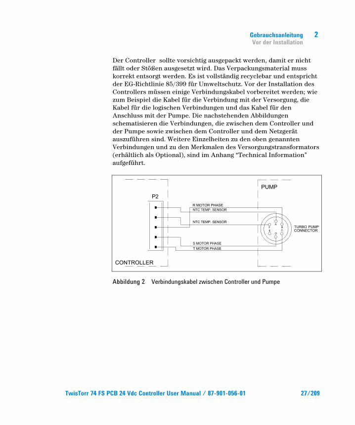
Der Controller sollte vorsichtig ausgepackt werden, damit er nicht fällt oder Stößen ausgesetzt wird. Das Verpackungsmaterial muss korrekt entsorgt werden. Es ist vollständig recyclebar und entspricht der EG-Richtlinie 85/399 für Umweltschutz. Vor der Installation des Controllers müssen einige Verbindungskabel vorbereitet werden; wie zum Beispiel die Kabel für die Verbindung mit der Versorgung, die Kabel für die logischen Verbindungen und das Kabel für den Anschluss mit der Pumpe. Die nachstehenden Abbildungen schematisieren die Verbindungen, die zwischen dem Controller und der Pumpe sowie zwischen dem Controller und dem Netzgerät auszuführen sind. Weitere Einzelheiten zu den oben genannten Verbindungen und zu den Merkmalen des Versorgungstransformators (erhältlich als Optional), sind im Anhang “Technical Information” aufgeführt.
Abbildung 2 Verbindungskabel zwischen Controller und Pumpe
TwisTorr 74 FS PCB 24 Vdc Controller User Manual / 87-901-056-01 27/209
2 Gebrauchsanleitung Installation
Installation
WARNUNG!
Im Innern des Controllers bilden sich Spannungen, die zu schweren Schäden führen können. Vor jedem Installations- oder Wartungseingriff den Controller von der Stromversorgung trennen. Im Innern des Controllers bilden sich erhöhte Temperaturen, die schwere Schäden verursachen können. Schützen Sie den Controller bei seiner definitiven Installation vor zufälligen Berührungen.
HINWEIS Der im definitiven System installierte Controller muss so positioniert sein, dass die Kühlungsluft frei um das Gerät zirkulieren kann. Der Controller darf nicht in Umgebungen installiert u/o benutzt werden, die Witterungseinflüssen (Regen, Frost, Schnee), Staub und aggressiven Gasen ausgesetzt sind und in denen Explosions- und erhöhte Brandgefahr besteht.
Beim Betrieb müssen folgende Umgebungsbedingungen eingehalten werden:
Temperatur: von 0 °C bis +40 °C;
Relative Luftfeuchtigkeit: 0 – 95 % (nicht kondensierend).
28/209 TwisTorr 74 FS PCB 24 Vdc Controller User Manual / 87-901-056-01
Gebrauchsanleitung Gebrauch
2
Gebrauch In diesem Kapitel sind die wichtigsten Betriebsvorgänge aufgeführt. Für weitere Hinweise bezüglich Anschlüsse und Montage des bestellbaren Zubehörs siehe Kapitel "USE" im Anhang zu "Technical Information". Vor Benutzung des Controllers sämtliche elektrischen und pneumatischen Anschlüsse ausführen und die Betriebsanleitung der angeschlossenen Pumpe durchlesen.
WARNUNG!
Bevor Sie die fragliche Pumpe in Betrieb setzen, beachten Sie zu Ihrer Sicherheit bitte die Hinweise im entsprechenden Handbuch.
Bedienung
Einschalten des Controllers Zum Einschalten des Controllers genügt es, das Netzkabel an die Steckdose anzuschließen.
Pumpenstart Zum Starten der Pumpe ist PIN 12 des Verbinders J4 offen zu lassen, so dass bei Zuschaltung der 24V-Gleichspannung am Controller der Pumpenstart erfolgt.
Pumpenstopp Zum Stoppen der Pumpe sind die PIN 12 und 15 des Verbinders J4 kurzzuschließen.
TwisTorr 74 FS PCB 24 Vdc Controller User Manual / 87-901-056-01 29/209
2 Gebrauchsanleitung Wartung
Wartung Die Controller der Serie TwisTorr 74 FS sind wartungsfrei. Eventuell erforderliche Eingriffe müssen von dazu befugtem Fachpersonal ausgeführt werden.
Bei einem Defekt kann der Agilent Reparaturdienst bzw. der "Agilent advanced exchange service" in Anspruch genommen werden, der für die Erneuerung des defekten Controllers sorgt.
WARNUNG!
Vor jedem Eingriff am Controller muss der Netzstecker gezogen werden.
Eine eventuelle Verschrottung hat unter Einhaltung der einschlägigen landesüblichen Vorschriften zu erfolgen.
30/209 TwisTorr 74 FS PCB 24 Vdc Controller User Manual / 87-901-056-01
Gebrauchsanleitung Entsorgung
2
Entsorgung Bedeutung des "WEEE" Logos auf den Etiketten. Das folgende Symbol ist in Übereinstimmung mit der EU-Richtlinie WEEE (Waste Electrical and Electronic Equipment) angebracht. Dieses Symbol (nur in den EU-Ländern gültig) zeigt an, dass das betreffende Produkt nicht zusammen mit Haushaltsmüll entsorgt werden darf sondern einem speziellen Sammelsystem zugeführt werden muss. Der Endabnehmer sollte daher den Lieferanten des Geräts - d.h. die Muttergesellschaft oder den Wiederverkäufer - kontaktieren, um den Entsorgungsprozess zu starten, nachdem er die Verkaufsbedingungen geprüft hat.
Weitere Informationen finden Sie unter: http://www.agilent.com/environment/product/index.shtml
TwisTorr 74 FS PCB 24 Vdc Controller User Manual / 87-901-056-01 31/209

2 Gebrauchsanleitung Entsorgung
32/209 TwisTorr 74 FS PCB 24 Vdc Controller User Manual / 87-901-056-01
TwisTorr 74 FS PCB 24 Vdc Controller User Manual
3Mode d’emploi Indications Générales 34 Emmagasinage 35 Préparation pour l’installation 36 Installation 38 Utilisation 39 Procédures d’utilisation 39
Allumage du contrôleur 39 Mise en marche de la Pompe 39 Arrêt de la Pompe 39
Entretien 40 Mis au rebut 41
Traduction de la mode d’emploi originale
33/209
3 Mode d’emploi Indications Générales
Indications Générales Cet appareillage a été conçu en vue d'une utilisation professionnelle. Il est conseillé à l'utilisateur de lire attentivement cette notice d'instructions ainsi que toute autre indication supplémentaire fournie par Agilent, avant l'utilisation de l'appareil. Agilent décline par conséquent toute responsabilité en cas d'inobservation totale ou partielle des instructions données, d'utilisation incorrecte de la part d'un personnel non formé, d'opérations non autorisées ou d'un emploi contraire aux réglementations nationales spécifiques. Le contrôleur TwisTorr 74 FS PCB est un convertisseur de fréquence, contrôlé par un microprocesseur, réalisé avec des éléments à l'état solide et ayant des capacités d'autodiagnostic et d'autoprotection. Il incorpore l'ensemble de circuits nécessaire au fonctionnement automatique des pompes de la série TwisTorr 74 FS. Le contrôleur pilote les pompes de la série TwisTorr 74 FS (selon un processus subdivisé en dix pas) pendant la phase de mise en marche, en contrôlant la tension et le courant par rapport à la vitesse atteinte par la pompe. Des connecteurs auxiliaires permettent de disposer des commandes de mise en marche et d'arrêt de la pompe à distance, des signaux indiquant l'état opérationnel de la pompe, des signaux de blocage (pour interrupteurs à pression, interrupteurs de contrôle du flux de l’eau etc.) Le contrôleur doit être alimenté avec une tension continue de 24 Vdc.
Les paragraphes suivants donnent toutes les indications nécessaires à garantir la sécurité de l'opérateur pendant l'utilisation de l'appareillage.
Des renseignements plus détaillés se trouvent dans "Technical Information".
34/209 TwisTorr 74 FS PCB 24 Vdc Controller User Manual / 87-901-056-01
Mode d’emploi Emmagasinage
3
Cette notice utilise les signes conventionnels suivants:
ATTENTION! Les messages d'attention apparaissent avant certaines procédures qui, si elles ne sont pas observées, pourraient endommager sérieusement l'appareillage.
AVERTISSEMENT! Les messages d’avertissement attirent l'attention de l'opérateur sur une procédure ou une manoeuvre spéciale qui, si elle n'est pas effectuée correctement, risque de provoquer de graves lésions.
NOTE Les notes contiennent des renseignements importants, isolés du texte.
Emmagasinage Pendant le transport et l'emmagasinage des contrôleurs, il faudra veiller à respecter les conditions environnementales suivantes:
température: de -20 °C à + 70 °C
humidité relative: 0 – 95 % (non condensante).
TwisTorr 74 FS PCB 24 Vdc Controller User Manual / 87-901-056-01 35/209
3 Mode d’emploi Préparation pour l’installation
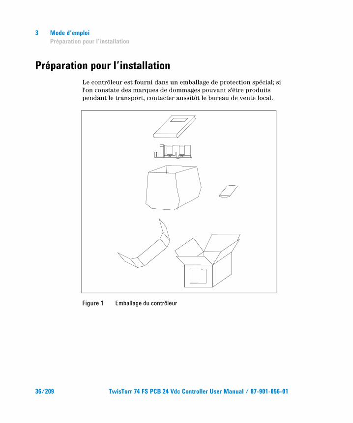
Préparation pour l’installation Le contrôleur est fourni dans un emballage de protection spécial; si l'on constate des marques de dommages pouvant s'être produits pendant le transport, contacter aussitôt le bureau de vente local.
Figure 1 Emballage du contrôleur
36/209 TwisTorr 74 FS PCB 24 Vdc Controller User Manual / 87-901-056-01
Mode d’emploi Préparation pour l’installation
3
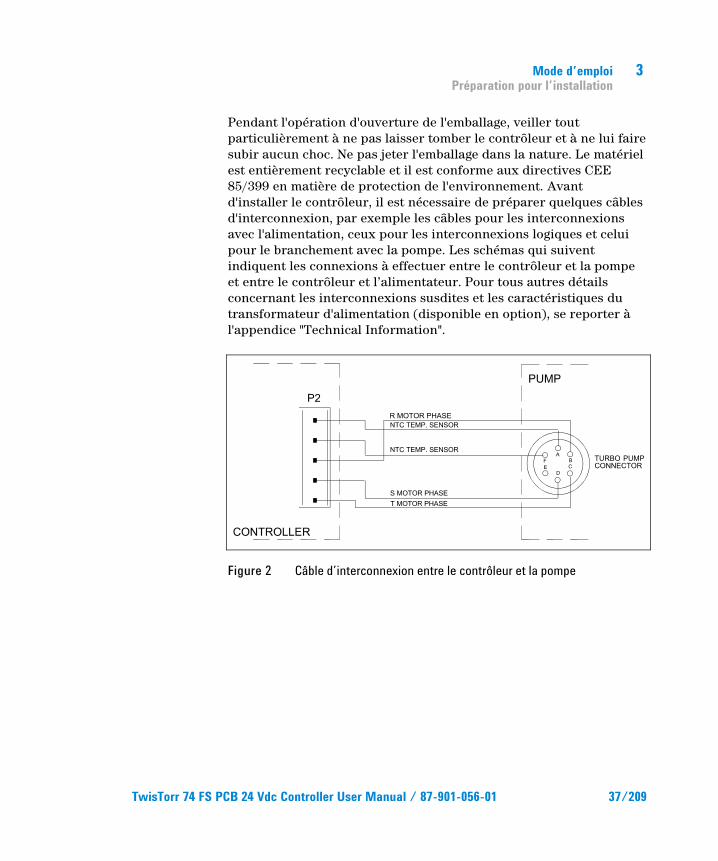
Pendant l'opération d'ouverture de l'emballage, veiller tout particulièrement à ne pas laisser tomber le contrôleur et à ne lui faire subir aucun choc. Ne pas jeter l'emballage dans la nature. Le matériel est entièrement recyclable et il est conforme aux directives CEE 85/399 en matière de protection de l'environnement. Avant d'installer le contrôleur, il est nécessaire de préparer quelques câbles d'interconnexion, par exemple les câbles pour les interconnexions avec l'alimentation, ceux pour les interconnexions logiques et celui pour le branchement avec la pompe. Les schémas qui suivent indiquent les connexions à effectuer entre le contrôleur et la pompe et entre le contrôleur et l’alimentateur. Pour tous autres détails concernant les interconnexions susdites et les caractéristiques du transformateur d'alimentation (disponible en option), se reporter à l'appendice "Technical Information".
Figure 2 Câble d’interconnexion entre le contrôleur et la pompe
TwisTorr 74 FS PCB 24 Vdc Controller User Manual / 87-901-056-01 37/209
3 Mode d’emploi Installation
Installation
AVERTISSEMENT! A l'intérieur du contrôleur se développent des tensions qui peuvent causer de graves dommages. Avant d'effectuer toute opération d'installation ou d'entretien du contrôleur, le débrancher de la prise d'alimentation. A l'intérieur du contrôleur se développent des températures élevées qui peuvent causer de graves dommages. Protéger de façon appropriée le contrôleur, dans son installation définitive, contre tous contacts accidentels.
NOTE Le contrôleur installé dans le système définitif doit être positionné de façon à ce que l'air de refroidissement puisse circuler librement autour de l'appareil. Ne pas installer et/ou utiliser le contrôleur dans des milieux exposés à des agents atmosphériques (pluie, gel, neige), à des poussières, à des gaz de combat ainsi que dans des milieux explosifs ou à risque élevé d'incendie.
Pendant le fonctionnement, il est nécessaire de respecter les conditions environnementales suivantes:
température: de 0 °C à + 40 °C
humidité relative: de 0 % à 95 % (non condensante).
38/209 TwisTorr 74 FS PCB 24 Vdc Controller User Manual / 87-901-056-01
Mode d’emploi Utilisation
3
Utilisation Ce paragraphe indique les principales procédures opérationnelles. Pour tous autres détails et pour les procédures concernant des connexions ou des éléments en option, se reporter au paragraphe "USE" de l'appendice "Technical Information". Avant d'utiliser le contrôleur, effectuer toutes les connexions électriques et pneumatiques et se référer à la notice de la pompe connectée.
AVERTISSEMENT!
Veuillez-vous référer au manuel de la pompe spécifique pour l’utiliser en toute sécurité avant le démarrage.
Procédures d’utilisation
Allumage du contrôleur Pour allumer le contrôleur, il suffit d'introduire le câble d'alimentation dans la prise du réseau.
Mise en marche de la Pompe Pour mettre la pompe en marche il faut laisser ouvert le contact sur le pin 12 du connecteur J4 de façon que lorsque le contrôleur reçoit la tension de 24 Vdc, la pompe se met en marche .
Arrêt de la Pompe Pour arrêter la pompe, il est nécessaire de court-circuiter les pins 12 et 15 du connecteur J4.
TwisTorr 74 FS PCB 24 Vdc Controller User Manual / 87-901-056-01 39/209
3 Mode d’emploi Entretien
Entretien Les contrôleurs de la série TwisTorr 74 FS n'exigent aucun entretien. Toute opération doit être effectuée par un personnel agréé. En cas de panne, il est possible de s'adresser au Service de réparation Agilent ou bien au "Agilent advance exchange service" qui permet d'obtenir un contrôler régénéré à la place du contrôleur détraqué.
AVERTISSEMENT!
Avant d'effectuer toute opération sur le contrôleur, débrancher le câble d'alimentation.
Si un contrôleur doit être mis au rebut, procéder à son élimination dans le respect des normes nationales en vigueur.
40/209 TwisTorr 74 FS PCB 24 Vdc Controller User Manual / 87-901-056-01
Mode d’emploi Mis au rebut
3
Mis au rebut Signification du logo "WEEE" figurant sur les étiquettes. Le symbole ci-dessous est appliqué conformément à la directive CE nommée "WEEE". Ce symbole (uniquement valide pour les pays de la Communauté européenne) indique que le produit sur lequel il est appliqué NE doit PAS être mis au rebut avec les ordures ména-gères ou les déchets industriels ordinaires, mais passer par un système de collecte sélective. Après avoir vérifié les termes et conditions du contrat de vente, l’utilisateur final est donc prié de contacter le fournisseur du dispositif, maison mère ou revendeur, pour mettre en œuvre le processus de collecte et mise au rebut.
Pour en savoir plus, consulter : http://www.agilent.com/environment/product/index.shtml
TwisTorr 74 FS PCB 24 Vdc Controller User Manual / 87-901-056-01 41/209

3 Mode d’emploi Mis au rebut
42/209 TwisTorr 74 FS PCB 24 Vdc Controller User Manual / 87-901-056-01
Manual de istrucciones Mis au rebut
4
4Manual de istrucciones Informaciones de carácter general 45 Almacenamiento 46 Preparación para la instalación 48 Instalación 49 Uso 49 Procedimientos de uso 49
Encendido del controlador 49 Puesta en marcha de la Bomba 49 Parada de la Bomba 49
Mantenimiento 50 Eliminación 51
Traducción de las instrucciones originales
TwisTorr 74 FS PCB 24 Vdc Controller User Manual / 87-901-056-01 43/209
4 Manual de istrucciones Informaciones de carácter general
Informaciones de carácter general Este equipo se ha concebido para un uso profesional. El usuario deberá leer atentamente el presente manual de instrucciones y cualquier otra información suplementaria facilitada por Agilent antes de utilizar el equipo. Agilent se considera libre de cualquier responsabilidad debida al incumplimiento total o parcial de las instrucciones, al uso poco apropiado por parte de personal sin formación, a las operaciones no autorizadas o al uso que no cumpla con las normas nacionales específicas. El controlador TwisTorr 74 FS PCB es un convertidor de frecuencia, controlado por un microprocesador, realizado con componentes en estado sólido y con capacidad de autodiagnosis y autoprotección. Éste incorpora todos los circuitos necesarios para el funcionamiento automático de las bombas de la serie TwisTorr 74 FS.
El controlador pilotea las bombas de la serie TwisTorr 74 FS (con un proceso dividido en diez pasos) durante la fase de puesta en marcha, controlando la tensión y la corriente en relación a la velocidad alcanzada por la bomba. Mediante conectores auxiliares están disponibles los mandos para la puesta en marcha y la parada de la bomba desde remoto, las señales que indican el estado operativo de la bomba y las señales de bloqueo (para interruptores a presión, interruptores de control del flujo del agua, etc.). El controlador debe ser alimentado con una tensión continua de 24 Vdc.
En los apartados siguientes se facilita toda la información necesaria para garantizar la seguridad del operador durante el uso del equipo. Una información más detallada se facilita en el Suplemento "Technical Information".
44/209 TwisTorr 74 FS PCB 24 Vdc Controller User Manual / 87-901-056-01
Manual de istrucciones Almacenamiento
4
Este manual utiliza los siguientes símbolos convencionales:
¡ATENCIÓN! Los mensajes de atención se visualizan antes de procedimientos que, al no respetarse, podrían provocar daños al equipo.
¡ADVERTENCIA! Los mensajes de advertencia atraen la atención del operador sobre un procedimiento o una operación específica que, al no realizarse correctamente, podría provocar graves lesiones personales.
NOTA Las notas contienen informaciones importantes extrapoladas del texto.
Almacenamiento Durante el transporte y el almacenamiento del controlador se deberá cumplir con las condiciones ambientales siguientes:
temperatura: de -20 °C a +70 °C
humedad relativa: 0 – 95 % (no condensadora)
TwisTorr 74 FS PCB 24 Vdc Controller User Manual / 87-901-056-01 45/209
4 Manual de istrucciones Preparación para la instalación
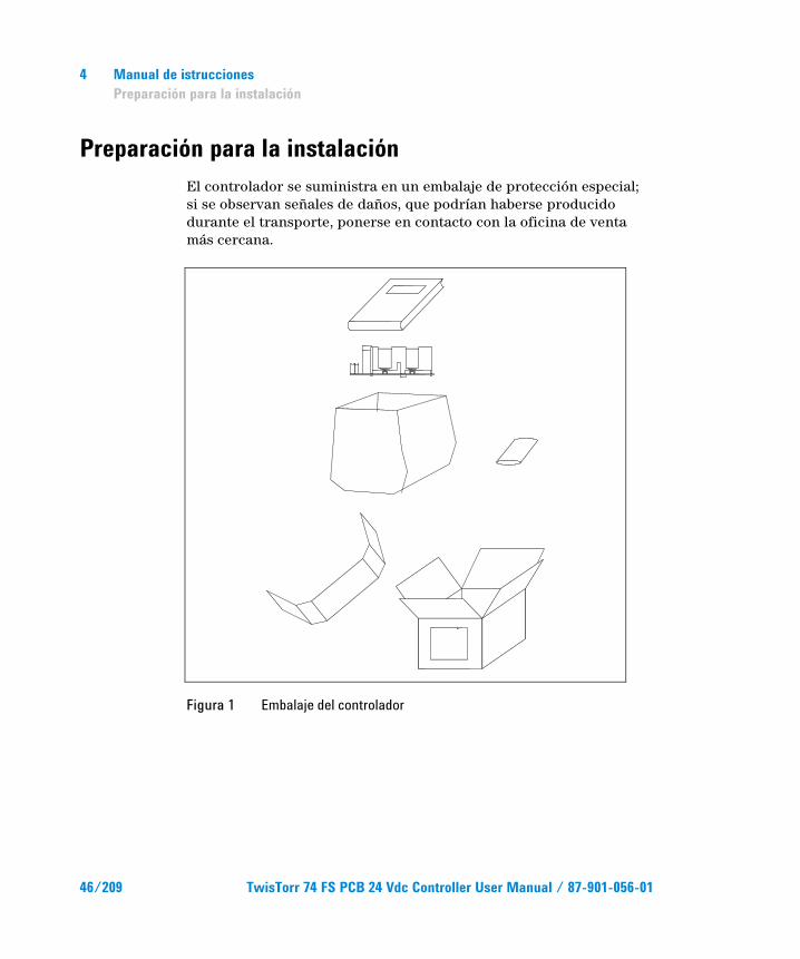
Preparación para la instalación El controlador se suministra en un embalaje de protección especial; si se observan señales de daños, que podrían haberse producido durante el transporte, ponerse en contacto con la oficina de venta más cercana.
Figura 1 Embalaje del controlador
46/209 TwisTorr 74 FS PCB 24 Vdc Controller User Manual / 87-901-056-01
Manual de istrucciones Preparación para la instalación
4
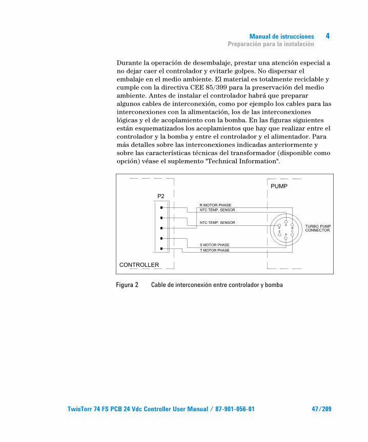
Durante la operación de desembalaje, prestar una atención especial a no dejar caer el controlador y evitarle golpes. No dispersar el embalaje en el medio ambiente. El material es totalmente reciclable y cumple con la directiva CEE 85/399 para la preservación del medio ambiente. Antes de instalar el controlador habrá que preparar algunos cables de interconexión, como por ejemplo los cables para las interconexiones con la alimentación, los de las interconexiones lógicas y el de acoplamiento con la bomba. En las figuras siguientes están esquematizados los acoplamientos que hay que realizar entre el controlador y la bomba y entre el controlador y el alimentador. Para más detalles sobre las interconexiones indicadas anteriormente y sobre las características técnicas del transformador (disponible como opción) véase el suplemento "Technical Information".
Figura 2 Cable de interconexión entre controlador y bomba
TwisTorr 74 FS PCB 24 Vdc Controller User Manual / 87-901-056-01 47/209
4 Manual de istrucciones Instalación
Instalación
¡ADVERTENCIA!
Dentro del controlador se desarrollan tensiones que pueden causar graves daños. Antes de efectuar cualquier operación de instalación o mantenimiento del controlador, desconectarlo de la alimentación. Dentro del controlador se desarrollan altas temperaturas que pueden causar graves daños. Proteger el controlador adecuadamente en su instalación definitiva contra contactos accidentales.
NOTA El controlador instalado en el sistema definitivo ha de colocarse de manera que el aire de refrigeración pueda circular libremente alrededor del aparato. No instalar ni utilizar el controlador en ambientes expuestos a agentes atmosféricos (lluvia, hielo y nieve), polvos, gases agresivos, en ambientes explosivos o con alto riesgo de incendio.
Durante el funcionamiento es necesario que se respeten las siguientes condiciones ambientales:
temperatura: de 0 °C a + 40 °C
humedad relativa: 0 – 95 % (no condensadora).
48/209 TwisTorr 74 FS PCB 24 Vdc Controller User Manual / 87-901-056-01
Manual de istrucciones Uso
4
Uso En este apartado se indican los procedimientos operativos principales. Para más detalles y para procedimientos que impliquen conexiones o elementos opcionales, les remitimos al apartado “USE” del anexo “Technical Information”. Antes de usar el controlador efectuar todas las conexiones eléctricas y neumáticas y consultar el manual de la bomba conectada.
¡ADVERTENCIA!
Antes de arrancar la bomba consulte el correspondiente manual de instrucciones de la misma para operar de forma segura.
Procedimientos de uso
Encendido del controlador Para encender el controlador es suficiente aprovisionar el controlador mismo con tensión de alimentación.
Puesta en marcha de la Bomba Para poner en marcha la bomba dejar abierto el pin 12 del conector J4, de manera que al conectarse al controlador la tensión de 24 Vdc se verifique el arranque de la bomba.
Parada de la Bomba Para detener la bomba es necesario cortocircuitar los pins 12 y 15 del conector J4.
TwisTorr 74 FS PCB 24 Vdc Controller User Manual / 87-901-056-01 49/209
4 Manual de istrucciones Mantenimiento
Mantenimiento Los controladores de la serie TwisTorr 74 FS no necesitan ningún mantenimiento. Toda operación ha de ser efectuada por personal autorizado. En caso de avería es posible utilizar el servicio de reparación Agilent o el “Agilent advance exchange service”, que permite obtener un controlador regenerado en vez del averiado.
¡ADVERTENCIA!
Antes de efectuar cualquier operación en el controlador se debe desenchufar el cable de alimentación.
En caso de que un controlador se tenga que desguazar, efectuar su eliminación respetando las normas nacionales específicas.
50/209 TwisTorr 74 FS PCB 24 Vdc Controller User Manual / 87-901-056-01
Manual de istrucciones Eliminación
4
Eliminación Significado del logotipo "WEEE" presente en las etiquetas. El símbolo que se indica a continuación, es aplicado en observancia de la directiva CE denominada "WEEE". Este símbolo (válido sólo para los países miembros de la Comunidad Europea) indica que el producto sobre el cual ha sido aplicado, NO debe ser eliminado junto con los residuos comunes sean éstos domésticos o industriales, y que, por el contrario, deberá ser sometido a un procedimiento de recogida diferenciada. Por lo tanto, se invita al usuario final, a ponerse en contacto con el proveedor del dispositivo, tanto si éste es la casa fabricante o un distribuidor, para poder proveer a la recogida y eliminación del producto, después de haber efectuado una verificación de los términos y condiciones contractuales de venta.
Para obtener más información, consulte: http://www.agilent.com/environment/product/index.shtml
TwisTorr 74 FS PCB 24 Vdc Controller User Manual / 87-901-056-01 51/209

4 Manual de istrucciones Eliminación
52/209 TwisTorr 74 FS PCB 24 Vdc Controller User Manual / 87-901-056-01
TwisTorr 74 FS PCB 24 Vdc Controller User Manual
5Manual de Istruções Informações gerais 54 Armazenagem 55 Preparação para a instalação 56 Instalação 58 Utilização 59 Procedimentos de uso 59
Acendimento do Controller 59 Activação da bomba 59 Paragem da bomba 59
Manutenção 60 Eliminação 61
Tradução das instruções originais
53/209
5 Manual de Istruções Informações gerais
Informações gerais Esta aparelhagem destinase ao uso profissional. O utilizador deve ler atentamente o presente manual de instruções e todas as informações adicionais fornecidas pela Agilent antes de utilizar a aparelhagem. A Agilent não se responsabiliza pela inobservância total ou parcial das instruções, pelo uso indevido por parte de pessoas não treinadas, por operações não autorizadas ou pelo uso contrário às normas nacionais específicas. O controller TwisTorr 74 FS PCB é um conversor de frequência, controlado por um microprocessador, realizado com componentes em estado sólido e com capacidade de autodiagnóstico e autoprotecção. Incorpora todos os circuitos necessários para o funcionamento automático das bombas da série TwisTorr 74 FS. O controller comanda as bombas da série TwisTorr 74 FS (com um processo subdividido em dez passos) durante a fase de activação, controlando a tensão e a corrente em relação à velocidade atingida pela bomba. Através de conectores auxiliares, estão disponíveis os comandos para a activação e a paragem da bomba por controlo remoto, os sinais que indicam o estado operativo da bomba, os sinais de bloqueio (para interruptores de pressão, interruptores de controlo do fluxo de água, etc.). O controller deve ser alimentado por tensão contínua de 24 Vdc.
Nos parágrafos seguintes estão descritas todas as informações necessárias para garantir a segurança do operador durante o uso da aparelhagem. Informações pormenorizadas são fornecidas no apêndice "Technical Information".
54/209 TwisTorr 74 FS PCB 24 Vdc Controller User Manual / 87-901-056-01
Manual de Istruções Armazenagem
5
Este manual utiliza as seguintes convenções:
CUIDADO! As mensagens de cuidado são visualizadas antes de procedimentos que, se não observados, podem causar danos à aparelhagem.
ATENÇAO!
As mensagens de atenção chamam a atenção do operador para um procedimento ou uma prática específica que, se não efectuada correctamente, pode provocar graves lesões pessoais.
NOTA As notas contêm informações importantes destacadas do texto.
Armazenagem Durante o transporte e a armazenagem do controller, devem ser satisfeitas as seguintes condições ambientais:
temperatura: de -20 °C a + 70 °C
humidade relativa: 0 – 95 % (não condensadora)
TwisTorr 74 FS PCB 24 Vdc Controller User Manual / 87-901-056-01 55/209
5 Manual de Istruções Preparação para a instalação
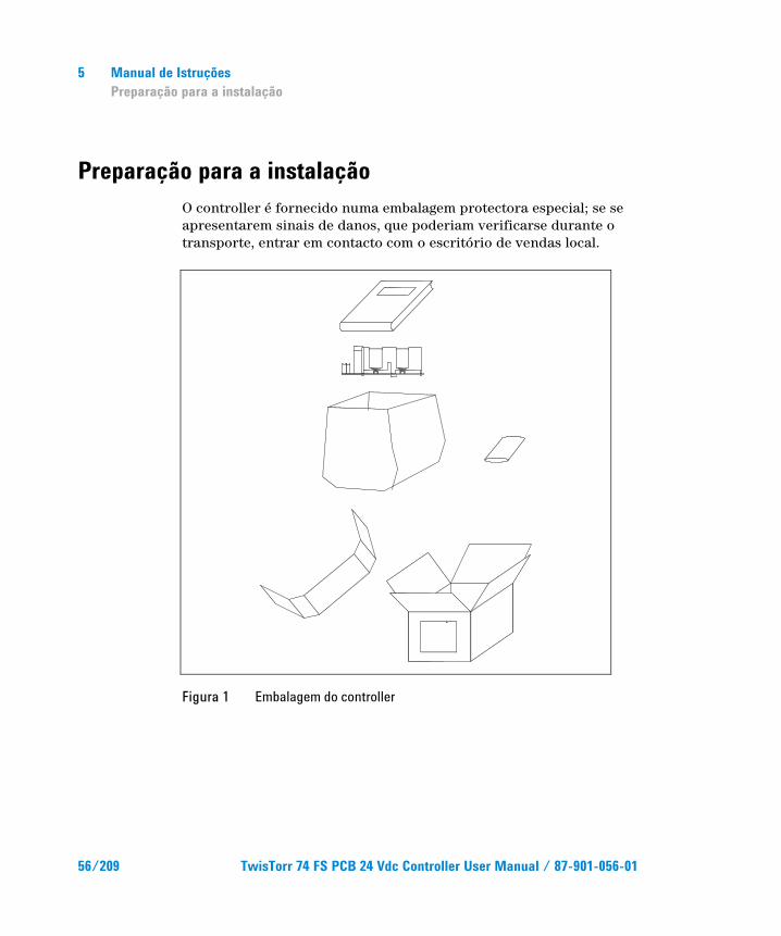
Preparação para a instalação O controller é fornecido numa embalagem protectora especial; se se apresentarem sinais de danos, que poderiam verificarse durante o transporte, entrar em contacto com o escritório de vendas local.
Figura 1 Embalagem do controller
56/209 TwisTorr 74 FS PCB 24 Vdc Controller User Manual / 87-901-056-01
Manual de Istruções Preparação para a instalação
5
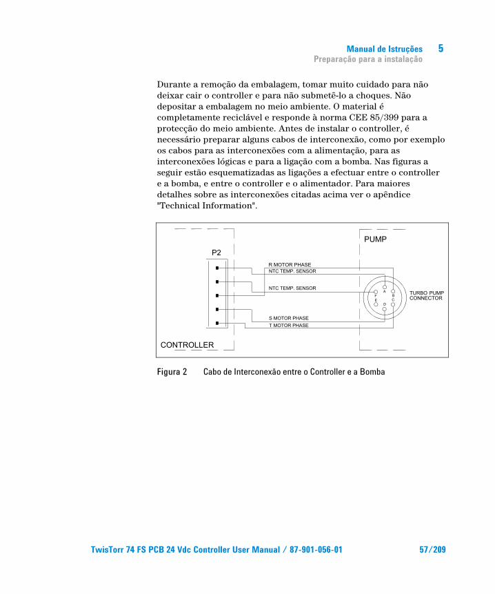
Durante a remoção da embalagem, tomar muito cuidado para não deixar cair o controller e para não submetê-lo a choques. Não depositar a embalagem no meio ambiente. O material é completamente reciclável e responde à norma CEE 85/399 para a protecção do meio ambiente. Antes de instalar o controller, é necessário preparar alguns cabos de interconexão, como por exemplo os cabos para as interconexões com a alimentação, para as interconexões lógicas e para a ligação com a bomba. Nas figuras a seguir estão esquematizadas as ligações a efectuar entre o controller e a bomba, e entre o controller e o alimentador. Para maiores detalhes sobre as interconexões citadas acima ver o apêndice "Technical Information".
Figura 2 Cabo de Interconexão entre o Controller e a Bomba
TwisTorr 74 FS PCB 24 Vdc Controller User Manual / 87-901-056-01 57/209
5 Manual de Istruções Instalação
Instalação
ATENÇAO!
No interior do controller desenvolvem-se altas tensões que podem provocar graves danos ou a morte. Antes de efectuar qualquer operação de instalação ou manutenção do controller, desligar a tomada de alimentação. No interior do controller desenvolvem-se temperaturas elevadas que podem provocar graves danos. Proteger adequadamente o controller contra contactos acidentais durante a sua instalação definitiva.
NOTA O controller instalado no sistema definitivo deve ser posicionado de modo que o ar de refrigeração possa circular livremente ao redor da aparelhagem. Não instalar e/ou utilizar o controller em ambientes expostos a agentes atmosféricos (chuva, gelo, neve), poeiras, gases agressivos ou em ambientes explosivos ou com elevado risco de incêndio.
Durante o funcionamento é necessário que sejam respeitadas as seguintes condições ambientais:
temperatura: de 0 °C a + 40 °C
humidade relativa: 0 – 95 % (não condensadora)
58/209 TwisTorr 74 FS PCB 24 Vdc Controller User Manual / 87-901-056-01
Manual de Istruções Utilização
5
Utilização Neste parágrafo são descritos os principais procedimentos operativos. Para maiores detalhes e para procedimentos que envolvam ligações ou peças opcionais, consultar o parágrafo "USE" do apêndice "Technical Information". Antes de usar o controller, efectuar todas as ligações eléctricas e pneumáticas e consultar o manual da bomba ligada.
ATENÇAO!
Consulte o respectivo manual da bomba para operá-la de forma segura antes de começar.
Procedimentos de uso
Acendimento do Controller Para ligar o controller é suficiente fornecer a tensão de alimentação ao controller.
Activação da bomba Para activar a bomba é necessário deixar o pin 12 do conector J4 aberto. Deste modo , quando o controller for alimentado com uma tensão de 24 Vdc, a bomba activa-se.
Paragem da bomba Para parar a bomba é necessário pôr os pins 12 e 15 do conector J4 em curto-circuito.
TwisTorr 74 FS PCB 24 Vdc Controller User Manual / 87-901-056-01 59/209
5 Manual de Istruções Manutenção
Manutenção O controller da série TwisTorr 74 FS não requer qualquer manutenção. Todas as operações devem ser efectuadas por pessoal autorizado. Em caso de defeito é possível utilizar o serviço de reparação Agilent ou o "Agilent advance exchange service", que permite obter um controller regenerado que substitua o controller com defeito.
ATENÇAO!
Antes de efectuar qualquer operação no controller, desligar o cabo de alimentação.
Caso um controller deva ser destruído, proceder à sua eliminação respeitando as normas nacionais específicas.
60/209 TwisTorr 74 FS PCB 24 Vdc Controller User Manual / 87-901-056-01
Manual de Istruções Eliminação
5
Eliminação Significado do logótipo "WEEE" presente nos rótulos. O símbolo abaixo indicado é aplicado de acordo com a directiva CE denominada "WEEE". Este símbolo (válido apenas para os países da Comunidade Europeia) indica que o produto no qual está aplicado NÃO deve ser eliminado juntamente com os resíduos domésticos ou industriais comuns, mas deve ser dirigido a um sistema de recolha diferenciada. Portanto, convidamos o utilizador final a contactar o fornecedor do dispositivo, seja este o fabricante ou um revendedor, para encaminhar o processo de recolha e eliminação, após a oportuna verificação dos termos e condições do contrato de venda.
Para mais informações consulte: http://www.agilent.com/environment/product/index.shtml
TwisTorr 74 FS PCB 24 Vdc Controller User Manual / 87-901-056-01 61/209

5 Manual de Istruções Eliminação
62/209 TwisTorr 74 FS PCB 24 Vdc Controller User Manual / 87-901-056-01
TwisTorr 74 FS PCB 24 Vdc Controller User Manual
6Bedrijfshandleiding Algemene informatie 64 Opslag 65 Voorbereiding voor installatie 66 Installatie 68 Gebruik 69 Gebruiksprocedures 69
Inschakelen van de controller 69 Starten van de pomp 69 Stoppen van de pomp 69
Onderhoud 70 Afvalverwerking 71
Vertaling van de originele instructies
63/209
6 Bedrijfshandleiding Algemene informatie
Algemene informatie Deze apparatuur is bestemd voor beroepsmatig gebruik. De gebruiker wordt verzocht aandachtig deze handleiding en alle overige door Agilent verstrekte informatie door te lezen alvorens het apparaat in gebruik te nemen. Agilent acht zich niet aansprakelijk voor de gevolgen van het niet of gedeeltelijk in acht nemen van de aanwijzingen, onoordeelkundig gebruik door niet hiervoor opgeleid personeel, reparaties waarvoor geen toestemming is verkregen of gebruik in strijd met de specifieke nationale wetgeving. De controller TwisTorr 74 FS PCB is een frequentieomzetter die gestuurd wordt door een microprocessor, is gemaakt van halfgeleiderelementen en is in staat om zelfdiagnose en zelfbescherming uit te voeren. De controller is van circuits voorzien die noodzakelijk zijn voor de automatische werking van de pompen van de serie TwisTorr 74 FS. De controller stuurt de pompen van de serie TwisTorr 74 FS (met een proces bestaande uit tien stappen) tijdens de startfase, en controleert hierbij de spanning en de stroom in verhouding tot de door de pomp bereikte snelheid. Via hulpconnectors zijn de sturingen voor het op afstand starten en stoppen van de pomp beschikbaar, de signalen die de bedrijfstoestand van de pomp aangeven, blokkeersignalen (voor drukschakelaars, regelschakelaars van de waterstroom, enz.). De controller moet met een gelijkspanning van 24 Vdc worden gevoed.
In de volgende paragrafen is alle informatie vermeld om de veiligheid van de operator tijdens het gebruik van de apparatuur te verzekeren. Gedetailleerde informatie is te vinden in de bijlage "Technical information".
64/209 TwisTorr 74 FS PCB 24 Vdc Controller User Manual / 87-901-056-01
Bedrijfshandleiding Opslag
6
Deze handleiding hanteert de volgende symbolen:
VOORZICHTIG! Bij dit symbool staat tekst met procedures die, indien niet opgevolgd, schade aan apparatuur kunnen veroorzaken.
WAARSCHUWING! Bij dit symbool staat tekst die de aandacht van de operator vestigt op een speciale procedure of methode die, indien niet correct uitgevoerd, ernstig lichamelijk letsel kan veroorzaken.
OPMERKING De opmerkingen bevatten belangrijke informatie die uit de tekst is gelicht.
Opslag Tijdens het transport en de opslag van de controllers moeten de volgende omgevingscondities aanwezig zijn:
temperatuur: van -20 °C tot +70 °C
relatieve vochtigheid: 0 – 95 % (niet condenserend)
TwisTorr 74 FS PCB 24 Vdc Controller User Manual / 87-901-056-01 65/209
6 Bedrijfshandleiding Voorbereiding voor installatie
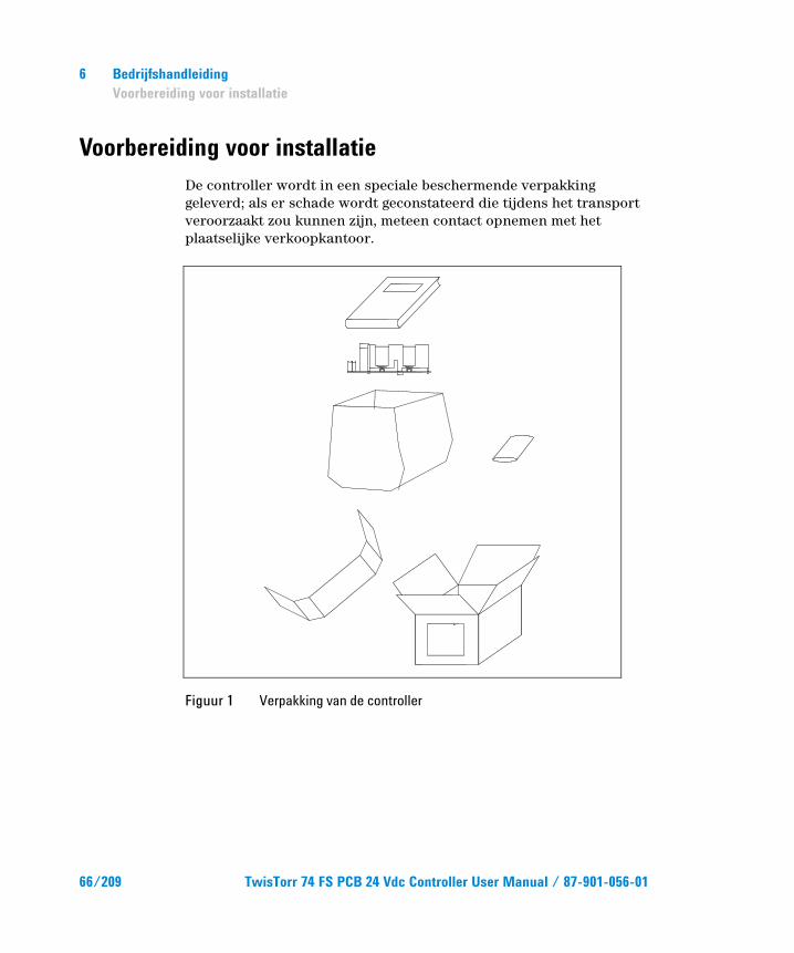
Voorbereiding voor installatie De controller wordt in een speciale beschermende verpakking geleverd; als er schade wordt geconstateerd die tijdens het transport veroorzaakt zou kunnen zijn, meteen contact opnemen met het plaatselijke verkoopkantoor.
Figuur 1 Verpakking van de controller
66/209 TwisTorr 74 FS PCB 24 Vdc Controller User Manual / 87-901-056-01
Bedrijfshandleiding Voorbereiding voor installatie
6
Zorg er bij het uitpakken voor dat de controller niet kan vallen of stoten te verduren krijgt. Laat de verpakking niet ergens buiten achter. Het verpakkingsmateriaal is volledig recyclebaar en voldoet aan de EEG milieurichtlijn 85/399.
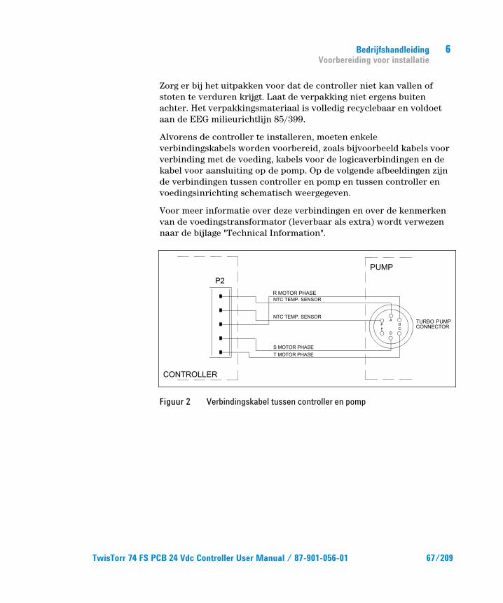
Alvorens de controller te installeren, moeten enkele verbindingskabels worden voorbereid, zoals bijvoorbeeld kabels voor verbinding met de voeding, kabels voor de logicaverbindingen en de kabel voor aansluiting op de pomp. Op de volgende afbeeldingen zijn de verbindingen tussen controller en pomp en tussen controller en voedingsinrichting schematisch weergegeven.
Voor meer informatie over deze verbindingen en over de kenmerken van de voedingstransformator (leverbaar als extra) wordt verwezen naar de bijlage "Technical Information".
Figuur 2 Verbindingskabel tussen controller en pomp
TwisTorr 74 FS PCB 24 Vdc Controller User Manual / 87-901-056-01 67/209
6 Bedrijfshandleiding Installatie
Installatie
WAARSCHUWING!
In de controller ontwikkelen zich hoge spanningen die ernstige schade kunnen veroorzaken. Alvorens installatie- of onderhoudswerkzaamheden uit te voeren, de controller van de voeding afkoppelen. In de controller ontwikkelen zich hoge temperaturen die zware schade kunnen veroorzaken. Bij de definitieve installatie van de controller, deze op passende wijze tegen eventueel contact beschermen.
OPMERKING De controller die definitief in het systeem geïnstalleerd wordt moet zodanig geplaatst worden dat de koellucht vrij rondom het apparaat kan circuleren. De controller mag niet geïnstalleerd en/of gebruikt worden in ruimten die blootgesteld zijn aan de weersomstandigheden (regen, vorst, sneeuw), stof, agressieve gassen, of in ruimten met explosiegevaar of zeer hoog brandgevaar.
Tijdens de werking moeten de volgende omgevings- condities aanwezig zijn:
temperatuur: van 0 °C tot +40 °C
relatieve vochtigheid: 0 – 95 % (niet condenserend).
68/209 TwisTorr 74 FS PCB 24 Vdc Controller User Manual / 87-901-056-01
Bedrijfshandleiding Gebruik
6
Gebruik In deze paragraaf worden de voornaamste bedieningswijzen uitgelegd. Voor meer informatie of procedures die aansluitingen of speciale opties betreffen wordt verwezen naar de paragraaf "USE" van de bijlage "Technical Information". Breng, alvorens de controller in gebruik te nemen, alle elektrische en pneumatische aansluitingen tot stand en raadpleeg hiervoor de handleiding van de aan te sluiten pomp.
WAARSCHUWING!
Raadpleeg de betreffende handleiding van de pomp, voor een veilige bediening, voorafgaand aan het starten.
Gebruiksprocedures
Inschakelen van de controller Om de controller in te schakelen, de voedingskabel in de netcontactdoos inbrengen.
Starten van de pomp Voor het starten van de pomp moet pin 12 van connector J4 open gelaten worden, zodat de pomp start wanneer 24 Vdc spanning aan de controller wordt geleverd.
Stoppen van de pomp Voor het stoppen van de pomp moeten de pins 12 en 15 van connector J4 kortgesloten worden.
TwisTorr 74 FS PCB 24 Vdc Controller User Manual / 87-901-056-01 69/209
6 Bedrijfshandleiding Onderhoud
Onderhoud De controllers van de serie TwisTorr 74 FS zijn onderhoudsvrij. Eventuele werkzaamheden moeten door bevoegd personeel worden uitgevoerd. In geval van storing is het mogelijk om de reparatiedienst van Agilent of de "Agilent advanced exchange service" in te schakelen: zo krijgt men een ruilcontroller ter vervanging van de defecte controller.
WAARSCHUWING!
Alvorens werkzaamheden aan de controller uit te voeren, de voedingskabel afkoppelen.
Mocht de controller gesloopt worden, ga dan overeenkomstig de specifieke nationale wetgeving te werk.
70/209 TwisTorr 74 FS PCB 24 Vdc Controller User Manual / 87-901-056-01
Bedrijfshandleiding Afvalverwerking
6
Afvalverwerking Betekenis van het logo "WEEE" op de etiketten. Het onderstaande symbool wordt aangebracht in overeenstemming met de EG-richtlijn "WEEE". Dit symbool (alleen geldig voor de landen van de Europese Gemeenschap) geeft aan dat het product waarop het is aangebracht, NIET mag worden afgevoerd samen met mormaal huisvuil of industrieel afval, maar gescheiden moet worden ingezameld. De eindgebruiker wordt dus verzocht contact op te nemen met de leverancier van het apparaat, zij het de fabrikant of een wederverkoper, om het proces van gescheiden inzameling en verwerking in gang te zetten, na de van toepassing zijnde termen en voorwaarden van het verkoopcontract te hebben gecontroleerd.
Voor meer informatie wordt verwezen naar: http://www.agilent.com/environment/product/index.shtml
TwisTorr 74 FS PCB 24 Vdc Controller User Manual / 87-901-056-01 71/209

6 Bedrijfshandleiding Afvalverwerking
72/209 TwisTorr 74 FS PCB 24 Vdc Controller User Manual / 87-901-056-01
TwisTorr 74 FS PCB 24 Vdc Controller User Manual
7Istruktionsbog Generel Information 74 Opbevaring 75 Forberedelser før installation 76 Installation 78 Anvendelse 79 Instruktion 79
Start af styreenheden 79 Start af pumpen 79 Stop af pumpen 79
Vedligeholdelse 80 Bortskaffelse 81
Oversættelse af originalinstruktionerne
73/209
7 Istruktionsbog Generel Information
Generel Information Dette materiel er beregnet til professionel anvendelse. Brugeren bør læse denne brugsanvisning og anden yderligere information fra Agilent, før udstyret anvendes. Agilent tager ikke ansvar for skader helt eller delvis som følge af tilsidesættelse af disse instruktioner, fejlagtig brug af personer uden tilstrækkelig kendskab, ukorrekt anvendelse af udstyret eller håndtering, der strider imod gældende lokale regler. Styreenheden i TwisTorr 74 FS PCB-serien er en mikroprocessorstyret frekvens-omformer, der består af komponenter med fast tilstand. Styreenheden er udstyret med selvdiagnose og selvbeskyttelsesfunktioner. Styreenheden omfatter alle midler, der kræves for automatisk drift af pumperne i TwisTorr 74 FS serien. Styreenheden kontrollerer pumperne i TwisTorr 74 FS serien (med en ti-trins-proces) i forbindelse med start. Spænding og strøm reguleres i forhold til pumpens opnåede hastighed. Hjælpekontakter forsyner kontrol til fjernstart og -stop af pumpen, signaler om pumpens tilstand, blokeringssignaler (til tryk- og vandføringsafbrydere, osv.). Styreenheden skal forsynes med jævnspænding på 24 Vdc.
De følgende afsnit indeholder al information der behøves, for at garantere operatørens sikkerhed under anvendelsen. Detaljeret information findes i bilaget "Technical Information".
74/209 TwisTorr 74 FS PCB 24 Vdc Controller User Manual / 87-901-056-01

Istruktionsbog Opbevaring
7
I brugsanvisningen anvendes følgende standard-rubrikker:
FORSIGTIG! Denne advarselsmeddelelse vises før procedurer, der skal følges nøje for ikke at risikere maskinskader.
ADVARSEL! Advarselsmeddelelserne informerer operatøren om, at en speciel procedure eller en vis type arbejde skal udføres præcist efter anvisningerne. I modsat fald er der risiko for svære personskader.
BEMÆRK Dette gør opmærksom på vigtig information i teksten.
Opbevaring Følgende krav til omgivelsesforholdene gælder ved transport og opbevaring af styreenheden:
temperatur: fra -20 °C til +70 °C
relativ luftfugtighed: 0 – 95 % (ikke kondenserende)
TwisTorr 74 FS PCB 24 Vdc Controller User Manual / 87-901-056-01 75/209

7 Istruktionsbog Forberedelser før installation
Forberedelser før installation Styreenheden leveres i en speciel beskyttende emballage. Kontakt den lokale forhandler, hvis emballagen viser tegn på skader, der kan være opstået under transporten.
Figur 1 Styreenhedens emballage
76/209 TwisTorr 74 FS PCB 24 Vdc Controller User Manual / 87-901-056-01
Istruktionsbog Forberedelser før installation
7
Sørg for at styreenheden ikke tabes eller udsættes for stød ved udpakningen.
Smid ikke emballagen ud. Materialet kan genbruges 100 % og opfylder EU-direktiv 85/399 om miljøbeskyttelse.
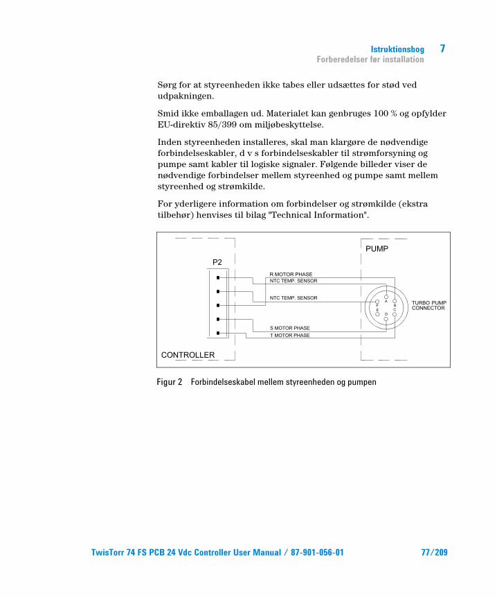
Inden styreenheden installeres, skal man klargøre de nødvendige forbindelseskabler, d v s forbindelseskabler til strømforsyning og pumpe samt kabler til logiske signaler. Følgende billeder viser de nødvendige forbindelser mellem styreenhed og pumpe samt mellem styreenhed og strømkilde.
For yderligere information om forbindelser og strømkilde (ekstra tilbehør) henvises til bilag "Technical Information".
Figur 2 Forbindelseskabel mellem styreenheden og pumpen
TwisTorr 74 FS PCB 24 Vdc Controller User Manual / 87-901-056-01 77/209
7 Istruktionsbog Installation
Installation
ADVARSEL!
Spændinger frembragt i styreenheden kan nå høje værdier og forårsage stor skade. Frakobl altid strømkablet, inden der udføres installations- eller vedligeholdelsesarbejde på styreenheden. Temperaturen frembragt i styreenheden kan nå høje værdier og forårsage stor skade. I forbindelse med permanent installation skal styreenheden og transformatoren på egnet måde beskyttes mod utilsigtet tilslutning.
BEMÆRK Styreenheden skal anbringes på en sådan måde, at luft kan cirkulere frit omkring apparatet. Installér og anvend ikke styreenheden i miljøer, der udsættes for påvirkninger fra atmosfæren (regn, sne, is), damp, aggressive gasser, og ligeledes ikke i eksplosivt eller brandfarligt miljø.
Følgende krav til omgivelsesforholdene gælder ved drift:
temperatur: fra 0 °C til +40 °C
relativ luftfugtighed: 0 – 95 % (ikke kondenserende)
78/209 TwisTorr 74 FS PCB 24 Vdc Controller User Manual / 87-901-056-01
Istruktionsbog Anvendelse
7
Anvendelse Dette afsnit beskriver de vigtigste driftsprocedurer. For en detaljeret beskrivelse samt procedurer, der involverer tilslutninger eller tilbehør, henvises til afsnittet "USE" i bilag "Technical Information". Inden styreenheden anvendes, bør samtlige elektriske og pneumatiske tilslutninger udføres. Læs brugsanvisningen før pumpen tilsluttes.
ADVARSEL!
For at operere den sikkert, henvises der til den relevantepumpemanualfør start.
Instruktion
Start af styreenheden Styreenheden startes ved at sætte strømkablet i vægudtaget.
Start af pumpen Pumpen startes ved at lade stiften 12 på konnektoren J4 være åben, således at pumpen startes, når kontrolenheden forsynes med spænding på 24 Vdc.
Stop af pumpen Pumpen stopper ved at kortslutte stift 12 og stift 15 på konnektoren J4.
TwisTorr 74 FS PCB 24 Vdc Controller User Manual / 87-901-056-01 79/209
7 Istruktionsbog Vedligeholdelse
Vedligeholdelse Styreenhederne i TwisTorr 74 FS-serien behøver ikke nogen vedligeholdelse. Ethvert indgreb på pumpen skal foretages af autoriseret personale. Hvis pumpen går i stykker, kan man benytte sig af Agilents reparations-service eller Agilent udvekslingsservice, hvor man kan få en repareret pumpe i bytte for den, der er gået i stykker.
ADVARSEL!
Inden der foretages noget som helst indgreb på styreenheden, skal strømmen først afbrydes.
Skrotning af pumpen skal foregå i overensstemmelse med det pågældende lands særlige love.
80/209 TwisTorr 74 FS PCB 24 Vdc Controller User Manual / 87-901-056-01
Istruktionsbog Bortskaffelse
7
Bortskaffelse Betydningen af "WEEE" logoet på mærkaterne. Nedenstående symbol anvendes i overensstemmelse med det såkaldte EU-direktiv "WEEE". Symbolet (kun gældende for EU-landene) viser, at produktet, som det sidder på IKKE må bortskaffes sammen med affald fra private husholdninger eller industriel affald men skal indleveres på en godkendt affaldsstation. Vi opfordrer derfor slutbrugeren til at kontakte leverandøren af anordningen, enten fabrikken eller en forhandler, for igangsættelse af afhentnings- og bortskaffelsesprocessen efter nøje at have kontrolleret betingelserne i salgskontrakten.
For yderligere oplysninger henvises til: http://www.agilent.com/environment/product/index.shtml
TwisTorr 74 FS PCB 24 Vdc Controller User Manual / 87-901-056-01 81/209

7 Istruktionsbog Bortskaffelse
82/209 TwisTorr 74 FS PCB 24 Vdc Controller User Manual / 87-901-056-01
TwisTorr 74 FS PCB 24 Vdc Controller User Manual
8Bruksanvisning Allmän information 84 Förvaring 85 Förberedelser för Installation 86 Installation 88 Användning 89 Instruktioner för bruk 89
Start av styrenheten 89 Start av pumpen 89 Stopp av pumpen 89
Underhåll 90 Bortskaffning 91
Översättning av originalinstruktionerna
83/209
8 Bruksanvisning Allmän information
Allmän information Utrustningen är avsedd för yrkesmässig användning. Användaren bör läsa denna bruksanvisning, samt övrig dokumentation från Agilent före användning av utrustningen. Agilent tar inget ansvar för skador som helt eller delvis orsakats av åsidosättande av instruktionerna, olämplig användning av person utan tillräcklig kunskap, obehörigt bruk av utrustningen eller hantering som strider mot gällande lokala föreskrifter.
Styrenheten i TwisTorr 74 FS PCB-serien är en mikro-processorstyrd frekvensomvandlare som består av komponenter med fast tillstånd. Styrenheten är försedda med självdiagnos- och självskyddsfunktion. Styrenheten omfattar alla kretsar som behövs för automatisk drift av pumparna i TwisTorr 74 FS serien.
Styrenheten kontrollerar pumparna i TwisTorr 74 FS-serien (med en tiostegs-process) i samband med start. Spänning och ström regleras i förhållande till pumpens uppnådda hastighet. Hjälpkontakter erbjuder kontroller för fjärrstart och fjärrstopp av pumpen, signaler för pumpens tillstånd, blockeringssignaler (för tryckvakter, kontrollbrytare för vattenflöde osv). Styrenheten ska förses med likspänning på 24 Vdc.
De följande avsnitten innehåller all information som behövs för att garantera operatörens säkerhet under driften. Detaljerade uppgifter finns i bilagan "Technical information".
84/209 TwisTorr 74 FS PCB 24 Vdc Controller User Manual / 87-901-056-01
Bruksanvisning Förvaring
8
I bruksanvisningen används följande standard-rubriker:
OBSERVER! Detta varningsmeddelande visas framför procedurer som måste följas exakt för att undvika skador på maskinen.
VARNING! Varningsmeddelandena informerar operatören om att en speciell procedur eller en viss typ av arbete måste utföras exakt enligt anvisningarna. I annat fall finns risk för svåra personskador.
OBSERVERA Detta visar på viktig information i texten.
Förvaring Följande krav på omgivningsförhållanden gäller vid transport och förvaring av styrenheten:
temperatur: från -20 °C till +70 °C
relativ luftfuktighet: 0 – 95 % (utan kondens)
TwisTorr 74 FS PCB 24 Vdc Controller User Manual / 87-901-056-01 85/209

8 Bruksanvisning Förberedelser för Installation
Förberedelser för Installation Styrenheten levereras i ett särskilt skyddande emballage. Kontakta det lokala försäljningskontoret om emballaget visar tecken på skador som kan ha uppstått under transporten. Se till att styrenheten inte tappas eller utsätts för stötar vid uppackningen.
Figur 1 Styrenhetensförpackning
86/209 TwisTorr 74 FS PCB 24 Vdc Controller User Manual / 87-901-056-01
Bruksanvisning Förberedelser för Installation
8
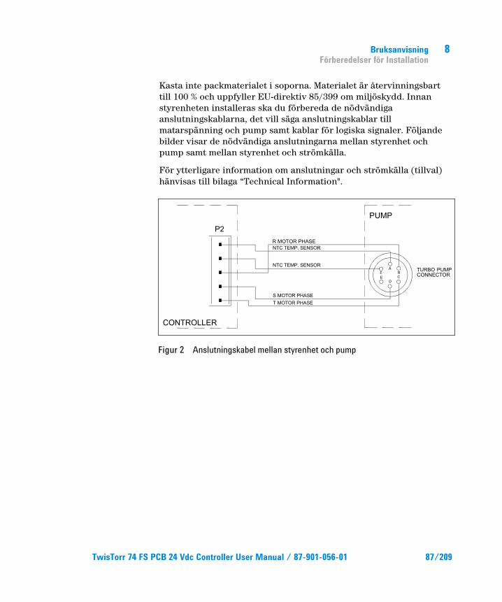
Kasta inte packmaterialet i soporna. Materialet är återvinningsbart till 100 % och uppfyller EU-direktiv 85/399 om miljöskydd. Innan styrenheten installeras ska du förbereda de nödvändiga anslutningskablarna, det vill säga anslutningskablar till matarspänning och pump samt kablar för logiska signaler. Följande bilder visar de nödvändiga anslutningarna mellan styrenhet och pump samt mellan styrenhet och strömkälla.
För ytterligare information om anslutningar och strömkälla (tillval) hänvisas till bilaga “Technical Information".
Figur 2 Anslutningskabel mellan styrenhet och pump
TwisTorr 74 FS PCB 24 Vdc Controller User Manual / 87-901-056-01 87/209
8 Bruksanvisning Installation
Installation
VARNING!
Spänningen inuti styrenheten kan nå höga värden och förorsaka allvarliga skador. Frånkoppla alltid strömkabeln innan något installations- eller underhålls-moment utförs på styrenheten. Temperaturen inuti styrenheten kan nå höga värden och förorsaka allvarliga skador. I samband med permanent installation ska styrenhet och transformator lämpligen skyddas mot oavsiktlig kontakt.
OBSERVERA Styrenheten ska installeras permanent på ett sådant ställe, att kylluften kan cirkulera fritt kring apparaten. Installera och använd inte styrenheten i miljöer som utsätts för påverkan från atmosfären (regn, snö, is), damm, aggressiva gaser, och inte heller i explosiv eller brandfarlig miljö.
Följande krav på omgivningsförhållanden gäller vid drift:
temperatur: från 0 °C till +40 °C
relativ luftfuktighet: 0 – 95 % (utan kondens)
88/209 TwisTorr 74 FS PCB 24 Vdc Controller User Manual / 87-901-056-01
Bruksanvisning Användning
8
Användning Detta avsnitt beskriver de viktigaste driftmomenten. För en detaljerad beskrivning samt beträffande moment som involverar anslutningar eller tillbehör hänvisas till avsnittet "USE" i bilaga "Technical Information". Innan styrenheten används bör samtliga elektriska och pneumatiska anslutningar utföras. Läs bruksanvisningen för den anslutna pumpen.
VARNING!
Referera till den relevanta pumpmanualen innan start för att använda den på ett säkert sätt.
Instruktioner för bruk
Start av styrenheten Styrenheten startas enkelt genom att strömkabeln sätts i vägguttaget.
Start av pumpen Pumpen startas genom att stift 12 öppnas på kontakt J4 så att pumpen startar när spänningen 24 Vdc når styrenheten.
Stopp av pumpen Pumpen stoppas genom att stift 12 och 15 kortsluts på kontakt J4.
TwisTorr 74 FS PCB 24 Vdc Controller User Manual / 87-901-056-01 89/209
8 Bruksanvisning Underhåll
Underhåll Styrenheterna i TwisTorr 74 FS-serien är underhållsfria. Allt servicearbete måste utföras av auktoriserad personal.
Om styrenheten havererar, kontakta Agilent reparation- sverkstad eller Agilent utbytesservice, som kan ersätta styrenheten med en renoverad styrenhet.
VARNING!
Innan något arbete utförs på styrenheten måste dess strömförsörjning brytas.
Skrotning av pumpen skall ske enligt gällande lagstiftning.
90/209 TwisTorr 74 FS PCB 24 Vdc Controller User Manual / 87-901-056-01
Bruksanvisning Bortskaffning
8
Bortskaffning Betydelse av logotypen "WEEE" på etiketterna. Symbolen som visas nedan har tillämpats i enlighet med CD-direktivet som har betecknats som "WEEE". Den här symbolen (gäller endast i de länder som tillhör den Europeiska Unionen) indikerar att produkten på vilken symbolen har applicerats INTE får skaffas bort tillsammans med vanliga hushålls- eller industriavfall, men att däremot ett differentierat uppsamlingssystem måste upprättas. Vi rekommenderar därför att slutanvändaren tar kontakt med leverantören av anordningen, oberoende om det handlar om moderföretaget eller återförsäljaren, för att kunna starta uppsamlings- och bortskaffningsprocessen, detta efter lämplig kontroll av kontraktsenliga tidsgränser och försäljningsvillkor.
För mer information, se: http://www.agilent.com/environment/product/index.shtml
TwisTorr 74 FS PCB 24 Vdc Controller User Manual / 87-901-056-01 91/209

8 Bruksanvisning Bortskaffning
92/209 TwisTorr 74 FS PCB 24 Vdc Controller User Manual / 87-901-056-01
TwisTorr 74 FS PCB 24 Vdc Controller User Manual
9Instruksjon Manual Generell informasjon 94 Lagring 95 Forberede installasjonen 96 Installasjon 98 Bruk 99 Instruksjoner for bruk 99
Starte styreenheten 99 Starte pumpen 99 Stoppe pumpen 99
Vedlikehold 100 Eliminering 101
Oversetting av den opprinnelige samsvarserklæringen
93/209
9 Instruksjon Manual Generell informasjon
Generell informasjon Dette utstyret er beregnet til bruk av profesjonelle brukere. Brukeren bør lese denne brukerveiledningen og all annen informasjon fra Agilent før utstyret tas i bruk.
Agilent kan ikke holdes ansvarlig for hendelser som skjer på grunn av manglende oppfølging, selv delvis, av disse instruksjonene, feilaktig bruk av utrenet personell, ikke godkjente endringer av utstyret eller handlinger som på noen måte er i strid med nasjonale bestemmelser.
Styreenheten i TwisTorr 74 FS PCB serien er en mikroprosessorstyrt frekvensomvender, som består av komponenter med fast tilstand. Styreenheten har funksjoner for selvdiagnose og selvbeskyttelse.
Styreenheten omfatter alle kretser som er nødvendige for automatisk drift av pumpene i TwisTorr 74 FS serien.
Styreenheten kontrollerer pumpene i TwisTorr 74 FS serien (med en titrinnsprosess) ved oppstart. Spenning og strømstyrke justeres i forhold til pumpens oppnådde hastighet. Hjelpekontakter gir muligheter for fjernstyrt start og stopp av pumpen, signaler for pumpens tilstand, blokkeringssignaler (for trykksensorer, kontrollbrytere for vannstrøm osv). Styreenheten skal forsynes med jevnspenning på 24 VDC.
De følgende avsnittene inneholder all informasjon som er nødvendig for å sikre brukeren når utstyret er i bruk. For mer detaljert bruk vises det til tillegget "Technical Information".
94/209 TwisTorr 74 FS PCB 24 Vdc Controller User Manual / 87-901-056-01
Instruksjon Manual Lagring
9
Denne veiledningen bruker følgende standard- protokoll:
FORSIKTIG! Denne advarselen vises foran fremgangsmåter som, dersom de ikke følges, kan fore til at utstyret skades.
ADVARSEL! Disse meldingene skal tiltrekke seg brukerens oppmerksomhet til en spesiell fremgangsmåte eller praksis som, hvis den ikke følges, kan medføre alvorlige skader.
MERK Merknadene inneholder viktig informasjon som er hentet fra teksten.
Lagring Når styreenhetene transporteres eller lagres, må følgende forhold være oppfylt:
temperatur: fra 20 °C til +70 °C
relativ fuktighet:0 – 95 % (uten kondens)
TwisTorr 74 FS PCB 24 Vdc Controller User Manual / 87-901-056-01 95/209
9 Instruksjon Manual Forberede installasjonen
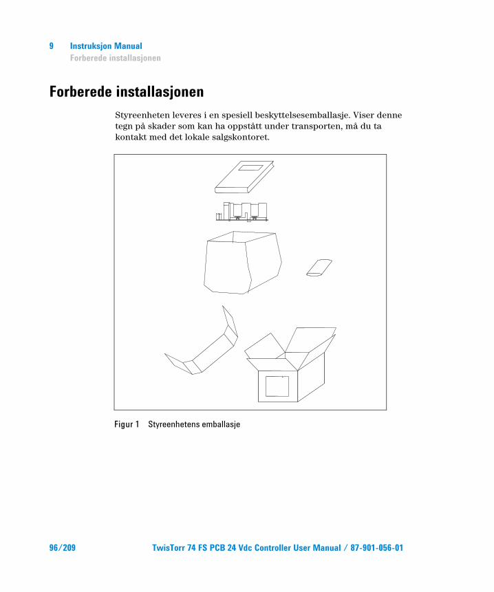
Forberede installasjonen Styreenheten leveres i en spesiell beskyttelsesemballasje. Viser denne tegn på skader som kan ha oppstått under transporten, må du ta kontakt med det lokale salgskontoret.
Figur 1 Styreenhetens emballasje
96/209 TwisTorr 74 FS PCB 24 Vdc Controller User Manual / 87-901-056-01
Instruksjon Manual Forberede installasjonen
9
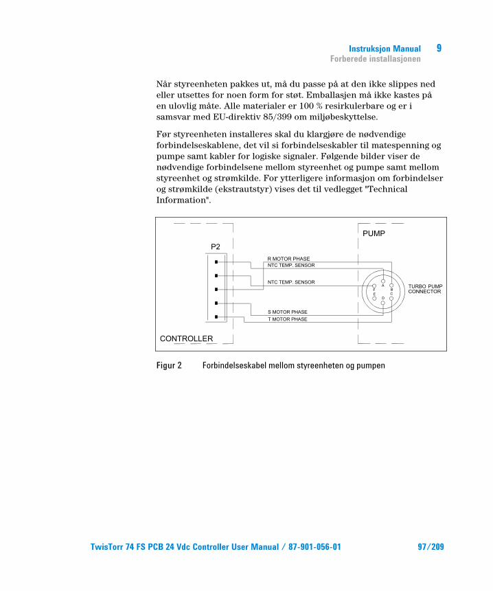
Når styreenheten pakkes ut, må du passe på at den ikke slippes ned eller utsettes for noen form for støt. Emballasjen må ikke kastes på en ulovlig måte. Alle materialer er 100 % resirkulerbare og er i samsvar med EU-direktiv 85/399 om miljøbeskyttelse.
Før styreenheten installeres skal du klargjøre de nødvendige forbindelseskablene, det vil si forbindelseskabler til matespenning og pumpe samt kabler for logiske signaler. Følgende bilder viser de nødvendige forbindelsene mellom styreenhet og pumpe samt mellom styreenhet og strømkilde. For ytterligere informasjon om forbindelser og strømkilde (ekstrautstyr) vises det til vedlegget "Technical Information".
Figur 2 Forbindelseskabel mellom styreenheten og pumpen
TwisTorr 74 FS PCB 24 Vdc Controller User Manual / 87-901-056-01 97/209
9 Instruksjon Manual Installasjon
Installasjon
ADVARSEL!
Spenningen inne i styreenheten kan nå høye verdier og kan føre til alvorlige skader. Kople alltid strømkabelen fra strømnettet før alle installasjons- eller vedlikeholds-arbeider som utføres på styreenheten. Temperaturen inne i styreenheten kan nå høye verdier og kan føre til alvorlige skader. I forbindelse med permanent installasjon skal styreenhet og transformator beskyttes mot utilsiktet kontakt på en passende måte.
MERK Styreenheten skal installeres på slik måte, at kjøleluften kan sirkulere fritt rundt apparatet. Ikke installer eller bruk styreenheten i miljøer som utsettes for regn, snø eller is, støv, aggressive gasser, eksplosjonsfarlige miljøer eller i miljøer med stor brannfare.
Under bruk må følgende forhold respekteres:
temperatur: fra 0 °C til + 40 °C
relativ fuktighet: 0 – 95 % (uten kondens)
98/209 TwisTorr 74 FS PCB 24 Vdc Controller User Manual / 87-901-056-01
Instruksjon Manual Bruk
9
Bruk Dette avsnittet beskriver de viktigste driftsmomentene. For en detaljert beskrivelse samt moment som omfatter tilkoplinger eller ekstrautstyr vises det til avsnittet "Use" i vedlegget "Technical Information". Før styreenheten tas i bruk bør samtlige elektriske og pneumatiske tilkoplinger gjøres. Les brukerveiledningen for pumpen som er tilkoplet.
ADVARSEL!
Se i den relevante pumpehåndboken for sikker bruk før du starter.
Instruksjoner for bruk
Starte styreenheten Styreenheten startes ved å sette strømkabelen i veggkontakten.
Starte pumpen Pumpen startes ved å la stift 12 på konnektoren J4 være åpen, slik at pumpen starter når styreenheten får spenningen på 24 Vdc.
Stoppe pumpen Pumpen stopper når stiftene 12 og 14 på konnektoren J4 kortsluttes.
TwisTorr 74 FS PCB 24 Vdc Controller User Manual / 87-901-056-01 99/209
9 Instruksjon Manual Vedlikehold
Vedlikehold TwisTorr 74 FS seriens styreenheter er vedlikeholdsfrie. Alt arbeid på styreenheten må kun utføres av autorisert personell. Dersom styreenheten stanser, må du ta kontakt med Agilents reparasjonservice eller med Agilents avanserte bytteservice, som kan tilby overhalte styreenheter til erstatning for den ødelagte styreenheten.
ADVARSEL!
Før noe arbeid utføres på styreenheten, må den frakoples strømnettet.
Dersom en styreenhet skal kasseres, må dette skje i henhold til nasjonale bestemmelser.
100/209 TwisTorr 74 FS PCB 24 Vdc Controller User Manual / 87-901-056-01
Instruksjon Manual Eliminering
9
Eliminering Betydelsen av symbolet på logo "WEEE" på etikettene. Symbolet nedenunder som finnes, er anvendt i henhold til EC-direktiv kalt "WEEE". Dette symbolet (som bare gjelder for land i Det europeiske fellesselskap), viser at produktet som det sitter på, IKKE må behandles som vanlig hus-industriavfall, men må legges i kildesortering. Derfor oppfordrer man den sluttelige brukeren av anordningen å henvende seg til leverandøren av anordningen, som kan være et firma eller en forhandler, som sørger for oppsamling og eliminering etter å ha kontrollert avtal og betingelser i kjøpekontrakten.
For mer informasjon se: http://www.agilent.com/environment/product/index.shtml
TwisTorr 74 FS PCB 24 Vdc Controller User Manual / 87-901-056-01 101/209

9 Instruksjon Manual Eliminering
102/209 TwisTorr 74 FS PCB 24 Vdc Controller User Manual / 87-901-056-01
TwisTorr 74 FS PCB 24 Vdc Controller User Manual
10Ohjekäsikirja Yleisiä tietoja 104 Varastointi 105 Valmistelut asennusta varten 106 Asennus 108 Käyttö 109 Käyttötoimenpiteet 109
Valvojan päälle pano 109 Pumpun käynnistys 109 Pumpun pysäyttäminen 109
Huolto 110 Hävittäminen 111
Alkuperäisen ohjeiden käännös
103/209
10 Ohjekäsikirja Yleisiä tietoja
Yleisiä tietoja Tämä laite on tarkoitettu ammattimaiseen käyttöön. Ennen laitteen käyttöönottoa käyttäjän tulee lukea huolellisesti mukana seuraava käyttöohje sekä kaikki muut Agilentin toimittamat lisätiedot. Agilent ei vastaa seurauksista, jotka johtuvat laitteen käyttöohjeiden täydellisestä tai osittaisesta laiminlyömisestä, ammattitaidottomien henkilöiden suorittamasta laitteen virheellisestä käytöstä, valtuuttamattomista toimenpiteistä tai maakohtaisten säädösten ja normien vastaisesta käytöstä. Sarjan TwisTorr 74 FS PCB valvoja on mikroprosessorin valvoma kiinteistä materiaaleista tehtyjä taajuudenmuuntimia, jotka kykenevät itsemäärittelyyn ja itsesuojaukseen. Ne yhdistävät kaikki sähköpiirit, jotka ovat välttämättömiä TwisTorr 74 FS-sarjan pumpun automaattiselle toiminnalle. Valvoja ajaa TwisTorr 74 FS-sarjan pumppuja (kymmenportaisessa järjestelmässä) käynnistysvaiheessa valvoen jännitettä ja sähkövirtaa suhteessa pumpunsaavuttamaan nopeuteen.
Apuliittimiä käyttäen on mahdollista käyttää kauko-ohjattua pumpun käynnistystä ja pysähdystä, signaaleja, jotka ilmaisevat pumpun toimintatilan, pysäytyssignaaleja (painokatkaisimille, veden virtauksen säätelykatkaisijalle jne.). Valvojan syöttöjännitteen tulee olla 24 Vdc.
Seuraavilla sivuilla on luettavissa tarpeelliset tiedot laitteen käyttäjän turvallisuuden takaamiseksi laitteen käytön aikana. Yksityiskohtaiset tiedot löytyvät liitteestä "Technical Information".
104/209 TwisTorr 74 FS PCB 24 Vdc Controller User Manual / 87-901-056-01
Ohjekäsikirja Varastointi
10
Tämä käsikirja käyttää seuraavia merkintöjä:
HUOMIO! Huomio-merkinnät varoittavat toiminnoista, joiden laiminlyönti voi johtaa laitteen vaurioitumiseen.
VAROITUS! Vaara-merkinnät saavat käyttäjän huomion kiinnittymään erityisiin toimintotatapoihin, joiden seuraamatta jättäminen voi aiheuttaa vakavia henkilövaurioita.
HUOM Huomiot sisältävät tärkeätä tekstistä otettua tietoa.
Varastointi Valvojan kuljetuksen ja varastoinnin aikana tulevat seuraavat ympäristövaatimukset olla täytettyinä:
lämpötila: -20 °C ja +70 °C asteen välillä
suhteellinen kosteus: 0 – 95 % (ilman lauhdetta)
TwisTorr 74 FS PCB 24 Vdc Controller User Manual / 87-901-056-01 105/209
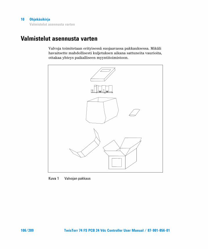
10 Ohjekäsikirja Valmistelut asennusta varten
Valmistelut asennusta varten Valvoja toimitetaan erityisessä suojaavassa pakkauksessa. Mikäli havaitsette mahdollisesti kuljetuksen aikana sattuneita vaurioita, ottakaa yhteys paikalliseen myyntitoimistoon.
Kuva 1 Valvojan pakkaus
106/209 TwisTorr 74 FS PCB 24 Vdc Controller User Manual / 87-901-056-01
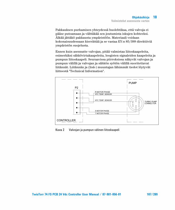
Ohjekäsikirja Valmistelut asennusta varten
10
Pakkauksen purkamisen yhteydessä huolehtikaa, että valvoja ei pääse putoamaan ja välttäkää sen joutumista iskujen kohteeksi. Älkää jättäkö pakkausta ympäristöön. Materiaali voidaan kokonaisuudessaan kierrättää ja se vastaa EY:n 85/399 direktiiviä ympäristön suojelusta.
Ennen kuin asennatte valvojan, pitää valmistaa liitoskaapeleita, esimerkiksi sähkövirtakaapeleita, loogisten signaleiden kaapeleita ja pumpun liitoskaapeli. Seuraavissa piirroksissa näkyvät valvojan ja pumpun välillä ja valvojan ja sähkön syötön välillä suoritettavat liitännät. Liitännän ja (lisä-) muuntajan lähimmät tiedot löytyvät liitteestä "Technical Information".
Kuva 2 Valvojan ja pumpun välinen liitoskaapeli
TwisTorr 74 FS PCB 24 Vdc Controller User Manual / 87-901-056-01 107/209
10 Ohjekäsikirja Asennus
Asennus
VAROITUS!
Valvojan sisällä syntyy korkeajännitettä, joka voi aiheuttaa vakavia vammoja. Ennen minkätahansa valvojan huolto- tai asennustoimenpiteen suorittamista, irroittakaa valvoja sähköverkosta. Valvojan sisällä syntyy ylikuumenemista, joka voi aiheuttaa vakavia vammoja. Suojatkaa valvoja ja muuntaja tahattomalta kosketukselta, kun ne ovat jo asennetut.
HUOM Lopulliseen järjestelmään asennettu valvoja on asetettava siten, että jäähdytysilma pystyy kiertämään vapaasti laitteen sisällä. Älä asenna ja/tai käytä valvojaa ilmaston tekijöille (sade, jää, lumi), pölylle, syövyttäville kaasuille, räjähdyksille tai tulelle alttiissa paikoissa.
Toiminnan aikana tulee noudattaa seuraavia ympäristönoloja koskevia sääntöjä:
lämpötila: 0 °C ja +40 °C välillä
suhteellinen kosteus: 0 – 95 % välillä (ilman lauhdetta)
108/209 TwisTorr 74 FS PCB 24 Vdc Controller User Manual / 87-901-056-01
Ohjekäsikirja Käyttö
10
Käyttö Tähän kappaleeseen on kirjattu tärkeimmät käyttötoimen-piteet. Tarkempia lisätietoja sekä kytkentöjä, että valinnaisia lisälaitteita koskevien toimenpiteiden suorittamista käsittäviä tietoja löydätte kappaleesta "Käyttö", joka on "Technical Information" -kappaleen liitteenä. Ennen valvojan käyttöä suorittaakaa kaikki sähkökytkennät seuraten kytkettävän pumpun käyttöohjeita.
VAROITUS!
Tutustu pumpun käyttöohjeeseen ennen aloittamista pumpun turvalliseksi käyttämiseksi.
Käyttötoimenpiteet
Valvojan päälle pano Valvoja käynnistyy asettamalla virtakaapeli pistorasiaan.
Pumpun käynnistys Jättäkää pumpun käynnistämiseksi liittimen J4 pistike 12 auki siten, että pumppu käynnistyy valvojan 24 Vdc jännitteen päälle panon yhteydessä.
Pumpun pysäyttäminen Pumppu pysähtyy, kun liittimen J4 pistikkeet 12 ja 15 asetetaan oikosulkuun.
TwisTorr 74 FS PCB 24 Vdc Controller User Manual / 87-901-056-01 109/209
10 Ohjekäsikirja Huolto
Huolto TwisTorr 74 FS sarjan valvojat eivät kaipaa minkäänlaista huoltoa. Mahdolliset valvojaan tehtävät toimenpiteet tulee jättää aina valtuutetun henkilön tehtäviksi. Toimintahäiriön sattuessa on mahdollista käyttää Agilentin korjauspalvelua tai "Agilent advance exchange service" -palvelua, jolloin on mahdollista vaihtaa rikkoontunut valvoja ladattuun valvojaan.
VAROITUS!
Ennen minkätahansa valvojaan tehtävän toimenpiteen suorittamista irroittakaa sähkökaapeli pistorasiasta.
Mikäli valvoja täytyy romuttaa, toimikaa sen hävittämisessä kansallisten säädösten ja normien määräävällä tavalla.
110/209 TwisTorr 74 FS PCB 24 Vdc Controller User Manual / 87-901-056-01
Ohjekäsikirja Hävittäminen
10
Hävittäminen Pakkausmerkinnöissä olevan WEEE-logon merkitys. Alla näkyvä merkki on lisätty pakkaukseen EY:n ns. WEEE-direktiivin mukaisesti. Merkki (koskee ainoastaan Euroopan Unionin jäsenmaita) tarkoittaa, että tuotetta EI saa hävittää tavallisen kotitalous- tai teollisuusjätteen mukana, vaan se on toimitettava erilliseen keräyspisteeseen. Loppukäyttäjää kehotetaan sen vuoksi ottamaan keräys- ja hävittämisprosessia varten yhteyttä laitteen toimittajaan, olipa se sitten laitteen valmistaja tai jälleenmyyjä, tarkastettuaan ensin kaupan sopimusehdot.
Katso lisätietoja kohdasta: http://www.agilent.com/environment/product/index.shtml
TwisTorr 74 FS PCB 24 Vdc Controller User Manual / 87-901-056-01 111/209

10 Ohjekäsikirja Hävittäminen
112/209 TwisTorr 74 FS PCB 24 Vdc Controller User Manual / 87-901-056-01
TwisTorr 74 FS PCB 24 Vdc Controller User Manual
11Felhasználói Kézikönyv Általános információk 114 Tárolás 115 A telepítésre való előkészítés 116 Telepítés 118 Használat 119 Használati eljárások 119
A vezérlő bekapcsolása 119 A szivattyú beindítása 119 A szivattyú leállítása 119
Karbantartás 120 Megsemmisítés 121
Az eredeti utasítás fordítása
113/209
11 Felhasználói Kézikönyv Általános információk
Általános információk Ez a berendezés hivatásos használatra tervezett. A felhasználónak, a berendezés használatát megelőzően, gondosan el kell olvasnia e felhasználói kézikönyvet és minden egyéb, a Agilent által szolgáltatott információt. A Agilent elhárít magától minden esetleges felelősséget, mely a felhasználói utasítások teljes vagy részleges figyelmen kívül hagyásához, a nem kiképzett személyzet által történő nem megfelelő használathoz, meghatalmazás nélküli beavatkozásokhoz, vagy a specifikus nemzeti irányelvekkel ellentétes használathoz kötődik.
A TwisTorr 74 FS PCB sorozatú vezérlők mikroprocesszoros vezérlésű, szilárdtest-elemekkel realizált frekvencia-átalakítók, öndiagnosztikai és saját védelmi képességekkel. A TwisTorr 74 FS sorozatú szivattyúk automatikus működtetéséhez szükséges valamennyi áramkört. A vezérlők TwisTorr 74 FS sorozatú szivattyúkat irányítanak (egy tíz lepésből álló folyamat révén), az indítási fázisban a feszültséget és az áramot a szivattyú által elért sebesség függvényében szabályozva. Segédcsatlakozók révén rendelkezésre állnak a szivattyú indítási és leállítási távparancsai, a szivattyú működési állapotát mutató jelek, az elő-vákuum szivattyú indításához és leállításához szükséges parancsok, valamint a reteszelő jelek (nyomáskapcsolók, vízáram-érzékelő kapcsolók stb. számára). A vezérlőt 24 Vdc egyenfeszültséggel kell táplálni.
Az elkövetkező szakaszok tartalmazzák mindazokat az ismereteket, melyek a kezelő biztonságát hivatottak garantálni a berendezés használata során. Részletes információk találhatók a “Technical Information” című mellékletben.
114/209 TwisTorr 74 FS PCB 24 Vdc Controller User Manual / 87-901-056-01
Felhasználói Kézikönyv Tárolás
11
E kézikönyv az alábbi megegyezésszerű jelöléseket alkalmazza:
FIGYELEM! A figyelmeztető üzenetek azon eljárások előtt kerülnek megjelenítésre, melyek figyelmen kívül hagyása a berendezés károsodásához vezethet.
VESZÉLY!
A veszélyt jelző üzenetek olyan eljárásra vagy specifikus tevékenységre hívják fel a kezelő figyelmét, melyek, ha nem megfelelő módon kerülnek végrehajtásra, súlyos személyi sérüléseket okozhatnak.
MEGJEGYZÉS A megjegyzések fontos, a szövegből kivonatolt információkat tartalmaznak.
Tárolás A vezérlők szállítása és tárolása során az alábbi környezeti feltételeket kell biztosítani:
hőmérséklet: -20 °C és +70 °C között
relatív nedvességtartalom: 0 – 95 % (nem lecsapódó).
TwisTorr 74 FS PCB 24 Vdc Controller User Manual / 87-901-056-01 115/209
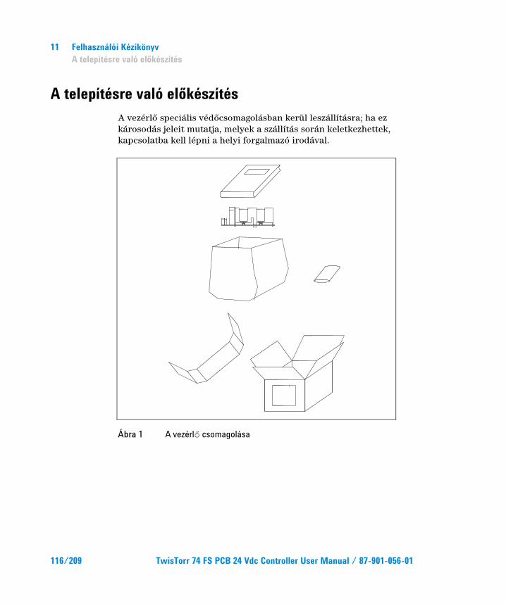
11 Felhasználói Kézikönyv A telepítésre való előkészítés
A telepítésre való előkészítés A vezérlő speciális védőcsomagolásban kerül leszállításra; ha ez károsodás jeleit mutatja, melyek a szállítás során keletkezhettek, kapcsolatba kell lépni a helyi forgalmazó irodával.
Ábra 1 A vezérlő csomagolása
116/209 TwisTorr 74 FS PCB 24 Vdc Controller User Manual / 87-901-056-01
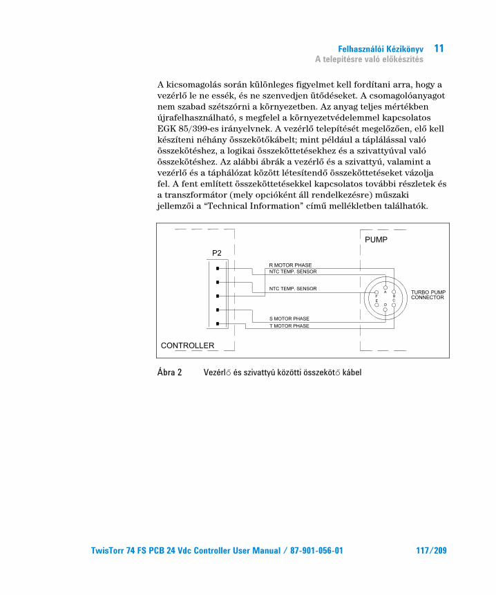
Felhasználói Kézikönyv A telepítésre való előkészítés
11
A kicsomagolás során különleges figyelmet kell fordítani arra, hogy a vezérlő le ne essék, és ne szenvedjen ütődéseket. A csomagolóanyagot nem szabad szétszórni a környezetben. Az anyag teljes mértékben újrafelhasználható, s megfelel a környezetvédelemmel kapcsolatos EGK 85/399-es irányelvnek. A vezérlő telepítését megelőzően, elő kell készíteni néhány összekötőkábelt; mint például a táplálással való összekötéshez, a logikai összeköttetésekhez és a szivattyúval való összekötéshez. Az alábbi ábrák a vezérlő és a szivattyú, valamint a vezérlő és a táphálózat között létesítendő összeköttetéseket vázolja fel. A fent említett összeköttetésekkel kapcsolatos további részletek és a transzformátor (mely opcióként áll rendelkezésre) műszaki jellemzői a “Technical Information” című mellékletben találhatók.
Ábra 2 Vezérlő és szivattyú közötti összekötő kábel
TwisTorr 74 FS PCB 24 Vdc Controller User Manual / 87-901-056-01 117/209
11 Felhasználói Kézikönyv Telepítés
Telepítés
VESZÉLY!
A vezérlő belsejében nagyfeszültségek alakulnak ki, melyek súlyos károkat vagy halált okozhatnak. A vezérlő bármely telepítési vagy karbantartási műveletének megkezdése előtt ki kell húzni a hálózati csatlakozót. A vezérlő belsejében magas hőmérséklet képződhet, mely súlyos károkat okozhat. A vezérlőt, végleges telepítésekor, megfelelően védeni kell, a véletlenszerű érintések elkerülése érdekében.
MEGJEGYZÉS A végleges rendszerben telepített vezérlő elhelyezésének biztosítania kell a hűtőlevegő szabad áramlását a berendezés körül. A vezérlőt nem szabad légköri hatásoknak (eső, fagy, hó) kitett, poros, maró hatású gázt tartalmazó, robbanás- vagy fokozottan tűzveszélyes környezetben telepíteni és/vagy használni.
Üzem közben az alábbi környezeti feltételeket kell biztosítani:
hőmérséklet: 0 °C és +40 °C között
relatív nedvességtartalom: 0 – 95 % (nem lecsapódó).
118/209 TwisTorr 74 FS PCB 24 Vdc Controller User Manual / 87-901-056-01
Felhasználói Kézikönyv Használat
11
Használat Ebben a szakaszban a fontosabb működési eljárások kerülnek ismertetésre. További részletek és az összekötéseket vagy az opcionális elemeket érintő eljárások találhatók a “Technical Information” melléklet “USE“ című szakaszában. A vezérlő használata előtt valamennyi elektromos és pneumatikus összeköttetést létre kell hozni, és figyelembe kell venni a csatlakoztatott szivattyú kézikönyvét.
VESZÉLY!
Kérjük, beindtás előtt gondosan olvassa el a szóban forgó szivattyú kézikönyvét, a biztonságos használat érdekében.
Használati eljárások
A vezérlő bekapcsolása A vezérlő bekapcsolásához elegendő számára a tápfeszültség biztosítása.
A szivattyú beindítása A szivattyú beindításához a J4 csatlakozó 12-es pin-jét nyitva kell hagyni; ily módon, amikor a 24 Vdc feszültség a vezérlőre rákapcsolásra kerül, a szivattyú beindul.
A szivattyú leállítása A szivattyú leállítása a J4 csatlakozó 12-es és 15-ös pin-jének rövidre zárásával történhet.
TwisTorr 74 FS PCB 24 Vdc Controller User Manual / 87-901-056-01 119/209
11 Felhasználói Kézikönyv Karbantartás
Karbantartás A TwisTorr 74 FS sorozatú vezérlők semmiféle karbantartást sem igényelnek. Valamennyi beavatkozást meghatalmazott személyzet hajthat csak végre. Meghibásodás esetén igénybe vehető a Agilent javítási szolgáltatása, vagy a "Agilent advanced exchange service", mely a meghibásodott helyett, egy javított vezérlőt biztosít.
VESZÉLY!
A vezérlőn való bármely beavatkozás végrehajtása előtt ki kell húzni a hálózati csatlakozót.
Amikor egy vezérlőt le kell selejtezni, megsemmisítésekor a tárgykörbe tartozó nemzeti normáknak megfelelően kell eljárni.
120/209 TwisTorr 74 FS PCB 24 Vdc Controller User Manual / 87-901-056-01
Felhasználói Kézikönyv Megsemmisítés
11
Megsemmisítés A címkén jelenlévő "WEEE" logo jelentése.
Az alább látható szimbólum az EK "WEEE" elnevezésű irányelvével összhangban kerül alkalmazásra. Ez a szimbólum (mely csak az Európai Közösség országaiban érvényes), azt jelzi, hogy a termék, melyen megtalálható, NEM kerülhet közönséges háztartási vagy ipari hulladékkal együtt megsemmisítésre, hanem azt egy szelektív hulladékgyűjtő rendszerbe kell továbbítani. A végfelhasználónak, a gyűjtési és megsemmisítési eljárás beindítása céljából, az adásvételi szerződés határidőinek és feltételeinek alapos áttanulmányozása után, fel kell vennie a kapcsolatot a berendezés szállítójával, legyen ez a gyártó vagy egy viszonteladó.
További információkért lásd: http://www.agilent.com/environment/product/index.shtml
TwisTorr 74 FS PCB 24 Vdc Controller User Manual / 87-901-056-01 121/209

11 Felhasználói Kézikönyv Megsemmisítés
122/209 TwisTorr 74 FS PCB 24 Vdc Controller User Manual / 87-901-056-01
TwisTorr 74 FS PCB 24 Vdc Controller User Manual
12Podrecznik Instrukcji Informacje ogolne 124 Magazynowanie 125 Przygotowanie do instalacji 126 Instalacja 128 Uzytkowanie 129 Procedury uzytkowania 129
Zaswiecenie kontrolera 129 Uruchomienie pompy 129 Zatrzymanie pompy 129
Konserwacja 130 Przetworstwo odpadow 131
Tłumaczenie instrukcji oryginalnej
123/209
12 Podrecznik Instrukcji Informacje ogolne
Informacje ogolne Urzadzenie to jest przeznaczone do uzytku zawodowego. Przed przystapieniem do korzystania uzytkownik powinien wnikliwie przesledzic zarowno ten podrecznik zawierajacy instrukcje jak rowniez kazda inna dostarczona przez Agilent informacje.Agilent uchyla sie od jakiejkolwiek odpowiedzialnosci w przypadku calkowitego lub czesciowego nie przestrzegania swoich instrukcji, przeznaczenia urzadzenia niezgodnie z jego przeznaczeniem i jego obslugi przez personel uprzednio nie przeszkolony, naprawy urzadzenia bez odpowiedniej autoryzacji lub przeznaczenia niezgodnego z obowiazujacymi, specyficznymi normami krajowymi. Kontroler z serii TwisTorr 74 FS PCB jest przetwornikiem czestotliwosci kontrolowanym przez mikroprocesor zrealizowanym z komponentow w stanie stalym i posiadajacym zdolnosci samodiagnostyczne i samoochronne.
Kontroler ten pilotuje pompe z serii TwisTorr 74 FS (przy pomocy procesu podzielonego na dziesiec etapow) Podczas fazy rozruchu kontroluje napiecie I prad elektryczny w stosunku do szybkosci pompy. Do jego zadania nalezy polaczenie calego obwodu niezbedne do prawidlowego automatycznego funkcjonowania pompy z serii TwisTorr 74 FS. Poprzez dodatkowy przetwornik sa dostepne sterowniki sterujace uruchomienie i zatrzymywanie pompy na odleglosc, sygnaly wskazujace stan operatywny pompy, i sterowniki sterujace uruchomienie i zatrzymywanie pompy wstepnej prozni, sygnaly blokujace (dla przerywaczy cisnieniowych, przerywaczy kontrolujacych przeplyw wody itp). Kontroler powinien byc zasilany napieciem stalym 24 Vdc.
W nastepnych paragrafach zawarte sa wszystkie niezbedne informacje dotyczace gwarancji bezpieczenstwa personelu obslugujacego urzadzenie.
Bardziej szczegolowe informacje sa zawarte w dodatku do “Technical Information”.
124/209 TwisTorr 74 FS PCB 24 Vdc Controller User Manual / 87-901-056-01
Podrecznik Instrukcji Magazynowanie
12
Podrecznik ten opiera sie na nastepujacych konwencjach:
UWAGA! Sygnaly wzrokowe ukazujace sie przed procedura jezeli zostana zlekcewazone moga spowodowac uszkodzenia urzadzenia.
ZAGROZENIE! Sygnaly ostrzegajace o zagrozeniu powinny zwrocic uwage operatora na odpowiednia specyficzna procedure ktora jezeli nie jest przestrzegana w sposob prawidlowy moze przyczynic sie do powaznych obrazen osoby obslugujacej.
PRZYPIS Przypisy zawieraja najwazniejsze informacje wyciagniete z tekstu.
Magazynowanie Kontrolery podczas transportu i przechowywania w magazynie powinny miec nastepujace warunki otoczenia:
temperatura: od -20 °C do +70 °C
wilgotnosc wzgledna: od 0 – 95 % (nie kondensujaca).
TwisTorr 74 FS PCB 24 Vdc Controller User Manual / 87-901-056-01 125/209
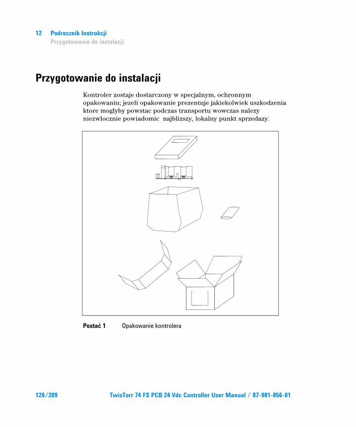
12 Podrecznik Instrukcji Przygotowanie do instalacji
Przygotowanie do instalacji Kontroler zostaje dostarczony w specjalnym, ochronnym opakowaniu; jezeli opakowanie prezentuje jakiekolwiek uszkodzenia ktore moglyby powstac podczas transportu wowczas nalezy niezwlocznie powiadomic najblizszy, lokalny punkt sprzedazy.
Postać 1 Opakowanie kontrolera
126/209 TwisTorr 74 FS PCB 24 Vdc Controller User Manual / 87-901-056-01
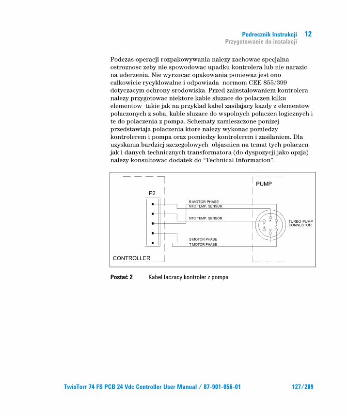
Podrecznik Instrukcji Przygotowanie do instalacji
12
Podczas operacji rozpakowywania nalezy zachowac specjalna ostroznosc zeby nie spowodowac upadku kontrolera lub nie narazic na uderzenia. Nie wyrzucac opakowania poniewaz jest ono calkowicie rycyklowalne i odpowiada normom CEE 855/399 dotyczacym ochrony srodowiska. Przed zainstalowaniem kontrolera nalezy przygotowac niektore kable sluzace do polaczen kilku elementow takie jak na przyklad kabel zasilajacy kazdy z elementow polaczonych z soba, kable sluzace do wspolnych polaczen logicznych i te do polaczenia z pompa. Schematy zamieszczone ponizej przedstawiaja polaczenia ktore nalezy wykonac pomiedzy kontrolerem i pompa oraz pomiedzy kontrolerem i zasilaniem. Dla uzyskania bardziej szczegolowych objasnien na temat tych polaczen jak i danych technicznych transformatora (do dyspozycji jako opzja) nalezy konsultowac dodatek do “Technical Information”.
Postać 2 Kabel laczacy kontroler z pompa
TwisTorr 74 FS PCB 24 Vdc Controller User Manual / 87-901-056-01 127/209
12 Podrecznik Instrukcji Instalacja
Instalacja
ZAGROZENIE!
Wewnatrz kontrolera powstaja wysokie napiecia ktore moga spowodowac powazne obrazenia lub smiertelne wypadki. Przed wykonaniem jakiejkolwiek operaci instalacji lub konserwacji nalezy odlaczyc kontroler od zrodla zasilania. Wewnatrz kontrolera postaja rowniez bardo wysokie temperatury ktore moga spowodowac powazne obrazenia. Podczas definitywnej instalacji kontrolera chronic go odpowiednio od przypadkowych kontaktow.
PRZYPIS Kontroler zainstalowany w systemie definitywnie powinien byc tak usytuowany aby wokol niego moglo swobodnie krazyc powietrze chlodzace.Ne nalezy instalowac i/lub uzytkowac kontroler w miejscach narazonych na dzialanie warunkow atmosferycznych (deszcz, mroz, snieg) pylow, gazow agresywnych, w rodowiskach wybuchowych lub o duzym zagrozeniu pozarowym.
Podczas pracy kontrolera nalezy zapewnic nastepujace warunki otoczenia:
temperatura: od 0 °C do +40 °C
wilgotnosc wzgledna: 0 – 95 % (nie kondensujaca).
128/209 TwisTorr 74 FS PCB 24 Vdc Controller User Manual / 87-901-056-01
Podrecznik Instrukcji Uzytkowanie
12
Uzytkowanie Paragraf ten zawiera podstawowe procedury operatywne. Dla uzyskania dodatkowych bardziej szczegolowych informacji lub dostepu do procedur na temat polaczen lub akcesoriow skonsultowac paragraf “USE“ znajdujacy sie w dodatku do “Technical Information“. Przed przystapieniem do uzytkowania kontrolera wykonac wszystkie polaczenia elektryczne i pneumatyczne podlaczenie pompy konsultowac z odnosna instrukcja.
ZAGROZENIE!
Aby obslugiwać pompe w bezpieczny sposób, należy zapoznać sie z odpowiednia instrukcja obslugi.
Procedury uzytkowania
Zaswiecenie kontrolera Aby zaswiecic kontroler wystarczy dostarczyc do niego napiecie zasilania.
Uruchomienie pompy Zeby uruchomic pompe nalezy zostawic otwarty pin 12 lacznika J4 w ten sposob dostarczone kontrolerowi napiecie 24 Vdc pozwoli na uruchomienie pompy.
Zatrzymanie pompy Do zatrzymania pompy nalezy zewrzec pin 12 i 15 lacznika J4.
TwisTorr 74 FS PCB 24 Vdc Controller User Manual / 87-901-056-01 129/209
12 Podrecznik Instrukcji Konserwacja
Konserwacja Kontroler z serii TwisTorr 74 FS nie wymaga zadnej konserwacji. Jakakolwiek interwencja musi byc przeprowadzona wylacznie przez osoby autoryzowane.
.W przypadku uszkodzenia mozliwe jest korzystanie z serwisow naprawczych Agilent lub “Agilent advance exchange service”, w ktorym mozna otrzymac kontroler odnowiony zastepujac go tym uszkodzonym.
ZAGROZENIE!
Przed wykonaniem jakiejkolwiek interwencji na kontrolerze nalezy odlaczyc kabel zasilajacy.
W przypadku decyzji zlomowania nalezy przeprowadzic operacje respektujac krajowe, specyficzne normy.
130/209 TwisTorr 74 FS PCB 24 Vdc Controller User Manual / 87-901-056-01
Podrecznik Instrukcji Przetworstwo odpadow
12
Przetworstwo odpadow Objasnienie znajdujacego sie na etykiecie znaczenia logo “WEEE”. Uzyty ponizej symbol jest zgodny z wymogiem zarzadzenia “WEEE” Unii Europejskiej. Symbol ten (prawomocny tylko w krajach Unii Europejskiej) oznacza, ze wyrob ktory nim zostal oznaczony NIE moze byc przetworzony jako odpad razem z innymi domowymi lub przemyslowymi natomiast musi byc skladowany w miejscu przeznaczonym dla odpadow do przerobki zroznicowanej .
Dlatego tez poleca sie uzytkownikowi, po uprzedniej weryfikacji terminu i warunkow zawartych w kontrakcie sprzedazy, nawiazac kontakt z dostawca lub sprzedawca urzadzenia w celu uruchomienia procesu zbiorki i przerobu.
Aby uzyskać więcej informacji, patrz: http://www.agilent.com/environment/product/index.shtml
TwisTorr 74 FS PCB 24 Vdc Controller User Manual / 87-901-056-01 131/209

12 Podrecznik Instrukcji Przetworstwo odpadow
132/209 TwisTorr 74 FS PCB 24 Vdc Controller User Manual / 87-901-056-01
TwisTorr 74 FS PCB 24 Vdc Controller User Manual
13Návod k Použití Všeobecné informácie 134 Uskladnění 135 Příprava k instalaci 136 Instalace 138 Použití 139 Používané procedury 139
Zapalování Kontrolérů 139 Spuštění čerpadla 139 Zastavení čerpadla 139
Údržba 140 Likvidace 141
Překlad originálního návodu
133/209
13 Návod k Použití Všeobecné informace
Všeobecné informace Tento přístroj je určen pro profesionální potřebu. Uživatel si musí před použitím tuto příručku velmi pozorně přečíst, ale i každou další aktualizaci, kterou podnik bude předávat. V důsledku nedostatečného i částečně nesprávného použití, nebo v případě chyb nevyškoleného personálu či neoprávněných zásahů a neodpovídajících specifickým státním normám, Agilent nepřijímá a nenese žádnou zodpovědnost.
Kontrolér TwisTorr 74 FS PCB je frekvenčním konvertorem, je kontrolovaný mikroprocesorem a skládá se z pevných komponentů s autodiagnostickou a samoochrannou schopností.
Obsahuje veškeré obvody nutné pro automatický provoz čerpadel série TwisTorr 74 FS. Kontrolér řídí čerpadla série TwisTorr 74 FS (s procesem rozděleným na deset kroků), během spouštěcí fáze kontrolují napětí a proud ve vztahu k rychlosti, kterou čerpadlo dosáhne. Dálkové příkazy ke spuštění a zastavení čerpadla jsou vykonávany prostřednictvím výpomocného konektoru, signály, které poukazují na operativní stav čerpadla, příkazy ke spuštění a zastavení pre-prázdného čerpadla, blokovací signály (pro tlakové vypínače, kontrolní vypínače vodního toku, atd.). Kontrolér musí být napájený stejnosměrným 24 Vdc napětím.
V následujících odstavcích jsou uvedeny veškeré nutné informace, týkající se operátora a bezpečnostních podmínek během provozu přístroje. Detailní informace se nacházejí v dodatku "Technical Information".
134/209 TwisTorr 74 FS PCB 24 Vdc Controller User Manual / 87-901-056-01
Návod k Použití Uskladnění
13
Tato příručka používá následující běžná označení:
POZOR! Tyto zprávy bývají vizualizovány před jakoukoliv procedurou, je třeba se jimi řídit, aby nedošlo k poškození přístroje.
NEBEZPEČÍ! Odkazy, které upozorňují na nebezpečí a donutí operátora, aby se řídil dle procedury nebo specifické praktiky, která nebude-li řádně vykonána, může ohrozit vážným způsobem jeho zdraví.
POZNÁMKA Poznámky, vyjmuté z textu obsahují velmi důležité informace.
Uskladnění Během dopravy a skladování kontrolérů, se musí dbát na následující podmínky prostředí:
temperatura: od -20 °C do +70 °C
relativní vlhkost: 0 – 95 % (nesmí kondenzovat).
TwisTorr 74 FS PCB 24 Vdc Controller User Manual / 87-901-056-01 135/209
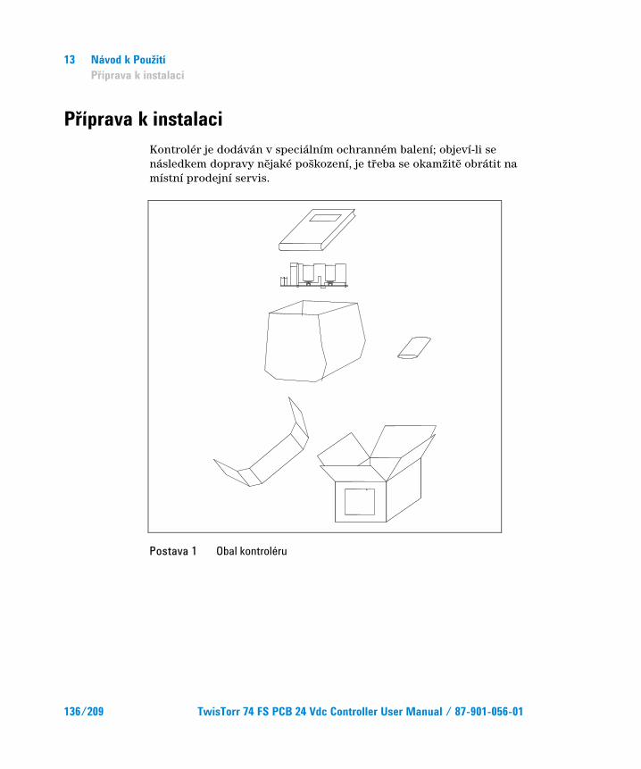
13 Návod k Použití Příprava k instalaci
Příprava k instalaci Kontrolér je dodáván v speciálním ochranném balení; objeví-li se následkem dopravy nějaké poškození, je třeba se okamžitě obrátit na místní prodejní servis.
Postava 1 Obal kontroléru
136/209 TwisTorr 74 FS PCB 24 Vdc Controller User Manual / 87-901-056-01
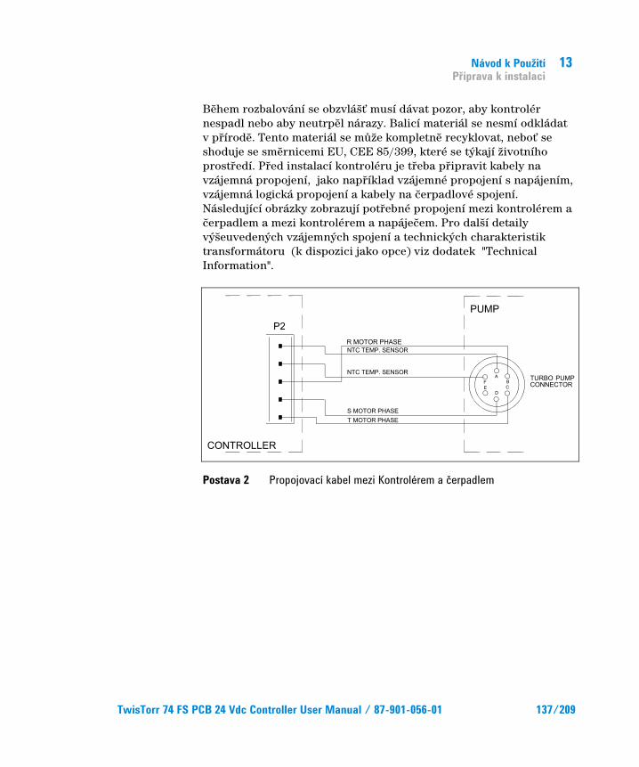
Návod k Použití Příprava k instalaci
13
Během rozbalování se obzvlášť musí dávat pozor, aby kontrolér nespadl nebo aby neutrpěl nárazy. Balicí materiál se nesmí odkládat v přírodě. Tento materiál se může kompletně recyklovat, neboť se shoduje se směrnicemi EU, CEE 85/399, které se týkají životního prostředí. Před instalací kontroléru je třeba připravit kabely na vzájemná propojení, jako například vzájemné propojení s napájením, vzájemná logická propojení a kabely na čerpadlové spojení. Následující obrázky zobrazují potřebné propojení mezi kontrolérem a čerpadlem a mezi kontrolérem a napáječem. Pro další detaily výšeuvedených vzájemných spojení a technických charakteristik transformátoru (k dispozici jako opce) viz dodatek "Technical Information".
Postava 2 Propojovací kabel mezi Kontrolérem a čerpadlem
TwisTorr 74 FS PCB 24 Vdc Controller User Manual / 87-901-056-01 137/209
13 Návod k Použití Instalace
Instalace
NEBEZPEČÍ!
Uvnitř kontroléru dochází k vysokým napětím, která jsou velmi nebezpečná i smrtící. Před provedením jakékoliv instalační či údržbové operace s kontrolérem, je třeba ho odpojit od elektrického příkonu. Uvnitř kontroléru vznikají velmi vysoké teploty, které mohou být velice škodlivé. Kontrolér je třeba adekvátně ochránit proti nahodilým kontaktům.
POZNÁMKA Kontrolér nainstalovaný v definitivním systému musí být umístěn tak, aby kolem přístroje mohl volně proudit ochlazovací vzduch. Kontroléry se nesmí instalovat v místech vystavených atmosferickým vlivům (déšť, mráz, sníh), prachu, agresivním plynům, na výbušných místech nebo na místech kde existuje velké riziko požárů.
Během provozu se musí dbát na následující podmínky prostředí:
temperatura: od 0 °C do +40 °C
relativní vlhkost: 0 – 95 % (nesmí kondenzovat).
138/209 TwisTorr 74 FS PCB 24 Vdc Controller User Manual / 87-901-056-01
Návod k Použití Použití
13
Použití V tomto odstavci jsou uvedeny hlavní operativní postupy. Pro další detajly i pro procedury týkající se spojení nebo dalších opčních detajlů, je třeba se obracet na odstavec "USE" v příloze "Technical Information". Před použitím kontroléru se musí vykonat veškerá elektrická a pneumatická spojení, při čemž je třeba se obracet na příslušnou příručku napojeného čerpadla.
NEBEZPEČÍ!
Před spuštěním se pro bezpečný provoz obraťte na příslušný manuál k pumpě.
Používané procedury
Zapalování Kontrolérů Zapálení kontrolérů se děje tak, že se přivede elektrické napětí do kontroléru.
Spuštění čerpadla Pro spuštění čerpadla je třeba nechat otevřený pin 12 konektoru J4 tak, aby se, až kontrolér dostane napětí 24 Vdc, čerpadlo spustilo.
Zastavení čerpadla Na zastavení čerpadla je třeba uskutečnit zkrat pinu 12 a 15 konektoru J4.
TwisTorr 74 FS PCB 24 Vdc Controller User Manual / 87-901-056-01 139/209
13 Návod k Použití Údržba
Údržba Kontrolér série TwisTorr 74 FS nevyžaduje žádnou údržbu. Jakýkoliv zásah musí být vykonáván jen kompetentním personálem. V případě poruchy se může využít opravářského servisu Agilent nebo "Agilent advanced exchange service", kde poškozený kontrolér bude vyměněn za nový.
NEBEZPEČÍ!
Nejdříve, před jakýmkoliv zásahem na kontroléru, se musí odpojit elektrický kabel.
Budeli zapotřebí kontrolér likvidovat, musí se postupovat dle platných specifických státních norem.
140/209 TwisTorr 74 FS PCB 24 Vdc Controller User Manual / 87-901-056-01
Návod k Použití Likvidace
13
Likvidace Význam loga "WEEE" nacházejícího se na štítku. Níže uvedený symbol odpovídá směrnicím CE pojmenovaným "WEEE". Tento symbol (platný jen pro státy Evropské Unie) určuje, že výrobek, který je takto označen NESMÍ být likvidován společně s ostatními domácími nebo průmyslovými odpady, ale je nutno ho předat do patřičných provozních sběren, kde musí být tříděn a likvidován odděleně od městského odpadu. Uživateli, který míní výrobek likvidovat doporučujeme, aby se nakontaktoval přímo s výrobcem nebo prodejcem, který se po patřičném prověření termínů a smluvních podmínek postará o kompletní likvidaci uvedeného výrobku.
Více informací naleznete na: http://www.agilent.com/environment/product/index.shtml
TwisTorr 74 FS PCB 24 Vdc Controller User Manual / 87-901-056-01 141/209

13 Návod k Použití Likvidace
142/209 TwisTorr 74 FS PCB 24 Vdc Controller User Manual / 87-901-056-01
TwisTorr 74 FS PCB 24 Vdc Controller User Manual
14Návod na Obsluhu Všeobecné informácie 144 Uskladňovanie 145 Príprava pre inštaláciu 146 Inštalácia 148 Použitie 149 Postup pri použití 149
Zapnutie Controller 149 Spustenie čerpadla 149 Zastavenie čerpadla 149
Údržba 150 Likvidácia 151
Preklad originálneho návodu
143/209
14 Návod na Obsluhu Všeobecné informácie
Všeobecné informácie Tento prístroj slúži k profesionálnemu použitiu. Užívateľ si pred použitím tohto prístroja musí pozorne prečítať tento návod k použitiu a jeho ďalšie doplnky, dodané podnikom Agilent. Podnik Agilent nepreberá na seba žiadnu zodpovednosť za úplné, alebo čiastočné nedodržiavanie návodu, za nesprávne používanie prístroja nekompetentnými osobami, za nepovolené zásahy a za používanie, ktoré nie je v zhode s príslušnými národnými normami.
“Controllers” série TwisTorr 74 FS PCB je menič kmitočtu, kontrolovaný mikroprocesorom, vyrobený prvkami pevnej fázy a so schopnosťou samodiagnostiky a samokontroly.
Obsahuje všetky obvody, potrebné pre automatickú prevádzku čerpadiel série TwisTorr 74 FS. “Controllers” riadi čerpadlá série TwisTorr 74 FS (s procesom, rozdeleným do desať rozpätí) počas štartovacej fázy, kontrolujúc napätie a prúd vo vzťahu s rýchlosťou, dosiahnutou čerpadlom. Pomocná spojka umožní diaľkové povely pre štart a vypnutie čerpadla, signály, ktoré ukazujú opreratívny stav čerpadla, povely pre štart a vypnutie pred-prázdnového čerpadla blokovacie signály (pre tlakové tlačidlá, tlačidlá pre kontrolu toku vody, atď.). Controller musí byť napájaný rovnakosmerným 24 Vdc napätím.
Ďalej sú popísané všetky potrebné informácie, ktorých úlohou je zabezpečiť bezpečnosť pracovníka počas používania prístroja.
Podrobné informácie sú uvedené v dodatku "Technical Information".
144/209 TwisTorr 74 FS PCB 24 Vdc Controller User Manual / 87-901-056-01
Návod na Obsluhu Uskladňovanie
14
Tento návod používa nasledujúce signály:
POZOR! Signály “pozor” sú pred tými postupmi, ktoré, v prípade ich nedodržania, môžu poškodiť prístroj.
NEBEZPEČÍ! Signál nebezpečie upozorňuje pracovníka na určitý pracovný postup, ktorý, keď nie je prevedený správne, môže zapríčiniť vážne osobné poranenia.
POZNÁMKA Poznámky, vybraté z textu obsahujú veľmi dôležité informácie.
Uskladňovanie Počas prepravy a uskladňovania “Controllers” musia byť dodržané tieto podmienky prostredia:
teplota: od -20 °C do +70 °C
relatívna vlhkosť: 0 – 95 % (bez kondenzátu).
TwisTorr 74 FS PCB 24 Vdc Controller User Manual / 87-901-056-01 145/209
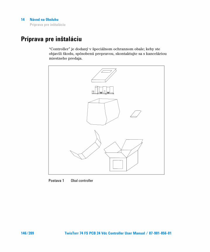
14 Návod na Obsluhu Príprava pre inštaláciu
Príprava pre inštaláciu “Controller” je dodaný v špeciálnom ochrannom obale; keby ste objavili škodu, spôsobenú prepravou, skontaktujte sa s kanceláriou miestneho predaja.
Postava 1 Obal controller
146/209 TwisTorr 74 FS PCB 24 Vdc Controller User Manual / 87-901-056-01
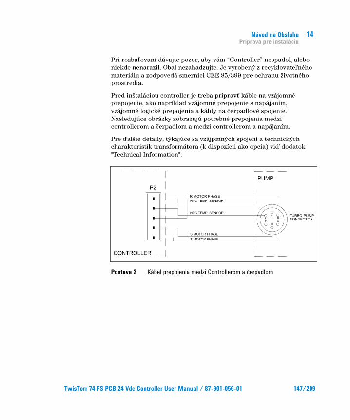
Návod na Obsluhu Príprava pre inštaláciu
14
Pri rozbaľovaní dávajte pozor, aby vám “Controller” nespadol, alebo niekde nenarazil. Obal nezahadzujte. Je vyrobený z recyklovateľného materiálu a zodpovedá smernici CEE 85/399 pre ochranu životného prostredia.
Pred inštaláciou controller je treba pripravť káble na vzájomné prepojenie, ako napríklad vzájomné prepojenie s napájaním, vzájomné logické prepojenia a kábly na čerpadlové spojenie. Nasledujúce obrázky zobrazujú potrebné prepojenia medzi controllerom a čerpadlom a medzi controllerom a napájaním.
Pre ďalšie detaily, týkajúce sa vzájpmných spojení a technických charakteristík transformátora (k dispozícii ako opcia) viď dodatok "Technical Information".
Postava 2 Kábel prepojenia medzi Controllerom a čerpadlom
TwisTorr 74 FS PCB 24 Vdc Controller User Manual / 87-901-056-01 147/209
14 Návod na Obsluhu Inštalácia
Inštalácia
NEBEZPEČÍ!
Vo vnútri controller dochádza k vysokému napätiu, ktoré môže spôsobiť veľké škody alebo smrť. Pred prevedením akéjkoľvek inštalácie alebo údržby controller, je treba tento odpojiť od elektrického príkonu. Vo vnútri controller vznikajú vsoké teploty, ktoré môžu byť veľmi škodlivé. Controller je treba adekvátne ochrániť voči náhodným kontaktom.
POZNÁMKA Controller nainštalovaný v definitívnom systéme musí byť umiestnený tak, aby okolo prístroja mohol voľne prúdiť chladný vzduch. Controllers sa nesmú inštalovať v miestach, vystavených atmosferickým vplyvom (dážď, mráz, sneh), prachu, agresívnym plynom, na výbušných miestach, alebo na miestach, kde existuje veľké riziko požiarov.
Počas chodu je dôležité, aby boli rešpektované tieto podmienky prostredia:
teplota: od O °C do +40 °C
relatívna vlhkosť: 0 – 95 % (nekondenzovaná).
148/209 TwisTorr 74 FS PCB 24 Vdc Controller User Manual / 87-901-056-01
Návod na Obsluhu Použitie
14
Použitie V tomto odstavci sú uvedené hlavné operatívne postupy. Pre ostatné detaily a pre postupy, ktoré sa vzťahujú na napojenia, alebo na zvolené príslušenstvo, postupujte podľa časti "USE" v dodatku "Technical Information". Všetky elektrické a pneumatické napojenia treba previesť pre použitím controller. Pritom treba konzultovať príslušnú príručku napojeného čerpadla.
NEBEZPEČÍ!
Pred začiatkom manipulácie si z dôvodu zaistenia bezpečného použitia dôkladne preštudujte priložený manuál.
Postup pri použití
Zapnutie Controller Na zapnutie controller stačí priviesť elektrické napätie do controller.
Spustenie čerpadla Pre spustenie čerpadla nechajte otvorený pin 12 spojky J4 tak, že keď controller dostane napätie 24 Vdc, čerpadlo sa spustí.
Zastavenie čerpadla Na zastavenie čerpadla treba skratovať pin 12 a 15 spojky J4.
TwisTorr 74 FS PCB 24 Vdc Controller User Manual / 87-901-056-01 149/209
14 Návod na Obsluhu Údržba
Údržba “Controllers” série TwisTorr 74 FS nevyžadujú žiadnu údržbu. Akýkoľvek zásah musí previesť poverený personál. V prípade vady je možné využiť opravnú službu Agilent alebo “Agilent advanced exchange service”, ktorá vymení vadný controller.
NEBEZPEČÍ!
Pred akýmkoľvek zásahom na “controller” vytiahnite šnúru z elektrickej siete.
V prípade, že “controller” musí ísť do zberu, riaďte sa platnými príslušnými národnými normami.
150/209 TwisTorr 74 FS PCB 24 Vdc Controller User Manual / 87-901-056-01
Návod na Obsluhu Likvidácia
14
Likvidácia Význam loga "WEEE" nachádzajúceho sa na štítkoch. Aplikovanie doluozznačeného symbolu dodržuje smernicu EÚ s názvom "WEEE". Tento symbol (platný iba pre štáty Európskej Únie) znamená, že výrobok s týmto štítkom NESMIE byť odstránený spolu s bežným domácim alebo priemyselným odpadom, ale sa musí odstrániť ako delený odpad. Vyzývame preto konečného užívateľa, aby sa skontaktoval s dodávateľom prístroja, či už je to výrobca alebo predajca za účelom jeho likvidácie podľa zmluvných podmienok predaja.
Viac informácií nájdete na: http://www.agilent.com/environment/product/index.shtml
TwisTorr 74 FS PCB 24 Vdc Controller User Manual / 87-901-056-01 151/209
14 Návod na Obsluhu Likvidácia
152/209 TwisTorr 74 FS PCB 24 Vdc Controller User Manual / 87-901-056-01
TwisTorr 74 FS PCB 24 Vdc Controller User Manual
15Priročnik za Navodila Splošna navodila 154 Skladiščenje 155 Priprava za montažo 156 Montaža 158 Uporaba 159 Postopki za uporabo 159
Vklopitev Controllera 159 Zagon Črpalke159 Zaustavitev Črpalke 159
Vzdrževanje 160 Odlaganje opadkov 161
Prevod navodil v izvirniku
153/209
15 Priročnik za Navodila Splošna navodila
Splošna navodila Naprava je namenjena samo za strokovno rabo. Uporabnik mora temeljito prebrati priročnik in pri tem upoštevati vsako dodatno informacijo, ki jo nudi Agilent. Agilent ne odgovarja v slučaju celotnega ali delnega nespoštovanja navodil, pri nepravilni uporabi s strani nestrokovnega osebja, v slučaju nedovoljenih posegov ali pri zanemarjenju specifičnih nacionalnih meril.
Controller serije TwisTorr 74 FS PCB je frekvenčni pretvornik, na katerega nadzor ima mikrokrmilnik, sestavljen iz solidnih delov za katere so značilne lastnosti avtodiagnoze in avtozaščite. Controller vsebuje celotno električno vezje, ki je potrebno za avtomatično delovanje črpalke serije TwisTorr 74 FS. Controller krmi črpalke serije TwisTorr 74 FS (s 10-faznim postopkom) med pogonom in nadzoruje napetost ter električni tok v sorazmerju s hitrostjo, ki jo doseže črpalka.
Preko pomočnih konektorjev so na razpolago komande za pogon in zaustavitev črpalke (ki se regulira s daljinskim upravljanjem), komande ki pokažejo operativno stanje črpalke, komande za zagon in za zaustavitev črpalke predhodnega črpanja, komande za blokiranje (za stikala na pritisk, nadzorna stikala vodnega toka, itn.). Controlleru dovodite trajno napetost od 24 Vdc. V naslednjih odstavkih so navedene vse informacije potrebene za zagotavljanje sigurnosti uporabnika med rokovanjem s to napravo. Podrobnejše informacije dobite v priponki "Technical Information".
154/209 TwisTorr 74 FS PCB 24 Vdc Controller User Manual / 87-901-056-01
Priročnik za Navodila Skladiščenje
15
V tem priročniku so varnostne informacije razvrščene v dva razreda:
POZOR! Znak ‘pozor’ se pojavi pred postopke, ki če jih uporabnik zanemari, lahko napravo poškoduje.
SVARILO! Znak svarila opozarja uporabnika, da mora pri določenem postopku ali pri posebnem delovanju paziti. Kršitev svarila lahko privede do lažjih ali hudih telesnih poškodb.
OPOMBA V opombah so vsebovane vse najbolj pomembne informacije iz besedila.
Skladiščenje Med prevozom in skladiščenjem controllera morate zagotoviti naslednje pogoje okolice:
temperatura: od -20 °C do +70 °C
relativna vlaga 0 – 95 % (ne-kondenzna)
TwisTorr 74 FS PCB 24 Vdc Controller User Manual / 87-901-056-01 155/209

15 Priročnik za Navodila Priprava za montažo
Priprava za montažo Controller dobite v posebni zaščitni embalaži; če so na embalaži znaki poškodbe, ki naj bi nastale med transportom obrnite se krejavnemu prodajalnemu biroju.
Slika 1 Embalaža controllera
156/209 TwisTorr 74 FS PCB 24 Vdc Controller User Manual / 87-901-056-01
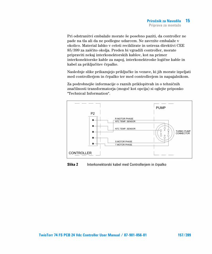
Priročnik za Navodila Priprava za montažo
15
Pri odstranitvi embalaže morate še posebno paziti, da controller ne pade na tla ali da ne podlegne udarcem. Ne zavrzite embalaže v okolico. Material lahko v celoti reciklirate in ustreza direktivi CEE 85/399 za zaščito okolja. Preden bi vgradili controller, morate pripraviti nekaj interkonektorskih kablov, kot na primer interkonektorske kable za napoj, interkonektroske logične kable in kabel za priključitev črpalke.
Naslednje slike prikazujejo priključke in vezave, ki jih morate izpeljati med controllerjem in črpalko ter med controllerjem in napajalnikom.
Za podrobnejše informacije o raznih priklopitvah in o tehničnih značilnosti transformatorja (mogoč kot opcija) si oglejte priponko "Technical Information".
Slika 2 Interkonektorski kabel med Controllerjem in črpalko
TwisTorr 74 FS PCB 24 Vdc Controller User Manual / 87-901-056-01 157/209
15 Priročnik za Navodila Montaža
Montaža
SVARILO!
Znotraj controllera se razvija visoka napetost, ki lahko resno poškoduje ali celo povzroči smrt. Preden bi nadaljevali s katerokoli dejavnostjo montaže ali vzdrževanja, izklopite controller iz vtičnice. V notranjosti controllera se razvijajo visoke temperature, ki lahko povzročijo hude telesne poškodbe.
OPOMBA Ko controller vgradite v dokončni sistem, mora imeti taki položaj, da lahko zrak za hlajenje prosto kroži skozi napravo. Controller ne smete vgraditi in/ali uporabiti v okolicah, ki so ogrožene s klimatskimi dejavniki (dež, led, sneg), ki so izpostavljene prahu, agresivnim plinom ali v okolicah, kjer obstaja nevarnost vnetja ali požara.
Med delovanjem controllera morate zagotoviti naslednje pogoje okolice:
temperatura: od 0 °C do +40 °C
relativna vlaga: 0 – 95 % (ne-kondenzna).
158/209 TwisTorr 74 FS PCB 24 Vdc Controller User Manual / 87-901-056-01
Priročnik za Navodila Uporaba
15
Uporaba V tem odsatvku so navedeni glavni operativni postopki. Za podrobnejše informacije in postopke, ki se nanašajo na priključitve ali posamezne opcije ogledajte si paragraf "USE" v dodatku "Technical Information".
Predno vklučite controller, morate izvesti vse električne in pnevmatske priključke; pri tem se nanajšate na priročnik priložene črpalke.
SVARILO!
Pred zagonom si poglejte ustrezen priročnik za varno upravljanje in delovanje črpalke.
Postopki za uporabo
Vklopitev Controllera Controllera vklopite tako, da controlleru priključite napajalno napetost.
Zagon Črpalke Za zagon črpalke mora biti pin 12 konektorja J4 odprt, tako da ko Controller dobi napetost od 24 Vdc lahko začne zagon črpalke.
Zaustavitev Črpalke Za zaustavitev črpalke morata biti pin 12 in 15 konektorja J4 v kratkem stiku.
TwisTorr 74 FS PCB 24 Vdc Controller User Manual / 87-901-056-01 159/209
15 Priročnik za Navodila Vzdrževanje
Vzdrževanje Controllerji serije TwisTorr 74 FS ne potrebujejo vzdrževanja. Samo pooblaščeno osebje lahko rokuje s to napravo. V slučaju okvare se lahko obrnite servisu Agilent ali "Agilent advance exchange service", ki Vam stavlja na razpolago popravljeni controller.
SVARILO!
Pred katerikoli posegom, izključite napajlni kabel iz controllera.
Controller zavrzite kot industrijski odpadek v skladu z državnimi predpisi.
160/209 TwisTorr 74 FS PCB 24 Vdc Controller User Manual / 87-901-056-01
Priročnik za Navodila Odlaganje opadkov
15
Odlaganje opadkov Pomen znamke "WEEE" na etiketah. Spodaj navedeni simbol je v skladu z direktivo ES znano pod imenom "WEEE". Ta simbol (ki velja samo v državah Evropske Skupnosti) pomeni, da izdelek NE SMETE ODSTRANITI skupaj z ostalimi komunalnimi ali pa industrijskimi odpadki, temveč morate poskrbeti za njihovo primerno ločevanje. Zato pozivamo uporabnike, da se ali pri prodajalnem centru ali pa pri prodajalcu seznani o postopku ločevanja in odstranitve odpadkov, šele nato, ko se je seznanil s pogoji in z merili kupopordajne pogodbe.
Za dodatne informacije se obrnite na: http://www.agilent.com/environment/product/index.shtml
TwisTorr 74 FS PCB 24 Vdc Controller User Manual / 87-901-056-01 161/209

15 Priročnik za Navodila Odlaganje opadkov
162/209 TwisTorr 74 FS PCB 24 Vdc Controller User Manual / 87-901-056-01
TwisTorr 74 FS PCB 24 Vdc Controller User Manual
16Instructions for Use General Information 164 Storage 165 Preparation prior to Installation 166 Installation 168 Use 169 Operating Procedures 169
Powering on the Controller 169 Starting the Pump 169
Stopping the Pump 169 Maintenance 170 Disposal 171
Original Instructions
163/209
16 Instructions for Use General Information
General Information This equipment is intended for professional use. Prior to using the equipment, the operator must carefully read this instruction manual and any other additional information provided by Agilent. Agilent declines all responsibility which may become as the result of the total or partial misinterpretation of the information provided in the documentation, by the improper use of the equipment by untrained personnel or by the use of the equipment by unauthorized personnel or not in compliance with specific national norms. The TwisTorr 74 FS PCB controller is a microprocessor-controlled frequency converter made up of solid state components and capable of autodiagnostic and auto-protection functionality. It incorporates the circuitry needed for the automatic operation of TwisTorr 74 FS series pumps.
The TwisTorr 74 FS series pumps are driven by the controller (in a 10-step procedure) during the start-up phase that also checks the voltage and current according to the speed reached by the pump. Auxiliary connectors render the commands needed to start and stop the pump from remote, the signals that indicate the operating state of the pump and the locking commands (for pressure switches, water flow control switches, etc.) available. The controller must be provided with 24 Vdc.
In the next sections you will find all the information needed to guarantee operator safety during the use of the equipment. Detailed information is provided in the Appendix entitled "Technical Information".
164/209 TwisTorr 74 FS PCB 24 Vdc Controller User Manual / 87-901-056-01
Instructions for Use Storage
16
The following conventions are adopted in this manual:
CAUTION! Caution messages are provided before a procedure that could damage the equipment is not executed in the correct way.
WARNING! Warning messages call the operator's attention to a specific procedure or operation that could cause serious personal injury if not executed in the correct way.
NOTE Notes provide important information extracted from the text.
Storage The controller must be transported or stored within the following environmental conditions:
Temperature: -20 °C to +70 °C
Relative humidity 0 to 95 % (non-condensing)
TwisTorr 74 FS PCB 24 Vdc Controller User Manual / 87-901-056-01 165/209
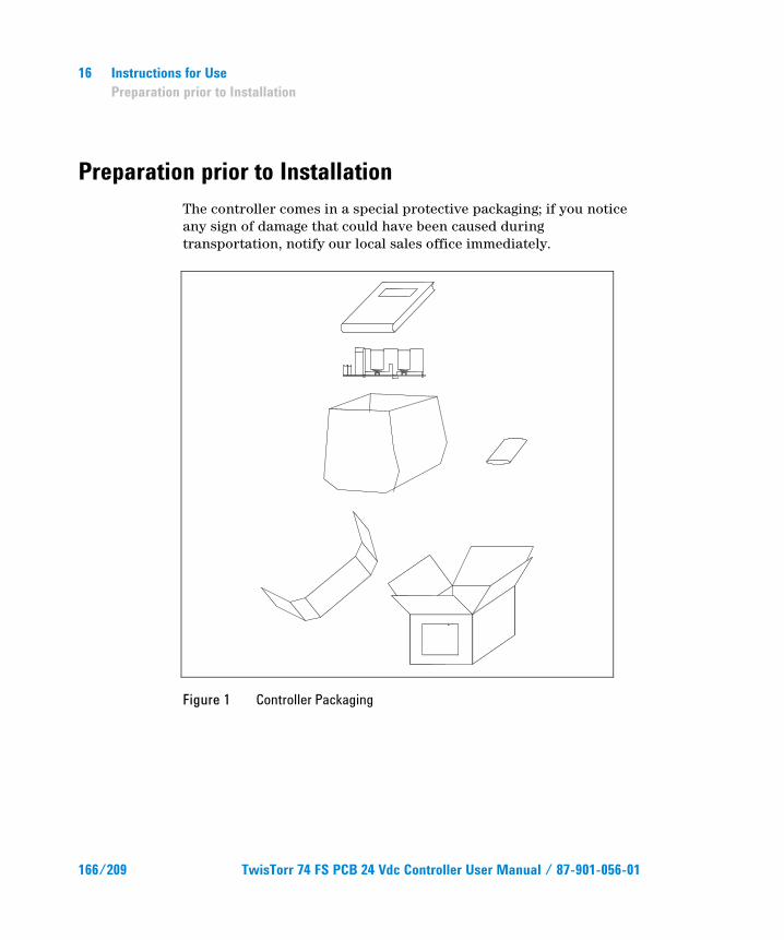
16 Instructions for Use Preparation prior to Installation
Preparation prior to Installation The controller comes in a special protective packaging; if you notice any sign of damage that could have been caused during transportation, notify our local sales office immediately.
Figure 1 Controller Packaging
166/209 TwisTorr 74 FS PCB 24 Vdc Controller User Manual / 87-901-056-01
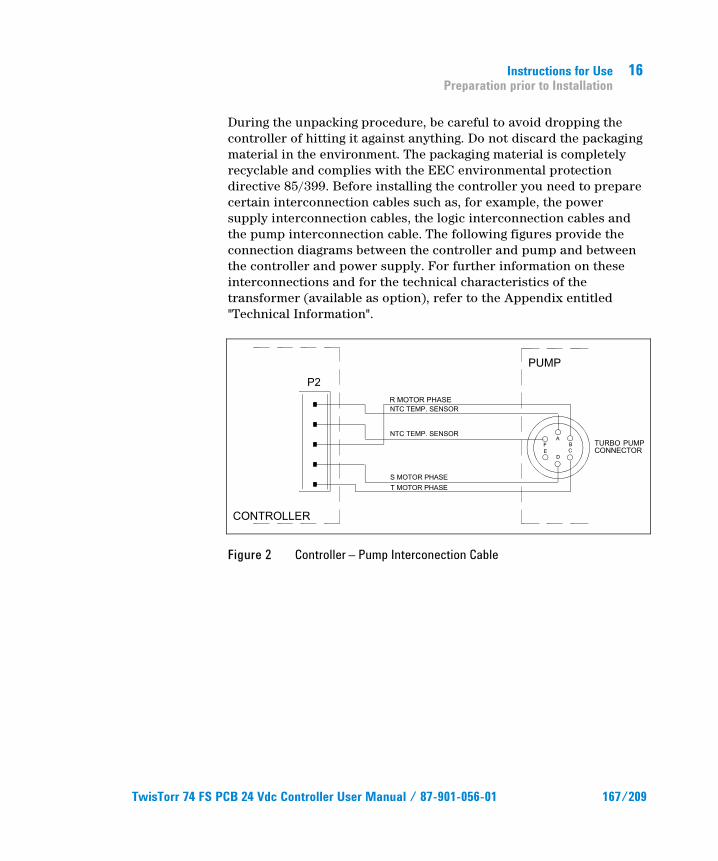
Instructions for Use Preparation prior to Installation
16
During the unpacking procedure, be careful to avoid dropping the controller of hitting it against anything. Do not discard the packaging material in the environment. The packaging material is completely recyclable and complies with the EEC environmental protection directive 85/399. Before installing the controller you need to prepare certain interconnection cables such as, for example, the power supply interconnection cables, the logic interconnection cables and the pump interconnection cable. The following figures provide the connection diagrams between the controller and pump and between the controller and power supply. For further information on these interconnections and for the technical characteristics of the transformer (available as option), refer to the Appendix entitled "Technical Information".
Figure 2 Controller – Pump Interconection Cable
TwisTorr 74 FS PCB 24 Vdc Controller User Manual / 87-901-056-01 167/209
16 Instructions for Use Installation
Installation
WARNING!
The controller develops internal voltages that could cause serious injury. Unplug the controller from the electrical wall outlet before beginning with any type of installation or maintenance procedure. In addition, the controller develops internal temperatures that could also cause serious injury. Adequately protect the controller in it final point of installation so as to avoid accidental contacts.
NOTE When definitively installed in the system, the controller must be positioned so that the cooling air can circulate freely around the equipment. Do not install and/or use the controller in environments exposed to the atmosphere (rain, ice, and snow), to dust, to aggressive gases and in explosive areas where there is a high risk of fire.
The controller must be used within the following environmental conditions:
Temperature: 0 °C to +40 °C
Relative humidity: 0 to 95 % (non-condensing).
168/209 TwisTorr 74 FS PCB 24 Vdc Controller User Manual / 87-901-056-01
Instructions for Use Use
16
Use This section provides all the major operating procedures. For further details and for the procedures that involve connections or specific options, refer to the section entitled "USE" in the Appendix "Technical Information".
Perform all electrical and pneumatic connections before using the controller, with reference to the manual of the connected pump.
WARNING!
Refer to the relevant pump manual to operate it in a safe way before starting.
Operating Procedures
Powering on the Controller To power on the controller, simply provide electrical power to it.
Starting the Pump To start the pump, leave pin 12 of connector J4 open so that the pump starts-up when 24 Vdc is provided to the controller.
Stopping the Pump To stop the pump, short-circuit pins 12 and 15 of connector J4.
TwisTorr 74 FS PCB 24 Vdc Controller User Manual / 87-901-056-01 169/209
16 Instructions for Use Maintenance
Maintenance The TwisTorr 74 FS series controllers do not require any form of maintenance. Any intervention must be performed by authorized personnel.
In case of failure you can use the Agilent customer support service or the "Agilent advance exchange service", the latter consisting of replacing a faulty controller with a refurbished one.
WARNING!
Unplug the power cord from the electrical socket before performing any type of intervention on the controller.
If a controller needs to be scraped, proceed to do so in compliance with the specific national laws.
170/209 TwisTorr 74 FS PCB 24 Vdc Controller User Manual / 87-901-056-01
Instructions for Use Disposal
16
Disposal Meaning of the "WEEE" logo found in labels. The following symbol is applied in accordance with the EC WEEE (Waste Electrical and Electronic Equipment) Directive. This symbol (valid only in countries of the European Community) indicates that the product it applies to must NOT be disposed of together with ordinary domestic or industrial waste but must be sent to a differentiated waste collection system. The end user is therefore invited to contact the supplier of the device, whether the Parent Company or a retailer, to initiate the collection and disposal process after checking the contractual terms and conditions of sale
For more information refer to: http://www.agilent.com/environment/product/index.shtml
TwisTorr 74 FS PCB 24 Vdc Controller User Manual / 87-901-056-01 171/209

16 Instructions for Use Disposal
172/209 TwisTorr 74 FS PCB 24 Vdc Controller User Manual / 87-901-056-01
TwisTorr 74 FS PCB 24 Vdc Controller User Manual
17 Technical Information General Description 174 TwisTorr 74 FS PCB 24 Vdc Controller Description 174 Controller Specifications 175 Controller Connector and Jumper 176 Jumper Configurations 177 Run-up Time Adjustment 177 Controller Outline 178 Installation 179 Data Exchange Protocols 184 RS-232 Protocol 1 Communication Description 184 Communication Protocol 185 Error Code Table 190 RS-232 Protocol 2 Communication Descriptions 190 Transmission Channel Characteristics 190 Message Structure 191 Example 194 Operation 199 Low Speed Activation/Deactivation 200 Maintenance 201 Accessories and Spare Parts 202
173/209
17 Technical Information General Description
General Description The TwisTorr 74 FS PCB controller is a microprocessor-controlled, solid-state, frequency converter with self-diagnosis and protection features.
TwisTorr 74 FS PCB 24 Vdc Controller Description The controller is driven by a single chip microcomputer and is composed of a PCB that includes all the circuitry necessary for its operation. The microcomputer generates the variable output voltage according to the software and the gas load condition of the pump. Moreover, it manages signals from sensors, input/output connection information, and gives output for a fully automatic operation. The controller can be operated via remote signals through an RS-232 connection. The controller can be operated in local mode through suitable switches connected between the input pins of J4 connector and ground (see section J4 connector for a detailed description of the input signal present on J4 connector).
174/209 TwisTorr 74 FS PCB 24 Vdc Controller User Manual / 87-901-056-01
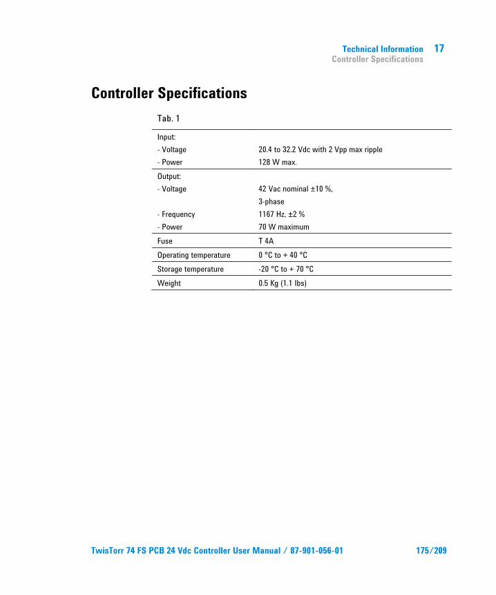
Technical Information Controller Specifications
17
Controller Specifications Tab. 1
Input: - Voltage - Power
20.4 to 32.2 Vdc with 2 Vpp max ripple 128 W max.
Output: - Voltage - Frequency - Power
42 Vac nominal ±10 %, 3-phase 1167 Hz, ±2 % 70 W maximum
Fuse T 4A Operating temperature 0 °C to + 40 °C Storage temperature -20 °C to + 70 °C Weight 0.5 Kg (1.1 Ibs)
TwisTorr 74 FS PCB 24 Vdc Controller User Manual / 87-901-056-01 175/209
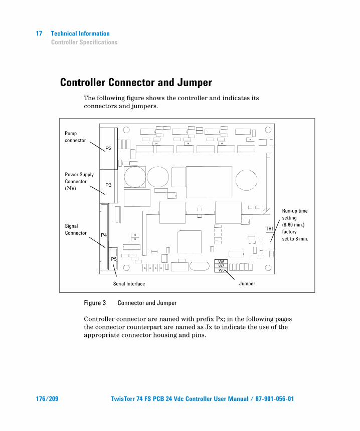
17 Technical Information Controller Specifications
Controller Connector and Jumper The following figure shows the controller and indicates its connectors and jumpers.
Figure 3 Connector and Jumper
Controller connector are named with prefix Px; in the following pages the connector counterpart are named as Jx to indicate the use of the appropriate connector housing and pins.
Pump connector
Power Supply Connector (24V)
Signal Connector
Run-up time setting (8-60 min.) factory set to 8 min.
Serial Interface Jumper
TR1
176/209 TwisTorr 74 FS PCB 24 Vdc Controller User Manual / 87-901-056-01
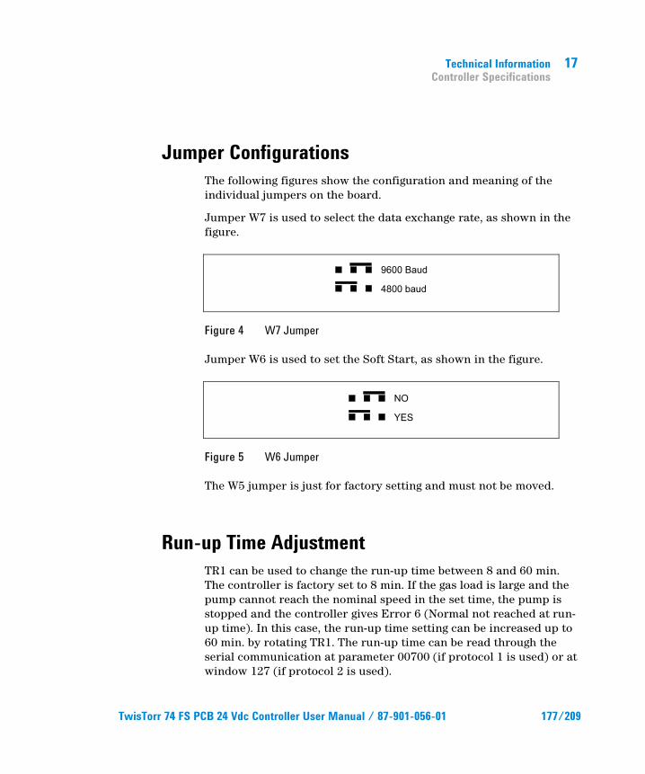
Technical Information Controller Specifications
17
Jumper Configurations The following figures show the configuration and meaning of the individual jumpers on the board.
Jumper W7 is used to select the data exchange rate, as shown in the figure.
Figure 4 W7 Jumper
Jumper W6 is used to set the Soft Start, as shown in the figure.
Figure 5 W6 Jumper
The W5 jumper is just for factory setting and must not be moved.
Run-up Time Adjustment TR1 can be used to change the run-up time between 8 and 60 min. The controller is factory set to 8 min. If the gas load is large and the pump cannot reach the nominal speed in the set time, the pump is stopped and the controller gives Error 6 (Normal not reached at run-up time). In this case, the run-up time setting can be increased up to 60 min. by rotating TR1. The run-up time can be read through the serial communication at parameter 00700 (if protocol 1 is used) or at window 127 (if protocol 2 is used).
TwisTorr 74 FS PCB 24 Vdc Controller User Manual / 87-901-056-01 177/209
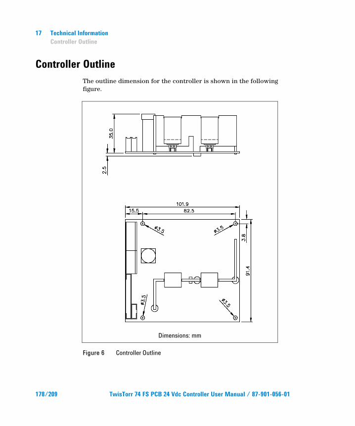
17 Technical Information Controller Outline
Controller Outline The outline dimension for the controller is shown in the following figure.
Dimensions: mm
Figure 6 Controller Outline
178/209 TwisTorr 74 FS PCB 24 Vdc Controller User Manual / 87-901-056-01
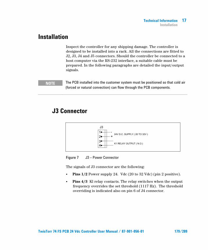
Technical Information Installation
17
Installation Inspect the controller for any shipping damage. The controller is designed to be installed into a rack. All the connections are fitted to J2, J3, J4 and J5 connectors. Should the controller be connected to a host computer via the RS-232 interface, a suitable cable must be prepared. In the following paragraphs are detailed the input/output signals.
NOTE The PCB installed into the customer system must be positioned so that cold air (forced or natural convection) can flow through the PCB components.
J3 Connector
Figure 7 J3 – Power Connector
The signals of J3 connector are the following:
Pins 1/2 Power supply 24. Vdc (20 to 32 Vdc) (pin 2 positive).
Pins 4/3 Kl relay contacts. The relay switches when the outputfrequency overrides the set threshold (1117 Hz). The thresholdoverriding is indicated also on pin 6 of J4 connector.
TwisTorr 74 FS PCB 24 Vdc Controller User Manual / 87-901-056-01 179/209
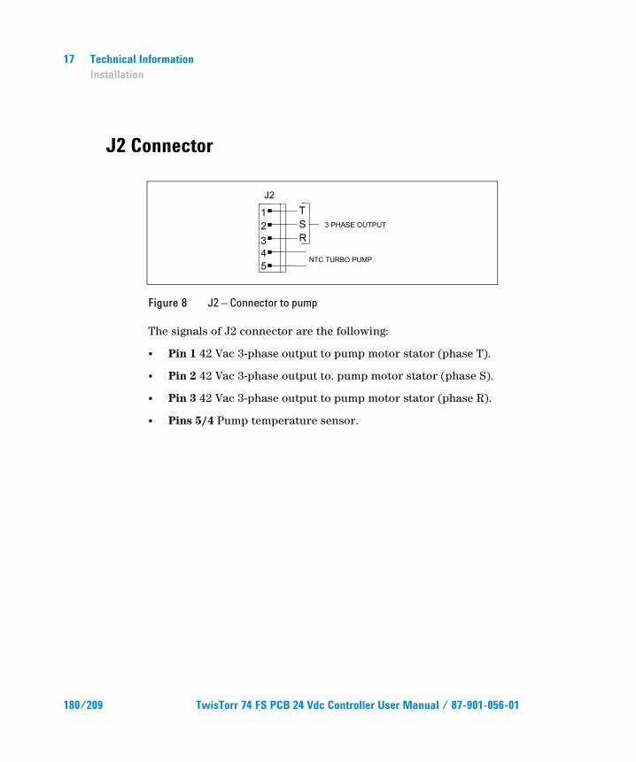
17 Technical Information Installation
J2 Connector
Figure 8 J2 – Connector to pump
The signals of J2 connector are the following:
Pin 1 42 Vac 3-phase output to pump motor stator (phase T).
Pin 2 42 Vac 3-phase output to. pump motor stator (phase S).
Pin 3 42 Vac 3-phase output to pump motor stator (phase R).
Pins 5/4 Pump temperature sensor.
180/209 TwisTorr 74 FS PCB 24 Vdc Controller User Manual / 87-901-056-01
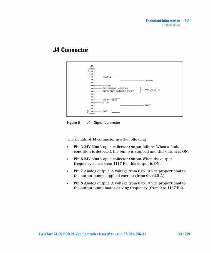
Technical Information Installation
17
TwisTorr 74 FS PCB 24 Vdc Controller User Manual / 87-901-056-01 181/209
J4 Connector
Figure 9 J4 – Signal Connector
The signals of J4 connector are the following:
Pin 3 24V 60mA open collector Output failure. When a faultcondition is detected, the pump is stopped and this output is ON.
Pin 6 24V 60mA open collector Output When the outputfrequency is less than 1117 Hz, this output is ON.
Pin 7 Analog output. A voltage from 0 to 10 Vdc proportional tothe output pump supplied current (from 0 to 2.5 A).
Pin 8 Analog output. A voltage from 0 to 10 Vdc proportional tothe output pump motor driving frequency (from 0 to 1167 Hz).
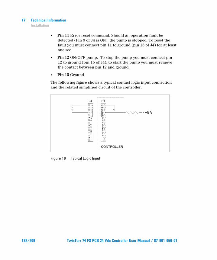
17 Technical Information Installation
Pin 11 Error reset command. Should an operation fault be
detected (Pin 3 of J4 is ON), the pump is stopped. To reset the fault you must connect pin 11 to ground (pin 15 of J4) for at least one sec.
Pin 12 ON/OFF pump. To stop the pump you must connect pin 12 to ground (pin 15 of J4); to start the pump you must remove the contact between pin 12 and ground.
Pin 15 Ground
The following figure shows a typical contact logic input connection and the related simplified circuit of the controller.
Figure 10 Typical Logic Input
+5 V
182/209 TwisTorr 74 FS PCB 24 Vdc Controller User Manual / 87-901-056-01
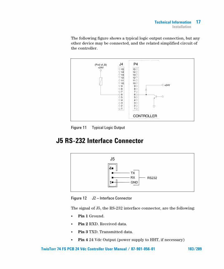
Technical Information Installation
17
The following figure shows a typical logic output connection, but any other device may be connected, and the related simplified circuit of the controller.
Figure 11 Typical Logic Output
J5 RS-232 Interface Connector
Figure 12 J2 – Interface Connector
The signal of J5, the RS-232 interface connector, are the following:
Pin 1 Ground.
Pin 2 RXD. Received data.
Pin 3 TXD. Transmitted data.
Pin 4 24 Vdc Output (power supply to HHT, if necessary)
TwisTorr 74 FS PCB 24 Vdc Controller User Manual / 87-901-056-01 183/209
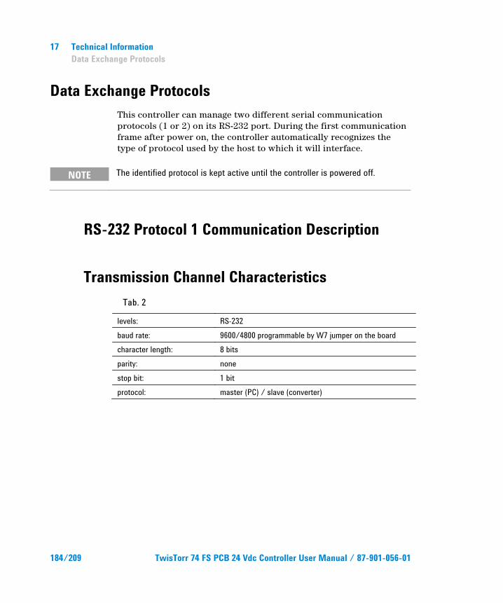
17 Technical Information Data Exchange Protocols
Data Exchange Protocols This controller can manage two different serial communication protocols (1 or 2) on its RS-232 port. During the first communication frame after power on, the controller automatically recognizes the type of protocol used by the host to which it will interface.
NOTE The identified protocol is kept active until the controller is powered off.
RS-232 Protocol 1 Communication Description
Transmission Channel Characteristics Tab. 2
levels: RS-232 baud rate: 9600/4800 programmable by W7 jumper on the board character length: 8 bits parity: none stop bit: 1 bit protocol: master (PC) / slave (converter)
184/209 TwisTorr 74 FS PCB 24 Vdc Controller User Manual / 87-901-056-01
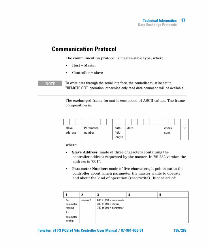
Technical Information Data Exchange Protocols
17
Communication Protocol The communication protocol is master-slave type, where:
Host = Master
Controller = slave
NOTE To write data through the serial interface, the controller must be set to "REMOTE OFF” operation, otherwise only read data command will be available.
The exchanged frame format is composed of ASCII values. The frame composition is:
slave address
Parameter number
data field length
data check sum
CR
where:
Slave Address: made of three characters containing thecontroller address requested by the master. In RS-232 version theaddress is "001";
Parameter Number: made of five characters, it points out to thecontroller about which parameter the master wants to operate,and about the kind of operation (read/write). It consists of:
1 2 3 4 5 0= parameter reading 1 = parameter writing
always 0 000 to 299 = commands 300 to 699 = status 700 to 999 = parameter
TwisTorr 74 FS PCB 24 Vdc Controller User Manual / 87-901-056-01 185/209
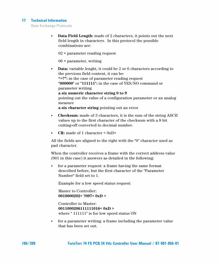
17 Technical Information Data Exchange Protocols
Data Field Length: made of 2 characters, it points out the nextfield length in characters. In this protocol the possiblecombinations are:
02 = parameter reading request
06 = parameter, writing
Data: variable lenght, it could be 2 or 6 characters according tothe previous field content, it can be:“=?”: in the case of parameter reading request"000000" or "111111": in the case of YES/NO command orparameter writinga six numeric character string 0 to 9pointing out the value of a configuration parameter or an analogmeasurea six character string pointing out an error
Checksum: made of 3 characters, it is the sum of the string ASCIIvalues up to the first character of the checksum with a 8 bitcutting-off converted to decimal number.
CR: made of 1 character < 0xD>
All the fields are aligned to the right with the "0" character used as pad character.
When the controller receives a frame with the correct address value (001 in this case) it answers as detailed in the following:
for a parameter request: a frame having the same formatdescribed before, but the first character of the "ParameterNumber" field set to 1.
Example for a low speed status request:
Master to Controller:0010000202= ?097< 0xD >
Controller to Master:0011000206111111016< 0xD >where " 111111" is for low speed status ON
for a parameter writing: a frame including the parameter valuethat has been set out.
186/209 TwisTorr 74 FS PCB 24 Vdc Controller User Manual / 87-901-056-01
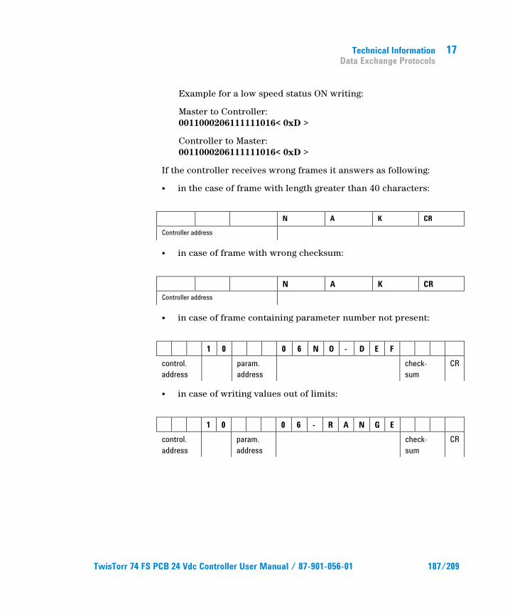
Technical Information Data Exchange Protocols
17
Example for a low speed status ON writing:
Master to Controller: 0011000206111111016< 0xD >
Controller to Master: 0011000206111111016< 0xD >
If the controller receives wrong frames it answers as following:
in the case of frame with length greater than 40 characters:
N A K CR
Controller address
in case of frame with wrong checksum:
N A K CR Controller address
in case of frame containing parameter number not present:
1 0 0 6 N O - D E F control. address
param. address
check-sum
CR
in case of writing values out of limits:
1 0 0 6 - R A N G E control. address
param. address
check-sum
CR
TwisTorr 74 FS PCB 24 Vdc Controller User Manual / 87-901-056-01 187/209
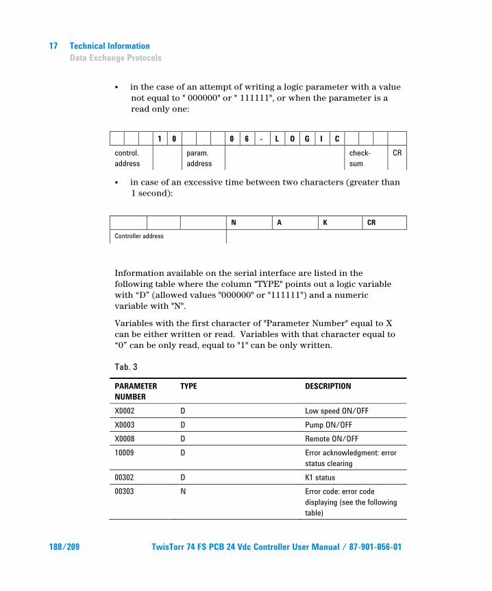
17 Technical Information Data Exchange Protocols
in the case of an attempt of writing a logic parameter with a value not equal to " 000000" or " 111111", or when the parameter is a read only one:
1 0 0 6 - L O G I C control. address
param. address
check-sum
CR
in case of an excessive time between two characters (greater than 1 second):
N A K CR
Controller address
Information available on the serial interface are listed in the following table where the column "TYPE" points out a logic variable with “D” (allowed values "000000" or "111111") and a numeric variable with "N".
Variables with the first character of "Parameter Number" equal to X can be either written or read. Variables with that character equal to “0” can be only read, equal to "1" can be only written.
Tab. 3
PARAMETER NUMBER
TYPE DESCRIPTION
X0002 D Low speed ON/OFF X0003 D Pump ON/OFF X0008 D Remote ON/OFF 10009 D Error acknowledgment: error
status clearing 00302 D K1 status 00303 N Error code: error code
displaying (see the following table)
188/209 TwisTorr 74 FS PCB 24 Vdc Controller User Manual / 87-901-056-01
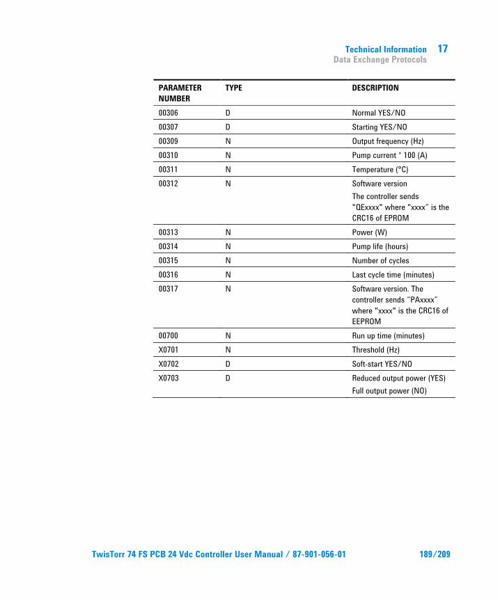
Technical Information Data Exchange Protocols
17
PARAMETER NUMBER
TYPE DESCRIPTION
00306 D Normal YES/NO 00307 D Starting YES/NO 00309 N Output frequency (Hz) 00310 N Pump current * 100 (A) 00311 N Temperature (°C) 00312 N Software version
The controller sends "QExxxx" where "xxxx” is the CRC16 of EPROM
00313 N Power (W) 00314 N Pump life (hours) 00315 N Number of cycles 00316 N Last cycle time (minutes) 00317 N Software version. The
controller sends “PAxxxx” where "xxxx" is the CRC16 of EEPROM
00700 N Run up time (minutes) X0701 N Threshold (Hz) X0702 D Soft-start YES/NO X0703 D Reduced output power (YES)
Full output power (NO)
TwisTorr 74 FS PCB 24 Vdc Controller User Manual / 87-901-056-01 189/209
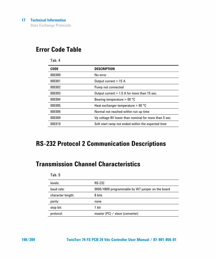
17 Technical Information Data Exchange Protocols
Error Code Table Tab. 4
CODE DESCRIPTION 00E000 No error 00E001 Output current > 15 A 00E002 Pump not connected 00E003 Output current > 1.5 A for more than 15 sec. 00E004 Bearing temperature > 60 °C 00E005 Heat exchanger temperature > 60 °C 00E006 Normal not reached within run up time 00E009 Vp voltage 8V lower than nominal for more than 5 sec. 00E010 Soft start ramp not ended within the expected time
RS-232 Protocol 2 Communication Descriptions
Transmission Channel Characteristics Tab. 5
levels: RS-232 baud rate: 9600/4800 programmable by W7 jumper on the board character length: 8 bits parity: none stop bit: 1 bit protocol: master (PC) / slave (converter)
190/209 TwisTorr 74 FS PCB 24 Vdc Controller User Manual / 87-901-056-01
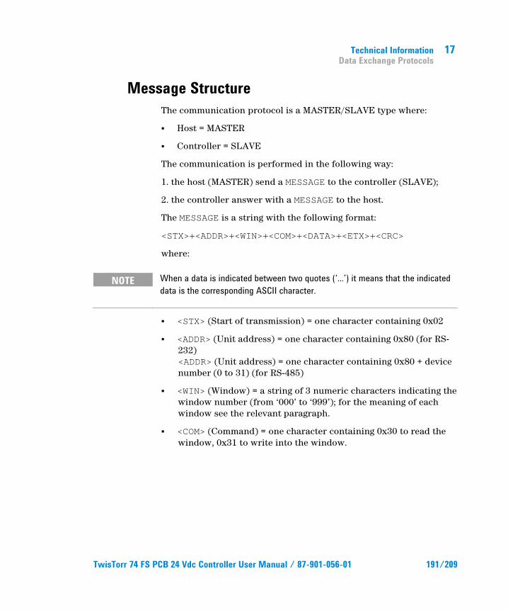
Technical Information Data Exchange Protocols
17
Message Structure The communication protocol is a MASTER/SLAVE type where:
Host = MASTER
Controller = SLAVE
The communication is performed in the following way:
1. the host (MASTER) send a MESSAGE to the controller (SLAVE);
2. the controller answer with a MESSAGE to the host.
The MESSAGE is a string with the following format:
<STX>+<ADDR>+<WIN>+<COM>+<DATA>+<ETX>+<CRC>
where:
NOTE When a data is indicated between two quotes (‘...’) it means that the indicated data is the corresponding ASCII character.
<STX> (Start of transmission) = one character containing 0x02
<ADDR> (Unit address) = one character containing 0x80 (for RS-232) <ADDR> (Unit address) = one character containing 0x80 + devicenumber (0 to 31) (for RS-485)
<WIN> (Window) = a string of 3 numeric characters indicating thewindow number (from ‘000’ to ‘999’); for the meaning of eachwindow see the relevant paragraph.
<COM> (Command) = one character containing 0x30 to read thewindow, 0x31 to write into the window.
TwisTorr 74 FS PCB 24 Vdc Controller User Manual / 87-901-056-01 191/209
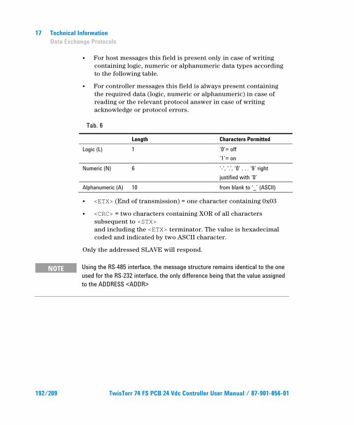
17 Technical Information Data Exchange Protocols
For host messages this field is present only in case of writingcontaining logic, numeric or alphanumeric data types accordingto the following table.
For controller messages this field is always present containingthe required data (logic, numeric or alphanumeric) in case ofreading or the relevant protocol answer in case of writingacknowledge or protocol errors.
Tab. 6
Length Characters Permitted Logic (L) 1 ‘0’= off
‘1’= on Numeric (N) 6 ‘-‘, ‘.’, ‘0’ . . . ‘9’ right
justified with ‘0’ Alphanumeric (A) 10 from blank to ‘_’ (ASCII)
<ETX> (End of transmission) = one character containing 0x03
<CRC> = two characters containing XOR of all characterssubsequent to <STX>and including the <ETX> terminator. The value is hexadecimalcoded and indicated by two ASCII character.
Only the addressed SLAVE will respond.
NOTE Using the RS-485 interface, the message structure remains identical to the one used for the RS-232 interface, the only difference being that the value assigned to the ADDRESS <ADDR>
192/209 TwisTorr 74 FS PCB 24 Vdc Controller User Manual / 87-901-056-01
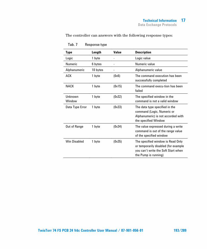
Technical Information Data Exchange Protocols
17
The controller can answers with the following response types:
Tab. 7 Response type
Type Length Value Description Logic 1 byte - Logic value Numeric 6 bytes - Numeric value Alphanumeric 10 bytes - Alphanumeric value ACK 1 byte (0x6) The command execution has been
successfully completed NACK 1 byte (0x15) The command execu-tion has been
failed Unknown Window
1 byte (0x32) The specified window in the command is not a valid window
Data Type Error 1 byte (0x33) The data type specified in the command (Logic, Numeric or Alphanumeric) is not accorded with the specified Window
Out of Range 1 byte (0x34) The value expressed during a write command is out of the range value of the specified window
Win Disabled 1 byte (0x35) The specified window is Read Only or temporarily disabled (for example you can’t write the Soft Start when the Pump is running)
TwisTorr 74 FS PCB 24 Vdc Controller User Manual / 87-901-056-01 193/209
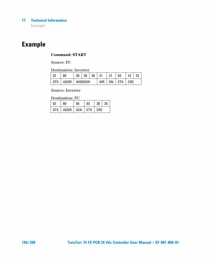
17 Technical Information Example
Example Command: START
Source: PC
Destination: Inverter 02 80 30 30 30 31 31 03 42 33 STX ADDR WINDOW WR ON ETX CRC
Source: Inverter
Destination: PC 02 80 06 03 38 35 STX ADDR ACK ETX CRC
194/209 TwisTorr 74 FS PCB 24 Vdc Controller User Manual / 87-901-056-01
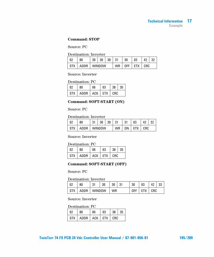
Technical Information Example
17
Command: STOP
Source: PC
Destination: Inverter 02 80 30 30 30 31 30 03 42 32 STX ADDR WINDOW WR OFF ETX CRC
Source: Inverter
Destination: PC 02 80 06 03 38 35 STX ADDR ACK ETX CRC
Command: SOFT-START (ON)
Source: PC
Destination: Inverter 02 80 31 30 30 31 31 03 42 32 STX ADDR WINDOW WR ON ETX CRC
Source: Inverter
Destination: PC 02 80 06 03 38 35 STX ADDR ACK ETX CRC
Command: SOFT-START (OFF)
Source: PC
Destination: Inverter 02 80 31 30 30 31 30 03 42 33 STX ADDR WINDOW WR OFF ETX CRC
Source: Inverter
Destination: PC 02 80 06 03 38 35 STX ADDR ACK ETX CRC
TwisTorr 74 FS PCB 24 Vdc Controller User Manual / 87-901-056-01 195/209
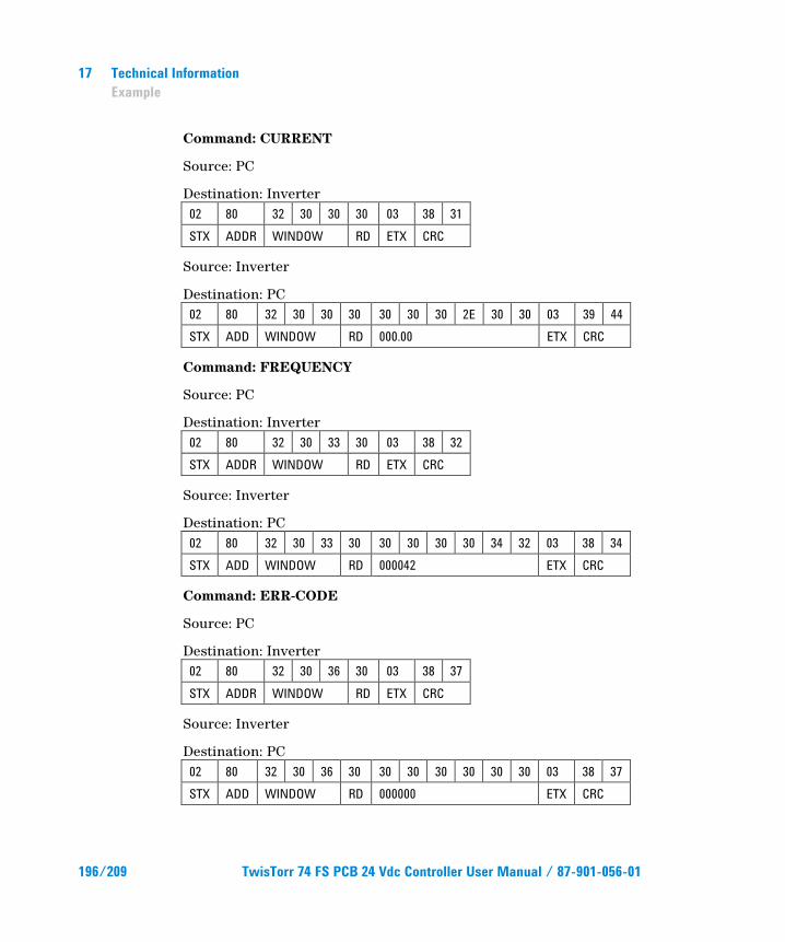
17 Technical Information Example
Command: CURRENT
Source: PC
Destination: Inverter 02 80 32 30 30 30 03 38 31 STX ADDR WINDOW RD ETX CRC
Source: Inverter
Destination: PC 02 80 32 30 30 30 30 30 30 2E 30 30 03 39 44 STX ADD WINDOW RD 000.00 ETX CRC
Command: FREQUENCY
Source: PC
Destination: Inverter 02 80 32 30 33 30 03 38 32 STX ADDR WINDOW RD ETX CRC
Source: Inverter
Destination: PC 02 80 32 30 33 30 30 30 30 30 34 32 03 38 34 STX ADD WINDOW RD 000042 ETX CRC
Command: ERR-CODE
Source: PC
Destination: Inverter 02 80 32 30 36 30 03 38 37 STX ADDR WINDOW RD ETX CRC
Source: Inverter
Destination: PC 02 80 32 30 36 30 30 30 30 30 30 30 03 38 37 STX ADD WINDOW RD 000000 ETX CRC
196/209 TwisTorr 74 FS PCB 24 Vdc Controller User Manual / 87-901-056-01
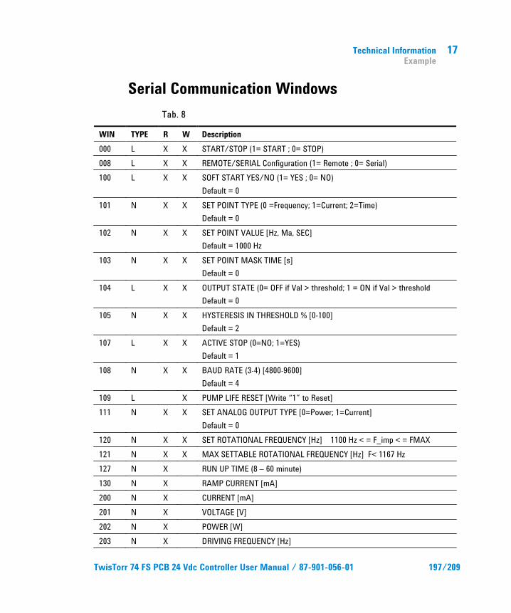
Technical Information Example
17
Serial Communication Windows
Tab. 8
WIN TYPE R W Description 000 L X X START/STOP (1= START ; 0= STOP) 008 L X X REMOTE/SERIAL Configuration (1= Remote ; 0= Serial) 100 L X X SOFT START YES/NO (1= YES ; 0= NO)
Default = 0 101 N X X SET POINT TYPE (0 =Frequency; 1=Current; 2=Time)
Default = 0 102 N X X SET POINT VALUE [Hz, Ma, SEC]
Default = 1000 Hz 103 N X X SET POINT MASK TIME [s]
Default = 0 104 L X X OUTPUT STATE (0= OFF if Val > threshold; 1 = ON if Val > threshold
Default = 0 105 N X X HYSTERESIS IN THRESHOLD % [0-100]
Default = 2 107 L X X ACTIVE STOP (0=NO; 1=YES)
Default = 1 108 N X X BAUD RATE (3-4) [4800-9600]
Default = 4 109 L X PUMP LIFE RESET [Write “1” to Reset] 111 N X X SET ANALOG OUTPUT TYPE [0=Power; 1=Current]
Default = 0 120 N X X SET ROTATIONAL FREQUENCY [Hz] 1100 Hz < = F_imp < = FMAX 121 N X X MAX SETTABLE ROTATIONAL FREQUENCY [Hz] F< 1167 Hz 127 N X RUN UP TIME (8 – 60 minute) 130 N X RAMP CURRENT [mA] 200 N X CURRENT [mA] 201 N X VOLTAGE [V] 202 N X POWER [W] 203 N X DRIVING FREQUENCY [Hz]
TwisTorr 74 FS PCB 24 Vdc Controller User Manual / 87-901-056-01 197/209
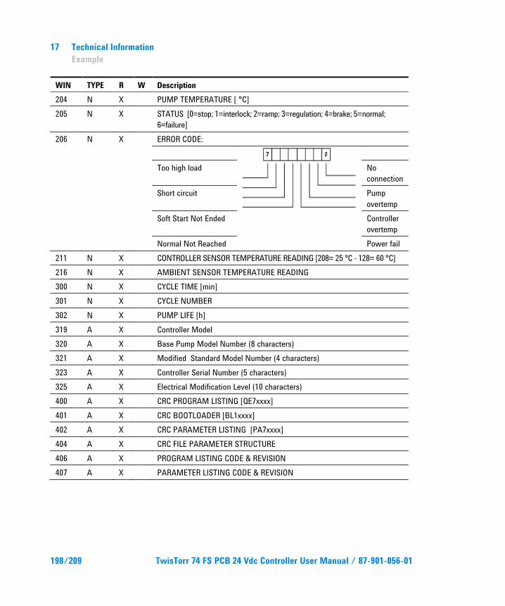
17 Technical Information Example
WIN TYPE R W Description 204 N X PUMP TEMPERATURE [ °C] 205 N X STATUS [0=stop; 1=interlock; 2=ramp; 3=regulation; 4=brake; 5=normal;
6=failure] 206 N X ERROR CODE:
Too high load No
connection Short circuit Pump
overtemp Soft Start Not Ended Controller
overtemp Normal Not Reached Power fail
211 N X CONTROLLER SENSOR TEMPERATURE READING [208= 25 °C - 128= 60 °C] 216 N X AMBIENT SENSOR TEMPERATURE READING 300 N X CYCLE TIME [min] 301 N X CYCLE NUMBER 302 N X PUMP LIFE [h] 319 A X Controller Model 320 A X Base Pump Model Number (8 characters) 321 A X Modified Standard Model Number (4 characters) 323 A X Controller Serial Number (5 characters) 325 A X Electrical Modification Level (10 characters) 400 A X CRC PROGRAM LISTING [QE7xxxx] 401 A X CRC BOOTLOADER [BL1xxxx] 402 A X CRC PARAMETER LISTING [PA7xxxx] 404 A X CRC FILE PARAMETER STRUCTURE 406 A X PROGRAM LISTING CODE & REVISION 407 A X PARAMETER LISTING CODE & REVISION
198/209 TwisTorr 74 FS PCB 24 Vdc Controller User Manual / 87-901-056-01
Technical Information Operation
17
WIN = Window
R = Read
W = Write
T = Type
L = Logical
N = Numeric
A = Alphanumeric
Operation Make all vacuum manifold and electrical connections and refer to Turbo pump instruction manual prior to operating the Turbo controller.
The controller operates completely automatically after the remote start command is given.
Switching On/Off the Pump To switch on the pump is necessary to remove the connection between pin 12 of J4 connector and pin 15 (ground) of the same connector. To switch off the pump is necessary to connect pin 12 of J4 connector to pin I5 (ground) of the same connector.
TwisTorr 74 FS PCB 24 Vdc Controller User Manual / 87-901-056-01 199/209
17 Technical Information Operation
Low Speed Activation/Deactivation
To activate the Low Speed it is necessary to connect pin 13 of J4 connector to pin 15 (ground) of the same connector.
To deactivate the Low Speed status it is necessary to disconnect pin 13 of J4 connector from pin 15 (ground) of the same connector.
The low speed status is available on pin 5 of the same connector.
The low speed frequency is 1100 Hz.
Error reset If the controller identifies an error, the pump is switched off. To start again the pump the error cause has been removed and the error status has to be reset connecting pin 11 of J4 connector to pin 15 (ground) of the same connector for at least 1 second.
200/209 TwisTorr 74 FS PCB 24 Vdc Controller User Manual / 87-901-056-01
Technical Information Maintenance
17
Maintenance Replacement controllers are available on an advance exchange basis through Agilent. If necessary, information is provided to aid the operator in determining malfunctions and corrective steps to be taken.
WARNING!
Voltages developed in the unit are dangerous and may be fatal. Service must be performed by authorized personnel only.
Error Messages The controller will self-diagnose some error causes. The controller shows the error occurred by means of a diagnostic LED located on the board, and through the serial communication port.
The LED blinks in a coded mode:
it flashes a number of time equal to the error code (see the following table) and then stays off for a while; this sequence has been repeated until the error status has been reset.
TwisTorr 74 FS PCB 24 Vdc Controller User Manual / 87-901-056-01 201/209
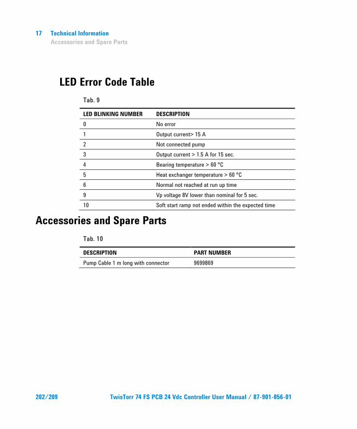
17 Technical Information Accessories and Spare Parts
LED Error Code Table Tab. 9
LED BLINKING NUMBER DESCRIPTION 0 No error 1 Output current> 15 A 2 Not connected pump 3 Output current > 1.5 A for 15 sec. 4 Bearing temperature > 60 °C 5 Heat exchanger temperature > 60 °C 6 Normal not reached at run up time 9 Vp voltage 8V lower than nominal for 5 sec. 10 Soft start ramp not ended within the expected time
Accessories and Spare Parts Tab. 10
DESCRIPTION PART NUMBER Pump Cable 1 m long with connector 9699869
202/209 TwisTorr 74 FS PCB 24 Vdc Controller User Manual / 87-901-056-01

Technical Information Accessories and Spare Parts
17
TwisTorr 74 FS PCB 24 Vdc Controller User Manual / 87-901-056-01 203/209

Vacuum Products Division
Dear Customer,
Thank you for purchasing an Agilent vacuum product. At Agilent Vacuum Products Division we make every effort to ensure that you will be satisfied with the product and/or service you have purchased.
As part of our Continuous Improvement effort, we ask that you report to us any problem you may have had with the purchase or operation of our products. On the back side you find a Corrective Action request form that you may fill out in the first part and return to us.
This form is intended to supplement normal lines of communications and to resolve problems that existing systems are not addressing in an adequate or timely manner.
Upon receipt of your Corrective Action Request we will determine the Root Cause of the problem and take the necessary actions to eliminate it. You will be contacted by one of our employees who will review the problem with you and update you, with the second part of the same form, on our actions.
Your business is very important to us. Please, take the time and let us know how we can improve.
Sincerely.
Giampaolo LEVI
Vice President and General Manager Agilent Vacuum Products Division
Note: Fax or mail the Customer Request for Action (see backside page) to Agilent Vacuum Products Division (Torino) – Quality Assurance or to your nearest Agilent representative for onward transmission to the same address.
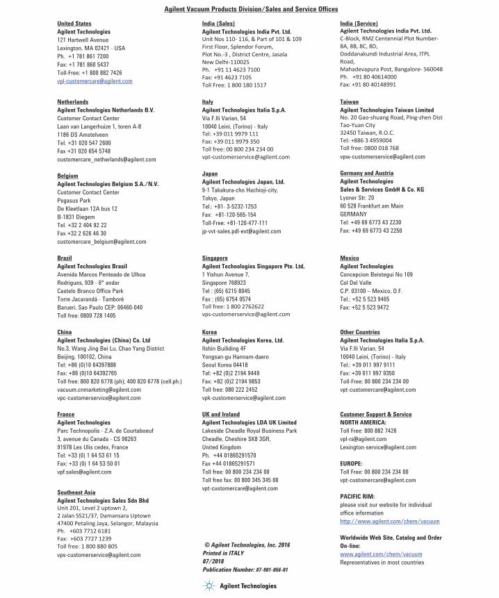
Request for Return Form
Agilent Vacuum Products Division/Sales and Service Offices
United States Agilent Technologies 121 Hartwell Avenue Lexington, MA 02421 - USA Ph. +1 781 861 7200 Fax: +1 781 860 5437 Toll-Free: +1 800 882 7426 [email protected]
India (Sales) Agilent Technologies India Pvt. Ltd. Unit Nos 110- 116, & Part of 101 & 109 First Floor, Splendor Forum, Plot No.-3 , District Centre, Jasola New Delhi-110025 Ph. +91 11 4623 7100 Fax: +91 4623 7105 Toll Free: 1 800 180 1517
India (Service) Agilent Technologies India Pvt. Ltd. C-Block, RMZ Centennial Plot Number- 8A, 8B, 8C, 8D, Doddanakundi Industrial Area, ITPL Road, Mahadevapura Post, Bangalore- 560048 Ph. +91 80 40614000 Fax: +91 80 40148991
Netherlands Agilent Technologies Netherlands B.V. Customer Contact Center Laan van Langerhuize 1, toren A-8 1186 DS Amstelveen Tel. +31 020 547 2600 Fax +31 020 654 5748 [email protected]
Belgium Agilent Technologies Belgium S.A./N.V. Customer Contact Center Pegasus Park De Kleetlaan 12A bus 12 B-1831 Diegem Tel. +32 2 404 92 22 Fax +32 2 626 46 30 [email protected]
Italy Agilent Technologies Italia S.p.A. Via F.lli Varian, 54 10040 Leini, (Torino) - Italy Tel: +39 011 9979 111 Fax: +39 011 9979 350 Toll free: 00 800 234 234 00 [email protected]
Japan Agilent Technologies Japan, Ltd. 9-1 Takakura-cho Hachioji-city, Tokyo, Japan Tel.: +81- 3-5232-1253 Fax: +81-120-565-154 Toll-Free: +81-120-477-111 [email protected]
Taiwan Agilent Technologies Taiwan Limited No. 20 Gao-shuang Road, Ping-zhen Dist Tao-Yuan City 32450 Taiwan, R.O.C. Tel: +886 3 4959004 Toll free: 0800 018 768 [email protected]
Germany and Austria Agilent Technologies Sales & Services GmbH & Co. KG Lyoner Str. 20 60 528 Frankfurt am Main GERMANY Tel: +49 69 6773 43 2230 Fax: +49 69 6773 43 2250
Brazil Agilent Technologies Brasil Avenida Marcos Penteado de Ulhoa Rodrigues, 939 - 6° andar Castelo Branco Office Park Torre Jacarandá - Tamboré Barueri, Sao Paulo CEP: 06460-040 Toll free: 0800 728 1405
Singapore Agilent Technologies Singapore Pte. Ltd, 1 Yishun Avenue 7, Singapore 768923 Tel : (65) 6215 8045 Fax : (65) 6754 0574 Toll free: 1 800 2762622 [email protected]
Mexico Agilent Technologies Concepcion Beistegui No 109 Col Del Valle C.P. 03100 – Mexico, D.F. Tel.: +52 5 523 9465 Fax: +52 5 523 9472
China Agilent Technologies (China) Co. Ltd No.3, Wang Jing Bei Lu, Chao Yang District Beijing, 100102, China Tel: +86 (0)10 64397888 Fax: +86 (0)10 64392765 Toll free: 800 820 6778 (ph); 400 820 6778 (cell.ph.) [email protected] [email protected]
Korea Agilent Technologies Korea, Ltd. Ilshin Builiding 4F Yongsan-gu Hannam-daero Seoul Korea 04418 Tel: +82 (0)2 2194 9449 Fax: +82 (0)2 2194 9853 Toll free: 080 222 2452 [email protected]
Other Countries Agilent Technologies Italia S.p.A. Via F.lli Varian, 54 10040 Leini, (Torino) - Italy Tel.: +39 011 997 9111 Fax: +39 011 997 9350 Toll-Free: 00 800 234 234 00 [email protected]
France Agilent Technologies Parc Technopolis - Z.A. de Courtaboeuf 3, avenue du Canada - CS 90263 91978 Les Ulis cedex, France Tel: +33 (0) 1 64 53 61 15 Fax: +33 (0) 1 64 53 50 01 [email protected]
Southeast Asia Agilent Technologies Sales Sdn Bhd Unit 201, Level 2 uptown 2, 2 Jalan SS21/37, Damansara Uptown 47400 Petaling Jaya, Selangor, Malaysia Ph. +603 7712 6181 Fax: +603 7727 1239 Toll free: 1 800 880 805 [email protected]
UK and Ireland Agilent Technologies LDA UK Limited Lakeside Cheadle Royal Business Park Cheadle, Cheshire SK8 3GR, United Kingdom Ph. +44 01865291570 Fax +44 01865291571 Toll free: 00 800 234 234 00 Toll free fax: 00 800 345 345 00 [email protected]
© Agilent Technologies, Inc. 2016 Printed in ITALY 07/2018Publication Number: 87-901-056-01
Customer Support & Service NORTH AMERICA: Toll Free: 800 882 7426 [email protected] [email protected]
EUROPE: Toll Free: 00 800 234 234 00 [email protected]
PACIFIC RIM: please visit our website for individual office information http://www.agilent.com/chem/vacuum
Worldwide Web Site, Catalog and Order On-line: www.agilent.com/chem/vacuum Representatives in most countries
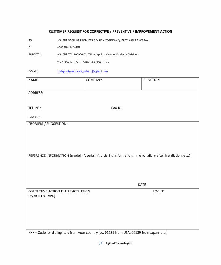
CUSTOMER REQUEST FOR CORRECTIVE / PREVENTIVE / IMPROVEMENT ACTION
TO: AGILENT VACUUM PRODUCTS DIVISION TORINO – QUALITY ASSURANCE FAX
N°: XXXX‐011‐9979350
ADDRESS: AGILENT TECHNOLOGIES ITALIA S.p.A. – Vacuum Products Division –
Via F.lli Varian, 54 – 10040 Leinì (TO) – Italy
E‐MAIL: vpd‐qualityassurance_pdl‐[email protected]
NAME COMPANY FUNCTION
ADDRESS:
TEL. N° : FAX N° :
E‐MAIL:
PROBLEM / SUGGESTION :
REFERENCE INFORMATION (model n°, serial n°, ordering information, time to failure after installation, etc.):
DATE
CORRECTIVE ACTION PLAN / ACTUATION LOG N° (by AGILENT VPD)
XXX = Code for dialing Italy from your country (es. 01139 from USA; 00139 from Japan, etc.)
Page 1 of 3 Agilent VPD Request for Return
Vacuum Products Division Instructions for returning products
Dear Customer,
Please follow these instructions whenever one of our products needs to be returned.
Complete the attached Request for Return form and send it to Agilent Technologies (see below), taking particular care to include the completed Health and Safety declaration Section. No work can be started on your unit until we receive a completed copy of this form. After evaluating the information, Agilent Technologies will provide you with a Return Authorization (RA) number via email or fax, as requested. Note: Depending on the type of return, a Purchase Order may be required at the time the Request for Return is submitted. We will quote any necessary services (evaluation, repair, special cleaning, eg).
Product preparation o Remove all accessories from the core product (e.g. inlet screens, vent valves).o Prior to shipment and if applicable for your product, drain any oils or other liquids, purge or flush all gasses, and
wipe off any excess residue.o If ordering an Advance Exchange product, please use the packaging from the Advance Exchange to return the
defective product.o Seal the product in a plastic bag, and package product carefully to avoid damage in transit. You are responsible
for loss or damage in transit.o Include a copy of the Health and Safety Declaration in the shipping documentation on the outside of the shipping
box of your returning product.o Clearly label package with RA number. Using the shipping label provided will ensure the proper address and RA
number are on the package. Packages shipped to Agilent without a RA clearly written on the outside cannot beaccepted and will be returned.
o Return only products for which the RA was issued.
Shipping o Ship to the location specified on the printable label, which will be sent, along with the RA number, as soon as
we have received all of the required information. Customer is responsible for freight charges on returning product.
o Return shipments must comply with all applicable Shipping Regulations (IATA, DOT, ADR, etc.) and carrierrequirements.
RETURN THE COMPLETED REQUEST FOR RETURN FORM TO YOUR NEAREST LOCATION:
EUROPE: NORTH AMERICA: PACIFIC RIM:
Fax: 00 39 011 9979 330 Fax Free: 00 800 345 345 00 Toll Free: 00 800 234 234 00
Fax: 1 781 860 9252 Toll Free: 800 882 7426, Option 3
Please visit our website for individual office information
[email protected] [email protected] http://www.agilent.com
Page 2 of 3 Agilent VPD Request for Return
Vacuum Products Division Terms and conditions
TERMS AND CONDITIONS Please read the terms and conditions below as they apply to all returns and are in addition to the Agilent Technologies Vacuum Product Division – Products and Services Terms of Sale.
o Unless otherwise pre-negotiated, customer is responsible for the freight charges for the returning product.Return shipments must comply with all applicable Shipping Regulations (IATA, DOT, etc.) and carrierrequirements.
o Agilent Technologies is not responsible for returning customer provided packaging or containers.o Customers receiving an Advance Exchange product agree to return the defective, rebuildable part to Agilent
Technologies within 15 business days. Failure to do so, or returning a non-rebuildable part (crashed), will resultin an invoice for the non-returned/non-rebuildable part.
o Returns for credit toward the purchase of new or refurbished Products are subject to prior Agilent approval andmay incur a restocking fee. Please reference the original purchase order number.
o Units returned for evaluation will be evaluated, and a quote for repair will be issued. If you choose to have theunit repaired, the cost of the evaluation will be deducted from the final repair pricing. A Purchase Order for thefinal repair price should be issued within 3 weeks of quotation date. Units without a Purchase Order for repairwill be returned to the customer, and the evaluation fee will be invoiced.
o Products returned that have not been drained from oil will be disposed.o A Special Cleaning fee will apply to all exposed products.o If requesting a calibration service, units must be functionally capable of being calibrated.
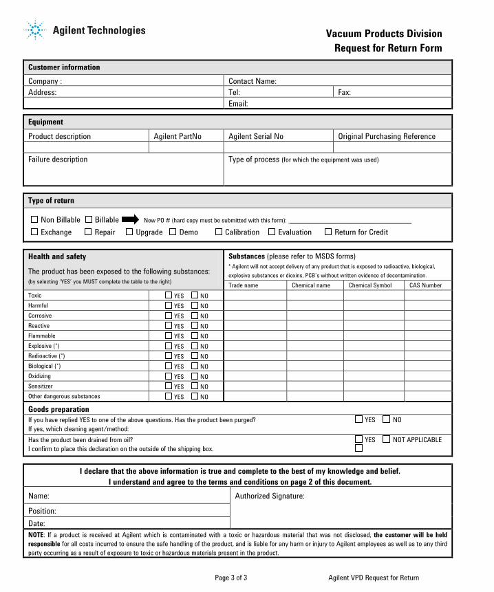
Page 3 of 3 Agilent VPD Request for Return
Vacuum Products Division Request for Return Form
Customer information Company : Contact Name: Address: Tel: Fax:
Email:
Equipment
Product description Agilent PartNo Agilent Serial No Original Purchasing Reference
Failure description Type of process (for which the equipment was used)
Type of return
Non Billable Billable New PO # (hard copy must be submitted with this form): ______________________________________
Exchange Repair Upgrade Demo Calibration Evaluation Return for Credit
Health and safety
The product has been exposed to the following substances: (by selecting ‘YES’ you MUST complete the table to the right)
Substances (please refer to MSDS forms) * Agilent will not accept delivery of any product that is exposed to radioactive, biological,explosive substances or dioxins, PCB’s without written evidence of decontamination. Trade name Chemical name Chemical Symbol CAS Number
Toxic YES NO Harmful YES NO Corrosive YES NO Reactive YES NO Flammable YES NO Explosive (*) YES NO Radioactive (*) YES NO Biological (*) YES NO Oxidizing YES NO Sensitizer YES NO Other dangerous substances YES NO
Goods preparation If you have replied YES to one of the above questions. Has the product been purged? YES NO If yes, which cleaning agent/method: Has the product been drained from oil? YES NOT APPLICABLE I confirm to place this declaration on the outside of the shipping box.
I declare that the above information is true and complete to the best of my knowledge and belief. I understand and agree to the terms and conditions on page 2 of this document.
Name: Authorized Signature:
Position: Date: NOTE: If a product is received at Agilent which is contaminated with a toxic or hazardous material that was not disclosed, the customer will be held responsible for all costs incurred to ensure the safe handling of the product, and is liable for any harm or injury to Agilent employees as well as to any third party occurring as a result of exposure to toxic or hazardous materials present in the product.
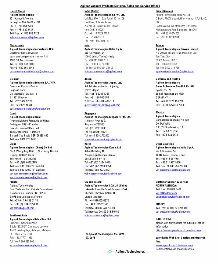
Request for Return FormAgilent Vacuum Products Division/Sales and Service Offices
United States
Agilent Technologies
121 Hartwell Avenue
Lexington, MA 02421 - USA
Ph. +1 781 861 7200
Fax: +1 781 860 5437
Toll-Free: +1 800 882 7426
India (Sales)
Agilent Technologies India Pvt. Ltd.
Unit Nos 110- 116, & Part of 101 & 109
First Floor, Splendor Forum,
Plot No.-3 , District Centre, Jasola
New Delhi-110025
Ph. +91 11 4623 7100
Fax: +91 4623 7105
Toll Free: 1 800 180 1517
India (Service)
Agilent Technologies India Pvt. Ltd.
C-Block, RMZ Centennial Plot Number- 8A, 8B, 8C,
8D,
Doddanakundi Industrial Area, ITPL Road,
Mahadevapura Post, Bangalore- 560048
Ph. +91 80 40614000
Fax: +91 80 40148991
Netherlands
Agilent Technologies Netherlands B.V.
Customer Contact Center
Laan van Langerhuize 1, toren A-8
1186 DS Amstelveen
Tel. +31 020 547 2600
Fax +31 020 654 5748
Belgium
Agilent Technologies Belgium S.A./N.V.
Customer Contact Center
Pegasus Park
De Kleetlaan 12A bus 12
B-1831 Diegem
Tel. +32 2 404 92 22
Fax +32 2 626 46 30
Italy
Agilent Technologies Italia S.p.A.
Via F.lli Varian, 54
10040 Leini, (Torino) - Italy
Tel: +39 011 9979 111
Fax: +39 011 9979 350
Toll free: 00 800 234 234 00
Japan
Agilent Technologies Japan, Ltd.
9-1 Takakura-cho Hachioji-city,
Tokyo, Japan
Tel.: +81- 3-5232-1253
Fax: +81-120-565-154
Toll-Free: +81-120-477-111
Taiwan
Agilent Technologies Taiwan Limited
No. 20 Gao-shuang Road, Ping-zhen Dist
Tao-Yuan City
32450 Taiwan, R.O.C.
Tel: +886 3 4959004
Toll free: 0800 018 768
Germany and Austria
Agilent Technologies
Sales & Services GmbH & Co. KG
Lyoner Str. 20
60 528 Frankfurt am Main
GERMANY
Tel: +49 69 6773 43 2230
Fax: +49 69 6773 43 2250
Brazil
Agilent Technologies Brasil
Avenida Marcos Penteado de Ulhoa
Rodrigues, 939 - 6° andar
Castelo Branco Office Park
Torre Jacarandá - Tamboré
Barueri, Sao Paulo CEP: 06460-040
Toll free: 0800 728 1405
Singapore
Agilent Technologies Singapore Pte. Ltd,
1 Yishun Avenue 7,
Singapore 768923
Tel : (65) 6215 8045
Fax : (65) 6754 0574
Toll free: 1 800 2762622
Mexico
Agilent Technologies
Concepcion Beistegui No 109
Col Del Valle
C.P. 03100 – Mexico, D.F.
Tel.: +52 5 523 9465
Fax: +52 5 523 9472
China
Agilent Technologies (China) Co. Ltd
No.3, Wang Jing Bei Lu, Chao Yang District
Beijing, 100102, China
Tel: +86 (0)10 64397888
Fax: +86 (0)10 64392765
Toll free: 400 8206778 (mobile)
Toll free: 800 8206778 (landline)
Korea
Agilent Technologies Korea, Ltd.
Ilshin Builiding 4F
Yongsan-gu Hannam-daero
Seoul Korea 04418
Tel: +82 (0)2 2194 9449
Fax: +82 (0)2 2194 9853
Toll free: 080 222 2452
Other Countries
Agilent Technologies Italia S.p.A.
Via F.lli Varian, 54
10040 Leini, (Torino) - Italy
Tel.: +39 011 997 9111
Fax: +39 011 997 9350
Toll-Free: 00 800 234 234 00
France
Agilent Technologies
Parc Technopolis - Z.A. de Courtaboeuf
3, avenue du Canada - CS 90263
91978 Les Ulis cedex, France
Tel: +33 (0) 1 64 53 61 15
Fax: +33 (0) 1 64 53 50 01
Southeast Asia
Agilent Technologies Sales Sdn Bhd
Unit 201, Level 2 uptown 2,
2 Jalan SS21/37, Damansara Uptown
47400 Petaling Jaya, Selangor, Malaysia
Ph. +603 7712 6181
Fax: +603 7727 1239
Toll free: 1 800 880 805
UK and Ireland
Agilent Technologies LDA UK Limited
Lakeside Cheadle Royal Business Park
Cheadle, Cheshire SK8 3GR,
United Kingdom
Ph. +44 01865291570
Fax +44 01865291571
Toll free: 00 800 234 234 00
Toll free fax: 00 800 345 345 00
© Agilent Technologies, Inc. 2018
07/2018
Customer Support & Service
NORTH AMERICA:
Toll Free: 800 882 7426
EUROPE:
Toll Free: 00 800 234 234 00
PACIFIC RIM:
please visit our website for individual office
information
http://www.agilent.com/chem/vacuum
Worldwide Web Site, Catalog and Order On-
line:
www.agilent.com/chem/vacuum
Representatives in most countries