35% reader discount on new basic concept - world radio
TRANSCRIPT
35% reader discount on new Basic concept
INCORPORATING WIRELESS WORLD
June 1997. £2.35
Opto devices and a new light meter
Does RF affect audio?
Designing voltage doubling psus
Double balanced
• mixers
Working with VHDL
Error feedback amp examples
.. ~-i. --
Austria Asch. 66.00 Denmark DKr. 67.00 Germany DM 15.00 G...,.,.e Dra .1100.00
Holland Dft. 11.75 Italy L 8800.00 Malta Lm. 1.55
IR£3.30 Singapore S$7.50
Spain Pts. 850 USA $5.95
A REED BUSINESS PUBLICATION SOR DISTRIBUTION
£ I 00 discount - Kenwood oscillosco e • . • • = •

, ® For all your Power
Distribution Olson offer a varie choice
,,,, 11 ! 1,,, .. .. ""• ..
11 11 ti I I I Ir flf CTRDNICS llMITfD CIRCLE NO. 110 ON REPLY CARD
. ___ ... - ... -·--=- -::_:,: . = ~-..=:.-----. :::-...:=~-:=--:. =~;::- ===-=·
FOUNTAYNE HOUSE, FOUNTAYNE RD., LONDON N15 4QL TEL: 0181-885 2884 FAX: 0181-885 2496
Contents ••••••••••••••••••••
Cover - Hashim Altib
456 LOUDSPEAKERS EXPOSED John Watkinson investigates why current loudspeaker designs are so backwards relative to the rest of the hi-fi chain.
466 A LOOK AT LIGHT With the aid of his new light meter design, Ian Hickman looks at some of the more recent op'to devices.
472 HANDS ON INTERNET New search options, a directory for UK electronics companies and filter design CAD are this month's discoveries from Cyril Bateman.
476 ERROR FEEDBACK IN AUDIO POWER William de Bruyn outlines three power amplifiers illustrating different ways of implementing error feedback.
480 RF EFFECTS ON AF Could mysterious audio distortions be explained by pick-up from broadcast stations? Cyril Bateman investigates.
June 1997 ELECTRONICS WORLD
486 APPLYING DIODE MIXERS Darren Conway describes how to get the best lanced diode mixers.
507 VOLTAGE DOUBLING Look-up tables make designing a reliable voltage doubling power supply relatively simple, explains Ray Fautley.
517 CD JITTER BUG Could jitter on signals between a cd player's transport and its d-to-a converter cause audible distortion? If it can, Chris Day's redesigned interface may be the answer.
519 PROGRAMMABLE LOGIC The language for describing logic systems -VHDL - and turning schematics into code are Geoff Bostock' s topics this month.
Regulars ••••••••••••••••••
443 COMMENT Pre-election blues
444 NEWS EMC laws difficult to enforce, Engineers lack lateral thinking, 56kbit modem.
450 RESEARCH NOTES Thought control, New semicoductor technique, MW sun power, Super magnets.
493 LETTERS Overload matters, Resistors in C, x-over distortion, phase quadrature.
498 CIRCUIT IDEAS • Improved infrared proximity detector • Power amp with adjustable impedance • Two-wire remote control • Ultra-simple oscillators • Infinite impedance detector • Offset source for op-amps • Switch/latch/trigger
511 NEW PRODUCTS The month's round-up of passive, active, instrumentation and computing products.
Special offers
A new language for helping scientists and engineers to visualise data is available to Electronics World readers exclusively at discounts to 44% -see page 464.
This Kenwood 20MHz dual-trace oscilloscope is on offer to EW readers at just £319 - turn to page 471.
Cars with surround-sound systems based on flat-panel loudspeakers could appear this year - see page 444.
JULY ISSUE ON SALE 5 JUNE
441 .
New: Windows software for TiePieSCOPE HS508 and TP508
This powerful! windows software gives you new possibilitie.s and intuitive control of the five integrated devices (Oscilloscope, Voltmeter, Transient recorder, Spectrum analyzer and Square wave generator) to perform all your advanced measurements.
Oscilloscope: - Number of samples settable between 10 and 32760 - Up to 32K samples on screen - Free settable pretrigger between 0 and 100% • Easy time axis zoom: scaleable scrollbar slider - Free settable sample frequency from 0.01 Hz to 50MHz - Graphical adjustment of vertical offset and gain • WYSIWYG trigger level, -hysteresis and -slope-adjustment with one control - Place the mouse over a control, press the right button and adjust all properties of that
control using the popup menu - Cursor measurements - Storing and recalling reference signals - Match channel available - Speedbutton toolbar - Colour printing supported
Voltmeter: - Up to six clear, fully configurable displays - 10 math operations, like true RMS, mean, peak to peak, frequency etc - 16 display functions like Ch1+Ch2, Ch2-Ch1 , Chi "Ch2, log(Ch1/Ch2) etc. - Data logging to disk and printer - Speedbutton toolbar
TiePieSCOPE HS508
-.;i r TP508
- interface parallel printer port - resolution B bits • input range 200mV • BOV lull scale
- interface PC-XT/AT /SA slot - resolute B bits - input range 20mV · BOV lull scale
Minimum system requirements: Window 3.1 or higher, 386 prooessor, 4MB RAM, 4MB free disk space
• price £597.00 incl. software, manual and 2 probes (1: 111:10 switchable}
- price £630.00 incl. software, manual and 2 probes (1:1/ 1:0 switchable) Prices are excluding VAT
TiePie engineering (UK) TiePie engineering (NL) P.O. Box 290 8600 WL SNEEK
E-mail: [email protected] Site: http://www.tiepie.nl
28, Stephenson Road, Industrial Estate, St. Ives, Cambs, PE17 4WJ,
The Netherlands United Kingdom Tel.: +31515415 416 Fax:+31515418819 Tel: +44 1480 460028 Fax: +44 1480 460340
8 CAVANS WAY, BINLAY INDUSTRIAL ESTATE, COVENTRY CV3 2SF Tel: 01203 650702 Fax: 01203 650773 Mobile: 0860 400683
IP'rtmiset sm,rtod dDM to EalttnH>y-f'UI in Coventry witll euy _. to M1, M6, M40, M42. M45 and Me&)
MISCELLANEOUS Adm 700A - 100Kllz· 1120MHz Synth. sign.I_.,., . . ..... ••. . •••• moo
==:~~";:.:':SO:.,~.::::::::::: :::::::::::= lllff I Sboud - EF3 variable llller 10.1Hz· 100KH,I . . . . . .. .. ......... .. t150
=.,~~~~~;·:::::::::::::::::::::::~ f!::~hzP~T-':1~~~-~\rt~·,q·~·::::: :: :: '. :: : :: : ::= flub5100A-Calibrator .. , .. , ..•• .•••••••••• .. , . . . . , .. •• .•••••• £2500 FluQ5100B-Cllitw&tor .. , .. , ..• ..• •.•••••••• . , .... • . , . • . ••••• • £3500
~it~f~~ffiodf::::::::::::······•::::::ie =1~~n,: !'c:r:~:·:rv=': ~:~ ~~~~~.::::::: :::: ::= ===:i!::~e1-:-~~s.i.M1·::::::::::::~J;; _ ,_ 435A o, B - Powe! Me<tr (with &481M484A) . ... ·"°"' £750
=::=1:.:%~~i~=ili.W1·653·,:.;· ... ts&O
~l=rmsA-_·z1MHz"irn1~ifu;.n·gen:::::::::::: = - ,_ 33W, - S""""""'1. signal gener'1or l1DH•·21MHz) •• . £1000
=;===r~mr:=::::::::::::::::::::::::::m: ===:~~lt.:='.r'.~~1~.:::::::::::::::g: - ,,_ U78A - Mu-., IS~ d,i;,t HI'S . ...... . ........ .. . lSSO Hewl9tt PICU'd 3'IIA - HP-18 swi1.ohkoM:rol un'it lvariovs plug.ins
av1illblel ... ..... . •• .......... •. . .••• .• ••• . •. . . . . ... .. . , . . . teso - P-3711A/371ZA/31918/37938- MktowlVI linl ,,,.,,... Sensor
l2ffi Hewlett PICU'd mu.. PCM Termin,I le:sUet .... '. ' . .....•.••. .•. aooo HewMt Pac:btd 3779 AJC- Primary mux aNilystf . , .. .••••••••• .tS00/£900 - hcbtd UllB- LC!I ""'" ldigitaO .... •• .• ••••••••.•••••• .fJ00 - hcl:.-d U7SA - Mulll-ftoquoncy LCR motet .••• • • ••..• •• • •• • £3960 Hewlett ~.tl19.A-1MHi. CV met:er ...... . ... . .. . ........... NISOO HtwllrtPect.-d433U-Mi11iohmete,(asnewt . . . . ... . ...•.. •.••.•• £2000 Hlwlltt:Ptc:ksd'3GA.-Qtnet:tr . • . ... . . .. ... . . .. .•••••••.•••••• .£995 twlttt hctn4941A - 1r1nsmis.sion impairment meaturing Mt ... , .. £2000
====~~l:~::~~r·:::: :: :: : : : : : : : : : ::: :: ltl¥Mtt PICU"d6lkA -(new) 100MHz umverHI counter ... . . • , . ..•• .£25C1
====i=~n:i::.:r,~~~~ ... ' .. ... .£25CI
..=~~:s;;,;;.; ...-.s:u:~ .·,o~ : :: : : : : : :: : :: : :: : :ai: Hew4d hcurd S111C - D.C. current soun:, •. • , .. . ..... ... ... • .... • £150
I tte..4ott Plcbrd 92118-Powor supply :10V-50A • • .. • .. .. .... .£460 I • CNSCOUNTFOROUANTIT!ES _
442
( II/( If /\0 /01, UN 1/fl'l l ( ·\1//J
TELNET ~ '9cbrd'355A - Millimeter WIWSOUl'Ct 2&,SG.Hz...&OG}h . . .•• .£4000 tfilwrMtt Pacbrd 1355A - Millimete, WIW tOUl'Cf 33G.Hz--50Glii , . . . ... .£'250 -hcbtdl403A-modul110f . . .. .. . ....... .. .... ........... IMO Hlwtltt Pld&lrd ..,_ - Veccor vol1rnett1 .. . . . .. . .. •. • .• • ..• •••••• .f5CIO HewtettPacbrdll20C-Swe.p0tclllsto(m,inftlfflt . . , . • . • ..• • • ••.. .aoG
====~~~~"ll,u~~;~SGH~::::::::::: - hcb,d llSOA-Stor~ notrnlliMr .. . .......... . ......... .075 = =:: := :~: -~~.,m,·::::::::::::: m: tt.wtttt Pac:brd 1951A-Celtu1ar radio intemoe ....... . ... . . .. . ... . £3500
~~~r=p-~r:n:::~.:::::::::::::::::::::i: ===--~~~"'svnihiiii,;.;.·····;;.;; :::::::::::::::~ Mao<or,i zo1SA-801(1u•1040M!h · sig. Uf'I . ....... . ..... . m so Mao<or,i 2022A - 10IOu· 1GHz . signal -110, ... ... .. ..... . moo ::=m;=~~:!nv::::..·way;.;::::::::::::::::::::::J: Marcod2956 • 29ISI-RdoCommstestset+taesa<t.plo, •.••.••• •. .DtiOO
=~rm:: 1r::.,,e,:Gioia ·:: :: : : : :: : :: : : : : : : : : : : : : = Pllllps PM 5519-Colour TV plfltm ;enerator •••••••••• •• • •.•. , .. , . ,DOO =:: ~: r~~h· ;;,.;.,;;o;,·.;,;-.,;;_;, ',;,..;,;;::::::::::: = ~ PM N70 - 120MHz high resolution lifnlt,tcoum.« ..••.••. •.• . , . .£150
R:TO:. ~-:. 1,-~.r~=':u~1! =~s:1~.~~~~~.: = := :=::;::::-_sr.::::.~g~ ~:-'.~::::: :: ::: : : : : : : : : : : : ::= Racal Dfl\l9301A· Tru,Rls R.f miUivoftmet:t r . ...••• • . .•• ..• .•• , .. 000
=====i(;~~MSMlevelmete<···•: :::::::::::::::::::=: =:==- 5 &,:;;~.;.::::::~ Rohde 1Sct,_dl11£ - R QH, 10 25MHz ..... • .. · .. . £SOD SchlllJnw NSG 203A - Linci Y(lttaot varirtion ,imulll:Of . ••. • • • • • • • · · · • .£195
==~i~~:::.:::'~i.:::::::::::::::::::::::= Schlffnw NSG 01· EltctrONtic C'9C', simutacor .. , , , , · • · • • • • • .£1250
=E=i==~~~:::::··••:::::::::::::::i5 ScHumbervlf 10&0n085n075 - Mutlimsttf1 from , · • · · · • • · • • • • • • · · • .tl50 Systron Donner 19I08- Micrc,wa..,, Swe,epe, '12·18GHzl , , . · · , · · · · · • J:2500 Tektronixm-Curvtlrto11r . ......... •.. .. • , • •, • • • • • •·· ·· · ··• ··f1150 T.-onlx-Pf~ns- Many avatllble sucll a, PGS08, FGSO,t, SC504,
1.=•L ~ Af(i5101 - Allfit,ary Function Ctn. • , • . • • • , • • , • • .t17SO Ttbrofu 12'0-Looic Afla1ystr .... .. ... . , . · · · · · .. .- • .... · .. · • .. • .£150 TtboNx AMS03 + 1MS01 + "302 - cuntnl probe Im~ •. • . , • , ••• .t9SIIS Ttttronl.l .US001 + TMSeoe - Mtlnfn1me p,ogrammeblt
diRortlon antl'('!tr ••• . .. . , · · · · · • · • • • · · · · · · · · · · · · · ·: · · • · · • • • .t1996 Tektronla:PGSOI+ TG501 +SG503TM&Q - Otcibeopecel1brttor . . .. t1995 Time 9114 . Voltage eelibrator • • • • • • • · · · · • · · · · · · · · · · · · · · · · · · • · • · · ..t150 WIV,t:9': 171 -Synthesmd fundin gene,1101 •. , , • , · . . , . , , , , , , • • , • • • aso Wl'!lftMl:1721 - f>n>vta~tlg.,ource(0.0001Hz·13MHzl . , . , . . .. , .t460
f:€E'a1ie11:~;~=:::::::::::::::::::re - - - P,ovramm,olo ._Uf'I. (3.&-6.iGHzl ... . ....... . . . .£SCI
OSCILLOSCOPES
=-,:!~~!\":~~: :::::::::::::::::::::::: ::::~ Gould Cl62A6Al2501255/I00/3000/33611-From ............... .... ms ,_ Z03/20M/20W/ZOU-From . . ..... .. ............ . ... . .. . .£150 - ,_ 1~110C/111A/112C-from .. . ... . ......... . . ... . mo _,....,. ,140A. 1mA.11..,- 100M1U .i..1c11 .... . .... . . froffloso
( Ill< If '\<J 11r ()'\ 1/f/'ll ( ·\1//J
-P-541000-1GH?diglti<ing ... .. .. ... .. .. .. ...... . , .£:19 =:i=.=~~==,vli;oi,: ,;.;.;; : : : .t_;,7: Hltadll Ya2t!i- 100MHz dig;ul dorago 1H now) ....... .. . . .. . . .. . .£2000
:::.z:"S11~l:"~~,.:,0~ !~'.:.I.::::::::::::::::::::::·= Moguro MSO 12'10A • 120M!lt d,ik~ '1orago las_, . ..... . , ... · · · · ·-Klliuu 5100- 100MHz dual clllMOI .... ...... . . .. . . .. . .. ....... .. . DIIO - COS f100 • 100MH, S dllnnel 12 traoo .. . .. .. .. .. ... .. .. ... £475
5":i-~lf~~~J~~;!~:::::::::::::::::::::::::5 ~1=~1=::..wi:~1=~.~~~'..£125 =~;=~-::::~r-'.:::::::::::::::::::::::::~m: Tllrlrorlbc2446A-150MHz-4chlnnel. . . . ..... . . . ..£1800 Tettrontx& - SOhttb dualch~, .. ...• •• ..•... . , .. , ..• •••.•• •. £no ~===~~:i~~:.~ .. i,;,j ~ ·:::::: :: :11: ~55:~~~i~~:.•.•.:·:·:·:·:·:·•·:·:·:·•·:·:·:·•·:·:·:·:·:·:·•·~·= Tettronll 47S/47SA-20(lt250 MHz dual di•!'IMI . • • . ... . .• . .. from tA15 Tettronlx 43A - 2SMHz 2 chlnntl + analogue storagfl . . , . , • ••••....•. tZ50 T-464- 1IOMHz 2 dllMel . . . . ...... .. . UOO
!5~~i~~~~hi::::::::::::::::::::::::::::i Ttlllrona 2231-100MH1 Dual Tr1e1 with '°"nter/Time,it)mm . . . . .. . . • 095 T-2335 -5100MH, dual ch. (oonablol ....................... .mo Ttlttronll M03 - 60MHz 2 o, 4 channel from •••. . ..• ••••• • • • • ••••• •• f:250 r-nu. 1ea. 1111. 1121. 1ffl. - 100MHz 4 dl. . ...... ... ·"°"' mo T-770, • 2SOMHz 4 di ......... ... .... . ..... . ... . . . . . . froffl!MO T-7904-SOOMH, . ..... ..... . ...... .... . . ........ . . . frofflmo Ttilrtronb:79M- 500Mtf:rwith stor.;e . , ...• •. , . , •••• •. ... . , .. fromf1000
f~?:~:t,:E:2'::::::::::::::::::::::::::::i: Olhor __ ...
SPECTRUM ANALYSERS
=-:1'!~~~a;;-.SG~'. 1~PB'.: :::: ..... :. :::::::::::: :::=: =::,~~'!"~!~:·11iiMH;.:1sciilii: ::::::::::::= -P-112T---!10f,tHz-21GHz} .. .. . . . . .. .. . ... .£31SG _,_1m---t1ot,tHz-1S00MHzJ . ... .. . . .. . . . . . fZIY -P-IISIA-1ti591-l0.01·1500MH<I ... .. . . .. .. ...... £32511
=:::==..."!"'=;:~1:~:.~!ci,;,idla~nei·:::::::= -P-3SIOA-51tz-50KH< .......... ...... . .. .. . .. .. .. . A: ......, Pac:u,d 3512.A - 2SKHi an,:r:r, dull chann.1 •. .. , . . • • • · · · · £SOOD
=:= == ~e-:t.n Aii,iy,.;·,;;;h ·;sic-ii. H19h ·iir,j;.d,~ IMerf10t[nnewt .. ..•• ••.•• . . ,,., . ••••••.• •.. , .. . . •.. . , · · · ~
_,_ISOSA- Netwo<t,n,Jy,or l500KHz·1.3GHzl •· ······ · £fflO _,_,,1516A- l0.01·22GHzl . ... .. . ...... .. . .. . .. . . .. . . . fZIY -P-'™A-Netwo<tanorr 130QMHzi .. •• · · · ·· ·· · · · . ·moo
ei~~$~~,.::•::::::::::::::::::::••::a SEND LARGE SAE FOR LIST Of MANY MORE ITEMS AVAILABLE . ALL EQUIPMENT IS USED ·
WITH 30 DAYS GUARANTEE, PLEASE CHECK FOR AVAILABILITY BEFORE ORDERING CARRIAGE
& VAT TO BE ADDED TO ALL GOODS
ELECTRONICS WORLD June 1997 l
EDITOR
Martin Eccles 018 1 6523128
CONSULTANTS
Jonathan Campbell Philip Darrington Frank Ogden
DESIGN
Alan Kerr
EDITORIAL ADMINISTRATION
Jackie Lowe 0 181-652 3614
E-MAIL ORDERS
ADVERTISEMENT MANAGER
Richard Napier 018 1-652 3620
DISPLAY SALES EXECUTIVE
Joannah Cox 0181-652 3620
ADVERTISING PRODUCTION
0 181-652 3620
PUBLISHER
Mick Elliott
EDITORIAL FAX
0181-652 8956
CLASSIFIED FAX
0181-652 8956
SUBSCRIPTION HOTLINE
0 1 622 778000
SUBSCRIPTION QUERIES
01444 445566 FAX 01444 445447
ISSN 0959-8332
NEWSTRADE ENQUIRIES
0171 261 7704
For a full listing of RBI magazines: http//www.reedbuslness.com
~ REED t~-..t BUSINESS 1111111':!!" INFORMATION
Pre-election blues The election campaign had its moments. Forget
Neil Hamilton and Martin Bell. Our vote for the most intriguing comment of the campaign came from Ian Taylor MP, Minister for Science and Technology in pre-election days.
"We now have a semiconductor industry in this country second to none," said the minister.
This remark may be surprising to many readers, familiar with the long list of failures in the UK semiconductor industry from GEC's closure of Elliott Automation and Marconi-Elliott Microelectronics in the seventies and its pull out from the GEC/Philips chip-making joint venture Associated Semiconductor Manufacturers, to the demise of Ferranti Semiconductors and the takeovers of Plessey Semiconductors and Inrnos in the 1980s.
Taylor's next words gave the clue to his apparently curious remark: "LG, Samsung, Siemens ... " - he was talking about the inward investors.
Inwardly investing chip companies have done a lot for the UK, from Motorola, National Semiconductor and General Instrument Microelectronics in the seventies, to NEC and Fujitsu in the eighties, to Siemens, Hyundai and LG in the nineties.
They have, as have the inwardly investing Asian tv set manufacturers, helped redress the import deficit for electronics, they have employed a lot of people, they have initiated generations of young engineers into chip manufacturing, and they have acted as a forcing ground for aspiring managers.
Many a high-flying career in the semiconductor industry started at the offices of the inward investors.
So noone's knocking the inward investors, but it would be a pity if the attitude to microelectronics in official circles in the UK is that it is something done by foreigners and all our money and effort in the area should be directed at encouraging foreigners to do it here.
That would be a pity because we have a flourishing and technologically advanced microelectronics industry in the UK from the fully integrated GPS - a world-class (top ten) player in areas such as analog and mixed signal arrays - and to fabless design-based companies like Wolfson Microelectronics which sell worldwide. In the universities the expertise is still world-leading - as witness Cambridge University's single electron memory project.
So an aware and astute government could do much to achieve the synergies and environment in which our design strengths can be encourage4 both to develop new products and compete on the world stage.
It has to be said that microelectronics does need government involvement. Even in America the contribution of government-funded laboratories to the chip industry is immense and the governmentbacked Sematech consortium maintained the US
Electronics World is published monthly. By post, currenl issue £2 .35, bock issues (if available £2.50. Order,, poymenls ond general correspondence lo L333, Electronics World, Quadrant House, The Quadrant, Sutton, Surrey SM2 SAS. Tlx:892984 REED BP G. Cheques should be mode poyoble to Reed Business lnformotion ltd Newstrade: Oi,lributed by Morke~orce (UK) ltd, 247 Tottenham Court Rood London W l P OAU 0171 26 1-51 0 8. Subscriptio ns: Quodronl Subscrip tion Services, Oakfield House Perrymoun1 Rood, Hoywords Heolh, Sus.sex RH 16 30H. Telephone 01444 445566. Please notify change of address. Subscription rotes 1 yeor £32 UK 2 years £43.00 3 years £75.00. Surface moil 1 yeor £37.00 2 years £60 00 3 yeors £86.00 Air moil Europe/Eu 1 yeor £46.00 2 yeors £73.00 ROW 1 year £56.00 2 year, £89.00
industry's world-class abilities in basic process technology when it looked, in the mid-80s, as if the companies could not afford to develop it themselves.
In Japan the collaborative programmes such as the VLSI programme of the 1980s are well-documented and led directly to Japanese domination of the memory business.
In Taiwan the government bought basic CMOS technology (seven micron) from RCA and refined it in the same government funded laboratory for twenty years - now down to quarter micron - every so often transferring the latest process to a commercial company and spinning it off as a start-up.
In Korea, the government funded the original acquisition of chip technology through the Korean Institute for Electronics Technology (set up in 1979) and followed that with the Semiconductor Industry Promotion Plan in 1982. Now the Korean Big Three - Samsung, Hyundai and LG - are all in the world top fifteen companies.
"We now have a semiconductor industry in this country second to none, 11
In Europe collaboration such as the 1980s Megaproject, and the 1990s Jessi programme, helped Philips and SGS-Thomson to top ten status, and Siemens to become No.12 in the semiconductor firmament.
So we need government involvement and funding in microelectronics. We need the government .to help our companies to participate in MEDEA - the new European joint R&D project, we need government to help to facilitate transfer of technology from defence establishments to our companies, we need it to enable our relatively small chip companies to engage in world. markets, and we need it to lubricate university/industry co-operation.
But will the politicians look behind the glamour of the headlines that accompany billion pound investments from foreigners to see and support the indigenous UK companies surviving, without much help, in a bitterly competitive world? • David Manners
Overseas a dvertising a gents: Fra nce and Belgium: Pierre Mu.ssord, 18-20 Place de lo M adeleine, Poris 75008. United Stoles of America: Roy Borne, , Reed Business Publishing l td, 475 Pork Avenue Soulh, 2nd Fl New York, NY 10016 Tel; (21 2) 679 8B88 Fox; (2 12) 679 9455 USA mailing agento: Mercury Airfreight International ltd Inc, 1 O(b) Englehord Ave, Avenel NJ 07001 . 2nd doss postage poid al Rohwoy NJ Po, tmosler. Send address change, to above. . Printed by BPCC Magazines (Carlisle) ltd, New1own Trading E, tole Carlisle. Cumbria, CA2 7NR TYf>eset by M arlin Imaging 2-4 Powerscrott Rood, Sidcup, Kent OAt 4 SOT ,
© Reed Business Information ltd 1997 ISSN 0959 8332
June 1997 ELECTRONICS WORLD 443
UPDATE ••••••••••••
Wireless data services to increase fourfold The wireless data services market is expected to increase four-fold over the next few years despite confusion on the part of users over what services are available. A report by fTMedia & Telecoms predicts a $1 Obn mobile data market by the year 2000.
444
EMC law proving difficult to enforce E uropean EMC legislation may
not be enforceable in its present form due to the cost of investigation, claims a trading standards chief.
"It's becoming questionable whether the legislation is going to be properly enforced," said David Holland, head of Cardiff County Council's trading standards unit.
Holland's team is halfway through what could tum out to be the UK's first EMC related prosecution. The unit bought four pcs and found three failed EMC tests. Trading standards officers have interviewed the companies in question.
Holland said: "In two instances all components were CE-marked. We now have to examine all the
components to determine why the pcs failed."
This burden means Holland is now doing far more work than originally envisaged. He may need to draw manpower from other investigations, placing a heavy drain on the unit's resources. If Holland discovers components were improperly CE-marked, further investigation of suppliers will be needed.
Whether or not the pc manufacturers sold faulty equipment is not in question. "The people we've interviewed have committed offences," said Holland, "that is clear cut."
But the real question that must be determined before prosecution is whether they showed due diligence
Engineers lack lateral thinking The engineering profession needs to
attract a different type of person if its to produce more top flight executives. So argues a book published by Warwick University's Institute for Employment Research.
Engineers in Top Management, based on a three-year study of over 250 companies, shows that companies run by accountants tend to outperform all others, while those headed by qualified scientists and
engineers do least well. The reason for this, argues Rob
Wilson, one of the book's authors, is due to the personalities attracted to engineering and science in the first place. They do not have the lateral thinking required for top management "Someone who goes for engineering tends to be more focused," he said.
Measures to improve the situation include the training of qualified
when designing their products. " If they have done nothing, we will prosecute," Holland confirrned. But proving this could tum out to be far too expensive for many trading standards units to justify.
The Europe-wide EMC legislation came into force on 1 January, 1996. The first year of its existence was dubbed the 'year of grace'. EMC clubs and trading standards units worked with companies to ensure conformance with the directives.
Since the start of this year, trading standards units responsible for policing the legislation have taken a tougher line. Any company at the wrong end of a successful prosecution can expect a fine of up to £5000.
scientists and engineers in management practice, as well as the development of a cadre of outstanding managers to be 'corporate mentors'.
The long term solution, described by the institute as 'brutal', is to attract what the book calls 'divergers' -bright students who currently opt for humanities subjects. "It is important that we attract our best and brightest into the profession," said Wilson.
,
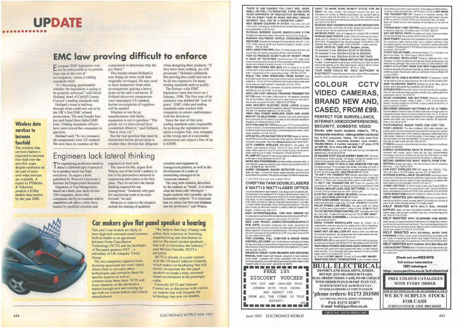
Car makers give flat panel speaker a hearing This year's car models are likely to have high-tech surround sound systems built-in thanks to an agreement between Noise Cancellation Technology (NCfl) and the developer of flat panel speakers NXT - a subsidiary of UK company Veriry Group.
The two companies signed a crosslicensing agreement last week which allows them to use each others technologies and customise them for specific markets as well as commercialise them there. NCTI will focus intensely on the automotive market through new and existing tieups with car system makers and vehicle manufacturers.
"We believe that they (Verity) will uti lise their expertise in licensing, manufacturing and distribution to deliver flat panel speaker products that will revolutionise the industry," said Michael Parrella, NCTI's president.
NCTJ is already in a joint venture with the US-based Johnson Controls, which makes car headlining that will ideally incorporate the flat panel speakers to create a truly surroundsound environment in the passenger cabin.
Currently NCTI and Johnson Control are in discussion with various car makers that will integrate the technology into new car models.
ELECTRONICS WORLD June 1997
THERE IS ONE DANGER YOU CAN'T SEE, HEAR, SMELL OR FEEL- ITS RADIATION. THERE ARE OVER 10,000 SHIPMENTS OF RADIOACTIVE MATERIAL IN THE UK EVERY YEAR BY ROAD AND RAIL! WOULD ANYBODY TELL YOU OF A RADIATION LEAK? NEW GEIGER COUNTER IN STOCK Hand held unil wiln LCD scree!\ autoranging. low battery alarm. audible'Click' output. New and guaranteed. £129 rel GE1 RUSSIAN BORDER GUARD BINOCULARS £1799 Probably IJ1e best binoculais in the wo,ldl nng ror colou, brocllwe. RUSSIAN MULTIBAND WORLD COMMUNICATIONS RECEIVER. 8<ceplionaleoverageof9 waveban<!s. (5 short. 1 LW. 1FM, 1MW) internal rernte and externaJ telescopic aerials, mains/ battery. £45 ref VEGA NEW LASER POINTERS 4.5mw. 75 metre range, hand held unit runs on two AA batteries (supplied) 670nm. £29 rer DEC49 HOW TO PRODUCE 35 BOTTLES OF WHISKY FROM A SACK OF POTATOES Comprehensive 270 page book coversallaspec:tsofspiritproductfonrromevecydaymaterials. Includes construcbon details of simple stilts elc. £12 ref MS3
NEW HIGH POWER MINI BUG With a range of up to 800 melfes and a 3 days use from a PP3 this is O\Jf lop selling bug\ less than 1·· square and a 10m v.>ce pickup range. £28 Rel LOT102. BUILD YOU OWN WINDFARM FROM SCRAP New publication giVes step by step guide 10 building wind generators and propellors Armed w,11\ 11\is publication and a good local scrap yard could make you self sufficient in elec!Jieityl E12 rel LOT81 PC KEYBOARDS PS2 connector. top quality sultat>le ror all 286/ 386/486 etc £ 10 ref PCKB. 10 foc £65. NEW LOW COST VEHICLE TRACKING TRANSMITTER KIT £29 range 1.5-5 miles. 5.000houe,on AA batteries, transmits info on car direction, left and nghl turns, start and stop information. Wot1<s with any good FM radio. £29 ref LOT101 a HIGH SECURITY ELECTRIC COOR LOCKS Complete brand new Italian lock an<! lat ell assembly with both Yale Iypelock(keys inc) an<! 12v operated deadlock £10 rer LOT99 "NEW HIGH POWER WIRELESS VIDEO AND AUDIO BUG KIT 112 MILE RANGE Transmits Video and audio signals from a minature CCTV camera (included) to any standard tele\lisiont Suppl red with telescopic aerial. £ 169 CCTV PAN AND TILT KIT Motorize your CCTV camera wilh this simple 12voc kil 2 hermentically sealed DC nnear servo motors 5mm threMed output 5 secs s\01> to stop, can be stopped any where. 10mm travel, i,owerfUI. £12 ref LOT125 GPS SATELLITE NAVIGATION SYSTEM Made by Garmin. the GPS38 IS hand held. pocket sized, 255g, posrtion. attitude. graphic compass. map builder, nitrofilted. Bargain price Just £179 refGPS1.
CCTV CAMERA MODULES 46X70X29mm, 30 grams. 12v 100mA. auto electtonic shulter, 3.6mm F2 lens, CCIR. 512x492 pixels, video output is 1v P·P (75 ohm). WoJ1.cs directly into a scart or Video Input on a tv or video. IR sensitive. £79.95 ref EF137. IR LAMP KIT Sui!able for the above camera, enables the camera to be useo in total darlcnessl £6 ref EF138 INFRA RED POWERBEAM Handheld battery p,,,ered lamp, 4 inch reflector. gives out PQWCrful Pore infrared lrghtl perfect for CCTV use. nightslghts ete £29 ref P81. SUPER WIDEBAND RADAR DETECTOR Detects both radar and lase< • X K and KA bands. speetj cameras. and all known speeddetecrionsyslems. 360degreecoverage, front&earwaveguides,
1 1-x2,7""x4 6"' fits on sun vtSOr or dash £149 ref
CHI EFT AN TANK DOUBLE LASERS 9 WATT +3 WATT +LASER OPTICS Could be adapted for laser listener. long range communicallons etc Oout>re beam units designed to fit 1n the gun barrel of a tank. each unit has two semi conductor lasers and motor drive unrts for alignement. 7 mile range, no circuit diagrams due to MOO, new price £50,0CNJ? us? £ 199. Each unit has two gallium Arsenide injection lasers, 1 x 9 watt, 1 x3wart, 900nmwavelength. 28Vdc, 600hz pulse frequency. The units also contain an electronic tecerver to detect reflected signals from targels. £199 for one Ref LOT4. EA SY DIV/PROFESSIONAL TWO WAY MIRROR KIT Includes special adhesNe film tomaketwoway m1110<{s) upto60""2C1'. (glass not included) includes full instructions. £12 ref TW1. NEW LOW PRICED COMPUTER/WORKSHOP/HI-Fl RCB UNITS Complete prolectlon rrom rauny equipment for everybody! lnline unit rrts lo stalldard !EC lead (extends it by 750mm). fitted in less than 10seconds, reset/lest boJtton. 10Aratir9. £6.99each ref LOTS. Ora pack ol 10al£49.90 reJLOT6. If you want a box of 100 you can have one for £2501 TWO CHANNEL FULL FUNCTION B GRADE RADIO CONTROLLED CARS From Wood ra= manufacturer these are relllms so they wll need attention (usually physical damage) cheap way olbuy!og TX and RX plUs servos etc for new projects etc. £12 each sold as seen ref LOT2. MAGNETIC CREDIT CARD READERS AND ENCODING MANUAL £9.95 Cased with nylea<ls. designed to read standard cred;t cards! complete with cootrof eJctronics PCB and manual covering every!hing yoo could want to know about whats hiddeo m that magnetic strip on your card! Just £9. 95 ,er BAR31
·----------.. FREE 10%
: DISCOUNT VOUCHER :
I CUT OUT AND I NCLUDE THIS I
CORNER WITH YOUR ORDER
I AND DEDUCT 1 0% I I FROM ALL THE ITEMS IN THIS I
ADVERT !
1.---------.:~ June 1997 ELECTRONICS WORLD
WANT TO MAKE SOME MONEY? STUCK FOR AN IDEA? We have collated 140 business manuals Iha! give ,oo Information on setbng up <1ifferent businesses, y0u peruse these. al your leisu,e using the text editor on your PC. Also included is lhe certificate enabling you to reproduce (and sell) the manuals as much as you like! £1 4 ref EP74 RUSSIAN 900X MAGNIFICATION ZOOM MICROSCOPE metal construction, bu1II in lfght, mirror etc. Russianshrimpfarml. group vIewmg screen, lots of accessories. £29 ref ANAYLT AA NICAD PACK Pack ol 4 tagged AA nicads £2 99 rel BAR34 RUSSIAN NIGHTSIGHTS Model TZS4 with mrra red illuminate,, views up to 75 metres in full darkness in infrared mode. 150m range, 45mm1ens, 13degangleofview. fOCt:Jssingra·nge1.5m to infinity 2AA batteries required. 950g weight £199 ref BAR61. 1 years warranty LIQUID CRYSTAL DISPLAYS Bargain prices, 16 character 2 line, 99x24mm £2.99 ref SM1623A 20 character 2 line, 83x19mm £3.99 ref SM2024A 16 c haracler 4 line, 62x25mm £5.99 ref SMC1640A TAL-1, 110MM NEWTONIAN REFLECTOR TELESCOPE Russian, Superb astronomical 'scope, everything you need for some serious star gazing! up to 169x magnirtCation. Send or fax for further lnformation.20kg. 885XOO!lx1650mm re! TAL-1. £249 YOUR HOME COULD BE SELF SUFFICENT IN ELECTRICITY Compieheosive plans with loads ofinfoondesigning systems, panels. control electronics en: £7 ref PV1
COLOUR. CCTV VIDEO CAMERAS, BRAND NEW AND, CASED, FROM £99. PERFECT FOR SURVEILLANCE, INTERNET,VIOEOCONFERENCING, SECURITY, DOMESTIC VIDEO Works with most modem video's, TV's, Composite monitors, videograbbercardsetc Pal, 1v P~. composi te, 75ohm, 113"' CCD, 4mm F2.8, 500x582, 12vdc, mounting b racket , auto shutter, 100x50x180mm, 3 months w arranty,1 off pr ice £119 ref XEF150, 10 or more £S9 ea 100+ £89 MICRO RADIO If s tiny, JUSI W !hick, auto tunnir9, complete with headphones. FM £9.99 ref EP35 25 SQUARE FOOT SOLAR ENERGY BANK KIT 100 6"x6" 6v Amorphous 100mA panels, 100 diodes. connection details etc to build a 25 square foot sola, cell klr just E99 rer EF112. CONVERT YOUR TV INTO A VGA MONITOR FOR £25! Converts a colour TV in1o a basic VGA screen. Complete wilh built in psu. lead ands/ware .. Ideal for laptops or a cheap upgrade.Supplied 1n kil rorm foc home assembly. SALE PRICE £25 REF SA34 "15 WATT FM TRANSMITTER Already assembled but some RF knowledge will be useful for setting up. Preamp req"d. • sIage 80-108mhZ, 12·18vdc, can use ground plane, yagi or dipole £.69 ref 1021 •4 WATT FM TRANSMITTER KIT Small boJt powerful FM transmitter kit 3RF stages, mic & audiol)<eamp incJuded£24 ,er 1028 YUASHA SEALED LEAD ACID BATTERIES 12v 15AH at £ 16 <er LOTS and be!ow spec 6v 10AH at £5 a pa,r ELECTRIC CAR WINDOW DE-ICERS Complete with cable. plug etc SALE PRICE JUST £4,99 REF SA28 AUTO SUNCHARGER 155x300mm solar panel wtth diode and 3 metre lead fitted with a cigar plug. 12v2watt. £12.99REF AUG10P3. SOLAR POWER LAB SPECIAL You get 2 6"x6" 6v 130rnA cells, 4 LED's. wire, boJzzer. swftcro • 1 retay or motor. E7 .99 REF SA27 12V DC MOTOR SPEED CONTROL KIT Complete witn PCS etc. Up lo 30A. A heat sink may be required £19.00 REF: MAG17 SOLAR NICAO CHARGERS 4 x AA srze £9.99 ref 6P476. 2 x C size £9.99 ref 6P477 MEGA POWER B INOCULARS Made by Helios, 20 x magnlfocation, precision ground fully coated optrcs, 60mm objectrves, shock resist an I caged prisms. case and neck strap. £89 ref HP~ 1 GIANT HOT AIR BALLOON KIT Bulfd a 4.5m c,rcumrrence, fully functioning balloon. can be launched with home made burner etc. Reusable (Until you loose ill) £12.50 relHA1 . AIR RIFLES .22 As used by the Chinese army for training puposes. solhere is a lot aboutl £39.95 Rel EF78. 500 pellets £4.50 ref EFSO. "NEW MEGA POWER VJDEOANO AUDIO SENDER UNIT. Transmits both aud10 and video signals from either a video camera. video recorder. TV or Computer etc lo any sIan<!ard TV set ,n e 500m range! (tune TV to ctiannel 31) 12v DC oP Price is £65 REF: MAG15 12v psu Is £5 extra REF: MAG5f'2 "MINA TU RE RADIO TRANSCEIVERS A pair of walkie talkies
BULL ELECTRICAL 250 PORTLAND ROAD, HOVE, SUSSEX .
BN3 5QT. (ESTABLISHED 50 YEARS). MAIL ORDER T:ERMS: CASH, PO OR CHEQUE
WITH ORDERPLUS£3.50 P&P PLUS VAT. 24 HOUR SERVICE £4.50 PLUS VAT. OVERSEAS ORDERS AT COST PLUS £3.50
'phone orders: 01273 203500 (ACCESS, VISA. SWJTCR,AME!UCAN EXPRESS)
FAX 01273 323077 E--mail bull@pavilion_co.uk
CIR( LE NO. I 1111 ON REPLY CARD
with a range upto2 km m open count,y Units measure 12:):52x155mm Including cases aod earp·ces. 2xPP3 req'd, £37 .00 pr.REF: MAG30 "FM TRANSMITTER KIT housed In a standard worl<ing 13A adapterl1 lhe boJg ru~s d11eo11y o.i the mains so lasts for....,;11 why pay £700? 0< pnce is £18 REF: EF62 (l<il ) Tra,sm,ts to any FM radio. Buill and tested version nQIN avaliabfe of the above unit at £45 ref EXM34 •FM BUG BUil T AND TESTED superiDf design to kit. Supplied lo delectr;e agencies. 9v battery req'd E 14 REF MAG 14 GAT AIR PISTOL PACK Complete With pistol. darts and pellets E14 95 Rer EF82B extra pellets (500) E4.50 rel EFSO. HEAT PUMPS These are mains ope,ated air to a11 units 11,at oonsisl of a aJummium ~ate (co~ ing side) and a raefiator (wanning s,deJ connected together with a cornp<essor. The plate if inserted into water wil1freeze it. Probably about 3-400 watts so could produce 1 k'.v in ideal cond;ttons. £30 ref HP1
3 FOOT SOLAR PANEL Amorpnous silicon. 3' x 1· housed 1n an aluminium frame. 1311 IOOmA ooput. £55 ref MAG45 SOLAR/WIND REGULATOR Prevents batteries from over charging, On reaching capae1ty the regulator diverts excess pow-er 1n10 heat avoiding damage. Max PQWCrrs 60 watts. £2799refSICA11-/05 FANCY A FLUTTER? SEEN OUR NEW PUBLICATION? Covers all aspecIsof horse and dog betting. systems etc and goves you a betting system that should make your betting rar more profitable! £6 a copy rel BET 1 FIBRE OPTIC CABLE BUMPER PACK 10 meIn,,i for £4.99 ref MAG5P13 ideal for el(penmenleisl 30 m for £12.99 ref MAG13P1 4X28 TELESCOPIC SIGHTS Su~able for all a,r ones. ground lenses. good light gathefing properties. £24.95 ref R/7 _ GYROSCOPES Remember these? v,eU we have found a company that stilt manufactures these popular scaent1fic toys. perfect gift or for educational use etc £6 ref EP70 NICAD CHARGERS AND BATTERIES Standard universal mains ope,ated charger, takes 4 batts • 1 PP3. £10 rel P011D Nicads• AA size (4 pack) £4 ref 4P44, C Sile (2 pack) £4 ref 4P73, D srze (4 pack) £9 ref 9P12. RECHARGE ORDINARY BATTERIES UP TO 10 TIMES! With the 8a:ttery WtZard1 Uses the latest pulse wave charge system to charge all popular brands of ordinary batteries AAA, AA, c. D, four at a timeJ Led ,iyslem shows when batteries ere charged. automatically rejects unsuitable cells, complete \Mth mains adaptor BS approved. Price is £21 95 ref EP31. PHOTOGRAPHIC RADAR TRAPS CAN COST YOU YOUR LICENCE! The new multiband 2000 radar detector can pcevent even the most responsible of drtvers rrom 1osiOQ m~r l1cencel AdJustable audible alarm with 8 flashing recs gives instant warning of radar iones De!ects X. K. and Ka bands. 3 mire Iange, ·crver the hor 'around bends' and 'rear trap facilities micro size Just 4. 25'"x2. 5''x. 75". can pay ror itsel1 in just one dayl £89 ref EP3 3"' DISCS As used on older Am st rad machrnes. Spectrum plus3"s etc £3 each ref 8AR400 STEREO MICROSOPES BACK IN STOCK Russian. 200x complete with lenses. lights. filteis etc etc very comprehensive microscope that would normally be around the £700 mark, our price is just £299 (full money back guarantee) full delails in catalogue. SECOND GENERATION NIGHT SIGHTS FROM £748 RE TRON Russian mght sight, 1.8x, infra red lamp, 10m-inf. standard M42 lens. 1.Jkg £349 rel RET1
. LOW COST CORDLESS MIC 500' range, 90. 105mhl. 115g. 193 x 26 x 39mm. 9v PP3 battery required £17 rel MAG15P1 HI POWER SURVEILLANCE TELESCOPE Continuous zoom control from 20 times 10 an amazing 60 times magnif,cat.,n. 60mm fully coated objective lens for ma:idmum light transm\-S-ston. oomplete with tripod reaturing miem elevation control. £75 ref zn JUMBO LED PACK 15 10mm b1eolour !eds, plus 5 gianl (55mm) seven segment displays all on a pcb ES ref JUM 1. Paek of 30 55mm sevensegdisptays onpcl>sos£19 ref LED4. packo/50 £31 relLEDOO 12VOC40MM FANS MADEBYPANAFLO, NEW, £4 REFFAN12
HELP WANTED W ITH MOTORS we haVe thousands to clear al rock bottom pricesl boJmper pack orw motocs (oot eh0tce) rs Iust E19.951 Some of these will be 5" or mayt,e large~ HELP WANTED WIT H MULTI RAIL POWER
SUPPLIES Again we have thou.;,nds available. most with rans. mostly cased, sold as seen. condition may va(Y, some working some. not. Pack of 10 is £19.95
HELP WANTED W ITH TELEPHONE COIN BOXES Needwe say, thousands ewilablet these ere unrts des,gned to convert an 01dina.ry phonemto a coin box phone They have damaged cases but ltle efectronics and oonslOts are ok. Speech chip on the board talks to you as you program ltl Pack of 10 Is £19.95
HELP WANTED WITH EXTERNAL MICRO TAPE STREAMERS 10.(XXl in stock. space needed I brand new cased unrts with loads of lnteresllng bits (motor. lape heads. PCB etc etc. Very smart plastic ease useful foc projects etc. Paci< of 20 is£ 19.95 ref M02
HELP WANTED WITH YUASHA 12V 6.5AH SEALED
LEAD ACID BATTERIES Ab0u110paletsfull justinsl<lewarehouse no 21 pack of 5 for just£ 19.95 also some belO>N spec6V 10.H al£ 19.95 r0< a pack or 8
Check out ourWEB SITE
full colour interactive 1997 catalogue , ... ,_.
httpa/ / www.pavillon.eo.uk/bull-electrlcal
FREE COLOUR CATALOGUE WITH EVERY ORDER
"SOME OF OUR PRODUCTS MAY B E UNLICENSABLE lN THE UX
WE BUY SURPLUS STOCK FOR CASH
SURPLUS STOCK LINE 0802 660335
445
UPDATE
446
World standard DAB setback The worldwide adoption of the
European Eureka 147 standard for DAB, or digital audio broadcasting, has taken a blow after a US decision to favour a satellite-based system.
To this aim, the US Federal Communications Commission (FCC) has auctioned frequencies in the S-b and spectrum (2310 to 2360MHz). However, satellite-based DAB systems, unlike Eureka 147, cannot deliver cd-clarity audio to stationary and mobile users in open and urban areas, countering the whole purpose of adopting DAB. ·
The US government's decision has been described by the Consumer Electronics Manufacturers
Association (CEMA) as "disastrous for digital audio radio in the US".
CEMA now hopes to sway the US government towards giving up the Lband frequencies (1452 to 1492MHz), currently reserved for Pentagon use. The L-Band is suited to the improved quality terrestrial debvery of DAB, and CEMA is lobbying to get the Eureka 147 system implemented in the spectrum, even though it believes the license fees demanded for Eureka 147 are too steep for US broadcasters.
Frans Westra, DAB project leader at Philips, countered the claim by saying: "It's not quite clear what is going on, but I have never seen a
technically superior system fail because of high licence fees."
Moreover, certain Eureka 147 DAB receiver makers are not unduly concerned about developments in the US. "Currently we are looking at Europe although we are keeping a close eye on the situation in the States," said Tony Star.ling, sales director at Kenwood, which is launching the first commercial carDAB receiver in a couple of week's time.
Eureka 147 has been selected by 20 countries worldwide. Japan has still to choose and is watching developments in the US.
End of 56kbit modem war in sight Peace talks next month could end
the 56kbit/s high speed modem standard war.
Lucent Technologies and Rockwell , who are promoting their joint K56Flex protocol, invited their rival, US Robotics, which is marketing its x2 modem, to the inaugural meeting of the Open 56K
Forum held in New York. Although US Robotics could not
make the conference in tin1e -"Unfortunately, they only asked us to join half-an-hour before the first meeting," said a US Robotics spokesperson - the company is considering taking part in the next one, scheduled for later this month.
It raises the possibility that all three companies contribute to a common standard which would be put before the International Telecommunications Union (ITU) for approval, so users can be confident the modem they buy will be compatible with those used by all Internet service providers.
UMIST researches self drive cars
C ars which drive themselves is the goal of research being
carried out at University of Manchester Institute of Science and Technology (UMIST).
Follow on from the EC-funded Prometheus project aimed at preventing accidents through corrected steering, UMIST is developing vision systems which enable cars to operate on all road types.
Panos Liatsis, of UMIST's Control
Systems Centre, explained that a system for motorway use, where the road is well defined, is relative ly straightforward, but "driving within the city is far more adventurous."
According to Liatsis, the intelligent sensing system for obstacle detection currently being developing relies on image analysis and neural network techniques. It consists of two modules: one for obstacle detection, the other for classification.
The first module examines an
image for edges, to determine regions of interest (ROis). The second module uses higher order neural networks (HONNs) to identify obstacles within the ROis. They decompose ROls into coarse fields, which are matched with known vehicle shapes.
The system has been tested with 400 images containing objects with different scaling and positions, and achieved a detection accuracy of 96 per cent.
Marconi archive to stay in UK Guglie lmo Marconi 's archive of scientific equipment and documents relating to his years developing the first practical radio transmitters at the beginning of the century is to be given to the nation by GEC-Marconi, the present owner.
Original plans to auction the archive - valued at between £1 m and £3m - were scrapped earlier this year in response to criticism, including a letter to The Times from Marconi's daughter, that the archive was too important to the history of scientific discovery to be broken up.
GEC-Marconi has agreed to give the archive of over 1000 items, which includes Marconi's first patent for improvements to wireless te legraph y, a letter from Queen Victoria and radio message transmitted from the sinking Titanic, to the Science Museum in London.
Part of the archive will be displayed in a Marconi centre to be set up at the Chelmsford site where Marconi built the world's 11rst radio factory.
ELECTRONICS WORLD June 1997
The Home of ~t-"Juee44e. Its not what you do, its HOW you do it that counts!.
Hart Audio Kits and fac1ory assembled units use the unique combination of circuit designs by the renowned John Linsley Hood, the very best audiophile components. and our own engineering expertise, to give you u nbea1able performance and unbelievable value for money. We have always led the field for easy home construction to professional standards, even In the sixties we were using easily assembled printed circuits when Heathkit In America were still using tagboardst. Many years o f e xperience and Innovation, going back to the early Dinsdale and Balley classics gives us Incomparable design background in the needs of the home constructor . This sJmply means that building a Hart kit Is a real pleasure, resulting In a p iece of equipment that not only saves you money but you wllt be proud to own. Why not buy the repr ints and construction manual for the kit you are Interested in to see how easy It Is to bulld your own equipment the HART way. The FULL cost can be credited against your subsequent kit purchase.
'AUDIO DESIGN' 80 WATT POWER AMPLIFIER.
. _.. ~- ... - - --' - -
. - -
This fantastic John Linsley Hood designed ampliUer is the flagship of our range, and 1he Ideal powerhouse for your ultimate hill system. This k it is your way to get £K pe,tormance at bargain basement prices. Unlque design lealures such as fully FET stabilised power supplies give this amplifie r World Class pertorrnance with sta'11iog clarity and transparency ot soul'td, allied to the famous HART quality components and ease of construction. Standard mddel comes w11h a versatile passive lront--end giving 3 switched Inputs, with ALPS precision •stue Velver low•ooise volume and balance con1<ols, no need for an external preamp!. Construction is very simple and enjoyable with all the dlfficull work done for you, even the wiring is pre-terminated, ready for instant use I. All versions are available wilh Standard components or specially selected Super Audiophile components and Gold Plated speaker terminals and atl are also available factory assembled. K1100 Complete STANDARD Stereo Amplifier KIi, , , , . .. £415.21 K1100S Complete SLAVE Amplifier Kil,. . . . .. . £353.62 K1100M Complete MONOBLOC Amplttier Kil,. , . . , . , , . , £271.20 RLH1 1 Reprints of latest Am~ifier articles . . . . . , . . £1.80 K1100CM Conslructioo Manual with lull parts lists , . , , . . . . £5.50
ALPS " Blue Velvet" PRECISION AUDIO CONTROLS.
Now you can throw out those -noisy Ill-matched carbon pots and replace with the famous Hart exclusive ALPS 'Blue Velvet' range components only used selectivety in the very lop flight o1 Wor1d class amplifiers, The improvement in track accuracy and matching really is incredible giving better tonai balance between channels and rock solid image stability. Motorised versions have Sv DC motor.
MANUAL POTENTIOMETERS 2-Gang 100K Lin. , .. , , . , , .. .. , ..... , • £15.67 2-0ang 10K, 50K or 100K Log .. , . . . .... , .... , . .... , . £16.40 2-Gang 10K Special Balance, zero crosstalk and zero centre loss. . ..... . .. , , , , .. , . . .. . . £17.48
MOTORISED POTENTIOMETERS 2-Gang 20K Log Volume Control ....... , . ... , . .... ... £26.20 2•Gang 10K RD Special Balance, zero crosstalk and less than 10% loss in centre posillon . . . . . . . . . . . .. £26.98
TOROIDAL MAINS & OUTPUT TRANSFORMERS for EL34, 32W VALVE AMPLIFIER
Special set of toroida1 transformers, 2 output & 1 mains for the ~Hot Audio Power" vatve amplifier design described lo the Oct. 1995 issue of 'Wireless WOfld•. Total Wt 4.8Kg. Special price for the set. £99, Posl £8 RJM 1. Photocop,es ol lhe Miele by Jett Macaulay. £2
PRECISION Triple Purpose TEST CASSETTE TC10.
SHUNT FEEDBACK PICKUP PREAMPLIFIER
Ir you want the very best sound out of v;nyl discs then you need our high quality preamplifier with Shunt Feedback equalisation. The K1450 also has an advanced Iron! end, specially optimised lot low impedance moving coil cartridges as well as moving magnet types. Selected discre1e componenls are used throughout for ultimate sound Quality. The combination of John Linsley Hood design, high quality components and an advanced double sided printed circuit board layout make this a product al the leading edge ol technology that you will be proud to own. A recen1 review in "Gramophone· magazine endorsing this view. Bought in kit form our step by step instructions it is very easy and satlslying to assemble, or you can buy a factory assembled version if you wish. This magnificent kil, comes complete w ith all parts ready to assemble inside the fully finished 228 x 134 x 63mm case. Comes with full, easy 10 foUov,, instructions as well as the Hart Guide to PCB Constru<:tlon, we even throw in enough Hart Audlograde Silver Solder lo construct your kill K1450 Complete KIi .. . .. ..... £116.58 K1450SAAudiophile Kil ... . .... , . . , .. , .. , .. , .... , , £138.94 A1450SA Factory assembled Audiophile untt . . . , ...• . . £188.94
"CHIARA" HEADPHONE AMPLIAER.
....... - ~ ··- -,~-~· . .,~· .~ •. '., '
# . . ~ • ,;,, , ..... , ; . '
: I ~· ~'•-.. • . .- 'I'!,,- -..... , ·, ,_ " '
··~'- ~ · 0 '· ' ' -•~..... . ' i ...... r
Highest quatlty, purpose designed, 'single ended' class 'A ' headphone amplifier for 'stand alone' use or to supplement those many power amplifiers that do not have a headphooe facility. Easy installation with special signal link-through feature, the unit uses our 'Andante' Ullfa High Quality power supply. Housed in the neat, black finished, Hart mlnibox it features the wide frequency response, low-d istortion and 'musicality' that one associates with designs 1rom the renowned John LinsJey Hood. Volume and balance controls are Alps "Blue Velver components. Very easy lo build, Of available factory assembled. the kit has very detailed instructions, and comes with Hart audiograde silver solder. A valuable personal listening oplion and an auractive and harmonious addition to any hifi system. 1<2100 Complete Standard Ktt . ,.. .. . . . . . .... . ... £1 12.50 K2100SA 'Series Audiophile' Kil with selected audiophile components . .• , . .... . . . . . . . . . . . .. . . . .. . ...• . . .. £115.46 A2100SA 'Series Audiophile', Factory Assembled. . . . £115.46 CM2100 Conslruclioo Manual . . .. . . . . . £2.50
·•Andante" Unear Technology AUDIOPHILE POWER SUPPLIES
The HART "Andante· series power supplies are speciruly designed ro·r exacting audlo uM requiring absolute minimum noise, low hum fiek:I and total freedom from mechanical noise. Utilising linear technology throughout for smoolhness and musicruity makes it the perfect partner for the above units, Of any equipment requiring fully stabilised ± 1 Sv suppl!es. There are two versions, K3550 has 2 :t15v.supplies and a single 1 Sv for relays etc. K3565 tS identical in appearance and has ooe ±1 Sv, Both are In cases to match our 'ChLara' Headphone Amplifler and our K 1450 -Shun! Feedback" Pickup preamp. K3550 Full Supply wilh all OU!pUtS • . , . , . . •. . . , . . . . .. . £94,75 K3565 Power Supply tor K1450 or 1<2100 . ,, ..... , .... , £134.42 A3550 Factory Assembled Full Supply .. . £147.25
SPEAKER DESIGN SOFTWARE. VISATON 'Speaker Pro 6" Is a complete speaker design program for use on IBM machines. Covers cabinet and CfOssover design and contains a full expandable database of drive units. Earning a ·most reccommendable" accolade it tests this program is Ideal for the professional speaker builder or serious audiophile. 0303 Speaker Pro 6. 3.5'Disk . .. . . , .. , , , .. . , ..... . .. £45.51 0309 Demo Version with Database .. , . . .... . . . .. ... . .. £9.28
Are you sure your !ape re<:order Is set up lo give ils best? Our latest SPEAKER DAMPING MATERIALS
ROARING SUBWOOFER. A lull revised kit ~I be avaiable soon tor !his excellent and imaginative d<>sign lrom Russel B.-0 IY{W Feb.97). The latest design will use !he 30mm mrucimom cone displacemenl ol lhe 10" VISATON GF250 Driver to give even better performance at slighUy reduced cosl. Featuring a rubber suspended fibreglass cone, extended pole plate, vented magnet. Kaplan carrier and dual 40hm voice ooils the GF250 Is unbelievably good value al only £111.45 each.
SPECIAL OFFER]. SOLENOID CONTROLLED FRONT LOAD CASSETTE DECK SFL800
High quality (0.08%W&F) casselle mechanism with capablllty ol using standard or downstream monitor A/P head. OIiers all standard facilities under remole. logic or sottware control. The control requiremenls are so srmple that for many applications not needing all func1ions manua l switches will suffice . Power requirements are also simple wilh 12v solenoids and 12v speed controlled Motor, total power requirement being under 300mA. Logic control and wil'lng circuits are included lree with each deck. SFL800 Deck with Slandard slereo head . . . . . ...• . . . . £29.50 SFL800D Fitted with High Quality Downstream monitor head. £44.90 (The Head alone Is normally over £601)
HART TECHNICAL BOOKSHELF Try us lor.- Bigger Range of Books, Beller Prices,
NO "28 Day Wair
" AUDIO ELECTRONICS" John Linsley Hood . . , . £18.99' ''THE ART OF LINEAR ELECTRONICS" John Linsley Hood. 1994 .. .. . .. . .. £16.95' "THE ART OF ELECTRONICS" Horowitz & Hill , , . , . £35.00' "DIGITAL A UDIO AND COMPACT DISC TECHNOLOGY" 3rd.Edn. 0•240 51397 5 . ... . .... . .. , . . , ., .. .. ,, , , , £19.95" "INTRODUCING DIGITAL AUDIO CO, DAT ANO SAMPLING" ISBN 1870775 22 8 .... ... £7.95 "ACTIVE FILTER COOKBOOK" Don Lancaster ... . , . , , £19.95 "THE ART OF SOLDERING" 0.85935-324•3. 0 .... . . .. .. £3.95 "TOWERS' INTERNATIONAL TRANSISTOR SELECTOR"
·o-512-01002-1 .. . . .. . .. . . . . . ..... . .. .. . ..... .. £19.95' "AUDIO" FAWilson. BP111 . . ... , . , .. , . , .. , .... , . . £3.95 " HOW TO USE OSCILLOSCOPES & OTHER TEST EQUIPMENT" R.A.Penlold, BP267 .. .. .. . .. ......... £3.50 "THE HART PRINTED CIRCUIT BOARD CONSTRUCTION GUIDE." .. .. .. ..... . . .. , , .. , . .. , ... , ... ... . .. . .. .. £2,50 "A SIMPLE CLASS A A MPLIFIER" J .L.Linsley Hood M.1.E.E. 1969. RLH12 . , .. . •. . . .. , , , . £2.75 " CLASS-A POWER" Single Ended 15W Amp, J.L.Linsley Hood MJ.E.E. 1996. RLH13 . . , . • , . . £2.50
LOUDSPEAKERS; THE WHY ANO HOW OF GOOD REPRODUCTION. G .Briggs, 1949. , , , . . , , , . , , , . . . £8.95 "THE LOUDSPEAKER DESIGN COOKBOOK" Vance Dickason. (5th Edn.) . . . . . .. .. . . . .. . . .... .. .. £23.95' ELECTROSTATIC LOUDSPEAKER DESIGN AND CONSTRUCTION Ronald Wagner BKT6 . . . , . , , , . , .... £15.95 "THE ELECTROSTATIC LOUDSPEAKER DESIGN COOKBOOK" Roger P.Sanders. 1995 . , .... , , , , , . .. . . . .. £24.95 " BULLOCK ON BOXES" Bullock & While , . . , , . , . . .. £10.95 "AN INTRODUCTION TO LOUDSPEAKERS & ENCLOSURE DESIGN" V, Capel, BP256 .... . .. .. . . ... . . . , .. .. , .. , £3.95 "LOUDSPEAKERS FOR MUSICIANS" BP297 .. . .. , £3.95 "THEORY & DESIGN OF LOUDSPEAKER ENCLOSURES" J .E.Benson .. . .. .. .. . .. . .. . . . .. ... £21.95 "QUICK & EASY TRANSMISSION LINE SPEAKER DESIGN" Larry D.Sharp . . . , . . . , , . . , . , . , .. . .. , ..... , .. , , .. .. £8.95 "THE COUPLED CAVITY HANBOOK" David Purton . , . . .. £4.90 "VISATON. HOME HI Fl CATALOGUE," Full Specifications and Thiele Small Data on all Drive Units . . .. . . . _ . . •.. . . £4.50 " VISATON. CAR HI Fl CATALOGUE." In car guide . .. . . £3.50 " VISAr ON. CABINET PROPOSALS" Book 1. In GERMAN £6.50 " VISATON. CABINET PROPOSALS" Book 2. In GERMAN £6.50 "SPEAKER PRO 6." VISATON Cabinet Design Soltware • . £45.51 " SPEAKER PRO 6." Demo Version with drive uni! database £9.28
"VALVE AMPLIFIERS" Morgan Jones. 1995/6 . . . . . . . £24.50 THE VTL BOOK David Manley 1994. BKVT1 . , . , . . , £17.95 MULLARO TUBE CIRCUITS FOR AUDIO AMPLIFIERS BKAA27
.. .. .. .. . .. .. .. ............. .. £11.95 "THE WILLIAMSON AMPLIAER." 0-9624-1918·4 .... . . • £6.95 AN APPROACH TO AUDIO FREQUENCY AMPLIFIER DESIGN. GEC 1957 .. .. . .. .. .. . £17.95 AUDIO ANTHOLOGIES, articles from Audio Engineering. Six volumes covering the days when audio was young and valves were king!. BKAA3/1 lo 6. . . . . .. .... , .... , . All £12.95 each "THE RADIOTRON DESIGNERS HANDBOOK" (CD) . , , , £49.00 "PRINCIPLES OF ELECTRON TUBES" H.D.Reich PH.O. £25.95 ''POWER AMP PROJECTS" Anthology. 1970•1989 . . , . , . £15.50 "WORLO TUBE DIRECTORY" 1996•7 Sourcebook of valve related products . , . ... , . . . . . . . . . . . . . • . . . . . . . .. £5.95 Fuller descriptions of the contents or all our books is given in our full catalogue, price , ... ....... , . , . , . .... , .... . ..... . .. £4.50
Postage on all books, unless starred, is onl y £2 per book, maximum £4.50 for any number, any size!. Starred items are heavy books cosling £3.50 to send. Don't forget No waiting at HART!. AH listed books are normally In stock!. Jusl r ing with your Credit Card Number for instant despatch!.
POSTAGE on UK Orders up to £20 is £2. Over £20 is £4.50. 1,iple purpose test cassette checks the three most important tape Potyester Wool and Pure Lambs Wool bOlh have optimal damping parameter.; without test equipment. Ideal when fitting new properties and are pleasant to handle. Standard 125g bag ls OVERSEAS Please Enqulre. r~=::N::•~:~ 24 :~:::.::. ~=···g~ :::~-·~•;ooo, ~ of our LISTS Fax. 01891 882884 UK/EC VAT.
CIRCLE NO. IU9 ON Rf PLY CARD
UPDATE
Intel to lose ground I ntel is the undisputed king of the
x86 microprocessor market. But it will lose a big chunk of its market over the next three years, predicts US market research firm Dataquest, which is impressed with the performance of Advanced M.icro Devices' new K6 microprocessor.
A key beneficiary of Intel's lower market share will be AMD which has managed to match the performance of Intel's microprocessors with its K6 microprocessor.
Philips back in the top ten
Philips has returned to the _top ten of the world's
semiconductor manufacturers, according to industry analyst Dataquest (see table below).
Advanced Micro Devices (AMD), Cyrix and others, could snag 25 percent of the market by the year 2000, reducing Intel's share from 95 percent to 75 percent. The x86 microprocessor market was worth about$ I 5.4bn in I 996.
"Unlike prior incursions, when AMD arrived with too little fab capacity or too late with competitive performance, this time, bolstered by the technology boost it received via its NexGen acquisition, AMD's gun may shoot real bullets," said Nathan Brookwood senior analyst at Dataquest.
Dataquest' s final 1996 worldwide market rankings shows that Philips, after increasing revenues by 8.2 per cent on 1995, is at number nme, just ahead of SGS-Thomson Microelectronics. Mitsubishi dropped out of the top IO to number 11 with revenues of $4. lbn.
Hand-held records MPEG In 1995, Hitachi developed a prototype c·amera that recorded
digital video on a 400MB multi-layered flash memory. Now the company has demonstrated a camera that can record JPEG compressed still images and MPEG-1 compressed full motion video on a slot-in PCMCIA hard disk. And it's small enough to be held in the hand. The breakthrough has come through Hjtachi 's development of a single chip integrating the 300,000 components necessary to handle all camera functions, including real-time MPEG-1 and high speed JPEG encodmg/decoding and playback. This CODEC LSI chip uses a 3-layer 0.5 micrometre c-mos process, and has a power consumption of 500m W (the camera consumes 6.5W in total). fmage resolution is said to be greater than 352x240 dots. The 260MB disk can store up to 2880 JPEG images - or 1000 with 10 seconds of MPEG audio each - 20 minutes of MPEG-1 video and audio, or four hours of audio alone.
NEWS IN BRIEF BT has received a veiled warning from
industry regulator Oftel over its plans to become a global telecommunications group. Oftel is to investigate whether BT's expansionist plans, which includes the proposed merger with US operator MCI, will have a detrimental impact on the telephone operator's services domestically.
After a consultation period Oftel will decide whether any safeguards should be added to BT's license . "It is possible that BT's moves towards globalisation may have an impact on the company's ability and willingness to meet its UK license obligations," said Oftel director general Don Cruickshank.
DVD-ram, the rewritable version of digital versatile discs, or DVDs, has
moved a step closer to its commercialisation. Last week ten major consumer electronics firms agreed on a single DVD ram format. Its specification will be published later in April.
Toshiba demonstrated its version of DVD ram hardware in Tokyo last month.
448
Other equipment makers are expected to produce DVD ram systems sometime before the spring of 1998.
U SA Global Link has introduced what it says is the first worldwide Internet
telephony system. The Global Internetwork service wiU be
offered in 35 countries with rates varying between 25 cents and 50 cents per minute. The company claims that voice quality wi ll be comparable with satellite-routed phone calls which often have a voice delay, but will be better than using Internet-connected PCs to caU other PC users.
Global Link is not the first company to offer such services but it is the first to plan a worldwide one. The company is a leading 'call back' firm, offering overseas clients cheap phone rates by offering access to a US dial tone and cheap US phone rates.
The company plans to install gateways in various countries that will connect local phone users to the Internet. However, there are concerns that such services will further congest the already overburdened Internet.
Provisional figures, released in January have been largely confirmed with Philips and M.itsubisru being the only companies to swap positions.
World wide semiconductor ranking for 1996 1 Intel 17.781 2 NEC 10.428 3 Motorola 8.076 4 Hitachi 8.071 5 Toshiba 8.065 6 Tl 7.064 7 Samsung 6.464 8 Fujitsu 4.427 9 Philips 4.219 10 SGS-Thomson4.112
MIA COM, the US microwave and rf specialist has produced a range of very
low cost 14GHz Schottky diodes in plastic packaging. Charles Howell, a company spokesman, said: "Consumer applications like DBS and VSAT can't afford $5 for a ceramic part. Plastic packaged diodes cost 25 to 30¢ and we got the capacitance on ours down to allow them to work at 14GHz." Schottky diodes are used as mixers for frequency converters in receivers. Howell said: "The hjghest frequency diodes, in hand assembled and tuned beam-lead packages, will work at 100GHz."
ICE~, the Industry _Council for Electronic Equipment Recyclmg, has launched its
design guidelines for the recycling of electrical and electronic equipment. "The guidelines include information on the principles of designing for recycling and cover developing an appropriate design strategy," said Claire Snow, the director of ICER. The launch is to be followed by an industry-wide consultation process, promoted by ICER, beginning in April. • The 30 page ICER Guidelines: Design for Recycling Electronic and Electrical Equipment document is available at £20 fromICER. Tel: 01717299121. •
ELECTRONICS WORLD June 1997
• • lXltU · +h Electronics
wz,,,, W• rkbench"f DA The analog, digital and mixed-mode circuit simulator that really moves!
Over 75,000 users
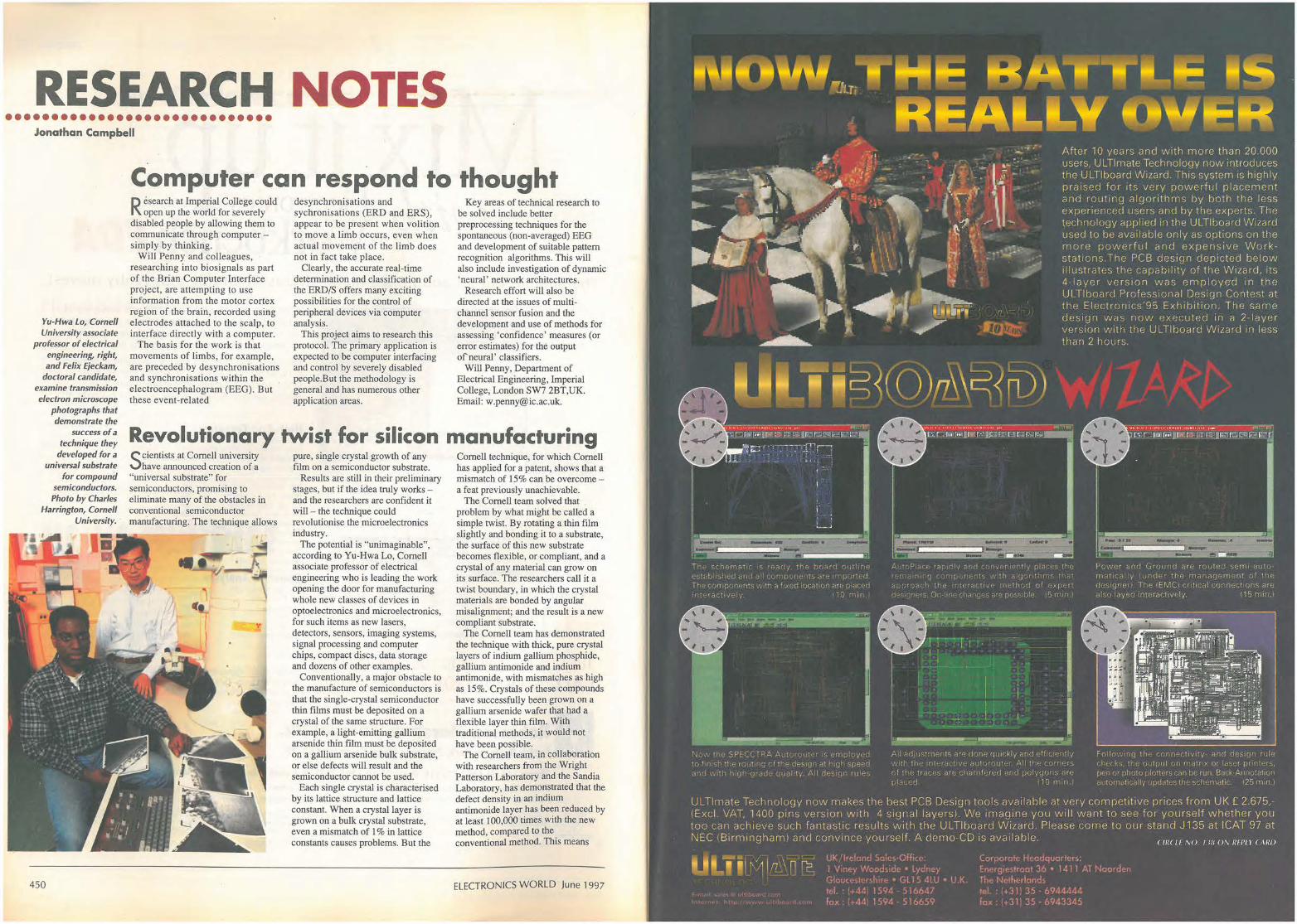
NEW ! Electronics Workbench Version 5 with analog, digital and mixed ND SPICE simulation, a full suite of analyses and over 4,000 devices. St ill t he standard for power and ease of use. Now ten times faster. Still the same low price.
Join over 75,000 customers and find out why more engineers and hobbyists buy Electronics Workbench than any ot her SPICE simulator. You'll be working productively in 20 minutes, and creating better designs faster. We guarantee it!
High-End Features True Mixed Analog/Digital Fully Interactive Simulation Analog Engine Digital Engine Temperature Control Pro Schematic Editor Hierarchical Circuits Virtual Instruments On-Screen Graphs Analog Components Digital components Device Models Money-Back Guarantee Technical Support
Powerful Analyses DC Operating Point AC Frequency
Yes Yes Spice 3F5, 32-bit Native, 32-bit Yes Yes Yes Yes Yes Over 100 Over 200 Over 4,000 30-day Free . II
I/ Only
£199* Transient Fourier Noise Distortion
Yes Yes Yes Yes Yes Yes
Turn on the power to your designs ... CALL + 44 (0) 1203 233216 today!
No-risk 30-day money-back for first time buyers! Runs on Windows 95/NT/3.l *Special upgrade prices are available. All prices are exclusive of VAT and £7.99 p+p.
RI Robinson Marshall (Europe) Pie. Leofric Business Park, Progress Close, Coventry CV3 2TF
.. INTERACTIVE
Phone: +44 (0) 1203 233216 Fax: +44 (0) 1203 233210 E-mail:[email protected] Shipping Charges UK f:7.99. All prices are plus VAT. Eleclronics Workbench is a trademark of Interactive Image Technologies Ltd, Tomto, Canada. All other trademarks are the property of their respective owners
Australia • Belgium • Brazil • Canada • Chiie • Colombia • Cyprus • Czech Rep1JbHc • Denmark • ~1.nla_nd • France • Germany ~ Gree . .ce • Hong Kong •. Hungary • In_dia • Indonesia Israel • Italy • Japan • Malaysia • Mexico • Netherlands • New Zealand • Norway • Ph1lipp1nes • Portugal • Romama • Singapore • Slovenia • South Africa •
South Korea • Spain Sweden • Switzerland • Taiwan • Thailand • Turkey • United Arab Emirates • United Kingdom
Trademarks art tnt propertY of their resptetivt holders.
,._ c,,
" 0
RESEARCH NOTES •••••••••••••••••••••••••••••
Jonathan Campbell
Computer can respond to thought
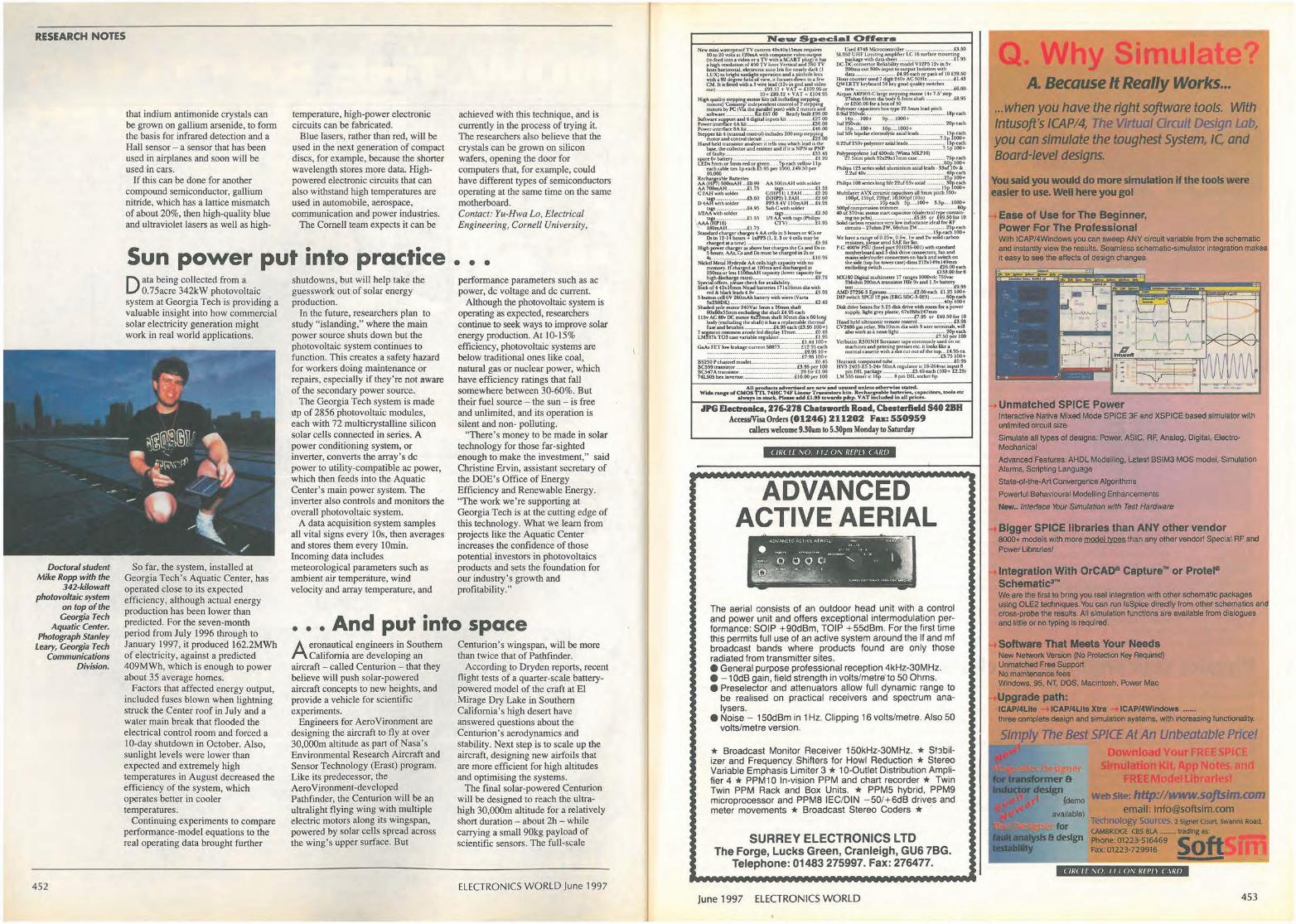
Yu-Hwa Lo, Cornell University associate
professor of electrical engineering, right, and Felix Ejeckam,
doctoral candidate, examine transmission electron microscope
photographs that demonstrate (he
success of a technique they
developed for a universal substrate
for compound semiconductors. Photo by Charles
Harrington, Cornell University.
450
R esearch at Imperial College could open up the world for severely
disabled people by allowing them to communicate through computer -simply by thinking.
Will Penny and colleagues, researching into biosignals as part of the Brian Computer Interface project, are attempting to use information from the motor cortex region of the brain, recorded using electrodes attached to the scalp, to interface directly with a computer.
The basis for the work is that movements of limbs, for example, are preceded by desynchronisations and synchronisations within the e lectroencephalogram (EEG). But these event-related
desynchronisations and sychronisations (ERO and ERS), appear to be present when volition to move a limb occurs, even when actual movement of the limb does not in fact take place.
Clearly, the accurate real-time determination and classification of the ERD/S offers many exciting possibilities for the control of peripheral devices via computer analysis.
This project aims to research this protocol. The primary application is expected to be computer interfacing and control by severely disabled people.But the methodology is general and has numerous other application areas.
Key areas of technical research to be solved include better preprocessing techniques for the spontaneous (non-averaged) EEG and development of suitable pattern recognition algorithms. This will also include investigation of dynamic 'neural' network architectures.
Research effort will also be directed at the issues of multichannel sensor fusion and the development and use of methods for assessing 'confidence' measures (or error estimates) for the output of'neural' classifiers.
Will Penny, Department of Electrical Engineering, Imperial College, London SW7 2BT,UK. Email: [email protected].
Revolutionary twist for silicon manufacturing Scientists at Cornell university
have announced creation of a "universal substrate" for semiconductors, promising to eliminate many of the obstacles in conventional semiconductor manufacturing. The technique allows
pure, single crystal growth of any film on a semiconductor substrate.
Results are still in their preliminary stages, but if the idea truly works -and the researchers are confident it will - the technique could revolutionise the microelectronics industry.
The potential is "unimaginable", according to Yu-Hwa Lo, Cornell associate professor of electrical engineering who is leading the work opening the door for manufacturing whole new classes of devices in Optoelectronics and microelectronics, for such items as new lasers, detectors, sensors, imaging systems, signal processing and computer chips, compact discs, data storage and dozens of other examples.
Conventionally, a major obstacle to the manufacture of semiconductors is that the single-crystal semiconductor thin films must be deposited on a crystal of the same structure. For example, a light-emitting gallium arsenide thin film must be deposited on a gallium arsenide bulk substrate, or else defects will result and the semiconductor cannot be used.
Each single crystal is characterised by its lattice structure and lattice constant. When a crystal layer is grown on a bulk crystal substrate, even a mismatch of 1 % in lattice constants causes problems. But the
Cornell technique, for which Cornell has applied for a patent, shows that a mismatch of 15% can be overcome -a feat previously unachievable.
The Cornell team solved that . problem by what might be called a simple twist. By rotating a thin film slight! y and bonding it to a substrate, the surface of this new substrate becomes flexible, or compliant, and a crystal of any material can grow on its surface. The researchers call it a twist boundary, in which the crystal materials are bonded by angular misalignment; and the result is a new compliant substrate.
The Cornell team has demonstrated the technique with thick, pure crystal layers of indium gallium phosphide, gallium antimonide and indium antimonide, with mismatches as high as 15%. Crystals of these compounds have successfully been grown on a gallium arsenide wafer that had a flexible layer thin film. With traditional methods, it would not have been possible.
The Cornell team, in collaboration with researchers from the Wright Patterson Laboratory and the Sandia Laboratory, has demonstrated that the defect density in an indium antimonide layer has been reduced by at least 100,000 times with the new method, compared to the conventional method. This means
ELECTRONICS WORLD June 1997
1\111 "JLTi
--a--NII-- K&a·-.--·· a-•.-• I~
'~ :; ''.; , ,
· ;:, • , ;I:: ··,
REALLY IIV~R After 10 years and w ith more than 20.000 users, ULTlmate Technology now introduces the ULTlboarcl Wizard. This system is high ly praised for its very powerfu l p lacement and rout ing algor ithms by both the less experienced users and by the experts. The technology applied in the ULTlboard Wi1ard used to be ava ilable on ly as options on the more powerful and expens ive Work stations.The PCB design depicted below i llustrates the capab i li ty of the Wizard, its 4- iayer version was employed in the ULTlboard Professional Des ign Contest at the Electronics'95 Exhibition. The sarne design was now r1xr1cuted in a 2-layror version vvith the ULTlboarcJ W izard in less than 2 hours.
;, , i j ' , •,' ·1•: r ; : '; ; ~, rj r ; ,; : r;.; 1' .i< i i ;J' : l :_ 'f :, ! I 1 :: :: : 1 1 r 1,_r;, ~, ;:- ; 1 ::1_.r,1· !'':~ ,L.. : 1 : • , , ; ( -~;• r11_:: ;,
r. '. • • tr ;_,_,_. ,_ ;i r <; :~ i 1-i ·: ! '•_, , ;_.{ j :n · ! ; .;r __ ,1 ,.., ; •:, : :-, :ir1: '70 ., . / 1
f: , , ,l,T :, :·1 q i !r , · ' , r, •111;<; '. .·,1,,, :p11! d1:_~;iqr: •;; it •
, . ; ; i •/ :., , •. '. , ., • ; , ; , ; : ; J I i ~ ( _. i; I' - ;I 1 r Y r \~ ; il '-,': • ; 1 r 1 • · '. , : ":. ,
r1•::1 ( )' ; ,' 1' _:tr ; ;,r !:~•. r:, •,;1• · t;r; ·~; •; 8 ; 1r i,(- t..11•1u ~:1t 1cr
{_11. '.'/"l<1~•·,d ·,· ,;;r!c!•;; (, 1•·,r: sr_t:•:r-"1nt 1'.'"; 125 P 1i r:_i
ULTlrnate Technology now makes the hest PCB Design tools available at very competitive prices f rom UK£ 2.675,iExcl. VAT, 1400 pins version with 4 signa l layers) . We imagine you will want to see for yourself whether you too urn achieve such fantastic results with the ULTlboard W izard. Please come to our stand J135 at ICAT 97 at NEC I Birmi1,gham1 ancl convince yourself. A demo CD is c1vailable. < 111< 11 \II I w 0 , 1111,11 r ,11111
lJ I .J i 1 ~ >~ I rt\ n · ~-C :.,:r: in· 'i~< hrr:r ::q1..:c::--~f_•r :,:
~r\(: rrJi1_: · •r:.".':t .~.I-., • l ,~ -I~ /->,i f _r;,_:n:--:,,::
RESEARCH NOTES
that indium antimonide crystals can be grown on gallium arsenide, to form the basis for infrared detection and a Hall sensor - a sensor that has been used in airplanes and soon will be used in cars.
If this can be done for another compound semiconductor, gallium nitride, which has a lattice mismatch of about 20%, then high-quality blue and ultraviolet lasers as well as high-
temperature, high-power electronic circuits can be fabricated.
Blue lasers, rather than red, will be used in the next generation of compact discs, for example, because the shorter wavelength stores more data. Highpowered electronic circuits that can also withstand high temperatures are used in automobile, aerospace, communication and power industries.
The Cornell team expects it can be
Sun power put into practice Data being collected from a
0.75acre 342kW photovoltaic system at Georgia Tech is providing a valuable insight into how commercial solar electricity generation might work in real world applications.
shutdowns, but will help take the guesswork out of solar energy production.
In the future, researchers plan to study "islanding," where the main power source shuts down but the photovoltaic system continues to function. This creates a safety hazard for workers doing maintenance or repairs, especial! y if they' re not aware of the secondary power source.
The Georgia Tech system is made up of 2856 photovoltaic modules, each with 72 multicrystalline silicon solar cells connected in series. A power conditioning system, or inverter, converts the array's de power to utility-compatible ac power, which then feeds into the Aquatic Center's main power system. The inverter also controls and monitors the overall photovoltaic system.
A data acquisition system samples all vital signs every 10s, then averages and stores them every lOmin. Incoming data includes meteorological parameters such as ambient air temperature, wind velocity and array temperature, and
achieved with this technique, and is currently in the process of trying it. The researchers also believe that the crystals can be grown on silicon wafers, opening the door for computers that, for example, could have different types of semiconductors operating at the same time on the same motherboard. Contact: Yu-Hwa Lo, Electrical Engineering, Cornell University,
• • • performance parameters such as ac power, de voltage and de current.
Although the photovoltaic system is operating as expected, researchers continue to seek ways to improve solar energy production. At 10-15% efficiency, photovoltaic systems are below traditional ones like coal, natural gas or nuclear power, which have efficiency ratings that fall somewhere between 30-60%. But their fuel source - the sun - is free and unlimited, and its operation is si.lent and non- polluting.
"There's money to be made in solar technology for those far-sighted enough to make the investment," said Christine Ervin, assistant secretary of the DOE's Office of Energy Efficiency and Renewable Energy. "The work we're supporting at Georgia Tech is at the cutting edge of this technology. What we learn from projects like the Aquatic Center increases the confidence of those potential investors in photovoltaics products and sets the foundation for our industry's growth and profitability."
Doctoral student Mike Ropp with the
342-kilowatt photovoltaic system
on top of the Georgia Tech
Aquatic Center. Photograph Stanley
Leary, Georgia Tech Communications
Division.
So far, the system, installed at Georgia Tech's Aquatic Center, has operated close to its expected efficiency, although actual energy production has been lower than predicted. For the seven-month period from July 1996 through to January 1997, it produced 162.2MWh of electricity, against a predicted 409MWh, which is enough to power about 35 average homes.
... And put into space
452
Factors that affected energy output, included fuses blown when lightning struck the Center roof in July and a water main break that flooded the electrical control room and forced a 10-day shutdown in October. Also, sunlight levels were lower than expected and extremely high temperatures in August decreased the efficiency of the system, which operates better in cooler temperatures.
Continuing experiments to compare performance-model equations to the real operating data brought further
Aeronautical engineers in Southern California are developing an
aircraft - called Centu.rion - that they believe will push solar-powered aircraft concepts to new heights, and provide a vehicle for scientific experiments.
Engineers for AeroVironment are designing the aircraft to fly at over 30,000m altitude as part of Nasa's Environmental Research Aircraft and Sensor Technology (Erast) program. Like its predecessor, the Aero Vironment-developed Pathfinder, the Centurion will be an ultralight flying wing with multiple electric motors along its wingspan, powered by solar cells spread across the wing's upper surface. But
Centurion's wingspan, will be more than twice that of Pathfinder.
According to Dryden reports, recent flight tests of a quarter-scale batterypowered model of the craft at El Mirage Dry Lake in Southern California's high desert have answered questions about the Centurion's aerodynamics and stability. Next step is to scale up the aircraft, designing new airfoils that are more efficient for high altitudes and optimising the systems.
The final solar-powered Centurion will be designed to reach the ultrahigh 30,000m altitude for a relatively short duration - about 2h - while carrying a small 90kg payload of scientific sensors. The full-scale
ELECTRONICS WORLD June 1997
New s .. eclal Offers
M 500tn.AH with iOldit:r ._ ...................... £1.; s
C(HPII) l .?AH ......... £2.20 D(HP'l) l .2AH •.......... £2.60 PPl 8,4V I IOmA.H .... £•.9S SubC with soldit:r
l/3~~:·:~'.i•~r.:
.1PG Eectrollics, 276-278 Cla• tswordl Road, Chesterfield 540 28H Access/Visa Orders (01246) 211202 Fu.: 550959
callers welcome 9.30am to 5.30pm Monday to Saturday
( /R( LE W). 11! ()\ REPLI ( \Rf)
ADVANCED ACTIVE AERIAL
The aeria l consists of an outdoor head unit with a control and power unit and offers exceptional intermodulation performance: SOIP + 90dBm, TOIP + 55dBm. For the first time this permits full use of an active system around the If and mf broadcast bands where products found are only those radiated from transmitter sites. • General purpose professional reception 4kHz-30MHz. • - 1 0dB gain, field strength in volts/metre'to 50 Ohms. • Preselector and attenuators allow full dynamic range to
be realised on practical receivers and spectrum analysers.
• Noise - 150dBm in 1 Hz. Clipping 16 volts/metre. Also 50 volts/metre version.
* Broadcast Monitor Receiver 150kHz-30MHz. * S!'.:1bilizer and Frequency Shifters for Howl Reduction * Stereo Variable Emphasis Limiter 3 * 10-Outlet Distribution Amplifier 4 * PPM10 In-vision PPM and chart recorder* Twin Twin PPM Rack and Box Units. * PPM5 hybrid, PPM9 microprocessor and PPM8 !EC/DIN -50/+6dB drives and meter movements * Broadcast Stereo Coders * ·
SURREY ELECTRONICS LTD The Forge, Lucks Green, Cranleigh, GU6 7BG.
Telephone: 01483 275997. Fax: 276477.
June 1997 ELECTRONICS WORLD
Q Why Simul A. Because It Really Works ...
... when you have the right software toots. With tntusojt's ICAP/4, The Virtual Orcuit Design Lab, you can simulate the toughest System, IC and Board-level designs.
You said you would do more slmulatfon If the tools were easier to use. Well here you gol
Ease of Use for The Beginner, Power For The Professional With ICAP/4Wllldows you can sweep ANY circuit variable from the schematic and instantly view the results. Seamless schematic-simulator integration makes it easy to see the effects of design changes.
• Unmatched SPICE Power Interactive Native Mixed Mode SPICE 3F and XSPICE based simulator with unlimited circuit size
Simulate all types of designs; Power, ASIC, RF, Analog, Digital, ElectroMechanical
Advanced Features: AHDL Modelling, Laest BSIM3 MOS model, Simulation Alanns, Scripting Language
State-of-the-Art Convergence Algorithms
Powerful Behavioural Modelling Enhancements
New •. Interface \'bur Simulation with Test Hardware
Bigger SPICE libraries than ANY other vendor 8000+ models with more model types than any other vendorl Special RF and Power Ubrariesl
lntegraUon With OrCAO- Capture"' or Prote.Schematlc"" We are the first to bring you real integration with other schematic packages using OLE2 techniques. You can run lsSpice dlred1y from other schematies anct cross-probe the results. All Stmulation functlons are available from dialogues and little or no typing Is required.
Software That Meets Your Needs New Network Version (No Protection Key Required) Unmatched Free Support No maintenance fees Windows, 95, NT, DOS, Macintosh, Power Mac
Upgrade path: ICAP/4Llle ICAP/41.lte Xtra ICAP/4Wlndowa ...... three complete design and simulation systems, with increasing functionality.
Simply The Best SPICE At An Unbeatable Price! Download You R
ulatlo KJ A REM d
Web Site: http://www.sojt5lm.com email: [email protected]
lechnology Sources, 2 Signet Court. swanns Road.
CAMIIRIOGE CBS SLA trading as. Phone: 01223-516469 So Fax: 01223-729916
-"'!""!!"'~ -___J ( /R( LE NO 11 I () \ ' REP/ I ( ,\RD
453
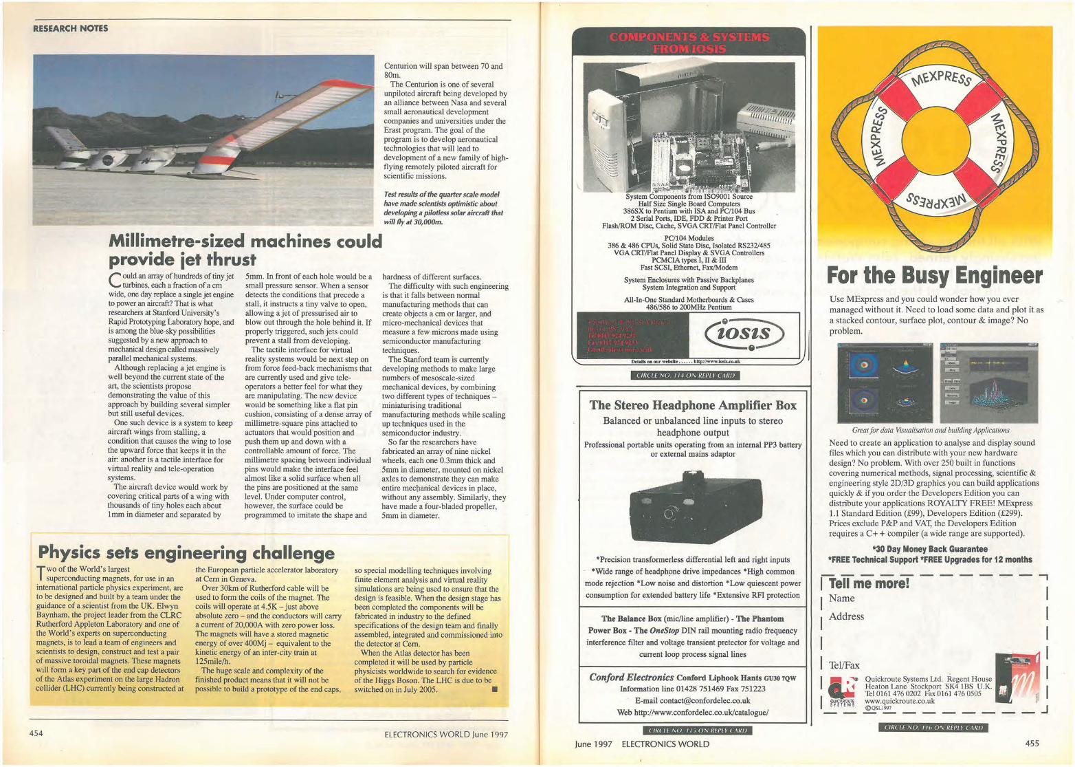
RESEARCH NOTES
Centurion will span between 70 and 80m.
The Centurion is one of several unpiloted aircraft being developed by an alliance between Nasa and several small aeronautical development companies and universities under the Erast program. The goal of the prograrn is to develop aeronautical technologies that will lead to development of a new family of highflying remotely piloted aircraft for scientific missions.
Test results of the quarter scale model have made scientists optimistic about developing a pifotless solar aircraft that wiff fly at 30,000m.
Millimetre-sized machines could provide iet thrust C ould an array of hundreds of tiny jet
turbines, each a fraction of a cm wide, one day replace a single jet engine to power an aircraft? That is what researchers at Stanford University's Rapid Prototyping Laboratory hope, and is among the blue-sky possibilities suggested by a new approach to mechanical design called massively parallel mechanical systems.
Although replacing a jet engine is well beyond the current state of the art, the scientists propose demonstrating the value of this approach by building several simpler but still useful devices.
One such device is a system to keep aircraft wings from stalling, a condition that causes the wing to lose the upward force that keeps it in the air: another is a tactile interface for virtual reality and tele-operation systems.
The aircraft device would work by covering critical parts of a wing with thousands of tiny holes each about 1mm in diameter and separated by
5mm. In front of each hole would be a small pressure sensor. When a sensor detects the conditions that precede a stall, it instructs a tiny valve to open, allowing a jet of pressurised air to blow out through the hole behind it. If properly triggered, such jets could prevent a stall from developing.
The tactile interface for virtual reality systems would be next step on from force feed-back mechanisms that are currently used and give teleoperators a better feel for what they are manipulating. The new device would be something like a flat pin cushion, consisting of a dense array of millimetre-square pins attached to actuators that would position and push them up and down with a controllable amount of force. The millimetre spacing between individual pins would make the interface feel almost like a solid surface when all the pins are positioned at the same level. Under computer control, however, the surface could be programmed to imitate the shape and
Physics sets engineering challenge
hardness of different surfaces. The difficulty with such engineering
is that it falls between normal manufacturing methods that can create objects a cm or larger, and micro-mechanical devices that measure a few microns made using semiconductor manufacturing techniques.
The Stanford team is currently developing methods to make large numbers of mesoscale-sized mechanical devices, by combining two different types of techniques -miniaturising traditional manufacturing methods while scaling up techniques used in the semiconductor industry.
So far the researchers have fabricated an array of nine nickel wheels, each one 0.3mm thick and 5mm in diameter, mounted on nickel axles to demonstrate they can make entire mectianical devices in place, without any assembly. Similarly, they have made a four-bladed propeller, 5mm in diameter.
Two of the World's largest superconducting magnets, for use in an
international particle physics experiment, are to be designed and built by a team under the guidance of a scientist from the UK. Elwyn Baynham, the project leader from the CLRC Rutherford Appleton Laboratory and one of the World's experts on superconducting magnets, is to lead a team of engineers and scientists to design, construct and test a pair of massive toroidal magnets. These magnets will form a key part of the end cap detectors of the Atlas experiment on the large Hadron collider (LHC) currently being constructed at
the European particle accelerator laboratory at Cem in Geneva.
Over 30km of Rutherford cable will be used to form the coils of the magnet. The coils will operate at 4.5K- just above absolute zero - and the conductors will carry a current of 20,000A with zero power loss. The magnets will have a stored magnetic energy of over 400Mj - equivalent to the kinetic energy of an inter-city train at 125mile/h.
so special modelling techniques involving finite element analysis and virtual reality simulations are being used to ensure that the design is feasible. When the design stage has been completed the components will be fabricated in industry to the defined specifications of the design team and finally assembled, integrated and commissioned into the detector at Cem.
454
The huge scale and complexity of the finished product means that it will not be possible to build a prototype of the end caps,
When the Atlas detector has been completed it will be used by particle physicists worldwide to search for evidence of the Higgs Boson. The LHC is due to be switched on in July 2005. •
ELECTRONICS WORLD June 1997
• " · - !•1 1 · 1f1i' '. I nit
System Components from 1SO9001 Source Half Size Single Board Computers
386SX to Pentium with ISA and PC/104 Bus 2 Serial Pons, IDE, FDD & Printer Port
Flash/ROM Disc, Cache, SVGA CRT/Flat Panel Controller
PC/104 Modules 386 & 486 CPUs, Solid State Disc, Isolated RS232/485
VGA CRT/Flat Panel Display & SVGA Controllers PCMCIA types I, II & III
Fast SCSI, Ethernet, Fax/Modem
System Enclosures with Passive Backplanes System Integration and Support
All-In-One Standard Motherboards & Cases 486/586 to 200MHz Pentium -----------""'
( JR( I [ ,VJ I I~ 01, Rfl'L) ( ARIJ
The Stereo Headphone Amplifier Box Balanced or unbalanced line inputs to stereo
headphone output Professional portable units operating from an internal PP3 battery
or external mains adaptor
*Precision transformerless differential left and right inputs
*Wide range of headph~ne drive impedances *High common
mode rejection *Low noise and distortion *Low quiescent power
consumption for extended battery life *Extensive RFI protection
The Balance Box (mic/line amplifier) -The Phantom Power Box • The OneStop DIN rail mounting radio frequency
interference filter and voltage transient pretector for voltage and
current loop process signal lines
Conford Electronics Conford Llphook Hants GUJO 7QW
Information line 01428 751469 Fax 751223
E-mail [email protected]
Web http://www.confordelec.eo.uk/catalogue/
( JR( If MJ I I; 0/\ RF/'/) ( ,\RI)
June 1997 ELECTRONICS WORLD
For the Busy Engineer Use MExpress and you could wonder how you ever managed without it. Need to load som e da ta and plot it as a stacked contour, surface plo t , contour & image? No problem.
Great for data Visualisation and building Applications
Need to create an application to analyse and display sound files which you can distribute with your new hardware design? No problem. With over 250 built in filnctions covering numerical methods, signal processing, scientific & engineering style 2D/3D graphics you can build applications quickly & if you order the Developers Edition you can distribute your applications ROYALTY FRE E ! MExpress 1.1 Standard Edition (£99), Developers Edition (£299). Prices exclude P&P and VAT, the Developers Edition requires a C+ + compiler (a wide range are supported).
*30 Day Money Back Guarantee *FREE Technical Support *FREE Upgrades for 12 months
ITeU me more! I Name
- - - - - - -,
I Address
I I Tel/Fax
,, .• I m~
Q uickroute Systems Ltd. Regent House Heaton Lane Stockport SK4 18S U.K. Tel 0161 476 0202 Fax 0161 476 0505 www.quickroute.co.uk @ OSLl997 -------
( JR( I f ,\() I II, (),'\/ Rf/'/ I ( ARI)
J
455
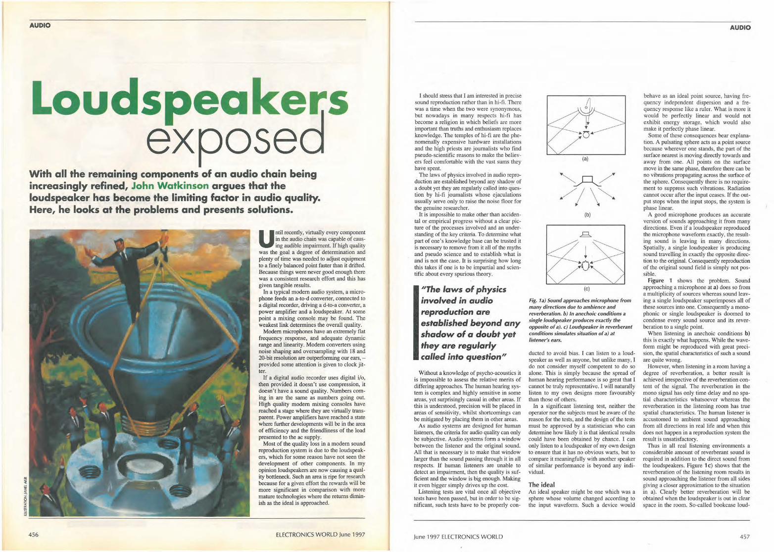
AUDIO
Loudspeakers expose
With all the remaining components of an audio chain being increasingly refined, John Watkinson argues that the loudspeaker has become the limiting factor in audio quality. Here, he looks at the problems and presents solutions.
456
Until recently, virtually every component in the audio chain was capable of causing audible impairment. If high quality
was the goal a degree of determination and plenty of time was needed to adjust equipment to a finely balanced point faster than it drifted. Because things were never good enough there was a consistent research effort and this has given tangible results.
In a typical modern audio system, a microphone feeds an a-to-d converter, connected to a digital recorder, driving ad-to-a converter, a power amplifier and a loudspeaker. At some point a mixing console may be found. The weakest link determines the overall quality.
Modern microphones have an extremely flat frequency response, and adequate dynamic range and linearity. Modern converters using noise shaping and oversampling with 18 and 20-bit resolution are outperforming our ears, -provided some attention is given to clock jitter.
If a digital audio recorder uses digital i/o, then provided it doesn't use compression, it doesn't have a sound quality. Numbers coming in are the same as numbers going out. High quality modern mixing consoles have reached a stage where they are virtually transparent. Power amplifiers have reached a state where further developments will be in the area of efficiency and the friendliness of the load presented to the ac supply.
Most of the quality loss in a modem sound reproduction system is due to the loudspeakers, which for some reason have not seen the development of other components. In my opinion loudspeakers are now causing a quality bottleneck. Such an area is ripe for research because for a given effort the rewards will be more significant in comparison with more mature technologies where the returns diminish as the ideal is approached.
ELECTRONICS WORLD June 1997
I should srress that I am interested in precise sound reproduction rather than in hi-fi. There was a time when the two were synonymous, but nowadays in many respects hi-fi has become a religion in which beliefs are more important than 1ruths and enthusiasm replaces knowledge. The temples of hi-fi are the phenomenally expensive hardware installations and the high priests are journalists who find pseudo-scientific reasons to make the believers feel comfortable with the vast sums they have spent.
The laws of physics involved in audio reproduction are established beyond any shadow of a doubt yet they are regularly called into question by hi-fi journalists whose ejaculations usually serve only to raise the noise floor for the genuine researcher. · It is impossible to make other than acciden
tal or empirical progress without a clear picture of the processes involved and an understanding of the key criteria. To determine what part of one's knowledge base can be trusted it is necessary to remove from it all of the myths and pseudo science and to establish what is and is not the case. It is surprising how long this takes if one is to be impartial and scientific about every spurious theory.
"The laws of physics involved in audio reproduction are established .beyond any shadow of a doubt yet they are regularly called into question"
Without a knowledge of psycho-acoustics it is impossible to assess the relative merits of differing approaches. The human hearing system is complex and highly sensitive in some areas, yet surprisingly casual in other areas. If this is understood, precision will be placed in areas of sensitivity, whilst shortcomings can be mitigated by placing them in other areas.
As audio systems are designed for human listeners, the criteria for audio quality can only be subjective. Audio systems form a window between the listener and the original sound. All that is necessary is to make that window larger than the sound passing through it in all respects. If human listeners are unable to detect an impairment, then the quality is sufficient and the window is big enough. Making it even bigger simply drives up the cost.
Listening tests are vital once all objective tests have been passed, but in order to be significant, such tests have to be properly con-
June 1997 ELECTRONICS WORLD
(a)
(b)
i 0 (c)
Fig. ta) Sound approaches microphone from many directions due to ambience and reverberation. b) In anechoic conditions a single loudspeaker produces exactly the opposite of a). c) Loudspeaker in reverberant conditions simulates situation of a) at listener's ears.
ducted to avoid bias. I can listen to a loudspeaker as well as anyone, but unlike many, I do not consider myself competent to do so alone. This is simply because the spread of human hearing performance is so great that I cannot be truly representative. I will naturally listen to my own designs more favourably than those of others.
In a significant listening test, neither the operator nor the subjects must be aware of the reason for the tests, and the design of the tests must be approved by a statistician who can determine how likely it is that identical results could have been obtained by chance. I can only listen to a loudspeaker of my own design to ensure that it has no obvious warts, but to compare it meaningfully with another speaker of similar performance is beyond any individual.
The ideal An ideal speaker might be one which was a sphere whose volume changed according to the input waveform. Such a device would
AUDIO
behave as an ideal point source, having frequency independent dispersion and a frequency response like a ruler. What is more it would be perfectly linear and would not exhibit energy storage, which would also make it perfectly phase linear.
Some of these consequences bear explanation. A pulsating sphere acts as a point source because wherever one stands, the part of the surface nearest is moving directly towards and away from one. All points on the surface move in the same phase, therefore there can be no vibrations propagating across the surface of the sphere. Consequently there is no requirement to suppress such vibrations. Radiation cannot occur after the input ceases. If the output stops when the input stops, the system is phase linear.
A good microphone produces an accurate version of sounds approaching it from many directions. Even if a loudspeaker reproduced the microphone waveform exactly, the resulting sound is leaving in many directions. Spatially, a single loudspeaker is producing sound !ravelling in exactly the opposite direction to the original. Consequently reproduction of the original sound field is simply not possible.
Figure 1 shows the problem. Sound approaching a microphone at a) does so from a multiplicity of sources whereas sound leaving a single loudspeaker superimposes all of these sources into one. Consequently a monophonic or single loudspeaker is doomed to condense every sound source and its reverberation to a single point.
When listening in anechoic conditions b) this is exactly what happens. While the waveform might be reproduced with great precision, the spatial characteristics of such a sound are quite wrong.
However, when listening in a room having a degree of reverberation, a better result is achieved irrespective of the reverberation content of the signal. The reverberation in the mono signal has only time delay and no spatial characteristics whatsoever whereas the reverberation in the listening room has true spatial characteristics. The human listener is accustomed to ambient sound approaching from all directions in real life and when tllis does not happen in a reproduction system the result is unsatisfactory.
Thus in all real listening environments a considerable amount of reverberant sound is required in addition to the direct sound from the loudspeakers. Figure 1 c) shows that the reverberation of the listening room results in sound approaching the listener from all sides giving a closer approximation to the situation in a) . Clearly better reverberation will be obtained when the loudspeaker is out in clear space in the room. So-called bookcase loud-
457
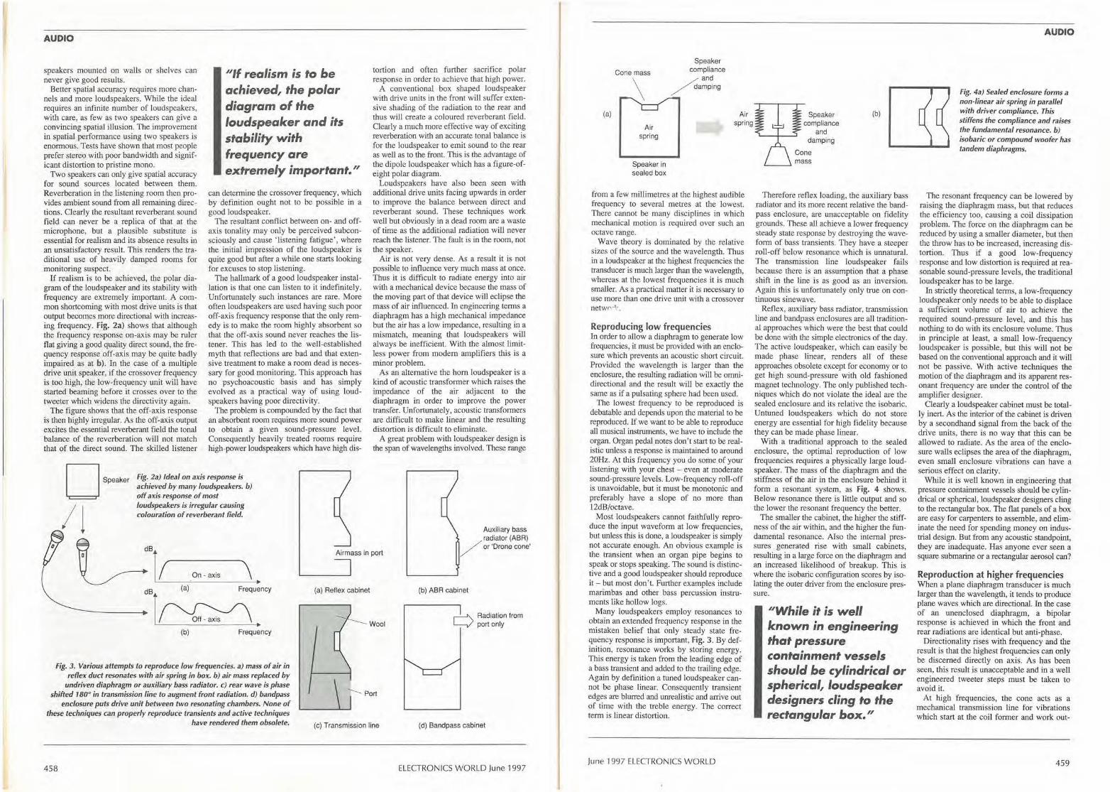
AUDIO
speakers mounted on waUs or shelves can never give good results.
Better spatial accuracy requires more channels and more loudspeakers. While the ideal requires an infinite number of loudspeakers, with care, as few as two speakers can give a convincing spatial illusion. The improvement in spatial performance using two speakers is enormous. Tests have shown that most people prefer stereo with poor bandwidth and significant distortion to pristine mono.
Two speakers can only give spatial accuracy for sound sources located between them. Reverberation in the listening room then provides ambient sound from all remaining directions. Clearly the resultant reverberant sound field can never be a replica of that at the microphone, but a plausible substitute is essential for realism and its absence results in an unsatisfactory result. This renders the traditional use of heavily damped rooms for monitoring suspect.
If realism 'is to be achieved, the polar diagram of the loudspeaker and its stability with frequency are extremely important. A common shoncorning with most drive units is that output becomes more directional with increasing frequency. Fig. 2a) shows that although the frequency response on-axis may be ruler flat giving a good quality direct sound, the frequency response off-axis may be quite badly impaired as at b). In the case of a multiple drive unit speaker, if the crossover frequency is too high, the low-frequency unit will have started beaming before it crosses over to the tweeter which widens the directivity again.
The figure shows that the off-axis response is then highly irregular. As the off-axis output excites the essential reverberant field the tonal balance of the reverberation will not match that of the direct sound. The skilled listener
"If realism is to be achieved, the polar diagram of the loudspeaker and its stability with frequency are extremely important."
can determine the crossover frequency, which by definition ought not to be possible in a good loudspeaker.
The resultant conflict between on- and offax_is tonality may only be perceived subconsciously and cause 'listening fatigue', where the initial impression of the loudspeaker is quite good but after a while one starts looking for excuses to stop listening.
The hallmark of a good loudspeaker installation is that one can listen to it indefinitely. Unfortunately such instances are rare. More often loudspeakers are used having such poor off-axis frequency response that the only remedy is to make the room highly absorbent so that the off-axis sound never reaches the listener. This has led to the well-established myth that reflections are bad and that extensive treatment to make a room dead is necessary for good monitoring. This approach has no psychoacoustic basis and has simply evolved as a practical way of using loudspeakers having poor directivity.
The problem is compounded by the fact that an absorbent room requires more sound power to obtain a given sound-pressure level. Consequently heavily treated rooms require high-power loudspeakers which have high dis-• Speake,
/j
Fig. 2a) Ideal on axis response is achieved by many loudspeakers. b) off axis response of most loudspeakers is irregular causing colouration of reverberant field.
tortion and often further sacrifice polar response in order to achieve that high power.
A conventional box shaped loudspeaker with drive units in the front will suffer extensive shading of the radiation to the rear and thus will create a coloured reverberant field. Clearly a much more effective way of exciting reverberation with an accurate tonal balance is for the loudspeaker to emit sound to the rear as well as to the front. This is the advantage of the dipole loudspeaker which has a figure-ofeight polar diagram.
Loudspeakers have also been seen with additional drive units facing upwards in order to improve the balance between direct and reverberant sound. These techniques work well but obviously in a dead room are a waste of time as the additional radiation will never reach the listener. The fault is in the room, not the speaker.
Air is not very dense. As a result it is not possible to influence very much mass at once. Thus it is difficult to radiate energy into air with a mechanical device because the mass of the moving part of that device will eclipse the mass of air influenced. In engineering terms a diaphragm has a high mechanical impedance but the air has a low impedance, resulting in a mismatch, meaning that loudspeakers will always be inefficient. With the almost limitless power from modem amplifiers this is a minor problem.
As an alternative the horn loudspeaker is a kind of acoustic trnnsforrner which raises the impedance of the air adjacent to the diaphragm in order to improve the power transfer. Unfortunately, acoustic transformers are difficult to make linear and the resulting distortion is difficult to eliminate.
A great problem with loudspeaker design is the span of wavelengths involved. These range
tof . d d811 ______ \ Airmass in port
Auxiliary bass radiator (ABR)
/ or 'Drone cone'
~ - On-axis
dB (a) Frequency
1~. (b) Frequency
Fig. 3. Various attempts to reproduce low frequencies. a) mass of air in reflex duct resonates with air spring in box. b) air mass replaced by
undriven diaphragm or auxiliary bass radiator. c) rear wave is phase shifted 180° in transmission line to augment front radiation. d) bandpass
enclosure puts drive unit between two resonating chambers. None of these techniques can properly reproduce transients and active techniques
have rendered them obsolete.
458
(a) Reflex cabinet
Wool
----- Port
(c) Transmission line
(b) ABR cabinet
r'-'\. Radiation from L__/ portonly
(d) Bandpass cabinet
ELECTRONICS WORLD June 1997
Speaker compliance
/4 and / -,amping
(a)
Air spring
Air spring
Speaker (b) compliance
Speaker in sealed box
from a few miUimetres at the highest audible frequency to several metres at the lowest. There cannot be many disciplines in which mechanical motion is required over such an octave range.
Wave theory is dominated by the relative sizes of the source and the wavelength. Thus in a loudspeaker at the highest frequencies the transducer is much larger than the wavelength, whereas at the lowest frequencies it is much smaller. As a practical matter it is necessary to use more than one drive unit with a crossover netwr' ·1- .
Reproducing low frequencies In order to allow a diaphragm to generate low frequencies, it must be provided with an enclosure which prevents an acoustic sh011 circuit. Provided the wavelength is larger than the enclosure, the resulting radiation will be omnidirectional and the result will be exactly the same as if a pulsating sphere had been used.
The lowest frequency to be reproduced is debatable and depends upon the material to be reproduced. lf we want to be able to reproduce all musical instruments, we have to include the organ. Organ pedal notes don 't start to be realistic unless a response is maintained Lo around 20Hz. At this frequency you do some of your listening with your chest - even at moderate sound-pressure levels. Low-frequency roll-off is unavoidable, but it must be monotonic and preferably have a slope of no more than 12dB/octave.
Most loudspeakers cannot faithfully reproduce the input waveform at low frequencies, but unless this is done, a loudspeaker is simply not accurate enough. An obvious example is the transient when an organ pipe begins to speak or stops speaking. The sound is distinctive and a good loudspeaker should reproduce it - but most don't. Further examples include marimbas and other bass percussion instruments like hollow logs.
Many loudspeakers employ resonances to obtain an extended frequency response in the mistaken belief that only steady state frequency response is important, Fig. 3. By definition, resonance works by storing energy. This energy is taken from the leading edge of a bass transient and added to the trailing edge. Again by definition a nmed loudspeaker cannot be phase linear. Consequently transient edges are blurred and unrealistic and arrive out of time with the treble energy. The correct term is linear disto11ion.
June 1997 ELECTRONICS WORLD
and damping
Therefore reflex loading, the auxiliary bass radiator and itS more recent relative the bandpass enclosure, are unacceptable on fidelity grounds. These all achieve a lower frequency steady state response by destroying the waveform of bass transients. They have a steeper roll-off below resonance which is unnatural. The trans1nission line loudspeaker fails because there is an assumption that a phase shift in the line is as good as an inversion; Again this is unfortunately only true on continuous sinewave.
Reflex, auxiliary bass radiator, transmission line and bandpass enclosures are aU traditional approaches which were the best that could be done with the simple electronics of the day. The active loudspeaker, which can easily be made phase linear, renders all of these approaches obsolete except for economy or to get high sound-pressure with old fashioned magnet technology. The only published techniques which do not violate the ideal are the sealed enclosure and its relative the isobaric. Untuned loudspeakers which do not store energy are essential for high fidelity because they can be made phase linear.
With a traditional approach to the sealed enclosure, the optimal reproduction of low frequencies requires a physically large loudspeaker. The mass of the diaphragm and the stiffness of the air in the enclosure behind it form a resonant system, as Fig. 4 shows. Below resonance there is little output and so the lower the resonant frequency the better.
The smaller the cabinet, the higher the stiff. ness of the air within, and the higher the fundamental resonance. Also the internal pressures generated rise with small cabinets, resulting in a large force on the diaphragm and an increased likelihood of breakup. This is where the isobaric configuration scores by isolating the outer driver from the enclosure pressure.
"While it is well known in engineering that pressure containment vessels should be cylindrical or spherical, loudspeaker designers cling to the rectangular box."
AUDIO
Fig. 4a) Sealed enclosure forms a non-linear air spring in parallel with driver compliance. This stiffens the compliance and raises the fundamental resonance. b) isobaric or compound woofer has tandem diaphragms.
The resonant frequency can be lowered by raising the diaphragm mass, but that reduces the efficiency too, causing a coil dissipation problem. The force on the diaphragm can be reduced by using a smaller diameter, but then the throw has to be increased, increasing distortion. Thus if a good low-frequency response and low distortion is required at reasonable sound-pressure levels, the traditional loudspeaker has to be large.
In strictly theoretical terms, a low-frequency loudspeaker only needs to be able to displace a sufficient volume of air to achieve the required sound-pressure level, and this has nothing to do with its enclosure volume. Thus in principle at least, a small low-frequency loudspeaker is possible, but this will not be based on the conventional approach and it will not be passive. With active techniques the motion of the diaphragm and its apparent resonant frequency are under the control of the amplifier designer.
Clearly a loudspeaker cabinet must be totalI y inen. As the interior of the cabinet is driven by a secondhand signal from the back of the drive units, there is no way that this can be allowed to radiate. As the area of the enclosure walls eclipses the area of the diaphragm, even small eocloswe vibrations can have a serious effect on clarity.
While it is well known in engineering that pressure containment vessels should be cylindrical or spherical, loudspeaker designers cling to the rectangular box. The flat panels of a box are easy for carpenters to assemble, and eliminate the need for spending money on industrial design. But from any acoustic standpoint, they are inadequate. Has anyone ever seen a square submarine or a rectangular aerosol can?
Reproduction at higher frequencies When a plane di aphragm transducer is much larger than the wavelength, it tends to produce plane waves which are directional. In the case of an unenclosed diaphragm, a bipolar response is achieved in which the front and rear radiations are identical but anti-phase.
Directionality rises with frequency and the result is that the highest frequencies can only be discerned directly on axis. As has been seen, this result is unacceptable and in a well engineered tweeter steps must be taken to avoid it.
At high frequencies, the cone acts as a mechanical transmission line for vibrations which start at the coil former and work out-
459
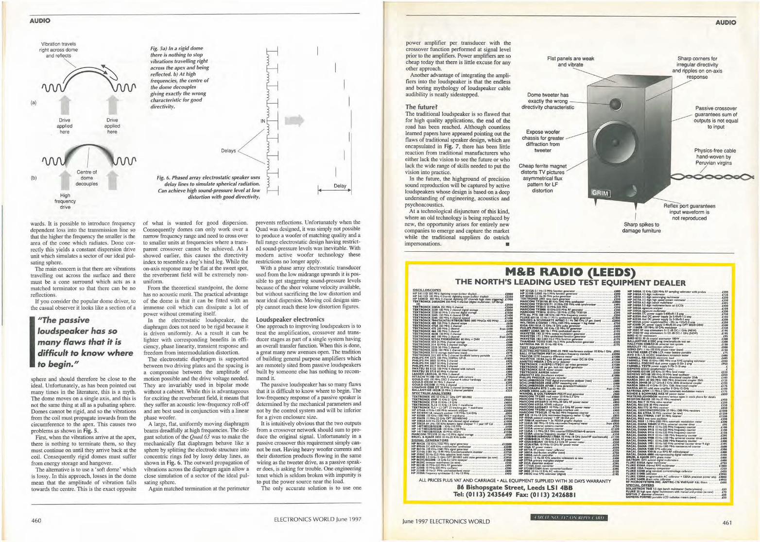
AUDIO
(a)
(b)
Drive applied
here
High
Centre of dome
decouples
frequency drive
Drive applied
here
wards. It is possible to introduce frequency dependent loss into the transmission line so that the higher the frequency the smaller is the area of the cone which radiates. Done correctly this yields a constant dispersion drive unit which simulates a sector of our ideal pulsating sphere.
The main concern is that there are vibrations travelling out across the surface and there must be a cone surround which acts as a matched terminator so that there can be no reflections.
If you consider the popular dome driver, to the casual observer it looks like a section of a
''The passive loudspeaker has so many flaws that it is difficult to know where to begin."
sphere and should therefore be close to the ideal. Unfortunately, as has been pointed out many times io the literature, this is a myth. The dome moves on a single axis, and this is not the same thing at all as a pulsating sphere. Domes cannot be rigid, and so the vibrations from the coil must propagate inwards from the circumference to the apex. This causes two problems as shown in Fig. 5.
First, when the vibrations arrive at the apex, there is nothing to terminate them, so they must continue on until they arrive back at the coil. Consequently rigid domes must suffer from energy storage and hangover.
The alternative is to use a 'soft dome' which is lossy. In this approach, losses in the dome mean that the amplitude of vibration falls towards the centre. This is the exact opposite
460
Fig. Sa) In a rigid dome there is nothing to stop vibrations travelling right across the apex and being reflected. b) At high frequencies, the centre of the dome decouples giving exactly the wrong characteristic for good directivity.
IN
I
I I
Fig. 6. Phased array electrostatic speaker uses delay lines to simulate spherical radiation. Delay
Can achieve high sound-pressure level at low distortion with good directivity.
..
of what is wanted for good dispersion. Consequently domes can only work over a narrow frequency range and need to cross over to smaller units at frequencies where a transparent crossover cannot be achieved. As I showed earlier, this causes the directivity index to resemble a dog's bind leg. While the on-axis response may be flat at the sweet spot, the reverberant field will be extreme! y nonuniform.
From the theoretical standpoint, the dome has no acoustic merit. The practical advantage of the dome is that it can be fitted with an immense coil which can dissipate a lot of power without cremating itself.
In the electrostatic loudspeaker, the diaphragm does not need to be rigid because it is driven uniformly. As a result it can be lighter with corresponding benefits in efficiency, phase linearity, transieni response and freedom from intermodulation distortion.
The electrostatic diaphragm is supported between two driving plates and the spacing is a compromise between the amplitude of motion possible and the drive voltage needed. They are invariably used in bipolar mode without a cabinet. While this is advantageous for exciting the reverberant field, it means that they suffer an acoustic !ow-frequency roll-off and are best used in conjunction with a linear phase woofer.
A large, flat, uniformly moving diaphragm beams dreadfully at high frequencies. The elegant solution of the Quad 63 was to make the mechanically flat diaphragm behave like a sphere by splitting the electrode structure into concentric rings fed by lossy delay lines, as shown in Fig. 6. The outward propagation of vibrations across the diaphragm again allow a close simulation of a sector of the ideal pulsating sphere.
Again matched termination at the perimeter
prevents reflections. Unfortunately when the Quad was designed, it was simply not possible to produce a woofer of matching quality and a full range electrostatic design having restricted sound-pressure levels was inevitable. With modem active woofer technology these restrictions no longer apply.
With a phase array electrostatic transducer used from the low midrange upwards it is possible to get staggering sound-pressure levels because of the sheer volume velocity available, but without sacrificing the low distortion and near ideal dispersion. Moving coil designs simply cannot reach these low distortion figures.
Loudspeaker electronics One approach to improving loudspeakers is to treat the amplification, crossover and transducer stages as part of a single system having an overall transfer function. When this is done, a great many new avenues open. The tradition of building general purpose amplifiers which are remotely sited from passive loudspeakers built by someone else has nothing to recommend it.
The passive loudspeaker has so many flaws that it is difficult to know where to begin. The low-frequency response of a passive speaker is determined by the mechanical parameters and not by the control system and will be inferior for a given enclosure size.
It is intuitively obvious that the two outputs from a crossover network should sum to produce the original signal. Unfortunately in a passive crossover this requirement simply cannot be met. Having heavy woofer currents and their distortion products flowing in the same wiring as the tweeter drive, as a passive speaker does, is asking for trouble. One engineering tenet which is seldom broken with impunity is to put the power source near the load.
The only accurate solution is to use one
ELECTRONICS WORLD June 1997
power amplifier per transducer with the crossover function performed at signal level prior to the amplifiers. Power amplifiers are so cheap today that there is little excuse for any other approach.
Another advantage of integrating the amplifiers into the loudspeaker is that the endless and boring mythology of loudspeaker cable audibility is neatly sidestepped.
The future? The traditional loudspeaker is so flawed that for high quality applications, the end of the road has been reached. Although countless learned papers have appeared pointing out the flaws of traditional speaker design, which are encapsulated in Fig. 7, there has been little reaction from traditional manufacturers who either Jack the vision to see the future or who lack the wide range of skills needed to put the vision into practice.
In the future, the highground of precision sound reproduction will be captured by active loudspeakers whose design is based on a deep understanding of engineering, acoustics and psychoacoustics.
At a technological disjuncture of this kind, where an old technology is being replaced by new, the opportunity arises for entirely new companies to emerge and capture the market while the traditional suppliers do ostrich impersonations. •
Flat panels are weak and vibrate
Dome tweeter has exactly the wrong - - -+--
directivity characteristic
Expose woofer chassis for greater
diffraction from tweeter
Cheap ferrite magnet distorts TV pictures asymmetrical flux
pattern for LF distortion
Sharp spikes to damage furniture
AUDIO
Sharp corners for irregular directivity
and ripples on on-axis response
Passive crossover guarantees sum of outputs is not equal
to input
Physics-free cable hand-woven by Peruvian virgins
/
Reflex port guarantees input waveform is
not reproduced
M&B RADIO (LEEDS) THE NORTH'S LEADING USED TEST EQUIPMENT DEALER
ALL PRICES PLUS VAT AND CARRIAGE • ALL EQUIPMENT SUPPLIED WITH 30 DAYS WARRANTY
$6 Bishopsgate Street, Leeds LS I 488 Tel: (0113) 243S649 Fax: (0113) 2426881
June 1997 ELECTRONICS WORLD I II/( II ,o II - o, 111/'ll I \1//J
461
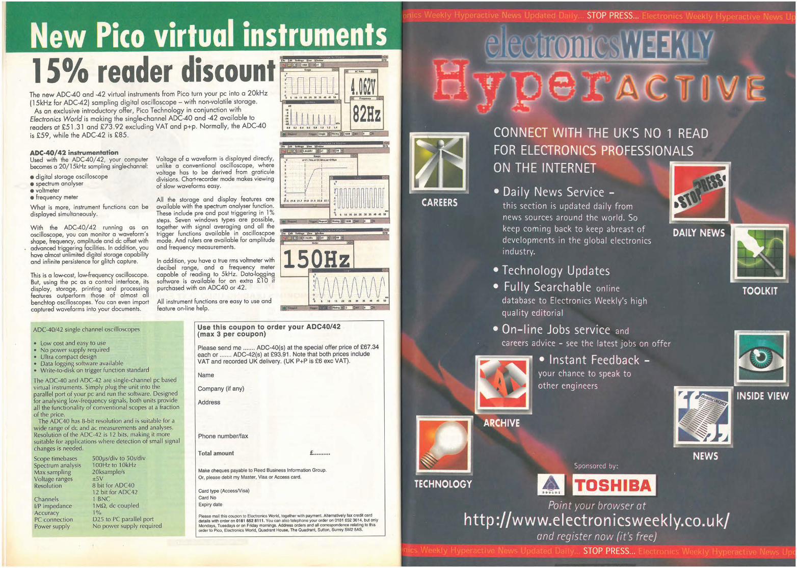
New Pico virtual instruments , ., . • , . ... o. , .~,. • ~ "ll ~ . . . 1 S % reader discount .. ·-· · --
The new ADC-4O and -42 virtual instruments from Pico turn your pc into a 2OkHz flJl_n_fU _ f I d II h I I
t ' 11 IS H ti • :K • ,S iO
(15kHz or ADC-42) samp ing igital osci oscope - wit non-vo ati e storage. As an exclusive introductory offer, Pico Technology in conjunction with
Electronics World is making the single-channel ADC-40 and -42 available to readers at £51.31 and £73.92 excluding VAT and p+p. Normally, the ADC-4O is £59, while the ADC-42 is £85.
.. . . ... u ut.•t.•uuuu
82Hz I• l>
fh fftl ; X'ltW )IJ!lflM'W ... ADC-40/ 42 instrumentation Used with the ADC-40/ 42, your computer becomes a 20/15kHz sampling single-channel:
• digital storage oscilloscope • spectrum analyser
1..-wm , • .,.,, ldl1el lid 't'IOl l'lll J ~ ..
,• r111.r • .,.0 2t.';"..,...1:flllt . I I . I I
I I . . .
.: . l I V • • voltmeter • frequency meter
What is m9re, instrument functions can be displayed simultaneously.
Voltage of a waveform is displayed directly, unlike a conventional oscilloscope, where voltage has 19 be derived from graticule divisions. Chart-recorder mode makes viewing of slow waveforms easy. ·
Al l the storage and display features are available with the spectrum analyser function. These include pre and post triggering in 1 % steps. Seven windows types are possible, together with signal averaging and all the trigger functions available in oscilloscpoe mode. And rulers are available for amplitude and frequency measurements.
~_y ·• I I -I 1- :11111 .. I il..s !1.t !1.1 :u 21.1 H~ H ,1
·• .. .. , 15 1'1StlHJIHIOf5 H
With the ADC-40/ 42 running as an oscilloscope, you can monitor a waveform's shape, frequency, amplitude and de offset with advanced triggering facilities. In addition, you have almost unlimited digital storage capability and infinite persistence for glitch capture.
,, __ ---.u,-,,. .. 1 TRl-.-1eo.~
.... ·--I-JW11!1 al,-... 1 Ill Vl(Nl l.a - w,w ·-
150Hz
' '"' •·· I
. This is a low-<:ost, low-frequency oscilloscope. But, using the pc as a control interface, its display, storage, printing and processing features outperform those of almost all benchtop oscilloscopes. You can even import captured waveforms into your documents.
In addition, you have a true rms voltmeter with decibel range, and a frequency meter capable of reading to 5kHz. Data-logging software is available for an extra £ 10 if purchased with an ADC40 or 42.
All instrument functions are easy to use and feature on-line help.
NvW\Mf ., .. -
ADC-40/42 single channel oscilloscopes
• low cost and easy to use • No power supply required • Ultra compact design • Data logging software available • Write-to-disk on trigger function standard
The ADC-40 and ADC-42 are single-channel pc based virtual instruments. Simply plug the unit into the parallel port of your pc and run the software. Designed for analysing low-frequency signals, both units provide all the functionality of conventional scopes at a fraction of the price.
The ADC40 has 8-bit resolution and is suitable for a wide range of de and ac measurements and analyses. Resolution of the ADC-42 is 12 bits, making it more suitable for applications where detection of small signal changes is needed.
Scope timebases Spectrum analysis Max sampling Voltage ranges Resolution
Channels I/P impedance Accuracy PC connection Power supply
S00µs/div to S0s/div 1 00Hz to 1 0kHz 20ksample/s ±SV 8 bit for ADC40 12 bit for ADC42 1 BNC 1 Mn, de coupled 1% 025 to PC parallel port No power supply required
I S 11 15 H ft~~.~ P
·-- ·- Al•lflt-0 ..-- II t!w,
Use this coupon to order your ADC40/42 (max 3 per coupon)
Please send me ....... ADC-40(s) at the special offer price of £67.34 each or ....... ADC-42(s) at £93.91. Note that both prices include VAT and recorded UK delivery. (UK P+P is £6 exc VAT).
Name
Company (if any)
Address
Phone number/fax
Total amount £ ........ ..
Make cheques payable to Reed Business Information Group.
Or, please debit my Master, Visa or Access card.
Card type (Access/Visa)
Card No
Expiry date
Please mail this coupon to Electronics World, together with payment. Alternatively fax credit card details with order on 0181 652 8111. You can also telephone your order on 0181 652 3614, but only Mondays, Tuesdays or on Friday mornings. Address orders and all correspondence relating to this order to Pico, Electronics World, Quadrant House, The Quadrant, Sutton, Surrey SM2 SAS.
nics Weekly Hyperactive News Updated Daily ... STOP PRESS ... Electronics Weekly Hyperactive News U~
CONNECT WITH THE UK'S NO 1 READ FOR ELECTRONICS PROFESSIONALS ON THE INTERNET
--· ~ • Da ily News Service -CAREERS
TECHNOLOGY
this section is updated daily from news sources around the world. So keep coming back to keep abreast of developments in the global electronics industry.
• Technology Updates • Fully Sea rchable on line
database to Electron ics Week ly's high qual ity edit oria l
• On-Ii ne Jobs service and
careers advice - see the lat est j obs on offer
• Instant Feedback -your chance to speak to other engineers
Sponsored by:
TOSHIBA Point your browser at
http ://www.e lectron i cs weekly.co. u k/ and register now (it's free)
nics Weekly Hyperactive News Updated Daily ... STOP PRESS ... Electronics Weekly Hyperactive News Upc
Plus: • 30-day money back guarantee • Free technical support • Free upgrades for 12 months.
discount Think of it as Basic for engineers and scientists. MExpress has the interactive ease of use of Basic, but with the extensive and powerful 32bit functionality of a modern scientific & engineering development tool.
The package is essentially a means of helping scientists and engineers to visualise complex data by representing it in pictorial form.
It includes over 250 functions covering everything from solving simultaneous equations and signal processing, to advanced 3D plotting and creation of user interfaces.
Until l August,.Quickroute Systems is offering MExpress exclusively to Electronics World readers at special prices of £79 fully inclusive for the Standard Edition and £ 199 for the Developers Edition -fully inclusive of VAT, packing and UK post. This represents discounts of 35% and 44% respectively.
The exclusive rrp for MExpress Standard Edition is £99 while the Developers Edition £299.
The Developers Edition requires a C++ compiler which can be Symantec® C++ 7.2, Microsoft® Visual C++ 2.0, or Borland® C++ 5.0.
Please contact Quickroute Systems at Regent House Heaton Lane Stockport SK4 IBS UK for further details. Tel 0 161 47 6 0202 Fax 0 161 47 6 0505 EMail [email protected]://www.quickroute.co.uk
** for a free i•formation pack, call Quickroute al the number above. **
Use this coupon to order MExpress
Please send me ....... copies of MExpress 1.1 Standard edition at the fully inclusive price of £79 or ...... copies of MExpress 1.1 Developers' edition at the fully inclusive price of £199.
Name
Company (if any)
Address
Phone number/fax
Total amount
Make cheques payable to Quickroute Systems Ltd
Or, please debit my Master, Visa or Access card.
Card type (AccessNisa/SwitchNisa Delta)
Card No
Expiry date
Signature
£ ........ ..
Please mail lhis coupon lo Quickroute Systems, together with payment. Alternatively fax credit card details wilh order on 0161 476 0505 or telephone on 0161 476 0202. Address orders and all correspondence relating to this order to Ouickroule at auickroute Systems ltd, Regent House, Heaton Lane, Stockport SK4 1 BS. ·overseas readers can also obtain this discount but details vary according to country. Please ring, write or fax to Quickroute for details.
Minimum system requirements: 386, BM ram, Windows 3.1, '9 5 or NT. Coprocessor not essential.
MExpress - Features MExpress can be used as a "super charged graphing calculator",by simply typing commands and expressions at a familiar prompt. Data can be loaded, processed, and plotted or visualised by calling on the powerful built-in functions. Once you are happy with basic C(?mmands, you can move on to create simple script
files. These are lists of commands - similar to batch files. You can also create functions and in turn complete applications with buttons, sliders, menus, multiple windows, etc. If you are using the Developers Edition of MExpress, the applications can be compiled into a Win32s executable which can be distributed - royalty free.
ELECTRONICS WORLD + WIRELESS WORLD
Electronics World+ Wireless world is applied electronic design. We'll show you how to use the latest silicon technology plus ...
✓ CAE software
✓
Money back Guarantee. Receive a full refund on your
subscription within the first
90 days if you are not completely
satisfied. Thereafter, we'll
refund the unused portion of
your subscription should you
wish to cancel.
✓
✓
✓
✓
New product reviews
Technology reports ·· ·· N,cs Cl E,ClRO ~_1_i
Detailed circuit diagrams 1-'-oo•O 1 - -W_0~ ---;;;.
✓
Innovations ~ ..-"'' i.o\ot• 11s13~ Explanations of complex
technology , .. 1,0"'" Oploe ,I
lft•esli9olt ..,, .. ,, ... , •• ,.-.11 Comment and much more in ,,0,,.10"'"
your issue. \ft, ••
fo-•• ""'
I 4. tlll,2.udd•"' la•~/d~-
,, .... , S h h d \\ft•l•Y•lloo11
0 W et er you are esigning your own oo\se , • .iu••·
system or curious about your competitors lP~lt~\ 1" •
E 111 1 ,
lectronics World + Wireless World will help ••9"1" 0
you keep the leading edge.
SAIi IP TrO 11°to
;urably ·1r value
md ,nts or money.
s are available including bench eters, counters, logic analysers, trum analysers and more.
UVUIO v..::> .. V'"tU ,;>t,;Ut,Jt:, X. I ,~.vv Hewlett Packard Scanjet £95.00 Hewlett Packard 8407A Network Analyser with 8412A £450.00 Racal Inst. 9915 UHF Freq. Meter 500 MHz £90.00 Racal Inst. 9916 UHF Freq. Counter 500 MHz £130.00 Leader LMV 181A AC Millivoltmeter £130.00
All TTi products are designed and manufactured here in the U.K. and are backed by a level of quality and technical support that few competitors can match.
Hewlett Packard 239A Oscillator £125.00 Wavetek Model 185 Function Gen £160.00 Farnell PSU 0•70VDC 0-5N0-30 VDC 0-10A £225.00 Marconi AM/FM Sig=Gen-2002B 88MHz £150.00 AVO RM 215/L2 AC/DC Breakdown Tester £250.00 Philips PM5171 AMP/LOG Converter £100.00 PSI A100 Wavefonm Gen= £200.00 Krohn-HITE 3343 Filter £100.00 Racal 9902 Counter £70.00 Hewlett Packard 415E SWR Meter £75.00 Hewlett Packard 3551A Transmission Test Set £160.00 Hewlett Packard 5004A Signature Analyser £75.00 Phillps PM 6611 Universal Counter BO MHz £90.00 Hewlett Packard 5300B Measuring System with 5312A HP-IB Interface
1 .3 GHz £225.00 Weir761-1 Bench PSU £117.00 Ortec Brookdeal Phase Sensitive Detector 9412 Ref Unit 9422 £140.00
PLEASE RING FOR 7000 SERIES 'SCOPES + PLUG IN'S OVERSEAS ENQ. WELCOME
TELEPHONE ORDERS ACCEPTED C/P DETAILS PLEASE RING. ALL PRICES PLUS 17.5% VAT
(IR(lf NO 1.!0 ON Rf/'I} (ARIJ
June 1997 ELECTRONICS WORLD
For details and prices of the full TTi range, contact our sales desk or circle the reply number.
DD Measurably better value Thurlby Thandar Instruments Limited Glebe Road, Huntingdon, Cambs. PE18 7DX Tel: 01480 412451, Fax: 450409, e-mail: [email protected]
Tl !UR L BY Tl l 1\Nl)1\R INSTRUi'vll •: NTS
465
MExpress has the interactive ease of u powerful 32bit functionality of a mode development tool.
The package is essentially a means c visualise complex data by representin~
It includes over 250 functions coverir simultaneous equations and signal pro creation of user interfaces.
Until 1 August,.Quickroute Systems is< Electronics World readers at special pri, Standard Edition and £ 199 for the Devi packing ond UK post. This represents di
The exclusive rrp for MExpress Stand Developers Edition £299.
The Developers Edition requires a c~ C++ 7.2, Microsoft® Visual C++ 2.0,
Please contact Quickroute Systems al SK4 IBS UK for further details. Tel O l t. EMail [email protected] W
** For a free information pack, call l
Use this coupon to order ME
Please send me ....... copies of MExp edition at the fully inclusive price of£. MExpress 1.1 Developers' edition at 1 price of £199.
Name
Company (if any)
Address
Phone number/fax
Total amount
Make cheques payable to Quickroute Systems Ltd
Or, please debit my Master, Visa or Access card.
Card type (Access/Visa/SwitchNisa Delta)
Card No
Expiry date
Signature
• -= --0 3: en en m -m -·-3: +
-= --0 3: en u ·-C 0 -... u m -LU 0 ... m .er •--u en .er = en 0 ... m
.:.::: ·---= -= 0
== -.. en m >-
. •
•
•
. . •
•
~ Cl ,-w ;;; u:, r'I co '+I
Q) Q) a. a. e e :::l :::l
w w
• •
•
£ ........ ..
Please mall this coupon to Ouickroute Systems, together with payment. Alternatively fax credit card details with order on 0161 476 0505 or telephone on 0161 476 0202. Address orders and all correspondence relating to this order to Ouickroute at Ouickroute Systems Ltd, Regent House, Heaton Lane, Stockport SK4 1 BS. ·overseas readers can also obtain this discount but details vary according to country. Please ring, write or fax to Quickroute for details.
.
>-,._ .., C :::l 0 u
"' "' Cl) ,._
" " < .., Q) C ,._ ~ .E
"' V ·c e .. V ~
jjj 0 ..,
'o ,._ "' u Q) .., "' ·;: a. e a.. a.. "' ~ Q)
Qi
" Q)
"' "' Q)
:e, "' "' ~ a.. X w C
"' u ·;: Q)
E ~ .0 :::l
0 "' ,._ Q) C
6 -,., "' ~ "' "' Q) u
~ u .0 < "' =a iu' ,._ a.. rl Q)
" "' E
,._ ~ "' "' L >--E
Q) .., "' 0 >-,._ ·a. X w
,._ Q)
.0 E :::l C ,._ Q)
~ 0 Q) <I)
"' ..c ~ :::l
0..
•
Q) :::l tT Q)
..c u ~ '+I
"' ..... ..c 0 u E ,._
Q) .0
Cl) Cl) QI :::l
~ "' E >--c "' "' "' a. Cl)
_:, C 0 O u ..c .., g-
11,1 11,1
Q) Q) :::l C 0::: -5
E -5 0 " u < ~ ~ I • D -5
t- ..- N -~ ~ "' u
MExpress can be used as
a "super charged graphing calculator" ,by simply typing commands and expressions at a familiar prompt. Data can be loaded, processed, and plotted or visualised by calling on the powerful built-in functions. Once you are happy with basic commands, you con move o~ to create simple script
commands - similar to batch fi les. You can also create functions and in turn complete applications with buttons, sl iders, menus, multiple windows, etc. If you are using the Developers Edition of MExpress, the applications can be compiled into a Win32s executable which can be distributed - royalty free.
Following just advertising, our c base has increased by 55% in the UK'' .
Mr. p Hart W E Couplings & Coatings
Over 332,000 buyers are using the TK Kompass Register every day
o find companies like yours.
Is it you they're finding or your competitors?
all now the next edition ~1393
14" Colour VGA Monitors var ious 1st brand makes £60.00 Sony 9" RGB Colour Monitors (Trinitron) £39.00 14"SVGA 1st Brand Makes from £95.00 Hewlett Packard 334A Distonlon Analyser £120.00 Calcomp 81 Plotter (Digitizing) £90.00 Hewlett Packard 5345 A Counter £995.00 Tektronic/Sony 308 Data Analyser £650.00 Hauppauge Winrrv Card 16 bit ISA card £40.00 Gould SG200 RF SIG GEN £125.00 Gould OS4000 10 MHz Scope (Pans) £70.00 Hewlett Packard 7470A Plotter RS232 B Pen £75.00 Hewlett Packard Colour Pro Plotter RS232 8 Pen £75.00 Hewlett Packard 7475A Plotter RS232 6 Pen £70.00 Hewlett Packard 7550A Plotter HPIB RS232 etc £155.00 Gould OS4040 Scope £125.00 Hewlett Packard Scanjet £95.00 Hewlett Packard 8407A Network Analyser with 8412A £450.00 Racal Inst. 9915 UHF Freq. Meter 500 MHz £90.00 Racal Inst. 9916 UHF Freq. Counter 500 MHz £130.00 Leader LMV 181A AC Millivoltmeter £130.00 Hewlett Packard 239A Oscillator £125.00 Wavetek Model 185 Function Gen £160.00 Farnell PSU 0-70VDC 0-5A/0-30 voe 0-1 OA £225.00 Marconi AM/FM Sig=Gen-2002B 88MHz £150.00 AVO AM 215/L2 AC/DC Breakdown Tester £250.00 Phillps PM5171 AMP/LOG Convener £100.00 PSI A100 Waveform Gen= £200.00 Krohn-HITE 3343 Filter £100.00 Aacal 9902 Counter £70.00 Hewlett Packard 415E SWR Meter £75.00 Hewlett Packard 3551A Transmission Test Set £160.00 Hewlett Packard 5004A Signature Analyser £75.00 Philips PM 6611 Universal Counter 80 MHz £90.00 Hewlett Packard 5300B Measuring System with 5312A HP-IB lnter1ace
1.3 GHz £225.00 Weir 761-1 Bench PSU £117.00 Ortec Brookdeal Phase Sensitive Detector 9412 Ref Unit 9422 £i 40.00
PLEASE RING FOR 7000 SERIES~COPES • PLUG IN'S OVERSEAS ENQ. WELCOME
TELEPHONE ORDERS ACCEPTED C/P DETAILS PLEASE RING. ALL PRICES PLUS 17.5% VAT
( /RC If NO 1111 UN Rf PO CARI)
June 1997 ELECTRONICS WORLD
1.3GHz hand-held counter
PFM1300
£99 +vat
The TTi range of test and measurement instruments offers unrivalled value for money.
More than 60 products are available including bench power supplies, multimeters, counters, logic analysers, signal generators, spectrum analysers and more.
All TTi products are designed and manufactured here in the U.K. and are backed by a level of quality and technical support that few competitors can match.
For details and prices of the full TTi range, contact our sales desk or circle the reply number.
DD Measurably better value Thurlby Thandar Instruments Limited Glebe Road, Huntingdon, Cambs. PE18 7DX Tel: 01480 412451, Fax: 450409, e-mail: [email protected]
T l I URLBY Tl l 1\N D1\R I NSTRU [\ 11:NTS
465
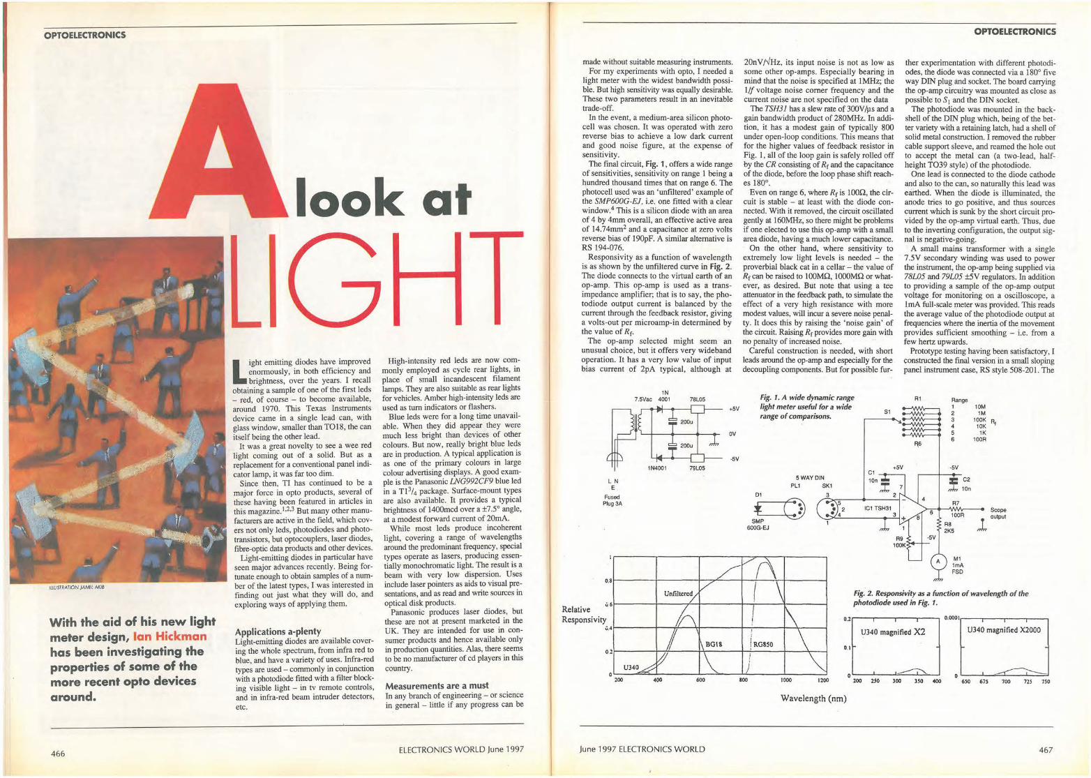
OPTOELECTRONICS
IUUSTRATION JAME( AKIB
With the aid of his new light meter design, Ian Hickman has been investigating the properties of some of the more recent opto devices around.
466
look at
Light emitting diodes have improved enormously, in both efficiency and brightness, over the years. I recall
obtaining a sample of one of the first !eds - red, of course - to become available, around 1970. This Texas Instruments device came in a single lead can, with glass window, smaller than TO18, the can itself being the other lead.
It was a great novelty to see a wee red light coming out of a solid. But as a replacement for a conventional panel indicator lamp, it was far too dim.
Since then, TI has continued to be a major force in opto products, several of these having been featured in articles in this magazine.1•2•3 But many other manufacturers are active in the field, which covers not only !eds, photodiodes and phototransistors, but optocouplers, laser diodes, fibre-optic data products and other devices.
Light-emitting diodes in particular have seen major advances recently. Being fortunate enough to obtain samples of a number of the latest types, I was interested in finding out just what they will do, and exploring ways of applying them.
Applications a-plenty Light-emitting diodes are available covering the whole spectrum, from infra red to blue, and have a variety of uses. Infra-red types are used- commonly in conjunction with a photodiode fitted with a filter blocking visible light - in tv remote controls, and in infra-red beam intruder detectors, etc.
High-intensity red !eds are now commonly employed as cycle rear lights, in place of small incandescent filament lamps. They are also suitable as rear lights for vehicles. Amber high-intensity !eds are used as turn indicators or flashers.
Blue !eds were for a long time unavailable. When they did appear they were much less bright than devices of other colours. But now, really bright blue leds are in production. A typical application is as one of the primary colours in large colour advertising displays. A good example is the Panasonic LNG992CF9 blue led in a n 3/4 package. Surface-mount types are also available. It provides a typical brightness of 1400mcd over a ±7.5° angle, at a modest forward current of 20mA.
While most !eds produce incoherent light, covering a range of wavelengths around the predominant frequency, special types operate as lasers, producing essentially monochromatic light. The result is a beam with very low dispersion. Uses include laser pointers as aids to visual presentations, and as read and write sources in optical disk products.
Panasonic produces laser diodes, but these are not at present marketed in the UK. They are intended for use in consumer products and hence available only in production quantities. Alas, there seems to be no manufacturer of cd players in this country.
Measurements are a must In any branch of engineering - or science in general - little if any progress can be
ELECTRONICS WORLD June 1997
made without suitable measuring instruments. For my experiments with opto, I needed a
light meter with the widest bandwidth possible. But high sensitivity was equally desirable. These two parameters result in an inevitable trade-off.
In the event, a medium-area silicon photocell was chosen. It was operated with zero reverse bias to achieve a low dark current and good noise figure, at the expense of sensitivity.
The final circuit, Fig. 1, offers a wide range of sensitivities, sensitivity on range I being a hundred thousand times that on range 6. The photocell used was an 'unfiltered' example of the SMP600G-EJ, i.e. one fitted with a clear window.4 This is a silicon diode with an area of 4 by 4mm overall, an effective active area of 14.74mm2 and a capacitance at zero volts reverse bias of l 90pF. A similar alternative is RS 194-076.
Responsivity as a function of wavelength is as shown by the unfiltered curve in Fig. 2. The diode connects to the virtual earth of an op-amp. This op-amp is used as a transimpedance amplifier; that is to say, the photodiode output current is balanced by the current through the feedback resistor, giving a volts-out per microamp-in determined by the value of Rr.
The op-amp selected might seem an unusual choice, but it offers very wideband operation. It has a very low value of input bias current of 2pA typical, although at
Relative
L N E
Fused Plug 3A
1N 7.5Vac 4001
1N4001
78L05
+SV
ov
·SV
79L05
20nV/✓Hz, its input noise is not as low as some other op-amps. Especially bearing in mind that the noise is specified at I MHz; the 1/f voltage noise comer frequency and the current noise are not specified on the data
The TSH31 has a slew rate of 300V/µs and a gain bandwidth. product of 280MHz. In addition, it has a modest gain of typically 800 under open-loop conditions. This means that for the higher values of feedback resistor in Fig. I , all of the loop gain is safely rolled off by the CR consisting of Rr and the capacitance of the diode, before the loop phase shift reaches 180°.
Even on range 6, where Rr is IO0Q, the circuit is stable - at least with the diode connected. With it removed, the circuit oscillated gently at 160MHz, so there might be problems if one elected to use this op-amp with a small area diode, having a much lower capacitance.
On the other hand, where sensitivity to extremely low light levels is needed - the proverbial black cat in a cellar - the value of Rr can be raised to lOOMQ, IOOOMQ or whatever, as desired. But note that using a tee attenuator in the feedback path, to simulate the effect of a very high resistance with more modest values, will incur a severe noise penalty. It does this by raising the 'noise gain' of the circuit. Raising Rr provides more gain with no penalty of increased noise.
Careful construction is needed, with short leads around the op-amp and especially for the decoupling components. But for possible fur-
Fig. 1. A wide dynamic range light meter useful for a wide
S1 range of comparisons.
+SV C1
SWAYOIN PU SK1
D1 3
* (:}) • 5
• 2 • 4
SMP 1 600G-EJ
OPTOELECTRONICS
ther experimentation with different photodiodes, the diode was connected via a 180° five way DIN plug and socket. The board carrying the op-amp circuitry was mounted as close as possible to S I and the DIN socket.
The photodiode was mounted in the backshell of the DIN plug which, being of the better variety with a retaining latch, had a shell of solid metal construction. I removed the rubber cable support sleeve, and reamed the hole out to accept the metal can (a two-lead, halfheight TO39 style) of the photodiode.
One lead is connected to the diode cathode and also to the can, so naturally this lead was earthed. When the diode is illuminated, the anode tries to go positive, and thus sources current which is sunk by the short circuit provided by the op-amp virtual earth. Thus, due to the inverting configuration, the output signal is negative-going. · A small mains transformer with a single
7 .5V secondary winding was used to power the instrument, the op-amp being supplied via 78l05 and 79l05 ±5V regulators. In addition to providing a sample of the op-amp output voltage for monitoring on a oscilloscope, a lmA full0scaJe meter was provided. This reads the average value of the photodiode output at frequencies where the inertia of the movement provides sufficient smoothing - i.e. from a few hertz upwards.
Prototype testing having been satisfactory, I constructed the final version in a small sloping panel instrument case, RS style 508-201. The
R1
F\6
6
Range 1 2 3 4 5 6
-SV
C2
10n
R7
100R
M1 1mA FSD
10M 1M
100K R1 10K 1K
100R
Scope
1 output
Fig. 2. Responsivity as a function of wavelength of the photodiode used in Fig. 1.
Responsivity u.41-----+--,,'-----'.+-- ---1-;...----+--'..----I
0.2.----.---,.--..---~ 0.00011,-.---~--~-~
U340 magnified X2 U340 magnified X2000
! RG8SO 0.21----- ~-'------j..J,---- l--''-----+---,._--l 0.1
i ' U340 /1
oL---"':Z:::....L------l-_,, __ ..J....1; ___ .-1. ___ __J
200 •00 600 100 1000 1200 o o'---'---'::::.J.---'--===~
200 250 300 350 •00 650 67S 700 725 7SO
Wavelength (nm)
June 1997 ELECTRONICS WORLD 467
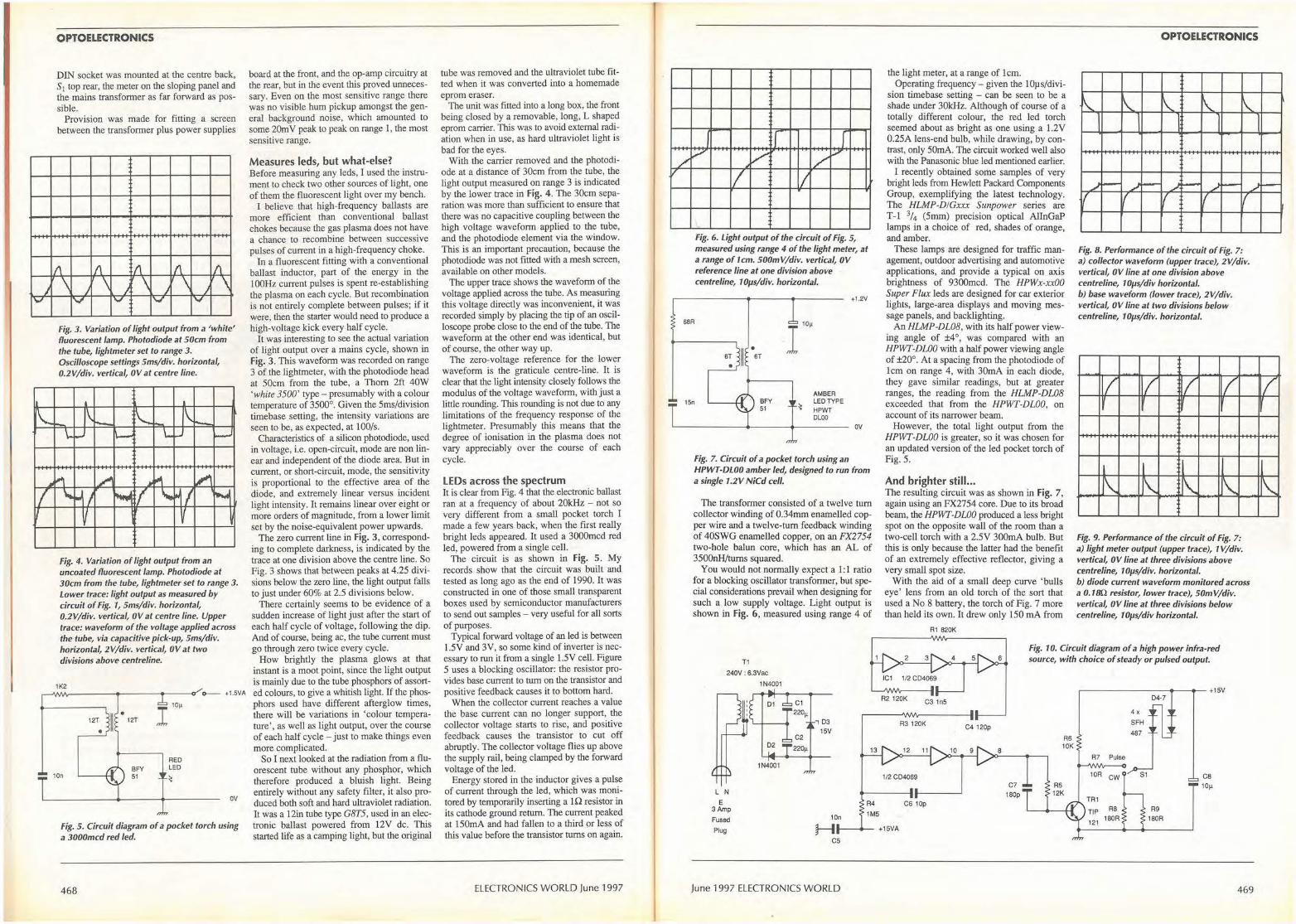
J y
OPTOELECTRONICS
DIN socket was mounted at the centre back, S 1 top rear, the meter on the sloping panel and the mains transformer as far forward as possible.
Provision was made for fitting a screen between the transformer plus power supplies
I\ I\ ,,, I\ I\
\ )
\ ) \ ) \ ) \ IV ..., V V
Fig. 3. Variation of light output from a 'white' fluorescent lamp. Photodiode at 50cm from the tube, lightmeter set to range 3. Oscilloscope settings 5ms/div. horizontal, 0.2V/div. vertical, 0V at centre line.
~ \ __ \_ "--
\ lo...
\.. - - \.._ ~
.. ""I ./' ... ~ .,'I
I .... • I ~ f '- ,.. I
"""" I
✓ ' Fig. 4. Variation of light output from an uncoated fluorescent lamp. Photodiode at 30cm from the tube, lightmeter set to range 3. Lower trace: light output as measured by circuit of Fig. 1, 5ms/div. horizontal, 0.2V/div. vertical, OV at centre line. Upper trace: waveform of the voltage applied across the tube, via capacitive pick-up, 5ms/div. horizontal, 2V/div. vertical, OV at two divisions above centreline.
1K2 ,--I\JVl/lr-- -----<p-----t---<>' o-- +1.5VA
10n
I 10µ
RED LED
OV
Fig. 5. Circuit diagram of a pocket torch using a 3000mcd red led.
468
board at the front, and the op-amp circuitry at the rear, but in the event this proved unnecessary. Even on the most sensitive range there was no visible hum pickup amongst the general background noise, which amounted to some 20m V peak to peak on range 1, the most sensitive range.
Measures leds, but what-else? Before measuring any Jeds, I used the instrument to check two other sources of light, one of them the fluorescent light over my bench.
I believe that high-frequency ballasts are more efficient than conventional ballast chokes because the gas plasma does not have a chance to recombine between successive pulses of current in a high-frequency choke.
In a fluorescent fitting with a conventional ballast inductor, part of the energy in the I 00Hz current pulses is spent re-establishing the plasma on each cycle. But recombination is not entirely complete between pulses; if it were, then the starter would need to produce a high-voltage kick every half cycle.
It was interesting to see the actual variation of light output over a mains cycle, shown in Fig. 3. This waveform was recorded on range 3 of the Jightmeter, with the photodiode head at 50cm from the tube, a Thom 2ft 40W 'white 3500' type - presumably with a colour temperature of 3500°. Given the 5ms/division timebase setting, the intensity variations are seen to be, as expected, at 100/s.
Characteristics of a silicon photodiode, used in voltage, i.e. open-circuit, mode are non linear and independent of the diode area. But in current, or short-circuit, mode, the sensitivity is proportional to the effective area of the diode, and extremely linear versus incident light intensity. It remains linear over eight or more orders of magnitude, from a lower limit set by the noise-equivalent power upwards.
The zero current line in Fig. 3, corresponding to complete darkness, is indicated by the trace at one division above the centre line. So Fig. 3 shows that between peaks at 4 .25 divisions below the zero Line, the light output falls to just under 60% at 2.5 divisions below.
There certainly seems to be evidence of a sudden increase of light just after the start of each half cycle of voltage, following the dip. And of course, being ac, the tube current must go through zero twice every cycle.
How brightly the plasma glows at that instant is a moot point, since the light output is mainly due to the tube phosphors of assorted colours, to give a whitish light. If the phosphors used have different afterglow times, there will be variations in 'colour temperature' , as well as light output, over the course of each half cycle - just to make things even more complicated.
So I next looked at the radiation from a fluorescent tube without any phosphor, which therefore produced a bluish light. Being entirely without any safety filter, it also produced both soft and hard ultraviolet radiation. It was a 12in tube type G8T5, used in an electronic ballast powered from 12V de. This started life as a camping light, but the original
tube was removed and the ultraviolet tube fitted when it was converted into a homemade eprom eraser.
The unit was fitted into a long box, the front being closed by a removable, long, L shaped eprom carrier. This was to avoid external radiation when in use, as hard ultraviolet light is bad for the eyes.
Witb the carrier removed and the photodiode at a distance of 30cm from the tube, the light output measured on range 3 is indicated by the lower trace in Fig. 4. The 30cm separation was more than sufficient to ensure that there was no capacitive coupling between the high voltage waveform applied to the tube, and the photodiode element via the window. This is an important precaution, because the photodiode was not fitted with a mesh screen, available on other models.
The upper trace shows the waveform of the voltage applied across the tube. As measuring this voltage directly was inconvenient, it was recorded simply by placing the tip of an oscilloscope probe close to the end of the tube. The waveform at the other end was identical, but of course, the other way up.
The zero-voltage reference for the lower waveform is the graticule centre-line. lt is clear that the light intensity. closely follows the modulus of the voltage waveform, with just a little rounding. This rounding is not due to any limitations of the frequency response of the lightmeter. Presumably this means that the degree of ionisation in the plasma does not vary appreciably over the course of each cycle.
LEDs across the spectrum It is clear from Fig. 4 that the electronic ballast ran at a frequency of about 20kHz - not so very different from a small pocket torch I made a few years back, when the first really bright !eds appeared. It used a 3000mcd red led, powered from a single cell.
The circuit is as shown in Fig. 5. My records show that the circuit was built and tested as long ago as the end of 1990. It was constructed in one of those small transparent boxes used by semiconductor manufacturers to send out samples - very useful for all sorts of purposes.
Typical forward voltage of an led is between 1.SV and 3V, so some kind of inverter is necessary to run it from a single 1.5V cell. Figure 5 uses a blocking oscillator: the resistor provides base current to turn on the transistor and positive feedback causes it to bottom hard.
When the collector current reaches a value the base current can no longer support, the collector voltage starts to rise, and positive feedback causes the transistor to cut off abruptly. The collector voltage flies up above the supply rail, being clamped by the forward voltage of the led.
Energy stored in the inductor gives a pulse of current through the led, which was monitored by temporarily inserting a 1 Q resistor in its cathode ground return. The current peaked at I 50mA and had fallen to a third or less of this value before the transistor turns on again.
ELECTRONICS WORLD June 1997
I : r f V
/ V _v /
V I I
Fig. 6. Light output of the circuit of Fig. 5, measured using range 4 of the light meter, at a range of 1cm. 500mV/div. vertical, OV reference line at one division above centreline, 1 Oµs/div. horizontal.
68R
15n
6T
BFY 51
AMBER LED TYPE HPWT OLOO
+1.2V
~ - ------- ------- ov
Fig. 7. Circuit of a pocket torch using an HPWT-DLOO amber led, designed to run from a single 1.2V NiCd cell.
The transformer consisted of a twelve tum collector winding of 0.34mm enamelled copper wire and a twelve-tum feedback winding of 40SWG enamelled copper, on an FX2754 two-hole balun core, which has an AL of 3500nH/tums squared.
You would not normally expect a 1:1 ratio for a blocking oscillator transformer, but special considerations prevail when designing for such a low supply voltage. Light output is shown in Fig. 6, measured using range 4 of
the light meter, at a range of 1cm. Operating frequency - given the I 0µ s/divi
sion timebase setting - can be seen to be a shade under 30kHz. Although of course of a totally different colour, the red led torch seemed about as bright as one using a 1.2V 0.25A Jens-end bulb, while drawing, by contrast, only 50mA. The circuit worked well also with the Panasonic blue led mentioned earlier.
I recently obtained some samples of very bright !eds from Hewlett Packard Components Group, exemplifying the latest technology. The HLMP-D!Gxxx Sunpower series are T-1 3/4 (5mm) precision optical AllnGaP lamps in a choice of red, shades of orange, and amber.
These lamps are designed for traffic management, outdoor advertising and automotive applications, and provide a typical on axis brightness of 9300mcd. The HPWx-xx00 Super Flux !eds are designed for car exterior lights, large-area displays and moving message panels, and backlighting.
An HLMP-DL08, with its half power viewing angle of ±4°, was compared with an HPWT-DUJ0 with a half power viewing angle of ±20°. At a spacing from the photodiode of 1cm on range 4, with 30mA in each diode, they gave similar readings, but at greater ranges, the reading from the HLMP-DL08 exceeded that from the HPWT-DL00, on account of its narrower beam.
However, the total light output from the HPWT-DLO0 is greater, so it was chosen for an updated version of the led pocket torch of Fig. 5 .
And brighter still ... The resulting circuit was as shown in Fig. 7, again using an FX2754 core. Due to its broad beam, the HPWT-DLO0 produced a less bright spot on the opposite wall of the room than a two-cell torch with a 2.5V 300mA bulb. But this is only because the latter bad the benefit of an extremely effective reflector, giving a very small spot size.
With the aid of a small deep curve 'bulls eye' lens from an old torch of the sort that used a No 8 battery, the torch of Fig. 7 more than held its own. It drew only 150 mA from
R1 820K
OPTOELECTRONICS
I\. '- I\. \. I'-.. 1
'
1
.,) i--~ -- ,) - .J---
I l I I I
Fig. 8. Performance of the circuit of Fig. 7: a) collector waveform (upper trace), 2V/div. vertical, 0V line at one division above centreline, 10µs/div horizontal. b) base waveform (lower trace), 2V/div. vertical, 0V line at two divisions below centreline, 1 Oµs/div. horizontal.
I I I I
I
[\ ' \. '-Fig. 9. Performance of the circuit of Fig. 7: a) light meter output (upper trace), 1 V/div. vertical, OV line at three divisions above centreline, 10µs/div. horizontal. b) diode current waveform monitored across a 0.1 IJQ resistor, lower trace), 50m V /div. vertical, OV line at three divisions below centreline, 1 Oµs/div horizontal.
I
.,)
T1
Fig. 10. Circuit diagram of a high power infra-red source, with choice of steady or pulsed output.
240V : 6.3Vac
1N4001
L N E
3Amp Fused
Plug
1N4001
C1
220µ
C2
220µ
, 03
15V
10n
1/2 C04069
R4 C6 10p
1M5
H-- -- +15VA
cs
June 1997 ELECTRONICS WORLD
C4 120p
8
C7
180p
RS 12K
~ ------------- +15V
R7 Pulse
10R CW
TR1
TIP R8
121 180R
4x
SFH
487
04-7
R9
180R
ca 10µ
469
i---
;
~
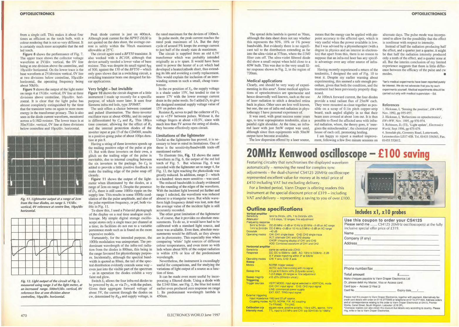
OPTOELECTRONICS
from a single cell. This makes it about four times as efficient as the torch bulb, with a colour rendering that is not so very different. It is certainly much more acceptable that the red led torch.
Figure 8 shows the performance of Fig. 7. The upper trace shows the collector voltage waveform at 2V/div. vertical, the 0V line being at one division above the centreline, and lOµs/div horizontal. On the lower trace is the base waveform at 2V/division vertical, 0V line at two divisions below centreline, lOµs/div horizontal, the operating frequency being about S0kHz.
Figure 9 shows the output of the light meter on range 4 at 1 V/div. vertical, 0V line at three divisions above · centreline, l0µs/div. horizontal. It is clear that the light pulse has almost completely extinguished by the time that the transistor turns on again to store more energy in the transformer primary. This is also seen in the diode current waveform, monitored across a 0.180 resistor. The lower trace is at 50mV/div. vertical, 0V line at three divisions below centreline and lOµs/div. horizontal.
i·--- ··-· ·· -. . - - - ·--- ·- · - -·-,···-l l·-·-r-· E -:I- - ,-1 L_ I_ - -- -- - -- -- ---- ---\
~"' " " "H "'' "" "" "" "" .. ,, ""
1,,- .-4----- - -· ·-- - - - -- . , .
V
Fig. 11. Lightmeter output at a range of 2cm from the four diodes, on range 5. 1 V /div. vertical, OV reference at centre line, 1 Oµs/div horizontal.
r r I /v / /
I'"
V "
Fig. 12. Light output of the circuit of Fig. 5, measured using range 2 of the light meter, at an increased range. 500m V/div. vertical, OV reference line at one division above centreline, 1 Oµs/div. horizontal.
470
Peak diode current is just on 400mA. Although peak current for the HPWI-DUJO is not quoted on the data sheet, the average current is safely within the 70mA maximum allowable at 25°C.
The circuit again used a BFY50 transistor. It also worked with a BC 108, although that device actually needed a lower value of base resistor. This was despite its small signal hFE of 500, against the I 30 of the BFY50 - which only goes shows that in a switching circuit, a switching transistor beats one designed for linear applications.
Very bright - but invisible Figure 1 O shows the circuit diagram of a little instrument I made up recently for a specific purpose, of which more later. It uses four Siemens infra-red leds, type SFH487.
The unit offers a choice between constant and pulsed illumination. The three-inverter oscillator runs at about 450Hz, and its output is differentiated by C4 and R4 . This 180µs time constant, allowing for the effect of R3 and the internal protection diodes of the inverter input at pin 13 of the CD4069, results in a positive-going pulse of about IOOµs duration at pin 8.
Having a string of three inverters speeds up the trailing positive edge of the pulse at pin .13. But with three inverters on their own, a glitch on the trailing edge of the pulse is inevitable, due to internal coupling between the six inverters in the package. So C6 is added to provide a little positive feedback to make the trailing edge of the pulse snap off cleanly.
Figure 11 shows the output of the lightmeter when illuminated by the diodes, at a range of 2cm on range 5. Despite the presence of D3, there is still some l00Hz ripple on the supply line. This results in some 10GHz modulation of the the pulse amplitude, and also of the pulse repetiLion frequency, or prf, boLh visible in Fig. l l.
To show Lhis, I used a Polaroid photograph of the display on a real time analogue oscilloscope. My simple digital storage oscilloscope stores only a single trace per channel at a time; its facilities do not run to a variable persistence mode such as is found on the more expensive models.
Fortunately, for the intended purpose, the JOOHz modulation was unimportant. The predominant wavelength of the infra-red radiation from the diodes is 880nm, this being in the range favoured for physiotherapy purposes. Incidentally, although the spectral bandwidth is quoted as 80nm, the tail of the spectral distribution evidently extends some way even just into the visible part of the spectrum - as in operation the diodes exhibit a very faint red glow.
Switch SI allows the four infra-red diodes to be powered by de, or via Tr1, with the pulses. Given their aggregate forward voltage of about 5V, the current through the diodes on cw, determined by Rs,9 and supply voltage, is
the rated maximum for the devices of lOOmA. In pulse mode, the peak current reaches the
rated peak maximum of lA. But the duty cycle of around 5% keeps the average current to just half of the steady state de maximum.
The circuit is supplied from an old 6.3V transformer which was probably intended originally as a tv spare. It would have been used to power the heater of a crt which had developed a heater/cathode short, thus extending its life and avoiding a costly replacement. This would explain the inclusion of an interwinding screen in such a small, cheap transformer.
In the cw position of Si, the supply voltage is a shade under 15V, but tended to rise to nearer 17V with the lower average current drain in the pulse mode. So I added D3 to give the designed nominal supply voltage value of 15V on pulses also.
Resistor R6 serves to pull the collector of Tr1 up to +15V between pulses. Without it, the voltage lingers at about +10.5V, since with much less than 5V across the string of diodes, they become effectively open circuit.
Limitations of the lightmeter Useful as the lightmeter has proved, it is necessary to bear in mind its limitations. One of these is the sensitivity/bandwidth trade-off mentioned earlier.
To illustrate this, Fig. 12 shows the same waveform as Fig. 6, the output of the red led torch of Fig. 5. But whereas Fig. 6 was recorded with the lightmeter set to range 4, for Fig. 12, the light reaching the photodiode was greatly reduced. In addition, range 2 - which is a hundred times more sensitive - was used.
The reduced bandwidth is clearly evidenced by the rounding of the edges of the waveform. With the incident light lowered yet further and range 1 selected, the waveform was reduced almost to a triangular wave. But while waveform high frequency detail was lost, note that the average value of the incident light is still accurately recorded.
The other great limitation of the lightmeter is, of course, that it provides no absolute measurements. To do so, it would have had to be calibrated with a standard light source, and none was available. Even then, absolute measurements would be difficult, as they always are io photometry. This especially true when comparing 'white' light sources of different colour temperatures, and even more so with !eds where about 90% of the output radiation is within ±5% or less of the predominant wavelength.
Nevertheless, the instrument is exceedingly useful for comparisons, and for studying the variations of light output of a source as a function of time.
It can be made even more useful by incorporating a filtered diode. Using a diode with the U340 filter, see Fig. 2, the blue led tested earlier even produced zero response on range 1. Its predominant wavelength lambda is 450nm.
ELECTRONICS WORLD June 1997
The spread delta lambda is quoted as 70nm, although the data sheet does not say whether this represents the 50%, 10% or 1 % power bandwidth. But evidently there is no significant tail to the distribution extending as far into the ultra-violet at 375nm, where the U340 filter cuts off. The ultra-violet filtered diode did show a small output when held close to a 60W bulb. This was due to the very smaU filter response shown in Fig. 2, in the region of 720nm.
Medical applications Clearly, one should be very wary of experimenting in this area*. Some medical applications of optoelectronics are spectacular and hence deservedly well known, such as the use of laser radiation to stitch a detached retina back in place. Other uses are less weU known, but one, the use of infra-red radiation in physiotherapy I have personal experience of.
It was used, with great success some years ago, to treat supraspinatus tendonitis, alias a painful right shoulder. At the time, an infrared laser with just 5mW output was used, although since then equipments with 50mW output have become available.
The low dispersion offered by a laser source,
means that the energy can be applied with pinpoint accuracy to the affected spot, which is very useful when the power available is low. But I was advised by a physiotherapist (with a degree in physics and an interest in electronics) that apart from this, there is no reason to suppose that an infra-red laser has any specific advantage over any other source of infrared.
Having recently experienced a return of the tendonitis, I designed the unit of Fig. 10 to treat it. Despite my earlier warning about experimenting, this seemed a safe enough procedure, given that both the condition, and the treatment had been previously properly diagnosed.
At lO0mA forward current, the four diodes provide a total radiant flux of 25mW each. They were mounted as close together as possible on a scrap of 0 .1 in pitch copper-strip board, each angled slightly in so that their beam axes crossed at about 1cm out. It is thus possible to flood the affected area with infrared radiation, where, the theory goes, it 'energises the mitochrondria', the chemical power house of each cell, promoting healing.
I am happy to report a marked improvement, following a few five minute sessions on
OPTOELECTRONICS
alternate days. The pulse mode was incorporated to allow for the possibility that the effect is nonlinear with respect to intensity.
Instead of half the radiation producing half the effect, and a quarter just a quarter, it might be that half the radiation intensity produced only a tenth of the effect, and a quarter none at all. But the interim conclusion of my limited experience suggests that there is little difference between the efficacy of the pulse and cw modes. •
*Ian's medical experiments have been reported purely
for interest. We do not advocate that you try such
experiments yourself. Medical experiments should be
carried out only with medical supervision - Ed.
References I. Hickman, I, 'Sensing the position', EW + WW, Nov. 1992, pp 955-957. 2. Hickman, I, 'Reflections on optoelectronics ' , EW+WW, Nov. 1995, pp 970-974. 3. Robinson, D, (Tl) , 'Light update', Electronics World, Sept 1996, pp 675-679. 4 . Semelab pie, Coventry Road, Lutterworth, Leicestershire LEI 7 4JB. Tel. 01455 556565, Fax. 01455 552612.
20MHz Kenwood oscilloscope - £ 1 00 saving Featuring circuitry that synchronises the displayed waveform automatically - removing the need for complex sync adjustments - the dual-channel CS4125 20MHz oscilloscope represented excellent value for money at its retail price of £410 including VAT but excluding delivery.
--------
'~r,,f,f'if,~f\ For a limited period, Vann Draper is offering readers this instrument at the special discount price of £319 - including VAT and delivery - representing a saving to you of over £100.
.~vvv~VV
Outline specifications Vertlcal amplllier Sensitivity SmV to 5V/div, ±3%, 1 to 2mV/div ±5% Attenuator 1 ·2·5 steps, 12 ranges, l ine adjustment Frequency response
SmV lo SV/div OC-20 MHz -3 dB or 10 Hz to 20 MHz -3 dB on AC range 1 mV lo 2mV/div OC•5 MHz -3 dB or 10 Hz to 5 MHz -3 dB on AC range
Crosstalk ~ o dB Operating modes CHI: CH1 single•trace CH2: CH2 single-trace
ALT: alternate CH 1 and CH2 display CHOP: chopping display of CH t and CH2 ADD: Combined waveform of CH1 and CH2
Horizontal amplifier Sensitivity same as vertical axis (CH2) Response DC: DC lo SOOkHz -3dB AC: 10Hz to 500kHz -3 dB
Operating modes Sweep Modes
Sweep time
Sweep magnify Triggering Trigger sources
External triggering
X-Y phase matching within 3° at 50kHz CHI: Y axis, CH2: X axis
NORM: trigger sweep AUTO: auto tree-running with no signal 0.5 µs to 0 .5sldiv ±3% (0.2µs/d,v uncal.), 1-2-5 steps, 20 ranges w. fine adjustment x10 ±5% (20ns/div uncal.)
VERT MOOE: input signal selected in VERTICAL mode CHI: CHI input signal CH2: CH2 input signal LINE: commercial power supply EXT: EXT. TRIG input signal
Input impedance 1 MO and 22 pf approx. Coupling modes AUTO, NORM, FIX: AC coupling
TV-FRAME: TV-LINE: Calibration o/p square wave, positive polarity, 1 Vp•p ±3%, approx. 1 kHz Intensity mod. TTL input to 3.5 MHz and CH1 olp SOmV/div to 10MHz
Includes x 1, x 1 0 probes Use this coupon to order your CS4125 Please send me ....... CS4125 20MHz oscilloscope(s) at the fu lly inclusive special offer price of £319. Name ____ _ ______________ _
Company (if any) _____________ _
Address __________________ _
Phone number/fax _______________ _
Total amount £ ••.••••••. Make cheques payable to Vann Draper Electronics Ltd
Or, please debit my Master, Visa or Access card:
Card type - Access O Visa D Card No ___________ Expiry date _ _ / __
Please mail this coupon to Vann Draper Electronics. together with payment. Alternatively fax credit card details with order on 0116 2773945 or telephone on 0116 2771400. Address orders and all correspondence relating to this order lo Vann Draper Electronics al Un~ 5, Premier Works, Canal Street, South Wigston, Leicester LE18 2PL. ·Overseas readers can also obtain lhis discount but details vary according to country. Please ring. write or lax to Vann Draper Electronics.
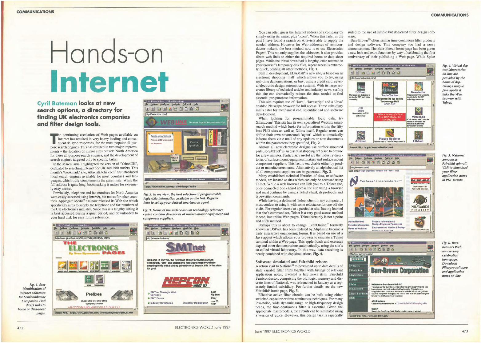
COMMUNICATIONS
Hands-on Internet
Cyril Bateman looks at new search options, a directory for finding UK electronics companies and filter design tools.
Fig. 1. Easy identification of
Internet addresses for Semiconductor
Companies. Find direct links to
home or data-sheet pages.
472
The continuing escalation of Web pages available on Internet has resulted in very heavy loading and consequent delayed responses, for the most popular all-pur
pose search engines. This has resulted in two major improvements - the location of mirror sites outside North America for these all-purpose search engines, and the development of search engines targeted only to specific tasks.
In the March issue I highlighted the version of 'Y ahooUK', dedicated to searching Internet for UK and Irish surfers. This month's 'bookmark' site, Altavista.telia.com1 has introduced local search engines available for most countries and languages, which truly complements the parent site. While the full address is quite long, bookmarking it makes for extremely easy access.
Previously, telephone and fax numbers for North America were easily accessed using Internet, but not so for other countries. Applegate Media2 has now released its Web site which specifically aims to supply the telephone and fax numbers of the UK electronics industry. Since this is a lengthy listing it is best accessed during a quiet period, and downloaded to your hard disk for easy future reference.
-
Prefixes
Cllooie -..imle-..rof 11>• compony't •-·
ABCPEEGHIJKLMNOP~6SJUYWXXZ ~• [.u' ' !I CWniM UM.: 1111p,//www,....,llla.CIIII/Sll'-Vlllllll/15'4/,rflLllf,._
11:M Wl'bl xp!otr1 X1lmx llomc- 1•,111P
i
Fig. 2. In my view, the best selection of programmable logic data information available on the Net. Register here to set up your desired smartsearch agent.
Fig. 3. Home of the surface-mount technology reference centre contains directories of surface-mount equipment and component suppliers.
ll'l 1W1 Iii ){)111111'1 \ Mlm•I \111l,Ut• t-lOUIII lt•1 hnulOlJV ( \ M T). l'1i11f1•d LU(l1
Welcome to SMl'MI, the Nlanlnc,a oen111r tor SU~ Mount Technology (SMT) .nc1.1ec110•• m1nlftcllll1"9I II you hlNe enyth1"9 to Clo with bwldl~ print«! ~lro~ IIOtll'CII, 1111111 the pllcie lorYoUI
Ci ~~.:•c".!sStr11tegic Web
a SMTForurn
a lndust,y Directories Directory Registr11tion
lllll Update Deily Jon. 2a 1997
:J
ELECTRONICS WORLD June 1997
You can often guess the Internet address of a company by simply using its name, plus '.com'. When thjs fails, in Lhe past I have found a search on Altavista able to supply the needed address. However for Web addresses of semiconductor makers, the best method now is to use Electronics Pages3. This not only supplies the addresses, it also provides direct web links to either the required home or data sheet pages. While the initial download is lengthy, once retained in your browser's temporary disk files, repeat access is extremely quick, beating all other methods, Fig. 1.
Still in development, EDAMa114 a new site, is based on an electronic shopping 'mall' which allows you to try, using real-time demonstrations, or buy, using a credjt card, several electronic design automation systems. With its large reference library of technical articles and industry news, surfing this site can dramatically reduce the time needed to find essential pre-purchase information.
This site requires use of ' Java' , 'Javascript' and a 'Java' enabled Netscape browser for full access. Three subsidiary malls cater for mechanical cad, scientific cad and software development.
When looking for programmable logic data, try Xilinx.com5 This site has its own specialised Weblinx smartsearch method which looks for information within the fifty best PLD sites as well as Xilinx itself. Regular users can define their own smartsearch ' agent' which automatically informs them via e-mail of any updates or new documents within the parameters they specified, Fig. 2.
Almost all new electronic designs use surface mounted parts, so SMTnet6 is an essential stopping off place to browse for a few minutes. Particularly useful are the industry directories of surface mount equipment makers and surface mount component suppliers. This last is searchable either by product or manufacturers name. Alternatively an alphabetical list of all component suppliers can be generated, Fig. 3.
Many established technical libraries of data, or software models, are located at sites which can only be accessed using Telnet. While a web browser can link you to a Telnet site, once connected one cannot access the site using a browser and must continue by using a Telnet client, its protocols and typewritten commands.
While having a dedicated Telnet client in my computer, I must confess to using it with some reluctance for one-off site visits. For regular access to a particular site, having learned that site's command set, Telnet is a very good access method indeed, but unlike Web pages, Telnet certainly is not a point and click method.
Perhaps this is about to change. TechOnline,7 formerly known as DSPnet, has been updated by Aliphas to become a truly interactive engineering forum. It is based on use of a Java applet which allows your browser to emulate a Telnet terminal within a Web page. This applet loads and executes dsp and other demonstrations automatically, using the site• s so-called virtual laboratory. In this way, data searching is neatly combined with dsp simulations, Fig. 4.
Software simulated and Fairchild reborn A return visit to National8 to download up to date details of state variable filter chips together with listings of relevant application notes, revealed a late news item. Fairchild Semiconductor, comprising the old logic, memory and discrete lines of National. was relaunched in January as a separately funded subsidiary. For further details see the new Fairchild9 home page, Fig. 5.
Effective active filter circuits can be built using either switched-capacitor or time-continuous techniques. For many low-noise, wide dynamic range or high-frequency design needs, the time-continuous filter is essential. Given the appropriate macromodels, the circuits can be simulated using a version of Spice. However, this design task is especially
June 1997 ELECTRONICS WORLD
COMMUNICATIONS
suited to the use of simple but dedicated filter design software.
Burr-Brown10 offers similar time-continuous filter products and design software. This company too had a news announcement. The Burr-Brown home page has been given a new look and extra functions by way of celebrating the fust anniversary of their publishing a Web page. While Spice
;.;+iHl&rittdlii!PMMb@WIMM@MtiMIUiiMMt@ii/ii flo!llll""'~~g,,ldlllll~ () • ~ 1!l -~ ~ o: ~ ~ A
111 DSPnet ... ___ ,.
' hDSP_...,
Jobi Jobs
~,..OSP -rs
ACQnet ,-
• TechOnL11t6 Wetce-1 to Iha Oll-litle
Tec:M4>logy Me.II Whal'> new
Tl Off ors Industry's First [ 32-b,I OSP Starter K,t
for only $99
Please Register ,OU_!'"!!.~l~l(J.lneed\O • EDAnet
tr,NiHIW&ri&SiiiiYM&MibliMMQYOiiiliMiMhiF\IN&HiiiHH! IIM flt Qlillolll ~ l!MIIR g,,ldlllll u,111 ;. I • •l a 'Ill o ~ o !i'll ai ~ _ _ ~i,pJfwww ••ctoml
.... Ma: o.,~ EftllfflNtf• · lrwfflOI lnlo · N1w1 -,lobl
_,;.,===::....i ,1
About Nettonal Produc:I Information & lnve,tor lnlormetion DHlgn EnglnHr RHour.-1 NIWI et Netlonel Envfron1n1ntel Health & Safely ., ,._ .. _ •• , ......... t. -
-•to •-,ownw,,~ 'It To ce!11breie.,. e....-We1>s11o·, limOMNOfllll\l,.,. tllohas
.11 I ,
blen ~ e. n..-k:lok end odded fundionedit,,. Thanks lo~u,
,uggen0<11 and "'""""nb. we hol,e ~-•loAcobM Quldelo J sioyoWfneMQotonthroughouttie site. oswal ate.lb! Harc:h anginA to ~youllndl'le ~ you ne~.
AOUIOclllh Clied< °"'°"' '°""'"" line o1 It• &l'>d I 1-8,1 ¢MOS S.tt,pi,oO ,o/01
-· Seerdl ... ~ Web sa. bv QIOducl.nanut Ot t\lb5tct I • ~ C...- IMI.: """'"_,,_.., __ _
Fig. 4. Virtual dsp test laboratories on-line are provided by the homeofdsp. Using a unique Java applet it links the Web browser with Telnet.
Fig. 5. National announces Fairchild spin-off. Visit to download your filter application notes in PDF format.
Fig. 6. BurrBrown's Web anniversary celebration homepage. Download Filterpro software and application notes on-line.
473
COMMUNICATIONS
Fig. 7. New look and name for Motorola
Semiconductors' page. View Motorola
manufacturing locations worldwide.
engineer's needs, giving easy access to data and applications sheets. The Semiconductor Division has more than twenty design and manufacturing locations world wide which can be viewed on the facilities page map, Fig. 7.
In November, I mentioned the new Windows evaluation version of PSpice 7.1 was available on cd rom as part of Motorola's DesignLab evaluation software. This has now been joined by the Intusoft Spice and So Much More demonstration ed.
While both evaluation software packages are fully usable, perhaps of even more benefit to the simulation novice and experienced user, is the wealth of application notes and online manuals these disks contain. While any of this software or data could be downloaded from Internet, the sheer volume of data contained on either cd, is only practical when supplied on cd rom. •
References I. Alta Vista.Telia.Com http://www.altavista.telia.com 2. AppleGate Media Specialist Publishers. http://host. web 121 bf.claimname.com
models for individual parts can be down-loaded, completing their literature request fonn will arrange a disk containing all their Spice macromodels, sent by post.
3. The Electronics Pages. http://www.geocities.com/Silicon Valley 4. EDA Mall. http://www.edamall.com 5. Xilinx Inc. http://www.xilinx.com
The company's software, Fi/terPro, which can be downloaded, unpacks to give two dos packages; Filter2 caters for m.tb, or multi-feedback, style as well as Sallen-Key designs, while Filter42 is dedicated to the UAF42 state-variable chip, Fig. 6.
Design-net.com 11 is a new service from Motorola Semiconductor Products Division, dedicated to the design
6 . Surface Mount Technology. http://www.smtnet.com 7 . TechOnline.Com.http://www.techonline.com 8. National Semiconductor. http://www.nsc.com 9. Fairchild Semiconductor. http://www.nsc.com/Fairchild/company IO.Burr-Brown Corporation. http://www.burr-brown.com I I.Motorola Semiconductor Products .. http://www.design-net.com
Nine year index - new update Hard copies and floppy-disk databases both available
* * Includes over 600 circuit idea references** Whether os o PC dote base or os hard copy, SottCopy con supply o
complete index of Electronics World articles going bock over the post eight years.
The computerised index of Electronics World magazine covers the e,ght years from 1988 to 1996, volumes 94 to 102 inclusive is available now.
It contains almost 2000 references to articles, circuit ideas ond
oppl,colions - including o synopsis for each.
The EW index dote base ,s easy to use and very lost. It runs on any IBM or compatible PC w ith 512k ram and o hard disk
The disk-based index price is still only £20 inclusive Please specify whether you need 5 25in, 3 .5in DD or 3 .5in HD format. Existing users
con obtain on upgrade for £ 15 by quoting their serial number with their order.
Photo copies of l:"lectro11ic.1· World articles
Hard copy /:'/et·tm11ics m1r/d in<.le,
474
C:i rcu i l ll'i.e<\s
Rcnutt: Motor cunlro 1 H1:sisl,1nce Mttltipl ier S<:R l nuf:rl1!r
S,1nplc- t"11cl-inf i1lite hold Schr,itt trig~r:r, prO!f• thrr.::.holds Self-JD f or plll!fS ,,nd ~Cll!';Ors St:ns:or, I. i nc.,r CHrrfmt Scruo, Hi!1h -torftLW posit.ion Scruo, Sinple
S I MlJI.ATOll. INSERTI ON & RF.TUHN LOSS C J 11,d I
"Sinult;u1eOlt!~ insertim1 nn<l return loss plots". Mo<lcl I ia9' ,\ rclurn·· loss hri<1!Jf: nt the rclcu.u1t port .ti lo\J plot of
=i. -,,~-.-,-1.~--:-,.....,..;;.;.··~-------.;.' -----.;.;.-..;...i.....1.1o1i;,i;,l,l,i1,i.,..i1~ .... il,IM ... ,j,l,l,,l,ll~r...-----• ioglw-po Soft-·st.,1.r r, i Des i•fn: AF
Sp1:1:ch co S<rl1.trc w,, Sl,1tu~ <le Stepper M St(!pver t1 Stcpa:,cr M Slt:rf:11 ex Suitch , I.
D"iri:c I. ion,l l cou1• l,·rs, lt•Jl,r i,l Gi•j,\}11;r•tz ~•J:c.lcn:. u11 ,, Chi1• IIF rP,~1: i vr.r v1:rforM.\IW•• Hf r 1:i:1:ivi1111 1001•, iMi•rov,:,f Ur!1••• fnr RF 1•uutir ,u•,p 1 i r il·r des ii111 Uir1h 1111,, Ii t•J pund, fnr- r.,n iticn"ns lf•1hl"'i<h: i,, llf c11nhint:r~~ 1 n1•ct1.1111·1, tr,, nsf orn,1 t i(111 t1,•,1:>:11ri11!1 D1:l1•1·tors M1:,1~11r-in~1 1-1i th TD}(
I .. ~_:-:.~_f: ;_~. ~ r:-;:--:..~ -----... ,.~ .. ~ t1 it:ruu,1v,~•;, N1•u u,,vf" /l. Noi'.~1: •;1111r•:1:, :;1:Jf r;,1lihr,1li11H 1'11 I ,.,.,h,\st; 88R Ht-' D1~s.i~11 H1?vnl11tion Rr J'ou,•r N•·r1s11rPtu:11l~: i 1\ ni J I j...,_,,tl~ Rr Tr,111si•;lcir~, lli~in•J .11 Nf f 1•,111:,is;t,,r:.., th in~l ,17. HF Tr,1n~~i<..lnr•~, ll·:iw1 /]
• IH' Ii lier for 1•l•!Ctr11 t!Xl'loxiv,:,
!It C:orn:1!1>t:, . 1:irc;ttil·: l< clcivic,,•; . n1•r i I t 'J1H , pl'((,
11:1. tlw I..u.n: of t1i r.rns trip M,"J l 'J'M , ~•1tf'l
tt:i l.11np•!A conpt111t:11t~ R w" VC'.JI! i.-11:'.,.; .furn: l'l'J1, ~1/l
tt1 n,.tiv1• ,lcvic:t;'.~ for r,illin1:tr1:
.fu h 1 t<J•M , p'.,'/ 1
ni, O~r; i l ,1 t.1Jr ,,,u1 ,,npl ir ic:r ,\,:vi•:•:!. (m,,o:,.I J<l'M, 1•(,f,f,
The EW index data base price of £20 includes
UK postage and Vl'J'. Add an extra £ 1 for
overseas EC orders or £5 for non-EC overseas
orders.
For enquiries about photocop ies, etc, please
send an sae to SoftCopy Ltd at the address
below.
Send your order to SoftCopy Ltd., I Vineries
Close, Cheltenham GL53, tel 01242 241455, or
e-mail at [email protected]. Please
make cheques payable to SoftCopy Ltd - not
EW or Reed Business Publishing. Please allow
up to 28 days for delivery.
Posial charges on hard copy indexes and on
photocopies are 50p UK. £ I forthe rest of the
EC or £2 worldwide.
ELECTRONICS WORLD June 1997
SMALL SELECTION ONLY LISTED - EXPORT TRADE AND QUANTITY DISCOUNTS - RING US FOR YOUR REQUIREMENTS WHICH MAY BE IN STOCK HPN-ColourSpeetrumAn• lysera Tektronix Plug-Ins 7A13- 7A14-7At8 -7A24 -7A26-7A11-7M11-7S11-7010-7S12-S1 HP141T+85S2BIF + 8553B RF- l KHz-l lOMc/s-£700. - S2 - S6 - S52 - PG506 - SC504 - SG502 - SG503 - SG504 - OC503 --OC508 - 00501 -HP1'1T +8552B IF + 85548 RF -100KHz-1250Mc/s-£900. WR501 - DM501A- FG501A-TG501 -PG502 - DC505A - FG504-7880 + 8&-7892A HP141T +8552B IF + 8556A RF-20Hz--300KHz- £700. Gould J3B test oscillator+ manual -£150. Special Offer jult In from MOD Qty 40 HP8555A RF Units 10Mc/s-18GHzS. Tektronix MainframH - 7603 - 7623A-7613 - 7704A-7844 - 7904-TM501 - TM503 - TM506-HP141T +8552B IF + 8555A 10Mc/s-18GHzS-£1200. 7904A-7834-7623- 7633. HP ANZ Units Avollalll .. eparolely- N-Colo urs- Tested Ma=ni 6155A Signal Sour~ - 1 to 2GHz -LEO readout - £400. HP141T Mainframe - £350. Barr&S1roud Variable fi lter EF3 0.1Hz-100kc/s + high pass + low pass -£150. HP8552B IF-£300_ Marconi TF2l63S attenuator- 1GHz. £200. HP8553B RF lKHzto 1 lOMc/s-£200. Farnell power unit H60150 - £400 tested, H60/25 - £250. HP8564B RF tOOKHzto 1250Mc/s-£500. Racal/Dona 9300 RMS voltmeter-£250. HP85SSA RF 10Mc/s to 18GHzS - £800. HP B7SOA storage normalizer -£400 with lead + S.A or N,A lnterfa~. HP85515A RF 20Hz to 300KHzS- £250. MarconiTF2330- or TF2330A wave analysers - £100·£150. HP8443A Tracking Generator Counter 100KHz- 110Mc/s-£300. Tektronix- 7S14 - 7T11- 7S11 - 7S12-S1 -S2-S39-S47-S51-S52-S53-7M11. HP844SB Tracking Preselector DC to 18GHz - £350. Marconi mod meters type TF2304- £250. HP3580A 6Hz-SOKHz ANZ- £750-£1000. HP 5065A rubidrum vapour FX standard - £1 .5k. HP3582A .02Hz to 25.6KHz- £2k. Syltron Donner counter type 60548- 20Mc/s-24GHz- LEO readout-£1 k. HP8568A 100Hz-1500Mc/s ANZ- £6k. Raall/Dana 9083 signal source - two tone- £250. HP85699 10Mc/s-22GHz ANZ- £6k. Systron Donner- signal generator 1702-synthesized to 1 GHz-AM/FM - £600. HP Mixe,1 •re avellIble for the above ANZ's to 40GHz Tektronix TMS1S mainframe + TMS006 mainframe-£450-£850. TEK 492- 50KHz- 18GHz Opt 1 + 2 - £4k-£4-2k. Fama II electronic load type R81030-35 - £350. TEK492- 50KHz-18GHz Opt 1 + 2+ 3-£4.Sk. Racal/Dana counters-9904 - 9905 -9906-9915-9916 - 9917 - 9921 - SOMc/s-3GHz - £100-TEK 492P- 50KHz- 21 GHz Opt I +2+3-£5k. £450- all fitted with FX standards. TEK 494AP 1 KC/S - 21 GHz- £7k. HP4815A RF vector impedan~ meter c/w probe-£500-£600. TEK 496P 1KH<-1.8GHz-£4k. Marconi TF2092 noise receiver. A. 8 or C p lus fitters-£100-£350. TEKSL4N 0-100KHz- £400. Merconl Tf2091 noise generator. A. 8 o r C plus filters-£100-£350. TEK 715 + L1 - 20Hz-5Mc/s -£700. Marconi 2017 SIG 10Khz- 1024MHz. TEK 715 + L3- 0pt 25 Tracking Gen - £900. HP180TR. HP182T mainframes £300-£500. TEK 7l 12 - 100KHz-1800Mc/s - £1000. Philips panoramic receiver type PM7900 -1 to 20GHz -£400. TEK 7l 1S- 1.5-60GHzs- £1500. Marconi 6700A sweep oscillator + 18GHz Pl's available. TEK 491 10Mc/s-12.4GHzs-40GHzs - £750. 12.4Ghzs-40Ghzs with Mixers. HP8505A network ANZ + 8503A S parametertest set + 8501 A normalizer-£4k. Tektronix Mixers are available for above ANZ to 60GHz:s HPSSOS network ANZ 8505 + 8501A + 8503A. Syatron Donner 763 Spee1rum ANZ + 47458 Preselector .01-18GHz + Two Mixers l~OGHz in Racal/ Oana VLF frequency standard ec:iuipment. Tracer receiver type 900A + difference meter
Transit Case - £3k. type 527E + rubid ium standard type 9475 - £2750. HP8673D Signal Generator .0&-26.5GHz- £20k. HP signal generators type 626- 628- frequency 10GHz- 21 GHz. Sy• tron Donner 16188 Microwave AM FM Synthesizer 50M c/s 2-1 SG Hzs HP432A-435Aor B-436A-power meters + powerheads-Mcls - 40GHz -£200·£1000.
R&S SWP Sweep Generator Synthesizer AM FM 4-2500Mc/s- £3.Sk. Bradley oscilloscope calibrator type 192 - £:600. ADRET 3310A FX Synthesizer 300Hz- 60Mc/s- £600. HP8614A signal generator 800McJs - 2.4GHz, new colour [400. HP8640A Signal Generators-1024Mc/s-AM FM - £800. HP8616A signal gen 1.8GHz - ~.5GHz, new colour £400. HP3717A 70Mc/s Modulator- Demodulator- £500. HP 3325A syn function gen 20Mc/s -£1500. HP8651A.RF Oscillator 22KC/S - 22Mc/s. HP 3336A or 8 syn level genera tor -£500-£600. HP53168 Universal Counter A+B. HP 3586B o r C selective levef meter -£750~£1000.
~=~ : r;r;ruP~~i'u~1i1~~:~r. ~~ ~~ w,n .::rc~~~;:~·n ~zl ;di~:'~~. ~:_003 - £4.Sk. HP461-SA-467AAmplifieu. HP 8660 A-8·C syn SIG. AM + FM + 10Kc/s to 110Mc/s Pl - !Meis to 1300Mc/s - 1Mc/s to HP81S19A Optica l Receiver OC--400Mc/s. 2600Mc/s- £600-£2000. HP Plotters 7470A-7475A. HP 8640B SIG AM-FM 512Mc/s or 1024Mc/s. Opt 001 or 002 or 003- £800-£1250. HP3770A Amplitude Delay Distortion ANZ. HP 86222BX Sweep Pl -01 -2.4GHz + ATT - £1750. HP3nOBTelephone Line Analyser. HP 8629A Sweep Pl-2- 18GHz-£1000, HP8182AData Analyser. HP 862908 Sweep Pl -2- lSGHz-£1250. HP59401A Bus System Analyser. HP 86 SeriesPl's in stock-splitband from 10Mc/s-18.6GHz- £250-Ctk. HP6260B Power Unit 0-10V 0-100 Amps. HP 8620C Mainframe-£250. IEEE - £500. HP3782A Error Detector. HP861SA Programmable signal sourca- 1 MHz- 50Mc/s-opt 002-£1k. HP3781A Pattern Generator. HP 8601A Sweep generator .1- l lOMc/s-000. HP3730A+ 3737A Down Conver1or Osclllator 3.5-6.SGHz. HP 3488A HP-1B switch control unit - [500 + control modules various - [ 175 each. HP Microwave Amps 491-492-493-494-49&-1GHz-12.4GHz- £250. HP 8160A 50Mc/s programmable pulse generator- £1000. HP105BOuartz Oscillator- £400. HP853A MFANZ-£1.5k. HP5087A Distribution Amplifier. HP 8349A Microwave Amp 2 - 20GHz Solid state-£1500 HP6034A System Power Supply (H;()V 0-10A-200W - £500. HP 3585A Analyser 20Hz-40Mc/s - £4k. HP&131C Digital Voltage Source+ - 100V ½ Amp, HP 8569B Analyser .01 - 22GHz-£5k. HP4275A Multi Frequency L.C.R. Meter. HP 3580A Analyser 5Hz- 50kHz - £1 k. HP3n9A Primary Multiplex Analyser. HP 19808 Oscillo scope measurement system-£600. HP3779C Primary Multiplex Analyser. HP 3455A Oigi1al voltmeter - (500. HP8150A Optical Signal Source. HP3437A Svstem voltmeter-£300. HP1630G Logic Anaryser. HP 3581C Selective voltmeter- £250. HP5316A Universal Co unter A+B. HP 5370A Universal time interval counter - £450. HP5335A Universal Counter A+B+ C. HP 5335A Universal counter-200Mc/s- £500. HPS9501B Isolated Power Supply Programmer. HP 5328A Universal counter-500Mc/s - £250. HP8901A Modulation Meter AM - FM - also 890 t B. HP 6034A System power supply -0 - 60V - 0 - 1 o amps - £500. HP5370A Universal Time Interval Counter. HPS150A Thermal printer-£250. Marconi TF2370 - 30Hz- 110Mc/s 750HM Output (2 BNC Sockets+ Aesistor for 500HM MOO wilh HP 1645A Data error analyser -£150.
Marconi MOO Sheet supplied- £650. HP 4437A Attenuator- £150. Marconi TF2370 30H<-110Mc/s 50 ohm Output - £750. HP 3717A 70Mc/s modulator - £400. MarconiTf2370as abovebutlatetype-£850. HP 3710A - 3715A - 3716A - 37028 - 37038 - 3705A - 3711A - 37918 - 3712A - 37938 Marconi TF2370 as above but late type Brown Case - £1000. microwave link analyser- P.0.R. Marconi Tf2374Zero Loss Probe - £200. HP 3730A+B RF down converter-P.0.R. Marconi TF2440 Microwave Counter- 20GHz - £1500. HP 3552A Transmission test set- [400. Marconi Tf2442 Microwave Counter- 26.5GHz-£2k.. HP 3763A Error detector - £500. Marconi TF2305 Modulation Meter- £2.3k. ~~ ~~::2~~a~!r:~~7!~~s~r~0a;~!r;:!;_E~&. =~g:~: ~~~1~ta~r:e?:a~St:;~ i~z~~~~~\-~Meis Pl Cards. HP 3780A Pattetn generator deteetor-(400. Rllcal/Oana 9303 True AMS Levelmeter+ Head- £450. IFFE - £:soO. ~~ ~::~: ~=~=;~ g:~=~=:~~(b;:: 000. TEKA6902A also A6902B Isolator- £300--£400. HP 3782A Error detector - £400. TEK 1240 Logic Analyser- £400. HP 3782B Error detector (belll-£300. TEK FGS010 Programmable Function Generator 20Mc/s - £600. HP 3785A Jitter generator+ receiver-£750-£1k. TEK246SA 350Mc/s Oscilloscope -£2.5k + probes-£150 each. HP B006A Word generator-£100·£150. TEK CT·S High Current Transformer Probe-£250. HP 8016A Word generator-£250. TEK J16 Digital Photometer + J6523---2 Luminance Probe -£300. HP 8170A Logic pattern generator- £500. TEK J 16 Digital Pho1ometer + .16503 Luminance Probe- £250. HP 59401A Bus system analyser - £350. ROTEK 320 Galibrator + 350 High Current Adaptor AC--OC-£500. HP 59500A Multiprogrammer HP- 18 -£300. FLUKE5102BAC-DC Calibrator-£4k. PhillpsPM5390RFsyn - 0.1 - 1GHz- AM + FM - £1000. FLUKE 1120A IEEE -488Translator - £250. S.A. Spectral Dynamics SD345 spectrascope 111 -LF ANZ- £1500. Tinaley Standard Cell Battery 56448-[500. Tektronix R7912 Transient waveform digitizer- programmable-£400. Tinsley Transpcrtable Voltage Reference -£500. Tektronix TR503 + TM503 tracking generator 0.1 - 1.8GHz-£1 k-or TR502. FLUKE Y5020 Current Shunt - £150. Tektronix 576 Curve tracer+ adaptors- £900. HP74SA+ 746A AC Calibrator- £600. Tektronix 577 Curve tracer+ adaptors- £900. HPSOSOA MF + 8091A 1GHz Rate Generator + 8092A Delay Generator + Two 8093A 1 GHz Amps Tek1ronix 1502/1503 TOR cable test set - £1000.
+ 15400A-£800. Tektronix AM503 Current probe + TM501 mlframe- £1000.
~~~ g~~~::';.l'o?.:'~~~~01-18GHz- LEF ~ £2000. f =~~~:~ ::~~5Si~~S ~~~:A~~ _?~:~~s_:g4~:3:46- £250-£1000. HP3311A Function Generator- £300. Kikusui 100Mcls Oscillo scope COS6l00M -£350. Marconi TF2008 - AM•FM signal generator - also sweeper - 10Kc/s - 510Mc/s - from £250 - Nicolet3091 LF oscilloscope-[400.
tested to £400 as new w ith manual - probe kit in wooden carrying box. Rae.al 1991 - 1992-1988-1300Mc/s counters - £500-£900. HP Frequency comb generator type 8406-£400. Auke 80K·40 High voltage probe in case-BN-£100. HP Vector Voltmeter type 840SA-[400 new colour. Racal Recorders-Store 4 - 40- 7 - 14 channels in stock - £250- £500. HP Sweep Oacill• ton,type 8690 A & e • plug-ins from 10Mc/s to 18GHz also 18·40GHz. P.O.R.. Racal Store Horse Recorder & control-£400•£750 Tested. HP NotworkAn• lyzertype 8407A + 8412A + 8S01A- 100Kc/s-110Mc/s-£500-£1000. EIP 545 microwavet8GHz counter-£1200. HP Amplifier type 8447A-1-400Mc/s £200-HP8447A Oual - £300. Fluke 510A AC ref standard - 400Hz-£200. HP Frequency Counter type 5340A-18GHz £1000 - rear output £800. fluke 355A DC voltage standard-£300-HP 8410 - A - B - C Network Analyzer 110Mc/sto 12GHz or 18GHz- plus most other units and Wil1ron 610DSweepGenerator + 6124C Pl-4-8GHz-£400.
displays used in this set-up -841 h - 8412-8413-8414-8418- 8740 - 8741-8742-8743 - Wiltron 610D Sweep Generator+ 610840 Pl- 1Mc/s-1500Mc/s-£500. 8746-8650. From £1000. Time Electronics 9814 Voltage c,ilibrator- £750.
Racal/Oana 930IA-9302 RF Millivoltmeter-1.5-2GHz-£250-£400. Tlme Electronics 9811 Programmable resistance-£600. Raul/Oona Modulation Meler type 9009-8Mc/s-1.5GHz-£250. Tlme Electronics 2004 O.C. voltage standard - £1000. Marconi RCL Bridge type TF2700-£150. HP 86998 Sweep Pl VIG oscillator .01 -4GHz-£300. 86908 MF-£250. Both £500. Marconi/ Saunden Signal Sources type - 60588 - 6070A - 6055A - 6059A - 6057A - 6056 - Schlumberger 1250 Frequency response ANZ - £1500.
£250-[350. 400Mc/s to 18GHz. Dummy Loads & power att up to 2.5 kilowatts FX up to 18GHz - microwave parts new and ex Marconi TF124S Circuit Magnificat ion meter + 1246 & 1247 Oscillators-£100-£300. equipt- relays- attenuators - switches -waveguides- Yfgs-SMA-APC7 plugs- adaptors. Mara,nl mic:row,ve 6600A sweep osc .. mainframe w ith 6650 Pl - 18·26.SGHz or 6651 Pl - 26.5- B&K Items in stock-ask for list.
40GHz- £1000 or Pl only £600. MF only [250. W&G Items in stock - ask for list. Marconi distortion meter type TF2331- E150. TF2.331A-£200. Power Supplies Heavy duty + bench in stock - Farnell-HP-Weir-Thurlby-Racal etc. Ask for list.
ITTMS BOUGHT FROM HM GO'IWMENT BEING SURPlUS. PRlct tS EX WORKS. SAE FOR ENQUIRIES. PHONE FOR APPOINTMENT OR FOR DEMONSTRATION OF ANY ITTMS, AVAIIABllllY OR PRICE CHAIIGE. VAT AND CARRIAGE EXTRA ITTMS WKEO TESTED HAVUIOAY WARRANTY. WANrul: TEST EQUIPMENT--VALVES-l'WGS AND SOCKETs-sYNCROS-TRANSMITTlNG AND RECEIVING EQUIPMENT ETC.
Johns Radio, Whnehall Works, 84 Whitehall Road East Birkenshaw, Bradford 80112ER. Tel. No: 1012741684007. fax: 651160 < /I{( IF .'\O. 111 0\ l{ff'L\ ( 41{/J
June 1997 ELECTRONICS WORLD 475
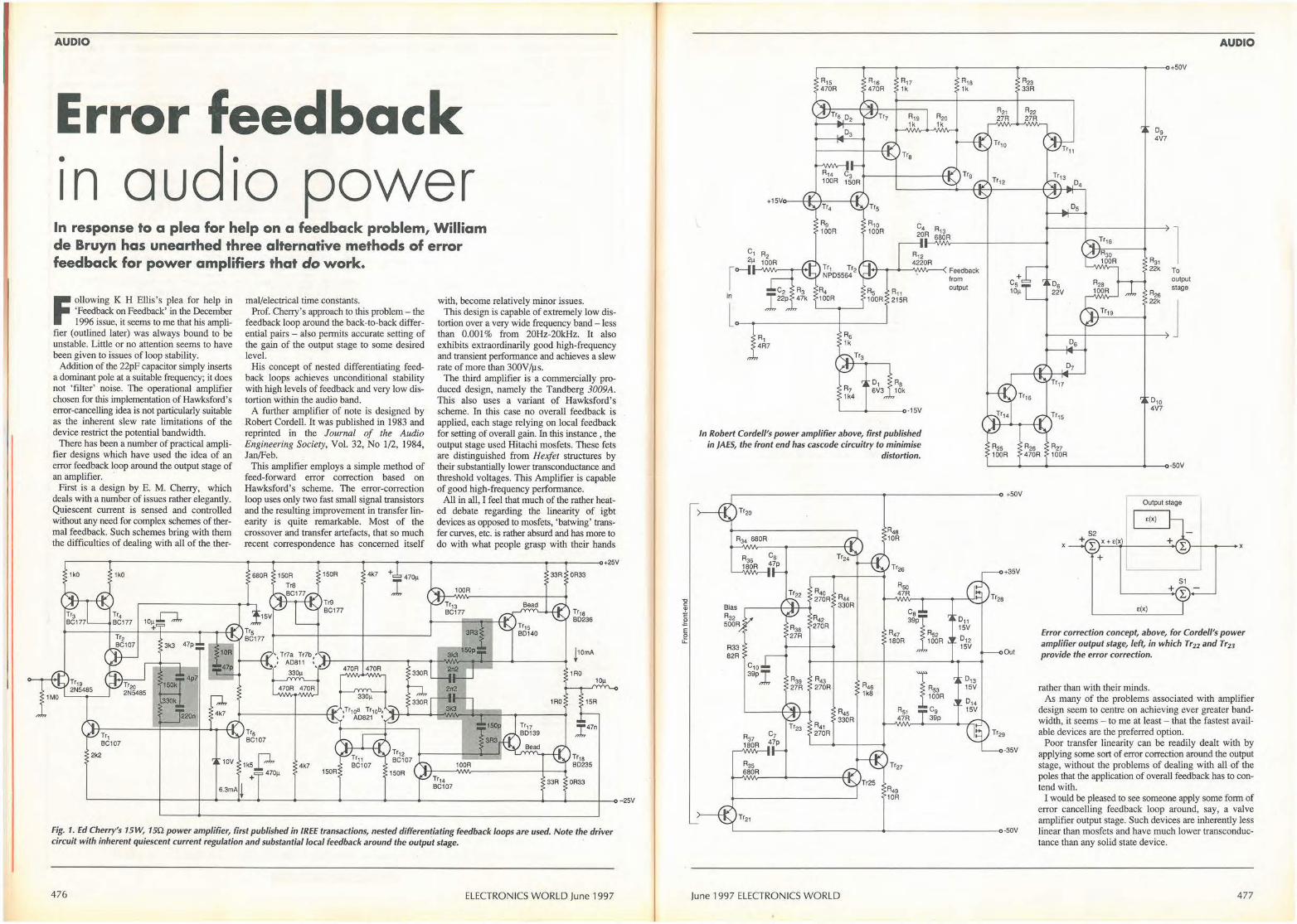
AUDIO
Error feedback •
audio power In response to a plea for help on a feedback problem, William de Bruyn has unearthed three alternative methods of error feedback for power amplifiers that do work.
Following K H Eilis's plea for help in 'Feedback on Feedback' in the December 1996 issue, it seems to me that his ampli
fier (outlined later) was always bound to be unstable. Little or no attention seems to have been given to issues of loop stability.
Addition of the 22pF capacitor simply inserts a dominant pole at a suitable frequency; it does not 'filter' noise. The operational amplifier chosen for this implementation of Hawksford's error-cancelling idea is not particularly suitable as the inherent slew rate limitations of the device restrict the potential bandwidth.
There has been a number of practical amplifier designs which have used the idea of an error feedback loop around the output stage of an amplifier. ·
First is a design by E. M. Cherry, which deals with a number of issues rather elegantly. Quiescent current is sensed and controlled without any need for complex schemes of thermal feedback. Such schemes bring with them the difficulties of dealing with all of the ther-
mal/electrical time constants. Prof. Cherry's approach to this problem - the
feedback loop around the back-to-back differential pairs - also permits accurate setting of the gain of the output stage to some desired level.
His concept of nested differentiating feedback loops achieves unconditional stability with high levels of feedback and very low distortion within the audio band.
A further amplifier of note is designed by Robert Cordell. It was published in 1983 and reprinted in the Journal of the Audio Engineering Society, Vol. 32, No 1/2, 1984, Jan/Feb.
This amplifier employs a simple method of feed-forward error correction based on Hawksford's scheme. The error-correction loop uses only two fast small signal transistors and the resulting improvement in transfer linearity is quite remarkable. Most of the crossover and transfer artefacts, that so much recent correspondence has concerned itself
with, become relatively minor issues. This design is capable of extremely low dis
tortion over a very wide frequency band - less than 0.001% from 20Hz-20kHz. It also exhibits extraordinarily good high-frequency and transient performance and achieves a slew rate of more than 300V /µ s.
The third amplifier is a commercially produced design, namely the Tandberg 3009A. This also uses a variant of Hawksford's scheme. In this case no overall feedback is applied, each stage relying on local feedback for setting of overall gain. In this instance , the output stage used Hitachi mosfets. These fets are distinguished from Hexfet structures by their substantially lower transconductance and threshold voltages. This Amplifier is capable of good high-frequency performance.
All in all, I feel that much of the rather heated debate regarding the linearity of igbt devices as opposed to mosfets, 'batwing' transfer curves, etc. is rather absurd and has more to do with what people grasp with their hands
,-----...-------------------...---------+----+-----------o------<>+25V
Tr1 BC107
2k2
1k5p + 470µ
4k7 +1470µ
470A 470A
4k7
33A 0R33 6.3mAi
'--------t----t---<1---<1~--.-------...__----+----+-------------+---+----l--o-25V
Fig. 1. Ed Cherry's 15W, 15Q power amplifier, first published in /REE transactions, nested differentiating feedback loops are used. Note the driver circuit with inherent quiescent current regulation and substantial local feedback around the output stage. ·
476 ELECTRONICS WORLD June 1997
"O C ., -!. C
g E e LL
AUDIO
------+-----+--------------.------------..-----o+S0V
R17 R,a 1k 1k
03
Tr8
,o-1 l+t----+---'IN""""-< Feedback
in
lo----+---R1 4R7
'----+----o-1 SV
In Robert Cordell's power amplifier above, first published in /AES, the front end has cascade circuitry to minimise
distortion.
from output
R21 27R
A23 33A
R22 27R
Og 4V7
05
R31 l 22k To
05 output
22V R2s stage
22k
j Os
07
0 10 4V7
'------+----------+---<>·SOV
-------------->------------<> +S0V
Tr20
R34 680R
Bias R32 SOOR
R33 82R
R35 680R
R40 R44 270R 330R
R42 270R
R43 270R R45
1k8
R45
R41 330R
270R
Tr26 +35V
Rso 47R
;1,I 011 15V
R47 R52 012 180R 100R 15V
Out
0 ,3
1"• 15V 100R
014 R51 Cg 15V 47R 39p
'------ ------------4- -------- --o·50V
June 1997 ELECTRONICS WORLD
Output s tage
t(X)
'-----x
e(x)
Error correction concept, above, for Cordell's power amplifier output stage, left, in which Tr22 and Tr23 provide the error correction.
rather than with their minds. As many of the problems associated with amplifier
design seem to centre on achieving ever greater bandwidth, it seems - to me at least - that the fastest available devices are the preferred option.
Poor transfer linearity can be readily dealt with by applying some sort of error correction around the output stage, without the problems of dealing with all of the poles that the application of overall feedback has to contend with.
I would be pleased to see someone apply some form of error cancelling feedback loop around, say, a valve amplifier output stage. Such devices are inherently less linear than mosfets and have much lower transconductance than any solid state device.
477

AUDIO
--....--------------....---------<,-----<>+74V
220A
2mA 3.7mA
,-
470A
10k
470A
'-----------
,--------------------.-------~+64V
0R1
4.5mA
2SK175 10µ
680A
680A
680A
10A 330A
2SJ55
1,on
390A 10µ
390A
390A
0R1
'---------- - - -------------c•64V
Tandberg 3009A mosfet amplifier features feed forward error correction, shown in the dotted box.
--+---------------+-------4----<>-74V
Extract from EIiis's original query ... applying negative feedback to give a gain of four, the stage shown gives reasonable performance, except that output impedance is about 1.Q. Also, when loaded, the stage distorts because there is nothing to increase the drive.
I was about to give in when I came across a reference to an error cancelling technique by Hawksford. The small diagram below gives the theory. Having got the gains right, the results were astounding.
During testing, I found that a capacitive load of more than 22nF c;iused a high output at high frequency. This was a surprise as the output stage itself would happily drive a 1 OµF at 1 kHz. More experimenting gave the feeling that this was not parasitic oscillation, but rather amplified and filtered noise. While loading the output with increasing values of capacitor, the output of A1 became increasingly noisy until it burst into oscillation at about 2MHz. Putting a small capacitor across R6 (A1) stopped the oscillation but was not the best place as only the error signal was being fi ltered. The best solution was a 22pF across R12 (A1) to filter signal and error. The amplifier now drives 1 OµF with no problem.
I would welcome your comments.
478
15V
Tl Texan output stage, top, before a practical implementation (below right) of Hawksford's error-cancelling idea, below left, was added.
.35V
lq C70mA
CLOSEO LOOP GAIN • x4
Zo c 1RS
Zo ::. 1RO
0R47 SLEW RATE c 300V/µS
LINEARITY (OfF LOAD) c 0.5%
0R47
I,oon
~0.00lll(IOOR~
..,,..,1. ,ovi.,s
-~1oi,,F.eRM
111HJ, TY ,.,...
·3SV
"""
l = S70R , A0JUST FOR ZERO SIGHAL AT'O'OFF LOAD mo AT 50% MAX OUTPUT
ELECTRONICS WORLD June 1997
I ,cacling Edgt· Tcl'hnolog~ I ,tel Low cost Programmers for all your requirements GAL PROGRAMMER ~9 ~ 16V8 / 16V8A / 16VIZ 2GV8 / 2GV8A / :l&VIZ • • Stylish canpoct case with quality ZIF socket • Easy to use software. loa&.ve in JEDEC format • Plugs into Cen11'0nics ~er port • Works on ,my IBM PC or canporible / laptops / notebooks etc • Fast and reliable prc,sramming ming manufacturers algorithms • Prcsr- protec:lian fuses to prevenl Wl8l1thorised ~ • Supplied with Pl.AN Logic compiler software • Complece systmi wilh example mes, connection lead, and PSU • Full 12 manlhs parts and labour guanintee
P87C51/2 PROGRAMMER Programs all makes of P87C51/l and Atmel 89C51 Flash types.
A, obovo thil ,mit ph,,_ illlo C..IIOIUQ P'"''" port 011 Ill)' IBM PC or ccmpolibl,. 1114 comes complele wilb »llwlR, comcctioo leld, PSU, ml luU 12 .-bl_......
M !:PROMS/ HPIIOMS / PLASH HPROMS / UC BUS !I.PROMS
• Coven all types of £prom, EEprom, and flash up to 32 pin • Fast prc,sramming and verificalion • Easy to use software • support, Bin / Intel Hex / Motorola S
and ASC ftle fonn.alS • Read/ Edit / Verify/ reprogram etc • Supplied with full 12 months parts and labour guanintee
Mepprom ,... 00 any mM PC / comi-tible, connecb direcdy to Ibo """100ics print« cable £99 95 and require, J2.J8V AC/DC PSU. Low cost mu:., it ide&I for hobbyi,11 and mgi.-. alilce. •
ENHANCED PIC PROGRAMMER • Programs PICS4, SS, S7, SSA, 61, 64, 65, 71, 75, 84, 620, 621,
622, MEMORY CHIPS, 24LC0I, 02, 16, 32, 65 • Read / Write / Copy / Program fuses • Software supports Microchip, Intel Hex, binary format
also supplied with Editor assembler for 54 series and 71/84 Runs on IBM PC / ~ble, - IO Ille ca,ln>oica pri,= 69 95 cable 1114 ....-... ll•IIV AC/DC PSU. F.U p111111!0o. £ •
I----- V VwtOllrWeb,i1e•: h11p:/lwww.M,clllt<.com/fffl:llcadodJ0.hlm1
or£mailut•: [email protected]<yworid.net
I " IIOfilld,,IW.NoVATarO'C
It u h u:..: I i l:..:l l1ll11111l,1:.:, I Iii \\ luh 1{11, \ lluu,1 ,1111111 -..11\ \ I
I , II \It II l'I \ 11 \I.tit I 1,1 ,no , ;;:,, ,,~s,u•> I ·" 1UII , .::,,, M,~"S~
( Ill( II '\() I !!()'\ llf/'11 C \ Ill)
FEATURES 16/32 bit 68307 CPU for fan operation Up to 1 Mbyte of EPROM space onboard Up to S12Kbyte SRAM sp3ce onboard 32 Kbyte SRAM fitted as standard RS232 serial with RS485 option MOOBUS & other protocols supported Up to 22 digital 110 channets 2 timer/counter/match registers I1C port or Mbus & Watch dog fa<ilities large Proto-typing area for user circuits Up to 5 chip selects available Program in C. C+-+, Modula-2 & Assembler Fleal Time muttitasking Operating System 0S9 or MINOS with free run time license option Manufacturing available even in low volumes A full range of other Controllers available
For users of PCs, 8051 &
68000
P.C. 'C' STARTER PACK AT ONLY £29S + VAT The Micfo Module will reduce development time for quick turnaround produeu/projects and with the P.C. 'C'
SU!'tet pack a11owyou to start coding your application immediately, all drivers and librarit$ are supplied as standard along w ith MINOS the real time operating system all ready to run from power on. The 'C' Starter p.:tC:k includes: A Micro Modufe w ith 128 Kbyte SRAM, PSU, Cables;, Manuals, C com pH er, Debug monitor ROM, Terminal program, Downloader, a single copy of MINOS. Extensive example software, and free unlimited technical support all for £29S + VAT.
,~ '\ ' ._, Cambddg• Microproc•ssor ~,UJ-.::.J Sy~temsLimiled
Unil 17-18, Zone 'D', Chelmiiford Road Ind. Est., Gr.at Ounmow, Essex, U.K. CM61XG Pf'tone01371875644 Fax 01371 8760n
C Ill( I F WI I!/ o, /lfl'll ( ,\Ill/
June 1997 ELECTRONICS WORLD
ITT Canon: authorised stocking distr.i.l>utor. for 38pin StarCards, 38pin StarCard . connectors and 68pin PC Card connecto~s
~ lluna: authorised stocking distributor for Calluna's type Ill ATA PC card range
Centenn.ial: 38 edge card flash memories and connectors . .,.. A wide range of Reader/w~iters ar:~ available with ISA, SCSII, parallel ana seri.~J host interfaces for cards ·in ou~{~ ~folio
.. , .-·, . -~ ~ ;';; Card Professionals
Limited . :;,· .. ·.
Card Professionals Limited Cedarmount House, Owlsmoor Road, Owlsmoor, Sandhurst, Berkshire, GU47 0SS.
Tel: +44 (0~ 1344 779632. Fax: +44 (0 1344 779633.
www.card-pro essionals-uk.com
ORCL f NO. I 14 ON Rf PO. CARI>
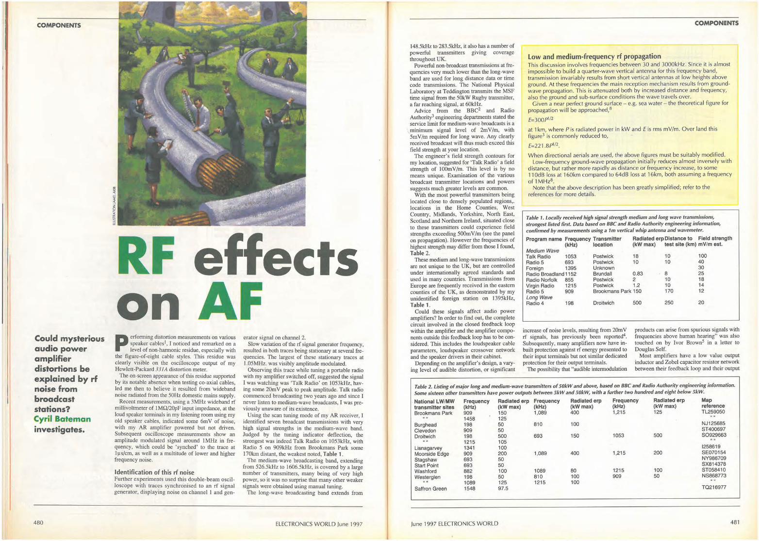
COMPONENTS
Could mysterious audio power amplifier distortions be explained by rf noise from broadcast stations? Cyril Bateman investigates.
480
RF on P erforming distortion measurements on various
speaker cables 1, I noticed and remarked on a level of non-harmonic residue, especially with
the figure-of-eight cable styles. This residue was clearly visible on the oscilloscope output of my Hewlett-Packard 331A distortion meter.
The on-screen appearance of this residue supported by its notable absence when testing co-axial cables, led me then to believe it resulted from wideband noise radiated from the 50Hz domestic mains supply.
Recent measurements, using a 3MHz wideband rf millivoltmeter of 1MQ/20pF input impedance, at the loud speaker terminals in my listening room using my old speaker cables, indicated some 6m V of noise, with my AR amplifier powered but not driven. Subsequent oscilloscope measurements show an amplitude modulated signal around 1MHz in frequency, which could be 'synched' to the trace at lµs/cm, as well as a multitude of lower and higher frequency noise.
Identification of this rf noise Further experiments used this double-beam oscilloscope with traces synchronised to an rf signal generator, displaying noise on channel 1 and gen-
erator signal on channel 2. Slow variation of the rf signal generator frequency,
resulted in both traces being stationary at several frequencies. The largest of these stationary traces at 1.05MHz. was visibly amplitude modulated.
Observing this trace while tuning a portable radio with my amplifier switched off, suggested the signal I was watching was 'Talk Radio' on l053kHz, having some 20mV peak to peak amplitude. Talk radio commenced broadcasting two years ago and since I never listen to medium-wave broadcasts, I was previously unaware of its existence.
Using the scan tuning mode of my AR receiver, I identified seven broadcast transmissions with very high signal strengths in the medium-wave band. Judged by the tuning indicator deflection, the strongest was indeed Talk Radio on 1053kHz, with Radio 5 on 909kHz from Brookmans Park some 170km distant, the weakest noted, Table 1.
The medium-wave broadcasting band, extending from 526.SkHz to 1606.SkHz, is covered by a large number of transmitters, many being of very high power, so it was no surprise that many other weaker signals were obtained using manual tuning.
The long-wave broadcasting band extends from
ELECTRONICS WORLD June 1997
148.SkHz to 283.SkHz, it also has a number of powerful transmitters giving coverage throughout UK.
Powerful non-broadcast transmissions at frequencies very much lower than the long-wave band are used for Jong distance data or time code transmissions. The National Physical Laboratory at Teddington transmits the MSF time signal from the 50kW Rugby transmitter, a far reaching signal, at 60kHz.
Advice from the BBC2 and Radio Authority3 engineering departments stated the service limit for medium-wave broadcasts is a minimum signal level of 2mV/m, with 5mV/m required for long wave. Any clearly received broadcast will thus much exceed this field strength at your location.
The engineer's field strength contours for my location, suggested for 'Talk Radio' a field strength of IO0m V /m. This level is by no means unique. Examination of the various broadcast transmitter locations and powers suggests much greater levels are common.
With the most powerful transmitters being located close to densely populated regions,. locations in the Home Counties, West Country, Midlands, Yorkshire, North East, Scotland and Northern Ireland, situated close to these transmitters could experience field strengths exceeding 500mV/m (see the panel on propagation). However the frequencies of highest strength may differ from those I found, Table 2.
These medium and Jong-wave transmissions are not unique to the UK, but are controlled under internationally agreed standards and used in many countries. Transmissions from Europe are frequently received in the eastern counties of the UK, as demonstrated by my unidentified foreign station on 1395kHz, Table 1.
Could these signals affect audio power amplifiers? In order to find out, the complete circuit involved in the closed feedback loop within the amplifier and the amplifier components outside this feedback loop has to be considered. This includes the loudspeaker cable parameters, loudspeaker crossover network and the speaker drivers in their cabinet.
Depending on the amplifier's design, a varying level of audible distortion, or significant
COMPONENTS
Low and medium-frequency rf propagation This discussion involves frequencies between 30 and 3000kHz. Since it is almost impossible to build a quarter-wave vertical antenna for this frequency band, transmission invariably results from short vertical antennas at low heights a bove g round. At these frequencies the main reception mechanism results from groundwave propagation. This is attenuated both by increased distance and frequency, a lso the ground and sub-surface condit ions the wave travels ove r.
Given a near perfect ground surface - e.g. sea water - the theoretical figure for propagation will be approached,8
E=300P1l2
at 1 km, where Pis radiated power in kW and f is rms mV/m. Over land th is figure3 is commonly reduced to,
£=221 .8P112.
When directional aerials are used, the above figu res must be sui tably modifi ed. Low-frequency ground-wave propagation initially reduces a lmost inversely w ith
distance, but rather more rapidly as distance or frequency increase, to some 11 OdB loss at 160km compared to 64d B loss at 16km, both assuming a frequency of 1 MHz8 .
Note that the above description has been greatly simplified; refer to the references for more details.
Table 1. Locally received high signal strength medium and long wave transmissions, strongest listed first. Data based on BBC and Radio Authority engineering information, confirmed by measurements using a 1m vertical whip antenna and wavemeter.
Program name Frequency Transmitter Radiated erpDistance to Field strength (kHz) location (kW max) test site (km) mV/m est.
Medium Wave Talk Radio 1053 Postwick 18 10 100 Radio 5 693 Postwick 10 10 40 Foreign 1395 Unknown 30 Radio Broadland 1152 Brundall 0.83 8 25 Radio Norfolk 855 Postwick 2 10 18 Virgin Radio 1215 Postwick 1.2 10 14 Radio 5 909 Brookmans Park 150 170 12 Long Wave Radio 4 198 Droitwich
increase of noise levels, resulting from 20m V rf signals, has previously been reported4.
Subsequently, many amplifiers now have inbuilt protection against rf energy presented to their input terminals but not similar dedicated protection for their output terminals .
The possibility that "audible intermodulation
500 250 20
products can arise from spurious signals with frequencies above human hearing" was also touched on by Ivor Brown5 in a letter to Douglas Self.
Most amplifiers have a low value output inductor and Zobel capacitor resistor network between their feedback loop and their output
Table 2. Listing of major long and medium-wave transmitters of 50kW and above, based on BBC and Radio Authority engineering information. Some sixteen other transmitters have power outputs between 5kW and 50kW, with a further two hundred and eight below 5kW.
National LW/MW Frequency Radiated erp Frequency Radiated erp Frequency Radiated erp Map transmitter sites (kHz) (kW max) (kHz) (kW max) (kHz) (kW max) reference Brookmans Park 909 150 1,089 400 1,215 125 TL259050
1458 125 Burghead 198 50 810 100 NJ 125685 Clevedon 909 50 ST400697 Droitwich 198 500 693 150 1053 500 S0929663
1215 105 Lis nagarvey 1341 100 1258619 Moorside Edge 909 200 1,089 400 1,215 200 SE070154 Stagshaw 693 50 NY986709 Start Point 693 50 SX814378 Washford 882 100 1089 80 1215 100 ST058410 Westerglen 198 50 810 100 909 50 NS868773
"" 1089 125 1215 100 Saffron Green 1548 97.5 TQ216977
June 1997 ELECTRONICS WORLD 481
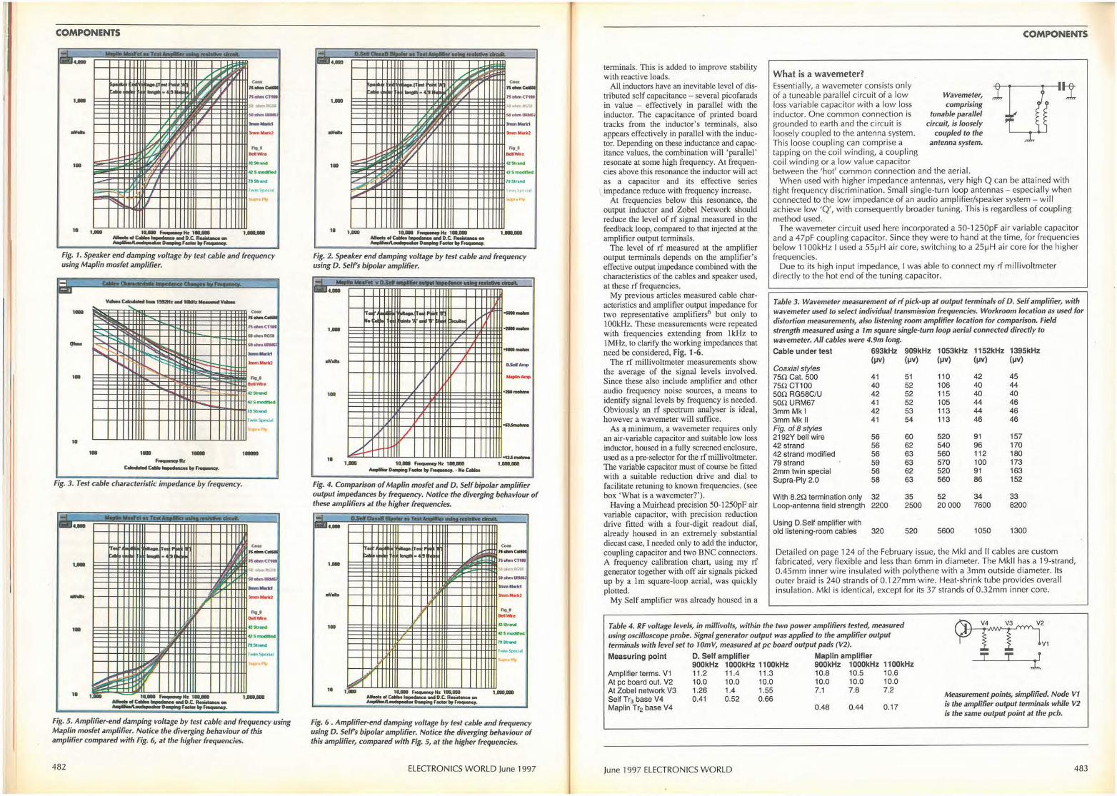
COMPONENTS
1-r -MNFd•Tnc -_,.__ I
~ •• c-11-C.-
t.11 . -~ 1.- 7S--Ct-
.. ~ .. __ --- /.:½ 3mm-1cl
~~ ,.,,_. --,. .,,.,_,
,I 42Srnodlf'.ed
l!Strand I
l ,w111Speu• I
r,;;~ I/ ' . ,,,
11 1.- 11.- ~lb1tlQ ...
, ____ _.,c--......... - 0.c.--.. ~D__,,F-lo,F-.
Fig. 1. Sp_eaker end damping voltage by test cable and frequency using Map/in mosfet amplifier.
...
~ ~ ~
' , ... ---~ ::::- .... ~ .... "' ~ ----~~ ' 1•
11 ,.
~
~~ :::::: ~"' i::,.._
-- ....
,._ JS ollmCTW .. _ ..... ....... --3mm"-la
... _. ......... ..,,.,_ Cl S modlRed:
,,., .... _...,...., 1
l
1, ,_ Fig. 3. Test cable characteristic impedance by frequency.
..-
, .. -,.
11
..... -t--+-++tffiftt--+-H++-Hfl- #+++H-Hl3mm-k2
...... _.,.._ CSb-lWld
<Z S:"'°""""'
7t Stl-.nd
1--+-++tffiit-~lr-t-+t+Hif-++t+t+Hl•wln St,c,~
1 .... ~ ... , .... _ _,~--D.C.-• ft ea C lll:11~F----~
Fig. 5. Amplifier-end damping voltage by test cable and frequency using Map/in mosfet amplifier. Notice the diverging behaviour of this amplifier compared with Fig. 6, at the higher frequencies.
482
ri. ...... D.Sa11a..illl1II • TUI •••u ~ ........ CN111. ,
• .....-.:: ,.
f s .. ~- - -~~ ~ ~
c-.;;... 11-C-.
t.11 . ·- _.,, .. ~ 15ohmCl1.
1.DIIO • ,. . ....... ,_, --.,, ... / . ,z ,.,,,. ...... ,
~v ~v flt.•
~ ......... --11111 42 5111,'tnd
oQ Smc>dirtcd'
' 2't S,r,anct -/ '"I" I I
....
10 uao 10.111111 F-lb 11111,111111 -d~t....,_..tD.C.-• ~D__,.F_..,F_,
1.GOO.GOO
Fig. 2. Speaker end damping voltage by test cable and frequency using D. Self's bipolar amplifier.
.a. 11111 YNF1'I vD.W •• ::au,, n.!!!!l.....,_dlall.
··-I
,a p ,o ·- - i,.,"'V --1 hi .. - -· ·-~- 51 -I / 1.111111 --
I
... flllQNn
.,, ... ' J / II.Sol'-,, --I
ICJII ---I I
, ,, -~"' / /
£. ---10 -1u.-.. 1.000 10.la F-lb 100,000 1.000.111111
A..,-11--.F--"'-·•No~
Fig. 4. Comparison of Map/in mosfet and D. Self bipolar amplifier output impedances by frequency. Notice the diverging behaviour of these amplifiers at the higher frequencies.
_, ... 1--Teii .......... -- i ..... .-'T• ., .. ~ ~ ir .. P'9•
c ... 11-C.. - ,-- .. , •·~ ti 1'ohmCT111
1.1• "'"t ,,Ria, J- ....... _,
_,,_,,. .,, ... ,.,,,.......,
J , ..... I ........
1• 42S1r'ffldl .. . ..-19 Strand
TWlnSpocWI
"" i '
L,,, i, i I 11 1.11111 11.000 F-K• 100.IIIO•
-d~t-andD.C.R-... _11.. __ o_,_..,.., • ._ _ 1.000.000-
Fig. 6 . Amplifier-end damping voltage by test cable and frequency using D. Self's bipolar amplifier. Notice the diverging behaviour of this amplifier, compared with Fig. 5, at the higher frequencies.
ELECTRONICS WORLD June 1997
terminals. This is added to improve stability with reactive loads.
All inductors have an inevitable level of distributed self capacitance - several picofarads in value - effectively in parallel with the inductor. The capacitance of printed board tracks from the inductor's terminals, also appears effectively in parallel with the inductor. Depending on these inductance and capacitance values, the combination will 'parallel' resonate at some high frequency. At frequencies above this resonance the inductor will act as a capacitor and its effective series impedance reduce with frequency increase.
At frequencies below this resonance, the output inductor and Zobel Network should reduce the level of rf signal measured in the feedback loop, compared to that injected at the amplifier output terminals.
The level of rf measured at the amplifier output terminals depends on the amplifier's effective output impedance combined with the characteristics of the cables and speaker used, at these rf frequencies.
My previous articles measured cable characteristics and amplifier output impedance for two representative amplifiers6 but only to 1 00kHz. These measurements were repeated with frequencies extending from !kHz to 1MHz, to clarify the working impedances that need be considered, Fig. 1-6. ·
The rf millivoltmeter measurements show the average of the signal levels involved. Since these also include amplifier and other audio frequency noise sources, a means to identify signal levels by frequency is needed. Obviously an rf spectrum analyser is ideal, however a wavemeter will suffice.
As a minimum, a wavemeter requires only an air-variable capacitor and suitable low loss inductor, housed in a fully screened enclosure, used as a pre-selector for the rf millivoltmeter. The variable capacitor must of course be fitted with a suitable reduction drive and dial to facilitate retuning to known frequencies. (see box 'What is a wavemeter?').
Having a Muirhead precision 50-1250pF air variable capacitor, with precision reduction drive fitted with a four-digit readout diaf, already housed in an extremely substantial diecast case, I needed only to add the inductor, coupling capacitor and two BNC connectors. A frequency calibration chart, using my rf generator together with off air signals picked up by a Im square-loop aerial, was quickly plotted .
My Self amplifier was already housed in a
What is a wavemeter? Essentially, a wavemeter consists only of a tuneable parallel circuit of a low loss variable capacitor with a low loss inductor. One common connection is grounded to earth and the circuit is loosely coupled to the antenna system. This loose coupl ing can comprise a tapping on the coil winding, a coupling coil winding or a low value capacitor
Wavemeter, comprising
tunable parallel circuit, is loosely
coupled to the antenna system.
between the 'hot' common connection and the aerial.
COMPONENTS
,l
;(
When used with higher impedance antennas, very h igh Q can be attained with tight frequency d iscrimination. Smal l single-turn loop antennas - especially when connected to the low impedance of an audio amplifier/speaker system - will achieve low 'Q', with consequently broader tuni ng. This is regardless of coupl ing method used.
The wavemeter circuit used here incorporated a 50-1250pF air variable capacitor and a 47pF coupling capacitor. Si nce they were to hand at the time, for frequencies below 11 0OkHz I used a SSµH air core, switching to a 25µH air core for the higher frequencies.
Due to its high input impedance, I was able to connect my rf m ill ivoltmeter directly to the hot end of the tuning capacitor.
Table 3. Wavemeter measurement of rf pick-up at output terminals of D. Self amplifier, with wavemeter used to select individual transmission frequencies. Workroom location as used for distortion measurements, also listening room amplifier location for comparison. Field strength measured using a 1 m square single-turn loop aerial connected directly to wavemeter. All cables were 4.9m long.
Cable under test 693kHz 909kHz 1053kHz 1152kHz 1395kHz (µv) (µv) (µv) (µv) (µv)
Coaxial styles 750 Cat. 500 41 51 110 42 45 750 CT100 40 52 106 40 44 son RG58C/U 42 52 115 40 40 son URM67 41 52 105 44 46 3mmMkl 42 53 113 44 46 3mm Mkll 41 54 113 46 46 Fig. of 8 styles 2192Y bell wire 56 60 520 91 157 42 strand 56 62 540 96 170 42 strand modified 56 63 560 112 180 79 strand 59 63 570 100 173 2mm twin special 56 62 520 91 163 Supra-Ply 2.0 58 63 560 86 152
With 8.20 termination only 32 35 52 34 33 Loop-antenna field strength 2200 2500 20 000 7600 8200
Using D.Self amplifier with old listening-room cables 320 520 5600 1050 1300
Detailed on page 124 of the February issue, the Mkl and II cables are custom fabricated, very flexible and less than 6mm in diameter. The Mkll has a 19-strand, 0.45mm inner w ire insulated with polythene with a 3mm outside diameter. Its outer braid is 240 strands of 0.1 27mm wire. Heat-shrink tube provides overall insulation. Mkl is identical, except for its 37 strands o f 0.32mm inner core.
Table 4. RF voltage levels, in millivolts, within the two power amplifiers tested, measured using oscilloscope probe. Signal generator output was applied to the amplifier output terminals with level set to 10mV, measured at pc board output pads (V2).
~2
I l l Lv1 T T J! Measuring point D. Self amplifier Maplin amplifier
Amplifier terms. V1 At pc board out. V2 At Zobel network V3 Self Tr3 base V4 Maplin Tr2 base V4
900kHz 1000kHz 1100kHz 900kHz 1000kHz 1100kHz 11.2 11.4 11.3 10.8 10.5 10.6 10.0 10.0 10.0 10.0 10.0 10.0 1.26 1.4 1.55 7.1 7.8 7.2 0.41 0.52 0.66
0.48 0.44 0.17
June 1997 ELECTRONICS WORLD
Measurement points, simplified. Node V1 is the amplifier output terminals while V2 is the same output point at the pcb.
483
COMPONENTS
Table 5. Wavemeter measurement at 1053kHz of rf pick-up at D. Self amplifier output terminals. Using figure-of-eight cables in balanced and un-balanced configuration to conned to loudspeaker system alternately to 8.2n dummy loudspeaker load. Balun transformer made with 30 twisted bifilar turns of 0.5mm wire, wound on TMC107523 toroidal core, which was un-balanced using removable link from earthy output to one wire of figure-of-eight cable. Cables 4.9m long.
Cables under test Balanced Unbalanced Unbalanced with
With speaker load 42 strand
w. balun (µV) w. balun (µV) cable direct wired (µV)
42 strand modified With B.2Q load
440 460
42 strand
I Loud speaker
330
Cable under test 4.9m length
720 820
460
740 800
560
Test amplifier
Test set-up for making the cable measurements, showing the balanced/unbalanced switch.
Table 6. RF millivoltmeter measurements, in microvolts, of pick-up with amplifier replaced by dummy amplifier loading network of output inductor with 1 on shunt resistor, a Zobel network and 0.033Q termination resistor. Measured at this dummy load, with crossover or cable screened in turn, to determine proportion of noise pick-up due to crossover/speaker and cable under test. Shows excessive rf pickup with figure-of-eight cable. Cables 4.9m long.
Cable under test In normal use W. Xover screen Cable screened Both screened Coax styles 75Q Cat. 500 54 47 75Q CT100 52 46 son RG58C/U 45 40 son URM67 45 40 3mm Mkl 40 33 3mm Mkll 40 36 Fig. of 8 styles 2192Y bell wire 440 420 42 strand 460 430 42 strand modified 710 660 79 strand 420 410 2mm twin special 265 255 Supra Ply 2.0 280 260
Termination only 16
substantial aluminium screened case. I measured the wavemeter output, for five of the locally strong medium-wave frequencies, at the amplifier output terminals with the amplifier powered but not driven. The rf pick-up from the twelve test cables and speaker system, was measured using the same cable locations and orientation as for the distortion measurements, Table 3.
This wavemeter/amplifier measurement system was also used to measure the signal levels picked up by the old cables in my listening room. These were significantly higher due to increased cable lengths, the.cable's direction and proximity to the ring mains.
Having established the frequency and voltage levels at the amplifier terminals when used with the various test cables, attempts were made to measure similar signals within the amplifier. Obviously should its output inductor sufficiently block these signal levels from entering the amplifier. In this way, the rf signals could not cause any audible intermodulation distortion.
With my rf signal generator set to a test frequency of 1MHz, I used HP9100 oscilloscope probes to connect the test points to my rf mil-
484
26 19 30 20 20 16 22 20 20 15 20 15
30 22 35 20 40 25 26 20 29 21 20 16
livoltmeter. With the signal generator output applied to the amplifier output terminals and signal level set to lOmV measured at the amplifiers pcb output pads (V2), I measured l.4mV at the 'Zobel' network and 0.52mV at Tr3 base, of the Self amplifier. Having established that for this design a measurable rf level can be found within the feedback loop, the measurements were repeated for 900kHz and 1.1MHz, then with the Maplin amplifier. Table 4.
Having now confirmed that rf signals picked up on speaker cables can intrude within the amplifier, and that this rf level differs substantially between figure-of-eight and co-axial cable styles, bow are these signals picked up ? Just what is the pickup mechanism ?
RF pick-up mechanisms A single-tum loop antenna can be formed by winding coaxial cable around a· wooden frame and connecting the outer braid free end to the inner feeder conductor at the completion of the loop. Its termination at the receiver is unbalanced, i.e. the braid is connected to earth.
Alternatively an antenna can comprise a figure-of-eight cable partially unzipped, with
each unzipped wire wrapped around one half of the frame, the free ends then being joined to complete the loop. Using balanced termination at the receiver minimises any stray pickup on the cable connecting the loop antenna to the receiver. This balanced termination is important, since any unbalanced figure-of-ei!!ht or twin feeder cable will both transmit7 and receive signals.
Signal pickup depends on the area enclosed by the loop, and while pickup of higher frequencies is quite good it discriminates heavily against much lower frequencies. The cable/amplifier rf pickup measurements of Table 3 also show similar frequency discrimination
When a figure-of-eight cable is used with a conventional amplifier as a loudspeaker cable, one line of the cable is earthed by the amplifier's 'low' output terminal, the cable is clearly unbalanced. The speaker ends of the cable are terminated by the speaker's rf impedance. Hence the figure-of-eight test cable and speaker system could form a very shallow singleturn loop aerial.
To put this to the test, I wound a simple I: 1 balun transformer, of some S0µH primary inductance, and re-measured the rf picked up by the 42-strand figure-of-eight cables. If the above analogy was correct, I expected a notable reduction in rf when measured with the figure-of-eight cable balanced to earth, versus the same cable deliberately unbalanced.
Using my wavemeter set to 1053kHz, approximately half the level of rf signal was measured with cables balanced compared to the same system unbalanced. To eliminate the balun transformer losses from clouding these results, the balun and its connections with the test cable were retained for both measurements. A temporary earth link, connecting amplifier 'low' output to one line of the figure-of-eight cable, was used to establish the unbalanced state, it was removed for the balanced configuration, Table 5.
Regardless of loudspeaker cable used, the speaker cabinet wiring and the inductors used in any crossover network, will also function as antennas with some degree of rf signal pickup. Since speaker and crossover systems vary widely in their construction and thus potential for rf pickup, this has not been investigated other than to clarify the relative pickup levels with my test speaker system.
The methods used were both simple and effective. I decided to measure rf levels with the speaker and cables arranged exactly as for the distortion measurements. Next they were measured with the crossover network screened by a Faraday shield, and finally with the speaker cable similarly shielded. Not having a suitable metal container easily able to contain my test speaker cabinet, or my amplifier complete with the test cables, I needed to simplify the task.
The crossover had previously been moved outside the speaker cabinet for the distortion measurements. Connection to both drivers involved short lengths of 42-strand figure-ofeight cable. Replacing the amplifier with a
ELECTRONICS WORLD June 1997
dummy load allowed the test cable leads to be easily coiled up and screened. Grounding one dummy load terminal ensured the figure-ofeight test cables remained unbalanced at one end, exactly as in normal use.
This dummy amplifier load was made up using a typical output inductor, Zobel network and 0.033Q resistor to replace the amplifier. A few experiments confirmed my metal wastebin, suitably earthed, served as an excellent Faraday shield.
Using the rf millivoltmeter, I measured the voltage levels at this dummy amplifier load for each of the 12 test cables. First, I measured with nothing shielded, next with the crossover only shielded, then with the cables coiled up and placed in the shield, and finally with both cable and crossover shielded.
In every case, the greatest reduction of measured rf resulted from simply screening the cable, thus clarifying the cable's pickup is the major contributor to rf pickup with my test speaker. While measurable changes were found for all cables, the unbalanced figure-ofeight cables were found to be particularly prone to rf pickup, Table 6.
Coaxial cable definitely is best Due to the considerable variations in amplifier design and thus potential sensitivity to rf, no attempt has been made to confirm whether these rf signals caused measurable or audible
distortions with either test amplifier. However the work published by Paul Miller4 suggests this is more than likely with most amplifier designs, given sufficient rf levels.
However, these signals cannot be beneficial and are thus best avoided. Using coaxial cables with a conventional inductor output amplifier minimises this rf pickup. When combined witb the other benefits already established in my previous articles, there remains no good reason for not changing to coaxial speaker cables.
One final proviso, the output terminals of two amplifiers arranged in a bridge output configuration may be truly balanced with respect to earth. The output terminals of a valve amplifier could also be balanced if neither terminal of the output transformer secondary winding were tied to earth.
When amplifier output terminals are balanced to earth at rf, to be effective in reducing rf pickup, coaxial cables must be wired correctly. The inner cores should only be used to convey signal power, with the inner of a second coaxial cable used to return the signal. The amplifier end of each braid should be connected to earth, providing a Faraday shield for each signal conductor.
With a conventional amplifier system, the coaxial cable inner wire is connected to the 'hot' terminals at the amplifier and speaker system, with the outer braid connected to both
COMPONENTS
the amplifier and speaker 'cold' terminals. This completes the return path while shielding the amplifier's hot output terminal from rf pickup.
In summary Having brought this anomaly of noise signals to a conclusion, work is now proceeding rapidly to refine the MkII coaxial cable design to give even more improved performance, reduce materials cost and improve ease of manufacture. •
References I. Bateman, C, 'Speaker Cables', Electronics World. Feb. 1997, pp. 119,124. 2. BBC Engineering Information, Villiers House, The Broadway, Ealing, London WS 2PA. 3. Radio Authority, Holbrook House, 14 Great Queen St, Holbom, London WC2B SDG. 4. Miller, P, ' Resonances and Repercussions', HiFi News & Record Review, June 1989, pp. 35,37 5. Brown, I, 'Silent Problems', Letters, Electronics World & Wireless World, Feb. 1994 p. 125. 6. Bateman, C, Measuring speaker cables, Electronics World & Wireless World, Jan. 1997, p. 55. 7. Aerials, feeders and arrays, sect. 37, Admiralty Handbook of Wireless Telegraphy, HMSO. 8. Reference Data for Radio Engineers, Sams, section on Electromagnetic wave propagation.
TELFORD ELECTRONICS
AN !XllllSIVI RAHGI 01 ,m £0UltMINT IS AVAIWlf. PUASE SEND IOR OUR NEW <AIALOGIII - Pomge on,/ podiag mtl!I 6, odd,,/, ,,_ pl,«,, '" pric~ IIIT@ 11 Y,% lo I» odd,,/ lo all o,,J.,,, ,,_ ,..J lo,g, SAE'" d./d,.
Telford Electronics, Old Officers Mess, Hoo Farm, Humbers lane, Horton, Telford TF6 6DJ Tel: 01952 605451 Fax: 01952 677978
CIR( ll /\0 l.!i 0/\ Rfl'II C \R/1 I
June 1997 ELECTRONICS WORLD 485
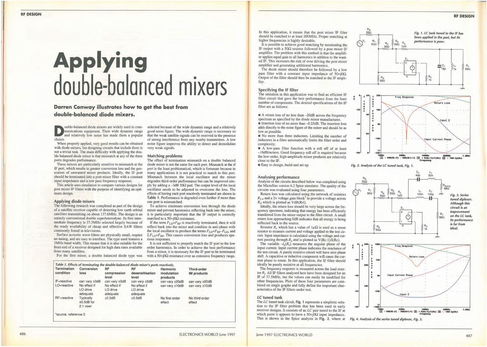
RF DESIGN
486
Applying double-balanced mixers Darren Conway illustrates how to get the best from double-balanced diode mixers.
Double-balanced diode mixers are widely used in communications equipment. Their wide dynamic range and relatively low noise has made them a popular
choice. When properly applied, very good results can be obtained
with diode mixers, but designing circuits that include them is not a trivial task. The main difficulty with applying the double balanced diode mixer is that mismatch at any of the three ports degrades performance.
These mixers are particularly sensitive to mismatch at the IF port, which results in greater conversion loss and the generation of unwanted mixer products. Ideally, the IF port should be terminated into a post mixer filter with a constant input impedance and a low pass frequency response.
This article uses simulation to compare various designs for post mixer IF filters with the purpose of identifying an optimum design.
Applying diode mixers The following research was completed as part of the design of a satellite receiver capable of detecting low earth orbital satellites transmitting on about 137.6MHz. The design is an entirely conventional double superheterodyne. Its first intermediate frequency is 37.SMHz selected largely because of the ready availability of cheap and effective SAW filters commonly found in televisions.
Surface acoustic wave filters are physically small, require no tuning, and are easy to interface. The type used features a 3MHz band width. This means that it is also suitable for the front end of a receiver designed for high data rates available from many satellites.
For the first mixer, a double balanced diode type was
selected because of the wide dynamic range and a relatively good noise figure. The wide dynamic range is necessary so that the weak satellite signals can be received in the presence of strong interference from any nearby transmitters. A low noise figure improves the ability to detect and demodulate very weak signals.
Matching problems The effect of termination mismatch on a double balanced diode mixer is not the same for each port. Mismatch at the rf port is the least problematical, which is fortunate because in many applications it is not practical to match to this port. Mismatch between the local oscillator and the mixer degrades third-order performance but can be improved simply by adding a -3dB SOQ pad. The output level of the local oscillator needs to be adjusted to overcome the loss. The effects of having each port reactively terminated are shown in Table 1 . Performance is degraded even further if more than one port is mismatched.
To achieve minimum conversion loss through the diode mixer and prevent harmonics reflecting back into the mixer, it is particularly important that the IF output is correctly matched to a SO+jOQ resistance.
If the term Fw+FRF is reactively terminated, then it will reflect back into the mixer and combine in anti-phase with the local oscillator to produce the terms Fw+Fpy-Fw, and 2.FLo+FRF· This causes conversion loss and produces spurious responses.
It is not sufficient to properly match the IF port to the low order harmonics. In order to achieve the best performance from a mixer, it is necessary for the IF port to be terminated with a SO+jOQ resistance over an extensive frequency range.
Table 1. Effects of terminating the double-balanced diode mixer's ports reactively. Termination Conversion RF RF Harmonic condition loss compression desensitisation modulation
IF=reactive can vary ±3dB LO=reactive No effect if
LO drive adequate
RF=reactive Typically ±0.SdB for 2:1 vswr
*source, reference 3
level level products can vary ±3dB No effect if LO drive adequate ±0.SdB
can vary ±3dB No effect if LO drive adequate ±0.SdB
can vary ±20dB can vary ±1 0dB
No first-order effect
Third-order IM products
can vary ±20dB can vary ±1 0dB
No third-order effect
ELECTRONICS WORLD June 1997
In this application, it means that the post mixer IF filter should be matched to at least 200MHz. Proper matching at higher frequencies is highly desirable.
It is possible to achieve good matching by terminating the IF output with a son resistor followed by a post mixer IF amplifier. The problem with this method is that the amplifier applies equal gain to all harmonics in addition to the wanted IF. This increases the risk of over driving the post mixer amplifier and generating additional harmonics.
The diode mixer should therefore be followed by a low pass filter with a constant input impedance of SO+jOQ. Output of the filter should then be matched to the IF amplifier.
Specifying the IF filter The intention in this application was to find an efficient IF filter circuit that gave the best performance from the least number of components. The desired specifications of the IF filter are as follows:
• A return loss of no less than -20dB across the frequency spectrum as specified by the diode mixer manufacturer. • Insertion loss of no more than -0.2SdB. The insertion loss adds directly to the noise figure of the mixer and should be as low as possible. • No more than three inductors. Limiting the number of inductors in a filter automatically limits the ftlter order and complexity. • A low-pass filter function with a roll off of at least -18dB/octave. Good frequency roll off is required because the low-order, high-amplitude mixer products are relatively close to the IF. • Easy to design, build and set up.
Analysing performance Analysis of the circuits described below was completed using the MicroSim version 6.2 Spice simulator. The quality of the circuits was evaluated using four parameters.
Return loss was calculated using the network of resistors R1-4 and a 2x voltage gain block7 to provide a voltage across R,1 which is plotted as VdB(Rrl).
Ideally, the return loss should be very large across the frequency spectrum, indicating that energy has been efficiently transferred from the mixer output to the filter circuit. A small return loss approaching OdB indicates that all energy is being reflected back to the source.
Resistor R0 which has a value of lµQ is used as a sense resistor to measure current and voltage applied to the test circuit. Input impedance is calculated using the voltage and current passing through Re and ·is plotted as V(Rc: 1)/I(Rc).
The variable - /p(Rc;) measures the angular phase of the input current. Input current phase indicates the reactance of the test circuit. A purely resistive circuit will have zero phase shift. A capacitive or inductive component will cause the current phase to rotate. In this application, the If' filter should ideally be purely resistive at all frequencies.
The frequency response is measured across the load resistor R,. All IF filters analysed here have been designed for an IF of 37.SMHz, but the values can easily be modified for other frequencies. Plots of these four parameters are combined on single graphs and fully define the important characteristics of the IF filters under test.
LC tuned tank The LC tuned tank circuit, Fig. 1 represents a simplistic solution to the IF filter problem that has been used in early receiver designs. It consists of an LC pair tuned to the IF at which point it appears to have a SO+jOQ input impedance. This is shown in the Spice analysis in Fig. 2, where at
June 1997 ELECTRONICS WORLD
• • -21 • t
---....
....
Rs son
--
21
•
• , • t , -• s
• • • I
RF DESIGN
Fig. 1. LC tank tuned to the IF has been applied in the past, but its performance is poor.
--ht--------~-
c, 18p
L, 1µ
. ' ' ' ' '
·1
e R,1 1k
-1Nl · J~ut Cur~nt Phase ·
R1 son
' ' ' '
I >>: . . - : 2-• •---------------.-----•--•-••"'·-----r-------•----•-•...,.----------------t 1- ·- 1- ·- 1.-ID , -«•=11 • _,1r1:1) Ill • 111c:011c1c1 lJI • 1H•r,1 .. , r........,
Fig. 2. Analysis of the LC tuned tank, Fig. 1.
• • •
-II
---
....
...
Rs son
z•• I
• • • t ,. 1•
I
I
• • . t , -• • • • • ,
C1 L1 40p son
,:---:1':.;• ,;g_ ,_ s,,;,, ._JW\J\,-_ _..__,,.J\N\,--+--.., tuned diplexer.
____ ::~: e
-SN•::: l_!!ut z
! »:
Although this circuit is an improvement
6~h on the LC tank, its performance is far from ideal.
. '. . . . . . . .
. . .
I i
-1-• -••-· .................... --~-------- .,._; 1- - 1- -Cl] • -(11.•I) • •-(ll'lt1) IJI • ll(tltU)/1(11) Ill • - -lf(IIII) ..._, 1.-
Fig. 4. Analysis of the series tuned diplexer, Fig. 3.
487
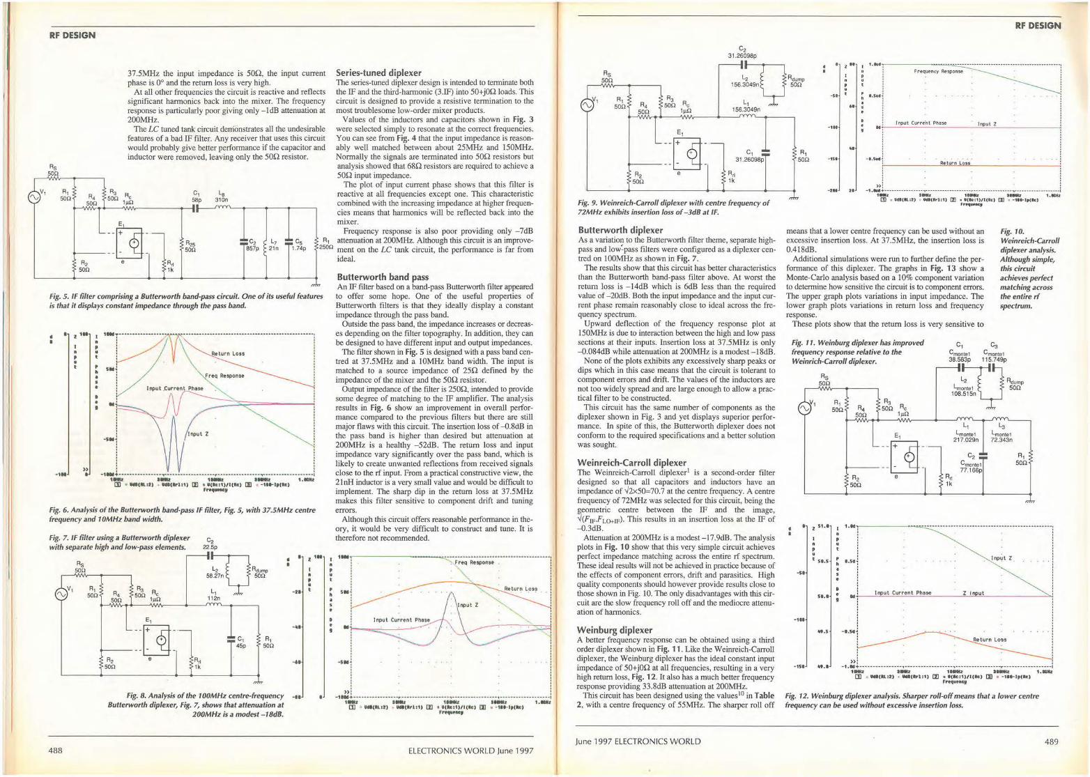
RF DESIGN
Rs 500
R1 50!1
37.5MHz the input impedance is son, the input current phase is 0° and the return loss is very high.
At all other frequencies the circuit is reactive and reflects significant harmonics back into the mixer. The frequency response is particularly poor giving only - ldB attenuation at 200MHz.
The LC tuned tank circuit demonstrates all the undesirable features of a bad IF filter. Any receiver that uses this circuit would probably give better performance if the capacitor and inductor were removed, leaving only the son resistor.
la 310n
Series-tuned diplexer The series-tuned diplexer design is intended to tenninate both the IF and the third-harmonic (3.IF) into 50+j0n loads. This circuit is designed to provide a resistive termination to the most troublesome low-order mixer products.
Values of the inductors and capacitors shown in Fig. 3 were selected simply to resonate at the correct frequencies. You can see from Fig. 4 that the input impedance is reasonably well matched between about 2SMHz and lS0MHz. Normally the signals are terminated into son resistors but analysis showed that 68n resistors are required to achieve a son input impedance.
The plot of input current phase shows that this filter is reactive at all frequencies except one. This characteristic combined with the increasing impedance at higher frequencies means that harmonics will be reflected back into the mixer.
Frequency response is also poor providing only - 7dB _::~ : C2 L7 c5 R1 attenuation at 200MHz. Although this circuit is an improve-u4p 2500 ment on the LC tank circuit, the performance is far from
e R,1 1k
857p 21n
fig. 5 . IF filter comprising a Butterworth band-pass circuit. One of its useful features is that it displays constant impedance through the pass band.
• • I z 111 ! ·-~ ~\~······:::::·::~·························1
i ··1 \ : 0
• • N
·SN . . . » • • ·1 ... +·----· ------· ..... ., ............................. ,. ...................................................................... j
1NI I NI UNI 1-1 1 .NNI CD • llff(lll.:11 • Uff(lrl:1) [I] • f(lc:1)/l(Rc) Ill • -11 .. l p(Rc)
f rt4utftcy
fig. 6. Analysis of the Butterworth band-pass IF filter, Fig. 5, with 37.5MHz centre frequency and 10MHz band width.
Fig. 7. IF filter using a Butterworth diplexer with separate high and low-pass elements.
C2 22.Sp
488
Rs son
d I
Rdump sa son
I
R1 son R, 1
112n ·H
son
e,
_ ::r]: e Rr1
1k
R1 son
... Fig. 8. Analysis of the 100MHz centre-frequency -11
Butterworth diplexer, Fig. 7, shows that attenuation at 200MHz is a modest-18d8.
z 111
I ft p u t
I ft p • t
, h • s •
ideal.
Butterworth band pass An IF filter based on a band-pass Butterworth filter appeared to offer some hope. One of the useful properties of Butterworth filters is that they ideally display a constant impedance through the pass band.
Outside the pass band, the impedance increases or decreases depending on the filter topography. In addition, they can be designed to have different input and output impedances.
The filter shown in Fig. 5 is designed with a pass band centred at 37.SMHz and a 10MHz band width. The input is matched to a source impedance of 2Sn defined by the impedance of the mixer and the son resistor.
Output impedance of the filter is 2S0n, intended to provide some degree of matching to the IF amplifier. The analysis results in Fig. 6 show an improvement in overall performance compared to the previous filters but there are still major flaws with this circuit. The insertion loss of -0.8dB in the pass band is higher than desired but attenuation at 200MHz is a healthy -52dB. The return loss and input impedance vary significantly over the pass band, which is likely to create unwanted reflections from received signals close to the rf input. From a practical constructive view, the 2lnH inductor is a very small value and would be difficult to implement. The sharp dip in the return loss at 37.SMHz makes this filter sensitive to component drift and tuning errors.
Although this circuit offers reasonable performance in theory, it would be very difficult to construct and tune. It is therefore not recommended.
!IN
I Sllli
l ' . '
------- - ~ -=--·-···-··-··-·····················-·-···-, .-.,Freq Respons• J
,, I
.. : rj- - =:'----'-___,~- .! l l I • • ! -s•1
I l >>: . . : - 1 IN+- ----- --- - - - - - - --~--- - - --- - - ----- ---, - ---- ------ - - - ----,--- - --- - - - -- - - ---- -,
11111t •1111• 11Nt ltNI 1.•N• (]] • ijdl(IU.I!) • U<ll(llrl:1) (IJ I ij(~c:1)/l(Rc) (JJ • -11 .. lp("c)
trtqu.ncy
ELECTRONICS WORLD June 1997
C2 31.26098p
RF DESIGN
Rs son
R1 son R4 ~
Rdump 1 S6.3049n son
L1
• z .. 1.••-r-------~~-"'-::.:··:.:··:.-··--------------------------------------, Response
-st .. ..... ] son
E1
--~-
------LI--e
156.3049n
C1 31.26098p
Fig. 9. Weinreich•Carroll diplexer with centre frequency of 72MHz exhibits insertion loss of-3dB at IF.
Butterworth diplexer As a variation to the Butterworth filter theme, separate highpass and low:pass filters were configured as a diplexer centred on 100MHz as shown in Fig. 7.
The results show that this circuit has better characteristics than the Butterworth band-pass filter above. At worst the return loss is - 14dB which is 6dB less than the required value of -20dB. Both the input impedance and the input current phase remain reasonably close to ideal across the frequency spectrum.
Upward deflection of the frequency response plot at IS0MHz is due to interaction between the high and low pass sections at their inputs. Insertion loss at 37.SMHz is only -0.084dB while attenuation at 200MHz is a modest -18dB.
None of the plots exhibits any excessively sharp peaks or dips which in this case means that the circuit is tolerant to component errors and drift. The values of the inductors are not too widely spread and are large enough to allow a practical filter to be constructed.
This circuit has the same number of components as the diplexer shown in Fig. 3 and yet displays superior performance. In spite of this, the Butterworth diplexer does not conform to the required specifications and a better solution was sought.
Weinreich-Carroll diplexer The Weinreich-Carroll diplexer1 is a second-order filter designed so that all capacitors and inductors have an impedance of✓2xS0=70.7 at the centre frequency. A centre frequency of 72MHz was selected for this circuit, being the geometric centre between the IF and the image, ✓(FIFFLO+IF)- This results in an insertion loss at the IF of -0.3dB.
Attenuation at 200MHz is a modest -17.9dB. The analysis plots in Fig. 10 show that this very simple circuit achieves perfect impedance matching across the entire rf spectrum. These ideal results will not be achieved in practice because of the effects of component errors, drift and parasitics. High quality components should however provide results close to those shown io Fig. 10. The only disadvantages with this circuit are the slow frequency roll off and the mediocre attenuation of harmonics.
Weinburg diplexer A better frequency response can be obtained using a third order diplexer shown in Fig. 11. Like the Weinreich-Carroll diplexer, the Weinburg diplexer has the ideal constant input impedance of 50+j0n at all frequencies, resulting in a very high return loss, Fig. 12. It also has a much better frequency response providing 33.8dB attenuation at 200MHz.
This circuit has been designed using the values10 in Table 2, with a centre frequency of SSMHz. The sharper roll off
June 1997 ELECTRONICS WORLD
R1 son
-1 11
.. -151
- 211 21
·1 Input Curr-~fn t Phase lr1)Ul Z
-I.Sudi Return Lo,, ,-------~~~~-----------
» : I
•1.tud +-----......... ••• -~-•• •• · •• •• ••••• ••• .,.. ••· • · •· --------,--· · -· --· •· --· ---- -1 1Mlz INz 111NNZ H-z 1.IC-Nz
CD III Udl (ftl..:2) • Uft(ll:r-1:1) (II • U(lc:1)/l (llc) (I) • -1t• tp(Rc) Frtq1i111ncy
means that a lower centre frequency can be used without an excessive insertion loss. At 37.SMHz, the insertion loss is 0.418dB.
Fig. 10. Weinreich-Carroll diplexer analysis. Although simple, this circuit achieves perfect matching across the entire rf spectrum.
Additional simulations were run to further define the performance of this diplexer. The graphs in Fig. 13 show a Monte-Carlo analysis based on a I 0% component variation to detennine how sensitive the circuit is to component errors. The upper graph plots variations in input impedance. The lower graph plots variations in return loss and frequency response.
These plots show that the return loss is very sensitive to
fig. 11. Weinburg diplexer has improved frequency response relative to the Weinrich-Carroll diplexer.
c, Cmonte1 38.S83p
C3 Cmonte1 11S.749p
Rs son Rdump
son
R,1 1k
C2 Cmonte1 77.166p
R1 son
• 2 s1., I 1.ld~, --------=.-·:.:·· .................................................... :
ft p u t St. S
•st
s, .•
- 111
'9 .5
• • • D • g
' ' . '
,.so~ I np~t z :
.,.,__ ..:.;I nci;p.;;.ut:...;;.;Cu::..r ;.;r e;.;.:n.;..t .;..Ph;.;.:a:.:.se=-----=Z~ ic:=u:..:t ______ ......;:.._,
' » :
- 15 I "'. I - 1 . Id+·•• - •· • • - - - - - --- ,. - - - •· • •· • •· •· • • • •"' - - - - - - -------- ---r ----------------•·I 1 Mlz 3-t 1 IINu: 3 IMtz 1 • MINI:
(]] • Udl(RL:2) • U<ll(Rrl:1) (IJ • U(Rc:1)/l(Rc) (JJ • -1' .. lp(Rc) frequtncj
Fig. 12. Weinburg diplexer analysis. Sharper roll-off means that a lower centre frequency can be used without excessive insertion loss.
489
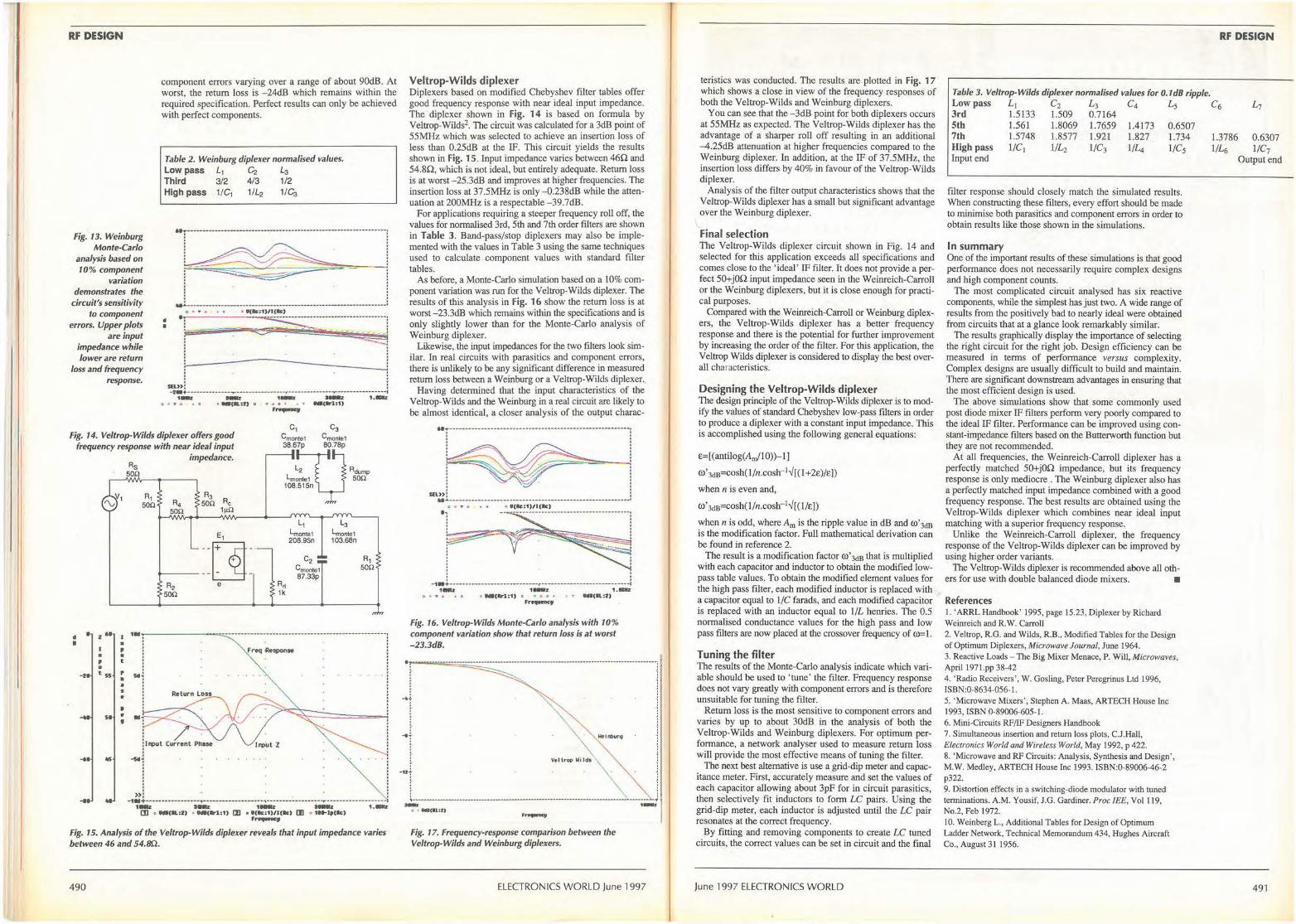
RF DESIGN
Fig. 13. Weinburg Monte-Carlo
analysis based on 10% component
variation demonstrates the
circuit's sensitivity to component
errors. Upper plots are input
impedance while lower are return
loss and frequency response.
component errors varying over a range of about 90dB. At worst, the return loss is -24dB which remains within the required specification. Perfect results can only be achieved with perfect components.
Table 2. Weinburg diplexer normalised values. Low pass L1 C2 Ls Third 3/2 4/3 1/2 High pass 1/C1 1/L2 1/C:,
• • •: :~!iimii----=-~~~~~~~ ~>: ' -z .... - ... -.......................... ......,.. .............. -------r--------------.,..----·---·--•-·-·I ·- ·- ·- ·- ··-II • • .a, • W: _. .. ,.:2) 0 • ,& 0 • A T ... , .... 1:1) ,~
Fig. 14. Veltrop-Wilds diplexer offers good frequency response with near ideal input
C3 Cmonte1
38.6~7p 80.78p Rdump
• • z" I • • , • • , t •
·H t"5 • • • s
• • .... 51 • '
... 115
Rs son
impedance.
E1
--~-·
------LI-e
lmonte1 son 108.S1Sn
A~ lk
L1
lmonte1 208.9Sn
L3
lmontel 103.68n
R1 son
... '!",------~--~---·---~===·~:-············--------------,
~1 .. ! J ~ut Current PtJase
-1 »i -•• .., .. +----·-··---................ ., .................................................. ., ........................................... -r--------.... ------.... .. ·- ·- ·- ·- ··CD , _,a:r> • _,1r1:o CZI • •1ac:111111c> IJI • 11•1,c1c1 ,..._
Fig. 15. Analysis of the Veltrop-Wilds diplexer reveals that input impedance varies between 46 and 54.Bn.
490
Veltrop-Wilds diplexer Diplexers based on modified Chebyshev filter tables offer good frequency response with near ideal input impedance. The diplexer shown in Fig. 14 is based on fonnula by Veltrop-Wilds2. The circuit was calculated for a 3dB point of 55MHz which was selected to achieve an insertion loss of less than 0.25dB at the IF. This circuit yields the results shown in Fig. 15. Input impedance varies between 46Q and 54.8Q, which is not ideal, but entirely adequate. Return loss is at worst - 25.3dB and improves at higher frequencies. The insertion loss at 37.5MHz is only-0.238dB while the attenuation at 200MHz is a respectable -39.7dB.
For applications requiring a steeper frequency roll off, the values for normalised 3rd, 5th and 7th order filters are shown in Table 3. Band-pass/stop diplexers may also be implemented with the values in Table 3 using the same techniques used to calculate component values with standard filter tables.
As before, a Monte-Carlo simulation based on a 10% component variation was run for the Veltrop-Wilds diplexer. The results of this analysis in Fig. 16 show the return loss is at worst-23.3dB which remains within the specifications and is only slightly lower than for the Monte-Carlo analysis of Weinburg diplexer.
Likewise, the input impedances for the two filters look similar. In real circuits with parasitics and component errors, there is unlikely to be any significant difference in measured return loss between a Weinburg or a Veltrop-Wilds diplexer..
Having determined that the input characteristics of the Veltrop-Wilds and the Weinburg in a real circuit are likely to be almost identical, a closer analysis of the output charac-
. '
sn»: ...... _.,. ___ ,.. ______ .......................................................................................... ... 0 .. • • • I( • •<&c:1)/l(ltc)
}~~r~ I : ~:
-111+-------------------------·-·r··-------•-···--•-•--··-····j 1 aaJ: , ... z 1. IClti
1:1 • • • • i,c • IMl(ltrl:1) o • .-. o • .1. ., ... (Rl:f) ,._, Fig. 16. Veltrop-Wilds Monte-Carlo analysis with 10% component variation show that return loss is at worst -23.3d8 .
Fig. 17. Frequency-response comparison between the Veltrop-Wilds and Weinburg diplexers.
ELECTRONICS WORLD June 1997
teristics was conducted. The results are plotted in Fig. 17 which shows a close in view of the frequency responses of both the Veltrop-Wilds and Weinburg diplexers.
You can see that the -3dB point for both diplexers occurs at 55MHz as expected. The Veltrop-Wilds diplexer has the advantage of a sharper roll off resulting in an additional -4.25dB attenuation at higher frequencies compared to the Weinburg diplexer. In addition, at the IF of 37.5MHz, the insertion loss differs by 40% in favour of the Veltrop-Wilds diplexer.
Analysis of the filter output characteristics shows that the Veltrop-Wilds diplexer has a small but significant advantage over the Weinburg diplexer.
Final selection The Veltrop-Wilds diplexer circuit shown in Fig. 14 and selected for this application exceeds all specifications and comes close to the 'ideal' IF filter. It does not provide a perfect 50+j0Q input impedance seen in the Weinreich-Carroll or the Weinburg diplexers, but it is close enough for practical purposes.
Compared with the Weinreich-Carroll or Weinburg diplexers, the Veltrop-Wilds diplexer has a better frequency response and there is the potential for further improvement by increasing the order of the filter. For this application, the Veltrop Wilds diplexer is considered to display the best overall characteristics.
Designing the Veltrop-Wilds diplexer The design principle of the Veltrop-Wilds diplexer is to modify the values of standard Chebyshev low-pass filters in order to produce a diplexer with a constant input impedance. This is accomplished using the following general equations:
E=[(antilog(Am/10))-1]
ro' Jds=cosh(l/n.cosh- 1✓[( I +2E)/E])
when n is even and,
ro' Jds=cosh( l/n.cosh-1✓[( 1/E])
when n is odd, where Am is the ripple value in dB and ro' JdB is the modification factor. Full mathematical derivation can be found in reference 2.
The result is a modification factor ro' JdB that is multiplied with each capacitor and inductor to obtain the modified lowpass table values. To obtain the modified element values for the high pass filter, each modified inductor is replaced with a capacitor equal to 1/C farads, and each modified capacitor is replaced with an inductor equal to 1/L henries. The 0.5 normalised conductance values for the high pass and low pass filters are now placed at the crossover frequency of (t)::J .
Tuning the filter The results of the Monte-Carlo analysis indicate which variable should be used to 'tune' the filter. Frequency response does not vary greatly with component errors and is therefore unsuitable for tuning the filter.
Return loss is the most sensitive to component errors and varies by up to about 30dB in the analysis of both the Veltrop-Wilds and Weinburg diplexers. For optimum performance, a network analyser used to measure return loss will provide the most effective means of tuning the filter.
The next best alternative is use a grid-dip meter and capacitance meter. First, accurately measure and set the values of each capacitor allowing about 3pF for in circuit parasitics, then selectively fit inductors to form LC pairs. Using the grid-dip meter, each inductor is adjusted until the LC pair resonates at the correct frequency.
By fitting and removing components to create LC tuned circuits, the correct values can be set in circuit and the final
June 1997 ELECTRONICS WORLD
RF DESIGN
Table 3. Veltrop-Wilds diplexer normalised values for 0.1d8 ripple. Low pass Li C2 L3 C4 L5 C6 3rd 1.5133 1.509 0.7164 5th 1.561 1.8069 1.7659 7th 1.5748 1.8577 1.921 High pass 1/C1 1/L,. l /C3 Input end
1.4173 1.827 l/L4
0.6507 1.734 l /C5
filter response should closely match the simulated results. When constructing these filters, every effort should be made to minimise both parasitics and component errors in order to obtain results like those shown in the simulations.
In summary One of the important results of these simulations is that good performance does not necessarily require complex designs and high component counts.
The most complicated circuit analysed has six reactive components, while the simplest has just two. A wide range of results from the positively bad to nearly ideal were obtained from circuits that at a glance look remarkably similar.
The results graphically display the importance of selecting the right circuit for the right job. Design efficiency can be measured in terms of performance versus complexity. Complex designs are usually difficult to build and maintain. There are significant downstream advantages in ensuring that the most efficient design is used.
The above simulations show that some commonly used post diode mixer IF filters perform very poorly compared to the ideal IF filter. Performance can be improved using constant-impedance filters based on the Butterworth function but they are not recommended.
At all frequencies, the Weimeich-Carroll diplexer has a perfectly matched 50+j0.Q impedance, but its frequency response is only mediocre . The Weinburg diplexer also has a perfectly matched input impedance combined with a good frequency response. The best results are obtained using the Veltrop-Wilds diplexer which combines near ideal input matching with a superior frequency response.
Unlike the Weinreich-Carroll diplexer, the frequency response of the Veltrop-Wilds diplexer can be improved by using higher order variants.
The Veltrop-Wilds diplexer is recommended above all oth-ers for use with double balanced diode mixers. •
References I. ' ARRL Handbook' 1995, page 15.23, Diplexer by Richard Weimeich and R.W. Carroll 2. Veltrop, R.G. and Wilds, R.B., Modified Tables for the Design of Optimum Diplexers, Microwave Journal, June 1964. 3. Reactive Loads - The Big Mixer Menace, P. WiU, Microwaves, ApriJ I 971.pp 38-42 4. ' Radio Receivers', W. Gosling, Peter Peregrinus Ltd 1996, ISBN:0-8634-056-1. 5. ' Microwave Mixers ' , Stephen A. Maas, ARTECH House Inc I 993, ISBN 0-89006-605-J. 6. Mini-Circuits RF/IF Designers Handbook 7. Simultaneous insertion and return loss plots, CJ.Hall, Electronics World and Wireless World, May 1992, p 422. 8. 'Microwave and RF Circuits: Analysis, Synthesis and Design', M.W. Medley, ARTECH House Inc 1993. ISBN:0-89006-46-2 p322. 9. Distortion effects in a switching-diode modulator with tuned terminations. A.M. Yousif, J.G. Gardiner. Proc IEE, Voll 19, No.2, Feb 1972. I 0. Weinberg L., Additional Tables for Design of Optimum Ladder Network, Technical Memorandum 434, Hughes Aircraft Co., August 3 I 1956.
1.3786 1/L6
0 .6307 l/C1
Output end
491
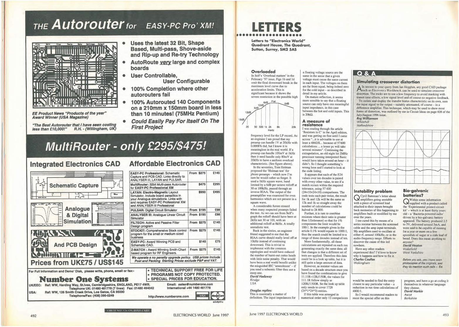
THE Autorouter for EASY-PC Pro' XM!
EE Product News "Products of the year" Award Winner (USA Magazine)
"The Best Autorouter that I have seen costing less than £10,000!" R.H.• (WIiiingham, UK)
• Uses the latest 32 Bit, Shape Based, Multi-pass, Shove-aside and Rip-up and Re-try Technology
• AutoRoute ~ large and complex boards
• User Controllable, User Configurable
• 100% Completion where other autorouters fail
• 100% Autorouted 140 Components on a 210mm x 150mm board in less than 1 o minutes! (75MHz Pentium)
• Could Easily Pay For Itself On The First Project
MultiRouter - only £295/$475!
Integrated Electronics CAD
Schematic Capture
'=oo•,,?· - ·-- ....... ·-- ~ . . . . . . . -- - - - -.... -·
Analogue & Digital
Simulation
Prices from UK£75 / US$145
AffQrdable Electronics CAD EASY-PC Professional: Schematic From $275 £145 Capture and PCB CAD. Links directly to ANALYSER Ill, LAVAN and PU.LSAR.
MultiRouter: 32bit Multi-pass Autorouter for EASY.PC Professional XM
$475 £295
LAVAN: Electro-Magnetic Layout $950 £495 Simulator. Include board parasitics in your Analogue simulations. Links with and requires EASY-PC Professional XM and ANALYSER Ill Professional
PULSAR: Digital Circuit Simulator From $195 £98
ANALYSER Ill: Analogue Linear Circuit Simulator
From $195 £98
FILTECH: Active and Passive Filter From $275 £145 Design program
STOCKIT: Comprehensive Stock control program for the small or medium sized business
From $275 £145
EASY-PC: Award Winning PCB and $145 £75 Schematic CAD.
Z·MATCH: Award Winning Smith-Chart based program for RF Engineers.
From $275 £145
We operate a no penalty upgrade po/Jcy. USS prices Include Post and Packing Ster/Jng Prices exclude P&P and VAT.
For Full Information and Demo' Disk, please write, phone, email or fax:- • TECHNICAL SUPPORT FREE FOR LIFE • PROGRAMS NOT COPY PROTECTED.
Number One Systems . sPecIAL PR1cEs FoR EDUCATION. UK/EEC: Ref: WW, Harding Way, St.Ives, Cambridgeshire, ENGLAND, PE17 4WR. Emall: [email protected]
Telephone UK: 01480 461n8 (7 llnes) Fax: 01480 494042 International +441480 461n8 USA: Ref: WW, 126 Smith Creek Drive, Loa Gatos, CA 95030 ---11111
Telephone/Fax: (408} 395-0249 http://www.numberone.com
ada4pnnu
( Iii< tr !1.0 / ! 1, 0\ 11£1'1 1 C ,\RI}
492 ELECTRONICS WORLD June 1997
LETTERS ••••••••••••••••••••
Letters to "Electronics World" Quadrant House, The Quadrant, Sutton, Surrey, SM2 5AS
Overloaded In Self's 'Overload matters' in the February '97 issue, Figs I b and Id omit the final downward break in the maximum level curve due to acceleration limits. This is significant because it shows the severe restriction in the possible high
Flat 6d8
50 500 1k 2k 8k 20k Hertz
frequency level for the LP record. As an engineer I am proud that my preamp can handle 1 V at 20kHz with 0.0008% thd, but I know it is meaningless in the real world. If a preamp can handle lOOmV at !kHz then it need handle only 80m V at 20kHz to have a uniform overload characteristic. (See figure above),
In the seventies, Tom Holman proposed the 'Holman test ' for phono preamps - which now I'm sure he would rather us forget. It used a !kHz square wave, band limited by a 6dB per octave rolloff at 30 or 1 OOkHz, passed through an inverse RIAA. The output of the preamplifier was examined for even harmonics which are not present in a square wave.
A considerable furore ensued when many respected preamps failed the test. As we can see from Self's graph the rolloff should have been at 2kHz not 30 or 100, with an additional rolloff at 8kHz. A totally unrealistic test.
Back in the sixties, an engineer friend suggested to me that the RlAA curve should really level off at I0kHz instead of continuing downward. This is trivial to implement with the common topologies and would have reduced the number of burnt-out cutter heads with little noise penalty. That would have been a real world benefit unlike the misguided IEC 'amendment' - if you need a subsonic filter then use a steep one. David Hadaway Rindge USA
Douglas replies: This is essentially a matter of definition. The input impedances for
a floating voltage source arc the same in the sense that a given voilage must cause the same current in each input. The voltages on them are far from equal, being indeed zero for the cold input - as described in detail in my article.
On mature reflection, it seems more sensible to say that a floating source can only have one meaningful input impedance, in this case between the hot and cold inputs. This is20kn.
A measure of resistance I was reading through the article ' Resistors in C' in the April edition, and was getting on fine until I came across" .. .it is advisable to use at least a 486DX ... because of 57 600 calculations ... a lesser pc will take several minutes". Continuing the extrapolation, an old eight bit 2MHz processor running interpreted Basic would have taken around an hour - it didn't. So I thought something's wrong here and I started to look at the code listing.
It appears that each of the E24 values over ten decades is paired with every other value, to see if a match occurs within the required tolerance, using 57 600 (24x!0x24xl0) comparisons. The code tests each pair twice, the result for lk and 12k will be the same as 12k and lk so straight away the number of calculations could be halved to 28 800.
Further, it is rare to combine resistors where their ratio is greater than !/(tolerance) so that for I% components the limit would be 100:1. In the example given in the article 0.1 % would equate to l000: l , thus the search could be limited to a range of three decades instead of ten.
More fundamentally, all these calculations are repeated on each run generating exactly the same data; all that changes is that a different set of tests are applied. Therefore this data could be in a look up table, but it is still quite a large amount of data.
However, as resistor values are based on a decade structure once you have found the combinations to give I l.11R=l2R//150R, the values for 111.J R follow simply as 120R//1500R. So the look up table only needs to cover 1728 (24*1*24*3) entries.
If this table was arranged in numerical order only 12 comparisons
June 1997 ELECTRONICS WORLD
Simulating crossover distortion
Arn answer to your query from Ian Hegglun, any good CAD package such as Elec1ronics Workbench, can be used to simulate crossover
distortion. The tricks are to use a low frequency to avoid masking with transit time effects, a low signal level and of course no negative feedback.
To isolate and display the transfer hiatus characteristic on its own, sum the input signal to the output - suitably attenuated, of course - in a difference amplifier. This technique, which may be used to show most forms of distortion, was outlined by me in Circuit Ideas on page 608 of the July/August 1996 issue. Reg Williamson Whitehill Staffordshire
v - ~ / \ L _I ~
V
\ I I
, V ~ I
I ----·-
I r"v ._,,
I Instability problem
Q Cyril_ Batem~' s letter about amplifiers gomg unstable
,.___
with a piece of screened lead attached to their inputs brought back memories of this happening to amplifiers built or modified by me over the years .
I too cured this by means of a series resistor between the screened cable and the amp ioput terminals. My amplifiers used to oscillate at either rf, around I OOkHz, or in the audio-frequency range. Efforts to discover the cause of this led nowhere.
Have any other readers experienced this? I'd love to know why it happens and how to fix it. Charles Coultas Wokingham
would be needed to fmd the entry closest to any particular value - a reduction in run time calculations of 4800:1.
So I would recommend readers to resist the special offer on this
\ V
I ' V i ~
I '
--1----~ -...,, r--,
Bio-galvanic batteries?
QWithin some information supplied with a product called
the 'Experimental printed circuit · kit' - which is at least thirty years
old - a • Bacteria-powered radio' driven by a bio-galvanic battery appeared. The battery produced 2.5 to 3V, delivered around 5mA, and were said to be capable of running for a year or more on a few spoonfuls of sugar or a stale loaf of bread. Does this mean anything to anyone? David Heaton Wakefield West Yorkshire
Before you ask, yes I have seen photocopies of the originals, and they do mention such cells - Ed.
program, and have a go at coding it themselves in whatever language they choose. David Markie Ascot Berkshire
493
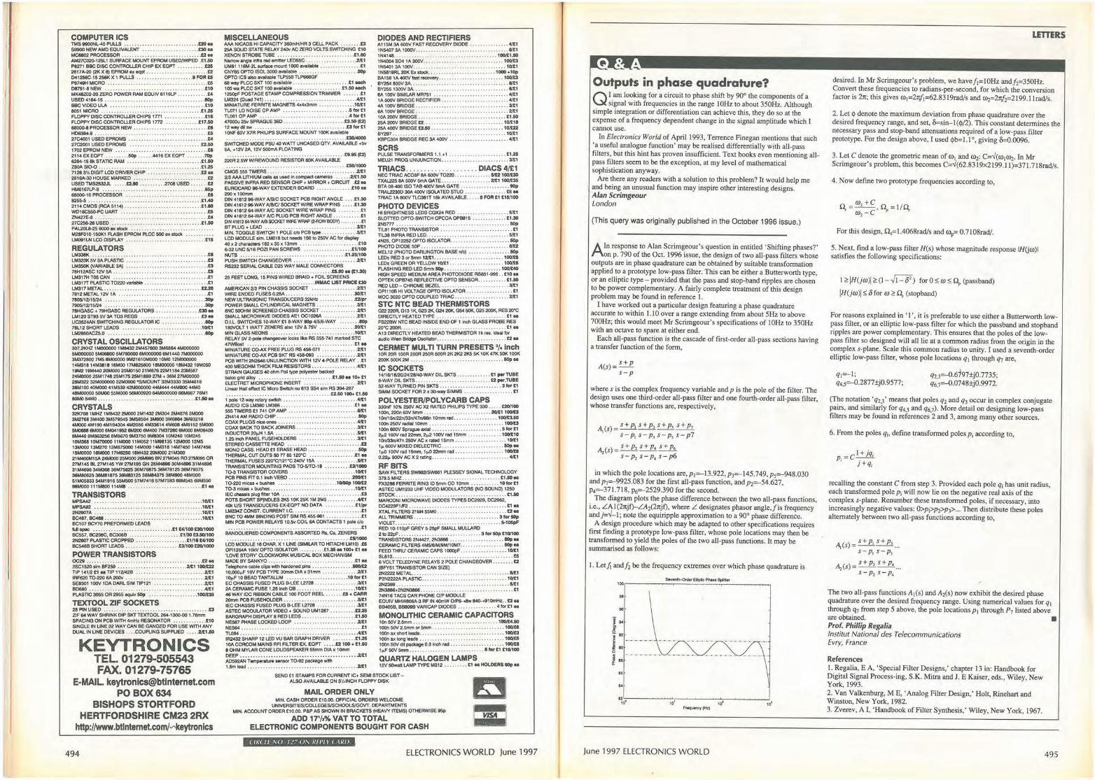
COMPUTER ICS TMS9900NL~PUUS ........... , .. , • , ......... ... t20ea $9900 NEW AMO EQUIVALENT .. .. ... ......... ...... £30 ea MC8802 PROCESSOR ... - .. .. .. . • . . . - .. .... £2 ea AM27C020-12SL1 SURFACE MOUNTEPAOM USEDM'IPED .£1.50 P8271 BBC DISC CONTROU£R CHIP EX EQPT • . •..•.•... £25 2817A•20 (2K X 8) EPAOM ox-........................ £2 D41256C-15 256K X 1 P\JU..S .......... . ... . ...... . 9 FOR £5 P8749H MICRO .. .............. . .. .......... . ......... £5 06751-8 NEW . .. .................................... £10 MK48Z0:2•20 ZERO POWER RAM EQUIV 6116lP . .••. . ••• .. • EA USEC 4164-15 • .. .. .. . .. • .. . .. .. .. • .. . .. .. eop BBC VIDEO ULA ... .. . ... .. .......... .. .... ... .. . .... . £10 8051 MICRO .•. , . •• •• ..•• . ••• ...•• •• , •.•• , •.••. . •• . £1.25 FLOPPVDISCCONTROU£RCHIPS 1n1 . ..... ......... . £18 FLOPPY DISC CONTROU£R CHIPS 1772 .. ••••.•. .. •• £17.50 68000-8 PROCESSOR NEW .......................... .. . £8 HD636+6. ...... . .... .. .. ... .. .. ........... ... £5 27C4001 USED EPROMS ..... .. .... ................. . .. EA 27C2001 USED El'ROMS ........................... .£2.SO 1702 El'ROM NEW .. .. .. . .. ... . £8 2114EXEOPT . ....... .acp ... .. . 4416EXEOPT ....... 70p 6264--15 6k STATIC RAM -- .. £1.50 ZBOA SI0-0 ..... ... .. ... .. ... .. , .... .. ..... .... , . .. £1.25 7126 3'/, DIGIT LCD DRIVER CHIP .. . ............ ... ... £2 .. 2818A-30 HOUSE MARKED ......... .. .... . . ............ £2 USED TMS2532JL .... . £2.50 ...... .... 2708 USED ...... . £2 HIM!167LP•8 . . . . ............ , . . l&p 680()().10 PROCESSOR ................................ £8 8255-5 . . ,. ··• 1 ·••• 1• • •• • • ••·• •• •£1A,()
2114 CMOS (RCA 5114) .................. ...... . .. .. . £1.80 W016C550-PC UART . .................. .. , ... .. ...... .tS ZN427E-8 .. .. .. .. .. .. .. . .. .. .. .. .. .. .... .. EA 27C256-26 USED .. . .. • .. . .. .. .. .. • .. .. .. .. .. . .. £1.50 PAL20L8·25 9000 ox stocl< . ... . .... . ...... . .. .. M28FOI0-150K1 FLASH EPROM PLCC 500 ox stocl< lM091LN LCD DISPLAY . . . ••• . .• £15
REGULATORS IM338K .. . .. . .... ..... ...... ...£8 lM323K 5V 3A PLASTIC .. . . ... , , .. • .. .. .. .. • .. • • .. • ..£3 LM350K (VARIABLE 3A) .............. ,. .. • • .. .. . .. . ... £3 78H12ASC 12V 5A .. . . . • • .. • .. . . .. .. .. • .. .. . .. ..£5 LM317H T05 CAN ..... .... . ... .. .... , ............... . . £1 LM3 I TT PLASTIC T0220 variable ....... ..... .. ......... . . £1 LM317 METAL .......... ....... . .... .... .. . ......... £2.20 7812 METAL 12V 1A .. . .................... . ...... . . ... £1 7805/12/15/24 .................... . .... . ., .. . ....... . 30p 7905/12/15124 . .. .. . .. • .. ......... , ...... .30p 78HGASC + 79HGASC REGULA TORS •••..••••..••... • £30 M LM123 ST93 SV 3A T03 REGS .......... .. ............ £3 ea UC3524AN SWITCHING REGULATOR IC .... • eop 78L12 SHORT LEADS ........... . ..... . ....... ...... 10/£1 I.M2950ACZ5.0 . • . . . . . eo,, CRYSTAL OSCILLATORS 307.2KHZ 1MOOOOOO 1M8432 2M457600 3t.16864 4MOOOOOO 5MOOOOOO 5M06800 5"4760000 6MOOOOOO 6M1440 7MOOOOOO 3M37280()7M5 8M000009M21610!Ml00 10MO 12MOOOOOO 14M31814M3816 16MOO 171M!25600 18!AOOOOO 16M43219M050 19M2 19!A440 201M)()() 20M0150 211M!78 22M1184 23"'587 24MOOOO 25M174825Ml75 25M1889 27M • 36M 27MOOOOO 26!A322 32MOOOOOO 32MOOOO-s/MOUNT 33M3330 35!A4816 38M100 40M00041M539 42M000000 44M444 44M900 44MO 48MOOOOO 50MOO 55MOOO 56M00920 64MOOOOOO 66M667 78M 1 SOMO 84MO ........ .. ........... , ........ . ...... .£1.50 M
CRYSTALS 321<768 1MHZ 1!A84322MOOO 2M1432 2M304 2"44576 3!Ml00 3M2768 3M400 3!,579545 3M58584 3M600 3M6864 3M93216 4M0004M190 4M194304 4M2056 4!A33614 41M!06 4M9152 5MOOO 5M0688 6IMlOO 6M041952 6M200 6M400 7"437260 6MOOO 8M06400 8M4468M-8M86709M3750 9M830410M240 10M245 10M368 10t.11'0000 11MOOO 11M05211M98135 12MOOO 12M5 13MOOO 13"4270131M!7500014MOOO 14M31814M7450 14M7456 15MOOOO 16!Ml00 17M6250 181,432 20IMlOO 21!A300 21M400M15A24!Ml0025M00026M995 8NVM045 RD27M0950R 27M145 BL 27M145 VW 27Mt95 GN 28M4696 301M896 31M4696 31IM89634"'368 36M75625 36M76875 36M78125 36M79375 36M80625 36M81875 36M83125 38M84375 38!AOOO 48MOOO 51 M05833 54M1916 55M500 57"47416 57M7583 69!A545 69M550 96M000111M800114M8 ........• .•..... .•. . •.. . •.. .£1N
TRANSISTORS MPSA42 .. . .... . ... .. ...... , ............ 10/£1 MPSA92 ..... . .. .. .. ..... ........... ... . 10/£1 2N2907A . .. ... .. .... 10/£1 8C487. BC488 .. . .. .. . .... . ........ 10/£1 BC107 BCY70 PREFORMED LEADS full OP« ............. ............ .. .... £1 tAf100 £30/1000 BC557, BC238C, BC308B . ••• ..• ••.. . .• ....•. £1/30 £3.50/100 2N2907 PLASTIC CROPPED •. .. •. ...... ... • ..• . £1/15 U/100 BC548B SHORT LEADS : ............ .... ... . £3/100 £20/1000
POWER TRANSISTORS OC29 ........ ........... . . , .... .. .......... ....... £2N 2SC1520 swn BF259 ........ . .. ... .... .. ....... 3,'21100/£22 TIP 141/2£1 eoTIP 112142B .. .. .. .. .... . .. . .21£1 IRF620 TQ.220 8A 200v .. .. .. . . .. .. .................. 2/£1 SE0001 100V IOA DARL SIM TIP121 .. ...... 2/£1 80680 .. .......... . ....... .... .................... .4/tl PLASTIC 3055 OR 2955 eqtJlv ~ .. .. • .. 1 OO/t35
TEXTOOL ZIF SOCKETS 28 PIN USED ..... ...... ....... .. ..................... £3 ZIF 84 WAY SHRINK DIP SKTTEXTOOL264-1300-00 1.78mm SPAC,NG ON PCB WITH 4mHz RESONATOR •. . .•.....•. . £10 SINGLE IN LINE 32 WAY CAN BE GANGED FOR USE WITH ANY DUAL IN UNE DEVICES ...• COUPLING SUPPLIED ... . .21£1.!0
KEYTRONICS TEL. 01279-505543 FAX.01279-75765
E-MAIL [email protected] PO BOX634
BISHOPS STORTFORD HERTFORDSHIRE CM23 2RX
http://www.btinternet.com/'-"'keytronics
494
MISCELLANEOUS AAA NICADS HI CAPACITY 360mH/HR 3 CELL PACK ..• •••.• £3 25ASOUDSTATE RELAY240vAC ZERO VOLTS SWITCHING £10 XENON STROBE TUBE . .... ... ................ .. .. .. £1.80 Narrow angle Intra red emitter LEOSSC . . . • . . .•. .21£1 UM61 116M-2l surface mount 1000 available •••• , . ••• . ••••. . £1 CNY65 OPTO ISOL 3000 avallablo , . ................... --~ OPTO ICS also ovallablo TLP550 Tl.P666GF 68 way PLCC SKT 100 available .. .. ... ... .. . ... ... ... £1 ... h 100 wa Pl.CC SKT 100 availal)je •. . ... . ..... .. ... . . £1.50 uch 1250pF POSTAGE STAMP COMPRESSION TRIMMER .•••• • . £1 LM324 (Quad 741) ....... ...... .. ................. . .. .A/£1 MINIATURE FERRITE MAGNETS 4x4x3mm • . •....••. . .•• 10/£1 Tl.071 LO NOISE OP AMP ..... ............. . ....... 5 lo< £1 Tl.081 OP AMP .. . .. .. .. .. .. .. .. .. ... .. 4 lo< £1 47000., 25v SPRAGUE 360 . ........ .. ............ . £3.50 (t2) 12waydUsw .. .. ..... .. .... .... . , ... . ... . .... .. . £3fof£1 10NF 63V X7R PHI UPS SURFACE MOUNT 100K availabl<> .. .. . . . .. . .. .. .. .. . . .. .. . .. . . . . . . . . .. . .. .. .. .. . £30/4000
SWITCHED MODE PSU 40 WATT UNCASED QTY. AVAJLABLE +Sv 5A, +12V 2A, 12V 500mA FLOATING ............. .... . .... . .... ... .. ... ... ... .. .. . £9.115 (t2)
220R 2.&N WIREWOUND RESISTOR 60K AVAILABLE .. .. . .. .. .. . .. . .. . .. .... . ..... . .. £50/1000
CMOS 555 TIMERS ... . ........ ..... . ......... . ... ... .2/£1 2/3 AAA LITHIUM cells as US<d In ccmpact cameras ..•••. 2/£1.50 PASSIVE INFRA RED SENSOR CHIP• MIRROR• CIRCUIT .£2 eo EUROCARD 96-WAY EXTENDER BOARD ••. ..• •. .• •. .. £10 M 290x 100mm DIN4161296-WAY AIB/C SOCKET PCB RIGHT ANGLE .. .. £1.30 DIN 41612 96-WAY A/BICISOCKETWIREWRAP PINS .. .• .£1.30 DIN 41612 64-WAY AIC SOCKET WIRE WRAP PINS .. •.. . . . . £1 DIN 41612 64-WAY A1C PWG PCB RIGHT ANGLE ..... • ... •• £1 DIN41612 64--WAY Ml SOCKETVMEWRAP (2-ROW BODY) .... . .... .£1 BT PLUG • LEAD .. .. .. .. • .. .. . . .... .. 3/£1 MIN. TOGGLE SWITCH 1 POLE C/o PCB type •. .. ••. . . • . •• . 5/£1 LCD MODULE slm. LM0181>ut-150to250VACfof display 40x2(tlafactetS 182 x35x 13mm ............ .... . .. ... . £10 8<!2 UNC 5/16 POZI PAN SCREWS . .... . .. .. . ... .. ... £1/100 NUTS .. . ................. . .. . ..... ... ....... , .£1.25/100 PUSH SWITCH CHANGEOVER .. ...... .. ..... .... . .... . 2/£1 RS232 SERIAL CABLE D25 WAY MALE CONNECTORS . .. . .. . . .. . . . . .. .. . .. . .. . .. ... £5.90 H (£1.30)
25 FEET LONG, 15 PINS WIRED BRAID• FOIL SCREENS .. . .. . .... .... . ...... ...... . .. .. .. INMAC UST PRICE £30
AMERICAN 2/3 PIN CHASSIS SOCKET . • . • . . ...... .. .2/£1 W1RE ENDED FUSES 0.25A ... .. .... . ................ ,30/!1 NEWULTRASONICTRANSOUCERS32kliz. , • .. . •• ••...• £2/pr POWER SMALL CYLINDRICAL MAGNETS • ... •. ..• ...• . .. 3/£1 8NC 500HM SCREENED CHASS4S SOCKET .. . . . . . •.. •. •• .21£1 SMALL MICROWAVE DIODES AE1 OC1026A ... .. ..... .. .2/£1 D.I.L SWITCHES 10,WAY £1 6-WAY 80p 4/5/f,.WAY .•. • • . BOp 180VOLT 1 WATT ZENER$ also 12V & 7SV ... ... . ....... 20/£1 MINGLASSNEONS .... .......... .. ....... 10/£1 RELAY 5V2-polo cnangeover looks Nke RS 355-741 marked STC 47W!los1 ................. .. . .. ............ . .... ... £1 M MINIATURE CQ.AX FREE PLUG RS 456-071 . . . . . . . . . . . .2/£1 MINIATURE CO-AX PCB SKT RS 456-093 ....•... . •... . . .21£1 PCB WITH 2N2648 UNIJUNCTION WITH 12V 4·POLE RELAY .. £1 400 MEGOHM THICK FILM RESISTORS .. ••. .. • . . . . •. . ..• 4~1 STRAIN GAUGES 40 ohm Fol type polyOSlor backed - grid alloy ... ....... . . .. .. ............. £1.60 N 10+ £1 ELECTRET MICROPHONE INSERT . . . . . • 2/£1 Unoar Hall effect IC Mao Sw'<eh 00613 SS4 swn RS 304-267
.. . ...... .. ....... , ......... . , .£2.50100+ £1.SO
!.:"011~=T::.::. :::: ::: : : : : : : : : : : : : : : : : : :,!~!
555 TIMERS £1 741 OP AMP ........................... 11/21 ZN414 AM RADIO CHIP .. . ........ ... .. , .... .... . .. .. .IOp COAX PLUGS rice ones ...... .. . .... , . . ........ ....... 4/1:1 COAX BACK TO BACK JQlNERS .. . . .... . ............... 3/£1 INDUCTOR 20,H 1.5A . .. .. .. . .. • . .. ..... 51£1 1.25 lncll PANEL FUSEHOLDE:RS . . .. ............. . .... . 3/£1 STEREO CASSETTE HEAO .... .... , ..... ... . .. ......... £2 MONO CASS. HEAD £1 ERASE HEAD . ........ ...... ..... ~ 'THERMAL CUT ours SO n 651:WC .••• . £111 'THERMAL FUSES 220"C/121"C 240V 15A ... .5/t1 TRANSISTOR MOUNTING PADS T0-5/T0·18 •. . .• • . .. • £3/1000 T0-3 TRANSISTOR COVERS ....... ........... ... .... 10/£1 PCB PINS FIT 0.1 Inch VEl)O . . ............ .. . .... ... .200/£1 T0·220mlcas + bushes .. .. . .. .. .. . . .. . . 10/50p 100/£2 TQ.3 micas+ bu$hes . .. .. . ....... . ....... .. . . . .. ... .. 1SIE1 IEC chassis plug filter 10A . . .............. . . , ...... .. .... £3 POTS SHORT SP)NDLES 2K5 10K 25K 1M 2M5 •• .. •• ... •• .4/t1 40k UIS TRANSDUCERS EX·EOPT NO CATA ....... .... . £1/r>< LM234Z CONST. CURRENT I.C . . . .... . ....... . ..... ...... £1 BNC TO 4MM BINDING POST SIM RS 455-961 •• .. .••.. . •••. £1 MIN PCB POWER RELAYS 1 O.Sv COIL 6A CONT ACTS 1 pole C/o .......... .... . .. .... ... • .. ... .. . £1
BANDOUERED COMPONENTS ASSORTED Rs, es. ZENERS . . ..... .. . .. .. . .. .. . .. . .. .. . .. .. . .. .. . .. .. ..... . £5/1000
LCDMOOULE 16CHAR.X 1 UNE(S4MILARTOHITACHI LM10) .ts OPl1264A 101<V OPTO ISOLATOR ••• ..••..• £1.35 M 100+ £1 .. 'LOVE STORY' CLOCKWORK MUSICAL BOX MECHANISM MADE BY SANKYO ...... .......... . ....... .. .. .... .. £1 N Tolophooe cable ci!)S with hardened pins ...• .. ••. . ..•• . . 500/£2 10,000,.F 16VPCBTVPE30mm 0 IAx31mm ... .. ... .. .... 2/£1 10,.F 10 BEAD TANTALUM ......... ....... .. ..... 10fo<C1 EC CHASSIS FUSED PLUG B-LEE L2728 . . . .. 3/£1 2A CERAMIC FUSE 1.25 Inell OB ... . . .. ..... . . ... .... .. 10/£1 48 WAY IOC RIBBON CABLE 100 FOOT REEL • . . . .tS • CARR 20mm PC8 FUSEHOLOER .... .. .. ........ .. ..... . ..... 5/21 IEC CHASSIS FUSED PLUG B-LEE L2728 . .. • ... 3/£1 ASTEC MODULATOR VIDEO+ SOUND UM1287 ••••..••. . £2.25 BARGRAPH DISPLAY 8 RED LEDS , .... . ... . .... .. ..... £1.50 NE567 PHASE LOCKED LOOP .. .. . .. .. • .. .. • .. . .. ... .2/£1 NE564 .. .. .... ................... .. £1 TUl84 ... ... . ' ........ . ... . ... .. .. . ........ . ....... . 4/£1 IR2432SHARP 12 LED VU BAR GRAPH DRIVER ••... • • • • £1.25 10ACORCOM MAINSRFI FILTER EX. EOPT ..•. • £2100+ £1.50 8 OHM MYLAR CONE LOUDSPEAKER 55mm DIA x 10mm DEEP ........................ .. ................... .2/£1 AD592AN Tomperatuto sens<K T0·92 package with 1.5m load . ........................... .. ......... .. .. 21£1
DIODES AND RECTIFIERS A115M 3A 600V FAST RECOIIEJ1Y DIODE ... ••••. , .. . ••• 41£1 1N5407 3A 1000V. . . • .. . .. .. . .. .. .. .. • . . . .. .. .. . . . .. l/t1 1N4148 ...... . ... . ... , ..... ..... .. .. . .... . .... 100/£1.50 1N4004 S04 1A 300V ............................ , .. 100/£3 1N5401 3A 100V.. ... ..... .. .. .. . .. , .... ... . 10/£1 1N5819RL 20K Ex stocl< . ... ........ , ......... ... . 1000 +10p BA1581A 400V1aS1 rocovory .. ..... ... .. ............. 100/£3 BY254 800V 3A ..................... .. ...... . ........ 1/£1 BY255 1300V 3A.. . . . .. .. . .. . . . ............ 1/£1 6A 100V SIMILAR MR751 .. .. .. . .. • .. .. .. . .. .. .. . .. 4/£1 1A 600V BRIDGE RECTIFIER . , , . .. . . ... , .... . .... .... 4/£1 4A 100V BRIDGE . .. ......... .. .. .. .... .. ... .. . .. , . .. 3/t1 6A 100V BRIDGE. .. . . ........ ..... . .... .. .. 2/£1 10A 200V BRIDGE ....... . .... . ......... . ... .... .. . £1.50 25A 200V BRIDGE £2. .. . ... . . , ... ., .. . ., .. ...... .. 10/£18 25A 400V BRIDGE £2.50 ....... . ......... .. ...... , .. 10/£22 BY297.. .. . .. .. .. . . .. .. .. .. . .............. .... 10/£1 l<BPC304 BRIDGE REC 3A 400V ......... .. , ........... 4/£1
SCRS PULSE TRANSFORMERS 1.1.• 1 . .. • .. .. .. .. . •. £1.25 MEU21 PROO UNIJUNCTION ....... . .................. 3/t1
TRIACS ............. .. .. .. . DIACS 4/£1 NEC TRIAC AC08F9A 600VT0220 ... . ... .. ..... 5/£2100/£30 TXAL225 9A 500V 5mA GATE ............ ,, ..... 2/£1100/t35 BTA 08-400 ISO TAB 400V 5mA GATE . ....... .... .. .. .. 90p TRAL2230D 30A 400V ISOLATED STUD • • , , . . •• .•••. ... £5 M TRIAC 1A 600V TLC381T 16kAVAJLABLE .• ••. 5 FOR £1 £151100
PHOTO DEVICES HI BRIGHTNESS LEDS COX24 RED .... . ............... 51£1 SLOTTED OPTQ.SWITCH OPCOAOPB815 • ..••. ..••. , • £1.30 2N5m ...... .. ..... ....... ....... ..... .......... 50p Tll.81 PHOTO TRANSISTOR ... ................ .... ..... £1 TIL38 INFRA RED LED ........ . , ... . . ..... .. .. · . .. .. · • 51£1 4N25. OP12252 OPTO ISOLATOR ... .. ....... , ......... . 50p PHOTO DIODE SOP .................... , ........... . . 81£2 MEL12 (PHOTO DARLINGTON BASE r>'<) •. • •• , ••••• •• •• • ~ LEDsRED3or5mm 12/£1 ... .. .. ... ... .............. 100/U LEDs GREEN OR YEl.LOW 10/£1. . .••.. ••• . •• , . 100/U FLASHING REC LED 5mm ~ ............. ... ..... -1-HIGH SPEED MEDIUM AREA PHOTODIODE RS851-S95 . . £10 N OPTEK OPB745 REFLECTIVE OPTO SENSOR .. ••• .•• • .. El.SO RED LED - CHROME BEZEL • . . . . . . 3/t1 OP1110BHIVOLTAGEOPTO ISOLATOR . ......... .. .. , ,. , £1 MOC 3020 OPTO COUPLED TRIAC . . .••..••. , .••. . .. •.• 2/£1
STC NTC BEAD THERMISTORS G22 220R. G13 1 K. G23 2K, G24 20K. G54 50K. G25 200K, RES 20'C DIRECTLY HEATED TYPE ............. . .. ... ....... . £1 ea FS22BW NTC BEAD INSIDE END OF 1 Inch GLASS PROBE RES 20•C200R ... , ... • . ... , . .• .. , .. . ... . . . .. - - . ..... . . . £1 M A13 DIRECTLY HEATED BEAD THERMISTOR 1k ros. ldealfof aoolo Wion &ldge Oscillator.. . .. .. .. . .. . .. .. £2 ..
CERMET MULTI TURN PRESETS'/• Inch 10R 20R 100R 200R 250R 500R 2K2K2 2K5 5K 10K47K SOK 100K 200K 500K 2M .. .. • .. .. · .. • .... · 50p 00
IC SOCKETS 14116118/20/24/28/40•WA Y OIL SKTS .. . . . .. .... . £1 po, TUBE S•WAY OIL SKTS . .. . .... . .................... £2 per.TUBE 32-WAY TURNED PIN SKTS .. . .. .. .. .............. 3 lor t1 SIMM SOCKET FOR 2 x 30-way SIMMS . .... ........ ... ... £1
POL VESTER/POL YCARB CAPS 330nF 10% 250V AC X2 RATED PHILIPS TYPE 330 .. . . . £20/100 1 OOn. 220n 63V 5mm . .. .. .. ....... .. . . 20/£1 100/£3 1°'1/15n/22n/33tl/47n/6&! 10/TVTI rad .. ........... .... 100/£3.50 100n 250V radio! 10mm .... ...... . ..... ............. 100/£3 100n 600V Spraguux/al . .. ...... ......... . ...... s lo< £1 2,.2160V rad22mm. 2,.2100V rad 15mm . .. . .. . ... 100/£10 10n/'J3rv47n 250V AC x rated 15mm .... .. .. ......... , .. 10/£1 1~ 600V MIXED DIELECTRIC ...... ...... . ..... ...... ~ M 1,.0 100V rad 15mm, 1,.0 22mm rad .. ....... .. ........ 100/E& 0.22~ 900V AC X 2 rating. .. . .. . .. . . . • . . . . . .. ...... 4/£1
RF BITS SAW FILTERS SW662/SW661 PLESS EV SIGNAL TECHNOLOGY 379.5 MHZ . .. . .. . . . .. . .. .. . ......... ... .. .... . , £1.SO N FX3286 FERRITE RJNG ID 5mm OD 10mm .... .... ... IO !of £1 ASTEC UM1233 UHF VIDEO MODULATORS (NO SOUND) 1250 STOCK . .. .. . .. . .. .. .. .. .. . .. .. . .... . £1.50 MARCONI MICROWAVE DIODES TYPES OC2929. OC2962, DC4229F1/F2. . . . . . . .. .. . .. ... ..... .. ... .......... 21 N XT AL FILTERS 21 M4 55MO .... ............ ........... £2 M ALL TRIMMERS .. . .. • .. .. . .. .. .. . .. • .. .. • .. .. -Jlor ~ VIOLET. ........... .. ............ . .. ... .. . .. . . S-105pF RED 11).110pFGREV 5·25Pf SMALLMULLARD 2 to 22pF .. . .. . . . . .. ......... . ....... . ... 3 lor ~ t 1~00 TRANSISTORS 2N4427, 2N3888 .. ............ ....... IIOp oa CERAMIC FILTERS 4MSN"1/91,1/10M7 ••. . •.. . .. • .. ••.. IIOp N FEED THRu• CERAMIC CAPS 1000pF ....... .... . .. .... 1W£1 SL610. .... . .. ...... .. . . . .. .. . • .. .. .... .. · · £5 6 VOLT TELEDYNE RELAYS 2 POLE CHANGEOVER •• . .• ... £2 (BFY51 TRANSISTOR CAN SIZE) 2N2222 METAL.. .. .. . .. .. .. . .. .. • .. . . .. .. .. .. . .. . 51£1 P2N2222A PLASTIC . .. ........ .. ........ . , .. 10/£1 2N2369 • .. .. . .. .. • .. .. . .. . .. • .. . . .. .. . .. • .. .. .. .. &/£1 2N3866+2N2N3866 .............. ... . ....... · , · .. · .... • £1 74N16 TACS CAR PHONE 0/P MODULE EQUIV MHW806A-3 RF IN 40mW O/P6-sw 840-+910mHz . . £3 u 884058, 88809B VARICAP DIODES .•• •• , ••..••• .. 4 !of £1 M
MONOLITHIC CERAMIC CAPACITORS 10nSOV2.5mm ...................... . ....... . .. 100,'U.50 100n 50V 2.5mm or 5mm. . . . . . . • . . . • ..•. • , .•... .• . , 100/te 1 txln ax short loads . .. . .. . .. .. .. . . .. . . . .. . .... . .... 100/£3 100n ax long leads . .... .. ....... . ..... . . . ....... ... 100/ES 100n SOV dll package 0.3 lnc/1 rad .. . . . . . .. . ......... 100/£8 1,.F SOV 5mm .... .. .. .. . . .. . .. . .. .. 8 lo< £1£1~00
QUARTZ HALOGEN LAMPS 12V 50watt LAMP TYPE !<312 . .. ...... £1 M HOLDERS IIOp ta
SEND £1 STAMPS FOR CURRENT IC+ SEMI STOCK UST -ALSO AVAILABLE ON 31/a INCH FlOPPY DISK
MAIL ORDER ONLY MIN, CASH ORDER £10.00. OFFICIAL ORDERS WELCOME
UNIIIEJ1SIT1ES/COU£GES/SCHOOI.SIGOVT. DEPARTMENTS MIN. ACCOUNT ORDER £10.00. P&P AS SHOWN 114 BRACKETS1HEAVV ITEMS) OTHERWISE 95P
ADD 17'/,% VAT TO TOTAL ELECTRONIC COMPONENTS BOUGHT FOR CASH
URU f WJ I 17 ON REI' / Y < •1RIJ
ELECTRONICS WORLD June 1997
Outputs in phase quadrature?
Q I am looking for a circuit to phase shift by 90° the components of a signal with frequencies in the range I 0Hz to about 350Hz. Although
simple integration or differentiation can achieve this, they do so at the expense of a frequency dependent change in the signal amplirude which I cannot use.
In Electro11ics World of April 1993, Terrence Finegan mentions that such 'a useful analogue function' may be realised differentially with all-pass filters, but this hint has proven insufficient. Text books even mentioning allpass filters seem to be the exception, at my level of mathematical sophistication anyway.
Are there any readers with a solution to this problem? It would help me and being an unusual function may inspire other interesting designs. Alan Scrimgeour London
(This query was originally published in the October 1996 issue.)
Ain response to Alan Scrimgeour's question in entitled 'Shifting phases?' on p. 790 of the Oct. I 996 issue , the design of two all-pass filters whose
outputs are in phase quadralllre can be obtained by suitable transformation applied to a prototype low-pass filter. This can be either a Butterwonh type, or an elliptic type - provided that the pass and stop-band ripples are chosen to be power complementary. A fairly complete treatment of this design problem may be found in reference I.
I have worked out a panicular design featuring a phase quadralllre accurate to within 1.10 over a range extending from about 5Hz to above 700Hz; this would meet Mr Scrimgeour' s specifications of I 0Hz to 350Hz with an octave to spare at either end.
Each all-pass function is the cascade of first-order all-pass sections having a transfer function of the form,
A(s) = s + P s - p
wheres is the complex frequency variable and p is the pole of the fil ter. The design uses one third-order all-pass filter and one founh-order all-pass filter, whose transfer functions are, respectively,
Ai(s)=s+ p1 s+p3 s+P, s+p, s - p1 s - p3 s-Ps s - p7
~(s) = s+ P, s+ p, s+ p6 s-p2 s-p4 s-p6
in which the pole locations are, p 1=-13.922, p3=-145.749, p5=-948.030 and p7=-9925.083 for the first all-pass function, and p 2=-54.627, p4=-371.718, P6=-2529.390 for the second.
The diagram plots the phase difference between the two all-pass functions, i.e., L AJ(2njf)-LA2(2njf), where L designates phaser angle,/is frequency andJ=✓-1; note the equiripple approximation to a 90° phase di fference.
A design procedure which may be adapted to other specifications requires first finding a prototype low-pass filter, whose pole locations may then be transformed to yield the poles of the two all-pass functions. It may be summarised as follows:
I. Let .ti and h be the frequency extremes over which phase quadrature is
100,-------------~------. •• ..
J .. I .. ------· ! 110 1 " ---··--...
..
.. 9~o";;,- -----,"c.,;------~,.-:-, _ ____ ...,10'
June 1997 ELECTRONICS WORLD
LmERS
desired. In Mr Scrimgeour's problem, we have / 1=10Hz andfi=350Hz. Conven these frequencies to radians-per·Second, for which the conversion factor is 2n ; this gives ro1=2nf1=62.8319rad/s and roi=21th=2199.J l rad/s.
2. Let ip denote the maximum deviation from phase quadralllre over the desired frequency range, and set, 6=sin-l(ip/2). This constant determines the necessary pass and stop-band attenuations required of a low-pass filter prototype. For the design above, I used !pb=I.I 0 , giving 6=o.0096 .
3. Let C denote the geometric mean of ro~ and roi: C=✓(ro1 roi. In Mr Scrimgeour's problem, this becomes C="/(62.83 I 9x2 J 99. l 1 )=37 I. 7 l 8rad/s.
4. Now define two prototype frequencies according to,
For this design, n ,=l.4068rad/s and eop=0.7108rad/,
5. Next, find a low-pass fi lter H(s) whose magnirude response IH(jro)I satisfies the following specifications:
1 ~ IH(jw)j ~ (1- ✓1 - 8 2) for Os l1J $ nP (passband)
IH(jw~ :s; 8for l1J ~ 0, (stopband)
For reasons explained in ' l ' , it is preferable to use either a Butterworth lowpass filter, or an elliptic low-pass filter for which the passband and stopband ripples are power complementary. This ensures that the poles of the lowpass filter so designed will all lie at a common radius from the origin in the complex s-plane. Scale this common radius to unity. I used a seventh-order elJiptic low-pass filter, whose pole locations q I through q7 are,
q1=-l; q4.5=-0.2877±j0.9577;
q2_3=-0,6797±j0.7735; q6_7=-0.0748±j0.9972.
(The notation 'q2,3' means that poles q2 and q3 occur in complex conjugate pairs, and similarly for q4.s and q6,7). More detail on designing low-pass filters may be found in references 2 and 3, among many other sources.
6. From the poles q;, define transformed poles p ; according to,
C l+ Jq, p, = -.-J +q,
recalling the constant C from step 3. Provided each pole q; has unit radius, each transformed pole Pi will now lie on the negative real axis of the complex s-plane. Renumber these transformed poles, if necessary, into increasingly negative values: 0>p1>p2>p3> .. . Then distribute these poles alternately between two all-pass functions according to,
A1 (s) = s + P, s + P, ... s-p1 s-p3
A,(s)=s+p, s+p• ... s-p, s - p,
The two all-pass functions A1(s) and A2(s) now exhibit the desired phase quadralllre over the desired frequency range. Using numerical values for q 1 through q7 from step 5 above, the pole locations p 1 through P7 listed above are obtained, • Prof. Phillip Regalia lnstitut National des Telecommunications Evry, France
References I. Regalia, E A, 'Special Filter Designs,' chapter 13 in: Handbook for Digital Signal Process-ing, S.K, Mitra and J. E Kaiser, eds., Wiley, New York, 1993. 2. Yan Yalkenburg, ME, ' Analog Filter Design,' Holt, Rinehan and Winston, New York, 1982, 3. Zverev, A I, ' Handbook of Filter Synthesis,' Wiley, New York, 1967.
495

~KEIL l,.L__JS<:>FTWARE
• • • • •
Cl I, Cl Ix. Cl& 1 C oompllel'S with 11umePOUS mlcrocontroRer language extensions for the fastest, tightest code. HISIM CPU ancl peripheNI simulator
HITOP remote clelauaser RTX TINY .... 1.t1me executive
Comprelleulve ,.... ... mmtna examples
With our low cost emulator rental, training courses and hands-on user guides
aJso availabJe, you can be assured of meeting p,roject reJease dates and budget
targets everytime.
So let us give ypu a help)ng hand, as,k for our comprehensive Kejl information pack,
including CDrROMs !
Hitex (UK) Ltd. ES Unive.rsity of W,arwJck Science Park, Cove,ntry,
Cl'..4 7/EZ Tel: 0 1203 692066 Fax: 01203 692'131
Email:[email protected] Compuse__rve: 100646, 1526
CIR( IE ,'\O I !II O'\ REl'L I ( ,\Rf)
496
Dill~ Ille leading directorymr aD your dectrical/e1ectronic; putthasing requirements - and it's FREE to qualifying applic:anls. How can you ~ out any longer on the following ...
I Access to Offl' 11,000 electrical/electronics companies throughout the UK
I Easy product/service or company searches
I Trade Names Section - if you know the brand/trade name, now you can find the supplier
I Products and Services Showcase - the simple way to obtain in depth information about companies
I Faxback service for instant additional company information
fo find. out how to rereiw your FR££ <:opy of Dial f-: lr<.1ric.:aUF.ln·tronk~ or ho,, to adn·rti.,t widtin 1hr direc1ory. phone Judi Chapman on 08!10 ;21_w3 quoting reference llH6 or e-mail Judi on j([email protected]
eDtal E'lg/Jreerlltg Is also (U)(ll/abf,, - contact Judi for more details
CIRUE •\/0. 11'1 01\ REl'l I ( ARI)
Halcyon Electronics Off-Air Frequency Products
We manufacture a range of Off-Air Frequency products lncludlng frequency standards, sources and disciplined
standards Including GPS, Customised units also available
Precision Frequency Source 1 kHz to 16MHz sinewave output, 0.0001 Hz resolution,
Easily settable via decade switches, VCXO backup as standard
Off-Air Frequency Standard 1 MHz, 5MHz and 10MHz, outputs,
Options include Sinewave, Signal inhibit and Audio Warning ( IRC LE '\O 1,0 O ,'\ Rf Pl} ( \RI)
We are well known for our quality new and used test equipment. Our list Is extensive, ranging through most
dlscallnes. Call for details aa1•11rr.• AIIW}JJDIUl}JI•
Halcyon Electronics 423 Kingston Road, Wimbledon Chase, London SW20 8JR
Phone: 0 181 542 6383 Fax: 01 8 1 542 0340
( IR( l E '\'O I W 0 ,'\ Rfl'l} C •\RI)
ELECTRONICS WORLD June 1997
ELECTRONICS WORLD
u • u,uOuf! .. 6 wlelll H WOOI I
READER INFORMATION SERVICE
For more information about any of the products or seivices in this issue of ELECTRONICS WORLD,
simply ring the relevant enQuiry number.
Enquiry numbers may be found at the bottom of each individual advertisement.
101 102 103 104 105 106 107 108 109 110 111 11 2 113 11 4 115 116 117 11 8 119 120 121 122 123 124 125 126 127 128 129 130 131 132 133 134 135 136 137 138 139 140 141 142 143 144 145 146 147 148 149 150 151 152 153 154
155 156 157 158 159 160 161 162 163 164 165 166 167 168 169 170 171 172
173 174 175 176 177 178 179 180 181
Name
Job title
Company Address
Telephone JUNE 1997
Only tick here if you do not wish to receive direct marketing • promotions from other companies.
Subscribe today! Guarantee your own
persona\ copy each month
Save on a 2 year · subscription
ELECTRONICS WORLD INCO•POLl.nN• WIUUII WH.l.D
Newsagent order form Pass this order form to your newsagent to
ensure you don't m iss the next issue of EW.
To ....... .... ........ ................... ........ ...... ............ ..... .. . (name of Newsagent)
Please reserve me the July issue of Electronics World- on sale
5th June - and continue to order every month's issue until
further notice
Name ...... ........ ..... ...... ... .................................. .
Address ....... .................. ............. .................... .
Thank you
Subscribe today! Guarantee your own
persona\ copy each month
Save on a 2 year subscription
ELECTRONICS WORLD INCO•Poun•• WIUWI WOILD

.... ~ ...
!!..,.• .. .:
. ' . < • ~ " , ..
-, en .. .. :m ,. . .. . ;· ·. ,_,, ... ~;.,• ·.m '\ : I l ~
... ~--· .: ; '. 0 , .• , ~ ~ •• t
'~--•- ' ':•. . .. <· ~• •• ,.o I
. q· . . . m·-
" . )
.. ' •
. . , I
, ·. :D . ,: - ·-
I . ..
., .,
I •
, . , \
'.
. -·--· ·.•-·· ·---- --- -- ---- ··-· ---· --~· ·- ·· ···- ---- •---.-·-· -
ELECTRONICS WORLD IIICO......_n ........... ...
t .
SUBSCRIPTION CARD . , t ,; • • ,/ • . . • I•
Please enter my subscription to ELECTR9NICS,W0RL0 .. I enclose Cheque/Eurocheque to the valu~ of £ · ma(le payable _to Reed Bi,atnei,a lnfOl'llllllion Please charge my ,
:~~~~~;sa/ 1 · I l. I': I I I With£ ' Etpi;y Dc1te
Signature
Name
Job Title
Address
Postcode
Tel: Country
SUBSCRIPTION RATES Post to:
ELECTRONICS WORLD UK 1 year £32
P.O. Box 302 UK 2 years £58 Student rate(proof required) ~1
Haywards Heath,
West Sussex RH16 3DH UK.
Airmail Europe 1 year £46 CREDIT CARD HOTLINE Europe 2 years £83 Tel: +44 01444 445566 Rest of the world 1 year £56 Fax: +44 01444 445447 Rest of the world 2 years £101 Surface mail 1 year £37 Please lick here if you do not wish to
receive direct mal1<eting.promotlon from other companies 0
049
CD ,c - · (/) 0 -· (1) :, :, (1) 0 (/) (1) (/)
z :0 0 (1) . 'O (')'< -< C/) -....J (1) ..... < ~ n·
(1)
I\)
! - .. ·-·· .... - -- '
ELECTRONICS WORLD ·-~ .............. ... SUBSCRIPTION CARD
Please enter my subscription to ELECTRONICS WORLD. I enclose Cheque/Eurocheque to the value of £ ____ made payable to Reed Business lnfomlallon
. Please. charge my MastercardNlsa/ Amex account
With£ _ _______ Expiry Date _______ _
Signature _ ________________ _
Name ________ _ _ _ ________ _
Job Title __________________ _
I
r
Back issues of Electronics World are available, priced at £2.50 in the UK and £3.00 elsewhere, including postage. Please complete the coupon and send with correct payment to: Electronics World, Quadrant House, The Quadrant, Sutton Surrey, SM2 SAS. Note that not all issues are available and please a llow 2 1 days for delivery •
ELECTRONICS ORLD
ELECTRONICS WORLD
\ # . . '· . ~ --:"·
t W ' '"''rl,-., ~/>ct,o / offer 30V .SA pill I.1'
........ - · ....... -....... ~rv,= .. ~ir-=-
I 1 I I
ELECTRONICS ORLD ~I
INC.0 1-•&TIN. WllllUH WOHO -..,,"" ft.it
LECTRONICS ORLD !i :=~=•~a! w1u11u won• "··-:;,~rn
RF deJign winner: o new Im domodulotor
ELECTRONICS ORLD i
IINCOUOU.11N. WlltUU WOll-0
ELECTRONICS WQRl.D. ___ 1 .._._1 ... n.u
Address __________________ _
: Issue (Month/Year) Quantity Price Total Name Address __________ Postcode ________ _
Tel: _ _______ Country
SUBSCRIPTION RATES Post to:
ELECTRONICS WORLD UK 1 year £32
P.O. Box 302 UK 2 years £58 Student rate(proof re_quired) £21 Haywards Heath,
West Sussex RH16 3DH UK.
Airmail Europe 1 year £46 CREDIT CARD HOTLINE Europe 2 years £83 Tel: +44 01444 445566 Rest of the world 1 year £56 Fax: +44 01444 445447 Rest of the world 2 years £101 Surface mail 1 year £37 Please tick here If you do not wish to
receive direct marketing.promotion from other companies 0
049
Total Order
Post code Method of payment (please circle): Access/Mastercard Visa Cheque PO
Cheques payable to Reed Business Publishing
Credit Card Number
Signed Expiry Date .
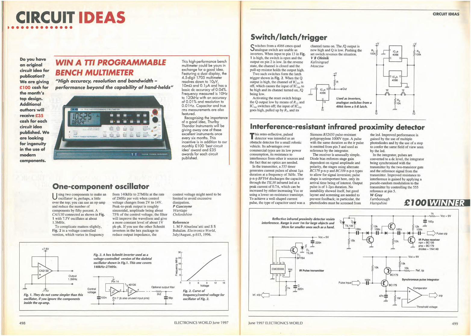
CIRCUIT IDEAS ••••••••••••••
WIN A 111 PROGRAMMABLE BENCH MULTIMETER
Do you have an original circuit idea for publication? We are giving £100 cash for the month's top design. Additional authors will receive £35 cash for each circuit idea published. We are looking for ingenuity in the use of modern components.
''High accuracy, resolution and bandwidth -performance beyond the capability of hand-helds"
This high-performance bench multimeter could be yours in exchange for a good idea. Featuring a dual display, the 4.5-digit 1705 multimeter resolves down to 1 0µV, 1 0mn and 0. 1 µA and hos a basic de accuracy of 0.04%. Frequency measured is 1 0Hz to 1 20kHz with an accuracy of 0.01 % and resolution to 0.01 Hz. Capacitor and true rms measurements are also featured.
+7.SV
lftL-f-~·~ • • • •· • ~ • · • • • • •
One-component oscillator U sing two components to make an
oscillator' is, perhaps, a little over the top; you can use an op-amp and reduce the number of components by fifty percent. A CA3 l 30 connected as shown in Fig. 1 with 7.5V oscillates at about 1.3MHz.
To complicate matters slightly, Fig. 2 is a voltage-controlled version, which varies in frequency
from 140kHz to 27MHz at the rate of 2MHz per volt when control voltage changes from 2V to 14V. Peak-to-peak output is roughly sinusoidal, amplitude being about 75% of the control voltage; the filter will improve the waveform and give a more constant level of about l V pk-pk. If you use the other Schmitt inverters in the hex package to reduce output impedance, the
Fig. 2. A hex Schmitt inverter used as a voltage-controlled version of the skeletal oscillator shown in Fig.1. This one covers 140lcHz-27MHz.
Output 1.3MHz
Recognising -the importance of a good idea, Thurlby Thandar Instruments will be giving away one of these excellent instruments once every six months. This incentive is in addition to our monthly £ 100 'best circuit idea' award and £35 awards for each circuit published.
control voltage might need to be limited to avoid excessive dissipation. PGascoyne Wantage Oxfordshire
Reference l. M F Abuelma' atti and S S Buhalim. Electronics World, July/August, p.615, 1996.
30
N 24 :c ~18 0 C
~ 12 C' (l)
.t 6
0 3 6 9 12 15
Optional output filter Voltage
-7 fiV
Fig. 1. They do not come simpler than this oscillator, if you ignore the components inside the op-amp.
498
I Fig. 2. Curve of frequency/control voltage for oscillator of Fig. 2.
ELECTRONICS WORLD June 1997
CIRCUIT IDEAS
Switch/latch/trigger
Switches from a 4066 cmos quad analogue switch are usable as
inverters. When input to pin 13 in Fig. 1 is high, the switch is open and the output on pin 2 is low. In the reverse state, the channel is closed and the pull-up resistor holds the output high.
Two such switches form the latch trigger shown in Fig. 2. When the Q output is high, the channel of IC,cb> is off, which causes the input ofIC,<aJ to be high and its channel turned on, IQ being low.
channel turns on. The /Q output is now high and Q is low. Pushing the set switch reverses the situation. VB 0/einik Kaliningrad Moscow
+V
A
1 I IC1a o 2 Out
4066
C Used as inverters,
+V
'A'
I IC1a 4066
C 0
0 IC1b C 4066
'S' -=- -=-
+V
Activating the reset switch brings the Q output low by means of R,.2 and IC,c,i switches off; the input of IC1<b> goes high, pulled up by R3, and its
13 analogue switches from a p k 4066 form a S-R latch.
In a IQ
Interference-resistant infrared proximity detector This retro-reflective, pulsed
detector was intended as an obstacle detector for a small robotic vehicle. Its advantages over commercial types are its low power consumption, its resistance to interference from other ir sources and the fact that no optics are needed.
Siemens B32650 pulse-resistant polypropylene lOOOV type. A pulse with the same duration as the ir pulse is emitted from pin 3 and used as reference by the integrator.
The receiver is unusually simple.
the led. Improved performance is gained by the use of multiple photodiodes and by the use of a stop to confer the same field of view seen by the led.
In the integrator, pulses are converted to a de level, the integrator being synchronised with the transmitter by the two-transistor gate and the reference signal from the transmitter. Improved resistance to interference is gained by applying a pseudo-random modulation to the transmitter by controlling the 555 reference at pin 5. WGray
In the transmitter, a 555 timer generates current pulses of about l µ s duration at a frequency of 3kHz. The p-n-p BFY64 discharges the capacitor through the TIL38 infrared led at a peak current of0.7 A, which can be increased by either increasing V cc or using a lower on-resistance transistpr. To achieve a well-shaped current pulse, the type of capacitor used was a
Diode bias enforces stage gain dependent on signal amplitude and polarity, the stages using alternate BCJ79 p-n-p and BCJ09 n-p-n types to allow for signal inversion; pulse shape is unimportant here, only its arrival time being of interest. Output pulse is of l -2µs duration. No instability showed itself, but good layout and screening are needed to prevent feedback; in particular, the photodiodes must be screened from ~:~~~~~!h £ 100 l~'J/~I~/~:
Reflective infrared proximity detector resists interference. Range is over 1 m for large objects and
30cm for smaller ones such as a hand.
------------Vee= 9V
"T' 220n ,; ,.;,,
Tr1 r----BFY64
D1 TIL38
IR Pulse transmitter
let. o/p<:=J-----
C 1k ,I22on
June 1997 ELECTRONICS WORLD
1k ~-----+-----------+---+--".NVv-- Vee= 9V
"T' 100µ
12k ,.J,, 100n
-+----+---11--+-----• 1---1o111f-+--1 J-- c) Pulse o/p
IR Pulse receiver npn = BC109 pnp = BC179 diodes= 1N4148
---+-------~-Vee= 9V
10k
10k
r-'\. 100n Pulse input L...,/ --l---+-11
Synchronous pulse Integrator
1M c)o/p
'----- Threshold voltage
499
CIRCUIT IDEAS
Infinite-impedance detector
Fig.1. The infinite
I nfinite-impedance rf detectors have been with us for almost 60 years', the
first consisting simply of a cathodefollower with a high-value cathode resistor and a cathode capacitor, the charge on the capacitor tending to cut the triode off on negative-going excursions of the rf input. But it was in 1959 that Telefunken patented the transistor version2•
Figure 1 is a useful example of the circuit. Transistor Tr, is the detector,
18k
470n
impedance Y;n(O:--.-+I
detector resurrected - in
this case with an adjustment
to eliminate output offset.
20k
Mute ,,__ ____ .._ __
(To VPF to unmute)
~WINNER
Ct 680n
lnputo---1-----"1
Varying one resistor changes
the output impedance of this transconductance
amplifier from near zero to an
upper limit depending on
amplifier performance.
500
VNF-40V
i;~;µ 1Cs + ~100n
taking the rf input from a 50Q line. Capacitor C, charges up to nearly the positive peak of the input, C, discharging between the peaks at / 8I/C, volts/s, which is made sufficiently slow to maintain most of the charge between rf peaks but speedy enough to follow the modulation. The effect is to produce a de offset to the base-band output, which is compensated by Tr2 at the input to the op-amp buffer, the
+15V
amount of offset being adjusted by the 20kn pot to give zero output level when rf input is at -zero. TH O'Dell London W2
References J. Weeden W N. New detector circuit , Wireless World, vol.40, 1937. 2. Meyer-Brotz G. West German Patent No. 1011481, 1959.
470n
Fig.2. Performance of the circuit between 100kHz and 50MHz. Offset from the ideal, shown dotted, is about one-tenth of that from a good Schottky detector and the input impedance is much higher at 20kil.
::,:6'--+---;---oVout
V001 (DC)
mV 150 /
/ /
/ 100 /
/ 470n /
/
50 /
/
0 100 150 200 mV
- 15V Vin (pk)
Audio power amplifier with widely adiustable output impedance
This transconductance amplifier was meant to drive a sub-woofer
loudspeaker, damping to be applied by velocity feedback. High output impedance was therefore needed. It is theoretically possible to vary the impedance from zero to infinity by
Rx
R8 R9 1RO 1RO
so varying R., although amplifier loop gain imposes restraints. Apan from audio use, the circuit should find application in industrial applications.
Resistor R8,9 in parallel define transconductance, these resistors being specified to avoid gain variation with temperature. The TDA7294 typically gives 70W into 40 or 8Q if heat-sinked adequately, although any available power amplifier should serve. These amplifiers need a minimum closedloop gain for stability; in this case, 24dB. This figure cannot always be guaranteed with current drive and at high frequencies, which is the reason for the inclusion of C9 to provide hf feedback. Paul Mills Airdrie Lanarkshire
ELECTRONICS WORLD June 1997
THE ORIGINAL SURPLUS WONDERLAND! Surplus always wanted for cash! THIS MONTH'S SELECTION FROM OUR VAST EVER CHANGING STOCKS
40Mb HO + 3Mb Ram
LIMITED QUANTITY only of these 12Mhz HI GRADE 286 'systems Made in the USA to an industrial specification, the system was designed tor total reliability. The compact case houses !he mother• board, PSU and EGA video card w~h single 5¼" 1.2 Mb floppy disk drive & Integral 40Mb hard disk drive 10 !he front. Real time clock wilh battery bacl<up is provided as standard. Supplied in good used condilion complete with enhanced keyboard, 640k + 2Mb RAM, DOS 4.01 and 90 DAY Full Guarantee. Ready to Run I OrderasHIGRAOE286 OHL y £f29. 00 e Optional Fitted extras: VGA graphics card 1.4Mb 3½' floppy disk drive (instead of 1 .2 Mb) Wordperlect 6.0 for Dos • when 3½" FOO option ordere<I NE2000 Ethernet (thick, thin or twiste<I) network card
LOW COST 486DX-33 SYSTEM Limi ted quantity of this 2nd user, supurb small size desktop unit. Fully feature<! with standard simm connectors 30 & 72 pin. Suppfied with keyboard, 4 Mb of RAM, SVGA monitor output, 256k cache and 1ntegraf 120 Mb IDE drive wil.h single 1.44 Mb 3.5" floppy disk drive. Fully tested and guaranteed. Fully expandable Only Many other options avalab/e • cs/I for cletalls. £399.00 (E)
FLOPPY DISK DRIVES 3½" - 8 " 5¼" or 3½" from only £18.95 !
Massive purchases of standard 5!/4• and 3½• drives enables us to present prime product at industry beating low prices! All units (unless slated) are BRAND NEW or remove<! from often brand new equip. ment and are fully tested, aligned and shipped to you with a 90 day guarantee and operate from standard voltages and are of standard size. All are IBM-PC compatible (if 3Y:,' supporte<I on your PC). 3½' Panasonic JU363/4 720K or equivalenl RFE £24.95(6 3½" Mitsubishi MF355C·L. 1.4 Meg. Laptops ooly £25.95(6 3½" Mitsubishi MF355C·D. 1.4 Meg. Noo laptop £18.95(6 5¼" Teac FO-55GFR 1.2 Meg (for IBM pc's) RFE £18.95(6 5¼ • Teac FD·55F-03-U 720K 40/80 (for BBC's etc) RFE £29.95 B 5¼" BRAND NEW Mitsubishi MF501 B 360K £22.95 8 Table top case with integral PSU for HH 5¼" Flopp or HO £29.95 B 8" Shugart 800/801 8' SS refurbished & tested £195.00 E 8" Shugart 810 a• SS HH Brand New £195.00 E 8" Shugart 851 a· double sided relutblsned & tested £250.00 E Mitsubishi M2894-63 8" double sided NEW £275.00 E Mitsubishi M2896-63--02U 8" OS slimline NEW £285.00 El Dual a• cased drives with integral power suppl 2 Mb £499.00(E .. ,, ,. End of line purchase scoopl Brand new NEC 02246 8' 85 Mbyte drive with Industry standard SMO Interface, replaces Fujitsu equivalent model. Full manual. Only £299.00 or 2 for £525.00 (E)
3Y:t' FUJI FK-309·26 20mb MFM 1/F RFE £59.95 C 3½' CONNER CP3024 20 mb IDE 1/F (or equiv )RFE £59.95 C 3½' CONNER CP3044 40mb IDE I/F (or equiv.)RFE £69.00 C 3½' RODIME RO3057S 45mb SCSI 1/F (Mac & Acorn) £69.00 C 3½" WESTERN DIGITAL 850mb IOE I/F Brsnd New £185.00 C 514' MINISCRIBE 3425 20mb MFM 1/F (or equiv.) RFE £49.95 C 5¼' SEAGATE ST-238R 30 mb ALL Ill' Refurb £69.95!C 514' CDC 94205·51 40mb HH MFM 1/F RFE teste<I £69.95 C 5¼' HP 9754B 850 Mb SCSI RFE tested £89.00 C 5¼' HP C3010 2 Gbyte SCSI different/a/ RFE teste<I £195.00 C 8' FUJITSU M2322K 160Mb SMD I/F RFE teste<I £195.00 E) Hard disc controllers for MFM, IOE, SCSI, All etc. from £16.95
THE AMAZING TELEBOX Converts your colour monitor Into a QUAUTY COLOUR TVtt
TV SOUND & VIDEO TUNER CABLE COMPATIBLE'
The TELEBOX is an atlractive fully cased mains powere<I untt, containing all electronics ready to plug into a host of video monitors made by makers such as MICROVITEC, ATARI, SANYO, SONY, COMMODORE, PHILIPS, TATUNG, AMSTRAO etc. The composite video output will also plug directly into most video recorders, allowing receplion of TV channels not normally receivable on most televlslon receivers• (TELEBOX MB). Push button controls on the front panel allow reception of 8 fully tuneable 'off air' UHF colour television channels. TELEBOX MB covers virtually all television frequencies VHF and UHF including the HVPERBANO as us~d by most cable TV operators. A composite video output is located on the rear panel for direct connection to most makes of monttor or desktop computer video systems. For complete compatibility - even tor monitors wtthout sound • an integral 4 wau audio amptif;er and tow level Hi Fi audio output are provided as standard. TELEBOX ST for composite video input type monitors £36.95 TELEBOX STL as ST bu, fttted with integral speaker £39.50 TELEBOX MB Muttiband VHF/UHF/Cable/Hyperband tuner £69.95 For overseas PAL versioos state 5.5 or 6 mHz sound specifical ion. ·For cable/ hyperband reception Telebox MB should be connected 10 a cable type service. Shipping code on all Teleboxe's is (B)
DC POWER SUPPLIES Virtually every tr,pe of power supply you can m ag lne.Over
10,000 Power Supp/Jes Ex Stock Call for Info I list.
/C's -TRANSISTORS - DIODES OBSOLETE - SHORT SUPPLY • BULK-
6 ,,000, 000 items EX STOCK Fot MAJOR SAVINGS· CALL FOR SEMICONDUCTOR HOn JST
VIDEO MONITOR SPECIALS
19" RACK CABINETS Superb quality 6 foot 40U
Virtually New, Ultra Smart Less than Half Price/
Top quality 19' rack cabinets made in UK by Optima Enclosures Ltd. Units feature
0 f th h · h t 'f' t• designer. smoked acrylic lockable front door ne O e 19 eS SpeCI !Ca 100 full height lockable half louvered back door • monitors YOU Will ever See • • and louvered removable side panels. Fully
;... At th'1s pr·1ce • Don't m·,ss ,·ti. '· ;... adjustable internal fixing struts, ready punched for any configuration of equipment mounting
Mitsubishi FA3415ETKL 14" SVGA" .. ltl colou · .. ~ ~- plus ready mounted inte~ral 12 way 13 amp mu sync r monilOr """ '"" socket switched mains distribution strip make
028 dot p!ch tube and resolutioo of 1024 x 768. A these racks some of the most versatlle we vafiely of q,uts aJows correction to a host of 0011llO~ h · c hg IBM PC's it CGA. EGA. VGA & fNGA av~ evar sold. Racks may be stacl<e<I side by side and therefore
BSC, COMMODORE fnciJdng Amiga 1200), ~:;~ri ~~e~1o~~~~~~~~\O J~~gJ(ng\ ~~n :.u~~~e~/;,· EDES and APPLE. Many features: Elcred
. faceplate, tell! switching and LOW RADIATION MPR OPT Rack 1 Complete with removable side panels. £335.00 (G) specif,cation. Fully guaranteed, supplied in EXCEL· OPT Rack 2 Rack, Less side panels £225.00 (G)
LENT lttle used oondition. Order as I I TI1t&SWtve1ease £4.75 Only £119 (EJ Mrrs..svGA 32U - High Quality• All steel RakCab VGA cable for IBM PC Included. . . Extsmal ....,_for othet"-.., --CALL Made by Eurocraft Enclosures Ltd to the highest possible spec .----;.;.. ____ ., __ ,..,...;;..;."'.;-;.;.;.;.' ;:;.;..,...-;;.;.;•.;.;.;;;; ______ rack features a ll steel construction with removable '
As NBW - Used on film sBt for 1 week only/I side, froot and back doors. Front and back doors are 15• 0.28 SVGA 1024 x 768 res. colour monitor·~. hinged for easy access and all are lockable with
~ live secure 5 lever barrel locks. The front door Swivel & tilt lite. Fu/190 day guarantee. £145.00 (E) Is constructed of double walled steel with a
'designer style' smoked acryl ic front panel to Just In • Mlcrovltec 20" VGA (800 x 600 res.) colour monttors. enable status Indicators to be seen through the
Good SH condition • f rom £299 . CALL for Info panel, yet remain unobtrusive. Internally the rack PHILIPS HCS35 (same style as CMa833) allraclively styled 14• features fully slotted reinforced vertical fixing
1 R members to tak e the heaviest of 19" rack co our monilor with lllllll GB and standard composite 15.625 equipment. The two movable vertical fixing struts Khz video Inputs via SCART socket and separate phono jacks. Integral audio power amp and speaker tor all audio visual uses. /extras available) are pre punched tor standard Will connect direct to Amiga and Atari BBC computers. Ideal tor all cage nuts'. A mains distribution panel internalvideo monitoring / security applications with direct connection ly mounted to the boltom rear, provides 8 x IEC 3 to most colour cameras. High Quality with many features such as pin Euro sockets and 1 x 13 amp 3 pin switched front concealed flap controls, VCR correction buuon etc. Good utility socket. Overall venlilation is provided use<! condition - fully tested. guaranteed Only £gs lu_lly louvere<I back door and double skinned tops o·mensi Wt4' H12¾' 15" ' 0 wijh top and side louvres. The top panel may be remove<! tor filling 1 ens: x x r, · (E) of Integral fans to the sub plate etc. Other features include: filled PHILIPS HCS31 Ultra compact 9" colour video mooitor with stan- castors and floor levelers, prepunche<I ulility panel at lower rear tor dard composite 15.625 Khz video input via SCART socket. Ideal cable / connector access etc. Supplied In excellent, slightly used tor all monitoring/ securlly applications. High quamy, ex-equipment condition with keys. Colour Royal blue. External d imensions fully tested & guaranteed (possible minor screen burns). tn attrac- mm~1625H x 6350 x 603 W. ( 64" H x 25" D x 23¾" W) tive square black plastic case measuring W10' x Hto· x 13½' D. Sold at LESS than a third of makers price II 240VACmainspowered. Only£79.OO (D) £195 OO KME 10" t5M10009 high delinttion colour monitors with 0.28' dot A superb buy at only • (G) pitch. Superb clarity and modern styling . Operates from any 15.625 khz sync RGB video source, with RGB analog and composite sync such as Alari, Commodore Amiga, Acorn Archimedes & BBC. Measures only 13½. x 12· x 11'. Good used conditioo. Only £125 (E)
20" 22" and 26" AV SPECIALS Superbly made UK manufacture. PIL all solid stale colour monitors, comptele with composite video & options/ sound Input. Altractive teak style case. Perteet for Schools, Shops, Disco. Clubs, etc.In EXCELLENT linle used condition wtth lull 90 day guarantee.
?0" .... £135 22" .... £155 26" .... £185 (F)
MITS. FA3445ETKL 14" Industrial spec SVGA monitors £245 2kWlo400kW • 400Hz3phaliep0'Mll'scua!8•exstock £POA IBM 8230 Type 1, Token ring base untt driver £950 IBM 53F5501 Token Ring res 20 por1 lobe modules £750 IBM MAU Token rin9 distribution panel 8228-23-SOSON £95 AIM 501 Low distort,on Oscillator 9Hz to 330Khz, IEEE £550 Trend DSA 274 Data Analvser with G703(2M) 64 Vo £POA Marconi 6310 Programmable 2 lo 22 GHz sweep generator £6500 HP1650B Logic Analyser £3750 HP3781A Pattern generator & HP3782A Error Detector £POA HP APOLLO RX700 system un~s £950 HP6621A Dual Programmable GPIB PSU 0-7 V 160 walls £1800 HP3081A lndustrila workstation c\w Barcode swipe reader £175 HP6264 Rack mount variable 0·20V @ 20A metered PSU £675 HP54121A DC to 22 GHz four channel lest sel £POA HP7580A A1 8 pen HPGL high spee<ldrum plotter £1650 EG+G Brookdeal 95035C Precision lock in amp £650 View Eng. Mod 1200 computerised inspection system £POA Ling Dynamics 2kW programmable vibration test system £POA Computer controlled 1056 x 560 mm XV table & controller £1425 Keithley 590 CV capacitor / voltage analyser £POA Racal tCR40 dual 40 channel voice recorder system £3750 Flskers 45KVA 3 ph On line UPS· New balls Dec. 1995 £9500 ICI R5030UV34 Cleanline ultrasonic cleaning system £POA Mann Tally MT645 High speed line printer £2200 Intel SBC 486/133SE Multibus 486 system. 8Mb Ram £1200 Zeta 3220-05 AO 4 pen HPGL last drum plouers £1150 Nikon HFX-11 (Ephiphot) exposure control unit £1450 Motorola VME Bus Boards & Components List. SAE / CALL £POA Trio 0-18 vdc linear. melere<I 30 amp bench PSU. New £550 Fujitsu M3041 R 600 LPM band printer £1950 Fu lt su M3041 D 600 LPM printer wtth netwol1< interlace £1250 Perkin Elmer 2998 Infrared spectrophotometer £POA VG Elec1ronlcs 1035 TELETEXT Decoding Margin Meler £3750 Andlewa LARGE 3.1 m Satelltte Dish + mount (For Voya9e~) £950 Sekonlc SO 150H 18 channel digttal Hybrid chM recorder £1995 TAYLOR HOBSON Tallysurl amplif,er /recorder £750 System Video 1152 PAL waveform monitor £485 Teal Lab • 2 mu square quielised acoustic test cabinets £300
K•rw,::::~;1r f;r ~~~h~~o~~;ti);~n the above itemr.:50
Over 1000 racks• 19" 22" & 24" wide 3 to 44 U high. Available from stock !!
Call with your requirements.
TOUCH SCREEN SYSTEM The ultimate in 'Touch Screen Technology' made by the experts -Micro Touch• but sold at a price below cost II System consists of a flat translucent glass laminate<! panel measuring 29.5 x 23.5 cm connected to an electrooic controller PCB. The controller produces a standard seflal RS232 or TTL output Which continuously gives simple senal data containing positional X & V co-ordinates as to ~ere a finger is touching the panel ~ as the finger moves, the data instantly changes. The X & V information is given at an Incredible matrix resolution of 1024 x 1024 positions over the entire screen size II A host of available translation software enables direct con• neclion_ to a PC for a myriad of applications including: cootrol pan· els, poInling devices, POS systems. controllers for the disabled or computer un-trained etc etc. lmaQlne us ing your finger with 'Windows', instead of a mouse!! (a dnver is indeed available !) Ths appllcatlons for this amazing product are only 1/mlted by your Jmsglnation/1 Complete system including Controller. Power Supply and Data supplie<I at an incredible price ol ooly: £145 OO Full M/CROTOUCH solrwa.-. ,uppo,t pllek • (B) •nd manuals for IBM compall~ PC'• £29.95 RFE ~ THt9d
LOW COST RAM & CPU'S INTEL 'ABOVE' Memory Expansion Board. Full length PC•XT and PC-AT compatible card with 2 Mbytes of memory on board. Card is fully selectable for Expanded or Extended (286 processor and above) memory. Full data and driver disks SUl)l)lled. RFE. Fully tested and guarantee<!. Windows compatible. £59.95(A1) Half length 8 bit memory upgrade cards tor PC AT XT expands memory either 256k or 512k in 64k steps. May also be use<! to fill in RAM above 640k DOS limit. Complete with data. Order as: XT RAM UG. 256k. £34.95 or 512k £39.95 (A 1)
filMM SPECIALS · 1 MB x 9 SIMM 9 chip 120ns Only £16.50 !A1J 1 MB i<9 SIMM 3chip80ns £19.50 or 70ns £22.95 A1 1 MB x 9 SIMM 9 chip 80 ns £21.50 or 70ns £23.75 Al 4 MB 70 ns 72 pin SIMM ·with psrity- Only £95.00 At IHfEL 48&-0X33 CPU £55.00 IHfEL 486-OX66 CPU £69.00 At RJLL RANGE OF ~OCESSOR'S EX STOCK· CALL FOR£££
FANS & BLOWERS EPSONOO412 40x40x20mm 12voc -£7.95 10 / £65 PAPST TYPE 612 60x60x25 mm 12v DC £8.95 10/ £75 MITSUBISHI MMf.O6012.0 L60x60x25 mm 12v DC £4.9510 / £42 MITSUBISHI MMF-08C12DM 80x80x25 mm 12V oc £5.25 10 / £49 MITSUBISHI MMF-09B120H 92x92x25 mm 12v DC £5.95 10 / £53 PANCAKE 12-3.5 92x92x18 mm 12v DC £7.95 10 / £69 EX-EQUIP AC fans. ALL TESTED 120 x 120 x 38 mm spec~y 110 or 240 v £6.95. 80 x 80 x 38 mm. specify 110 or 240 v £5.95 IMHOF B261900 rack mnt 3U x 19• Blower 1101240V NEW £79.95 Shipping on all fans (A). Blowers (B). 50,000 Fans Ex Stock CALL
Issue 13 of 'Dispfay 'J.[f.ws now available - send large SAE - PACKED with bargalnsl .... • . .. •••• • . .. . : : . . . . • . . . . . . .. . . • . • • . . . ... .... : ••••• ••• . . . . . • • • . • • • • • . • . : NH • ••• • ..... . •
ALL MAIL & OFFICES LONDON SHOP ~DISTEL© ALL U ENQUIRIES Open Mon-Fri 9.00-5:30
Oplr 5i°h'!iei~i:~~r,i3o TheOri lnal 0181 679 4414 Dept WW. 32 Blggln Way South Norwood On line ~atabase
Upper Norwood On 68A Sua Aoute Info on 20,000 + stock Items! N". Thornton Heath &
-ELE[Tk'D/Y/[5-LONDON SE19 3XF RETURNING SOON I FAX 0181 679 1927 Selhurat Park SR Rall StaUons
Al J"""'!:" for UK Mainland. UK OJSlome,s add 17.5% VAT to TOTAL order aroount Molimrn order £10. Bena F(le aCCOt..'ll orders 8<X:l!p!ed from GovelMlertt, Schools,
:me [i] Universaies and Local Autholties • mr,inum acoou,t order £50. ChEQ,es 0llef £100 are subject to 10 WOl1<ng days ciearana:. Gamage charges (A)~£3.oo. (A1)=£4.00,
2••5r (8)=£5.50, (C)=£ll.50, (D)=£12.00, (E)=£15.00, (F)=£18.00, (G).CAI.L MDN awrox 6 days tor shippr,g • laster CALL Soo!land surmarge CALL Al goods st.Wied lo our
Standard Condlions of Sale and Lnless Slated guaranteed for 90 days. Al ~-on a retum lo base basis. Al rig1ts r8S8M!d to chanae prices/ specifcations ..ihout prior v,,.,., notice. Orde<s subjecltoslock. Oisoounlslor volcme. Top CASH prices paid for surplus goods. Altrademalksetc ad<nowledged.©OispiayF:iedroni::s 1996. E& OE. 00'6
( IR( I f N O I I I ON 1/EPL I ( ,\ //{)
;1
II
CIRCUIT IDEAS
Two-wire remote control
Two wires control eight outputs, in this case to a dot/bar driver.
The LM3915 supplies constant current to the switch/resistor chain at the remote end of the wires. Selecting one of the resistors by
Eight outputs from the LM3915 bar driver are controllable remotely by the switches.
A1 180A
means of a switch applies the voltage dropped across it to one of the driver outputs, the log. scale of the driver allowing fairly wide resistor tolerance. Since, according to the data sheet, LM39 l 5s may be
1mA
Tr1 ZTX500
7 RFO LO1 1
cascaded, the number of remote resistors can be increased to suit other purposes. Alex Birkett London SE22
A10 13k
LD2i-:1.:.:.8--4-+-+-+-i--i--!-+---/Sw5
----+--"le RFA IC1 LD3 17
/Sw7
Ag 10k
LM3915 LD4 16 /Sws 6 RLH Dot/Bar LD5 15 /Sws
Driver LOS 14 /Sw4 ----+--------'<4 ALO LD7 13 /Sw3
LOS 12 /Sw2 '----+----4>-------+-----+--~1----+-t-{ -~t--+-~-----",5 SIN LO9 11 /Sw1
LD10 lO
Offset source for op-amps
A separate source of offset voltage for a number of op-amps avoids the need to use the offset adjustment on some op
arnps, which is intended for the op-amp's internal offset, not that from other parts of a system. Further, such procedures can adversely affect other characteristics such as offset drift and, in some cases where the gain from the offset terminals is high, cause trouble with noise pickup from inevitably longish connections to the adjustment pot. This one provides a stable source of offset voltage, independent of the power supply.
A band-gap reference, well decoupled, provides up to 5V, which is divided to reduce the effect of the LM61 I offset and allow the 611 output to be only loosely coupled to the rest of the system by a largish resistor.
Since gain from the 611 non-inverting input is +2 and that from the inverting input - 1, varying the potentiometer end to end varies the output between -5V and +5V. The two !Mn resistors ensure that, in the event of the wiper being opencircuit, the 611 output becomes zero rather than swinging to a supply rail.
Care with wiring is needed, particularly for ground connections.
39k
120k
V-MODE 9
Vee
10k
68k
+ 1M 110µ
10k
1M
470n polyester
Vee Universal
Offset (10-15V)
Source 68k
VEE 9k1 (- 10V to - 1 SV)
1k8 System (eg.Power amp)
Phil Denniss University of Sydney NSW
Offset-voltage source corrects for offsets __ +--1
caused by outside influences in a system
Australia
502
using a number of op-amps, rather than those 200A
internal to op-amps.
ELECTRONICS WORLD June 1997
ANTRIM TRANSFORMERS LTD TOROIDAL TRANSFO~
Large standard range from 15V A to l kV A approved to EN60742 & A~3108
Custom designs to most international standards from I0VA to 3kVA
Rapid quotation, design and prototype service Any size production nm catered for
All transfonners manufactured at UK factory allowing fast lead times at no extra cost
~ 70V / 100V Line, valve output & low noise audio designs available
~Medical designs to IEC601/BS5724 & UL544
AGENTS / Dmmlumu R~IDID WOBlfflfiiE Technical Sales Department, 30 Bramley Avenue
Canterbury, Kent, CTI 3XW, England
Tel: +44 (0)1227 450810 Fax: +44 (0)1227 764609
llunsn MADE & BmT n Lur ( /RC.LE /\'O. I U 01\ Rf Pl} <.ARIJ
\'IE HIVE !HE mom CHOICE OF USED OICILLOICOPEI IN lH[ COUNTRY
U .alte,-..OKailh~M•VMz ,,.. U .afflCS-,Olctiitlli22ZIUMAGMrc__--~II •• SMSl,aSil:CO.l.l•,_... tt1SI ... 101,~.-,\15lcC..IOl',kz-llMCllv'- .• -~,H•'1111 --M IWFIIS,c:Gtllllflll•IGMf ____ ~ 1• ---.Z.IM~Mmf-'-IIIMr•SZOllta'- ,,- -·--''• U .IMMAMIISIC:C..SOOl!Ht-102•11111----~1'1, 11. ISNC~l"x--lllilffMt... OIi fllEI.SSGS20~~SilCttll>-~ ,_
==,!;;~'f~--- -=--=--=-====::::= ::-M1:~.:r= ~~2.:'::.-:.-:.-:_-:_-:_-_-_-_-~~;_•~ U.1614.t.llWSt(ul C:..•eo»cr-tM"Jb CM --Tf1J31A~r'ICW11111111t1t1o-2DQl!t.~~UR..- ____ ms ... 1ffl38Mdll,,_llfllllltSiN41------"" 1uvw.1111se...-lf'Sf2.-ft'K40tlr-l0011v ... H-••"--...... ,1• ftffllMIOl\.,_,_..MtS-,Grll l•2Qlt----.... 11. U .Wil~ll'l'elC..IDlll-?llft ta U .116Cll"""-*""fllbt"'-SOllcl 1151 --230SIIIIIMlt...._, ,_.,Ml:Ws..ttfll11C..O.OOUQ-20llltr~lifk- , .... ,-.. U. 11.SOMS.,t.reM..,_ _______ _,,,.
U.S004,A,Sipa,t•MUJW•------~ 1• U . .f4'51~DC-IGCl:U'OdllllOIIIIJIS,1 OM U.J:SfllAWM~ISICl-50NMIUOA~ -U.Mw.YtcWVtll.....,1-IOC!Clftflta U.lll1Al'r1wr1.,..W.!alNZ,.._GIMrtle, ____ _,,. NliPS ntSIMS-tf.._'-..O.o:IOl llllr-2Qlatl:Siw$4fTMl!w..., .... UN UUl~r.:c..,o,111t-1:at2.-RIISl•~'hic/Clll* ,-""··-···UII U.M'4MwltllM-..MMuaMlo,tOOUll'Nllftl713A _ ___ ,_,,.,.Jlnl .llltmudll'&lldl 0...
====~============~::: ==~~s---Z:c=======_::;-"'...,..Ac.«*T-lliMIIIIM1 ...... 1t11115tl2---~
=~::::=::=========~; U.54J2.lc.ffltr?4Qblft_ _ _____ __.,,
I.I, "8c-lW1 IIMl-lGII:
... l4Ur1111-..IC!lv•M IU. ltMmi!I c-i., JJgCrCiftMipM.111.-d_ .. .,. ____ __.... utlt l"l u-.r,,I c.nt•n-- IMl!Mr9 d.ll .. --..... -: .... -11N .... 2m~c...rm..OC- I00111tzljp:., .. ___ , __ ..Jm 1111eaz01tr,....,.c..1a,....,41,.,._ __ ~,n IIIC,ll,t'tl6~C..-1Clttl~----~"' U.MlS.W..i,i. ........ ~l.£D IN
=-~~~r:.:---c:======::::= =1~~1:.~'-=:!!!c,.·-:-__ -_-_ -_-_ -_ -..;:_-m flm:DIGI\OlcitM .... ~-------~n.mlOSOt~-••t.ti&iltn-NS on =•1:.~~.:.dl~':r.nn'·'=',,.,.-b<-*---.. --~•• =~=":~~SIICL=._..,,-c-7,-.,-_-____ ---..lffl~III f-.U.lffl~~l~IJialr CM utlttoOIA111Mttlt-,IIMI.SMtct-1CM? -U.,W2SZ_._bt1Nllltltl.51111i•I-ZI"• CUI utlt'302 l iwNS~IDIDll-1~ tHI U.436A,_..,_.,lH411-...,..------ 1H1 U.SIIJIMmlllffSJSCTt,,tU-t'n-4 ,,_ -CP501,..~-------rwnsz ...... TwW nct IDIDw.tl'tl&MlfllllfVlfnO.lllt-lOllft~---~WIUUG:l.llS...-~'=---,,...,..-----'--TU!lal lU l'llcttrxtpt1ilDSZIAWMln._illr ______ ,_J 1• fll.ft556J~llitl~!i6.SWl'tltflfalilllit.- ,. 11,Yll'fl,Z-Scttte.air•"-------~ utll.'ID4U.,._IIIIWU11t,ICJl!rl..... Dtt ... m:1'0~1,i(Ct,""-Yo,,mtw- , .. ,_ .... , ....... 1111 _.11MIIZ•Olclt1C...,,....-Lc. ____ _,_ ~=~-::=:.~w-pe ____ _,= sa(IISIJDCfiOO-UIMOCINl:SHJMfl,~---~1•, U.'2.IIMl'Ml:0-30itr.r all rlllBl..WMOYals.0-SOA,,tpt._,u,_,_"""" «-r.t11Wflti6"25,M0\19111.:0-n ~ t.-------"• rMIW.tlOflDMYlib; IIMIJ,$..Ytri~----.. _JIii f,Wllll.Ul,5o.3D\lolts;O.SMlf'l,,.2._,.., , ... fMIIU.UOI D,.JO¥iftt:G-51mpJ......., ____ ~ 1• fillllllU0-20-3GVob;O-lAllt,.__. Pl fllllU. l.Do-10-JOM:tO-l - .f'Ma IM flllELU0-10-30Yob:0-1Mf.lllMM-----~TIIIIJ'f-TIIMIIJ'Sl'lm~)N:2,_TMC:tCN ..... ,_ntt naJTfU20fll)l)..)W:f-2AhbNe)9' cm _...IWll,m:+1-ll.Ytiillt....t'-------
IIIIIITITW:l,_......UfflA.IA[
SPECTRUM ANALYSERS
UMCI ac&ul-1- QUAIIANftlD) . ......... aupplled If_. ..... . This is a VERY $MAU SAMPU: Of STOCK. SA£ or Telephone for lists. Please check a,ailability before ordering.
CARRIAGE all un~s £16. VATto be added to fo(al of Goods and Carnage.
STEWART of READING - 110 WYKEHAM ROAD, READING, BERKS. RG6 IPL ~ ~ Telephone: (0118) 9268041. Fax: (0118) 9351696 i.-
c,11.,, W.loome 9am-5,30pm Monday to Friday (other times by anangement)
C II(( I £ ',O. 1 11 () \ Rf /'/ l ( ,\R/J
June 1997 ELECTRONICS WORLD
One stop solutions for all your radio
telemetry module needs. When the success of your products depends on radio telemetry modules, you need a business partner you can trust. A skilled and experienced manufacture r that can offer modules of the highest quality, operating over a wide range of frequencies.
In other words, a partner like Wood & Douglas. Founded on technical excellence, Wood & Douglas is a British company that specialises in the design, development and production of radio-based products. With over 30 staff dedicated to meeting your requirements, the company is able to provide true one-stop purchasing - whatever your ATM needs .
All radio modules a re highly functional, capable of meeting a wide range of requirements. Designed to offer efficient, easy-to-use radio telemetry components for system designers, they can open up a ~ whole new world of product possibilities. ~
From portable bar-code readers to earthquake monitors, Wood & Douglas can help you make the most of the opportunities in radio telemetry.
To find out more about the possib ilities, contact...
Lattice House, Baughurst, Tadley, Hampshire RG26 5LP, England Telephone: 0118 981 1444 Fax: 0118 981 1567
email: [email protected] web site: http://www.woodanddouglas.co.uk
( I I/( I l fl:() I 1./ 01\ //[/'/) C ,\ /l//
503

I.., v-~ I.-,;
C
C L-In ~ 0
I 0 Ill I.., v-~ I.-,;
L.:.2.
C L-In ~ 0 0 II I.., v-~ i,_,..,
L.:.:..
C L-In ~ 0 0 Ill
SPREADSHEET ANALYSIS
FOR ENGINEERS AND SCIENTISTS
I ,I t, i ·,J.,,J I
S. C i'>loch
Iii J'• l,;I,
Spreadsheet Analysis for Engineers and Scientists With this practical, hands-on guide, engineers and researchers learn, quickly and easily, the latest and most useful electronic spreadsheet methods. Using a variety of interactive techniques, including worksheets, self-test and practical programs on the included disk, Spreadsheet Analysis for Engineers and Scientists show you how to harness the power and versatility of spreadsheet programs, including those that contain the fast Fourier transform, complex operations and Bessel functions, and how to customise your own applications. Includes disk 0471126837,336pp UK £37.50, Europe £39.50, ROW £49.50
Electronic Component Reliability Fundamentals, Modelling, Evaluation and Assurance This text approaches the quality and reliability of electronic components from a unique standpoint. Traditionally the twin subjects of reliability physics and reliability statistics have been treated as seperote entities. Here, the author examines both areas and reveals how components foil and how. fai lures develop over a period of time. 0471 952966, 374pp UK £50.50, Europe £53.50, ROW £66.50
111 ( 1 /U l\/< ( I )\/1'( )\/ \ I I" 11 \l;//1 / 'i
li1111)<·11.,,·11
f. W!l[Y
Fuzzy Logic Implementations and Applications Offering a new perspective on a growing field, this text explores the many hardware implications of fuzzy logic based circuits. As use of Al increases, so the VLSI area of circuits is becoming o growth subject. Opening with on overview of fuzzy sets and fuzzy logic the book moves on to cover a range of nonstandard solutions for fuzzy logic VLSI circuits. Future trends, new concepts and ideas are all examined and supported with practical examples from the author's research. ISBN 0471 950599, opprox 346pp, UK £50.50, Europe £53.50, ROW £66.50
Microelectronic Switched-Capacitor Filters Switched-capacitor filters and osscoioted MOS integrated circuits ore now on established technology finding applications in the telecommunications and instrumentation fields. With unrivalled breadth of coverage, this book surveys the design techniques of an important doss of analogue signal processing systems. An accompanying diskette containing a comprehensive computer-aided design package (ISICAP) enables readers to gain a greater depth of understanding of the described techniques. Containing both source code
II •. Mlrll'!l.E!Etf1,0N IC I ·swlTCHED~ PACITOR I . • I
FILTERS
files and an executable version of the main design package, this alone will be on indispensable tool for many circuit designers. Includes disk 0471 954047 384pp UK £75.50, Ewope £79.00, ROW £92.00
The 12C Bus From theory to Practice With a special emphasis on the l 2C Bus, this guidebook through the world of micro controller-managed serial buses presents comprehensive coverage of the theory necessary to design the best possible communications bus for any particular application. The book examines typical industrial and consumer applications and enables the reader to design effectively in a rel-world environment. A disk containing software for the 12c bus is also included. Includes disk 0471 96268 6, 314pp UK £54.50, Europe £56.SO, ROW £6S.OO
High Frequency Analog Integrated Circuits As one of the first textbooks to discuss integrated circuit design considerations and
actual designs from the basic concepts, this title provides a solid background in designing basic circuits, advanced circuits and synthesis techniques. 0471 530433 424pp UK £80.00, Europe £83.00, ROW £9S.OO
Speech Coding A Computing Loboratoty Textbook This is one of the first lab manuals with software dedicated exclusively to speech processing and coding. It takes advantage of the development of the personal computer by making this technology accessible to a wider audience The manual and Dos based software together create a user-friendly digital signal processing lab which allows the user to
perform a wide variety of speech coding and speech processing experiments. The text presents and explains a set of basic speech coders analytically and in terms of the specific parameters controlling each coder. The manual leads the student through the experimental process of understanding how speech coders work and sound via over 70 exercises and projects. The class-tested menu-driven, Dos-based software can be operated by students with little or no training. Includes disks 0471 516929, 194pp, UK £28.95, Europe £30.9S, ROW £36.95
Solar Cells and their Applications The past decade has witnessed numerous important breakthroughs in solar cell technology, many of which have occurred in just the past few years. Far cheaper to produce and maintain, exhibiting a longer lifetime, and considerably more efficient than ever before, solar cells are, at last, in a position to compete with traditional technologies for both small and large-scale energy conversion applications. Including contributions from some of the world's leading experts in the field, this book reports the most important recent advances in solar cell technology. From in-depth discussions of breakthroughs in cell, module, and system technologies to a probing look at important environmental, health, and ssfety issues in the photovoltaic industry, it covers a broad range of topics of vital interest to solar cell researches, power systems designers, and all those with professional interest in current and future capabilities of this important technology. Offers a detailed look at cutting-edge solar technology from an international team
of researchers. Covers silicon, GoAs, lnP, CdTe, a-Si:H, CulnSe29 and GaSb solar cells, cells, concentrators, multijunction cell configurations, space cells, and more. Describes a w ide range of applications - from space cells to terrestrial systems Provides an informal look ahead at the future of solar cell technology. 0471 574201 , 596pp, UK £71.SO, Europe £7S.OO, ROW £92.00
Introduction to High .. Speed Electronics and Optoelectronics Lasers, fibre optics, and highspeed optical systems shore many concepts with microwave devices. Furthermore, semiconductor• based optoelectronics and microwave integrated circuits share evolving process technologies. It is only natural, therfore, that students of optoelectronics be introduced to high-speed concepts in a unified manner. This highly practical intensive introduction enables electrical engineers, applied physicists, and students to develop and identify tools for understanding, analysis, design, and characterisation of high speed components. Broad in scope, this unique
hl!P' 1NrnoournoN ro 1111 i lllGH-WffD
Hf CIRONIC~ AND OPTOHtCTRONI(~
I · ....... ,. · :· ::.::".:::.:·.:·" ... , .... ·· I ~ - ' ~
text/reference examines the complementary nature of electronics and optics and emphasizes high-speed technology in which the two fields a re less differentiated. Beginning with on overview that develops a perspective and appreciation of analog high-speed technology in general, the book goes on to cover devices and circuits used at microwave and millimeter-wave frequencies, optical components, and optoelectronic integrated circuits and subsystems. Particular attention is paid to applications in the area of high levels of interest in this area and because many of the concepts are applicable in other fields. The book concludes with important coverage of the oftenoverlooked area of measurement and characterization of high-speed devices. Fully referenced and supplemented with hundreds of helpful illustrations, Introduction to High-Speed Electronics and Optoelectronics is equally useful as a professional reference or a textbook for senior undergraduate and first-year graduate courses. 0471 0 15822, 312pp, UK £6S.OO, Europe £67.00, ROW £77.00
Rise Systems and Applications Professor Daniel Tabak has completely revised and updated his two previous books on Reduced Instruction Set Computer architecture to produce this new book, RISC Systems and Applications. The text is a unique, concentrated, detailed description of the architecture and implementation of most recent high-performance RISC systems, such as DEC Alpha AXP21164, IBM/Motorola/ Apple PowerPC 620, Sun Microsystems and Texas Instruments UltraSPARC and SuperSPARC, MIPS technologies R l 0000, Intel i860 XP, Motorola MC88110, Hewlett-Packard PA-7100/8000 and the transputer. It also includes details of pioneering devices such as Berkley's RISC II and Stanford's MIPS and multiprocessor, real-time and workstation systems. ISBN 0863 801889, 452pp, UK £SO.SO, EVfope £54.00, ROW £67.00
All prices are fully inclusive of packing and delivery Return to Jackie Lowe, Room L333, Quadrant House, The Quadrant, Sutton, Surrey, SM2 SAS
Please supply the following titles:
Qty Title or ISBN Price
* * All prices on these pages include delivery and package **
Total
Name
Address
Postcode Tele12hone
Method of payment (please circle)
Access/Mastercard/Visa/Cheque/PO
Cheques should be made payable to
Reed Business Publishing
Credit card no
Card expiry dote
Signed
Please allow up to 28 days for delivery
J
J I
i
11J 11
I
l l
II
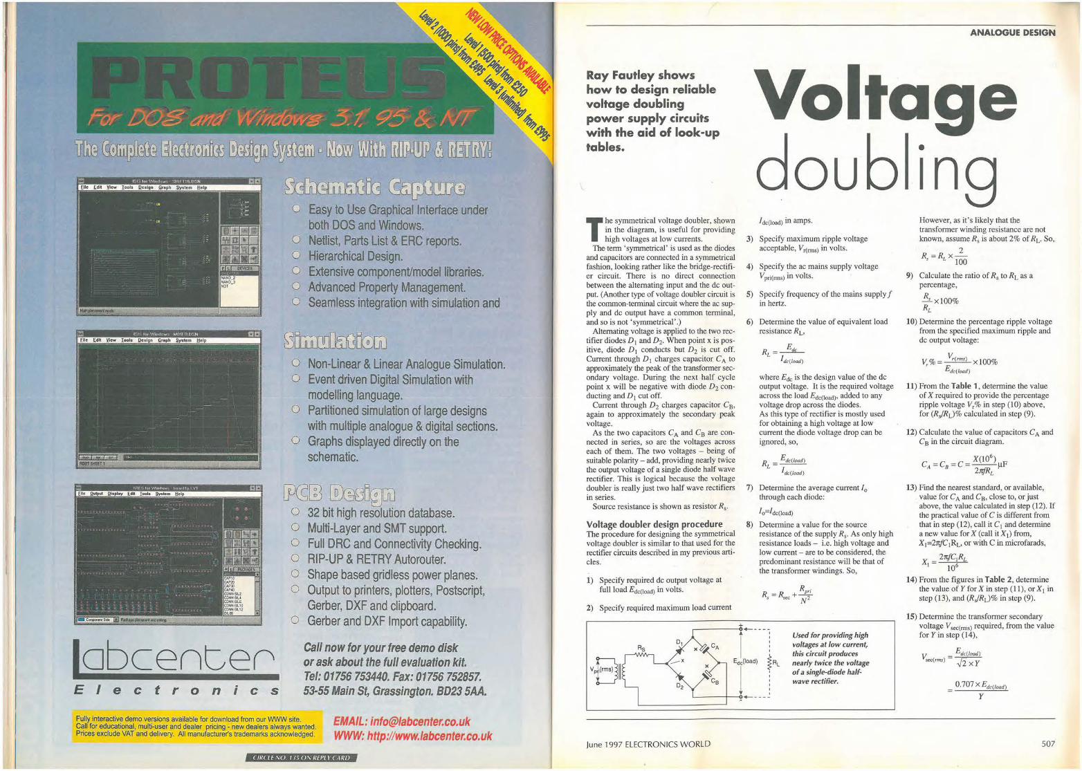
: ,,w •;,.,,w.,.,,.,. , , .. , ... 111,,·n tli:i
r I I I I : i
~~JIil-~-~---~·--~- _:__!!l![l· ~-~ -~--~ ___ !!(l] __ ~_,,_!!!!!!!!!!! __ l!!!!_ !!!!!!!!!!!_!l!!l_!!!I_!!!!!!!!!!! __ _
lobcen~e0 Electronics
fu~OC5 ~ITV@ o Easy to Use Graphical Interface under
both DOS and Windows. o Netlist, Parts List & ERC reports. o Hierarchical Design. o Extensive component/model libraries. o Advanced Property Management. o Seamless integration with simulation and
~• LJLillJllifsCEw o Non-Linear & Linear Analogue Simulation. o Event driven Digital Simulation with
modelling language. o Partitioned simulation of large designs
with multiple analogue & digital sections. o Graphs displayed directly on the
schematic.
~m ~00illuu o 32 bit high resolution database. o Multi-Layer and SMT support. o Full DRC and Connectivity Checking. O RIP-UP & RETRY Autorouter. o Shape based gridless power planes. o Output to printers, plotters, Postscript,
Gerber, DXF and clipboard. o Gerber and DXF Import capability.
Call now for your free demo disk or ask about the full evaluation kit. Tel: 01756 753440. Fax: 01756 752857. 53-55 Main St, Grassington. 8D23 SAA.
Fully interactive demo versions available for download from our WWW site. Call for educational, multi-user and dealer pricing - new dealers always wanted. Prices exclude VAT and delivery. All manufacturer's trademarl<s acknowledged.
EMAIL: [email protected] WWW: http://www.labcenter.co.uk
( IR( lf \:0. I Vi 0,\. Rf PL I CAR/J
Ray Fautley shows how to design reliable voltage doubling power supply circuits with the aid of look-up tables.
The symmetrical voltage doubler, shown in the diagram, is useful for providing high voltages at low currents.
The-term 'symmetrical' is used as the diodes and capacitors are connected in a symmetrical fashion, looking rather like the bridge-rectifier circuit. There is no direct connection between the alternating input and the de output. (Another type of voltage doubler circuit is the common-terminal circuit where the ac supply and de output have a common terminal, and so is not 'symmetrical'.)
Alternating voltage is applied to the two rectifier diodes D 1 and D2. When point xis positive, diode D 1 conducts but D2 is cut off. Current through D 1 charges capacitor CA to approximately the peak of the transformer secondary voltage. During the next half cycle point x will be negative with diode D2 conducting and D1 cut off.
Current through D2 charges capacitor Ca, again to approximately the secondary peak voltage.
As the two capacitors CA and Ca are connected in series, so are the voltages across each of them. The two voltages - being of suitable polarity - add, providing nearly twice the output voltage of a single diode half wave rectifier. This is logical because the voltage doubler is really just two half wave rectifiers in series.
Source resistance is shown as resistor Rs.
Voltage doubler design procedure The procedure for designing the symmetrical voltage doubler is similar to that used for the rectifier circuits described in my previous articles. ·
1) Specify required de output voltage at full load Edc{load) in volts.
2) Specify required maximum load current
Rs D1
OU I dc(load) in amps.
3) Specify maximum ripple voltage acceptable, V r(rms) in volts.
4) Specify the ac mains supply voltage Vpri(rms) in volts.
5) Specify frequency of the mains supply f in hertz.
6) Determine the value of equivalent load resistance RL,
R -~ L -Jdc(load)
where Ede is the design value of the de output voltage. It is the required voltage across the load Edc(load), added to any voltage drop across the diodes. As this type of rectifier is mostly used for obtaining a high voltage at low current the diode voltage drop can be ignored, so,
RL = Edc(load)
I dc(load)
7) Determine the average current /0
through each diode:
I o=f dc(load)
8) Determine a value for the source resistance of the supply R5• As only high resistance loads - i.e. high voltage and low current - are to be considered, the predominant resistance will be that of the transformer windings. So,
,._ ___ _ I Used for providing high I I voltages at low current, I I
this circuit produces
VPB11 __.. X Edc(load) iRL nearly twice the voltage
j of a single-diode half-I I wave rectifier.
D2 I +------
June 1997 ELECTRONICS WORLD
ANALOGUE DESIGN
• 1ng However, as it's likely that the transformer winding resistance are not known, assume Rs is about 2% of RL. So,
2 R, =RLx-
100
9) Calculate the ratio of R5 to RL as a percentage,
R --1.. X 100% RL
10) Determine the percentage ripple voltage from the specified maximum ripple and de output voltage:
V % = V,.( ,ms) X 100% r Edc(load)
11) From the Table 1, determine the value of X required to provide the percentage ripple voltage V, % in step (I 0) above, for (RJRL)% calculated in step (9).
12) Calculate the value of capacitors CA and Ca in the circuit diagram.
13) Find the nearest standard, or available, value for CA and Ca, close to, or just above, the value calculated in step (12). If the practical value of C is different from that in step ( 12), call it C I and determine a new value for X (call itX1) from, X1=21ifC'iRL, or with C in rnicrofarads,
X 21tfC1RL I 106
14) From the figures in Table 2, determine the value of Y for X in step (I!), or X1 in step (13), and (RJRL)% in step (9).
15) Determine the transformer secondary voltage Vsec(rms) required, from the value for Yin step (14) ,
V = E dc(load) sec(rms) ✓2 X Y
- 0. 707 X E dc(load)
y
507

ANALOGUE DESIGN
16) Determine the peak voltage, or PIV, that each of the rectifiers must withstand,
PIV=2xVsec(peak) =2x✓2xVsec(rms) =2.828Vsec(nns)
17) Find the value for Z from Table 3 for 0.5X (or 0.5X1) whereX was found in step ( I 1) or XI in step (13), and for (RJ0.5RL)%, where (RJRL)o/o was found in step (9),
18) From the value of Z found in step (17), determine the current through each rectifier diode from /(rms)=/0 XZ.
19) Determine recurrent peak current !(peak) through each rectifier diode. From Table 4, for 0.5X (or 0.5X1) and (RJ0.5RL)% find W, which is /(peak// 0 • Next find /(peak) from l0 xW.
20) Determine initial switch-on current Ion· As capacitors CA and CB are initially discharged, the load on the rectifier diodes will be nearly a short circuit at the instant of switch-on, limited only by the source resistance R5• As a result,
lon=Vsec(peakYRs,
This very high current flows for only a very short time, but the rectifier diodes must be capable of withstanding it. If suitable devices with such high pulse ratings are not available, the source resistance R5 must be increased by adding an external resistor Rexi where Rs is shown in the circuit diagram. The value of Rexi to limit the switch-on
Table 2. Finding the value of Y. X (R5/RL)%
current to an acceptable lower value lon(L) is determined in step (28).
21) Decide on a suitable rectifier diode type. The device must have all its ratings equal to: or greater than, the following,
PIV or 2xVsec(peak) (sometimes VRRM), see step (16)
Initial switch-on current or/ on (sometimes /FsM), see (20)
Average current or /0
(sometimes /F(AV)), see (7)
22) Determine rms ripple current Ic(nns)• flowing through capacitors CA and Cs,
I c(nns)=✓ [ (/cnns) 2)-(/ dc(load) 2)]
for Icrms) see (18) and for /dc(load) see (2).
23) Decide on the specification for capacitors CA and CB. Each capacitor must have ratings equal to,<' r'" ·1ter than, the following,
Capacitance CA and Cs see (12) or (13)
Working de voltage ✓2xVsec(rms), see (15)
Ripple current lc(rms), see ("2 .:) ·
24) Total transformer secondary current /1(rms) comprises two currents, one in each rectifier, which must be summed by, .
f 1(rms)=✓[ (/(rms) 2)+(/ (rms) 2)]
=✓2xl(rms)= l .414xlcrms)
0.1 0.25 0.5 1 1.5 2 3 4 5 6 7 1.3 0.60 0.59 0.59 0.58 0.58 0.58 0.57 0.57 0.56 0.55 0.55 1.5 0 .66 0.65 0.64 0.64 0.63 0.63 0.63 0.63 0.62 0.62 0.61 2 0.77 0.76 0.75 0.74 0.74 0.73 0.73 0.72 0.71 0.70 0.69 3 0.93 0.92 0.92 0.91 0.90 0.89 0.88 0.87 0.87 0.86 0.85 4 1.04 1.03 1.03 1.02 1.01 1.00 0.98 0.97 0.96 0.95 0.94 5 1.13 1.12 1.12 1.10 1.09 1.08 1.06 1.03 1.03 1.02 1.00 6 1.19 1.18 1.1 7 1.16 1.15 1.14 1.12 1.06 1.08 1.07 1.03 7 1.25 1.24 1.24 1.22 1.20 1.19 1.16 1.14 1.12 1.09 1.06 8 1.31 1.30 1.29 1.27 1.25 1.24 1.21 1.18 1.15 1.12 1.08 9 1.35 1.34 1.32 1.30 1.29 1.27 1.24 1.21 1.17 1.13 1.09 10 1.39 1.38 1.36 1.34 1.32 1.31 1.27 1.23 1.19 1.15 1.10 15 1.51 1.50 1.48 1.44 1.42 1.39 1.33 1.27 1.22 1.17 1.13 20 1.62 1.61 1.59 1.54 1.52 1.47 1 .39 1 .31 1 .25 1. 19 1.15 30 1.77 1.72 1.68 1.62 1.57 1.51 1 .42 1.34 1 .27 1.21 1.16 40 1.79 1.77 1.73 1.65 1.60 1.53 1 .43 1 .35 1.28 1.21 1.17 50 1.82 1.79 1.75 1.67 1.61 1.54 1.44 1.35 1.28 1 .22 1.1 7 60 1.84 1.81 1.76 1.68 1.61 1.55 1.45 1.35 1.28 1.22 1.17 70 1 .85 1.82 1. 77 1 . 68 1.62 1.55 1.45 1.36 1.29 1.22 1.17 80 1.86 1.83 1.78 1.69 1.62 1.55 1.45 1.36 1.29 1.22 1.17 90 1.87 1.83 1.78 1.69 1.62 1.56 1.45 1.36 1.29 1.22 1 .17 100 1.88 1.84 1.78 1.69 1.62 1.56 1.45 1.36 1.29 1.22 1 .17 200 1.91 1.85 1.78 1.70 1.63 1.56 1.46 1.36 1.29 1.22 1 .17 300 1.92 1.86 1.79 1.70 1.63 1.56 1.46 1.36 1.29 1.22 1 .17 400 1.93 1.86 1.79 1.71 1.63 1.57 1.46 1.36 1.29 1.22 1.17
508
Table 1. Finding the value of X for the voltage doubler design. V,°lo (R5/RL)%
0.1 0.2 03 0.4 0.5 0.6 0.7 0.8 0.9 1.0 2.0 3.0 4.0 5.0 6.0 7.0 8.0 9.0 10 20 30 40
0.1 1780 863 561 418 332 280 238 203 183 163 80 52 39 30 24 20 18 14 13 4.8 2.3 1.1
0.3 1594 772 506 375 299 250 214 183 165 147 72 47 37 27 22 18 16 13 12 4.5 2.2 1.07
For lcrms) see step _18.
1.0 1428 691 456 337 270 224 193 165 148 131 64 42 35 24 20 17 15 12 11 4.3 2.1 1.04
3.0 1279 618 411 302 243 200 174 149 133 120 58 38 33 22 18 15 13 11 10 4.0 2.0 1.02
5.0 1210 585 390 286 231 189 165 141 126 114 55 36 32 21 17 14 12 10.7 9.6 3.9 2.0 1.01
25) Transformer volt-amp, or VA rating TvA is,
TvA=Vsec(rms)xf1(nns)
This determines the size of the transformer.
26) Transformer requirements:
Volt-amp rating TvA, see step (25) Primary winding Vpri(~s), see (4) Secondary winding Vsec(nns) see ( 15) Secondary current /1cnns), see (24)
8 10 13 20 0.54 0.53 0.51 0.49 0.60 0.59 0.56 0.54 0.69 0.68 0.66 0.62 0.85 0.83 0.77 0.71 0.93 0.89 0.81 0.74 0.98 0.94 0.93 0.75 1.01 0.97 0.84 0.75 1.02 0.98 0.85 0.75 1.04 0.99 0.85 0.75 1.05 1.00 0.85 0.75 1.06 1.01 0.86 0.75 1.08 1.02 0.86 0.75 1.10 1.03 0.87 0.75 1.11 1.03 0.87 0 .75 1.11 1.03 0.87 0. 75 1.12 1.03 0.87 0.75 1.12 1.03 0.88 0.76 1.12 1.03 0.88 0.76 1.12 1.03 0.88 0. 76 1.12 1.03 0.88 o. 76 1.12 1.04 0.88 0. 76 1.12 1.04 0.88 0. 76 1.12 1.04 0.88 0. 76 1.12 1.04 0.88 0.76
ELECTRONICS WORLD June 1997
10 1145 553 370 271 219 179 157 134 120 109 52 34 32 20 16 14 12 10.5 9.2 3.8 2.0 1.0
27) When a suitable transformer has been chosen, measure the resistance of both windings. If the measured source resistance,
Rp,; R ,(m) = J?.ec + N2
is less than Rs calculated in step (8), then an external resistor,
RexrRs-Rs(m)
must be added, see (28), to limit I on lo the value found in (20).
28) If an external resistor Rexi was found necessary in (20) or (27) to be fitted where Rs is shown to limit switch-on current to a lower level lon(L)• its value will be,
R,xr V.ec(peak) R /on(L) s
29) Power dissipated in Rex1> if used, is given by,
P r=[/1(nns/lxRex1
A suitable resistor should have a power rating of about twice the value of P, for reliable operation.
30) If Rexi is used, the regulation of the supply can be improved by adding a shorting-out device, as recommended for the bridge rectifier circuit described my article in the September 1996 issue.
Voltage doubler design example Finally, here is a worked example for the voltage-doubler circuit. Assume that a supply of 1000V at lO0mA is required, having an acceptable ripple level of IOV rms.
1) Edc(load)=l000V
2) ldc(load)=lOOmA or 0. lA
3) V,(nns)=l0V rms
4) V pri(rms)=240V nns
5) .f=50Hz
6) RL = Edc(load) = 1000 = lOkQ
/ dc(load) 0 .1
7) fo=/dc(load)=lOOmA
8) Let R,=2% of RL, i.e.,
R = R X ~ = l04
X 2
= 200Q s L 100 100
9) R 200 .....!..%=-4 xl00%=2% Rl 10
June 1997 ELECTRONICS WORLD
10) V
V %= ~x100% ' Edc(load)
10 =--x100%=1%
1000
11) The value of X for V,% and (RJRL)o/o, i.e. V,%=1 and (RJRL)%=2 from Table 1 is found to be 125.
12)
C _ X(l0
6) µF- 125 x 10
6 F ---- - 4µ
2rtf x RL 2rtx 50x 10
= 125 µF = 39.8µF 1t
13) The nearest standard value above 39.8µF is 47µF, so,
x, =21tfxC1xRL =2rtx50x47xl0-6xl04=148
14) From Table 2, the value of Y for X1 and (RJRL)o/o, i.e. X 1=148 and (RJRL)%=2, is found to be 1.56
15) 0. 707 X Edc(/oad)
V.ec(rms) - y
0.707xl000
1.56 =453V rms
16) PIV=2.828V sec(nns)=2.828x453=128 l V
17) From Table 3, the value of Z for 0.5X1 and (RJ0.5RL)%, i.e. 0.5X1=0.5x148=74 and (RJ0.5RJ%=2/0.5=4, is found to be 2.46.
Table 3. To Find the value for Z. 0.5X (R5/0.5RL)%
0.02 0.05 0.1 0.2 0.5 1 1.80 1.80 1.79 1.79 1.79 2 2.03 2.02 2.01 2.00 1.99 3 2.19 2.17 · 2.16 2.14 2.13 4 2.32 2.30 2.28 2.26 2 .24 5 2.43 2.40 2.36 2.32 2.27 6 2.50 2.48 2.46 2.44 2.42 7 2.58 2.53 2.51 2.49 2.47 8 2.66 2.63 2.61 2.60 2.58 9 2.73 2.70 2.68 2.66 2.64 10 2.80 2.78 2.75 2.73 2.70 20 3.30 3.20 3.17 3.15 2.83 30 3.64 3.50 3.40 3 .29 3.05 40 3.91 3.72 3.55 3.40 3.13 50 4.08 3.87 3.68 3.48 3.22 60 4.23 3.97 3.78 3 .55 3.25 70 4.35 4.03 3.87 3.60 3.27 80 4.45 4.10 3.94 3.65 3.30 90 4.52 4.18 3.98 3.67 3.31 100 4.62 4.23 4.02 3.69 3.32 200 5.03 4.60 4.27 3.86 3.37 300 5.20 4.79 4.33 3.88 3.38 400 5.35 4.86 4.37 3.88 3.38 500 5.45 4.90 4.38 3 .89 3.38 600 5.51 4.03 4.38 3.89 3.39 700 5.60 4.96 4.39 3.90 3.39 800 5.67 4.98 4.39 3.90 3.39 900 5.70 4.99 4 .39 3.90 3.39 1000 5.75 5.00 4.39 3.90 3.39
ANALOGUE DESIGN
18) l cnns)=/0 XZ=0. lx2.46=0.246A or 246mA
19) From Table 4, the value of W for 0.5X1 and (RJ0.5RL)%, i.e. 0.5X1=74 and (RJ 0.5RL)%=4, is found to be 7 .02. As a result, /(peak)=/0 XW=0.lx7.02=0.702A, or702mA.
20) I = Vsoe(p,ak) = l.414XVsec(rms) on R, R,
= 1.414x453 = 3_2A 200
21) Diode ratings required:
PIV (VRRM)=I281V Ion (/FsM)=3.2A / 0 (/F(AV))=0.lA
For safe operation, two BYX38-I200 type diodes should be used in series for each of the two diodes in the voltage doubler circuit.
22)
/ c(rms) = [f;,.,]-[l,t(load)]
= ✓o.2462 -0.12
= ✓0.0605-0.01
= ✓0.0505 = 0.225A
23) Capacitor ratings required, CA=C8=C C=capacitance=4 7µ F Vsec(peak)=Voqwkg)=✓2x453=641 V fc(nns)=ripple current=0.225A
1.0 2 5 10 30 100 1.78 1.77 1.77 1.73 1.70 1.66 1.98 1.97 1.96 1.89 1.77 1.67 2.11 2.10 2.03 1.95 1.79 1 67 2.22 2.17 2.08 1.98 1.80 1.68 2.23 2.19 2.10 2.01 1.82 1.68 2.40 2.28 2.13 2.04 1.83 1.68 2.45 2.31 2.16 2.05 1.84 1.68 2 .50 2.35 2.17 2.06 1.84 1.68 2 .57 2.38 2.18 2.07 1.85 1.68 2.62 2.40 2.19 2.08 1.86 1.68 2 .82 2.53 2.26 2.12 1.88 1.68 2.89 2.59 2 .30 2.15 1.90 1.68 2.92 2.62 2 .32 2.16 · 1.90 1.68 2.93 2.64 2 .33 2.17 1.91 1.68 2.94 2.66 2.35 2.18 1.91 1.68 2.95 2.67 2.36 2.18 1.91 1.68 2.96 2.68 2 .36 2.1 8 1.91 1.68 2.97 2 .68 2 .37 2.19 1.91 1.68 2.98 2 .69 2.37 2.19 1.91 1.68 3.00 2.69 2 .38 2.19 1.91 1.68 3.00 2.69 2.38 2.19 1.91 1.68 3.00 2.70 2.38 2.19 1.91 1.68 3.00 2 .70 2.39 2.19 1.91 1.68 3.00 2.70 2.39 2.19 1.91 1.68 3.01 2.70 2.39 2.19 1.91 1.68 3.01 2.70 2.39 2.19 1.91 1.68 3.01 2.70 2.39 2 .19 1.91 1.68 3.01 2.70 2.39 2.19 1.91 1.68
509
ANALOGUE DESIGN
24) i1(nns)=✓2xlnns=✓2x0.246=0.348A, or 348mA
25) TVA =Vsec(rms)xlt(nns)=453x0.348 =158VA
26) Mains transformer ratings required,
TVA volt/ampere rating 158V A V pri(nns) primary winding 240V Vsec(nns) secondary winding 453V l1(nns) secondary current 348mA
I hope that the four simple procedures for
designing the four key types of rectifier circuits that I have described over the past few months will prove as useful to you as they have to me over the years. •
Designing reliable rectifiers Ray Fautley has produced three earlier articles along similar lines to this one, covering:
Full-wave bridge rectifier September 1996 issue, p. 691
Half-wave rectifiers December 1996 issue, p. 980
Full-wave rectifier with centre tap February 1997 issue, p. 133
Table 4. To Find the value for W. 0.5X (R5/0.5RL)o/o
0.02 0.05 0.1 0.2 1 3.70 3.70 3 .70 3.64 2 4.60 4.57 4.55 4.53 3 5.50 5.40 5.33 5.30 4 6.20 6.17 6.13 6.10 5 7.30 6.95 6.90 6.85 6 8.00 7.90 7.70 7.60 7 8.70 8.55 8.50 8.30 8 9.60 9.50 9.35 9.00 9 10.3 9.80 9.60 9.50 10 10.9 10.7 10.5 10.1 20 16.0 15.0 14.4 13.0 30 19,7 18.0 16.3 14.3 40 21 .9 20.0 17.3 14.7 50 23.7 20.8 18.2 15.2 60 24.9 21.1 18.5 15.4 70 25.9 21.4 18.9 15.6 80 26.7 21.8 19.4 15.7 90 27.5 22.2 19.5 15.8 100 28.5 22.5 19.7 15.9 200 30.5 23.0 20.0 16.3 300 31.6 23.3 20.5 16.9 400 32.8 23.5 20.9 17.0 500 33.3 23.8 21.0 17.1 600 33.8 24.0 21.1 17.2 700 34.2 24.5 21.2 17.3 800 34.4 24.9 21.4 17.4 900 34.5 25.8 21.5 17.5 1000 34.7 27.0 21.6 17.6
0.5 1.0 2 5 10 30 100 3.62 3.60 3.60 3.59 3.58 3.57 3.46 4.52 4.50 4.28 4.20 4.08 3.72 3.51 5.20 5.10 5.00 4.67 4.33 4.00 3.55 6.00 5.98 5.45 5.20 4.95 4.05 3.57 6.80 6.75 6.51 5.60 5.00 4.10 3.62 7.50 7.30 6.90 5.84 5.09 4.19 3.63 8.10 7.82 7.30 6.00 5.10 4.22 3.64 8.50 8.20 7.69 6.15 5.14 4.23 3.64 9.10 8.55 7.72 6.23 5.21 4 .25 3.65 9.50 8.64 7.74 6.30 5.28 4.26 3.66 11.1 9.44 7.83 6.47 5.29 4.27 3.66 11.7 9.60 7.92 6.50 5.31 4.27 3.66 12.1 9.64 8.01 6.51 5.33 4.28 3.66 12.2 9.70 8.10 6.51 5.34 4.28 3.66 12.3 9.77 8.12 6.51 5.34 4.29 3.66 12.4 9.84 8 .14 6.51 5.34 4.29 3.66 12.4 9.90 8 .16 6.51 5.34 4.30 3.66 12.5 9.93 8.18 6.51 5.34 4.30 3.66 12.5 9.96 8.19 6.52 5.35 4 .31 3.66 12.6 10.0 8.19 6.52 5.36 4 .31 3.67 12.7 10.0 8.20 6.53 5.38 4.32 3.67 12.7 10.0 8.20 6.54 5.40 4.32 3.67 12.8 10.0 8.20 6.55 5.42 4.33 3.68 12.8 10.1 8.20 6.56 5.44 4.33 3.68 12.9 10.1 8.20 6.57 5.46 4.33 3.69 12.9 10.1 8.20 6.58 5.48 4.33 3.69 13.0 10.1 8.20 6.59 5.52 4.33 3.70 13.0 10.1 8.20 6.60 5.56 4.33 3.70
Luxuriant editing! SpiceAge interfaces smoothly to almost any PCB design suite.
:, l'I• I J\l ,I ~£)
Although we would like you to use our own excellent Geswin schematic capture program which is purpose built for SpiceAge, if you already have a schematic
program, there is a good chance that SpiceAge will work with it better than any other circuit simulator.
1,-,, • file: c:\g8s,..n'!>foj8ct1\Mt6es7.sew • Desi!J' lpro,oct1\svel6as7.s • Format. Spicel\go ~ Pro,gr~: GftS8(':B tor Windows. Version 2.11
9¢0 •out:ygnG -o,,t:ca v,,.60,0000 \IS;10. 01 an:VGRID2 ca:vgrid v=1.000000
\ ~o
~hen ~ou iter~te between a schematic and a SPICE-like simulation environment while refining your circuits, the s1mulat1on settings and precious details such as polynomial functions on components can be lost. So without Geswin, it was sometimes easier to write the simulation netlist directly. However, SpiceAge's circuit update button only affects cha_nges in the circuit built by the schematic and, because it retains all the previous information, you can spontaneously iterate between schematic and circuit.
To hear more about this and other nice touches in SpiceAge, please contact:
Those Engineers Ltd, 31 Birkbeck Road, LONDON NW7 4BP. Tel 0181 906 0155 FAX 0181 906 0969 Email [email protected]
510 < If<( II \() I <J, I I \ 1.:/1'/\ ( \1.:/1
ELECTRONICS WORLD June 1997
NEW PRODUCTS CLASSIFIED ••••••••••••••••••••••••••••••
Please quote "Electronics World" when seeking further information
ACTIVE Arrays Hlgh-//V darllngtons. Arrays of seven and eight darlington driver transistors by FET Electronics interface between logic-level circuitry and power loads such as relays, print hammers and displays. FE ULN2001-24 (seven drivers) and FE ULN2801-2824 (eight) take up to 500mA through each driver, outputs being paralleled for more, and all have open-collector output and clamp diodes. Voltage rating is 50V or 95V, depending on type. Various input characteristics cope with pmos, comas and cmos input. FET Electronics Ltd. Tel., 01635 524490; fax, 01635 552244.
A-to-d and d-to-a converters Fast a-to-d converters. Philips intends its TDA8762A and TDA8763A high-speed, highaccuracy and low-power converters for use in broadcast quality cameras, communications and medical imaging. Both provide 10-bit resolution at 80Msample/s and 50Msample/s respectively, the 8762 giving a ttl output and the 8763 cmos output from 2.7V to 5.25V. When sampling at 40Msample/s, the 8763 achieves an effective bit length of 9.4bit, s:n of 58dB and thd of -68dB, the 8762 at 80Msample/s being similar but with an effective bit length of 9.3bit. Sample-and-hold circuitry is not needed and low input capacitance avoids the need for buffering. Gothic Crellon Ltd. Tel., 01734 788878; fax, 01734 776095.
Transmission d•to-as. Analog Devices' AD976x family of cmos dto-a converters is meant for use in the transmission path of communications and signalgeneration equipment, all members providing differential 20mA output current and sharing a common 28-pin SOIC package. The 125Msample/s family consists of the 8-bit 9708, 10-bit 9760, 12-bit 9762 and 14-bit 9764, plus the 50Msample/s, 10-bit 9760-50. All run from a 2.7-5,5V single supply on 45mW (3V) with a power-down mode on 25mW. Performance features include a spurious-free dynamic range over the Nyquist band from 53dB when clocked at 1 OOMsample/s to 79dB at 50Msample/s. Total harmonic distortion of the 9752 clocked at
25Msample/s with a 1 MHz output is -78dB. Analog Devices Ltd. Tel., 01932 266000; fax, 01932 247401.
Logic Electronic tagging. Holtek HT6P20 electronic serial number chips offer 224 combinations and are intended for use in wireless key fobs, access control and burglar alarms. They are available programmed or blank and in five styles: the HT6P20 outputs its code on power-up; 6P20B allows the last two digits to be set by the user to identify the type of sensor or area from which the code was transmitted; and HT6P20D/E allow the last four and eight bits to be set. Supplies down to 2V will power the devices. With a Holtek 48000 8-bit microcontroller, a low-power tagging system can be made for under £1. Flint Distribution. Tel., 01530 510333; fax, 01530 510275.
Optical devices Multiple leds. Dialight's range of led arrays now includes the 553 Series. a dual, six-position type previously to special order and now standard. It replaces six bi-level devices or 12 separate ones, removing the need to bend 24 leads and giving accurate alignment. The leds have integral resistors for 5V, draw 2mA and are available in two-colour types. Viewing angle is 30°. Dialight. Tel., 01223 424313; fax, 01223 423493.
PASSIVE Passive components Miniature coils. Three new miniature wire-wound coils in the 1008 package from Toko, the FSLU2520 Series offer inductances from 0.01 µH to 220µH in l:;12 values, low resistance, typical Q of 45 and 750ppml"C temperature coefficient. Coils are in a sealed, heat-resistant case for flow or reflow soldering, Cirkit Distribution Ltd. Tel., 01992 444111; fax, 01992 464457.
Thick-film resistors. Virtually noninductive thick-film power resistors from RS Components are made by two suppliers: Vishay-Sfernice make the 5-50W types, while the 1 OOW and 250W resistors come from Meggitt CGS. Cermet thick-film techniques are used, the housing being hard epoxy, and the components are meant to be mounted on a heat sink. The V-S resistors are to ±5% tolerance and
June 1997 ELECTRONICS WORLD
work in temperatures from -55°C to 12s0 c, the Meggitt CGS ones having a :1:10% tolerance and -55°C to 70°C temperature range. All types will withstand a short-term overload. RS Components Ltd. Tel., 01536 201234; fax, 01536 405678.
Wirewound, switched pots. BFI lbexsa offers a range of 24mm diameter, single-turn wirewound potentiometers with a 4W rating and values in the 1 O!l-22kn band. Switches are two-pole changeover types rated at 240V ac, 4A and 12V de, 1 OA. Spindles are supplied to customers· specification, in either metric or imperial sizes. BFI lbexsa Electronics Ltd. Tel., 01622 882467; fax, 01622 882469.
Audio products Comprehensive sound processor. Mitsubishi announces the M62460FP sound processor which forms a single-chip providing Dolby Pro Logic surround sound including centre and surround sound channel trimming for five speaker systems. It is an analogue processor with Pro Logic decoder, on-board memory and the 12c bus for closed-circuit television. A microprocessor interface renders the device simple to use, facilities including disco, hall, live mode and five delay time positions for digital space surround effects and 147.5ms or 196.6ms echoes. The use of BICMOS is said to provide improved performance over cmos devices, as does the analogue design over combined analogue-digital types. Mitsubishi Electric UK Ltd. Tel., 01707 276100; fax, 01707 278837.
Communications equipment Comms boards. C320 from Amplicon Liveline is an intelligent communications system providing between eight and 32 RS232 or RS422 serial comms ports for any pc having a free ISA slot. Each contains a plug-in controller board for the pc, a cpu module which is mountable up to 1 oom from the pc and a uart to plug into the cpu module to give eight serial channels, each cpu taking up to four uarts for 32 channels and each pc holding four controller boards to give a total of 128 ports. Controller and cpu both have 46MHz rise processors and RS422 interfaces which, with the 512K of dual-ported ram in the controller, relieves the host of processing overhead. Software supplied is configuration and driver
Microwave components L-band GaAs lets. Over the 1.6GHz to 2GHz, Toshiba's TPM1919-AO GaAs lets deliver an output power of 42.7W or 46.33dBm, with a gain of 13.3dB and 42% power added efficiency; saturated power output is 51 .3W. This is said to be the highest power at 1.8GHz ever achieved by a GaAs let. gain flatness is ±0.5dB. Steatite Microelectronics Ltd. Tel., 0121 643 6333; fax, 0121 643 2011
software for Windows3.x, NT, 95, dos, SCO Unix, SCO Xenix, Unix SVR3.x, Unix SVR4.2, UnixWare and Solaris x86. Amplicon Liveline Ltd. Tel., 0800 525 335 (free); fax, 01273 570215.
Connectors and cabling D-type connector hoods. Hoods for 9-37 way D-type connectors made by ODU UK are quick to assemble, need no fixing screws and come in a choice of ten colours. They are made in one piece and snap to lock together, incorporating a quicklyassembled reversible cable clamp with self-tapping screws to enable the use of cables of varying diameters up to 15mm thick for the 37-way hood. All have a captive steel thumb screw.The connectors themselves are of the mixed variety, in which data, power, coaxial and high-voltage contacts can be used in the one shell. ODU UK Ltd. Tel., 01653 600489; fax, 01653 600493.
Bga socket. Methode's 1.27mm pitch ball-grid-array socket provides a s imple means of removing the bga device from the board, effectively turning the bga device into a pin grid
511
NEW PRODUCTS CLASSIFIED
Please quote "Electronics World" when seeking further information
array type for socket or through-hole mounting. It is compatible with all popular bga packages and heat sinks; it needs no hold-down device and the footprint is standard bga size. Insertion force is 2oz/position and withdrawal 0.35oz/position, with several choices of ejector. Contact ratirig is 0.5A de at 20-40mQ. Methode Electronics Europe Ltd. Tel. , 01389 732123; fax, 01389 732777.
Crimps and housings. AMP CST-100 crimp contacts and housings are available with 2-28 positions pitched at 0.1 in and are compatible with the Molex KK series. This is a low-cost wire-toboard connection with a 250V ac, 4A rating and contact resistance of 2mQ. Both tin and gold-plated contacts are supplied and there is an overstress feature to prevent damage to the contact. Locking tabs and polarising tabs are standard. Gothic Crellon Ltd. Tel., 01734 788878; fax, 01734 776095.
or. rd-tofrom
to the h•hole or
lliierts, electrical to pads on the
Delng made by gasbetylllum-copper
jpltngs. There are models wlttt from 22 to 78 contacts on • 1.27mm pitch. Selwyn auggests that the connectors are suitable for hand-held data collection devices, In which the pcb pads would be exposed for mating with the connector, avoiding the use of cables. Selwyn Electronics Ltd. Tel., 01732 763436; fax, 01732 763395.
,· .. --;-- -- -
Crystals Wide-pull oscillator. Model 937 from Oak Frequency Control Group is a high-frequency voltagecontrolled crystal oscillator covering the 100-155.52 range of frequencies and is contained in a 16-pin dip. Output is eel complementary in a variety of pin arrangements and standard frequency units are available from stock. Wyle Ginsbury Electronics Ltd. Tel., 01634 290903; fax, 01634 290903.
Test and measurement Digital wattmeter. The Yokogawa W/1000 is a versatile digital power meter with a maximum bandwidth of 300kHz and working to an accuracy within 0.1 %. It is available in singlephase or three-phase versions and there is a version tor testing the performance of motors. Input range is 15V-1 kV rms and a filter with a selectable cut-off frequency isolates fundamental frequencies in inverters to allow harmonic analysis on fundamentals from 440Hz to the 50th harmonic. On three phases, the instrument simultaneously measures the phase difference between phases and active, reactive and apparent power of the fundamental. , simultaneously showing voltage. current and a choice of other quantities on four front-panel displays. Martron Instruments Ltd. Tel., 01494 459200; fax, 01494 535002.
Jitter tester for comms. JitterGEN from NoiseCom tests communications systems, PSTN, cellular and PCS base stations, for behaviour in the presence of digital noise to the specifications of AT&T, Accunet, TR62411 and international specs such as G.823 and G.702. The instrument provides controlled Im and pm jitter and wander in the 0.009Hz-400kHz range and unit interval-controlled jitter from 0 to 200ui, either under the control of an
I • • , • • ---: .. I II • II • ··;----
11 i · •• .• •1 fr a. ·•• i i·;·t? •;;;----! :"I/ ::••·- ------.. ; -•; :'"1•••••-
512
' . ~-:; ; I t • :' : "t -~ • • •- -
I I I I i-• ! { " : : • · • • I • I ' ii ·'. .-,· -~ ! fl :: ••• ··••ii JJ: ·~··
~,··· • • C ... ,,~,,,~ ~, .... •.•,• I I I I I I
. ,,,,,, \\\\\\\\\\\\\~,\,II I I I I I I ' ,~, II I I I I I I I I
external controller or stand-alone. Jitter is applied to a self-generated clock or to a data stream from another source and re-output to the system under test. Jittergen is contained in a portable unit with a fold-away keyboard, having a pc architecture and Windows gui. Sematron UK Ltd. Tel., 01256 812222; fax, 01256 812666.
Rf absorbing clamp. For the measurement of radiated emissions from the cables of electrical equipment, the EMC standard EN55014 specifies the use of an rf absorbing clamp, contrary to the impression many engineers have that a broadband antenna is needed. Laplace has such a clamp, the RF400, which consists of ferrite rings which open up to admit the cable and are then closed and held with no gap by springs. Insertion loss is ±1d8, maximum cable diameter is 18mm, load current is unlimited and there are wheels underneath the instrument so that it can be run along the cable. Instruments are supplied with a six-metre mains test cable and antenna factor data to load into a receiver or spectrum analyser. Laplace Instruments Ltd. Tel., 01692 500777; fax, 01692 406177.
CE-compliance tester. CE marking under the Low Voltage Directive now being in force, Seaward's new Premier L VD tester will help with the design of products to enable self-certification. It is microprocessor-controlled and contains all necessary data for testing to seven harmonised standards, accommodating ten programmable safety tests, manually or automatically. After selection of the standard, the instrument will carry out the sequence of tests and display the results on an led with pass or fail indication. Results are recorded and may be downloaded for printing. An optional Windows package is available to allow remote control from a pc. Accessories such as various probes and a remotecontrol earth bond can be supplied. Seaward Electronic Ltd. Tel., 0191 586 3511 ; fax, 0191 586 0227.
Lab. in a box. Several instruments from Feedback fit into one bench-top case, the 604 Mini-Lab. There is a 20MHz function generator with am/Im modulation producing sine, triangle, square, ramp and pulse waveforms, a 4-digit led readout being accurate to within ±1 count, and usable as a log/lin sweep generator; a 30MHz counter; a power operational amplifier; ±1 SV. 1 A, adjustable dual or 5V, 3A power supplies; and a 3.5-digit multimeter measuring V, I, Rand true rms. Feedback Test and Measurement. Tel., 01892 653322; fax, 01892 663719.
Fm/am signal generators. Kenwood announces the SG Series of programmable fm/am signal generators to cover the 100kHz-2GHz range of frequencies. SG-7200/7130 models go up to 2GHz and 1.3GHz respectively, being provided with a GPIB interface and modulation consisting of Im, am, am-fm and fm-fm
' simultaneously. Output levels increase in 0.1 dB steps from -133d8m to 13d8m. SG-5150/5155 cover 100kHz-150MHz, the 5150 having fm stereo modulation and both having the GPIB interface. All have both rotary knobs and a keypad for control. Kenwood UK Ltd. Tel. , 01923 218794; fax, 01923 212905.
Literature Racks. Vero has published the KM6-I/ Selector to help engineers find their way through the maze of options available in sub-racking systems, explaining the choices of style and the sizes of Eurocard to fit, considerations discussed being screening, ease of assembly, cost and number of configurations. The same process is then carried out for front panels and plug-in units. Vero Electronics Ltd. Tel., 01703 266300; fax, 01703 265126.
Power supplies. In 216 pages, Chloride Powerline's new catalogue, The Power Guide, describes a range of linear and switched-mode supplies, de-to-de converters and inverters from many of the leading makers. It also contains applic11tions information and data on safety standards and the EMC Directive. Chloride Powerline. Tel., 0118 9868567; fax, 0118 9755172.
Electromechanicals. Roxburgh can supply a catalogue of Grayhi/1 components, featuring series encoders, push-buttons and keylock switches, a new section describing the full range of optical and mechanical decoders. Roxburgh Electronics Ltd. Tel., 01724 281770; fax, 01724 281650.
Frequency control. Fordahl GB (used to be McKnight Crystals) has a new catalogue of components and assemblies for a range of products for frequency control, such as quartz clock oscillators, voltage-controlled oscillators and crystal filters. Fordahl GB. Tel., 01703 877200; fax, 01703 846532.
Power supplies High-reliability de-to-de converters. lnterpoint has four new models in its MFL Series of converters, delivering 2V, 3.3V, av and 28V at up to 65W and intended for applications in which reliability is essential. All have a 16-40V de input
ELECTRONICS WORLD June 1997
range, nominal being 28V, they are isolated to 100MQ at 500V de and are synchronised for system work. Conversion frequency is 550-650kHz. Protection includes short-circuit, input transients and low-voltage lockout. All have the facility for parallel working for up to three units. lnterpoint UK Ltd. Tel. , 01252 81551 1; fax, 01252 815577.
3.3Vl5V smps. New to Power-One's MAP/ 10 range of universal-input, switched-mode supplies is the MAPl 10-4300, which prov ides, in addition to the 5V, 8A and ±12V,1A, a 3.3V,15A main channel, overvoltage protection being a feature of both 3.3V and 5V outputs. Others include zero minimum turnon load, and optional power failure and thermal shutdown. Relevant standards requirements are met, an emi filter helping with FCC and CISPR 22 level 8 . The units come in three styles: open-board, with L brackets or totally enclosed. With forced air cooling, output is 11 OW or, with conventional cooling, 80W. Power-One Europe. Tel. , 01769 540744; fax, 01769 540756.
100W pluggable supply. Vere's EC/00 range of low-cost, pluggable switched-mode supplies provide 5V and 24 V rails for both logic circuitry
cflannab, eight traces. has two new
~s. the CS-5270/75, fOOMHz bandwidth, threedlannet. eight-trace instruments !flat offer :t3% measurement accuracy. Features include delayed sweep for expanded waveforms, single sweep and variable hold-off. There 1s automatic trigger and 1 mV/div vertical sensitivity.The display is a 150mm rectangular tube with an internal graticule and illuminated scales. the 5270 also being provided with a digital readout and a cursor. Kenwood UK Ltd. Tel., 01923 218794; fax, 01923 212905.
NEW PRODUCTS CLASSIFIED
Please quote "Electronics World"when seeking further information
and peripheral components such as relays and contactors. The supplies are in 3U by 12HP modules taking up three slot positions in a 19in rack and the rear heat sink is so designed to allow interfacing with both backplane and free-standing interconnection systems by way of a standard DIN41612 H15 connector. Versions are available to give 24 Vat 4A and 5V at 3A with power sharing, or 5V at 12A, 12V at 2A and -12V at 0.2A. Units are CE marked. Vero Electronics Ltd. Tel., 01489 780078; fax, 01489 780978.
Low-current voltage regulators. FET Electronics has a range of positive and negative regulators, FE 78LXXA and FE BLXXA which, in a number of versions, provide fixed outputs from ±5V to ±18V at up to 100mA on inputs of ±25-35V. They are seen as replacements for resistor/zener combinations with much better performance and lower current. There is thermal shutdown and short-circuit current limiting. FET Electronics Ltd. Tel., 01635 524490; tax, 01635 552244.
Brighter ups. Five new accessory modules increase the intellect of Vero's SmartSlot range of intelligent, uninterruptible power supplies. The Interface Expander module enables one ups to handle three different servers, which may be running different operating systems. On power failure, the Expander signals each server to shut down gently, tells the ups to start battery conservation and then manages each system's reboot when mains power is restored. Measure-UPS monitors ambient temperature and humidity within set limits and uses other sensors to detect fire, unauthorised access, etc. The Remote UPS Management Device uses a modem to control the ups remotely and to initiate tests, dialling two pagers if anything is amiss. Relay 1/0 Module allow control and monitoring via a dry contact interface, the format used by pbx and alarm makers. Vero Electronics
Ltd. Tel., 01703 266300; fax, 01703 265126.
Protection devices Low-C transient suppressors. Semtech offers the LC03-6 transient voltage suppressor, which has a peak pulse power of 360W for a pulse width of 1 Oms and is designed to protect devices connected to ISDN interfaces and high-speed data comms lines from voltage surges caused by discharges, fast transients and lightning-induced spikes. Operating and clamping voltages are 6V and 12V and the design, consisting of a tvs diode and bridge rectifier, affords transient protection in both common and differential mode in the one device. Peak pulse current is 30A, leakage current 5µA and operating temperature - 55°C to 150°C. Capacitance is 30pF. Semtech Ltd. Tel ., 01592 773520; fax, 01592 774781.
Switches and relays Separate membrane switches. From EAO-Highland comes the Series 70 range of pcb-mounted pushbuttons and spacers in the form of discrete membrane units, from which can be assembled a complete membrane switch panel, coloured caps and multi-chip or Tl led backlighting being available. EAO-Highland Electronics Ltd. Tel., 01444 236000; fax, 01444 236641.
Photo-interrupter. lsocom's ISTS802 optical interrupter has a 5mm wide slot for the opaque object to pass through and a light aperture of 0.5mm. Switching time is typically 3µs. There is a number of case styles with either pins or flying leads, special designs being made to order. lsocom Components Ltd. Tel., 01429 863609; fax, 01429 863581.
Thermal cut-outs. Texas Instruments' range of Klixon bi-metallic thermal trips now includes 2mm and 8mm versions with very reliable snap-action silver contacts. The smaller one can be installed in cavities in transformers and motors and has a layer of epoxy resin to protect it against transformer and motor impregnations. Rated at 3A and 7 A, the larger type works over the 70-160°C temperature range in 5°C increments at a tolerance of ±5°C. Steatite Power Ltd. Tel. , 0181 778 6611; fax, 0181 778 7722.
Television components Wireless cctv. Radio Data Technology announces its VideoWave hand-portable viewer/receiver for surveillance work and for setting-up procedures with the Video Wave wireless transmission system. It needs no licence for use in the UK and works indoors or outside with no need for line-of-sight transmission paths. Features include signal scrambling and low power, a battery pack or lighter socket providing sufficient. The detachable viewer screen is a 2.9in led with a removable light shield. Radio Data Technology Ltd. Tel., 01376 501255; fax, 01376 501312.
Transducers and sensors Sensor Interface. Industrial sensor interface MCA7707provides programmable analogue signal conditioning for silicon piezoresistive
June 1997 ELECTRONICS WORLD 513
NEW PRODUOS ClASSIFIED
Please quote "Electronics World" when seeking further information
sensors. It will calibrate and compensate transducers, several at a time if required, to better than ±0. 1 % total error over the industrial temperature range and, in conjunction with an eeprom, store the calibration data and link to a pc via a parallel port. Both analogue and digital outputs are provided for pressure and temperature, a frequency output being obtained by using an external custom gate array. FET Electronics Ltd. Tel., 01635 524490; fax, 01635 552244.
Signal-conditioned accelerometer. Possibly the smallest conditioned de-response accelerometer available, the Model 3255from AG&G IC Sensors contains a micromachined accelerometer die and an asic for signal conditioning, all in a 16-pin surface-mounted ic. In three versions handling ±50g, ±250g and ±500g, typical sensitivity is 40, 8 and 4mV/g respectively at bandwidths of 2kHz, 3kHz and 3kHz. A self-test pin is provided, an electrostatic force moving the mass to simulate an acceleration. Over-range stops are
Optical encode rs. Control Transducers offers the MD Series, a series of modular optical shaft encoders to detect position, speed and direction of movement, which are intended to supply feedback for position control in mechanical positioning equipment such as hydraulic presses or antenna positioning. Line counts are 96-2048 pulses per revolution, dual-channel, with or without index pulse and a line driver for long cable runs is available. The encoders, which have internal signal conditioning, are 25mm or 50mm in diameter and will take up an axial shaft play of ±0.25mm without damage. There is a variety of mounting accessories. Control Transducers. Tel., 01234 217704; fax, 01234 217083.
514
built in. Eurosensor. Tel., 0171 405 6060; fax, 0171 405 2040.
Hall sensor gives direction. Allegro has a family of Hall-effect sensors that provide contactless speed and direction sensing. A3420l1/2 contain two latches, the Hall elements being spaced 1.5mm apart. Each latch independently detects the ambient magnetic field to give high or low outputs, a subsequent logic circuit providing the direction signal. Latching means that the action requires a field reversal to operate, giving clean and positive switching. The chips contain internal voltage regulators for both analogue and digital circuitry. Allegro Microsystems Inc. Tel. , 01932 253355; fax, 01932 246622.
Dual thermostat chip. Two thermostats sharing one sensor in National's LM56 operate from a 2.7V supply and need 230µA of quiescent current. The device contains a temperature sensor, two comparators and a reference in the one 8-pin ic, three external resistors serving to set up trip points from -40°C to 125°C. An additional analogue output provides 6.25mVl°C with good linearity. Hysteresis over the whole range is 5°. Applications will include the control of system fans. National Semiconductor GmbH. Tel., 0049 1805 32 7832; fax, 0049 814103515.
Small speakers. Kingstate miniature waterproof speakers have Mylar cones, a rated input of 0.5W and come in impedances in the 8-5000 range. In a number of frame styles, sizes are from 20mm to 50mm diameter, frames being in metal or ABS, 5mm in depth, some cased for pcb mounting. There are units for voice to 4kHz or for full-range working up to 9kHz. Roxburgh Electronics Ltd. Tel., 01724 281770; fax, 01724 281650.
Vision systems Conference camera. eaZy is a colour ccd camera for video
conferencing (conferring?) that gives video and audio output to interface to MPEG or similar computer cards. Resolution is 320 000 pixels from a 0.25in ccd sensor through a 4mm, 13.8 lens with a built-in colour filter. It works in light levels from 10Iux, 500lux being recommended, and there is an auto-white balance and electronic shutter with speeds from 1/50s to 1/120s. Voltage requirement of 5V can be obtained from the host in most cases. Premier Electronics Ltd. Tel. , 01922 634652; fax, 01922 634616.
COMPUTER Computers Reconfigurable hardware. Embedded Solutions announces its first product, the Accelerator, which can be used to increase integer performance of processors, to provide customised interfaces to external devices, for prototyping and evaluation or for building scalable computing systems. Its main feature is the use of two field-programmable gate arrays instead of a conventional processor, an approach that offers the possibility of reorganising the hardware in a different configuration. Two Xilinx field-programmable gate arrays are connected to each other and to a daughter board, the connector to which may be used to interface the board to inpuVoutput devices or to make network interfaces between Accelerators and other devices. A companion communications board allows connection to transputer networks, converting an OS serial link to two parallel buses, linked to as many Accelerators as necessary. Embedded Solutions Ltd. Tel. and fax; 0118 9771682.
Data acquisition Anti-alias cards. From Laplace Instruments. the AAF-16 16-channel anti-alias filter card for data acquisition using a pc. Filters can be specified as Bessel, Butterworth, Cauer or linear phase types, depending on the application, roll-off being up to 120dB/octave for the Cauer. Cut-off frequency is programmed from the pc from 2Hz to 50kHz or 1 OOkHz, depending on filter type. Single-ended inputs are at 2MO impedance and the input range is ±10V, with protection to 120V rms and 250V for 5s. An optional daughter board provides protection against clock aliasing. Software supplied includes Windows in its various incarnations and Dos programs for setting key parameters and drivers compatible with Visual Basic, Visual C++, C and Pascal; drivers for LabView are also available. Laplace Instruments Lid. Tel., 01692 500777; fax, 01692 406177.
Data communications Data/fax modems. ClipperCom World by Apex Data is a PC Card data and fax modem providing 33.6kb/s V.34 performance with MNP2-4 and V.42 error correction, and MNP-5 and V.42.bis data compression. Software included allows faxes to be sent directly from applications and to be scheduled for later transmission, faxes being sent and received in the background. The card is compatible with many notebook computers and with Windows 3.X, 95, NT Workstation, OS/2 and Dos. DIP Systems. Tel. , 01483 202070; fax, 01483 202023.
ELECTRONICS WORLD June 1997
Data logging Black box for vehicles. RoadRecorder is a video logging system for buses, trains, police cars, etc., that collects relevant data in much the same way as does the flight recorder found in aircraft. Video and other types of data are logged and saved to hard disk to provide information on accidents or crime. On buses or trains, it is envisaged that there may be several video cameras inside and around the outside to provide internal security and to deter vandals. There could also be one pointed forward to record what happens in accidents. A GPS navigation and location device might be integrated with the system. Visimetrics UK Lid. Tel., 01436 677557; fax, 01436 672131.
Multimedia Web guide to CE marking. If, after reading leaflets, books and posters, watching videos and using computer programs, you are still baffled by CE marking, you can now catch it all on the Worldwide Web site of the Assessment Services. It shows which Directives apply to common products, although • ... obviously the list is not exhaustive.". Highlighting a product brings up the Directives for that product and what you have to do to make sure it conforms to Holy
Writ. If you already know which Directives are relevant, you can see more information on any of six specific Directives applicable to most electrotechnical products. You can also ask questions by e-mail. To see all this try http://www.neag.co.uk/cgi-binlcemark.cgi "and get in the fast lane to compliance". Assessment Services' Tel., 01329 443350; fax, 01329 443421.
Computer security Computer safe. If a technically inclined tealeat is intent upon stealing a computer's memory, nothing will stop him, but the Armagardfamily of computer safes will at least give him pause for thought; the Crown Jewels spring to mind. Latest in the range is the one for Mini Tower pcs; the computer cowers inside a 2mm thick steel box that has a seven-lever mortice lock. The whole thing bolts to the desk, has an inset door with concealed hinges, is of welded construction and is fitted with dog-bolts so that the door cannot be removed without unlocking it. There is a brush strip for cables at the rear, ventilation is taken care of and a tan can be fitted. Computers up to 350mm high, 220mm wide and 500mm deep fit inside and stay there while working.
lntek Electronics Lid. Tel. , 01352 810603; fax, 01352 810403.
Software Efficient C complier. Version 4 of Cosmic Software's C cross compiler for 68HC 11 microcontrollers is source-code-compatible with earlier versions but has a new C driver structure for multipass processes, new unified compiler options and a 32-bit internal data structure for unrestricted development of new code optimisation. There is also a new C parser for optimisation before compiling. The company says that Version 4 is a virtually new package, methods used in earlier ones having reached a limiting point. This one is said to produce the most efficient code for the 68HC1 1. Included in this full ANSI C package are a macro assembler, linker, librarian, object inspector, hex file generator, object format converters, debugging support, a royalty-free run-time library source code and a multipass compiler command driver. Cosmic Software. Tel., 0118 9880241 ; fax 0118 9880360.
Software verification for VME. In its latest version, CodeTEST from AMC is applied to VMEbus system software for test and analysis. CodeTEST-VMEwill trace the code
NEW PRODUCTS CLASSIFIED
execution of a cpu or follow the workings of several cpus via VME system trace. The package consists of a single-slot 6U board, plugging into the VMEbus backplane, and application software modules for in-circuit verification of software performance, memory allocation analysis and deep trace capability; it runs on H-P and Sun workstations and pcs running Windows 95 or NT. Applied Microsystems Corporation Ltd. Tel., 01296 625462; fax, 01296 623460.
Waveform analysis. For use with its dsos, data acquisition systems and recorders, Gould has introduced Pro View, an analysis and report generating package. Its features include display and manipulation · facilities, a search function for points of interest in waveforms and a document composition tool to assist in making reports. The package is to be used with the company's Transition 2, View II or View-toASCII linking software to connect ProView with digital storage oscilloscopes or to signals on disk and memory cards in recorders and data systems. Analysis includes a variety of statistical and mathematical functions and those in the frequency domain. Gould Instrument Systems Lid. Tel., 0181 500 1000; fax, 0181 501 0116. •
ADVERTISE FREE OF CHARGE Subscribers* to Electronics World can advertise their
electronics and electrical equipment completely free of charge Simply write your ad in the form below, using one word per box, up to a maximum of twenty words. Remember to
include your telephone number as one word. You must include your latest mailing label with your form. * This free offer applies to private subscribers only. Your ad will be placed in the first available issue.
This offer applies to private sales of electrical and electronic equipment only. Trade advertisers - call Malcolm Wells on 0 181-652 3620
All adverts will be placed as soon as possible. However, we ore unable to guorontee insertion dates. We regret that we ore unable to enter into correspondence w ith readers using this service, we a lso reserve the right to reject adverts which do not fulfil the terms o f this offer.
Please send your completed forms to: Free Classified Offer: Electronics World, L333, Quadrant House, The Quadrant, Sutton, Surrey SM2 5AS
June 1997 ELECTRONICS WORLD 515
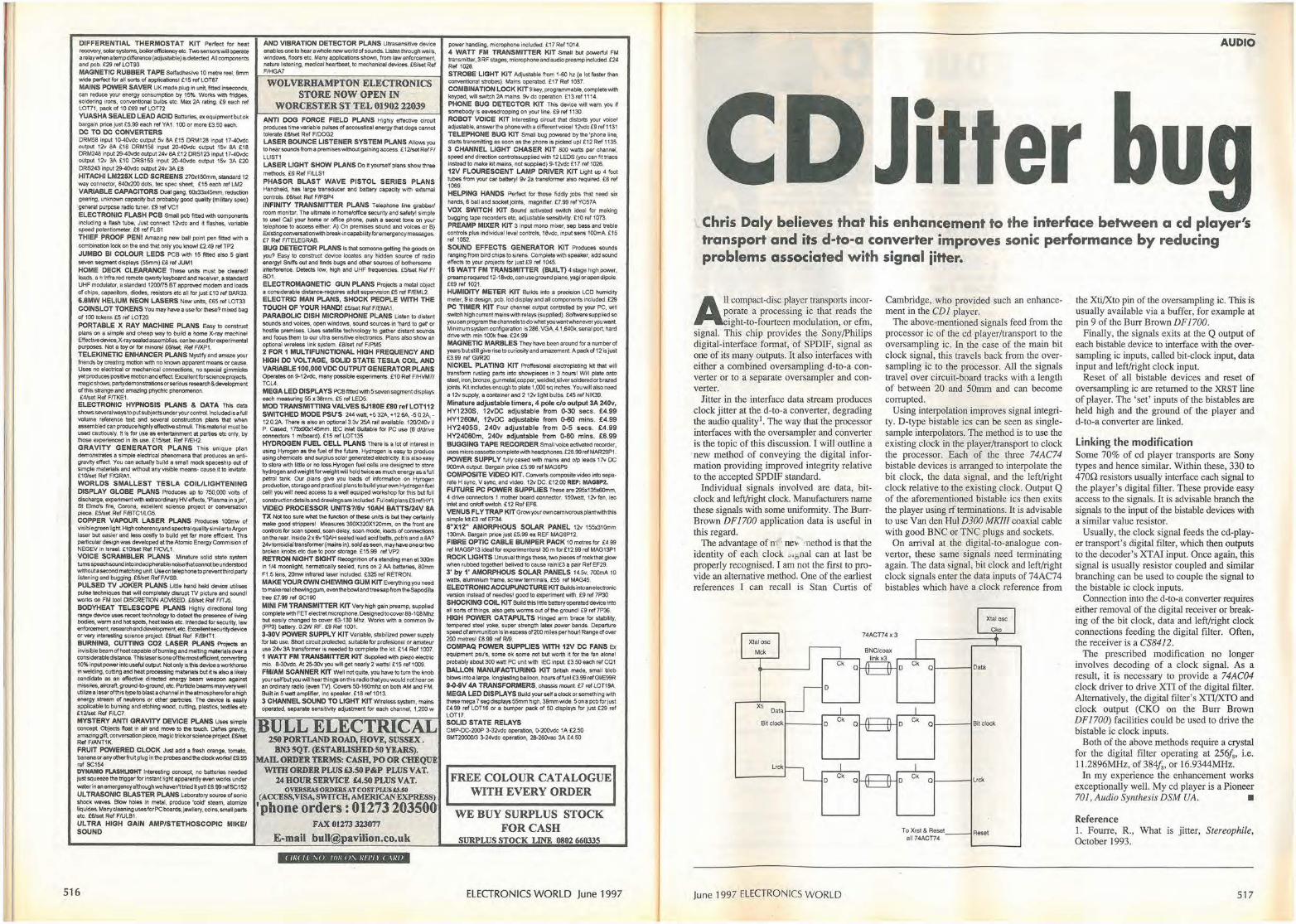
DIFFERENTIAL THERMOSTAT KIT Perfect for heat <"""""'Y, solar systems, boiler efficlency elc. Two sensoo; "'fl Ol)e(Ote a retayY.tlenatempdifference (adjustable) isdetoctsd. All oomponents and pcb. £29 ref l0T93 MAGNETIC RUBBER TAPE SelfadhesM 10 metre reel, 8mm wide perfect for all sons ol applications! £15 relLOT87 MAINS POWER SAVER UK made plug In unit, fitted insec<>nds. can raduce your ene,gy ooosumption by 15%. Wor1<s With fridges, soldering irons. conventional bulbs etc. Max 2A rating. £9 each ref LOT71, pack ol 10 £69 ref LOT72 YUASHA SEALED LEAD ACID Batteries. execuipmoot b<Jtok bargaln prioe Just £5.99 each ,er YA1. 100 or more £3.50 each. DC TO DC CONVERTERS DRM58 rnput 10-40vdc output 5v 8A £15 DRM128 Input 17-4(Mlc ootput 12v 8A £18 DRM158 Input 20-•0l<lc output 15v 8A £18 DRM248 lnput 29-40,dc outplrt 24v 8A£12 DRSl23 input 17-40vdc <Ml><Jl 12v 3A £10 ORS15"3 input 20-40\/dc output 15v 3A £20 DRS243 Input 29-40Ydc outj)<jl 24v 3A £8 HITACHI LM225X LCD SCREENS 270x150mm. stondaro 12 way oonnector. 640x200 dOOi, tee spec sheet. £15 eadl ref LM2 VARIABLE CAPACITORS Dualga,,g, 60x33x45mm, reduclion gearing, unJ<nov,,i capacity but probably good quality (mUi1ary spec) general purpose radio IUll<!t. £9 rel VC1 ELECTRON.IC FLASH PCB Small pct, fitted will\ components incruding a ftash tube, Just connect 121/dc and it nasties, variable spead pctenliometer, £6 ref FLS1 THIEF PROOF PENI Asnazing""" ball point pen fitted "1th a oombination lock on lhe and tl>"1 only you lcno,,1 £2.49 rel TP2 JUMBO Bl COLOUR LEDS PCB With 15 fitted also 5 giant ..,,.,. segme,t displays (55mm) £8 r(lf JUM I HOME DECK CLEARANCE These unllS must be cleared! leads, a n tntra red remote Q\\18rty keyboard and recetYer, a standard UHF modulator, a standard 1200'75 BT approved modem and loads of chips, capacitors, diodes. resistors etc an for just £10 ref BAR33.
6.6MW HELIUM NEON LASERS New uni1s. £65 ref LOT33 COINS LOT TOKENS You may have a use forlhese? mbood bag of TOO tokens £5 rer LOT20. PORTABLE X RAY MACHINE PLANS Easy lo construct plans on a slmp&e end C'heap V"fJ'f to buik:i a home X-ray macllinel EfleclM,device,X-raysealed assemblies. can be usedforexpertmental pu,poses. Nol a toy or for minors! £6/set. Rel F/XPI. TELEKINETIC ENHANCER PLANS Mystify and amaze your friends by creating motion wtth no 1cnown apparent means or cause, Uses no electrical or mechanical connections, no special gimmicks yet produces posiliva motion and el!ect Exeellootforsc,encepn)jec1S, magic shews, partydemonstrationsorsetious research &devetopmen1 ol lhis strange and amazing phychi(: ph<momenon. £4/set Rel F/TKE1 .
ELECTRONIC HYPNOSIS PLANS & DATA This data
shows several ways to putsut,ieets under you, controt Included isa fu11 volume reference text and several oonstruction 'Plans that when assembled can produce hlghty effective stimull. Th1s material must be u,od cautiously. tt Is fc,r use as entenainmenl at parties ale only, by !hose experienced In i1s use. £15/set. Rel FIEH2. GRAVITY GENERATOR PLANS This unique plan demonstrates a simpfe electrical phenomena lhat produces an ant>gravity effect. You can actuany bulkl a sman mock spaceship out of simple maten,1s and without any visible moons- cause it to levitate. £10/set Ref FIGRA1. WORLDS SMALLEST TESLA COIULIGHTENING DISPLAY GLOBE PLANS PrOduces up 10 750,000 vo11S of discharge, expef\rTMMrlW11tl extraordlnaryHV effects, 'Plasma in a}a.r', St Brno's fire, Corona, exoelleot science project or conversatk>n piece. £5/set Ref F/BTC1/LG5. COPPER VAPOUR LASER PLANS Produces 100mw of visJb1egreen light High coherency and spectral qua lit)' slmilartoArgon laser but easier and less costly to build yet far more efficient This particular deSign was developed at the Atomic Energy CommfSJOn of NEGEV in Israel. £10/set Rel FICVL1. VOICE SCRAMBLER PLANS MinalUre solid Slate system 1Umsspo«hsoundinlOindeCipt,erablenoiselhatcannotbOunde<$t>od without a second matching unrt. Us.eon telephone to prevel'ltthird party listening and bugging. £6/set Rel FNS9. PULSED TV JOK
0
ER PLANS Li121o hand hold dovic:e utilises pulse t.echniqlleS that will completely disrupt TV picture and soundl ""'1<s on FM lool DISCRETION ADVISED. £8/sot Ref F/TJ5. BODYHEA T TELESCOPE PLANS Highly directional loog range - usos recoo! l9cllnology IO detect tho presenoo of tMng bodies, warm and hot spots, heat leaks etc. Intended for security, &aw enfor<>ement,resee<chandde-..elopmen~otc. Exce!lentsec\lfityor very interes11ng science project £8/set Ref FIBHT1 BURNING, CUTTING CO2 LASER PLANS Pn,Jec1s an invisible beam of heatcapa~ofburning aDd melting materiaJsover a coosiderabledistance. Th!staserlsone olthe mostefficien1, COIM)rting 10% input power inlO useful output. Not ooly is this device a worl<hor5e in wefding, cutting a:nd heat processing materiats but it is atso a likely candidate as an effective directed energy beam weapon against ""5Sio!s. 8lrcra11, grou11d-to-groond. e!C. Particle beoms mayvery....,I utilize a laserofttiis typetoblastachannel in theatmospherefora high energy slroem ol MUI'°"' Of ottief particies. The - Is eeslly applicable to buming and elOhlng wood. cutting, plastics. textiles etc £12/set Rd FILC7. MYSTERY ANTI GRAVITY DEVICE PLANS Uses simple concept Obj,)cts float In air and move to tho louch. Oefles gravity, amazing gift C011Ve1Satlon piece. magic trick or science project £8/set Rel FIAI-IT1K FRUIT POWERED CLOCK Jusl add a fresh orange. tomalO, banana or any other fruit plug In the probes and the c1ockWOlb1 £9.95 ref SC15• OYNAMO 1'1.ASM\.IOHT lnteros~ng concept, no batteries needed just squeeze lhe trigger tor lnslllnt light apparentty 8VM wortcl under IM!terinanemergencyallhoughwehavon,lriedayeli£6.99relSC152 ULTRASONIC BLASTER PLANS Laboratory sou,oe of sonic shock waves. Blow holes In IM!al. prOduce 'cold' steam. atomize liquldes. Many cleaning uses for PCboards,jewllery, coins. small parts &IC. Wset Rel F/ULB1 , ULTRA HIGH GAIN AMP/STETHOSCOPIC MIKE/ SOUND
516
AND VIBRATION DETECTOR PLANS Urtrasensitive device enables one to hear a whole new world of $0und$. Us.ten thto1.1gh waits, windows, noors etc. Many applications shown, from taw enfo,cement, natl.Ira listening, mecfteaf heartbeat to mechanical devJces, £6/set Ref F/HGA7
WOLVERHAMPTON ELECTRONICS STORE NOW OPEN IN
WORCESTER ST TEL 01902 22039 ANTI DOG FORCE FIELD PLANS Highly affactiw clrcu~ produces time variable puPses of aceoustrcal energy that dogs cannot - rate £8/S8t Ref FIDOG2 LASER BOUNCE LISTENER SYSTEM PLANS Allows you to hear sounds from a premises without gaining aecess. £12/set Ref Fl LLIST1 LASER LIGHT SHOW PLANS Do ttyourseffp1ans sha.Ythree methods, £6 Ref F/LLSI PHASOR BLAST WAVE PISTOL SERIES PLANS HaMSheld, has 1al'S)e tranSducer and battery capacity "Mth external controls. £6/set Rel F/PSP4 INFINITY TRANSMITTER PLANS Telephone line grabber/ room monitor. The ultimate In home/office 590urity and safety! simp!e to uwl Gall yoor home or ot!icG phone, push a sec.-et tone on your t~ephone to a0Ce$S eithoc: A) On premises sound and voices or B) Existing conversation with bteal<•incapability for emergency messages.. £7 Rel FITELEGRAB. BUG DETECTOR PLANS Is Iha! someone getting the goods on you? Easy IO ooostruct device locates any hidden source of radio ene,gyl Sn.ti's out and finds bUgs and othe< souroes ol bothersome 1nteffere""". Detects low, high and UHF ~equoncles, £5/sel Ref Fl 8Dt. ELECTROMAGNETIC GUN PLANS Projects a metal object a considerable drstance,..requires adult supervision £5 ref FIEML2. ELECTRIC MAN PLANS, SHOCK PEOPLE WITH THE TOUCH OF YOUR HAND? £5/set RefFIEMAL PARABOLIC DISH MICROPHONE PLANS Listen to distant sounds and voices, open windows, sound sources in 'hard to get' °' hosti1e premises, Uses satellite technology to gathef distant sounds and focus them to our ultra sensitive electronics.. Plans also shON an optional wireless !Ink system. £8/set ref F/PM5 2 FOR 1 MULTIFUNCTIONAL HIGH FREQUENCY AND HIGH OC VOLTAGE, SOLID STATE TESLA COIL AND VARIABLE 100,000 voe OUTPUT GENERATOR PLANS Operates on ~ 121,odc, many possible exporimenlS £10 Re! FIHVM71 TCL4. MEGA LEO DISPLAYS PC8f111edwith 5sevensegmentdr.;plays each measuring 55 x 38mm. £5 ref LED5. MOD TRANSMITTING VALVES 6J180E £80 refLOT112 SWITCHED MODE PSU'S 244 w.itt, +5 32A, • 12 6A. -5 0.2A, -12 0.2A. There is also an optional 3.3v 25A rail available. 120/240\/ II P. Cased, t 75xll0x 145mm. IEC inlet SUitable ror PC use (6 d/drive connectors I mlboald). £15 ref LOT135 HYDROGEN FUEL CELL PLANS There ts a lot of Interest in using Hyrogen as the tu~ of the future, Hydrogen is easy to produce ~sing ehem;ea~ and surplus solar generated etectricity. It Is also easy to stOfQ with frttle or no loss.Hyrogen fuel cells are designed to store hydrogen and weightforwelght will hold lwice as much """'9Y as a full petrof tank. Our plans give you loads of tnrormatlon on Hyrogcn production, storage and practical plans to build your own Hydrogen fvel oelll you will need access to a wetr equiped workshop ror lhis b<Jt full construcbondetailsanddrawingsareinc1uded.Fu1cel1p1ans£9refHY1 VIDEO PROCESSOR UNITS?/6v 10AH BATTS/24V 8A TX Not too Sl.Jre what the function of these un~ts is but they oertainly make good strippers! Measures 390X320X120mm. on lhe front are oonll'OI$ for scan speed', scan del,ay, scan mode. loads of connections on the rear. lnside2x6v tOAH sealed k3ad acid batts, pcb'sanda8A? 2Avtorroidialtranslorme< (mains In). soldas seen, may ha"" one or two broken knobs etc due to poor storage. £15,99 refVP2 RE TRON NIGHT SIGHT Recognition of o standing man ot 300m in 1/4 moonlight, hermetically sealed, runs on 2 AA batteries, 80mm Fl.5 lens, 20mw intrared taser included £325 ref RETRON. MAKE YOUR OWN CHEWING GUM KIT Everything you nood tomakerealchewinggum,eventhebowlandtreesapfromthe5apodilla tree £7.99 ruf $CHIO MINI FM TRANSMITTER KIT Very high gain preamp, supplied complete with FET electret microphone. Designed to rover 88-108 MhZ but easUy changed lo CO\l'Elr 63--130 MhZ. Works. with a common 91/ (PP3) battery. 0.-z.N RF. £9 Ref 1001. 3-30V POWER SUPPLY KIT Variable, stabiliaad power supply 1or Jab use. Short cl,tuit protected,, sultable for profesJonaJ or amateur use 24v3A transformer is noededto complete the kil £14 Ref i oo7. 1 WATT FM TRANSMITTER KIT SUpplied with pleio electric mic. 8-30\/dc. At 25-30vyou wiff get neariy2 watts! £15 ref 1009. FM/AM SCANNER KIT Well not quite, you have to tum the knob your self but you will hear thh1gsoo this radio that you would not hear on an ordinary radio (even TV). Co,ei,; 50-160mhz on bolh AM and FM. Builtln 5wattamplifler, inc speaker. £18 ref 1013, 3 CHANNEL SOIJNO TO LIGHT KIT Wireless sys1em, mains operated, separate sonsitMty adjustment for each cha.nnel, 1,200 w
BULL ELECTRICAL 250 PORTLAND ROAD, HOVE, SUSSEX.
BN3 SQT. (ESTABLISHED 50 YEARS). MAIL OlU>ER TERMS: CASH. PO OR CHEQUE
WITH-ORDERPWS£3.50P&P PLUS VAT. 24 HOUR SERVICE £4.SO PLUS VAT.
O~EAS O~;El,I.S ATCOS)' PWS.fJ.50 (ACCESS, VISA, SWITCH, AMERICAN EXPRESS)
'phone orders: 01273 203500 FAX 01273 323077
E-mail [email protected]
< Iii< II ,o Ill// o, ///I' ll < \////
power handllng, microphone included. £ 17 Ref 10, 4. <I WATT FM TRANSMITTER KIT Smarr b<Jt po,,efful FM transmitter, 3 RF stages, mtcrophone and audio preamp lnciuded. £24 Rd 1028. STROBE LIGHT KIT Adjustabfe from 1-60 hz (a lot faster than convontionat strobes). Mains operated, £17 Rel 1037. COMBINATION LOCK KIT 9 key, programmable. oomple!O with keypad, w!A S'Nftch 2A mains. 9vdc operation. £13 ref 1114. PHONE BUG DETECTOR KIT This de'Vice will warn you H somebody is eavesdropping on your line, £9 rel 1130 ROBOT VOICE KIT ln1eres1fng clrcu~ t/ull distorts your ""icel adju.stabte, answer the phone with a d1fferentvoicel 12vdc £9 ref 113i TELEPHONE BUG KJT Small bug po;,ered by lhe 'phono Hne. stans llansmltting aucon •• lhe phone is picked upl £12Rel 1135. 3 CHANNEL LIGHT CHASER KIT SOO watts P<J( chaMel. speed ar\d direction controlssupplied with 12 LEOS (rou can flt triacs instod to make kit mains, not supplied) 9 ·12vdc £17 ref 1026. 12V FLOURESCENT LAMP DRIVER KIT Light up 4 foot tubes from yoor car batt.ryl 9v 2• transformer also naquifed. £8 ref 1069. HELPING HANDS Peofecl for !hose fiddly jobs that need six hands, 6 ball and socketjoinlS, magnifier. £7.99 refYOS7A VOX SWITCH KIT SOund activated switch ideal for making bugging lape recorders etc, adjustable sensitMty. £10 rel I 073. PREAMP MIX.ER KIT 3 input mono mixe,, sep bass and treble contsols plus lndividuar level oontrols. 18"'1<, input sens 100mA £15 ref 1052. SOUND EFFECTS GENERATOR KIT PrOduces sounds ranging from bird chips to sirens. Complete with speaker. add sound e"ects to your p~ects ror just £9 ref 1045. 16 WATT FM TRANSMITTER (BUil n • stige high powe,. preamp requln>d 12-f Svdc, can usegroundplane. yagloropondfpole. £69 rel 1021. HUMIDITY METER KIT Buikls lnlO a ~loo LCD humid1ty meter, 9 ic dGS)Qn, pcb, Jed display and c1U components included. £29 PC TIMER KIT Four channel OU1PU1 oontro11ed by your PC, v,n switch high current mains with relays (supplied). Software supplied so you can program the channels to do wtiat youwant'Nheneveryou want Mlnimum system configeralloo rs 286, VGA.4. 1.S•Ok. serial port hard drive with min 1001< free. £24.99 MAGNETIC MARBLES They have been around fo, a number of years but still give rise to curiosrly and amazement. A pack of 12ts tust £3.99 ref GIIR20 NICKEL PLATING KIT Proffesional efeciroplating l<it Iha! will transform rusting parts into shewpieces in 3 hours! WiN pf.ate onto steel, Iron, bronze, gunmetal,oopper, W&tded,s1lver soldered or brazed joints. Kit includes enough to plate 1,000 sq inches. You will also need a 1 ~ supply, a container and 2 12'-' light bulbs. £45 ref NIK39.
Minature adjustable timers, 4 pole c/o output 3A 240v, HY1230$, 12vDC adjustable from 0-30 secs. £4.99 HY1260M, 12vOC adjustable from 0-60 mins. £4.99 HY2405S. 240v adjustable from 0-5 secs. £4.99 HY24060m, 240\I adjustable from 0-60 m ins. £6.99 BUGGING TAPE RECORDER Small voice activated recorder. tJseµeassettecompletewithheadphones.£28.99refMAR29P1. POWER SUPPLY fUlfycased With mains and o/p leads 17V DC 900mA output_ 8a,gain price £5.99 ref MAG6P9 COMPOSITE VI0€0 KIT. Converts composite video into separate H sync. V sync, and video. 12v DC. £1200 REF: MA08P2. FUTURE PC POWER SUPPLIES These are 295x135x60mm, 4 drive oonnectors 1 mother board connector. 150Hatt. 12v fan, iec inlet and Qn/off switch, £12 Rd EF6. VENUS FL YTRAP KIT GrowyoorowncarnivorousplantWithlhls simplekit£3 refEF34. 6"X12" AMORPHOUS SOLAR PANEL 12v 155x310mm 1:lOmA. Bargain prce Just £5.99 ea REF MAG6Pl2. FIBRE OPTIC CABLE BUMPER PACK 10 metres for £4.99 ref MAG5P13 ideal forexperimente,st 30 m for £12.99 ref MAG13P1 ROCK LIGHTS Unusual things these. two pieces of rock lhat glow
when rubbed togetherl belived lO cause rainl£3 a pair Ref EF29. 3• by 1' AMORPHOUS SOLAR PANELS 14-5v, 700mA lO watts, aluminium frame, screw terminals, £55 ref MAG45. ELECTRONIC ACCUPUNCTURE KIT Buiidsintoeno!ecironic version Instead of needresl good to experiment With. £9 ref 7P30 SHOCKING COIL KIT Build this liffle battery opera lad device into all sorts of things, also gets worms out of lhe ground! £9 ,ef7P36, HIGH POWER CATAPULTS Hing ad arm brace for stibll ily, tempered steel yoke, super strength latex pc,,,.,er blinds. Departure speed of ammunition is in excess of200 miles per houri Range of OYer
200 metres! £8.99 ref R/9. COMPAQ POWER SUPPLIES WITH 12V DC FANS Ex equipment pslfs, some ok some not but worth it for the fan alooel probably abool 300watt PC unit wilh IEC input £3.50 eac/1 rel COi BALLON MANUFACTURING KIT British made. small blob blows into a large, longla.sting balloon, hours offunl £3.99 refGUE99R 9~-iV 4A TRANSFORMERS, chassis mounL £7 ref lOT19A. MEGA LED DISPLAYS Buifd your seh crock onomett>ing "1th thosv mega 7 segdisplays55mm high. 3Smmwide. Son• pcbforjust £4.99 ref LOTl6 or a bumper pack of 50 displays for just £29 rer LOT17. SOLID STATE RELAYS CMP-OC-200P 3-32vdc operation, 0-200vdc 1A £2.50 SMT20000/3 3-24vdc operation. 2e-280vac 3A £4.50
FREE COLOUR CATALOGUE WITH EVERY ORDER
WE BUY SURPLUS STOCK FOR CASH
SURPLUS STOCK LINE 0802 660335
ELECTRONICS WORLD June 1997
AUDIO
-I er
Chris Daly believes that his enhancement to the interface between a cd player's transport and its d-to-a converter improves sonic performance by reducing problems associated with signal iitter.
All compact-disc player transports incorporate a processing ic that reads the eight-to-fourteen modulation, or efm,
signal. This chip provides the Sony/Philips digital-interface format, of SPDIF, signal as one of its many outputs. It also interfaces with either a combined oversampling d-to-a converter or to a separate oversampler and converter.
Jitter in the interface data stream produces clock jitter at the d-to-a converter, degrading the audio quality1• The way that the processor interfaces with the oversampler and converter is the topic of this discussion. I will outline a new method of conveying the digital information providing improved integrity relative to the accepted SPDIF standard.
Individual signals involved are data, bitclock and left/right clock. Manufacturers name these signals with some uniformity. The BurrBrown DFJ700 application data is useful in this regard.
The advantage of nt · ne-.. -11ethod is that the identity of each clock ~,gnal can at last be properly recognised. I am not the first to provide an alternative method. One of the earliest references I can recall is Stan Curtis of
Cambridge, who provided such an enhancement in the CDJ player.
The above-mentioned signals feed from the processor ic of the cd player/transport to the oversampling ic. In the case of the main bit clock signal, this travels back from the oversampling ic to the processor. All the signals travel over circuit-board tracks with a length of between 20 and 50mm and can become corrupted.
Using interpolation improves signal integrity. D-type bistable ics can be seen as singlesample interpolators. The method is to use the existing clock in the player/transport to clock the processor. Each of the three 74AC74 bistable devices is arranged to interpolate the bit clock, the data signal, and the left/right clock relative to the existing clock. Output Q of the aforementioned bistable ics then exi.ts the player using rf terminations. It is advisable to use Van den Hul D300 MKlll coaxial cable with good BNC or TNC plugs and sockets.
On arrival at the digital-to-analogue convertor, these same signals need terminating again. The data signal, bit clock and left/right clock signals enter the data inputs of 74AC74 bistables which have a clock reference from
Xtal osc
Cko 74ACT74 X 3
Xtal osc
Mok
Bit clockt-----1D
June 1997 ELECTRONICS WORLD
Ck 01-- --;Data
Ck Ql----1Bilclock
To Xrsl & Resel all 74ACT74
Rase,
the Xti/Xto pin of the oversampling ic . Titls is usually available via a buffer, for example at pin 9 of the Burr Brown DF 1700.
Finally, the signals exits at the Q output of each bistable device to interface with the oversampling ic inputs, called bit-clock input, data input and left/right clock input.
Reset of all bistable devices and reset of oversampling ic are returned to the XRST line of player. The 'set' inputs of the bistables are held high and the ground of the player and d-to-a converter are linked.
Linking the modification Some 70% of cd player transports are Sony types and hence similar. Within these, 330 to 4700 resistors usually interface each signal to the player's digital filter. These provide easy access to the signals. It is advisable branch the signals to the input of the bistable devices with a similar value resistor.
Usually, the clock signal feeds the cd-player transport's digital filter, which then outputs to the decoder's XTAJ input. Once again, this signal is usually resistor coupled and similar branching can be used to couple the signal to the bistable ic clock inputs.
Connection into the d-to-a converter requires either removal of the digital receiver or breaking of the bit clock, data and left/right clock connections feeding the digital filter. Often, the receiver is a CS8412.
The prescribed modification no longer involves decoding of a clock signal. As a result, it is necessary to provide a 74AC04 clock driver to drive XTI of the digital filter. Alternatively, the digital filter's XTI/XTO and clock output (CKO on the Burr Brown DF 1700) facilities could be used to drive the bistable ic clock inputs.
Both of the above methods require a crystal for the digital filter operating at 256/5, i.e. 11.2896MHz, of384/,, or 16.9344MHz.
In my experience the enhancement works exceptionally well. My cd player is a Pioneer 701, Audio Synthesis DSM UA. •
Reference 1. Fourre, R., What is jitter, Stereophile, October 1993.
517
Transform your PC into a digital oscilloscope, spectrum analyser, frequency meter voltmeter data logger .• for as little as £49.00 :~~ ~?c~ic~~~pi~:~
' ' your computer a single Pico Technology specialises only in the development of PC based data acquisition channel ot analog input. instrumentation. Call tor your guide on 'Virtual Instrumentation'. ,t'!)(3-IO £49 with PicoLog £59
Virtual Instrumentation Pico's PC based oscilloscopes simply plug into the parallel port turning your PC into a fully featured oscilloscope, spectrum analyser and meter. Windows and DOS software supplied. AZJ(3- I 00 Dual Channel 12 bit resolution The ADC-100 offers both a high sampling rate 100kHz and a high resolution. Flexible input ranges (±50mV to ±20V) make the unit ideal for audio, automotive and education use. ,11:)(3-100 £199 ,IZ)(3-IOO with Picolog £219 AZJ(3-200 Digital Storage Oscilloscope • 50 MSPS Dual Channel Digital Storage Scope • 25 MHz Spectrum Analyser • Windows or DOS environment e ±S0mV to ±20V • Multimeter • 20 MSPS also available
,11:)(3 200-20 £359.00 ,11:)(3 200-50 £499.00
Data Logging Pico's range of PC based data logging products enable you to easily measure, display and record temperature, pressure and voltage signals.
TC-OB Thermocouple to PC Converter • Supplied with Picolog software for advanced
temperature processing, min/max detection and alarm. • 8 Thermocouple inputs • No power supply required.
TC-OB £199 TC-OB £224 with cal. Cert. complete with serial cable & adaptor. Thermocouple probes available.
Phone or FAX for sales, ordering information, data sheets, techn ical support. All prices exclusive of VAT
( IR( If NO / C 01\ REI'/ I ( ARIJ
ADVERTISE FREE OF CHARGE Subscribers* to Electronics World can advertise their
electronics and electrical equipment completely free of charge Simply write your ad in the form below, using one word per box, up to a maximum of twenty words. Remember to
include your telephone number as one word. You must include your latest mailing label with your form. * This free offer applies to private subscribers only. Your ad will be placed in the first available issue.
This offer applies to private sales of electrical and electronic equipment only.
Trade advertisers - call Joannah Cox on 0181 -652 3620 All adverts will be placed as soon as possible. However, we ore unable to guarantee insertion dotes. We regret that we me unable to enter into
correspondence with readers using this service, we also reserve the right to reiect adverts which do not fulfil the terms of th is offer.
Please send your completed forms to: Free Classified Offer: Electronics World, L333, Quadrant House, The Quadrant, Sutton, Surrey SM2 5AS
518 ELECTRONIC-:$ WORLD June 1997
DIGITAL DESIGN
Programmable -
0 IC Hardware description languages, or HDLs, are a more
generalised method of describing the behaviour of logic systems than logic equations. However, they do
embody some of the characteristics of logic and state equations. In this next section, I concentrate on one particular language - VHDL.
This language is becoming an industry standard, spurred on by MIL STD 454L, which requires all ASIC designs for the USA Defense Department to be documented in this language. It was devised as part of the VHSIC, or very highspeed integrated circuit, project to allow complex ASICs to be specified and simulated without reference to any specific technology. Having specified a circuit in this way, it should be transferable to any process or manufacturer with guaranteed reproducibility.
VHDL, an abbreviation derived from VHSIC HDL, describes logic systems from a top-down architectural standpoint. A system is visualised as a set of 'black boxes', called entities, with a set of interfaces. Top level entities may be broken into successively less complex functions until the bottom level is reached; this may be a
This article is derived from Geoff Bostock's
new book 'FPGAs and programmable LSI - a designer's handbook'. The work
covers designing FPGAs, large PAL structures, RAM and antifuse-based FPGAs and FPGA selection. Comprising 215 pages, this book is available by
sending a postal order or cheque with a
request for the book to Electronics World, Quadrant House, The Quadrant, Sutton, Surrey SM2 SAS. The fully-inclusive price is £27.50 UK, £30 Europe or £33 rest of world. Alternatively, fax your full credit card
details and address on 0181 652 8956 or e-mail [email protected].
June 1997 ELECTRONICS WORLD
Geoff Bostock looks at the most popular language used to describe logic systems -VHDL - and discusses how schematics are turned into code for programmable devices.
gate-level description of the function. Because each level of the logic hierarchy is specified
uniquely, each may be simulated to check both syntax and logic function. The lowest level may be validated first so that a completely tested system is built from the bottom up. This is followed by a synthesis step which translates the whole design to the logic cell level after which it is simulated at gate level with built-in timing parameters.
This hierarchical design allows whole systems to be defined without specifying technology, or even partitioning into devices. The whole process is akin to designing software in a high-level language, with the low-level entities playing the same role as subroutines. A complete system may be defined and then tested without specifying a target device. The modules are designed separately and may be stored and used over again in future designs; in effect a library of functions is generated for re-use in new designs.
VHDL logic specification Examples of VHDL definitions can show the difference between basic equations and HDL constructs. A four-bit
wu- 'JIJlln111lfllllllUUIDIDfflt!' • -I
Geoff Bostock
FPGAs and Programmable
LSI
Geoff Bostodl runs his own FPGA/PLD Desiga Consultmicy, and 111ay be cotttaded on 01380 828241, or by e·mad at [email protected]
519
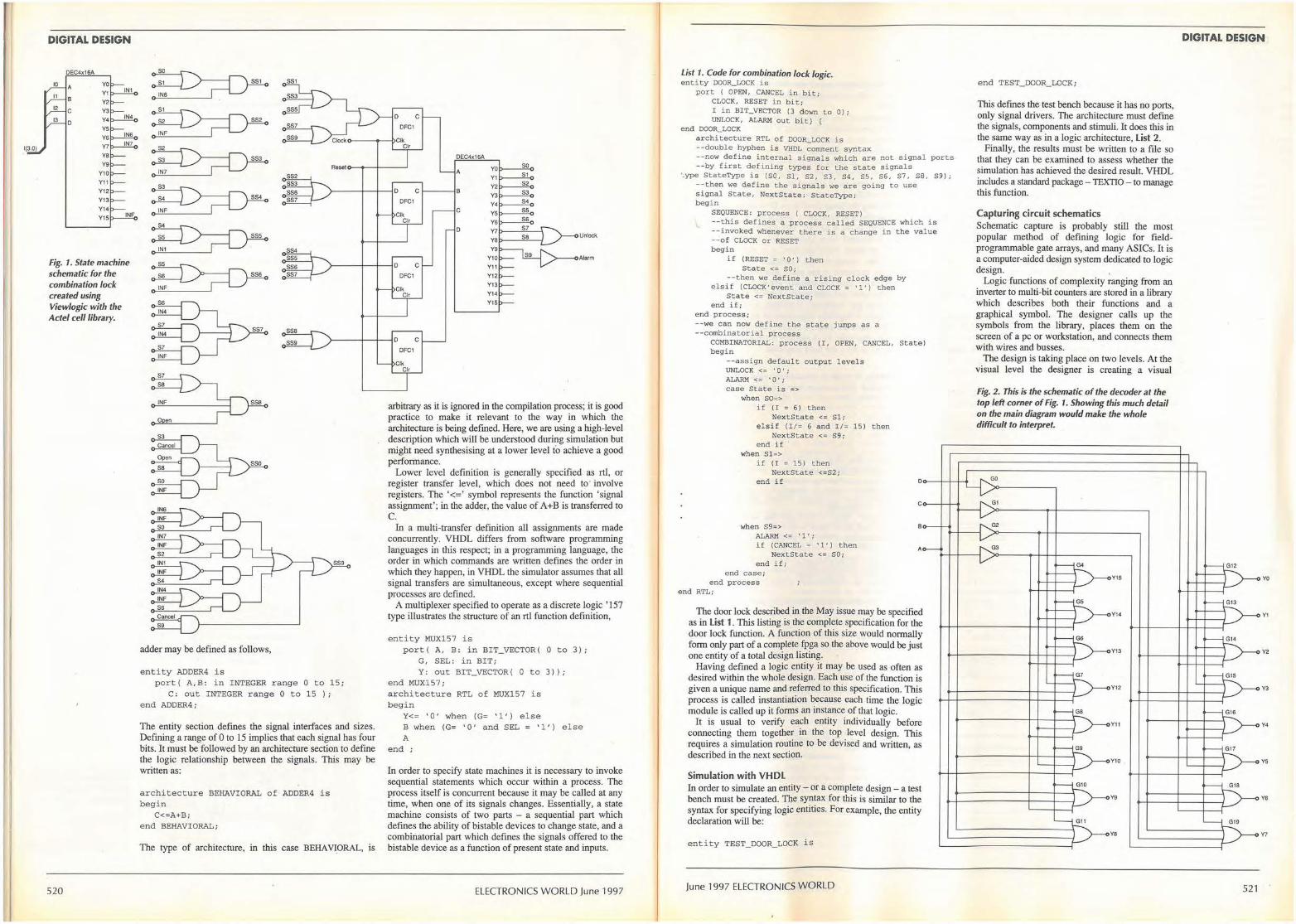
1(3.0
DIGITAL DESIGN
OEC4x16A
10 A 11 B
12 C
13 0
Fig. 1. State machine schematic for the combination Jock created using Viewlogic with the Acte/ eel/ library.
520
~ ~ -
~ ~ -
~ ~-
~ ~ -
~ ~-
Rese1
D
OEC4x16A
A
B
OFC1
C
0
C
OFC1
YO so Y1 S1
Y2 S2
Y3 S3
Y4 S4
VS S5
Y6 S6
Unlock
Alarm
,_ __ ..,__,.___, 0 C
u---,__...- OFC1
adder may be defined as follows,
entity ADDER4 is port( A,B: in INTEGER range Oto 15;
C: out INTEGER range Oto 15 ); end ADDER4;
The entity section defines the signal interfaces and sizes. Defining a range of Oto 15 implies that each signal has four bits. It must be followed by an architecture section to define the logic relationship between the signals. This may be written as:
architecture BEHAVIORAL of ADDER4 is b egin
C<=A+B; end BEHAVIORAL;
The type of architecture, in this case BEHA YI.ORAL, is
arbitrary as it is ignored in the compilation process; it is good practice to make it relevant to the way in which the architecture is being defined. Here, we are using a lrigh-level description which will be understood during simulation but might need synthesising at a lower level to achieve a good performance.
Lower level definition is generally specified as rd, or register transfer level, which does not need to· involve registers. The '<=' symbol represents the function 'signal assignment'; in the adder, the value of A+B is transferred to C.
In a multi-transfer definition all assignments are made concurrently. VHDL differs from software programming languages in this respect; in a programming language, the order in which commands are written defines the order in which they happen, in VHDL the simulator assumes that all signal transfers are simultaneous, except where sequential processes are defined.
A multiplexer specified to operate as a discrete logic '157 type illustrates the structure of an rd function definition,
entity MUX157 is p ort( A, B: in BIT_VECTOR( 0 to 3);
G, $EL : in BIT; Y: out BIT_VECTOR( 0 to 3));
end MUX157; architecture RTL of MUX157 is begin
Y<= '0' when (G= '1') else B when (G= '0' and SEL = ' 1') else A
end ;
In order to specify state machines it is necessary to invoke sequential statements which occur within a process. The process itself is concurrent because it may be called at any time, when one of its signals changes. Essentially, a state machine consists of two parts - a sequential part which defines the ability of bistable devices to change state, and a combinatorial part which defines the signals offered to the bistable device as a function of present state and inputs.
ELECTRONICS WORLD June 1997
List 1. Code for combination lock logic. entity DOOR_LOCK is
port ( OPEN. CANCEL i n bit; CLOCK, RESET in bit; I i n BIT_VECTOR (3 down to 0); UNLOCK, ALARM out bit} [
end DOOR_LOCK architecture RTL of DOOR LOCK is --double hyphen is VHDL ~omment syntax --now define i n ternal signals which are not signal ports --by first defining types for the stat e signal s
'.ype State'l'ype is (SO, Sl, S2, S3 , S4, S5, S6, S7, SS, S9); --then we define the signals we are going to use signal State, Nex tState : State'l'ype; begin
SEQUENCE: process ( CLOCK, RESET) --this defines a process called SEQUENCE which i s - - invoked whenever there is a change i n the value --of CLOCK or RESET begin
if (RESET= '0') then State<= SO;
- - then we define a rising clock edge by elsif (CLOCK'event and CLOCK= '1') then
State<= NextState; end if ;
end process; --we can now define the state jumps as a --combinatoria l process
COMBINATORIAL: process (I, OPEN, CANCEL, State) begin
--assign default output levels UNLOCK<= '0 '; ALARM <= ' 0 '; case State is=>
when SO=> if (I = 6) then
NextState <= Sl; e lsif (I/= 6 and I/= 15) then
Nextstate <= S9; end if
when Sl=> if (I= 15 ) t hen
NextState <=S2; end if
when S9=> ALARM <= ' 1' ; if (CANCEL= ' 1 ' ) then
Next State <= SO ; end if ;
end case; end process
end RTL;
D
C
B 0--
A 0--
The door lock described in the May issue may be specified as in List 1. This listing is the complete specification for the door lock function. A function of this size would normally form only part of a complete fpga so the above would be just one entity of a total design listing.
Having defined a logic entity it may be used as often as desired within the whole design. Each use of the function is given a unique name and referred to this specification. This process is called instantiation because each time the logic module is called up it forms an instance of that logic.
It is usual to verify each entity individually before connecting them together in the top level design. This requires a simulation routine to be devised and written, as described in the next section.
Simulation with VHDL In order to simulate an entity - or a complete design - a test bench must be created. The syntax for this is similar to the syntax for specifying logic entities. For example, the entity declaration will be:
entity TEST_DOOR_LOCK i s
June 1997 ELECTRONICS WORLD
-.....
I
end TEST_DOOR_ LOCK;
This defines the test bench because it has no ports, only signal drivers. The architecture must define the signals, components and stimuli. It does this in the same way as in a logic architecture, List 2.
Finally, the results must be written to a file so that they can be examined to assess whether the simulation has achieved the desired result. VHDL includes a standard package - TEXTIO - to manage this function.
Capturing circuit schematics Schematic capture is probably still the most popular method of defining logic for fieldprogrammable gate arrays, and many ASICs. It is a computer-aided design system dedicated to logic design. ,
Logic functions of complexity ranging from an inverter to multi-bit counters are stored in a library which describes both their functions and a graphical symbol. The designer calls up the symbols from the library, places them on the screen of a pc or workstation, and connects them with wires and busses.
The design is taking place on two levels. At the visual level the designer is creating a visual
Fig, 2. This is the schematic of the decoder at the top left corner of Fig. 1. Showing this much detail on the main diagram would make the whole difficult to interpret.
GO
r--{)G1
----CG2
G3
-~Y1S
~ ~ Y14
~~Y13
~ · - Y12
~ Y11
~ YtO
RS--yg
G11
l Y8
DIGITAL DESIGN
'-$-YO
~R5-- Y1
'-$-Y2
~$-Y3
$- Y4
$-Y5
~ Y6
G19
) Y7
521
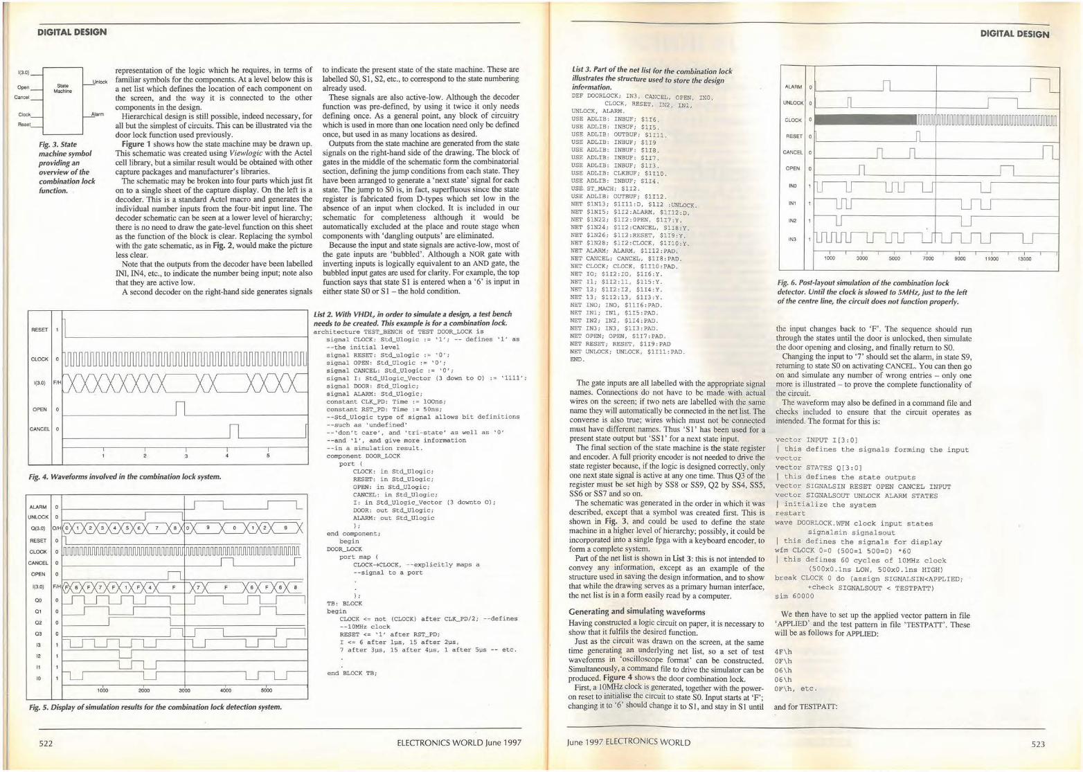
1(3.0)
Open
Cancel
Clock
Reset
DIGITAL DESIGN
State UnlO<k
Machine
A!arm
Fig. 3. State machine symbol providing an overview of the combination lock function.
OPEN 0
CANCEL 0
representation of the logic which he requires, in terms of familiar symbols for the components. At a level below this is a net list which defines the location of each component on the screen, and the way it is connected to the other components in the design.
Hierarchical design is still possible, indeed necessary, for all but the simplest of circuits. This can be illustrated via the door lock function used previously.
Figure 1 shows how the state machine may be drawn up. This schematic was created using Viewlogic with the Actel cell library, but a similar result would be obtained with other capture packages and manufacturer's libraries.
The schematic may be broken into four parts which just fit on to a single sheet of the capture display. On the left is a decoder. This is a standard Actel macro and generates the individual number inputs from the four-bit input line. The decoder schematic can be seen at a lower level of hierarchy; there is no need to draw the gate-level function on this sheet as the function of the block is clear. Replacing the symbol with the gate schematic, as in Fig. 2, would make the picture less clear.
Note that the outputs from the decoder have been labelled INI, IN4, etc., to indicate the number being input; note also that they are active low.
A second decoder on the right-hand side generates signals
Fig. 4. Waveforms involved in the combination lock system.
ALARM 0
UNLOCK 0
0 (3.0)
RESET 0
CLOCK 0
CANCEL 0
OPEN 0
1(3.0)
ao 0
o1 0
02 0
03 0
13
12
11
10
1000 2000 3000 4000 5000
Fig. 5. Display of simulation results for the combination lock detection system.
522
to indicate the present state of the state machine. These are labelled SO, SI, S2, etc., to correspond to the state numbering already used.
These signals are also active-low. Although the decoder function was pre-defined, by using it twice it only needs defining once. As a general point, any block of circuitry which is used in more than one location need only be defined once, but used in as many locations as desired.
Outputs from the state machine are generated from the state signals on the right-hand side of the drawing. The block of gates in the middle of the schematic fonn the combinatorial section, defining the jump conditions from each state. They have been arranged to generate a 'next state' signal for each state. The jump to SO is, in fact, superfluous since the state register is fabricated from D-types which set low in the absence of an input when clocked. It is included in our schematic for completeness although it would be automatically excluded at the place and route stage when components with 'dangling outputs' are eliminated.
Because the input and state signals are active-low, most of the gate inputs are 'bubbled'. Although a NOR gate with inverting inputs is logically equivalent to an AND gate, the bubbled input gates are used for clarity. For example, the top function says that state Sl is entered when a '6' is input in either state SO or S 1 - the hold condition.
List 2. With VHDL, in order to simulate a design, a test bench needs to be created. This example is for a combination lock. architecture TEST_BENCH of TEST DOOR_LOCK is
signal CLOCK: Std_Ulogic := ' 1' ; -- defines ' l' as --the initial level signal RESET: Std_ulogic := '0'; s ignal OPEN: Std_Ulogic : = ' 0 '; signal CANCEL : Std_Ulogic := ' 0'; signal I : Std_Ulogic_Vector (3 down to O) : = ' 1111'; signal DOOR: Std_Ulogic; signal ALARM: Std_Ulogic; constant CLK_PD: Time : = loons; constant RST_PD: Time := SOns; --Std_Ulogic type of signal allows bit definitions --such as ' undefined' --'don't care', and \tri-state • as well as 1 0' --and 'l', and give more information --in a s imulation result. component DOOR_LOCK
port ( CLOCK : in Std_Ulogic; RESET: in Std_Ulogic; OPEN: in Std_Ulogic; CANCEL : in Std_Ulogic; I: in Std_Ulogic_Vector (3 downto O); DOOR: out Std_Ul ogic; ALARM: out Std_Ulogic ) ;
end component; begin
DOOR_LOCK port map
CLOCK• CLOCK, --explicitly maps a --signal to a port
);
TB : BLOCK begin
CLOCK<= not (CLOCK) after CLK_PD/2; --defines - - lOMHz clock RESET<= ' 1 ' after RST_PD; I<= 6 after lµs , 15 after 2µs, 7 after 3µs, 15 after 4µs. 1 after Sµs -- etc.
end BLOCK TB;
ELECTRONICS WORLD June 1997
List 3. Part of the net list for the combination lock illustrates the structure used to store the design information. DEF DOORLOCK; IN3, CANCEL, OPEN, INO ,
CLOCK, RESET, IN2, INl, UNLOCK, ALARM . USE ADLIB : INBUF; $1I6. USE ADLIB: INBUF; $1I5 . USE ADLIB: OUTBUF; Slill. USE ADLIB: INBUF; $1I9 USE ADLIB : INBUF: $1I8. USE ADLIB : INBUF: S117. USE ADLIB: INBUF; $1I3 . USE ADLIB: CLKBUF; $1110. USE ADLIB: INBUF; $1I4 . USE ST_MACH; $1I2 . USE ADLIB: OUTBUF; $1112 . NET $1Nl3; $1Ill : D, $112 :UNLOCK. NET $1NI5; $112 : ALARM, $1112:D. NET $1N22; $1I2:0PEN, $117:Y. NET $1N24; $1I2 : CANCEL, $118:Y. NET $1N26 ; $1I2:RESET, $1I9 :Y. NET $1N28; $1I2 :CLOCK, $1110:Y. NET ALARM; ALARM, $1112 : PAD. NET CANCEL; CANCEL, $1I8:PAD, NET CLOCK; CLOCK, $1Il0 : PAD. NET IO; $1I2 : IO, $116:Y. NET Il; $1I2:11, $115 : Y. NET 12 ; $1I2:I2, $1I4:Y. NET 13; $1!2 :13, $1I3:Y. NET INO; !NO, $1116 : PAD . NET lNl; I Nl , $1IS: PAD. NET IN2 ; IN2. $1!4 : PAD . NET I N3; IN3, $1I3 : PAD. NET OPEN; OPEN, $117 : PAD. NET RESET; RESET, $1I9 : PAD NET UNLOCK; UNLOCK, $1111 :PAD. END.
The gate inputs are all labelled with the appropriate signal names. Connections do not have to be made with actual wires on the screen; if two nets are labelled with the same name they will automatically be connected in the net list. The converse is also true; wires which must not be connected must have different names. Thus ' SI' has been used for a present state output but 'SS I ' for a next state input.
The final section of the state machine is the state register and encoder. A fulJ priority encoder is not needed to drive the state register because, if the logic is designed correctly, only one next state signal is active at any one time. Thus Q3 of the register must be set high by SS8 or SS9, Q2 by SS4, SS5, SS6 or SS? and so on.
The schematic was generated in the order in which it was described, except that a symbol was created first. This is shown in Fig. 3, and could be used to define the state machine in a higher level of hierarchy; possibly, it could be incorporated into a single fpga with a keyboard encoder, to form a complete system.
Part of the net list is shown in List 3: this is not intended to convey any information, except as an example of the structure used in saving the design information, and to show that while the drawing serves as a primary human interface, the net list is in a form easily read by a computer.
Generating and simulating waveforms Having constructed a logic circuit on paper, it is necessary to show that it fulfils the desired function.
Just as the circuit was drawn on the screen, at the same time generating an under! ying net list, so a set of test waveforms in 'oscilloscope format' can be constructed. Simultaneously, a command file to drive the simulator can be produced. Figure 4 shows the door combination lock.
First, a 10MHz clock is generated, together with the poweron reset to initialise the circuit to state SO. Input starts at 'F'; changing it to '6' should change it to SI, and stay in SI until
June 1997 ELECTRONICS WORLD
ALARM 0 _______ __,
UNLOCK 0
CLOCK 0
RESET 0
CANCEL 0
OPEN 0
INO
IN1
IN2
IN3
1000 3000 5000 7000 9000
Fig. 6. Post-layout simulation of the combination lock detector. Until the clock is slowed to 5MHz, just to the left of the centre line, the circuit does not function properly.
the input changes back to 'F'. The sequence should run through the states until the door is unlocked, then simulate the door opening and closing, and finally return to SO.
Changing the input to '7' should set the alarm, in state S9, returning to state SO on activating CANCEL. You can then go on and simulate any number of wrong entries - only one more is illustrated - to prove the complete functionality of the circuit.
The waveform may also be defined in a command file and checks included to ensure that the circuit operates as intended. The format for this is:
vector INPUT I[3 : 0 ] / this defines the signals forming the input vector vector STATES Q(3 : 0] / this defines the state outputs vector SIGNALSIN RESET OPEN CANCEL INPUT vector SIGNALSOUT UNLOCK ALARM STATES I initialize the system restart wave DOORLOCK . WFM clock input states
signalsin s ignalsout I this defines the signals for display wfm CLOCK 0=0 (500=1 500=0) *60 I this defines 60 cycles of 10MHz clock
(500x0 . lns LOW, 500x0 . lns HIGH) break CLOCK Odo (assign SIGNALSIN<APPLIEO;
+check SIGNALSOUT < TESTPATT) s i m 60000
We then have to set up the applied vector pattern in file 'APPLIED' and the test pattern in file 'TESTPATT'. These will be as follows for APPLIED:
4F\h OF\h 06 \h 06\h OF\h, etc.
and for TESTP A TT:
DIGITAL DESIGN
11000 13000
523
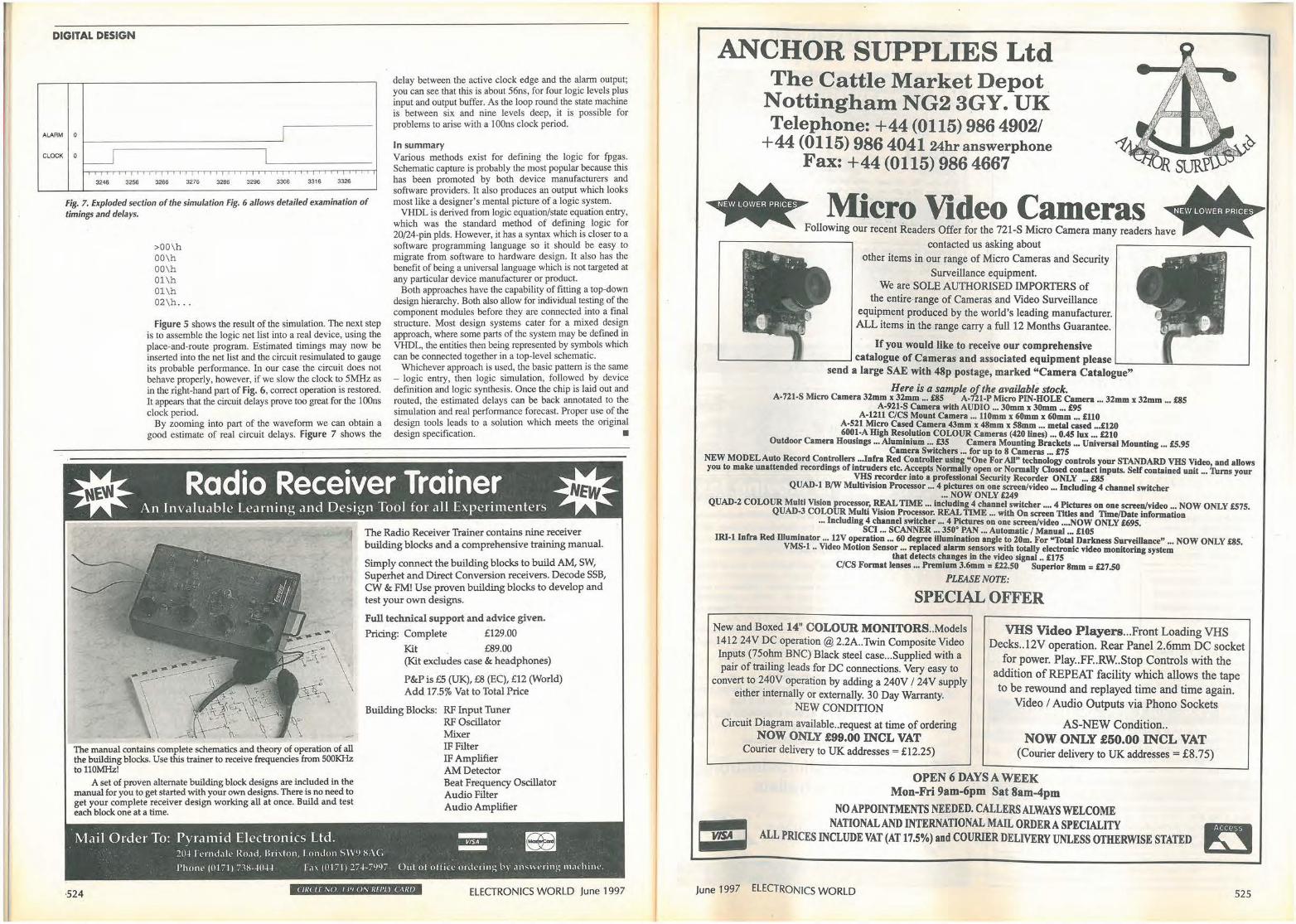
DIGITAL DESIGN
ALARM
CLOCK
0
0 L_J
3246 3256 3266 3276 3286 3296
I I
3306 3316 3326
delay between the active clock edge and the alarm output; you can see that this is about 56ns, for four logic levels plus input and output buffer. As the loop round the state machine is between six and nine levels deep, it is possible for problems to arise with a lO0ns clock period.
In summary
Fig. 7. Exploded section of the simulation Fig. 6 allows detailed examination of timings and delays.
Various methods exist for defining the logic for fpgas. Schematic capture is probably the most popular because this has been promoted by both device manufacturers and software providers. It also produces an output which looks most like a designer's mental picture of a logic system.
VHDL is derived from logic equation/state equation entry, which was the standard method of defining logic for 20/24-pin plds. However, it has a syntax which is closer to a software programming language so it should be easy to migrate from software to hardware design. It also has the benefit of being a universal language which is not targeted at any particular device manufacturer or product.
>00\h 00\h 00\h 01\h 01\h 02\h ...
Figure 5 shows the result of the simulation. The next step is to assemble the logic net list into a real device, using the place-and-route program. Estimated timings may new be inserted into the net list and the circuit resimulated to gauge its probable performance. In our case the circuit does not behave properly, however, if we slow the clock to 5MHz as in the right-hand part of Fig. 6, correct operation is restored. It appears that the circuit delays prove too great for the I OOns clock period.
By zooming into part of the waveform we can obtain a good estimate of real circuit delays. Figure 7 shows the
Both approaches have the capability of fitting a top-down design hierarchy. Both also allow for individual testing of the component modules before they are connected into a final structure. Most design systems cater for a mixed design approach, where some parts of the system may be defined in VHDL, the entities then being represented by symbols which can be connected together in a top-level schematic.
Whichever approach is used, the basic pattern is the same - logic entry, then logic simulation, followed by device definition and logic synthesis. Once the chip is laid out and routed, the estimated delays can be back annotated to the simulation and real performance forecast. Proper use of the design tools leads to a solution which meets the original design specification. •
The Radio Receiver Trainer contains nine receiver building blocks and a comprehensive training manual.
Simply connect the building blocks to build AM, SW, Superhet and Direct Conversion receivers. Decode SSB, CW & FM! Use proven building blocks to develop and test your own designs.
Full technical support and advice given.
Pricing: Complete £129.00
Kit £89.00 (Kit excludes case & headphones)
P&P is £5 (UK), £8 (EC), £12 (World) Add 17.5% Vat to Total Price
Building Blocks: RF Input Tuner RF Oscillator Mixer
The manual contains complete schematics and theory of operation of all the building blocks. Use this trainer to receive frequencies from SOOKHz toll0MHz!
IF Filter IF Amplifier AM Detector
A set of proven alternate building block designs are included in the manual for you to get started with your own designs. There is no need to get your complete receiver design working all at once. Build and test each block one at a time.
Beat Frequency Oscillator Audio Filter Audio Amplifier
Mail Order To: Pyramid Electronics Ltd. ::5: _ -20.J I l'1nd.1J,, Ro.Hi , B,i,1011, I 011do11S\\91-1:\C
l'ho1w (0171) ,:-1-1-.JO.J.J I .i, (0171) 27.J-7997 Out of ollit"l' mlkting by .111s\H'1i11g m,1chi1H'.
·524 < 1/U If M J I 1'1 ON IHl'll ( ,\lll) ELECTRONICS WORLD June 1997
ANCHOR SUPPLIES Ltd The Cattle Market Depot
Nottingham NG2 3GY. UK Telephone: +44 (0115) 986 4902/
+44 (0115) 986 404124hr~nswerphone Fax: +44 (0115) 986 4667
contacted us asking about
other items in our range of Micro Cameras and Security
Surveillance equipment. We are SOLE AUTHORISED IMPORTERS of
the entire range of Cameras and Video Surveillance equipment produced by the world's leading manufacturer. ALL items in the range carry a full 12 Months Guarantee.
If you would like to receive our comprehensive '---- -----""'-----' catalogue of Cameras and associated equipment please L-.---~-----___J
send a large SAE with 48p postage, marked "Camera Catalogue"
Here is a sample of the available srock. A-721-S Micro Camera 32mm x 32mm ... £85 A-121-P Micro PIN-HOLE Camera ... 32mm x 32mm ... £85
A-921-S Camera with AUDIO ... 30mm x 30mm ... £95 A-1211 C/CS Mount Camera ... 110mm x 60mm x 60mm ... £110
A-521 Micro Cased Camera 43mm x 48mm x 58mm ... metal cased ... £120 6001-A High Resolution COLOUR Cameras (420 Unes) ... 0.45 ho: ... £210
Outdoor Camera Housings ... Aluminium ... £35 Camera Mounting Brackets ... Universal Mounting ... £5.95 Camera Switchers ... for up to 8 Cameras ... £75
NEW MODEL Auto Record Controllers ... Infra Red Controller using "One For All" technology controls your STANDARD VHS Video and allows you to make unattended recordings of intruders etc. Accepts Normally open or Normally Closed contact inputs. Self contained unit ... Tums your
VHS recorder into a professional Security Recorder ONLY ••. £85 QUAD-1 B/W Multivision Processor ... 4 pictures on one screen/video ... Including 4 channel switcher
... NOW ONLY £249 QUAD-2 COLOUR Multi Vision processor, REAL TIME ... including 4 channel switcher .... 4 Pictures on one screen/video ... NOW ONLY £575.
QUAD-3 COLOUR Multi Vision Processor. REAL TIME ... with On screen Titles and 1lme/Date information ... Including 4 channel switcher ... 4 Pictures on one screen/video .... NOW ONLY £695. ·
SCI ... SCANNER ... 350° PAN ... Automatic / Manual ... £105 . IRI-1 Infra Red Illumlnator ... 12V operation ... 60 degree illumination angle to 20m. For "Total Darkness Surveillance" ... NOW ONLY £85.
VMS-1 .. Video Motion Sensor ... replaced alarm sensors with totally electronic video monitoring system that detects changes in the video signal .. £175
C/CS Format lenses ... Premium 3.6mm = £22.50 Superior 8mm = £27.50
PLEASE NOTE:
SPECIAL OFFER
New and Boxed 14" COLOUR MONITORS .. Models 1412 24V DC operation @2.2A..Twin Composite Video
Inputs (75ohm BNC) Black steel case ... Supplied with a pair of trailing leads for DC connections. Very easy to
convert to 240V operation by adding a 240V / 24V supply
either internally or externally. 30 Day Warranty.
VHS Video Players ... Front Loading VHS Decks . .12V operation. Rear Panel 2.6mm DC socket
for power. Play .. FF..RW.Stop Controls with the addition of REPEAT facility which allows the tape to be rewound and replayed time and time again.
NEW CONDITION
Circuit Diagram available .. request at time Qf ordering NOW ONLY £99.00 INCL VAT
Courier delivery to UK addresses= £12.25)
Video / Audio Outputs via Phono Sockets
AS-NEW Condition .. NOW ONLY £50.00 INCL VAT
{Courier delivery to UK addresses= £8.75)
OPEN 6 DAYS A WEEK Mon-Fri 9am-6pm Sat 8am-4pm
NO APPOINTMENTS NEEDED. CALLERS ALWAYS WELCOME ~ NATIONAL AND INTERNATIONAL MAIL ORDERA SPECIALITY -.a. ALL PRICES INCLUDE VAT (AT 17.5%) and COURIER DELIVERY UNLESS OTHERWISE STATED ~
June 1997 ELECTRONICS WORLD 525
ARTICLES WANTED
WE WANT TO BUY!! IN VIEW OF THE EXTREMELY
RAPID CHANGE TAKING PIA CE IN THE ELECTRONICS
INDUSTRY, LARGE QUANTITIES OF COMPONENTS BECOME REDUNDANT. WE ARE CASH
PURCHASERS OF SUCH MATERIALS AND WOUW
APPRECIATE A TELEPHONE CALL OR A LIST IF AVAIIABLE.
WE PAY TOP PRICES AND COLLECT.
R. HENSON LTD. 2i Lodge Lane, N.Finchley,
London N12 8JG. 5 Mins,from Tally Ho Corner.
TELEPHONE 0181-445-2713/0749 FAX 0181-445-5702
TOP PRICES PAID For all your valves, tubes, semi
conductors and IC's.
Langrex Supplies Limited 1 Mayo Road, Croydon
Surrey CRO 2QP TEL: 0181-6841166 FAX: 0181-684 3056
Wandel Goltermann PIUl.. l, 2mbit Frame Mux Analyzer superb
instnunent.
£3,500 o . n.o.
Tel: 01566 781680
WANl"ED: WW2 suitcase radioset (SOE/SIS) German milituy radios for display only, RAS Otterslad, OZ8RD, Hoslerkobveg Co DK-3460 Birierod, Denmark. Tel: ++45 4281 5205.
**WANTED** Test equipment, Electronic Scrap, Valves, Transmitters/Receivers, Factory & Warehouse Clearance.
Confidentiality Assured.
TELFORD ELECTRONICS Phone: 01952 605451
Fax: 01952 677978
RF DESIGN SERVICES
All aspects of RF hardware development considered from concept to production.
[WATERBEACH ELECTRONICS!
TEL: 01223 862550 FAX: 01223 440853
\'AL\'ES. and CRTs A \'AILABLE ONE MILLION VALVES stoc:ked for Audio, Receiving, Transmitting & RF Heating. Rare brands such as Mullard & GEC available.
Also MAGNETRONS, KL VSTRONS, CRTs and SOCKETS. Large stocks of Russian & Sovtek items.
Please ask for our free catalogues of valves or CRTs.
VALVES, etc. WANTED Most types considered but especially KT88 (£48), PX4/PX25 (£50), KT66 (£35), KT77 (£15), EL34 (£10), EL37 (£9), ECC83 (£3). Valves must be UK manufacture to achieve prices mentioned. Also various valve-era equipment e.g. Garrard 301, (up to) £80.
Ask for a free copy of our wanted List.
BILLINGTON EXPORT LTD., Bllllngshurst, Sussex RH14 9EZ. Tel: 01403 784961 Fax: 01403 783519
VISITORS STRICTLY BY APPOINTMENT. MINIMUM ORDER £50 plus VAT
ARTICLES FOR SALE ~ Protect Your Microchips ~ ~~~ from STATIC DISCHARGE ! ~~ - -
Use an SSE grounding kit. Kit lnclud•:
• etetlc dlHlpetlve •older raeletent rubbermllt.
- wrlet etrep - ground lead • earth plug
Met elze 70 x 30 cm• offer price £18.1515 per kit + VAT - Ref: AGK1 Met elze 215 x 20 cm - offer pitce £12.1515 per kit +VAT• Ref: AGK2 STATIC SAFE ENVIRONMENTS Payment by CHEQUE/ ACCESS 127 Hagley Road, Birmingham B16 BXU VISA I MASTERCARD Tel: 0121454 8238 Fa.: 0121 625 2275 Catalogue avatlable
Marconi Spectrum Analyser model 2382, 100Hz-400MHz,
3HzminRBW
QUAD ESL', For sale 1 pr only, offers lo Mike. Phone/Fax: 01483 487189.
DRANETZ PBASEMETER For sale, very accurate 0.01' from 2Hz 10 700 KHz. two only £200 ono. Phone/Fax: 01483 487189. With tracking generator and GPIB, new
Marconi seJVice manuals and fresh caubration.
£4000 Also HP7475A A3 plotter with GPIB interface
£500 Tel: 0118 979 2340
RECRUITMENT
Electronics is moving fast
Are you upto speed?
This innovative programme offers companies and individuals the opportunity to keep right up to speed on developments in microelectronics design without having to lose time at work.
No matter what your location the course will come to you via a high spec PC, connected to teaching resources and a host of other facilities, via your own high speed data link. Making a connection with this tale-learning programme will mean you can study from home when it suits you. The programme is approved under the Integrated Graduate Development Scheme and has been developed with considerable input from industrialists.
For more information contact:
Roy Attwood, IGDS Co-ordinator, Bolton Institute
Deane Road, Bolton, Lanes BL3 5AB
Tel. (01204) 528851/900800 Ext 3887 Fax. (01204j 370918 E-mail: r.attwooclObolton.ac.uk
MSc Advanced Microelectronics for lndustralists
BOLTON UNIVERSITY of -r INSTITUTE NORTHUMBRIA :1 ,..
at NEWCASTLE _.~-i..i--Pr<H iding Access to Fkxibk Study P rogrammes
CLASSIFIED TEL 0181652 3620 FAX 0181 652 8956
ARTICLES FOR SALE
- ==· SUPPLIER OF QUALITY USED
TEST INSTRUMENTS
CONTACT
Cooke International ELECTRONIC TEST & MEASURING INSTRUMENTS
Unit Four, Fordingbridge Site, Main Road, Barnham,, Bogner Regis, West Sussex, PO22 0HD, U.K.
Tel: (+44)01243 545111/2 Fax: (+44)01243 542457 < Ill( I f,\:() I.JO 01\ 1/fl'Ll ( ,\ 11/J
~ I k I,n~t:.:,er;;..••-tl_o•-:•~ __ c_oo-:-:8 ~llff'IW'"' iitt fO!JtO
1ue1~ ;~..:.::...,:;~•-~
..,...._ .• ~"""---;~-!-::ito<" .., ..
~ ?l · E\~:7~. ~ ~ l ;t:
1:\\1 \\\! CONTACT
Cooke International Unit Four, ·fordingbridge Site, Main Road, Barnham,
Bogner Regis, West Sussex, PO22 0HD, U.K. Tel: (+44)01243 545111/2 Fax: (+44)01243 542457
NOW AVAILABLE CATALOGUE ON DISC (/1/( Lf \ '() / .J I () \ ' 111/'ll ( 0 \/1/J
ADVERTISERS INDEX Anchor ....... ..... . ............ . ...... ... 526 Labcenter ................................ . 506 Antrim .................................... 503 Leading Edge .............................. 479 Bull Electrical .. ... ........ ............. 445, 517 M & B ......... ... .. ........ ...... . ....... 461 CMS ................................... : .479
Card Professionals .......................... 479
Compass ............................. 465, 496
Conford .................................. 455
Display Electronics .......................... 501
Equinox .................................. IBC
Field ....... , · · ........................... 465
Halcyon ........... .. . ........ ... ...... ... 496
Hart ...... · · · · ............ ..... ......... . 447
Number One Systems . ........ ..... ... . .... .492
Olson .................................... IFC
Pico Technology ........................ 462, 519
Quickroute ........................... .455, 464
Ralfe Electronics ........................... 529
Stewarts of Reading ...... .. ................. 503
Surrey Electrical .. . .... . ... .. .. .. ... . .... .. .453
TTi .• · · · · .... .. .. ... .. ..... .... .......... . 465
Hitex .......... . ... . ...................... 496 Technology ..... . ... ........ . ... .. .... ..... 453
ICE Technology . ..... ..... .. ... .. ........ . OBC Telnet .......... ........................... 442
IOSIS ... · · · · · · · · ......................... 455 Telford .................................. . 485
JPG .. · · · · · · · · · · · · ....................... 453 lie Pie .. ..... . ... ... ...... ............. . . 442
John's Radio .............................. 475 Ultimate .................................. 451
Keytronics ............................... .494 Wood & Douglas . ... ...... . .............. . . 503
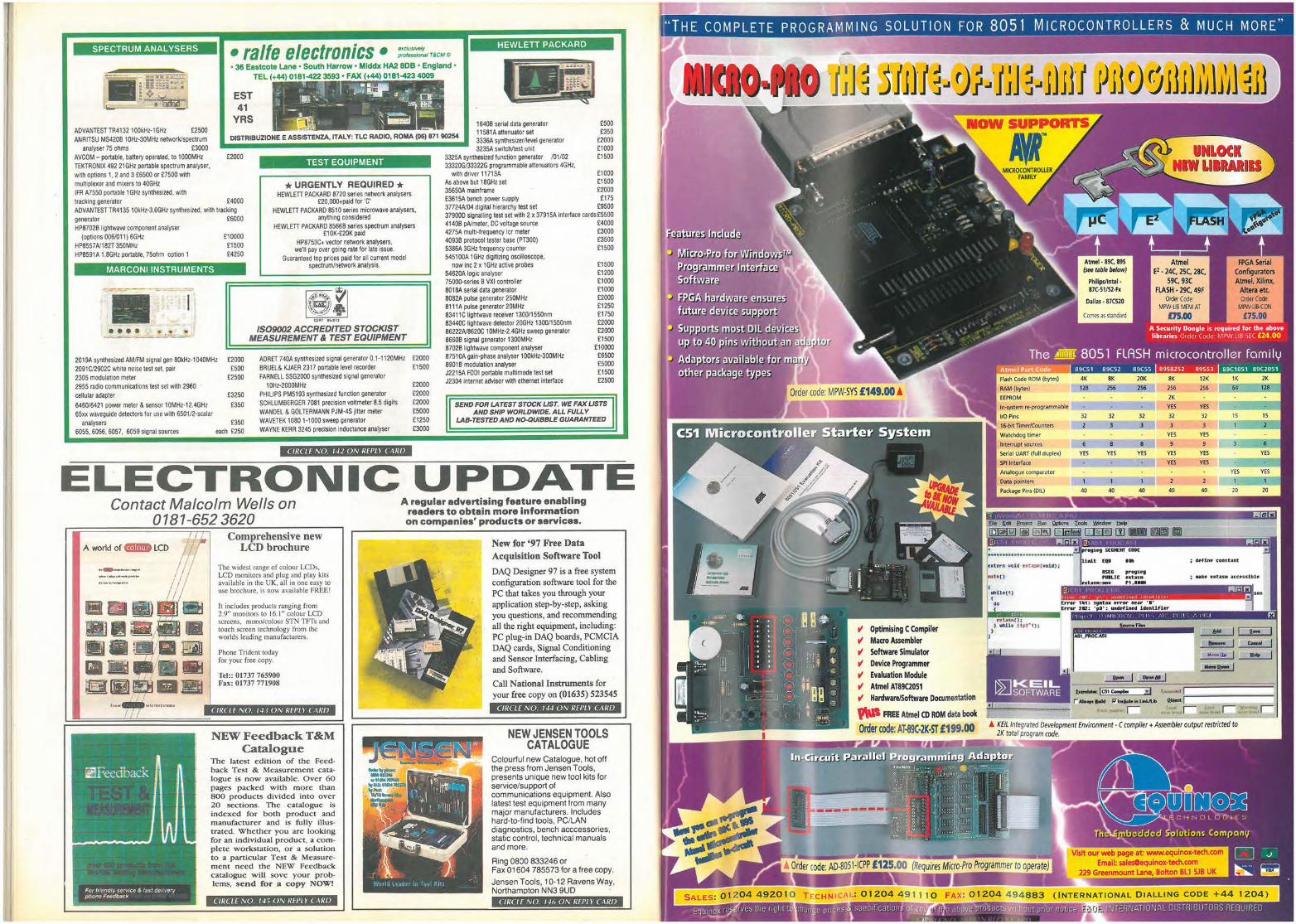
SPECTRUM ANALYSERS
ADVANTEST TR4132100kHz-1GHz £2500
• ralfe electronics • exduslvety pro/oulona/ T&CM C
• 36 Eastcote Lane • South Harrow • Mlddx HA2 808 • England • TEL (+44) 0181-422 3593 • FAX (+44) 0181-423 4009
EST 41
YRS
.,,. ~u- . ' .::. I .., - • • , ~ ~ • _.. . " ' : ~ ,.., . ' . ,.,, ~ . , !!!'!A " " . ' . ·-:<!I, _ " ~ - - '"' ""I
, -, l -~--- -. l "-' i;:____J -
I ' ...._ } -
HEWLETT PACKARD
·-ANRITSU MS4208 10Hz·30MHz network/sl)i!ctrum OISTRIBUZIONE E ASSISTENZA, rTALV: TLC RADIO, ROMA (06) 871 90254
1640B serial data generator 11581A attenuator set 3336A synthesizerAevel generator 3235A switcMest unit
£500 £350
£2000 £1000 £1500
analyser 75 ohms £3000 AVCOM - portable, battery operated, to 1000MHz TEKTRONIX 492 21GHz portable spectrum analyser, with options 1, 2 and 3 £6500 or £7500 with multiplexor and mixers to 40GHz IFR A7550 portable 1 GHz synthesized, with
£2000
tracking generator £4000 ADVANTEST TR4135 10kHz-3.6GHz synthesized, with tracking generator £6000 HP8702B lightwave component analyser
(options 006/011) 6GHz HP8557A/182T 350MHz HP8591A 1.8GHz portable. 75ohm option 1
MARCONI INSTRUMENTS
~ ~ - --:::: -
• . . . . .. . .. ,.. ~~:a:..= ~
2019A synthesized AM/FM signal gen 80kHz-1040MHz 2091 C/2902C white noise test set, pair 2305 modulation meter 2955 radio communications test set with 2960 · cellular adapter 6460/6421 power meter & sensor 10MHz-12.4GHz 65xx waveguide detectors for use with 6501/2-scalar
analysers
£10000 £1500 £4250
£2000 £500
£2500
£3250 £350
£350 6055, 6056, 6057, 6059 signal sources each £250
TEST EQUIPMENT
* URGENTLY REQUIRED * HEWLETT PACKAAD 8720 series network analysers
£20,000+paid for 'C' HEWlffi PACKARD 8510 series microwave analysers,
anything considered HEWLETT PACKARD 8566B series sl)i!ctrum analysers
£ 1 OK-£20K paid HP8753C+ vector network analysers,
we'll pay over going rate for late Issue. Guaranteed top prices paid for all current model
spectrum/network analysis.
IS09002 ACCREDITED STOCKIST MEASUREMENT & TEST EQUIPMENT
AORET 740A synthesized signal generator 0.1-1120MHz BRUEL& KJAER 2317 portable level recorder FARNELL SSG2000 synthesized signal generator
1 OHz·2000MHz PHILIPS PM5193 synthesized function generator SCHLUMBERGER 7081 precision voltmeter 8.5 digits WANDEL & GOL TERMANN PJM-4S jitter meter WAVETEK 1080 1-1000 sweep generator WAYNE KERR 3245 precision inductance analyser
CIRCLE NO 1.J2 ON RE/'0 CARI)
£2000 £1500
£2000 £2000 £2000 £5000 £1250 £3000
3325A synthesized 1unction generator /01/02 33320G/33322G programmable attenuators 4GHz,
with driver 11713A £1000 As above but 18GHz set £1500 35650A mainlrame £2000 E3615A bench power supply £175 37724A/04 digttal hierarchy test set £9500 379000 signalling test set with 2 x 37915A interlace cards£5500 41408 pA/meter, DC vottage source £4000 4275A multi-frequency lcr meter £3000 4093B protocol tester base (PT300) £3500 5386A 3GHz frequency counter £1500 545100A 1GHz digitizing oscilloscol)i!,
now inc 2 x 1GHz active probes 54620A IQ<Jic analyser 75000-series 8 VXI controller 8018A serial data generator 8082A pulse generator 250MHz 8111A pulse generator 20MHz 83411C lightwave receiver 130011550nm 83440C llghtwave detector 20GHz 1300/1550nm 86222A/8620C 10MHz-2.4GH2 sweep generator 86608 signal generator 1300MHz 8702B llghtwave component analyser 87510A gain-phase analyser 100kHz·300MHz 8901 B modulation analyser J2215A FOOi portable muttimode test set J2304 internet advisor with ethernet interlace
£1500 £1200 £1000 £1000 £2000 £1250 £1750 £2000 £2000 £1500
£10000 £6500 £5000 £1500 £2500
SEND FOR LA TEST STOCK UST. WE FAX USTS AND SHIP WORLDWIDE, AU FULL. Y
LAB-TESTED AND NO.QUIBBLE GUARANTEED
ELECTRONIC UPDATE Contact Malcolm Wells on
0181-652 3620 A regular advertising feature enabling
readers to obtain more information on companies' products or services.
,,...-. ,<,...Ytt••• TTT
Comprehensive new LCD brochure
The wides! range of colour LCDs, LCD monilors and plug and play kits available in 1he UK, all in one easy 10 use brochure, is now available FREE!
It includes products ranging from 2.9" moni1ors 10 16.1" colour LCD screens, mono/colour STN TFTs and 1ouch screen technology from the worlds leading manufac1urers.
Phone Trident today for your free copy.
Tel:: 01737 765900 Fax: 01737 771908
( /RC LE NO. l ~ I ON REPL) CARO
NEW Feedback T&M Catalogue
The latest edition of the Feedback Test & Measurement catalogue is now available. Over 60 pages packed with more than 800 products divided into over 20 sections. The catalogue is indexed for both product and manufacturer and is fully illustrated. Whether you are looking for an individual product, a com• plcte workstation, or a solution to a particular Test & Measurement need the NEW Feedback catalogue will sove your problems, send for a copy NOW!
New for '97 Free Data Acquisition Software Tool
DAQ Designer 97 is a free system configuration software tool for the PC that takes you through your application step-by-step, asking you questions, and recommending all the right equipment, including: PC plug-in DAQ boards, PCMCIA DAQ cards, Signal Conditioning and Sensor Interfacing, Cabling and Software.
Call National Instruments for your free copy on (01635) 523545
CIRCLE NO. 1.J.J ON REPL) CARD
NEW JENSEN TOOLS CATALOGUE
Colourful new Catalogue, hot off the press from Jensen Tools, presents unique new tool kits for service/support of communications equipment. Also latest test equipment from many major manufacturers. Includes hard-to-find tools, PC/LAN diagnostics, bench acccessories, static control, technical manuals and more.
Ring 0800 833246 or Fax 01604 785573 for a free copy.
Jensen Tools, 10-12 Ravens Way, Northamoton NN3 9UD
CIRCLE NO. I.J(, ON REPO CAR()
1'" T H E C O M P L ET E P R O G R A M M I N G S O LU T I O N F O R 8 0 5 1 M I C RO C O N T R O LL E R S & M U C H M O R E" .,......,...---- - ----------- ··- -··- ······-···
atures I elude
Mrcro-P.ro fo w·nc:10 ~,~ ... .-.....-.~iiii
. ,e_~gramme~-'le . ce Software - , P'~ .--.'"!(~ '
{FP.GArhardware 'e~SUl'.e ·"'"--. , ....... -........... ~ .. .. .... .,. ... • ~
fut1Jrt~evJ~e _ SUPP.I?, i_ • ,.
Supports,most OIL devjces , up to 40,:pinswithout1an a
Adaptors available for;ma other package types .
Software Simulator Device Programmer Evaluation Module Atmel AT89Q0S 1 Hardware/Software Documentation
f\\11 FREE Atmel CO ROM data book
Order code: AT-89C·2K-ST £199,00
Atmel P.trt Code
Interrupt sources
Serial UART (hotl duplex) SPI Interface
Analogue comparator
Data pomtef5
Package Pins (Oil)
-------·-----••ttrn uoid t-:wtH•(void);
{ .rdle(1) (
•• • 11:i
)
H U S.(); > ""111' 0 1111"1);
)
A Security Dongle is required for the above l ibraries Order Code: MPW-LIB SEC (24.00
89C51 89C52 89C55 8958252 89553 89C10 51 89C2051
32 32 .32
8 8 YES YES YES
1 1
40 40 40
• pr~5eg Sl CNENT CH[
ltllit EQIII
ltSEC PUil.iC
=-
2K
YES 32
YES 9
YES YES
40
64
YES 32 15 15
2
YES 9 6
YES YES YES
YES YES 1
40 20 20
~CE:J - ,~ ~ ~ __ ,
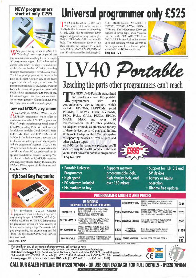
W ith prices starting as low as £295, ICE Technology's new range of parallel porr
Universal programmer only £S2S The Spccdmascer I OOO~ and
Micromasr.er 1000+ offer new levels of affordability in device programming. Ac only £395, the Speedmaster 1000+ supports all types of memory devices, plus 8748/51, BPROMs, GALs and erasable PALs. The Micromaster 1000+ at just £525 extends this support to include PALs, EPLDs, MACH, MAX, PSDs and over 180 microcomrollers including PIC,
ST6, MC68HC705, MC68HC711, TMS370, TMS320, 87Cxxx, 89Cxxx, COPs etc. The Micromaster 1000+ can support all device cypes, even Motorola micros, with NO ADAPTERS or MODULES for any dual in line devices up to and including 40 pins. As with all our programmers free sofrware updates are included via BBS or our ftp site. Enq No 178
J programmer, offers something for every budger. :::..:========================================= All programmers support dual in line devices directly in the socket • no adapters or modules are needed for any families of devices, providing extensive device coverage at very affordable prices. The fuU range of programmers is shown in the panel on the right. Our new easy to use device support checklist will help you co choose the programmer that is right foryou,just call or use our faxback for a copy. All progranunm come with FREE software updates on our BBS or our ftp site, full ceclmical support direct from the manufacmrer and one year's guaramee. All models can run from batteries or mains - ideal for use with laptops.
Low cost EPROM programmer
A t only £295, the EPMastcr LV is a powerful £PROM programmer which offers so
much more than other EPR.OM progranm1ers. With it's 40 pin socket it can support all types of EPROMs including 16 bit wide with no need for additional modules. Serial PROMs, Serial EEPROMs, Flash and EEPR.OMs are all included in the device support at no extra cost. In addition, low voltage parts arc fully supported \vith the programmer's separate 1.8V, 3.3V and 5V logic circuits. EPMaster LV connects to the parallel port of any PC compatible and can be operated from batteriei or mains electricity. You can also add a built in ROM/RAM emulator with a capability of up to 512k by 16, turning the EPMasccr LV into a powerful development cool.
EnqNo 176
High Speed Gang Programming
The Spcedmaster GLV-32 Gang/Set progr.urnner oilers simultaneous high speed
programnung for up co 8 EPROMs and Flash (up to 8Mbit) at 3.3V and SV. The 3.3V facility ensures that programmed device~ \\~ll work correctly at their nommal operatmg voltage. Funcnons include gang programming, set programming and full editing. The Speedmaster GLV32 works 111 PC or ,rand alone mode.
Enq No 177
Reaching the parts other programmers can't reach
The NEW LV40 Portable stands head and shoulders above other portable programmers with it 's
comprehensive device support which includes EPROMs, EEPROMs, Serial PROMs, BPROMs, Flash, NVRAMs, PSDs, PALs, GALs, PEELs, EPLDs, MACH, MAX and over 180 microcontrollers. Unlike other portables, no adapters or modules are needed for any of these devices up to 40 pins dual in line. With socket adapters the LV40 is capable of supporting devices of over 40 pins and other package types. At £995 for the complete package you' ll soon see why the LV40 Portable is the best value, most powerful portable programmer Enq No 179
• Portable Universal Programmer
• Supports memory, programmable logic, high density logic, and over 180 micros.
• Support for 1.8, 3.3 and SV devices
• High speed • PC software included • No modules to buy
• Battery or Mains operation
• Lifetime free updates
PROGRAMMER MODELS AND PRICES LV MODELS
(SUPPORT 1.8V, 3.3V and 5V DEVICES)
EPMASTER LV EPROMs, EEPROMs, Flash, Serial PROMs, Serial EEPROMs 8 to 40 pins all Wilhout adaplers. Built in emulator modules: 128k by 8: £395 128k by 16: £465
SPEEDMASTER LV EPROMs, EEPROMs, Flash. NVRAMs. Serial PROMs, Serial EEPROMs, BPROMs, GALs, PALs, EPLOs, MACH, MAX, 8748151.
EPROMs. EEPAOMs, NVRAMs, Flash, Serial, MICRO MASTER LV BPROMs, PALs, GALs, PEELs. MACH, MAX,
PSO, over 180 microcontrollers without adapters.
All devices supported by Micromaster LV, plus LV40 PORTABLE completely portable with built In keypad and
LCD display.
EPROMs, EEPROMs, flash NVRAMs, Serial SPEEOMASTER 1000+ PROMs, Serial EEPROMs, BPROMs. GALs,
8748151 £395
EPROMs, EEPROMs. NVRAMs. Flash. Serial, £295 MICROMASTER 1000+ BPROMs, PALs. GALs, PEELs, MACH, MAX, PSO, £525 over 180 m~rocontrollers wilhou1 adapters.
£495 SPEEDMASTER GLVJ2 High speed EPROM/Flash 8 way Gang/Set Programmer. Supports 3.3V and 5V
£625 COP GANG PROGRAMMER
8 way Gang programmer for National Sem,cOflduclOr COP family of micros
£995 SOCKET ADAPTERS for PLCC, TSOP, OFP, SOIC, SSOP etc.
£645
£1500
from £65
For details on any: of our range of programmers, call or fox us now. You can obtain information immed1otely by using our foxback :;.ervice or homepage. . ..
(E B
0 oY ...
ICE Technology Ltd, Penistone Court, Penistone, South Yorkshire S30 6HG. United Kingdom. Tel: +44 (0)1226 767404 Fax: +44 (0)1226 370434 Faxback: +44 (0)1226 761844 email: [email protected] Homepage: http:/ /www.icetech.com BBS: +44 (0)1226 761181 (14400 baud, 8Nl)
0 z
~J I
CALL OUR SALES HOTLINE ON 01226 767404 • OR USE OUR FAXBACK FOR FULL DETAILS· 01226 761844 ( fl{( LE ,\0. 11! I(),\' lltPl l ( Al{/J