3.5 inch setting tool technical manual
TRANSCRIPT
3.5 Inch Setting Tool Technical Manual
MAN-SET-3500-000 (R02)
12001 Cr 1000
Godley, Texas, 76044, USA
Phone: +1 (817) 551-0540
Fax: +1 (817) 551-1674
www.corelab.com/owen
Warning: use of owen equipment contrary to manufacturer’s specifications or operating instructions may result in property damage, serious injury or fatality. If you are not trained in the handling and use of explosive devices, do not attempt to use or assemble any owen perforating systems or owen firing devices.This technology is regulated by and, if exported, was exported from the united states in accordance with the export administration regulations (EAR). Diversion contrary to U.S. Law is prohibited. Export and/or re-export of this technology may require issuance of a license by the bureau of industry and security (BIS), U.S. Department of Commerce. Consult the BIS, the EAR, and/or Owen Compliance Services, Inc. To determine licensing requirements for export or re-export of this technology.This document contains confidential information of Owen Oil Tools LP (Owen) and is furnished to the customer for information purposes only. This document must not be reproduced in any way whatsoever, in part or in whole, or distributed outside the customer organization, without first obtaining the express written authorization of owen. This document is the property of owen and returnable upon request of Owen.
©2019-2020 Owen Oil Tools All rights reserved
MAN-SET-3500-000.indd 1MAN-SET-3500-000.indd 1 2/25/20 11:21 AM2/25/20 11:21 AM
3.5 in Setting Tool
2 I MAN-SET-3500-000 (R02) ©2019-2020 Owen Oil Tools All rights reserved
© 2
01
9 O
wen
Oil
Too
ls A
ll R
igh
ts R
eser
ved
3.5 in Setting Tool
OWEN OIL TOOLS | www.corelab.com/owen | 1.800.333.6936 | +1.817.551.0540 SET-3500-000 (R02)
© 2
017
- 201
9 O
wen
Oil
Tool
s A
ll R
ight
s R
eser
ved
TECHNICAL INFORMATION:
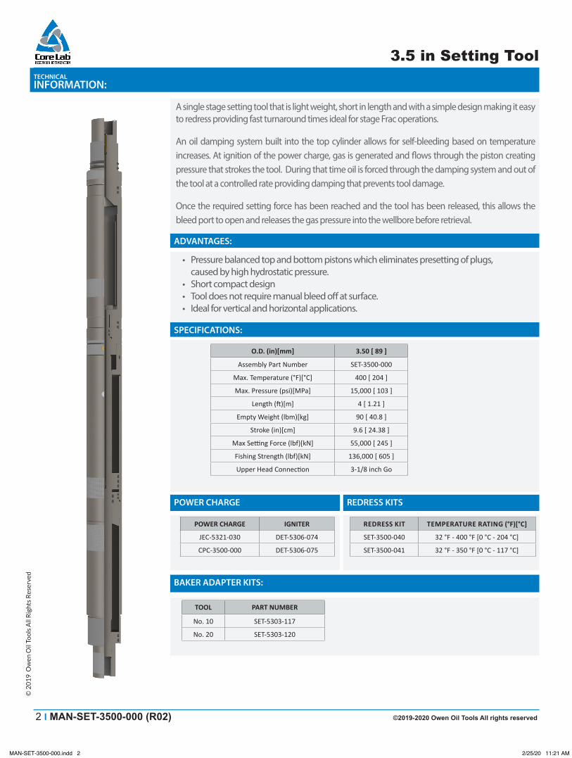
A single stage setting tool that is light weight, short in length and with a simple design making it easy to redress providing fast turnaround times ideal for stage Frac operations.
An oil damping system built into the top cylinder allows for self-bleeding based on temperature increases. At ignition of the power charge, gas is generated and � ows through the piston creating pressure that strokes the tool. During that time oil is forced through the damping system and out of the tool at a controlled rate providing damping that prevents tool damage.
Once the required setting force has been reached and the tool has been released, this allows the bleed port to open and releases the gas pressure into the wellbore before retrieval.
ADVANTAGES:
• Pressure balanced top and bottom pistons which eliminates presetting of plugs, caused by high hydrostatic pressure.
• Short compact design• Tool does not require manual bleed o� at surface.• Ideal for vertical and horizontal applications.
SPECIFICATIONS:
POWER CHARGE REDRESS KITS
BAKER ADAPTER KITS:
O.D. (in)[mm] 3.50 [ 89 ]
Assembly Part Number SET-3500-000
Max. Temperature (°F)[°C] 400 [ 204 ]
Max. Pressure (psi)[MPa] 15,000 [ 103 ]
Length (ft )[m] 4 [ 1.21 ]
Empty Weight (lbm)[kg] 90 [ 40.8 ]
Stroke (in)[cm] 9.6 [ 24.38 ]
Max Setti ng Force (lbf)[kN] 55,000 [ 245 ]
Fishing Strength (lbf)[kN] 136,000 [ 605 ]
Upper Head Connecti on 3-1/8 inch Go
POWER CHARGE IGNITER
JEC-5321-030 DET-5306-074
CPC-3500-000 DET-5306-075
TOOL PART NUMBER
No. 10 SET-5303-117
No. 20 SET-5303-120
REDRESS KIT TEMPERATURE RATING (°F)[°C]
SET-3500-040 32 °F - 400 °F [0 °C - 204 °C]
SET-3500-041 32 °F - 350 °F [0 °C - 117 °C]
MAN-SET-3500-000.indd 2MAN-SET-3500-000.indd 2 2/25/20 11:21 AM2/25/20 11:21 AM
©2019-2020 Owen Oil Tools All rights reserved MAN-SET-3500-000 (R02) I 3
3.5 in Setting Tool3.5 in Setting Tool
OWEN OIL TOOLS | www.corelab.com/owen | 1.800.333.6936 | +1.817.551.0540 SET-3500-000 (R02)
© 2
017
- 201
9 O
wen
Oil
Tool
s A
ll R
ight
s R
eser
ved
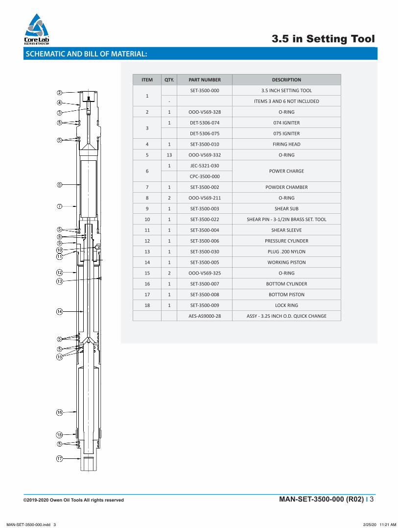
SCHEMATIC AND BILL OF MATERIAL:
ITEM QTY. PART NUMBER DESCRIPTION
1SET-3500-000 3.5 INCH SETTING TOOL
- ITEMS 3 AND 6 NOT INCLUDED
2 1 OOO-V569-328 O-RING
31 DET-5306-074 074 IGNITER
DET-5306-075 075 IGNITER
4 1 SET-3500-010 FIRING HEAD
5 13 OOO-V569-332 O-RING
61 JEC-5321-030
POWER CHARGECPC-3500-000
7 1 SET-3500-002 POWDER CHAMBER
8 2 OOO-V569-211 O-RING
9 1 SET-3500-003 SHEAR SUB
10 1 SET-3500-022 SHEAR PIN - 3-1/2IN BRASS SET. TOOL
11 1 SET-3500-004 SHEAR SLEEVE
12 1 SET-3500-006 PRESSURE CYLINDER
13 1 SET-3500-030 PLUG .200 NYLON
14 1 SET-3500-005 WORKING PISTON
15 2 OOO-V569-325 O-RING
16 1 SET-3500-007 BOTTOM CYLINDER
17 1 SET-3500-008 BOTTOM PISTON
18 1 SET-3500-009 LOCK RING
AES-AS9000-28 ASSY - 3.25 INCH O.D. QUICK CHANGE
MAN-SET-3500-000.indd 3MAN-SET-3500-000.indd 3 2/25/20 11:21 AM2/25/20 11:21 AM
3.5 in Setting Tool
4 I MAN-SET-3500-000 (R02) ©2019-2020 Owen Oil Tools All rights reserved
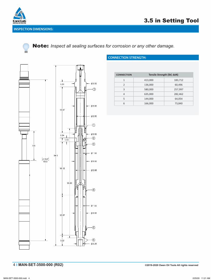
INSPECTION DIMENSIONS:
Note: Inspect all sealing surfaces for corrosion or any other damage.
CONNECTION STRENGTH:
CONNECTION Tensile Strength (lbf, daN)
1 413,000 183,712
2 136,000 60,496
3 580,000 257,997
4 635,000 282,462
5 144,000 64,054
6 166,000 73,840
MAN-SET-3500-000.indd 4MAN-SET-3500-000.indd 4 2/25/20 11:21 AM2/25/20 11:21 AM
©2019-2020 Owen Oil Tools All rights reserved MAN-SET-3500-000 (R02) I 5
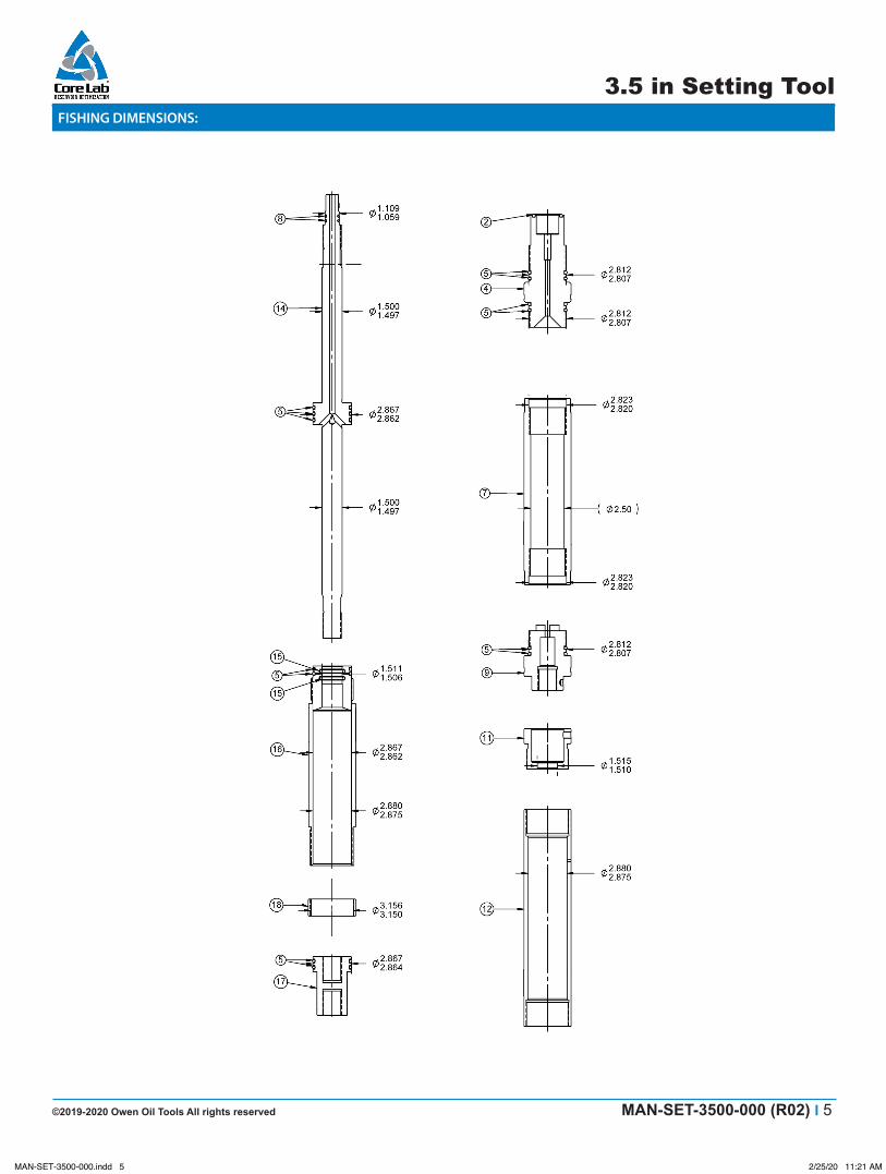
3.5 in Setting ToolFISHING DIMENSIONS:
MAN-SET-3500-000.indd 5MAN-SET-3500-000.indd 5 2/25/20 11:21 AM2/25/20 11:21 AM
6 I MAN-SET-3500-000 (R02) ©2019-2020 Owen Oil Tools All rights reserved
3.5 in Setting Tool
1.0 Assembly Procedures
Warning: Personal Protective Equipment (PPE) should be worn at all times!
Warning: Make sure all tool parts and components have been thoroughly cleaned or serious damage and/or injury could occur!
Caution: Make sure to wrench only on wrenching surfaces (knurled areas) provided! Always file wrench marks and burrs and clean off debris!
Note: Verify that the correct O-ring redress kit and quantities are used as specified on the Bill of Materials (for example, 5 each etc.). Lay out all redress kit components on a clean surface.
Note: Make sure to lubricate all O-rings and threaded surfaces.
Note: It is strongly recommended that MEMAC wrenches be used for assembly. These wrenches will not leave wrench marks when used on the knurled areas.
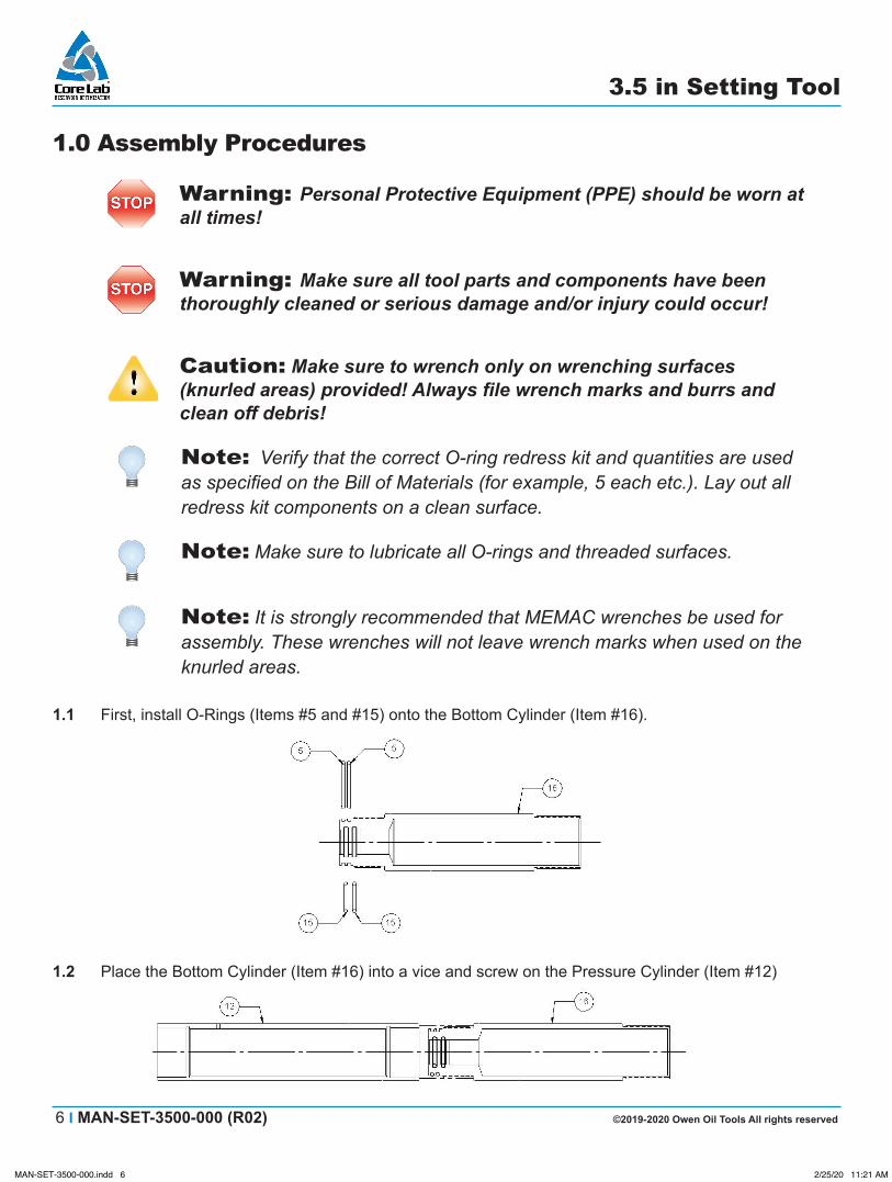
1.1 First, install O-Rings (Items #5 and #15) onto the Bottom Cylinder (Item #16).
1.2 Place the Bottom Cylinder (Item #16) into a vice and screw on the Pressure Cylinder (Item #12)
MAN-SET-3500-000.indd 6MAN-SET-3500-000.indd 6 2/25/20 11:21 AM2/25/20 11:21 AM
©2019-2020 Owen Oil Tools All rights reserved MAN-SET-3500-000 (R02) I 7
3.5 in Setting Tool
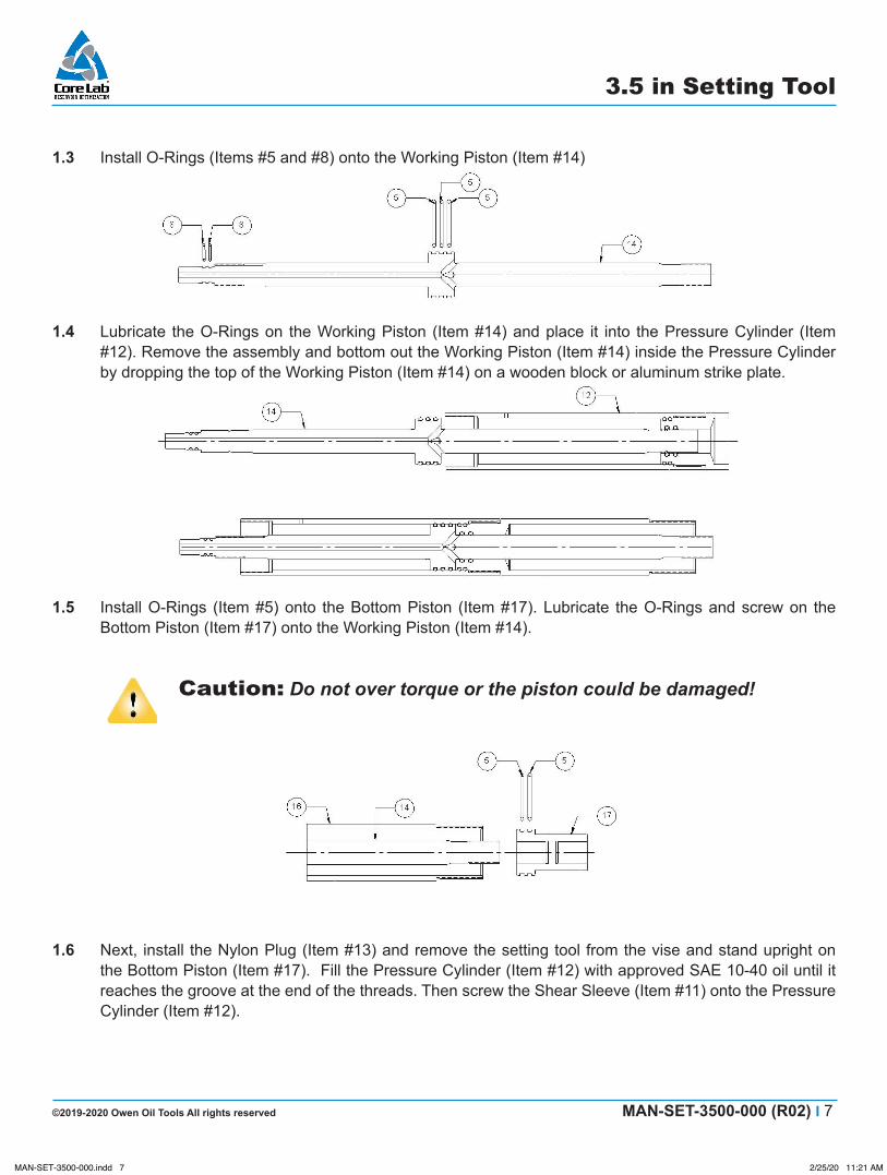
1.3 Install O-Rings (Items #5 and #8) onto the Working Piston (Item #14)
1.4 Lubricate the O-Rings on the Working Piston (Item #14) and place it into the Pressure Cylinder (Item #12). Remove the assembly and bottom out the Working Piston (Item #14) inside the Pressure Cylinder by dropping the top of the Working Piston (Item #14) on a wooden block or aluminum strike plate.
1.5 Install O-Rings (Item #5) onto the Bottom Piston (Item #17). Lubricate the O-Rings and screw on the Bottom Piston (Item #17) onto the Working Piston (Item #14).
Caution: Do not over torque or the piston could be damaged!
1.6 Next, install the Nylon Plug (Item #13) and remove the setting tool from the vise and stand upright on the Bottom Piston (Item #17). Fill the Pressure Cylinder (Item #12) with approved SAE 10-40 oil until it reaches the groove at the end of the threads. Then screw the Shear Sleeve (Item #11) onto the Pressure Cylinder (Item #12).
MAN-SET-3500-000.indd 7MAN-SET-3500-000.indd 7 2/25/20 11:21 AM2/25/20 11:21 AM
8 I MAN-SET-3500-000 (R02) ©2019-2020 Owen Oil Tools All rights reserved
3.5 in Setting Tool
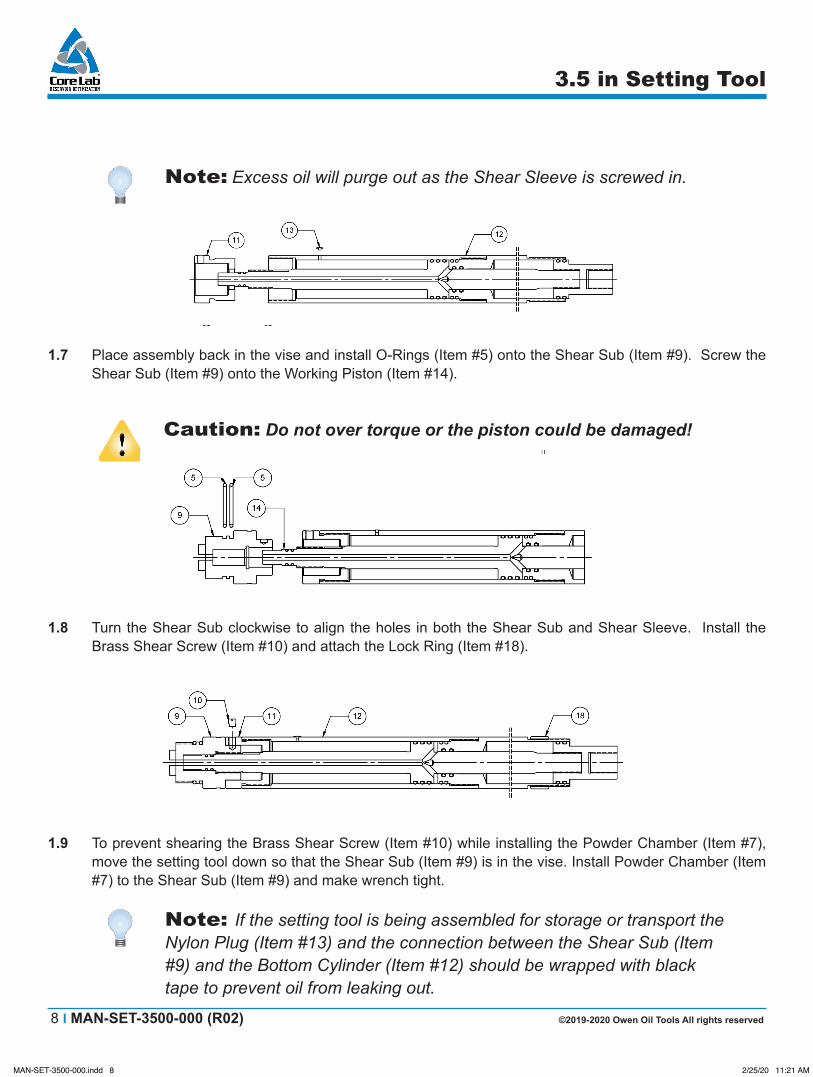
Note: Excess oil will purge out as the Shear Sleeve is screwed in.
1.7 Place assembly back in the vise and install O-Rings (Item #5) onto the Shear Sub (Item #9). Screw the Shear Sub (Item #9) onto the Working Piston (Item #14).
Caution: Do not over torque or the piston could be damaged!
1.8 Turn the Shear Sub clockwise to align the holes in both the Shear Sub and Shear Sleeve. Install the Brass Shear Screw (Item #10) and attach the Lock Ring (Item #18).
1.9 To prevent shearing the Brass Shear Screw (Item #10) while installing the Powder Chamber (Item #7), move the setting tool down so that the Shear Sub (Item #9) is in the vise. Install Powder Chamber (Item #7) to the Shear Sub (Item #9) and make wrench tight.
Note: If the setting tool is being assembled for storage or transport the Nylon Plug (Item #13) and the connection between the Shear Sub (Item #9) and the Bottom Cylinder (Item #12) should be wrapped with black tape to prevent oil from leaking out.
MAN-SET-3500-000.indd 8MAN-SET-3500-000.indd 8 2/25/20 11:21 AM2/25/20 11:21 AM
©2019-2020 Owen Oil Tools All rights reserved MAN-SET-3500-000 (R02) I 9
3.5 in Setting Tool
1.10 Next, remove end caps from the Power Charge and install it into the Powder Chamber, with pellet end facing upward toward the firing head.
Note: The above statement is a suggested step, as always; please refer to your company’s procedures for handling and installation of power charges (explosives or propellants)
1.11 Install O-Rings (Item #2 and #5) onto the Firing Head (Item #4). Install the Firing Head into the Powder Chamber.
1.12 Install the preferred Firing Adapter to the top of the Firing Head (Item #4).
Warning: Always follow American Petroleum Institute (API) RP-67 guidelines when handling and operating power charges!
Warning: Never pre-load, pre-dress or leave an assembled tool for extended periods. Redress and clean the tool prior to use. Never store a loaded tool!
Note: Clean and lubricate all parts immediately after each use.
Note: Visually inspect tool for swelling after each use. Damaged or swelled components must be replaced.
Note: It is recommended that Magnetic particle inspection (MPI) be completed on all components at least every 20 runs.
MAN-SET-3500-000.indd 9MAN-SET-3500-000.indd 9 2/25/20 11:21 AM2/25/20 11:21 AM
10 I MAN-SET-3500-000 (R02) ©2019-2020 Owen Oil Tools All rights reserved
3.5 in Setting Tool
2.0 Pre-Disassembly
Warning: Although theses setting tools are self-bleeding, after the tool has been fired, very high gas pressure may still be trapped or bridged inside the setting tool!
Warning: Safety glasses and Personal Protective Equipment (PPE) should be worn at all times! Be aware that the tool could be very hot!
3.0 Manual Bleeding3.1 If the gas pressure did not completely bleed at the self-bleeding hole in the ported Working Cylinder (Item
#12), an alternate method is to manually bleed the setting tool at the Shear Sub (Item #9) and Working Piston (Item #14).
Hold back up on the Working Piston (Item #14) and slowly turn the Shear Sub (Item #9) counter-clockwise until pressure releases through the thread channel.
Note: Once all gas pressure has been bled, the tool should be completely disassembled and all parts thoroughly washed in approved cleaner.
Warning: Gas pressure that may still be trapped or bridged inside the setting tool could be released during disassembly!
4.0 Disassembly4.1 After the gas pressure has been bled off, remove as one piece/section, the Shear Sub (Item #9), Powder
Chamber (Item #7), Firing Head (Item #4) and Firing Head Adapter from the Working Piston (Item #14).
4.2 Remove the Shear Sleeve (Item #11) from Pressure Cylinder (Item #12). Remove the Brass Shear Screw (Item #10) from the Shear Sub and Shear Sleeve.
4.3 Take the Pressure Cylinder (Item #12), Bottom Cylinder (Item #16) and turn upside down and drop on a wooden block or aluminum strike plate to drive the Bottom Piston (Item #17) out of the Bottom Cylinder.
4.4 Place assembly in a vise, then remove the Bottom Piston (Item #17) from the Working Piston (Item #14).
MAN-SET-3500-000.indd 10MAN-SET-3500-000.indd 10 2/25/20 11:21 AM2/25/20 11:21 AM
©2019-2020 Owen Oil Tools All rights reserved MAN-SET-3500-000 (R02) I 11
3.5 in Setting Tool
4.5 Remove the Bottom Cylinder (Item #16) from the Pressure Cylinder (Item #12).
4.6 Take the Pressure Cylinder and Working Piston and drop on a wooden block or aluminum strike plate to remove the piston.
4.7 Place the Powder Chamber (Item #7) in a vise. Remove the Firing Adapter from the Firing Head (Item #4). Remove Firing Head and then remove the used Igniter Assembly (Item #3) from the Firing Head. Next, remove the Shear Sub (Item #9). Finally, remove the used Power Charge (Item #6) from the Powder Chamber (Item #7).
4.8 Remove and discard all O-Rings from pistons and subs. Replace O-Rings after each use. Thoroughly clean setting tool parts in a cleaner approved by state and/or local laws. For the tool to work properly make sure the Working Piston, Firing Head and Shear Sub inner diameter are clean of any debris. To make sure there are no restrictions, run a rod down the inner diameter or blow out with air, until air will pass through the piston ports. Make sure to clean all cylinder inner diameters.
4.9 Complete a visual inspection of all parts per the inspection and fishing dimensions. Visually inspect all surfaces where O-Rings seal, for scars and/or scratches. If visual inspection reveals damage that may lead to failure, replace parts immediately. Pick up pistons and inspect for damage, then drift through cylinders.
Warning: Always follow American Petroleum Institute (API RP-67) guidelines when handling and operating oil well explosives!
Note: Remove and discard all O-Rings. Replace O-Rings after each use. Thoroughly clean tool parts in a cleaner approved by state and/or local laws.
Note: Visually inspect tool for swelling after each use. Damaged or swelled components must be replaced.
Note: It is recommended that a Magnetic Particle Inspection (MPI) be completed on all components at least every 20 runs.
MAN-SET-3500-000.indd 11MAN-SET-3500-000.indd 11 2/25/20 11:21 AM2/25/20 11:21 AM