pport townsend paper corp 18 inch cipp liner
TRANSCRIPT
P a g e | 1 of 2
PPORT TOWNSEND PAPER CORP 18 INCH CIPP LINER – CIPP DESIGN
5707 Schofield Avenue, PO Box 107 • Weston, WI 54476 • 715.359.9400 • www.mi-tech.us
September 9, 2020
ALLIED TRENCHLESS, LLC. Ron Smiley 246 W. Manson, HWY. 124 Chelan, WA 98816
Project: PORT TOWNSEND PAPER CORPORATION PORT TOWNSEND, WA. ALLIED TRENCHLESS, LLC. Mi-Tech Services Project No. 11414
Dear Mr. Smiley,
Per your request Mi-Tech Services has reviewed Plans, Specifications, and design loads provided by Peter Oxenbol for the project referenced above. It is our understanding that the lining material to be used is SAERTEX UV Cured S-PLUS Liner.
The following lists the design parameters and assumptions used for this project: 1) Specified Existing Pipe Condition = Fully Deteriorated;2) Existing Pipe Diameter = 18 inch;3) Pipe Depth = suspended above ground;4) Specified Soil Unit Weight = no soil load, N.A.;5) Specified Modulus of Soil Reaction = no soil load, N.A.;6) Specified Live Load = No live loads, N.A.;7) Specified 50 year design life;8) Ovality = 2.0% minimum;9) Poisson’s ratio = 0.3;10) Enhancement Factor = 7;11) Specified Factor of Safety = 2.0;12) Specified Groundwater Height = There is no groundwater.13) Total Suspended Load used (concrete host pipe, fiberglass wrap, Saertex liner, effluent) =
270 lb/ft
Design Parameters Utilized for SAERTEX S-PLUS Liner:
MAXIMUM VALUE IN AXIAL DIRECTION
VALUES USED FOR ASTM F2019 DESIGN
Short Term Flexural Modulus of Elasticity, psi
961,600 800,000 Short Term Flexural Strength, psi
21,000 15,000 Short Term Tensile Strength, psi
22,700 NA Creep Reduction Factor (Modulus of Elasticity), %
78 60 Creep Reduction Factor (Flexural Strength), %
77 60
P a g e | 2 of 2
PPORT TOWNSEND PAPER CORP 18 INCH CIPP LINER – CIPP DESIGN
5707 Schofield Avenue, PO Box 107 • Weston, WI 54476 • 715.359.9400 • www.mi-tech.us
IF ANY OF THE DESIGN ASSUMPTIONS OR PARAMETERS USED ARE INCORRECT, PLEASE RESUBMIT TO MI-TECH SERVICES FOR REDESIGN BEFORE ORDERING OR INSTALLING LINER.
Design parameters have been entered into Mi-Tech Services’ CIPP Liner Design Program, resulting in the Cured-in-Place Pipe liner thickness required for the liners. The host pipe is suspended above ground so typical design parameters do not apply. Programs such as this are accepted and utilized in the cured-in-place pipe industry for design, manufacturing, and construction purposes. The underlying formulas, including ASTM F-1216 and modifications found in ASTM F2019, within the program are accepted throughout the industry and design standards.
Also, as the host pipe is suspended above ground, a Simple Span Moment was calculated to determine forces acting in compression and tension at the center of each 10 foot segment. The calculations were a thickness design check based upon a minimum 3.0 mm liner design. Saertex liner minimum size is 3.0 mm.
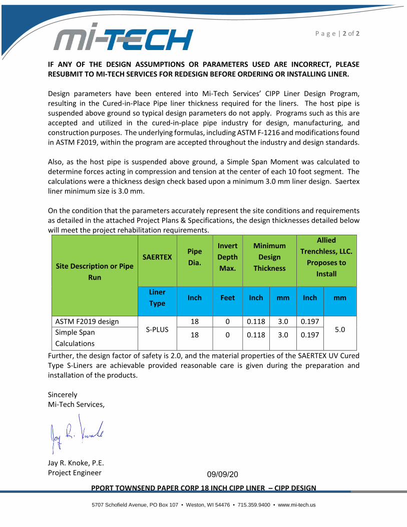
On the condition that the parameters accurately represent the site conditions and requirements as detailed in the attached Project Plans & Specifications, the design thicknesses detailed below will meet the project rehabilitation requirements.
Site Description or Pipe Run
SAERTEX Pipe Dia.
Invert Depth Max.
Minimum Design
Thickness
Allied Trenchless, LLC.
Proposes to Install
Liner Type
Inch Feet Inch mm Inch mm
ASTM F2019 design S-PLUS
18 0 0.118 3.0 0.197 5.0 Simple Span
Calculations 18 0 0.118 3.0 0.197
Further, the design factor of safety is 2.0, and the material properties of the SAERTEX UV Cured Type S-Liners are achievable provided reasonable care is given during the preparation and installation of the products.
Sincerely Mi-Tech Services,
Jay R. Knoke, P.E. Project Engineer 09/09/20
11414 Allied Trenchless Port Townsend Paper Corp 18in by 3.0mm CIPP Design
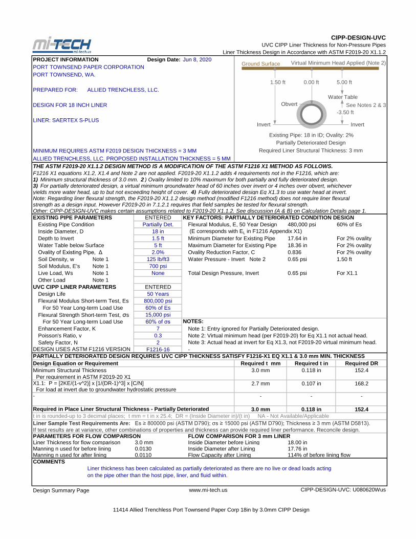
Liner Thickness Design in Accordance with ASTM F2019-20 X1.1.2Design Date: Jun 8, 2020
PORT TOWNSEND PAPER CORPORATIONPORT TOWNSEND, WA.
1.50 ft 0.00 ft 5.00 ftPREPARED FOR: ALLIED TRENCHLESS, LLC.
DESIGN FOR 18 INCH LINER See Notes 2 & 3-3.50 ft
LINER: SAERTEX S-PLUS
Existing Pipe: 18 in ID; Ovality: 2%
MINIMUM REQUIRES ASTM F2019 DESIGN THICKNESS = 3 MMALLIED TRENCHLESS, LLC. PROPOSED INSTALLATION THICKNESS = 5 MMTHE ASTM F2019-20 X1.1.2 DESIGN METHOD IS A MODIFICATION OF THE ASTM F1216 X1 METHOD AS FOLLOWS.F1216 X1 equations X1.2, X1.4 and Note 2 are not applied. F2019-20 X1.1.2 adds 4 requirements not in the F1216, which are:1) Minimum structural thickness of 3.0 mm. 2 ) Ovality limited to 10% maximum for both partially and fully deteriorated design.3) For partially deteriorated design, a virtual minimum groundwater head of 60 inches over invert or 4 inches over obvert, whicheveryields more water head, up to but not exceeding height of cover. 4) Fully deteriorated design Eq X1.3 to use water head at invert.Note: Regarding liner flexural strength, the F2019-20 X1.1.2 design method (modified F1216 method) does not require liner flexuralstrength as a design input. However F2019-20 in 7.1.2.1 requires that field samples be tested for flexural strength.Other: CIPP-DESIGN-UVC makes certain assumptions related to F2019-20 X1.1.2. See discussion (A & B) on Calculation Details page 1.EXISTING PIPE PARAMETERS ENTERED KEY FACTORS: PARTIALLY DETERIORATED CONDITION DESIGN
Existing Pipe Condition Partially Det. Flexural Modulus, E, 50 Year Design 480,000 psi 60% of EsInside Diameter, D 18 in (E corresponds with EL in F1216 Appendix X1)Depth to Invert 1.5 ft Minimum Diameter for Existing Pipe 17.64 in For 2% ovalityWater Table below Surface 5 ft Maximum Diameter for Existing Pipe 18.36 in For 2% ovalityOvality of Existing Pipe, Δ 2.0% Ovality Reduction Factor, C 0.836 For 2% ovalitySoil Density, w Note 1 125 lb/ft3 Water Pressure - Invert Note 2 0.65 psi 1.50 ftSoil Modulus, E's Note 1 700 psiLive Load, Ws Note 1 None Total Design Pressure, Invert 0.65 psi For X1.1Other Load Note 1
UVC CIPP LINER PARAMETERS ENTEREDDesign Life 50 YearsFlexural Modulus Short-term Test, Es 800,000 psi For 50 Year Long-term Load Use 60% of EsFlexural Strength Short-term Test, σs 15,000 psi For 50 Year Long-term Load Use 60% of σs NOTES:Enhancement Factor, K 7 Note 1: Entry ignored for Partially Deteriorated design.Poisson's Ratio, v 0.3 Note 2: Virtual minimum head (per F2019-20) for Eq X1.1 not actual head.Safety Factor, N 2 Note 3: Actual head at invert for Eq X1.3, not F2019-20 virtual minimum head.
F1216-16 -
Design Equation or Requirement Required t mm Required t in Required DRMinimum Structural Thickness 3.0 mm 0.118 in 152.4 Per requirement in ASTM F2019-20 X1
2.7 mm 0.107 in 168.2
- - -
3.0 mm 0.118 in 152.4
Liner Sample Test Requirements Are: Es ≥ 800000 psi (ASTM D790); σs ≥ 15000 psi (ASTM D790); Thickness ≥ 3 mm (ASTM D5813).If test results are at variance, other combinations of properties and thickness can provide required liner performance. Reconcile design.PARAMETERS FOR FLOW COMPARISON FLOW COMPARISON FOR 3 mm LINERLiner Thickness for flow comparison 3.0 mm Inside Diameter before Lining 18.00 inManning n used for before lining 0.0130 Inside Diameter after Lining 17.76 inManning n used for after lining 0.0110 Flow Capacity after Lining 114% of before lining flowCOMMENTS
Liner thickness has been calculated as partially deteriorated as there are no live or dead loads actingon the pipe other than the host pipe, liner, and fluid within.
www.mi-tech.us
DESIGN USES ASTM F1216 VERSION
X1.1: P = [2KE/(1-v^2)] x [1/(DR-1)^3] x [C/N]
PARTIALLY DETERIORATED DESIGN REQUIRES UVC CIPP THICKNESS SATISFY F1216-X1 EQ X1.1 & 3.0 mm MIN. THICKNESS
For load at invert due to groundwater hydrostatic pressure
CIPP-DESIGN-UVCUVC CIPP Liner Thickness for Non-Pressure Pipes
Virtual Minimum Head Applied (Note 2)PROJECT INFORMATION
Partially Deteriorated DesignRequired Liner Structural Thickness: 3 mm
Required in Place Liner Structural Thickness - Partially Deterioratedt in is rounded-up to 3 decimal places; t mm = t in x 25.4; DR = (Inside Diameter in)/(t in) NA - Not Available/Applicable
-
Design Summary Page CIPP-DESIGN-UVC: U080620Wus
Invert
Ground Surface
Water TableObvert
Invert
11414 Allied Trenchless Port Townsend Paper Corp 18in by 3.0mm CIPP Design
Mi-Tech Services, Inc.
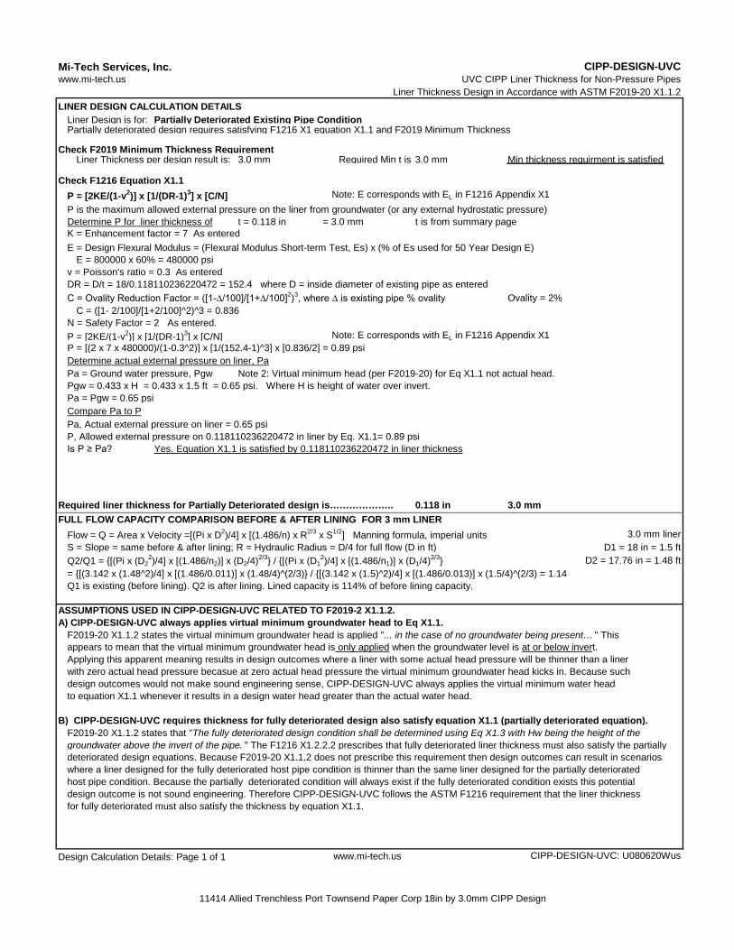
Liner Thickness Design in Accordance with ASTM F2019-20 X1.1.2LINER DESIGN CALCULATION DETAILS
Liner Design is for: Partially Deteriorated Existing Pipe ConditionPartially deteriorated design requires satisfying F1216 X1 equation X1.1 and F2019 Minimum Thickness
Check F2019 Minimum Thickness RequirementLiner Thickness per design result is: 3.0 mm Required Min t is 3.0 mm Min thickness requirment is satisfied
Check F1216 Equation X1.1P = [2KE/(1-v2)] x [1/(DR-1)3] x [C/N] Note: E corresponds with EL in F1216 Appendix X1P is the maximum allowed external pressure on the liner from groundwater (or any external hydrostatic pressure)Determine P for liner thickness of t = 0.118 in = 3.0 mm t is from summary page
C = Ovality Reduction Factor = ([1-∆/100]/[1+∆/100]2)3, where ∆ is existing pipe % ovality Ovality = 2%
P = [2KE/(1-v2)] x [1/(DR-1)3] x [C/N] Note: E corresponds with EL in F1216 Appendix X1P = [(2 x 7 x 480000)/(1-0.3^2)] x [1/(152.4-1)^3] x [0.836/2] = 0.89 psiDetermine actual external pressure on liner, PaPa = Ground water pressure, Pgw Note 2: Virtual minimum head (per F2019-20) for Eq X1.1 not actual head.Pgw = 0.433 x H = 0.433 x 1.5 ft = 0.65 psi. Where H is height of water over invert.Pa = Pgw = 0.65 psiCompare Pa to PPa, Actual external pressure on liner = 0.65 psiP, Allowed external pressure on 0.118110236220472 in liner by Eq. X1.1= 0.89 psiIs P ≥ Pa? Yes. Equation X1.1 is satisfied by 0.118110236220472 in liner thickness
Required liner thickness for Partially Deteriorated design is……………….. 0.118 in 3.0 mm
Flow = Q = Area x Velocity =[(Pi x D2)/4] x [(1.486/n) x R2/3 x S1/2] Manning formula, imperial units 3.0 mm linerS = Slope = same before & after lining; R = Hydraulic Radius = D/4 for full flow (D in ft) D1 = 18 in = 1.5 ftQ2/Q1 = {[(Pi x (D2
2)/4] x [(1.486/n2)] x (D2/4)2/3} / {[(Pi x (D12)/4] x [(1.486/n1)] x (D1/4)2/3} D2 = 17.76 in = 1.48 ft
= {[(3.142 x (1.48^2)/4] x [(1.486/0.011)] x (1.48/4)^(2/3)} / {[(3.142 x (1.5)^2)/4] x [(1.486/0.013)] x (1.5/4)^(2/3) = 1.14Q1 is existing (before lining). Q2 is after lining. Lined capacity is 114% of before lining capacity.
ASSUMPTIONS USED IN CIPP-DESIGN-UVC RELATED TO F2019-2 X1.1.2.A) CIPP-DESIGN-UVC always applies virtual minimum groundwater head to Eq X1.1.
F2019-20 X1.1.2 states the virtual minimum groundwater head is applied "... in the case of no groundwater being present… " Thisappears to mean that the virtual minimum groundwater head is only applied when the groundwater level is at or below invert.Applying this apparent meaning results in design outcomes where a liner with some actual head pressure will be thinner than a linerwith zero actual head pressure becasue at zero actual head pressure the virtual minimum groundwater head kicks in. Because such design outcomes would not make sound engineering sense, CIPP-DESIGN-UVC always applies the virtual minimum water head to equation X1.1 whenever it results in a design water head greater than the actual water head.
B) CIPP-DESIGN-UVC requires thickness for fully deteriorated design also satisfy equation X1.1 (partially deteriorated equation).F2019-20 X1.1.2 states that "The fully deteriorated design condition shall be determined using Eq X1.3 with Hw being the height of thegroundwater above the invert of the pipe. " The F1216 X1.2.2.2 prescribes that fully deteriorated liner thickness must also satisfy the partiallydeteriorated design equations. Because F2019-20 X1.1.2 does not prescribe this requirement then design outcomes can result in scenarioswhere a liner designed for the fully deteriorated host pipe condition is thinner than the same liner designed for the partially deteriorated host pipe condition. Because the partially deteriorated condition will always exist if the fully deteriorated condition exists this potential design outcome is not sound engineering. Therefore CIPP-DESIGN-UVC follows the ASTM F1216 requirement that the liner thickness for fully deteriorated must also satisfy the thickness by equation X1.1.
Design Calculation Details: Page 1 of 1 www.mi-tech.us
FULL FLOW CAPACITY COMPARISON BEFORE & AFTER LINING FOR 3 mm LINER
CIPP-DESIGN-UVC: U080620Wus
DR = D/t = 18/0.118110236220472 = 152.4 where D = inside diameter of existing pipe as entered
C = ([1- 2/100]/[1+2/100]^2)^3 = 0.836N = Safety Factor = 2 As entered.
K = Enhancement factor = 7 As entered
CIPP-DESIGN-UVC
v = Poisson's ratio = 0.3 As entered
www.mi-tech.us UVC CIPP Liner Thickness for Non-Pressure Pipes
E = Design Flexural Modulus = (Flexural Modulus Short-term Test, Es) x (% of Es used for 50 Year Design E)E = 800000 x 60% = 480000 psi
11414 Allied Trenchless Port Townsend Paper Corp 18in by 3.0mm CIPP Design
Mi-Tech Services, Inc.
Liner Thickness Design in Accordance with ASTM F2019-20 X1.1.2
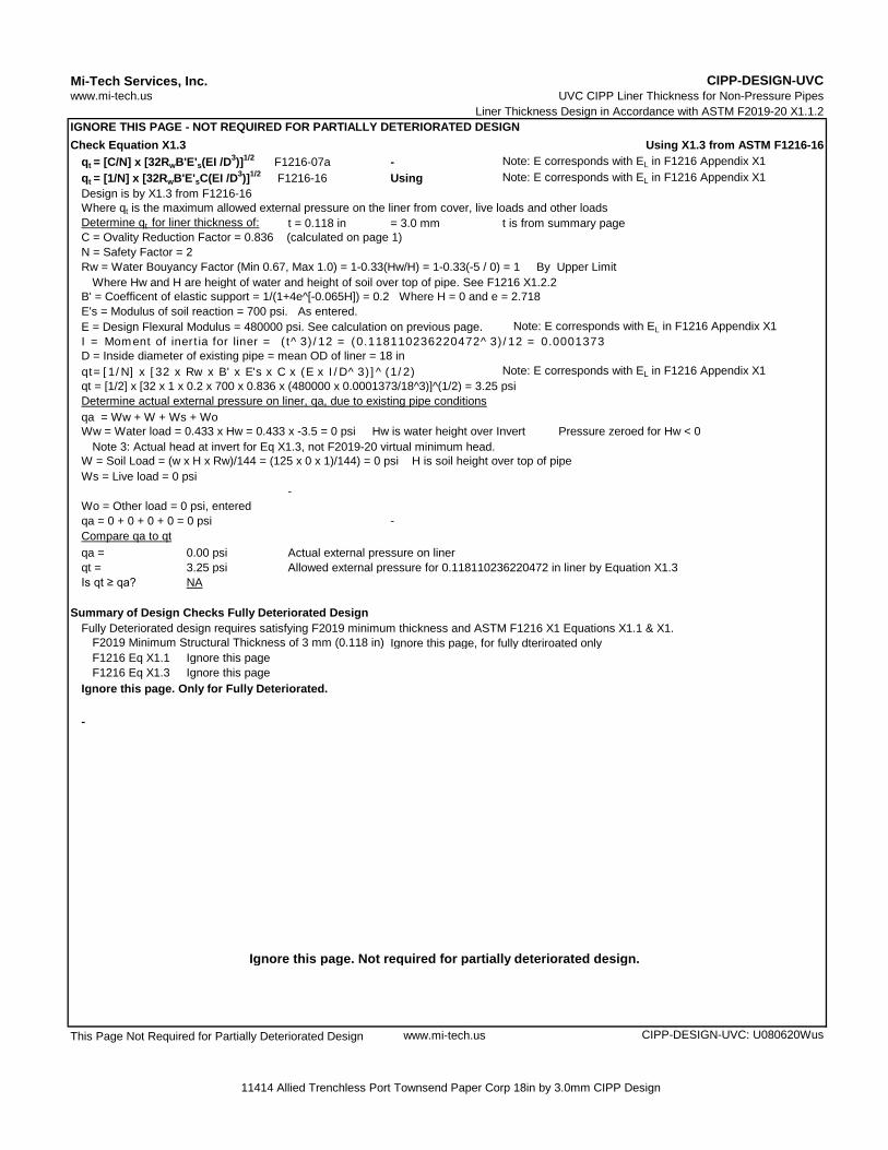
Check Equation X1.3 Using X1.3 from ASTM F1216-16qt = [C/N] x [32RwB'E's(EI/D3)]1/2 F1216-07a - Note: E corresponds with EL in F1216 Appendix X1qt = [1/N] x [32RwB'E'sC(EI/D3)]1/2 F1216-16 Using Note: E corresponds with EL in F1216 Appendix X1Design is by X1.3 from F1216-16Where qt is the maximum allowed external pressure on the liner from cover, live loads and other loadsDetermine qt for liner thickness of: t = 0.118 in = 3.0 mm t is from summary page
Where Hw and H are height of water and height of soil over top of pipe. See F1216 X1.2.2
E = Design Flexural Modulus = 480000 psi. See calculation on previous page. Note: E corresponds with EL in F1216 Appendix X1
qt=[1/N] x [32 x Rw x B' x E's x C x (E x I/D^3)]^(1/2) Note: E corresponds with EL in F1216 Appendix X1qt = [1/2] x [32 x 1 x 0.2 x 700 x 0.836 x (480000 x 0.0001373/18^3)]^(1/2) = 3.25 psi
qa = Ww + W + Ws + Wo
Note 3: Actual head at invert for Eq X1.3, not F2019-20 virtual minimum head.
Ws = Live load = 0 psi-
Wo = Other load = 0 psi, enteredqa = 0 + 0 + 0 + 0 = 0 psi -
qa = 0.00 psi Actual external pressure on linerqt = 3.25 psi Allowed external pressure for 0.118110236220472 in liner by Equation X1.3Is qt ≥ qa? NA
Summary of Design Checks Fully Deteriorated DesignFully Deteriorated design requires satisfying F2019 minimum thickness and ASTM F1216 X1 Equations X1.1 & X1.
F2019 Minimum Structural Thickness of 3 mm (0.118 in) Ignore this page, for fully dteriroated onlyF1216 Eq X1.1 Ignore this pageF1216 Eq X1.3 Ignore this page
Ignore this page. Only for Fully Deteriorated.
-
Ignore this page. Not required for partially deteriorated design.
This Page Not Required for Partially Deteriorated Design www.mi-tech.us
W = Soil Load = (w x H x Rw)/144 = (125 x 0 x 1)/144) = 0 psi H is soil height over top of pipe
CIPP-DESIGN-UVC: U080620Wus
UVC CIPP Liner Thickness for Non-Pressure Pipes
Determine actual external pressure on liner, qa, due to existing pipe conditions
Ww = Water load = 0.433 x Hw = 0.433 x -3.5 = 0 psi Hw is water height over Invert Pressure zeroed for Hw < 0
D = Inside diameter of existing pipe = mean OD of liner = 18 in
B' = Coefficent of elastic support = 1/(1+4e^[-0.065H]) = 0.2 Where H = 0 and e = 2.718E's = Modulus of soil reaction = 700 psi. As entered.
I = Moment of inertia for liner = (t^3)/12 = (0.118110236220472^3)/12 = 0.0001373
IGNORE THIS PAGE - NOT REQUIRED FOR PARTIALLY DETERIORATED DESIGN
C = Ovality Reduction Factor = 0.836 (calculated on page 1)N = Safety Factor = 2Rw = Water Bouyancy Factor (Min 0.67, Max 1.0) = 1-0.33(Hw/H) = 1-0.33(-5 / 0) = 1 By Upper Limit
Compare qa to qt
CIPP-DESIGN-UVCwww.mi-tech.us
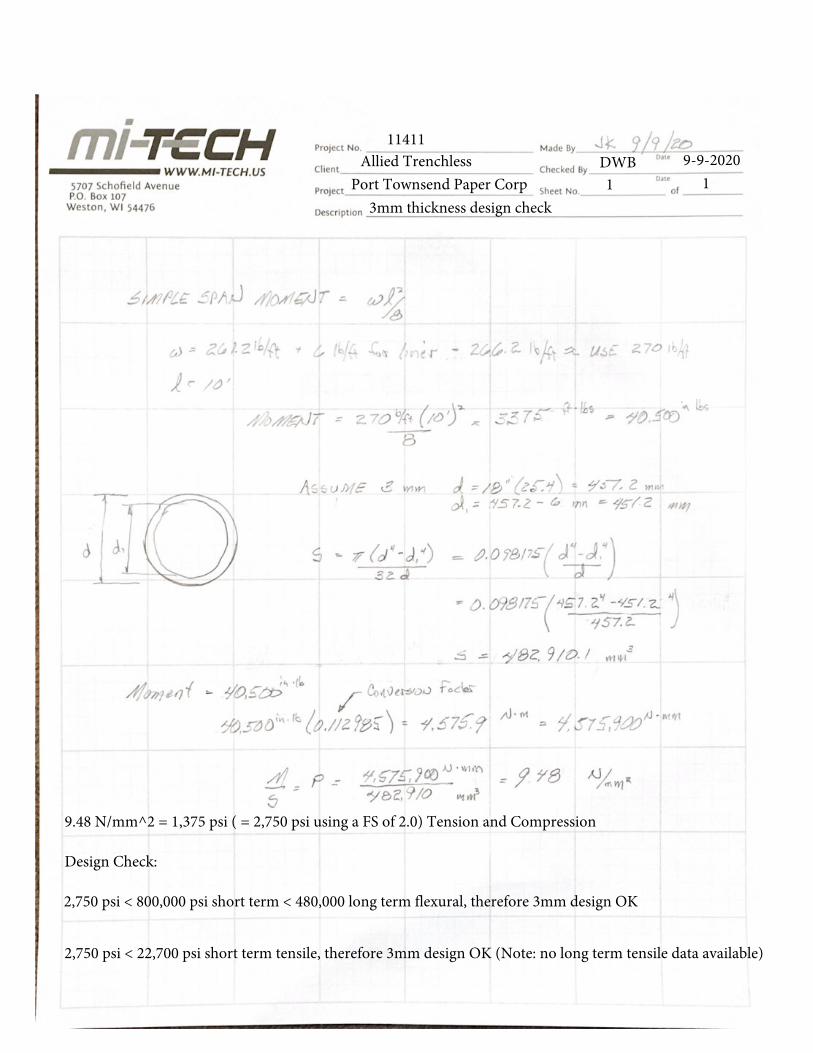
11411 Allied Trenchless
Port Townsend Paper CorpDWB1 1
9-9-2020
3mm thickness design check
9.48 N/mm^2 = 1,375 psi ( = 2,750 psi using a FS of 2.0) Tension and Compression
Design Check:
2,750 psi < 800,000 psi short term < 480,000 long term flexural, therefore 3mm design OK
2,750 psi < 22,700 psi short term tensile, therefore 3mm design OK (Note: no long term tensile data available)
1
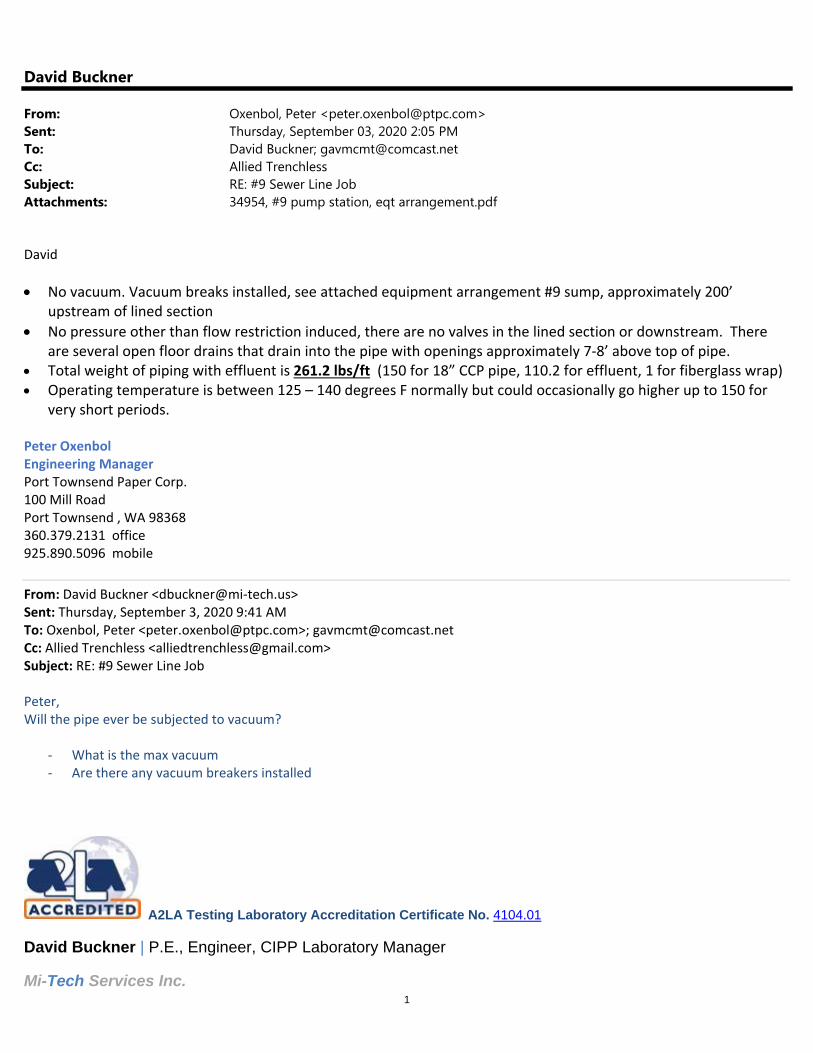
David Buckner
From: Oxenbol, Peter <[email protected]>Sent: Thursday, September 03, 2020 2:05 PMTo: David Buckner; [email protected]: Allied TrenchlessSubject: RE: #9 Sewer Line Job Attachments: 34954, #9 pump station, eqt arrangement.pdf
David
No vacuum. Vacuum breaks installed, see attached equipment arrangement #9 sump, approximately 200’ upstream of lined section
No pressure other than flow restriction induced, there are no valves in the lined section or downstream. There are several open floor drains that drain into the pipe with openings approximately 7‐8’ above top of pipe.
Total weight of piping with effluent is 261.2 lbs/ft (150 for 18” CCP pipe, 110.2 for effluent, 1 for fiberglass wrap) Operating temperature is between 125 – 140 degrees F normally but could occasionally go higher up to 150 for
very short periods. Peter Oxenbol Engineering Manager Port Townsend Paper Corp. 100 Mill Road Port Townsend , WA 98368 360.379.2131 office 925.890.5096 mobile
From: David Buckner <dbuckner@mi‐tech.us> Sent: Thursday, September 3, 2020 9:41 AM To: Oxenbol, Peter <[email protected]>; [email protected] Cc: Allied Trenchless <[email protected]> Subject: RE: #9 Sewer Line Job Peter, Will the pipe ever be subjected to vacuum?
‐ What is the max vacuum ‐ Are there any vacuum breakers installed
A2LA Testing Laboratory Accreditation Certificate No. 4104.01 David Buckner | P.E., Engineer, CIPP Laboratory Manager Mi-Tech Services Inc.
1
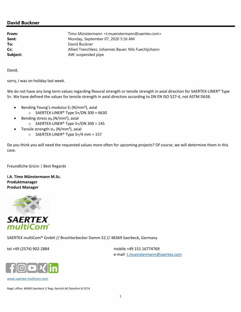
David Buckner
From: Timo Münstermann <[email protected]>Sent: Monday, September 07, 2020 5:16 AMTo: David BucknerCc: Allied Trenchless; Johannes Bauer; Nils FuechtjohannSubject: AW: suspended pipe
David, sorry, I was on holiday last week. We do not have any long term values regarding flexural strength or tensile strength in axial direction for SAERTEX‐LINER® Type S+. We have defined the values for tensile strength in axial direction according to DN EN ISO 527‐4, not ASTM D638.
Bending Young’s modulus Ef (N/mm²), axial o SAERTEX‐LINER® Type S+/DN 300 = 6630
Bending stress σfb (N/mm²), axial o SAERTEX‐LINER® Type S+/DN 300 = 145
Tensile strength σm (N/mm²), axial o SAERTEX‐LINER® Type S+/4 mm = 157
Do you think you will need the requested values more often for upcoming projects? Of course, we will determine them in this case. Freundliche Grüße | Best Regards i.A. Timo Münstermann M.Sc. Produktmanager Product Manager
SAERTEX multiCom® GmbH // Brochterbecker Damm 52 // 48369 Saerbeck, Germany
tel +49 (2574) 902‐2884 mobile +49 151 16774769
e‐mail [email protected]
www.saertex‐multicom.com
Regd. office: 48369 Saerbeck // Reg.‐Gericht AG Steinfurt B 5574
Product Data Sheet of SAERTEX-LINER
® / SAERTEX-LINER
® Premium Type S
+
SAERTEX multiCom
® LP – 12200 Mt. Holly-Huntersville Rd. – Huntersville, NC 28078, USA - www.saertex-multicom.com - +1 704 584-4059
2016-09-30-Product Data Sheet SAERTEX-LINER Type S+_us Page 1 / 1
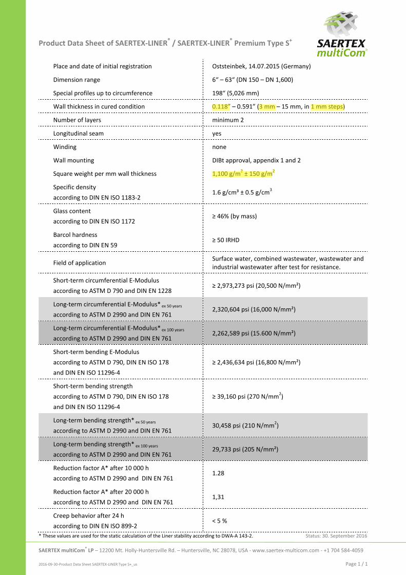
Place and date of initial registration Oststeinbek, 14.07.2015 (Germany)
Dimension range 6“ – 63“ (DN 150 – DN 1,600)
Special profiles up to circumference 198“ (5,026 mm)
Wall thickness in cured condition 0.118” – 0.591” (3 mm – 15 mm, in 1 mm steps)
Number of layers minimum 2
Longitudinal seam yes
Winding none
Wall mounting DIBt approval, appendix 1 and 2
Square weight per mm wall thickness 1,100 g/m2 ± 150 g/m
2
Specific density
according to DIN EN ISO 1183-2 1.6 g/cm³ ± 0.5 g/cm
3
Glass content
according to DIN EN ISO 1172 ≥ 46% (by mass)
Barcol hardness
according to DIN EN 59 ≥ 50 IRHD
Field of application Surface water, combined wastewater, wastewater and
industrial wastewater after test for resistance.
Short-term circumferential E-Modulus
according to ASTM D 790 and DIN EN 1228 ≥ 2,973,273 psi (20,500 N/mm²)
Long-term circumferential E-Modulus* ex 50 years
according to ASTM D 2990 and DIN EN 761 2,320,604 psi (16,000 N/mm²)
Long-term circumferential E-Modulus* ex 100 years
according to ASTM D 2990 and DIN EN 761 2,262,589 psi (15.600 N/mm²)
Short-term bending E-Modulus
according to ASTM D 790, DIN EN ISO 178
and DIN EN ISO 11296-4
≥ 2,436,634 psi (16,800 N/mm²)
Short-term bending strength
according to ASTM D 790, DIN EN ISO 178
and DIN EN ISO 11296-4
≥ 39,160 psi (270 N/mm2)
Long-term bending strength* ex 50 years
according to ASTM D 2990 and DIN EN 761 30,458 psi (210 N/mm
2)
Long-term bending strength* ex 100 years
according to ASTM D 2990 and DIN EN 761 29,733 psi (205 N/mm²)
Reduction factor A* after 10 000 h
according to ASTM D 2990 and DIN EN 761 1.28
Reduction factor A* after 20 000 h
according to ASTM D 2990 and DIN EN 761 1,31
Creep behavior after 24 h
according to DIN EN ISO 899-2 < 5 %
* These values are used for the static calculation of the Liner stability according to DWA-A 143-2. Status: 30. September 2016
UV Cured in Place Pipe Non-Proprietary Specification
SECTION
PIPE REHABILITATION BY UV CURED-IN-PLACE PIPE (CIPP) PROCESS PART 1 - GENERAL
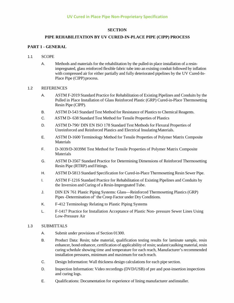
1.1 SCOPE
A. Methods and materials for the rehabilitation by the pulled-in place installation of a resin- impregnated, glass reinforced flexible fabric tube into an existing conduit followed by inflation with compressed air for either partially and fully deteriorated pipelines by the UV Cured-In-Place Pipe (CIPP) process.
1.2 REFERENCES
A. ASTM F-2019 Standard Practice for Rehabilitation of Existing Pipelines and Conduits by the Pulled in Place Installation of Glass Reinforced Plastic (GRP) Cured-in-Place Thermosetting Resin Pipe (CIPP).
B. ASTM D-543 Standard Test Method for Resistance of Plastics to Chemical Reagents. C. ASTM D- 638 Standard Test Method for Tensile Properties of Plastics
D. ASTM D-790/ DIN EN ISO 178 Standard Test Methods for Flexural Properties of Unreinforced and Reinforced Plastics and Electrical Insulating Materials.
E. ASTM D-1600 Terminology Method for Tensile Properties of Polymer Matrix Composite Materials
F. D-3039/D-3039M Test Method for Tensile Properties of Polymer Matrix Composite Materials
G. ASTM D-3567 Standard Practice for Determining Dimensions of Reinforced Thermosetting Resin Pipe (RTRP) and Fittings.
H. ASTM D-5813 Standard Specification for Cured-in-Place Thermosetting Resin Sewer Pipe.
I. ASTM F-1216 Standard Practice for Rehabilitation of Existing Pipelines and Conduits by the Inversion and Curing of a Resin-Impregnated Tube.
J. DIN EN 761 Plastic Piping Systems: Glass—Reinforced Thermosetting Plastics (GRP) Pipes -Determination of’ the Creep Factor under Dry Conditions.
K. F-412 Terminology Relating to Plastic Piping Systems
L. F-1417 Practice for Installation Acceptance of Plastic Non- pressure Sewer Lines Using Low-Pressure Air
1.3 SUBMITTALS
A. Submit under provisions of Section 01300.
B. Product Data: Resin; tube material, qualification testing results for laminate sample, resin enhancer, bond enhancer, certification of applicability of resin; sealant/caulking material, resin curing schedule showing time and temperature for each reach, Manufacturer’s recommended installation pressures, minimum and maximum for each reach.
C. Design Information: Wall thickness design calculations for each pipe section.
D. Inspection Information: Video recordings (DVD/USB) of pre and post-insertion inspections and curing logs.
E. Qualifications: Documentation for experience of lining manufacturer and installer.
UV Cured in Place Pipe Non-Proprietary Specification
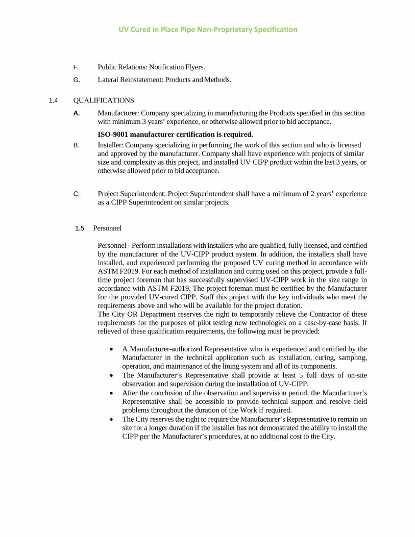
F. Public Relations: Notification Flyers.
G. Lateral Reinstatement: Products and Methods. 1.4 QUALIFICATIONS
A. Manufacturer: Company specializing in manufacturing the Products specified in this section with minimum 3 years’ experience, or otherwise allowed prior to bid acceptance.
ISO-9001 manufacturer certification is required. B. Installer: Company specializing in performing the work of this section and who is licensed
and approved by the manufacturer. Company shall have experience with projects of similar size and complexity as this project, and installed UV CIPP product within the last 3 years, or otherwise allowed prior to bid acceptance.
C. Project Superintendent: Project Superintendent shall have a minimum of 2 years’ experience as a CIPP Superintendent on similar projects.
1.5 Personnel
Personnel - Perform installations with installers who are qualified, fully licensed, and certified by the manufacturer of the UV-CIPP product system. In addition, the installers shall have installed, and experienced performing the proposed UV curing method in accordance with ASTM F2019. For each method of installation and curing used on this project, provide a full-time project foreman that has successfully supervised UV-CIPP work in the size range in accordance with ASTM F2019. The project foreman must be certified by the Manufacturer for the provided UV-cured CIPP. Staff this project with the key individuals who meet the requirements above and who will be available for the project duration. The City OR Department reserves the right to temporarily relieve the Contractor of these requirements for the purposes of pilot testing new technologies on a case-by-case basis. If relieved of these qualification requirements, the following must be provided:
• A Manufacturer-authorized Representative who is experienced and certified by the Manufacturer in the technical application such as installation, curing, sampling, operation, and maintenance of the lining system and all of its components.
• The Manufacturer’s Representative shall provide at least 5 full days of on-site observation and supervision during the installation of UV-CIPP.
• After the conclusion of the observation and supervision period, the Manufacturer’s Representative shall be accessible to provide technical support and resolve field problems throughout the duration of the Work if required.
• The City reserves the right to require the Manufacturer’s Representative to remain on site for a longer duration if the installer has not demonstrated the ability to install the CIPP per the Manufacturer’s procedures, at no additional cost to the City.
UV Cured in Place Pipe Non-Proprietary Specification
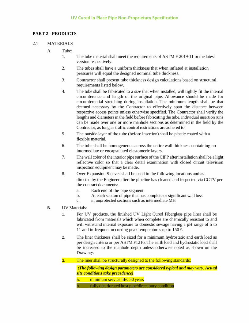
PART 2 - PRODUCTS
2.1 MATERIALS A. Tube: 1. The tube material shall meet the requirements of ASTM F 2019-11 or the latest
version respectively. 2. The tubes shall have a uniform thickness that when inflated at installation
pressures will equal the designed nominal tube thickness. 3. Contractor shall present tube thickness design calculations based on structural
requirements listed below. 4. The tube shall be fabricated to a size that when installed, will tightly fit the internal
circumference and length of the original pipe. Allowance should be made for circumferential stretching during installation. The minimum length shall be that deemed necessary by the Contractor to effectively span the distance between respective access points unless otherwise specified. The Contractor shall verify the lengths and diameters in the field before fabricating the tube. Individual insertion runs can be made over one or more manhole sections as determined in the field by the Contractor, as long as traffic control restrictions are adhered to.
5. The outside layer of the tube (before insertion) shall be plastic coated with a flexible material.
6. The tube shall be homogeneous across the entire wall thickness containing no intermediate or encapsulated elastomeric layers.
7. The wall color of the interior pipe surface of the CIPP after installation shall be a light reflective color so that a clear detail examination with closed circuit television inspection equipment may be made.
8. Over Expansion Sleeves shall be used in the following locations and as directed by the Engineer after the pipeline has cleaned and inspected via CCTV per
the contract documents: a. Each end of the pipe segment b. At each section of pipe that has complete or significant wall loss.
c. in unprotected sections such as intermediate MH B. UV Materials:
1. For UV products, the finished UV Light Cured Fiberglass pipe liner shall be fabricated from materials which when complete are chemically resistant to and will withstand internal exposure to domestic sewage having a pH range of 5 to 11 and in-frequent occurring peak temperatures up to 150 F.
2. The liner thickness shall be sized for a minimum hydrostatic and earth load as per design criteria or per ASTM F1216. The earth load and hydrostatic load shall be increased to the manhole depth unless otherwise noted as shown on the Drawings.
3. The liner shall be structurally designed to the following standards:
(The following design parameters are considered typical and may vary. Actual site conditions take precedence) a. minimum service life: 50 years b. fully deteriorated host pipe/direct bury condition
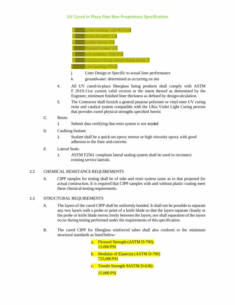
UV Cured in Place Pipe Non-Proprietary Specification
c. prism loading: 120 PCF soild. factor of safety: 2.0e. ovality factor: 2%f. Poisson’s ratio: 0.3g. soil modulus: 1000 PSIh. maximum lining enhancement factor: 7
i. Live loading: HS20j. Liner Design or Specific to actual liner performancek. groundwater: determined as occurring on site
4. All UV cured-in-place fiberglass lining products shall comply with ASTMF 2019-11or current valid version or the intent thereof as determined by theEngineer, minimum finished liner thickness as defined by design calculation.
5. The Contractor shall furnish a general purpose polyester or vinyl ester UV curingresin and catalyst system compatible with the Ultra Violet Light Curing processthat provides cured physical strengths specified herein
C. Resin: 1. Submit data certifying that resin system is not recycled.
D. Caulking Sealant: 1. Sealant shall be a quick-set epoxy mortar or high viscosity epoxy with good
adhesion to the liner and concrete.
E. Lateral Seals: 1. ASTM F2561 compliant lateral sealing system shall be used to reconnect
existing service laterals.
2.2 CHEMICAL RESISTANCE REQUIREMENTS
A. CIPP samples for testing shall be of tube and resin system same as to that proposed for actual construction. It is required that CIPP samples with and without plastic coating meet these chemical-testing requirements.
2.3 STRUCTURAL REQUIREMENTS
A. The layers of the cured CIPP shall he uniformly bonded. It shall not be possible to separate any two layers with a probe or point of a knife blade so that the layers separate cleanly or the probe or knife blade moves freely between the layers; nor shall separation of the layers occur during testing performed under the requirements of this specification.
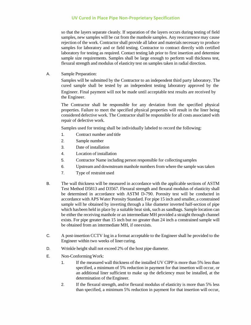
B. The cured CIPP for fiberglass reinforced tubes shall also conform to the minimum structural standards as listed below:
a. Flexural Strength (ASTM D-790):13.000 PSI
b. Modulus of Elasticity (ASTM D-790)725,000 PSI
c. Tensile Strength 9ASTM D-638):
15.000 PSI
UV Cured in Place Pipe Non-Proprietary Specification
PART 3 - EXECUTION
3.1 PREPARATION
A. Access Points - Contractor will locate and designate all manhole access points, open and make access points available for the Work.
B. Cleaning of Sewer Lines - The Contractor shall remove all roots and internal debris (including grease), from the sewer line prior to CIPP installation by any means necessary.
C. Inspection of Pipelines - Inspection of pipelines shall be performed by NASSCO PACP- certified personnel, experienced and trained in locating defects, breaks, obstacles and service connections by closed circuit television (CCTV).
D. Infiltration - Minor infiltration is a normal condition sometimes encountered during the CIPP process. It is not a “changed condition” and should not be regarded as a reason for change orders. If in the opinion of the Engineer, infiltration is significant enough to adversely affect the curing process, chemical grouting or other remedies may be required. This additional work will be paid for by the Owner as a change order.
E. Site Restoration - Areas damaged or modified by the work for this project shall be Repaired or restored to a condition equal to or better than the original condition. Site restoration is incidental to the Work and shall not be regarded as a reason for change orders.
F. Public Relations - A Public Information and Notification Program shall, as a minimum, require the Contractor to be responsible for contacting homeowners or businesses who will be affected by the construction activities and informing them of the Work to be done and the estimated timing for the Work. Written notice shall be delivered to each home or business 2 weeks prior to installation. Notice shall include a local telephone number of the Contractor they can call to discuss the project, and how the homeowner or business will be affected. The written notice must be reviewed by the Owner prior to the start of’ any work.
G. Service connections - Determine by dye test, running water or visual inspection whether connections are active or abandoned and provide results to Engineer prior to insertion. Engineer and Contractor shall agree prior to insertion which services are to be reopened. Only reopened services will be paid for.
3.2 INSTALLATION
A. CIPP installation shall be in accordance with ASTM F2019 for UV light Curing Installations. Installation shall be in accordance with manufacturer’s recommendations, which shall be available for verification by the Engineer.
UV Cured in Place Pipe Non-Proprietary Specification
B. Curing schedules shall be strictly adhered to, per manufacturer requirements.
C. The CIPP liner shall make a tight fitting seal with the existing pipe(s) in the manholes. If the CIPP liner fails to make a tight seal, the Contractor shall apply a seal at that point using a sealant or caulking material that is compatible with CIPP materials, watertight, flexible and impervious to hydrogen sulfide. The top half of the CIPP through a manhole shall be neatly cut off and not broken or sheared off. The channel in the manhole shall be a smooth continuation of the pipe(s) and shall be merged with other lines or channels. Void space between liner and channel wall shall be filled with non-shrink grout and sealed with sealant. CIPP and the existing pipe in the manhole must be sealed before proceeding on to the next manhole section and all manholes shall he individually inspected for CIPP cut-offs and sealing works. Liner shall be cut off at the pipes and all liner removed within intermediate manholes with deflection angles greater than 45 degrees.
D. The finished CIPP shall be continuous over the entire length of an insertion run between two manholes and be free from visual defects such as foreign inclusions, dry spots, pinholes, and delamination. If in the opinion of the Engineer, a portion of the liner is inadequate, the Contractor shall correct the defect(s) to the satisfaction of the Engineer.
E. Contractor shall terminate and seal end of CIPP liner to structures using one of the following approved methods:
1. Expanding Hydrophilic Rubber Joint Seal 2. CIPP manufacturer-approved epoxy or mechanical liner end seals
F. The liner shall be pulled into place via the manufacturer’s instructions.
G. The liner shall be inflated with air before curing with Ultra Violet light according to the manufacturer’s specifications.
H. The reconstruction tube will be impregnated to meet manufacturer specifications with UV Curing Resins in the manufacturing facility prior to installation. The Contractor shall allow the Owner to inspect the materials before installation.
I. The Pre Impregnated UV Light Cured Fiberglass Liner shall be inserted through the existing manhole or other approved access by means of a pull in place process utilizing a winch which will fully extend it to the next designated manhole or termination point. The Fiberglass Liner shall be inflated in place slightly with air to the manufacturer’s specification for installing the UV Chain. Liner cure schedule shall be adhered to per manufacturer’s specifications. The Fiberglass liner will then be inspected with a camera mounted on the UV Chain as it is pulled to the end of the liner. After inspection and complete inflation to manufacturer’s specifications, the UV light bulbs will he turned on. The curing will commence at a rate specified by the manufacturer according to the total dimensions of the liner.
J. As the liner is curing, the UV Curing System shall record all curing data in DVD format for the viewing of the Owner.
K. Initial cure shall be deemed to be complete when the UV Chain arrives at the initial entry point of insertion.
3.3 TESTING
Testing will be required for each insertion of CIPP lining. The layers of the cured CIPP shall he uniformly bonded. It shall not be possible to separate any two layers with a probe
UV Cured in Place Pipe Non-Proprietary Specification
so that the layers separate cleanly. If separation of the layers occurs during testing of field samples, new samples will be cut from the manhole samples. Any reoccurrence may cause rejection of the work. Contractor shall provide all labor and materials necessary to produce samples for laboratory and or field testing. Contractor to contract directly with certified laboratory for testing as required. Contact testing lab prior to first insertion and determine sample size requirements. Samples shall be large enough to perform wall thickness test, flexural strength and modulus of elasticity test on samples taken in radial direction.
A. Sample Preparation:
Samples will be submitted by the Contractor to an independent third party laboratory. The cured sample shall be tested by an independent testing laboratory approved by the Engineer. Final payment will not be made until acceptable test results are received by the Engineer.
The Contractor shall be responsible for any deviation from the specified physical properties. Failure to meet the specified physical properties will result in the liner being considered defective work. The Contractor shall be responsible for all costs associated with repair of defective work.
Samples used for testing shall be individually labeled to record the following: 1. Contract number and title 2. Sample number 3. Date of installation 4. Location of installation 5. Contractor Name including person responsible for collecting samples 6. Upstream and downstream manhole numbers from where the sample was taken 7. Type of restraint used
B. The wall thickness will be measured in accordance with the applicable sections of ASTM
Test Method D5813 and D3567. Flexural strength and flexural modulus of elasticity shall be determined in accordance with ASTM D-790. Porosity test will be conducted in accordance with APS Water Porosity Standard. For pipe 15 inch and smaller, a constrained sample will he obtained by inverting through a like diameter inverted half-section of pipe which has been held in place by a suitable heat sink, such as sandbags. Sample location can be either the receiving manhole or an intermediate MH provided a straight through channel exists. For pipe greater than 15 inch but no greater than 24 inch a constrained sample will be obtained from an intermediate MH, if one exists.
C. A post-insertion CCTV log in a format acceptable to the Engineer shall he provided to the
Engineer within two weeks of liner curing.
D. Wrinkle height shall not exceed 2% of the host pipe diameter.
E. Non-Conforming Work: 1. If the measured wall thickness of the installed UV ClPP is more than 5% less than
specified, a minimum of 5% reduction in payment for that insertion will occur, or an additional liner sufficient to make up the deficiency must be installed, at the determination of the Engineer.
2. If the flexural strength, and/or flexural modulus of elasticity is more than 5% less than specified, a minimum 5% reduction in payment for that insertion will occur,
UV Cured in Place Pipe Non-Proprietary Specification
or an additional liner sufficient to make up the deficiency must be installed, at the determination of the Engineer.
3. If the liner fails the APS water porosity test (pass/fail test), a minimum 5% reduction in payment for that insertion will occur, or complete liner removal may be required or an additional liner sufficient to make up the deficiency must be installed, at the determination of the Engineer.
4. For all instances where the CIPP is deemed unacceptable, the Contractor shall submit a method of repair or replacement for review and approval by the Owner.
5. All Work required to remedy non-conforming work shall he at the sole cost of the Contractor.
4.1 PRIVATE PROPERTY
Care shall be taken to avoid damage to private property (i.e. sprinkler stems, lawn areas). If damage occurs, repairs shall be completed as soon as possible. Costs associated with repairs shall be the responsibility of the Contractor.
END OF SECTION