221.1r-98 state-of-the-art report on alkali-aggregate reactivity
TRANSCRIPT
221
ACI Committee Reports, Guides, Standard Practices,and Commentaries are intended for guidance in planning,designing, executing, and inspecting construction. Thisdocument is intended for the use of individuals who arecompetent to evaluate the significance and limitations ofits content and recommendations and who will accept re-sponsibility for the application of the material it contains.The American Concrete Institute disclaims any and all re-sponsibility for the stated principles. The Institute shallnot be liable for any loss or damage arising therefrom.
Reference to this document shall not be made in con-tract documents. If items found in this document are de-sired by the Architect/Engineer to be a part of the contractdocuments, they shall be restated in mandatory languagefor incorporation by the Architect/Engineer.
State-of-the-Art Report on Alkali-Aggregate Reactivity
ACI 221.1R-98
Reported by ACI Committee 221
Stephen W. Forster*Chairman
David J. Akers Meng K. Lee Aimee Pergalsky*
Colin D. Arrand Donald W. Lewis James S. Pierce
Gregory S. Barger Dean R. MacDonald Raymond R. Pisaneschi
Richard L. Boone Kenneth Mackenzie Marc Q. Robert
Benoit Fournier Gary R. Mass* James W. Schmitt*
Michael S. Hammer Bryant Mather Charles F. Scholer*
F. A. Innis Richard C. Meininger* Peter G. Snow
James T. Kennedy Richard E. Miller David C. Stark*
Joseph F. Lamond Michael A. Ozol* Michael D. A. Thomas
D. Stephen Lane* Steven E. Parker Robert E. Tobin
*Member of subcommittee responsible for preparation of this report.Note: Other Task Force members include: Kim Anderson (former Committee member, deceased); Leonard Bell (former committee member);and Colin Lobo (non-committee member).
Information that is currently available on alkali-aggregate reactivity(AAR), including alkali-silica reactivity (ASR) and alkali-carbonate reac-tivity (ACR) is summarized in the report. Chapters are included that pro-vide an overview of the nature of ASR and ACR reactions, means to avoidthe deleterious effects of each reaction, methods of testing for potentialexpansion of aggregates and cement-aggregate combinations, measures toprevent deleterious reactions, and recommendations for evaluation andrepairof existing structures.
Keywords: aggregates; alkali-aggregate reactivity; alkali-carbonate reactiv-ity; alkali-silica reactivity; concrete; concrete distress; concrete durability.
CONTENTSChapter 1—Introduction, p. 221.1R-2
1.1—Historical perspective1.2—Scope of report
Chapter 2—Manifestations of distress due to alkali-silica reactivity, p. 221.1R-3
2.1—Introduction2.2—Cracking mechanisms2.3—Expansion and other indicators of alkali-silica reactivity 2.4—Alkali-silica reactivity reaction factors2.5—Microscopic evidence of alkali-silica reactivity
Chapter 3—Alkali-silica reactivity mechanisms, p. 221.1R-6
3.1—Factors influencing the reaction3.2—Basic mechanisms of reaction and expansion
Chapter 4—Petrography of alkali-silica reactive aggregate, p. 221.1R-8
4.1—Introduction4.2—Potentially reactive natural siliceous constituents4.3—Potentially reactive synthetic materials
ACI 221.1R-98 became effective August 19, 1998.Copyright 1998, American Concrete Institute.All rights reserved including rights of reproduction and use in any form or by any
means, including the making of copies by any photo process, or by electronic ormechanical device, printed, written, or oral, or recording for sound or visual reproduc-tion or for use in any knowledge or retrieval system or device, unless permission inwriting is obtained from the copyright proprietors.
.1R-1
221.1R-2 ACI COMMITTEE REPORT
Chapter 5—Measures to prevent alkali-silica reactivity, p. 221.1R-9
5.1—Overview5.2—Limiting moisture5.3—Aggregate selection5.4—Minimizing alkalies5.5—Cement selection5.6—Finely divided materials other than portland cement5.7—Testing for the effectiveness of pozzolans or slags5.8—Alkali content of concrete5.9—Chemical admixtures5.10—Other methods
Chapter 6—Methods to evaluate potential for expansive alkali-silica reactivity, p. 221.1R-14
6.1—Introduction6.2—Field service record6.3—Common tests to evaluate potential alkali-silica
reactivity of aggregates6.4—Less common tests to evaluate potential alkali-silica
reactivity of aggregates6.5—Tests to evaluate alkali-silica reactivity in hardened
concrete6.6—Summary of testing
Chapter 7—Manifestations of distress due to alkali-carbonate reactivity, p. 221.1R-19
7.1—Overview7.2—Field indicators7.3—Microscopic indicators7.4—Role of environment, structure geometry, and restraint
on distress development
Chapter 8—Alkali-carbonate reactivity mechanisms, p. 221.1R-21
8.1—Overview8.2—Characteristics of alkali-carbonate reactive rocks8.3—Mechanism of reaction and expansion
Chapter 9—Measures to prevent alkali-carbonate reactivity, p. 221.1R-23
9.1—Introduction9.2—Aggregate selection9.3—Cement9.4—Pozzolans9.5—Moisture
Chapter 10—Methods to evaluate potential for expansive alkali-carbonate reactivity, p. 221.1R-23
10.1—Introduction10.2—Field service record10.3—Petrographic examination10.4—Rock cylinder test10.5—Concrete prism tests10.6—Other procedures10.7—Evaluation of new aggregate sources
Chapter 11—Evaluation and repair of structures affected by alkali-aggregate reactivity, p. 221.1R-25
11.1—Introduction
11.2—Evaluation11.3—Repair methods and materials
Chapter 12—References, p. 221.1R-2712.1—Referenced standards and reports12.2—Cited references
CHAPTER 1—INTRODUCTIONIn many parts of the world, precautions must be taken to
avoid excessive expansion due to alkali-aggregate reactivity(AAR) in many types of concrete construction. AAR may in-volve siliceous aggregates (alkali-silica reactivity, ASR) orcarbonate aggregates (alkali-carbonate reactivity, ACR), andfailure to take precautions may result in progressive deterio-ration, requiring costly repair and rehabilitation of concretestructures to maintain their intended function.
Extensive knowledge is available regarding the mecha-nisms of the reactions, the aggregate constituents that mayreact deleteriously, and precautions that can be taken toavoid resulting distress. However, deficiencies still exist inour knowledge of both ASR and ACR. This is particularlytrue with respect to the applicability of test methods to iden-tify the potential for reactivity, methods to repair affectedconcrete, and means to control the consequences of the reac-tions in existing structures.
Intensive research has been conducted to develop thisneeded information. As a result, concrete structures can nowbe designed and built with a high degree of assurance that ex-cessive expansion due to AAR will not occur and cause pro-gressive degradation of the concrete.
This state-of-the-art report provides information for thoseinvolved with the design and construction of concrete, tomake them aware of the factors involved in AAR and themeans that are available to control it.
1.1—Historical perspective1.1.1 Alkali-silica reactivity—Alkali-silica reactivity
(ASR) was first recognized in concrete pavement in Califor-nia by Stanton (1940, 1942) of the California State Divisionof Highways. Stanton’s early laboratory work demonstratedthat expansion and cracking resulted when certain combina-tions of high-alkali cement and aggregate were combined inmortar bars stored in containers at very high relative humid-ity. Two important conclusions were drawn from this work:First, expansions resulting from ASR in damp mortar barswere negligible when alkali levels in cement were less than0.60 percent, expressed as equivalent sodium oxide (percentNa2Oe = percent Na2O + 0.658 × percent K2O). A secondconclusion was that the partial replacement of high-alkali ce-ment with a suitable pozzolanic material prevented exces-sive expansions. Thus, foundations for the engineeringcontrol of the reaction were developed. This work alsoformed the basis for ASTM C 227, the mortar-bar test proce-dure.
Based on Stanton’s work, the U.S. Bureau of Reclamation(Meissner, 1941) conducted investigations of abnormalcracking in concrete dams. Meissner’s findings generallycorroborated those of Stanton, and lent further credence to
221.1R-3ALKALI-AGGREGATE REACTIVITY
This is partly due to the heterogeneous nature of concrete
the importance of cement alkali level, aggregate composi-tion, and environmental requirements in the development ofexpansion due to ASR. One outcome of this work was thedevelopment of the quick chemical test, ASTM C 289 (Mie-lenz et al., 1948).
In the 1940s, other agencies both in the U.S. and othercountries conducted further studies on ASR. These agenciesincluded the Army Corps of Engineers, the Bureau of PublicRoads, and the Portland Cement Association in the U.S., theAustralian Council for Scientific and Industrial Research(Alderman et al., 1947) and the Danish National Committeefor Alkali Aggregate Research. They furthered the under-standing of relationships among cement composition, aggre-gate types, mixture proportions of mortar and concrete, andexpansion.
Other workers during this period and in the early 1950sconcentrated on clarifying mechanisms expansive and non-expansive reactions. At the Portland Cement Association,Hansen (1944) proposed that osmotic pressures generatedduring swelling of gel reaction products were responsible forthe observed expansion. Powers and Steinour (1955) pro-posed a variant of this hypothesis, while later researchers at-tempted to refine these ideas of expansion mechanisms. Aswith other aspects of the reaction, gaps still exist, particular-ly in the quantitative aspects of reactivity.
Mather (1993) reviewed the use of admixtures to preventexcessive expansion due to alkali-silica reaction. Stanton(1940, 1942) reported that 25 percent pumicite, a pozzolan,“seems to be effective” in reducing “the expansion to a neg-ligible amount at early periods.” The proposal to use poz-zolan to prevent excessive expansion due to ASR apparentlywas first advanced by Hanna (1947). The 1963 report of ACICommittee 212 indicated that there had been “a few instanc-es” where a mineral admixture was used to provide protec-tion with high-alkali cement and reactive aggregate. In spiteof this statement, Mather (1993) reported that he could findno documented evidence of such use. However, Rogers(1987) had written, “At the Lower Notch Dam on the Mont-real River, 20 percent fly ash replacement was used success-fully to prevent cracking of concrete containing argillite andgraywacke.” This appears to have been the first documentedcase where a pozzolan was used with cement known to havehigh-alkali content and with aggregate known to be poten-tially deleteriously reactive. A similar case was reportedfrom Wales (Blackwell and Pettifer, 1992).
Test methods currently in use to determine potential forexpansive reactivity, particularly in the United States, deriveprimarily from work carried out in the 1940s. However, re-search efforts in several countries today indicate a promiseof newer, more reliable tests to identify potentially deleteri-ously reactive cement-aggregate combinations.
1.1.2 Alkali-carbonate reactivity—Alkali-carbonate reac-tivity (ACR) was identified as causing a type of progressive de-terioration of concrete by Swenson (1957) of the NationalResearch Council of Canada. He found that an alkali-sensi-tive reaction had developed in concrete containing argilla-ceous calcitic dolomite aggregate that appeared to bedifferent than the alkali-silica reaction. Subsequent work by
Swenson (1957), Swenson and Gillott (1960), and Gillott(1963) in Canada, and by various other agencies in Canadaand the United States, further elucidated factors that affectedthe magnitude of expansion resulting from the reaction.Noteworthy among researchers in the United States wereNewlon and Sherwood (1962), Newlon et al. (1972a,1972b), and Hadley (1961, 1964). Two hypotheses on themechanism of ACR were developed, both of which still arecited.
Because rock susceptible to this type of reaction is rela-tively rare, and is often unacceptable for use as concrete ag-gregate for other reasons, reported occurrences ofdeleterious ACR in actual structures are relatively few. Theonly area where it appears to have developed to any great ex-tent is in southern Ontario, Canada, in the vicinities of King-ston and Cornwall. Isolated occurrences in concretestructures have been found in the United States in Indiana,Kentucky, Tennessee, and Virginia. So-called “alkali-dolo-mite reactions” involving dolomitic limestones and dolos-tones have also been recognized in China (Tang et al., 1996).
1.2—Scope of reportThis report is intended to provide information on ASR and
ACR. Accordingly, chapters in this report provide an over-view of the nature of both ASR and ACR reactions, themeans of avoiding the deleterious effects of each reaction,methods of testing for potential expansion of cement-aggre-gate combinations, measures to prevent deleterious reac-tions, and recommendations for evaluation and repair ofexisting structures.
CHAPTER 2—MANIFESTATIONS OF DISTRESS DUE TO ALKALI-SILICA REACTIVITY
2.1—IntroductionThe most evident manifestations of deleterious ASR in a
concrete structure are concrete cracking, displacement ofstructural members due to internal expansion of the concrete,and popouts. However, these features should not be used asthe only indicators in the diagnosis of ASR in a concretestructure. Cracking in concrete is essentially the result of thepresence of excessive tensile stress within the concrete,which can be caused by external forces such as load, or bydevelopment of a differential volume change within the con-crete. Early contraction, too large thermal gradients duringcuring of the concrete, corrosion of embedded reinforce-ment, freezing and thawing, and internal and external sulfateattack are some of the mechanisms that also can lead to theformation of cracks in concrete.
Diagnosing ASR-related cracking requires the additionalidentification of ASR reaction product in the concrete and,most importantly, requires positive indications that this producthas led to the generation of tensile stresses sufficiently largethat the tensile strength of the concrete was exceeded.
2.2—Cracking mechanismsLittle is usually known about the time necessary for devel-
opment of cracks in ASR-affected concrete in the field.
221.1R-4 ACI COMMITTEE REPORT
as a material, and to the fact that the reaction kinetics of ASRare practically unexplored. For example:
1. Does the reaction product swell at the place it forms, orat a different place where it migrates after formation?
2. How rapidly are expansive pressures generated from theswelling reaction product?
3. How do these mechanisms produce cracks in the concrete?However, some inferences can be made based on observing
ASR-affected concrete in the field and in the laboratory. For ex-ample, in an unreinforced and unconfined concrete element,such as a concrete slab or beam, the largest degree of deforma-tion of the concrete will occur in the direction of least restraint.
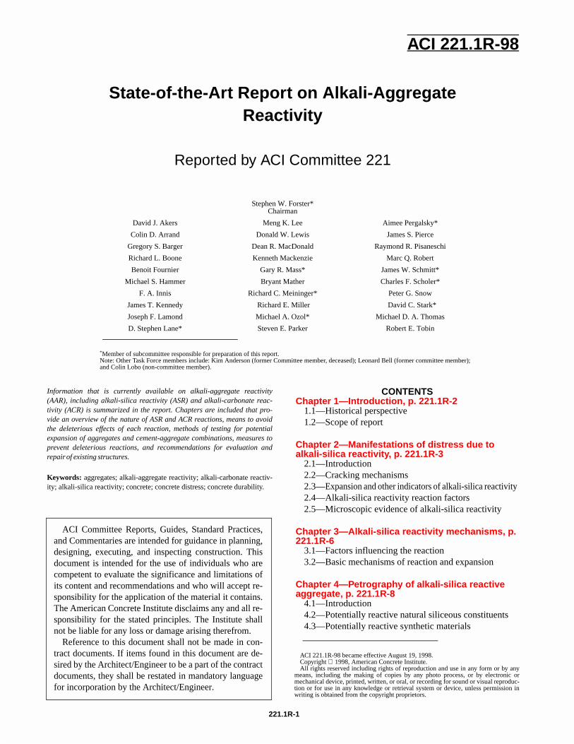
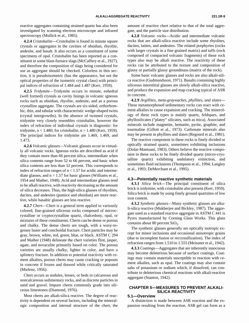
Fig. 1 is a sketch of the surface and a cross section of a con-crete slab undergoing ASR. Swelling due to the uptake ofwater by alkali-silica reaction product generates tensilestresses that lead to the local formation of fine cracks in theconcrete slab. Since the least restraint occurs in a directionperpendicular to the surface, the cracks tend to align them-selves subparallel to the surface. The expansion occurringwithin the concrete causes tension to occur in the concretenear the surface of the slab, where less expansion is taking
Fig. 1—Sketch showing typical features of surface map-crack-ing and subparallel cracks in concrete with ASR. Stresses due to ASR grades from horizontal tension near the surface to horizontal compression and vertical tension with depth.
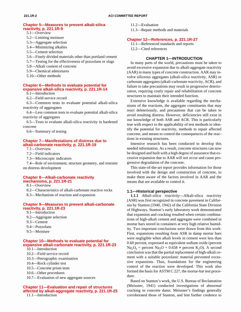
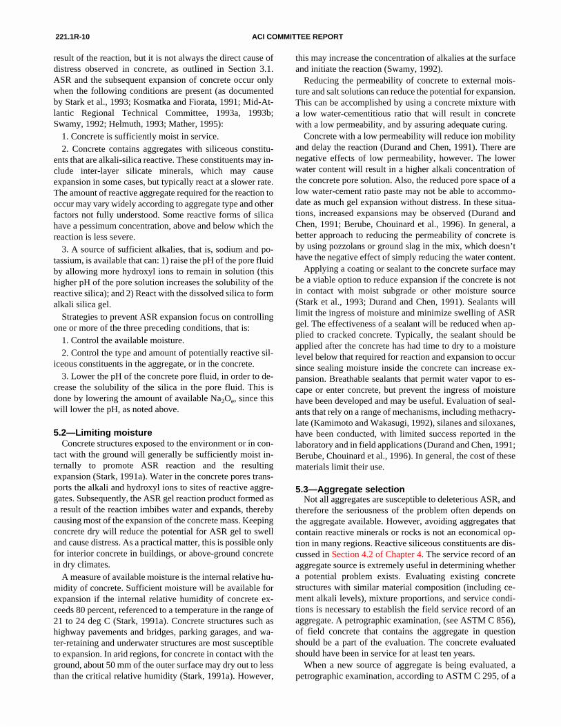
Fig. 2—Photograph of a parapet wall showing typical map-cracking at the surface.
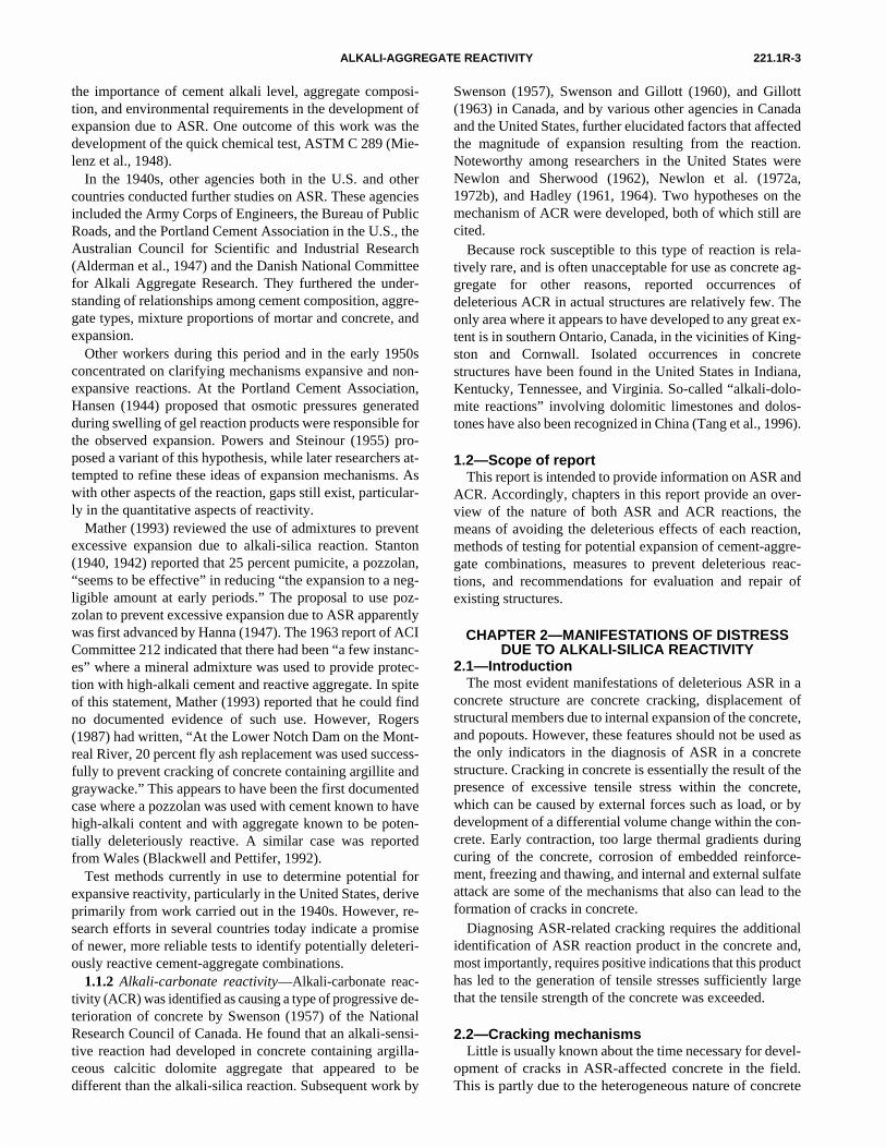
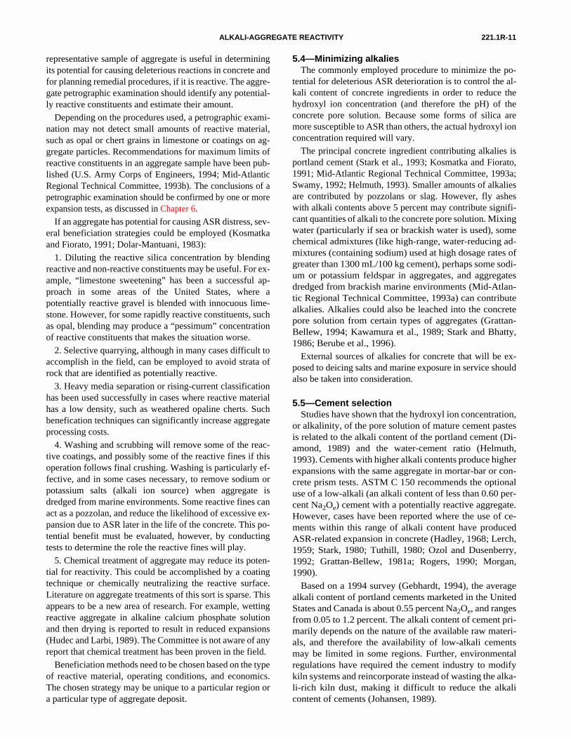
place due to a lower rate of reaction. These tensile stressesare relieved by the formation of relatively wider cracks per-pendicular to the surface. Viewed from above, these crackstend to occur in a polygonal pattern that is the basis for theterm “map-cracking.” Fig. 2 shows the typical appearance ofa concrete surface which has developed map-cracking due toASR. Fig. 3 is a bridge deck core showing both the verticaland horizontal cracking due to ASR.
The relaxation of tension in the surface concrete allowsfurther cracking subparallel to the surface to occur further in-ward from the surface. With an excessive supply of externalalkali and sufficient amounts of reactive silica in the aggre-gates, this subparallel cracking could theoretically continueto occur throughout the concrete. However, field experienceshows that the subparallel cracking seldom goes deeper than300 to 400 mm in unreinforced structures. In reinforced con-crete, the cracking rarely progresses below the level of thereinforcement. It appears reasonable to assume that any re-acting particle lying within concrete restrained by the rein-forcement experiences confining pressures that exceed theexpansive forces generated by the uptake of water by the re-action product. Cracking usually will not occur and the ex-pansive pressures will most likely be accommodated bycreep of the surrounding concrete. When evaluating specificstructures, the type, location, and amount of reinforcementmust be taken into account when considering the potentialfor cracking due to ASR.
The external appearance of the crack pattern in a concretemember is closely related to the stress distribution within theconcrete. The distribution of strain is, among other things,controlled by the location and type of reinforcement, and thestructural load imposed upon the concrete. Expansion of aconcrete element will tend to occur in the direction of leastrestraint. Cracks caused by the expansion due to ASR tend toalign parallel to the direction of maximum restraint.
Fig. 3—Bridge deck core showing both vertical and hori-zontal cracking due to ASR (top of core to the right). Cracks are emphasized by retained moisture.
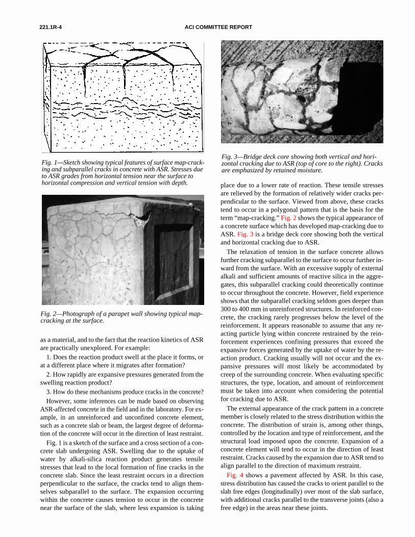
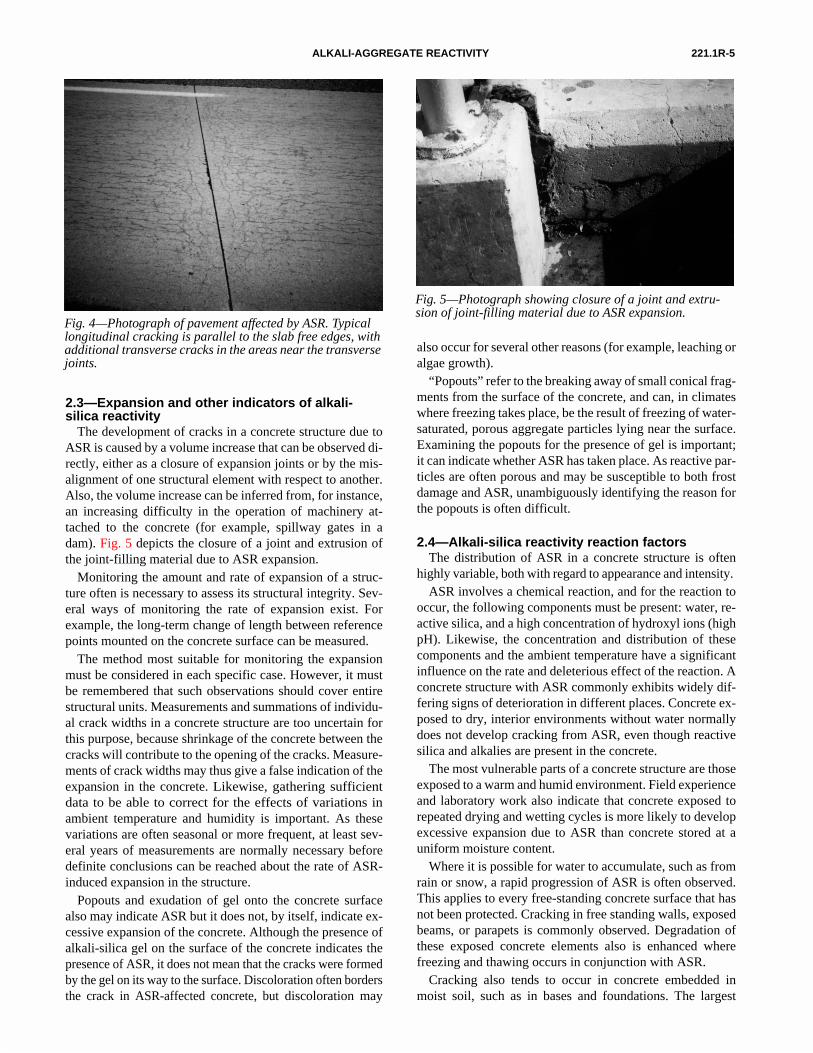
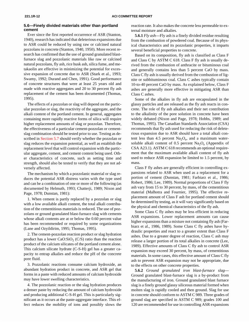
Fig. 4 shows a pavement affected by ASR. In this case,stress distribution has caused the cracks to orient parallel to theslab free edges (longitudinally) over most of the slab surface,with additional cracks parallel to the transverse joints (also afree edge) in the areas near these joints.
221.1R-5ALKALI-AGGREGATE REACTIVITY
Fig. 4—Photograph of pavement affected by ASR. Typical longitudinal cracking is parallel to the slab free edges, with additional transverse cracks in the areas near the transverse joints.
2.3—Expansion and other indicators of alkali-silica reactivity
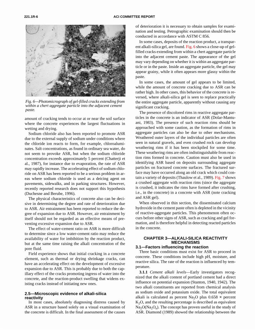
The development of cracks in a concrete structure due toASR is caused by a volume increase that can be observed di-rectly, either as a closure of expansion joints or by the mis-alignment of one structural element with respect to another.Also, the volume increase can be inferred from, for instance,an increasing difficulty in the operation of machinery at-tached to the concrete (for example, spillway gates in adam). Fig. 5 depicts the closure of a joint and extrusion ofthe joint-filling material due to ASR expansion.
Monitoring the amount and rate of expansion of a struc-ture often is necessary to assess its structural integrity. Sev-eral ways of monitoring the rate of expansion exist. Forexample, the long-term change of length between referencepoints mounted on the concrete surface can be measured.
The method most suitable for monitoring the expansionmust be considered in each specific case. However, it mustbe remembered that such observations should cover entirestructural units. Measurements and summations of individu-al crack widths in a concrete structure are too uncertain forthis purpose, because shrinkage of the concrete between thecracks will contribute to the opening of the cracks. Measure-ments of crack widths may thus give a false indication of theexpansion in the concrete. Likewise, gathering sufficientdata to be able to correct for the effects of variations inambient temperature and humidity is important. As thesevariations are often seasonal or more frequent, at least sev-eral years of measurements are normally necessary beforedefinite conclusions can be reached about the rate of ASR-induced expansion in the structure.
Popouts and exudation of gel onto the concrete surfacealso may indicate ASR but it does not, by itself, indicate ex-cessive expansion of the concrete. Although the presence ofalkali-silica gel on the surface of the concrete indicates thepresence of ASR, it does not mean that the cracks were formedby the gel on its way to the surface. Discoloration often bordersthe crack in ASR-affected concrete, but discoloration may
also occur for several other reasons (for example, leaching oralgae growth).
“Popouts” refer to the breaking away of small conical frag-ments from the surface of the concrete, and can, in climateswhere freezing takes place, be the result of freezing of water-saturated, porous aggregate particles lying near the surface.Examining the popouts for the presence of gel is important;it can indicate whether ASR has taken place. As reactive par-ticles are often porous and may be susceptible to both frostdamage and ASR, unambiguously identifying the reason forthe popouts is often difficult.
2.4—Alkali-silica reactivity reaction factorsThe distribution of ASR in a concrete structure is often
highly variable, both with regard to appearance and intensity. ASR involves a chemical reaction, and for the reaction to
occur, the following components must be present: water, re-active silica, and a high concentration of hydroxyl ions (highpH). Likewise, the concentration and distribution of thesecomponents and the ambient temperature have a significantinfluence on the rate and deleterious effect of the reaction. Aconcrete structure with ASR commonly exhibits widely dif-fering signs of deterioration in different places. Concrete ex-posed to dry, interior environments without water normallydoes not develop cracking from ASR, even though reactivesilica and alkalies are present in the concrete.
The most vulnerable parts of a concrete structure are thoseexposed to a warm and humid environment. Field experienceand laboratory work also indicate that concrete exposed torepeated drying and wetting cycles is more likely to developexcessive expansion due to ASR than concrete stored at auniform moisture content.
Where it is possible for water to accumulate, such as fromrain or snow, a rapid progression of ASR is often observed.This applies to every free-standing concrete surface that hasnot been protected. Cracking in free standing walls, exposedbeams, or parapets is commonly observed. Degradation ofthese exposed concrete elements also is enhanced wherefreezing and thawing occurs in conjunction with ASR.
Cracking also tends to occur in concrete embedded inmoist soil, such as in bases and foundations. The largest
Fig. 5—Photograph showing closure of a joint and extru-sion of joint-filling material due to ASR expansion.
221.1R-6 ACI COMMITTEE REPORT
amount of cracking tends to occur at or near the soil surfacewhere the concrete experiences the largest fluctuations inwetting and drying.
Sodium chloride also has been reported to promote ASRdue to the external supply of sodium under conditions wherethe chloride ion reacts to form, for example, chloroalumi-nates. Salt concentrations, as found in ordinary sea water, donot seem to provoke ASR, but when the sodium chlorideconcentration exceeds approximately 5 percent (Chatterji etal., 1987), for instance due to evaporation, the rate of ASRmay rapidly increase. The accelerating effect of sodium chlo-ride on ASR has been reported to be a serious problem in ar-eas where sodium chloride is used as a deicing agent onpavements, sidewalks, and in parking structures. However,recently reported research does not support this hypothesis(Duchesne and Berube, 1996).
The physical characteristics of concrete also can be deci-sive in determining the degree and rate of deterioration dueto ASR. Air entrainment has been reported to reduce the de-gree of expansion due to ASR. However, air entrainment byitself should not be regarded as an effective means of pre-venting excessive expansion due to ASR.
The effect of water-cement ratio on ASR is more difficultto determine since a low water-cement ratio may reduce theavailability of water for imbibition by the reaction product,but at the same time raising the alkali concentration of thepore fluid.
Field experience shows that initial cracking in a concreteelement, such as thermal or drying shrinkage cracks, canhave an accelerating effect on the development of excessiveexpansion due to ASR. This is probably due to both the cap-illary effect of the cracks promoting ingress of water into theconcrete, and the reaction-product swelling that widens ex-isting cracks instead of initiating new ones.
2.5—Microscopic evidence of alkali-silica reactivity
In most cases, absolutely diagnosing distress caused byASR in a structure based solely on a visual examination ofthe concrete is difficult. In the final assessment of the causes
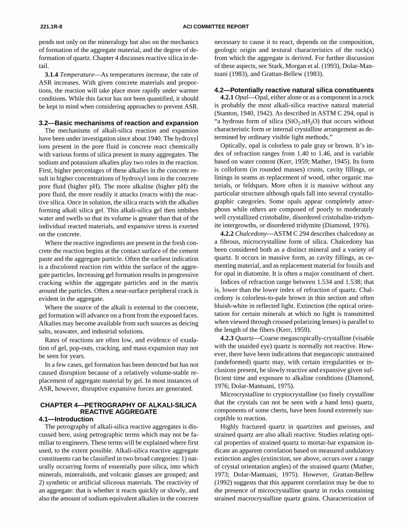
Fig. 6—Photomicrograph of gel-filled cracks extending from within a chert aggregate particle into the adjacent cement paste.
of deterioration it is necessary to obtain samples for exami-nation and testing. Petrographic examination should then beconducted in accordance with ASTM C 856.
In some cases, deposits of the reaction product, a transpar-ent alkali-silica gel, are found. Fig. 6 shows a close-up of gel-filled cracks extending from within a chert aggregate particleinto the adjacent cement paste. The appearance of the gelmay vary depending on whether it is within an aggregate par-ticle or in the paste. Inside an aggregate particle, the gel mayappear grainy, while it often appears more glassy within thepaste.
In some cases, the amount of gel appears to be limited,while the amount of concrete cracking due to ASR can berather high. In other cases, this behavior of the concrete is re-versed, where alkali-silica gel is seen to replace practicallythe entire aggregate particle, apparently without causing anysignificant cracking.
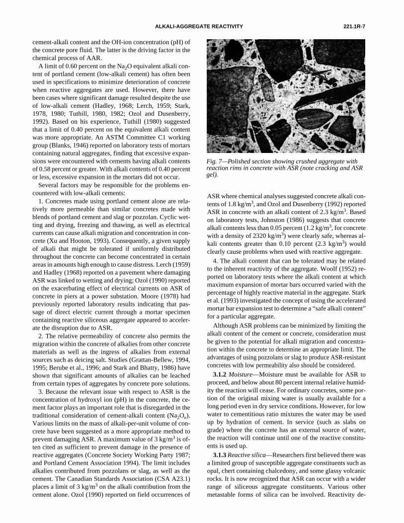
The presence of discolored rims in reactive aggregate par-ticles in the concrete is an indicator of ASR (Dolar-Mantu-ani, 1983). The presence of such reaction rims should beapproached with some caution, as the formation of rims inaggregate particles can also be due to other mechanisms.Weathered outer layers of the individual particles are oftenseen in natural gravels, and even crushed rock can developweathering rims if it has been stockpiled for some time.These weathering rims are often indistinguishable from reac-tion rims formed in concrete. Caution must also be used inidentifying ASR based on deposits surrounding aggregateparticles on fractured concrete surfaces. The fractured sur-face may have occurred along an old crack which could con-tain a variety of deposits (Thaulow et al., 1989). Fig. 7 showsa crushed aggregate with reaction rims (since the aggregateis crushed, it indicates the rims have formed after crushing,i.e., in the concrete) in a concrete with ASR (note crackingand ASR gel).
When observed in thin section, the disseminated calciumhydroxide in the cement paste often is depleted in the vicinityof reactive-aggregate particles. This phenomenon often oc-curs before other signs of ASR, such as cracking and gel for-mation, and is therefore helpful in detecting reacted particlesin the concrete.
CHAPTER 3—ALKALI-SILICA REACTIVITY MECHANISMS
3.1—Factors influencing the reactionThree basic conditions must exist for ASR to proceed in
concrete. These conditions include high pH, moisture, andreactive silica. The rate of the reaction is influenced by tem-perature.
3.1.1 Cement alkali levels—Early investigators recog-nized that the alkali content of portland cement had a directinfluence on potential expansion (Stanton, 1940, 1942). Thetwo alkali constituents are reported from chemical analysisas sodium oxide and potassium oxide. The total equivalentalkali is calculated as percent Na2O plus 0.658 × percentK2O, and the resulting percentage is described as equivalentNa2O(Na2Oe). The concept has proven useful in the study ofASR. Diamond (1989) showed the relationship between the
221.1R-7ALKALI-AGGREGATE REACTIVITY
cement-alkali content and the OH-ion concentration (pH) ofthe concrete pore fluid. The latter is the driving factor in thechemical process of AAR.
A limit of 0.60 percent on the Na2O equivalent alkali con-tent of portland cement (low-alkali cement) has often beenused in specifications to minimize deterioration of concretewhen reactive aggregates are used. However, there havebeen cases where significant damage resulted despite the useof low-alkali cement (Hadley, 1968; Lerch, 1959; Stark,1978, 1980; Tuthill, 1980, 1982; Ozol and Dusenberry,1992). Based on his experience, Tuthill (1980) suggestedthat a limit of 0.40 percent on the equivalent alkali contentwas more appropriate. An ASTM Committee C1 workinggroup (Blanks, 1946) reported on laboratory tests of mortarscontaining natural aggregates, finding that excessive expan-sions were encountered with cements having alkali contentsof 0.58 percent or greater. With alkali contents of 0.40 percentor less, excessive expansion in the mortars did not occur.
Several factors may be responsible for the problems en-countered with low-alkali cements:
1. Concretes made using portland cement alone are rela-tively more permeable than similar concretes made withblends of portland cement and slag or pozzolan. Cyclic wet-ting and drying, freezing and thawing, as well as electricalcurrents can cause alkali migration and concentration in con-crete (Xu and Hooton, 1993). Consequently, a given supplyof alkali that might be tolerated if uniformly distributedthroughout the concrete can become concentrated in certainareas in amounts high enough to cause distress. Lerch (1959)and Hadley (1968) reported on a pavement where damagingASR was linked to wetting and drying; Ozol (1990) reportedon the exacerbating effect of electrical currents on ASR ofconcrete in piers at a power substation. Moore (1978) hadpreviously reported laboratory results indicating that pas-sage of direct electric current through a mortar specimencontaining reactive siliceous aggregate appeared to acceler-ate the disruption due to ASR.
2. The relative permeability of concrete also permits themigration within the concrete of alkalies from other concretematerials as well as the ingress of alkalies from externalsources such as deicing salt. Studies (Grattan-Bellew, 1994,1995; Berube et al., 1996; and Stark and Bhatty, 1986) haveshown that significant amounts of alkalies can be leachedfrom certain types of aggregates by concrete pore solutions.
3. Because the relevant issue with respect to ASR is theconcentration of hydroxyl ion (pH) in the concrete, the ce-ment factor plays an important role that is disregarded in thetraditional consideration of cement-alkali content (Na2Oe).Various limits on the mass of alkali-per-unit volume of con-crete have been suggested as a more appropriate method toprevent damaging ASR. A maximum value of 3 kg/m3 is of-ten cited as sufficient to prevent damage in the presence ofreactive aggregates (Concrete Society Working Party 1987;and Portland Cement Association 1994). The limit includesalkalies contributed from pozzolans or slag, as well as thecement. The Canadian Standards Association (CSA A23.1)places a limit of 3 kg/m3 on the alkali contribution from thecement alone. Ozol (1990) reported on field occurrences of
ASR where chemical analyses suggested concrete alkali con-tents of 1.8 kg/m3, and Ozol and Dusenberry (1992) reportedASR in concrete with an alkali content of 2.3 kg/m3. Basedon laboratory tests, Johnston (1986) suggests that concretealkali contents less than 0.05 percent (1.2 kg/m3, for concretewith a density of 2320 kg/m3) were clearly safe, whereas al-kali contents greater than 0.10 percent (2.3 kg/m3) wouldclearly cause problems when used with reactive aggregate.
4. The alkali content that can be tolerated may be relatedto the inherent reactivity of the aggregate. Woolf (1952) re-ported on laboratory tests where the alkali content at whichmaximum expansion of mortar bars occurred varied with thepercentage of highly reactive material in the aggregate. Starket al. (1993) investigated the concept of using the acceleratedmortar bar expansion test to determine a “safe alkali content”for a particular aggregate.
Although ASR problems can be minimized by limiting thealkali content of the cement or concrete, consideration mustbe given to the potential for alkali migration and concentra-tion within the concrete to determine an appropriate limit. Theadvantages of using pozzolans or slag to produce ASR-resistantconcretes with low permeability also should be considered.
3.1.2 Moisture—Moisture must be available for ASR toproceed, and below about 80 percent internal relative humid-ity the reaction will cease. For ordinary concretes, some por-tion of the original mixing water is usually available for along period even in dry service conditions. However, for lowwater to cementitious ratio mixtures the water may be usedup by hydration of cement. In service (such as slabs ongrade) where the concrete has an external source of water,the reaction will continue until one of the reactive constitu-ents is used up.
3.1.3 Reactive silica—Researchers first believed there wasa limited group of susceptible aggregate constituents such asopal, chert containing chalcedony, and some glassy volcanicrocks. It is now recognized that ASR can occur with a widerrange of siliceous aggregate constituents. Various othermetastable forms of silica can be involved. Reactivity de-
Fig. 7—Polished section showing crushed aggregate with reaction rims in concrete with ASR (note cracking and ASR gel).
221.1R-8 ACI COMMITTEE REPORT
pends not only on the mineralogy but also on the mechanicsof formation of the aggregate material, and the degree of de-formation of quartz. Chapter 4 discusses reactive silica in de-tail.
3.1.4 Temperature—As temperatures increase, the rate ofASR increases. With given concrete materials and propor-tions, the reaction will take place more rapidly under warmerconditions. While this factor has not been quantified, it shouldbe kept in mind when considering approaches to prevent ASR.
3.2—Basic mechanisms of reaction and expansionThe mechanisms of alkali-silica reaction and expansion
have been under investigation since about 1940. The hydroxylions present in the pore fluid in concrete react chemicallywith various forms of silica present in many aggregates. Thesodium and potassium alkalies play two roles in the reaction.First, higher percentages of these alkalies in the concrete re-sult in higher concentrations of hydroxyl ions in the concretepore fluid (higher pH). The more alkaline (higher pH) thepore fluid, the more readily it attacks (reacts with) the reac-tive silica. Once in solution, the silica reacts with the alkaliesforming alkali silica gel. This alkali-silica gel then imbibeswater and swells so that its volume is greater than that of theindividual reacted materials, and expansive stress is exertedon the concrete.
Where the reactive ingredients are present in the fresh con-crete the reaction begins at the contact surface of the cementpaste and the aggregate particle. Often the earliest indicationis a discolored reaction rim within the surface of the aggre-gate particles. Increasing gel formation results in progressivecracking within the aggregate particles and in the matrixaround the particles. Often a near-surface peripheral crack isevident in the aggregate.
Where the source of the alkali is external to the concrete,gel formation will advance on a front from the exposed faces.Alkalies may become available from such sources as deicingsalts, seawater, and industrial solutions.
Rates of reactions are often low, and evidence of exuda-tion of gel, pop-outs, cracking, and mass expansion may notbe seen for years.
In a few cases, gel formation has been detected but has notcaused disruption because of a relatively volume-stable re-placement of aggregate material by gel. In most instances ofASR, however, disruptive expansive forces are generated.
CHAPTER 4—PETROGRAPHY OF ALKALI-SILICA REACTIVE AGGREGATE
4.1—IntroductionThe petrography of alkali-silica reactive aggregates is dis-
cussed here, using petrographic terms which may not be fa-miliar to engineers. These terms will be explained where firstused, to the extent possible. Alkali-silica reactive aggregateconstituents can be classified in two broad categories: 1) nat-urally occurring forms of essentially pure silica, into whichminerals, mineraloids, and volcanic glasses are grouped; and2) synthetic or artificial siliceous materials. The reactivity ofan aggregate: that is whether it reacts quickly or slowly, andalso the amount of sodium equivalent alkalies in the concrete
necessary to cause it to react, depends on the composition,geologic origin and textural characteristics of the rock(s)from which the aggregate is derived. For further discussionof these aspects, see Stark, Morgan et al. (1993), Dolar-Man-tuani (1983), and Grattan-Bellew (1983).
4.2—Potentially reactive natural silica constituents4.2.1 Opal—Opal, either alone or as a component in a rock
is probably the most alkali-silica reactive natural material(Stanton, 1940, 1942). As described in ASTM C 294, opal is“a hydrous form of silica (SiO2.nH2O) that occurs withoutcharacteristic form or internal crystalline arrangement as de-termined by ordinary visible light methods.”
Optically, opal is colorless to pale gray or brown. It’s in-dex of refraction ranges from 1.40 to 1.46, and is variablebased on water content (Kerr, 1959; Mather, 1945). Its formis colloform (in rounded masses) crusts, cavity fillings, orlinings in seams as replacement of wood, other organic ma-terials, or feldspars. More often it is massive without anyparticular structure although opals fall into several crystallo-graphic categories. Some opals appear completely amor-phous while others are composed of poorly to moderatelywell crystallized cristobalite, disordered cristobalite-tridym-ite intergrowths, or disordered tridymite (Diamond, 1976).
4.2.2 Chalcedony—ASTM C 294 describes chalcedony asa fibrous, microcrystalline form of silica. Chalcedony hasbeen considered both as a distinct mineral and a variety ofquartz. It occurs in massive form, as cavity fillings, as ce-menting material, and as replacement material for fossils andfor opal in diatomite. It is often a major constituent of chert.
Indices of refraction range between 1.534 and 1.538; thatis, lower than the lower index of refraction of quartz. Chal-cedony is colorless-to-pale brown in thin section and oftenbluish-white in reflected light. Extinction (the optical orien-tation for certain minerals at which no light is transmittedwhen viewed through crossed polarizing lenses) is parallel tothe length of the fibers (Kerr, 1959).
4.2.3 Quartz—Coarse megascopically-crystalline (visablewith the unaided eye) quartz is normally not reactive. How-ever, there have been indications that megascopic unstrained(undeformed) quartz may, with certain irregularities or in-clusions present, be slowly reactive and expansive given suf-ficient time and exposure to alkaline conditions (Diamond,1976; Dolar-Mantuani, 1975).
Microcrystalline to cryptocrystalline (so finely crystallinethat the crystals can not be seen with a hand lens) quartz,components of some cherts, have been found extremely sus-ceptible to reaction.
Highly fractured quartz in quartzites and gneisses, andstrained quartz are also alkali reactive. Studies relating opti-cal properties of strained quartz to mortar-bar expansion in-dicate an apparent correlation based on measured undulatoryextinction angles (extinction, see above, occurs over a rangeof crystal orientation angles) of the strained quartz (Mather,1973; Dolar-Mantuani, 1975). However, Grattan-Bellew(1992) suggests that this apparent correlation may be due tothe presence of microcrystalline quartz in rocks containingstrained macrocrystalline quartz grains. Characterization of
221.1R-9ALKALI-AGGREGATE REACTIVITY
reactive aggregates containing strained quartz has also beeninvestigated by scanning electron microscope and infraredspectroscopy (Mullick et al., 1985).
4.2.4 Cristobalite—Cristobalite is found in minute squarecrystals or aggregates in the cavities of obsidian, rhyolite,andesite, and basalt. It also occurs as a constituent of somespecimens of opal. Cristobalite has been reported as a con-stituent in some blast-furnace slags (McCaffery et al., 1927),and therefore the composition of slags being considered foruse as aggregate should be checked. Colorless in thin sec-tion, it is pseudoisometric (has the appearance, but not theoptical properties of the isometric crystal class) with princi-pal indices of refraction of 1.484 and 1.487 (Kerr, 1959).
4.2.5 Tridymite—Tridymite occurs in minute, euhedral(well formed) crystals as cavity linings in volcanic igneousrocks such as obsidian, rhyolite, andesite, and as a porouscrystalline aggregate. The crystals are six-sided, orthorhom-bic, thin, and tabular with characteristic wedge-shaped twins(crystal intergrowths). In the absence of twinned crystals,tridymite very closely resembles cristobalite, however theindex of refraction of individual crystals is diagnostic: fortridymite, n < 1.480; for cristobalite, n > 1.480 (Kerr, 1959).The principal indices for tridymite are 1.469, 1.469, and1.473.
4.2.6 Volcanic glasses—Volcanic glasses occur in virtual-ly all volcanic rocks. Igneous rocks are described as acid ifthey contain more than 66 percent silica, intermediate whensilica contents range from 52 to 66 percent, and basic whensilica contents are less than 52 percent. This corresponds toindex of refraction ranges of n < 1.57 for acidic and interme-diate glasses, and n > 1.57 for basic glasses (Williams et al.,1954 and Mather, 1948). Acid and intermediate glasses tendto be alkali reactive, with reactivity decreasing as the amountof silica decreases. Thus, the high-silica glasses of rhyolites,dacites, and andesites (pumice and obsidian) are more reac-tive, while basaltic glasses are less reactive.
4.2.7 Chert—Chert is a general term applied to variouslycolored, fine-grained siliceous rocks composed of microc-rystalline or cryptocrystalline quartz, chalcedony, opal, ormixtures of these constituents. Cherts can be dense or porousand chalky. The dense cherts are tough, with a waxy-to-greasy luster and conchoidal fracture. Chert particles may begray, brown, white, red, green, blue, or black. ASTM C 294and Mather (1948) delineate the chert varieties flint, jasper,agate, and novaculite primarily based on color. The porousvarieties are usually chalky, lighter in color, and have asplintery fracture. In addition to potential reactivity with ce-ment alkalies, porous cherts may cause cracking or popoutsin concrete if frozen and thawed while critically saturated(Mielenz, 1956).
Chert occurs as nodules, lenses, or beds in calcareous andnoncalcareous sedimentary rocks, and as discrete particles insand and gravel. Impure cherts commonly grade into sili-ceous limestones (Diamond, 1976).
Most cherts are alkali-silica reactive. The degree of reac-tivity is dependent on several factors, including the mineral-ogic composition and internal structure of the chert, the
amount of reactive chert relative to that of the total aggre-gate, and the particle size distribution.
4.2.8 Volcanic rocks—Acidic and intermediate volcanicrocks that are alkali-silica reactive include some rhyolites,dacites, latites, and andesites. The related porphyries (rockswith larger crystals in a fine grained matrix) and tuffs (rockcomposed of compacted volcanic fragments) of these rocktypes also may be alkali reactive. The reactivity of theserocks can be attributed to the texture and composition ofglassy or partially glassy groundmass (matrix of the rock).
Some basic volcanic glasses and rocks are also alkali-sili-ca reactive (Gudmundsson, 1971). Basalts containing highlysiliceous interstitial glasses are slowly alkali-silica reactive,and produce the expansion and map cracking typical of ASRin concrete.
4.2.9 Argillites, meta-graywackes, phyllites, and slates—These metamorphosed sedimentary rocks can react with ce-ment alkalies to cause expansion and cracking. The minerol-ogy of these rock types is mainly quartz, feldspars, andphyllosilicates (“platey” silicates, such as mica). Associatedminerals include magnetite, hematite, pyrite, graphite, andtourmaline (Gillott et al., 1973). Carbonate minerals alsomay be present in phyllites and slates (Regourd et al., 1981).
The reactive component in these rocks is finely divided oroptically strained quartz, sometimes exhibiting inclusions(Dolar-Mantuani, 1983). Others believe the reactive compo-nent in these rocks to be finely divided quartz (micro-crys-talline quartz) exhibiting undulatory extinction, andsometimes fluid inclusions (Thompson et al., 1994; Langleyet al., 1993; DeMerchant et al., 1995).
4.3—Potentially reactive synthetic materials4.3.1 Silica brick—The principal constituent of silica
brick is tridymite, with cristobalite also present (Kerr, 1959).Silica brick is made by using finely ground quartzites of lowiron content.
4.3.2 Synthetic glasses—Many synthetic glasses are alka-li-silica reactive (Mukherjee and Bickley, 1987). The aggre-gate used as a standard reactive aggregate in ASTM C 441 isPyrex manufactured by Corning Glass Works. This glasscontains about 80 percent SiO2.
The synthetic glasses generally are optically isotropic ex-cept for minor inclusions and occasional anisotropic grains(due to incomplete fusion or recrystallization). The index ofrefraction ranges from 1.510 to 1.555 (Meissner et al., 1942).
4.3.3 Coatings—Aggregates that are inherently innocuousmay become deleterious because of surface coatings. Coat-ings may contain materials susceptible to reaction with ce-ment alkalies, such as opal. The coatings may also containsalts of potassium or sodium which, if dissolved, can con-tribute to deleterious chemical reactions with alkali-reactiveaggregate (Stanton, 1942).
CHAPTER 5—MEASURES TO PREVENT ALKALI-SILICA REACTIVITY
5.1—OverviewA distinction is made between ASR reaction and the ex-
pansion resulting from the reaction. ASR gel can form as a
221.1R-10 ACI COMMITTEE REPORT
result of the reaction, but it is not always the direct cause ofdistress observed in concrete, as outlined in Section 3.1.ASR and the subsequent expansion of concrete occur onlywhen the following conditions are present (as documentedby Stark et al., 1993; Kosmatka and Fiorata, 1991; Mid-At-lantic Regional Technical Committee, 1993a, 1993b;Swamy, 1992; Helmuth, 1993; Mather, 1995):
1. Concrete is sufficiently moist in service.2. Concrete contains aggregates with siliceous constitu-
ents that are alkali-silica reactive. These constituents may in-clude inter-layer silicate minerals, which may causeexpansion in some cases, but typically react at a slower rate.The amount of reactive aggregate required for the reaction tooccur may vary widely according to aggregate type and otherfactors not fully understood. Some reactive forms of silicahave a pessimum concentration, above and below which thereaction is less severe.
3. A source of sufficient alkalies, that is, sodium and po-tassium, is available that can: 1) raise the pH of the pore fluidby allowing more hydroxyl ions to remain in solution (thishigher pH of the pore solution increases the solubility of thereactive silica); and 2) React with the dissolved silica to formalkali silica gel.
Strategies to prevent ASR expansion focus on controllingone or more of the three preceding conditions, that is:
1. Control the available moisture.2. Control the type and amount of potentially reactive sil-
iceous constituents in the aggregate, or in the concrete. 3. Lower the pH of the concrete pore fluid, in order to de-
crease the solubility of the silica in the pore fluid. This isdone by lowering the amount of available Na2Oe, since thiswill lower the pH, as noted above.
5.2—Limiting moistureConcrete structures exposed to the environment or in con-
tact with the ground will generally be sufficiently moist in-ternally to promote ASR reaction and the resultingexpansion (Stark, 1991a). Water in the concrete pores trans-ports the alkali and hydroxyl ions to sites of reactive aggre-gates. Subsequently, the ASR gel reaction product formed asa result of the reaction imbibes water and expands, therebycausing most of the expansion of the concrete mass. Keepingconcrete dry will reduce the potential for ASR gel to swelland cause distress. As a practical matter, this is possible onlyfor interior concrete in buildings, or above-ground concretein dry climates.
A measure of available moisture is the internal relative hu-midity of concrete. Sufficient moisture will be available forexpansion if the internal relative humidity of concrete ex-ceeds 80 percent, referenced to a temperature in the range of21 to 24 deg C (Stark, 1991a). Concrete structures such ashighway pavements and bridges, parking garages, and wa-ter-retaining and underwater structures are most susceptibleto expansion. In arid regions, for concrete in contact with theground, about 50 mm of the outer surface may dry out to lessthan the critical relative humidity (Stark, 1991a). However,
this may increase the concentration of alkalies at the surfaceand initiate the reaction (Swamy, 1992).
Reducing the permeability of concrete to external mois-ture and salt solutions can reduce the potential for expansion.This can be accomplished by using a concrete mixture witha low water-cementitious ratio that will result in concretewith a low permeability, and by assuring adequate curing.
Concrete with a low permeability will reduce ion mobilityand delay the reaction (Durand and Chen, 1991). There arenegative effects of low permeability, however. The lowerwater content will result in a higher alkali concentration ofthe concrete pore solution. Also, the reduced pore space of alow water-cement ratio paste may not be able to accommo-date as much gel expansion without distress. In these situa-tions, increased expansions may be observed (Durand andChen, 1991; Berube, Chouinard et al., 1996). In general, abetter approach to reducing the permeability of concrete isby using pozzolans or ground slag in the mix, which doesn’thave the negative effect of simply reducing the water content.
Applying a coating or sealant to the concrete surface maybe a viable option to reduce expansion if the concrete is notin contact with moist subgrade or other moisture source(Stark et al., 1993; Durand and Chen, 1991). Sealants willlimit the ingress of moisture and minimize swelling of ASRgel. The effectiveness of a sealant will be reduced when ap-plied to cracked concrete. Typically, the sealant should beapplied after the concrete has had time to dry to a moisturelevel below that required for reaction and expansion to occursince sealing moisture inside the concrete can increase ex-pansion. Breathable sealants that permit water vapor to es-cape or enter concrete, but prevent the ingress of moisturehave been developed and may be useful. Evaluation of seal-ants that rely on a range of mechanisms, including methacry-late (Kamimoto and Wakasugi, 1992), silanes and siloxanes,have been conducted, with limited success reported in thelaboratory and in field applications (Durand and Chen, 1991;Berube, Chouinard et al., 1996). In general, the cost of thesematerials limit their use.
5.3—Aggregate selectionNot all aggregates are susceptible to deleterious ASR, and
therefore the seriousness of the problem often depends onthe aggregate available. However, avoiding aggregates thatcontain reactive minerals or rocks is not an economical op-tion in many regions. Reactive siliceous constituents are dis-cussed in Section 4.2 of Chapter 4. The service record of anaggregate source is extremely useful in determining whethera potential problem exists. Evaluating existing concretestructures with similar material composition (including ce-ment alkali levels), mixture proportions, and service condi-tions is necessary to establish the field service record of anaggregate. A petrographic examination, (see ASTM C 856),of field concrete that contains the aggregate in questionshould be a part of the evaluation. The concrete evaluatedshould have been in service for at least ten years.
When a new source of aggregate is being evaluated, apetrographic examination, according to ASTM C 295, of a
221.1R-11ALKALI-AGGREGATE REACTIVITY
representative sample of aggregate is useful in determiningits potential for causing deleterious reactions in concrete andfor planning remedial procedures, if it is reactive. The aggre-gate petrographic examination should identify any potential-ly reactive constituents and estimate their amount.
Depending on the procedures used, a petrographic exami-nation may not detect small amounts of reactive material,such as opal or chert grains in limestone or coatings on ag-gregate particles. Recommendations for maximum limits ofreactive constituents in an aggregate sample have been pub-lished (U.S. Army Corps of Engineers, 1994; Mid-AtlanticRegional Technical Committee, 1993b). The conclusions of apetrographic examination should be confirmed by one or moreexpansion tests, as discussed in Chapter 6.
If an aggregate has potential for causing ASR distress, sev-eral beneficiation strategies could be employed (Kosmatkaand Fiorato, 1991; Dolar-Mantuani, 1983):
1. Diluting the reactive silica concentration by blendingreactive and non-reactive constituents may be useful. For ex-ample, “limestone sweetening” has been a successful ap-proach in some areas of the United States, where apotentially reactive gravel is blended with innocuous lime-stone. However, for some rapidly reactive constituents, suchas opal, blending may produce a “pessimum” concentrationof reactive constituents that makes the situation worse.
2. Selective quarrying, although in many cases difficult toaccomplish in the field, can be employed to avoid strata ofrock that are identified as potentially reactive.
3. Heavy media separation or rising-current classificationhas been used successfully in cases where reactive materialhas a low density, such as weathered opaline cherts. Suchbenefication techniques can significantly increase aggregateprocessing costs.
4. Washing and scrubbing will remove some of the reac-tive coatings, and possibly some of the reactive fines if thisoperation follows final crushing. Washing is particularly ef-fective, and in some cases necessary, to remove sodium orpotassium salts (alkali ion source) when aggregate isdredged from marine environments. Some reactive fines canact as a pozzolan, and reduce the likelihood of excessive ex-pansion due to ASR later in the life of the concrete. This po-tential benefit must be evaluated, however, by conductingtests to determine the role the reactive fines will play.
5. Chemical treatment of aggregate may reduce its poten-tial for reactivity. This could be accomplished by a coatingtechnique or chemically neutralizing the reactive surface.Literature on aggregate treatments of this sort is sparse. Thisappears to be a new area of research. For example, wettingreactive aggregate in alkaline calcium phosphate solutionand then drying is reported to result in reduced expansions(Hudec and Larbi, 1989). The Committee is not aware of anyreport that chemical treatment has been proven in the field.
Beneficiation methods need to be chosen based on the typeof reactive material, operating conditions, and economics.The chosen strategy may be unique to a particular region ora particular type of aggregate deposit.
5.4—Minimizing alkaliesThe commonly employed procedure to minimize the po-
tential for deleterious ASR deterioration is to control the al-kali content of concrete ingredients in order to reduce thehydroxyl ion concentration (and therefore the pH) of theconcrete pore solution. Because some forms of silica aremore susceptible to ASR than others, the actual hydroxyl ionconcentration required will vary.
The principal concrete ingredient contributing alkalies isportland cement (Stark et al., 1993; Kosmatka and Fiorato,1991; Mid-Atlantic Regional Technical Committee, 1993a;Swamy, 1992; Helmuth, 1993). Smaller amounts of alkaliesare contributed by pozzolans or slag. However, fly asheswith alkali contents above 5 percent may contribute signifi-cant quantities of alkali to the concrete pore solution. Mixingwater (particularly if sea or brackish water is used), somechemical admixtures (like high-range, water-reducing ad-mixtures (containing sodium) used at high dosage rates ofgreater than 1300 mL/100 kg cement), perhaps some sodi-um or potassium feldspar in aggregates, and aggregatesdredged from brackish marine environments (Mid-Atlan-tic Regional Technical Committee, 1993a) can contributealkalies. Alkalies could also be leached into the concretepore solution from certain types of aggregates (Grattan-Bellew, 1994; Kawamura et al., 1989; Stark and Bhatty,1986; Berube et al., 1996).
External sources of alkalies for concrete that will be ex-posed to deicing salts and marine exposure in service shouldalso be taken into consideration.
5.5—Cement selectionStudies have shown that the hydroxyl ion concentration,
or alkalinity, of the pore solution of mature cement pastesis related to the alkali content of the portland cement (Di-amond, 1989) and the water-cement ratio (Helmuth,1993). Cements with higher alkali contents produce higherexpansions with the same aggregate in mortar-bar or con-crete prism tests. ASTM C 150 recommends the optionaluse of a low-alkali (an alkali content of less than 0.60 per-cent Na2Oe) cement with a potentially reactive aggregate.However, cases have been reported where the use of ce-ments within this range of alkali content have producedASR-related expansion in concrete (Hadley, 1968; Lerch,1959; Stark, 1980; Tuthill, 1980; Ozol and Dusenberry,1992; Grattan-Bellew, 1981a; Rogers, 1990; Morgan,1990).
Based on a 1994 survey (Gebhardt, 1994), the averagealkali content of portland cements marketed in the UnitedStates and Canada is about 0.55 percent Na2Oe, and rangesfrom 0.05 to 1.2 percent. The alkali content of cement pri-marily depends on the nature of the available raw materi-als, and therefore the availability of low-alkali cementsmay be limited in some regions. Further, environmentalregulations have required the cement industry to modifykiln systems and reincorporate instead of wasting the alka-li-rich kiln dust, making it difficult to reduce the alkalicontent of cements (Johansen, 1989).
221.1R-12 ACI COMMITTEE REPORT
5.6—Finely divided materials other than portland cement
Ever since the first reported occurrence of ASR (Stanton,1940), research has indicated that deleterious expansions dueto ASR could be reduced by using raw or calcined naturalpozzolans in concrete (Stanton, 1940, 1950). More recent re-search has confirmed that the use of ground granulated blast-furnace slag and pozzolanic materials like raw or calcinednatural pozzolans, fly ash, rice husk ash, silica fume, and me-takaolin are effective in minimizing the potential for exces-sive expansion of concrete due to ASR (Stark et al., 1993;Swamy, 1992; Durand and Chen, 1991). Good performanceof concrete structures that were at least 25 years old andmade with reactive aggregates and 20 to 30 percent fly ashreplacement of the cement has been documented (Thomas,1995).
The effects of a pozzolan or slag will depend on the partic-ular pozzolan or slag, the reactivity of the aggregate, and thealkali content of the portland cement. In general, aggregatescontaining more rapidly reactive forms of silica will requirehigher replacement amounts of slag or pozzolan. Therefore,the effectiveness of a particular cement-pozzolan or cement-slag combination should be tested prior to use. Testing as de-
scribed in Section 5.7 should verify whether the pozzolan orslag reduces the expansion potential, as well as establish thereplacement level that will control expansion with the partic-ular aggregate, cement, and cement content being used. Oth-er characteristics of concrete, such as setting time andstrength, should also be tested to verify that they are not ad-versely affected.The mechanism by which a pozzolanic material or slag re-duces the potential ASR distress varies with the type usedand can be a combination of one or more of the following (asdocumented by Helmuth, 1993; Chatterji, 1989; Nixon andPage, 1978; Dunstan, 1981):
1. When cement is partly replaced by a pozzolan or slagwith a low available alkali content, the total alkali contribu-tion of the cementitious materials is reduced. The use of poz-zolans or ground granulated blast-furnace slag with cementswhose alkali contents are at or below the 0.60 percent valuehas been recommended or required by some organizations(Lane and Ozyildirim, 1995; Thomas, 1995).
2. The cement-pozzolan reaction product or slag hydrationproduct has a lower CaO:SiO2 (C/S) ratio than the reactionproduct of the calcium silicates of the portland cement alone.This calcium silicate hydrate (C-S-H) gel has a greater ca-pacity to entrap alkalies and reduce the pH of the concretepore fluid.
3. Pozzolanic reactions consume calcium hydroxide, anabundant hydration product in concrete, and ASR gel thatforms in a paste with reduced amounts of calcium hydroxidemay have lower swelling characteristics.
4. The pozzolanic reaction or the slag hydration producesa denser paste by reducing the amount of calcium hydroxideand producing additional C-S-H gel. This is particularly sig-nificant as it occurs at the paste-aggregate interface. This ef-fect reduces the mobility of ions and possibly slows the
reaction rate. It also makes the concrete less permeable to ex-ternal moisture and alkalies.
5.6.1 Fly ash—Fly ash is a finely divided residue resultingfrom the combustion of powdered coal. Because of its phys-ical characteristics and its pozzolanic properties, it impartsseveral beneficial properties to concrete.
Based on its composition, fly ash is classified as Class Fand Class C by ASTM C 618. Class F fly ash is usually de-rived from the combustion of anthracite or bituminous coaland generally contains less than 5 percent CaO by mass.Class C fly ash is usually derived from the combustion of lig-nite or subbituminous coal. Class C ashes typically contain10-to-40 percent CaO by mass. As explained below, Class Fashes are generally more effective in mitigating ASR thanClass C ashes.
Some of the alkalies in fly ash are encapsulated in theglassy particles and are released as the fly ash reacts in con-crete. The role of fly ash alkalies and their net contributionto the alkalinity of the pore solution in concrete have beenwidely debated (Nixon and Page, 1978; Hobbs, 1989; andThomas, 1995). The Canadian Standards Association (CSA)recommends that fly ash used for reducing the risk of delete-rious expansion due to ASR should have a total alkali con-tent less than 4.5 percent Na2Oe, and a maximum water-soluble alkali content of 0.5 percent Na2Oe (Appendix ofCSA A23.1). ASTM C 618 recommends an optional require-ment that the maximum available alkali content of fly ashused to reduce ASR expansion be limited to 1.5 percent, bymass.
Class F fly ashes are generally efficient in controlling ex-pansions related to ASR when used as a replacement for aportion of cement (Dunstan, 1981; Farbiarz et al., 1986;Robert, 1986; Lee, 1989). Normal proportions of Class F flyash vary from 15 to 30 percent, by mass, of the cementitiousmaterial (Malhotra and Fournier, 1995). The effective re-placement amount of Class F ash for portland cement shouldbe determined by testing, as it will vary significantly based onthe physical and chemical characteristics of the fly ash.
Some Class C fly ashes may be less efficient in reducingASR expansions. Lower replacement amounts can causehigher expansions than a mixture not containing fly ash (Far-biarz et al., 1986, 1989). Some Class C fly ashes have hy-draulic properties and react to a greater extent than Class Fashes. Due to a greater degree of reaction, Class C ash mayrelease a larger portion of its total alkalies in concrete (Lee,1989). Effective amounts of Class C fly ash to control ASRexpansion may exceed 30 percent, by mass, of cementitiousmaterials. In some cases, this effective amount of Class C flyash to prevent ASR expansion may not be appropriate, dueto the effects on other concrete properties.
5.6.2 Ground granulated iron blast-furnace slag—Ground granulated blast-furnace slag is a by-product fromthe manufacturing of iron. Ground granulated blast furnaceslag is a finely ground glassy siliceous material formed whenmolten slag is rapidly cooled and then ground. Slag for usein concrete should conform to ASTM C 989. Three grades ofground slag are specified in ASTM C 989; grades 100 and120 are recommended for use in controlling ASR expansions
221.1R-13ALKALI-AGGREGATE REACTIVITY
5.7—Testing for effectiveness of pozzolans or slagsASTM C 441 is the test method that evaluates the effec-
tiveness of a pozzolan or slag in reducing expansions due toASR. In this test, Pyrex glass is used as a standard reactiveaggregate. Test mortar bars are prepared with a high-alkalicement or the job cement with 25 percent pozzolan or 50 per-cent slag by mass. The tested pozzolan or slag qualifies as ef-fective if the mortar-bar expansion meets certain criteria.While this method qualifies the type of pozzolan or slag, itdoes not establish minimum effective amounts.
ASTM C 311 provides a procedure for evaluating the ef-fectiveness of fly ash or natural pozzolan in reducing ASRexpansion that is a modification of ASTM C 441. Mortarbars are made with Pyrex glass. A test mixture is preparedwith at least 15 percent fly ash or natural pozzolan by massof cementitious materials. The admixture is considered ef-fective if the expansion is reduced to the level produced by acontrol low-alkali cement mixture. This “effective” amountof admixture can then be used in concrete to control ASRwith cements having alkali contents that do not exceed bymore than 0.05 percent the alkali content of the cementused in the test mixture. Additional guidance is provided inAppendix XI of ASTM C 311.
Pyrex glass is a very reactive material, and if the pozzolan-cement combination can control its expansion, it shouldwork with natural aggregates. However, some have ques-tioned the use of Pyrex glass since it contains alkalies thatmay be released into the pore solution and is sensitive to testconditions (Berube and Duchesne, 1992; and Thomas,1995). The Strategic Highway Research Program (SHRP)and other research (Stark et al., 1993; Davies and Oberhol-ster, 1987) have indicated that the rapid mortar-bar test(ASTM C 1260) may also be able to be used to establishminimum effective amounts of pozzolans or slag. Multipleruns of the test using various amounts of pozzolan or slag areconducted. The effective amount of pozzolan or slag is theamount that reduces the expansion to below a prescribed ex-pansion limit. This approach could potentially qualify ce-mentitious material combinations for use with a particularaggregate. Further evaluation of this approach remains to bedone.
A problem cited with deriving conclusions on the effec-tiveness of pozzolans or slag based on the results of a two-week test, as in ASTM C 441, the procedure in ASTM C 311,or the proposed modification to ASTM C 1260, is the uncer-tain mechanism that causes a reduction in expansion. Withinthe test period, the pozzolans or slag are unlikely to react to anextent that replicates the actual mechanism that occurs in fieldconcretes. Appendix B in CSA A23.1 recommends a two-yeartesting period with the concrete prism test, ASTM C 1293, toevaluate concrete containing fly ash or slag. Research is un-derway on correlating laboratory tests with the performanceof concrete subject to field exposure (Fournier et al., 1995).
(Mid-Atlantic Regional Technical Committee, 1993b). Slagfor use in concrete should conform to ASTM C 989. Effec-tive amounts of slag to reduce ASR expansions vary from 25to 50 percent, or more, by mass of cementitious materials(Malhotra and Fournier, 1995). The alkalies in slag will con-tribute to the alkalinity of the concrete pore solution (Kawa-mura and Takemoto, 1984). The alkalies encapsulated inslag are released at a slower rate than those in portland ce-ment, but at a higher rate than those in fly ash.
5.6.3 Natural pozzolans—Natural pozzolans include natu-rally occurring amorphous siliceous material, or materialprocessed to obtain amorphous silica identified as Class Npozzolan in ASTM C 618. In the United States, the use ofnatural pozzolans has been relatively rare in recent times.Historically, one of the most commonly used natural poz-zolans has been volcanic ash. Calcining some siliceous ma-terial to temperatures of 1000 deg C can produce apozzolanic material. Some of these include calcined shale,certain pumicites and tuffs, opal, rice husk ash, metakaolin,and diatomaceous earth. Finely pulverized materials con-taining volcanic glass, opal, kaolinite, and smectite clays,may be used without calcining to produce pozzolanic mate-rials that can be effective in controlling ASR expansion(Mielenz et al., 1950). Recently, calcined kaolinite (metaka-olinite) has been shown to be effective in minimizing expan-sion caused by ASR (Jones et al., 1992).
Natural pozzolans can have significantly variable charac-teristics, and recommendations for use cannot be made with-out testing.
5.6.4 Silica fume—Silica fume is a very fine powder typi-cally containing 85 to 99 percent amorphous silica by mass.It is a by-product of the silicon and ferro-silicon metal indus-tries. The standard specification for silica fume for use inconcrete is ASTM C 1240. Silica fume actively removes al-kalies from the pore solution and thereby reduces the pH (Di-amond, 1989). There is some concern that at lower amounts,silica fume delays, rather than prevents, the onset of ASRdue to possible later regeneration of alkalies in the pore so-lution. Replacing at least 10 percent of high-alkali cementwith silica fume has been sufficient in some cases (Daviesand Oberholster, 1987), while using a minimum of 20 per-cent (Hobbs, 1989) has also been suggested. The higher per-centages of silica fume may cause other problems with theconcrete (such as cracking) that are unrelated to ASR. In Ice-land, concrete containing 5 to 10 percent silica fume hasbeen used successfully since 1979 to control ASR expan-sions (Olafsson, 1989). Silica fumes with higher amorphoussilica and lower total alkali contents are generally more ef-fective (ACI 234R). The commercial form of silica fume caninfluence its effectiveness in preventing ASR expansion.One study indicates that if densified pellets of silica fumeare not effectively dispersed while mixing, they may actlike reactive aggregate particles and cause cracking due toASR (Pettersson, 1992). A study in Iceland reports that bet-ter dispersion of silica fume may be achieved by intergrind-ing it with the cement (Gudmundsson and Olafsson, 1996).
5.6.5 Blended hydraulic cements—Use of blended ce-ments, such as ASTM C 595 Type IP, where the fly ash is
interground with cement, may be more effective in control-ling expansion, presumably due to a greater fineness and bet-ter distribution of the fly ash (Farbiarz et al., 1989).
221.1R-14 ACI COMMITTEE REPORT
CHAPTER 6—METHODS TO EVALUATE POTENTIAL FOR EXPANSIVE ALKALI-SILICA
5.8—Alkali content of concreteUsing a low-alkali cement (less than 0.60 percent alkali as
equivalent Na2O) does not guarantee that concrete contain-ing reactive aggregates will not produce excessive expansiondue to ASR. Increasing the cement content with a low-alkalicement may increase the alkali concentration of the concretepore solution and may cause deleterious expansions(Johnston, 1986).
Some specifying agencies limit the alkali content of con-crete. British specifications limit the alkali content to 3 kg/m3
(Concrete Society Working Party, 1987). The alkali contri-butions from cement, pozzolans, admixtures, some aggre-gates, and mixing water are considered. For pozzolans, thewater-soluble alkalies are used in the calculation. CanadianStandards Association (CSA) A23.1 Appendix B 5.2 doesnot include the alkali contents of fly ash and slag when spec-ified minimum replacement levels are maintained and the al-kali contents of these materials are within the CSA specifiedlimits of 4.5 percent for fly ash and 1 percent for granulatediron blast furnace slag. In South Africa, the limit on the alkalicontent of concrete varies depending on the type of reactiveaggregate (Oberholster, 1983).
5.9—Chemical admixturesMcCoy and Caldwell (1951) proposed the use of lithium
salts to prevent excessive expansion due to ASR. ACI212.3R lists salts of lithium (1 percent by mass of cement)and Hansen (1960) lists salts of barium (2 to 7 percent bymass of cement) to be effective in reducing ASR expansion.Sakaguchi et al. (1989) observed that lithium ion preventsthe formation of additional gel. SHRP research recommendsthat a minimum molar ratio of lithium to sodium (plus potas-sium) of 0.60:1 is required to prevent ASR (Stark et al.,1993; Stokes, 1996). Other chemicals that have shown somesuccess in laboratory studies include sodium silicofluorideand alkyl alkoxy silane (Ohama et al., 1989). Developmentof these last two admixtures is in the research stage, and theiruse in practice is not yet recommended.
Salts of protein materials and some water-reducing set-re-tarding admixtures are reported by ACI Committee 212(ACI 212.3R) to have produced moderate reductions in ASRexpansion. Salts of chlorides and sulfates can increase ex-pansion. High-range water-reducing admixtures used withopal as the reactive aggregate have resulted in increased ex-pansions (Wang and Gillott, 1989). Several organic com-pounds have been used to complex or chelate the alkali ionswith varying degrees of success. These generally tend to betoo expensive for practical applications.
The status of more recent research developments on ad-mixtures for ASR has been reviewed (Mather, 1993). Lithi-um salts appear to be the most promising admixtures,although still somewhat expensive.
5.10—Other methodsEntraining air in concrete has been reported to reduce ex-
pansions. An additional 4 percent entrained air (beyond thatneeded for freeze-thaw protection) resulted in a 40 percentreduction in expansion (Jensen et al., 1984). The gel has been
observed to fill air voids that provide relief zones for the ex-panding gel. Most air-entrained concrete is used for the pur-pose of resisting deterioration due to cycles of freezing andthawing. ASR gel filling a sufficient number of the air voidscould reduce the resistance of the concrete to freezing-thaw-ing. However, this phenomenon has not been reported infield concrete. Use of additional entrained air as a practicalsolution to ASR expansion has not been attempted in prac-tice.
SHRP research (Stark et al., 1993) evaluated the effect ofrestraint on ASR expansion. Sufficient triaxial restraint canresult in creep that will offset expansion due to ASR. Uniax-ial restraint will promote cracking in a direction parallel tothe restraint. Stark et al. (1993) also reported that if concreteis allowed to dry, the alkalies are chemically altered, andtheir recovery into the pore solution upon re-wetting is suffi-ciently slow that ASR expansion will be reduced. Practicalapproaches to incorporate these observations need develop-ment. Useful guidance is given in a report (Institution ofStructural Engineers, 1992) on the effectiveness of rein-forcement for controlling expansion due to ASR in concrete.
REACTIVITY6.1—Introduction
Several informative papers have been written on methodsto evaluate the potential for deleterious ASR. Diamond(1978), Grattan-Bellew (1981b, 1983, 1989), Sims (1981),Kosmatka and Panarese (1988), and Berube and Fournier(1994) have described various test methods used to evaluatepotential ASR of aggregates or cement-aggregate combina-tions. Standards organizations such as ASTM and CSA sup-ply detailed methodologies for evaluating potential ASR ofaggregates, concrete, and cement-aggregate combinations.Work funded by SHRP also provides some significant im-provements in understanding alkali-silica reactions and indevelopment of a rapid technique to evaluate potential ASRof aggregates (Stark et al., 1993). Tests continue to be mod-ified and developed in an effort to attain a definitive rapidtechnique for ASR potential of aggregate.
6.2—Field service recordThe most reliable means to determine potential ASR sus-
ceptibility of an aggregate is by verifying available field ser-vice records. Verification can be accomplished for existingsources through inspection of concrete structures, 10 yearsold or older, that were made with aggregate from the sourcein question, cements of similar alkali level, and other con-crete components, all in similar proportions. Moist, damp,and wet-dry environments would be most conducive to del-eterious reactivity; therefore, inspections should be gearedtoward such structures as wastewater treatment plants, dams,pavements, and bridges. Knowledge of the alkali level of thecement (from project records) used in the inspected concreteswould be needed in establishing performance of the aggre-gate, particularly its performance with a high-alkali cement.
To establish the service record of an aggregate in concrete,the inspector should look for manifestations of distress due
221.1R-15ALKALI-AGGREGATE REACTIVITY
to ASR, or a lack thereof. Such manifestations may includepattern or map cracking, displacement or evidence of move-ment due to expansion, exudation or deposits of alkali-silicagel, and reaction rims around aggregate particles that may bepresent along spalled or scaled surfaces (Stark, 1991c). Dur-ing the course of the field inspection, procuring concrete coresor other samples from a structure for petrographic examina-tion to verify the occurrence of deleterious ASR is advisable.
Satisfactory field service of an aggregate may not be aguarantee of future performance, if concrete materials previ-ously used (including aggregate composition, cement com-position, as well as concrete mixture components andproportions) have changed. If this is the case, several meth-ods of materials evaluation also should be used to ensure thatdeleterious ASR does not occur in the planned construction.
Aggregates having no service record should be tested bysome of the methods described later in this chapter.
6.3—Common tests to evaluate potential alkali-silica reactivity of aggregates
Several tests are commonly used (often in combination) toevaluate whether an aggregate or cement-aggregate combi-nation is potentially deleteriously alkali-reactive. These testsare usually done to pre-screen new aggregate sources beforeuse as concrete aggregate. Additional information on testingis contained in Stark, 1994.
6.3.1 Petrographic examination of aggregate—Potential-ly reactive components of an aggregate can be identified andquantified through petrographic examination when per-formed by an experienced petrographer. The petrographicexamination is generally done according to procedures out-lined in ASTM C 295. A petrographic examination can bedone on samples from undeveloped quarries (ledge rock ordrilled rock core), operating quarries (drilled rock core, pro-cessed crushed stone, or manufactured sand), undevelopedsand and gravel deposits (bulk sand and gravel samples fromeither test pits or drilled test holes), and operating sand andgravel deposits (bulk samples from processed natural sandand gravel stockpiles/process streams).
ASTM C 295 specifically recommends that the petrogra-pher identify and call attention to potentially alkali-silica re-active constituents. The examination, however, cannotpredict if potentially reactive materials are indeed deleteri-ously expansive. Therefore, ASTM C 295 directs the petrog-rapher to recommend appropriate additional tests todetermine if the amount of potentially reactive material iden-tified is capable of deleterious expansive reactivity. Thus, apetrographic examination is a useful screening procedurethat can be done early in the development and testing of anew aggregate source and as a periodic check of operating de-posits to verify consistency of composition. Great care is need-ed in making a petrographic examination, and in someinstances small amounts of micro-crystalline quartz, whichmay not be visible even in thin section examination may besufficient to cause expansion. In these cases, the presence ofthis micro-crystalline quartz can be determined by x-ray dif-fraction analysis. Chapter 4 of this report further describes thetypes of potentially alkali-silica reactive rocks and minerals.
6.3.2 Mortar-bar expansion test—One of the most com-monly used tests to determine whether a cement-aggregatecombination is potentially alkali-silica reactive is the mortar-bar expansion test, described in ASTM C 227. The test in-volves molding mortar bars containing either the fine aggre-gate or the coarse aggregate (which has been crushed andgraded to sizes required by ASTM C 227) in question and ei-ther a job cement or a reference cement of known alkali lev-el. Some gneisses and graywackes, which are more slowlyexpanding will only expand in the mortar-bar test if the alkalicontent of the cement is boosted by the addition of alkali toa level of 1.25 percent.
The mortar is placed in metal molds to fabricate a set offour mortar bars. After hardening, the four mortar bars aredemolded and measured for initial length in a comparatormeeting the requirements of ASTM C 490. The specimensare placed over water in containers, and the containers aresealed to maintain 100 percent relative humidity. Maintain-ing optimum moisture conditions in the storage containerspresents a problem. If there is excessive moisture, leachingmay reduce the alkali content of the mortar before expansionhas surpassed the maximum allowable limits. A high mois-ture level may give maximum expansion with some types ofaggregate (for example, opal, that causes the mortar bars toexpand within a few weeks). However, this same moisturelevel may not be suitable with another aggregate type (forexample, graywacke, for which the mortar bars may not startto expand for two or three months). For this reason, mortarbars made with graywacke, gneiss or other slower reactingaggregates, should be stored in containers over water butwithout wicks (Rogers and Hooton, 1989).
The containers are stored at 38 deg C to accelerate the ef-fects of alkali-silica reaction. Periodically, the specimens areremoved and length changes are determined. An averagelength change (for the four mortar bars) greater than 0.05percent at three months and greater than 0.10 percent at sixmonths test age is considered by ASTM C 33 to be excessiveand indicative of potentially deleterious ASR. Specimens ex-hibiting expansions greater than 0.05 percent at three monthsbut less than 0.10 percent at six months are not considered tobe deleteriously expansive by ASTM C 33.
The distinct advantage of this test is that it is a direct eval-uation of a particular cement-aggregate combination, whichis somewhat closer to an actual service condition. However,a disadvantage of the test is that the performance of the testmortar may not be the same as the performance of a fieldconcrete containing the same materials. Another difficulty isthe six-month test duration requirement. In many cases, con-struction sequencing does not allow for the long lead timerequired of the mortar-bar test. Further, some investigatorsbelieve six months is not long enough to adequately evalu-ate some aggregate types (Stark, 1980). When slowly ex-panding aggregate is being evaluated, the trend of theexpansion versus time graph at the end of the test should beconsidered when making the evaluation. If it is obvious thatin time the mortar bars will exceed the 0.10 percent expan-sion limit, care is needed in the use of such potentially reac-tive aggregates. For example, a cement with an alkali content
221.1R-16 ACI COMMITTEE REPORT
of 0.80 percent that meets the requirements of ASTM C 227(that is, alkali content having Na2Oe > 0.60) and does not ex-ceed the deleterious expansion limit during the mortar-bartest may cause expansion and deterioration of concrete in thefield.
Despite these and other shortcomings (Diamond, 1978;Grattan-Bellew, 1981b, 1983, 1989; Sims, 1981), this test isconsidered an accurate indicator of a highly-reactive sili-ceous aggregate's potential for deleterious reactivity with al-kalies in concrete.
6.3.3 Accelerated mortar-bar expansion test—There havebeen recent modifications and improvements to mortar-barexpansion tests that are currently in use, such as ASTM C1260, which are based on the National Building Research In-stitute (NBRI) or South African mortar-bar test (Oberholsterand Davies, 1986). This test is a modification of ASTM C227, and aggregate and test specimen preparation are thesame. However, the mortar bars are stored in a 1 NormalNaOH solution (to provide an immediate source of sodiumand hydroxyl ions to the bars) and maintained at a temperatureof 80 deg C to accelerate the alkali-silica reaction. Compara-tor readings are taken over a period of 14 days. The test con-ditions are more severe than most field service environments.
On the 16th day after casting, if the average expansion isless than or equal to 0.10 percent, the cement-aggregatecombination is considered non-reactive. If the average ex-pansion is greater than 0.10 percent but below 0.20 percent,the aggregate may be slowly reactive and additional confir-matory tests should be performed. If average expansion ex-ceeds 0.20 percent, the aggregate is considered deleteriouslyreactive.
After several years of extensive worldwide testing andevaluation of the NBRI method (Davies and Oberholster,1987; Hooton and Rogers, 1989, 1992; Hooton, 1990;Fournier and Berube, 1991), the test has gained acceptanceand has been adopted as ASTM C 1260. Investigators havefound that the method can identify slowly reactive rock typesthat previously could not be detected by other reactivity tests(Stark et al., 1993; Davies and Oberholster, 1986, 1987;Hooton and Rogers, 1989, 1992; Hooton, 1990).
One shortcoming of the ASTM C 1260 test is in the inter-pretation of test data when the observed expansion falls be-tween 0.10 and 0.20 percent. Work done on known reactiveand non-reactive rock types by Stark et al. (1993) suggestsmodification of the test interpretation criteria for some slow-ly reactive aggregate types: to eliminate the gray area be-tween 0.10 and 0.20 percent expansion, it has been suggestedthat expansions greater than 0.08 percent be interpreted aspotentially deleterious and expansions of 0.08 percent or lessas non-deleterious. These criteria are based on using a 1NNaOH immersion test solution. Stark et al. (1993) also inves-tigated a linear regression equation that relates the concen-tration of the NaOH solution to cement alkali level for agiven water-cement ratio. By adjusting the alkali level of theimmersion test solution (prior to the start of the test), theysought to simulate a range of cement alkali levels. When us-ing a lower normality (for example 0.60N) NaOH immersion
solution, the test criterion for potentially deleterious reactiv-ity must be progressively adjusted downward. Thus, the testwas investigated for its potential to determine a safe alkalilevel at which a potentially reactive aggregate will not resultin deleterious expansions. This option is currently under fur-ther investigation, and is not yet a recommended practice.
In general, the accelerated mortar-bar test is quick, reli-able, and can characterize the potential reactivity of slowlyas well as rapidly reactive rock types.
6.3.4 Quick chemical method—The ASTM C 289 quickchemical method determines the potential ASR of an aggre-gate. For this method, a representative sample of the aggre-gate in question is crushed to pass a 300-um sieve and beretained on a 150-um sieve. The crushed material is im-mersed in a hot (80 ± 1.0 deg C) 1N NaOH solution and issealed for 24 hours. The intent is to dissolve soluble silicathat is capable of being reactive and to allow it to react withthe NaOH solution.
After 24 hours, the solution is filtered and measured fordissolved silica (Sc) and a reduction of the original hydroxideion concentration (Rc) due to the reaction. The quantity ofdissolved silica and reduction in alkalinity are plotted on agraph presented in ASTM C 289. The graph basically di-vides plotted points, and hence aggregates, into three catego-ries: aggregates considered innocuous, aggregatesconsidered potentially reactive, and aggregates considereddeleterious.
The quick chemical test has been extensively evaluated(Mielenz et al., 1948; Mielenz and Benton, 1958; Chaikenand Halstead, 1958; and Mielenz and Witte, 1988). Correla-tions exist between the quick chemical test, and expansion ofmortar bars made with high-alkali cement, petrographic ex-amination of aggregates, and field performance. These cor-relations provided the basis for establishing the divisions onthe graph used in ASTM C 289 to classify an aggregate withrespect to potential for reactivity.
The test, although extensively studied, has limitations. Forexample, the category “aggregate considered potentially re-active” is vague. ASTM C 289 recommends that a series ofmortar bar tests be done to determine the “innocuous charac-ter” of an aggregate that falls into this category, or that proofof innocuous character be established by satisfactory servicehistory.
Operator techniques and judgement can influence the re-sults of the quick-chemical method. Grinding the sample toofine can lead to erroneous results. Aggregates containingcertain rocks such as carbonates, sulfates, and some magne-sium silicates such as serpentine can yield erroneous re-sults. Because of these limitations, ASTM C 289recommends correlation of results obtained by the quickchemical test with other reactivity tests, such as mortar-barexpansion and petrographic examination.
Now there is less need for the quick chemical method(ASTM C 289) due to the development of other rapid meth-ods such as the accelerated mortar bar method (ASTM C1260) and autoclave tests, developed in Japan, China,France, and Canada (see Section 6.4.6 of this report). These
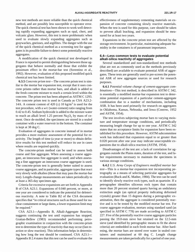
221.1R-17ALKALI-AGGREGATE REACTIVITY
new test methods are more reliable than the quick chemicalmethod, and are possibly less susceptible to operator error.The quick chemical test has been shown to work well detect-ing rapidly expanding aggregates such as opal, chert, andvolcanic glass. However, this test is more problematic whenused to evaluate slowly expanding aggregates such asgraywackes, gneisses, and argillites. The danger with the useof the quick chemical method as a screening test for aggre-gates is its possible failure to detect some potentially reactiveaggregates.
A modification of the quick chemical test developed inFrance is reported to permit distinguishing between those ag-gregates that behave normally and those that exhibit thepessimum effect in the mortar-bar test (Sorentino et al.,1992). However, evaluation of this proposed modified quickchemical test has been limited.
6.3.5 Concrete prism test—The concrete prism test is sim-ilar to the mortar bar expansion test, except that it uses con-crete prisms rather than mortar bars, and alkali is added tothe fresh concrete mixture to reach a certain level within theconcrete. The prism test has been adopted as ASTM C 1293.The concrete prism test is used in Canada as CSA A23.2-14A. A cement content of 420 (±) 10 kg/m3 is used for thetest procedure, with a w/c (water-cement) ratio ranging from0.42 to 0.45. Sodium hydroxide is added to the mixture waterto reach an alkali level 1.25 percent Na2Oe by mass of ce-ment. Once de-molded, the specimens are stored in a sealedcontainer with a water reservoir in the bottom. The containeris kept at 38 deg C.
Evaluation of aggregates in concrete instead of in mortarprovides a more realistic assessment of the potential for re-activity. The length of time (a year or more) to obtain defin-itive results for this test method will reduce its use in caseswhere results are required quickly.
The concrete-prism method can be used to assess bothcoarse and fine aggregate. When assessing a coarse aggre-gate, an innocuous fine aggregate is used; and when assess-ing a fine aggregate an innocuous coarse aggregate is used.The concrete-prism test is generally better suited to assesscoarse aggregate, and in particular, aggregate types that reactvery slowly with alkalies (those that may pass the mortar-bartest). Length-change measurements are taken periodically toat least a 365-day specimen age.
Criteria for excessive expansions are set forth in AppendixB of CSA A23.1. Expansions of 0.040 percent, or more, atone year are considered to indicate the potential for deleteri-ous reactivity. A note to Table B2 of the CSA documentspecifies that “in critical structures such as those used for nu-clear containment or large dams, a lower expansion limit maybe required.”
CSA A23.1—Appendix B, Alkali-Aggregate Reaction,suggests continuing the test until expansion has stopped.Grattan-Bellew (1983) recommended performing petro-graphic examination in conjunction with the concrete-prismtest to determine the type of reactivity that may occur (fast re-action or slow reaction). This information helps in determin-ing how long the test should be continued. CSA A23.1—
Appendix B 2.4 states that this test can be used to evaluate theeffectiveness of supplementary cementing materials on ex-pansion of concrete containing slowly reactive materials.When the test is used for this purpose, care should be takento prevent alkali leaching, and expansion should be mea-sured for at least two years.
Expansions in the concrete prism test are affected by thestorage environment. In particular, maintaining adequate hu-midity in the containers is of paramount importance.
6.4—Less common tests to evaluate potential alkali-silica reactivity of aggregates
Several standardized and non-standardized test methods(that are not as commonly used as the methods previouslydescribed) are available to evaluate potential ASR of aggre-gates. These tests are generally used to pre-screen the poten-tial ASR of new aggregate sources or used for researchpurposes.
6.4.1 Potential volume change of cement-aggregate com-binations—This test method, is described in ASTM C 342,is essentially a modified mortar-bar expansion test to deter-mine potential expansion of a particular cement-aggregatecombination due to a number of mechanisms, includingASR. It has been used primarily for research on aggregatesin Oklahoma, Kansas, Nebraska, and Iowa (Conrow, 1952and ASTM, 1954).
The test involves subjecting mortar bars to varying mois-ture and temperature storage conditions, and periodicallymeasuring length change for up to one year. ASTM C 342states that no acceptance limits for expansion have been es-tablished for this procedure. However, ASTM subcommitteework has indicated that expansion equal to or greater than0.020 percent after one year may indicate unacceptable ex-pansions due to alkali-silica reaction (ASTM, 1954).
Disadvantages of the test are: a lack of correlation for ag-gregates outside the Plains states, duration of the test, and la-bor requirements necessary to maintain the specimens invarious storage conditions.
6.4.2 U.S. Army Corps of Engineers modified mortar bartest—This is a mortar-bar expansion test incorporating pe-trography as a means of selecting particular aggregates forevaluation (Buck and K. Mather, 1984). The test can be usedto identify slowly reactive rock types, such as quartzite. If apetrographer identifies siliceous rock types that containmore than 20 percent strained quartz having an undulatoryextinction angle (an optical property indicating deformedcrystals) greater than 15 degrees during a petrographic ex-amination, then the aggregate is considered potentially reac-tive and is to be tested by the modified mortar bar test. Forcoarse aggregate evaluation, mortars using standard sand (asspecified in ASTM C 778) are made according to ASTM C227. Five of the potentially reactive coarse aggregate particlespassing the 19.0-mm sieve but retained on the 12.5-mmsieve (and identified by petrographic means to fit the abovecriteria) are embedded in each fresh mortar bar. After hard-ening, the mortar bars are stored over water in sealed con-tainers and maintained at 60 deg C. Length changemeasurements are taken periodically for a period of one year.
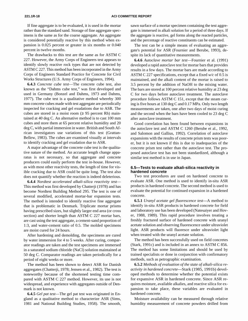
221.1R-18 ACI COMMITTEE REPORT
If fine aggregate is to be evaluated, it is used in the mortarrather than the standard sand. Storage of fine aggregate spec-imens is the same as for the coarse aggregate. An aggregateis considered potentially reactive by this method when ex-pansion is 0.025 percent or greater in six months or 0.040percent in twelve months.
The drawbacks to this test are the same as for ASTM C227. However, the Army Corps of Engineers test appears toidentify slowly reactive rock types that are not detected byASTM C 227. This method has been incorporated in the ArmyCorps of Engineers Standard Practice for Concrete for CivilWorks Structures (U.S. Army Corps of Engineers, 1994).
6.4.3 Concrete cube test—The concrete cube test, alsoknown as the “Dahms cube test,” was first developed andused in Germany (Bonzel and Dahms, 1973 and Dahms,1977). The cube test is a qualitative method whereby 300mm concrete cubes made with test aggregate are periodicallyinspected for cracking and gel exudations due to ASR. Thecubes are stored in a moist room (≥ 95 percent Rh) main-tained at 40 deg C. An alternative method is to cast 100 mmcubes and store them at 65 percent relative humidity and 20deg C, with partial immersion in water. British and South Af-rican investigators use variations of this test (Grattan-Bellew, 1983). The cubes are examined visually at intervalsto identify cracking and gel exudation due to ASR.
A major advantage of the concrete cube test is the qualita-tive nature of the method. An accurate length change appa-ratus is not necessary, so that aggregate and concreteproducers could easily perform the test in-house. However,as with most other reactivity tests, the length of time for vis-ible cracking due to ASR could be quite long. The test alsodoes not quantify whether the reaction is indeed deleterious.
6.4.4 Nordtest accelerated alkali-silica reactivity test—This method was first developed by Chatterji (1978) and hasbecome Nordtest Building Method 295. The test is one ofseveral modified, accelerated mortar-bar expansion tests.The method is intended to identify reactive fine aggregatethat is problematic in Denmark. Triplicate mortar prismshaving prescribed sizes, but slightly larger end area (or crosssection) and shorter length than ASTM C 227 mortar bars,are cast using the test aggregate, a cement-sand proportion of1:3, and water-cement ratio of 0.5. The molded specimensare moist cured for 24 hours.
After hardening and demolding, the specimens are curedby water immersion for 4 to 5 weeks. After curing, compar-ator readings are taken and the test specimens are immersedin a saturated sodium chloride (NaCl) solution maintained at50 deg C. Comparator readings are taken periodically for aperiod of eight weeks or more.
The method has been shown to detect ASR for Danishaggregates (Chatterji, 1978; Jensen et al., 1982). The test isnoteworthy because of the shortened testing time com-pared with ASTM C 227 method. However, its use is notwidespread, and experience with aggregates outside of Den-mark is not known.
6.4.5 Gel pat test—The gel pat test was originated in En-gland as a qualitative method to characterize ASR (Sims,1981 and National Building Studies, 1958). The smooth,
sawn surface of a mortar specimen containing the test aggre-gate is immersed in alkali solution for a period of three days. Ifthe aggregate is reactive, gel forms along the reacted particles,and the percentage of reactive constituents can be estimated.
The test can be a simple means of evaluating an aggre-gate's potential for ASR (Fournier and Berube, 1993), de-spite its lack of quantitative measurements.
6.4.6 Autoclave mortar bar test—Fournier et al. (1991)developed a rapid autoclave test for mortar bars that providesresults in a few days. The mortar bars are made according toASTM C 227 specifications, except that a fixed w/c of 0.5 ismaintained, and the alkali content of the mortar is raised to3.5 percent by the addition of NaOH to the mixing water.The bars are stored at 100 percent relative humidity at 23 degC for two days before autoclave treatment. The autoclaveprocedure follows ASTM C 151, except that the steam cur-ing is five hours at 130 deg C and 0.17 MPa. Only two lengthmeasurements are taken, one after two days of moist curingand the second when the bars have been cooled to 23 deg Cafter autoclave treatment.
Good correlation has been found between expansions inthe autoclave test and ASTM C 1260 (Berube et al., 1992,and Salomon and Gallius, 1992). Correlation of autoclaveexpansions with the results of concrete prism tests was poor-er, but it is not known if this is due to inadequacies of theconcrete prism test rather than the autoclave test. The pro-posed autoclave test has not been standardized, although asimilar test method is in use in Japan.
6.5—Tests to evaluate alkali-silica reactivity in hardened concrete
Two test procedures are used on hardened concrete toevaluate ASR. One method is used to identify in-situ ASRproducts in hardened concrete. The second method is used toevaluate the potential for continued expansion in a hardenedconcrete.
6.5.1 Uranyl acetate gel fluorescence test—A method toidentify in-situ ASR products in hardened concrete for fieldand laboratory use has been developed (Natesaiyer and Hov-er, 1988, 1989). This rapid procedure involves treating afreshly fractured surface of hardened concrete with uranylacetate solution and observing fluorescence under ultravioletlight. ASR products will fluoresce under ultraviolet lightwhen treated with the uranyl acetate solution.
The method has been successfully used on field concretes(Stark, 1991c) and is included in an annex to ASTM C 856.The method has some limitations and should be used bytrained specialists or done in conjunction with confirmatorymethods, such as petrographic examination.
6.5.2 Methods of evaluation of the state of alkali-silica re-activity in hardened concrete—Stark (1985, 1991b) devel-oped methods to determine whether the potential existsfor expansive ASR in hardened concrete. Since ASR re-quires moisture, available alkalies, and reactive silica for ex-pansion to take place, these variables are evaluated inhardened concrete.
Moisture availability can be measured through relativehumidity measurement of concrete powders drilled from
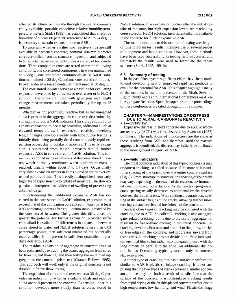
221.1R-19ALKALI-AGGREGATE REACTIVITY
affected structures or in-place through the use of commer-cially available, portable capacitive relative humidity/tem-perature meters. Stark (1985) has established that a relativehumidity of at least 80 percent, referenced to 21 to 24 deg C,is necessary to sustain expansion due to ASR.
To ascertain whether alkalies and reactive silica are stillavailable in hardened concrete, nominal 100-mm diametercores are drilled from the structure in question and subjectedto length change measurements under a variety of test condi-tions. Three companion cores are tested under the followingconditions: one core stored continuously in water maintainedat 38 deg C, one core stored continuously in 1N NaOH solu-tion maintained at 38 deg C, and one core stored continuous-ly over water in a sealed container maintained at 38 deg C.
The core stored in water serves as a baseline for evaluatingexpansion developed by cores stored over water or in NaOHsolution. The cores are fitted with gage pins and lengthchange measurements are taken periodically for up to 12months.
Whether or not potentially reactive but as yet unreactedsilica is present in the aggregate in concrete is determined bystoring the core in a NaOH solution. This storage could forceexpansive reaction to occur by providing additional alkali atelevated temperatures. If expansive reactivity develops,length changes develop steadily with time. Since testing isinitially done using partially-dried concrete, early rapid ex-pansion occurs due to uptake of moisture. This early expan-sion is subtracted from length increases due to furtherexpansive ASR in cores stored in NaOH solution. This cor-rection is applied using expansions of the cores stored in wa-ter, which normally terminates when equilibrium mass isreached, usually within about 7 to 14 days. Occasionallyvery slow expansion occurs in cores stored in water over ex-tended periods of time. This is easily distinguished from earlyhigh rate of expansion due to uptake of moisture. The slow ex-pansion is interpreted as evidence of swelling of pre-existingalkali-silica gel.
In determining that additional expansive ASR has oc-curred in the core stored in NaOH solution, expansion mustexceed that of the companion core stored in water by at least0.03 percentage points after equilibrium mass is reached bythe core stored in water. The greater this difference, thegreater the potential for further expansion, provided suffi-cient alkali is available. If differences in expansion betweencores stored in water and NaOH solution is less than 0.03percentage points, then sufficient unreacted but potentiallyreactive silica is not present in sufficient quantities to pro-duce deleterious ASR.
The residual expansion of aggregate in concrete has alsobeen estimated by extracting the coarse aggregate from coresby freezing and thawing, and then testing the reclaimed ag-gregate in the concrete prism test (Grattan-Bellew, 1995).This approach will work only if the original concrete is notdurable in freeze-thaw testing.
The expansion of cores stored over water at 38 deg C pro-vides an indication of whether available alkali and reactivesilica are still present in the concrete. Expansion under thiscondition develops more slowly than in cores stored in
NaOH solution. If no expansion occurs after the initial up-take of moisture, but high expansion levels are reached bycores stored in NaOH solution, insufficient alkali is availablein the concrete for further expansive ASR.
The main limitations to this method of testing are: lengthof time to obtain test results, intensive use of several piecesof equipment and labor, and cost. However, these methodshave been used successfully in testing field structures, andultimately the results were used to formulate the repairschemes (Stark, 1985, 1991b).
6.6—Summary of testingIn the past fifteen years significant efforts have been made
toward developing new or improved rapid test methods toevaluate the potential for ASR. This chapter highlights manyof the methods in use and presented at the Sixth, Seventh,Eighth, Ninth and Tenth International Conferences on Alka-li-Aggregate Reaction. Specific papers from the proceedingsof these conferences are cited throughout this chapter.
CHAPTER 7—MANIFESTATIONS OF DISTRESS DUE TO ALKALI-CARBONATE REACTIVITY
7.1—OverviewExpansive distress in field concrete due to alkali-carbon-
ate reactivity (ACR) was first observed by Swenson (1957)in Ontario. The indications of this distress are the same asthose resulting from ASR, and therefore, until the reactiveaggregate is identified, the distress may initially be attributedto the more general category of AAR.
7.2—Field indicatorsThe most common indication of this type of distress is map
or pattern cracking, so called because of the more or less uni-form spacing of the cracks over the entire concrete surface(Fig. 8). From structure to structure, the spacing of the cracksmay vary, depending on the extent of the reaction, environmen-tal conditions, and other factors. As the reaction progresses,crack spacing usually decreases as additional cracks developbetween the initial cracks. With continued degradation, spal-ling of the surface begins at the cracks, allowing further mois-ture ingress and accelerated breakdown of the concrete.
Several other types of cracking may be confused with thecracking due to ACR. So called D-cracking is also an aggre-gate- related cracking, but is due to the use of aggregate notresistant to freeze-thaw cycling in saturated concrete. D-cracking develops first near and parallel to the joints, cracks,or free edges of the concrete, and progresses inward fromthese areas. D-cracking does not divide the surface into equi-dimensional blocks but rather into elongated pieces with thelong dimension parallel to the edge. An additional distinc-tion is that D-cracking typically occurs only in concreteslabs-on-grade.
Another type of cracking that has a surface manifestationsimilar to AAR is plastic-shrinkage cracking. It is not sur-prising that the two types of cracks present a similar appear-ance, since they are both a result of tensile forces at thesurface of the concrete. Plastic-shrinkage cracking resultsfrom rapid drying of the freshly-placed concrete surface due tohigh temperature, low humidity, and wind. Plastic-shrinkage
221.1R-20 ACI COMMITTEE REPORT
Fig. 8—Photograph of typical surface map-cracking due to ACR.
cracking is generally noticed soon after construction (a fewhours to a few days). In contrast, cracking due to AAR willtake much longer time (usually months, to years) to develop.Plastic-shrinkage cracks are usually open at the surface andquickly wedge down to no opening within one to two inchesof the surface. Since these cracks occurred when the concretewas plastic, often “tails” of paste can be seen spanning theopen portion of the cracks.
General indicators of expansion due to the ACR includeclosed joints, blow-ups or crushed concrete, and relative off-sets of adjacent slabs or substructures (Stark, 1991c). Theamount of concrete expansion can be estimated in a numberof ways, but usually is done by comparison with some refer-ence structure or feature that has remained stable. For pave-ments, the reference may be an adjacent unaffected slab orshoulder, or the total length reduction of an expansion jointat the approach to a bridge. For bridges, decks may be com-pared with railings or substructures. Various parts of a dammay also be compared or height changes determined, if sur-vey data are available.
7.3—Microscopic indicatorsA number of features visible under the microscope are indica-
tive of alkali-carbonate-related distress. Although often not con-clusive individually, when several of these features are presenttogether, distress due to ACR can confidently be diagnosed.
Unlike ASR, there is no gel product formation related toACR. Rather, the process involves dedolomitization (decom-position) of the dolomite present in the aggregate to formbrucite and calcite. Unique evidence of this reaction, in theform of magnesium hydroxide (Mg(OH)2, brucite) or morecomplex magnesium silicates should therefore be sought.Brucite is not easily seen, so its apparent absence should notbe taken as evidence of the absence of ACR. Reaction rimsmay occur, as well as microcracking within the aggregateparticles and in the paste between the aggregate particles.
Cracking within the aggregate particles may be peripheral orrandom. Rims on the aggregate are not positive indicators ofdeleterious reactivity.
7.4—Role of environment, structure geometry, and restraint on distress development
A number of factors can influence the occurrence of ACR,and the severity of associated distress. Since the distressmechanism is not yet completely defined, the magnitude ofthese various influences is also somewhat uncertain. The en-vironment influences the reaction and the distress developedin concrete through the amount of water made available tothe concrete, and locations within the structure where thatmoisture is concentrated. Water is needed to provide the so-dium and potassium hydroxides necessary for the dedolo-mitization (see Section 8.3) reaction, and also for absorptionby the clay minerals exposed (by dedolomitization), thus cre-ating the expansive forces. The cracking actually occurs inthose zones of the concrete where expansion does not occur(normally, exposed surfaces that can dry out), since those zonesare put in tension by the adjacent expansion. Therefore, the rateand depth of drying of the concrete at the surface also influenc-es distress development.
In addition to moisture, temperature plays a role in the reac-tion. At least early in the reaction process, higher temperaturesincrease the rate of reaction and presumably the subsequentexpansion.
Finally, the environment can be the source of additionalalkalies, resulting in distress even if the concrete was madewith low-alkali cement. The ACR apparently may occur atalkali levels in the cement as low as 0.40 percent Na2Oe(Dolar-Mantuani, 1983).
Geometry of the structure can influence the distress as itaffects the ratio of exposed surface area (where distress oc-curs) to the volume of the concrete where expansion is occur-ring. In some structures (pavements, for example), the
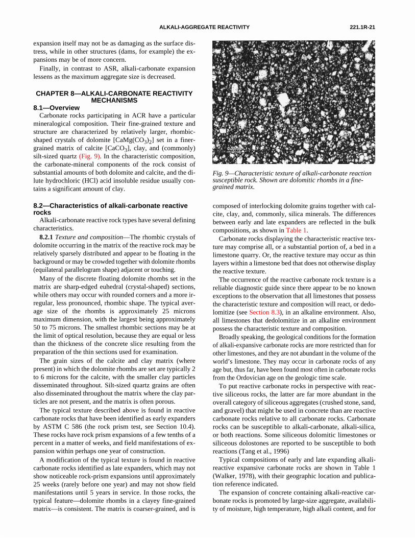
221.1R-21ALKALI-AGGREGATE REACTIVITY
expansion itself may not be as damaging as the surface dis-tress, while in other structures (dams, for example) the ex-pansions may be of more concern.
Finally, in contrast to ASR, alkali-carbonate expansionlessens as the maximum aggregate size is decreased.
CHAPTER 8—ALKALI-CARBONATE REACTIVITY MECHANISMS
8.1—OverviewCarbonate rocks participating in ACR have a particular
mineralogical composition. Their fine-grained texture andstructure are characterized by relatively larger, rhombic-shaped crystals of dolomite [CaMg(CO3)2] set in a finer-grained matrix of calcite [CaCO3], clay, and (commonly)silt-sized quartz (Fig. 9). In the characteristic composition,
Fig. 9—Characteristic texture of alkali-carbonate reaction susceptible rock. Shown are dolomitic rhombs in a fine-grained matrix.
the carbonate-mineral components of the rock consist ofsubstantial amounts of both dolomite and calcite, and the di-lute hydrochloric (HCl) acid insoluble residue usually con-tains a significant amount of clay.
8.2—Characteristics of alkali-carbonate reactive rocks
Alkali-carbonate reactive rock types have several definingcharacteristics.
8.2.1 Texture and composition—The rhombic crystals ofdolomite occurring in the matrix of the reactive rock may berelatively sparsely distributed and appear to be floating in thebackground or may be crowded together with dolomite rhombs(equilateral parallelogram shape) adjacent or touching.
Many of the discrete floating dolomite rhombs set in thematrix are sharp-edged euhedral (crystal-shaped) sections,while others may occur with rounded corners and a more ir-regular, less pronounced, rhombic shape. The typical aver-age size of the rhombs is approximately 25 micronsmaximum dimension, with the largest being approximately50 to 75 microns. The smallest rhombic sections may be atthe limit of optical resolution, because they are equal or lessthan the thickness of the concrete slice resulting from thepreparation of the thin sections used for examination.
The grain sizes of the calcite and clay matrix (wherepresent) in which the dolomite rhombs are set are typically 2to 6 microns for the calcite, with the smaller clay particlesdisseminated throughout. Silt-sized quartz grains are oftenalso disseminated throughout the matrix where the clay par-ticles are not present, and the matrix is often porous.
The typical texture described above is found in reactivecarbonate rocks that have been identified as early expandersby ASTM C 586 (the rock prism test, see Section 10.4).These rocks have rock prism expansions of a few tenths of apercent in a matter of weeks, and field manifestations of ex-pansion within perhaps one year of construction.
A modification of the typical texture is found in reactivecarbonate rocks identified as late expanders, which may notshow noticeable rock-prism expansions until approximately25 weeks (rarely before one year) and may not show fieldmanifestations until 5 years in service. In those rocks, thetypical feature—dolomite rhombs in a clayey fine-grainedmatrix—is consistent. The matrix is coarser-grained, and is
composed of interlocking dolomite grains together with cal-cite, clay, and, commonly, silica minerals. The differencesbetween early and late expanders are reflected in the bulkcompositions, as shown in Table 1.
Carbonate rocks displaying the characteristic reactive tex-ture may comprise all, or a substantial portion of, a bed in alimestone quarry. Or, the reactive texture may occur as thinlayers within a limestone bed that does not otherwise displaythe reactive texture.
The occurrence of the reactive carbonate rock texture is areliable diagnostic guide since there appear to be no knownexceptions to the observation that all limestones that possessthe characteristic texture and composition will react, or dedo-
lomitize (see Section 8.3), in an alkaline environment. Also,all limestones that dedolomitize in an alkaline environmentpossess the characteristic texture and composition.Broadly speaking, the geological conditions for the formationof alkali-expansive carbonate rocks are more restricted than forother limestones, and they are not abundant in the volume of theworld’s limestone. They may occur in carbonate rocks of anyage but, thus far, have been found most often in carbonate rocksfrom the Ordovician age on the geologic time scale.
To put reactive carbonate rocks in perspective with reac-tive siliceous rocks, the latter are far more abundant in theoverall category of siliceous aggregates (crushed stone, sand,and gravel) that might be used in concrete than are reactivecarbonate rocks relative to all carbonate rocks. Carbonaterocks can be susceptible to alkali-carbonate, alkali-silica,or both reactions. Some siliceous dolomitic limestones orsiliceous dolostones are reported to be susceptible to bothreactions (Tang et al., 1996)
Typical compositions of early and late expanding alkali-reactive expansive carbonate rocks are shown in Table 1(Walker, 1978), with their geographic location and publica-tion reference indicated.
The expansion of concrete containing alkali-reactive car-bonate rocks is promoted by large-size aggregate, availabili-ty of moisture, high temperature, high alkali content, and for
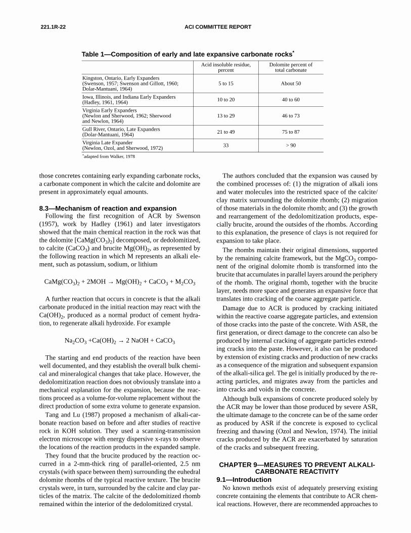
221.1R-22 ACI COMMITTEE REPORT
Table 1—Composition of early and late expansive carbonate rocks*
Acid insoluble residue, percent
Dolomite percent of total carbonate
Kingston, Ontario, Early Expanders (Swenson, 1957; Swenson and Gillott, 1960; Dolar-Mantuani, 1964)
5 to 15 About 50
Iowa, Illinois, and Indiana Early Expanders (Hadley, 1961, 1964) 10 to 20 40 to 60
Virginia Early Expanders (Newlon and Sherwood, 1962; Sherwood and Newlon, 1964)
13 to 29 46 to 73
Gull River, Ontario, Late Expanders (Dolar-Mantuani, 1964) 21 to 49 75 to 87
Virginia Late Expander (Newlon, Ozol, and Sherwood, 1972) 33 > 90
*adapted from Walker, 1978
8.3—Mechanism of reaction and expansionFollowing the first recognition of ACR by Swenson
(1957), work by Hadley (1961) and later investigatorsshowed that the main chemical reaction in the rock was thatthe dolomite [CaMg(CO3)2] decomposed, or dedolomitized,to calcite (CaCO3) and brucite Mg(OH)2, as represented bythe following reaction in which M represents an alkali ele-ment, such as potassium, sodium, or lithium
CaMg(CO3)2 + 2MOH → Mg(OH)2 + CaCO3 + M2CO3
A further reaction that occurs in concrete is that the alkalicarbonate produced in the initial reaction may react with theCa(OH)2, produced as a normal product of cement hydra-tion, to regenerate alkali hydroxide. For example
Na2CO3 +Ca(OH)2 → 2 NaOH + CaCO3
The starting and end products of the reaction have beenwell documented, and they establish the overall bulk chemi-cal and mineralogical changes that take place. However, thededolomitization reaction does not obviously translate into amechanical explanation for the expansion, because the reac-tions proceed as a volume-for-volume replacement without thedirect production of some extra volume to generate expansion.
Tang and Lu (1987) proposed a mechanism of alkali-car-bonate reaction based on before and after studies of reactiverock in KOH solution. They used a scanning-transmissionelectron microscope with energy dispersive x-rays to observethe locations of the reaction products in the expanded sample.
They found that the brucite produced by the reaction oc-curred in a 2-mm-thick ring of parallel-oriented, 2.5 nmcrystals (with space between them) surrounding the euhedraldolomite rhombs of the typical reactive texture. The brucitecrystals were, in turn, surrounded by the calcite and clay par-ticles of the matrix. The calcite of the dedolomitized rhomb
those concretes containing early expanding carbonate rocks,a carbonate component in which the calcite and dolomite arepresent in approximately equal amounts.
remained within the interior of the dedolomitized crystal.
The authors concluded that the expansion was caused bythe combined processes of: (1) the migration of alkali ionsand water molecules into the restricted space of the calcite/clay matrix surrounding the dolomite rhomb; (2) migrationof those materials in the dolomite rhomb; and (3) the growthand rearrangement of the dedolomitization products, espe-cially brucite, around the outsides of the rhombs. Accordingto this explanation, the presence of clays is not required forexpansion to take place.
The rhombs maintain their original dimensions, supportedby the remaining calcite framework, but the MgCO3 compo-nent of the original dolomite rhomb is transformed into thebrucite that accumulates in parallel layers around the peripheryof the rhomb. The original rhomb, together with the brucitelayer, needs more space and generates an expansive force thattranslates into cracking of the coarse aggregate particle.
Damage due to ACR is produced by cracking initiatedwithin the reactive coarse aggregate particles, and extensionof those cracks into the paste of the concrete. With ASR, thefirst generation, or direct damage to the concrete can also beproduced by internal cracking of aggregate particles extend-ing cracks into the paste. However, it also can be producedby extension of existing cracks and production of new cracksas a consequence of the migration and subsequent expansionof the alkali-silica gel. The gel is initially produced by the re-acting particles, and migrates away from the particles andinto cracks and voids in the concrete.
Although bulk expansions of concrete produced solely bythe ACR may be lower than those produced by severe ASR,the ultimate damage to the concrete can be of the same orderas produced by ASR if the concrete is exposed to cyclicalfreezing and thawing (Ozol and Newlon, 1974). The initialcracks produced by the ACR are exacerbated by saturationof the cracks and subsequent freezing.
CHAPTER 9—MEASURES TO PREVENT ALKALI-CARBONATE REACTIVITY
9.1—IntroductionNo known methods exist of adequately preserving existing
concrete containing the elements that contribute to ACR chem-
ical reactions. However, there are recommended approaches to
221.1R-23ALKALI-AGGREGATE REACTIVITY
prevent ACR in new construction. These approaches are de-scribed in the next several sections.
9.2—Aggregate selectionThe aggregate source should be tested for reactivity by the
rock cylinder test, ASTM C 586. The criterion for selectionof non-reactive rock is that the expansion of rock cylindersstored at 23 deg C, and immersed in 1N sodium hydroxidesolution for 84 days is not to exceed 0.20 percent (Smith,1974). A more conclusive way of identifying non-reactiverock is to measure not greater than 0.30 percent expansion inone year rather than not greater than 0.20 percent in 84 days(Ryell et al., 1974).
If the rock cylinder tests show reactivity, the best preventivemeasure is to avoid the rock by selective quarrying (Smith,1964). If it is not economically feasible to avoid the use of re-active material, it should be diluted either naturally or by arti-ficial means until the coarse aggregate contains less than 20percent of potentially reactive material. If both the coarse andfine aggregates are reactive, then less than 15 percent of the to-tal aggregate should be reactive material (Walker, 1978).
Another way to mitigate the effect of the ACR is to use asmaller aggregate size. Although a decrease in the aggregatesize does not slow the chemical reaction, the expansion ap-pears to be in direct proportion to the diameter of the aggregateparticles. Therefore, the smallest feasible size of the reactiveaggregate should be used (Walker, 1978).
9.3—CementAs with ASR, ACR may be prevented by the use of a ce-
ment with a low-alkali content. However, in the case ofACR, the alkali content must be even less than that typicallyspecified for ASR. With highly reactive carbonate aggre-gates, the low-alkali cement should be limited to 0.40 per-cent alkali content (Newlon et al., 1964).
9.4—PozzolansUnlike the reduction in ASR, pozzolans have little or no
effect in reducing by ACR (Swenson and Gillott, 1960).They may have an indirect effect by slowing the rate of thereactivity through reduction of concrete porosity, and there-by reduction in the rate of migration of the pore fluids.
9.5—MoistureWater or moisture is partly involved in at least some of the
ACR reactions. Therefore, any practical means of decreasingthe exposure of ACR-susceptible concrete to water mayextend its useful life.
CHAPTER 10—METHODS TO EVALUATE POTENTIAL FOR EXPANSIVE ALKALI-
CARBONATE REACTIVITY10.1—Introduction
Investigations of concrete deterioration resulting fromACR have provided several techniques and criteria for eval-uating the potential of aggregates to participate in this reaction(Swenson and Gillott, 1960; Smith, 1964, 1974; Newlon, Ozoland Sherwood, 1972; Ryell et al., 1974; Rogers, 1987).Through careful study of cases of deterioration, the lithologic
characteristics of reactive rocks have been identified, and thecause of deterioration understood.
A series of screening techniques eliminate most non-reac-tive rocks in steps. The remaining suspected rocks are sub-jected to a more rigorous evaluation technique. Themethodology culminates by testing the aggregate in concreteprisms, the most reliable method for determining its suscep-tibility to react with alkali and cause expansion of concrete.Concrete prism tests are more time consuming and involvedthan the other screening tests. Newlon, Ozol and Sherwood(1972), Ryell et al., (1974), and Rogers (1987) offer exam-ples of the evaluation process for potentially reactive carbon-ate rocks. Additional information on testing is in Chapter 33of ASTM STP 169 C (1994).
10.2—Field service recordThe first step in the process is to evaluate the field service
record of the aggregate, if one exists. Consideration must begiven to the environmental conditions as they may contributeto ACR as well as the type of structure in which the concretewas used. The similarity of conditions and structure to theproposed construction must be evaluated.
Field service records, when available, can provide the di-rect response to the question other evaluation techniques at-tempt to answer indirectly: Will concrete containing thisaggregate suffer distress from ACR in its intended serviceenvironment that will significantly reduce its service life?Unfortunately, this information is rarely complete enough toprovide a definitive answer and must therefore be supple-mented by other lines of evidence.
10.2.1 Factors to consider—In evaluating the perfor-mance of an aggregate in concrete with respect to ACR andits field service record, several factors are critical and mustbe addressed.
10.2.1.1 Aggregate particle size—The expansion caused byalkali-carbonate reactive aggregates is related to the particlesize of the aggregate, with larger particles causing greaterexpansions. Consequently, an aggregate that performs poor-ly as large particles may perform satisfactorily when reducedto smaller particles. Conversely, an aggregate with a good ser-vice record when used in small particle sizes may cause delete-rious expansion when used in larger particles.
10.2.1.2 Aggregate proportion—Expansion is directly relat-ed to the amount of reactive aggregate in the mixture. Themore reactive the aggregate, the greater the expansion. An ef-fort should be made to determine the amount of questionableaggregate in the concrete when establishing the field servicerecord.
10.2.1.3 Alkali content—Expansion increases with increas-ing alkali content. Therefore, it is useful to ascertain the al-kali content of structures inspected to establish the fieldservice record. External sources of alkali, such as deicingsalts, also contribute to the reaction and should be noted.
10.2.1.4 Moisture content—Moisture is necessary for expan-sion to occur. The environmental conditions relative to theavailability of moisture should be noted as well as design
221.1R-24 ACI COMMITTEE REPORT
features that promote or inhibit moisture ingress into theconcrete.
10.3—Petrographic examinationPetrographic examination of the aggregates determines if
their lithologic characteristics match those representative ofreactive carbonate rocks (see Section 8.2). This examinationis an important part of any evaluation of aggregates for con-crete, and should be performed by an individual qualified byeducation and experience. Guidance on performing petro-graphic examinations is provided in ASTM C 295 and byDolar-Mantuani (1983). Because of the variability of litho-logic characteristics in rock units, the sampling of aggregatesfor evaluation purposes is quite important and should be per-formed with care (Walker, 1978). Good sampling proce-dures are discussed in ASTM C 295 (Newlon, Sherwood,and Ozol, 1972; Rogers, 1987).
The distinctive texture of ACR susceptible rocks is illus-trated in Fig. 11 and can readily be identified in thin section(Walker, 1978; Dolar-Mantuani, 1983). When viewed withthe unaided eye, the reactive aggregates are usually dark,fine-grained, and exhibit conchoidal fracture (Walker,1978).
10.4—Rock cylinder testThis test is based on work by Hadley (1964) and indicates
whether a rock will expand when exposed to an alkaline so-lution. As described in ASTM C 586, the test provides a rel-atively rapid indication of potential expansive reactivity andis an effective tool for screening aggregate sources. It doesnot, however, directly predict the expansion that will occurin concrete and should not be used as an acceptance test.
Cylinders or prisms of suspected reactive rock are im-mersed in 1N sodium hydroxide solution and measured forlength change at specified ages. ASTM C 586 recommendsthe test specimens should be examined petrographically tobe sure they are representative of the lithologic characteris-tics of the rock being evaluated. The problems of specimenselection that arise from the natural variability of rock char-acteristics are discussed by Walker (1978). Appropriate sam-pling techniques are described in Newlon, Sherwood, andOzol (1972), ASTM C 295, and Rogers (1987).
ASTM C 586 interprets rock cylinder expansion of 0.10percent, or more, at 28 days to be considered indicative of ex-pansive reactivity. Some rocks have been found to initiallycontract before expanding at later ages (Dolar-Mantuani,1964), and an alternate expansion limit of 0.20 percent at 16weeks has been suggested (Newlon, Sherwood, and Ozol,1972; Ryell et al., 1974; Rogers, 1987). There is some suspi-cion that the later-expanding rocks may not cause deleteriousexpansion of concrete (Swenson and Gillott, 1960; Newlon,Sherwood and Ozol, 1972) but the potential of these rocks tocause deterioration should not be totally disregarded (Walk-er, 1978). Rocks that expand in this test should be subjectedto testing in concrete prisms to evaluate their potential forcausing expansion.
10.5—Concrete prism testsThe expansion of concrete prisms has long been used in in-
vestigations of expansive-reactive carbonate rocks. Throughthe work of many investigators (Swenson and Gillott, 1960;Smith, 1964; Smith, 1974; Newlon, Ozol and Sherwood,1972; Ryell et al., 1974; Buck, 1975; Rogers, 1987; Rogersand Hooton, 1992), the criteria used in this test for recogniz-ing rock that will expand in concrete has been refined. It isgenerally recognized that this test provides the best indica-tion of potential for deleterious expansion of a carbonate ag-gregate in concrete. Versions of the test have beenstandardized for some time by CSA A 23.2-14A and ASTMC 1105. The two methods use a similar size of test specimen.ASTM C 1105 specifies moist storage at 23 deg C whileCSA A 23.2-14A specifies moist storage at 38 deg C. Work byRogers and Hooton (1992) indicates that storage at 38 deg Cgives a better prediction of the long-term expansion of fieldconcrete. The two methods also differ in how they approach theissues of alkali content of the mixture and the aggregate grada-tion. Because these two factors influence the amount of expan-sion that results from the ACR, care must be taken in evaluatingand comparing the results and criteria of the two methods.
CSA A 23.2-14A uses a fixed grading of aggregate andspecifies that the cement have an alkali content (Na2Oe) of0.90 percent by mass. In addition, sodium hydroxide solu-tion must be added to the concrete mixture to attain an Na2Oealkali content of 1.25 percent, by mass of cement. The ce-ment of the highest alkali content expected is used. The CSAcriterion for potential deleterious reactivity is an expansiongreater than 0.04 percent at one year. ASTM C 1293 is sim-ilar to this method, and although specifically adopted forevaluating aggregates for ASR, could be used to evaluaterocks for ACR as well.
ASTM C 1105 specifies the use of the aggregate gradingproposed for the job with a maximum size of 19.0 mm. Whenthe proposed mixture contains larger size aggregates sus-pected of reactivity, they are crushed to pass the 19.0-mmsieve. The cement used in the test is that proposed for theproject. Reducing the size of aggregate for the test may ob-scure an expansive tendency of the larger particle sizes. Con-sequently, it is more appropriate to test the larger sizes,increasing the size of the test specimens if necessary, or limitthe maximum size of the aggregate in field use to that ofavailable test results. The suggested criteria for potential del-eterious expansion, based on work by Newlon, Ozol andSherwood (1972) and Buck (1975), are 0.015 percent atthree months, 0.025 percent at six months, and 0.030 percentat one year. Limits for expansion in this test have not beenadopted in ASTM C 33.
The suggested limits for expansion in concrete prisms inthese tests have resulted from comparison of laboratory stud-ies and concrete performance in the field. As with any typeof acceptance limit, the biggest problem arises in how to as-sess those results falling near the limit. In borderline situa-tions, consideration should be given to the relationshipbetween the conditions of test, the conditions existing infield studies (if available), and the conditions of the intendedservice. Other aspects to consider are the economics of the
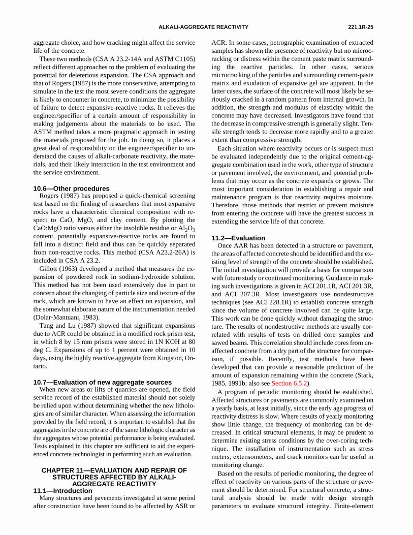
221.1R-25ALKALI-AGGREGATE REACTIVITY
aggregate choice, and how cracking might affect the servicelife of the concrete.
These two methods (CSA A 23.2-14A and ASTM C1105)reflect different approaches to the problem of evaluating thepotential for deleterious expansion. The CSA approach andthat of Rogers (1987) is the more conservative, attempting tosimulate in the test the most severe conditions the aggregateis likely to encounter in concrete, to minimize the possibilityof failure to detect expansive-reactive rocks. It relieves theengineer/specifier of a certain amount of responsibility inmaking judgements about the materials to be used. TheASTM method takes a more pragmatic approach in testingthe materials proposed for the job. In doing so, it places agreat deal of responsibility on the engineer/specifier to un-derstand the causes of alkali-carbonate reactivity, the mate-rials, and their likely interaction in the test environment andthe service environment.
10.6—Other proceduresRogers (1987) has proposed a quick-chemical screening
test based on the finding of researchers that most expansiverocks have a characteristic chemical composition with re-spect to CaO, MgO, and clay content. By plotting theCaO:MgO ratio versus either the insoluble residue or Al2O3content, potentially expansive-reactive rocks are found tofall into a distinct field and thus can be quickly separatedfrom non-reactive rocks. This method (CSA A23.2-26A) isincluded in CSA A 23.2.
Gillott (1963) developed a method that measures the ex-pansion of powdered rock in sodium-hydroxide solution.This method has not been used extensively due in part toconcern about the changing of particle size and texture of therock, which are known to have an effect on expansion, andthe somewhat elaborate nature of the instrumentation needed(Dolar-Mantuani, 1983).
Tang and Lu (1987) showed that significant expansionsdue to ACR could be obtained in a modified rock prism test,in which 8 by 15 mm prisms were stored in 1N KOH at 80deg C. Expansions of up to 1 percent were obtained in 10days, using the highly reactive aggregate from Kingston, On-tario.
10.7—Evaluation of new aggregate sourcesWhen new areas or lifts of quarries are opened, the field
service record of the established material should not solelybe relied upon without determining whether the new litholo-gies are of similar character. When assessing the informationprovided by the field record, it is important to establish that theaggregates in the concrete are of the same lithologic character asthe aggregates whose potential performance is being evaluated.Tests explained in this chapter are sufficient to aid the experi-enced concrete technologist in performing such an evaluation.
CHAPTER 11—EVALUATION AND REPAIR OF STRUCTURES AFFECTED BY ALKALI-
AGGREGATE REACTIVITY11.1—Introduction
Many structures and pavements investigated at some periodafter construction have been found to be affected by ASR or
ACR. In some cases, petrographic examination of extractedsamples has shown the presence of reactivity but no microc-racking or distress within the cement paste matrix surround-ing the reactive particles. In other cases, seriousmicrocracking of the particles and surrounding cement-pastematrix and exudation of expansive gel are apparent. In thelatter cases, the surface of the concrete will most likely be se-riously cracked in a random pattern from internal growth. Inaddition, the strength and modulus of elasticity within theconcrete may have decreased. Investigators have found thatthe decrease in compressive strength is generally slight. Ten-sile strength tends to decrease more rapidly and to a greaterextent than compressive strength.
Each situation where reactivity occurs or is suspect mustbe evaluated independently due to the original cement-ag-gregate combination used in the work, other type of structureor pavement involved, the environment, and potential prob-lems that may occur as the concrete expands or grows. Themost important consideration in establishing a repair andmaintenance program is that reactivity requires moisture.Therefore, those methods that restrict or prevent moisturefrom entering the concrete will have the greatest success inextending the service life of that concrete.
11.2—EvaluationOnce AAR has been detected in a structure or pavement,
the areas of affected concrete should be identified and the ex-isting level of strength of the concrete should be established.The initial investigation will provide a basis for comparisonwith future study or continued monitoring. Guidance in mak-ing such investigations is given in ACI 201.1R, ACI 201.3R,and ACI 207.3R. Most investigators use nondestructivetechniques (see ACI 228.1R) to establish concrete strengthsince the volume of concrete involved can be quite large.This work can be done quickly without damaging the struc-ture. The results of nondestructive methods are usually cor-related with results of tests on drilled core samples andsawed beams. This correlation should include cores from un-affected concrete from a dry part of the structure for compar-ison, if possible. Recently, test methods have beendeveloped that can provide a reasonable prediction of theamount of expansion remaining within the concrete (Stark,1985, 1991b; also see Section 6.5.2).
A program of periodic monitoring should be established.Affected structures or pavements are commonly examined ona yearly basis, at least initially, since the early age progress ofreactivity distress is slow. Where results of yearly monitoringshow little change, the frequency of monitoring can be de-creased. In critical structural elements, it may be prudent todetermine existing stress conditions by the over-coring tech-nique. The installation of instrumentation such as stressmeters, extensometers, and crack monitors can be useful inmonitoring change.
Based on the results of periodic monitoring, the degree ofeffect of reactivity on various parts of the structure or pave-ment should be determined. For structural concrete, a struc-tural analysis should be made with design strengthparameters to evaluate structural integrity. Finite-element
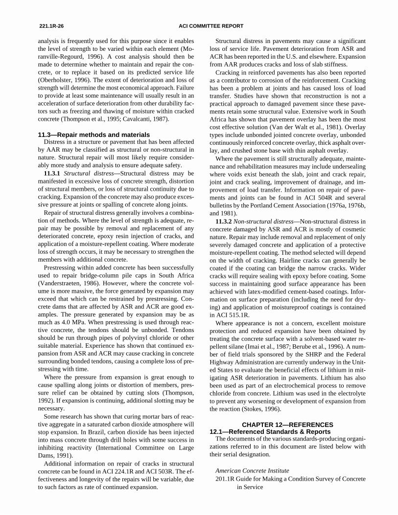
221.1R-26 ACI COMMITTEE REPORT
analysis is frequently used for this purpose since it enablesthe level of strength to be varied within each element (Mo-ranville-Regourd, 1996). A cost analysis should then bemade to determine whether to maintain and repair the con-crete, or to replace it based on its predicted service life(Oberholster, 1996). The extent of deterioration and loss ofstrength will determine the most economical approach. Failureto provide at least some maintenance will usually result in anacceleration of surface deterioration from other durability fac-tors such as freezing and thawing of moisture within crackedconcrete (Thompson et al., 1995; Cavalcanti, 1987).
11.3—Repair methods and materialsDistress in a structure or pavement that has been affected
by AAR may be classified as structural or non-structural innature. Structural repair will most likely require consider-ably more study and analysis to ensure adequate safety.
11.3.1 Structural distress—Structural distress may bemanifested in excessive loss of concrete strength, distortionof structural members, or loss of structural continuity due tocracking. Expansion of the concrete may also produce exces-sive pressure at joints or spalling of concrete along joints.
Repair of structural distress generally involves a combina-tion of methods. Where the level of strength is adequate, re-pair may be possible by removal and replacement of anydeteriorated concrete, epoxy resin injection of cracks, andapplication of a moisture-repellent coating. Where moderateloss of strength occurs, it may be necessary to strengthen themembers with additional concrete.
Prestressing within added concrete has been successfullyused to repair bridge-column pile caps in South Africa(Vanderstraeten, 1986). However, where the concrete vol-ume is more massive, the force generated by expansion mayexceed that which can be restrained by prestressing. Con-crete dams that are affected by ASR and ACR are good ex-amples. The pressure generated by expansion may be asmuch as 4.0 MPa. When prestressing is used through reac-tive concrete, the tendons should be unbonded. Tendonsshould be run through pipes of polyvinyl chloride or othersuitable material. Experience has shown that continued ex-pansion from ASR and ACR may cause cracking in concretesurrounding bonded tendons, causing a complete loss of pre-stressing with time.
Where the pressure from expansion is great enough tocause spalling along joints or distortion of members, pres-sure relief can be obtained by cutting slots (Thompson,1992). If expansion is continuing, additional slotting may benecessary.
Some research has shown that curing mortar bars of reac-tive aggregate in a saturated carbon dioxide atmosphere willstop expansion. In Brazil, carbon dioxide has been injectedinto mass concrete through drill holes with some success ininhibiting reactivity (International Committee on LargeDams, 1991).
Additional information on repair of cracks in structuralconcrete can be found in ACI 224.1R and ACI 503R. The ef-fectiveness and longevity of the repairs will be variable, dueto such factors as rate of continued expansion.
Structural distress in pavements may cause a significantloss of service life. Pavement deterioration from ASR andACR has been reported in the U.S. and elsewhere. Expansionfrom AAR produces cracks and loss of slab stiffness.
Cracking in reinforced pavements has also been reportedas a contributor to corrosion of the reinforcement. Crackinghas been a problem at joints and has caused loss of loadtransfer. Studies have shown that reconstruction is not apractical approach to damaged pavement since these pave-ments retain some structural value. Extensive work in SouthAfrica has shown that pavement overlay has been the mostcost effective solution (Van der Walt et al., 1981). Overlaytypes include unbonded jointed concrete overlay, unbondedcontinuously reinforced concrete overlay, thick asphalt over-lay, and crushed stone base with thin asphalt overlay.
Where the pavement is still structurally adequate, mainte-nance and rehabilitation measures may include undersealingwhere voids exist beneath the slab, joint and crack repair,joint and crack sealing, improvement of drainage, and im-provement of load transfer. Information on repair of pave-ments and joints can be found in ACI 504R and severalbulletins by the Portland Cement Association (1976a, 1976b,and 1981).
11.3.2 Non-structural distress—Non-structural distress inconcrete damaged by ASR and ACR is mostly of cosmeticnature. Repair may include removal and replacement of onlyseverely damaged concrete and application of a protectivemoisture-repellent coating. The method selected will dependon the width of cracking. Hairline cracks can generally becoated if the coating can bridge the narrow cracks. Widercracks will require sealing with epoxy before coating. Somesuccess in maintaining good surface appearance has beenachieved with latex-modified cement-based coatings. Infor-mation on surface preparation (including the need for dry-ing) and application of moistureproof coatings is containedin ACI 515.1R.
Where appearance is not a concern, excellent moistureprotection and reduced expansion have been obtained bytreating the concrete surface with a solvent-based water re-pellent silane (Imai et al., 1987; Berube et al., 1996). A num-ber of field trials sponsored by the SHRP and the FederalHighway Administration are currently underway in the Unit-ed States to evaluate the beneficial effects of lithium in mit-igating ASR deterioration in pavements. Lithium has alsobeen used as part of an electrochemical process to removechloride from concrete. Lithium was used in the electrolyteto prevent any worsening or development of expansion fromthe reaction (Stokes, 1996).
CHAPTER 12—REFERENCES12.1—Referenced Standards & Reports
The documents of the various standards-producing organi-zations referred to in this document are listed below withtheir serial designation.
American Concrete Institute201.1R Guide for Making a Condition Survey of Concrete
in Service
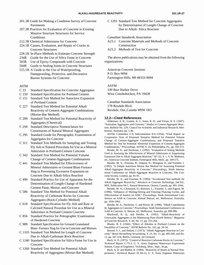
221.1R-27ALKALI-AGGREGATE REACTIVITY
201.3R Guide for Making a Condition Survey of ConcretePavements
207.3R Practices for Evaluation of Concrete in ExistingMassive Structure Structures for Service Conditions
212.3R Chemical Admixtures for Concrete224.1R Causes, Evaluation, and Repair of Cracks in
Concrete Structures228.1R In-Place Methods to Estimate Concrete Strength234R Guide for the Use of Silica Fume in Concrete503R Use of Epoxy Compounds with Concrete504R Guide to Sealing Joints in Concrete Structures515.1R A Guide to the Use of Waterproofing,
Dampproofing, Protective, and Decorative Barrier Systems for Concrete
ASTMC 33 Standard Specification for Concrete AggregatesC 150 Standard Specification for Portland CementC 151 Standard Test Method for Autoclave Expansion
of Portland CementC 227 Standard Test Method for Potential Alkali
Reactivity of Cement-Aggregate Combinations(Mortar-Bar Method)
C 289 Standard Test Method for Potential Reactivity ofAggregates (Chemical)
C 294 Standard Descriptive Nomenclature for Constituents of Natural Mineral Aggregates
C 295 Standard Guide for Petrographic Examination ofAggregates for Concrete
C 311 Standard Test Methods for Sampling and TestingFly Ash or Natural Pozzolans for Use as a MineralAdmixture in Portland-Cement Concrete
C 342 Standard Test Method for Potential VolumeChange of Cement-Aggregate Combinations
C 441 Standard Test Method for Effectiveness of Mineral Admixtures or Ground Blast-FurnaceSlag in Preventing Excessive Expansion on Concrete Due to Alkali-Silica Reaction
C 490 Standard Practice for Use of Apparatus for theDetermination of Length Change of HardenedCement Paste, Mortar, and Concrete
C 586 Standard Test Method for Potential Alkali Reactivity of Carbonate Rocks for Concrete Aggregates (Rock-Cylinder Method)
C 618 Standard Specification for Fly Ash and Raw orCalcined Natural Pozzolan for Use as a MineralAdmixture in Portland Cement Concrete
C 856 Standard Practice for Petrographic Examinationof Hardened Concrete
C 989 Standard Specification for Ground GranulatedBlast- Furnace Slag for Use in Concrete and Mortars
C 1105 Standard Test Method for Length of ConcreteDue to Alkali-Carbonate Rock Reaction
C 1240 Standard Specification for Silica Fume for Use inConcrete
C 1260 Standard Test Method for Potential Alkali Reactivity of Aggregates (Mortar-Bar Method)
C 1293 Standard Test Method for Concrete Aggregatesby Determination of Length Change of ConcreteDue to Alkali- Silica Reaction
Canadian Standards AssociationA23.1 Concrete Materials and Methods of Concrete
ConstructionA23.2 Methods of Test for Concrete
The above publications may be obtained from the followingorganizations:
American Concrete InstituteP.O. Box 9094Farmington Hills, MI 48333-9094
ASTM 100 Barr Harbor DriveWest Conshohocken, PA 19428
Canadian Standards Association178 Rexdale Blvd.Rexdale, Ont.,Canada M9W 1R3
12.2—Cited ReferencesAlderman, A. R.; Gaskin, A. J.; Jones, R. H.; and Vivian, H. E. (1947).
“Australian Aggregates and Cements,” Studies in Cement-Aggregate Reac-tion, Bulletin No. 229, Council for Scientific and Industrial Research, Mel-bourne, Australia, pp. 1-46.
ASTM, Committee C-9, Subcommittee II-b (1954). “Final Report onCooperative Tests of Proposed Tentative Method for Potential VolumeChange of Cement-Aggregate Combinations, and Proposed TentativeMethod for Test for Potential Abnormal Expansion of Cement-AggregateCombinations,” Proceedings, ASTM, V. 54, Philadelphia, Pa., pp. 356-373.
Berube, M. A., and Duchesne, J. (1992). “Evaluation of Testing MethodsUsed in Assessing the Effectiveness of Mineral Admixtures in SuppressingExpansion Due to Alkali-Aggregate Reaction,” SP 132, V. 1, V. M. Malhotra,ed., American Concrete Institute, Farmington Hills, Mich., pp. 549-575.
Berube, M. A.; Fournier, B.; Dupont, N.; Mongeau, P.; and Frenette, J.(1992). “A Simple Autoclave Mortar Bar Method for Assessing PotentialAlkali-Aggregate Reactivity in Concrete,” Proceedings, Ninth Interna-tional Conference on Alkali-Aggregate Reaction in Concrete, The Con-crete Society, London, pp. 81-91.
Berube, M. A., and Fournier, B. (1994). “Accelerated Test methods forAlkali-Aggregate Reactivity,” Advances in Concrete Technology, 2nd Ed.,MSL Publication 94-1, Natural Resources, Ottawa, Canada, pp. 991-1044.
Berube, M. A.; Chouinard, D.; Boisvert, L.; Frenette, J.; and Pigeon, M.(1996). “Influence of Wetting-Drying and Freezing-Thawing Cycles, andEffectiveness of Sealers on ASR,” Proceedings, Tenth International Con-ference on AAR in Concrete, Ahmad Sheyan, ed., Melbourne, Australia,pp. 1056-1063.
Berube, M. A.; Duchesne, J.; and Rivest, M. (1996). “Alkali Contributionby Aggregates to Concrete,” Proceedings, Tenth International Conference onAAR in Concrete, A. Sheyan, ed., Melbourne, Australia, pp. 899-906.
Blackwell, B. Q., and Pettifer, K. (1992). “Alkali-Reactivity ofGreywacke Aggregates in the Maentwrog Dam (North Wales),” Magazineof Concrete Research, V. 44, No. 11, pp. 255-264.
Blanks, R. F. (1946). “Effect of Alkalies in Portland Cement on theDurability of Concrete,” ASTM Bulletin No. 142, pp. 28-34.
Bonzel, V. J., and Dahms, J. (1973). “Alkali-Aggregate Reaction in Con-crete,” Beton Herstellung Verwendung, V. 23, No. 11, pp. 495-500, and No.12, pp. 547-554, Berlin, Germany. (in German)
Buck, A. D. (1975). “Control of Reactive Carbonate Rocks in Concrete,”Technical Report C-75-3, U. S. Army Engineer Waterways ExperimentStation, Corps of Engineers, Vicksburg, Miss., Sept., 36 pp.
Buck, A. D. and Mather, K. (1984). “Reactivity of Quartz at Normal Tem-peratures,” Technical Report SL-84-12, U. S. Army Engineer Waterways
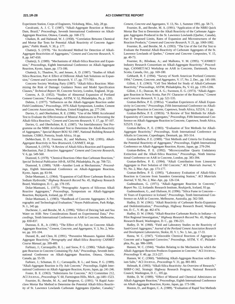
221.1R-28 ACI COMMITTEE REPORT
Experiment Station, Corps of Engineers, Vicksburg, Miss., July, 28 pp.Cavalcanti, A. J. C. T. (1987). “Alkali-Aggregate Reaction at Moxoto
Dam, Brazil,” Proceedings, Seventh International Conference on Alkali-Aggregate Reaction, Ottawa, Canada, pp. 168-172.
Chaiken, B. and Halstead, W. J. (1958). “Correlation Between Chemicaland Mortar Bar Tests for Potential Alkali Reactivity of Concrete Aggre-gates,” Public Roads, V. 30, p. 177.
Chatterji, S. (1978). “An Accelerated Method for Detection of Alkali-Aggregate Reactivities of Aggregates,” Cement and Concrete Research, V.8, pp. 647-650.
Chatterji, S. (1989). “Mechanisms of Alkali-Silica Reaction and Expan-sion,” Proceedings, Eighth International Conference on Alkali-AggregateReaction, Kyoto, Japan, pp. 173-186.
Chatterji, S.; Thaulow, N.; and Jensen, A. D. (1987). “Studies of AlkaliSilica Reaction, Part 4: Effect of Different Alkali Salt Solutions on Expan-sion,” Cement and Concrete Research, V. 17, pp. 777-783.
Concrete Society Working Party (1987). “Alkali-Silica Reaction: Mini-mizing the Risk of Damage: Guidance Notes and Model SpecificationClauses,” Technical Report 30, Concrete Society, London, England, 34 pp.
Conrow, A. D. (1952). “Studies of Abnormal Expansion of PortlandCement Concrete,” Proceedings, ASTM, V. 52, Philadelphia, Pa, p. 1205.
Dahms, J. (1977). “Influences on the Alkali-Aggregate Reaction underField Conditions,” Proceedings, 1976 Alkali Symposium, London, Cementand Concrete Association, Wexham, United Kingdom, pp. 277-290.
Davies, G. and Oberholster, R. E. (1986). “Use of the NBRI AcceleratedTest to Evaluate the Effectiveness of Mineral Admixtures in Preventing theAlkali-Silica Reaction,” Cement and Concrete Research, V. 17, pp. 97-107.
Davies, G. and Oberholster, R. E. (1987). “An Interlaboratory Test Pro-gramme on the NBRI Accelerated Test to Determine the Alkali-Reactivityof Aggregates,” Special Report BOU 92-1987, National Building ResearchInstitute, CSIRO, Pretoria, South Africa, 16 pp.
DeMerchant, D. P.; Fournier, B.; and Malhotra, V.M. (1995). Alkali-Aggregate Reactivity in New Brunswick, CANMET, 44 pp.
Diamond, S. (1976). “A Review of Alkali-Silica Reaction and ExpansionMechanism, Part 2: Reactive Aggregates” Cement and Concrete Research,V. 6, pp. 549-560.
Diamond, S. (1978). “Chemical Reactions Other than Carbonate Reactions,”Special Technical Publication 169-B, ASTM, Philadelphia, Pa, pp. 708-721.
Diamond, S. (1989). “ASR—Another Look at Mechanisms,” Proceed-ings, Eighth International Conference on Alkali-Aggregate Reaction,Kyoto, Japan, pp. 83-94.
Dolar-Mantuani, L. (1964). “Expansion of Gull River Carbonate Rocks inSodium Hydroxide,” Highway Research Record No. 45, Highway ResearchBoard, Washington, D. C., pp. 178-195.
Dolar-Mantuani, L. (1975). “Petrographic Aspects of Siliceous AlkaliReactive Aggregates,” Proceedings, Symposium on Alkali-AggregateReaction, Reykjavik, Iceland, pp. 87-100.
Dolar-Mantuani, L. (1983). “Handbook of Concrete Aggregates: A Pet-rographic and Technological Evaluation,” Noyes Publications, Park Ridge,N. J., 345 pp.
Duchesne, J., and Berube, M. A. (1996). “Effect of Deicing Salt and SeaWater on ASR: New Considerations Based on Experimental Data,” Pro-ceedings, Tenth International Conference on AAR in Concrete, Melbourne,pp. 830-837.
Dunstan, E. R., Jr. (1981). “The Effect of Fly Ash on Concrete Alkali-Aggregate Reaction,” Cement, Concrete, and Aggregates, V. 3, No. 2, Win-ter, pp. 101-104.
Durand, B., and Chen, H. (1991). “Preventive Measures Against Alkali-Aggregate Reactivity,” Petrography and Alkali-Silica Reactivity CANMETCourse Manual, pp. 399-489.
Farbiarz, J.; Carrasquillo, R. L.; and Snow, P. G. (1986). “Alkali-Aggre-gate Reaction in Concrete Containing Fly Ash,” Proceedings, Seventh Inter-national Conference on Alkali-Aggregate Reaction, Ottawa, Ontario,Canada, pp. 55-59.
Farbiarz, J.; Schuman, D. C.; Carrasquillo, R. L.; and Snow, P. G. (1989).“Alkali-Aggregate Reaction in Fly Ash Concrete,” Proceedings, Eighth Inter-national Conference on Alkali-Aggregate Reaction, Kyoto, Japan, pp. 241-246.
Foster, B. E. (1963). “Admixtures for Concrete,” ACI Committee 212,ACI JOURNAL, Proceedings V. 60, Farmington Hills, Mich., pp.1481-1523.
Fournier, B.; Berube, M. A.; and Bergeron, G. (1991). “A Rapid Auto-clave Mortar Bar Method to Determine the Potential Alkali-Silica Reactiv-ity of St. Lawrence Lowlands Carbonate Aggregates (Quebec, Canada),”
Cement, Concrete and Aggregates, V. 13, No. 1, Summer 1991, pp. 58-71.Fournier, B., and Berube, M. A. (1991). “Application of the NBRI Quick
Mortar Bar Test to Determine the Alkali Reactivity of the Carbonate Aggre-gate Aggregates Produced in the St. Lawrence Lowlands (Quebec, Canada),Part II: Proposed Limits, Rates of Expansion and Microstructures of theReaction Products,” Cement and Concrete Research, V. 21, pp. 1069-1082.
Fournier, B., and Berube, M. A. (1993). “The Use of the Gel Pat Test toEvaluate the Potential Alkali-Reactivity of Carbonate Aggregates of the St.Lawrence Lowlands of Quebec,” Cement and Concrete Composites, V. 15,pp. 49-73.
Fournier, B.; Bilodeau, A.; and Malhotra, V. M. (1995). “CANMET/Industry Research Consortium on Alkali-Aggregate Reactivity,” Proceed-ings, CANMET/ACI Workshop on AAR in Concrete, Dartmouth, NovaScotia, Canada, Oct., pp. 169-180.
Gebhardt, R. F. (1994). “Survey of North American Portland Cements:1994,” Cement, Concrete, and Aggregates, V. 17, No. 2, Dec., pp. 145-189.
Gillott, J. E. (1963). “Cell Test Method for Study of Alkali-CarbonateReactivity,” Proceedings, ASTM, Philadelphia, Pa, V. 63, pp. 1195-1206.
Gillott, J. E.; Duncan, M. A. G.; Swenson, E. G. (1973). “Alkali-Aggre-gate Reaction in Nova Scotia, Part IV: Character of the Reaction,” Cementand Concrete Research, V. 3, pp. 521-535.
Grattan-Bellew, P. E. (1981a). “Canadian Experiences of Alkali Expan-sivity in Concrete,” Proceedings, Fifth International Conference on Alkali-Aggregate Reaction in Concrete, Capetown, South Africa, S252/6, 11 pp.
Grattan-Bellew, P. E. (1981b). “A Review of Test Methods for Alkali-Expansivity of Concrete Aggregates,” Proceedings, Fifth International Con-ference on Alkali-Aggregate Reaction in Concrete, Capetown, South Africa,S252/9, 13 pp.
Grattan-Bellew, P., E. (1983). “Evaluation of Test Methods for Alkali-Aggregate Reactivity,” Proceedings, Sixth International Conference onAlkalis in Concrete, Copenhagen, Denmark, pp. 303-314.
Grattan-Bellew, P. E. (1989). “Test Methods and Criteria for Evaluatingthe Potential Reactivity of Aggregates,” Proceedings, Eighth InternationalConference on Alkali-Aggregate Reaction, Kyoto, Japan, pp. 279-294.
Grattan-Bellew, P. E. (1992). “Microcrystalline Quartz UndulatoryExtinction and the Alkali-Silica Reaction,” Proceedings, Ninth Interna-tional Conference on AAR in Concrete, London, pp. 383-394.
Grattan-Bellew, P. E. (1994). “Alkali Contribution from LimestoneAggregate to Pore Solution of Old Concrete,” ACI Materials Journal, V.91, No. 2, Mar.-Apr., pp. 173-177.
Grattan-Bellew, P. E. (1995). “Laboratory Evaluation of Alkali-SilicaReaction in Concrete from Saunders Generating Station,” ACI MaterialsJournal, V. 92, No. 2, Mar.-Apr., pp. 126-134.
Gudmudsson, G. (1971). “Alkali-Aggregate Reaction in Concrete,”Report No. 12, Icelandic Research Institute, Reykjavik, Iceland, 93 pp.
Gudmundsson, G., and Olafsson, H. (1996). “Silica Fume in Concrete—16 Years of Experience in Iceland,” Proceedings, Tenth International Con-ference on AAR in Concrete, Melbourne, Australia, pp. 562-569.
Hadley, D. W. (1961). “Alkali Reactivity of Carbonate Rocks-Expansionand Dedolomitization,” Proceedings, Highway Research Board, Washing-ton, D. C., V. 40, pp. 462-474.
Hadley, D. W. (1964). “Alkali-Reactive Carbonate Rocks in Indiana—APilot Regional Investigation,” Highway Research Record No. 45, HighwayResearch Board, Washington, D. C., pp. 196-221.
Hadley, D. W. (1968). “Field and Laboratory Studies on the Reactivity ofSand-Gravel Aggregates,” Journal of the Portland Cement Association Researchand Development Laboratories, Skokie, Ill, V. 1, No. 3, Jan., pp. 17-33.
Hanna, W. C. (1947). “Unfavorable Chemical Reactions of Aggregate inConcrete and a Suggested Corrective,” Proceedings, ASTM, V. 47, Philadel-phia, Pa., pp. 986-1009,
Hansen, W. C. (1944). “Studies Relating to the Mechanism by which theAlkali-Aggregate Reaction Produces Expansion in Concrete,” ACI JOURNAL,Proceedings V. 40, pp. 213-227.
Hansen, W. C. (1960). “Inhibiting Alkali-Aggregate Reaction with Bar-ium Salts,” ACI JOURNAL, Proceedings V. 31, pp. 881-883.
Helmuth, R. (1993). “Alkali-Silica Reactivity: An Overview of Research,”SHRP-C-342, Strategic Highway Research Program, National ResearchCouncil, Washington, D. C., 105 pp.
Hobbs, D. W. (1989). “Effect of Mineral and Chemical Admixtures onAlkali-Aggregate Reaction,” Proceedings, Eighth International Conferenceon Alkali-Aggregate Reaction, Kyoto, Japan, pp. 173-186.
Hooton, D., and Rogers, C. A. (1989). “Evaluation of Rapid Test Methods
221.1R-29ALKALI-AGGREGATE REACTIVITY
for Detecting Alkali-Reactive Aggregates,” Proceedings, Eighth Interna-tional Conference on Alkali-Aggregate Reaction, Kyoto, Japan, pp. 439-444.
Hooton, D., and Rogers, C. A. (1992). “Development of the NBRI RapidMortar Test Leading to its Use in North America,” Proceedings, NinthInternational Conference on AAR in Concrete, London, pp. 461-467.
Hooton, D. (1990). “Interlaboratory Study of the NBRI Rapid TestMethod and CSA Standardization Status,” Report EM-92, Ontario Ministryof Transportation, pp. 225-240.
Hudec, P. P., and Larbi, E. Y. (1989). “Chemical Treatments and Addi-tives to Minimize Alkali Reactivity,” Proceedings, Eighth InternationalConference on Alkali-Aggregate Reaction, Kyoto, Japan, pp. 193-198.
Imai, H.; Yamasaki, T.; Maehara, H.; and Miyagawa, T. (1987). “TheDeterioration by Alkali-Silica Reaction of Hanshin Expressway ConcreteStructures,” Proceedings, Seventh International Conference on Alkali-Aggregate Reaction, Ottawa, Ontario, Canada, pp. 131-135.
Institution of Structural Engineers (1992). “Structural Effects of Alkali-Silica Reaction,” London, England, July, 45 pp.
International Commission on Large Dams (1991). “Alkali-AggregateReaction in Concrete Dams,” Bulletin 79, 158 pp.
Jensen, A. D.; Chatterji, S.; Christensen, P.; Thaulow, N.; and Gud-mundsson, H. (1982). “Studies of Alkali-Silica Reaction, Part I: A Com-parison of Two Accelerated Test Methods,” Cement and ConcreteResearch, V. 12, pp. 641-647.
Jensen, A. D.; Chatterji, S.; Christensen, P.; and Thaulow, N. (1984).“Studies of Alkali-Silica Reactions, Part II: Effect of Air-Entrainment onExpansion,” Cement and Concrete Research, V. 14, pp. 311-314.
Johansen, V. (1989). “Cement Production and Cement Quality,” Mate-rial Science of Concrete I, Jan P. Skalny, ed., The American Ceramic Soci-ety, pp. 27-72.
Johnston, C. D. (1986). “Alkali-Silica Reactivity in Concrete—Impor-tance of Cement Content and Alkali Equivalent,” Proceedings, SeventhInternational Conference on Alkali-Aggregate Reaction, Ottawa, Ontario,Canada, pp. 477-482.
Jones, T. R.; Walters, G. V.; and Kostuch, J. A. (1992). “Role of Metaka-olin in Suppressing ASR in Concrete Containing Reactive Aggregate andExposed to Saturated NaCl Solution,” Proceedings, Ninth InternationalConference on Alkali-Aggregate Reaction in Concrete, London, England,July, pp. 485-496.
Kamimoto, H., and Wakasugi, M. (1992). “Effect of Coating with FlexiblePolymer-Modified Cement Mortar on Inhibition of Alkali-Silica Reaction,”Polymer-Modified Hydraulic Cement Mixtures, ASTM STP 1176, L. A. Kuhl-mann and D. G. Walters, eds., ASTM, West Conshohocken, Pa, pp. 34-43.
Kawamura, M., and Takemoto, K. (1984). “Correlation Between PoreSolution Composition and Alkali Silica Expansion in Mortars ContainingVarious Fly Ashes and Blastfurnace Slags,” International Journal ofCement Composites and Lightweight Concrete, V. 10, No. 4, pp. 215.
Kawamura, M.; Koike, M.; and Nakano, N. (1989). “Release of Alkalisfrom Reactive Andesitic Aggregates and Fly Ashes into Pore Solution,”Proceedings, Eighth International Conference on Alkali-Aggregate Reac-tion, Kyoto, Japan, July, pp. 271-278.
Kerr, P. F. (1959). “Optical Mineralogy,” McGraw-Hill Books, NewYork, N. Y., 442 pp.
Kosmatka, S. H., and Panarese, W. C. (1988). “Design and Control ofConcrete Mixtures,” 13th Ed., EB001.3T, Portland Cement Association,Skokie, Ill., 205 pp.
Kosmatka, S. H., and Fiorato, A. E. (1991). “Detecting and AvoidingAlkali-Aggregate Reactivity,” Concrete Technology Today, PortlandCement Association, Skokie, Ill., V. 12, No. 3.
Lane, D. S., and Ozyildirim, H. C. (1995). “Use of Fly Ash, Slag, orSilica Fume to Inhibit Alkali-Silica Reactivity,” VTRC 95-R21, VirginiaTransportation Research Council, Charlottesville, Va, June, 38 pp.
Langley, W. S.; Fournier, B.; and Malhotra, V. M. (1993). Alkali-Aggre-gate Reactivity in Nova Scotia, CANMET, 36 pp.
Lee, C. (1989). “Active Alkalies in Cement-Fly Ash Paste,” Proceed-ings, Eighth International Conference on Alkali-Aggregate Reaction,Kyoto, Japan, pp. 223-228.
Lerch, W. (1959). “A Cement-Aggregate Reaction that Occurs with Cer-tain Sand-Gravel Aggregates,” Journal of the Portland Cement AssociationResearch and Development Laboratories, Skokie, Ill., V. 1, No. 3, pp. 42-50. (Also PCA Research Department Bulletin No. 122)
Malhotra, V. M., and Fournier, B. (1995). “Overview of Research onAlkali-Aggregate Reactions at CANMET,” Proceedings, CANMET/ACI
International Workshop on Alkali-Aggregate Reactions in Concrete, NovaScotia, Canada, pp. 1-45.
Mather, B. (1945). “Discussion of a Paper by Leonard Bean and J. J. Tre-goning: Reactivity of Aggregate Constituents in Alkaline Solutions,” ACIJOURNAL, Proceedings V. 41, p. 52.
Mather, B. (1948). “Petrographic Identification of Reactive Constituentsin Concrete Aggregates,” Proceedings, ASTM, V. 48, pp. 1120-1127.
Mather, B. (1993). “Use of Admixtures to Prevent Excessive Expansionof Concrete Due to Alkali-Silica Reaction,” Transportation ResearchRecord No. 1382, Transportation Research Board, NAS-NRC, Washington,D. C., pp. 99-103.
Mather, B. (1995). “How to Avoid Excessive Expansion of Concrete Dueto Alkali-Aggregate Reaction,” Proceedings, Second International Confer-ence on Alkali-Aggregate Reactions in Hydroelectric Plants and Dams, U. S.Committee on Large Dams, Denver, Colo., pp. 421-439.
Mather, K. (1973). “Examination of Cores from Four Highway Bridgesin Georgia,” Miscellaneous Paper C-73-11, U. S. Army Engineer Water-ways Experiment Station, Corps of Engineers, Vicksburg, Miss., 36 pp.
McCaffery, R. S.; Oesterle, J. F.; and Shapiro, L. (1927). “Compositionof Iron Blastfurnace Slag,” Technical Publication No. 19, American Insti-tute of Mining, Metallurgical and Petroleum Engineers, N. Y., 42 pp.
McCoy, W. S., and Caldwell, A. G. (1951). “New Approach to InhibitingAlkali-Aggregate Expansion,” ACI JOURNAL, Proceedings V. 47, pp. 693-708.
Meissner, H. S. (1941). “Cracking in Concrete Due to Expansive Reac-tion between Aggregate and High-Alkali Cement as Evidenced in ParkerDam,” ACI JOURNAL, Proceedings V. 37, Apr., pp. 549-568.
Meissner, H. S. (1942). “Discussion: California Experience with theExpansion of Concrete Through Reaction Between Cement and Aggregate,”ACI JOURNAL, Proceedings V. 38, Jan., pp. 209-366. (Discussion, Nov.1942, ACI JOURNAL, Proceedings, V. 39, pp. 236.1-236.7).
Mid-Atlantic Regional Technical Committee (1993a). “Guide to Alkali-Aggregate Reactivity,” Silver Spring, Md., June, 17 pp.
Mid-Atlantic Regional Technical Committee (1993b). “Guide Specifica-tions for Concrete Subject to Alkali-Silica Reactions,” Silver Spring, Md.,June, 5 pp.
Mielenz, R. C.; Greene, K. T.; and Benton, E. J.; (1948). “Chemical Testfor the Reactivity of Aggregates with Cement Alkalies: Chemical Pro-cesses in Cement-Aggregate Reaction,” ACI JOURNAL, Proceedings V. 44,pp. 193-221.
Mielenz, R. C.; Witte, L. P.; and Glantz, O. J. (1950). “Effect of Calcina-tion on Natural Pozzolans,” Special Technical Publication No. 99, ASTM,Philadelphia, Pa, p. 43.
Mielenz, R. C., and Benton, E. J. (1958). “Evaluation of the QuickChemical Test for Alkali Reactivity of Concrete Aggregate,” Bulletin 171,Highway Research Board, Washington, D. C., p. 1.
Mielenz, R. C. and Witte, L. P. (1988). “Tests Used by the Bureau ofReclamation for Identifying Reactive Concrete Aggregates,” Proceedings,ASTM, Philadelphia, Pa, V. 48, pp. 1071-1105.
Moore, A. E. (1978). “Effect of Electric Current on Alkali-Silica Reac-tion,” Proceedings, Fourth International Conference on the Effects of Alkalisin Cement and Concrete, Purdue University, West Lafayette, Ind., Publica-tion CE-MAT-1-78, pp. 69-72.
Moranville-Regourd, M. (1996). “Modeling of Expansion Induced byASR—New Approaches,” Proceedings, Tenth International Conference onAlkali-Aggregate Reaction in Concrete, A. Shayan, ed., Melbourne, Aus-tralia, pp. 51-67.
Morgan, D. R. (1990). “Examples of Alkali-Aggregate Reactivity inConcrete Structures in Western Canada,” Report EM-92, Ministry ofTransportation, Ontario, Canada, Mar., pp. 35-49.
Mukherjee, P. K., and Bickley, J. A. (1987). “Performance of Glass asConcrete Aggregate,” Proceedings, Seventh International Conference onAlkali-Aggregate Reaction, Ottawa, Canada, pp. 36-42.
Mullick, A. K.; Samuel, G.; and Ghosh, S. N. (1985). “Identification ofReactive Aggregates Containing Strained Quartz by SEM and IR,” Pro-ceedings, Seventh International Conference on Cement Microscopy, Inter-national Cement Microscopy Association, Feb. 17, 1998, Duncanville,Tex., pp. 316-332.
Natesaiyer, K., and Hover, K. C. (1988). “In Situ Identification of ASRProducts in Concrete,” Cement and Concrete Research, V. 18, pp. 455-463.
Natesaiyer, K., and Hover, K. C. (1989). “Further Study of an In SituMethod for Identification of Alkali Silica Reaction Products in Concrete,”Cement and Concrete Research, V. 19, pp. 770-778.
221.1R-30 ACI COMMITTEE REPORT
National Building Studies (1958). “Reactions between Aggregates andCement, Part VI: Alkali-Aggregate Interaction: Experience with SomeForms of Rapid and Accelerated Test Procedures,” NBS Research PaperNo. 25, Her Majesty’s Stationery Office, London, England, 64 pp.
Newlon, H. H., Jr., and Sherwood, W. C. (1962). “An Occurrence ofAlkali-Reactive Carbonate Rock in Virginia,” Bulletin 355, HighwayResearch Board, Washington, D. C., pp. 27-44.
Newlon, H. H., Jr.; Sherwood, W. C.; and Cullen (1964). “Methods forReducing Expansion of Concrete Caused by Alkali-Carbonate Rock Reac-tions,” Highway Research Record No. 45, Highway Research Board,Washington, D. C., pp. 134-150.
Newlon, H. H., Jr.; Ozol, M. A.; and Sherwood, W. C. (1972). “An Eval-uation of Several Methods for Detecting Alkali-Carbonate Reaction,”Progress Report No. 5, 71-R33, Virginia Highway Research Council, Char-lottesville, Va., May, 73 pp.
Newlon, H. H., Jr.; Sherwood, W. C.; and Ozol, M. A. (1972). “Poten-tially Reactive Carbonate Rocks—A Strategy for Use and Control ofPotentially Reactive Carbonate Rocks Including an Annotated Bibliogra-phy of Virginia Research,” Progress Report No. 8, 71-R41, Virginia High-way Research Council, Charlottesville, Va., 18 pp.
Nixon, P. J., and Page, C. L. (1978). “Pore Solution Chemistry andAlkali-Aggregate Reaction,” SP-100, American Concrete Institute, Farm-ington Hills, Mich., p. 1833.
Nordtest (1985). “Alkali-Silica Reactivity Accelerated Test,” NordtestBuilding Method 295, Nordtest, Helsinki, Finland, pp. 220-224.
Oberholster, R. E. (1983). “Alkali Reactivity of Siliceous Rock Aggre-gates: Diagnosis of the Reaction, Testing of Cement and Aggregate, andPrescription of Preventive Measures,” Proceedings, Sixth InternationalConference on Alkali in Concrete Research and Practice, G. M. Idorn andS. Rostam, eds., Copenhagen, Germany pp. 419-433.
Oberholster, R. E., and Davies, G. (1986). “An Accelerated Method forTesting the Potential Alkali Reactivity of Siliceous Aggregates,” Cementand Concrete Research, V. 16, pp. 181-189.
Oberholster, R. E. (1996). “Case Studies of the Practical and EconomicImpact of Alkali-Silica Reaction in South Africa,” Proceedings, Tenth Interna-tional Conference on AAR in Concrete, Melbourne, Australia, pp. 123-132.
Ohama, Y.; Katsunori, D.; and Kakegawa, M. (1989). “Inhibiting Alkali-Aggregate Reaction with Chemical Admixtures,” Proceedings, Eighth Interna-tional Conference on Alkali-Aggregate Reaction, Kyoto, Japan, pp. 187-192.
Olafsson, H. (1989). “AAR Problems in Iceland,” Proceedings, Eighth Inter-national Conference on Alkali-Aggregate Reaction, Kyoto, Japan, pp. 65-70.
Ozol, M. A., and Newlon, H. H., Jr. (1974). “Bridge Deck DeteriorationPromoted by Alkali-Carbonate Reaction: A Documented Example,” Trans-portation Research Record No. 525, Transportation Research Board,National Research Council, Washington, D. C., pp. 55-63.
Ozol, M. A. (1990). “Alkali-Silica Reaction of Concrete in ElectricalSubstation Piers Accelerated by Electrical Currents,” Petrography Appliedto Concrete and Concrete Aggregates, ASTM STP 1061, B. Erlin and D.Stark, eds., pp. 106-120.
Ozol, M. A. and Dusenberry, D. O. (1992). “Deterioration of Precast Pan-els with Crushed Quartz Coarse Aggregate Due to Alkali-Silica Reaction,”SP-131, American Concrete Institute, Farmington Hills, Mich., pp. 407-415.
Ozol, M. A. (1994). “Alkali Carbonate Rock Reaction,” Significance ofTests and Properties of Concrete and Concrete-Making Materials, P.Klieger and J. Lamond, eds., ASTM STP 169 C, pp. 372-387.
Pettersson, K. (1992). “Effects of Silica Fume on Alkali-Silica Expansionin Mortar Specimens,” Cement and Concrete Research, V. 22, pp. 15-22.
Portland Cement Association (1976a). “Maintenance of Joints andCracks in Concrete Pavements,” IS188.01P, Portland Cement Association,Skokie, Ill., 10 pp.
Portland Cement Association (1976b). “Patching Concrete Pavements,”IS189.01P, Portland Cement Association, Skokie, Ill., 15 pp.
Portland Cement Association (1981). “Guide to Concrete ResurfacingDesigns and Selection Criteria,” EB087, Portland Cement Association,Skokie, Ill., 12 pp.
Portland Cement Association (1994). “Guide Specifications for Con-crete Subject to Alkali-Silica Reactions,” IS415, Portland Cement Associa-tion, Skokie, Ill., Jan., 7 pp.
Powers, T. C., and Steinour, H. H. (1955). “An Interpretation of Pub-lished Researches on the Alkali-Aggregate Reaction,” ACI JOURNAL, Pro-ceedings V. 51, pp. 497-516 and 785-812.
Regourd, M.; Hornain, H.; and Poitevin, P. (1981). “The Alkali-Aggregate
Reaction-Concrete Microstructural Evolution,” Proceedings, Fifth Interna-tional Conference on Alkali-Aggregate Reaction in Concrete, Capetown,South Africa, 12 pp.
Robert, E. C. (1986). “The Influence of Pulverized Fuel Ash on ASR:Behavioral Differences between Mortars Containing Pyrex Glass and Bel-tane Opal,” Proceedings, Seventh International Conference on Alkali-Aggregate Reaction, Ottawa, Ontario, Canada, pp. 98-103.
Rogers, C. A. (1987). “Alkali-Aggregate Reaction in Ontario,” Proceed-ings, Seventh International Conference on Alkali-Aggregate Reaction inConcrete, Ottawa, Ontario, Canada, pp. 5-9.
Rogers, C. A. (1990). “Alkali-Aggregate Reactions in Canada,” Cana-dian Developments in Testing Aggregates for Alkali-Aggregate Reactivity,Report EM-92, Ministry of Transportation, Ontario, Canada, Mar., pp. 1-9.
Rogers, C. A., and Hooton, R. D. (1989). “Leaching of Alkalies in Alkali-Aggregate Reaction Testing,” Proceedings, Eighth International Conferenceon Alkali-Aggregate Reaction, Kyoto, Japan, July, pp. 327-332.
Rogers, C. A., and Hooton, R. D. (1992). “Comparison between Labora-tory and Field Expansion of Alkali-Carbonate Reactive Concrete,” Pro-ceedings, Ninth International Conference on Alkali-Aggregate Reaction,London, England, pp. 877-884.
Ryell, J.; Chojnacki, B.; Woda, G.; and Kognuszy, Z. D. (1974). “TheUthoff Quarry Alkali-Carbonate Rock Reaction—A Laboratory and Field Per-formance Study,” Transportation Research Record No. 525, TransportationResearch Board, National Research Council, Washington, D. C., pp. 43-53.
Sakaguchi, Y.; Takakura, M.; Kitagawa, A.; Hori, T.; Tomosawa, F.; andAbe, M. (1989). “The Inhibiting Effect of Lithium Compounds on Alkali-Silica Reaction,” Proceedings, Eighth International Conference on Alkali-Aggregate Reaction, Kyoto, Japan, pp. 229-234.
Salomon, M., and Gallias, L. (1992). “Rapid Test Method for EvaluatingPotential Alkali-Aggregate Reactivity of Aggregates by Autoclaving Treat-ment,” Proceedings, Ninth International Conference on Alkali-AggregateReaction in Concrete, The Concrete Society, London, England pp. 933-952.
Sherwood, W. C., and Newlon, H. H., Jr. (1964). “A Survey for ReactiveCarbonate Aggregates in Virginia,” Highway Research Record No. 45,Highway Research Board, Washington, D. C., p. 222.
Sims, I. (1981). “The Application and Reliability of Standard TestingProcedures for Potential Alkali-Aggregate Reactivity,” Proceedings, FifthInternational Conference on Alkali-Aggregate Reaction in Concrete, S252/13, Capetown, South Africa, 11 pp.
Smith, P. (1964). “Learning to Live With a Reactive Carbonate Rock,”Highway Research Record No. 45, Highway Research Board, Washington,D. C., pp. 23-27.
Smith, P. (1974). “15 Years of Living at Kingston with a Reactive Car-bonate Rock,” Transportation Research Record No. 525, TransportationResearch Board, National Research Council, Washington, D. C., pp. 23-27.
Sorrentino, D.; Clement, J. Y.; and Golberg, J. M. (1992). “A NewApproach to Characterize the Chemical Reactivity of the Aggregates,”Ninth International Conference on AAR in Concrete, The Concrete Soci-ety, London, England, pp. 934-943.
Stanton, T. E. (1940). “Expansion of Concrete through Reaction betweenCement and Aggregate,” Proceedings, American Society of Civil Engi-neers, pp. 1781-1811. (Reprinted with discussion and closure in Transac-tion, ASCE, V. 107, pp. 54-126)
Stanton, T. E. (1942). “California Experience with the Expansion ofConcrete through Reaction between Cement and Aggregate,” ACI JOUR-NAL, Proceedings V. 38, p. 209.
Stanton, T. E. (1950). “Studies of Use of Pozzolans for CounteractingExcessive Concrete Expansion from Reaction between Aggregates andAlkalis in Cement,” Pozzolanic Materials in Mortars and Concretes,ASTM STP 99, ASTM, Philadelphia, Pa., pp. 178-203.
Stark, D. C. (1978). “Alkali-Silica Reactivity in the Rocky MountainRegion,” Proceedings, Fourth International Conference of the Effects ofAlkalies in Cement & Concrete, Purdue University, June, pp. 235-243.
Stark, D. C. (1980). “Alkali-Silica Reactivity: Some Reconsiderations,”Cement, Concrete, and Aggregates, V. 2, No. 2, Winter, pp. 92-94.
Stark, D. C. (1985). “Alkali-Silica Reactivity in Five Dams in South-western United States,” Report REC-ERC-85-10, U. S. Bureau of Recla-mation, Denver, Colo., 64 pp.
Stark, D. C., and Bhatty, M. S. Y. (1986). “Alkali-Silica Reactivity:Effect of Alkali in Aggregate on Expansion,” Alkalies in Concrete, ASTMSTP 930, pp. 16-30.
Stark, D. C. (1991a). “The Moisture Condition of Field Concrete Exhibiting
221.1R-31ALKALI-AGGREGATE REACTIVITY
Alkali-Silica Reactivity,” SP-126, American Concrete Institute, Farming-ton Hills, Mich., pp. 973-987.
Stark, D. C. (1991b). “How to Evaluate the State of Alkali-Silica Reac-tivity (ASR) in Concrete,” Concrete Repair Digest, Aug.-Sept., pp. 104-107.
Stark, D. C. (1991c). “Handbook for Identification of Alkali-Silica Reac-tivity in Highway Structures,” SHRP-C/FR-91-101, Strategic HighwayResearch Program, National Research Council, Washington, D. C., 49 pp.
Stark, D. C.; Morgan, B.; Okamoto, P.; and Diamond, S. (1993). “Eliminat-ing or Minimizing Alkali-Silica Reactivity,” SHRP-C-343, Strategic HighwayResearch Program, National Research Council, Washington, D. C., 266 pp.
Stark, D. C. (1994). “Alkali-Silica Reaction in Concrete,” Significance ofTests and Properties of Concrete and Concrete-Making Materials, ASTMSTP 169 C, P. Klieger and J. Lamind, eds., pp. 365-371.
Stokes, D. (1996). “Use of Lithium to Control Alkali-Silica Reactivity,”Proceedings, Tenth International Conference on AAR in Concrete, Mel-bourne, Australia, pp. 862-867.
Swamy, R. N., ed. (1992). The Alkali-Silica Reaction in Concrete, VanNostrand Reinhold, New York, N. Y., 336 pp.
Swenson, E. G. (1957). “A Reactive Aggregate Undetected by ASTMTests,” Bulletin No. 266, ASTM, Philadelphia, Pa., pp. 48-51.
Swenson, E. G., and Gillott, J. E. (1960). “Characteristics of KingstonCarbonate Rock Reaction: Concrete Quality Control, Aggregate Character-istics and the Cement Aggregate Reaction,” Highway Research BulletinNo. 275, Highway Research Board, Washington, D. C., pp. 18-31.
Tang, M. S.; Deng, M.; Xu, Z.; Lan, X.; and Han, S. F. (1996). “Alkali-Aggregate Reactions in China,” Proceedings, Tenth International Confer-ence on AAR in Concrete, Melbourne, Australia, pp. 195-201.
Tang, M. S.; Liu, Z.; and Han, S. F. (1987). “Mechanism of Alkali-Car-bonate Reaction,” Proceedings, Seventh International Conference onAlkali-Aggregate Reaction, Ottawa, Ontario, Canada, pp. 275-279.
Tang, M. S., and Lu, Y. N. (1987). “Rapid Method of Determining the Alkali-Reactivity of Carbonate Rock,” Proceedings, Seventh International Conferenceon Alkali-Aggregate Reaction, Ottawa, Ontario, Canada, pp. 286-287.
Thaulow, N.; Holm, J.; and Andersen, K. T. (1989). “PetrographicExamination and Chemical Analyses of the Lucinda Jetty Prestressed Con-crete Roadway,” Proceedings, Eighth International Conference on Alkali-Aggregate Reaction, Kyoto, Japan, pp. 573-581.
Thomas, M. D. A. (1995). “The Role of Fly Ash and Slag Alkalis inAlkali-Silica Reactions in Concrete,” Proceedings, CANMET/ACI Inter-national Workshop on AAR in Concrete, Dartmouth, Nova Scotia, Canada,
Oct., pp. 181-204.Thompson, M. L.; Grattan-Bellew, P. E.; and White, J. C. (1994). “Appli-
cation of Microscopic and XRD Techniques to Investigate Alkali-SilicaReactivity Potential of Rocks and Minerals,” Proceedings, Sixteenth Interna-tional Conference on Cement Microscopy, Duncanville, Tex., pp. 174-192.
Thompson, G. A. (1992). “Alkali-Aggregate Reaction at Mactaquac Gener-ating Station Remedial Measures Progress Report,” International Conferenceon Concrete Alkali-Aggregate Reactions in Hydroelectric Plants and Dams,Canadian Electrical Association & Canadian National Committee of the Inter-national Commission on Large Dams, Sept. 28-Oct. 2, 1992, 15 pp.
Thompson, G. A.; Steele, R. R.; and Coulson, D. M. (1995). “Manage-ment of Concrete Growth at the Mactaquac Generating Station,” USCOLDSecond International Conference on Alkali-Aggregate Reactions in LargeDams, Chattanooga, Tenn., Oct. 1995, pp. 147-159.
Tuthill, L. H. (1980). “Performance Failures of Concrete Materials and ofConcrete as a Material,” ACI Concrete International, V. 2, No. 1, pp. 33-39.
Tuthill, L. H. (1982). “Alkali-Silica Reaction—40 Years Later,” ACIConcrete International, V. 4, No. 4, pp. 32-36.
U.S. Army Corps of Engineers (1994). “Alkali-Silica Aggregate Reac-tions,” Standard Practice for Concrete for Civil Works, EM 1110-2-2000,Appendix D, U.S. Army Corps of Engineers Headquarters, Washington, D. C.
Vanderstraeten, A. T. (1986). “Repair of Alkali-Aggregate Reaction Dam-age to the Motorway Structures of the Pall Street Interchange, Port Elizabeth,Republic of South Africa,” Proceedings, Seventh International Conference onAlkali-Aggregate Reaction, Ottawa, Ontario, Canada, pp. 194-198.
Van der Walt, N.; Strauss, P. J.; and Schneider, O. (1981). “Rehabilita-tion Analysis of a Road Pavement Cracked by Alkali-Aggregate Reaction,”Proceedings, Fifth International Conference on Alkali-Aggregate Reactionin Concrete, S252/21, Capetown, South Africa, 10 pp.
Walker, H. N. (1978). “Chemical Reactions of Carbonate Aggregates inCement Paste,” Special Technical Publication 169-B, ASTM, Philadelphia,Pa., pp. 722-743.
Wang, H., and Gillott, J. E. (1989). “The Effect of Superplasticizers onAlkali-Silica Reactivity,” Proceedings, Eighth International Conference onAlkali-Aggregate Reaction, Kyoto, Japan, pp. 187-192.
Williams, H.; Turner, F. J.; and Gilbert, C. M. (1954). “Petrography: AnIntroduction to the Study of Rocks in Thin Sections,” W. H. Freeman andCompany, San Francisco, Calif., 406 pp.
Woolf, D. O. (1952). “Reaction of Aggregate with Low-Alkali Cement,”Public Roads, V. 27, No. 3, p. 50.
Xu, Z., and Hooton, R. D. (1993). “Migration of Alkali Ions in Mortar Dueto Several Mechanisms,” Cement and Concrete Research, V. 23, pp. 951-961.