2020 rf ideas inc rfideas configuration utility user manual p
TRANSCRIPT

©2020 rf IDEAS Inc. rfIDEAS Configuration Utility User Manual P a g e | i
©2020 rf IDEAS Inc. rfIDEAS Configuration Utility User Manual P a g e | ii
©2020 rf IDEAS Inc. rfIDEAS Configuration Utility User Manual P a g e | iii
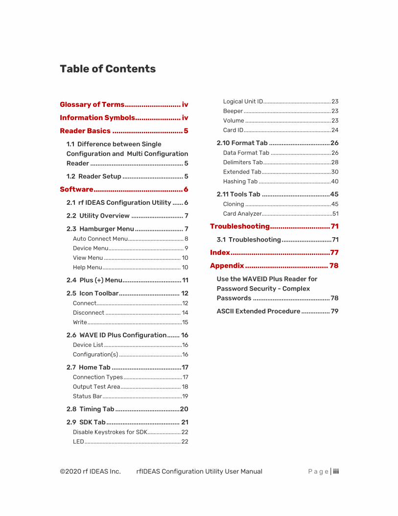
Table of Contents
Glossary of Terms ........................... iv
Information Symbols...................... iv
Reader Basics .................................. 5
1.1 Difference between Single Configuration and Multi Configuration Reader .................................................... 5
1.2 Reader Setup .................................. 5
Software ........................................... 6
2.1 rf IDEAS Configuration Utility ...... 6
2.2 Utility Overview ............................. 7
2.3 Hamburger Menu ........................... 7 Auto Connect Menu ..................................... 8 Device Menu .................................................. 9 View Menu ................................................... 10 Help Menu .................................................... 10
2.4 Plus (+) Menu ................................. 11
2.5 Icon Toolbar .................................. 12 Connect ......................................................... 12 Disconnect .................................................. 14 Write ............................................................... 15
2.6 WAVE ID Plus Configuration ....... 16 Device List .................................................... 16 Configuration(s) .......................................... 16
2.7 Home Tab ....................................... 17 Connection Types ....................................... 17 Output Test Area ........................................ 18 Status Bar ..................................................... 19
2.8 Timing Tab .................................... 20
2.9 SDK Tab ......................................... 21 Disable Keystrokes for SDK ...................... 22 LED ................................................................ 22
Logical Unit ID ............................................. 23 Beeper .......................................................... 23 Volume ......................................................... 23 Card ID .......................................................... 24
2.10 Format Tab .................................. 26 Data Format Tab ........................................ 26 Delimiters Tab ............................................. 28 Extended Tab .............................................. 30 Hashing Tab ................................................ 40
2.11 Tools Tab ...................................... 45 Cloning ......................................................... 45 Card Analyzer............................................... 51
Troubleshooting ............................. 71
3.1 Troubleshooting ............................ 71
Index ................................................ 77
Appendix ........................................ 78
Use the WAVEID Plus Reader for Password Security - Complex Passwords ........................................... 78
ASCII Extended Procedure ................ 79
©2020 rf IDEAS Inc. rfIDEAS Configuration Utility User Manual P a g e | iv
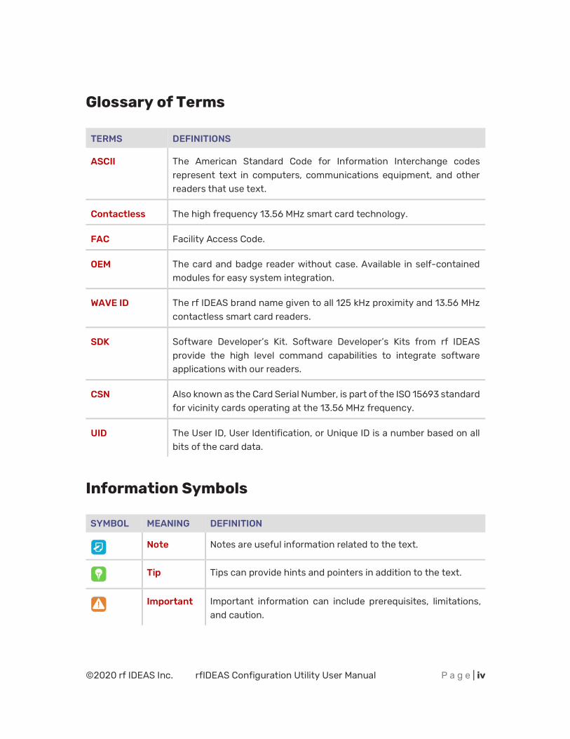
Glossary of Terms
TERMS DEFINITIONS
ASCII The American Standard Code for Information Interchange codes represent text in computers, communications equipment, and other readers that use text.
Contactless The high frequency 13.56 MHz smart card technology.
FAC Facility Access Code.
OEM The card and badge reader without case. Available in self-contained modules for easy system integration.
WAVE ID The rf IDEAS brand name given to all 125 kHz proximity and 13.56 MHz contactless smart card readers.
SDK Software Developer’s Kit. Software Developer’s Kits from rf IDEAS provide the high level command capabilities to integrate software applications with our readers.
CSN Also known as the Card Serial Number, is part of the ISO 15693 standard for vicinity cards operating at the 13.56 MHz frequency.
UID The User ID, User Identification, or Unique ID is a number based on all bits of the card data.
Information Symbols
SYMBOL MEANING DEFINITION
Note Notes are useful information related to the text.
Tip Tips can provide hints and pointers in addition to the text.
Important Important information can include prerequisites, limitations, and caution.
©2020 rf IDEAS Inc. rfIDEAS Configuration Utility User Manual P a g e | 5
Chapter 1
Reader Basics
1.1 Difference between Single Configuration and Multi Configuration Reader
The WAVE ID Plus is a dual frequency programmable reader that combines 125 kHz and 13.56 MHz technologies into the same reader. It’s the only reader in the industry that reads multiple cards of your choice among many different card types, delivering flexibility to any customer struggling with different card technologies. In contrast to the WAVE ID Plus reader, our standard WAVE ID Solo proximity and contactless readers function on a single frequency and single card type, which is either 125 kHz proximity or 13.56 MHz contactless.
1.2 Reader Setup
To setup the reader:
1. Connect the reader to the workstation using RS-232, USB, or Ethernet (Must be in the same Subnet as the workstation).
2. The workstation should detect new hardware for USB connections. Verify the workstation recognizes this connection using Device Manager.
©2020 rf IDEAS Inc. rfIDEAS Configuration Utility User Manual P a g e | 6
Chapter 2
Software
2.1 rf IDEAS Configuration Utility
The rf IDEAS Configuration Utility provides users with the ability to configure their WAVE ID Solo and WAVE ID Plus readers.
The Utility allows WAVE ID Plus to be configured for 2 or 4 (depending on model) card types. rf IDEAS WAVE ID Plus readers with extended functionality can operate in one of two modes, “Data Format” mode ID processing or the “Extended” mode ID processing for output generation. The default mode of processing is Data Format mode.
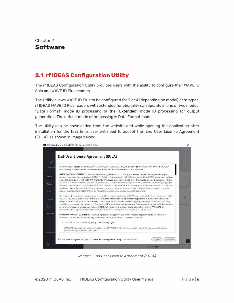
The utility can be downloaded from the website and while opening the application after installation for the first time, user will need to accept the ‘End User License Agreement (EULA)’ as shown in image below:
Image 1: End User License Agreement (EULA)
©2020 rf IDEAS Inc. rfIDEAS Configuration Utility User Manual P a g e | 7
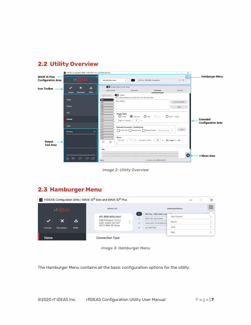
2.2 Utility Overview
Image 2: Utility Overview
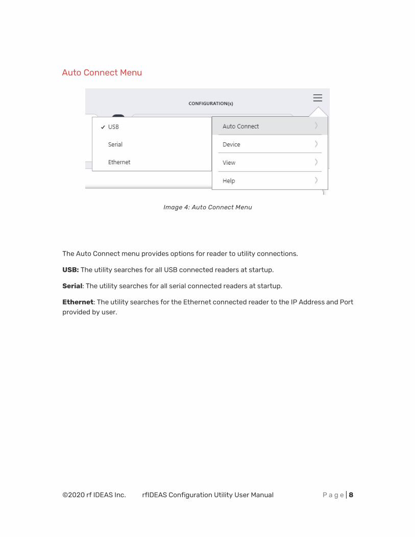
2.3 Hamburger Menu
Image 3: Hamburger Menu
The Hamburger Menu contains all the basic configuration options for the utility.
©2020 rf IDEAS Inc. rfIDEAS Configuration Utility User Manual P a g e | 8
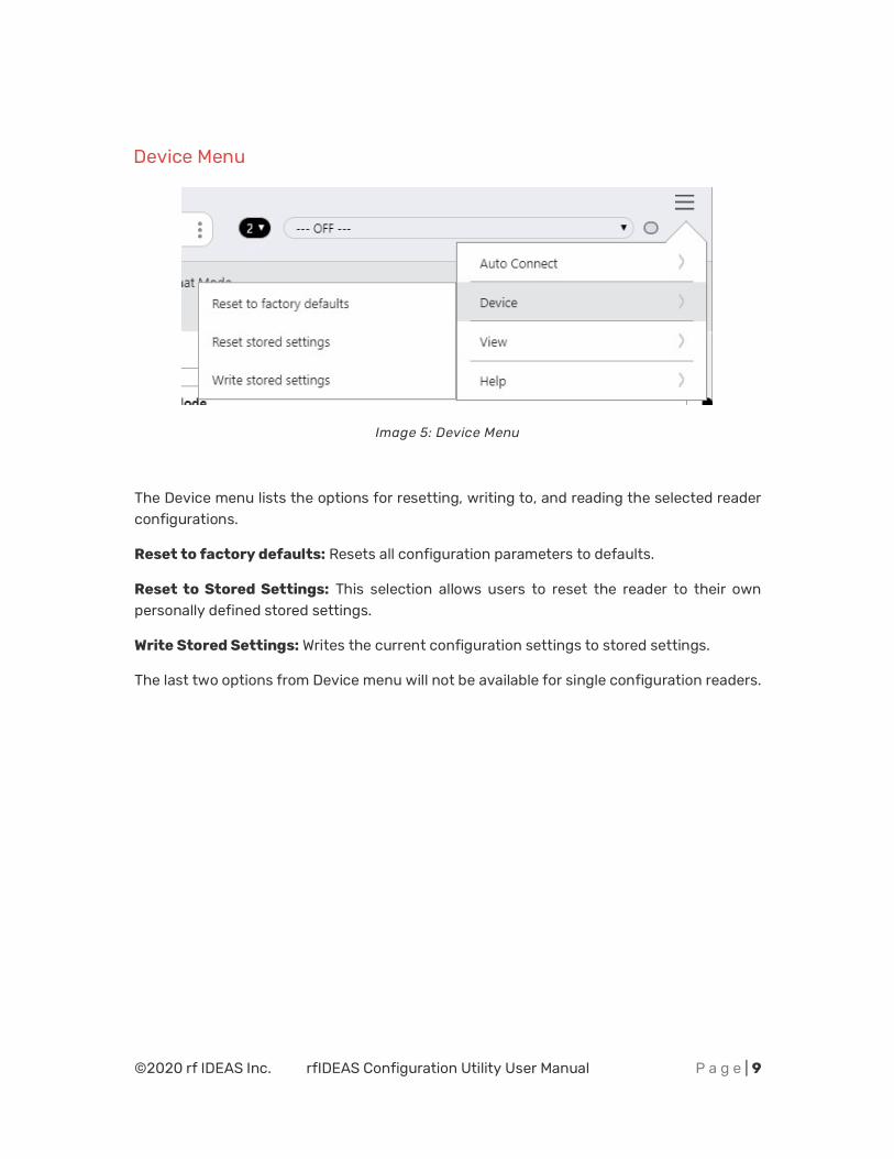
Auto Connect Menu
Image 4: Auto Connect Menu
The Auto Connect menu provides options for reader to utility connections.
USB: The utility searches for all USB connected readers at startup.
Serial: The utility searches for all serial connected readers at startup.
Ethernet: The utility searches for the Ethernet connected reader to the IP Address and Port provided by user.
©2020 rf IDEAS Inc. rfIDEAS Configuration Utility User Manual P a g e | 9
Device Menu
Image 5: Device Menu
The Device menu lists the options for resetting, writing to, and reading the selected reader configurations.
Reset to factory defaults: Resets all configuration parameters to defaults.
Reset to Stored Settings: This selection allows users to reset the reader to their own personally defined stored settings.
Write Stored Settings: Writes the current configuration settings to stored settings.
The last two options from Device menu will not be available for single configuration readers.
©2020 rf IDEAS Inc. rfIDEAS Configuration Utility User Manual P a g e | 10
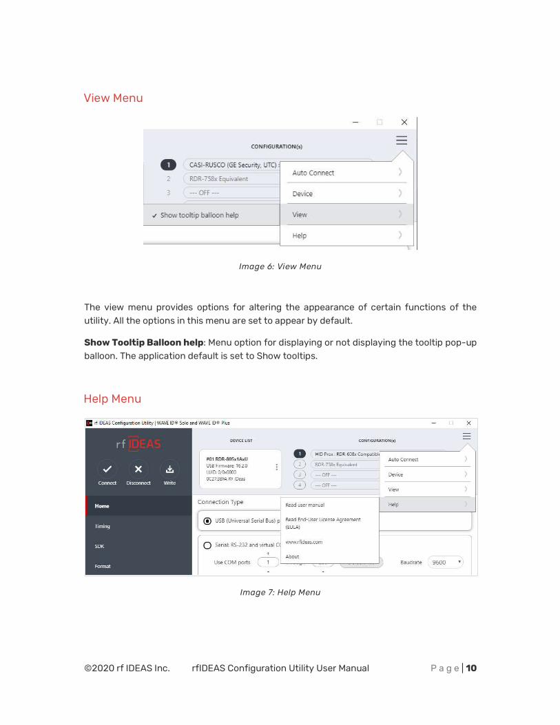
View Menu
Image 6: View Menu
The view menu provides options for altering the appearance of certain functions of the utility. All the options in this menu are set to appear by default.
Show Tooltip Balloon help: Menu option for displaying or not displaying the tooltip pop-up balloon. The application default is set to Show tooltips.
Help Menu
Image 7: Help Menu
©2020 rf IDEAS Inc. rfIDEAS Configuration Utility User Manual P a g e | 11
The Help menu provides information for which users can seek out additional assistance using the utility and/or reader.
Read User Manual: Opens the user manual that is provided in the download with the rf IDEAS Configuration Utility.
Read End-User License Agreement (EULA): Opens the end user license agreement which user has accepted while launching the application for the first time after installation.
www.rfideas.com: This operation will open a new window to the rf IDEAS website.
About: This menu options differ when a reader is connected to the utility vs. when there is no reader connected. Without a connected reader, the “About” informational content simply displays the utility version. When a reader is connected, the firmware information is also provided. The rf IDEAS website address is displayed in both modes.
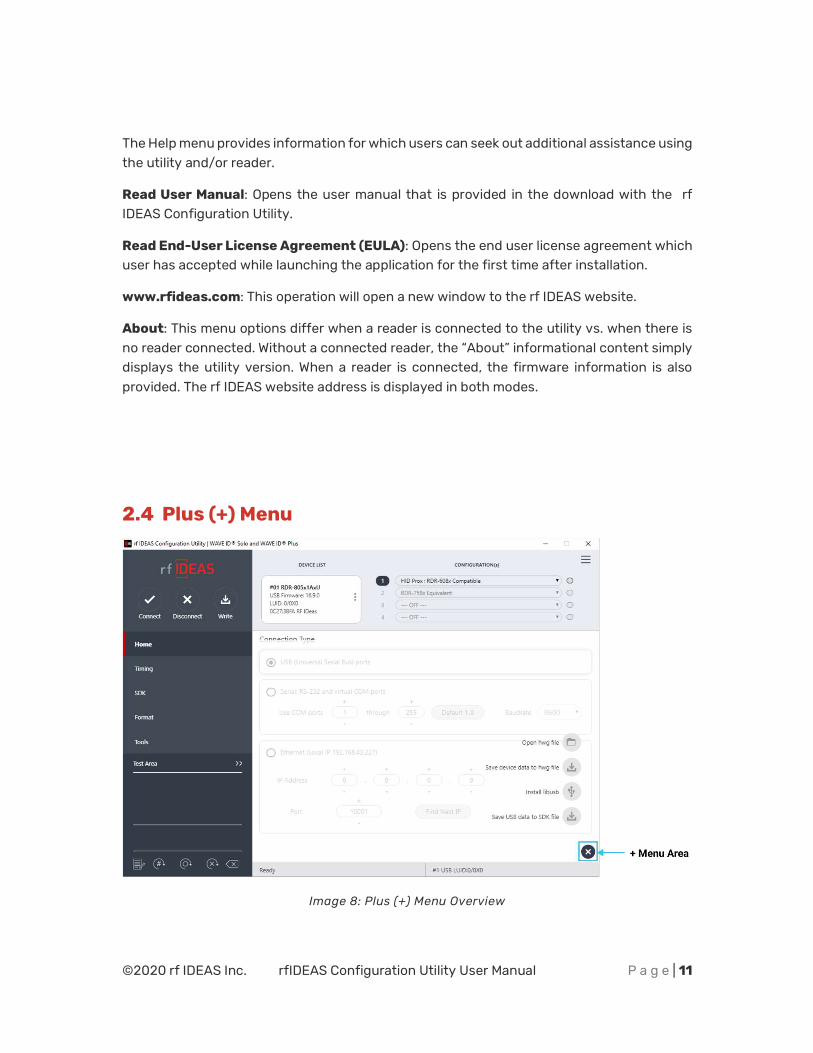
2.4 Plus (+) Menu
Image 8: Plus (+) Menu Overview
©2020 rf IDEAS Inc. rfIDEAS Configuration Utility User Manual P a g e | 12
The Plus (+) menu lists the following options:
Open hwg/hwg+ file…: Opens either a “.hwg” or a “.hwg+” file. A “. hwg” or “.hwg+” file contains all the configuration settings for the reader.
Save device data to hwg+ file: Saves the configuration settings of the reader.
Install libusb for NTWCC reader: It will install the driver needed to operate a NTWCC type reader.
Save USB data to SDK file: Report configuration block trace for USB connection.
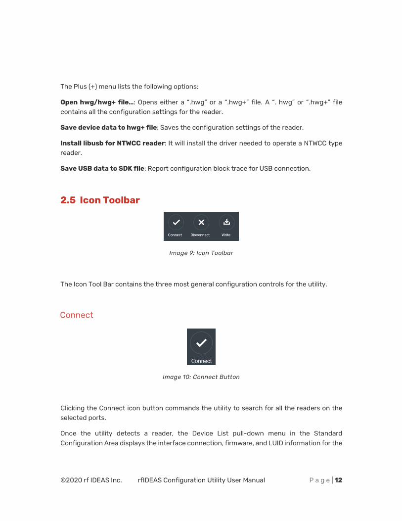
2.5 Icon Toolbar
Image 9: Icon Toolbar
The Icon Tool Bar contains the three most general configuration controls for the utility.
Connect
Image 10: Connect Button
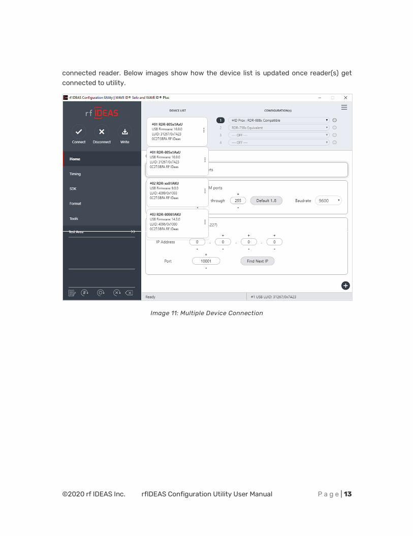
Clicking the Connect icon button commands the utility to search for all the readers on the selected ports.
Once the utility detects a reader, the Device List pull-down menu in the Standard Configuration Area displays the interface connection, firmware, and LUID information for the
©2020 rf IDEAS Inc. rfIDEAS Configuration Utility User Manual P a g e | 13
connected reader. Below images show how the device list is updated once reader(s) get connected to utility.
Image 11: Multiple Device Connection
©2020 rf IDEAS Inc. rfIDEAS Configuration Utility User Manual P a g e | 14
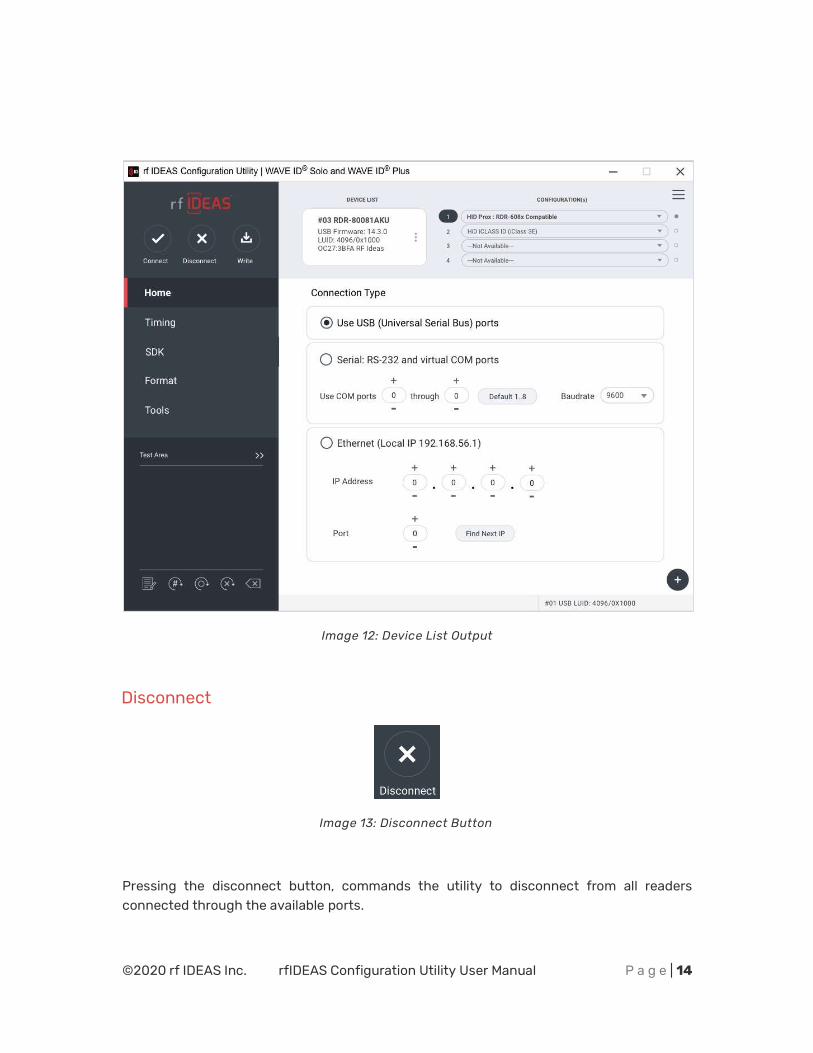
Image 12: Device List Output
Disconnect
Image 13: Disconnect Button
Pressing the disconnect button, commands the utility to disconnect from all readers connected through the available ports.
©2020 rf IDEAS Inc. rfIDEAS Configuration Utility User Manual P a g e | 15
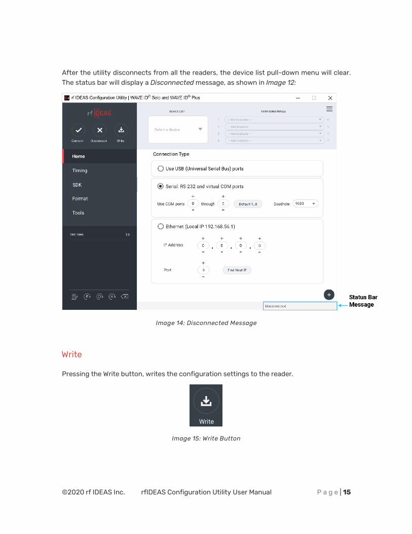
After the utility disconnects from all the readers, the device list pull-down menu will clear. The status bar will display a Disconnected message, as shown in Image 12:
Image 14: Disconnected Message
Write
Pressing the Write button, writes the configuration settings to the reader.
Image 15: Write Button
©2020 rf IDEAS Inc. rfIDEAS Configuration Utility User Manual P a g e | 16
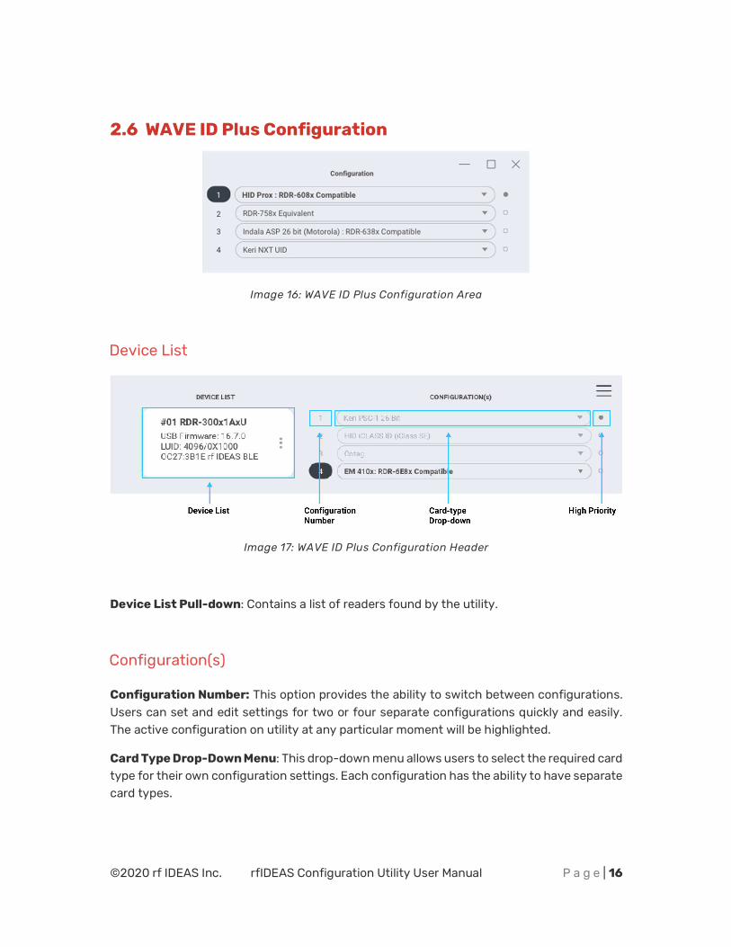
2.6 WAVE ID Plus Configuration
Image 16: WAVE ID Plus Configuration Area
Device List
Image 17: WAVE ID Plus Configuration Header
Device List Pull-down: Contains a list of readers found by the utility.
Configuration(s)
Configuration Number: This option provides the ability to switch between configurations. Users can set and edit settings for two or four separate configurations quickly and easily. The active configuration on utility at any particular moment will be highlighted.
Card Type Drop-Down Menu: This drop-down menu allows users to select the required card type for their own configuration settings. Each configuration has the ability to have separate card types.
©2020 rf IDEAS Inc. rfIDEAS Configuration Utility User Manual P a g e | 17
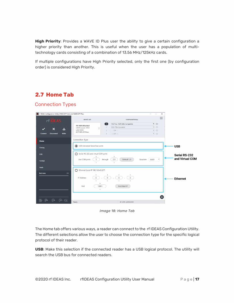
High Priority: Provides a WAVE ID Plus user the ability to give a certain configuration a higher priority than another. This is useful when the user has a population of multi-technology cards consisting of a combination of 13.56 MHz/125kHz cards.
If multiple configurations have High Priority selected, only the first one (by configuration order) is considered High Priority.
2.7 Home Tab
Connection Types
Image 18: Home Tab
The Home tab offers various ways, a reader can connect to the rf IDEAS Configuration Utility. The different selections allow the user to choose the connection type for the specific logical protocol of their reader.
USB: Make this selection if the connected reader has a USB logical protocol. The utility will search the USB bus for connected readers.
©2020 rf IDEAS Inc. rfIDEAS Configuration Utility User Manual P a g e | 18
Serial RS-232 and Virtual COM Ports: The utility will search for readers connected to RS-232 or Virtual COM ports. Default 1.8: Pressing this button will reset the COM port search range (COM1 through COM8).
Ethernet: Connects to an Ethernet reader at the given IP address and creates a TCP/IP path to the reader. The first, second, third, and fourth byte of the TCP/IP address and the port number must be entered.
Port Option: Allows for changing the Internet socket port numbers. Find Next IP Button: Looks for other readers on the same Ethernet connection.
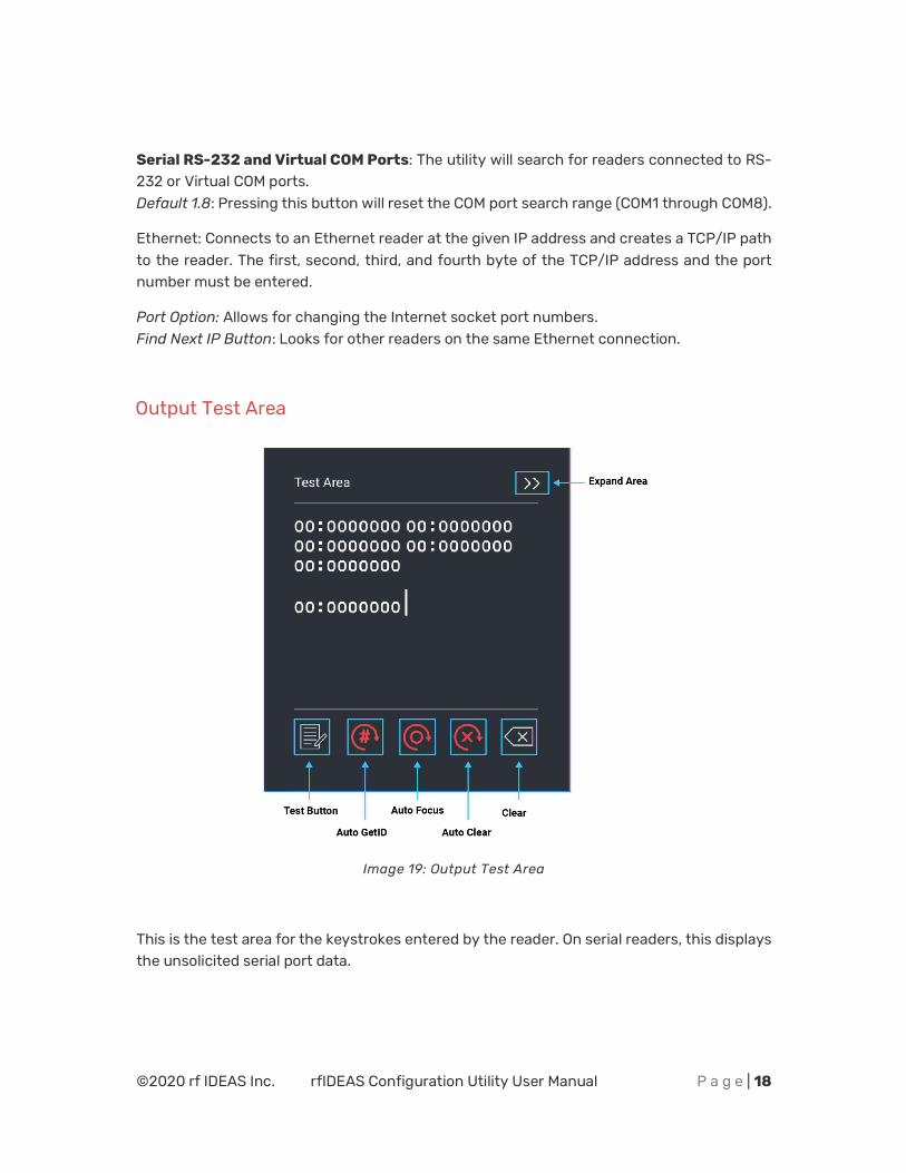
Output Test Area
Image 19: Output Test Area
This is the test area for the keystrokes entered by the reader. On serial readers, this displays the unsolicited serial port data.
©2020 rf IDEAS Inc. rfIDEAS Configuration Utility User Manual P a g e | 19
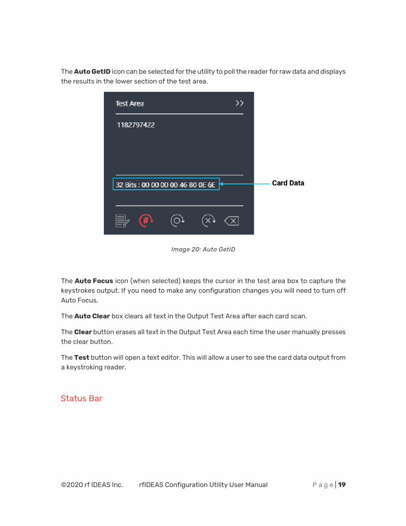
The Auto GetID icon can be selected for the utility to poll the reader for raw data and displays the results in the lower section of the test area.
Image 20: Auto GetID
The Auto Focus icon (when selected) keeps the cursor in the test area box to capture the keystrokes output. If you need to make any configuration changes you will need to turn off Auto Focus.
The Auto Clear box clears all text in the Output Test Area after each card scan.
The Clear button erases all text in the Output Test Area each time the user manually presses the clear button.
The Test button will open a text editor. This will allow a user to see the card data output from a keystroking reader.
Status Bar
©2020 rf IDEAS Inc. rfIDEAS Configuration Utility User Manual P a g e | 20
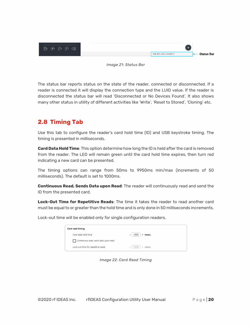
Image 21: Status Bar
The status bar reports status on the state of the reader, connected or disconnected. If a reader is connected it will display the connection type and the LUID value. If the reader is disconnected the status bar will read ‘Disconnected or No Devices Found’. It also shows many other status in utility of different activities like ‘Write’, ‘Reset to Stored’, ‘Cloning’ etc.
2.8 Timing Tab
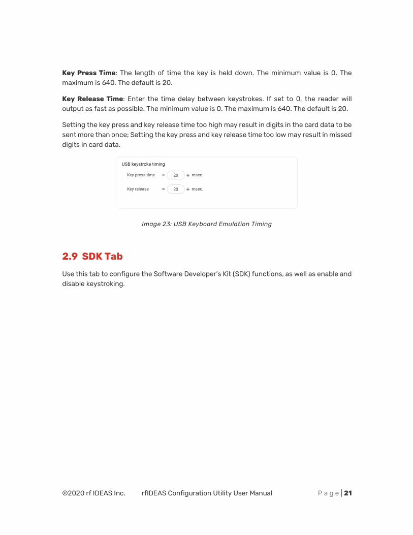
Use this tab to configure the reader’s card hold time (ID) and USB keystroke timing. The timing is presented in milliseconds.
Card Data Hold Time: This option determine how long the ID is held after the card is removed from the reader. The LED will remain green until the card hold time expires, then turn red indicating a new card can be presented.
The timing options can range from 50ms to 9950ms min/max (increments of 50 milliseconds). The default is set to 1000ms.
Continuous Read, Sends Data upon Read: The reader will continuously read and send the ID from the presented card.
Lock-Out Time for Repetitive Reads: The time it takes the reader to read another card must be equal to or greater than the hold time and is only done in 50 milliseconds increments.
Lock-out time will be enabled only for single configuration readers.
Image 22: Card Read Timing
©2020 rf IDEAS Inc. rfIDEAS Configuration Utility User Manual P a g e | 21
Key Press Time: The length of time the key is held down. The minimum value is 0. The maximum is 640. The default is 20.
Key Release Time: Enter the time delay between keystrokes. If set to 0, the reader will output as fast as possible. The minimum value is 0. The maximum is 640. The default is 20.
Setting the key press and key release time too high may result in digits in the card data to be sent more than once; Setting the key press and key release time too low may result in missed digits in card data.
Image 23: USB Keyboard Emulation Timing
2.9 SDK Tab
Use this tab to configure the Software Developer’s Kit (SDK) functions, as well as enable and disable keystroking.
©2020 rf IDEAS Inc. rfIDEAS Configuration Utility User Manual P a g e | 22
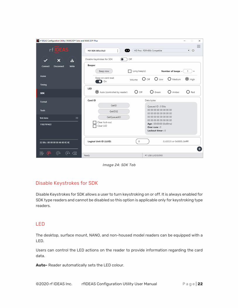
Image 24: SDK Tab
Disable Keystrokes for SDK
Disable Keystrokes for SDK allows a user to turn keystroking on or off. It is always enabled for SDK type readers and cannot be disabled so this option is applicable only for keystroking type readers.
LED
The desktop, surface mount, NANO, and non-housed model readers can be equipped with a LED.
Users can control the LED actions on the reader to provide information regarding the card data.
Auto- Reader automatically sets the LED colour.
©2020 rf IDEAS Inc. rfIDEAS Configuration Utility User Manual P a g e | 23
Off- LED is OFF.
Red- LED is set to always be red.
Green- LED is set to always be green.
Amber- LED is set to always be amber.
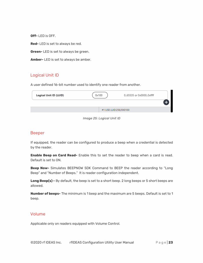
Logical Unit ID
A user defined 16-bit number used to identify one reader from another.
Image 25: Logical Unit ID
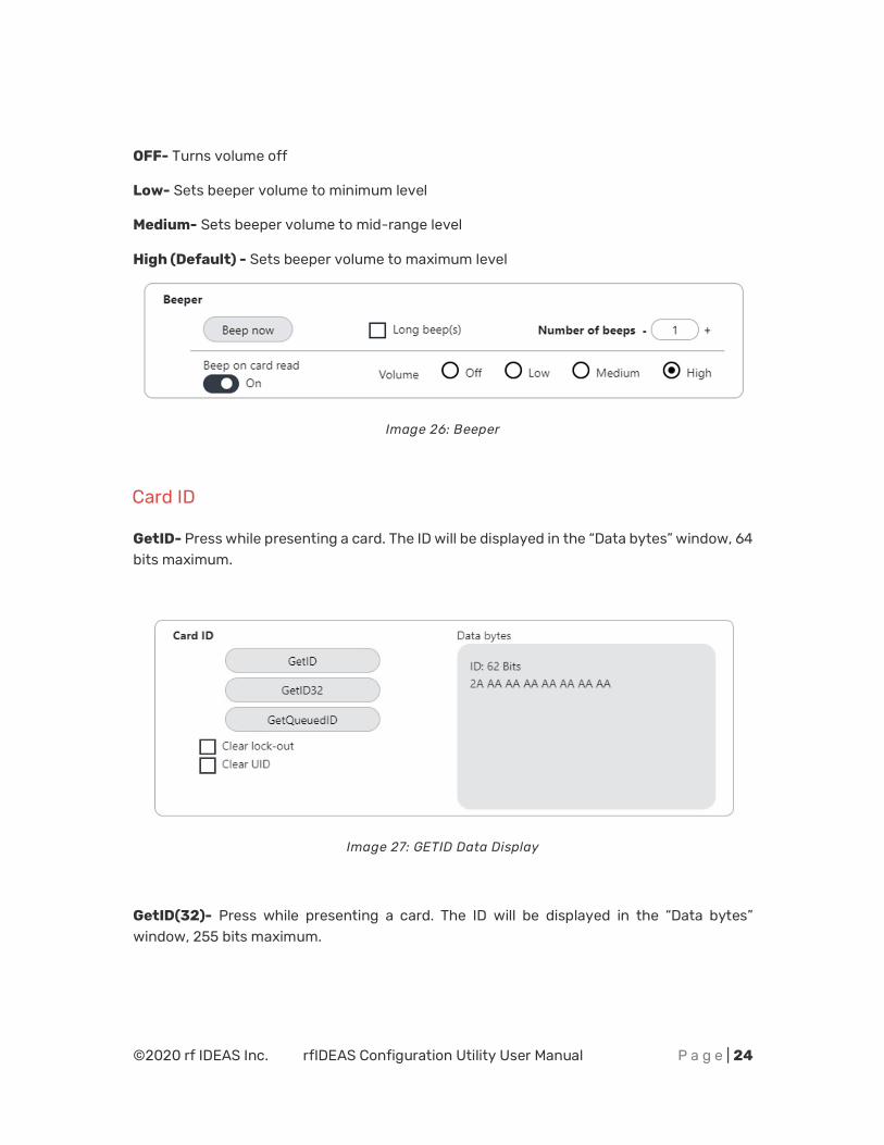
Beeper
If equipped, the reader can be configured to produce a beep when a credential is detected by the reader.
Enable Beep on Card Read- Enable this to set the reader to beep when a card is read. Default is set to ON.
Beep Now- Simulates BEEPNOW SDK Command to BEEP the reader according to “Long Beep” and “Number of Beeps.” It is reader configuration independent.
Long Beep(s) - By default, the beep is set to a short beep. 2 long beeps or 5 short beeps are allowed.
Number of beeps- The minimum is 1 beep and the maximum are 5 beeps. Default is set to 1 beep.
Volume
Applicable only on readers equipped with Volume Control.
©2020 rf IDEAS Inc. rfIDEAS Configuration Utility User Manual P a g e | 24
OFF- Turns volume off
Low- Sets beeper volume to minimum level
Medium- Sets beeper volume to mid-range level
High (Default) - Sets beeper volume to maximum level
Image 26: Beeper
Card ID
GetID- Press while presenting a card. The ID will be displayed in the “Data bytes” window, 64 bits maximum.
Image 27: GETID Data Display
GetID(32)- Press while presenting a card. The ID will be displayed in the “Data bytes” window, 255 bits maximum.
©2020 rf IDEAS Inc. rfIDEAS Configuration Utility User Manual P a g e | 25
Image 28: GETID (32) Data Display
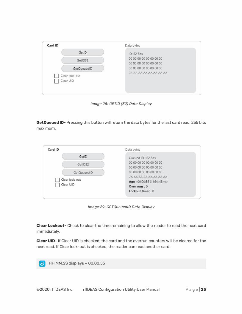
GetQueued ID- Pressing this button will return the data bytes for the last card read, 255 bits maximum.
Image 29: GETQueuedID Data Display
Clear Lockout- Check to clear the time remaining to allow the reader to read the next card immediately.
Clear UID- If Clear UID is checked, the card and the overrun counters will be cleared for the next read. If Clear lock-out is checked, the reader can read another card.
HH:MM:SS displays – 00:00:55
©2020 rf IDEAS Inc. rfIDEAS Configuration Utility User Manual P a g e | 26
2.10 Format Tab
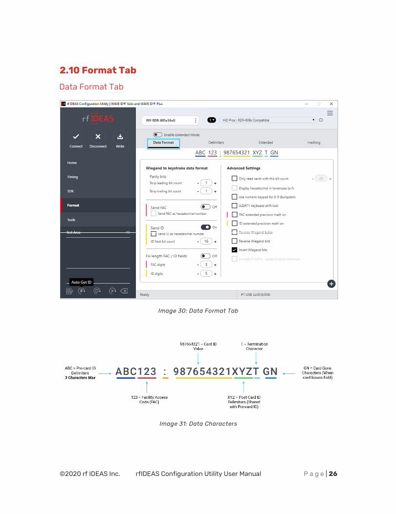
Data Format Tab
Image 30: Data Format Tab
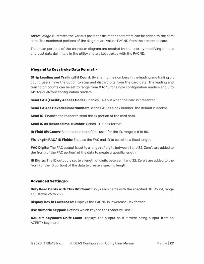
Image 31: Data Characters
©2020 rf IDEAS Inc. rfIDEAS Configuration Utility User Manual P a g e | 27
Above image illustrates the various positions delimiter characters can be added to the card data. The numbered portions of the diagram are values FAC/ID from the presented card.
The letter portions of the character diagram are created by the user by modifying the pre and post data delimiters in the utility and are keystroked with the FAC/ID.
Wiegand to Keystroke Data Format:-
Strip Leading and Trailing Bit Count: By altering the numbers in the leading and trailing bit count, users have the option to strip and discard bits from the card data. The leading and trailing bit counts can be set to range from 0 to 15 for single configuration readers and 0 to 142 for dual/four configuration readers.
Send FAC (Facility Access Code): Enables FAC out when the card is presented.
Send FAC as Hexadecimal Number: Sends FAC as a hex number, the default is decimal.
Send ID: Enables the reader to send the ID portion of the card data.
Send ID as Hexadecimal Number: Sends ID in hex format.
ID Field Bit Count: Sets the number of bits used for the ID, range is 8 to 80.
Fix length FAC/ ID Fields: Enables the FAC and ID to be set to a fixed length.
FAC Digits: The FAC output is set to a length of digits between 1 and 32. Zero's are added to the front (of the FAC portion) of the data to create a specific length.
ID Digits: The ID output is set to a length of digits between 1 and 32. Zero's are added to the front (of the ID portion) of the data to create a specific length.
Advanced Settings:-
Only Read Cards With This Bit Count: Only reads cards with the specified BIT Count, range adjustable 26 to 255.
Display Hex in Lowercase: Displays the FAC/ID in lowercase Hex format.
Use Numeric Keypad: Defines which keypad the reader will use.
AZERTY Keyboard Shift Lock: Displays the output as if it were being output from an AZERTY keyboard.
©2020 rf IDEAS Inc. rfIDEAS Configuration Utility User Manual P a g e | 28
FAC Extended Precision Math On: Enables TRUE 64 bit math.
ID Extended Precision Math On: Enables TRUE 64 bit math.
Reverse Wiegand Bytes: Reverses data in byte chunks (8 bits = 1 byte). Example using 26bit card output in Hexadecimal:
Non-Reverse Wiegand Bytes: 37C3E80 Reverse Wiegand Bytes: 803E7C03
Reverse Wiegand Bits: Reverses each bit. Example is shown below:
Non-Reverse Wiegand Bits: 37C3E80 = 11011111000011111010000000 Reverse Wiegand Bits: 05F0FB = 00000001011111000011111011
Invert Wiegand Bits: Inverts each bit. When looking at the binary string, it will change the 1’s to zeroes and 0’s to ones.
Emulate ProxPro-Append Serial Checksum: This option is only for serial readers. It adds a digit to the end of the serial data. It emulates the serial data format to match HID Corp. Prox Pro reader by sending a 2-byte checksum after the card data.
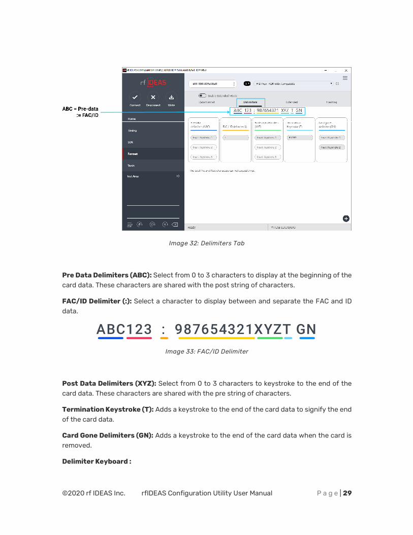
Delimiters Tab
The delimiter tab provides a way for users to add pre or post keystrokes to the card data. Click the appropriate keyboard icon to select the appropriate corresponding delimiters.
©2020 rf IDEAS Inc. rfIDEAS Configuration Utility User Manual P a g e | 29
Image 32: Delimiters Tab
Pre Data Delimiters (ABC): Select from 0 to 3 characters to display at the beginning of the card data. These characters are shared with the post string of characters.
FAC/ID Delimiter (:): Select a character to display between and separate the FAC and ID data.
Image 33: FAC/ID Delimiter
Post Data Delimiters (XYZ): Select from 0 to 3 characters to keystroke to the end of the card data. These characters are shared with the pre string of characters.
Termination Keystroke (T): Adds a keystroke to the end of the card data to signify the end of the card data.
Card Gone Delimiters (GN): Adds a keystroke to the end of the card data when the card is removed.
Delimiter Keyboard :
©2020 rf IDEAS Inc. rfIDEAS Configuration Utility User Manual P a g e | 30
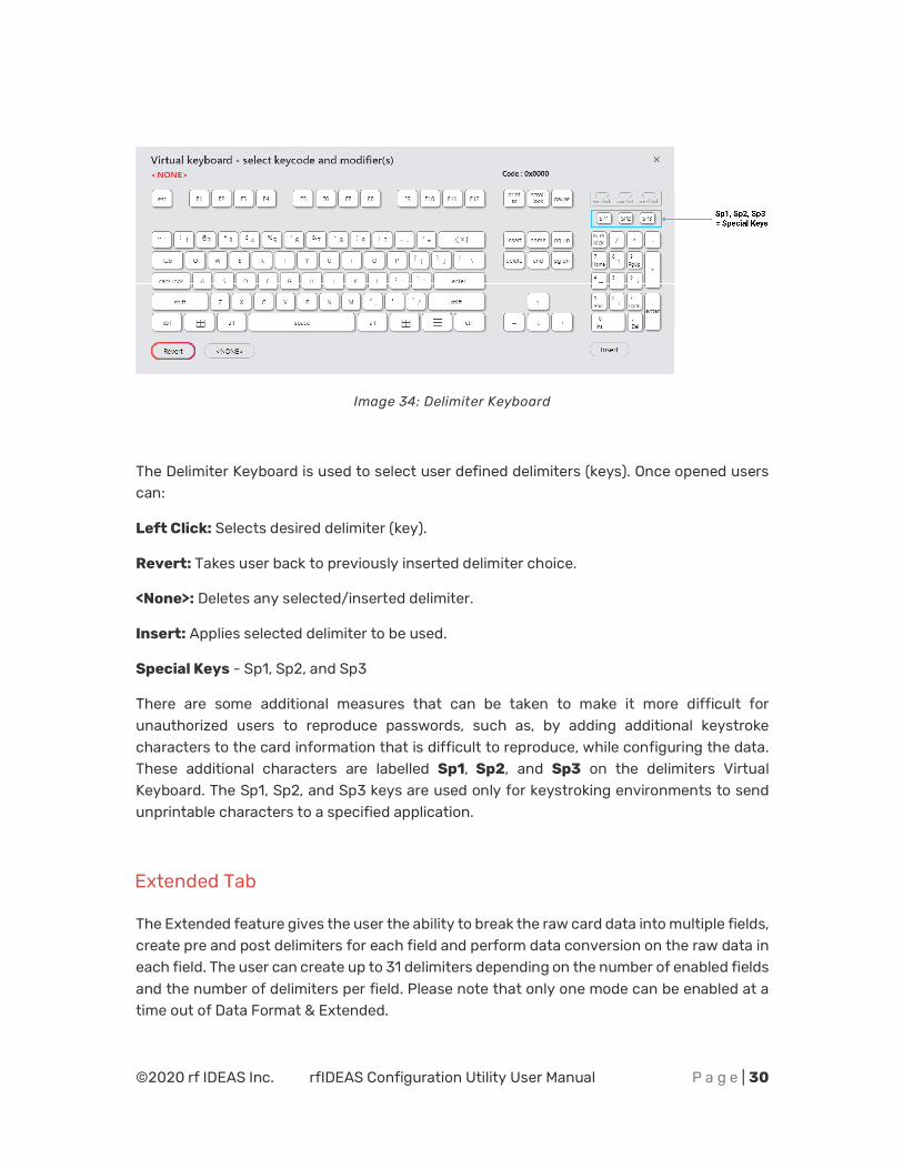
Image 34: Delimiter Keyboard
The Delimiter Keyboard is used to select user defined delimiters (keys). Once opened users can:
Left Click: Selects desired delimiter (key).
Revert: Takes user back to previously inserted delimiter choice.
<None>: Deletes any selected/inserted delimiter.
Insert: Applies selected delimiter to be used.
Special Keys - Sp1, Sp2, and Sp3
There are some additional measures that can be taken to make it more difficult for unauthorized users to reproduce passwords, such as, by adding additional keystroke characters to the card information that is difficult to reproduce, while configuring the data. These additional characters are labelled Sp1, Sp2, and Sp3 on the delimiters Virtual Keyboard. The Sp1, Sp2, and Sp3 keys are used only for keystroking environments to send unprintable characters to a specified application.
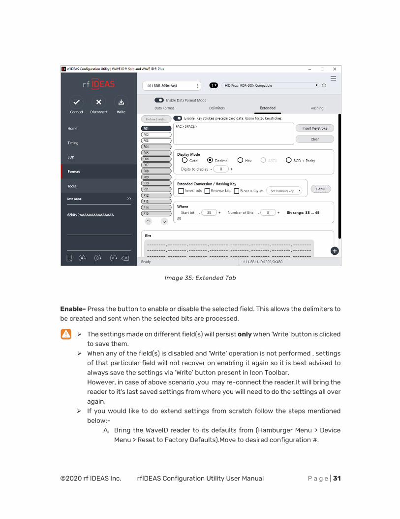
Extended Tab
The Extended feature gives the user the ability to break the raw card data into multiple fields, create pre and post delimiters for each field and perform data conversion on the raw data in each field. The user can create up to 31 delimiters depending on the number of enabled fields and the number of delimiters per field. Please note that only one mode can be enabled at a time out of Data Format & Extended.
©2020 rf IDEAS Inc. rfIDEAS Configuration Utility User Manual P a g e | 31
Image 35: Extended Tab
Enable- Press the button to enable or disable the selected field. This allows the delimiters to be created and sent when the selected bits are processed.
¾ The settings made on different field(s) will persist only when 'Write' button is clicked to save them.
¾ When any of the field(s) is disabled and 'Write' operation is not performed , settings of that particular field will not recover on enabling it again so it is best advised to always save the settings via ‘Write’ button present in Icon Toolbar. However, in case of above scenario ,you may re-connect the reader.It will bring the reader to it's last saved settings from where you will need to do the settings all over again.
¾ If you would like to do extend settings from scratch follow the steps mentioned below:-
A. Bring the WaveID reader to its defaults from (Hamburger Menu > Device Menu > Reset to Factory Defaults).Move to desired configuration #.
©2020 rf IDEAS Inc. rfIDEAS Configuration Utility User Manual P a g e | 32
B. Enable the extend mode on that configuration#. Click on ‘Write’ to save extend mode in the reader.
C. Open the Get ID and present the card.The GetID box will close automatically in few seconds.
D. Start making changes in extended settings afterward and click on ‘Write’ in the end to save those.
GetID – Press the button and present the new card to the reader, this must happen each time a new card is used. The information is used to set the max number of bits on the card and the bits displayed in bit window of the utility.
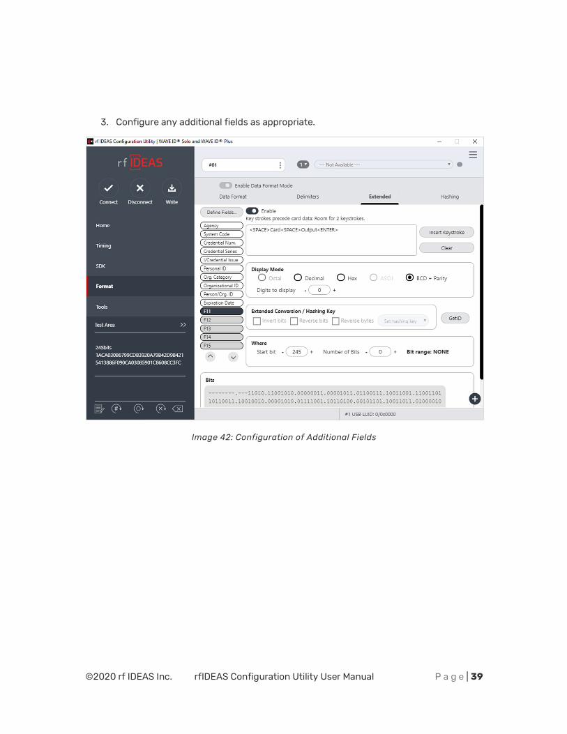
Define Fields- It is only available for the FIPS 201 RDR-7P71AKU and OEM chuid board reader types. Pressing this button will let the user select from the list of predefined card formats.
Start Bit- Enter a number to define the left most significant starting bit for the field.
Number of Bits- Enter the number of bits used for the field data. This value is added to the Start Bit to define the range of bits used in the field.
Insert Keystroke- Enter the delimiters in the delimiter text box (USB readers). Delimiters for serial readers are entered using the virtual keyboards.
Clear- Pressing the clear button will clear the delimiters in the delimiter text box.
Decimal- Enables the reader to output the card field in decimal format.
Hex- Enables the reader to output the card field as a base 16 number in uppercase hex.
ASCII- Displays Card Data in ASCII Character Mode, where every byte represents a printable ASCII Character. The ASCII data bit field shall be in multiples of 8 bits and each field bit pattern must define a printable ASCII character (0x20 thru 0x7F); otherwise, warnings (?...) will be displayed in the lower left portion of the “Where” box on the rf IDEAS Configuration Utility Extended TAB screen.
NOTE:-
¾ ASCII Extended Mode is available only for Secure Type Readers that are compatible with MIFARE DESFire EV1/EV2 Cards, LEAF Smart Cards, and similar technologies. For readers supporting ASCII Character Mode, contact [email protected]. See ASCII Extended Procedure in the Appendix to configure reader for ASCII Extended Mode Configuration.
¾ Before the reader can be configured in the ASCII Display mode, the reader must be preconfigured in advance using the Smartcard Manager Utility. Contact [email protected] for more information.
©2020 rf IDEAS Inc. rfIDEAS Configuration Utility User Manual P a g e | 33
BCD/Parity- Enables the reader to output the card data in binary coded decimal, where each 5 bits represent 1, 2, 4, 8, and parity.
Octal- Enables the reader to output the card data in Octal.
Invert Bits- Inverts the bits from the card.
Reverse Bits – Reverses the bits from the card.
Reverse Bytes- Reverses the bytes from the card.
Hashing Key- The Hashing Key selection box allows the user to select the key they created to use for encrypting the selected field. The options are “Off, “A” or “B”.
Digits- Used to set the number of digits the reader will output for the selected field.
Up arrow- Click to move the highlighted field up one position.
Down arrow- Click to move the highlighted field down one position.
Example Configuring WAVE ID Plus Reader using Extend:
1. Enable extended mode. Select the card type from list and save it using Write button. Click GET ID and present the badge.
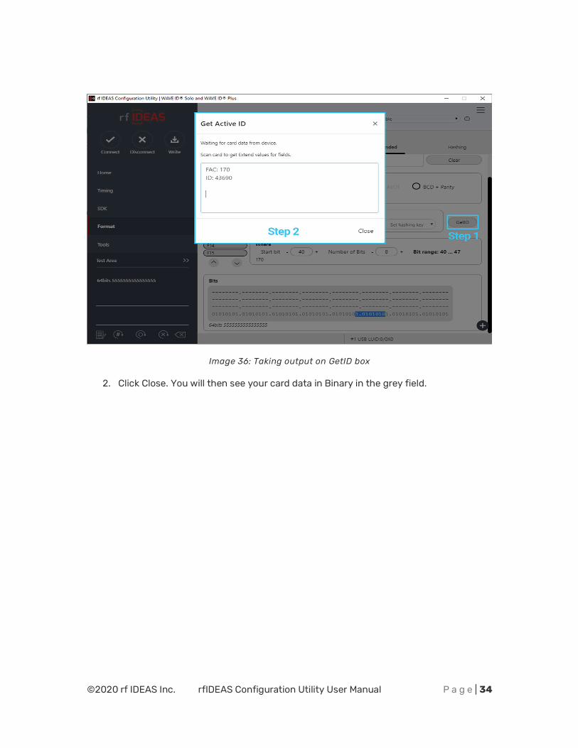
©2020 rf IDEAS Inc. rfIDEAS Configuration Utility User Manual P a g e | 34
Image 36: Taking output on GetID box
2. Click Close. You will then see your card data in Binary in the grey field.
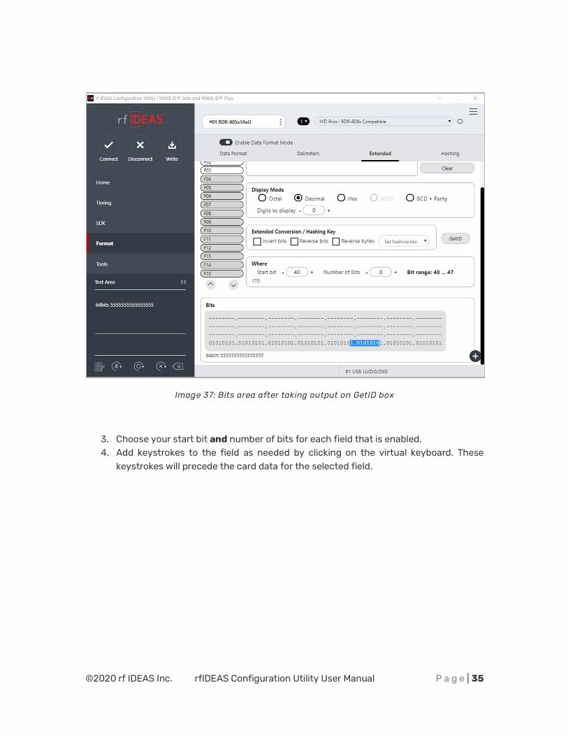
©2020 rf IDEAS Inc. rfIDEAS Configuration Utility User Manual P a g e | 35
Image 37: Bits area after taking output on GetID box
3. Choose your start bit and number of bits for each field that is enabled. 4. Add keystrokes to the field as needed by clicking on the virtual keyboard. These
keystrokes will precede the card data for the selected field.

©2020 rf IDEAS Inc. rfIDEAS Configuration Utility User Manual P a g e | 36
Image 38: Virtual Keyboard in Extended mode
HINT: If you need an ENTER key after the card data, enable the next field and set number of bits to ZERO. Add an enter in the keystrokes box. See example below:
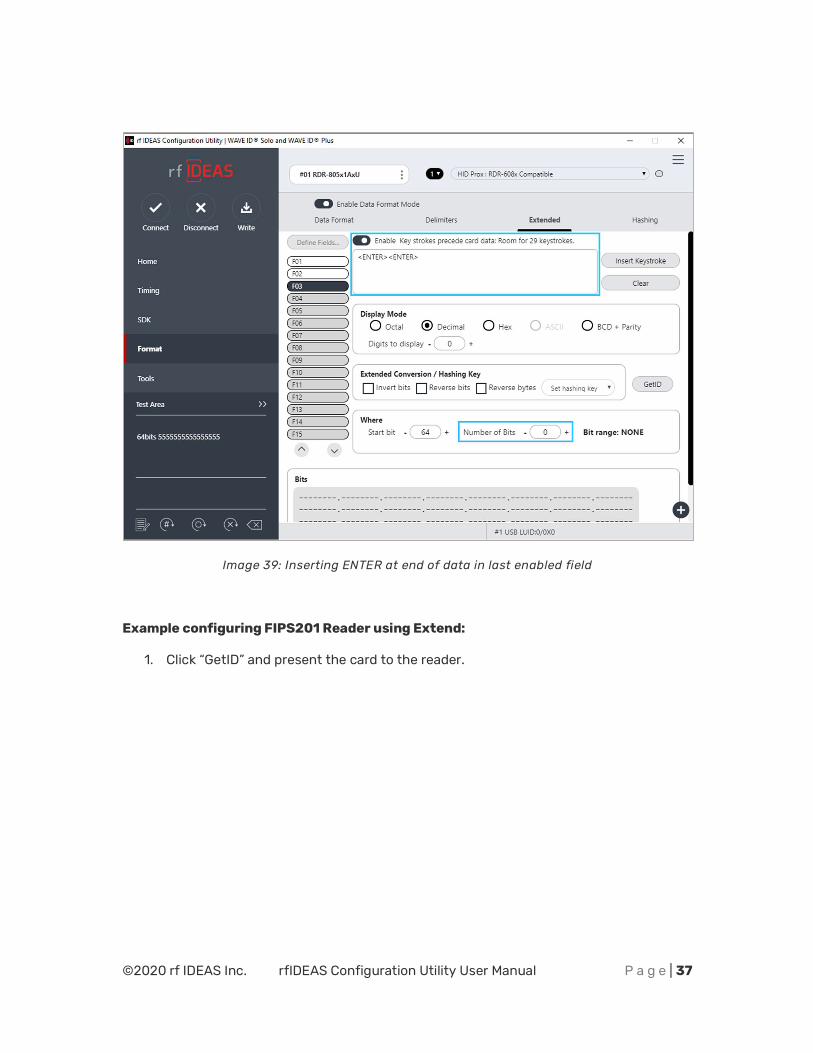
©2020 rf IDEAS Inc. rfIDEAS Configuration Utility User Manual P a g e | 37
Image 39: Inserting ENTER at end of data in last enabled field
Example configuring FIPS201 Reader using Extend:
1. Click “GetID” and present the card to the reader.
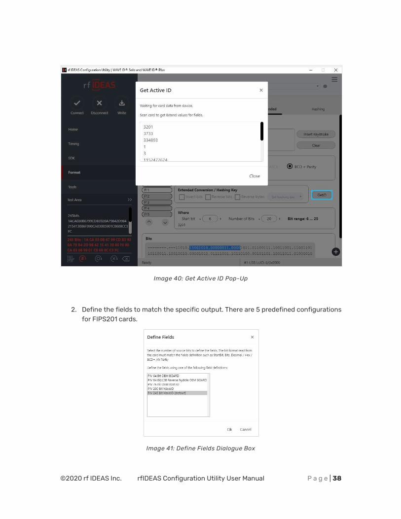
©2020 rf IDEAS Inc. rfIDEAS Configuration Utility User Manual P a g e | 38
Image 40: Get Active ID Pop-Up
2. Define the fields to match the specific output. There are 5 predefined configurations for FIPS201 cards.
Image 41: Define Fields Dialogue Box
©2020 rf IDEAS Inc. rfIDEAS Configuration Utility User Manual P a g e | 39
3. Configure any additional fields as appropriate.
Image 42: Configuration of Additional Fields
©2020 rf IDEAS Inc. rfIDEAS Configuration Utility User Manual P a g e | 40
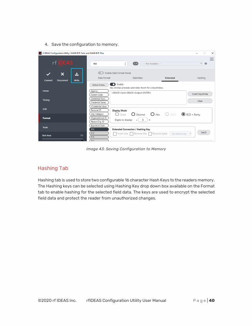
4. Save the configuration to memory.
Image 43: Saving Configuration to Memory
Hashing Tab
Hashing tab is used to store two configurable 16 character Hash Keys to the readers memory. The Hashing keys can be selected using Hashing Key drop down box available on the Format tab to enable hashing for the selected field data. The keys are used to encrypt the selected field data and protect the reader from unauthorized changes.
©2020 rf IDEAS Inc. rfIDEAS Configuration Utility User Manual P a g e | 41
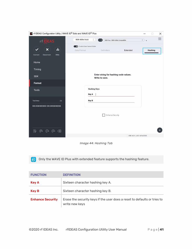
Image 44: Hashing Tab
Only the WAVE ID Plus with extended feature supports the hashing feature.
FUNCTION DEFINITION
Key A Sixteen character hashing key A.
Key B Sixteen character hashing key B.
Enhance Security Erase the security keys if the user does a reset to defaults or tries to write new keys
©2020 rf IDEAS Inc. rfIDEAS Configuration Utility User Manual P a g e | 42
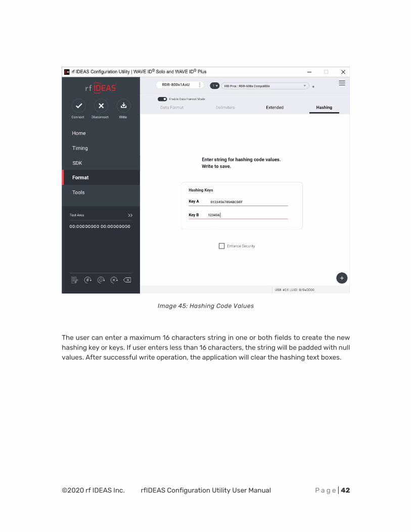
Image 45: Hashing Code Values
The user can enter a maximum 16 characters string in one or both fields to create the new hashing key or keys. If user enters less than 16 characters, the string will be padded with null values. After successful write operation, the application will clear the hashing text boxes.
©2020 rf IDEAS Inc. rfIDEAS Configuration Utility User Manual P a g e | 43
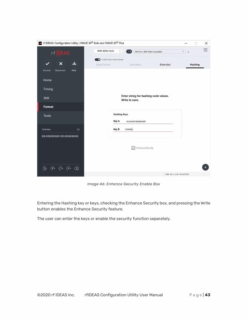
Image 46: Enhance Security Enable Box
Entering the Hashing key or keys, checking the Enhance Security box, and pressing the Write button enables the Enhance Security feature.
The user can enter the keys or enable the security function separately.
©2020 rf IDEAS Inc. rfIDEAS Configuration Utility User Manual P a g e | 44
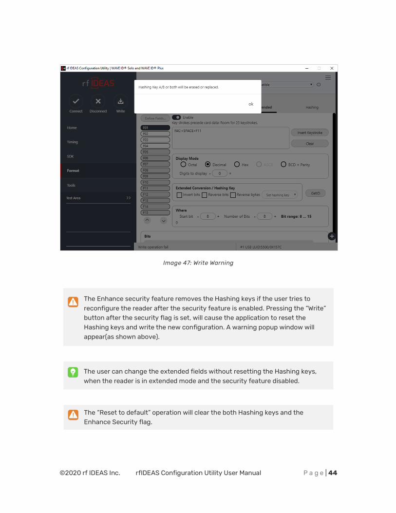
Image 47: Write Warning
The Enhance security feature removes the Hashing keys if the user tries to reconfigure the reader after the security feature is enabled. Pressing the “Write” button after the security flag is set, will cause the application to reset the Hashing keys and write the new configuration. A warning popup window will appear(as shown above).
The user can change the extended fields without resetting the Hashing keys, when the reader is in extended mode and the security feature disabled.
The “Reset to default” operation will clear the both Hashing keys and the Enhance Security flag.
©2020 rf IDEAS Inc. rfIDEAS Configuration Utility User Manual P a g e | 45
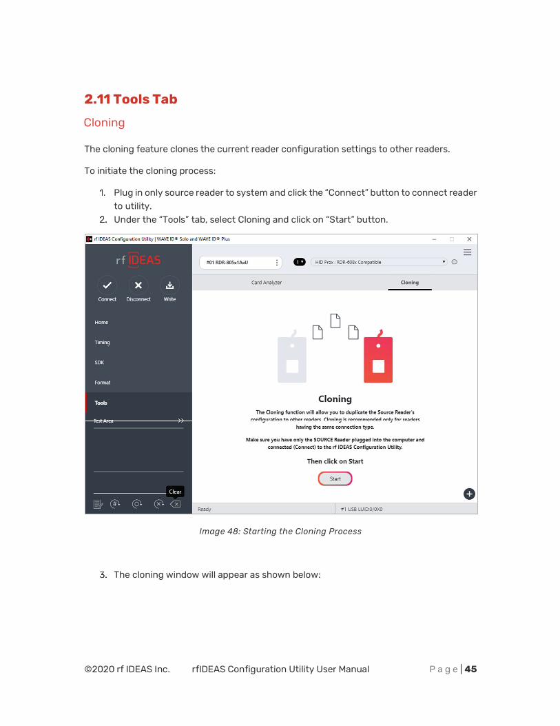
2.11 Tools Tab
Cloning
The cloning feature clones the current reader configuration settings to other readers.
To initiate the cloning process:
Plug in only source reader to system and click the “Connect” button to connect reader to utility.
Under the “Tools” tab, select Cloning and click on “Start” button.
Image 48: Starting the Cloning Process
The cloning window will appear as shown below:
©2020 rf IDEAS Inc. rfIDEAS Configuration Utility User Manual P a g e | 46
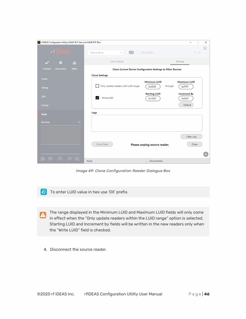
Image 49: Clone Configuration Reader Dialogue Box
To enter LUID value in hex use ‘0X’ prefix.
The range displayed in the Minimum LUID and Maximum LUID fields will only come in effect when the “Only update readers within the LUID range” option is selected. Starting LUID and Increment by fields will be written in the new readers only when the “Write LUID” field is checked.
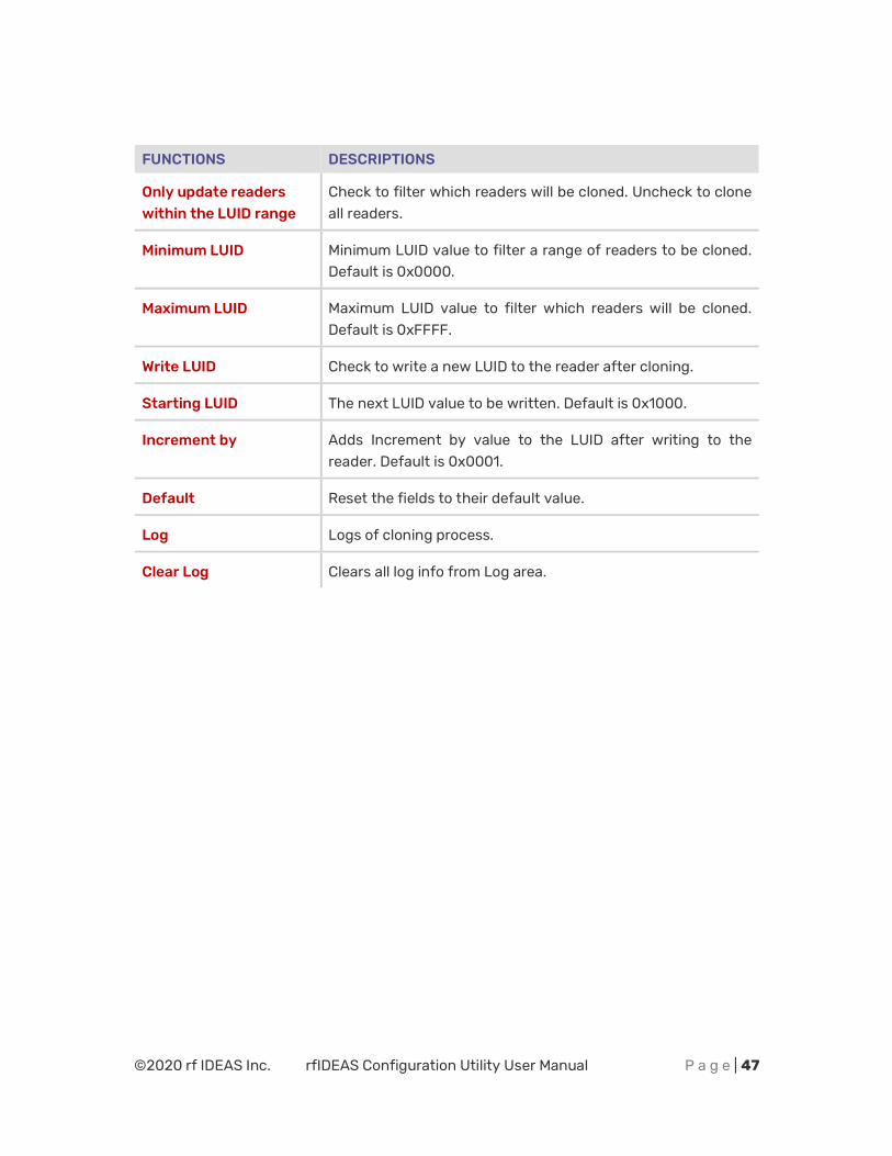
Disconnect the source reader.
©2020 rf IDEAS Inc. rfIDEAS Configuration Utility User Manual P a g e | 47
FUNCTIONS DESCRIPTIONS
Only update readers within the LUID range
Check to filter which readers will be cloned. Uncheck to clone all readers.
Minimum LUID Minimum LUID value to filter a range of readers to be cloned. Default is 0x0000.
Maximum LUID Maximum LUID value to filter which readers will be cloned. Default is 0xFFFF.
Write LUID Check to write a new LUID to the reader after cloning.
Starting LUID The next LUID value to be written. Default is 0x1000.
Increment by Adds Increment by value to the LUID after writing to the reader. Default is 0x0001.
Default Reset the fields to their default value.
Log Logs of cloning process.
Clear Log Clears all log info from Log area.
©2020 rf IDEAS Inc. rfIDEAS Configuration Utility User Manual P a g e | 48
Image 50: Reader Disconnected
If there are multiple readers to be cloned, it is recommended a HUB be utilized.
In case of serial readers the cloning process will be a little slower.
Connect the destination reader(s) that will be undergoing the cloning process and click on ‘Clone Now’ button in the end.
©2020 rf IDEAS Inc. rfIDEAS Configuration Utility User Manual P a g e | 49
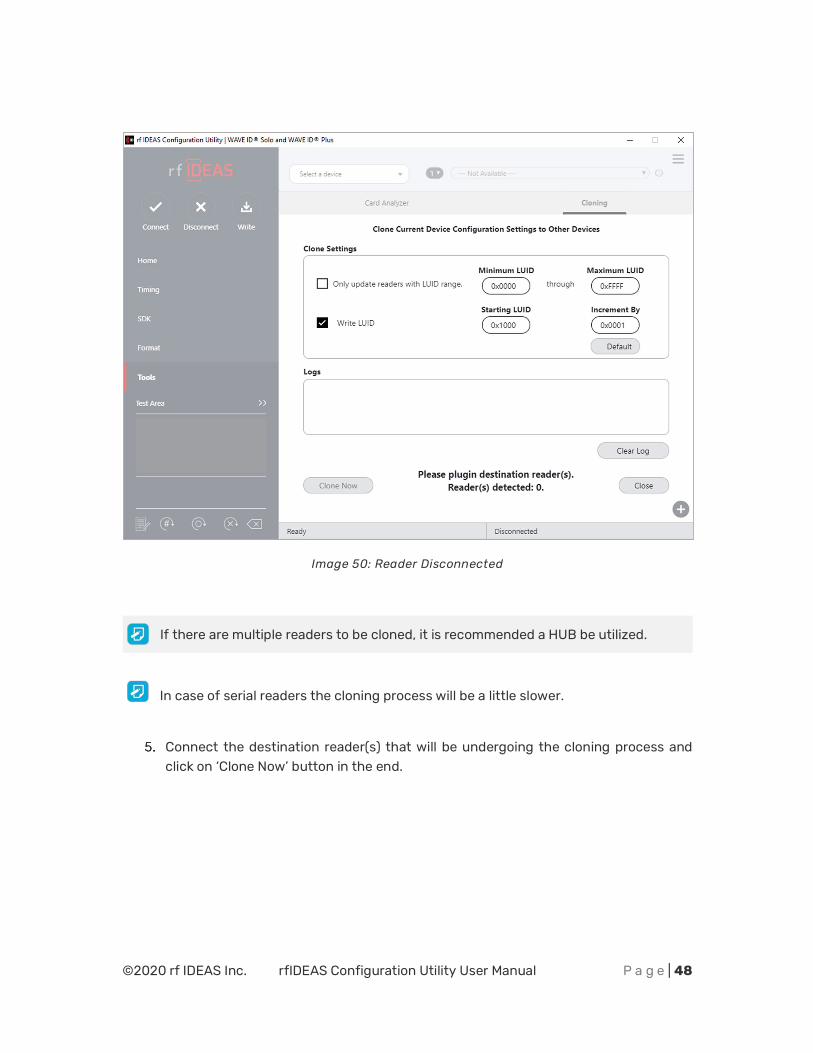
Image 51: Connecting Other Readers
More than one reader can be configured. Cloning will be done in reader(s) one by one and can be seen in Logs section.
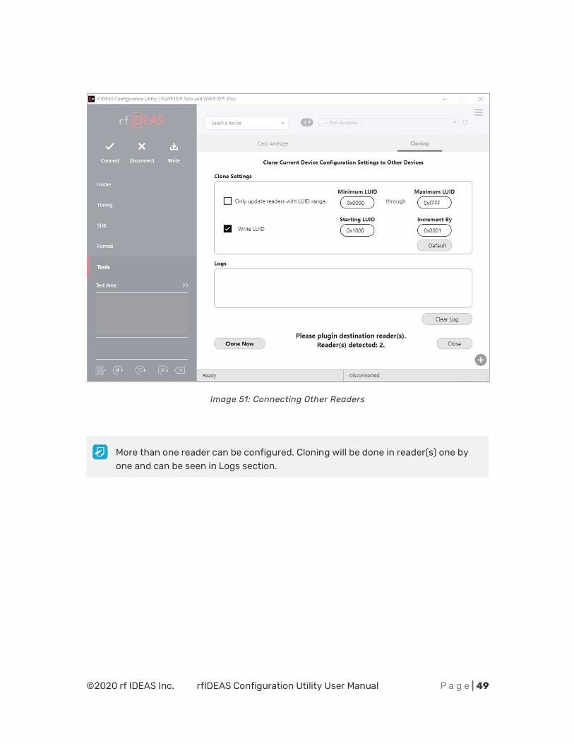
©2020 rf IDEAS Inc. rfIDEAS Configuration Utility User Manual P a g e | 50
Image 52: Configuring Reader(s)
Once the configuration process has finished, the below message will be displayed.
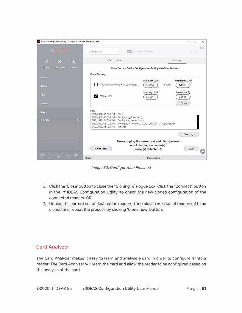
©2020 rf IDEAS Inc. rfIDEAS Configuration Utility User Manual P a g e | 51
Image 53: Configuration Finished
Click the ‘Close’ button to close the “Cloning” dialogue box. Click the “Connect” button in the ‘rf IDEAS Configuration Utility’ to check the new cloned configuration of the connected readers. OR
Unplug the current set of destination reader(s) and plug in next set of readers(s) to be cloned and repeat the process by clicking ‘Clone now’ button.
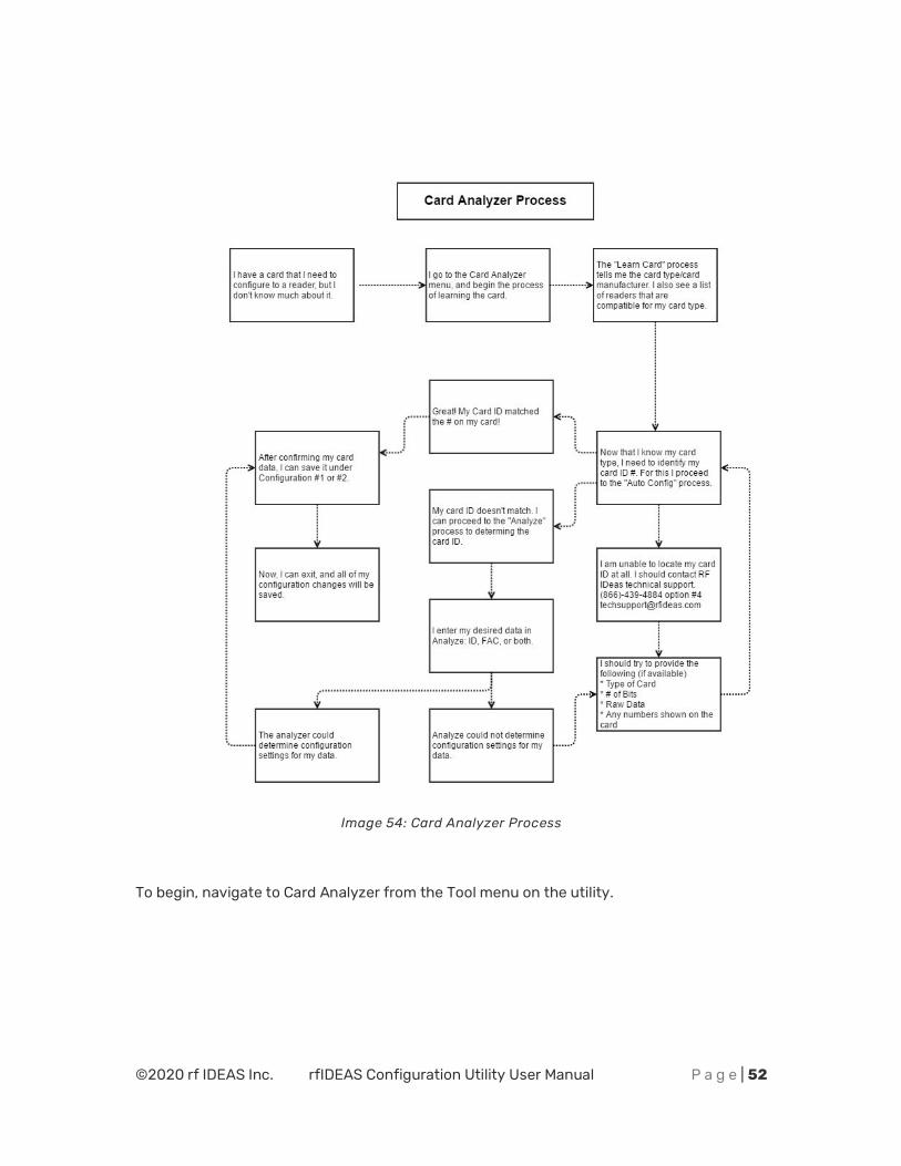
Card Analyzer
The Card Analyzer makes it easy to learn and analyse a card in order to configure it into a reader. The Card Analyzer will learn the card and allow the reader to be configured based on the analysis of the card.
©2020 rf IDEAS Inc. rfIDEAS Configuration Utility User Manual P a g e | 52
Image 54: Card Analyzer Process
To begin, navigate to Card Analyzer from the Tool menu on the utility.
©2020 rf IDEAS Inc. rfIDEAS Configuration Utility User Manual P a g e | 53
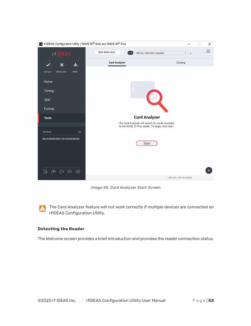
Image 55: Card Analyzer Start Screen
The Card Analyzer feature will not work correctly if multiple devices are connected on rfIDEAS Configuration Utility.
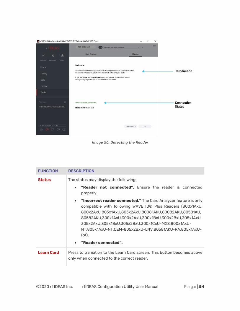
Detecting the Reader
The Welcome screen provides a brief introduction and provides the reader connection status.
©2020 rf IDEAS Inc. rfIDEAS Configuration Utility User Manual P a g e | 54
Image 56: Detecting the Reader
FUNCTION DESCRIPTION
Status The status may display the following:
x “Reader not connected”. Ensure the reader is connected properly.
x “Incorrect reader connected.” The Card Analyzer feature is only compatible with following WAVE ID® Plus Readers (800x1AxU, 800x2AxU,805x1AxU,805x2AxU,80081AKU,80082AKU,80581AU,80582AKU,300x1AxU,300x2AxU,300x1BxU,300x2BxU,305x1AxU,305x2AxU,305x1BxU,305x2BxU,300x1CxU-MXS,800x1AxU-NT,805x1AxU-NT,OEM-805x2BxU-LNV,80581AKU-RA,805x1AxU-RA).
x “Reader connected”.
Learn Card Press to transition to the Learn Card screen. This button becomes active only when connected to the correct reader.
©2020 rf IDEAS Inc. rfIDEAS Configuration Utility User Manual P a g e | 55
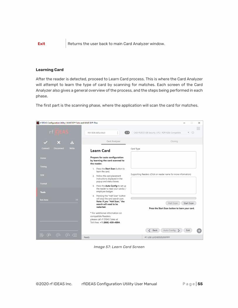
Exit Returns the user back to main Card Analyzer window.
Learning Card
After the reader is detected, proceed to Learn Card process. This is where the Card Analyzer will attempt to learn the type of card by scanning for matches. Each screen of the Card Analyzer also gives a general overview of the process, and the steps being performed in each phase.
The first part is the scanning phase, where the application will scan the card for matches.
Image 57: Learn Card Screen
©2020 rf IDEAS Inc. rfIDEAS Configuration Utility User Manual P a g e | 56
FIELD/BUTTON DESCRIPTION
Card Type Card type matches are displayed here.
Supporting Readers
Displays the supported rf IDEAS readers when a card type is selected.
Start Scan Start the scan function.
Halt Scan Stop the scan. This button becomes active after the “Start Scan” button is pressed, and the scanning starts.
Auto Config Takes the user to the “Auto Config” screen. This screen allows the user to configure the reader using the default Card Type settings.
Exit Returns user back to main Card Analyzer window.
Every time the Start Scan button is pressed, the application scans for the Contactless 13.56 MHz and Proximity 125 KHz Card Types.
To learn a card:
The application saves the current reader settings prior to scanning. They are restored if the user exits without writing the discovered settings.
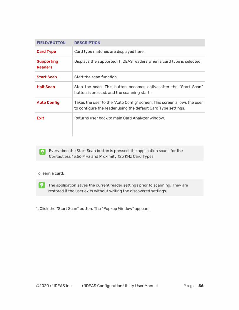
1. Click the “Start Scan” button. The “Pop-up Window” appears.
©2020 rf IDEAS Inc. rfIDEAS Configuration Utility User Manual P a g e | 57
Image 58: Starting the Scan
The “Back” button is disabled and the “Auto Config” button is unavailable during scanning.
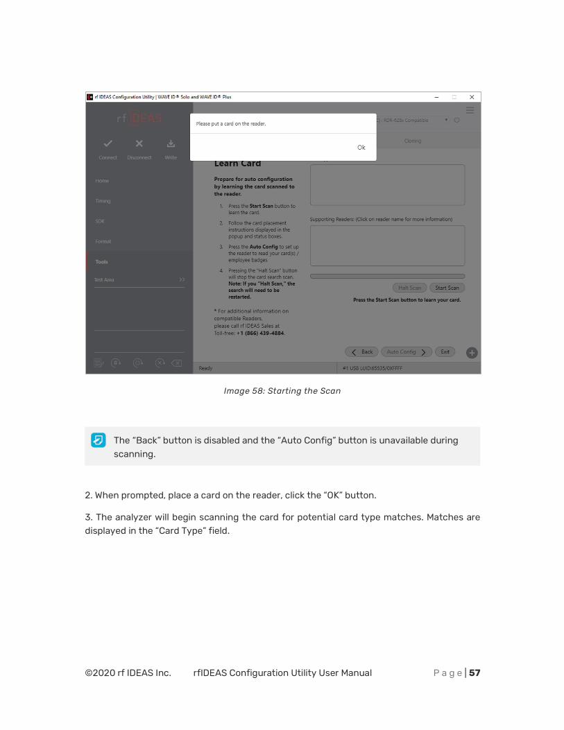
2. When prompted, place a card on the reader, click the “OK” button.
3. The analyzer will begin scanning the card for potential card type matches. Matches are displayed in the “Card Type” field.
©2020 rf IDEAS Inc. rfIDEAS Configuration Utility User Manual P a g e | 58
Image 59: Scanning Process
“Start Scan” button will be unavailable during the scan process. User can use the “Halt Scan” button to stop the scan process.
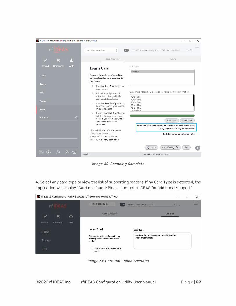
After the scan is complete, the following information will be displayed:
©2020 rf IDEAS Inc. rfIDEAS Configuration Utility User Manual P a g e | 59
Image 60: Scanning Complete
4. Select any card type to view the list of supporting readers. If no Card Type is detected, the application will display “Card not found: Please contact rf IDEAS for additional support”.
Image 61: Card Not Found Scenario
©2020 rf IDEAS Inc. rfIDEAS Configuration Utility User Manual P a g e | 60
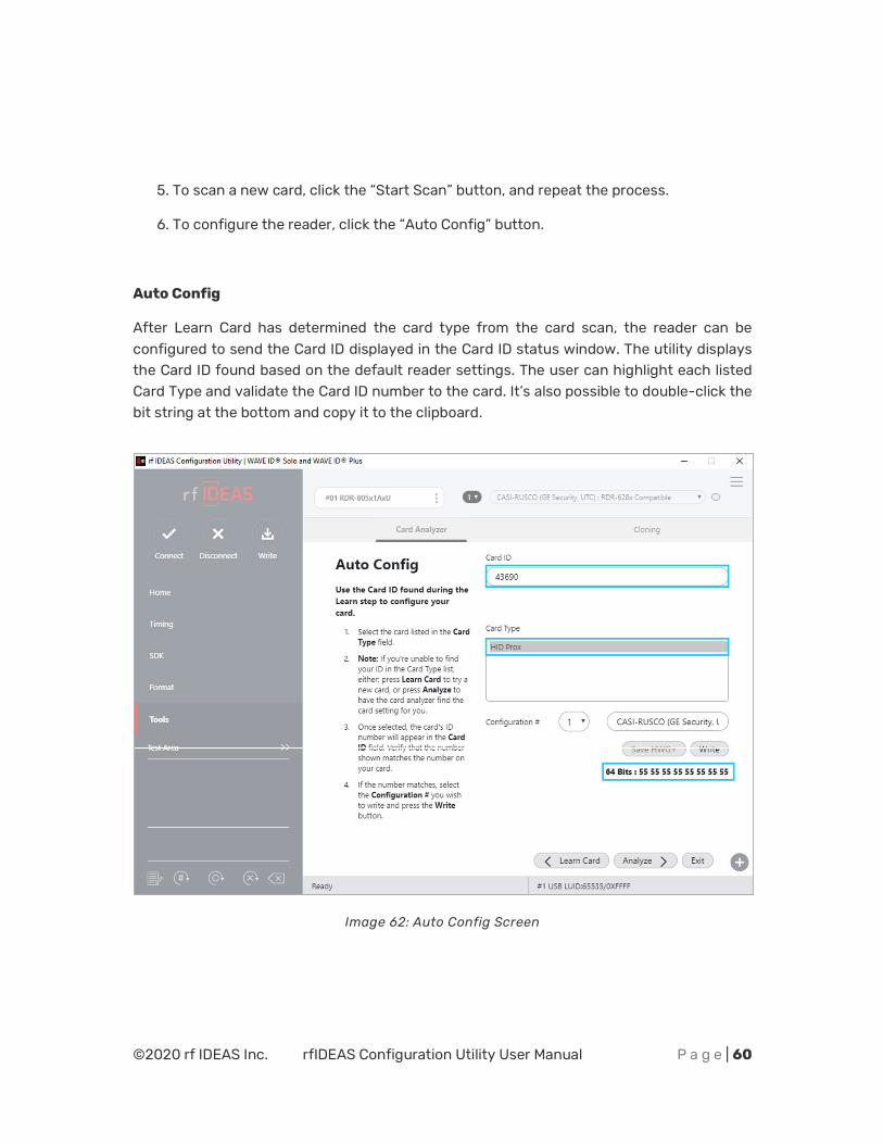
5. To scan a new card, click the “Start Scan” button, and repeat the process.
6. To configure the reader, click the “Auto Config” button.
Auto Config
After Learn Card has determined the card type from the card scan, the reader can be configured to send the Card ID displayed in the Card ID status window. The utility displays the Card ID found based on the default reader settings. The user can highlight each listed Card Type and validate the Card ID number to the card. It’s also possible to double-click the bit string at the bottom and copy it to the clipboard.
Image 62: Auto Config Screen
©2020 rf IDEAS Inc. rfIDEAS Configuration Utility User Manual P a g e | 61
It is not possible to jump directly to the “Auto Config” feature without first performing the “Learn Card” feature.
For some cases ‘Auto Config’ button may be disabled based on reader type or scanned card type.
FIELD/BUTTON DESCRIPTION
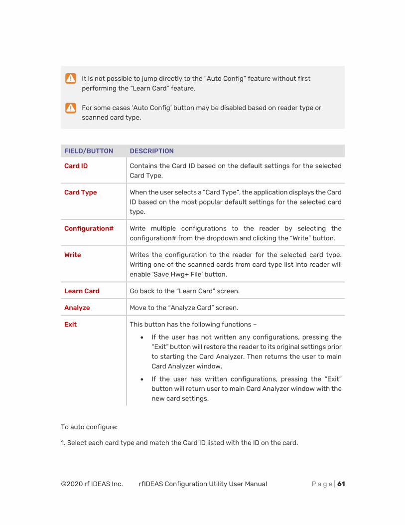
Card ID Contains the Card ID based on the default settings for the selected Card Type.
Card Type When the user selects a “Card Type”, the application displays the Card ID based on the most popular default settings for the selected card type.
Configuration# Write multiple configurations to the reader by selecting the configuration# from the dropdown and clicking the “Write” button.
Write Writes the configuration to the reader for the selected card type. Writing one of the scanned cards from card type list into reader will enable ‘Save Hwg+ File’ button.
Learn Card Go back to the “Learn Card” screen.
Analyze Move to the “Analyze Card” screen.
Exit This button has the following functions –
x If the user has not written any configurations, pressing the “Exit” button will restore the reader to its original settings prior to starting the Card Analyzer. Then returns the user to main Card Analyzer window.
x If the user has written configurations, pressing the “Exit” button will return user to main Card Analyzer window with the new card settings.
To auto configure:
1. Select each card type and match the Card ID listed with the ID on the card.
©2020 rf IDEAS Inc. rfIDEAS Configuration Utility User Manual P a g e | 62
Image 63: Writing Configuration Settings to the Reader
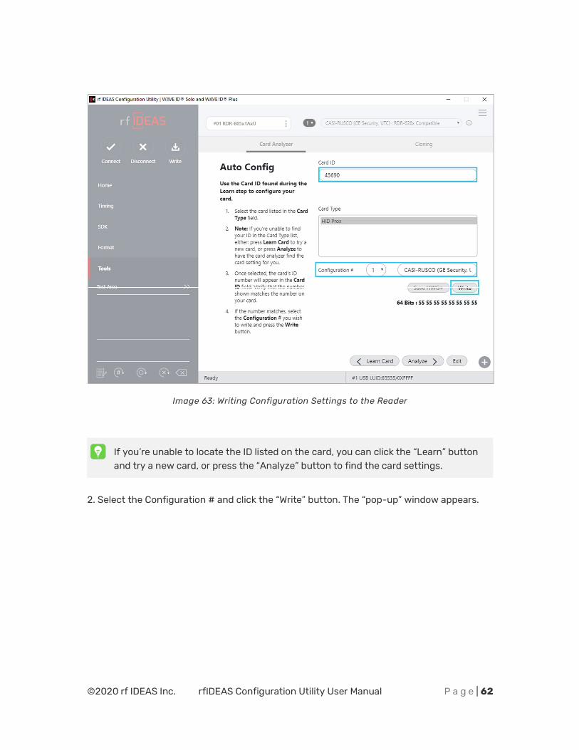
If you’re unable to locate the ID listed on the card, you can click the “Learn” button and try a new card, or press the “Analyze” button to find the card settings.
2. Select the Configuration # and click the “Write” button. The “pop-up” window appears.
©2020 rf IDEAS Inc. rfIDEAS Configuration Utility User Manual P a g e | 63
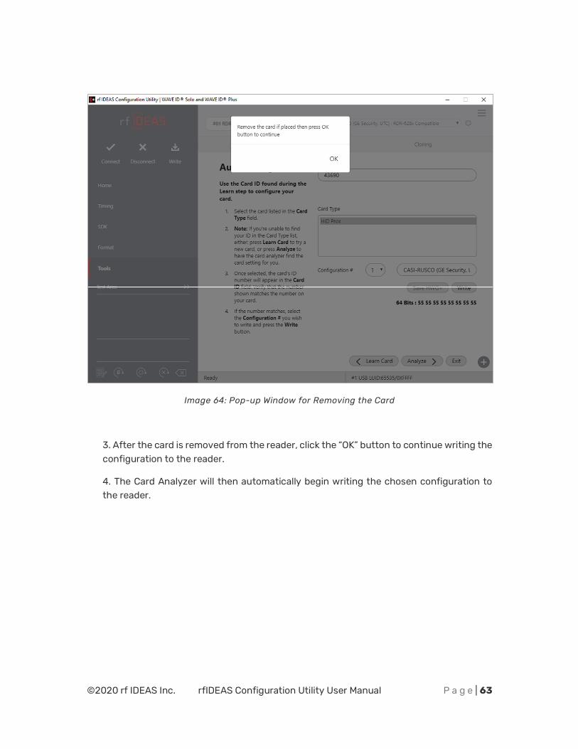
Image 64: Pop-up Window for Removing the Card
3. After the card is removed from the reader, click the “OK” button to continue writing the configuration to the reader.
4. The Card Analyzer will then automatically begin writing the chosen configuration to the reader.
©2020 rf IDEAS Inc. rfIDEAS Configuration Utility User Manual P a g e | 64
Image 65: Writing the Configuration to Reader
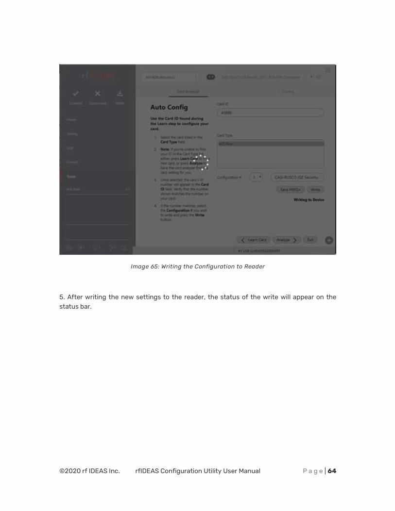
5. After writing the new settings to the reader, the status of the write will appear on the status bar.
©2020 rf IDEAS Inc. rfIDEAS Configuration Utility User Manual P a g e | 65
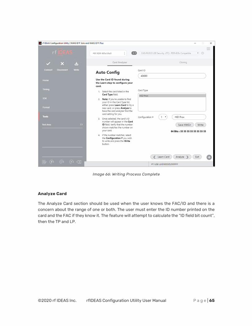
Image 66: Writing Process Complete
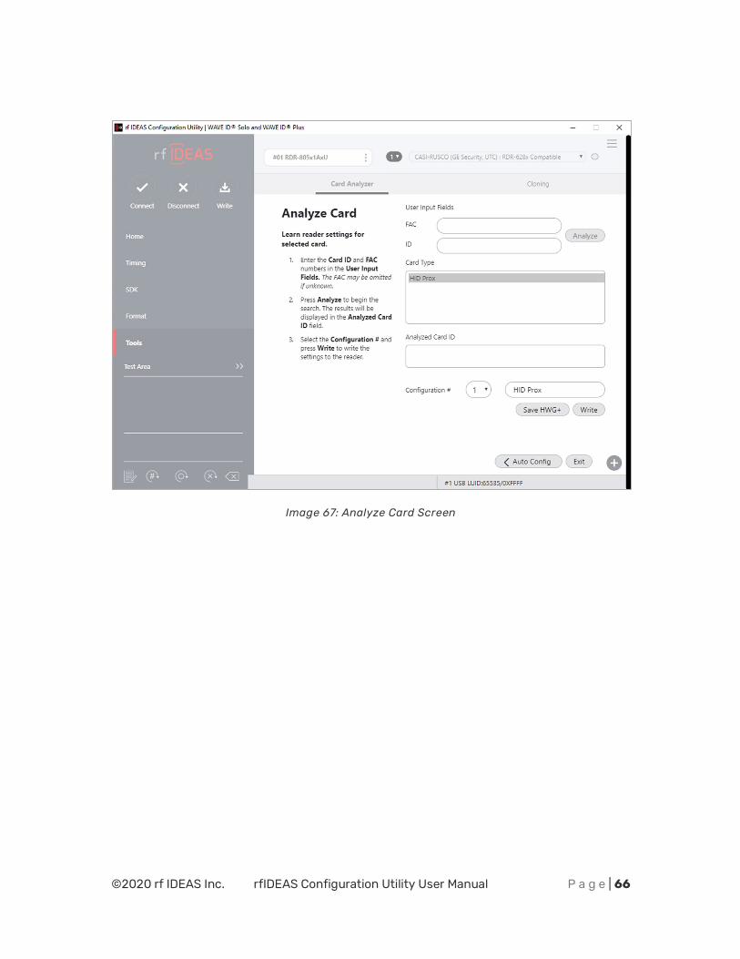
Analyze Card
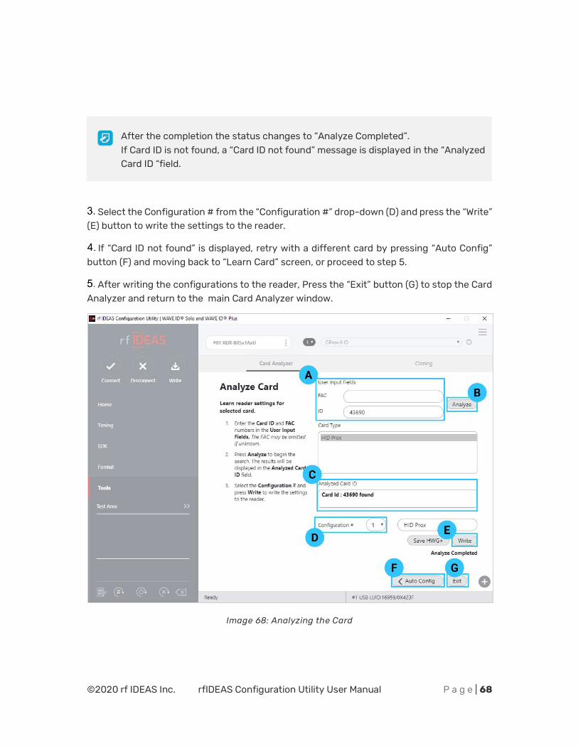
The Analyze Card section should be used when the user knows the FAC/ID and there is a concern about the range of one or both. The user must enter the ID number printed on the card and the FAC if they know it. The feature will attempt to calculate the “ID field bit count”, then the TP and LP.
©2020 rf IDEAS Inc. rfIDEAS Configuration Utility User Manual P a g e | 66
Image 67: Analyze Card Screen
©2020 rf IDEAS Inc. rfIDEAS Configuration Utility User Manual P a g e | 67
FIELD/BUTTON DESCRIPTION
FAC Field to enter a Facility Access Code (FAC).
ID Field to enter a card ID.
Analyze Starts the card analyse function. The application will attempt to learn the settings for the selected Card Type.
Card Types Displays learned Card Types. Each card type is selectable.
Analyze Card ID Displays status to the user: “Card ID found”, or “Contact rf IDEAS for additional support” if no results are found.
Configuration # Write multiple configurations to the reader by selecting the configuration # from the drop-down and clicking the “Write” button.
Write Writes the configuration to the reader.
Auto Config Go back to the “Auto Config” screen.
Exit This button has the following functions –
x If the user has not written configurations, pressing the “Exit” button will return user to rfIDEAS config utility without making any changes.
x If the user has written configurations, pressing the “Exit” button will return user to rfIDEAS config utility with new card settings.
To analyse a card:
1. Enter the “ID” or “FAC” or both numbers (A) in the “User Input Fields” section.
“ID” field is mandatory to analyse the card. FAC is optional, omit if unknown. The fields support numeric data.
Click the “Analyze” button (B) to begin the search.
The result is displayed in the “Analyzed Card ID” (C) field.
©2020 rf IDEAS Inc. rfIDEAS Configuration Utility User Manual P a g e | 68
Select the Configuration # from the “Configuration #” drop-down (D) and press the “Write” (E) button to write the settings to the reader.
If “Card ID not found” is displayed, retry with a different card by pressing “Auto Config” button (F) and moving back to “Learn Card” screen, or proceed to step 5.
After writing the configurations to the reader, Press the “Exit” button (G) to stop the Card Analyzer and return to the main Card Analyzer window.
Image 68: Analyzing the Card
After the completion the status changes to “Analyze Completed”. If Card ID is not found, a “Card ID not found” message is displayed in the “Analyzed Card ID “field.
©2020 rf IDEAS Inc. rfIDEAS Configuration Utility User Manual P a g e | 69
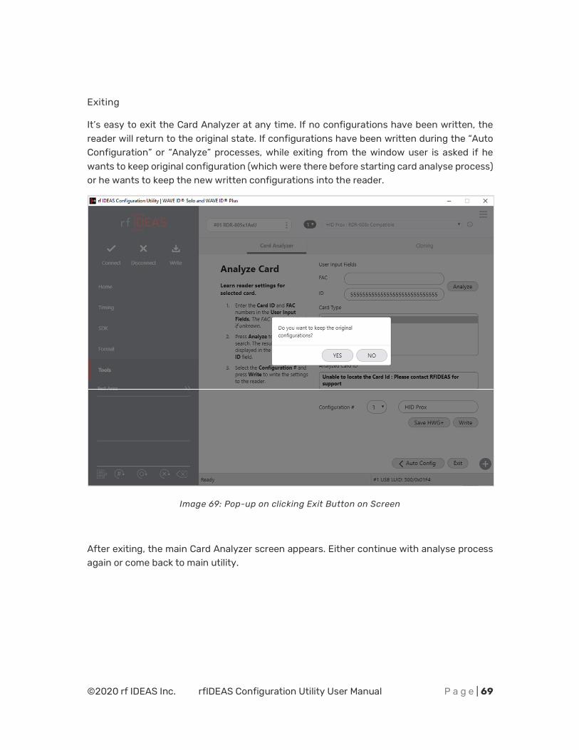
Exiting
It’s easy to exit the Card Analyzer at any time. If no configurations have been written, the reader will return to the original state. If configurations have been written during the “Auto Configuration” or “Analyze” processes, while exiting from the window user is asked if he wants to keep original configuration (which were there before starting card analyse process) or he wants to keep the new written configurations into the reader.
Image 69: Pop-up on clicking Exit Button on Screen
After exiting, the main Card Analyzer screen appears. Either continue with analyse process again or come back to main utility.
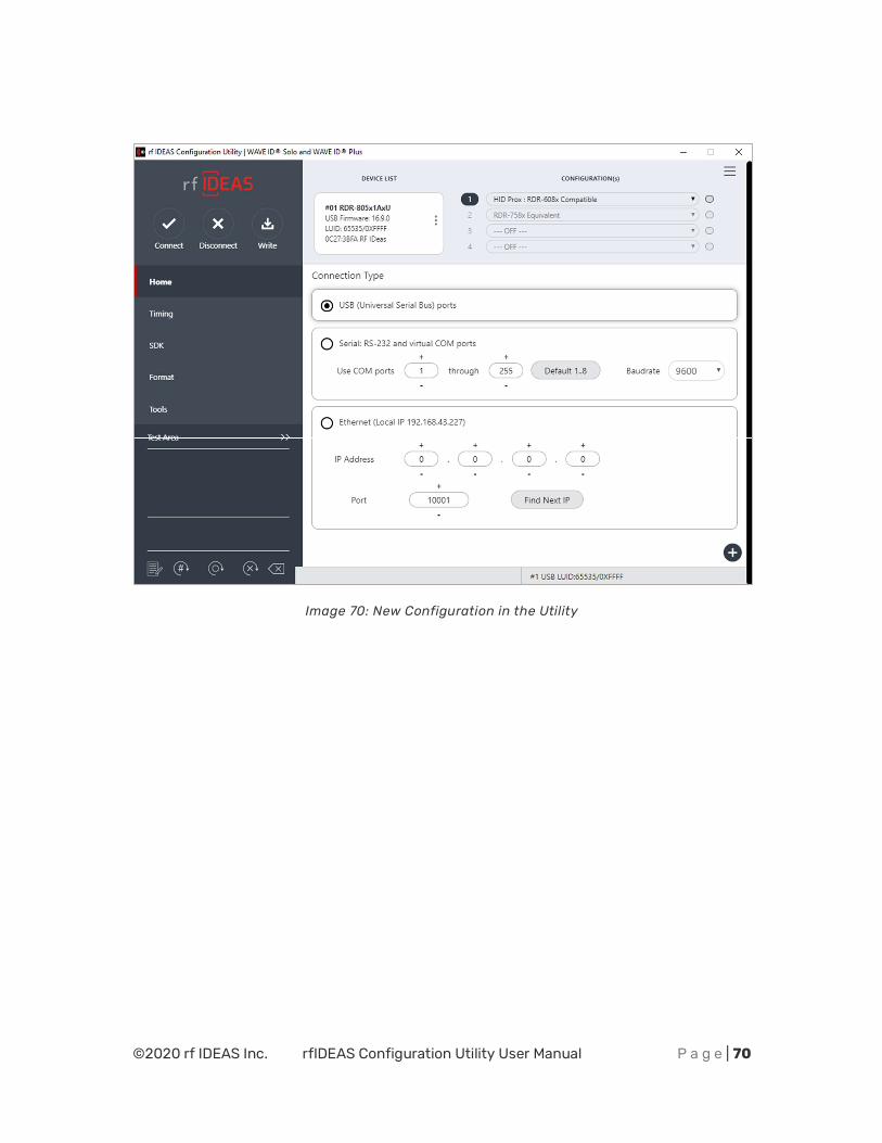
©2020 rf IDEAS Inc. rfIDEAS Configuration Utility User Manual P a g e | 70
Image 70: New Configuration in the Utility
©2020 rf IDEAS Inc. rfIDEAS Configuration Utility User Manual P a g e | 71
Chapter 3
Troubleshooting
3.1 Troubleshooting
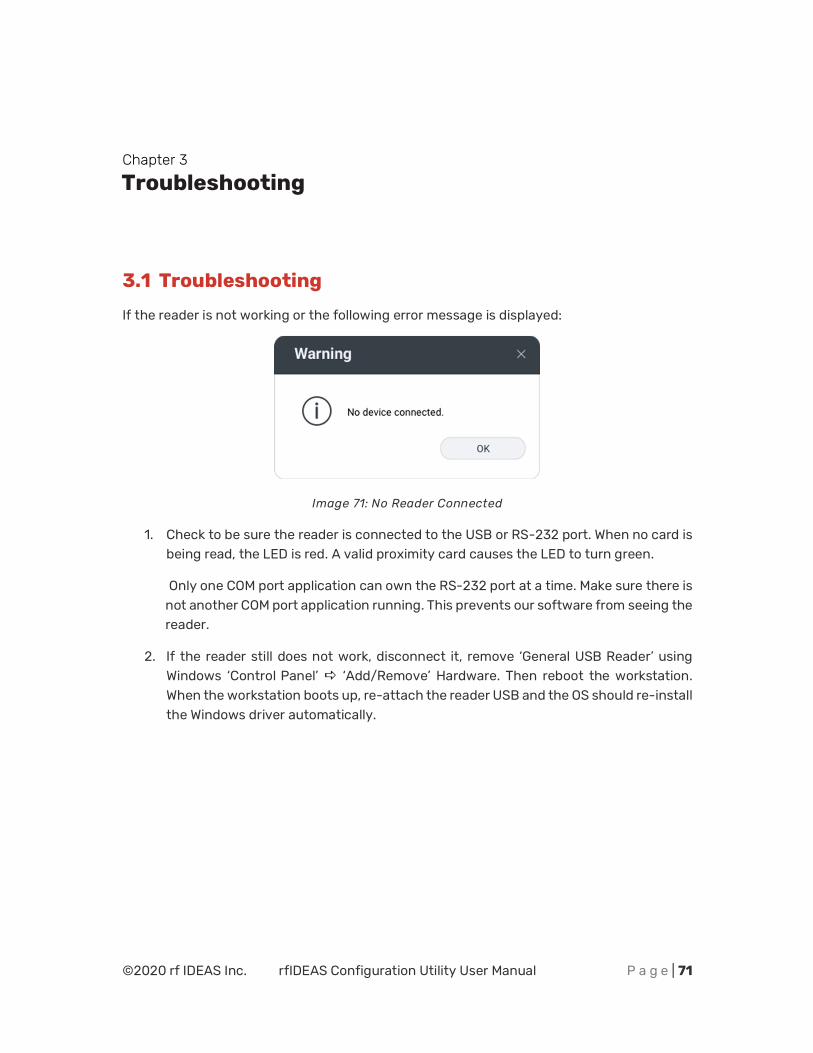
If the reader is not working or the following error message is displayed:
Image 71: No Reader Connected
1. Check to be sure the reader is connected to the USB or RS-232 port. When no card is being read, the LED is red. A valid proximity card causes the LED to turn green.
Only one COM port application can own the RS-232 port at a time. Make sure there is not another COM port application running. This prevents our software from seeing the reader.
2. If the reader still does not work, disconnect it, remove ‘General USB Reader’ using Windows ‘Control Panel’ D ‘Add/Remove’ Hardware. Then reboot the workstation. When the workstation boots up, re-attach the reader USB and the OS should re-install the Windows driver automatically.
©2020 rf IDEAS Inc. rfIDEAS Configuration Utility User Manual P a g e | 72
END-USER LICENSE AGREEMENT
LICENSE AGREEMENT
End-User License Agreement for rf IDEAS™ SOFTWARE and HARDWARE - –rf IDEAS’ WAVE ID®, Proximity Activated Readers, Software Developer’s Kit, and Proximity Reader DLLs, and Protocol(s).
IMPORTANT-READ CAREFULLY: This End-User License Agreement (“EULA”) is a legal agreement between you (either an individual or a single entity) and the manufacturer rf IDEAS (“Manufacturer”) with which you acquired the rf IDEAS software and hardware product(s) identified above (“PRODUCT”). The PRODUCT includes the rf IDEAS reader, computer software, the associated media, any printed materials, and any “on line” or electronic documentation. The SOFTWARE PORTION OF THE PRODUCT includes the computer software, the associated media, any printed materials, and any “on line” or electronic documentation. By installing, copying or otherwise using the PRODUCT, you agree to be bound by the terms of this EULA. If you do not agree to the terms of this EULA, rf IDEAS is unwilling to license the PRODUCT to you. In such event, you may not use or copy the SOFTWARE PORTION OF THE PRODUCT, and you should promptly contact the vendor you obtained this PRODUCT from for instructions on return of the unused product(s) for a refund.
The products described in this publication are intended for consumer applications. rf IDEAS assumes no liability for the performance of product. rf IDEAS products are not suitable for use in life-support applications, biological hazard applications, nuclear control applications, or radioactive areas. None of these products or components, software or hardware, are intended for applications that provide life support or any critical function necessary for the support of protection of life, property or business interests. The user assumes responsibility for the use of any of these products in any such application. rf IDEAS shall not be liable for losses due to failure of any of these products, or components of these products, beyond the rf IDEAS commercial warranty, limited to the original purchase price.
SOFTWARE PRODUCT LICENSE: The PRODUCT is protected by copyright laws and international copyright treaties, as well as other intellectual property laws and treaties. The SOFTWARE PORTION OF THE PRODUCT is licensed, not sold.
1. GRANT OF LICENSE. This EULA grants you the following rights: *Software. You may install and use one copy of the SOFTWARE PORTION OF THE PRODUCT on the COMPUTER. *Network Services. If the SOFTWARE PORTION OF THE PRODUCT includes functionality that enables the COMPUTER to act as a network server, any number of computers or workstations may access or otherwise utilize the basic network services of that server. The basic network services are more fully described in the printed materials accompanying the SOFTWARE PORTION OF THE PRODUCT. *Storage/Network Use. You may also store or install a copy of the computer SOFTWARE PORTION OF THE PRODUCT on the COMPUTER to allow your other computers to use the SOFTWARE PORTION OF THE PRODUCT over an internal network, and distribute the SOFTWARE PORTION OF THE PRODUCT to your other computers over an internal network.
1.1 General License Grant. rf IDEAS grants to an individual, a personal, nonexclusive license to make and use copies of the SOFTWARE PRODUCT for the sole purposes of designing, developing, and testing your software product(s) that are designed to operate in conjunction with any rf IDEAS designed proximity reader product. You may install copies of the SOFTWARE PRODUCT on an unlimited number of computers provided that you are the only individual using the SOFTWARE PRODUCT. If you are an entity, rf IDEAS grants the right to designate one individual within your organization to have the sole right to use the SOFTWARE PRODUCT in the manner provided above.
©2020 rf IDEAS Inc. rfIDEAS Configuration Utility User Manual P a g e | 73
1.2 Documentation. This EULA grants an individual, a personal, nonexclusive license to make and use an unlimited number of copies of any documentation, provided that such copies shall be used only for personal purposes and are not to be republished or distributed (either in hard copy or electronic form) beyond the user’s premises and with the following exception: you may use documentation identified in the SOFTWARE PRODUCT as the file format specification for rf IDEAS’ proximity readers solely in connection with your development of software product(s) or an integrated work or product suite whose components include one or more general purpose software products.
1.3 Storage/Network Use. You may also store or install a copy of the SOFTWARE PRODUCT on a storage reader, such as a network server, used only to install or run the SOFTWARE PRODUCT on computers used by a licensed end user in accordance with Section 1.1. A single license for the SOFTWARE PRODUCT may not be shared or used concurrently by other end users.
1.4 Sample Code. rf IDEAS grants you the right to use and modify the source code version of those portions of the SOFTWARE PRODUCT identified as “Samples in the SOFTWARE PRODUCT (“Sample Code”) for the sole purposes to design, develop, and test your software product(s), and to reproduce and distribute the Sample Code, along with any modifications thereof, only in object code form.
2. DESCRIPTION OF OTHER RIGHTS AND LIMITATIONS. *Limitations on Reverse Engineering, De-compilation and Disassembly. You may not reverse engineer, decompile, or disassemble the PRODUCT, except and only to the extent that such activity is expressly permitted by applicable law notwithstanding this limitation *You may not reproduce or otherwise emulate, in whole or in part, any form the protocol(s) defined within this PRODUCT for use without a rf IDEAS PRODUCT Redistributable Code. If you are authorized and choose to redistribute Sample Code (“Redistributables”) as described in Section 1.4, you agree to: (a) distribute the Redistributables in object code only in conjunction with and as a part of a software application product developed by you using the PRODUCT accompanying this EULA that adds significant and primary functionality to the SOFTWARE PRODUCT (“Licensed Product”); (b) not use rf IDEAS’ name, logo, or trademarks to market the Licensed Product; (c) include a valid copyright notice on the Licensed Product; (d) indemnify, hold harmless, and defend rf IDEAS from and against any claims or lawsuits, including attorney’s fees, that arise or result from the use or distribution of the Licensed Product; (otherwise comply with the terms of this EULA; and (g) agree that rf IDEAS reserves all rights not expressly granted. You also agree not to permit further distribution of the Redistributables by your end users except: (1) you may permit further redistribution of the Redistributables by your distributors to your end-user customers if your distributors only distribute the Redistributables in conjunction with, and as part of, the Licensed Product and you and your distributors comply with all other terms of this EULA; and (2) in the manner described in Section 1.4.
*Separation of Components. The PRODUCT is licensed as a single product. Its component parts may not be separated for use on more than one computer.
*Single COMPUTER. The PRODUCT is licensed with the COMPUTER as a single integrated product. The PRODUCT may only be used with the COMPUTER.
*Rental. You may not rent or lease the PRODUCT without permission from rf IDEAS.
*Software Transfer. You may permanently transfer all of your rights under this EULA only as part of a sale or transfer of the COMPUTER, provided you retain no copies, you transfer all of the PRODUCT (including all component parts, the media and printed materials, any upgrades, this EULA and, if applicable, the Certificate(s) of Authenticity), AND the recipient agrees to the terms of this EULA. If the PRODUCT is an upgrade, any transfer must include all prior versions of the PRODUCT.
©2020 rf IDEAS Inc. rfIDEAS Configuration Utility User Manual P a g e | 74
*Termination. Without prejudice to any other rights, rf IDEAS may terminate this EULA if you fail to comply with the terms and conditions of this EULA. In such event, you must destroy all copies of the SOFTWARE PORTION OF THE PRODUCT and all of its component parts.
3. UPGRADES. If the SOFTWARE PORTION OF THE PRODUCT is an upgrade from another product, whether from rf IDEAS or another supplier, you may use or transfer the PRODUCT only in conjunction with that upgraded product, unless you destroy the upgraded product. If the SOFTWARE PORTION OF THE PRODUCT is an upgrade of a rf IDEAS product, you now may use that upgraded product only in accordance with this EULA. If the SOFTWARE PORTION OF THE PRODUCT is an upgrade of a component of a package of software programs which you licensed as a single product, the SOFTWARE PORTION OF THE PRODUCT may be used and transferred only as part of that single product package and may not be separated for use on more than one computer.
4. OEM COPYRIGHT. All title and copyrights in and to the PRODUCT (including but not limited to images, photographs, animations, video, audio, music, text and “applets,” incorporated into the PRODUCT), the accompanying printed materials, and any copies of the SOFTWARE PORTION OF THE PRODUCT, are owned by rf IDEAS or its suppliers. The PRODUCT and SOFTWARE PORTION OF THE PRODUCT is protected by copyright laws and international treaty provisions. You may not copy the printed materials accompanying the PRODUCT.
5. DUAL-MEDIA SOFTWARE. You may receive the SOFTWARE PORTION OF THE PRODUCT in more than one medium. Regardless of the type or size of medium you receive, you may use only one medium that is appropriate for your single computer. You may not use or install the other medium on another computer. You may not loan, rent, lease, or otherwise transfer the other medium to another user, except as part of the permanent transfer (as provided above) of the SOFTWARE PORTION OF THE PRODUCT.
6. OEM PRODUCT SUPPORT. Product support for the product is not provided by rf IDEAS or its subsidiaries. For product support, please refer to the OEM supplies support number provided in the documentation. Should you have any questions concerning the EULA, or if you desire to contact OEM for any other reason, please refer to the address provided in the documentation provided.
FOR THE LIMITED WARRANTIES AND SPECIAL PROVISIONS PERTAINING TO YOUR PARTICULAR JURISDICTION, PLEASE REFER TO YOUR WARRANTY BOOKLET INCLUDED WITH THIS PACKAGE OR PROVIDED WITH THE SOFTWARE PRODUCT PRINTED MATERIALS.
Limited Warranty: rf IDEAS warrants to the original buyer of this product, that the hardware and related disk(s) are free of defects in material and workmanship for a period of one year from date of purchase from rf IDEAS or from an authorized rf IDEAS dealer. Should the rf IDEAS products fail to be in good working order at any time during the one-year period, rf IDEAS will, at its option, repair or replace the product at no additional charge, provided that the product has not been abused, misused, repaired or modified. This warranty shall be limited to repair or replacement and in no event shall rf IDEAS be liable for any loss of profit or any commercial or other damages, including but not limited to special, incidental, consequential or other similar claims. No dealer, distributor, company, or person has been authorized to change or add to the terms of this agreement, and rf IDEAS will not be bound by any representation to the contrary. rf IDEAS SPECIFICALLY DISCLAIMS ALL OTHER WARRANTIES, EXPRESSED OR IMPLIED, INCLUDING BUT NOT LIMITED TO IMPLIED WARRANTIES OF MERCHANTABILITY AND FITNESS OF PURPOSE. Since some states do not allow such exclusion of limitation of incidental or consequential damages for consumer products, check the statute of the state in which your business resides.
This warranty gives you the specific legal rights in addition to any rights that you have under the laws of the state in which your business resides or operates.
Returns: rf IDEAS products which require Limited Warranty service during the warranty period shall be delivered to the nearest authorized dealer or sent directly to rf IDEAS at the address below with proof of purchase and a
©2020 rf IDEAS Inc. rfIDEAS Configuration Utility User Manual P a g e | 75
Return Materials Authorization (RMA) Number provided by rf IDEAS Technical Support Dept. Replacement parts or complete boards become the property of rf IDEAS If the returned board or unit is sent by mail, the purchaser agrees to pre-pay the shipping charges and insure the board or unit or assume the risk of loss or damage which may occur in transit. The purchaser is expected to employ a container equivalent to the original packaging. Copyright: Copyright by rf IDEAS 2020. All rights reserved. Reproduction or distribution of this document in whole or in part or in any form is prohibited without express written permission from rf IDEAS.
Trademarks: All rf IDEAS products are trademarks of rf IDEAS. All other product names or names are trademarks or registered trademarks of their respective holders.
Applicable Patents: rf IDEAS WAVE ID Plus card readers supporting HID formats retain US Patent No. 5,952,935 and U.S. Patent No. 7,439,862.
Disclaimer: This Reference Guide is printed in the U.S.A. Any resemblance mentioned in the Reference Guide to persons living or dead, or to actual corporations or products is purely coincidental. rf IDEAS believes that the information contained in this manual is correct. However, rf IDEAS does not assume any responsibility for the accuracy of the content of this User Manual, nor for any patent infringements or other rights of third parties. rf IDEAS reserves the right to make any modifications in either product or the manual without giving prior written notification.
FCC Compliance Statement
FCC ID: M9MPCPROXHUSB100 (HID USB Model) FCC ID: M9MPCPROXM101 (Indala Model) FCC ID: M9MRDR6X8X (Kantech, Indala, Casi-Rusco) FCC ID: M9MPCPROXC101 (Casi-Rusco Model) FCC ID: M9MRFID1856I100 (MIFARE/iCLASS Models) FCC ID: M9MRDR7580 (iCLASS MIFARE and Other 13.56MHz) FCC ID: M9MRDR7581 (iCLASS MIFARE and Other 13.56MHz) FCC ID: M9MRDR7081AKE (iCLASS MIFARE and Other 13.56MHz) FCC ID: M9MRDR8XX8U (Plus combo Model) FCC ID: M9MRDR8058X (Multi-protocol Combo Model) FCC ID: M9M758XCCL (MIFARE and Contact Model) FCC ID: M9MRDR80081 (Plus SIO Combo Model) FCC ID: M9MRDR60DX (125kHz USB Dongle Model) FCC ID: M9MOEM805NX (Multi-protocol Combo Model) FCC ID: M9MSB758X (Mifare 13.56MHz) FCC ID: M9MLC6T8X (132 kHz USB Model) FCC ID: M9MLC608XU0 (125 kHz Virtual Com Model) FCC ID: M9MLC6X8X (Multi-protocol 125kHz) FCC ID: M9MLC805X (Multi-protocol Combo Model) FCC ID: M9MHP8058X (Multi-protocol Combo Model) FCC ID: M9MLC7X11U (13.56MHz USB Model)
FCC ID: M9MBUPCPROXH100 (HID RS-232 Model) FCC ID: M9MBUPCPROXA100 (AWID) FCC ID: M9MPCPROXP100 (Pyramid) FCC ID: M9MRDR7081 (iCLASS Module based) FCC ID: M9MRDR7P71 (FIPS 201 13.56MHz) FCC ID: M9MRDR7L81 (Legic 13.56MHz) FCC ID: M9MRDR7081AKF (iCLASS MIFARE and Other 13.56MHz) FCC ID: M9MRDR75DX (iCLASS MIFARE and Other 13.56MHz) FCC ID: M9MRDR758X (iCLASS MIFARE and Other 13.56 MHz) FCC ID: M9M8058XCCL (Multi-protocol and Contact Model) FCC ID: M9M7580CCL (MIFARE and Contact Model) FCC ID: M9MRDR70EX (13.56MHz Express Model) FCC ID: M9MLC608X (125KHz USB Model FCC ID: M9MSB708X (iCLASS 13.56MHz) FCC ID: M9MSB6X8X (Multi-protocol 125kHz) FCC ID: M9MLC60DX (125 KHz USB Model) FCC ID: M9MLC758X (13.56 MHz USB Model) FCC ID: M9MLC6X11U (125 kHz USB Model) FCC ID: M9MLC8058U (Multi-protocol Combo Model) FCC ID: M9MLC8008XU (Multi-protocol Combo Model)
“Pursuant to FCC 15.21 of the FCC rules, changes not expressly approved by rf IDEAS might cause harmful interference and void the FCC authorization to operate this product.
Note: This reader complies with Part 15 of the FCC Rules and Industry Canada license-exempt RSS standard(s). Operation is subject to the following two conditions: (1) This reader may not cause harmful interference, and (2) this reader must accept any interference received, including interference that may cause undesired operation. This product complies with FCC OET Bulletin 65 radiation exposure limits set forth for an uncontrolled environment.

©2020 rf IDEAS Inc. rfIDEAS Configuration Utility User Manual P a g e | 76
The reader may not recognize value cards in the presence of high RF fields. If the current reading is erratic, the user shall take the following step: Move the equipment from any known transmitters nearby. For more information contact Tech Support at (866) 439 - –884.
©2020 rf IDEAS Inc. rfIDEAS Configuration Utility User Manual P a g e | 77
Index
A ASCII, 32, 79
B Beeper, 23
C Card Data Hold Time, 20
Configuration, 16
Continuous Read, 20
D Decimal, 27, 32
Delimiter Keyboard, 29, 30
E Ethernet, 8, 18
F FAC, 27, 29, 67
FIPS, 37
G GetID, 24, 32, 33
GetQueued ID, 25
H Hashing, 40
I Icon Toolbar, 12
ID Digits, 27
K Key Press Time, 21
Key Release Time, 21
L LED, 20, 22, 23, 71
Lock-Out Time, 20
Logical Unit ID, 12, 20, 23, 46
M MIFARE, 75, 79
Minimum system requirements, 78
O OEM, 54, 75
Output Test Area, 18
P Parity, 33
R RS-232, 18, 71, 75, 78
S SDK, 12, 21, 22
Serial, 18, 28, 32
Special Keys, 30
T Termination Keystroke, 29
U USB, 8, 12, 17, 78
W Wiegand, 28
©2020 rf IDEAS Inc. Configuration Utility User Manual P a g e | 78
Appendix
COMPONENTS MINIMUM SYSTEM REQUIREMENTS
Hardware Intel® Pentium™ E5400 processor
Memory 2 GB RAM
Hard Disk Space 400 MB
I/O 1 USB port for USB device, 1 RS-232, and 1 USB port for serial device
Operating System Windows 10
Use the WAVEID Plus Reader for Password Security - Complex Passwords
It is possible with certain limitations, to use the proximity token as a password for an application or operating system log on. The unique card bit-stream converted to either decimal or hexadecimal becomes the entire or a portion of the password. Enroll this card data to the password of the operating system application for the user.
Since the proximity token has no read/write memory, there is no way to change this or write alphanumeric characters such as a user name to the proximity token.Please see rf IDEAS WAVE ID Playback Starter Kit or call the Sales Department if this capability is needed.
Several companies have adopted a policy that requires users to change their password every xx number of days to increase security. The PIN is the portion of the password the user changes every xx number of days. Since the card data is completely numeric, any alpha and upper/lower case letter constraints are handled in the user supplied PIN.
A two-factor authentication system is made up of:
1. Card ID data 2. Personal Identification Number (PIN)
The reader may be configured to allow operation under either a one or two-factor authentication system.
One-Factor
©2020 rf IDEAS Inc. Configuration Utility User Manual P a g e | 79
In a one-factor system, the user simply scans the ID card. The reader may be configured to add TAB keystrokes ahead of the data as well as a TAB or ENTER keystroke after the card data.
Two-Factor
The two-factor approach is especially useful when insisting on password construction rules or periodic changing of passwords.
In a two-factor system, the user may enter the PIN either before or after the card data. If the user adds the PIN before the card data, the reader may be configured to append the ENTER keystroke.
Pre and Post Characters
There are some additional measures that can be taken to make it more difficult for unauthorized users to reproduce passwords.
Adding additional keystroke characters to the card information, that is difficult to re-produce, while configuring the data. These additional characters are labelled as Sp1, Sp2, and Sp3 on the Delimiters Tab menu selections.
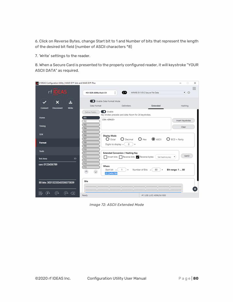
ASCII Extended Procedure
STOP! Before proceeding, please validate that the reader has been properly preconfigured with the Smartcard Manager Utility. Contact [email protected] for more information.
Referring to the figure below, use the following procedure to configure the Reader to output ASCII keystroking:
In this example, 30313233343536373839 will output as 0123456789.
1. Connect to the Secure Reader and insure one of the configurations has a Secure Card types configured, such as MIFARE EV1/EV2 Secure File Data.
2. Click on the Format tab and enable Extended mode.
3. In the text box on top, click Clear to remove CSN, if preferred.
4. Click on ASCII as Display mode.
5. Click on Get ID and present the Secure Card so the full range of data shows up in the Bits field.
©2020 rf IDEAS Inc. Configuration Utility User Manual P a g e | 80
6. Click on Reverse Bytes, change Start bit to 1 and Number of bits that represent the length of the desired bit field (number of ASCII characters *8)
7. ‘Write’ settings to the reader.
8. When a Secure Card is presented to the properly configured reader, it will keystroke "YOUR ASCII DATA" as required.
Image 72: ASCII Extended Mode

©2020 rf IDEAS Inc. Configuration Utility User Manual P a g e | 81
rf IDEAS
© 2020 rf IDEAS. All rights reserved.
Specifications subject to change without notice.
Windows is a trademark of Microsoft.
The Bluetooth® word mark and logos are registered trademarks owned by Bluetooth SIG, Inc. and any use of such marks by rf IDEAS is under license.
All other trademarks, service marks, and product or service names are property of their respective owners.
Mention of third-party products is for informational purposes only and constitutes neither an endorsement nor a recommendation. rf IDEAS assumes no responsibility regarding the performance or use of these products.
All understandings, agreements, or warranties, if any, take place directly between the vendors and the prospective users.
Please feel free to call, e-mail, or visit our web site for a full list of applications, products, configuration options, supported cards, and form factor specifications. Our web site includes application videos, support materials, case studies, and detailed information about our product line.
Every effort has been made to ensure that the information in this manual is accurate. rf IDEAS is not responsible for printing or clerical errors.