2012 ram truck chassis cab owner's manual - dealer e
TRANSCRIPT
R a m T r u c kChrysler Group LLC
O W N E R ’ S M A N U A L
2 0 1 2
20
12 R
am
Tr
uc
k C
ha
ss
is C
ab
12DD43-126-AA First Edition Printed in U.S.A.
C H A S S I S C A B
Information Provided by:
VEHICLES SOLD IN CANADAWith respect to any Vehicles Sold in Canada, the nameChrysler Group LLC shall be deemed to be deleted and thename Chrysler Canada Inc. used in substitution therefore.
DRIVING AND ALCOHOLDrunken driving is one of the most frequent causes of acci-dents.
Your driving ability can be seriously impaired with blood alcohollevels far below the legal minimum. If you are drinking, don’tdrive. Ride with a designated non-drinking driver, call a cab, afriend, or use public transportation.
WARNING!
Driving after drinking can lead to an accident. Your per-ceptions are less sharp, your reflexes are slower, and yourjudgment is impaired when you have been drinking.Never drink and then drive.
This manual illustrates and describes the operation of featuresand equipment that are either standard or optional on thisvehicle. This manual may also include a description of featuresand equipment that are no longer available or were not orderedon this vehicle. Please disregard any features and equipmentdescribed in this manual that are not on this vehicle.
Chrysler Group LLC reserves the right to make changes indesign and specifications, and/or make additions to or im-provements to its products without imposing any obligationupon itself to install them on products previously manufac-tured.
Copyright © 2011 Chrysler Group LLC
Information Provided by:
TABLE OF CONTENTSSECTION PAGE
1 INTRODUCTION . . . . . . . . . . . . . . . . . . . . . . . . . . . . . . . . . . . . . . . . . . . . . . . . . . . . . . . . . . . . 3
2 THINGS TO KNOW BEFORE STARTING YOUR VEHICLE . . . . . . . . . . . . . . . . . . . . . . . . . . . . . .9
3 UNDERSTANDING THE FEATURES OF YOUR VEHICLE . . . . . . . . . . . . . . . . . . . . . . . . . . . . . 83
4 UNDERSTANDING YOUR INSTRUMENT PANEL . . . . . . . . . . . . . . . . . . . . . . . . . . . . . . . . . . 183
5 STARTING AND OPERATING . . . . . . . . . . . . . . . . . . . . . . . . . . . . . . . . . . . . . . . . . . . . . . . . 269
6 WHAT TO DO IN EMERGENCIES . . . . . . . . . . . . . . . . . . . . . . . . . . . . . . . . . . . . . . . . . . . . . 375
7 MAINTAINING YOUR VEHICLE . . . . . . . . . . . . . . . . . . . . . . . . . . . . . . . . . . . . . . . . . . . . . . 399
8 MAINTENANCE SCHEDULES . . . . . . . . . . . . . . . . . . . . . . . . . . . . . . . . . . . . . . . . . . . . . . . . . 453
9 IF YOU NEED CONSUMER ASSISTANCE . . . . . . . . . . . . . . . . . . . . . . . . . . . . . . . . . . . . . . . . 471
10 INDEX . . . . . . . . . . . . . . . . . . . . . . . . . . . . . . . . . . . . . . . . . . . . . . . . . . . . . . . . . . . . . . . . . . . 481
1
2
3
4
5
6
7
8
9
10Information Provided by:

Information Provided by:
INTRODUCTION
CONTENTS
� Introduction . . . . . . . . . . . . . . . . . . . . . . . . . . . 4
� How To Use This Manual . . . . . . . . . . . . . . . . . . 4
� Warnings And Cautions . . . . . . . . . . . . . . . . . . . 6
� Van Conversions/Campers . . . . . . . . . . . . . . . . . 6
� Vehicle Identification Number . . . . . . . . . . . . . . 6
� Vehicle Modifications/Alterations . . . . . . . . . . . . 7
1
Information Provided by:
INTRODUCTIONCongratulations on selecting your new Chrysler GroupLLC vehicle. Be assured that it represents precisionworkmanship, distinctive styling, and high quality - allessentials that are traditional to our vehicles.
This Owner’s Manual has been prepared with the assis-tance of service and engineering specialists to acquaintyou with the operation and maintenance of your vehicle.It is supplemented by Warranty Information, and variouscustomer-oriented documents. Please take the time toread these publications carefully. Following the instruc-tions and recommendations in this manual will helpassure safe and enjoyable operation of your vehicle.
NOTE: After reviewing the owner information, itshould be stored in the vehicle for convenient referenc-ing and remain with the vehicle when sold.
When it comes to service, remember that your authorizeddealer knows your vehicle best, has factory-trained tech-nicians and genuine MOPAR� parts, and cares aboutyour satisfaction.
HOW TO USE THIS MANUALConsult the Table of Contents to determine which sectioncontains the information you desire.
Since the specification of your vehicle depends on theitems of equipment ordered, certain descriptions andillustrations may differ from your vehicle’s equipment.
The detailed index at the back of this Owner’s Manualcontains a complete listing of all subjects.
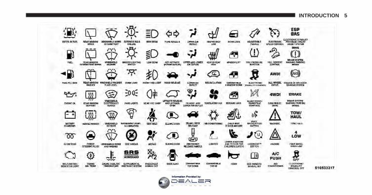
Consult the following table for a description of thesymbols that may be used on your vehicle or throughoutthis Owner’s Manual:
4 INTRODUCTION
Information Provided by:
INTRODUCTION 5
Information Provided by:
WARNINGS AND CAUTIONSThis Owner’s Manual contains WARNINGS against op-erating procedures that could result in a collision orbodily injury. It also contains CAUTIONS against proce-dures that could result in damage to your vehicle. If youdo not read this entire manual, you may miss importantinformation. Observe all Warnings and Cautions.
VAN CONVERSIONS/CAMPERSThe Manufacturer’s Warranty does not apply to bodymodifications or special equipment installed by vanconversion/camper manufacturers/body builders. Referto the Warranty Information book, Section 2.1.C. Suchequipment includes video monitors, VCRs, heaters,stoves, refrigerators, etc. For warranty coverage andservice on these items, contact the applicable manufac-turer.
Operating instructions for the special equipment in-stalled by the conversion/camper manufacturer should
also be supplied with your vehicle. If these instructionsare missing, please contact your authorized dealer forassistance in obtaining replacement documents from theapplicable manufacturer.
For information on the Body Builders Guide refer to:www.dodgebodybuilder.com. This website contains di-mensional and technical specifications for your vehicle. Itis intended for Second Stage Manufacturer’s technicalsupport. For service issues, contact your authorizeddealer.
VEHICLE IDENTIFICATION NUMBERThe Vehicle Identification Number (VIN) is found on theleft front corner of the instrument panel, visible throughthe windshield. This number also appears on the bottomof the frame rail, on the right hand side, near the centerof the vehicle and underbody as well as the AutomobileInformation Disclosure Label affixed to a window onyour vehicle, the vehicle registration and title.
6 INTRODUCTION
Information Provided by:
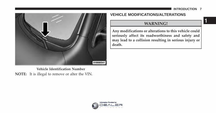
NOTE: It is illegal to remove or alter the VIN.
VEHICLE MODIFICATIONS/ALTERATIONS
WARNING!
Any modifications or alterations to this vehicle couldseriously affect its roadworthiness and safety andmay lead to a collision resulting in serious injury ordeath.
Vehicle Identification Number
1
INTRODUCTION 7
Information Provided by:

Information Provided by:
THINGS TO KNOW BEFORE STARTING YOUR VEHICLE
CONTENTS
� A Word About Your Keys . . . . . . . . . . . . . . . . . 12
▫ Wireless Ignition Node (WIN) —If Equipped . . . . . . . . . . . . . . . . . . . . . . . . . 12
▫ Key Fob . . . . . . . . . . . . . . . . . . . . . . . . . . . . 13
▫ Removing Key Fob From Ignition . . . . . . . . . . 14
▫ Key-In-Ignition Reminder . . . . . . . . . . . . . . . 16
� Sentry Key� . . . . . . . . . . . . . . . . . . . . . . . . . . 16
▫ Replacement Keys . . . . . . . . . . . . . . . . . . . . . 17
▫ Customer Key Programming . . . . . . . . . . . . . 18
▫ General Information . . . . . . . . . . . . . . . . . . . 18
� Vehicle Security Alarm — If Equipped . . . . . . . . 19
▫ Rearming Of The System . . . . . . . . . . . . . . . . 19
▫ To Arm The System . . . . . . . . . . . . . . . . . . . 19
▫ To Disarm The System . . . . . . . . . . . . . . . . . 19
▫ Security System Manual Override . . . . . . . . . 20
� Illuminated Entry — If Equipped . . . . . . . . . . . 20
� Remote Keyless Entry (RKE) — If Equipped . . . 21
▫ Remote Unlock The Doors . . . . . . . . . . . . . . . 21
2
Information Provided by:
▫ To Lock The Doors . . . . . . . . . . . . . . . . . . . . 23
▫ Using The Panic Alarm . . . . . . . . . . . . . . . . . 24
▫ Programming Additional Transmitters . . . . . . 25
▫ Transmitter Battery Replacement . . . . . . . . . . 25
▫ General Information . . . . . . . . . . . . . . . . . . . 26
� Remote Starting System — If Equipped . . . . . . . 26
▫ How To Use Remote Start . . . . . . . . . . . . . . . 27
� Door Locks . . . . . . . . . . . . . . . . . . . . . . . . . . . 30
▫ Manual Door Locks . . . . . . . . . . . . . . . . . . . 30
▫ Power Door Locks — If Equipped . . . . . . . . . 31
▫ Child-Protection Door Lock . . . . . . . . . . . . . . 32
� Windows . . . . . . . . . . . . . . . . . . . . . . . . . . . . 34
▫ Power Windows – If Equipped . . . . . . . . . . . . 34
▫ Wind Buffeting . . . . . . . . . . . . . . . . . . . . . . . 37
� Occupant Restraints . . . . . . . . . . . . . . . . . . . . . 38
▫ Lap/Shoulder Belts . . . . . . . . . . . . . . . . . . . . 39
▫ Adjustable Upper Shoulder Belt Anchorage . . . 48
▫ Center Lap Belts . . . . . . . . . . . . . . . . . . . . . . 48
▫ Seat Belts In Passenger Seating Positions . . . . . 49
▫ Automatic Locking Retractor Mode (ALR) —If Equipped . . . . . . . . . . . . . . . . . . . . . . . . . 50
▫ Enhanced Seat Belt Use Reminder System(BeltAlert�) . . . . . . . . . . . . . . . . . . . . . . . . . 51
▫ Seat Belts And Pregnant Women . . . . . . . . . . 52
▫ Seat Belt Extender . . . . . . . . . . . . . . . . . . . . . 52
10 THINGS TO KNOW BEFORE STARTING YOUR VEHICLE
Information Provided by:
▫ Driver And Right Front PassengerSupplemental Restraint System (SRS) — AirBag . . . . . . . . . . . . . . . . . . . . . . . . . . . . . . . 52
▫ Air Bag System Components . . . . . . . . . . . . . 54
▫ Advanced Front Air Bag Features . . . . . . . . . . 54
▫ Air Bag Deployment Sensors And Controls . . . 57
▫ Event Data Recorder (EDR) . . . . . . . . . . . . . . 63
▫ Child Restraints . . . . . . . . . . . . . . . . . . . . . . 64
� Engine Break-In Recommendations . . . . . . . . . . 77
� Safety Tips . . . . . . . . . . . . . . . . . . . . . . . . . . . 77
▫ Transporting Passengers . . . . . . . . . . . . . . . . 77
▫ Exhaust Gas . . . . . . . . . . . . . . . . . . . . . . . . . 78
▫ Safety Checks You Should Make Inside TheVehicle . . . . . . . . . . . . . . . . . . . . . . . . . . . . . 79
▫ Periodic Safety Checks You Should MakeOutside The Vehicle . . . . . . . . . . . . . . . . . . . 81
2
THINGS TO KNOW BEFORE STARTING YOUR VEHICLE 11
Information Provided by:
A WORD ABOUT YOUR KEYS
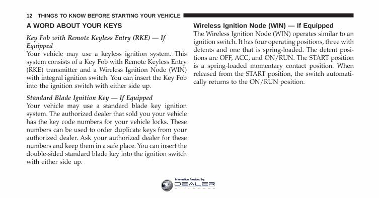
Key Fob with Remote Keyless Entry (RKE) — IfEquippedYour vehicle may use a keyless ignition system. Thissystem consists of a Key Fob with Remote Keyless Entry(RKE) transmitter and a Wireless Ignition Node (WIN)with integral ignition switch. You can insert the Key Fobinto the ignition switch with either side up.
Standard Blade Ignition Key — If EquippedYour vehicle may use a standard blade key ignitionsystem. The authorized dealer that sold you your vehiclehas the key code numbers for your vehicle locks. Thesenumbers can be used to order duplicate keys from yourauthorized dealer. Ask your authorized dealer for thesenumbers and keep them in a safe place. You can insert thedouble-sided standard blade key into the ignition switchwith either side up.
Wireless Ignition Node (WIN) — If EquippedThe Wireless Ignition Node (WIN) operates similar to anignition switch. It has four operating positions, three withdetents and one that is spring-loaded. The detent posi-tions are OFF, ACC, and ON/RUN. The START positionis a spring-loaded momentary contact position. Whenreleased from the START position, the switch automati-cally returns to the ON/RUN position.
12 THINGS TO KNOW BEFORE STARTING YOUR VEHICLE
Information Provided by:
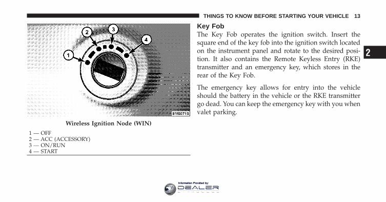
Key FobThe Key Fob operates the ignition switch. Insert thesquare end of the key fob into the ignition switch locatedon the instrument panel and rotate to the desired posi-tion. It also contains the Remote Keyless Entry (RKE)transmitter and an emergency key, which stores in therear of the Key Fob.
The emergency key allows for entry into the vehicleshould the battery in the vehicle or the RKE transmittergo dead. You can keep the emergency key with you whenvalet parking.
Wireless Ignition Node (WIN)
1 — OFF2 — ACC (ACCESSORY)3 — ON/RUN4 — START
2
THINGS TO KNOW BEFORE STARTING YOUR VEHICLE 13
Information Provided by:
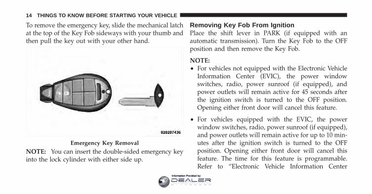
To remove the emergency key, slide the mechanical latchat the top of the Key Fob sideways with your thumb andthen pull the key out with your other hand.
NOTE: You can insert the double-sided emergency keyinto the lock cylinder with either side up.
Removing Key Fob From IgnitionPlace the shift lever in PARK (if equipped with anautomatic transmission). Turn the Key Fob to the OFFposition and then remove the Key Fob.
NOTE:• For vehicles not equipped with the Electronic Vehicle
Information Center (EVIC), the power windowswitches, radio, power sunroof (if equipped), andpower outlets will remain active for 45 seconds afterthe ignition switch is turned to the OFF position.Opening either front door will cancel this feature.
• For vehicles equipped with the EVIC, the powerwindow switches, radio, power sunroof (if equipped),and power outlets will remain active for up to 10 min-utes after the ignition switch is turned to the OFFposition. Opening either front door will cancel thisfeature. The time for this feature is programmable.Refer to “Electronic Vehicle Information Center
Emergency Key Removal
14 THINGS TO KNOW BEFORE STARTING YOUR VEHICLE
Information Provided by:
(EVIC)/Personal Settings (Customer-ProgrammableFeatures)” in “Understanding Your Instrument Panel”for further information.
CAUTION!
• If your vehicle battery becomes low or dead, yourKey Fob will become locked in the ignition.
• Do not attempt to remove the Key Fob while inthis condition, damage could occur to the Key Fobor ignition module. Only remove the emergencykey for locking and unlocking the doors.
• Leave the Key Fob in the ignition and either:• Jump Start the vehicle.• Charge the battery.
WARNING!
• Before exiting a vehicle, always apply the parkingbrake, shift the transmission into PARK, and re-move the key fob from the ignition. When leavingthe vehicle, always lock your vehicle.
• Never leave children alone in a vehicle, or withaccess to an unlocked vehicle.
• Allowing children to be in a vehicle unattended isdangerous for a number of reasons. A child orothers could be seriously or fatally injured. Chil-dren should be warned not to touch the parkingbrake, brake pedal or the shift lever.
• Do not leave the key fob in or near the vehicle, anddo not leave Keyless Enter-N-Go in the ACC orON/RUN mode. A child could operate power win-dows, other controls, or move the vehicle.
(Continued)
2
THINGS TO KNOW BEFORE STARTING YOUR VEHICLE 15
Information Provided by:
WARNING! (Continued)• Do not leave children or animals inside parked
vehicles in hot weather. Interior heat build-up maycause serious injury or death.
CAUTION!
An unlocked car is an invitation to thieves. Alwaysremove the key from the ignition and lock all doorswhen leaving the vehicle unattended.
Key-In-Ignition ReminderOpening the driver’s door when the Key Fob is in theignition and the ignition switch position is OFF or ACC,a chime will sound to remind you to remove the Key Fob.
NOTE:• The Key-In-Ignition reminder only sounds when the
Key Fob is placed in the OFF or ACC ignition position.
• If equipped with Electronic Vehicle Information Cen-ter (EVIC) the EVIC will display “Key In Ignition”.
SENTRY KEY�The Sentry Key� Immobilizer System prevents unauthor-ized vehicle operation by disabling the engine. Thesystem does not need to be armed or activated. Operationis automatic, regardless of whether the vehicle is lockedor unlocked.
The system uses a Key Fob with a factory-mated RemoteKeyless Entry (RKE) transmitter and Wireless IgnitionNode (WIN) to prevent unauthorized vehicle operation.Therefore, only Key Fobs that are programmed to thevehicle can be used to start and operate the vehicle. Thesystem will not allow the engine to crank if an invalidKey Fob is used to start and operate the vehicle. Thesystem will shut the engine off in two seconds if aninvalid Key Fob is used to start the engine.
16 THINGS TO KNOW BEFORE STARTING YOUR VEHICLE
Information Provided by:
NOTE: A Key Fob that has not been programmed is alsoconsidered an invalid key.
During normal operation, after turning on the ignitionswitch, the Vehicle Security Light will turn on for threeseconds for a bulb check. If the light remains on after thebulb check, it indicates that there is a problem with theelectronics. In addition, if the light begins to flash afterthe bulb check, it indicates that someone used an invalidKey Fob to try to start the engine. Either of theseconditions will result in the engine being shut off aftertwo seconds.
If the Vehicle Security Light turns on during normalvehicle operation (vehicle running for longer than 10 sec-onds), it indicates that there is a fault in the electronics.Should this occur, have the vehicle serviced as soon aspossible by an authorized dealer.
CAUTION!
The Sentry Key� Immobilizer system is not compat-ible with some after-market remote starting systems.Use of these systems may result in vehicle startingproblems and loss of security protection.
All of the Key Fobs provided with your new vehicle havebeen programmed to the vehicle electronics.
Replacement Keys
NOTE: Only Key Fobs that are programmed to thevehicle electronics can be used to start and operate thevehicle. Once a Key Fob is programmed to a vehicle, itcannot be programmed to any other vehicle.
2
THINGS TO KNOW BEFORE STARTING YOUR VEHICLE 17
Information Provided by:
CAUTION!
Always remove the Sentry Keys� from the vehicleand lock all doors when leaving the vehicle unat-tended.
At the time of purchase, the original owner is providedwith a four-digit Personal Identification Number (PIN).Keep the PIN in a secure location. This number isrequired for authorized dealer replacement of Key Fobs.Duplication of Key Fobs may be performed at an autho-rized dealer, this procedure consists of programming ablank Key Fob to the vehicle electronics. A blank Key Fobis one that has never been programmed.
NOTE:• When having the Sentry Key� Immobilizer System
serviced, bring all vehicle keys with you to an autho-rized dealer.
• If a programmed Key Fob is lost, see your authorizeddealer to have all remaining Key Fobs erased from thesystem’s memory. This will prevent the lost Key Fobsfrom starting your vehicle. The remaining Keys Fobsmust then be reprogrammed.
Customer Key ProgrammingProgramming Key Fobs or RKE transmitters may beperformed at an authorized dealer.
General InformationThe Sentry Key� system complies with FCC rules Part 15and with RSS-210 of Industry Canada. Operation issubject to the following conditions:
• This device may not cause harmful interference.
• This device must accept any interference that may bereceived, including interference that may cause unde-sired operation.
18 THINGS TO KNOW BEFORE STARTING YOUR VEHICLE
Information Provided by:
VEHICLE SECURITY ALARM — IF EQUIPPEDThe Vehicle Security Alarm monitors the vehicle doorsand ignition for unauthorized operation. When the Ve-hicle Security Alarm is activated, interior switches fordoor locks are disabled. The system provides both au-dible and visible signals, for the first three minutes thehorn will sound and the headlights will turn on, the parklamps and/or turn signals will flash and Vehicle SecurityLight will flash repeatedly. For an additional 15 minutesonly, the headlights will turn on, the park lamps and/orturn signals and Vehicle Security Light will flash.
Rearming Of The SystemThe Vehicle Security Alarm will rearm itself after the 15additional minutes of headlights turning on and VehicleSecurity Light flashing, if the system has not beendisabled. If the condition which initiated the alarm is stillpresent, the system will ignore that condition and moni-tor the remaining doors and ignition.
To Arm The SystemThe Vehicle Security Alarm will set when you use thepower door locks, or use the Remote Keyless Entry (RKE)transmitter to lock the doors. After all the doors arelocked and closed, the Vehicle Security Light in theinstrument panel cluster will flash rapidly for about16 seconds to indicate that the alarm is being set. Afterthe alarm is set, the Vehicle Security Light will flash at aslower rate to indicate that the system is armed.
To Disarm The SystemUse the RKE transmitter to unlock the door. If somethinghas triggered the Vehicle Security Alarm in your absence,the horn will sound three times when you unlock thedoors and the exterior lights will blink three times. Checkthe vehicle for tampering.
2
THINGS TO KNOW BEFORE STARTING YOUR VEHICLE 19
Information Provided by:
The Vehicle Security Alarm will also disarm if a pro-grammed Sentry Key� is inserted into the ignitionswitch. To exit the alarming mode, press the RKE trans-mitter UNLOCK button, or insert a programmed SentryKey� into the ignition switch.
The Vehicle Security Alarm is designed to protect yourvehicle; however, you can create conditions where thesystem will give you a false alarm. If one of the previ-ously described arming sequences has occurred, theVehicle Security Alarm will arm regardless of whetheryou are in the vehicle or not. If you remain in the vehicleand open a door, the alarm will sound. If this occurs,disarm the Vehicle Security Alarm.
Security System Manual OverrideThe Vehicle Security Alarm will not arm if you lock thedoors using the manual door lock plunger.
ILLUMINATED ENTRY — IF EQUIPPEDThe courtesy lights will turn on when you use theRemote Keyless Entry (RKE) transmitter to unlock thedoors or open any door.
This feature also turns on the approach lighting in theoutside mirrors (if equipped). Refer to “Mirrors” in“Understanding The Features Of Your Vehicle” for fur-ther information.
The lights will fade to off after approximately 30 seconds,or they will immediately fade to off once the ignitionswitch is turned to ON/RUN from the OFF position.
NOTE:• The front courtesy overhead console and door cour-
tesy lights will not turn off if the dimmer control is inthe “Dome ON” position (extreme top position).
20 THINGS TO KNOW BEFORE STARTING YOUR VEHICLE
Information Provided by:
• The illuminated entry system will not operate if thedimmer control is in the “dome defeat” position(extreme bottom position).
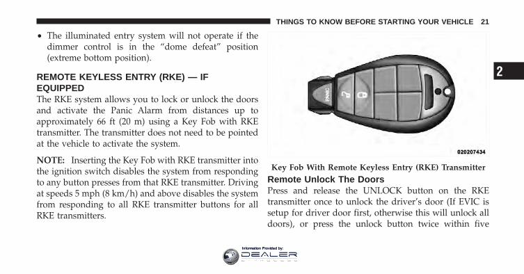
REMOTE KEYLESS ENTRY (RKE) — IFEQUIPPEDThe RKE system allows you to lock or unlock the doorsand activate the Panic Alarm from distances up toapproximately 66 ft (20 m) using a Key Fob with RKEtransmitter. The transmitter does not need to be pointedat the vehicle to activate the system.
NOTE: Inserting the Key Fob with RKE transmitter intothe ignition switch disables the system from respondingto any button presses from that RKE transmitter. Drivingat speeds 5 mph (8 km/h) and above disables the systemfrom responding to all RKE transmitter buttons for allRKE transmitters.
Remote Unlock The DoorsPress and release the UNLOCK button on the RKEtransmitter once to unlock the driver’s door (If EVIC issetup for driver door first, otherwise this will unlock alldoors), or press the unlock button twice within five
Key Fob With Remote Keyless Entry (RKE) Transmitter
2
THINGS TO KNOW BEFORE STARTING YOUR VEHICLE 21
Information Provided by:
seconds to unlock all doors. The turn signal lights willflash to acknowledge the unlock signal. The illuminatedentry system will also turn on.
Remote Key Unlock, Driver Door/All Doors FirstThis feature lets you program the system to unlock eitherthe driver’s door or all doors on the first press of theUNLOCK button on the RKE transmitter. To change thecurrent setting, proceed as follows:
• For vehicles equipped with the EVIC, refer to “Elec-tronic Vehicle Information Center (EVIC)/Customer-Programmable Features (System Setup)” in “Under-standing Your Instrument Panel” for furtherinformation.
• For vehicles not equipped with the EVIC, perform thefollowing procedure:
1. Press and hold the LOCK button on a programmedRKE transmitter for at least four seconds, but no longer
than ten seconds. Then, press and hold the UNLOCKbutton while still holding the LOCK button.
2. Release both buttons at the same time.
3. Test the feature while outside of the vehicle by press-ing the LOCK/UNLOCK buttons on the RKE transmitterwith the ignition switch in the OFF position and the keyremoved.
4. Repeat these steps if you want to return this feature toits previous setting.
NOTE: Pressing the LOCK button on the RKE transmit-ter while you are inside the vehicle will activate theVehicle Security Alarm System. Opening a door with theVehicle Security Alarm System activated will cause thealarm to sound. Press the UNLOCK button to deactivatethe Vehicle Security Alarm System.
22 THINGS TO KNOW BEFORE STARTING YOUR VEHICLE
Information Provided by:
Flash Lamps With Remote Key LockThis feature will cause the turn signal lights to flash whenthe doors are locked or unlocked with the RKE transmit-ter. This feature can be turned on or turned off. To changethe current setting, proceed as follows:
• For vehicles equipped with the EVIC, refer to “Elec-tronic Vehicle Information Center (EVIC)/Customer-Programmable Features (System Setup)” in “Under-standing Your Instrument Panel” for furtherinformation.
• For vehicles not equipped with the EVIC, perform thefollowing procedure:
1. Press and hold the UNLOCK button on a programmedRKE transmitter for at least four seconds, but no longerthan ten seconds. Then, press and hold the LOCK buttonwhile still holding the UNLOCK button.
2. Release both buttons at the same time.
3. Test the feature while outside of the vehicle by press-ing the LOCK/UNLOCK buttons on the RKE transmitterwith the ignition switch in the OFF position and the keyremoved.
4. Repeat these steps if you want to return this feature toits previous setting.
NOTE: Pressing the LOCK button on the RKE transmit-ter while you are in the vehicle will activate the VehicleSecurity Alarm System. Opening a door with the VehicleSecurity Alarm System activated will cause the alarm tosound. Press the UNLOCK button to deactivate theVehicle Security Alarm System.
To Lock The DoorsPress and release the LOCK button on the RKE transmit-ter to lock all doors. The turn signal lights will flash andthe horn will chirp to acknowledge the signal.
2
THINGS TO KNOW BEFORE STARTING YOUR VEHICLE 23
Information Provided by:
Sound Horn With Remote Key LockThis feature will cause the horn to chirp when the doorsare locked with the RKE transmitter. This feature can beturned on or turned off. To change the current setting,proceed as follows:
• For vehicles equipped with the EVIC, refer to “Elec-tronic Vehicle Information Center (EVIC)/Customer-Programmable Features (System Setup)” in “Under-standing Your Instrument Panel” for furtherinformation.
• For vehicles not equipped with the EVIC, perform thefollowing procedure:
1. Press the LOCK button on a programmed RKE trans-mitter for at least four seconds, but no longer than tenseconds. Then, press the PANIC button while still hold-ing the LOCK button.
2. Release both buttons at the same time.
3. Test the feature while outside of the vehicle by press-ing the LOCK button on the RKE transmitter with theignition switch in the OFF position and the key removed.
4. Repeat these steps if you want to return this feature toits previous setting.
NOTE: Pressing the LOCK button on the RKE transmit-ter while you are in the vehicle will activate the VehicleSecurity Alarm System. Opening a door with the VehicleSecurity Alarm System activated will cause the alarm tosound. Press the UNLOCK button to deactivate theVehicle Security Alarm System.
Using The Panic AlarmTo turn the Panic Alarm feature ON or OFF, press andhold the PANIC button on the RKE transmitter for atleast one second and release. When the Panic Alarm is on,the headlights will turn on, the park lights will flash, thehorn will pulse on and off, and the interior lights willturn on.
24 THINGS TO KNOW BEFORE STARTING YOUR VEHICLE
Information Provided by:
The Panic Alarm will stay on for three minutes unlessyou turn it off by either pressing the PANIC button asecond time or drive the vehicle at a speed of 5 mph(8 km/h) or greater.
NOTE:• The interior lights will turn off if you turn the ignition
switch to the ACC or ON/RUN position while thePanic Alarm is activated. However, the exterior lightsand horn will remain on.
• You may need to be less than 35 ft (11 m) from thevehicle when using the RKE transmitter to turn off thePanic Alarm due to the radio frequency noises emittedby the system.
Programming Additional TransmittersIf you do not have a programmed RKE transmitter,contact your authorized dealer for details.
Transmitter Battery ReplacementThe recommended replacement battery is one CR2032battery.
NOTE:• Perchlorate Material — special handling may apply.
See www.dtsc.ca.gov/hazardouswaste/perchlorate
• Do not touch the battery terminals that are on the backhousing or the printed circuit board.
1. With the RKE transmitter buttons facing down, use aflat blade screwdriver to pry the two halves of the RKEtransmitter apart. Make sure not to damage the sealduring removal.
2. Remove and replace the battery. Avoid touching thenew battery with your fingers. Skin oils may causebattery deterioration. If you touch a battery, clean it withrubbing alcohol.
2
THINGS TO KNOW BEFORE STARTING YOUR VEHICLE 25
Information Provided by:
3. To assemble the RKE transmitter case, snap the twohalves together.
General InformationThis device complies with Part 15 of the FCC rules andRSS 210 of Industry Canada. Operation is subject to thefollowing conditions:
• This device may not cause harmful interference.
• This device must accept any interference received,including interference that may cause undesiredoperation.
NOTE: Changes or modifications not expressly ap-proved by the party responsible for compliance couldvoid the user’s authority to operate the equipment.
If your RKE transmitter fails to operate from a normaldistance, check for these two conditions:
1. A weak battery in the RKE transmitter. The expectedlife of the battery is a minimum of three years.
2. Closeness to a radio transmitter such as a radio stationtower, airport transmitter, and some mobile or CB radios.
REMOTE STARTING SYSTEM — IF EQUIPPEDThis system uses the Remote Keyless Entry(RKE) transmitter to start the engine conve-niently from outside the vehicle while stillmaintaining security. The system has a range of
approximately 300 ft (91 m).
NOTE:• The vehicle must be equipped with an automatic
transmission to be equipped with Remote Start.
• Obstructions between the vehicle and the RKE trans-mitter may reduce this range.
26 THINGS TO KNOW BEFORE STARTING YOUR VEHICLE
Information Provided by:
How To Use Remote StartAll of the following conditions must be met before theengine will remote start:
• Shift lever in PARK
• Doors closed
• Hood closed
• HAZARD switch off
• BRAKE switch inactive (brake pedal not pressed)
• Ignition key removed from ignition switch
• Battery at an acceptable charge level
• RKE PANIC button not pressed
• Fuel meets minimum requirement
• System not disabled from previous remote start event
• Vehicle theft alarm not active
WARNING!
• Do not start or run an engine in a closed garage orconfined area. Exhaust gas contains Carbon Mon-oxide (CO) which is odorless and colorless. Car-bon Monoxide is poisonous and can cause seriousinjury or death when inhaled.
• Keep Remote Keyless Entry (RKE) transmittersaway from children. Operation of the Remote StartSystem, windows, door locks or other controlscould cause serious injury or death.
Remote Start Abort Message On Electronic VehicleInformation Center (EVIC) — If EquippedThe following messages will display in the EVIC if thevehicle fails to remote start or exits remote start prema-turely:
• Remote Start Aborted — Door Ajar
2
THINGS TO KNOW BEFORE STARTING YOUR VEHICLE 27
Information Provided by:
• Remote Start Aborted — Hood Ajar
• Remote Start Aborted — Fuel Low
• Remote Start Aborted — System Fault
• Remote Start Disabled — Start Vehicle to Reset
The EVIC message stays active until the ignition is turnedto the ON/RUN position.
To Enter Remote Start ModePress and release the REMOTE START buttonon the RKE transmitter twice within five sec-onds. The parking lights will flash and the hornwill chirp twice (if programmed). Once the
vehicle has started, the engine will run for 15 minutes.
NOTE:• If your power door locks were unlocked, Remote Start
will automatically lock the doors.
• If an engine fault is present or fuel level is low, thevehicle will start and then shut down in 10 seconds.
• The park lamps will turn on and remain on duringRemote Start mode.
• For security, power window and power sunroof op-eration (if equipped) are disabled when the vehicle isin the Remote Start mode.
• The engine can be started two consecutive times (two15-minute cycles) with the RKE transmitter. However,the ignition switch must be cycled to the ON/RUNposition before you can repeat the start sequence for athird cycle.
To Exit Remote Start Mode Without Driving TheVehiclePress and release the REMOTE START button one time orallow the engine to run for the entire 15-minute cycle.
28 THINGS TO KNOW BEFORE STARTING YOUR VEHICLE
Information Provided by:
NOTE: To avoid unintentional shut downs, the systemwill disable the one time press of the REMOTE STARTbutton for two seconds after receiving a valid RemoteStart request.
To Exit Remote Start Mode And Drive The VehicleBefore the end of the 15-minute cycle, press and releasethe UNLOCK button on the RKE transmitter to unlockthe doors and disarm the Vehicle Security Alarm System(if equipped). Insert the Key Fob into the ignition switchand turn the switch to the ON/RUN position.
NOTE:• The ignition switch must be in the ON/RUN position
in order to drive the vehicle.
• For vehicles equipped with the Electronic VehicleInformation Center (EVIC), the message “Insert Key/Turn To On” will flash in the EVIC until you insert theKey Fob into the ignition switch. Once inserted, the
message “Turn To On” will flash in the EVIC until youturn the ignition switch to the ON/RUN position.
• “Remote Start Active — Key To Run” will display inthe EVIC until you insert and turn the key to ON/RUN position. Refer to “Electronic Vehicle InformationCenter (EVIC)” for further information.
Remote Start Comfort Systems — If EquippedWhen remote start is activated, the heated steeringwheel, and driver heated seat features will automaticallyturn on in cold weather. In warm weather, the drivervented seat feature will automatically turn on when theremote start is activated. These features will stay onthrough the duration of remote start or until the ignitionswitch is turned to the ON/RUN position.
The Remote Start Comfort System can be activated anddeactivated through the Electronic Vehicle InformationCenter (EVIC). For more information on Remote StartComfort System operation refer to “Electronic Vehicle
2
THINGS TO KNOW BEFORE STARTING YOUR VEHICLE 29
Information Provided by:
Information Center (EVIC)/Customer-ProgrammableFeatures (System Setup)” in “Understanding Your Instru-ment Panel”.
DOOR LOCKS
Manual Door LocksFront and rear doors may be locked by moving the lockknob down or unlocked by moving the lock knob up.
Front doors may be opened with the inside door handlewithout lifting the lock knob.
Doors locked before closing will remain locked whenclosed.
The emergency key will unlock the driver door lock onyour vehicle.
WARNING!
• Do not leave children or animals inside parkedvehicles in hot weather. Interior heat build-up maycause serious injury or death.
• For personal security and safety in the event of anaccident, lock the vehicle doors as you drive aswell as when you park and leave the vehicle.
• Before exiting a vehicle, always apply the parkingbrake, shift the transmission into PARK, and re-move the key fob from the ignition. When leavingthe vehicle, always lock your vehicle.
• Never leave children alone in a vehicle, or withaccess to an unlocked vehicle.
(Continued)
30 THINGS TO KNOW BEFORE STARTING YOUR VEHICLE
Information Provided by:
WARNING! (Continued)• Allowing children to be in a vehicle unattended is
dangerous for a number of reasons. A child orothers could be seriously or fatally injured. Chil-dren should be warned not to touch the parkingbrake, brake pedal or the shift lever.
• Do not leave the key fob in or near the vehicle, anddo not leave the ignition in the ACC or ON/RUNposition. A child could operate power windows,other controls, or move the vehicle.
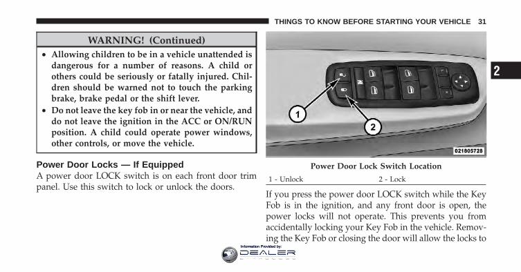
Power Door Locks — If EquippedA power door LOCK switch is on each front door trimpanel. Use this switch to lock or unlock the doors.
If you press the power door LOCK switch while the KeyFob is in the ignition, and any front door is open, thepower locks will not operate. This prevents you fromaccidentally locking your Key Fob in the vehicle. Remov-ing the Key Fob or closing the door will allow the locks to
Power Door Lock Switch Location
1 - Unlock 2 - Lock
2
THINGS TO KNOW BEFORE STARTING YOUR VEHICLE 31
Information Provided by:
operate. A chime will sound if the Key Fob is in theignition switch and a door is open, as a reminder toremove the Key Fob.
Automatic Door Locks — If EquippedWhen enabled, the door locks will lock automaticallywhen the vehicle’s speed exceeds 15 mph (24 km/h). Theauto door lock feature can be enabled or disabled by yourauthorized dealer per written request of the customer.Please see your authorized dealer for service.
Auto Unlock Doors — If EquippedThis feature unlocks all of the doors of the vehicle wheneither front door is opened. This will occur only after thevehicle has been shifted into the PARK position after thevehicle has been driven (shifted out of PARK and alldoors closed).
Auto Unlock Doors Programming — If EquippedThe Auto Unlock Doors feature can be enabled or dis-abled as follows:
For vehicles equipped with the EVIC, refer to “ElectronicVehicle Information Center (EVIC)/Personal Settings(System Setup)” in “Understanding Your InstrumentPanel” for further information.
NOTE: Use the Auto Unlock Doors feature in accor-dance with local laws.
Child-Protection Door LockTo provide a safer environment for children riding in therear seat, the rear doors (if equipped) of your vehiclehave the Child-Protection Door Lock system.
32 THINGS TO KNOW BEFORE STARTING YOUR VEHICLE
Information Provided by:
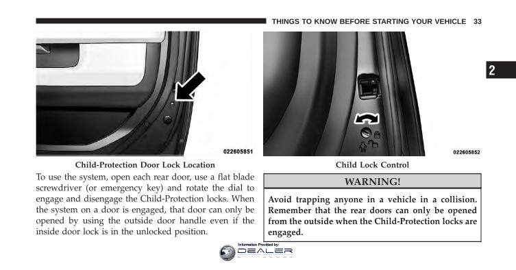
To use the system, open each rear door, use a flat bladescrewdriver (or emergency key) and rotate the dial toengage and disengage the Child-Protection locks. Whenthe system on a door is engaged, that door can only beopened by using the outside door handle even if theinside door lock is in the unlocked position.
WARNING!
Avoid trapping anyone in a vehicle in a collision.Remember that the rear doors can only be openedfrom the outside when the Child-Protection locks areengaged.
Child-Protection Door Lock Location Child Lock Control
2
THINGS TO KNOW BEFORE STARTING YOUR VEHICLE 33
Information Provided by:
NOTE:• After setting the Child-Protection Door Lock system,
always test the door from the inside to make certain itis in the desired position.
• For emergency exit with the system engaged, movethe door lock switch to the UNLOCK position, rolldown the window and open the door with the outsidedoor handle.
WINDOWS
Power Windows – If Equipped
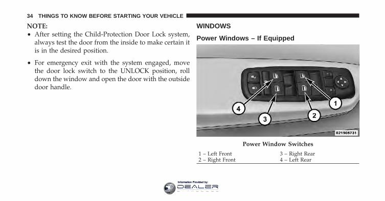
Power Window Switches
1 – Left Front 3 – Right Rear2 – Right Front 4 – Left Rear
34 THINGS TO KNOW BEFORE STARTING YOUR VEHICLE
Information Provided by:
The control on the left front door panel has UP-DOWNswitches that give you fingertip control of all powerwindows. There is a single opening and closing switch onthe front passenger door for passenger window controland on the rear doors of the Crew Cab models. Thewindows will operate when the ignition switch is turnedto the ON/RUN or ACC position, and for up to 10 min-utes after the ignition is turned OFF or until a front dooris opened.
NOTE: The Key Off Power Delay feature will allow thepower windows to operate for up to 10 minutes after theignition is turned OFF. This feature is cancelled wheneither front door is opened.
WARNING!
Never leave children alone in a vehicle. Leavingunattended children in a vehicle is dangerous for anumber of reasons. A child or others could be seri-ously or fatally injured. Don’t leave the key in theignition. A child could operate power windows,other controls, or move the vehicle.
Auto-DownBoth the driver and front passenger window switch havean Auto-Down feature. Press the window switch past thefirst detent, release, and the window will go downautomatically. To cancel the Auto-Down movement, op-erate the switch in either the up or down direction andrelease the switch.
To stop the window from going all the way down duringthe Auto-Down operation, pull up on the switch briefly.
2
THINGS TO KNOW BEFORE STARTING YOUR VEHICLE 35
Information Provided by:
To open the window part way, press to the first detentand release it when you want the window to stop.
Auto-Up Feature With Anti-Pinch Protection(4-Door Models Driver And Front Passenger DoorOnly) — If EquippedLift the window switch fully upward to the seconddetent, release, and the window will go up automatically.
To stop the window from going all the way up during theAuto Up operation, push down on the switch briefly.
To close the window part way, lift the window switch tothe first detent and release when you want the window tostop.
NOTE: If the window runs into any obstacle during theauto-closure, it will reverse direction and then go backdown. Remove the obstacle and use the window switchagain to close the window. Any impact due to rough road
conditions may trigger the auto reverse function unex-pectedly during auto closure. If this happens, pull theswitch lightly to the first detent and hold to close thewindow manually.
WARNING!
There is no anti-pinch protection when the windowis almost closed. Be sure to clear all objects from thewindow before closing.
Auto-Up ResetIt may be necessary at some point in time to reactivate theAuto-up/Auto-down feature. To do so, perform thefollowing steps:
1. Pull the window switch up to close the windowcompletely and continue to hold the switch up for anadditional two seconds after the window is closed.
36 THINGS TO KNOW BEFORE STARTING YOUR VEHICLE
Information Provided by:
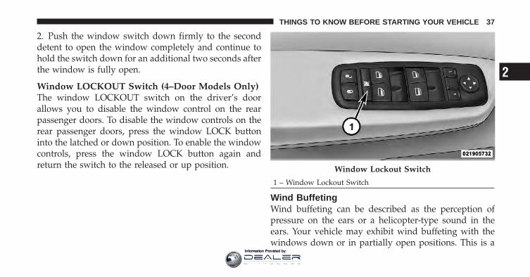
2. Push the window switch down firmly to the seconddetent to open the window completely and continue tohold the switch down for an additional two seconds afterthe window is fully open.
Window LOCKOUT Switch (4–Door Models Only)The window LOCKOUT switch on the driver’s doorallows you to disable the window control on the rearpassenger doors. To disable the window controls on therear passenger doors, press the window LOCK buttoninto the latched or down position. To enable the windowcontrols, press the window LOCK button again andreturn the switch to the released or up position.
Wind BuffetingWind buffeting can be described as the perception ofpressure on the ears or a helicopter-type sound in theears. Your vehicle may exhibit wind buffeting with thewindows down or in partially open positions. This is a
Window Lockout Switch
1 – Window Lockout Switch
2
THINGS TO KNOW BEFORE STARTING YOUR VEHICLE 37
Information Provided by:
normal occurrence and can be minimized. If the rearwindows are open and buffeting occurs, open the frontand rear windows together to minimize the buffeting.
OCCUPANT RESTRAINTS
Some of the most important safety features in yourvehicle are the restraint systems:
• Three-point lap and shoulder belts for the driver andall passengers
• Advanced Front Air Bags for driver and front passen-ger — if equipped
• An energy-absorbing steering column and steeringwheel
• Knee bolsters/blockers for front seat occupants
• All seat belt systems (except driver’s regular/CrewCab�, first and second row center position for CrewCab� only) include Automatic Locking Retractors(ALR)
If you will be carrying children too small for adult-sizedseat belts, the seat belts or the Lower Anchors and Tetherfor CHildren (LATCH) feature also can be used to holdinfant and child restraint systems. For further informa-tion, refer to “Lower Anchors and Tether for CHildren(LATCH)”.
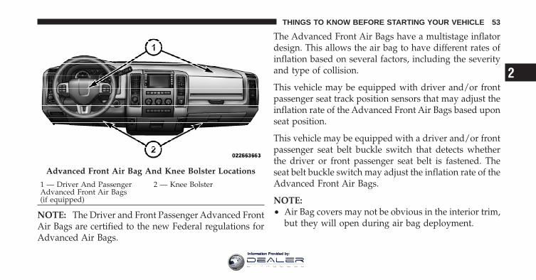
NOTE: The Advanced Front Air Bags have a multistageinflator design. This allows the air bag to have differentrates of inflation based on several factors, including theseverity and type of collision.
Please pay close attention to the information in thissection. It tells you how to use your restraint systemproperly, to keep you and your passengers as safe aspossible.
38 THINGS TO KNOW BEFORE STARTING YOUR VEHICLE
Information Provided by:
WARNING!
In a collision, you and your passengers can suffermuch greater injuries if you are not properly buckledup. You can strike the interior of your vehicle or otherpassengers, or you can be thrown out of the vehicle.Always be sure you and others in your vehicle arebuckled up properly.
Buckle up even though you are an excellent driver, evenon short trips. Someone on the road may be a poor driverand cause a collision that includes you. This can happenfar away from home or on your own street.
Research has shown that seat belts save lives, and theycan reduce the seriousness of injuries in a collision. Someof the worst injuries happen when people are thrownfrom the vehicle. Seat belts reduce the possibility ofejection and the risk of injury caused by striking theinside of the vehicle. Everyone in a motor vehicle shouldbe belted at all times.
Lap/Shoulder BeltsAll seating positions except the Crew Cab front centerseating position have combination lap/shoulder belts.The belt webbing retractor is designed to lock duringvery sudden stops or collisions. This feature allows theshoulder part of the belt to move freely with you undernormal conditions. However, in a collision the belt willlock and reduce the risk of you striking the inside of thevehicle or being thrown out.
2
THINGS TO KNOW BEFORE STARTING YOUR VEHICLE 39
Information Provided by:
WARNING!
• It is dangerous to ride in a cargo area, inside oroutside of a vehicle. In a collision, people riding inthese areas are more likely to be seriously injuredor killed.
• Do not allow people to ride in any area of yourvehicle that is not equipped with seats and seatbelts.
• Be sure everyone in your vehicle is in a seat andusing a seat belt properly.
(Continued)
WARNING! (Continued)• Wearing a seat belt incorrectly is dangerous. Seat
belts are designed to go around the large bones ofyour body. These are the strongest parts of yourbody and can take the forces of a collision best.Wearing your belt in the wrong place could makeyour injuries in a collision much worse. You mightsuffer internal injuries, or you could even slide outof part of the belt. Follow these instructions towear your seat belt safely and to keep your pas-sengers safe, too.
• Two people should never be belted into a singleseat belt. People belted together can crash into oneanother in a collision, hurting one another badly.Never use a lap/shoulder belt or a lap belt for morethan one person, no matter what their size.
40 THINGS TO KNOW BEFORE STARTING YOUR VEHICLE
Information Provided by:
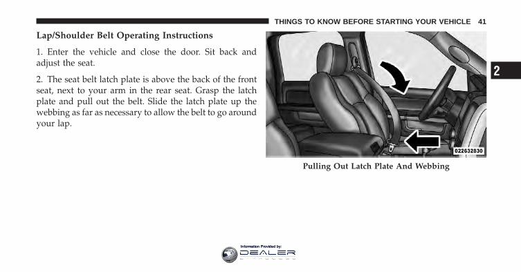
Lap/Shoulder Belt Operating Instructions
1. Enter the vehicle and close the door. Sit back andadjust the seat.
2. The seat belt latch plate is above the back of the frontseat, next to your arm in the rear seat. Grasp the latchplate and pull out the belt. Slide the latch plate up thewebbing as far as necessary to allow the belt to go aroundyour lap.
Pulling Out Latch Plate And Webbing
2
THINGS TO KNOW BEFORE STARTING YOUR VEHICLE 41
Information Provided by:
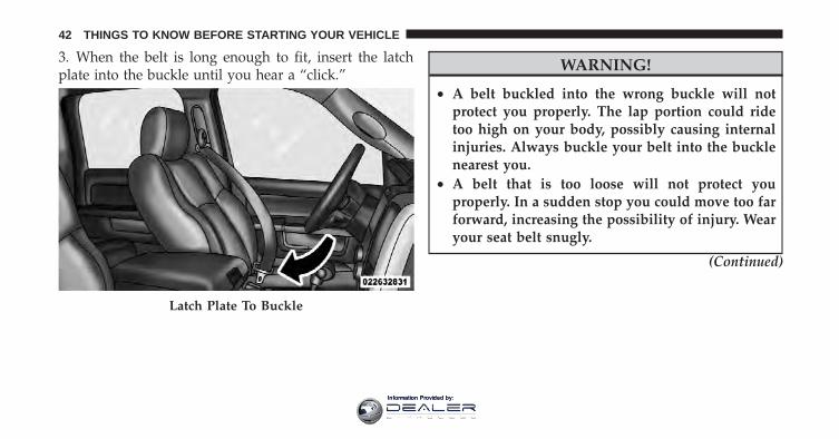
3. When the belt is long enough to fit, insert the latchplate into the buckle until you hear a “click.”
WARNING!
• A belt buckled into the wrong buckle will notprotect you properly. The lap portion could ridetoo high on your body, possibly causing internalinjuries. Always buckle your belt into the bucklenearest you.
• A belt that is too loose will not protect youproperly. In a sudden stop you could move too farforward, increasing the possibility of injury. Wearyour seat belt snugly.
(Continued)
Latch Plate To Buckle
42 THINGS TO KNOW BEFORE STARTING YOUR VEHICLE
Information Provided by:
WARNING! (Continued)• A belt that is worn under your arm is dangerous.
Your body could strike the inside surfaces of thevehicle in a collision, increasing head and neckinjury. A belt worn under the arm can causeinternal injuries. Ribs aren’t as strong as shoulderbones. Wear the belt over your shoulder so thatyour strongest bones will take the force in acollision.
• A shoulder belt placed behind you will not protectyou from injury during a collision. You are morelikely to hit your head in a collision if you do notwear your shoulder belt. The lap and shoulder beltare meant to be used together.
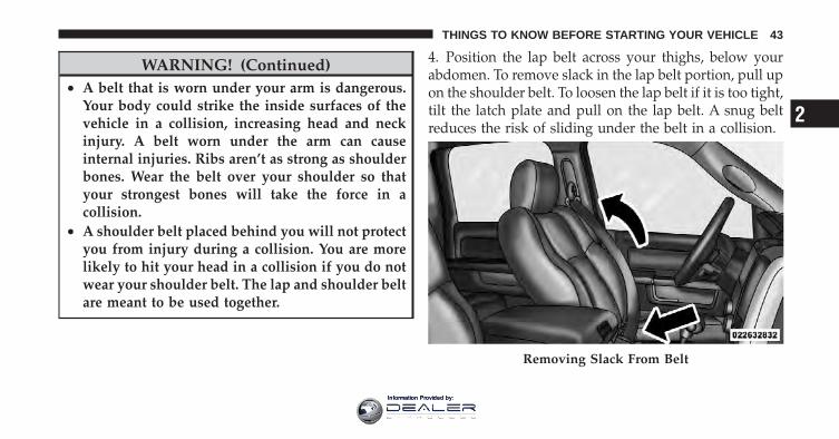
4. Position the lap belt across your thighs, below yourabdomen. To remove slack in the lap belt portion, pull upon the shoulder belt. To loosen the lap belt if it is too tight,tilt the latch plate and pull on the lap belt. A snug beltreduces the risk of sliding under the belt in a collision.
Removing Slack From Belt
2
THINGS TO KNOW BEFORE STARTING YOUR VEHICLE 43
Information Provided by:
WARNING!
• A lap belt worn too high can increase the risk ofinternal injury in a collision. The belt forces won’tbe at the strong hip and pelvic bones, but acrossyour abdomen. Always wear the lap belt as low aspossible and keep it snug.
• A twisted belt may not protect you properly. In acollision, it could even cut into you. Be sure thebelt is straight. If you can’t straighten a belt in avehicle, take it to your authorized dealer immedi-ately and have it fixed.
5. Position the shoulder belt on your chest so that it iscomfortable and not resting on your neck. The retractorwill withdraw any slack in the belt.
6. To release the belt, push the red button on the buckle.The belt will automatically retract to its stowed position.If necessary, slide the latch plate down the webbing toallow the belt to retract fully.
WARNING!
A frayed or torn belt could rip apart in a collision andleave you with no protection. Inspect the belt systemperiodically, checking for cuts, frays, or loose parts.Damaged parts must be replaced immediately. Donot disassemble or modify the system. Seat beltassemblies must be replaced after a collision if theyhave been damaged (bent retractor, torn webbing,etc.) or if the air bag deployed.
44 THINGS TO KNOW BEFORE STARTING YOUR VEHICLE
Information Provided by:
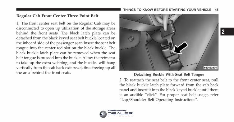
Regular Cab Front Center Three Point Belt
1. The front center seat belt on the Regular Cab may bedisconnected to open up utilization of the storage areasbehind the front seats. The black latch plate can bedetached from the black keyed seat belt buckle located onthe inboard side of the passenger seat. Insert the seat belttongue into the center red slot on the black buckle. Theblack buckle latch plate can be removed when the seatbelt tongue is pressed into the buckle. Allow the retractorto take up the extra webbing, and the buckles will hangvertically from the cab back exit bezel, thus freeing up allthe area behind the front seats.
2. To reattach the seat belt to the front center seat, pullthe black buckle latch plate forward from the cab backpanel and insert it into the black keyed buckle until thereis an audible “click”. For proper seat belt usage, refer“Lap/Shoulder Belt Operating Instructions”.
Detaching Buckle With Seat Belt Tongue
2
THINGS TO KNOW BEFORE STARTING YOUR VEHICLE 45
Information Provided by:
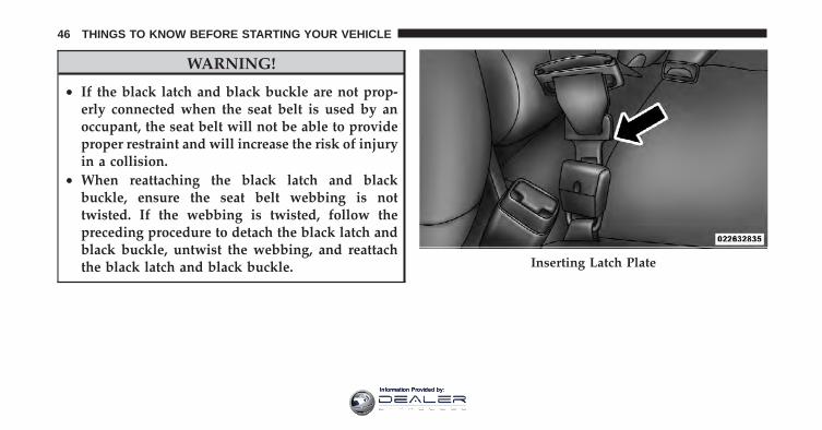
WARNING!
• If the black latch and black buckle are not prop-erly connected when the seat belt is used by anoccupant, the seat belt will not be able to provideproper restraint and will increase the risk of injuryin a collision.
• When reattaching the black latch and blackbuckle, ensure the seat belt webbing is nottwisted. If the webbing is twisted, follow thepreceding procedure to detach the black latch andblack buckle, untwist the webbing, and reattachthe black latch and black buckle. Inserting Latch Plate
46 THINGS TO KNOW BEFORE STARTING YOUR VEHICLE
Information Provided by:
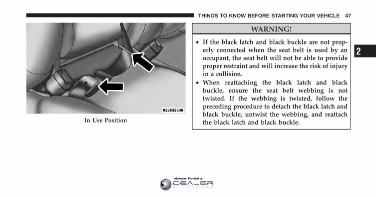
WARNING!
• If the black latch and black buckle are not prop-erly connected when the seat belt is used by anoccupant, the seat belt will not be able to provideproper restraint and will increase the risk of injuryin a collision.
• When reattaching the black latch and blackbuckle, ensure the seat belt webbing is nottwisted. If the webbing is twisted, follow thepreceding procedure to detach the black latch andblack buckle, untwist the webbing, and reattachthe black latch and black buckle.In Use Position
2
THINGS TO KNOW BEFORE STARTING YOUR VEHICLE 47
Information Provided by:
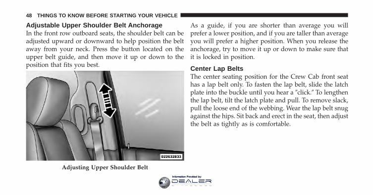
Adjustable Upper Shoulder Belt AnchorageIn the front row outboard seats, the shoulder belt can beadjusted upward or downward to help position the beltaway from your neck. Press the button located on theupper belt guide, and then move it up or down to theposition that fits you best.
As a guide, if you are shorter than average you willprefer a lower position, and if you are taller than averageyou will prefer a higher position. When you release theanchorage, try to move it up or down to make sure thatit is locked in position.
Center Lap BeltsThe center seating position for the Crew Cab front seathas a lap belt only. To fasten the lap belt, slide the latchplate into the buckle until you hear a �click.� To lengthenthe lap belt, tilt the latch plate and pull. To remove slack,pull the loose end of the webbing. Wear the lap belt snugagainst the hips. Sit back and erect in the seat, then adjustthe belt as tightly as is comfortable.
Adjusting Upper Shoulder Belt
48 THINGS TO KNOW BEFORE STARTING YOUR VEHICLE
Information Provided by:
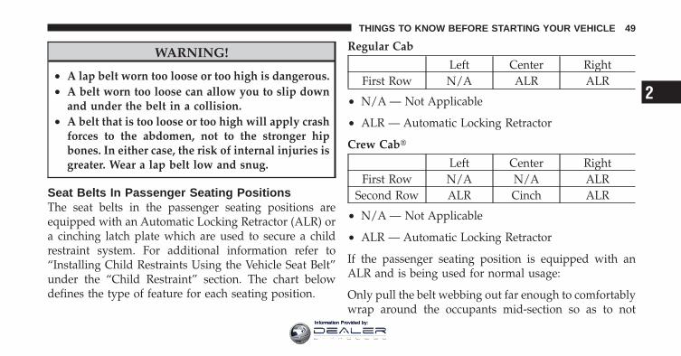
WARNING!
• A lap belt worn too loose or too high is dangerous.• A belt worn too loose can allow you to slip down
and under the belt in a collision.• A belt that is too loose or too high will apply crash
forces to the abdomen, not to the stronger hipbones. In either case, the risk of internal injuries isgreater. Wear a lap belt low and snug.
Seat Belts In Passenger Seating PositionsThe seat belts in the passenger seating positions areequipped with an Automatic Locking Retractor (ALR) ora cinching latch plate which are used to secure a childrestraint system. For additional information refer to“Installing Child Restraints Using the Vehicle Seat Belt”under the “Child Restraint” section. The chart belowdefines the type of feature for each seating position.
Regular Cab
Left Center RightFirst Row N/A ALR ALR
• N/A — Not Applicable
• ALR — Automatic Locking Retractor
Crew Cab�
Left Center RightFirst Row N/A N/A ALR
Second Row ALR Cinch ALR
• N/A — Not Applicable
• ALR — Automatic Locking Retractor
If the passenger seating position is equipped with anALR and is being used for normal usage:
Only pull the belt webbing out far enough to comfortablywrap around the occupants mid-section so as to not
2
THINGS TO KNOW BEFORE STARTING YOUR VEHICLE 49
Information Provided by:
activate the ALR. If the ALR is activated you will hear aratcheting sound as the belt retracts. Allow the webbingto retract completely in this case and then carefully pullout only the amount of webbing necessary to comfort-ably wrap around the occupants mid-section. Slide thelatch plate into the buckle until you hear a �click.�
Automatic Locking Retractor Mode (ALR) — IfEquippedIn this mode, the shoulder belt is automatically pre-locked. However, the belt will still retract to remove slackin the shoulder belt. Use the Automatic Locking Modeany time a child safety seat is installed in a seatingposition that has a seat belt with this feature. Children12 years old and younger should be properly restrainedin the rear seat whenever possible.
How To Engage The Automatic Locking Mode
1. Buckle the combination lap and shoulder belt.
2. Grasp the shoulder portion and pull downward untilthe entire belt is extracted.
3. Allow the belt to retract. As the belt retracts, you willhear a ratcheting sound. This indicates the safety belt isnow in the Automatic Locking mode.
How To Disengage The Automatic Locking ModeUnbuckle the combination lap and shoulder belt andallow it to retract completely to disengage the AutomaticLocking mode and activate the vehicle sensitive (emer-gency) locking mode.
Center Lap Belts — Crew Cab� OnlyThe front center seating position has a lap belt only. Tofasten the lap belt, slide the latch plate into the buckleuntil you hear a “click.” To lengthen the lap belt, tilt thelatch plate and pull. To remove slack, pull the loose endof the webbing. Wear the lap belt snug against the hips.Sit back and erect in the seat, then adjust the belt astightly as is comfortable.
50 THINGS TO KNOW BEFORE STARTING YOUR VEHICLE
Information Provided by:
Enhanced Seat Belt Use Reminder System(BeltAlert�)BeltAlert� is a feature intended to remind the driver andfront passenger (if equipped with front passengerBeltAlert�) to fasten their seat belts. The feature is activewhenever the ignition is on. If the driver or front seatpassenger is unbelted, the Seat Belt Reminder Light willturn on and remain on until both front seat belts arefastened.
The BeltAlert� warning sequence begins after the vehiclespeed is over 5 mph (8 km/h), by blinking the Seat BeltReminder Light and sounding an intermittent chime.Once the sequence starts, it will continue for the entireduration or until the respective seatbelts are fastened.After the sequence completes, the Seat Belt ReminderLight remains illuminated until the respective seat beltsare fastened. The driver should instruct all other occu-pants to fasten their seat belts. If a front seat belt is
unbuckled while traveling at speeds greater than 5 mph(8 km/h), BeltAlert� will provide both audio and visualnotification.
The front passenger seat BeltAlert� is not active when thefront passenger seat is unoccupied. BeltAlert� may betriggered when an animal or heavy object is on the frontpassenger seat or when the seat is folded flat (ifequipped). It is recommended that pets be restrained inthe rear seat in pet harnesses or pet carriers that aresecured by seat belts, and cargo is properly stowed.
BeltAlert� can be enabled or disabled by your authorizeddealer. Chrysler Group LLC does not recommend deac-tivating BeltAlert�.
NOTE: Although BeltAlert� has been deactivated, theSeat Belt Reminder Light will continue to illuminatewhile the driver’s or front passenger (if equipped withBeltAlert�) seat belt remains unfastened.
2
THINGS TO KNOW BEFORE STARTING YOUR VEHICLE 51
Information Provided by:
Seat Belts And Pregnant WomenWe recommend that pregnant women use seat beltsthroughout their pregnancies. Keeping the mother safe isthe best way to keep the baby safe.
Pregnant women should wear the lap part of the beltacross the thighs and as snug against the hips as possible.Keep the belt low so that it does not come across theabdomen. That way the strong bones of the hips will takethe force if there is a collision.
Seat Belt ExtenderIf a seat belt is too short even when fully extended, yourauthorized dealer can provide you with a seat beltextender. This extender should be used only if theexisting belt is not long enough. When it is not required,remove the extender and store it.
WARNING!
Using a seat belt extender when not needed canincrease the risk of injury in a collision. Only use theseat belt extender when the lap belt is not longenough when it is worn low and snug, and in therecommended seating positions. Remove and storethe extender when not needed.
Driver and Right Front Passenger SupplementalRestraint System (SRS) — Air BagThis vehicle has Advanced Front Air Bags for both thedriver and front passenger (if equipped) as a supplementto the seat belt restraint systems. The driver’s AdvancedFront Air Bag is mounted in the center of the steeringwheel. The passenger’s Advanced Front Air Bag ismounted in the instrument panel, above the glove com-partment. The words SRS AIRBAG are embossed on theair bag covers.
52 THINGS TO KNOW BEFORE STARTING YOUR VEHICLE
Information Provided by:
NOTE: The Driver and Front Passenger Advanced FrontAir Bags are certified to the new Federal regulations forAdvanced Air Bags.
The Advanced Front Air Bags have a multistage inflatordesign. This allows the air bag to have different rates ofinflation based on several factors, including the severityand type of collision.
This vehicle may be equipped with driver and/or frontpassenger seat track position sensors that may adjust theinflation rate of the Advanced Front Air Bags based uponseat position.
This vehicle may be equipped with a driver and/or frontpassenger seat belt buckle switch that detects whetherthe driver or front passenger seat belt is fastened. Theseat belt buckle switch may adjust the inflation rate of theAdvanced Front Air Bags.
NOTE:• Air Bag covers may not be obvious in the interior trim,
but they will open during air bag deployment.
Advanced Front Air Bag And Knee Bolster Locations
1 — Driver And PassengerAdvanced Front Air Bags(if equipped)
2 — Knee Bolster
2
THINGS TO KNOW BEFORE STARTING YOUR VEHICLE 53
Information Provided by:
• After any accident, the vehicle should be taken to anauthorized dealer immediately.
Air Bag System ComponentsYour vehicle may be equipped with the following air bagsystem components:
• Occupant Restraint Controller (ORC)
• Air Bag Warning Light
• Steering Wheel and Column
• Instrument Panel
• Knee Impact Bolster
• Driver Advanced Front Air Bag
• Passenger Advanced Front Air Bag
• Front Seat Belt Pretensioners, Seat Belt Buckle Switch,and Seat Track Position Sensors
Advanced Front Air Bag FeaturesThe Advanced Front Air Bag system has multistagedriver and front passenger (if equipped) air bags. Thissystem provides output appropriate to the severity andtype of collision as determined by the Occupant RestraintController (ORC).
The first stage inflator is triggered immediately during animpact that requires air bag deployment. This low outputis used in less severe collisions. A higher energy output isused for more severe collisions.
WARNING!
• No objects should be placed over or near the airbag on the instrument panel, because any suchobjects could cause harm if the vehicle is in acollision severe enough to cause the air bag toinflate.
(Continued)
54 THINGS TO KNOW BEFORE STARTING YOUR VEHICLE
Information Provided by:
WARNING! (Continued)• Do not put anything on or around the air bag
covers or attempt to open them manually. You maydamage the air bags and you could be injuredbecause the air bags may no longer be functional.The protective covers for the air bag cushions aredesigned to open only when the air bags areinflating.
• Do not drill, cut or tamper with the knee bolster inany way.
• Do not mount any accessories to the knee bolstersuch as alarm lights, stereos, citizen band radios,etc.
Knee Impact BolstersThe Knee Impact Bolsters help protect the knees of thedriver and the front passenger, and position front occu-pants for the best interaction with the Advanced FrontAir Bags.
Here are some simple steps you can take to minimize therisk of harm from a deploying air bag:
Children 12 years old and under should always ridebuckled up in a rear seat.
WARNING!
Infants in rear-facing child restraints should neverride in the front seat of a vehicle with a passengerAdvanced Front Air Bag. An air bag deployment cancause severe injury or death to infants in that posi-tion.
Children that are not big enough to wear the vehicle seatbelt properly (see Section on Child Restraints) should besecured in the rear seat in child restraints or belt-positioning booster seats. Older children who do not usechild restraints or belt-positioning booster seats should
2
THINGS TO KNOW BEFORE STARTING YOUR VEHICLE 55
Information Provided by:
ride properly buckled up in the rear seat. Never allowchildren to slide the shoulder belt behind them or undertheir arm.
If a child from 1 to 12 years old (not in a rear facing childseat) must ride in the front passenger seat, move the seatas far back as possible and use the proper child restraint.(Refer to “Child Restraints”)
You should read the instructions provided with yourchild restraint to make sure that you are using it properly.
All occupants should always wear their lap and shoulderbelts properly.
The driver and front passenger seats should be movedback as far as practical to allow the Advanced Front AirBags room to inflate.
If the air bag system in this vehicle needs to be modifiedto accommodate a disabled person, contact the CustomerCenter. Phone numbers are provided under �If You NeedAssistance�.
WARNING!
• Relying on the air bags alone could lead to moresevere injuries in a collision. The air bags workwith your seat belt to restrain you properly. Insome collisions, the air bags won’t deploy at all.Always wear your seat belts even though you haveair bags.
• Being too close to the steering wheel or instrumentpanel during Advanced Front Air Bag deploymentcould cause serious injury, including death. AirBags need room to inflate. Sit back, comfortablyextending your arms to reach the steering wheel orinstrument panel.
56 THINGS TO KNOW BEFORE STARTING YOUR VEHICLE
Information Provided by:
Air Bag Deployment Sensors And Controls
Occupant Restraint Controller (ORC)The ORC is part of a Federally regulated safety systemrequired for this vehicle.
The ORC determines if deployment of the front air bagsin a frontal or side collision is required. Based on theimpact sensor’s signals, a central electronic ORC deploysthe Advanced Front Air Bags, and front seat belt preten-sioners — if equipped, as required, depending on severalfactors, including the severity and type of impact.
Advanced Front Air Bags are designed to provide addi-tional protection by supplementing the seat belts incertain frontal collisions depending on several factors,including the severity and type of collision. AdvancedFront Air Bags are not expected to reduce the risk ofinjury in rear, side or rollover collisions.
The Advanced Front Air Bags will not deploy in allfrontal collisions, including some that may produce sub-stantial vehicle damage — for example, some pole colli-sions, truck underrides, and angle offset collisions. Onthe other hand, depending on the type and location ofimpact, Advanced Front Air Bags may deploy in crasheswith little vehicle front-end damage but that produce asevere initial deceleration.
Because air bag sensors measure vehicle decelerationover time, vehicle speed and damage by themselves arenot good indicators of whether or not an air bag shouldhave deployed.
Seat belts are necessary for your protection in all colli-sions, and also are needed to help keep you in position,away from an inflating air bag.
2
THINGS TO KNOW BEFORE STARTING YOUR VEHICLE 57
Information Provided by:
The ORC monitors the readiness of the electronic parts ofthe air bag system whenever the ignition switch is in theSTART or ON/RUN position. If the key is in the LOCKposition, in the ACC position, or not in the ignition, theair bag system is not on and the air bags will not inflate.
The ORC contains a backup power supply system thatmay deploy the air bags even if the battery loses power orit becomes disconnected prior to deployment.
Also, the ORC turns on the Air Bag WarningLight in the instrument panel for approxi-mately four to eight seconds for a self-checkwhen the ignition is first turned on. After the
self-check, the Air Bag Warning Light will turn off. If theORC detects a malfunction in any part of the system, itturns on the Air Bag Warning Light, either momentarilyor continuously. A single chime will sound if the lightcomes on again after initial startup.
It also includes diagnostics that will illuminate the instru-ment cluster Air Bag Warning Light if a malfunction isnoted that could affect the air bag system. The diagnos-tics also record the nature of the malfunction.
WARNING!
Ignoring the Air Bag Warning Light in your instru-ment panel could mean you won’t have the air bagsto protect you in a collision. If the light does not comeon as a bulb check when the ignition is first turnedon, stays on after you start the vehicle, or if it comeson as you drive, have an authorized dealer service theair bag system immediately.
58 THINGS TO KNOW BEFORE STARTING YOUR VEHICLE
Information Provided by:
Driver And Passenger Advanced Front Air BagInflator UnitsThe Driver and Passenger Advanced Front Air BagInflator Units are located in the center of the steeringwheel and on the right side of the instrument panel (ifequipped). When the ORC detects a collision requiringthe Advanced Front Air Bags, it signals the inflator units.A large quantity of non-toxic gas is generated to inflatethe Advanced Front Air Bags. Different air bag inflationrates are possible, based on the collision type and sever-ity. The steering wheel hub trim cover and the upperright side of the instrument panel separate and fold outof the way as the air bags inflate to their full size. The airbags fully inflate in about 50 to 70 milliseconds. This isabout half of the time it takes to blink your eyes. The airbags then quickly deflate while helping to restrain thedriver and front passenger.
The Advanced Front Air Bag gas is vented through thevent holes in the sides of the air bag. In this way, the airbags do not interfere with your control of the vehicle.
Enhanced Accident Response SystemIn the event of an impact causing air bag deployment, ifthe communication network remains intact, and thepower remains intact, depending on the nature of theevent the ORC will determine whether to have theEnhanced Accident Response System perform the follow-ing functions:
• Cut off fuel to the engine.
• Flash hazard lights as long as the battery has power oruntil the ignition key is turned off.
• Turn on the interior lights, which remain on as long asthe battery has power or until the ignition key isremoved.
• Unlock the doors automatically.
2
THINGS TO KNOW BEFORE STARTING YOUR VEHICLE 59
Information Provided by:
In order to reset the Enhanced Accident Response Systemfunctions after an event, the ignition switch must bechanged from IGN ON to IGN OFF.
If A Deployment OccursThe Advanced Front Air Bags are designed to deflateimmediately after deployment.
NOTE: Front air bags will not deploy in all collisions.This does not mean something is wrong with the air bagsystem.
If you do have a collision which deploys the air bags, anyor all of the following may occur:
• The nylon air bag material may sometimes causeabrasions and/or skin reddening to the driver andfront passenger as the air bags deploy and unfold. Theabrasions are similar to friction rope burns or those
you might get sliding along a carpet or gymnasiumfloor. They are not caused by contact with chemicals.They are not permanent and normally heal quickly.However, if you haven’t healed significantly within afew days, or if you have any blistering, see your doctorimmediately.
• As the air bags deflate, you may see some smoke-likeparticles. The particles are a normal by-product of theprocess that generates the non-toxic gas used for airbag inflation. These airborne particles may irritate theskin, eyes, nose, or throat. If you have skin or eyeirritation, rinse the area with cool water. For nose orthroat irritation, move to fresh air. If the irritationcontinues, see your doctor. If these particles settle onyour clothing, follow the garment manufacturer’s in-structions for cleaning.
60 THINGS TO KNOW BEFORE STARTING YOUR VEHICLE
Information Provided by:
Do not drive your vehicle after the air bags have de-ployed. If you are involved in another collision, the airbags will not be in place to protect you.
WARNING!
Deployed air bags cannot protect you in anothercollision. Have the air bags replaced by an autho-rized dealer immediately. Also, have the OccupantRestraint Controller (ORC) system serviced as well.
Maintaining Your Air Bag System
WARNING!
• Modifications to any part of the air bag systemcould cause it to fail when you need it. You couldbe injured if the air bag system is not there toprotect you. Do not modify the components orwiring, including adding any kind of badges orstickers to the steering wheel hub trim cover or theupper right side of the instrument panel. Do notmodify the front bumper, vehicle body structure,or add aftermarket side steps or running boards.
• It is dangerous to try to repair any part of the airbag system yourself. Be sure to tell anyone whoworks on your vehicle that it has an air bag system.
(Continued)
2
THINGS TO KNOW BEFORE STARTING YOUR VEHICLE 61
Information Provided by:
WARNING! (Continued)• Do not attempt to modify any part of your air bag
system. The air bag may inflate accidentally ormay not function properly if modifications aremade. Take your vehicle to an authorized dealerfor any air bag system service. If your seat includ-ing your trim cover and cushion needs to beserviced in any way (including removal orloosening/tightening of seat attachment bolts),take the vehicle to your authorized dealer. Onlymanufacturer approved seat accessories may beused. If it is necessary to modify the air bag systemfor persons with disabilities, contact your autho-rized dealer.
Air Bag Warning LightYou will want to have the air bags ready toinflate for your protection in a collision. TheAir Bag Warning Light monitors the internalcircuits and interconnecting wiring associated
with air bag system electrical components. While the airbag system is designed to be maintenance free, if any ofthe following occurs, have an authorized dealer servicethe air bag system immediately.
• The Air Bag Warning Light does not come on duringthe four to eight seconds when the ignition switch isfirst turned to the ON/RUN position.
• The Air Bag Warning Light remains on after the four toeight-second interval.
• The Air Bag Warning Light comes on intermittently orremains on while driving.
62 THINGS TO KNOW BEFORE STARTING YOUR VEHICLE
Information Provided by:
NOTE: If the speedometer, tachometer, or any enginerelated gauges are not working, the Occupant RestraintController (ORC) may also be disabled. The air bags maynot be ready to inflate for your protection. Promptlycheck the fuse block for blown fuses. Refer to the labellocated on the inside of the fuse block cover for theproper air bag fuses. See your authorized dealer if thefuse is good.
Event Data Recorder (EDR)This vehicle is equipped with an event data recorder(EDR). The main purpose of an EDR is to record, incertain crash or near crash-like situations, such as an airbag deployment or hitting a road obstacle, data that willassist in understanding how a vehicle’s systems per-formed. The EDR is designed to record data related tovehicle dynamics and safety systems for a short period oftime, typically 30 seconds or less. The EDR in this vehicleis designed to record such data as:
• How various systems in your vehicle were operating;
• Whether or not the driver and passenger safety beltswere buckled/fastened;
• How far (if at all) the driver was depressing theaccelerator and/or brake pedal; and,
• How fast the vehicle was traveling.
These data can help provide a better understanding ofthe circumstances in which crashes and injuries occur.
NOTE: EDR data are recorded by your vehicle only if anon-trivial crash situation occurs; no data are recorded bythe EDR under normal driving conditions and no per-sonal data (e.g., name, gender, age, and crash location)are recorded. However, other parties, such as law en-forcement, could combine the EDR data with the type ofpersonally identifying data routinely acquired during acrash investigation.
2
THINGS TO KNOW BEFORE STARTING YOUR VEHICLE 63
Information Provided by:
To read data recorded by an EDR, special equipment isrequired, and access to the vehicle or the EDR is needed.In addition to the vehicle manufacturer, other parties,such as law enforcement, that have the special equip-ment, can read the information if they have access to thevehicle or the EDR.
Child RestraintsEveryone in your vehicle needs to be buckled up all thetime, including babies and children. Every state in theUnited States and all Canadian provinces require thatsmall children ride in proper restraint systems. This is thelaw, and you can be prosecuted for ignoring it.
Children 12 years or younger should ride properlybuckled up in a rear seat, if available. According to crashstatistics, children are safer when properly restrained inthe rear seats rather than in the front.
WARNING!
In a collision, an unrestrained child, even a tiny baby,can become a projectile inside the vehicle. The forcerequired to hold even an infant on your lap canbecome so great that you could not hold the child, nomatter how strong you are. The child and otherscould be badly injured. Any child riding in yourvehicle should be in a proper restraint for the child’ssize.
Infants And Child RestraintsSafety experts recommend that children ride rearward-facing in the vehicle until they are two years old or untilthey reach either the height or weight limit of their rearfacing child safety seat. Two types of child restraints canbe used rearward-facing: infant carriers and convertiblechild seats.
64 THINGS TO KNOW BEFORE STARTING YOUR VEHICLE
Information Provided by:
The infant carrier is only used rearward-facing in thevehicle. It is recommended for children from birth untilthey reach the weight or height limit of the infant carrier.Convertible child seats can be used either rearward-facing or forward-facing in the vehicle. Convertible childseats often have a higher weight limit in the rearward-facing direction than infant carriers do, so they can beused rearward-facing by children who have outgrowntheir infant carrier but are still less than at least two yearsold. Children should remain rearward-facing until theyreach the highest weight or height allowed by theirconvertible child seat. Both types of child restraints areheld in the vehicle by the lap/shoulder belt or theLATCH child restraint anchor system. Refer to “LowerAnchors and Tether for CHildren (LATCH)”.
WARNING!
Rearward-facing child seats must never be used inthe front seat of a vehicle with the front passenger airbag. An air bag deployment could cause severeinjury or death to infants in this position.
Older Children And Child RestraintsChildren who are two years old or who have outgrowntheir rear-facing convertible child seat can ride forward-facing in the vehicle. Forward-facing child seats andconvertible child seats used in the forward-facing direc-tion are for children who are over two years old or whohave outgrown the rear-facing weight or height limit oftheir rear-facing convertible child seat. Children shouldremain in a forward-facing child seat with a harness foras long as possible, up to the highest weight or heightallowed by the child seat. These child seats are also held
2
THINGS TO KNOW BEFORE STARTING YOUR VEHICLE 65
Information Provided by:
in the vehicle by the lap/shoulder belt or the LATCHchild restraint anchorage system. Refer to “Lower An-chors and Tether for CHildren (LATCH)”.
All children whose weight or height is above theforward-facing limit for the child seat should use abelt-positioning booster seat until the vehicle’s seat beltsfit properly. If the child cannot sit with knees bent overthe vehicle’s seat cushion while the child’s back is againstthe seatback, they should use a belt-positioning boosterseat. The child and belt-positioning booster seat are heldin the vehicle by the lap/shoulder belt.
NOTE: For additional information, refer towww.seatcheck.org or call 1–866–SEATCHECK. Cana-dian residents should refer to Transport Canada’s web-site for additional information: http://www.tc.gc.ca/roadsafety/safedrivers/childsafety/index.htm
WARNING!
• Rearward-facing child seats must never be used inthe front seat of a vehicle with a front passengerair bag. An air bag deployment could cause severeinjury or death to infants in this position.
• Improper installation can lead to failure of aninfant or child restraint. It could come loose in acollision. The child could be badly injured orkilled. Follow the manufacturer’s directions ex-actly when installing an infant or child restraint.
• A rearward-facing child restraint should only beused in a rear seat.
Here are some tips for getting the most out of your childrestraint:
• Before buying any restraint system, make sure that ithas a label certifying that it meets all applicable SafetyStandards. Chrysler Group LLC also recommends that
66 THINGS TO KNOW BEFORE STARTING YOUR VEHICLE
Information Provided by:
you make sure that you can install the child restraint inthe vehicle where you will use it before you buy it.
• The restraint must be appropriate for your child’sweight and height. Check the label on the restraint forweight and height limits.
• Carefully follow the instructions that come with therestraint. If you install the restraint improperly, it maynot work when you need it.
• In the rear seat, you may have trouble tightening thelap/shoulder belt on the child restraint because thebuckle or latch plate is too close to the belt pathopening on the restraint. Disconnect the latch platefrom the buckle and twist the short buckle-end beltseveral times to shorten it. Insert the latch plate intothe buckle with the release button facing out.
• If the belt still can’t be tightened, or if pulling andpushing on the restraint loosens the belt, disconnectthe latch plate from the buckle, turn the latch platearound, and insert the latch plate into the buckleagain. If you still can’t make the child restraint secure,try a different seating position.
• Buckle the child into the seat according to the childrestraint manufacturer’s directions.
WARNING!
• Improper installation can lead to failure of aninfant or child restraint. It could come loose in acollision. The child could be badly injured orkilled. Follow the manufacturer’s directions ex-actly when installing an infant or child restraint.
(Continued)
2
THINGS TO KNOW BEFORE STARTING YOUR VEHICLE 67
Information Provided by:
WARNING! (Continued)• When your child restraint is not in use, secure it in
the vehicle with the seat belt or remove it from thevehicle. Do not leave it loose in the vehicle. In asudden stop or accident, it could strike the occu-pants or seatbacks and cause serious personalinjury.
Children Too Large For Booster SeatsChildren who are large enough to wear the shoulder beltcomfortably, and whose legs are long enough to bendover the front of the seat when their back is against theseat back should use the lap/shoulder belt in a rear seat.
• Make sure that the child is upright in the seat.
• The lap portion should be low on the hips and as snugas possible.
• Check belt fit periodically. A child’s squirming orslouching can move the belt out of position.
If the shoulder belt contacts the face or neck, move thechild closer to the center of the vehicle. Never allow achild to put the shoulder belt under an arm or behindtheir back.
Lower Anchors and Tether for CHildren (LATCH)Each vehicle is equipped with the child restraint anchor-age system called LATCH, which stands for LowerAnchors and Tether for CHildren. The LATCH systemprovides for the installation of the child restraint withoutusing the vehicle seat belt, instead securing the childrestraint using lower anchorages and upper tether strapsfrom the child restraint to the vehicle structure. LATCHchild restraint anchorage systems are installed in theQuad Cab�, Mega Cab� and Crew Cab rear seat outboardpositions. LATCH equipped seating positions featureboth lower anchor bars, located at the back of the seat
68 THINGS TO KNOW BEFORE STARTING YOUR VEHICLE
Information Provided by:
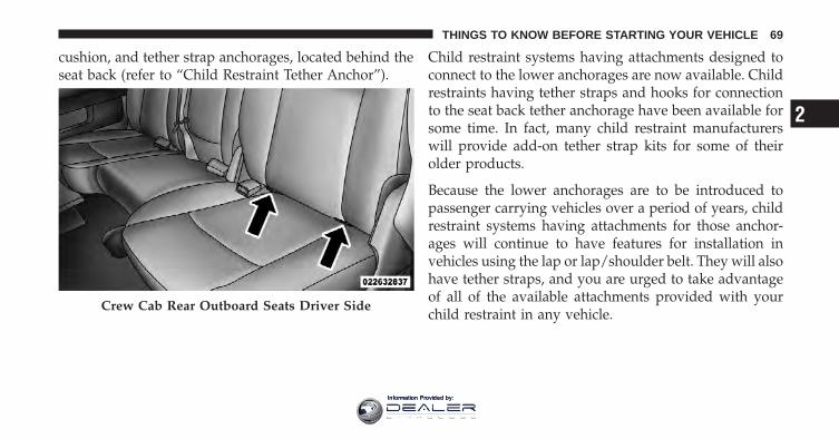
cushion, and tether strap anchorages, located behind theseat back (refer to “Child Restraint Tether Anchor”).
Child restraint systems having attachments designed toconnect to the lower anchorages are now available. Childrestraints having tether straps and hooks for connectionto the seat back tether anchorage have been available forsome time. In fact, many child restraint manufacturerswill provide add-on tether strap kits for some of theirolder products.
Because the lower anchorages are to be introduced topassenger carrying vehicles over a period of years, childrestraint systems having attachments for those anchor-ages will continue to have features for installation invehicles using the lap or lap/shoulder belt. They will alsohave tether straps, and you are urged to take advantageof all of the available attachments provided with yourchild restraint in any vehicle.
Crew Cab Rear Outboard Seats Driver Side
2
THINGS TO KNOW BEFORE STARTING YOUR VEHICLE 69
Information Provided by:
NOTE:• When using the LATCH attaching system to install a
child restraint, please ensure that all seat belts notbeing used for occupant restraints are stowed and outof reach of children. It is recommended that beforeinstalling the child restraint, buckle the seat belt so theseat belt is tucked behind the child restraint and out ofreach. If the buckled seat belt interferes with the childrestraint installation, instead of tucking the seat beltbehind the child restraint, route the seat belt throughthe child restraint belt path and then buckle it. Thisshould stow the seat belt out of the reach of aninquisitive child. Remind all children in the vehiclethat the seat belts are not toys and should not beplayed with, and never leave your child unattended inthe vehicle.
• If your child restraint seat is not LATCH-compatible,install the restraint using the vehicle seat belting.
Installing The Child Restraint System
WARNING!
Do not install child restraint systems equipped withLATCH mechanisms in the center position of a CrewCab model with a bench rear seat. A child may beplaced in the rear center seating position of a CrewCab bench model using the seat belt and child tetheranchorage. The LATCH anchorages in the rear seatare designed for the two outboard seating positionsfor Crew Cab� with a full bench rear seat, and allthree positions for Crew Cab� with a split bench rearseat. Failure to follow this may result in serious orfatal injury.
70 THINGS TO KNOW BEFORE STARTING YOUR VEHICLE
Information Provided by:
We urge you to carefully follow the directions of themanufacturer when installing your child restraint. Many,but not all, restraint systems will be equipped withseparate straps on each side, with each having a hook orconnector, and a means for adjusting the tension in thestrap. Forward-facing toddler restraints and somerearward-facing infant restraints will also be equippedwith a tether strap, a hook and means for adjusting thetension in the strap.
In general, you will first loosen the child seat adjusters onthe lower straps and tether straps so that you can moreeasily attach the hook or connector to the lower anchor-ages and tether anchorages. Then tighten all three strapsas you push the child restraint rearward and downwardinto the seat.
Not all child restraint systems will be installed as wehave described here. Again, carefully follow the instruc-tions that come with the child restraint system.
WARNING!Improper installation of a child restraint to theLATCH anchorages can lead to failure of an infant orchild restraint. The child could be badly injured orkilled. Follow the manufacturer’s directions exactlywhen installing an infant or child restraint.
Installing Child Restraints Using The Vehicle SeatBeltThe seat belts in the passenger seating positions areequipped with either an Automatic Locking Retractor(ALR) or a cinching latch plate or both. Both types of seatbelts are designed to keep the lap portion of the seat belttight around the child restraint so that it is not necessaryto use a locking clip. The ALR will make a ratchetingnoise if you extract the entire belt from the retractor andthen allow the belt to retract into the retractor. Foradditional information on ALR, refer to “AutomaticLocking Mode”.
2
THINGS TO KNOW BEFORE STARTING YOUR VEHICLE 71
Information Provided by:
The chart below defines the seating positions with anAutomatic Locking Retractor (ALR) or a cinching latchplate.
Regular Cab
Left Center RightFirst Row N/A ALR ALR
• N/A — Not Applicable
• ALR — Automatic Locking Retractor
Crew Cab�
Left Center RightFirst Row N/A N/A ALR
Second Row ALR Cinch ALR
• N/A — Not Applicable
• ALR — Automatic Locking Retractor
Installing a Child Restraint with an ALR:
1. To install a child restraint with ALR, first, pull enoughof the seat belt webbing from the retractor to route itthrough the belt path of the child restraint. Slide the latchplate into the buckle until you hear a “click.” Next,extract all the seat belt webbing out of the retractor andthen allow the belt to retract into the retractor. As the beltretracts, you will hear a ratcheting sound. This indicatesthe safety belt is now in the Automatic Locking mode.
2. Finally, pull on any excess webbing to tighten the lapportion around the child restraint. Any seat belt systemwill loosen with time, so check the belt occasionally, andpull it tight if necessary.
Installing a Child Restraint with a Cinching Latch Plate:
1. To install a child restraint with a cinching latch plate,first, pull enough of the seat belt webbing from the
72 THINGS TO KNOW BEFORE STARTING YOUR VEHICLE
Information Provided by:
retractor to route it through the belt path of the childrestraint. Slide the latch plate into the buckle until youhear a “click.”
2. Finally, pull on any excess webbing to tighten the lapportion around the child restraint. Any seat belt systemwill loosen with time, so check the belt occasionally, andpull it tight if necessary.
To attach a child restraint tether strap:
• Route the tether strap to provide the most direct pathfor the strap between the anchor and the child seat,preferably between the head restraint posts under-neath the head restraint.
Child Restraint Tether AnchorChild restraints having tether straps and hooks for con-nection to tether anchors have been available for sometime. In fact, many child restraint manufacturers willprovide add-on tether strap kits for their older products.
Regular Cab models have two tether anchorages, oneeach behind the front center and right seats. Crew Cabmodels have three anchorages, one behind each of therear seats.
WARNING!
An incorrectly anchored tether strap could lead toseat failure and injury to the child. In a collision, theseat could come loose and allow the child to crashinto the inside of the vehicle or other passengers, oreven be thrown from the vehicle. Use only the anchorpositions directly behind the child seat to secure achild restraint top tether strap. Follow the instruc-tions below. See your authorized dealer for help ifnecessary.
2
THINGS TO KNOW BEFORE STARTING YOUR VEHICLE 73
Information Provided by:
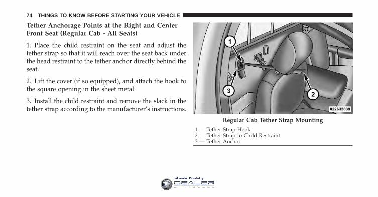
Tether Anchorage Points at the Right and CenterFront Seat (Regular Cab - All Seats)
1. Place the child restraint on the seat and adjust thetether strap so that it will reach over the seat back underthe head restraint to the tether anchor directly behind theseat.
2. Lift the cover (if so equipped), and attach the hook tothe square opening in the sheet metal.
3. Install the child restraint and remove the slack in thetether strap according to the manufacturer’s instructions.
Regular Cab Tether Strap Mounting
1 — Tether Strap Hook2 — Tether Strap to Child Restraint3 — Tether Anchor
74 THINGS TO KNOW BEFORE STARTING YOUR VEHICLE
Information Provided by:
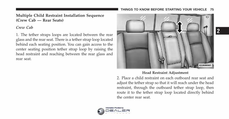
Multiple Child Restraint Installation Sequence(Crew Cab — Rear Seats)
Crew Cab
1. The tether straps loops are located between the rearglass and the rear seat. There is a tether strap loop locatedbehind each seating position. You can gain access to thecenter seating position tether strap loop by raising thehead restraint and reaching between the rear glass andrear seat.
2. Place a child restraint on each outboard rear seat andadjust the tether strap so that it will reach under the headrestraint, through the outboard tether strap loop, thenroute it to the tether strap loop located directly behindthe center rear seat.
Head Restraint Adjustment
2
THINGS TO KNOW BEFORE STARTING YOUR VEHICLE 75
Information Provided by:
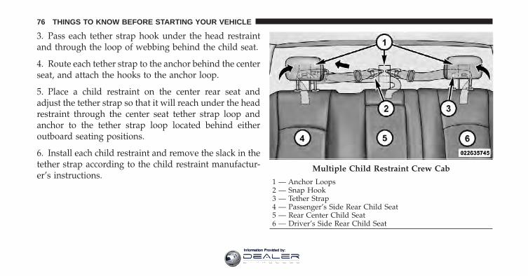
3. Pass each tether strap hook under the head restraintand through the loop of webbing behind the child seat.
4. Route each tether strap to the anchor behind the centerseat, and attach the hooks to the anchor loop.
5. Place a child restraint on the center rear seat andadjust the tether strap so that it will reach under the headrestraint through the center seat tether strap loop andanchor to the tether strap loop located behind eitheroutboard seating positions.
6. Install each child restraint and remove the slack in thetether strap according to the child restraint manufactur-er’s instructions.
Multiple Child Restraint Crew Cab
1 — Anchor Loops2 — Snap Hook3 — Tether Strap4 — Passenger’s Side Rear Child Seat5 — Rear Center Child Seat6 — Driver’s Side Rear Child Seat
76 THINGS TO KNOW BEFORE STARTING YOUR VEHICLE
Information Provided by:
Transporting PetsAir Bags deploying in the front seat could harm your pet.An unrestrained pet will be thrown about and possiblyinjured, or injure a passenger during panic braking or ina collision. Pets should be restrained in the rear seat inpet harnesses or pet carriers that are secured by seat belts.
ENGINE BREAK-IN RECOMMENDATIONSA long break-in period is not required for the engine anddrivetrain (transmission and axle) in your vehicle.
Drive moderately during the first 300 miles (500 km).After the initial 60 miles (100 km), speeds up to 50 or55 mph (80 or 90 km/h) are desirable.
While cruising, brief full-throttle acceleration within thelimits of local traffic laws contributes to a good break-in.Wide-open throttle acceleration in low gear can be detri-mental and should be avoided.
The engine oil installed in the engine at the factory is ahigh-quality energy conserving type lubricant. Oilchanges should be consistent with anticipated climateconditions under which vehicle operations will occur. Forthe recommended viscosity and quality grades, refer to“Maintenance Procedures” in “Maintaining Your Ve-hicle”. NON-DETERGENT OR STRAIGHT MINERALOILS MUST NEVER BE USED.
A new engine may consume some oil during its first fewthousand miles (kilometers) of operation. This should beconsidered a normal part of the break-in and not inter-preted as an indication of difficulty.
SAFETY TIPS
Transporting PassengersNEVER TRANSPORT PASSENGERS IN THE CARGOAREA.
2
THINGS TO KNOW BEFORE STARTING YOUR VEHICLE 77
Information Provided by:
WARNING!
• Do not leave children or animals inside parkedvehicles in hot weather. Interior heat build-up maycause serious injury or death.
• It is extremely dangerous to ride in a cargo area,inside or outside of a vehicle. In a collision, peopleriding in these areas are more likely to be seri-ously injured or killed.
• Do not allow people to ride in any area of yourvehicle that is not equipped with seats and seatbelts.
• Be sure everyone in your vehicle is in a seat andusing a seat belt properly.
Exhaust Gas
WARNING!
Exhaust gases can injure or kill. They contain carbonmonoxide (CO), which is colorless and odorless.Breathing it can make you unconscious and caneventually poison you. To avoid breathing (CO),follow these safety tips:• Do not run the engine in a closed garage or in
confined areas any longer than needed to moveyour vehicle in or out of the area.
• If you are required to drive with the trunk/liftgateopen, make sure that all windows are closed andthe climate control BLOWER switch is set at highspeed. DO NOT use the recirculation mode.
(Continued)
78 THINGS TO KNOW BEFORE STARTING YOUR VEHICLE
Information Provided by:
WARNING! (Continued)• If it is necessary to sit in a parked vehicle with the
engine running, adjust your heating or coolingcontrols to force outside air into the vehicle. Setthe blower at high speed.
The best protection against carbon monoxide entry intothe vehicle body is a properly maintained engine exhaustsystem.
Whenever a change is noticed in the sound of the exhaustsystem, when exhaust fumes can be detected inside thevehicle, or when the underside or rear of the vehicle isdamaged, have a competent mechanic inspect the com-plete exhaust system and adjacent body areas for broken,damaged, deteriorated, or mispositioned parts. Openseams or loose connections could permit exhaust fumesto seep into the passenger compartment. In addition,inspect the exhaust system each time the vehicle is raisedfor lubrication or oil change. Replace as required.
Safety Checks You Should Make Inside TheVehicle
Seat BeltsInspect the belt system periodically, checking for cuts,frays, and loose parts. Damaged parts must be replacedimmediately. Do not disassemble or modify the system.
Front seat belt assemblies must be replaced after acollision. Rear seat belt assemblies must be replaced aftera collision if they have been damaged (i.e., bent retractor,torn webbing, etc.). If there is any question regarding beltor retractor condition, replace the belt.
Air Bag Warning LightThe light should come on and remain on for four to eightseconds as a bulb check when the ignition switch is firstturned ON. If the light is not lit during starting, see yourauthorized dealer. If the light stays on, flickers, or comeson while driving, have the system checked by an autho-rized dealer.
2
THINGS TO KNOW BEFORE STARTING YOUR VEHICLE 79
Information Provided by:
DefrosterCheck operation by selecting the defrost mode and placethe blower control on high speed. You should be able tofeel the air directed against the windshield. See yourauthorized dealer for service if your defroster isinoperable.
Floor Mat Safety InformationAlways use floor mats designed to fit the footwell of yourvehicle. Use only floor mats that leave the pedal areaunobstructed and that are firmly secured so that theycannot slip out of position and interfere with the pedalsor impair safe operation of your vehicle in other ways.
WARNING!
Pedals that cannot move freely can cause loss ofvehicle control and increase the risk of serious per-sonal injury.
(Continued)
WARNING! (Continued)• Always make sure that floor mats are properly
attached to the floor mat fasteners.• Never place or install floor mats or other floor
coverings in the vehicle that cannot be properlysecured to prevent them from moving and inter-fering with the pedals or the ability to control thevehicle.
• Never put floor mats or other floor coverings ontop of already installed floor mats. Additionalfloor mats and other coverings will reduce the sizeof the pedal area and interfere with the pedals.
• Check mounting of mats on a regular basis. Al-ways properly reinstall and secure floor mats thathave been removed for cleaning.
(Continued)
80 THINGS TO KNOW BEFORE STARTING YOUR VEHICLE
Information Provided by:
WARNING! (Continued)• Always make sure that objects cannot fall into the
driver footwell while the vehicle is moving. Ob-jects can become trapped under the brake pedaland accelerator pedal causing a loss of vehiclecontrol.
• If required, mounting posts must be properlyinstalled, if not equipped from the factory.Failure to properly follow floor mat installation ormounting can cause interference with the brakepedal and accelerator pedal operation causing lossof control of the vehicle.
Periodic Safety Checks You Should Make OutsideThe Vehicle
TiresExamine tires for excessive tread wear and uneven wearpatterns. Check for stones, nails, glass, or other objects
lodged in the tread or sidewall. Inspect the tread for cutsand cracks. Inspect sidewalls for cuts, cracks and bulges.Check the wheel nuts for tightness. Check the tires(including spare) for proper cold inflation pressure.
LightsHave someone observe the operation of exterior lightswhile you work the controls. Check turn signal and highbeam indicator lights on the instrument panel.
Door LatchesCheck for positive closing, latching, and locking.
Fluid LeaksCheck area under vehicle after overnight parking for fuel,engine coolant, oil, or other fluid leaks. Also, if gasolinefumes are detected or if fuel, power steering fluid, orbrake fluid leaks are suspected, the cause should belocated and corrected immediately.
2
THINGS TO KNOW BEFORE STARTING YOUR VEHICLE 81
Information Provided by:

Information Provided by:
UNDERSTANDING THE FEATURES OF YOUR VEHICLE
CONTENTS
� Mirrors . . . . . . . . . . . . . . . . . . . . . . . . . . . . . . 87
▫ Inside Day/Night Mirror . . . . . . . . . . . . . . . . 87
▫ Automatic Dimming Mirror — If Equipped . . . 87
▫ Outside Mirrors . . . . . . . . . . . . . . . . . . . . . . 88
▫ Outside Mirrors Folding Feature . . . . . . . . . . 89
▫ Power Mirrors — If Equipped . . . . . . . . . . . . 90
▫ Heated Mirrors — If Equipped . . . . . . . . . . . . 91
▫ Illuminated Vanity Mirror — If Equipped . . . . 91
▫ “Slide-On-Rod” Features Of Sun Visor — IfEquipped . . . . . . . . . . . . . . . . . . . . . . . . . . . 92
▫ Trailer Towing Mirrors — If Equipped . . . . . . 92
� Uconnect™ Phone — If Equipped . . . . . . . . . . . 93
▫ Operation . . . . . . . . . . . . . . . . . . . . . . . . . . 96
▫ Phone Call Features . . . . . . . . . . . . . . . . . . 103
▫ Uconnect™ Phone Features . . . . . . . . . . . . . 106
▫ Advanced Phone Connectivity . . . . . . . . . . . . 111
▫ Things You Should Know About YourUconnect™ Phone . . . . . . . . . . . . . . . . . . . . 112
3
Information Provided by:
▫ General Information . . . . . . . . . . . . . . . . . . 123
� Voice Command — If Equipped . . . . . . . . . . . 123
▫ Voice Command System Operation . . . . . . . . 123
▫ Commands . . . . . . . . . . . . . . . . . . . . . . . . 124
▫ Voice Training . . . . . . . . . . . . . . . . . . . . . . 128
� Seats . . . . . . . . . . . . . . . . . . . . . . . . . . . . . . 128
▫ Driver’s Power Seat — If Equipped . . . . . . . 128
▫ Passenger’s Power Seat — If Equipped . . . . . 130
▫ Power Lumbar — If Equipped . . . . . . . . . . . 132
▫ Heated Seats — If Equipped . . . . . . . . . . . . 132
▫ Ventilated Seats — If Equipped . . . . . . . . . . 135
▫ Manual Seat Adjuster — If Equipped . . . . . . 136
▫ Manual Reclining Seats — If Equipped . . . . . 137
▫ Head Restraints . . . . . . . . . . . . . . . . . . . . . 138
▫ 40-20-40 Front Bench Seat — If Equipped . . . 140
� Driver Memory Seat — If Equipped . . . . . . . . 140
▫ Setting Memory Positions And Linking RKETransmitter To Memory . . . . . . . . . . . . . . . . 141
▫ Memory Position Recall . . . . . . . . . . . . . . . . 143
▫ To Disable A RKE Transmitter Linked ToMemory . . . . . . . . . . . . . . . . . . . . . . . . . . . 143
▫ Easy Entry/Exit Seat . . . . . . . . . . . . . . . . . . 144
� To Open And Close The Hood . . . . . . . . . . . . 145
� Lights . . . . . . . . . . . . . . . . . . . . . . . . . . . . . 147
▫ Headlights . . . . . . . . . . . . . . . . . . . . . . . . . 148
▫ Automatic Headlights — If Equipped . . . . . . 148
84 UNDERSTANDING THE FEATURES OF YOUR VEHICLE
Information Provided by:
▫ Headlights On With Wipers (Available WithAutomatic Headlights Only) . . . . . . . . . . . . 149
▫ Headlight Delay . . . . . . . . . . . . . . . . . . . . . 149
▫ Parking Lights And Panel Lights . . . . . . . . . 149
▫ Fog Lights — If Equipped . . . . . . . . . . . . . . 150
▫ Interior Lights . . . . . . . . . . . . . . . . . . . . . . 150
▫ Cargo Light . . . . . . . . . . . . . . . . . . . . . . . . 152
▫ Lights-On Reminder . . . . . . . . . . . . . . . . . . 152
▫ Battery Saver . . . . . . . . . . . . . . . . . . . . . . . 152
▫ Daytime Running Lights — If Equipped . . . . 153
▫ Multifunction Lever . . . . . . . . . . . . . . . . . . 153
� Windshield Wipers And Washers . . . . . . . . . . 154
▫ Windshield Wipers . . . . . . . . . . . . . . . . . . . 154
▫ Windshield Wiper Operation . . . . . . . . . . . . 155
▫ Intermittent Wiper System . . . . . . . . . . . . . . 155
▫ Windshield Washers . . . . . . . . . . . . . . . . . . 156
▫ Mist Feature . . . . . . . . . . . . . . . . . . . . . . . . 156
� Tilt Steering Column . . . . . . . . . . . . . . . . . . . 157
� Driver Adjustable Pedals — If Equipped . . . . . 158
� Heated Steering Wheel — If Equipped . . . . . . 159
� Electronic Speed Control . . . . . . . . . . . . . . . . 160
▫ To Activate . . . . . . . . . . . . . . . . . . . . . . . . . 161
▫ To Set A Desired Speed . . . . . . . . . . . . . . . . 162
▫ To Deactivate . . . . . . . . . . . . . . . . . . . . . . . 162
▫ To Resume Speed . . . . . . . . . . . . . . . . . . . . 162
▫ To Vary The Speed Setting . . . . . . . . . . . . . . 162
▫ To Accelerate For Passing . . . . . . . . . . . . . . 163
3
UNDERSTANDING THE FEATURES OF YOUR VEHICLE 85
Information Provided by:
� Overhead Console — If Equipped . . . . . . . . . . 163
▫ Courtesy/Reading Lights . . . . . . . . . . . . . . 164
� Electrical Power Outlets . . . . . . . . . . . . . . . . . 165
� Cigar Lighter And Ash Receiver —If Equipped . . . . . . . . . . . . . . . . . . . . . . . . . . 169
� Power Inverter — If Equipped . . . . . . . . . . . . 170
� Cupholders . . . . . . . . . . . . . . . . . . . . . . . . . . 172
▫ Front Instrument Panel Cupholders —(40–20–40 Seats) . . . . . . . . . . . . . . . . . . . . . 172
▫ Front Instrument Panel Cupholders — FloorStorage Bin . . . . . . . . . . . . . . . . . . . . . . . . . 172
▫ Rear Cupholder — Crew Cab . . . . . . . . . . . 173
� Storage . . . . . . . . . . . . . . . . . . . . . . . . . . . . . 173
▫ Glove Box Storage . . . . . . . . . . . . . . . . . . . 173
▫ Door Storage . . . . . . . . . . . . . . . . . . . . . . . 175
▫ Center Storage Compartment —If Equipped . . . . . . . . . . . . . . . . . . . . . . . . 176
▫ Seatback Storage . . . . . . . . . . . . . . . . . . . . . 178
▫ Storage (Regular Cab) . . . . . . . . . . . . . . . . . 178
▫ Storage And Seats (Crew Cab) . . . . . . . . . . . 179
▫ Plastic Grocery Bag Retainers(Regular Cab Models) . . . . . . . . . . . . . . . . . 180
� Rear Window Features . . . . . . . . . . . . . . . . . . 180
▫ Rear Window Defroster . . . . . . . . . . . . . . . . 180
▫ Power Sliding Rear Window —If Equipped . . . . . . . . . . . . . . . . . . . . . . . . 181
▫ Manual Sliding Rear Window —If Equipped . . . . . . . . . . . . . . . . . . . . . . . . 181
86 UNDERSTANDING THE FEATURES OF YOUR VEHICLE
Information Provided by:
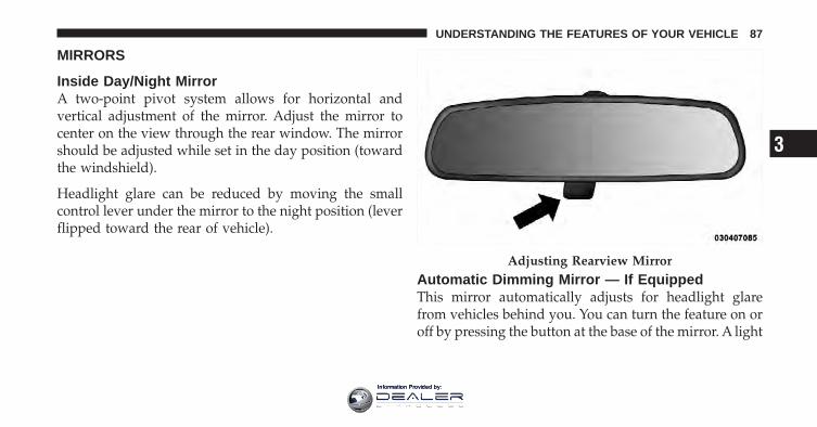
MIRRORS
Inside Day/Night MirrorA two-point pivot system allows for horizontal andvertical adjustment of the mirror. Adjust the mirror tocenter on the view through the rear window. The mirrorshould be adjusted while set in the day position (towardthe windshield).
Headlight glare can be reduced by moving the smallcontrol lever under the mirror to the night position (leverflipped toward the rear of vehicle).
Automatic Dimming Mirror — If EquippedThis mirror automatically adjusts for headlight glarefrom vehicles behind you. You can turn the feature on oroff by pressing the button at the base of the mirror. A light
Adjusting Rearview Mirror
3
UNDERSTANDING THE FEATURES OF YOUR VEHICLE 87
Information Provided by:
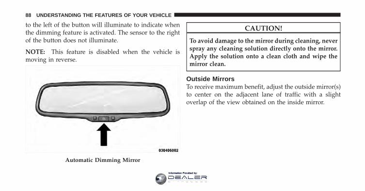
to the left of the button will illuminate to indicate whenthe dimming feature is activated. The sensor to the rightof the button does not illuminate.
NOTE: This feature is disabled when the vehicle ismoving in reverse.
CAUTION!
To avoid damage to the mirror during cleaning, neverspray any cleaning solution directly onto the mirror.Apply the solution onto a clean cloth and wipe themirror clean.
Outside MirrorsTo receive maximum benefit, adjust the outside mirror(s)to center on the adjacent lane of traffic with a slightoverlap of the view obtained on the inside mirror.
Automatic Dimming Mirror
88 UNDERSTANDING THE FEATURES OF YOUR VEHICLE
Information Provided by:
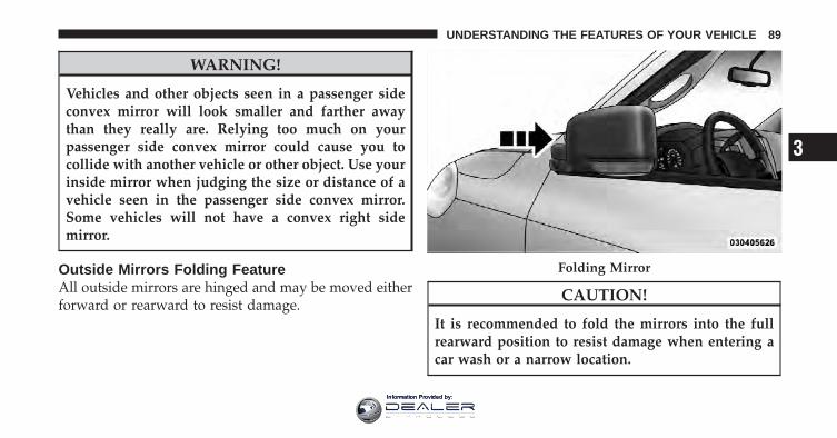
WARNING!
Vehicles and other objects seen in a passenger sideconvex mirror will look smaller and farther awaythan they really are. Relying too much on yourpassenger side convex mirror could cause you tocollide with another vehicle or other object. Use yourinside mirror when judging the size or distance of avehicle seen in the passenger side convex mirror.Some vehicles will not have a convex right sidemirror.
Outside Mirrors Folding FeatureAll outside mirrors are hinged and may be moved eitherforward or rearward to resist damage.
CAUTION!
It is recommended to fold the mirrors into the fullrearward position to resist damage when entering acar wash or a narrow location.
Folding Mirror
3
UNDERSTANDING THE FEATURES OF YOUR VEHICLE 89
Information Provided by:
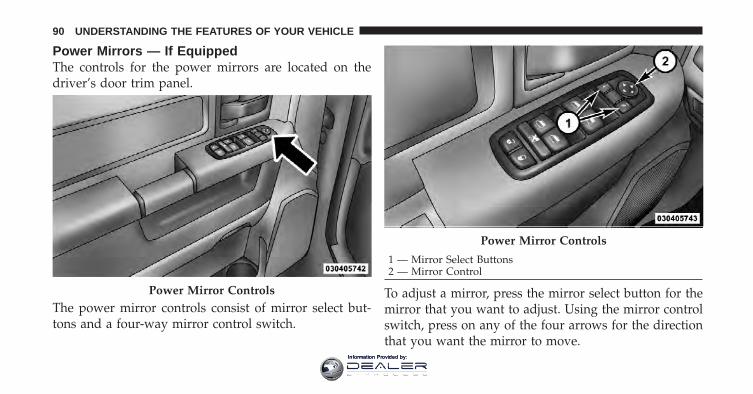
Power Mirrors — If EquippedThe controls for the power mirrors are located on thedriver’s door trim panel.
The power mirror controls consist of mirror select but-tons and a four-way mirror control switch.
To adjust a mirror, press the mirror select button for themirror that you want to adjust. Using the mirror controlswitch, press on any of the four arrows for the directionthat you want the mirror to move.
Power Mirror Controls
Power Mirror Controls
1 — Mirror Select Buttons2 — Mirror Control
90 UNDERSTANDING THE FEATURES OF YOUR VEHICLE
Information Provided by:
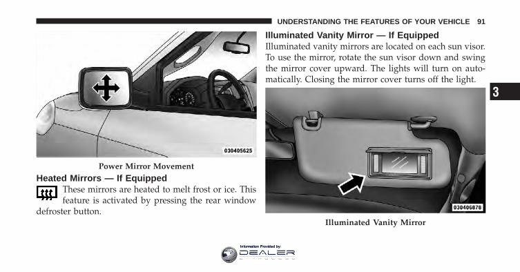
Heated Mirrors — If EquippedThese mirrors are heated to melt frost or ice. Thisfeature is activated by pressing the rear window
defroster button.
Illuminated Vanity Mirror — If EquippedIlluminated vanity mirrors are located on each sun visor.To use the mirror, rotate the sun visor down and swingthe mirror cover upward. The lights will turn on auto-matically. Closing the mirror cover turns off the light.
Power Mirror Movement
Illuminated Vanity Mirror
3
UNDERSTANDING THE FEATURES OF YOUR VEHICLE 91
Information Provided by:
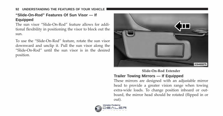
“Slide-On-Rod” Features Of Sun Visor — IfEquippedThe sun visor “Slide-On-Rod” feature allows for addi-tional flexibility in positioning the visor to block out thesun.
To use the “Slide-On-Rod” feature, rotate the sun visordownward and unclip it. Pull the sun visor along the“Slide-On-Rod” until the sun visor is in the desiredposition.
Trailer Towing Mirrors — If EquippedThese mirrors are designed with an adjustable mirrorhead to provide a greater vision range when towingextra-wide loads. To change position inboard or out-board, the mirror head should be rotated (flipped in orout).
Slide-On-Rod Extender
92 UNDERSTANDING THE FEATURES OF YOUR VEHICLE
Information Provided by:
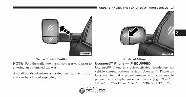
NOTE: Fold the trailer towing mirrors rearward prior toentering an automated car wash.
A small blindspot mirror is located next to main mirrorand can be adjusted separately.
Uconnect™ Phone — IF EQUIPPEDUconnect™ Phone is a voice-activated, hands-free, in-vehicle communications system. Uconnect™ Phone al-lows you to dial a phone number with your mobilephone using simple voice commands (e.g., “Call” �“Mike” � “Work” or “Dial” � “248-555-1212”). Your
Trailer Towing Position Blindspot Mirror
3
UNDERSTANDING THE FEATURES OF YOUR VEHICLE 93
Information Provided by:
mobile phone’s audio is transmitted through your vehi-cle’s audio system; the system will automatically muteyour radio when using the Uconnect™ Phone.
NOTE: The Uconnect™ Phone requires a mobile phoneequipped with the Bluetooth� “Hands-Free Profile”, Ver-sion 0.96 or higher. See the Uconnect™ website forsupported phones.
For Uconnect™ customer support, visit the followingwebsites:
• www.chrysler.com/uconnect
• www.dodge.com/uconnect
• www.jeep.com/uconnect
• or call 1–877–855–8400
Uconnect™ Phone allows you to transfer calls betweenthe system and your mobile phone as you enter or exityour vehicle and enables you to mute the system’smicrophone for private conversation.
The Uconnect™ Phone is driven through yourBluetooth� “Hands-Free Profile” mobile phone.Uconnect™ features Bluetooth� technology - the globalstandard that enables different electronic devices to con-nect to each other without wires or a docking station, soUconnect™ Phone works no matter where you stow yourmobile phone (be it your purse, pocket, or briefcase), aslong as your phone is turned on and has been paired tothe vehicle’s Uconnect™ Phone. The Uconnect™ Phoneallows up to seven mobile phones to be linked to thesystem. Only one linked (or paired) mobile phone can beused with the system at a time. The system is available inEnglish, Spanish, or French languages.
94 UNDERSTANDING THE FEATURES OF YOUR VEHICLE
Information Provided by:
WARNING!
Any voice commanded system should be used onlyin safe driving conditions following local laws andphone use. All attention should be kept on theroadway ahead. Failure to do so may result in acollision causing serious injury or death.
Uconnect™ Phone ButtonThe radio or steering wheel controls (ifequipped) will contain the two control buttons(Uconnect™ Phone button and Voice Com-mand button) that will enable you to
access the system. When you press the button you willhear the word Uconnect™ followed by a BEEP. The beepis your signal to give a command.
Voice Command ButtonActual button location may vary with the ra-dio. The individual buttons are described in the“Operation” section.
The Uconnect™ Phone can be used with any Hands-FreeProfile certified Bluetooth� mobile phone. See theUconnect™ website for supported phones. Refer to yourmobile service provider or the phone manufacturer fordetails.
The Uconnect™ Phone is fully integrated with the vehi-cle’s audio system. The volume of the Uconnect™ Phonecan be adjusted either from the radio volume controlknob or from the steering wheel radio control (rightswitch), if so equipped.
The radio display will be used for visual prompts fromthe Uconnect™ Phone such as “CELL” or caller ID oncertain radios.
3
UNDERSTANDING THE FEATURES OF YOUR VEHICLE 95
Information Provided by:
OperationVoice commands can be used to operate the Uconnect™Phone and to navigate through the Uconnect™ Phonemenu structure. Voice commands are required after mostUconnect™ Phone prompts. You will be prompted for aspecific command and then guided through the availableoptions.
• Prior to giving a voice command, one must wait forthe beep, which follows the “Ready” prompt or an-other prompt.
• For certain operations, compound commands can beused. For example, instead of saying “Setup” and then“Pair a Device”, the following compound commandcan be said: “Pair a Bluetooth� Device”.
• For each feature explanation in this section, only thecompound form of the voice command is given. Youcan also break the commands into parts and say eachpart of the command when you are asked for it. For
example, you can use the compound form voicecommand “Phonebook New Entry”, or you can breakthe compound form command into two voice com-mands: “Phonebook” and “New Entry”. Please re-member, the Uconnect™ Phone works best when youtalk in a normal conversational tone, as if speaking tosomeone sitting a few feet/meters away from you.
Voice Command TreeRefer to “Voice Tree” in this section.
Help CommandIf you need assistance at any prompt, or if you want toknow your options at any prompt, say “Help” followingthe beep. The Uconnect™ Phone will play some of theoptions at any prompt if you ask for help.
To activate the Uconnect™ Phone, simply press thebutton and follow the audible prompts for directions.Uconnect™ Phone sessions begin with a press of thebutton on the radio control head.
96 UNDERSTANDING THE FEATURES OF YOUR VEHICLE
Information Provided by:
Cancel CommandAt any prompt, after the beep, you can say “Cancel” andyou will be returned to the main menu. However, in afew instances the system will take you back to theprevious menu.
Pair (Link) Uconnect™ Phone To A Mobile PhoneTo begin using your Uconnect™ Phone, you must pairyour compatible Bluetooth� enabled mobile phone.
To complete the pairing process, you will need to refer-ence your mobile phone Owner’s Manual. TheUconnect™ website may also provide detailed instruc-tions for pairing.
The following are general phone to Uconnect™ Phonepairing instructions:
• Press the button to begin.
• After the “Ready” prompt and the following beep, say“Device Pairing”.
• When prompted, after the beep, say “Pair a Device”and follow the audible prompts.
• You will be asked to say a four-digit Personal Identi-fication Number (PIN), which you will later need toenter into your mobile phone. You can enter anyfour-digit PIN. You will not need to remember this PINafter the initial pairing process.
• For identification purposes, you will be prompted togive the Uconnect™ Phone a name for your mobilephone. Each mobile phone that is paired should begiven a unique phone name.
• You will then be asked to give your mobile phone apriority level between one and seven, with one beingthe highest priority. You can pair up to seven mobilephones to your Uconnect™ Phone. However, at anygiven time, only one mobile phone can be in use,connected to your Uconnect™ System. The priorityallows the Uconnect™ Phone to know which mobile
3
UNDERSTANDING THE FEATURES OF YOUR VEHICLE 97
Information Provided by:
phone to use if multiple mobile phones are in thevehicle at the same time. For example, if priority threeand priority five phones are present in the vehicle, theUconnect™ Phone will use the priority three mobilephone when you make a call. You can select to use alower priority mobile phone at any time (refer to“Advanced Phone Connectivity” in this section).
Dial By Saying A Number
• Press the button to begin.
• After the “Ready” prompt and the following beep, say“Dial”.
• The system will prompt you to say the number youwant to call.
• For example, you can say “234-567-8901”.
• The Uconnect™ Phone will confirm the phone numberand then dial. The number will appear in the displayof certain radios.
Call By Saying A Name
• Press the button to begin.
• After the “Ready” prompt and the following beep, say“Call”.
• The system will prompt you to say the name of theperson you want to call.
• After the “Ready” prompt and the following beep, saythe name of the person you want to call. For example,you can say “John Doe”, where John Doe is a previ-ously stored name entry in the Uconnect™ phonebookor downloaded phonebook. To learn how to store aname in the phonebook, refer to “Add Names to YourUconnect™ Phonebook”, in the phonebook.
98 UNDERSTANDING THE FEATURES OF YOUR VEHICLE
Information Provided by:
• The Uconnect™ system will confirm the name andthen dial the corresponding phone number, whichmay appear in the display of certain radios.
Add Names To Your Uconnect™ Phonebook
NOTE: Adding names to the Uconnect™ Phonebook isrecommended when the vehicle is not in motion.
• Press the button to begin.
• After the “Ready” prompt and the following beep, say“Phonebook New Entry”.
• When prompted, say the name of the new entry. Use oflong names helps the Voice Command and it is recom-mended. For example, say “Robert Smith” or “Robert”instead of “Bob”.
• When prompted, enter the number designation (e.g.,“Home”, “Work”, “Mobile”, or “Other”). This willallow you to store multiple numbers for each phone-book entry, if desired.
• When prompted, recite the phone number for thephonebook entry that you are adding.
After you are finished adding an entry into the phone-book, you will be given the opportunity to add morephone numbers to the current entry or to return to themain menu.
The Uconnect™ Phone will allow you to enter up to 32names in the phonebook with each name having up tofour associated phone numbers and designations. Eachlanguage has a separate 32-name phonebook accessibleonly in that language. In addition, if equipped andsupported by your phone, Uconnect™ Phone automati-cally downloads your mobile phone’s phonebook.
3
UNDERSTANDING THE FEATURES OF YOUR VEHICLE 99
Information Provided by:
Phonebook Download – Automatic PhonebookTransfer From Mobile PhoneIf equipped and specifically supported by your phone,Uconnect™ Phone automatically downloads names (textnames) and number entries from your mobile phone’sphonebook. Specific Bluetooth� Phones with Phone BookAccess Profile may support this feature. See Uconnect™website for supported phones.
• To call a name from the Uconnect™ Phonebook ordownloaded Phonebook, follow the procedure in“Call by Saying a Name” section.
• Automatic download and update, if supported, beginsas soon as the Bluetooth� wireless phone connection ismade to the Uconnect™ Phone, for example, after youstart the vehicle.
• A maximum of 1000 entries per phone will be down-loaded and updated every time a phone is connectedto the Uconnect™ Phone.
• Depending on the maximum number of entries down-loaded, there may be a short delay before the latestdownloaded names can be used. Until then, if avail-able, the previously downloaded phonebook is avail-able for use.
• Only the phonebook of the currently connected mobilephone is accessible.
• Only the mobile phone’s phonebook is downloaded.SIM card phonebook is not part of the Mobile phone-book.
• This downloaded phonebook cannot be edited ordeleted on the Uconnect™ Phone. These can only beedited on the mobile phone. The changes are trans-ferred and updated to Uconnect™ Phone on the nextphone connection.
100 UNDERSTANDING THE FEATURES OF YOUR VEHICLE
Information Provided by:
Edit Uconnect™ Phonebook Entries
NOTE:• Editing names in the phonebook is recommended
when the vehicle is not in motion.
• Automatic downloaded phonebook entries cannot bedeleted or edited.
• Press the button to begin.
• After the “Ready” prompt and the following beep, say“Phonebook Edit Entry”.
• You will then be asked for the name of the phonebookentry that you wish to edit.
• Next, choose the number designation (home, work,mobile, or other) that you wish to edit.
• When prompted, recite the new phone number for thephonebook entry that you are editing.
After you are finished editing an entry in the phonebook,you will be given the opportunity to edit another entry inthe phonebook, call the number you just edited, or returnto the main menu.
“Phonebook Edit Entry” can be used to add anotherphone number to a name entry that already exists in thephonebook. For example, the entry John Doe may have amobile and a home number, but you can add “JohnDoe’s” work number later using the “Phonebook EditEntry” feature.
Delete Uconnect™ Phonebook Entry
NOTE: Editing phonebook entries is recommendedwhen the vehicle is not in motion.
• Press the button to begin.
• After the “Ready” prompt and the following beep, say“Phonebook Delete”.
3
UNDERSTANDING THE FEATURES OF YOUR VEHICLE 101
Information Provided by:
• After you enter the Phonebook Delete menu, you willthen be asked for the name of the entry that you wishto delete. You can either say the name of a phonebookentry that you wish to delete or you can say “ListNames” to hear a list of the entries in the phonebookfrom which you choose. To select one of the entriesfrom the list, press the button while theUconnect™ Phone is playing the desired entry and say“Delete”.
• After you enter the name, the Uconnect™ Phone willask you which designation you wish to delete: home,work, mobile, other, or all. Say the designation youwish to delete.
• Note that only the phonebook entry in the currentlanguage is deleted.
• Automatic downloaded phonebook entries cannot bedeleted or edited.
Delete/Erase “All” Uconnect™ Phonebook Entries
• Press the button to begin.
• After the “Ready” prompt and the following beep, say“Phonebook Erase All”.
• The Uconnect™ Phone will ask you to verify that youwish to delete all the entries from the phonebook.
• After confirmation, the phonebook entries will bedeleted.
• Note that only the phonebook in the current languageis deleted.
• Automatic downloaded phonebook entries cannot bedeleted or edited.
List All Names In The Uconnect™ Phonebook
• Press the button to begin.
102 UNDERSTANDING THE FEATURES OF YOUR VEHICLE
Information Provided by:
• After the “Ready” prompt and the following beep, say“Phonebook List Names”.
• The Uconnect™ Phone will play the names of all thephonebook entries, including the downloaded phone-book entries, if available.
• To call one of the names in the list, press thebutton during the playing of the desired name, andsay “Call”.
NOTE: The user can also exercise “Edit” or “Delete”operations at this point.
• The Uconnect™ Phone will then prompt you as to thenumber designation you wish to call.
• The selected number will be dialed.
Phone Call FeaturesThe following features can be accessed through theUconnect™ Phone if the feature(s) are available on your
mobile service plan. For example, if your mobile serviceplan provides three-way calling, this feature can beaccessed through the Uconnect™ Phone. Check withyour mobile service provider for the features that youhave.
Answer Or Reject An Incoming Call — No CallCurrently In ProgressWhen you receive a call on your mobile phone, theUconnect™ Phone will interrupt the vehicle audio sys-tem, if on, and will ask if you would like to answer thecall. Press the button to accept the call. To reject thecall, press and hold the button until you hear a singlebeep, indicating that the incoming call was rejected.
Answer Or Reject An Incoming Call — CallCurrently In ProgressIf a call is currently in progress and you have anotherincoming call, you will hear the same network tones forcall waiting that you normally hear when using your
3
UNDERSTANDING THE FEATURES OF YOUR VEHICLE 103
Information Provided by:
mobile phone. Press the button to place the currentcall on hold and answer the incoming call.
NOTE: The Uconnect™ Phone compatible phones in themarket today do not support rejecting an incoming callwhen another call is in progress. Therefore, the user canonly answer an incoming call or ignore it.
Making A Second Call While Current Call Is InProgressTo make a second call while you are currently on a call,press the button and say “Dial” or “Call” followedby the phone number or phonebook entry you wish tocall. The first call will be on hold while the second call isin progress. To go back to the first call, refer to “TogglingBetween Calls” in this section. To combine two calls, referto “Conference Call” in this section.
Place/Retrieve A Call From HoldTo put a call on hold, press the button until you heara single beep. This indicates that the call is on hold. Tobring the call back from hold, press and hold thebutton until you hear a single beep.
Toggling Between CallsIf two calls are in progress (one active and one on hold),press the button until you hear a single beep,indicating that the active and hold status of the two callshave switched. Only one call can be placed on hold at atime.
Conference CallWhen two calls are in progress (one active and one onhold), press and hold the button until you hear adouble beep indicating that the two calls have beenjoined into one conference call.
104 UNDERSTANDING THE FEATURES OF YOUR VEHICLE
Information Provided by:
Three-Way CallingTo initiate three-way calling, press the button whilea call is in progress, and make a second phone call, asdescribed under “Making a Second Call While CurrentCall is in Progress”. After the second call has established,press and hold the button until you hear a doublebeep, indicating that the two calls have been joined intoone conference call.
Call TerminationTo end a call in progress, momentarily press thebutton. Only the active call(s) will be terminated and ifthere is a call on hold, it will become the new active call.If the active call is terminated by the phone far end, a callon hold may not become active automatically. This is cellphone-dependent. To bring the call back from hold, pressand hold the button until you hear a single beep.
Redial
• Press the button to begin.
• After the “Ready” prompt and the following beep, say“Redial”.
• The Uconnect™ Phone will call the last number thatwas dialed from your mobile phone.
NOTE: This may not be the last number dialed from theUconnect™ Phone.
Call ContinuationCall continuation is the progression of a phone call on theUconnect™ Phone after the vehicle ignition key has beenswitched to OFF. Call continuation functionality avail-able on the vehicle can be any one of three types:
• After the ignition key is switched to OFF, a call cancontinue on the Uconnect™ Phone either until the callends, or until the vehicle battery condition dictatescessation of the call on the Uconnect™ Phone andtransfer of the call to the mobile phone.
3
UNDERSTANDING THE FEATURES OF YOUR VEHICLE 105
Information Provided by:
• After the ignition key is switched to OFF, a call cancontinue on the Uconnect™ Phone for a certain dura-tion, after which the call is automatically transferredfrom the Uconnect™ Phone to the mobile phone.
• An active call is automatically transferred to themobile phone after the ignition key is switched to OFF.
Uconnect™ Phone Features
Language SelectionTo change the language that the Uconnect™ Phone isusing:
• Press the button to begin.
• After the “Ready” prompt and the following beep, saythe name of the language you wish to switch toEnglish, Espanol, or Francais.
• Continue to follow the system prompts to completethe language selection.
After selecting one of the languages, all prompts andvoice commands will be in that language.
NOTE: After every Uconnect™ Phone language changeoperation, only the language-specific 32-name phone-book is usable. The paired phone name is not language-specific and is usable across all languages.
Emergency AssistanceIf you are in an emergency and the mobile phone isreachable:
• Pick up the phone and manually dial the emergencynumber for your area.
If the phone is not reachable and the Uconnect™ Phone isoperational, you may reach the emergency number asfollows:
• Press the button to begin.
106 UNDERSTANDING THE FEATURES OF YOUR VEHICLE
Information Provided by:

• After the “Ready” prompt and the following beep, say“Emergency” and the Uconnect™ Phone will instructthe paired mobile phone to call the emergency num-ber. This feature is supported in the U.S., Canada, andMexico.
NOTE:• The emergency number dialed is based on the country
where the vehicle is purchased (911 for the U.S. andCanada and 060 for Mexico). The number dialed maynot be applicable with the available mobile service andarea.
• If supported, this number may be programmable onsome systems. To do this, press the button and say“Setup”, followed by “Emergency”.
• The Uconnect™ Phone does slightly lower yourchances of successfully making a phone call as to thatfor the mobile phone directly.
WARNING!
To use your Uconnect™ Phone System in an emer-gency, your mobile phone must be:• turned on,• paired to the Uconnect™ System,• and have network coverage.
Towing AssistanceIf you need towing assistance:
• Press the button to begin.
• After the “Ready” prompt and the following beep, say“Towing Assistance”.
NOTE:• The towing assistance number dialed is based on the
country where the vehicle is purchased (1-800-528-2069 for the U.S., 1-877-213-4525 for Canada, 55-14-3454 for Mexico City and 1-800-712-3040 for outside
3
UNDERSTANDING THE FEATURES OF YOUR VEHICLE 107
Information Provided by:
Mexico City in Mexico). Please refer to the 24-Hour“Towing Assistance” coverage details on the DVD inthe Warranty Information Booklet and the 24-HourTowing Assistance references.
• If supported, this number may be programmable onsome systems. To do this, press the button and say“Setup”, followed by “Towing Assistance”.
PagingTo learn how to page, refer to “Working with AutomatedSystems”. Paging works properly except for pagers ofcertain companies, which time out a little too soon towork properly with the Uconnect™ Phone.
Voice Mail CallingTo learn how to access your voice mail, refer to “Workingwith Automated Systems”.
Working With Automated SystemsThis method is used in instances where one generally hasto press numbers on the mobile phone keypad whilenavigating through an automated telephone system.
You can use your Uconnect™ Phone to access a voicemail system or an automated service, such as a pagingservice or automated customer service line. Some ser-vices require immediate response selection. In someinstances, that may be too quick for use of theUconnect™ Phone.
When calling a number with your Uconnect™ Phone thatnormally requires you to enter in a touch-tone sequenceon your mobile phone keypad, you can press thebutton and say the sequence you wish to enter, followedby the word “Send”. For example, if required to enteryour PIN followed with a pound, (3 7 4 6 #), you canpress the button and say, “3 7 4 6 # Send”. Sayinga number, or sequence of numbers, followed by “Send”,
108 UNDERSTANDING THE FEATURES OF YOUR VEHICLE
Information Provided by:
is also to be used for navigating through an automatedcustomer service center menu structure, and to leave anumber on a pager.
You can also send stored Uconnect™ phonebook entriesas tones for fast and easy access to voice mail and pagerentries. To use this feature, dial the number you wish tocall and then press the button and say, “Send.” Thesystem will prompt you to enter the name or number andsay the name of the phonebook entry you wish to send.The Uconnect™ Phone will then send the correspondingphone number associated with the phonebook entry, astones over the phone.
NOTE:• You may not hear all of the tones due to mobile phone
network configurations. This is normal.
• Some paging and voice mail systems have system timeout settings that are too short and may not allow theuse of this feature.
Barge In — Overriding PromptsThe “Voice Command” button can be used when youwish to skip part of a prompt and issue your voicecommand immediately. For example, if a prompt isasking “Would you like to pair a phone, clear a...,” youcould press the button and say, “Pair a Phone” toselect that option without having to listen to the rest ofthe voice prompt.
Turning Confirmation Prompts ON/OFFTurning confirmation prompts off will stop the systemfrom confirming your choices (e.g., the Uconnect™Phone will not repeat a phone number before you dial it).
• Press the button to begin.
• After the “Ready” prompt and the following beep, sayone of the following:
− “Setup Confirmation Prompts On”
− “Setup Confirmation Prompts Off”
3
UNDERSTANDING THE FEATURES OF YOUR VEHICLE 109
Information Provided by:
Phone And Network Status IndicatorsIf available on the radio and/or on a premium displaysuch as the instrument panel cluster, and supported byyour mobile phone, the Uconnect™ Phone will providenotification to inform you of your phone and networkstatus when you are attempting to make a phone callusing Uconnect™ Phone. The status is given for networksignal strength, phone battery strength, etc.
Dialing Using The Mobile Phone KeypadYou can dial a phone number with your mobile phonekeypad and still use the Uconnect™ Phone (while dialingvia the mobile phone keypad, the user must exercisecaution and take precautionary safety measures). Bydialing a number with your paired Bluetooth� mobilephone, the audio will be played through your vehicle’saudio system. The Uconnect™ Phone will work the sameas if you dial the number using Voice Command.
NOTE: Certain brands of mobile phones do not send thedial ring to the Uconnect™ Phone to play it on the vehicleaudio system, so you will not hear it. Under this situation,after successfully dialing a number the user may feel that thecall did not go through even though the call is in progress.Once your call is answered, you will hear the audio.
Mute/Un-Mute (Mute OFF)When you mute the Uconnect™ Phone, you will still beable to hear the conversation coming from the otherparty, but the other party will not be able to hear you. Inorder to mute the Uconnect™ Phone:
• Press the button.
• Following the beep, say “Mute”.
In order to un-mute the Uconnect™ Phone:
• Press the button.
• Following the beep, say “Mute off”.
110 UNDERSTANDING THE FEATURES OF YOUR VEHICLE
Information Provided by:
Advanced Phone Connectivity
Transfer Call To And From Mobile PhoneThe Uconnect™ Phone allows ongoing calls to be trans-ferred from your mobile phone to the Uconnect™ Phonewithout terminating the call. To transfer an ongoing callfrom your Uconnect™ Phone paired mobile phone to theUconnect™ Phone or vice versa, press the buttonand say “Transfer Call”.
Connect Or Disconnect Link Between TheUconnect™ Phone And Mobile PhoneYour mobile phone can be paired with many differentelectronic devices, but can only be actively “connected”with one electronic device at a time.
If you would like to connect or disconnect the Bluetooth�connection between your mobile phone and theUconnect™ Phone System, follow the instructions de-scribed in your mobile phone User’s Manual.
List Paired Mobile Phone Names
• Press the button to begin.
• After the “Ready” prompt and the following beep, say“Setup Phone Pairing”.
• When prompted, say “List Phones”.
• The Uconnect™ Phone will play the phone names ofall paired mobile phones in order from the highest tothe lowest priority. To “Select” or “Delete” a pairedphone being announced, press the button andsay “Select” or “Delete”. Also, see the next two sec-tions for an alternate way to “Select” or “Delete” apaired phone.
Select Another Mobile PhoneThis feature allows you to select and start using anotherphone paired with the Uconnect™ Phone.
• Press the button to begin.
3
UNDERSTANDING THE FEATURES OF YOUR VEHICLE 111
Information Provided by:
• After the “Ready” prompt and the following beep, say“Setup Select Phone” and follow the prompts.
• You can also press the button at any time while thelist is being played, and then choose the phone thatyou wish to select.
• The selected phone will be used for the next phonecall. If the selected phone is not available, theUconnect™ Phone will return to using the highestpriority phone present in or near (approximatelywithin 30 ft (9 m)) the vehicle.
Delete Uconnect™ Phone Paired Mobile Phones
• Press the button to begin.
• After the “Ready” prompt and the following beep, say“Setup Phone Pairing”.
• At the next prompt, say “Delete” and follow theprompts.
• You can also press the button at any time while thelist is being played, and then choose the phone youwish to delete.
Things You Should Know About Your Uconnect™Phone
Uconnect™ Phone TutorialTo hear a brief tutorial of the system features, press the
button and say “Uconnect™ Tutorial.”
Voice TrainingFor users experiencing difficulty with the system recogniz-ing their voice commands or numbers, the Uconnect™Phone Voice Training feature may be used. To enter thistraining mode, follow one of the two following procedures:
From outside the Uconnect™ Phone mode (e.g., fromradio mode):
• Press and hold the button for five seconds untilthe session begins, or,
112 UNDERSTANDING THE FEATURES OF YOUR VEHICLE
Information Provided by:
• Press the button and say the “Voice Training,System Training, or Start Voice Training” command.
You can either press the Uconnect™ Phone button torestore the factory setting or repeat the words andphrases when prompted by the Uconnect™ Phone. Forbest results, the Voice Training session should be com-pleted when the vehicle is parked with the enginerunning, all windows closed, and the blower fanswitched off.
This procedure may be repeated with a new user. Thesystem will adapt to the last trained voice only.
Reset
• press the button.
• After the “Ready” prompt, and the following beep, say“Setup”, then “Reset”.
This will delete all phone pairing, phone book entries,and other settings in all language modes. The System willprompt you before resetting to factory settings.
Voice Command
• For best performance, adjust the rearview mirror toprovide at least 1⁄2 in (1 cm) gap between the overheadconsole (if equipped) and the mirror.
• Always wait for the beep before speaking.
• Speak normally, without pausing, just as you wouldspeak to a person sitting a few feet/meters away fromyou.
• Make sure that no one other than you is speakingduring a Voice Command period.
• Performance is maximized under:
• low-to-medium blower setting,
3
UNDERSTANDING THE FEATURES OF YOUR VEHICLE 113
Information Provided by:
• low-to-medium vehicle speed,
• low road noise,
• smooth road surface,
• fully closed windows,
• dry weather condition.
• Even though the system is designed for users speakingin North American English, French, and Spanish ac-cents, the system may not always work for some.
• When navigating through an automated system suchas voice mail, or when sending a page, at the end ofspeaking the digit string, make sure to say “Send”.
• Storing names in the phonebook when the vehicle isnot in motion is recommended.
• It is not recommended to store similar soundingnames in the Uconnect™ Phonebook.
• Phonebook (Downloaded and Uconnect™ Phone Lo-cal) name recognition rate is optimized when theentries are not similar.
• Numbers must be spoken in single digits. “800” mustbe spoken “eight-zero-zero” not “eight hundred”.
• You can say “O” (letter “O”) for “0” (zero).
• Even though international dialing for most numbercombinations is supported, some shortcut dialingnumber combinations may not be supported.
• In a convertible vehicle, system performance may becompromised with the convertible top down.
Far End Audio Performance
• Audio quality is maximized under:
• low-to-medium blower setting,
• low-to-medium vehicle speed,
114 UNDERSTANDING THE FEATURES OF YOUR VEHICLE
Information Provided by:
• low road noise,
• smooth road surface,
• fully closed windows,
• dry weather conditions, and
• operation from the driver’s seat.
• Performance, such as audio clarity, echo, and loudnessto a large degree rely on the phone and network, andnot the Uconnect™ Phone.
• Echo at the phone far end can sometimes be reducedby lowering the in-vehicle audio volume.
• In a convertible vehicle, system performance may becompromised with the convertible top down.
Recent CallsIf your phone supports “Automatic Phonebook Down-load”, Uconnect™ Phone can list your Outgoing, Incom-ing and Missed Calls.
SMSUconnect™ Phone can read or send new messages onyour phone.
Read Messages:If you receive a new text message while your phone isconnected to Uconnect™ Phone, an announcement willbe made to notify you that you have a new text message.If you wish to hear the new message:
• Press the button.
• After the “Ready” prompt and the following beep, say“SMS Read” or “Read Messages.”
• Uconnect™ Phone will play the new text message foryou.
3
UNDERSTANDING THE FEATURES OF YOUR VEHICLE 115
Information Provided by:
After reading a message, you can “Reply” or “Forward”the message using Uconnect™ Phone.
Send Messages:You can send messages using Uconnect™ Phone. To senda new message:
• Press the button.
• After the “Ready” prompt and the following beep, say“SMS Send” or “Send Message.”
• You can either say the message you wish to send or say“List Messages.” There are 20 preset messages.
To send a message, press the button while thesystem is listing the message and say “Send.”
Uconnect™ Phone will prompt you to say the name ornumber of the person you wish to send the message to.
List of Preset Messages:
1. Yes
2. No
3. Where are you?
4. I need more direction.
5. L O L
6. Why
7. I love you
8. Call me
9. Call me later
10. Thanks
11. See You in 15 minutes
12. I am on my way
116 UNDERSTANDING THE FEATURES OF YOUR VEHICLE
Information Provided by:
13. I’ll be late
14. Are you there yet?
15. Where are we meeting?
16. Can this wait?
17. Bye for now
18. When can we meet
19. Send number to call
20. Start without me
Turn SMS Incoming Announcement ON/OFFTurning the SMS Incoming Announcement OFF will stopthe system from announcing the new incoming mes-sages.
• Press the button.
• After the “Ready” prompt and the following beep, say“Setup, SMS Incoming Message Announcement,” youwill then be given a choice to change it.
Bluetooth� Communication LinkMobile phones have been found to lose connection to theUconnect™ Phone. When this happens, the connectioncan generally be reestablished by switching the phoneoff/on. Your mobile phone is recommended to remain inBluetooth� ON mode.
Power-UpAfter switching the ignition key from OFF to either theON or ACC position, or after a language change, youmust wait at least fifteen seconds prior to using thesystem.
3
UNDERSTANDING THE FEATURES OF YOUR VEHICLE 117
Information Provided by:
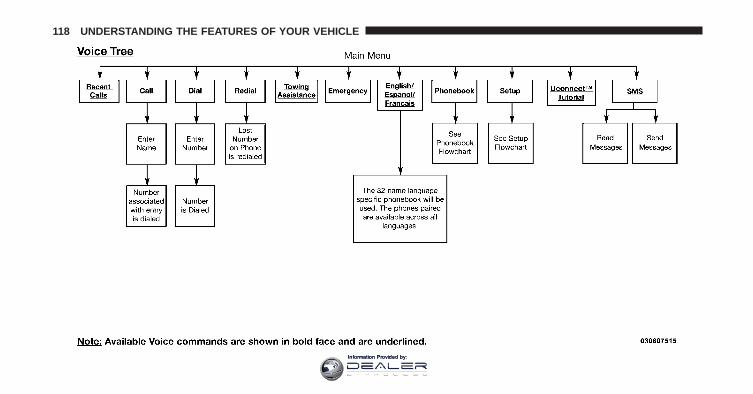
118 UNDERSTANDING THE FEATURES OF YOUR VEHICLE
Information Provided by:
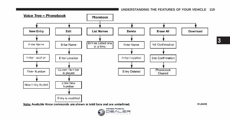
3
UNDERSTANDING THE FEATURES OF YOUR VEHICLE 119
Information Provided by:

120 UNDERSTANDING THE FEATURES OF YOUR VEHICLE
Information Provided by:
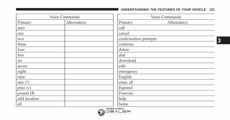
Voice CommandsPrimary Alternate(s)zeroonetwothreefourfivesixseveneightninestar (*)plus (+)pound (#)add locationall
Voice CommandsPrimary Alternate(s)callcancelconfirmation promptscontinuedeletedialdownloadeditemergencyEnglisherase allEspanolFrancaishelphome
3
UNDERSTANDING THE FEATURES OF YOUR VEHICLE 121
Information Provided by:
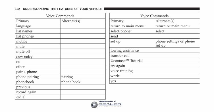
Voice CommandsPrimary Alternate(s)languagelist nameslist phonesmobilemutemute offnew entrynootherpair a phonephone pairing pairingphonebook phone bookpreviousrecord againredial
Voice CommandsPrimary Alternate(s)return to main menu return or main menuselect phone selectsendset up phone settings or phone
set uptowing assistancetransfer callUconnect™ Tutorialtry againvoice trainingworkyes
122 UNDERSTANDING THE FEATURES OF YOUR VEHICLE
Information Provided by:
General InformationThis device complies with Part 15 of the FCC rules andRSS 210 of Industry Canada. Operation is subject to thefollowing conditions:
• Changes or modifications not expressly approved bythe party responsible for compliance could void theuser’s authority to operate the equipment.
• This device may not cause harmful interference.
• This device must accept any interference received,including interference that may cause undesiredoperation.
VOICE COMMAND — IF EQUIPPED
Voice Command System OperationThis Voice Command system allows you tocontrol your AM, FM radio, satellite radio, discplayer, and a memo recorder.
NOTE: Take care to speak into the Voice InterfaceSystem as calmly and normally as possible. The ability ofthe Voice Interface System to recognize user voice com-mands may be negatively affected by rapid speaking or araised voice level.
WARNING!
Any voice commanded system should be used onlyin safe driving conditions following local laws. Allattention should be kept on the roadway ahead.Failure to do so may result in a collision causingserious injury or death.
When you press the Voice Command button, youwill hear a beep. The beep is your signal to give acommand.
NOTE: If you do not say a command within a fewseconds, the system will present you with a list of options.
3
UNDERSTANDING THE FEATURES OF YOUR VEHICLE 123
Information Provided by:
If you ever wish to interrupt the system while it listsoptions, press the Voice Command button, listenfor the beep, and say your command.
Pressing the Voice Command button while thesystem is speaking is known as “barging in.” The systemwill be interrupted, and after the beep, you can add orchange commands. This will become helpful once youstart to learn the options.
NOTE: At any time, you can say the words “Cancel”,“Help” or “Main Menu”.
These commands are universal and can be used from anymenu. All other commands can be used depending uponthe active application.
When using this system, you should speak clearly and ata normal speaking volume.
The system will best recognize your speech if the win-dows are closed, and the heater/air conditioning fan isset to low.
At any point, if the system does not recognize one of yourcommands, you will be prompted to repeat it.
To hear the first available Menu, press the Voice Com-mand button and say “Help” or “Main Menu”.
CommandsThe Voice Command system understands two types ofcommands. Universal commands are available at alltimes. Local commands are available if the supportedradio mode is active.
Changing the Volume
1. Start a dialogue by pressing the Voice Commandbutton.
2. Say a command (e.g., “Help”).
124 UNDERSTANDING THE FEATURES OF YOUR VEHICLE
Information Provided by:
3. Use the ON/OFF VOLUME rotary knob to adjust thevolume to a comfortable level while the Voice Commandsystem is speaking. Please note the volume setting forVoice Command is different than the audio system.
Main MenuStart a dialogue by pressing the Voice Commandbutton. You may say “Main Menu” to switch to the mainmenu.
In this mode, you can say the following commands:
• “Radio” (to switch to the radio mode)
• “Disc” (to switch to the disc mode)
• “Memo” (to switch to the memo recorder)
• “Setup” (to switch to system setup)
Radio AMTo switch to the AM band, say “AM” or “Radio AM”. Inthis mode, you may say the following commands:
• “Frequency #” (to change the frequency)
• “Next Station” (to select the next station)
• “Previous Station” (to select the previous station)
• “Radio Menu” (to switch to the radio menu)
• “Main Menu” (to switch to the main menu)
Radio FMTo switch to the FM band, say “FM” or “Radio FM”. Inthis mode, you may say the following commands:
• “Frequency #” (to change the frequency)
• “Next Station” (to select the next station)
• “Previous Station” (to select the previous station)
3
UNDERSTANDING THE FEATURES OF YOUR VEHICLE 125
Information Provided by:
• “Menu Radio” (to switch to the radio menu)
• “Main Menu” (to switch to the main menu)
Satellite RadioTo switch to satellite radio mode, say “Sat” or “SatelliteRadio”. In this mode, you may say the following com-mands:
• “Channel Number” (to change the channel by itsspoken number)
• “Next Channel” (to select the next channel)
• “Previous Channel” (to select the previous channel)
• “List Channel” (to hear a list of available channels)
• “Select Name” (to say the name of a channel)
• “Menu Radio” (to switch to the radio menu)
• “Main Menu” (to switch to the main menu)
DiscTo switch to the disc mode, say “Disc”. In this mode, youmay say the following commands:
• “Track” (#) (to change the track)
• “Next Track” (to play the next track)
• “Previous Track” (to play the previous track)
• “Main Menu” (to switch to the main menu)
MemoTo switch to the voice recorder mode, say “Memo”. Inthis mode, you may say the following commands:
• “New Memo” (to record a new memo) — During therecording, you may press the Voice Commandbutton to stop recording. You proceed by saying one ofthe following commands:
− “Save” (to save the memo)
126 UNDERSTANDING THE FEATURES OF YOUR VEHICLE
Information Provided by:
− “Continue” (to continue recording)
− “Delete” (to delete the recording)
• “Play Memos” (to play previously recorded memos)— During the playback you may press the VoiceCommand button to stop playing memos. Youproceed by saying one of the following commands:
− “Repeat” (to repeat a memo)
− “Next” (to play the next memo)
− “Previous” (to play the previous memo)
− “Delete” (to delete a memo)
• “Delete All” (to delete all memos)
SetupTo switch to system setup, you may say on of thefollowing:
• “Change to setup”
• “Switch to system setup”
• “Change to setup”
• “Main menu setup” or
• “Switch to setup”
In this mode, you may say the following commands:
• “Language English”
• “Language French”
• “Language Spanish”
• “Tutorial”
• “Voice Training”
NOTE: Keep in mind that you have to press the VoiceCommand button first and wait for the beep beforespeaking the “Barge In” commands.
3
UNDERSTANDING THE FEATURES OF YOUR VEHICLE 127
Information Provided by:
Voice TrainingFor users experiencing difficulty with the system recog-nizing their voice commands or numbers the Uconnect™Voice “Voice Training” feature may be used.
1. Press the Voice Command button, say “SystemSetup” and once you are in that menu then say “VoiceTraining.” This will train your own voice to the systemand will improve recognition.
2. Repeat the words and phrases when prompted byUconnect™ Voice. For best results, the “Voice Training”session should be completed when the vehicle is parked,engine running, all windows closed, and the blower fanswitched off. This procedure may be repeated with a newuser. The system will adapt to the last trained voice only.
SEATSSeats are a part of the Occupant Restraint System of thevehicle.
WARNING!
• It is extremely dangerous to ride in a cargo area,inside or outside of a vehicle. In a collision, peopleriding in these areas are more likely to be seri-ously injured or killed.
• Do not allow people to ride in any area of yourvehicle that is not equipped with seats and seatbelts.
• Be sure everyone in your vehicle is in a seat andusing a seat belt properly.
Driver’s Power Seat — If EquippedSome models may be equipped with an eight-way driv-er’s power seat. The power seat switches are located onthe outboard side of the driver’s seat cushion.
There are two power seat switches that are used tocontrol the movement of the seat cushion and the seat-back.
128 UNDERSTANDING THE FEATURES OF YOUR VEHICLE
Information Provided by:
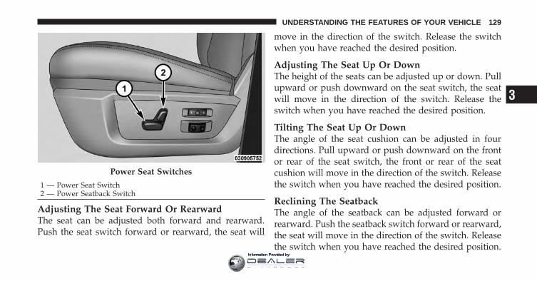
Adjusting The Seat Forward Or RearwardThe seat can be adjusted both forward and rearward.Push the seat switch forward or rearward, the seat will
move in the direction of the switch. Release the switchwhen you have reached the desired position.
Adjusting The Seat Up Or DownThe height of the seats can be adjusted up or down. Pullupward or push downward on the seat switch, the seatwill move in the direction of the switch. Release theswitch when you have reached the desired position.
Tilting The Seat Up Or DownThe angle of the seat cushion can be adjusted in fourdirections. Pull upward or push downward on the frontor rear of the seat switch, the front or rear of the seatcushion will move in the direction of the switch. Releasethe switch when you have reached the desired position.
Reclining The SeatbackThe angle of the seatback can be adjusted forward orrearward. Push the seatback switch forward or rearward,the seat will move in the direction of the switch. Releasethe switch when you have reached the desired position.
Power Seat Switches
1 — Power Seat Switch2 — Power Seatback Switch
3
UNDERSTANDING THE FEATURES OF YOUR VEHICLE 129
Information Provided by:
WARNING!
• Adjusting a seat while driving may be dangerous.Moving a seat while driving could result in loss ofcontrol which could cause a collision and seriousinjury or death.
• Seats should be adjusted before fastening the seatbelts and while the vehicle is parked. Seriousinjury or death could result from a poorly adjustedseat belt.
• Do not ride with the seatback reclined so that theshoulder belt is no longer resting against yourchest. In a collision you could slide under the seatbelt, which could result in serious injury or death.
CAUTION!
Do not place any article under a power seat orimpede its ability to move as it may cause damage tothe seat controls. Seat travel may become limited ifmovement is stopped by an obstruction in the seat’spath.
Passenger’s Power Seat — If EquippedSome models are equipped with a six-way power pas-senger seat. The power seat switch is located on theoutboard side of the seat. The switch is used to controlthe movement of the seat and seat cushion.
Adjusting The Seat Forward Or RearwardThe seat can be adjusted both forward and rearward.Push the seat switch forward or rearward, the seat willmove in the direction of the switch. Release the switchwhen you have reached the desired position.
130 UNDERSTANDING THE FEATURES OF YOUR VEHICLE
Information Provided by:
Adjusting The Seat Up Or DownThe height of the seats can be adjusted up or down. Pullupward or push downward on the seat switch, the seatwill move in the direction of the switch. Release theswitch when you have reached the desired position.
Tilting The Seat Up Or DownThe angle of the seat cushion can be adjusted up ordown. Pull upward or push downward on the front ofthe seat switch, the front of the seat cushion will move inthe direction of the switch. Release the switch when youhave reached the desired position.
WARNING!
• Adjusting a seat while driving may be dangerous.Moving a seat while driving could result in loss ofcontrol which could cause a collision and seriousinjury or death.
(Continued)
WARNING! (Continued)• Seats should be adjusted before fastening the seat
belts and while the vehicle is parked. Seriousinjury or death could result from a poorly adjustedseat belt.
• Do not ride with the seatback reclined so that theshoulder belt is no longer resting against yourchest. In a collision you could slide under the seatbelt, which could result in serious injury or death.
CAUTION!
Do not place any article under a power seat orimpede its ability to move as it may cause damage tothe seat controls. Seat travel may become limited ifmovement is stopped by an obstruction in the seat’spath.
3
UNDERSTANDING THE FEATURES OF YOUR VEHICLE 131
Information Provided by:
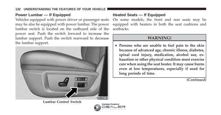
Power Lumbar — If EquippedVehicles equipped with power driver or passenger seatsmay be also be equipped with power lumbar. The powerlumbar switch is located on the outboard side of thepower seat. Push the switch forward to increase thelumbar support. Push the switch rearward to decreasethe lumbar support.
Heated Seats — If EquippedOn some models, the front and rear seats may beequipped with heaters in both the seat cushions andseatbacks.
WARNING!
• Persons who are unable to feel pain to the skinbecause of advanced age, chronic illness, diabetes,spinal cord injury, medication, alcohol use, ex-haustion or other physical condition must exercisecare when using the seat heater. It may cause burnseven at low temperatures, especially if used forlong periods of time.
(Continued)
Lumbar Control Switch
132 UNDERSTANDING THE FEATURES OF YOUR VEHICLE
Information Provided by:
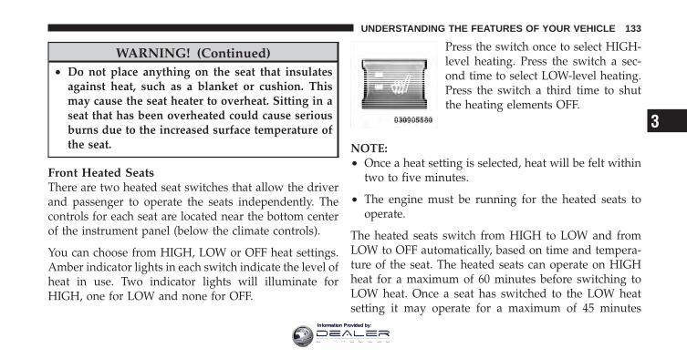
WARNING! (Continued)• Do not place anything on the seat that insulates
against heat, such as a blanket or cushion. Thismay cause the seat heater to overheat. Sitting in aseat that has been overheated could cause seriousburns due to the increased surface temperature ofthe seat.
Front Heated SeatsThere are two heated seat switches that allow the driverand passenger to operate the seats independently. Thecontrols for each seat are located near the bottom centerof the instrument panel (below the climate controls).
You can choose from HIGH, LOW or OFF heat settings.Amber indicator lights in each switch indicate the level ofheat in use. Two indicator lights will illuminate forHIGH, one for LOW and none for OFF.
Press the switch once to select HIGH-level heating. Press the switch a sec-ond time to select LOW-level heating.Press the switch a third time to shutthe heating elements OFF.
NOTE:• Once a heat setting is selected, heat will be felt within
two to five minutes.
• The engine must be running for the heated seats tooperate.
The heated seats switch from HIGH to LOW and fromLOW to OFF automatically, based on time and tempera-ture of the seat. The heated seats can operate on HIGHheat for a maximum of 60 minutes before switching toLOW heat. Once a seat has switched to the LOW heatsetting it may operate for a maximum of 45 minutes
3
UNDERSTANDING THE FEATURES OF YOUR VEHICLE 133
Information Provided by:
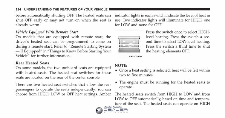
before automatically shutting OFF. The heated seats canshut OFF early or may not turn on when the seat isalready warm.
Vehicle Equipped With Remote StartOn models that are equipped with remote start, thedriver’s heated seat can be programmed to come onduring a remote start. Refer to “Remote Starting System— If Equipped” in “Things to Know Before Starting YourVehicle” for further information.
Rear Heated SeatsOn some models, the two outboard seats are equippedwith heated seats. The heated seat switches for theseseats are located on the rear of the center console.
There are two heated seat switches that allow the rearpassengers to operate the seats independently. You canchoose from HIGH, LOW or OFF heat settings. Amber
indicator lights in each switch indicate the level of heat inuse. Two indicator lights will illuminate for HIGH, onefor LOW and none for OFF.
Press the switch once to select HIGH-level heating. Press the switch a sec-ond time to select LOW-level heating.Press the switch a third time to shutthe heating elements OFF.
NOTE:• Once a heat setting is selected, heat will be felt within
two to five minutes.
• The engine must be running for the heated seats tooperate.
The heated seats switch from HIGH to LOW and fromLOW to OFF automatically, based on time and tempera-ture of the seat. The heated seats can operate on HIGH
134 UNDERSTANDING THE FEATURES OF YOUR VEHICLE
Information Provided by:
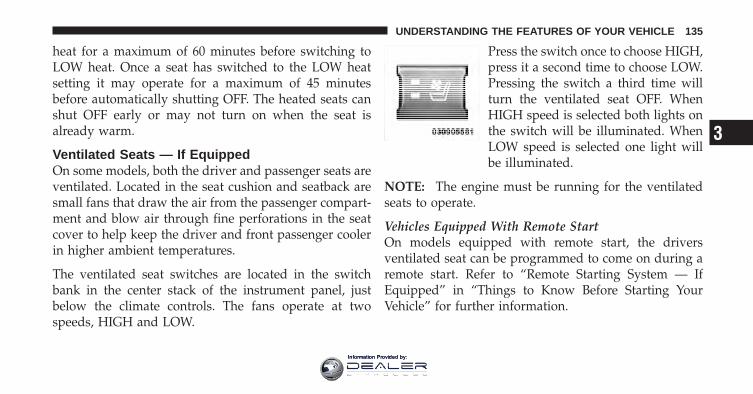
heat for a maximum of 60 minutes before switching toLOW heat. Once a seat has switched to the LOW heatsetting it may operate for a maximum of 45 minutesbefore automatically shutting OFF. The heated seats canshut OFF early or may not turn on when the seat isalready warm.
Ventilated Seats — If EquippedOn some models, both the driver and passenger seats areventilated. Located in the seat cushion and seatback aresmall fans that draw the air from the passenger compart-ment and blow air through fine perforations in the seatcover to help keep the driver and front passenger coolerin higher ambient temperatures.
The ventilated seat switches are located in the switchbank in the center stack of the instrument panel, justbelow the climate controls. The fans operate at twospeeds, HIGH and LOW.
Press the switch once to choose HIGH,press it a second time to choose LOW.Pressing the switch a third time willturn the ventilated seat OFF. WhenHIGH speed is selected both lights onthe switch will be illuminated. WhenLOW speed is selected one light willbe illuminated.
NOTE: The engine must be running for the ventilatedseats to operate.
Vehicles Equipped With Remote StartOn models equipped with remote start, the driversventilated seat can be programmed to come on during aremote start. Refer to “Remote Starting System — IfEquipped” in “Things to Know Before Starting YourVehicle” for further information.
3
UNDERSTANDING THE FEATURES OF YOUR VEHICLE 135
Information Provided by:
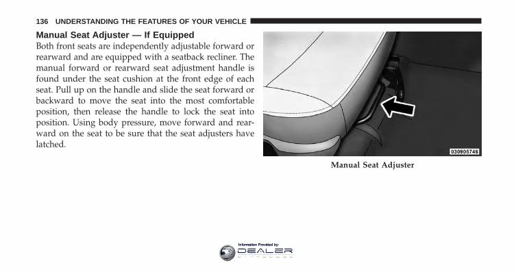
Manual Seat Adjuster — If EquippedBoth front seats are independently adjustable forward orrearward and are equipped with a seatback recliner. Themanual forward or rearward seat adjustment handle isfound under the seat cushion at the front edge of eachseat. Pull up on the handle and slide the seat forward orbackward to move the seat into the most comfortableposition, then release the handle to lock the seat intoposition. Using body pressure, move forward and rear-ward on the seat to be sure that the seat adjusters havelatched.
Manual Seat Adjuster
136 UNDERSTANDING THE FEATURES OF YOUR VEHICLE
Information Provided by:
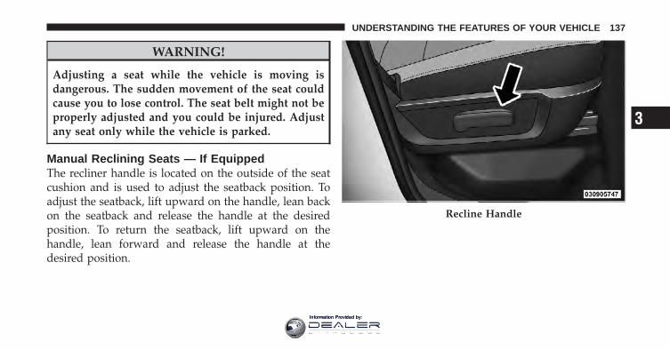
WARNING!
Adjusting a seat while the vehicle is moving isdangerous. The sudden movement of the seat couldcause you to lose control. The seat belt might not beproperly adjusted and you could be injured. Adjustany seat only while the vehicle is parked.
Manual Reclining Seats — If EquippedThe recliner handle is located on the outside of the seatcushion and is used to adjust the seatback position. Toadjust the seatback, lift upward on the handle, lean backon the seatback and release the handle at the desiredposition. To return the seatback, lift upward on thehandle, lean forward and release the handle at thedesired position.
Recline Handle
3
UNDERSTANDING THE FEATURES OF YOUR VEHICLE 137
Information Provided by:
WARNING!
• Actuating the recliner handle will allow the seat-back to swing (dump) forward on manual reclinerseats. Do not stand or lean in front of the seatwhile actuating the handle. The seatback mayswing forward and hit you causing injury. Thisdump feature allows access to the storage binbehind the seat. To avoid injury, place your handon the seatback and actuate the handle then posi-tion the seatback in the desired position.
(Continued)
WARNING! (Continued)• You can be seriously, even fatally, injured riding in
a seat with the seatback reclined. Do not ride withthe seatback reclined so that the shoulder belt isno longer resting against your chest. If you ride inthis position, the shoulder harness will no longerbe restraining you. In a collision you could slideunder the seat belt and receive serious or fatalinjuries. Recline in a seat only when the vehicle isparked.
Head RestraintsHead restraints are designed to reduce the risk of injuryby restricting head movement in the event of a rearimpact. Head restraints should be adjusted so that the topof the head restraint is located above the top of your ear.
138 UNDERSTANDING THE FEATURES OF YOUR VEHICLE
Information Provided by:
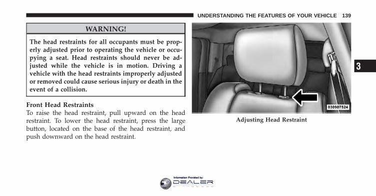
WARNING!
The head restraints for all occupants must be prop-erly adjusted prior to operating the vehicle or occu-pying a seat. Head restraints should never be ad-justed while the vehicle is in motion. Driving avehicle with the head restraints improperly adjustedor removed could cause serious injury or death in theevent of a collision.
Front Head RestraintsTo raise the head restraint, pull upward on the headrestraint. To lower the head restraint, press the largebutton, located on the base of the head restraint, andpush downward on the head restraint.
Adjusting Head Restraint
3
UNDERSTANDING THE FEATURES OF YOUR VEHICLE 139
Information Provided by:
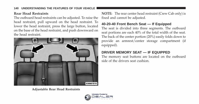
Rear Head RestraintsThe outboard head restraints can be adjusted. To raise thehead restraint, pull upward on the head restraint. Tolower the head restraint, press the large button, locatedon the base of the head restraint, and push downward onthe head restraint.
NOTE: The rear center head restraint (Crew Cab only) isfixed and cannot be adjusted.
40-20-40 Front Bench Seat — If EquippedThe seat is divided into three segments. The outboardseat portions are each 40% of the total width of the seat.The back of the center portion (20%) easily folds down toprovide an armrest/center storage compartment (ifequipped).
DRIVER MEMORY SEAT — IF EQUIPPEDThe memory seat buttons are located on the outboardside of the drivers seat cushion.
Adjustable Rear Head Restraints
140 UNDERSTANDING THE FEATURES OF YOUR VEHICLE
Information Provided by:
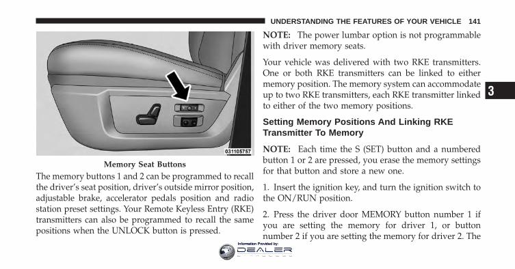
The memory buttons 1 and 2 can be programmed to recallthe driver’s seat position, driver’s outside mirror position,adjustable brake, accelerator pedals position and radiostation preset settings. Your Remote Keyless Entry (RKE)transmitters can also be programmed to recall the samepositions when the UNLOCK button is pressed.
NOTE: The power lumbar option is not programmablewith driver memory seats.
Your vehicle was delivered with two RKE transmitters.One or both RKE transmitters can be linked to eithermemory position. The memory system can accommodateup to two RKE transmitters, each RKE transmitter linkedto either of the two memory positions.
Setting Memory Positions And Linking RKETransmitter To Memory
NOTE: Each time the S (SET) button and a numberedbutton 1 or 2 are pressed, you erase the memory settingsfor that button and store a new one.
1. Insert the ignition key, and turn the ignition switch tothe ON/RUN position.
2. Press the driver door MEMORY button number 1 ifyou are setting the memory for driver 1, or buttonnumber 2 if you are setting the memory for driver 2. The
Memory Seat Buttons
3
UNDERSTANDING THE FEATURES OF YOUR VEHICLE 141
Information Provided by:
system will recall any stored settings. Wait for the systemto complete the memory recall before continuing toStep 3.
3. Adjust the driver’s seat, recliner, and driver’ssideview mirror to the desired positions.
4. Adjust the power adjustable pedals (if equipped) tothe desired positions.
5. Turn on the radio and set the radio station presets (upto 12 AM and 12 FM stations can be set).
6. Turn the ignition switch to the OFF position andremove the key.
7. Press and release the S (SET) button located on thedriver’s door.
8. Within five seconds, press and release MEMORYbutton 1 or 2 on the driver’s door. The next step must beperformed within five seconds if you desire to also use aRKE transmitter to recall memory positions.
9. Press and release the LOCK button on one of the RKEtransmitters.
10. Insert the ignition key, and turn the ignition switch tothe ON position.
11. Select “Remote Linked to Memory” in the ElectronicVehicle Information Center (EVIC) and enter “Yes”. Referto “Electronic Vehicle Information Center (EVIC)/Customer-Programmable Features” in “UnderstandingYour Instrument Panel” for further information.
12. Repeat the above steps to set the next memoryposition, using the other numbered memory button, or tolink another RKE transmitter to memory.
142 UNDERSTANDING THE FEATURES OF YOUR VEHICLE
Information Provided by:
Memory Position Recall
NOTE: The vehicle must be in PARK to recall memorypositions. If a recall is attempted when the vehicle is notin PARK, a message will be displayed in the ElectronicVehicle Information Center (EVIC).
To recall the memory settings for driver one, pressMEMORY button number 1 on the driver’s door, or theUNLOCK button on the RKE transmitter linked tomemory position 1.
To recall the memory setting for driver two, pressMEMORY button number 2 on the driver’s door, or theUNLOCK button on the RKE transmitter linked tomemory position 2.
A recall can be cancelled by pressing any of theMEMORY buttons on the drivers seat during a recall (S,1, or 2). When a recall is cancelled, the driver’s seat,
driver’s mirror and the pedals stop moving. A delay ofone second will occur before another recall can beselected.
To Disable A RKE Transmitter Linked To Memory
1. Turn the ignition switch to the LOCK position, andremove the key.
2. Press and release MEMORY button number 1. Thesystem will recall any memory settings stored in position1. Wait for the system to complete the memory recallbefore continuing to Step 3.
3. Press and release the memory S (SET) button locatedon the driver’s door.
4. Within five seconds, press and release MEMORYbutton 1 on the driver’s door.
5. Within five seconds, press and release the UNLOCKbutton on the RKE transmitter. To disable another RKE
3
UNDERSTANDING THE FEATURES OF YOUR VEHICLE 143
Information Provided by:
transmitter linked to either memory position, repeatsteps 1 through 5 for each RKE transmitter.
NOTE: Once programmed, all RKE transmitters linkedto memory can be easily enabled or disabled at one time.Refer to “Electronic Vehicle Information Center (EVIC)/Customer-Programmable Features” in “UnderstandingYour Instrument Panel” for further information.
Easy Entry/Exit SeatThis feature provides automatic driver’s seat positioningwhich will enhance driver mobility out of and into thevehicle.
There are two possible Easy Entry/Exit adjustmentsavailable:
• The seat cushion will move rearward approximately2.5 in (60 mm), if the starting position of the seat isgreater than or equal to 2.67 in (68 mm) forward of therear seat stop when the key is removed from the
ignition switch. The seat will then move forwardapproximately 2.5 in (60 mm) when the key is placedinto the ignition and turned out of the LOCK position.
• The seat will move to the position located 0.3 in(8 mm) forward of the rear stop if the starting positionis between 0.9 to 2.67 in (23 to 68 mm) forward of therear stop when the key is removed from the ignitionswitch. The seat will move forward to the memory/driving position when the key is placed into theignition, and turned out of the LOCK position towardthe ACC/ON position.
The Easy Entry/Exit feature will be automatically dis-abled if the seat is already positioned closer than 0.9 in(23 mm) forward of the rear stop. At this position, thereis no benefit to the driver by moving the seat for EasyExit/Entry.
Each stored memory setting will have an associated EasyEntry/Exit position.
144 UNDERSTANDING THE FEATURES OF YOUR VEHICLE
Information Provided by:
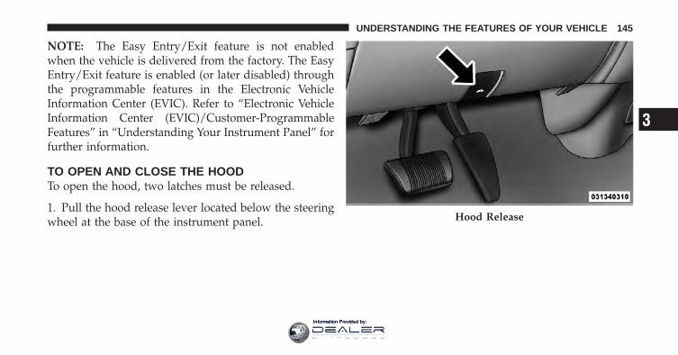
NOTE: The Easy Entry/Exit feature is not enabledwhen the vehicle is delivered from the factory. The EasyEntry/Exit feature is enabled (or later disabled) throughthe programmable features in the Electronic VehicleInformation Center (EVIC). Refer to “Electronic VehicleInformation Center (EVIC)/Customer-ProgrammableFeatures” in “Understanding Your Instrument Panel” forfurther information.
TO OPEN AND CLOSE THE HOODTo open the hood, two latches must be released.
1. Pull the hood release lever located below the steeringwheel at the base of the instrument panel. Hood Release
3
UNDERSTANDING THE FEATURES OF YOUR VEHICLE 145
Information Provided by:
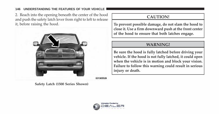
2. Reach into the opening beneath the center of the hoodand push the safety latch lever from right to left to releaseit, before raising the hood.
CAUTION!
To prevent possible damage, do not slam the hood toclose it. Use a firm downward push at the front centerof the hood to ensure that both latches engage.
WARNING!
Be sure the hood is fully latched before driving yourvehicle. If the hood is not fully latched, it could openwhen the vehicle is in motion and block your vision.Failure to follow this warning could result in seriousinjury or death.
Safety Latch (1500 Series Shown)
146 UNDERSTANDING THE FEATURES OF YOUR VEHICLE
Information Provided by:
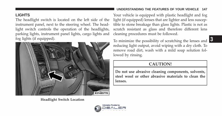
LIGHTSThe headlight switch is located on the left side of theinstrument panel, next to the steering wheel. The head-light switch controls the operation of the headlights,parking lights, instrument panel lights, cargo lights andfog lights (if equipped).
Your vehicle is equipped with plastic headlight and foglight (if equipped) lenses that are lighter and less suscep-tible to stone breakage than glass lights. Plastic is not asscratch resistant as glass and therefore different lenscleaning procedures must be followed.
To minimize the possibility of scratching the lenses andreducing light output, avoid wiping with a dry cloth. Toremove road dirt, wash with a mild soap solution fol-lowed by rinsing.
CAUTION!
Do not use abrasive cleaning components, solvents,steel wool or other abrasive materials to clean thelenses.
Headlight Switch Location
3
UNDERSTANDING THE FEATURES OF YOUR VEHICLE 147
Information Provided by:
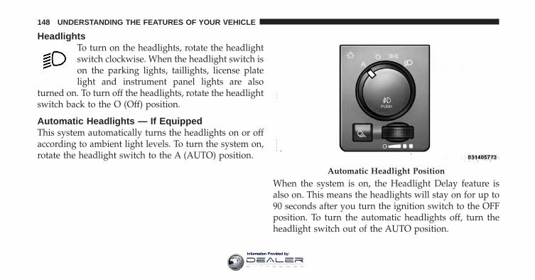
HeadlightsTo turn on the headlights, rotate the headlightswitch clockwise. When the headlight switch ison the parking lights, taillights, license platelight and instrument panel lights are also
turned on. To turn off the headlights, rotate the headlightswitch back to the O (Off) position.
Automatic Headlights — If EquippedThis system automatically turns the headlights on or offaccording to ambient light levels. To turn the system on,rotate the headlight switch to the A (AUTO) position.
When the system is on, the Headlight Delay feature isalso on. This means the headlights will stay on for up to90 seconds after you turn the ignition switch to the OFFposition. To turn the automatic headlights off, turn theheadlight switch out of the AUTO position.
Automatic Headlight Position
148 UNDERSTANDING THE FEATURES OF YOUR VEHICLE
Information Provided by:
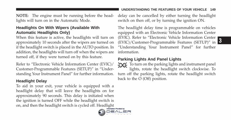
NOTE: The engine must be running before the head-lights will turn on in the Automatic Mode.
Headlights On With Wipers (Available WithAutomatic Headlights Only)When this feature is active, the headlights will turn onapproximately 10 seconds after the wipers are turned onif the headlight switch is placed in the AUTO position. Inaddition, the headlights will turn off when the wipers areturned off, if they were turned on by this feature.
Refer to “Electronic Vehicle Information Center (EVIC)/Customer-Programmable Features (SETUP)” in “Under-standing Your Instrument Panel” for further information.
Headlight DelayTo aid in your exit, your vehicle is equipped with aheadlight delay that will leave the headlights on forapproximately 90 seconds. This delay is initiated whenthe ignition is turned OFF while the headlight switch ison, and then the headlight switch is cycled off. Headlight
delay can be cancelled by either turning the headlightswitch on then off, or by turning the ignition ON.
The headlight delay time is programmable on vehiclesequipped with an Electronic Vehicle Information Center(EVIC). Refer to “Electronic Vehicle Information Center(EVIC)/Customer-Programmable Features (SETUP)” in“Understanding Your Instrument Panel” for furtherinformation.
Parking Lights And Panel LightsTo turn on the parking lights and instrument panellights, rotate the headlight switch clockwise. To
turn off the parking lights, rotate the headlight switchback to the O (Off) position.
3
UNDERSTANDING THE FEATURES OF YOUR VEHICLE 149
Information Provided by:
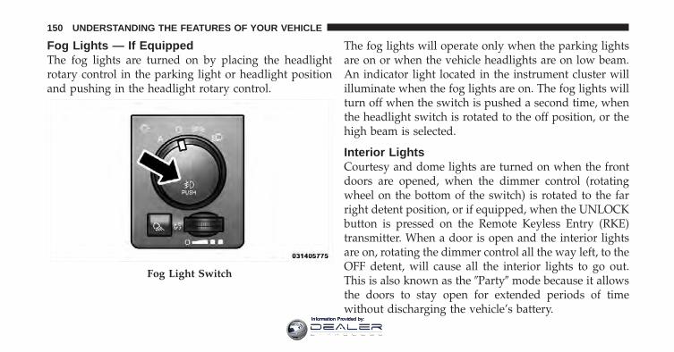
Fog Lights — If EquippedThe fog lights are turned on by placing the headlightrotary control in the parking light or headlight positionand pushing in the headlight rotary control.
The fog lights will operate only when the parking lightsare on or when the vehicle headlights are on low beam.An indicator light located in the instrument cluster willilluminate when the fog lights are on. The fog lights willturn off when the switch is pushed a second time, whenthe headlight switch is rotated to the off position, or thehigh beam is selected.
Interior LightsCourtesy and dome lights are turned on when the frontdoors are opened, when the dimmer control (rotatingwheel on the bottom of the switch) is rotated to the farright detent position, or if equipped, when the UNLOCKbutton is pressed on the Remote Keyless Entry (RKE)transmitter. When a door is open and the interior lightsare on, rotating the dimmer control all the way left, to theOFF detent, will cause all the interior lights to go out.This is also known as the �Party� mode because it allowsthe doors to stay open for extended periods of timewithout discharging the vehicle’s battery.
Fog Light Switch
150 UNDERSTANDING THE FEATURES OF YOUR VEHICLE
Information Provided by:
The brightness of the instrument panel lighting can beregulated by rotating the dimmer control right (brighter)or left (dimmer). When the headlights are on you cansupplement the brightness of the odometer, trip odom-eter, radio and overhead console by rotating the controlto the right until you hear a click. This feature is termedthe “Parade” mode and is useful when headlights arerequired during the day.
Dimmer Control
3
UNDERSTANDING THE FEATURES OF YOUR VEHICLE 151
Information Provided by:
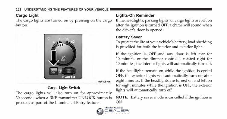
Cargo LightThe cargo lights are turned on by pressing on the cargobutton.
The cargo lights will also turn on for approximately30 seconds when a RKE transmitter UNLOCK button ispressed, as part of the Illuminated Entry feature.
Lights-On ReminderIf the headlights, parking lights, or cargo lights are left onafter the ignition is turned OFF, a chime will sound whenthe driver’s door is opened.
Battery SaverTo protect the life of your vehicle’s battery, load sheddingis provided for both the interior and exterior lights.
If the ignition is OFF and any door is left ajar for10 minutes or the dimmer control is rotated right for10 minutes, the interior lights will automatically turn off.
If the headlights remain on while the ignition is cycledOFF, the exterior lights will automatically turn off aftereight minutes. If the headlights are turned on and left onfor eight minutes while the ignition is OFF, the exteriorlights will automatically turn off.
NOTE: Battery saver mode is cancelled if the ignition isON.
Cargo Light Switch
152 UNDERSTANDING THE FEATURES OF YOUR VEHICLE
Information Provided by:
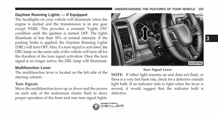
Daytime Running Lights — If EquippedThe headlights on your vehicle will illuminate when theengine is started and the transmission is in any gearexcept PARK. This provides a constant �Lights ON�condition until the ignition is turned OFF. The lightsilluminate at less than 50% of normal intensity. If theparking brake is applied, the Daytime Running Lights(DRL) will turn OFF. Also, if a turn signal is activated, theDRL lamp on the same side of the vehicle will turn off forthe duration of the turn signal activation. Once the turnsignal is no longer active, the DRL lamp will illuminate.
Multifunction LeverThe multifunction lever is located on the left side of thesteering column.
Turn SignalsMove the multifunction lever up or down and the arrowson each side of the instrument cluster flash to showproper operation of the front and rear turn signal lights.
NOTE: If either light remains on and does not flash, orthere is a very fast flash rate, check for a defective outsidelight bulb. If an indicator fails to light when the lever ismoved, it would suggest that the indicator bulb isdefective.
Turn Signal Lever
3
UNDERSTANDING THE FEATURES OF YOUR VEHICLE 153
Information Provided by:
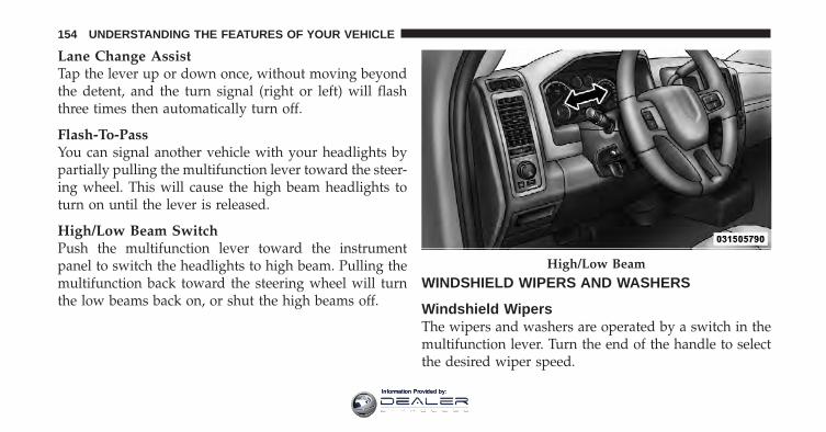
Lane Change AssistTap the lever up or down once, without moving beyondthe detent, and the turn signal (right or left) will flashthree times then automatically turn off.
Flash-To-PassYou can signal another vehicle with your headlights bypartially pulling the multifunction lever toward the steer-ing wheel. This will cause the high beam headlights toturn on until the lever is released.
High/Low Beam SwitchPush the multifunction lever toward the instrumentpanel to switch the headlights to high beam. Pulling themultifunction back toward the steering wheel will turnthe low beams back on, or shut the high beams off.
WINDSHIELD WIPERS AND WASHERS
Windshield WipersThe wipers and washers are operated by a switch in themultifunction lever. Turn the end of the handle to selectthe desired wiper speed.
High/Low Beam
154 UNDERSTANDING THE FEATURES OF YOUR VEHICLE
Information Provided by:
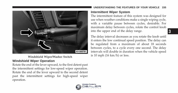
Windshield Wiper OperationRotate the end of the lever upward, to the first detent pastthe intermittent settings for low-speed wiper operation.Rotate the end of the lever upward to the second detentpast the intermittent settings for high-speed wiperoperation.
Intermittent Wiper SystemThe intermittent feature of this system was designed foruse when weather conditions make a single wiping cycle,with a variable pause between cycles, desirable. Formaximum delay between cycles, rotate the control knobinto the upper end of the delay range.
The delay interval decreases as you rotate the knob untilit enters the low continual speed position. The delay canbe regulated from a maximum of about 18 secondsbetween cycles, to a cycle every one second. The delayintervals will double in duration when the vehicle speedis 10 mph (16 km/h) or less.Windshield Wiper/Washer Switch
3
UNDERSTANDING THE FEATURES OF YOUR VEHICLE 155
Information Provided by:
Windshield WashersTo use the windshield washer, push the washer knob,located on the end of the multifunction lever, inward tothe second detent. Washer fluid will be sprayed and thewiper will operate for two to three cycles after the washerknob is released from this position. If the washer knob isdepressed while in the delay range, the wiper willoperate for several seconds after the washer knob isreleased. It will then resume the intermittent intervalpreviously selected. If the washer knob is pushed whilein the off position, the wiper will turn on and cycleapproximately three times after the wash knob is re-leased.
To prevent freeze-up of your windshield washer systemin cold weather, select a solution or mixture that meets orexceeds the temperature range of your climate. Thisrating information can be found on most washer fluidcontainers.
WARNING!
Sudden loss of visibility through the windshieldcould lead to a collision. You might not see othervehicles or other obstacles. To avoid sudden icing ofthe windshield during freezing weather, warm thewindshield with the defroster before and duringwindshield washer use.
Mist FeatureWhen a single wipe to clear off road mist or spray froma passing vehicle is needed, push the washer knob,located on the end of the multifunction lever, inward tothe first detent and release. The wipers will cycle onetime and automatically shut off.
NOTE: The mist feature does not activate the washerpump; therefore, no washer fluid will be sprayed on thewindshield. The wash function must be used in order tospray the windshield with washer fluid.
156 UNDERSTANDING THE FEATURES OF YOUR VEHICLE
Information Provided by:
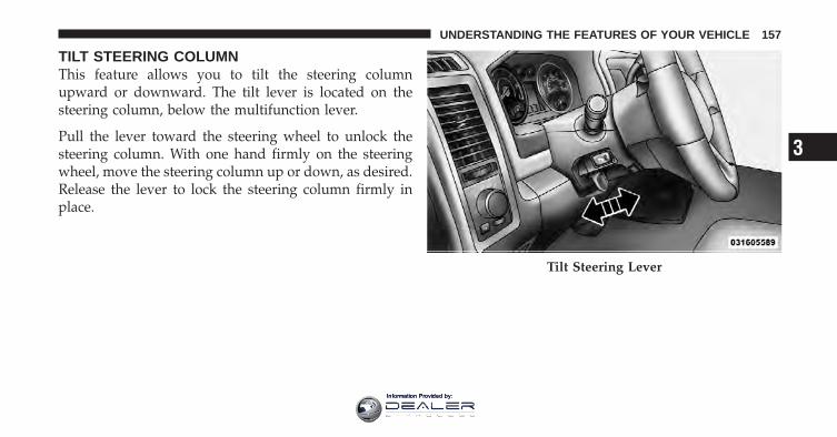
TILT STEERING COLUMNThis feature allows you to tilt the steering columnupward or downward. The tilt lever is located on thesteering column, below the multifunction lever.
Pull the lever toward the steering wheel to unlock thesteering column. With one hand firmly on the steeringwheel, move the steering column up or down, as desired.Release the lever to lock the steering column firmly inplace.
Tilt Steering Lever
3
UNDERSTANDING THE FEATURES OF YOUR VEHICLE 157
Information Provided by:
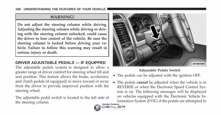
WARNING!
Do not adjust the steering column while driving.Adjusting the steering column while driving or driv-ing with the steering column unlocked, could causethe driver to lose control of the vehicle. Be sure thesteering column is locked before driving your ve-hicle. Failure to follow this warning may result inserious injury or death.
DRIVER ADJUSTABLE PEDALS — IF EQUIPPEDThe adjustable pedals system is designed to allow agreater range of driver comfort for steering wheel tilt andseat position. This feature allows the brake, accelerator,and clutch pedals (if equipped) to move toward or awayfrom the driver to provide improved position with thesteering wheel.
The adjustable pedal switch is located to the left side ofthe steering column.
• The pedals can be adjusted with the ignition OFF.
• The pedals cannot be adjusted when the vehicle is inREVERSE or when the Electronic Speed Control Sys-tem is on. The following messages will be displayedon vehicles equipped with the Electronic Vehicle In-formation System (EVIC) if the pedals are attempted to
Adjustable Pedals Switch
158 UNDERSTANDING THE FEATURES OF YOUR VEHICLE
Information Provided by:
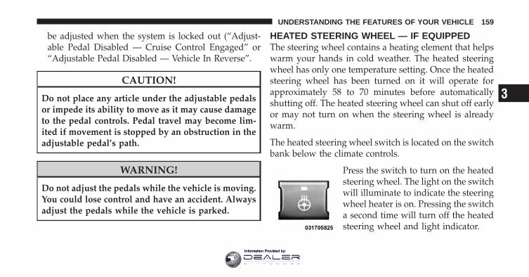
be adjusted when the system is locked out (“Adjust-able Pedal Disabled — Cruise Control Engaged” or“Adjustable Pedal Disabled — Vehicle In Reverse”.
CAUTION!
Do not place any article under the adjustable pedalsor impede its ability to move as it may cause damageto the pedal controls. Pedal travel may become lim-ited if movement is stopped by an obstruction in theadjustable pedal’s path.
WARNING!
Do not adjust the pedals while the vehicle is moving.You could lose control and have an accident. Alwaysadjust the pedals while the vehicle is parked.
HEATED STEERING WHEEL — IF EQUIPPEDThe steering wheel contains a heating element that helpswarm your hands in cold weather. The heated steeringwheel has only one temperature setting. Once the heatedsteering wheel has been turned on it will operate forapproximately 58 to 70 minutes before automaticallyshutting off. The heated steering wheel can shut off earlyor may not turn on when the steering wheel is alreadywarm.
The heated steering wheel switch is located on the switchbank below the climate controls.
Press the switch to turn on the heatedsteering wheel. The light on the switchwill illuminate to indicate the steeringwheel heater is on. Pressing the switcha second time will turn off the heatedsteering wheel and light indicator.
3
UNDERSTANDING THE FEATURES OF YOUR VEHICLE 159
Information Provided by:
NOTE: The engine must be running for the heatedsteering wheel to operate.
Vehicles Equipped With Remote StartOn models that are equipped with remote start, theheated steering wheel can be programmed to come onduring a remote start. Refer to “Remote Starting System— If Equipped” in “Things to Know Before Starting YourVehicle” for further information.
WARNING!
• Persons who are unable to feel pain to the skinbecause of advanced age, chronic illness, diabetes,spinal cord injury, medication, alcohol use, ex-haustion, or other physical conditions must exer-cise care when using the steering wheel heater. Itmay cause burns even at low temperatures, espe-cially if used for long periods.
(Continued)
WARNING! (Continued)• Do not place anything on the steering wheel that
insulates against heat, such as a blanket or steeringwheel covers of any type and material.. This maycause the steering wheel heater to overheat.
ELECTRONIC SPEED CONTROLWhen engaged, the Electronic Speed Control takes overaccelerator operations at speeds greater than 25 mph(40 km/h).
The Electronic Speed Control buttons are located on theright side of the steering wheel.
160 UNDERSTANDING THE FEATURES OF YOUR VEHICLE
Information Provided by:
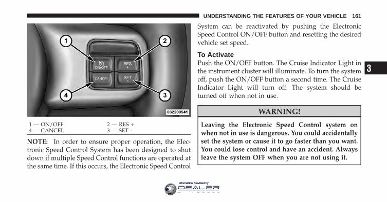
NOTE: In order to ensure proper operation, the Elec-tronic Speed Control System has been designed to shutdown if multiple Speed Control functions are operated atthe same time. If this occurs, the Electronic Speed Control
System can be reactivated by pushing the ElectronicSpeed Control ON/OFF button and resetting the desiredvehicle set speed.
To ActivatePush the ON/OFF button. The Cruise Indicator Light inthe instrument cluster will illuminate. To turn the systemoff, push the ON/OFF button a second time. The CruiseIndicator Light will turn off. The system should beturned off when not in use.
WARNING!
Leaving the Electronic Speed Control system onwhen not in use is dangerous. You could accidentallyset the system or cause it to go faster than you want.You could lose control and have an accident. Alwaysleave the system OFF when you are not using it.
1 — ON/OFF 2 — RES +4 — CANCEL 3 — SET -
3
UNDERSTANDING THE FEATURES OF YOUR VEHICLE 161
Information Provided by:
To Set A Desired SpeedTurn the Electronic Speed Control ON. When the vehiclehas reached the desired speed, press the SET (-) buttonand release. Release the accelerator and the vehicle willoperate at the selected speed.
NOTE: The vehicle should be traveling at a steadyspeed and on level ground before pressing the SETbutton.
To DeactivateA soft tap on the brake pedal, pushing the CANCELbutton, or normal brake pressure while slowing thevehicle will deactivate Electronic Speed Control withouterasing the set speed memory. Pressing the ON/OFFbutton or turning the ignition switch OFF erases the setspeed memory.
To Resume SpeedTo resume a previously set speed, push the RES (+)button and release. Resume can be used at any speedabove 20 mph (32 km/h).
To Vary The Speed SettingWhen the Electronic Speed Control is set, you can in-crease speed by pushing the RES (+) button. If the buttonis continually pressed, the set speed will continue toincrease until the button is released, then the new setspeed will be established.
Pressing the RES (+) button once will result in a 1 mph(1.6 km/h) increase in set speed. Each subsequent tap ofthe button results in an increase of 1 mph (1.6 km/h).
To decrease speed while the Electronic Speed Control isset, push the SET (-) button. If the button is continuallyheld in the SET (-) position, the set speed will continue to
162 UNDERSTANDING THE FEATURES OF YOUR VEHICLE
Information Provided by:
decrease until the button is released. Release the buttonwhen the desired speed is reached, and the new set speedwill be established.
Pressing the SET (-) button once will result in a 1 mph(1.6 km/h) decrease in set speed. Each subsequent tap ofthe button results in a decrease of 1 mph (1.6 km/h).
To Accelerate For PassingPress the accelerator as you would normally. When thepedal is released, the vehicle will return to the set speed.
Using Electronic Speed Control On HillsThe transmission may downshift on hills to maintain thevehicle set speed.
NOTE: The Electronic Speed Control system maintainsspeed up and down hills. A slight speed change onmoderate hills is normal.
On steep hills, a greater speed loss or gain may occur soit may be preferable to drive without Electronic SpeedControl.
WARNING!
Electronic Speed Control can be dangerous where thesystem cannot maintain a constant speed. Your ve-hicle could go too fast for the conditions, and youcould lose control and have an accident. Do not useElectronic Speed Control in heavy traffic or on roadsthat are winding, icy, snow-covered or slippery.
OVERHEAD CONSOLE — IF EQUIPPEDThe overhead console is located on the headliner abovethe review mirror. The overhead console contains thefollowing features:
• Courtesy/Reading Lights
3
UNDERSTANDING THE FEATURES OF YOUR VEHICLE 163
Information Provided by:
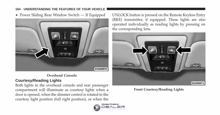
• Power Sliding Rear Window Switch — If Equipped
Courtesy/Reading LightsBoth lights in the overhead console and rear passengercompartment will illuminate as courtesy lights when adoor is opened, when the dimmer control is rotated to thecourtesy light position (full right position), or when the
UNLOCK button is pressed on the Remote Keyless Entry(RKE) transmitter, if equipped. These lights are alsooperated individually as reading lights by pressing onthe corresponding lens.
Overhead Console
Front Courtesy/Reading Lights
164 UNDERSTANDING THE FEATURES OF YOUR VEHICLE
Information Provided by:
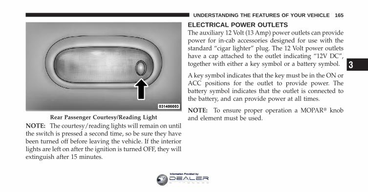
NOTE: The courtesy/reading lights will remain on untilthe switch is pressed a second time, so be sure they havebeen turned off before leaving the vehicle. If the interiorlights are left on after the ignition is turned OFF, they willextinguish after 15 minutes.
ELECTRICAL POWER OUTLETSThe auxiliary 12 Volt (13 Amp) power outlets can providepower for in-cab accessories designed for use with thestandard “cigar lighter” plug. The 12 Volt power outletshave a cap attached to the outlet indicating “12V DC”,together with either a key symbol or a battery symbol.
A key symbol indicates that the key must be in the ON orACC positions for the outlet to provide power. Thebattery symbol indicates that the outlet is connected tothe battery, and can provide power at all times.
NOTE: To ensure proper operation a MOPAR� knoband element must be used.Rear Passenger Courtesy/Reading Light
3
UNDERSTANDING THE FEATURES OF YOUR VEHICLE 165
Information Provided by:
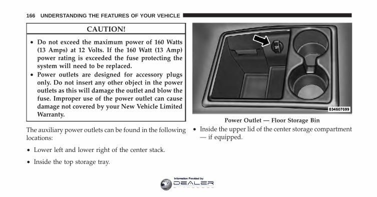
CAUTION!
• Do not exceed the maximum power of 160 Watts(13 Amps) at 12 Volts. If the 160 Watt (13 Amp)power rating is exceeded the fuse protecting thesystem will need to be replaced.
• Power outlets are designed for accessory plugsonly. Do not insert any other object in the poweroutlets as this will damage the outlet and blow thefuse. Improper use of the power outlet can causedamage not covered by your New Vehicle LimitedWarranty.
The auxiliary power outlets can be found in the followinglocations:
• Lower left and lower right of the center stack.
• Inside the top storage tray.
• Inside the upper lid of the center storage compartment— if equipped.
Power Outlet — Floor Storage Bin
166 UNDERSTANDING THE FEATURES OF YOUR VEHICLE
Information Provided by:
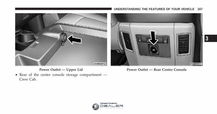
• Rear of the center console storage compartment —Crew Cab.
Power Outlet — Upper Lid Power Outlet — Rear Center Console
3
UNDERSTANDING THE FEATURES OF YOUR VEHICLE 167
Information Provided by:
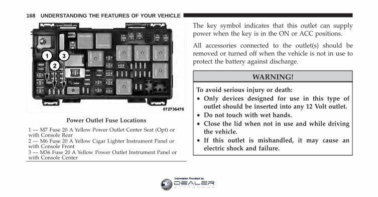
The key symbol indicates that this outlet can supplypower when the key is in the ON or ACC positions.
All accessories connected to the outlet(s) should beremoved or turned off when the vehicle is not in use toprotect the battery against discharge.
WARNING!
To avoid serious injury or death:• Only devices designed for use in this type of
outlet should be inserted into any 12 Volt outlet.• Do not touch with wet hands.• Close the lid when not in use and while driving
the vehicle.• If this outlet is mishandled, it may cause an
electric shock and failure.
Power Outlet Fuse Locations
1 — M7 Fuse 20 A Yellow Power Outlet Center Seat (Opt) orwith Console Rear2 — M6 Fuse 20 A Yellow Cigar Lighter Instrument Panel orwith Console Front3 — M36 Fuse 20 A Yellow Power Outlet Instrument Panel orwith Console Center
168 UNDERSTANDING THE FEATURES OF YOUR VEHICLE
Information Provided by:
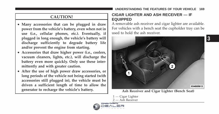
CAUTION!
• Many accessories that can be plugged in drawpower from the vehicle’s battery, even when not inuse (i.e., cellular phones, etc.). Eventually, ifplugged in long enough, the vehicle’s battery willdischarge sufficiently to degrade battery lifeand/or prevent the engine from starting.
• Accessories that draw higher power (i.e., coolers,vacuum cleaners, lights, etc.), will discharge thebattery even more quickly. Only use these inter-mittently and with greater caution.
• After the use of high power draw accessories, orlong periods of the vehicle not being started (withaccessories still plugged in), the vehicle must bedriven a sufficient length of time to allow thegenerator to recharge the vehicle’s battery.
CIGAR LIGHTER AND ASH RECEIVER — IFEQUIPPEDA removable ash receiver and cigar lighter are available.For vehicles with a bench seat the cupholder tray can beused to hold the ash receiver.
Ash Receiver and Cigar Lighter (Bench Seat)
1 — Cigar Lighter2 — Ash Receiver
3
UNDERSTANDING THE FEATURES OF YOUR VEHICLE 169
Information Provided by:
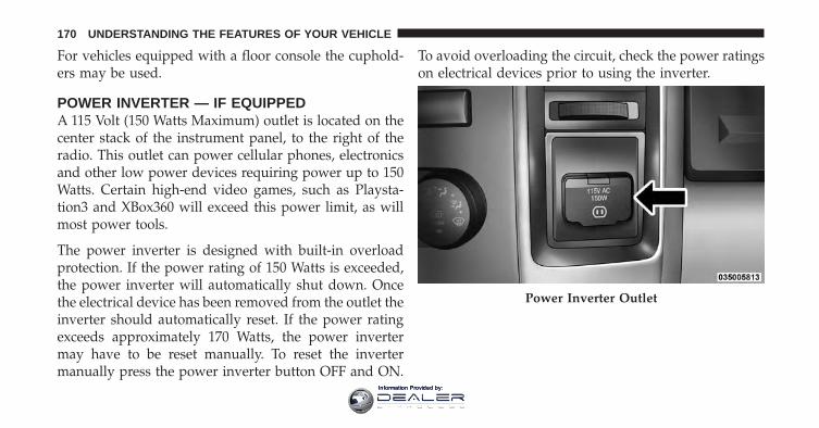
For vehicles equipped with a floor console the cuphold-ers may be used.
POWER INVERTER — IF EQUIPPEDA 115 Volt (150 Watts Maximum) outlet is located on thecenter stack of the instrument panel, to the right of theradio. This outlet can power cellular phones, electronicsand other low power devices requiring power up to 150Watts. Certain high-end video games, such as Playsta-tion3 and XBox360 will exceed this power limit, as willmost power tools.
The power inverter is designed with built-in overloadprotection. If the power rating of 150 Watts is exceeded,the power inverter will automatically shut down. Oncethe electrical device has been removed from the outlet theinverter should automatically reset. If the power ratingexceeds approximately 170 Watts, the power invertermay have to be reset manually. To reset the invertermanually press the power inverter button OFF and ON.
To avoid overloading the circuit, check the power ratingson electrical devices prior to using the inverter.
Power Inverter Outlet
170 UNDERSTANDING THE FEATURES OF YOUR VEHICLE
Information Provided by:
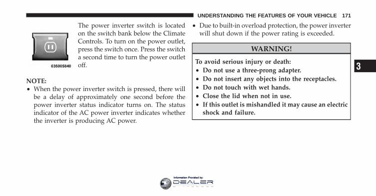
The power inverter switch is locatedon the switch bank below the ClimateControls. To turn on the power outlet,press the switch once. Press the switcha second time to turn the power outletoff.
NOTE:• When the power inverter switch is pressed, there will
be a delay of approximately one second before thepower inverter status indicator turns on. The statusindicator of the AC power inverter indicates whetherthe inverter is producing AC power.
• Due to built-in overload protection, the power inverterwill shut down if the power rating is exceeded.
WARNING!
To avoid serious injury or death:• Do not use a three-prong adapter.• Do not insert any objects into the receptacles.• Do not touch with wet hands.• Close the lid when not in use.• If this outlet is mishandled it may cause an electric
shock and failure.
3
UNDERSTANDING THE FEATURES OF YOUR VEHICLE 171
Information Provided by:
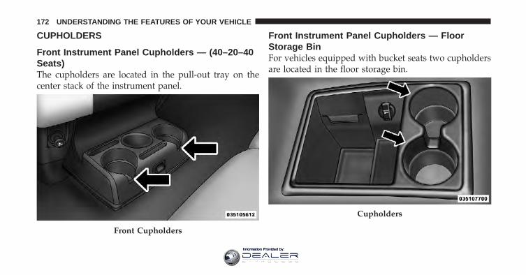
CUPHOLDERS
Front Instrument Panel Cupholders — (40–20–40Seats)The cupholders are located in the pull-out tray on thecenter stack of the instrument panel.
Front Instrument Panel Cupholders — FloorStorage BinFor vehicles equipped with bucket seats two cupholdersare located in the floor storage bin.
Front Cupholders
Cupholders
172 UNDERSTANDING THE FEATURES OF YOUR VEHICLE
Information Provided by:
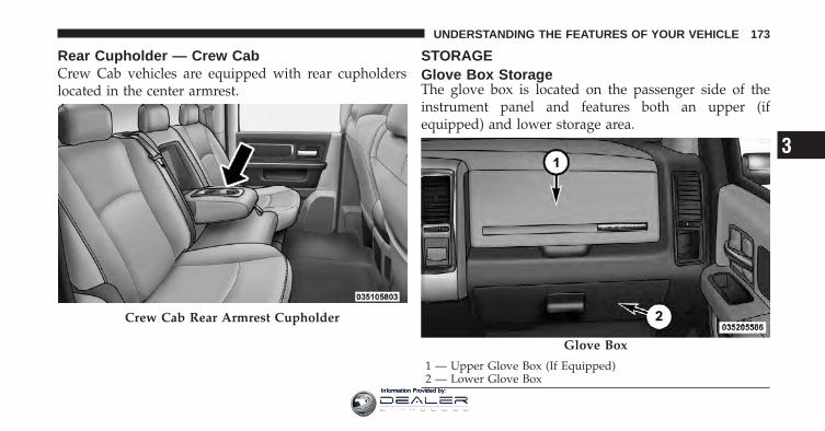
Rear Cupholder — Crew CabCrew Cab vehicles are equipped with rear cupholderslocated in the center armrest.
STORAGEGlove Box StorageThe glove box is located on the passenger side of theinstrument panel and features both an upper (ifequipped) and lower storage area.
Crew Cab Rear Armrest Cupholder
Glove Box
1 — Upper Glove Box (If Equipped)2 — Lower Glove Box
3
UNDERSTANDING THE FEATURES OF YOUR VEHICLE 173
Information Provided by:
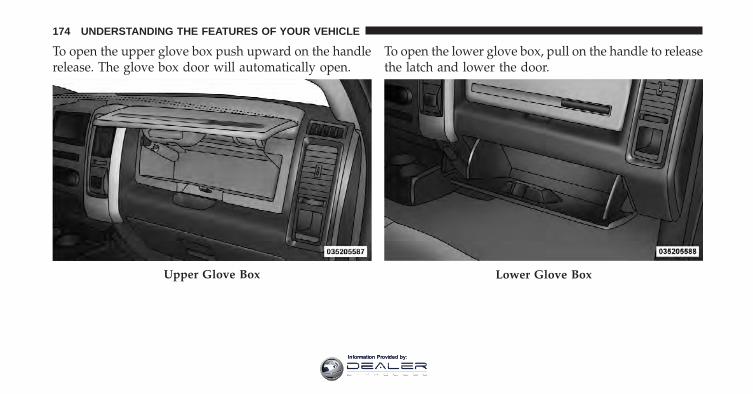
To open the upper glove box push upward on the handlerelease. The glove box door will automatically open.
To open the lower glove box, pull on the handle to releasethe latch and lower the door.
Upper Glove Box Lower Glove Box
174 UNDERSTANDING THE FEATURES OF YOUR VEHICLE
Information Provided by:
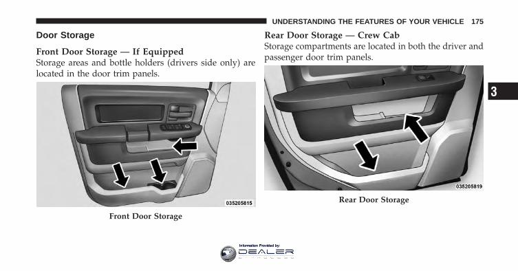
Door Storage
Front Door Storage — If EquippedStorage areas and bottle holders (drivers side only) arelocated in the door trim panels.
Rear Door Storage — Crew CabStorage compartments are located in both the driver andpassenger door trim panels.
Front Door Storage
Rear Door Storage
3
UNDERSTANDING THE FEATURES OF YOUR VEHICLE 175
Information Provided by:
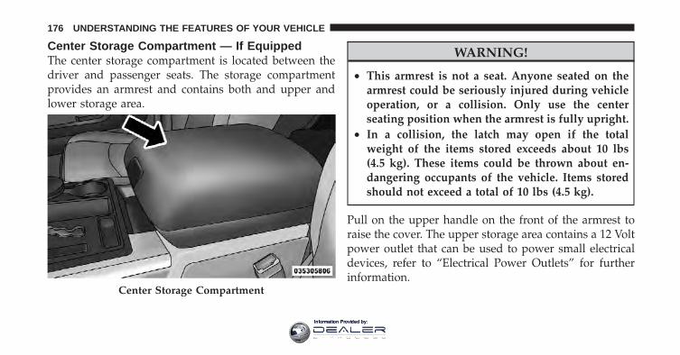
Center Storage Compartment — If EquippedThe center storage compartment is located between thedriver and passenger seats. The storage compartmentprovides an armrest and contains both and upper andlower storage area.
WARNING!
• This armrest is not a seat. Anyone seated on thearmrest could be seriously injured during vehicleoperation, or a collision. Only use the centerseating position when the armrest is fully upright.
• In a collision, the latch may open if the totalweight of the items stored exceeds about 10 lbs(4.5 kg). These items could be thrown about en-dangering occupants of the vehicle. Items storedshould not exceed a total of 10 lbs (4.5 kg).
Pull on the upper handle on the front of the armrest toraise the cover. The upper storage area contains a 12 Voltpower outlet that can be used to power small electricaldevices, refer to “Electrical Power Outlets” for furtherinformation.
Center Storage Compartment
176 UNDERSTANDING THE FEATURES OF YOUR VEHICLE
Information Provided by:
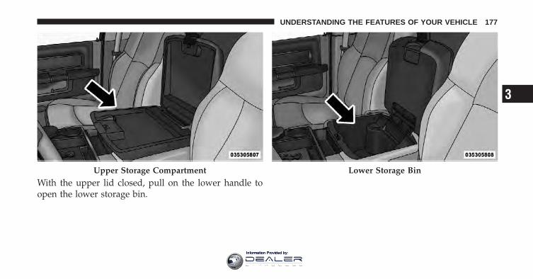
With the upper lid closed, pull on the lower handle toopen the lower storage bin.
Upper Storage Compartment Lower Storage Bin
3
UNDERSTANDING THE FEATURES OF YOUR VEHICLE 177
Information Provided by:
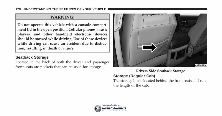
WARNING!
Do not operate this vehicle with a console compart-ment lid in the open position. Cellular phones, musicplayers, and other handheld electronic devicesshould be stowed while driving. Use of these deviceswhile driving can cause an accident due to distrac-tion, resulting in death or injury.
Seatback StorageLocated in the back of both the driver and passengerfront seats are pockets that can be used for storage.
Storage (Regular Cab)The storage bin is located behind the front seats and runsthe length of the cab.
Drivers Side Seatback Storage
178 UNDERSTANDING THE FEATURES OF YOUR VEHICLE
Information Provided by:
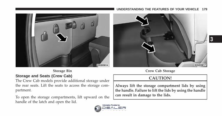
Storage and Seats (Crew Cab)The Crew Cab models provide additional storage underthe rear seats. Lift the seats to access the storage com-partment.
To open the storage compartments, lift upward on thehandle of the latch and open the lid.
CAUTION!
Always lift the storage compartment lids by usingthe handle. Failure to lift the lids by using the handlecan result in damage to the lids.
Storage Bin Crew Cab Storage
3
UNDERSTANDING THE FEATURES OF YOUR VEHICLE 179
Information Provided by:
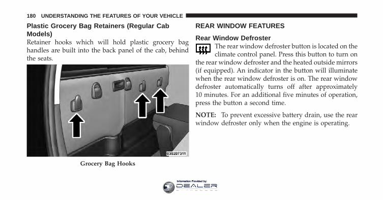
Plastic Grocery Bag Retainers (Regular CabModels)Retainer hooks which will hold plastic grocery baghandles are built into the back panel of the cab, behindthe seats.
REAR WINDOW FEATURES
Rear Window DefrosterThe rear window defroster button is located on theclimate control panel. Press this button to turn on
the rear window defroster and the heated outside mirrors(if equipped). An indicator in the button will illuminatewhen the rear window defroster is on. The rear windowdefroster automatically turns off after approximately10 minutes. For an additional five minutes of operation,press the button a second time.
NOTE: To prevent excessive battery drain, use the rearwindow defroster only when the engine is operating.
Grocery Bag Hooks
180 UNDERSTANDING THE FEATURES OF YOUR VEHICLE
Information Provided by:
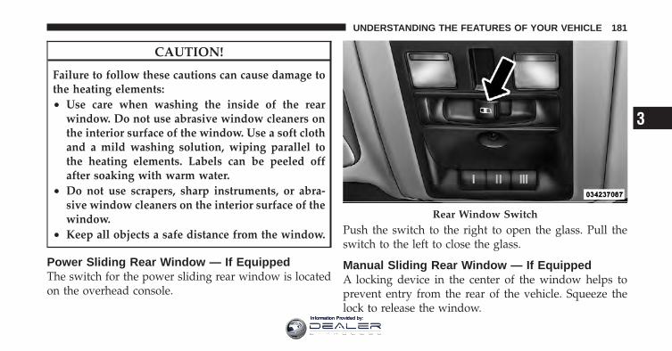
CAUTION!
Failure to follow these cautions can cause damage tothe heating elements:• Use care when washing the inside of the rear
window. Do not use abrasive window cleaners onthe interior surface of the window. Use a soft clothand a mild washing solution, wiping parallel tothe heating elements. Labels can be peeled offafter soaking with warm water.
• Do not use scrapers, sharp instruments, or abra-sive window cleaners on the interior surface of thewindow.
• Keep all objects a safe distance from the window.
Power Sliding Rear Window — If EquippedThe switch for the power sliding rear window is locatedon the overhead console.
Push the switch to the right to open the glass. Pull theswitch to the left to close the glass.
Manual Sliding Rear Window — If EquippedA locking device in the center of the window helps toprevent entry from the rear of the vehicle. Squeeze thelock to release the window.
Rear Window Switch
3
UNDERSTANDING THE FEATURES OF YOUR VEHICLE 181
Information Provided by:

Information Provided by:
UNDERSTANDING YOUR INSTRUMENT PANEL
CONTENTS
� Instrument Panel Features . . . . . . . . . . . . . . . 186
� Instrument Cluster — Base . . . . . . . . . . . . . . . 187
� Instrument Cluster — Premium . . . . . . . . . . . 188
� Instrument Cluster Descriptions . . . . . . . . . . . 189
� Electronic Vehicle Information Center(EVIC) — If Equipped . . . . . . . . . . . . . . . . . . . 203
▫ Electronic Vehicle Information Center(EVIC) Displays . . . . . . . . . . . . . . . . . . . . . 205
▫ Distance To Empty (DTE) . . . . . . . . . . . . . . 211
▫ EVIC Average Fuel Economy . . . . . . . . . . . . 212
▫ Trip Functions . . . . . . . . . . . . . . . . . . . . . . 212
▫ Vehicle Info(Customer Information Features) . . . . . . . . . 213
▫ Units . . . . . . . . . . . . . . . . . . . . . . . . . . . . . 213
▫ Compass / Temperature Display . . . . . . . . . 214
▫ Customer-Programmable Features(System Setup) . . . . . . . . . . . . . . . . . . . . . . 216
4
Information Provided by:
� Media Center 730N/430/430N (RHR/RER/RBZ/RHB) CD/DVD/HDD/NAV — IfEquipped . . . . . . . . . . . . . . . . . . . . . . . . . . . . 222
▫ Operating Instructions (Voice CommandSystem) — If Equipped . . . . . . . . . . . . . . . . 222
▫ Operating Instructions (Uconnect™ Phone)— If Equipped . . . . . . . . . . . . . . . . . . . . . . 222
� Media Center 130 (Sales Code RES) . . . . . . . . . 222
▫ Operating Instructions — Radio Mode . . . . . 223
▫ Operation Instructions — CD Mode For CDAnd MP3 Audio Play . . . . . . . . . . . . . . . . . 226
▫ Notes On Playing MP3 Files . . . . . . . . . . . . 228
▫ Operation Instructions - Auxiliary Mode . . . . 230
� Media Center 130 With Satellite Radio(Sales Code RES+RSC). . . . . . . . . . . . . . . . . . . 231
▫ Operating Instructions — Radio Mode . . . . . 231
▫ Operation Instructions — CD Mode For CDAnd MP3 Audio Play . . . . . . . . . . . . . . . . . 237
▫ Notes On Playing MP3 Files . . . . . . . . . . . . 239
▫ List Button (CD Mode For MP3 Play) . . . . . . 241
▫ Info Button (CD Mode For MP3 Play) . . . . . . 241
▫ Uconnect™ Multimedia (Satellite Radio) — IfEquipped . . . . . . . . . . . . . . . . . . . . . . . . . . 242
� iPod�/USB/MP3 Control — If Equipped . . . . . 246
▫ Connecting The iPod� Or External USBDevice . . . . . . . . . . . . . . . . . . . . . . . . . . . . 247
▫ Using This Feature . . . . . . . . . . . . . . . . . . . 248
184 UNDERSTANDING YOUR INSTRUMENT PANEL
Information Provided by:
▫ Controlling The iPod� Or External USBDevice Using Radio Buttons . . . . . . . . . . . . . 248
▫ Play Mode . . . . . . . . . . . . . . . . . . . . . . . . . 249
▫ List Or Browse Mode . . . . . . . . . . . . . . . . . 250
▫ Bluetooth Streaming Audio (BTSA) . . . . . . . . 252
� Steering Wheel Audio Controls —If Equipped . . . . . . . . . . . . . . . . . . . . . . . . . . 253
▫ Radio Operation . . . . . . . . . . . . . . . . . . . . . 254
▫ CD Player . . . . . . . . . . . . . . . . . . . . . . . . . 254
� CD/DVD Disc Maintenance . . . . . . . . . . . . . . 255
� Radio Operation And Mobile Phones . . . . . . . 255
� Climate Controls . . . . . . . . . . . . . . . . . . . . . . 256
▫ Manual Heating And Air ConditioningSystem . . . . . . . . . . . . . . . . . . . . . . . . . . . . 256
▫ Automatic Temperature Control (ATC) — IfEquipped . . . . . . . . . . . . . . . . . . . . . . . . . . 260
▫ Summer Operation . . . . . . . . . . . . . . . . . . . 265
▫ Winter Operation . . . . . . . . . . . . . . . . . . . . 265
▫ Vacation/Storage . . . . . . . . . . . . . . . . . . . . 266
▫ Window Fogging And Frosting . . . . . . . . . . 266
▫ Outside Air Intake . . . . . . . . . . . . . . . . . . . 266
▫ Operating Tips . . . . . . . . . . . . . . . . . . . . . . 267
4
UNDERSTANDING YOUR INSTRUMENT PANEL 185
Information Provided by:
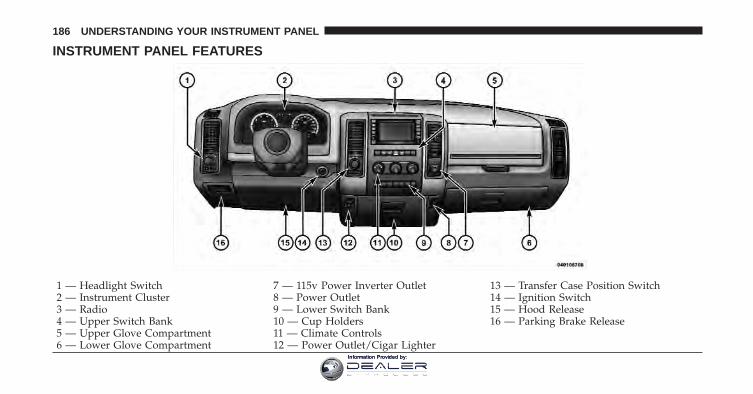
INSTRUMENT PANEL FEATURES
1 — Headlight Switch 7 — 115v Power Inverter Outlet 13 — Transfer Case Position Switch2 — Instrument Cluster 8 — Power Outlet 14 — Ignition Switch3 — Radio 9 — Lower Switch Bank 15 — Hood Release4 — Upper Switch Bank 10 — Cup Holders 16 — Parking Brake Release5 — Upper Glove Compartment 11 — Climate Controls6 — Lower Glove Compartment 12 — Power Outlet/Cigar Lighter
186 UNDERSTANDING YOUR INSTRUMENT PANEL
Information Provided by:
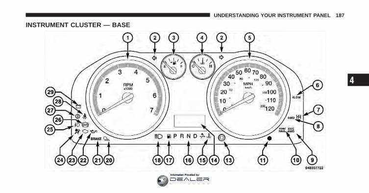
INSTRUMENT CLUSTER — BASE
4
UNDERSTANDING YOUR INSTRUMENT PANEL 187
Information Provided by:
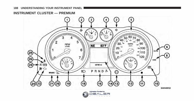
INSTRUMENT CLUSTER — PREMIUM
188 UNDERSTANDING YOUR INSTRUMENT PANEL
Information Provided by:
INSTRUMENT CLUSTER DESCRIPTIONS
1. TachometerThe Tachometer indicates engine speed in revolutions perminute (RPM x 1000).
CAUTION!
Do not operate the engine with the tachometerpointer at high RPM for extended periods. Enginedamage may occur.
2. Turn Signal IndicatorsThe arrow will flash with the exterior turn signalwhen the turn signal lever is operated.
NOTE:• A continuous chime will sound if the vehicle is driven
more than 1 mile (1.6 km) with either turn signal on.
• Check for an inoperative outside light bulb if eitherindicator flashes at a rapid rate.
3. Fuel GaugeShows level of fuel in tank when ignition switch is in theON/RUN position.
4. Temperature GaugeThe temperature gauge shows engine coolant tempera-ture. Any reading within the normal range indicates thatthe engine cooling system is operating satisfactorily.
The gauge pointer will likely indicate a higher tempera-ture when driving in hot weather, up mountain grades,or when towing a trailer. It should not be allowed toexceed the upper limits of the normal operating range.
4
UNDERSTANDING YOUR INSTRUMENT PANEL 189
Information Provided by:
CAUTION!
Driving with a hot engine cooling system coulddamage your vehicle. If the temperature gauge reads“H” pull over and stop the vehicle. Idle the vehiclewith the air conditioner turned off until the pointerdrops back into the normal range. If the pointerremains on the “H” and you hear continuous chimes,turn the engine off immediately and call an autho-rized dealership for service.
WARNING!
A hot engine cooling system is dangerous. You orothers could be badly burned by steam or boilingcoolant. You may want to call an authorized dealer-ship for service if your vehicle overheats. If youdecide to look under the hood yourself, see “Main-taining Your Vehicle”. Follow the warnings under theCooling System Pressure Cap paragraph.
5. SpeedometerThe speedometer shows the vehicle speed in miles perhour and/or kilometers per hour (mph/km/h).
6. 4 LOWThis light alerts the driver that the vehicle is inthe four-wheel drive LOW mode. The front andrear driveshafts are mechanically locked to-gether forcing the front and rear wheels to
190 UNDERSTANDING YOUR INSTRUMENT PANEL
Information Provided by:
rotate at the same speed. Low range provides a greatergear reduction ratio to provide increased torque at thewheels.
7. Electronic Throttle Control (ETC) LightThis light informs you of a problem with theElectronic Throttle Control (ETC) system. Thelight will come on when the ignition is firstturned to ON/RUN and remain on briefly as a
bulb check. If the light does not come on during starting,have the system checked by an authorized dealer.
If a problem is detected, the light will come on while theengine is running. Cycle the ignition key when thevehicle has completely stopped and the shift lever isplaced in the PARK position, the light should turn off.
If the light remains lit with the engine running, yourvehicle will usually be drivable; however, see an autho-rized dealer for service as soon as possible. If the light isflashing when the engine is running, immediate service is
required and you may experience reduced performance,an elevated/rough idle or engine stall and your vehiclemay require towing.
For vehicles equipped with a premium cluster this indi-cator will display in the Electronic Vehicle InformationCenter (EVIC). Refer to ”Electronic Vehicle InformationCenter (EVIC) — If Equipped” for further information.
8. 4WD IndicatorThis light indicates the vehicle is in four-wheeldrive and 4LOCK. 4WD allows all four wheelsto receive torque from the engine simultane-ously.
9. SVC (Service) 4WDThe SVC 4WD light monitors the electric shiftfour-wheel drive system. If the SVC 4WD lightstays on or comes on during driving, it meansthat the four-wheel drive system is not func-
tioning properly and that service is required.
4
UNDERSTANDING YOUR INSTRUMENT PANEL 191
Information Provided by:
For vehicles equipped with a premium cluster this indi-cator will display in the Electronic Vehicle InformationCenter (EVIC). Refer to ”Electronic Vehicle InformationCenter (EVIC) — If Equipped” for further information.
10. TOW/HAULThe TOW HAUL button is located on thecenter stack switch bank. This light will illumi-nate when TOW HAUL mode is selected
11. Vehicle Security Light — If EquippedThis light will flash at a fast rate for approxi-mately 15 seconds, when the vehicle securityalarm is arming, and then will flash slowlyuntil the vehicle is disarmed.
12. Oil Pressure Gauge — If EquippedThe pointer should always indicate some oil pressurewhen the engine is running. A continuous high or lowreading under normal driving conditions may indicate alubrication system malfunction. Immediate serviceshould be obtained from an authorized dealer.
13. Odometer/Trip Odometer ButtonPress this button to toggle between the odometer and thetrip odometer display. Holding the button in resets thetrip odometer reading when in trip mode.
14. Odometer Display / Electronic Vehicle InformationCenter (EVIC) Display Area
Odometer DisplayThe odometer display shows the total distance the ve-hicle has been driven. Regulations require that upontransfer of vehicle ownership, the seller certify to thepurchaser the correct mileage that the vehicle has beendriven. If your odometer needs to be repaired or serviced,
192 UNDERSTANDING YOUR INSTRUMENT PANEL
Information Provided by:
the repair technician should leave the odometer readingthe same as it was before the repair or service. If s/hecannot do so, then the odometer must be set at zero, anda sticker must be placed in the door jamb stating what themileage was before the repair or service. It is a good ideafor you to make a record of the odometer reading beforethe repair/service, so that you can be sure that it isproperly reset, or that the door jamb sticker is accurate ifthe odometer must be reset at zero.
The two trip odometers show individual trip mileage. Toswitch from odometer to trip odometers, press andrelease the TRIP ODOMETER button.
To reset a trip odometer, display the desired trip odom-eter to be reset then push and hold the button forapproximately two seconds until the display resets.
Vehicle Odometer MessagesWhen the appropriate conditions exist, the followingmessages will display in the odometer:
noFUSE . . . . . . . . . . . . . . . . . . . . . . . . . . Fuse FaultCHANgE OIL. . . . . . . . . . . . . . . Oil Change RequiredESCOFF . . . . . . . . . . . . Electronic Stability Control OffgASCAP . . . . . . . . . . . . . . . . . . . . . . Gas Cap LooseHOTOIL . . . . . . . . . . . . . . . . . . . Engine Oil too HotLoCOOL. . . . . . . . . . . . . . . . . . . Low Engine CoolantLoW tirE . . . . . . . . . . . . . . . . . . . . Tire Pressure Low
NOTE: There is also an engine hour function. Thisindicates the total number of hours the engine has beenrunning. To display the engine hours on the base cluster,perform the following: Place the ignition in the ON/RUN, but do not start the engine. With the odometervalue displayed, hold the TRIP button down for a periodof six seconds. The odometer will change to trip valuefirst, then it will display the engine hour value. The
4
UNDERSTANDING YOUR INSTRUMENT PANEL 193
Information Provided by:
engine hours will be displayed for a period of 30 secondsuntil the ignition is turned OFF or the engine is started.
Some of the above warnings will be displayed in theElectronic Vehicle Information Center (EVIC) DisplayArea located in the instrument cluster. Refer to ”Elec-tronic Vehicle Information Center (EVIC) — If Equipped”for further information.
gASCAPIf the vehicle diagnostic system determines that the fuelfiller cap is loose, improperly installed, or damaged, aloose gascap indicator or the message “gASCAP” willdisplay in the odometer display area. Tighten the fuelfiller cap properly and press the TRIP button to turn offthe message. If the problem continues, the message willappear the next time the vehicle is started.
A loose gas cap indicator will display in the ElectronicVehicle Information Center (EVIC) for the premium
cluster (Refer to ”Electronic Vehicle InformationCenter(EVIC) — If Equipped” for further information).
A loose, improperly installed, or damaged fuel filler capmay also turn on the Malfunction Indicator Light (MIL).
noFUSEIf the vehicle diagnostic system determines that theIgnition Off Draw (IOD) fuse is improperly installed, ordamaged, a “noFUSE” message will display in the odom-eter display area. For further information on fuses andfuse locations refer to “Fuses” in “Maintaining YourVehicle”.
CHANgE OILYour vehicle is equipped with an engine oil changeindicator system. The CHANgE OIL message will flashin the instrument cluster odometer for approximately12 seconds after a single chime has sounded to indicatethe next scheduled oil change interval. The engine oilchange indicator system is duty cycle-based, which
194 UNDERSTANDING YOUR INSTRUMENT PANEL
Information Provided by:
means the engine oil change interval may fluctuatedependent upon your personal driving style.
Unless reset, this message will continue to display eachtime you turn the ignition switch to the ON/RUNposition. To turn off the message temporarily, press andrelease the Trip Odometer button on the instrumentcluster. To reset the oil change indicator system (afterperforming the scheduled maintenance), refer to thefollowing procedure:
1. Turn the ignition switch to the ON/RUN position(do not start the engine).
2. Fully depress the accelerator pedal slowly threetimes within 10 seconds.
3. Turn the ignition switch to the OFF/LOCK position.
NOTE: If the indicator message illuminates when youstart the vehicle, the oil change indicator system did notreset. If necessary, repeat this procedure.
15. Engine Temperature Warning LightThis light warns of an overheated engine condi-tion. As engine coolant temperatures rise and thegauge approaches H, this indicator will illuminate
and a single chime will sound after reaching a setthreshold. Further overheating will cause the tempera-ture gauge to pass H, the indicator will continuouslyflash and a continuous chime will occur until the engineis allowed to cool.
If the light turns on while driving, safely pull over andstop the vehicle. If the A/C system is on, turn it off. Also,shift the transmission into NEUTRAL and idle the ve-hicle. If the temperature reading does not return tonormal, turn the engine off immediately and call forservice. Refer to “If Your Engine Overheats” in “What ToDo In Emergencies” for further information.
For vehicles equipped with a premium cluster this indi-cator will display in the Electronic Vehicle Information
4
UNDERSTANDING YOUR INSTRUMENT PANEL 195
Information Provided by:
Center (EVIC). Refer to ”Electronic Vehicle InformationCenter (EVIC) — If Equipped” for further information.
16. Shift Lever IndicatorThe Shift Lever Indicator is self-contained within theinstrument cluster. It displays the gear position of theautomatic transmission.
NOTE: In vehicles with a 4.7L or 5.7L engine, thehighest available transmission gear is displayed in thelower right corner of the Electronic Vehicle InformationCenter (EVIC) whenever the Electronic Range Select(ERS) feature is active. Use the +/- selector on the shiftlever to activate ERS. Refer to “Automatic Transmission”in “Starting And Operating” for further information.
17. Low Fuel LightWhen the fuel level reaches approximately 3.0 gal(11.0 L) this light will turn on, and remain on untilfuel is added.
For vehicles equipped with a premium cluster this indi-cator will display in the Electronic Vehicle InformationCenter (EVIC). Refer to ”Electronic Vehicle InformationCenter (EVIC) — If Equipped” for further information.
18. High Beam IndicatorThis indicator shows that headlights are on highbeam. Push the multifunction lever forward to
switch the headlights to high beam, and pull towardyourself (normal position) to return to low beam.
19. Voltmeter — If EquippedWhen the engine is running, the gauge indicates theelectrical system voltage. The pointer should stay withinthe normal range if the battery is charged. If the pointermoves to either extreme left or right and remains thereduring normal driving, the electrical system should beserviced.
NOTE: The voltmeter may show a gauge fluctuation atvarious engine temperatures. This cycling operation is
196 UNDERSTANDING YOUR INSTRUMENT PANEL
Information Provided by:
caused by the post-heat cycle of the intake manifoldheater system. The number of cycles and the length of thecycling operation is controlled by the engine controlmodule. Post-heat operation can run for several minutes,and then the electrical system and voltmeter needle willstabilize.
20. Cargo LightThe cargo light will illuminate when the cargolight is activated by pressing the cargo lightbutton on the headlight switch.
21. Brake Warning LightThis light monitors various brake functions,including brake fluid level and parking brakeapplication. If the brake light turns on it mayindicate that the parking brake is applied, that
the brake fluid level is low, or that there is a problem withthe Anti-lock Brake System reservoir.
If the light remains on when the parking brake has beendisengaged, and the fluid level is at the full mark on themaster cylinder reservoir, it indicates a possible brakehydraulic system malfunction or that a problem with theBrake Booster has been detected by the Anti-Lock BrakeSystem (ABS). In this case, the light will remain on untilthe condition has been corrected. If the problem is relatedto the brake booster, the ABS pump will run whenapplying the brake and a brake pedal pulsation may befelt during each stop.
The dual brake system provides a reserve braking capac-ity in the event of a failure to a portion of the hydraulicsystem. A leak in either half of the dual brake system isindicated by the Brake Warning Light, which will turn onwhen the brake fluid level in the master cylinder hasdropped below a specified level.
The light will remain on until the cause is corrected.
4
UNDERSTANDING YOUR INSTRUMENT PANEL 197
Information Provided by:
NOTE: The light may flash momentarily during sharpcornering maneuvers, which change fluid level condi-tions. The vehicle should have service performed, andthe brake fluid level checked.
If brake failure is indicated, immediate repair is neces-sary.
WARNING!
Driving a vehicle with the red brake light on isdangerous. Part of the brake system may have failed.It will take longer to stop the vehicle. You could havea collision. Have the vehicle checked immediately.
Vehicles equipped with the ABS, are also equipped withElectronic Brake Force Distribution (EBD). In the event ofan EBD failure, the Brake Warning Light will turn onalong with the ABS Light. Immediate repair to the ABSsystem is required.
Operation of the Brake Warning Light can be checked byturning the ignition switch from the OFF position to theON/RUN position. The light should illuminate for ap-proximately two seconds. The light should then turn offunless the parking brake is applied or a brake fault isdetected. If the light does not illuminate, have the lightinspected by an authorized dealer.
The light also will turn on when the parking brake isapplied with the ignition switch in the ON/RUN posi-tion.
NOTE: This light shows only that the parking brake isapplied. It does not show the degree of brake application.
22. Oil Pressure Warning LightThis light indicates low engine oil pressure. Thelight should turn on momentarily when the engine
is started. If the light turns on while driving, stop thevehicle and shut off the engine as soon as possible. A chimewill sound for four minutes when this light turns on.
198 UNDERSTANDING YOUR INSTRUMENT PANEL
Information Provided by:
Do not operate the vehicle until the cause is corrected.This light does not indicate how much oil is in the engine.The engine oil level must be checked under the hood.
For vehicles equipped with a premium cluster this indi-cator will display in the Electronic Vehicle InformationCenter (EVIC). Refer to ”Electronic Vehicle InformationCenter (EVIC) — If Equipped” for further information.
23. Malfunction Indicator Light (MIL)The Malfunction Indicator Light (MIL) is part ofan onboard diagnostic (OBDII) system whichmonitors the emissions and engine control sys-
tem. If the vehicle is ready for emissions testing, the lightwill come on when the ignition is first turned on andremain on, as a bulb check, until the engine is started. Ifthe vehicle is not ready for emissions testing the light willcome on when the ignition is first turned on and remainon for 15 seconds, then blink for 5 seconds, and remain
on until the vehicle is started. If the bulb does not comeon during starting, have the condition investigatedpromptly.
If this light comes on and remains on while driving, itsuggests a potential engine control problem and the needfor system service.
Although your vehicle will usually be drivable and notneed towing, see your authorized dealer for service assoon as possible.
CAUTION!
Prolonged driving with the MIL on could causedamage to the engine control system. It also couldaffect fuel economy and drivability. If the MIL isflashing, severe catalytic converter damage andpower loss will soon occur. Immediate service isrequired.
4
UNDERSTANDING YOUR INSTRUMENT PANEL 199
Information Provided by:
WARNING!
A malfunctioning catalytic converter, as referencedabove, can reach higher temperatures than in normaloperating conditions. This can cause a fire if youdrive slowly or park over flammable substances suchas dry plants, wood, cardboard, etc. This could resultin death or serious injury to the driver, occupants orothers.
24. Air Bag Warning LightThis light will turn on for four to eight secondsas a bulb check when the ignition switch is firstturned to ON/RUN. If the light is either not onduring starting, stays on, or turns on while
driving, have the system inspected at an authorizeddealer as soon as possible. Refer to “Occupant Restraints”in “Things To Know Before Starting Your Vehicle” forfurther information.
25. Front Fog Light Indicator — If EquippedThis indicator will illuminate when the front foglights are on.
26. Anti-Lock Brake (ABS) LightThis light monitors the Anti-lock Brake System(ABS). The light will turn on when the ignitionswitch is turned to the ON/RUN position andmay stay on for as long as four seconds.
If the ABS light remains on or turns on while driving, itindicates that the anti-lock portion of the brake system isnot functioning and that service is required. However,the conventional brake system will continue to operatenormally if the BRAKE warning light is not on.
If the ABS light is on, the brake system should be servicedas soon as possible to restore the benefits of anti-lockbrakes. If the ABS light does not turn on when theignition switch is turned to the ON/RUN position, havethe light inspected by an authorized dealer.
200 UNDERSTANDING YOUR INSTRUMENT PANEL
Information Provided by:
27. Transmission Temperature Warning LightThis light indicates that there is excessive trans-mission fluid temperature that might occurwith severe usage such as trailer towing. It mayalso occur when operating the vehicle in a high
torque converter slip condition, such as 4-wheel-driveoperation (e.g., snow plowing, off-road operation). If thislight comes on, stop the vehicle and run the engine at idleor faster with the transmission in NEUTRAL until thelight goes off.
CAUTION!
Continuous driving with the Transmission Tempera-ture Warning Light illuminated will eventually causesevere transmission damage or transmission failure.
WARNING!
If the Transmission Temperature Warning Light isilluminated and you continue operating the vehicle,in some circumstances you could cause the fluid toboil over, come in contact with hot engine or exhaustcomponents and cause a fire.
For vehicles equipped with a premium cluster this warn-ing light will display in the Electronic Vehicle Informa-tion Center (EVIC). Refer to ”Electronic Vehicle Informa-tion Center (EVIC) — If Equipped” for furtherinformation.
4
UNDERSTANDING YOUR INSTRUMENT PANEL 201
Information Provided by:
28. Seat Belt Reminder LightWhen the ignition switch is first turned to ON/RUN, this light will turn on for four to eightseconds as a bulb check. During the bulb check, if
the driver’s seat belt is unbuckled, a chime will sound.After the bulb check or when driving, if the driver’s seatbelt remains unbuckled, the seat belt reminder light willflash or remain on continuously. Refer to “OccupantRestraints” in “Things To Know Before Starting YourVehicle” for further information.
29. Charging System LightThis light shows the status of the electrical charg-ing system. The light should come on when the
ignition switch is first turned to ON/RUN and remain on
briefly as a bulb check. If the light stays on or comes onwhile driving, turn off some of the vehicle’s non-essentialelectrical devices or increase engine speed (if at idle). Ifthe charging system light remains on, it means that thevehicle is experiencing a problem with the chargingsystem. Obtain SERVICE IMMEDIATELY. See an autho-rized dealer.
If jump starting is required, refer to “Jump StartingProcedures” in “What To Do In Emergencies”.
For vehicles equipped with a premium cluster this indi-cator will display in the Electronic Vehicle InformationCenter (EVIC). Refer to ”Electronic Vehicle InformationCenter (EVIC) — If Equipped” for further information.
202 UNDERSTANDING YOUR INSTRUMENT PANEL
Information Provided by:
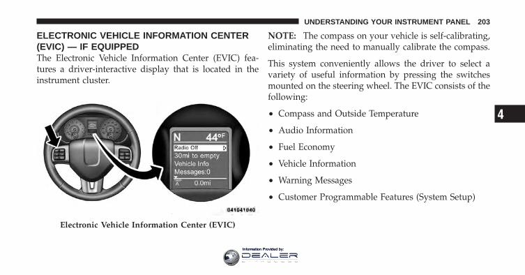
ELECTRONIC VEHICLE INFORMATION CENTER(EVIC) — IF EQUIPPEDThe Electronic Vehicle Information Center (EVIC) fea-tures a driver-interactive display that is located in theinstrument cluster.
NOTE: The compass on your vehicle is self-calibrating,eliminating the need to manually calibrate the compass.
This system conveniently allows the driver to select avariety of useful information by pressing the switchesmounted on the steering wheel. The EVIC consists of thefollowing:
• Compass and Outside Temperature
• Audio Information
• Fuel Economy
• Vehicle Information
• Warning Messages
• Customer Programmable Features (System Setup)
Electronic Vehicle Information Center (EVIC)
4
UNDERSTANDING YOUR INSTRUMENT PANEL 203
Information Provided by:
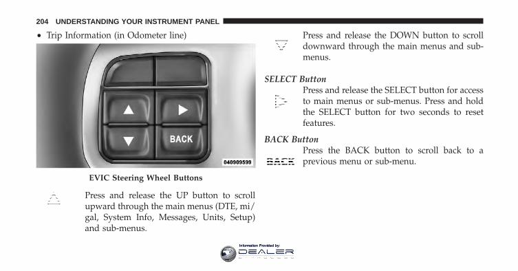
• Trip Information (in Odometer line)
Press and release the UP button to scrollupward through the main menus (DTE, mi/gal, System Info, Messages, Units, Setup)and sub-menus.
Press and release the DOWN button to scrolldownward through the main menus and sub-menus.
SELECT ButtonPress and release the SELECT button for accessto main menus or sub-menus. Press and holdthe SELECT button for two seconds to resetfeatures.
BACK ButtonPress the BACK button to scroll back to aprevious menu or sub-menu.
EVIC Steering Wheel Buttons
204 UNDERSTANDING YOUR INSTRUMENT PANEL
Information Provided by:
Electronic Vehicle Information Center (EVIC)DisplaysWhen the appropriate conditions exist, the EVIC displaysthe following messages:
• Left front turn signal lamp out
• Right front turn signal lamp out
• Left rear turn signal lamp out
• Right rear turn signal lamp out
• Service air filter
• Perform service
• ESC Off
• Coolant Low
• Check Trailer Brake Wiring
• Service Trailer Brake System
• Trailer Brake Connected
• Trailer Brake Disconnected
• Lights On
• Keyfob Battery Low
• Wrong Key
• Damaged Key
• Key not programmed
• Key In Ignition
• Turn Signal On
• Oil Change Due > Dealer Info
• System Setup Unavailable
• Warning Object Detected
• System Setup Unavailable - Vehicle in Motion
4
UNDERSTANDING YOUR INSTRUMENT PANEL 205
Information Provided by:
• Service Four Wheel Drive System
• Adjustable pedals unavail.
• Cruise engaged
• Adjustable pedals unavail. Veh. in reverse
• Clean Park Assist sensors
• Front Park Assist Not available - Blinded
• Rear Park Assist Not available - Blinded
• Low Fuel
• Personal Settings Not Available — Vehicle Not in Park
• Service blind spot system
• Exhaust filter full – Power reduced See Dealer -Exhaust Filter 99% Full - - -
• Blind spot system off
• Blind spot detection unavailable
• Automatic High Beams on
• Automatic High Beams off
• Service Keyless System
• Clearing channels
• Channels cleared
• Channels defaulted
• Channel X transmitting
• Channel X training
• Channel X trained
• Did not train
• Oil temp high Speed may be limited
• Remote start aborted — Door ajar
206 UNDERSTANDING YOUR INSTRUMENT PANEL
Information Provided by:
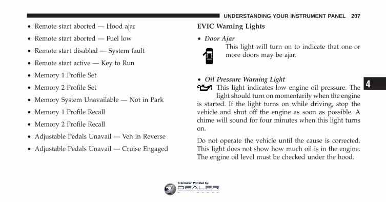
• Remote start aborted — Hood ajar
• Remote start aborted — Fuel low
• Remote start disabled — System fault
• Remote start active — Key to Run
• Memory 1 Profile Set
• Memory 2 Profile Set
• Memory System Unavailable — Not in Park
• Memory 1 Profile Recall
• Memory 2 Profile Recall
• Adjustable Pedals Unavail — Veh in Reverse
• Adjustable Pedals Unavail — Cruise Engaged
EVIC Warning Lights
• Door AjarThis light will turn on to indicate that one ormore doors may be ajar.
• Oil Pressure Warning LightThis light indicates low engine oil pressure. Thelight should turn on momentarily when the engine
is started. If the light turns on while driving, stop thevehicle and shut off the engine as soon as possible. Achime will sound for four minutes when this light turnson.
Do not operate the vehicle until the cause is corrected.This light does not show how much oil is in the engine.The engine oil level must be checked under the hood.
4
UNDERSTANDING YOUR INSTRUMENT PANEL 207
Information Provided by:
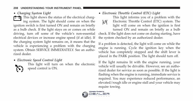
• Charging System LightThis light shows the status of the electrical charg-ing system. The light should come on when the
ignition switch is first turned ON and remain on brieflyas a bulb check. If the light stays on or comes on whiledriving, turn off some of the vehicle’s non-essentialelectrical devices or increase engine speed (if at idle). Ifthe charging system light remains on, it means that thevehicle is experiencing a problem with the chargingsystem. Obtain SERVICE IMMEDIATELY. See an autho-rized dealer.
• Electronic Speed Control LightThis light will turn on when the electronicspeed control is ON.
• Electronic Throttle Control (ETC) LightThis light informs you of a problem with theElectronic Throttle Control (ETC) system. Thelight will come on when the ignition is firstturned ON and remain on briefly as a bulb
check. If the light does not come on during starting, havethe system checked by an authorized dealer.
If a problem is detected, the light will come on while theengine is running. Cycle the ignition key when thevehicle has completely stopped and the shift lever isplaced in the PARK position. The light should turn off.
If the light remains lit with the engine running, yourvehicle will usually be drivable. However, see an autho-rized dealer for service as soon as possible. If the light isflashing when the engine is running, immediate service isrequired. You may experience reduced performance, anelevated/rough idle or engine stall and your vehicle mayrequire towing.
208 UNDERSTANDING YOUR INSTRUMENT PANEL
Information Provided by:
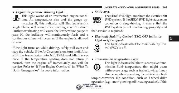
• Engine Temperature Warning LightThis light warns of an overheated engine condi-tion. As temperatures rise and the gauge ap-proaches H, this indicator will illuminate and a
single chime will sound after reaching a set threshold.Further overheating will cause the temperature gauge topass H, the indicator will continuously flash and acontinuous chime will occur until the engine is allowedto cool.
If the light turns on while driving, safely pull over andstop the vehicle. If the A/C system is on, turn it off. Also,shift the transmission into NEUTRAL and idle the ve-hicle. If the temperature reading does not return tonormal, turn the engine off immediately and call forservice. Refer to “If Your Engine Overheats” in “What ToDo In Emergencies” for more information.
• SERV 4WDThe SERV 4WD light monitors the electric shift4WD system. If the SERV 4WD light stays on orcomes on during driving, it means that the4WD system is not functioning properly and
that service is required.
• Electronic Stability Control (ESC) OFF IndicatorLight — If Equipped
This light indicates the Electronic Stability Con-trol (ESC) is off.
• Transmission Temperature LightThis light indicates that there is excessive trans-mission fluid temperature that might occurwith severe usage such as trailer towing. It mayalso occur when operating the vehicle in a high
torque converter slip condition, such as 4-wheel-driveoperation (e.g., snow plowing, off- road operation). If this
4
UNDERSTANDING YOUR INSTRUMENT PANEL 209
Information Provided by:
light comes on, stop the vehicle and run the engine at idleor faster, with the transmission in NEUTRAL until thelight goes off.
CAUTION!
Continuous driving with the Transmission Tempera-ture Indicator illuminated will eventually cause se-vere transmission damage or transmission failure.
WARNING!
If the Transmission Temperature Warning Light isilluminated and you continue operating the vehicle,in some circumstances you could cause the fluid toboil over, come in contact with hot engine or exhaustcomponents and cause a fire.
• Loose Gascap MessageIf the vehicle diagnostic system determinesthat the fuel filler cap is loose, improperlyinstalled, or damaged, a loose gascap icon willdisplay in the telltale display area. Tighten the
fuel filler cap properly and press the SELECT button toturn off the message. If the problem continues, themessage will appear the next time the vehicle is started.
A loose, improperly installed, or damaged fuel filler capmay also turn on the Malfunction Indicator Light (MIL).
Oil Change DueYour vehicle is equipped with an engine oil changeindicator system. The Oil Change Due message willflash in the EVIC display for approximately 10 secondsafter a single chime has sounded to indicate the nextscheduled oil change interval. The engine oil change
210 UNDERSTANDING YOUR INSTRUMENT PANEL
Information Provided by:
indicator system is duty-cycle based, which means theengine oil change interval may fluctuate dependent uponyour personal driving style.
Unless reset, this message will continue to display eachtime you turn the ignition switch to the ON position. Toturn off the message temporarily, press and release theBACK button. To reset the oil change indicator system(after performing the scheduled maintenance), performthe following steps.
1. Turn the ignition switch to the ON position. (Do notstart the engine)
2. Fully depress the accelerator pedal slowly three timeswithin 10 seconds.
3. Turn the ignition switch to the OFF position.
NOTE: If the indicator message illuminates when youstart the engine, the oil change indicator system did notreset. If necessary, repeat these steps.
Distance To Empty (DTE)
Shows the estimated distance that can be traveled withthe fuel remaining in the tank. This estimated distance isdetermined by a weighted average of the instantaneousand average fuel economy, according to the current fueltank level. DTE cannot be reset.
NOTE: Significant changes in driving style or vehicleloading will greatly affect the actual drivable distance ofthe vehicle, regardless of the DTE displayed value.
When the DTE value is less than 10 miles (16 km)estimated driving distance, the DTE display will changeto a text display of �LOW FUEL.� This display willcontinue until the vehicle runs out of fuel. Adding asignificant amount of fuel to the vehicle will turn off the�LOW FUEL� text and a new DTE value will display.
4
UNDERSTANDING YOUR INSTRUMENT PANEL 211
Information Provided by:
EVIC Average Fuel Economy
Shows the average fuel economy since the last reset.When the fuel economy is reset, the display will read“RESET” or show dashes for two seconds. Then, thehistory information will be erased and the averaging willcontinue from the last fuel average reading before thereset.
Trip FunctionsPress and release the ODOMETER/TRIP ODOMETERbutton until one of the following Trip Functions displayin the EVIC odometer line:
• Trip A
• Trip B
• Elapsed Time
Press the ODOMETER/TRIP ODOMETER button tocycle through all the Trip Computer functions.
The Trip Functions mode displays the following informa-tion:
• Trip AShows the total distance traveled for Trip A since the lastreset.
• Trip BShows the total distance traveled for Trip B since the lastreset.
• Elapsed TimeShows the total elapsed time of travel since the last resetwhen the ignition switch is in the ACC position. Elapsedtime will increment when the ignition switch is in the ONor START position.
212 UNDERSTANDING YOUR INSTRUMENT PANEL
Information Provided by:
To Reset The DisplayReset will only occur while a resettable function is beingdisplayed. Press and release the ODOMETER/TRIPODOMETER button once to clear the resettable functionbeing displayed.
Vehicle Info (Customer Information Features)Press and release the UP or DOWN button until “VehicleInfo” displays in the EVIC and press the SELECT button.Press the UP and DOWN button to scroll through theavailable information displays, then press SELECT todisplay any one of the following choices.
• Coolant TempDisplays the actual coolant temperature.
• Oil PressureDisplays the actual oil pressure.
• Trans TemperatureDisplays the actual transmission temperature.
• Trailer Brake — If EquippedDisplays trailer brake output power and trailer brakestatus indicator.
• Engine HoursDisplays the number of hours of engine operation.
UnitsPress and release the UP or DOWN button until “Units”displays in the EVIC and press the SELECT button. TheEVIC, odometer, and navigation system (if equipped) canbe changed between English and Metric units of mea-sure. To make your selection, scroll up or down until thepreferred setting is highlighted, then press and releasethe SELECT button until a check-mark appears next tothe setting, showing that the setting has been selected.
4
UNDERSTANDING YOUR INSTRUMENT PANEL 213
Information Provided by:
Compass / Temperature Display
The compass readings indicate the direction the vehicle isfacing. The EVIC will display one of eight compassreadings and the outside temperature.
NOTE:• The system will display the last known outside tem-
perature when starting the vehicle and may need to bedriven several minutes before the updated tempera-ture is displayed. Engine temperature can also affectthe displayed temperature; therefore, temperaturereadings are not updated when the vehicle is notmoving.
• During snowplow usage on vehicles equipped withoutside temperature display, the display may showhigher temperatures than the outside ambient tem-perature. The higher displayed temperature is due toblocked or reduced airflow to the underhood ambient
temperature sensor caused by the snowplow. In addi-tion, on vehicles equipped with Automatic Tempera-ture Control (ATC), it is suggested that the interiorcabin temperature be manually controlled should thesystem not perform as desired while in automaticmode. Both the outside temperature display and ATCoperation will return to normal when the snowplow isremoved.
Automatic Compass CalibrationThis compass is self-calibrating, which eliminates theneed to manually reset the compass. When the vehicle isnew, the compass may appear erratic and the EVIC willdisplay CAL until the compass is calibrated. You mayalso calibrate the compass by completing one or more360–degree turns (in an area free from large metal ormetallic objects) until the CAL indicator displayed in theEVIC turns off. The compass will now function normally.
214 UNDERSTANDING YOUR INSTRUMENT PANEL
Information Provided by:
NOTE: A good calibration requires a level surface andan environment free from large metallic objects such asbuildings, bridges, underground cables, railroad tracks,etc.
Manual Compass CalibrationIf the compass appears erratic and the CAL indicatordoes not appear in the EVIC display, you must put thecompass into the Calibration Mode manually, as follows:
1. Turn ON the ignition switch.
2. Press the UP or DOWN button until the System Setup(Customer-Programmable Features) menu is reached,then press the SELECT button.
3. Press the DOWN button until “Calibrate Compass” isdisplayed in the EVIC then press and release the SELECTbutton.
4. Press and release the SELECT button to start thecalibration. The “CAL” indicator will be displayed in theEVIC.
5. Complete one or more 360–degree turns (in an areafree from large metal or metallic objects) until the “CAL”indicator turns off. The compass will now functionnormally.
Compass VarianceCompass Variance is the difference between MagneticNorth and Geographic North. To compensate for thedifferences the variance should be set for the zone wherethe vehicle is driven, per the zone map. Once properlyset, the compass will automatically compensate for thedifferences, and provide the most accurate compassheading. For the most accurate compass performance, thecompass must be set using the following steps.
4
UNDERSTANDING YOUR INSTRUMENT PANEL 215
Information Provided by:
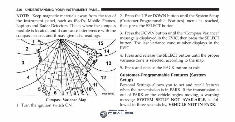
NOTE: Keep magnetic materials away from the top ofthe instrument panel, such as iPod’s, Mobile Phones,Laptops and Radar Detectors. This is where the compassmodule is located, and it can cause interference with thecompass sensor, and it may give false readings.
1. Turn the ignition switch ON.
2. Press the UP or DOWN button until the System Setup(Customer-Programmable Features) menu is reached,then press the SELECT button.
3. Press the DOWN button until the “Compass Variance”message is displayed in the EVIC, then press the SELECTbutton. The last variance zone number displays in theEVIC.
4. Press and release the SELECT button until the propervariance zone is selected, according to the map.
5. Press and release the BACK button to exit.
Customer-Programmable Features (SystemSetup)Personal Settings allows you to set and recall featureswhen the transmission is in PARK. If the transmission isout of PARK or the vehicle begins moving, a warningmessage SYSTEM SETUP NOT AVAILABLE, is fol-lowed in three seconds by, VEHICLE NOT IN PARK.
Compass Variance Map
216 UNDERSTANDING YOUR INSTRUMENT PANEL
Information Provided by:
Press and release the UP or DOWN button until SystemSetup displays in the EVIC.
Use the UP or DOWN button to display one of thefollowing choices.
Select LanguageWhen in this display you may select one of five lan-guages for all display nomenclature, including the tripfunctions and the navigation system (if equipped). Pressthe UP or DOWN button while in this display and scrollthrough the language choices. Press the SELECT buttonto select English, Spanish (Español), French (Français),Italian (Italiano), German (Deutsch), and Dutch (Neder-lands). Then, as you continue, the information will dis-play in the selected language.
Nav–Turn By TurnWhen this feature is selected, the navigation systemutilizes voice commands, guiding through the drive
route, mile by mile, turn-by-turn until the final destina-tion is reached. To make your selection, press and releasethe SELECT button until a check-mark appears next tothe feature showing the system has been activated or thecheck-mark is removed showing the system has beendeactivated.
Auto Unlock DoorsWhen this feature is selected, all doors will unlock whenthe vehicle is stopped and the transmission is in thePARK or NEUTRAL position and the driver’s door isopened. To make your selection, press and release theSELECT button until a check-mark appears next to thefeature showing the system has been activated, or thecheck-mark is removed showing the system has beendeactivated.
Remote Unlock SequenceWhen Driver Door 1st Press is selected, only the driver’sdoor will unlock on the first press of the RKE transmitter
4
UNDERSTANDING YOUR INSTRUMENT PANEL 217
Information Provided by:
UNLOCK button. When Driver Door 1st Press is selected,you must press the RKE transmitter UNLOCK buttontwice to unlock the passenger’s doors. When All Doors1st Press is selected, all of the doors will unlock on thefirst press of the RKE transmitter UNLOCK button. Tomake your selection, press and release the SELECTbutton until “Driver Door 1st Press” or “All Doors 1stPress” appears.
RKE Linked To MemoryWhen this feature is selected the memory seat, mirror,pedals, and radio settings will return to the memory setposition when the Remote Keyless Entry (RKE) transmit-ter UNLOCK button is pressed. If this feature is notselected then the memory seat, mirror, and radio settingscan only return to the memory set position using the seatmounted switch. To make your selection, press andrelease the SELECT button until a check-mark appears
next to the feature showing the system has been activatedor the check-mark is removed showing the system hasbeen deactivated.
Remote Start Comfort Sys.When this feature is selected and the remote start isactivated, the heated steering wheel and driver heatedseat features will automatically turn on when tempera-tures are below 40° F (4.4° C). When temperatures areabove 80° F (26.7° C) the driver vented seat will turn onwhen remote start is activated. These features will stay onthrough the duration of remote start or until the key isturned to RUN. To make your selection, press and releasethe SELECT button until a check-mark appears next tothe feature showing the system has been activated or thecheck-mark is removed showing the system has beendeactivated.
218 UNDERSTANDING YOUR INSTRUMENT PANEL
Information Provided by:
Horn With Remote StartWhen this feature is selected, a short horn sound willoccur when the RKE transmitter REMOTE START buttonis pressed. To make your selection, press and release theSELECT button until a check-mark appears next to thefeature showing the system has been activated or thecheck-mark is removed showing the system has beendeactivated.
Sound Horn With LockWhen this feature is selected, a short horn sound willoccur when the RKE transmitter LOCK button is pressed.This feature may be selected with or without the FlashLamps with Lock feature. To make your selection, pressand release the SELECT button until a check-mark ap-pears next to the feature showing the system has beenactivated or the check-mark is removed showing thesystem has been deactivated.
Flash Lamps With LockWhen this feature is selected, the front and rear turnsignals will flash when the doors are locked or unlockedwith the RKE transmitter. This feature may be selectedwith or without the sound horn on lock feature selected.To make your selection, press and release the SELECTbutton until a check-mark appears next to the featureshowing the system has been activated or the check-markis removed showing the system has been deactivated.
Headlamp Off DelayWhen this feature is selected, the driver can choose tohave the headlights remain on for 0, 30, 60, or 90 secondswhen exiting the vehicle. To make your selection, scrollup or down until the preferred setting is highlighted,then press and release the SELECT button until a check-mark appears next to the setting, showing that the settinghas been selected.
4
UNDERSTANDING YOUR INSTRUMENT PANEL 219
Information Provided by:
Headlamps With WipersWhen this feature is selected and the HEADLIGHTswitch is in the AUTO position, the headlights will turnon approximately 10 seconds after the wipers are turnedon. The headlights will also turn off when the wipers areturned off if they were turned on by this feature. To makeyour selection, press and release the SELECT button untila check-mark appears next to the feature showing thesystem has been activated or the check-mark is removedshowing the system has been deactivated.
Easy Exit Seat — If EquippedThis feature provides automatic driver seat positioning toenhance driver mobility when entering and exiting thevehicle. To make your selection, press and release theSELECT button until a check-mark appears next to thefeature showing the system has been activated or thecheck-mark is removed showing the system has beendeactivated.
NOTE: The seat will return to the memorized seatlocation (if Recall Memory with Remote Key Unlock is setto ON) when the RKE transmitter is used to unlock thedoor. Refer to “Driver Memory Seat” in “UnderstandingThe Features Of Your Vehicle” for further information.
Tilt Mirror In Reverse — If EquippedWhen this feature is selected and the shift lever is placedin reverse gear, the side mirrors tilt downward to allowthe driver to see into the previous blind spot and avoidobjects in close proximity to the rear of the vehicle. Tomake your selection, press and release the SELECTbutton until a check-mark appears next to the featureshowing the system has been activated or the check-markis removed showing the system has been deactivated.
Key-Off Power DelayWhen this feature is selected, the power windowswitches, radio, hands-free system (if equipped), DVDvideo system (if equipped), power sunroof (if equipped),
220 UNDERSTANDING YOUR INSTRUMENT PANEL
Information Provided by:
and power outlets will remain active for up to 10 minutesafter the ignition switch is turned OFF. Opening eitherfront vehicle door will cancel this feature. To make yourselection, scroll up or down until the preferred setting ishighlighted, then press and release the SELECT buttonuntil a check-mark appears next to the setting, showingthat the setting has been selected.
Illuminated ApproachWhen this feature is selected, the headlights will activateand remain on for 0, 30, 60, or 90 seconds when the doorsare unlocked with the RKE transmitter. To make yourselection, scroll up or down until the preferred setting ishighlighted, then press and release the SELECT buttonuntil a check-mark appears next to the setting, showingthat the setting has been selected.
Trailer Brake TypeWhen this feature is selected, the Trailer Brake Type canbe changed between “Light Electric” and “Heavy Elec-tric”. To make your selection, scroll up or down until thepreferred setting is highlighted, then press and releasethe SELECT button until a check-mark appears next tothe setting, showing that the setting has been selected.Refer to “Integrated Trailer Brake Module” in “StartingAnd Operating.”
Calibrate CompassRefer to “Compass Display” for more information.
Compass VarianceRefer to “Compass Display” for more information.
4
UNDERSTANDING YOUR INSTRUMENT PANEL 221
Information Provided by:
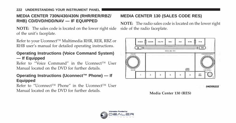
MEDIA CENTER 730N/430/430N (RHR/RER/RBZ/RHB) CD/DVD/HDD/NAV — IF EQUIPPED
NOTE: The sales code is located on the lower right sideof the unit’s faceplate.
Refer to your Uconnect™ Multimedia RHR, RER, RBZ orRHB user’s manual for detailed operating instructions.
Operating Instructions (Voice Command System)— If EquippedRefer to “Voice Command” in the Uconnect™ UserManual located on the DVD for further details.
Operating Instructions (Uconnect™ Phone) — IfEquippedRefer to “Uconnect™ Phone” in the Uconnect™ UserManual located on the DVD for further details.
MEDIA CENTER 130 (SALES CODE RES)
NOTE: The radio sales code is located on the lower rightside of the radio faceplate.
Media Center 130 (RES)
222 UNDERSTANDING YOUR INSTRUMENT PANEL
Information Provided by:
Operating Instructions — Radio Mode
NOTE: The ignition switch must be in the ON or ACCposition to operate the radio.
Power Switch/Volume Control (Rotary)Push the ON/VOLUME control knob to turn on theradio. Push the ON/VOLUME control knob a secondtime to turn off the radio.
Electronic Volume ControlThe electronic volume control turns continuously (360degrees) in either direction, without stopping. Turningthe ON/VOLUME control knob to the right increases thevolume, and to the left decreases it.
When the audio system is turned on, the sound will beset at the same volume level as last played.
SEEK ButtonsPress and release the SEEK buttons to search for the nextlistenable station in AM/FM mode. Press the right switch
to seek up and the left switch to seek down. The radiowill remain tuned to the new station until you makeanother selection. Holding either button will bypassstations without stopping, until you release it.
TIME ButtonPress the TIME button to alternate display of the timeand radio frequency.
Clock Setting Procedure
1. Press and hold the TIME button until the hours blink.
2. Adjust the hours by turning the right side TUNE/SCROLL control knob.
3. After adjusting the hours, press the right side TUNE/SCROLL control knob to set the minutes. The minuteswill begin to blink.
4
UNDERSTANDING YOUR INSTRUMENT PANEL 223
Information Provided by:
4. Adjust the minutes using the right side TUNE/SCROLL control knob. Press the TUNE/SCROLL controlknob to save time change.
5. To exit, press any button/knob, or wait five seconds.
RW/FFPressing the RW (Rewind) or FF (Fast Forward) buttonscauses the tuner to search for the next frequency in thedirection of the arrows. This feature operates in eitherAM or FM frequencies.
TUNE ControlTurn the rotary TUNE/SCROLL control knob clockwiseto increase or counterclockwise to decrease the frequency.
Setting the Tone, Balance, and FadePush the rotary TUNE/SCROLL control knob and BASSwill display. Turn the TUNE/SCROLL control knob tothe right or left to increase or decrease the bass tones.
Push the rotary TUNE/SCROLL control knob a secondtime and MID will display. Turn the TUNE/SCROLLcontrol knob to the right or left to increase or decrease themid-range tones.
Push the rotary TUNE/SCROLL control knob a thirdtime and TREBLE will display. Turn the TUNE/SCROLLcontrol knob to the right or left to increase or decrease thetreble tones.
Push the rotary TUNE/SCROLL control knob a fourthtime and BALANCE will display. Turn the TUNE/SCROLL control knob to the right or left to adjust thesound level from the right or left side speakers.
Push the rotary TUNE/SCROLL control knob a fifth timeand FADE will display. Turn the TUNE/SCROLL controlknob to the left or right to adjust the sound level betweenthe front and rear speakers.
224 UNDERSTANDING YOUR INSTRUMENT PANEL
Information Provided by:
Push the rotary TUNE/SCROLL control knob again toexit setting tone, balance, and fade.
AM/FM ButtonPress the buttons to select either AM or FM mode.
SET/RND Button — To Set the PushbuttonMemoryWhen you are receiving a station that you wish tocommit to pushbutton memory, press the SET/RNDbutton. The symbol SET 1 will now show in the displaywindow. Select the button (1 to 6) you wish to lock ontothis station and press and release that button. If a buttonis not selected within five seconds after pressing theSET/RND button, the station will continue to play butwill not be stored into pushbutton memory.
You may add a second station to each pushbutton byrepeating the above procedure with this exception: Pressthe SET/RND button twice and SET 2 will show in thedisplay window. Each button can be set for SET 1 andSET 2 in both AM and FM. This allows a total of 12 AMand 12 FM stations to be stored into pushbutton memory.The stations stored in SET 2 memory can be selected bypressing the pushbutton twice.
Every time a preset button is used, a correspondingbutton number will display.
Buttons 1 - 6These buttons tune the radio to the stations that youcommit to pushbutton memory (12 AM and 12 FMstations).
DISC ButtonPressing the DISC button will allow you to switch fromAM/FM modes to Disc modes.
4
UNDERSTANDING YOUR INSTRUMENT PANEL 225
Information Provided by:
Operation Instructions — CD MODE For CD AndMP3 Audio Play
NOTE:• The ignition switch must be in the ON or ACC
position to operate the radio.
• This radio is capable of playing compact discs (CD),recordable compact discs (CD-R), rewritable compactdiscs (CD-RW), compact discs with MP3 tracks andmultisession compact discs with CD and MP3 tracks.
Inserting Compact Disc(s)Gently insert one CD into the CD player with the CDlabel facing up. The CD will automatically be pulled intothe CD player and the CD icon will illuminate on theradio display. If a CD does not go into the slot more than1.0 in (2.5 cm), a disc may already be loaded and must beejected before a new disc can be loaded.
If you insert a disc with the ignition ON and the radioON, the unit will switch from radio to CD mode andbegin to play when you insert the disc. The display willshow the track number, and index time in minutes andseconds. Play will begin at the start of track 1.
CAUTION!
• This CD player will accept 4-3/4 in (12 cm) discsonly. The use of other sized discs may damage theCD player mechanism.
• Do not use adhesive labels. These labels can peelaway and jam the player mechanism.
• The RES Media Center is a single CD player. Donot attempt to insert a second CD if one is alreadyloaded.
EJECT Button - Ejecting a CDPress the EJECT button to eject the CD.
226 UNDERSTANDING YOUR INSTRUMENT PANEL
Information Provided by:
If you have ejected a disc and have not removed it within10 seconds, it will be reloaded. If the CD is not removed,the radio will reinsert the CD but will not play it.
A disc can be ejected with the radio and ignition OFF.
NOTE: Ejecting with the ignition OFF is not allowed onconvertible or soft-top models (if equipped).
SEEK ButtonPress the right SEEK button for the next selection on theCD. Press the left SEEK button to return to the beginningof the current selection, or return to the beginning of theprevious selection if the CD is within the first second ofthe current selection. Pressing and holding the SEEKbutton will allow faster scrolling through the tracks inCD and MP3 modes.
TIME ButtonPress this button to change the display from a large CDplaying time display to a small CD playing time display.
RW/FFPress and hold the FF (Fast Forward) button and the CDplayer will begin to fast forward until FF is released, orRW or another CD button is pressed. The RW (Reverse)button works in a similar manner.
AM/FM ButtonPress the button to select either AM or FM mode.
SET/RND Button (Random Play Button)Press this button while the CD is playing to activateRandom Play. This feature plays the selections on thecompact disc in random order to provide an interestingchange of pace.
Press the right SEEK button to move to the next ran-domly selected track.
Press the RND button a second time to stop RandomPlay.
4
UNDERSTANDING YOUR INSTRUMENT PANEL 227
Information Provided by:
Notes on Playing MP3 FilesThe radio can play MP3 files; however, acceptable MP3file recording media and formats are limited. Whenwriting MP3 files, pay attention to the following restric-tions.
Supported Media (Disc Types)The MP3 file recording media supported by the radio areCDDA, CD-R, CD-RW, MP3, and CDDA+MP3.
Supported Medium Formats (File Systems)The medium formats supported by the radio are ISO 9660Level 1 and Level 2 and includes the Joliet extension.When reading discs recorded using formats other thanISO 9660 Level 1 and Level 2, the radio may fail to readfiles properly and may be unable to play the file nor-mally. UDF and Apple HFS formats are not supported.
The radio uses the following limits for file systems:
• Maximum number of folder levels: 8
• Maximum number of files: 255
• Maximum number of folders. (The radio display of filenames and folder names is limited. For large numbersof files and/or folders, the radio may be unable todisplay the file name and folder name, and will assigna number instead. With a maximum number of files,exceeding 20 folders will result in this display. With200 files, exceeding 50 folders will result in thisdisplay.)
• Maximum number of characters in file/folder names:
• Level 1: 12 (including a separator �.� and a three-character extension)
• Level 2: 31 (including a separator �.� and a three-character extension)
Multisession disc formats are supported by the radio.Multisession discs may contain combinations of normalCD audio tracks and computer files (including MP3 files).
228 UNDERSTANDING YOUR INSTRUMENT PANEL
Information Provided by:
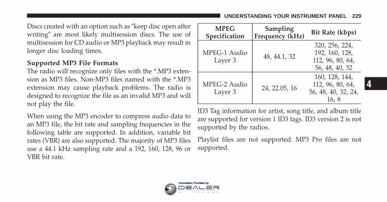
Discs created with an option such as �keep disc open afterwriting� are most likely multisession discs. The use ofmultisession for CD audio or MP3 playback may result inlonger disc loading times.
Supported MP3 File FormatsThe radio will recognize only files with the *.MP3 exten-sion as MP3 files. Non-MP3 files named with the *.MP3extension may cause playback problems. The radio isdesigned to recognize the file as an invalid MP3 and willnot play the file.
When using the MP3 encoder to compress audio data toan MP3 file, the bit rate and sampling frequencies in thefollowing table are supported. In addition, variable bitrates (VBR) are also supported. The majority of MP3 filesuse a 44.1 kHz sampling rate and a 192, 160, 128, 96 orVBR bit rate.
MPEGSpecification
SamplingFrequency (kHz) Bit Rate (kbps)
MPEG-1 AudioLayer 3 48, 44.1, 32
320, 256, 224,192, 160, 128,
112, 96, 80, 64,56, 48, 40, 32
MPEG-2 AudioLayer 3 24, 22.05, 16
160, 128, 144,112, 96, 80, 64,
56, 48, 40, 32, 24,16, 8
ID3 Tag information for artist, song title, and album titleare supported for version 1 ID3 tags. ID3 version 2 is notsupported by the radios.
Playlist files are not supported. MP3 Pro files are notsupported.
4
UNDERSTANDING YOUR INSTRUMENT PANEL 229
Information Provided by:
Playback of MP3 FilesWhen a medium containing MP3 data is loaded, theradio checks all files on the medium. If the mediumcontains a lot of folders or files, the radio will take moretime to start playing the MP3 files.
Loading times for playback of MP3 files may be affectedby the following:
• Media - CD-RW media may take longer to load thanCD-R media
• Medium formats - Multisession discs may take longerto load than non-multisession discs
• Number of files and folders - Loading times willincrease with more files and folders
To increase the speed of disc loading, it is recommendedto use CD-R media and single-session discs. To create asingle-session disc, enable the “Disc at Once” optionbefore writing to the disc.
Operation Instructions - Auxiliary ModeThe auxiliary (AUX) jack is an audio input jack, whichallows the user to plug in a portable device, such as anMP3 player, or cassette player, and utilize the vehicle’saudio system to amplify the source and play through thevehicle speakers.
Pressing the DISC/AUX button will change the mode toauxiliary device if the AUX jack is connected.
NOTE: The AUX device must be turned on and thedevice’s volume set to proper level. If the AUX audio isnot loud enough, turn the device’s volume up. If the AUXaudio sounds distorted, turn the device’s volume down.
TIME Button (Auxiliary Mode)Press this button to change the display to time of day. Thetime of day will display for five seconds (when ignition isOFF).
230 UNDERSTANDING YOUR INSTRUMENT PANEL
Information Provided by:
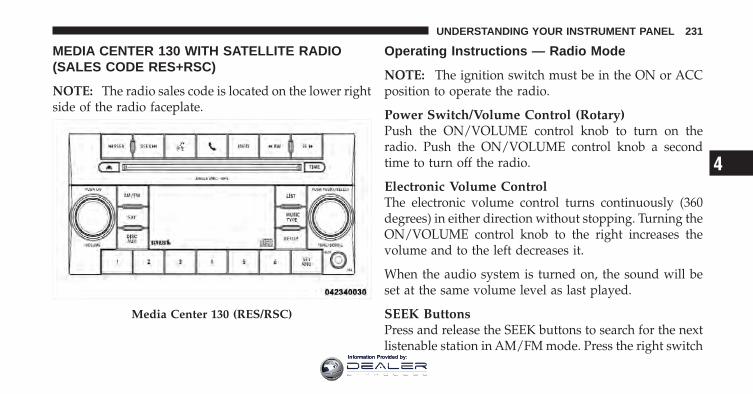
MEDIA CENTER 130 WITH SATELLITE RADIO(SALES CODE RES+RSC)
NOTE: The radio sales code is located on the lower rightside of the radio faceplate.
Operating Instructions — Radio Mode
NOTE: The ignition switch must be in the ON or ACCposition to operate the radio.
Power Switch/Volume Control (Rotary)Push the ON/VOLUME control knob to turn on theradio. Push the ON/VOLUME control knob a secondtime to turn off the radio.
Electronic Volume ControlThe electronic volume control turns continuously (360degrees) in either direction without stopping. Turning theON/VOLUME control knob to the right increases thevolume and to the left decreases it.
When the audio system is turned on, the sound will beset at the same volume level as last played.
SEEK ButtonsPress and release the SEEK buttons to search for the nextlistenable station in AM/FM mode. Press the right switch
Media Center 130 (RES/RSC)
4
UNDERSTANDING YOUR INSTRUMENT PANEL 231
Information Provided by:
to seek up and the left switch to seek down. The radiowill remain tuned to the new station until you makeanother selection. Holding either button will bypassstations without stopping until you release it.
Voice Command System (Radio) — If EquippedRefer to “Voice Command” in “Understanding The Fea-tures Of Your Vehicle”.
Voice Command Button Uconnect™ Phone — IfEquippedPress this button to operate the Uconnect™ Phone feature(if equipped). Refer to “Uconnect™ Phone” in “Under-standing The Features Of Your Vehicle”.
If your vehicle is not equipped with or this feature is notavailable on your vehicle, a “Not Equipped WithUconnect Phone” message will display on the radioscreen.
Phone Button Uconnect™ Phone — If EquippedPress this button to operate the Uconnect™ Phone feature(if equipped). Refer to “Uconnect™ Phone” in “Under-standing The Features Of Your Vehicle”.
If your vehicle is not equipped with or this feature is notavailable on your vehicle, a “Not Equipped WithUconnect Phone” message will display on the radioscreen.
TIME ButtonPress the TIME button to alternate display of the timeand radio frequency.
Clock Setting Procedure
1. Press and hold the TIME button until the hours blink.
2. Adjust the hours by turning the right side TUNE/SCROLL control knob.
232 UNDERSTANDING YOUR INSTRUMENT PANEL
Information Provided by:
3. After adjusting the hours, press the right side TUNE/SCROLL control knob to set the minutes. The minuteswill begin to blink.
4. Adjust the minutes using the right side TUNE/SCROLL control knob. Press the TUNE/SCROLL controlknob to save time change.
5. To exit, press any button/knob or wait five seconds.
The clock can also be set by pressing the SETUP button.For vehicles equipped with satellite radio, press theSETUP button, use the TUNE/SCROLL control to selectSET CLOCK, and then follow the above procedure,starting at Step 2. For vehicles not equipped with satelliteradio, press the SETUP button and then follow the aboveprocedure, starting at Step 2.
INFO ButtonPress the INFO button for an RDS station (one with callletters displayed). The radio will return a Radio Textmessage broadcast from an FM station (FM mode only).
RW/FFPressing the RW (Rewind) or FF (Fast Forward) buttonscauses the tuner to search for the next frequency in thedirection of the arrows. This feature operates in eitherAM or FM frequencies.
TUNE ControlTurn the rotary TUNE/SCROLL control knob clockwiseto increase or counterclockwise to decrease the frequency.
Setting the Tone, Balance, and FadePush the rotary TUNE/SCROLL control knob and BASSwill display. Turn the TUNE/SCROLL control knob tothe right or left to increase or decrease the bass tones.
4
UNDERSTANDING YOUR INSTRUMENT PANEL 233
Information Provided by:
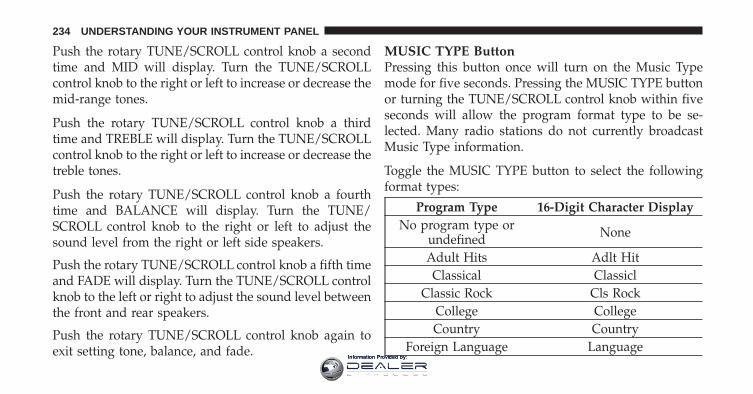
Push the rotary TUNE/SCROLL control knob a secondtime and MID will display. Turn the TUNE/SCROLLcontrol knob to the right or left to increase or decrease themid-range tones.
Push the rotary TUNE/SCROLL control knob a thirdtime and TREBLE will display. Turn the TUNE/SCROLLcontrol knob to the right or left to increase or decrease thetreble tones.
Push the rotary TUNE/SCROLL control knob a fourthtime and BALANCE will display. Turn the TUNE/SCROLL control knob to the right or left to adjust thesound level from the right or left side speakers.
Push the rotary TUNE/SCROLL control knob a fifth timeand FADE will display. Turn the TUNE/SCROLL controlknob to the left or right to adjust the sound level betweenthe front and rear speakers.
Push the rotary TUNE/SCROLL control knob again toexit setting tone, balance, and fade.
MUSIC TYPE ButtonPressing this button once will turn on the Music Typemode for five seconds. Pressing the MUSIC TYPE buttonor turning the TUNE/SCROLL control knob within fiveseconds will allow the program format type to be se-lected. Many radio stations do not currently broadcastMusic Type information.
Toggle the MUSIC TYPE button to select the followingformat types:
Program Type 16-Digit Character DisplayNo program type or
undefined None
Adult Hits Adlt HitClassical Classicl
Classic Rock Cls RockCollege CollegeCountry Country
Foreign Language Language
234 UNDERSTANDING YOUR INSTRUMENT PANEL
Information Provided by:
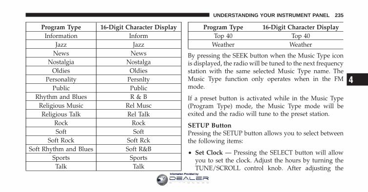
Program Type 16-Digit Character DisplayInformation Inform
Jazz JazzNews News
Nostalgia NostalgaOldies Oldies
Personality PersnltyPublic Public
Rhythm and Blues R & BReligious Music Rel MuscReligious Talk Rel Talk
Rock RockSoft Soft
Soft Rock Soft RckSoft Rhythm and Blues Soft R&B
Sports SportsTalk Talk
Program Type 16-Digit Character DisplayTop 40 Top 40
Weather Weather
By pressing the SEEK button when the Music Type iconis displayed, the radio will be tuned to the next frequencystation with the same selected Music Type name. TheMusic Type function only operates when in the FMmode.
If a preset button is activated while in the Music Type(Program Type) mode, the Music Type mode will beexited and the radio will tune to the preset station.
SETUP ButtonPressing the SETUP button allows you to select betweenthe following items:
• Set Clock — Pressing the SELECT button will allowyou to set the clock. Adjust the hours by turning theTUNE/SCROLL control knob. After adjusting the
4
UNDERSTANDING YOUR INSTRUMENT PANEL 235
Information Provided by:
hours, press the TUNE/SCROLL control knob to setthe minutes. The minutes will begin to blink. Adjustthe minutes using the right side TUNE/SCROLLcontrol knob. Press the TUNE/SCROLL control knobto save time change.
AM/FM ButtonPress the button to select either AM or FM mode.
SET/RND Button — To Set the PushbuttonMemoryWhen you are receiving a station that you wish tocommit to pushbutton memory, press the SET/RNDbutton. The symbol SET 1 will now show in the displaywindow. Select the button (1–6) you wish to lock onto thisstation and press and release that button. If a button isnot selected within five seconds after pressing the SET/RND button, the station will continue to play but will notbe stored into pushbutton memory.
You may add a second station to each pushbutton byrepeating the above procedure with this exception: Pressthe SET/RND button twice and SET 2 will show in thedisplay window. Each button can be set for SET 1 andSET 2 in both AM and FM. This allows a total of 12 AMand 12 FM stations to be stored into pushbutton memory.The stations stored in SET 2 memory can be selected bypressing the pushbutton twice.
Every time a preset button is used, a correspondingbutton number will display.
Buttons 1 - 6These buttons tune the radio to the stations that youcommit to pushbutton memory (12 AM and 12 FMstations).
DISC/AUX ButtonPressing the DISC/AUX button will allow you to switchfrom AM/FM modes to DISC/AUX mode.
236 UNDERSTANDING YOUR INSTRUMENT PANEL
Information Provided by:

Operation Instructions — CD MODE for CD andMP3 Audio Play
NOTE:• The ignition switch must be in the ON or ACC
position to operate the radio.
• This radio is capable of playing compact discs (CD),recordable compact discs (CD-R), rewritable compactdiscs (CD-RW), compact discs with MP3 tracks andmultisession compact discs with CD and MP3 tracks.
Inserting Compact Disc(s)Gently insert one CD into the CD player with the CDlabel facing up. The CD will automatically be pulled intothe CD player and the CD icon will illuminate on theradio display. If a CD does not go into the slot more than1.0 in (2.5 cm), a disc may already be loaded and must beejected before a new disc can be loaded.
If you insert a disc with the ignition ON and the radioON, the unit will switch from radio to CD mode andbegin to play when you insert the disc. The display willshow the track number, and index time in minutes andseconds. Play will begin at the start of track 1.
CAUTION!
• This CD player will accept 4–3/4 in (12 cm) discsonly. The use of other sized discs may damage theCD player mechanism.
• Do not use adhesive labels. These labels can peelaway and jam the player mechanism.
• The RES Media Center is a single CD player. Donot attempt to insert a second CD if one is alreadyloaded.
EJECT Button - Ejecting a CDPress the EJECT button to eject the CD.
4
UNDERSTANDING YOUR INSTRUMENT PANEL 237
Information Provided by:
If you have ejected a disc and have not removed it within10 seconds, it will be reloaded. If the CD is not removed,the radio will reinsert the CD but will not play it.
A disc can be ejected with the radio and ignition OFF.
NOTE: Ejecting with the ignition OFF is not allowed onconvertible or soft-top models (if equipped).
SEEK ButtonPress the right SEEK button for the next selection on theCD. Press the left SEEK button to return to the beginningof the current selection, or return to the beginning of theprevious selection if the CD is within the first second ofthe current selection. Pressing and holding the SEEKbutton will allow faster scrolling through the tracks inCD and MP3 modes.
TIME ButtonPress this button to change the display from a large CDplaying time display to a small CD playing time display.
RW/FFPress and hold FF (Fast Forward) and the CD player willbegin to fast forward until FF is released or RW oranother CD button is pressed. The RW (Reverse) buttonworks in a similar manner.
AM/FM ButtonPress the button to select either AM or FM mode.
SET/RND Button (Random Play Button)Press this button while the CD is playing to activateRandom Play. This feature plays the selections on thecompact disc in random order to provide an interestingchange of pace.
Press the right SEEK button to move to the next ran-domly selected track.
Press the SET/RND button a second time to stop Ran-dom Play.
238 UNDERSTANDING YOUR INSTRUMENT PANEL
Information Provided by:
Notes On Playing MP3 FilesThe radio can play MP3 files; however, acceptable MP3file recording media and formats are limited. Whenwriting MP3 files, pay attention to the following restric-tions.
Supported Media (Disc Types)The MP3 file recording media supported by the radio areCDDA, CD-R, CD-RW, MP3, and CDDA+MP3.
Supported Medium Formats (File Systems)The medium formats supported by the radio are ISO 9660Level 1 and Level 2 and includes the Joliet extension.When reading discs recorded using formats other thanISO 9660 Level 1 and Level 2, the radio may fail to readfiles properly and may be unable to play the file nor-mally. UDF and Apple HFS formats are not supported.
The radio uses the following limits for file systems:
• Maximum number of folder levels: 8
• Maximum number of files: 255
• Maximum number of folders. (The radio display of filenames and folder names is limited. For large numbersof files and/or folders, the radio may be unable todisplay the file name and folder name and will assigna number instead. With a maximum number of files,exceeding 20 folders will result in this display. With200 files, exceeding 50 folders will result in thisdisplay.)
• Maximum number of characters in file/folder names:
• Level 1: 12 (including a separator �.� and a three-character extension)
• Level 2: 31 (including a separator �.� and a three-character extension)
Multisession disc formats are supported by the radio.Multisession discs may contain combinations of normalCD audio tracks and computer files (including MP3 files).
4
UNDERSTANDING YOUR INSTRUMENT PANEL 239
Information Provided by:
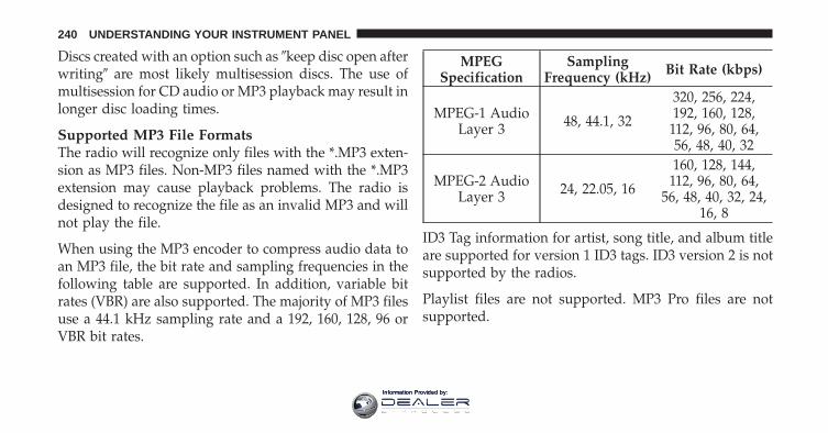
Discs created with an option such as �keep disc open afterwriting� are most likely multisession discs. The use ofmultisession for CD audio or MP3 playback may result inlonger disc loading times.
Supported MP3 File FormatsThe radio will recognize only files with the *.MP3 exten-sion as MP3 files. Non-MP3 files named with the *.MP3extension may cause playback problems. The radio isdesigned to recognize the file as an invalid MP3 and willnot play the file.
When using the MP3 encoder to compress audio data toan MP3 file, the bit rate and sampling frequencies in thefollowing table are supported. In addition, variable bitrates (VBR) are also supported. The majority of MP3 filesuse a 44.1 kHz sampling rate and a 192, 160, 128, 96 orVBR bit rates.
MPEGSpecification
SamplingFrequency (kHz) Bit Rate (kbps)
MPEG-1 AudioLayer 3 48, 44.1, 32
320, 256, 224,192, 160, 128,
112, 96, 80, 64,56, 48, 40, 32
MPEG-2 AudioLayer 3 24, 22.05, 16
160, 128, 144,112, 96, 80, 64,
56, 48, 40, 32, 24,16, 8
ID3 Tag information for artist, song title, and album titleare supported for version 1 ID3 tags. ID3 version 2 is notsupported by the radios.
Playlist files are not supported. MP3 Pro files are notsupported.
240 UNDERSTANDING YOUR INSTRUMENT PANEL
Information Provided by:
Playback of MP3 FilesWhen a medium containing MP3 data is loaded, theradio checks all files on the medium. If the mediumcontains a lot of folders or files, the radio will take moretime to start playing the MP3 files.
Loading times for playback of MP3 files may be affectedby the following:
• Media - CD-RW media may take longer to load thanCD-R media
• Medium formats - Multisession discs may take longerto load than non-multisession discs
• Number of files and folders - Loading times willincrease with more files and folders
To increase the speed of disc loading, it is recommendedto use CD-R media and single-session discs. To create asingle-session disc, enable the “Disc at Once” optionbefore writing to the disc.
LIST Button (CD Mode for MP3 Play)Pressing the LIST button will bring up a list of all folderson the disc. Scrolling up or down the list is done byturning the TUNE/SCROLL control knob. Selecting afolder by pressing the TUNE/SCROLL control knob willbegin playing the files contained in that folder (or thenext folder in sequence if the selection does not containplayable files).
The folder list will time out after five seconds.
INFO Button (CD Mode for MP3 Play)Pressing the INFO button repeatedly will scroll throughthe following TAG information: Song Title, Artist, FileName, and Folder Name (if available).
Press the INFO button once more to return to �elapsedtime� priority mode.
Press and hold the INFO button for three seconds ormore and the radio will display song titles for each file.
4
UNDERSTANDING YOUR INSTRUMENT PANEL 241
Information Provided by:
Press and hold the INFO button again for three secondsto return to �elapsed time� display.
Operation Instructions - Auxiliary ModeThe auxiliary (AUX) jack is an audio input jack whichallows the user to plug in a portable device such as anMP3 player or cassette player and utilize the vehicle’saudio system to amplify the source and play through thevehicle speakers.
Pressing the AUX button will change the mode to auxil-iary device if the AUX jack is connected.
NOTE: The AUX device must be turned on and thedevice’s volume set to the proper level. If the AUX audiois not loud enough, turn the device’s volume up. If theAUX audio sounds distorted, turn the device’s volumedown.
TIME Button (Auxiliary Mode)Press this button to change the display to time of day. Thetime of day will display for five seconds (when theignition is OFF).
Uconnect™ Multimedia (Satellite Radio) — IfEquippedSatellite radio uses direct satellite-to-receiver broadcast-ing technology to provide clear digital sound, coast tocoast. The subscription service provider is Sirius SatelliteRadio. This service offers over 130 channels of music,sports, news, entertainment, and programming for chil-dren, directly from its satellites and broadcasting studios.
NOTE: Sirius service is not available in Hawaii and haslimited coverage in Alaska.
System ActivationSirius Satellite Radio service is pre-activated, and youmay begin listening immediately to the one year of audioservice that is included with the factory-installed satellite
242 UNDERSTANDING YOUR INSTRUMENT PANEL
Information Provided by:
radio system in your vehicle. Sirius will supply a wel-come kit that contains general information, includinghow to setup your on-line listening account. For furtherinformation, call the toll-free number 888-539-7474, orvisit the Sirius web site at www.sirius.com, or at www-.siriuscanada.ca for Canadian residents.
Electronic Serial Number/Sirius IdentificationNumber (ESN/SID)Please have the following information available whencalling:
1. The Electronic Serial Number/Sirius IdentificationNumber (ESN/SID).
2. Your Vehicle Identification Number.
To access the ESN/SID, refer to the following steps:
ESN/SID AccessWith the ignition switch in the ON/RUN or ACC posi-tion and the radio on, press the SETUP button and scroll
using the TUNE/SCROLL control knob until Sirius ID isselected. Press the TUNE/SCROLL control knob and theSirius ID number will display. The Sirius ID numberdisplay will time out in two minutes. Press any button onthe radio to exit this screen.
Selecting Uconnect™ Multimedia (Satellite) ModePress the SAT button until �SAT� appears in the display. ACD may remain in the radio while in the Satellite radiomode.
Satellite AntennaTo ensure optimum reception, do not place items on theroof around the rooftop antenna location. Metal objectsplaced within the line of sight of the antenna will causedecreased performance. Larger luggage items such asbikes should be placed as far rearward as possible, withinthe loading design of the rack. Do not place items directlyon or above the antenna.
4
UNDERSTANDING YOUR INSTRUMENT PANEL 243
Information Provided by:
Reception QualitySatellite reception may be interrupted due to one of thefollowing reasons:
• The vehicle is parked in an underground parkingstructure or under a physical obstacle.
• Dense tree coverage may interrupt reception in theform of short audio mutes.
• Driving under wide bridges or along tall buildings cancause intermittent reception.
• Placing objects over or too close to the antenna cancause signal blockage.
Operating Instructions - Uconnect™ Multimedia(Satellite) Mode
NOTE: The ignition switch must be in the ON/RUN orACC position to operate the radio.
SEEK ButtonsPress and release the SEEK buttons to search for the nextchannel in Satellite mode. Press the right switch to seekup and the left switch to seek down. The radio willremain tuned to the new channel until you make anotherselection. Holding either button will bypass channelswithout stopping until you release it.
SCAN ButtonPressing the SCAN button causes the tuner to search forthe next channel, pausing for eight seconds before con-tinuing to the next. To stop the search, press the SCANbutton a second time.
INFO ButtonPressing the INFO button will cycle the display informa-tion between Artist, Song Title, and Composer (if avail-able). Also, pressing and holding the INFO button for anadditional three seconds will make the radio display theSong Title all of the time (press and hold again to returnto normal display).
244 UNDERSTANDING YOUR INSTRUMENT PANEL
Information Provided by:
RW/FFPressing the RW (Rewind) or FF (Fast Forward) buttonscauses the tuner to search for the next channel in thedirection of the arrows.
TUNE Control (Rotary)Turn the rotary TUNE/SCROLL control knob clockwiseto increase or counterclockwise to decrease the channel.
MUSIC TYPE ButtonPressing this button once will turn on the Music Typemode for five seconds. Pressing the MUSIC TYPE buttonor turning the TUNE/SCROLL control knob within fiveseconds will allow the program format type to be se-lected.
Toggle the MUSIC TYPE button again to select the musictype.
By pressing the SEEK button when the Music Typefunction is active, the radio will be tuned to the nextchannel with the same selected Music Type name.
If a preset button is activated while in the Music Type(Program Type) mode, the Music Type mode will beexited and the radio will tune to the preset channel.
SETUP ButtonPressing the SETUP button allows you to select thefollowing items:
• Display Sirius ID number — Press the AUDIO/SELECT button to display the Sirius ID number. Thisnumber is used to activate, deactivate, or change theSirius subscription.
SET Button – To Set the Pushbutton MemoryWhen you are receiving a channel that you wish tocommit to pushbutton memory, press the SET button.The symbol SET 1 will now show in the display window.
4
UNDERSTANDING YOUR INSTRUMENT PANEL 245
Information Provided by:
Select the button (1-6) you wish to lock onto this channeland press and release that button. If a button is notselected within five seconds after pressing the SET but-ton, the channel will continue to play but will not bestored into pushbutton memory.
You may add a second channel to each pushbutton byrepeating the above procedure with this exception: Pressthe SET button twice and SET 2 will show in the displaywindow. Each button can be set for SET 1 and SET 2. Thisallows a total of 12 Satellite channels to be stored intopushbutton memory. The channels stored in SET 2memory can be selected by pressing the pushbuttontwice.
Every time a preset button is used, a correspondingbutton number will display.
Buttons 1 - 6These buttons tune the radio to the channels that youcommit to pushbutton memory (12 Satellite stations).
Operating Instructions - Uconnect™ Phone (IfEquipped)Refer to “Uconnect™ Phone” in “Understanding TheFeatures Of Your Vehicle”.
iPod�/USB/MP3 CONTROL — IF EQUIPPED
NOTE: This section is for sales code RES and REQ/REL/RET radios only with Uconnect™. For sales codeRBZ/RHB, RHR, RHP, RHW or RB2 touch-screen radioiPod�/USB/MP3 control feature, refer to the separateRBZ/RHB, RHR, RHP, RHW or RB2 User’s Manual.iPod�/USB/MP3 control is available only if equipped asan option with these radios.
This feature allows an iPod� or external USB device to beplugged into the USB port, located in the glove compart-ment.
246 UNDERSTANDING YOUR INSTRUMENT PANEL
Information Provided by:
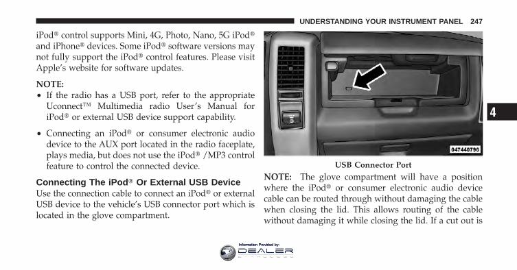
iPod� control supports Mini, 4G, Photo, Nano, 5G iPod�and iPhone� devices. Some iPod� software versions maynot fully support the iPod� control features. Please visitApple’s website for software updates.
NOTE:• If the radio has a USB port, refer to the appropriate
Uconnect™ Multimedia radio User’s Manual foriPod� or external USB device support capability.
• Connecting an iPod� or consumer electronic audiodevice to the AUX port located in the radio faceplate,plays media, but does not use the iPod� /MP3 controlfeature to control the connected device.
Connecting The iPod� Or External USB DeviceUse the connection cable to connect an iPod� or externalUSB device to the vehicle’s USB connector port which islocated in the glove compartment.
NOTE: The glove compartment will have a positionwhere the iPod� or consumer electronic audio devicecable can be routed through without damaging the cablewhen closing the lid. This allows routing of the cablewithout damaging it while closing the lid. If a cut out is
USB Connector Port
4
UNDERSTANDING YOUR INSTRUMENT PANEL 247
Information Provided by:
not available in the glove compartment, route the cableaway from the lid latch and in a place that will allow thelid to close without damaging the cable.
Once the audio device is connected and synchronized tothe vehicle’s iPod�/USB/MP3 control system (iPod� orexternal USB device may take a few minutes to connect),the audio device starts charging and is ready for use bypressing radio switches, as described below.
NOTE: If the audio device battery is completely dis-charged, it may not communicate with the iPod�/USB/MP3 control system until a minimum charge is attained.Leaving the audio device connected to the iPod�/USB/MP3 control system may charge it to the required level.
Using This FeatureBy using iPod cable or external USB device to connect toUSB port:
• The audio device can be played on the vehicle’s soundsystem, providing metadata (artist, track title, album,etc.) information on the radio display.
• The audio device can be controlled using the radiobuttons to Play, Browse, and List the iPod� contents.
• The audio device battery charges when plugged intothe USB/AUX connector (if supported by the specificaudio device)
Controlling The iPod� Or External USB DeviceUsing Radio ButtonsTo get into the iPod�/USB/MP3 control mode and accessa connected audio device, either press the “AUX” buttonon the radio faceplate or press the VR button and say�USB� or �Switch to USB�. Once in the iPod�/USB/MP3
248 UNDERSTANDING YOUR INSTRUMENT PANEL
Information Provided by:
control mode, audio tracks (if available from audiodevice) start playing over the vehicle’s audio system.
Play ModeWhen switched to iPod�/USB/MP3 control mode, theiPod� or external USB device automatically starts Playmode. In Play mode, the following buttons on the radiofaceplate may be used to control the iPod� or externalUSB device and display data:
• Use the TUNE control knob to select the next orprevious track.
• Turning it clockwise (forward) by one click, whileplaying a track, skips to the next track or press theVR button and say �Next Track�.
• Turning it counterclockwise (backward) by oneclick, will jump to the previous track in the list orpress the VR button and say �Previous Track�
• Jump backward in the current track by pressing andholding the << RW button. Holding the << RWbutton long enough will jump to the beginning ofthe current track.
• Jump forward in the current track by pressing andholding the FF >> button.
• A single press backward << RW or forward FF >> willjump backward or forward respectively, for fiveseconds.
• Use the << SEEK and SEEK >> buttons to jump to theprevious or next track. Pressing the SEEK >> buttonduring play mode will jump to the next track in thelist, or press the VR button and say �Next or PreviousTrack�.
• While a track is playing, press the INFO button to seethe associated metadata (artist, track title, album, etc.)for that track. Pressing the INFO button again jumps
4
UNDERSTANDING YOUR INSTRUMENT PANEL 249
Information Provided by:
to the next screen of data for that track. Once allscreens have been viewed, the last INFO button presswill go back to the play mode screen on the radio.
• Pressing the REPEAT button will change the audiodevice mode to repeat the current playing track orpress the VR button and say �Repeat ON� or �RepeatOff�.
• Press the SCAN button to use iPod�/USB/MP3 de-vice scan mode, which will play the first 10 seconds ofeach track in the current list and then forward to thenext song. To stop SCAN mode and start playing thedesired track, when it is playing the track, press theSCAN button again. During Scan mode, pressing the<< SEEK and SEEK >> buttons will select the previ-ous and next tracks.
• RND button (available on sales code RES radio only):Pressing this button toggles between Shuffle ON andShuffle OFF modes for the iPod� or external USB
device, or press the VR button and say �Shuffle ON� or�Shuffle Off�. If the RND icon is showing on the radiodisplay, then the shuffle mode is ON.
List Or Browse ModeDuring Play mode, pressing any of the buttons describedbelow, will bring up List mode. List mode enablesscrolling through the list of menus and tracks on theaudio device.
• TUNE control knob: The TUNE control knob functionsin a similar manner as the scroll wheel on the audiodevice or external USB device.
• Turning it clockwise (forward) and counterclock-wise (backward) scrolls through the lists, displayingthe track detail on the radio display. Once the trackto be played is highlighted on the radio display,press the TUNE control knob to select and startplaying the track. Turning the TUNE control knob
250 UNDERSTANDING YOUR INSTRUMENT PANEL
Information Provided by:
fast will scroll through the list faster. During fastscroll, a slight delay in updating the information onthe radio display may be noticeable.
• During all List modes, the iPod� displays all lists in“wrap-around” mode. So if the track is at thebottom of the list, just turn the wheel backward(counterclockwise) to get to the track faster.
• In List mode, the radio PRESET buttons are used asshortcuts to the following lists on the iPod� orexternal USB device.
• Preset 1 – Playlists
• Preset 2 – Artists
• Preset 3 – Albums
• Preset 4 – Genres
• Preset 5 – Audiobooks
• Preset 6 – Podcasts
• Pressing a PRESET button will display the currentlist on the top line and the first item in that list onthe second line.
• To exit List mode without selecting a track, press thesame PRESET button again to go back to Playmode.
• LIST button: The LIST button will display the toplevel menu of the iPod� or external USB device. Turnthe TUNE control knob to list the top-menu item to beselected and press the TUNE control knob. This willdisplay the next sub-menu list item on the audiodevice, then follow the same steps to go to the desiredtrack in that list. Not all iPod� or external USB devicesub-menu levels are available on this system.
• MUSIC TYPE button: The MUSIC TYPE button isanother shortcut button to the genre listing on youraudio device.
4
UNDERSTANDING YOUR INSTRUMENT PANEL 251
Information Provided by:
CAUTION!
• Leaving the iPod� or external USB device (or anysupported device) anywhere in the vehicle inextreme heat or cold can alter the operation ordamage the device. Follow the device manufactur-er’s guidelines.
• Placing items on the iPod� or external USB device,or connections to the iPod� or external USB devicein the vehicle, can cause damage to the deviceand/or to the connectors.
WARNING!
Do not plug in or remove the iPod� or external USBdevice while driving. Failure to follow this warningcould result in an accident.
Bluetooth Streaming Audio (BTSA)Music can be streamed from your cellular phone to theUconnect™ phone system.
Controlling BTSA Using Radio ButtonsTo get into the BTSA mode, press either “AUX” button onthe radio or press the VR button and say “BluetoothStreaming Audio”.
Play ModeWhen switched to BTSA mode, some audio devices canstart playing music over the vehicle’s audio system, butsome devices require the music to be initiated on thedevice first, then it will get streamed to the Uconnect™phone system. Seven devices can be paired to theUconnect™ phone system, but just one can be selectedand played.
Selecting Different Audio Device
1. Press PHONE button to begin.
252 UNDERSTANDING YOUR INSTRUMENT PANEL
Information Provided by:
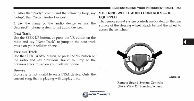
2. After the �Ready� prompt and the following beep, say�Setup�, then �Select Audio Devices�.
3. Say the name of the audio device or ask theUconnect™ phone system to list audio devices.
Next TrackUse the SEEK UP button, or press the VR button on theradio and say “Next Track” to jump to the next trackmusic on your cellular phone.
Previous TrackUse the SEEK DOWN button, or press the VR button onthe radio and say “Previous Track” to jump to theprevious track music on your cellular phone.
BrowseBrowsing is not available on a BTSA device. Only thecurrent song that is playing will display info.
STEERING WHEEL AUDIO CONTROLS — IFEQUIPPEDThe remote sound system controls are located on the rearsurface of the steering wheel. Reach behind the wheel toaccess the switches.
Remote Sound System Controls(Back View Of Steering Wheel)
4
UNDERSTANDING YOUR INSTRUMENT PANEL 253
Information Provided by:
The right hand control is a rocker type switch with apushbutton in the center. Pressing the top of the switchwill increase the volume, and pressing the bottom of theswitch will decrease the volume.
The button located in the center of the right hand controlwill switch modes to Radio, CD or other valid audiosource.
The left hand control is a rocker type switch with apushbutton in the center. The function of the left handcontrol is different depending on which mode you are in.
The following describes the left hand control operation ineach mode.
Radio OperationPressing the top of the switch will SEEK up for the nextlistenable station and pressing the bottom of the switchwill SEEK down for the next listenable station.
The button located in the center of the left hand controlwill tune to the next pre-set station that you haveprogrammed in the radio pre-set pushbuttons.
CD PlayerPressing the top of the switch once will go to the nexttrack on the CD. Pressing the bottom of the switch oncewill go to the beginning of the current track or to thebeginning of the previous track if it is within one secondafter the current track begins to play.
If you press the switch up or down twice it plays thesecond track, three times, it will play the third, etc.
The button in the center of the left hand switch changesCDs on the 6–Disc in-dash CD changer radio. This buttondoes not function for all other radios.
254 UNDERSTANDING YOUR INSTRUMENT PANEL
Information Provided by:
CD/DVD DISC MAINTENANCETo keep a CD/DVD in good condition, take the followingprecautions:
1. Handle the disc by its edge; avoid touching thesurface.
2. If the disc is stained, clean the surface with a soft cloth,wiping from center to edge.
3. Do not apply paper or tape to the disc; avoid scratch-ing the disc.
4. Do not use solvents such as benzene, thinner, cleaners,or anti-static sprays.
5. Store the disc in its case after playing.
6. Do not expose the disc to direct sunlight.
7. Do not store the disc where temperatures may becometoo high.
NOTE: If you experience difficulty in playing a particu-lar disc, it may be damaged (i.e., scratched, reflectivecoating removed, a hair, moisture or dew on the disc)oversized, or have protection encoding. Try a knowngood disc before considering disc player service.
RADIO OPERATION AND MOBILE PHONESUnder certain conditions, the mobile phone being on inyour vehicle can cause erratic or noisy performance fromyour radio. This condition may be lessened or eliminatedby relocating the mobile phone antenna. This condition isnot harmful to the radio. If your radio performance doesnot satisfactorily “clear” by the repositioning of theantenna, it is recommended that the radio volume beturned down or off during mobile phone operation whennot using Uconnect™ (if equipped).
4
UNDERSTANDING YOUR INSTRUMENT PANEL 255
Information Provided by:
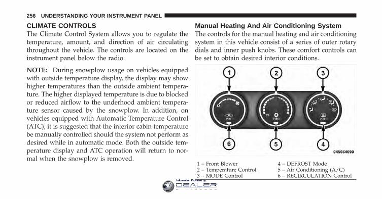
CLIMATE CONTROLSThe Climate Control System allows you to regulate thetemperature, amount, and direction of air circulatingthroughout the vehicle. The controls are located on theinstrument panel below the radio.
NOTE: During snowplow usage on vehicles equippedwith outside temperature display, the display may showhigher temperatures than the outside ambient tempera-ture. The higher displayed temperature is due to blockedor reduced airflow to the underhood ambient tempera-ture sensor caused by the snowplow. In addition, onvehicles equipped with Automatic Temperature Control(ATC), it is suggested that the interior cabin temperaturebe manually controlled should the system not perform asdesired while in automatic mode. Both the outside tem-perature display and ATC operation will return to nor-mal when the snowplow is removed.
Manual Heating And Air Conditioning SystemThe controls for the manual heating and air conditioningsystem in this vehicle consist of a series of outer rotarydials and inner push knobs. These comfort controls canbe set to obtain desired interior conditions.
1 – Front Blower 4 – DEFROST Mode2 – Temperature Control 5 – Air Conditioning (A/C)3 – MODE Control 6 – RECIRCULATION Control
256 UNDERSTANDING YOUR INSTRUMENT PANEL
Information Provided by:
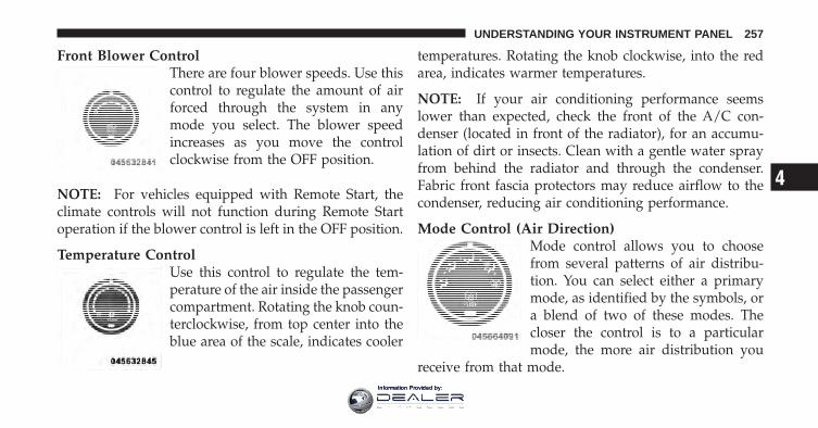
Front Blower ControlThere are four blower speeds. Use thiscontrol to regulate the amount of airforced through the system in anymode you select. The blower speedincreases as you move the controlclockwise from the OFF position.
NOTE: For vehicles equipped with Remote Start, theclimate controls will not function during Remote Startoperation if the blower control is left in the OFF position.
Temperature ControlUse this control to regulate the tem-perature of the air inside the passengercompartment. Rotating the knob coun-terclockwise, from top center into theblue area of the scale, indicates cooler
temperatures. Rotating the knob clockwise, into the redarea, indicates warmer temperatures.
NOTE: If your air conditioning performance seemslower than expected, check the front of the A/C con-denser (located in front of the radiator), for an accumu-lation of dirt or insects. Clean with a gentle water sprayfrom behind the radiator and through the condenser.Fabric front fascia protectors may reduce airflow to thecondenser, reducing air conditioning performance.
Mode Control (Air Direction)Mode control allows you to choosefrom several patterns of air distribu-tion. You can select either a primarymode, as identified by the symbols, ora blend of two of these modes. Thecloser the control is to a particularmode, the more air distribution you
receive from that mode.
4
UNDERSTANDING YOUR INSTRUMENT PANEL 257
Information Provided by:
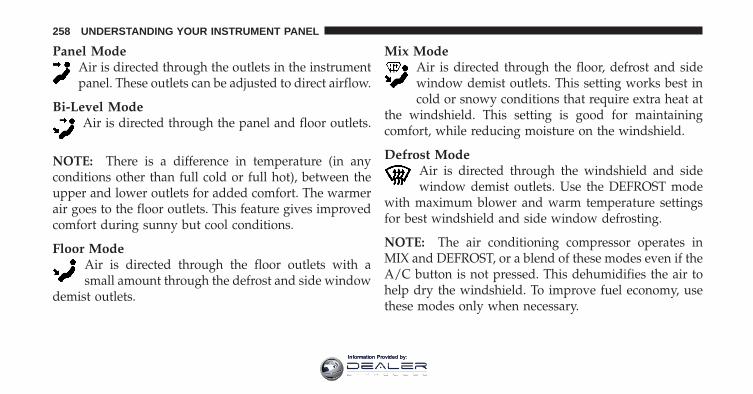
Panel ModeAir is directed through the outlets in the instrumentpanel. These outlets can be adjusted to direct airflow.
Bi-Level ModeAir is directed through the panel and floor outlets.
NOTE: There is a difference in temperature (in anyconditions other than full cold or full hot), between theupper and lower outlets for added comfort. The warmerair goes to the floor outlets. This feature gives improvedcomfort during sunny but cool conditions.
Floor ModeAir is directed through the floor outlets with asmall amount through the defrost and side window
demist outlets.
Mix ModeAir is directed through the floor, defrost and sidewindow demist outlets. This setting works best incold or snowy conditions that require extra heat at
the windshield. This setting is good for maintainingcomfort, while reducing moisture on the windshield.
Defrost ModeAir is directed through the windshield and sidewindow demist outlets. Use the DEFROST mode
with maximum blower and warm temperature settingsfor best windshield and side window defrosting.
NOTE: The air conditioning compressor operates inMIX and DEFROST, or a blend of these modes even if theA/C button is not pressed. This dehumidifies the air tohelp dry the windshield. To improve fuel economy, usethese modes only when necessary.
258 UNDERSTANDING YOUR INSTRUMENT PANEL
Information Provided by:
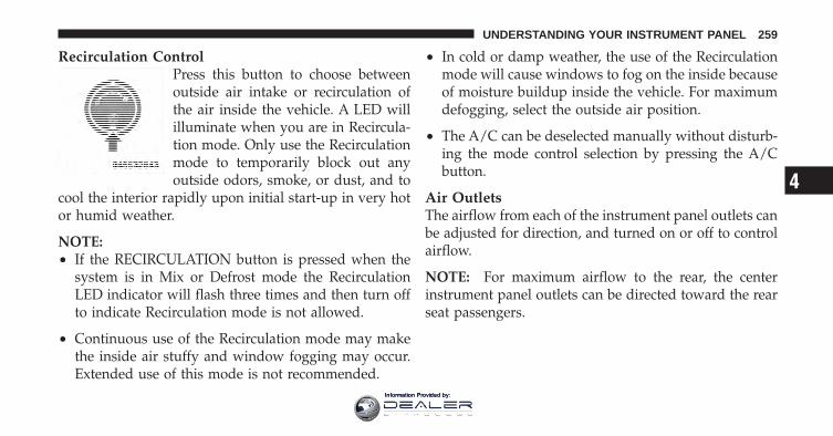
Recirculation ControlPress this button to choose betweenoutside air intake or recirculation ofthe air inside the vehicle. A LED willilluminate when you are in Recircula-tion mode. Only use the Recirculationmode to temporarily block out anyoutside odors, smoke, or dust, and to
cool the interior rapidly upon initial start-up in very hotor humid weather.
NOTE:• If the RECIRCULATION button is pressed when the
system is in Mix or Defrost mode the RecirculationLED indicator will flash three times and then turn offto indicate Recirculation mode is not allowed.
• Continuous use of the Recirculation mode may makethe inside air stuffy and window fogging may occur.Extended use of this mode is not recommended.
• In cold or damp weather, the use of the Recirculationmode will cause windows to fog on the inside becauseof moisture buildup inside the vehicle. For maximumdefogging, select the outside air position.
• The A/C can be deselected manually without disturb-ing the mode control selection by pressing the A/Cbutton.
Air OutletsThe airflow from each of the instrument panel outlets canbe adjusted for direction, and turned on or off to controlairflow.
NOTE: For maximum airflow to the rear, the centerinstrument panel outlets can be directed toward the rearseat passengers.
4
UNDERSTANDING YOUR INSTRUMENT PANEL 259
Information Provided by:
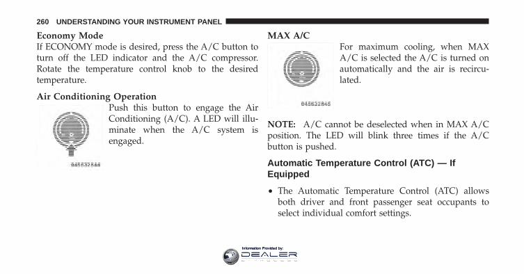
Economy ModeIf ECONOMY mode is desired, press the A/C button toturn off the LED indicator and the A/C compressor.Rotate the temperature control knob to the desiredtemperature.
Air Conditioning OperationPush this button to engage the AirConditioning (A/C). A LED will illu-minate when the A/C system isengaged.
MAX A/CFor maximum cooling, when MAXA/C is selected the A/C is turned onautomatically and the air is recircu-lated.
NOTE: A/C cannot be deselected when in MAX A/Cposition. The LED will blink three times if the A/Cbutton is pushed.
Automatic Temperature Control (ATC) — IfEquipped
• The Automatic Temperature Control (ATC) allowsboth driver and front passenger seat occupants toselect individual comfort settings.
260 UNDERSTANDING YOUR INSTRUMENT PANEL
Information Provided by:
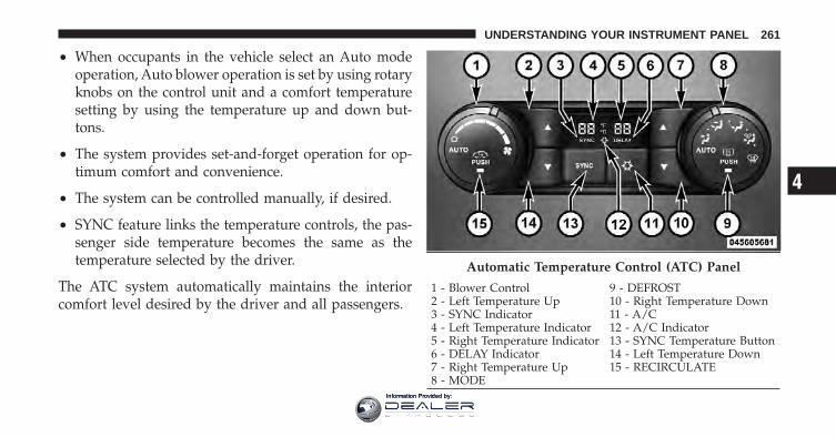
• When occupants in the vehicle select an Auto modeoperation, Auto blower operation is set by using rotaryknobs on the control unit and a comfort temperaturesetting by using the temperature up and down but-tons.
• The system provides set-and-forget operation for op-timum comfort and convenience.
• The system can be controlled manually, if desired.
• SYNC feature links the temperature controls, the pas-senger side temperature becomes the same as thetemperature selected by the driver.
The ATC system automatically maintains the interiorcomfort level desired by the driver and all passengers.
Automatic Temperature Control (ATC) Panel
1 - Blower Control 9 - DEFROST2 - Left Temperature Up 10 - Right Temperature Down3 - SYNC Indicator 11 - A/C4 - Left Temperature Indicator 12 - A/C Indicator5 - Right Temperature Indicator 13 - SYNC Temperature Button6 - DELAY Indicator 14 - Left Temperature Down7 - Right Temperature Up 15 - RECIRCULATE8 - MODE
4
UNDERSTANDING YOUR INSTRUMENT PANEL 261
Information Provided by:
Automatic Operation
1. Position the MODE control knob to the Auto positionon the Automatic Temperature Control (ATC) Panel.
2. Position the BLOWER control knob in the Auto posi-tion on the ATC Panel.
3. Next, adjust the temperature you would like thesystem to maintain by adjusting the driver and frontpassenger temperature buttons. Once the desired tem-perature is displayed, the system will achieve and auto-matically maintain that comfort level.
4. When the system is set up for your comfort level, it isnot necessary to change the settings. You will experiencethe greatest efficiency by simply allowing the system tofunction automatically.
NOTE:• It is not necessary to move the temperature settings for
cold or hot vehicles. The system automatically adjuststhe temperature, mode and fan speed to providecomfort as quickly as possible.
• The temperature can be displayed in U.S. or Metricunits by selecting the US/M customer-programmablefeature. Refer to the “Electronic Vehicle InformationCenter (EVIC) — Customer-Programmable Features(SETUP)” in this section of the manual.
To provide you with maximum comfort in the Automaticmode, during cold start-ups the blower fan will remainon low and the DELAY symbol will appear in the ATCdisplay until the engine warms up. The blower willincrease in speed and transition into Auto mode andDELAY will no longer be illuminated in the display. The
262 UNDERSTANDING YOUR INSTRUMENT PANEL
Information Provided by:
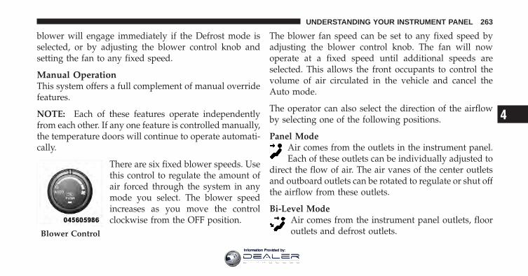
blower will engage immediately if the Defrost mode isselected, or by adjusting the blower control knob andsetting the fan to any fixed speed.
Manual OperationThis system offers a full complement of manual overridefeatures.
NOTE: Each of these features operate independentlyfrom each other. If any one feature is controlled manually,the temperature doors will continue to operate automati-cally.
There are six fixed blower speeds. Usethis control to regulate the amount ofair forced through the system in anymode you select. The blower speedincreases as you move the controlclockwise from the OFF position.
The blower fan speed can be set to any fixed speed byadjusting the blower control knob. The fan will nowoperate at a fixed speed until additional speeds areselected. This allows the front occupants to control thevolume of air circulated in the vehicle and cancel theAuto mode.
The operator can also select the direction of the airflowby selecting one of the following positions.
Panel ModeAir comes from the outlets in the instrument panel.Each of these outlets can be individually adjusted to
direct the flow of air. The air vanes of the center outletsand outboard outlets can be rotated to regulate or shut offthe airflow from these outlets.
Bi-Level ModeAir comes from the instrument panel outlets, flooroutlets and defrost outlets.Blower Control
4
UNDERSTANDING YOUR INSTRUMENT PANEL 263
Information Provided by:
NOTE: In many temperature positions, the BI-LEVELmode is designed to provide cooler air out of the paneloutlets and warmer air from the floor outlets.
Floor ModeAir comes from the floor outlets. A slight amount ofair is directed through the defrost and side window
demister outlets.
Mix ModeAir comes from the floor, defrost and side windowdemist outlets. This mode works best in cold orsnowy conditions. It allows you to stay comfortable
while keeping the windshield clear.
Defrost ModeAir comes from the windshield and side windowdemist outlets. Use Defrost mode with maximum
blower and temperature settings for best windshield andside window defrosting.
NOTE: While operating in the other modes, the systemwill not automatically sense the presence of fog, mist orice on the windshield. Defrost mode must be manuallyselected to clear the windshield and side glass.
The Air Conditioning (A/C) button allows theoperator to manually activate or deactivate the airconditioning system. When in A/C mode and the
ATC is set to a cool temperature, dehumidified air flowsthrough the air outlets. If Economy mode is desired, pressthe A/C button to turn off the A/C mode in the ATCdisplay and deactivate the A/C system.
NOTE:• If the system is in Mix, Bi-Level or Defrost Mode, the
A/C can be turned off, but the A/C system shallremain active to prevent fogging of the windows.
• If fog or mist appears on the windshield or side glass,select Defrost mode and increase blower speed.
264 UNDERSTANDING YOUR INSTRUMENT PANEL
Information Provided by:
Recirculation ControlWhen outside air contains smoke, odors, orhigh humidity, or if rapid cooling is desired,you may wish to recirculate interior air bypressing the RECIRCULATION control button.
Recirculation mode should only be used temporarily. Therecirculation LED will illuminate on the blower controlknob when this button is selected. Push the button asecond time to turn off the Recirculation mode LED andallow outside air into the vehicle.
NOTE: In cold weather, use of Recirculation mode maylead to excessive window fogging. The Recirculationmode is not allowed in the Floor/Defrost Mix andDefrost modes to improve window clearing operation.Recirculation will be disabled automatically if thesemodes are selected.
Summer OperationThe engine cooling system in air conditioned vehiclesmust be protected with a high-quality antifreeze coolantto provide proper corrosion protection and to protectagainst engine overheating. A solution of 50% ethyleneglycol antifreeze coolant and 50% water is recommended.Refer to “Maintenance Procedures” in “Maintaining YourVehicle” for proper coolant selection.
Winter OperationTo ensure the best possible heater and defroster perfor-mance, make sure the engine cooling system is function-ing properly and the proper amount, type, and concen-tration of coolant is used. Refer to “MaintenanceProcedures” in “Maintaining Your Vehicle” for propercoolant selection. Use of the air Recirculation modeduring Winter months is not recommended because itmay cause window fogging.
4
UNDERSTANDING YOUR INSTRUMENT PANEL 265
Information Provided by:
Vacation/StorageAny time you store your vehicle or keep it out of service(i.e., vacation) for two weeks or more, run the airconditioning system at idle for about five minutes infresh air with the blower setting in high. This will ensureadequate system lubrication to minimize the possibilityof compressor damage when the system is started again.
Window Fogging and FrostingVehicle windows tend to fog on the inside of the glass inmild, rainy and/or humid weather. Windows may froston the inside of the glass in very cold weather. To clearthe windows, select Defrost or Mix mode and increasethe front blower speed. Do not use the Recirculationmode without A/C for long periods, as fogging mayoccur.
Outside Air IntakeMake sure the air intake, located directly in front of thewindshield, is free of obstructions such as leaves. Leavescollected in the air intake may reduce airflow, can causeodor, and if they enter the plenum they could plug thewater drains. In Winter months make sure the air intakeis clear of ice, slush and snow.
266 UNDERSTANDING YOUR INSTRUMENT PANEL
Information Provided by:
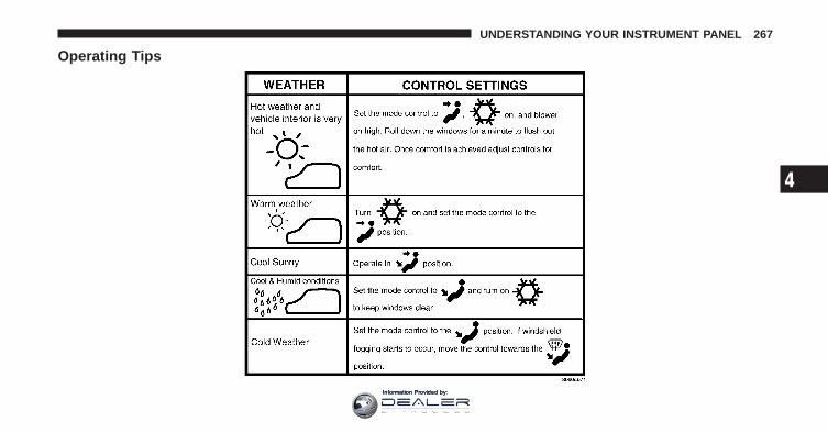
Operating Tips
4
UNDERSTANDING YOUR INSTRUMENT PANEL 267
Information Provided by:

Information Provided by:
STARTING AND OPERATING
CONTENTS
� Starting Procedures . . . . . . . . . . . . . . . . . . . . 273
▫ Normal Starting . . . . . . . . . . . . . . . . . . . . . 273
▫ Automatic Transmission . . . . . . . . . . . . . . . 273
▫ Extreme Cold Weather(Below –20°F Or �29°C) . . . . . . . . . . . . . . . 274
▫ If Engine Fails To Start . . . . . . . . . . . . . . . . 274
▫ After Starting . . . . . . . . . . . . . . . . . . . . . . . 275
� Engine Block Heater — If Equipped . . . . . . . . 275
� Automatic Transmission . . . . . . . . . . . . . . . . . 276
▫ Key Ignition Park Interlock . . . . . . . . . . . . . 278
▫ Brake/Transmission Shift Interlock System . . 278
▫ Six–Speed Automatic Transmission(5.7L Engine) — If Equipped . . . . . . . . . . . . 278
� Four-Wheel Drive Operation — If Equipped . . 288
▫ Manually Shifted Transfer Case – IfEquipped . . . . . . . . . . . . . . . . . . . . . . . . . . 288
▫ Shifting Procedure – Manually ShiftedTransfer Case . . . . . . . . . . . . . . . . . . . . . . . 290
▫ Transfer Case Position Indicator Light . . . . . . 291
5
Information Provided by:
▫ Electronically Shifted Transfer Case(Four-Position Switch) – If Equipped . . . . . . . 292
▫ Shifting Procedure . . . . . . . . . . . . . . . . . . . 296
� Limited-Slip Differential . . . . . . . . . . . . . . . . . 298
� Driving On Slippery Surfaces . . . . . . . . . . . . . 299
▫ Acceleration . . . . . . . . . . . . . . . . . . . . . . . . 299
▫ Traction . . . . . . . . . . . . . . . . . . . . . . . . . . . 299
� Driving Through Water . . . . . . . . . . . . . . . . . 300
▫ Flowing/Rising Water . . . . . . . . . . . . . . . . . 300
▫ Shallow Standing Water . . . . . . . . . . . . . . . 300
� Power Steering . . . . . . . . . . . . . . . . . . . . . . . 302
▫ Power Steering Fluid Check . . . . . . . . . . . . . 303
� Parking Brake . . . . . . . . . . . . . . . . . . . . . . . . 304
� Brake System . . . . . . . . . . . . . . . . . . . . . . . . 306
▫ Four-Wheel Anti-Lock Brake System . . . . . . . 307
� Tire Safety Information . . . . . . . . . . . . . . . . . 309
▫ Tire Markings . . . . . . . . . . . . . . . . . . . . . . . 309
▫ Tire Identification Number (TIN) . . . . . . . . . 312
▫ Tire Terminology And Definitions . . . . . . . . . 313
▫ Tire Loading And Tire Pressure . . . . . . . . . . 314
� Tires — General Information . . . . . . . . . . . . . 318
▫ Tire Pressure . . . . . . . . . . . . . . . . . . . . . . . 318
▫ Tire Inflation Pressures . . . . . . . . . . . . . . . . 319
▫ Radial Ply Tires . . . . . . . . . . . . . . . . . . . . . 324
▫ Spare Tire Matching Original Equipped TireAnd Wheel – If Equipped . . . . . . . . . . . . . . 324
270 STARTING AND OPERATING
Information Provided by:
▫ Compact Spare Tire – If Equipped . . . . . . . . 325
▫ Full Size Spare – If Equipped . . . . . . . . . . . . 326
▫ Limited-Use Spare – If Equipped . . . . . . . . . 326
▫ Tire Spinning . . . . . . . . . . . . . . . . . . . . . . . 327
▫ Tread Wear Indicators . . . . . . . . . . . . . . . . . 327
▫ Life Of Tire . . . . . . . . . . . . . . . . . . . . . . . . 328
▫ Replacement Tires . . . . . . . . . . . . . . . . . . . . 328
� Supplemental Tire Pressure Information — IfEquipped . . . . . . . . . . . . . . . . . . . . . . . . . . . . 330
� Tire Chains . . . . . . . . . . . . . . . . . . . . . . . . . . 330
� Snow Tires . . . . . . . . . . . . . . . . . . . . . . . . . . 332
� Tire Rotation Recommendations . . . . . . . . . . . 333
▫ Dual Rear Wheels . . . . . . . . . . . . . . . . . . . . 334
� Fuel Requirements . . . . . . . . . . . . . . . . . . . . . 335
▫ Reformulated Gasoline . . . . . . . . . . . . . . . . 336
▫ Gasoline/Oxygenate Blends . . . . . . . . . . . . . 336
▫ E-85 Usage In Non-Flex Fuel Vehicles . . . . . . 336
▫ MMT In Gasoline . . . . . . . . . . . . . . . . . . . . 337
▫ Materials Added To Fuel . . . . . . . . . . . . . . . 338
▫ Fuel System Cautions . . . . . . . . . . . . . . . . . 338
▫ Carbon Monoxide Warnings . . . . . . . . . . . . 339
� Adding Fuel . . . . . . . . . . . . . . . . . . . . . . . . . 340
▫ Loose Fuel Filler Cap Message . . . . . . . . . . . 341
� Vehicle Loading . . . . . . . . . . . . . . . . . . . . . . 342
▫ Certification Label . . . . . . . . . . . . . . . . . . . 342
5
STARTING AND OPERATING 271
Information Provided by:
� Trailer Towing . . . . . . . . . . . . . . . . . . . . . . . . 344
▫ Common Towing Definitions . . . . . . . . . . . . 344
▫ Trailer Hitch Classification . . . . . . . . . . . . . . 347
▫ Trailer Towing Weights(Maximum Trailer Weight Ratings) . . . . . . . . 348
▫ Trailer And Tongue Weight . . . . . . . . . . . . . 349
▫ Towing Requirements . . . . . . . . . . . . . . . . . 351
▫ Towing Tips . . . . . . . . . . . . . . . . . . . . . . . . 360
� Snowplow . . . . . . . . . . . . . . . . . . . . . . . . . . 361
▫ Before Plowing . . . . . . . . . . . . . . . . . . . . . . 362
▫ Snowplow Prep Package ModelAvailability . . . . . . . . . . . . . . . . . . . . . . . . . 362
▫ Over The Road Operation With SnowplowAttached . . . . . . . . . . . . . . . . . . . . . . . . . . 363
▫ Operating Tips . . . . . . . . . . . . . . . . . . . . . . 363
▫ General Maintenance . . . . . . . . . . . . . . . . . . 364
� Recreational Towing(Behind Motorhome, Etc.) . . . . . . . . . . . . . . . . 365
▫ Towing This Vehicle BehindAnother Vehicle . . . . . . . . . . . . . . . . . . . . . 365
▫ Recreational Towing – Two-Wheel DriveModels . . . . . . . . . . . . . . . . . . . . . . . . . . . 366
▫ Recreational Towing – Four-Wheel DriveModels . . . . . . . . . . . . . . . . . . . . . . . . . . . 367
272 STARTING AND OPERATING
Information Provided by:
STARTING PROCEDURESBefore starting your vehicle, adjust your seat, adjust bothinside and outside mirrors, and fasten your seat belt.
The starter should not be operated for more than 15-second intervals. Waiting a few seconds between suchintervals will protect the starter from overheating.
WARNING!
Never leave children alone in a vehicle. Leavingchildren in a vehicle unattended is dangerous for anumber of reasons. A child or others could be seri-ously or fatally injured. Children should be warnednot to touch the parking brake, brake pedal or theshift lever. Do not leave the key fob in the vehicle. Achild could operate power windows, other controls,or move the vehicle.
Normal StartingNormal starting of either a warm or cold engine isobtained without pumping or pressing the acceleratorpedal. Turn the key fob to the START position and releasewhen the engine starts. If the engine fails to start within10 seconds, turn the key fob to the OFF position, wait fiveseconds, then repeat the “Normal Starting” procedure.
Automatic TransmissionStart the engine with the shift lever in the NEUTRAL orPARK position. Apply the brake before shifting into anydriving range.
NOTE: This vehicle is equipped with a transmissionshift interlocking system. The brake pedal must bepressed to shift out of PARK.
5
STARTING AND OPERATING 273
Information Provided by:
Tip Start FeatureDo not press the accelerator. Turn the ignition switchbriefly to the START position and release it. The startermotor will continue to run but will automatically disen-gage when the engine is running.
Extreme Cold Weather (Below –20°F or �29°C)To ensure reliable starting at these temperatures, use ofan externally powered electric engine block heater (avail-able from your authorized dealer) is recommended.
If Engine Fails To StartIf the engine fails to start after you have followed the“Normal Starting” procedure, it may be flooded. Pushthe accelerator pedal all the way to the floor and hold itthere while cranking the engine. This should clear anyexcess fuel in case the engine is flooded.
CAUTION!
To prevent damage to the starter, do not crank theengine for more than 15 seconds at a time. Wait 10 to15 seconds before trying again.
WARNING!
• Never pour fuel or other flammable liquids intothe throttle body air inlet opening in an attempt tostart the vehicle. This could result in a flash firecausing serious personal injury.
• Do not attempt to push or tow your vehicle to getit started. Vehicles equipped with an automatictransmission cannot be started this way. Unburnedfuel could enter the catalytic converter and oncethe engine has started, ignite and damage theconverter and vehicle.
(Continued)
274 STARTING AND OPERATING
Information Provided by:
WARNING! (Continued)• If the vehicle has a discharged battery, booster
cables may be used to obtain a start from a boosterbattery or the battery in another vehicle. This typeof start can be dangerous if done improperly. Referto “Jump Starting” in “What To Do In Emergen-cies” for further information.
If the engine has been flooded, it may start to run, but nothave enough power to continue running when the keyfob is released. If this occurs, continue cranking with theaccelerator pedal pushed all the way to the floor. Releasethe accelerator pedal and the key fob once the engine isrunning smoothly.
If the engine shows no sign of starting after two 15-second periods of cranking with the accelerator pedalheld to the floor, the “Normal Starting” procedure shouldbe repeated.
After StartingThe idle speed is automatically controlled and will de-crease as the engine warms up.
ENGINE BLOCK HEATER — IF EQUIPPEDThe engine block heater warms the engine, and permitsquicker starts in cold weather. Connect the cord to astandard 110-115 Volt AC electrical outlet with agrounded, three-wire extension cord.
3500 Models — 5.7L Engine OnlyThe engine block heater cord is routed through the grilleby the right front tow hook.
It includes a removable cap that is secured by a tetheredstrap. It also has a c-clip that is used for storage when notin use for the winter months. During winter months,remove the heater cord wiring assembly from itself onthe c-clip.
5
STARTING AND OPERATING 275
Information Provided by:
The engine block heater must be plugged in at least onehour to have an adequate warming effect on the engine.
WARNING!
Remember to disconnect the engine block heatercord before driving. Damage to the 110-115 Voltelectrical cord could cause electrocution.
AUTOMATIC TRANSMISSION
CAUTION!
Damage to the transmission may occur if the follow-ing precautions are not observed:• Shift into PARK only after the vehicle has come to
a complete stop.
(Continued)
CAUTION! (Continued)• Shift into or out of REVERSE only after the
vehicle has come to a complete stop and the engineis at idle speed.
• Do not shift between PARK, REVERSE, NEU-TRAL, or DRIVE when the engine is above idlespeed.
• Before shifting into any gear, make sure your footis firmly pressing the brake pedal.
276 STARTING AND OPERATING
Information Provided by:
WARNING!
• Unintended movement of a vehicle could injurethose in or near the vehicle. As with all vehicles,you should never exit a vehicle while the engine isrunning. Before exiting a vehicle, always apply theparking brake, shift the transmission into PARK,and remove the key fob. Once the key fob isremoved, the shift lever is locked in the PARKposition, securing the vehicle against unwantedmovement. Furthermore, you should never leaveunattended children inside a vehicle.
(Continued)
WARNING! (Continued)• Leaving children in a vehicle unattended is dan-
gerous for a number of reasons. A child or otherscould be seriously or fatally injured. Childrenshould be warned not to touch the parking brake,brake pedal or the shift lever. Do not leave the keyfob in the vehicle. A child could operate powerwindows, other controls, or move the vehicle.
• It is dangerous to move the shift lever out of PARKor NEUTRAL if the engine speed is higher thanidle speed. If your foot is not firmly pressing thebrake pedal, the vehicle could accelerate quicklyforward or in reverse. You could lose control of thevehicle and hit someone or something. Only shiftinto gear when the engine is idling normally andwhen your foot is firmly pressing the brake pedal.
5
STARTING AND OPERATING 277
Information Provided by:
Key Ignition Park InterlockThis vehicle is equipped with a Key Ignition Park Inter-lock which requires the shift lever to be placed in PARKbefore the ignition switch can be turned to the LOCK/OFF position. The key fob can only be removed from theignition when the ignition is in the LOCK/OFF position,and once removed the shift lever is locked in PARK.
Brake/Transmission Shift Interlock SystemThis vehicle is equipped with a Brake Transmission ShiftInterlock System (BTSI) that holds the shift lever in thePARK position unless the brakes are applied. To movethe shift lever out of the PARK position, the ignitionswitch must be turned to the ON/RUN position (enginerunning or not) and the brake pedal must be pressed.
Six–Speed Automatic Transmission(5.7L Engine) — If EquippedThe shift lever position display (located in the instrumentpanel cluster) indicates the transmission gear range. The
shift lever is mounted on the right side of the steeringcolumn. You must press the brake pedal to move the shiftlever out of the PARK position (refer to “Brake/Transmission Shift Interlock System” in this section). Todrive, move the shift lever from PARK or NEUTRAL tothe DRIVE position. Pull the shift lever toward you whenshifting into REVERSE or PARK, or when shifting out ofPARK.
The electronically-controlled transmission provides aprecise shift schedule. The transmission electronics areself-calibrating; therefore, the first few shifts on a newvehicle may be somewhat abrupt. This is a normalcondition, and precision shifts will develop within a fewhundred miles (kilometers).
Shifting from DRIVE to PARK or REVERSE should bedone only after the accelerator pedal is released and thevehicle is stopped. Be sure to keep your foot on the brakepedal when moving the shift lever between these gears.
278 STARTING AND OPERATING
Information Provided by:
The transmission shift lever has only PARK, REVERSE,NEUTRAL, and DRIVE shift positions. Manual down-shifts can be made using the Electronic Range Select(ERS) shift control (refer to “Electronic Range Select(ERS)” in this section). Pressing the ERS (-/+) switches onthe shift lever while in the DRIVE position will select thehighest available transmission gear, and will display thatgear in the instrument cluster as 6, 5, 4, 3, 2, 1.
Gear RangesDO NOT race the engine when shifting from PARK orNEUTRAL into another gear range.
PARKThis range supplements the parking brake by locking thetransmission. The engine can be started in this range.Never attempt to use PARK while vehicle is in motion.Apply the parking brake when leaving vehicle in thisrange.
When parking on a level surface, you may place the shiftlever in the PARK position first, and then apply theparking brake.
When parking on a hill, apply the parking brake beforeplacing the shift lever in PARK, otherwise the load on thetransmission locking mechanism may make it difficult tomove the shift lever out of PARK. As an added precau-tion, turn the front wheels toward the curb on a downhillgrade and away from the curb on an uphill grade
WARNING!
• Never use the PARK position as a substitute forthe parking brake. Always apply the parkingbrake fully when parked to guard against vehiclemovement and possible injury or damage.
(Continued)
5
STARTING AND OPERATING 279
Information Provided by:
WARNING! (Continued)• Your vehicle could move and injure you and others
if it is not completely in PARK. Check by trying tomove the shift lever clockwise without first pull-ing it toward you after you have placed it in PARK.Make sure the transmission is in PARK beforeleaving the vehicle.
• It is dangerous to move the shift lever out of PARKor NEUTRAL if the engine speed is higher thanidle speed. If your foot is not firmly pressing thebrake pedal, the vehicle could accelerate quicklyforward or in reverse. You could lose control of thevehicle and hit someone or something. Only shiftinto gear when the engine is idling normally andwhen your foot is firmly pressing the brake pedal.
(Continued)
WARNING! (Continued)• Unintended movement of a vehicle could injure
those in and near the vehicle. As with all vehicles,you should never exit a vehicle while the engine isrunning. Before exiting a vehicle, always apply theparking brake, shift the transmission into PARK,and remove the key fob. Once the key fob isremoved, the shift lever is locked in the PARKposition, securing the vehicle against unwantedmovement. Furthermore, you should never leaveunattended children inside a vehicle.
• Never leave children alone in a vehicle. Leavingunattended children in a vehicle is dangerous for anumber of reasons. A child or others could beseriously or fatally injured. Do not leave the keyfob in the vehicle. A child could operate powerwindows, other controls, or move the vehicle.
280 STARTING AND OPERATING
Information Provided by:
CAUTION!
• Before moving the shift lever out of PARK, youmust turn the ignition switch from the LOCK/OFFposition to the ON/RUN position, and also pressthe brake pedal. Otherwise, damage to the shiftlever could result.
• DO NOT race the engine when shifting fromPARK or NEUTRAL into another gear range, asthis can damage the drivetrain.
The following indicators should be used to ensure thatyou have engaged the shift lever into the PARK position:
• When shifting into PARK, pull the shift lever towardyou and move it all the way counterclockwise until itstops.
• Release the shift lever and make sure it is fully seatedin the PARK gate.
• Look at the shift lever position display and verify thatit indicates the PARK position.
• With brake pedal released, verify that the shift leverwill not move out of PARK.
REVERSEThis range is for moving the vehicle rearward. Use thisrange only after the vehicle has come to a complete stop.
NEUTRALUse this range when the vehicle is standing for prolongedperiods with the engine running. The engine may bestarted in this range. Set the parking brake and shift thetransmission into PARK if you must leave the vehicle.
5
STARTING AND OPERATING 281
Information Provided by:
WARNING!
Do not coast in NEUTRAL and never turn off theignition to coast down a hill. These are unsafepractices that limit your response to changing trafficor road conditions. You might lose control of thevehicle and have a collision.
CAUTION!
Towing the vehicle, coasting, or driving for any otherreason with the transmission in NEUTRAL can resultin severe transmission damage. Refer to “Recre-ational Towing” in “Starting And Operating” and“Towing A Disabled Vehicle” in “What To Do InEmergencies” for further information.
DRIVEThis range should be used for most city and highwaydriving. It provides the smoothest upshifts and down-shifts, and the best fuel economy. The transmissionautomatically upshifts through underdrive first, second,and third gears, direct fourth gear and overdrive fifth andsixth gears. The DRIVE position provides optimum driv-ing characteristics under all normal operating conditions.
When frequent transmission shifting occurs (such aswhen operating the vehicle under heavy loading condi-tions, in hilly terrain, traveling into strong head winds, orwhile towing heavy trailers), use the Electronic RangeSelect (ERS) feature (refer to “Electronic Range Select(ERS)” in this section) to select a lower gear range. Underthese conditions, using a lower gear range will improveperformance and extend transmission life by reducingexcessive shifting and heat buildup.
282 STARTING AND OPERATING
Information Provided by:
If the transmission operating temperature exceeds normaloperating limits, the powertrain controller will modify thetransmission shift schedule and expand the range oftorque converter clutch engagement. This is done toprevent transmission damage due to overheating.
If the transmission becomes extremely hot, the “Trans-mission Temperature Warning Light” may illuminate andthe transmission may downshift out of Overdrive untilthe transmission cools down.
NOTE: Use caution when operating a heavily loadedvehicle at low speeds (such as towing a trailer up a steepgrade, or in stop-and-go traffic) during hot weather. Inthese conditions, torque converter slip can impose asignificant additional heat load on the cooling system.Downshifting the transmission to the lowest possiblegear (when climbing a grade), or shifting to NEUTRAL(when stopped in heavy traffic) can help to reduce thisexcess heat generation.
During cold temperatures, transmission operation maybe modified depending on engine and transmissiontemperature as well as vehicle speed. This feature im-proves warm up time of the engine and transmission toachieve maximum efficiency. Engagement of both thetorque converter clutch and the top overdrive gear areinhibited until the transmission fluid is warm (refer to the“Note” under “Torque Converter Clutch” in this section).During extremely cold temperatures (-16°F [-27°C] orbelow), operation may briefly be limited to first anddirect gears only. Normal operation will resume once thetransmission temperature has risen to a suitable level.
Transmission Limp Home ModeTransmission function is monitored electronically forabnormal conditions. If a condition is detected that couldresult in transmission damage, Transmission Limp HomeMode is activated. In this mode, the transmission remainsin fourth gear regardless of which forward gear isselected. PARK, REVERSE, and NEUTRAL will continue
5
STARTING AND OPERATING 283
Information Provided by:
to operate. Limp Home Mode allows the vehicle to bedriven to an authorized dealer for service without dam-aging the transmission.
In the event of a momentary problem, the transmissioncan be reset to regain all forward gears by performing thefollowing steps:
1. Stop the vehicle.
2. Shift the transmission into PARK.
3. Turn the ignition switch to the LOCK/OFF position.
4. Wait approximately 10 seconds.
5. Restart the engine.
6. Shift into the desired gear range. If the problem is nolonger detected, the transmission will return to normaloperation.
NOTE: Even if the transmission can be reset, we recom-mend that you visit your authorized dealer at yourearliest possible convenience. Your authorized dealer hasdiagnostic equipment to determine if the problem couldrecur.
If the transmission cannot be reset, authorized dealerservice is required.
Electronic Range Select (ERS) OperationThe Electronic Range Select (ERS) shift control allows thedriver to limit the highest available gear when the shiftlever is in the DRIVE position. For example, if you shiftthe transmission into 3 (third gear), the transmission willnever shift above third gear, but will shift down intosecond and first gear normally.
You can switch between DRIVE and ERS mode at anyvehicle speed. When the shift lever is in the DRIVEposition, the transmission will operate automatically,shifting between all available gears. Tapping the ERS (-)
284 STARTING AND OPERATING
Information Provided by:
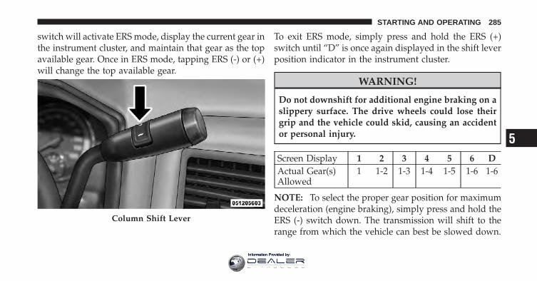
switch will activate ERS mode, display the current gear inthe instrument cluster, and maintain that gear as the topavailable gear. Once in ERS mode, tapping ERS (-) or (+)will change the top available gear.
To exit ERS mode, simply press and hold the ERS (+)switch until “D” is once again displayed in the shift leverposition indicator in the instrument cluster.
WARNING!
Do not downshift for additional engine braking on aslippery surface. The drive wheels could lose theirgrip and the vehicle could skid, causing an accidentor personal injury.
Screen Display 1 2 3 4 5 6 DActual Gear(s)Allowed
1 1-2 1-3 1-4 1-5 1-6 1-6
NOTE: To select the proper gear position for maximumdeceleration (engine braking), simply press and hold theERS (-) switch down. The transmission will shift to therange from which the vehicle can best be slowed down.
Column Shift Lever
5
STARTING AND OPERATING 285
Information Provided by:
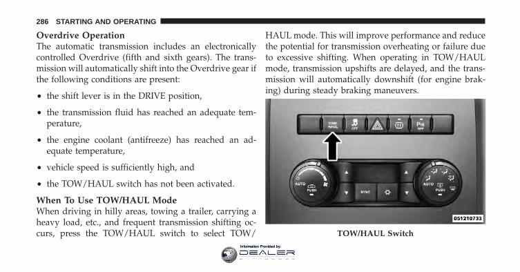
Overdrive OperationThe automatic transmission includes an electronicallycontrolled Overdrive (fifth and sixth gears). The trans-mission will automatically shift into the Overdrive gear ifthe following conditions are present:
• the shift lever is in the DRIVE position,
• the transmission fluid has reached an adequate tem-perature,
• the engine coolant (antifreeze) has reached an ad-equate temperature,
• vehicle speed is sufficiently high, and
• the TOW/HAUL switch has not been activated.
When To Use TOW/HAUL ModeWhen driving in hilly areas, towing a trailer, carrying aheavy load, etc., and frequent transmission shifting oc-curs, press the TOW/HAUL switch to select TOW/
HAUL mode. This will improve performance and reducethe potential for transmission overheating or failure dueto excessive shifting. When operating in TOW/HAULmode, transmission upshifts are delayed, and the trans-mission will automatically downshift (for engine brak-ing) during steady braking maneuvers.
TOW/HAUL Switch
286 STARTING AND OPERATING
Information Provided by:
The “TOW/HAUL Indicator Light” will illuminate in theinstrument cluster to indicate that TOW/HAUL modehas been activated. Pressing the switch a second timerestores normal operation. If the TOW/HAUL mode isdesired, the switch must be pressed each time the engineis started.
Torque Converter ClutchA feature designed to improve fuel economy has beenincluded in the automatic transmission on your vehicle.A clutch within the torque converter engages automati-cally at calibrated speeds. This may result in a slightlydifferent feeling or response during normal operation inthe upper gears. When the vehicle speed drops or duringsome accelerations, the clutch automatically disengages.
NOTE:• The torque converter clutch will not engage, and the
transmission will not shift to sixth gear, until the
transmission fluid and engine coolant are warm [usu-ally after 1 to 3 miles (1.6 to 4.8 km) of driving].Because sixth gear is disabled, and engine speed ishigher when the torque converter clutch is not en-gaged, it may seem as if the transmission is notshifting properly when cold. This is normal. Using theElectronic Range Select (ERS) feature, when the trans-mission is sufficiently warm, will demonstrate that thetransmission is able to shift into and out of Overdrive.
• If the vehicle has not been driven for several days, thefirst few seconds of operation after shifting the trans-mission into gear may seem sluggish. This is due to thefluid partially draining from the torque converter intothe transmission. This condition is normal and will notcause damage to the transmission. The torque con-verter will refill within five seconds after starting theengine.
5
STARTING AND OPERATING 287
Information Provided by:
FOUR-WHEEL DRIVE OPERATION — IFEQUIPPEDFour-wheel drive trucks are equipped with either amanually shifted transfer case or an electronically shiftedtransfer case. Refer to the operating instructions for yourtransfer case, located in this section for further informa-tion.
Manually Shifted Transfer Case – If EquippedThe transfer case provides four mode positions.
• Two-wheel drive high range (2H)
• Four-wheel drive high range (4H)
• Neutral (N)
• Four-wheel drive low range (4L)
This transfer case is intended to be driven in the 2Hposition for normal street and highway conditions suchas dry, hard surfaced roads.
When additional traction is required, the 4H and 4Lpositions can be used to lock the front and rear drive-shafts together and force the front and rear wheels torotate at the same speed. This is accomplished by simplymoving the shift lever to the desired positions. The 4Hand 4L positions are intended for loose, slippery roadsurfaces only. Driving in the 4H and 4L positions on dry,hard surfaced roads may cause increased tire wear anddamage to the driveline components.
The “Transfer Case Position Indicator Light” in theinstrument cluster will alert the driver that the vehicle isin four-wheel drive and that the front and rear drive-shafts are locked together. This light will illuminate whenthe transfer case is shifted into either the 4H or 4Lposition. There is no light for the 2H or NEUTRALpositions.
288 STARTING AND OPERATING
Information Provided by:
When operating your vehicle in 4L, the engine speed isapproximately three times that of the 2H or 4H positionsat a given road speed. Take care not to overspeed theengine and do not exceed 25 mph (40 km/h).
Proper operation of four-wheel drive vehicles dependson tires of equal size, type and circumference on eachwheel. Any difference will adversely affect shifting andcan cause damage to the drivetrain.
NOTE: Do not attempt to make a shift while only thefront or rear wheels are spinning. The transfer case is notequipped with a synchronizer and therefore the front andrear driveshaft speeds must be equal for the shift to takeplace. Shifting while only the front or rear wheels arespinning can cause damage to the transfer case.
Because four-wheel drive provides improved traction,there is a tendency to exceed safe turning and stoppingspeeds. Do not go faster than road conditions permit.
NOTE: Delayed shifts out of four-wheel drive may beexperienced due to uneven tire wear, low or uneven tirepressures, excessive vehicle loading, or cold tempera-tures.
WARNING!
You or others could be injured if you leave thevehicle unattended with the transfer case in theNEUTRAL position without first fully engaging theparking brake. The transfer case NEUTRAL positiondisengages both the front and rear driveshafts fromthe powertrain and will allow the vehicle to moveregardless of the transmission position. The parkingbrake should always be applied when the driver isnot in the vehicle.
5
STARTING AND OPERATING 289
Information Provided by:
For additional information on the appropriate use of eachtransfer case mode position, see the information below:
2HRear-Wheel Drive High Range - This range is for normalstreet and highway driving on dry hard surfaced roads.
4HFour-Wheel Drive High Range - This range locks thefront and rear driveshafts together forcing the front andrear wheels to rotate at the same speed. Additionaltraction for loose, slippery road surfaces only.
NNeutral - This range disengages the front and reardriveshafts from the powertrain. To be used for flattowing behind another vehicle. Refer to “RecreationalTowing” in “Starting and Operating” for furtherinformation.
4LFour-Wheel Drive Low Range - This range locks the frontand rear driveshafts together forcing the front and rearwheels to rotate at the same speed. Additional tractionand maximum pulling power for loose, slippery roadsurfaces only. Do not exceed 25 mph (40 km/h).
Shifting Procedure – Manually Shifted TransferCase
2H ⇔ 4HShifting between 2H and 4H can be made with thevehicle stopped or in motion. If the vehicle is in motion,shifts can be made up to 55 mph (88 km/h). With thevehicle in motion, the transfer case will engage/disengage faster if you momentarily release the accelera-tor pedal after completing the shift. Apply a constantforce when shifting the transfer case lever.
290 STARTING AND OPERATING
Information Provided by:
2H or 4H ⇔ 4LWith the vehicle rolling at 2 to 3 mph (3 to 5 km/h), shiftthe transmission into NEUTRAL. While the vehicle iscoasting at 2 to 3 mph (3 to 5 km/h), shift the transfercase lever firmly to the desired position. Do not pause intransfer case NEUTRAL.
NOTE:• Pausing in transfer case NEUTRAL in vehicles
equipped with an automatic transmission may requireshutting the engine OFF to avoid gear clash whilecompleting the shift. If difficulty occurs, shift thetransmission into NEUTRAL, hold foot on brake, andturn the engine OFF. Make shift to the desired mode.
• Shifting into or out of 4L is possible with the vehiclecompletely stopped, however difficulty may occur dueto the mating clutch teeth not being properly aligned.Several attempts may be required for clutch teethalignment and shift completion to occur. The preferredmethod is with the vehicle rolling 2 to 3 mph (3 to5 km/h). Avoid attempting to engage or disengage 4Lwith the vehicle moving faster than 2 to 3 mph (3 to5 km/h).
• Do not attempt to shift into or from 4L while thetransmission is in gear.
Transfer Case Position Indicator LightThe “Transfer Case Position Indicator Light” in theinstrument cluster is used to alert the driver that the frontaxle is fully engaged and all four wheels are driving.
5
STARTING AND OPERATING 291
Information Provided by:
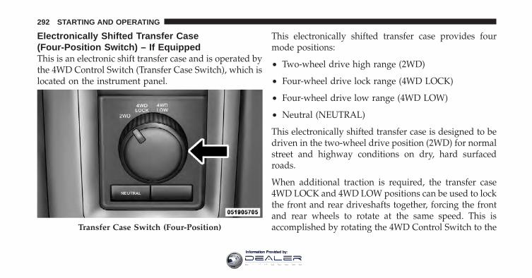
Electronically Shifted Transfer Case(Four-Position Switch) – If EquippedThis is an electronic shift transfer case and is operated bythe 4WD Control Switch (Transfer Case Switch), which islocated on the instrument panel.
This electronically shifted transfer case provides fourmode positions:
• Two-wheel drive high range (2WD)
• Four-wheel drive lock range (4WD LOCK)
• Four-wheel drive low range (4WD LOW)
• Neutral (NEUTRAL)
This electronically shifted transfer case is designed to bedriven in the two-wheel drive position (2WD) for normalstreet and highway conditions on dry, hard surfacedroads.
When additional traction is required, the transfer case4WD LOCK and 4WD LOW positions can be used to lockthe front and rear driveshafts together, forcing the frontand rear wheels to rotate at the same speed. This isaccomplished by rotating the 4WD Control Switch to theTransfer Case Switch (Four-Position)
292 STARTING AND OPERATING
Information Provided by:
desired position. Refer to “Shifting Procedure” for spe-cific shifting instructions. The 4WD LOCK and 4WDLOW positions are designed for loose, slippery roadsurfaces only. Driving in the 4WD LOCK and 4WD LOWpositions on dry hard surfaced roads may cause in-creased tire wear and damage to the driveline compo-nents.
NOTE: The transfer case NEUTRAL position is selectedby pressing the recessed button located on the lower lefthand corner of the 4WD Control Switch. The transfer caseNEUTRAL position is to be used for recreational towingonly. Refer to “Recreational Towing” in “Starting andOperating” for further information.
Transfer Case Position Indicator LightsThe Transfer Case Position Indicator Lights (4WD and4LOW) are located in the instrument cluster and indicatethe current and desired transfer case selection. When youselect a different transfer case position, the indicatorlights will do the following:
If All Shift Conditions Are Met:
1. The current position indicator light will turn OFF.
2. The selected position indicator light will flash until thetransfer case completes the shift.
3. When the shift is complete, the indicator light for theselected position will stop flashing and remain ON.
If One Or More Shift Conditions Are Not Met:
1. The indicator light for the current position will remainON.
5
STARTING AND OPERATING 293
Information Provided by:
2. The newly selected position indicator light will con-tinue to flash.
3. The transfer case will not shift.
NOTE: Before retrying a selection, make certain that allthe necessary requirements for selecting a new transfercase position have been met. To retry the selection, turnthe control knob back to the current position, wait fiveseconds, and retry selection. To find the shift require-ments, refer to the �Shifting Procedure� in this section forfurther information.
The “SVC 4WD Warning Light” monitors the electronicshift four-wheel drive system. If this light remains onafter engine start up or illuminates during driving, itmeans that the four-wheel drive system is not function-ing properly and that service is required.
WARNING!
Always engage the parking brake when poweringdown the vehicle if the “SVC 4WD Warning Light” isilluminated. Not engaging the parking brake mayallow the vehicle to roll, which may cause personalinjury.
NOTE: Do not attempt to make a shift while only thefront or rear wheels are spinning, as this can causedamage to driveline components.
When operating your vehicle in 4WD LOW, the enginespeed is approximately three times that of the 2WD or4WD LOCK positions at a given road speed. Take carenot to overspeed the engine and do not exceed 25 mph(40 km/h).
294 STARTING AND OPERATING
Information Provided by:
Proper operation of four-wheel drive vehicles dependson tires of equal size, type and circumference on eachwheel. Any difference in tire size can cause damage to thedrivetrain.
Because four-wheel drive provides improved traction,there is a tendency to exceed safe turning and stoppingspeeds. Do not go faster than road conditions permit.
WARNING!
You or others could be injured if you leave thevehicle unattended with the transfer case in theNEUTRAL position without first fully engaging theparking brake. The transfer case NEUTRAL positiondisengages both the front and rear driveshafts fromthe powertrain and will allow the vehicle to moveregardless of the transmission position. The parkingbrake should always be applied when the driver isnot in the vehicle.
For additional information on the appropriate use of eachtransfer case mode position, see the information below:
2WDRear Wheel Drive High Range - This range is for normalstreet and highway driving on dry, hard surfaced roads.
4WD LOCKFour-Wheel Drive Lock Range - This range locks the frontand rear driveshafts together forcing the front and rearwheels to rotate at the same speed. This range providesadditional traction for loose, slippery road surfaces only.
4WD LOWFour-Wheel Drive Low Range - This range provides lowspeed four-wheel drive. It locks the front and reardriveshafts together forcing the front and rear wheels torotate at the same speed. This range provides additionaltraction and maximum pulling power for loose, slipperyroad surfaces only. Do not exceed 25 mph (40 km/h).
5
STARTING AND OPERATING 295
Information Provided by:
NNeutral - This range disengages both the front and reardriveshafts from the powertrain. To be used for flattowing behind another vehicle. Refer to “RecreationalTowing” in Starting and Operating” for furtherinformation.
Shifting Procedure
NOTE:• If any of the requirements to select a new transfer case
position have not been met, the transfer case will notshift. The position indicator light for the previousposition will remain ON and the newly selected posi-tion indicator light will continue to flash until all therequirements for the selected position have been met.To retry a shift: return the control knob back to theoriginal position, make certain all shift requirementshave been met, wait five seconds and try the shiftagain.
• If all the requirements to select a new transfer caseposition have been met, the current position indicatorlight will turn OFF, the selected position indicator lightwill flash until the transfer case completes the shift.When the shift is complete, the position indicator lightfor the selected position will stop flashing and remainON.
2WD⇔ 4WD LOCKRotate the 4WD control switch to the desired position.Shifts between 2WD and 4WD LOCK can be done withthe vehicle stopped or in motion. With the vehicle inmotion, the transfer case will engage/disengage faster ifyou momentarily release the accelerator pedal after turn-ing the control switch. If the vehicle is stopped, theignition switch must be in the ON position with theengine either running or off. This shift cannot be com-pleted if the ignition switch is in the ACC position.
296 STARTING AND OPERATING
Information Provided by:
NOTE: The four-wheel drive system will not allowshifts between 2WD/4WD LOCK if the front and/or rearwheels are spinning (no traction). In this situation, theselected position indicator light will flash and the origi-nal position indicator light will remain ON. At this time,reduce speed and stop spinning the wheels to completethe shift.
2WD or 4WD LOCK⇔ 4WD LOW
NOTE: When shifting into or out of 4WD LOW somegear noise may be heard. This noise is normal and is notdetrimental to the vehicle or occupants.
Shifting can be performed with the vehicle rolling 2 to3 mph (3 to 5 km/h) or completely stopped. You can useeither of the following procedures:
Preferred Procedure
1. With the engine running, slow the vehicle to 2 to3 mph (3 to 5 km/h).
2. Shift the transmission into NEUTRAL.
3. While still rolling, rotate the transfer case controlswitch to the desired position.
4. After the desired position indicator light is ON (notflashing), shift the transmission back into gear.
Alternate Procedure
1. Bring the vehicle to a complete stop.
2. With the ignition switch in the ON position, and theengine either OFF or running, shift the transmission intoNEUTRAL.
3. Rotate the transfer case control switch to the desiredposition.
4. After the desired position indicator light is ON (notflashing), shift the transmission back into gear.
5
STARTING AND OPERATING 297
Information Provided by:
NOTE:• If Steps 1 or 2 of either the Preferred or Alternate
Procedure are not satisfied prior to attempting theshift, then the desired position indicator light will flashcontinuously while the original position indicator lightis ON, until all requirements have been met.
• The ignition switch must be in the ON position for ashift to take place and for the position indicator lightsto be operable. If the ignition switch is not in the ONposition, the shift will not take place and no positionindicator lights will be on or flashing.
LIMITED-SLIP DIFFERENTIALThe limited-slip differential provides additional tractionon snow, ice, mud, sand and gravel, particularly whenthere is a difference between the traction characteristics ofthe surface under the right and left rear wheels. Duringnormal driving and cornering, the limited-slip unit per-forms similarly to a conventional differential. On slippery
surfaces, however, the differential delivers more of thedriving effort to the rear wheel having the better traction.
The limited-slip differential is especially helpful duringslippery driving conditions. With both rear wheels on aslippery surface, a slight application of the acceleratorwill supply maximum traction. When starting with onlyone rear wheel on an excessively slippery surface, slightmomentary application of the parking brake may benecessary to gain maximum traction.
WARNING!
On vehicles equipped with a limited-slip differentialnever run the engine with one rear wheel off theground since the vehicle may drive through the rearwheel remaining on the ground. You could losecontrol of the vehicle.
298 STARTING AND OPERATING
Information Provided by:
Care should be taken to avoid sudden accelerations whenboth rear wheels are on a slippery surface. This couldcause both rear wheels to spin, and allow the vehicle toslide sideways on the crowned surface of a road or in aturn.
DRIVING ON SLIPPERY SURFACES
AccelerationRapid acceleration on snow covered, wet, or other slip-pery surfaces may cause the driving wheels to pullerratically to the right or left. This phenomenon occurswhen there is a difference in the surface traction underthe rear (driving) wheels.
WARNING!
Rapid acceleration on slippery surfaces is dangerous.Unequal traction can cause sudden pulling of the rearwheels. You could lose control of the vehicle andpossibly have a collision. Accelerate slowly andcarefully whenever there is likely to be poor traction(ice, snow, wet mud, loose sand, etc.).
TractionWhen driving on wet or slushy roads, it is possible for awedge of water to build up between the tire and roadsurface. This is known as hydroplaning and may causepartial or complete loss of vehicle control and stoppingability. To reduce this possibility, the following precau-tions should be observed:
1. Slow down during rainstorms or when the roads areslushy.
5
STARTING AND OPERATING 299
Information Provided by:
2. Slow down if the road has standing water or puddles.
3. Replace tires when tread wear indicators first becomevisible.
4. Keep tires properly inflated.
5. Maintain sufficient distance between your vehicle andthe vehicle in front of you to avoid a collision in a suddenstop.
DRIVING THROUGH WATERDriving through water more than a few inches/centimeters deep will require extra caution to ensuresafety and prevent damage to your vehicle.
Flowing/Rising Water
WARNING!
Do not drive on or across a road or path where wateris flowing and/or rising (as in storm run-off). Flow-ing water can wear away the road or path’s surfaceand cause your vehicle to sink into deeper water.Furthermore, flowing and/or rising water can carryyour vehicle away swiftly. Failure to follow thiswarning may result in injuries that are serious orfatal to you, your passengers, and others around you.
Shallow Standing WaterAlthough your vehicle is capable of driving throughshallow standing water, consider the following Cautionand Warning before doing so.
300 STARTING AND OPERATING
Information Provided by:
CAUTION!
• Always check the depth of the standing waterbefore driving through it. Never drive throughstanding water that is deeper than the bottom ofthe tire rims mounted on the vehicle.
• Determine the condition of the road or the paththat is under water and if there are any obstacles inthe way before driving through the standing wa-ter.
• Do not exceed 5 mph (8 km/h) when drivingthrough standing water. This will minimize waveeffects.
(Continued)
CAUTION! (Continued)• Driving through standing water may cause dam-
age to your vehicle’s drivetrain components. Al-ways inspect your vehicle’s fluids (i.e., engine oil,transmission, axle, etc.) for signs of contamination(i.e., fluid that is milky or foamy in appearance)after driving through standing water. Do not con-tinue to operate the vehicle if any fluid appearscontaminated, as this may result in further dam-age. Such damage is not covered by the NewVehicle Limited Warranty.
• Getting water inside your vehicle’s engine cancause it to lock up and stall out, and cause seriousinternal damage to the engine. Such damage is notcovered by the New Vehicle Limited Warranty.
5
STARTING AND OPERATING 301
Information Provided by:
WARNING!
• Driving through standing water limits your vehi-cle’s traction capabilities. Do not exceed 5 mph(8 km/h) when driving through standing water.
• Driving through standing water limits your vehi-cle’s braking capabilities, which increases stop-ping distances. Therefore, after driving throughstanding water, drive slowly and lightly press onthe brake pedal several times to dry the brakes.
• Getting water inside your vehicle’s engine cancause it to lock up and stall out, and leave youstranded.
• Failure to follow these warnings may result ininjuries that are serious or fatal to you, yourpassengers, and others around you.
POWER STEERINGThe standard power steering system will give you goodvehicle response and increased ease of maneuverabilityin tight spaces. The system will provide mechanicalsteering capability if power assist is lost.
If for some reason the power assist is interrupted, it willstill be possible to steer your vehicle. Under these condi-tions, you will observe a substantial increase in steeringeffort, especially at very low vehicle speeds and duringparking maneuvers.
NOTE:• Increased noise levels at the end of the steering wheel
travel are considered normal and do not indicate thatthere is a problem with the power steering system.
• Upon initial start-up in cold weather, the power steer-ing pump may make noise for a short amount of time.This is due to the cold, thick fluid in the steering
302 STARTING AND OPERATING
Information Provided by:
system. This noise should be considered normal, and itdoes not in any way damage the steering system.
WARNING!
Continued operation with reduced power steeringassist could pose a safety risk to yourself and others.Service should be obtained as soon as possible.
CAUTION!
Prolonged operation of the steering system at the endof the steering wheel travel will increase the steeringfluid temperature and it should be avoided whenpossible. Damage to the power steering pump mayoccur.
Power Steering Fluid CheckChecking the power steering fluid level at a definedservice interval is not required. The fluid should only be
checked if a leak is suspected, abnormal noises areapparent, and/or the system is not functioning as antici-pated. Coordinate inspection efforts through an autho-rized dealer.
CAUTION!
Do not use chemical flushes in your power steeringsystem as the chemicals can damage your powersteering components. Such damage is not covered bythe New Vehicle Limited Warranty.
WARNING!
Fluid level should be checked on a level surface andwith the engine off to prevent injury from movingparts and to ensure accurate fluid level reading. Donot overfill. Use only manufacturer’s recommendedpower steering fluid.
5
STARTING AND OPERATING 303
Information Provided by:
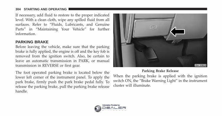
If necessary, add fluid to restore to the proper indicatedlevel. With a clean cloth, wipe any spilled fluid from allsurfaces. Refer to “Fluids, Lubricants, and GenuineParts” in “Maintaining Your Vehicle” for furtherinformation.
PARKING BRAKEBefore leaving the vehicle, make sure that the parkingbrake is fully applied, the engine is off and the key fob isremoved from the ignition switch. Also, be certain toleave an automatic transmission in PARK, or manualtransmission in REVERSE or first gear.
The foot operated parking brake is located below thelower left corner of the instrument panel. To apply thepark brake, firmly push the park brake pedal fully. Torelease the parking brake, pull the parking brake releasehandle.
When the parking brake is applied with the ignitionswitch ON, the “Brake Warning Light” in the instrumentcluster will illuminate.
Parking Brake Release
304 STARTING AND OPERATING
Information Provided by:
NOTE:• When the parking brake is applied and the automatic
transmission is placed in gear, the “Brake WarningLight” will flash. If vehicle speed is detected, a chimewill sound to alert the driver. Fully release the parkingbrake before attempting to move the vehicle.
• This light only shows that the parking brake is ap-plied. It does not show the degree of brake application.
When parking on a hill, it is important to turn the frontwheels toward the curb on a downhill grade and awayfrom the curb on an uphill grade. For vehicles equippedwith an automatic transmission, apply the parking brakebefore placing the shift lever in PARK, otherwise the loadon the transmission locking mechanism may make itdifficult to move the shift lever out of PARK.
The parking brake should always be applied wheneverthe driver is not in the vehicle.
WARNING!
• Never leave children alone in a vehicle. Leavingunattended children in a vehicle is dangerous for anumber of reasons. A child or others could beseriously or fatally injured.
• Do not leave the key fob in the vehicle. A childcould operate power windows, other controls, ormove the vehicle.
• Be sure the parking brake is fully disengagedbefore driving; failure to do so can lead to brakefailure and a collision.
• Always fully apply the parking brake when leav-ing your vehicle or it may roll and cause damage orinjury. Also, be certain to leave an automatictransmission in PARK, a manual transmission inREVERSE or first gear. Failure to do so may causethe vehicle to roll and cause damage or injury.
5
STARTING AND OPERATING 305
Information Provided by:
CAUTION!
If the “Brake Warning Light” remains on with theparking brake released, a brake system malfunctionis indicated. Have the brake system serviced by anauthorized dealer immediately.
BRAKE SYSTEMIf power assist is lost for any reason (for example,repeated brake applications with the engine off), thebrakes will still function. However, you will experience asubstantial increase in braking effort to stop the vehicle.
If either the front or rear hydraulic system loses normalbraking capability, the remaining system will still func-tion with some loss of overall braking effectiveness. Thiswill be evident by increased pedal travel during applica-tion, greater pedal force required to slow or stop, andactivation of the “Brake Warning Light” and the “ABSWarning Light” (if equipped) during brake use.
The brake system power assist is provided by a hydro-boost unit which shares fluid with the power steeringsystem. You may experience some clicking or hissingnoises from the hydro-boost system during hard brakingconditions.
NOTE: Under cold temperatures, pedal effort will behigher than normal until the power steering fluid reachesoperating temperature.
306 STARTING AND OPERATING
Information Provided by:
Four-Wheel Anti-Lock Brake System
WARNING!
The Four-Wheel Anti-Lock Brake System containssophisticated electronic equipment. It may be sus-ceptible to interference caused by improperly in-stalled or high output radio transmitting equipment.This interference can cause possible loss of anti-lockbraking capability. Installation of such equipmentshould be performed by qualified professionals.
The Four-Wheel Anti-Lock Brake System (ABS) is de-signed to aid the driver in maintaining vehicle controlunder adverse braking conditions. The system operateswith a separate computer to modulate hydraulic pressureto prevent wheel lockup and help avoid skidding onslippery surfaces.
The system’s pump motor runs during an ABS stop toprovide regulated hydraulic pressure. The pump motormakes a low humming noise during operation. This isnormal.
The ABS conducts a low-speed selftest at about 10 mph(16 km/h). If you have your foot lightly on the brakewhile this test is occurring, you may feel slight pedalmovement. The movement can be more apparent on iceand snow. This is normal.
When you are in a severe braking condition involvinguse of the ABS, you will experience some pedal drop asthe vehicle comes to a complete stop. This is the result ofthe system reverting to the base brake system and isnormal.
Engagement of the ABS may be accompanied by apulsing sensation. You may also hear a clicking noise.These occurrences are normal, and indicate that thesystem is functioning.
5
STARTING AND OPERATING 307
Information Provided by:
ABS Warning LightThe ABS includes an amber warning light. When the lightis illuminated, the ABS is not functioning. The systemreverts to standard, non-anti-lock brakes.
WARNING!
• Pumping of the anti-lock brakes will diminishtheir effectiveness and may lead to a collision.Pumping makes the stopping distance longer. Justpress firmly on your brake pedal when you needto slow down or stop.
• The Anti-Lock Brake System (ABS) cannot preventthe natural laws of physics from acting on thevehicle, nor can it increase braking or steeringefficiency beyond that afforded by the conditionof the vehicle brakes and tires or the tractionafforded.
(Continued)
WARNING! (Continued)• The ABS cannot prevent collisions, including
those resulting from excessive speed in turns,following another vehicle too closely, or hydro-planing.
• The capabilities of an ABS-equipped vehicle mustnever be exploited in a reckless or dangerousmanner which could jeopardize the user’s safetyor the safety of others.
308 STARTING AND OPERATING
Information Provided by:
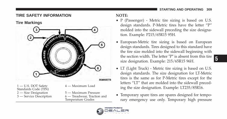
TIRE SAFETY INFORMATION
Tire Markings
NOTE:• P (Passenger) - Metric tire sizing is based on U.S.
design standards. P-Metric tires have the letter “P”molded into the sidewall preceding the size designa-tion. Example: P215/65R15 95H.
• European-Metric tire sizing is based on Europeandesign standards. Tires designed to this standard havethe tire size molded into the sidewall beginning withthe section width. The letter �P� is absent from this tiresize designation. Example: 215/65R15 96H.
• LT (Light Truck) - Metric tire sizing is based on U.S.design standards. The size designation for LT-Metrictires is the same as for P-Metric tires except for theletters “LT” that are molded into the sidewall preced-ing the size designation. Example: LT235/85R16.
• Temporary spare tires are spares designed for tempo-rary emergency use only. Temporary high pressure
1 — U.S. DOT SafetyStandards Code (TIN)
4 — Maximum Load
2 — Size Designation 5 — Maximum Pressure3 — Service Description 6 — Treadwear, Traction and
Temperature Grades
5
STARTING AND OPERATING 309
Information Provided by:
compact spare tires have the letter “T” or “S” moldedinto the sidewall preceding the size designation. Ex-ample: T145/80D18 103M.
• High flotation tire sizing is based on U.S. designstandards and it begins with the tire diameter moldedinto the sidewall. Example: 31x10.5 R15 LT.
Tire Sizing Chart
EXAMPLE:Size Designation:
P = Passenger car tire size based on U.S. design standards�....blank....� = Passenger car tire based on European design standardsLT = Light truck tire based on U.S. design standardsT or S = Temporary spare tire31 = Overall diameter in inches (in)215 = Section width in millimeters (mm)65 = Aspect ratio in percent (%)
— Ratio of section height to section width of tire10.5 = Section width in inches (in)R = Construction code
— �R� means radial construction— �D� means diagonal or bias construction
15 = Rim diameter in inches (in)
310 STARTING AND OPERATING
Information Provided by:
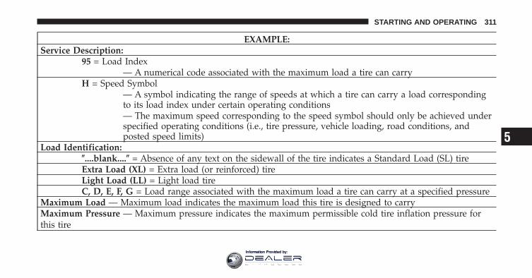
EXAMPLE:Service Description:
95 = Load Index— A numerical code associated with the maximum load a tire can carry
H = Speed Symbol— A symbol indicating the range of speeds at which a tire can carry a load correspondingto its load index under certain operating conditions— The maximum speed corresponding to the speed symbol should only be achieved underspecified operating conditions (i.e., tire pressure, vehicle loading, road conditions, andposted speed limits)
Load Identification:�....blank....� = Absence of any text on the sidewall of the tire indicates a Standard Load (SL) tireExtra Load (XL) = Extra load (or reinforced) tireLight Load (LL) = Light load tireC, D, E, F, G = Load range associated with the maximum load a tire can carry at a specified pressure
Maximum Load — Maximum load indicates the maximum load this tire is designed to carryMaximum Pressure — Maximum pressure indicates the maximum permissible cold tire inflation pressure forthis tire
5
STARTING AND OPERATING 311
Information Provided by:
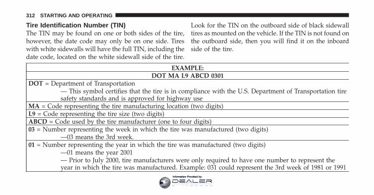
Tire Identification Number (TIN)The TIN may be found on one or both sides of the tire,however, the date code may only be on one side. Tireswith white sidewalls will have the full TIN, including thedate code, located on the white sidewall side of the tire.
Look for the TIN on the outboard side of black sidewalltires as mounted on the vehicle. If the TIN is not found onthe outboard side, then you will find it on the inboardside of the tire.
EXAMPLE:DOT MA L9 ABCD 0301
DOT = Department of Transportation— This symbol certifies that the tire is in compliance with the U.S. Department of Transportation tiresafety standards and is approved for highway use
MA = Code representing the tire manufacturing location (two digits)L9 = Code representing the tire size (two digits)ABCD = Code used by the tire manufacturer (one to four digits)03 = Number representing the week in which the tire was manufactured (two digits)
—03 means the 3rd week.01 = Number representing the year in which the tire was manufactured (two digits)
—01 means the year 2001— Prior to July 2000, tire manufacturers were only required to have one number to represent theyear in which the tire was manufactured. Example: 031 could represent the 3rd week of 1981 or 1991
312 STARTING AND OPERATING
Information Provided by:
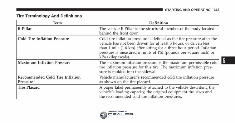
Tire Terminology And Definitions
Term DefinitionB-Pillar The vehicle B-Pillar is the structural member of the body located
behind the front door.Cold Tire Inflation Pressure Cold tire inflation pressure is defined as the tire pressure after the
vehicle has not been driven for at least 3 hours, or driven lessthan 1 mile (1.6 km) after sitting for a three hour period. Inflationpressure is measured in units of PSI (pounds per square inch) orkPa (kilopascals).
Maximum Inflation Pressure The maximum inflation pressure is the maximum permissible coldtire inflation pressure for this tire. The maximum inflation pres-sure is molded into the sidewall.
Recommended Cold Tire InflationPressure
Vehicle manufacturer’s recommended cold tire inflation pressureas shown on the tire placard.
Tire Placard A paper label permanently attached to the vehicle describing thevehicle’s loading capacity, the original equipment tire sizes andthe recommended cold tire inflation pressures.
5
STARTING AND OPERATING 313
Information Provided by:
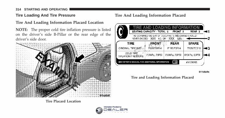
Tire Loading And Tire Pressure
Tire And Loading Information Placard Location
NOTE: The proper cold tire inflation pressure is listedon the driver’s side B-Pillar or the rear edge of thedriver’s side door.
Tire And Loading Information Placard
Tire Placard Location
Tire and Loading Information Placard
314 STARTING AND OPERATING
Information Provided by:
This placard tells you important information aboutthe:1) number of people that can be carried in the vehicle2) total weight your vehicle can carry3) tire size designed for your vehicle4) cold tire inflation pressures for the front, rear, andspare tires.
LoadingThe vehicle maximum load on the tire must not exceedthe load carrying capacity of the tire on your vehicle. Youwill not exceed the tire’s load carrying capacity if youadhere to the loading conditions, tire size, and cold tireinflation pressures specified on the Tire and LoadingInformation placard and in the “Vehicle Loading” sectionof this manual.
NOTE: Under a maximum loaded vehicle condition,gross axle weight ratings (GAWRs) for the front and rear
axles must not be exceeded. For further information onGAWRs, vehicle loading, and trailer towing, refer to“Vehicle Loading” in this section.
To determine the maximum loading conditions of yourvehicle, locate the statement “The combined weight ofoccupants and cargo should never exceed XXX lbs orXXX kg” on the Tire and Loading Information placard.The combined weight of occupants, cargo/luggage andtrailer tongue weight (if applicable) should never exceedthe weight referenced here.
Steps For Determining Correct Load Limit
1. Locate the statement “The combined weight of occu-pants and cargo should never exceed XXX lbs or XXX kg”on your vehicle’s placard.
2. Determine the combined weight of the driver andpassengers that will be riding in your vehicle.
5
STARTING AND OPERATING 315
Information Provided by:
3. Subtract the combined weight of the driver and pas-sengers from XXX lbs or XXX kg.
4. The resulting figure equals the available amount ofcargo and luggage load capacity. For example, if “XXX”amount equals 1,400 lbs (635 kg) and there will be five150 lb (68 kg) passengers in your vehicle, the amount ofavailable cargo and luggage load capacity is 650 lbs(295 kg) (since 5 x 150 = 750, and 1400 – 750 = 650 lbs[295 kg]).
5. Determine the combined weight of luggage and cargobeing loaded on the vehicle. That weight may not safelyexceed the available cargo and luggage load capacitycalculated in Step 4.
6. If your vehicle will be towing a trailer, load from yourtrailer will be transferred to your vehicle. Consult thismanual to determine how this reduces the availablecargo and luggage load capacity of your vehicle.
NOTE:• The following table shows examples on how to calcu-
late total load, cargo/luggage, and towing capacitiesof your vehicle with varying seating configurationsand number and size of occupants. This table is forillustration purposes only and may not be accurate forthe seating and load carry capacity of your vehicle.
• For the following example, the combined weight ofoccupants and cargo should never exceed 865 lbs(392 kg).
316 STARTING AND OPERATING
Information Provided by:
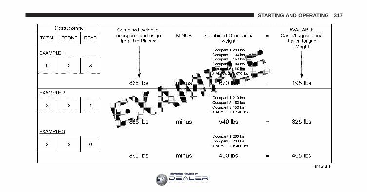
STARTING AND OPERATING 317
Information Provided by:
WARNING!
Overloading of your tires is dangerous. Overloadingcan cause tire failure, affect vehicle handling, andincrease your stopping distance. Use tires of therecommended load capacity for your vehicle. Neveroverload them.
TIRES — GENERAL INFORMATION
Tire PressureProper tire inflation pressure is essential to the safe andsatisfactory operation of your vehicle. Three primaryareas are affected by improper tire pressure:
Safety
WARNING!
• Improperly inflated tires are dangerous and cancause collisions.
• Under-inflation increases tire flexing and can re-sult in tire failure.
• Over-inflation reduces a tire’s ability to cushionshock. Objects on the road and chuckholes cancause damage that result in tire failure.
• Over-inflated or under-inflated tires can affectvehicle handling and can fail suddenly, resultingin loss of vehicle control.
• Unequal tire pressures can cause steering prob-lems. You could lose control of your vehicle.
(Continued)
318 STARTING AND OPERATING
Information Provided by:
WARNING! (Continued)• Unequal tire pressures from one side of the ve-
hicle to the other can cause the vehicle to drift tothe right or left.
• Always drive with each tire inflated to the recom-mended cold tire inflation pressure.
EconomyImproper inflation pressures can cause uneven wearpatterns to develop across the tire tread. These abnormalwear patterns will reduce tread life resulting in a need forearlier tire replacement. Under-inflation also increasestire rolling resistance resulting in higher fuelconsumption.
Ride Comfort And Vehicle StabilityProper tire inflation contributes to a comfortable ride.Over-inflation produces a jarring and uncomfortableride.
Tire Inflation PressuresThe proper cold tire inflation pressure is listed on thedriver’s side “B” Pillar or rear edge of the driver’s sidedoor.
Some vehicles may have Supplemental Tire PressureInformation for vehicle loads that are less than themaximum loaded vehicle condition. These pressure con-ditions will be found in the “Supplemental Tire PressureInformation” section of this manual.
The pressure should be checked and adjusted as well asinspecting for signs of tire wear or visible damage at leastonce a month. Use a good quality pocket-type gauge tocheck tire pressure. Do not make a visual judgementwhen determining proper inflation. Radial tires may lookproperly inflated even when they are under-inflated.
5
STARTING AND OPERATING 319
Information Provided by:
CAUTION!
After inspecting or adjusting the tire pressure, al-ways reinstall the valve stem cap. This will preventmoisture and dirt from entering the valve stem,which could damage the valve stem.
Inflation pressures specified on the placard are always“cold tire inflation pressure.” Cold tire inflation pressureis defined as the tire pressure after the vehicle has notbeen driven for at least three hours, or driven less than1 mile (1.6 km) after a three hour period. The cold tireinflation pressure must not exceed the maximum infla-tion pressure molded into the tire sidewall.
Check tire pressures more often if subject to a wide rangeof outdoor temperatures, as tire pressures vary withtemperature changes.
Tire pressures change by approximately 1 psi (7 kPa) per12°F (7°C) of air temperature change. Keep this in mindwhen checking tire pressure inside a garage, especially inthe winter.
Example: If garage temperature = 68°F (20°C) and theoutside temperature = 32°F (0°C) then the cold tireinflation pressure should be increased by 3 psi (21 kPa),which equals 1 psi (7 kPa) for every 12°F (7°C) for thisoutside temperature condition.
Tire pressure may increase from 2 to 6 psi (13 to 40 kPa)during operation. DO NOT reduce this normal pressurebuild up or your tire pressure will be too low.
320 STARTING AND OPERATING
Information Provided by:
Tire Inflation Pressure – 4500/5500 With SteelCarcass Ply TiresThis type of tire utilizes steel cords in the sidewall. Assuch, they cannot be treated like normal light truck tires.Adjusting tire pressure must be performed by personneltrained, supervised and equipped accordingly.
Inflation Pressure Adjustment When Mounted ToVehicleDuring procedures when adding tire inflation pressure,the technician or individual must utilize a remote infla-tion device, and ensure that all persons are clear of thetrajectory area.
5
STARTING AND OPERATING 321
Information Provided by:
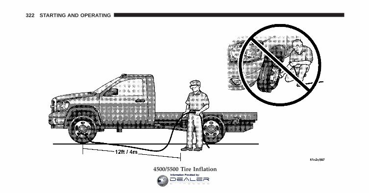
4500/5500 Tire Inflation
322 STARTING AND OPERATING
Information Provided by:
When adjusting inflation pressure to a tire and wheelassembly mounted on a vehicle, use a Remote MountAutomatic Inflation Kit or see your authorized dealer.
NOTE: Never attempt to re-inflate a tire and wheelassembly which has been run flat or is extremely under-inflated without first removing the tire from the wheelassembly for inspection.
Personnel trained, supervised, and equipped accordingto Federal Occupational Safety and Health Administra-tion (OSHA) should perform this work.
Inflation Pressure Adjustment When Not Mounted toVehicleWhen adjusting inflation pressure to a tire and wheelassembly not mounted on a vehicle, use a Remote MountAutomatic Inflation Kit and a Tire Inflation Cage or seeyour authorized dealer.
Tire Pressures For High Speed OperationThe manufacturer advocates driving at safe speedswithin posted speed limits. Where speed limits or condi-tions are such that the vehicle can be driven at highspeeds, maintaining correct tire inflation pressure is veryimportant. Increased tire pressure and reduced vehicleloading may be required for high-speed vehicle opera-tion. Refer to original equipment or an authorized tiredealer for recommended safe operating speeds, loadingand cold tire inflation pressures.
WARNING!
High speed driving with your vehicle under maxi-mum load is dangerous. The added strain on yourtires could cause them to fail. You could have aserious collision resulting in serious injury or death.Don’t drive a vehicle loaded to the maximum capac-ity at continuous speeds above 75 mph (120 km/h).
5
STARTING AND OPERATING 323
Information Provided by:
Radial Ply Tires
WARNING!
Combining radial ply tires with other types of tireson your vehicle will cause your vehicle to handlepoorly. The instability could cause a collision result-ing in serious injury or death. Always use radial plytires in sets of four (or six, in case of trucks with dualrear wheels). Never combine them with other typesof tires.
Cuts and punctures in radial tires are repairable only inthe tread area because of sidewall flexing. Consult yourauthorized tire dealer for radial tire repairs.
Spare Tire Matching Original Equipped Tire AndWheel – If EquippedYour vehicle may be equivalent with a spare tire andwheel in look and function as the original equipment tireand wheel found on the front or rear axle of your vehicle.This spare tire may be used in the tire rotation for yourvehicle. If your vehicle has this option refer to anauthorized tire dealer for the recommended tire rotationpattern.
If your vehicle is not equipped with an original equip-ment tire and wheel as a spare, a non-matching tempo-rary emergency use spare may be equipped with yourvehicle. Temporary use spares are engineered to be usedonly with your vehicle. Your vehicle may be equippedwith one of the following types of non-matching tempo-rary use spares; compact, full size, or limited-use. Do notinstall more than one non-matching temporary use sparetire/wheel on the vehicle at any given time.
324 STARTING AND OPERATING
Information Provided by:
CAUTION!
Because of the reduced ground clearance, do not takeyour vehicle through an automatic car wash with acompact, full size or limited-use temporary spareinstalled. Damage to the vehicle may result.
Compact Spare Tire – If EquippedThe compact spare is for temporary emergency use only.You can identify if your vehicle is equipped with acompact spare by looking at the spare tire description onthe Tire and Loading Information Placard located on thedriver’s side door opening or on the sidewall of the tire.Compact spare tire descriptions begin with the letter “T”or “S” preceding the size designation. Example: T145/80D18 103M.
T, S = Temporary Spare Tire
Since this tire has limited tread life the original equip-ment tire should be repaired (or replaced) and reinstalledon your vehicle at the first opportunity.
Do not install a wheel cover or attempt to mount aconventional tire on the compact spare wheel, since thewheel is designed specifically for the compact spare tire.Do not install more than one compact spare tire andwheel on the vehicle at any given time
WARNING!
Compact spares are for temporary emergency useonly. With these spares, do not drive more than50 mph (80 km/h). Temporary use spares have limitedtread life. When the tread is worn to the tread wearindicators, the temporary use spare tire needs to bereplaced. Be sure to follow the warnings, whichapply to your spare. Failure to do so could result inspare tire failure and loss of vehicle control.
5
STARTING AND OPERATING 325
Information Provided by:
Full Size Spare – If EquippedThe full size spare is for temporary emergency use only.This tire may look like the original equipped tire on thefront or rear axle of your vehicle, but it is not. This sparetire may have limited tread life. When the tread is wornto the tread wear indicators, the temporary use full sizespare tire needs to be replaced. Since it is not the same asyour original equipment tire, replace (or repair) theoriginal equipment tire and reinstall on the vehicle at thefirst opportunity.
Limited-Use Spare – If EquippedThe limited-use spare tire is for temporary emergencyuse only. This tire is identified by a label located on thelimited-use spare wheel. This label contains the drivinglimitations for this spare. This tire may look like theoriginal equipped tire on the front or rear axle of yourvehicle, but it is not. Installation of this limited-use sparetire affects vehicle handling. Since it is not the same as
your original equipment tire, replace (or repair) theoriginal equipment tire and reinstall on the vehicle at thefirst opportunity.
WARNING!
Limited-use spares are for emergency use only. In-stallation of this limited-use spare tire affects vehiclehandling. With this tire, do not drive more than thespeed listed on the limit-use spare wheel. Keepinflated to the cold tire inflation pressure listed onyour Tire and Loading Information Placard locatedon the driver’s side door opening. Replace (or repair)the original equipment tire at the first opportunityand reinstall it on your vehicle. Failure to do so couldresult in loss of vehicle control.
326 STARTING AND OPERATING
Information Provided by:
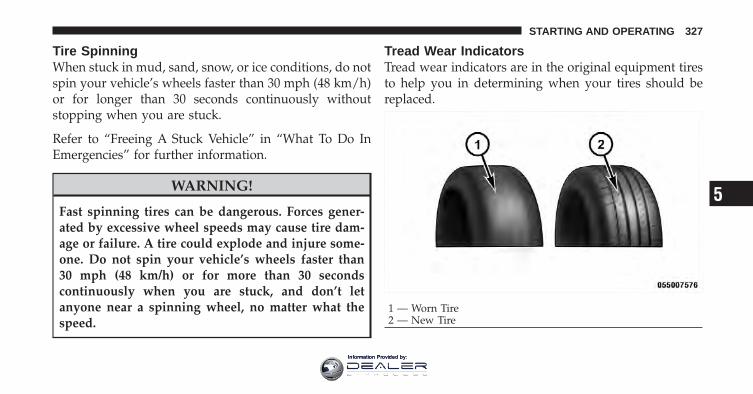
Tire SpinningWhen stuck in mud, sand, snow, or ice conditions, do notspin your vehicle’s wheels faster than 30 mph (48 km/h)or for longer than 30 seconds continuously withoutstopping when you are stuck.
Refer to “Freeing A Stuck Vehicle” in “What To Do InEmergencies” for further information.
WARNING!
Fast spinning tires can be dangerous. Forces gener-ated by excessive wheel speeds may cause tire dam-age or failure. A tire could explode and injure some-one. Do not spin your vehicle’s wheels faster than30 mph (48 km/h) or for more than 30 secondscontinuously when you are stuck, and don’t letanyone near a spinning wheel, no matter what thespeed.
Tread Wear IndicatorsTread wear indicators are in the original equipment tiresto help you in determining when your tires should bereplaced.
1 — Worn Tire2 — New Tire
5
STARTING AND OPERATING 327
Information Provided by:
These indicators are molded into the bottom of the treadgrooves. They will appear as bands when the tread depthbecomes 1/16 in (2 mm). When the tread is worn to thetread wear indicators, the tire should be replaced.
Many states have laws requiring tire replacement at thispoint.
Life Of TireThe service life of a tire is dependent upon varyingfactors including, but not limited to:
• Driving style
• Tire pressure
• Distance driven
WARNING!
Tires and spare tire should be replaced after six years,regardless of the remaining tread. Failure to followthis warning can result in sudden tire failure. Youcould lose control and have a collision resulting inserious injury or death.
Keep dismounted tires in a cool, dry place with as littleexposure to light as possible. Protect tires from contactwith oil, grease, and gasoline.
Replacement TiresThe tires on your new vehicle provide a balance of manycharacteristics. They should be inspected regularly forwear and correct cold tire inflation pressure. The manu-facturer strongly recommends that you use tires equiva-lent to the originals in size, quality and performancewhen replacement is needed (refer to the paragraph on“Tread Wear Indicators”). Refer to the “Tire and Loading
328 STARTING AND OPERATING
Information Provided by:
Information” placard for the size designation of your tire.The Load Index and Speed Symbol for your tire will befound on the original equipment tire sidewall. See theTire Sizing Chart example found in the Tire SafetyInformation section of this manual for more informationrelating to the Load Index and Speed Symbol of a tire.
It is recommended to replace the two front tires or tworear tires as a pair. Replacing just one tire can seriouslyaffect your vehicle’s handling. If you ever replace awheel, make sure that the wheel’s specifications matchthose of the original wheels.
It is recommended you contact your original equipmentor an authorized tire dealer with any questions you mayhave on tire specifications or capability. Failure to useequivalent replacement tires may adversely affect thesafety, handling, and ride of your vehicle.
WARNING!
• Do not use a tire, wheel size or rating other thanthat specified for your vehicle. Some combinationsof unapproved tires and wheels may change sus-pension dimensions and performance characteris-tics, resulting in changes to steering, handling, andbraking of your vehicle. This can cause unpredict-able handling and stress to steering and suspen-sion components. You could lose control and havea collision resulting in serious injury or death. Useonly the tire and wheel sizes with load ratingsapproved for your vehicle.
(Continued)
5
STARTING AND OPERATING 329
Information Provided by:
WARNING! (Continued)• Never use a tire with a smaller load index or
capacity, other than what was originally equippedon your vehicle. Using a tire with a smaller loadindex could result in tire overloading and failure.You could lose control and have a collision result-ing in serious injury or death.
• Failure to equip your vehicle with tires havingadequate speed capability can result in sudden tirefailure and loss of vehicle control resulting inserious injury or death.
CAUTION!
Replacing original tires with tires of a different sizemay result in false speedometer and odometer read-ings.
SUPPLEMENTAL TIRE PRESSURE INFORMATION— IF EQUIPPEDA light load vehicle condition is defined as two passen-gers [150 lbs (68 kg) each] plus 200 lbs (91 kg) of cargo.Cold tire inflation pressures for a lightly loaded vehiclewill be found on the face of the driver’s door.
TIRE CHAINSUse “Class U” chains or other traction aids that meet SAEType “U” specifications.
NOTE: Chains must be the proper size for the vehicle,as recommended by the chain manufacturer.
CAUTION!
To avoid damage to your vehicle, tires or chains,observe the following precautions:
(Continued)
330 STARTING AND OPERATING
Information Provided by:
CAUTION! (Continued)• Because of limited chain clearance between tires
and other suspension components, it is importantthat only chains in good condition are used. Bro-ken chains can cause serious vehicle damage. Stopthe vehicle immediately if noise occurs that couldsuggest chain breakage. Remove the damagedparts of the chain before further use.
• Install chains as tightly as possible and thenretighten after driving about 1/2 mi (0.8 km).
• Do not exceed 45 mph (72 km/h).• Drive cautiously and avoid severe turns and large
bumps, especially with a loaded vehicle.• Do not install tire chains on front wheels of 4x2
vehicles.• Do not drive for a prolonged period on dry pave-
ment.
(Continued)
CAUTION! (Continued)• Observe the tire chain manufacturer’s instructions
on method of installation, operating speed, andconditions for usage. Always use the lower sug-gested operating speed of the chain manufacturerif different than the speed recommended by themanufacturer.
These cautions apply to all chain traction devices, includ-ing link and cable (radial) chains.
Tire chain use is permitted only on the rear tires of your4X2 trucks.
NOTE:• The use of class “U” chains is permitted on the front
and rear of 4X4 vehicles, trucks with dual rear wheelsand LT235/80R17 tires.
5
STARTING AND OPERATING 331
Information Provided by:
• On 4X2 vehicles, class “U” snow chains are permittedon the rear wheels only of vehicles equipped withLT245/70R17, LT265/70R17, and LT235/80R17 sizetires.
• On 4X4 Single Rear Wheel (SRW) vehicles, class “U”snow chains are permitted on the rear wheels only onvehicles equipped with LT265/70R17.
CAUTION!
Do not use tire chains on the 4X2 front wheels ofSRW (Single Rear Wheels) equipped with LT245/70R17, LT265/70R17 tires or 4X4 front tires of vehiclesequipped with LT265/70R17 tires. There may not beadequate clearance for the chains and you are riskingstructural or body damage to your vehicle.
SNOW TIRESSome areas of the country require the use of snow tiresduring the winter. All season tires can be identified by theM+S designation on the tire sidewall.
If you need snow tires, select tires equivalent in size andtype to the original equipment tires. Use snow tires onlyin sets of four; failure to do so may adversely affect thesafety and handling of your vehicle.
Snow tires generally have lower speed ratings than whatwas originally equipped with your vehicle and shouldnot be operated at sustained speeds over 75 mph(120 km/h). For speeds above 75 mph (120 km/h) refer tooriginal equipment or an authorized tire dealer forrecommended safe operating speeds, loading and coldtire inflation pressures.
332 STARTING AND OPERATING
Information Provided by:
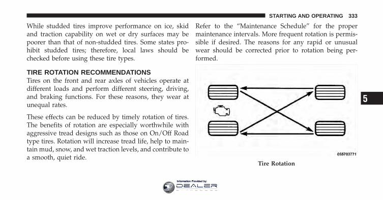
While studded tires improve performance on ice, skidand traction capability on wet or dry surfaces may bepoorer than that of non-studded tires. Some states pro-hibit studded tires; therefore, local laws should bechecked before using these tire types.
TIRE ROTATION RECOMMENDATIONSTires on the front and rear axles of vehicles operate atdifferent loads and perform different steering, driving,and braking functions. For these reasons, they wear atunequal rates.
These effects can be reduced by timely rotation of tires.The benefits of rotation are especially worthwhile withaggressive tread designs such as those on On/Off Roadtype tires. Rotation will increase tread life, help to main-tain mud, snow, and wet traction levels, and contribute toa smooth, quiet ride.
Refer to the “Maintenance Schedule” for the propermaintenance intervals. More frequent rotation is permis-sible if desired. The reasons for any rapid or unusualwear should be corrected prior to rotation being per-formed.
Tire Rotation
5
STARTING AND OPERATING 333
Information Provided by:
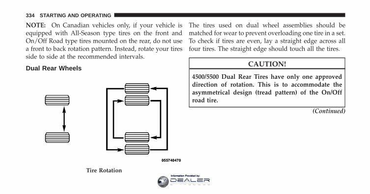
NOTE: On Canadian vehicles only, if your vehicle isequipped with All-Season type tires on the front andOn/Off Road type tires mounted on the rear, do not usea front to back rotation pattern. Instead, rotate your tiresside to side at the recommended intervals.
Dual Rear Wheels
The tires used on dual wheel assemblies should bematched for wear to prevent overloading one tire in a set.To check if tires are even, lay a straight edge across allfour tires. The straight edge should touch all the tires.
CAUTION!
4500/5500 Dual Rear Tires have only one approveddirection of rotation. This is to accommodate theasymmetrical design (tread pattern) of the On/Offroad tire.
(Continued)
Tire Rotation
334 STARTING AND OPERATING
Information Provided by:
CAUTION! (Continued)• When replacing a flat, the spare tire may have to
be remounted on the rim or installed at a differentlocation to maintain the correct placement of thetire on the wheel relative to the tire/wheel positionon the vehicle. For example, if the spare is used toreplace an outer rear tire it will have to be re-mounted on the rim so that the wheel is dishedinward. That way the tread design of asymmetricaltires will maintain proper position.
FUEL REQUIREMENTSThe 5.7L engine is designed to meet allemissions regulations and provide satisfac-tory fuel economy and performance whenusing high-quality unleaded gasoline hav-ing an octane range of 87 to 89. The manu-facturer recommends the use of 89 octane
for optimum performance. The use of premium gasolineis not recommended, as it will not provide any benefitover regular gasoline in these engines.
Light spark knock at low engine speeds is not harmful toyour engine. However, continued heavy spark knock athigh speeds can cause damage and immediate service isrequired.
Poor quality gasoline can cause problems such as hardstarting, stalling and hesitations. If you experience thesesymptoms, try another brand of “regular” gasoline be-fore considering service for the vehicle.
Over 40 auto manufacturers worldwide have issued andendorsed consistent gasoline specifications (the World-wide Fuel Charter, WWFC) to define fuel propertiesnecessary to deliver enhanced emissions, performanceand durability for your vehicle. We recommend the useof gasolines that meet the WWFC specifications if theyare available.
5
STARTING AND OPERATING 335
Information Provided by:
Reformulated GasolineMany areas of the country require the use of cleanerburning gasoline referred to as “Reformulated Gasoline”Reformulated gasolines contain oxygenates, and are spe-cifically blended to reduce vehicle emissions and im-prove air quality.
The manufacturer supports the use of reformulated gaso-lines. Properly-blended reformulated gasolines will pro-vide excellent performance and durability of engine andfuel system components.
Gasoline/Oxygenate BlendsSome fuel suppliers blend unleaded gasoline with oxy-genates such as 10% ethanol, MTBE, and ETBE. Oxygen-ates are required in some areas of the country during theWinter months to reduce carbon monoxide emissions.Fuels blended with these oxygenates may be used inyour vehicle.
CAUTION!
Do not use gasolines containing Methanol or E-85Ethanol. Use of these blends may result in startingand drivability problems and may damage criticalfuel system components.
Problems that result from using methanol/gasoline orE-85 Ethanol blends are not the responsibility of themanufacturer. While MTBE is an oxygenate made fromMethanol, it does not have the negative effects ofMethanol.
E-85 Usage In Non-Flex Fuel VehiclesNon-FFV vehicles are compatible with gasoline contain-ing 10% ethanol (E10). Gasoline with higher ethanolcontent may void the vehicle’s warranty.
336 STARTING AND OPERATING
Information Provided by:
If a Non-FFV vehicle is inadvertently fueled with E-85fuel, the engine will have some or all of these symptoms:
• operate in a lean mode
• OBD II “Malfunction Indicator Light” on
• poor engine performance
• poor cold start and cold drivability
• increased risk for fuel system component corrosion
To fix a Non-FFV vehicle inadvertently fueled once withE-85 perform the following:
• drain the fuel tank (see your authorized dealer)
• change the engine oil and oil filter
• disconnect and reconnect the battery to reset theengine controller memory
More extensive repairs will be required for prolongedexposure to E-85 fuel.
MMT In GasolineMMT is a manganese containing metallic additive that isblended into some gasoline to increase octane. Gasolineblended with MMT provides no performance advantagebeyond gasoline of the same octane number withoutMMT. Gasoline blended with MMT reduces spark pluglife and reduces emission system performance in somevehicles. The manufacturer recommends that gasolinewithout MMT be used in your vehicle. The MMT contentof gasoline may not be indicated on the gasoline pump,therefore, you should ask your gasoline retailer whetheror not the gasoline contains MMT. It is even moreimportant to look for gasolines without MMT in Canada,because MMT can be used at levels higher than thoseallowed in the United States. MMT is prohibited inFederal and California reformulated gasoline.
5
STARTING AND OPERATING 337
Information Provided by:
Materials Added To FuelAll gasolines sold in the United States are required tocontain effective detergent additives. Use of additionaldetergents or other additives is not needed under normalconditions and would result in unnecessary cost. There-fore, you should not have to add anything to the fuel.
Fuel System Cautions
CAUTION!
Follow these guidelines to maintain your vehicle’sperformance:• The use of leaded gas is prohibited by Federal law.
Using leaded gasoline can impair engine perfor-mance, damage the emission control system.
(Continued)
CAUTION! (Continued)• An out-of-tune engine, or certain fuel or ignition
malfunctions, can cause the catalytic converter tooverheat. If you notice a pungent burning odor orsome light smoke, your engine may be out of tuneor malfunctioning and may require immediateservice. Contact your authorized dealer for serviceassistance.
• When pulling a heavy load or driving a fully-loaded vehicle when the humidity is low and thetemperature is high, use a premium unleaded fuelto help prevent spark knock. If spark knock per-sists, lighten the load, or engine piston damagemay result.
(Continued)
338 STARTING AND OPERATING
Information Provided by:
CAUTION! (Continued)• The use of fuel additives which are now being
sold as octane enhancers is not recommended.Many of these products contain high concentra-tions of methanol. Fuel system damage or vehicleperformance problems resulting from the use ofsuch fuels or additives is not the responsibility ofthe manufacturer.
NOTE: Intentional tampering with emissions controlsystems can result in civil penalties being assessedagainst you.
Carbon Monoxide Warnings
WARNING!
Carbon monoxide (CO) in exhaust gases is deadly.Follow the precautions below to prevent carbonmonoxide poisoning:• Do not inhale exhaust gases. They contain carbon
monoxide, a colorless and odorless gas which cankill. Never run the engine in a closed area, such asa garage, and never sit in a parked vehicle with theengine running for an extended period. If thevehicle is stopped in an open area with the enginerunning for more than a short period, adjust theventilation system to force fresh, outside air intothe vehicle.
(Continued)
5
STARTING AND OPERATING 339
Information Provided by:
WARNING! (Continued)• Guard against carbon monoxide with proper
maintenance. Have the exhaust system inspectedevery time the vehicle is raised. Have any abnor-mal conditions repaired promptly. Until repaired,drive with all side windows fully open.
ADDING FUEL
CAUTION!
• Damage to the fuel system or emissions controlsystem could result from using an improper fueltank filler tube cap (gas cap). A poorly fitting capcould let impurities into the fuel system. Also, apoorly-fitted aftermarket cap can cause the MIL(Malfunction Indicator Light) to illuminate due tofuel vapors escaping from the system.
• A poorly fitting gas cap may cause the MIL to turnon.
• To avoid fuel spillage and overfilling, do not “topoff” the fuel tank after filling.
NOTE: When the fuel nozzle “clicks” or shuts off thefuel tank is full.
340 STARTING AND OPERATING
Information Provided by:
WARNING!
• Never have any smoking materials lit in or nearthe vehicle when the gas cap is removed or thetank is being filled.
• Never add fuel to the vehicle when the engine isrunning. This is in violation of most state andfederal fire regulations and may cause the MIL toturn on.
NOTE: Tighten the gas cap 1/4 turn until you hear oneclick. This is an indication that the cap is properlytightened.
If the gas cap is not tightened properly, the MalfunctionIndicator Light will come on, Be sure the gas cap istightened every time the vehicle is refueled.
WARNING!
A fire may result if gasoline is pumped into aportable container that is inside of a vehicle. Youcould be burned. Always place gas containers on theground while filling.
Loose Fuel Filler Cap MessageIf the vehicle diagnostic system determinesthat the fuel filler cap is loose, improperlyinstalled, or damaged, a loose gascap indicatorwill display in the EVIC telltale display area.
Refer to “Electronic Vehicle Information Center (EVIC) in“Understanding Your Instrument Panel” for further in-formation. Tighten the fuel filler cap properly and pressthe SELECT button to turn off the message. If theproblem continues, the message will appear the next timethe vehicle is started.
5
STARTING AND OPERATING 341
Information Provided by:
VEHICLE LOADING
Certification LabelAs required by National Highway Traffic Safety Admin-istration regulations, your vehicle has a certification labelaffixed to the driver’s side door or pillar.
This label contains the month and year of manufacture,Gross Vehicle Weight Rating (GVWR), Gross Axle WeightRating (GAWR) front and rear, and Vehicle IdentificationNumber (VIN). A Month-Day-Hour (MDH) number isincluded on this label and indicates the Month, Day andHour of manufacture. The bar code that appears on thebottom of the label is your Vehicle Identification Number(VIN).
Gross Vehicle Weight Rating (GVWR)The GVWR is the total permissible weight of your vehicleincluding driver, passengers, vehicle, options and cargo.The label also specifies maximum capacities of front and
rear axle systems (GAWR). Total load must be limited soGVWR and front and rear GAWR are not exceeded.
PayloadThe payload of a vehicle is defined as the allowable loadweight a truck can carry, including the weight of thedriver, all passengers, options and cargo.
Gross Axle Weight Rating (GAWR)The GAWR is the maximum permissible load on the frontand rear axles. The load must be distributed in the cargoarea so that the GAWR of each axle is not exceeded.
Each axle GAWR is determined by the components in thesystem with the lowest load carrying capacity (axle,springs, tires or wheels). Heavier axles or suspensioncomponents sometimes specified by purchasers for in-creased durability does not necessarily increase the vehi-cle’s GVWR.
342 STARTING AND OPERATING
Information Provided by:
Tire SizeThe tire size on the Label represents the actual tire size onyour vehicle. Replacement tires must be equal to the loadcapacity of this tire size.
Rim SizeThis is the rim size that is appropriate for the tire sizelisted.
Inflation PressureThis is the cold tire inflation pressure for your vehicle forall loading conditions up to full GAWR.
Curb WeightThe curb weight of a vehicle is defined as the total weightof the vehicle with all fluids, including vehicle fuel, at fullcapacity conditions, and with no occupants or cargoloaded into the vehicle. The front and rear curb weightvalues are determined by weighing your vehicle on acommercial scale before any occupants or cargo areadded.
LoadingThe actual total weight and the weight of the front andrear of your vehicle at the ground can best be determinedby weighing it when it is loaded and ready for operation.
The entire vehicle should first be weighed on a commer-cial scale to insure that the GVWR has not been exceeded.The weight on the front and rear of the vehicle shouldthen be determined separately to be sure that the load isproperly distributed over front and rear axle. Weighingthe vehicle may show that the GAWR of either the frontor rear axles has been exceeded but the total load iswithin the specified GVWR. If so, weight must be shiftedfrom front to rear or rear to front as appropriate until thespecified weight limitations are met. Store the heavieritems down low and be sure that the weight is distributedequally. Stow all loose items securely before driving.
5
STARTING AND OPERATING 343
Information Provided by:
Improper weight distributions can have an adverse effecton the way your vehicle steers and handles and the waythe brakes operate.
CAUTION!
Do not load your vehicle any heavier than the GVWRor the maximum front and rear GAWR. If you do,parts on your vehicle can break, or it can change theway your vehicle handles. This could cause you tolose control. Also overloading can shorten the life ofyour vehicle.
TRAILER TOWINGIn this section you will find safety tips and informationon limits to the type of towing you can reasonably dowith your vehicle. Before towing a trailer, carefullyreview this information to tow your load as efficientlyand safely as possible.
To maintain warranty coverage, follow the requirementsand recommendations in this manual concerning ve-hicles used for trailer towing.
Common Towing DefinitionsThe following trailer towing related definitions will assistyou in understanding the following information:
Gross Vehicle Weight Rating (GVWR)The GVWR is the total allowable weight of your vehicle.This includes driver, passengers, cargo and tongueweight. The total load must be limited so that you do notexceed the GVWR. Refer to “Vehicle Loading/VehicleCertification Label” in “Starting and Operating” forfurther information.
Gross Trailer Weight (GTW)The GTW is the weight of the trailer plus the weight of allcargo, consumables and equipment (permanent or tem-porary) loaded in or on the trailer in its �loaded andready for operation� condition.
344 STARTING AND OPERATING
Information Provided by:
The recommended way to measure GTW is to put yourfully loaded trailer on a vehicle scale. The entire weightof the trailer must be supported by the scale.
Gross Combination Weight Rating (GCWR)The GCWR is the total permissible weight of your vehicleand trailer when weighed in combination.
NOTE: The GCWR rating includes a 150 lbs (68 kg)allowance for the presence of a driver.
Gross Axle Weight Rating (GAWR)The GAWR is the maximum capacity of the front and rearaxles. Distribute the load over the front and rear axlesevenly. Make sure that you do not exceed either front orrear GAWR. Refer to “Vehicle Loading/Vehicle Certifica-tion Label” in “Starting and Operating” for furtherinformation.
WARNING!
It is important that you do not exceed the maximumfront or rear GAWR. A dangerous driving conditioncan result if either rating is exceeded. You could losecontrol of the vehicle and have a collision.
Tongue Weight (TW)The tongue weight is the downward force exerted on thehitch ball by the trailer. In most cases it should not be lessthan 10% or more than 15% of the trailer load. You mustconsider this as part of the load on your vehicle.
Frontal AreaThe frontal area is the maximum height multiplied by themaximum width of the front of a trailer.
Trailer Sway ControlThe trailer sway control can be a mechanical telescopinglink that can be installed between the hitch receiver and
5
STARTING AND OPERATING 345
Information Provided by:
the trailer tongue that typically provides adjustable fric-tion associated with the telescoping motion to dampenany unwanted trailer swaying motions while traveling.
Weight-Carrying HitchA weight-carrying hitch supports the trailer tongueweight, just as if it were luggage located at a hitch ball orsome other connecting point of the truck. These kind ofhitches are the most popular on the market today andthey are commonly used to tow small- and medium-sized trailers.
Weight-Distributing HitchA weight-distributing system works by applying lever-age through spring (load) bars. They are typically usedfor heavier loads to distribute trailer tongue weight to thetow vehicle’s front axle and the trailer axle(s). When usedin accordance with the manufacturer’s directions, it pro-vides for a more level ride, offering more consistentsteering and brake control, thereby enhancing towing
safety. The addition of a friction/hydraulic sway controlalso dampens sway caused by traffic and crosswinds andcontributes positively to tow vehicle and trailer stability.Trailer sway control and a weight distributing (loadequalizing) hitch are recommended for heavier TongueWeights (TW) and may be required depending on vehicleand trailer configuration/loading to comply with GAWRrequirements.
WARNING!
• An improperly adjusted weight distributing hitchsystem may reduce handling, stability and brakingperformance and could result in a collision.
• Weight distributing systems may not be compat-ible with surge brake couplers. Consult with yourhitch and trailer manufacturer or a reputable Rec-reational Vehicle dealer for additionalinformation.
346 STARTING AND OPERATING
Information Provided by:
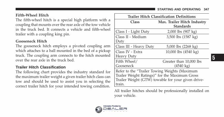
Fifth-Wheel HitchThe fifth-wheel hitch is a special high platform with acoupling that mounts over the rear axle of the tow vehiclein the truck bed. It connects a vehicle and fifth-wheeltrailer with a coupling king pin.
Gooseneck HitchThe gooseneck hitch employs a pivoted coupling armwhich attaches to a ball mounted in the bed of a pickuptruck. The coupling arm connects to the hitch mountedover the rear axle in the truck bed.
Trailer Hitch ClassificationThe following chart provides the industry standard forthe maximum trailer weight a given trailer hitch class cantow and should be used to assist you in selecting thecorrect trailer hitch for your intended towing condition.
Trailer Hitch Classification DefinitionsClass Max. Trailer Hitch Industry
StandardsClass I - Light Duty 2,000 lbs (907 kg)Class II - MediumDuty
3,500 lbs (1587 kg)
Class III - Heavy Duty 5,000 lbs (2268 kg)Class IV - ExtraHeavy Duty
10,000 lbs (4540 kg)
Fifth Wheel/Gooseneck
Greater than 10,000 lbs(4540 kg)
Refer to the “Trailer Towing Weights (MaximumTrailer Weight Ratings)” for the Maximum GrossTrailer Weight (GTW) towable for your given drive-train.
All trailer hitches should be professionally installed onyour vehicle.
5
STARTING AND OPERATING 347
Information Provided by:
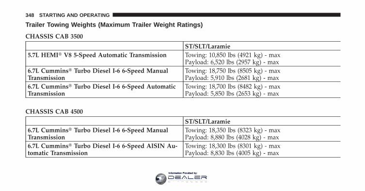
Trailer Towing Weights (Maximum Trailer Weight Ratings)
CHASSIS CAB 3500
ST/SLT/Laramie5.7L HEMI� V8 5-Speed Automatic Transmission Towing: 10,850 lbs (4921 kg) - max
Payload: 6,520 lbs (2957 kg) - max6.7L Cummins� Turbo Diesel I-6 6-Speed ManualTransmission
Towing: 18,750 lbs (8505 kg) - maxPayload: 5,910 lbs (2681 kg) - max
6.7L Cummins� Turbo Diesel I-6 6-Speed AutomaticTransmission
Towing: 18,700 lbs (8482 kg) - maxPayload: 5,850 lbs (2653 kg) - max
CHASSIS CAB 4500
ST/SLT/Laramie6.7L Cummins� Turbo Diesel I-6 6-Speed ManualTransmission
Towing: 18,350 lbs (8323 kg) - maxPayload: 8,880 lbs (4028 kg) - max
6.7L Cummins� Turbo Diesel I-6 6-Speed AISIN Au-tomatic Transmission
Towing: 18,300 lbs (8301 kg) - maxPayload: 8,830 lbs (4005 kg) - max
348 STARTING AND OPERATING
Information Provided by:
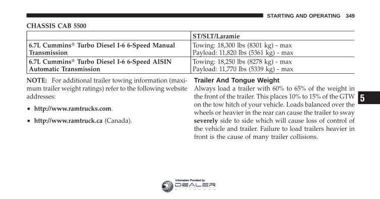
CHASSIS CAB 5500
ST/SLT/Laramie6.7L Cummins� Turbo Diesel I-6 6-Speed ManualTransmission
Towing: 18,300 lbs (8301 kg) - maxPayload: 11,820 lbs (5361 kg) - max
6.7L Cummins� Turbo Diesel I-6 6-Speed AISINAutomatic Transmission
Towing: 18,250 lbs (8278 kg) - maxPayload: 11,770 lbs (5339 kg) - max
NOTE: For additional trailer towing information (maxi-mum trailer weight ratings) refer to the following websiteaddresses:
• http://www.ramtrucks.com.
• http://www.ramtruck.ca (Canada).
Trailer And Tongue WeightAlways load a trailer with 60% to 65% of the weight inthe front of the trailer. This places 10% to 15% of the GTWon the tow hitch of your vehicle. Loads balanced over thewheels or heavier in the rear can cause the trailer to swayseverely side to side which will cause loss of control ofthe vehicle and trailer. Failure to load trailers heavier infront is the cause of many trailer collisions.
5
STARTING AND OPERATING 349
Information Provided by:
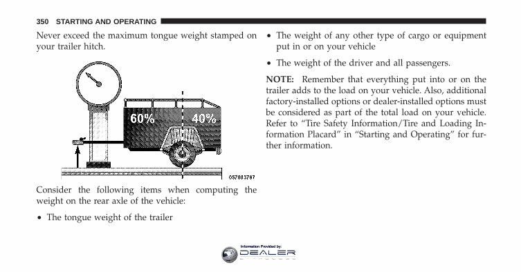
Never exceed the maximum tongue weight stamped onyour trailer hitch.
Consider the following items when computing theweight on the rear axle of the vehicle:
• The tongue weight of the trailer
• The weight of any other type of cargo or equipmentput in or on your vehicle
• The weight of the driver and all passengers.
NOTE: Remember that everything put into or on thetrailer adds to the load on your vehicle. Also, additionalfactory-installed options or dealer-installed options mustbe considered as part of the total load on your vehicle.Refer to “Tire Safety Information/Tire and Loading In-formation Placard” in “Starting and Operating” for fur-ther information.
350 STARTING AND OPERATING
Information Provided by:
Towing RequirementsTo promote proper break-in of your new vehicle drive-train components the following guidelines are recom-mended:
CAUTION!
• Do not tow a trailer at all during the first 500 miles(805 km) the new vehicle is driven. The engine,axle or other parts could be damaged.
• Then, during the first 500 miles (805 km) that atrailer is towed, do not drive over 50 mph(80 km/h) and do not make starts at full throttle.This helps the engine and other parts of thevehicle wear in at the heavier loads.
WARNING!
Improper towing can lead to a collision. Follow theseguidelines to make your trailer towing as safe aspossible:• Make certain that the load is secured in the trailer
and will not shift during travel. When traileringcargo that is not fully secured, dynamic load shiftscan occur that may be difficult for the driver tocontrol. You could lose control of your vehicle andhave a collision.
• When hauling cargo or towing a trailer, do notoverload your vehicle or trailer. Overloading cancause a loss of control, poor performance or dam-age to brakes, axle, engine, transmission, steering,suspension, chassis structure or tires.
(Continued)
5
STARTING AND OPERATING 351
Information Provided by:
WARNING! (Continued)• Safety chains must always be used between your
vehicle and trailer. Always connect the chains tothe hook retainers of the vehicle hitch. Cross thechains under the trailer tongue and allow enoughslack for turning corners.
• Vehicles with trailers should not be parked on agrade. When parking, apply the parking brake onthe tow vehicle. Put the tow vehicle transmissionin PARK. For four-wheel drive vehicles, make surethe transfer case is not in NEUTRAL. Always,block or �chock� the trailer wheels.
• GCWR must not be exceeded.• Total weight must be distributed between the tow
vehicle and the trailer such that the following fourratings are not exceeded:1. GVWR
(Continued)
WARNING! (Continued)2. GTW3. GAWR4. Trailer tongue weight rating for the trailer hitchutilized (This requirement may limit the ability toalways achieve the 10% to 15% range of tongueweight as a percentage of total trailer weight).
Towing Requirements – Tires
• Do not attempt to tow a trailer with less than the fullsize spare tire.
• Proper tire inflation pressures are essential to the safeand satisfactory operation of your vehicle. Refer to“Tires – General Information” in “Starting and Oper-ating” for proper tire inflation procedures.
• Check the trailer tires for proper tire inflation pres-sures before trailer usage.
352 STARTING AND OPERATING
Information Provided by:
• Check for signs of tire wear or visible tire damagebefore towing a trailer. Refer to “Tires – GeneralInformation” in “Starting and Operating” for theproper inspection procedure.
• When replacing tires, refer to “Tires – General Infor-mation” in “Starting and Operating” for proper tirereplacement procedures. Replacing tires with a higherload carrying capacity will not increase the vehicle’sGVWR and GAWR limits.
Towing Requirements – Trailer Brakes
• Do not interconnect the hydraulic brake system orvacuum system of your vehicle with that of the trailer.This could cause inadequate braking and possiblepersonal injury.
• An electronically actuated trailer brake controller isrequired when towing a trailer with electronicallyactuated brakes. When towing a trailer equipped witha hydraulic surge actuated brake system, an electronicbrake controller is not required.
• Trailer brakes are recommended for trailers over1,000 lbs (454 kg) and required for trailers in excess of2,000 lbs (907 kg).
CAUTION!
If the trailer weighs more than 1,000 lbs (454 kg)loaded, it should have its own brakes and theyshould be of adequate capacity. Failure to do thiscould lead to accelerated brake lining wear, higherbrake pedal effort, and longer stopping distances.
5
STARTING AND OPERATING 353
Information Provided by:
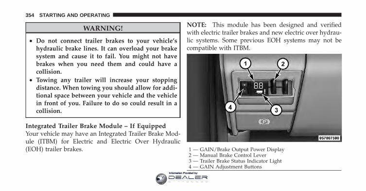
WARNING!
• Do not connect trailer brakes to your vehicle’shydraulic brake lines. It can overload your brakesystem and cause it to fail. You might not havebrakes when you need them and could have acollision.
• Towing any trailer will increase your stoppingdistance. When towing you should allow for addi-tional space between your vehicle and the vehiclein front of you. Failure to do so could result in acollision.
Integrated Trailer Brake Module – If EquippedYour vehicle may have an Integrated Trailer Brake Mod-ule (ITBM) for Electric and Electric Over Hydraulic(EOH) trailer brakes.
NOTE: This module has been designed and verifiedwith electric trailer brakes and new electric over hydrau-lic systems. Some previous EOH systems may not becompatible with ITBM.
1 — GAIN/Brake Output Power Display2 — Manual Brake Control Lever3 — Trailer Brake Status Indicator Light4 — GAIN Adjustment Buttons
354 STARTING AND OPERATING
Information Provided by:
The user interface consists of the following:
GAIN/ Brake Output Power DisplayShows the current GAIN setting.
This display may also be used to display diagnosticinformation, if needed.
• SC — Short Circuit to Ground
• Sb — Short to Battery
• CF — Controller Fault – If this message appears on thedisplay, see your authorized dealer.
When the vehicle brakes are applied, the display will nolonger show GAIN and will change to the output to thetrailer brakes.
Manual Brake Control LeverSlide the manual brake control lever to the right toactivate power to the trailer’s electric brakes independentof the tow vehicle’s brakes. If the manual brake control
lever is activated while the brake is also applied, thegreater of the two inputs determines the power sent tothe trailer brakes.
The trailer and the vehicle’s brake lamps will come onwhen either vehicle braking or manual trailer brakes areapplied.
Trailer Brake Status Indicator LightThis light indicates the trailer electrical connection status.
If no electrical connection is detected after the ignition isturned on, pressing the GAIN adjustment button orsliding the manual brake control lever will display theGAIN setting for 10 seconds and the “Trailer Brake StatusIndicator Light” will not be displayed.
If a fault is detected in the trailer wiring or the IntegratedTrailer Brake Module (ITBM), the “Trailer Brake StatusIndicator Light” will flash.
5
STARTING AND OPERATING 355
Information Provided by:
GAIN Adjustment Buttons (+/-)Pressing these buttons will adjust the brake controlpower output to the trailer brakes in 0.5 increments. TheGAIN setting can be increased to a maximum of 10 ordecreased to a minimum of 0 (no trailer braking).
GAINThe GAIN setting is used to set the trailer brake controlfor the specific towing condition and should be changedas towing conditions change. Changes to towing condi-tions include trailer load, vehicle load, road conditionsand weather.
Adjusting GAIN
NOTE: This should only be performed in a traffic freeenvironment at speeds of approximately 20–25 mph(30–40 km/h).
1. Make sure the trailer brakes are in good workingcondition, functioning normally, and properly adjusted.See your trailer dealer if necessary.
2. Hook up the trailer and make the electrical connec-tions according to the trailer manufacturer’s instructions.
3. When a trailer with electric/EOH brakes is pluggedin, the trailer connected message should appear in theEVIC (if the connection is not recognized by the ITBM,braking functions will not be available), the GAIN settingwill illuminate and the correct type of trailer must beselected from the EVIC options.
356 STARTING AND OPERATING
Information Provided by:
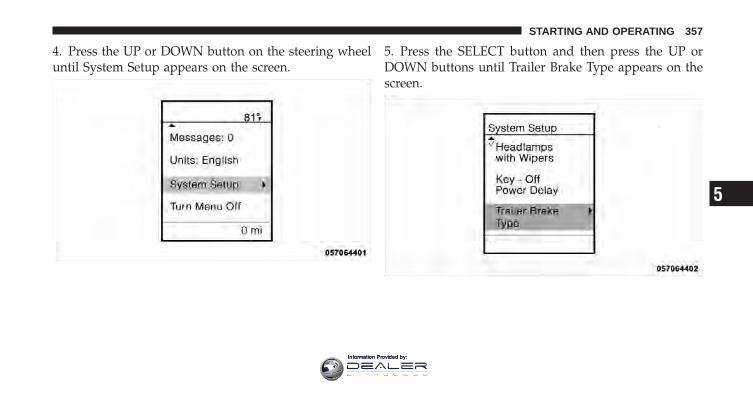
4. Press the UP or DOWN button on the steering wheeluntil System Setup appears on the screen.
5. Press the SELECT button and then press the UP orDOWN buttons until Trailer Brake Type appears on thescreen.
5
STARTING AND OPERATING 357
Information Provided by:
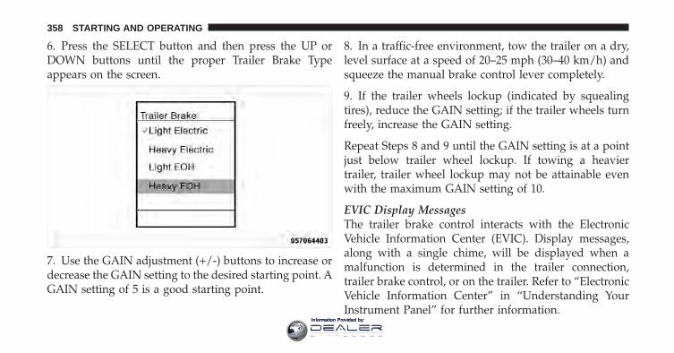
6. Press the SELECT button and then press the UP orDOWN buttons until the proper Trailer Brake Typeappears on the screen.
7. Use the GAIN adjustment (+/-) buttons to increase ordecrease the GAIN setting to the desired starting point. AGAIN setting of 5 is a good starting point.
8. In a traffic-free environment, tow the trailer on a dry,level surface at a speed of 20–25 mph (30–40 km/h) andsqueeze the manual brake control lever completely.
9. If the trailer wheels lockup (indicated by squealingtires), reduce the GAIN setting; if the trailer wheels turnfreely, increase the GAIN setting.
Repeat Steps 8 and 9 until the GAIN setting is at a pointjust below trailer wheel lockup. If towing a heaviertrailer, trailer wheel lockup may not be attainable evenwith the maximum GAIN setting of 10.
EVIC Display MessagesThe trailer brake control interacts with the ElectronicVehicle Information Center (EVIC). Display messages,along with a single chime, will be displayed when amalfunction is determined in the trailer connection,trailer brake control, or on the trailer. Refer to “ElectronicVehicle Information Center” in “Understanding YourInstrument Panel” for further information.
358 STARTING AND OPERATING
Information Provided by:
CAUTION!
Connecting a trailer that is not compatible with theITBM system may result in reduced or complete lossof trailer braking. There may be a increase in stop-ping distance or trailer instability which could resultin damage to your vehicle, trailer, or other property.
WARNING!
Connecting a trailer that is not compatible with theITBM system may result in reduced or complete lossof trailer braking. There may be a increase in stop-ping distance or trailer instability which could resultin personal injury.
NOTE:• An aftermarket controller may be available for use
with air trailer brake systems and other systems notcompatible with ITBM. To determine the type ofbrakes on your trailer and the availability of control-lers, check with your trailer manufacturer or dealer.
• Removal of the ITBM will cause errors and it maycause damage to the electrical system and electronicmodules of the vehicle. See your authorized dealer ifan aftermarket module is to be installed.
Towing Requirements – Trailer Lights And WiringWhenever you pull a trailer, regardless of the trailer size,stop lights and turn signals on the trailer are required formotoring safety.
NOTE: Do not cut or splice wiring into the vehicle’swiring harness.
5
STARTING AND OPERATING 359
Information Provided by:
WARNING!
Any work done to the vehicle’s electrical system orwiring should be performed by a qualified automo-tive technician. If done improperly it may causedamage to the electrical system wiring and couldresult in serious or fatal injury.
Towing TipsBefore setting out on a trip, practice turning, stoppingand backing the trailer up in an area away from heavytraffic.
Automatic TransmissionThe “DRIVE” range can be selected when towing. How-ever, if frequent shifting occurs while in this range, select“TOW/HAUL” mode or select a lower gear using theElectronic Range Select (ERS) feature.
NOTE: Using “TOW/HAUL” mode or a lower gearrange while operating the vehicle under heavy operatingconditions will improve performance and extend trans-mission life by reducing excessive shifting and heat buildup. This action will also provide better engine braking.
The automatic transmission fluid and filter should bechanged if you regularly tow a trailer for more than45 minutes of continuous operation. Refer to “Mainte-nance Schedule” for the proper maintenance intervals.
NOTE: Check the automatic transmission fluid levelbefore towing.
Tow/HaulTo reduce potential for automatic transmission overheat-ing, turn the “TOW/HAUL” feature ON when driving inhilly areas, or select a lower gear range (using theElectronic Range Select (ERS) feature) on more severegrades.
360 STARTING AND OPERATING
Information Provided by:
Electronic Speed Control – If Equipped
− Do not use in hilly terrain or with heavy loads.
− When using the speed control, if you experience speeddrops greater than 10 mph (16 km/h), disengage untilyou can get back to cruising speed.
− Use speed control in flat terrain and with light loads tomaximize fuel efficiency.
Cooling SystemTo reduce potential for engine and transmission over-heating, take the following actions:
− City DrivingWhen stopped for short periods of time, shift the trans-mission into NEUTRAL and increase engine idle speed.
− Highway DrivingReduce speed.
− Air ConditioningTurn off temporarily.
SNOWPLOWSnowplow Prep Packages are available as a factoryinstalled option. These packages include componentsnecessary to equip your vehicle with a snowplow.
NOTE: Before installation of a snowplow it is highlyrecommended that the owner/installer obtain and followthe recommendations contained within the currentDodge Body Builders Guide. See your authorized dealer,installer or snowplow manufacturer for this information.There are unique electrical systems that must be con-nected to properly assure operator safety and preventoverloading vehicle systems.
5
STARTING AND OPERATING 361
Information Provided by:
WARNING!
Attaching a snowplow to this vehicle could adverselyaffect performance of the airbag system in a collision.Do not expect that the airbag will perform as de-scribed earlier in this manual
CAUTION!
The “Lamp Out” indicator could illuminate if exte-rior lamps are not properly installed.
Before Plowing
• Check the hydraulic system for leaks and proper fluidlevel.
• Check the mounting bolts and nuts for proper tight-ness.
• Check the runners and cutting edge for excessive wear.The cutting edge should be 1/4 to 1/2 in (6 cm to1.2 cm) above ground in snow plowing position.
• Check that snowplow lighting is connected and func-tioning properly.
Snowplow Prep Package Model AvailabilityFor Information about snowplow applications visitwww.dodge.com or refer to the current Dodge BodyBuilders Guide.
1. The maximum number of occupants in the truckshould not exceed two.
2. The total GVWR or the Front GAWR or the RearGAWR should never be exceeded.
3. Cargo capacity will be reduced by the addition ofoptions or passengers, etc.
362 STARTING AND OPERATING
Information Provided by:
The loaded vehicle weight, including the snowplowsystem, all aftermarket accessories, driver, passengers,options, and cargo, must not exceed either the GrossVehicle Weight (GVWR) or Gross Axle Weight (GAWR)ratings. These weights are specified on the Safety Com-pliance Certification Label on the driver’s side dooropening.
NOTE: Detach the snowplow when transporting pas-sengers.
Vehicle front end wheel alignment was set to specifica-tions at the factory without consideration for the weightof the plow. Front end toe-in should be checked and resetif necessary at the beginning and end of the snowplowseason. This will help prevent uneven tire wear.
The blade should be lowered whenever the vehicle isparked.
Maintain and operate your vehicle and snowplow equip-ment following the recommendations provided by thespecific snowplow manufacturer.
Over The Road Operation With SnowplowAttachedThe blade restricts air flow to the radiator and causes theengine to operate at higher than normal temperatures.Therefore, when transporting the plow, angle the bladecompletely and position it as low as road or surfaceconditions permit. Do not exceed 40 mph (64 km/h). Theoperator should always maintain a safe stopping distanceand allow adequate passing clearance.
Operating TipsUnder ideal snow plowing conditions, 20 mph (32 km/h)should be maximum operating speed. The operatorshould be familiar with the area and surface to becleaned. Reduce speed and use extreme caution whenplowing unfamiliar areas or under poor visibility.
5
STARTING AND OPERATING 363
Information Provided by:
NOTE: During snowplow usage on vehicles equippedwith outside temperature display, the display may showhigher temperatures than the outside ambient tempera-ture. The higher displayed temperature is due to blockedor reduced airflow to the underhood ambient tempera-ture sensor caused by the snowplow. In addition, onvehicles equipped with Automatic Temperature Control(ATC), it is suggested that the interior cabin temperaturebe manually controlled should the system not perform asdesired while in automatic mode. Both the outside tem-perature display and ATC operation will return to nor-mal when the snowplow is removed.
General MaintenanceSnowplows should be maintained in accordance with theplow manufacturer’s instructions.
Keep all snowplow electrical connections and batteryterminals clean and free of corrosion.
When plowing snow, to avoid transmission and drive-train damage, the following precautions should be ob-served.
• Operate with transfer case in 4L when plowing smallor congested areas where speeds are not likely toexceed 15 mph (24 km/h). At higher speeds operate in4H.
• Vehicles with automatic transmissions should use 4Lrange when plowing deep or heavy snow for extendedperiods of time to avoid transmission overheating.
• Do not shift the transmission unless the engine hasreturned to idle and wheels have stopped. Make apractice of stepping on the brake pedal before shiftingthe transmission.
364 STARTING AND OPERATING
Information Provided by:

RECREATIONAL TOWING (BEHIND MOTORHOME, ETC.)Towing This Vehicle Behind Another Vehicle
Towing Condition Wheels OFF TheGround
Two-Wheel DriveModels
Four-Wheel Drive Models
Flat Tow NONE NOT ALLOWED
See Instructions
• Transmission in PARK
• Transfer case in NEUTRAL (N)
• Tow in forward direction
Dolly TowFront NOT ALLOWED NOT ALLOWEDRear OK NOT ALLOWED
On Trailer ALL OK OK
5
STARTING AND OPERATING 365
Information Provided by:
Recreational Towing – Two-Wheel Drive ModelsDO NOT flat tow this vehicle. Damage to the drivetrainwill result.
Recreational towing (for two-wheel drive models) isallowed ONLY if the rear wheels are OFF the ground.This may be accomplished using a tow dolly or vehicletrailer. If using a tow dolly, follow this procedure:
1. Properly secure the dolly to the tow vehicle, followingthe dolly manufacturer’s instructions.
2. Drive the rear wheels onto the tow dolly.
3. Firmly set the parking brake. Place the transmission inPARK.
4. Properly secure the rear wheels to the dolly, followingthe dolly manufacturer’s instructions.
5. Remove the key fob from the ignition switch.
6. Install a suitable clamping device, designed for tow-ing, to secure the front wheels in the straight position.
CAUTION!
• Towing with the rear wheels on the ground willcause severe transmission damage. Damage fromimproper towing is not covered under the NewVehicle Limited Warranty.
• Do not disconnect the driveshaft because fluidmay leak from the transmission, causing damageto internal parts.
366 STARTING AND OPERATING
Information Provided by:
Recreational Towing – Four-Wheel Drive Models
NOTE: Both the manual shift and electronic shift trans-fer cases must be shifted into NEUTRAL (N) for recre-ational towing. Automatic transmissions must be shiftedinto PARK for recreational towing. Refer to the followingfor the proper transfer case NEUTRAL (N) shiftingprocedure for your vehicle.
CAUTION!
• Front or rear wheel lifts should not be used.Internal damage to the transmission or transfercase will occur if a front or rear wheel lift is usedwhen recreational towing.
• Tow only in the forward direction. Towing thisvehicle backwards can cause severe damage to thetransfer case.
(Continued)
CAUTION! (Continued)• Automatic transmissions must be placed in the
PARK position for recreational towing.• Before recreational towing, perform the procedure
outlined under “Shifting Into NEUTRAL (N)” tobe certain that the transfer case is fully in NEU-TRAL (N). Otherwise, internal damage will result.
• Towing this vehicle in violation of the aboverequirements can cause severe transmission and/ortransfer case damage. Damage from improper tow-ing is not covered under the New Vehicle LimitedWarranty.
• Do not disconnect the rear driveshaft becausefluid will leak from the transfer case, causingdamage to internal parts.
• Do not use a bumper-mounted clamp-on tow baron your vehicle. The bumper face bar will bedamaged.
5
STARTING AND OPERATING 367
Information Provided by:
Shifting Into NEUTRAL (N) – Manual ShiftTransfer Case (If Equipped)Use the following procedure to prepare your vehicle forrecreational towing.
WARNING!
You or others could be injured if you leave thevehicle unattended with the transfer case in theNEUTRAL (N) position without first fully engagingthe parking brake. The transfer case NEUTRAL (N)position disengages both the front and rear drive-shafts from the powertrain and will allow the vehicleto move, even if the transmission is in PARK. Theparking brake should always be applied when thedriver is not in the vehicle.
CAUTION!
It is necessary to follow these steps to be certain thatthe transfer case is fully in NEUTRAL (N) beforerecreational towing to prevent damage to internalparts.
1. Bring the vehicle to a complete stop.
2. Turn OFF the engine.
3. Press and hold the brake pedal.
4. Shift the transmission into NEUTRAL.
5. Shift the transfer case lever into NEUTRAL (N).
6. Start the engine.
7. Shift the transmission into REVERSE.
8. Release the brake pedal for five seconds and ensurethat there is no vehicle movement.
368 STARTING AND OPERATING
Information Provided by:
9. Repeat steps 7 and 8 with transmission in DRIVE.
10. Turn OFF the engine.
11. Firmly apply the parking brake.
12. Shift the transmission into PARK.
CAUTION!
Damage to the transmission may occur if the trans-mission is shifted into PARK with the transfer case inNEUTRAL (N) and the engine running. With thetransfer case in NEUTRAL (N) ensure that the engineis OFF prior to shifting the transmission into PARK.
13. Remove the key fob from the ignition switch.
14. Attach the vehicle to the tow vehicle using a suitabletow bar.
15. Release the parking brake.
Shifting Out Of NEUTRAL (N) – Manual ShiftTransfer Case (If Equipped)Use the following procedure to prepare your vehicle fornormal usage.
1. Bring the vehicle to a complete stop, leaving it con-nected to the tow vehicle.
2. Firmly apply the parking brake.
3. Turn the ignition switch to the ON/RUN position, butdo not start the engine.
4. Press and hold the brake pedal.
5. Shift the transmission into NEUTRAL.
6. Shift the transfer case lever to the desired position.
NOTE: When shifting out of transfer case NEUTRAL(N), turning the engine OFF may be required to avoidgear clash.
5
STARTING AND OPERATING 369
Information Provided by:
7. Shift the transmission into PARK.
8. Release the brake pedal.
9. Disconnect vehicle from the tow vehicle.
10. Start the engine.
11. Press and hold the brake pedal.
12. Release the parking brake.
13. Shift the transmission into gear, release the brakepedal, and check that the vehicle operates normally.
Shifting Into NEUTRAL – Electronic Shift TransferCase (If Equipped)Use the following procedure to prepare your vehicle forrecreational towing:
WARNING!
You or others could be injured if you leave thevehicle unattended with the transfer case in theNEUTRAL position without first fully engaging theparking brake. The transfer case NEUTRAL positiondisengages both the front and rear driveshafts fromthe powertrain and will allow the vehicle to move,even if the transmission is in PARK. The parkingbrake should always be applied when the driver isnot in the vehicle.
370 STARTING AND OPERATING
Information Provided by:
CAUTION!
It is necessary to follow these steps to be certain thatthe transfer case is fully in NEUTRAL before recre-ational towing to prevent damage to internal parts.
1. Bring the vehicle to a complete stop. Shift automatictransmission into PARK.
2. Turn OFF the engine.
3. Turn the ignition switch to the ON/RUN position, butdo not start the engine.
4. Press and hold the brake pedal.
5. Shift the transmission into NEUTRAL.
6. Press and hold the transfer case NEUTRAL button(located by the selector switch). The NEUTRAL indicator
light will blink while the shift is in progress. The lightwill stop blinking (stay on solid) when the shift toNEUTRAL is complete.
7. After the shift is completed and the NEUTRAL lightstays on, release the NEUTRAL button.
8. Start the engine.
9. Shift the transmission into REVERSE.
10. Release the brake pedal for five seconds and ensurethat there is no vehicle movement.
11. Repeat steps 9 and 10 with transmission in DRIVE.
12. Turn OFF the engine.
13. Firmly apply the parking brake.
14. Shift the transmission into PARK.
5
STARTING AND OPERATING 371
Information Provided by:
CAUTION!
Damage to the transmission may occur if the trans-mission is shifted into PARK with the transfer case inNEUTRAL and the engine running. With the transfercase in NEUTRAL, ensure that the engine is OFFprior to shifting the transmission into PARK.
15. Remove the key fob from the ignition switch.
16. Attach the vehicle to the tow vehicle using a suitabletow bar.
17. Release the parking brake.
NOTE:• The transfer case cannot be shifted into NEUTRAL
from the 4WD AUTO (if equipped) position.
• Steps 1 through 5 are requirements that must be metprior to pressing the NEUTRAL button, and mustcontinue to be met until the shift has been completed.If any of these requirements are not met prior topressing the NEUTRAL button or are no longer metduring the shift, the NEUTRAL indicator light willflash continuously until all requirements are met oruntil the NEUTRAL button is released.
• The ignition switch must be in the ON/RUN positionfor a shift to take place and for the position indicatorlights to be operable. If the ignition switch is not in theON/RUN position, the shift will not take place and noposition indicator lights will be on or flashing.
• A flashing NEUTRAL indicator light indicates thatshift requirements have not been met.
372 STARTING AND OPERATING
Information Provided by:
Shifting Out Of NEUTRAL – Electronic ShiftTransfer Case (If Equipped)Use the following procedure to prepare your vehicle fornormal usage:
1. Bring the vehicle to a complete stop, leaving it con-nected to the tow vehicle.
2. Firmly apply the parking brake.
3. Turn the ignition switch to the ON/RUN position, butdo not start the engine.
4. Press and hold the brake pedal.
5. Shift the transmission into NEUTRAL.
6. Press and hold the transfer case NEUTRAL button(located by the selector switch) until the NEUTRALindicator light turns off.
7. After the NEUTRAL indicator light turns off, releasethe NEUTRAL button.
8. After the NEUTRAL button has been released, thetransfer case will shift to the position indicated by theselector switch.
NOTE: When shifting out of transfer case NEUTRAL,turning the engine OFF may be required to avoid gearclash.
9. Shift the transmission into PARK.
10. Release the brake pedal.
11. Disconnect vehicle from the tow vehicle.
12. Start the engine.
13. Press and hold the brake pedal.
14. Release the parking brake.
15. Shift the transmission into gear, release the brakepedal, and check that the vehicle operates normally.
5
STARTING AND OPERATING 373
Information Provided by:
NOTE:• Steps 1 through 5 are requirements that must be met
prior to pressing the transfer case NEUTRAL buttonand must continue to be met until the shift has beencompleted. If any of these requirements are not metprior to pressing the NEUTRAL button, or are nolonger met during the shift, the NEUTRAL indicatorlight will flash continuously until all requirements aremet or until the NEUTRAL button is released.
• The ignition switch must be in the ON/RUN positionfor a transfer case shift to take place and for theposition indicator lights to be operable. If the ignitionswitch is not in the ON/RUN position, the shift willnot take place and no position indicator lights will beon or flashing.
• A flashing NEUTRAL position indicator light indicatesthat shift requirements have not been met.
374 STARTING AND OPERATING
Information Provided by:
WHAT TO DO IN EMERGENCIES
CONTENTS
� Hazard Warning Flashers . . . . . . . . . . . . . . . . 376
� Jacking And Tire Changing . . . . . . . . . . . . . . . 376
▫ 3500 Models — If Equipped . . . . . . . . . . . . . 377
▫ Preparations For Jacking . . . . . . . . . . . . . . . 378
▫ Jacking Instructions . . . . . . . . . . . . . . . . . . . 379
� Hoisting . . . . . . . . . . . . . . . . . . . . . . . . . . . . 388
� Jump-Starting Procedures . . . . . . . . . . . . . . . . 388
▫ Preparations For Jump-Start . . . . . . . . . . . . . 389
▫ Jump-Starting Procedure . . . . . . . . . . . . . . . 390
� Freeing A Stuck Vehicle . . . . . . . . . . . . . . . . . 392
� Emergency Tow Hooks — If Equipped . . . . . . 393
� Shift Lever Override . . . . . . . . . . . . . . . . . . . 394
� Towing A Disabled Vehicle . . . . . . . . . . . . . . . 395
▫ Towing Without The Ignition Key Fob . . . . . 396
▫ Two-Wheel Drive Models . . . . . . . . . . . . . . 397
▫ Four-Wheel Drive Vehicles . . . . . . . . . . . . . . 398
6
Information Provided by:
HAZARD WARNING FLASHERSThe Hazard Warning flasher switch is located on theupper switch bank just below the radio.
Press the switch to turn on the Hazard Warningflasher. When the switch is activated, all directionalturn signals will flash on and off to warn oncoming
traffic of an emergency. Press the switch a second time toturn off the Hazard Warning flashers.
This is an emergency warning system and it should notbe used when the vehicle is in motion. Use it when yourvehicle is disabled and it is creating a safety hazard forother motorists.
When you must leave the vehicle to seek assistance, theHazard Warning flashers will continue to operate eventhough the ignition is placed in the OFF position.
NOTE: With extended use the Hazard Warning flashersmay wear down your battery.
JACKING AND TIRE CHANGING
WARNING!
• Do not attempt to change a tire on the side of thevehicle close to moving traffic, pull far enough offthe road to avoid the danger of being hit whenoperating the jack or changing the wheel.
• Being under a jacked-up vehicle is dangerous. Thevehicle could slip off the jack and fall on you. Youcould be crushed. Never put any part of your bodyunder a vehicle that is on a jack.
• Never start or run the engine while the vehicle ison a jack. If you need to get under a raised vehicle,take it to a service center where it can be raised ona lift.
(Continued)
376 WHAT TO DO IN EMERGENCIES
Information Provided by:
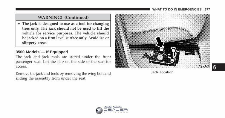
WARNING! (Continued)• The jack is designed to use as a tool for changing
tires only. The jack should not be used to lift thevehicle for service purposes. The vehicle shouldbe jacked on a firm level surface only. Avoid ice orslippery areas.
3500 Models — If EquippedThe jack and jack tools are stored under the frontpassenger seat. Lift the flap on the side of the seat foraccess.
Remove the jack and tools by removing the wing bolt andsliding the assembly from under the seat.
Jack Location6
WHAT TO DO IN EMERGENCIES 377
Information Provided by:
WARNING!
After using the jack and tools, always reinstall themin the original carrier and location. While drivingyou may experience abrupt stopping, rapid accelera-tion, or sharp turns. A loose jack, tools, bracket orother objects in the vehicle may move around withforce, resulting in serious injury.
4500/5500 ModelsThese vehicles do not come equipped with a jack.
NOTE: Jacking and tire changing on 4500/5500 modelsshould be performed by an authorized dealer, or knowl-edgeable service personnel with the appropriate heavyduty equipment, like a tire service company.
Preparations For Jacking
1. Park the vehicle on a firm, level surface. Avoid ice orslippery areas.
WARNING!
Do not attempt to change a tire on the side of thevehicle close to moving traffic, pull far enough offthe road to avoid the danger of being hit whenoperating the jack or changing the wheel.
2. Turn on the Hazard Warning flasher.
3. Set the parking brake.
4. Place the shift lever into PARK (automatic transmis-sion) or REVERSE (manual transmission). On 4-Wheeldrive vehicles, shift the transfer case to the “4L” position.
5. Turn OFF the ignition.
378 WHAT TO DO IN EMERGENCIES
Information Provided by:
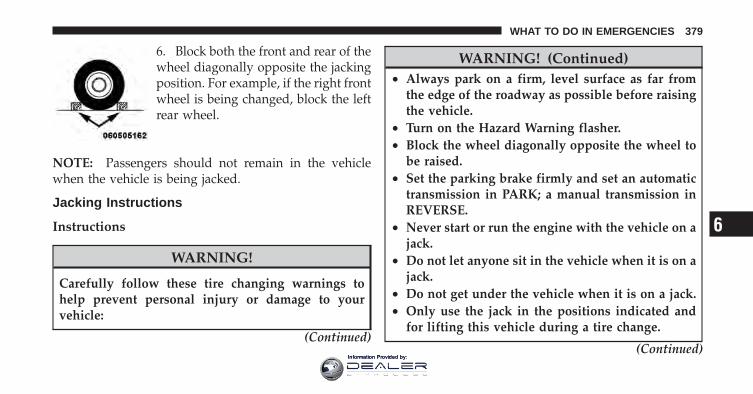
6. Block both the front and rear of thewheel diagonally opposite the jackingposition. For example, if the right frontwheel is being changed, block the leftrear wheel.
NOTE: Passengers should not remain in the vehiclewhen the vehicle is being jacked.
Jacking Instructions
Instructions
WARNING!
Carefully follow these tire changing warnings tohelp prevent personal injury or damage to yourvehicle:
(Continued)
WARNING! (Continued)• Always park on a firm, level surface as far from
the edge of the roadway as possible before raisingthe vehicle.
• Turn on the Hazard Warning flasher.• Block the wheel diagonally opposite the wheel to
be raised.• Set the parking brake firmly and set an automatic
transmission in PARK; a manual transmission inREVERSE.
• Never start or run the engine with the vehicle on ajack.
• Do not let anyone sit in the vehicle when it is on ajack.
• Do not get under the vehicle when it is on a jack.• Only use the jack in the positions indicated and
for lifting this vehicle during a tire change.
(Continued)
6
WHAT TO DO IN EMERGENCIES 379
Information Provided by:
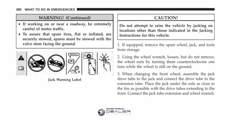
WARNING! (Continued)• If working on or near a roadway, be extremely
careful of motor traffic.• To assure that spare tires, flat or inflated, are
securely stowed, spares must be stowed with thevalve stem facing the ground.
CAUTION!
Do not attempt to raise the vehicle by jacking onlocations other than those indicated in the JackingInstructions for this vehicle.
1. If equipped, remove the spare wheel, jack, and toolsfrom storage.
2. Using the wheel wrench, loosen, but do not remove,the wheel nuts by turning them counterclockwise oneturn while the wheel is still on the ground.
3. When changing the front wheel, assemble the jackdrive tube to the jack and connect the drive tube to theextension tube. Place the jack under the axle as close tothe tire as possible with the drive tubes extending to thefront. Connect the jack tube extension and wheel wrench.
Jack Warning Label
380 WHAT TO DO IN EMERGENCIES
Information Provided by:
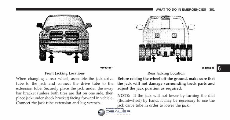
When changing a rear wheel, assemble the jack drivetube to the jack and connect the drive tube to theextension tube. Securely place the jack under the swaybar bracket (unless both tires are flat on one side, thenplace jack under shock bracket) facing forward in vehicle.Connect the jack tube extension and lug wrench.
Before raising the wheel off the ground, make sure thatthe jack will not damage surrounding truck parts andadjust the jack position as required.
NOTE: If the jack will not lower by turning the dial(thumbwheel) by hand, it may be necessary to use thejack drive tube in order to lower the jack.
Front Jacking Locations Rear Jacking Location6
WHAT TO DO IN EMERGENCIES 381
Information Provided by:
4. By rotating the wheel wrench clockwise, raise thevehicle until the wheel just clears the surface.
WARNING!
Raising the vehicle higher than necessary can makethe vehicle unstable and cause a collision. It couldslip off the jack and hurt someone near it. Raise thevehicle only enough to remove the tire.
5. Remove the wheel nuts and pull the wheel off. Installthe spare wheel and wheel nuts with the cone shaped endof the nuts toward the wheel on single rear wheel (SRW)models. On dual rear wheel models (DRW) the lug nutsare a two-piece assembly with a flat face. Lightly tightenthe nuts. To avoid risk of forcing the vehicle off the jack,do not fully tighten the nuts until the vehicle has beenlowered.
6. Using the wheel wrench, finish tightening the nutsusing a crisscross pattern. The correct nut tightness is135 ft lbs (183 N·m) torque for single rear wheel (SRW)models and 145 ft lbs (197 N·m) for dual rear wheelmodels. If in doubt about the correct tightness, have themchecked with a torque wrench by your authorized dealeror at a service station.
WARNING!
A loose tire or jack thrown forward in a collision orhard stop could injure someone in the vehicle. Al-ways stow the jack parts and the extra tire and wheelin the places provided.
7. Install wheel center cap (if equipped) and removewheel blocks. Do not install chrome or aluminum wheelcenter caps on the spare wheel. This may result in capdamage.
382 WHAT TO DO IN EMERGENCIES
Information Provided by:
8. Lower the jack to its fully closed position. If the jackwill not lower by turning the dial (thumbwheel) by hand,it may be necessary to use the jack drive tube in order tolower the jack. Stow the replaced tire, jack, and tools aspreviously described.
9. Adjust the tire pressure when possible.
NOTE: Do not oil wheel studs. For chrome wheels, donot substitute with chrome plated wheel nuts.
Hub Caps/Wheel Covers — If EquippedThe hub caps must be removed before raising the vehicleoff the ground.
CAUTION!
Use extreme caution when removing the front andrear center caps. Damage can occur to the center capand/or the wheel if screwdriver type tools are used. Apulling motion, not a pry off motion, is recom-mended to remove the caps.
For single rear wheel (SRW) models, use the blade on theend of the lug wrench to pry the hub cap off. Insert theblade end into the pry off notch and carefully pop off thehub cap with a back and forth motion.
On 3500 models with dual rear wheels (DRW), you mustfirst remove the hub caps. The jack handle driver has ahook at one end that will fit in the pry off notch of therear hub caps. Position the hook and pull out on theratchet firmly. The hub cap should pop off. The wheelskins can now be removed. For the front hub cap on
6
WHAT TO DO IN EMERGENCIES 383
Information Provided by:
models use the blade on the end of the lug wrench to prythe caps off. The wheel skin can now be removed.
CAUTION!
• Use a back and forth motion to remove the hubcap. Do not use a twisting motion when removingthe hub cap, damage to the hub cap; finish mayoccur.
• The rear hub caps on the dual rear wheel has twopry off notches. Make sure that the hook of thejack handle driver is located squarely in the capnotch before attempting to pull off.
You must use the flat end of the lug wrench to pry off thewheel skins. Insert the flat tip completely and using aback and forth motion, loosen the wheel skin. Repeat thisprocedure around the tire until the skin pops off.
Replace the wheel skins first using a rubber mallet. Whenreplacing the hub caps, tilt the cap retainer over the lugnut bolt circle and strike the high side down with arubber mallet. Be sure that the hub caps and wheel skinsare firmly seated around the wheel.
Dual Rear WheelsDual wheels are flat mounted, center piloted. The lugnuts are a two-piece assembly. When the tires are beingrotated or replaced, clean these lug nuts and add twodrops of oil at the interface between the hex and thewasher.
384 WHAT TO DO IN EMERGENCIES
Information Provided by:
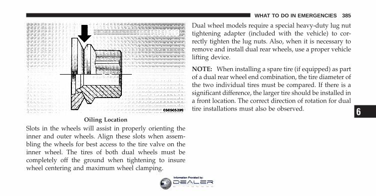
Slots in the wheels will assist in properly orienting theinner and outer wheels. Align these slots when assem-bling the wheels for best access to the tire valve on theinner wheel. The tires of both dual wheels must becompletely off the ground when tightening to insurewheel centering and maximum wheel clamping.
Dual wheel models require a special heavy-duty lug nuttightening adapter (included with the vehicle) to cor-rectly tighten the lug nuts. Also, when it is necessary toremove and install dual rear wheels, use a proper vehiclelifting device.
NOTE: When installing a spare tire (if equipped) as partof a dual rear wheel end combination, the tire diameter ofthe two individual tires must be compared. If there is asignificant difference, the larger tire should be installed ina front location. The correct direction of rotation for dualtire installations must also be observed.
Oiling Location6
WHAT TO DO IN EMERGENCIES 385
Information Provided by:
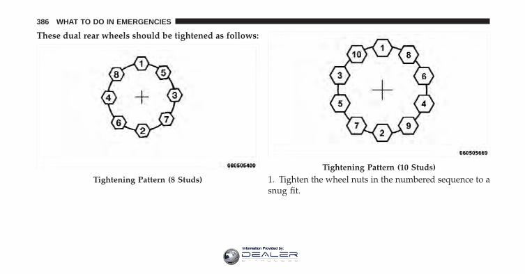
These dual rear wheels should be tightened as follows:
1. Tighten the wheel nuts in the numbered sequence to asnug fit.
Tightening Pattern (8 Studs)
Tightening Pattern (10 Studs)
386 WHAT TO DO IN EMERGENCIES
Information Provided by:
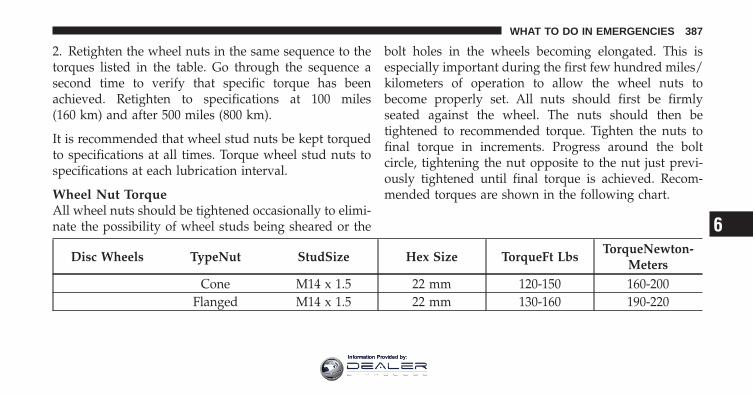
2. Retighten the wheel nuts in the same sequence to thetorques listed in the table. Go through the sequence asecond time to verify that specific torque has beenachieved. Retighten to specifications at 100 miles(160 km) and after 500 miles (800 km).
It is recommended that wheel stud nuts be kept torquedto specifications at all times. Torque wheel stud nuts tospecifications at each lubrication interval.
Wheel Nut TorqueAll wheel nuts should be tightened occasionally to elimi-nate the possibility of wheel studs being sheared or the
bolt holes in the wheels becoming elongated. This isespecially important during the first few hundred miles/kilometers of operation to allow the wheel nuts tobecome properly set. All nuts should first be firmlyseated against the wheel. The nuts should then betightened to recommended torque. Tighten the nuts tofinal torque in increments. Progress around the boltcircle, tightening the nut opposite to the nut just previ-ously tightened until final torque is achieved. Recom-mended torques are shown in the following chart.
Disc Wheels TypeNut StudSize Hex Size TorqueFt LbsTorqueNewton-
MetersCone M14 x 1.5 22 mm 120-150 160-200
Flanged M14 x 1.5 22 mm 130-160 190-220
6
WHAT TO DO IN EMERGENCIES 387
Information Provided by:
To Stow The Flat Or Spare — If EquippedRefer to Upfitters Body Builders Guide for informationon stowing your spare tire (if equipped).
HOISTINGA conventional floor jack may be used at the jackinglocations. Refer to the graphics that show jacking loca-tions. However, a floor jack or frame hoist must never beused on any other parts of the underbody.
CAUTION!
Never use a floor jack directly under the differentialhousing of a loaded truck or damage to your vehiclemay result.
JUMP-STARTING PROCEDURESIf your vehicle has a discharged battery it can be jump-started using a set of jumper cables and a battery inanother vehicle or by using a portable battery booster
pack. Jump-starting can be dangerous if done improperlyso please follow the procedures in this section carefully.
NOTE: When using a portable battery booster packfollow the manufacturer’s operating instructions andprecautions.
CAUTION!
Do not use a portable battery booster pack or anyother booster source with a system voltage greaterthan 12 Volts or damage to the battery, starter motor,alternator or electrical system may occur.
WARNING!
Do not attempt jump-starting if the battery is frozen.It could rupture or explode and cause personal injury.
388 WHAT TO DO IN EMERGENCIES
Information Provided by:
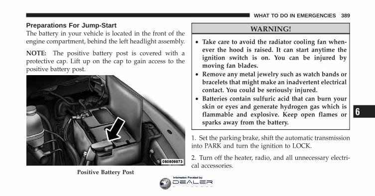
Preparations For Jump-StartThe battery in your vehicle is located in the front of theengine compartment, behind the left headlight assembly.
NOTE: The positive battery post is covered with aprotective cap. Lift up on the cap to gain access to thepositive battery post.
WARNING!
• Take care to avoid the radiator cooling fan when-ever the hood is raised. It can start anytime theignition switch is on. You can be injured bymoving fan blades.
• Remove any metal jewelry such as watch bands orbracelets that might make an inadvertent electricalcontact. You could be seriously injured.
• Batteries contain sulfuric acid that can burn yourskin or eyes and generate hydrogen gas which isflammable and explosive. Keep open flames orsparks away from the battery.
1. Set the parking brake, shift the automatic transmissioninto PARK and turn the ignition to LOCK.
2. Turn off the heater, radio, and all unnecessary electri-cal accessories.
Positive Battery Post
6
WHAT TO DO IN EMERGENCIES 389
Information Provided by:
3. If using another vehicle to jump-start the battery, parkthe vehicle within the jumper cables reach, set theparking brake and make sure the ignition is OFF.
WARNING!
Do not allow vehicles to touch each other as thiscould establish a ground connection and personalinjury could result.
Jump-Starting Procedure
WARNING!
Failure to follow this procedure could result in per-sonal injury or property damage due to battery ex-plosion.
CAUTION!
Failure to follow these procedures could result indamage to the charging system of the booster vehicleor the discharged vehicle.
1. Connect the positive (+) end of the jumper cable to thepositive (+) post of the discharged vehicle.
2. Connect the opposite end of the positive (+) jumpercable to the positive (+) post of the booster battery.
3. Connect the negative end (-) of the jumper cable to thenegative (-) post of the booster battery.
4. Connect the opposite end of the negative (-) jumpercable to a good engine ground (exposed metal part of thedischarged vehicle’s engine) away from the battery andthe fuel injection system.
390 WHAT TO DO IN EMERGENCIES
Information Provided by:
WARNING!
Do not connect the cable to the negative post (-) of thedischarged battery. The resulting electrical sparkcould cause the battery to explode and could result inpersonal injury.
5. Start the engine in the vehicle that has the boosterbattery, let the engine idle a few minutes, and then startthe engine in the vehicle with the discharged battery.
Once the engine is started, remove the jumper cables inthe reverse sequence:
6. Disconnect the negative (-) jumper cable from theengine ground of the vehicle with the discharged battery.
7. Disconnect the negative end (-) of the jumper cablefrom the negative (-) post of the booster battery.
8. Disconnect the opposite end of the positive (+) jumpercable from the positive (+) post of the booster battery.
9. Disconnect the positive (+) end of the jumper cablefrom the positive (+) post of the discharged vehicle.
If frequent jump-starting is required to start your vehicleyou should have the battery and charging system in-spected at your authorized dealer.
CAUTION!
Accessories that can be plugged into the vehiclepower outlets draw power from the vehicle’s battery,even when not in use (i.e., cellular phones, etc.).Eventually, if plugged in long enough, the vehicle’sbattery will discharge sufficiently to degrade batterylife and/or prevent the engine from starting.
6
WHAT TO DO IN EMERGENCIES 391
Information Provided by:
FREEING A STUCK VEHICLEIf the vehicle becomes stuck in snow, sand, or mud, it canoften be moved by a rocking motion. Move the shift leverrhythmically between DRIVE/1st and REVERSE whileapplying slight pressure to the accelerator.
CAUTION!
• Racing the engine or spinning the wheels maylead to transmission overheating and failure. Al-low the engine to idle with the shift lever inNEUTRAL for at least one minute after every fiverocking-motion cycles. This will minimize over-heating and reduce the risk of transmission failureduring prolonged efforts to free a stuck vehicle.
(Continued)
CAUTION! (Continued)• When “rocking” a stuck vehicle by moving be-
tween DRIVE/1st and REVERSE, do not spin thewheels faster than 15 mph (24 km/h), or drivetraindamage may result.
• Revving the engine or spinning the wheels too fastmay lead to transmission overheating and failure.It can also damage the tires. Do not spin thewheels above 30 mph (48 km/h) while in gear (notransmission shifting occurring).
392 WHAT TO DO IN EMERGENCIES
Information Provided by:
WARNING!
Fast spinning tires can be dangerous. Forces gener-ated by excessive wheel speeds may cause damage, oreven failure, of the axle and tires. A tire couldexplode and injure someone. Do not spin your vehi-cle’s wheels faster than 30 mph (48 km/h) or forlonger than 30 seconds continuously without stop-ping when you are stuck and do not let anyone neara spinning wheel, no matter what the speed.
EMERGENCY TOW HOOKS — IF EQUIPPEDYour vehicle may be equipped with emergency towhooks.
NOTE: For off-road recovery, it is recommended to useboth of the front tow hooks to minimize the risk ofdamage to the vehicle.
WARNING!
• Chains are not recommended for freeing a stuckvehicle. Chains may break, causing serious injuryor death.
• Stand clear of vehicles when pulling with towhooks. Tow straps may become disengaged, caus-ing serious injury.
CAUTION!
Tow hooks are for emergency use only to rescue avehicle stranded off-road. Do not use tow hooks fortow truck hookup or highway towing. You coulddamage your vehicle.
6
WHAT TO DO IN EMERGENCIES 393
Information Provided by:
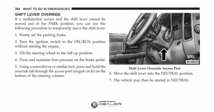
SHIFT LEVER OVERRIDEIf a malfunction occurs and the shift lever cannot bemoved out of the PARK position, you can use thefollowing procedure to temporarily move the shift lever:
1. Firmly set the parking brake.
2. Turn the ignition switch to the ON/RUN positionwithout starting the engine.
3. Tilt the steering wheel to the full up position.
4. Press and maintain firm pressure on the brake pedal.
5. Using a screwdriver or similar tool, press and hold theoverride tab through the access port (ringed circle) on thebottom of the steering column.
6. Move the shift lever into the NEUTRAL position.
7. The vehicle may then be started in NEUTRAL.
Shift Lever Override Access Port
394 WHAT TO DO IN EMERGENCIES
Information Provided by:
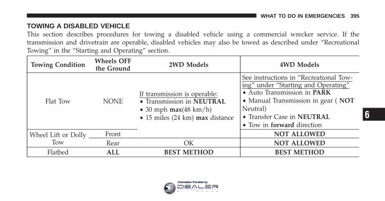
TOWING A DISABLED VEHICLEThis section describes procedures for towing a disabled vehicle using a commercial wrecker service. If thetransmission and drivetrain are operable, disabled vehicles may also be towed as described under “RecreationalTowing” in the “Starting and Operating” section.
Towing Condition Wheels OFFthe Ground 2WD Models 4WD Models
Flat Tow NONEIf transmission is operable:• Transmission in NEUTRAL• 30 mph max(48 km/h)• 15 miles (24 km) max distance
See instructions in “Recreational Tow-ing” under “Starting and Operating”• Auto Transmission in PARK• Manual Transmission in gear ( NOTNeutral)• Transfer Case in NEUTRAL• Tow in forward direction
Wheel Lift or DollyTow
Front NOT ALLOWEDRear OK NOT ALLOWED
Flatbed ALL BEST METHOD BEST METHOD
6
WHAT TO DO IN EMERGENCIES 395
Information Provided by:
Proper towing or lifting equipment is required to preventdamage to your vehicle. Use only tow bars and otherequipment designed for the purpose, following equip-ment manufacturer’s instructions. Use of safety chains ismandatory. Attach a tow bar or other towing device tomain structural members of the vehicle, not to bumpersor associated brackets. State and local laws applying tovehicles under tow must be observed.
If you must use the accessories (wipers, defrosters, etc.)while being towed, the ignition must be in the ON/RUNposition, not the ACC position.
If the vehicle’s battery is discharged, see “Shift LeverOverride” in “What To Do In Emergencies” for instruc-tions on shifting the automatic transmission out of thePARK position for towing.
CAUTION!
Do not attempt to use sling type equipment whentowing. When securing the vehicle to a flat bed truck,do not attach to front or rear suspension components.Damage to your vehicle may result from impropertowing.
Towing Without The Ignition Key FobSpecial care must be taken when the vehicle is towedwith the ignition in the LOCK/OFF position. The onlyapproved method of towing without the ignition key iswith a flatbed truck. Proper towing equipment is neces-sary to prevent damage to the vehicle.
396 WHAT TO DO IN EMERGENCIES
Information Provided by:
Two-Wheel Drive ModelsThe manufacturer recommends towing your vehicle withall four wheels OFF the ground using a flatbed.
If flatbed equipment is not available, and the transmis-sion is operable, the vehicle may be towed (with rearwheels on the ground) with the transmission in NEU-TRAL. Speed must not exceed 30 mph (48 km/h) and thedistance must not exceed 15 miles (24 km).
CAUTION!
Towing faster than 30 mph (48 km/h) or farther than15 miles (24 km) with rear wheels on the ground cancause severe damage to the transmission. Such dam-age is not covered by the New Vehicle LimitedWarranty.
If the transmission is not operable, or the vehicle must betowed faster than 30 mph (48 km/h) or farther than15 miles (24 km), tow with the rear wheels OFF theground. Acceptable methods are to tow the vehicle on aflatbed, or with the front wheels raised and the rearwheels on a towing dolly, or (when using a suitablesteering wheel stabilizer to hold the front wheels in thestraight position) with the rear wheels raised and thefront wheels on the ground.
6
WHAT TO DO IN EMERGENCIES 397
Information Provided by:
Four-Wheel Drive VehiclesThe manufacturer recommends towing with all wheelsOFF the ground. Acceptable methods are to tow thevehicle on a flatbed or with one end of vehicle raised andthe opposite end on a towing dolly.
If flatbed equipment is not available, and the transfercase is operable, the vehicle may be towed (in theforward direction, with ALL wheels on the ground), IFthe transfer case is in NEUTRAL and the transmission isin PARK (for automatic transmissions) or in gear (NOTin Neutral, for manual transmissions). Refer to “Recre-ational Towing” in “Starting And Operating” for furtherinformation.
CAUTION!
• Front or rear wheel lifts should not be used.Internal damage to the transmission or transfercase will occur if a front or rear wheel lift is usedwhen towing.
• Failure to follow these towing methods can causesevere damage to the transmission and/or transfercase. Such damage is not covered by the NewVehicle Limited Warranty.
398 WHAT TO DO IN EMERGENCIES
Information Provided by:
MAINTAINING YOUR VEHICLE
CONTENTS
� Engine Compartment — 5.7L . . . . . . . . . . . . . 401
� Onboard Diagnostic System (OBD II) . . . . . . . 402
▫ Loose Fuel Filler Cap Message . . . . . . . . . . . 402
� Emissions Inspection And MaintenancePrograms . . . . . . . . . . . . . . . . . . . . . . . . . . . . 403
� Replacement Parts . . . . . . . . . . . . . . . . . . . . . 404
� Dealer Service . . . . . . . . . . . . . . . . . . . . . . . . 405
� Maintenance Procedures . . . . . . . . . . . . . . . . . 405
▫ Engine Oil . . . . . . . . . . . . . . . . . . . . . . . . . 406
▫ Engine Oil Filter . . . . . . . . . . . . . . . . . . . . . 408
▫ Engine Air Cleaner Filter . . . . . . . . . . . . . . . 408
▫ Maintenance-Free Battery . . . . . . . . . . . . . . 409
▫ Air Conditioner Maintenance . . . . . . . . . . . . 411
▫ Front Prop Shaft Lubrication – Four-WheelDrive Models . . . . . . . . . . . . . . . . . . . . . . . 412
▫ Body Lubrication . . . . . . . . . . . . . . . . . . . . 412
▫ Windshield Wiper Blades . . . . . . . . . . . . . . . 413
▫ Adding Washer Fluid . . . . . . . . . . . . . . . . . 413
7
Information Provided by:
▫ Exhaust System . . . . . . . . . . . . . . . . . . . . . 414
▫ Cooling System . . . . . . . . . . . . . . . . . . . . . 417
▫ Brake System . . . . . . . . . . . . . . . . . . . . . . . 423
▫ Rear Axle And 4X4 Front Driving Axle FluidLevel . . . . . . . . . . . . . . . . . . . . . . . . . . . . . 425
▫ Transfer Case . . . . . . . . . . . . . . . . . . . . . . . 427
▫ Automatic Transmission . . . . . . . . . . . . . . . 427
▫ Appearance Care And Protection FromCorrosion . . . . . . . . . . . . . . . . . . . . . . . . . . 430
� Fuses . . . . . . . . . . . . . . . . . . . . . . . . . . . . . . 435
▫ Totally Integrated Power Module . . . . . . . . . 435
� Vehicle Storage . . . . . . . . . . . . . . . . . . . . . . . 441
� Replacement Bulbs . . . . . . . . . . . . . . . . . . . . 442
� Bulb Replacement . . . . . . . . . . . . . . . . . . . . . 443
▫ Dual Or Quad Headlamp/Front Park AndTurn Signal – If Equipped . . . . . . . . . . . . . . 443
▫ Fog Lamps – If Equipped . . . . . . . . . . . . . . 445
▫ Center High-Mounted Stoplamp (CHMSL)With Cargo Lamp . . . . . . . . . . . . . . . . . . . . 445
▫ Cab Top Clearance Lamps – If Equipped . . . . 447
� Fluid Capacities . . . . . . . . . . . . . . . . . . . . . . 449
� Fluids, Lubricants And Genuine Parts . . . . . . . 450
▫ Engine . . . . . . . . . . . . . . . . . . . . . . . . . . . . 450
▫ Chassis . . . . . . . . . . . . . . . . . . . . . . . . . . . 451
400 MAINTAINING YOUR VEHICLE
Information Provided by:
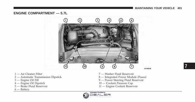
ENGINE COMPARTMENT — 5.7L
1 — Air Cleaner Filter 7 — Washer Fluid Reservoir2 — Automatic Transmission Dipstick 8 — Integrated Power Module (Fuses)3 — Engine Oil Fill 9 — Power Steering Fluid Reservoir4 — Engine Oil Dipstick 10 — Coolant Pressure Cap5 — Brake Fluid Reservoir 11 — Engine Coolant Reservoir6 — Battery
7
MAINTAINING YOUR VEHICLE 401
Information Provided by:
ONBOARD DIAGNOSTIC SYSTEM (OBD II)Your vehicle is equipped with a sophisticated onboarddiagnostic system called OBD II. This system monitorsthe performance of the emissions, engine, and automatictransmission control systems. When these systems areoperating properly, your vehicle will provide excellentperformance and fuel economy, as well as engine emis-sions well within current government regulations.
If any of these systems require service, the OBD II systemwill turn on the “Malfunction Indicator Light (MIL).” Itwill also store diagnostic codes and other information toassist your service technician in making repairs. Al-though your vehicle will usually be drivable and notneed towing, see your authorized dealer for service assoon as possible.
CAUTION!
• Prolonged driving with the MIL on could causefurther damage to the emission control system. Itcould also affect fuel economy and drivability. Thevehicle must be serviced before any emissionstests can be performed.
• If the MIL is flashing, while the engine is running,severe catalytic converter damage and power losswill soon occur. Immediate service is required.
Loose Fuel Filler Cap MessageIf the vehicle diagnostic system determinesthat the fuel filler cap is loose, improperlyinstalled, or damaged, a loose gascap indicatorwill display in the EVIC telltale display area.
Refer to “Electronic Vehicle Information Center (EVIC) in“Understanding Your Instrument Panel” for further in-formation. Tighten the fuel filler cap properly and press
402 MAINTAINING YOUR VEHICLE
Information Provided by:
the SELECT button to turn off the message. If theproblem continues, the message will appear the next timethe vehicle is started.
A loose, improperly installed, or damaged fuel filler capmay also turn on the Malfunction Indicator Light (MIL).
EMISSIONS INSPECTION AND MAINTENANCEPROGRAMSIn some localities, it may be a legal requirement to passan inspection of your vehicle’s emissions control system.Failure to pass could prevent vehicle registration.
For states that require an Inspection and Mainte-nance (I/M), this check verifies the “MalfunctionIndicator Light (MIL)” is functioning and is not
on when the engine is running, and that the OBD IIsystem is ready for testing.
Normally, the OBD II system will be ready. The OBD IIsystem may not be ready if your vehicle was recentlyserviced, recently had a dead battery or a battery replace-ment. If the OBD II system should be determined notready for the I/M test, your vehicle may fail the test.
Your vehicle has a simple ignition key-actuated test,which you can use prior to going to the test station. Tocheck if your vehicle’s OBD II system is ready, you mustdo the following:
1. Turn the ignition switch to the ON position, but do notcrank or start the engine.
2. If you crank or start the engine, you will have to startthis test over.
3. As soon as you turn the ignition switch to the ONposition, you will see the MIL symbol come on as part ofa normal bulb check.
7
MAINTAINING YOUR VEHICLE 403
Information Provided by:
4. Approximately 15 seconds later, one of two things willhappen:
a. The MIL will flash for about 10 seconds and thenreturn to being fully illuminated until you turn OFFthe ignition or start the engine. This means that yourvehicle’s OBD II system is not ready and you shouldnot proceed to the I/M station.
b. The MIL will not flash at all and will remain fullyilluminated until you turn OFF the ignition or start theengine. This means that your vehicle’s OBD II systemis ready and you can proceed to the I/M station.
If your OBD II system is not ready, you should see yourauthorized dealer or repair facility. If your vehicle wasrecently serviced or had a battery failure or replacement,you may need to do nothing more than drive yourvehicle as you normally would in order for your OBD IIsystem to update. A recheck with the above test routinemay then indicate that the system is now ready.
Regardless of whether your vehicle’s OBD II system isready or not, if the MIL is illuminated during normalvehicle operation you should have your vehicle servicedbefore going to the I/M station. The I/M station can failyour vehicle because the MIL is on with the enginerunning.
REPLACEMENT PARTSUse of genuine MOPAR� parts for normal/scheduledmaintenance and repairs is highly recommended to en-sure the designed performance. Damage or failurescaused by the use of non-MOPAR� parts for maintenanceand repairs will not be covered by the manufacturer’swarranty.
404 MAINTAINING YOUR VEHICLE
Information Provided by:
DEALER SERVICEYour authorized dealer has the qualified service person-nel, special tools, and equipment to perform all serviceoperations in an expert manner. Service Manuals areavailable which include detailed service information foryour vehicle. Refer to these Service Manuals beforeattempting any procedure yourself.
NOTE: Intentional tampering with emissions controlsystems may void your warranty and could result in civilpenalties being assessed against you.
WARNING!
You can be badly injured working on or around amotor vehicle. Only do service work for which youhave the knowledge and the proper equipment. Ifyou have any doubt about your ability to perform aservice job, take your vehicle to a competent me-chanic.
MAINTENANCE PROCEDURESThe pages that follow contain the required maintenanceservices determined by the engineers who designed yourvehicle.
Besides those maintenance items specified in the fixedmaintenance schedule, there are other components whichmay require servicing or replacement in the future.
CAUTION!
• Failure to properly maintain your vehicle or per-form repairs and service when necessary couldresult in more costly repairs, damage to othercomponents or negatively impact vehicle perfor-mance. Immediately have potential malfunctionsexamined by an authorized Chrysler Group LLCdealership or qualified repair center.
(Continued)
7
MAINTAINING YOUR VEHICLE 405
Information Provided by:
CAUTION! (Continued)• Your vehicle has been built with improved fluids
that protect the performance and durability ofyour vehicle and also allow extended maintenanceintervals. Do not use chemical flushes in thesecomponents as the chemicals can damage yourengine, transmission, power steering or air condi-tioning. Such damage is not covered by the NewVehicle Limited Warranty. If a flush is neededbecause of component malfunction, use only thespecified fluid for the flushing procedure.
Engine OilChecking Oil LevelTo assure proper lubrication of your vehicle’s engine, theengine oil must be maintained at the correct level. Checkthe oil level at regular intervals, such as every fuel stop.The best time to check the engine oil level is about fiveminutes after a fully warmed up engine is shut off.
Checking the oil while the vehicle is on level ground willimprove the accuracy of the oil level readings. Alwaysmaintain the oil level within the SAFE zone on thedipstick. Adding one quart of oil when the reading is atthe bottom of the SAFE zone will result in a reading at thetop of the safe zone on these engines.
CAUTION!
Overfilling or underfilling the crankcase will causeoil aeration or loss of oil pressure. This could damageyour engine.
Change Engine OilThe oil change indicator system will remind you that it istime to take your vehicle in for scheduled maintenance.Refer to the “Maintenance Schedule” for further informa-tion.
406 MAINTAINING YOUR VEHICLE
Information Provided by:
NOTE: Under no circumstances should oil changeintervals exceed 8,000 miles (13 000 km) or six months,whichever occurs first.
Engine Oil SelectionFor best performance and maximum protection under alltypes of operating conditions, the manufacturer onlyrecommends engine oils that are API Certified and meetthe requirements of Chrysler Material Standard MS-6395.
American Petroleum Institute (API) Engine OilIdentification Symbol
This symbol means that the oil hasbeen certified by the AmericanPetroleum Institute (API). Themanufacturer only recommendsAPI Certified engine oils.
CAUTION!
Do not use chemical flushes in your engine oil as thechemicals can damage your engine. Such damage isnot covered by the New Vehicle Limited Warranty.
Engine Oil Viscosity (SAE Grade)SAE 5W-20 engine oil is recommended for all operatingtemperatures. This engine oil improves low temperaturestarting and vehicle fuel economy. The engine oil fillercap also shows the recommended engine oil viscosity foryour engine. For information on engine oil filler caplocation, refer to “Engine Compartment” in “MaintainingYour Vehicle” for further information.
Lubricants which do not have both the engine oil certi-fication mark and the correct SAE viscosity grade num-ber should not be used.
7
MAINTAINING YOUR VEHICLE 407
Information Provided by:
Synthetic Engine OilsYou may use synthetic engine oils if the recommended oilquality requirements are met and the recommendedmaintenance intervals for oil and filter changes arefollowed.
Materials Added To Engine OilThe manufacturer strongly recommends against the ad-dition of any additives (other than leak detection dyes) tothe engine oil. Engine oil is an engineered product and itsperformance may be impaired by supplementaladditives.
Disposing Of Used Engine Oil And Oil FiltersCare should be taken in disposing of used engine oil andoil filters from your vehicle. Used oil and oil filters,indiscriminately discarded, can present a problem to theenvironment. Contact your authorized dealer, service
station or governmental agency for advice on how andwhere used oil and oil filters can be safely discarded inyour area.
Engine Oil FilterThe engine oil filter should be replaced with a new filterat every engine oil change.
Engine Oil Filter SelectionThe manufacturer’s engines have a full-flow type oilfilter. Use a filter of this type for replacement. The qualityof replacement filters varies considerably. Only high-quality filters should be used to assure most efficientservice. MOPAR� engine oil filters are a high-quality oilfilter and are recommended.
Engine Air Cleaner FilterRefer to the “Maintenance Schedule” for the propermaintenance intervals.
408 MAINTAINING YOUR VEHICLE
Information Provided by:
WARNING!
The air induction system (air cleaner, hoses, etc.) canprovide a measure of protection in the case of enginebackfire. Do not remove the air induction system (aircleaner, hoses, etc.) unless such removal is necessaryfor repair or maintenance. Make sure that no one isnear the engine compartment before starting thevehicle with the air induction system (air cleaner,hoses, etc.) removed. Failure to do so can result inserious personal injury.
Engine Air Cleaner Filter SelectionThe quality of replacement engine air cleaner filtersvaries considerably. Only high quality filters should beused to assure most efficient service. MOPAR� engine aircleaner filters are a high quality filter and arerecommended.
Maintenance-Free BatteryYour vehicle is equipped with a maintenance-free battery.You will never have to add water, nor is periodic main-tenance required.
WARNING!
• Battery fluid is a corrosive acid solution and canburn or even blind you. Do not allow battery fluidto contact your eyes, skin, or clothing. Do not leanover a battery when attaching clamps. If acidsplashes in eyes or on skin, flush the area imme-diately with large amounts of water. Refer to“Jump-Starting Procedures” in “What To Do InEmergencies” for further information.
(Continued)
7
MAINTAINING YOUR VEHICLE 409
Information Provided by:
WARNING! (Continued)• Battery gas is flammable and explosive. Keep
flame or sparks away from the battery. Do not usea booster battery or any other booster source withan output greater than 12 Volts. Do not allow cableclamps to touch each other.
• Battery posts, terminals, and related accessoriescontain lead and lead compounds. Wash handsafter handling.
CAUTION!
• It is essential when replacing the cables on thebattery that the positive cable is attached to thepositive post and the negative cable is attached tothe negative post. Battery posts are marked posi-tive (+) and negative (-) and are identified on thebattery case. Cable clamps should be tight on theterminal posts and free of corrosion.
• If a “fast charger” is used while the battery is inthe vehicle, disconnect both vehicle battery cablesbefore connecting the charger to the battery. Donot use a “fast charger” to provide starting voltage.
410 MAINTAINING YOUR VEHICLE
Information Provided by:
Air Conditioner MaintenanceFor best possible performance, your air conditionershould be checked and serviced by an authorized dealerat the start of each warm season. This service shouldinclude cleaning of the condenser fins and a performancetest. Drive belt tension should also be checked at thistime.
CAUTION!
Do not use chemical flushes in your air conditioningsystem as the chemicals can damage your air condi-tioning components. Such damage is not covered bythe New Vehicle Limited Warranty.
WARNING!
• Use only refrigerants and compressor lubricantsapproved by the manufacturer for your air condi-tioning system. Some unapproved refrigerants areflammable and can explode, injuring you. Otherunapproved refrigerants or lubricants can causethe system to fail, requiring costly repairs. Refer toSection 3 of the Warranty Information Book, lo-cated on the DVD, for further warranty informa-tion.
• The air conditioning system contains refrigerantunder high pressure. To avoid risk of personalinjury or damage to the system, adding refrigerantor any repair requiring lines to be disconnectedshould be done by an experienced repairman.
7
MAINTAINING YOUR VEHICLE 411
Information Provided by:
NOTE: Use only manufacturer approved A/C SystemSealers, Stop Leak Products, Seal Conditioners, Compres-sor Oil, or Refrigerants.
Refrigerant Recovery And RecyclingR-134a Air Conditioning Refrigerant is a hydrofluoro-carbon (HFC) that is endorsed by the EnvironmentalProtection Agency (EPA) and is an ozone-saving product.However, the manufacturer recommends that air condi-tioning service be performed by authorized dealers orother service facilities using recovery and recyclingequipment.
Front Prop Shaft Lubrication – Four-Wheel DriveModelsLubricate the front driveshaft grease fitting at each oilchange. Refer to the “Maintenance Schedule” for theproper maintenance intervals. Use MOPAR� Type MS-6560 (lithium-based grease), or equivalent.
Body LubricationLocks and all body pivot points, including such items asseat tracks, door hinge pivot points and rollers, liftgate,tailgate, sliding doors and hood hinges, should be lubri-cated periodically with a lithium based grease, such asMOPAR� Spray White Lube or equivalent, to assurequiet, easy operation and to protect against rust andwear. Prior to the application of any lubricant, the partsconcerned should be wiped clean to remove dust andgrit. After lubricating, excess oil and grease should beremoved. Particular attention should also be given tohood latching components to ensure proper function.When performing other underhood services, the hoodlatch, release mechanism and safety catch should becleaned and lubricated.
412 MAINTAINING YOUR VEHICLE
Information Provided by:
The external lock cylinders should be lubricated twice ayear, preferably in the Fall and Spring. Apply a smallamount of a high quality lubricant such as MOPAR�Lock Cylinder Lubricant or equivalent directly into thelock cylinder.
Windshield Wiper BladesClean the rubber edges of the wiper blades and thewindshield periodically with a sponge or soft cloth and amild nonabrasive cleaner. This will remove accumula-tions of salt or road film.
Operation of the wipers on dry glass for long periodsmay cause deterioration of the wiper blades. Always usewasher fluid when using the wipers to remove salt or dirtfrom a dry windshield.
Avoid using the wiper blades to remove frost or ice fromthe windshield. Keep the blade rubber out of contact withpetroleum products such as engine oil, gasoline, etc.
NOTE: Life expectancy of wiper blades varies depend-ing on geographical area and frequency of use. Poorperformance of blades may be present with chattering,marks, water lines or wet spots. If any condition ispresent please proceed to clean wiper blades with humidcloth removing any debris that may be affecting itsfunction.
Adding Washer FluidThe fluid reservoir is located under the hood and shouldbe checked for fluid level at regular intervals. Fill thereservoir with windshield washer solvent only (not ra-diator antifreeze). When refilling the washer fluid reser-voir, take some washer fluid and apply it to a cloth ortowel and wipe the wiper blades clean. This will helpblade performance.
To prevent freeze-up of your windshield washer systemin cold weather, select a solution or mixture that meets or
7
MAINTAINING YOUR VEHICLE 413
Information Provided by:
exceeds the temperature range of your climate. Thisrating information can be found on most washer fluidcontainers.
The washer fluid reservoir will hold a full gallon of fluidwhen the Low Washer Fluid Light illuminates.
WARNING!
Commercially available windshield washer solventsare flammable. They could ignite and burn you. Caremust be exercised when filling or working aroundthe washer solution.
After the engine has warmed up, operate the defroster fora few minutes to reduce the possibility of smearing orfreezing the fluid on the cold windshield. Windshieldwasher solution used with water as directed on thecontainer, aids cleaning action, reduces the freezing pointto avoid line clogging, and is not harmful to paint or trim.
Exhaust SystemThe best protection against carbon monoxide entry intothe vehicle body is a properly maintained engine exhaustsystem.
If you notice a change in the sound of the exhaust system;or if the exhaust fumes can be detected inside the vehicle;or when the underside or rear of the vehicle is damaged;have an authorized technician inspect the complete ex-haust system and adjacent body areas for broken, dam-aged, deteriorated, or mispositioned parts. Open seamsor loose connections could permit exhaust fumes to seepinto the passenger compartment. In addition, inspect theexhaust system each time the vehicle is raised for lubri-cation or oil change. Replace as required.
414 MAINTAINING YOUR VEHICLE
Information Provided by:
WARNING!
• Exhaust gases can injure or kill. They containcarbon monoxide (CO), which is colorless andodorless. Breathing it can make you unconsciousand can eventually poison you. To avoid breathingCO, refer to “Safety Tips/Exhaust Gas” in “ThingsTo Know Before Starting Your Vehicle” for furtherinformation.
• A hot exhaust system can start a fire if you parkover materials that can burn. Such materials mightbe grass or leaves coming into contact with yourexhaust system. Do not park or operate your ve-hicle in areas where your exhaust system cancontact anything that can burn.
CAUTION!
• The catalytic converter requires the use of un-leaded fuel only. Leaded gasoline will destroy theeffectiveness of the catalyst as an emissions con-trol device and may seriously reduce engine per-formance and cause serious damage to the engine.
• Damage to the catalytic converter can result if yourvehicle is not kept in proper operating condition.In the event of engine malfunction, particularlyinvolving engine misfire or other apparent loss ofperformance, have your vehicle serviced promptly.Continued operation of your vehicle with a severemalfunction could cause the converter to overheat,resulting in possible damage to the converter andvehicle.
7
MAINTAINING YOUR VEHICLE 415
Information Provided by:
Under normal operating conditions, the catalytic con-verter will not require maintenance. However, it is im-portant to keep the engine properly tuned to assureproper catalyst operation and prevent possible catalystdamage.
NOTE: Intentional tampering with emissions controlsystems can result in civil penalties being assessedagainst you.
In unusual situations involving grossly malfunctioningengine operation, a scorching odor may suggest severeand abnormal catalyst overheating. If this occurs, stopthe vehicle, turn off the engine and allow it to cool.Service, including a tune-up to manufacturer’s specifica-tions, should be obtained immediately.
To minimize the possibility of catalytic converter dam-age:
• Do not shut off the engine or interrupt the ignition,when the transmission is in gear and the vehicle is inmotion.
• Do not try to start the engine by pushing or towing thevehicle.
• Do not idle the engine with any spark plug wiresdisconnected or removed, such as when diagnostictesting, or for prolonged periods during very roughidle or malfunctioning operating conditions.
416 MAINTAINING YOUR VEHICLE
Information Provided by:
Cooling System
WARNING!
You or others can be badly burned by hot coolant orsteam from your radiator. If you see or hear steamcoming from under the hood, do not open the hooduntil the radiator has had time to cool. Never try toopen a cooling system pressure cap when the radiatoris hot.
Engine Coolant ChecksCheck the engine coolant (antifreeze) protection every12 months (before the onset of freezing weather, whereapplicable). If the engine coolant (antifreeze) is dirty orrusty in appearance, the system should be drained,flushed and refilled with fresh coolant. Check the front ofthe A/C condenser for any accumulation of bugs, leaves,etc. If dirty, clean by gently spraying water from a gardenhose vertically down the face of the condenser.
Check the coolant recovery bottle tubing for brittle rub-ber, cracking, tears, cuts and tightness of the connectionat the bottle and radiator. Inspect the entire system forleaks.
With the engine at normal operating temperature (butnot running), check the cooling system pressure cap forproper vacuum sealing by draining a small amount ofengine coolant (antifreeze) from the radiator drain cock.If the cap is sealing properly, the engine coolant (anti-freeze) will begin to drain from the coolant recoverybottle. DO NOT REMOVE THE COOLANT PRESSURECAP WHEN THE COOLING SYSTEM IS HOT.
Cooling System – Drain, Flush, And RefillIf the engine coolant (antifreeze) is dirty or contains aconsiderable amount of sediment, clean and flush with areliable cooling system cleaner. Follow with a thoroughrinsing to remove all deposits and chemicals. Properlydispose of old engine coolant (antifreeze) solution.
7
MAINTAINING YOUR VEHICLE 417
Information Provided by:
Refer to the “Maintenance Schedule” for the propermaintenance intervals.
Selection Of CoolantUse only the manufacturer’s recommended engine cool-ant (antifreeze). Refer to “Fluids, Lubricants, and Genu-ine Parts” in “Maintaining Your Vehicle” for furtherinformation.
CAUTION!
• Mixing of engine coolant (antifreeze) other thanspecified HOAT engine coolant (antifreeze), mayresult in engine damage and may decrease corro-sion protection. If a non-HOAT engine coolant(antifreeze) is introduced into the cooling systemin an emergency, it should be replaced with thespecified engine coolant (antifreeze) as soon aspossible.
(Continued)
CAUTION! (Continued)• Do not use water alone or alcohol-based engine
coolant (antifreeze) products. Do not use addi-tional rust inhibitors or antirust products, as theymay not be compatible with the engine coolant(antifreeze) and may plug the radiator.
• This vehicle has not been designed for use withPropylene Glycol based engine coolant (anti-freeze). Use of Propylene Glycol based enginecoolant (antifreeze) is not recommended.
Adding CoolantYour vehicle has been built with an improved enginecoolant (antifreeze) that allows extended maintenanceintervals. This engine coolant (antifreeze) can be used upto five years or 104,000 miles (169 000 km) before replace-ment. To prevent reducing this extended maintenanceperiod, it is important that you use the same enginecoolant (antifreeze) throughout the life of your vehicle.
418 MAINTAINING YOUR VEHICLE
Information Provided by:
Please review these recommendations for using HybridOrganic Additive Technology (HOAT) engine coolant(antifreeze). When adding engine coolant (antifreeze):
• The manufacturer recommends using MOPAR�Antifreeze/Coolant 5 Year/100,000 Mile FormulaHOAT (Hybrid Organic Additive Technology) orequivalent.
• Mix a minimum solution of 50% HOAT engine coolantand distilled water. Use higher concentrations (not toexceed 70%) if temperatures below �34°F (�37°C) areanticipated.
• Use only high purity water such as distilled or deion-ized water when mixing the water/engine coolant(antifreeze) solution. The use of lower quality waterwill reduce the amount of corrosion protection in theengine cooling system.
Please note that it is the owner’s responsibility to main-tain the proper level of protection against freezing ac-cording to the temperatures occurring in the area wherethe vehicle is operated.
NOTE: Mixing engine coolant (antifreeze) types willdecrease the life of the engine coolant (antifreeze) andwill require more frequent coolant changes.
Cooling System Pressure CapThe cap must be fully tightened to prevent loss of enginecoolant (antifreeze), and to ensure that the engine coolant(antifreeze) will return to the radiator from the coolantrecovery bottle.
The cap should be inspected and cleaned if there is anyaccumulation of foreign material on the sealing surfaces.
7
MAINTAINING YOUR VEHICLE 419
Information Provided by:
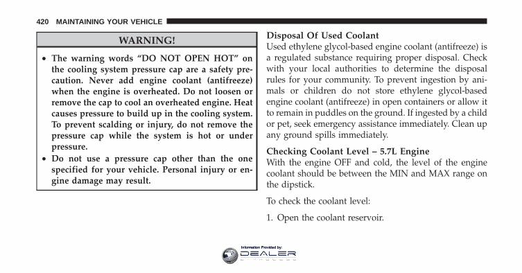
WARNING!
• The warning words “DO NOT OPEN HOT” onthe cooling system pressure cap are a safety pre-caution. Never add engine coolant (antifreeze)when the engine is overheated. Do not loosen orremove the cap to cool an overheated engine. Heatcauses pressure to build up in the cooling system.To prevent scalding or injury, do not remove thepressure cap while the system is hot or underpressure.
• Do not use a pressure cap other than the onespecified for your vehicle. Personal injury or en-gine damage may result.
Disposal Of Used CoolantUsed ethylene glycol-based engine coolant (antifreeze) isa regulated substance requiring proper disposal. Checkwith your local authorities to determine the disposalrules for your community. To prevent ingestion by ani-mals or children do not store ethylene glycol-basedengine coolant (antifreeze) in open containers or allow itto remain in puddles on the ground. If ingested by a childor pet, seek emergency assistance immediately. Clean upany ground spills immediately.
Checking Coolant Level – 5.7L EngineWith the engine OFF and cold, the level of the enginecoolant should be between the MIN and MAX range onthe dipstick.
To check the coolant level:
1. Open the coolant reservoir.
420 MAINTAINING YOUR VEHICLE
Information Provided by:
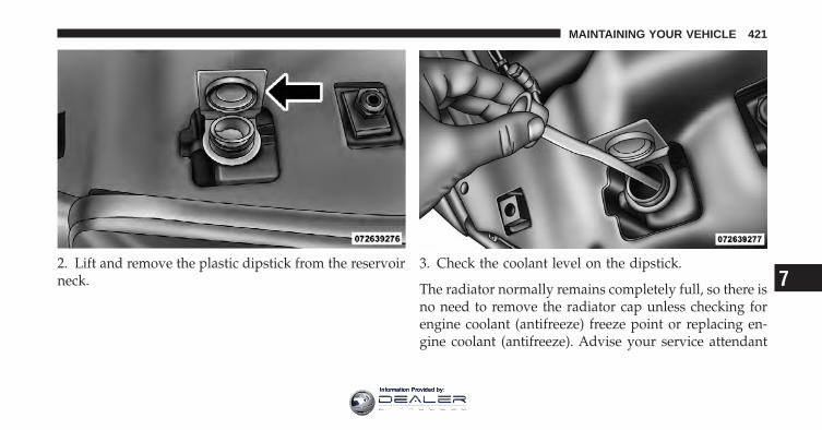
2. Lift and remove the plastic dipstick from the reservoirneck.
3. Check the coolant level on the dipstick.
The radiator normally remains completely full, so there isno need to remove the radiator cap unless checking forengine coolant (antifreeze) freeze point or replacing en-gine coolant (antifreeze). Advise your service attendant
7
MAINTAINING YOUR VEHICLE 421
Information Provided by:
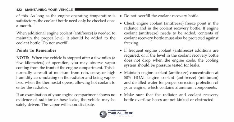
of this. As long as the engine operating temperature issatisfactory, the coolant bottle need only be checked oncea month.
When additional engine coolant (antifreeze) is needed tomaintain the proper level, it should be added to thecoolant bottle. Do not overfill.
Points To Remember
NOTE: When the vehicle is stopped after a few miles (afew kilometers) of operation, you may observe vaporcoming from the front of the engine compartment. This isnormally a result of moisture from rain, snow, or highhumidity accumulating on the radiator and being vapor-ized when the thermostat opens, allowing hot coolant toenter the radiator.
If an examination of your engine compartment shows noevidence of radiator or hose leaks, the vehicle may besafely driven. The vapor will soon dissipate.
• Do not overfill the coolant recovery bottle.
• Check engine coolant (antifreeze) freeze point in theradiator and in the coolant recovery bottle. If enginecoolant (antifreeze) needs to be added, contents ofcoolant recovery bottle must also be protected againstfreezing.
• If frequent engine coolant (antifreeze) additions arerequired, or if the level in the coolant recovery bottledoes not drop when the engine cools, the coolingsystem should be pressure tested for leaks.
• Maintain engine coolant (antifreeze) concentration at50% HOAT engine coolant (antifreeze) (minimum)and distilled water for proper corrosion protection ofyour engine, which contains aluminum components.
• Make sure that the radiator and coolant recoverybottle overflow hoses are not kinked or obstructed.
422 MAINTAINING YOUR VEHICLE
Information Provided by:
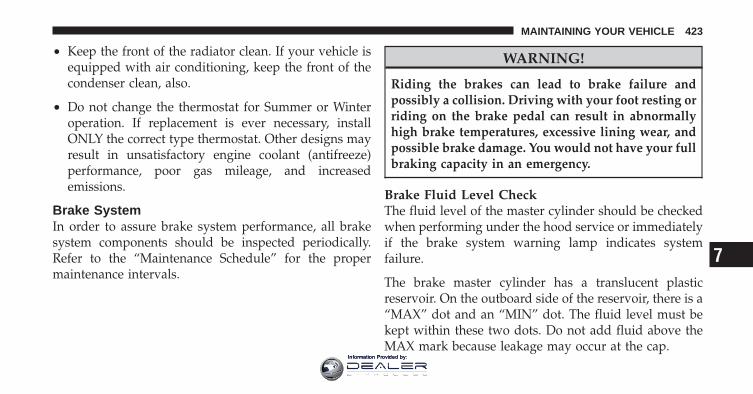
• Keep the front of the radiator clean. If your vehicle isequipped with air conditioning, keep the front of thecondenser clean, also.
• Do not change the thermostat for Summer or Winteroperation. If replacement is ever necessary, installONLY the correct type thermostat. Other designs mayresult in unsatisfactory engine coolant (antifreeze)performance, poor gas mileage, and increasedemissions.
Brake SystemIn order to assure brake system performance, all brakesystem components should be inspected periodically.Refer to the “Maintenance Schedule” for the propermaintenance intervals.
WARNING!
Riding the brakes can lead to brake failure andpossibly a collision. Driving with your foot resting orriding on the brake pedal can result in abnormallyhigh brake temperatures, excessive lining wear, andpossible brake damage. You would not have your fullbraking capacity in an emergency.
Brake Fluid Level CheckThe fluid level of the master cylinder should be checkedwhen performing under the hood service or immediatelyif the brake system warning lamp indicates systemfailure.
The brake master cylinder has a translucent plasticreservoir. On the outboard side of the reservoir, there is a“MAX” dot and an “MIN” dot. The fluid level must bekept within these two dots. Do not add fluid above theMAX mark because leakage may occur at the cap.
7
MAINTAINING YOUR VEHICLE 423
Information Provided by:
With disc brakes the fluid level can be expected to fall asthe brake linings wear. However, an unexpected drop influid level may be caused by a leak and a system checkshould be conducted.
Use only the manufacturer’s recommended brake fluid.Refer to “Fluids, Lubricants, and Genuine Parts” in“Maintaining Your Vehicle” for further information.
WARNING!
• Use only manufacturer’s recommended brakefluid. Refer to “Fluids, Lubricants, and GenuineParts” in “Maintaining Your Vehicle” for furtherinformation. Using the wrong type of brake fluidcan severely damage your brake system and/orimpair its performance. The proper type of brakefluid for your vehicle is also identified on theoriginal factory installed hydraulic master cylin-der reservoir.
(Continued)
424 MAINTAINING YOUR VEHICLE
Information Provided by:
WARNING! (Continued)• To avoid contamination from foreign matter or
moisture, use only new brake fluid or fluid thathas been in a tightly closed container. Keep themaster cylinder reservoir cap secured at all times.Brake fluid in a open container absorbs moisturefrom the air resulting in a lower boiling point.This may cause it to boil unexpectedly during hardor prolonged braking, resulting in sudden brakefailure. This could result in a collision.
• Overfilling the brake fluid reservoir can result inspilling brake fluid on hot engine parts, causingthe brake fluid to catch fire. Brake fluid can alsodamage painted and vinyl surfaces, care should betaken to avoid its contact with these surfaces.
(Continued)
WARNING! (Continued)• Do not allow petroleum based fluid to contami-
nate the brake fluid. Brake seal components couldbe damaged, causing partial or complete brakefailure. This could result in a collision.
Rear Axle And 4x4 Front Driving Axle Fluid LevelFor models with 9.25 in Front Axles and 11.5 in RearAxles, refer to “Fluids, Lubricants, and Genuine Parts” in“Maintaining Your Vehicle” for further information. Fornormal service, periodic fluid level checks are not re-quired. When the vehicle is serviced for other reasons,the exterior surfaces of the axle assembly should beinspected.
When checking the fluid level (4500/5500 only), thevehicle should be in a level position. The fluid levelshould be 1/4 in ± 1/4 in (6.4 mm ± 6.4 mm) below the
7
MAINTAINING YOUR VEHICLE 425
Information Provided by:
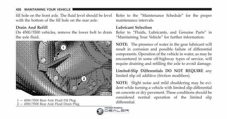
fill hole on the front axle. The fluid level should be levelwith the bottom of the fill hole on the rear axle.
Drain And RefillOn 4500/5500 vehicles, remove the lower bolt to drainthe axle fluid.
Refer to the “Maintenance Schedule” for the propermaintenance intervals.
Lubricant SelectionRefer to “Fluids, Lubricants, and Genuine Parts” in“Maintaining Your Vehicle” for further information.
NOTE: The presence of water in the gear lubricant willresult in corrosion and possible failure of differentialcomponents. Operation of the vehicle in water, as may beencountered in some off-highway types of service, willrequire draining and refilling the axle to avoid damage.
Limited-Slip Differentials DO NOT REQUIRE anylimited slip oil additive (friction modifiers).
NOTE: Slight noise and mild shuddering may be evi-dent while turning a vehicle with limited slip differentialon concrete or dry pavement. These conditions should beconsidered normal operation of the limited slipdifferential.1 — 4500/5500 Rear Axle Fluid Fill Plug
2 — 4500/5500 Rear Axle Fluid Drain Plug
426 MAINTAINING YOUR VEHICLE
Information Provided by:
Transfer Case
Drain And RefillRefer to the “Maintenance Schedule” for the propermaintenance intervals.
Lubricant SelectionRefer to “Fluids, Lubricants, and Genuine Parts” in“Maintaining Your Vehicle” for further information.
Fluid Level CheckThis fluid level can be checked by removing the fillerplug. The fluid level should be to the bottom edge of thefiller plug hole with the vehicle in a level position.
Automatic Transmission
Selection Of LubricantIt is important that the proper lubricant is used in thetransmission to assure optimum transmission perfor-mance. Use only the manufacturer’s recommended trans-mission fluid. Refer to “Fluids, Lubricants, and GenuineParts” in “Maintaining Your Vehicle” for further informa-tion. It is important that the transmission fluid be main-tained at the prescribed level using the recommendedfluid.
CAUTION!
• Do not use chemical flushes in your transmissionas the chemicals can damage your transmissioncomponents. Such damage is not covered by theNew Vehicle Limited Warranty.
(Continued)
7
MAINTAINING YOUR VEHICLE 427
Information Provided by:

CAUTION! (Continued)• Using a transmission fluid other than the manu-
facturer’s recommended fluid may cause deterio-ration in transmission shift quality and/or torqueconverter shudder. Using a transmission fluidother than the manufacturer’s recommended fluidwill require more frequent fluid and filterchanges. Refer to “Fluids, Lubricants, and Genu-ine Parts” in “Maintaining Your Vehicle” for fur-ther information.
Special AdditivesAutomatic Transmission Fluid (ATF) is an engineeredproduct and its performance may be impaired by supple-mental additives. Therefore, do not add any fluid addi-tives to the transmission. The only exception to thispolicy is the use of special dyes to aid in detecting fluidleaks. In addition, avoid using transmission sealers asthey may adversely affect seals.
Fluid Level CheckThe fluid level should be checked when the engine isfully warmed up and the fluid in the transmission is atnormal operating temperature. Operation of the trans-mission with an improper fluid level will greatly reducethe life of the transmission and of the fluid. Check thefluid level whenever the vehicle is serviced.
Fluid Level Check – 5.7L EngineCheck the fluid level while the transmission is at normaloperating temperature 82°C (180°F). This occurs after atleast 15 miles (25 km) of driving. At normal operatingtemperature the fluid cannot be held comfortably be-tween the fingertips.
To check the automatic transmission fluid level properly,the following procedure must be used:
1. Operate the engine at idle speed and normal operatingtemperature.
428 MAINTAINING YOUR VEHICLE
Information Provided by:
2. The vehicle must be on level ground.
3. Fully apply the parking brake and press the brakepedal.
4. Place the shift lever momentarily into each gear posi-tion ending with the lever in PARK.
5. Remove the dipstick, wipe it clean and reinsert it untilseated.
6. Remove the dipstick again and note the fluid level onboth sides. The fluid level should be between the “HOT”(upper) reference holes on the dipstick at normal operat-ing temperature. Verify that solid coating of oil is seen onboth sides of the dipstick. If the fluid is low, add asrequired into the dipstick tube. Do not overfill. Afteradding any quantity of oil through the oil fill tube, waita minimum of two minutes for the oil to fully drain intothe transmission before rechecking the fluid level.
NOTE: If it is necessary to check the transmission belowthe operating temperature, the fluid level should bebetween the two “COLD” (lower) holes on the dipstickwith the fluid at approximately 70°F (21°C) (room tem-perature). If the fluid level is correctly established atroom temperature, it should be between the “HOT”(upper) reference holes when the transmission reaches180°F (82°C). Remember it is best to check the level at thenormal operating temperature.
CAUTION!
Be aware that if the fluid temperature is below 50°F(10°C) it may not register on the dipstick. Do not addfluid until the temperature is elevated enough toproduce an accurate reading.
7. Check for leaks. Release parking brake.
7
MAINTAINING YOUR VEHICLE 429
Information Provided by:
To prevent dirt and water from entering the transmissionafter checking or replenishing fluid, make certain that thedipstick cap is properly reseated. It is normal for thedipstick cap to spring back slightly from its fully seatedposition, as long as its seal remains engaged in thedipstick tube.
Automatic Transmission Fluid And Filter ChangeRefer to the “Maintenance Schedule” for the propermaintenance intervals.
NOTE: If the transmission is disassembled for anyreason, the fluid and filter(s) should be changed.
It is important that proper lubricant is used in thetransmission. Refer to “Fluids, Lubricants, and GenuineParts” in “Maintaining Your Vehicle” for furtherinformation.
Appearance Care And Protection From Corrosion
Protection Of Body And Paint From CorrosionVehicle body care requirements vary according to geo-graphic locations and usage. Chemicals that make roadspassable in snow and ice, and those that are sprayed ontrees and road surfaces during other seasons, are highlycorrosive to the metal in your vehicle. Outside parking,which exposes your vehicle to airborne contaminants,road surfaces on which the vehicle is operated, extremehot or cold weather and other extreme conditions willhave an adverse affect on paint, metal trim, and under-body protection.
The following maintenance recommendations will enableyou to obtain maximum benefit from the corrosionresistance built into your vehicle.
What Causes Corrosion?Corrosion is the result of deterioration or removal ofpaint and protective coatings from your vehicle.
430 MAINTAINING YOUR VEHICLE
Information Provided by:

The most common causes are:
• Road salt, dirt and moisture accumulation.
• Stone and gravel impact.
• Insects, tree sap and tar.
• Salt in the air near seacoast localities.
• Atmospheric fallout/industrial pollutants.
Washing
• Wash your vehicle regularly. Always wash your ve-hicle in the shade using MOPAR� Car Wash or equiva-lent, or a mild car wash soap and rinse the panelscompletely with clear water.
• If insects, tar or other similar deposits have accumu-lated on your vehicle, use MOPAR� Super Kleen Bugand Tar Remover or equivalent to remove.
• Use a high quality cleaner wax, such as MOPAR�Cleaner Wax or equivalent to remove road film, stainsand to protect your paint finish. Take care never toscratch the paint.
• Avoid using abrasive compounds and power buffingthat may diminish the gloss or thin out the paintfinish.
CAUTION!
• Do not use abrasive or strong cleaning materialssuch as steel wool or scouring powder which willscratch metal and painted surfaces.
• Use of power washers exceeding 1,200 psi(8 274 kPa) can result in damage or removal ofpaint and decals.
7
MAINTAINING YOUR VEHICLE 431
Information Provided by:
Special Care
• If you drive on salted or dusty roads or if you drivenear the ocean, hose off the undercarriage at least oncea month.
• It is important that the drain holes in the lower edgesof the doors, rocker panels and trunk be kept clear andopen.
• If you detect any stone chips or scratches in the paint,touch them up immediately. The cost of such repairs isconsidered the responsibility of the owner.
• If your vehicle is damaged due to a collision or similarcause which destroys the paint and protective coating,have your vehicle repaired as soon as possible. Thecost of such repairs is considered the responsibility ofthe owner.
• If you carry special cargo such as chemicals, fertilizers,de-icer salt, etc., be sure that such materials are wellpackaged and sealed.
• If a lot of driving is done on gravel roads, considermud or stone shields behind each wheel.
• Use MOPAR� Touch Up Paint or equivalent onscratches as soon as possible. Your authorized dealerhas touch up paint to match the color of your vehicle.
Wheel And Wheel Trim Care
• All wheels and wheel trim, especially aluminum andchrome plated wheels, should be cleaned regularlywith a mild soap and water to prevent corrosion.
• To remove heavy soil and/or excessive brake dust, useMOPAR� Wheel Cleaner or equivalent or select anon-abrasive, non-acidic cleaner.
432 MAINTAINING YOUR VEHICLE
Information Provided by:

CAUTION!
Do not use scouring pads, steel wool, a bristle brush,or metal polishes. Do not use oven cleaner. Theseproducts may damage the wheel’s protective finish.Avoid automatic car washes that use acidic solutionsor harsh brushes that may damage the wheel’s pro-tective finish. Only MOPAR� Wheel Cleaner orequivalent is recommended.
Stain Repel Fabric Cleaning Procedure – IfEquippedStain Repel seats may be cleaned in the following man-ner:
• Remove as much of the stain as possible by blottingwith a clean, dry towel.
• Blot any remaining stain with a clean, damp towel.
• For tough stains, apply MOPAR� Total Clean orequivalent, or a mild soap solution to a clean, dampcloth and remove stain. Use a fresh, damp towel toremove soap residue.
• For grease stains, apply MOPAR� Multi-PurposeCleaner or equivalent to a clean, damp cloth andremove stain. Use a fresh, damp towel to remove soapresidue.
• Do not use any harsh solvents or any other form ofprotectants on Stain Repel products.
Interior CareUse MOPAR� Total Clean or equivalent to clean fabricupholstery and carpeting.
Use MOPAR� Total Clean or equivalent to clean vinylupholstery.
MOPAR� Total Clean or equivalent is specifically recom-mended for leather upholstery.
7
MAINTAINING YOUR VEHICLE 433
Information Provided by:
Your leather upholstery can be best preserved by regularcleaning with a damp soft cloth. Small particles of dirtcan act as an abrasive and damage the leather upholsteryand should be removed promptly with a damp cloth.Stubborn soils can be removed easily with a soft clothand MOPAR� Total Clean or equivalent. Care should betaken to avoid soaking your leather upholstery with anyliquid. Please do not use polishes, oils, cleaning fluids,solvents, detergents, or ammonia-based cleaners to cleanyour leather upholstery. Application of a leather condi-tioner is not required to maintain the original condition.
WARNING!
Do not use volatile solvents for cleaning purposes.Many are potentially flammable, and if used inclosed areas they may cause respiratory harm.
Cleaning HeadlightsYour vehicle is equipped with plastic headlights and foglights (if equipped) that are lighter and less susceptible tostone breakage than glass headlights.
Plastic is not as scratch resistant as glass and thereforedifferent lens cleaning procedures must be followed.
To minimize the possibility of scratching the lenses andreducing light output, avoid wiping with a dry cloth. Toremove road dirt, wash with a mild soap solution fol-lowed by rinsing.
Do not use abrasive cleaning components, solvents, steelwool or other aggressive material to clean the lenses.
434 MAINTAINING YOUR VEHICLE
Information Provided by:
Glass SurfacesAll glass surfaces should be cleaned on a regular basiswith MOPAR� Glass Cleaner or any commercialhousehold-type glass cleaner. Never use an abrasive typecleaner. Use caution when cleaning the inside rear win-dow equipped with electric defrosters or the right rearquarter window equipped with the radio antenna. Donot use scrapers or other sharp instruments which mayscratch the elements. When cleaning the rearview mirror,spray cleaner on the towel or rag that you are using. Donot spray cleaner directly on the mirror.
Cleaning Plastic Instrument Cluster LensesThe lenses in front of the instruments in this vehicle aremolded in clear plastic. When cleaning the lenses, caremust be taken to avoid scratching the plastic.
1. Clean with a wet soft rag. A mild soap solution may beused, but do not use high alcohol content or abrasivecleaners. If soap is used, wipe clean with a clean damp rag.
2. Dry with a soft cloth.
Seat Belt MaintenanceDo not bleach, dye or clean the belts with chemicalsolvents or abrasive cleaners. This will weaken the fabric.Sun damage can also weaken the fabric.
If the belts need cleaning, use a mild soap solution orlukewarm water. Do not remove the belts from the car towash them. Dry with a soft cloth.
Replace the belts if they appear frayed or worn or if thebuckles do not work properly.
FUSES
Totally Integrated Power ModuleThe Totally Integrated Power Module is located in theengine compartment near the battery. This center con-tains cartridge fuses and mini fuses. A description of eachfuse and component may be stamped on the inside cover,
7
MAINTAINING YOUR VEHICLE 435
Information Provided by:
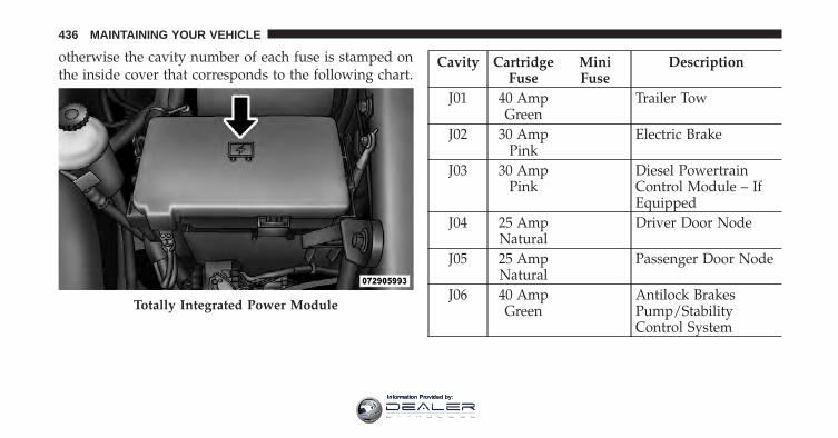
otherwise the cavity number of each fuse is stamped onthe inside cover that corresponds to the following chart.
Cavity CartridgeFuse
MiniFuse
Description
J01 40 AmpGreen
Trailer Tow
J02 30 AmpPink
Electric Brake
J03 30 AmpPink
Diesel PowertrainControl Module – IfEquipped
J04 25 AmpNatural
Driver Door Node
J05 25 AmpNatural
Passenger Door Node
J06 40 AmpGreen
Antilock BrakesPump/StabilityControl System
Totally Integrated Power Module
436 MAINTAINING YOUR VEHICLE
Information Provided by:
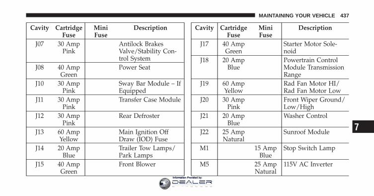
Cavity CartridgeFuse
MiniFuse
Description
J07 30 AmpPink
Antilock BrakesValve/Stability Con-trol System
J08 40 AmpGreen
Power Seat
J10 30 AmpPink
Sway Bar Module – IfEquipped
J11 30 AmpPink
Transfer Case Module
J12 30 AmpPink
Rear Defroster
J13 60 AmpYellow
Main Ignition OffDraw (IOD) Fuse
J14 20 AmpBlue
Trailer Tow Lamps/Park Lamps
J15 40 AmpGreen
Front Blower
Cavity CartridgeFuse
MiniFuse
Description
J17 40 AmpGreen
Starter Motor Sole-noid
J18 20 AmpBlue
Powertrain ControlModule TransmissionRange
J19 60 AmpYellow
Rad Fan Motor HI/Rad Fan Motor Low
J20 30 AmpPink
Front Wiper Ground/Low/High
J21 20 AmpBlue
Washer Control
J22 25 AmpNatural
Sunroof Module
M1 15 AmpBlue
Stop Switch Lamp
M5 25 AmpNatural
115V AC Inverter
7
MAINTAINING YOUR VEHICLE 437
Information Provided by:
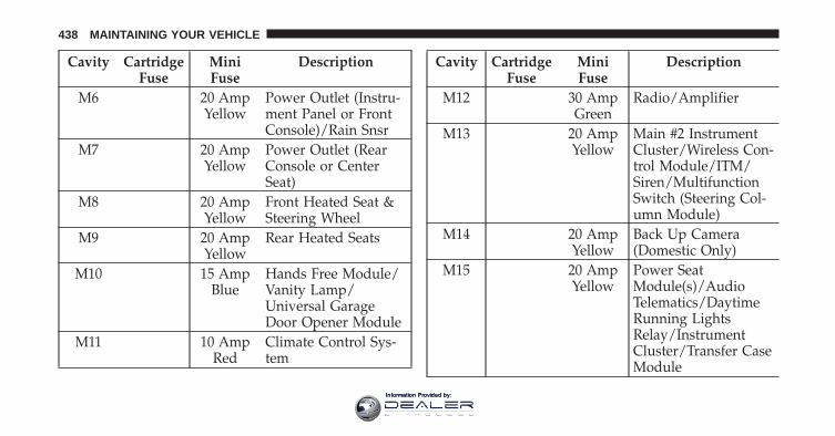
Cavity CartridgeFuse
MiniFuse
Description
M6 20 AmpYellow
Power Outlet (Instru-ment Panel or FrontConsole)/Rain Snsr
M7 20 AmpYellow
Power Outlet (RearConsole or CenterSeat)
M8 20 AmpYellow
Front Heated Seat &Steering Wheel
M9 20 AmpYellow
Rear Heated Seats
M10 15 AmpBlue
Hands Free Module/Vanity Lamp/Universal GarageDoor Opener Module
M11 10 AmpRed
Climate Control Sys-tem
Cavity CartridgeFuse
MiniFuse
Description
M12 30 AmpGreen
Radio/Amplifier
M13 20 AmpYellow
Main #2 InstrumentCluster/Wireless Con-trol Module/ITM/Siren/MultifunctionSwitch (Steering Col-umn Module)
M14 20 AmpYellow
Back Up Camera(Domestic Only)
M15 20 AmpYellow
Power SeatModule(s)/AudioTelematics/DaytimeRunning LightsRelay/InstrumentCluster/Transfer CaseModule
438 MAINTAINING YOUR VEHICLE
Information Provided by:
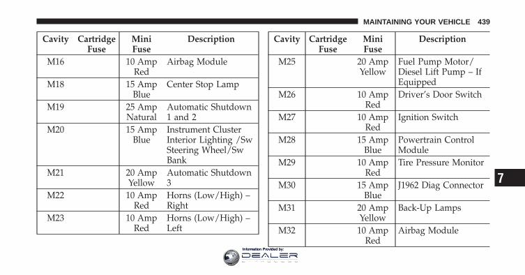
Cavity CartridgeFuse
MiniFuse
Description
M16 10 AmpRed
Airbag Module
M18 15 AmpBlue
Center Stop Lamp
M19 25 AmpNatural
Automatic Shutdown1 and 2
M20 15 AmpBlue
Instrument ClusterInterior Lighting /SwSteering Wheel/SwBank
M21 20 AmpYellow
Automatic Shutdown3
M22 10 AmpRed
Horns (Low/High) –Right
M23 10 AmpRed
Horns (Low/High) –Left
Cavity CartridgeFuse
MiniFuse
Description
M25 20 AmpYellow
Fuel Pump Motor/Diesel Lift Pump – IfEquipped
M26 10 AmpRed
Driver’s Door Switch
M27 10 AmpRed
Ignition Switch
M28 15 AmpBlue
Powertrain ControlModule
M29 10 AmpRed
Tire Pressure Monitor
M30 15 AmpBlue
J1962 Diag Connector
M31 20 AmpYellow
Back-Up Lamps
M32 10 AmpRed
Airbag Module
7
MAINTAINING YOUR VEHICLE 439
Information Provided by:
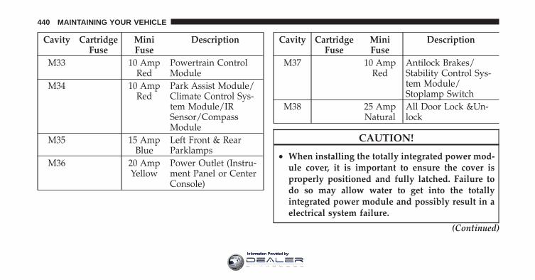
Cavity CartridgeFuse
MiniFuse
Description
M33 10 AmpRed
Powertrain ControlModule
M34 10 AmpRed
Park Assist Module/Climate Control Sys-tem Module/IRSensor/CompassModule
M35 15 AmpBlue
Left Front & RearParklamps
M36 20 AmpYellow
Power Outlet (Instru-ment Panel or CenterConsole)
Cavity CartridgeFuse
MiniFuse
Description
M37 10 AmpRed
Antilock Brakes/Stability Control Sys-tem Module/Stoplamp Switch
M38 25 AmpNatural
All Door Lock &Un-lock
CAUTION!
• When installing the totally integrated power mod-ule cover, it is important to ensure the cover isproperly positioned and fully latched. Failure todo so may allow water to get into the totallyintegrated power module and possibly result in aelectrical system failure.
(Continued)
440 MAINTAINING YOUR VEHICLE
Information Provided by:
CAUTION! (Continued)• When replacing a blown fuse, it is important to
use only a fuse having the correct amperage rating.The use of a fuse with a rating other than indicatedmay result in a dangerous electrical system over-load. If a properly rated fuse continues to blow, itindicates a problem in the circuit that must becorrected.
VEHICLE STORAGEIf you are storing your vehicle for more than 21 days, werecommend that you take the following steps to mini-mize the drain on your vehicle’s battery:
• Disconnect the Ignition-Off Draw (IOD) fuse located inthe Integrated Power Module, located in the enginecompartment. The IOD cavity includes a snap-in re-tainer that allows the fuse to be disconnected withoutremoving it from the fuse block.
• As an alternative to the above steps you may discon-nect the negative cables from both batteries.
• Any time you store your vehicle or keep it out ofservice (i.e., vacation) for two weeks or more, run theair conditioning system at idle for about five minutesin the fresh air and high blower setting. This willensure adequate system lubrication to minimize thepossibility of compressor damage when the system isstarted again.
NOTE:• When reinstalling the IOD fuse push firmly until fully
seated; the gauges in the instrument cluster will do afull sweep when the ignition switch is turned to theRUN position. This is a normal condition.
• When the vehicle is shipped from the factory, the IODfuse is in the up or extracted position. If the radio,interior lamps, keyless entry or other features do notwork with the key OFF, check the position of the fuse
7
MAINTAINING YOUR VEHICLE 441
Information Provided by:
(or check to see if the fuse is blown) to ensure that it isfully seated. When the IOD fuse is extracted, theinstrument cluster in the odometer window will dis-play �NO FUSE.”
REPLACEMENT BULBS
LIGHT BULBS – Interior Bulb No.Overhead Console Lamps . . . . . . . . . . . . . . . TS 212-2Dome Lamp . . . . . . . . . . . . . . . . . . . . . . . . . . . 7679
NOTE: For lighted switches, see your authorized dealerfor replacement instructions.
All of the inside bulbs are brass or glass-wedge base.Aluminum base bulbs are not approved.
LIGHT BULBS – Exterior Bulb No.Center High Mounted Stop Lamp (CHMSL) . . . . . 921Fog Lamp . . . . . . . . . . . . . . . . . . . . . . . . . . . . . 9145Dual Headlamp . . . . . . . . . . . . . . . . . . . . . . . . . H13Quad Headlamp – Low Beam . . . . . . . . . . . . . . . H11Quad Headlamp – High Beam . . . . . . . . . . . . . . 9005Front Turn Signal Lamp (Dual Headlamp) . . . . . 3157KFront Turn Signal Lamp (Quad Headlamp) . . . 3157NARear Cargo Lamp . . . . . . . . . . . . . . . . . . . . . . . . 921Cab Roof Marker Lamps . . . . . . . . . . . . . . . . . 194NA
442 MAINTAINING YOUR VEHICLE
Information Provided by:
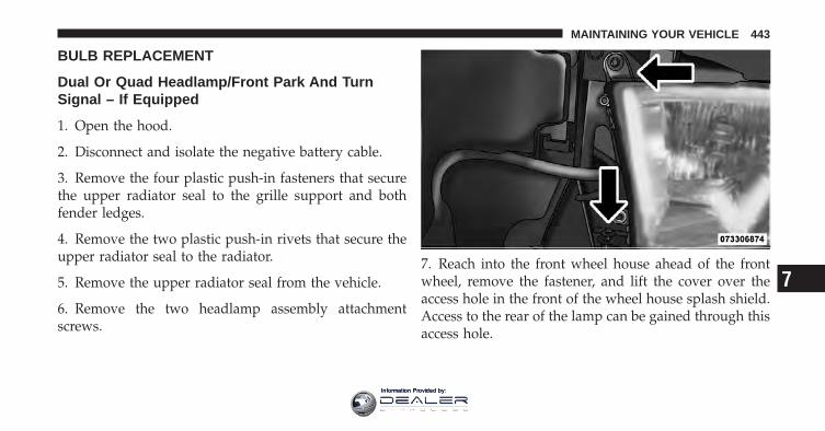
BULB REPLACEMENT
Dual Or Quad Headlamp/Front Park And TurnSignal – If Equipped
1. Open the hood.
2. Disconnect and isolate the negative battery cable.
3. Remove the four plastic push-in fasteners that securethe upper radiator seal to the grille support and bothfender ledges.
4. Remove the two plastic push-in rivets that secure theupper radiator seal to the radiator.
5. Remove the upper radiator seal from the vehicle.
6. Remove the two headlamp assembly attachmentscrews.
7. Reach into the front wheel house ahead of the frontwheel, remove the fastener, and lift the cover over theaccess hole in the front of the wheel house splash shield.Access to the rear of the lamp can be gained through thisaccess hole.
7
MAINTAINING YOUR VEHICLE 443
Information Provided by:
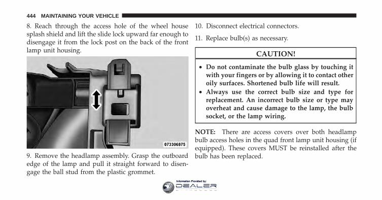
8. Reach through the access hole of the wheel housesplash shield and lift the slide lock upward far enough todisengage it from the lock post on the back of the frontlamp unit housing.
9. Remove the headlamp assembly. Grasp the outboardedge of the lamp and pull it straight forward to disen-gage the ball stud from the plastic grommet.
10. Disconnect electrical connectors.
11. Replace bulb(s) as necessary.
CAUTION!
• Do not contaminate the bulb glass by touching itwith your fingers or by allowing it to contact otheroily surfaces. Shortened bulb life will result.
• Always use the correct bulb size and type forreplacement. An incorrect bulb size or type mayoverheat and cause damage to the lamp, the bulbsocket, or the lamp wiring.
NOTE: There are access covers over both headlampbulb access holes in the quad front lamp unit housing (ifequipped). These covers MUST be reinstalled after thebulb has been replaced.
444 MAINTAINING YOUR VEHICLE
Information Provided by:
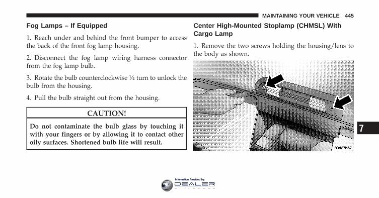
Fog Lamps – If Equipped
1. Reach under and behind the front bumper to accessthe back of the front fog lamp housing.
2. Disconnect the fog lamp wiring harness connectorfrom the fog lamp bulb.
3. Rotate the bulb counterclockwise 1⁄4 turn to unlock thebulb from the housing.
4. Pull the bulb straight out from the housing.
CAUTION!
Do not contaminate the bulb glass by touching itwith your fingers or by allowing it to contact otheroily surfaces. Shortened bulb life will result.
Center High-Mounted Stoplamp (CHMSL) WithCargo Lamp
1. Remove the two screws holding the housing/lens tothe body as shown.
7
MAINTAINING YOUR VEHICLE 445
Information Provided by:
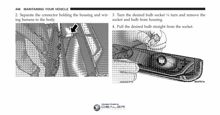
2. Separate the connector holding the housing and wir-ing harness to the body.
3. Turn the desired bulb socket 1⁄4 turn and remove thesocket and bulb from housing.
4. Pull the desired bulb straight from the socket.
446 MAINTAINING YOUR VEHICLE
Information Provided by:
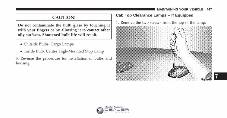
CAUTION!
Do not contaminate the bulb glass by touching itwith your fingers or by allowing it to contact otheroily surfaces. Shortened bulb life will result.
• Outside Bulbs: Cargo Lamps
• Inside Bulb: Center High-Mounted Stop Lamp
5. Reverse the procedure for installation of bulbs andhousing.
Cab Top Clearance Lamps – If Equipped
1. Remove the two screws from the top of the lamp.
7
MAINTAINING YOUR VEHICLE 447
Information Provided by:
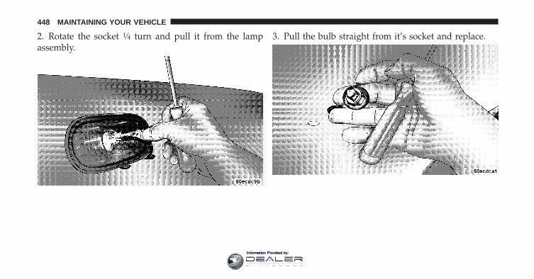
2. Rotate the socket 1⁄4 turn and pull it from the lampassembly.
3. Pull the bulb straight from it’s socket and replace.
448 MAINTAINING YOUR VEHICLE
Information Provided by:
FLUID CAPACITIES
U.S. MetricFuel (Approximate)Standard Rear Tank 52 Gallons 197 LitersOptional Midship Tank 22 Gallons 83 LitersEngine Oil with Filter5.7L Engine (SAE 5W-20, API Certified) 7 Quarts 6.6 LitersCooling System5.7L Engine (MOPAR� Antifreeze/Coolant 5Year/100,000 Mile Formula) or equivalent.
18.7 Quarts 17.7 Liters
7
MAINTAINING YOUR VEHICLE 449
Information Provided by:
FLUIDS, LUBRICANTS AND GENUINE PARTS
Engine
Component Fluid, Lubricant, or Genuine PartEngine Coolant MOPAR� Antifreeze/Coolant 5–Year/100,000 Mile Formula HOAT (Hy-
brid Organic Additive Technology) or equivalent.Engine Oil – 5.7L Engine Use API Certified SAE 5W-20 Engine Oil, meeting the requirements of
Chrysler Material Standard MS-6395. Refer to your engine oil filler cap forcorrect SAE grade.
Engine Oil Filter – 5.7L Engine MOPAR� Engine Oil Filter or equivalent.Spark Plugs – 5.7L Engine LZFR5C–11 (Gap 0.043 in [1.1 mm])Fuel Selection – 5.7L Engine 87 Octane Acceptable - 89 Octane Recommended
450 MAINTAINING YOUR VEHICLE
Information Provided by:
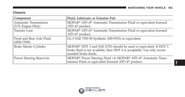
Chassis
Component Fluid, Lubricant, or Genuine PartAutomatic Transmission(5.7L Engine Only)
MOPAR� ATF+4� Automatic Transmission Fluid or equivalent licensedATF+4� product.
Transfer Case MOPAR� ATF+4� Automatic Transmission Fluid or equivalent licensedATF+4� product.
Front and Rear Axle Fluid(4500/5500)
GL-5 SAE 75W-90 Synthetic (MS-9763) or equivalent.
Brake Master Cylinder MOPAR� DOT 3 and SAE J1703 should be used or equivalent. If DOT 3brake fluid is not available, then DOT 4 is acceptable. Use only recom-mended brake fluids.
Power Steering Reservoir MOPAR� Power Steering Fluid +4, MOPAR� ATF+4� Automatic Trans-mission Fluid or equivalent licensed ATF+4� product. 7
MAINTAINING YOUR VEHICLE 451
Information Provided by:

Information Provided by:
MAINTENANCE SCHEDULES
CONTENTS
� Maintenance Schedule . . . . . . . . . . . . . . . . . . 454
▫ 5.7L Gas Engine . . . . . . . . . . . . . . . . . . . . . 454
▫ Required Maintenance Intervals . . . . . . . . . . 456
8
MAINTENANCE
SCHEDULES
Information Provided by:
MAINTENANCE SCHEDULE
5.7L Gas EngineThe Scheduled Maintenance services listed in thismanual must be done at the times or mileages specifiedto protect your vehicle warranty and ensure the bestvehicle performance and reliability. More frequent main-tenance may be needed for vehicles in severe operatingconditions, such as dusty areas and very short tripdriving. Inspection and service should also be doneanytime a malfunction is suspected.
Your vehicle is equipped with an automatic oil changeindicator system. The oil change indicator system willremind you that it is time to take your vehicle in forscheduled maintenance.
On Electronic Vehicle Information Center (EVIC)equipped vehicles, “Oil Change Required” will be dis-played in the EVIC and a single chime will sound,indicating that an oil change is necessary.
On Non-EVIC equipped vehicles, “Change Oil” will flashin the instrument cluster odometer and a single chimewill sound, indicating that an oil change is necessary.
Based on engine operation conditions, the oil changeindicator message will illuminate. This means that ser-vice is required for your vehicle. Operating conditionssuch as frequent short-trips, trailer tow, extremely hot orcold ambient temperatures, and E85 fuel usage willinfluence when the “Change Oil” message is displayed.Depending on operating conditions, the message mayappear as early as 3,500 miles (5 630 km) since last reset.Have your vehicle serviced as soon as possible, withinthe next 500 miles (805 km).
8
MAINTENANCE
SCHEDULES
454 MAINTENANCE SCHEDULES
Information Provided by:
NOTE:• The oil change indicator message will not monitor the
time since the last oil change. Change your vehicle’soil if it has been six months since your last oil change,even if the oil change indicator message is NOTilluminated.
• Change your engine oil more often if you drive yourvehicle off-road for an extended period of time.
• Under no circumstances should oil change intervalsexceed 8,000 miles (13 000 km) or six months, which-ever comes first.
Your authorized dealer will reset the oil change indicatormessage after completing the scheduled oil change. If ascheduled oil change is performed by someone otherthan your authorized dealer, the message can be reset by
referring to the steps described under “Electronic VehicleInformation Center (EVIC)/Oil Change Required” in“Understanding Your Instrument Panel” or under “In-strument Cluster Description/Odometer/Trip Odom-eter” in “Understanding Your Instrument Panel” forfurther information.
At Each Stop For Fuel
• Check the engine oil level about 5 minutes after a fullywarmed engine is shut off. Checking the oil level whilethe vehicle is on level ground will improve the accu-racy of the oil level reading. Add oil only when thelevel is at or below the ADD or MIN mark.
• Check the windshield washer solvent and add ifrequired. 8
MAINTENANCE
SCHEDULES
MAINTENANCE SCHEDULES 455
Information Provided by:
Once A Month
• Check tire pressure and look for unusual wear ordamage.
• Inspect the battery and clean and tighten the terminalsas required.
• Check the fluid levels of coolant reservoir, brakemaster cylinder, power steering and transmission andadd as needed.
• Check all lights and other electrical items for correctoperation.
At Each Oil Change
• Change the engine oil filter.
• Inspect the brake hoses and lines.
CAUTION!
Failure to perform the required maintenance itemsmay result in damage to the vehicle.
Required Maintenance IntervalsRefer to the Maintenance Schedules on the followingpages for the required maintenance intervals.
8
MAINTENANCE
SCHEDULES
456 MAINTENANCE SCHEDULES
Information Provided by:
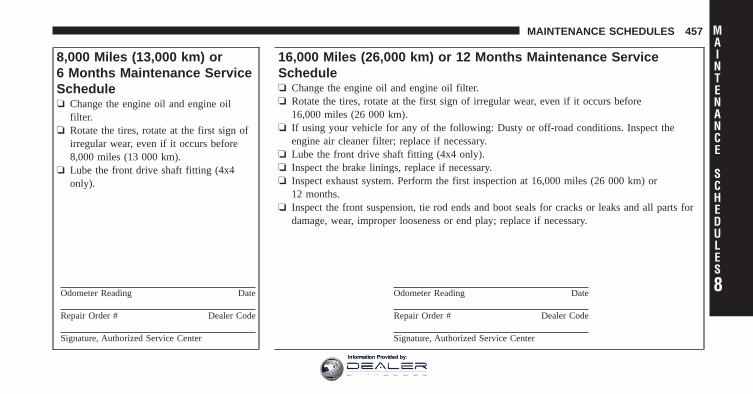
8,000 Miles (13,000 km) or6 Months Maintenance ServiceSchedule❏ Change the engine oil and engine oil
filter.❏ Rotate the tires, rotate at the first sign of
irregular wear, even if it occurs before8,000 miles (13 000 km).
❏ Lube the front drive shaft fitting (4x4only).
Odometer Reading Date
Repair Order # Dealer Code
Signature, Authorized Service Center
16,000 Miles (26,000 km) or 12 Months Maintenance ServiceSchedule❏ Change the engine oil and engine oil filter.❏ Rotate the tires, rotate at the first sign of irregular wear, even if it occurs before
16,000 miles (26 000 km).❏ If using your vehicle for any of the following: Dusty or off-road conditions. Inspect the
engine air cleaner filter; replace if necessary.❏ Lube the front drive shaft fitting (4x4 only).❏ Inspect the brake linings, replace if necessary.❏ Inspect exhaust system. Perform the first inspection at 16,000 miles (26 000 km) or
12 months.❏ Inspect the front suspension, tie rod ends and boot seals for cracks or leaks and all parts for
damage, wear, improper looseness or end play; replace if necessary.
Odometer Reading Date
Repair Order # Dealer Code
Signature, Authorized Service Center
8
MAINTENANCE
SCHEDULES
MAINTENANCE SCHEDULES 457
Information Provided by:
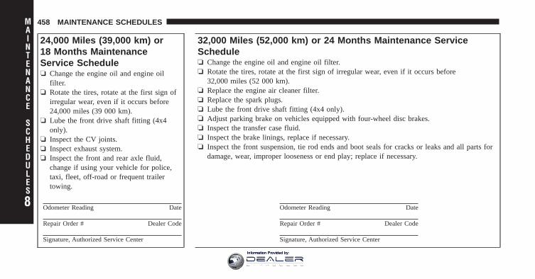
24,000 Miles (39,000 km) or18 Months MaintenanceService Schedule❏ Change the engine oil and engine oil
filter.❏ Rotate the tires, rotate at the first sign of
irregular wear, even if it occurs before24,000 miles (39 000 km).
❏ Lube the front drive shaft fitting (4x4only).
❏ Inspect the CV joints.❏ Inspect exhaust system.❏ Inspect the front and rear axle fluid,
change if using your vehicle for police,taxi, fleet, off-road or frequent trailertowing.
Odometer Reading Date
Repair Order # Dealer Code
Signature, Authorized Service Center
32,000 Miles (52,000 km) or 24 Months Maintenance ServiceSchedule❏ Change the engine oil and engine oil filter.❏ Rotate the tires, rotate at the first sign of irregular wear, even if it occurs before
32,000 miles (52 000 km).❏ Replace the engine air cleaner filter.❏ Replace the spark plugs.❏ Lube the front drive shaft fitting (4x4 only).❏ Adjust parking brake on vehicles equipped with four-wheel disc brakes.❏ Inspect the transfer case fluid.❏ Inspect the brake linings, replace if necessary.❏ Inspect the front suspension, tie rod ends and boot seals for cracks or leaks and all parts for
damage, wear, improper looseness or end play; replace if necessary.
Odometer Reading Date
Repair Order # Dealer Code
Signature, Authorized Service Center
8
MAINTENANCE
SCHEDULES
458 MAINTENANCE SCHEDULES
Information Provided by:
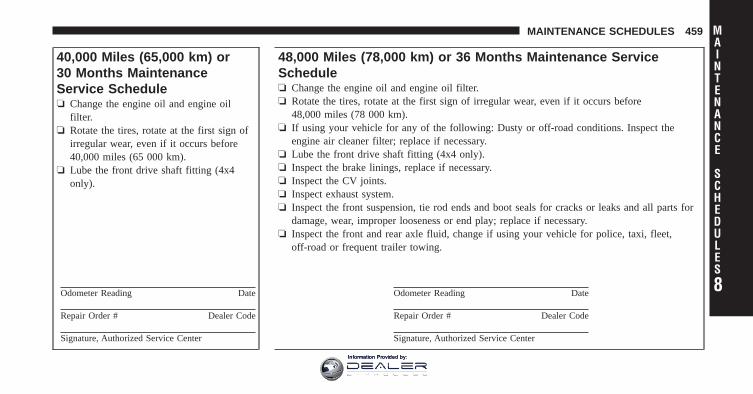
40,000 Miles (65,000 km) or30 Months MaintenanceService Schedule❏ Change the engine oil and engine oil
filter.❏ Rotate the tires, rotate at the first sign of
irregular wear, even if it occurs before40,000 miles (65 000 km).
❏ Lube the front drive shaft fitting (4x4only).
Odometer Reading Date
Repair Order # Dealer Code
Signature, Authorized Service Center
48,000 Miles (78,000 km) or 36 Months Maintenance ServiceSchedule❏ Change the engine oil and engine oil filter.❏ Rotate the tires, rotate at the first sign of irregular wear, even if it occurs before
48,000 miles (78 000 km).❏ If using your vehicle for any of the following: Dusty or off-road conditions. Inspect the
engine air cleaner filter; replace if necessary.❏ Lube the front drive shaft fitting (4x4 only).❏ Inspect the brake linings, replace if necessary.❏ Inspect the CV joints.❏ Inspect exhaust system.❏ Inspect the front suspension, tie rod ends and boot seals for cracks or leaks and all parts for
damage, wear, improper looseness or end play; replace if necessary.❏ Inspect the front and rear axle fluid, change if using your vehicle for police, taxi, fleet,
off-road or frequent trailer towing.
Odometer Reading Date
Repair Order # Dealer Code
Signature, Authorized Service Center
8
MAINTENANCE
SCHEDULES
MAINTENANCE SCHEDULES 459
Information Provided by:
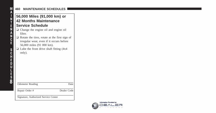
56,000 Miles (91,000 km) or42 Months MaintenanceService Schedule❏ Change the engine oil and engine oil
filter.❏ Rotate the tires, rotate at the first sign of
irregular wear, even if it occurs before56,000 miles (91 000 km).
❏ Lube the front drive shaft fitting (4x4only).
Odometer Reading Date
Repair Order # Dealer Code
Signature, Authorized Service Center
8
MAINTENANCE
SCHEDULES
460 MAINTENANCE SCHEDULES
Information Provided by:
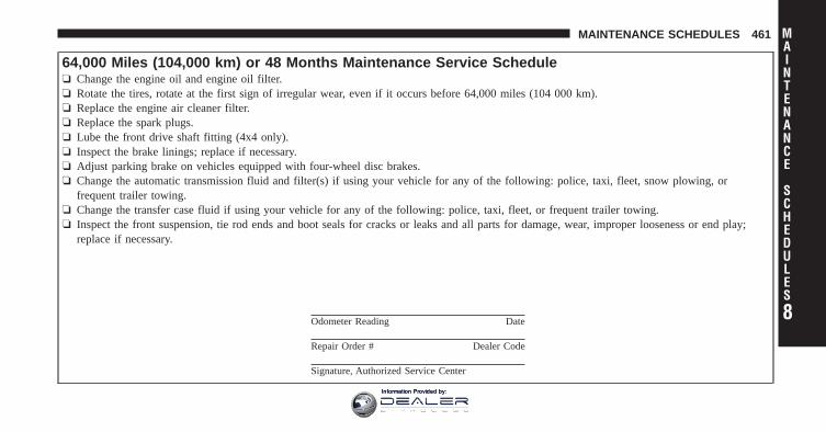
64,000 Miles (104,000 km) or 48 Months Maintenance Service Schedule❏ Change the engine oil and engine oil filter.❏ Rotate the tires, rotate at the first sign of irregular wear, even if it occurs before 64,000 miles (104 000 km).❏ Replace the engine air cleaner filter.❏ Replace the spark plugs.❏ Lube the front drive shaft fitting (4x4 only).❏ Inspect the brake linings; replace if necessary.❏ Adjust parking brake on vehicles equipped with four-wheel disc brakes.❏ Change the automatic transmission fluid and filter(s) if using your vehicle for any of the following: police, taxi, fleet, snow plowing, or
frequent trailer towing.❏ Change the transfer case fluid if using your vehicle for any of the following: police, taxi, fleet, or frequent trailer towing.❏ Inspect the front suspension, tie rod ends and boot seals for cracks or leaks and all parts for damage, wear, improper looseness or end play;
replace if necessary.
Odometer Reading Date
Repair Order # Dealer Code
Signature, Authorized Service Center
8
MAINTENANCE
SCHEDULES
MAINTENANCE SCHEDULES 461
Information Provided by:
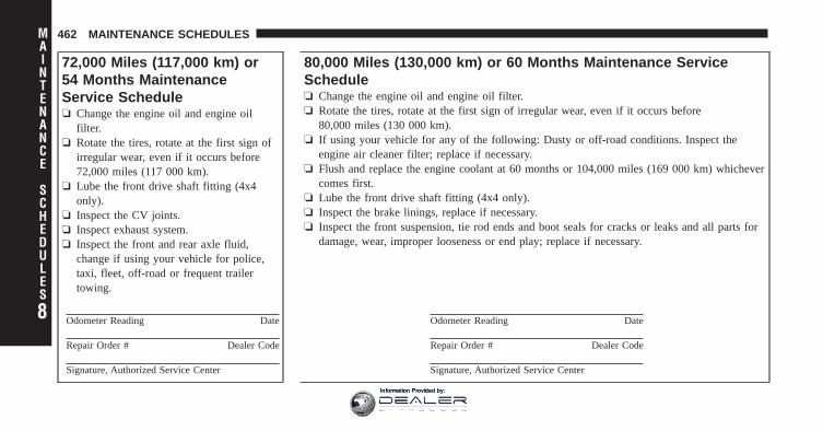
72,000 Miles (117,000 km) or54 Months MaintenanceService Schedule❏ Change the engine oil and engine oil
filter.❏ Rotate the tires, rotate at the first sign of
irregular wear, even if it occurs before72,000 miles (117 000 km).
❏ Lube the front drive shaft fitting (4x4only).
❏ Inspect the CV joints.❏ Inspect exhaust system.❏ Inspect the front and rear axle fluid,
change if using your vehicle for police,taxi, fleet, off-road or frequent trailertowing.
Odometer Reading Date
Repair Order # Dealer Code
Signature, Authorized Service Center
80,000 Miles (130,000 km) or 60 Months Maintenance ServiceSchedule❏ Change the engine oil and engine oil filter.❏ Rotate the tires, rotate at the first sign of irregular wear, even if it occurs before
80,000 miles (130 000 km).❏ If using your vehicle for any of the following: Dusty or off-road conditions. Inspect the
engine air cleaner filter; replace if necessary.❏ Flush and replace the engine coolant at 60 months or 104,000 miles (169 000 km) whichever
comes first.❏ Lube the front drive shaft fitting (4x4 only).❏ Inspect the brake linings, replace if necessary.❏ Inspect the front suspension, tie rod ends and boot seals for cracks or leaks and all parts for
damage, wear, improper looseness or end play; replace if necessary.
Odometer Reading Date
Repair Order # Dealer Code
Signature, Authorized Service Center
8
MAINTENANCE
SCHEDULES
462 MAINTENANCE SCHEDULES
Information Provided by:
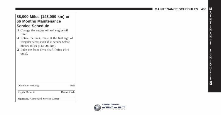
88,000 Miles (143,000 km) or66 Months MaintenanceService Schedule❏ Change the engine oil and engine oil
filter.❏ Rotate the tires, rotate at the first sign of
irregular wear, even if it occurs before88,000 miles (143 000 km).
❏ Lube the front drive shaft fitting (4x4only).
Odometer Reading Date
Repair Order # Dealer Code
Signature, Authorized Service Center
8
MAINTENANCE
SCHEDULES
MAINTENANCE SCHEDULES 463
Information Provided by:
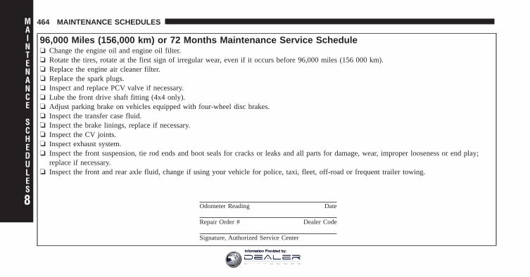
96,000 Miles (156,000 km) or 72 Months Maintenance Service Schedule❏ Change the engine oil and engine oil filter.❏ Rotate the tires, rotate at the first sign of irregular wear, even if it occurs before 96,000 miles (156 000 km).❏ Replace the engine air cleaner filter.❏ Replace the spark plugs.❏ Inspect and replace PCV valve if necessary.❏ Lube the front drive shaft fitting (4x4 only).❏ Adjust parking brake on vehicles equipped with four-wheel disc brakes.❏ Inspect the transfer case fluid.❏ Inspect the brake linings, replace if necessary.❏ Inspect the CV joints.❏ Inspect exhaust system.❏ Inspect the front suspension, tie rod ends and boot seals for cracks or leaks and all parts for damage, wear, improper looseness or end play;
replace if necessary.❏ Inspect the front and rear axle fluid, change if using your vehicle for police, taxi, fleet, off-road or frequent trailer towing.
Odometer Reading Date
Repair Order # Dealer Code
Signature, Authorized Service Center
8
MAINTENANCE
SCHEDULES
464 MAINTENANCE SCHEDULES
Information Provided by:
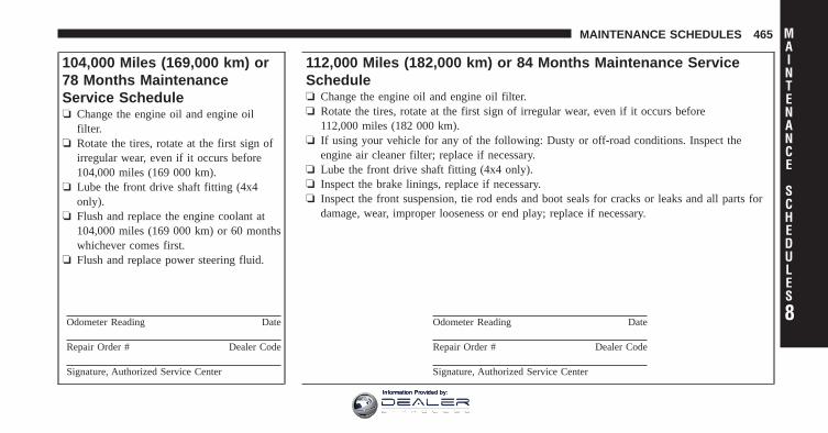
104,000 Miles (169,000 km) or78 Months MaintenanceService Schedule❏ Change the engine oil and engine oil
filter.❏ Rotate the tires, rotate at the first sign of
irregular wear, even if it occurs before104,000 miles (169 000 km).
❏ Lube the front drive shaft fitting (4x4only).
❏ Flush and replace the engine coolant at104,000 miles (169 000 km) or 60 monthswhichever comes first.
❏ Flush and replace power steering fluid.
Odometer Reading Date
Repair Order # Dealer Code
Signature, Authorized Service Center
112,000 Miles (182,000 km) or 84 Months Maintenance ServiceSchedule❏ Change the engine oil and engine oil filter.❏ Rotate the tires, rotate at the first sign of irregular wear, even if it occurs before
112,000 miles (182 000 km).❏ If using your vehicle for any of the following: Dusty or off-road conditions. Inspect the
engine air cleaner filter; replace if necessary.❏ Lube the front drive shaft fitting (4x4 only).❏ Inspect the brake linings, replace if necessary.❏ Inspect the front suspension, tie rod ends and boot seals for cracks or leaks and all parts for
damage, wear, improper looseness or end play; replace if necessary.
Odometer Reading Date
Repair Order # Dealer Code
Signature, Authorized Service Center
8
MAINTENANCE
SCHEDULES
MAINTENANCE SCHEDULES 465
Information Provided by:
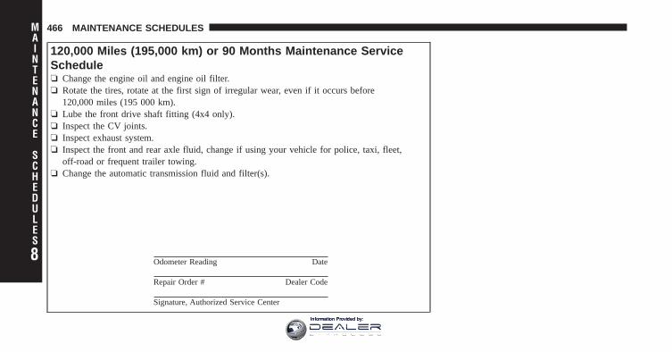
120,000 Miles (195,000 km) or 90 Months Maintenance ServiceSchedule❏ Change the engine oil and engine oil filter.❏ Rotate the tires, rotate at the first sign of irregular wear, even if it occurs before
120,000 miles (195 000 km).❏ Lube the front drive shaft fitting (4x4 only).❏ Inspect the CV joints.❏ Inspect exhaust system.❏ Inspect the front and rear axle fluid, change if using your vehicle for police, taxi, fleet,
off-road or frequent trailer towing.❏ Change the automatic transmission fluid and filter(s).
Odometer Reading Date
Repair Order # Dealer Code
Signature, Authorized Service Center
8
MAINTENANCE
SCHEDULES
466 MAINTENANCE SCHEDULES
Information Provided by:
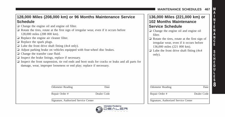
128,000 Miles (208,000 km) or 96 Months Maintenance ServiceSchedule❏ Change the engine oil and engine oil filter.❏ Rotate the tires, rotate at the first sign of irregular wear, even if it occurs before
128,000 miles (208 000 km).❏ Replace the engine air cleaner filter.❏ Replace the spark plugs.❏ Lube the front drive shaft fitting (4x4 only).❏ Adjust parking brake on vehicles equipped with four-wheel disc brakes.❏ Change the transfer case fluid.❏ Inspect the brake linings, replace if necessary.❏ Inspect the front suspension, tie rod ends and boot seals for cracks or leaks and all parts for
damage, wear, improper looseness or end play; replace if necessary.
Odometer Reading Date
Repair Order # Dealer Code
Signature, Authorized Service Center
136,000 Miles (221,000 km) or102 Months MaintenanceService Schedule❏ Change the engine oil and engine oil
filter.❏ Rotate the tires, rotate at the first sign of
irregular wear, even if it occurs before136,000 miles (221 000 km).
❏ Lube the front drive shaft fitting (4x4only).
Odometer Reading Date
Repair Order # Dealer Code
Signature, Authorized Service Center
8
MAINTENANCE
SCHEDULES
MAINTENANCE SCHEDULES 467
Information Provided by:
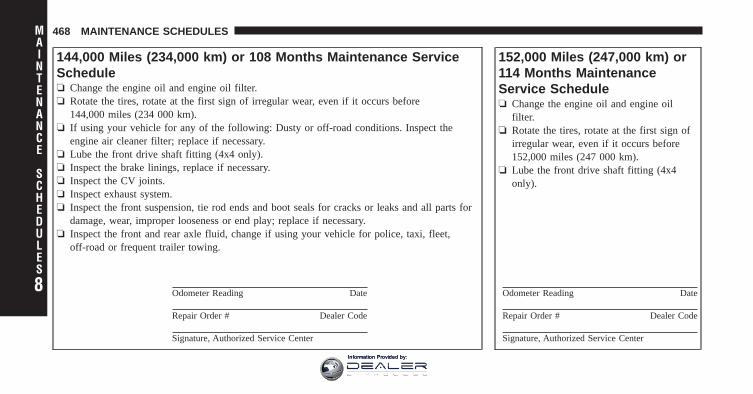
144,000 Miles (234,000 km) or 108 Months Maintenance ServiceSchedule❏ Change the engine oil and engine oil filter.❏ Rotate the tires, rotate at the first sign of irregular wear, even if it occurs before
144,000 miles (234 000 km).❏ If using your vehicle for any of the following: Dusty or off-road conditions. Inspect the
engine air cleaner filter; replace if necessary.❏ Lube the front drive shaft fitting (4x4 only).❏ Inspect the brake linings, replace if necessary.❏ Inspect the CV joints.❏ Inspect exhaust system.❏ Inspect the front suspension, tie rod ends and boot seals for cracks or leaks and all parts for
damage, wear, improper looseness or end play; replace if necessary.❏ Inspect the front and rear axle fluid, change if using your vehicle for police, taxi, fleet,
off-road or frequent trailer towing.
Odometer Reading Date
Repair Order # Dealer Code
Signature, Authorized Service Center
152,000 Miles (247,000 km) or114 Months MaintenanceService Schedule❏ Change the engine oil and engine oil
filter.❏ Rotate the tires, rotate at the first sign of
irregular wear, even if it occurs before152,000 miles (247 000 km).
❏ Lube the front drive shaft fitting (4x4only).
Odometer Reading Date
Repair Order # Dealer Code
Signature, Authorized Service Center
8
MAINTENANCE
SCHEDULES
468 MAINTENANCE SCHEDULES
Information Provided by:
WARNING!
• You can be badly injured working on or around amotor vehicle. Do only service work for which youhave the knowledge and the right equipment. Ifyou have any doubt about your ability to performa service job, take your vehicle to a competentmechanic.
• Failure to properly inspect and maintain yourvehicle could result in a component malfunctionand effect vehicle handling and performance. Thiscould cause an accident.
8
MAINTENANCE
SCHEDULES
MAINTENANCE SCHEDULES 469
Information Provided by:

Information Provided by:
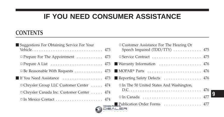
IF YOU NEED CONSUMER ASSISTANCE
CONTENTS
� Suggestions For Obtaining Service For YourVehicle . . . . . . . . . . . . . . . . . . . . . . . . . . . . . . 473
▫ Prepare For The Appointment . . . . . . . . . . . 473
▫ Prepare A List . . . . . . . . . . . . . . . . . . . . . . 473
▫ Be Reasonable With Requests . . . . . . . . . . . . 473
� If You Need Assistance . . . . . . . . . . . . . . . . . 473
▫ Chrysler Group LLC Customer Center . . . . . 474
▫ Chrysler Canada Inc. Customer Center . . . . . 474
▫ In Mexico Contact . . . . . . . . . . . . . . . . . . . . 474
▫ Customer Assistance For The Hearing OrSpeech Impaired (TDD/TTY) . . . . . . . . . . . . 475
▫ Service Contract . . . . . . . . . . . . . . . . . . . . . 475
� Warranty Information . . . . . . . . . . . . . . . . . . 476
� MOPAR� Parts . . . . . . . . . . . . . . . . . . . . . . . 476
� Reporting Safety Defects . . . . . . . . . . . . . . . . 476
▫ In The 50 United States And Washington,D.C. . . . . . . . . . . . . . . . . . . . . . . . . . . . . . . 476
▫ In Canada . . . . . . . . . . . . . . . . . . . . . . . . . 477
� Publication Order Forms . . . . . . . . . . . . . . . . 477
9
Information Provided by:
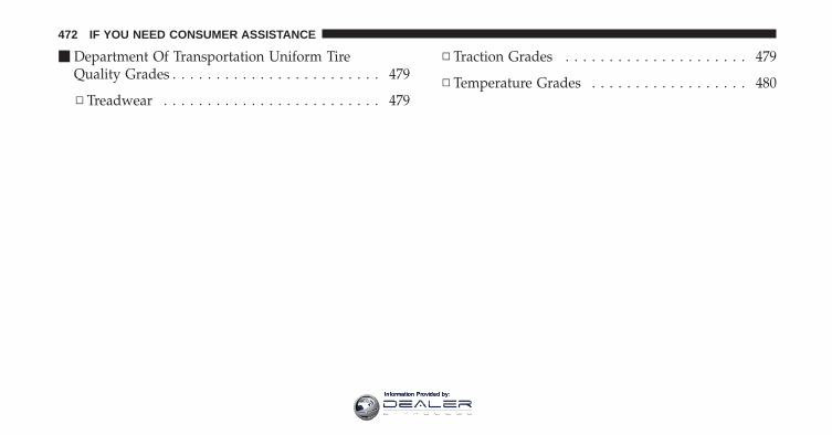
� Department Of Transportation Uniform TireQuality Grades . . . . . . . . . . . . . . . . . . . . . . . . 479
▫ Treadwear . . . . . . . . . . . . . . . . . . . . . . . . . 479
▫ Traction Grades . . . . . . . . . . . . . . . . . . . . . 479
▫ Temperature Grades . . . . . . . . . . . . . . . . . . 480
472 IF YOU NEED CONSUMER ASSISTANCE
Information Provided by:
SUGGESTIONS FOR OBTAINING SERVICE FORYOUR VEHICLE
Prepare For The AppointmentIf you’re having warranty work done, be sure to have theright papers with you. Take your warranty folder. Allwork to be performed may not be covered by thewarranty. Discuss additional charges with the servicemanager. Keep a maintenance log of your vehicle’sservice history. This can often provide a clue to thecurrent problem.
Prepare A ListMake a written list of your vehicle’s problems or thespecific work you want done. If you’ve had an accidentor work done that is not on your maintenance log, let theservice advisor know.
Be Reasonable With RequestsIf you list a number of items and you must have yourvehicle by the end of the day, discuss the situation with
the service advisor and list the items in order of priority.At many authorized dealers, you may obtain a rentalvehicle at a minimal daily charge. If you need a rental, itis advisable to make these arrangements when you callfor an appointment.
IF YOU NEED ASSISTANCEThe manufacturer and its authorized dealers are vitallyinterested in your satisfaction. We want you to be happywith our products and services.
Warranty service must be done by an authorized dealer.We strongly recommend that you take the vehicle to anauthorized dealer. They know your vehicle the best, andare most concerned that you get prompt and high qualityservice. The manufacturer’s authorized dealers have thefacilities, factory-trained technicians, special tools, andthe latest information to ensure the vehicle is fixedcorrectly and in a timely manner. 9
IF YOU NEED CONSUMER ASSISTANCE 473
Information Provided by:
This is why you should always talk to an authorizeddealer’s service manager first. Most matters can be re-solved with this process.
• If for some reason you are still not satisfied, talk to thegeneral manager or owner of the authorized dealer-ship. They want to know if you need assistance.
• If an authorized dealership is unable to resolve theconcern, you may contact the manufacturer’s customercenter.
Any communication to the manufacturer’s customer cen-ter should include the following information:
• Owner’s name and address
• Owner’s telephone number (home and office)
• Authorized dealership name
• Vehicle Identification Number (VIN)
• Vehicle delivery date and mileage
Chrysler Group LLC Customer CenterP.O. Box 21–8004Auburn Hills, MI 48321–8004Phone: (866) 726–4636
Chrysler Canada Inc. Customer CenterP.O. Box 1621Windsor, Ontario N9A 4H6Phone: (800) 465–2001 English / (800) 387–9983 French
In Mexico contact:Av. Prolongacion Paseo de la Reforma, 1240Sante Fe C.P. 05109Mexico, D. F.In Mexico City: 5081-7568Outside Mexico City: 1-800-505-1300
474 IF YOU NEED CONSUMER ASSISTANCE
Information Provided by:
Customer Assistance For The Hearing Or SpeechImpaired (TDD/TTY)To assist customers who have hearing difficulties, themanufacturer has installed special TDD (Telecommuni-cation Devices for the Deaf) equipment at its customercenter. Any hearing or speech impaired customer, whohas access to a TDD or a conventional teletypewriter(TTY) in the United States, can communicate with themanufacturer by dialing 1–800–380–CHRY.Canadian residents with hearing difficulties that requireassistance can use the special needs relay service offeredby Bell Canada. For TTY teletypewriter users, dial 711and for Voice callers, dial 1 800 855-0511 to connect witha Bell Relay Service operator.
Service ContractYou may have purchased a service contract for a vehicleto help protect you from the high cost of unexpectedrepairs after the manufacturer’s New Vehicle LimitedWarranty expires. The manufacturer stands behind only
the manufacturer’s service contracts. If you purchased amanufacturer’s service contract, you will receive PlanProvisions and an Owner Identification Card in the mailwithin three weeks of the vehicle delivery date. If youhave any questions about the service contract, call themanufacturer’s Service Contract National CustomerHotline at 1-800-521-9922 (Canadian residents, call (800)465–2001 English / (800) 387–9983 French).
The manufacturer will not stand behind any servicecontract that is not the manufacturer’s service contract. Itis not responsible for any service contract other than themanufacturer’s service contract. If you purchased a ser-vice contract that is not a manufacturer’s service contract,and you require service after the manufacturer’s NewVehicle Limited Warranty expires, please refer to thecontract documents, and contact the person listed inthose documents. 9
IF YOU NEED CONSUMER ASSISTANCE 475
Information Provided by:
We appreciate that you have made a major investmentwhen you purchased the vehicle. An authorized dealerhas also made a major investment in facilities, tools, andtraining to assure that you are absolutely delighted withthe ownership experience. You’ll be pleased with theirsincere efforts to resolve any warranty issues or relatedconcerns.
WARNING!
Engine exhaust, some of its constituents, and certainvehicle components contain, or emit, chemicalsknown to the State of California to cause cancer andbirth defects, or other reproductive harm. In addi-tion, certain fluids contained in vehicles and certainproducts of component wear contain, or emit, chemi-cals known to the State of California to cause cancerand birth defects, or other reproductive harm.
WARRANTY INFORMATIONSee the Warranty Information Booklet, located on theDVD, for the terms and provisions of Chrysler GroupLLC warranties applicable to this vehicle and market.
MOPAR� PARTSMOPAR� fluids, lubricants, parts, and accessories areavailable from an authorized dealer. They are recom-mended for your vehicle in order to help keep the vehicleoperating at its best.
REPORTING SAFETY DEFECTS
In the 50 United States and Washington, D.C.If you believe that your vehicle has a defect that couldcause a crash or cause injury or death, you shouldimmediately inform the National Highway Traffic SafetyAdministration (NHTSA) in addition to notifying themanufacturer.
476 IF YOU NEED CONSUMER ASSISTANCE
Information Provided by:
If NHTSA receives similar complaints, it may open aninvestigation, and if it finds that a safety defect exists ina group of vehicles, it may order a recall and remedycampaign. However, NHTSA cannot become involved inindividual problems between you, your authorizeddealer, and the manufacturer.
To contact NHTSA, you may either call the Auto SafetyHotline toll free at 1–888–327–4236 (TTY: 1–800–424–9153), or go to http://www.safercar.gov; or write to:Administrator, NHTSA, 1200 New Jersey Avenue, SE.,West Building, Washington, D.C. 20590. You can alsoobtain other information about motor vehicle safety fromhttp://www.safercar.gov.
In CanadaIf you believe that your vehicle has a safety defect, youshould contact the Customer Service Department imme-diately. Canadian customers who wish to report a safetydefect to the Canadian government should contact Trans-port Canada, Motor Vehicle Defect Investigations andRecalls at 1-800-333-0510 or go tohttp://www.tc.gc.ca/roadsafety/
PUBLICATION ORDER FORMSTo order the following manuals, you may use either thewebsite or the phone numbers listed below. Visa, Mas-tercard, American Express, and Discover orders are ac-cepted. If you prefer mailing your payment, please callfor an order form.
NOTE: A street address is required when orderingmanuals (no P.O. Boxes). 9
IF YOU NEED CONSUMER ASSISTANCE 477
Information Provided by:
• Service Manuals
These comprehensive Service Manuals provide theinformation that students and professional techniciansneed in diagnosing/troubleshooting, problem solving,maintaining, servicing, and repairing Chrysler GroupLLC vehicles. A complete working knowledge of thevehicle, system, and/or components is written instraightforward language with illustrations, diagrams,and charts.
• Diagnostic Procedure Manuals
Diagnostic Procedure Manuals are filled with dia-grams, charts and detailed illustrations. These practi-cal manuals make it easy for students and techniciansto find and fix problems on computer-controlled ve-hicle systems and features. They show exactly how tofind and correct problems the first time, using step-by-step troubleshooting and drivability procedures,proven diagnostic tests and a complete list of all toolsand equipment.
• Owner’s Manuals
These Owner’s Manuals have been prepared with theassistance of service and engineering specialists toacquaint you with specific Chrysler Group LLC ve-hicles. Included are starting, operating, emergencyand maintenance procedures as well as specifications,capabilities and safety tips.
Call toll free at:
• 1–800–890–4038 (U.S.)
• 1–800–387–1143 (Canada)
Or
Visit us on the Worldwide Web at:
• www.techauthority.com
478 IF YOU NEED CONSUMER ASSISTANCE
Information Provided by:
DEPARTMENT OF TRANSPORTATION UNIFORMTIRE QUALITY GRADESThe following tire grading categories were established bythe National Highway Traffic Safety Administration. Thespecific grade rating assigned by the tire’s manufacturerin each category is shown on the sidewall of the tires onyour vehicle.
All passenger car tires must conform to Federal safetyrequirements in addition to these grades.
TreadwearThe Treadwear grade is a comparative rating, based onthe wear rate of the tire when tested under controlledconditions on a specified government test course. Forexample, a tire graded 150 would wear one and one-halftimes as well on the government course as a tire graded100. The relative performance of tires depends upon theactual conditions of their use, however, and may depart
significantly from the norm due to variations in drivinghabits, service practices, and differences in road charac-teristics and climate.
Traction GradesThe Traction grades, from highest to lowest, are AA, A, B,and C. These grades represent the tire’s ability to stop onwet pavement, as measured under controlled conditionson specified government test surfaces of asphalt andconcrete. A tire marked C may have poor traction perfor-mance.
WARNING!
The traction grade assigned to this tire is based onstraight-ahead braking traction tests, and does notinclude acceleration, cornering, hydroplaning, orpeak traction characteristics.
9
IF YOU NEED CONSUMER ASSISTANCE 479
Information Provided by:
Temperature GradesThe temperature grades are A (the highest), B, and C,representing the tire’s resistance to the generation of heatand its ability to dissipate heat, when tested undercontrolled conditions on a specified indoor laboratorytest wheel. Sustained high temperature can cause thematerial of the tire to degenerate and reduce tire life, andexcessive temperature can lead to sudden tire failure. Thegrade C corresponds to a level of performance, which allpassenger car tires must meet under the Federal MotorVehicle Safety Standard No. 109. Grades B and A repre-sent higher levels of performance on the laboratory testwheel, than the minimum required by law.
WARNING!
The temperature grade for this tire is established fora tire that is properly inflated and not overloaded.Excessive speed, under-inflation, or excessive load-ing, either separately or in combination, can causeheat buildup and possible tire failure.
480 IF YOU NEED CONSUMER ASSISTANCE
Information Provided by:

INDEX
10Information Provided by:
Adding Engine Coolant (Antifreeze) . . . . . . . . . . 418Adding Fuel . . . . . . . . . . . . . . . . . . . . . . . . . . . 340Adjustable Pedals . . . . . . . . . . . . . . . . . . . . . . . 158Air Cleaner, Engine (Engine Air Cleaner Filter) . . . 408Air Conditioner Maintenance . . . . . . . . . . . . . . . 411Air Conditioning . . . . . . . . . . . . . . . . . . . . . . . . 256Air Conditioning Controls . . . . . . . . . . . . . . . . . 256Air Conditioning Refrigerant . . . . . . . . . . . . . 411,412Air Conditioning System . . . . . . . . . . . . . 256,260,411Air Conditioning, Operating Tips . . . . . . . . . . . . 267Air Pressure, Tires . . . . . . . . . . . . . . . . . . . . 319,330Airbag . . . . . . . . . . . . . . . . . . . . . . . . . . . . . . . . 52Airbag Deployment . . . . . . . . . . . . . . . . . . . . . . . 60Airbag Light . . . . . . . . . . . . . . . . . . . . . 58,62,79,200Airbag Maintenance . . . . . . . . . . . . . . . . . . . . . . . 61Airbag, Side . . . . . . . . . . . . . . . . . . . . . . . . . . . . 57Airbag, Window (Side Curtain) . . . . . . . . . . . . . . . 57Alarm (Security Alarm) . . . . . . . . . . . . . . . . . . . . 19Alarm Light . . . . . . . . . . . . . . . . . . . . . . . . . . . 192
Alarm System (Security Alarm) . . . . . . . . . . . . . . . 19Alarm, Panic . . . . . . . . . . . . . . . . . . . . . . . . . . . . 24Alterations/Modifications, Vehicle . . . . . . . . . . . . . 7Antenna, Satellite Radio . . . . . . . . . . . . . . . . . . . 243Anti-Lock Warning Light . . . . . . . . . . . . . . . 200,308Anti-Theft Security Alarm (Theft Alarm) . . . . . . . . 19Anti-Theft System . . . . . . . . . . . . . . . . . . . . . . . . 19Antifreeze (Engine Coolant) . . . . . . . . . . . . . . . . 418
Capacities . . . . . . . . . . . . . . . . . . . . . . . . . . 449Disposal . . . . . . . . . . . . . . . . . . . . . . . . . . . 420
Appearance Care . . . . . . . . . . . . . . . . . . . . . . . . 430Ashtray . . . . . . . . . . . . . . . . . . . . . . . . . . . . . . . 169Assistance Towing . . . . . . . . . . . . . . . . . . . . . . . 107Auto Down Power Windows . . . . . . . . . . . . . . . . 35Automatic Dimming Mirror . . . . . . . . . . . . . . . . . 87Automatic Door Locks . . . . . . . . . . . . . . . . . . . . . 32Automatic Headlights . . . . . . . . . . . . . . . . . . . . 148Automatic Temperature Control (ATC) . . . . . . . . . 260
482 INDEX
Information Provided by:
Automatic TransmissionAdding Fluid . . . . . . . . . . . . . . . . . . . . . . . 429Fluid and Filter Changes . . . . . . . . . . . . . . . 430Fluid Level Check . . . . . . . . . . . . . . . . . 427,428Fluid Type . . . . . . . . . . . . . . . . . . . . . . 427,451Shifting . . . . . . . . . . . . . . . . . . . . . . . . . . . 278Special Additives . . . . . . . . . . . . . . . . . . . . . 428
Axle Fluid . . . . . . . . . . . . . . . . . . . . . . . 425,426,451Axle Lubrication (Axle Fluid) . . . . . . . . . . . . 425,426
B-Pillar Location . . . . . . . . . . . . . . . . . . . . . . . . 314Battery . . . . . . . . . . . . . . . . . . . . . . . . . . . . . . . 409
Keyless Transmitter Replacement (RKE) . . . . . 25Saving Feature (Protection) . . . . . . . . . . . . . . 152
Belts, Seat . . . . . . . . . . . . . . . . . . . . . . . . . . . . 39,79Body Builders Guide . . . . . . . . . . . . . . . . . . . . . . . 6Body Mechanism Lubrication . . . . . . . . . . . . . . . 412Brake Fluid . . . . . . . . . . . . . . . . . . . . . . . . . 423,451
Brake System . . . . . . . . . . . . . . . . . . . . . . . . 306,423Anti-Lock (ABS) . . . . . . . . . . . . . . . . . . . . . 307Fluid Check . . . . . . . . . . . . . . . . . . . . . . . . 423Master Cylinder . . . . . . . . . . . . . . . . . . . . . 423Parking . . . . . . . . . . . . . . . . . . . . . . . . . . . 304Warning Light . . . . . . . . . . . . . . . . . . . . . . . 197
Brake/Transmission Interlock . . . . . . . . . . . . . . . 278Bulb Replacement . . . . . . . . . . . . . . . . . . . . . . . 443Bulbs, Light . . . . . . . . . . . . . . . . . . . . . . . . . . 81,442
Cab Top Clearance Lights . . . . . . . . . . . . . . . . . . 447Calibration, Compass . . . . . . . . . . . . . . . . . . . . . 215Capacities, Antifreeze (Engine Coolant) . . . . . . . . 449Capacities, Fluid . . . . . . . . . . . . . . . . . . . . . . . . 449Caps, Filler
Oil (Engine) . . . . . . . . . . . . . . . . . . . . . . . . 407Power Steering . . . . . . . . . . . . . . . . . . . . . . 303Radiator (Coolant Pressure) . . . . . . . . . . . . . 419
Car Washes . . . . . . . . . . . . . . . . . . . . . . . . . . . . 431 10
INDEX 483
Information Provided by:
Carbon Monoxide Warning . . . . . . . . . . . . . . . 78,339Cargo Light . . . . . . . . . . . . . . . . . . . . . . . . . . . . 152Cellular Phone . . . . . . . . . . . . . . . . . . . . . . . . 93,255Center High Mounted Stop Light . . . . . . . . . . . . 445Center Lap Belts . . . . . . . . . . . . . . . . . . . . . . . . . 48Center Seat Storage Compartment . . . . . . . . . . . . 176Certification Label . . . . . . . . . . . . . . . . . . . . . . . 342Chart, Tire Sizing . . . . . . . . . . . . . . . . . . . . . . . . 310Check Engine Light(Malfunction Indicator Light) . . . . . . . . . . . . . 199,403Checking Your Vehicle For Safety . . . . . . . . . . . . . 77Checks, Safety . . . . . . . . . . . . . . . . . . . . . . . . . . . 77Child Restraint . . . . . . . . . . . . . . . . . . . . . . . . 64,65Child Restraint Tether Anchors . . . . . . . . . . . . . 68,73Child Seat . . . . . . . . . . . . . . . . . . . . . . . . . . . . . . 70Cigar Lighter . . . . . . . . . . . . . . . . . . . . . . . . . . . 169Cleaning
Wheels . . . . . . . . . . . . . . . . . . . . . . . . . . . . 432Climate Control . . . . . . . . . . . . . . . . . . . . . . . . . 256
Clock . . . . . . . . . . . . . . . . . . . . . . . . . . . . . 223,232Cold Weather Operation . . . . . . . . . . . . . . . . . . . 274Compact Disc (CD) Maintenance . . . . . . . . . . . . . 255Compact Spare Tire . . . . . . . . . . . . . . . . . . . . . . 325Compass . . . . . . . . . . . . . . . . . . . . . . . . . . . . . . 214Compass Calibration . . . . . . . . . . . . . . . . . . . . . 215Compass Variance . . . . . . . . . . . . . . . . . . . . . . . 215Computer, Trip/Travel . . . . . . . . . . . . . . . . . . . . 212Connector
UCI . . . . . . . . . . . . . . . . . . . . . . . . . . . . . . 246Universal Consumer Interface (UCI) . . . . . . . 246
Console, Overhead . . . . . . . . . . . . . . . . . . . . . . . 163Contract, Service . . . . . . . . . . . . . . . . . . . . . . . . 475Coolant Pressure Cap (Radiator Cap) . . . . . . . . . . 419Cooling System . . . . . . . . . . . . . . . . . . . . . . . . . 417
Adding Coolant (Antifreeze) . . . . . . . . . . . . . 418Coolant Capacity . . . . . . . . . . . . . . . . . . . . . 449Coolant Level . . . . . . . . . . . . . . . . . . . . 417,420Disposal of Used Coolant . . . . . . . . . . . . . . . 420
484 INDEX
Information Provided by:
Drain, Flush, and Refill . . . . . . . . . . . . . . . . 417Inspection . . . . . . . . . . . . . . . . . . . . . . . . . . 420Points to Remember . . . . . . . . . . . . . . . . . . 422Pressure Cap . . . . . . . . . . . . . . . . . . . . . . . . 419Radiator Cap . . . . . . . . . . . . . . . . . . . . . . . 419Selection of Coolant (Antifreeze) . . . . . . . 418,450
Cupholders . . . . . . . . . . . . . . . . . . . . . . . . . . . . 172Customer Assistance . . . . . . . . . . . . . . . . . . . . . 473
Data Recorder, Event . . . . . . . . . . . . . . . . . . . . . . 63Daytime Running Lights . . . . . . . . . . . . . . . . . . . 153Dealer Service . . . . . . . . . . . . . . . . . . . . . . . . . . 405Defroster, Rear Window . . . . . . . . . . . . . . . . . . . 180Defroster, Windshield . . . . . . . . . . . . . . . . 80,258,264Delay (Intermittent) Wipers . . . . . . . . . . . . . . . . . 155Differential, Limited-Slip . . . . . . . . . . . . . . . . . . 298Dipsticks
Automatic Transmission . . . . . . . . . . . . . . . . 428Power Steering . . . . . . . . . . . . . . . . . . . . . . 303
Disabled Vehicle Towing . . . . . . . . . . . . . . . . . . . 395Disposal
Antifreeze (Engine Coolant) . . . . . . . . . . . . . 420Door Locks . . . . . . . . . . . . . . . . . . . . . . . . . . . . . 30Door Locks, Automatic . . . . . . . . . . . . . . . . . . . . 32Driving
Through Flowing, Rising, or ShallowStanding Water . . . . . . . . . . . . . . . . . . . . . . 300
Dual Rear Wheels . . . . . . . . . . . . . . . . . . . . . 334,384
Electric Rear Window Defrost . . . . . . . . . . . . . . . 180Electrical Power Outlets . . . . . . . . . . . . . . . . . . . 165Electronic Range Select (ERS) . . . . . . . . . . . . . . . 284Electronic Speed Control (Cruise Control) . . . . . . 160Electronic Vehicle Information Center (EVIC) . . . . 203Electronically Shifted Transfer Case . . . . . . . . . . . 292Emergency Brake . . . . . . . . . . . . . . . . . . . . . . . . 304
10
INDEX 485
Information Provided by:
Emergency, In Case ofFreeing Vehicle When Stuck . . . . . . . . . . . . . 392Hazard Warning Flasher . . . . . . . . . . . . . . . 376Jump Starting . . . . . . . . . . . . . . . . . . . . . . . 388Tow Hooks . . . . . . . . . . . . . . . . . . . . . . . . . 393
Emission Control System Maintenance . . . . . . . . . 403Engine . . . . . . . . . . . . . . . . . . . . . . . . . . . . . . . 401
Air Cleaner . . . . . . . . . . . . . . . . . . . . . . . . . 408Block Heater . . . . . . . . . . . . . . . . . . . . . . . . 275Break-In Recommendations . . . . . . . . . . . . . . 77Compartment Identification . . . . . . . . . . . . . 401Coolant (Antifreeze) . . . . . . . . . . . . . . . . . . 450Exhaust Gas Caution . . . . . . . . . . . . . . . . 78,339Flooded, Starting . . . . . . . . . . . . . . . . . . . . . 274Jump Starting . . . . . . . . . . . . . . . . . . . . . . . 388Oil . . . . . . . . . . . . . . . . . . . . . . . . . . . . 406,450Oil Filler Cap . . . . . . . . . . . . . . . . . . . . . . . 407Oil Selection . . . . . . . . . . . . . . . . . . . . . . . . 407Oil Synthetic . . . . . . . . . . . . . . . . . . . . . . . . 408
Temperature Gauge . . . . . . . . . . . . . . . . . . . 189Enhanced Accident Response Feature . . . . . . . . . . 59Entry System, Illuminated . . . . . . . . . . . . . . . . . . 20Event Data Recorder . . . . . . . . . . . . . . . . . . . . . . 63Exhaust Gas Caution . . . . . . . . . . . . . . . . . . . 78,339Exhaust System . . . . . . . . . . . . . . . . . . . . . . . 78,414Exterior Lighting . . . . . . . . . . . . . . . . . . . . . . . . 148Exterior Lights . . . . . . . . . . . . . . . . . . . . . . . . . . 81
FiltersAir Cleaner . . . . . . . . . . . . . . . . . . . . . . . . . 408Engine Fuel . . . . . . . . . . . . . . . . . . . . . . . . 450Engine Oil . . . . . . . . . . . . . . . . . . . . . . . 408,450Engine Oil Disposal . . . . . . . . . . . . . . . . . . . 408
FlashersTurn Signal . . . . . . . . . . . . . . . . . . . . 81,153,189
Flat Tire Stowage . . . . . . . . . . . . . . . . . . . . . . . . 388Flooded Engine Starting . . . . . . . . . . . . . . . . . . . 274Fluid Capacities . . . . . . . . . . . . . . . . . . . . . . . . . 449
486 INDEX
Information Provided by:
Fluid Leaks . . . . . . . . . . . . . . . . . . . . . . . . . . . . . 81Fluid Level Checks
Automatic Transmission . . . . . . . . . . . . . . . . 428Brake . . . . . . . . . . . . . . . . . . . . . . . . . . . . . 423Power Steering . . . . . . . . . . . . . . . . . . . . . . 303
Fluid, Brake . . . . . . . . . . . . . . . . . . . . . . . . . . . 451Fluids, Lubricants and Genuine Parts . . . . . . . . . . 450Fog Lights . . . . . . . . . . . . . . . . . . . . . . . 150,200,445Four Wheel Drive . . . . . . . . . . . . . . . . . . . . . . . 288Four-Way Hazard Flasher . . . . . . . . . . . . . . . . . . 376Freeing A Stuck Vehicle . . . . . . . . . . . . . . . . . . . 392Front Axle (Differential) . . . . . . . . . . . . . . . . . . . 425Fuel . . . . . . . . . . . . . . . . . . . . . . . . . . . . . . . . . 335
Adding . . . . . . . . . . . . . . . . . . . . . . . . . . . 340Diesel . . . . . . . . . . . . . . . . . . . . . . . . . . . . . 450Filler Cap (Gas Cap) . . . . . . . . . . . . . . . . . . 341Filter . . . . . . . . . . . . . . . . . . . . . . . . . . . . . 450Gauge . . . . . . . . . . . . . . . . . . . . . . . . . . . . 189Light . . . . . . . . . . . . . . . . . . . . . . . . . . . . . 196
Octane Rating . . . . . . . . . . . . . . . . . . . . . . . 335Requirements . . . . . . . . . . . . . . . . . . . . . . . 335Tank Capacity . . . . . . . . . . . . . . . . . . . . . . . 449
Fuses . . . . . . . . . . . . . . . . . . . . . . . . . . . . . . . . 435
Gas Cap (Fuel Filler Cap) . . . . . . . . . . . . . . . 341,402Gasoline (Fuel) . . . . . . . . . . . . . . . . . . . . . . . . . 335Gasoline, Reformulated . . . . . . . . . . . . . . . . . . . 336Gauges
Coolant Temperature . . . . . . . . . . . . . . . . . . 189Fuel . . . . . . . . . . . . . . . . . . . . . . . . . . . . . . 189Oil Pressure . . . . . . . . . . . . . . . . . . . . . . . . 192Speedometer . . . . . . . . . . . . . . . . . . . . . . . . 190Tachometer . . . . . . . . . . . . . . . . . . . . . . . . . 189Voltmeter . . . . . . . . . . . . . . . . . . . . . . . . . . 196
Gear Ranges . . . . . . . . . . . . . . . . . . . . . . . . . . . 279Gear Select Lever Override . . . . . . . . . . . . . . . . . 394General Information . . . . . . . . . . . . . . . . . . 18,26,123Glass Cleaning . . . . . . . . . . . . . . . . . . . . . . . . . . 435 10
INDEX 487
Information Provided by:
Grocery Bag Retainer . . . . . . . . . . . . . . . . . . . . . 180Gross Axle Weight Rating . . . . . . . . . . . . . . . . . . 345Gross Vehicle Weight Rating . . . . . . . . . . . . . . . . 344Guide, Body Builders . . . . . . . . . . . . . . . . . . . . . . 6GVWR . . . . . . . . . . . . . . . . . . . . . . . . . . . . . . . 342
Hands-Free Phone (Uconnect™) . . . . . . . . . . . . . . 93Hazard
Driving Through Flowing, Rising, or ShallowStanding Water . . . . . . . . . . . . . . . . . . . . . . 300
Hazard Warning Flasher . . . . . . . . . . . . . . . . . . . 376Head Restraints . . . . . . . . . . . . . . . . . . . . . . . . . 138Headlights . . . . . . . . . . . . . . . . . . . . . . . . . . . . 443
Automatic . . . . . . . . . . . . . . . . . . . . . . . . . 148Cleaning . . . . . . . . . . . . . . . . . . . . . . . . . . . 434High Beam . . . . . . . . . . . . . . . . . . . . . . . . . 154High Beam/Low Beam Select Switch . . . . . . 154Lights On Reminder . . . . . . . . . . . . . . . . . . 152Passing . . . . . . . . . . . . . . . . . . . . . . . . . . . . 154
Switch . . . . . . . . . . . . . . . . . . . . . . . . . . . . 148Heated Mirrors . . . . . . . . . . . . . . . . . . . . . . . 91,180Heated Seats . . . . . . . . . . . . . . . . . . . . . . . . . . . 132Heater . . . . . . . . . . . . . . . . . . . . . . . . . . . . . . . 256Heater, Engine Block . . . . . . . . . . . . . . . . . . . . . 275High Beam/Low Beam Select (Dimmer) Switch . . 154Hitches
Trailer Towing . . . . . . . . . . . . . . . . . . . . . . . 347Hoisting . . . . . . . . . . . . . . . . . . . . . . . . . . . . . . 388Hood Release . . . . . . . . . . . . . . . . . . . . . . . . . . 145Hub Caps . . . . . . . . . . . . . . . . . . . . . . . . . . . . . 383
Ignition . . . . . . . . . . . . . . . . . . . . . . . . . . . . . . . 14Key . . . . . . . . . . . . . . . . . . . . . . . . . . . . . 12,14
Ignition Key Removal . . . . . . . . . . . . . . . . . . . . . 14Illuminated Entry . . . . . . . . . . . . . . . . . . . . . . . . 20Immobilizer (Sentry Key) . . . . . . . . . . . . . . . . . . . 16Infant Restraint . . . . . . . . . . . . . . . . . . . . . . . . . . 64Inflation Pressure Tires . . . . . . . . . . . . . . . . . . . . 330
488 INDEX
Information Provided by:
Information Center, Vehicle . . . . . . . . . . . . . . . . . 203Inside Rearview Mirror . . . . . . . . . . . . . . . . . . . . 87Instrument Cluster . . . . . . . . . . . . . . . . . . . . 187,189Instrument Panel and Controls . . . . . . . . . . . . . . 186Instrument Panel Lens Cleaning . . . . . . . . . . . . . 435Integrated Power Module (Fuses) . . . . . . . . . . . . 435Integrated Trailer Brake Controls . . . . . . . . . . . . . 354Interior Appearance Care . . . . . . . . . . . . . . . . . . 433Interior Lights . . . . . . . . . . . . . . . . . . . . . . . . . . 150Intermittent Wipers (Delay Wipers) . . . . . . . . . . . 155Introduction . . . . . . . . . . . . . . . . . . . . . . . . . . . . . 4Inverter Outlet (115V) . . . . . . . . . . . . . . . . . . . . . 170
Jack Location . . . . . . . . . . . . . . . . . . . . . . . . . . . 376Jump Starting . . . . . . . . . . . . . . . . . . . . . . . . . . 388
Key-In Reminder . . . . . . . . . . . . . . . . . . . . . . . . . 16Key, Programming . . . . . . . . . . . . . . . . . . . . . . . . 18Key, Replacement . . . . . . . . . . . . . . . . . . . . . . . . 17
Key, Sentry (Immobilizer) . . . . . . . . . . . . . . . . . . . 16Keyless Entry System . . . . . . . . . . . . . . . . . . . . . . 21Keys . . . . . . . . . . . . . . . . . . . . . . . . . . . . . . . . . 12
Lane Change and Turn Signals . . . . . . . . . . . . . . 153Lane Change Assist . . . . . . . . . . . . . . . . . . . . . . 154Lap Belts . . . . . . . . . . . . . . . . . . . . . . . . . . . . . . 48Lap/Shoulder Belts . . . . . . . . . . . . . . . . . . . . . . . 39LATCH(Lower Anchors and Tether for CHildren) . . . . . . . 68Latches . . . . . . . . . . . . . . . . . . . . . . . . . . . . . . . . 81Leaks, Fluid . . . . . . . . . . . . . . . . . . . . . . . . . . . . 81Life of Tires . . . . . . . . . . . . . . . . . . . . . . . . . . . . 328Light Bulbs . . . . . . . . . . . . . . . . . . . . . . . . . . . . . 81Lights . . . . . . . . . . . . . . . . . . . . . . . . . . . . . . 81,147
Airbag . . . . . . . . . . . . . . . . . . . . . . 58,62,79,200Alarm . . . . . . . . . . . . . . . . . . . . . . . . . . . . 192Anti-Lock . . . . . . . . . . . . . . . . . . . . . . . . . . 200Anti-Lock Warning . . . . . . . . . . . . . . . . . . . 308 10
INDEX 489
Information Provided by:
Automatic Headlights . . . . . . . . . . . . . . . . . 148Brake Warning . . . . . . . . . . . . . . . . . . . . . . 197Bulb Replacement . . . . . . . . . . . . . . . . . 442,443Cap Top Clearance . . . . . . . . . . . . . . . . . . . 447Cargo . . . . . . . . . . . . . . . . . . . . . . . . . . . . . 152Center Mounted Stop . . . . . . . . . . . . . . . . . . 445Check Engine (Malfunction Indicator) . . . . . . 199Courtesy/Reading . . . . . . . . . . . . . . . . . . . . 164Daytime Running . . . . . . . . . . . . . . . . . . . . 153Exterior . . . . . . . . . . . . . . . . . . . . . . . . . . . . 81Fog . . . . . . . . . . . . . . . . . . . . . . . . . 150,200,445Four-Wheel Drive Indicator . . . . . . . . . . . . . 291Hazard Warning Flasher . . . . . . . . . . . . . . . 376Headlights . . . . . . . . . . . . . . . . . . . . . . . . . 148High Beam . . . . . . . . . . . . . . . . . . . . . . 154,196High Beam Indicator . . . . . . . . . . . . . . . . . . 196High Beam/Low Beam Select . . . . . . . . . . . . 154Illuminated Entry . . . . . . . . . . . . . . . . . . . . . 20Instrument Cluster . . . . . . . . . . . . . . . . . . . 189
Interior . . . . . . . . . . . . . . . . . . . . . . . . . 150,164Lights On Reminder . . . . . . . . . . . . . . . . . . 152Low Fuel . . . . . . . . . . . . . . . . . . . . . . . . . . 196Oil Pressure . . . . . . . . . . . . . . . . . . . . . . . . 198Passing . . . . . . . . . . . . . . . . . . . . . . . . . . . . 154Seat Belt Reminder . . . . . . . . . . . . . . . . . . . 202Security Alarm (Theft Alarm) . . . . . . . . . . . . 192Service . . . . . . . . . . . . . . . . . . . . . . . . . 442,443Theft Alarm (Security Alarm) . . . . . . . . . . . . 192Transfer Case . . . . . . . . . . . . . . . . . . . . . . . 291Turn Signal . . . . . . . . . . . . . . . . . . . . 81,153,443Warning (Instrument Cluster Description) . . . 189
Limited-Slip Differential . . . . . . . . . . . . . . . . 298,426Loading Vehicle . . . . . . . . . . . . . . . . . . . . . . . . . 342
Tires . . . . . . . . . . . . . . . . . . . . . . . . . . . . . . 314Locks . . . . . . . . . . . . . . . . . . . . . . . . . . . . . . . . . 30
Automatic Door . . . . . . . . . . . . . . . . . . . . . . 32Child Protection . . . . . . . . . . . . . . . . . . . . . . 32Door . . . . . . . . . . . . . . . . . . . . . . . . . . . . . . 30
490 INDEX
Information Provided by:
Power Door . . . . . . . . . . . . . . . . . . . . . . . . . 31Lower Anchors and Tether forCHildren (LATCH) . . . . . . . . . . . . . . . . . . . . . . . 68Lubrication, Body . . . . . . . . . . . . . . . . . . . . . . . 412Lug Nuts . . . . . . . . . . . . . . . . . . . . . . . . . . . 382,384
Maintenance Free Battery . . . . . . . . . . . . . . . . . . 409Maintenance Procedures . . . . . . . . . . . . . . . . . . . 405Maintenance Schedule . . . . . . . . . . . . . . . . . . . . 454Malfunction Indicator Light (Check Engine) . . . . . 403Manual Transmission
Fluid Level Check . . . . . . . . . . . . . . . . . . . . 427Lubricant Selection . . . . . . . . . . . . . . . . . . . 451
Manual, Service . . . . . . . . . . . . . . . . . . . . . . . . . 477Memory Seat . . . . . . . . . . . . . . . . . . . . . . . . . . . 140Mini-Trip Computer . . . . . . . . . . . . . . . . . . . . . . 212Mirrors . . . . . . . . . . . . . . . . . . . . . . . . . . . . . . . . 87
Automatic Dimming . . . . . . . . . . . . . . . . . . . 87Electric Powered . . . . . . . . . . . . . . . . . . . . . . 90
Heated . . . . . . . . . . . . . . . . . . . . . . . . . . . . . 91Memory . . . . . . . . . . . . . . . . . . . . . . . . . . . 140Outside . . . . . . . . . . . . . . . . . . . . . . . . . . . . 88Rearview . . . . . . . . . . . . . . . . . . . . . . . . . . . 87Trailer Towing . . . . . . . . . . . . . . . . . . . . . . . 92
Modifications/Alterations, Vehicle . . . . . . . . . . . . . 7Mopar Parts . . . . . . . . . . . . . . . . . . . . . . . . . 404,476Multi-Function Control Lever . . . . . . . . . . . . . . . 153
New Vehicle Break-In Period . . . . . . . . . . . . . . . . 77
Occupant Restraints . . . . . . . . . . . . . . . . . . . 38,57,60Occupant Restraints (Sedan) . . . . . . . . . . . . . . . . . 57Octane Rating, Gasoline (Fuel) . . . . . . . . . . . . . . 335Odometer . . . . . . . . . . . . . . . . . . . . . . . . . . . . . 192
Trip . . . . . . . . . . . . . . . . . . . . . . . . . . . . . . 192Oil Change Indicator . . . . . . . . . . . . . . . . . . 194,210Oil Change Indicator, Reset . . . . . . . . . . . . . . 194,210
10
INDEX 491
Information Provided by:
Oil, Engine . . . . . . . . . . . . . . . . . . . . . . . . . 406,450Capacity . . . . . . . . . . . . . . . . . . . . . . . . . . . 449Change Interval . . . . . . . . . . . . . . . . . . . . . 406Dipstick . . . . . . . . . . . . . . . . . . . . . . . . . . . 406Disposal . . . . . . . . . . . . . . . . . . . . . . . . . . . 408Filter . . . . . . . . . . . . . . . . . . . . . . . . . . 408,450Filter Disposal . . . . . . . . . . . . . . . . . . . . . . . 408Identification Logo . . . . . . . . . . . . . . . . . . . 407Materials Added to . . . . . . . . . . . . . . . . . . . 408Pressure Gauge . . . . . . . . . . . . . . . . . . . . . . 192Recommendation . . . . . . . . . . . . . . . . . . . . . 407Synthetic . . . . . . . . . . . . . . . . . . . . . . . . . . 408Viscosity . . . . . . . . . . . . . . . . . . . . . . . . . . . 407
Onboard Diagnostic System . . . . . . . . . . . . . . 402,403Operating Precautions . . . . . . . . . . . . . . . . . . . . 402Operator Manual (Owner’s Manual) . . . . . . . . . . . . 4Outside Rearview Mirrors . . . . . . . . . . . . . . . . . . 88Overdrive . . . . . . . . . . . . . . . . . . . . . . . . . . . . . 286Overdrive OFF Switch . . . . . . . . . . . . . . . . . . . . 286
Overhead Console . . . . . . . . . . . . . . . . . . . . . . . 163Overheating, Engine . . . . . . . . . . . . . . . . . . . . . . 190Owner’s Manual (Operator Manual) . . . . . . . . . 4,477
Panic Alarm . . . . . . . . . . . . . . . . . . . . . . . . . . . . 24Parking Brake . . . . . . . . . . . . . . . . . . . . . . . . . . 304Passing Light . . . . . . . . . . . . . . . . . . . . . . . . . . . 154Pedals, Adjustable . . . . . . . . . . . . . . . . . . . . . . . 158Personal Settings . . . . . . . . . . . . . . . . . . . . . . . . 216Pets . . . . . . . . . . . . . . . . . . . . . . . . . . . . . . . . . . 77Pets, Transporting . . . . . . . . . . . . . . . . . . . . . . . . 77Phone, Cellular . . . . . . . . . . . . . . . . . . . . . . . . . . 93Phone, Hands-Free (Uconnect™) . . . . . . . . . . . . . . 93Placard, Tire and Loading Information . . . . . . . . . 314Power
Door Locks . . . . . . . . . . . . . . . . . . . . . . . . . 31Mirrors . . . . . . . . . . . . . . . . . . . . . . . . . . . . 90Outlet (Auxiliary Electrical Outlet) . . . . . 165,170Seats . . . . . . . . . . . . . . . . . . . . . . . . . . . . . 128
492 INDEX
Information Provided by:
Sliding Rear Window . . . . . . . . . . . . . . . . . . 181Steering . . . . . . . . . . . . . . . . . . . . . . . . 302,303Windows . . . . . . . . . . . . . . . . . . . . . . . . . . . 34
Power Steering Fluid . . . . . . . . . . . . . . . . . . . . . 451Pregnant Women and Seat Belts . . . . . . . . . . . . . . 52Programmable Electronic Features . . . . . . . . . . . . 216Programming Transmitters(Remote Keyless Entry) . . . . . . . . . . . . . . . . . . . . 21
Radial Ply Tires . . . . . . . . . . . . . . . . . . . . . . . . . 324Radiator Cap (Coolant Pressure Cap) . . . . . . . 417,419Radio Operation . . . . . . . . . . . . . . . . . . . . . . . . 255Rear Axle (Differential) . . . . . . . . . . . . . . . . . 425,426Rear Window Features . . . . . . . . . . . . . . . . . . . . 180Rear Window, Sliding . . . . . . . . . . . . . . . . . . . . . 181Reclining Front Seats . . . . . . . . . . . . . . . . . . . . . 137Recorder, Event Data . . . . . . . . . . . . . . . . . . . . . . 63Recreational Towing . . . . . . . . . . . . . . . . . . . . . . 365
Shifting into Transfer Case Neutral (N) . . 368,370
Shifting out of TransferCase Neutral (N) . . . . . . . . . . . . . . . . . . 369,373
Reformulated Gasoline . . . . . . . . . . . . . . . . . . . . 336Refrigerant . . . . . . . . . . . . . . . . . . . . . . . . . . . . 412Reminder, Seat Belt . . . . . . . . . . . . . . . . . . . . . . . 51Remote Control
Starting System . . . . . . . . . . . . . . . . . . . . . . . 26Remote Keyless Entry (RKE) . . . . . . . . . . . . . . . . . 21Remote Sound System (Radio) Controls . . . . . . . . 253Remote Starting System . . . . . . . . . . . . . . . . . . . . 26Replacement Keys . . . . . . . . . . . . . . . . . . . . . . . . 17Replacement Parts . . . . . . . . . . . . . . . . . . . . . . . 404Replacement Tires . . . . . . . . . . . . . . . . . . . . . . . 328Reporting Safety Defects . . . . . . . . . . . . . . . . . . . 476Resetting Oil Change Indicator . . . . . . . . . . . 194,210Restraint, Head . . . . . . . . . . . . . . . . . . . . . . . . . 138Restraints, Child . . . . . . . . . . . . . . . . . . . . . . . 64,70Restraints, Occupant . . . . . . . . . . . . . . . . . . . . . . 38Rotation, Tires . . . . . . . . . . . . . . . . . . . . . . . . . . 333 10
INDEX 493
Information Provided by:
Safety Checks Inside Vehicle . . . . . . . . . . . . . . . . . 79Safety Checks Outside Vehicle . . . . . . . . . . . . . . . 81Safety Defects, Reporting . . . . . . . . . . . . . . . . . . 476Safety Information, Tire . . . . . . . . . . . . . . . . . . . 309Safety Tips . . . . . . . . . . . . . . . . . . . . . . . . . . . . . 77Safety, Exhaust Gas . . . . . . . . . . . . . . . . . . . . . . . 78Satellite Radio Antenna . . . . . . . . . . . . . . . . . . . 243Schedule, Maintenance . . . . . . . . . . . . . . . . . . . . 454Seat Belt Maintenance . . . . . . . . . . . . . . . . . . . . 435Seat Belt Reminder . . . . . . . . . . . . . . . . . . . . . . . 51Seat Belts . . . . . . . . . . . . . . . . . . . . . . . . . . 38,39,79
Adjustable Upper Shoulder Anchorage . . . . . . 48And Pregnant Women . . . . . . . . . . . . . . . . . . 52Child Restraint . . . . . . . . . . . . . . . . . . . . . 64,68Extender . . . . . . . . . . . . . . . . . . . . . . . . . . . 52Front Seat . . . . . . . . . . . . . . . . . . . . . . . . . . 39Inspection . . . . . . . . . . . . . . . . . . . . . . . . . . 79Reminder . . . . . . . . . . . . . . . . . . . . . . . . . . 202
Seats . . . . . . . . . . . . . . . . . . . . . . . . . . . . . . 128,140Adjustment . . . . . . . . . . . . . . . . . . . . . . . . . 128Child . . . . . . . . . . . . . . . . . . . . . . . . . . . . . . 68Heated . . . . . . . . . . . . . . . . . . . . . . . . . . . . 132Memory . . . . . . . . . . . . . . . . . . . . . . . . . . . 140Power . . . . . . . . . . . . . . . . . . . . . . . . . . . . 128Reclining . . . . . . . . . . . . . . . . . . . . . . . . . . 137
Security Alarm (Theft Alarm) . . . . . . . . . . . . . . . . 19Selection of Coolant (Antifreeze) . . . . . . . . . . 418,450Sentry Key (Immobilizer) . . . . . . . . . . . . . . . . . . . 16Sentry Key Programming . . . . . . . . . . . . . . . . . . . 18Sentry Key Replacement . . . . . . . . . . . . . . . . . . . 17Service Assistance . . . . . . . . . . . . . . . . . . . . . . . 473Service Contract . . . . . . . . . . . . . . . . . . . . . . . . . 475Service Manuals . . . . . . . . . . . . . . . . . . . . . . . . 477Setting the Clock . . . . . . . . . . . . . . . . . . . . . 223,232Settings, Personal . . . . . . . . . . . . . . . . . . . . . . . . 216Shift Lever Override . . . . . . . . . . . . . . . . . . . . . . 394
494 INDEX
Information Provided by:
Shifting . . . . . . . . . . . . . . . . . . . . . . . . . . . . . . . 276Automatic Transmission . . . . . . . . . . . . . . . . 278Transfer Case . . . . . . . . . . . . . . . . . . . . . . . 290Transfer Case, Shifting into TransferCase Neutral (N) . . . . . . . . . . . . . . . . . . 368,370Transfer Case, Shifting out of TransferCase Neutral (N) . . . . . . . . . . . . . . . . . . 369,373
Short Message Service (SMS) . . . . . . . . . . . . . . . . 115Shoulder Belt Upper Anchorage . . . . . . . . . . . . . . 48Shoulder Belts . . . . . . . . . . . . . . . . . . . . . . . . . . . 39Signals, Turn . . . . . . . . . . . . . . . . . . . . . . 81,153,189Sliding Rear Window
Power . . . . . . . . . . . . . . . . . . . . . . . . . . . . 181Snow Chains (Tire Chains) . . . . . . . . . . . . . . . . . 330Snow Plow . . . . . . . . . . . . . . . . . . . . . . . . . . . . 361Snow Tires . . . . . . . . . . . . . . . . . . . . . . . . . . . . 332Spare Tire . . . . . . . . . . . . . . . . . . . . . . . . . . 325,326Spark Plugs . . . . . . . . . . . . . . . . . . . . . . . . . . . . 450Speed Control (Cruise Control) . . . . . . . . . . . . . . 160
Speedometer . . . . . . . . . . . . . . . . . . . . . . . . . . . 190Starting . . . . . . . . . . . . . . . . . . . . . . . . . . . . . 26,273
Automatic Transmission . . . . . . . . . . . . . . . . 273Cold Weather . . . . . . . . . . . . . . . . . . . . . . . 274Engine Fails to Start . . . . . . . . . . . . . . . . . . 274Remote . . . . . . . . . . . . . . . . . . . . . . . . . . . . 26
Starting Procedures (Gas Engines) . . . . . . . . . . . . 273Steel Carcass Ply Tires . . . . . . . . . . . . . . . . . . . . 321Steering
Power . . . . . . . . . . . . . . . . . . . . . . . . . . 302,303Wheel, Heated . . . . . . . . . . . . . . . . . . . . . . 159Wheel, Tilt . . . . . . . . . . . . . . . . . . . . . . . . . 157
Steering Wheel Audio Controls . . . . . . . . . . . . . . 253Steering Wheel Mounted SoundSystem Controls . . . . . . . . . . . . . . . . . . . . . . . . . 253Storage Compartment, Center Seat . . . . . . . . . . . 176Storage, Vehicle . . . . . . . . . . . . . . . . . . . . . . 266,441Storing Your Vehicle . . . . . . . . . . . . . . . . . . . . . . 441Supplemental Tire Pressure Information . . . . . . . . 330 10
INDEX 495
Information Provided by:
Synthetic Engine Oil . . . . . . . . . . . . . . . . . . . . . . 408System, Remote Starting . . . . . . . . . . . . . . . . . . . . 26
Tachometer . . . . . . . . . . . . . . . . . . . . . . . . . . . . 189Temperature Control, Automatic (ATC) . . . . . . . . 260Temperature Gauge, Engine Coolant . . . . . . . . . . 189Tether Anchor, Child Restraint . . . . . . . . . . . . . 68,73Text Messaging . . . . . . . . . . . . . . . . . . . . . . . . . 115Tilt Steering Column . . . . . . . . . . . . . . . . . . . . . 157Tip Start . . . . . . . . . . . . . . . . . . . . . . . . . . . . . . 274Tire and Loading Information Placard . . . . . . 314,330Tire Identification Number (TIN) . . . . . . . . . . . . . 312Tire Markings . . . . . . . . . . . . . . . . . . . . . . . . . . 309Tire Safety Information . . . . . . . . . . . . . . . . . . . . 309Tires . . . . . . . . . . . . . . . . . . . . . . . . . . . . 81,318,479
Aging (Life of Tires) . . . . . . . . . . . . . . . . . . 328Air Pressure . . . . . . . . . . . . . . . . . . . . . . . . 318Chains . . . . . . . . . . . . . . . . . . . . . . . . . . . . 330Compact Spare . . . . . . . . . . . . . . . . . . . . . . 325
Dual . . . . . . . . . . . . . . . . . . . . . . . . . . . 334,384General Information . . . . . . . . . . . . . . . . . . 318High Speed . . . . . . . . . . . . . . . . . . . . . . . . . 323Inflation Pressures . . . . . . . . . . . . . . . . . . . . 319Life of Tires . . . . . . . . . . . . . . . . . . . . . . . . 328Load Capacity . . . . . . . . . . . . . . . . . . . . 314,315Quality Grading . . . . . . . . . . . . . . . . . . . . . 479Radial . . . . . . . . . . . . . . . . . . . . . . . . . . . . 324Replacement . . . . . . . . . . . . . . . . . . . . . . . . 328Rotation . . . . . . . . . . . . . . . . . . . . . . . . . . . 333Safety . . . . . . . . . . . . . . . . . . . . . . . . . . 309,318Sizes . . . . . . . . . . . . . . . . . . . . . . . . . . . . . 310Snow Tires . . . . . . . . . . . . . . . . . . . . . . . . . 332Spinning . . . . . . . . . . . . . . . . . . . . . . . . . . . 327Steel Carcass Ply . . . . . . . . . . . . . . . . . . . . . 321Tread Wear Indicators . . . . . . . . . . . . . . . . . 327Wheel Nut Torque . . . . . . . . . . . . . . . . . . . . 382
Tongue Weight/Trailer Weight . . . . . . . . . . . . . . 349Torque Converter Clutch . . . . . . . . . . . . . . . . . . 287
496 INDEX
Information Provided by:
Tow Hooks, Emergency . . . . . . . . . . . . . . . . . . . 393Towing . . . . . . . . . . . . . . . . . . . . . . . . . . . . 344,395
24-Hour Towing Assistance . . . . . . . . . . . . . 107Disabled Vehicle . . . . . . . . . . . . . . . . . . . . . 395Guide . . . . . . . . . . . . . . . . . . . . . . . . . . . . . 348Recreational . . . . . . . . . . . . . . . . . . . . . . . . 365Weight . . . . . . . . . . . . . . . . . . . . . . . . . . . . 348
Towing Assistance . . . . . . . . . . . . . . . . . . . . . . . 107Traction . . . . . . . . . . . . . . . . . . . . . . . . . . . . . . 299Trailer Towing . . . . . . . . . . . . . . . . . . . . . . . . . . 344
Cooling System Tips . . . . . . . . . . . . . . . . . . 361Hitches . . . . . . . . . . . . . . . . . . . . . . . . . . . . 347Minimum Requirements . . . . . . . . . . . . . . . . 351Mirrors . . . . . . . . . . . . . . . . . . . . . . . . . . . . 92Trailer and Tongue Weight . . . . . . . . . . . . . . 349Wiring . . . . . . . . . . . . . . . . . . . . . . . . . . . . 359
Trailer Towing Guide . . . . . . . . . . . . . . . . . . . . . 348Trailer Weight . . . . . . . . . . . . . . . . . . . . . . . . . . 348
Transfer Case . . . . . . . . . . . . . . . . . . . . . . . . . . . 427Electronically Shifted . . . . . . . . . . . . . . . . . . 292Fluid . . . . . . . . . . . . . . . . . . . . . . . . . . . . . 451
TransmissionAutomatic . . . . . . . . . . . . . . . . . . . . . . . 278,427Fluid . . . . . . . . . . . . . . . . . . . . . . . . . . . . . 451Maintenance . . . . . . . . . . . . . . . . . . . . . . . . 427Shifting . . . . . . . . . . . . . . . . . . . . . . . . . . . 276
Transmitter Battery Service(Remote Keyless Entry) . . . . . . . . . . . . . . . . . . . . 25Transmitter Programming(Remote Keyless Entry) . . . . . . . . . . . . . . . . . . . . 21Transmitter, Remote Keyless Entry (RKE) . . . . . . . . 21Tread Wear Indicators . . . . . . . . . . . . . . . . . . . . 327Trip Odometer . . . . . . . . . . . . . . . . . . . . . . . . . . 192Turn Signals . . . . . . . . . . . . . . . . . . . . . . 153,189,443
10
INDEX 497
Information Provided by:
UCI Connector . . . . . . . . . . . . . . . . . . . . . . . . . 246Uconnect™ (Hands-Free Phone) . . . . . . . . . . . . . . 93Uniform Tire Quality Grades . . . . . . . . . . . . . . . . 479Universal Consumer Interface (UCI) Connector . . . 246
Variance, Compass . . . . . . . . . . . . . . . . . . . . . . . 215Vehicle Identification Number (VIN) . . . . . . . . . . . . 6Vehicle Loading . . . . . . . . . . . . . . . . . . . . . . 315,342Vehicle Modifications/Alterations . . . . . . . . . . . . . . 7Vehicle Storage . . . . . . . . . . . . . . . . . . . . . . . 266,441Voice Recognition System (VR) . . . . . . . . . . . . . . 123Voltmeter . . . . . . . . . . . . . . . . . . . . . . . . . . . . . 196
Warning Lights(Instrument Cluster Description) . . . . . . . . . . . . . 189Warnings and Cautions . . . . . . . . . . . . . . . . . . . . . 6Warranty Information . . . . . . . . . . . . . . . . . . . . . 476Washers, Windshield . . . . . . . . . . . . . . . . . . 156,413Washing Vehicle . . . . . . . . . . . . . . . . . . . . . . . . . 431
WaterDriving Through . . . . . . . . . . . . . . . . . . . . . 300
Wheel and Wheel Trim . . . . . . . . . . . . . . . . . . . . 432Wheel and Wheel Trim Care . . . . . . . . . . . . . . . . 432Wheel Cover . . . . . . . . . . . . . . . . . . . . . . . . . . . 383Wheel Nut Torque . . . . . . . . . . . . . . . . . . . . 382,387Wind Buffeting . . . . . . . . . . . . . . . . . . . . . . . . . . 37Window Fogging . . . . . . . . . . . . . . . . . . . . . . . . 266Windows . . . . . . . . . . . . . . . . . . . . . . . . . . . . . . 34
Power . . . . . . . . . . . . . . . . . . . . . . . . . . . . . 34Rear Sliding . . . . . . . . . . . . . . . . . . . . . . . . 181
Windshield Defroster . . . . . . . . . . . . . . . . . . . . . . 80Windshield Washers . . . . . . . . . . . . . . . . 154,156,413
Fluid . . . . . . . . . . . . . . . . . . . . . . . . . . 154,413Windshield Wiper Blades . . . . . . . . . . . . . . . . . . 413Windshield Wipers . . . . . . . . . . . . . . . . . . . . . . . 154Wiper Blade Replacement . . . . . . . . . . . . . . . . . . 413Wipers, Intermittent . . . . . . . . . . . . . . . . . . . . . . 155
498 INDEX
Information Provided by:
INSTALLATION OF RADIO TRANSMITTINGEQUIPMENTSpecial design considerations are incorporated into this vehi-cle’s electronic system to provide immunity to radio frequencysignals. Mobile two-way radios and telephone equipment mustbe installed properly by trained personnel. The following mustbe observed during installation.
The positive power connection should be made directly to thebattery and fused as close to the battery as possible. Thenegative power connection should be made to body sheetmetal adjacent to the negative battery connection. This con-nection should not be fused.
Antennas for two-way radios should be mounted on the roof orthe rear area of the vehicle. Care should be used in mountingantennas with magnet bases. Magnets may affect the accu-racy or operation of the compass on vehicles so equipped.
The antenna cable should be as short as practical and routedaway from the vehicle wiring when possible. Use only fullyshielded coaxial cable.
Carefully match the antenna and cable to the radio to ensure alow Standing Wave Ratio (SWR).
Mobile radio equipment with output power greater than nor-mal may require special precautions.
All installations should be checked for possible interferencebetween the communications equipment and the vehicle’selectronic systems.
Information Provided by:
Chrysler Group LLC12DD43-126-AD 4th Edition Printed in U.S.A.
Information Provided by: