product catalog - ram jack
TRANSCRIPT
To order custom product please email [email protected]
PRODUCT CATALOGVersion 1.2
Release Date: 1.30.19
®
Page i To order custom product please email [email protected]
CONTACTINFORMATION
AddressRam Jack Systems Distribution, LLC13655 CR 1570 Ada, OK 74820
TelephoneTOLL FREE: 1-888-332-9909LOCAL: 1-580-332-9980
WebWEB: www.ramjack.comEMAIL: [email protected]

Page ii To order custom product please email [email protected]
Page iii To order custom product please email [email protected]
TABLE OF CONTENTSHELICALS Helical Pile System..................................................................................................................1-3 Helical Pile Anchor & Lead Section 1 1/2” Diameter Tieback Anchors and Extensions..........................................................................5-6 2 3/8” Diameter Helical Pile and Anchor Lead Sections (Threaded)................................................7-9 2 3/8” Diameter Helical Pile and Anchor Lead Sections (External)...............................................11-12 2 7/8” Diameter Helical Pile and Anchor Lead Sections (Threaded)............................................13-15 2 7/8” Diameter Helical Pile and Anchor Lead Sections (External)...............................................17-18 3 1/2” Diameter Helical Pile and Anchor Lead Sections (Threaded)............................................19-20 3 1/2” Diameter Helical Pile and Anchor Lead Sections (Internal)................................................21-22 4 1/2” Diameter Helical Pile and Anchor Lead Sections (Internal)................................................23-24 5 1/2” Diameter Helical Pile and Anchor Lead Sections (External)...............................................25-26 Guide Sleeve 2 7/8” Independent Guide Sleeve....................................................................................................27 3 1/2” Independent Guide Sleeve....................................................................................................27 4 1/2” Independent Guide Sleeve....................................................................................................28
Brackets Pile Bracket Pile Bracket w/ Narrow Seat...........................................................................................................29 Pile Bracket................................................................................................................................30-32 Pile Bracket w/ Squared 90o Back Plate.........................................................................................33 Pile Bracket w/ Extended Seat........................................................................................................34 Helical Pile Bracket w/ Narrow Seat................................................................................................35 Helical Pile Bracket..........................................................................................................................36 Helical Pile Bracket w/ Flat Top.......................................................................................................37 Extra Wide Seat Bracket..................................................................................................................38 Shallow Footing Bracket..................................................................................................................39 Low Profile Bracket Low Profile Bracket w/ Narrow Seat...............................................................................................40 Low Profile Bracket w/ Short Back.................................................................................................41 Low Profile Bracket w/ Tall Back.....................................................................................................42 Extra Low Profile Bracket................................................................................................................43 Porch Bracket Flush Profile Porch Bracket..............................................................................................................44 Low Profile Porch Bracket w/o Back Plate.......................................................................................45 Porch Bracket w/ Back Plate...........................................................................................................46 Interior Slab Bracket Standard Floor Slab Bracket...........................................................................................................47 Heavy Floor Slab Brackets..............................................................................................................48 Fold-Up Floor Slab Bracket.............................................................................................................49 Hydraulic Lift Floor Slab Bracket......................................................................................................50 Floor Beam Bracket.........................................................................................................................51 Screw Jack Bracket........................................................................................................................52 New Construction Bracket New Construction Bracket..........................................................................................................53-54 Other Brackets Timber Column Bracket...................................................................................................................55 Boardwalk Bracket.....................................................................................................................56-58 Wall Mount Basement Bracket........................................................................................................59 Tieback Assembly Wall Tieback Assembly...............................................................................................................60-61 Pile Tieback Assembly.....................................................................................................................62 Additional Design & Pile Considerations..............................................................................63-64
Page iv To order custom product please email [email protected]
TABLE OF CONTENTSDRIVEN Driven Pile System...............................................................................................................65-66 Driven Pilings 2 7/8” Diameter Driven Pile.............................................................................................................67 3 1/2” Diameter Driven Pile.............................................................................................................68 Starter Driven Pile Starter............................................................................................................................69 Driven Starter Piling.........................................................................................................................70 Guide Sleeves 3 1/2” Independent Guide Sleeve.....................................................................................................71 4 1/2” Independent Guide Sleeve....................................................................................................72
Brackets Pile Bracket Driven Pile Bracket w/ Narrow Seat.................................................................................................73 Driven Pile Bracket.....................................................................................................................74-75 Driven Pile Bracket w/ Squared 90o Back Plate..............................................................................76 Driven Pile Bracket w/ Extended Seat.............................................................................................77 Extra Wide Seat Bracket..................................................................................................................78 Wall Mount Basement Bracket.........................................................................................................79 Low Profile Bracket Low Profile Bracket w/ Narrow Seat................................................................................................80 Low Profile Bracket w/ Short Back..................................................................................................81 Low Profile Bracket w/ Tall Back.....................................................................................................82 Shallow Footing Bracket..................................................................................................................83 Driven Pile Load Conversion Charts..........................................................................................84
Page 1 To order custom product please email [email protected]
Ram Jack’s Helical Pile System is used to underpin new and existing structures. A key advantage of the helical pile over the driven pile is that the helical pile does not rely on the structure to provide the reaction resistance in order to install.
They are installed with a high torque hydraulic motor. Ram Jack’s helical piles can be used for new construc-tion and foundation repair, accommodating loads rang-ing from lightweight to heavy.
Ram Jack’s helical piles have the power and versatility to support all loads. They also work very effectively in ten-sion as a tieback or anchor.
Ram Jack offers a wide array of specialty brackets for almost every helical underpinning, tieback and anchor-age application. If for some reason you are unable to find the correct bracket for your application in this catalog, please feel free to contact Ram Jack for assistance. We will work with you to find an appropriate design for your underpinning needs. If you are not able to find a bracket to fit your loading application, Ram Jack’s engineering department will work with you or your engineer to cus-tom design a bracket to fit you needs.
Ram Jack manufactures helical piles and anchor shafts in a wide array of shaft diameters to fit almost every ap-plication. Ram Jack’s standard helical pile shafts consist of 1 5/8”, 2 3/8”, 2 7/8”, 3 1/2”, 4 1/2”, and 5 1/2” diameters. All standard helical shaft and extensions are carbon steel with minimum yield strength of 65 ksi. The high strength of the shafts allows high torque values to be applied to penetrate deep into stable soils.
The 2 3/8”, 2 7/8”, and 3 ½” diameter pile shafts have an internal threaded coupling connection that is unique to the industry. The internal threaded connection is ex-tremely rigid and has zero eccentricity. This allows the pile shaft to have a higher resistance to bending and buck-ling stresses. The connection also allows the exterior of the pile shaft to have a smooth homogenous surface.
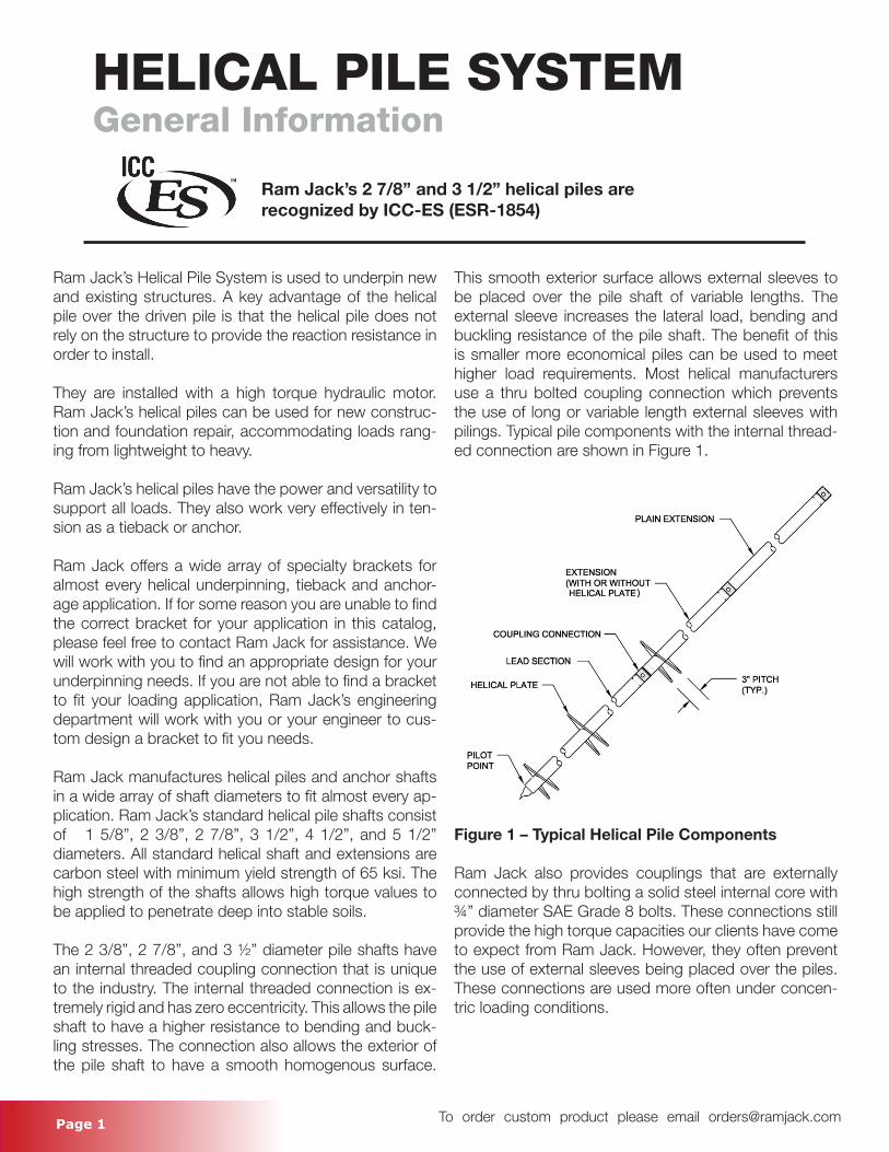
This smooth exterior surface allows external sleeves to be placed over the pile shaft of variable lengths. The external sleeve increases the lateral load, bending and buckling resistance of the pile shaft. The benefit of this is smaller more economical piles can be used to meet higher load requirements. Most helical manufacturers use a thru bolted coupling connection which prevents the use of long or variable length external sleeves with pilings. Typical pile components with the internal thread-ed connection are shown in Figure 1.
Figure 1 – Typical Helical Pile Components Ram Jack also provides couplings that are externally connected by thru bolting a solid steel internal core with ¾” diameter SAE Grade 8 bolts. These connections still provide the high torque capacities our clients have come to expect from Ram Jack. However, they often prevent the use of external sleeves being placed over the piles. These connections are used more often under concen-tric loading conditions.
HELICAL PILE SYSTEMGeneral Information
Ram Jack’s 2 7/8’’ and 3 1/2” helical piles are recognized by ICC-ES (ESR-1854)
Page 2 To order custom product please email [email protected]
HELICAL PILE SYSTEMGeneral Information
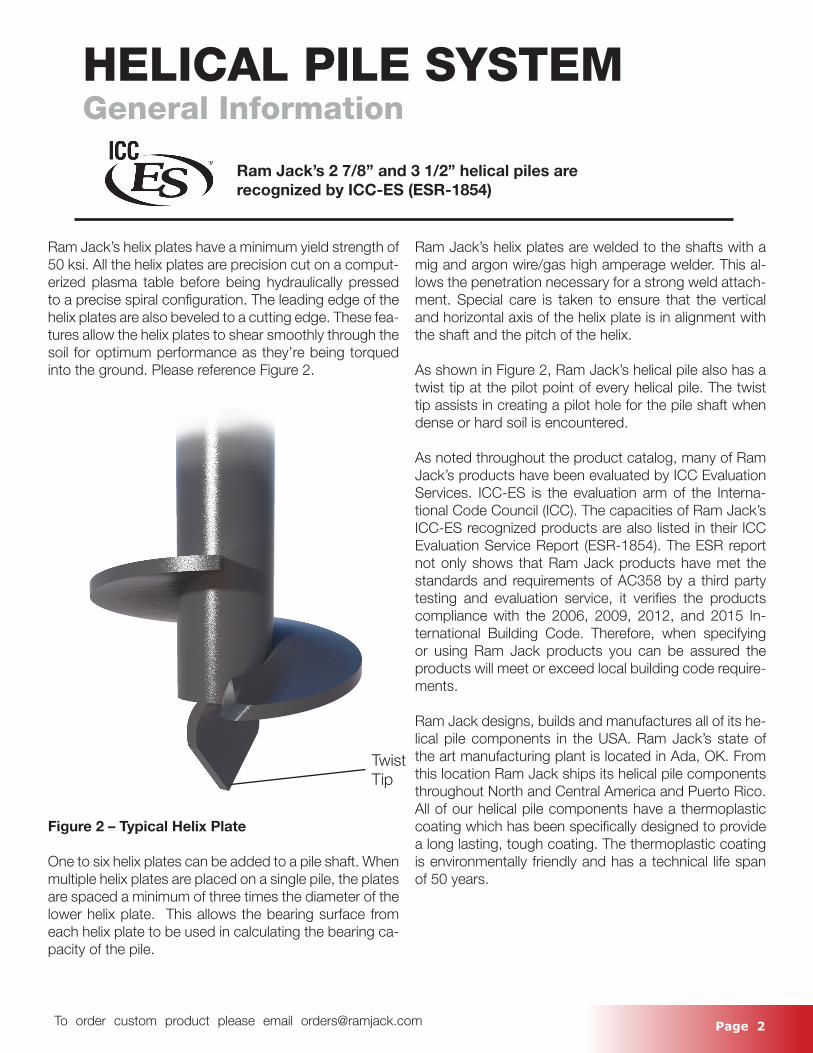
Ram Jack’s helix plates have a minimum yield strength of 50 ksi. All the helix plates are precision cut on a comput-erized plasma table before being hydraulically pressed to a precise spiral configuration. The leading edge of the helix plates are also beveled to a cutting edge. These fea-tures allow the helix plates to shear smoothly through the soil for optimum performance as they’re being torqued into the ground. Please reference Figure 2.
Figure 2 – Typical Helix Plate
One to six helix plates can be added to a pile shaft. When multiple helix plates are placed on a single pile, the plates are spaced a minimum of three times the diameter of the lower helix plate. This allows the bearing surface from each helix plate to be used in calculating the bearing ca-pacity of the pile.
Ram Jack’s helix plates are welded to the shafts with a mig and argon wire/gas high amperage welder. This al-lows the penetration necessary for a strong weld attach-ment. Special care is taken to ensure that the vertical and horizontal axis of the helix plate is in alignment with the shaft and the pitch of the helix.
As shown in Figure 2, Ram Jack’s helical pile also has a twist tip at the pilot point of every helical pile. The twist tip assists in creating a pilot hole for the pile shaft when dense or hard soil is encountered.
As noted throughout the product catalog, many of Ram Jack’s products have been evaluated by ICC Evaluation Services. ICC-ES is the evaluation arm of the Interna-tional Code Council (ICC). The capacities of Ram Jack’s ICC-ES recognized products are also listed in their ICC Evaluation Service Report (ESR-1854). The ESR report not only shows that Ram Jack products have met the standards and requirements of AC358 by a third party testing and evaluation service, it verifies the products compliance with the 2006, 2009, 2012, and 2015 In-ternational Building Code. Therefore, when specifying or using Ram Jack products you can be assured the products will meet or exceed local building code require-ments.
Ram Jack designs, builds and manufactures all of its he-lical pile components in the USA. Ram Jack’s state of the art manufacturing plant is located in Ada, OK. From this location Ram Jack ships its helical pile components throughout North and Central America and Puerto Rico. All of our helical pile components have a thermoplastic coating which has been specifically designed to provide a long lasting, tough coating. The thermoplastic coating is environmentally friendly and has a technical life span of 50 years.
Ram Jack’s 2 7/8’’ and 3 1/2” helical piles are recognized by ICC-ES (ESR-1854)
TwistTip
Page 3 To order custom product please email [email protected]
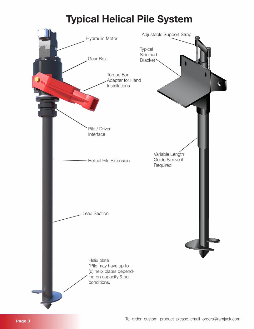
Hydraulic Motor
Gear Box
Torque Bar Adapter for Hand Installations
Pile / Driver Interface
Helical Pile Extension
Lead Section
Helix plate *Pile may have up to (6) helix plates depend-ing on capacity & soil conditions.
Adjustable Support Strap
Typical Sideload Bracket
Variable Length Guide Sleeve if Required
Typical Helical Pile System

Page 4 To order custom product please email [email protected]
Page 5 To order custom product please email [email protected]
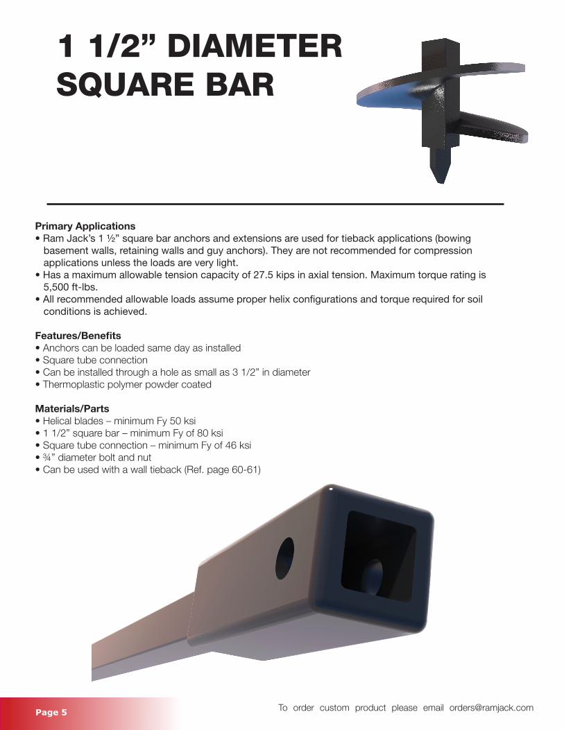
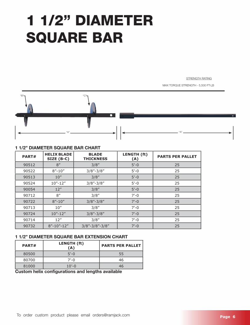
1 1/2” DIAMETERSQUARE BAR
Primary Applications• Ram Jack’s 1 ½” square bar anchors and extensions are used for tieback applications (bowing basement walls, retaining walls and guy anchors). They are not recommended for compression applications unless the loads are very light.• Has a maximum allowable tension capacity of 27.5 kips in axial tension. Maximum torque rating is 5,500 ft-lbs. • All recommended allowable loads assume proper helix configurations and torque required for soil conditions is achieved.
Features/Benefits• Anchors can be loaded same day as installed• Square tube connection• Can be installed through a hole as small as 3 1/2” in diameter• Thermoplastic polymer powder coated
Materials/Parts• Helical blades – minimum Fy 50 ksi• 1 1/2” square bar – minimum Fy of 80 ksi• Square tube connection – minimum Fy of 46 ksi• ¾” diameter bolt and nut• Can be used with a wall tieback (Ref. page 60-61)
Page 6 To order custom product please email [email protected]
1 1/2” DIAMETERSQUARE BAR
1 1/2” DIAMETER SQUARE BAR CHART
PART# HELIX BLADE SIZE (B-C)
BLADE THICKNESS
LENGTH (ft)(A) PARTS PER PALLET
90512 8” 3/8” 5’-0 2590522 8”-10” 3/8”-3/8” 5’-0 2590513 10” 3/8” 5’-0 2590524 10”-12” 3/8”-3/8” 5’-0 2590054 12” 3/8” 5’-0 2590712 8” 3/8” 7’-0 2590722 8”-10” 3/8”-3/8” 7’-0 2590713 10” 3/8” 7’-0 2590724 10”-12” 3/8”-3/8” 7’-0 2590714 12” 3/8” 7’-0 2590732 8”-10”-12” 3/8”-3/8”-3/8” 7’-0 25
1 1/2” DIAMETER SQUARE BAR EXTENSION CHART
PART# LENGTH (ft)(A) PARTS PER PALLET
80500 5’-0 5580700 7’-0 4681000 10’-0 46
Custom helix configurations and lengths available
“A”“A”
“B” “C”
STRENGTH RATING
MAX TORQUE STRENGTH - 5,500 FT-LB
Page 7 To order custom product please email [email protected]
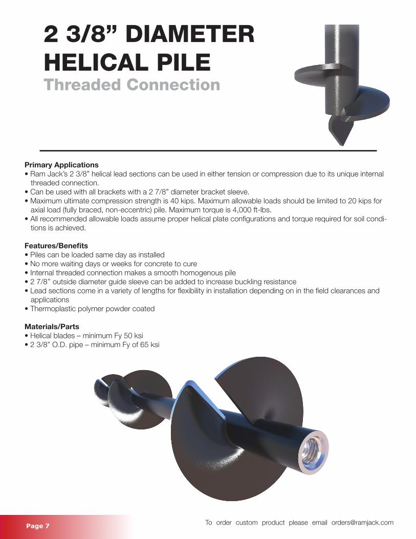
2 3/8” DIAMETER HELICAL PILEThreaded Connection
Primary Applications• Ram Jack’s 2 3/8” helical lead sections can be used in either tension or compression due to its unique internal threaded connection.• Can be used with all brackets with a 2 7/8” diameter bracket sleeve.• Maximum ultimate compression strength is 40 kips. Maximum allowable loads should be limited to 20 kips for axial load (fully braced, non-eccentric) pile. Maximum torque is 4,000 ft-lbs. • All recommended allowable loads assume proper helical plate configurations and torque required for soil condi- tions is achieved.
Features/Benefits• Piles can be loaded same day as installed• No more waiting days or weeks for concrete to cure• Internal threaded connection makes a smooth homogenous pile• 2 7/8’’ outside diameter guide sleeve can be added to increase buckling resistance• Lead sections come in a variety of lengths for flexibility in installation depending on in the field clearances and applications• Thermoplastic polymer powder coated
Materials/Parts• Helical blades – minimum Fy 50 ksi• 2 3/8” O.D. pipe – minimum Fy of 65 ksi
Page 8 To order custom product please email [email protected]
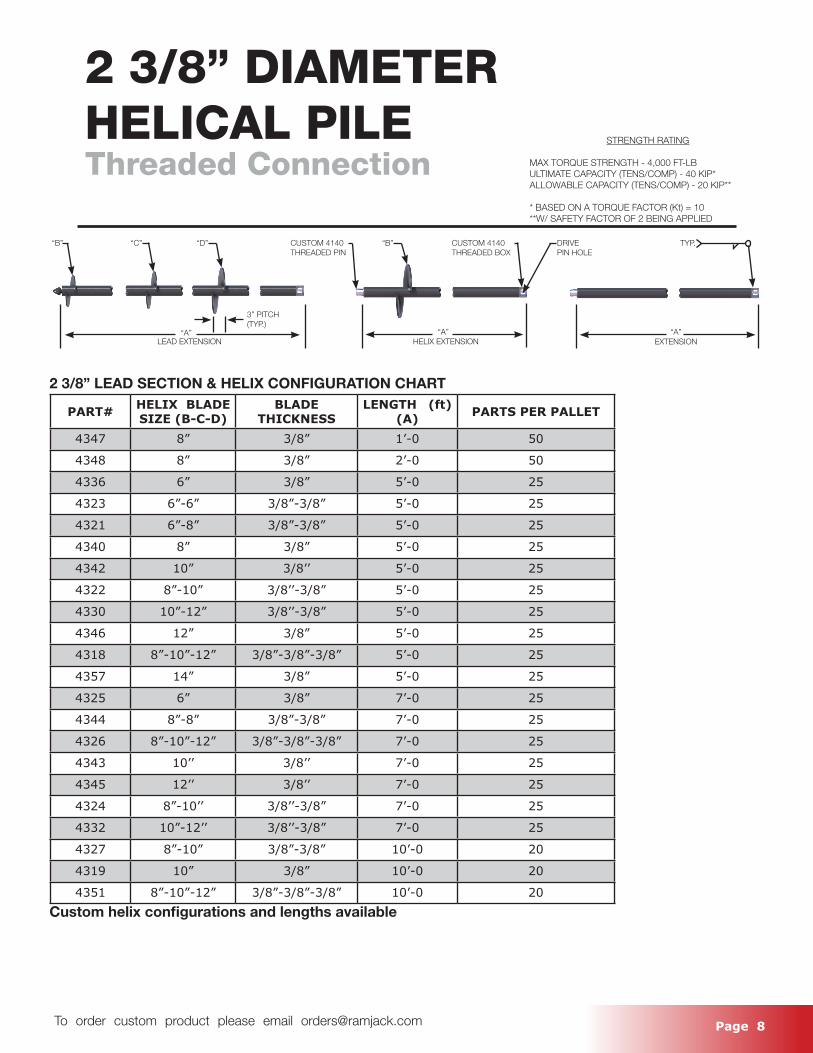
2 3/8” DIAMETERHELICAL PILEThreaded Connection
2 3/8” LEAD SECTION & HELIX CONFIGURATION CHART
PART# HELIX BLADE SIZE (B-C-D)
BLADE THICKNESS
LENGTH (ft) (A) PARTS PER PALLET
4347 8” 3/8” 1’-0 50
4348 8” 3/8” 2’-0 50
4336 6” 3/8” 5’-0 25
4323 6”-6” 3/8”-3/8” 5’-0 25
4321 6”-8” 3/8”-3/8” 5’-0 25
4340 8” 3/8” 5’-0 25
4342 10” 3/8’’ 5’-0 25
4322 8”-10” 3/8’’-3/8” 5’-0 25
4330 10”-12” 3/8’’-3/8” 5’-0 25
4346 12” 3/8” 5’-0 25
4318 8”-10”-12” 3/8”-3/8”-3/8” 5’-0 25
4357 14” 3/8” 5’-0 25
4325 6” 3/8” 7’-0 25
4344 8”-8” 3/8”-3/8” 7’-0 25
4326 8”-10”-12” 3/8”-3/8”-3/8” 7’-0 25
4343 10’’ 3/8’’ 7’-0 25
4345 12’’ 3/8’’ 7’-0 25
4324 8”-10’’ 3/8’’-3/8” 7’-0 25
4332 10”-12’’ 3/8’’-3/8” 7’-0 25
4327 8”-10” 3/8”-3/8” 10’-0 20
4319 10” 3/8” 10’-0 20
4351 8”-10”-12” 3/8”-3/8”-3/8” 10’-0 20Custom helix configurations and lengths available
STRENGTH RATING
MAX TORQUE STRENGTH - 4,000 FT-LBULTIMATE CAPACITY (TENS/COMP) - 40 KIP*ALLOWABLE CAPACITY (TENS/COMP) - 20 KIP**
* BASED ON A TORQUE FACTOR (Kt) = 10**W/ SAFETY FACTOR OF 2 BEING APPLIED
“B” “C”
“A”
CUSTOM 4140THREADED PIN
“D”
3” PITCH(TYP.)
“B” DRIVEPIN HOLE
TYP.
“A”EXTENSIONHELIX EXTENSIONLEAD EXTENSION
“A”
CUSTOM 4140 THREADED BOX
Page 9 To order custom product please email [email protected]
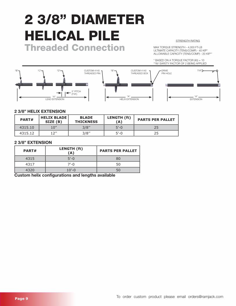
2 3/8” DIAMETERHELICAL PILEThreaded Connection
2 3/8” HELIX EXTENSION
PART# HELIX BLADE SIZE (B)
BLADE THICKNESS
LENGTH (ft)(A) PARTS PER PALLET
4315.10 10” 3/8’’ 5’-0 254315.12 12’’ 3/8’’ 5’-0 25
2 3/8” EXTENSION
PART# LENGTH (ft)(A) PARTS PER PALLET
4315 5’-0 804317 7’-0 504320 10’-0 50
Custom helix configurations and lengths available
STRENGTH RATING
MAX TORQUE STRENGTH - 4,000 FT-LBULTIMATE CAPACITY (TENS/COMP) - 40 KIP*ALLOWABLE CAPACITY (TENS/COMP) - 20 KIP**
* BASED ON A TORQUE FACTOR (Kt) = 10**W/ SAFETY FACTOR OF 2 BEING APPLIED
“B” “C”
“A”
CUSTOM 4140 THREADED PIN
“D”
3” PITCH(TYP.)
“B” DRIVEPIN HOLE
TYP.
“A”EXTENSIONHELIX EXTENSIONLEAD EXTENSION
“A”
CUSTOM 4140THREADED BOX

Page 10 To order custom product please email [email protected]
Page 11 To order custom product please email [email protected]
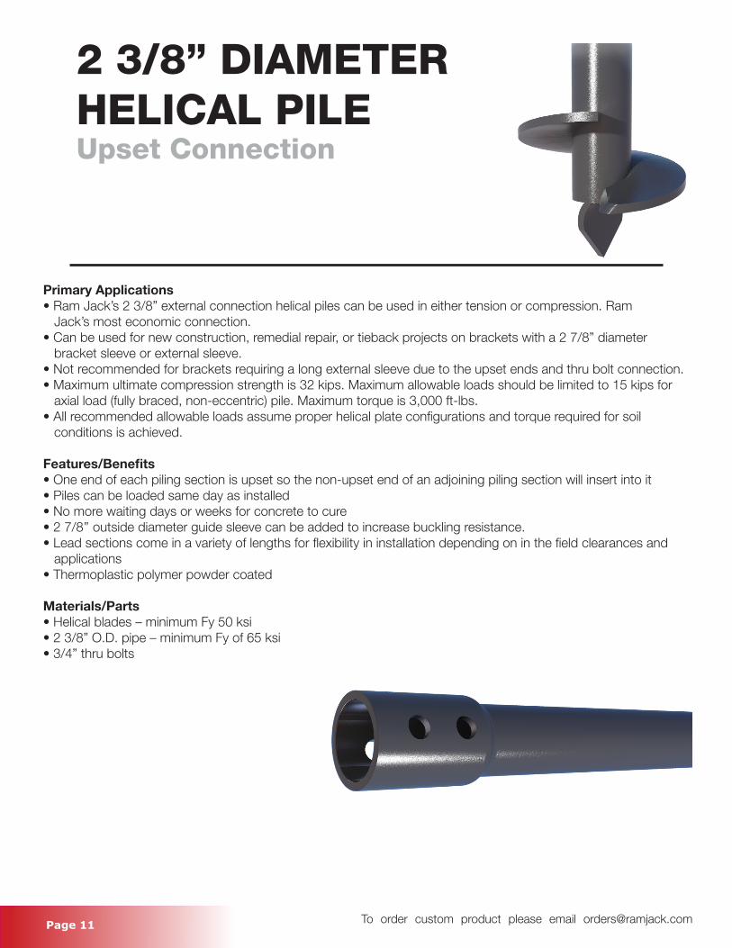
2 3/8” DIAMETER HELICAL PILEUpset Connection
Primary Applications• Ram Jack’s 2 3/8” external connection helical piles can be used in either tension or compression. Ram Jack’s most economic connection.• Can be used for new construction, remedial repair, or tieback projects on brackets with a 2 7/8” diameter bracket sleeve or external sleeve.• Not recommended for brackets requiring a long external sleeve due to the upset ends and thru bolt connection.• Maximum ultimate compression strength is 32 kips. Maximum allowable loads should be limited to 15 kips for axial load (fully braced, non-eccentric) pile. Maximum torque is 3,000 ft-lbs. • All recommended allowable loads assume proper helical plate configurations and torque required for soil conditions is achieved.
Features/Benefits• One end of each piling section is upset so the non-upset end of an adjoining piling section will insert into it• Piles can be loaded same day as installed• No more waiting days or weeks for concrete to cure• 2 7/8’’ outside diameter guide sleeve can be added to increase buckling resistance. • Lead sections come in a variety of lengths for flexibility in installation depending on in the field clearances and applications• Thermoplastic polymer powder coated
Materials/Parts• Helical blades – minimum Fy 50 ksi• 2 3/8” O.D. pipe – minimum Fy of 65 ksi• 3/4” thru bolts
Page 12 To order custom product please email [email protected]
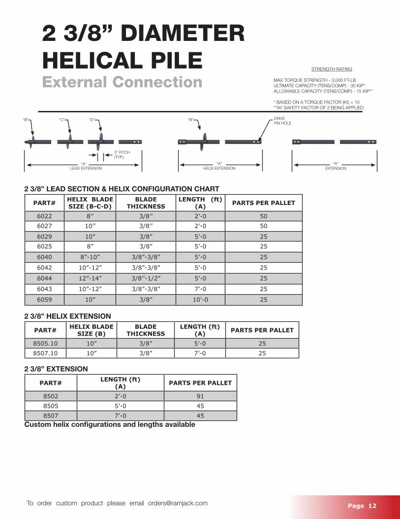
2 3/8” DIAMETERHELICAL PILEExternal Connection
2 3/8” LEAD SECTION & HELIX CONFIGURATION CHART
PART# HELIX BLADE SIZE (B-C-D)
BLADE THICKNESS
LENGTH (ft) (A) PARTS PER PALLET
6022 8’’ 3/8’’ 2’-0 506027 10’’ 3/8’’ 2’-0 50
6029 10” 3/8” 5’-0 256025 8” 3/8” 5’-0 25
6040 8”-10” 3/8”-3/8” 5’-0 25
6042 10”-12” 3/8”-3/8” 5’-0 25
6044 12”-14” 3/8’’-1/2” 5’-0 25
6043 10”-12” 3/8”-3/8” 7’-0 25
6059 10” 3/8” 10’-0 25
2 3/8” HELIX EXTENSION
PART# HELIX BLADE SIZE (B)
BLADE THICKNESS
LENGTH (ft)(A) PARTS PER PALLET
8505.10 10” 3/8” 5’-0 258507.10 10” 3/8” 7’-0 25
2 3/8” EXTENSION
PART# LENGTH (ft)(A) PARTS PER PALLET
8502 2’-0 918505 5’-0 458507 7’-0 45
Custom helix configurations and lengths available
STRENGTH RATING
MAX TORQUE STRENGTH - 3,000 FT-LBULTIMATE CAPACITY (TENS/COMP) - 30 KIP*ALLOWABLE CAPACITY (TENS/COMP) - 15 KIP**
* BASED ON A TORQUE FACTOR (Kt) = 10**W/ SAFETY FACTOR OF 2 BEING APPLIED
“B” “C”
“A”
“D”
3” PITCH(TYP.)
“B” DRIVEPIN HOLE
“A”EXTENSIONHELIX EXTENSIONLEAD EXTENSION
“A”
Page 13 To order custom product please email [email protected]
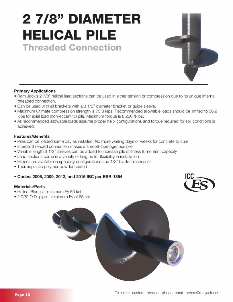
2 7/8” DIAMETERHELICAL PILEThreaded Connection
Primary Applications• Ram Jack’s 2 7/8” helical lead sections can be used in either tension or compression due to its unique internal threaded connection.• Can be used with all brackets with a 3 1/2” diameter bracket or guide sleeve. • Maximum ultimate compression strength is 73.8 kips. Recommended allowable loads should be limited to 36.9 kips for axial load (non-eccentric) pile. Maximum torque is 8,200 ft-lbs. • All recommended allowable loads assume proper helix configurations and torque required for soil conditions is achieved.
Features/Benefits• Piles can be loaded same day as installed. No more waiting days or weeks for concrete to cure• Internal threaded connection makes a smooth homogenous pile• Variable length 3 1/2’’ sleeves can be added to increase pile stiffness & moment capacity• Lead sections come in a variety of lengths for flexibility in installation• Helices are available in specialty configurations and 1/2” blade thicknesses• Thermoplastic polymer powder coated
• Codes: 2006, 2009, 2012, and 2015 IBC per ESR-1854
Materials/Parts• Helical Blades – minimum Fy 50 ksi• 2 7/8” O.D. pipe – minimum Fy of 65 ksi
Page 14 To order custom product please email [email protected]
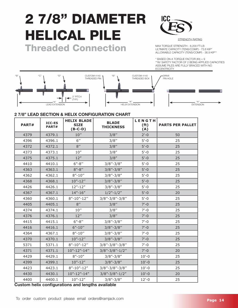
2 7/8” DIAMETERHELICAL PILEThreaded Connection
STRENGTH RATING
MAX TORQUE STRENGTH - 8,200 FT-LBULTIMATE CAPACITY (TENS/COMP) - 73.8 KIP*ALLOWABLE CAPACITY (TENS/COMP) - 36.9 KIP**
* BASED ON A TORQUE FACTOR (Kt) = 9**W/ SAFETY FACTOR OF 2 BEING APPLIED CAPACITIES ASSUME PILES ARE FULLY BRACED WITH NO ECCENTRICITY
“B” “C”
“A”
CUSTOM 4140THREADED PIN
“D”
3” PITCH(TYP.)
“B” DRIVEPIN HOLE
“A”EXTENSIONHELIX EXTENSIONLEAD EXTENSION
“A”
CUSTOM 4140THREADED BOX
2 7/8” LEAD SECTION & HELIX CONFIGURATION CHART
PART# ICC-ES PART#
HELIX BLADE SIZE
(B-C-D)
BLADE THICKNESS
L E N G T H (ft)(A)
PARTS PER PALLET
4379 4379.1 10’’ 3/8’’ 2’-0 504396 4396.1 6’’ 3/8’’ 5’-0 254372 4372.1 8’’ 3/8’’ 5’-0 254373 4373.1 10” 3/8” 5’-0 254375 4375.1 12” 3/8” 5’-0 254410 4410.1 6”-8’’ 3/8’’-3/8” 5’-0 254363 4363.1 8”-8’’ 3/8’’-3/8” 5’-0 254362 4362.1 8”-10’’ 3/8’’-3/8” 5’-0 254368 4368.1 10”-12’’ 3/8’’-3/8’’ 5’-0 254426 4426.1 12”-12” 3/8”-3/8” 5’-0 254367 4367.1 14”-16” 1/2”-1/2” 5’-0 204360 4360.1 8”-10”-12’’ 3/8’’-3/8’’-3/8’’ 5’-0 254405 4405.1 8’’ 3/8’’ 7’-0 254374 4374.1 10’’ 3/8’’ 7’-0 254376 4376.1 12’’ 3/8’’ 7’-0 254415 4415.1 6”-8’’ 3/8’’-3/8’’ 7’-0 254416 4416.1 6”-10’’ 3/8’’-3/8’’ 7’-0 254364 4367.1 8”-10’’ 3/8’’-3/8’’ 7’-0 254370 4370.1 10”-12’’ 3/8’’-3/8’’ 7’-0 255371 5371.1 8”-10”-12’’ 3/8’’-3/8’’-3/8’’ 7’-0 254371 4371.1 10”-12”-14’’ 3/8’’-3/8’’-1/2’’ 7’-0 204429 4429.1 8”-10” 3/8”-3/8” 10’-0 254399 4399.1 10”-12” 3/8”-3/8” 10’-0 254423 4423.1 8”-10”-12” 3/8’’-3/8’’-3/8’’ 10’-0 254430 4430.1 10”-12”-14” 3/8”-3/8”-1/2” 10’-0 204400 4400.1 10”-12” 3/8”-3/8” 12’-0 25
Custom helix configurations and lengths available

Page 15 To order custom product please email [email protected]
2 7/8” HELIX EXTENSION
PART# ICC-ES PART#
Helix BladeSize(B)
BLADE THICKNESS LENGTH (ft)
(A)PARTS PER PALLET
4382.12 4382.12.1 12” 3/8’’ 2’-0 254382.14 4382.14.1 14” 1/2” 2’-0 254385.10 4385.10.1 10” 3/8’’ 5’-0 254385.12 4385.12.1 12” 3/8’’ 5’-0 254385.14 4385.14.1 14” 1/2” 5’-0 254387.10 4387.10.1 10” 3/8” 7’-0 254387.12 4387.12.1 12” 3/8’’ 7’-0 254387.14 4387.14.1 14” 1/2” 7’-0 25
2 7/8” EXTENSION
PART# ICC-ES PART#
LENGTH (ft)(A) PARTS PER PALLET
4382 4382.1 2’-0 1104383 4383.1 3’-6 554385 4385.1 5’-0 554387 4387.1 7’-0 464422 4422.1 10’-0 46
Custom helix configurations and lengths available
2 7/8” DIAMETERHELICAL PILEThreaded Connection Continued
STRENGTH RATING
MAX TORQUE STRENGTH - 8,200 FT-LBULTIMATE CAPACITY (TENS/COMP) - 73.8 KIP*ALLOWABLE CAPACITY (TENS/COMP) - 36.9 KIP**
* BASED ON A TORQUE FACTOR (Kt) = 9**W/ SAFETY FACTOR OF 2 BEING APPLIED CAPACITIES ASSUME PILES ARE FULLY BRACED WITH NO ECCENTRICITY
“B” “C”
“A”
CUSTOM 4140THREADED PIN
“D”
3” PITCH(TYP.)
“B” DRIVEPIN HOLE
“A”EXTENSIONHELIX EXTENSIONLEAD EXTENSION
“A”
CUSTOM 4140THREADED BOX

Page 16 To order custom product please email [email protected]
Page 17 To order custom product please email [email protected]
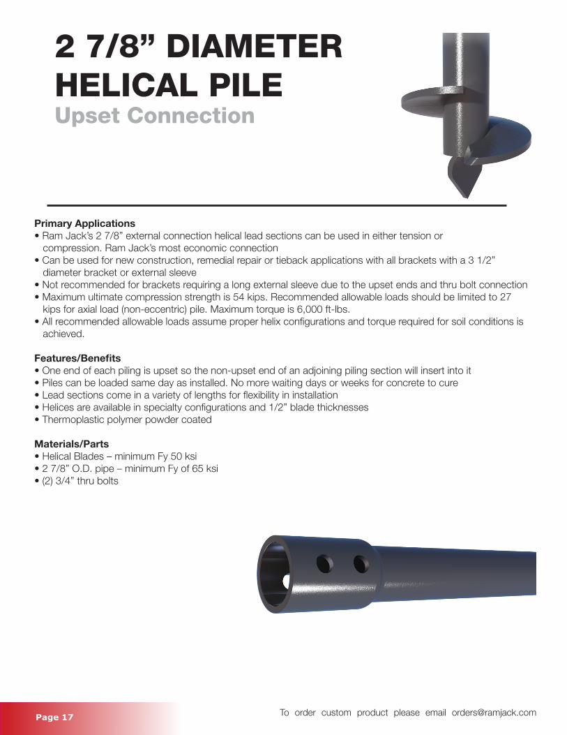
2 7/8” DIAMETERHELICAL PILEUpset Connection
Primary Applications• Ram Jack’s 2 7/8” external connection helical lead sections can be used in either tension or compression. Ram Jack’s most economic connection• Can be used for new construction, remedial repair or tieback applications with all brackets with a 3 1/2” diameter bracket or external sleeve • Not recommended for brackets requiring a long external sleeve due to the upset ends and thru bolt connection• Maximum ultimate compression strength is 54 kips. Recommended allowable loads should be limited to 27 kips for axial load (non-eccentric) pile. Maximum torque is 6,000 ft-lbs. • All recommended allowable loads assume proper helix configurations and torque required for soil conditions is achieved.
Features/Benefits• One end of each piling is upset so the non-upset end of an adjoining piling section will insert into it• Piles can be loaded same day as installed. No more waiting days or weeks for concrete to cure• Lead sections come in a variety of lengths for flexibility in installation• Helices are available in specialty configurations and 1/2” blade thicknesses• Thermoplastic polymer powder coated
Materials/Parts• Helical Blades – minimum Fy 50 ksi• 2 7/8” O.D. pipe – minimum Fy of 65 ksi• (2) 3/4” thru bolts
Page 18 To order custom product please email [email protected]
“B” “C”
“A”
“D” “B”
“A”EXTENSIONHELIX EXTENSIONLEAD EXTENSION
“A”
DRIVEPIN HOLE
3” PITCH(TYP.)
2 7/8” DIAMETERHELICAL PILEUpset Connection
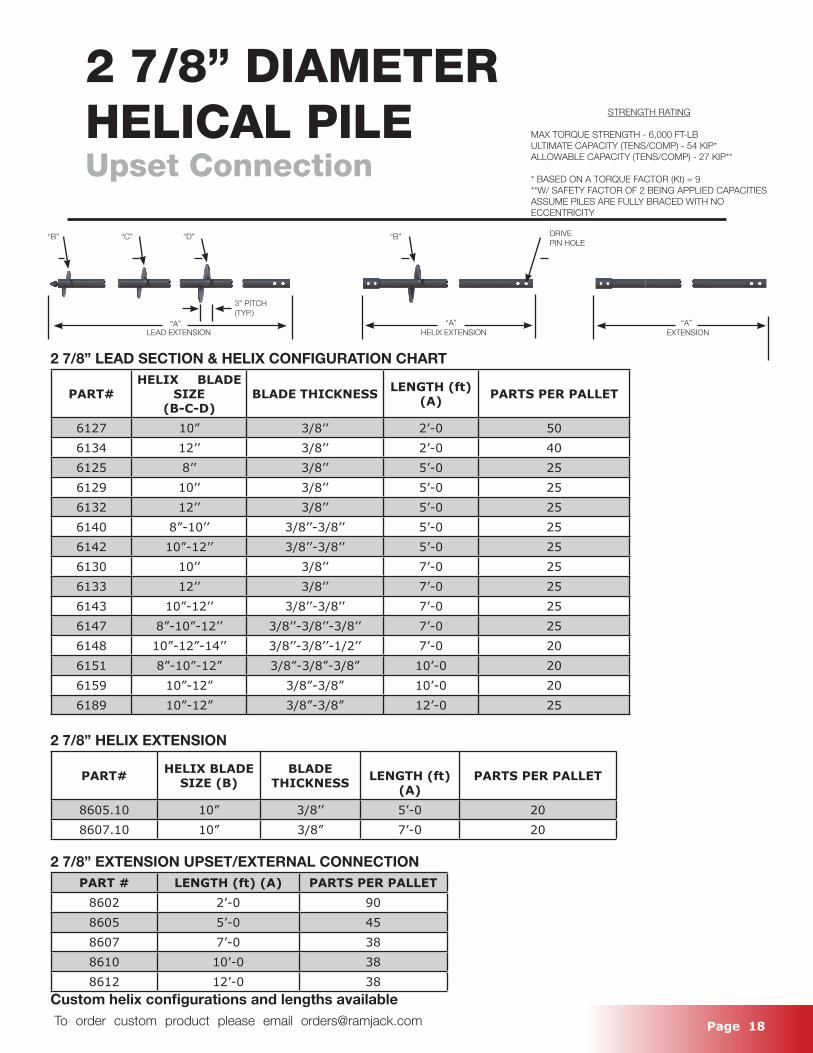
2 7/8” LEAD SECTION & HELIX CONFIGURATION CHART
PART#HELIX BLADE
SIZE(B-C-D)
BLADE THICKNESS LENGTH (ft)(A) PARTS PER PALLET
6127 10” 3/8’’ 2’-0 506134 12’’ 3/8’’ 2’-0 406125 8’’ 3/8’’ 5’-0 256129 10’’ 3/8’’ 5’-0 256132 12’’ 3/8’’ 5’-0 256140 8”-10’’ 3/8’’-3/8’’ 5’-0 256142 10”-12’’ 3/8’’-3/8’’ 5’-0 256130 10’’ 3/8’’ 7’-0 256133 12’’ 3/8’’ 7’-0 256143 10”-12’’ 3/8’’-3/8’’ 7’-0 256147 8”-10”-12’’ 3/8’’-3/8’’-3/8’’ 7’-0 256148 10”-12”-14’’ 3/8’’-3/8’’-1/2’’ 7’-0 206151 8”-10”-12” 3/8”-3/8”-3/8” 10’-0 206159 10”-12” 3/8”-3/8” 10’-0 206189 10”-12” 3/8”-3/8” 12’-0 25
2 7/8” HELIX EXTENSION
PART# HELIX BLADE SIZE (B)
BLADE THICKNESS LENGTH (ft)
(A)PARTS PER PALLET
8605.10 10” 3/8’’ 5’-0 208607.10 10” 3/8” 7’-0 20
2 7/8” EXTENSION UPSET/EXTERNAL CONNECTIONPART # LENGTH (ft) (A) PARTS PER PALLET
8602 2’-0 908605 5’-0 458607 7’-0 388610 10’-0 388612 12’-0 38
Custom helix configurations and lengths available
STRENGTH RATING
MAX TORQUE STRENGTH - 6,000 FT-LBULTIMATE CAPACITY (TENS/COMP) - 54 KIP*ALLOWABLE CAPACITY (TENS/COMP) - 27 KIP**
* BASED ON A TORQUE FACTOR (Kt) = 9**W/ SAFETY FACTOR OF 2 BEING APPLIED CAPACITIES ASSUME PILES ARE FULLY BRACED WITH NO ECCENTRICITY
Page 19 To order custom product please email [email protected]
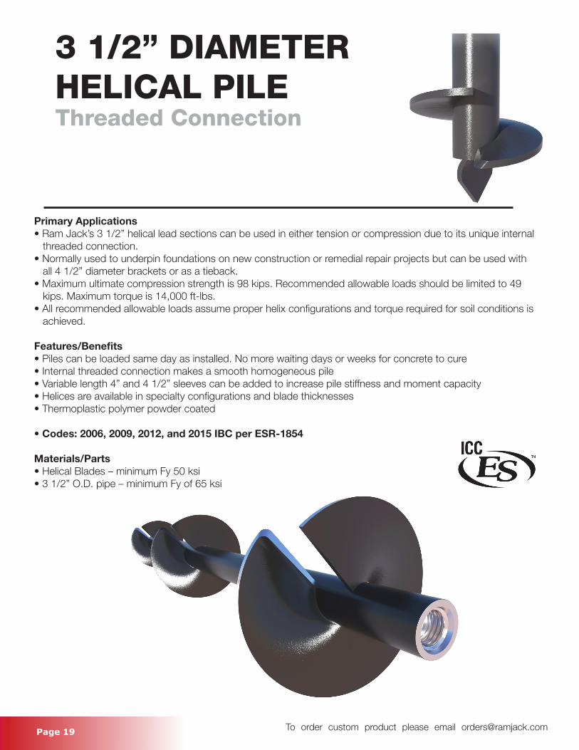
3 1/2” DIAMETERHELICAL PILEThreaded Connection
Primary Applications• Ram Jack’s 3 1/2” helical lead sections can be used in either tension or compression due to its unique internal threaded connection.• Normally used to underpin foundations on new construction or remedial repair projects but can be used with all 4 1/2” diameter brackets or as a tieback.• Maximum ultimate compression strength is 98 kips. Recommended allowable loads should be limited to 49 kips. Maximum torque is 14,000 ft-lbs. • All recommended allowable loads assume proper helix configurations and torque required for soil conditions is achieved.
Features/Benefits• Piles can be loaded same day as installed. No more waiting days or weeks for concrete to cure• Internal threaded connection makes a smooth homogeneous pile • Variable length 4” and 4 1/2” sleeves can be added to increase pile stiffness and moment capacity• Helices are available in specialty configurations and blade thicknesses• Thermoplastic polymer powder coated
• Codes: 2006, 2009, 2012, and 2015 IBC per ESR-1854
Materials/Parts• Helical Blades – minimum Fy 50 ksi• 3 1/2” O.D. pipe – minimum Fy of 65 ksi
Page 20 To order custom product please email [email protected]
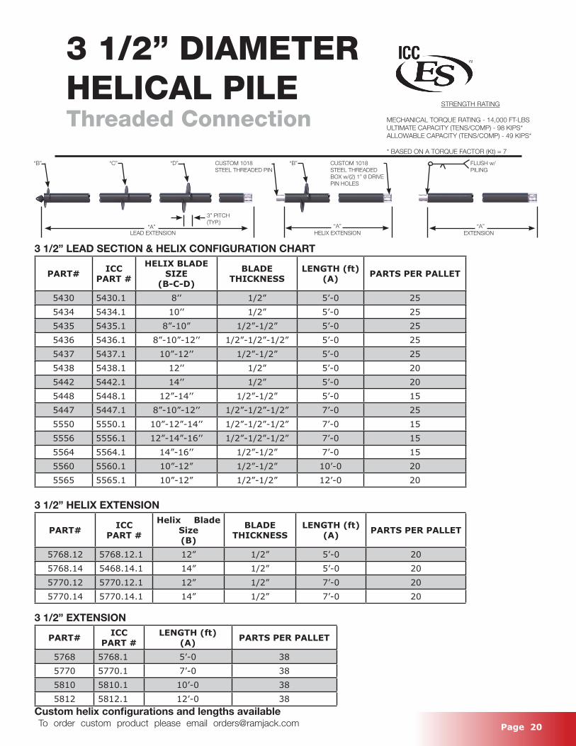
3 1/2” LEAD SECTION & HELIX CONFIGURATION CHART
PART# ICC PART #
HELIX BLADE SIZE
(B-C-D)
BLADE THICKNESS
LENGTH (ft)(A) PARTS PER PALLET
5430 5430.1 8’’ 1/2” 5’-0 255434 5434.1 10’’ 1/2” 5’-0 255435 5435.1 8”-10” 1/2”-1/2” 5’-0 255436 5436.1 8”-10”-12’’ 1/2”-1/2”-1/2” 5’-0 255437 5437.1 10”-12’’ 1/2”-1/2” 5’-0 255438 5438.1 12’’ 1/2” 5’-0 205442 5442.1 14’’ 1/2” 5’-0 205448 5448.1 12”-14’’ 1/2”-1/2” 5’-0 155447 5447.1 8”-10”-12’’ 1/2”-1/2”-1/2” 7’-0 255550 5550.1 10”-12”-14’’ 1/2”-1/2”-1/2” 7’-0 155556 5556.1 12”-14”-16’’ 1/2”-1/2”-1/2” 7’-0 155564 5564.1 14”-16’’ 1/2”-1/2” 7’-0 155560 5560.1 10”-12” 1/2”-1/2” 10’-0 205565 5565.1 10”-12” 1/2”-1/2” 12’-0 20
3 1/2” HELIX EXTENSION
PART# ICC PART #
Helix Blade Size(B)
BLADE THICKNESS
LENGTH (ft)(A) PARTS PER PALLET
5768.12 5768.12.1 12” 1/2” 5’-0 205768.14 5468.14.1 14” 1/2” 5’-0 205770.12 5770.12.1 12” 1/2” 7’-0 205770.14 5770.14.1 14” 1/2” 7’-0 20
3 1/2” EXTENSION
PART# ICC PART #
LENGTH (ft)(A) PARTS PER PALLET
5768 5768.1 5’-0 385770 5770.1 7’-0 385810 5810.1 10’-0 385812 5812.1 12’-0 38
Custom helix configurations and lengths available
3 1/2” DIAMETERHELICAL PILEThreaded Connection
STRENGTH RATING
MECHANICAL TORQUE RATING - 14,000 FT-LBSULTIMATE CAPACITY (TENS/COMP) - 98 KIPS*ALLOWABLE CAPACITY (TENS/COMP) - 49 KIPS*
* BASED ON A TORQUE FACTOR (Kt) = 7
“B” “C”
“A”
CUSTOM 1018STEEL THREADED PIN
“D”
3” PITCH(TYP.)
“B” FLUSH w/ PILING
“A”EXTENSIONHELIX EXTENSIONLEAD EXTENSION
“A”
CUSTOM 1018 STEEL THREADED BOX w/(2) 1” 0 DRIVE PIN HOLES
Page 21 To order custom product please email [email protected]
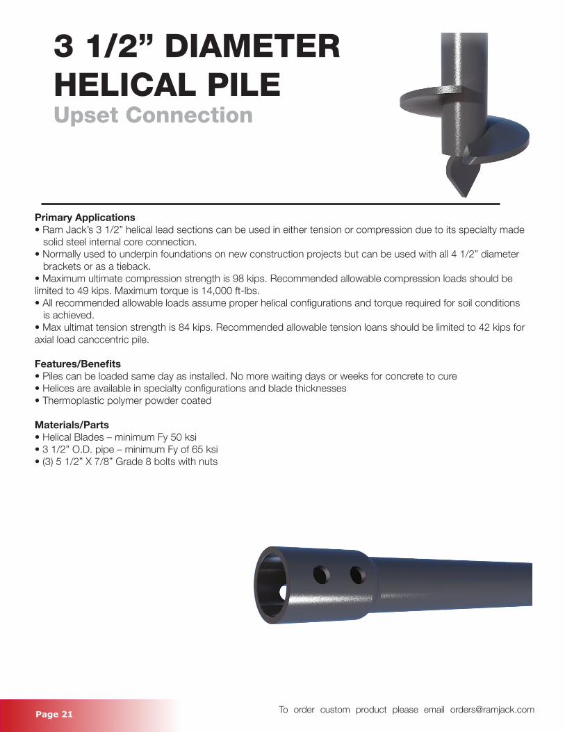
3 1/2” DIAMETERHELICAL PILEUpset Connection
Primary Applications• Ram Jack’s 3 1/2” helical lead sections can be used in either tension or compression due to its specialty made solid steel internal core connection.• Normally used to underpin foundations on new construction projects but can be used with all 4 1/2” diameter brackets or as a tieback.• Maximum ultimate compression strength is 98 kips. Recommended allowable compression loads should be limited to 49 kips. Maximum torque is 14,000 ft-lbs. • All recommended allowable loads assume proper helical configurations and torque required for soil conditions is achieved. • Max ultimat tension strength is 84 kips. Recommended allowable tension loans should be limited to 42 kips for axial load canccentric pile.
Features/Benefits• Piles can be loaded same day as installed. No more waiting days or weeks for concrete to cure• Helices are available in specialty configurations and blade thicknesses• Thermoplastic polymer powder coated
Materials/Parts• Helical Blades – minimum Fy 50 ksi• 3 1/2” O.D. pipe – minimum Fy of 65 ksi• (3) 5 1/2” X 7/8” Grade 8 bolts with nuts
Page 22 To order custom product please email [email protected]
3 1/2” DIAMETERHELICAL PILEUpset Connection
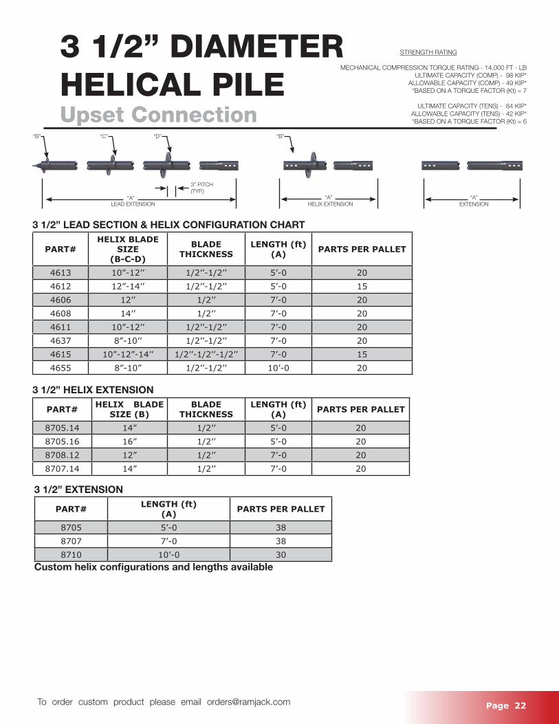
3 1/2” LEAD SECTION & HELIX CONFIGURATION CHART
PART#HELIX BLADE
SIZE(B-C-D)
BLADE THICKNESS
LENGTH (ft)(A) PARTS PER PALLET
4613 10”-12’’ 1/2’’-1/2’’ 5’-0 204612 12”-14’’ 1/2’’-1/2’’ 5’-0 154606 12’’ 1/2’’ 7’-0 204608 14’’ 1/2’’ 7’-0 204611 10”-12’’ 1/2’’-1/2’’ 7’-0 204637 8”-10’’ 1/2’’-1/2’’ 7’-0 204615 10”-12”-14’’ 1/2’’-1/2’’-1/2’’ 7’-0 154655 8”-10” 1/2’’-1/2’’ 10’-0 20
3 1/2” HELIX EXTENSION
PART# HELIX BLADE SIZE (B)
BLADE THICKNESS
LENGTH (ft)(A) PARTS PER PALLET
8705.14 14” 1/2’’ 5’-0 208705.16 16” 1/2’’ 5’-0 208708.12 12” 1/2’’ 7’-0 208707.14 14” 1/2’’ 7’-0 20
3 1/2” EXTENSION
PART# LENGTH (ft)(A) PARTS PER PALLET
8705 5’-0 388707 7’-0 388710 10’-0 30
Custom helix configurations and lengths available
STRENGTH RATING
MECHANICAL COMPRESSION TORQUE RATING - 14,000 FT - LBULTIMATE CAPACITY (COMP) - 98 KIP*
ALLOWABLE CAPACITY (COMP) - 49 KIP**BASED ON A TORQUE FACTOR (Kt) = 7
ULTIMATE CAPACITY (TENS) - 84 KIP*ALLOWABLE CAPACITY (TENS) - 42 KIP**BASED ON A TORQUE FACTOR (Kt) = 6
“B” “C”
“A”
“D”
3” PITCH(TYP.)
“B”
“A”EXTENSIONHELIX EXTENSIONLEAD EXTENSION
“A”
Page 23 To order custom product please email [email protected]
3 1/2” DIAMETERHELICAL PILEUpset Connection
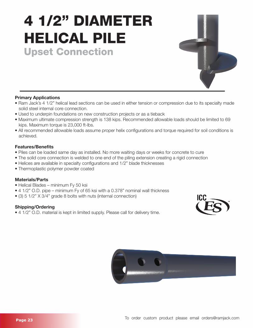
4 1/2” DIAMETERHELICAL PILEUpset Connection
Primary Applications• Ram Jack’s 4 1/2” helical lead sections can be used in either tension or compression due to its specialty made solid steel internal core connection.• Used to underpin foundations on new construction projects or as a tieback• Maximum ultimate compression strength is 138 kips. Recommended allowable loads should be limited to 69 kips. Maximum torque is 23,000 ft-lbs. • All recommended allowable loads assume proper helix configurations and torque required for soil conditions is achieved.
Features/Benefits• Piles can be loaded same day as installed. No more waiting days or weeks for concrete to cure• The solid core connection is welded to one end of the piling extension creating a rigid connection• Helices are available in specialty configurations and 1/2” blade thicknesses• Thermoplastic polymer powder coated
Materials/Parts• Helical Blades – minimum Fy 50 ksi• 4 1/2” O.D. pipe – minimum Fy of 65 ksi with a 0.378” nominal wall thickness• (3) 5 1/2” X 3/4” grade 8 bolts with nuts (internal connection)
Shipping/Ordering• 4 1/2” O.D. material is kept in limited supply. Please call for delivery time.
Page 24 To order custom product please email [email protected]
4 1/2” DIAMETERHELICAL PILE Upset Connection
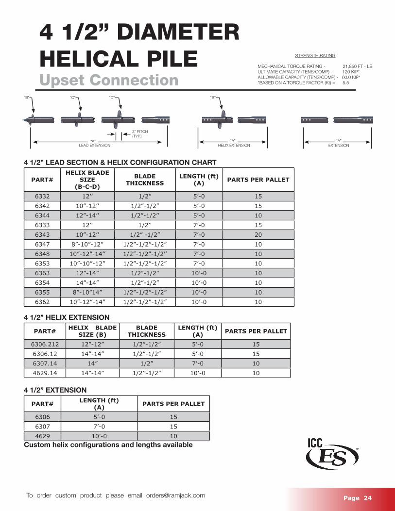
4 1/2” LEAD SECTION & HELIX CONFIGURATION CHART
PART#HELIX BLADE
SIZE(B-C-D)
BLADE THICKNESS
LENGTH (ft)(A) PARTS PER PALLET
6332 12’’ 1/2” 5’-0 156342 10”-12’’ 1/2”-1/2” 5’-0 156344 12”-14’’ 1/2”-1/2’’ 5’-0 106333 12’’ 1/2’’ 7’-0 156343 10”-12’’ 1/2” -1/2” 7’-0 206347 8”-10”-12” 1/2”-1/2”-1/2” 7’-0 106348 10”-12”-14’’ 1/2”-1/2”-1/2’’ 7’-0 106353 10”-10”-12” 1/2”-1/2”-1/2” 7’-0 106363 12”-14” 1/2”-1/2” 10’-0 106354 14”-14” 1/2”-1/2” 10’-0 106355 8”-10”14” 1/2”-1/2”-1/2” 10’-0 106362 10”-12”-14” 1/2”-1/2”-1/2” 10’-0 10
4 1/2” HELIX EXTENSION
PART# HELIX BLADE SIZE (B)
BLADE THICKNESS
LENGTH (ft)(A) PARTS PER PALLET
6306.212 12”-12” 1/2”-1/2” 5’-0 156306.12 14”-14” 1/2”-1/2” 5’-0 156307.14 14” 1/2” 7’-0 104629.14 14”-14” 1/2’’-1/2” 10’-0 10
4 1/2” EXTENSION
PART# LENGTH (ft)(A) PARTS PER PALLET
6306 5’-0 156307 7’-0 154629 10’-0 10
Custom helix configurations and lengths available
STRENGTH RATING
MECHANICAL TORQUE RATING - 21,850 FT - LBULTIMATE CAPACITY (TENS/COMP) - 120 KIP*ALLOWABLE CAPACITY (TENS/COMP) - 60.0 KIP**BASED ON A TORQUE FACTOR (Kt) = 5.5
“B” “C”
“A”
“D”
3” PITCH(TYP.)
“B”
“A”EXTENSIONHELIX EXTENSIONLEAD EXTENSION
“A”
Page 25 To order custom product please email [email protected]
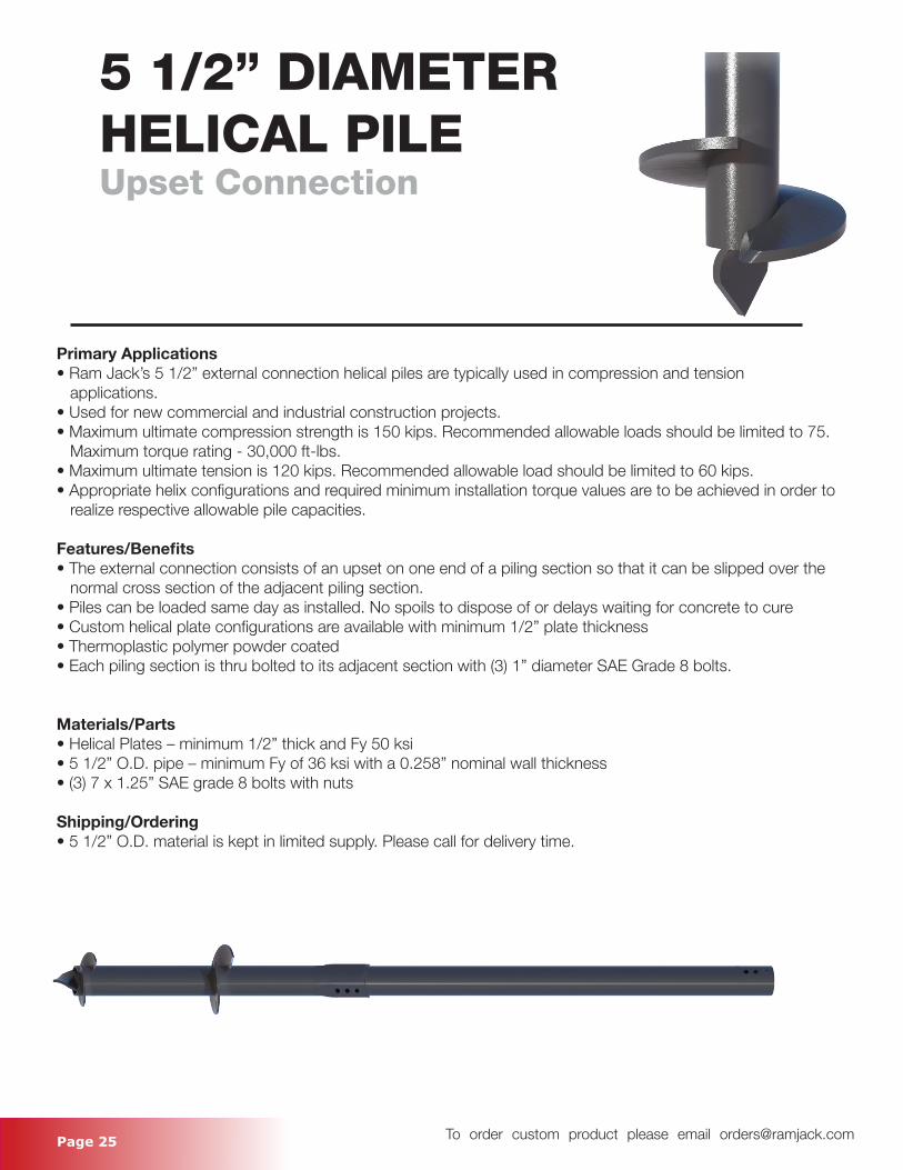
Primary Applications• Ram Jack’s 5 1/2” external connection helical piles are typically used in compression and tension applications. • Used for new commercial and industrial construction projects. • Maximum ultimate compression strength is 150 kips. Recommended allowable loads should be limited to 75. Maximum torque rating - 30,000 ft-lbs.• Maximum ultimate tension is 120 kips. Recommended allowable load should be limited to 60 kips.• Appropriate helix configurations and required minimum installation torque values are to be achieved in order to realize respective allowable pile capacities.
Features/Benefits• The external connection consists of an upset on one end of a piling section so that it can be slipped over the normal cross section of the adjacent piling section.• Piles can be loaded same day as installed. No spoils to dispose of or delays waiting for concrete to cure• Custom helical plate configurations are available with minimum 1/2” plate thickness • Thermoplastic polymer powder coated• Each piling section is thru bolted to its adjacent section with (3) 1” diameter SAE Grade 8 bolts.
Materials/Parts• Helical Plates – minimum 1/2” thick and Fy 50 ksi• 5 1/2” O.D. pipe – minimum Fy of 36 ksi with a 0.258” nominal wall thickness• (3) 7 x 1.25” SAE grade 8 bolts with nuts
Shipping/Ordering• 5 1/2” O.D. material is kept in limited supply. Please call for delivery time.
5 1/2” DIAMETERHELICAL PILE Upset Connection
Page 26 To order custom product please email [email protected]
5 1/2” DIAMETERHELICAL PILEUpset Connection
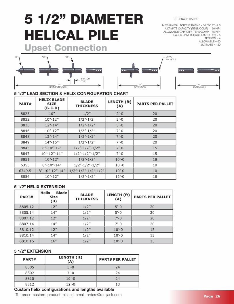
5 1/2” LEAD SECTION & HELIX CONFIGURATION CHART
PART#HELIX BLADE
SIZE(B-C-D)
BLADE THICKNESS
LENGTH (ft)(A) PARTS PER PALLET
8825 10” 1/2” 2’-0 208832 10”-12’’ 1/2”-1/2’’ 5’-0 208833 12”-14” 1/2”-1/2” 5’-0 208846 10”-12’’ 1/2”-1/2’’ 7’-0 208848 12”-14” 1/2”-1/2” 7’-0 208849 14”-16’’ 1/2”-1/2’’ 7’-0 208845 8”-10”-12” 1/2”-1/2’’-1/2’’ 7’-0 158847 10”-12”-14’’ 1/2”-1/2’’-1/2’’ 7’-0 158851 10”-12” 1/2”-1/2” 10’-0 186355 8”-10”-14” 1/2”-1/2”-1/2” 10’-0 10
6749.5 8”-10”-12”-14” 1/2”-1/2”-1/2”-1/2” 10’-0 108854 10”-12” 1/2”-1/2” 12’-0 18
5 1/2” HELIX EXTENSION
PART#Helix Blade
Size(B)
BLADE THICKNESS
LENGTH (ft)(A) PARTS PER PALLET
8805.12 12” 1/2’’ 5’-0 208805.14 14” 1/2’’ 5’-0 208807.12 12” 1/2’’ 7’-0 208807.14 14” 1/2’’ 7’-0 208810.12 12” 1/2’’ 10’-0 158810.14 14” 1/2’’ 10’-0 158810.16 16” 1/2’’ 10’-0 15
5 1/2” EXTENSION
PART# LENGTH (ft)(A) PARTS PER PALLET
8805 5’-0 248807 7’-0 248810 10’-0 248812 12’-0 18
Custom helix configurations and lengths available
STRENGTH RATING
MECHANICAL TORQUE RATING - 30,000 FT - LBULTIMATE CAPACITY (TENS/COMP) - 150 KIP*
ALLOWABLE CAPACITY (TENS/COMP) - 75 KIP**BASED ON A TORQUE FACTOR (Kt) = 5
TENSION = 4ALLOWABLE = 60
ULTIMATE = 120
“B” “C”
“A”
“D”
3” PITCH(TYP.)
“A”“A”EXTENSIONEXTENSIONLEAD EXTENSION
DRIVEPIN HOLE
Page 27 To order custom product please email [email protected]
INDEPENDENTGUIDE SLEEVE
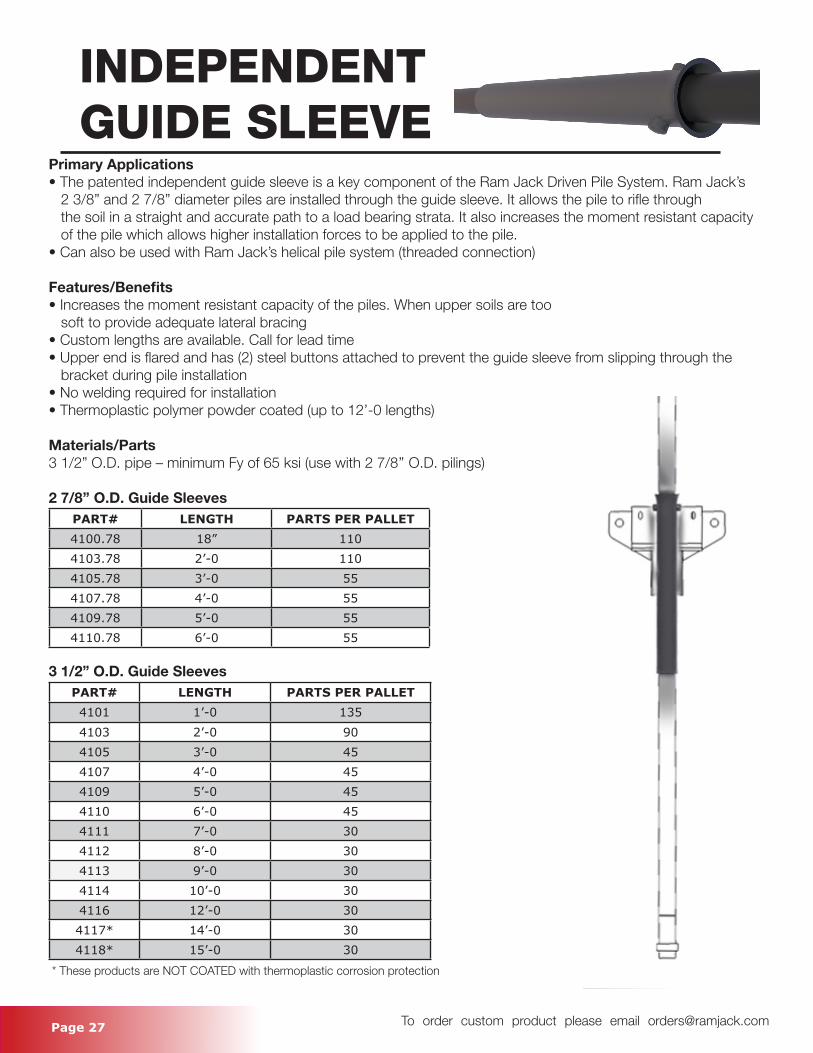
Primary Applications• The patented independent guide sleeve is a key component of the Ram Jack Driven Pile System. Ram Jack’s 2 3/8” and 2 7/8” diameter piles are installed through the guide sleeve. It allows the pile to rifle through the soil in a straight and accurate path to a load bearing strata. It also increases the moment resistant capacity of the pile which allows higher installation forces to be applied to the pile.• Can also be used with Ram Jack’s helical pile system (threaded connection)
Features/Benefits• Increases the moment resistant capacity of the piles. When upper soils are too soft to provide adequate lateral bracing• Custom lengths are available. Call for lead time• Upper end is flared and has (2) steel buttons attached to prevent the guide sleeve from slipping through the bracket during pile installation• No welding required for installation• Thermoplastic polymer powder coated (up to 12’-0 lengths)
Materials/Parts3 1/2” O.D. pipe – minimum Fy of 65 ksi (use with 2 7/8’’ O.D. pilings)
2 7/8’’ O.D. Guide SleevesPART# LENGTH PARTS PER PALLET4100.78 18” 1104103.78 2’-0 1104105.78 3’-0 554107.78 4’-0 554109.78 5’-0 554110.78 6’-0 55
3 1/2” O.D. Guide SleevesPART# LENGTH PARTS PER PALLET4101 1’-0 1354103 2’-0 904105 3’-0 454107 4’-0 454109 5’-0 454110 6’-0 454111 7’-0 304112 8’-0 304113 9’-0 304114 10’-0 304116 12’-0 304117* 14’-0 304118* 15’-0 30
* These products are NOT COATED with thermoplastic corrosion protection
Page 28 To order custom product please email [email protected]
INDEPENDENTGUIDE SLEEVE
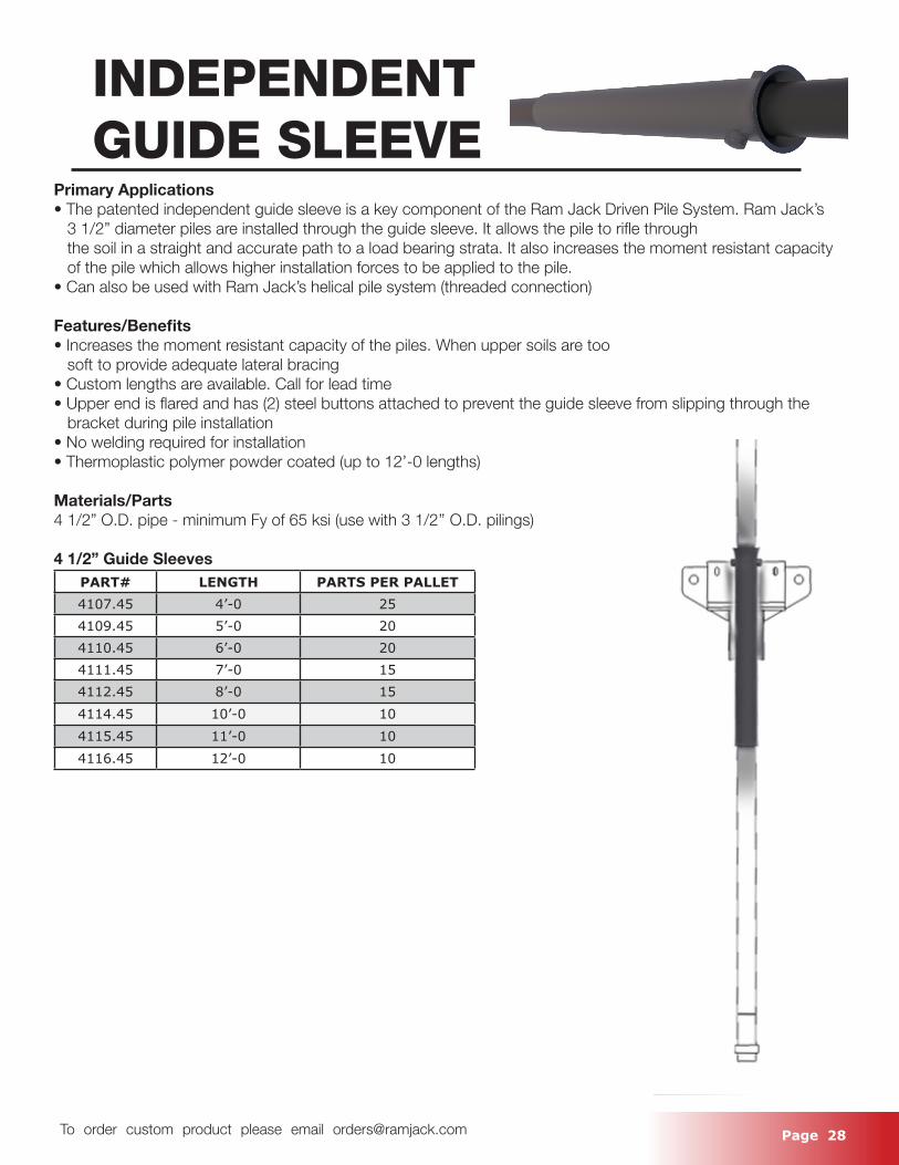
Primary Applications• The patented independent guide sleeve is a key component of the Ram Jack Driven Pile System. Ram Jack’s 3 1/2” diameter piles are installed through the guide sleeve. It allows the pile to rifle through the soil in a straight and accurate path to a load bearing strata. It also increases the moment resistant capacity of the pile which allows higher installation forces to be applied to the pile.• Can also be used with Ram Jack’s helical pile system (threaded connection)
Features/Benefits• Increases the moment resistant capacity of the piles. When upper soils are too soft to provide adequate lateral bracing• Custom lengths are available. Call for lead time• Upper end is flared and has (2) steel buttons attached to prevent the guide sleeve from slipping through the bracket during pile installation• No welding required for installation• Thermoplastic polymer powder coated (up to 12’-0 lengths)
Materials/Parts4 1/2” O.D. pipe - minimum Fy of 65 ksi (use with 3 1/2’’ O.D. pilings)
4 1/2” Guide SleevesPART# LENGTH PARTS PER PALLET4107.45 4’-0 254109.45 5’-0 204110.45 6’-0 204111.45 7’-0 154112.45 8’-0 154114.45 10’-0 104115.45 11’-0 104116.45 12’-0 10
Page 29 To order custom product please email [email protected]
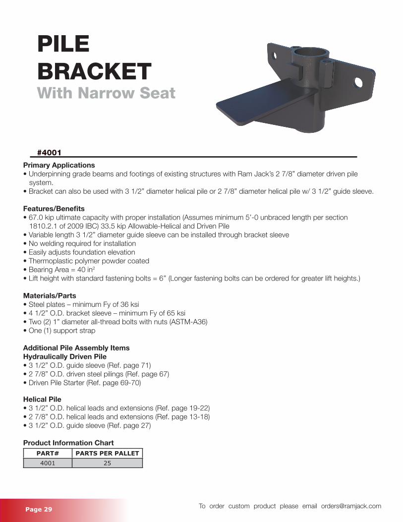
PILEBRACKETWith Narrow Seat
#4001
Primary Applications• Underpinning grade beams and footings of existing structures with Ram Jack’s 2 7/8” diameter driven pile system.• Bracket can also be used with 3 1/2” diameter helical pile or 2 7/8” diameter helical pile w/ 3 1/2” guide sleeve.
Features/Benefits• 67.0 kip ultimate capacity with proper installation (Assumes minimum 5’-0 unbraced length per section 1810.2.1 of 2009 IBC) 33.5 kip Allowable-Helical and Driven Pile• Variable length 3 1/2” diameter guide sleeve can be installed through bracket sleeve• No welding required for installation• Easily adjusts foundation elevation• Thermoplastic polymer powder coated• Bearing Area = 40 in2
• Lift height with standard fastening bolts = 6’’ (Longer fastening bolts can be ordered for greater lift heights.)
Materials/Parts• Steel plates – minimum Fy of 36 ksi• 4 1/2” O.D. bracket sleeve – minimum Fy of 65 ksi• Two (2) 1” diameter all-thread bolts with nuts (ASTM-A36)• One (1) support strap
Additional Pile Assembly ItemsHydraulically Driven Pile• 3 1/2” O.D. guide sleeve (Ref. page 71)• 2 7/8” O.D. driven steel pilings (Ref. page 67)• Driven Pile Starter (Ref. page 69-70)
Helical Pile• 3 1/2” O.D. helical leads and extensions (Ref. page 19-22)• 2 7/8” O.D. helical leads and extensions (Ref. page 13-18)• 3 1/2” O.D. guide sleeve (Ref. page 27)
Product Information ChartPART# PARTS PER PALLET4001 25
Page 30 To order custom product please email [email protected]
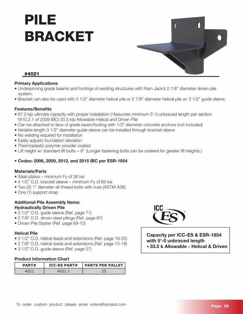
PILEBRACKET
#4021
Primary Applications• Underpinning grade beams and footings of existing structures with Ram Jack’s 2 7/8” diameter driven pile system.• Bracket can also be used with 3 1/2” diameter helical pile or 2 7/8” diameter helical pile w/ 3 1/2” guide sleeve.
Features/Benefits• 67.0 kip ultimate capacity with proper installation (*Assumes minimum 5’-0 unbraced length per section 1810.2.1 of 2009 IBC) 33.5 kip Allowable-Helical and Driven Pile• Can be attached to face of grade beam/footing with 1/2” diameter concrete anchors (not included)• Variable length 3 1/2” diameter guide sleeve can be installed through bracket sleeve• No welding required for installation• Easily adjusts foundation elevation• Thermoplastic polymer powder coated• Lift height w/ standard lift bolts = 6’’ (Longer fastening bolts can be ordered for greater lift heights.)
• Codes: 2006, 2009, 2012, and 2015 IBC per ESR-1854
Materials/Parts• Steel plates – minimum Fy of 36 ksi• 4 1/2” O.D. bracket sleeve – minimum Fy of 65 ksi• Two (2) 1” diameter all-thread bolts with nuts (ASTM-A36)• One (1) support strap
Additional Pile Assembly Items:Hydraulically Driven Pile• 3 1/2” O.D. guide sleeve (Ref. page 71)• 2 7/8” O.D. driven steel pilings (Ref. page 67)• Driven Pile Starter (Ref. page 69-70)
Helical Pile• 3 1/2” O.D. helical leads and extensions (Ref. page 19-22)• 2 7/8” O.D. helical leads and extensions (Ref. page 13-18)• 3 1/2” O.D. guide sleeve (Ref. page 27)
Product Information ChartPART# ICC-ES PART# PARTS PER PALLET4021 4021.1 25
Capacity per ICC-ES & ESR-1854 with 5’-0 unbraced length • 33.5 k Allowable - Helical & Driven
Page 31 To order custom product please email [email protected]
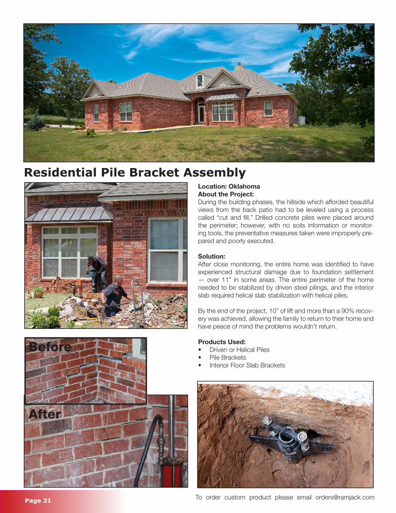
Residential Pile Bracket AssemblyLocation: OklahomaAbout the Project:During the building phases, the hillside which afforded beautiful views from the back patio had to be leveled using a process called “cut and fill.” Drilled concrete piles were placed around the perimeter; however, with no soils information or monitor-ing tools, the preventative measures taken were improperly pre-pared and poorly executed.
Solution:After close monitoring, the entire home was identified to have experienced structural damage due to foundation settlement — over 11” in some areas. The entire perimeter of the home needed to be stabilized by driven steel pilings, and the interior slab required helical slab stabilization with helical piles.
By the end of the project, 10” of lift and more than a 90% recov-ery was achieved, allowing the family to return to their home and have peace of mind the problems wouldn’t return.
Products Used:• Driven or Helical Piles • Pile Brackets• Interior Floor Slab Brackets
Before
After
Page 32 To order custom product please email [email protected]
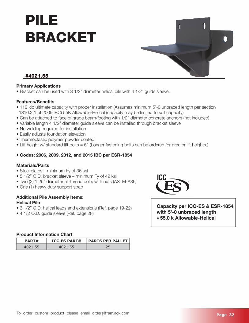
PILEBRACKET
#4021.55
Primary Applications• Bracket can be used with 3 1/2” diameter helical pile with 4 1/2” guide sleeve.
Features/Benefits• 110 kip ultimate capacity with proper installation (Assumes minimum 5’-0 unbraced length per section 1810.2.1 of 2009 IBC) 55K Allowable-Helical (capacity may be limited to soil capacity) • Can be attached to face of grade beam/footing with 1/2” diameter concrete anchors (not included)• Variable length 4 1/2” diameter guide sleeve can be installed through bracket sleeve• No welding required for installation• Easily adjusts foundation elevation• Thermoplastic polymer powder coated• Lift height w/ standard lift bolts = 6’’ (Longer fastening bolts can be ordered for greater lift heights.)
• Codes: 2006, 2009, 2012, and 2015 IBC per ESR-1854
Materials/Parts• Steel plates – minimum Fy of 36 ksi• 5 1/2” O.D. bracket sleeve – minimum Fy of 42 ksi• Two (2) 1.25” diameter all-thread bolts with nuts (ASTM-A36)• One (1) heavy duty support strap
Additional Pile Assembly Items:Helical Pile• 3 1/2” O.D. helical leads and extensions (Ref. page 19-22)• 4 1/2 O.D. guide sleeve (Ref. page 28)
Product Information ChartPART# ICC-ES PART# PARTS PER PALLET4021.55 4021.55 25
Capacity per ICC-ES & ESR-1854 with 5’-0 unbraced length • 55.0 k Allowable-Helical
Page 33 To order custom product please email [email protected]
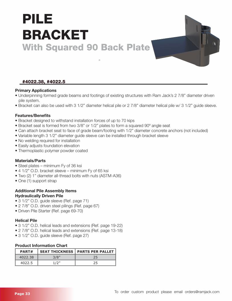
PILEBRACKETWith Squared 90 Back Plate
#4022.38, #4022.5
Primary Applications• Underpinning formed grade beams and footings of existing structures with Ram Jack’s 2 7/8” diameter driven pile system.• Bracket can also be used with 3 1/2” diameter helical pile or 2 7/8” diameter helical pile w/ 3 1/2” guide sleeve.
Features/Benefits• Bracket designed to withstand installation forces of up to 70 kips• Bracket seat is formed from two 3/8” or 1/2” plates to form a squared 90o angle seat• Can attach bracket seat to face of grade beam/footing with 1/2” diameter concrete anchors (not included)• Variable length 3 1/2” diameter guide sleeve can be installed through bracket sleeve• No welding required for installation• Easily adjusts foundation elevation• Thermoplastic polymer powder coated
Materials/Parts• Steel plates – minimum Fy of 36 ksi• 4 1/2” O.D. bracket sleeve – minimum Fy of 65 ksi• Two (2) 1” diameter all-thread bolts with nuts (ASTM-A36)• One (1) support strap
Additional Pile Assembly ItemsHydraulically Driven Pile• 3 1/2” O.D. guide sleeve (Ref. page 71)• 2 7/8” O.D. driven steel pilings (Ref. page 67)• Driven Pile Starter (Ref. page 69-70)
Helical Pile• 3 1/2” O.D. helical leads and extensions (Ref. page 19-22)• 2 7/8” O.D. helical leads and extensions (Ref. page 13-18)• 3 1/2” O.D. guide sleeve (Ref. page 27)
Product Information ChartPART# SEAT THICKNESS PARTS PER PALLET4022.38 3/8” 254022.5 1/2” 25
Page 34 To order custom product please email [email protected]
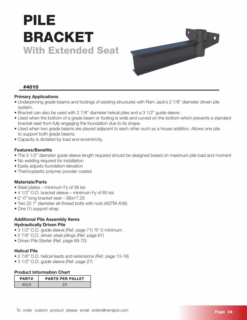
PILEBRACKETWith Extended Seat
#4010
Primary Applications• Underpinning grade beams and footings of existing structures with Ram Jack’s 2 7/8” diameter driven pile system.• Bracket can also be used with 2 7/8” diameter helical piles and a 3 1/2” guide sleeve.• Used when the bottom of a grade beam or footing is wide and curved on the bottom which prevents a standard bracket seat from fully engaging the foundation due to its shape.• Used when two grade beams are placed adjacent to each other such as a house addition. Allows one pile to support both grade beams.• Capacity is dictated by load and eccentricity.
Features/Benefits• The 3 1/2” diameter guide sleeve length required should be designed based on maximum pile load and moment• No welding required for installation• Easily adjusts foundation elevation• Thermoplastic polymer powder coated
Materials/Parts• Steel plates – minimum Fy of 36 ksi • 4 1/2” O.D. bracket sleeve – minimum Fy of 65 ksi• 2’-0” long bracket seat – S6x17.25• Two (2) 1” diameter all-thread bolts with nuts (ASTM-A36)• One (1) support strap
Additional Pile Assembly ItemsHydraulically Driven Pile• 3 1/2” O.D. guide sleeve (Ref. page 71) *6’-0 minimum• 2 7/8” O.D. driven steel pilings (Ref. page 67)• Driven Pile Starter (Ref. page 69-70)
Helical Pile• 2 7/8” O.D. helical leads and extensions (Ref. page 13-18)• 3 1/2” O.D. guide sleeve (Ref. page 27)
Product Information ChartPART# PARTS PER PALLET4010 25
Page 35 To order custom product please email [email protected]
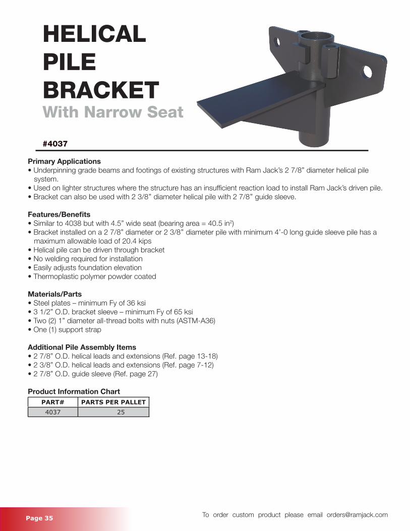
HELICALPILEBRACKETWith Narrow Seat
#4037
Primary Applications• Underpinning grade beams and footings of existing structures with Ram Jack’s 2 7/8” diameter helical pile system. • Used on lighter structures where the structure has an insufficient reaction load to install Ram Jack’s driven pile.• Bracket can also be used with 2 3/8’’ diameter helical pile with 2 7/8’’ guide sleeve.
Features/Benefits• Similar to 4038 but with 4.5” wide seat (bearing area = 40.5 in2)• Bracket installed on a 2 7/8” diameter or 2 3/8’’ diameter pile with minimum 4’-0 long guide sleeve pile has a maximum allowable load of 20.4 kips• Helical pile can be driven through bracket• No welding required for installation• Easily adjusts foundation elevation• Thermoplastic polymer powder coated
Materials/Parts• Steel plates – minimum Fy of 36 ksi• 3 1/2” O.D. bracket sleeve – minimum Fy of 65 ksi• Two (2) 1” diameter all-thread bolts with nuts (ASTM-A36)• One (1) support strap
Additional Pile Assembly Items• 2 7/8” O.D. helical leads and extensions (Ref. page 13-18)• 2 3/8” O.D. helical leads and extensions (Ref. page 7-12)• 2 7/8” O.D. guide sleeve (Ref. page 27)
Product Information ChartPART# PARTS PER PALLET4037 25
Page 36 To order custom product please email [email protected]
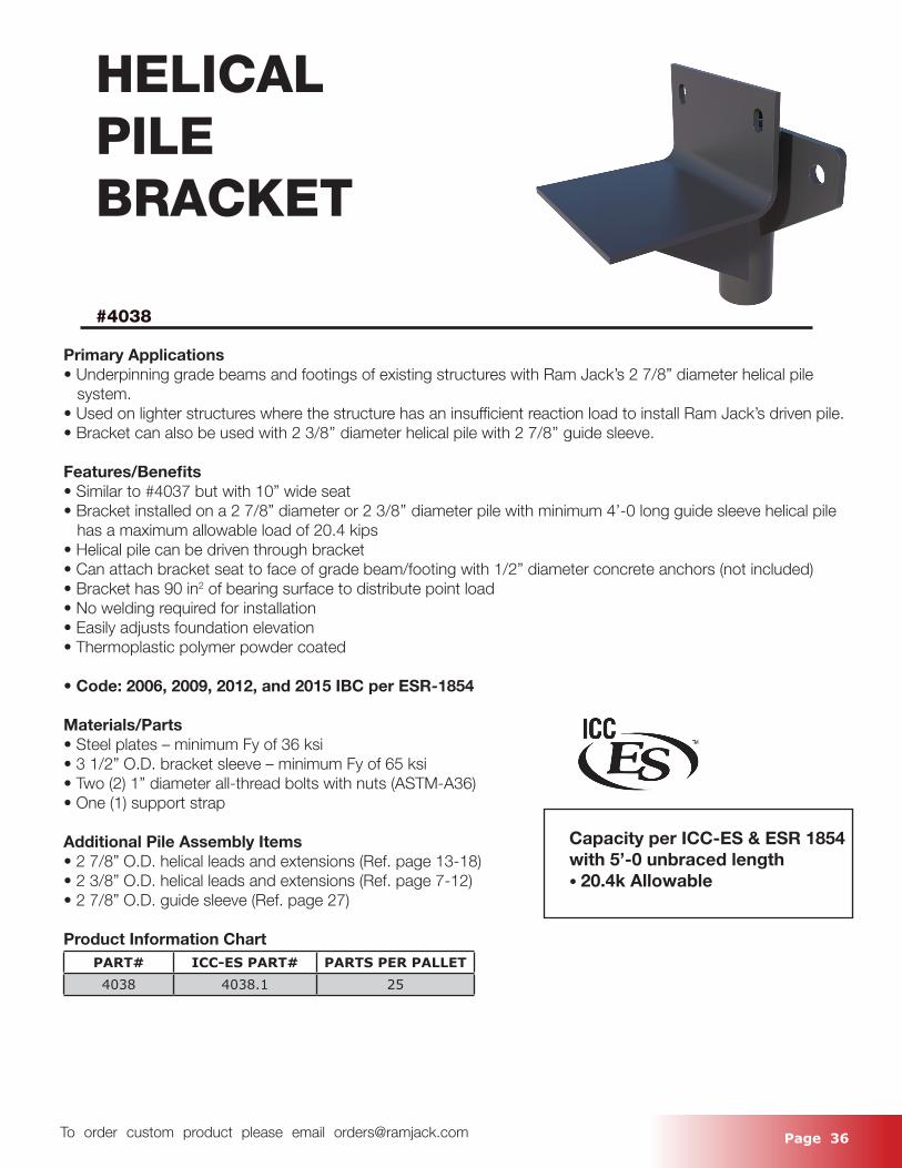
HELICALPILEBRACKET
#4038
Primary Applications• Underpinning grade beams and footings of existing structures with Ram Jack’s 2 7/8” diameter helical pile system.• Used on lighter structures where the structure has an insufficient reaction load to install Ram Jack’s driven pile.• Bracket can also be used with 2 3/8’’ diameter helical pile with 2 7/8’’ guide sleeve.
Features/Benefits• Similar to #4037 but with 10” wide seat• Bracket installed on a 2 7/8” diameter or 2 3/8’’ diameter pile with minimum 4’-0 long guide sleeve helical pile has a maximum allowable load of 20.4 kips• Helical pile can be driven through bracket• Can attach bracket seat to face of grade beam/footing with 1/2” diameter concrete anchors (not included)• Bracket has 90 in2 of bearing surface to distribute point load• No welding required for installation• Easily adjusts foundation elevation• Thermoplastic polymer powder coated
• Code: 2006, 2009, 2012, and 2015 IBC per ESR-1854
Materials/Parts• Steel plates – minimum Fy of 36 ksi• 3 1/2” O.D. bracket sleeve – minimum Fy of 65 ksi• Two (2) 1” diameter all-thread bolts with nuts (ASTM-A36)• One (1) support strap
Additional Pile Assembly Items• 2 7/8” O.D. helical leads and extensions (Ref. page 13-18)• 2 3/8” O.D. helical leads and extensions (Ref. page 7-12)• 2 7/8” O.D. guide sleeve (Ref. page 27)
Product Information ChartPART# ICC-ES PART# PARTS PER PALLET4038 4038.1 25
Capacity per ICC-ES & ESR 1854 with 5’-0 unbraced length • 20.4k Allowable
Page 37 To order custom product please email [email protected]
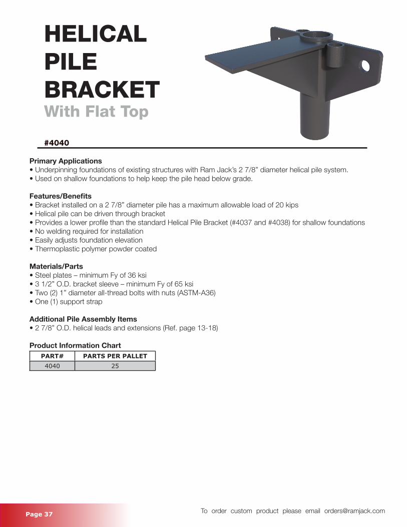
HELICALPILEBRACKETWith Flat Top
#4040
Primary Applications• Underpinning foundations of existing structures with Ram Jack’s 2 7/8” diameter helical pile system.• Used on shallow foundations to help keep the pile head below grade.
Features/Benefits• Bracket installed on a 2 7/8” diameter pile has a maximum allowable load of 20 kips• Helical pile can be driven through bracket• Provides a lower profile than the standard Helical Pile Bracket (#4037 and #4038) for shallow foundations• No welding required for installation• Easily adjusts foundation elevation• Thermoplastic polymer powder coated
Materials/Parts• Steel plates – minimum Fy of 36 ksi• 3 1/2” O.D. bracket sleeve – minimum Fy of 65 ksi• Two (2) 1” diameter all-thread bolts with nuts (ASTM-A36)• One (1) support strap
Additional Pile Assembly Items• 2 7/8” O.D. helical leads and extensions (Ref. page 13-18)
Product Information ChartPART# PARTS PER PALLET4040 25

Page 38 To order custom product please email [email protected]
EXTRA WIDE SEAT
#4048, #4041, #4041.55HP, #4041.55DP
Primary Applications•The wide seat bracket is used to underpin weak or under reinforced foundations• The wide seat allows the capacity of the pile to govern pile spacing and not the strength of the footing in most cases• The 4-foot wide bracket seat can be used to replace the standard 10” wide seat on the 4038, 4021 and 4021.55 brackets
Features/Benefits• The 4-foot wide bracket seat provides up to 372 in2 of bearing area• Since the wide seat doesn’t change the eccentricity of the bracket on the 4038, 4021 or 4021.55, their respective capacities do not change• Can be used with helical or driven pile system• No welding required for installation• Easily adjusts foundation elevation• Thermoplastic polymer powder coated• Lift height with standard fastening bolts = 6’’ (Longer fastening bolts can be ordered for greater lift heights.)
Materials/Parts• Steel plates – minimum Fy of 36 ksi• Bracket sleeve – minimum Fy of 65 ksi• Two (2) all-thread bolts with nuts (ASTM-A36)• One (1) support strap
Additional Pile Assembly Items• Reference standard bracket the wide seat is being used on (4038, 4021, 4021.55, 4021.55DP)
Product Information ChartPART# originial part number PARTS PER PALLET
4048 4038 144041 4021 14
4041.55HP 4021.55HP 144041.55DP 4021.55DP 14
Page 39 To order custom product please email [email protected]
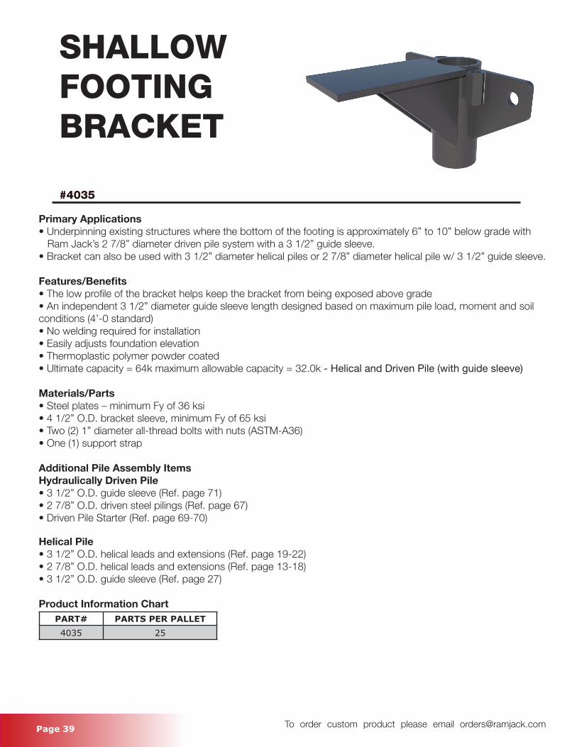
SHALLOWFOOTINGBRACKET
#4035
Primary Applications• Underpinning existing structures where the bottom of the footing is approximately 6” to 10” below grade with Ram Jack’s 2 7/8” diameter driven pile system with a 3 1/2” guide sleeve.• Bracket can also be used with 3 1/2” diameter helical piles or 2 7/8” diameter helical pile w/ 3 1/2” guide sleeve.
Features/Benefits• The low profile of the bracket helps keep the bracket from being exposed above grade• An independent 3 1/2” diameter guide sleeve length designed based on maximum pile load, moment and soil conditions (4’-0 standard)• No welding required for installation• Easily adjusts foundation elevation• Thermoplastic polymer powder coated• Ultimate capacity = 64k maximum allowable capacity = 32.0k - Helical and Driven Pile (with guide sleeve)
Materials/Parts• Steel plates – minimum Fy of 36 ksi• 4 1/2” O.D. bracket sleeve, minimum Fy of 65 ksi• Two (2) 1” diameter all-thread bolts with nuts (ASTM-A36)• One (1) support strap
Additional Pile Assembly ItemsHydraulically Driven Pile• 3 1/2” O.D. guide sleeve (Ref. page 71)• 2 7/8” O.D. driven steel pilings (Ref. page 67)• Driven Pile Starter (Ref. page 69-70)
Helical Pile• 3 1/2” O.D. helical leads and extensions (Ref. page 19-22)• 2 7/8” O.D. helical leads and extensions (Ref. page 13-18)• 3 1/2” O.D. guide sleeve (Ref. page 27)
Product Information ChartPART# PARTS PER PALLET4035 25
Page 40 To order custom product please email [email protected]
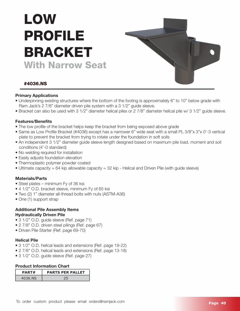
LOWPROFILEBRACKETWith Narrow Seat
#4036.NS
Primary Applications• Underpinning existing structures where the bottom of the footing is approximately 6” to 10” below grade with Ram Jack’s 2 7/8” diameter driven pile system with a 3 1/2” guide sleeve.• Bracket can also be used with 3 1/2” diameter helical piles or 2 7/8” diameter helical pile w/ 3 1/2” guide sleeve.
Features/Benefits• The low profile of the bracket helps keep the bracket from being exposed above grade• Same as Low Profile Bracket (#4036) except has a narrower 6” wide seat with a small PL 3/8”x 3”x 0’-3 vertical plate to prevent the bracket from trying to rotate under the foundation in soft soils• An independent 3 1/2” diameter guide sleeve length designed based on maximum pile load, moment and soil conditions (4’-0 standard)• No welding required for installation• Easily adjusts foundation elevation• Thermoplastic polymer powder coated• Ultimate capacity = 64 kip allowable capacity = 32 kip - Helical and Driven Pile (with guide sleeve)
Materials/Parts• Steel plates – minimum Fy of 36 ksi• 4 1/2” O.D. bracket sleeve, minimum Fy of 65 ksi• Two (2) 1” diameter all-thread bolts with nuts (ASTM-A36)• One (1) support strap
Additional Pile Assembly ItemsHydraulically Driven Pile• 3 1/2” O.D. guide sleeve (Ref. page 71)• 2 7/8” O.D. driven steel pilings (Ref. page 67)• Driven Pile Starter (Ref. page 69-70)
Helical Pile• 3 1/2” O.D. helical leads and extensions (Ref. page 19-22)• 2 7/8” O.D. helical leads and extensions (Ref. page 13-18)• 3 1/2” O.D. guide sleeve (Ref. page 27)
Product Information ChartPART# PARTS PER PALLET4036.NS 25
Page 41 To order custom product please email [email protected]
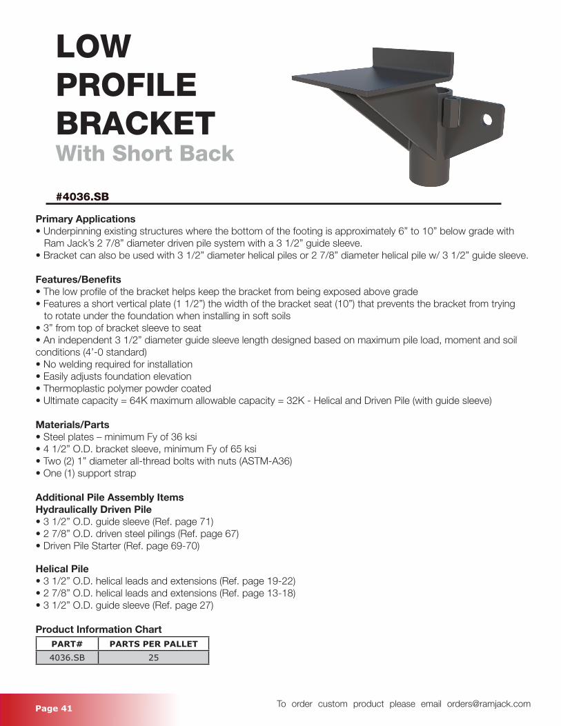
LOWPROFILEBRACKETWith Short Back
#4036.SB
Primary Applications• Underpinning existing structures where the bottom of the footing is approximately 6” to 10” below grade with Ram Jack’s 2 7/8” diameter driven pile system with a 3 1/2” guide sleeve.• Bracket can also be used with 3 1/2” diameter helical piles or 2 7/8” diameter helical pile w/ 3 1/2” guide sleeve.
Features/Benefits• The low profile of the bracket helps keep the bracket from being exposed above grade• Features a short vertical plate (1 1/2”) the width of the bracket seat (10”) that prevents the bracket from trying to rotate under the foundation when installing in soft soils• 3” from top of bracket sleeve to seat• An independent 3 1/2” diameter guide sleeve length designed based on maximum pile load, moment and soil conditions (4’-0 standard)• No welding required for installation• Easily adjusts foundation elevation• Thermoplastic polymer powder coated• Ultimate capacity = 64K maximum allowable capacity = 32K - Helical and Driven Pile (with guide sleeve)
Materials/Parts• Steel plates – minimum Fy of 36 ksi• 4 1/2” O.D. bracket sleeve, minimum Fy of 65 ksi• Two (2) 1” diameter all-thread bolts with nuts (ASTM-A36)• One (1) support strap
Additional Pile Assembly ItemsHydraulically Driven Pile• 3 1/2” O.D. guide sleeve (Ref. page 71)• 2 7/8” O.D. driven steel pilings (Ref. page 67)• Driven Pile Starter (Ref. page 69-70)
Helical Pile• 3 1/2” O.D. helical leads and extensions (Ref. page 19-22)• 2 7/8” O.D. helical leads and extensions (Ref. page 13-18)• 3 1/2” O.D. guide sleeve (Ref. page 27)
Product Information ChartPART# PARTS PER PALLET4036.SB 25
Page 42 To order custom product please email [email protected]
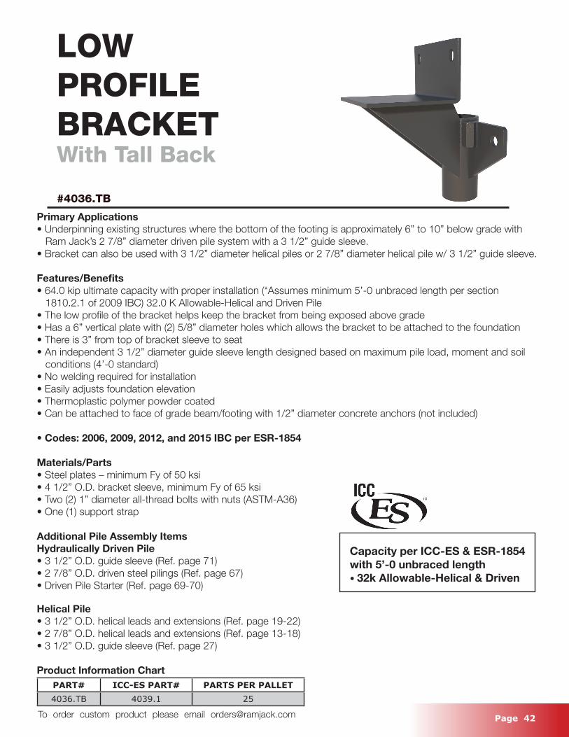
LOWPROFILEBRACKETWith Tall Back
#4036.TB
Primary Applications• Underpinning existing structures where the bottom of the footing is approximately 6” to 10” below grade with Ram Jack’s 2 7/8” diameter driven pile system with a 3 1/2” guide sleeve.• Bracket can also be used with 3 1/2” diameter helical piles or 2 7/8” diameter helical pile w/ 3 1/2” guide sleeve.
Features/Benefits• 64.0 kip ultimate capacity with proper installation (*Assumes minimum 5’-0 unbraced length per section 1810.2.1 of 2009 IBC) 32.0 K Allowable-Helical and Driven Pile• The low profile of the bracket helps keep the bracket from being exposed above grade• Has a 6” vertical plate with (2) 5/8” diameter holes which allows the bracket to be attached to the foundation • There is 3” from top of bracket sleeve to seat • An independent 3 1/2” diameter guide sleeve length designed based on maximum pile load, moment and soil conditions (4’-0 standard)• No welding required for installation• Easily adjusts foundation elevation• Thermoplastic polymer powder coated• Can be attached to face of grade beam/footing with 1/2” diameter concrete anchors (not included)
• Codes: 2006, 2009, 2012, and 2015 IBC per ESR-1854
Materials/Parts• Steel plates – minimum Fy of 50 ksi• 4 1/2” O.D. bracket sleeve, minimum Fy of 65 ksi• Two (2) 1” diameter all-thread bolts with nuts (ASTM-A36)• One (1) support strap
Additional Pile Assembly ItemsHydraulically Driven Pile• 3 1/2” O.D. guide sleeve (Ref. page 71)• 2 7/8” O.D. driven steel pilings (Ref. page 67)• Driven Pile Starter (Ref. page 69-70)
Helical Pile• 3 1/2” O.D. helical leads and extensions (Ref. page 19-22)• 2 7/8” O.D. helical leads and extensions (Ref. page 13-18)• 3 1/2” O.D. guide sleeve (Ref. page 27)
Product Information ChartPART# ICC-ES PART# PARTS PER PALLET4036.TB 4039.1 25
Capacity per ICC-ES & ESR-1854 with 5’-0 unbraced length • 32k Allowable-Helical & Driven
Page 43 To order custom product please email [email protected]
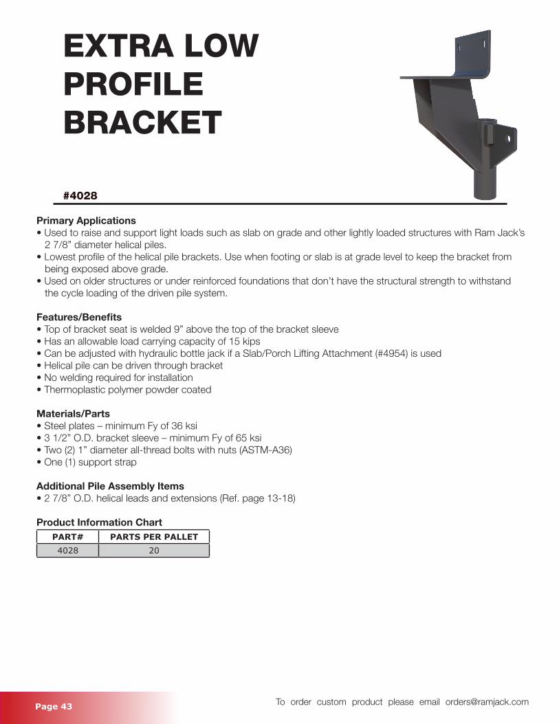
EXTRA LOWPROFILEBRACKET
#4028
Primary Applications• Used to raise and support light loads such as slab on grade and other lightly loaded structures with Ram Jack’s 2 7/8” diameter helical piles.• Lowest profile of the helical pile brackets. Use when footing or slab is at grade level to keep the bracket from being exposed above grade.• Used on older structures or under reinforced foundations that don’t have the structural strength to withstand the cycle loading of the driven pile system.
Features/Benefits• Top of bracket seat is welded 9” above the top of the bracket sleeve• Has an allowable load carrying capacity of 15 kips• Can be adjusted with hydraulic bottle jack if a Slab/Porch Lifting Attachment (#4954) is used• Helical pile can be driven through bracket• No welding required for installation• Thermoplastic polymer powder coated
Materials/Parts• Steel plates – minimum Fy of 36 ksi• 3 1/2” O.D. bracket sleeve – minimum Fy of 65 ksi• Two (2) 1” diameter all-thread bolts with nuts (ASTM-A36)• One (1) support strap
Additional Pile Assembly Items• 2 7/8” O.D. helical leads and extensions (Ref. page 13-18)
Product Information ChartPART# PARTS PER PALLET4028 20
Page 44 To order custom product please email [email protected]
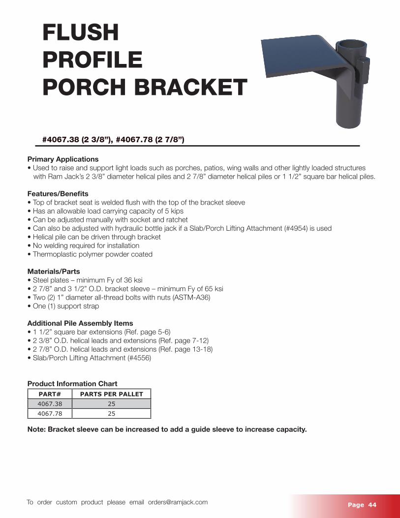
FLUSHPROFILEPORCH BRACKET
#4067.38 (2 3/8”), #4067.78 (2 7/8”)
Primary Applications• Used to raise and support light loads such as porches, patios, wing walls and other lightly loaded structures with Ram Jack’s 2 3/8” diameter helical piles and 2 7/8” diameter helical piles or 1 1/2” square bar helical piles.
Features/Benefits• Top of bracket seat is welded flush with the top of the bracket sleeve• Has an allowable load carrying capacity of 5 kips• Can be adjusted manually with socket and ratchet• Can also be adjusted with hydraulic bottle jack if a Slab/Porch Lifting Attachment (#4954) is used• Helical pile can be driven through bracket• No welding required for installation• Thermoplastic polymer powder coated
Materials/Parts• Steel plates – minimum Fy of 36 ksi• 2 7/8” and 3 1/2” O.D. bracket sleeve – minimum Fy of 65 ksi• Two (2) 1” diameter all-thread bolts with nuts (ASTM-A36)• One (1) support strap
Additional Pile Assembly Items• 1 1/2” square bar extensions (Ref. page 5-6)• 2 3/8” O.D. helical leads and extensions (Ref. page 7-12)• 2 7/8” O.D. helical leads and extensions (Ref. page 13-18)• Slab/Porch Lifting Attachment (#4556)
Product Information ChartPART# PARTS PER PALLET4067.38 254067.78 25
Note: Bracket sleeve can be increased to add a guide sleeve to increase capacity.
Page 45 To order custom product please email [email protected]
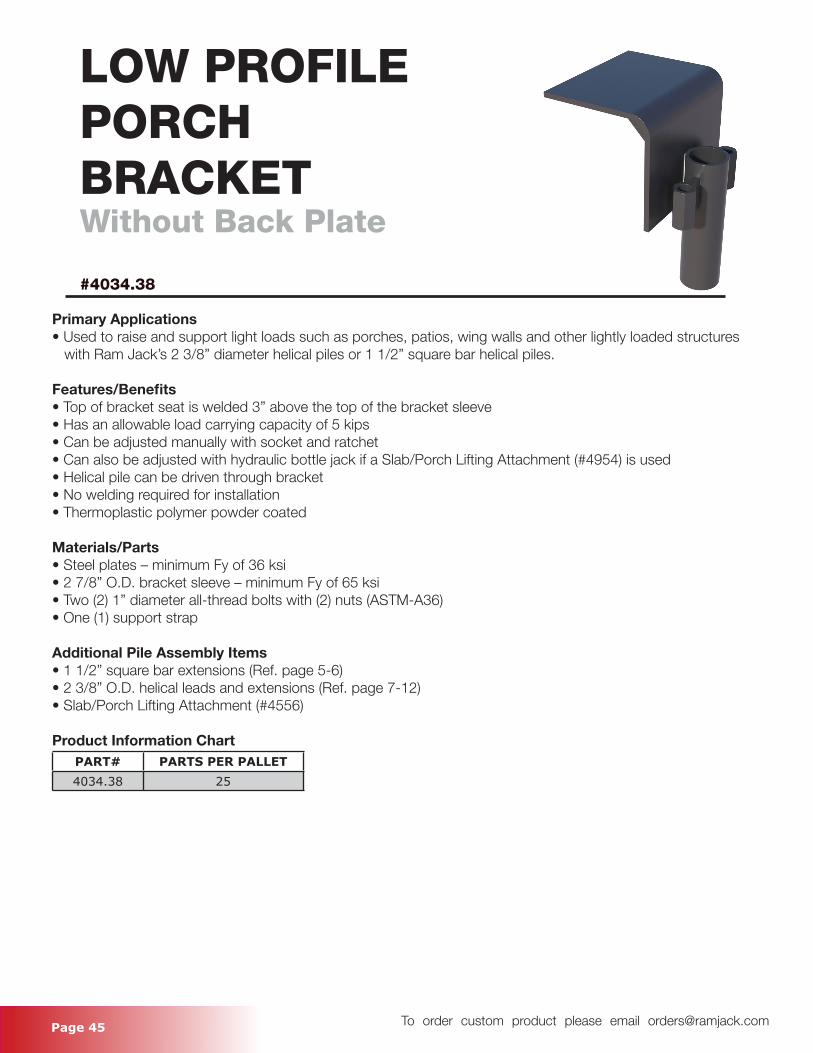
LOW PROFILEPORCHBRACKETWithout Back Plate
#4034.38
Primary Applications• Used to raise and support light loads such as porches, patios, wing walls and other lightly loaded structures with Ram Jack’s 2 3/8” diameter helical piles or 1 1/2” square bar helical piles.
Features/Benefits• Top of bracket seat is welded 3” above the top of the bracket sleeve• Has an allowable load carrying capacity of 5 kips• Can be adjusted manually with socket and ratchet• Can also be adjusted with hydraulic bottle jack if a Slab/Porch Lifting Attachment (#4954) is used• Helical pile can be driven through bracket• No welding required for installation• Thermoplastic polymer powder coated
Materials/Parts• Steel plates – minimum Fy of 36 ksi• 2 7/8” O.D. bracket sleeve – minimum Fy of 65 ksi• Two (2) 1” diameter all-thread bolts with (2) nuts (ASTM-A36)• One (1) support strap
Additional Pile Assembly Items• 1 1/2” square bar extensions (Ref. page 5-6)• 2 3/8” O.D. helical leads and extensions (Ref. page 7-12)• Slab/Porch Lifting Attachment (#4556)
Product Information ChartPART# PARTS PER PALLET4034.38 25
Page 46 To order custom product please email [email protected]
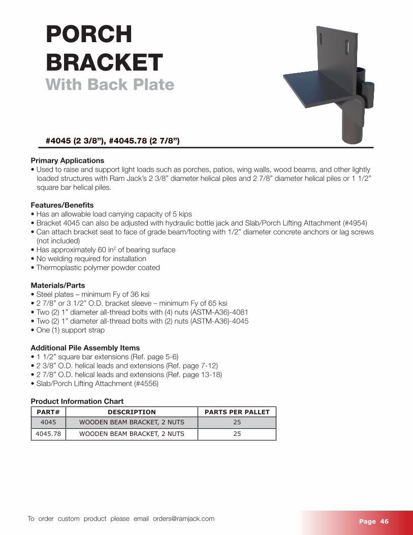
PORCHBRACKETWith Back Plate
#4045 (2 3/8”), #4045.78 (2 7/8”)
Primary Applications• Used to raise and support light loads such as porches, patios, wing walls, wood beams, and other lightly loaded structures with Ram Jack’s 2 3/8” diameter helical piles and 2 7/8” diameter helical piles or 1 1/2” square bar helical piles.
Features/Benefits• Has an allowable load carrying capacity of 5 kips• Bracket 4045 can also be adjusted with hydraulic bottle jack and Slab/Porch Lifting Attachment (#4954) • Can attach bracket seat to face of grade beam/footing with 1/2” diameter concrete anchors or lag screws (not included) • Has approximately 60 in2 of bearing surface• No welding required for installation• Thermoplastic polymer powder coated
Materials/Parts• Steel plates – minimum Fy of 36 ksi• 2 7/8” or 3 1/2” O.D. bracket sleeve – minimum Fy of 65 ksi• Two (2) 1” diameter all-thread bolts with (4) nuts (ASTM-A36)-4081• Two (2) 1” diameter all-thread bolts with (2) nuts (ASTM-A36)-4045• One (1) support strap
Additional Pile Assembly Items• 1 1/2” square bar extensions (Ref. page 5-6)• 2 3/8” O.D. helical leads and extensions (Ref. page 7-12)• 2 7/8” O.D. helical leads and extensions (Ref. page 13-18)• Slab/Porch Lifting Attachment (#4556)
Product Information ChartPART# DESCRIPTION PARTS PER PALLET4045 WOODEN BEAM BRACKET, 2 NUTS 25
4045.78 WOODEN BEAM BRACKET, 2 NUTS 25
Page 47 To order custom product please email [email protected]
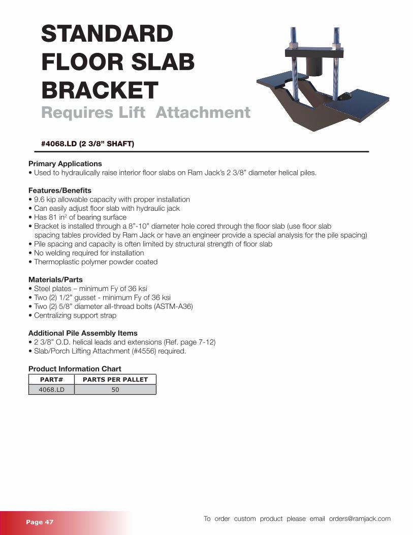
STANDARDFLOOR SLAB BRACKETRequires Lift Attachment
#4068.LD (2 3/8” SHAFT)
Primary Applications• Used to hydraulically raise interior floor slabs on Ram Jack’s 2 3/8” diameter helical piles.
Features/Benefits• 9.6 kip allowable capacity with proper installation• Can easily adjust floor slab with hydraulic jack• Has 81 in2 of bearing surface• Bracket is installed through a 8”-10” diameter hole cored through the floor slab (use floor slab spacing tables provided by Ram Jack or have an engineer provide a special analysis for the pile spacing)• Pile spacing and capacity is often limited by structural strength of floor slab• No welding required for installation• Thermoplastic polymer powder coated
Materials/Parts• Steel plates – minimum Fy of 36 ksi• Two (2) 1/2” gusset - minimum Fy of 36 ksi• Two (2) 5/8” diameter all-thread bolts (ASTM-A36)• Centralizing support strap
Additional Pile Assembly Items• 2 3/8” O.D. helical leads and extensions (Ref. page 7-12)• Slab/Porch Lifting Attachment (#4556) required.
Product Information ChartPART# PARTS PER PALLET4068.LD 50
Page 48 To order custom product please email [email protected]
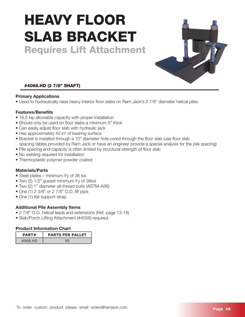
HEAVY FLOOR SLAB BRACKETRequires Lift Attachment
#4068.HD (2 7/8” SHAFT)
Primary Applications• Used to hydraulically raise heavy interior floor slabs on Ram Jack’s 2 7/8” diameter helical piles.
Features/Benefits• 16.5 kip allowable capacity with proper installation• Should only be used on floor slabs a minimum 5” thick• Can easily adjust floor slab with hydraulic jack• Has approximately 40 in2 of bearing surface• Bracket is installed through a 10” diameter hole cored through the floor slab (use floor slab spacing tables provided by Ram Jack or have an engineer provide a special analysis for the pile spacing)• Pile spacing and capacity is often limited by structural strength of floor slab• No welding required for installation• Thermoplastic polymer powder coated
Materials/Parts• Steel plates – minimum Fy of 36 ksi• Two (2) 1/2” gusset minimum Fy of 36ksi• Two (2) 1” diameter all-thread bolts (ASTM-A36)• One (1) 2 3/8” or 2 7/8” O.D. lift pipe• One (1) flat support strap
Additional Pile Assembly Items• 2 7/8” O.D. helical leads and extensions (Ref. page 13-18)• Slab/Porch Lifting Attachment (#4556) required.
Product Information ChartPART# PARTS PER PALLET4068.HD 50
Page 49 To order custom product please email [email protected]
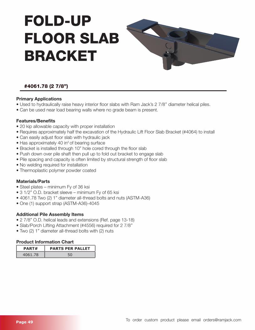
FOLD-UPFLOOR SLABBRACKET
#4061.78 (2 7/8”)
Primary Applications• Used to hydraulically raise heavy interior floor slabs with Ram Jack’s 2 7/8’’ diameter helical piles.• Can be used near load bearing walls where no grade beam is present.
Features/Benefits• 20 kip allowable capacity with proper installation• Requires approximately half the excavation of the Hydraulic Lift Floor Slab Bracket (#4064) to install• Can easily adjust floor slab with hydraulic jack• Has approximately 40 in2 of bearing surface• Bracket is installed through 10” hole cored through the floor slab• Push down over pile shaft then pull up to fold out bracket to engage slab• Pile spacing and capacity is often limited by structural strength of floor slab• No welding required for installation• Thermoplastic polymer powder coated
Materials/Parts• Steel plates – minimum Fy of 36 ksi• 3 1/2” O.D. bracket sleeve – minimum Fy of 65 ksi• 4061.78 Two (2) 1” diameter all-thread bolts and nuts (ASTM-A36)• One (1) support strap (ASTM-A36)-4045
Additional Pile Assembly Items• 2 7/8” O.D. helical leads and extensions (Ref. page 13-18)• Slab/Porch Lifting Attachment (#4556) required for 2 7/8’’• Two (2) 1” diameter all-thread bolts with (2) nuts
Product Information ChartPART# PARTS PER PALLET4061.78 50
Page 50 To order custom product please email [email protected]
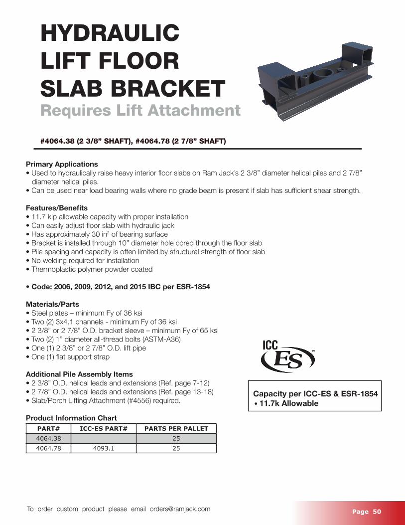
HYDRAULICLIFT FLOORSLAB BRACKETRequires Lift Attachment
#4064.38 (2 3/8” SHAFT), #4064.78 (2 7/8” SHAFT)
Primary Applications• Used to hydraulically raise heavy interior floor slabs on Ram Jack’s 2 3/8” diameter helical piles and 2 7/8” diameter helical piles.• Can be used near load bearing walls where no grade beam is present if slab has sufficient shear strength.
Features/Benefits• 11.7 kip allowable capacity with proper installation• Can easily adjust floor slab with hydraulic jack• Has approximately 30 in2 of bearing surface• Bracket is installed through 10” diameter hole cored through the floor slab• Pile spacing and capacity is often limited by structural strength of floor slab• No welding required for installation• Thermoplastic polymer powder coated
• Code: 2006, 2009, 2012, and 2015 IBC per ESR-1854
Materials/Parts• Steel plates – minimum Fy of 36 ksi• Two (2) 3x4.1 channels - minimum Fy of 36 ksi• 2 3/8” or 2 7/8” O.D. bracket sleeve – minimum Fy of 65 ksi• Two (2) 1” diameter all-thread bolts (ASTM-A36)• One (1) 2 3/8” or 2 7/8” O.D. lift pipe• One (1) flat support strap
Additional Pile Assembly Items• 2 3/8” O.D. helical leads and extensions (Ref. page 7-12)• 2 7/8” O.D. helical leads and extensions (Ref. page 13-18)• Slab/Porch Lifting Attachment (#4556) required.
Product Information ChartPART# ICC-ES PART# PARTS PER PALLET4064.38 254064.78 4093.1 25
Capacity per ICC-ES & ESR-1854 • 11.7k Allowable
Page 51 To order custom product please email [email protected]
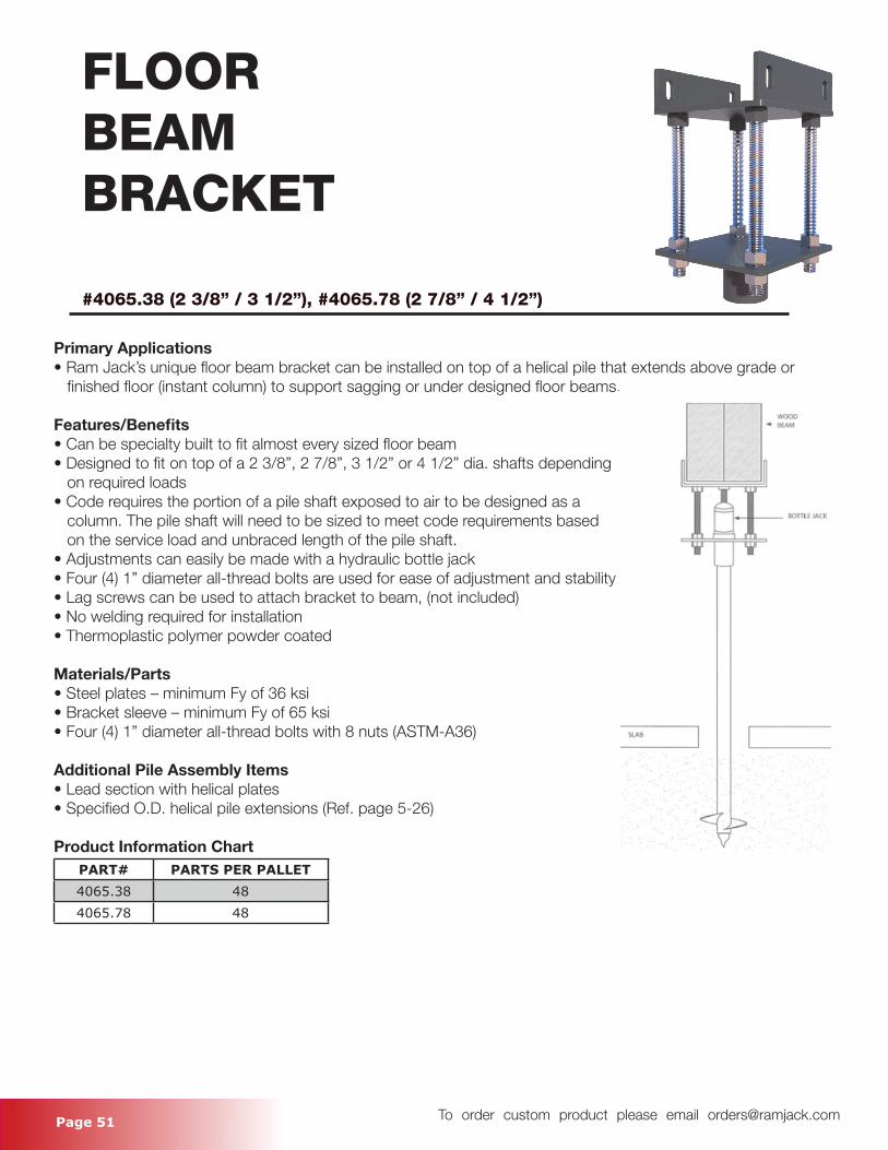
FLOORBEAMBRACKET
#4065.38 (2 3/8” / 3 1/2”), #4065.78 (2 7/8” / 4 1/2”)
Primary Applications• Ram Jack’s unique floor beam bracket can be installed on top of a helical pile that extends above grade or finished floor (instant column) to support sagging or under designed floor beams.
Features/Benefits• Can be specialty built to fit almost every sized floor beam• Designed to fit on top of a 2 3/8”, 2 7/8”, 3 1/2” or 4 1/2” dia. shafts depending on required loads• Code requires the portion of a pile shaft exposed to air to be designed as a column. The pile shaft will need to be sized to meet code requirements based on the service load and unbraced length of the pile shaft. • Adjustments can easily be made with a hydraulic bottle jack• Four (4) 1” diameter all-thread bolts are used for ease of adjustment and stability• Lag screws can be used to attach bracket to beam, (not included)• No welding required for installation• Thermoplastic polymer powder coated
Materials/Parts• Steel plates – minimum Fy of 36 ksi• Bracket sleeve – minimum Fy of 65 ksi• Four (4) 1” diameter all-thread bolts with 8 nuts (ASTM-A36)
Additional Pile Assembly Items• Lead section with helical plates• Specified O.D. helical pile extensions (Ref. page 5-26)
Product Information ChartPART# PARTS PER PALLET4065.38 484065.78 48
Page 52 To order custom product please email [email protected]
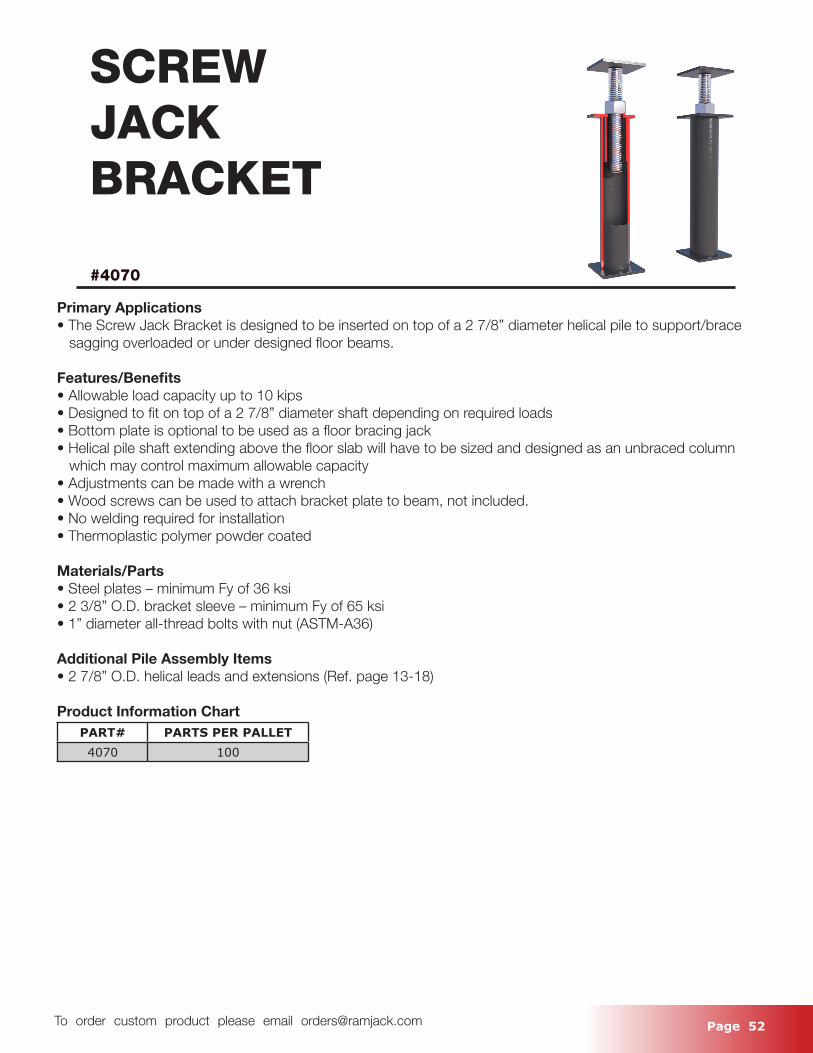
SCREWJACKBRACKET
#4070
Primary Applications• The Screw Jack Bracket is designed to be inserted on top of a 2 7/8” diameter helical pile to support/brace sagging overloaded or under designed floor beams.
Features/Benefits• Allowable load capacity up to 10 kips• Designed to fit on top of a 2 7/8” diameter shaft depending on required loads• Bottom plate is optional to be used as a floor bracing jack• Helical pile shaft extending above the floor slab will have to be sized and designed as an unbraced column which may control maximum allowable capacity• Adjustments can be made with a wrench• Wood screws can be used to attach bracket plate to beam, not included.• No welding required for installation• Thermoplastic polymer powder coated
Materials/Parts• Steel plates – minimum Fy of 36 ksi• 2 3/8” O.D. bracket sleeve – minimum Fy of 65 ksi• 1” diameter all-thread bolts with nut (ASTM-A36)
Additional Pile Assembly Items• 2 7/8” O.D. helical leads and extensions (Ref. page 13-18)
Product Information ChartPART# PARTS PER PALLET4070 100
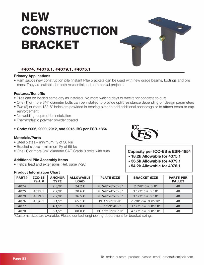
Page 53 To order custom product please email [email protected]
NEWCONSTRUCTIONBRACKET
#4074, #4076.1, #4079.1, #4075.1
Primary Applications• Ram Jack’s new construction pile (Instant Pile) brackets can be used with new grade beams, footings and pile caps. They are suitable for both residential and commercial projects.
Features/Benefits• Piles can be loaded same day as installed. No more waiting days or weeks for concrete to cure• One (1) or more 3/4” diameter bolts can be installed to provide uplift resistance depending on design parameters• Two (2) or more 13/16” holes are provided in bearing plate to add additional anchorage or to attach beam or cap reinforcement• No welding required for installation• Thermoplastic polymer powder coated
• Code: 2006, 2009, 2012, and 2015 IBC per ESR-1854
Materials/Parts• Steel plates – minimum Fy of 36 ksi• Bracket sleeve – minimum Fy of 65 ksi• One (1) or more 3/4” diameter SAE Grade 8 bolts with nuts
Additional Pile Assembly Items• Helical lead and extensions (Ref. page 7-26)
Product Information ChartPART# ICC-ES
Part #ANCHOR
TYPEALLOWABLE
LOADPLATE SIZE BRACKET SIZE PARTS PER
PALLET4074 2 3/8” 24.2 k PL 5/8”x8”x0’-8” 2 7/8” dia. x 8” 404075 4075.1 2 7/8” 20.6 k PL 5/8”x4”x0’-8” 3 1/2” dia. x 10” 404079 4079.1 2 7/8” 36.5 k PL 5/8”x8”x0’-8” 3 1/2” dia. x 10” 404076 4076.1 3 1/2” 65.1 k PL 1”x9”x0’-9” 2 7/8” dia. X 0’-10” 404077 4 1/2” 75.8 k PL 1”x9”x0-9” 3 1/2” dia. x 0’-10” 404078 5 1/2” 80.0 k PL 1”x10”x0’-10” 4 1/2” dia. x 0’-10” 40
*Customs sizes are available. Please contact engineering department for bracket sizing.
Capacity per ICC-ES & ESR-1854 • 18.2k Allowable for 4075.1 • 36.5k Allowable for 4079.1 • 54.2k Allowable for 4076.1
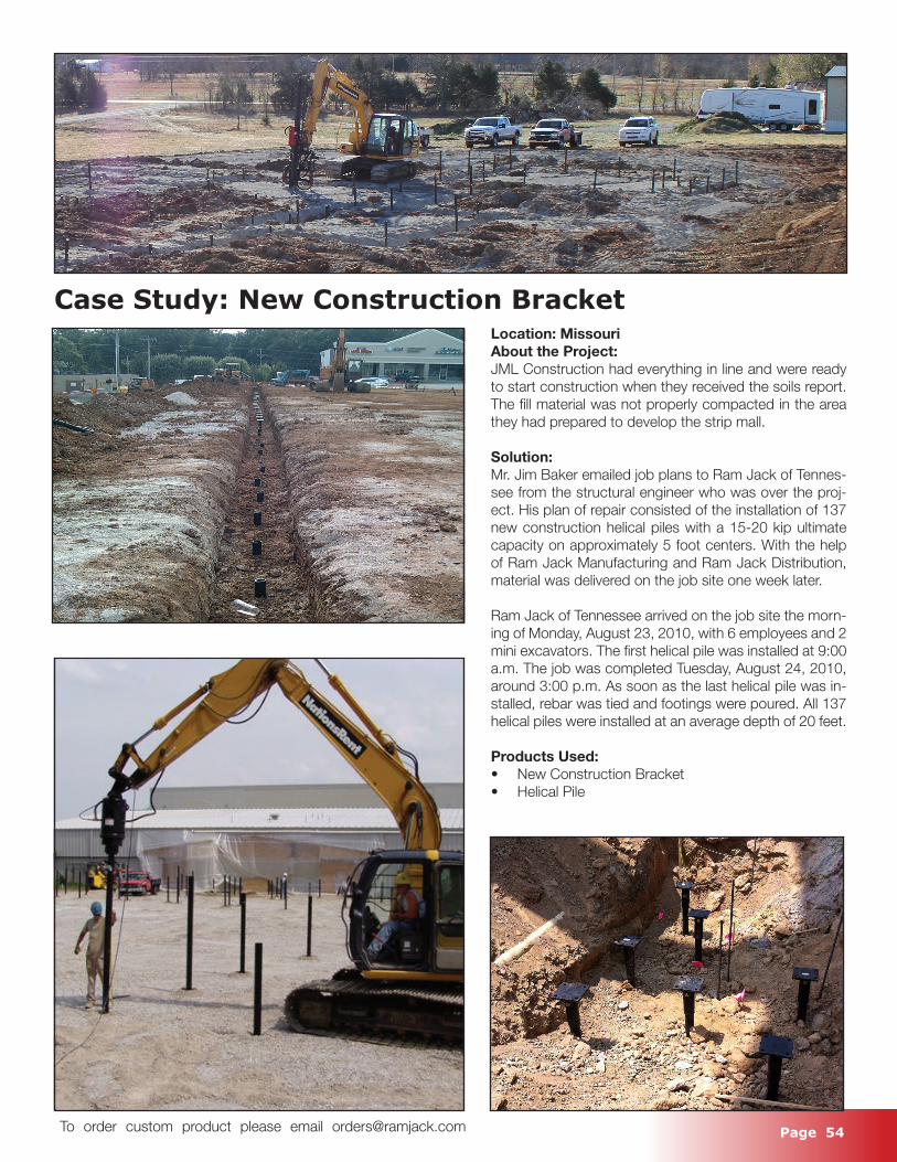
Page 54 To order custom product please email [email protected]
Case Study: New Construction BracketLocation: MissouriAbout the Project:JML Construction had everything in line and were ready to start construction when they received the soils report. The fill material was not properly compacted in the area they had prepared to develop the strip mall.
Solution:Mr. Jim Baker emailed job plans to Ram Jack of Tennes-see from the structural engineer who was over the proj-ect. His plan of repair consisted of the installation of 137 new construction helical piles with a 15-20 kip ultimate capacity on approximately 5 foot centers. With the help of Ram Jack Manufacturing and Ram Jack Distribution, material was delivered on the job site one week later.
Ram Jack of Tennessee arrived on the job site the morn-ing of Monday, August 23, 2010, with 6 employees and 2 mini excavators. The first helical pile was installed at 9:00 a.m. The job was completed Tuesday, August 24, 2010, around 3:00 p.m. As soon as the last helical pile was in-stalled, rebar was tied and footings were poured. All 137 helical piles were installed at an average depth of 20 feet.
Products Used:• New Construction Bracket• Helical Pile
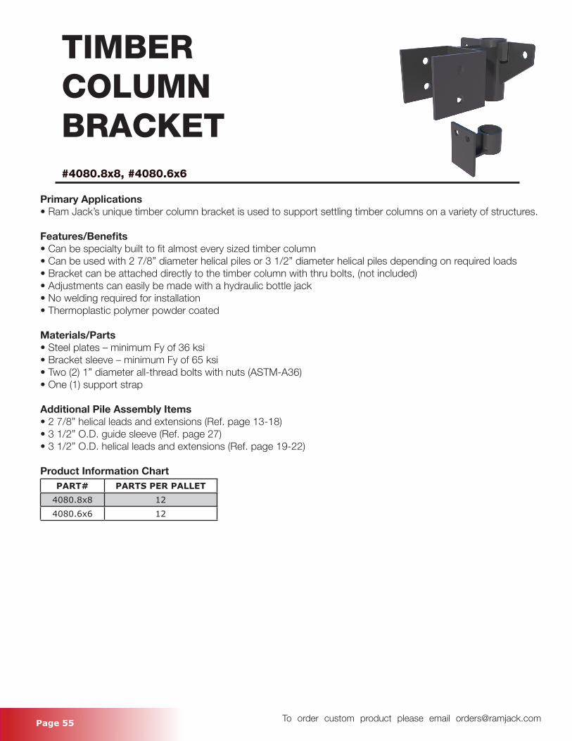
Page 55 To order custom product please email [email protected]
TIMBERCOLUMNBRACKET#4080.8x8, #4080.6x6
Primary Applications• Ram Jack’s unique timber column bracket is used to support settling timber columns on a variety of structures.
Features/Benefits• Can be specialty built to fit almost every sized timber column• Can be used with 2 7/8” diameter helical piles or 3 1/2” diameter helical piles depending on required loads• Bracket can be attached directly to the timber column with thru bolts, (not included)• Adjustments can easily be made with a hydraulic bottle jack• No welding required for installation• Thermoplastic polymer powder coated
Materials/Parts• Steel plates – minimum Fy of 36 ksi• Bracket sleeve – minimum Fy of 65 ksi• Two (2) 1” diameter all-thread bolts with nuts (ASTM-A36)• One (1) support strap
Additional Pile Assembly Items• 2 7/8” helical leads and extensions (Ref. page 13-18)• 3 1/2” O.D. guide sleeve (Ref. page 27)• 3 1/2” O.D. helical leads and extensions (Ref. page 19-22)
Product Information ChartPART# PARTS PER PALLET
4080.8x8 124080.6x6 12
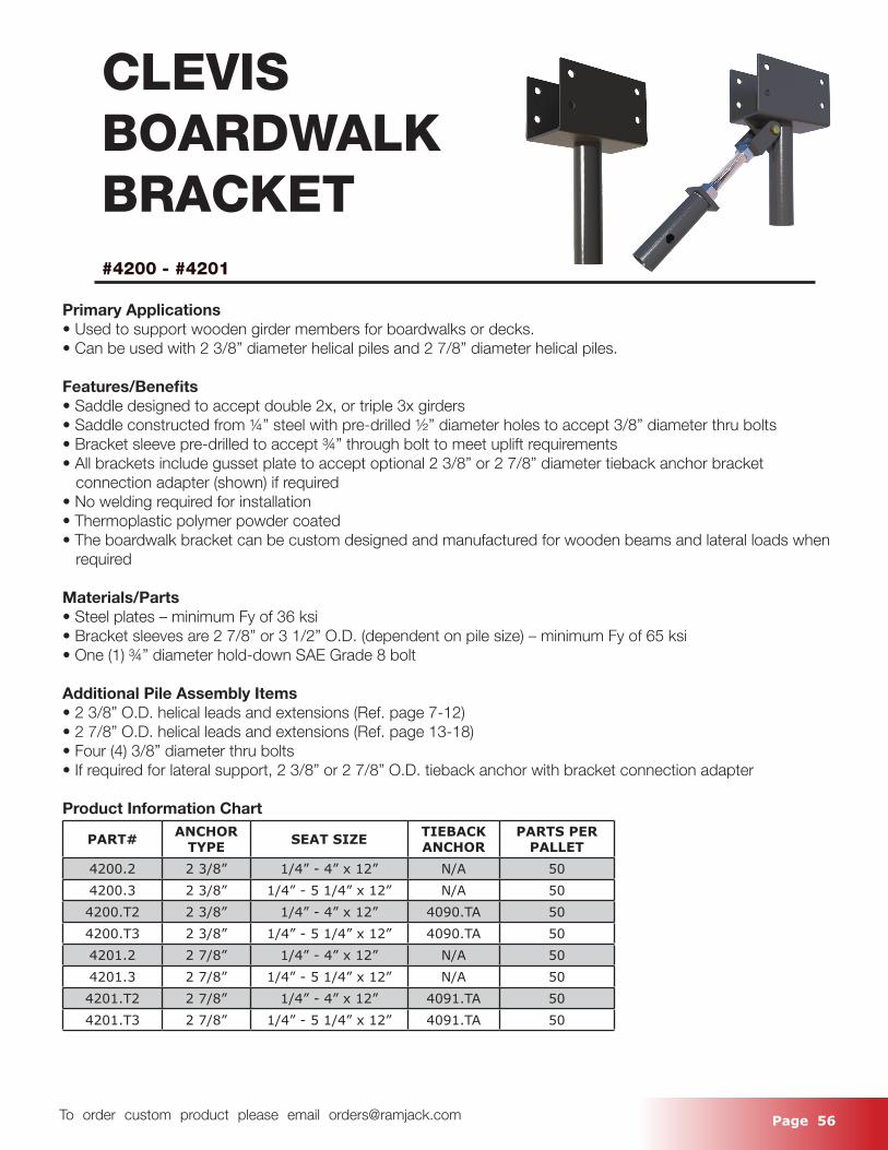
Page 56 To order custom product please email [email protected]
CLEVIS BOARDWALKBRACKET#4200 - #4201
Primary Applications• Used to support wooden girder members for boardwalks or decks.• Can be used with 2 3/8” diameter helical piles and 2 7/8” diameter helical piles.
Features/Benefits• Saddle designed to accept double 2x, or triple 3x girders• Saddle constructed from ¼” steel with pre-drilled ½” diameter holes to accept 3/8” diameter thru bolts• Bracket sleeve pre-drilled to accept ¾” through bolt to meet uplift requirements• All brackets include gusset plate to accept optional 2 3/8” or 2 7/8” diameter tieback anchor bracket connection adapter (shown) if required• No welding required for installation• Thermoplastic polymer powder coated• The boardwalk bracket can be custom designed and manufactured for wooden beams and lateral loads when required
Materials/Parts • Steel plates – minimum Fy of 36 ksi• Bracket sleeves are 2 7/8” or 3 1/2” O.D. (dependent on pile size) – minimum Fy of 65 ksi• One (1) ¾” diameter hold-down SAE Grade 8 bolt
Additional Pile Assembly Items• 2 3/8” O.D. helical leads and extensions (Ref. page 7-12)• 2 7/8” O.D. helical leads and extensions (Ref. page 13-18)• Four (4) 3/8” diameter thru bolts• If required for lateral support, 2 3/8” or 2 7/8” O.D. tieback anchor with bracket connection adapter
Product Information Chart
PART# ANCHOR TYPE SEAT SIZE TIEBACK
ANCHORPARTS PER
PALLET4200.2 2 3/8” 1/4” - 4” x 12” N/A 504200.3 2 3/8” 1/4” - 5 1/4” x 12” N/A 504200.T2 2 3/8” 1/4” - 4” x 12” 4090.TA 504200.T3 2 3/8” 1/4” - 5 1/4” x 12” 4090.TA 504201.2 2 7/8” 1/4” - 4” x 12” N/A 504201.3 2 7/8” 1/4” - 5 1/4” x 12” N/A 504201.T2 2 7/8” 1/4” - 4” x 12” 4091.TA 504201.T3 2 7/8” 1/4” - 5 1/4” x 12” 4091.TA 50
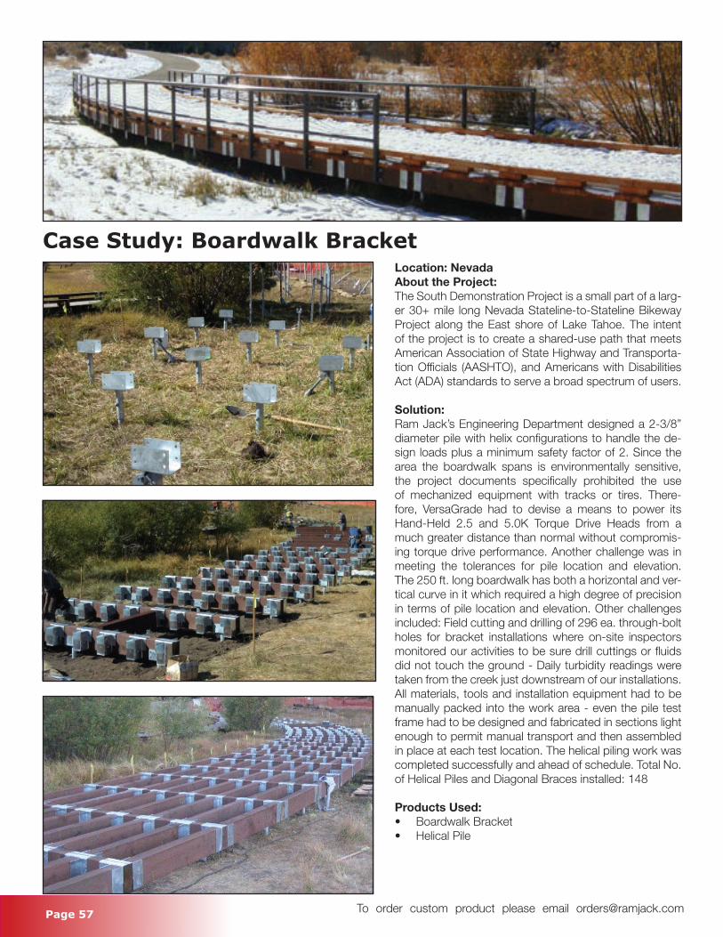
Page 57 To order custom product please email [email protected]
Case Study: Boardwalk BracketLocation: NevadaAbout the Project:The South Demonstration Project is a small part of a larg-er 30+ mile long Nevada Stateline-to-Stateline Bikeway Project along the East shore of Lake Tahoe. The intent of the project is to create a shared-use path that meets American Association of State Highway and Transporta-tion Officials (AASHTO), and Americans with Disabilities Act (ADA) standards to serve a broad spectrum of users.
Solution:Ram Jack’s Engineering Department designed a 2-3/8” diameter pile with helix configurations to handle the de-sign loads plus a minimum safety factor of 2. Since the area the boardwalk spans is environmentally sensitive, the project documents specifically prohibited the use of mechanized equipment with tracks or tires. There-fore, VersaGrade had to devise a means to power its Hand-Held 2.5 and 5.0K Torque Drive Heads from a much greater distance than normal without compromis-ing torque drive performance. Another challenge was in meeting the tolerances for pile location and elevation. The 250 ft. long boardwalk has both a horizontal and ver-tical curve in it which required a high degree of precision in terms of pile location and elevation. Other challenges included: Field cutting and drilling of 296 ea. through-bolt holes for bracket installations where on-site inspectors monitored our activities to be sure drill cuttings or fluids did not touch the ground - Daily turbidity readings were taken from the creek just downstream of our installations. All materials, tools and installation equipment had to be manually packed into the work area - even the pile test frame had to be designed and fabricated in sections light enough to permit manual transport and then assembled in place at each test location. The helical piling work was completed successfully and ahead of schedule. Total No. of Helical Piles and Diagonal Braces installed: 148
Products Used:• Boardwalk Bracket• Helical Pile
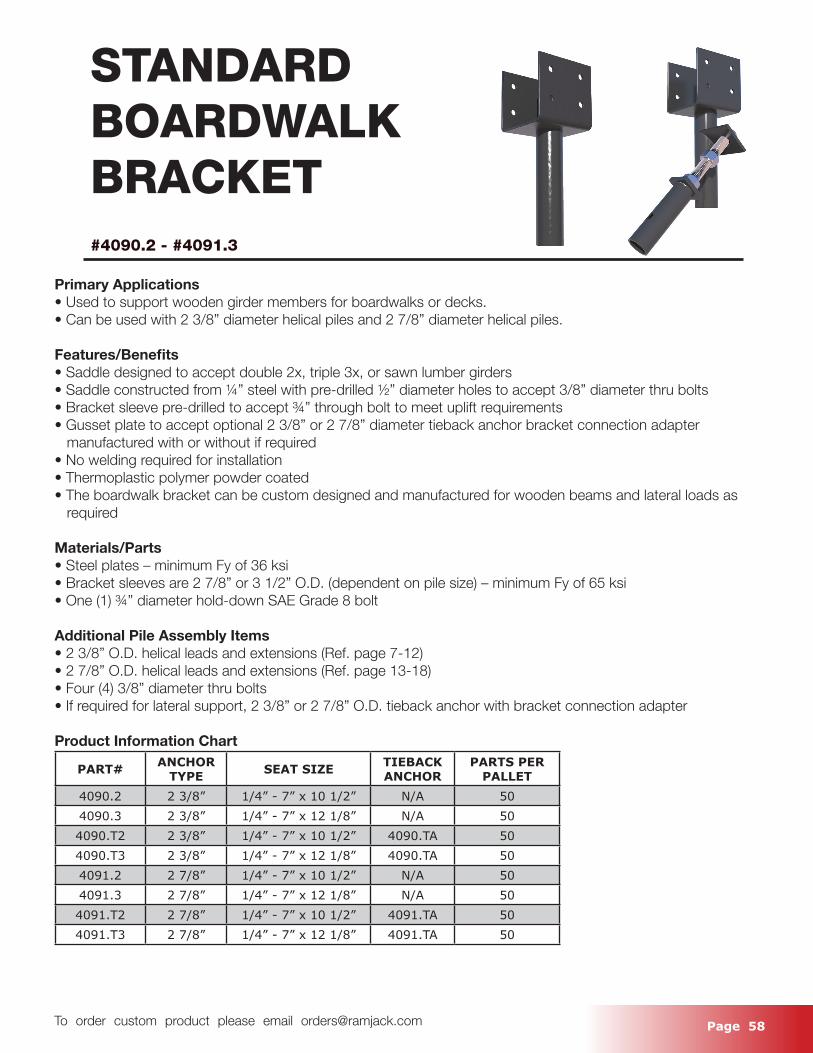
Page 58 To order custom product please email [email protected]
STANDARD BOARDWALKBRACKET#4090.2 - #4091.3
Primary Applications• Used to support wooden girder members for boardwalks or decks.• Can be used with 2 3/8” diameter helical piles and 2 7/8” diameter helical piles.
Features/Benefits• Saddle designed to accept double 2x, triple 3x, or sawn lumber girders• Saddle constructed from ¼” steel with pre-drilled ½” diameter holes to accept 3/8” diameter thru bolts• Bracket sleeve pre-drilled to accept ¾” through bolt to meet uplift requirements• Gusset plate to accept optional 2 3/8” or 2 7/8” diameter tieback anchor bracket connection adapter manufactured with or without if required• No welding required for installation• Thermoplastic polymer powder coated• The boardwalk bracket can be custom designed and manufactured for wooden beams and lateral loads as required
Materials/Parts • Steel plates – minimum Fy of 36 ksi• Bracket sleeves are 2 7/8” or 3 1/2” O.D. (dependent on pile size) – minimum Fy of 65 ksi• One (1) ¾” diameter hold-down SAE Grade 8 bolt
Additional Pile Assembly Items• 2 3/8” O.D. helical leads and extensions (Ref. page 7-12)• 2 7/8” O.D. helical leads and extensions (Ref. page 13-18)• Four (4) 3/8” diameter thru bolts• If required for lateral support, 2 3/8” or 2 7/8” O.D. tieback anchor with bracket connection adapter
Product Information Chart
PART# ANCHOR TYPE SEAT SIZE TIEBACK
ANCHORPARTS PER
PALLET4090.2 2 3/8” 1/4” - 7” x 10 1/2” N/A 504090.3 2 3/8” 1/4” - 7” x 12 1/8” N/A 504090.T2 2 3/8” 1/4” - 7” x 10 1/2” 4090.TA 504090.T3 2 3/8” 1/4” - 7” x 12 1/8” 4090.TA 504091.2 2 7/8” 1/4” - 7” x 10 1/2” N/A 504091.3 2 7/8” 1/4” - 7” x 12 1/8” N/A 504091.T2 2 7/8” 1/4” - 7” x 10 1/2” 4091.TA 504091.T3 2 7/8” 1/4” - 7” x 12 1/8” 4091.TA 50
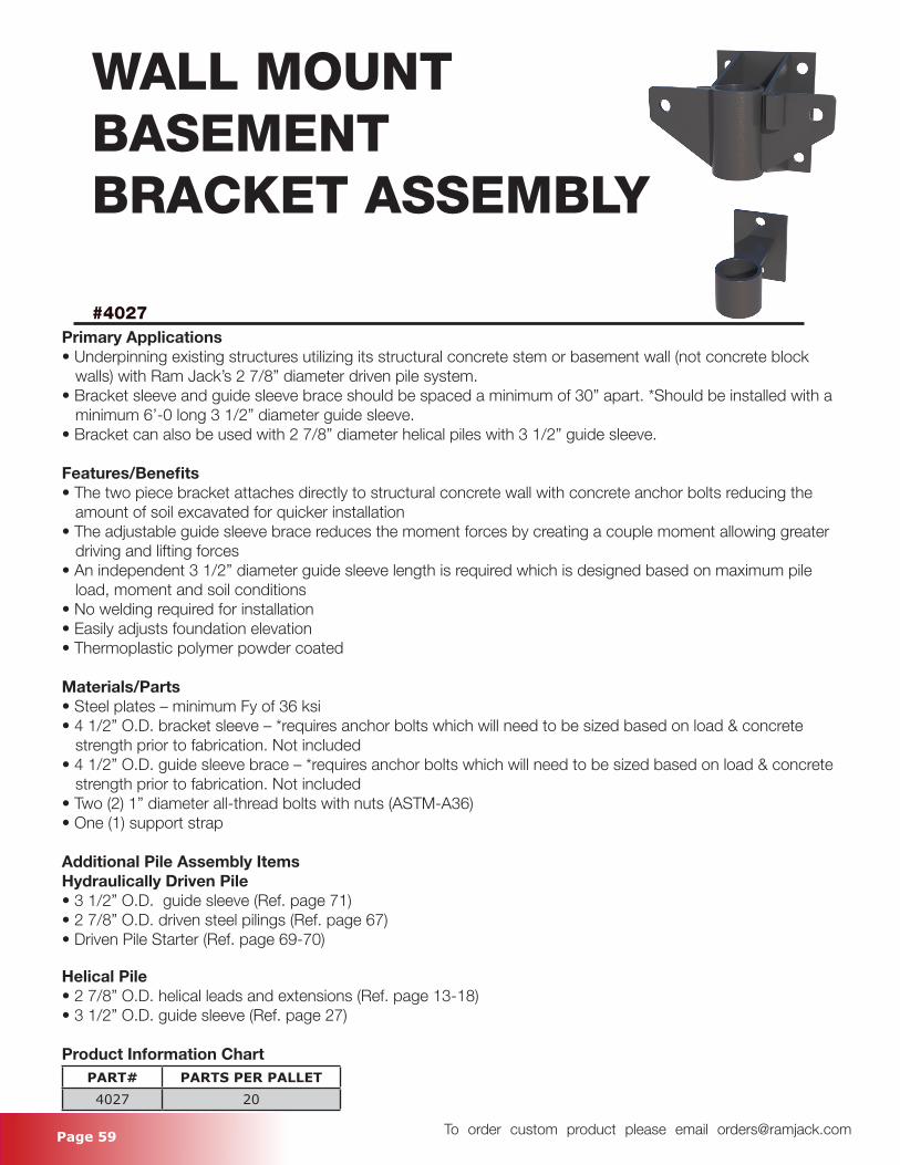
Page 59 To order custom product please email [email protected]
WALL MOUNTBASEMENTBRACKET ASSEMBLY
#4027Primary Applications• Underpinning existing structures utilizing its structural concrete stem or basement wall (not concrete block walls) with Ram Jack’s 2 7/8” diameter driven pile system.• Bracket sleeve and guide sleeve brace should be spaced a minimum of 30” apart. *Should be installed with a minimum 6’-0 long 3 1/2” diameter guide sleeve.• Bracket can also be used with 2 7/8” diameter helical piles with 3 1/2” guide sleeve.
Features/Benefits• The two piece bracket attaches directly to structural concrete wall with concrete anchor bolts reducing the amount of soil excavated for quicker installation• The adjustable guide sleeve brace reduces the moment forces by creating a couple moment allowing greater driving and lifting forces• An independent 3 1/2” diameter guide sleeve length is required which is designed based on maximum pile load, moment and soil conditions• No welding required for installation• Easily adjusts foundation elevation• Thermoplastic polymer powder coated
Materials/Parts• Steel plates – minimum Fy of 36 ksi• 4 1/2” O.D. bracket sleeve – *requires anchor bolts which will need to be sized based on load & concrete strength prior to fabrication. Not included• 4 1/2” O.D. guide sleeve brace – *requires anchor bolts which will need to be sized based on load & concrete strength prior to fabrication. Not included• Two (2) 1” diameter all-thread bolts with nuts (ASTM-A36)• One (1) support strap
Additional Pile Assembly ItemsHydraulically Driven Pile• 3 1/2” O.D. guide sleeve (Ref. page 71)• 2 7/8” O.D. driven steel pilings (Ref. page 67)• Driven Pile Starter (Ref. page 69-70)
Helical Pile• 2 7/8” O.D. helical leads and extensions (Ref. page 13-18)• 3 1/2” O.D. guide sleeve (Ref. page 27)
Product Information ChartPART# PARTS PER PALLET4027 20
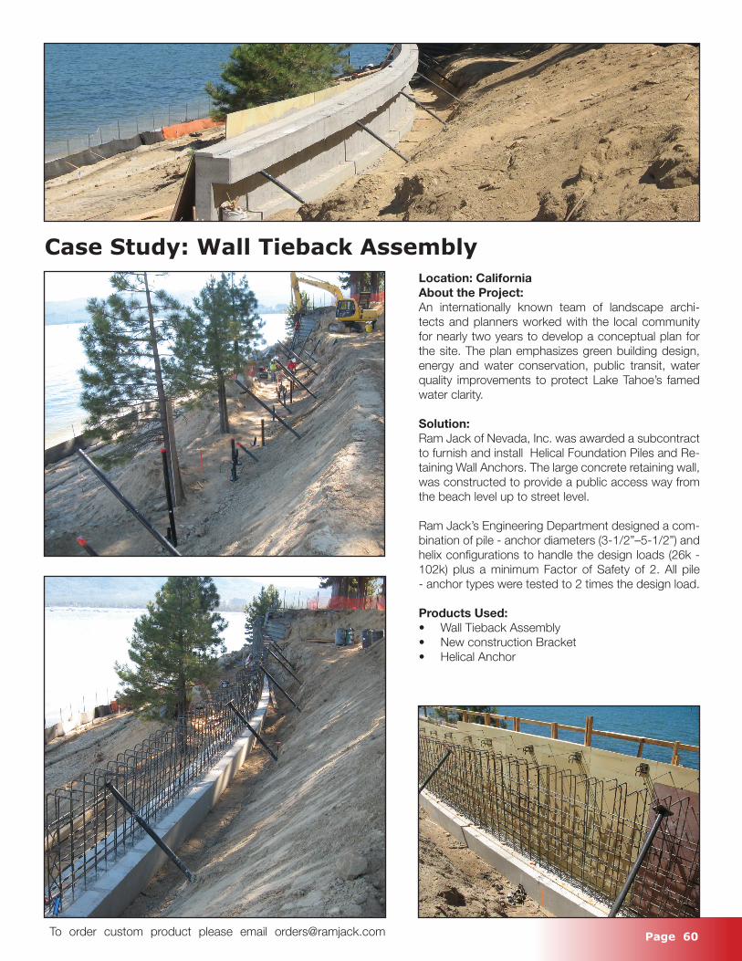
Page 60 To order custom product please email [email protected]
Case Study: Wall Tieback AssemblyLocation: CaliforniaAbout the Project:An internationally known team of landscape archi-tects and planners worked with the local community for nearly two years to develop a conceptual plan for the site. The plan emphasizes green building design, energy and water conservation, public transit, water quality improvements to protect Lake Tahoe’s famed water clarity.
Solution:Ram Jack of Nevada, Inc. was awarded a subcontract to furnish and install Helical Foundation Piles and Re-taining Wall Anchors. The large concrete retaining wall, was constructed to provide a public access way from the beach level up to street level.
Ram Jack’s Engineering Department designed a com-bination of pile - anchor diameters (3-1/2”–5-1/2”) and helix configurations to handle the design loads (26k - 102k) plus a minimum Factor of Safety of 2. All pile - anchor types were tested to 2 times the design load.
Products Used:• Wall Tieback Assembly• New construction Bracket• Helical Anchor
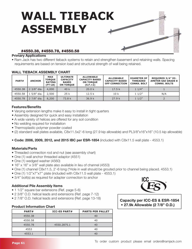
Page 61 To order custom product please email [email protected]
WALL TIEBACKASSEMBLY
#4550.38, #4550.78, #4550.58Primary Applications• Ram Jack has two different tieback systems to retain and strengthen basement and retaining walls. Spacing requirements are based on tension load and structural strength of wall being retained.
WALL TIEBACK ASSEMBLY CHART
PART# ANCHOR
MAX TORQUE RATING (FT-LB)
ULTIMATE CAPACITY
BASED ON TORQUE
ALLOWABLE CAPACITY BASED
ON TORQUE (S.F.=2)
ALLOWABLE CAPACITY BASED OFF CONNECTION
DIAMETER OF THREADED
CONNX. BOLT
REQUIRED 3/4” DI-AMETER SAE GRADE 8
CONNX. BOLTS
4550.38 2 3/8” dia. 4,000 40 k 20.0 k 17.5 k 1 1/4” 1
4550.58 1 5/8” dia. 2,500 25 k 12.5 k 10 k 1 1/2” N/A
4550.78 2 7/8” dia. 8,200 73.8 k 36.9 k 27.9 k 1 1/2” 2
Features/Benefits• Varying extension lengths make it easy to install in tight quarters• Assembly designed for quick and easy installation• A wide variety of helices are offered for any soil condition• No welding required for installation• Thermoplastic polymer powder coated• (2) standard wall plates available, C8x11.5x2’-6 long (27.9 kip allowable) and PL3/8”x16”x16” (10.5 kip allowable)
• Code: 2006, 2009, 2012, and 2015 IBC per ESR-1854 (included with C8x11.5 wall plate - 4553.1)
Materials/Parts• Threaded connection rod and nut (see assembly chart)• One (1) wall anchor threaded adaptor (4551)• One (1) wedged washer (4560)• 16” x 16” x 3/8” wall plate also available in lieu of channel (4553)• One (1) channel C8x11.5, 2’-6 long (*Hole in wall should be grouted prior to channel being placed. 4553.1) • One (1) 1/2’’x7’’x7’’ plate (included with C8x11.5 wall plate - 4553.1)• 3/4” bolt(s) as required for adapter connection to anchor
Additional Pile Assembly Items• 1 1/2” square bar extensions (Ref. page 5-6)• 2 3/8” O.D. helical leads and extensions (Ref. page 7-12)• 2 7/8” O.D. helical leads and extensions (Ref. page 13-18)
Product Information ChartPART# ICC-ES PART# PARTS PER PALLET
4550.38 40
4550.58 40
4550.78 4550.2875.1 40
4553 40
4553.1 40
Capacity per ICC-ES & ESR-1854 • 27.9k Allowable (2 7/8” O.D.)
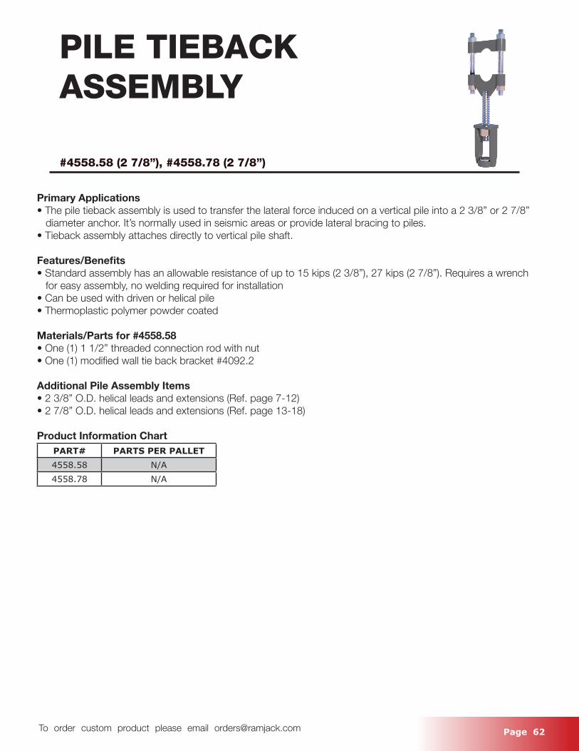
Page 62 To order custom product please email [email protected]
PILE TIEBACKASSEMBLY
#4558.58 (2 7/8”), #4558.78 (2 7/8”)
Primary Applications• The pile tieback assembly is used to transfer the lateral force induced on a vertical pile into a 2 3/8” or 2 7/8” diameter anchor. It’s normally used in seismic areas or provide lateral bracing to piles. • Tieback assembly attaches directly to vertical pile shaft.
Features/Benefits• Standard assembly has an allowable resistance of up to 15 kips (2 3/8”), 27 kips (2 7/8”). Requires a wrench for easy assembly, no welding required for installation• Can be used with driven or helical pile• Thermoplastic polymer powder coated
Materials/Parts for #4558.58• One (1) 1 1/2” threaded connection rod with nut• One (1) modified wall tie back bracket #4092.2
Additional Pile Assembly Items• 2 3/8” O.D. helical leads and extensions (Ref. page 7-12)• 2 7/8” O.D. helical leads and extensions (Ref. page 13-18)
Product Information ChartPART# PARTS PER PALLET4558.58 N/A4558.78 N/A
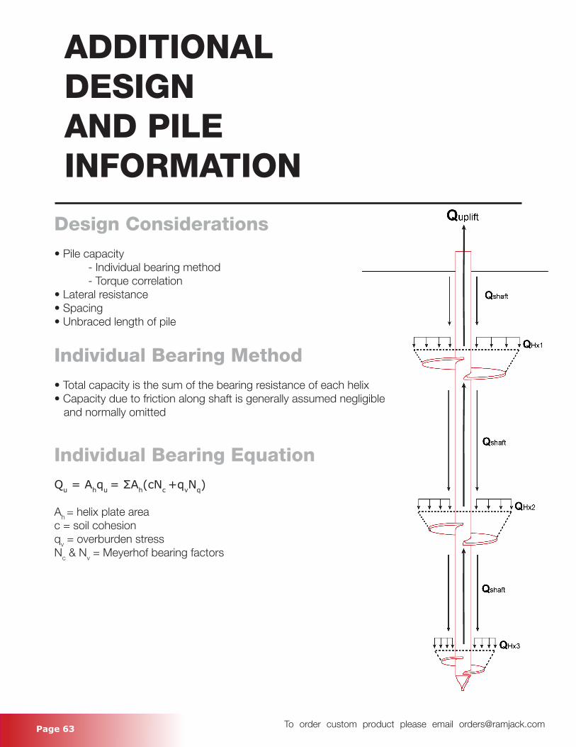
Page 63 To order custom product please email [email protected]
ADDITIONALDESIGNAND PILEINFORMATION
Design Considerations• Pile capacity - Individual bearing method - Torque correlation• Lateral resistance• Spacing• Unbraced length of pile
Individual Bearing Method• Total capacity is the sum of the bearing resistance of each helix• Capacity due to friction along shaft is generally assumed negligible and normally omitted
Individual Bearing EquationQu = Ahqu = ΣAh(cNc +qvNq)
Ah = helix plate areac = soil cohesionqv = overburden stressNc & Nv = Meyerhof bearing factors
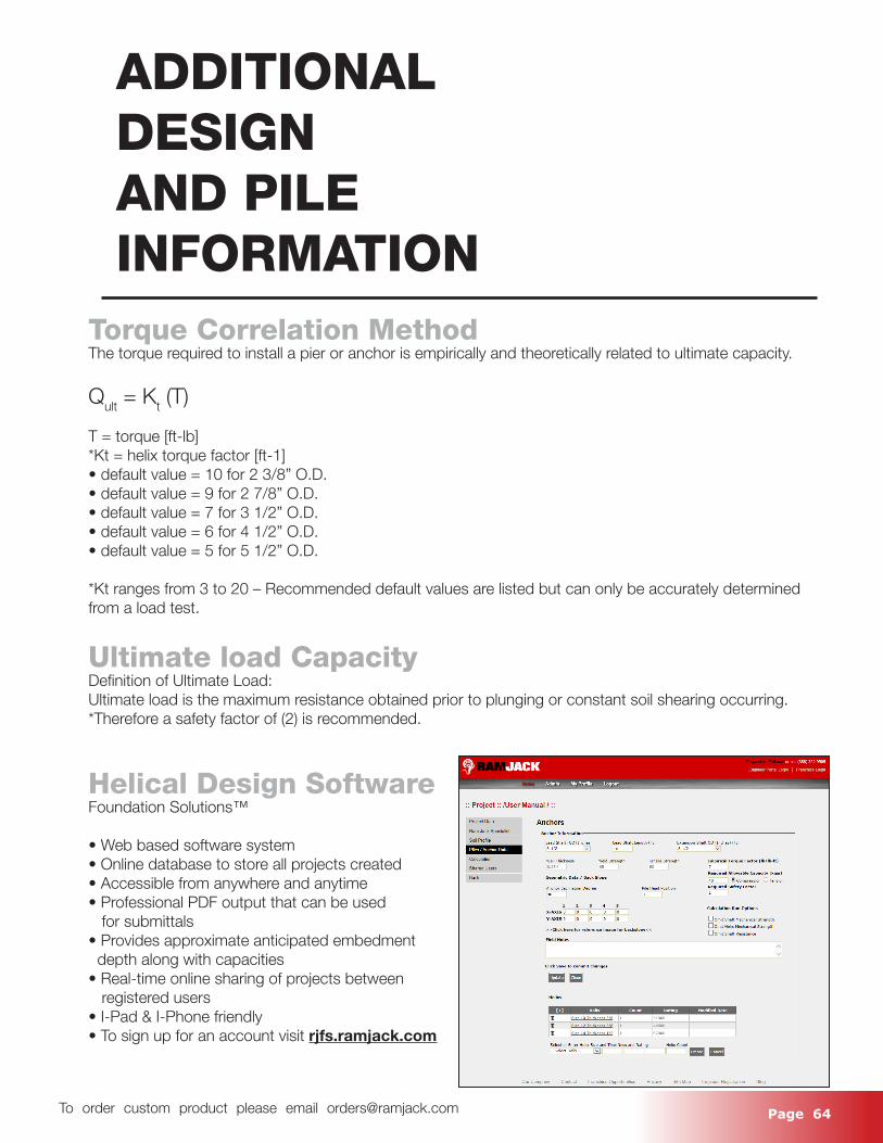
Page 64 To order custom product please email [email protected]
ADDITIONALDESIGNAND PILEINFORMATION
Torque Correlation MethodThe torque required to install a pier or anchor is empirically and theoretically related to ultimate capacity.
Qult = Kt (T)
T = torque [ft-lb]*Kt = helix torque factor [ft-1]• default value = 10 for 2 3/8” O.D.• default value = 9 for 2 7/8” O.D.• default value = 7 for 3 1/2” O.D.• default value = 6 for 4 1/2” O.D.• default value = 5 for 5 1/2” O.D.
*Kt ranges from 3 to 20 – Recommended default values are listed but can only be accurately determined from a load test.
Ultimate load CapacityDefinition of Ultimate Load:Ultimate load is the maximum resistance obtained prior to plunging or constant soil shearing occurring.*Therefore a safety factor of (2) is recommended.
Helical Design SoftwareFoundation Solutions™
• Web based software system • Online database to store all projects created• Accessible from anywhere and anytime• Professional PDF output that can be used for submittals• Provides approximate anticipated embedment depth along with capacities• Real-time online sharing of projects between registered users• I-Pad & I-Phone friendly• To sign up for an account visit rjfs.ramjack.com
Page 65 To order custom product please email [email protected]
Driven Pile SystemGeneral Information
The Ram Jack® Driven Pile System is used tounderpin existing structures. (NOTE: The structuremust have sufficient resistance for pile installation.)Each pile should be installed individually, therebyutilizing the maximum resistance of the structureas a reaction force.
Each pile consists of 4 primary components:• Bracket• Guide Sleeve (4’-0 standard length)• Piling Extensions• Driven Pile Starter
One of the key benefits of choosing Ram Jack’s Driven Pile System is its unique bracket selection. The most common bracket for typical installations is our Driven Pile Bracket (#4021). However, presented in this catalog is a wide array of specialty brackets for almost every struc-ture and underpinning situation. If for some reason you are unable to find the correct bracket for your applica-tion, please feel free to contact Ram Jack for assistance. We will work with you to find an appropriate design for your underpinning needs.
Other benefits to the Ram Jack® Driven Pile System are its speed of installation and the fact that no welding is required in the field during installation.
The Ram Jack® guide sleeve allows the 2 7/8” diameter pile to rifle through the soil in a straight and accurate path to a load bearing strata. It also increases the mo-ment resistance capacity of the pile which allows high installation forces to be applied to the pile. The standard length of the guide sleeve is 4’-0. However, where the upper soils are too soft to provide adequate lateral brac-ing lengths, custom lengths are available.
The guide sleeve has a minimum yield strength of 65 ksi with a flexural yield moment capacity of 10,500 ft-lbs.
Ram Jack’s 2 7/8” diameter steel pilings are slip jointed allowing for a smooth and homogeneous pile. The slip joint connection allows additional pilings to be easily added as the pile is advanced to a load bearing strata. The slip joint inserts 6” into the adjoining piling section to provide for a rigid connection to resist bucking. The piling extensions have a minimum yield strength of 65 ksi with a flexural yield moment capacity of 6,750 ft-lbs.
Ram Jack® designs, builds and manufactures all of its piling components. Ram Jack’s state of the art manufac-turing plant is located in Ada, OK. All of Ram Jack’s pil-ing components are manufactured from new steel. The components are precision cut and welded with a mig and argon wire/gas high amperage welder. This allows the penetration necessary for a strong weld attachment.
From this location Ram Jack® ships its piling compo-nents throughout North and Central America and Puerto Rico. All of our piling components have a thermoplastic coating which has been specifically designed to provide a long lasting, tough coating. The thermoplastic coating is environmentally friendly and has a technical life span of 50 years.
Ram Jack has the only Driven Steel Pile System recognized by ICC-ES (ESR 1854).
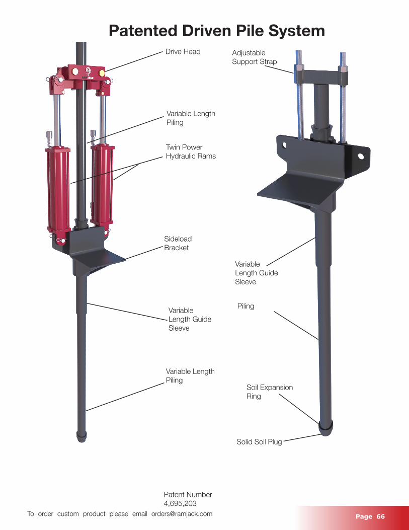
Page 66 To order custom product please email [email protected]
Drive Head
Variable Length Piling
Twin Power Hydraulic Rams
Sideload Bracket
Variable Length Guide Sleeve
Variable Length Piling
Patent Number 4,695,203
Adjustable Support Strap
Piling
Variable Length Guide Sleeve
Soil Expansion Ring
Solid Soil Plug
Patented Driven Pile System
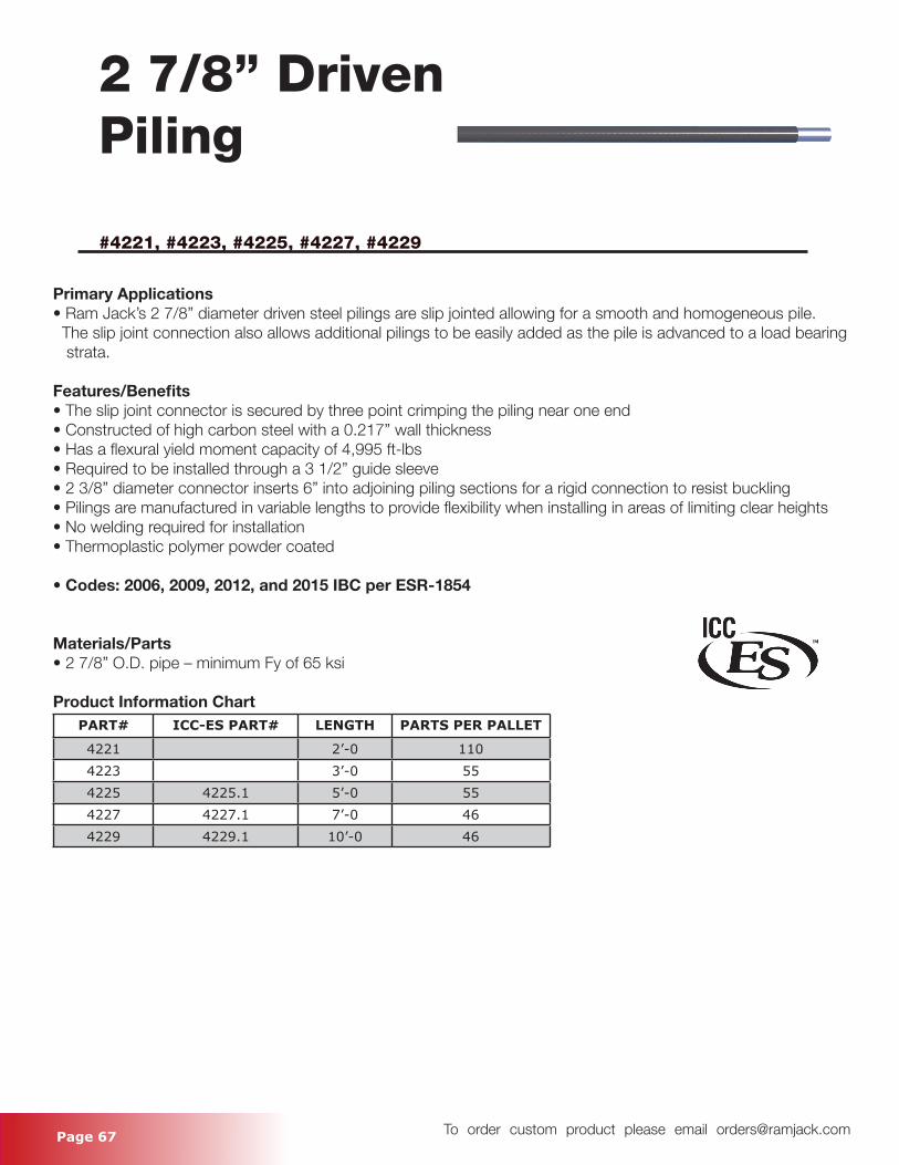
Page 67 To order custom product please email [email protected]
2 7/8’’ Driven Piling
#4221, #4223, #4225, #4227, #4229
Primary Applications• Ram Jack’s 2 7/8” diameter driven steel pilings are slip jointed allowing for a smooth and homogeneous pile. The slip joint connection also allows additional pilings to be easily added as the pile is advanced to a load bearing strata.
Features/Benefits• The slip joint connector is secured by three point crimping the piling near one end• Constructed of high carbon steel with a 0.217” wall thickness• Has a flexural yield moment capacity of 4,995 ft-lbs• Required to be installed through a 3 1/2” guide sleeve• 2 3/8” diameter connector inserts 6” into adjoining piling sections for a rigid connection to resist buckling• Pilings are manufactured in variable lengths to provide flexibility when installing in areas of limiting clear heights• No welding required for installation• Thermoplastic polymer powder coated
• Codes: 2006, 2009, 2012, and 2015 IBC per ESR-1854
Materials/Parts• 2 7/8” O.D. pipe – minimum Fy of 65 ksi
Product Information ChartPART# ICC-ES PART# LENGTH PARTS PER PALLET
4221 2’-0 1104223 3’-0 554225 4225.1 5’-0 554227 4227.1 7’-0 464229 4229.1 10’-0 46
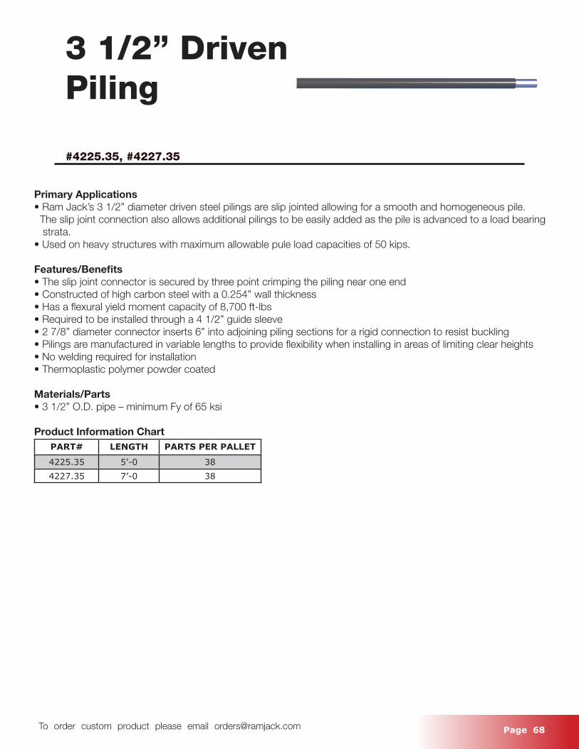
Page 68 To order custom product please email [email protected]
3 1/2’’ Driven Piling
#4225.35, #4227.35
Primary Applications• Ram Jack’s 3 1/2” diameter driven steel pilings are slip jointed allowing for a smooth and homogeneous pile. The slip joint connection also allows additional pilings to be easily added as the pile is advanced to a load bearing strata.• Used on heavy structures with maximum allowable pule load capacities of 50 kips.
Features/Benefits• The slip joint connector is secured by three point crimping the piling near one end• Constructed of high carbon steel with a 0.254” wall thickness• Has a flexural yield moment capacity of 8,700 ft-lbs• Required to be installed through a 4 1/2” guide sleeve• 2 7/8” diameter connector inserts 6” into adjoining piling sections for a rigid connection to resist buckling• Pilings are manufactured in variable lengths to provide flexibility when installing in areas of limiting clear heights• No welding required for installation• Thermoplastic polymer powder coated
Materials/Parts• 3 1/2” O.D. pipe – minimum Fy of 65 ksi
Product Information ChartPART# LENGTH PARTS PER PALLET
4225.35 5’-0 384227.35 7’-0 38
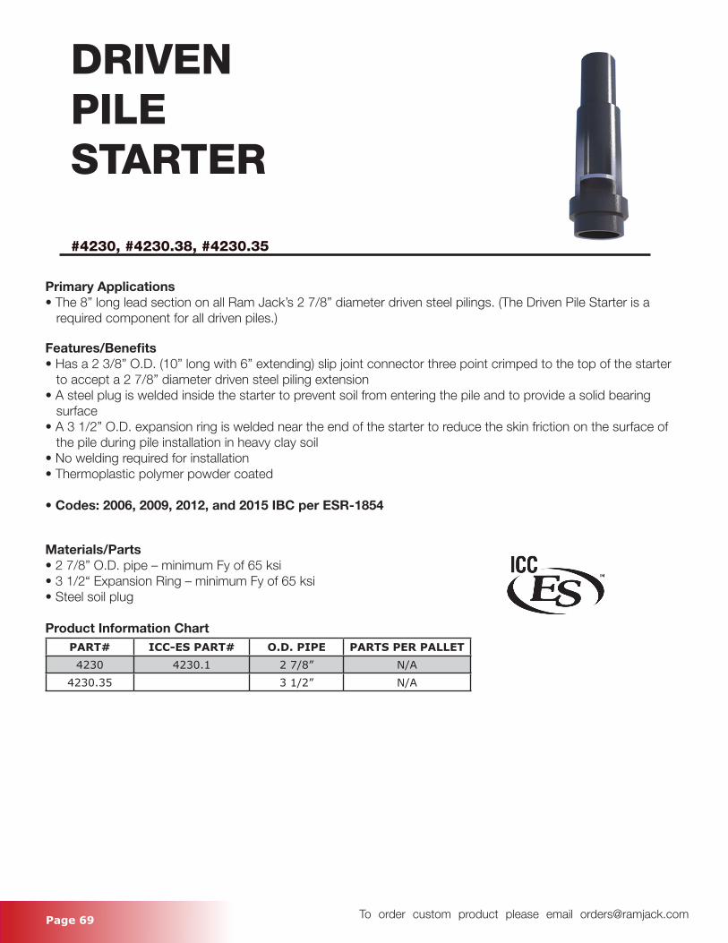
Page 69 To order custom product please email [email protected]
DRIVENPILESTARTER
#4230, #4230.38, #4230.35
Primary Applications• The 8” long lead section on all Ram Jack’s 2 7/8” diameter driven steel pilings. (The Driven Pile Starter is a required component for all driven piles.)
Features/Benefits• Has a 2 3/8” O.D. (10” long with 6” extending) slip joint connector three point crimped to the top of the starter to accept a 2 7/8” diameter driven steel piling extension• A steel plug is welded inside the starter to prevent soil from entering the pile and to provide a solid bearing surface• A 3 1/2” O.D. expansion ring is welded near the end of the starter to reduce the skin friction on the surface of the pile during pile installation in heavy clay soil• No welding required for installation• Thermoplastic polymer powder coated
• Codes: 2006, 2009, 2012, and 2015 IBC per ESR-1854
Materials/Parts• 2 7/8” O.D. pipe – minimum Fy of 65 ksi• 3 1/2“ Expansion Ring – minimum Fy of 65 ksi• Steel soil plug
Product Information ChartPART# ICC-ES PART# O.D. PIPE PARTS PER PALLET4230 4230.1 2 7/8” N/A
4230.35 3 1/2” N/A
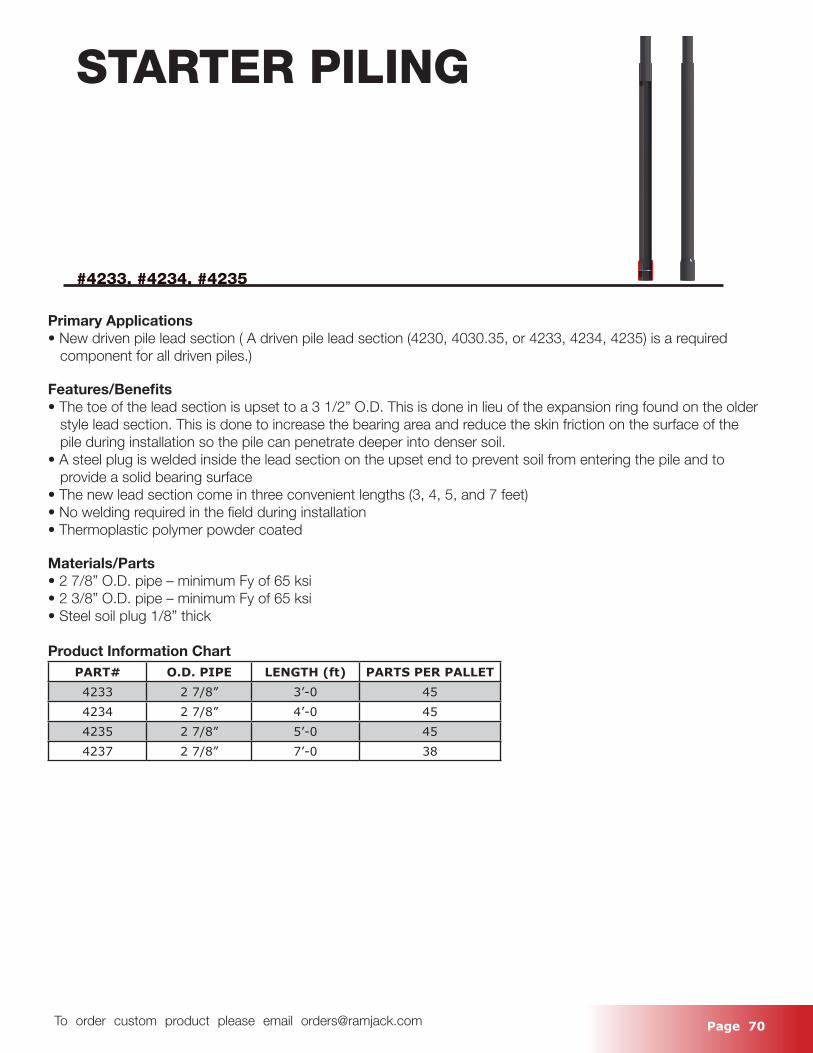
Page 70 To order custom product please email [email protected]
STARTER PILING
#4233, #4234, #4235
Primary Applications• New driven pile lead section ( A driven pile lead section (4230, 4030.35, or 4233, 4234, 4235) is a required component for all driven piles.)
Features/Benefits• The toe of the lead section is upset to a 3 1/2” O.D. This is done in lieu of the expansion ring found on the older style lead section. This is done to increase the bearing area and reduce the skin friction on the surface of the pile during installation so the pile can penetrate deeper into denser soil. • A steel plug is welded inside the lead section on the upset end to prevent soil from entering the pile and to provide a solid bearing surface• The new lead section come in three convenient lengths (3, 4, 5, and 7 feet)• No welding required in the field during installation• Thermoplastic polymer powder coated
Materials/Parts• 2 7/8” O.D. pipe – minimum Fy of 65 ksi• 2 3/8” O.D. pipe – minimum Fy of 65 ksi• Steel soil plug 1/8” thick
Product Information ChartPART# O.D. PIPE LENGTH (ft) PARTS PER PALLET4233 2 7/8” 3’-0 454234 2 7/8” 4’-0 454235 2 7/8” 5’-0 454237 2 7/8” 7’-0 38
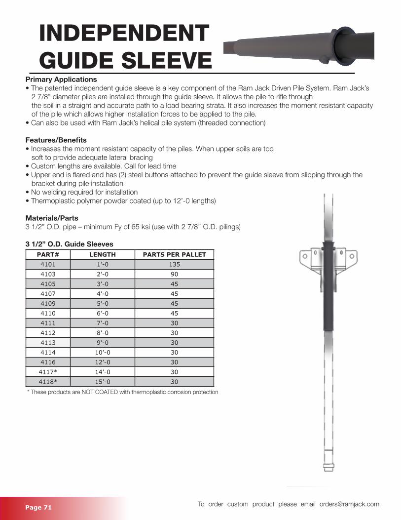
Page 71 To order custom product please email [email protected]
INDEPENDENTGUIDE SLEEVE
Primary Applications• The patented independent guide sleeve is a key component of the Ram Jack Driven Pile System. Ram Jack’s 2 7/8” diameter piles are installed through the guide sleeve. It allows the pile to rifle through the soil in a straight and accurate path to a load bearing strata. It also increases the moment resistant capacity of the pile which allows higher installation forces to be applied to the pile.• Can also be used with Ram Jack’s helical pile system (threaded connection)
Features/Benefits• Increases the moment resistant capacity of the piles. When upper soils are too soft to provide adequate lateral bracing• Custom lengths are available. Call for lead time• Upper end is flared and has (2) steel buttons attached to prevent the guide sleeve from slipping through the bracket during pile installation• No welding required for installation• Thermoplastic polymer powder coated (up to 12’-0 lengths)
Materials/Parts3 1/2” O.D. pipe – minimum Fy of 65 ksi (use with 2 7/8’’ O.D. pilings)
3 1/2” O.D. Guide SleevesPART# LENGTH PARTS PER PALLET4101 1’-0 1354103 2’-0 904105 3’-0 454107 4’-0 454109 5’-0 454110 6’-0 454111 7’-0 304112 8’-0 304113 9’-0 304114 10’-0 304116 12’-0 304117* 14’-0 304118* 15’-0 30
* These products are NOT COATED with thermoplastic corrosion protection
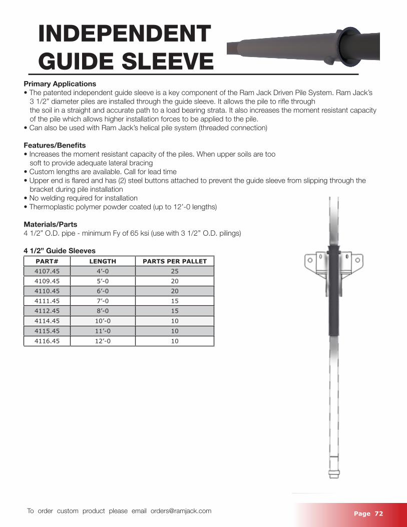
Page 72 To order custom product please email [email protected]
INDEPENDENTGUIDE SLEEVE
Primary Applications• The patented independent guide sleeve is a key component of the Ram Jack Driven Pile System. Ram Jack’s 3 1/2” diameter piles are installed through the guide sleeve. It allows the pile to rifle through the soil in a straight and accurate path to a load bearing strata. It also increases the moment resistant capacity of the pile which allows higher installation forces to be applied to the pile.• Can also be used with Ram Jack’s helical pile system (threaded connection)
Features/Benefits• Increases the moment resistant capacity of the piles. When upper soils are too soft to provide adequate lateral bracing• Custom lengths are available. Call for lead time• Upper end is flared and has (2) steel buttons attached to prevent the guide sleeve from slipping through the bracket during pile installation• No welding required for installation• Thermoplastic polymer powder coated (up to 12’-0 lengths)
Materials/Parts4 1/2” O.D. pipe - minimum Fy of 65 ksi (use with 3 1/2’’ O.D. pilings)
4 1/2” Guide SleevesPART# LENGTH PARTS PER PALLET4107.45 4’-0 254109.45 5’-0 204110.45 6’-0 204111.45 7’-0 154112.45 8’-0 154114.45 10’-0 104115.45 11’-0 104116.45 12’-0 10
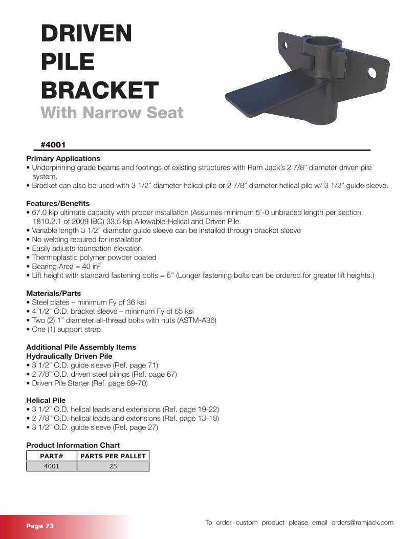
Page 73 To order custom product please email [email protected]
DRIVEN PILEBRACKETWith Narrow Seat
#4001
Primary Applications• Underpinning grade beams and footings of existing structures with Ram Jack’s 2 7/8” diameter driven pile system.• Bracket can also be used with 3 1/2” diameter helical pile or 2 7/8” diameter helical pile w/ 3 1/2” guide sleeve.
Features/Benefits• 67.0 kip ultimate capacity with proper installation (Assumes minimum 5’-0 unbraced length per section 1810.2.1 of 2009 IBC) 33.5 kip Allowable-Helical and Driven Pile• Variable length 3 1/2” diameter guide sleeve can be installed through bracket sleeve• No welding required for installation• Easily adjusts foundation elevation• Thermoplastic polymer powder coated• Bearing Area = 40 in2
• Lift height with standard fastening bolts = 6’’ (Longer fastening bolts can be ordered for greater lift heights.)
Materials/Parts• Steel plates – minimum Fy of 36 ksi• 4 1/2” O.D. bracket sleeve – minimum Fy of 65 ksi• Two (2) 1” diameter all-thread bolts with nuts (ASTM-A36)• One (1) support strap
Additional Pile Assembly ItemsHydraulically Driven Pile• 3 1/2” O.D. guide sleeve (Ref. page 71)• 2 7/8” O.D. driven steel pilings (Ref. page 67)• Driven Pile Starter (Ref. page 69-70)
Helical Pile• 3 1/2” O.D. helical leads and extensions (Ref. page 19-22)• 2 7/8” O.D. helical leads and extensions (Ref. page 13-18)• 3 1/2” O.D. guide sleeve (Ref. page 27)
Product Information ChartPART# PARTS PER PALLET4001 25
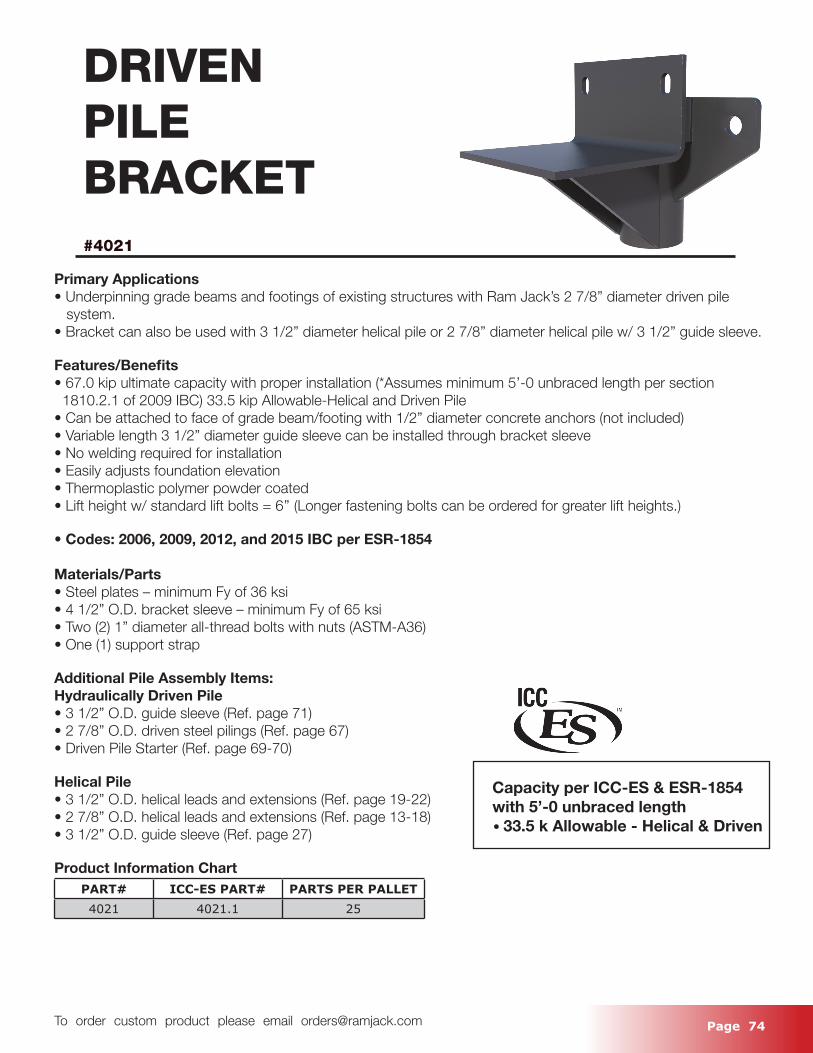
Page 74 To order custom product please email [email protected]
DRIVEN PILEBRACKET#4021
Primary Applications• Underpinning grade beams and footings of existing structures with Ram Jack’s 2 7/8” diameter driven pile system.• Bracket can also be used with 3 1/2” diameter helical pile or 2 7/8” diameter helical pile w/ 3 1/2” guide sleeve.
Features/Benefits• 67.0 kip ultimate capacity with proper installation (*Assumes minimum 5’-0 unbraced length per section 1810.2.1 of 2009 IBC) 33.5 kip Allowable-Helical and Driven Pile• Can be attached to face of grade beam/footing with 1/2” diameter concrete anchors (not included)• Variable length 3 1/2” diameter guide sleeve can be installed through bracket sleeve• No welding required for installation• Easily adjusts foundation elevation• Thermoplastic polymer powder coated• Lift height w/ standard lift bolts = 6’’ (Longer fastening bolts can be ordered for greater lift heights.)
• Codes: 2006, 2009, 2012, and 2015 IBC per ESR-1854
Materials/Parts• Steel plates – minimum Fy of 36 ksi• 4 1/2” O.D. bracket sleeve – minimum Fy of 65 ksi• Two (2) 1” diameter all-thread bolts with nuts (ASTM-A36)• One (1) support strap
Additional Pile Assembly Items:Hydraulically Driven Pile• 3 1/2” O.D. guide sleeve (Ref. page 71)• 2 7/8” O.D. driven steel pilings (Ref. page 67)• Driven Pile Starter (Ref. page 69-70)
Helical Pile• 3 1/2” O.D. helical leads and extensions (Ref. page 19-22)• 2 7/8” O.D. helical leads and extensions (Ref. page 13-18)• 3 1/2” O.D. guide sleeve (Ref. page 27)
Product Information ChartPART# ICC-ES PART# PARTS PER PALLET4021 4021.1 25
Capacity per ICC-ES & ESR-1854 with 5’-0 unbraced length • 33.5 k Allowable - Helical & Driven
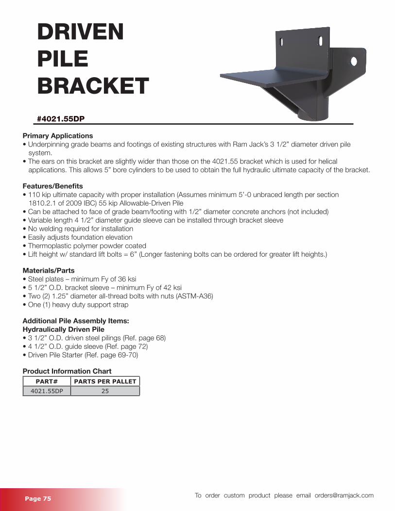
Page 75 To order custom product please email [email protected]
DRIVENPILEBRACKET#4021.55DP
Primary Applications• Underpinning grade beams and footings of existing structures with Ram Jack’s 3 1/2” diameter driven pile system.• The ears on this bracket are slightly wider than those on the 4021.55 bracket which is used for helical applications. This allows 5” bore cylinders to be used to obtain the full hydraulic ultimate capacity of the bracket.
Features/Benefits• 110 kip ultimate capacity with proper installation (Assumes minimum 5’-0 unbraced length per section 1810.2.1 of 2009 IBC) 55 kip Allowable-Driven Pile • Can be attached to face of grade beam/footing with 1/2” diameter concrete anchors (not included)• Variable length 4 1/2” diameter guide sleeve can be installed through bracket sleeve• No welding required for installation• Easily adjusts foundation elevation• Thermoplastic polymer powder coated• Lift height w/ standard lift bolts = 6’’ (Longer fastening bolts can be ordered for greater lift heights.)
Materials/Parts• Steel plates – minimum Fy of 36 ksi• 5 1/2” O.D. bracket sleeve – minimum Fy of 42 ksi• Two (2) 1.25” diameter all-thread bolts with nuts (ASTM-A36)• One (1) heavy duty support strap
Additional Pile Assembly Items:Hydraulically Driven Pile• 3 1/2” O.D. driven steel pilings (Ref. page 68)• 4 1/2” O.D. guide sleeve (Ref. page 72)• Driven Pile Starter (Ref. page 69-70)
Product Information ChartPART# PARTS PER PALLET
4021.55DP 25
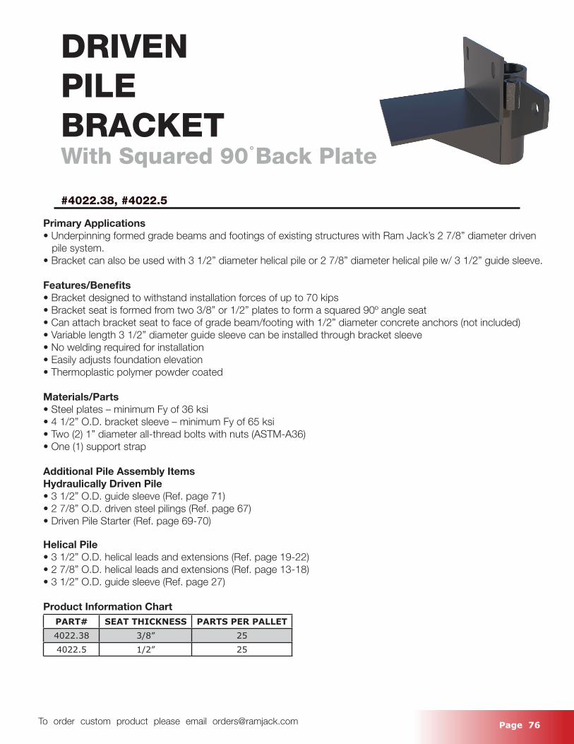
Page 76 To order custom product please email [email protected]
DRIVENPILEBRACKETWith Squared 90 Back Plate
#4022.38, #4022.5
Primary Applications• Underpinning formed grade beams and footings of existing structures with Ram Jack’s 2 7/8” diameter driven pile system.• Bracket can also be used with 3 1/2” diameter helical pile or 2 7/8” diameter helical pile w/ 3 1/2” guide sleeve.
Features/Benefits• Bracket designed to withstand installation forces of up to 70 kips• Bracket seat is formed from two 3/8” or 1/2” plates to form a squared 90o angle seat• Can attach bracket seat to face of grade beam/footing with 1/2” diameter concrete anchors (not included)• Variable length 3 1/2” diameter guide sleeve can be installed through bracket sleeve• No welding required for installation• Easily adjusts foundation elevation• Thermoplastic polymer powder coated
Materials/Parts• Steel plates – minimum Fy of 36 ksi• 4 1/2” O.D. bracket sleeve – minimum Fy of 65 ksi• Two (2) 1” diameter all-thread bolts with nuts (ASTM-A36)• One (1) support strap
Additional Pile Assembly ItemsHydraulically Driven Pile• 3 1/2” O.D. guide sleeve (Ref. page 71)• 2 7/8” O.D. driven steel pilings (Ref. page 67)• Driven Pile Starter (Ref. page 69-70)
Helical Pile• 3 1/2” O.D. helical leads and extensions (Ref. page 19-22)• 2 7/8” O.D. helical leads and extensions (Ref. page 13-18)• 3 1/2” O.D. guide sleeve (Ref. page 27)
Product Information ChartPART# SEAT THICKNESS PARTS PER PALLET4022.38 3/8” 254022.5 1/2” 25
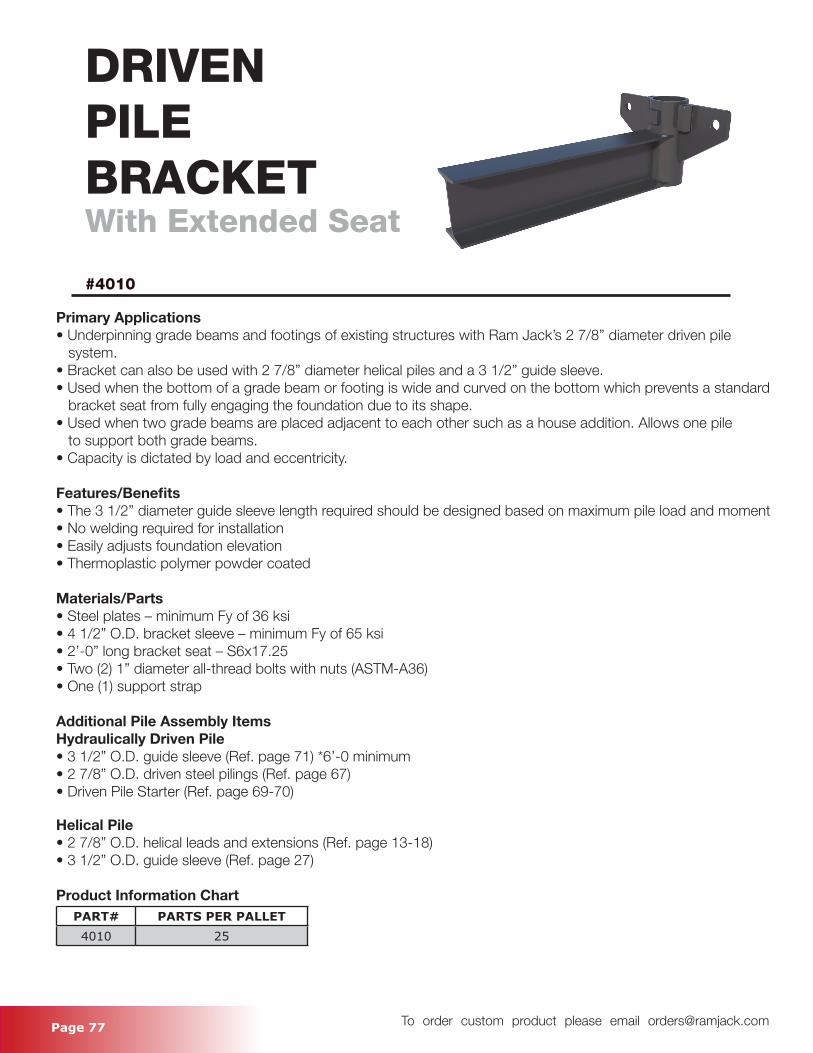
Page 77 To order custom product please email [email protected]
DRIVEN PILEBRACKETWith Extended Seat
#4010
Primary Applications• Underpinning grade beams and footings of existing structures with Ram Jack’s 2 7/8” diameter driven pile system.• Bracket can also be used with 2 7/8” diameter helical piles and a 3 1/2” guide sleeve.• Used when the bottom of a grade beam or footing is wide and curved on the bottom which prevents a standard bracket seat from fully engaging the foundation due to its shape.• Used when two grade beams are placed adjacent to each other such as a house addition. Allows one pile to support both grade beams.• Capacity is dictated by load and eccentricity.
Features/Benefits• The 3 1/2” diameter guide sleeve length required should be designed based on maximum pile load and moment• No welding required for installation• Easily adjusts foundation elevation• Thermoplastic polymer powder coated
Materials/Parts• Steel plates – minimum Fy of 36 ksi • 4 1/2” O.D. bracket sleeve – minimum Fy of 65 ksi• 2’-0” long bracket seat – S6x17.25• Two (2) 1” diameter all-thread bolts with nuts (ASTM-A36)• One (1) support strap
Additional Pile Assembly ItemsHydraulically Driven Pile• 3 1/2” O.D. guide sleeve (Ref. page 71) *6’-0 minimum• 2 7/8” O.D. driven steel pilings (Ref. page 67)• Driven Pile Starter (Ref. page 69-70)
Helical Pile• 2 7/8” O.D. helical leads and extensions (Ref. page 13-18)• 3 1/2” O.D. guide sleeve (Ref. page 27)
Product Information ChartPART# PARTS PER PALLET4010 25
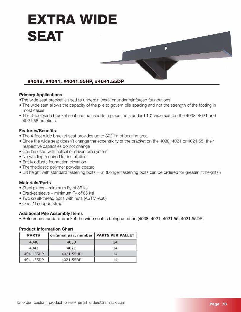
Page 78 To order custom product please email [email protected]
EXTRA WIDE SEAT
#4048, #4041, #4041.55HP, #4041.55DP
Primary Applications•The wide seat bracket is used to underpin weak or under reinforced foundations• The wide seat allows the capacity of the pile to govern pile spacing and not the strength of the footing in most cases• The 4-foot wide bracket seat can be used to replace the standard 10” wide seat on the 4038, 4021 and 4021.55 brackets
Features/Benefits• The 4-foot wide bracket seat provides up to 372 in2 of bearing area• Since the wide seat doesn’t change the eccentricity of the bracket on the 4038, 4021 or 4021.55, their respective capacities do not change• Can be used with helical or driven pile system• No welding required for installation• Easily adjusts foundation elevation• Thermoplastic polymer powder coated• Lift height with standard fastening bolts = 6’’ (Longer fastening bolts can be ordered for greater lift heights.)
Materials/Parts• Steel plates – minimum Fy of 36 ksi• Bracket sleeve – minimum Fy of 65 ksi• Two (2) all-thread bolts with nuts (ASTM-A36)• One (1) support strap
Additional Pile Assembly Items• Reference standard bracket the wide seat is being used on (4038, 4021, 4021.55, 4021.55DP)
Product Information ChartPART# originial part number PARTS PER PALLET
4048 4038 144041 4021 14
4041.55HP 4021.55HP 144041.55DP 4021.55DP 14
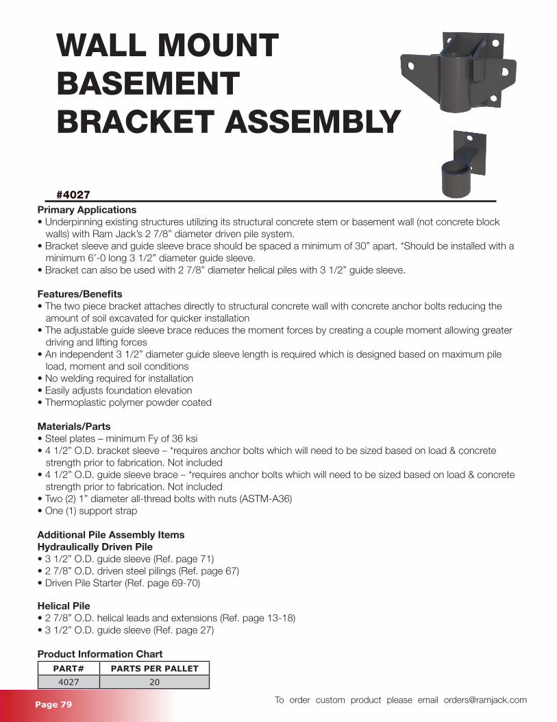
Page 79 To order custom product please email [email protected]
WALL MOUNTBASEMENTBRACKET ASSEMBLY
#4027Primary Applications• Underpinning existing structures utilizing its structural concrete stem or basement wall (not concrete block walls) with Ram Jack’s 2 7/8” diameter driven pile system.• Bracket sleeve and guide sleeve brace should be spaced a minimum of 30” apart. *Should be installed with a minimum 6’-0 long 3 1/2” diameter guide sleeve.• Bracket can also be used with 2 7/8” diameter helical piles with 3 1/2” guide sleeve.
Features/Benefits• The two piece bracket attaches directly to structural concrete wall with concrete anchor bolts reducing the amount of soil excavated for quicker installation• The adjustable guide sleeve brace reduces the moment forces by creating a couple moment allowing greater driving and lifting forces• An independent 3 1/2” diameter guide sleeve length is required which is designed based on maximum pile load, moment and soil conditions• No welding required for installation• Easily adjusts foundation elevation• Thermoplastic polymer powder coated
Materials/Parts• Steel plates – minimum Fy of 36 ksi• 4 1/2” O.D. bracket sleeve – *requires anchor bolts which will need to be sized based on load & concrete strength prior to fabrication. Not included• 4 1/2” O.D. guide sleeve brace – *requires anchor bolts which will need to be sized based on load & concrete strength prior to fabrication. Not included• Two (2) 1” diameter all-thread bolts with nuts (ASTM-A36)• One (1) support strap
Additional Pile Assembly ItemsHydraulically Driven Pile• 3 1/2” O.D. guide sleeve (Ref. page 71)• 2 7/8” O.D. driven steel pilings (Ref. page 67)• Driven Pile Starter (Ref. page 69-70)
Helical Pile• 2 7/8” O.D. helical leads and extensions (Ref. page 13-18)• 3 1/2” O.D. guide sleeve (Ref. page 27)
Product Information ChartPART# PARTS PER PALLET4027 20
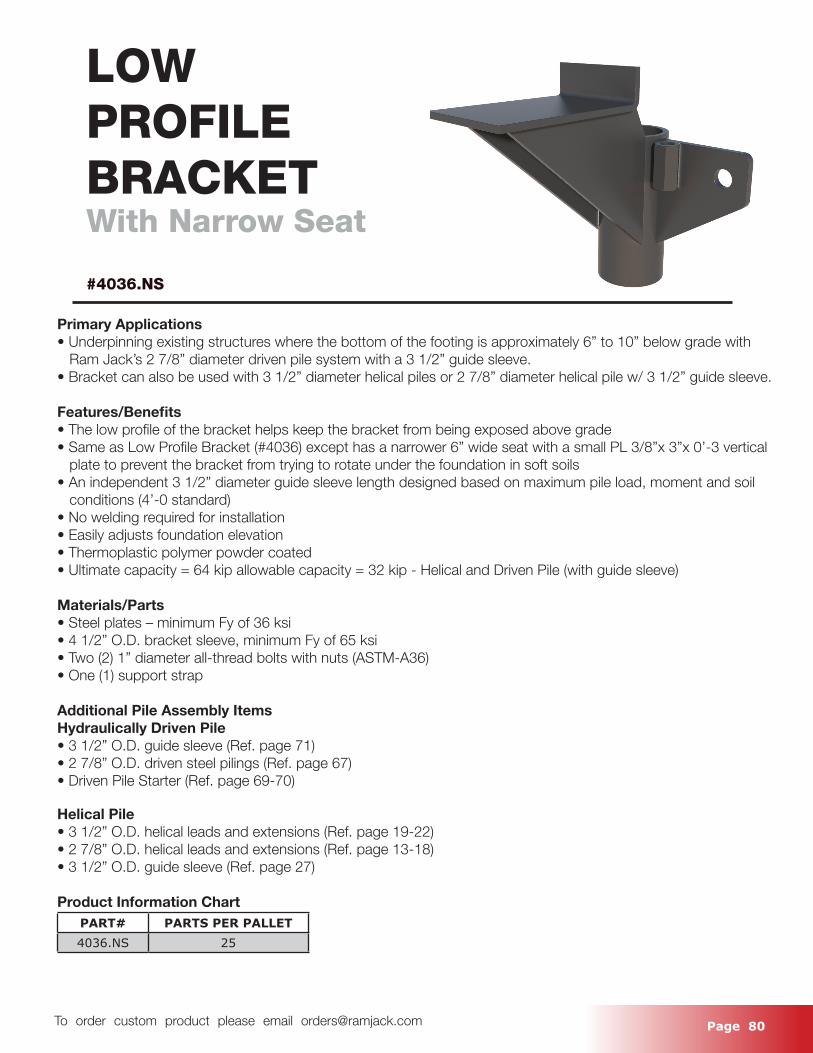
Page 80 To order custom product please email [email protected]
LOWPROFILEBRACKETWith Narrow Seat
#4036.NS
Primary Applications• Underpinning existing structures where the bottom of the footing is approximately 6” to 10” below grade with Ram Jack’s 2 7/8” diameter driven pile system with a 3 1/2” guide sleeve.• Bracket can also be used with 3 1/2” diameter helical piles or 2 7/8” diameter helical pile w/ 3 1/2” guide sleeve.
Features/Benefits• The low profile of the bracket helps keep the bracket from being exposed above grade• Same as Low Profile Bracket (#4036) except has a narrower 6” wide seat with a small PL 3/8”x 3”x 0’-3 vertical plate to prevent the bracket from trying to rotate under the foundation in soft soils• An independent 3 1/2” diameter guide sleeve length designed based on maximum pile load, moment and soil conditions (4’-0 standard)• No welding required for installation• Easily adjusts foundation elevation• Thermoplastic polymer powder coated• Ultimate capacity = 64 kip allowable capacity = 32 kip - Helical and Driven Pile (with guide sleeve)
Materials/Parts• Steel plates – minimum Fy of 36 ksi• 4 1/2” O.D. bracket sleeve, minimum Fy of 65 ksi• Two (2) 1” diameter all-thread bolts with nuts (ASTM-A36)• One (1) support strap
Additional Pile Assembly ItemsHydraulically Driven Pile• 3 1/2” O.D. guide sleeve (Ref. page 71)• 2 7/8” O.D. driven steel pilings (Ref. page 67)• Driven Pile Starter (Ref. page 69-70)
Helical Pile• 3 1/2” O.D. helical leads and extensions (Ref. page 19-22)• 2 7/8” O.D. helical leads and extensions (Ref. page 13-18)• 3 1/2” O.D. guide sleeve (Ref. page 27)
Product Information ChartPART# PARTS PER PALLET4036.NS 25
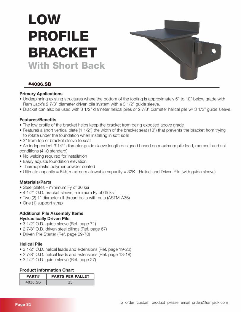
Page 81 To order custom product please email [email protected]
LOWPROFILEBRACKETWith Short Back
#4036.SB
Primary Applications• Underpinning existing structures where the bottom of the footing is approximately 6” to 10” below grade with Ram Jack’s 2 7/8” diameter driven pile system with a 3 1/2” guide sleeve.• Bracket can also be used with 3 1/2” diameter helical piles or 2 7/8” diameter helical pile w/ 3 1/2” guide sleeve.
Features/Benefits• The low profile of the bracket helps keep the bracket from being exposed above grade• Features a short vertical plate (1 1/2”) the width of the bracket seat (10”) that prevents the bracket from trying to rotate under the foundation when installing in soft soils• 3” from top of bracket sleeve to seat• An independent 3 1/2” diameter guide sleeve length designed based on maximum pile load, moment and soil conditions (4’-0 standard)• No welding required for installation• Easily adjusts foundation elevation• Thermoplastic polymer powder coated• Ultimate capacity = 64K maximum allowable capacity = 32K - Helical and Driven Pile (with guide sleeve)
Materials/Parts• Steel plates – minimum Fy of 36 ksi• 4 1/2” O.D. bracket sleeve, minimum Fy of 65 ksi• Two (2) 1” diameter all-thread bolts with nuts (ASTM-A36)• One (1) support strap
Additional Pile Assembly ItemsHydraulically Driven Pile• 3 1/2” O.D. guide sleeve (Ref. page 71)• 2 7/8” O.D. driven steel pilings (Ref. page 67)• Driven Pile Starter (Ref. page 69-70)
Helical Pile• 3 1/2” O.D. helical leads and extensions (Ref. page 19-22)• 2 7/8” O.D. helical leads and extensions (Ref. page 13-18)• 3 1/2” O.D. guide sleeve (Ref. page 27)
Product Information ChartPART# PARTS PER PALLET4036.SB 25
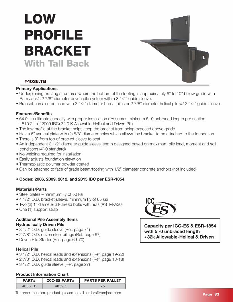
Page 82 To order custom product please email [email protected]
LOWPROFILEBRACKETWith Tall Back
#4036.TB
Primary Applications• Underpinning existing structures where the bottom of the footing is approximately 6” to 10” below grade with Ram Jack’s 2 7/8” diameter driven pile system with a 3 1/2” guide sleeve.• Bracket can also be used with 3 1/2” diameter helical piles or 2 7/8” diameter helical pile w/ 3 1/2” guide sleeve.
Features/Benefits• 64.0 kip ultimate capacity with proper installation (*Assumes minimum 5’-0 unbraced length per section 1810.2.1 of 2009 IBC) 32.0 K Allowable-Helical and Driven Pile• The low profile of the bracket helps keep the bracket from being exposed above grade• Has a 6” vertical plate with (2) 5/8” diameter holes which allows the bracket to be attached to the foundation • There is 3” from top of bracket sleeve to seat • An independent 3 1/2” diameter guide sleeve length designed based on maximum pile load, moment and soil conditions (4’-0 standard)• No welding required for installation• Easily adjusts foundation elevation• Thermoplastic polymer powder coated• Can be attached to face of grade beam/footing with 1/2” diameter concrete anchors (not included)
• Codes: 2006, 2009, 2012, and 2015 IBC per ESR-1854
Materials/Parts• Steel plates – minimum Fy of 50 ksi• 4 1/2” O.D. bracket sleeve, minimum Fy of 65 ksi• Two (2) 1” diameter all-thread bolts with nuts (ASTM-A36)• One (1) support strap
Additional Pile Assembly ItemsHydraulically Driven Pile• 3 1/2” O.D. guide sleeve (Ref. page 71)• 2 7/8” O.D. driven steel pilings (Ref. page 67)• Driven Pile Starter (Ref. page 69-70)
Helical Pile• 3 1/2” O.D. helical leads and extensions (Ref. page 19-22)• 2 7/8” O.D. helical leads and extensions (Ref. page 13-18)• 3 1/2” O.D. guide sleeve (Ref. page 27)
Product Information ChartPART# ICC-ES PART# PARTS PER PALLET4036.TB 4039.1 25
Capacity per ICC-ES & ESR-1854 with 5’-0 unbraced length • 32k Allowable-Helical & Driven
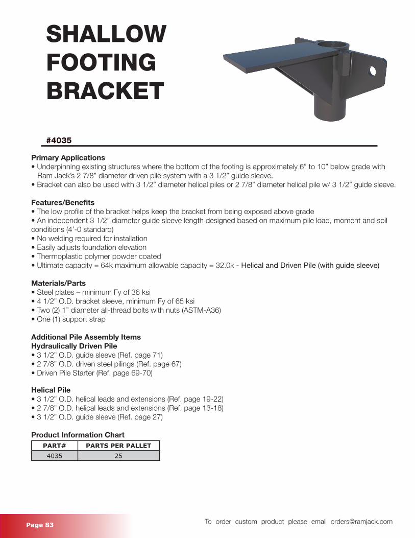
Page 83 To order custom product please email [email protected]
SHALLOWFOOTINGBRACKET
#4035
Primary Applications• Underpinning existing structures where the bottom of the footing is approximately 6” to 10” below grade with Ram Jack’s 2 7/8” diameter driven pile system with a 3 1/2” guide sleeve.• Bracket can also be used with 3 1/2” diameter helical piles or 2 7/8” diameter helical pile w/ 3 1/2” guide sleeve.
Features/Benefits• The low profile of the bracket helps keep the bracket from being exposed above grade• An independent 3 1/2” diameter guide sleeve length designed based on maximum pile load, moment and soil conditions (4’-0 standard)• No welding required for installation• Easily adjusts foundation elevation• Thermoplastic polymer powder coated• Ultimate capacity = 64k maximum allowable capacity = 32.0k - Helical and Driven Pile (with guide sleeve)
Materials/Parts• Steel plates – minimum Fy of 36 ksi• 4 1/2” O.D. bracket sleeve, minimum Fy of 65 ksi• Two (2) 1” diameter all-thread bolts with nuts (ASTM-A36)• One (1) support strap
Additional Pile Assembly ItemsHydraulically Driven Pile• 3 1/2” O.D. guide sleeve (Ref. page 71)• 2 7/8” O.D. driven steel pilings (Ref. page 67)• Driven Pile Starter (Ref. page 69-70)
Helical Pile• 3 1/2” O.D. helical leads and extensions (Ref. page 19-22)• 2 7/8” O.D. helical leads and extensions (Ref. page 13-18)• 3 1/2” O.D. guide sleeve (Ref. page 27)
Product Information ChartPART# PARTS PER PALLET4035 25
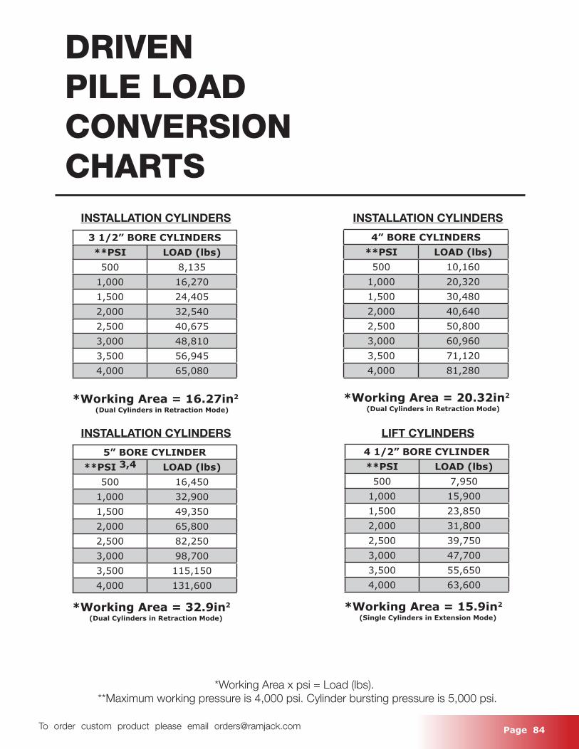
Page 84 To order custom product please email [email protected]
DRIVENPILE LOADCONVERSIONCHARTS
3 1/2” BORE CYLINDERS**PSI LOAD (lbs)
500 8,1351,000 16,2701,500 24,4052,000 32,5402,500 40,6753,000 48,8103,500 56,9454,000 65,080
4” BORE CYLINDERS**PSI LOAD (lbs)
500 10,1601,000 20,3201,500 30,4802,000 40,6402,500 50,8003,000 60,9603,500 71,1204,000 81,280
*Working Area = 20.32in2
(Dual Cylinders in Retraction Mode)
INSTALLATION CYLINDERS
INSTALLATION CYLINDERS LIFT CYLINDERS
INSTALLATION CYLINDERS
4 1/2” BORE CYLINDER**PSI LOAD (lbs)
500 7,9501,000 15,9001,500 23,8502,000 31,8002,500 39,7503,000 47,7003,500 55,6504,000 63,600
*Working Area = 15.9in2
(Single Cylinders in Extension Mode)
5” BORE CYLINDER**PSI 3,4 LOAD (lbs)
500 16,4501,000 32,9001,500 49,3502,000 65,8002,500 82,2503,000 98,7003,500 115,1504,000 131,600
*Working Area = 32.9in2
(Dual Cylinders in Retraction Mode)
*Working Area x psi = Load (lbs). **Maximum working pressure is 4,000 psi. Cylinder bursting pressure is 5,000 psi.
*Working Area = 16.27in2
(Dual Cylinders in Retraction Mode)