1395, 1397, and flexpak 3000 dc drives to powerflex dc
TRANSCRIPT

1395, 1397, and FlexPak 3000 DC Drives to PowerFlex DC DriveCatalog Numbers 1395, 1397, 20P
Migration Guide
Important User Information
Solid-state equipment has operational characteristics differing from those of electromechanical equipment. Safety Guidelines for the Application, Installation and Maintenance of Solid State Controls (publication SGI-1.1 available from your local Rockwell Automation® sales office or online at http://www.rockwellautomation.com/literature/) describes some important differences between solid-state equipment and hard-wired electromechanical devices. Because of this difference, and also because of the wide variety of uses for solid-state equipment, all persons responsible for applying this equipment must satisfy themselves that each intended application of this equipment is acceptable.
In no event will Rockwell Automation, Inc. be responsible or liable for indirect or consequential damages resulting from the use or application of this equipment.
The examples and diagrams in this manual are included solely for illustrative purposes. Because of the many variables and requirements associated with any particular installation, Rockwell Automation, Inc. cannot assume responsibility or liability for actual use based on the examples and diagrams.
No patent liability is assumed by Rockwell Automation, Inc. with respect to use of information, circuits, equipment, or software described in this manual.
Reproduction of the contents of this manual, in whole or in part, without written permission of Rockwell Automation, Inc., is prohibited.
Throughout this manual, when necessary, we use notes to make you aware of safety considerations.
Allen-Bradley, ControlLogix, MicroLogix, DriveExplorer, DriveExecutive, Encompass, PowerFlex, Rockwell Software, Rockwell Automation, and TechConnect are trademarks of Rockwell Automation, Inc.
Trademarks not belonging to Rockwell Automation are property of their respective companies.
WARNING: Identifies information about practices or circumstances that can cause an explosion in a hazardous environment, which may lead to personal injury or death, property damage, or economic loss.
ATTENTION: Identifies information about practices or circumstances that can lead to personal injury or death, property damage, or economic loss. Attentions help you identify a hazard, avoid a hazard, and recognize the consequence.
SHOCK HAZARD: Labels may be on or inside the equipment, for example, a drive or motor, to alert people that dangerous voltage may be present.
BURN HAZARD: Labels may be on or inside the equipment, for example, a drive or motor, to alert people that surfaces may reach dangerous temperatures.
IMPORTANT Identifies information that is critical for successful application and understanding of the product.
Table of Contents
Preface Overview . . . . . . . . . . . . . . . . . . . . . . . . . . . . . . . . . . . . . . . . . . . . . . . . . . . . . . . . . . 5Pre-migration . . . . . . . . . . . . . . . . . . . . . . . . . . . . . . . . . . . . . . . . . . . . . . . . . . . . . . 5
Best Practices . . . . . . . . . . . . . . . . . . . . . . . . . . . . . . . . . . . . . . . . . . . . . . . . . . 5Additional Resources . . . . . . . . . . . . . . . . . . . . . . . . . . . . . . . . . . . . . . . . . . . . . . . 6
View All Publications for a Specific Drive . . . . . . . . . . . . . . . . . . . . . . . . 7
Chapter 1Drive Comparisons Specifications and Features. . . . . . . . . . . . . . . . . . . . . . . . . . . . . . . . . . . . . . . . 10
Drive Catalog Number Explanations . . . . . . . . . . . . . . . . . . . . . . . . . . . . . . 18Bulletin 1395 Digital DC Drive . . . . . . . . . . . . . . . . . . . . . . . . . . . . . . . 18Bulletin 1395 Digital DC Drive in Bulletin 2361 Motor Control Centers . . . . . . . . . . . . . . . . . . . . . . . . . . . . . . . . . . . . . . . . . . . . . . . . . . . . . . 21Bulletin 1397 Digital DC Drive . . . . . . . . . . . . . . . . . . . . . . . . . . . . . . . 24FlexPak 3000 Digital DC Drive . . . . . . . . . . . . . . . . . . . . . . . . . . . . . . . 26PowerFlex Digital DC Drive . . . . . . . . . . . . . . . . . . . . . . . . . . . . . . . . . . 28PowerFlex Digital DC Drive, Continued . . . . . . . . . . . . . . . . . . . . . . 29
Drive Conversion Guides . . . . . . . . . . . . . . . . . . . . . . . . . . . . . . . . . . . . . . . . . 30Bulletin 1395 to PowerFlex DC Drive Conversions . . . . . . . . . . . . . 30Bulletin 1397 to PowerFlex DC Drive Conversions . . . . . . . . . . . . . 32FlexPak 3000 to PowerFlex DC Drive Conversions . . . . . . . . . . . . . 34
Drive Dimensions. . . . . . . . . . . . . . . . . . . . . . . . . . . . . . . . . . . . . . . . . . . . . . . . 36Bulletin 1395 Drive Approximate Dimensions. . . . . . . . . . . . . . . . . . 36Bulletin 1397 Drive Approximate Dimensions. . . . . . . . . . . . . . . . . . 39FlexPak 3000 Drive Approximate Dimensions . . . . . . . . . . . . . . . . . . 43PowerFlex DC Drive Approximate Dimensions. . . . . . . . . . . . . . . . . 49
Power Comparisons . . . . . . . . . . . . . . . . . . . . . . . . . . . . . . . . . . . . . . . . . . . . . . 541395 Power Connections - Standard Field Voltage . . . . . . . . . . . . . . 541395 External Field Transformer Connections. . . . . . . . . . . . . . . . . . 561397 AC Input Line Connections . . . . . . . . . . . . . . . . . . . . . . . . . . . . . 571397 Field and Motor Armature Connections . . . . . . . . . . . . . . . . . . 61FlexPak 3000 AC Input Line Connections . . . . . . . . . . . . . . . . . . . . . 65FlexPak 3000 DC Motor Field and Armature Connections . . . . . . 68PowerFlex DC Drive Power Wiring . . . . . . . . . . . . . . . . . . . . . . . . . . . 73
Control and Feedback Comparisons . . . . . . . . . . . . . . . . . . . . . . . . . . . . . . . 94Bulletin 1395 Digital DC Drive . . . . . . . . . . . . . . . . . . . . . . . . . . . . . . . 94Bulletin 1397 Digital DC Drive . . . . . . . . . . . . . . . . . . . . . . . . . . . . . . 101FlexPak 3000 DC Drive . . . . . . . . . . . . . . . . . . . . . . . . . . . . . . . . . . . . . 108PowerFlex DC Drive . . . . . . . . . . . . . . . . . . . . . . . . . . . . . . . . . . . . . . . . 118
Chapter 2Wiring Examples Bulletin 1395 to PowerFlex DC Drive Comparison . . . . . . . . . . . . . . . . 165
Bulletin 1397 to PowerFlex DC Drive Comparison . . . . . . . . . . . . . . . . 169FlexPak 3000 to PowerFlex DC Drive Comparison . . . . . . . . . . . . . . . . 173
Rockwell Automation Publication PFLEX-AP009A-EN-P - September 2012 3

Table of Contents
Chapter 3Network Communication Overview . . . . . . . . . . . . . . . . . . . . . . . . . . . . . . . . . . . . . . . . . . . . . . . . . . . . . . . 177
Bulletin 1395 DC Drive Network Communication Options . . . . . . . . 1771395 Node Adapter Board . . . . . . . . . . . . . . . . . . . . . . . . . . . . . . . . . . . 177Multi-Communication Board . . . . . . . . . . . . . . . . . . . . . . . . . . . . . . . . 178ControlNet Adapter Board. . . . . . . . . . . . . . . . . . . . . . . . . . . . . . . . . . . 178
Bulletin 1397 DC Drive Network Communication Options . . . . . . . . 179FlexPak 3000 DC Drive Network Communication Options . . . . . . . . 180
ControlNet Network Communication Option Board . . . . . . . . . . 180AutoMax Network Communication Option Board . . . . . . . . . . . . 180DeviceNet Network . . . . . . . . . . . . . . . . . . . . . . . . . . . . . . . . . . . . . . . . . 180
PowerFlex DC Drive Network Communication Options. . . . . . . . . . . 181Logic Command and Status . . . . . . . . . . . . . . . . . . . . . . . . . . . . . . . . . . . . . . 182
Bulletin 1395 DC Drive. . . . . . . . . . . . . . . . . . . . . . . . . . . . . . . . . . . . . . 182Bulletin 1397 DC Drive. . . . . . . . . . . . . . . . . . . . . . . . . . . . . . . . . . . . . . 185FlexPak 3000 DC Drive . . . . . . . . . . . . . . . . . . . . . . . . . . . . . . . . . . . . . . 186PowerFlex DC Drive. . . . . . . . . . . . . . . . . . . . . . . . . . . . . . . . . . . . . . . . . 188
Rockwell Automation Encompass Partner Migration Offerings . . . . . 190ProLinx 5210-DFNT-RIO . . . . . . . . . . . . . . . . . . . . . . . . . . . . . . . . . . . 191ProLinx 5201-DFNT-DH485 . . . . . . . . . . . . . . . . . . . . . . . . . . . . . . . . 191AN-X-ABRIO-SCAN . . . . . . . . . . . . . . . . . . . . . . . . . . . . . . . . . . . . . . . 191AN-X-DHP. . . . . . . . . . . . . . . . . . . . . . . . . . . . . . . . . . . . . . . . . . . . . . . . . 192AN-X-DCSNet . . . . . . . . . . . . . . . . . . . . . . . . . . . . . . . . . . . . . . . . . . . . . 192
4 Rockwell Automation Publication PFLEX-AP009A-EN-P - September 2012
Preface
Overview The purpose of this publication is to assist in migrating from a 1395, 1397, or FlexPak 3000 DC drive to a PowerFlex® DC drive. Please refer to the respective User Manual, Technical Data and/or Installation Instructions for more detail.
This publication contains these chapters:
• Chapter 1: Drive ComparisonsContains comparisons of the specifications, features, drive catalog numbers, dimensions, power and control terminals, and feedback options of the 1395, 1397, and FlexPak 3000 DC drives to the PowerFlex DC drive. This chapter also provides information on the user-installed options, contactors and recommended fuses for the PowerFlex DC drive.
• Chapter 2: Wiring ExamplesContains comparisons of the drive configuration, control wiring and parameters of the 1395, 1397, and FlexPak 3000 DC drives to the PowerFlex DC drive.
• Chapter 3: Network CommunicationIdentifies the 1395, 1397, and FlexPak 3000 drives network options that can be migrated to networks used by the PowerFlex DC drive. This chapter also provides overview information for the velocity reference/feedback, I/O adaptors, 16 bit-based processors (PLC 5) and provides information for Quest (a Rockwell Automation Encompass™ partner), that offers a remote I/O to EtherNet/IP communication convertor migration solution.
Pre-migration Best Practices
• Upload and save the drive parameters via DriveExplorer™ or DriveExecutive™. If you cannot connect to the drive online, manually record the drive parameter values.
• Record the motor nameplate data, record and label all power, motor, and digital and analog I/O control wiring.
• Upload and save any network files and Programmable Logic Controller (PLC) programs.
• Update and/or markup any changes to hardware prints.
Topic Page
Overview 5
Pre-migration 5
Additional Resources 6
Rockwell Automation Publication PFLEX-AP009A-EN-P - September 2012 5
Preface
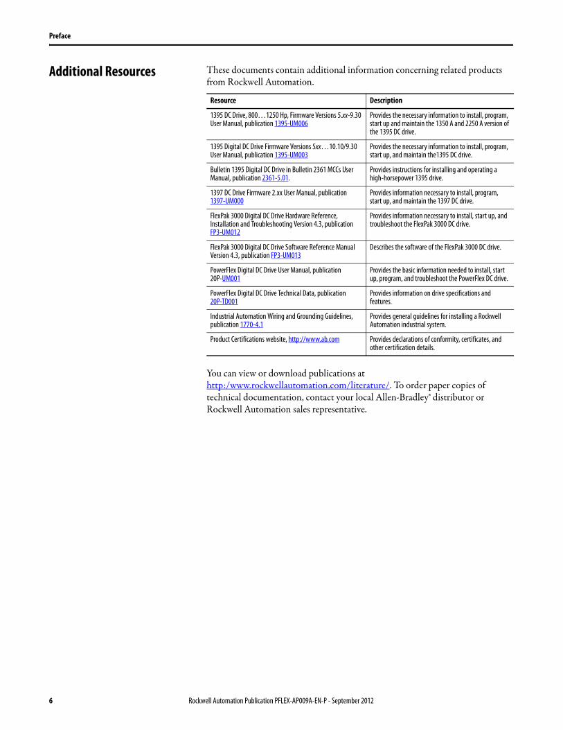
Additional Resources These documents contain additional information concerning related products from Rockwell Automation.
You can view or download publications athttp:/www.rockwellautomation.com/literature/. To order paper copies of technical documentation, contact your local Allen-Bradley® distributor or Rockwell Automation sales representative.
Resource Description
1395 DC Drive, 800…1250 Hp, Firmware Versions 5.xx-9.30 User Manual, publication 1395-UM006
Provides the necessary information to install, program, start up and maintain the 1350 A and 2250 A version of the 1395 DC drive.
1395 Digital DC Drive Firmware Versions 5xx…10.10/9.30 User Manual, publication 1395-UM003
Provides the necessary information to install, program, start up, and maintain the1395 DC drive.
Bulletin 1395 Digital DC Drive in Bulletin 2361 MCCs User Manual, publication 2361-5.01.
Provides instructions for installing and operating a high-horsepower 1395 drive.
1397 DC Drive Firmware 2.xx User Manual, publication1397-UM000
Provides information necessary to install, program, start up, and maintain the 1397 DC drive.
FlexPak 3000 Digital DC Drive Hardware Reference, Installation and Troubleshooting Version 4.3, publication FP3-UM012
Provides information necessary to install, start up, and troubleshoot the FlexPak 3000 DC drive.
FlexPak 3000 Digital DC Drive Software Reference Manual Version 4.3, publication FP3-UM013
Describes the software of the FlexPak 3000 DC drive.
PowerFlex Digital DC Drive User Manual, publication20P-UM001
Provides the basic information needed to install, start up, program, and troubleshoot the PowerFlex DC drive.
PowerFlex Digital DC Drive Technical Data, publication20P-TD001
Provides information on drive specifications and features.
Industrial Automation Wiring and Grounding Guidelines, publication 1770-4.1
Provides general guidelines for installing a Rockwell Automation industrial system.
Product Certifications website, http://www.ab.com Provides declarations of conformity, certificates, and other certification details.
6 Rockwell Automation Publication PFLEX-AP009A-EN-P - September 2012
Preface
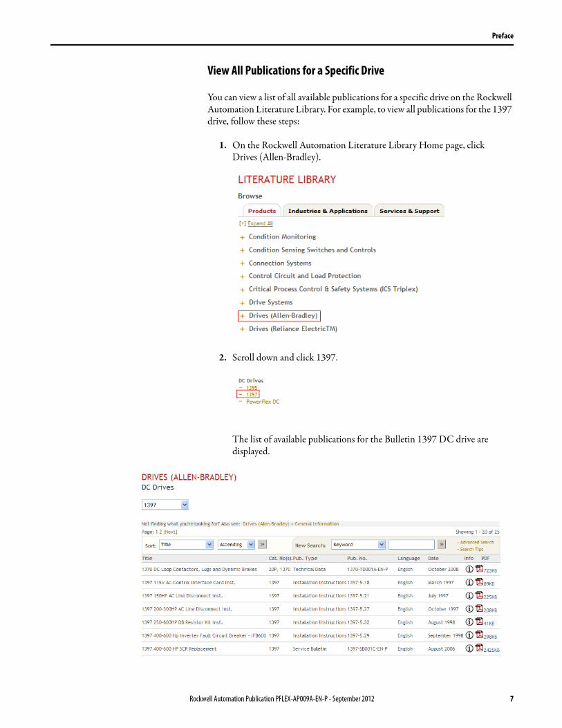
View All Publications for a Specific Drive
You can view a list of all available publications for a specific drive on the Rockwell Automation Literature Library. For example, to view all publications for the 1397 drive, follow these steps:
1. On the Rockwell Automation Literature Library Home page, click Drives (Allen-Bradley).
2. Scroll down and click 1397.
The list of available publications for the Bulletin 1397 DC drive are displayed.
Rockwell Automation Publication PFLEX-AP009A-EN-P - September 2012 7

Preface
Notes:
8 Rockwell Automation Publication PFLEX-AP009A-EN-P - September 2012
Chapter 1
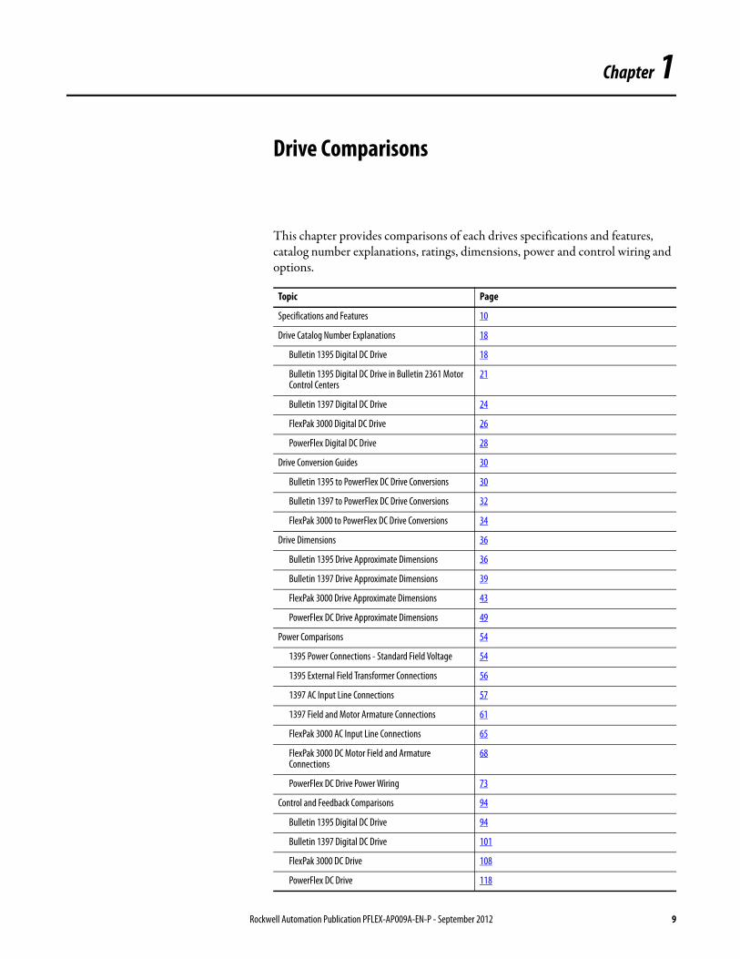
Drive Comparisons
This chapter provides comparisons of each drives specifications and features, catalog number explanations, ratings, dimensions, power and control wiring and options.
Topic Page
Specifications and Features 10
Drive Catalog Number Explanations 18
Bulletin 1395 Digital DC Drive 18
Bulletin 1395 Digital DC Drive in Bulletin 2361 Motor Control Centers
21
Bulletin 1397 Digital DC Drive 24
FlexPak 3000 Digital DC Drive 26
PowerFlex Digital DC Drive 28
Drive Conversion Guides 30
Bulletin 1395 to PowerFlex DC Drive Conversions 30
Bulletin 1397 to PowerFlex DC Drive Conversions 32
FlexPak 3000 to PowerFlex DC Drive Conversions 34
Drive Dimensions 36
Bulletin 1395 Drive Approximate Dimensions 36
Bulletin 1397 Drive Approximate Dimensions 39
FlexPak 3000 Drive Approximate Dimensions 43
PowerFlex DC Drive Approximate Dimensions 49
Power Comparisons 54
1395 Power Connections - Standard Field Voltage 54
1395 External Field Transformer Connections 56
1397 AC Input Line Connections 57
1397 Field and Motor Armature Connections 61
FlexPak 3000 AC Input Line Connections 65
FlexPak 3000 DC Motor Field and Armature Connections
68
PowerFlex DC Drive Power Wiring 73
Control and Feedback Comparisons 94
Bulletin 1395 Digital DC Drive 94
Bulletin 1397 Digital DC Drive 101
FlexPak 3000 DC Drive 108
PowerFlex DC Drive 118
Rockwell Automation Publication PFLEX-AP009A-EN-P - September 2012 9
Chapter 1 Drive Comparisons
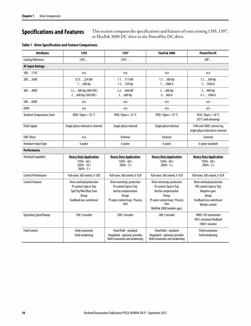
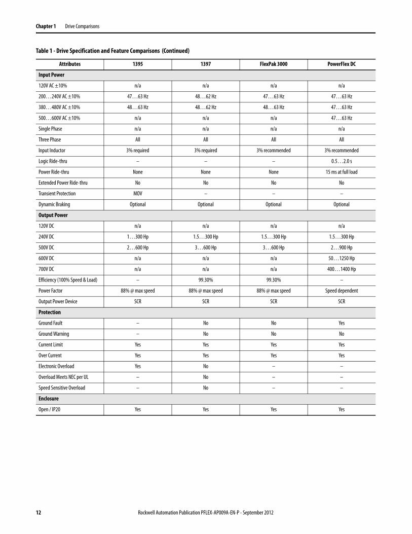
Specifications and Features This section compares the specifications and features of your existing 1395, 1397, or FlexPak 3000 DC drive to the PowerFlex DC drive.
Table 1 - Drive Specification and Feature Comparisons
Attributes 1395 1397 FlexPak 3000 PowerFlex DC
Catalog Reference 1395… 1397… 20P…
AC Input Ratings
100…115V n/a n/a n/a n/a
200…240V 0.75…224 kW1…300 Hp
1.1…111 kW1.5…150 Hp
1.5…300 Hp7…1000 A
1.5…300 Hp7…1050 A
400…480V 1.5…500 Hp (400 VDC)2…600 Hp (500 VDC)
2.2…448 kW3…600 Hp
3…600 Hp6…960 A
2…900 Hp4.1…1494 A
500…600V n/a n/a n/a n/a
690V n/a n/a n/a n/a
Ambient Temperature Limit IP00 / Open = 55 °C IP00 / Open = 55 °C IP00 / Open = 55 °C IP20 / Open = 50 °C(55°C with derating)
Field Supply Single phase internal or external Single phase internal Single phase internal 150V and 300V, current reg.single phase internal or external
EMC Filters n/a External External External
Armature Input Type 6-pulse 6-pulse 6-pulse 6-pulse standard
Performance
Overload Capability Heavy Duty Application150% - 60 s200% - 10 s260% - 5 s
Heavy Duty Application150% - 60 s200% - 5 s
Heavy Duty Application150% - 60 s200% - 5 s
Heavy Duty Application150% - 60 s200% - 3 s
Control Performance Full wave, full control, 6-SCR Full wave, full control, 6-SCR Full wave, full control, 6-SCR Full wave, full control, 6-SCR
Control Features Drive overload protectionPI control (Spd or Trq)
Spd/Trq/Min/Max/SumDroop
Feedback loss switchover
Drive overtemp. protectionPI control (Spd or Trq)Inertia compensation
DroopPI outer control loop / Process
trim
Drive overtemp. protectionPI control (Spd or Trq)Inertia compensation
DroopPI outer control loop / Process
trimWebPak 3000 (winder app.)
Drive overload protectionPID control (Spd or Trq)
Adaptive gain Droop
Feedback loss switchoverWinder control
Operating Speed Range 100:1 encoder 200:1 encoder 200:1 encoder 1000:1 DC tachometer100:1 armature feedback
1000:1 encoder
Field Control Field economizeField weakening
Fixed field - standardRegulated - optional, provides
field economize and weakening
Fixed field - standardRegulated - optional, provides
field economize and weakening
Field economizeField weakening
10 Rockwell Automation Publication PFLEX-AP009A-EN-P - September 2012
Drive Comparisons Chapter 1
Interface
User Interface Programming/Control terminalRemote terminal
DriveExecutive
Local ScanPort HIMsRemote ScanPort HIMs
DriveExplorerDriveExecutive
Five-language graphical LCDOperator Interface Module (OIM)
CS3000 Control/Configuration Software
Local PowerFlex HIMsRemote PowerFlex HIMs
DriveExplorerDriveExecutive
Connected Components Workbench
Communications Options ControlNetRemote I/O
DH+Serial
Node adapter board (PLC3/5)Multi-communication board
Internal - ScanPortDeviceNetControlNetRemote I/ODF1/DH485
Internal - SerialAutoMax network
DeviceNetControlNet
ProfibusInterbus - S
Internal - DPIBACnet
DeviceNetControlNetEtherNet/IP
Remote I/O (1)
RS485 DF-1RS485 HVACModbus RTUModbus/TCP)PROFIBUS DPInterbus - S
Preset Speeds 5 3 (with I/O expansion) 3 (with I/O expansion) 7
Standard Analog Inputs 0 2 fixed(12 bit + sign, ±1V or mA, ±1V)
2 fixed(12 bit + sign, ±1V or mA, ±1V)
3 configurable(11 bit + sign, each ±V or mA)
Standard Digital Inputs 4 fixed24V DC
10 - Fixed24V DC
10 - Fixed24V DC
8 - Configurable24V DC
Standard Analog Outputs 0 2 - Configurable(12 bit + sign, each ±V)
2 - Configurable(12 bit + sign, each ±V)
2 - Configurable(11 Bit + sign, each ±V)
Standard Digital Outputs 1 fixed24V DC
3 fixed24V DC
3 fixed24V DC
4 configurable (24V DC)2 configurable relay (N.O.)
Optional I/O Discrete Adapter(4 digital inputs, 2 digital
outputs, 4 analog inputs, 4 analog outputs)
Digital Ref(1 fixed input, 10 digital inputs,
5 digital outputs, 2 analog inputs, 2 analog outputs)
2 analog outputs2 analog inputs
5 fixed digital inputs 2 configurable digital outputs
1 pulse train input1 pulse train output
2 analog outputs2 analog inputs
5 fixed digital inputs 2 configurable digital outputs
1 pulse train input1 pulse train output
120V AC external interface
2 configurable analog outputs4 configurable digital inputs
4 configurable digital outputs115V AC interface
Protection
Motor OL Protection Yes Yes Yes Yes
Field Loss Yes Yes Yes Yes
Feedback Loss Yes Yes Yes Yes
Under & Over Voltage Protection – Yes Yes Yes
Dynamic Braking Armature regen or dynamic braking resistor
Armature regen or dynamic braking resistor
Armature regen or dynamic braking resistor
Armature regen or dynamic braking resistor
Over Current Yes Yes Yes Yes
MOVs Field bridge only – – –
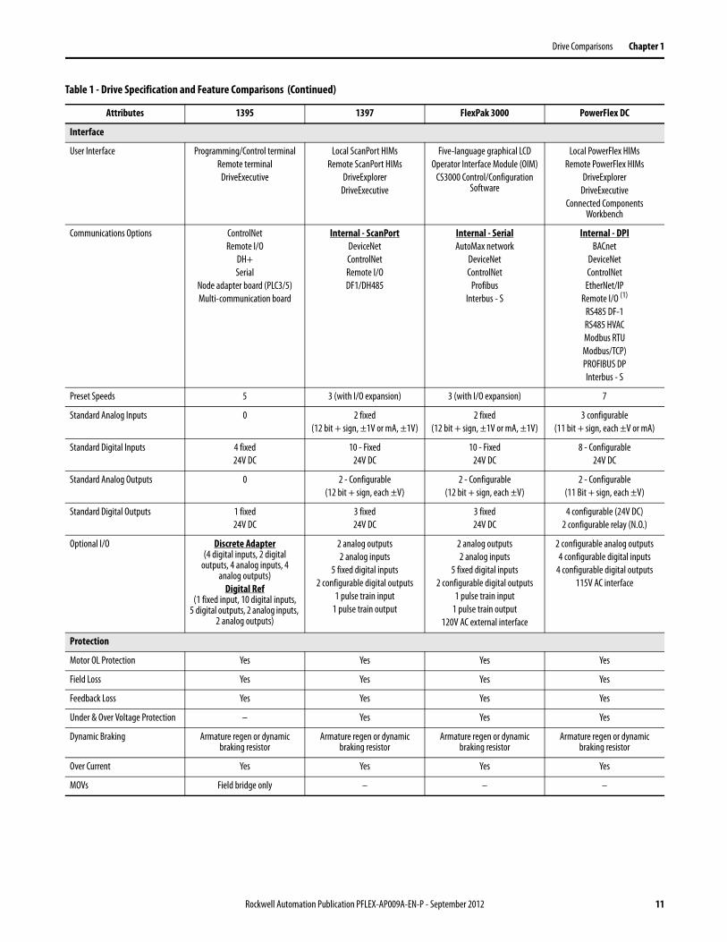
Table 1 - Drive Specification and Feature Comparisons (Continued)
Attributes 1395 1397 FlexPak 3000 PowerFlex DC
Rockwell Automation Publication PFLEX-AP009A-EN-P - September 2012 11
Chapter 1 Drive Comparisons
Input Power
120V AC ±10% n/a n/a n/a n/a
200…240V AC ±10% 47…63 Hz 48…62 Hz 47…63 Hz 47…63 Hz
380…480V AC ±10% 48…63 Hz 48…62 Hz 48…63 Hz 47…63 Hz
500…600V AC ±10% n/a n/a n/a 47…63 Hz
Single Phase n/a n/a n/a n/a
Three Phase All All All All
Input Inductor 3% required 3% required 3% recommended 3% recommended
Logic Ride-thru – – – 0.5…2.0 s
Power Ride-thru None None None 15 ms at full load
Extended Power Ride-thru No No No No
Transient Protection MOV – – –
Dynamic Braking Optional Optional Optional Optional
Output Power
120V DC n/a n/a n/a n/a
240V DC 1…300 Hp 1.5…300 Hp 1.5…300 Hp 1.5…300 Hp
500V DC 2…600 Hp 3…600 Hp 3…600 Hp 2…900 Hp
600V DC n/a n/a n/a 50…1250 Hp
700V DC n/a n/a n/a 400…1400 Hp
Efficiency (100% Speed & Load) – 99.30% 99.30% –
Power Factor 88% @ max speed 88% @ max speed 88% @ max speed Speed dependent
Output Power Device SCR SCR SCR SCR
Protection
Ground Fault – No No Yes
Ground Warning – No No No
Current Limit Yes Yes Yes Yes
Over Current Yes Yes Yes Yes
Electronic Overload Yes No – –
Overload Meets NEC per UL – No – –
Speed Sensitive Overload – No – –
Enclosure
Open / IP20 Yes Yes Yes Yes
Table 1 - Drive Specification and Feature Comparisons (Continued)
Attributes 1395 1397 FlexPak 3000 PowerFlex DC
12 Rockwell Automation Publication PFLEX-AP009A-EN-P - September 2012
Drive Comparisons Chapter 1
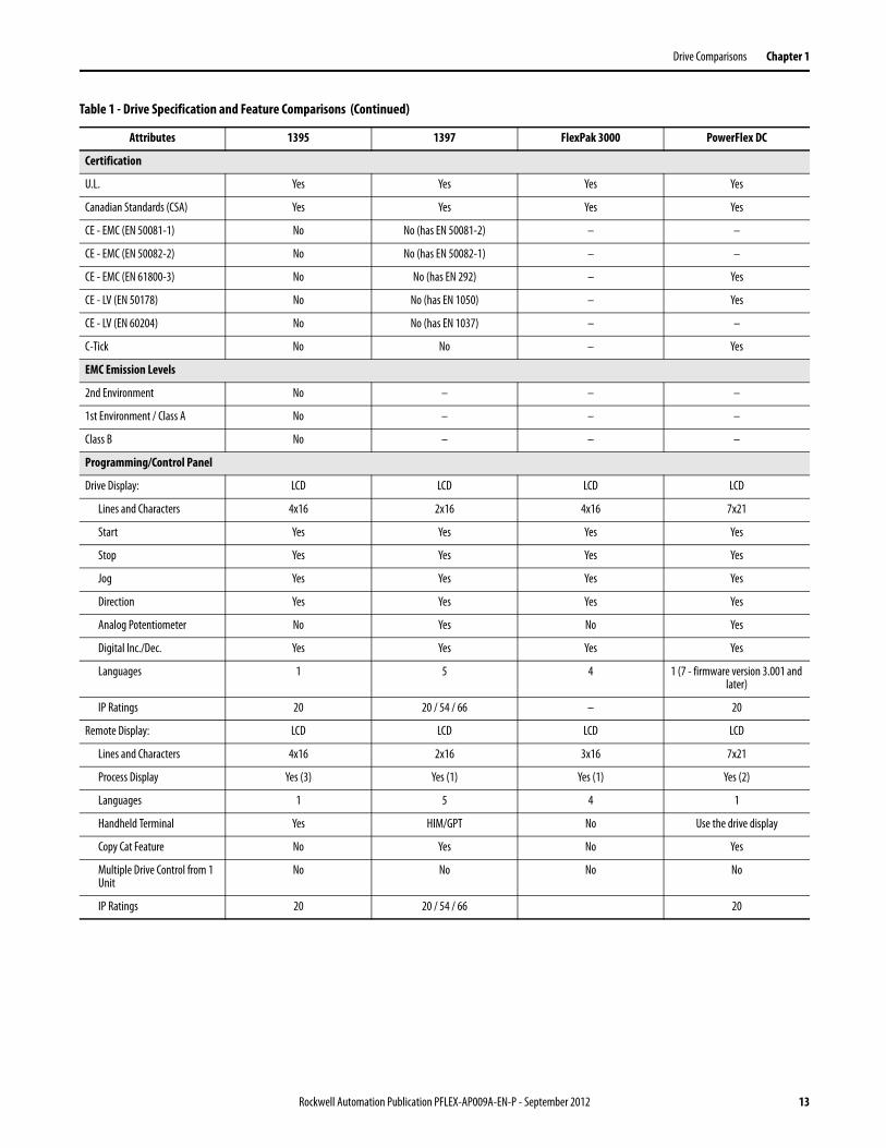
Certification
U.L. Yes Yes Yes Yes
Canadian Standards (CSA) Yes Yes Yes Yes
CE - EMC (EN 50081-1) No No (has EN 50081-2) – –
CE - EMC (EN 50082-2) No No (has EN 50082-1) – –
CE - EMC (EN 61800-3) No No (has EN 292) – Yes
CE - LV (EN 50178) No No (has EN 1050) – Yes
CE - LV (EN 60204) No No (has EN 1037) – –
C-Tick No No – Yes
EMC Emission Levels
2nd Environment No – – –
1st Environment / Class A No – – –
Class B No – – –
Programming/Control Panel
Drive Display: LCD LCD LCD LCD
Lines and Characters 4x16 2x16 4x16 7x21
Start Yes Yes Yes Yes
Stop Yes Yes Yes Yes
Jog Yes Yes Yes Yes
Direction Yes Yes Yes Yes
Analog Potentiometer No Yes No Yes
Digital Inc./Dec. Yes Yes Yes Yes
Languages 1 5 4 1 (7 - firmware version 3.001 and later)
IP Ratings 20 20 / 54 / 66 – 20
Remote Display: LCD LCD LCD LCD
Lines and Characters 4x16 2x16 3x16 7x21
Process Display Yes (3) Yes (1) Yes (1) Yes (2)
Languages 1 5 4 1
Handheld Terminal Yes HIM/GPT No Use the drive display
Copy Cat Feature No Yes No Yes
Multiple Drive Control from 1 Unit
No No No No
IP Ratings 20 20 / 54 / 66 20
Table 1 - Drive Specification and Feature Comparisons (Continued)
Attributes 1395 1397 FlexPak 3000 PowerFlex DC
Rockwell Automation Publication PFLEX-AP009A-EN-P - September 2012 13
Chapter 1 Drive Comparisons
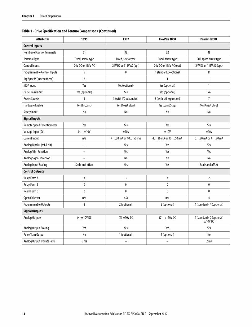
Control Inputs
Number of Control Terminals 51 32 32 48
Terminal Type Fixed, screw type Fixed, screw type Fixed, screw type Pull apart, screw type
Control Inputs 24V DC or 115V AC 24V DC or 115V AC (opt) 24V DC or 115V AC (opt) 24V DC or 115V AC (opt)
Programmable Control Inputs 5 0 1 standard, 5 optional 11
Jog Speeds (independent) 2 1 1 1
MOP Input Yes Yes (optional) Yes (optional) 1
Pulse Train Input Yes (optional) Yes Yes (optional) No
Preset Speeds 5 3 (with I/O expansion) 3 (with I/O expansion) 7
Hardware Enable Yes (E-Coast) Yes (Coast Stop) Yes (Coast Stop) Yes (Coast Stop)
Safety Input No No No No
Signal Inputs
Remote Speed Potentiometer Yes Yes Yes Yes
Voltage Input (DC) 0 …±10V ±10V ±10V ±10V
Current Input n/a 4…20 mA or 10…50 mA 4…20 mA or 10…50 mA 0…20 mA or 4…20 mA
Analog Bipolar (ref & dir) – Yes Yes Yes
Analog Trim Function – Yes Yes Yes
Analog Signal Inversion – No No No
Analog Input Scaling Scale and offset Yes Yes Scale and offset
Control Outputs
Relay Form A 3 3 3 2
Relay Form B 0 0 0 0
Relay Form C 0 0 0 0
Open Collector n/a n/a n/a 4
Programmable Outputs 2 2 (optional) 2 (optional) 4 (standard), 4 (optional)
Signal Outputs
Analog Outputs (4) ±10V DC (2) ±10V DC (2) +/- 10V DC 2 (standard), 2 (optional)±10V DC
Analog Output Scaling Yes Yes Yes Yes
Pulse Train Output No 1 (optional) 1 (optional) No
Analog Output Update Rate 6 ms – – 2 ms
Table 1 - Drive Specification and Feature Comparisons (Continued)
Attributes 1395 1397 FlexPak 3000 PowerFlex DC
14 Rockwell Automation Publication PFLEX-AP009A-EN-P - September 2012
Drive Comparisons Chapter 1
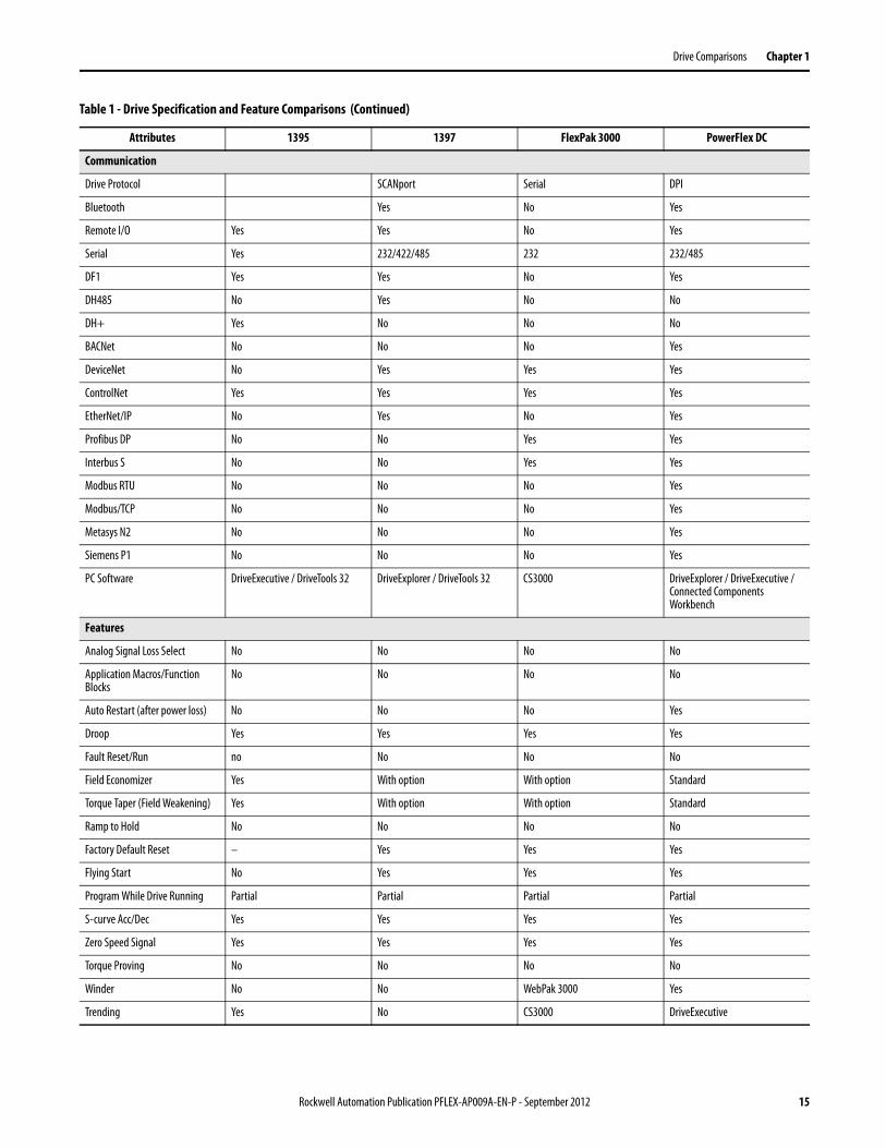
Communication
Drive Protocol SCANport Serial DPI
Bluetooth Yes No Yes
Remote I/O Yes Yes No Yes
Serial Yes 232/422/485 232 232/485
DF1 Yes Yes No Yes
DH485 No Yes No No
DH+ Yes No No No
BACNet No No No Yes
DeviceNet No Yes Yes Yes
ControlNet Yes Yes Yes Yes
EtherNet/IP No Yes No Yes
Profibus DP No No Yes Yes
Interbus S No No Yes Yes
Modbus RTU No No No Yes
Modbus/TCP No No No Yes
Metasys N2 No No No Yes
Siemens P1 No No No Yes
PC Software DriveExecutive / DriveTools 32 DriveExplorer / DriveTools 32 CS3000 DriveExplorer / DriveExecutive / Connected Components Workbench
Features
Analog Signal Loss Select No No No No
Application Macros/Function Blocks
No No No No
Auto Restart (after power loss) No No No Yes
Droop Yes Yes Yes Yes
Fault Reset/Run no No No No
Field Economizer Yes With option With option Standard
Torque Taper (Field Weakening) Yes With option With option Standard
Ramp to Hold No No No No
Factory Default Reset – Yes Yes Yes
Flying Start No Yes Yes Yes
Program While Drive Running Partial Partial Partial Partial
S-curve Acc/Dec Yes Yes Yes Yes
Zero Speed Signal Yes Yes Yes Yes
Torque Proving No No No No
Winder No No WebPak 3000 Yes
Trending Yes No CS3000 DriveExecutive
Table 1 - Drive Specification and Feature Comparisons (Continued)
Attributes 1395 1397 FlexPak 3000 PowerFlex DC
Rockwell Automation Publication PFLEX-AP009A-EN-P - September 2012 15
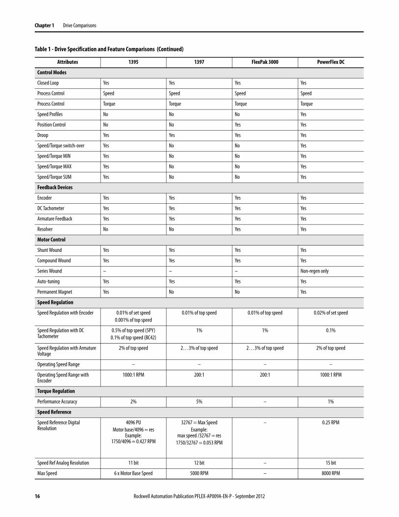
Chapter 1 Drive Comparisons
Control Modes
Closed Loop Yes Yes Yes Yes
Process Control Speed Speed Speed Speed
Process Control Torque Torque Torque Torque
Speed Profiles No No No Yes
Position Control No No Yes Yes
Droop Yes Yes Yes Yes
Speed/Torque switch-over Yes No No Yes
Speed/Torque MIN Yes No No Yes
Speed/Torque MAX Yes No No Yes
Speed/Torque SUM Yes No No Yes
Feedback Devices
Encoder Yes Yes Yes Yes
DC Tachometer Yes Yes Yes Yes
Armature Feedback Yes Yes Yes Yes
Resolver No No Yes Yes
Motor Control
Shunt Wound Yes Yes Yes Yes
Compound Wound Yes Yes Yes Yes
Series Wound – – – Non-regen only
Auto-tuning Yes Yes Yes Yes
Permanent Magnet Yes No No Yes
Speed Regulation
Speed Regulation with Encoder 0.01% of set speed0.001% of top speed
0.01% of top speed 0.01% of top speed 0.02% of set speed
Speed Regulation with DC Tachometer
0.5% of top speed (5PY)0.1% of top speed (BC42)
1% 1% 0.1%
Speed Regulation with Armature Voltage
2% of top speed 2…3% of top speed 2…3% of top speed 2% of top speed
Operating Speed Range – – – –
Operating Speed Range with Encoder
1000:1 RPM 200:1 200:1 1000:1 RPM
Torque Regulation
Performance Accuracy 2% 5% – 1%
Speed Reference
Speed Reference Digital Resolution
4096 PUMotor base/4096 = res
Example:1750/4096 = 0.427 RPM
32767 = Max SpeedExample:
max speed /32767 = res1750/32767 = 0.053 RPM
– 0.25 RPM
Speed Ref Analog Resolution 11 bit 12 bit – 15 bit
Max Speed 6 x Motor Base Speed 5000 RPM – 8000 RPM
Table 1 - Drive Specification and Feature Comparisons (Continued)
Attributes 1395 1397 FlexPak 3000 PowerFlex DC
16 Rockwell Automation Publication PFLEX-AP009A-EN-P - September 2012
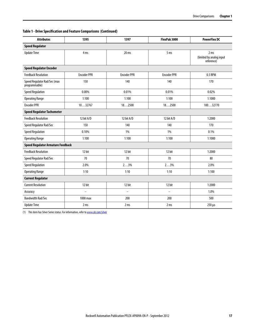
Drive Comparisons Chapter 1
Speed Regulator
Update Time 4 ms 20 ms 5 ms 2 ms(limited by analog input
reference)
Speed Regulator Encoder
Feedback Resolution Encoder PPR Encoder PPR Encoder PPR 0.5 RPM
Speed Regulator Rad/Sec (max programmable)
150 140 140 170
Speed Regulation 0.00% 0.01% 0.01% 0.02%
Operating Range 1:100 1:100 1:100 1:1000
Encoder PPR 10…32767 18…2500 18…2500 100…32770
Speed Regulator Tachometer
Feedback Resolution 12 bit A/D 12 bit A/D 12 bit A/D 1:2000
Speed Regulator Rad/Sec 150 140 140 170
Speed Regulation 0.10% 1% 1% 0.1%
Operating Range 1:100 1:100 1:100 1:1000
Speed Regulator Armature Feedback
Feedback Resolution 12 bit 12 bit 12 bit 1:2000
Speed Regulator Rad/Sec 70 70 70 80
Speed Regulation 2.0% 2…3% 2…3% 2.0%
Operating Range 1:10 1:10 1:10 1:100
Current Regulator
Current Resolution 12 bit 12 bit 12 bit 1:2000
Accuracy – – – 1.0%
Bandwidth Rad/Sec 1000 max 200 200 500
Update Time 2 ms 2 ms 2 ms 250 μs
(1) This item has Silver Series status. For information, refer to www.ab.com/silver
Table 1 - Drive Specification and Feature Comparisons (Continued)
Attributes 1395 1397 FlexPak 3000 PowerFlex DC
Rockwell Automation Publication PFLEX-AP009A-EN-P - September 2012 17
Chapter 1 Drive Comparisons
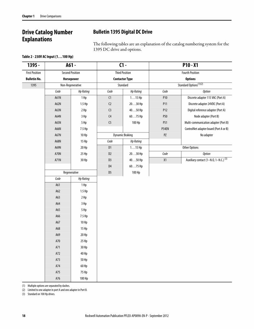
Drive Catalog Number Explanations
Bulletin 1395 Digital DC Drive
The following tables are an explanation of the catalog numbering system for the 1395 DC drive and options.
Table 2 - 230V AC Input (1…100 Hp)
1395 - A61 - C1 - P10 - X1First Position Second Position Third Position Fourth Position
Bulletin No. Horsepower Contactor Type Options
1395 Non-Regenerative Standard Standard Options(1)(2)
Code Hp Rating Code Hp Rating Code Option
A61N 1 Hp C1 1…15 Hp P10 Discrete adapter 115 VAC (Port A)
A62N 1.5 Hp C2 20…30 Hp P11 Discrete adapter 24VDC (Port A)
A63N 2 Hp C3 40…50 Hp P12 Digital reference adapter (Port A)
A64N 3 Hp C4 60…75 Hp P50 Node adapter (Port B)
A65N 5 Hp C5 100 Hp P51 Multi-communication adapter (Port B)
A66N 7.5 Hp P54EN ControlNet adapter board (Port A or B)
A67N 10 Hp Dynamic Braking PZ No adapter
A68N 15 Hp Code Hp Rating
A69N 20 Hp D1 1…15 Hp Other Options
A70N 25 Hp D2 20…30 Hp Code Option
A71N 30 Hp D3 40…50 Hp X1 Auxiliary contact (1–N.O, 1–N.C.) (3)
D4 60…75 Hp
Regenerative D5 100 Hp
Code Hp Rating
A61 1 Hp
A62 1.5 Hp
A63 2 Hp
A64 3 Hp
A65 5 Hp
A66 7.5 Hp
A67 10 Hp
A68 15 Hp
A69 20 Hp
A70 25 Hp
A71 30 Hp
A72 40 Hp
A73 50 Hp
A74 60 Hp
A75 75 Hp
A76 100 Hp
(1) Multiple options are separated by dashes.(2) Limited to one adapter in port A and one adapter in Port B.(3) Standard on 100 Hp drives.
18 Rockwell Automation Publication PFLEX-AP009A-EN-P - September 2012
Drive Comparisons Chapter 1
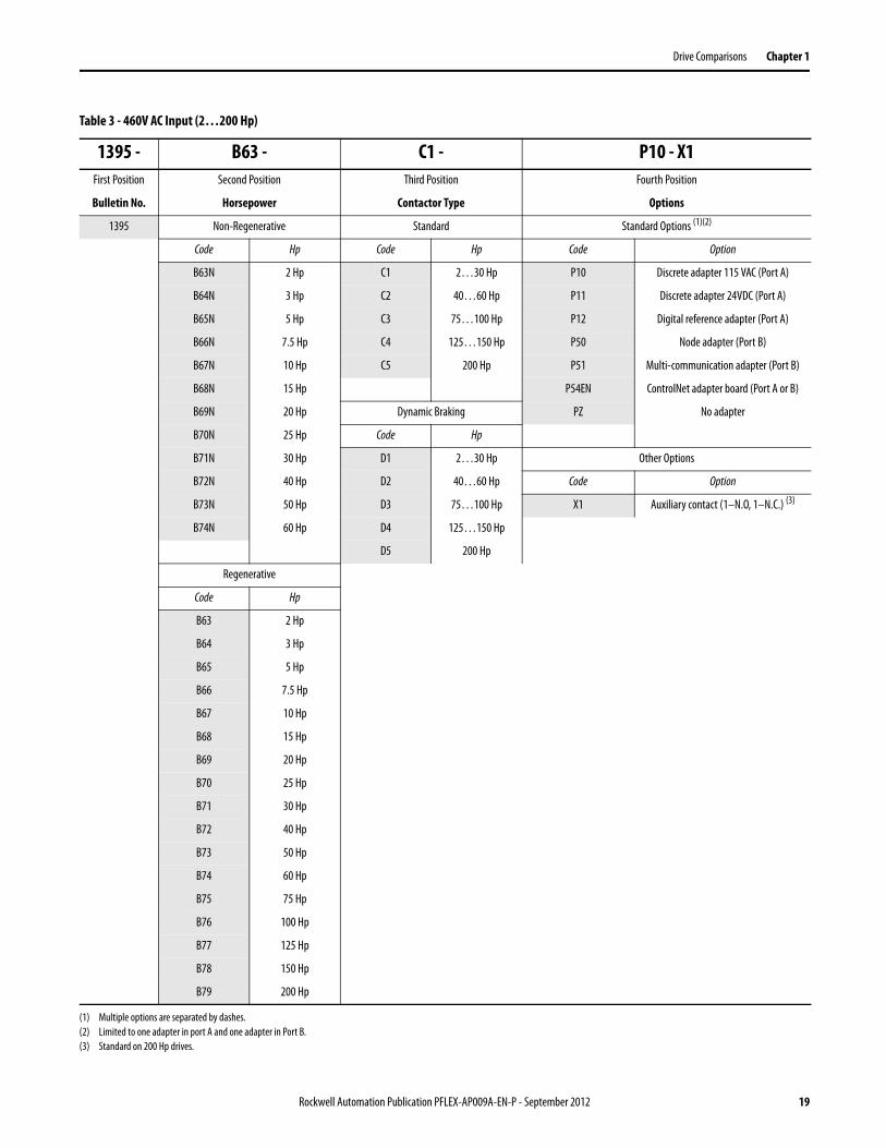
Table 3 - 460V AC Input (2…200 Hp)
1395 - B63 - C1 - P10 - X1First Position Second Position Third Position Fourth Position
Bulletin No. Horsepower Contactor Type Options
1395 Non-Regenerative Standard Standard Options (1)(2)
Code Hp Code Hp Code Option
B63N 2 Hp C1 2…30 Hp P10 Discrete adapter 115 VAC (Port A)
B64N 3 Hp C2 40…60 Hp P11 Discrete adapter 24VDC (Port A)
B65N 5 Hp C3 75…100 Hp P12 Digital reference adapter (Port A)
B66N 7.5 Hp C4 125…150 Hp P50 Node adapter (Port B)
B67N 10 Hp C5 200 Hp P51 Multi-communication adapter (Port B)
B68N 15 Hp P54EN ControlNet adapter board (Port A or B)
B69N 20 Hp Dynamic Braking PZ No adapter
B70N 25 Hp Code Hp
B71N 30 Hp D1 2…30 Hp Other Options
B72N 40 Hp D2 40…60 Hp Code Option
B73N 50 Hp D3 75…100 Hp X1 Auxiliary contact (1–N.O, 1–N.C.) (3)
B74N 60 Hp D4 125…150 Hp
D5 200 Hp
Regenerative
Code Hp
B63 2 Hp
B64 3 Hp
B65 5 Hp
B66 7.5 Hp
B67 10 Hp
B68 15 Hp
B69 20 Hp
B70 25 Hp
B71 30 Hp
B72 40 Hp
B73 50 Hp
B74 60 Hp
B75 75 Hp
B76 100 Hp
B77 125 Hp
B78 150 Hp
B79 200 Hp
(1) Multiple options are separated by dashes.(2) Limited to one adapter in port A and one adapter in Port B.(3) Standard on 200 Hp drives.
Rockwell Automation Publication PFLEX-AP009A-EN-P - September 2012 19
Chapter 1 Drive Comparisons
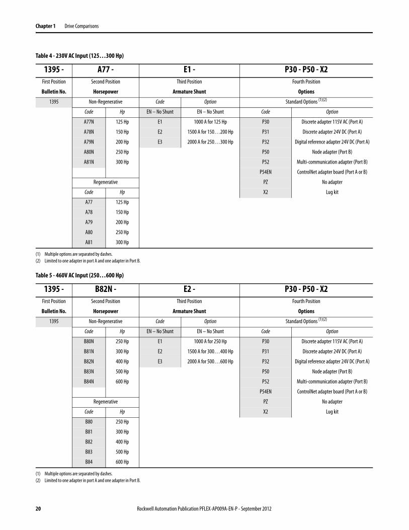
Table 4 - 230V AC Input (125…300 Hp)
1395 - A77 - E1 - P30 - P50 - X2First Position Second Position Third Position Fourth Position
Bulletin No. Horsepower Armature Shunt Options
1395 Non-Regenerative Code Option Standard Options (1)(2)
Code Hp EN – No Shunt EN – No Shunt Code Option
A77N 125 Hp E1 1000 A for 125 Hp P30 Discrete adapter 115V AC (Port A)
A78N 150 Hp E2 1500 A for 150…200 Hp P31 Discrete adapter 24V DC (Port A)
A79N 200 Hp E3 2000 A for 250…300 Hp P32 Digital reference adapter 24V DC (Port A)
A80N 250 Hp P50 Node adapter (Port B)
A81N 300 Hp P52 Multi-communication adapter (Port B)
P54EN ControlNet adapter board (Port A or B)
Regenerative PZ No adapter
Code Hp X2 Lug kit
A77 125 Hp
A78 150 Hp
A79 200 Hp
A80 250 Hp
A81 300 Hp
(1) Multiple options are separated by dashes.(2) Limited to one adapter in port A and one adapter in Port B.
Table 5 - 460V AC Input (250…600 Hp)
1395 - B82N - E2 - P30 - P50 - X2First Position Second Position Third Position Fourth Position
Bulletin No. Horsepower Armature Shunt Options
1395 Non-Regenerative Code Option Standard Options (1)(2)
Code Hp EN – No Shunt EN – No Shunt Code Option
B80N 250 Hp E1 1000 A for 250 Hp P30 Discrete adapter 115V AC (Port A)
B81N 300 Hp E2 1500 A for 300…400 Hp P31 Discrete adapter 24V DC (Port A)
B82N 400 Hp E3 2000 A for 500…600 Hp P32 Digital reference adapter 24V DC (Port A)
B83N 500 Hp P50 Node adapter (Port B)
B84N 600 Hp P52 Multi-communication adapter (Port B)
P54EN ControlNet adapter board (Port A or B)
Regenerative PZ No adapter
Code Hp X2 Lug kit
B80 250 Hp
B81 300 Hp
B82 400 Hp
B83 500 Hp
B84 600 Hp
(1) Multiple options are separated by dashes.(2) Limited to one adapter in port A and one adapter in Port B.
20 Rockwell Automation Publication PFLEX-AP009A-EN-P - September 2012
Drive Comparisons Chapter 1
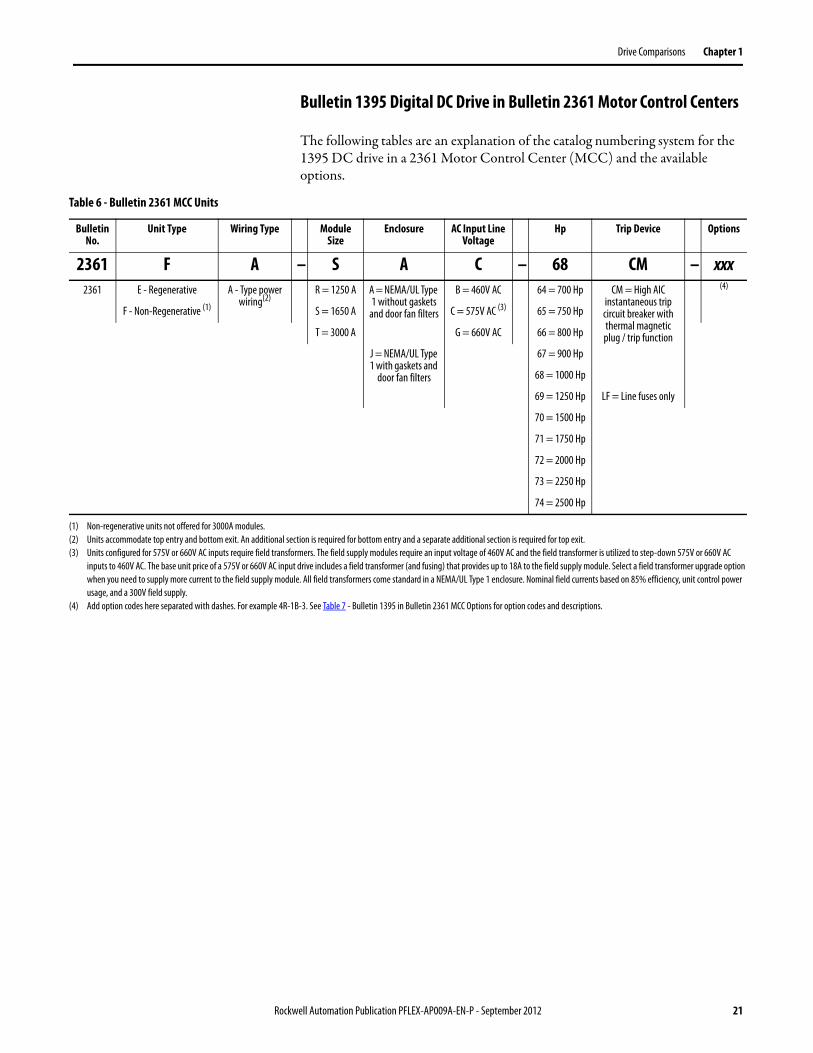
Bulletin 1395 Digital DC Drive in Bulletin 2361 Motor Control Centers
The following tables are an explanation of the catalog numbering system for the 1395 DC drive in a 2361 Motor Control Center (MCC) and the available options.
Table 6 - Bulletin 2361 MCC Units
Bulletin No.
Unit Type Wiring Type Module Size
Enclosure AC Input Line Voltage
Hp Trip Device Options
2361 F A – S A C – 68 CM – xxx2361 E - Regenerative A - Type power
wiring(2)R = 1250 A A = NEMA/UL Type
1 without gaskets and door fan filters
B = 460V AC 64 = 700 Hp CM = High AIC instantaneous trip circuit breaker with thermal magnetic plug / trip function
(4)
F - Non-Regenerative (1) S = 1650 A C = 575V AC (3) 65 = 750 Hp
T = 3000 A G = 660V AC 66 = 800 Hp
J = NEMA/UL Type 1 with gaskets and
door fan filters
67 = 900 Hp
68 = 1000 Hp
69 = 1250 Hp LF = Line fuses only
70 = 1500 Hp
71 = 1750 Hp
72 = 2000 Hp
73 = 2250 Hp
74 = 2500 Hp
(1) Non-regenerative units not offered for 3000A modules.(2) Units accommodate top entry and bottom exit. An additional section is required for bottom entry and a separate additional section is required for top exit.(3) Units configured for 575V or 660V AC inputs require field transformers. The field supply modules require an input voltage of 460V AC and the field transformer is utilized to step-down 575V or 660V AC
inputs to 460V AC. The base unit price of a 575V or 660V AC input drive includes a field transformer (and fusing) that provides up to 18A to the field supply module. Select a field transformer upgrade option when you need to supply more current to the field supply module. All field transformers come standard in a NEMA/UL Type 1 enclosure. Nominal field currents based on 85% efficiency, unit control power usage, and a 300V field supply.
(4) Add option codes here separated with dashes. For example 4R-1B-3. See Table 7 - Bulletin 1395 in Bulletin 2361 MCC Options for option codes and descriptions.
Rockwell Automation Publication PFLEX-AP009A-EN-P - September 2012 21
Chapter 1 Drive Comparisons
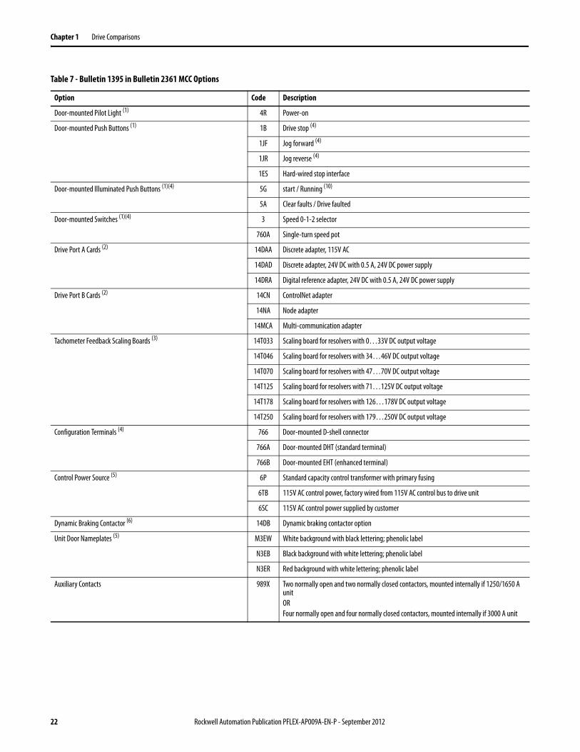
Table 7 - Bulletin 1395 in Bulletin 2361 MCC Options
Option Code Description
Door-mounted Pilot Light (1) 4R Power-on
Door-mounted Push Buttons (1) 1B Drive stop (4)
1JF Jog forward (4)
1JR Jog reverse (4)
1ES Hard-wired stop interface
Door-mounted Illuminated Push Buttons (1)(4) 5G start / Running (10)
5A Clear faults / Drive faulted
Door-mounted Switches (1)(4) 3 Speed 0-1-2 selector
760A Single-turn speed pot
Drive Port A Cards (2) 14DAA Discrete adapter, 115V AC
14DAD Discrete adapter, 24V DC with 0.5 A, 24V DC power supply
14DRA Digital reference adapter, 24V DC with 0.5 A, 24V DC power supply
Drive Port B Cards (2) 14CN ControlNet adapter
14NA Node adapter
14MCA Multi-communication adapter
Tachometer Feedback Scaling Boards (3) 14T033 Scaling board for resolvers with 0…33V DC output voltage
14T046 Scaling board for resolvers with 34…46V DC output voltage
14T070 Scaling board for resolvers with 47…70V DC output voltage
14T125 Scaling board for resolvers with 71…125V DC output voltage
14T178 Scaling board for resolvers with 126…178V DC output voltage
14T250 Scaling board for resolvers with 179…250V DC output voltage
Configuration Terminals (4) 766 Door-mounted D-shell connector
766A Door-mounted DHT (standard terminal)
766B Door-mounted EHT (enhanced terminal)
Control Power Source (5) 6P Standard capacity control transformer with primary fusing
6TB 115V AC control power, factory wired from 115V AC control bus to drive unit
6SC 115V AC control power supplied by customer
Dynamic Braking Contactor (6) 14DB Dynamic braking contactor option
Unit Door Nameplates (5) M3EW White background with black lettering; phenolic label
N3EB Black background with white lettering; phenolic label
N3ER Red background with white lettering; phenolic label
Auxiliary Contacts 989X Two normally open and two normally closed contactors, mounted internally if 1250/1650 A unitORFour normally open and four normally closed contactors, mounted internally if 3000 A unit
22 Rockwell Automation Publication PFLEX-AP009A-EN-P - September 2012
Drive Comparisons Chapter 1
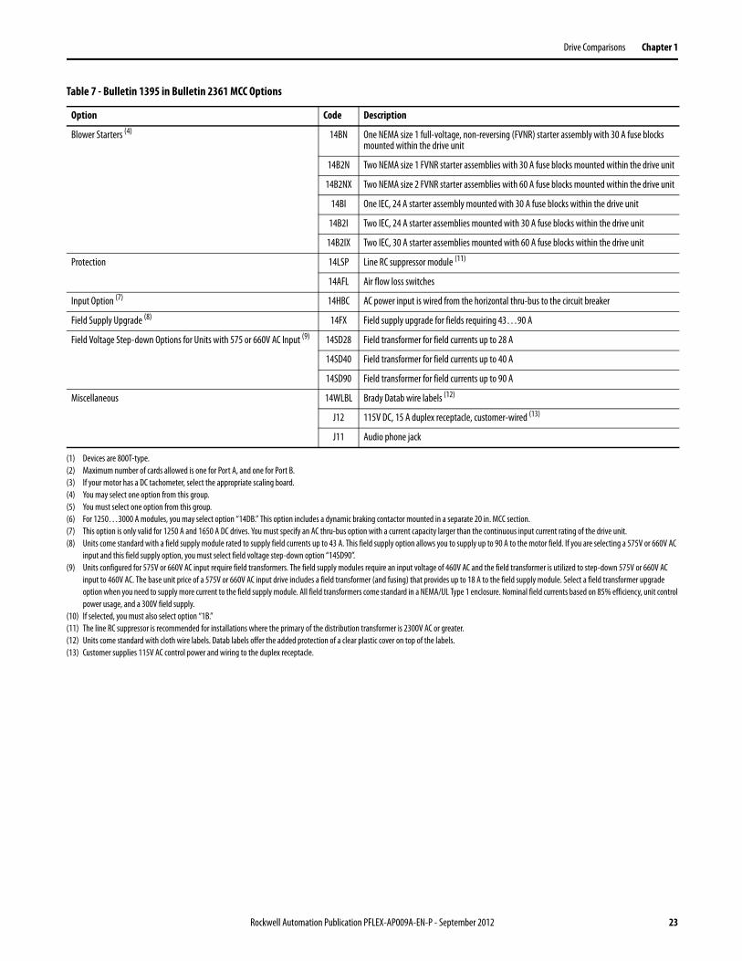
Blower Starters (4) 14BN One NEMA size 1 full-voltage, non-reversing (FVNR) starter assembly with 30 A fuse blocks mounted within the drive unit
14B2N Two NEMA size 1 FVNR starter assemblies with 30 A fuse blocks mounted within the drive unit
14B2NX Two NEMA size 2 FVNR starter assemblies with 60 A fuse blocks mounted within the drive unit
14BI One IEC, 24 A starter assembly mounted with 30 A fuse blocks within the drive unit
14B2I Two IEC, 24 A starter assemblies mounted with 30 A fuse blocks within the drive unit
14B2IX Two IEC, 30 A starter assemblies mounted with 60 A fuse blocks within the drive unit
Protection 14LSP Line RC suppressor module (11)
14AFL Air flow loss switches
Input Option (7) 14HBC AC power input is wired from the horizontal thru-bus to the circuit breaker
Field Supply Upgrade (8) 14FX Field supply upgrade for fields requiring 43…90 A
Field Voltage Step-down Options for Units with 575 or 660V AC Input (9) 14SD28 Field transformer for field currents up to 28 A
14SD40 Field transformer for field currents up to 40 A
14SD90 Field transformer for field currents up to 90 A
Miscellaneous 14WLBL Brady Datab wire labels (12)
J12 115V DC, 15 A duplex receptacle, customer-wired (13)
J11 Audio phone jack
(1) Devices are 800T-type.(2) Maximum number of cards allowed is one for Port A, and one for Port B.(3) If your motor has a DC tachometer, select the appropriate scaling board.(4) You may select one option from this group.(5) You must select one option from this group.(6) For 1250…3000 A modules, you may select option “14DB.” This option includes a dynamic braking contactor mounted in a separate 20 in. MCC section.(7) This option is only valid for 1250 A and 1650 A DC drives. You must specify an AC thru-bus option with a current capacity larger than the continuous input current rating of the drive unit.(8) Units come standard with a field supply module rated to supply field currents up to 43 A. This field supply option allows you to supply up to 90 A to the motor field. If you are selecting a 575V or 660V AC
input and this field supply option, you must select field voltage step-down option “14SD90”.(9) Units configured for 575V or 660V AC input require field transformers. The field supply modules require an input voltage of 460V AC and the field transformer is utilized to step-down 575V or 660V AC
input to 460V AC. The base unit price of a 575V or 660V AC input drive includes a field transformer (and fusing) that provides up to 18 A to the field supply module. Select a field transformer upgrade option when you need to supply more current to the field supply module. All field transformers come standard in a NEMA/UL Type 1 enclosure. Nominal field currents based on 85% efficiency, unit control power usage, and a 300V field supply.
(10) If selected, you must also select option “1B.”(11) The line RC suppressor is recommended for installations where the primary of the distribution transformer is 2300V AC or greater.(12) Units come standard with cloth wire labels. Datab labels offer the added protection of a clear plastic cover on top of the labels.(13) Customer supplies 115V AC control power and wiring to the duplex receptacle.
Table 7 - Bulletin 1395 in Bulletin 2361 MCC Options
Option Code Description
Rockwell Automation Publication PFLEX-AP009A-EN-P - September 2012 23
Chapter 1 Drive Comparisons
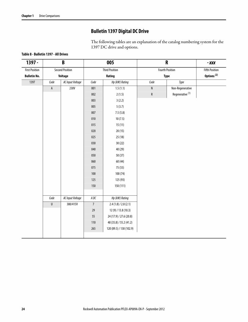
Bulletin 1397 Digital DC Drive
The following tables are an explanation of the catalog numbering system for the 1397 DC drive and options.
Table 8 - Bulletin 1397 - All Drives
1397 - B 005 R - xxxFirst Position Second Position Third Position Fourth Position Fifth Position
Bulletin No. Voltage Rating Type Options (2)
1397 Code AC Input Voltage Code Hp (kW) Rating Code Type
A 230V 001 1.5 (1.1) N Non-Regenerative
002 2 (1.5) R Regenerative (1)
003 3 (2.2)
005 5 (3.7)
007 7.5 (5.8)
010 10 (7.5)
015 15 (11)
020 20 (15)
025 25 (18)
030 30 (22)
040 40 (29)
050 50 (37)
060 60 (44)
075 75 (55)
100 100 (74)
125 125 (93)
150 150 (111)
Code AC Input Voltage A DC Hp (kW) Rating
U 380/415V 7 2.4 (1.8) / 2.8 (2.1)
29 12 (9) / 13.8 (10.3)
55 24 (17.9) / 27.6 (20.8)
110 48 (35.8) / 55.2 (41.2)
265 120 (89.5) / 138 (102.9)
24 Rockwell Automation Publication PFLEX-AP009A-EN-P - September 2012
Drive Comparisons Chapter 1
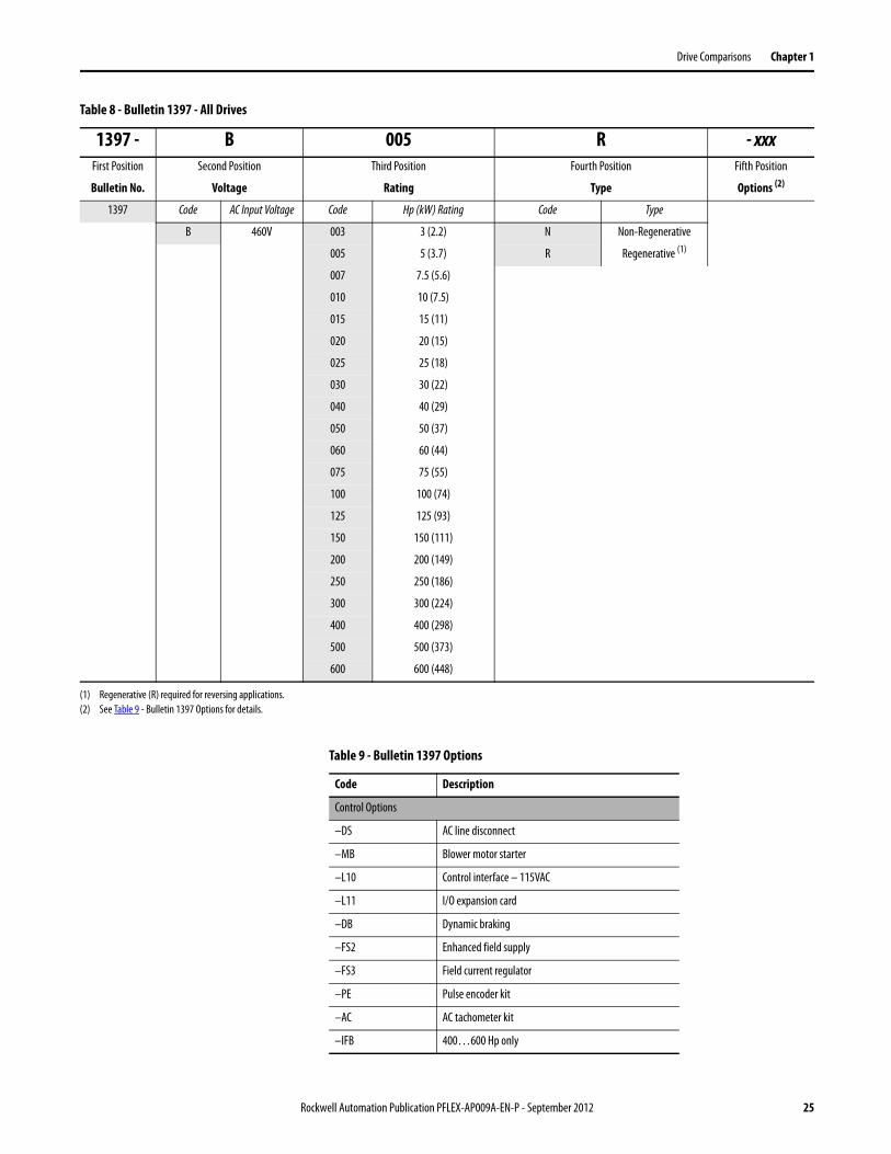
1397 Code AC Input Voltage Code Hp (kW) Rating Code Type
B 460V 003 3 (2.2) N Non-Regenerative
005 5 (3.7) R Regenerative (1)
007 7.5 (5.6)
010 10 (7.5)
015 15 (11)
020 20 (15)
025 25 (18)
030 30 (22)
040 40 (29)
050 50 (37)
060 60 (44)
075 75 (55)
100 100 (74)
125 125 (93)
150 150 (111)
200 200 (149)
250 250 (186)
300 300 (224)
400 400 (298)
500 500 (373)
600 600 (448)
(1) Regenerative (R) required for reversing applications.(2) See Table 9 - Bulletin 1397 Options for details.
Table 8 - Bulletin 1397 - All Drives
1397 - B 005 R - xxxFirst Position Second Position Third Position Fourth Position Fifth Position
Bulletin No. Voltage Rating Type Options (2)
Table 9 - Bulletin 1397 Options
Code Description
Control Options
–DS AC line disconnect
–MB Blower motor starter
–L10 Control interface – 115VAC
–L11 I/O expansion card
–DB Dynamic braking
–FS2 Enhanced field supply
–FS3 Field current regulator
–PE Pulse encoder kit
–AC AC tachometer kit
–IFB 400…600 Hp only
Rockwell Automation Publication PFLEX-AP009A-EN-P - September 2012 25
Chapter 1 Drive Comparisons
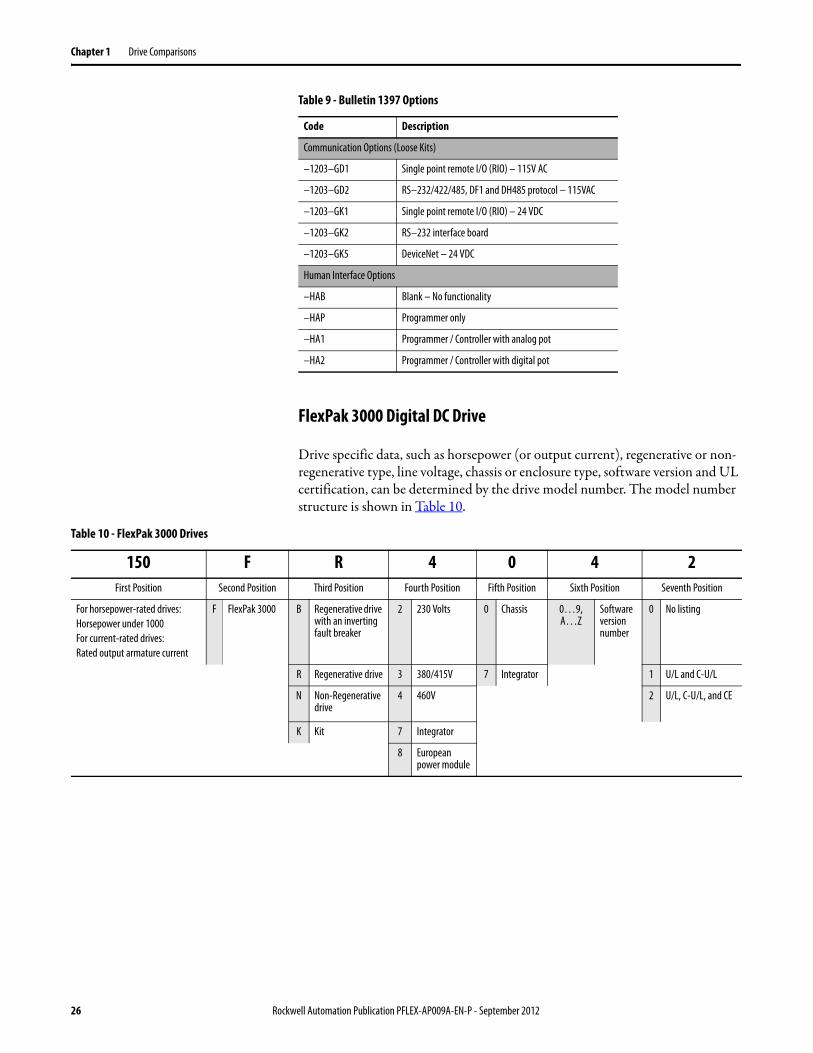
FlexPak 3000 Digital DC Drive
Drive specific data, such as horsepower (or output current), regenerative or non-regenerative type, line voltage, chassis or enclosure type, software version and UL certification, can be determined by the drive model number. The model number structure is shown in Table 10.
Communication Options (Loose Kits)
–1203–GD1 Single point remote I/O (RIO) – 115V AC
–1203–GD2 RS–232/422/485, DF1 and DH485 protocol – 115VAC
–1203–GK1 Single point remote I/O (RIO) – 24 VDC
–1203–GK2 RS–232 interface board
–1203–GK5 DeviceNet – 24 VDC
Human Interface Options
–HAB Blank – No functionality
–HAP Programmer only
–HA1 Programmer / Controller with analog pot
–HA2 Programmer / Controller with digital pot
Table 9 - Bulletin 1397 Options
Code Description
Table 10 - FlexPak 3000 Drives
150 F R 4 0 4 2First Position Second Position Third Position Fourth Position Fifth Position Sixth Position Seventh Position
For horsepower-rated drives:Horsepower under 1000For current-rated drives:Rated output armature current
F FlexPak 3000 B Regenerative drive with an inverting fault breaker
2 230 Volts 0 Chassis 0…9, A…Z
Software version number
0 No listing
R Regenerative drive 3 380/415V 7 Integrator 1 U/L and C-U/L
N Non-Regenerative drive
4 460V 2 U/L, C-U/L, and CE
K Kit 7 Integrator
8 European power module
26 Rockwell Automation Publication PFLEX-AP009A-EN-P - September 2012
Drive Comparisons Chapter 1
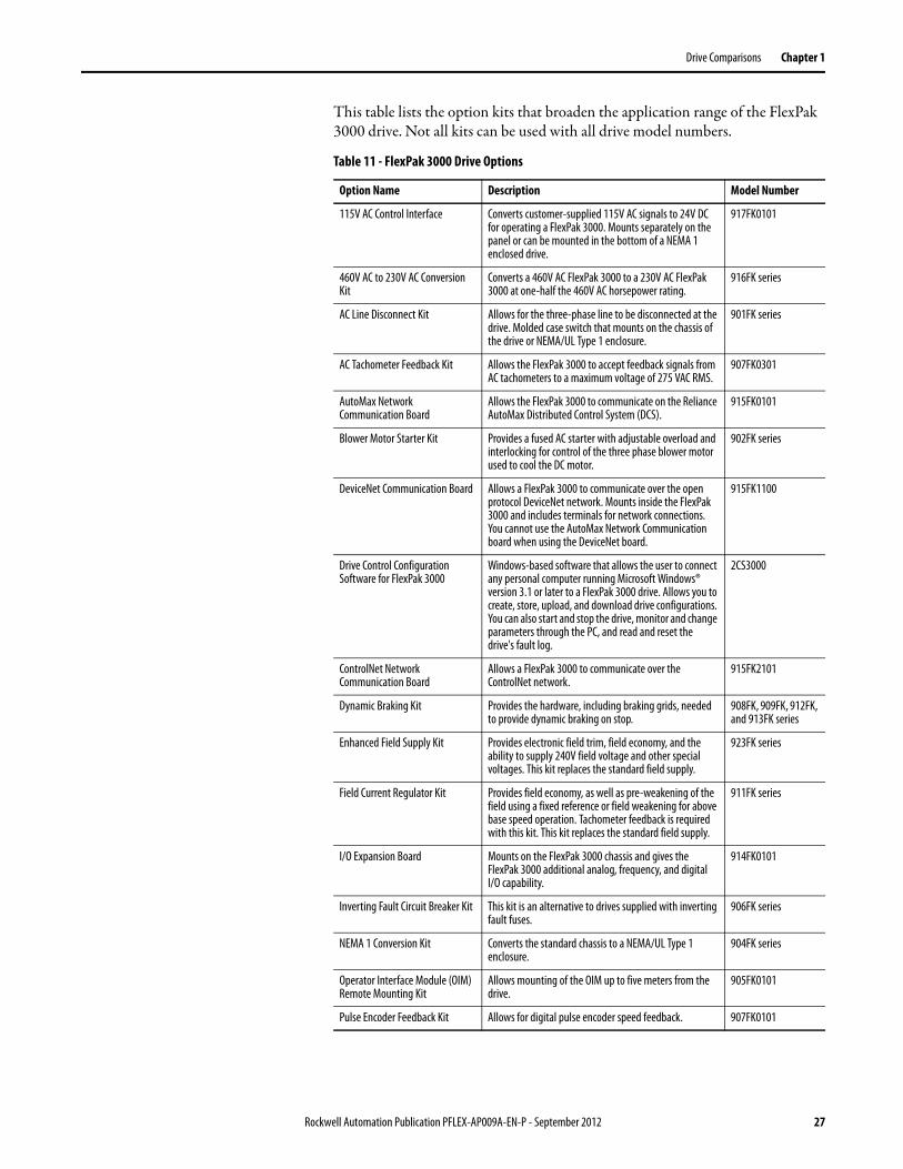
This table lists the option kits that broaden the application range of the FlexPak 3000 drive. Not all kits can be used with all drive model numbers.
Table 11 - FlexPak 3000 Drive Options
Option Name Description Model Number
115V AC Control Interface Converts customer-supplied 115V AC signals to 24V DC for operating a FlexPak 3000. Mounts separately on the panel or can be mounted in the bottom of a NEMA 1 enclosed drive.
917FK0101
460V AC to 230V AC Conversion Kit
Converts a 460V AC FlexPak 3000 to a 230V AC FlexPak 3000 at one-half the 460V AC horsepower rating.
916FK series
AC Line Disconnect Kit Allows for the three-phase line to be disconnected at the drive. Molded case switch that mounts on the chassis of the drive or NEMA/UL Type 1 enclosure.
901FK series
AC Tachometer Feedback Kit Allows the FlexPak 3000 to accept feedback signals from AC tachometers to a maximum voltage of 275 VAC RMS.
907FK0301
AutoMax Network Communication Board
Allows the FlexPak 3000 to communicate on the Reliance AutoMax Distributed Control System (DCS).
915FK0101
Blower Motor Starter Kit Provides a fused AC starter with adjustable overload and interlocking for control of the three phase blower motor used to cool the DC motor.
902FK series
DeviceNet Communication Board Allows a FlexPak 3000 to communicate over the open protocol DeviceNet network. Mounts inside the FlexPak 3000 and includes terminals for network connections. You cannot use the AutoMax Network Communication board when using the DeviceNet board.
915FK1100
Drive Control Configuration Software for FlexPak 3000
Windows-based software that allows the user to connect any personal computer running Microsoft Windows® version 3.1 or later to a FlexPak 3000 drive. Allows you to create, store, upload, and download drive configurations. You can also start and stop the drive, monitor and change parameters through the PC, and read and reset the drive's fault log.
2CS3000
ControlNet Network Communication Board
Allows a FlexPak 3000 to communicate over the ControlNet network.
915FK2101
Dynamic Braking Kit Provides the hardware, including braking grids, needed to provide dynamic braking on stop.
908FK, 909FK, 912FK, and 913FK series
Enhanced Field Supply Kit Provides electronic field trim, field economy, and the ability to supply 240V field voltage and other special voltages. This kit replaces the standard field supply.
923FK series
Field Current Regulator Kit Provides field economy, as well as pre-weakening of the field using a fixed reference or field weakening for above base speed operation. Tachometer feedback is required with this kit. This kit replaces the standard field supply.
911FK series
I/O Expansion Board Mounts on the FlexPak 3000 chassis and gives the FlexPak 3000 additional analog, frequency, and digitalI/O capability.
914FK0101
Inverting Fault Circuit Breaker Kit This kit is an alternative to drives supplied with inverting fault fuses.
906FK series
NEMA 1 Conversion Kit Converts the standard chassis to a NEMA/UL Type 1 enclosure.
904FK series
Operator Interface Module (OIM) Remote Mounting Kit
Allows mounting of the OIM up to five meters from the drive.
905FK0101
Pulse Encoder Feedback Kit Allows for digital pulse encoder speed feedback. 907FK0101
Rockwell Automation Publication PFLEX-AP009A-EN-P - September 2012 27
Chapter 1 Drive Comparisons
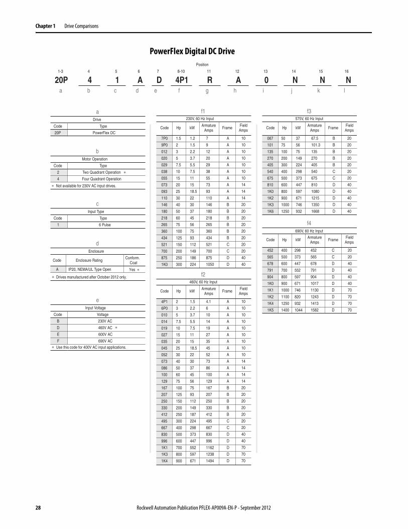
PowerFlex Digital DC Drive Position
1-3 4 5 6 7 8-10 11 12 13 14 15 16
20P 4 1 A D 4P1 R A 0 N N Na b c d e f g h i j k l
aDrive
Code Type
20P PowerFlex DC
bMotor Operation
Code Type
2 Two Quadrant Operation
4 Four Quadrant Operation
cInput Type
Code Type
1 6 Pulse
dEnclosure
Code Enclosure Rating Conform.Coat
A IP20, NEMA/UL Type Open
eInput Voltage
Code Voltage
B 230V AC
D 460V AC
E 600V AC
F 690V AC
f1
f2Yes
Not available for 230V AC input drives.
Use this code for 400V AC input applications.
f3
f4
2
3
5
7.5
10
15
20
25
30
40
50
60
75
100
125
150
200
250
300
400
500
600
700
800
900
1.5
2.2
3.7
5.5
7.5
11
15
18.5
22
30
37
45
56
75
93
112
149
187
224
298
373
447
552
597
671
4.1
6
10
14
19
27
35
45
52
73
86
100
129
167
207
250
330
412
495
667
830
996
1162
1238
1494
A
A
A
A
A
A
A
A
A
A
A
A
A
B
B
B
B
B
C
C
D
D
D
D
D
10
10
10
10
10
10
10
10
10
14
14
14
14
20
20
20
20
20
20
20
40
40
70
70
70
Hp ArmatureAmps Frame Field
AmpsCode kW
460V, 60 Hz Input
4P1
6P0
010
014
019
027
035
045
052
073
086
100
129
167
207
250
330
412
495
667
830
996
1K1
1K3
1K4
1.5
2
3
5
7.5
10
15
20
25
30
40
50
60
75
100
125
150
200
250
300
1.2
1.5
2.2
3.7
5.5
7.5
11
15
18.5
22
30
37
45
56
75
93
112
149
186
224
7
9
12
20
29
38
55
73
93
110
146
180
218
265
360
434
521
700
875
1050
A
A
A
A
A
A
A
A
A
A
B
B
B
B
B
B
C
C
D
D
10
10
10
10
10
10
10
14
14
14
20
20
20
20
20
20
20
20
40
40
Hp ArmatureAmps Frame Field
AmpsCode kW
230V, 60 Hz Input
7P0
9P0
012
020
029
038
055
073
093
110
146
180
218
265
360
434
521
700
875
1K0
50
75
100
200
300
400
500
600
800
900
1000
1250
37
56
75
149
224
298
373
447
597
671
746
932
67.5
101.3
135
270
405
540
675
810
1080
1215
1350
1668
B
B
B
B
B
C
C
D
D
D
D
D
20
20
20
20
20
20
20
40
40
40
40
40
Hp ArmatureAmps Frame Field
AmpsCode kW
575V, 60 Hz Input
067
101
135
270
405
540
675
810
1K0
1K2
1K3
1K6
298
373
447
552
597
671
746
820
932
1044
Hp ArmatureAmps Frame Field
AmpsCode kW
690V, 60 Hz Input
452
565
678
791
904
1K0
1K1
1K2
1K4
1K5
400
500
600
700
800
900
1000
1100
1250
1400
452
565
678
791
904
1017
1130
1243
1413
1582
C
C
D
D
D
D
D
D
D
D
20
20
40
40
40
40
70
70
70
70
Drives manufactured after October 2012 only.
28 Rockwell Automation Publication PFLEX-AP009A-EN-P - September 2012

Drive Comparisons Chapter 1
PowerFlex Digital DC Drive, Continued
Position
1-3 4 5 6 7 8-10 11 12 13 14 15 16
20P 4 1 A D 4P1 R A 0 N N Na b c d e f g h i j k l
gField Supply
Code Type
R Single-Phase Regulated
hPackaging/Documentation
A Yes Yes
iHIM
Code Operator Interface
0 Blank Cover
Standard - for additional selections, refer to thePowerFlex Digital DC Drive Technical Data,publication 20P-TD001. . .
jI/O Options
Code Control
NNone (8 - 24V DC Digital Inputs,
4 Digital Outputs, 3 Analog Outputs,and 2 Analog Inputs are Standard)
kCommunication Options
Code Description
N None
lCabinet Options
Code Type
N None
Standard - for additional selections, refer to thePowerFlex Digital DC Drive Technical Data,publication 20P-TD001. . .
All I/O Options are purchased separately and areuser installed.
Code Shipping Carton User Manual
Rockwell Automation Publication PFLEX-AP009A-EN-P - September 2012 29
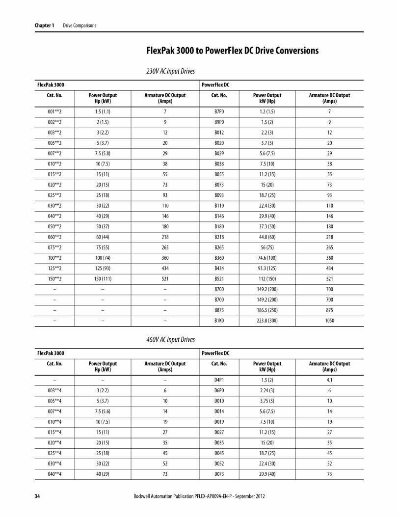
Chapter 1 Drive Comparisons
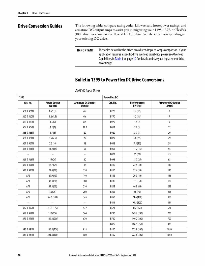
Drive Conversion Guides The following tables compare rating codes, kilowatt and horsepower ratings, and armature DC output amps to assist you in migrating your 1395, 1397, or FlexPak 3000 drive to a comparable PowerFlex DC drive. See the table corresponding to your existing DC drive.
Bulletin 1395 to PowerFlex DC Drive Conversions
230V AC Input Drives
IMPORTANT The tables below list the drives on a direct Amps-to-Amps comparison. If your application requires a specific drive overload capability, please see Overload Capabilities in Table 1 on page 10 for details and size your replacement drive accordingly.
1395 PowerFlex DC
Cat. No. Power OutputkW (Hp)
Armature DC Output(Amps)
Cat. No. Power OutputkW (Hp)
Armature DC Output(Amps)
A61 & A61N 0.75 (1) 4.7 B7P0 1.2 (1.5) 7
A62 & A62N 1.2 (1.5) 6.6 B7P0 1.2 (1.5) 7
A63 & A63N 1.5 (2) 8.5 B9P0 1.5 (2) 9
A64 & A64N 2.2 (3) 12.2 B012 2.2 (3) 12
A65 & A65N 3.7 (5) 20 B020 3.7 (5) 20
A66 & A66N 5.6 (7.5) 29 B029 5.6 (7.5) 29
A67 & A67N 7.5 (10) 38 B038 7.5 (10) 38
A68 & A68N 11.2 (15) 55 B055 11.2 (15) 55
– – – B073 15 (20) 73
A69 & A69N 15 (20) 80 B093 18.7 (25) 93
A70 & A70N 18.7 (25) 98 B110 22.4 (30) 110
A71 & A71N 22.4 (30) 110 B110 22.4 (30) 110
A72 29.9 (40) 140 B146 29.9 (40) 146
A73 37.3 (50) 180 B180 37.3 (50) 180
A74 44.8 (60) 210 B218 44.8 (60) 218
A75 56 (75) 260 B265 56 (75) 265
A76 74.6 (100) 345 B360 74.6 (100) 360
– – – B434 93.3 (125) 434
A77 & A77N 93.3 (125) 472 B521 112 (150) 521
A78 & A78N 112 (150) 564 B700 149.2 (200) 700
A79 & A79N 149.2 (200) 670 B700 149.2 (200) 700
– – – B875 186.5 (250) 875
A80 & A81N 186.5 (250) 918 B1K0 223.8 (300) 1050
A81 & A81N 223.8 (300) 980 B1K0 223.8 (300) 1050
30 Rockwell Automation Publication PFLEX-AP009A-EN-P - September 2012
Drive Comparisons Chapter 1
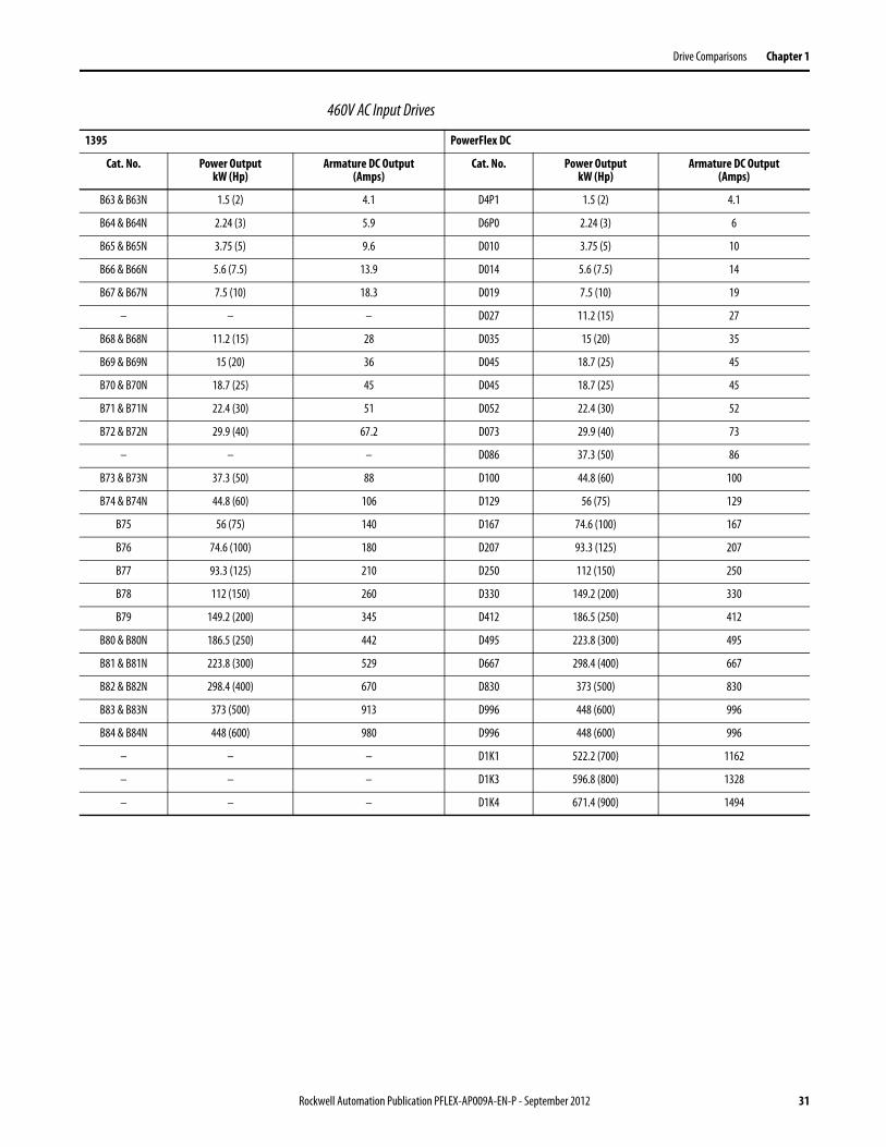
460V AC Input Drives
1395 PowerFlex DC
Cat. No. Power OutputkW (Hp)
Armature DC Output(Amps)
Cat. No. Power OutputkW (Hp)
Armature DC Output(Amps)
B63 & B63N 1.5 (2) 4.1 D4P1 1.5 (2) 4.1
B64 & B64N 2.24 (3) 5.9 D6P0 2.24 (3) 6
B65 & B65N 3.75 (5) 9.6 D010 3.75 (5) 10
B66 & B66N 5.6 (7.5) 13.9 D014 5.6 (7.5) 14
B67 & B67N 7.5 (10) 18.3 D019 7.5 (10) 19
– – – D027 11.2 (15) 27
B68 & B68N 11.2 (15) 28 D035 15 (20) 35
B69 & B69N 15 (20) 36 D045 18.7 (25) 45
B70 & B70N 18.7 (25) 45 D045 18.7 (25) 45
B71 & B71N 22.4 (30) 51 D052 22.4 (30) 52
B72 & B72N 29.9 (40) 67.2 D073 29.9 (40) 73
– – – D086 37.3 (50) 86
B73 & B73N 37.3 (50) 88 D100 44.8 (60) 100
B74 & B74N 44.8 (60) 106 D129 56 (75) 129
B75 56 (75) 140 D167 74.6 (100) 167
B76 74.6 (100) 180 D207 93.3 (125) 207
B77 93.3 (125) 210 D250 112 (150) 250
B78 112 (150) 260 D330 149.2 (200) 330
B79 149.2 (200) 345 D412 186.5 (250) 412
B80 & B80N 186.5 (250) 442 D495 223.8 (300) 495
B81 & B81N 223.8 (300) 529 D667 298.4 (400) 667
B82 & B82N 298.4 (400) 670 D830 373 (500) 830
B83 & B83N 373 (500) 913 D996 448 (600) 996
B84 & B84N 448 (600) 980 D996 448 (600) 996
– – – D1K1 522.2 (700) 1162
– – – D1K3 596.8 (800) 1328
– – – D1K4 671.4 (900) 1494
Rockwell Automation Publication PFLEX-AP009A-EN-P - September 2012 31
Chapter 1 Drive Comparisons
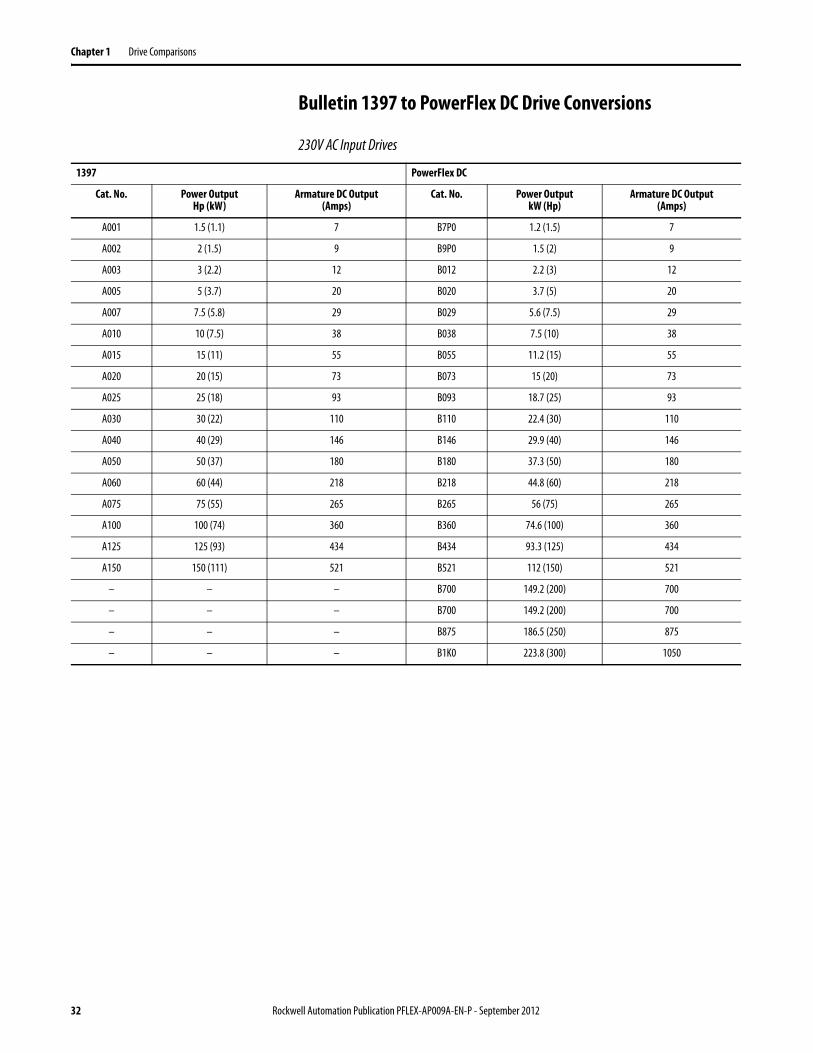
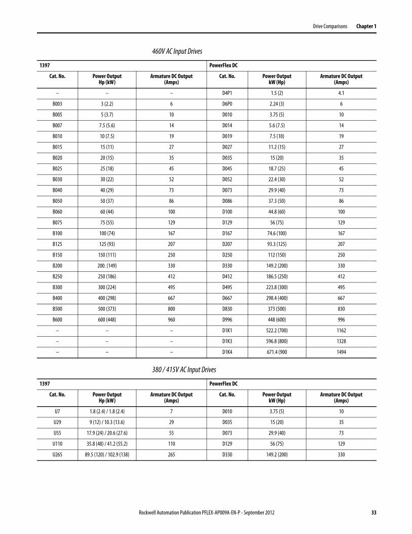
Bulletin 1397 to PowerFlex DC Drive Conversions
230V AC Input Drives
1397 PowerFlex DC
Cat. No. Power OutputHp (kW)
Armature DC Output(Amps)
Cat. No. Power OutputkW (Hp)
Armature DC Output(Amps)
A001 1.5 (1.1) 7 B7P0 1.2 (1.5) 7
A002 2 (1.5) 9 B9P0 1.5 (2) 9
A003 3 (2.2) 12 B012 2.2 (3) 12
A005 5 (3.7) 20 B020 3.7 (5) 20
A007 7.5 (5.8) 29 B029 5.6 (7.5) 29
A010 10 (7.5) 38 B038 7.5 (10) 38
A015 15 (11) 55 B055 11.2 (15) 55
A020 20 (15) 73 B073 15 (20) 73
A025 25 (18) 93 B093 18.7 (25) 93
A030 30 (22) 110 B110 22.4 (30) 110
A040 40 (29) 146 B146 29.9 (40) 146
A050 50 (37) 180 B180 37.3 (50) 180
A060 60 (44) 218 B218 44.8 (60) 218
A075 75 (55) 265 B265 56 (75) 265
A100 100 (74) 360 B360 74.6 (100) 360
A125 125 (93) 434 B434 93.3 (125) 434
A150 150 (111) 521 B521 112 (150) 521
– – – B700 149.2 (200) 700
– – – B700 149.2 (200) 700
– – – B875 186.5 (250) 875
– – – B1K0 223.8 (300) 1050
32 Rockwell Automation Publication PFLEX-AP009A-EN-P - September 2012
Drive Comparisons Chapter 1
460V AC Input Drives
380 / 415V AC Input Drives
1397 PowerFlex DC
Cat. No. Power OutputHp (kW)
Armature DC Output(Amps)
Cat. No. Power OutputkW (Hp)
Armature DC Output(Amps)
– – – D4P1 1.5 (2) 4.1
B003 3 (2.2) 6 D6P0 2.24 (3) 6
B005 5 (3.7) 10 D010 3.75 (5) 10
B007 7.5 (5.6) 14 D014 5.6 (7.5) 14
B010 10 (7.5) 19 D019 7.5 (10) 19
B015 15 (11) 27 D027 11.2 (15) 27
B020 20 (15) 35 D035 15 (20) 35
B025 25 (18) 45 D045 18.7 (25) 45
B030 30 (22) 52 D052 22.4 (30) 52
B040 40 (29) 73 D073 29.9 (40) 73
B050 50 (37) 86 D086 37.3 (50) 86
B060 60 (44) 100 D100 44.8 (60) 100
B075 75 (55) 129 D129 56 (75) 129
B100 100 (74) 167 D167 74.6 (100) 167
B125 125 (93) 207 D207 93.3 (125) 207
B150 150 (111) 250 D250 112 (150) 250
B200 200. (149) 330 D330 149.2 (200) 330
B250 250 (186) 412 D412 186.5 (250) 412
B300 300 (224) 495 D495 223.8 (300) 495
B400 400 (298) 667 D667 298.4 (400) 667
B500 500 (373) 800 D830 373 (500) 830
B600 600 (448) 960 D996 448 (600) 996
– – – D1K1 522.2 (700) 1162
– – – D1K3 596.8 (800) 1328
– – – D1K4 671.4 (900 1494
1397 PowerFlex DC
Cat. No. Power OutputHp (kW)
Armature DC Output(Amps)
Cat. No. Power OutputkW (Hp)
Armature DC Output(Amps)
U7 1.8 (2.4) / 1.8 (2.4) 7 D010 3.75 (5) 10
U29 9 (12) / 10.3 (13.6) 29 D035 15 (20) 35
U55 17.9 (24) / 20.6 (27.6) 55 D073 29.9 (40) 73
U110 35.8 (48) / 41.2 (55.2) 110 D129 56 (75) 129
U265 89.5 (120) / 102.9 (138) 265 D330 149.2 (200) 330
Rockwell Automation Publication PFLEX-AP009A-EN-P - September 2012 33
Chapter 1 Drive Comparisons
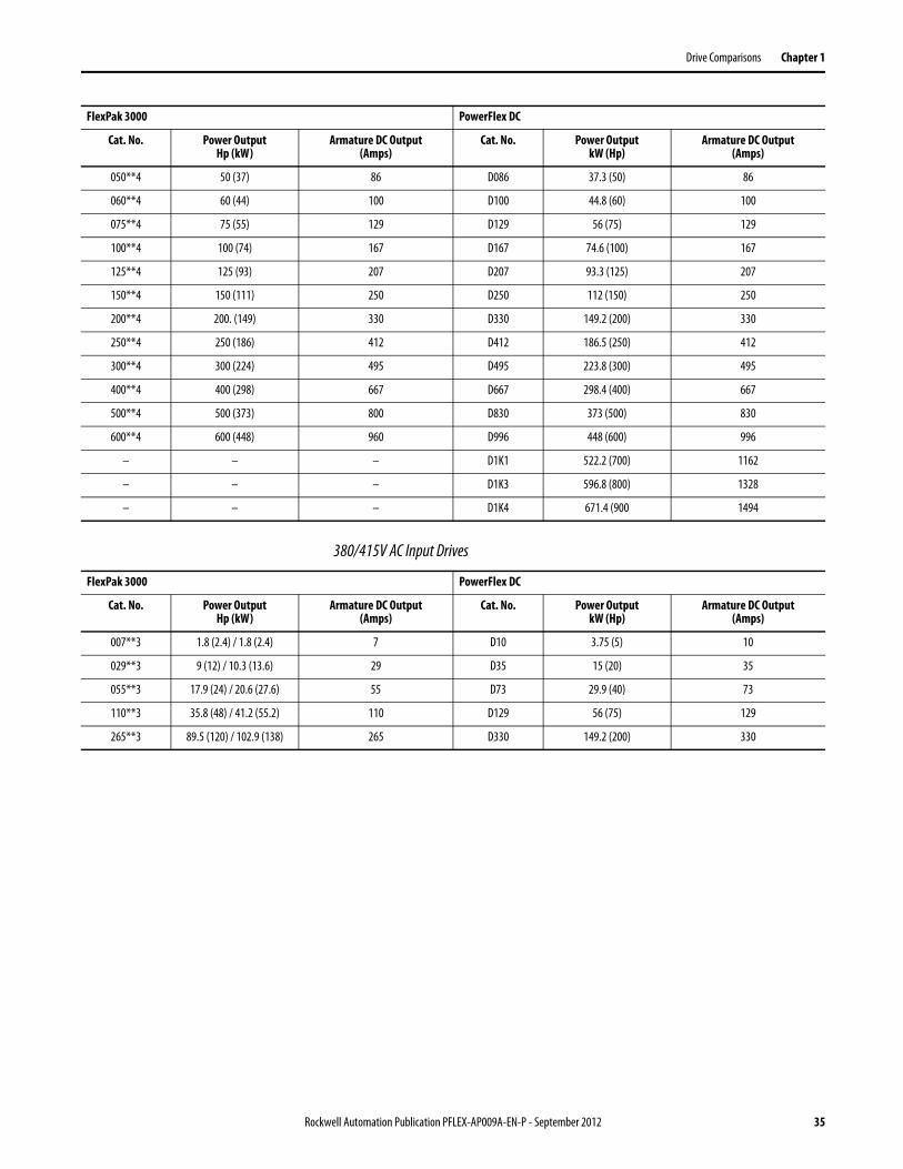
FlexPak 3000 to PowerFlex DC Drive Conversions
230V AC Input Drives
460V AC Input Drives
FlexPak 3000 PowerFlex DC
Cat. No. Power OutputHp (kW)
Armature DC Output(Amps)
Cat. No. Power OutputkW (Hp)
Armature DC Output(Amps)
001**2 1.5 (1.1) 7 B7P0 1.2 (1.5) 7
002**2 2 (1.5) 9 B9P0 1.5 (2) 9
003**2 3 (2.2) 12 B012 2.2 (3) 12
005**2 5 (3.7) 20 B020 3.7 (5) 20
007**2 7.5 (5.8) 29 B029 5.6 (7.5) 29
010**2 10 (7.5) 38 B038 7.5 (10) 38
015**2 15 (11) 55 B055 11.2 (15) 55
020**2 20 (15) 73 B073 15 (20) 73
025**2 25 (18) 93 B093 18.7 (25) 93
030**2 30 (22) 110 B110 22.4 (30) 110
040**2 40 (29) 146 B146 29.9 (40) 146
050**2 50 (37) 180 B180 37.3 (50) 180
060**2 60 (44) 218 B218 44.8 (60) 218
075**2 75 (55) 265 B265 56 (75) 265
100**2 100 (74) 360 B360 74.6 (100) 360
125**2 125 (93) 434 B434 93.3 (125) 434
150**2 150 (111) 521 B521 112 (150) 521
– – – B700 149.2 (200) 700
– – – B700 149.2 (200) 700
– – – B875 186.5 (250) 875
– – – B1K0 223.8 (300) 1050
FlexPak 3000 PowerFlex DC
Cat. No. Power OutputHp (kW)
Armature DC Output(Amps)
Cat. No. Power OutputkW (Hp)
Armature DC Output(Amps)
– – – D4P1 1.5 (2) 4.1
003**4 3 (2.2) 6 D6P0 2.24 (3) 6
005**4 5 (3.7) 10 D010 3.75 (5) 10
007**4 7.5 (5.6) 14 D014 5.6 (7.5) 14
010**4 10 (7.5) 19 D019 7.5 (10) 19
015**4 15 (11) 27 D027 11.2 (15) 27
020**4 20 (15) 35 D035 15 (20) 35
025**4 25 (18) 45 D045 18.7 (25) 45
030**4 30 (22) 52 D052 22.4 (30) 52
040**4 40 (29) 73 D073 29.9 (40) 73
34 Rockwell Automation Publication PFLEX-AP009A-EN-P - September 2012
Drive Comparisons Chapter 1
380/415V AC Input Drives
050**4 50 (37) 86 D086 37.3 (50) 86
060**4 60 (44) 100 D100 44.8 (60) 100
075**4 75 (55) 129 D129 56 (75) 129
100**4 100 (74) 167 D167 74.6 (100) 167
125**4 125 (93) 207 D207 93.3 (125) 207
150**4 150 (111) 250 D250 112 (150) 250
200**4 200. (149) 330 D330 149.2 (200) 330
250**4 250 (186) 412 D412 186.5 (250) 412
300**4 300 (224) 495 D495 223.8 (300) 495
400**4 400 (298) 667 D667 298.4 (400) 667
500**4 500 (373) 800 D830 373 (500) 830
600**4 600 (448) 960 D996 448 (600) 996
– – – D1K1 522.2 (700) 1162
– – – D1K3 596.8 (800) 1328
– – – D1K4 671.4 (900 1494
FlexPak 3000 PowerFlex DC
Cat. No. Power OutputHp (kW)
Armature DC Output(Amps)
Cat. No. Power OutputkW (Hp)
Armature DC Output(Amps)
FlexPak 3000 PowerFlex DC
Cat. No. Power OutputHp (kW)
Armature DC Output(Amps)
Cat. No. Power OutputkW (Hp)
Armature DC Output(Amps)
007**3 1.8 (2.4) / 1.8 (2.4) 7 D10 3.75 (5) 10
029**3 9 (12) / 10.3 (13.6) 29 D35 15 (20) 35
055**3 17.9 (24) / 20.6 (27.6) 55 D73 29.9 (40) 73
110**3 35.8 (48) / 41.2 (55.2) 110 D129 56 (75) 129
265**3 89.5 (120) / 102.9 (138) 265 D330 149.2 (200) 330
Rockwell Automation Publication PFLEX-AP009A-EN-P - September 2012 35
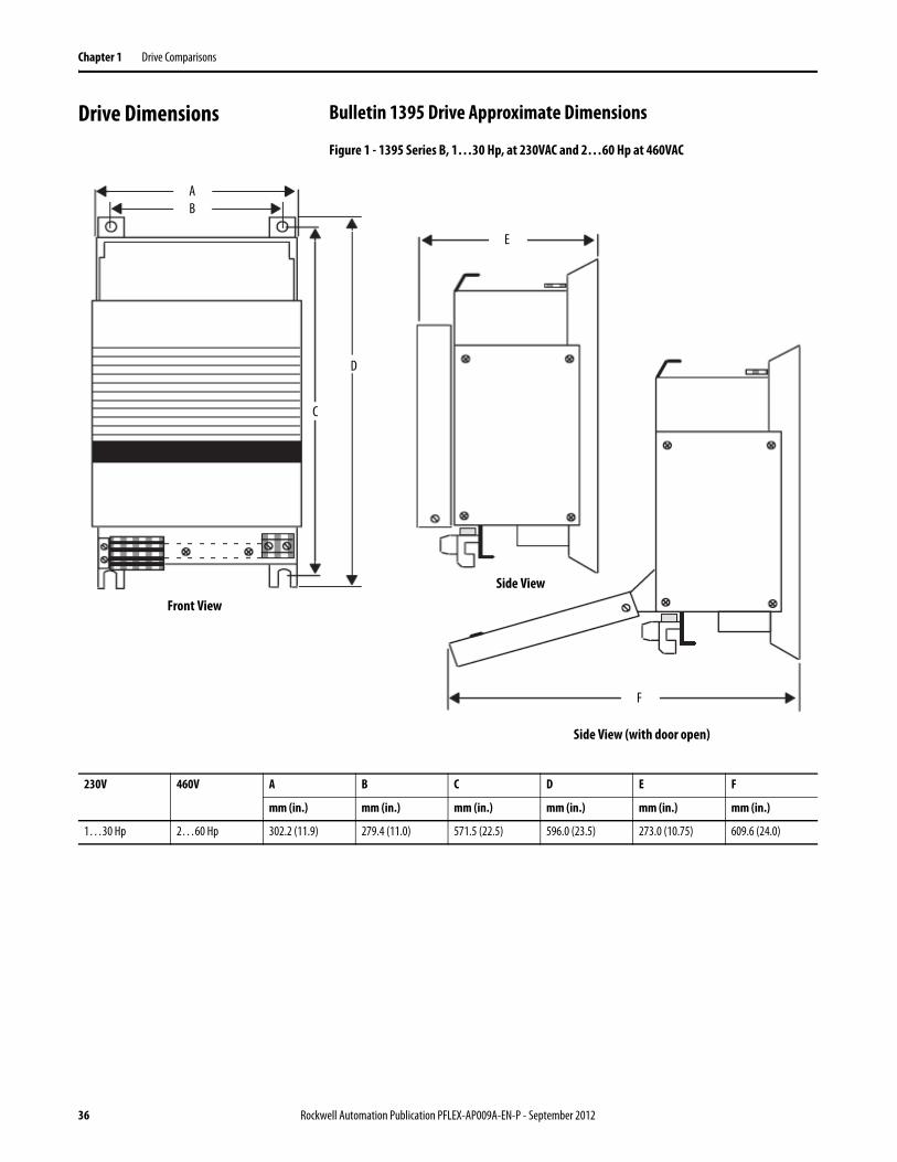
Chapter 1 Drive Comparisons
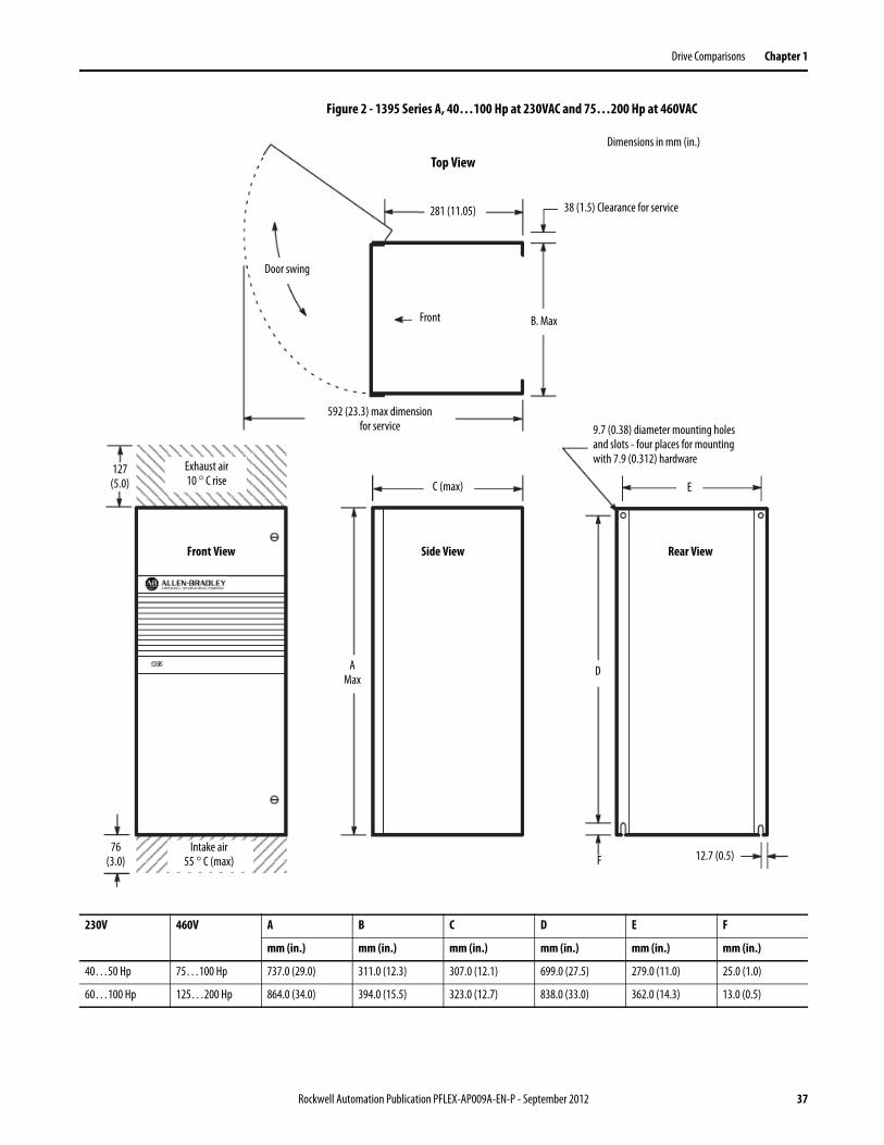
Drive Dimensions Bulletin 1395 Drive Approximate Dimensions
Figure 1 - 1395 Series B, 1…30 Hp, at 230VAC and 2…60 Hp at 460VAC
AB
D
C
Side View (with door open)
Front View
Side View
F
E
230V 460V A B C D E F
mm (in.) mm (in.) mm (in.) mm (in.) mm (in.) mm (in.)
1…30 Hp 2…60 Hp 302.2 (11.9) 279.4 (11.0) 571.5 (22.5) 596.0 (23.5) 273.0 (10.75) 609.6 (24.0)
36 Rockwell Automation Publication PFLEX-AP009A-EN-P - September 2012
Drive Comparisons Chapter 1
Figure 2 - 1395 Series A, 40…100 Hp at 230VAC and 75…200 Hp at 460VAC
127(5.0)
592 (23.3) max dimension for service
Door swing
Top View
281 (11.05) 38 (1.5) Clearance for service
Front B. Max
76(3.0)
Dimensions in mm (in.)
9.7 (0.38) diameter mounting holes and slots - four places for mounting with 7.9 (0.312) hardware
AMax
Side View Rear View
F
D
EC (max)
12.7 (0.5)
Exhaust air10 ° C rise
Intake air55 ° C (max)
Front View
230V 460V A B C D E F
mm (in.) mm (in.) mm (in.) mm (in.) mm (in.) mm (in.)
40…50 Hp 75…100 Hp 737.0 (29.0) 311.0 (12.3) 307.0 (12.1) 699.0 (27.5) 279.0 (11.0) 25.0 (1.0)
60…100 Hp 125…200 Hp 864.0 (34.0) 394.0 (15.5) 323.0 (12.7) 838.0 (33.0) 362.0 (14.3) 13.0 (0.5)
Rockwell Automation Publication PFLEX-AP009A-EN-P - September 2012 37
Chapter 1 Drive Comparisons
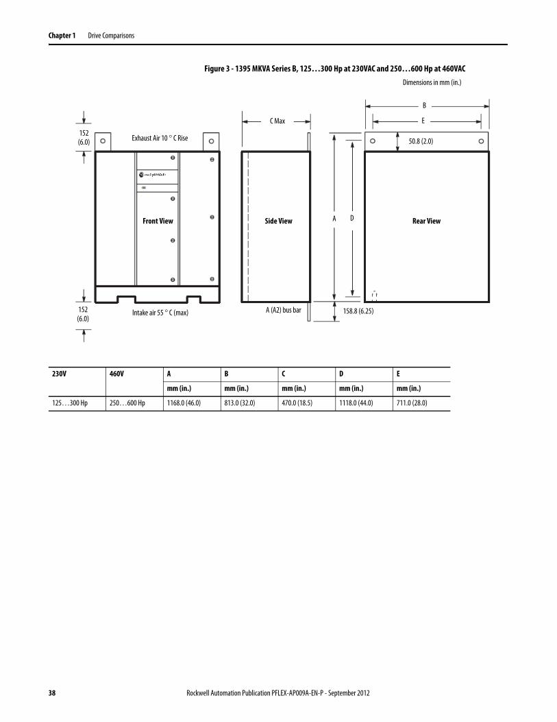
Figure 3 - 1395 MKVA Series B, 125…300 Hp at 230VAC and 250…600 Hp at 460VAC Dimensions in mm (in.)
EC Max
Exhaust Air 10 ° C Rise
B
Intake air 55 ° C (max)
152(6.0)
ASide View Rear ViewD
152(6.0)
A (A2) bus bar 158.8 (6.25)
50.8 (2.0)
Front View
230V 460V A B C D E
mm (in.) mm (in.) mm (in.) mm (in.) mm (in.)
125…300 Hp 250…600 Hp 1168.0 (46.0) 813.0 (32.0) 470.0 (18.5) 1118.0 (44.0) 711.0 (28.0)
38 Rockwell Automation Publication PFLEX-AP009A-EN-P - September 2012

Drive Comparisons Chapter 1
Bulletin 1397 Drive Approximate Dimensions
Figure 4 - 1397 - 1.5…30 Hp at 230VAC, 7…110 A at 380/415VAC, 3…60 Hp at 460VAC
Top View
Rec. hardware3xM6 or 1/4 in.
All dimensions are in mm (in.)Approximate shipping weight 30.8 kg (68 lb)
270.5(10.65)
135 angle°
Side ViewFront View
22.5(0.89)
7.0(0.28)
225.0(8.86)
300.0(11.81)
497.5(19.59)
463.0(18.23)
136.0(5.35)
477.5(18.80)
Rockwell Automation Publication PFLEX-AP009A-EN-P - September 2012 39
Chapter 1 Drive Comparisons
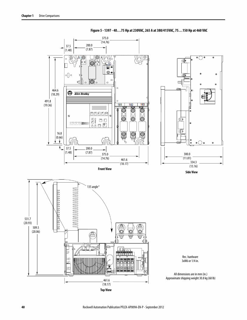
Figure 5 - 1397 - 40…75 Hp at 230VAC, 265 A at 380/415VAC, 75…150 Hp at 460 VAC
Top View
Rec. hardware3xM6 or 1/4 in.
All dimensions are in mm (in.)Approximate shipping weight 30.8 kg (68 lb)461.6
(18.17)
531.7(20.93)
135 angle°
509.5(20.06)
37.5(1.48)
Front View
461.6(18.17)
375.0(14.76)
200.0(7.87) 300.0
(11.81)334.3
(13.16)
16.8(0.66)
491.8(19.36)
464.6(18.29)
37.5(1.48)
200.0(7.87)
375.0(14.76)
Side View
40 Rockwell Automation Publication PFLEX-AP009A-EN-P - September 2012
Drive Comparisons Chapter 1
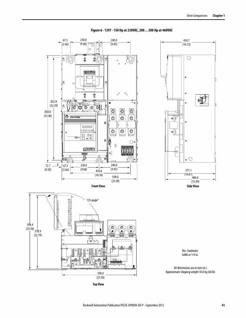
Figure 6 - 1397 - 150 Hp at 230VAC, 200…300 Hp at 460VAC
Top View
Rec. hardware3xM6 or 1/4 in.
All dimensions are in mm (in.)Approximate shipping weight 30.8 kg (68 lb)599.0
(23.58)
578.9(22.79)
135 angle°
598.4(23.56)
599.0(23.58)
Front View Side View
470.0(18.50)
240.0(9.45)
230.0(9.06)
67.5(2.66)
12.7(0.50)
850.0(33.46)
822.8(32.39)
67.5(2.66)
424.7(16.72)
230.0(9.06)
240.0(9.45)
406.0(15.99)
371.1(14.61)
Rockwell Automation Publication PFLEX-AP009A-EN-P - September 2012 41
Chapter 1 Drive Comparisons
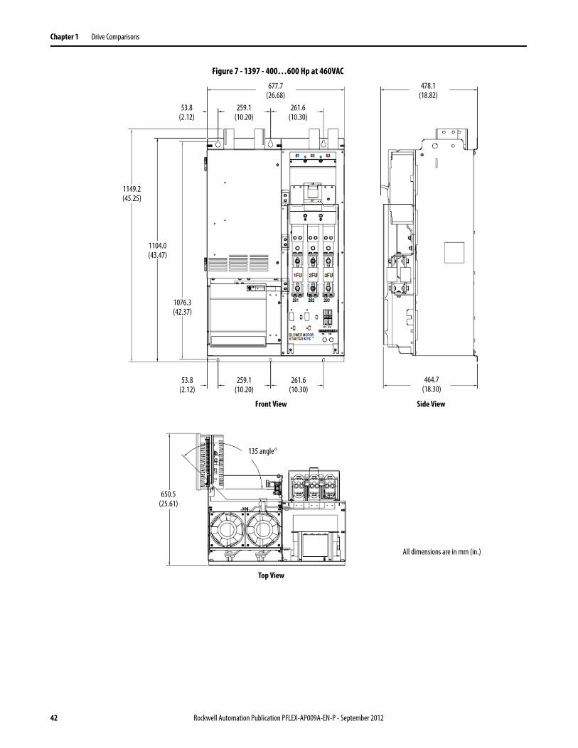
Figure 7 - 1397 - 400…600 Hp at 460VAC
650.5(25.61)
677.7(26.68)
53.8(2.12)
259.1(10.20)
261.6(10.30)
478.1(18.82)
1149.2(45.25)
1104.0(43.47)
1076.3(42.37)
53.8(2.12)
259.1(10.20)
261.6(10.30)
464.7(18.30)
Top View
Front View Side View
All dimensions are in mm (in.)
135 angle°
42 Rockwell Automation Publication PFLEX-AP009A-EN-P - September 2012
Drive Comparisons Chapter 1
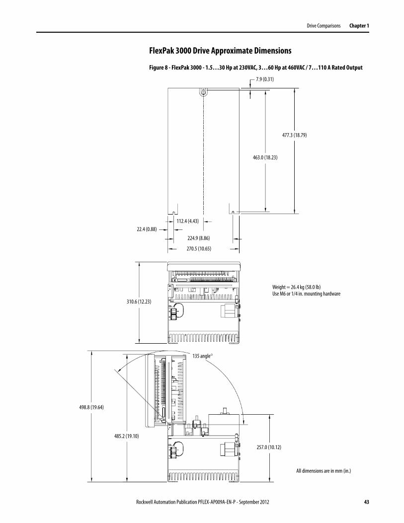
FlexPak 3000 Drive Approximate Dimensions
Figure 8 - FlexPak 3000 - 1.5…30 Hp at 230VAC, 3…60 Hp at 460VAC / 7…110 A Rated Output
7.9 (0.31)
477.3 (18.79)
463.0 (18.23)
112.4 (4.43)22.4 (0.88)
All dimensions are in mm (in.)
224.9 (8.86)
270.5 (10.65)
310.6 (12.23)
Weight = 26.4 kg (58.0 lb)Use M6 or 1/4 in. mounting hardware
135 angle°
498.8 (19.64)
485.2 (19.10)
257.0 (10.12)
Rockwell Automation Publication PFLEX-AP009A-EN-P - September 2012 43
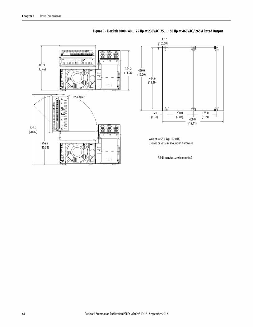
Chapter 1 Drive Comparisons
Figure 9 - FlexPak 3000 - 40…75 Hp at 230VAC, 75…150 Hp at 460VAC / 265 A Rated Output
All dimensions are in mm (in.)
Weight = 55.0 kg (122.0 lb)Use M8 or 5/16 in. mounting hardware
341.9 (13.46)
135 angle°
304.2 (11.98)
490.0 (19.29)
464.6 (18.29)
35.0 (1.38)
12.7(0.50)
200.0 (7.87)
460.0 (18.11)
175.0 (6.89)
516.5 (20.33)
528.9 (20.82)
44 Rockwell Automation Publication PFLEX-AP009A-EN-P - September 2012
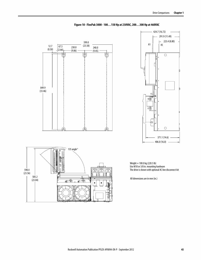
Drive Comparisons Chapter 1
Figure 10 - FlexPak 3000 - 100…150 Hp at 230VAC, 200…300 Hp at 460VAC
Weight = 100.0 kg (220.5 lb)Use M10 or 3/8 in. mounting hardwareThe drive is shown with optional AC line disconnect kit
135 angle°
585.2 (23.04) All dimensions are in mm (in.)
598.4 (23.56)
849.9 (33.46)
12.7 (0.50)
67.5(2.66)
230.0(9.06)
599.0(23.58)
240.0(9.45)
424.7 (16.72)
291.9 (11.49)
223.4 (8.80)A1 45
371.1 (14.6)
406.0 (16.0)
Rockwell Automation Publication PFLEX-AP009A-EN-P - September 2012 45
Chapter 1 Drive Comparisons
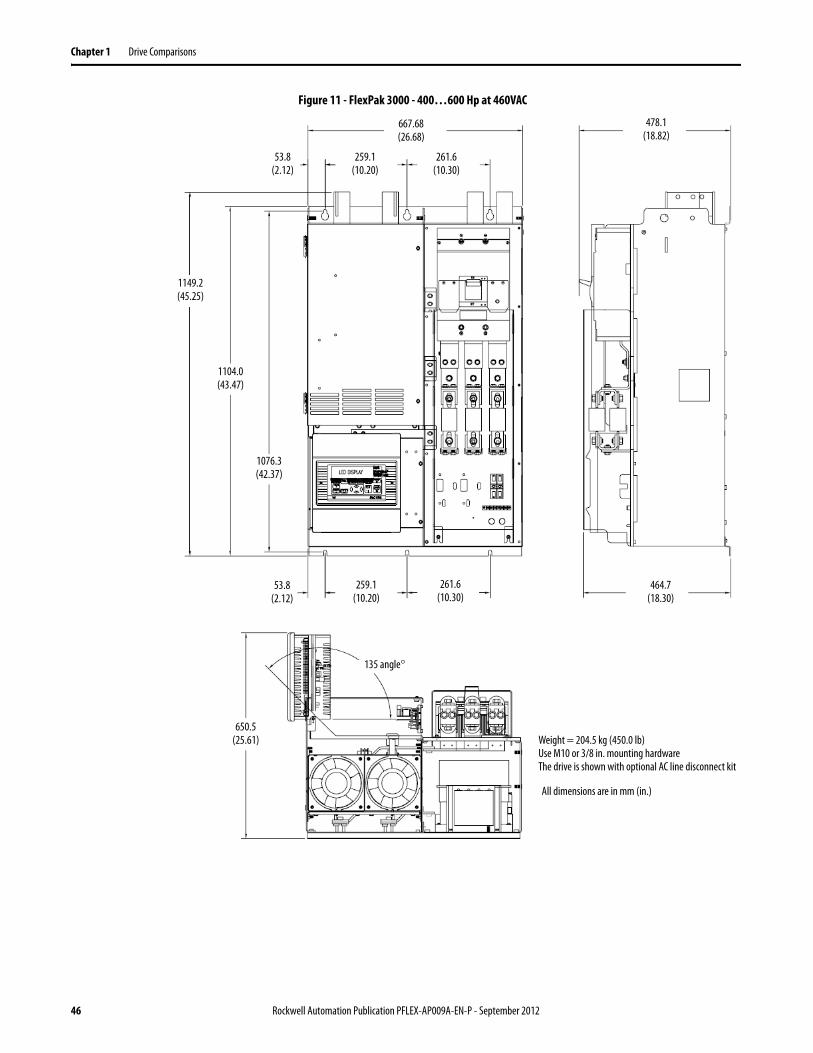
Figure 11 - FlexPak 3000 - 400…600 Hp at 460VAC
Weight = 204.5 kg (450.0 lb)Use M10 or 3/8 in. mounting hardwareThe drive is shown with optional AC line disconnect kit
135 angle°
650.5 (25.61)
All dimensions are in mm (in.)
464.7 (18.30)
261.6 (10.30)
259.1 (10.20)
53.8 (2.12)
1076.3 (42.37)
1104.0 (43.47)
1149.2 (45.25)
261.6 (10.30)
259.1 (10.20)
53.8 (2.12)
667.68 (26.68)
478.1 (18.82)
46 Rockwell Automation Publication PFLEX-AP009A-EN-P - September 2012
Drive Comparisons Chapter 1
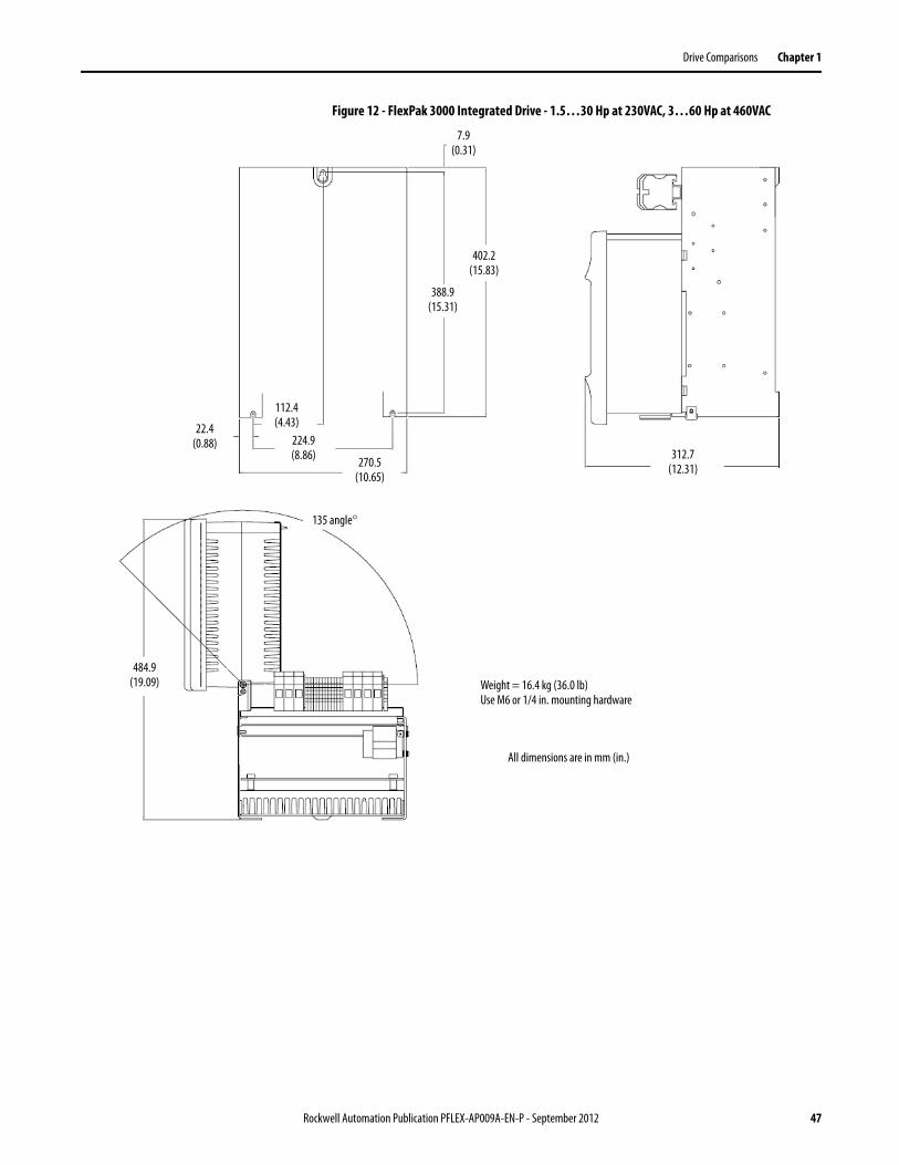
Figure 12 - FlexPak 3000 Integrated Drive - 1.5…30 Hp at 230VAC, 3…60 Hp at 460VAC
All dimensions are in mm (in.)
Weight = 16.4 kg (36.0 lb)Use M6 or 1/4 in. mounting hardware
135 angle°
484.9 (19.09)
22.4 (0.88)
112.4 (4.43)
224.9 (8.86) 270.5
(10.65)
388.9 (15.31)
402.2 (15.83)
7.9(0.31)
312.7 (12.31)
Rockwell Automation Publication PFLEX-AP009A-EN-P - September 2012 47
Chapter 1 Drive Comparisons
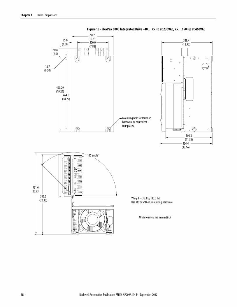
Figure 13 - FlexPak 3000 Integrated Drive - 40…75 Hp at 230VAC, 75…150 Hp at 460VAC
All dimensions are in mm (in.)
Weight = 36.3 kg (80.0 lb)Use M8 or 5/16 in. mounting hardware
135 angle°
516.5 (20.33)
531.6 (20.93)
490.29 (19.29)
464.6 (18.29)
12.7 (0.50)
50.8 (2.0)
35.0 (1.38)
270.5(10.63)200.0(7.88)
Mounting hole for M8x1.25 hardware or equivalent - four places.
328.4(12.93)
334.4(13.16)
300.0(11.81)
48 Rockwell Automation Publication PFLEX-AP009A-EN-P - September 2012
Drive Comparisons Chapter 1
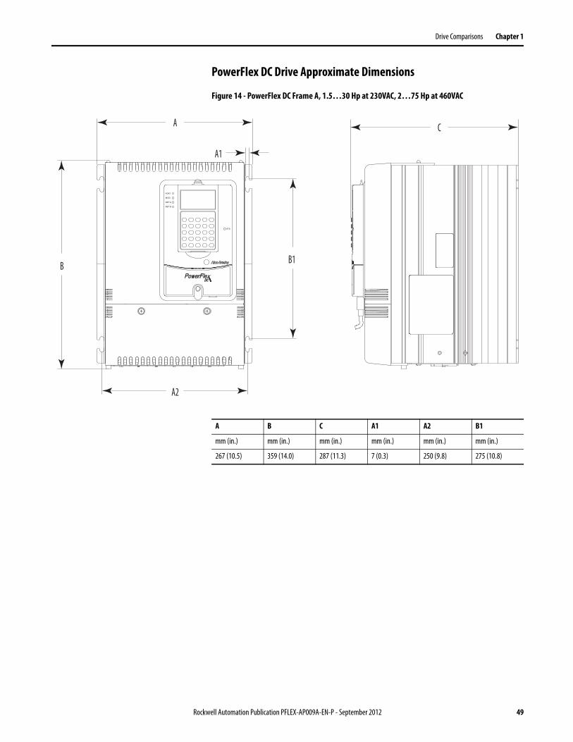
PowerFlex DC Drive Approximate Dimensions
Figure 14 - PowerFlex DC Frame A, 1.5…30 Hp at 230VAC, 2…75 Hp at 460VAC
A
B
A2
B1
C
STS
PORT
MOD
NET A
NET B
A1
A B C A1 A2 B1
mm (in.) mm (in.) mm (in.) mm (in.) mm (in.) mm (in.)
267 (10.5) 359 (14.0) 287 (11.3) 7 (0.3) 250 (9.8) 275 (10.8)
Rockwell Automation Publication PFLEX-AP009A-EN-P - September 2012 49
Chapter 1 Drive Comparisons
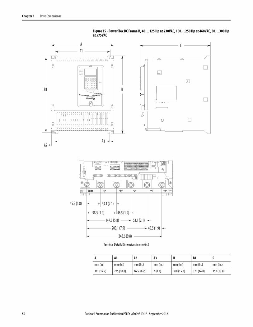
Figure 15 - PowerFlex DC Frame B, 40…125 Hp at 230VAC, 100…250 Hp at 460VAC, 50…300 Hp at 575VAC
AA1
B1
C
B
A2
STS
PORT
MOD
NET A
NET B
A3
45.2 (1.8)
98.5 (3.9)
53.1 (2.1)
48.5 (1.9)
147.0 (5.8) 53.1 (2.1)
48.5 (1.9)200.1 (7.9)
248.6 (9.8)
Terminal Details Dimensions in mm (in.)
A A1 A2 A3 B B1 C
mm (in.) mm (in.) mm (in.) mm (in.) mm (in.) mm (in.) mm (in.)
311 (12.2) 275 (10.8) 16.5 (0.65) 7 (0.3) 388 (15.3) 375 (14.8) 350 (13.8)
50 Rockwell Automation Publication PFLEX-AP009A-EN-P - September 2012
Drive Comparisons Chapter 1
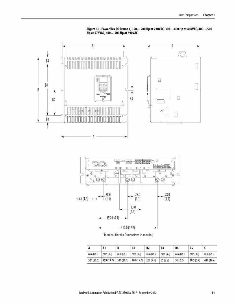
Figure 16 - PowerFlex DC Frame C, 150…200 Hp at 230VAC, 300…400 Hp at 460VAC, 400…500 Hp at 575VAC, 400…500 Hp at 690VAC
B1
B2
B3
A
A1 C
B
B4
STS
PORT
MOD
NET A
NET B
B5
310.0 (12.2)
155.0 (6.1)
113.0(4.5)
28.0(1.1)
28.0(1.1)
28.0(1.1)35.5 (1.4)
Terminal Details Dimensions in mm (in.)
A A1 B B1 B2 B3 B4 B5 C
mm (in.) mm (in.) mm (in.) mm (in.) mm (in.) mm (in.) mm (in.) mm (in.) mm (in.)
521 (20.5) 499 (19.7) 511 (20.1) 400 (15.7) 200 (7.9) 55 (2.2) 56 (2.2) 10.5 (0.4) 416 (16.4)
Rockwell Automation Publication PFLEX-AP009A-EN-P - September 2012 51
Chapter 1 Drive Comparisons
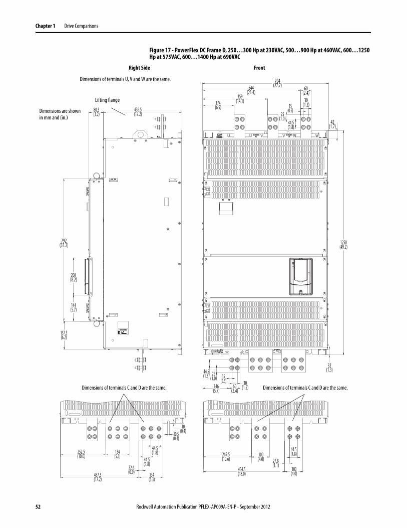
Figure 17 - PowerFlex DC Frame D, 250…300 Hp at 230VAC, 500…900 Hp at 460VAC, 600…1250 Hp at 575VAC, 600…1400 Hp at 690VAC
1250(49.2)
436.5(17.2)
157.5(6.2)
144(5.7)
208(8.2)
792(31.2)
42(1.7)
32(1.3)
80.5(3.2)
10.5(0.4)
10(0.4)
252.5(10.0)
134(5.3)
437.5(17.2)
134(5.3)
22.6(0.9)
44.5(1.8)
44.5(1.8) 269.5
(10.6)100
(4.0) 27.8(1.1)
44.5(1.8)
704(27.7)
174(6.9)
359(14.1)
544(21.4)
60(2.4)
454.5(18.0)
100(4.0)
15(0.6)
30(1.2)
25(1.0)
44.5(1.8)
146(5.7)
60(2.4)
25(1.0)
44.5(1.8) 15
(0.6) 30(1.2)
Dimensions of terminals U, V and W are the same.
Dimensions are shown in mm and (in.)
Dimensions of terminals C and D are the same.
Lifting flange
Dimensions of terminals C and D are the same.
Right Side Front
52 Rockwell Automation Publication PFLEX-AP009A-EN-P - September 2012
Drive Comparisons Chapter 1
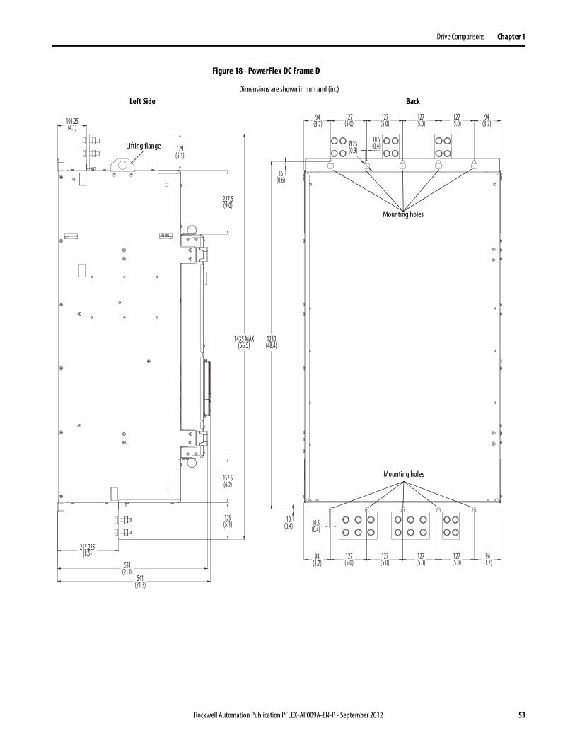
Figure 18 - PowerFlex DC Frame D
215.225(8.5)
103.25(4.1)
1435 MAX(56.5)
129(5.1)
129(5.1)
227.5(9.0)
157.5(6.2)
1230(48.4)
16(0.6)
10.5(0.4)
10(0.4)
10.5(0.4)
127(5.0)
531(21.0)
541(21.3)
94(3.7)
127(5.0)
127(5.0)
127(5.0)
Ø 23(0.9)
127(5.0)
127(5.0)
127(5.0)
127(5.0)
94(3.7)
94(3.7)
94(3.7)
Dimensions are shown in mm and (in.)
Mounting holes
Mounting holes
Lifting flange
Left Side Back
Rockwell Automation Publication PFLEX-AP009A-EN-P - September 2012 53
Chapter 1 Drive Comparisons
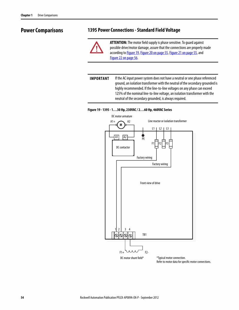
Power Comparisons 1395 Power Connections - Standard Field Voltage
Figure 19 - 1395 - 1…30 Hp, 230VAC / 2…60 Hp, 460VAC Series
ATTENTION: The motor field supply is phase sensitive. To guard against possible drive/motor damage, assure that the connections are properly made according to Figure 19, Figure 20 on page 55, Figure 21 on page 55, and Figure 22 on page 56.
IMPORTANT If the AC input power system does not have a neutral or one phase referenced ground, an isolation transformer with the neutral of the secondary grounded is highly recommended. If the line-to-line voltages on any phase can exceed 125% of the nominal line-to-line voltage, an isolation transformer with the neutral of the secondary grounded, is always required.
A1+ A2
L1 L2 L3M
A2A1
DC contactor
PE
Line reactor or isolation transformer
F1 F2 F3
Factory wiring
Factory wiring
Front view of drive
TB1
1 2 3 4
F1+ F2-
DC motor shunt field* *Typical motor connection.Refer to motor data for specific motor connections.
DC motor armature
54 Rockwell Automation Publication PFLEX-AP009A-EN-P - September 2012
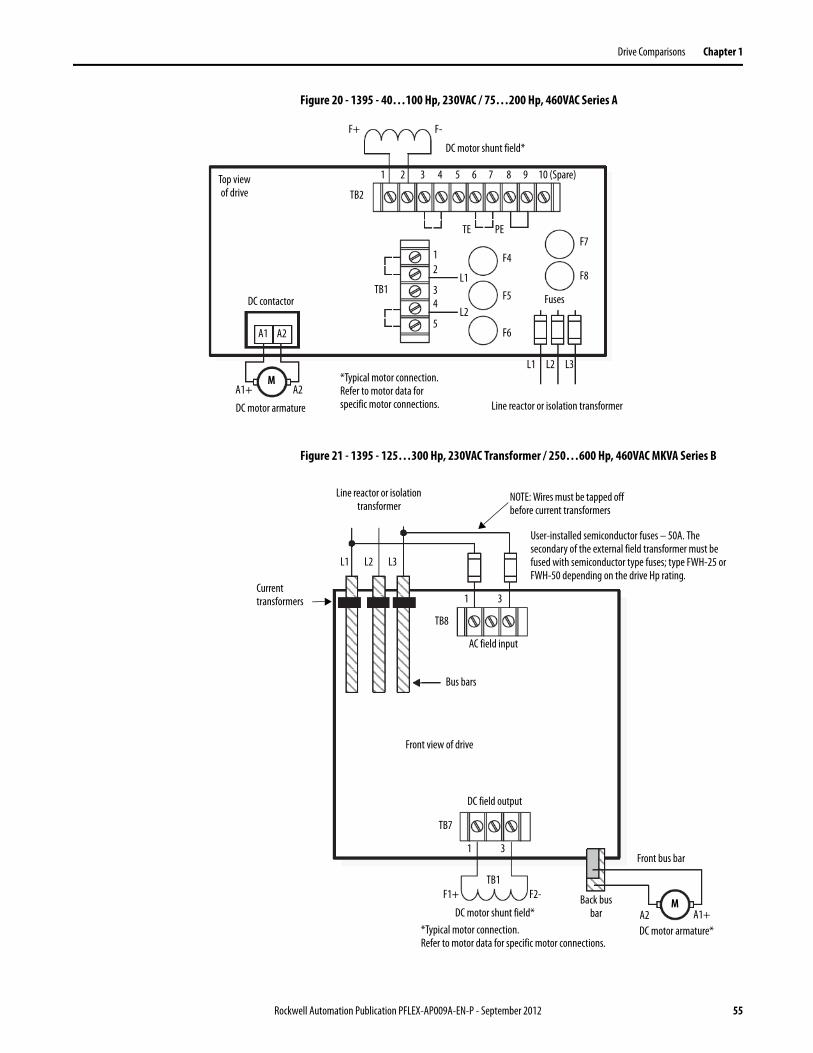
Drive Comparisons Chapter 1
Figure 20 - 1395 - 40…100 Hp, 230VAC / 75…200 Hp, 460VAC Series A
Figure 21 - 1395 - 125…300 Hp, 230VAC Transformer / 250…600 Hp, 460VAC MKVA Series B
A1+ A2
L1 L2 L3M
A2A1
DC contactor
PE
Line reactor or isolation transformer
Fuses
Top view of drive
TB1
1
F+ F-
DC motor shunt field*
*Typical motor connection.Refer to motor data for specific motor connections.
TB2
TE
DC motor armature
2 3 4 5 6 7 8 9 10 (Spare)
12
34
5
L1
L2
F4
F5
F6
F7
F8
L1 L2 L3
MA2 A1+
Front bus bar
Line reactor or isolation transformer
Front view of drive
DC motor armature*
TB1
1 3
F1+ F2-
DC motor shunt field**Typical motor connection.Refer to motor data for specific motor connections.
Bus bars
NOTE: Wires must be tapped off before current transformers
User-installed semiconductor fuses – 50A. The secondary of the external field transformer must be fused with semiconductor type fuses; type FWH-25 or FWH-50 depending on the drive Hp rating.
Back bus bar
DC field output
TB7
Current transformers 1 3
TB8
AC field input
Rockwell Automation Publication PFLEX-AP009A-EN-P - September 2012 55
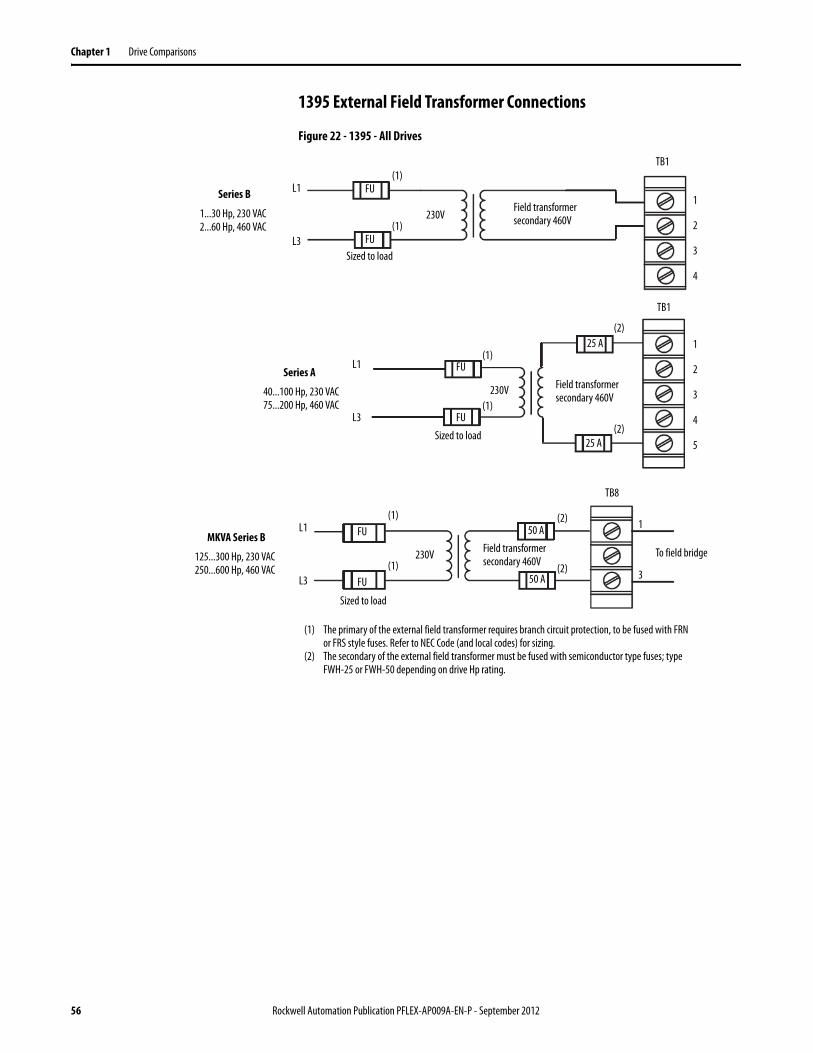
Chapter 1 Drive Comparisons
1395 External Field Transformer Connections
Figure 22 - 1395 - All Drives
L1
L3
1...30 Hp, 230 VAC2...60 Hp, 460 VAC
TB1
TB1
TB8
1
2
3
4
1
2
3
4
5
1
3
To field bridge
L1
L3
L1
L3
FU
FU
FU
FU
FU
FU
25 A
25 A
50 A
50 A
Series B
125...300 Hp, 230 VAC250...600 Hp, 460 VAC
MKVA Series B
40...100 Hp, 230 VAC75...200 Hp, 460 VAC
Series A
230V
230V
230V
Field transformer secondary 460V
Field transformer secondary 460V
Field transformer secondary 460V
(2)
(2)
(2)
(2)
Sized to load
(1)
(1)
(1)
(1)
(1)
(1)
(1) The primary of the external field transformer requires branch circuit protection, to be fused with FRN or FRS style fuses. Refer to NEC Code (and local codes) for sizing.
(2) The secondary of the external field transformer must be fused with semiconductor type fuses; type FWH-25 or FWH-50 depending on drive Hp rating.
Sized to load
Sized to load
56 Rockwell Automation Publication PFLEX-AP009A-EN-P - September 2012
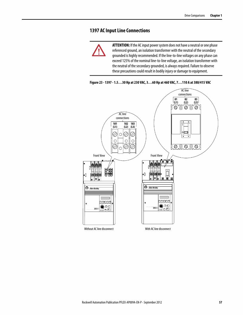
Drive Comparisons Chapter 1
1397 AC Input Line Connections
Figure 23 - 1397 - 1.5…30 Hp at 230 VAC, 3…60 Hp at 460 VAC, 7…110 A at 380/415 VAC
ATTENTION: If the AC input power system does not have a neutral or one phase referenced ground, an isolation transformer with the neutral of the secondary grounded is highly recommended. If the line-to-line voltages on any phase can exceed 125% of the nominal line-to-line voltage, an isolation transformer with the neutral of the secondary grounded, is always required. Failure to observe these precautions could result in bodily injury or damage to equipment.
AC lineconnections
Front View
AC lineconnections
Front View
Without AC line disconnect With AC line disconnect
181(L1)
182(L2)
183(L3)
81(L1)
82(L2)
83(L3)
Rockwell Automation Publication PFLEX-AP009A-EN-P - September 2012 57
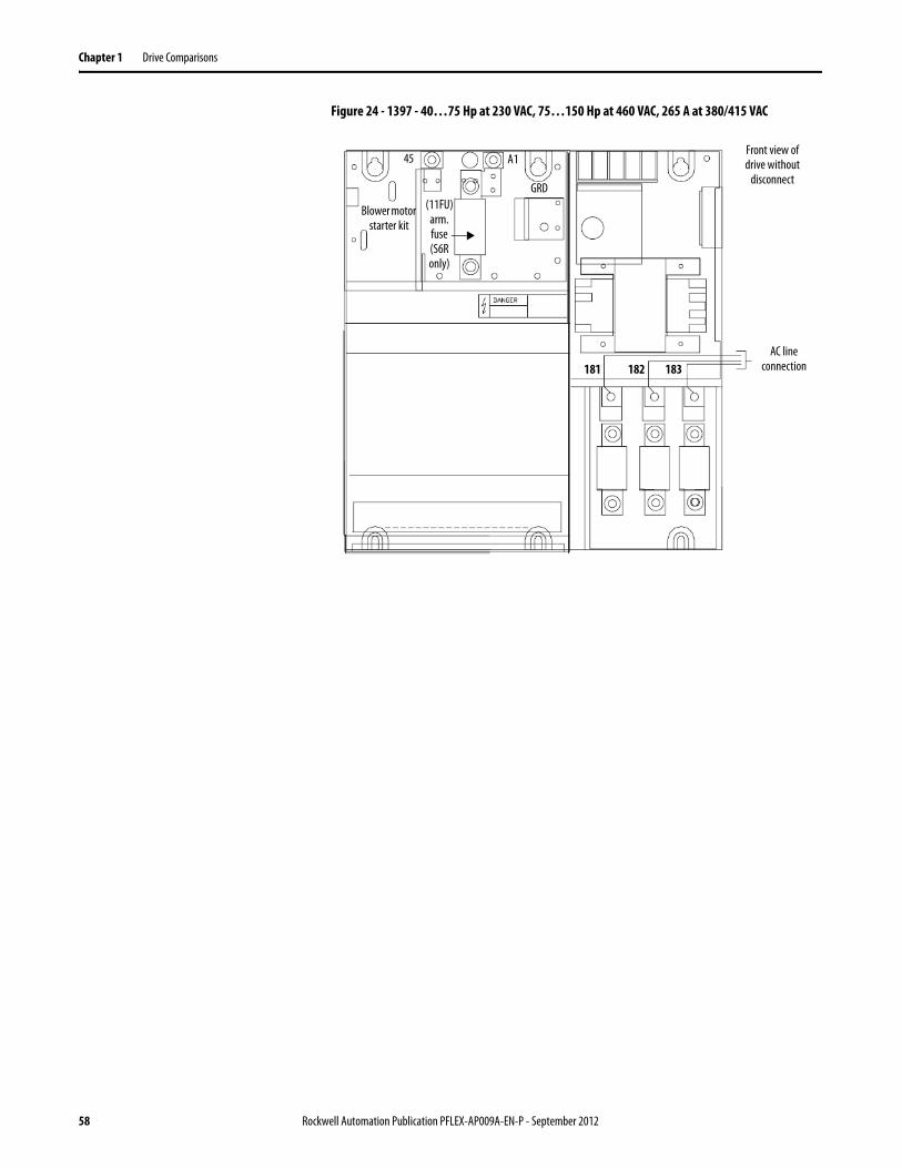
Chapter 1 Drive Comparisons
Figure 24 - 1397 - 40…75 Hp at 230 VAC, 75…150 Hp at 460 VAC, 265 A at 380/415 VAC
AC lineconnection
Front view of drive without
disconnect
181 182 183
Blower motor starter kit
45
(11FU) arm. fuse (S6R only)
A1
GRD
58 Rockwell Automation Publication PFLEX-AP009A-EN-P - September 2012
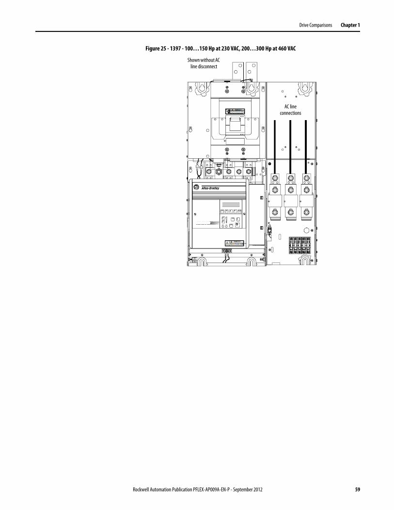
Drive Comparisons Chapter 1
Figure 25 - 1397 - 100…150 Hp at 230 VAC, 200…300 Hp at 460 VAC
AC lineconnections
Shown without AC line disconnect
Rockwell Automation Publication PFLEX-AP009A-EN-P - September 2012 59
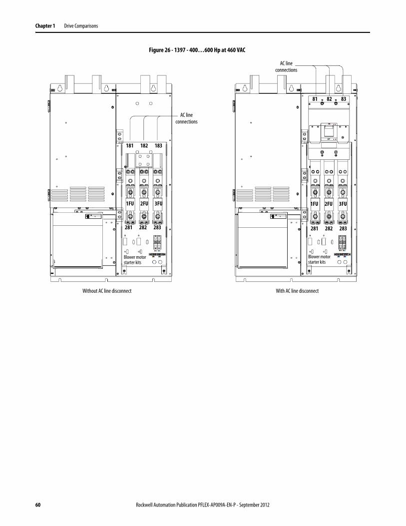
Chapter 1 Drive Comparisons
Figure 26 - 1397 - 400…600 Hp at 460 VAC
AC lineconnections
AC lineconnections
Without AC line disconnect With AC line disconnect
181 182 183
1FU 2FU 3FU
81 82 83
1FU 2FU 3FU
281 282 283 281 282 283
Blower motor starter kits
Blower motor starter kits
60 Rockwell Automation Publication PFLEX-AP009A-EN-P - September 2012
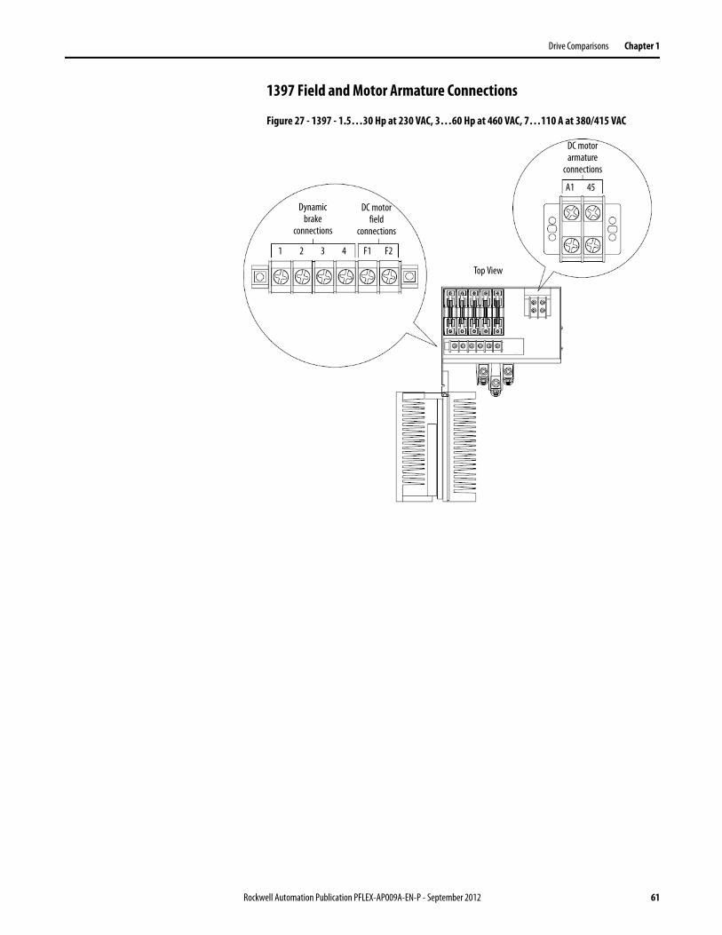
Drive Comparisons Chapter 1
1397 Field and Motor Armature Connections
Figure 27 - 1397 - 1.5…30 Hp at 230 VAC, 3…60 Hp at 460 VAC, 7…110 A at 380/415 VAC
DC motor armature
connections
Dynamic brake
connections
DC motor field
connections
1 2 3 4 F1 F2
A1 45
Top View
Rockwell Automation Publication PFLEX-AP009A-EN-P - September 2012 61
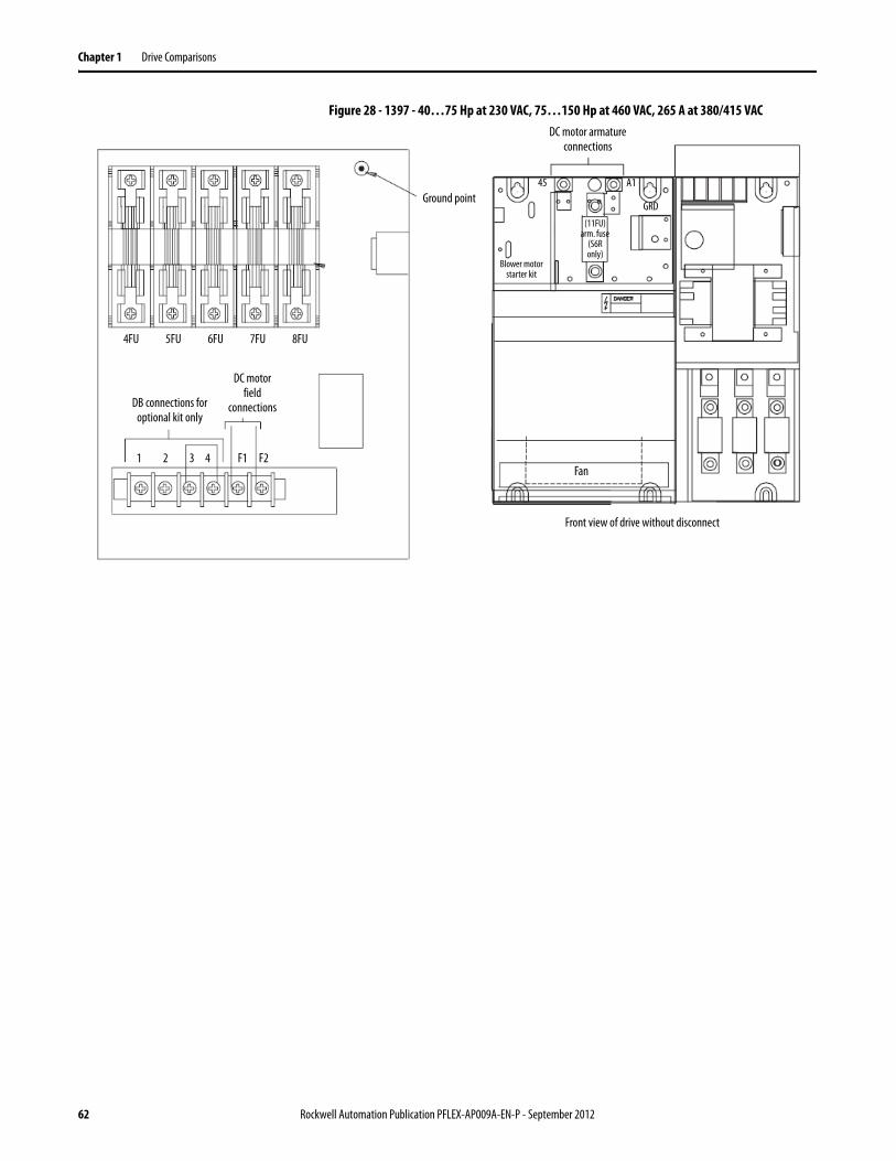
Chapter 1 Drive Comparisons
Figure 28 - 1397 - 40…75 Hp at 230 VAC, 75…150 Hp at 460 VAC, 265 A at 380/415 VAC
Ground point45 A1
4FU 5FU 6FU 7FU 8FU
1 2 3 4 F1 F2
DB connections for optional kit only
DC motor field
connections
DC motor armature connections
Front view of drive without disconnect
Blower motor starter kit
(11FU) arm. fuse
(S6R only)
GRD
Fan
62 Rockwell Automation Publication PFLEX-AP009A-EN-P - September 2012
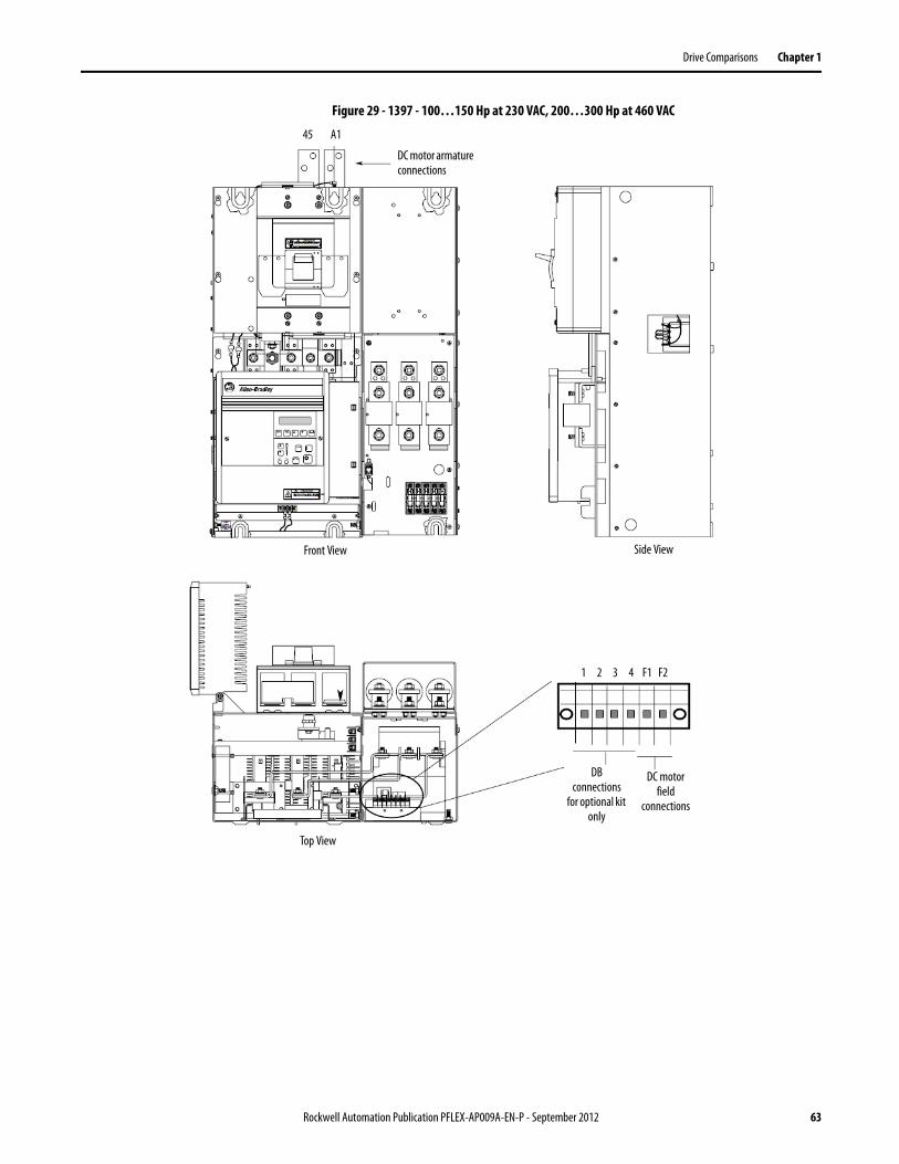
Drive Comparisons Chapter 1
Figure 29 - 1397 - 100…150 Hp at 230 VAC, 200…300 Hp at 460 VAC
DC motor armature connections
45 A1
Front View Side View
Top View
1 2 3 4 F1 F2
DB connections
for optional kit only
DC motor field
connections
Rockwell Automation Publication PFLEX-AP009A-EN-P - September 2012 63
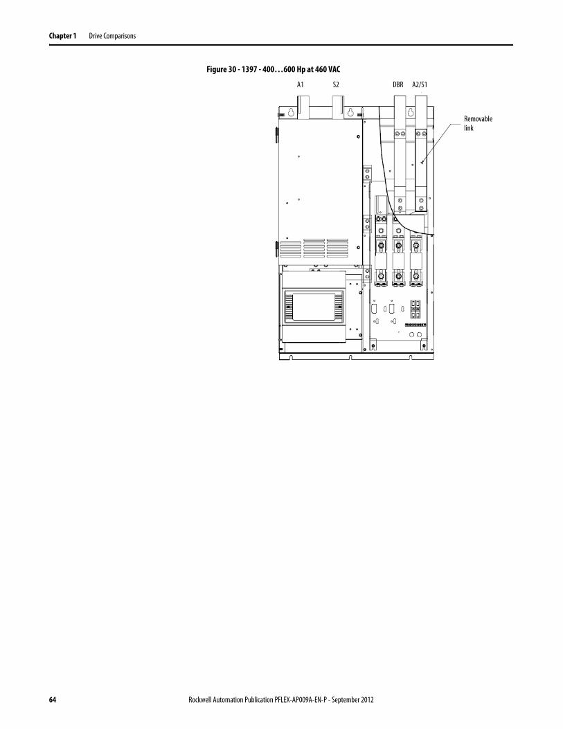
Chapter 1 Drive Comparisons
Figure 30 - 1397 - 400…600 Hp at 460 VAC
Removable link
A1 S2 DBR A2/S1
64 Rockwell Automation Publication PFLEX-AP009A-EN-P - September 2012
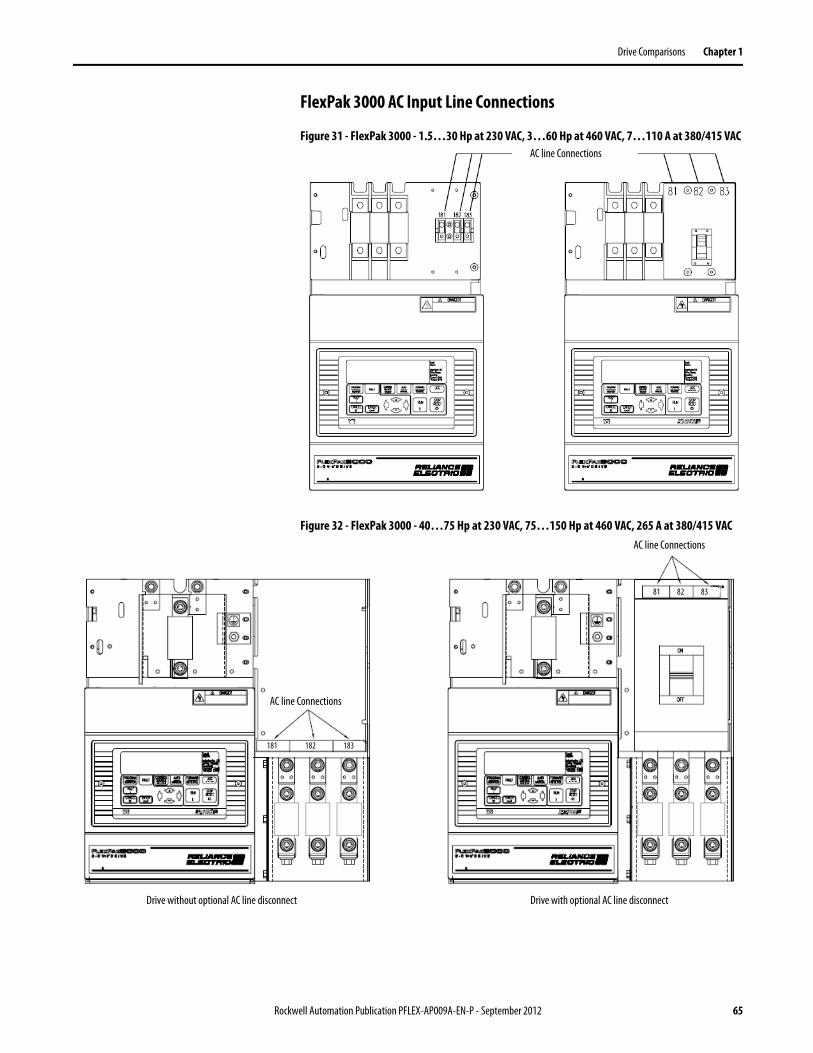
Drive Comparisons Chapter 1
FlexPak 3000 AC Input Line Connections
Figure 31 - FlexPak 3000 - 1.5…30 Hp at 230 VAC, 3…60 Hp at 460 VAC, 7…110 A at 380/415 VAC
Figure 32 - FlexPak 3000 - 40…75 Hp at 230 VAC, 75…150 Hp at 460 VAC, 265 A at 380/415 VAC
AC line Connections
AC line Connections
181 182 183
81 82 83
AC line Connections
Drive without optional AC line disconnect Drive with optional AC line disconnect
Rockwell Automation Publication PFLEX-AP009A-EN-P - September 2012 65
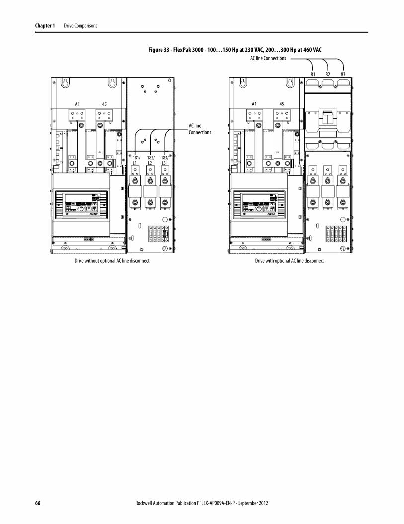
Chapter 1 Drive Comparisons
Figure 33 - FlexPak 3000 - 100…150 Hp at 230 VAC, 200…300 Hp at 460 VAC AC line Connections
181/ 182/ 183/L1 L2 L3
81 82 83
AC line Connections
Drive without optional AC line disconnect Drive with optional AC line disconnect
A1 45A1 45
66 Rockwell Automation Publication PFLEX-AP009A-EN-P - September 2012
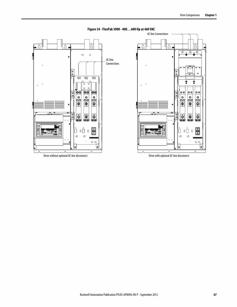
Drive Comparisons Chapter 1
Figure 34 - FlexPak 3000 - 400…600 Hp at 460 VAC AC line Connections
181 182 183
81 82 83
AC line Connections
Drive without optional AC line disconnect Drive with optional AC line disconnect
Rockwell Automation Publication PFLEX-AP009A-EN-P - September 2012 67
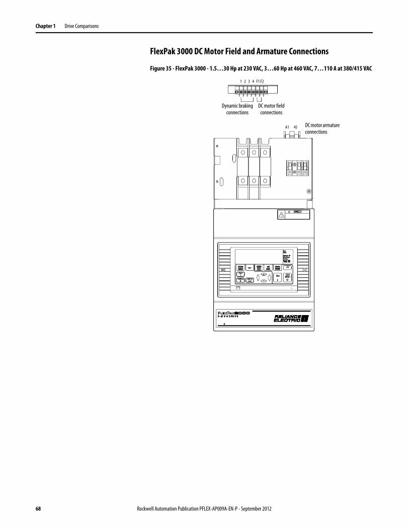
Chapter 1 Drive Comparisons
FlexPak 3000 DC Motor Field and Armature Connections
Figure 35 - FlexPak 3000 - 1.5…30 Hp at 230 VAC, 3…60 Hp at 460 VAC, 7…110 A at 380/415 VAC
Dynamic braking connections
45
1 2 3 4 F1 F2
A1
DC motor field connections
DC motor armature connections
68 Rockwell Automation Publication PFLEX-AP009A-EN-P - September 2012
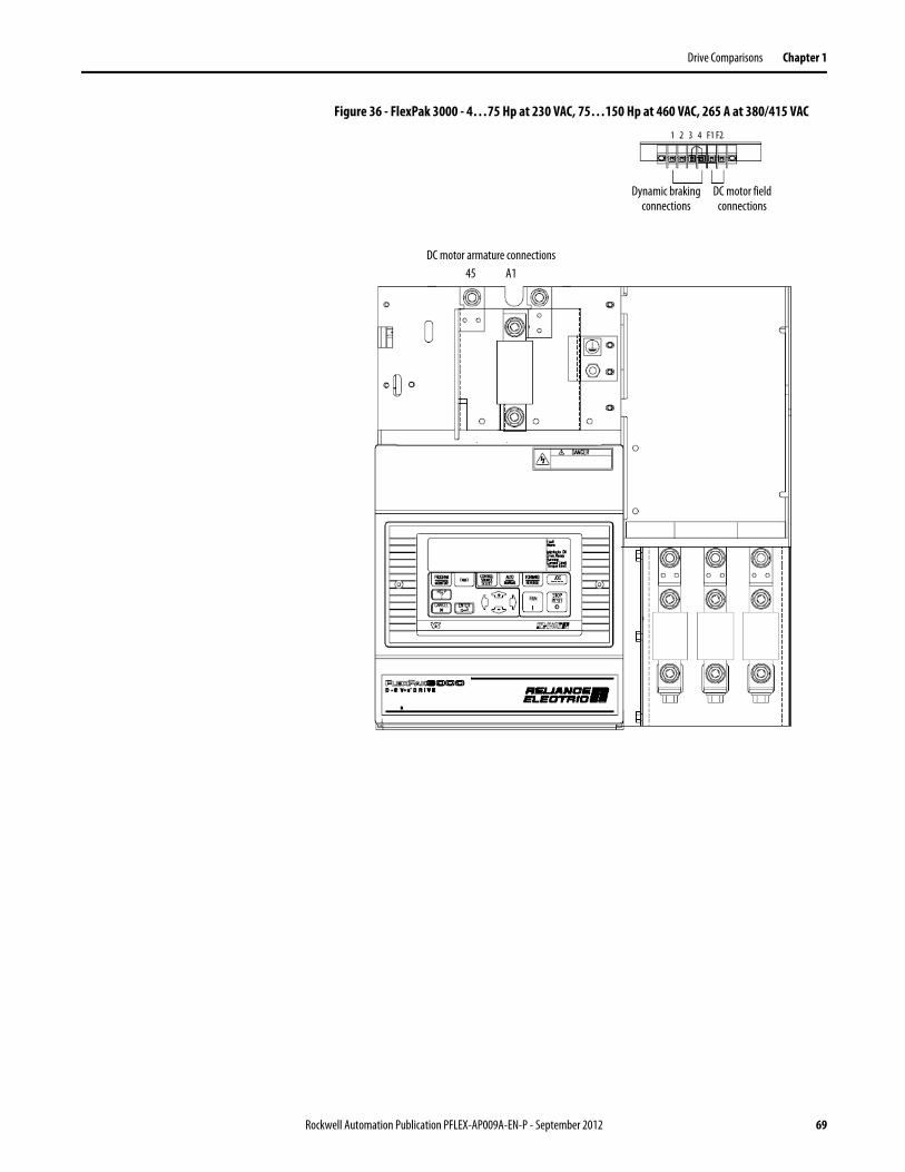
Drive Comparisons Chapter 1
Figure 36 - FlexPak 3000 - 4…75 Hp at 230 VAC, 75…150 Hp at 460 VAC, 265 A at 380/415 VAC
Dynamic braking connections
45
1 2 3 4 F1 F2
DC motor field connections
DC motor armature connectionsA1
Rockwell Automation Publication PFLEX-AP009A-EN-P - September 2012 69
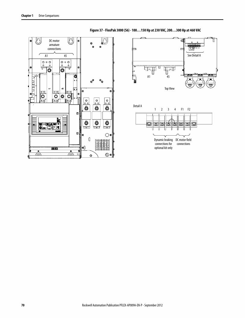
Chapter 1 Drive Comparisons
Figure 37 - FlexPak 3000 (S6) - 100…150 Hp at 230 VAC, 200…300 Hp at 460 VAC
Dynamic braking connections for optional kit only
45
1 2 3 4 F1 F2
DC motor field connections
DC motor armature
connections
A1 See Detail A
Detail A
Top View
45A1
70 Rockwell Automation Publication PFLEX-AP009A-EN-P - September 2012
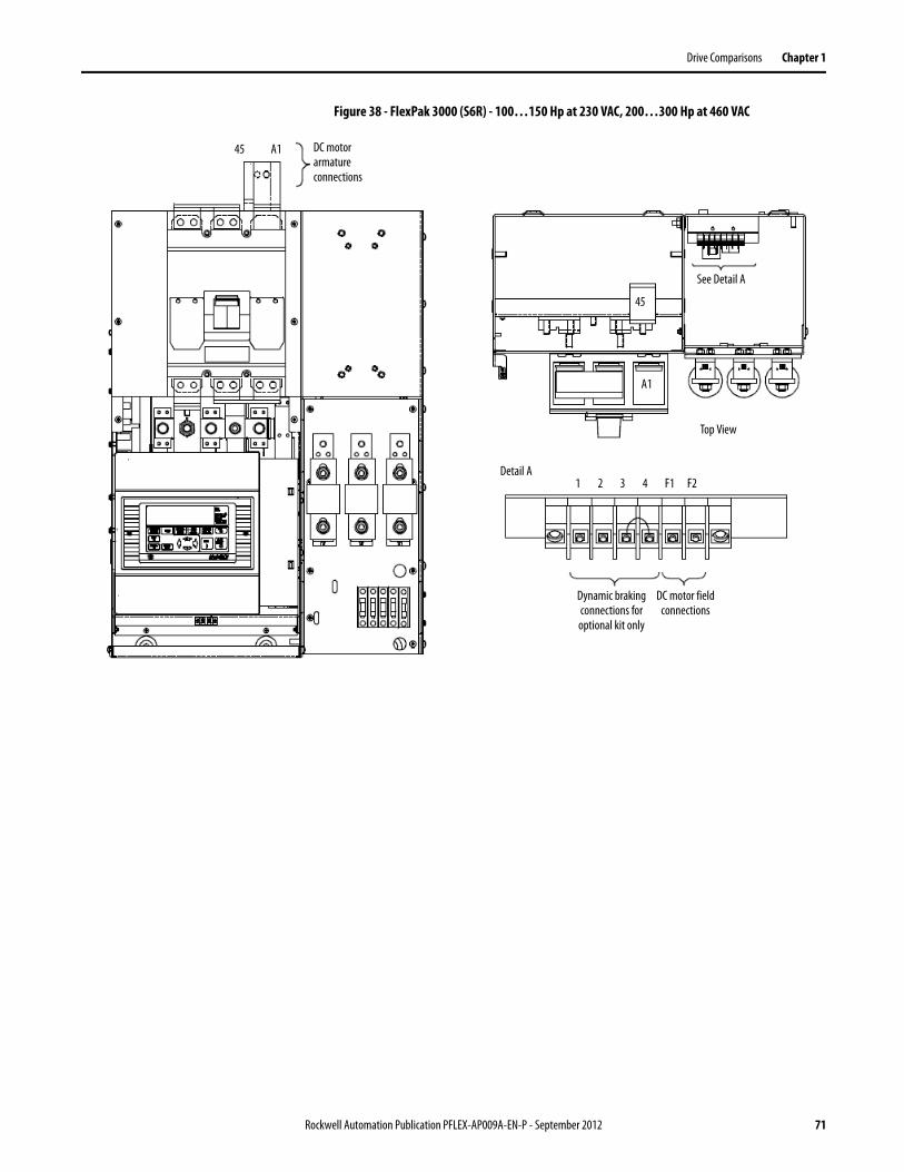
Drive Comparisons Chapter 1
Figure 38 - FlexPak 3000 (S6R) - 100…150 Hp at 230 VAC, 200…300 Hp at 460 VAC
Dynamic braking connections for optional kit only
45
1 2 3 4 F1 F2
DC motor field connections
DC motor armature connections
A1
See Detail A
Detail A
Top View
45
A1
Rockwell Automation Publication PFLEX-AP009A-EN-P - September 2012 71
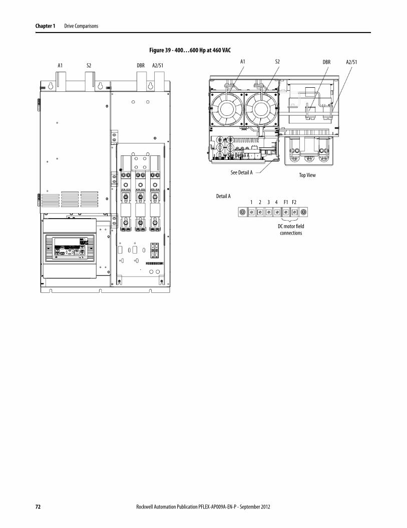
Chapter 1 Drive Comparisons
Figure 39 - 400…600 Hp at 460 VAC
See Detail A
Detail A
A1
1 2 3 4 F1 F2
DC motor field connections
Top ViewSee Detail A
S2 DBR A2/S1A1 S2 DBR A2/S1
72 Rockwell Automation Publication PFLEX-AP009A-EN-P - September 2012
Drive Comparisons Chapter 1
PowerFlex DC Drive Power Wiring
AC Input Voltages
PowerFlex DC drives are rated for the following AC input voltages @ 50/60 Hz ±5%:
Mains Circuit (Terminals U, V, W)• 230V ±10%, 3Ph• 400V ±10%, 3Ph• 440V ±10%, 3Ph• 460V ±10%, 3Ph• 480V ±10%, 3Ph• 575V ±10%, 3Ph• 690V ±10%, 3Ph
Field Circuit (Terminals U1, V1)• 230V ±10%, 1Ph• 400V ±10%, 1Ph• 460V ±10%, 1Ph
Control Circuit (Terminals U2, V2)• 115V ±15% or 230V ±15%, 1Ph
Note: For frame B and C drives only, a jumper must be placed between terminals SA-SB on the Switching Power Supply circuit board for the control circuits to work with 115V AC input. Refer to Figure 59 on page 90 and Figure 60 on page 90 for terminal block locations.
DC Output Voltages
The output voltages below take into account an AC input undervoltage within the stated tolerance limits and a voltage drop of 4% due to an AC input line reactor. It is the same as the rated armature voltage suggested for the connected motor.
Armature Circuit
Field Circuit
AC Input Voltage DC Output Armature Voltage (Terminals C & D)(Terminals U, V, W) Two Quadrant Drive Four Quadrant Drive 230V ±10%, 3Ph 260V 240V400V ±10%, 3Ph 470V 420V440V ±10%, 3Ph 530V 460V460V ±10%, 3Ph 560V 480V480V ±10%, 3Ph 580V 500V575V ±10%, 3Ph 680V 600V690V ±10%, 3Ph 810V 720V
AC Input Voltage DC Output Field Voltage(1) (Terminals C1 & D1)
(1) The max field voltage is equal to 0.85 x AC input line voltage
(Terminals U1 & V1) Fixed Field Adjustable Field230V ±10%, 1Ph 200V 200V400V ±10%, 1Ph 310V 310V460V ±10%, 1Ph 360V 360V
Rockwell Automation Publication PFLEX-AP009A-EN-P - September 2012 73
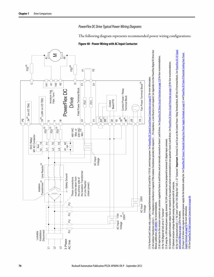
Chapter 1 Drive Comparisons
PowerFlex DC Drive Typical Power Wiring Diagrams
The following diagram represents recommended power wiring configurations:
Figure 40 - Power Wiring with AC Input Contactor
M
C D
Aux
Pow
erFl
ex D
CD
rive
36(8
)
34(4
) (on
I/O T
B4)
19(5
) (+24
V o
n I/O
TB
2)
(N.O
. Rel
ay)
M1
AC
Con
tact
or
Con
trol
Boar
d P/
S
AC
Inpu
tV
olta
ge11
5V or23
0V(1
)
V2U2
F2
A1 A2
35(8
)
U V W
3 P
hase
AC
line
L1 L2 L3
1314
L1 L2 L3 A1
T1 T2 T3 A2
U1
V1
C1
D1
F1FS2(6
)
FS2(6
)
FS1(3
)
FS1(3
)
FS1(3
)
FU1
FV1
FUFU
Fiel
d P
ower
Ter
min
al B
lock
Con
trol P
ower
/ R
elay
Term
inal
Blo
ck
A1
A2
Arm
atur
e V
olt.
Fdbk
. Ter
m.(7
)
1A1
1A2
U3
V3
Fan
Pow
er T
erm
inal
Blo
ck(9
)23
0V
FUFU
Line
Rea
ctor
(2)
Isol
atio
nTr
ansf
orm
er(2
)
Lock
able
Inst
alla
tion
Dis
conn
ect
SB
(1)
SA
(1)
Thes
e co
nnec
tions
mus
t be
take
n fro
mth
e pr
imar
y si
de o
fth
e Is
olat
ion
Tran
sfor
mer
or L
ine
Rea
ctor
(cle
an p
ower
).
AC
Inpu
tV
olta
ge
PE
Saf
ety
Gro
und
AC
Inpu
tV
olta
ge
460
VA
CM
ax. o
r23
0 V
AC
Min
.(10)
(1) F
or fr
ame B
and C
drive
s onl
y, a j
umpe
r is re
quire
d bet
ween
term
inals
SA an
d SB f
or 11
5V AC
cont
rol in
put p
ower.
See P
ower
Flex D
C Con
trol C
ircuit
Powe
r Con
necti
onso
n pag
e87 f
or m
ore i
nfor
mat
ion.
(2) A
n Iso
lation
Tran
sform
er an
d/or
3…5%
impe
danc
e Line
Reac
tor is
requ
ired.
If the
Isola
tion T
rans
form
er pr
ovide
s the
requ
ired 3
…5%
impe
danc
e, a L
ine Re
acto
r is no
t req
uired
. See
Appe
ndix
A in t
he Po
werFl
ex D
igita
l DC D
rive U
ser
Man
ual, p
ublic
ation
20P-
UM00
1, fo
r rec
omm
enda
tions
.(3
) AC i
nput
fuse
s for
the a
rmat
ure c
onve
rter a
re cu
stom
er su
pplie
d for
fram
e A an
d B dr
ives a
nd ar
e int
erna
lly m
ount
ed on
fram
e C an
d D dr
ives.
See P
ower
Flex D
C Driv
es Ci
rcuit
Prot
ectio
non p
age1
39 fo
r fus
e rec
omm
enda
tions
.(4
) Par
140 [
Digit
al In
8 Sel]
set t
o 31 “
Cont
acto
r”(5
) If u
sing t
he +
24V i
nter
nal p
ower
supp
ly, te
rmina
l 18 (
24V c
omm
on) m
ust b
e jum
pere
d to t
erm
inal
35 (d
igita
l inpu
t com
mon
).(6
) Cus
tom
er su
pplie
d arm
atur
e out
put f
uses
are r
equir
ed on
four
quad
rant
and a
re re
com
men
ded o
n two
quad
rant
Fram
e A an
d B dr
ives.
See P
ower
Flex D
C Driv
es Ci
rcuit
Prot
ectio
non p
age1
39 fo
r fus
e rec
omm
enda
tions
.(7
) Opt
ional
arm
atur
e volt
age f
eedb
ack s
ensin
g not
requ
ired w
ith AC
cont
acto
r. (8
) Par
1391
[Con
tacto
rCon
trol]
= 1
“AC C
ntctr
” and
Par 1
392 [
Relay
Out
1 Se
l] =
25 “C
onta
ctor”.
Impo
rtan
t: Te
rmin
al 35
and 3
6 are
on th
e Con
trol P
ower
/ Re
lay Te
rmina
l bloc
k, NO
T the
I/O
term
inal b
locks
. See
Powe
rFlex
DC I
/O Si
gnal
and C
ontro
l Wiri
ngon
page
118 f
or lo
catio
ns.
(9) F
ram
e C &
D dr
ives o
nly r
equir
e an e
xter
nal p
ower
supp
ly fo
r the
heat
sink c
oolin
g fan
. See
Powe
rFlex
DC F
ram
e C H
eatsi
nk Co
oling
Fans
Powe
r Sup
ply Te
rmina
lson
page
91 an
d Pow
erFle
x DC F
ram
e D H
eatsi
nk Co
oling
Fans
Powe
r Su
pply
Term
inals
on pa
ge92
for m
ore i
nfor
mat
ion.
(10)
See P
ower
Flex D
C Fiel
d Con
verte
r Con
necti
ons o
n pag
e84.
74 Rockwell Automation Publication PFLEX-AP009A-EN-P - September 2012
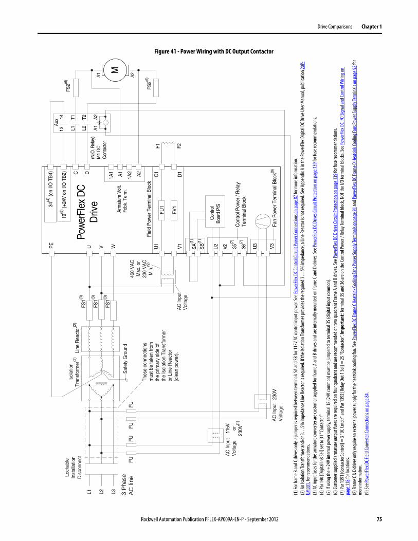
Drive Comparisons Chapter 1
Figure 41 - Power Wiring with DC Output Contactor
C DPo
wer
Flex
DC
Driv
e
36(7
)
34(4
) (on
I/O T
B4)
19(5
) (+24
V o
n I/O
TB
2)
Con
trol
Boar
d P/
S
115V or
230V
(1)
V2U2
F2
35(7
)
U V W
3 P
hase
AC
line
L1 L2 L3
U1
V1
C1
D1
F1
FS1(3
)
FS1(3
)
FS1(3
)
FU1
FV1
FUFU
Fiel
d P
ower
Ter
min
al B
lock
Con
trol P
ower
/ R
elay
Term
inal
Blo
ck
A1
A2
Arm
atur
e V
olt.
Fdbk
. Ter
m.
1A1
1A2
U3
V3
Fan
Pow
er T
erm
inal
Blo
ck(8
)23
0V
FUFU
Line
Rea
ctor
(2)
Lock
able
Inst
alla
tion
Dis
conn
ect
SB
(1)
SA
(1)
M
Aux
(N.O
. Rel
ay)
M1
DC
Con
tact
orA1 A2
1314
L1 L2 A1
T1 T2 A2
FS2(6
)
FS2(6
)Th
ese
conn
ectio
nsm
ust b
e ta
ken
from
the
prim
ary
side
of
the
Isol
atio
n Tr
ansf
orm
eror
Lin
e R
eact
or(c
lean
pow
er).
AC
Inpu
tV
olta
ge
AC
Inpu
tV
olta
ge
Isol
atio
nTr
ansf
orm
er(2
)
Saf
ety
Gro
und
PE
AC
Inpu
tV
olta
ge
460
VA
CM
ax. o
r23
0 V
AC
Min
.(9)
(1) F
or fr
ame B
and C
drive
s onl
y, a j
umpe
r is r
equir
ed be
twee
n ter
mina
ls SA
and S
B for
115V
AC co
ntro
l inpu
t pow
er. Se
e Pow
erFle
x DC C
ontro
l Circ
uit Po
wer C
onne
ction
son p
age8
7 for
mor
e inf
orm
ation
.(2
) An I
solat
ion Tr
ansfo
rmer
and/
or 3…
5% im
peda
nce L
ine Re
acto
r is re
quire
d. If t
he Is
olatio
n Tra
nsfo
rmer
prov
ides t
he re
quire
d 3…
5% im
peda
nce,
a Line
Reac
tor is
not r
equir
ed. S
ee Ap
pend
ix A
in th
e Pow
erFle
x Digi
tal D
C Driv
e Use
r Man
ual, p
ublic
ation
20P-
UM00
1, fo
r rec
omm
enda
tions
.(3
) AC i
nput
fuse
s for
the a
rmat
ure c
onve
rter a
re cu
stom
er su
pplie
d for
fram
e A an
d B dr
ives a
nd ar
e int
erna
lly m
ount
ed on
fram
e C an
d D dr
ives.
See P
ower
Flex D
C Driv
es Ci
rcuit
Prot
ectio
non p
age1
39 fo
r fus
e rec
omm
enda
tions
.(4
) Par
140 [
Digit
al In
8 Sel]
set t
o 31 “
Cont
acto
r”(5
) If u
sing t
he +
24V i
nter
nal p
ower
supp
ly, te
rmina
l 18 (
24V c
omm
on) m
ust b
e jum
pere
d to t
erm
inal 3
5 (dig
ital in
put c
omm
on).
(6) C
usto
mer
supp
lied a
rmat
ure o
utpu
t fus
es ar
e req
uired
on fo
ur qu
adra
nt an
d are
reco
mm
ende
d on t
wo qu
adra
nt Fr
ame A
and B
drive
s. Se
e Pow
erFle
x DC D
rives
Circu
it Pr
otec
tiono
n pag
e139
for f
use r
ecom
men
datio
ns.
(7) P
ar 13
91 [C
onta
ctorC
ontro
l] =
3 “D
C Cnt
ctr” a
nd Pa
r 139
2 [Re
lay O
ut 1
Sel]
= 25
“Con
tacto
r”. Im
port
ant:
Term
inal 3
5 and
36 ar
e on t
he Co
ntro
l Pow
er /
Relay
Term
inal b
lock,
NOT t
he I/
O te
rmina
l bloc
ks. S
ee Po
werFl
ex D
C I/O
Sign
al an
d Con
trol W
iring
on
page
118 f
or lo
catio
ns.
(8) F
ram
e C &
D dr
ives o
nly r
equir
e an e
xter
nal p
ower
supp
ly fo
r the
heat
sink c
oolin
g fan
. See
Powe
rFlex
DC F
ram
e C H
eatsi
nk Co
oling
Fans
Powe
r Sup
ply Te
rmina
lson
page
91 an
d Pow
erFle
x DC F
ram
e D H
eatsi
nk Co
oling
Fans
Powe
r Sup
ply Te
rmina
lson
page
92 fo
r m
ore i
nfor
mat
ion.
(9) S
ee Po
werFl
ex D
C Fiel
d Con
verte
r Con
necti
ons o
n pag
e84.
Rockwell Automation Publication PFLEX-AP009A-EN-P - September 2012 75
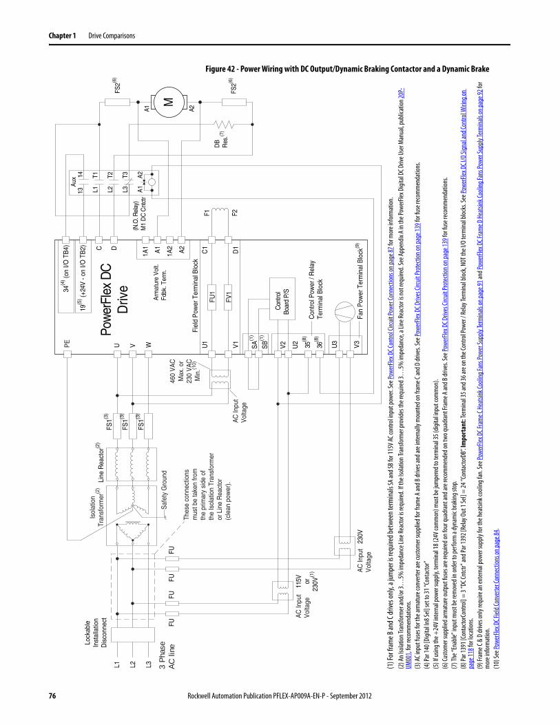
Chapter 1 Drive Comparisons
Figure 42 - Power Wiring with DC Output/Dynamic Braking Contactor and a Dynamic Brake
C DPo
wer
Flex
DC
Driv
e
36(8
)
34(4
) (on
I/O T
B4)
19(5
) (+24
V -
on I/
O T
B2)
Con
trol
Boar
d P/
S
115V or
230V
(1)
U2
V2
F2
35(8
)
U V W
3 P
hase
AC
line
L1 L2 L3
U1
V1
C1
D1
F1
FS1(3
)
FS1(3
)
FU1
FV1
FUFU
Fiel
d P
ower
Ter
min
al B
lock
Con
trol P
ower
/ R
elay
Term
inal
Blo
ck
A1
A2
Arm
atur
e V
olt.
Fdbk
. Ter
m.
1A1
1A2
U3
V3
Fan
Pow
er T
erm
inal
Blo
ck(9
)23
0V
FUFU
Line
Rea
ctor
(2)
Lock
able
Inst
alla
tion
Dis
conn
ect
SB
(1)
SA
(1)
Aux
(N.O
. Rel
ay)
M1
DC
Cnt
ctr
1314
L1 L2 L3 A1
T1 T2 T3 A2
M
A1 A2
FS2(6
)
FS2(6
)
DB
Res
.(7)
FS1(3
)
Thes
e co
nnec
tions
mus
t be
take
n fro
mth
e pr
imar
y si
de o
fth
e Is
olat
ion
Tran
sfor
mer
or L
ine
Rea
ctor
(cle
an p
ower
).
AC
Inpu
tV
olta
ge
AC
Inpu
tV
olta
ge
Isol
atio
nTr
ansf
orm
er(2
)
Saf
ety
Gro
und
PE
AC
Inpu
tV
olta
ge
460
VA
CM
ax. o
r23
0 V
AC
Min
.(10)
(1) F
or fr
ame B
and C
drive
s only
, a ju
mpe
r is re
quire
d bet
ween
term
inals S
A an
d SB f
or 11
5V AC
cont
rol in
put p
ower.
See P
ower
Flex D
C Con
trol C
ircuit
Powe
r Con
necti
onso
n pag
e87 f
or m
ore i
nfor
mat
ion.
(2) A
n Iso
lation
Tran
sform
er an
d/or
3…5%
impe
danc
e Line
Reac
tor i
s req
uired
. If th
e Iso
lation
Tran
sform
er pr
ovide
s the
requ
ired 3
…5%
impe
danc
e, a L
ine Re
acto
r is no
t req
uired
. See
Appe
ndix
A in
the P
ower
Flex D
igita
l DC D
rive U
ser M
anua
l, pub
licat
ion 20
P-UM
001,
for r
ecom
men
datio
ns.
(3) A
C inp
ut fu
ses f
or th
e arm
atur
e con
verte
r are
custo
mer
supp
lied f
or fr
ame A
and B
drive
s and
are i
nter
nally
mou
nted
on fr
ame C
and D
drive
s. Se
e Pow
erFle
x DC D
rives
Circu
it Pr
otec
tiono
n pag
e139
for f
use r
ecom
men
datio
ns.
(4) P
ar 14
0 [Di
gital
In8 S
el] se
t to 3
1 “Co
ntac
tor”
(5) I
f usin
g the
+24
V int
erna
l pow
er su
pply,
term
inal 1
8 (24
V com
mon
) mus
t be j
umpe
red t
o ter
min
al 35
(digi
tal in
put c
omm
on).
(6) C
usto
mer
supp
lied a
rmat
ure o
utpu
t fus
es ar
e req
uired
on fo
ur qu
adra
nt an
d are
reco
mm
ende
d on t
wo qu
adra
nt Fr
ame A
and B
drive
s. Se
e Pow
erFle
x DC D
rives
Circu
it Pr
otec
tiono
n pag
e139
for f
use r
ecom
men
datio
ns.
(7) T
he “E
nable
” inp
ut m
ust b
e rem
oved
in or
der t
o per
form
a dy
nam
ic br
aking
stop
.(8
) Par
1391
[Con
tacto
rCon
trol]
= 3
“DC C
ntctr
” and
Par 1
392 [
Relay
Out
1 Se
l] =
24 “C
onta
ctorD
B”. Im
port
ant:
Term
inal
35 an
d 36 a
re on
the C
ontro
l Pow
er /
Relay
Term
inal b
lock,
NOT t
he I/
O te
rmina
l bloc
ks. S
ee Po
werFl
ex D
C I/O
Sign
al an
d Con
trol W
iring
on
page
118 f
or lo
catio
ns.
(9) F
ram
e C &
D dr
ives o
nly r
equir
e an e
xter
nal p
ower
supp
ly fo
r the
heat
sink c
oolin
g fan
. See
Powe
rFlex
DC F
ram
e C H
eatsi
nk Co
oling
Fans
Powe
r Sup
ply Te
rmina
lson
page
91 an
d Pow
erFle
x DC F
ram
e D H
eatsi
nk Co
oling
Fans
Powe
r Sup
ply Te
rmina
lson
page
92 fo
r m
ore i
nfor
mat
ion.
(10)
See P
ower
Flex D
C Fiel
d Con
verte
r Con
necti
ons o
n pag
e84.
76 Rockwell Automation Publication PFLEX-AP009A-EN-P - September 2012
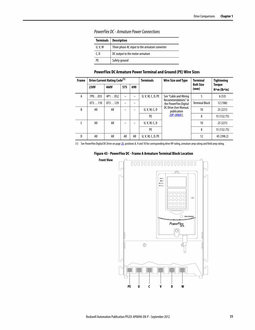
Drive Comparisons Chapter 1
PowerFlex DC - Armature Power Connections
PowerFlex DC Armature Power Terminal and Ground (PE) Wire Sizes
Figure 43 - PowerFlex DC - Frame A Armature Terminal Block Location
Terminals Description
U, V, W Three phase AC input to the armature converter
C, D DC output to the motor armature
PE Safety ground
Frame Drive Current Rating Code(1) Terminals Wire Size and Type Terminal Bolt Size (mm)
Tightening TorqueN•m (lb•in)
230V 460V 575 690
A 7P0…055 4P1…052 – – U, V, W, C, D, PE See “Cable and Wiring Recommendations” in the PowerFlex Digital DC Drive User Manual,
publication20P-UM001.
5 6 (53)
073…110 073…129 – – Terminal Block 12 (106)
B All All – – U, V, W, C, D 10 25 (221)
PE 8 15 (132.75)
C All All – – U, V, W, C, D 10 25 (221)
PE 8 15 (132.75)
D All All All All U, V, W, C, D, PE 12 45 (398.2)
(1) See PowerFlex Digital DC Drive on page 28, positions 8, 9 and 10 for corresponding drive HP rating, armature amp rating and field amp rating.
U C V D WPE
Front View
Rockwell Automation Publication PFLEX-AP009A-EN-P - September 2012 77
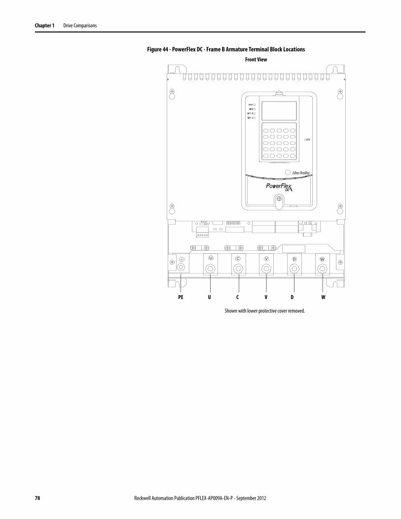
Chapter 1 Drive Comparisons
Figure 44 - PowerFlex DC - Frame B Armature Terminal Block Locations
U VC D W
U C V D WPE
Front View
Shown with lower protective cover removed.
78 Rockwell Automation Publication PFLEX-AP009A-EN-P - September 2012
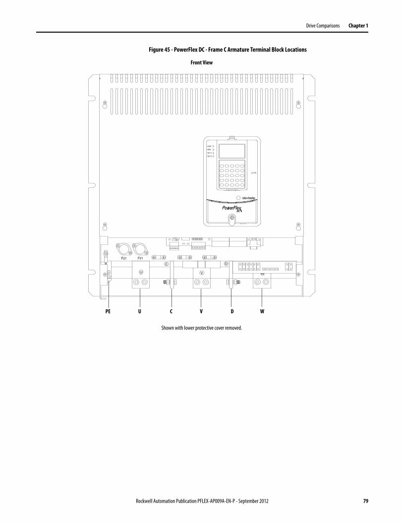
Drive Comparisons Chapter 1
Figure 45 - PowerFlex DC - Frame C Armature Terminal Block Locations
STS
PORT
MOD
NET A
NET B
FU1 FV1
U V
C D
W
U C V D WPE
Front View
Shown with lower protective cover removed.
Rockwell Automation Publication PFLEX-AP009A-EN-P - September 2012 79
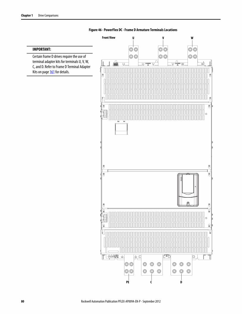
Chapter 1 Drive Comparisons
Figure 46 - PowerFlex DC - Frame D Armature Terminals Locations
Front View U V W
PE C D
IMPORTANT:
Certain frame D drives require the use of terminal adapter kits for terminals U, V, W, C, and D. Refer to Frame D Terminal Adapter Kits on page 161 for details.
80 Rockwell Automation Publication PFLEX-AP009A-EN-P - September 2012
Drive Comparisons Chapter 1
PowerFlex DC - Armature Voltage Feedback Connections
When a DC output contactor or inverting fault breaker/fuse is used with the drive, and a speed feedback device (tachometer or encoder) is not used, the Armature Voltage Feedback terminals can be used to monitor the armature voltage at the motor regardless of the state of the contactor or inverting fault device. When this terminal block is not connected to the motor armature terminals, the terminals must be jumpered (as described in the table below) and the armature voltage feedback is monitored internally within the drive. In this case, when a DC contactor is used with the drive, a speed feedback device is not used, and the contactor opens, the drive will no longer receive the armature voltage feedback signal.
Note that this terminal block is not present on drives shipped from the factory prior to those with v3.001 firmware installed. However, new Pulse Transformer boards shipped as replacement parts from the factory will contain this terminal block and can be used with any version of firmware.
PowerFlex DC Armature Voltage Feedback Circuit Wire Sizes and Terminal Specifications
IMPORTANT By default, these terminals are jumpered - 1A1 to A1 and 1A2 to A2. If these terminals are not wired to the motor terminals, the jumpers must be installed.
Terminal Description
1A1 Jumpered to A1 when internal armature voltage feedback is used.Not used when A1 is connected to motor terminal A1.
A1 Voltage feedback from motor terminal A1.
1A2 Jumpered to A2 when internal armature voltage feedback is used.Not used when A2 is connected to motor terminal A2.
A2 Voltage feedback from motor terminal A2.
Frame Terminals Wire Size and Type(1)
(1) Wire with an insulation rating of 600V or greater is recommended. See “Cable and Wiring Recommendations” in the PowerFlex Digital DC Drive User Manual, publication 20P-UM001, for cable spacing information.
Tightening TorqueN•m (lb•in)
A, B & C 1A1, A1, 1A2, A2 24…10 AWG/kcmils 0.5…0.6 (4.4…5.3)D 22…8 AWG/kcmils 0.8…1.6 (7.1…14.2)
Rockwell Automation Publication PFLEX-AP009A-EN-P - September 2012 81
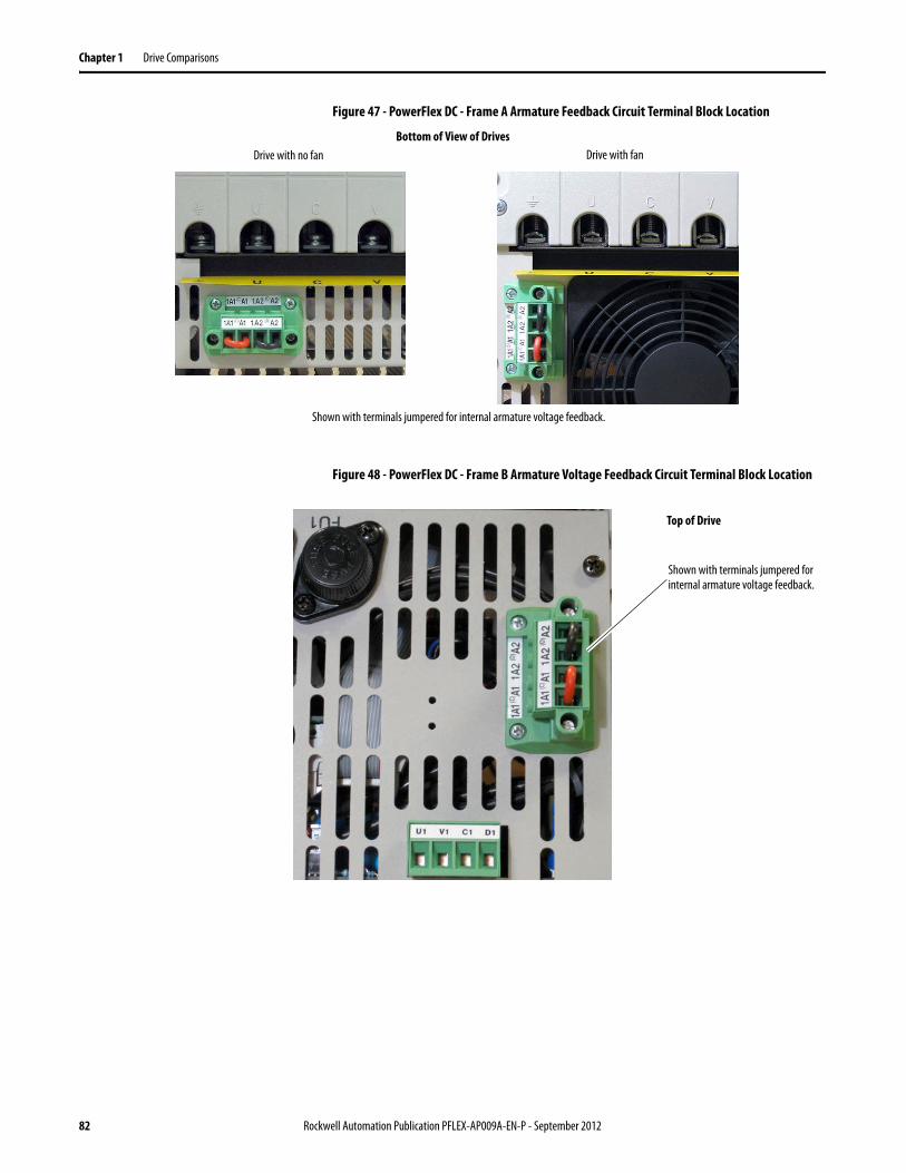
Chapter 1 Drive Comparisons
Figure 47 - PowerFlex DC - Frame A Armature Feedback Circuit Terminal Block Location
Figure 48 - PowerFlex DC - Frame B Armature Voltage Feedback Circuit Terminal Block Location
Bottom of View of Drives
Shown with terminals jumpered for internal armature voltage feedback.
Drive with no fan Drive with fan
Top of Drive
Shown with terminals jumpered for internal armature voltage feedback.
82 Rockwell Automation Publication PFLEX-AP009A-EN-P - September 2012
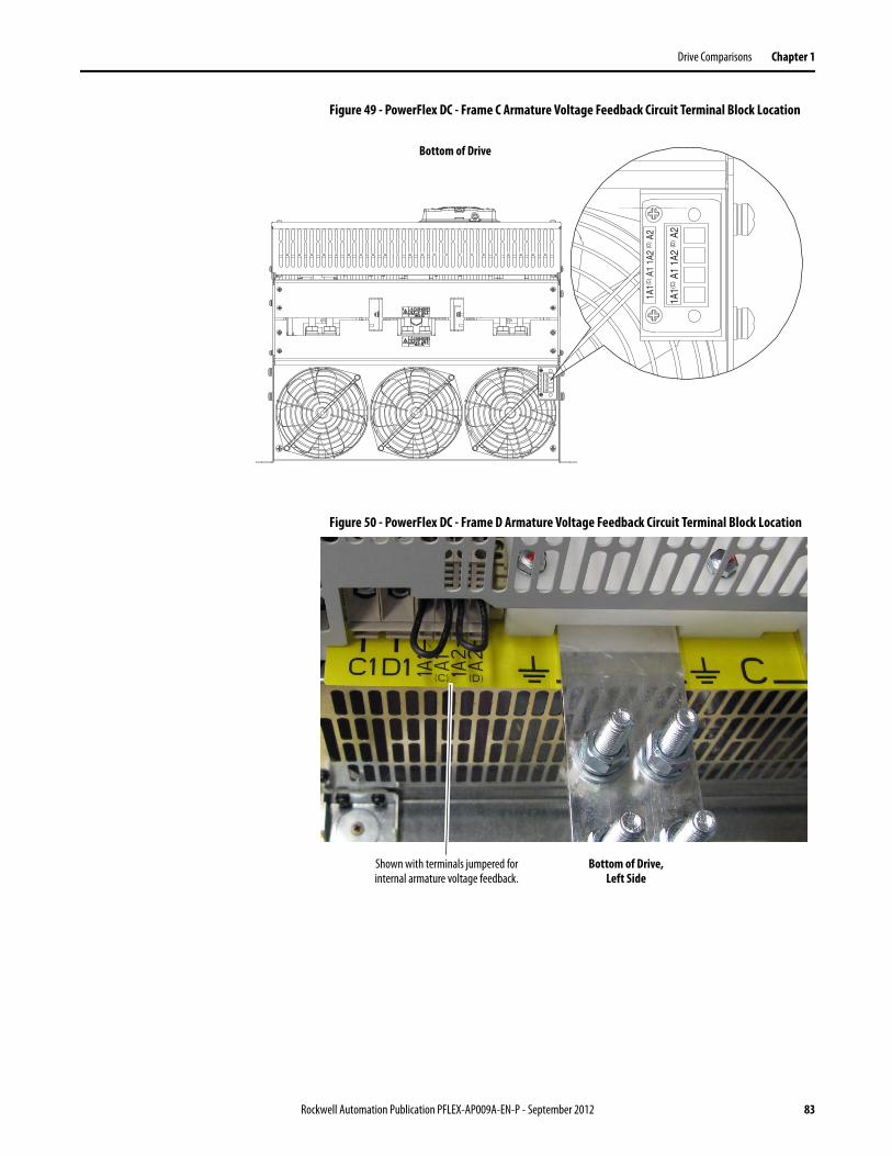
Drive Comparisons Chapter 1
Figure 49 - PowerFlex DC - Frame C Armature Voltage Feedback Circuit Terminal Block Location
Figure 50 - PowerFlex DC - Frame D Armature Voltage Feedback Circuit Terminal Block Location 1A
1(C) A
1 1A
2 (D
) A2
1A1(C
) A1
1A2
(D) A
2
1A1(C
) A1
1A2
(D) A
2
1A1(C
) A1
1A2
(D) A
2
Bottom of Drive
Bottom of Drive, Left Side
Shown with terminals jumpered for internal armature voltage feedback.
Rockwell Automation Publication PFLEX-AP009A-EN-P - September 2012 83
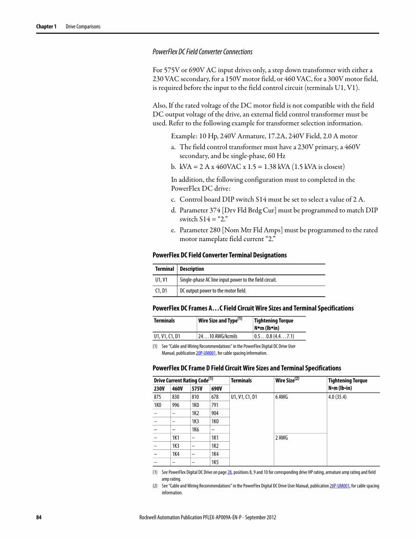
Chapter 1 Drive Comparisons
PowerFlex DC Field Converter Connections
For 575V or 690V AC input drives only, a step down transformer with either a 230 VAC secondary, for a 150V motor field, or 460 VAC, for a 300V motor field, is required before the input to the field control circuit (terminals U1, V1).
Also, If the rated voltage of the DC motor field is not compatible with the field DC output voltage of the drive, an external field control transformer must be used. Refer to the following example for transformer selection information.
Example: 10 Hp, 240V Armature, 17.2A, 240V Field, 2.0 A motora. The field control transformer must have a 230V primary, a 460V
secondary, and be single-phase, 60 Hzb. kVA = 2 A x 460VAC x 1.5 = 1.38 kVA (1.5 kVA is closest)
In addition, the following configuration must to completed in the PowerFlex DC drive:c. Control board DIP switch S14 must be set to select a value of 2 A.d. Parameter 374 [Drv Fld Brdg Cur] must be programmed to match DIP
switch S14 = “2.”e. Parameter 280 [Nom Mtr Fld Amps] must be programmed to the rated
motor nameplate field current “2.”
PowerFlex DC Field Converter Terminal Designations
PowerFlex DC Frames A…C Field Circuit Wire Sizes and Terminal Specifications
PowerFlex DC Frame D Field Circuit Wire Sizes and Terminal Specifications
Terminal Description
U1, V1 Single-phase AC line input power to the field circuit.
C1, D1 DC output power to the motor field.
Terminals Wire Size and Type(1)
(1) See “Cable and Wiring Recommendations” in the PowerFlex Digital DC Drive User Manual, publication 20P-UM001, for cable spacing information.
Tightening TorqueN•m (lb•in)
U1, V1, C1, D1 24…10 AWG/kcmils 0.5…0.8 (4.4…7.1)
Drive Current Rating Code(1)
(1) See PowerFlex Digital DC Drive on page 28, positions 8, 9 and 10 for corresponding drive HP rating, armature amp rating and field amp rating.
Terminals Wire Size(2)
(2) See “Cable and Wiring Recommendations” in the PowerFlex Digital DC Drive User Manual, publication 20P-UM001, for cable spacing information.
Tightening TorqueN•m (lb•in)230V 460V 575V 690V
875 830 810 678 U1, V1, C1, D1 6 AWG 4.0 (35.4)1K0 996 1K0 791– – 1K2 904– – 1K3 1K0– – 1K6 –– 1K1 – 1K1 2 AWG– 1K3 – 1K2– 1K4 – 1K4– – – 1K5
84 Rockwell Automation Publication PFLEX-AP009A-EN-P - September 2012
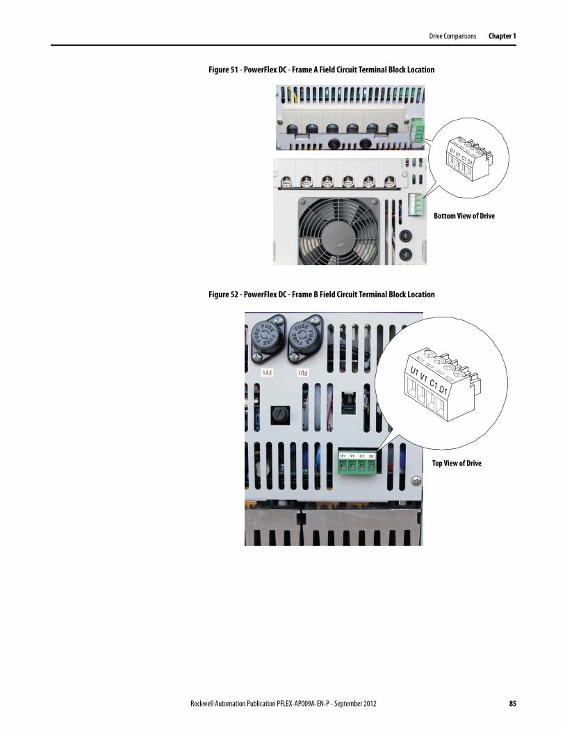
Drive Comparisons Chapter 1
Figure 51 - PowerFlex DC - Frame A Field Circuit Terminal Block Location
Figure 52 - PowerFlex DC - Frame B Field Circuit Terminal Block Location
V1 C1 D1
U1
Bottom View of Drive
V1 C1 D1
U1
Top View of Drive
Rockwell Automation Publication PFLEX-AP009A-EN-P - September 2012 85
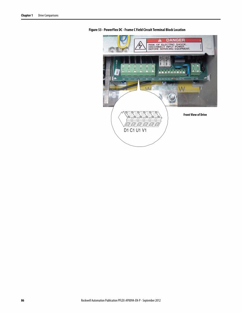
Chapter 1 Drive Comparisons
Figure 53 - PowerFlex DC - Frame C Field Circuit Terminal Block Location
V1U1C1D1
Front View of Drive
86 Rockwell Automation Publication PFLEX-AP009A-EN-P - September 2012
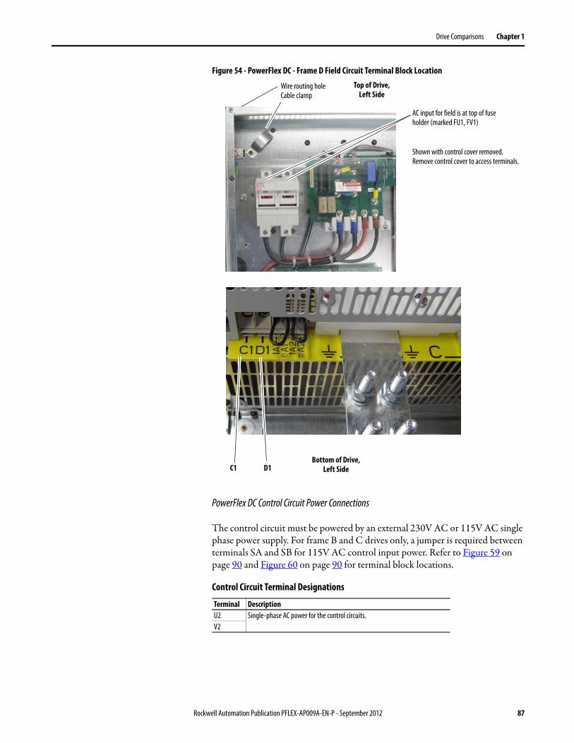
Drive Comparisons Chapter 1
Figure 54 - PowerFlex DC - Frame D Field Circuit Terminal Block Location
PowerFlex DC Control Circuit Power Connections
The control circuit must be powered by an external 230V AC or 115V AC single phase power supply. For frame B and C drives only, a jumper is required between terminals SA and SB for 115V AC control input power. Refer to Figure 59 on page 90 and Figure 60 on page 90 for terminal block locations.
Control Circuit Terminal Designations
Terminal DescriptionU2 Single-phase AC power for the control circuits.V2
Bottom of Drive, Left Side
Top of Drive,Left Side
Shown with control cover removed. Remove control cover to access terminals.
AC input for field is at top of fuse holder (marked FU1, FV1)
C1 D1
Wire routing holeCable clamp
Rockwell Automation Publication PFLEX-AP009A-EN-P - September 2012 87
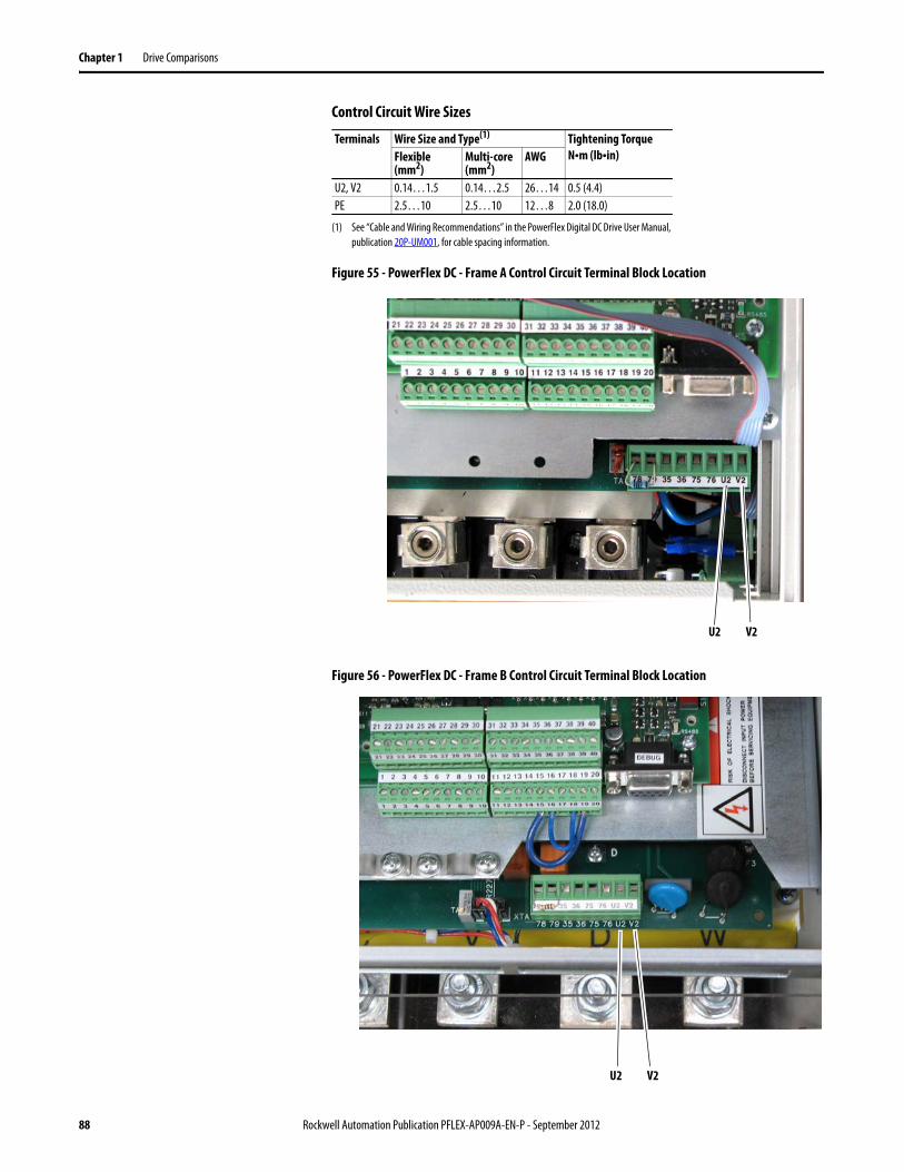
Chapter 1 Drive Comparisons
Control Circuit Wire Sizes
Figure 55 - PowerFlex DC - Frame A Control Circuit Terminal Block Location
Figure 56 - PowerFlex DC - Frame B Control Circuit Terminal Block Location
Terminals Wire Size and Type(1)
(1) See “Cable and Wiring Recommendations” in the PowerFlex Digital DC Drive User Manual, publication 20P-UM001, for cable spacing information.
Tightening TorqueN•m (lb•in)Flexible
(mm2)Multi-core (mm2)
AWG
U2, V2 0.14…1.5 0.14…2.5 26…14 0.5 (4.4)PE 2.5…10 2.5…10 12…8 2.0 (18.0)
U2 V2
U2 V2
88 Rockwell Automation Publication PFLEX-AP009A-EN-P - September 2012
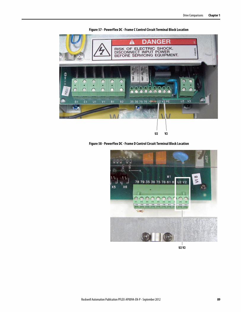
Drive Comparisons Chapter 1
Figure 57 - PowerFlex DC - Frame C Control Circuit Terminal Block Location
Figure 58 - PowerFlex DC - Frame D Control Circuit Terminal Block Location
U2 V2
U2 V2
Rockwell Automation Publication PFLEX-AP009A-EN-P - September 2012 89
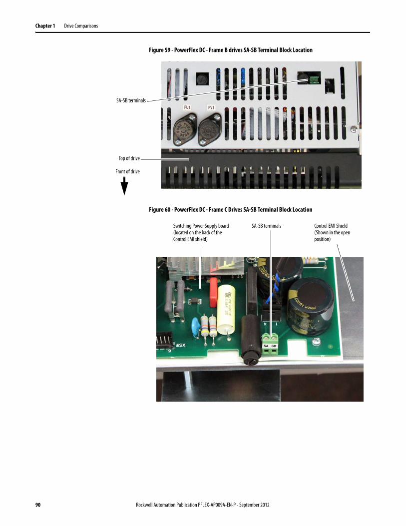
Chapter 1 Drive Comparisons
Figure 59 - PowerFlex DC - Frame B drives SA-SB Terminal Block Location
Figure 60 - PowerFlex DC - Frame C Drives SA-SB Terminal Block Location
Top of drive
Front of drive
SA-SB terminals
Switching Power Supply board (located on the back of the Control EMI shield)
SA-SB terminals Control EMI Shield(Shown in the open position)
90 Rockwell Automation Publication PFLEX-AP009A-EN-P - September 2012
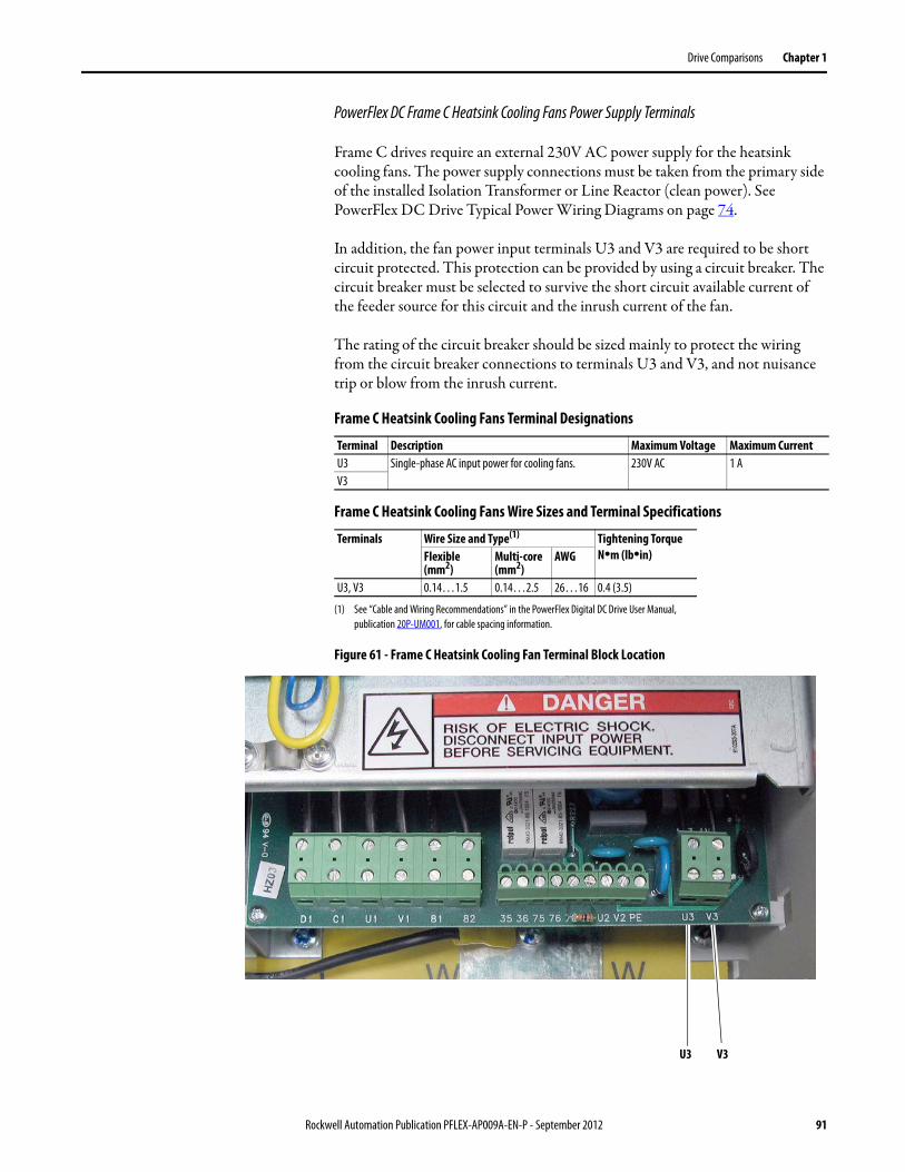
Drive Comparisons Chapter 1
PowerFlex DC Frame C Heatsink Cooling Fans Power Supply Terminals
Frame C drives require an external 230V AC power supply for the heatsink cooling fans. The power supply connections must be taken from the primary side of the installed Isolation Transformer or Line Reactor (clean power). See PowerFlex DC Drive Typical Power Wiring Diagrams on page 74.
In addition, the fan power input terminals U3 and V3 are required to be short circuit protected. This protection can be provided by using a circuit breaker. The circuit breaker must be selected to survive the short circuit available current of the feeder source for this circuit and the inrush current of the fan.
The rating of the circuit breaker should be sized mainly to protect the wiring from the circuit breaker connections to terminals U3 and V3, and not nuisance trip or blow from the inrush current.
Frame C Heatsink Cooling Fans Terminal Designations
Frame C Heatsink Cooling Fans Wire Sizes and Terminal Specifications
Figure 61 - Frame C Heatsink Cooling Fan Terminal Block Location
Terminal Description Maximum Voltage Maximum CurrentU3 Single-phase AC input power for cooling fans. 230V AC 1 AV3
Terminals Wire Size and Type(1)
(1) See “Cable and Wiring Recommendations” in the PowerFlex Digital DC Drive User Manual, publication 20P-UM001, for cable spacing information.
Tightening TorqueN•m (lb•in)Flexible
(mm2)Multi-core (mm2)
AWG
U3, V3 0.14…1.5 0.14…2.5 26…16 0.4 (3.5)
U3 V3
Rockwell Automation Publication PFLEX-AP009A-EN-P - September 2012 91
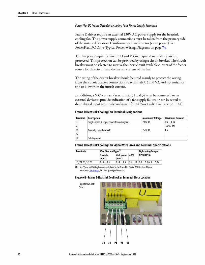
Chapter 1 Drive Comparisons
PowerFlex DC Frame D Heatsink Cooling Fans Power Supply Terminals
Frame D drives require an external 230V AC power supply for the heatsink cooling fan. The power supply connections must be taken from the primary side of the installed Isolation Transformer or Line Reactor (clean power). See PowerFlex DC Drive Typical Power Wiring Diagrams on page 74.
The fan power input terminals U3 and V3 are required to be short circuit protected. This protection can be provided by using a circuit breaker. The circuit breaker must be selected to survive the short circuit available current of the feeder source for this circuit and the inrush current of the fan.
The rating of the circuit breaker should be sized mainly to protect the wiring from the circuit breaker connections to terminals U3 and V3, and not nuisance trip or blow from the inrush current.
In addition, a N.C. contact (at terminals 31 and 32) can be connected to an external device to provide indication of a fan supply failure or can be wired to drive digital input terminals configured for 14 “Aux Fault” (via Pars133…144).
Frame D Heatsink Cooling Fan Terminal Designations
Frame D Heatsink Cooling Fan Signal Wire Sizes and Terminal Specifications
Figure 62 - Frame D Heatsink Cooling Fan Terminal Block Location
Terminal Description Maximum Voltage Maximum CurrentU3 Single-phase AC input power for cooling fans. 230V AC 2.4…3.3 A
(50/60 Hz)V331 Normally closed contact. 250V AC 1 A32PE Safety ground
Terminals Wire Size and Type(1)
(1) See “Cable and Wiring Recommendations” in the PowerFlex Digital DC Drive User Manual, publication 20P-UM001, for cable spacing information.
Tightening TorqueN•m (lb•in)Flexible
(mm2)Multi-core (mm2)
AWG
U3, V3, 31, 32, PE 0.14…1.5 0.14…2.5 28…12 0.5…0.6 (4.4…5.3)
32 31 PE V3 U3
Top of Drive, Left Side
92 Rockwell Automation Publication PFLEX-AP009A-EN-P - September 2012
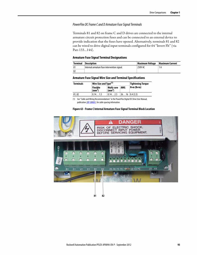
Drive Comparisons Chapter 1
PowerFlex DC Frame C and D Armature Fuse Signal Terminals
Terminals 81 and 82 on frame C and D drives are connected to the internal armature circuit protection fuses and can be connected to an external device to provide indication that the fuses have opened. Alternatively, terminals 81 and 82 can be wired to drive digital input terminals configured for 64 “Invert Flt” (via Pars 133…144).
Armature Fuse Signal Terminal Designations
Armature Fuse Signal Wire Size and Terminal Specifications
Figure 63 - Frame C Internal Armature Fuse Signal Terminal Block Location
Terminal Description Maximum Voltage Maximum Current81 Internal armature fuse intervention signal. 250V AC 1 A82
Terminals Wire Size and Type(1)
(1) See “Cable and Wiring Recommendations” in the PowerFlex Digital DC Drive User Manual, publication 20P-UM001, for cable spacing information.
Tightening TorqueN•m (lb•in)Flexible
(mm2)Multi-core (mm2)
AWG
81, 82 0.14…1.5 0.14…2.5 26…16 0.4 (3.5)
81 82
Rockwell Automation Publication PFLEX-AP009A-EN-P - September 2012 93
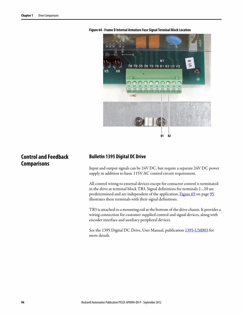
Chapter 1 Drive Comparisons
Figure 64 - Frame D Internal Armature Fuse Signal Terminal Block Location
Control and Feedback Comparisons
Bulletin 1395 Digital DC Drive
Input and output signals can be 24V DC, but require a separate 24V DC power supply in addition to basic 115V AC control circuit requirement.
All control wiring to external devices except for contactor control is terminated in the drive at terminal block TB3. Signal definitions for terminals 1…20 are predetermined and are independent of the application. Figure 65 on page 95 illustrates these terminals with their signal definitions.
TB3 is attached to a mounting rail at the bottom of the drive chassis. It provides a wiring connection for customer supplied control and signal devices, along with encoder interface and auxiliary peripheral devices.
See the 1395 Digital DC Drive, User Manual, publication 1395-UM003 for more details.
81 82
94 Rockwell Automation Publication PFLEX-AP009A-EN-P - September 2012
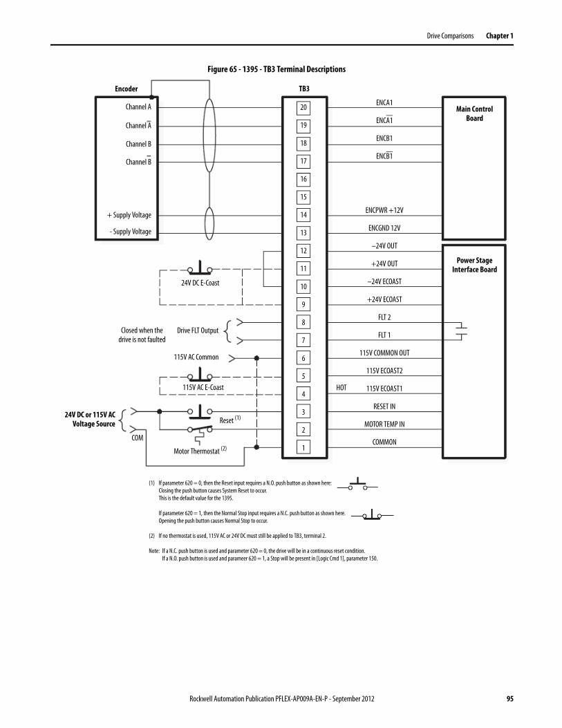
Drive Comparisons Chapter 1
Figure 65 - 1395 - TB3 Terminal Descriptions
Encoder
Channel A
Channel A
Channel B
Channel B
+ Supply Voltage
- Supply Voltage
TB3
Main Control Board
Power Stage Interface Board
20
19
18
17
16
15
14
13
12
11
10
9
8
7
6
5
4
3
2
1
24V DC E-Coast
Drive FLT OutputClosed when the drive is not faulted
115V AC E-Coast
115V AC Common
24V DC or 115V ACVoltage Source
COM
Motor Thermostat (2)
Reset (1)
(1) If parameter 620 = 0, then the Reset input requires a N.O. push button as shown here:Closing the push button causes System Reset to occur.This is the default value for the 1395.
If parameter 620 = 1, then the Normal Stop input requires a N.C. push button as shown here.Opening the push button causes Normal Stop to occur.
(2) If no thermostat is used, 115V AC or 24V DC must still be applied to TB3, terminal 2.
Note: If a N.C. push button is used and parameter 620 = 0, the drive will be in a continuous reset condition.If a N.O. push button is used and parameer 620 = 1, a Stop will be present in [Logic Cmd 1], parameter 150.
ENCA1
ENCA1
ENCB1
ENCB1
ENCPWR +12V
ENCGND 12V
–24V OUT
+24V OUT
–24V ECOAST
+24V ECOAST
FLT 2
FLT 1
115V COMMON OUT
115V ECOAST2
115V ECOAST1
RESET IN
MOTOR TEMP IN
COMMON
HOT
Rockwell Automation Publication PFLEX-AP009A-EN-P - September 2012 95
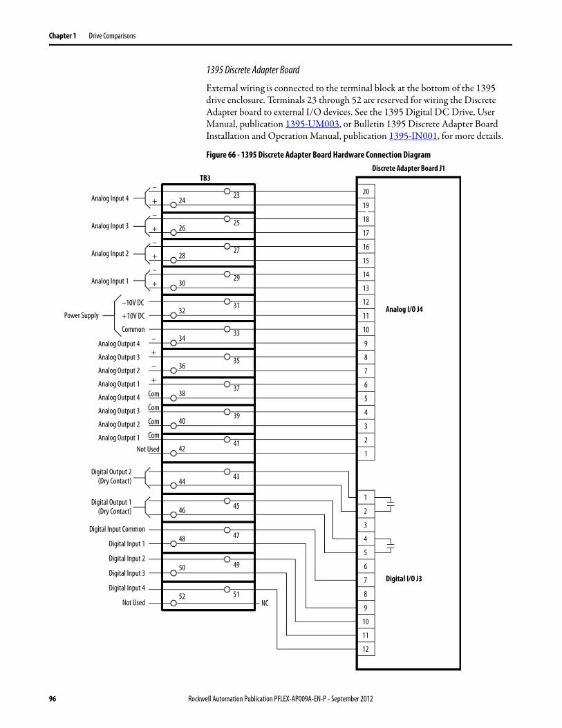
Chapter 1 Drive Comparisons
1395 Discrete Adapter Board
External wiring is connected to the terminal block at the bottom of the 1395 drive enclosure. Terminals 23 through 52 are reserved for wiring the Discrete Adapter board to external I/O devices. See the 1395 Digital DC Drive, User Manual, publication 1395-UM003, or Bulletin 1395 Discrete Adapter Board Installation and Operation Manual, publication 1395-IN001, for more details.
Figure 66 - 1395 Discrete Adapter Board Hardware Connection Diagram
Analog Input 4
Analog Input 3
Analog Input 2
Analog Input 1
TB3
Analog I/O J4
20
19
18
17
16
15
14
13
12
11
10
9
8
7
6
5
4
3
2
1
Discrete Adapter Board J1
1
2
3
4
5
6
7
8
9
10
11
12
Digital I/O J3
–
+
–
+
–
+
–
+
–
+
–
+
Com
Com
Com
Com
–10V DC
+10V DC
Common
Not Used
Power Supply
Analog Output 4
Analog Output 3
Analog Output 2
Analog Output 1
Analog Output 4
Analog Output 3
Analog Output 2
Analog Output 1
24
26
28
30
32
34
36
38
40
42
44
46
48
50
52
23
25
27
29
31
33
35
37
39
41
43
45
47
49
51NC
Digital Input Common
Digital Input 1
Digital Input 2
Digital Input 3
Digital Input 4
Not Used
Digital Output 2(Dry Contact)
Digital Output 1(Dry Contact)
96 Rockwell Automation Publication PFLEX-AP009A-EN-P - September 2012
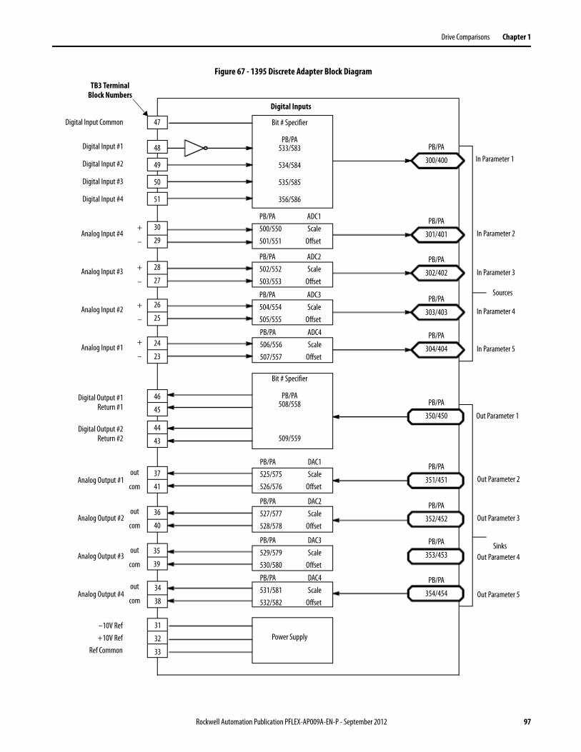
Drive Comparisons Chapter 1
Figure 67 - 1395 Discrete Adapter Block Diagram
Analog Input #4
Analog Input #3
Analog Input #2
Analog Input #1
TB3 Terminal Block Numbers
+
–
Analog Output #1
Analog Output #2
Analog Output #3
Analog Output #4
47
48
49
50
51
Digital Input Common
Digital Output #1Return #1
Digital Output #2Return #2
30
29
28
27
26
25
24
23
+
–
+
–
+
–
–10V Ref+10V Ref
Ref Common
46
45
44
43
37
41
36
40
35
39
34
38
31
32
33
Digital Inputs
Bit # Specifier
PB/PA533/583
534/584
535/585
356/586
PB/PA ADC1500/550 Scale501/551 Offset
PB/PA ADC2502/552 Scale503/553 Offset
PB/PA ADC3504/554 Scale505/555 Offset
PB/PA ADC4506/556 Scale507/557 Offset
Bit # Specifier
PB/PA508/558
509/559
PB/PA DAC1525/575 Scale526/576 Offset
PB/PA DAC2527/577 Scale528/578 Offset
PB/PA DAC3529/579 Scale530/580 Offset
PB/PA DAC4531/581 Scale532/582 Offset
Power Supply
PB/PA
300/400
PB/PA
301/401
PB/PA
302/402
PB/PA
303/403
PB/PA
304/404
PB/PA
350/450
PB/PA
351/451
PB/PA
352/452
PB/PA
353/453
PB/PA
354/454
Sources
out
com
out
com
out
com
out
com
Digital Input #1
Digital Input #2
Digital Input #3
Digital Input #4
In Parameter 1
In Parameter 2
In Parameter 3
In Parameter 4
In Parameter 5
Out Parameter 1
Out Parameter 2
Out Parameter 3
Out Parameter 4
Out Parameter 5
Sinks
Rockwell Automation Publication PFLEX-AP009A-EN-P - September 2012 97
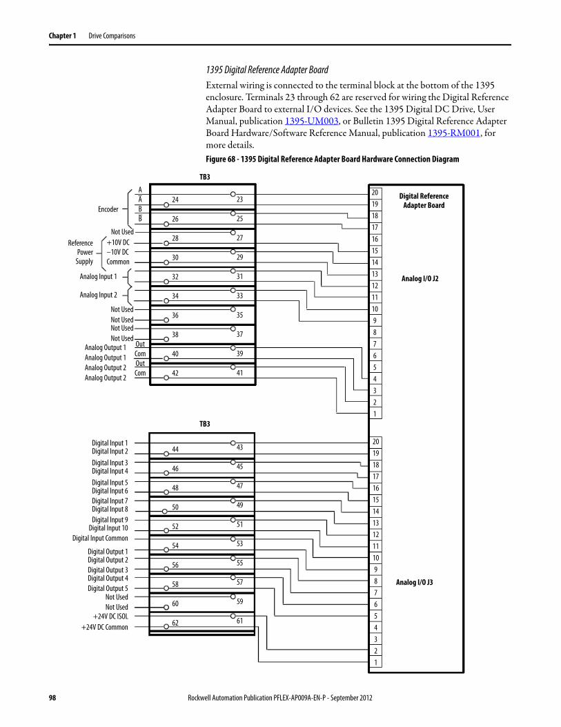
Chapter 1 Drive Comparisons
1395 Digital Reference Adapter BoardExternal wiring is connected to the terminal block at the bottom of the 1395 enclosure. Terminals 23 through 62 are reserved for wiring the Digital Reference Adapter Board to external I/O devices. See the 1395 Digital DC Drive, User Manual, publication 1395-UM003, or Bulletin 1395 Digital Reference Adapter Board Hardware/Software Reference Manual, publication 1395-RM001, for more details.Figure 68 - 1395 Digital Reference Adapter Board Hardware Connection Diagram
Analog Input 1
Analog Input 2
TB3
Analog I/O J2
2019181716151413121110987654321
Digital Reference Adapter Board
Analog I/O J3
OutComOutCom
+10V DC–10V DCCommon
Encoder
ReferencePower
Supply
Analog Output 1Analog Output 1Analog Output 2Analog Output 2
24
26
28
30
32
34
36
38
40
42
44
46
48
50
52
54
56
58
60
62
23
25
27
29
31
33
35
37
39
41
43
45
47
49
51
53
55
57
59
61
Digital Input 1Digital Input 2
2019181716151413121110987654321
TB3
Not Used
Not UsedNot UsedNot UsedNot Used
Digital Input 3Digital Input 4Digital Input 5Digital Input 6Digital Input 7Digital Input 8Digital Input 9
Digital Input 10
Digital Output 1Digital Output 2Digital Output 3Digital Output 4Digital Output 5
Not UsedNot Used
+24V DC ISOL+24V DC Common
AABB
Digital Input Common
98 Rockwell Automation Publication PFLEX-AP009A-EN-P - September 2012
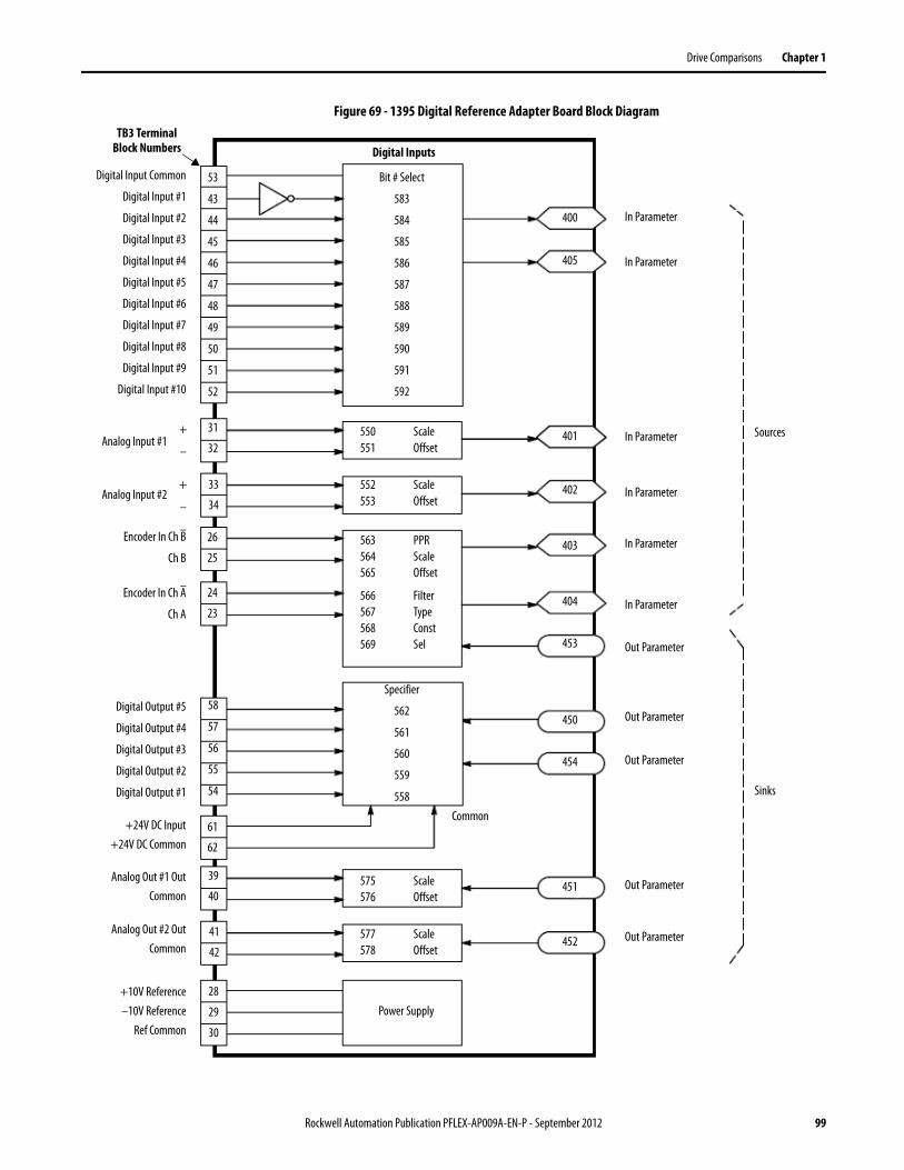
Drive Comparisons Chapter 1
Figure 69 - 1395 Digital Reference Adapter Board Block Diagram
Analog Input #1
Analog Input #2
TB3 Terminal Block Numbers
53
43
44
45
46
47
48
49
50
51
52
Digital Input Common
31
32
33
34
26
25
24
23
+
–
+
–
+10V Reference–10V Reference
Ref Common
61
62
39
40
41
42
28
29
30
Digital Inputs
Bit # Select
583
584
585
586
587
588
589
590
591
592
Power Supply
400
401
402
403
404
450
451
452
453
454
Sources
Digital Input #1
Digital Input #2
Digital Input #3
Digital Input #4
Digital Input #5
Digital Input #6
Digital Input #7
Digital Input #8
Digital Input #9
Digital Input #10
In Parameter
Out Parameter
Sinks
Encoder In Ch B
Ch B
Encoder In Ch A
Ch A
58
57
56
55
54
Digital Output #5
Digital Output #4
Digital Output #3
Digital Output #2
Digital Output #1
+24V DC Input+24V DC Common
Analog Out #1 OutCommon
Analog Out #2 OutCommon
550 Scale551 Offset
552 Scale553 Offset
563 PPR564 Scale565 Offset
566 Filter567 Type568 Const569 Sel
Specifier
562
561
560
559
558
575 Scale576 Offset
577 Scale578 Offset
405 In Parameter
In Parameter
In Parameter
In Parameter
In Parameter
Out Parameter
Out Parameter
Out Parameter
Out Parameter
Common
Rockwell Automation Publication PFLEX-AP009A-EN-P - September 2012 99

Chapter 1 Drive Comparisons
1395 Encoder Driver Interface Module
The Encoder Driver Interface module is a multi-purpose pulse amplifier primarily used for generating 15 mA, double-ended, sink and source output signals. These signals are acceptable as inputs to digital reference and/or digital feedbacks into opto-isolated circuits of Bulletin 1395, 1336 PLUS, 1336 FORCE and 1399 drives. The opto-isolated input signals are designed to guard against signal common loops and also to provide an improved signal to noise input circuit.
See the Encoder Driver Interface Module Installation Instructions, publication 1395-IN010, for more details.
1395 Digital Reference Adapter for RTP Applications
The Digital Reference Adapter board provides an interface between an external device and the Bulletin 1395 drive Main Control board. When used with the Reel-Tension-Paster (RTP) drive, the Digital Reference Adapter board allows the drive to be commanded by a digital reference input signal from a single channel encoder or frequency generator, whose shaft speed is equal to press speed. In this application, a magnetic pickup with a gear ranging from 128 to 140 teeth (dependent on printing diameter of the press) is used as the press speed sensor for the drive.
This board also allows the drive to be controlled using combinations of internal programmable relay logic at digital inputs 1…8, or through use of an analog device such as a dancer potentiometer. When the analog device is used for control, the dancer potentiometer provides position feedback sensing and controls the reel speed through the P/I regulator located on the Digital Reference Adapter board and the process trim regulator located on the Bulletin 1395 drive Main Control board.
See the Digital Reference Adapter for RTP Applications User Manual, publication 1395-IN030, for more details.
Please contact [email protected] via email for help with your migration strategy.
100 Rockwell Automation Publication PFLEX-AP009A-EN-P - September 2012
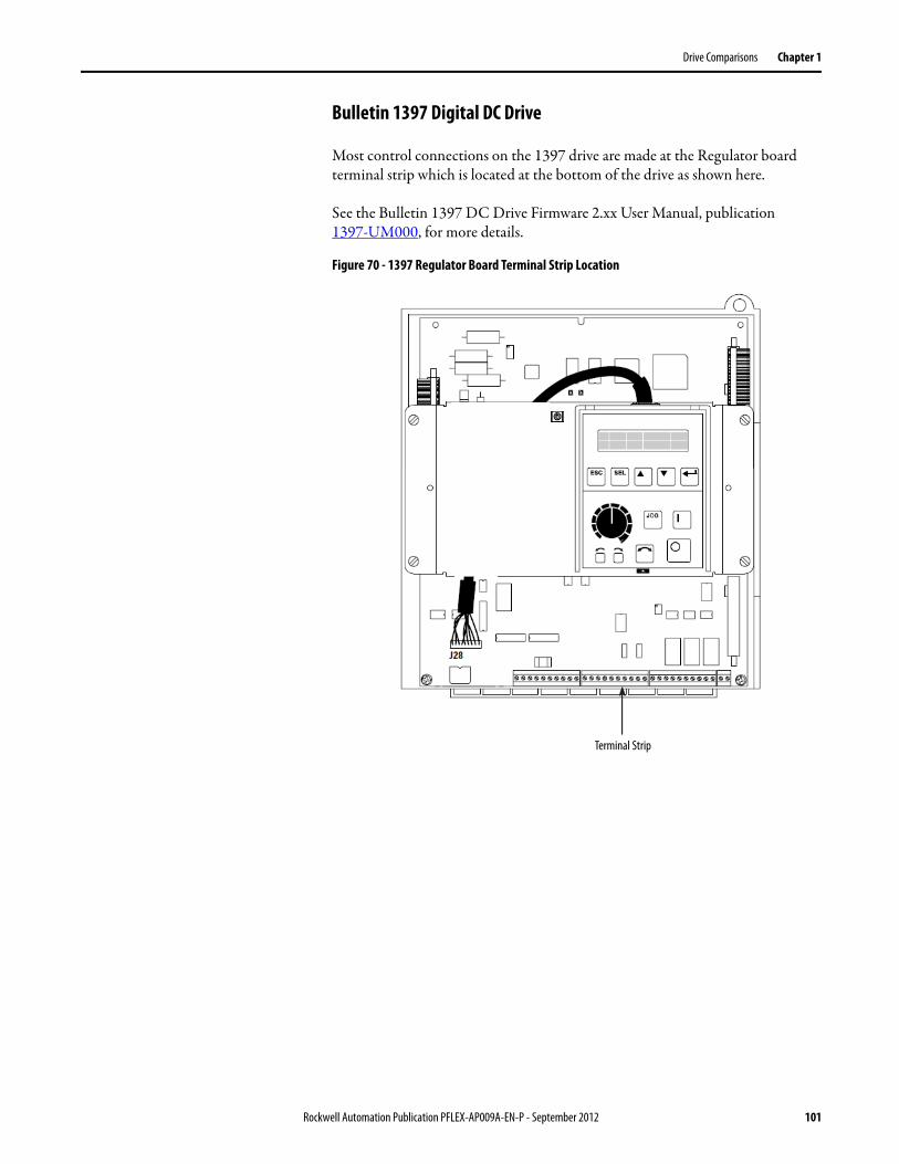
Drive Comparisons Chapter 1
Bulletin 1397 Digital DC Drive
Most control connections on the 1397 drive are made at the Regulator board terminal strip which is located at the bottom of the drive as shown here.
See the Bulletin 1397 DC Drive Firmware 2.xx User Manual, publication1397-UM000, for more details.
Figure 70 - 1397 Regulator Board Terminal Strip Location
Terminal Strip
Rockwell Automation Publication PFLEX-AP009A-EN-P - September 2012 101
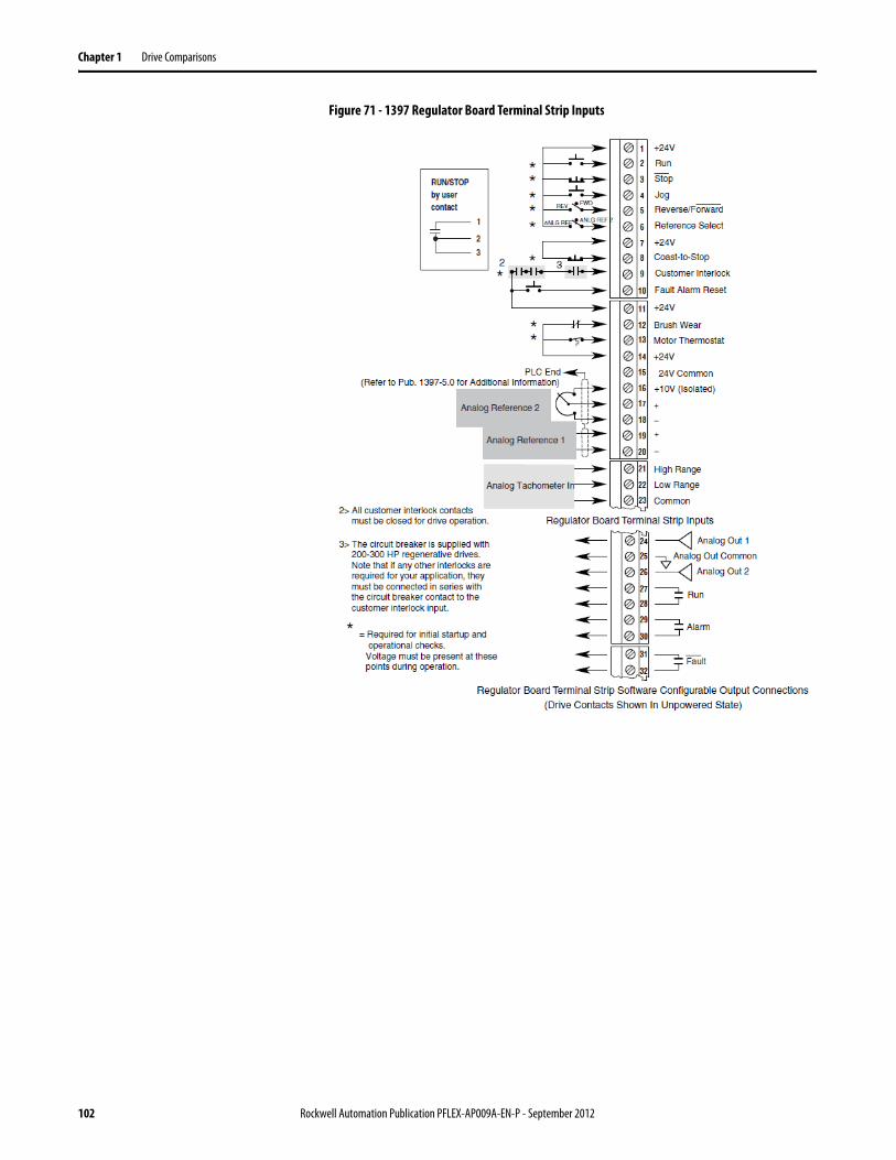
Chapter 1 Drive Comparisons
Figure 71 - 1397 Regulator Board Terminal Strip Inputs
102 Rockwell Automation Publication PFLEX-AP009A-EN-P - September 2012
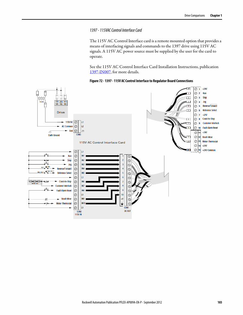
Drive Comparisons Chapter 1
1397 - 115VAC Control Interface Card
The 115V AC Control Interface card is a remote mounted option that provides a means of interfacing signals and commands to the 1397 drive using 115V AC signals. A 115V AC power source must be supplied by the user for the card to operate.
See the 115V AC Control Interface Card Installation Instructions, publication 1397-IN007, for more details.
Figure 72 - 1397 - 115V AC Control Interface to Regulator Board Connections
Rockwell Automation Publication PFLEX-AP009A-EN-P - September 2012 103
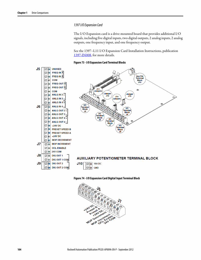
Chapter 1 Drive Comparisons
1397 I/O Expansion Card
The I/O Expansion card is a drive mounted board that provides additional I/O signals, including five digital inputs, two digital outputs, 2 analog inputs, 2 analog outputs, one frequency input, and one frequency output.
See the 1397–L11 I/O Expansion Card Installation Instructions, publication 1397-IN008, for more details.
Figure 73 - I/O Expansion Card Terminal Blocks
Figure 74 - I/O Expansion Card Digital Input Terminal Block
104 Rockwell Automation Publication PFLEX-AP009A-EN-P - September 2012
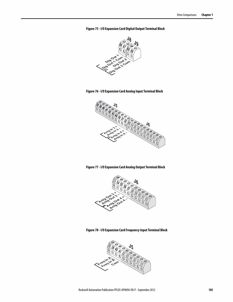
Drive Comparisons Chapter 1
Figure 75 - I/O Expansion Card Digital Output Terminal Block
Figure 76 - I/O Expansion Card Analog Input Terminal Block
Figure 77 - I/O Expansion Card Analog Output Terminal Block
Figure 78 - I/O Expansion Card Frequency Input Terminal Block
Rockwell Automation Publication PFLEX-AP009A-EN-P - September 2012 105
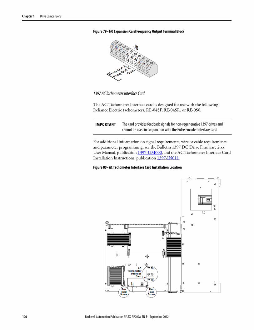
Chapter 1 Drive Comparisons
Figure 79 - I/O Expansion Card Frequency Output Terminal Block
1397 AC Tachometer Interface Card
The AC Tachometer Interface card is designed for use with the following Reliance Electric tachometers; RE-045F, RE-045R, or RE-050.
For additional information on signal requirements, wire or cable requirements and parameter programming, see the Bulletin 1397 DC Drive Firmware 2.xx User Manual, publication 1397-UM000, and the AC Tachometer Interface Card Installation Instructions, publication 1397-IN011.
Figure 80 - AC Tachometer Interface Card Installation Location
IMPORTANT The card provides feedback signals for non-regenerative 1397 drives and cannot be used in conjunction with the Pulse Encoder Interface card.
106 Rockwell Automation Publication PFLEX-AP009A-EN-P - September 2012
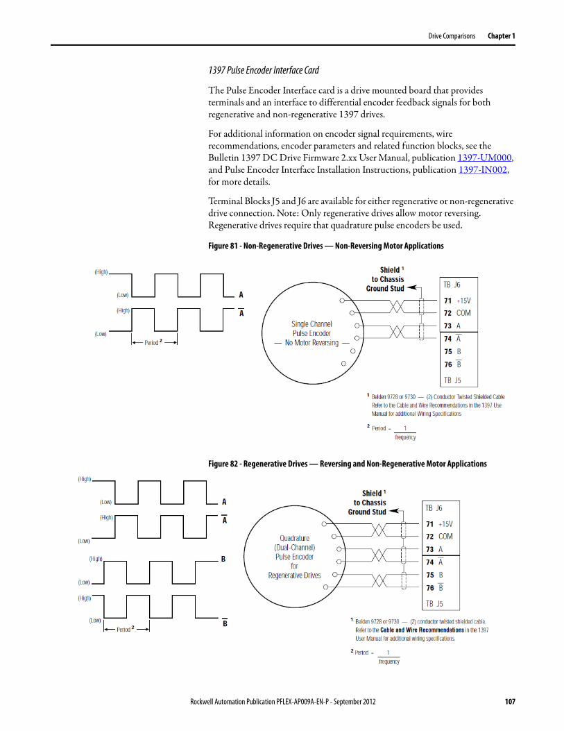
Drive Comparisons Chapter 1
1397 Pulse Encoder Interface Card
The Pulse Encoder Interface card is a drive mounted board that provides terminals and an interface to differential encoder feedback signals for both regenerative and non-regenerative 1397 drives.
For additional information on encoder signal requirements, wire recommendations, encoder parameters and related function blocks, see the Bulletin 1397 DC Drive Firmware 2.xx User Manual, publication 1397-UM000, and Pulse Encoder Interface Installation Instructions, publication 1397-IN002, for more details.
Terminal Blocks J5 and J6 are available for either regenerative or non-regenerative drive connection. Note: Only regenerative drives allow motor reversing. Regenerative drives require that quadrature pulse encoders be used.
Figure 81 - Non-Regenerative Drives — Non-Reversing Motor Applications
Figure 82 - Regenerative Drives — Reversing and Non-Regenerative Motor Applications
Rockwell Automation Publication PFLEX-AP009A-EN-P - September 2012 107

Chapter 1 Drive Comparisons
FlexPak 3000 DC Drive
Figure 83 - Regulator Board Terminal Strip Location
Shown with Standard Cover Removed
Terminal Strip
RS-232Connector
108 Rockwell Automation Publication PFLEX-AP009A-EN-P - September 2012
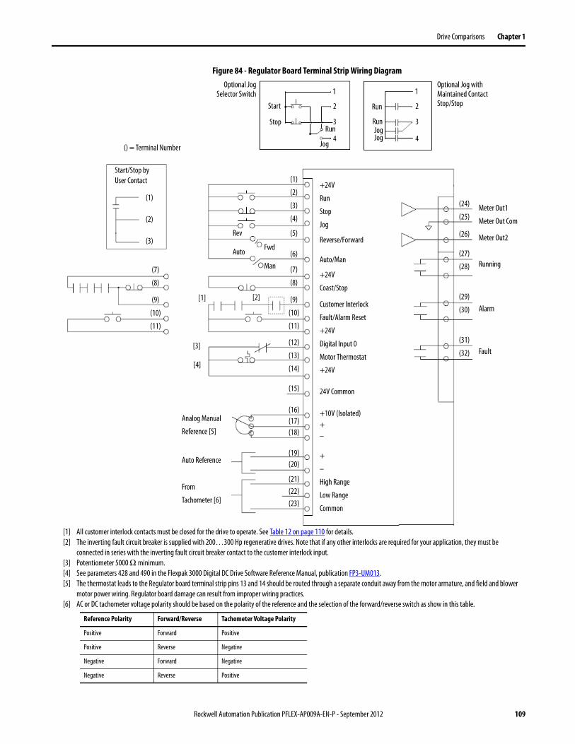
Drive Comparisons Chapter 1
Figure 84 - Regulator Board Terminal Strip Wiring Diagram Optional Jog
Selector SwitchOptional Jog with Maintained Contact Stop/StopStart
Stop
Run
Run
Jog
1
2
3
4
RunJogJog
1
2
3
4() = Terminal Number
(1)
(2)
(3)
(4)
(5)
(6)
(7)
(8)
(9)
(10)
(11)
(12)
(13)
(14)
(15)
(16)(17)(18)
(19)(20)
(21)(22)(23)
+24V
Run
Stop
Jog
Reverse/Forward
Auto/Man
+24V
Coast/Stop
Customer Interlock
Fault/Alarm Reset
+24V
Digital Input 0
Motor Thermostat
+24V
(1)
(2)
(3)
(7)
(8)
(9)
(10)
(11)
Start/Stop by User Contact
24V Common
+10V (Isolated)+–
+
–
High Range
Low Range
Common
[1] [2]
[3]
[4]
Analog Manual
Reference [5]
Auto Reference
From
Tachometer [6]
[1] All customer interlock contacts must be closed for the drive to operate. See Table 12 on page 110 for details.[2] The inverting fault circuit breaker is supplied with 200…300 Hp regenerative drives. Note that if any other interlocks are required for your application, they must be
connected in series with the inverting fault circuit breaker contact to the customer interlock input.[3] Potentiometer 5000 Ω minimum.[4] See parameters 428 and 490 in the Flexpak 3000 Digital DC Drive Software Reference Manual, publication FP3-UM013.[5] The thermostat leads to the Regulator board terminal strip pins 13 and 14 should be routed through a separate conduit away from the motor armature, and field and blower
motor power wiring. Regulator board damage can result from improper wiring practices.[6] AC or DC tachometer voltage polarity should be based on the polarity of the reference and the selection of the forward/reverse switch as show in this table.
Reference Polarity Forward/Reverse Tachometer Voltage Polarity
Positive Forward Positive
Positive Reverse Negative
Negative Forward Negative
Negative Reverse Positive
Rev
FwdAuto
Man
(24)
(25)
(27)
(28)
(26)
(29)
(30)
(31)
(32)
Meter Out1
Meter Out Com
Meter Out2
Running
Alarm
Fault
Rockwell Automation Publication PFLEX-AP009A-EN-P - September 2012 109
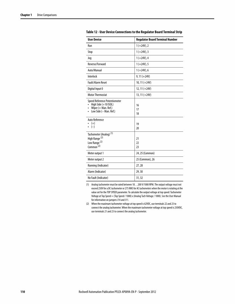
Chapter 1 Drive Comparisons
Table 12 - User Device Connections to the Regulator Board Terminal Strip
User Device Regulator Board Terminal Number
Run 1 (+24V), 2
Stop 1 (+24V), 3
Jog 1 (+24V), 4
Reverse/Forward 1 (+24V), 5
Auto/Manual 1 (+24V), 6
Interlock 9, 11 (+24V)
Fault/Alarm Reset 10, 11 (+24V)
Digital Input 0 12, 11 (+24V)
Motor Thermostat 13, 11 (+24V)
Speed Reference Potentiometer• High Side (+10 ISOL)• Wiper (+ Man. Ref.)• Low Side (– Man. Ref.)
161718
Auto Reference• (+)• (–)
1920
Tachometer (Analog) (1)
High Range (2)
Low Range (2)
Common (2)
(1) Analog tachometer must be rated between 18…200 V/1000 RPM. The output voltage must not exceed 250V for a DC tachometer or 275 RMS for AC tachometers when the motor is rotating at the value set for the TOP SPEED parameter. To calculate the output voltage at top speed: Tachometer Voltage at Top Speed = (Top Speed / 1000) x (Analog Tach Voltage / 1000). See the User Manual for information on jumpers J14 and J11.
(2) When the maximum tachometer voltage at top speed is 62VDC, use terminals 22 and 23 to connect the analog tachometer. When the maximum tachometer voltage at top speed is 250VDC, use terminals 21 and 23 to connect the analog tachometer.
212223
Meter output 1 24, 25 (Common)
Meter output 2 25 (Common), 26
Running (Indicator) 27, 28
Alarm (Indicator) 29, 30
No Fault (Indicator) 31, 32
110 Rockwell Automation Publication PFLEX-AP009A-EN-P - September 2012
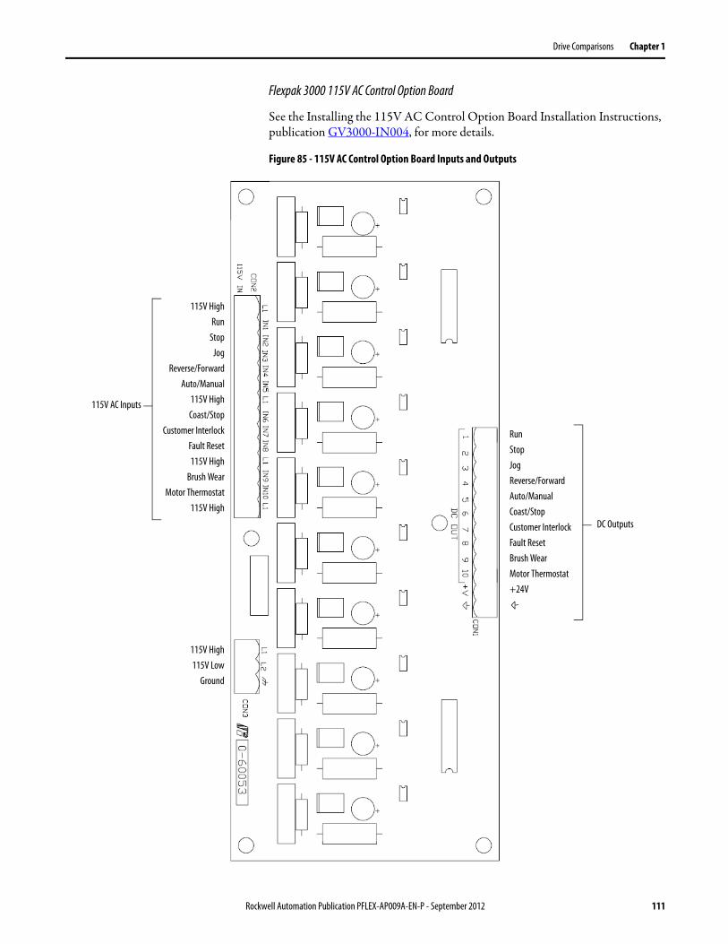
Drive Comparisons Chapter 1
Flexpak 3000 115V AC Control Option Board
See the Installing the 115V AC Control Option Board Installation Instructions, publication GV3000-IN004, for more details.
Figure 85 - 115V AC Control Option Board Inputs and Outputs
115V AC Inputs
115V HighRun
StopJog
Reverse/ForwardAuto/Manual
115V HighCoast/Stop
Customer InterlockFault Reset115V High
Brush WearMotor Thermostat
115V High
RunStopJogReverse/ForwardAuto/ManualCoast/StopCustomer InterlockFault ResetBrush WearMotor Thermostat+24V
DC Outputs
115V High115V Low
Ground
Rockwell Automation Publication PFLEX-AP009A-EN-P - September 2012 111
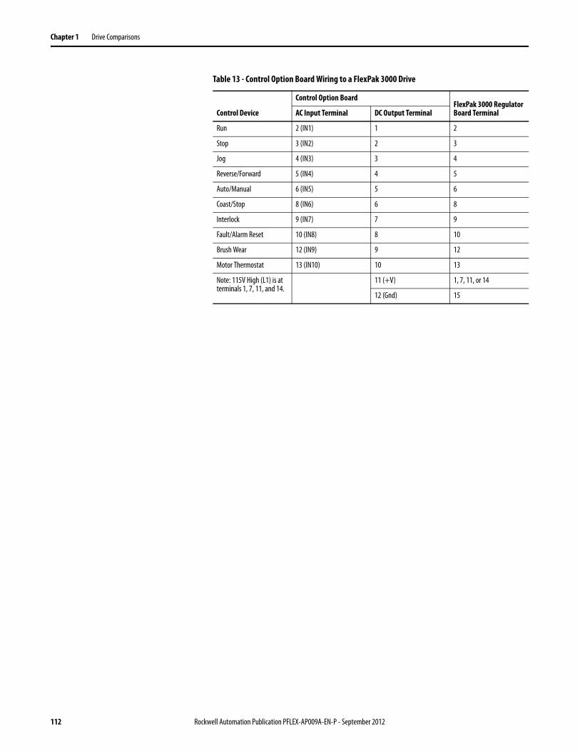
Chapter 1 Drive Comparisons
Table 13 - Control Option Board Wiring to a FlexPak 3000 Drive
Control Device
Control Option BoardFlexPak 3000 Regulator Board TerminalAC Input Terminal DC Output Terminal
Run 2 (IN1) 1 2
Stop 3 (IN2) 2 3
Jog 4 (IN3) 3 4
Reverse/Forward 5 (IN4) 4 5
Auto/Manual 6 (IN5) 5 6
Coast/Stop 8 (IN6) 6 8
Interlock 9 (IN7) 7 9
Fault/Alarm Reset 10 (IN8) 8 10
Brush Wear 12 (IN9) 9 12
Motor Thermostat 13 (IN10) 10 13
Note: 115V High (L1) is at terminals 1, 7, 11, and 14.
11 (+V) 1, 7, 11, or 14
12 (Gnd) 15
112 Rockwell Automation Publication PFLEX-AP009A-EN-P - September 2012
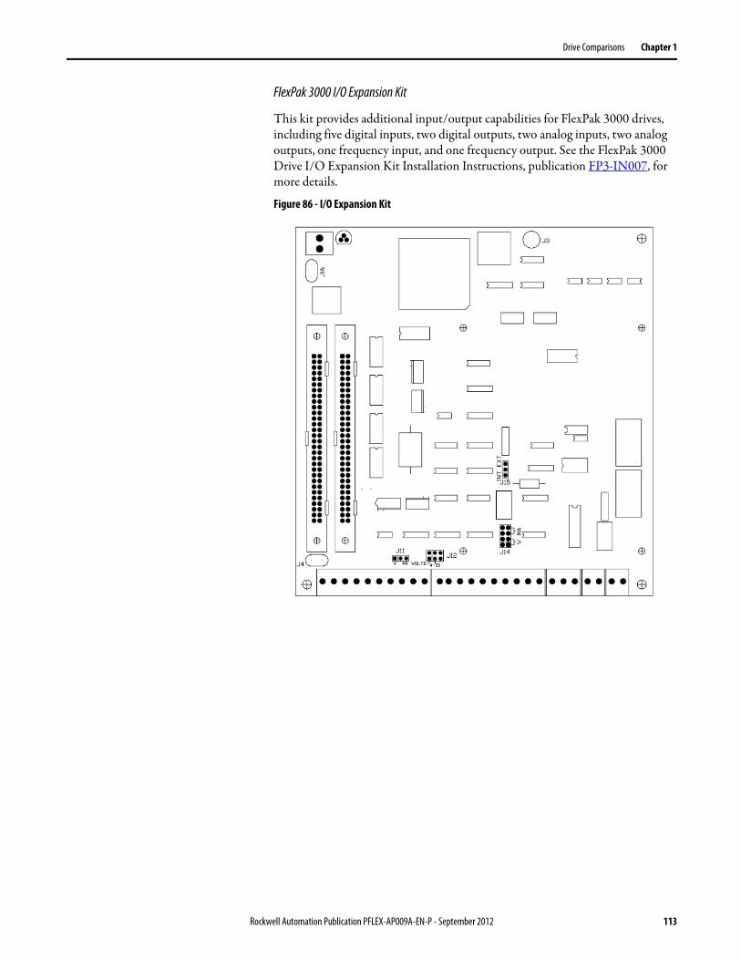
Drive Comparisons Chapter 1
FlexPak 3000 I/O Expansion Kit
This kit provides additional input/output capabilities for FlexPak 3000 drives, including five digital inputs, two digital outputs, two analog inputs, two analog outputs, one frequency input, and one frequency output. See the FlexPak 3000 Drive I/O Expansion Kit Installation Instructions, publication FP3-IN007, for more details.
Figure 86 - I/O Expansion Kit
Rockwell Automation Publication PFLEX-AP009A-EN-P - September 2012 113
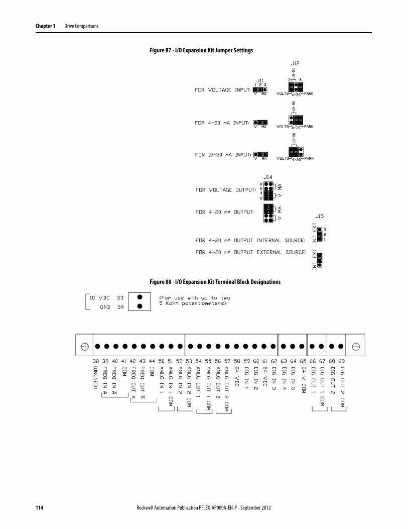
Chapter 1 Drive Comparisons
Figure 87 - I/O Expansion Kit Jumper Settings
Figure 88 - I/O Expansion Kit Terminal Block Designations
114 Rockwell Automation Publication PFLEX-AP009A-EN-P - September 2012
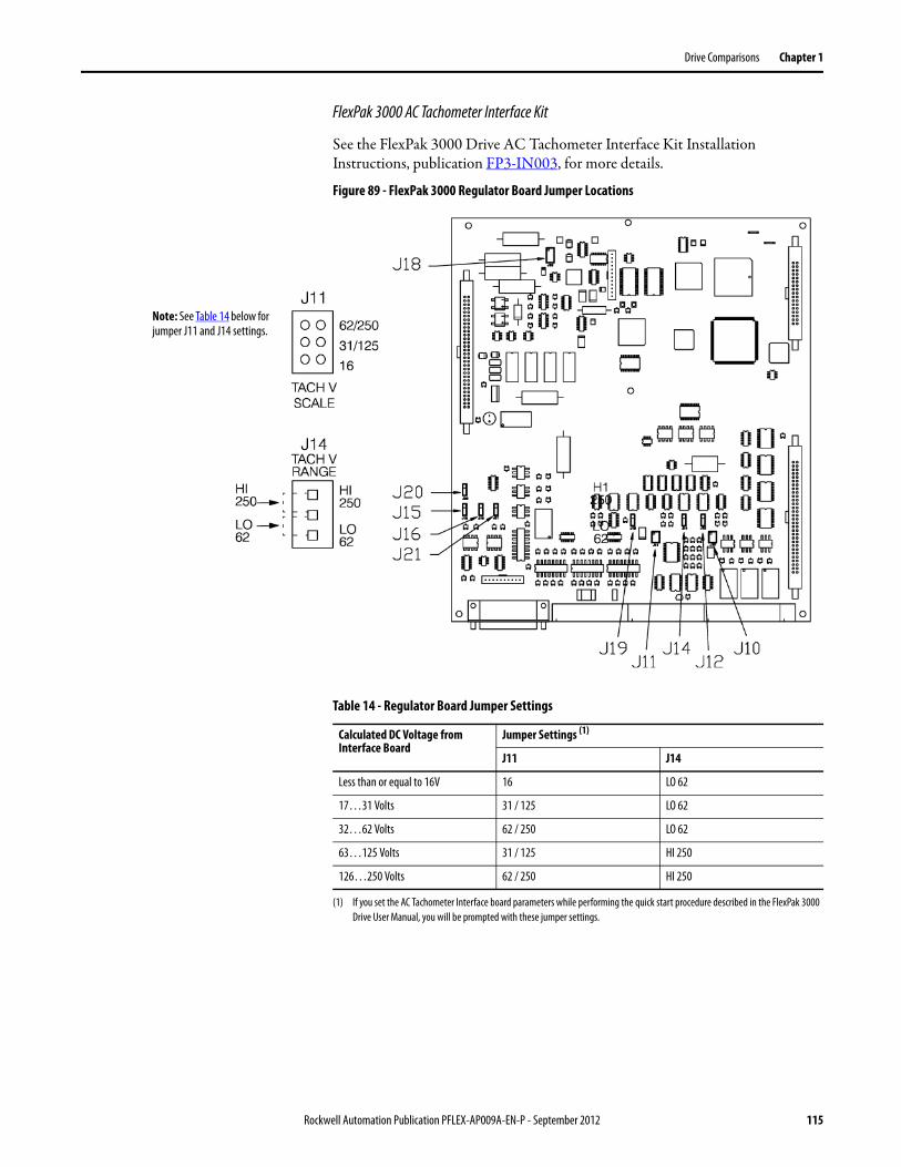
Drive Comparisons Chapter 1
FlexPak 3000 AC Tachometer Interface Kit
See the FlexPak 3000 Drive AC Tachometer Interface Kit Installation Instructions, publication FP3-IN003, for more details.
Figure 89 - FlexPak 3000 Regulator Board Jumper Locations
Note: See Table 14 below for jumper J11 and J14 settings.
Table 14 - Regulator Board Jumper Settings
Calculated DC Voltage from Interface Board
Jumper Settings (1)
(1) If you set the AC Tachometer Interface board parameters while performing the quick start procedure described in the FlexPak 3000 Drive User Manual, you will be prompted with these jumper settings.
J11 J14
Less than or equal to 16V 16 LO 62
17…31 Volts 31 / 125 LO 62
32…62 Volts 62 / 250 LO 62
63…125 Volts 31 / 125 HI 250
126…250 Volts 62 / 250 HI 250
Rockwell Automation Publication PFLEX-AP009A-EN-P - September 2012 115
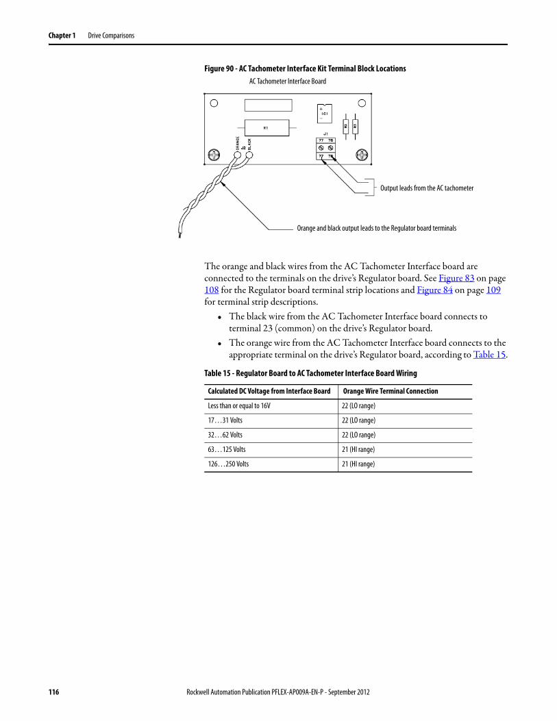
Chapter 1 Drive Comparisons
Figure 90 - AC Tachometer Interface Kit Terminal Block Locations
The orange and black wires from the AC Tachometer Interface board are connected to the terminals on the drive’s Regulator board. See Figure 83 on page 108 for the Regulator board terminal strip locations and Figure 84 on page 109 for terminal strip descriptions.
• The black wire from the AC Tachometer Interface board connects to terminal 23 (common) on the drive’s Regulator board.
• The orange wire from the AC Tachometer Interface board connects to the appropriate terminal on the drive’s Regulator board, according to Table 15.
AC Tachometer Interface Board
Output leads from the AC tachometer
Orange and black output leads to the Regulator board terminals
Table 15 - Regulator Board to AC Tachometer Interface Board Wiring
Calculated DC Voltage from Interface Board Orange Wire Terminal Connection
Less than or equal to 16V 22 (LO range)
17…31 Volts 22 (LO range)
32…62 Volts 22 (LO range)
63…125 Volts 21 (HI range)
126…250 Volts 21 (HI range)
116 Rockwell Automation Publication PFLEX-AP009A-EN-P - September 2012
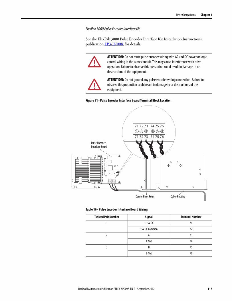
Drive Comparisons Chapter 1
FlexPak 3000 Pulse Encoder Interface Kit
See the FlexPak 3000 Pulse Encoder Interface Kit Installation Instructions, publication FP3-IN008, for details.
Figure 91 - Pulse Encoder Interface Board Terminal Block Location
ATTENTION: Do not route pulse encoder wiring with AC and DC power or logic control wiring in the same conduit. This may cause interference with drive operation. Failure to observe this precaution could result in damage to or destructions of the equipment.
ATTENTION: Do not ground any pulse encoder wiring connection. Failure to observe this precaution could result in damage to or destructions of the equipment.
71 72 73 74 75 76
71 72 73 74 75 76
71 72 73 74 75 76
71 72 73 74 75 76
Carrier Pivot Point Cable Routing
Pulse Encoder Interface Board
Table 16 - Pulse Encoder Interface Board Wiring
Twisted Pair Number Signal Terminal Number
1 +15V DC 71
15V DC Common 72
2 A 73
A Not 74
3 B 75
B Not 76
Rockwell Automation Publication PFLEX-AP009A-EN-P - September 2012 117
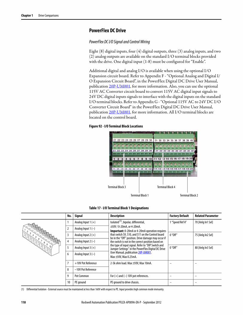
Chapter 1 Drive Comparisons
PowerFlex DC Drive
PowerFlex DC I/O Signal and Control Wiring
Eight (8) digital inputs, four (4) digital outputs, three (3) analog inputs, and two (2) analog outputs are available on the standard I/O terminal blocks provided with the drive. One digital input (1-8) must be configured for “Enable”.
Additional digital and analog I/O is available when using the optional I/O Expansion circuit board. Refer to Appendix F - “Optional Analog and Digital I/O Expansion Circuit Board”, in the PowerFlex Digital DC Drive User Manual, publication 20P-UM001, for more information. Also, you can use the optional 115V AC Converter circuit board to convert 115V AC digital input signals to 24V DC digital inputs signals to interface with the digital inputs on the standard I/O terminal blocks. Refer to Appendix G - “Optional 115V AC to 24V DC I/O Converter Circuit Board” in the PowerFlex Digital DC Drive User Manual, publication 20P-UM001, for more information. All I/O terminal blocks are located on the control board.
Figure 92 - I/O Terminal Block Locations
Table 17 - I/O Terminal Block 1 Designations
Terminal Block 1
Terminal Block 3 Terminal Block 4
Terminal Block 2
No. Signal Description Factory Default Related Parameter
1 Analog Input 1 (+) Isolated (1), bipolar, differential,±10V / 0-20mA, or 4-20mA.Important: 0-20mA or 4-20mA operation requires that switch S9, S10, and S11 on the Control board be in the “Off” position. Drive damage may occur if the switch is not in the correct position based on the type of input signal. Refer to “DIP Switch and Jumper Settings” in the PowerFlex Digital DC Drive User Manual, publication 20P-UM001.Max ±10V, Max 0.25mA.
1 “Speed Ref A” 70 [Anlg In1 Sel]
2 Analog Input 1 (–)
3 Analog Input 2 (+) 0 “Off” 75 [Anlg In2 Sel]
4 Analog Input 2 (–)
5 Analog Input 3 (+) 0 “Off” 80 [Anlg In3 Sel]
6 Analog Input 3 (–)
7 +10V Pot Reference 2-5k ohm load. Max ±10V, Max 10mA. – –
8 –10V Pot Reference
9 Pot Common For (+) and (–) 10V pot references. – –
10 PE ground PE ground to drive chassis. – –
(1) Differential Isolation - External source must be maintained at less than 160V with respect to PE. Input provides high common mode immunity.
23
45
1
78
910
6
118 Rockwell Automation Publication PFLEX-AP009A-EN-P - September 2012
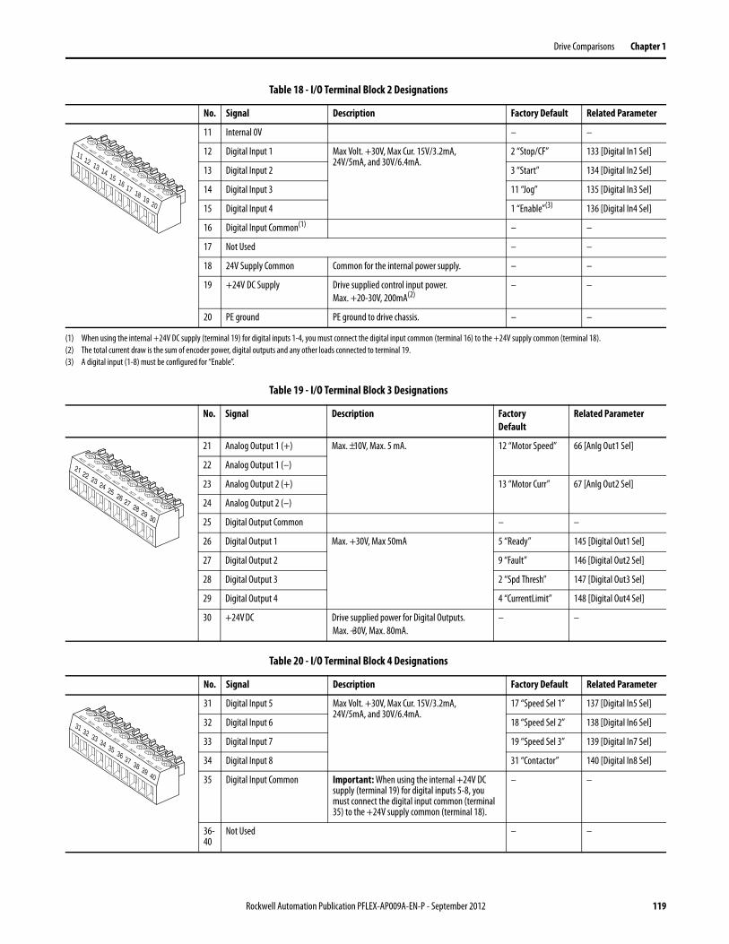
Drive Comparisons Chapter 1
Table 18 - I/O Terminal Block 2 Designations
Table 19 - I/O Terminal Block 3 Designations
Table 20 - I/O Terminal Block 4 Designations
No. Signal Description Factory Default Related Parameter
11 Internal 0V – –
12 Digital Input 1 Max Volt. +30V, Max Cur. 15V/3.2mA,24V/5mA, and 30V/6.4mA.
2 “Stop/CF” 133 [Digital In1 Sel]
13 Digital Input 2 3 “Start” 134 [Digital In2 Sel]
14 Digital Input 3 11 “Jog” 135 [Digital In3 Sel]
15 Digital Input 4 1 “Enable”(3) 136 [Digital In4 Sel]
16 Digital Input Common(1) – –
17 Not Used – –
18 24V Supply Common Common for the internal power supply. – –
19 +24V DC Supply Drive supplied control input power.Max. +20-30V, 200mA(2)
– –
20 PE ground PE ground to drive chassis. – –
(1) When using the internal +24V DC supply (terminal 19) for digital inputs 1-4, you must connect the digital input common (terminal 16) to the +24V supply common (terminal 18).(2) The total current draw is the sum of encoder power, digital outputs and any other loads connected to terminal 19.(3) A digital input (1-8) must be configured for “Enable”.
12 13 14 15
11
17 18 19 20
16
No. Signal Description FactoryDefault
Related Parameter
21 Analog Output 1 (+) Max. ±10V, Max. 5 mA. 12 “Motor Speed” 66 [Anlg Out1 Sel]
22 Analog Output 1 (–)
23 Analog Output 2 (+) 13 “Motor Curr” 67 [Anlg Out2 Sel]
24 Analog Output 2 (–)
25 Digital Output Common – –
26 Digital Output 1 Max. +30V, Max 50mA 5 “Ready” 145 [Digital Out1 Sel]
27 Digital Output 2 9 “Fault” 146 [Digital Out2 Sel]
28 Digital Output 3 2 “Spd Thresh” 147 [Digital Out3 Sel]
29 Digital Output 4 4 “CurrentLimit” 148 [Digital Out4 Sel]
30 +24V DC Drive supplied power for Digital Outputs.Max. +30V, Max. 80mA.
– –
22 23 24 25
21
27 28 29 30
26
No. Signal Description Factory Default Related Parameter
31 Digital Input 5 Max Volt. +30V, Max Cur. 15V/3.2mA,24V/5mA, and 30V/6.4mA.
17 “Speed Sel 1” 137 [Digital In5 Sel]
32 Digital Input 6 18 “Speed Sel 2” 138 [Digital In6 Sel]
33 Digital Input 7 19 “Speed Sel 3” 139 [Digital In7 Sel]
34 Digital Input 8 31 “Contactor” 140 [Digital In8 Sel]
35 Digital Input Common Important: When using the internal +24V DC supply (terminal 19) for digital inputs 5-8, you must connect the digital input common (terminal 35) to the +24V supply common (terminal 18).
– –
36- 40
Not Used – –
32 33 34 35
31
37 38 39 40
36
Rockwell Automation Publication PFLEX-AP009A-EN-P - September 2012 119
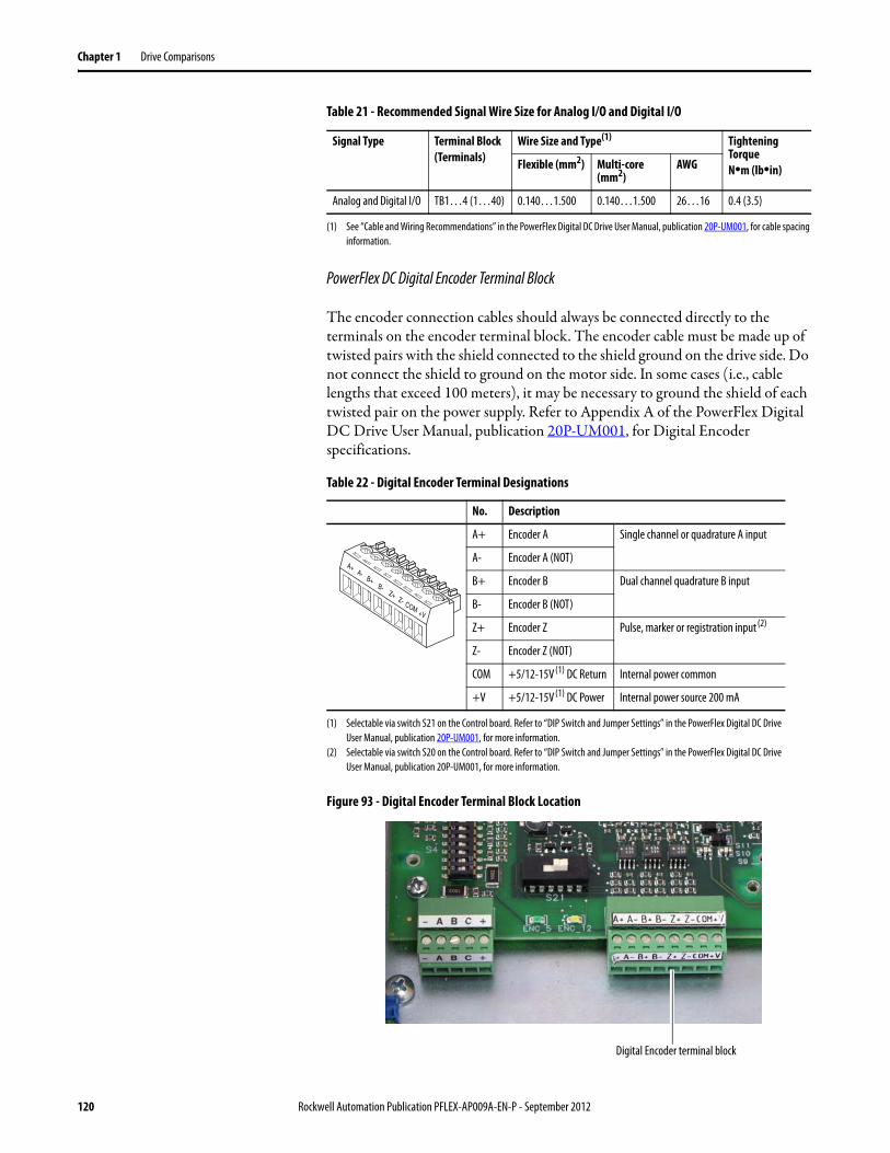
Chapter 1 Drive Comparisons
Table 21 - Recommended Signal Wire Size for Analog I/O and Digital I/O
PowerFlex DC Digital Encoder Terminal Block
The encoder connection cables should always be connected directly to the terminals on the encoder terminal block. The encoder cable must be made up of twisted pairs with the shield connected to the shield ground on the drive side. Do not connect the shield to ground on the motor side. In some cases (i.e., cable lengths that exceed 100 meters), it may be necessary to ground the shield of each twisted pair on the power supply. Refer to Appendix A of the PowerFlex Digital DC Drive User Manual, publication 20P-UM001, for Digital Encoder specifications.
Table 22 - Digital Encoder Terminal Designations
Figure 93 - Digital Encoder Terminal Block Location
Signal Type Terminal Block(Terminals)
Wire Size and Type(1)
(1) See “Cable and Wiring Recommendations” in the PowerFlex Digital DC Drive User Manual, publication 20P-UM001, for cable spacing information.
Tightening TorqueN•m (lb•in)Flexible (mm2) Multi-core
(mm2)AWG
Analog and Digital I/O TB1…4 (1…40) 0.140…1.500 0.140…1.500 26…16 0.4 (3.5)
No. Description
A+ Encoder A Single channel or quadrature A input
A- Encoder A (NOT)
B+ Encoder B Dual channel quadrature B input
B- Encoder B (NOT)
Z+ Encoder Z Pulse, marker or registration input (2)
(2) Selectable via switch S20 on the Control board. Refer to “DIP Switch and Jumper Settings” in the PowerFlex Digital DC Drive User Manual, publication 20P-UM001, for more information.
Z- Encoder Z (NOT)
COM +5/12-15V (1) DC Return Internal power common
+V +5/12-15V (1) DC Power
(1) Selectable via switch S21 on the Control board. Refer to “DIP Switch and Jumper Settings” in the PowerFlex Digital DC Drive User Manual, publication 20P-UM001, for more information.
Internal power source 200 mA
A-B+
B-Z+
A+
COM+V
Z-
Digital Encoder terminal block
120 Rockwell Automation Publication PFLEX-AP009A-EN-P - September 2012
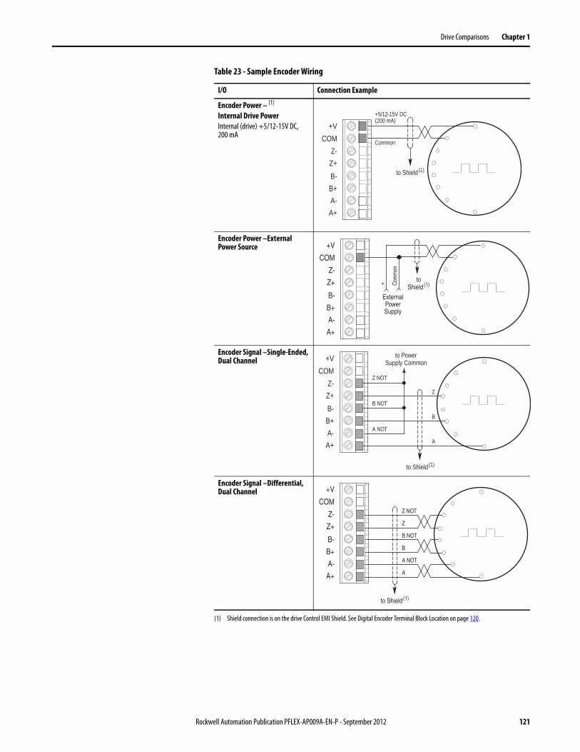
Drive Comparisons Chapter 1
Table 23 - Sample Encoder Wiring
I/O Connection Example
Encoder Power – (1)
Internal Drive PowerInternal (drive) +5/12-15V DC,200 mA
(1) Shield connection is on the drive Control EMI Shield. See Digital Encoder Terminal Block Location on page 120.
Encoder Power –External Power Source
Encoder Signal –Single-Ended, Dual Channel
Encoder Signal –Differential, Dual Channel
Common
+5/12-15V DC(200 mA)
A+
A-
B+
B-
Z+
Z-
COM
+V
to Shield (1)
+ Com
mon
ExternalPowerSupply
toShield (1)
A+
A-
B+
B-
Z+
Z-
COM
+V
B
B NOT
A NOT
A
Z
Z NOT
to PowerSupply Common
A+
A-
B+
B-
Z+
Z-
COM
+V
to Shield (1)
B
B NOT
A NOT
A
Z
Z NOT
to Shield (1)
A+
A-
B+
B-
Z+
Z-
COM
+V
Rockwell Automation Publication PFLEX-AP009A-EN-P - September 2012 121
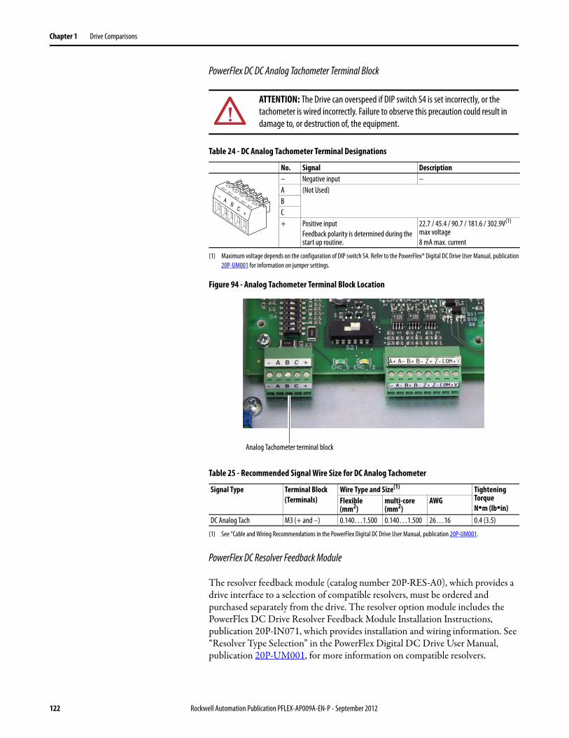
Chapter 1 Drive Comparisons
PowerFlex DC DC Analog Tachometer Terminal Block
Table 24 - DC Analog Tachometer Terminal Designations
Figure 94 - Analog Tachometer Terminal Block Location
Table 25 - Recommended Signal Wire Size for DC Analog Tachometer
PowerFlex DC Resolver Feedback Module
The resolver feedback module (catalog number 20P-RES-A0), which provides a drive interface to a selection of compatible resolvers, must be ordered and purchased separately from the drive. The resolver option module includes the PowerFlex DC Drive Resolver Feedback Module Installation Instructions, publication 20P-IN071, which provides installation and wiring information. See “Resolver Type Selection” in the PowerFlex Digital DC Drive User Manual, publication 20P-UM001, for more information on compatible resolvers.
ATTENTION: The Drive can overspeed if DIP switch S4 is set incorrectly, or the tachometer is wired incorrectly. Failure to observe this precaution could result in damage to, or destruction of, the equipment.
No. Signal Description – Negative input –A (Not Used)BC+ Positive input
Feedback polarity is determined during the start up routine.
22.7 / 45.4 / 90.7 / 181.6 / 302.9V(1) max voltage8 mA max. current
(1) Maximum voltage depends on the configuration of DIP switch S4. Refer to the PowerFlex® Digital DC Drive User Manual, publication 20P-UM001 for information on jumper settings.
Signal Type Terminal Block(Terminals)
Wire Type and Size(1)
(1) See “Cable and Wiring Recommendations in the PowerFlex Digital DC Drive User Manual, publication 20P-UM001.
Tightening TorqueN•m (lb•in)
Flexible (mm2)
multi-core (mm2)
AWG
DC Analog Tach M3 (+ and –) 0.140…1.500 0.140…1.500 26…16 0.4 (3.5)
AB
C+
−
Analog Tachometer terminal block
122 Rockwell Automation Publication PFLEX-AP009A-EN-P - September 2012
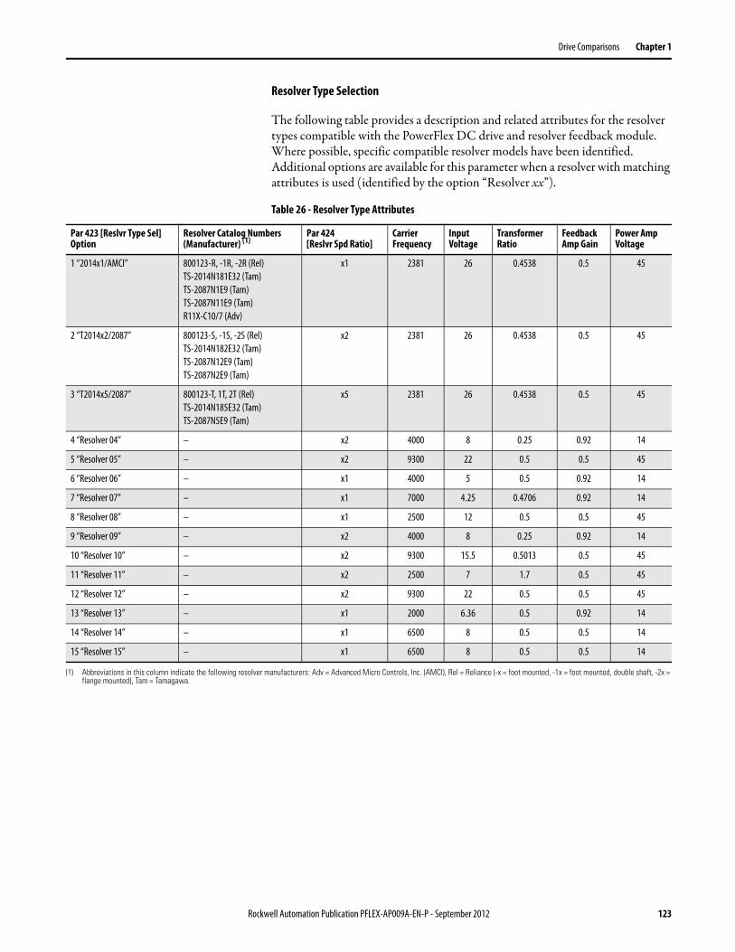
Drive Comparisons Chapter 1
Resolver Type Selection
The following table provides a description and related attributes for the resolver types compatible with the PowerFlex DC drive and resolver feedback module. Where possible, specific compatible resolver models have been identified. Additional options are available for this parameter when a resolver with matching attributes is used (identified by the option “Resolver xx”).
Table 26 - Resolver Type Attributes
Par 423 [Reslvr Type Sel] Option
Resolver Catalog Numbers (Manufacturer) (1)
Par 424[Reslvr Spd Ratio]
Carrier Frequency
Input Voltage
Transformer Ratio
Feedback Amp Gain
Power Amp Voltage
1 “2014x1/AMCI” 800123-R, -1R, -2R (Rel)TS-2014N181E32 (Tam)TS-2087N1E9 (Tam)TS-2087N11E9 (Tam)R11X-C10/7 (Adv)
x1 2381 26 0.4538 0.5 45
2 “T2014x2/2087” 800123-S, -1S, -2S (Rel)TS-2014N182E32 (Tam)TS-2087N12E9 (Tam)TS-2087N2E9 (Tam)
x2 2381 26 0.4538 0.5 45
3 “T2014x5/2087” 800123-T, 1T, 2T (Rel)TS-2014N185E32 (Tam)TS-2087N5E9 (Tam)
x5 2381 26 0.4538 0.5 45
4 “Resolver 04” – x2 4000 8 0.25 0.92 14
5 “Resolver 05” – x2 9300 22 0.5 0.5 45
6 “Resolver 06” – x1 4000 5 0.5 0.92 14
7 “Resolver 07” – x1 7000 4.25 0.4706 0.92 14
8 “Resolver 08” – x1 2500 12 0.5 0.5 45
9 “Resolver 09” – x2 4000 8 0.25 0.92 14
10 “Resolver 10” – x2 9300 15.5 0.5013 0.5 45
11 “Resolver 11” – x2 2500 7 1.7 0.5 45
12 “Resolver 12” – x2 9300 22 0.5 0.5 45
13 “Resolver 13” – x1 2000 6.36 0.5 0.92 14
14 “Resolver 14” – x1 6500 8 0.5 0.5 14
15 “Resolver 15” – x1 6500 8 0.5 0.5 14
(1) Abbreviations in this column indicate the following resolver manufacturers: Adv = Advanced Micro Controls, Inc. (AMCI), Rel = Reliance (-x = foot mounted, -1x = foot mounted, double shaft, -2x = flange mounted), Tam = Tamagawa.
Rockwell Automation Publication PFLEX-AP009A-EN-P - September 2012 123
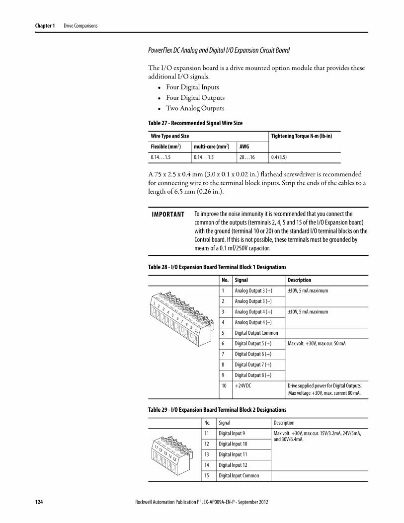
Chapter 1 Drive Comparisons
PowerFlex DC Analog and Digital I/O Expansion Circuit Board
The I/O expansion board is a drive mounted option module that provides these additional I/O signals.
• Four Digital Inputs• Four Digital Outputs• Two Analog Outputs
Table 27 - Recommended Signal Wire Size
A 75 x 2.5 x 0.4 mm (3.0 x 0.1 x 0.02 in.) flathead screwdriver is recommended for connecting wire to the terminal block inputs. Strip the ends of the cables to a length of 6.5 mm (0.26 in.).
Table 28 - I/O Expansion Board Terminal Block 1 Designations
Table 29 - I/O Expansion Board Terminal Block 2 Designations
Wire Type and Size Tightening Torque N•m (lb•in)
Flexible (mm2) multi-core (mm2) AWG
0.14…1.5 0.14…1.5 28…16 0.4 (3.5)
IMPORTANT To improve the noise immunity it is recommended that you connect the common of the outputs (terminals 2, 4, 5 and 15 of the I/O Expansion board) with the ground (terminal 10 or 20) on the standard I/O terminal blocks on the Control board. If this is not possible, these terminals must be grounded by means of a 0.1 mf/250V capacitor.
No. Signal Description
1 Analog Output 3 (+) ±10V, 5 mA maximum
2 Analog Output 3 (–)
3 Analog Output 4 (+) ±10V, 5 mA maximum
4 Analog Output 4 (–)
5 Digital Output Common
6 Digital Output 5 (+) Max volt. +30V, max cur. 50 mA
7 Digital Output 6 (+)
8 Digital Output 7 (+)
9 Digital Output 8 (+)
10 +24V DC Drive supplied power for Digital Outputs.Max voltage +30V, max. current 80 mA.
No. Signal Description
11 Digital Input 9 Max volt. +30V, max cur. 15V/3.2mA, 24V/5mA, and 30V/6.4mA.
12 Digital Input 10
13 Digital Input 11
14 Digital Input 12
15 Digital Input Common
23
45
1
78
910
6
12 13 14 15
11
124 Rockwell Automation Publication PFLEX-AP009A-EN-P - September 2012
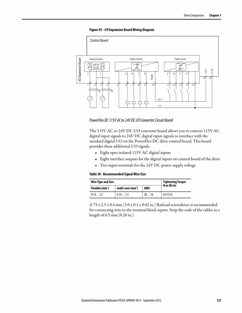
Drive Comparisons Chapter 1
Figure 95 - I/O Expansion Board Wiring Diagram
PowerFlex DC 115V AC to 24V DC I/O Converter Circuit Board
The 115V AC to 24V DC I/O converter board allows you to convert 115V AC digital input signals to 24V DC digital input signals to interface with the standard digital I/O on the PowerFlex DC drive control board. This board provides these additional I/O signals.
• Eight opto isolated 115V AC digital inputs• Eight interface outputs for the digital inputs on control board of the drive• Two input terminals for the 24V DC power supply voltage
Table 30 - Recommended Signal Wire Size
A 75 x 2.5 x 0.4 mm (3.0 x 0.1 x 0.02 in.) flathead screwdriver is recommended for connecting wire to the terminal block inputs. Strip the ends of the cables to a length of 6.5 mm (0.26 in.).
Analog Outputs
3 4
1 2 3 4
Digital Outputs
5 6 7 8
5 6 7 8 9 10
ylppuS
Digital Inputs
11 12 13 14 15
9
19 18
42V
0
V42
+
0 V
+ 24 V
Control Board
I/O E
xpan
sion
Boa
rd
10 11 12
Wire Type and Size Tightening Torque N•m (lb•in)
Flexible (mm2) multi-core (mm2) AWG
0.14…1.5 0.14…1.5 28…16 0.4 (3.5)
Rockwell Automation Publication PFLEX-AP009A-EN-P - September 2012 125
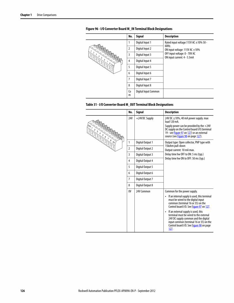
Chapter 1 Drive Comparisons
Figure 96 - I/O Converter Board M_IN Terminal Block Designations
Table 31 - I/O Converter Board M_OUT Terminal Block Designations
No. Signal Description
1 Digital Input 1 Rated input voltage:115V AC ±10% 50 - 60Hz.ON input voltage: 115V AC ±10%OFF input voltage: 0 - 70V ACON input current: 4 - 5.5mA
2 Digital Input 2
3 Digital Input 3
4 Digital Input 4
5 Digital Input 5
6 Digital Input 6
7 Digital Input 7
8 Digital Input 8
Com
Digital Input Common
No. Signal Description
24V +24V DC Supply 24V DC ±10%, 40 mA power supply. max load 120 mA.Supply power can be provided by the +24V DC supply on the Control board I/O (terminal 19 - see Figure 97 on 127) or an external source (see Figure 98 on page 127).
1 Digital Output 1 Output type: Open collector, PNP type with 15kohm pull-downOutput current: 10 mA max.Delay time hw OFF to ON: 5 ms (typ.)Delay time hw ON to OFF: 50 ms (typ.)
2 Digital Output 2
3 Digital Output 3
4 Digital Output 4
5 Digital Output 5
6 Digital Output 6
7 Digital Output 7
8 Digital Output 8
0V 24V Common Common for the power supply.• If an internal supply is used, this terminal
must be wired to the digital input common (terminal 16 or 35) on the Control board I/O. See Figure 97 on 127.
• If an external supply is used, this terminal must be wired to the external 24V DC supply common and the digital input common (terminal 16 or 35) on the Control board I/O. See Figure 98 on page 127.
23
45
1
78
6
COM
12
34
24V
67
80V
5
126 Rockwell Automation Publication PFLEX-AP009A-EN-P - September 2012
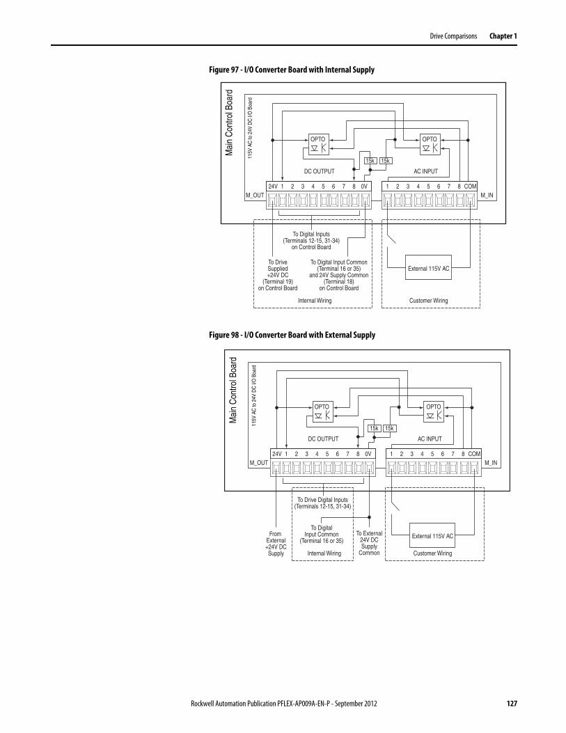
Drive Comparisons Chapter 1
Figure 97 - I/O Converter Board with Internal Supply
Figure 98 - I/O Converter Board with External Supply
24V 1 2 3 4 5 6 7 8 0V 1 2 3 4 5 6 7 8 COM
Mai
n C
ontro
l Boa
rd
115V
AC
to 2
4V D
C I/
O B
oard
M_OUT M_IN
External 115V AC
OPTO OPTO
To DriveSupplied+24V DC
(Terminal 19)on Control Board
To Digital Inputs(Terminals 12-15, 31-34)
on Control Board
To Digital Input Common(Terminal 16 or 35)
and 24V Supply Common(Terminal 18)
on Control Board
15k 15k
Customer WiringInternal Wiring
DC OUTPUT AC INPUT
24V 1 2 3 4 5 6 7 8 0V 1 2 3 4 5 6 7 8 COM
Mai
n C
ontro
l Boa
rd
115V
AC
to 2
4V D
C I/
O B
oard
M_OUT M_IN
External 115V AC
OPTO OPTO
From External+24V DCSupply
To Drive Digital Inputs(Terminals 12-15, 31-34)
To External24V DCSupply
Common
To DigitalInput Common
(Terminal 16 or 35)
15k 15k
Customer WiringInternal Wiring
DC OUTPUT AC INPUT
Rockwell Automation Publication PFLEX-AP009A-EN-P - September 2012 127

Chapter 1 Drive Comparisons
Installation Considerations for PowerFlex DC Drives
The PowerFlex Digital DC drive has the following built in protective features to help simplify installation.
• Ground fault protection during start up and running ensures reliable operation
• Electronic motor overload protection increases motor life
There are many other factors that must be considered for optimal performance in any given application. The block diagram below highlights the primary installation considerations.
Input Circuit Protection - See page 139
Input Power Conditioning- See page 132
LCD HIM - See page 129
Motor Overload Protection - See page 162
Motor Recommendations - See the Allen-Bradley Variable Speed AC/DC Motors
Catalog, publication RAPS-1348
DC Drive Accessories - See page 157
128 Rockwell Automation Publication PFLEX-AP009A-EN-P - September 2012
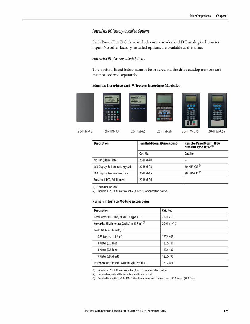
Drive Comparisons Chapter 1
PowerFlex DC Factory-installed Options
Each PowerFlex DC drive includes one encoder and DC analog tachometer input. No other factory installed options are available at this time.
PowerFlex DC User-installed Options
The options listed below cannot be ordered via the drive catalog number and must be ordered separately.
Human Interface and Wireless Interface Modules
Human Interface Module Accessories
20-HIM-C3S 20-HIM-C5S20-HIM-A0 20-HIM-A3 20-HIM-A5 20-HIM-A6
Description Handheld/Local (Drive Mount) Remote (Panel Mount) IP66, NEMA/UL Type 4x/12 (1)
(1) For indoor use only.
Cat. No. Cat. No.
No HIM (Blank Plate) 20-HIM-A0 –
LCD Display, Full Numeric Keypad 20-HIM-A3 20-HIM-C3S (2)
(2) Includes a 1202-C30 interface cable (3 meters) for connection to drive.
LCD Display, Programmer Only 20-HIM-A5 20-HIM-C3S (2)
Enhanced, LCD, Full Numeric 20-HIM-A6 –
Description Cat. No.
Bezel Kit for LCD HIMs, NEMA/UL Type 1 (1)
(1) Includes a 1202-C30 interface cable (3 meters) for connection to drive.
20-HIM-B1
PowerFlex HIM Interface Cable, 1 m (39 in.) (2)
(2) Required only when HIM is used as handheld or remote.
20-HIM-H10
Cable Kit (Male-Female) (3)
(3) Required in addition to 20-HIM-H10 for distances up to a total maximum of 10 Meters (32.8 Feet).
0.33 Meters (1.1 Feet) 1202-H03
1 Meter (3.3 Feet) 1202-H10
3 Meter (9.8 Feet) 1202-H30
9 Meter (29.5 Feet) 1202-H90
DPI/SCANport™ One to Two Port Splitter Cable 1203-S03
Rockwell Automation Publication PFLEX-AP009A-EN-P - September 2012 129
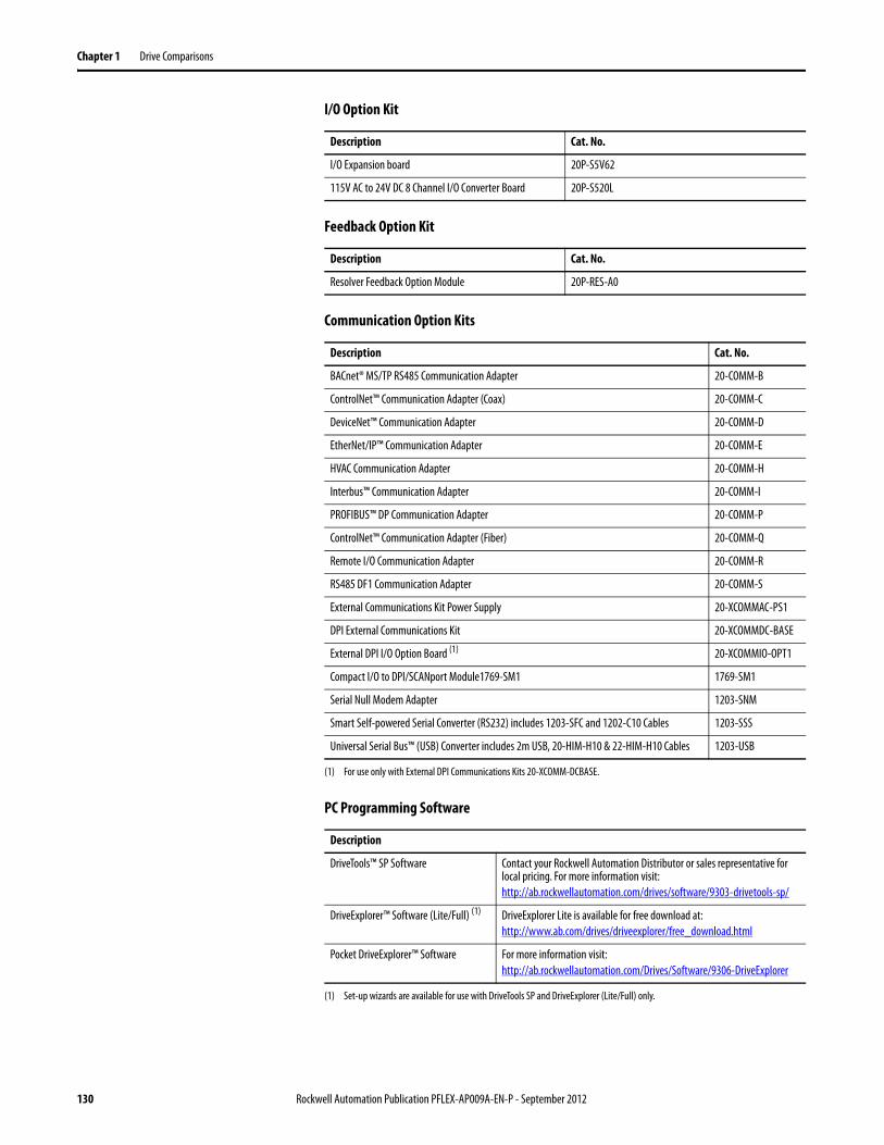
Chapter 1 Drive Comparisons
I/O Option Kit
Feedback Option Kit
Communication Option Kits
PC Programming Software
Description Cat. No.
I/O Expansion board 20P-S5V62
115V AC to 24V DC 8 Channel I/O Converter Board 20P-S520L
Description Cat. No.
Resolver Feedback Option Module 20P-RES-A0
Description Cat. No.
BACnet® MS/TP RS485 Communication Adapter 20-COMM-B
ControlNet™ Communication Adapter (Coax) 20-COMM-C
DeviceNet™ Communication Adapter 20-COMM-D
EtherNet/IP™ Communication Adapter 20-COMM-E
HVAC Communication Adapter 20-COMM-H
Interbus™ Communication Adapter 20-COMM-I
PROFIBUS™ DP Communication Adapter 20-COMM-P
ControlNet™ Communication Adapter (Fiber) 20-COMM-Q
Remote I/O Communication Adapter 20-COMM-R
RS485 DF1 Communication Adapter 20-COMM-S
External Communications Kit Power Supply 20-XCOMMAC-PS1
DPI External Communications Kit 20-XCOMMDC-BASE
External DPI I/O Option Board (1)
(1) For use only with External DPI Communications Kits 20-XCOMM-DCBASE.
20-XCOMMIO-OPT1
Compact I/O to DPI/SCANport Module1769-SM1 1769-SM1
Serial Null Modem Adapter 1203-SNM
Smart Self-powered Serial Converter (RS232) includes 1203-SFC and 1202-C10 Cables 1203-SSS
Universal Serial Bus™ (USB) Converter includes 2m USB, 20-HIM-H10 & 22-HIM-H10 Cables 1203-USB
Description
DriveTools™ SP Software Contact your Rockwell Automation Distributor or sales representative for local pricing. For more information visit:http://ab.rockwellautomation.com/drives/software/9303-drivetools-sp/
DriveExplorer™ Software (Lite/Full) (1)
(1) Set-up wizards are available for use with DriveTools SP and DriveExplorer (Lite/Full) only.
DriveExplorer Lite is available for free download at:http://www.ab.com/drives/driveexplorer/free_download.html
Pocket DriveExplorer™ Software For more information visit:http://ab.rockwellautomation.com/Drives/Software/9306-DriveExplorer
130 Rockwell Automation Publication PFLEX-AP009A-EN-P - September 2012
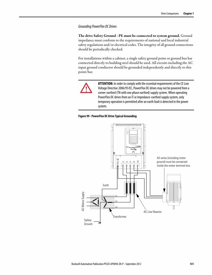
Drive Comparisons Chapter 1
Grounding PowerFlex DC Drives
The drive Safety Ground - PE must be connected to system ground. Ground impedance must conform to the requirements of national and local industrial safety regulations and/or electrical codes. The integrity of all ground connections should be periodically checked.
For installations within a cabinet, a single safety ground point or ground bus bar connected directly to building steel should be used. All circuits including the AC input ground conductor should be grounded independently and directly to this point/bar.
Figure 99 - PowerFlex DC Drive Typical Grounding
ATTENTION: In order to comply with the essential requirements of the CE Low Voltage Directive 2006/95/EC, PowerFlex DC drives may not be powered from a corner-earthed (TN with one phase earthed) supply system. When operating PowerFlex DC drives from an IT or impedance-earthed supply system, only temporary operation is permitted after an earth fault is detected in the power system.
L1
L2
L3
U V WC D
PE
1/
STS
PORT
MOD
NET A
NET B
Earth
All wires (including motorground) must be connectedinside the motor terminal box.
TransformerSafetyGround
AC M
ains
Sup
ply
AC Line Reactor
Rockwell Automation Publication PFLEX-AP009A-EN-P - September 2012 131
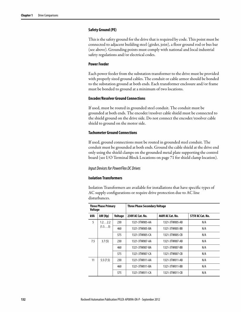
Chapter 1 Drive Comparisons
Safety Ground (PE)
This is the safety ground for the drive that is required by code. This point must be connected to adjacent building steel (girder, joist), a floor ground rod or bus bar (see above). Grounding points must comply with national and local industrial safety regulations and/or electrical codes.
Power Feeder
Each power feeder from the substation transformer to the drive must be provided with properly sized ground cables. The conduit or cable armor should be bonded to the substation ground at both ends. Each transformer enclosure and/or frame must be bonded to ground at a minimum of two locations.
Encoder/Resolver Ground Connections
If used, must be routed in grounded steel conduit. The conduit must be grounded at both ends. The encoder/resolver cable shield must be connected to the shield ground on the drive side. Do not connect the encoder/resolver cable shield to ground on the motor side.
Tachometer Ground Connections
If used, ground connections must be routed in grounded steel conduit. The conduit must be grounded at both ends. Ground the cable shield at the drive end only using the shield clamps on the grounded metal plate supporting the control board (see I/O Terminal Block Locations on page 71 for shield clamp location).
Input Devices for PowerFlex DC Drives
Isolation Transformers
Isolation Transformers are available for installations that have specific types of AC supply configurations or require drive protection due to AC line disturbances.
Three Phase Primary Voltage
Three Phase Secondary Voltage
kVA kW (Hp) Voltage 230V AC Cat. No. 460V AC Cat. No. 575V AC Cat. No.
5 1.2…2.2(1.5…3)
230 1321-3TW005-AA 1321-3TW005-AB N/A
460 1321-3TW005-BA 1321-3TW005-BB N/A
575 1321-3TW005-CA 1321-3TW005-CB N/A
7.5 3.7 (5) 230 1321-3TW007-AA 1321-3TW007-AB N/A
460 1321-3TW007-BA 1321-3TW007-BB N/A
575 1321-3TW007-CA 1321-3TW007-CB N/A
11 5.5 (7.5) 230 1321-3TW011-AA 1321-3TW011-AB N/A
460 1321-3TW011-BA 1321-3TW011-BB N/A
575 1321-3TW011-CA 1321-3TW011-CB N/A
132 Rockwell Automation Publication PFLEX-AP009A-EN-P - September 2012
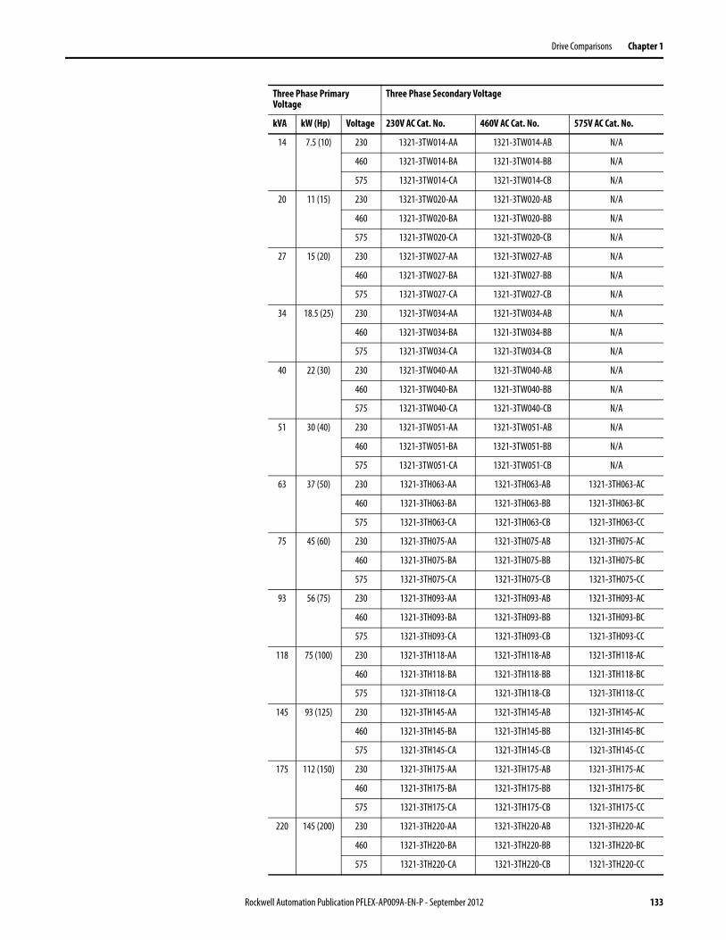
Drive Comparisons Chapter 1
14 7.5 (10) 230 1321-3TW014-AA 1321-3TW014-AB N/A
460 1321-3TW014-BA 1321-3TW014-BB N/A
575 1321-3TW014-CA 1321-3TW014-CB N/A
20 11 (15) 230 1321-3TW020-AA 1321-3TW020-AB N/A
460 1321-3TW020-BA 1321-3TW020-BB N/A
575 1321-3TW020-CA 1321-3TW020-CB N/A
27 15 (20) 230 1321-3TW027-AA 1321-3TW027-AB N/A
460 1321-3TW027-BA 1321-3TW027-BB N/A
575 1321-3TW027-CA 1321-3TW027-CB N/A
34 18.5 (25) 230 1321-3TW034-AA 1321-3TW034-AB N/A
460 1321-3TW034-BA 1321-3TW034-BB N/A
575 1321-3TW034-CA 1321-3TW034-CB N/A
40 22 (30) 230 1321-3TW040-AA 1321-3TW040-AB N/A
460 1321-3TW040-BA 1321-3TW040-BB N/A
575 1321-3TW040-CA 1321-3TW040-CB N/A
51 30 (40) 230 1321-3TW051-AA 1321-3TW051-AB N/A
460 1321-3TW051-BA 1321-3TW051-BB N/A
575 1321-3TW051-CA 1321-3TW051-CB N/A
63 37 (50) 230 1321-3TH063-AA 1321-3TH063-AB 1321-3TH063-AC
460 1321-3TH063-BA 1321-3TH063-BB 1321-3TH063-BC
575 1321-3TH063-CA 1321-3TH063-CB 1321-3TH063-CC
75 45 (60) 230 1321-3TH075-AA 1321-3TH075-AB 1321-3TH075-AC
460 1321-3TH075-BA 1321-3TH075-BB 1321-3TH075-BC
575 1321-3TH075-CA 1321-3TH075-CB 1321-3TH075-CC
93 56 (75) 230 1321-3TH093-AA 1321-3TH093-AB 1321-3TH093-AC
460 1321-3TH093-BA 1321-3TH093-BB 1321-3TH093-BC
575 1321-3TH093-CA 1321-3TH093-CB 1321-3TH093-CC
118 75 (100) 230 1321-3TH118-AA 1321-3TH118-AB 1321-3TH118-AC
460 1321-3TH118-BA 1321-3TH118-BB 1321-3TH118-BC
575 1321-3TH118-CA 1321-3TH118-CB 1321-3TH118-CC
145 93 (125) 230 1321-3TH145-AA 1321-3TH145-AB 1321-3TH145-AC
460 1321-3TH145-BA 1321-3TH145-BB 1321-3TH145-BC
575 1321-3TH145-CA 1321-3TH145-CB 1321-3TH145-CC
175 112 (150) 230 1321-3TH175-AA 1321-3TH175-AB 1321-3TH175-AC
460 1321-3TH175-BA 1321-3TH175-BB 1321-3TH175-BC
575 1321-3TH175-CA 1321-3TH175-CB 1321-3TH175-CC
220 145 (200) 230 1321-3TH220-AA 1321-3TH220-AB 1321-3TH220-AC
460 1321-3TH220-BA 1321-3TH220-BB 1321-3TH220-BC
575 1321-3TH220-CA 1321-3TH220-CB 1321-3TH220-CC
Three Phase Primary Voltage
Three Phase Secondary Voltage
kVA kW (Hp) Voltage 230V AC Cat. No. 460V AC Cat. No. 575V AC Cat. No.
Rockwell Automation Publication PFLEX-AP009A-EN-P - September 2012 133
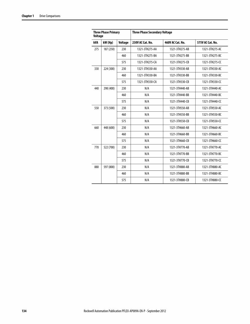
Chapter 1 Drive Comparisons
275 187 (250) 230 1321-3TH275-AA 1321-3TH275-AB 1321-3TH275-AC
460 1321-3TH275-BA 1321-3TH275-BB 1321-3TH275-BC
575 1321-3TH275-CA 1321-3TH275-CB 1321-3TH275-CC
330 224 (300) 230 1321-3TH330-AA 1321-3TH330-AB 1321-3TH330-AC
460 1321-3TH330-BA 1321-3TH330-BB 1321-3TH330-BC
575 1321-3TH330-CA 1321-3TH330-CB 1321-3TH330-CC
440 298 (400) 230 N/A 1321-3TH440-AB 1321-3TH440-AC
460 N/A 1321-3TH440-BB 1321-3TH440-BC
575 N/A 1321-3TH440-CB 1321-3TH440-CC
550 373 (500) 230 N/A 1321-3TH550-AB 1321-3TH550-AC
460 N/A 1321-3TH550-BB 1321-3TH550-BC
575 N/A 1321-3TH550-CB 1321-3TH550-CC
660 448 (600) 230 N/A 1321-3TH660-AB 1321-3TH660-AC
460 N/A 1321-3TH660-BB 1321-3TH660-BC
575 N/A 1321-3TH660-CB 1321-3TH660-CC
770 522 (700) 230 N/A 1321-3TH770-AB 1321-3TH770-AC
460 N/A 1321-3TH770-BB 1321-3TH770-BC
575 N/A 1321-3TH770-CB 1321-3TH770-CC
880 597 (800) 230 N/A 1321-3TH880-AB 1321-3TH880-AC
460 N/A 1321-3TH880-BB 1321-3TH880-BC
575 N/A 1321-3TH880-CB 1321-3TH880-CC
Three Phase Primary Voltage
Three Phase Secondary Voltage
kVA kW (Hp) Voltage 230V AC Cat. No. 460V AC Cat. No. 575V AC Cat. No.
134 Rockwell Automation Publication PFLEX-AP009A-EN-P - September 2012
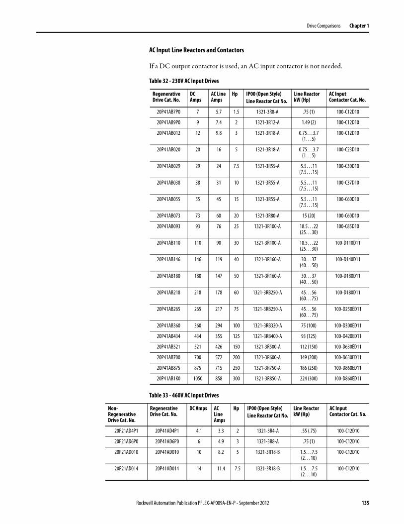
Drive Comparisons Chapter 1
AC Input Line Reactors and Contactors
If a DC output contactor is used, an AC input contactor is not needed.
Table 32 - 230V AC Input Drives
Table 33 - 460V AC Input Drives
Regenerative Drive Cat. No.
DC Amps
AC Line Amps
Hp IP00 (Open Style)Line Reactor Cat No.
Line Reactor kW (Hp)
AC Input Contactor Cat. No.
20P41AB7P0 7 5.7 1.5 1321-3R8-A .75 (1) 100-C12D10
20P41AB9P0 9 7.4 2 1321-3R12-A 1.49 (2) 100-C12D10
20P41AB012 12 9.8 3 1321-3R18-A 0.75…3.7 (1…5)
100-C12D10
20P41AB020 20 16 5 1321-3R18-A 0.75…3.7 (1…5)
100-C23D10
20P41AB029 29 24 7.5 1321-3R55-A 5.5…11 (7.5…15)
100-C30D10
20P41AB038 38 31 10 1321-3R55-A 5.5…11 (7.5…15)
100-C37D10
20P41AB055 55 45 15 1321-3R55-A 5.5…11 (7.5…15)
100-C60D10
20P41AB073 73 60 20 1321-3R80-A 15 (20) 100-C60D10
20P41AB093 93 76 25 1321-3R100-A 18.5…22 (25…30)
100-C85D10
20P41AB110 110 90 30 1321-3R100-A 18.5…22 (25…30)
100-D110D11
20P41AB146 146 119 40 1321-3R160-A 30…37 (40…50)
100-D140D11
20P41AB180 180 147 50 1321-3R160-A 30…37 (40…50)
100-D180D11
20P41AB218 218 178 60 1321-3RB250-A 45…56 (60…75)
100-D180D11
20P41AB265 265 217 75 1321-3RB250-A 45…56 (60…75)
100-D250ED11
20P41AB360 360 294 100 1321-3RB320-A 75 (100) 100-D300ED11
20P41AB434 434 355 125 1321-3RB400-A 93 (125) 100-D420ED11
20P41AB521 521 426 150 1321-3R500-A 112 (150) 100-D630ED11
20P41AB700 700 572 200 1321-3R600-A 149 (200) 100-D630ED11
20P41AB875 875 715 250 1321-3R750-A 186 (250) 100-D860ED11
20P41AB1K0 1050 858 300 1321-3R850-A 224 (300) 100-D860ED11
Non-Regenerative Drive Cat. No.
Regenerative Drive Cat. No.
DC Amps AC Line Amps
Hp IP00 (Open Style)Line Reactor Cat No.
Line Reactor kW (Hp)
AC Input Contactor Cat. No.
20P21AD4P1 20P41AD4P1 4.1 3.3 2 1321-3R4-A .55 (.75) 100-C12D10
20P21AD6P0 20P41AD6P0 6 4.9 3 1321-3R8-A .75 (1) 100-C12D10
20P21AD010 20P41AD010 10 8.2 5 1321-3R18-B 1.5…7.5 (2…10)
100-C12D10
20P21AD014 20P41AD014 14 11.4 7.5 1321-3R18-B 1.5…7.5 (2…10)
100-C12D10
Rockwell Automation Publication PFLEX-AP009A-EN-P - September 2012 135
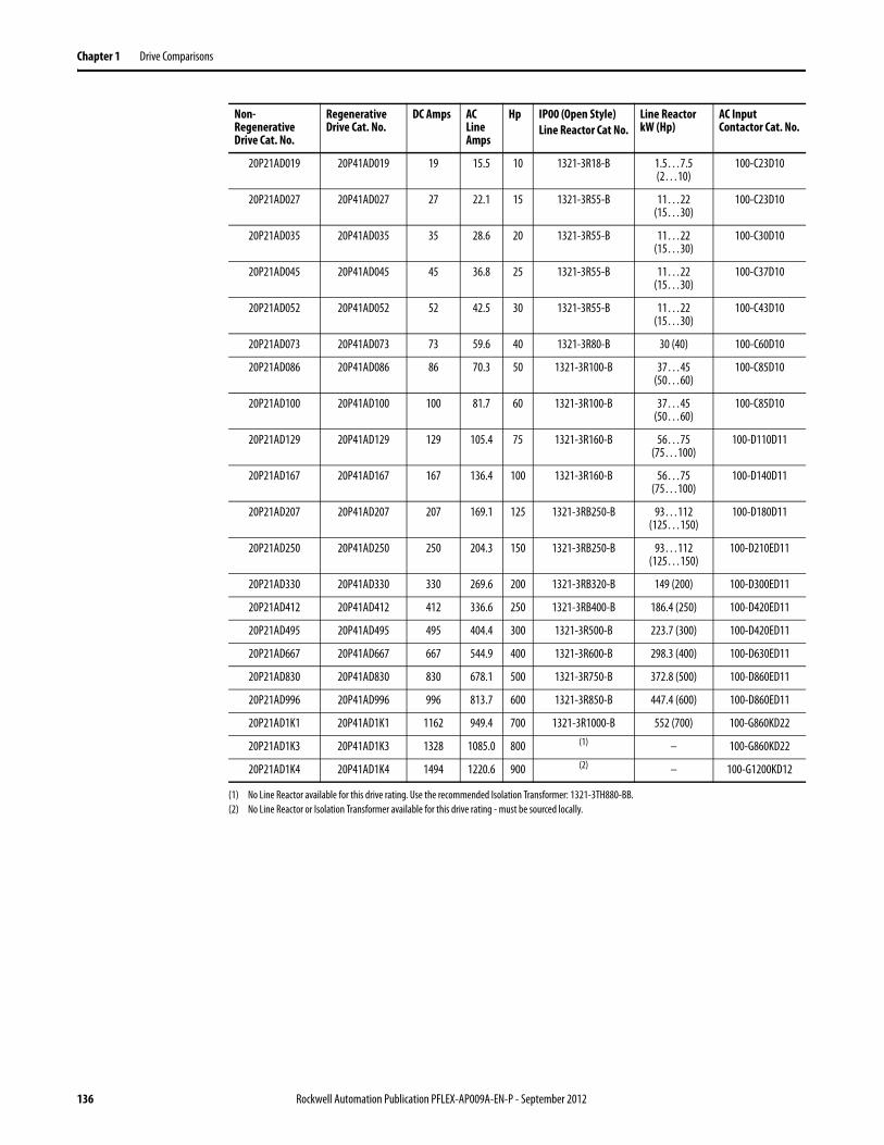
Chapter 1 Drive Comparisons
20P21AD019 20P41AD019 19 15.5 10 1321-3R18-B 1.5…7.5 (2…10)
100-C23D10
20P21AD027 20P41AD027 27 22.1 15 1321-3R55-B 11…22 (15…30)
100-C23D10
20P21AD035 20P41AD035 35 28.6 20 1321-3R55-B 11…22 (15…30)
100-C30D10
20P21AD045 20P41AD045 45 36.8 25 1321-3R55-B 11…22 (15…30)
100-C37D10
20P21AD052 20P41AD052 52 42.5 30 1321-3R55-B 11…22 (15…30)
100-C43D10
20P21AD073 20P41AD073 73 59.6 40 1321-3R80-B 30 (40) 100-C60D10
20P21AD086 20P41AD086 86 70.3 50 1321-3R100-B 37…45 (50…60)
100-C85D10
20P21AD100 20P41AD100 100 81.7 60 1321-3R100-B 37…45 (50…60)
100-C85D10
20P21AD129 20P41AD129 129 105.4 75 1321-3R160-B 56…75 (75…100)
100-D110D11
20P21AD167 20P41AD167 167 136.4 100 1321-3R160-B 56…75 (75…100)
100-D140D11
20P21AD207 20P41AD207 207 169.1 125 1321-3RB250-B 93…112 (125…150)
100-D180D11
20P21AD250 20P41AD250 250 204.3 150 1321-3RB250-B 93…112 (125…150)
100-D210ED11
20P21AD330 20P41AD330 330 269.6 200 1321-3RB320-B 149 (200) 100-D300ED11
20P21AD412 20P41AD412 412 336.6 250 1321-3RB400-B 186.4 (250) 100-D420ED11
20P21AD495 20P41AD495 495 404.4 300 1321-3R500-B 223.7 (300) 100-D420ED11
20P21AD667 20P41AD667 667 544.9 400 1321-3R600-B 298.3 (400) 100-D630ED11
20P21AD830 20P41AD830 830 678.1 500 1321-3R750-B 372.8 (500) 100-D860ED11
20P21AD996 20P41AD996 996 813.7 600 1321-3R850-B 447.4 (600) 100-D860ED11
20P21AD1K1 20P41AD1K1 1162 949.4 700 1321-3R1000-B 552 (700) 100-G860KD22
20P21AD1K3 20P41AD1K3 1328 1085.0 800 (1) – 100-G860KD22
20P21AD1K4 20P41AD1K4 1494 1220.6 900 (2) – 100-G1200KD12
(1) No Line Reactor available for this drive rating. Use the recommended Isolation Transformer: 1321-3TH880-BB.(2) No Line Reactor or Isolation Transformer available for this drive rating - must be sourced locally.
Non-Regenerative Drive Cat. No.
Regenerative Drive Cat. No.
DC Amps AC Line Amps
Hp IP00 (Open Style)Line Reactor Cat No.
Line Reactor kW (Hp)
AC Input Contactor Cat. No.
136 Rockwell Automation Publication PFLEX-AP009A-EN-P - September 2012
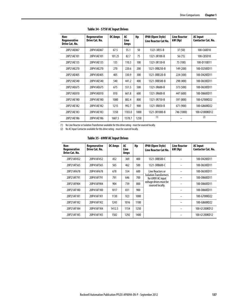
Drive Comparisons Chapter 1
Table 34 - 575V AC Input Drives
Table 35 - 690V AC Input Drives
Non-Regenerative Drive Cat. No.
Regenerative Drive Cat. No.
DC Amps AC Line Amps
Hp IP00 (Open Style)Line Reactor Cat No.
Line Reactor kW (Hp)
AC Input Contactor Cat. No.
20P21AE067 20P41AE067 67.5 55.1 50 1321-3R55-B 37 (50) 100-C60D10
20P21AE101 20P41AE101 101.25 82.7 75 1321-3R100-B 56 (75) 100-C85D10
20P21AE135 20P41AE135 135 110.3 100 1321-3R130-B 75 (100) 100-D110D11
20P21AE270 20P41AE270 270 220.6 200 1321-3RB250-B 149 (200) 100-D250ED11
20P21AE405 20P41AE405 405 330.9 300 1321-3RB320-B 224 (300) 100-D420ED11
20P21AE540 20P41AE540 540 441.2 400 1321-3RB500-B 298 (400) 100-D630ED11
20P21AE675 20P41AE675 675 551.5 500 1321-3R600-B 373 (500) 100-D630ED11
20P21AE810 20P41AE810 810 661.8 600 1321-3R600-B 447 (600) 100-D860ED11
20P21AE1K0 20P41AE1K0 1080 882.4 800 1321-3R750-B 597 (800) 100-G700KD22
20P21AE1K2 20P41AE1K2 1215 992.7 900 1321-3R850-B 671 (900) 100-G860KD22
20P21AE1K3 20P41AE1K3 1350 1103.0 1000 1321-3R1000-B 746 (1000) 100-G1000KD12
20P21AE1K6 20P41AE1K6 1687.5 1378.7 1250 (1) – (2)
(1) No Line Reactor or Isolation Transformer available for this drive rating - must be sourced locally.(2) No AC Input Contactor available for this drive rating - must be sourced locally.
Non-Regenerative Drive Cat. No.
Regenerative Drive Cat. No.
DC Amps AC Line Amps
Hp IP00 (Open Style)Line Reactor Cat No.
Line Reactor kW (Hp)
AC Input Contactor Cat. No.
20P21AF452 20P41AF452 452 369 400 1321-3RB500-C – 100-D420ED11
20P21AF565 20P41AF565 565 462 500 1321-3RB600-C – 100-D630ED11
20P21AF678 20P41AF678 678 554 600 Line Reactors or Isolation Transformers
for 690V AC input voltage drives must be
sourced locally.
– 100-D630ED11
20P21AF791 20P41AF791 791 646 700 – 100-D860ED11
20P21AF904 20P41AF904 904 739 800 – 100-D860ED11
20P21AF1K0 20P41AF1K0 1017 831 900 – 100-D860ED11
20P21AF1K1 20P41AF1K1 1130 923 1000 – 100-G700KD22
20P21AF1K2 20P41AF1K2 1243 1016 1100 – 100-G860KD22
20P21AF1K4 20P41AF1K4 1412.5 1154 1250 – 100-G1200KD12
20P21AF1K5 20P41AF1K5 1582 1292 1400 – 100-G1200KD12
Rockwell Automation Publication PFLEX-AP009A-EN-P - September 2012 137
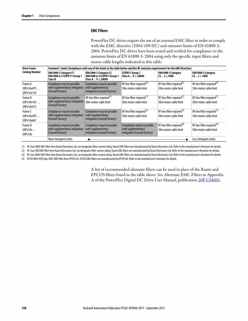
Chapter 1 Drive Comparisons
EMC Filters
PowerFlex DC drives require the use of an external EMC filter in order to comply with the EMC directive (2004/109/EC) and emission limits of EN 61800-3: 2004. PowerFlex DC drives have been tested and verified for compliance to the emission limits of EN 61800-3: 2004 using only the specific input filters and motor cable lengths indicated in this table:
A list of recommended alternate filters can be used in place of the Rasmi and EPCOS filters listed in the table above. See Alternate EMC Filters in Appendix A of the PowerFlex Digital DC Drive User Manual, publication 20P-UM001.
Drive FrameCatalog Number
Standard / Limits (Compliance with any of the limits in the table below satisfies RF emission requirements for the EMC Directive)EN61800-3 Category C1EN61000-6-3 CISPR 11 Group 1 Class B
EN61800-3 Category C2EN61000-6-4 CISPR11 Group 1 Class A…P < 20kVA
CISPR11 Group 1Class A…P > 20kVA
EN61800-3 CategoryC3…I < 100A
EN61800-3 CategoryC3…I > 100A
Frame A20Px1Ax4P1…20Px1Ax129
Compliance may be possible with supplementary mitigation (Consult factory)
Compliance may be possible with supplementary mitigation (Consult factory)
RF line filter required(2)
50m motor cable limit RF line filter required(2)
50m motor cable limit RF line filter required(2)
50m motor cable limit
Frame B20Px1Ax167…20Px1Ax412
Compliance may be possible with supplementary mitigation (Consult factory)
RF line filter required(1)
50m motor cable limit RF line filter required(1)
50m motor cable limit RF line filter required(1)
50m motor cable limit RF line filter required(1)
50m motor cable limit
Frame C20Px1Ax495…20Px1Ax667
Compliance may be possible with supplementary mitigation (Consult factory)
Compliance may be possible with supplementary mitigation (Consult factory)
RF line filter required(3)
50m motor cable limit RF line filter required(3)
50m motor cable limit RF line filter required(3)
50m motor cable limit
Frame D20Px1Ax…20Px1Ax
Compliance may be possible with supplementary mitigation (Consult factory)
Compliance may be possible with supplementary mitigation (Consult factory)
Compliance may be possible with supplementary mitigation (Consult factory)
RF line filter required(4)
50m motor cable limit RF line filter required(4)
50m motor cable limit
More Stringent Limits Less Stringent Limits
(1) RF 3xxx-MHU EMC filter from Rasmi Electronics Ltd. xxx designates filter current rating. Rasmi EMC filters are manufactured by Rasmi Electronics Ltd. Refer to the manufacturer’s literature for details.(2) RF 3xxx-SIEI EMC filter from Rasmi Electronics Ltd. xxx designates filter current rating. Rasmi EMC filters are manufactured by Rasmi Electronics Ltd. Refer to the manufacturer’s literature for details.(3) RF 3xxx-MHU EMC filter from Rasmi Electronics Ltd. xxx designates filter current rating. Rasmi EMC filters are manufactured by Rasmi Electronics Ltd. Refer to the manufacturer’s literature for details.(4) EPCOS B84143B Type S081 EMC filter from EPCOS AG. EPCOS EMC filters are manufactured by EPCOS AG. Refer to the manufacturer’s literature for details.
138 Rockwell Automation Publication PFLEX-AP009A-EN-P - September 2012
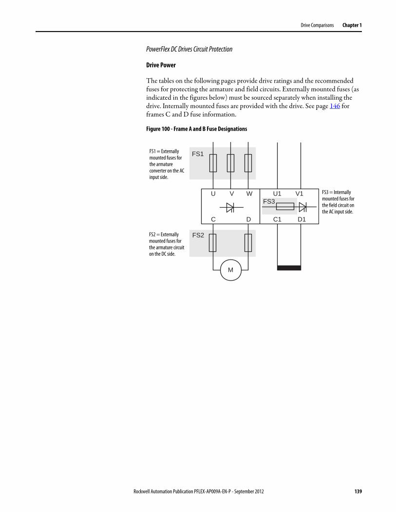
Drive Comparisons Chapter 1
PowerFlex DC Drives Circuit Protection
Drive Power
The tables on the following pages provide drive ratings and the recommended fuses for protecting the armature and field circuits. Externally mounted fuses (as indicated in the figures below) must be sourced separately when installing the drive. Internally mounted fuses are provided with the drive. See page 146 for frames C and D fuse information.
Figure 100 - Frame A and B Fuse Designations
FS1
FS2
M
U V W
C D
FS3
C1 D1
U1 V1
FS1 = Externally mounted fuses for the armature converter on the AC input side.
FS2 = Externally mounted fuses for the armature circuit on the DC side.
FS3 = Internally mounted fuses for the field circuit on the AC input side.
Rockwell Automation Publication PFLEX-AP009A-EN-P - September 2012 139
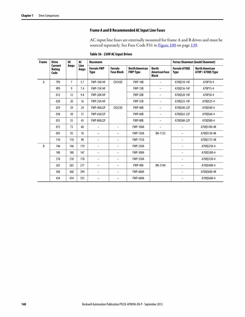
Chapter 1 Drive Comparisons
Frame A and B Recommended AC Input Line Fuses
AC input line fuses are externally mounted for frame A and B drives and must be sourced separately. See Fuse Code FS1 in Figure 100 on page 139.
Table 36 - 230V AC Input Drives
Frame Drive Current Rating Code
DC Amps
AC Line Amps
Bussmann Ferraz Shawmut (Gould Shawmut)
Ferrule FWP Type
Ferrule Fuse Block
North American FWP Type
North American Fuse Block
Ferrule A70QS Type
North American A70P / A70QS Type
A 7P0 7 5.7 FWP-10A14F CH143D FWP-10B – A70QS10-14F A70P10-4
9P0 9 7.4 FWP-15A14F FWP-15B – A70QS16-14F A70P15-4
012 12 9.8 FWP-20A14F FWP-20B – A70QS20-14F A70P20-4
020 20 16 FWP-25A14F FWP-25B – A70QS25-14F A70QS25-4
029 29 24 FWP-40A22F CH223D FWP-40B – A70QS40-22F A70QS40-4
038 38 31 FWP-63A22F FWP-60B – A70QS63-22F A70QS60-4
055 55 45 FWP-80A22F FWP-80B – A70QS80-22F A70QS80-4
073 73 60 – – FWP-100A – – A70QS100-4K
093 93 76 – – FWP-150A BH-1133 – A70QS150-4K
110 110 90 – – FWP-175A – A70QS175-4K
B 146 146 119 – – FWP-250A – A70QS250-4
180 180 147 – – FWP-300A – A70QS300-4
218 218 178 – – FWP-350A – A70QS350-4
265 265 217 – – FWP-400 BH-3144 – A70QS400-4
360 360 294 – – FWP-600A – A70QS600-4K
434 434 355 – – FWP-600A – A70QS600-4
140 Rockwell Automation Publication PFLEX-AP009A-EN-P - September 2012
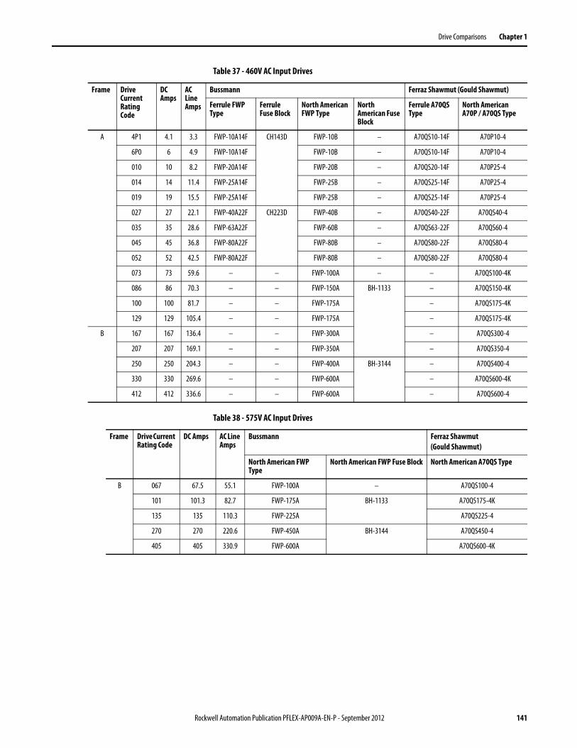
Drive Comparisons Chapter 1
Table 37 - 460V AC Input Drives
Table 38 - 575V AC Input Drives
Frame Drive Current Rating Code
DC Amps
AC Line Amps
Bussmann Ferraz Shawmut (Gould Shawmut)
Ferrule FWP Type
Ferrule Fuse Block
North American FWP Type
North American Fuse Block
Ferrule A70QS Type
North American A70P / A70QS Type
A 4P1 4.1 3.3 FWP-10A14F CH143D FWP-10B – A70QS10-14F A70P10-4
6P0 6 4.9 FWP-10A14F FWP-10B – A70QS10-14F A70P10-4
010 10 8.2 FWP-20A14F FWP-20B – A70QS20-14F A70P25-4
014 14 11.4 FWP-25A14F FWP-25B – A70QS25-14F A70P25-4
019 19 15.5 FWP-25A14F FWP-25B – A70QS25-14F A70P25-4
027 27 22.1 FWP-40A22F CH223D FWP-40B – A70QS40-22F A70QS40-4
035 35 28.6 FWP-63A22F FWP-60B – A70QS63-22F A70QS60-4
045 45 36.8 FWP-80A22F FWP-80B – A70QS80-22F A70QS80-4
052 52 42.5 FWP-80A22F FWP-80B – A70QS80-22F A70QS80-4
073 73 59.6 – – FWP-100A – – A70QS100-4K
086 86 70.3 – – FWP-150A BH-1133 – A70QS150-4K
100 100 81.7 – – FWP-175A – A70QS175-4K
129 129 105.4 – – FWP-175A – A70QS175-4K
B 167 167 136.4 – – FWP-300A – A70QS300-4
207 207 169.1 – – FWP-350A – A70QS350-4
250 250 204.3 – – FWP-400A BH-3144 – A70QS400-4
330 330 269.6 – – FWP-600A – A70QS600-4K
412 412 336.6 – – FWP-600A – A70QS600-4
Frame Drive Current Rating Code
DC Amps AC Line Amps
Bussmann Ferraz Shawmut(Gould Shawmut)
North American FWP Type
North American FWP Fuse Block North American A70QS Type
B 067 67.5 55.1 FWP-100A – A70QS100-4
101 101.3 82.7 FWP-175A BH-1133 A70QS175-4K
135 135 110.3 FWP-225A A70QS225-4
270 270 220.6 FWP-450A BH-3144 A70QS450-4
405 405 330.9 FWP-600A A70QS600-4K
Rockwell Automation Publication PFLEX-AP009A-EN-P - September 2012 141
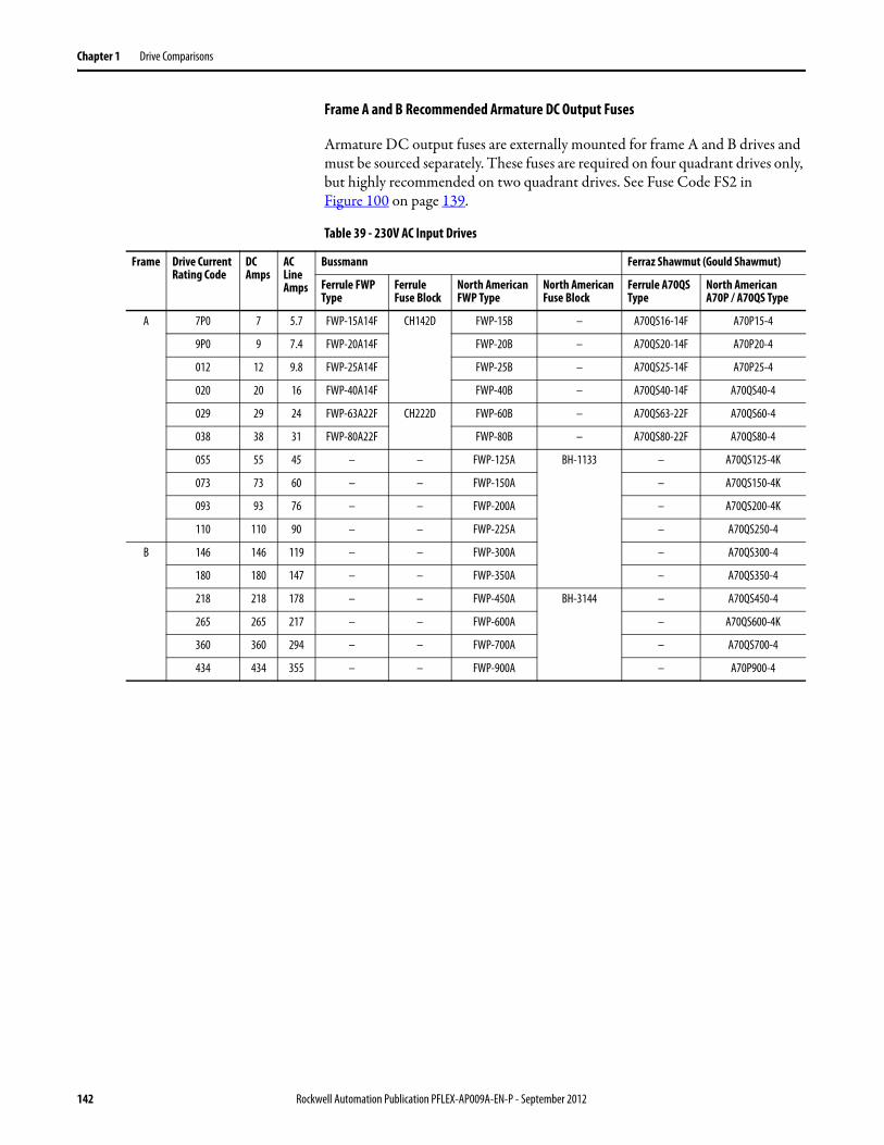
Chapter 1 Drive Comparisons
Frame A and B Recommended Armature DC Output Fuses
Armature DC output fuses are externally mounted for frame A and B drives and must be sourced separately. These fuses are required on four quadrant drives only, but highly recommended on two quadrant drives. See Fuse Code FS2 in Figure 100 on page 139.
Table 39 - 230V AC Input Drives
Frame Drive Current Rating Code
DC Amps
AC Line Amps
Bussmann Ferraz Shawmut (Gould Shawmut)
Ferrule FWP Type
Ferrule Fuse Block
North American FWP Type
North American Fuse Block
Ferrule A70QS Type
North American A70P / A70QS Type
A 7P0 7 5.7 FWP-15A14F CH142D FWP-15B – A70QS16-14F A70P15-4
9P0 9 7.4 FWP-20A14F FWP-20B – A70QS20-14F A70P20-4
012 12 9.8 FWP-25A14F FWP-25B – A70QS25-14F A70P25-4
020 20 16 FWP-40A14F FWP-40B – A70QS40-14F A70QS40-4
029 29 24 FWP-63A22F CH222D FWP-60B – A70QS63-22F A70QS60-4
038 38 31 FWP-80A22F FWP-80B – A70QS80-22F A70QS80-4
055 55 45 – – FWP-125A BH-1133 – A70QS125-4K
073 73 60 – – FWP-150A – A70QS150-4K
093 93 76 – – FWP-200A – A70QS200-4K
110 110 90 – – FWP-225A – A70QS250-4
B 146 146 119 – – FWP-300A – A70QS300-4
180 180 147 – – FWP-350A – A70QS350-4
218 218 178 – – FWP-450A BH-3144 – A70QS450-4
265 265 217 – – FWP-600A – A70QS600-4K
360 360 294 – – FWP-700A – A70QS700-4
434 434 355 – – FWP-900A – A70P900-4
142 Rockwell Automation Publication PFLEX-AP009A-EN-P - September 2012
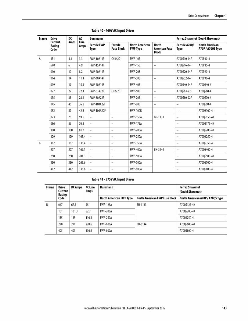
Drive Comparisons Chapter 1
Table 40 - 460V AC Input Drives
Table 41 - 575V AC Input Drives
Frame Drive Current Rating Code
DC Amps
AC Line Amps
Bussmann Ferraz Shawmut (Gould Shawmut)
Ferrule FWP Type
Ferrule Fuse Block
North American FWP Type
North American Fuse Block
Ferrule A70QS Type
North American A70P / A70QS Type
A 4P1 4.1 3.3 FWP-10A14F CH142D FWP-10B – A70QS10-14F A70P10-4
6P0 6 4.9 FWP-15A14F FWP-15B – A70QS16-14F A70P15-4
010 10 8.2 FWP-20A14F FWP-20B – A70QS20-14F A70P20-4
014 14 11.4 FWP-30A14F FWP-30B – A70QS32-14F A70P30-4
019 19 15.5 FWP-40A14F FWP-40B – A70QS40-14F A70QS40-4
027 27 22.1 FWP-63A22F CH222D FWP-60B – A70QS63-22F A70QS60-4
035 35 28.6 FWP-80A22F FWP-70B – A70QS80-22F A70QS70-4
045 45 36.8 FWP-100A22F FWP-90B – – A70QS90-4
052 52 42.5 FWP-100A22F FWP-100B – – A70QS100-4
073 73 59.6 – – FWP-150A BH-1133 – A70QS150-4K
086 86 70.3 – – FWP-175A – A70QS175-4K
100 100 81.7 – – FWP-200A – A70QS200-4K
129 129 105.4 – – FWP-250A – A70QS250-4
B 167 167 136.4 – – FWP-350A – A70QS350-4
207 207 169.1 – – FWP-400A BH-3144 – A70QS400-4
250 250 204.3 – – FWP-500A – A70QS500-4K
330 330 269.6 – – FWP-700A – A70QS700-4
412 412 336.6 – – FWP-800A – A70QS800-4
Frame Drive Current Rating Code
DC Amps AC Line Amps
Bussmann Ferraz Shawmut(Gould Shawmut)
North American FWP Type North American FWP Fuse Block North American A70P / A70QS Type
B 067 67.5 55.1 FWP-125A BH-1133 A70QS125-4K
101 101.3 82.7 FWP-200A A70QS200-4K
135 135 110.3 FWP-250A A70QS250-4
270 270 220.6 FWP-600A BH-3144 A70QS600-4K
405 405 330.9 FWP-800A A70QS800-4
Rockwell Automation Publication PFLEX-AP009A-EN-P - September 2012 143
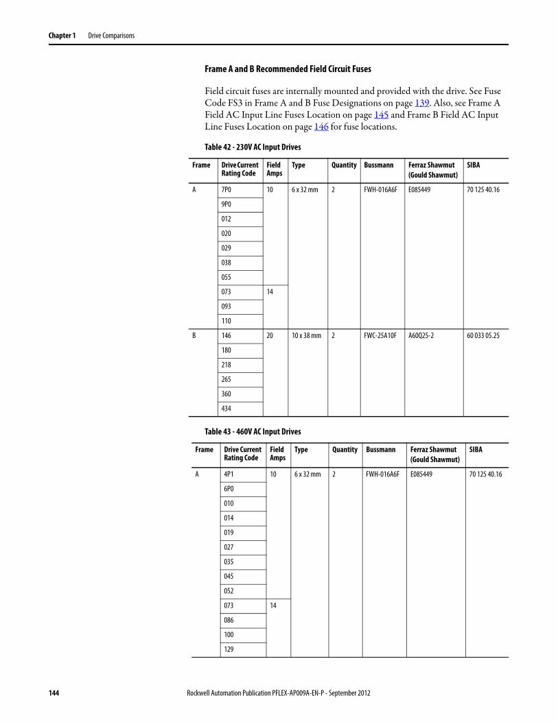
Chapter 1 Drive Comparisons
Frame A and B Recommended Field Circuit Fuses
Field circuit fuses are internally mounted and provided with the drive. See Fuse Code FS3 in Frame A and B Fuse Designations on page 139. Also, see Frame A Field AC Input Line Fuses Location on page 145 and Frame B Field AC Input Line Fuses Location on page 146 for fuse locations.
Table 42 - 230V AC Input Drives
Table 43 - 460V AC Input Drives
Frame Drive Current Rating Code
Field Amps
Type Quantity Bussmann Ferraz Shawmut(Gould Shawmut)
SIBA
A 7P0 10 6 x 32 mm 2 FWH-016A6F E085449 70 125 40.16
9P0
012
020
029
038
055
073 14
093
110
B 146 20 10 x 38 mm 2 FWC-25A10F A60Q25-2 60 033 05.25
180
218
265
360
434
Frame Drive Current Rating Code
Field Amps
Type Quantity Bussmann Ferraz Shawmut(Gould Shawmut)
SIBA
A 4P1 10 6 x 32 mm 2 FWH-016A6F E085449 70 125 40.16
6P0
010
014
019
027
035
045
052
073 14
086
100
129
144 Rockwell Automation Publication PFLEX-AP009A-EN-P - September 2012
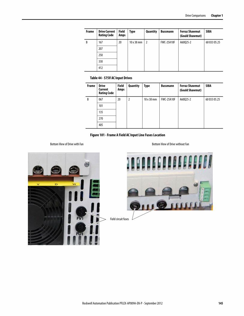
Drive Comparisons Chapter 1
Table 44 - 575V AC Input Drives
Figure 101 - Frame A Field AC Input Line Fuses Location
B 167 20 10 x 38 mm 2 FWC-25A10F A60Q25-2 60 033 05.25
207
250
330
412
Frame Drive Current Rating Code
Field Amps
Type Quantity Bussmann Ferraz Shawmut(Gould Shawmut)
SIBA
Frame Drive Current Rating Code
Field Amps
Quantity Type Bussmann Ferraz Shawmut(Gould Shawmut)
SIBA
B 067 20 2 10 x 38 mm FWC-25A10F A60Q25-2 60 033 05.25
101
135
270
405
Bottom View of Drive without Fan
Field circuit fuses
Bottom View of Drive with Fan
Rockwell Automation Publication PFLEX-AP009A-EN-P - September 2012 145
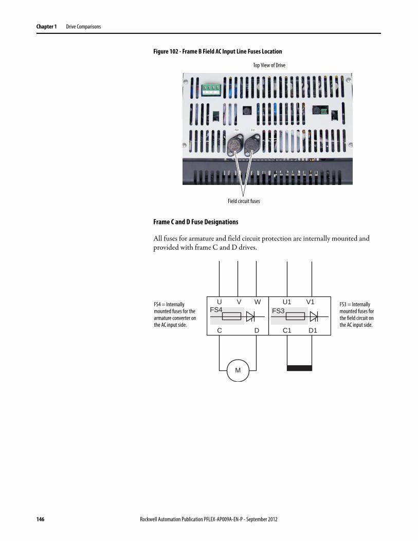
Chapter 1 Drive Comparisons
Figure 102 - Frame B Field AC Input Line Fuses Location
Frame C and D Fuse Designations
All fuses for armature and field circuit protection are internally mounted and provided with frame C and D drives.
Top View of Drive
Field circuit fuses
U V W
C D
FS3FS4
C1 D1
U1 V1
M
FS3 = Internally mounted fuses for the field circuit on the AC input side.
FS4 = Internally mounted fuses for the armature converter on the AC input side.
146 Rockwell Automation Publication PFLEX-AP009A-EN-P - September 2012
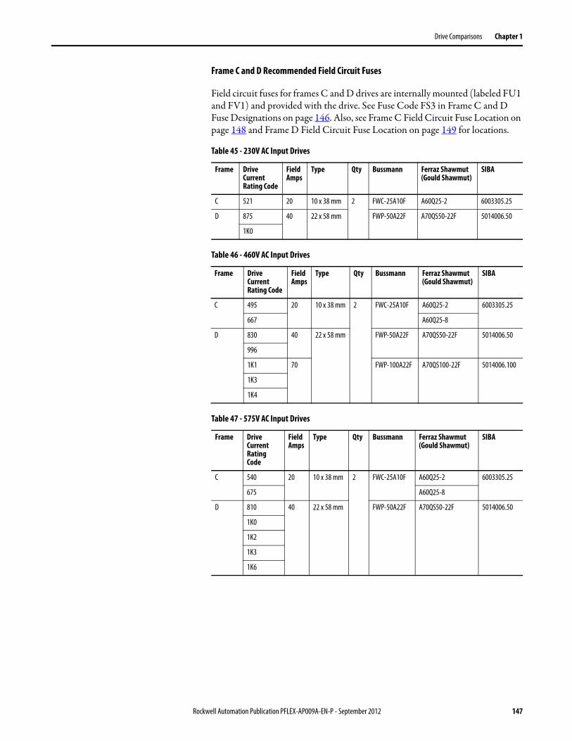
Drive Comparisons Chapter 1
Frame C and D Recommended Field Circuit Fuses
Field circuit fuses for frames C and D drives are internally mounted (labeled FU1 and FV1) and provided with the drive. See Fuse Code FS3 in Frame C and D Fuse Designations on page 146. Also, see Frame C Field Circuit Fuse Location on page 148 and Frame D Field Circuit Fuse Location on page 149 for locations.
Table 45 - 230V AC Input Drives
Table 46 - 460V AC Input Drives
Table 47 - 575V AC Input Drives
Frame Drive Current Rating Code
Field Amps
Type Qty Bussmann Ferraz Shawmut (Gould Shawmut)
SIBA
C 521 20 10 x 38 mm 2 FWC-25A10F A60Q25-2 6003305.25
D 875 40 22 x 58 mm FWP-50A22F A70QS50-22F 5014006.50
1K0
Frame Drive Current Rating Code
Field Amps
Type Qty Bussmann Ferraz Shawmut (Gould Shawmut)
SIBA
C 495 20 10 x 38 mm 2 FWC-25A10F A60Q25-2 6003305.25
667 A60Q25-8
D 830 40 22 x 58 mm FWP-50A22F A70QS50-22F 5014006.50
996
1K1 70 FWP-100A22F A70QS100-22F 5014006.100
1K3
1K4
Frame Drive Current Rating Code
Field Amps
Type Qty Bussmann Ferraz Shawmut (Gould Shawmut)
SIBA
C 540 20 10 x 38 mm 2 FWC-25A10F A60Q25-2 6003305.25
675 A60Q25-8
D 810 40 22 x 58 mm FWP-50A22F A70QS50-22F 5014006.50
1K0
1K2
1K3
1K6
Rockwell Automation Publication PFLEX-AP009A-EN-P - September 2012 147
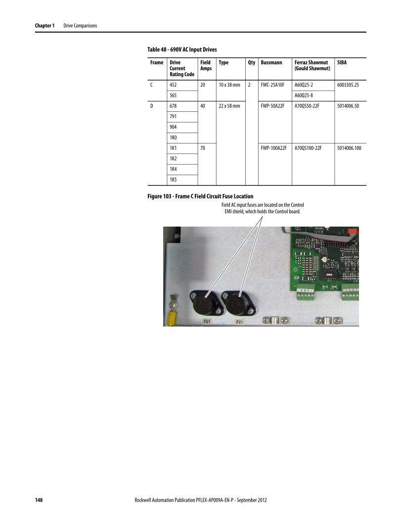
Chapter 1 Drive Comparisons
Table 48 - 690V AC Input Drives
Figure 103 - Frame C Field Circuit Fuse Location
Frame Drive Current Rating Code
Field Amps
Type Qty Bussmann Ferraz Shawmut (Gould Shawmut)
SIBA
C 452 20 10 x 38 mm 2 FWC-25A10F A60Q25-2 6003305.25
565 A60Q25-8
D 678 40 22 x 58 mm FWP-50A22F A70QS50-22F 5014006.50
791
904
1K0
1K1 70 FWP-100A22F A70QS100-22F 5014006.100
1K2
1K4
1K5
Field AC input fuses are located on the Control EMI shield, which holds the Control board.
148 Rockwell Automation Publication PFLEX-AP009A-EN-P - September 2012
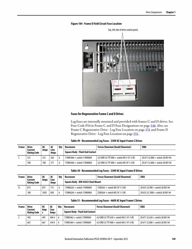
Drive Comparisons Chapter 1
Figure 104 - Frame D Field Circuit Fuse Location
Fuses for Regenerative Frame C and D Drives
Leg fuses are internally mounted and provided with frames C and D drives. See Fuse Code FS4 in Frame C and D Fuse Designations on page 146. Also, see Frame C Regenerative Drive - Leg Fuse Location on page 151 and Frame D Regenerative Drive - Leg Fuse Location on page 151.
Table 49 - Recommended Leg Fuses - 230V AC Input Frame C Drives
Table 50 - Recommended Leg Fuses - 230V AC Input Frame D Drives
Table 51 - Recommended Leg Fuses - 460V AC Input Frame C Drives
Top, left side of drive control panel.
Frame Drive Current Rating Code
DC Amps
AC Line Amps
Qty Bussmann Ferraz Shawmut (Gould Shawmut) SIBA
Square Body - Flush End Contact
C 521 521 426 6 170M5464 + switch 170H0069 6,9 URD 32 TTF 800 + switch MS 3-V1-5 BS 20 671 32.800 + switch 28 001 04
700 700 571 6 170M5464 + switch 170H0069 6,9 URD 32 TTF 800 + switch MS 3V 1-5 BS 20 671 32.800 + switch 28 001 04
Frame Drive Current Rating Code
DC Amps
AC Line Amps
Qty Bussmann Ferraz Shawmut (Gould Shawmut) SIBA
Square Body - DIN 43653 Stud-Mount
D 875 875 715 6 170M6263 + switch 170H0069 Y300263 + switch MS 3V 1-5 UR 20 635 32.900 + switch 28 001 04
1K0 1050 858 6 170M6264 + switch 170H0069 Z300264 + switch MS 3V 1-5 UR 20 635 32.1000 + switch 28 001 04
Frame Drive Current Rating Code
DC Amps
AC Line Amps
Qty Bussmann Ferraz Shawmut (Gould Shawmut) SIBA
Square Body - Flush End Contact
C 495 495 404.4 6 170M5462 + switch 170H0069 6,9 URD 32 TTF 630 + switch MS 3-V1-5 BS 20 671 32.630 + switch 28 001 04
667 667 544.9 6 170M5464 + switch 170H0069 6,9 URD 32 TTF 800 + switch MS 3-V1-5 BS 20 671 32.800 + switch 28 001 04
Rockwell Automation Publication PFLEX-AP009A-EN-P - September 2012 149
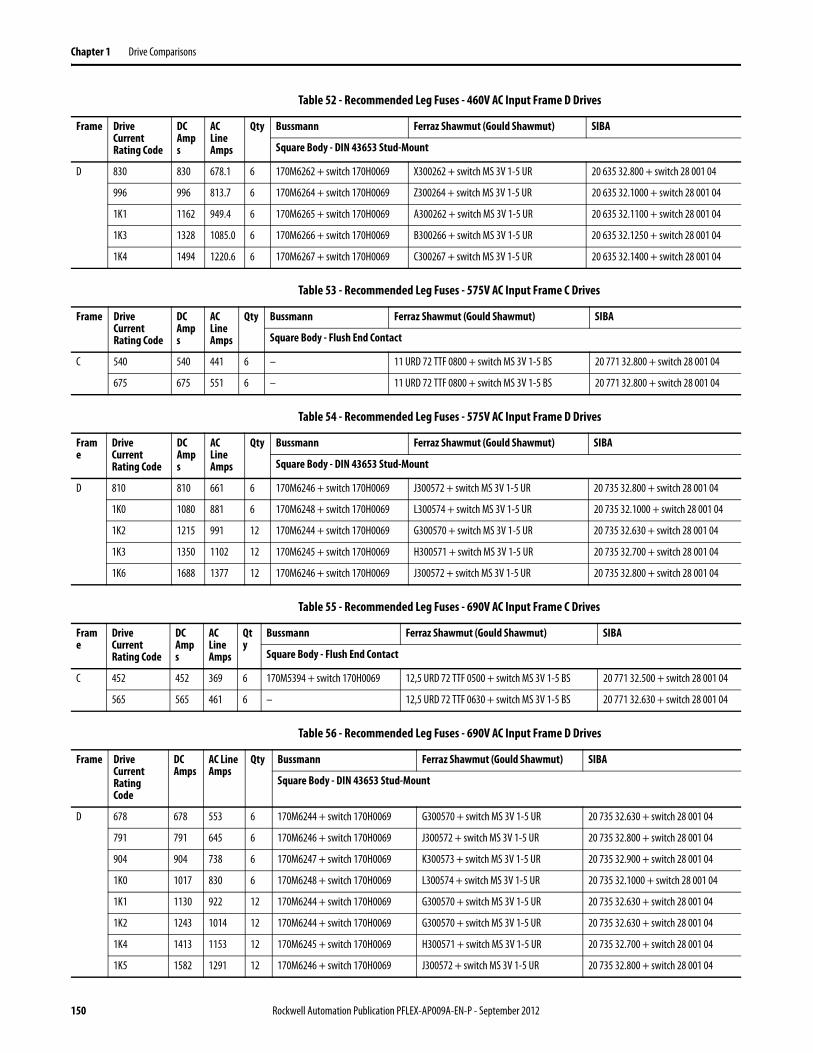
Chapter 1 Drive Comparisons
Table 52 - Recommended Leg Fuses - 460V AC Input Frame D Drives
Table 53 - Recommended Leg Fuses - 575V AC Input Frame C Drives
Table 54 - Recommended Leg Fuses - 575V AC Input Frame D Drives
Table 55 - Recommended Leg Fuses - 690V AC Input Frame C Drives
Table 56 - Recommended Leg Fuses - 690V AC Input Frame D Drives
Frame Drive Current Rating Code
DC Amps
AC Line Amps
Qty Bussmann Ferraz Shawmut (Gould Shawmut) SIBA
Square Body - DIN 43653 Stud-Mount
D 830 830 678.1 6 170M6262 + switch 170H0069 X300262 + switch MS 3V 1-5 UR 20 635 32.800 + switch 28 001 04
996 996 813.7 6 170M6264 + switch 170H0069 Z300264 + switch MS 3V 1-5 UR 20 635 32.1000 + switch 28 001 04
1K1 1162 949.4 6 170M6265 + switch 170H0069 A300262 + switch MS 3V 1-5 UR 20 635 32.1100 + switch 28 001 04
1K3 1328 1085.0 6 170M6266 + switch 170H0069 B300266 + switch MS 3V 1-5 UR 20 635 32.1250 + switch 28 001 04
1K4 1494 1220.6 6 170M6267 + switch 170H0069 C300267 + switch MS 3V 1-5 UR 20 635 32.1400 + switch 28 001 04
Frame Drive Current Rating Code
DC Amps
AC Line Amps
Qty Bussmann Ferraz Shawmut (Gould Shawmut) SIBA
Square Body - Flush End Contact
C 540 540 441 6 – 11 URD 72 TTF 0800 + switch MS 3V 1-5 BS 20 771 32.800 + switch 28 001 04
675 675 551 6 – 11 URD 72 TTF 0800 + switch MS 3V 1-5 BS 20 771 32.800 + switch 28 001 04
Frame
Drive Current Rating Code
DC Amps
AC Line Amps
Qty Bussmann Ferraz Shawmut (Gould Shawmut) SIBA
Square Body - DIN 43653 Stud-Mount
D 810 810 661 6 170M6246 + switch 170H0069 J300572 + switch MS 3V 1-5 UR 20 735 32.800 + switch 28 001 04
1K0 1080 881 6 170M6248 + switch 170H0069 L300574 + switch MS 3V 1-5 UR 20 735 32.1000 + switch 28 001 04
1K2 1215 991 12 170M6244 + switch 170H0069 G300570 + switch MS 3V 1-5 UR 20 735 32.630 + switch 28 001 04
1K3 1350 1102 12 170M6245 + switch 170H0069 H300571 + switch MS 3V 1-5 UR 20 735 32.700 + switch 28 001 04
1K6 1688 1377 12 170M6246 + switch 170H0069 J300572 + switch MS 3V 1-5 UR 20 735 32.800 + switch 28 001 04
Frame
Drive Current Rating Code
DC Amps
AC Line Amps
Qty
Bussmann Ferraz Shawmut (Gould Shawmut) SIBA
Square Body - Flush End Contact
C 452 452 369 6 170M5394 + switch 170H0069 12,5 URD 72 TTF 0500 + switch MS 3V 1-5 BS 20 771 32.500 + switch 28 001 04
565 565 461 6 – 12,5 URD 72 TTF 0630 + switch MS 3V 1-5 BS 20 771 32.630 + switch 28 001 04
Frame Drive Current Rating Code
DC Amps
AC Line Amps
Qty Bussmann Ferraz Shawmut (Gould Shawmut) SIBA
Square Body - DIN 43653 Stud-Mount
D 678 678 553 6 170M6244 + switch 170H0069 G300570 + switch MS 3V 1-5 UR 20 735 32.630 + switch 28 001 04
791 791 645 6 170M6246 + switch 170H0069 J300572 + switch MS 3V 1-5 UR 20 735 32.800 + switch 28 001 04
904 904 738 6 170M6247 + switch 170H0069 K300573 + switch MS 3V 1-5 UR 20 735 32.900 + switch 28 001 04
1K0 1017 830 6 170M6248 + switch 170H0069 L300574 + switch MS 3V 1-5 UR 20 735 32.1000 + switch 28 001 04
1K1 1130 922 12 170M6244 + switch 170H0069 G300570 + switch MS 3V 1-5 UR 20 735 32.630 + switch 28 001 04
1K2 1243 1014 12 170M6244 + switch 170H0069 G300570 + switch MS 3V 1-5 UR 20 735 32.630 + switch 28 001 04
1K4 1413 1153 12 170M6245 + switch 170H0069 H300571 + switch MS 3V 1-5 UR 20 735 32.700 + switch 28 001 04
1K5 1582 1291 12 170M6246 + switch 170H0069 J300572 + switch MS 3V 1-5 UR 20 735 32.800 + switch 28 001 04
150 Rockwell Automation Publication PFLEX-AP009A-EN-P - September 2012
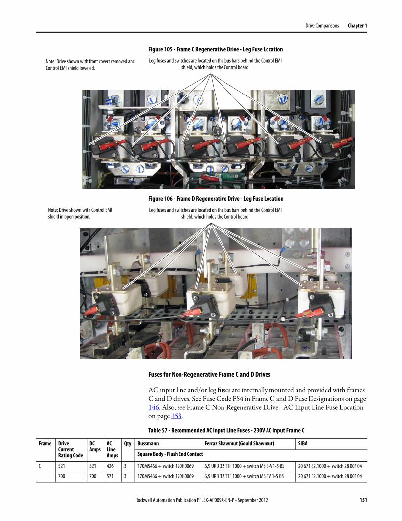
Drive Comparisons Chapter 1
Figure 105 - Frame C Regenerative Drive - Leg Fuse Location
Figure 106 - Frame D Regenerative Drive - Leg Fuse Location
Fuses for Non-Regenerative Frame C and D Drives
AC input line and/or leg fuses are internally mounted and provided with frames C and D drives. See Fuse Code FS4 in Frame C and D Fuse Designations on page 146. Also, see Frame C Non-Regenerative Drive - AC Input Line Fuse Location on page 153.
Table 57 - Recommended AC Input Line Fuses - 230V AC Input Frame C
Note: Drive shown with front covers removed and Control EMI shield lowered.
Leg fuses and switches are located on the bus bars behind the Control EMI shield, which holds the Control board.
Note: Drive shown with Control EMI shield in open position.
Leg fuses and switches are located on the bus bars behind the Control EMI shield, which holds the Control board.
Frame Drive Current Rating Code
DC Amps
AC Line Amps
Qty Bussmann Ferraz Shawmut (Gould Shawmut) SIBA
Square Body - Flush End Contact
C 521 521 426 3 170M5466 + switch 170H0069 6,9 URD 32 TTF 1000 + switch MS 3-V1-5 BS 20 671 32.1000 + switch 28 001 04
700 700 571 3 170M5466 + switch 170H0069 6,9 URD 32 TTF 1000 + switch MS 3V 1-5 BS 20 671 32.1000 + switch 28 001 04
Rockwell Automation Publication PFLEX-AP009A-EN-P - September 2012 151
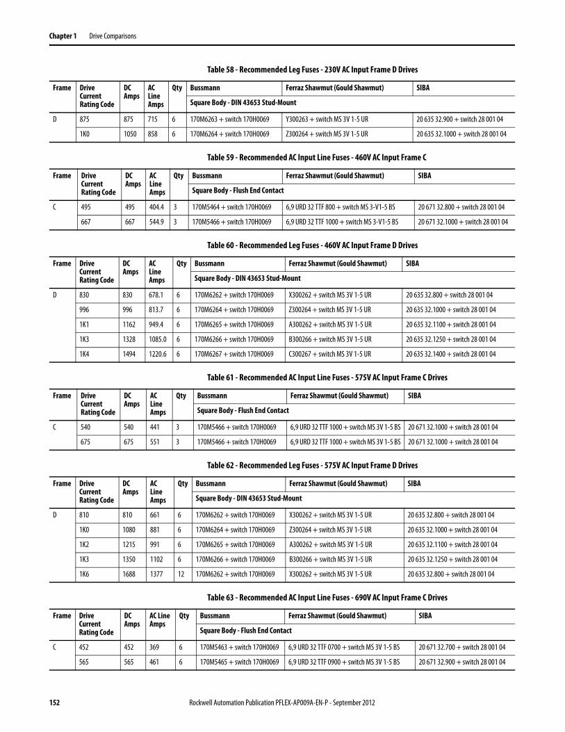
Chapter 1 Drive Comparisons
Table 58 - Recommended Leg Fuses - 230V AC Input Frame D Drives
Table 59 - Recommended AC Input Line Fuses - 460V AC Input Frame C
Table 60 - Recommended Leg Fuses - 460V AC Input Frame D Drives
Table 61 - Recommended AC Input Line Fuses - 575V AC Input Frame C Drives
Table 62 - Recommended Leg Fuses - 575V AC Input Frame D Drives
Table 63 - Recommended AC Input Line Fuses - 690V AC Input Frame C Drives
Frame Drive Current Rating Code
DC Amps
AC Line Amps
Qty Bussmann Ferraz Shawmut (Gould Shawmut) SIBA
Square Body - DIN 43653 Stud-Mount
D 875 875 715 6 170M6263 + switch 170H0069 Y300263 + switch MS 3V 1-5 UR 20 635 32.900 + switch 28 001 04
1K0 1050 858 6 170M6264 + switch 170H0069 Z300264 + switch MS 3V 1-5 UR 20 635 32.1000 + switch 28 001 04
Frame Drive Current Rating Code
DC Amps
AC Line Amps
Qty Bussmann Ferraz Shawmut (Gould Shawmut) SIBA
Square Body - Flush End Contact
C 495 495 404.4 3 170M5464 + switch 170H0069 6,9 URD 32 TTF 800 + switch MS 3-V1-5 BS 20 671 32.800 + switch 28 001 04
667 667 544.9 3 170M5466 + switch 170H0069 6,9 URD 32 TTF 1000 + switch MS 3-V1-5 BS 20 671 32.1000 + switch 28 001 04
Frame Drive Current Rating Code
DC Amps
AC Line Amps
Qty Bussmann Ferraz Shawmut (Gould Shawmut) SIBA
Square Body - DIN 43653 Stud-Mount
D 830 830 678.1 6 170M6262 + switch 170H0069 X300262 + switch MS 3V 1-5 UR 20 635 32.800 + switch 28 001 04
996 996 813.7 6 170M6264 + switch 170H0069 Z300264 + switch MS 3V 1-5 UR 20 635 32.1000 + switch 28 001 04
1K1 1162 949.4 6 170M6265 + switch 170H0069 A300262 + switch MS 3V 1-5 UR 20 635 32.1100 + switch 28 001 04
1K3 1328 1085.0 6 170M6266 + switch 170H0069 B300266 + switch MS 3V 1-5 UR 20 635 32.1250 + switch 28 001 04
1K4 1494 1220.6 6 170M6267 + switch 170H0069 C300267 + switch MS 3V 1-5 UR 20 635 32.1400 + switch 28 001 04
Frame Drive Current Rating Code
DC Amps
AC Line Amps
Qty Bussmann Ferraz Shawmut (Gould Shawmut) SIBA
Square Body - Flush End Contact
C 540 540 441 3 170M5466 + switch 170H0069 6,9 URD 32 TTF 1000 + switch MS 3V 1-5 BS 20 671 32.1000 + switch 28 001 04
675 675 551 3 170M5466 + switch 170H0069 6,9 URD 32 TTF 1000 + switch MS 3V 1-5 BS 20 671 32.1000 + switch 28 001 04
Frame Drive Current Rating Code
DC Amps
AC Line Amps
Qty Bussmann Ferraz Shawmut (Gould Shawmut) SIBA
Square Body - DIN 43653 Stud-Mount
D 810 810 661 6 170M6262 + switch 170H0069 X300262 + switch MS 3V 1-5 UR 20 635 32.800 + switch 28 001 04
1K0 1080 881 6 170M6264 + switch 170H0069 Z300264 + switch MS 3V 1-5 UR 20 635 32.1000 + switch 28 001 04
1K2 1215 991 6 170M6265 + switch 170H0069 A300262 + switch MS 3V 1-5 UR 20 635 32.1100 + switch 28 001 04
1K3 1350 1102 6 170M6266 + switch 170H0069 B300266 + switch MS 3V 1-5 UR 20 635 32.1250 + switch 28 001 04
1K6 1688 1377 12 170M6262 + switch 170H0069 X300262 + switch MS 3V 1-5 UR 20 635 32.800 + switch 28 001 04
Frame Drive Current Rating Code
DC Amps
AC Line Amps
Qty Bussmann Ferraz Shawmut (Gould Shawmut) SIBA
Square Body - Flush End Contact
C 452 452 369 6 170M5463 + switch 170H0069 6,9 URD 32 TTF 0700 + switch MS 3V 1-5 BS 20 671 32.700 + switch 28 001 04
565 565 461 6 170M5465 + switch 170H0069 6,9 URD 32 TTF 0900 + switch MS 3V 1-5 BS 20 671 32.900 + switch 28 001 04
152 Rockwell Automation Publication PFLEX-AP009A-EN-P - September 2012
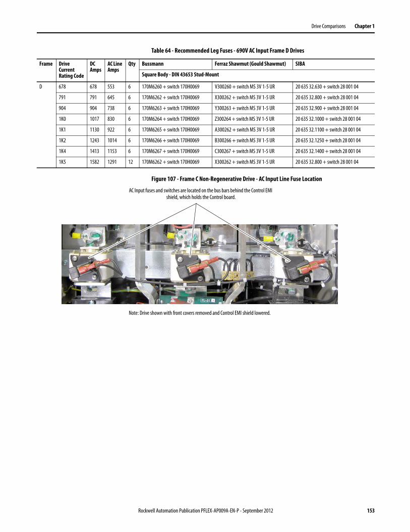
Drive Comparisons Chapter 1
Table 64 - Recommended Leg Fuses - 690V AC Input Frame D Drives
Figure 107 - Frame C Non-Regenerative Drive - AC Input Line Fuse Location
Frame Drive Current Rating Code
DC Amps
AC Line Amps
Qty Bussmann Ferraz Shawmut (Gould Shawmut) SIBA
Square Body - DIN 43653 Stud-Mount
D 678 678 553 6 170M6260 + switch 170H0069 V300260 + switch MS 3V 1-5 UR 20 635 32.630 + switch 28 001 04
791 791 645 6 170M6262 + switch 170H0069 X300262 + switch MS 3V 1-5 UR 20 635 32.800 + switch 28 001 04
904 904 738 6 170M6263 + switch 170H0069 Y300263 + switch MS 3V 1-5 UR 20 635 32.900 + switch 28 001 04
1K0 1017 830 6 170M6264 + switch 170H0069 Z300264 + switch MS 3V 1-5 UR 20 635 32.1000 + switch 28 001 04
1K1 1130 922 6 170M6265 + switch 170H0069 A300262 + switch MS 3V 1-5 UR 20 635 32.1100 + switch 28 001 04
1K2 1243 1014 6 170M6266 + switch 170H0069 B300266 + switch MS 3V 1-5 UR 20 635 32.1250 + switch 28 001 04
1K4 1413 1153 6 170M6267 + switch 170H0069 C300267 + switch MS 3V 1-5 UR 20 635 32.1400 + switch 28 001 04
1K5 1582 1291 12 170M6262 + switch 170H0069 X300262 + switch MS 3V 1-5 UR 20 635 32.800 + switch 28 001 04
Note: Drive shown with front covers removed and Control EMI shield lowered.
AC Input fuses and switches are located on the bus bars behind the Control EMI shield, which holds the Control board.
Rockwell Automation Publication PFLEX-AP009A-EN-P - September 2012 153
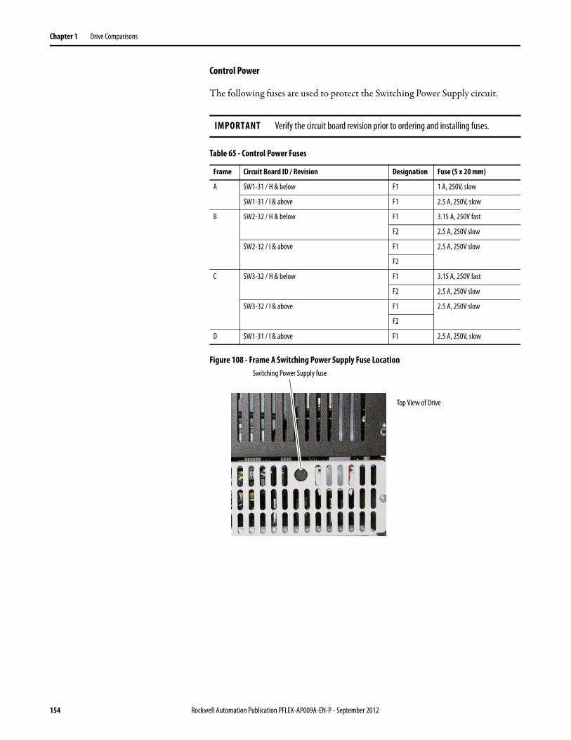
Chapter 1 Drive Comparisons
Control Power
The following fuses are used to protect the Switching Power Supply circuit.
Table 65 - Control Power Fuses
Figure 108 - Frame A Switching Power Supply Fuse Location
IMPORTANT Verify the circuit board revision prior to ordering and installing fuses.
Frame Circuit Board ID / Revision Designation Fuse (5 x 20 mm)
A SW1-31 / H & below F1 1 A, 250V, slow
SW1-31 / I & above F1 2.5 A, 250V, slow
B SW2-32 / H & below F1 3.15 A, 250V fast
F2 2.5 A, 250V slow
SW2-32 / I & above F1 2.5 A, 250V slow
F2
C SW3-32 / H & below F1 3.15 A, 250V fast
F2 2.5 A, 250V slow
SW3-32 / I & above F1 2.5 A, 250V slow
F2
D SW1-31 / I & above F1 2.5 A, 250V, slow
Top View of Drive
Switching Power Supply fuse
154 Rockwell Automation Publication PFLEX-AP009A-EN-P - September 2012
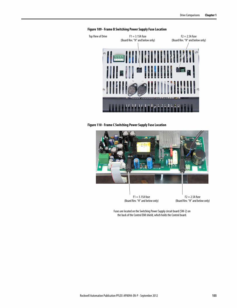
Drive Comparisons Chapter 1
Figure 109 - Frame B Switching Power Supply Fuse Location
Figure 110 - Frame C Switching Power Supply Fuse Location
Top View of Drive F1 = 3.15A fuse(Board Rev. “H” and below only)
F2 = 2.5A fuse(Board Rev. “H” and below only)
Fuses are located on the Switching Power Supply circuit board (SW-2) on the back of the Control EMI shield, which holds the Control board.
F1 = 3.15A fuse(Board Rev. “H” and below only)
F2 = 2.5A fuse(Board Rev. “H” and below only)
Rockwell Automation Publication PFLEX-AP009A-EN-P - September 2012 155
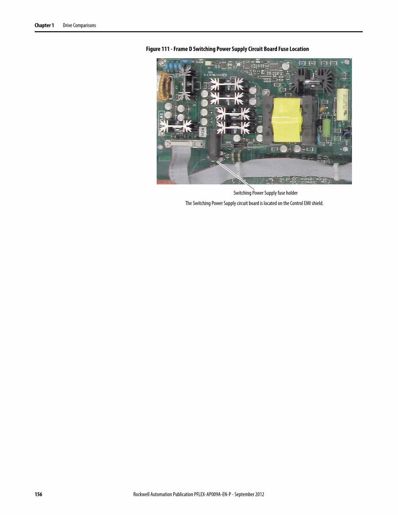
Chapter 1 Drive Comparisons
Figure 111 - Frame D Switching Power Supply Circuit Board Fuse Location
The Switching Power Supply circuit board is located on the Control EMI shield.
Switching Power Supply fuse holder
156 Rockwell Automation Publication PFLEX-AP009A-EN-P - September 2012
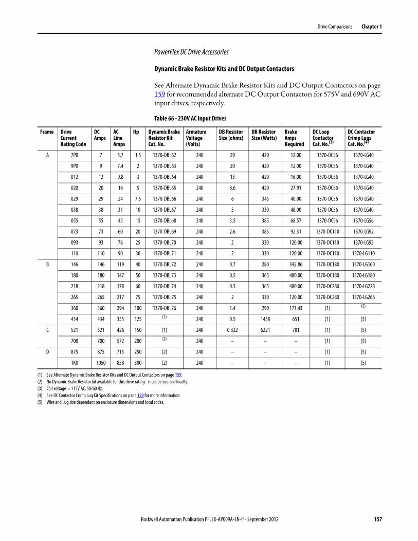
Drive Comparisons Chapter 1
PowerFlex DC Drive Accessories
Dynamic Brake Resistor Kits and DC Output Contactors
See Alternate Dynamic Brake Resistor Kits and DC Output Contactors on page 159 for recommended alternate DC Output Contactors for 575V and 690V AC input drives, respectively.
Table 66 - 230V AC Input Drives
Frame Drive Current Rating Code
DC Amps
AC Line Amps
Hp Dynamic Brake Resistor Kit Cat. No.
Armature Voltage (Volts)
DB Resistor Size (ohms)
DB Resistor Size (Watts)
Brake Amps Required
DC Loop Contactor Cat. No.(3)
DC Contactor Crimp Lugs Cat. No.(4)
A 7P0 7 5.7 1.5 1370-DBL62 240 20 420 12.00 1370-DC56 1370-LG40
9P0 9 7.4 2 1370-DBL63 240 20 420 12.00 1370-DC56 1370-LG40
012 12 9.8 3 1370-DBL64 240 15 420 16.00 1370-DC56 1370-LG40
020 20 16 5 1370-DBL65 240 8.6 420 27.91 1370-DC56 1370-LG40
029 29 24 7.5 1370-DBL66 240 6 345 40.00 1370-DC56 1370-LG40
038 38 31 10 1370-DBL67 240 5 330 48.00 1370-DC56 1370-LG40
055 55 45 15 1370-DBL68 240 3.5 385 68.57 1370-DC56 1370-LG56
073 73 60 20 1370-DBL69 240 2.6 385 92.31 1370-DC110 1370-LG92
093 93 76 25 1370-DBL70 240 2 330 120.00 1370-DC110 1370-LG92
110 110 90 30 1370-DBL71 240 2 330 120.00 1370-DC110 1370-LG110
B 146 146 119 40 1370-DBL72 240 0.7 280 342.86 1370-DC180 1370-LG160
180 180 147 50 1370-DBL73 240 0.5 365 480.00 1370-DC180 1370-LG180
218 218 178 60 1370-DBL74 240 0.5 365 480.00 1370-DC280 1370-LG228
265 265 217 75 1370-DBL75 240 2 330 120.00 1370-DC280 1370-LG268
360 360 294 100 1370-DBL76 240 1.4 290 171.43 (1) (5)
434 434 355 125 (1) 240 0.5 1458 651 (1) (5)
C 521 521 426 150 (1) 240 0.322 6221 781 (1) (5)
700 700 572 200 (2) 240 – – – (1) (5)
D 875 875 715 250 (2) 240 – – – (1) (5)
1K0 1050 858 300 (2) 240 – – – (1) (5)
(1) See Alternate Dynamic Brake Resistor Kits and DC Output Contactors on page 159.(2) No Dynamic Brake Resistor kit available for this drive rating - must be sourced locally.(3) Coil voltage = 115V AC, 50/60 Hz.(4) See DC Contactor Crimp Lug Kit Specifications on page 159 for more information.(5) Wire and Lug size dependant on enclosure dimensions and local codes.
Rockwell Automation Publication PFLEX-AP009A-EN-P - September 2012 157
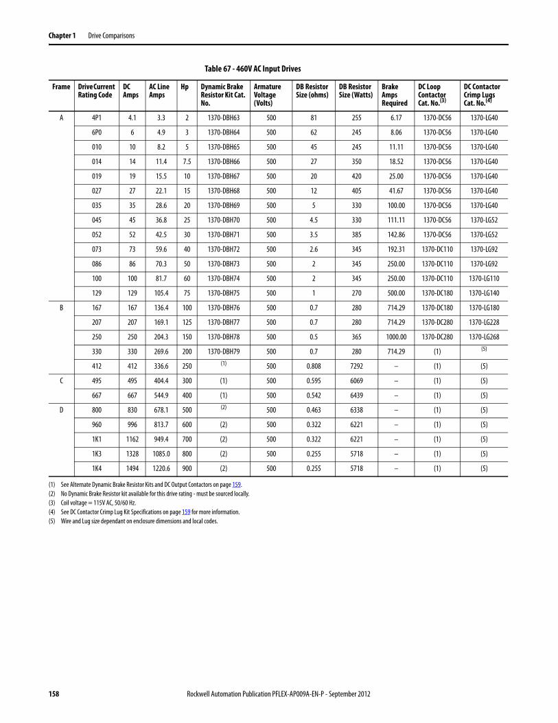
Chapter 1 Drive Comparisons
Table 67 - 460V AC Input Drives
Frame Drive Current Rating Code
DC Amps
AC Line Amps
Hp Dynamic Brake Resistor Kit Cat. No.
Armature Voltage (Volts)
DB Resistor Size (ohms)
DB Resistor Size (Watts)
Brake Amps Required
DC Loop Contactor Cat. No.(3)
DC Contactor Crimp Lugs Cat. No.(4)
A 4P1 4.1 3.3 2 1370-DBH63 500 81 255 6.17 1370-DC56 1370-LG40
6P0 6 4.9 3 1370-DBH64 500 62 245 8.06 1370-DC56 1370-LG40
010 10 8.2 5 1370-DBH65 500 45 245 11.11 1370-DC56 1370-LG40
014 14 11.4 7.5 1370-DBH66 500 27 350 18.52 1370-DC56 1370-LG40
019 19 15.5 10 1370-DBH67 500 20 420 25.00 1370-DC56 1370-LG40
027 27 22.1 15 1370-DBH68 500 12 405 41.67 1370-DC56 1370-LG40
035 35 28.6 20 1370-DBH69 500 5 330 100.00 1370-DC56 1370-LG40
045 45 36.8 25 1370-DBH70 500 4.5 330 111.11 1370-DC56 1370-LG52
052 52 42.5 30 1370-DBH71 500 3.5 385 142.86 1370-DC56 1370-LG52
073 73 59.6 40 1370-DBH72 500 2.6 345 192.31 1370-DC110 1370-LG92
086 86 70.3 50 1370-DBH73 500 2 345 250.00 1370-DC110 1370-LG92
100 100 81.7 60 1370-DBH74 500 2 345 250.00 1370-DC110 1370-LG110
129 129 105.4 75 1370-DBH75 500 1 270 500.00 1370-DC180 1370-LG140
B 167 167 136.4 100 1370-DBH76 500 0.7 280 714.29 1370-DC180 1370-LG180
207 207 169.1 125 1370-DBH77 500 0.7 280 714.29 1370-DC280 1370-LG228
250 250 204.3 150 1370-DBH78 500 0.5 365 1000.00 1370-DC280 1370-LG268
330 330 269.6 200 1370-DBH79 500 0.7 280 714.29 (1) (5)
412 412 336.6 250 (1) 500 0.808 7292 – (1) (5)
C 495 495 404.4 300 (1) 500 0.595 6069 – (1) (5)
667 667 544.9 400 (1) 500 0.542 6439 – (1) (5)
D 800 830 678.1 500 (2) 500 0.463 6338 – (1) (5)
960 996 813.7 600 (2) 500 0.322 6221 – (1) (5)
1K1 1162 949.4 700 (2) 500 0.322 6221 – (1) (5)
1K3 1328 1085.0 800 (2) 500 0.255 5718 – (1) (5)
1K4 1494 1220.6 900 (2) 500 0.255 5718 – (1) (5)
(1) See Alternate Dynamic Brake Resistor Kits and DC Output Contactors on page 159.(2) No Dynamic Brake Resistor kit available for this drive rating - must be sourced locally.(3) Coil voltage = 115V AC, 50/60 Hz.(4) See DC Contactor Crimp Lug Kit Specifications on page 159 for more information.(5) Wire and Lug size dependant on enclosure dimensions and local codes.
158 Rockwell Automation Publication PFLEX-AP009A-EN-P - September 2012
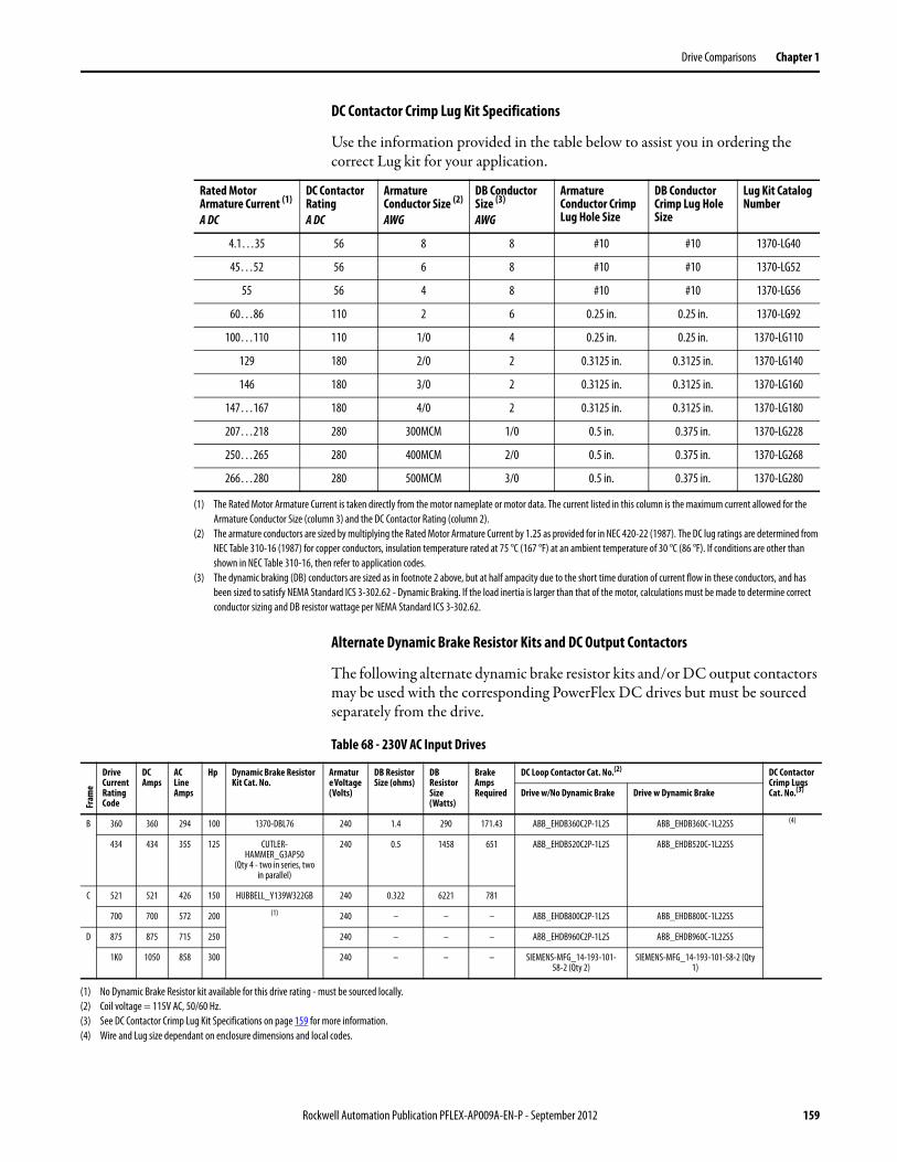
Drive Comparisons Chapter 1
DC Contactor Crimp Lug Kit Specifications
Use the information provided in the table below to assist you in ordering the correct Lug kit for your application.
Alternate Dynamic Brake Resistor Kits and DC Output Contactors
The following alternate dynamic brake resistor kits and/or DC output contactors may be used with the corresponding PowerFlex DC drives but must be sourced separately from the drive.
Table 68 - 230V AC Input Drives
Rated Motor Armature Current (1)
A DC
DC Contactor RatingA DC
Armature Conductor Size (2)
AWG
DB Conductor Size (3)
AWG
Armature Conductor Crimp Lug Hole Size
DB Conductor Crimp Lug Hole Size
Lug Kit Catalog Number
4.1…35 56 8 8 #10 #10 1370-LG40
45…52 56 6 8 #10 #10 1370-LG52
55 56 4 8 #10 #10 1370-LG56
60…86 110 2 6 0.25 in. 0.25 in. 1370-LG92
100…110 110 1/0 4 0.25 in. 0.25 in. 1370-LG110
129 180 2/0 2 0.3125 in. 0.3125 in. 1370-LG140
146 180 3/0 2 0.3125 in. 0.3125 in. 1370-LG160
147…167 180 4/0 2 0.3125 in. 0.3125 in. 1370-LG180
207…218 280 300MCM 1/0 0.5 in. 0.375 in. 1370-LG228
250…265 280 400MCM 2/0 0.5 in. 0.375 in. 1370-LG268
266…280 280 500MCM 3/0 0.5 in. 0.375 in. 1370-LG280
(1) The Rated Motor Armature Current is taken directly from the motor nameplate or motor data. The current listed in this column is the maximum current allowed for the Armature Conductor Size (column 3) and the DC Contactor Rating (column 2).
(2) The armature conductors are sized by multiplying the Rated Motor Armature Current by 1.25 as provided for in NEC 420-22 (1987). The DC lug ratings are determined from NEC Table 310-16 (1987) for copper conductors, insulation temperature rated at 75 °C (167 °F) at an ambient temperature of 30 °C (86 °F). If conditions are other than shown in NEC Table 310-16, then refer to application codes.
(3) The dynamic braking (DB) conductors are sized as in footnote 2 above, but at half ampacity due to the short time duration of current flow in these conductors, and has been sized to satisfy NEMA Standard ICS 3-302.62 - Dynamic Braking. If the load inertia is larger than that of the motor, calculations must be made to determine correct conductor sizing and DB resistor wattage per NEMA Standard ICS 3-302.62.
Fram
e
Drive Current Rating Code
DC Amps
AC Line Amps
Hp Dynamic Brake Resistor Kit Cat. No.
Armature Voltage (Volts)
DB Resistor Size (ohms)
DB Resistor Size (Watts)
Brake Amps Required
DC Loop Contactor Cat. No.(2) DC Contactor Crimp Lugs Cat. No.(3)Drive w/No Dynamic Brake Drive w Dynamic Brake
B 360 360 294 100 1370-DBL76 240 1.4 290 171.43 ABB_EHDB360C2P-1L2S ABB_EHDB360C-1L22SS (4)
434 434 355 125 CUTLER-HAMMER_G3AP50
(Qty 4 - two in series, two in parallel)
240 0.5 1458 651 ABB_EHDB520C2P-1L2S ABB_EHDB520C-1L22SS
C 521 521 426 150 HUBBELL_Y139W322GB 240 0.322 6221 781
700 700 572 200 (1) 240 – – – ABB_EHDB800C2P-1L2S ABB_EHDB800C-1L22SS
D 875 875 715 250 240 – – – ABB_EHDB960C2P-1L2S ABB_EHDB960C-1L22SS
1K0 1050 858 300 240 – – – SIEMENS-MFG_14-193-101-58-2 (Qty 2)
SIEMENS-MFG_14-193-101-58-2 (Qty 1)
(1) No Dynamic Brake Resistor kit available for this drive rating - must be sourced locally.(2) Coil voltage = 115V AC, 50/60 Hz.(3) See DC Contactor Crimp Lug Kit Specifications on page 159 for more information.(4) Wire and Lug size dependant on enclosure dimensions and local codes.
Rockwell Automation Publication PFLEX-AP009A-EN-P - September 2012 159
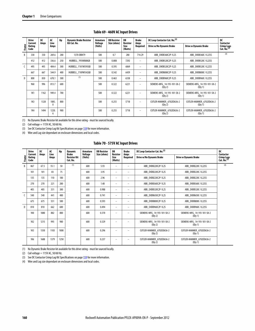
Chapter 1 Drive Comparisons
Table 69 - 460V AC Input Drives
Table 70 - 575V AC Input Drives
Fram
e
Drive Current Rating Code
DC Amps
AC Line Amps
Hp Dynamic Brake Resistor Kit Cat. No.
Armature Voltage (Volts)
DB Resistor Size (ohms)
DB Resistor Size (Watts)
Brake Amps Required
DC Loop Contactor Cat. No.(2) DC Contactor Crimp Lugs Cat. No.(3)
Drive w/No Dynamic Brake Drive w Dynamic Brake
B 330 330 269.6 200 1370-DBH79 500 0.7 280 714.29 ABB_EHDB360C2P-1L2S ABB_EHDB360C-1L22SS (4)
412 412 336.6 250 HUBBELL_Y95W808GB 500 0.808 7292 – ABB_EHDB520C2P-1L2S ABB_EHDB520C-1L22SS
C 495 495 404.4 300 HUBBELL_Y101W595GB 500 0.595 6069 – ABB_EHDB520C2P-1L2S ABB_EHDB520C-1L22SS
667 667 544.9 400 HUBBELL_Y109W542GB 500 0.542 6439 – ABB_EHDB800C2P-1L2S ABB_EHDB800C-1L22SS
D 800 830 678.1 500 (1) 500 0.463 6338 – ABB_EHDB960C2P-1L2S ABB_EHDB960C-1L22SS
960 996 813.7 600 500 0.322 6221 – SIEMENS-MFG_14-193-101-58-2(Qty 2)
SIEMENS-MFG_14-193-101-58-2 (Qty 1)
1K1 1162 949.4 700 500 0.322 6221 – SIEMENS-MFG_14-193-101-58-2(Qty 2)
SIEMENS-MFG_14-193-101-58-2 (Qty 1)
1K3 1328 1085.0
800 500 0.255 5718 – CUTLER-HAMMER_6702ED636-2(Qty 2)
CUTLER-HAMMER_6702ED636-2 (Qty 1)
1K4 1494 1220.6
900 500 0.255 5718 – CUTLER-HAMMER_6702ED636-2(Qty 2)
CUTLER-HAMMER_6702ED636-2 (Qty 1)
(1) No Dynamic Brake Resistor kit available for this drive rating - must be sourced locally.(2) Coil voltage = 115V AC, 50/60 Hz.(3) See DC Contactor Crimp Lug Kit Specifications on page 159 for more information.(4) Wire and Lug size dependant on enclosure dimensions and local codes.
Fram
e
Drive Current Rating Code
DC Amps
AC Line Amps
Hp Dynamic Brake Resistor Kit Cat. No.
Armature Voltage (Volts)
DB Resistor Size (ohms)
DB Resistor Size (Watts)
Brake Amps Required
DC Loop Contactor Cat. No.(2) DC Contactor Crimp Lugs Cat. No.(3)
Drive w/No Dynamic Brake Drive w Dynamic Brake
B 067 67.5 55.1 50 (1) 600 5.93 – – ABB_EHDB220C2P-1L2S ABB_EHDB220C-1L22SS (4)
101 101 83 75 600 3.95 – – ABB_EHDB220C2P-1L2S ABB_EHDB220C-1L22SS
135 135 110 100 600 2.96 – – ABB_EHDB220C2P-1L2S ABB_EHDB220C-1L22SS
270 270 221 200 600 1.48 – – ABB_EHDB360C2P-1L2S ABB_EHDB360C-1L22SS
405 405 331 300 600 0.988 – – ABB_EHDB520C2P-1L2S ABB_EHDB520C-1L22SS
C 540 540 441 400 600 0.741 – – ABB_EHDB650C2P-1L2S ABB_EHDB650C-1L22SS
675 675 551 500 600 0.593 – – ABB_EHDB800C2P-1L2S ABB_EHDB800C-1L22SS
D 810 810 662 600 600 0.494 – – ABB_EHDB960C2P-1L2S ABB_EHDB960C-1L22SS
1K0 1080 882 800 600 0.370 – – SIEMENS-MFG_14-193-101-58-2(Qty 2)
SIEMENS-MFG_14-193-101-58-2(Qty 1)
1K2 1215 993 900 600 0.329 – – SIEMENS-MFG_14-193-101-58-2(Qty 2)
SIEMENS-MFG_14-193-101-58-2(Qty 1)
1K3 1350 1103 1000 600 0.296 – – CUTLER-HAMMER_6702ED636-2(Qty 2)
CUTLER-HAMMER_6702ED636-2(Qty 1)
1K6 1688 1379 1250 600 0.237 – – CUTLER-HAMMER_6702ED636-2(Qty 2)
CUTLER-HAMMER_6702ED636-2(Qty 1)
(1) No Dynamic Brake Resistor kit available for this drive rating - must be sourced locally.(2) Coil voltage = 115V AC, 50/60 Hz.(3) See DC Contactor Crimp Lug Kit Specifications on page 159 for more information.(4) Wire and Lug size dependant on enclosure dimensions and local codes.
160 Rockwell Automation Publication PFLEX-AP009A-EN-P - September 2012
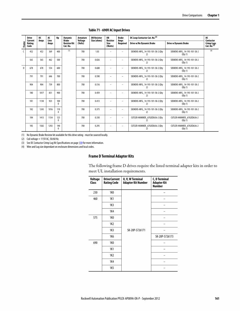
Drive Comparisons Chapter 1
Table 71 - 690V AC Input Drives
Frame D Terminal Adapter Kits
The following frame D drives require the listed terminal adapter kits in order to meet UL installation requirements.
Fram
e
Drive Current Rating Code
DC Amps
AC Line Amps
Hp Dynamic Brake Resistor Kit Cat. No.
Armature Voltage (Volts)
DB Resistor Size (ohms)
DB Resistor Size (Watts)
Brake Amps Required
DC Loop Contactor Cat. No.(2) DC Contactor Crimp Lugs Cat. No.(3)
Drive w/No Dynamic Brake Drive w Dynamic Brake
C 452 452 369 400 (1) 700 1.03 – – SIEMENS-MFG_14-193-101-58-2 (Qty 2)
SIEMENS-MFG_14-193-101-58-2(Qty 1)
(4)
565 565 462 500 700 0.826 – – SIEMENS-MFG_14-193-101-58-2 (Qty 2)
SIEMENS-MFG_14-193-101-58-2 (Qty 1)
D 678 678 554 600 700 0.688 – – SIEMENS-MFG_14-193-101-58-2 (Qty 2)
SIEMENS-MFG_14-193-101-58-2 (Qty 1)
791 791 646 700 700 0.590 – – SIEMENS-MFG_14-193-101-58-2 (Qty 2)
SIEMENS-MFG_14-193-101-58-2 (Qty 1)
904 904 739 800 700 0.516 – – SIEMENS-MFG_14-193-101-58-2 (Qty 2)
SIEMENS-MFG_14-193-101-58-2 (Qty 1)
1K0 1017 831 900 700 0.459 – – SIEMENS-MFG_14-193-101-58-2 (Qty 2)
SIEMENS-MFG_14-193-101-58-2 (Qty 1)
1K1 1130 923 1000
700 0.413 – – SIEMENS-MFG_14-193-101-58-2 (Qty 2)
SIEMENS-MFG_14-193-101-58-2 (Qty 1)
1K2 1243 1016 1100
700 0.375 – – SIEMENS-MFG_14-193-101-58-2 (Qty 2)
SIEMENS-MFG_14-193-101-58-2 (Qty 1)
1K4 1413 1154 1250
700 0.330 – – CUTLER-HAMMER_6702ED636-2 (Qty 2)
CUTLER-HAMMER_6702ED636-2 (Qty 1)
1K5 1582 1292 1400
700 0.295 – – CUTLER-HAMMER_6702ED636-2 (Qty 2)
CUTLER-HAMMER_6702ED636-2 (Qty 1)
(1) No Dynamic Brake Resistor kit available for this drive rating - must be sourced locally.(2) Coil voltage = 115V AC, 50/60 Hz.(3) See DC Contactor Crimp Lug Kit Specifications on page 159 for more information.(4) Wire and Lug size dependant on enclosure dimensions and local codes.
Voltage Class
Drive Current Rating Code
U, V, W Terminal Adapter Kit Number
C, D Terminal Adapter Kit Number
230 1K0
SK-20P-S726171
–
460 1K1 –
1K3 –
1K4 –
575 1K0 –
1K2 –
1K3 –
1K6 SK-20P-S726173
690 1K0 –
1K1 –
1K2 –
1K4 –
1K5 –
Rockwell Automation Publication PFLEX-AP009A-EN-P - September 2012 161
Chapter 1 Drive Comparisons
PowerFlex DC Motor Overload Protection
Thermistors and Thermal Switches
To detect motor overheating and protect the motor from overloading, an external, user-supplied thermistor (PTC) or thermal switch must be connected to terminals 78 and 79. The drive’s response to a motor over temperature fault is configured in parameter 365 [OverTemp Flt Cfg]. If a temperature sensor is not used, a 1k ohm resistor must be connected between terminals 78 and 79 (installed at the factory). The instructions for installing a thermal sensor are detailed below.
Thermistors (PTC)
PTC thermistors fitted in the motor can be connected directly to the drive via terminals 78 and 79. In this case the 1k ohm resistor is not required between terminals 78 and 79.
Thermal Switches (Klixon®) in the Motor Windings
“Klixon” type temperature-dependent contacts can disconnect the drive from the motor via an external control or can be configured as an external fault using a digital input on drive. They can also be connected to terminals 78 and 79 in order to indicate a drive “Motor Over Temp” fault (F16), though this is not recommended due to the noise sensitivity of the current threshold circuitry. If a thermal switch is used a 1k ohm resistor must be placed in series between the switch and one of the terminals.
Table 72 - Contact Relay and Thermistor Terminal Designations
Terminal Description
35 Normally open contact. Configured with parameter 1392 [Relay Out 1 Sel] - set to 25 “Contactor” by default.
36
75 Normally open contact. Configured with parameter 629 [Relay Out 2 Sel] - set to 5 “Ready” by default.
76
78 Motor thermistor connections (PTC)
79
162 Rockwell Automation Publication PFLEX-AP009A-EN-P - September 2012
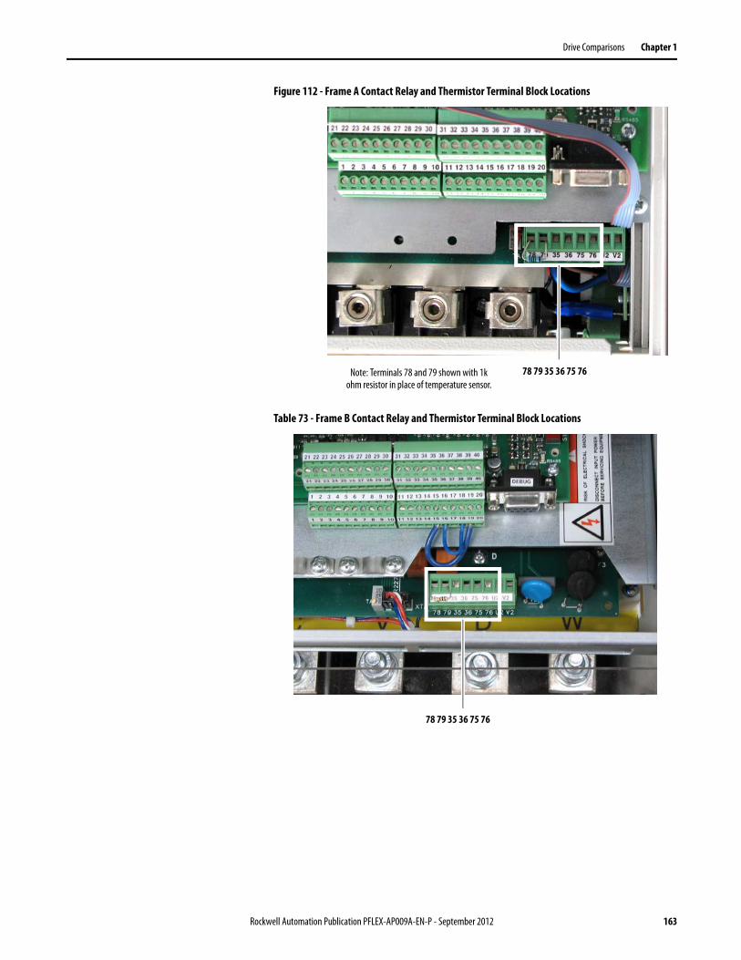
Drive Comparisons Chapter 1
Figure 112 - Frame A Contact Relay and Thermistor Terminal Block Locations
Table 73 - Frame B Contact Relay and Thermistor Terminal Block Locations
78 79 35 36 75 76Note: Terminals 78 and 79 shown with 1k ohm resistor in place of temperature sensor.
78 79 35 36 75 76
Rockwell Automation Publication PFLEX-AP009A-EN-P - September 2012 163
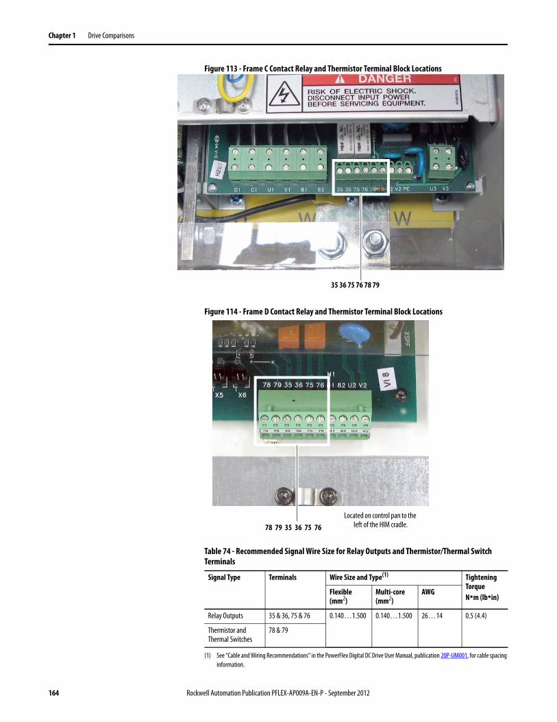
Chapter 1 Drive Comparisons
Figure 113 - Frame C Contact Relay and Thermistor Terminal Block Locations
Figure 114 - Frame D Contact Relay and Thermistor Terminal Block Locations
Table 74 - Recommended Signal Wire Size for Relay Outputs and Thermistor/Thermal Switch Terminals
35 36 75 76 78 79
Signal Type Terminals Wire Size and Type(1)
(1) See “Cable and Wiring Recommendations” in the PowerFlex Digital DC Drive User Manual, publication 20P-UM001, for cable spacing information.
Tightening TorqueN•m (lb•in)
Flexible (mm2)
Multi-core (mm2)
AWG
Relay Outputs 35 & 36, 75 & 76 0.140…1.500 0.140…1.500 26…14 0.5 (4.4)
Thermistor and Thermal Switches
78 & 79
78 79 35 36 75 76Located on control pan to the
left of the HIM cradle.
164 Rockwell Automation Publication PFLEX-AP009A-EN-P - September 2012
Chapter 2
Wiring Examples
Bulletin 1395 to PowerFlex DC Drive Comparison
See the Bulletin 1395 Digital DC Drive User Manual, publication 1395-UM003, the Bulletin 1395 Discrete Adapter Board Installation & Operation Manual, publication 1395-IN001, or the Bulletin 1395 Digital Reference Adapter Board, publication 1395-RM001 for more details.
See the PowerFlex Digital DC Drive User Manual, publication 20P-UM001, for details on example wiring diagrams.
Topic Page
Bulletin 1395 to PowerFlex DC Drive Comparison 165
Bulletin 1397 to PowerFlex DC Drive Comparison 165
FlexPak 3000 to PowerFlex DC Drive Comparison 173
Rockwell Automation Publication PFLEX-AP009A-EN-P - September 2012 165
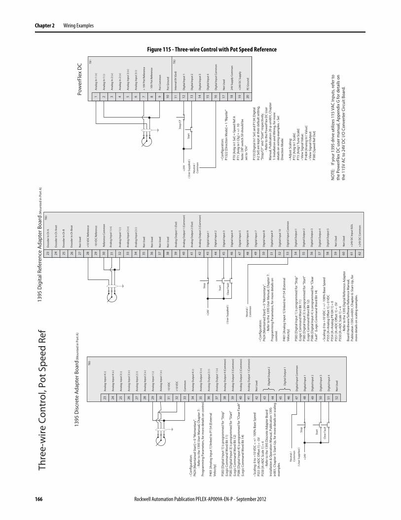
Chapter 2 Wiring Examples
Figure 115 - Three-wire Control with Pot Speed Reference Th
ree-
wire
Con
trol
, Pot
Spe
ed R
ef
44434241403937363523 29 30 31 32 33 34 45 4627 2824 2625 494847 525150
Dig
ital I
nput
Com
mon
Dig
ital I
nput
1
Dig
ital I
nput
3
Dig
ital I
nput
4
Not
Use
d
Dig
ital I
nput
2
1395
Dis
cret
e A
dapt
er B
oard
(Mou
nted
in P
ort A
)
161514131 7 8 9 10 11 125 62 43
Ana
log
In 1
(+)
Ana
log
In 1
(-)
Ana
log
In 2
(+)
Ana
log
In 2
(+)
Pot C
omm
on
17 18 2019
-10V
Pot
Ref
eren
ce
+24V
DC
Supp
ly
Dig
ital I
nput
Com
mon
24V
Supp
ly C
omm
on
Dig
ital I
nput
1
Dig
ital I
nput
2
Dig
ital I
nput
3
Dig
ital I
nput
4
+ 10
V Po
t Ref
eren
ce
Stop
/CF
Star
t
Pow
erFl
ex D
C
Ana
log
Inpu
t 3 (+
)
Ana
log
Inpu
t 3 (-
)
TB1
Pot G
roun
d
TB2
Not
Use
d
PE G
roun
d
Inte
rnal
0V
(Grd
)
• Con
figur
atio
n:P1
322
[Dire
ctio
n M
ode]
= 1
“Bip
olar
”
P70
[Anl
g in
1 Se
l] =
Spee
d Re
f AP7
1 [A
nlg
In1
Cfg]
= +
/-10
Not
e: D
IP sw
itch
S9 sh
ould
be
set t
o “O
n”
P133
[Dig
ital I
n1 S
el] a
nd P
134
[Dig
ital
In2
Sel]
are
kept
at t
heir
defa
ult s
ettin
g,
“Sto
p/CF
” and
“Sta
rt” r
espe
ctiv
ely.
-Ref
er to
the
Pow
erFl
ex D
C U
ser
Man
ual,
Publ
icat
ion
20-p
-um
001,
Cha
pter
1:
Inst
alla
tion
and
Wiri
ng, f
or m
ore
deta
ils o
n w
iring
exa
mpl
es. •
Set
D
irect
ion
Mod
e:
• Adj
ust S
calin
g:P7
2 [A
nlg
In1
Scal
e]P7
3 [A
nlg1
Tun
e Sc
ale]
• Vie
w S
igna
l Val
ue:
P140
4 [A
nalo
g In
1 Va
lue]
• Vie
w S
igna
l Out
put:
P385
[Spe
ed R
ef O
ut]
38
TB3
Ana
log
Inpu
t 4 (-
)
Ana
log
Inpu
t 4 (+
)
Ana
log
Inpu
t 3 (-
)
Ana
log
Inpu
t 3 (+
)
Ana
log
Inpu
t 2 (-
)
Ana
log
Inpu
t 2 (+
)
Ana
log
Inpu
t 1 (-
)
Ana
log
Inpu
t 1 (+
)
-10
VDC
+10
VD
C
Com
mon
Ana
log
Out
put 4
(-)
Ana
log
Out
put 3
(+)
Ana
log
Out
put 2
(-)
Ana
log
Out
put 1
(+)
Ana
log
Out
put 4
(Com
mon
)
Ana
log
Out
put 3
(Com
mon
)
Ana
log
Out
put 2
(Com
mon
)
Ana
log
Out
put 1
(Com
mon
)
Not
Use
d
Dig
ital O
utpu
t 2
Dig
ital O
utpu
t 1
+24V
Neu
tral
/ Co
mm
on
( Use
r Sup
plie
d )
Stop
Star
t
+24V
Neu
tral
/ Co
mm
on
( Use
r Sup
plie
d )
50494847464543424129 35 36 37 38 39 40 51 5233 3430 3231 555453 585756
Dig
ital I
nput
Com
mon
Dig
ital I
nput
1
Dig
ital I
nput
3
Dig
ital I
nput
4
Not
Use
d
Dig
ital I
nput
2
1395
Dig
ital R
efer
ence
Ada
pter
Boa
rd (M
ount
ed in
Por
t A)
44
TB3
Ana
log
Inpu
t 2 (-
)
Ana
log
Inpu
t 2 (+
)
Ana
log
Inpu
t 1 (-
)
Ana
log
Inpu
t 1 (+
)
-10
VDC
Refe
renc
e
+10
VDC
Refe
renc
e
Refe
renc
e Co
mm
on
Ana
log
Out
put 1
(Out
)
Neu
tral
/ Co
mm
on
• Con
figur
atio
n:
P624
[Mai
ntai
ned
Star
t] =
0 “M
omen
tary
”.
-Ref
er to
the
1395
Use
r Man
ual,
Chap
ter 7
: Pr
ogra
mm
ing
Para
met
ers,
for m
ore
deta
ils o
n co
ntro
l.
P401
[Ana
log
Inpu
t 1] l
inke
d to
P15
4 [E
xter
nal
Velo
city
]
P583
[Dig
ital I
nput
1] i
s pr
ogra
mm
ed fo
r “St
op”
(Log
ic C
omm
and
Wor
d Bi
t 11)
P585
[Dig
ital I
nput
3] i
s pr
ogra
mm
ed fo
r “St
art”
(L
ogic
Com
man
d W
ord
Bit 1
2)
P586
[Dig
ital I
nput
4] i
s pr
ogra
mm
ed fo
r “Cl
ear F
ault”
(L
ogic
Com
man
d W
ord
Bit 1
4)
• Sca
ling:
0 to
+10
VD
C =
+/-1
00%
Bas
e Sp
eed
P551
[A>A
DC
Offs
et 1
] = -5
VP5
50 [A
>AD
C Sc
ale
1] =
4-R
efer
to th
e 13
95 D
iscr
ete
Ada
pter
Boa
rd
Inst
alla
tion
& O
pera
tion
Man
ual,
Publ
icat
ion
1395
-in
001,
Cha
pter
5: S
tart
-Up,
for m
ore
deta
ils o
n sc
alin
g ex
ampl
es.
23 27 2824 2625 59 60 61 62
Enco
der I
n Ch
A
Enco
der I
n Ch
Ano
t
Enco
der I
n Ch
B
Enco
der I
n Ch
Bno
t
Not
Use
d
Not
Use
d
Not
Use
d
Not
Use
d
Not
Use
d
Ana
log
Out
put 1
(Com
mon
)
Ana
log
Out
put 2
(Out
)
Ana
log
Out
put 2
(Com
mon
)
Dig
ital I
nput
5
Dig
ital I
nput
7
Dig
ital I
nput
8
Dig
ital I
nput
6
Dig
ital I
nput
9
Dig
ital I
nput
10
Dig
ital O
utpu
t 1
Dig
ital O
utpu
t 2
Dig
ital O
utpu
t 3
Dig
ital O
utpu
t 4
Not
Use
d
Dig
ital O
utpu
t 5
+24
V D
C In
put I
SOL
+24
V D
C Co
mm
on
• Con
figur
atio
n:
P624
[Mai
ntai
ned
Star
t] =
0 “M
omen
tary
”.
-Ref
er to
the
1395
Use
r Man
ual,
Chap
ter 7
: Pr
ogra
mm
ing
Para
met
ers,
for m
ore
deta
ils o
n co
ntro
l.
P401
[Ana
log
Inpu
t 1] l
inke
d to
P15
4 [E
xter
nal
Velo
city
]
P583
[Dig
ital I
nput
1] i
s pro
gram
med
for “
Stop
” (L
ogic
Com
man
d W
ord
Bit 1
1)
P585
[Dig
ital I
nput
3] i
s pro
gram
med
for “
Star
t”
(Log
ic C
omm
and
Wor
d Bi
t 12)
P5
86 [D
igita
l Inp
ut 4
] is p
rogr
amm
ed fo
r “Cl
ear
Faul
t” (
Logi
c Co
mm
and
Wor
d Bi
t 14)
• Sca
ling:
0 to
+10
VD
C =
+/-
100%
Bas
e Sp
eed
P555
[A>A
nalo
g O
ffset
1] =
0 V
DC
P554
[A>A
nalo
g PR
GN
1] =
0P5
51 [A
>AD
C O
ffset
1] =
-5V
P550
[A>A
DC
Scal
e 1]
= 4
-Ref
er to
the
1395
Dig
ital R
efer
ence
Ada
pter
Bo
ard
Har
dwar
e/So
ftw
are
Refe
renc
e M
anua
l, Pu
blic
atio
n 13
95-r
m00
1, C
hapt
er 6
: Sta
rt-U
p, fo
r m
ore
deta
ils o
n sc
alin
g ex
ampl
es.
NO
TE:
If yo
ur 1
395
driv
e ut
ilize
s 11
5 VA
C In
puts
, ref
er to
th
e Po
wer
Flex
DC
user
man
ual,
App
endi
x G
for d
etai
ls o
n th
e 11
5V A
C to
24V
DC
I/O C
onve
rter
Circ
uit B
oard
.
Clea
r Fau
lt
Stop
Star
t
+24V
( Use
r Sup
plie
d )
Clea
r Fau
lt
166 Rockwell Automation Publication PFLEX-AP009A-EN-P - September 2012
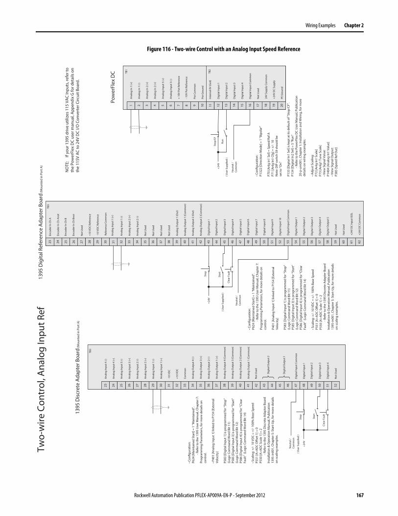
Wiring Examples Chapter 2
Figure 116 - Two-wire Control with an Analog Input Speed Reference
161514131 7 8 9 10 11 125 62 43
Ana
log
In 1
(+)
Ana
log
In 1
(-)
Ana
log
In 2
(+)
Ana
log
In 2
(+)
Pot C
omm
on
17 18 2019
-10V
Pot
Ref
eren
ce
+24V
DC
Supp
ly
Dig
ital I
nput
Com
mon
24V
Supp
ly C
omm
on
Dig
ital I
nput
1
Dig
ital I
nput
2
Dig
ital I
nput
3
Dig
ital I
nput
4
+ 10
V Po
t Ref
eren
ce
Pow
erFl
ex D
C
Ana
log
Inpu
t 3 (+
)
Ana
log
Inpu
t 3 (-
)
Pot G
roun
d
Not
Use
d
PE G
roun
d
Inte
rnal
0V
(Grd
)
• Con
figur
atio
n:P1
322
[Dire
ctio
n M
ode]
= 1
“Bip
olar
”
P70
[Anl
g in
1 Se
l] =
Spee
d Re
f AP7
1 [A
nlg
In1
Cfg]
= +
/-10
Not
e: D
IP sw
itch
S9 sh
ould
be
set t
o “O
n”
P133
[Dig
ital I
n1 S
el] i
s kep
t at i
ts d
efau
lt of
“Sto
p/CF
”.
P134
[Dig
ital I
n2 S
el] =
5 “R
un”
-Ref
er to
the
Pow
erFl
ex D
C U
ser M
anua
l, Pu
blic
atio
n 20
-p-u
m00
1, C
hapt
er 1
: Ins
talla
tion
and
Wiri
ng, f
or m
ore
deta
ils o
n w
iring
exa
mpl
es.
• Adj
ust S
calin
g:P7
2 [A
nlg
In1
Scal
e]P7
3 [A
nlg1
Tun
e Sc
ale]
• Vie
w S
igna
l Val
ue:
P140
4 [A
nalo
g In
1 Va
lue]
• Vie
w S
igna
l Out
put:
P385
[Spe
ed R
ef O
ut]
TB1
TB2
44434241403937363523 29 30 31 32 33 34 45 4627 2824 2625 494847 525150
Dig
ital I
nput
Com
mon
Dig
ital I
nput
1
Dig
ital I
nput
3
Dig
ital I
nput
4
Not
Use
d
Dig
ital I
nput
2
1395
Dis
cret
e A
dapt
er B
oard
(Mou
nted
in P
ort A
)
38
TB3
Ana
log
Inpu
t 4 (-
)
Ana
log
Inpu
t 4 (+
)
Ana
log
Inpu
t 3 (-
)
Ana
log
Inpu
t 3 (+
)
Ana
log
Inpu
t 2 (-
)
Ana
log
Inpu
t 2 (+
)
Ana
log
Inpu
t 1 (-
)
Ana
log
Inpu
t 1 (+
)
-10
VDC
+10
VDC
Com
mon
Ana
log
Out
put 4
(-)
Ana
log
Out
put 3
(+)
Ana
log
Out
put 2
(-)
Ana
log
Out
put 1
(+)
Ana
log
Out
put 4
(Com
mon
)
Ana
log
Out
put 3
(Com
mon
)
Ana
log
Out
put 2
(Com
mon
)
Ana
log
Out
put 1
(Com
mon
)
Not
Use
d
Dig
ital O
utpu
t 2
Dig
ital O
utpu
t 1
50494847464543424129 35 36 37 38 39 40 51 5233 3430 3231 555453 585756
Dig
ital I
nput
Com
mon
Dig
ital I
nput
1
Dig
ital I
nput
3
Dig
ital I
nput
4
Not
Use
d
Dig
ital I
nput
2
1395
Dig
ital R
efer
ence
Ada
pter
Boa
rd (M
ount
ed in
Por
t A)
44
TB3
Ana
log
Inpu
t 2 (-
)
Ana
log
Inpu
t 2 (+
)
Ana
log
Inpu
t 1 (-
)
Ana
log
Inpu
t 1 (+
)
-10
VDC
Refe
renc
e
+10
VDC
Refe
renc
e
Refe
renc
e Co
mm
on
Ana
log
Out
put 1
(Out
)
23 27 2824 2625 59 60 61 62
Enco
der I
n Ch
A
Enco
der I
n Ch
Ano
t
Enco
der I
n Ch
B
Enco
der I
n Ch
Bno
t
Not
Use
d
Not
Use
d
Not
Use
d
Not
Use
d
Not
Use
d
Ana
log
Out
put 1
(Com
mon
)
Ana
log
Out
put 2
(Out
)
Ana
log
Out
put 2
(Com
mon
)
Dig
ital I
nput
5
Dig
ital I
nput
7
Dig
ital I
nput
8
Dig
ital I
nput
6
Dig
ital I
nput
9
Dig
ital I
nput
10
Dig
ital O
utpu
t 1
Dig
ital O
utpu
t 2
Dig
ital O
utpu
t 3
Dig
ital O
utpu
t 4
Not
Use
d
Dig
ital O
utpu
t 5
+24V
DC
Inpu
t ISO
L
+24V
DC
Com
mon
NO
TE:
If yo
ur 1
395
driv
e ut
ilize
s 11
5 VA
C In
puts
, ref
er to
th
e Po
wer
Flex
DC
user
man
ual,
App
endi
x G
for d
etai
ls o
n th
e 11
5V A
C to
24V
DC
I/O C
onve
rter
Circ
uit B
oard
.
Neu
tral
/ Co
mm
on
( Use
r Sup
plie
d )
Stop
/CF
Run
+24V
Neu
tral
/ Co
mm
on
( Use
r Sup
plie
d )
• Con
figur
atio
n:P6
24 [M
aint
aine
d St
art]
= 1
“Mai
ntai
ned”
. -R
efer
to th
e 13
95 U
ser M
anua
l, Ch
apte
r 7:
Prog
ram
min
g Pa
ram
eter
s, fo
r mor
e de
tails
on
cont
rol.
• P40
1 [A
nalo
g In
put 1
] lin
ked
to P
154
[Ext
erna
l Ve
loci
ty]
P583
[Dig
ital I
nput
1] i
s pro
gram
med
for “
Stop
” (L
ogic
Com
man
d W
ord
Bit 1
1)P5
85 [D
igita
l Inp
ut 3
] is p
rogr
amm
ed fo
r “St
art”
(L
ogic
Com
man
d W
ord
Bit 1
2)
P586
[Dig
ital I
nput
4] i
s pro
gram
med
for “
Clea
r Fa
ult”
(Lo
gic
Com
man
d W
ord
Bit 1
4)
• Sca
ling:
+/-
10 V
DC
= +/
-100
% B
ase
Spee
d P5
51 [A
>AD
C O
ffset
1] =
0P5
50 [A
>AD
C Sc
ale
1] =
2-R
efer
to th
e 13
95 D
iscr
ete
Ada
pter
Boa
rd
Inst
alla
tion
& O
pera
tion
Man
ual,
Publ
icat
ion
1395
-in00
1, C
hapt
er 5
: Sta
rt-U
p, fo
r mor
e de
tails
on
scal
ing
exam
ples
.
• Con
figur
atio
n:P6
24 [M
aint
aine
d St
art]
= 1
“Mai
ntai
ned”
. -R
efer
to th
e 13
95 U
ser M
anua
l, Ch
apte
r 7:
Prog
ram
min
g Pa
ram
eter
s, fo
r mor
e de
tails
on
cont
rol.
P401
[Ana
log
Inpu
t 1] l
inke
d to
P15
4 [E
xter
nal
Velo
city
]
P583
[Dig
ital I
nput
1] i
s pro
gram
med
for “
Stop
” (L
ogic
Com
man
d W
ord
Bit 1
1)P5
85 [D
igita
l Inp
ut 3
] is p
rogr
amm
ed fo
r “St
art”
(L
ogic
Com
man
d W
ord
Bit 1
2)
P586
[Dig
ital I
nput
4] i
s pro
gram
med
for “
Clea
r Fa
ult”
(Lo
gic
Com
man
d W
ord
Bit 1
4)
• Sca
ling:
+/-
10 V
DC
= +/
-100
% B
ase
Spee
d P5
51 [A
>AD
C O
ffset
1] =
0P5
50 [A
>AD
C Sc
ale
1] =
2-R
efer
to th
e 13
95 D
iscr
ete
Ada
pter
Boa
rd
Inst
alla
tion
& O
pera
tion
Man
ual,
Publ
icat
ion
1395
-in00
1, C
hapt
er 5
: Sta
rt-U
p, fo
r mor
e de
tails
on
sca
ling
exam
ples
.
Stop Star
t
+24V
Neu
tral
/ Co
mm
on
( Use
r Sup
plie
d )
Clea
r Fau
lt
Stop
Star
t
+24V
Clea
r Fau
lt
Two-
wire
Con
trol
, Ana
log
Inpu
t Ref
Rockwell Automation Publication PFLEX-AP009A-EN-P - September 2012 167
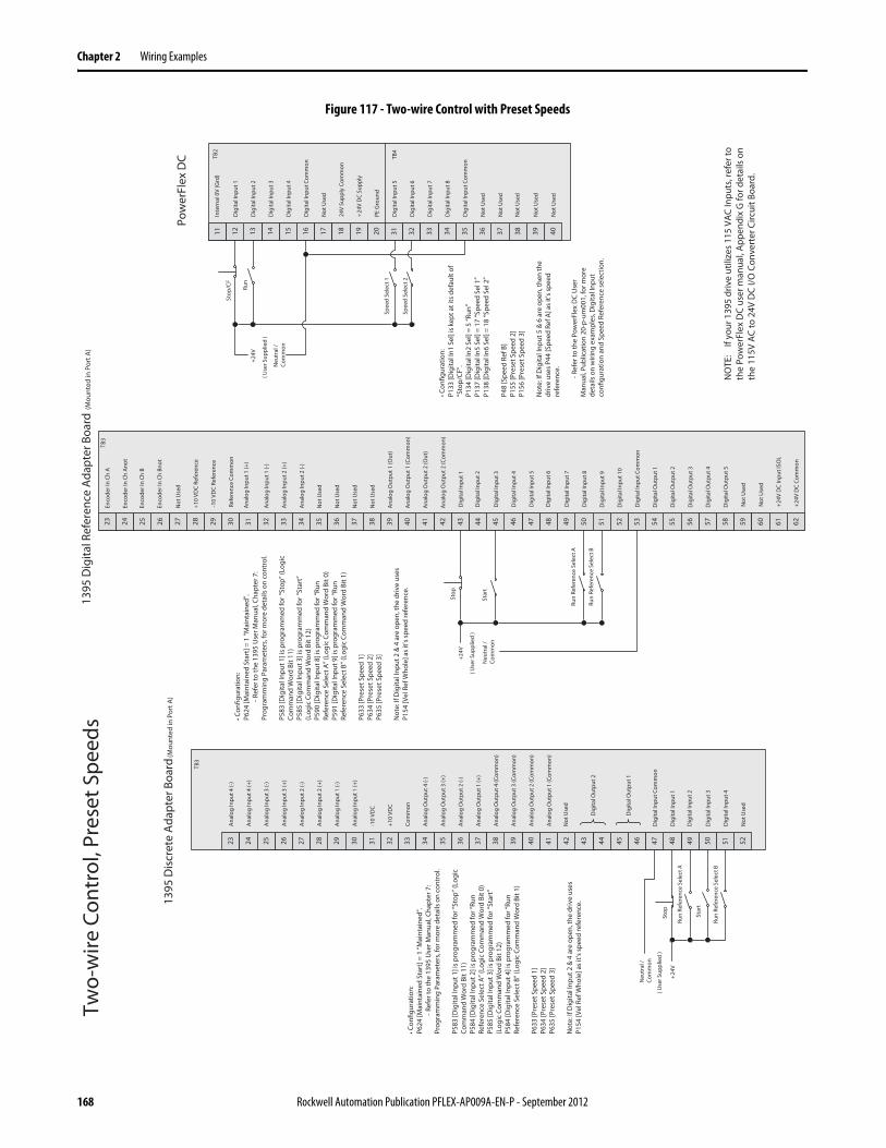
Chapter 2 Wiring Examples
Figure 117 - Two-wire Control with Preset Speeds
Run
Stop
/CF
Spee
d Se
lect
2
16151413 31 37 38 39 4011 12 35 3632 3433
Dig
ital I
nput
5
Dig
ital I
nput
6
Dig
ital I
nput
7
Dig
ital I
nput
8
Not
Use
d
17 18 2019
Not
Use
d
+24
V D
C Su
pply
Dig
ital I
nput
Com
mon
24V
Supp
ly C
omm
on
Dig
ital I
nput
1
Dig
ital I
nput
2
Dig
ital I
nput
3
Dig
ital I
nput
4
Not
Use
d
Dig
ital I
nput
Com
mon
Not
Use
d
Not
Use
d
Not
Use
d
PE G
roun
d
Inte
rnal
0V
(Grd
)
Pow
erFl
ex D
C TB2
TB4
+24V
Neu
tral
/ Co
mm
on
• Con
figur
atio
n:P1
33 [D
igita
l In1
Sel
] is k
ept a
t its
def
ault
of
“Sto
p/CF
”.
P134
[Dig
ital I
n2 S
el] =
5 “R
un”
P137
[Dig
ital I
n5 S
el] =
17
“Spe
ed S
el 1
”P1
38 [D
igita
l In6
Sel
] = 1
8 “S
peed
Sel
2”
P48
[Spe
ed R
ef B
]P1
55 [P
rese
t Spe
ed 2
]P1
56 [P
rese
t Spe
ed 3
]
Not
e: If
Dig
ital I
nput
5 &
6 a
re o
pen,
then
the
driv
e us
es P
44 [S
peed
Ref
A] a
s it’s
spee
d re
fere
nce.
-Ref
er to
the
Pow
erFl
ex D
C U
ser
Man
ual,
Publ
icat
ion
20-p
-um
001,
for m
ore
deta
ils o
n w
iring
exa
mpl
es, D
igita
l Inp
ut
confi
gura
tion
and
Spee
d Re
fere
nce
sele
ctio
n.
( Use
r Sup
plie
d )
44434241403937363523 29 30 31 32 33 34 45 4627 2824 2625 494847 525150
Dig
ital I
nput
Com
mon
Dig
ital I
nput
1
Dig
ital I
nput
3
Dig
ital I
nput
4
Not
Use
d
Dig
ital I
nput
2
1395
Dis
cret
e A
dapt
er B
oard
(Mou
nted
in P
ort A
)
38
TB3
Ana
log
Inpu
t 4 (-
)
Ana
log
Inpu
t 4 (+
)
Ana
log
Inpu
t 3 (-
)
Ana
log
Inpu
t 3 (+
)
Ana
log
Inpu
t 2 (-
)
Ana
log
Inpu
t 2 (+
)
Ana
log
Inpu
t 1 (-
)
Ana
log
Inpu
t 1 (+
)
-10
VDC
+10
VDC
Com
mon
Ana
log
Out
put 4
(-)
Ana
log
Out
put 3
(+)
Ana
log
Out
put 2
(-)
Ana
log
Out
put 1
(+)
Ana
log
Out
put 4
(Com
mon
)
Ana
log
Out
put 3
(Com
mon
)
Ana
log
Out
put 2
(Com
mon
)
Ana
log
Out
put 1
(Com
mon
)
Not
Use
d
Dig
ital O
utpu
t 2
Dig
ital O
utpu
t 1
50494847464543424129 35 36 37 38 39 40 51 5233 3430 3231 555453 585756
Dig
ital I
nput
Com
mon
Dig
ital I
nput
1
Dig
ital I
nput
3
Dig
ital I
nput
4
Not
Use
d
Dig
ital I
nput
2
1395
Dig
ital R
efer
ence
Ada
pter
Boa
rd(M
ount
ed in
Por
t A)
44
TB3
Ana
log
Inpu
t 2 (-
)
Ana
log
Inpu
t 2 (+
)
Ana
log
Inpu
t 1 (-
)
Ana
log
Inpu
t 1 (+
)
-10
VDC
Refe
renc
e
+10
VDC
Refe
renc
e
Refe
renc
e Co
mm
on
Ana
log
Out
put 1
(Out
)
23 27 2824 2625 59 60 61 62
Enco
der I
n Ch
A
Enco
der I
n Ch
Ano
t
Enco
der I
n Ch
B
Enco
der I
n Ch
Bno
t
Not
Use
d
Not
Use
d
Not
Use
d
Not
Use
d
Not
Use
d
Ana
log
Out
put 1
(Com
mon
)
Ana
log
Out
put 2
(Out
)
Ana
log
Out
put 2
(Com
mon
)
Dig
ital I
nput
5
Dig
ital I
nput
7
Dig
ital I
nput
8
Dig
ital I
nput
6
Dig
ital I
nput
9
Dig
ital I
nput
10
Dig
ital O
utpu
t 1
Dig
ital O
utpu
t 2
Dig
ital O
utpu
t 3
Dig
ital O
utpu
t 4
Not
Use
d
Dig
ital O
utpu
t 5
+24V
DC
Inpu
t ISO
L
+24V
DC
Com
mon
NO
TE:
If yo
ur 1
395
driv
e ut
ilize
s 11
5 VA
C In
puts
, ref
er to
th
e Po
wer
Flex
DC
user
man
ual,
App
endi
x G
for d
etai
ls o
n th
e 11
5V A
C to
24V
DC
I/O C
onve
rter
Circ
uit B
oard
.
Stop
Star
t
+24V
Neu
tral
/ Co
mm
on
( Use
r Sup
plie
d )
Run
Refe
renc
e Se
lect
A
Neu
tral
/ Co
mm
on
( Use
r Sup
plie
d )
Stop
Star
t
+24V
Run
Refe
renc
e Se
lect
B
Run
Refe
renc
e Se
lect
B
Run
Refe
renc
e Se
lect
A
Spee
d Se
lect
1
• Con
figur
atio
n:P6
24 [M
aint
aine
d St
art]
= 1
“Mai
ntai
ned”
. -R
efer
to th
e 13
95 U
ser M
anua
l, Ch
apte
r 7:
Prog
ram
min
g Pa
ram
eter
s, fo
r mor
e de
tails
on
cont
rol.
P583
[Dig
ital I
nput
1] i
s pro
gram
med
for “
Stop
” (Lo
gic
Com
man
d W
ord
Bit 1
1)P5
84 [D
igita
l Inp
ut 2
] is p
rogr
amm
ed fo
r “Ru
n Re
fere
nce
Sele
ct A
” (Lo
gic
Com
man
d W
ord
Bit 0
)P5
85 [D
igita
l Inp
ut 3
] is p
rogr
amm
ed fo
r “St
art”
(L
ogic
Com
man
d W
ord
Bit 1
2)
P584
[Dig
ital I
nput
4] i
s pro
gram
med
for “
Run
Refe
renc
e Se
lect
B” (
Logi
c Co
mm
and
Wor
d Bi
t 1)
P633
[Pre
set S
peed
1]
P634
[Pre
set S
peed
2]
P635
[Pre
set S
peed
3]
Not
e: If
Dig
ital I
nput
2 &
4 a
re o
pen,
the
driv
e us
es
P154
[Vel
Ref
Who
le] a
s it’s
spee
d re
fere
nce.
• Con
figur
atio
n:P6
24 [M
aint
aine
d St
art]
= 1
“Mai
ntai
ned”
. -R
efer
to th
e 13
95 U
ser M
anua
l, Ch
apte
r 7:
Prog
ram
min
g Pa
ram
eter
s, fo
r mor
e de
tails
on
cont
rol.
P583
[Dig
ital I
nput
1] i
s pro
gram
med
for “
Stop
” (Lo
gic
Com
man
d W
ord
Bit 1
1)P5
85 [D
igita
l Inp
ut 3
] is p
rogr
amm
ed fo
r “St
art”
(L
ogic
Com
man
d W
ord
Bit 1
2)
P590
[Dig
ital I
nput
8] i
s pro
gram
med
for “
Run
Refe
renc
e Se
lect
A” (
Logi
c Co
mm
and
Wor
d Bi
t 0)
P591
[Dig
ital I
nput
9] i
s pro
gram
med
for “
Run
Refe
renc
e Se
lect
B” (
Logi
c Co
mm
and
Wor
d Bi
t 1)
P633
[Pre
set S
peed
1]
P634
[Pre
set S
peed
2]
P635
[Pre
set S
peed
3]
Not
e: If
Dig
ital I
nput
2 &
4 a
re o
pen,
the
driv
e us
es
P154
[Vel
Ref
Who
le] a
s it’s
spee
d re
fere
nce.
Two-
wire
Con
trol
, Pre
set S
peed
s
168 Rockwell Automation Publication PFLEX-AP009A-EN-P - September 2012

Wiring Examples Chapter 2
Bulletin 1397 to PowerFlex DC Drive Comparison
See the 1397 D Drive User Manual, publication 1397-UM000, for more details.
See the PowerFlex Digital DC Drive User Manual, publication 20P-UM001, for details on example wiring diagrams.
Rockwell Automation Publication PFLEX-AP009A-EN-P - September 2012 169
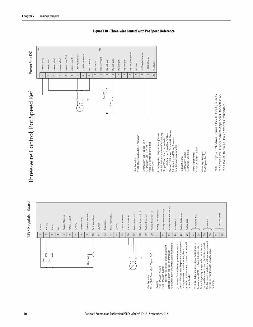
Chapter 2 Wiring Examples
Figure 118 - Three-wire Control with Pot Speed Reference
2221201918171514131 7 8 9 10 11 12 23 245 62 43 272625 302928
Ana
log
Out
Com
mon
Ana
log
Out
2
1397
Reg
ulat
or B
oard
161514131 7 8 9 10 11 125 62 43
Ana
log
In 1
(+)
Ana
log
In 1
(-)
Ana
log
In 2
(+)
Ana
log
In 2
(+)
Pot C
omm
on
17 18 2019
-10V
Pot
Ref
eren
ce
+24V
DC
Supp
ly
Dig
ital I
nput
Com
mon
24V
Supp
ly C
omm
on
Dig
ital I
nput
1
Dig
ital I
nput
2
Dig
ital I
nput
3
Dig
ital I
nput
4
+ 10
V Po
t Ref
eren
ce
Stop
/CF
Star
t
Pow
erFl
ex D
C
Ana
log
Inpu
t 3 (+
)
Ana
log
Inpu
t 3 (-
)
TB1
Pot G
roun
d
TB2
Not
Use
d
PE G
roun
d
Inte
rnal
0V
(Grd
)
• Con
figur
atio
n:P1
322
[Dire
ctio
n M
ode]
= 1
“Bip
olar
”
P70
[Anl
g in
1 Se
l] =
Spee
d Re
f AP7
1 [A
nlg
In1
Cfg]
= +
/-10
Not
e: D
IP sw
itch
S9 sh
ould
be
set t
o “O
n”
P133
[Dig
ital I
n1 S
el] a
nd P
134
[Dig
ital
In2
Sel]
are
kept
at t
heir
defa
ult s
ettin
g,
“Sto
p/CF
” and
“Sta
rt” r
espe
ctiv
ely.
-Ref
er to
the
Pow
erFl
ex D
C U
ser
Man
ual,
Publ
icat
ion
20-p
-um
001,
Cha
pter
1:
Inst
alla
tion
and
Wiri
ng, f
or m
ore
deta
ils o
n w
iring
exa
mpl
es.
• Adj
ust S
calin
g:P7
2 [A
nlg
In1
Scal
e]P7
3 [A
nlg1
Tun
e Sc
ale]
• Vie
w S
igna
l Val
ue:
P140
4 [A
nalo
g In
1 Va
lue]
• Vie
w S
igna
l Out
put:
P385
[Spe
ed R
ef O
ut]
16
+24
VDC
Run
(1) (
2)
Stop
(1)
Jog
Reve
rse
/ For
war
d
Refe
renc
e Se
lect
+24
VDC
Coas
t-to
-Sto
p (1)
Cust
omer
Inte
rlock
(1)
Faul
t Ala
rm R
eset
+24
VDC
Brus
h W
ear (
1)
Mot
or T
herm
osta
t (1)
+24
VDC
+24
VDC
Com
mon
+10
VDC
(Isol
ated
)
Ana
log
Refe
renc
e 2
(+)
Ana
log
Refe
renc
e 2
(-)
Ana
log
Refe
renc
e 1
(+)
Ana
log
Refe
renc
e 1
(-)
Stop
Star
t
NO
TE:
If yo
ur 1
397
driv
e ut
ilize
s 11
5 VA
C In
puts
, ref
er to
th
e Po
wer
Flex
DC
user
man
ual,
App
endi
x G
for d
etai
ls o
n th
e 11
5V A
C to
24V
DC
I/O C
onve
rter
Circ
uit B
oard
.
Clea
r Fau
lt
31 32
Ana
log
Tach
omet
er In
(+)
Ana
log
Tach
omet
er In
(-)
Ana
log
Tach
omet
er In
(Com
)
Ana
log
Out
1
Runn
ing
(N.O
.)
Ala
rm (N
.O.)
No
Faul
t (N
.O.)
• Con
figur
atio
n:P9
1 –
[Ref
2 S
ourc
e] =
1 “S
peed
Pot
”
• Sca
ling:
P130
–[A
nlg
In 2
Gai
n]P1
31 –
[Anl
g In
2 Z
ero]
-Ref
er to
the
Jum
per a
nd A
djus
tmen
t Se
ttin
gs ta
ble
in th
e 13
97 U
ser M
anua
l, Pu
blic
atio
n 13
97-u
m00
0 fo
r add
ition
al d
etai
ls.
(1)
Requ
ire fo
r ini
tial s
tart
up a
nd o
pera
tiona
l ch
ecks
. Vo
ltage
mus
t be
pres
ent a
t the
se p
oint
s du
ring
oper
atio
n. I
n ot
her w
ords
, the
se
term
inal
s mus
t be
mad
e. I
f ope
n, th
e dr
ive
will
be
‘Not
Rea
dy’.
(2)
RUN
– E
dge
sens
itive
sig
nal t
hat i
nitia
tes a
Ru
n co
mm
and
(0
1 =
Run
). If
the
Driv
e is
Ru
n, v
olta
ge m
ay b
e ap
plie
d to
the
arm
atur
e ca
usin
g th
e m
otor
to re
ach
the
desi
red
spee
d.
The
Run
inpu
t is l
atch
ed a
nd th
eref
ore
does
not
ha
ve to
be
mai
ntai
ned
to k
eep
the
driv
e Ru
nnin
g.
Thre
e-w
ire C
ontr
ol, P
ot S
peed
Ref
170 Rockwell Automation Publication PFLEX-AP009A-EN-P - September 2012
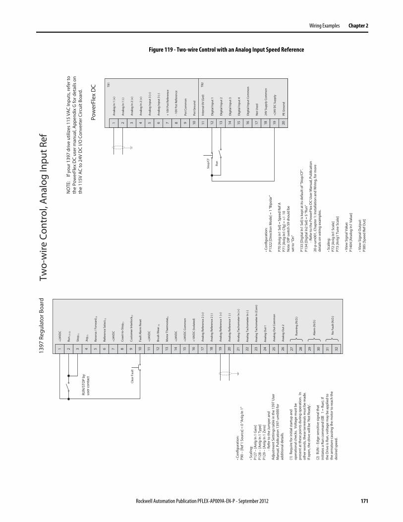
Wiring Examples Chapter 2
Figure 119 - Two-wire Control with an Analog Input Speed Reference
161514131 7 8 9 10 11 125 62 43
Ana
log
In 1
(+)
Ana
log
In 1
(-)
Ana
log
In 2
(+)
Ana
log
In 2
(+)
Pot C
omm
on
17 18 2019
-10V
Pot
Ref
eren
ce
+24V
DC
Supp
ly
Dig
ital I
nput
Com
mon
24V
Supp
ly C
omm
on
Dig
ital I
nput
1
Dig
ital I
nput
2
Dig
ital I
nput
3
Dig
ital I
nput
4
+ 10
V Po
t Ref
eren
ce
Pow
erFl
ex D
C
Ana
log
Inpu
t 3 (+
)
Ana
log
Inpu
t 3 (-
)
Pot G
roun
d
Not
Use
d
PE G
roun
d
Inte
rnal
0V
(Grd
)
• Con
figur
atio
n:P1
322
[Dire
ctio
n M
ode]
= 1
“Bip
olar
”
P70
[Anl
g in
1 Se
l] =
Spee
d Re
f AP7
1 [A
nlg
In1
Cfg]
= +
/-10
Not
e: D
IP sw
itch
S9 sh
ould
be
set t
o “O
n”
P133
[Dig
ital I
n1 S
el] i
s kep
t at i
ts d
efau
lt of
“Sto
p/CF
”.
P134
[Dig
ital I
n2 S
el] =
5 “R
un”
-Ref
er to
the
Pow
erFl
ex D
C U
ser M
anua
l, Pu
blic
atio
n 20
-p-u
m00
1, C
hapt
er 1
: Ins
talla
tion
and
Wiri
ng, f
or m
ore
deta
ils o
n w
iring
exa
mpl
es.
• Sca
ling:
P72
[Anl
g In
1 Sc
ale]
P73
[Anl
g1 T
une
Scal
e]
• Vie
w S
igna
l Val
ue:
P140
4 [A
nalo
g In
1 Va
lue]
• Vie
w S
igna
l Out
put:
P385
[Spe
ed R
ef O
ut]
TB1
TB2
NO
TE:
If yo
ur 1
397
driv
e ut
ilize
s 11
5 VA
C In
puts
, ref
er to
th
e Po
wer
Flex
DC
user
man
ual,
App
endi
x G
for d
etai
ls o
n th
e 11
5V A
C to
24V
DC
I/O C
onve
rter
Circ
uit B
oard
.
Stop
/CF
Run
2221201918171514131 7 8 9 10 11 12 23 245 62 43 272625 302928
Ana
log
Out
Com
mon
Ana
log
Out
2
1397
Reg
ulat
or B
oard
16
+24
VDC
Run
(1) (
2)
Stop
(1)
Jog
(1)
Reve
rse
/ For
war
d(1
)
Refe
renc
e Se
lect
(1)
+24
VDC
Coas
t-to
-Sto
p (1)
Cust
omer
Inte
rlock
(1)
Faul
t Ala
rm R
eset
+24
VDC
Brus
h W
ear (
1)
Mot
or T
herm
osta
t (1)
+24
VDC
+24
VDC
Com
mon
+10
VDC
(Isol
ated
)
Ana
log
Refe
renc
e 2
(+)
Ana
log
Refe
renc
e 2
(-)
Ana
log
Refe
renc
e 1
(+)
Ana
log
Refe
renc
e 1
(-)
Clea
r Fau
lt
31 32
Ana
log
Tach
omet
er In
(+)
Ana
log
Tach
omet
er In
(-)
Ana
log
Tach
omet
er In
(Com
)
Ana
log
Out
1
Runn
ing
(N.O
.)
Ala
rm (N
.O.)
No
Faul
t (N
.O.)
• Con
figur
atio
n:P9
0 –
[Ref
1 S
ourc
e] =
0 “A
nlg
In 1
”
• Sca
ling:
P127
–[A
nlg
In 1
Gai
n]P1
28 –
[Anl
g In
1 T
ype]
P129
–[A
nlg
In 1
Zer
o]-R
efer
to th
e Ju
mpe
r and
A
djus
tmen
t Set
tings
tabl
e in
the
1397
Use
r M
anua
l, Pu
blic
atio
n 13
97-u
m00
0 fo
r ad
ditio
nal d
etai
ls.
(1)
Requ
ire fo
r ini
tial s
tart
up a
nd
oper
atio
nal c
heck
s. V
olta
ge m
ust b
e pr
esen
t at t
hese
poi
nts d
urin
g op
erat
ion.
In
othe
r wor
ds, t
hese
term
inal
s mus
t be
mad
e.
If op
en, t
he d
rive
will
be
‘Not
Rea
dy’.
(2)
RUN
– E
dge
sens
itive
sign
al th
at
initi
ates
a R
un c
omm
and
(0
1 =
Run
). If
the
Driv
e is
Run
, vol
tage
may
be
appl
ied
to
the
arm
atur
e ca
usin
g th
e m
otor
to re
ach
the
desi
red
spee
d.
RUN
/STO
P by
us
er c
onta
ct
Two-
wire
Con
trol
, Ana
log
Inpu
t Ref
Rockwell Automation Publication PFLEX-AP009A-EN-P - September 2012 171
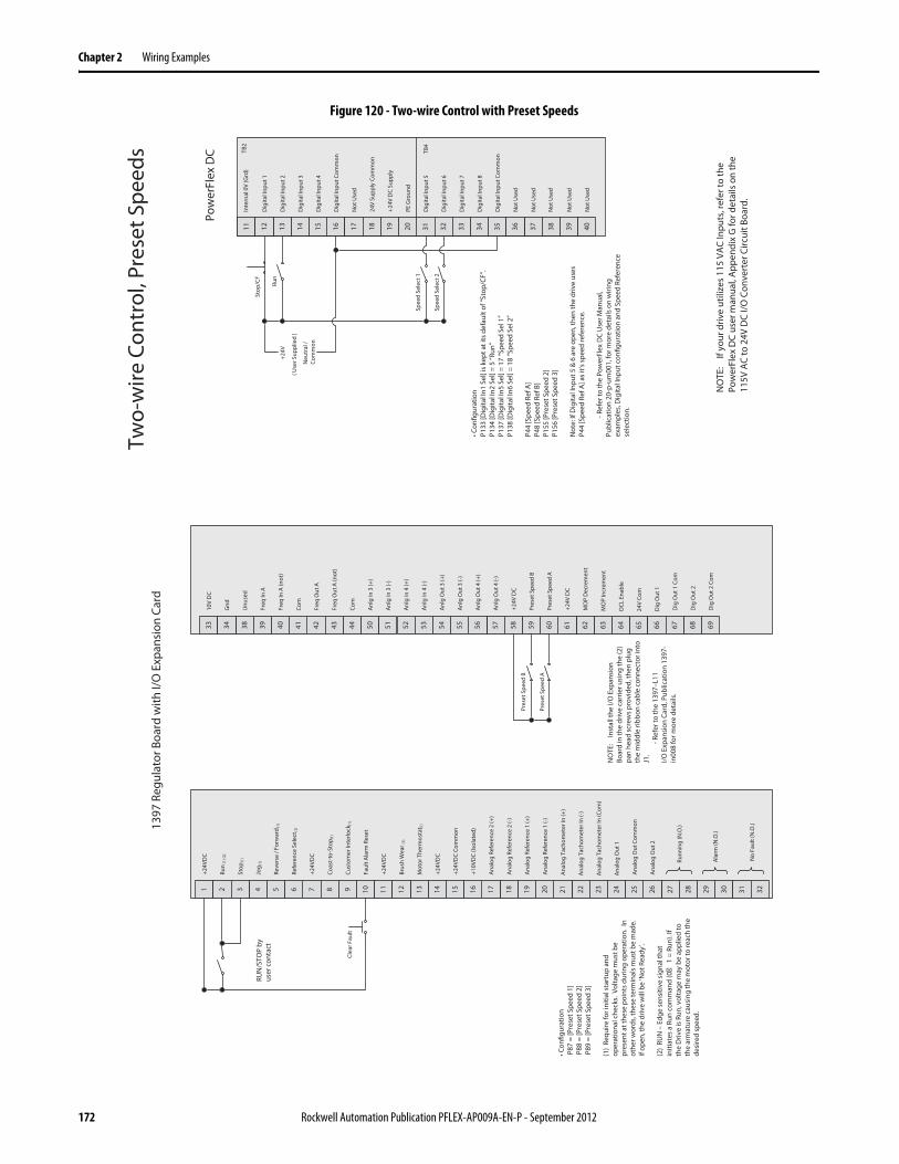
Chapter 2 Wiring Examples
Figure 120 - Two-wire Control with Preset Speeds
Run
Stop
/CF
Spee
d Se
lect
2
16151413 31 37 38 39 4011 12 35 3632 3433
Dig
ital I
nput
5
Dig
ital I
nput
6
Dig
ital I
nput
7
Dig
ital I
nput
8
Not
Use
d
17 18 2019
Not
Use
d
+24
V D
C Su
pply
Dig
ital I
nput
Com
mon
24V
Supp
ly C
omm
on
Dig
ital I
nput
1
Dig
ital I
nput
2
Dig
ital I
nput
3
Dig
ital I
nput
4
Not
Use
d
Dig
ital I
nput
Com
mon
Not
Use
d
Not
Use
d
Not
Use
d
PE G
roun
d
Inte
rnal
0V
(Grd
)
Pow
erFl
ex D
C TB2
TB4
+24V
Neu
tral
/ Co
mm
on
• Con
figur
atio
nP1
33 [D
igita
l In1
Sel
] is k
ept a
t its
def
ault
of “S
top/
CF”.
P1
34 [D
igita
l In2
Sel
] = 5
“Run
”P1
37 [D
igita
l In5
Sel
] = 1
7 “S
peed
Sel
1”
P138
[Dig
ital I
n6 S
el] =
18
“Spe
ed S
el 2
”
P44
[Spe
ed R
ef A
]P4
8 [S
peed
Ref
B]
P155
[Pre
set S
peed
2]
P156
[Pre
set S
peed
3]
Not
e: If
Dig
ital I
nput
5 &
6 a
re o
pen,
then
the
driv
e us
es
P44
[Spe
ed R
ef A
] as i
t’s sp
eed
refe
renc
e.
-Ref
er to
the
Pow
erFl
ex D
C U
ser M
anua
l, Pu
blic
atio
n 20
-p-u
m00
1, fo
r mor
e de
tails
on
wiri
ng
exam
ples
, Dig
ital I
nput
con
figur
atio
n an
d Sp
eed
Refe
renc
e se
lect
ion.
( Use
r Sup
plie
d )
NO
TE:
If yo
ur d
rive
utili
zes
115
VAC
Inpu
ts, r
efer
to th
e Po
wer
Flex
DC
user
man
ual,
App
endi
x G
for d
etai
ls o
n th
e 11
5V A
C to
24V
DC
I/O C
onve
rter
Circ
uit B
oard
.
Spee
d Se
lect
1
2221201918171514131 7 8 9 10 11 12 23 245 62 43 272625 302928
Ana
log
Out
Com
mon
Ana
log
Out
2
1397
Reg
ulat
or B
oard
with
I/O
Exp
ansi
on C
ard
16
+24V
DC
Run
(1) (
2)
Stop
(1)
Jog
(1)
Reve
rse
/ For
war
d(1
)
Refe
renc
e Se
lect
(1)
+24V
DC
Coas
t-to
-Sto
p (1)
Cust
omer
Inte
rlock
(1)
Faul
t Ala
rm R
eset
+24V
DC
Brus
h W
ear (
1)
Mot
or T
herm
osta
t (1)
+24V
DC
+24V
DC
Com
mon
+10V
DC
(Isol
ated
)
Ana
log
Refe
renc
e 2
(+)
Ana
log
Refe
renc
e 2
(-)
Ana
log
Refe
renc
e 1
(+)
Ana
log
Refe
renc
e 1
(-)
Clea
r Fau
lt
31 32
Ana
log
Tach
omet
er In
(+)
Ana
log
Tach
omet
er In
(-)
Ana
log
Tach
omet
er In
(Com
)
Ana
log
Out
1
Runn
ing
(N.O
.)
Ala
rm (N
.O.)
No
Faul
t (N
.O.)
• Con
figur
atio
n P
87 =
[Pre
set S
peed
1]
P88
= [P
rese
t Spe
ed 2
] P
89 =
[Pre
set S
peed
3]
(1)
Requ
ire fo
r ini
tial s
tart
up a
nd
oper
atio
nal c
heck
s. V
olta
ge m
ust b
e pr
esen
t at t
hese
poi
nts d
urin
g op
erat
ion.
In
othe
r wor
ds, t
hese
term
inal
s mus
t be
mad
e.
If op
en, t
he d
rive
will
be
‘Not
Rea
dy’.
(2)
RUN
– E
dge
sens
itive
sign
al th
at
initi
ates
a R
un c
omm
and
(0
1 =
Run
). If
the
Driv
e is
Run
, vol
tage
may
be
appl
ied
to
the
arm
atur
e ca
usin
g th
e m
otor
to re
ach
the
desi
red
spee
d.
RUN
/STO
P by
us
er c
onta
ct
64636261605957565538 44 50 51 52 53 54 65 6642 4339 4140 696867D
ig O
ut 1
Com
Dig
Out
2
58
Unu
sed
Freq
In A
Freq
In A
(not
)
Com
Freq
Out
A
Freq
Out
A (n
ot)
Com
Anl
g In
3 (+
)
Anl
g In
3 (-
)
Anl
g In
4 (+
)
Anl
g In
4 (-
)
Anl
g O
ut 3
(+)
Anl
g O
ut 3
(-)
Anl
g O
ut 4
(+)
+24V
DC
Pres
et S
peed
B
Pres
et S
peed
A
+24V
DC
MO
P D
ecre
men
t
MO
P In
crem
ent
OCL
Ena
ble
24V
Com
Dig
Out
1
33 34
Anl
g O
ut 4
(-)
Dig
Out
2 C
om
10V
DC
Gnd
Pres
et S
peed
A
Pres
et S
peed
B
NO
TE:
Inst
all t
he I/
O E
xpan
sion
Bo
ard
in th
e dr
ive
carr
ier u
sing
the
(2)
pan
head
scre
ws p
rovi
ded,
then
plu
g th
e m
iddl
e rib
bon
cabl
e co
nnec
tor i
nto
J1.
-Ref
er to
the
1397
–L11
I/O E
xpan
sion
Car
d, P
ublic
atio
n 13
97-
in00
8 fo
r mor
e de
tails
.
Two-
wire
Con
trol
, Pre
set S
peed
s
172 Rockwell Automation Publication PFLEX-AP009A-EN-P - September 2012

Wiring Examples Chapter 2
FlexPak 3000 to PowerFlex DC Drive Comparison
See the FlexPak 3000 Hardware Reference, Installation and Troubleshooting Manual, publication FP3-UM012, for more details.
See the PowerFlex Digital DC Drive User Manual, publication 20P-UM001, for details on example wiring diagrams.
Rockwell Automation Publication PFLEX-AP009A-EN-P - September 2012 173
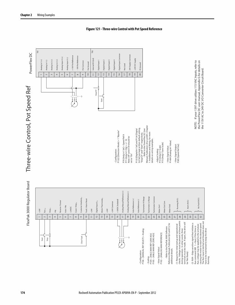
Chapter 2 Wiring Examples
Figure 121 - Three-wire Control with Pot Speed Reference
2221201918171514131 7 8 9 10 11 12 23 245 62 43 272625 302928
Met
er O
ut C
om
Met
er O
ut2
Flex
Pak
3000
Reg
ulat
or B
oard
161514131 7 8 9 10 11 125 62 43
Ana
log
In 1
(+)
Ana
log
In 1
(-)
Ana
log
In 2
(+)
Ana
log
In 2
(+)
Pot C
omm
on
17 18 2019
-10V
Pot
Ref
eren
ce
+24V
DC
Supp
ly
Dig
ital I
nput
Com
mon
24V
Supp
ly C
omm
on
Dig
ital I
nput
1
Dig
ital I
nput
2
Dig
ital I
nput
3
Dig
ital I
nput
4
+ 10
V Po
t Ref
eren
ce
Stop
/CF
Star
t
Pow
erFl
ex D
C
Ana
log
Inpu
t 3 (+
)
Ana
log
Inpu
t 3 (-
)
TB1
Pot G
roun
d
TB2
Not
Use
d
PE G
roun
d
Inte
rnal
0V
(Grd
)
• Con
figur
atio
n:P1
322
[Dire
ctio
n M
ode]
= 1
“Bip
olar
”
P70
[Anl
g in
1 Se
l] =
Spee
d Re
f AP7
1 [A
nlg
In1
Cfg]
= +
/-10
Not
e: D
IP sw
itch
S9 sh
ould
be
set t
o “O
n”
P133
[Dig
ital I
n1 S
el] a
nd P
134
[Dig
ital
In2
Sel]
are
kept
at t
heir
defa
ult s
ettin
g,
“Sto
p/CF
” and
“Sta
rt” r
espe
ctiv
ely.
-Ref
er to
the
Pow
erFl
ex D
C U
ser
Man
ual,
Publ
icat
ion
20-p
-um
001,
Cha
pter
1:
Inst
alla
tion
and
Wiri
ng, f
or m
ore
deta
ils o
n w
iring
exa
mpl
es.
• Adj
ust S
calin
g:P7
2 [A
nlg
In1
Scal
e]P7
3 [A
nlg1
Tun
e Sc
ale]
• Vie
w S
igna
l Val
ue:
P140
4 [A
nalo
g In
1 Va
lue]
• Vie
w S
igna
l Out
put:
P385
[Spe
ed R
ef O
ut]
16
+24
V
Run
(1)
Stop
(1)
Jog
Reve
rse
/ For
war
Aut
o / M
a
+24
VDC
Coas
t / S
top (
1)
Cust
omer
Inte
rlock
(1)
Faul
t / A
larm
Res
et
+24
V
Dig
ital I
nput
0(1
)
Mot
or T
herm
osta
t (1)
+24
V
+24
V Co
mm
on
+10
VDC
(Isol
ated
)
Ana
log
Man
ual R
efer
ence
(+)
Ana
log
Man
ual R
efer
ence
(-)
Aut
o Re
fere
nce
(+)
Aut
o Re
fere
nce
(-)
Stop
Star
t
NO
TE:
If yo
ur 1
397
driv
e ut
ilize
s 11
5 VA
C In
puts
, ref
er to
th
e Po
wer
Flex
DC
user
man
ual,
App
endi
x G
for d
etai
ls o
n th
e 11
5V A
C to
24V
DC
I/O C
onve
rter
Circ
uit B
oard
.
Clea
r Fau
lt
31 32
Tach
omet
er H
i Ran
ge
Tach
omet
er L
o Ra
nge
Tach
omet
er C
omm
on
Met
er O
ut1
Runn
ing
(N.O
.)
Ala
rm (N
.O.)
No
Faul
t (N
.O.)
• Con
figur
atio
n:P1
06 –
[MA
NU
AL
REF
SELE
CT] =
Ana
log
• Sca
ling:
P104
–[A
NLG
MA
N R
EF G
AIN
AD
J]P1
05 –
[AN
LG M
AN
REF
ZER
O A
DJ]
• Vie
w S
igna
l Val
ue:
P192
–[A
NA
LOG
MA
N R
EFER
ENCE
]
-Ref
er to
the
Flex
Pak
3000
Sof
twar
e Re
fere
nce
Man
ual,
Publ
icat
ion
fp3-
um01
3, fo
r ad
ditio
nal d
etai
ls.
(1)
Requ
ire fo
r ini
tial s
tart
up a
nd o
pera
tiona
l ch
ecks
. Vo
ltage
mus
t be
pres
ent a
t the
se p
oint
s du
ring
oper
atio
n. I
n ot
her w
ords
, the
se
term
inal
s mus
t be
mad
e. I
f ope
n, th
e dr
ive
will
be
‘Not
Rea
dy’.
(2)
RUN
– E
dge
sens
itive
sign
al th
at in
itiat
es a
Ru
n co
mm
and
(0
1 =
Run
). If
the
Driv
e is
Ru
n, v
olta
ge m
ay b
e ap
plie
d to
the
arm
atur
e ca
usin
g th
e m
otor
to re
ach
the
desi
red
spee
d.
The
Run
inpu
t is l
atch
ed a
nd th
eref
ore
does
not
ha
ve to
be
mai
ntai
ned
to k
eep
the
driv
e Ru
nnin
g.
Thre
e-w
ire C
ontr
ol, P
ot S
peed
Ref
174 Rockwell Automation Publication PFLEX-AP009A-EN-P - September 2012
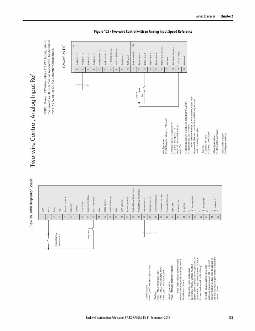
Wiring Examples Chapter 2
Figure 122 - Two-wire Control with an Analog Input Speed Reference
161514131 7 8 9 10 11 125 62 43
Ana
log
In 1
(+)
Ana
log
In 1
(-)
Ana
log
In 2
(+)
Ana
log
In 2
(+)
Pot C
omm
on
17 18 2019
-10V
Pot
Ref
eren
ce
+24V
DC
Supp
ly
Dig
ital I
nput
Com
mon
24V
Supp
ly C
omm
on
Dig
ital I
nput
1
Dig
ital I
nput
2
Dig
ital I
nput
3
Dig
ital I
nput
4
+ 10
V Po
t Ref
eren
ce
Pow
erFl
ex D
C
Ana
log
Inpu
t 3 (+
)
Ana
log
Inpu
t 3 (-
)
Pot G
roun
d
Not
Use
d
PE G
roun
d
Inte
rnal
0V
(Grd
)
• Con
figur
atio
n:P1
322
[Dire
ctio
n M
ode]
= 1
“Bip
olar
”
P70
[Anl
g in
1 Se
l] =
Spee
d Re
f AP7
1 [A
nlg
In1
Cfg]
= +
/-10
Not
e: D
IP sw
itch
S9 sh
ould
be
set t
o “O
n”
P133
[Dig
ital I
n1 S
el] i
s kep
t at i
ts d
efau
lt of
“Sto
p/CF
”.
P134
[Dig
ital I
n2 S
el] =
5 “R
un”
-Ref
er to
the
Pow
erFl
ex D
C U
ser M
anua
l, Pu
blic
atio
n 20
-p-u
m00
1, C
hapt
er 1
: Ins
talla
tion
and
Wiri
ng, f
or m
ore
deta
ils o
n w
iring
exa
mpl
es.
• Sca
ling:
P72
[Anl
g In
1 Sc
ale]
P73
[Anl
g1 T
une
Scal
e]
• Vie
w S
igna
l Val
ue:
P140
4 [A
nalo
g In
1 Va
lue]
• Vie
w S
igna
l Out
put:
P385
[Spe
ed R
ef O
ut]
TB1
TB2
NO
TE:
If yo
ur 1
397
driv
e ut
ilize
s 11
5 VA
C In
puts
, ref
er to
th
e Po
wer
Flex
DC
user
man
ual,
App
endi
x G
for d
etai
ls o
n th
e 11
5V A
C to
24V
DC
I/O C
onve
rter
Circ
uit B
oard
.
Stop
/CF
Run
2221201918171514131 7 8 9 10 11 12 23 245 62 43 272625 302928
Flex
Pak
3000
Reg
ulat
or B
oard
16
Clea
r Fau
lt
31 32
RUN
/STO
P by
us
er c
onta
ct
Met
er O
ut C
om
Met
er O
ut2
+24
V
Run
(1)
Stop
(1)
Jog
Reve
rse
/ For
war
d
Aut
o / M
an
+24
VDC
Coas
t / S
top (
1)
Cust
omer
Inte
rlock
(1)
Faul
t / A
larm
Res
et
+24
V
Dig
ital I
nput
0(1
)
Mot
or T
herm
osta
t (1)
+24
V
+24
V Co
mm
on
+10
VDC
(Isol
ated
)
Ana
log
Man
ual R
efer
ence
(+)
Ana
log
Man
ual R
efer
ence
(-)
Aut
o Re
fere
nce
(+)
Aut
o Re
fere
nce
(-)
Tach
omet
er H
i Ran
ge
Tach
omet
er L
o Ra
nge
Tach
omet
er C
omm
on
Met
er O
ut1
Runn
ing
(N.O
.)
Ala
rm (N
.O.)
No
Faul
t (N
.O.)
• Con
figur
atio
n:P1
03 –
[AU
TO R
EF S
ELEC
T] =
Ana
log
• Sca
ling:
P101
–[A
NLG
AU
TO G
AIN
AD
J]P1
00 –
[AN
LG A
UTO
SIG
NA
L TY
PE]
P102
–[A
NLG
AU
TO Z
ERO
AD
J]
• Vie
w S
igna
l Val
ue:
P188
–[A
NA
LOG
AU
TO R
EFER
ENCE
]
-Ref
er to
the
Flex
Pak
3000
Sof
twar
e Re
fere
nce
Man
ual,
Publ
icat
ion
fp3-
um01
3,
for a
dditi
onal
det
ails
.
(1)
Requ
ire fo
r ini
tial s
tart
up a
nd
oper
atio
nal c
heck
s. V
olta
ge m
ust b
e pr
esen
t at t
hese
poi
nts d
urin
g op
erat
ion.
In
othe
r wor
ds, t
hese
term
inal
s mus
t be
mad
e.
If op
en, t
he d
rive
will
be
‘Not
Rea
dy’.
(2)
RUN
– E
dge
sens
itive
sign
al th
at
initi
ates
a R
un c
omm
and
(0
1 =
Run
). If
the
Driv
e is
Run
, vol
tage
may
be
appl
ied
to
the
arm
atur
e ca
usin
g th
e m
otor
to re
ach
the
desi
red
spee
d.
Two-
wire
Con
trol
, Ana
log
Inpu
t Ref
Rockwell Automation Publication PFLEX-AP009A-EN-P - September 2012 175
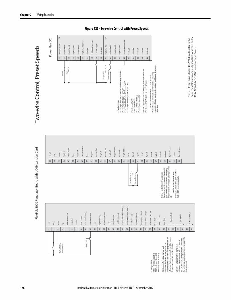
Chapter 2 Wiring Examples
Figure 123 - Two-wire Control with Preset Speeds
Run
Stop
/CF
Spee
d Se
lect
2
16151413 31 37 38 39 4011 12 35 3632 3433
Dig
ital I
nput
5
Dig
ital I
nput
6
Dig
ital I
nput
7
Dig
ital I
nput
8
Not
Use
d
17 18 2019
Not
Use
d
+24
V D
C Su
pply
Dig
ital I
nput
Com
mon
24V
Supp
ly C
omm
on
Dig
ital I
nput
1
Dig
ital I
nput
2
Dig
ital I
nput
3
Dig
ital I
nput
4
Not
Use
d
Dig
ital I
nput
Com
mon
Not
Use
d
Not
Use
d
Not
Use
d
PE G
roun
d
Inte
rnal
0V
(Grd
)
Pow
erFl
ex D
C TB2
TB4
• Con
figur
atio
nP1
33 [D
igita
l In1
Sel
] is k
ept a
t its
def
ault
of “S
top/
CF”.
P1
34 [D
igita
l In2
Sel
] = 5
“Run
”P1
37 [D
igita
l In5
Sel
] = 1
7 “S
peed
Sel
1”
P138
[Dig
ital I
n6 S
el] =
18
“Spe
ed S
el 2
”
P44
[Spe
ed R
ef A
]P4
8 [S
peed
Ref
B]
P155
[Pre
set S
peed
2]
P156
[Pre
set S
peed
3]
Not
e: If
Dig
ital I
nput
5 &
6 a
re o
pen,
then
the
driv
e us
es
P44
[Spe
ed R
ef A
] as i
t’s sp
eed
refe
renc
e.
-Ref
er to
the
Pow
erFl
ex D
C U
ser M
anua
l, Pu
blic
atio
n 20
-p-u
m00
1, fo
r mor
e de
tails
on
wiri
ng
exam
ples
, Dig
ital I
nput
con
figur
atio
n an
d Sp
eed
Refe
renc
e se
lect
ion.
NO
TE:
If yo
ur d
rive
utili
zes
115
VAC
Inpu
ts, r
efer
to th
e Po
wer
Flex
DC
user
man
ual,
App
endi
x G
for d
etai
ls o
n th
e 11
5V A
C to
24V
DC
I/O C
onve
rter
Circ
uit B
oard
.
Spee
d Se
lect
1
2221201918171514131 7 8 9 10 11 12 23 245 62 43 272625 302928
Flex
Pak
3000
Reg
ulat
or B
oard
with
I/O
Exp
ansi
on C
ard
16
Clea
r Fau
lt
31 32
RUN
/STO
P by
us
er c
onta
ct
64636261605957565538 44 50 51 52 53 54 65 6642 4339 4140 696867D
ig O
ut 1
Com
Dig
Out
2
58
Unu
sed
Freq
In A
Freq
In A
(not
)
Com
Freq
Out
A
Freq
Out
A (n
ot)
Com
Anl
g In
1
Anl
g In
1 C
om
Anl
g In
2
Anl
g In
2 C
om
Anl
g O
ut 1
Anl
g O
ut 1
Com
Anl
g O
ut 2
24V
DC
Dig
In 1
Dig
In 2
24V
DC
Dig
In 3
Dig
In 4
Dig
In 5
24V
Com
Dig
Out
1
33 34
Anl
g O
ut 2
Com
Dig
Out
2 C
om
10V
DC
Gnd
Met
er O
ut C
om
Met
er O
ut2
+24V
Run
(1)
Stop
(1)
Jog
Reve
rse
/ For
war
d
Aut
o / M
an
+24V
DC
Coas
t / S
top (
1)
Cust
omer
Inte
rlock
(1)
Faul
t / A
larm
Res
et
+24V
Dig
ital I
nput
0(1
)
Mot
or T
herm
osta
t (1)
+24V
+24V
Com
mon
+10V
DC
(Isol
ated
)
Ana
log
Man
ual R
efer
ence
(+)
Ana
log
Man
ual R
efer
ence
(-)
Aut
o Re
fere
nce
(+)
Aut
o Re
fere
nce
(-)
Tach
omet
er H
i Ran
ge
Tach
omet
er L
o Ra
nge
Tach
omet
er C
omm
on
Met
er O
ut1
Runn
ing
(N.O
.)
Ala
rm (N
.O.)
No
Faul
t (N
.O.)
• Con
figur
atio
n P
117
= [P
rese
t Spe
ed 1
] P
118
= [P
rese
t Spe
ed 2
] P
119
= [P
rese
t Spe
ed 3
]
(1)
Requ
ire fo
r ini
tial s
tart
up a
nd
oper
atio
nal c
heck
s. V
olta
ge m
ust b
e pr
esen
t at t
hese
poi
nts d
urin
g op
erat
ion.
In
othe
r wor
ds, t
hese
term
inal
s mus
t be
mad
e.
If op
en, t
he d
rive
will
be
‘Not
Rea
dy’.
(2)
RUN
– E
dge
sens
itive
sign
al th
at
initi
ates
a R
un c
omm
and
(0
1 =
Run
). If
the
Driv
e is
Run
, vol
tage
may
be
appl
ied
to
the
arm
atur
e ca
usin
g th
e m
otor
to re
ach
the
desi
red
spee
d.
NO
TE:
Inst
all t
he I/
O E
xpan
sion
Bo
ard
in th
e dr
ive
carr
ier u
sing
the
(2)
pan
head
scre
ws p
rovi
ded,
then
plu
g th
e m
iddl
e rib
bon
cabl
e co
nnec
tor i
nto
J1.
-Ref
er to
the
Flex
Pak
3000
D
rive
I/O E
xpan
sion
Kit,
Pub
licat
ion
fp3-
in00
7, fo
r mor
e de
tails
.
Pres
et S
peed
A
Pres
et S
peed
B
Two-
wire
Con
trol
, Pre
set S
peed
s
176 Rockwell Automation Publication PFLEX-AP009A-EN-P - September 2012
Chapter 3
Network Communication
Overview The process of migrating from a 1395, 1397, and FlexPak 3000 to a PowerFlex DC drive can vary significantly depending on the controller type communicating with the drive and the particular communication module installed in the drive.
This chapter describes which architecture-class (20-COMM) network options can be used with the PowerFlex DC drives. Because of the wide variety of networks, processors, and drive options to consider, only migration information is presented, rather than step-by-step procedures.
Bulletin 1395 DC Drive Network Communication Options
The 1395 drive has the following network communication options:• Remote I/O• Serial• DF1• Data Highway Plus• ControlNet™
1395 Node Adapter Board
The Node Adapter board provides a sophisticated interface between external devices and the main control board. This adapter board provides the following features:
• Capable of configuration as a Remote I/O (RIO) interface• Compatible with Allen-Bradley PLC3 or PLC5 family of programmable
logic controllers (PLC)
Topic Page
Overview 177
Bulletin 1395 DC Drive Network Communication Options 177
Bulletin 1397 DC Drive Network Communication Options 179
FlexPak 3000 DC Drive Network Communication Options 180
PowerFlex DC Drive Network Communication Options 181
Logic Command and Status 182
Rockwell Automation Encompass Partner Migration Offerings 190
Rockwell Automation Publication XXXX-X.X.X - Month Year 177
Chapter 3 Network Communication
The 1395 Node Adapter Board Installation and Operation Manual, publication 1395-IN017, contains the information necessary to perform the following functions:
• Install and set-up the Node Adapter board• Configure the drive for control by a PLC• Maintain and troubleshoot the board
Multi-Communication Board
The Multi-communication Adapter (MCA) board provides a sophisticated interface to an Allen-Bradley PLC and other equipment capable of communicating over serial communication links. This adapter board provides the following features:
• Two separate communications channels, each capable of being configured as Remote I/O (RIO) or Data Highway Plus (DH+) interfaces.
• Four programmable function blocks, which can be used to manipulate data.
• One programmable discrete input (24V DC or 115V AC).• Compatible with Allen-Bradley PLC5/60, PLC5/40, PLC5/25,
PLC5/15, PLC250, PLC3, and Control View.
The 1395 Multi-Communication Board Hardware/Software Reference Manual, publication 1395-RM000, contains the information necessary to perform the following functions:
• Install and set-up the MCA board• Configure the drive for control by a PLC• Maintain and troubleshoot the board
ControlNet Adapter Board
The ControlNet Adapter (CNA) board provides a sophisticated interface to an Allen-Bradley PLC and other equipment capable of communicating over ControlNet. This adapter board provides the following features:
• One ControlNet channel, with a redundant connector to allow for backup connection in case one cable fails.
• Compatible with all Allen-Bradley PLCs and other products that support programmable controller communication commands (PCCC).
• Compatible with Allen-Bradley 1395 drives equipped with version 8.10 or later software.
The 1395 ControlNet Communication Board User Manual, publication1395-UM007, contains the information necessary to perform the following functions:
• Install and set-up the CNA board• Configure the drive for control by a PLC• Maintain and troubleshoot the board
178 Rockwell Automation Publication XXXX-X.X.X - Month Year
Network Communication Chapter 3
Bulletin 1397 DC Drive Network Communication Options
The 1397 drive uses the SCANPort communication protocol with the following network communication options:
• Remote I/O (RIO) • RS-232/422/485, DF1 and DH485 Protocol • DeviceNet - 24 VDC• ControlNet• Ethernet/IP• Profibus DP (ProSoft)• Modbus Plus (ProSoft)• Modbus RTU (ProSoft)• Metasys N2 (ProSoft)• LonWorks (ProSoft)
See Appendix D, Using SCANPort Capabilities, in the 1397 DC Drive User Manual, publication 1397-UM000, for details on the following communication topics:
• Understanding the Logic Command and Status parameter• Configuring the SCANPort controls• Setting the loss of communication fault• Using the SCANPort I/O image
For more details on the respective 1203 communication adapter user manuals, see the Rockwell Automation Literature Library athttp:/www.rockwellautomation.com/literature/.
Also, for any relevant technical documents, see the Rockwell Automation Knowledgebase at https://rockwellautomation.custhelp.com/.
Rockwell Automation Publication XXXX-X.X.X - Month Year 179

Chapter 3 Network Communication
FlexPak 3000 DC Drive Network Communication Options
A DeviceNet Interface board, AutoMax Network Communication board, or ControlNet Network Communication board may be installed in the drive. See Chapter 10, Configuring a Network, in the The FlexPak 300 Digital DC Drive Software Reference Manual, publication FP3-UM013, for a description of the parameters used to configure for these networks.
For information on the DeviceNet, AutoMax, or ControlNet networks, see the appropriate network manual.
Some parameters are only accessible over the network using the alternate register map (NETW REGISTER MAP SEL (P.914) set to ALTERNATE).
See the appropriate option board instruction manual for more information.
ControlNet Network Communication Option Board
This option allows a FlexPak 3000 DC drive to send and receive data via a control processor over the ControlNet network. FlexPak 3000 drives (version 4.2 or later) are compatible with all versions of the network option board. See the ControlNet Network Communication Option Board Instruction Manual, publication PFP3-IN024, for more details.
AutoMax Network Communication Option Board
This board enables a FlexPak 3000 DC drive for operation and monitoring over the AutoMax network.
For normal operation, the drive can be completely controlled using the AutoMax Network option board. This option provides drive control using only a network interface connection with a hard-wired emergency stop and three-phase input and output power wiring. Drive control (such as start, stop, and reset), reference changes, parameter modification, and drive monitoring can all be performed over the AutoMax network.
Refer to the AutoMax Network Communication Option Board Instruction Manual, publication FP3-IN010, for more details.
DeviceNet Network
See DeviceNet Network for use with Reliance Electric FlexPak 3000 DC Drive for details in using the DeviceNet network with FlexPak 3000 DC drives. This is also highlighted in Rockwell Automation Knowledgebase ID# 64604. See the Rockwell Automation Knowledgebase athttps://rockwellautomation.custhelp.com/.
180 Rockwell Automation Publication XXXX-X.X.X - Month Year

Network Communication Chapter 3
PowerFlex DC Drive Network Communication Options
The PowerFlex DC drive supports the following network communication protocols:
• BACnet MS/TP RS485 Communication Adapter: 20-COMM-B• ControlNet Communication Adapter (Coax): 20-COMM-C• DeviceNet Communication Adapter: 20-COMM-D• EtherNet/IP Communication Adapter: 20-COMM-E• HVAC Communication Adapter: 20-COMM-H• Interbus Communication Adapter: 20-COMM-I• PROFIBUS DP Communication Adapter: 20-COMM-P• ControlNet Communication Adapter (Fiber) 20-COMM-Q• Remote I/O Communication Adapter: 20-COMM-R• RS485 DF1 Communication Adapter: 20-COMM-S• External Communications Kit Power Supply: 20-XCOMMAC-PS1 *• DPI External Communications Kit: 20-XCOMMDC-BASE• External DPI I/O Option Board: 20-XCOMMIO-OPT1• Compact I/O to DPI/SCANport Module 1769-SM1• Serial Null Modem Adapter: 1203-SNM
* For use only with External DPI Communications Kits20-XCOMM-DCBASE.
Refer to the respective communication adapter user manuals for details. See the Rockwell Automation Literature Library athttp:/www.rockwellautomation.com/literature/.
Also, for any relevant technical documents, see the Rockwell Automation Knowledgebase at https://rockwellautomation.custhelp.com/.
Rockwell Automation Publication XXXX-X.X.X - Month Year 181
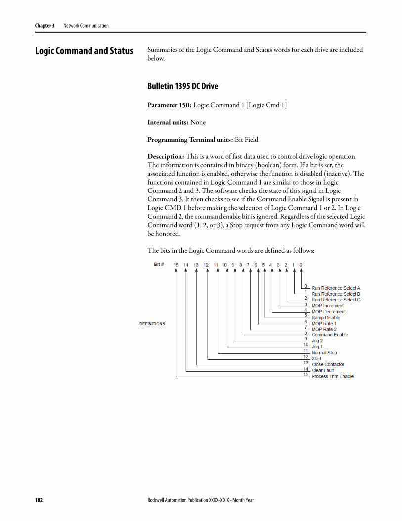
Chapter 3 Network Communication
Logic Command and Status Summaries of the Logic Command and Status words for each drive are included below.
Bulletin 1395 DC Drive
Parameter 150: Logic Command 1 [Logic Cmd 1]
Internal units: None
Programming Terminal units: Bit Field
Description: This is a word of fast data used to control drive logic operation. The information is contained in binary (boolean) form. If a bit is set, the associated function is enabled, otherwise the function is disabled (inactive). The functions contained in Logic Command 1 are similar to those in Logic Command 2 and 3. The software checks the state of this signal in Logic Command 3. It then checks to see if the Command Enable Signal is present in Logic CMD 1 before making the selection of Logic Command 1 or 2. In Logic Command 2, the command enable bit is ignored. Regardless of the selected Logic Command word (1, 2, or 3), a Stop request from any Logic Command word will be honored.
The bits in the Logic Command words are defined as follows:
182 Rockwell Automation Publication XXXX-X.X.X - Month Year
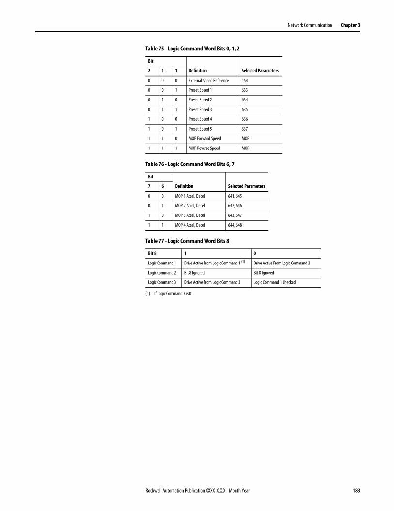
Network Communication Chapter 3
Table 75 - Logic Command Word Bits 0, 1, 2
Table 76 - Logic Command Word Bits 6, 7
Table 77 - Logic Command Word Bits 8
Bit
Definition Selected Parameters2 1 1
0 0 0 External Speed Reference 154
0 0 1 Preset Speed 1 633
0 1 0 Preset Speed 2 634
0 1 1 Preset Speed 3 635
1 0 0 Preset Speed 4 636
1 0 1 Preset Speed 5 637
1 1 0 MOP Forward Speed MOP
1 1 1 MOP Reverse Speed MOP
Bit
Definition Selected Parameters7 6
0 0 MOP 1 Accel, Decel 641, 645
0 1 MOP 2 Accel, Decel 642, 646
1 0 MOP 3 Accel, Decel 643, 647
1 1 MOP 4 Accel, Decel 644, 648
Bit 8 1 0
Logic Command 1 Drive Active From Logic Command 1 (1)
(1) If Logic Command 3 is 0
Drive Active From Logic Command 2
Logic Command 2 Bit 8 Ignored Bit 8 Ignored
Logic Command 3 Drive Active From Logic Command 3 Logic Command 1 Checked
Rockwell Automation Publication XXXX-X.X.X - Month Year 183
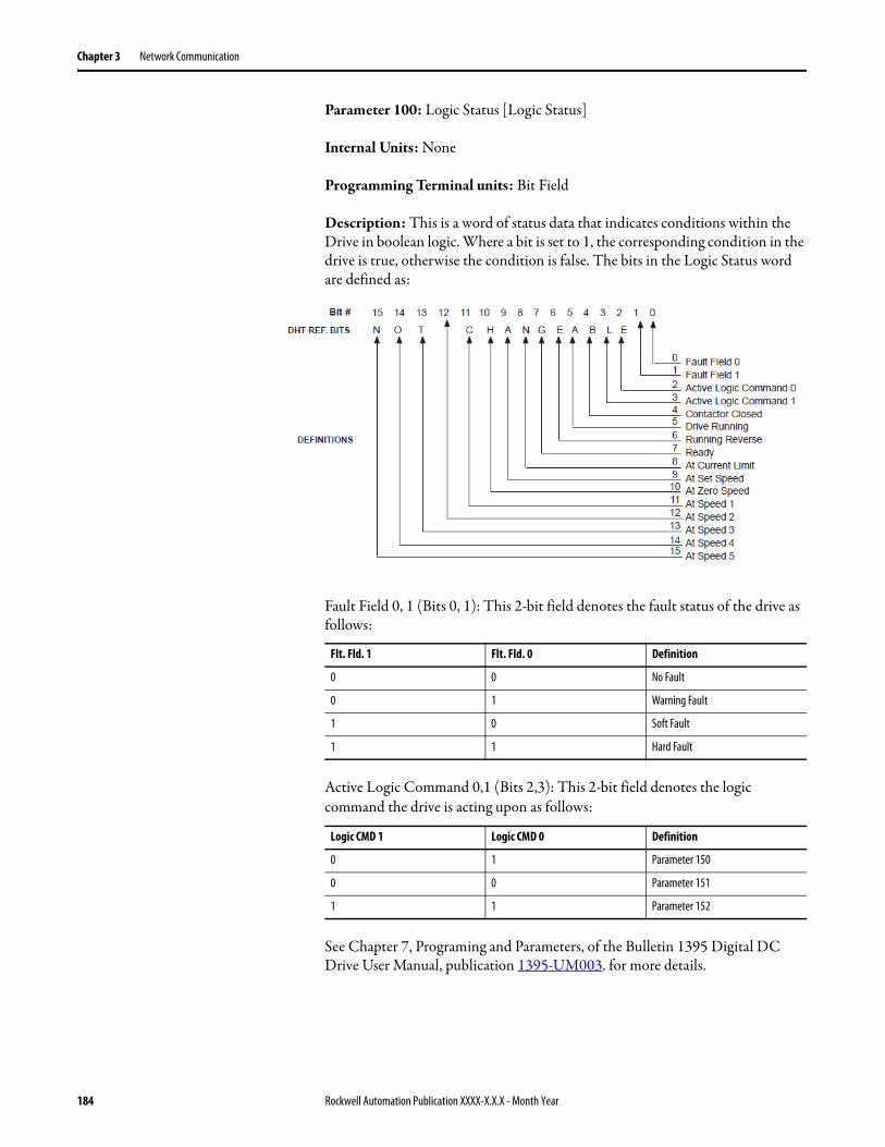
Chapter 3 Network Communication
Parameter 100: Logic Status [Logic Status]
Internal Units: None
Programming Terminal units: Bit Field
Description: This is a word of status data that indicates conditions within the Drive in boolean logic. Where a bit is set to 1, the corresponding condition in the drive is true, otherwise the condition is false. The bits in the Logic Status word are defined as:
Fault Field 0, 1 (Bits 0, 1): This 2-bit field denotes the fault status of the drive as follows:
Active Logic Command 0,1 (Bits 2,3): This 2-bit field denotes the logic command the drive is acting upon as follows:
See Chapter 7, Programing and Parameters, of the Bulletin 1395 Digital DC Drive User Manual, publication 1395-UM003. for more details.
Flt. Fld. 1 Flt. Fld. 0 Definition
0 0 No Fault
0 1 Warning Fault
1 0 Soft Fault
1 1 Hard Fault
Logic CMD 1 Logic CMD 0 Definition
0 1 Parameter 150
0 0 Parameter 151
1 1 Parameter 152
184 Rockwell Automation Publication XXXX-X.X.X - Month Year
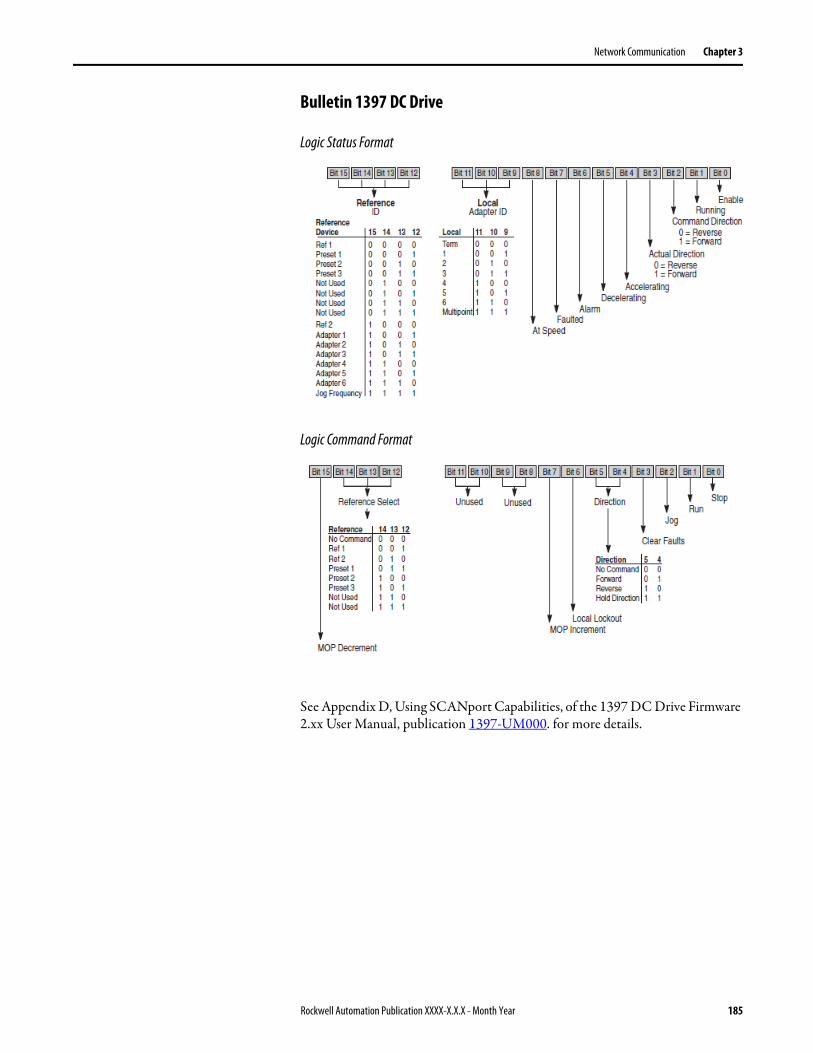
Network Communication Chapter 3
Bulletin 1397 DC Drive
Logic Status Format
Logic Command Format
See Appendix D, Using SCANport Capabilities, of the 1397 DC Drive Firmware 2.xx User Manual, publication 1397-UM000. for more details.
Rockwell Automation Publication XXXX-X.X.X - Month Year 185
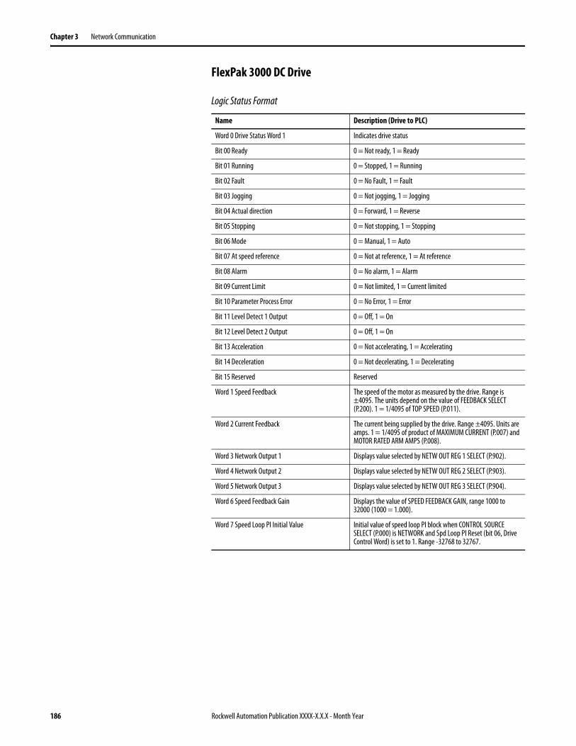
Chapter 3 Network Communication
FlexPak 3000 DC Drive
Logic Status Format
Name Description (Drive to PLC)
Word 0 Drive Status Word 1 Indicates drive status
Bit 00 Ready 0 = Not ready, 1 = Ready
Bit 01 Running 0 = Stopped, 1 = Running
Bit 02 Fault 0 = No Fault, 1 = Fault
Bit 03 Jogging 0 = Not jogging, 1 = Jogging
Bit 04 Actual direction 0 = Forward, 1 = Reverse
Bit 05 Stopping 0 = Not stopping, 1 = Stopping
Bit 06 Mode 0 = Manual, 1 = Auto
Bit 07 At speed reference 0 = Not at reference, 1 = At reference
Bit 08 Alarm 0 = No alarm, 1 = Alarm
Bit 09 Current Limit 0 = Not limited, 1 = Current limited
Bit 10 Parameter Process Error 0 = No Error, 1 = Error
Bit 11 Level Detect 1 Output 0 = Off, 1 = On
Bit 12 Level Detect 2 Output 0 = Off, 1 = On
Bit 13 Acceleration 0 = Not accelerating, 1 = Accelerating
Bit 14 Deceleration 0 = Not decelerating, 1 = Decelerating
Bit 15 Reserved Reserved
Word 1 Speed Feedback The speed of the motor as measured by the drive. Range is ±4095. The units depend on the value of FEEDBACK SELECT (P.200). 1 = 1/4095 of TOP SPEED (P.011).
Word 2 Current Feedback The current being supplied by the drive. Range ±4095. Units are amps. 1 = 1/4095 of product of MAXIMUM CURRENT (P.007) and MOTOR RATED ARM AMPS (P.008).
Word 3 Network Output 1 Displays value selected by NETW OUT REG 1 SELECT (P.902).
Word 4 Network Output 2 Displays value selected by NETW OUT REG 2 SELECT (P.903).
Word 5 Network Output 3 Displays value selected by NETW OUT REG 3 SELECT (P.904).
Word 6 Speed Feedback Gain Displays the value of SPEED FEEDBACK GAIN, range 1000 to 32000 (1000 = 1.000).
Word 7 Speed Loop PI Initial Value Initial value of speed loop PI block when CONTROL SOURCE SELECT (P.000) is NETWORK and Spd Loop PI Reset (bit 06, Drive Control Word) is set to 1. Range -32768 to 32767.
186 Rockwell Automation Publication XXXX-X.X.X - Month Year
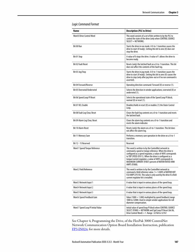
Network Communication Chapter 3
Logic Command Format
See Chapter 4, Programming the Drive, of the FlexPak 3000 ControlNet Network Communication Option Board Installation Instruction, publication FP3-IN024, for more details.
Name Description (PLC to Drive)
Word 0 Drive Control Word This word consists of a set of bits written to by the PLC to control the state of the drive (only when CONTROL SOURCE SELECT = NETWORK).
Bit 00 Run Starts the drive in run mode. A 0-to-1 transition causes the drive to start (if ready). Setting this bit to zero (0) does not stop the drive.
Bit 01 Stop A value of 0 stops the drive. A value of 1 allows the drive to become ready.
Bit 02 Fault Reset Resets (only) the latched fault on a 0-to-1 transition. This bit does not affect the contents of the fault log.
Bit 03 Jog/Stop Starts the drive in jog mode. A 0-to-1 transition causes the drive to start (if ready). Setting this bit to zero (0) causes the drive to stop (only after jog time-out or if no run command is asserted).
Bit 04 Forward/Reverse Operating direction command: Forward (0) or reverse (1).
Bit 05 Overwind/Underwind Selects the direction in winder applications; overwind (0) or underwind (1).
Bit 06 Speed Loop PI Reset Selects the operational state of the Speed Loop PI block; normal (0) or reset (1).
Bit 07 OCL Enable Disables/holds in reset (0) or enables (1) the Outer Control Loop.
Bit 08 Fault Log Clear, Reset Clears the fault log contents on a 0-to-1 transition and resets the latched fault.
Bit 09 Alarm Log Clear, Reset Clears the alarm log contents on a 0-to-1 transition and resets the alarm indicator.
Bit 10 Alarm Reset Resets (only) the alarm on a 0-to-1 transition. This bit does not affect the alarm log.
Bit 11 Memory Save Performs a memory save operation in the drive on a 0-to-1 transition.
Bit 12 - 15 Reserved Reserved
Word 1 Speed/Torque Reference This word is written to by the ControlNet network to command a speed or torque reference. When the drive is configured as a speed regulator, a value of 4095 corresponds to TOP SPEED (P.011). When the drive is configured as a torque/current regulator, a value of 4095 corresponds to MAXIMUM CURRENT (P.007) percent of MOTOR RATED ARM AMPS (P.008).
Word 2 Field Reference This word is written to by the ControlNet network to command a field reference value. 1= 1/4095 of MOTOR HOT FLD AMPS (P.510). This value is only used by the drive if a field current regulator kit is installed.
Word 3 Network Input 1 A value that is input in various places of the speed loop.
Word 4 Network Input 2 A value that is input in various places of the speed loop.
Word 5 Network Input 3 A value that is input in various places of the speed loop.
Word 6 Speed Feedback Gain Value (1000 = 1.000) multiplied by speed feedback (range 1000 to 32000. Used in simple winder applications for roll diameter compensation.
Word 7 Speed Loop PI Initial Value Initial value of speed loop PI block when CONTROL SOURCE SELECT (P.000) = NETWORK and Spd Loop PI Reset (bit 06, Drive Control Word) = 1. Range -32768 to 32767.
Rockwell Automation Publication XXXX-X.X.X - Month Year 187
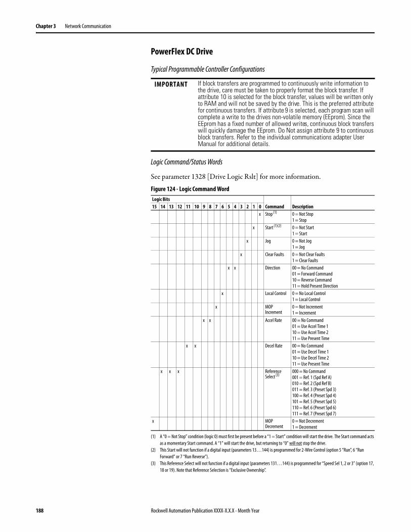
Chapter 3 Network Communication
PowerFlex DC Drive
Typical Programmable Controller Configurations
Logic Command/Status Words
See parameter 1328 [Drive Logic Rslt] for more information.
Figure 124 - Logic Command Word
IMPORTANT If block transfers are programmed to continuously write information to the drive, care must be taken to properly format the block transfer. If attribute 10 is selected for the block transfer, values will be written only to RAM and will not be saved by the drive. This is the preferred attribute for continuous transfers. If attribute 9 is selected, each program scan will complete a write to the drives non-volatile memory (EEprom). Since the EEprom has a fixed number of allowed writes, continuous block transfers will quickly damage the EEprom. Do Not assign attribute 9 to continuous block transfers. Refer to the individual communications adapter User Manual for additional details.
Logic BitsCommand Description15 14 13 12 11 10 9 8 7 6 5 4 3 2 1 0
x Stop (1) 0 = Not Stop1 = Stop
x Start (1)(2)
(1) A “0 = Not Stop” condition (logic 0) must first be present before a “1 = Start” condition will start the drive. The Start command acts as a momentary Start command. A “1” will start the drive, but returning to “0” will not stop the drive.
(2) This Start will not function if a digital input (parameters 13…144) is programmed for 2-Wire Control (option 5 “Run”, 6 “Run Forward” or 7 “Run Reverse”).
0 = Not Start1 = Start
x Jog 0 = Not Jog1 = Jog
x Clear Faults 0 = Not Clear Faults1 = Clear Faults
x x Direction 00 = No Command01 = Forward Command10 = Reverse Command11 = Hold Present Direction
x Local Control 0 = No Local Control1 = Local Control
x MOP Increment
0 = Not Increment1 = Increment
x x Accel Rate 00 = No Command01 = Use Accel Time 110 = Use Accel Time 211 = Use Present Time
x x Decel Rate 00 = No Command01 = Use Decel Time 110 = Use Decel Time 2 11 = Use Present Time
x x x Reference Select (3)
(3) This Reference Select will not function if a digital input (parameters 131…144) is programmed for “Speed Sel 1, 2 or 3” (option 17, 18 or 19). Note that Reference Selection is “Exclusive Ownership”.
000 = No Command001 = Ref. 1 (Spd Ref A)010 = Ref. 2 (Spd Ref B)011 = Ref. 3 (Preset Spd 3)100 = Ref. 4 (Preset Spd 4)101 = Ref. 5 (Preset Spd 5)110 = Ref. 6 (Preset Spd 6)111 = Ref. 7 (Preset Spd 7)
x MOP Decrement
0 = Not Decrement1 = Decrement
188 Rockwell Automation Publication XXXX-X.X.X - Month Year
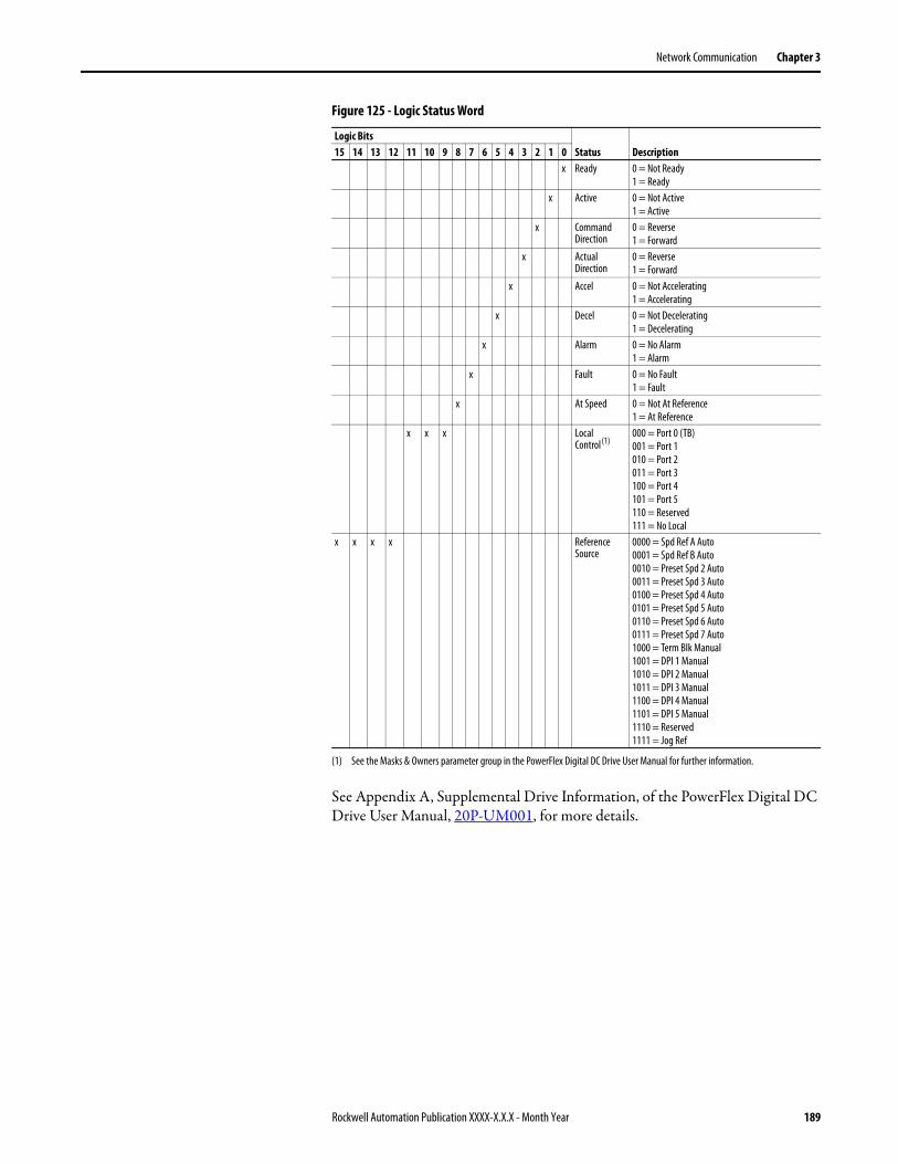
Network Communication Chapter 3
Figure 125 - Logic Status Word
See Appendix A, Supplemental Drive Information, of the PowerFlex Digital DC Drive User Manual, 20P-UM001, for more details.
Logic BitsStatus Description15 14 13 12 11 10 9 8 7 6 5 4 3 2 1 0
x Ready 0 = Not Ready1 = Ready
x Active 0 = Not Active1 = Active
x Command Direction
0 = Reverse1 = Forward
x Actual Direction
0 = Reverse1 = Forward
x Accel 0 = Not Accelerating1 = Accelerating
x Decel 0 = Not Decelerating1 = Decelerating
x Alarm 0 = No Alarm1 = Alarm
x Fault 0 = No Fault1 = Fault
x At Speed 0 = Not At Reference1 = At Reference
x x x Local Control(1)
(1) See the Masks & Owners parameter group in the PowerFlex Digital DC Drive User Manual for further information.
000 = Port 0 (TB)001 = Port 1010 = Port 2011 = Port 3100 = Port 4101 = Port 5110 = Reserved111 = No Local
x x x x Reference Source
0000 = Spd Ref A Auto0001 = Spd Ref B Auto0010 = Preset Spd 2 Auto0011 = Preset Spd 3 Auto0100 = Preset Spd 4 Auto0101 = Preset Spd 5 Auto0110 = Preset Spd 6 Auto0111 = Preset Spd 7 Auto1000 = Term Blk Manual1001 = DPI 1 Manual1010 = DPI 2 Manual1011 = DPI 3 Manual1100 = DPI 4 Manual1101 = DPI 5 Manual1110 = Reserved1111 = Jog Ref
Rockwell Automation Publication XXXX-X.X.X - Month Year 189
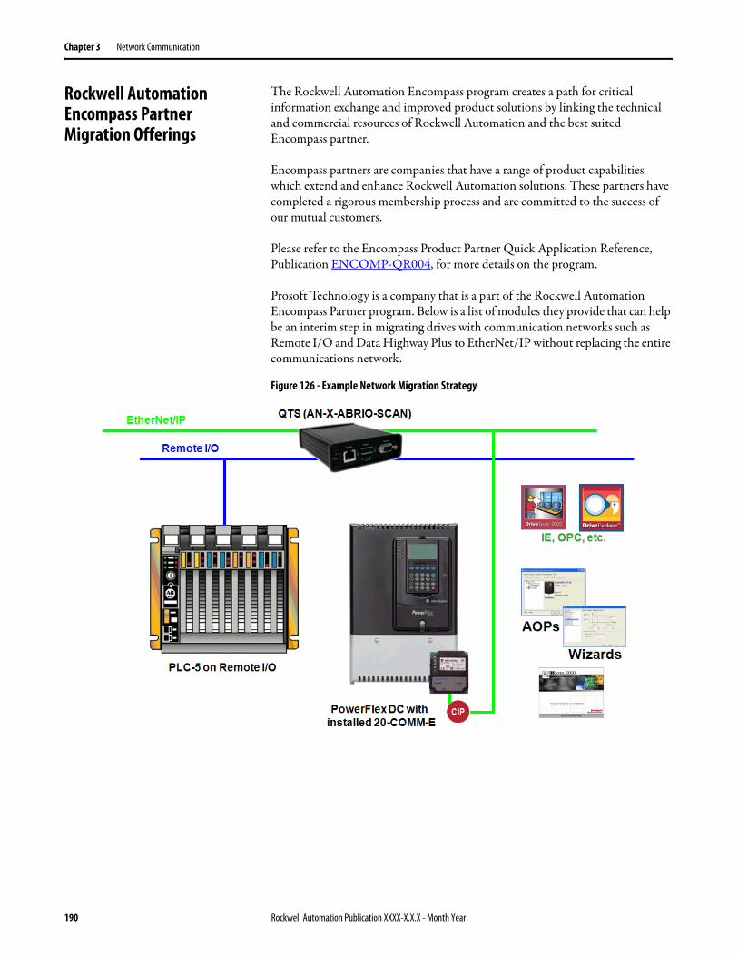
Chapter 3 Network Communication
Rockwell Automation Encompass Partner Migration Offerings
The Rockwell Automation Encompass program creates a path for critical information exchange and improved product solutions by linking the technical and commercial resources of Rockwell Automation and the best suited Encompass partner.
Encompass partners are companies that have a range of product capabilities which extend and enhance Rockwell Automation solutions. These partners have completed a rigorous membership process and are committed to the success of our mutual customers.
Please refer to the Encompass Product Partner Quick Application Reference, Publication ENCOMP-QR004, for more details on the program.
Prosoft Technology is a company that is a part of the Rockwell Automation Encompass Partner program. Below is a list of modules they provide that can help be an interim step in migrating drives with communication networks such as Remote I/O and Data Highway Plus to EtherNet/IP without replacing the entire communications network.
Figure 126 - Example Network Migration Strategy
190 Rockwell Automation Publication XXXX-X.X.X - Month Year
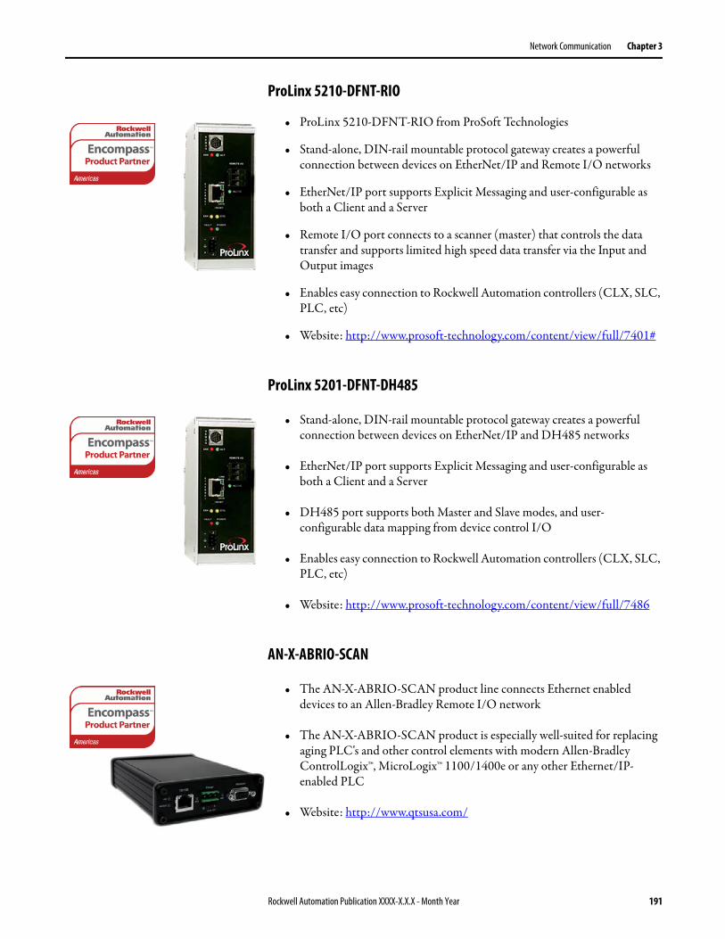
Network Communication Chapter 3
ProLinx 5210-DFNT-RIO
• ProLinx 5210-DFNT-RIO from ProSoft Technologies
• Stand-alone, DIN-rail mountable protocol gateway creates a powerful connection between devices on EtherNet/IP and Remote I/O networks
• EtherNet/IP port supports Explicit Messaging and user-configurable as both a Client and a Server
• Remote I/O port connects to a scanner (master) that controls the data transfer and supports limited high speed data transfer via the Input and Output images
• Enables easy connection to Rockwell Automation controllers (CLX, SLC, PLC, etc)
• Website: http://www.prosoft-technology.com/content/view/full/7401#
ProLinx 5201-DFNT-DH485
• Stand-alone, DIN-rail mountable protocol gateway creates a powerful connection between devices on EtherNet/IP and DH485 networks
• EtherNet/IP port supports Explicit Messaging and user-configurable as both a Client and a Server
• DH485 port supports both Master and Slave modes, and user-configurable data mapping from device control I/O
• Enables easy connection to Rockwell Automation controllers (CLX, SLC, PLC, etc)
• Website: http://www.prosoft-technology.com/content/view/full/7486
AN-X-ABRIO-SCAN
• The AN-X-ABRIO-SCAN product line connects Ethernet enabled devices to an Allen-Bradley Remote I/O network
• The AN-X-ABRIO-SCAN product is especially well-suited for replacing aging PLC's and other control elements with modern Allen-Bradley ControlLogix™, MicroLogix™ 1100/1400e or any other Ethernet/IP-enabled PLC
• Website: http://www.qtsusa.com/
Rockwell Automation Publication XXXX-X.X.X - Month Year 191
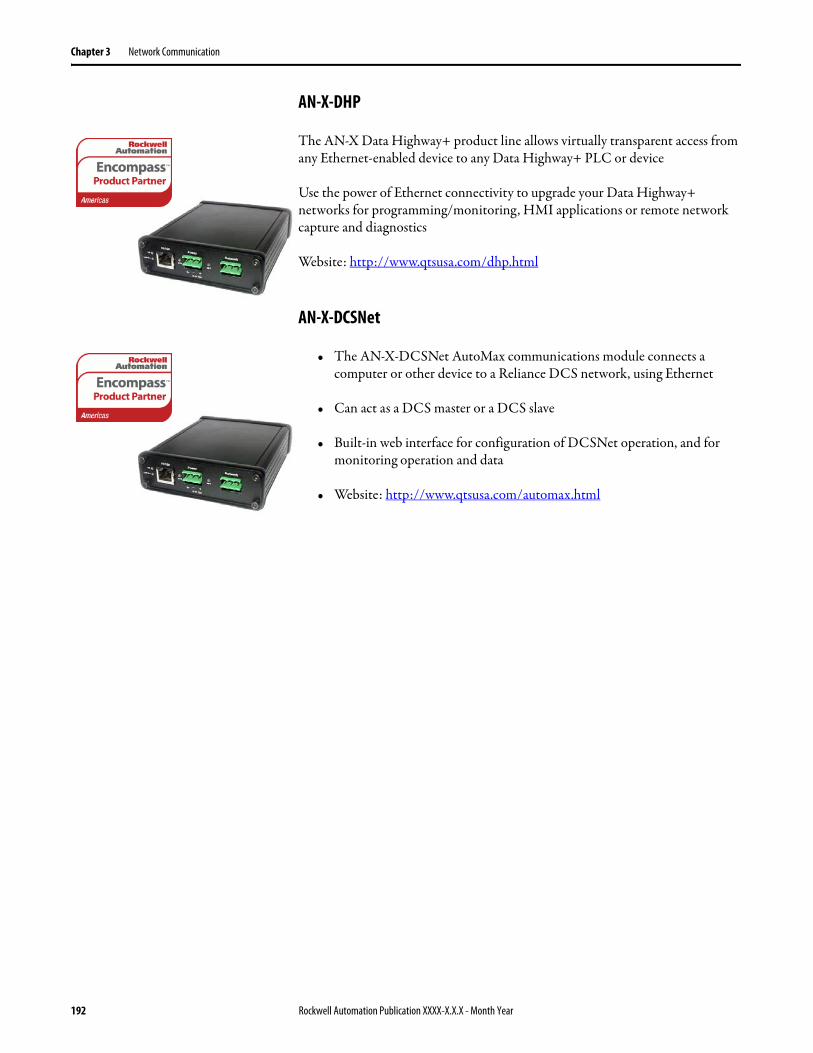
Chapter 3 Network Communication
AN-X-DHP
The AN-X Data Highway+ product line allows virtually transparent access from any Ethernet-enabled device to any Data Highway+ PLC or device
Use the power of Ethernet connectivity to upgrade your Data Highway+ networks for programming/monitoring, HMI applications or remote network capture and diagnostics
Website: http://www.qtsusa.com/dhp.html
AN-X-DCSNet
• The AN-X-DCSNet AutoMax communications module connects a computer or other device to a Reliance DCS network, using Ethernet
• Can act as a DCS master or a DCS slave
• Built-in web interface for configuration of DCSNet operation, and for monitoring operation and data
• Website: http://www.qtsusa.com/automax.html
192 Rockwell Automation Publication XXXX-X.X.X - Month Year


Publication PFLEX-AP009A-EN-P - September 2012 Copyright © 2012 Rockwell Automation, Inc. All rights reserved. Printed in the U.S.A.
Rockwell Automation Support
Rockwell Automation provides technical information on the Web to assist you in using its products. At http://www.rockwellautomation.com/support, you can find technical manuals, technical and application notes, sample code and links to software service packs, and a MySupport feature that you can customize to make the best use of these tools. You can also visit our Knowledgebase at http://www.rockwellautomation.com/knowledgebase for FAQs, technical information, support chat and forums, software updates, and to sign up for product notification updates.
For an additional level of technical phone support for installation, configuration, and troubleshooting, we offer TechConnectSM support programs. For more information, contact your local distributor or Rockwell Automation representative, or visit http://www.rockwellautomation.com/support/.
Installation Assistance
If you experience a problem within the first 24 hours of installation, review the information that is contained in this manual. You can contact Customer Support for initial help in getting your product up and running.
New Product Satisfaction Return
Rockwell Automation tests all of its products to ensure that they are fully operational when shipped from the manufacturing facility. However, if your product is not functioning and needs to be returned, follow these procedures.
Documentation Feedback
Your comments will help us serve your documentation needs better. If you have any suggestions on how to improve this document, complete this form, publication RA-DU002, available at http://www.rockwellautomation.com/literature/.
United States or Canada 1.440.646.3434
Outside United States or Canada Use the Worldwide Locator at http://www.rockwellautomation.com/support/americas/phone_en.html, or contact your local Rockwell Automation representative.
United States Contact your distributor. You must provide a Customer Support case number (call the phone number above to obtain one) to your distributor to complete the return process.
Outside United States Please contact your local Rockwell Automation representative for the return procedure.