1000 series - vandal resistant keypads
TRANSCRIPT
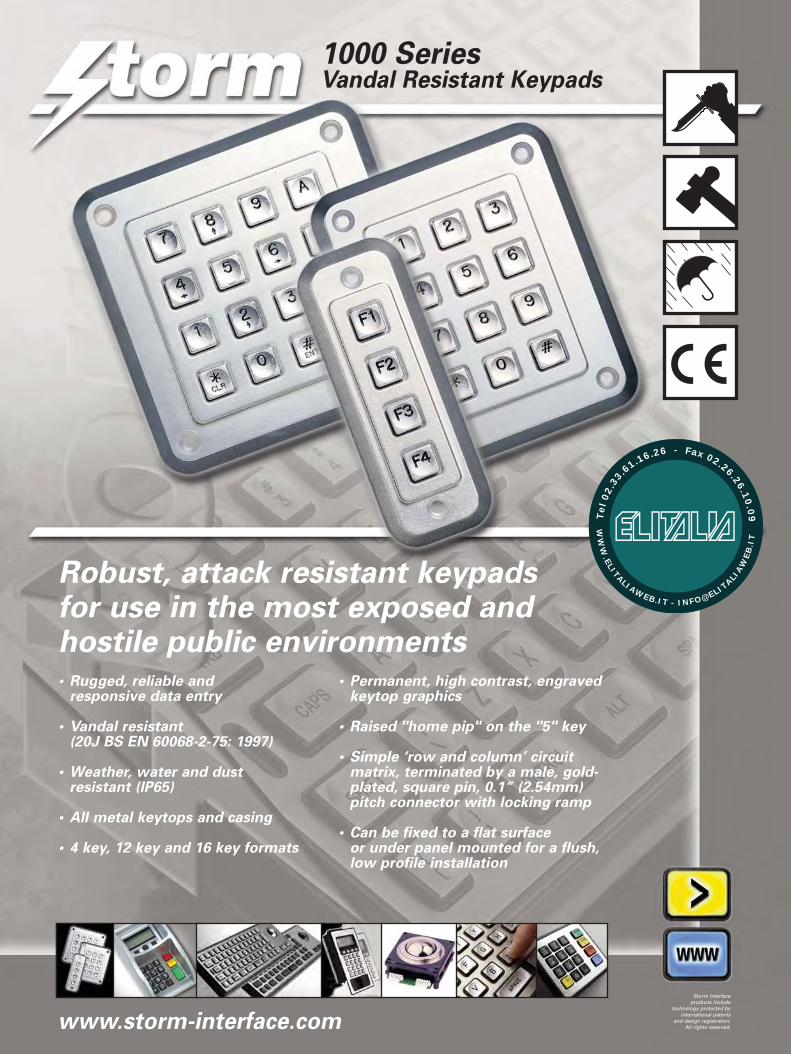
Robust, attack resistant keypads for use in the most exposed and hostile public environments• Rugged, reliable and
responsive data entry
• Vandal resistant(20J BS EN 60068-2-75: 1997)
• Weather, water and dust resistant (IP65)
• All metal keytops and casing
• 4 key, 12 key and 16 key formats
• Permanent, high contrast, engravedkeytop graphics
• Raised "home pip" on the "5" key
• Simple ‘row and column’ circuitmatrix, terminated by a male, gold-plated, square pin, 0.1” (2.54mm)pitch connector with locking ramp
• Can be fixed to a flat surface or under panel mounted for a flush,low profile installation
1000 Series Vandal Resistant Keypads
www.storm-interface.com
Storm Interfaceproducts include
technology protected byinternational patents
and design registration.All rights reserved.
WW
W.ELITALIAWEB.IT - INFO@ELIT
ALIAW
EB
.IT
Tel
02.
33
.61.16.26 - Fax 02.26.26.10
.09
1000 Series vandal resistant keypads
118.50
118.
50
19.00
19.00
82.50
82.5
0
93.00
93.0
0
99.50
118.
50
63.50
82.5
0
19.00
19.00
74.00
93.0
0
42.50
118.
50
82.0
0
19.00
25.00
93.0
0
Ø 4.5 typ
10.50
2.58
11.1
• • • • •5 4 3 2 1
COMMON
1A
B
C
D
KEY LOCATION
CONTACT CONNECTIONS
(As viewed from rear of keypad)
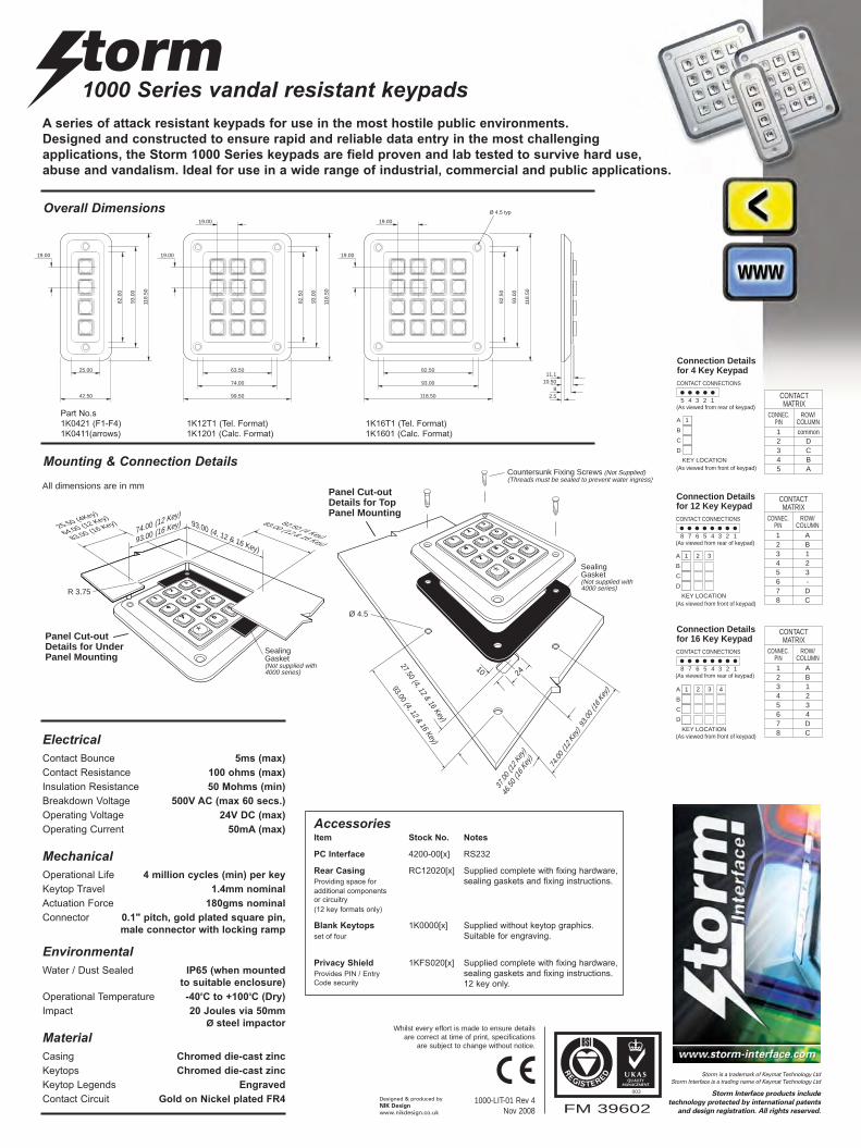
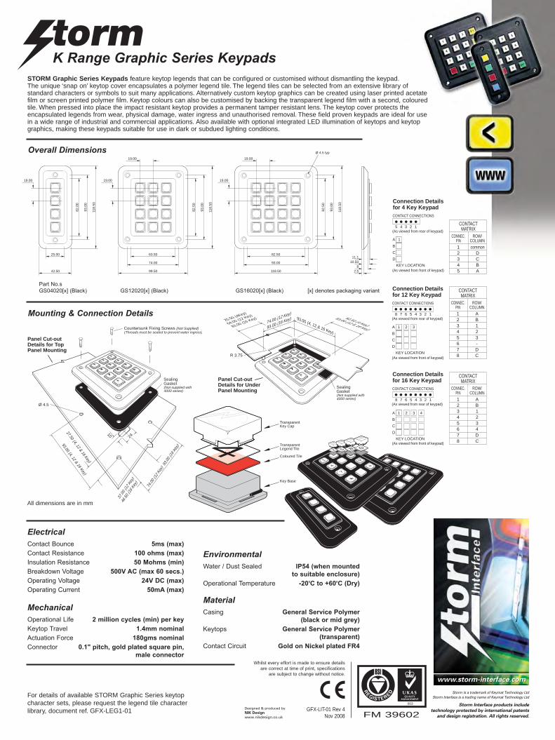
Connection Details for 4 Key Keypad
(As viewed from front of keypad)
12345
commonDCBA
CONNEC.PIN
ROW/COLUMN
CONTACTMATRIX
37.00 (12 K
e
46.50 (
16
1 2 3A
B
C
D
KEY LOCATION
CONTACT CONNECTIONS
• • • • • • • •8 7 6 5 4 3 2 1
(As viewed from rear of keypad)
Connection Details for 12 Key Keypad
(As viewed from front of keypad)
12345678
AB123-DC
CONNEC.PIN
ROW/COLUMN
CONTACTMATRIX
1 2 3 4A
B
C
D
KEY LOCATION
12345678
AB1234DC
CONNEC.PIN
ROW/COLUMN
CONTACTMATRIX
CONTACT CONNECTIONS
• • • • • • • •8 7 6 5 4 3 2 1
(As viewed from rear of keypad)
Connection Details for 16 Key Keypad
(As viewed from front of keypad)
A series of attack resistant keypads for use in the most hostile public environments. Designed and constructed to ensure rapid and reliable data entry in the most challengingapplications, the Storm 1000 Series keypads are field proven and lab tested to survive hard use,abuse and vandalism. Ideal for use in a wide range of industrial, commercial and public applications.
Part No.s
1K0421 (F1-F4)
1K0411(arrows)
1K12T1 (Tel. Format)
1K1201 (Calc. Format)
1K16T1 (Tel. Format)
1K1601 (Calc. Format)
Overall Dimensions
Mounting & Connection Details
CONTACT CONNECTIONS
• • • • • • • •8 7 6 5 4 3 2 1
Connection Detaifor 12 Key Keypad
• • • • •5 4 3 2 1
CONTACT CONNECTIONS
(As viewed from rear of keypad)
Connection Details for 4 Key Keypad
CONTACTMATRIX
10
Panel Cut-out Details for Top Panel Mounting
27.50 (4, 12 & 16 Key)
37.00 (12 K
ey)
46.50 (
16 Key
)
Countersunk Fixing Screws (Not Supplied) (Threads must be sealed to prevent water ingress)
Ø 4.5
93.00 (4, 12 & 16 Key)
74.00 (12 K
ey) 93
.00 (
16 Key
)
24
PaDePa
Sealing Gasket (Not supplied with 4000 series)
All dimensions are in mm
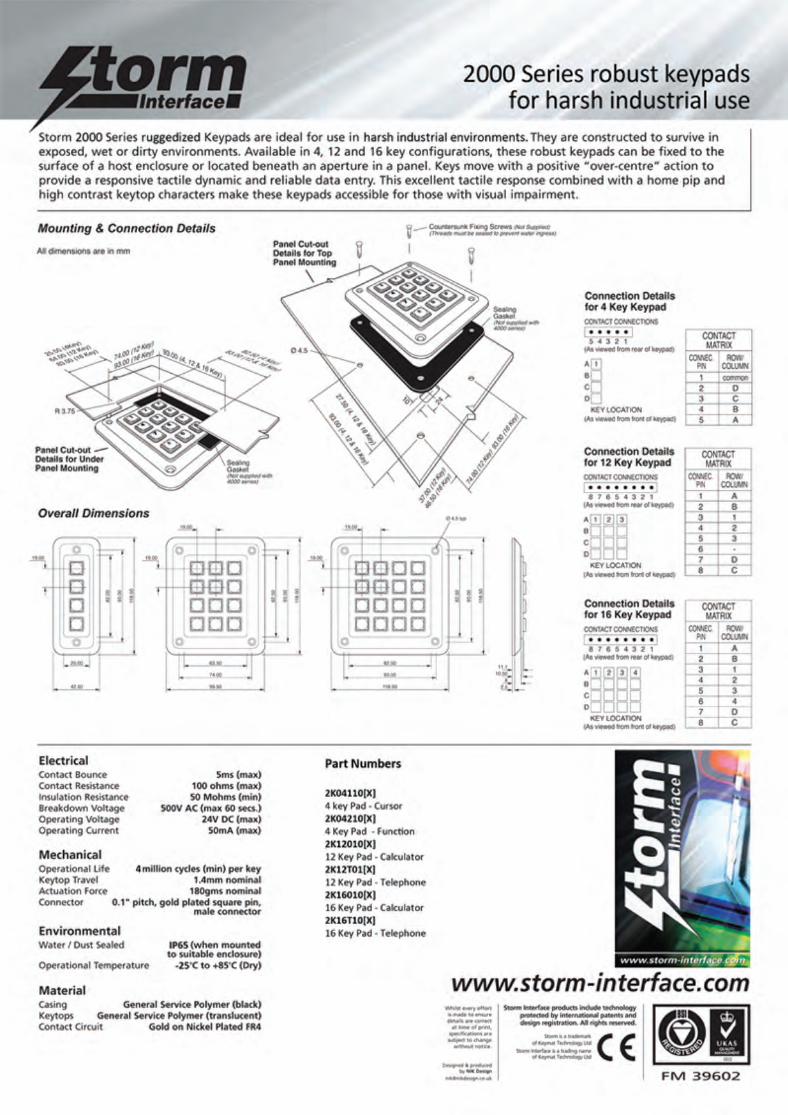
ElectricalContact Bounce 5ms (max)
Contact Resistance 100 ohms (max)
Insulation Resistance 50 Mohms (min)
Breakdown Voltage 500V AC (max 60 secs.)
Operating Voltage 24V DC (max)
Operating Current 50mA (max)
MechanicalOperational Life 4 million cycles (min) per key
Keytop Travel 1.4mm nominal
Actuation Force 180gms nominal
Connector 0.1" pitch, gold plated square pin,
male connector with locking ramp
MaterialCasing Chromed die-cast zinc
Keytops Chromed die-cast zinc
Keytop Legends Engraved
Contact Circuit Gold on Nickel plated FR4
EnvironmentalWater / Dust Sealed IP65 (when mounted
to suitable enclosure)
Operational Temperature -40oC to +100oC (Dry)
Impact 20 Joules via 50mmØ steel impactor
pplied) ingress)
Sealing Gasket (Not supplied with4000 series)
Panel Cut-out Details for Under Panel Mounting
25.50 (4Key)
64.00 (12 Key)
83.00 (16 Key) 82.50 (4 Key)
83.00 (12 & 16 Key)
R 3.75
74.00 (12 Key)
93.00 (16 Key) 93.00 (4, 12 & 16 Key)
h
AccessoriesItem Stock No. Notes
PC Interface 4200-00[x] RS232
Rear Casing RC12020[x] Supplied complete with fixing hardware,
Providing space for sealing gaskets and fixing instructions.additional components
or circuitry
(12 key formats only)
Blank Keytops 1K0000[x] Supplied without keytop graphics.
set of four Suitable for engraving.
Privacy Shield 1KFS020[x] Supplied complete with fixing hardware,
Provides PIN / Entry sealing gaskets and fixing instructions.Code security 12 key only.
FM 39602
003
1000-LIT-01 Rev 4 Nov 2008
Whilst every effort is made to ensure detailsare correct at time of print, specifications
are subject to change without notice.
Designed & produced byNIK Design
www.nikdesign.co.uk
Storm is a trademark of Keymat Technology LtdStorm Interface is a trading name of Keymat Technology Ltd
Storm Interface products include
technology protected by international patents
and design registration. All rights reserved.
1000 PLX Series Keypads
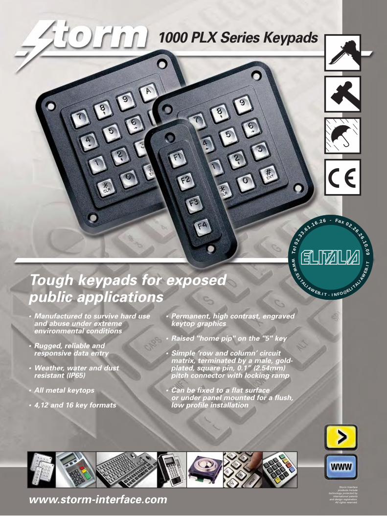
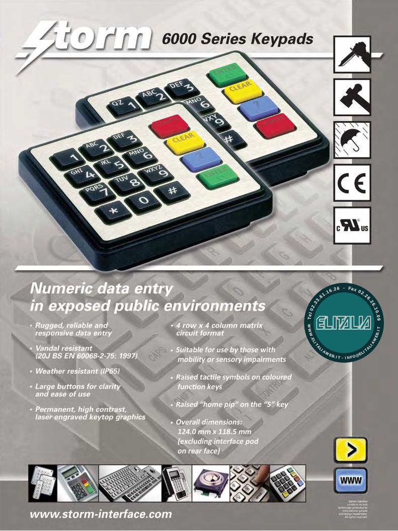
Tough keypads for exposed public applications• Manufactured to survive hard use
and abuse under extremeenvironmental conditions
• Rugged, reliable and responsive data entry
• Weather, water and dust resistant (IP65)
• All metal keytops
• 4,12 and 16 key formats
• Permanent, high contrast, engravedkeytop graphics
• Raised "home pip" on the "5" key
• Simple ‘row and column’ circuitmatrix, terminated by a male, gold-plated, square pin, 0.1” (2.54mm)pitch connector with locking ramp
• Can be fixed to a flat surface or under panel mounted for a flush,low profile installation
www.storm-interface.com
Storm Interfaceproducts include
technology protected byinternational patents
and design registration.All rights reserved.
WW
W.ELITALIAWEB.IT - INFO@ELIT
ALIAW
EB
.IT
Tel
02.
33
.61.16.26 - Fax 02.26.26.10
.09
1000 PLX Series keypads
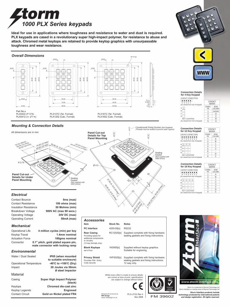
Mounting & Connection Details
118.50
118.
50
19.00
19.00
82.50
82.5
0
93.00
93.0
0
99.50
118.
50
63.50
82.5
0
19.00
19.00
74.00
93.0
0
42.50
118.
50
82.0
0
19.00
25.00
93.0
0
Ø 4.5 typ
10.50
2.58
11.1
All dimensions are in mm
Ideal for use in applications where toughness and resistance to water and dust is required. PLX keypads are cased in a revolutionary super high-impact polymer, for resistance to abuse andattack. Chromed metal keytops are retained to provide keytop graphics with unsurpassabletoughness and wear resistance.
Part No.s
PLX0422 (F1-F4)
PLX0412 ( )
PLX12T2 (Tel. Format)
PLX1202 (Calc. Format)
PLX16T2 (Tel. Format)
PLX1602 (Calc. Format)
Overall Dimensions
• • • • •5 4 3 2 1
COMMON
1A
B
C
D
KEY LOCATION
CONTACT CONNECTIONS
(As viewed from rear of keypad)
Connection Details for 4 Key Keypad
(As viewed from front of keypad)
12345
commonDCBA
CONNEC.PIN
ROW/COLUMN
CONTACTMATRIX
37.00 (12 K
e
46.50 (
16
1 2 3A
B
C
D
KEY LOCATION
CONTACT CONNECTIONS
• • • • • • • •8 7 6 5 4 3 2 1
(As viewed from rear of keypad)
Connection Details for 12 Key Keypad
(As viewed from front of keypad)
12345678
AB123-DC
CONNEC.PIN
ROW/COLUMN
CONTACTMATRIX
1 2 3 4A
B
C
D
KEY LOCATION
12345678
AB1234DC
CONNEC.PIN
ROW/COLUMN
CONTACTMATRIX
CONTACT CONNECTIONS
• • • • • • • •8 7 6 5 4 3 2 1
(As viewed from rear of keypad)
Connection Details for 16 Key Keypad
(As viewed from front of keypad)
CONTACT CONNECTIONS
• • • • • • • •8 7 6 5 4 3 2 1
Connection Detaifor 12 Key Keypad
• • • • •5 4 3 2 1
CONTACT CONNECTIONS
(As viewed from rear of keypad)
Connection Details for 4 Key Keypad
CONTACTMATRIX
10
Panel Cut-out Details for Top Panel Mounting
27.50 (4, 12 & 16 Key)
37.00 (12 K
ey)
46.50 (
16 Key
)
Countersunk Fixing Screws (Not Supplied) (Threads must be sealed to prevent water ingress)
Ø 4.5
93.00 (4, 12 & 16 Key)
74.00 (12 K
ey) 93
.00 (
16 Key
)
24
PaDePa
Sealing Gasket (Not supplied with 4000 series)
pplied) ingress)
Sealing Gasket (Not supplied with4000 series)
Panel Cut-out Details for Under Panel Mounting
25.50 (4Key)
64.00 (12 Key)
83.00 (16 Key) 82.50 (4 Key)
83.00 (12 & 16 Key)
R 3.75
74.00 (12 Key)
93.00 (16 Key) 93.00 (4, 12 & 16 Key)
h
FM 39602
003
PLX-LIT-01 Rev 4 Nov 2008
Whilst every effort is made to ensure detailsare correct at time of print, specifications
are subject to change without notice.
Designed & produced byNIK Design
www.nikdesign.co.uk
Storm is a trademark of Keymat Technology LtdStorm Interface is a trading name of Keymat Technology Ltd
Storm Interface products include
technology protected by international patents
and design registration. All rights reserved.
ElectricalContact Bounce 5ms (max)
Contact Resistance 100 ohms (max)
Insulation Resistance 50 Mohms (min)
Breakdown Voltage 500V AC (max 60 secs.)
Operating Voltage 24V DC (max)
Operating Current 50mA (max)
MechanicalOperational Life 4 million cycles (min) per key
Keytop Travel 1.4mm nominal
Actuation Force 180gms nominal
Connector 0.1" pitch, gold plated square pin,
male connector with locking ramp
Material
Casing Super High Impact Polymer
(black)
Keytops Chromed die-cast zinc
Keytop Legends Engraved
Contact Circuit Gold on Nickel plated FR4
EnvironmentalWater / Dust Sealed IP65 (when mounted
to suitable enclosure)
Operational Temperature -40oC to +100oC (Dry)
Impact 20 Joules via 50mmØ steel impactor
AccessoriesItem Stock No. Notes
PC Interface 4200-00[x] RS232
Rear Casing RC12020[x] Supplied complete with fixing hardware,
Providing space for sealing gaskets and fixing instructions.additional components
or circuitry
(12 key formats only)
Blank Keytops 1K0000[x] Supplied without keytop graphics.
set of four Suitable for engraving.
Privacy Shield 1KFS020[x] Supplied complete with fixing hardware,
Provides PIN / Entry sealing gaskets and fixing instructions.Code security 12 way only.
WW
W.ELITALIAWEB.IT - INFO@ELIT
ALIAW
EB
.IT
Tel
02.
33
.61.16.26 - Fax 02.26.26.10
.09

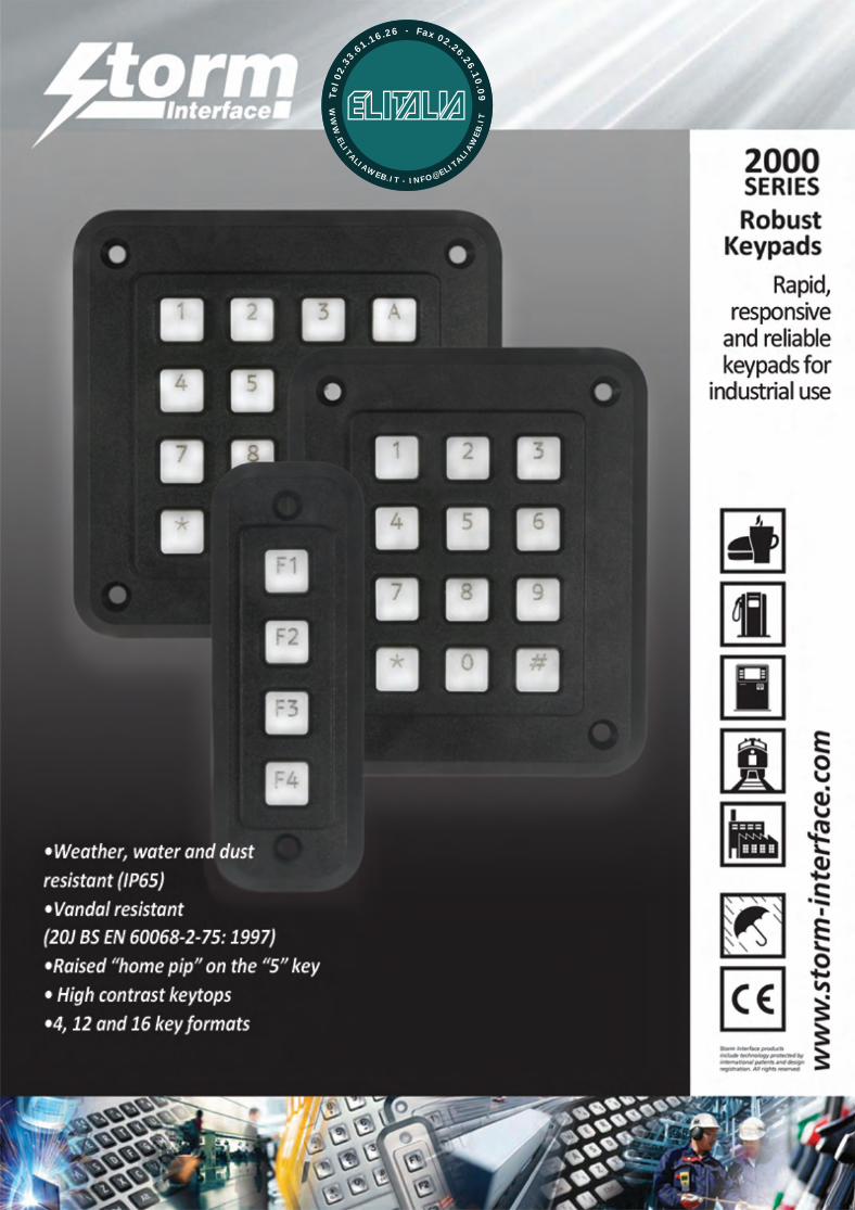
3000SERIES
IlluminatedKeypads
Responsive,illuminatedkeypads for
low-lightapplications
• Reliable data entry in outdoor orindoor locations
• High contrast keytops with integralwhite light LED illumination
• Robust construction for use inextreme, wet or dirty environments
• Responsive tactile keys
• 4, 12 and 16 key formats
ww
w.s
torm
-int
erfa
ce.c
om
Storm Interface products include technology protected byinternational patents and designregistration. All rights reserved.
WW
W.ELITALIAWEB.IT - INFO@ELIT
ALIAW
EB
.IT
Tel
02.
33
.61.16.26 - Fax 02.26.26.10
.09
3000 Series Illuminated Keypadsfor low-light applications
FM 39602
003
3KLW-LIT-01 Rev 2 Feb 2013
Designed & producedby NIK Design
Whilst every effortis made to ensuredetails are correct
at time of print,specifications aresubject to change
without notice.
Storm is a trademark of Keymat Technology Ltd
Storm Interface is a trading name of Keymat Technology Ltd
Storm Interface products include technologyprotected by international patents anddesign registration. All rights reserved.
www.storm-interface.com
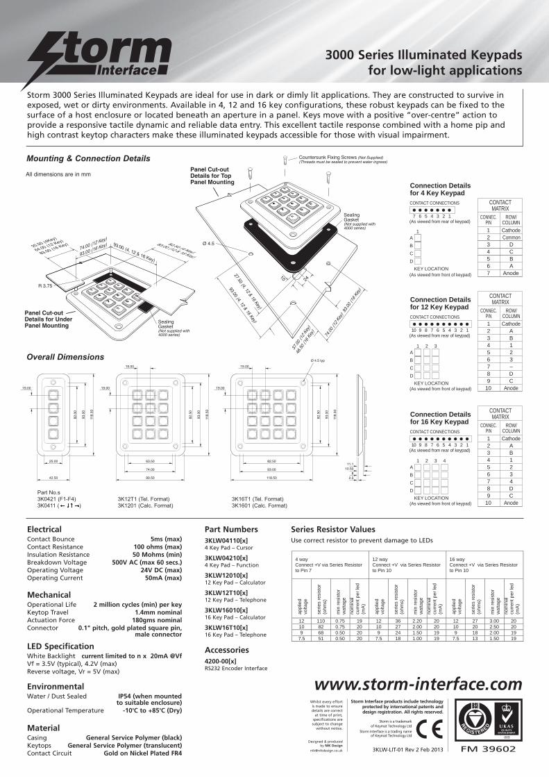
Storm 3000 Series Illuminated Keypads are ideal for use in dark or dimly lit applications. They are constructed to survive inexposed, wet or dirty environments. Available in 4, 12 and 16 key configurations, these robust keypads can be fixed to thesurface of a host enclosure or located beneath an aperture in a panel. Keys move with a positive “over-centre” action toprovide a responsive tactile dynamic and reliable data entry. This excellent tactile response combined with a home pip andhigh contrast keytop characters make these illuminated keypads accessible for those with visual impairment.
118.50
118.
50
19.00
19.00
82.50
82.5
0
93.00
93.0
0
99.50
118.
50
63.50
82.5
0
19.00
19.00
74.00
93.0
0
42.50
118.
50
82.0
0
19.00
25.00
93.0
0
Ø 4.5 typ
10.50
2.58
11.1
• • • • •5 4 3 2 1
COMMON
1A
B
C
D
KEY LOCATION
CONTACT CONNECTIONS
(As viewed from rear of keypad)
Connection Details for 4 Key Keypad
(As viewed from front of keypad)
12345
commonDCBA
CONNEC.PIN
ROW/COLUMN
CONTACTMATRIX
37.00 (12 Ke
46.50 (16
1 2 3A
B
C
D
KEY LOCATION
CONTACT CONNECTIONS
• • • • • • • •8 7 6 5 4 3 2 1
(As viewed from rear of keypad)
Connection Details for 12 Key Keypad
(As viewed from front of keypad)
12345678
AB123-DC
CONNEC.PIN
ROW/COLUMN
CONTACTMATRIX
1 2 3 4A
B
C
D
KEY LOCATION
12345678
AB1234DC
CONNEC.PIN
ROW/COLUMN
CONTACTMATRIX
CONTACT CONNECTIONS
• • • • • • • •8 7 6 5 4 3 2 1
(As viewed from rear of keypad)
Connection Details for 16 Key Keypad
(As viewed from front of keypad)
Overall Dimensions
Mounting & Connection Details
CONTACT CONNECTIONS
• • • • • • • •8 7 6 5 4 3 2 1
Connection Detaifor 12 Key Keypad
• • • • •5 4 3 2 1
CONTACT CONNECTIONS
(As viewed from rear of keypad)
Connection Details for 4 Key Keypad
CONTACTMATRIX
10
Panel Cut-out Details for Top Panel Mounting
27.50 (4, 12 & 16 Key)
37.00 (12 Ke
y)
46.50 (16 Ke
y)
Countersunk Fixing Screws (Not Supplied) (Threads must be sealed to prevent water ingress)
Ø 4.5
93.00 (4, 12 & 16 Key)
74.00 (12 Ke
y) 9
3.00
(16 Ke
y)
24
PaDePa
Sealing Gasket (Not supplied with 4000 series)
All dimensions are in mm
plied) ingress)
Sealing Gasket (Not supplied with4000 series)
Panel Cut-out Details for Under Panel Mounting
25.50 (4Key)
64.00 (12 Key)
83.00 (16 Key) 82.50 (4 Key)
83.00 (12 & 16 Key)
R 3.75
74.00 (12 Key)
93.00 (16 Key) 93.00 (4, 12 & 16 Key)
h
Part No.s
3K0421 (F1-F4)
3K0411 ( )
3K12T1 (Tel. Format)
3K1201 (Calc. Format)
3K16T1 (Tel. Format)
3K1601 (Calc. Format)
ElectricalContact Bounce 5ms (max)Contact Resistance 100 ohms (max)Insulation Resistance 50 Mohms (min)Breakdown Voltage 500V AC (max 60 secs.)Operating Voltage 24V DC (max)Operating Current 50mA (max)
MechanicalOperational Life 2 million cycles (min) per keyKeytop Travel 1.4mm nominalActuation Force 180gms nominalConnector 0.1" pitch, gold plated square pin,
male connector
LED SpecificationWhite Backlight current limited to n x 20mA @VfVf = 3.5V (typical), 4.2V (max)Reverse voltage, Vr = 5V (max)
EnvironmentalWater / Dust Sealed IP54 (when mounted
to suitable enclosure)Operational Temperature -10oC to +85oC (Dry)
MaterialCasing General Service Polymer (black)Keytops General Service Polymer (translucent)Contact Circuit Gold on Nickel Plated FR4
4 way Connect +V via Series Resistor to Pin 7
12 way Connect +V via Series Resistor to Pin 10
16 way Connect +V via Series Resistor to Pin 10
ap
plie
d
vo
lta
ge
se
rie
s r
esis
tor
(oh
ms)
min
re
sis
tor
wattage
no
min
al
cu
rre
nt p
er
led
(mA
)
ap
plie
d
vo
lta
ge
se
rie
s r
esis
tor
(oh
ms)
min
re
sis
tor
wattage
no
min
al
cu
rre
nt p
er
led
(mA
)
ap
plie
d
vo
lta
ge
se
rie
s r
esis
tor
(oh
ms)
min
re
sis
tor
wa
tta
ge
no
min
al
cu
rre
nt p
er
led
(mA
)
12 110 0.75 19 12 36 2.20 20 12 27 3.00 20
10 82 0.75 20 10 27 2.00 20 10 20 2.50 20
9 68 0.50 20 9 24 1.50 19 9 18 2.00 19
7.5 51 0.50 20 7.5 18 1.00 19 7.5 13 1.50 19
Part Numbers3KLW04110[x] 4 Key Pad – Cursor
3KLW04210[x] 4 Key Pad – Function
3KLW12010[x] 12 Key Pad – Calculator
3KLW12T10[x]12 Key Pad – Telephone
3KLW16010[x] 16 Key Pad – Calculator
3KLW16T10[x] 16 Key Pad – Telephone
Series Resistor ValuesUse correct resistor to prevent damage to LEDs
Accessories4200-00[x] RS232 Encoder Interface
1 2 3 4A
B
C
D
KEY LOCATION
123456789
10
AB
Cathode
1234
CAnode
D
CONNEC.PIN
ROW/COLUMN
CONTACTMATRIX
CONTACT CONNECTIONS
• • • • • • • • • •10 9 8 7 6 5 4 3 2 1
(As viewed from rear of keypad)
Connection Details for 16 Key Keypad
(As viewed from front of keypad)
1 2 3A
B
C
D
KEY LOCATION
123456789
10
AB
Cathode
123–
CAnode
D
CONNEC.PIN
ROW/COLUMN
CONTACTMATRIX
CONTACT CONNECTIONS
• • • • • • • • • •10 9 8 7 6 5 4 3 2 1
(As viewed from rear of keypad)
Connection Details for 12 Key Keypad
(As viewed from front of keypad)
• • • • • • •7 6 5 4 3 2 1
COMMON1A
B
C
D
KEY LOCATION
CONTACT CONNECTIONS
(As viewed from rear of keypad)
Connection Details for 4 Key Keypad
(As viewed from front of keypad)
1234567
CommonCathode
DCBA
Anode
CONNEC.PIN
ROW/COLUMN
CONTACTMATRIX
Graphic Series Keypads
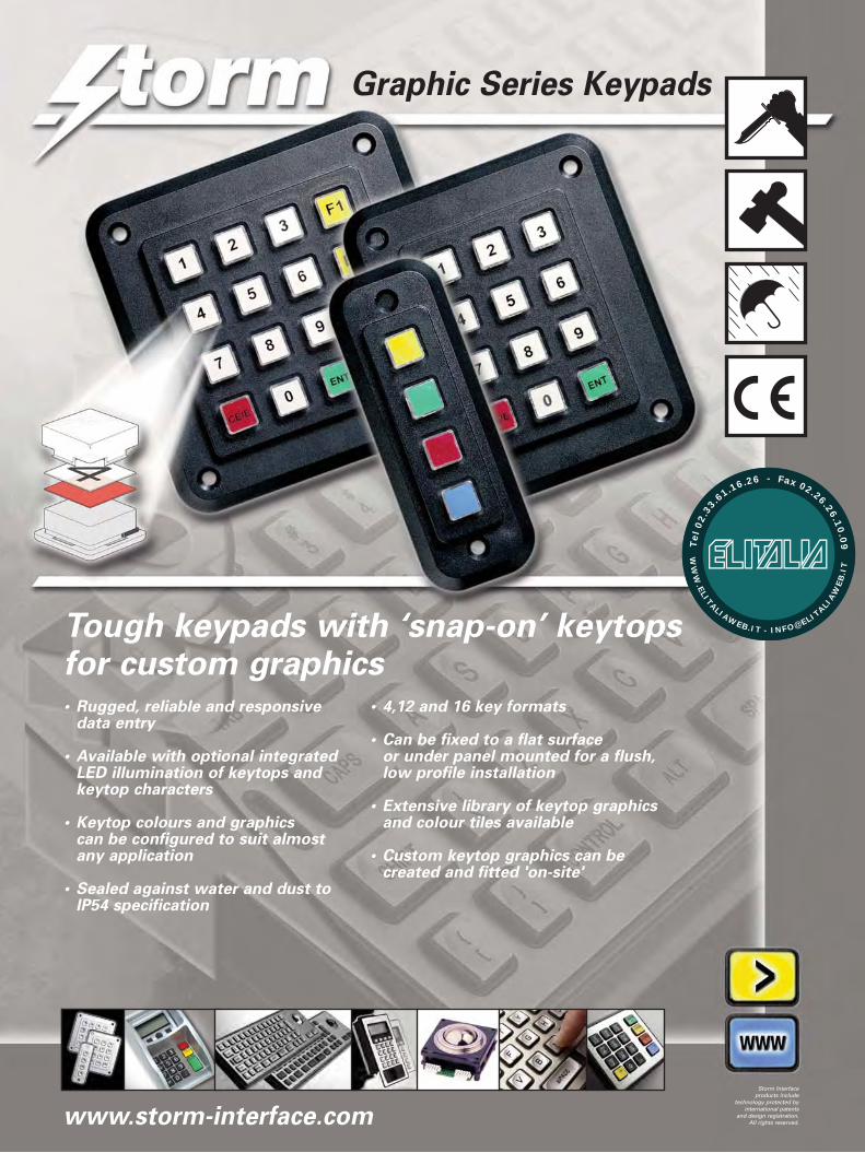
Tough keypads with ‘snap-on’ keytopsfor custom graphics• Rugged, reliable and responsive
data entry
• Available with optional integratedLED illumination of keytops and keytop characters
• Keytop colours and graphics can be configured to suit almost any application
• Sealed against water and dust toIP54 specification
• 4,12 and 16 key formats
• Can be fixed to a flat surface or under panel mounted for a flush,low profile installation
• Extensive library of keytop graphicsand colour tiles available
• Custom keytop graphics can becreated and fitted 'on-site'
www.storm-interface.com
Storm Interfaceproducts include
technology protected byinternational patents
and design registration.All rights reserved.
WW
W.ELITALIAWEB.IT - INFO@ELIT
ALIAW
EB
.IT
Tel
02.
33
.61.16.26 - Fax 02.26.26.10
.09
K Range Graphic Series Keypads
FM 39602
003
GFX-LIT-01 Rev 4 Nov 2008
Whilst every effort is made to ensure detailsare correct at time of print, specifications
are subject to change without notice.
Designed & produced byNIK Design
www.nikdesign.co.uk
Mounting & Connection Details
118.50
118.
50
19.00
19.00
82.50
82.5
0
93.00
93.0
0
99.50
118.
50
63.50
82.5
0
19.00
19.00
74.00
93.0
0
42.50
118.
50
82.0
0
19.00
25.00
93.0
0
Ø 4.5 typ
10.50
2.58
11.1
CONTACT CONNECTIONS
• • • • • • • •8 7 6 5 4 3 2 1
Connection Detaifor 12 Key Keypad
• • • • •5 4 3 2 1
CONTACT CONNECTIONS
(As viewed from rear of keypad)
Connection Details for 4 Key Keypad
CONTACTMATRIX
10
Panel Cut-out Details for Top Panel Mounting
27.50 (4, 12 & 16 Key)
37.00 (12 K
ey)
46.50 (
16 Key
)
Countersunk Fixing Screws (Not Supplied) (Threads must be sealed to prevent water ingress)
Ø 4.5
93.00 (4, 12 & 16 Key)
74.00 (12 K
ey) 93
.00 (
16 Key
)
24
PaDePa
Sealing Gasket (Not supplied with 4000 series)
• • • • •5 4 3 2 1
COMMON
1A
B
C
D
KEY LOCATION
CONTACT CONNECTIONS
(As viewed from rear of keypad)
Connection Details for 4 Key Keypad
(As viewed from front of keypad)
12345
commonDCBA
CONNEC.PIN
ROW/COLUMN
CONTACTMATRIX
37.00 (12 K
e
46.50 (
16
1 2 3A
B
C
D
KEY LOCATION
CONTACT CONNECTIONS
• • • • • • • •8 7 6 5 4 3 2 1
(As viewed from rear of keypad)
Connection Details for 12 Key Keypad
(As viewed from front of keypad)
12345678
AB123-DC
CONNEC.PIN
ROW/COLUMN
CONTACTMATRIX
1 2 3 4A
B
C
D
KEY LOCATION
12345678
AB1234DC
CONNEC.PIN
ROW/COLUMN
CONTACTMATRIX
CONTACT CONNECTIONS
• • • • • • • •8 7 6 5 4 3 2 1
(As viewed from rear of keypad)
Connection Details for 16 Key Keypad
(As viewed from front of keypad)
All dimensions are in mm
STORM Graphic Series Keypads feature keytop legends that can be configured or customised without dismantling the keypad. The unique ‘snap on’ keytop cover encapsulates a polymer legend tile. The legend tiles can be selected from an extensive library ofstandard characters or symbols to suit many applications. Alternatively custom keytop graphics can be created using laser printed acetatefilm or screen printed polymer film. Keytop colours can also be customised by backing the transparent legend film with a second, colouredtile. When pressed into place the impact resistant keytop provides a permanent tamper resistant lens. The keytop cover protects theencapsulated legends from wear, physical damage, water ingress and unauthorised removal. These field proven keypads are ideal for usein a wide range of industrial and commercial applications. Also available with optional integrated LED illumination of keytops and keytopgraphics, making these keypads suitable for use in dark or subdued lighting conditions.
Part No.s
GS04020[x] (Black) GS12020[x] (Black) GS16020[x] (Black) [x] denotes packaging variant
Key Base
Coloured Tile
TransparentLegend Tile
TransparentKey Cap
1
36
9
4
7
*
#
2 5 8 0
ElectricalContact Bounce 5ms (max)
Contact Resistance 100 ohms (max)
Insulation Resistance 50 Mohms (min)
Breakdown Voltage 500V AC (max 60 secs.)
Operating Voltage 24V DC (max)
Operating Current 50mA (max)
MechanicalOperational Life 2 million cycles (min) per key
Keytop Travel 1.4mm nominal
Actuation Force 180gms nominal
Connector 0.1" pitch, gold plated square pin,
male connector
MaterialCasing General Service Polymer
(black or mid grey)
Keytops General Service Polymer
(transparent)
Contact Circuit Gold on Nickel plated FR4
EnvironmentalWater / Dust Sealed IP54 (when mounted
to suitable enclosure)
Operational Temperature -20oC to +60oC (Dry)
For details of available STORM Graphic Series keytopcharacter sets, please request the legend tile characterlibrary, document ref. GFX-LEG1-01
Overall Dimensions
pplied) ingress)
Sealing Gasket (Not supplied with4000 series)
Panel Cut-out Details for Under Panel Mounting
25.50 (4Key)
64.00 (12 Key)
83.00 (16 Key) 82.50 (4 Key)
83.00 (12 & 16 Key)
R 3.75
74.00 (12 Key)
93.00 (16 Key) 93.00 (4, 12 & 16 Key)
h
Storm is a trademark of Keymat Technology LtdStorm Interface is a trading name of Keymat Technology Ltd
Storm Interface products include
technology protected by international patents
and design registration. All rights reserved.
1
3 4 5 6 7
8 9
0 2
* # + – –
=
CE/EENT
AC I/OX F8F7F6 F9 F10
F3F2FI F4 F5
£F12F11 $ ?
! ( ) @ <
> Fn ’ %
&
’’
,
ENT PRINT DEL INS CAP
ESC CTRL ALT ON OFF
/ \ LOCK
,$£
., ,..
765 8 9
210 3 4
CBA D E
F
* # + –
CE/E ENT OFF
HGF I J
CBA D E
MLK N O
RQP S T
WVU X Y
Z
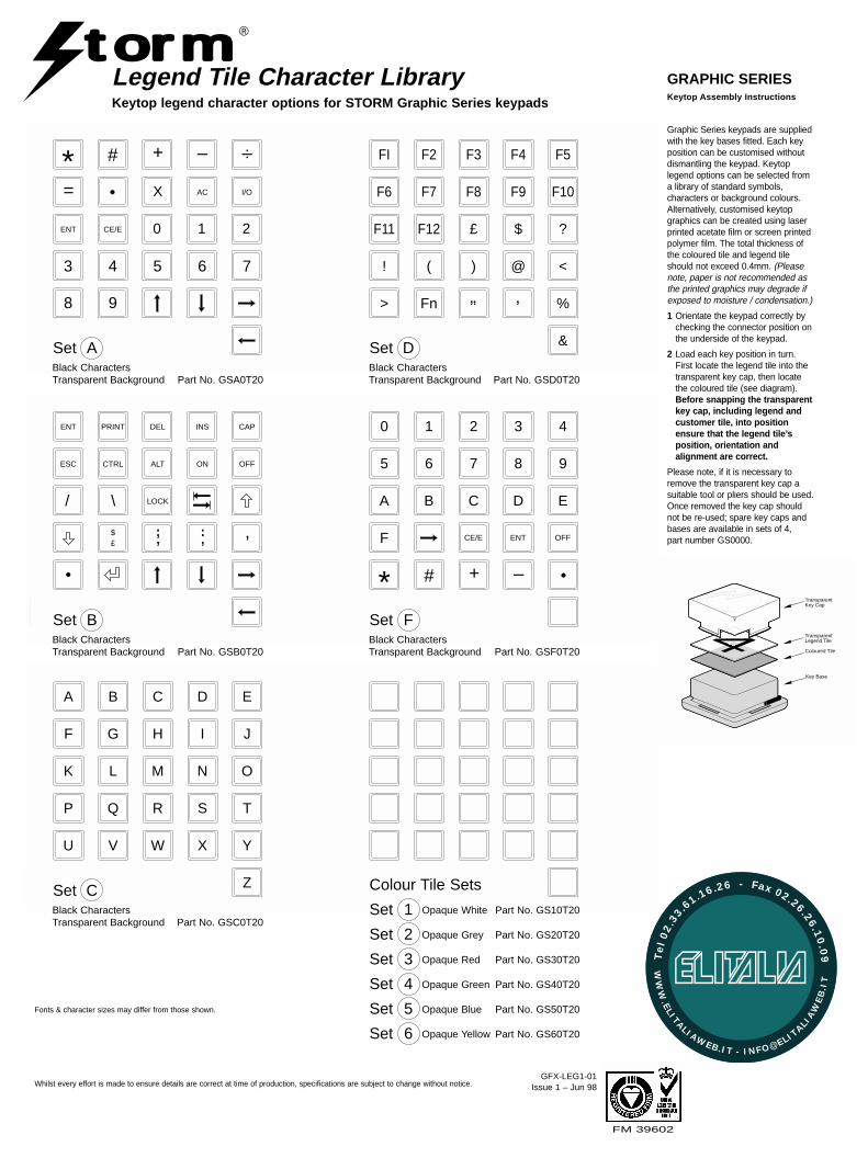
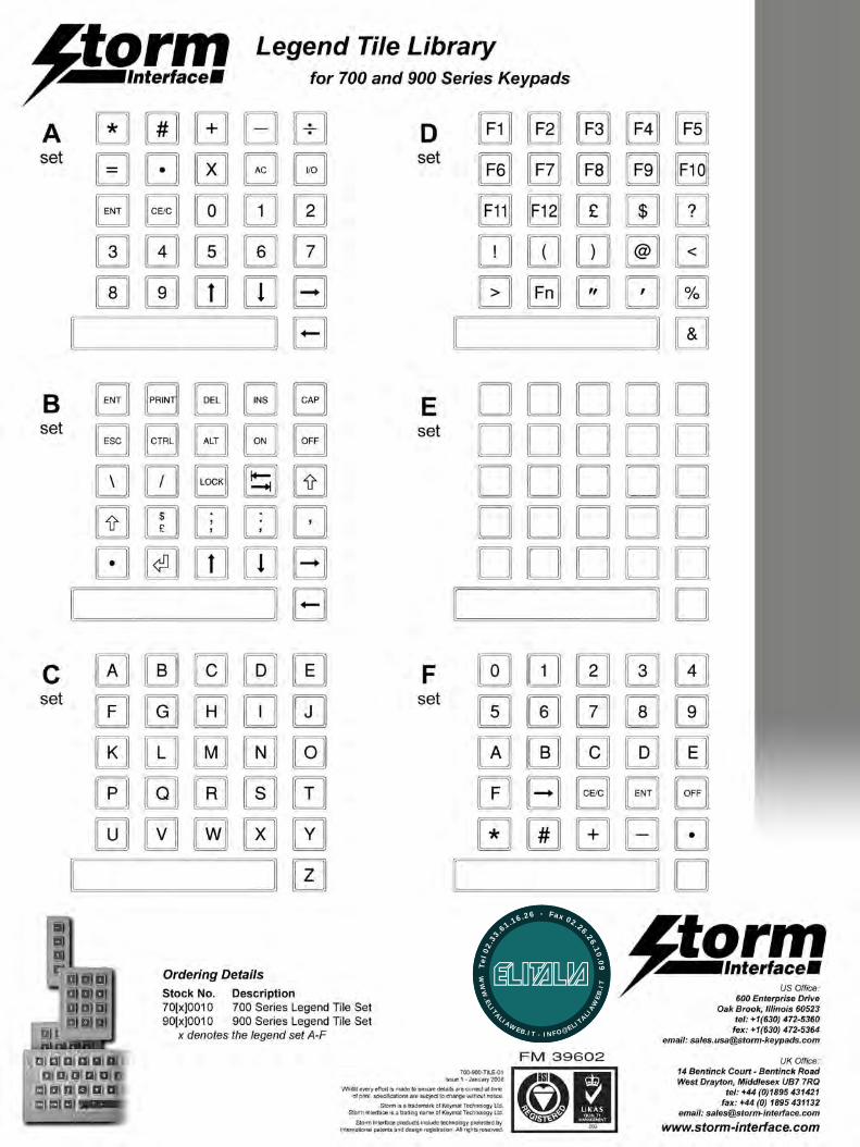
Legend Tile Character LibraryKeytop legend character options for STORM Graphic Series keypads
GRAPHIC SERIES
Coloured Tile
TransparentLegend Tile
TransparentKey Cap
Key Base
Graphic Series keypads are suppliedwith the key bases fitted. Each keyposition can be customised withoutdismantling the keypad. Keytoplegend options can be selected froma library of standard symbols,characters or background colours.Alternatively, customised keytopgraphics can be created using laserprinted acetate film or screen printedpolymer film. The total thickness ofthe coloured tile and legend tileshould not exceed 0.4mm. (Pleasenote, paper is not recommended asthe printed graphics may degrade ifexposed to moisture / condensation.)
1 Orientate the keypad correctly bychecking the connector position onthe underside of the keypad.
2 Load each key position in turn.First locate the legend tile into thetransparent key cap, then locatethe coloured tile (see diagram).Before snapping the transparentkey cap, including legend andcustomer tile, into positionensure that the legend tile’sposition, orientation andalignment are correct.
Please note, if it is necessary toremove the transparent key cap asuitable tool or pliers should be used.Once removed the key cap shouldnot be re-used; spare key caps andbases are available in sets of 4, part number GS0000.
Keytop Assembly Instructions
t mro ®
GFX-LEG1-01Issue 1 – Jun 98Whilst every effort is made to ensure details are correct at time of production, specifications are subject to change without notice.
Fonts & character sizes may differ from those shown.
FM 39602
Set ABlack CharactersTransparent Background Part No. GSA0T20
Set DBlack CharactersTransparent Background Part No. GSD0T20
Set BBlack CharactersTransparent Background Part No. GSB0T20
Set FBlack CharactersTransparent Background Part No. GSF0T20
Set CBlack CharactersTransparent Background Part No. GSC0T20
Colour Tile Sets
Set 2 Opaque Grey Part No. GS20T20
Set 1 Opaque White Part No. GS10T20
Set 3 Opaque Red Part No. GS30T20
Set 4 Opaque Green Part No. GS40T20
Set 5 Opaque Blue Part No. GS50T20
Set 6 Opaque Yellow Part No. GS60T20
WW
W.ELITALIAWEB.IT - INFO@ELIT
ALIAW
EB
.IT
Tel
02.
33
.61.16.26 - Fax 02.26.26.10
.09
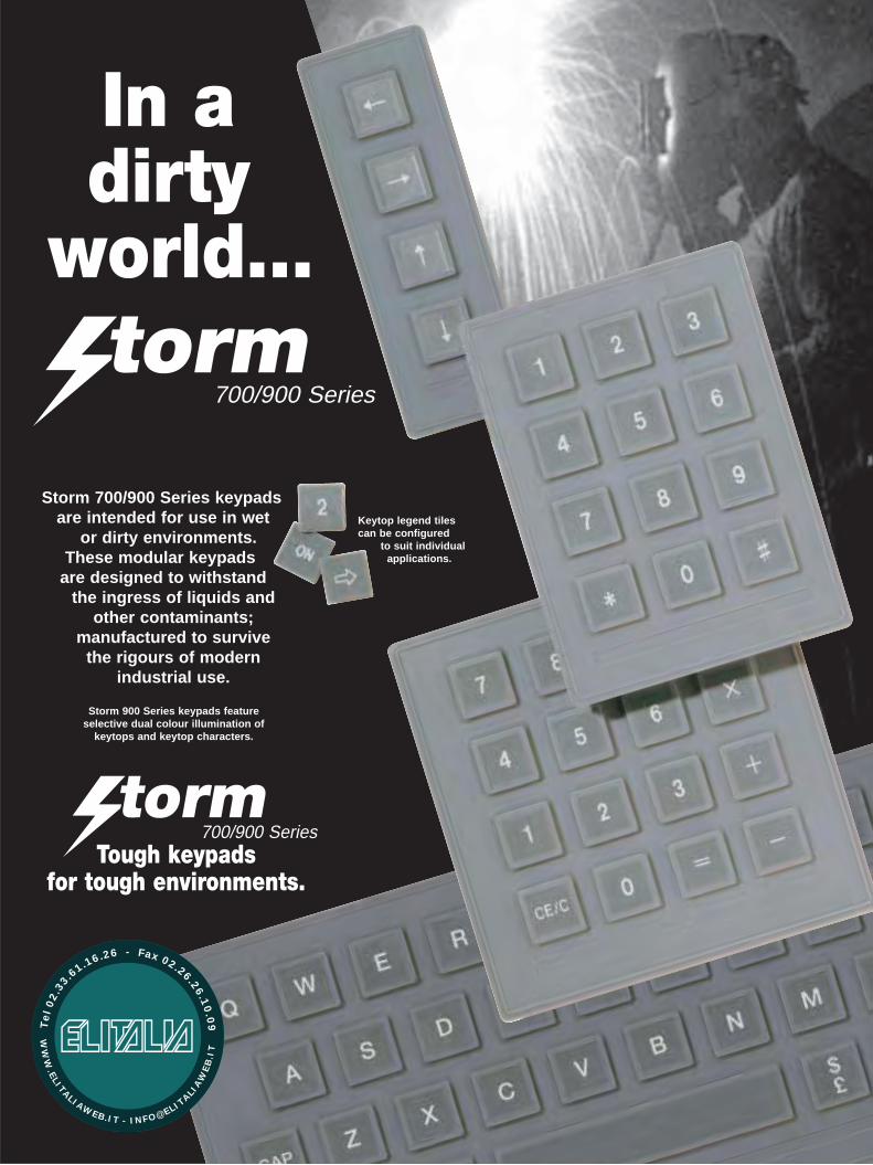
In adirty
world…
700/900 Series
Storm 700/900 Series keypads are intended for use in wet
or dirty environments. These modular keypads
are designed to withstand the ingress of liquids and
other contaminants;manufactured to survive
the rigours of modern industrial use.
Storm 900 Series keypads featureselective dual colour illumination of
keytops and keytop characters.
Keytop legend tilescan be configured
to suit individualapplications.
700/900 SeriesTough keypads
for tough environments.
WW
W.ELITALIAWEB.IT - INFO@ELIT
ALIAW
EB
.IT
Tel
02.
33
.61.16.26 - Fax 02.26.26.10
.09
Item
STORMKeypad Encoder
Legend Tile Set
Under PanelMounting Clips
Part Number
40000001
70X0010190X00101(X denotes type,"A to K")
7004CL01
Description
Keypad interface for STORM 700/900 Series & K Range keypads.PC XT or AT, PS2 and ASCII RS232/432 data formats configurable via an 8 way DIL switch.
A: 0 - 9, *, #, +, -, ÷, =, ., X, AC, I/O, ENT, CE/C, SP.B: ENT, PRINT, DEL, INS, CAP, ESC, CTRL, ALT,
ON, OFF, \, /, LOCK, , , , $£, :, ;, ,, ., , SP.
D: FI TO F12, £, $, ?, !, (, ), @, <, >, Fn, ", ', %, &, SP.F: 0 - 9, A - F, CE/C, ENT, OFF, *, #, +, -, ., blank, SP.
1 pair for 4 key keypad, 2 pairs for 12/16 key keypads & 3 pairs for 36 key keypad.
C: "A TO Z"E: BlankJ: French symbolsK: German symbols
ACCESSORIES FOR USE WITH STORM 700/900 SERIES KEYPADS
ELECTRICALContact BounceContact ResistanceInsulation ResistanceBreakdown Voltage (to case)Operating VoltageOperating CurrentLED Drive Current(900 Series only)LED Drive Voltage
LED Drive Voltage Single Diode (900 Series only)
Twin Diode (900 Series only)
ENVIRONMENTALWater Sealed
Humidity
Operational Temperature
5ms (max)100 ohm (max)50 Mohms (min) at 480V DC500V AC (max 60 seconds)24V DC (max)50 mA (max)20 mA typ 25mA (max)
3.3V typ
2.2V typ
BS5490 Class IP67 / EC529 Class IP67when panel mounted
90% RH at 40°C (104°F10 day (max) - Non-condensing
900 Series only:
700 Series only:-25°C to +85°C (-13°F to +185°F)
-55°C to +125°C (-67°F to +257°F)
MECHANICALOperational LifeKeytop TravelActuation ForceSealing TorqueConnector
MATERIALKeypad SurfaceKeypad chassisContact Circuit
2 million cycles (min)1.5mm nominal160gms typical0.14 - 0.16 NmLocking 0.1" pitch gold-plated squarepin connector suitable for use withMolex 2695/6471 or 7720S seriesor similar female connectors
Engineering grade silicone rubberCoated non-ferrous metalGold on nickel plated FR4 PCB
SPECIFICATION & OPERATIONAL PERFORMANCE
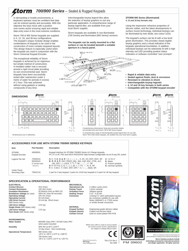
In demanding or hostile environments, akeyboard operator must be confident that datacan be entered quickly and accurately. With thisobjective the keys move with a positive over-centre action ensuring rapid and reliabledata entry even in the most extreme conditions.
Storm 700 & 900 Series keypads are suppliedin 4, 12, 16, and 36 key configurations.The keypad’s unique modular design enablescombinations of keypads to be used in theconstruction of more complex keypanel layouts.This design feature is especially useful whenthe keypads are used in conjunction with theStorm Universal Keypad Encoder.
The exceptional reliability of Stormkeypads is achieved by an ingeniousbut simple method of construction.A moulded rubber mat is securedaround a rigid circuit plate providingits own environmental seal. Stormkeypads have been successfullytested after submersion under 1metre of water for periods in excessof 1 hour. This was achievedwithout using gaskets or sealingcompounds of any kind.
700/900 Series – Sealed & Rugged Keypads
Interchangeable keytop legend tiles allowthe selection of keytop graphics to suit anyparticular application. A comprehensive range ofkeytop legend tiles, are available from your local Storm supplier.
Storm keypads are available in non-illuminated(700 Series) and illuminated (900 Series) versions.
STORM 900 Series (illuminated)4, 12 and 16 key formats only
Using the impressive refractive properties ofsilicone rubber, and the latest developments insurface mount technology, individual keytops canbe illuminated by twin diode, two colour LEDs.
The keypad’s surface can be lit with a low levelgreen illumination. This provides clearly legiblekeytop graphics and a visual indication of thekeypads operational boundaries. In addition,individual keytops can be selectively lit with a highintensity red LED providing positive statusindication or software controlled "user prompts".
The keypads can be easily mounted to a flatsurface or can be located beneath a suitableaperture in a fascia panel.
• Rapid & reliable data entry• Sealed against fluids, dust & corrosives• Resistant to vibration & shock• Interchangeable keytop legends• 4, 12 and 16 key formats in both series• Compatible with the STORM keypad encoder
DIMENSIONS
19
96
P
1619
19.5
96
14
10.819
96
P
1619
16
70
14
10.8
96
1619
32
14
10.8
P
19
96
P
1619
23
1932.5
217
1410.8 14 max
8
5.4
M3ThreadedStud
14 max
8
5.4
M3ThreadedStud
14 max
8
5.4
M3ThreadedStud
700 Series 700/900 Series 700 Series 900 Series
Comprehensive dimensional, fixing and connection detailsare provided with each Storm 700 & 900 Series keypad.
A comprehensive range of interchangeable keytop legend tiles, for use withStorm 700 & 900 Series keypads, are availble from your local Storm supplier.All dimensions are in millimetres.
FM 39602
003
700-LIT-01 Rev 4Nov 2008
Whilst every effort is made to ensure detailsare correct at time of print, specifications
are subject to change without notice.
Designed & produced byNIK Design
www.nikdesign.co.uk
Storm is a trademark of Keymat Technology LtdStorm Interface is a trading name of Keymat Technology Ltd
Storm Interface products include
technology protected by international patents
and design registration. All rights reserved.
WW
W.ELITALIAWEB.IT - INFO@ELIT
ALIAW
EB
.IT
Tel
02.
33
.61.16.26 - Fax 02.26.26.10
.09

WW
W.ELITALIAWEB.IT - INFO@ELIT
ALIAW
EB
.IT
Tel
02.
33
.61.16.26 - Fax 02.26.26.10
.09
Mounting Details Page 1 of 1 EZK-XX-08KT Rev 1 Oct 2008
EZ® and EZ Access® are registered trademarks of the Uni-versity of Wisconsin. To ensure correct function and maxi-mum accessibility by those with sensory or mobility impair-ment, these EZ Access keypads are specifically designed for use with appropriate software as part of an approved EZ Access Implementation.
www.storm-interface.com Storm Interface is a trading name of
Keymat Technology Ltd
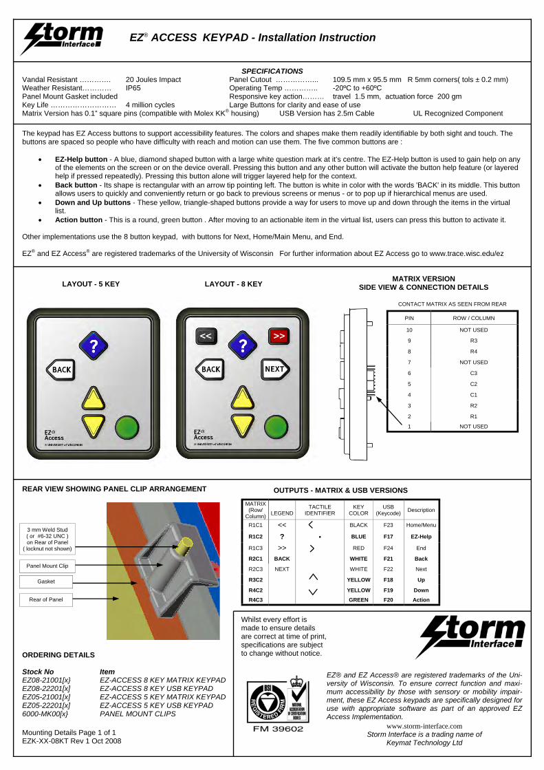
EZ® ACCESS KEYPAD - Installation Instruction
ORDERING DETAILS Stock No Item EZ08-21001[x} EZ-ACCESS 8 KEY MATRIX KEYPAD EZ08-22201[x] EZ-ACCESS 8 KEY USB KEYPAD EZ05-21001[x] EZ-ACCESS 5 KEY MATRIX KEYPAD EZ05-22201[x] EZ-ACCESS 5 KEY USB KEYPAD 6000-MK00[x} PANEL MOUNT CLIPS
Whilst every effort is made to ensure details are correct at time of print, specifications are subject to change without notice.
OUTPUTS - MATRIX & USB VERSIONS
MATRIX (Row/
Column)
LEGEND
R1C1 << R1C2 ? R1C3 >> R2C1 BACK
R2C3 NEXT
R3C2
R4C2
R4C3
KEY COLOR
BLACK
BLUE
RED
WHITE
WHITE
YELLOW
YELLOW
GREEN
Description
Home/Menu
EZ-Help
End
Back
Next
Up
Down
Action
USB (Keycode)
F23
F17
F24
F21
F22
F18
F19
F20
TACTILE IDENTIFIER
·
LAYOUT - 5 KEY LAYOUT - 8 KEY MATRIX VERSION
SIDE VIEW & CONNECTION DETAILS
SPECIFICATIONS Vandal Resistant …………. 20 Joules Impact Panel Cutout ……………... 109.5 mm x 95.5 mm R 5mm corners( tols ± 0.2 mm) Weather Resistant………… IP65 Operating Temp ………….. -20ºC to +60ºC Panel Mount Gasket included Responsive key action……… travel 1.5 mm, actuation force 200 gm Key Life ……………………… 4 million cycles Large Buttons for clarity and ease of use Matrix Version has 0.1” square pins (compatible with Molex KK® housing) USB Version has 2.5m Cable UL Recognized Component
Gasket
Rear of Panel
Panel Mount Clip
3 mm Weld Stud ( or #6-32 UNC ) on Rear of Panel
( locknut not shown)
REAR VIEW SHOWING PANEL CLIP ARRANGEMENT
The keypad has EZ Access buttons to support accessibility features. The colors and shapes make them readily identifiable by both sight and touch. The buttons are spaced so people who have difficulty with reach and motion can use them. The five common buttons are :
• EZ-Help button - A blue, diamond shaped button with a large white question mark at it’s centre. The EZ-Help button is used to gain help on any of the elements on the screen or on the device overall. Pressing this button and any other button will activate the button help feature (or layered help if pressed repeatedly). Pressing this button alone will trigger layered help for the context.
• Back button - Its shape is rectangular with an arrow tip pointing left. The button is white in color with the words 'BACK' in its middle. This button allows users to quickly and conveniently return or go back to previous screens or menus - or to pop up if hierarchical menus are used.
• Down and Up buttons - These yellow, triangle-shaped buttons provide a way for users to move up and down through the items in the virtual list.
• Action button - This is a round, green button . After moving to an actionable item in the virtual list, users can press this button to activate it. Other implementations use the 8 button keypad, with buttons for Next, Home/Main Menu, and End. EZ® and EZ Access® are registered trademarks of the University of Wisconsin For further information about EZ Access go to www.trace.wisc.edu/ez
CONTACT MATRIX AS SEEN FROM REAR
PIN ROW / COLUMN
10 NOT USED
9 R3
8 R4
7 NOT USED
6 C3
5 C2
4 C1
3 R2
2 R1
1 NOT USED
WW
W.ELITALIAWEB.IT - INFO@ELIT
ALIAW
EB
.IT
Tel
02.
33
.61.16.26 - Fax 02.26.26.10
.09

WW
W.ELITALIAWEB.IT - INFO@ELIT
ALIAW
EB
.IT
Tel
02.
33
.61.16.26 - Fax 02.26.26.10
.09

WW
W.ELITALIAWEB.IT - INFO@ELIT
ALIAW
EB
.IT
Tel
02.
33
.61.16.26 - Fax 02.26.26.10
.09

Mounting Details Page 1 of 4 420-XX-08KT Rev 2 Oct 2008
420 Series RS232 Encoder for Keypad Applications - Installation Instruction
CONNECTION DETAILS
ORDERING DETAILS Stock No Item 4200-00[X] RS232 Encoder [X] denotes packaging variant free downloads from www.storm-interface.com :- 420 Encoder Application/Engineering Manual Test Software
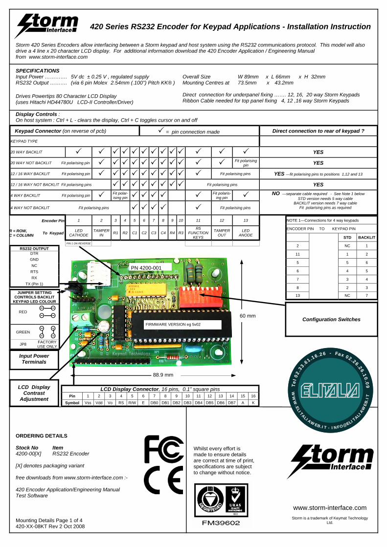
Storm 420 Series Encoders allow interfacing between a Storm keypad and host system using the RS232 communications protocol. This model will also drive a 4 line x 20 character LCD display. For additional information download the 420 Encoder Application / Engineering Manual from www.storm-interface.com
SPECIFICATIONS Input Power …………. 5V dc ± 0.25 V , regulated supply RS232 Output ………. (via 6 pin Molex 2.54mm (.100") Pitch KK® ) Drives Powertips 80 Character LCD Display (uses Hitachi HD44780U LCD-II Controller/Driver) Display Controls : On host system : Ctrl + L - clears the display, Ctrl + C toggles cursor on and off
Input Power Terminals
88.9 mm
60 mm
LCD Display Contrast
Adjustment Pin 1 2 3 4 5 6 7 8 9 10 11 12 13 14 15 16
Symbol Vss Vdd Vo RS R/W E DB0 DB1 DB2 DB3 DB4 DB5 DB6 DB7 A K
LCD Display Connector, 16 pins, 0.1” square pins
Keypad Connector (on reverse of pcb) = pin connection made Direct connection to rear of keypad ?
20 WAY BACKLIT YES
20 WAY NOT BACKLIT Fit polarising pin Fit polarising pin YES
12 / 16 WAY BACKLIT Fit polarising pin Fit polarising pins YES —fit polarising pins to positions 1,12 and 13
12 / 16 WAY NOT BACKLIT Fit polarising pins Fit polarising pins YES
4 WAY BACKLIT Fit polarising pin Fit polar-ising pin Fit polaris-
ing pin NO —separate cable required - See Note 1 below STD version needs 5 way cable
BACKLIT version needs 7 way cable Fit polarising pins as required
4 WAY NOT BACKLIT Fit polarising pins Fit polarising pins
Encoder Pin 1 2 3 4 5 6 7 8 9 10 11 12 13
R = ROW, C = COLUMN To Keypad LED
CATHODE TAMPER
IN R1 R2 C1 C2 C3 C4 R4 R3 R5
FUNCTION KEYS
TAMPER OUT
LED ANODE
PIN 1 ON REVERSE
KEYPAD TYPE
NOTE 1—Connections for 4 way keypads
STD BACKLIT
2 NC 1
11 1 2
5 5 6
6 4 5
7 3 4
8 2 3
13 NC 7
ENCODER PIN TO KEYPAD PIN
JUMPER SETTING CONTROLS BACKLIT
KEYPAD LED COLOUR
RED Θ Θ
Θ Θ
GREEN Θ Θ
Θ Θ
JP8 FACTORY USE ONLY
FIRMWARE VERSION eg 5v02
PN 4200-001
Configuration Switches
Overall Size W 89mm x L 66mm x H 32mm Mounting Centres at 73.5mm x 43.2mm Direct connection for underpanel fixing ……. 12, 16, 20 way Storm Keypads Ribbon Cable needed for top panel fixing 4, 12 ,16 way Storm Keypads
Whilst every effort is made to ensure details are correct at time of print, specifications are subject to change without notice.
RS232 OUTPUT DTR GND NC
RTS RX
TX (Pin 1)
www.storm-interface.com
Storm is a trademark of Keymat Technology Ltd.
WW
W.ELITALIAWEB.IT - INFO@ELIT
ALIAW
EB
.IT
Tel
02.
33
.61.16.26 - Fax 02.26.26.10
.09
Mounting Details Page 2 of 4 420-XX-08KT Rev 2 Oct 2008
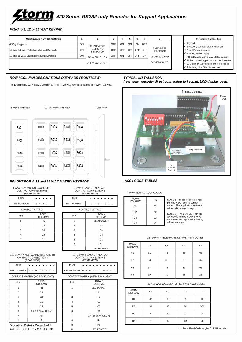
Configuration Switch Settings 1 2 3 4 5 6 7 8 Installation Checklist
4 Way Keypads ON CHARACTER
ECHOING SELECTOR
ON = ECHO ON
OFF = ECHO OFF
OFF ON ON ON OFF
BAUD RATE SELECTOR
OFF=9600 BAUD
ON=1200 BAUD
Keypad Encoder , configuration switch set Panel Fixing prepared +5V regulated supply RS 232 cable with 6 way Molex socket Ribbon cable keypad to encoder if needed LCD and 16 way ribbon cable if needed Polarising pins fitted to encoder
12 and 16 Way Telephone Layout Keypads ON OFF OFF OFF OFF ON
12 and 16 Way Calculator Layout Keypads ON OFF ON OFF OFF ON
ROW/ COLUMN R5
C1 11
C2 12
C3 13
C4 14
4 WAY KEYPAD ASCII CODES
NOTE 1 : These codes are non-printing ASCII device control codes. The application software will need to assign usage NOTE 2 : The COMMON pin on a 4 way is termed ROW 5 to be consistent with applications using 4 function keys.
4 WAY KEYPAD (NO BACKLIGHT) CONTACT CONNECTIONS
(REAR VIEW)
PINS ● ● ● ● ●
PIN NUMBER 5 4 3 2 1
PIN ROW / COLUMN
1 R5
2 C4
3 C3
4 C2
5 C1
CONTACT MATRIX
4 WAY BACKLIT KEYPAD CONTACT CONNECTIONS
(REAR VIEW)
PINS ● ● ● ● ● ● ●
PIN NUMBER 7 6 5 4 3 2 1
PIN ROW / COLUMN
1 LED POWER
2 R5
3 C4
4 C3
7 LED POWER
CONTACT MATRIX
6 C1
5 C2
ROW/ COLUMN C1 C2 C3 C4
R1 31 32 33 61
R2 34 35 36 62
R3 37 38 39 63
R4 2A 30 23 2E
12 / 16 WAY TELEPHONE KEYPAD ASCII CODES
12 / 16 WAY KEYPAD (NO BACKLIGHT) CONTACT CONNECTIONS
(REAR VIEW)
PINS ● ● ● ● ● ● ● ●
PIN NUMBER 8 7 6 5 4 3 2 1
PIN ROW / COLUMN
1 R1
2 R2
3 C1
4 C2
8 R3
CONTACT MATRIX (NO BACKLIGHT)
6 C4 (16 WAY ONLY)
5 C3
7 R4
12 / 16 WAY BACKLIT KEYPAD CONTACT CONNECTIONS
(REAR VIEW)
PINS ● ● ● ● ● ● ● ● ● ●
PIN NUMBER 10 9 8 7 6 5 4 3 2 1
PIN ROW / COLUMN
1 LED POWER
2 R1
3 R2
4 C1
10 LED POWER
CONTACT MATRIX (WITH BACKLIGHT)
6 C3
5 C2
7 C4 (16 WAY ONLY)
8 R4
9 R3 * = Form Feed Code to give CLEAR function
ROW/ COLUMN C1 C2 C3 C4
R1 37 38 39 1B
R2 34 35 36 0C*
R3 31 35 33 05
R4 7F 30 0D 2E
12 / 16 WAY CALCULATOR KEYPAD ASCII CODES
PIN-OUT FOR 4, 12 and 16 WAY MATRIX KEYPADS ASCII CODE TABLES
420 Series RS232 only Encoder for Keypad Applications
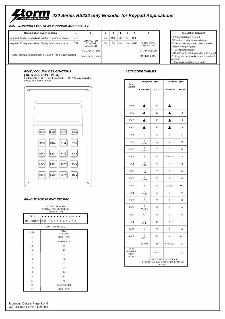
ROW / COLUMN DESIGNATIONS (KEYPADS FRONT VIEW) For Example R1C2 = Row 1 Column 2. NB : A 20 way keypad is treated as 4 way + 16 way.
TYPICAL INSTALLATION (rear view, encoder direct connection to keypad, LCD display used)
4 Way Front View 12 / 16 Way Front View Side View
↓ RS232 Output
Power Input
To LCD Display
Keypad Pin 1
Fitted to 4, 12 or 16 WAY KEYPAD
Mounting Details Page 3 of 4 420-XX-08KT Rev 2 Oct 2008
420 Series RS232 only Encoder for Keypad Applications
Configuration Switch Settings 1 2 3 4 5 6 7 8 Installation Checklist
Integrated 20 Way Keypad and Display - Telephone Layout OFF CHARACTER
ECHOING SELECTOR
ON = ECHO ON
OFF = ECHO OFF
ON OFF OFF ON OFF
BAUD RATE SELECTOR
OFF=9600 BAUD
ON=1200 BAUD
Integrated 20 way Keypad Encoder , configuration switch set LCD and 16 way ribbon cable if needed Panel Fixing prepared +5V regulated supply RS 232 cable with 6 way Molex KK socket 13 way ribbon cable keypad to encoder if
needed Polarising pins fitted to encoder
Integrated 20 Way Keypad and Display - Calculator Layout OFF ON ON ON ON OFF
Note : Remove Jumpers from JP3 and JP4 in this configuration.
Fitted to INTEGRATED 20 WAY KEYPAD AND DISPLAY
20 WAY KEYPAD CONTACT CONNECTIONS
(REAR VIEW) PINS ● ● ● ● ● ● ● ● ● ● ● ● ●
PIN NUMBER 13 12 11 10 9 8 7 6 5 4 3 2 1
PIN ROW / COLUMN
1 NOT USED
2 TAMPER IN
3 R1
4 R2
13 NOT USED
CONTACT MATRIX
6 C2
5 C1
7 C3
8 C4
12 TAMPER OUT
9 R4
10 R3
11 R5
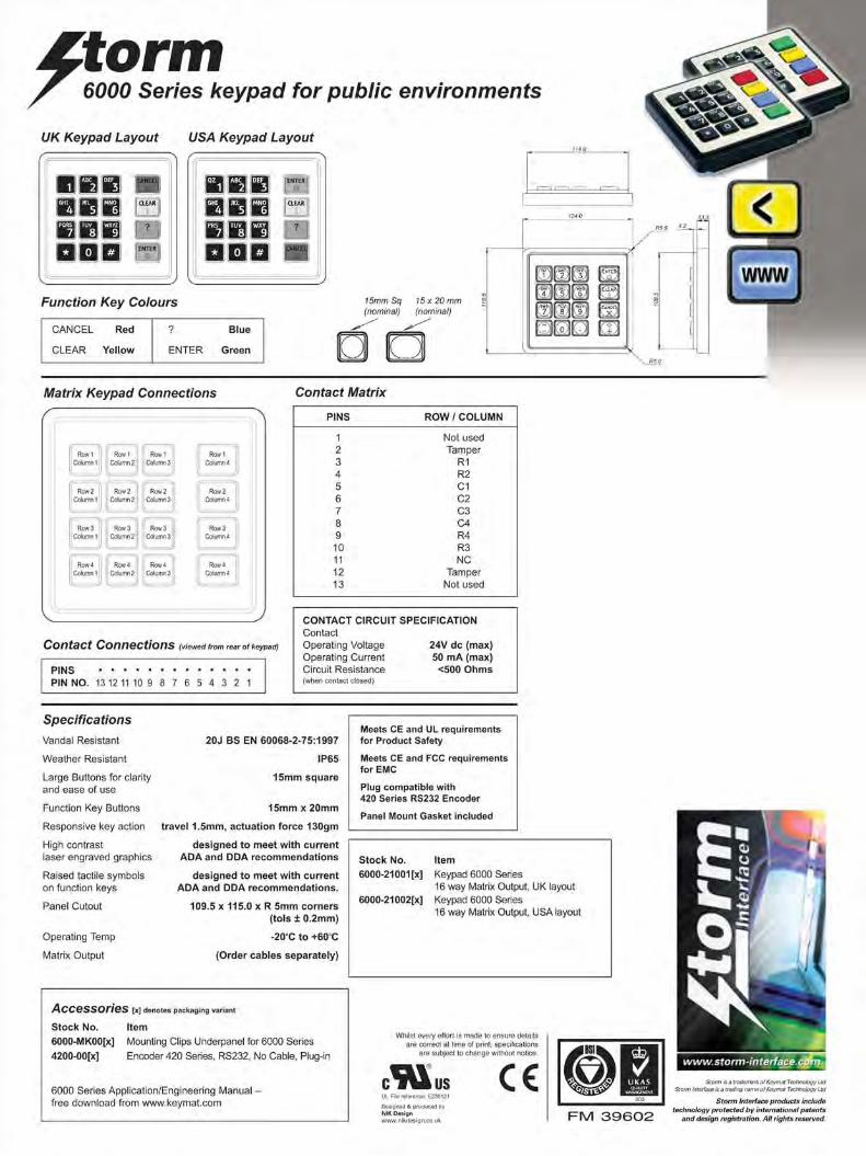
ROW / COLUMN DESIGNATIONS ( KEYPAD FRONT VIEW) For Example R1C2 = Row 1 Column 2. NB : A 20 way keypad is treated as 4 way + 16 way.
Row / Column
Telephone Layout Calculator Layout
Character ASCII Character ASCII
R5C1 ▲ 11 ▲ 11
R5C2 ▲ 12 ▲ 12
R5C3 ▲ 13 ▲ 13
R5C4 ▲ 14 ▲ 14
R1C1 1 31 1 31
R1C2 2 ABC 32 2 32
R1C3 3 DEF 33 3 33
R1C4 A 41 ENTER 1B
R2C1 4 GHI 34 4 34
R2C2 5 JKL 35 5 35
R2C3 6 MNO 36 6 36
R2C4 B 42 CLEAR 0C
R3C1 7 PQRS 37 7 37
R3C2 8 TUV 38 8 38
R3C3 9 WXYZ 39 9 39
R3C4 C 43 ? 05
R4C1 * CLR 2A * 7F
R4C2 0 30 0 30
R4C3 # ENT 23 # 0D
. ENTER 2E CANCEL 2E
* = CODE REPEATS EVERY 10 SECONDS WHILST CONDITION REMAINS
ACTIVE
ANTI-TAMPER
OPEN CIRCUIT
07* 07*
ASCII CODE TABLES
PIN-OUT FOR 20 WAY KEYPAD
Mounting Details Page 4 of 4 420-XX-08KT Rev 2 Oct 2008
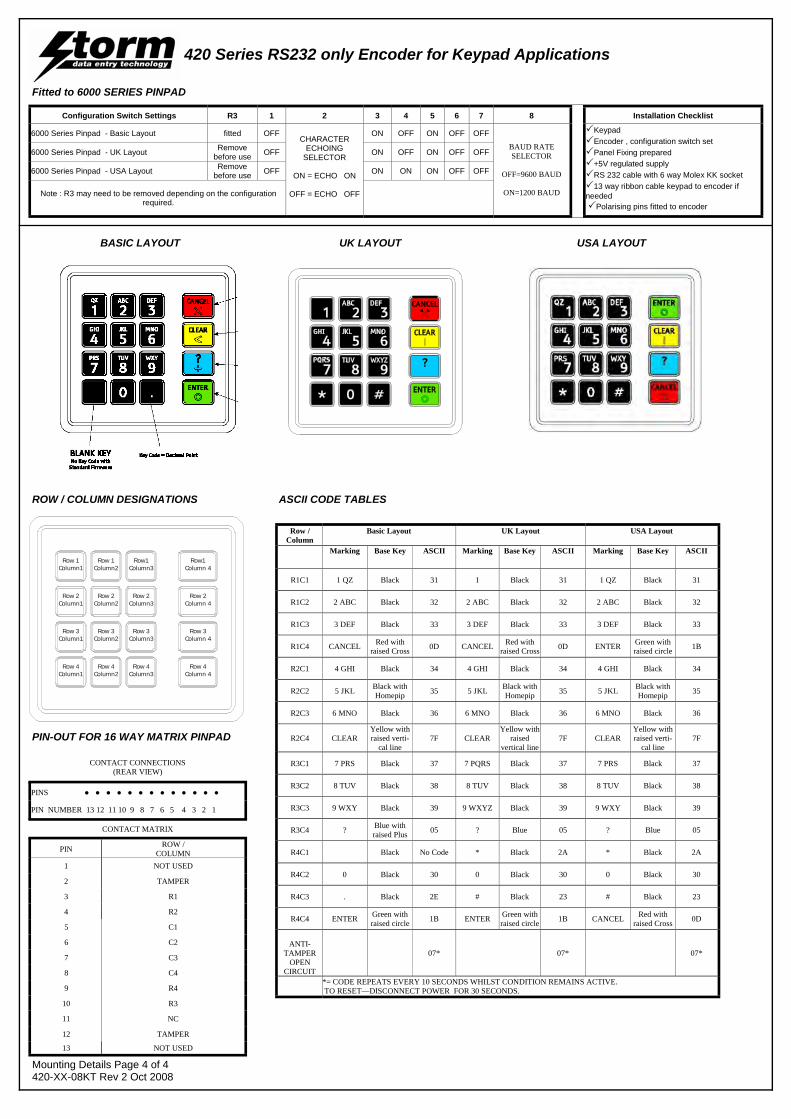
420 Series RS232 only Encoder for Keypad Applications
Configuration Switch Settings R3 1 2 3 4 5 6 7 8 Installation Checklist
6000 Series Pinpad - Basic Layout fitted OFF CHARACTER
ECHOING SELECTOR
ON = ECHO ON
OFF = ECHO OFF
ON OFF ON OFF OFF
BAUD RATE SELECTOR
OFF=9600 BAUD
ON=1200 BAUD
Keypad Encoder , configuration switch set Panel Fixing prepared +5V regulated supply RS 232 cable with 6 way Molex KK socket 13 way ribbon cable keypad to encoder if
needed Polarising pins fitted to encoder
6000 Series Pinpad - UK Layout Remove before use OFF ON OFF ON OFF OFF
6000 Series Pinpad - USA Layout Remove before use OFF ON ON ON OFF OFF
Note : R3 may need to be removed depending on the configuration required.
Fitted to 6000 SERIES PINPAD
Row / Column
Basic Layout UK Layout Marking Base Key ASCII
Marking Base Key ASCII
Marking Base Key ASCII
R1C1 1 QZ Black 31 1 Black 31 1 QZ Black 31
R1C2 2 ABC Black 32 2 ABC Black 32 2 ABC Black 32
R1C3 3 DEF Black 33 3 DEF Black 33 3 DEF Black 33
R1C4 CANCEL Red with raised Cross 0D CANCEL Red with
raised Cross 0D ENTER Green with raised circle 1B
R2C1 4 GHI Black 34 4 GHI Black 34 4 GHI Black 34
R2C2 5 JKL Black with Homepip 35 5 JKL Black with
Homepip 35 5 JKL Black with Homepip 35
R2C3 6 MNO Black 36 6 MNO Black 36 6 MNO Black 36
R2C4 CLEAR Yellow with raised verti-
cal line 7F CLEAR
Yellow with raised
vertical line 7F CLEAR
Yellow with raised verti-
cal line 7F
R3C1 7 PRS Black 37 7 PQRS Black 37 7 PRS Black 37
R3C2 8 TUV Black 38 8 TUV Black 38 8 TUV Black 38
R3C3 9 WXY Black 39 9 WXYZ Black 39 9 WXY Black 39
R3C4 ? Blue with raised Plus 05 ? Blue 05 ? Blue 05
R4C1 Black No Code * Black 2A * Black 2A
R4C2 0 Black 30 0 Black 30 0 Black 30
R4C3 . Black 2E # Black 23 # Black 23
R4C4 ENTER Green with raised circle 1B ENTER Green with
raised circle 1B CANCEL Red with raised Cross 0D
ANTI-
TAMPER OPEN
CIRCUIT
07* 07* 07*
*= CODE REPEATS EVERY 10 SECONDS WHILST CONDITION REMAINS ACTIVE. TO RESET—DISCONNECT POWER FOR 30 SECONDS.
USA Layout
BASIC LAYOUT UK LAYOUT USA LAYOUT
CONTACT CONNECTIONS (REAR VIEW)
PINS ● ● ● ● ● ● ● ● ● ● ● ● ●
CONTACT MATRIX
PIN ROW / COLUMN
1 NOT USED
2 TAMPER
3 R1
4 R2
5 C1
6 C2
7 C3
8 C4
9 R4
10 R3
11 NC
12 TAMPER
13 NOT USED
PIN NUMBER 13 12 11 10 9 8 7 6 5 4 3 2 1
Row 1Column1
Row 2Column1
Row 3Column1
Row 4Column1
Row 1Column2
Row 2Column2
Row 3Column2
Row 4Column2
Row1Column3
Row1Column 4
Row 2Column3
Row 2Column 4
Row 3Column3
Row 3Column 4
Row 4Column3
Row 4Column 4
ROW / COLUMN DESIGNATIONS ASCII CODE TABLES
PIN-OUT FOR 16 WAY MATRIX PINPAD
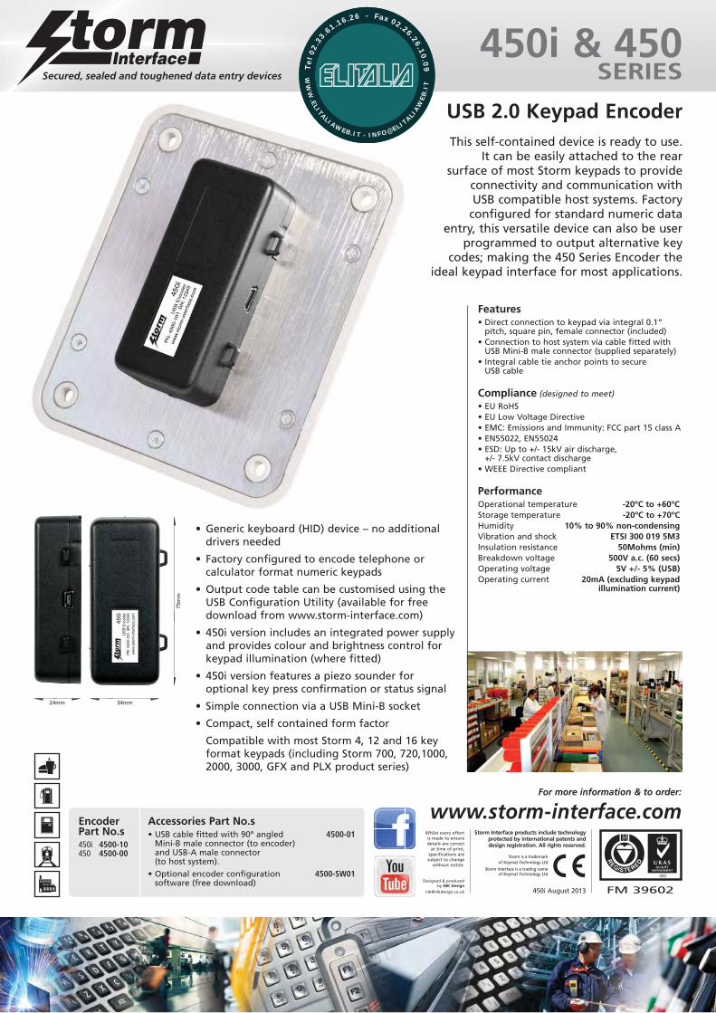
450i & 450SERIES
USB 2.0 Keypad EncoderThis self-contained device is ready to use.
It can be easily attached to the rear surface of most Storm keypads to provide
connectivity and communication with USB compatible host systems. Factoryconfigured for standard numeric data
entry, this versatile device can also be userprogrammed to output alternative key
codes; making the 450 Series Encoder theideal keypad interface for most applications.
Features• Direct connection to keypad via integral 0.1”
pitch, square pin, female connector (included)• Connection to host system via cable fitted with
USB Mini-B male connector (supplied separately)• Integral cable tie anchor points to secure
USB cable
PerformanceOperational temperature -20ºC to +60ºCStorage temperature -20ºC to +70ºCHumidity 10% to 90% non-condensingVibration and shock ETSI 300 019 5M3Insulation resistance 50Mohms (min)Breakdown voltage 500V a.c. (60 secs)Operating voltage 5V +/- 5% (USB)Operating current 20mA (excluding keypad
illumination current)
Compliance (designed to meet)
• EU RoHS • EU Low Voltage Directive• EMC: Emissions and Immunity: FCC part 15 class A• EN55022, EN55024• ESD: Up to +/- 15kV air discharge,
+/- 7.5kV contact discharge• WEEE Directive compliant
Accessories Part No.s• USB cable fitted with 90º angled 4500-01
Mini-B male connector (to encoder)and USB-A male connector(to host system).
• Optional encoder configuration 4500-SW01software (free download)
EncoderPart No.s450i 4500-10450 4500-00
FM 39602
003
450i August 2013
Designed & producedby NIK Design
Whilst every effortis made to ensuredetails are correct
at time of print,specifications aresubject to change
without notice.
Storm is a trademark of Keymat Technology Ltd
Storm Interface is a trading name of Keymat Technology Ltd
Storm Interface products include technologyprotected by international patents anddesign registration. All rights reserved.
www.storm-interface.com For more information & to order:
• Generic keyboard (HID) device – no additionaldrivers needed
• Factory configured to encode telephone orcalculator format numeric keypads
• Output code table can be customised using theUSB Configuration Utility (available for freedownload from www.storm-interface.com)
• 450i version includes an integrated power supplyand provides colour and brightness control forkeypad illumination (where fitted)
• 450i version features a piezo sounder foroptional key press confirmation or status signal
• Simple connection via a USB Mini-B socket
• Compact, self contained form factor
Compatible with most Storm 4, 12 and 16 keyformat keypads (including Storm 700, 720,1000,2000, 3000, GFX and PLX product series)
24mm 34mm
75m
m
WW
W.ELITALIAWEB.IT - INFO@ELIT
ALIAW
EB
.IT
Tel
02.
33
.61.16.26 - Fax 02.26.26.10
.09
WW
W.ELITALIAWEB.IT - INFO@ELIT
ALIAW
EB
.IT
Tel
02.
33
.61.16.26 - Fax 02.26.26.10
.09
Whilst every effort is made to ensure details are correct at time of print, specifications are subject to change without notice.
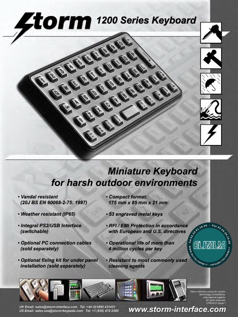
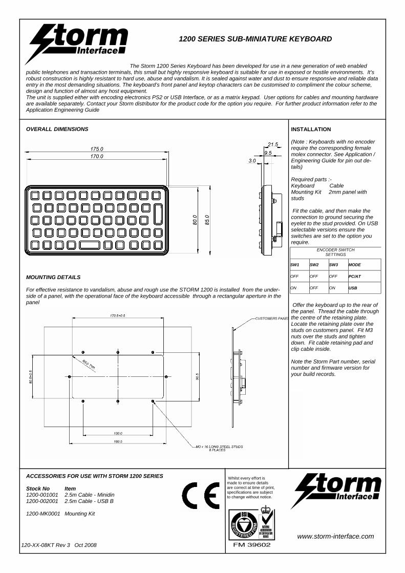
1200 SERIES SUB-MINIATURE KEYBOARD
The Storm 1200 Series Keyboard has been developed for use in a new generation of web enabled
public telephones and transaction terminals, this small but highly responsive keyboard is suitable for use in exposed or hostile environments. It’s robust construction is highly resistant to hard use, abuse and vandalism. It is sealed against water and dust to ensure responsive and reliable data entry in the most demanding situations. The keyboard’s front panel and keytop characters can be customised to compliment the colour scheme, design and function of almost any host equipment. The unit is supplied either with encoding electronics PS2 or USB Interface, or as a matrix keypad. User options for cables and mounting hardware are available separately. Contact your Storm distributor for the product code for the option you require. For further product information refer to the Application Engineering Guide
120-XX-08KT Rev 3 Oct 2008
OVERALL DIMENSIONS
ACCESSORIES FOR USE WITH STORM 1200 SERIES Stock No Item 1200-001001 2.5m Cable - Minidin 1200-002001 2.5m Cable - USB B 1200-MK0001 Mounting Kit
INSTALLATION (Note : Keyboards with no encoder require the corresponding female molex connector. See Application /Engineering Guide for pin out de-tails) Required parts :- Keyboard Cable Mounting Kit 2mm panel with studs Fit the cable, and then make the connection to ground securing the eyelet to the stud provided. On USB selectable versions ensure the switches are set to the option you require.
Offer the keyboard up to the rear of the panel. Thread the cable through the centre of the retaining plate. Locate the retaining plate over the studs on customers panel. Fit M3 nuts over the studs and tighten down. Fit cable retaining pad and clip cable inside. Note the Storm Part number, serial number and firmware version for your build records.
SW1 SW2 SW3 MODE
OFF OFF OFF PC/AT
ON OFF ON USB
ENCODER SWITCH SETTINGS
MOUNTING DETAILS For effective resistance to vandalism, abuse and rough use the STORM 1200 is installed from the under-side of a panel, with the operational face of the keyboard accessible through a rectangular aperture in the panel
www.storm-interface.com
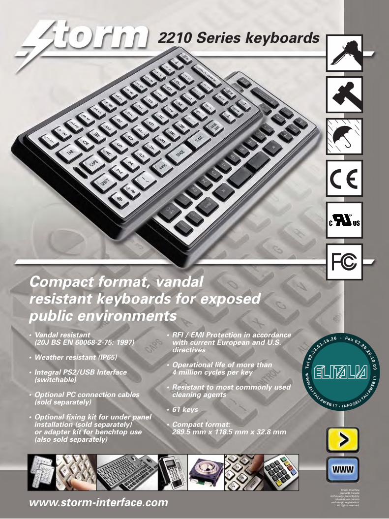
2210 Series keyboards
Compact format, vandal resistant keyboards for exposedpublic environments• Vandal resistant
(20J BS EN 60068-2-75: 1997)
• Weather resistant (IP65)
• Integral PS2/USB Interface (switchable)
• Optional PC connection cables (sold separately)
• Optional fixing kit for under panel installation (sold separately)or adapter kit for benchtop use (also sold separately)
• RFI / EMI Protection in accordancewith current European and U.S.directives
• Operational life of more than 4 million cycles per key
• Resistant to most commonly usedcleaning agents
• 61 keys
• Compact format:289.5 mm x 118.5 mm x 32.8 mm
www.storm-interface.com
Storm Interfaceproducts include
technology protected byinternational patents
and design registration.All rights reserved.
WW
W.ELITALIAWEB.IT - INFO@ELIT
ALIAW
EB
.IT
Tel
02.
33
.61.16.26 - Fax 02.26.26.10
.09
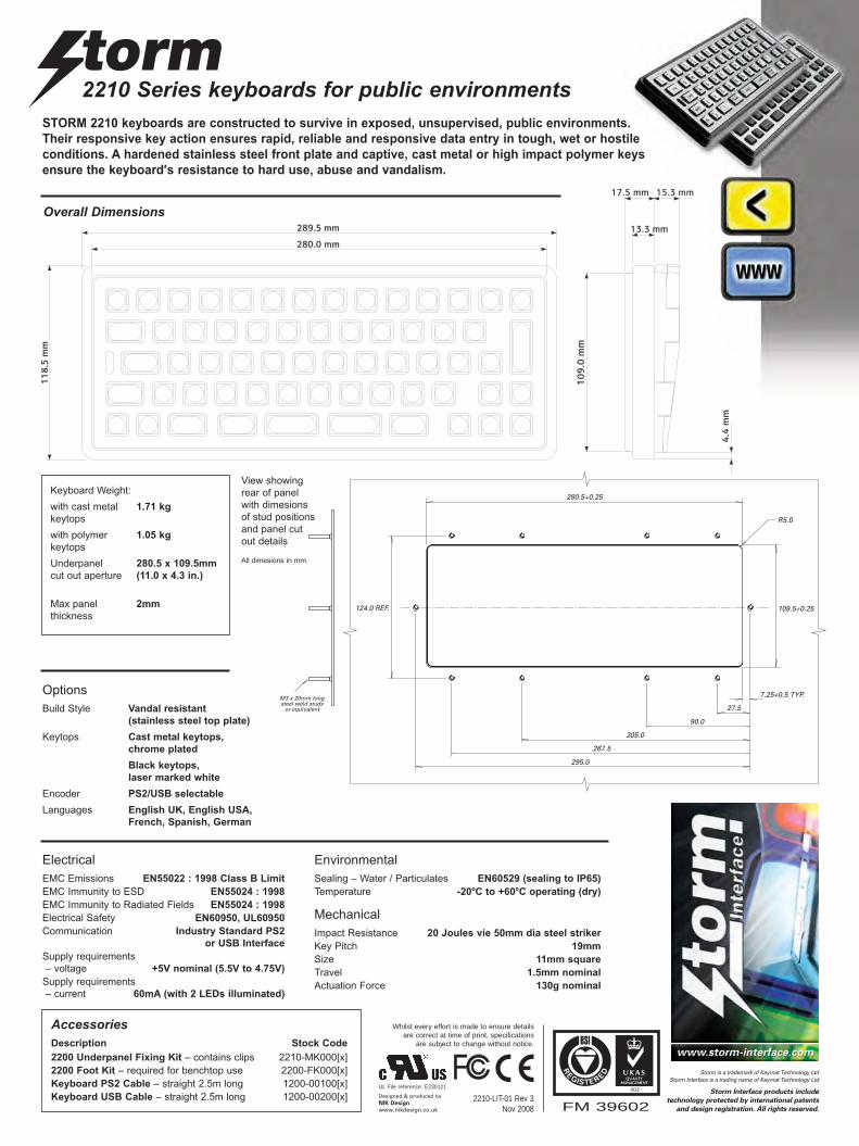
2210 Series keyboards for public environments
Overall Dimensions
Options
Build Style Vandal resistant
(stainless steel top plate)
Keytops Cast metal keytops,
chrome plated
Black keytops,
laser marked white
Encoder PS2/USB selectable
Languages English UK, English USA,
French, Spanish, German
AccessoriesDescription Stock Code
2200 Underpanel Fixing Kit – contains clips 2210-MK000[x]
2200 Foot Kit – required for benchtop use 2200-FK000[x]
Keyboard PS2 Cable – straight 2.5m long 1200-00100[x]
Keyboard USB Cable – straight 2.5m long 1200-00200[x]FM 39602
003
2210-LIT-01 Rev 3 Nov 2008
Whilst every effort is made to ensure detailsare correct at time of print, specifications
are subject to change without notice.
STORM 2210 keyboards are constructed to survive in exposed, unsupervised, public environments.
Their responsive key action ensures rapid, reliable and responsive data entry in tough, wet or hostile
conditions. A hardened stainless steel front plate and captive, cast metal or high impact polymer keys
ensure the keyboard’s resistance to hard use, abuse and vandalism.
Electrical
EMC Emissions EN55022 : 1998 Class B Limit
EMC Immunity to ESD EN55024 : 1998
EMC Immunity to Radiated Fields EN55024 : 1998
Electrical Safety EN60950, UL60950
Communication Industry Standard PS2
or USB Interface
Supply requirements
– voltage +5V nominal (5.5V to 4.75V)
Supply requirements
– current 60mA (with 2 LEDs illuminated)
Mechanical
Impact Resistance 20 Joules vie 50mm dia steel striker
Key Pitch 19mm
Size 11mm square
Travel 1.5mm nominal
Actuation Force 130g nominal
Environmental
Sealing – Water / Particulates EN60529 (sealing to IP65)
Temperature -20oC to +60oC operating (dry)
205.0
267.5
295.0
90.0
27.5
280.5+0.25
109.5+0.25124.0 REF.
R5.0
7.25+0.5 TYP.M3 x 20mm longsteel weld studs
or equivalent
Keyboard Weight:
with cast metal 1.71 kg
keytops
with polymer 1.05 kg
keytops
Underpanel 280.5 x 109.5mm
cut out aperture (11.0 x 4.3 in.)
Max panel 2mm
thickness
UL File reference: E230121
Designed & produced byNIK Design
www.nikdesign.co.uk
View showing
rear of panel
with dimesions
of stud positions
and panel cut
out details
All dimesions in mm.
Storm is a trademark of Keymat Technology LtdStorm Interface is a trading name of Keymat Technology Ltd
Storm Interface products include
technology protected by international patents
and design registration. All rights reserved.

2210-T/B Series Keyboards
Compact format, vandal resistantkeyboards with integrated trackball• Vandal resistant
(20J BS EN 60068-2-75: 1997)
• Weather resistant (IP65)
• Integral PS2/USB Interface (switchable)
• Optional PC connection cables (sold separately)
• Optional fixing kit for under panel installation (sold separately)or adapter kit for benchtop use (also sold separately)
• RFI / EMI Protection in accordance with current European and U.S. directives
• Operational life of more than 4 million cycles per key
• Resistant to most commonly usedcleaning agents
• Integral 38mm PS2 / USB compatibletrackball with left & right click keys
• 63 keys
• Compact format:360.0 mm x 118.5 mm x 38.5 mm
www.storm-interface.com
Storm Interfaceproducts include
technology protected byinternational patents
and design registration.All rights reserved.
WW
W.ELITALIAWEB.IT - INFO@ELIT
ALIAW
EB
.IT
Tel
02.
33
.61.16.26 - Fax 02.26.26.10
.09
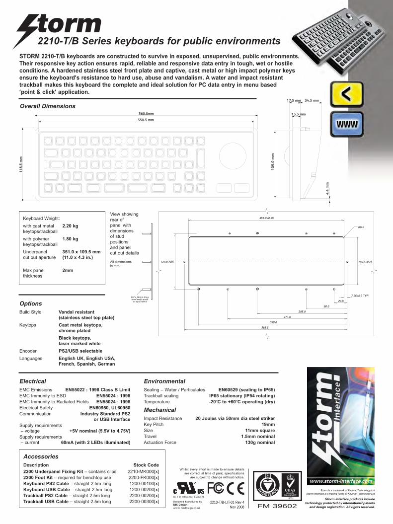
2210-T/B Series keyboards for public environments
OptionsBuild Style Vandal resistant
(stainless steel top plate)
Keytops Cast metal keytops,
chrome plated
Black keytops,
laser marked white
Encoder PS2/USB selectable
Languages English UK, English USA,
French, Spanish, German
AccessoriesDescription Stock Code
2200 Underpanel Fixing Kit – contains clips 2210-MK000[x]
2200 Foot Kit – required for benchtop use 2200-FK000[x]
Keyboard PS2 Cable – straight 2.5m long 1200-00100[x]
Keyboard USB Cable – straight 2.5m long 1200-00200[x]
Trackball PS2 Cable – straight 2.5m long 2200-00200[x]
Trackball USB Cable – straight 2.5m long 2200-00300[x]
STORM 2210-T/B keyboards are constructed to survive in exposed, unsupervised, public environments.
Their responsive key action ensures rapid, reliable and responsive data entry in tough, wet or hostile
conditions. A hardened stainless steel front plate and captive, cast metal or high impact polymer keys
ensure the keyboard’s resistance to hard use, abuse and vandalism. A water and impact resistant
trackball makes this keyboard the complete and ideal solution for PC data entry in menu based
‘point & click’ application.
ElectricalEMC Emissions EN55022 : 1998 Class B Limit
EMC Immunity to ESD EN55024 : 1998
EMC Immunity to Radiated Fields EN55024 : 1998
Electrical Safety EN60950, UL60950
Communication Industry Standard PS2
or USB Interface
Supply requirements
– voltage +5V nominal (5.5V to 4.75V)
Supply requirements
– current 60mA (with 2 LEDs illuminated)
MechanicalImpact Resistance 20 Joules via 50mm dia steel striker
Key Pitch 19mm
Size 11mm square
Travel 1.5mm nominal
Actuation Force 130g nominal
EnvironmentalSealing – Water / Particulates EN60529 (sealing to IP65)
Trackball sealing IP65 stationary (IP54 rotating)
Temperature -20oC to +60oC operating (dry)
205.0
271.5
365.5
90.0
27.5
351.0+0.25
109.5+0.25124.0 REF.
R5.0
7.25+0.5 TYP.M3 x 20mm longsteel weld studs
or equivalent
338.0
Keyboard Weight:
with cast metal 2.20 kg
keytops/trackball
with polymer 1.80 kg
keytops/trackball
Underpanel 351.0 x 109.5 mm
cut out aperture (11.0 x 4.3 in.)
Max panel 2mm
thickness
View showing
rear of
panel with
dimensions
of stud
positions
and panel
cut out details
All dimensions
in mm.
Overall Dimensions
FM 39602
003
2210-T/B-LIT-01 Rev 4 Nov 2008
Whilst every effort is made to ensure detailsare correct at time of print, specifications
are subject to change without notice.
UL File reference: E230121
Designed & produced byNIK Design
www.nikdesign.co.uk
Storm is a trademark of Keymat Technology LtdStorm Interface is a trading name of Keymat Technology Ltd
Storm Interface products include
technology protected by international patents
and design registration. All rights reserved.

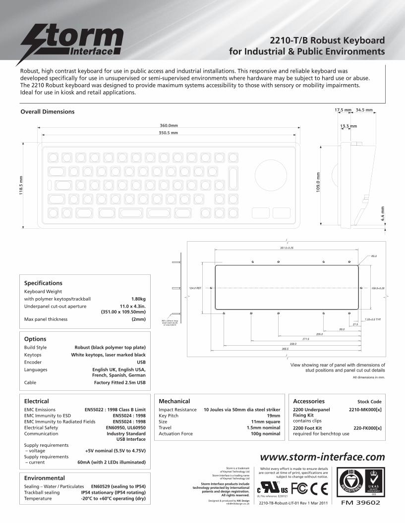
Robust Keyboards2210-T/B Series
Compact format, robust keyboardwith integrated trackball
• Vandal resistant(10J BS EN 60068-2-75: 1997)
• Weather resistant (IP54)
• With factory fitted 2.5m USB cable
• Optional fixing kit for under panelinstallation or adapter kit forbenchtop use (both sold separately)
• RFI/EMI Protection in accordance with current European and US directives
• Operational life of more than 4 million cycles per key
• Resistant to most commonly used cleaning agents
• Integral 38mm trackballwith left & right click keys
• 63 keys
• Compact format:360mm x 118.5mm x 438.5mm
www.storm-interface.com
Storm Interface products include technology protected byinternational patents and design
registration. All rights reserved.
WW
W.ELITALIAWEB.IT - INFO@ELIT
ALIAW
EB
.IT
Tel
02.
33
.61.16.26 - Fax 02.26.26.10
.09
ElectricalEMC Emissions EN55022 : 1998 Class B LimitEMC Immunity to ESD EN55024 : 1998EMC Immunity to Radiated Fields EN55024 : 1998Electrical Safety EN60950, UL60950Communication Industry Standard USB InterfaceSupply requirements– voltage +5V nominal (5.5V to 4.75V)Supply requirements – current 60mA (with 2 LEDs illuminated)
OptionsBuild Style Robust (black polymer top plate)
Keytops White keytops, laser marked black
Encoder USB
Languages English UK, English USA, French, Spanish, German
Cable Factory Fitted 2.5m USB
SpecificationsKeyboard Weight
with polymer keytops/trackball 1.80kg
Underpanel cut-out aperture 11.0 x 4.3in. (351.00 x 109.50mm)
Max panel thickness (2mm)
MechanicalImpact Resistance 10 Joules via 50mm dia steel strikerKey Pitch 19mmSize 11mm squareTravel 1.5mm nominalActuation Force 100g nominal
Accessories Stock Code
2200 Underpanel 2210-MK000[x]Fixing Kitcontains clips
2200 Foot Kit 220-FK000[x]required for benchtop use
EnvironmentalSealing – Water / Particulates EN60529 (sealing to IP54) Trackball sealing IP54 stationary (IP54 rotating)Temperature -20oC to +60oC operating (dry)
FM 39602
003
2210-TB-Robust-LIT-01 Rev 1 Mar 2011
Whilst every effort is made to ensure detailsare correct at time of print, specifications are
subject to change without notice.
UL File reference: E230121
Designed & produced by NIK [email protected]
Storm is a trademark of Keymat Technology Ltd
Storm Interface is a trading name of Keymat Technology Ltd
Storm Interface products include technology protected by international
patents and design registration. All rights reserved.
www.storm-interface.com
205.0
271.5
365.5
90.0
27.5
351.0+0.25
109.5+0.25124.0 REF.
R5.0
7.25+0.5 TYP.M3 x 20mm longsteel weld studs
or equivalent
338.0
View showing rear of panel with dimensions ofstud positions and panel cut out details
All dimensions in mm.
Overall Dimensions
Robust, high contrast keyboard for use in public access and industrial installations. This responsive and reliable keyboard wasdeveloped specifically for use in unsupervised or semi-supervised environments where hardware may be subject to hard use or abuse.The 2210 Robust keyboard was designed to provide maximum systems accessibility to those with sensory or mobility impairments. Ideal for use in kiosk and retail applications.
2210-T/B Robust Keyboardfor Industrial & Public Environments
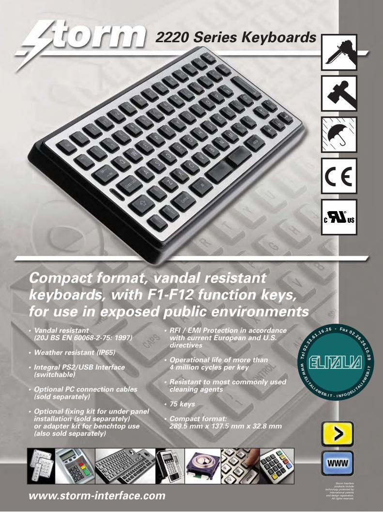
2220 Series Keyboards
Compact format, vandal resistantkeyboards, with F1-F12 function keys,for use in exposed public environments• Vandal resistant
(20J BS EN 60068-2-75: 1997)
• Weather resistant (IP65)
• Integral PS2/USB Interface (switchable)
• Optional PC connection cables (sold separately)
• Optional fixing kit for under panel installation (sold separately)or adapter kit for benchtop use (also sold separately)
• RFI / EMI Protection in accordancewith current European and U.S.directives
• Operational life of more than 4 million cycles per key
• Resistant to most commonly usedcleaning agents
• 75 keys
• Compact format:289.5 mm x 137.5 mm x 32.8 mm
www.storm-interface.com
Storm Interfaceproducts include
technology protected byinternational patents
and design registration.All rights reserved.
WW
W.ELITALIAWEB.IT - INFO@ELIT
ALIAW
EB
.IT
Tel
02.
33
.61.16.26 - Fax 02.26.26.10
.09

2220 Series keyboards for public environments
Overall Dimensions
OptionsBuild Style Vandal resistant
(stainless steel top plate)
Keytops Black keytops,
laser marked white
Encoder PS2/USB selectable
Languages English UK, English USA,
French, Spanish, German
AccessoriesDescription Stock Code
2200 Underpanel Fixing Kit – contains clips 2210-MK000[x]
2200 Foot Kit – required for benchtop use 2200-FK000[x]
Keyboard PS2 Cable – straight 2.5m long 1200-00100[x]
Keyboard USB Cable – straight 2.5m long 1200-00200[x]
STORM 2220 keyboards are constructed to survive in exposed, unsupervised, public environments.
Their responsive key action ensures rapid, reliable and responsive data entry in tough, wet or hostile
conditions. A hardened stainless steel front plate and high impact polymer keys ensure the keyboard’sresistance to hard use, abuse and vandalism.
ElectricalEMC Emissions EN55022 : 1998 Class B Limit
EMC Immunity to ESD EN55024 : 1998
EMC Immunity to Radiated Fields EN55024 : 1998
Electrical Safety EN60950, UL60950
Communication Industry Standard PS2
or USB Interface
Supply requirements
– voltage +5V nominal (5.5V to 4.75V)
Supply requirements
– current 60mA (with 2 LEDs illuminated)
MechanicalImpact Resistance 20 Joules via 50mm dia steel striker
Key Pitch 19mm
Size 11mm square
Travel 1.5mm nominal
Actuation Force 130g nominal
EnvironmentalSealing – Water / Particulates EN60529 (sealing to IP65)
Temperature -20oC to +60oC operating (dry)
Keyboard Weight:
with polymer 1.70 kg
keytops
Underpanel 280.5 x 128.5mm
cut out aperture (11.0 x 5.06 in.)
Max panel 2mm
thickness
View showing
rear of
panel with
dimensions
of stud
positions
and panel
cut out details
All dimensions
in mm.
205.0
267.5
295.0
90.0
27.5
280.5+0.25
128.5+0.25143.0 REF.
R5.0
7.25+0.5 TYP.M3 x 20mm longsteel weld studs
or equivalent
FM 39602
003
2220-LIT-01 Rev 4 Nov 2008
Whilst every effort is made to ensure detailsare correct at time of print, specifications
are subject to change without notice.
UL File reference: E230121
Designed & produced byNIK Design
www.nikdesign.co.uk
Storm is a trademark of Keymat Technology LtdStorm Interface is a trading name of Keymat Technology Ltd
Storm Interface products include
technology protected by international patents
and design registration. All rights reserved.
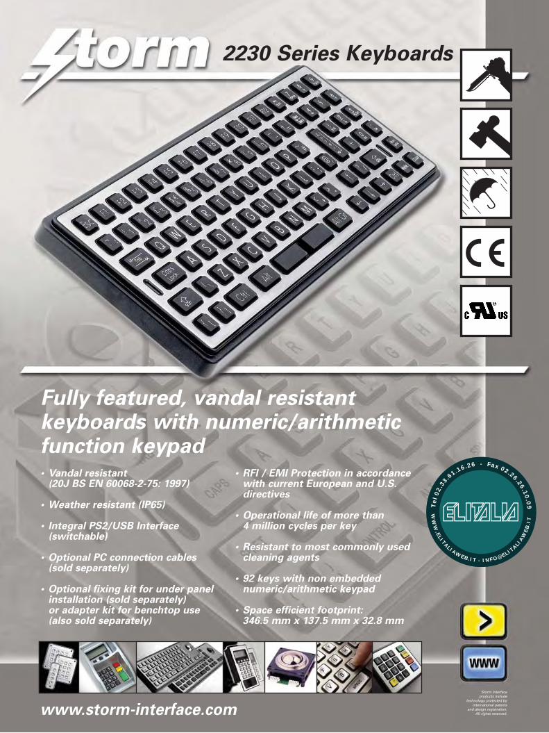
2230 Series Keyboards
Fully featured, vandal resistant keyboards with numeric/arithmeticfunction keypad• Vandal resistant
(20J BS EN 60068-2-75: 1997)
• Weather resistant (IP65)
• Integral PS2/USB Interface (switchable)
• Optional PC connection cables (sold separately)
• Optional fixing kit for under panel installation (sold separately)or adapter kit for benchtop use (also sold separately)
• RFI / EMI Protection in accordancewith current European and U.S.directives
• Operational life of more than 4 million cycles per key
• Resistant to most commonly usedcleaning agents
• 92 keys with non embeddednumeric/arithmetic keypad
• Space efficient footprint:346.5 mm x 137.5 mm x 32.8 mm
www.storm-interface.com
Storm Interfaceproducts include
technology protected byinternational patents
and design registration.All rights reserved.
WW
W.ELITALIAWEB.IT - INFO@ELIT
ALIAW
EB
.IT
Tel
02.
33
.61.16.26 - Fax 02.26.26.10
.09
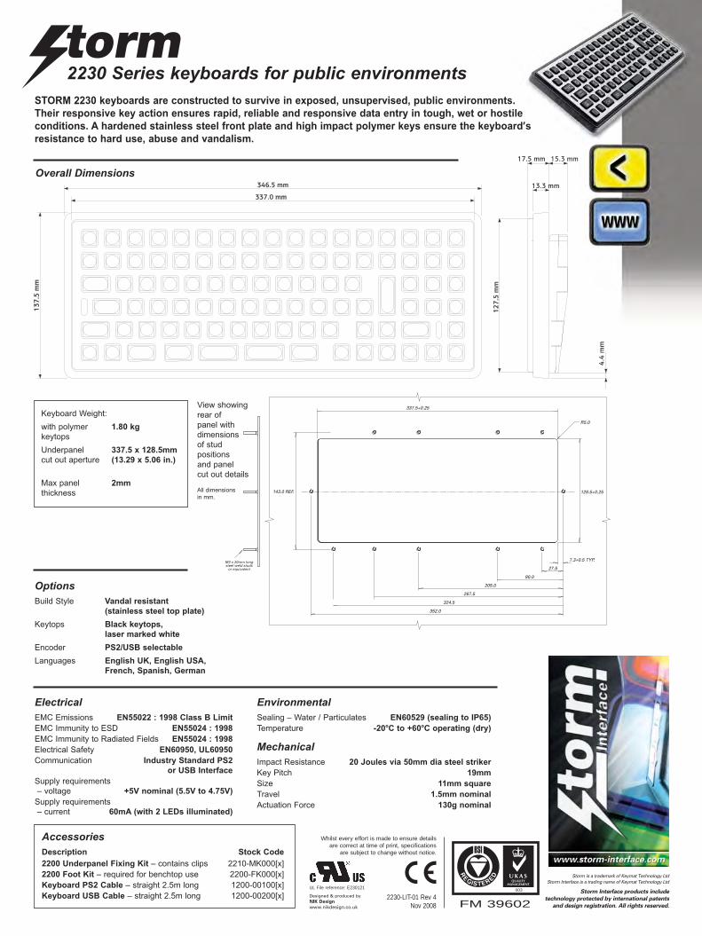
2230 Series keyboards for public environments
Overall Dimensions
OptionsBuild Style Vandal resistant
(stainless steel top plate)
Keytops Black keytops,
laser marked white
Encoder PS2/USB selectable
Languages English UK, English USA,
French, Spanish, German
AccessoriesDescription Stock Code
2200 Underpanel Fixing Kit – contains clips 2210-MK000[x]
2200 Foot Kit – required for benchtop use 2200-FK000[x]
Keyboard PS2 Cable – straight 2.5m long 1200-00100[x]
Keyboard USB Cable – straight 2.5m long 1200-00200[x]
STORM 2230 keyboards are constructed to survive in exposed, unsupervised, public environments.
Their responsive key action ensures rapid, reliable and responsive data entry in tough, wet or hostile
conditions. A hardened stainless steel front plate and high impact polymer keys ensure the keyboard’sresistance to hard use, abuse and vandalism.
ElectricalEMC Emissions EN55022 : 1998 Class B Limit
EMC Immunity to ESD EN55024 : 1998
EMC Immunity to Radiated Fields EN55024 : 1998
Electrical Safety EN60950, UL60950
Communication Industry Standard PS2
or USB Interface
Supply requirements
– voltage +5V nominal (5.5V to 4.75V)
Supply requirements
– current 60mA (with 2 LEDs illuminated)
MechanicalImpact Resistance 20 Joules via 50mm dia steel striker
Key Pitch 19mm
Size 11mm square
Travel 1.5mm nominal
Actuation Force 130g nominal
EnvironmentalSealing – Water / Particulates EN60529 (sealing to IP65)
Temperature -20oC to +60oC operating (dry)
205.0
267.5
352.0
90.0
27.5
337.5+0.25
128.5+0.25143.0 REF.
R5.0
7.3+0.5 TYP.M3 x 20mm longsteel weld studs
or equivalent
324.5
Keyboard Weight:
with polymer 1.80 kg
keytops
Underpanel 337.5 x 128.5mm
cut out aperture (13.29 x 5.06 in.)
Max panel 2mm
thickness
View showing
rear of
panel with
dimensions
of stud
positions
and panel
cut out details
All dimensions
in mm.
FM 39602
003
2230-LIT-01 Rev 4 Nov 2008
Whilst every effort is made to ensure detailsare correct at time of print, specifications
are subject to change without notice.
UL File reference: E230121
Designed & produced byNIK Design
www.nikdesign.co.uk
Storm is a trademark of Keymat Technology LtdStorm Interface is a trading name of Keymat Technology Ltd
Storm Interface products include
technology protected by international patents
and design registration. All rights reserved.
Top Mounting Keyboards2212-T/B Series
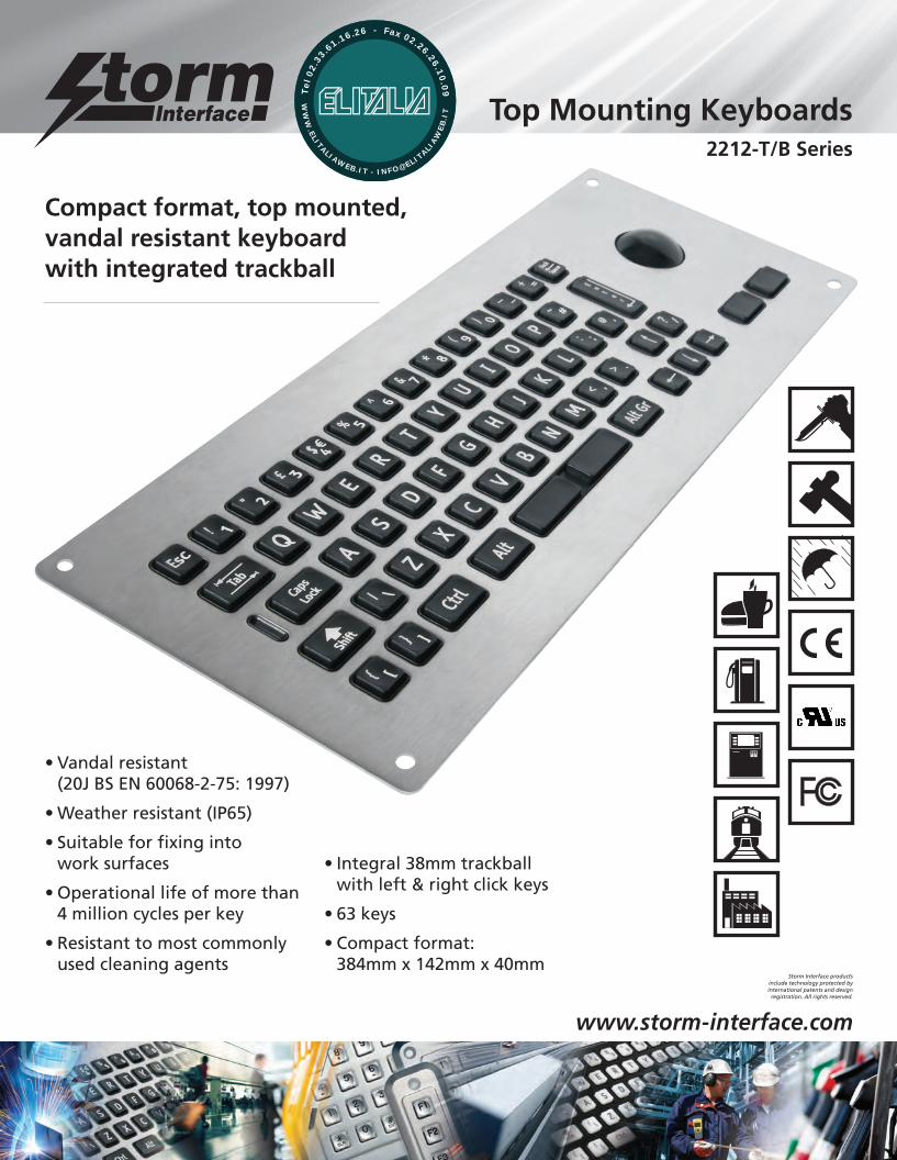
Compact format, top mounted,vandal resistant keyboardwith integrated trackball
• Vandal resistant(20J BS EN 60068-2-75: 1997)
• Weather resistant (IP65)
• Suitable for fixing into work surfaces
• Operational life of more than 4 million cycles per key
• Resistant to most commonlyused cleaning agents
• Integral 38mm trackballwith left & right click keys
• 63 keys
• Compact format:384mm x 142mm x 40mm
www.storm-interface.com
Storm Interface products include technology protected byinternational patents and design
registration. All rights reserved.
WW
W.ELITALIAWEB.IT - INFO@ELIT
ALIAW
EB
.IT
Tel
02.
33
.61.16.26 - Fax 02.26.26.10
.09
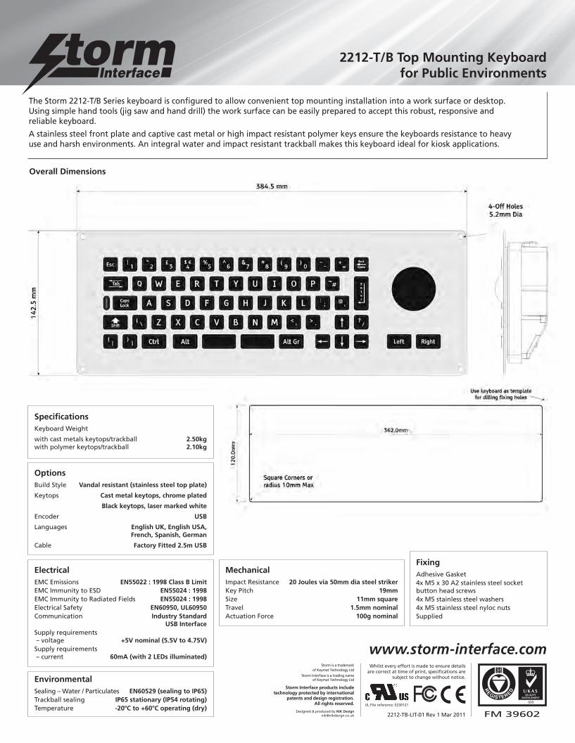
ElectricalEMC Emissions EN55022 : 1998 Class B LimitEMC Immunity to ESD EN55024 : 1998EMC Immunity to Radiated Fields EN55024 : 1998Electrical Safety EN60950, UL60950Communication Industry Standard USB InterfaceSupply requirements– voltage +5V nominal (5.5V to 4.75V)Supply requirements – current 60mA (with 2 LEDs illuminated)
OptionsBuild Style Vandal resistant (stainless steel top plate)
Keytops Cast metal keytops, chrome plated
Black keytops, laser marked white
Encoder USB
Languages English UK, English USA, French, Spanish, German
Cable Factory Fitted 2.5m USB
SpecificationsKeyboard Weight
with cast metals keytops/trackball 2.50kgwith polymer keytops/trackball 2.10kg
MechanicalImpact Resistance 20 Joules via 50mm dia steel strikerKey Pitch 19mmSize 11mm squareTravel 1.5mm nominalActuation Force 100g nominal
FixingAdhesive Gasket4x M5 x 30 A2 stainless steel socketbutton head screws4x M5 stainless steel washers4x M5 stainless steel nyloc nutsSupplied
EnvironmentalSealing – Water / Particulates EN60529 (sealing to IP65) Trackball sealing IP65 stationary (IP54 rotating)Temperature -20oC to +60oC operating (dry)
FM 39602
003
2212-TB-LIT-01 Rev 1 Mar 2011
Whilst every effort is made to ensure detailsare correct at time of print, specifications are
subject to change without notice.
UL File reference: E230121
Designed & produced by NIK [email protected]
Storm is a trademark of Keymat Technology Ltd
Storm Interface is a trading name of Keymat Technology Ltd
Storm Interface products include technology protected by international
patents and design registration. All rights reserved.
www.storm-interface.com
2212-T/B Top Mounting Keyboardfor Public Environments
Overall Dimensions
The Storm 2212-T/B Series keyboard is configured to allow convenient top mounting installation into a work surface or desktop.Using simple hand tools (jig saw and hand drill) the work surface can be easily prepared to accept this robust, responsive andreliable keyboard.
A stainless steel front plate and captive cast metal or high impact resistant polymer keys ensure the keyboards resistance to heavyuse and harsh environments. An integral water and impact resistant trackball makes this keyboard ideal for kiosk applications.
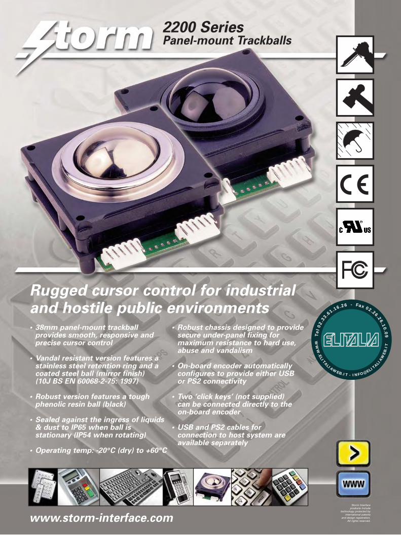
Rugged cursor control for industrialand hostile public environments• 38mm panel-mount trackball
provides smooth, responsive andprecise cursor control
• Vandal resistant version features astainless steel retention ring and acoated steel ball (mirror finish)(10J BS EN 60068-2-75: 1997)
• Robust version features a toughphenolic resin ball (black)
• Sealed against the ingress of liquids& dust to IP65 when ball isstationary (IP54 when rotating)
• Operating temp: -20oC (dry) to +60oC
• Robust chassis designed to providesecure under-panel fixing formaximum resistance to hard use,abuse and vandalism
• On-board encoder automaticallyconfigures to provide either USB or PS2 connectivity
• Two ‘click keys’ (not supplied) can be connected directly to the on-board encoder
• USB and PS2 cables for connection to host system areavailable separately
2200 Series Panel-mount Trackballs
www.storm-interface.com
Storm Interfaceproducts include
technology protected byinternational patents
and design registration.All rights reserved.
WW
W.ELITALIAWEB.IT - INFO@ELIT
ALIAW
EB
.IT
Tel
02.
33
.61.16.26 - Fax 02.26.26.10.0
9

Panel-mount trackballs for industrial and public environments
25
60
Connector Pinout Details
Pin Button PS2 / USB
Connections Output
(P1) Connections
(P3)
1 0V D- / Data
2 Button 1 (left) D+ / Clock
3 0V Test Only
4 Button 2 (right) Power +5V
5 0V Ground 0V
6 Button 3 (middle) Not used
ElectricalSupply Voltage 5.0V dc ±10%
Switch Debounce 30ms rising/falling
Supply Current 15mA maximum
Resolution 150 pulses, 600 counts/revolution
MechanicalTracking Force 50g nominal any direction
Ball Speed 250 rpm maximum
Operational Life 10 million revolutions (min)
Mounting Angle within 45o from horizontal
InstallationPrepare plate with hole for o43.0mm bezel and M3 x 40mm studs on 52.5mm centres.
Fit sealing gasket to trackball.
Place trackball over studs.
Place vandal plate over studs (VR version only).
Secure with plain washers and Nyloc nuts.
IMPORTANT: Max torque 40Ncm on nuts.
Connect switches to connector P1.
If reqd,fit jumper to enable both buttons as left click.
MaterialRobust Trackball Phenolic Resin
Vandal Resistant Trackball Surface Treated Steel
Seal Material PTFE with low friction fill
Vandal Plate Stainless Steel
NB. Robust Version does not have Vandal Plate
EnvironmentalOperating Temp -20oC (dry) to +60oC
IP65 seal when ball stationary
IP54 seal when ball rotating
Humidity 95% Rh max, non-condensing
Accessories [x] denotes packaging variant
Stock No. Item
2200-00200[x] Cable 2.5m PS2
2200-00300[x] Cable 2.5m USB
2200-00020[x] Trackball Unit PS2 / USB Black Phenolic Ball
2200-00030[x] Trackball Unit PS2 / USB Coated Steel Ball
Overall Dimensions(Vandal plate not shown)
43
52.5
52.5
Panel Preparation Details
Panel Thickness: 1.5 – 3.0mm
Trackballo 38.0mm
M3 x 40mm studs (4off)
The unit automatically selects either USB or PS/2 protocols on power-up. No re-setting of
any DIP switches required.
If both buttons are required to be set as left click then a connection must be made between
pins on connector P2 using the jumper device (supplied).
Please note that the TEST input is reserved for factory test only. On no account should a
connection be made to this terminal.
The Button inputs are pulled high to 5V within the unit.
Both rising and falling edges of this signal are debounced for 30ms.
The Storm Trackball is designed to work with resident drivers and does not require
additional software to be loaded.
These 38mm trackballs provide smooth, accurate and responsive cursor control in wet, dirty or
aggressive environments. Each device automatically configures to provide USB or PS2 connectivity.
Two selector (click) buttons (not supplied) can be configured to provide either left and right click
functions or for both buttons to provide left click functions only. These trackballs can be installed as
a flush mounted component in a control panel or equipment housing. Cables enabling connection to
either USB or PS2 systems are supplied separately. The trackballs are constructed to ensure
maximum resistance to hard use, abuse, and vandalism.
1 2 3 4 5 6
CONNECTORP1
1 2 3 4 5 6
CONNECTORP3P2
FM 39602
003
2200-LIT-01 Rev 4 Nov 2008
Whilst every effort is made to ensure detailsare correct at time of print, specifications
are subject to change without notice.
UL File reference: E230121
Designed & produced byNIK Design
www.nikdesign.co.uk
Storm is a trademark of Keymat Technology LtdStorm Interface is a trading name of Keymat Technology Ltd
Storm Interface products include
technology protected by international patents
and design registration. All rights reserved.

t mroSecure Keypads for access control
®
AlternativeSecure
The
www.keymat.com
WW
W.ELITALIAWEB.IT - INFO@ELIT
ALIAW
EB
.IT
Tel
02.
33
.61.16.26 - Fax 02.26.26.10
.09

personnel, whilst securing premises against thosewho are not. The high risk practice ofissuing duplicate door keys is no longeracceptable or economically viable. Keys (or cards) are regularly lost, stolen orcopied. If a breach in security is suspected,
locks must be changed and new keys (or cards) issued.This is not practical on a repeated or routine basis.
The fitting of a STORM AXS Keypad provides a secure,efficient and cost effective solution. Authorised personnelcan be allocated a ‘Personal Identification Number’ (PIN)which, when entered into the keypad, triggers an electrically
operated strike or lock. This permits instant access through anormally locked door or barrier. PIN codes can be regularlychanged to maintain system security, or can be withdrawn atany time to discontinue an individual’s access to the securedarea.
Code holders can be given access to selected areas anddebarred from others. For example; an office worker’s PIN codecan be programmed to allow access to an administration centre
but prohibit access to a stores area; whereas the StoreManager’s PIN code can be programmed to access both theadministration centre and the stores area. PIN codes can beprogrammed to unlock a door and leave it unlocked (latched)until the code is re-entered. Alternatively they can beprogrammed to unlock the door for a pre-set time allowing justone person to enter before the door re-locks.
STORM AXS Keypadsprovide rapid and reliableaccess control inprofessional ‘high-traffic’
applications.Constructed to withstand hard useand abuse the keypads can be fittedin exposed outdoor locations.
Available in both ‘general service’ and‘vandal resistant’ specifications,complying with current and forthcomingmandatory standards, STORM AXSKeypads are ideal for use in all indoor and outdoor installations.
STORM AXS Keypads include sophisticatedelectronic controllers. These controllers,utilising the latest developments inmicroprocessor technology, are securely
housed within the keypad casing. Thekeypads include high level protection againststatic discharge damage. They can beselected to achieve direct, local control of
door locking mechanisms (Strike Master) or toprovide electronic communication with centralisedalarm and access control systems (Code Master).The STORM AXS Strike Masterkeypad includes an electronicsensor that detects any attempt toremove or tamper with the keypad.This feature provides high level
system security whilst maintaining the advantages of aself-contained, compact, ‘one-box’ installation.
With rising crime rates and
an increasing incidence of assaults on
personnel, the need to control
access to buildings or work areas has never
been greater.
t mroSecure Keypads for access control
®
It is essential to provide free access to authorised
Secure and simple to install.
Robust, responsive
keypad technology,
proven in military,
industrial and public
environments.
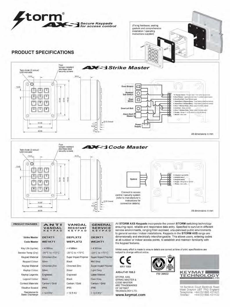
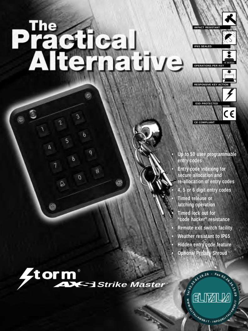
• Up to 50 user programmableentry codes
• Entry code indexing forsecure allocation andre-allocation of entry codes
• 4, 5 or 6 digit entry codes
• Timed release or latching operation
• Timed lock out for “code hacker” resistance
• Remote exit switch facility
• Weather resistant to IP65
• Hidden entry code feature
• Optional Privacy Shroud
Strike Master
IMPACT RESISTANT
IP65 SEALED
OPERATIONS PER KEY
RESPONSIVE KEY ACTION
ESD PROTECTED
CE COMPLIANT
>4 Million
t mro ®
WW
W.ELITALIAWEB.IT - INFO@ELIT
ALIAW
EB
.IT
Tel
02.
33
.61.16.26 - Fax 02.26.26.10
.09
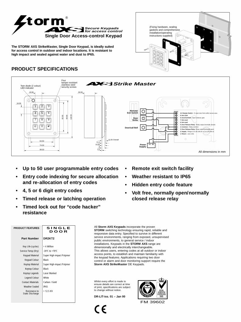
Whilst every effort is made toensure details are correct at timeof print, specifications are subjectto change without notice.
All Storm AXS Keypads incorporate the proven STORM switching technology ensuring rapid, reliable andresponsive data entry. Specified to survive in different service environments, ranging from exposed, unsupervisedpublic environments, to general service / indoorinstallations. Keypads in the STORM AXS range aredimensionally and electrically interchangeable.This allows users, entering codes at all outdoor or indooraccess points, to establish and maintain familiarity with the keypad features. Applications requiring two door control or alarm and door monitoring support require theStorm AXS StrikeMaster DE Keypads.
FM 39602
NATIONALACCREDITATION
OF CERTIFICATIONBODIES
BSI
DR-LIT-iss. 01 – Jan 00
t mroSecure Keypads for access control
Single Door Access-control Keypad
(Fixing hardware, sealinggaskets and comprehensiveinstallation/operatinginstructions supplied)
The STORM AXS StrikeMaster, Single Door Keypad, is ideally suitedfor access control in outdoor and indoor locations. It is resistant tohigh impact and sealed against water and dust to IP65.
PRODUCT SPECIFICATIONS
99.50
118.
50
63.50
82.5
0
19.00
19.00
74.00
93.0
0
10.50
30.00
2 31
5 64
8 97
0
13.35 Overall
2.58
11.1
Twin diode (2 colour)LED indicator
Four tamper-resistant stainless steel security screws
Strike Master
• Up to 50 user programmable entry codes
• Entry code indexing for secure allocationand re-allocation of entry codes
• 4, 5 or 6 digit entry codes
• Timed release or latching operation
• Timed lock out for “code hacker”resistance
• Remote exit switch facility
• Weather resistant to IP65
• Hidden entry code feature
• Volt free, normally open/normallyclosed release relay
DR2KT2
> 4 Million
-200C to +700C
Super High-impact Polymer
Black
Super High-impact Polymer
Black
Laser Marked
White
Carbon / Gold
IP65
> 12.5 KV
Part Number
Key Life (cycles)
Service Temp (Dry)
Keypad Material
Keypad Colour
Keytop Material
Keytop Colour
Keytop Legends
Legend Colour
Contact Materials
Weather Sealed
Resistance to Static Discharge
PRODUCT FEATURES S I N G L ED O O R
21 3
54 6
87 9
0
Remote/Exit Switch
DoorStrike
Door/call Bell
PowerSupply
10. Remote Switch - To open door from within secure area
9. Not used
8. Door/Call Bell - Open collector gate
7. Not used
5. Door Release Relay - Relay output (normally closed)
4. Common - Relay common
3. Door Release Relay -Relay output (normally open)
2. Supply - Range 11 to 28 volts dc or 9 to 20 volts ac.
1. Return – zero volts
6. Not used
+V 0V
All dimensions in mm
1
32
65
4
7
98
0
t mro ®