design seismic motions and wind loads for 1000 m high, 1000
TRANSCRIPT
Design seismic motions and wind loads for1000 m high, 1000 year use building
Autor(en): Kanda, Jun / Kubota, Toshihiko / Asano, Mitsugu
Objekttyp: Article
Zeitschrift: IABSE reports = Rapports AIPC = IVBH Berichte
Band (Jahr): 79 (1998)
Persistenter Link: http://doi.org/10.5169/seals-59941
PDF erstellt am: 03.02.2022
NutzungsbedingungenDie ETH-Bibliothek ist Anbieterin der digitalisierten Zeitschriften. Sie besitzt keine Urheberrechte anden Inhalten der Zeitschriften. Die Rechte liegen in der Regel bei den Herausgebern.Die auf der Plattform e-periodica veröffentlichten Dokumente stehen für nicht-kommerzielle Zwecke inLehre und Forschung sowie für die private Nutzung frei zur Verfügung. Einzelne Dateien oderAusdrucke aus diesem Angebot können zusammen mit diesen Nutzungsbedingungen und denkorrekten Herkunftsbezeichnungen weitergegeben werden.Das Veröffentlichen von Bildern in Print- und Online-Publikationen ist nur mit vorheriger Genehmigungder Rechteinhaber erlaubt. Die systematische Speicherung von Teilen des elektronischen Angebotsauf anderen Servern bedarf ebenfalls des schriftlichen Einverständnisses der Rechteinhaber.
HaftungsausschlussAlle Angaben erfolgen ohne Gewähr für Vollständigkeit oder Richtigkeit. Es wird keine Haftungübernommen für Schäden durch die Verwendung von Informationen aus diesem Online-Angebot oderdurch das Fehlen von Informationen. Dies gilt auch für Inhalte Dritter, die über dieses Angebotzugänglich sind.
Ein Dienst der ETH-BibliothekETH Zürich, Rämistrasse 101, 8092 Zürich, Schweiz, www.library.ethz.ch
http://www.e-periodica.ch
581
Design Seismic Motions and Wind Loads for 1000 m High,1000 Year Use Building
Jun KANDAProf.Univ. of TokyoTokyo, Japan
Toshihiko KUBOTAMan. Dir.Kobori Research Complex Inc.Tokyo, Japan
Mitsugu ASANOGen. MgrNikken Sekkei LtdTokyo, Japan
Shin-ichi HIRASHIMAGen. MgrShimizu Corp.Tokyo, Japan
Yoshihiro MATAKISen. Chief Research Eng.Takenaka Corp.Chiba, Japan
Summary
Construction of 1,000-meter-high hyper buildings for 1,000-year use having a total floor area of10 million square meters in Japan requires studies on structural safety against earthquakes andwinds. In this study, flowcharts for checking the structural safety of hyper buildings taking intoconsideration their characteristics, namely height and service life, were proposed, throughcomparison with typical flowcharts for high-rise buildings. Target performance and methods fordetermining design values of seismic and wind loads were also studied. This paper presents thebasic concepts thus developed, along with a list of subjects of further study.
1. Introduction
Starting in 1995, a group of organizations including the Ministry of Construction, the BuildingCenter of Japan, general contractors, and design firms conducted a two-year joint study as a steptoward the realization of the scheme for hyper buildings, which are 1,000 m high and have aservice life of 1,000 years and a total floor area of 10 million square meters. The study covered13 fields of research, and the subject of design ground motions and wind loads was adopted asone of them.Needless to say, a l,000m-high building for 1,000-year use requires a more comprehensivestructural safety evaluation than a conventional 300m-high 100-year-or-so-useful-life high-risebuilding does.In this study, considering the construction of hyper buildings in Japan, methods for evaluatingtheir structural performance and target structural performance are proposed. An example ofcalculation of a measure of safety common to seismic loads and wind loads is also presented.Finally, the basic concepts of seismic- and wind-resistant design and flowcharts for the proposeddesign procedures are presented.
582 DESIGN SEISMIC MOTIONS AND WIND LOADS
2. Basic concept of structural safety
2.1 Image of a hyper building
Structural safety of a hyper building is considered for its three major components: main structure,secondary structure, and infrastructure. The main structure is the part of the hyper building that issupposed to remain unchanged in performance throughout the service life of the building. Thesecondary structure is any structure inside the main structure that may be changed, often morethan once during the service life of the building, depending on performance requirements. Theinfrastructure is the part of the building that supports the circulation of people, vehicles, energy,and the like and computer-based control functions and is therefore subject to change dependingon the performance needs of the time.
2.2 Flowchart for structural performance evaluation
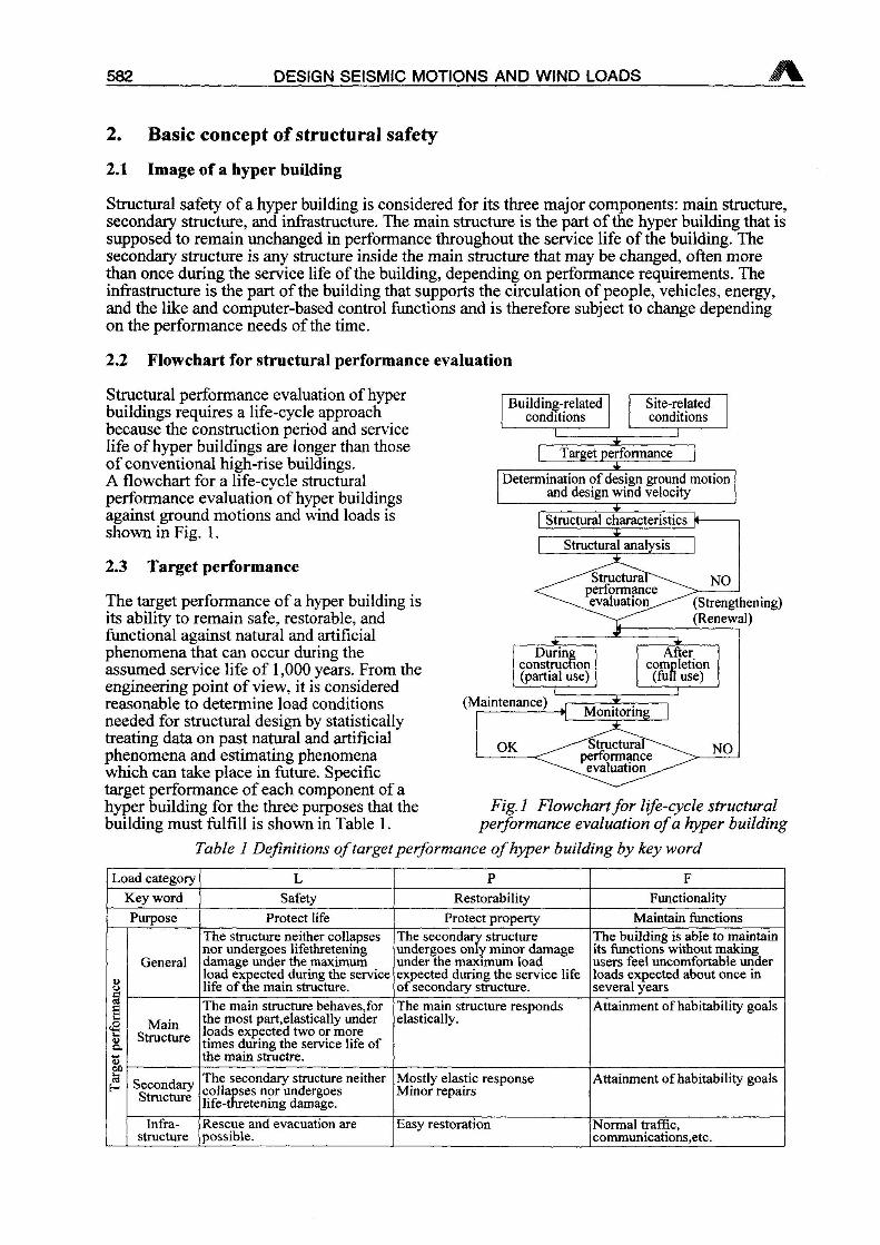
Structural performance evaluation of hyperbuildings requires a life-cycle approachbecause the construction period and servicelife of hyper buildings are longer than thoseof conventional high-rise buildings.A flowchart for a life-cycle structuralperformance evaluation of hyper buildingsagainst ground motions and wind loads isshown in Fig. 1.
Building-relatedconditions
Site-relatedconditions
Target performance
Determination of design ground motionand design wind velocity
jEStructural characteristics K-
2.3 Target performance
The target performance of a hyper building isits ability to remain safe, restorable, andfunctional against natural and artificialphenomena that can occur during theassumed service life of 1,000 years. From theengineering point of view, it is consideredreasonable to determine load conditionsneeded for structural design by statisticallytreating data on past natural and artificialphenomena and estimating phenomenawhich can take place in future. Specifictarget performance of each component of ahyper building for the three purposes that thebuilding must fulfill is shown in Table 1.
(Strengthening)(Renewal)
(Maintenance)
Fig. 1 Flowchartfor life-cycle structuralperformance evaluation ofa hyper building
Table 1 Definitions of targetperformance ofhyper building by key word
Load category L P F
Key word Safety Restorability FunctionalityPurpose Protect life Protect property Maintain functions
»o
General
The structure neither collapsesnor undergoes lifethreteningdamage under the maximumload expected during the servicelife of the main structure.
The secondary structureundergoes only minor damageunder the maximum loadexpected during the service lifeof secondary structure.
The building is able to maintainits functions without makingusers feel uncomfortable underloads expected about once inseveral years
3
§uQ."5
MainStructure
The main structure behaves,forthe most part,elastically underloads expected two or moretimes during the service life ofthe main structre.
The main structure respondselastically.
Attainment of habitability goals
SecondaryStructure
The secondary structure neithercollapses nor undergoeslife-thretening damage.
Mostly elastic responseMinor repairs
Attainment of habitability goals
InfrastructureRescue and evacuation arepossible.
Easy restoration Normal traffic,communications,etc.
J. KANDA, T. KUBOTA, M. ASANO, S. HIRASHIMA, Y. MATAKI 583
2.4 Calculation of design load based on optimum reliability and checks of structuralsafety
1) Optimum reliability index
Using Kanda's method,1' the optimum reliability index ßopr is calculated from the equation
Pan -aeVa + kaeVQf + 2 ln( 8
] d2xKaQVQ
where ccq : separation factorVq : coefficient of variation of load effectg : normalized failure costk : normalized cost ratio
The design load Xd can be given as
XD exy(aQßorr)pQT
where pqt is the mean value of maximum loads per T years.In this study, ag=0.85, g=2, and k=0.052' are assumed for both seismic loads and wind loads.
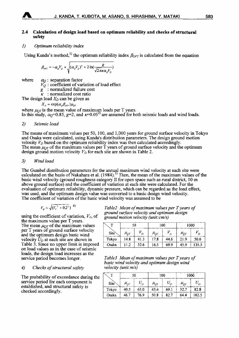
2) Seismic load
The means ofmaximum values per 50, 100, and 1,000 years for ground surface velocity in Tokyoand Osaka were calculated, using Kanda's distribution parameters. The design ground motionvelocity To based on the optimum reliability index was then calculated accordingly.The mean juqt of the maximum values per T years of ground surface velocity and the optimumdesign ground motion velocity Vo for each site are shown in Table 2.
3) Wind load
The Gumbel distribution parameters for the annual maximum wind velocity at each site werecalculated on the basis ofNakahara et al. (1984).3' Then, the mean of the maximum values of thebasic wind velocity (ground roughness category II for open space such as rural district, 10mabove ground surface) and the coefficient of variation at each site were calculated. For theevaluation of optimum reliability, dynamic pressure, which can be regarded as the load effect,was used, and the optimum design value was converted to a basic design wind velocity.The coefficient of variation of the basic wind velocity was assumed to be
ve J(.vP+022) 4>
using the coefficient of variation, Vy, ofthe maximum value per T years.The mean pqt of the maximum valuesper T years of ground surface velocityand the optimum design basic windvelocity Uo at each site are shown inTable 3. Since no upper limit is imposedon load values as in the case of seismicloads, the design load increases as theservice period becomes longer.
4) Checks ofstructural safety
The probability of exceedance during theservice period for each component isestablished, and structural safety ischecked accordingly.
Table2 Mean ofmaximum values per Tyears ofground surface velocity and optimum designground motion velocity (unit:cm/s)
50 100 1000
Site\ Pqt Vo Pqt yD Pqt yD
Tokyo 14.8 41.3 17.8 44.6 21.9 50.6
Osaka 11.2 52.6 16.5 69.9 45.9 135.5
Table3 Mean ofmaximum values per Tyears ofbasic wind velocity and optimum design windvelocity (unif.mls)
50 100 1000
Site\ Pqt Pqt vD Pqt vD
Tokyo 40.5 65.0 43.4 69.1 52.7 82.8
Osaka 46.7 76.9 50.8 82.7 64.4 102.5
584 DESIGN SEISMIC MOTIONS AND WIND LOADS
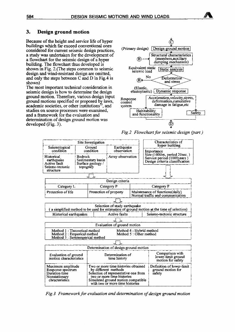
3. Design ground motion
Because of the height and service life ofhyperbuildings which far exceed conventional onesconsidered for current seismic design practices,a study was undertaken for the development ofa flowchart for the seismic design of a hyperbuilding. The flowchart thus developed isshown in Fig. 2.(The steps common to seismicdesign and wind-resistant design are omitted,and only the steps between C and D in Fig.4 isshown)The most important technical consideration inseismic design is how to determine the designground motion. Therefore, various design inputground motions specified or proposed bv laws,academic societies, or other institutions andstudies on source processes were examined,and a framework for the evaluation anddetermination of design ground motion wasdeveloped (Fig. 3).
(Primary design)
® *
'
Design ground motion |
Structural characteristics(members,auxiliary
damping mechanism)
Equivalent static [~gtatjc analysis^"seismic load 1 .—1—1
No
(Elastic,elastoplastic)
Responsecontrolsystem
DeformatiofT-and stress
Dynamicjusponse
Acceleration,velocity,stress,deformation,cumulative
damage in fatigue,etc
Habitabilityand functionality Safety
¥Fig. 2 Flowchartfor seismic design (part
Site InvestigationSeismological
conditionGround
conditionEarthquakeobservation
Historicalearthquake
Active faultSeismo-tectonic
structure
BedrockSedimentary basinSurface geology /
topografy
Array observation
Characteristics ofhyper building
ImportanceSize (1000m, period 20sec.Service period (lOOOyearsDesign criteria classification
Design criteria
Category L Category P Category F
Protection of life Protection of property Maintenance of functions(daily)Normal traffic and communication
Selection of study earthquakea simplified method to be used for estimation of ground motion at the time of selection)Historical earthquakes | Active faults | Seismo-tectonic structure
Evaluation of ground motion
Method 1 : Theoretical method Method 4 : Hybrid methodMethod 2 : Emperical method Method 5 : Other methodMethod 3 : Semiemperical method
Determination of design ground motion
Evaluation ofgroundmotion characteristics
Determination oftime history
Comparison withlower-limit groundmotion for safety
Maximum amplitudeResponse spectrumDuration timeNonstationary
chracteristics
Two or more time histories obtainedby different methods
Selection of representative one fromtwo or more time histories
Simulated ground motion compatiblewith two or more time histories
Definition of lower-limitground motion forsafety
Fig. 3 Frameworkfor evaluation and determination ofdesign ground motion
J. KANDA, T. KUBOTA, M. ASANO, S. HIRASHIMA, Y. MATAKI 585
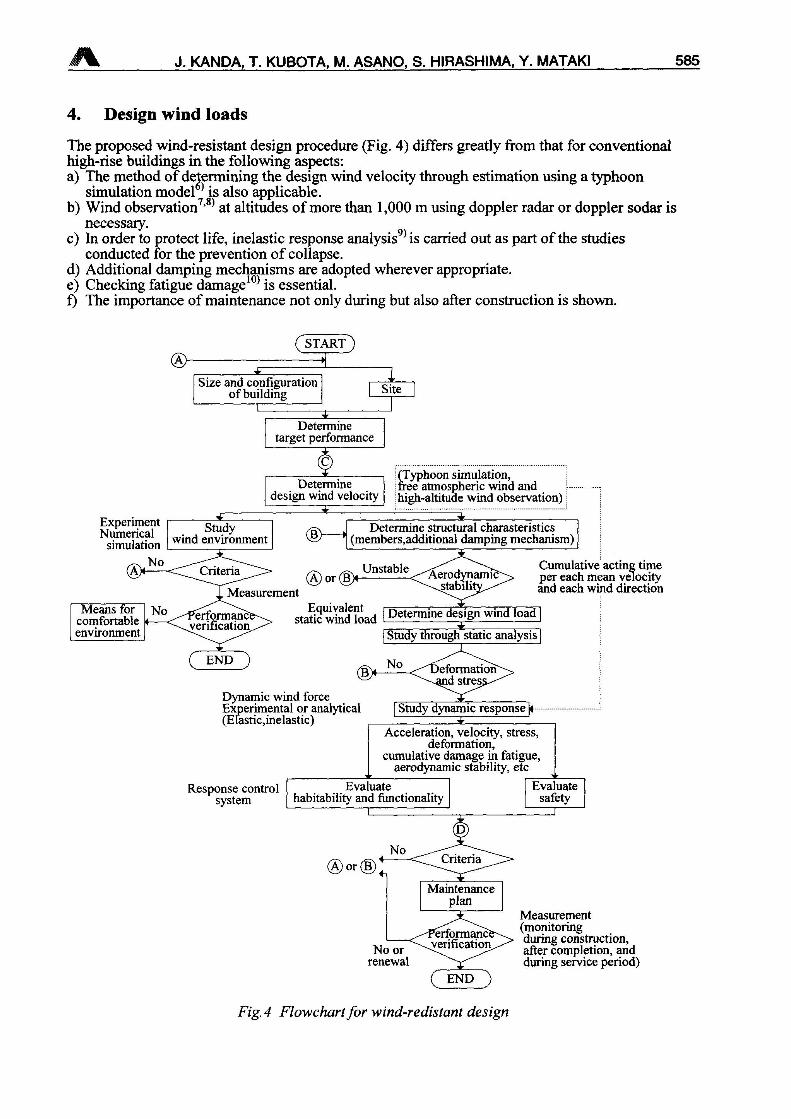
4. Design wind loads
The proposed wind-resistant design procedure (Fig. 4) differs greatly from that for conventionalhigh-rise buildings in the following aspects:a) The method of determining the design wind velocity through estimation using a typhoon
simulation model6' is also applicable.b) Wind observation7'8' at altitudes of more than 1,000 m using doppler radar or doppler sodar is
necessary.c) In order to protect life, inelastic response analysis9' is carried out as part of the studies
conducted for the prevention of collapse.d) Additional damping mechanisms are adopted wherever appropriate.e) Checking fatigue damage10' is essential.f) The importance of maintenance not only during but also after construction is shown.
(START)>1
Size and configurationofbuilding Site
Determinetarget performance
ExperimentNumerical
simulation
Determinedesign wind velocity
(Typhoon simulation,free atmospheric wind andhigh-altitude wind observation)
® »Determine structural charasteristics
(members,additional damping mechanism)
Criteria
Measurementor(B>
Unstable'Aerodynamic~ stabilif '
Cumulative acting timeper each mean velocityand each wind direction
staticwmdload 1 Determine design wind load [
END(1>
I Study through static analysis]
No
Dynamic wind forceExperimental or analytical Study dynamic response |»
Response controlsystem
Acceleration, velocity, stress,deformation,
cumulative damage in fatigue,aerodynamic stability, etc
Evaluatehabitability and functionality
Evaluatesafety
No orrenewal
END
Fig. 4 Flowchartfor wind-redistant design
Measurement(monitoringduring construction,after completion, andduring service period)
586 DESIGN SEISMIC MOTIONS AND WIND LOADS J%L
5. Conclusions
In this paper, basic concepts ofwhat should be done to ensure the structural safety of hyperbuildings against earthquakes and winds have been presented. As a result of this study, a numberof subjects of further study have been identified. Among them are as follows,
1) Subjects concerning structural safety
(1) Risk level determination by use of such techniques as risk management(2) Design recurrence interval and criteria(3) Variations among analysis models
2) Subjects concerning design ground motion
(1) Synthesizing of broad-band (period: 0.1 to 20 second) design ground motions(2) Zoning ofpredominant periods of ground based on past studies of velocity structure and on
observation records of long-period strong ground motions(3) Seismological conditions at the construction site and the determination of ground
investigation areas(4) Variations of factors affecting the maximum ground motion
3) Subjects concerning with wind-resistant design
(1) Development of wind-resistant design methods which consider elastoplasticity of structuralmembers
(2) Development of more accurate typhoon simulation methods(3) Observation of high-altitude winds
REFERENCE
1. J. Kanda, B. Ellingwood, Formulation of Load Factors Based on Optimum Reliability,Structural Safety, 9, 1991
2. J. Kanda et al, Construction Cost for Various Buildings with Varying Seismic Load, Proc.Annual Meeting, Architectural Institute of Japan (A.I.J.), Nagoya, 1994 (in Japanese)
3. M. Nakahara, Y. Tamura, Y. Asami, Y. Niihori and Y. Yoshikawa, Map of Japan showingDesign Wind Speed, Trans, of A.I.J., No.336, Feb., 1984 (in Japanese)
4. J.Kanda, Stochastic Evaluation of Wind Load Considering Dynamic Gust Response, Proc.Symposium Wind Eng., 1982 (in Japanese)
5. T. Ishii and T. Sato, An Evaluation Methodology of Design Earthquake Motions Based onSite -Related Earthquakes, J. Struct. Constr. Eng., A.I.J., No.462, Aug., 1994 (in Japanese)
6. Y. Meng, M. Matsui, and K. Hibi, An Analytical Model for Simulation of the Wind Field in aTyphoon Boundary Layer, J. Wind Eng. Ind. Aerdyn., No. 56,1995
7. H. Hayashida, S. Fukao, T. Kobayashi, H. Nirasawa, Y. Mataki, K. Ohtake and M. Kikuchi,Remote Sensing of Wind Velocity by Boundary Layer Radar, J. Wind Eng., No.67, April,1996 (in Japanese)
8. T. Amano, T. Ohkuma, A. Kawaguchi and S. Goto, The Wind Observation in Okinawa byDoppler Sodar during Typhoons, J. Wind Eng., No.67, April. 1996 (in Japanese)
9. O. Tsujita, Y. Hayabe, T. Ohkuma and A. Wada, A Study on Wind-Induced ResponseCharacteristics and Prediction for Inelastic Structure Parti. A case of across-wind vibration, J.Struct. Constr. Eng., A.I.J., No.481, Mar., 1996 (in Japanese)
10. M. Yoshida, T. Kobayashi, T. Fukumoto, S. Hanyuuda and Y. Matuzaki, Estimation ofWind-Induced Damage Ratio of Steel Damper Controlling Structural Vibration, SteelConstruction Eng., Vol.1, No.2,1994 (in Japanese)