1. use pen and ink to complete all paper bids. 2. - maine.gov
TRANSCRIPT

July 6, 2005 Supersedes August 4, 2004
BIDDING INSTRUCTIONS
FOR ALL PROJECTS: 1. Use pen and ink to complete all paper Bids. 2. As a minimum, the following must be received prior to the time of Bid opening:
For a Paper Bid: a) a copy of the Notice to Contractors, b) the completed Acknowledgement of Bid Amendments form, c) the completed Schedule of Items, d) two copies of the completed and signed Contract Offer, Agreement & Award form, e) a Bid Guaranty if required, and f) any other certifications or Bid requirements listed in the Bid Documents as due by Bid opening.
For an Electronic Bid:
a) a completed Bid using Expedite® software and submitted via the Bid Express™ web-based service, b) a Bid Guaranty (as described below) or a faxed copy of a Bid Bond if required (with original to be delivered within 72 hours), and c) any other certifications or Bid requirements listed in the Bid Documents as due by Bid opening.
3. Include prices for all required items in the Schedule of Items. (“Zero is not considered a Bid
price.”) 4. Include a Bid Guaranty (If Required). Acceptable forms are:
a. a properly completed and signed Bid Bond on the Department’s prescribed form (or on a form that does not contain any significant variations from the Department’s form as determined by the Department) for 5% of the Bid Amount or
b. an Official Bank Check, Cashier’s Check, Certified Check, U.S. Postal Money
Order or Negotiable Certificate of Deposit in the amount stated in the Notice to Contractors.
5. If a paper Bid is to be sent, Federal Express overnight delivery is suggested as the package is
delivered directly to the DOT Headquarters Building in Augusta. Other means, such as U.S. Postal Service’s Express Mail has proven not to be reliable.
IN ADDITION, FOR FEDERAL AID PROJECTS: 6. Complete the DBE Proposed Utilization form in the proper amounts, and deliver to the
Contracts section by 4:30 PM on bid opening day If you need further information regarding Bid preparation, call the DOT Contracts Section at (207)624-3410. For complete bidding requirements, refer to Section 102 of the Maine Department of Transportation, Standard Specifications, Revision of December 2002.

January 30, 2004 Supercedes February 11, 2003
Page 1 of 1
NOTICE The Maine Department of Transportation is attempting to improve the way Bid Amendments/Addendums are handled, and allow for an electronic downloading of bid packages from our website, while continuing to maintain a planholders list. Prospective bidders, subcontractors or suppliers who wish to download a copy of the bid package and receive a courtesy notification of project specific bid amendments, must provide an email address to Diane Barnes or Mike Babb at the MDOT Contracts mailbox at: [email protected]. Each bid package will require a separate request. Additionally, interested parties will be responsible for reviewing and retrieving the Bid Amendments from our web site, and acknowledging receipt and incorporating those Bid Amendments in their bids using the Acknowledgement of Bid Amendment Form. The downloading of bid packages from the MDOT website is not the same as providing an electronic bid to the Department. Electronic bids must be submitted via http://www.BIDX.com. For information on electronic bidding contact Larry Childs at [email protected].

NOTICE
For security and other reasons, all Bid Packages which are mailed, shall be provided in double (one envelope inside the other) envelopes. The Inner Envelope shall have the following information provided on it: Bid Enclosed - Do Not Open PIN: Town: Date of Bid Opening:
Name of Contractor with mailing address and telephone number:
In Addition to the usual address information, the Outer Envelope should have written or typed on it: Double Envelope: Bid Enclosed PIN: Town: Date of Bid Opening: Name of Contractor:
This should not be much of a change for those of you who use Federal Express or similar services.
Hand-carried Bids may be in one envelope as before, and should be marked with the following infrormation: Bid Enclosed: Do Not Open PIN: Town: Name of Contractor:
October 16, 2001

STATE OF MAINE DEPARTMENT OF TRANSPORTATION Bid Guaranty-Bid Bond Form
KNOW ALL MEN BY THESE PRESENTS THAT , of the City/Town of and State of as Principal, and as Surety, a Corporation duly organized under the laws of the State of and having a usual place of Business in and hereby held and firmly bound unto the Treasurer of the State of Maine in the sum of ,for payment which Principal and Surety bind themselves, their heirs, executers, administrators, successors and assigns, jointly and severally. The condition of this obligation is that the Principal has submitted to the Maine Department of Transportation, hereafter Department, a certain bid, attached hereto and incorporated as a part herein, to enter into a written contract for the construction of and if the Department shall accept said bid and the Principal shall execute and deliver a contract in the form attached hereto (properly completed in accordance with said bid) and shall furnish bonds for this faithful performance of said contract, and for the payment of all persons performing labor or furnishing material in connection therewith, and shall in all other respects perform the agreement created by the acceptance of said bid, then this obligation shall be null and void; otherwise it shall remain in full force, and effect. Signed and sealed this day of 20 WITNESS: PRINCIPAL: By By: By: WITNESS SURETY: By By: Name of Local Agency:

NOTICE
Bidders: Please use the attached “Request for Information” form when faxing questions and comments concerning specific Contracts that have been Advertised for Bid. Include additional numbered pages as required. Questions are to be faxed to the number listed in the Notice to Contractors. This is the only allowable mechanism for answering Project specific questions. Maine DOT will not be bound to any answers to Project specific questions received during the Bidding phase through other processes.

State of Maine Department of Transportation
REQUEST FOR INFORMATION Date _______________ Time __________ Information Requested: PIN: __________ Town(s): _________________________
________________________________________________________________________________________________________________________________________________________________________________________________________________________________________________________________________________________________________________________________________________________________________________________________________________________________________________________________________________________________________________________________________________________________________________________________________________________________________________ Request by: _______________________________ Phone: (______)_____________________ Bid Date: _________________________________ Fax: (_____)________________________ Complete top portion of form and transmit to the number listed in the Notice to Contractors
RFI No: ________ RFI received: __________________________________________
Response:____________________________________________________________________________________________________________________________________________________________________________________________________________________________________________________________________________________________________________________________________________________________________________________________________________________________________________________________________________________________________________________________________________________________________________________ Response By:________________________________ Date: __________________

NOTICE Disadvantaged Business Enterprise Proposed Utilization
The Apparent Low Bidder must submit the Disadvantaged Business Enterprise Proposed Utilization form by close of Business (4:30 P.M.) on Bid day. The Contractor’s Disadvantaged Business Enterprise Proposed Utilization Plan form contains additional information that is required by USDOT. The Contractor’s Disadvantaged Business Enterprise Proposed Utilization Plan form must be used. A copy of the new Contractor’s Disadvantaged Business Enterprise Proposed Utilization Plan and instructions for completing it are attached. Note: Questions about DBE firms, or to obtain a printed copy of the DBE Directory, contact the Civil Rights Office at (207) 624-3066. MDOTs DBE Directory of Certified firms can also be obtained at www.maine.gov/mdot/disadvantaged-business-enterprises/dbe-home.php
INSTRUCTIONS FOR PREPARING THE CONTRACTOR’S DISADVANTAGED BUSINESS
ENTERPRISE UTILIZATION PLAN The Contractor Shall:
1. Submit a completed Contractor’s Disadvantaged Business Enterprise Utilization Plan to the Contract’s Engineer by 4:30 P.M. on the Bid day.
2. Extend equal opportunity to MDOT certified DBE firms (as
listed in MDOT’s DBE Directory of Certified Businesses) in the selection and utilization of Subcontractors and Suppliers.
SPECIFIC INSTRUCTIONS FOR COMPLETING THE FORM: Insert Contractor name, the name of the person(s) preparing the form, and that person(s) telephone and fax number. Provide total Bid price, Federal Project Identification Number, and location of the Project work. In the columns, name each DBE firm to be used, provide the Unit or Item cost of the Work/Product to be provided by the DBE firm, give a brief description of the Work, and the dollar value of the Work. If no DBE firm is to be utilized, the Contractor must document the reason(s) why no DBE firms are being used. Specific supporting evidence of good faith efforts taken by Contractors to solicit DBE Bidders must be attached. This evidence, as a minimum, includes phone logs, e-mail and/or mail DBE solicitation records, and the documented results of these solicitations.

NOTICE Maine Department of Transportation
Disadvantaged Business Enterprise Program Notice is hereby given that in accordance with US DOT regulation 49 CFR Part 26, the Maine Department of Transportation has established a DBE Program for disadvantaged business participation in the federal-aid construction program; MaineDOT contracts covered by the program include consulting, construction, supplies, manufacturing, and service contracts. For FFY 2007 (October 1, 2006 through September 30, 2007), MaineDOT has established a DBE participation goal of 6% as follows: 5% to be achieved through race/gender neutral means, with an additional 1% to be achieved through race/gender conscious contract goals. Interested parties may view MaineDOT’s DBE goal setting methodology for the next 30 days during normal business hours (8-4, M-F) at the Maine Department of Transportation, Office of Civil Rights, 16 State House Station, Augusta ME 04333-0016. Appointments may be scheduled by telephone at (207) 624-3066. The goal setting methodology is also available for viewing on the MaineDOT website: http://www.maine.gov/mdot/disadvantaged-business-enterprises/dbe-home.php. Comments on the goal will be accepted for 45 days from the date of this notice. Written comments should be addressed to Holly Anderson, Maine Department of Transportation, Civil Rights Office, 16 State House Station, Augusta, Maine 04333-0016 or by e-mail at: [email protected].

____ Original Submission Page ___ of ___
____ Revision # ________
MaineDOT CONTRACTOR’S DBE/SUBCONTRACTOR PROPOSED UTILIZATION FORM
Low Bidder must furnish this form to Contracts Section Bid Opening day.
Contractor: ______________________________________________ Telephone: ___________________ Ext. ______
Prepared by:______________________________________________ Fax: _______________________________ BID PRICE: $_________________________ BID DATE: ______/________/________ FEDERAL PROJECT PIN # ____________________________ PROJECT LOCATION: _________________________________ TOTAL DBE ________ % PARTICIPATION FOR THIS SUBMISSION
W B E•
D B E•
Non DBE
Firm Name Unit/Item Cost Unit # Description of Work & Item
Number
Actual $ Value
Total ›
Contractors must make a good faith effort to include Certified DBE firms in all aspects of the project. If no DBE firms are to be part of this project, a detailed explanation is required. Attach supporting evidence to the maximum participation of DBEs on this project. This is a requirement. This evidence must include name of firm(s) contacted, date contacted, and outcome of solicitation.
• WBEs are non-minority women owned firms certified by MaineDOT • DBEs are male and minority owned firms certified by MaineDOT
For a complete list of certified firms go to http://www.maine.gov/mdot
Equal Opportunity Use: Form received: ___/___/___ Verified by: ______________________________ ____ Accepted ____ Rejected ___________________________________________________ cc: Contracts Other ___________________________
Rev. 6/06

MaineDOT’s CIVIL RIGHTS OFFICE
To search for a specific work item, click on the binoculars, type in the word you want to search for and click on find. To go to the next selected item, click on the binoculars with the arrow.
MAINE DEPARTMENT OF TRANSPORTATION
CERTIFIED DISADVANTAGED AND WOMEN BUSINESS ENTERPRISE
DECEMBER 2005
Information is updated on an ongoing basis and can be retrieved by visiting our Website:
www.maine.gov/mdot/disadvantaged-business-enterprises/dbe-home.php

Special Instructions: Return this form to:
New VendorAddress Change Multi Address Name Change
Contact Update ID # Change
Business name in "DBA" field below. Business name in "Name" field below.
NEW:* OLD:Remit to Address: Individual or Business Name. Old number:
Name* NameDBA or C/O DBA or C/O
Address* Address
Tel #* Tel #
Is this the same name on your Social Security card? Acct #If not, have you told Social Security about your name change? Provider #
Signature* Contact Name
Print Name or Title Accounts Receivable Contact Name
Date* (within 3 months) Phone # if Different or for Contact Info
Dealer: Manufacturer: Factory Rep:Jobber: Retailer: Commodity:
Individual: Partnership: Incorporated:Minority: Small Business: In-State:
State Agency* & SHS # Telephone #*
May-04
Send to: Maine Department of Transportation/ Contracts 16 SHS, Augusta, ME 04333-0014 Attn: Pat Brown
Vendor Indicators: Enter Y (Yes) For All Categories Listed Below That Apply To This Vendor
Information on State Agency Submitting Vendor Form
Contact Person Name & Title*
E
Federal Taxpayer ID Number*
This form will affect all transactions with ALL state agencies.
CorporationSocial Security Number*
SOR
Please fill in ONE.Individual or Sole Proprietor
State of MaineVENDOR FORM
For New Vendors & for Updates on Current Vendors
ONLY ONE NAME/VENDOR PER FORM* = MUST BE COMPLETED TO PROCESS
PLEASE PRINT CLEARLY

1. Print Clearly2. All sections marked with an * must be completed for processing3. Send completed form to requesting State agency OR remit to address at bottom of form.4. Do NOT send by Fax. Only originals will be accepted.
FIELDS INFORMATION NEEDED FOR FIELD
Please check mark all that apply to the vendor. If other, please specify.If it's a new vendor only one will apply: "New Vendor"
Businesses or professionals providing services.(ID # needs to be use for REMITTANCE purposes.) Use if not using SSN
New Current Information
Old Old information (If another ID# had been used please put it next to "OLD")
Name Individual's Name or Business Name. ONLY ONE name per a form.
DBA or C/O "Doing business as" or "In Care Of"
Address REMITTANCE ADDRESS - Street Address OR PO Box (one or the other)
Tel # Phone Number of individual or business
Date Current Date (no more than 3 months old)
Contact Name Contact person at business
Accounts Receivable Contact Name Contact person at business for accounts receivables.
Phone # Phone for Act Rec Contact
Vendor Indicators Indicate all that apply for the vendor, as needed
Agency Info For Agency personnel submitting the form. Contact info incase of questions.
Special Instructions Instructions to Vendor from Agency requesting information.
Federal Taxpayer ID Number*
INSTRUCTIONS FOR COMPLETING VENDOR FORM
Boxes above SSN/EIN Fields
Return toThe location of agency where the form is to be mailed back to. If none use address at bottom of form.
Individual or authorized representative of individual or authorized representative of the businessSignature
Social Security NumberIndividuals, individuals "doing business as", and individuals without a Federal Taxpayer ID #. Use if not using EIN


1
1

RANGELEY PIN 014197.09
July 11, 2007 Supercedes March 17, 2004
SPECIAL PROVISION 102.7.3
ACKNOWLEDGMENT OF BID AMENDMENTS
With this form, the Bidder acknowledges its responsibility to check for all
Amendments to the Bid Package. For each Project under Advertisement, Amendments are located at http://www.maine.gov/mdot/comprehensive-list-projects/project-information.php It is the responsibility of the Bidder to determine if there are Amendments to the Project, to download them, to incorporate them into their Bid Package, and to reference the Amendment number and the date on the form below. The Maine DOT will not post Bid Amendments any later than noon the day before Bid opening without individually notifying all the planholders.
Amendment Number Date
The Contractor, for itself, its successors and assigns, hereby acknowledges that it has received all of the above referenced Amendments to the Bid Package.
CONTRACTOR ____ ________________ __ Date Signature of authorized representative _____________________________ (Name and Title Printed)
Page 1 of 1
2
2

MAINE DEPARTMENT OF TRANSPORTATION PAGE: 1 DATE: 070730
SCHEDULE OF ITEMS REVISED:
CONTRACT ID: 014197.09 PROJECT(S): SB-ME05(010)
CONTRACTOR :________________________________________________________________ ------------------------------------------------------------------------------- LINE| ITEM | APPROX. | UNIT PRICE | BID AMOUNT NO | DESCRIPTION | QUANTITY |----------------|-------------- | | AND UNITS | DOLLARS | CTS | DOLLARS |CTS -------------------------------------------------------------------------------
SECTION 0001 PROJECT ITEMS
------------------------------------------------------------------------------- |639.19 FIELD OFFICE - | | | | | 0010|TYPE B | 1.000| | | | | |EA | | | |
------------------------------------------------------------------------------- |832.071 CONTRACTOR | | | | | 0020|ALLOWANCE (CMP CHARGES) |$5,000 $5,000 | | | | | | | | |
------------------------------------------------------------------------------- |DIV. 1 MOBILIZATION / | | | | | 0030|DEMOBILIZATION (GENERAL |LUMP |LUMP | | | |REQUIREMENTS) | | | | |
------------------------------------------------------------------------------- |DIV. 10 SPECIALTIES | | | | | 0040| |LUMP |LUMP | | | | | | | | |
------------------------------------------------------------------------------- |DIV. 15 MECHANICAL | | | | | 0050| |LUMP |LUMP | | | | | | | | |
------------------------------------------------------------------------------- |DIV. 16 ELECTRICAL | | | | | 0060| |LUMP |LUMP | | | | | | | | |
------------------------------------------------------------------------------- |DIV. 3 CONCRETE | | | | | 0070| |LUMP |LUMP | | | | | | | | |
------------------------------------------------------------------------------- |DIV. 4 MASONRY | | | | | 0080| |LUMP |LUMP | | | | | | | | |
------------------------------------------------------------------------------- |DIV. 5 METALS | | | | | 0090| |LUMP |LUMP | | | | | | | | |
------------------------------------------------------------------------------- |DIV. 6 WOOD & PLASTIC | | | | | 0100|(ROUGH CARPENTRY) |LUMP |LUMP | | | | | | | | |
-------------------------------------------------------------------------------
3
3

MAINE DEPARTMENT OF TRANSPORTATION PAGE: 2 DATE: 070730
SCHEDULE OF ITEMS REVISED:
CONTRACT ID: 014197.09 PROJECT(S): SB-ME05(010)
CONTRACTOR :________________________________________________________________ ------------------------------------------------------------------------------- LINE| ITEM | APPROX. | UNIT PRICE | BID AMOUNT NO | DESCRIPTION | QUANTITY |----------------|-------------- | | AND UNITS | DOLLARS | CTS | DOLLARS |CTS ------------------------------------------------------------------------------- |DIV. 7 THERMAL & | | | | | 0110|MOISTURE PROTECTION |LUMP |LUMP | | | | | | | | |
------------------------------------------------------------------------------- |DIV. 8 DOORS & WINDOWS | | | | | 0120| |LUMP |LUMP | | | | | | | | |
------------------------------------------------------------------------------- |DIV. 9 FINISHES | | | | | 0130| |LUMP |LUMP | | | | | | | | |
------------------------------------------------------------------------------- | | | | SECTION 0001 TOTAL | |
------------------------------------------------------------------------------- | | | | TOTAL BID | |
-------------------------------------------------------------------------------
4
4

CONTRACT AGREEMENT, OFFER & AWARD
AGREEMENT made on the date last signed below, by and between the State of Maine, acting through and by its Department of Transportation (Department), an agency of state government with its principal administrative offices located at Child Street, Augusta, Maine, with a mailing address at 16 State House Station, Augusta, Maine 04333-0016, and ________________ ____________ a corporation or other legal entity organized under the laws of the State of _ _______, with its principal place of business located at ___ _____ ________________________________________________________________________ The Department and the Contractor, in consideration of the mutual promises set forth in this Agreement (the “Contract”), hereby agree as follows: A. The Work.
The Contractor agrees to complete all Work as specified or indicated in the Contract including Extra Work in conformity with the Contract, PIN No. 14197.09, for the Restroom Building in the town of Rangeley, County of Franklin, Maine. The Work includes working on existing site/foundation preparations; connecting to utilities; building construction to include plumbing, heating and electrical; and maintenance during construction, warranty as provided in the Contract, and other incidental work. The Contractor shall be responsible for furnishing all supervision, labor, equipment, tools supplies, permanent materials and temporary materials required to perform the Work including construction quality control including inspection, testing and documentation, all required documentation at the conclusion of the project, warranting its work and performing all other work indicated in the Contract. The Department shall have the right to alter the nature and extent of the Work as provided in the Contract; payment to be made as provided in the same.
B. Time.
The Contractor agrees to complete all Work, except warranty work, on or before May 23, 2008. Further, the Department may deduct from moneys otherwise due the Contractor, not as a penalty, but as Liquidated Damages in accordance with Sections 107.7 and 107.8 of the State of Maine Department of Transportation Standard Specifications, Revision of December 2002 and related Special Provisions.
5
5

C. Price.
The quantities given in the Schedule of Items of the Bid Package will be used as the basis for determining the original Contract amount and for determining the amounts of the required Performance Surety Bond and Payment Surety Bond, and that the amount of this offer is ______________________________________________ _ ___________________________________________________________________ $_ ________________________ Performance Bond and Payment Bond each being 100% of the amount of this Contract.
D. Contract.
This Contract, which may be amended, modified, or supplemented in writing only, consists of the Contract documents as defined in the Plans, Standard Specifications, Revision of December 2002, Standard Details Revision of December 2002 as updated through advertisement, Supplemental Specifications, Special Provisions, Contract Agreement; and Contract Bonds. It is agreed and understood that this Contract will be governed by the documents listed above.
E. Certifications.
By signing below, the Contractor hereby certifies that to the best of the Contractor’s knowledge and belief: 1. All of the statements, representations, covenants, and/or certifications required or
set forth in the Bid and the Bid Documents, including those in the Federal Contract Provisions Supplement, and the Contract are still complete and accurate as of the date of this Agreement.
2. The Contractor knows of no legal, contractual, or financial impediment to entering
into this Contract. 3. The person signing below is legally authorized by the Contractor to sign this
Contract on behalf of the Contractor and to legally bind the Contractor to the terms of the Contract.
F. Offer.
6
6

The undersigned, having carefully examined the site of work, the Plans, Standard Specifications Revision of December 2002, Standard Details Revision of December 2002 as updated through advertisement, Supplemental Specifications, Special Provisions, Contract Agreement; and Contract Bonds contained herein for construction of: Restroom Building in Rangeley, State of Maine, on which bids will be received until the time specified in the “Notice to Contractors” do(es) hereby bid and offer to enter into this contract to supply all the materials, tools, equipment and labor to construct the whole of the Work in strict accordance with the terms and conditions of this Contract at the unit prices in the attached “Schedule of Items”.
The Offeror agrees to perform the work required at the price specified above and in accordance with the bids provided in the attached “Schedule of Items” in strict accordance with the terms of this solicitation, and to provide the appropriate insurance and bonds if this offer is accepted by the Government in writing.
As Offeror also agrees:
First: To do any extra work, not covered by the attached “Schedule of Items”, which may be ordered by the Resident, and to accept as full compensation the amount determined upon a “Force Account” basis as provided in the Standard Specifications, Revision of December 2002, and as addressed in the contract documents.
Second: That the bid bond at 5% of the bid amount or the official bank check, cashier’s check, certificate of deposit or U. S. Postal Money Order in the amount given in the “Notice to Contractors”, payable to the Treasurer of the State of Maine and accompanying this bid, shall be forfeited, as liquidated damages, if in case this bid is accepted, and the undersigned shall fail to abide by the terms and conditions of the offer and fail to furnish satisfactory insurance and Contract bonds under the conditions stipulated in the Specifications within 15 days of notice of intent to award the contract.
Third: To begin the Work as stated in Section 107.2 of the Standard Specifications Revision of December 2002 and complete the Work within the time limits given in the Special Provisions of this Contract.
Fourth: The Contractor will be bound to the Disadvantaged Business Enterprise (DBE) Requirements contained in the attached Notice (Additional Instructions to Bidders) and submit a completed Contractor’s Disadvantaged Business Enterprise Utilization Plan by 4:30pm on the day of bid opening to the Contracts Engineer.
Fifth: That this offer shall remain open for 30 calendar days after the date of opening of bids. Sixth: The Bidder hereby certifies, to the best of its knowledge and belief that: the Bidder has not, either directly or indirectly, entered into any agreement, participated in
7
7

any collusion, or otherwise taken any action in restraint of competitive bidding in connection with its bid, and its subsequent contract with the Department.
IN WITNESS WHEREOF, the Contractor, for itself, its successors and assigns, hereby execute two duplicate originals of this Agreement and thereby binds itself to all covenants, terms, and obligations contained in the Contract Documents. CONTRACTOR ____________________________ _______________________________________ Date (Signature of Legally Authorized Representative of the Contractor) ____________________________ _______________________________________ Witness (Name and Title Printed) G. Award.
Your offer is hereby accepted. This award consummates the Contract, and the documents referenced herein.
MAINE DEPARTMENT OF TRANSPORTATION ____ ________________ __ Date By: David A. Cole, Commissioner Witness
8
8

CONTRACT AGREEMENT, OFFER & AWARD
AGREEMENT made on the date last signed below, by and between the State of Maine, acting through and by its Department of Transportation (Department), an agency of state government with its principal administrative offices located at Child Street, Augusta, Maine, with a mailing address at 16 State House Station, Augusta, Maine 04333-0016, and ________________ ____________ a corporation or other legal entity organized under the laws of the State of _ _______, with its principal place of business located at ___ _____ ________________________________________________________________________ The Department and the Contractor, in consideration of the mutual promises set forth in this Agreement (the “Contract”), hereby agree as follows: A. The Work.
The Contractor agrees to complete all Work as specified or indicated in the Contract including Extra Work in conformity with the Contract, PIN No. 14197.09, for the Restroom Building in the town of Rangeley, County of Franklin, Maine. The Work includes working on existing site/foundation preparations; connecting to utilities; building construction to include plumbing, heating and electrical; and maintenance during construction, warranty as provided in the Contract, and other incidental work. The Contractor shall be responsible for furnishing all supervision, labor, equipment, tools supplies, permanent materials and temporary materials required to perform the Work including construction quality control including inspection, testing and documentation, all required documentation at the conclusion of the project, warranting its work and performing all other work indicated in the Contract. The Department shall have the right to alter the nature and extent of the Work as provided in the Contract; payment to be made as provided in the same.
B. Time.
The Contractor agrees to complete all Work, except warranty work, on or before May 23, 2008. Further, the Department may deduct from moneys otherwise due the Contractor, not as a penalty, but as Liquidated Damages in accordance with Sections 107.7 and 107.8 of the State of Maine Department of Transportation Standard Specifications, Revision of December 2002 and related Special Provisions.
9
9

C. Price.
The quantities given in the Schedule of Items of the Bid Package will be used as the basis for determining the original Contract amount and for determining the amounts of the required Performance Surety Bond and Payment Surety Bond, and that the amount of this offer is ______________________________________________ _ ___________________________________________________________________ $_ ________________________ Performance Bond and Payment Bond each being 100% of the amount of this Contract.
D. Contract.
This Contract, which may be amended, modified, or supplemented in writing only, consists of the Contract documents as defined in the Plans, Standard Specifications, Revision of December 2002, Standard Details Revision of December 2002 as updated through advertisement, Supplemental Specifications, Special Provisions, Contract Agreement; and Contract Bonds. It is agreed and understood that this Contract will be governed by the documents listed above.
E. Certifications.
By signing below, the Contractor hereby certifies that to the best of the Contractor’s knowledge and belief: 1. All of the statements, representations, covenants, and/or certifications required or
set forth in the Bid and the Bid Documents, including those in the Federal Contract Provisions Supplement, and the Contract are still complete and accurate as of the date of this Agreement.
2. The Contractor knows of no legal, contractual, or financial impediment to entering
into this Contract. 3. The person signing below is legally authorized by the Contractor to sign this
Contract on behalf of the Contractor and to legally bind the Contractor to the terms of the Contract.
F. Offer.
10
10

The undersigned, having carefully examined the site of work, the Plans, Standard Specifications Revision of December 2002, Standard Details Revision of December 2002 as updated through advertisement, Supplemental Specifications, Special Provisions, Contract Agreement; and Contract Bonds contained herein for construction of: Restroom Building in Rangeley, State of Maine, on which bids will be received until the time specified in the “Notice to Contractors” do(es) hereby bid and offer to enter into this contract to supply all the materials, tools, equipment and labor to construct the whole of the Work in strict accordance with the terms and conditions of this Contract at the unit prices in the attached “Schedule of Items”.
The Offeror agrees to perform the work required at the price specified above and in accordance with the bids provided in the attached “Schedule of Items” in strict accordance with the terms of this solicitation, and to provide the appropriate insurance and bonds if this offer is accepted by the Government in writing.
As Offeror also agrees:
First: To do any extra work, not covered by the attached “Schedule of Items”, which may be ordered by the Resident, and to accept as full compensation the amount determined upon a “Force Account” basis as provided in the Standard Specifications, Revision of December 2002, and as addressed in the contract documents.
Second: That the bid bond at 5% of the bid amount or the official bank check, cashier’s check, certificate of deposit or U. S. Postal Money Order in the amount given in the “Notice to Contractors”, payable to the Treasurer of the State of Maine and accompanying this bid, shall be forfeited, as liquidated damages, if in case this bid is accepted, and the undersigned shall fail to abide by the terms and conditions of the offer and fail to furnish satisfactory insurance and Contract bonds under the conditions stipulated in the Specifications within 15 days of notice of intent to award the contract.
Third: To begin the Work as stated in Section 107.2 of the Standard Specifications Revision of December 2002 and complete the Work within the time limits given in the Special Provisions of this Contract.
Fourth: The Contractor will be bound to the Disadvantaged Business Enterprise (DBE) Requirements contained in the attached Notice (Additional Instructions to Bidders) and submit a completed Contractor’s Disadvantaged Business Enterprise Utilization Plan by 4:30pm on the day of bid opening to the Contracts Engineer.
Fifth: That this offer shall remain open for 30 calendar days after the date of opening of bids. Sixth: The Bidder hereby certifies, to the best of its knowledge and belief that: the Bidder has not, either directly or indirectly, entered into any agreement, participated in
11
11

any collusion, or otherwise taken any action in restraint of competitive bidding in connection with its bid, and its subsequent contract with the Department.
IN WITNESS WHEREOF, the Contractor, for itself, its successors and assigns, hereby execute two duplicate originals of this Agreement and thereby binds itself to all covenants, terms, and obligations contained in the Contract Documents. CONTRACTOR ____________________________ _______________________________________ Date (Signature of Legally Authorized Representative of the Contractor) ____________________________ _______________________________________ Witness (Name and Title Printed) G. Award.
Your offer is hereby accepted. This award consummates the Contract, and the documents referenced herein.
MAINE DEPARTMENT OF TRANSPORTATION ____ ________________ __ Date By: David A. Cole, Commissioner Witness
12
12

CONTRACT AGREEMENT, OFFER & AWARD
AGREEMENT made on the date last signed below, by and between the State of Maine, acting through and by its Department of Transportation (Department), an agency of state government with its principal administrative offices located at Child Street Augusta, Maine, with a mailing address at 16 State House Station, Augusta, Maine 04333-0016, and _________(Name of the firm bidding the job)__________________ a corporation or other legal entity organized under the laws of the State of Maine, with its principal place of business located at ___(address of the firm bidding the job) _____ ________________________________________________________________________ The Department and the Contractor, in consideration of the mutual promises set forth in this Agreement (the “Contract”), hereby agree as follows: A. The Work.
The Contractor agrees to complete all Work as specified or indicated in the Contract including Extra Work in conformity with the Contract, PIN No.1224.00, for the Hot Mix Asphalt Overlay in the town/city of South Nowhere, County of Washington, Maine. The Work includes construction, maintenance during construction, warranty as provided in the Contract, and other incidental work. The Contractor shall be responsible for furnishing all supervision, labor, equipment, tools supplies, permanent materials and temporary materials required to perform the Work including construction quality control including inspection, testing and documentation, all required documentation at the conclusion of the project, warranting its work and performing all other work indicated in the Contract. The Department shall have the right to alter the nature and extent of the Work as provided in the Contract; payment to be made as provided in the same.
B. Time.
The Contractor agrees to complete all Work, except warranty work, on or before November 15, 2006. Further, the Department may deduct from moneys otherwise due the Contractor, not as a penalty, but as Liquidated Damages in accordance with Sections 107.7 and 107.8 of the State of Maine Department of Transportation Standard Specifications, Revision of December 2002 and related Special Provisions.
13
13

C. Price.
The quantities given in the Schedule of Items of the Bid Package will be used as the basis for determining the original Contract amount and for determining the amounts of the required Performance Surety Bond and Payment Surety Bond, and that the amount of this offer is ____(Place bid here in alphabetical form such as One Hundred and Two dollars and 10 cents) ________________________________ $_ (repeat bid here in numerical terms, such as $102.10)__________ Performance Bond and Payment Bond each being 100% of the amount of this Contract.
D. Contract.
This Contract, which may be amended, modified, or supplemented in writing only, consists of the Contract documents as defined in the Plans, Standard Specifications, Revision of December 2002, Standard Details Revision of December 2002, Supplemental Specifications, Special Provisions, Contract Agreement; and Contract Bonds. It is agreed and understood that this Contract will be governed by the documents listed above.
E. Certifications.
By signing below, the Contractor hereby certifies that to the best of the Contractor’s knowledge and belief: 1. All of the statements, representations, covenants, and/or certifications required or
set forth in the Bid and the Bid Documents, including those in Appendix A to Division 100 of the Standard Specifications Revision of December 2002 (Federal Contract Provisions Supplement), and the Contract are still complete and accurate as of the date of this Agreement.
2. The Contractor knows of no legal, contractual, or financial impediment to entering
into this Contract. 3. The person signing below is legally authorized by the Contractor to sign this
Contract on behalf of the Contractor and to legally bind the Contractor to the terms of the Contract.
14
14

F. Offer.
The undersigned, having carefully examined the site of work, the Plans, Standard Specifications, Revision of December 2002, Standard Details Revision of December 2002, Supplemental Specifications, Special Provisions, Contract Agreement; and Contract Bonds contained herein for construction of:
________PIN 1234.00 South Nowhere, Hot Mix Asphalt Overlay ,
State of Maine, on which bids will be received until the time specified in the “Notice to Contractors” do(es) hereby bid and offer to enter into this contract to supply all the materials, tools, equipment and labor to construct the whole of the Work in strict accordance with the terms and conditions of this Contract at the unit prices in the attached “Schedule of Items”.
The Offeror agrees to perform the work required at the price specified above and in accordance with the bids provided in the attached “Schedule of Items” in strict accordance with the terms of this solicitation, and to provide the appropriate insurance and bonds if this offer is accepted by the Government in writing.
As Offeror also agrees:
First: To do any extra work, not covered by the attached “Schedule of Items”, which may be ordered by the Resident, and to accept as full compensation the amount determined upon a “Force Account” basis as provided in the Standard Specifications, Revision of December 2002, and as addressed in the contract documents.
Second: That the bid bond at 5% of the bid amount or the official bank check, cashier’s check, certificate of deposit or U. S. Postal Money Order in the amount given in the “Notice to Contractors”, payable to the Treasurer of the State of Maine and accompanying this bid, shall be forfeited, as liquidated damages, if in case this bid is accepted, and the undersigned shall fail to abide by the terms and conditions of the offer and fail to furnish satisfactory insurance and Contract bonds under the conditions stipulated in the Specifications within 15 days of notice of intent to award the contract.
Third: To begin the Work as stated in Section 107.2 of the Standard Specifications Revision of 2002 and complete the Work within the time limits given in the Special Provisions of this Contract.
Fourth: The Contractor will be bound to the Disadvantaged Business Enterprise (DBE) Requirements contained in the attached Notice (Additional Instructions to Bidders) and submit a completed Contractor’s Disadvantaged Business Enterprise Utilization Plan by 4:30pm on the day of bid opening to the Contracts Engineer.
Fifth: That this offer shall remain open for 30 calendar days after the date of opening of bids.
15
15

Sixth: The Bidder hereby certifies, to the best of its knowledge and belief that: the Bidder has not, either directly or indirectly, entered into any agreement, participated in any collusion, or otherwise taken any action in restraint of competitive bidding in connection with its bid, and its subsequent contract with the Department.
IN WITNESS WHEREOF, the Contractor, for itself, its successors and assigns, hereby execute two duplicate originals of this Agreement and thereby binds itself to all covenants, terms, and obligations contained in the Contract Documents. CONTRACTOR ____________________________ ______________(Sign Here)_______________ Date (Signature of Legally Authorized Representative of the Contractor) ____(Witness Sign Here)__ __ __________(Print Name Here)____________ Witness (Name and Title Printed) G. Award.
Your offer is hereby accepted. This award consummates the Contract, and the documents referenced herein.
MAINE DEPARTMENT OF TRANSPORTATION ________________________________ __________________________________ Date By: David A. Cole, Commissioner ________________________________ (Witness)
16
16

BOND # _____________________
CONTRACT PERFORMANCE BOND (Surety Company Form)
KNOW ALL MEN BY THESE PRESENTS: That ______________________________ ___________________ and the State of _________________________, as principal, and………………………………………............................................................................., a corporation duly organized under the laws of the State of ........................ and having a usual place of business ...................... .................................................................................., as Surety, are held and firmly bound unto the Treasurer of the State of Maine in the sum of ______________________________________ and 00/100 Dollars ($ ), to be paid said Treasurer of the State of Maine or his successors in office, for which payment well and truly to be made, Principal and Surety bind themselves, their heirs, executors and administrators, successors and assigns, jointly and severally by these presents.
The condition of this obligation is such that if the Principal designated as Contractor in the Contract to construct Project Number ____________ in the Municipality of ______________________ promptly and faithfully performs the Contract, then this obligation shall be null and void; otherwise it shall remain in full force and effect.
The Surety hereby waives notice of any alteration or extension of time made by the State of Maine.
Signed and sealed this .................................. day of ............................................, 20….. .
WITNESSES: SIGNATURES: CONTRACTOR: Signature.................................................... ..........................................…........................ Print Name Legibly ................................... Print Name Legibly ...……......................... SURETY: Signature ................................................... .....……........................................................ Print Name Legibly .................................. Print Name Legibly ..................................... SURETY ADDRESS: NAME OF LOCAL AGENCY: .................................................................. ADDRESS .................................................. .................................................................. ..……………............................................... .................................................................. .......…………….......................................... TELEPHONE........................................... .......……………..........................................
vii
17
17

BOND # _______________________
CONTRACT PAYMENT BOND (Surety Company Form)
KNOW ALL MEN BY THESE PRESENTS: That ______________________________ _______________________ and the State of ______________________, as principal, and....................................................................….................................................................. a corporation duly organized under the laws of the State of .......................... and having a usual place of business in .....................…………………………………………………., as Surety, are held and firmly bound unto the Treasurer of the State of Maine for the use and benefit of claimants as herein below defined, in the sum of __________________________________________ and 00/100 Dollars ($ ) for the payment whereof Principal and Surety bind themselves, their heirs, executors and administrators, successors and assigns, jointly and severally by these presents. The condition of this obligation is such that if the Principal designated as Contractor in the Contract to construct Project Number ____________ in the Municipality of _________________________ promptly satisfies all claims and demands incurred for all labor and material, used or required by him in connection with the work contemplated by said Contract, and fully reimburses the obligee for all outlay and expense which the obligee may incur in making good any default of said Principal, then this obligation shall be null and void; otherwise it shall remain in full force and effect.
A claimant is defined as one having a direct contract with the Principal or with a Subcontractor of the Principal for labor, material or both, used or reasonably required for use in the performance of the contract. Signed and sealed this ............................. day of ...………......................................., 20 ... . WITNESS: SIGNATURES: CONTRACTOR: Signature……............................................ ......…............................................................. Print Name Legibly .........................…….. Print Name Legibly .….................................
SURETY: Signature.................................................... ...…............................................................... Print Name Legibly .................................. Print Name Legibly .….................................. SURETY ADDRESS: NAME OF LOCAL AGENCY: ...…............................................................ ADDRESS …................................................ ................................................................... …………….................................................... TELEPHONE ........................................... ………………................................................
viii
18
18

GENERAL DECISION: ME20070002 06/15/2007 ME2 Date: June 15, 2007 General Decision Number: ME20070002 06/15/2007 Superseded General Decision Number: ME20030002 State: Maine Construction Type: Building Counties: Aroostook, Franklin, Hancock, Kennebec, Knox, Lincoln, Oxford, Piscataquis, Sagadahoc, Somerset, Waldo, Washington and York Counties in Maine. Building Construction Projects (does not include single family homes and apartments up to and including 4 stories). Modification Number Publication Date 0 02/09/2007 1 04/06/2007 2 06/15/2007 BOIL0029-003 10/01/2006 Rates Fringes BOILERMAKER......................$ 27.64 8.96+25.6% ---------------------------------------------------------------- CARP1996-002 04/01/2006 Rates Fringes Carpenters: Millwright..................$ 21.00 11.08 ---------------------------------------------------------------- ELEC0490-002 06/01/2005 YORK COUNTY (Townships of Alfred, Lebanon, Sanford, Wells and area south thereof) Rates Fringes Electrician......................$ 24.90 12.40 Teledata System Installer........$ 18.75 10.11 ---------------------------------------------------------------- ELEC0567-002 09/01/2006 AROOSTOOK COUNTY; FRANKLIN COUNTY: Entire County excluding Carthage, Perkins Plantation, Temple, Farmington, Industry Township and area south therof; LINCOLN COUNTY: Townships of Boothbay, Bristol, Edgecomb, Newcastle, Westport, Wiscasset; OXFORD COUNTY; PISCATAQUIS COUNTY: Entire county excluding Bernard, Bowerbank, Brownville, Greenville, Elliotsville, Lake View, Squaw, Williamsburg Townships and areas south thereof; SAGADAHOC COUNTY: Entire county south of Bowdoin and Bowdoinham Townships; SOMERSET COUNTY: Entire county west of the Kennebec River and north of Starks Townships; YORK COUNTY: Entire county excluding Alfred, Lebanon, Sanford and Wells Township and area
Page 1 of 4WAIS Document Retrieval
7/20/2007http://frwebgate.access.gpo.gov/cgi-bin/getdoc.cgi?dbname=Davis-Bacon&docid=ME200...
19
19

south thereof. Rates Fringes Electricians:....................$ 25.63 12.32 Teledata Technician.........$ 19.00 8.73 ---------------------------------------------------------------- ELEC1253-002 09/01/2006 FRANKLIN COUNTY: Townships of Carthage, Chesterville, Farmington, Industry, Jay, Perkins Pl., New Sharon, Temple, Washington Pl., Wilton; HANCOCK COUNTY; KENNEBEC COUNTY; KNOX COUNTY; LINCOLN COUNTY; PISCATAQUIS COUNTY: Townships of Abbott, Atkinson, Bernard, Blanchard, Bowerbank, Brownville, Dover/Foxcroft, Elliotsville, Greenfield, Guildford, Kingsbury, Little Squaw, Medford, Milo, Monson, Orneville, Parkman, Sangerville, Sebec, Shirley, Squaw, Wellington, Williamsburg, Willimantic; SAGADAHOC COUNTY: Townships of Bowdoin, Bowdoinham, Richmond; SOMERSET COUNTY: Townships of Athens, Bald Mt., Bingham, Brighton Place, Canaan, Carratunk, Cornville, East Moxie, Fairfield, Harmony, Hartland, Indian Pond, Madison, Mayfield, Mercer, Moxie Gore, Norridgewock, Palmyra, Pittsfield, Ripley, Skowhegan, Sonon, Squaretown, Starks, St. Albans, The Forks; WALDO COUNTY; WASHINGTON COUNTY Rates Fringes Electricians:....................$ 23.87 12.00 Teledata Technicians........$ 19.00 8.73 ---------------------------------------------------------------- * ENGI0004-006 06/01/2007 Rates Fringes Power equipment operators: GROUP I.....................$ 27.22 18.16 GROUP II....................$ 27.13 18.16 Group I: Backhoes, Cranes, Excavators, Loaders, Pile Drivers Group II: Bulldozers, Rollers ---------------------------------------------------------------- IRON0496-001 09/16/2003 Rates Fringes Ironworkers: Structural and Reinforcing..$ 20.15 14.99 ---------------------------------------------------------------- PLUM0716-001 01/13/2007 Rates Fringes Pipefitter (including HVAC work)............................$ 22.64 12.78 ---------------------------------------------------------------- SHEE0017-009 07/01/2006 Rates Fringes Sheetmetal Worker................$ 18.965 16.49
Page 2 of 4WAIS Document Retrieval
7/20/2007http://frwebgate.access.gpo.gov/cgi-bin/getdoc.cgi?dbname=Davis-Bacon&docid=ME200...
20
20

---------------------------------------------------------------- SUME2000-002 10/24/2000 Rates Fringes Bricklayer.......................$ 14.39 Carpenters: (including acoustical ceiling installation, drywall hanging and batt insulation installation)....................$ 14.09 3.47 Cement Mason/Finisher............$ 12.24 1.48 Drywall Finisher.................$ 14.42 Elevator Constructor.............$ 17.63 3.18 Laborers: (including general laborers and brick mason tenders).........................$ 10.59 4.61 Painters: Brush, Roller...............$ 11.03 Plasterer........................$ 14.02 Plumber..........................$ 12.59 1.91 Roofer (including Built Up, Composition and Single Ply)......$ 11.97 1.32 Sprinkler Fitter.................$ 13.56 2.65 ---------------------------------------------------------------- WELDERS - Receive rate prescribed for craft performing operation to which welding is incidental. ================================================================ Unlisted classifications needed for work not included within the scope of the classifications listed may be added after award only as provided in the labor standards contract clauses (29CFR 5.5 (a) (1) (ii)). ---------------------------------------------------------------- In the listing above, the "SU" designation means that rates listed under the identifier do not reflect collectively bargained wage and fringe benefit rates. Other designations indicate unions whose rates have been determined to be prevailing. ---------------------------------------------------------------- WAGE DETERMINATION APPEALS PROCESS 1.) Has there been an initial decision in the matter? This can be:
Page 3 of 4WAIS Document Retrieval
7/20/2007http://frwebgate.access.gpo.gov/cgi-bin/getdoc.cgi?dbname=Davis-Bacon&docid=ME200...
21
21

* an existing published wage determination * a survey underlying a wage determination * a Wage and Hour Division letter setting forth a position on a wage determination matter * a conformance (additional classification and rate) ruling On survey related matters, initial contact, including requests for summaries of surveys, should be with the Wage and Hour Regional Office for the area in which the survey was conducted because those Regional Offices have responsibility for the Davis-Bacon survey program. If the response from this initial contact is not satisfactory, then the process described in 2.) and 3.) should be followed. With regard to any other matter not yet ripe for the formal process described here, initial contact should be with the Branch of Construction Wage Determinations. Write to: Branch of Construction Wage Determinations Wage and Hour Division U.S. Department of Labor 200 Constitution Avenue, N.W. Washington, DC 20210 2.) If the answer to the question in 1.) is yes, then an interested party (those affected by the action) can request review and reconsideration from the Wage and Hour Administrator (See 29 CFR Part 1.8 and 29 CFR Part 7). Write to: Wage and Hour Administrator U.S. Department of Labor 200 Constitution Avenue, N.W. Washington, DC 20210 The request should be accompanied by a full statement of the interested party's position and by any information (wage payment data, project description, area practice material, etc.) that the requestor considers relevant to the issue. 3.) If the decision of the Administrator is not favorable, an interested party may appeal directly to the Administrative Review Board (formerly the Wage Appeals Board). Write to: Administrative Review Board U.S. Department of Labor 200 Constitution Avenue, N.W. Washington, DC 20210 4.) All decisions by the Administrative Review Board are final. ================================================================ END OF GENERAL DECISION
Page 4 of 4WAIS Document Retrieval
7/20/2007http://frwebgate.access.gpo.gov/cgi-bin/getdoc.cgi?dbname=Davis-Bacon&docid=ME200...
22
22

23
23

Pin 014197.09 Rangeley
July 11, 2007
SPECIAL PROVISION
SECTION 104 104.2.2 FURNISHING OF PERMITS: The DEPARTMENT has received various permits from local, state, and federal governing bodies required to perform the Work for this Project. Those approvals/permits are attached. CONTRACTOR shall be responsible for submitting to the Town of Rangeley for all building, electrical, HVAC and plumbing permits and complying with all the conditions and inspections of said Permits issued by the Town. DEPARTMENT shall provide to the CONTRACTOR additional full size sets of project drawings and technical specifications necessary to obtain the permits. FEE for all Town Permits shall be incidental to the work (included in lump sum bid items) and paid for by the contractor at the time the permit is applied for.
24
24

Pin 14197.09
Fryeburg June 1, 2006
SPECIAL PROVISIONS
SECTION 107.9 TIME
(Project Closeout)
The following is in addition to the requirements of Section 107.9.
The Contractor shall maintain, at the site, a set of Drawings, on which shall be recorded accurately as the work progresses, the actual dimensions and grades of all his work, indicating thereon all variations from the Contract Drawings. The record shall include the work of all Subcontractors. Record drawings shall be reviewed by the Resident, and the Contractor shall make all necessary changes according to the Resident’s review. Prior to final acceptance of the Work, all recorded data shall be transferred by the Contractor, to a complete set of reproducible record drawings, in ink or photolitho reproductions of the original of the Contract Drawings showing “As-Built” conditions. Reproductions shall be 3 mil mylar, single matted, as approved by the Department.
25
25

Pin 14197.09 Rangeley
July 11, 2007
SPECIAL PROVISION
SECTION 107
TIME (Contract Time)
All work shall be completed by May 23, 2008, which is the specified completion date for this contract.
26
26

Rangley 14197.09
July 17, 2007 SPECIAL PROVISION
SECTION 656 Temporary Soil Erosion and Water Pollution Control
Standard Specifications, Section 656 is deleted and replaced by this Special Provision. The following information and requirements apply specifically to this Project. 1) If the Work includes the handling or storage of petroleum products or Hazardous Materials
including the on site fueling of Equipment, the Resident must be provided with a Spill Prevention Control and Countermeasure Plan (SPCCP) plan for his/her approval. At a minimum, the SPCCP shall include:
a) The name and emergency response numbers (telephone number, cellular phone and pager numbers, if applicable) of the Contractor's representative responsible for spill prevention;
b) General description and location of (1) handling, transfer, storage, and containment facilities of such products or Materials ("activities and facilities") and (2) potential receptors of such products or Materials including oceans, lakes, ponds, rivers, streams, wetlands, and sand and gravel aquifers ("sensitive resources") including the distances between said activities and facilities and said sensitive resources;
c) Description of preventative measures to be used to minimize the possibility of a spill including Equipment and/or Materials to be used to prevent discharges including absorbent Materials,
d) A contingency response plan to be implemented if a spill should occur including a list of emergency phone/pager numbers including the Contractor's representative, MDEP Spill Response, the Resident, and local police and fire authorities. For a related provision, see Standard Specification, Section 105.2.2 - Project Specific Emergency Planning.
2) The following information and requirements will constitute the Soil Erosion and Water Pollution Control Plan for this Project. The soil erosion and water pollution control measures associated with this work are as follows:
a) All work shall be done in accordance with the latest revision of the Maine Department of Transportation Best Management Practices for Erosion and Sediment Control (a.k.a. Best Management Practices manual or BMP Manual). The "Table of Contents" of the latest version is dated "1/19/00” (available at http://www.state.me.us/mdot/mainhtml/bmp/bmpjan2000.pdf.)
b) The on-site person responsible for implementation of this plan, shall be the Contractor’s Superintendent or other supervisory employee (the “Environmental Coordinator”) with the authority to immediately remedy any deficient controls and shall provide the Resident with their numbers (telephone number, cellular phone and pager numbers, if applicable) where the Environmental Coordinator can be reached 24 hours a day.
Special Provision 656 - Page 1 of 2
27
27

Rangley 14197.09
July 17, 2007 SPECIAL PROVISION
SECTION 656 Temporary Soil Erosion and Water Pollution Control
c) A sediment control BMP, such as silt fence or Erosion Control Mix Berm shall be installed on the contour and down-gradient from any earth disturbance before that disturbance begins.
d) All areas where soil is disturbed shall be mulched on a daily basis and seeded on a weekly basis (if seeded by hand, it shall be done on a daily basis). All previously mulched areas shall be maintained and re-mulched on a daily basis if bare areas develop until an acceptable growth of grass has been obtained.
e) Disturbed earth materials shall be disposed of in accordance with all federal, state, and local laws and regulations. If the materials will be stockpiled on-site they shall be contained on-site to prevent sediments from entering any drainage system or from washing into a protected water body or resource.
f) If the earth materials will be reused on-site, they shall be mulched at the end of each working day, and seeded in accordance with Standard Specification, Section 618 - Seeding, unless the contract states otherwise. The materials shall be contained, as necessary, to prevent sediments from entering any drainage system or from washing into a protected water body or resource.
g) Winter stabilization BMPs such as Erosion Control Mix shall be applied in accordance with the MDOT BMP Manual between November 1 and April 15 or during frozen ground conditions.
h) The Environmental Coordinator must inspect and maintain daily all erosion and sediment controls for the duration of the project.
i) Any costs related to this plan shall be considered incidental to the contract.
j) If the Project Resident directs activity that involves soil disturbance beyond the auguring and/or trenching activities or that involve In-stream Work, all permits shall be obtained by the DOT, the Standard Specification 656 shall be re-instituted, and a full SEWPCP will be required and paid for as Extra Work, prior to the start of the new activity.
Special Provision 656 - Page 2 of 2
28
28

February 12, 2007 Supersedes October 12, 2006
Page 1 of 2
STANDARD DETAIL UPDATES
Standard Details and Standard Detail updates are available at: http://www.maine.gov/mdot/contractor-consultant-information/ss_standard_details_updates.php Detail # Description Revision Date 504(15) Diaphragms 12/30/02 507(04) Steel Bridge Railing 2/05/03 526(33) Concrete Transition Barrier 8/18/03 645(06) H-Beam Posts – Highway Signing 7/21/04 645(09) Installation of Type II Signs 7/21/04 626(09) Electrical Junction Box for Traffic Signals 2/25/05
and Lighting 604(01) Catch Basins 11/16/05 604(05) Type “A” & “B” Catch Basin Tops 11/16/05 604(06) Type “C” Catch Basin Tops 11/16/05 604(07) Manhole Top “D” 11/16/05 604(09) Catch Basin Type “E” 11/16/05 606(02) Multiple Mailbox Support 11/16/05 606(07) Reflectorized Beam Guardrail Delineator Details 11/16/05 609(06) Vertical Bridge Curb 11/16/05 504(23) Hand-Hold Details 12/08/05 609(03) Curb Type 3 6/27/06 609(07) Curb Type 1 6/27/06 535(01) Precast Superstructure - Shear Key 10/12/06 535(02) Precast Superstructure - Curb Key & Drip Notch 10/12/06
29
29

February 12, 2007 Supersedes October 12, 2006
Page 2 of 2
535(03) Precast Superstructure - Shear Key 10/12/06 535(04) Precast Superstructure - Shear Key 10/12/06 535(05) Precast Superstructure - Post Tensioning 10/12/06 535(06) Precast Superstructure - Sections 10/12/06 535(07) Precast Superstructure - Precast Slab & Box 10/12/06 535(08) Precast Superstructure - Sections 10/12/06 535(09) Precast Superstructure - Sections 10/12/06 535(10) Precast Superstructure - Sections 10/12/06 535(11) Precast Superstructure - Sections 10/12/06 535(12) Precast Superstructure - Sections 10/12/06 535(13) Precast Superstructure - Sections 10/12/06 535(14) Precast Superstructure - Stirrups 10/12/06 535(15) Precast Superstructure - Plan 10/12/06 535(16) Precast Superstructure - Reinforcing 10/12/06 535(17) Precast Superstructure - Notes 10/12/06 801(01) Drives on Sidewalk Sections 2/06/07 801(02) Drives on Non-Sidewalk Sections 2/06/07
30
30

January 26, 2007 Supersedes August 15, 2006
Page 1 of 20
SUPPLEMENTAL SPECIFICATION (Corrections, Additions, & Revisions to Standard Specifications - Revision of December 2002)
SECTION 101
CONTRACT INTERPRETATION 101.2 Definitions Closeout Documentation Replace the sentence “A letter stating the amount….. DBE goals.” with “DBE Goal Attainment Verification Form” Add “Environmental Information Hazardous waste assessments, dredge material test results, boring logs, geophysical studies, and other records and reports of the environmental conditions. For a related provision, see Section 104.3.14 - Interpretation and Interpolation.” Add “Fabrication Engineer The Department’s representative responsible for Quality Assurance of pre-fabricated products that are produced off-site.” Geotechnical Information Replace with the following: “Boring logs, soil reports, geotechnical design reports, ground penetrating radar evaluations, seismic refraction studies, and other records of subsurface conditions. For a related provision, see Section 104.3.14 - Interpretation and Interpolation.”
SECTION 102 DELIVERY OF BIDS
102.7.1 Location and Time Add the following sentence “As a minimum, the Bidder will submit a Bid Package consisting of the Notice to Contractors, the completed Acknowledgement of Bid Amendments form, the completed Schedule of Items, 2 copies of the completed Agreement, Offer, & Award form, a Bid Bond or Bid Guarantee, and any other Certifications or Bid Requirements listed in the Bid Book.” 102.11.1 Non-curable Bid Defects Replace E. with “E. The unit price and bid amount is not provided or a lump sum price is not provided or is illegible as determined by the Department.”
SECTION 103 AWARD AND CONTRACTING
103.3.1 Notice and Information Gathering Change the first paragraph to read as follows: “After Bid Opening and as a condition for Award of a Contract, the Department may require an Apparent Successful Bidder to demonstrate to the Department’s satisfaction that the Bidder is responsible and qualified to perform the Work.”
SECTION 104 GENERAL RIGHTS AND RESPONSIBILITIES
104.3.14 Interpretation and Interpolation In the first sentence, change “…and Geotechnical Information.” to “…Environmental Information, and Geotechnical Information.”
31
31

January 26, 2007 Supersedes August 15, 2006
Page 2 of 20
Delete the entire Section 104.5.9 and replace with the following: 104.5.9 Landscape Subcontractors The Contractor shall retain only Landscape Subcontractors that are certified by the Department’s Environmental Office Landscape Unit.
SECTION 105 GENERAL SCOPE OF WORK
Delete the entire Section 105.6 and replace with the following: 105.6.1 Department Provided Services The Department will provide the Contractor with the description and coordinates of vertical and horizontal control points, set by the Department, within the Project Limits, for full construction Projects and other Projects where survey control is necessary. For Projects of 1,500 feet in length, or less: The Department will provide three points. For Projects between 1,500 and 5,000 feet in length: The Department will provide one set of two points at each end of the Project. For Projects in excess of 5,000 feet in length, the Department will provide one set of two points at each end of the Project, plus one additional set of two points for each mile of Project length. For non-full construction Projects and other Projects where survey control is not necessary, the Department will not set any control points and, therefore, will not provide description and coordinates of any control points. Upon request of the Contractor, the Department will provide the Department’s survey data management software and Survey Manual to the Contractor, or its survey Subcontractor, for the exclusive use on the Department’s Projects. 105.6.2 Contractor Provided Services Utilizing the survey information and points provided by the Department, described in Subsection 105.6.1, Department Provided Services, the Contractor shall provide all additional survey layout necessary to complete the Work. This may include, but not be limited to, reestablishing all points provided by the Department, establishing additional control points, running axis lines, providing layout and maintenance of all other lines, grades, or points, and survey quality control to ensure conformance with the Contract. The Contractor is also responsible for providing construction centerline, or close reference points, for all Utility Facilities relocations and adjustments as necessary to complete the Work. When the Work is to connect with existing Structures, the Contractor shall verify all dimensions before proceeding with the Work. The Contractor shall employ or retain competent engineering and/or surveying personnel to fulfill these responsibilities. The Contractor must notify the Department of any errors or inconsistencies regarding the data and layout provided by the Department as provided by Section 104.3.3 - Duty to Notify Department If Ambiguities Discovered. 105.6.2.1 Survey Quality Control The Contractor is responsible for all construction survey quality control. Construction survey quality control is generally defined as, first, performing initial field survey layout of the Work and, second, performing an independent check of the initial layout using independent survey data to assure the accuracy of the initial layout; additional iterations of checks may be required if significant discrepancies are discovered in this process. Construction survey layout quality control also requires written documentation of
32
32

January 26, 2007 Supersedes August 15, 2006
Page 3 of 20
the layout process such that the process can be followed and repeated, if necessary, by an independent survey crew. 105.6.3 Survey Quality Assurance It is the Department’s prerogative to perform construction survey quality assurance. Construction survey quality assurance may, or may not, be performed by the Department. Construction survey quality assurance is generally defined as an independent check of the construction survey quality control. The construction survey quality assurance process may involve physically checking the Contractor’s construction survey layout using independent survey data, or may simply involve reviewing the construction survey quality control written documentation. If the Department elects to physically check the Contractor’s survey layout, the Contractor’s designated surveyor may be required to be present. The Department will provide a minimum notice of 48 hours to the Contractor, whenever possible, if the Contractor’s designated surveyor’s presence is required. Any errors discovered through the quality assurance process shall be corrected by the Contractor, at no additional cost to the Department. 105.6.4 Boundary Markers The Contractor shall preserve and protect from damage all monuments or other points that mark the boundaries of the Right-of-Way or abutting parcels that are outside the area that must be disturbed to perform the Work. The Contractor indemnifies and holds harmless the Department from all claims to reestablish the former location of all such monuments or points including claims arising from 14 MRSA § 7554-A. For a related provision, see Section 104.3.11 - Responsibility for Property of Others.
SECTION 106 QUALITY
106.4.3 Testing Change the first sentence in paragraph three from “…maintain records of all inspections and tests.” to “…maintain original documentation of all inspections, tests, and calculations used to generate reports.” 106.6 Acceptance Add the following to paragraph 1 of A: “This includes Sections 401 - Hot Mix Asphalt, 402 - Pavement Smoothness, and 502 - Structural Concrete - Method A - Air Content.” Add the following to the beginning of paragraph 3 of A: “For pay factors based on Quality Level Analysis, and” 106.7.1 Standard Deviation Method Add the following to F: “Note: In cases where the mean of the values is equal to either the USL or the LSL, then the PWL will be 50 regardless of the computed value of s.” Add the following to H: “Method C Hot Mix Asphalt: PF = [55 + (Quality Level *0.5)] * 0.01”
SECTION 107 TIME
107.3.1 General Add the following: “If a Holiday occurs on a Sunday, the following Monday shall be considered a Holiday. Sunday or Holiday work must be approved by the Department,
33
33

January 26, 2007 Supersedes August 15, 2006
Page 4 of 20
except that the Contractor may work on Martin Luther King Day, President’s Day, Patriot’s Day, the Friday after Thanksgiving, and Columbus Day without the Department’s approval.” 107.7.2 Schedule of Liquidated Damages Replace the table of Liquidated Damages as follows: From Up to and Amount of Liquidated More Than Including Damages per Calendar Day $0 $100,000 $100 $100,000 $300,000 $200 $300,000 $500,000 $400 $500,000 $1,000,000 $575 $1,000,000 $2,000,000 $750 $2,000,000 $4,000,000 $900 $4,000,000 and more $1,875
SECTION 108 PAYMENT
108.4 Payment for Materials Obtained and Stored First paragraph, second sentence, delete the words “…Delivered on or near the Work site at acceptable storage places.”
SECTION 109 CHANGES
109.1.1 Changes Permitted Add the following to the end of the paragraph: “There will be no adjustment to Contract Time due to an increase or decrease in quantities, compared to those estimated, except as addressed through Contract Modification(s).” 109.1.2 Substantial Changes to Major Items Add the following to the end of the paragraph: “Contract Time adjustments may be made for substantial changes to Major Items when the change affects the Critical Path, as determined by the Department” 109.4.4 Investigation / Adjustment Third sentence, delete the words “subsections (A) - (E)” 109.5.1 Definitions - Types of Delays
B. Compensable Delay Replace (1) with the following; “a weather related Uncontrollable Event of such an unusually severe nature that a Federal Emergency Disaster is declared. The Contractor will only be entitled to an Equitable Adjustment if the Project falls within the geographic boundaries prescribed under the disaster declaration.” 109.7.2 Basis of Payment Replace with the following: “Equitable Adjustments will be established by mutual Agreement for compensable items listed in Section 109.7.3- Compensable Items, based upon Unit or Lump Sum Prices. If Agreement cannot be reached, the Contractor shall accept payment on a Force Account basis as provided in Section 109.7.5 - Force Account Work, as full and complete compensation for all Work relating to the Equitable Adjustment.”
34
34

January 26, 2007 Supersedes August 15, 2006
Page 5 of 20
109.7.3 Compensable Items Replace with the following: “The Contractor is entitled to compensation for the following items, with respect to agreed upon Unit or Lump Sum Prices:
1. Labor expenses for non-salaried Workers and salaried foremen.
2. Costs for Materials.
3. A 15 % markup on the totals of Items 1 and 2 of this subsection 109.7.3 for home office overhead and profit of the Contractor, its Subcontractors and suppliers, and any lower tier Subcontractors or suppliers, with no mark-ups on mark-ups.
4. Cost for Equipment, based on Blue Book Rates or leased rates, as set forth in Section
109.7.5(C), or the Contractor’s Actual Costs if determined by the Department to be lower.
5. Costs for extended job-site overhead. 6. Time.
7. Subcontractor quoted Work, as set forth below in Section 109.7.5 (F).”
109.7.5 Force Account Work
C. Equipment
Paragraph 2, delete sentence 1 which starts; “Equipment leased….”
Paragraph 6, change sentence 2 from “The Contractor may furnish…” to read “If requested by the Department, the Contractor will produce cost data to assist the Department in the establishment of such rental rate, including all records that are relevant to the Actual Costs including rental Receipts, acquisition costs, financing documents, lease Agreements, and maintenance and operational cost records.” Add the following paragraph; “Equipment leased by the Contractor for Force Account Work and actually used on the Project will be paid for at the actual invoice amount plus 10% markup for administrative costs.”
Add the following section;
“F. Subcontractor Quoted Work When accomplishing Force Account Work that utilizes Subcontractors, the Contractor will be allowed a maximum markup of 5% for profit and overhead on the Subcontractor’s portion of the Force Account Work.”
SECTION 110
INDEMNIFICATION, BONDING, AND INSURANCE
Delete the entire Section 110.2.3 and replace with the following: 110.2.3 Bonding for Landscape Establishment Period The Contractor shall provide a signed, valid, and enforceable Performance, Warranty, or Maintenance Bond complying with the Contract, to the Department at Final Acceptance.
35
35

January 26, 2007 Supersedes August 15, 2006
Page 6 of 20
The bond shall be in the full amount for all Pay Items for work pursuant to Sec 621, Landscape, payable to the “Treasurer - State of Maine,” and on the Department’s forms, on exact copies thereof, or on forms that do not contain any significant variations from the Department’s forms as solely determined by the Department. The Contractor shall pay all premiums and take all other actions necessary to keep said bond in effect for the duration of the Landscape Establishment Period described in Special Provision 621.0036 - Establishment Period. If the Surety becomes financially insolvent, ceases to be licensed or approved to do business in the State of Maine, or stops operating in the United States, the Contractor shall file new bonds complying with this Section within 10 Days of the date the Contractor is notified or becomes aware of such change. All Bonds shall be procured from a company organized and operating in the United States, licensed or approved to do business in the State of Maine by the State of Maine Department of Business Regulation, Bureau of Insurance, and listed on the latest Federal Department of the Treasury listing for “Companies Holding Certificates of Authority as Acceptable Sureties on Federal Bonds and as Acceptable Reinsuring Companies.” By issuing a bond, the Surety agrees to be bound by all terms of the Contract, including those related to payment, time for performance, quality, warranties, and the Department’s self-help remedy provided in Section 112.1 - Default to the same extent as if all terms of the Contract are contained in the bond(s). Regarding claims related to any obligations covered by the bond, the Surety shall provide, within 60 Days of Receipt of written notice thereof, full payment of the entire claim or written notice of all bases upon which it is denying or contesting payment. Failure of the Surety to provide such notice within the 60-day period constitutes the Surety’s waiver of any right to deny or contest payment and the Surety’s acknowledgment that the claim is valid and undisputed.
SECTION 202 REMOVING STRUCTURES AND OBSTRUCTIONS
202.02 Removing Buildings Make the following change to the last sentence in the final paragraph, change “…Code of Maine Regulations 401.” to “…Department of Environmental Protection Maine Solid Waste Management Rules, 06-096 CMR Ch. 401, Landfill Siting, Design and Operation.”
SECTION 203 EXCAVATION AND EMBANKMENT
203.01 Description Under b. Rock Excavation; add the following sentence: “The use of perchlorate is not allowed in blasting operations.”
36
36

January 26, 2007 Supersedes August 15, 2006
Page 7 of 20
SECTION 502 STRUCTURAL CONCRETE
502.05 Composition and Proportioning; TABLE #1; NOTE #2; third sentence; Change “…alcohol based saline sealer…” to “alcohol based silane sealer…”. Add NOTE #6 to Class S Concrete. 502.0502 Quality Assurance Method A - Rejection by Resident Change the first sentence to read: “For an individual sublot with test results failing to meet the criteria in Table #1, or if the calculated pay factor for Air Content is less than 0.80……” 502.0503 Quality Assurance Method B - Rejection by Resident Change the first sentence to read: “For material represented by a verification test with test results failing to meet the criteria in Table #1, the Department will……” 502.0505 Resolution of Disputed Acceptance Test Results Combine the second and third sentence to read: “Circumstances may arise, however, where the Department may ……” 502.10 Forms and False work D. Removal of Forms and False work 1., First paragraph; first, second, and third sentence; replace “forms” with “forms and false work” 502.11 Placing Concrete G. Concrete Wearing Surface and Structural Slabs on Precast Superstructures Last paragraph; third sentence; replace “The temperature of the concrete shall not exceed 24° C [75° F} at the time of placement.” with “The temperature of the concrete shall not exceed 24° C [75° F} at the time the concrete is placed in its final position.” 502.15 Curing Concrete First paragraph; replace the first sentence with the following; “All concrete surfaces shall be kept wet with clean, fresh water for a curing period of at least 7 days after concrete placing, with the exception of vertical surfaces as provided for in Section 502.10 (D) - Removal of Forms and False work.” Second paragraph; delete the first two sentences. Third paragraph; delete the entire paragraph which starts “When the ambient temperature….” Fourth paragraph; delete “approved” to now read “…continuously wet for the entire curing period…” Fifth paragraph; second sentence; change “…as soon as it is possible to do so without damaging the concrete surface.” to “…as soon as possible.” Seventh paragraph; first sentence; change “…until the end of the curing period.” to “…until the end of the curing period, except as provided for in Section 502.10(D) - Removal of Forms and False work.”
37
37

January 26, 2007 Supersedes August 15, 2006
Page 8 of 20
502.19 Basis of Payment First paragraph, second sentence; add "pier nose armor" to the list of items included in the contract price for concrete.
SECTION 503 REINFORCING STEEL
503.06 Placing and Fastening Change the second paragraph, first sentence from: “All tack welding shall be done in accordance with Section 504, Structural Steel.” to “All tack welding shall be done in accordance with AWS D1.4 Structural Welding Code - Reinforcing Steel.”
SECTION 504 STRUCTURAL STEEL
504.09 Facilities for Inspection Add the follow as the last paragraph: “Failure to comply with the above requirements will be consider to be a denial to allow access to work by the Contractor. The Department will reject any work done when access for inspection is denied.” 504.18 Plates for Fabricated Members Change the second paragraph, first sentence from: “…ASTM A 898/A 898 M…” to “…ASTM A 898/A 898 M or ASTM A 435/A 435 M as applicable and…” 504.31 Shop Assembly Add the following as the last sentence: “The minimum assembly length shall include bearing centerlines of at least two substructure units.” 504.64 Non Destructive Testing-Ancillary Bridge Products and Support Structures Change the third paragraph, first sentence from “One hundred percent…” to “Twenty five percent…”
SECTION 535 PRECAST, PRESTRESSED CONCRETE SUPERSTRUCTURE
535.02 Materials Change “Steel Strand for Concrete Reinforcement” to “Steel Strand.” Add the following to the beginning of the third paragraph; “Concrete shall be Class P conforming to the requirements in this section. 28 day compressive strength shall be as stated on the plans. Coarse aggregate….” 535.05 Inspection Facilities Add the follow as the last paragraph: “If the above requirements are not met, the Contractor shall be considered to be in violation of Standard Specification 104.2.5 – Right to Inspect Work. All work occurring during a violation of this specification will be rejected.” 535.26 Lateral Post-Tensioning Replace the first paragraph; “A final tension…” with “Overstressing strands for setting losses cannot be accomplished for chuck to chuck lengths of 7.6 m [25 ft] and less. In such instances, refer to the Plans for all materials and methods. Otherwise, post-tensioning shall be in accordance with PCI standards and shall provide the anchorage force noted in the Plans. The applied jacking force shall be no less than 100% of the design jacking force.”
38
38

January 26, 2007 Supersedes August 15, 2006
Page 9 of 20
SECTION 603 PIPE CULVERTS AND STORM DRAINS
603.0311 Corrugated Polyethylene Pipe for Option III Replace the Minimum Mandrel Diameter Table with the following:
Nominal Size US Customary (in)
Minimum Mandrel Diameter (in)
Nominal SizeMetric (mm)
Minimum Mandrel Diameter (mm)
12 11.23 300 280.73 15 14.04 375 350.91 18 16.84 450 421.09 24 22.46 600 561.45 30 28.07 750 701.81 36 33.69 900 842.18 42 39.30 1050 982.54 48 44.92 1200 1122.90
SECTION 604
MANHOLES, INLETS, AND CATCH BASINS 604.02 Materials Add the following: “Tops and Traps 712.07 Corrugated Metal Units 712.08 Catch Basin and Manhole Steps 712.09”
SECTION 605 UNDERDRAINS
605.05 Underdrain Outlets Make the following change: In the first paragraph, second sentence, delete the words “metal pipe”.
SECTION 606 GUARDRAIL
606.02 Materials Delete the entire paragraph which reads “The sole patented supplier of multiple mailbox….” and replace with “Acceptable multiple mailbox assemblies shall be listed on the Department’s Approved Products List and shall be NCHRP 350 tested and approved.” Delete the entire paragraph which reads “Retroreflective beam guardrail delineators….” and replace with “Reflectorized sheeting for Guardrail Delineators shall meet the requirements of Section 719.01 - Reflective Sheeting. Delineators shall be fabricated from high-impact, ultraviolet and weather resistant thermoplastic. 606.09 Basis of Payment First paragraph; delete the second and third sentence in their entirety and replace with “Butterfly-type guardrail reflectorized delineators shall be mounted on all W-beam guardrail at an interval of every 10 posts [62.5 ft] on tangents sections and every 5 posts [31.25 ft] on curved sections as directed by the Resident. On divided highways, the delineators shall be yellow on the left hand side and silver/white on the right hand side. On two-way
39
39

January 26, 2007 Supersedes August 15, 2006
Page 10 of 20
roadways, the delineators shall be silver/white on the right hand side. All delineators shall have retroreflective sheeting applied to only the traffic facing side. Reflectorized guardrail delineators will not be paid for directly, but will be considered incidental to the guardrail items.”
SECTION 609 CURB
609.04 Bituminous Curb f., Delete the requirement “Color Natural (White)”
SECTION 615 LOAM
615.02 Materials Make the following change: Organic Content Percent by Volume Humus “5% - 10%”, as determined by Ignition Test
SECTION 618 SEEDING
618.01 Description Change the first sentence to read as follows: “This work shall consist of furnishing and applying seed …..” Also remove “,and cellulose fiber mulch” from 618.01(a). 618.03 Rates of Application In 618.03(a), remove the last sentence and replace with the following: “These rates shall apply to Seeding Method 2, 3, and Crown Vetch.” In 618.03(c) “1.8 kg [4 lb]/unit.” to “1.95 kg [4 lb]/unit.” 618.09 Construction Method In 618.09(a) 1, sentence two, replace “100 mm [4 in]” with “25 mm [1 in] (Method 1 areas) and 50 mm [2 in] (Method 2 areas)” 618.15 Temporary Seeding Change the Pay Unit from Unit to Kg [lb].
SECTION 620 GEOTEXTILES
620.03 Placement Section (c)
Title: Replace “Non-woven” in title with “Erosion Control”. First Paragraph: Replace first word “Non-woven” with “Woven monofilament”. Second Paragraph: Replace second word “Non-woven” with “Erosion Control”. 620.07 Shipment, Storage, Protection and Repair of Fabric Section (a)
Replace the second sentence with the following: “Damaged geotextiles, as identified by the Resident, shall be repaired immediately.”
620.09 Basis of Payment Pay Item 620.58: Replace “Non-woven” with “Erosion Control”
40
40

January 26, 2007 Supersedes August 15, 2006
Page 11 of 20
Pay Item 620.59: Replace “Non-woven” with “Erosion Control”
SECTION 621 LANDSCAPING
621.0036 Establishment Period In paragraph 4 and 5, change “time of Final Acceptance” to “end of the period of establishment”. In Paragraph 7, change “Final Acceptance date” to ““end of the period of establishment” and change “date of Final Acceptance” to “end of the period of establishment”.
SECTION 626 HIGHWAY SIGNING
626.034 Concrete Foundations Add to the following to the end of the second paragraph: “Pre-cast and cast-in-place foundations shall be warranteed against leaning and corrosion for two years after the project is completed. If the lean is greater than 2 degrees from normal or the foundation is spalling within the first two years, the Contractor shall replace the foundation at no extra cost.”
SECTION 627 PAVEMENT MARKINGS
627.10 Basis of Payment Add to the following to the end of the third paragraph: “If allowed by Special Provision, the Contractor may utilize Temporary Bi-Directional Yellow and White(As required) Delineators as temporary pavement marking lines and paid for at the contract lump sum price. Such payment will include as many applications as required and removal.”
SECTION 637 DUST CONTROL
637.06 Basis of Payment Add the following after the second sentence of the third paragraph: “Failure by the Contractor to follow Standard Specification or Special Provision - Section 637 and/or the Contractor’s own Soil Erosion and Pollution Control Plan concerning Dust Control and/or the Contractor’s own Traffic Control Plan concerning Dust Control and/or visible evidence of excessive dust problems, as determined by the Resident, will result in a reduction in payment, computed by reducing the Lump Sum Total by 5% per occurrence per day. The Department’s Resident or any other representative of the Department reserves the right to suspend the work at any time and request a meeting to discuss violations and remedies. The Department shall not be held responsible for any delay in the work due to any suspension under this item. Additional penalties may also be assessed in accordance with Special Provision 652 - Work Zone Traffic Control and Standard Specification 656 - Temporary Soil Erosion and Water Pollution Control.”
SECTION 639 ENGINEERING FACILITIES
639.04 Field Offices Change the forth to last paragraph from: “The Contractor shall provide a fully functional desktop copier…” to “….desktop copier/scanner…”
41
41

January 26, 2007 Supersedes August 15, 2006
Page 12 of 20
SECTION 652 MAINTENANCE OF TRAFFIC
652.2.3 Flashing Arrow Board Delete the existing 5 paragraphs and replace with the following: Flashing Arrow Panels (FAP) must be of a type that has been submitted to AASHTO’s National Transportation Product Evaluation Program (NTPEP) for evaluation and placed on the Maine Department of Transportations’ Approved Products List of Portable Changeable Message Signs & Flashing Arrow Panels. FAP units shall meet requirements of the current Manual on Uniform Traffic Control Devices (MUTCD) for Type “C” panels as described in Section 6F.56 - Temporary Traffic Control Devices. An FAP shall have matrix of a minimum of 15 low-glare, sealed beam, Par 46 elements capable of either flashing or sequential displays as well as the various operating modes as described in the MUTCD, Chapter 6-F. If an FAP consisting of a bulb matrix is used, each element should be recess-mounted or equipped with an upper hood of not less than 180 degrees. The color presented by the elements shall be yellow. FAP elements shall be capable of at least a 50 percent dimming from full brilliance. Full brilliance should be used for daytime operation and the dimmed mode shall be used for nighttime operation. FAP shall be at least 2.4 M x 1.2 M [96” x 48”] and finished in non-reflective black. The FAP shall be interpretable for a distance not less than 1.6 km [1 mile]. Operating modes shall include, flashing arrow, sequential arrow, sequential chevron, flashing double arrow, and flashing caution. In the three arrow signals, the second light from the arrow point shall not operate. The minimum element on-time shall be 50 percent for the flashing mode, with equal intervals of 25 percent for each sequential phase. The flashing rate shall be not less than 25 nor more than 40 flashes per minute. All on-board circuitry shall be solid state. Primary power source shall be 12 volt solar with a battery back-up to provide continuous operation when failure of the primary power source occurs, up to 30 days with fully charged batteries. Batteries must be capable of being charged from an onboard 110 volt AC power source and the unit shall be equipped with a cable for this purpose. Controller and battery compartments shall be enclosed in lockable, weather-tight boxes. The FAP shall be mounted on a pneumatic-tired trailer or other suitable support for hauling to various locations, as directed. The minimum mounting height of an arrow panel should be 2.1 M [7 feet] from the roadway to the bottom of the panel. The face of the trailer shall be delineated on a permanent basis by affixing retro-reflective material, known as conspicuity material, in a continuous line as seen by oncoming drivers. A portable changeable message sign may be used to simulate an arrow panel display.” 652.2.4 Other Devices Delete the last paragraph and add the following: “652.2.5 Portable Changeable Message Sign Trailer mounted Portable Changeable Message Signs (PCMS) must be of a type that has been submitted to AASHTO’s National
42
42

January 26, 2007 Supersedes August 15, 2006
Page 13 of 20
Transportation Product Evaluation Program (NTPEP) for evaluation and placed on the Maine Department of Transportations’ Approved Products List of Portable Changeable Message Signs & Flashing Arrow Panels. The PCMS unit shall meet or exceed the current specifications of the Manual on Uniform Traffic Control Devices (MUTCD), 6F.55. The front face of the sign should be covered with a low-glare protective material. The color of the LED elements shall be amber on a black background. The PCMS should be visible from a distance of 0.8 km [0.5 mile] day and night and have a minimum 15º viewing angle. Characters must be legible from a distance of at least 200 M [650 feet]. The message panel should have adjustable display rates (minimum of 3 seconds per phase), so that the entire message can be read at least twice at the posted speed, the off-peak 85th-percentile speed prior to work starting, or the anticipated operating speed. Each message shall consist of either one or two phases. A phase shall consist of up to eight characters per line. The unit must be capable of displaying at least three lines of text with eight characters per line. Each character shall be 457 mm [18”] high. Each character module shall use at least a five wide and seven high pixel matrix. The text of the messages shall not scroll or travel horizontally or vertically across the face of the sign. Units shall automatically adjust their brightness under varying light conditions to maintain legibility. The control system shall include a display screen upon which messages can be reviewed before being displayed on the message sign. The control system shall be capable of maintaining memory when power is unavailable. Message must be changeable with either a notebook computer or an on-board keypad. The controller shall have the capability to store a minimum of 200 user-defined and 200 pre-programmed messages. Controller and battery compartments shall be enclosed in lockable, weather-tight boxes. PCMS units shall have the capability of being made programmable by means of wireless communications. PCMS units shall also be fully capable of having an on-board radar system installed if required for a particular application. PCMS’ primary power source shall be solar with a battery back-up to provide continuous operation when failure of the primary power source occurs. Batteries must be capable of being charged from a 110 volt AC power source. The unit must also be capable of being operated solely from a 110 volt AC power source and be equipped with a cable for this purpose. The PCMS shall be mounted on a trailer in such a way that the bottom of the message sign panel shall be a minimum of 2.1 M [7 ft] above the roadway in urban areas and 1.5 M [5 ft] above the roadway in rural areas when it is in the operating mode. PCMS trailers should be of a heavy duty type with a 51 mm [2”] ball hitch and a minimum of four leveling jacks (at each corner). The sign shall be capable of being rotated 360° relative to the trailer. The face of the trailer shall be delineated on a permanent basis by affixing retro-reflective material, known as conspicuity material, in a continuous line as seen by oncoming drivers.” 652.3.3 Submittal of Traffic Control Plan In item e. change “A list of all certified flaggers…” to “A list of all the Contractor’s certified flaggers…”
43
43

January 26, 2007 Supersedes August 15, 2006
Page 14 of 20
In the last paragraph add the following as the second sentence: “The Department will review and provide comments to the Contractor within 14 days of receipt of the TCP.” 652.3.5 Installation of Traffic Control Devices In the first paragraph, first sentence; change “Signs shall be erected…” to “Portable signs shall be erected..” In the third sentence; change “Signs must be erected so that the sign face…” to “Post-mounted signs must also be erected so that the sign face…” 652.4 Flaggers Replace the first paragraph with the following; “The Contractor shall furnish flaggers as required by the TCP or as otherwise specified by the Resident. All flaggers must have successfully completed a flagger test approved by the Department and administered by a Department-approved Flagger-Certifier who is employing that flagger. All flaggers must carry an official certification card with them while flagging that has been issued by their employer. Flaggers shall wear safety apparel meeting ANSI 107-1999 Class 2 risk exposure and clearly identify the wearer as a person, shall be visible at a minimum distance of 300 m [1000 ft], and shall wear a hardhat with retroreflectivity. For nighttime conditions, Class 3 apparel should be considered, retroreflective or flashing SLOW/STOP paddles shall be used, and except in emergency situations the flagger station shall be illuminated to assure visibility.” Second paragraph, first sentence; change “…have sufficient distance to stop before entering the workspace.” to “…have sufficient distance to stop at the intended stopping point.” Third sentence; change “At a spot obstruction…” to “At a spot obstruction with adequate sight distance,…” Fourth paragraph, delete and replace with “Flaggers shall be provided as a minimum, a 10 minute break, every 2 hours and a 30 minute or longer lunch period away from the work station. Flaggers may only receive 1 unpaid break per day; all other breaks must be paid. Sufficient certified flaggers shall be available onsite to provide for continuous flagging operations during break periods. Breaker flaggers will not be paid for separately, but shall be considered incidental to the appropriate pay item.” 652.8.2 Other Items Replace the last paragraph with the following: “There will be no payment made under any 652 pay items after the expiration of the adjusted total contract time.”
SECTION 653 POLYSTYRENE PLASTIC INSULATION
653.05 Placing Backfill In the second sentence; change “…shall be not less than 150 mm [6 in] loose measure.” to “…shall be not less than 250 mm [10 in] loose measure.” In the third sentence; change “…crawler type bulldozer of not more than 390 kg/m2 [80 lb/ft2] ground contact pressure…” to “…crawler type bulldozer of not more than 4875 kg/m2 [2000 lb/ft2] ground contact pressure…” 653.06 Compaction In the last sentence; change “…not more than 390 kg/m2 [80 lb/ft2] ground contact…” to “…not more than 4875 kg/m2 [2000 lb/ft2] ground contact…”
44
44
January 26, 2007 Supersedes August 15, 2006
Page 15 of 20
SECTION 656 TEMPORARY SOIL EROSION AND WATER POLLUTION CONTROL
656.5.1 If Pay Item 656.75 Provided Replace the second paragraph with the following: “Failure by the Contractor to follow Standard Specification or Special Provision - Section 656 and/or the Contractor’s own Soil Erosion and Pollution Control Plan will result in a reduction in payment, computed by reducing the Lump Sum Total by 5% per occurrence per day. The Department’s Resident or any other representative of the Department reserves the right to suspend the work at any time and request a meeting to discuss violations and remedies. The Department shall not be held responsible for any delay in the work due to any suspension under this item.”
SECTION 701 STRUCTURAL CONCRETE RELATED MATERIALS
701.10 Fly Ash - Chemical Requirements Change all references from “ASTM C311” to “ASTM C114”.
SECTION 703 AGGREGATES
703.05 Aggregate for Sand Leveling Change the percent passing the 9.5 mm [3/8 in] sieve from “85 – 10” to “85 – 100” 703.06 Aggregate for Base and Subbase Delete the first paragraph: “The material shall have…” and replace with “The material shall have a minimum degradation value of 15 as determined by Washington State DOT Test Method T113, Method of Test for Determination of Degradation Value (March 2002 version), except that the reported degradation value will be the result of testing a single specimen from that portion of a sample that passes the 12.5 mm [½ in] sieve and is retained on the 2.00 mm [No. 10] sieve, minus any reclaimed asphalt pavement used." 703.07 Aggregates for HMA Pavements Delete the forth paragraph: “The composite blend shall have…” and replace with “The composite blend, minus any reclaimed asphalt pavement used, shall have a Micro-Deval value of 18.0 or less as determined by AASHTO T 327. In the event the material exceeds the Micro Deval limit, a Washington Degradation test shall be performed. The material shall be acceptable if it has a value of 30 or more as determined by Washington State DOT Test Method T 113, Method of Test for Determination of Degradation Value (March 2002 version) except that the reported degradation value will be the result of testing a single composite specimen from that portion of the sample that passes the 12.5mm [1/2 inch] sieve and is retained on the 2.00mm [No 10] sieve, minus any reclaimed asphalt pavement used."
703.18 Common Borrow Replace the first paragraph with the following: “Common borrow shall consist of earth, suitable for embankment construction. It shall be free from frozen material, perishable rubbish, peat, and other unsuitable material including material currently or
45
45

January 26, 2007 Supersedes August 15, 2006
Page 16 of 20
previously contaminated by chemical, radiological, or biological agents unless the material is from a DOT project and authorized by DEP for use.”
703.22 Underdrain Backfill Material Change the first paragraph from “…for Underdrain Type B…” to “…for Underdrain Type B and C…”
SECTION 706 NON-METALLIC PIPE
706.06 Corrugated Polyethylene Pipe for Underdrain, Option I and Option III Culvert Pipe Change the first sentence from “…300 mm diameters to 900 mm” to “…300 mm diameters to 1200 mm” Delete, in it’s entirety, the last sentence which begins “This pipe and resins…” and replace with the following; “The manufacturing plants of polyethylene pipe shall be certified by the Eastern States Consortium. Polyethylene pipe shall be accepted based on third party certification by the AASHTO’s National Transportation Product Evaluation Program.”
SECTION 709
REINFORCING STEEL AND WELDED STEEL WIRE FABIC 709.03 Steel Strand Change the second paragraph from “…shall be 12mm [½ inch] AASHTO M203M/M203 (ASTM A416/A416M)…” to “…shall be 15.24 mm [0.600 inch] diameter AASHTO M203 (ASTM A416)…”
SECTION 710 FENCE AND GUARDRAIL
710.03 Chain Link Fabric Add the following sentence: “Chain Link fabric for PVC coated shall conform to the requirements of AASHTO M181, Type IV-Class B.” 710.07 Guardrail Posts Section b. change “…AASHTO M183/M183M…” to “…AASHTO M 270M/M 270 Grade 250 (36)…”
SECTION 712 MISCELLANEOUS HIGHWAY MATERIALS
712.06 Precast Concrete Units In the first paragraph, change “…ASTM C478M…” to “…AASHTO M199…” Delete the second paragraph and replace with the following; “Approved structural fibers may be used as a replacement of 6 x 6 #10 gauge welded wire fabric when used at an approved dosage rate for the construction of manhole and catch basin units. The material used shall be one of the products listed on the Maine Department of Transportation’s Approved Product List of Structural Fiber Reinforcement.” Delete the fifth paragraph and replace with the following; “The concrete mix design shall be approved by the Department. Concrete shall contain 6% air content, plus or minus 1½% tolerance when tested according to AASHTO T152. All concrete shall develop a minimum compressive strength of 28 MPa [4000 psi] in 28 days when tested according to AASHTO T22. The absorption of a specimen, when tested according to AASHTO T280, Test Method “A”, shall not exceed nine percent of the dry mass.”
46
46

January 26, 2007 Supersedes August 15, 2006
Page 17 of 20
Add the following: “712.07 Tops, and Traps These metal units shall conform to the plan dimensions and to the following specification requirements for the designated materials. Gray iron or ductile iron castings shall conform to the requirements of AASHTO M306 unless otherwise designated. 712.08 Corrugated Metal Units The units shall conform to plan dimensions and the metal to AASHTO M36/M36M. Bituminous coating, when specified, shall conform to AASHTO M190 Type A. 712.09 Catch Basin and Manhole Steps Steps for catch basins and for manholes shall conform to ASTM C478M [ASTM C478], Section 13 for either of the following material:
(a) Aluminum steps-ASTM B221M, [ASTM B211] Alloy 6061-T6 or 6005-T5. (b) Reinforced plastic steps Steel reinforcing bar with injection molded plastic coating copolymer polypropylene. Polypropylene shall conform to ASTM D 4101.
712.23 Flashing Lights Flashing Lights shall be power operated or battery operated as specified.
(a) Power operated flashing lights shall consist of housing, adapters, lamps, sockets, reflectors, lens, hoods and other necessary equipment designed to give clearly visible signal indications within an angle of at least 45 degrees and from 3 to 90 m [10 to 300 ft] under all light and atmospheric conditions. Two circuit flasher controllers with a two-circuit filter capable of providing alternate flashing operations at the rate of not less than 50 nor more than 60 flashes per minute shall be provided. The lamps shall be 650 lumens, 120 volt traffic signal lamps with sockets constructed to properly focus and hold the lamp firmly in position. The housing shall have a rotatable sun visor not less than 175 mm [7 in] in length designed to shield the lens. Reflectors shall be of such design that light from a properly focused lamp will reflect the light rays parallel. Reflectors shall have a maximum diameter at the point of contact with the lens of approximately 200 mm [8 in]. The lens shall consist of a round one-piece convex amber material which, when mounted, shall have a visible diameter of approximately 200 mm [8 in]. They shall distribute light and not diffuse it. The distribution of the light shall be asymmetrical in a downward direction. The light distribution of the lens shall not be uniform, but shall consist of a small high intensity portion with narrow distribution for long distance throw and a larger low intensity portion with wide distribution for short distance throw. Lenses shall be marked to indicate the top and bottom of the lens.
47
47

January 26, 2007 Supersedes August 15, 2006
Page 18 of 20
(b) Battery operated flashing lights shall be self- illuminated by an electric lamp behind the lens. These lights shall also be externally illuminated by reflex-reflective elements built into the lens to enable it to be seen by reflex-reflection of the light from the headlights of oncoming traffic. The batteries must be entirely enclosed in a case. A locking device must secure the case. The light shall have a flash rate of not less than 50 nor more than 60 flashes per minute from minus 30 °C [minus 20 °F] to plus 65 °C [plus 150 °F]. The light shall have an on time of not less than 10 percent of the flash cycle. The light beam projected upon a surface perpendicular to the axis of the light beam shall produce a lighted rectangular projection whose minimum horizontal dimension shall be 5 degrees each side of the horizontal axis. The effective intensity shall not have an initial value greater than 15.0 candelas or drop below 4.0 candelas during the first 336 hours of continuous flashing. The illuminated lens shall appear to be uniformly bright over its entire illuminated surface when viewed from any point within an angle of 9 degrees each side of the vertical axis and 5 degrees each side of the horizontal axis. The lens shall not be less than 175 mm [7 in] in diameter including a reflex-reflector ring of 13 mm [½ in] minimum width around the periphery. The lens shall be yellow in color and have a minimum relative luminous transmittance of 0.440 with a luminance of 2854° Kelvin. The lens shall be one-piece construction. The lens material shall be plastic and meet the luminous transmission requirements of this specification. The case containing the batteries and circuitry shall be constructed of a material capable of withstanding abuse equal to or greater than 1.21 mm thick steel [No. 18 U.S. Standard Gage Steel]. The housing and the lens frame, if of metal shall be properly cleaned, degreased and pretreated to promote adhesion. It shall be given one or more coats of enamel which, when dry shall completely obscure the metal. The enamel coating shall be of such quality that when the coated case is struck a light blow with a sharp tool, the paint will not chip or crack and if scratched with a knife will not powder. The case shall be so constructed and closed as to exclude moisture that would affect the proper operation of light. The case shall have a weep hole to allow the escape of moisture from condensation. Photoelectric controls, if provided, shall keep the light operating whenever the ambient light falls below 215 lx [20 foot candles]. Each light shall be plainly marked as to the manufacturer's name and model number. If required by the Resident, certification as to conformance to these specifications shall be furnished based on results of tests made by an independent testing laboratory. All lights are subject to random inspection and testing. All necessary random samples shall be provided to the Resident upon request without cost to the Department. All such samples shall be returned to the Contractor upon completion of the tests.
712.32 Copper Tubing Copper tubing and fittings shall conform to the requirements of ASTM B88M Type A [ASTM B88, Type K] or better. 712.33 Non-metallic Pipe, Flexible Non-metallic pipe and pipe fittings shall be acceptable flexible pipe manufactured from virgin polyethylene polymer suitable for transmitting liquids intended for human or animal consumption. 712.34 Non-metallic Pipe, Rigid Non-metallic pipe shall be Schedule 40 polyvinylchloride (PVC) that meets the requirement of ASTM D1785. Fittings shall be of the same material.
48
48

January 26, 2007 Supersedes August 15, 2006
Page 19 of 20
712.341 Metallic Pipe Metallic pipe shall be ANSI, Standard B36.10, Schedule 40 steel pipe conforming to the requirements of ASTM A53 Types E or S, Grade B. End plates shall be steel conforming to ASTM A36/A36M. Both the sleeve and end plates shall be hot dip galvanized. Pipe sleeve splices shall be welded splices with full penetration weld before galvanizing. 712.35 Epoxy Resin Epoxy resin for grouting or sealing shall consist of a mineral filled thixotropic, flexible epoxy resin having a pot life of approximately one hour at 10°C [50°F]. The grout shall be an approved product suitable for cementing steel dowels into the preformed holes of curb inlets and adjacent curbing. The sealant shall be an approved product, light gray in color and suitable for coating the surface. 712.36 Bituminous Curb The asphalt cement for bituminous curb shall be of the grade required for the wearing course, or shall be Viscosity Grade AC-20 meeting the current requirements of Subsection 702.01 Asphalt Cement. The aggregate shall conform to the requirements of Subsection 703.07. The coarse aggregate portion retained on the 2.36 mm [No. 8] sieve may be either crushed rock or crushed gravel. The mineral constituents of the bituminous mixture shall be sized and graded and combined in a composite blend that will produce a stable durable curbing with an acceptable texture. Bituminous material for curb shall meet the requirements of Section 403 - Hot Bituminous Pavement. 712.37 Precast Concrete Slab Portland cement concrete for precast slabs shall meet the requirements of Section 502 - Structural Concrete, Class A. The slabs shall be precast to the dimension shown on the plans and cross section and in accordance with the Standard Detail plans for Concrete Sidewalk Slab. The surface shall be finished with a float finish in accordance with Subsection 502.14(c). Lift devices of sufficient strength to hold the slab while suspended from cables shall be cast into the top or back of the slab. 712.38 Stone Slab Stone slabs shall be of granite from an acceptable source, hard, durable, predominantly gray in color, free from seams which impair the structural integrity and be of smooth splitting character. Natural color variations characteristic of the deposit will be permitted. Exposed surfaces shall be free from drill holes or indications of drill holes. The granite slabs in any one section of backslope must be all the same finish. The granite slabs shall be scabble dressed or sawed to an approximately true plane having no projections or depressions over 13 mm [½ in] under a 600 mm [2 ft] straightedge or over 25 mm [1 in] under a 1200 mm [4 ft] straightedge. The arris at the intersection of the top surface and exposed front face shall be pitched so that the arris line is uniform throughout the length of the installed slabs. The sides shall be square to the exposed face unless the slabs are to be set on a radius or other special condition which requires that the joints be cut to fit, but in any case shall be so finished that when the stones are placed side by side no space more than 20 mm [3/4 in] shall show in the joint for the full exposed height.
49
49

January 26, 2007 Supersedes August 15, 2006
Page 20 of 20
Liftpin holes in all sides will be allowed except on the exposed face.
SECTION 717 ROADSIDE IMPROVEMENT MATERIAL
717.03 C. Method #3 - Roadside Mixture #3 Change the seed proportions to the following: Crown Vetch 25% Perennial Lupine 25% Red Clover 12.5% Annual Rye 37.5% 717.05 Mulch Binder Change the third sentence to read as follows: “Paper fiber mulch may be used as a binder at the rate of 2.3 kg/unit [5 lb/unit].”
SECTION 720 STRUCTURAL SUPPORTS FOR HIGHWAY SIGNS, LUMINAIRES, AND
TRAFFIC SIGNALS 720.08 U-Channel Posts Change the first sentence from “…, U-Channel posts…” to “…, Rib Back U-Channel posts…”
SECTION 722 GEOTEXTILES
722.01 Stabilization/Reinforcement Geotextile Add the following to note #3; “The strengths specified in the columns labeled”<50%” and “≥ 50%” refer to the elongation at which the geotextile material was tested. For example; if a fabric is tested at 15% elongation then it must meet or exceed the minimum strength shown in the “<50%” column. Submittals must include the percent elongation at which the material was tested.” 722.02 Drainage Geotextile Add the following to note #3; “The strengths specified in the columns labeled”<50%” and “≥ 50%” refer to the elongation at which the geotextile material was tested. For example; if a fabric is tested at 15% elongation then it must meet or exceed the minimum strength shown in the “<50%” column. Submittals must include the percent elongation at which the material was tested.” 722.01 Erosion Control Geotextile Add the following note to Elongation in the Mechanical Property Table; “The strengths specified in the columns labeled”<50%” and “≥ 50%” refer to the elongation at which the geotextile material was tested. For example; if a fabric is tested at 15% elongation then it must meet or exceed the minimum strength shown in the “<50%” column. Submittals must include the percent elongation at which the material was tested.”
50
50

December 14, 2005 Supersedes September 1, 2005
Page 1 of 36
APPENDIX A TO DIVISION 100
SECTION 1 - BIDDING PROVISIONS
A. Federally Required Certifications By signing and delivering a Bid, the Bidder certifies as provided in all certifications set forth in this Appendix A - Federal Contract Provisions Supplement including: • Certification Regarding No Kickbacks to Procure Contract as provided on this page 1 below. • Certification Regarding Non-collusion as provided on page 1 below. • Certification Regarding Non-segregated Facilities as provided by FHWA Form 1273, section
III set forth on page 21 below. • "Certification Regarding Debarment, Suspension, Ineligibility and Voluntary Exclusion" as
provided by FHWA Form 1273, section XI set forth on page 32 below. • "Certification Regarding Use of Contract Funds for Lobbying" as provided by FHWA Form
1273, section XII set forth on page 35 below. Unless otherwise provided below, the term "Bidder”, for the purposes of these certifications, includes the Bidder, its principals, and the person(s) signing the Bid. Upon execution of the Contract, the Bidder (then called the Contractor) will again make all the certifications indicated in this paragraph above. Upon execution of the Contract, the Bidder (then called the Contractor) will again make all the certifications indicated in this paragraph above. CERTIFICATION REGARDING NO KICKBACKS TO PROCURE CONTRACT Except expressly stated by the Bidder on sheets submitted with the Bid (if any), the Bidder hereby certifies, to the best of its knowledge and belief, that it has not: (A) employed or retained for a commission, percentage, brokerage, contingent fee, or
other consideration, any firm or person (other then a bona fide employee working solely for me) to solicit or secure this contract;
(B) agreed, as an express or implied condition for obtaining this contract, to employ or
retain the services of any firm or person in connection with carrying out the contract, or; C) paid, or agreed to pay, to any firm, organization, or person (other than a bona fide
employee working solely for me) any fee, contribution, donation, or consideration of any kind for, or in connection with, procuring or carrying out the contract;
By signing and submitting a Bid, the Bidder acknowledges that this certification is to be furnished to the Maine Department of Transportation and the Federal Highway Administration, U.S. Department of Transportation in connection with this contract in anticipation of federal aid highway funds and is subject to applicable state and federal laws, both criminal and civil.
CERTIFICATION REGARDING NONCOLLUSION Under penalty of perjury as provided by federal law (28 U.S.C. §1746), the Bidder hereby certifies, to the best of its knowledge and belief, that:
51
51

December 14, 2005 Supersedes September 1, 2005
Page 2 of 36
the Bidder has not, either directly or indirectly, entered into any agreement, participated in any collusion, or otherwise taken any action in restraint of competitive bidding in connection with the Contract.
For a related provisions, see Section 102.7.2 (C) of the Standard Specifications - "Effects of Signing and Delivery of Bids" - "Certifications", Section 3 of this Appendix A entitled "Other Federal Requirements" including section XI - "Certification Regarding Debarment, Suspension, Ineligibility, and Voluntary Exclusion" and section XII. - "Certification Regarding Use of Contract Funds for Lobbying." ******************************************************************************
B. Bid Rigging Hotline To report bid rigging activities call: 1-800-424-9071
The U.S. Department of Transportation (DOT) operates the above toll-free “hotline” Monday through Friday, 8:00 a.m. to 5:00 p.m., eastern time. Anyone with knowledge of possible bid rigging, bidder collusion, or other fraudulent activities should use the “hotline” to report such activities.
The “hotline” is part of the DOT’s continuing effort to identify and investigate highway construction contract fraud and abuse and is operated under the direction of the DOT Inspector General. All information will be treated confidentially and caller anonymity will be respected. ******************************************************************************
SECTION 2 - FEDERAL EEO AND CIVIL RIGHTS REQUIREMENTS Unless expressly otherwise provided in the Bid Documents, the provisions contained in this Section 2 of this "Federal Contract Provisions Supplement" are hereby incorporated into the Bid Documents and Contract. A. Nondiscrimination & Civil Rights - Title VI The Contractor and its subcontractors shall not discriminate on the basis of race, color, national origin, or sex in the performance of this Contract. The Contractor shall carry out applicable requirements of 49 CFR Part 26 in the award and administration of DOT assisted contracts. Failure by the Contractor to carry out these requirements is a material breach of this contract, which may result in the termination of this contract or such other remedy as the Department deems appropriate. The Contractor and subcontractors shall comply with Title VI of the Civil Rights Act of 1964, as amended, and with all State of Maine and other Federal Civil Rights laws.
For related provisions, see Subsection B - "Nondiscrimination and Affirmative Action - Executive Order 11246" of this Section 2 and Section 3 - Other Federal Requirements of this "Federal Contract Provisions Supplement" including section II - "Nondiscrimination" of the “Required Contract Provisions, Federal Aid Construction Contracts”, FHWA-1273.
B. Nondiscrimination and Affirmative Action - Executive Order 11246 Pursuant to Executive Order 11246, which was issued by President Johnson in 1965 and amended in 1967 and 1978, this Contract provides as follows. The Contractor shall take specific affirmative actions to ensure equal employment opportunity. The evaluation of the Contractor’s compliance with these specifications shall be based upon its efforts to achieve maximum results from its actions. The Contractor shall
52
52
December 14, 2005 Supersedes September 1, 2005
Page 3 of 36
document these efforts fully, and shall implement affirmative action steps at least as extensive as the following:
1. Ensure and maintain a working environment free of harassment, intimidations, and
coercion at all sites, and in all facilities at which the Contractor’s employees are assigned to work. The Contractor, where possible, will assign two or more women to each construction project. The Contractor shall specifically ensure that all forepersons, superintendents, and other on-site supervisory personnel are aware of and carry out the Contractor’s obligation to maintain such a working environment, with specific attention to minority or female individuals working at such sites or in such facilities.
2. Establish and maintain a current list of minority and female recruitment sources, provide
written notification to minority and female recruitment sources and to community organizations when the Contractor or its union have employment opportunities available, and to maintain a record of the organization’s responses.
3. Maintain a current file of the names, addresses and telephone numbers of each minority
and female off-the-street applicant and minority or female referral from a union, a recruitment source or community organization and of what action was taken with respect to each such individual. If such individual was sent to the union hiring hall for referral and was not referred back to the Contractor by the union or, if referred, not employed by the Contractor, this shall be documented in the file with the reason therefore, along with whatever additional actions the Contractor may have taken.
4. Provide immediate written notification to the Department’s Civil Rights Office when the
union or unions with which the Contractor has a collective bargaining agreement has not referred to the Contractor a minority person or woman sent by the Contractor, or when the Contractor has other information that the union referral process has impeded the Design-Builder’s efforts to meet its obligations.
5. Develop on-the-job training opportunities and/or participate in training programs for the
area which expressly include minorities and women, including upgrading programs and apprenticeship and trainee programs relevant to the Contractor’s employment needs, especially those programs funded or approved by the Department of Labor. The Contractor shall provide notice of these programs to the sources compiled under B above.
6. Disseminate the Contractor’s EEO policy by providing notice of the policy to unions and
training programs and requesting their cooperation in assisting the Contractor in meeting its EEO obligation; by including it in any policy manual and collective bargaining agreement; by publicizing it in the company newspaper, annual report, etc.; by specific review of the policy with all management personnel and with all minority and female employees at least once a year; and by posting the company EEO policy on bulletin boards accessible to all employees at each location where construction work is performed.
7. Review, at least annually, the company’s EEO policy and affirmative action obligations
under these specifications with all employees having any responsibility for hiring, assignment, layoff, termination, or other employment decisions including specific review
53
53

December 14, 2005 Supersedes September 1, 2005
Page 4 of 36
of these items with on-site supervisory personnel such as Superintendents, General Forepersons, etc., prior to the initiation of construction work at any job site. A written record shall be made and maintained identifying the time and place of these meetings, persons attending, subject matter discussed, and disposition of the subject matter.
8. Disseminate the Contractor’s EEO policy externally by including it in any advertising in
the news media, specifically including minority and female news media, and providing written notification to and discussing the Contractor’s EEO policy with other Contractor’s and Subcontractors with whom the Contractor does or anticipates doing business.
9. Direct its recruitment efforts, both orally and written to minority, female and community
organizations, to schools with minority and female students and to minority and female recruitment and training organizations serving the Contractor’s recruitment area and employment needs. Not later that one month prior to the date for the acceptance of applications for apprenticeship or other training by any recruitment source, the Contractor shall send written notification to organizations such as the above describing the openings, screenings, procedures, and test to be used in the selection process.
10. Encourage present minority and female employees to recruit other minority persons and
women and, where reasonable, provide after school, summer and vacation employment to minority and female youth, both on the site and in other areas of a Contractor’s workforce.
11. Validate all tests and other selection requirements. 12. Conduct, at least annually, an inventory and evaluation at least of all minority and female
personnel for promotional opportunities and encourage these employees to seek or to prepare for, through appropriate training, etc., such opportunities.
13. Ensure that seniority practices, job classifications, work assignments and other personnel
practices, do not have a discriminatory effect by continually monitoring all personnel and employment related activities to ensure that the EEO policy and the Contractor’s obligations under these specifications are being carried out.
14. Ensure that all facilities and company activities are non segregated except that separate or
single-user toilet and necessary changing facilities shall be provided to assure privacy between the sexes.
15. Document and maintain a record of all solicitations of offers for subcontracts from
minority and female construction Contractor’s and suppliers, including circulation of solicitations to minority and female Contractor associations and other business associations.
16. Conduct a review, at least annually, of all supervisors’ adherence to and performance
under the Contractor’s EEO policies and affirmative action obligations.
54
54

December 14, 2005 Supersedes September 1, 2005
Page 5 of 36
C. Goals for Employment of Women and Minorities Per Executive Order 11246, craft tradesperson goals are 6.9% women and .5% minorities employed. However, goals may be adjusted upward at the mutual agreement of the Contractor and the Department. Calculation of these percentages shall not include On-the-Job Training Program trainees, and shall not include clerical or field clerk position employees. For a more complete presentation of requirements for such Goals, see the federally required document “Goals for Employment of Females and Minorities” set forth in the next 6 pages below. ******************************************************************************
Start of GOALS FOR EMPLOYMENT OF FEMALES AND MINORITIES Federally Required Contract Document
§60-4.2 Solicitations
(d) The following notice shall be included in, and shall be part of, all solicitations for offers and bids on all Federal and federally assisted construction contracts or subcontracts in excess of $10,000 to be performed in geographical areas designated by the Director pursuant to §60-4.6 of this part (see 41 CFR 60-4.2(a)):
Notice of Requirement for Affirmative Action to Ensure Equal Opportunity (Executive Order
11246)
1. The Offeror's or bidder's attention is called to the "Equal Opportunity Clause" and the "Standard Federal Equal Employment Specifications" set forth herein.
2. The goals and timetables for minority and female participation, expressed in percentage terms for the Contractor's aggregate work force in each trade on all construction work in the covered area, are as follows:
Goals for female participation in each trade 6.9%
Goals for minority participation for each trade Maine 001 Bangor, ME 0.8% Non-SMSA Counties (Aroostook, Hancock, Penobscot, Piscataquis, Waldo, Washington)
002 Portland-Lewiston, ME SMSA Counties: 4243 Lewiston-Auburn, ME 0.5% (Androscoggin)
6403 Portland, ME 0.6% (Cumberland, Sagadahoc)
Non-SMSA Counties: 0.5% (Franklin, Kennebec, Knox, Lincoln, Oxford, Somerset, York)
55
55

December 14, 2005 Supersedes September 1, 2005
Page 6 of 36
These goals are applicable to all the Contractor's construction work (whether or not it is Federal or federally assisted) performed in the covered area. If the contractor performs construction work in a geographical area located outside of the covered area, it shall apply the goals established for such geographical area where the work is actually performed. With regard to this second area, the contractor also is subject to the goals for both its federally involved and non federally involved construction.
The contractor's compliance with the Executive Order and the regulations in 41 CFR Part
60-4 shall be based on its implementation of the Equal Opportunity Clause, specific affirmative action obligations required by the specifications set forth in 41 CFR 60-4.3(a), and its efforts to meet the goals. The hours of minority and female employment and training must be substantially uniform throughout the length of the contract, and in each trade, and the contractor shall make a good faith effort to employ minorities and women evenly on each of its projects. The transfer of minority or female employees or trainees from Contractor to Contractor or from project to project for the sole purpose of meeting the Contractor's goals shall be in violation of the contract, the Executive Order and the regulations in 41 CFR Part 60-4. Compliance with the goals will be measured against the total work hours performed.
3. The Contractor shall provide written notification to the Director of the Office of Federal Contract Compliance Programs within 10 working days of award of any construction subcontract in excess of $10,000 at any tier for construction work under the contract resulting from this solicitation. The notification shall list the name, address and telephone number of the subcontractor, employer identification number of the subcontractor, estimated dollar amount of the subcontract; estimated started and completion dates of the subcontract; and the geographical area in which the subcontract is to be performed.
4. As used in this Notice, and in the Contract resulting from this solicitation, the "covered area" is (insert description of the geographical areas where the contract is to be performed giving the state, county and city, if any).
STANDARD FEDERAL EQUAL EMPLOYMENT OPPORTUNITY CONSTRUCTION
CONTRACT SPECIFICATIONS (EXECUTIVE ORDER 11246) 1. As used in these specifications:
a. "Covered area" means the geographical area described in the solicitation from which this contract resulted;
b. "Director" means Director, Office of Federal Contract Compliance Programs, United
States Department of Labor, or any person to whom the Director delegates authority; c. "Employer identification number" means the Federal Social Security number used on the
Employer's Quarterly Federal Tax Return, U.S. Treasury Department form 941; d. "Minority" includes:
(i) Black (all persons having origins in any of the Black African racial groups not of Hispanic origin);
56
56

December 14, 2005 Supersedes September 1, 2005
Page 7 of 36
(ii) Hispanic (all persons of Mexican, Puerto Rican, Cuban, Central or South American or other Spanish Culture or origin, regardless of race);
(iii) Asian and Pacific Islander (all persons having origins in any of the original peoples of the Far East, Southeast Asia, the Indian Subcontinent, or the Pacific Islands); and
(iv) American Indian or Alaskan Native (all persons having origins in any of the original peoples of the North America and maintaining identifiable tribal affiliations through membership and participation or community identification).
2. Whenever the Contractor, or any subcontractor at any tier, subcontracts a portion of the work
involving any construction trade, it shall physically include in each subcontract in excess of $10,000 the provisions of these specifications and the Notice which contains the applicable goals for minority and female participation and which is set forth in the solicitations from which this contract resulted.
3. If the contractor, is participating (pursuant to 41 CFR 60-4.5) in a Hometown Plan approved
by the U.S. Department of Labor in the covered area either individually or through an association, its affirmative action obligations on all work in the Plan area (including goals and timetables) shall be in accordance with that Plan for those trades which have unions participating in the Plan. Contractors must be able to demonstrate their participation in and compliance with the provisions of any such Hometown Plan. Each Contractor or Subcontractor participating in an approved Plan is individually required to comply with its obligations under the EEO clause, and to make a good faith effort to achieve each goal under the Plan in each trade in which it has employees. The overall good faith performance by other Contractors for Subcontractors toward a goal in an approved Plan does not excuse any covered Contractor's or Subcontractor's failure to take good faith efforts to achieve the Plan goals and timetables.
4. The Contractor shall implement the specific affirmative action standards provided in
paragraphs 7 a. through p. of these specifications. The goals set forth in the solicitation from which this contract resulted are expressed as percentages of the total hours of employment and training of minority and female utilization the Contractor should reasonably be able to achieve in each construction trade in which it has employees in contractors performing construction work in geographical areas where they do not have a Federal or federally assisted construction contract shall apply the minority and female goals established for the geographical areas where the work is being performed. Goals are published periodically in the Federal Register in notice form and such notices may be obtained from any Office of Federal Contract Compliance Programs office or from Federal procurement contracting officers. The Contractor is expected to make substantially uniform progress in meeting its goals in each craft during the period specific.
5. Neither the provisions of any collective bargaining agreement, nor the failure by a union with
whom the Contractor has a collective bargaining agreement, to refer either minorities or women shall excuse the Contractor's obligations under these specifications, Executive Order 11246, or the regulations promulgated pursuant, thereto.
6. In order for the non working training hours of apprentices and trainees to be counted in
meeting the goals, such apprentices and trainees must be employed by the Contractor during the training period, and the Contractor must have made a commitment to employ the
57
57

December 14, 2005 Supersedes September 1, 2005
Page 8 of 36
apprentices and trainees at the completion of their training, subject to the availability of employment opportunities. Trainees must be trained pursuant to training programs approved by the U.S. Department of Labor.
7. The Contractor shall take specific affirmative actions to ensure equal employment
opportunity. The evaluation of the Contractor's compliance with these specifications shall be based upon its effort to achieve maximum results from its actions. The Contractor shall document these efforts fully, and shall implement affirmative action steps at least as expensive as the following:
a. Ensure and maintain a working environment free of harassment, intimidation, coercion at
all sites, and in all facilities at which the Contractor's employees are assigned to work. The Contractor, when possible, will assign two or more women to each construction project. The Contractor shall specifically ensure that all foremen, superintendents, and other on-site supervisory personnel are aware of and carry out the Contractor's obligation to maintain such a working environment, with specific attention to minority or female individuals working at such sites or in such facilities.
b. Establish and maintain a current list of minority and female recruitment sources provide
written notification to minority and female recruitment sources and to community organizations when the Contractor or its unions have employment opportunities available, and maintain a record of the organization's responses.
c. Maintain a current file of the names, addresses and telephone numbers of each minority
and female off-the-street applicant and minority or female referral from a union, a recruitment sources or community organization and of what action was taken with respect to each such individual. If such individual was sent to the union hiring hall for referral and was not referred back to the Contractor by the union or, if referred, not employed by the Contractor, this shall be documented in the file with the reason therefore, along with whatever additional actions the Contractor may have taken.
d. Provide immediate written notification to the Director when the union or unions with
which the Contractor has a collective bargaining agreement has not referred to the Contractor a minority person or woman sent by the Contractor, or when the Contractor has other information that the union referral process has impeded the Contractor's efforts to meet its obligations.
e. Develop on-the-job training opportunities and/or participate in training programs for the
area which expressly include minorities and women, including upgrading programs and apprenticeship and trainee programs relevant to the Contractor's employment needs, especially those programs funded or approved by the Department of Labor. The Contractor shall provide notice of these programs to the sources complied under 7b above.
f. Disseminate the Contractor's EEO policy by providing notice of the policy to unions and
training programs and requesting their cooperation in assisting the Contractor in meeting its EEO obligations; by including in any policy manual and collective bargaining agreement; by publicizing it in the company newspaper, annual report, etc.; by specific
58
58

December 14, 2005 Supersedes September 1, 2005
Page 9 of 36
review of the policy with all management personnel and with all minority and female employees at least once a year; and by posting the company EEO policy on bulletin boards accessible to all employees at each location where construction work is performed.
g. Review, at least annually, the company's EEO policy and affirmative action obligations
under these specifications with all employees having any responsibility for hiring, assignment, layoff, termination or other employment decisions including specific review of these items with on-site supervisory personnel such as Superintendents, General Foremen, etc., prior to the initiation of construction work at any job site. A written record shall be made and maintained identifying the time and place of these meetings, persons attending, subject matter discussed, and disposition of the subject matter.
h. Disseminate the Contractor's EEO policy externally by including it in any advertising in
the news media, specifically including minority and female news media, and providing written notification to and discussing the Contractor's EEO policy with other Contractors and Subcontractors with whom the Contractor does or anticipates doing business.
i. Direct its recruitment, efforts, both oral and written, to minority, female and community
organizations, to schools with minority and female students and to minority and female recruitment and training organizations serving the Contractor's recruitment area and employment needs. Not later than one month other training by any recruitment source, the Contractor shall send written notification to organizations such as the above, describing prior to the date for the acceptance of applications for apprenticeship or the openings, screening procedures, and tests to be used in the selection process.
j. Encourage present minority and female employees to recruit other minority persons and
women and, where reasonable, provide after school, summer and vacation employment to minority and female youth both on site and in other areas of a Contractor's work force.
k. Validate all tests and other selection requirements where there is an obligation to do so
under 41 CFR Part 60-3. l. Conduct, at least annually, an inventory and evaluation at least of all minority and female
personnel for promotional opportunities and encourage these employees to seek or to prepare for, through appropriate training, etc., such opportunities.
m. Ensure that seniority practices, job classifications, work assignments and other personnel
practices, do not have a discriminatory effect by continually monitoring all personnel and employment related activities to ensure that the EEO policy and the Contractor's obligations under these specifications are being carried out.
n. Ensure that all facilities and company activities are non segregated except that separate or
single-user toilet and necessary changing facilities shall be provided to assure privacy between the sexes.
o. Document and maintain a record of all solicitations of offers for subcontracts from
minority and female construction contractors and suppliers, including circulation of
59
59

December 14, 2005 Supersedes September 1, 2005
Page 10 of 36
solicitation to minority and female contractor associations and other business associations.
p. Conduct a review, at least annually, of all supervisor's adherence to and performance
under the Contractor's EEO policies and affirmative action obligations. 8. Contractors are encouraged to participate in voluntary associations which assist in fulfilling
one or more of their affirmative action obligations (7 a through p.). The efforts of a contractor association, joint contractor-union, contractor-community, or other similar group of which the contractor is a member and participant, may be asserted as fulfilling any one or more of its obligations under 7 a through p. of these specifications provided that the contractor actively participates in the group, makes every effort to assure that the group has a positive impact on the employment of minorities and women in the industry, ensures that the concrete benefits of the program and reflected in the Contractor's minority and female work force participation, makes a good faith effort to meet its individual goals and timetables, and can provide access to documentation which demonstrates the effectiveness of actions take on behalf of the Contractor. The obligation to comply, however, is the Contractor's and failure of such a group to fulfill an obligation shall not be a defense for the Contractor's noncompliance.
9. A single goal for minorities and a separate single goal for women have been established. The
Contractor, however, is required to provide equal employment opportunity and to take affirmative action for all minority groups, both make and female, and all women, both minority and non-minority. Consequently, the Contractor may be in violation of the Executive Order if a particular group is employed in a substantially disparate manner (for example, specific minority group of women is underutilized.)
10. The Contractor shall not use the goals and timetables or affirmative action even through the
Contractor has achieved its goals for women generally, the Contractor may be in violation of the Executive Order if standards to discriminate against any person because of race, color, religion, sex, or national origin.
11. The Contractor shall not enter into any Subcontract with any person or firm debarred from
Government contracts pursuant to Executive Order 11246. 12. The Contractor shall carry out such sanctions and penalties for violation of these
specifications and of the Equal Opportunity Clause, including suspension, termination and cancellation of existing subcontracts as may be imposed or ordered pursuant to Executive Order 11246, as amended, and its implementation regulations by the Office of Federal Contract Compliance Programs. Any Contractor who fails to carry out such sanctions and penalties shall be in violation of these specifications and Executive Order 11246, as amended.
13. The Contractor, in fulfilling its obligations under these specifications, shall implement
specific affirmative action steps, at least as extensive as those standards prescribed in paragraph 7 of these specifications, so as to achieve maximum results from its efforts to ensure equal employment opportunity. If the Contractor fails to comply with the
60
60

December 14, 2005 Supersedes September 1, 2005
Page 11 of 36
requirements of the Executive Order, the implementing regulations, or these specifications, the Director shall proceed in accordance with 41 CFR 60-4.6.
14. The Contractor shall designate a responsible official to monitor all employment related
activity to ensure that the company EEO policy is being carried out, to submit reports relating to the provisions hereof as may be required by the Government and to keep records. Records shall at least include for each employee the name, address, telephone numbers, construction trade, union affiliation if any, employee identification number when assigned, social security number, race, sex, status (e.g. mechanic, apprentice, trainee, helper, or laborer), dates of changes in status, hours worked per week in the indicated trade, rate of pay, and location sat which the work was performed. Records be maintained in an easily understandable and retrievable form; however, to the degree that existing records satisfy this requirement, contractors shall not be required to maintain separate records.
15. Nothing herein provided shall be construed as a limitation upon the application of other laws
which establish different standards of compliance or upon the application of requirements for the hiring of local or other area residents (e.g., those under the Public Works Employment Act of 1977 and the Community Development Block Grant Program).
End of GOALS FOR EMPLOYMENT OF FEMALES AND MINORITIES
Federally Required Contract Document ****************************************************************************** D. Disadvantaged Business Enterprise (DBE) Requirements The Department has established an annual Disadvantaged Business Enterprise goal to be achieved through race neutral means. This goal will adjusted periodically and will be provided by Supplemental Provision. The Contractor shall comply with all provisions of this section regarding DBE participation and the Department’s latest version of the Disadvantaged Business Enterprise Program Manual, said Manual being incorporated herein by reference. In the case of conflict between this Contract and said Manual, this Contract shall control. The Department reserves the right to adjust DBE goals on a project-by-project basis by addendum.
Policy. It is the Department’s policy that DBEs as defined in 23 CFR Part 26 and referenced in the Transportation Equity Act for 21st Century of 1998, as amended from the Surface Transportation Uniform Relocation Assistance Act of 1987, and the Intermeddle Surface Transportation Efficiency Act of 1991. The intent hereto remains to provide the maximum opportunity for DBEs to participate in the performance of contracts financed in whole or in part with federal funds.
The Department and its Contractors shall not discriminate on the basis of race, color, national origin, ancestry, sex, age, or disability in the award and performance of DOT assisted contracts.
Disadvantaged Business Enterprises are those so certified by the Maine Department of Transportation Civil Rights Office prior to bid opening date.
The Department has determined that elements of a good faith effort to meet the contract goal
include but are not limited to the following:
61
61

December 14, 2005 Supersedes September 1, 2005
Page 12 of 36
1. Whether the Contractor advertised in general circulation, trade association, and minority/women’s-focus media concerning the subcontracting opportunities;
2. Whether the Contractor provided written notice to a reasonable number of specific DBEs
that their interest in the contract is being solicited;
3. Whether the Contractor followed up on initial solicitations of interest by contacting DBEs to determine with certainty whether the DBEs were interested;
4. Whether the Contractor selected portions of the work to be performed by DBEs in order
to increase the likelihood of meeting the DBE goals;
5. Whether the Contractor provided interested DBEs with adequate information about the plans, specification and requirements of the contract;
6. Whether the Contractor negotiated in good faith with interested DBEs, not rejecting the
DBE as unqualified without sound reasons based on a thorough investigation of their capabilities;
7. Whether the Contractor made efforts to assist interested DBEs with other appropriate
technical/financial assistance required by the Department or Contractor;
8. Whether the Contractor effectively used the services of available minority/women’s community organizations, minority/women’s business assistance offices; and other organizations that provide assistance in the recruitment and placement of DBEs.
Substitutions of DBEs. The following may be acceptable reasons for Civil Rights Office
approval of such a change order: • The DBE defaults, voluntarily removes itself or is over-extended; • The Department deletes portions of the work to by performed by the DBE.
It is not intended that the ability to negotiate a more advantageous contract with another certified DBE be considered a valid basis for such a change in DBE utilization once the DBE Bid Submission review has been passed. Any requests to alter the DBE commitment must be in writing and included with the change order.
Failure to carry out terms of this Standard Specification shall be treated as a violation of this contract and will result in contract sanctions which may include withholding of partial payments totaling the creditable dollars amount which would have been paid for said DBE participation, termination of this contract or other measures which may affect the ability of the Contractor to obtain Department contracts.
Copies of the Maine Department of Transportation’s DBE Program may be obtained from: Maine Department of Transportation
Civil Rights Office #16 State House Station
Augusta, Maine 04333-0016 tel. (207) 624-3519
62
62

December 14, 2005 Supersedes September 1, 2005
Page 13 of 36
Quarterly Reporting Requirement. The Contractor must submit Semi-annual reports of actual dollars paid to Disadvantaged Business Enterprises (DBE's) on this Project to the MDOT Civil Rights Office by the end of the third week of April and October for the period covering the preceding six months considered Federal Fiscal Year periods. The reports will be submitted directly to the Civil Rights Office on the form provided in the latest version of the DBE Program Manual. Failure to submit the report by the deadline may result in a withholding of approval of partial payment estimates by the Department.
SECTION 3 - OTHER FEDERAL REQUIREMENTS Unless expressly otherwise provided in the Bid Documents, the provisions contained in this Section 3 of this "Federal Contract Provisions Supplement" are hereby incorporated into the Bid Documents and Contract. A. Buy America If the cost of products purchased for permanent use in this project which are manufactured of steel, iron or the application of any coating to products of these materials exceeds 0.1 percent of the contract amount, or $2,500.00, whichever is greater, the products shall have been manufactured and the coating applied in the United States. The coating materials are not subject to this clause, only the application of the coating. In computing that amount, only the cost of the product and coating application cost will be included. Ore, for the manufacture of steel or iron, may be from outside the United States; however, all other manufacturing processes of steel or iron must be in the United States to qualify as having been manufactured in the United States. United States includes the 50 United States and any place subject to the jurisdiction thereof. Products of steel include, but are not limited to, such products as structural steel, piles, guardrail, steel culverts, reinforcing steel, structural plate and steel supports for signs, luminaries and signals. Products of iron include, but are not limited to, such products as cast iron grates. Application of coatings include, but are not limited to, such applications as epoxy, galvanized and paint. To assure compliance with this section, the Contractor shall submit a certification letter on its letterhead to the Department stating the following:
“This is to certify that products made of steel, iron or the application of any coating to products of these materials whose costs are in excess of $2,500.00 or 0.1 percent of the original contract amount, whichever is greater, were manufactured and the coating, if one was required, was applied in the United States.”
B. Materials
63
63
December 14, 2005 Supersedes September 1, 2005
Page 14 of 36
a. Convict Produced Materials References: 23 U.S.C. 114(b)(2), 23 CFR 635.417 Applicability: FHWA's prohibition against the use of convict material only applies to
Federal-aid highways. Materials produced after July 1, 1991, by convict labor may only be incorporated in a Federal-aid highway construction project if: 1) such materials have been produced by convicts who are on parole, supervised release, or probation from a prison; or 2) such material has been produced in a qualified prison facility, e.g., prison industry, with the amount produced during any 12-month period, for use in Federal-aid projects, not exceeding the amount produced, for such use, during the 12-month period ending July 1, 1987.
Materials obtained from prison facilities (e.g., prison industries) are subject to the same requirements for Federal-aid participation that are imposed upon materials acquired from other sources. Materials manufactured or produced by convict labor will be given no preferential treatment.
The preferred method of obtaining materials for a project is through normal contracting
procedures which require the contractor to furnish all materials to be incorporated in the work. The contractor selects the source, public or private, from which the materials are to be obtained (23 CFR 635.407). Prison industries are prohibited from bidding on projects directly (23 CFR 635.112e), but may act as material supplier to construction contractors.
Prison materials may also be approved as State-furnished material. However, since public
agencies may not bid in competition with private firms, direct acquisition of materials from a prison industry for use as State-furnished material is subject to a public interest finding with the Division Administrator's concurrence (23 CFR 635.407d). Selection of materials produced by convict labor as State-furnished materials for mandatory use should be cleared prior to the submittal of the Plans Specifications & Estimates (PS&E).
b. Patented/Proprietary Products References: 23 U.S.C. 112, 23 CFR 635.411 FHWA will not participate, directly or indirectly, in payment for any premium or royalty
on any patented or proprietary material, specification, or process specifically set forth in the plans and specifications for a project, unless:
• the item is purchased or obtained through competitive bidding with equally suitable
unpatented items, • the STA certifies either that the proprietary or patented item is essential for
synchronization with the existing highway facilities or that no equally suitable alternative exists, or
• the item is used for research or for a special type of construction on relatively short sections of road for experimental purposes. States should follow FHWA's procedures for "Construction Projects Incorporating Experimental Features" (expermnt.htm) for the submittal of work plans and evaluations.
The primary purpose of the policy is to have competition in selection of materials and
allow for development of new materials and products. The policy further permits materials and products that are judged equal may be bid under generic specifications. If only patented or proprietary products are acceptable, they shall be bid as alternatives with all, or at least a
64
64

December 14, 2005 Supersedes September 1, 2005
Page 15 of 36
reasonable number of, acceptable materials or products listed; and the Division Administrator may approve a single source if it can be found that its utilization is in the public interest.
Trade names are generally the key to identifying patented or proprietary materials. Trade
name examples include 3M, Corten, etc. Generally, products identified by their brand or trade name are not to be specified without an "or equal" phrase, and, if trade names are used, all, or at least a reasonable number of acceptable "equal" materials or products should be listed. The licensing of several suppliers to produce a product does not change the fact that it is a single product and should not be specified to the exclusion of other equally suitable products.
c. State Preference References: 23 U.S.C. 112, 23 CFR 635.409 Materials produced within Maine shall not be favored to the exclusion of comparable
materials produced outside of Maine. State preference clauses give particular advantage to the designated source and thus restrict competition. Therefore, State preference provisions shall not be used on any Federal-aid construction projects.
This policy also applies to State preference actions against materials of foreign origin,
except as otherwise permitted by Federal law. Thus, States cannot give preference to in-State material sources over foreign material sources. Under the Buy America provisions, the States are permitted to expand the Buy America restrictions provided that the STA is legally authorized under State law to impose more stringent requirements.
d. State Owned/Furnished/Designated Materials References: 23 U.S.C. 112, 23 CFR
635.407 Current FHWA policy requires that the contractor must furnish all materials to be
incorporated in the work, and the contractor shall be permitted to select the sources from which the materials are to be obtained. Exceptions to this requirement may be made when there is a definite finding, by MDOT and concurred in by Federal Highway Administration’s (FHWA) Division Administrator, that it is in the public interest to require the contractor to use materials furnished by the MDOT or from sources designated by MDOT. The exception policy can best be understood by separating State-furnished materials into the categories of manufactured materials and local natural materials.
Manufactured Materials When the use of State-furnished manufactured materials is
approved based on a public interest finding, such use must be made mandatory. The optional use of State-furnished manufactured materials is in violation of our policy prohibiting public agencies from competing with private firms. Manufactured materials to be furnished by MDOT must be acquired through competitive bidding, unless there is a public interest finding for another method, and concurred in by FHWA’s Division Administrator.
Local Natural Materials When MDOT owns or controls a local natural materials source
such as a borrow pit or a stockpile of salvaged pavement material, etc., the materials may be designated for either optional or mandatory use; however, mandatory use will require a public interest finding (PIF) and FHWA’s Division Administrator's concurrence.
65
65

December 14, 2005 Supersedes September 1, 2005
Page 16 of 36
In order to permit prospective bidders to properly prepare their bids, the location, cost, and any conditions to be met for obtaining materials that are made available to the contractor shall be stated in the bidding documents.
Mandatory Disposal Sites Normally, the disposal site for surplus excavated materials is
to be of the contractor's choosing; although, an optional site(s) may be shown in the contract provisions. A mandatory site shall be specified when there is a finding by MDOT, with the concurrence of the Division Administrator, that such placement is the most economical or that the environment would be substantially enhanced without excessive cost. Discussion of the mandatory use of a disposal site in the environmental document may serve as the basis for the public interest finding.
Summarizing FHWA policy for the mandatory use of borrow or disposal sites:
• mandatory use of either requires a public interest finding and FHWA’s Division Administrator's concurrence,
• mandatory use of either may be based on environmental consideration where the environment will be substantially enhanced without excessive additional cost, and
• where the use is based on environmental considerations, the discussion in the environmental document may be used as the basis for the public interest finding.
Factors to justify a public interest finding should include such items as cost effectiveness, system integrity, and local shortages of material.
C. Standard FHWA Contract Provisions - FHWA 1273 Unless expressly otherwise provided in the Bid Documents, the following “Required Contract Provisions, Federal Aid Construction Contracts”, FHWA-1273, are hereby incorporated into the Bid Documents and Contract. ******************************************************************************
Start of FHWA 1273 REQUIRED CONTRACT PROVISIONS FEDERAL-AID CONSTRUCTION CONTRACTS(As revised through March 10, 1994)
I. GENERAL 1. These contract provisions shall apply to all work performed on the contract by the
contractor's own organization and with the assistance of workers under the contractor's immediate superintendence and to all work performed on the contract by piecework, station work, or by subcontract.
2. Except as otherwise provided for in each section, the contractor shall insert in each
subcontract all of the stipulations contained in these Required Contract Provisions, and further require their inclusion in any lower tier subcontract or purchase order that may in turn be made. The Required Contract Provisions shall not be incorporated by reference in any case. The prime contractor shall be responsible for compliance by any subcontractor or lower tier subcontractor with these Required Contract Provisions.
66
66

December 14, 2005 Supersedes September 1, 2005
Page 17 of 36
3. A breach of any of the stipulations contained in these Required Contract Provisions shall be sufficient grounds for termination of the contract.
4. A breach of the following clauses of the Required Contract Provisions may also be grounds
for debarment as provided in 29 CFR 5.12:
Section I, paragraph 2; Section IV, paragraphs 1, 2, 3, 4, and 7; Section V, paragraphs 1 and 2a through 2g.
5. Disputes arising out of the labor standards provisions of Section IV (except paragraph 5) and
Section V of these Required Contract Provisions shall not be subject to the general disputes clause of this contract. Such disputes shall be resolved in accordance with the procedures of the U.S. Department of Labor (DOL) as set forth in 29 CFR 5, 6, and 7. Disputes within the meaning of this clause include disputes between the contractor (or any of its subcontractors) and the contracting agency, the DOL, or the contractor's employees or their representatives.
6. Selection of Labor: During the performance of this contract, the contractor shall not:
a. discriminate against labor from any other State, possession, or territory of the United
States (except for employment preference for Appalachian contracts, when applicable, as specified in Attachment A), or
b. employ convict labor for any purpose within the limits of the project unless it is labor
performed by convicts who are on parole, supervised release, or probation.
II. NONDISCRIMINATION (Applicable to all Federal-aid construction contracts and to all related subcontracts of $10,000 or more.) 1. Equal Employment Opportunity: Equal employment opportunity (EEO) requirements not to
discriminate and to take affirmative action to assure equal opportunity as set forth under laws, executive orders, rules, regulations (28 CFR 35, 29 CFR 1630 and 41 CFR 60) and orders of the Secretary of Labor as modified by the provisions prescribed herein, and imposed pursuant to 23 U.S.C. 140 shall constitute the EEO and specific affirmative action standards for the contractor's project activities under this contract. The Equal Opportunity Construction Contract Specifications set forth under 41 CFR 60-4.3 and the provisions of the American Disabilities Act of 1990 (42 U.S.C. 12101 et seq.) set forth under 28 CFR 35 and 29 CFR 1630 are incorporated by reference in this contract. In the execution of this contract, the contractor agrees to comply with the following minimum specific requirement activities of EEO: a. The contractor will work with the State highway agency (SHA) and the Federal Government in carrying out EEO obligations and in their review of his/her activities under the contract. b. The contractor will accept as his operating policy the following statement:
"It is the policy of this Company to assure that applicants are employed, and that employees are treated during employment, without regard to their race, religion, sex, color, national origin, age or disability. Such action shall include: employment,
67
67

December 14, 2005 Supersedes September 1, 2005
Page 18 of 36
upgrading, demotion, or transfer; recruitment or recruitment advertising; layoff or termination; rates of pay or other forms of compensation; and selection for training, including apprenticeship, preapprenticeship, and/or on-the-job training."
2. EEO Officer. The contractor will designate and make known to the SHA contracting officers
an EEO Officer who will have the responsibility for and must be capable of effectively administering and promoting an active contractor program of EEO and who must be assigned adequate authority and responsibility to do so.
3. Dissemination of Policy. All members of the contractor's staff who are authorized to hire,
supervise, promote, and discharge employees, or who recommend such action, or who are substantially involved in such action, will be made fully cognizant of, and will implement, the contractor's EEO policy and contractual responsibilities to provide EEO in each grade and classification of employment. To ensure that the above agreement will be met, the following actions will be taken as a minimum: a. Periodic meetings of supervisory and personnel office employees will be conducted
before the start of work and then not less often than once every six months, at which time the contractor's EEO policy and its implementation will be reviewed and explained. The meetings will be conducted by the EEO Officer.
b. All new supervisory or personnel office employees will be given a thorough
indoctrination by the EEO Officer, covering all major aspects of the contractor's EEO obligations within thirty days following their reporting for duty with the contractor.
c. All personnel who are engaged in direct recruitment for the project will be instructed by
the EEO Officer in the contractor's procedures for locating and hiring minority group employees.
d. Notices and posters setting forth the contractor's EEO policy will be placed in areas
readily accessible to employees, applicants for employment and potential employees. e. The contractor's EEO policy and the procedures to implement such policy will be brought
to the attention of employees by means of meetings, employee handbooks, or other appropriate means.
4. Recruitment. When advertising for employees, the contractor will include in all
advertisements for employees the notation: "An Equal Opportunity Employer." All such advertisements will be placed in publications having a large circulation among minority groups in the area from which the project work force would normally be derived. a. The contractor will, unless precluded by a valid bargaining agreement, conduct systematic
and direct recruitment through public and private employee referral sources likely to yield qualified minority group applicants. To meet this requirement, the contractor will identify sources of potential minority group employees, and establish with such identified sources procedures whereby minority group applicants may be referred to the contractor for employment consideration.
68
68
December 14, 2005 Supersedes September 1, 2005
Page 19 of 36
b. In the event the contractor has a valid bargaining agreement providing for exclusive hiring hall referrals, he is expected to observe the provisions of that agreement to the extent that the system permits the contractor's compliance with EEO contract provisions. (The DOL has held that where implementation of such agreements have the effect of discriminating against minorities or women, or obligates the contractor to do the same, such implementation violates Executive Order 11246, as amended.)
c. The contractor will encourage his present employees to refer minority group applicants
for employment. Information and procedures with regard to referring minority group applicants will be discussed with employees.
5. Personnel Actions. Wages, working conditions, and employee benefits shall be established
and administered, and personnel actions of every type, including hiring, upgrading, promotion, transfer, demotion, layoff, and termination, shall be taken without regard to race, color, religion, sex, national origin, age or disability. The following procedures shall be followed: a. The contractor will conduct periodic inspections of project sites to insure that working
conditions and employee facilities do not indicate discriminatory treatment of project site personnel.
b. The contractor will periodically evaluate the spread of wages paid within each
classification to determine any evidence of discriminatory wage practices. c. The contractor will periodically review selected personnel actions in depth to determine
whether there is evidence of discrimination. Where evidence is found, the contractor will promptly take corrective action. If the review indicates that the discrimination may extend beyond the actions reviewed, such corrective action shall include all affected persons.
d. The contractor will promptly investigate all complaints of alleged discrimination made to
the contractor in connection with his obligations under this contract, will attempt to resolve such complaints, and will take appropriate corrective action within a reasonable time. If the investigation indicates that the discrimination may affect persons other than the complainant, such corrective action shall include such other persons. Upon completion of each investigation, the contractor will inform every complainant of all of his avenues of appeal.
6. Training and Promotion.
a. The contractor will assist in locating, qualifying, and increasing the skills of minority
group and women employees, and applicants for employment. b. Consistent with the contractor's work force requirements and as permissible under Federal
and State regulations, the contractor shall make full use of training programs, i.e., apprenticeship, and on-the-job training programs for the geographical area of contract performance. Where feasible, 25 percent of apprentices or trainees in each occupation shall be in their first year of apprenticeship or training. In the event a special provision
69
69

December 14, 2005 Supersedes September 1, 2005
Page 20 of 36
for training is provided under this contract, this subparagraph will be superseded as indicated in the special provision.
c. The contractor will advise employees and applicants for employment of available training
programs and entrance requirements for each. d. The contractor will periodically review the training and promotion potential of minority
group and women employees and will encourage eligible employees to apply for such training and promotion.
7. Unions. If the contractor relies in whole or in part upon unions as a source of employees,
the contractor will use his/her best efforts to obtain the cooperation of such unions to increase opportunities for minority groups and women within the unions, and to effect referrals by such unions of minority and female employees. Actions by the contractor either directly or through a contractor's association acting as agent will include the procedures set forth below: a. The contractor will use best efforts to develop, in cooperation with the unions, joint
training programs aimed toward qualifying more minority group members and women for membership in the unions and increasing the skills of minority group employees and women so that they may qualify for higher paying employment.
b. The contractor will use best efforts to incorporate an EEO clause into each union
agreement to the end that such union will be contractually bound to refer applicants without regard to their race, color, religion, sex, national origin, age or disability.
c. The contractor is to obtain information as to the referral practices and policies of the labor
union except that to the extent such information is within the exclusive possession of the labor union and such labor union refuses to furnish such information to the contractor, the contractor shall so certify to the SHA and shall set forth what efforts have been made to obtain such information.
d. In the event the union is unable to provide the contractor with a reasonable flow of
minority and women referrals within the time limit set forth in the collective bargaining agreement, the contractor will, through independent recruitment efforts, fill the employment vacancies without regard to race, color, religion, sex, national origin, age or disability; making full efforts to obtain qualified and/or qualifiable minority group persons and women. (The DOL has held that it shall be no excuse that the union with which the contractor has a collective bargaining agreement providing for exclusive referral failed to refer minority employees.) In the event the union referral practice prevents the contractor from meeting the obligations pursuant to Executive Order 11246, as amended, and these special provisions, such contractor shall immediately notify the SHA.
8. Selection of Subcontractors, Procurement of Materials and Leasing of Equipment. The
contractor shall not discriminate on the grounds of race, color, religion, sex, national origin, age or disability in the selection and retention of subcontractors, including procurement of materials and leases of equipment.
70
70

December 14, 2005 Supersedes September 1, 2005
Page 21 of 36
a. The contractor shall notify all potential subcontractors and suppliers of his/her EEO
obligations under this contract. b. Disadvantaged business enterprises (DBE), as defined in 49 CFR 23, shall have equal
opportunity to compete for and perform subcontracts which the contractor enters into pursuant to this contract. The contractor will use his best efforts to solicit bids from and to utilize DBE subcontractors or subcontractors with meaningful minority group and female representation among their employees. Contractors shall obtain lists of DBE construction firms from SHA personnel.
c. The contractor will use his best efforts to ensure subcontractor compliance with their EEO
obligations. 9. Records and Reports. The contractor shall keep such records as necessary to document
compliance with the EEO requirements. Such records shall be retained for a period of three years following completion of the contract work and shall be available at reasonable times and places for inspection by authorized representatives of the SHA and the FHWA.
a. The records kept by the contractor shall document the following:
(1) The number of minority and non-minority group members and women employed in
each work classification on the project; (2) The progress and efforts being made in cooperation with unions, when applicable, to
increase employment opportunities for minorities and women; (3) The progress and efforts being made in locating, hiring, training, qualifying, and
upgrading minority and female employees; and (4) The progress and efforts being made in securing the services of DBE subcontractors
or subcontractors with meaningful minority and female representation among their employees.
b. All such records must be retained for a period of three years following completion of the
contract work and shall be available at reasonable times and places for inspection by authorized representatives of the MDOT and the Federal Highway Administration.
The Contractor will submit to the MDOT a report for the month of July, indicating the total hours worked by minority, women and non-minority group employees currently engaged in each work classification required by the contract work. This information is to be reported on Form PR-1391. If on-the-job training is being required by “Training Special Provision,” the Contractor will be required to furnish Form FHWA-1409. The report is required for week ending July 15 and can be obtained from MDOT, is due by week ending August 20th. This report is to be furnished directly to MDOT - Civil Rights Office. III. NONSEGREGATED FACILITIES (Applicable to all Federal-aid construction contracts and to all related subcontracts of $10,000 or more.)
71
71

December 14, 2005 Supersedes September 1, 2005
Page 22 of 36
a. By submission of this bid, the execution of this contract or subcontract, or the consummation
of this material supply agreement or purchase order, as appropriate, the bidder, Federal-aid construction contractor, subcontractor, material supplier, or vendor, as appropriate, certifies that the firm does not maintain or provide for its employees any segregated facilities at any of its establishments, and that the firm does not permit its employees to perform their services at any location, under its control, where segregated facilities are maintained. The firm agrees that a breach of this certification is a violation of the EEO provisions of this contract. The firm further certifies that no employee will be denied access to adequate facilities on the basis of sex or disability.
b. As used in this certification, the term "segregated facilities" means any waiting rooms, work
areas, restrooms and washrooms, restaurants and other eating areas, time clocks, locker rooms, and other storage or dressing areas, parking lots, drinking fountains, recreation or entertainment areas, transportation, and housing facilities provided for employees which are segregated by explicit directive, or are, in fact, segregated on the basis of race, color, religion, national origin, age or disability, because of habit, local custom, or otherwise. The only exception will be for the disabled when the demands for accessibility override (e.g. disabled parking).
c. The contractor agrees that it has obtained or will obtain identical certification from proposed
subcontractors or material suppliers prior to award of subcontracts or consummation of material supply agreements of $10,000 or more and that it will retain such certifications in its files.
IV. PAYMENT OF PREDETERMINED MINIMUM WAGE (Applicable to all Federal-aid construction contracts exceeding $2,000 and to all related subcontracts, except for projects located on roadways classified as local roads or rural minor collectors, which are exempt.) 1. General:
a. All mechanics and laborers employed or working upon the site of the work will be paid
unconditionally and not less often than once a week and without subsequent deduction or rebate on any account [except such payroll deductions as are permitted by regulations (29 CFR 3) issued by the Secretary of Labor under the Copeland Act (40 U.S.C. 276c)] the full amounts of wages and bona fide fringe benefits (or cash equivalents thereof) due at time of payment. The payment shall be computed at wage rates not less than those contained in the wage determination of the Secretary of Labor (hereinafter "the wage determination") which is attached hereto and made a part hereof, regardless of any contractual relationship which may be alleged to exist between the contractor or its subcontractors and such laborers and mechanics. The wage determination (including any additional classifications and wage rates conformed under paragraph 2 of this Section IV and the DOL poster (WH-1321) or Form FHWA-1495) shall be posted at all times by the contractor and its subcontractors at the site of the work in a prominent and accessible place where it can be easily seen by the workers. For the purpose of this Section, contributions made or costs reasonably anticipated for bona fide fringe benefits under Section 1(b)(2) of the Davis-Bacon Act (40 U.S.C. 276a) on behalf of laborers or mechanics are considered wages paid to such laborers or mechanics, subject to the
72
72

December 14, 2005 Supersedes September 1, 2005
Page 23 of 36
provisions of Section IV, paragraph 3b, hereof. Also, for the purpose of this Section, regular contributions made or costs incurred for more than a weekly period (but not less often than quarterly) under plans, funds, or programs, which cover the particular weekly period, are deemed to be constructively made or incurred during such weekly period. Such laborers and mechanics shall be paid the appropriate wage rate and fringe benefits on the wage determination for the classification of work actually performed, without regard to skill, except as provided in paragraphs 4 and 5 of this Section IV.
b. Laborers or mechanics performing work in more than one classification may be
compensated at the rate specified for each classification for the time actually worked therein, provided, that the employer's payroll records accurately set forth the time spent in each classification in which work is performed.
c. All rulings and interpretations of the Davis-Bacon Act and related acts contained in 29
CFR 1, 3, and 5 are herein incorporated by reference in this contract. 2. Classification:
a. The SHA contracting officer shall require that any class of laborers or mechanics
employed under the contract, which is not listed in the wage determination, shall be classified in conformance with the wage determination.
b. The contracting officer shall approve an additional classification, wage rate and fringe
benefits only when the following criteria have been met: (1) the work to be performed by the additional classification requested is not performed
by a classification in the wage determination; (2) the additional classification is utilized in the area by the construction industry; (3) the proposed wage rate, including any bona fide fringe benefits, bears a reasonable
relationship to the wage rates contained in the wage determination; and (4) with respect to helpers, when such a classification prevails in the area in which the
work is performed. c. If the contractor or subcontractors, as appropriate, the laborers and mechanics (if known)
to be employed in the additional classification or their representatives, and the contracting officer agree on the classification and wage rate (including the amount designated for fringe benefits where appropriate), a report of the action taken shall be sent by the contracting officer to the DOL, Administrator of the Wage and Hour Division, Employment Standards Administration, Washington, D.C. 20210. The Wage and Hour Administrator, or an authorized representative, will approve, modify, or disapprove every additional classification action within 30 days of receipt and so advise the contracting officer or will notify the contracting officer within the 30-day period that additional time is necessary.
73
73

December 14, 2005 Supersedes September 1, 2005
Page 24 of 36
d. In the event the contractor or subcontractors, as appropriate, the laborers or mechanics to be employed in the additional classification or their representatives, and the contracting officer do not agree on the proposed classification and wage rate (including the amount designated for fringe benefits, where appropriate), the contracting officer shall refer the questions, including the views of all interested parties and the recommendation of the contracting officer, to the Wage and Hour Administrator for determination. Said Administrator, or an authorized representative, will issue a determination within 30 days of receipt and so advise the contracting officer or will notify the contracting officer within the 30-day period that additional time is necessary
e. The wage rate (including fringe benefits where appropriate) determined pursuant to
paragraph 2c or 2d of this Section IV shall be paid to all workers performing work in the additional classification from the first day on which work is performed in the classification.
3. Payment of Fringe Benefits:
a. Whenever the minimum wage rate prescribed in the contract for a class of laborers or
mechanics includes a fringe benefit which is not expressed as an hourly rate, the contractor or subcontractors, as appropriate, shall either pay the benefit as stated in the wage determination or shall pay another bona fide fringe benefit or an hourly case equivalent thereof.
b. If the contractor or subcontractor, as appropriate, does not make payments to a trustee or
other third person, he/she may consider as a part of the wages of any laborer or mechanic the amount of any costs reasonably anticipated in providing bona fide fringe benefits under a plan or program, provided, that the Secretary of Labor has found, upon the written request of the contractor, that the applicable standards of the Davis-Bacon Act have been met. The Secretary of Labor may require the contractor to set aside in a separate account assets for the meeting of obligations under the plan or program.
4. Apprentices and Trainees (Programs of the U.S. DOL) and Helpers:
a. Apprentices:
(1) Apprentices will be permitted to work at less than the predetermined rate for the work they performed when they are employed pursuant to and individually registered in a bona fide apprenticeship program registered with the DOL, Employment and Training Administration, Bureau of Apprenticeship and Training, or with a State apprenticeship agency recognized by the Bureau, or if a person is employed in his/her first 90 days of probationary employment as an apprentice in such an apprenticeship program, who is not individually registered in the program, but who has been certified by the Bureau of Apprenticeship and Training or a State apprenticeship agency (where appropriate) to be eligible for probationary employment as an apprentice.
(2) The allowable ratio of apprentices to journeyman-level employees on the job site in
any craft classification shall not be greater than the ratio permitted to the contractor
74
74

December 14, 2005 Supersedes September 1, 2005
Page 25 of 36
as to the entire work force under the registered program. Any employee listed on a payroll at an apprentice wage rate, who is not registered or otherwise employed as stated above, shall be paid not less than the applicable wage rate listed in the wage determination for the classification of work actually performed. In addition, any apprentice performing work on the job site in excess of the ratio permitted under the registered program shall be paid not less than the applicable wage rate on the wage determination for the work actually performed. Where a contractor or subcontractor is performing construction on a project in a locality other than that in which its program is registered, the ratios and wage rates (expressed in percentages of the journeyman-level hourly rate) specified in the contractor's or subcontractor's registered program shall be observed.
(3) Every apprentice must be paid at not less than the rate specified in the registered
program for the apprentice's level of progress, expressed as a percentage of the journeyman-level hourly rate specified in the applicable wage determination. Apprentices shall be paid fringe benefits in accordance with the provisions of the apprenticeship program. If the apprenticeship program does not specify fringe benefits, apprentices must be paid the full amount of fringe benefits listed on the wage determination for the applicable classification. If the Administrator for the Wage and Hour Division determines that a different practice prevails for the applicable apprentice classification, fringes shall be paid in accordance with that determination.
(4) In the event the Bureau of Apprenticeship and Training, or a State apprenticeship
agency recognized by the Bureau, withdraws approval of an apprenticeship program, the contractor or subcontractor will no longer be permitted to utilize apprentices at less than the applicable predetermined rate for the comparable work performed by regular employees until an acceptable program is approved.
b. Trainees:
(1) Except as provided in 29 CFR 5.16, trainees will not be permitted to work at less than the predetermined rate for the work performed unless they are employed pursuant to and individually registered in a program which has received prior approval, evidenced by formal certification by the DOL, Employment and Training Administration.
(2) The ratio of trainees to journeyman-level employees on the job site shall not be
greater than permitted under the plan approved by the Employment and Training Administration. Any employee listed on the payroll at a trainee rate who is not registered and participating in a training plan approved by the Employment and Training Administration shall be paid not less than the applicable wage rate on the wage determination for the classification of work actually performed. In addition, any trainee performing work on the job site in excess of the ratio permitted under the registered program shall be paid not less than the applicable wage rate on the wage determination for the work actually performed.
75
75

December 14, 2005 Supersedes September 1, 2005
Page 26 of 36
(3) Every trainee must be paid at not less than the rate specified in the approved program for his/her level of progress, expressed as a percentage of the journeyman-level hourly rate specified in the applicable wage determination. Trainees shall be paid fringe benefits in accordance with the provisions of the trainee program. If the trainee program does not mention fringe benefits, trainees shall be paid the full amount of fringe benefits listed on the wage determination unless the Administrator of the Wage and Hour Division determines that there is an apprenticeship program associated with the corresponding journeyman-level wage rate on the wage determination which provides for less than full fringe benefits for apprentices, in which case such trainees shall receive the same fringe benefits as apprentices.
(4) In the event the Employment and Training Administration withdraws approval of a
training program, the contractor or subcontractor will no longer be permitted to utilize trainees at less than the applicable predetermined rate for the work performed until an acceptable program is approved.
c. Helpers. Helpers will be permitted to work on a project if the helper classification is
specified and defined on the applicable wage determination or is approved pursuant to the conformance procedure set forth in Section IV.2. Any worker listed on a payroll at a helper wage rate, who is not a helper under a approved definition, shall be paid not less than the applicable wage rate on the wage determination for the classification of work actually performed.
5. Apprentices and Trainees (Programs of the U.S. DOT). Apprentices and trainees working
under apprenticeship and skill training programs which have been certified by the Secretary of Transportation as promoting EEO in connection with Federal-aid highway construction programs are not subject to the requirements of paragraph 4 of this Section IV. The straight time hourly wage rates for apprentices and trainees under such programs will be established by the particular programs. The ratio of apprentices and trainees to journeymen shall not be greater than permitted by the terms of the particular program.
6. Withholding. The SHA shall upon its own action or upon written request of an authorized
representative of the DOL withhold, or cause to be withheld, from the contractor or subcontractor under this contract or any other Federal contract with the same prime contractor, or any other Federally-assisted contract subject to Davis-Bacon prevailing wage requirements which is held by the same prime contractor, as much of the accrued payments or advances as may be considered necessary to pay laborers and mechanics, including apprentices, trainees, and helpers, employed by the contractor or any subcontractor the full amount of wages required by the contract. In the event of failure to pay any laborer or mechanic, including any apprentice, trainee, or helper, employed or working on the site of the work, all or part of the wages required by the contract, the SHA contracting officer may, after written notice to the contractor, take such action as may be necessary to cause the suspension of any further payment, advance, or guarantee of funds until such violations have ceased.
7. Overtime Requirements. No contractor or subcontractor contracting for any part of the
contract work which may require or involve the employment of laborers, mechanics, watchmen, or guards (including apprentices, trainees, and helpers described in paragraphs 4
76
76

December 14, 2005 Supersedes September 1, 2005
Page 27 of 36
and 5 above) shall require or permit any laborer, mechanic, watchman, or guard in any workweek in which he/she is employed on such work, to work in excess of 40 hours in such workweek unless such laborer, mechanic, watchman, or guard receives compensation at a rate not less than one-and-one-half times his/her basic rate of pay for all hours worked in excess of 40 hours in such workweek.
8. Violation. Liability for Unpaid Wages; Liquidated Damages: In the event of any violation of
the clause set forth in paragraph 7 above, the contractor and any subcontractor responsible thereof shall be liable to the affected employee for his/her unpaid wages. In addition, such contractor and subcontractor shall be liable to the United States (in the case of work done under contract for the District of Columbia or a territory, to such District or to such territory) for liquidated damages. Such liquidated damages shall be computed with respect to each individual laborer, mechanic, watchman, or guard employed in violation of the clause set forth in paragraph 7, in the sum of $10 for each calendar day on which such employee was required or permitted to work in excess of the standard work week of 40 hours without payment of the overtime wages required by the clause set forth in paragraph 7.
9. Withholding for Unpaid Wages and Liquidated Damages. The SHA shall upon its own
action or upon written request of any authorized representative of the DOL withhold, or cause to be withheld, from any monies payable on account of work performed by the contractor or subcontractor under any such contract or any other Federal contract with the same prime contractor, or any other Federally-assisted contract subject to the Contract Work Hours and Safety Standards Act, which is held by the same prime contractor, such sums as may be determined to be necessary to satisfy any liabilities of such contractor or subcontractor for unpaid wages and liquidated damages as provided in the clause set forth in paragraph 8 above.
V. STATEMENTS AND PAYROLLS (Applicable to all Federal-aid construction contracts exceeding $2,000 and to all related subcontracts, except for projects located on roadways classified as local roads or rural collectors, which are exempt.) 1. Compliance with Copeland Regulations (29 CFR 3). The contractor shall comply with the
Copeland Regulations of the Secretary of Labor which are herein incorporated by reference. 2. Payrolls and Payroll Records:
a. Payrolls and basic records relating thereto shall be maintained by the contractor and each subcontractor during the course of the work and preserved for a period of 3 years from the date of completion of the contract for all laborers, mechanics, apprentices, trainees, watchmen, helpers, and guards working at the site of the work.
b. The payroll records shall contain the name, social security number, and address of each
such employee; his or her correct classification; hourly rates of wages paid (including rates of contributions or costs anticipated for bona fide fringe benefits or cash equivalent thereof the types described in Section 1(b)(2)(B) of the Davis Bacon Act); daily and weekly number of hours worked; deductions made; and actual wages paid. In addition, for Appalachian contracts, the payroll records shall contain a notation indicating whether the employee does, or does not, normally reside in the labor area as defined in
77
77

December 14, 2005 Supersedes September 1, 2005
Page 28 of 36
Attachment A, paragraph 1. Whenever the Secretary of Labor, pursuant to Section IV, paragraph 3b, has found that the wages of any laborer or mechanic include the amount of any costs reasonably anticipated in providing benefits under a plan or program described in Section 1(b)(2)(B) of the Davis Bacon Act, the contractor and each subcontractor shall maintain records which show that the commitment to provide such benefits is enforceable, that the plan or program is financially responsible, that the plan or program has been communicated in writing to the laborers or mechanics affected, and show the cost anticipated or the actual cost incurred in providing benefits. Contractors or subcontractors employing apprentices or trainees under approved programs shall maintain written evidence of the registration of apprentices and trainees, and ratios and wage rates prescribed in the applicable programs.
c. Each contractor and subcontractor shall furnish, each week in which any contract work is
performed, to the SHA resident engineer a payroll of wages paid each of its employees (including apprentices, trainees, and helpers, described in Section IV, paragraphs 4 and 5, and watchmen and guards engaged on work during the preceding weekly payroll period). The payroll submitted shall set out accurately and completely all of the information required to be maintained under paragraph 2b of this Section V. This information may be submitted in any form desired. Optional Form WH-347 is available for this purpose and may be purchased from the Superintendent of Documents (Federal stock number 029-005-0014-1), U.S. Government Printing Office, Washington, D.C. 20402. The prime contractor is responsible for the submission of copies of payrolls by all subcontractors.
d. Each payroll submitted shall be accompanied by a "Statement of Compliance," signed by
the contractor or subcontractor or his/her agent who pays or supervises the payment of the persons employed under the contract and shall certify the following:
(1) that the payroll for the payroll period contains the information required to be
maintained under paragraph 2b of this Section V and that such information is correct and complete;
(2) that such laborer or mechanic (including each helper, apprentice, and trainee)
employed on the contract during the payroll period has been paid the full weekly wages earned, without rebate, either directly or indirectly, and that no deductions have been made either directly or indirectly from the full wages earned, other than permissible deductions as set forth in the Regulations, 29 CFR 3;
(3) that each laborer or mechanic has been paid not less that the applicable wage rate and
fringe benefits or cash equivalent for the classification of worked performed, as specified in the applicable wage determination incorporated into the contract.
e. The weekly submission of a properly executed certification set forth on the reverse side
of Optional Form WH-347 shall satisfy the requirement for submission of the "Statement of Compliance" required by paragraph 2d of this Section V.
f. The falsification of any of the above certifications may subject the contractor to civil or
criminal prosecution under 18 U.S.C. 1001 and 31 U.S.C. 231.
78
78

December 14, 2005 Supersedes September 1, 2005
Page 29 of 36
g. The contractor or subcontractor shall make the records required under paragraph 2b of this Section V available for inspection, copying, or transcription by authorized representatives of the SHA, the FHWA, or the DOL, and shall permit such representatives to interview employees during working hours on the job. If the contractor or subcontractor fails to submit the required records or to make them available, the SHA, the FHWA, the DOL, or all may, after written notice to the contractor, sponsor, applicant, or owner, take such actions as may be necessary to cause the suspension of any further payment, advance, or guarantee of funds. Furthermore, failure to submit the required records upon request or to make such records available may be grounds for debarment action pursuant to 29 CFR 5.12.
VI. RECORD OF MATERIALS, SUPPLIES, AND LABOR 1. On all Federal-aid contracts on the National Highway System, except those which provide
solely for the installation of protective devices at railroad grade crossings, those which are constructed on a force account or direct labor basis, highway beautification contracts, and contracts for which the total final construction cost for roadway and bridge is less than $1,000,000 (23 CFR 635) the contractor shall:
a. Become familiar with the list of specific materials and supplies contained in Form
FHWA-47, "Statement of Materials and Labor Used by Contractor of Highway Construction Involving Federal Funds," prior to the commencement of work under this contract.
b. Maintain a record of the total cost of all materials and supplies purchased for and
incorporated in the work, and also of the quantities of those specific materials and supplies listed on Form FHWA-47, and in the units shown on Form FHWA-47.
c. Furnish, upon the completion of the contract, to the SHA resident engineer on Form
FHWA-47 together with the data required in paragraph 1b relative to materials and supplies, a final labor summary of all contract work indicating the total hours worked and the total amount earned.
2. At the prime contractor's option, either a single report covering all contract work or separate
reports for the contractor and for each subcontract shall be submitted. VII. SUBLETTING OR ASSIGNING THE CONTRACT 1. The contractor shall perform with its own organization contract work amounting to not less
than 30 percent (or a greater percentage if specified elsewhere in the contract) of the total original contract price, excluding any specialty items designated by the State. Specialty items may be performed by subcontract and the amount of any such specialty items performed may be deducted from the total original contract price before computing the amount of work required to be performed by the contractor's own organization (23 CFR 635).
a. "Its own organization" shall be construed to include only workers employed and paid
directly by the prime contractor and equipment owned or rented by the prime contractor,
79
79

December 14, 2005 Supersedes September 1, 2005
Page 30 of 36
with or without operators. Such term does not include employees or equipment of a subcontractor, assignee, or agent of the prime contractor.
b. "Specialty Items" shall be construed to be limited to work that requires highly specialized
knowledge, abilities, or equipment not ordinarily available in the type of contracting organizations qualified and expected to bid on the contract as a whole and in general are to be limited to minor components of the overall contract.
2. The contract amount upon which the requirements set forth in paragraph 1 of Section VII is
computed includes the cost of material and manufactured products which are to be purchased or produced by the contractor under the contract provisions.
3. The contractor shall furnish (a) a competent superintendent or supervisor who is employed
by the firm, has full authority to direct performance of the work in accordance with the contract requirements, and is in charge of all construction operations (regardless of who performs the work) and (b) such other of its own organizational resources (supervision, management, and engineering services) as the SHA contracting officer determines is necessary to assure the performance of the contract.
4. No portion of the contract shall be sublet, assigned or otherwise disposed of except with the
written consent of the SHA contracting officer, or authorized representative, and such consent when given shall not be construed to relieve the contractor of any responsibility for the fulfillment of the contract. Written consent will be given only after the SHA has assured that each subcontract is evidenced in writing and that it contains all pertinent provisions and requirements of the prime contract.
VIII. SAFETY: ACCIDENT PREVENTION 1. In the performance of this contract the contractor shall comply with all applicable Federal,
State, and local laws governing safety, health, and sanitation (23 CFR 635). The contractor shall provide all safeguards, safety devices and protective equipment and take any other needed actions as it determines, or as the SHA contracting officer may determine, to be reasonably necessary to protect the life and health of employees on the job and the safety of the public and to protect property in connection with the performance of the work covered by the contract.
2. It is a condition of this contract, and shall be made a condition of each subcontract, which the
contractor enters into pursuant to this contract, that the contractor and any subcontractor shall not permit any employee, in performance of the contract, to work in surroundings or under conditions which are unsanitary, hazardous or dangerous to his/her health or safety, as determined under construction safety and health standards (29 CFR 1926) promulgated by the Secretary of Labor, in accordance with Section 107 of the Contract Work Hours and Safety Standards Act (40 U.S.C. 333).
3. Pursuant to 29 CFR 1926.3, it is a condition of this contract that the Secretary of Labor or
authorized representative thereof, shall have right of entry to any site of contract performance to inspect or investigate the matter of compliance with the construction safety and health
80
80
December 14, 2005 Supersedes September 1, 2005
Page 31 of 36
standards and to carry out the duties of the Secretary under Section 107 of the Contract Work Hours and Safety Standards Act (40 U.S.C. 333).
IX. FALSE STATEMENTS CONCERNING HIGHWAY PROJECTS In order to assure high quality and durable construction in conformity with approved plans and specifications and a high degree of reliability on statements and representations made by engineers, contractors, suppliers, and workers on Federal-aid highway projects, it is essential that all persons concerned with the project perform their functions as carefully, thoroughly, and honestly as possible. Willful falsification, distortion, or misrepresentation with respect to any facts related to the project is a violation of Federal law. To prevent any misunderstanding regarding the seriousness of these and similar acts, the following notice shall be posted on each Federal-aid highway project (23 CFR 635) in one or more places where it is readily available to all persons concerned with the project:
NOTICE TO ALL PERSONNEL ENGAGED ON FEDERAL-AID HIGHWAY PROJECTS
18 U.S.C. 1020 reads as follows: "Whoever, being an officer, agent, or employee of the United States, or of any State or Territory, or whoever, whether a person, association, firm, or corporation, knowingly makes any false statement, false representation, or false report as to the character, quality, quantity, or cost of the material used or to be used, or the quantity or quality of the work performed or to be performed, or the cost thereof in connection with the submission of plans, maps, specifications, contracts, or costs of construction on any highway or related project submitted for approval to the Secretary of Transportation; or Whoever knowingly makes any false statement, false representation, false report or false claim with respect to the character, quality, quantity, or cost of any work performed or to be performed, or materials furnished or to be furnished, in connection with the construction of any highway or related project approved by the Secretary of Transportation; or Whoever knowingly makes any false statement or false representation as to material fact in any statement, certificate, or report submitted pursuant to provisions of the Federal-aid Roads Act approved July 1, 1916, (39 Stat. 355), as amended and supplemented; Shall be fined not more that $10,000 or imprisoned not more than 5 years or both." X. IMPLEMENTATION OF CLEAN AIR ACT AND FEDERAL WATER POLLUTION CONTROL ACT (Applicable to all Federal-aid construction contracts and to all related subcontracts of $100,000 or more.) By submission of this bid or the execution of this contract, or subcontract, as appropriate, the bidder, Federal-aid construction contractor, or subcontractor, as appropriate, will be deemed to have stipulated as follows: 1. That any facility that is or will be utilized in the performance of this contract, unless such
contract is exempt under the Clean Air Act, as amended (42 U.S.C. 1857 et seq., as amended by Pub.L. 91-604), and under the Federal Water Pollution Control Act, as amended (33 U.S.C. 1251 et seq., as amended by Pub.L. 92-500), Executive Order 11738, and regulations
81
81

December 14, 2005 Supersedes September 1, 2005
Page 32 of 36
in implementation thereof (40 CFR 15) is not listed, on the date of contract award, on the U.S. Environmental Protection Agency (EPA) List of Violating Facilities pursuant to 40 CFR 15.20.
2. That the firm agrees to comply and remain in compliance with all the requirements of
Section 114 of the Clean Air Act and Section 308 of the Federal Water Pollution Control Act and all regulations and guidelines listed thereunder.
3. That the firm shall promptly notify the SHA of the receipt of any communication from the
Director, Office of Federal Activities, EPA, indicating that a facility that is or will be utilized for the contract is under consideration to be listed on the EPA List of Violating Facilities.
4. That the firm agrees to include or cause to be included the requirements of paragraph 1
through 4 of this Section X in every nonexempt subcontract, and further agrees to take such action as the government may direct as a means of enforcing such requirements.
XI. CERTIFICATION REGARDING DEBARMENT, SUSPENSION, INELIGIBILITY AND
VOLUNTARY EXCLUSION 1. Instructions for Certification - Primary Covered Transactions: (Applicable to all Federal-aid contracts - 49 CFR 29)
a. By signing and submitting this proposal, the prospective primary participant is providing the certification set out below.
b. The inability of a person to provide the certification set out below will not necessarily
result in denial of participation in this covered transaction. The prospective participant shall submit an explanation of why it cannot provide the certification set out below. The certification or explanation will be considered in connection with the department or agency's determination whether to enter into this transaction. However, failure of the prospective primary participant to furnish a certification or an explanation shall disqualify such a person from participation in this transaction.
c. The certification in this clause is a material representation of fact upon which reliance
was placed when the department or agency determined to enter into this transaction. If it is later determined that the prospective primary participant knowingly rendered an erroneous certification, in addition to other remedies available to the Federal Government, the department or agency may terminate this transaction for cause of default.
d. The prospective primary participant shall provide immediate written notice to the
department or agency to whom this proposal is submitted if any time the prospective primary participant learns that its certification was erroneous when submitted or has become erroneous by reason of changed circumstances.
e. The terms "covered transaction," "debarred," "suspended," "ineligible," "lower tier
covered transaction," "participant," "person," "primary covered transaction," "principal," "proposal," and "voluntarily excluded," as used in this clause, have the meanings set out
82
82

December 14, 2005 Supersedes September 1, 2005
Page 33 of 36
in the Definitions and Coverage sections of rules implementing Executive Order 12549. You may contact the department or agency to which this proposal is submitted for assistance in obtaining a copy of those regulations.
f. The prospective primary participant agrees by submitting this proposal that, should the
proposed covered transaction be entered into, it shall not knowingly enter into any lower tier covered transaction with a person who is debarred, suspended, declared ineligible, or voluntarily excluded from participation in this covered transaction, unless authorized by the department or agency entering into this transaction.
g. The prospective primary participant further agrees by submitting this proposal that it will
include the clause titled "Certification Regarding Debarment, Suspension, Ineligibility and Voluntary Exclusion-Lower Tier Covered Transaction," provided by the department or agency entering into this covered transaction, without modification, in all lower tier covered transactions and in all solicitations for lower tier covered transactions.
h. A participant in a covered transaction may rely upon a certification of a prospective
participant in a lower tier covered transaction that is not debarred, suspended, ineligible, or voluntarily excluded from the covered transaction, unless it knows that the certification is erroneous. A participant may decide the method and frequency by which it determines the eligibility of its principals. Each participant may, but is not required to, check the nonprocurement portion of the "Lists of Parties Excluded From Federal Procurement or Nonprocurement Programs" (Nonprocurement List) which is compiled by the General Services Administration.
i. Nothing contained in the foregoing shall be construed to require establishment of a
system of records in order to render in good faith the certification required by this clause. The knowledge and information of participant is not required to exceed that which is normally possessed by a prudent person in the ordinary course of business dealings.
j. Except for transactions authorized under paragraph f of these instructions, if a participant
in a covered transaction knowingly enters into a lower tier covered transaction with a person who is suspended, debarred, ineligible, or voluntarily excluded from participation in this transaction, in addition to other remedies available to the Federal Government, the department or agency may terminate this transaction for cause or default.
****************************************************************************** Certification Regarding Debarment, Suspension, Ineligibility and Voluntary Exclusion--
Primary Covered Transactions 1. The prospective primary participant certifies to the best of its knowledge and belief, that it and its principals:
a. Are not presently debarred, suspended, proposed for debarment, declared ineligible, or voluntarily excluded from covered transactions by any Federal department or agency;
b. Have not within a 3-year period preceding this proposal been convicted of or had a civil
judgment rendered against them for commission of fraud or a criminal offense in connection with obtaining, attempting to obtain, or performing a public (Federal, State or
83
83

December 14, 2005 Supersedes September 1, 2005
Page 34 of 36
local) transaction or contract under a public transaction; violation of Federal or State antitrust statutes or commission of embezzlement, theft, forgery, bribery, falsification or destruction of records, making false statements, or receiving stolen property;
c. Are not presently indicted for or otherwise criminally or civilly charged by a
governmental entity (Federal, State or local) with commission of any of the offenses enumerated in paragraph 1b of this certification; and
d. Have not within a 3-year period preceding this application/proposal had one or more
public transactions (Federal, State or local) terminated for cause or default.
2. Where the prospective primary participant is unable to certify to any of the statements in this certification, such prospective participant shall attach an explanation to this proposal.
****************************************************************************** 2. Instructions for Certification - Lower Tier Covered Transactions: (Applicable to all subcontracts, purchase orders and other lower tier transactions of $25,000 or more - 49 CFR 29) a. By signing and submitting this proposal, the prospective lower tier is providing the
certification set out below. b. The certification in this clause is a material representation of fact upon which reliance was
placed when this transaction was entered into. If it is later determined that the prospective lower tier participant knowingly rendered an erroneous certification, in addition to other remedies available to the Federal Government, the department, or agency with which this transaction originated may pursue available remedies, including suspension and/or debarment.
c. The prospective lower tier participant shall provide immediate written notice to the person to
which this proposal is submitted if at any time the prospective lower tier participant learns that its certification was erroneous by reason of changed circumstances.
d. The terms "covered transaction," "debarred," "suspended," "ineligible," "primary covered
transaction," "participant," "person," "principal," "proposal," and "voluntarily excluded," as used in this clause, have the meanings set out in the Definitions and Coverage sections of rules implementing Executive Order 12549. You may contact the person to which this proposal is submitted for assistance in obtaining a copy of those regulations.
e. The prospective lower tier participant agrees by submitting this proposal that, should the
proposed covered transaction be entered into, it shall not knowingly enter into any lower tier covered transaction with a person who is debarred, suspended, declared ineligible, or voluntarily excluded from participation in this covered transaction, unless authorized by the department or agency with which this transaction originated.
f. The prospective lower tier participant further agrees by submitting this proposal that it will
include this clause titled "Certification Regarding Debarment, Suspension, Ineligibility and Voluntary Exclusion-Lower Tier Covered Transaction," without modification, in all lower tier covered transactions and in all solicitations for lower tier covered transactions.
84
84

December 14, 2005 Supersedes September 1, 2005
Page 35 of 36
g. A participant in a covered transaction may rely upon a certification of a prospective participant in a lower tier covered transaction that is not debarred, suspended, ineligible, or voluntarily excluded from the covered transaction, unless it knows that the certification is erroneous. A participant may decide the method and frequency by which it determines the eligibility of its principals. Each participant may, but is not required to, check the Nonprocurement List.
h. Nothing contained in the foregoing shall be construed to require establishment of a system of
records in order to render in good faith the certification required by this clause. The knowledge and information of participant is not required to exceed that which is normally possessed by a prudent person in the ordinary course of business dealings.
i. Except for transactions authorized under paragraph e of these instructions, if a participant in
a covered transaction knowingly enters into a lower tier covered transaction with a person who is suspended, debarred, ineligible, or voluntarily excluded from participation in this transaction, in addition to other remedies available to the Federal Government, the department or agency with which this transaction originated may pursue available remedies, including suspension and/or debarment.
****************************************************************************** Certification Regarding Debarment, Suspension, Ineligibility and Voluntary Exclusion--
Lower Tier Covered Transactions: 1. The prospective lower tier participant certifies, by submission of this proposal, that neither it
nor its principals is presently debarred, suspended, proposed for debarment, declared ineligible, or voluntarily excluded from participation in this transaction by any Federal department or agency.
2. Where the prospective lower tier participant is unable to certify to any of the statements in
this certification, such prospective participant shall attach an explanation to this proposal. ******************************************************************************
XII. CERTIFICATION REGARDING USE OF CONTRACT FUNDS FOR LOBBYING (Applicable to all Federal-aid construction contracts and to all related subcontracts which exceed $100,000 - 49 CFR 20) 1. The prospective participant certifies, by signing and submitting this bid or proposal, to the
best of his or her knowledge and belief, that: a. No Federal appropriated funds have been paid or will be paid, by or on behalf of the
undersigned, to any person for influencing or attempting to influence an officer or employee of any Federal agency, a Member of Congress, an officer or employee of Congress, or an employee of a Member of Congress in connection with the awarding of any Federal contract, the making of any Federal grant, the making of any Federal loan, the entering into of any cooperative agreement, and the extension, continuation, renewal, amendment, or modification of any Federal contract, grant, loan, or cooperative agreement.
b. If any funds other than Federal appropriated funds have been paid or will be paid to any
person for influencing or attempting to influence an officer or employee of any Federal agency, a Member of Congress, an officer or employee of Congress, or an employee of a
85
85
December 14, 2005 Supersedes September 1, 2005
Page 36 of 36
Member of Congress in connection with this Federal contract, grant, loan, or cooperative agreement, the undersigned shall complete and submit Standard Form-LLL, "Disclosure Form to Report Lobbying," in accordance with its instructions.
2. This certification is a material representation of fact upon which reliance was placed when
this transaction was made or entered into. Submission of this certification is a prerequisite for making or entering into this transaction imposed by 31 U.S.C. 1352. Any person who fails to file the required certification shall be subject to a civil penalty of not less than $10,000 and not more than $100,000 for each such failure.
3. The prospective participant also agrees by submitting his or her bid or proposal that he or she
shall require that the language of this certification be included in all lower tier subcontracts, which exceed $100,000 and that all such recipients shall certify and disclose accordingly.
End of FHWA 1273
86
86

87
87

88
88
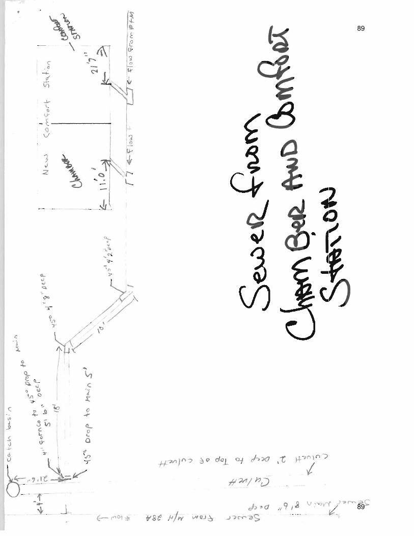
89
89

90
90

SUMMARY OF WORK 01100 - 1 RESTROOM BUILDING RANGELEY, MAINE PIN NO. 14197.09
SECTION 01100 – SUMMARY OF WORK
PART 1 - GENERAL
1.1 RELATED DOCUMENTS
A. If the Contractor discovers any ambiguity, error, omission, conflict, or discrepancy, Special Provision Section 101.3.6 Priority of Contract Documents shall control.
1. Drawings and general provisions of the Contract, including General and Supplementary Conditions and other Division 1 Specification Sections, apply to this Section.
2. State of Maine Department of Transportation, “Standard Specifications,” Revision 2002, apply to this Section.
3. State of Maine Department of Transportation Standard Details revised 2002 4. State of Maine Department of Transportation Best Management Practices for Erosion and
Sediment control the “table of contents” of the latest version is dated 1/19/00. 5. Any supplements to any of the above specifications and or standards issued prior to
issuance of this specification.
1.2 SECTION INCLUDES
A. Work Covered by Contract Documents
B. Contract Method
C. Contractor’s Use of Premises
D. Work Under Other Contracts
E. Future Work
F. Products Ordered in Advance
G. Specification Formats and Conventions
H. Drawings Furnished
I. Examination of the SiteContractor’s Duties
K. Weather Protection
1.3 WORK COVERED BY CONTRACT DOCUMENTS
A. Project Identification: Project consists of the construction of a new 750 square foot block building, including all mechanical, plumbing, and electrical work as defined in this project
91
91

SUMMARY OF WORK 01100 - 2 RESTROOM BUILDING RANGELEY, MAINE PIN NO. 14197.09
manual and the plans. The various items of work for this project are hereinafter specified under the respective branch headings of the work or shown on the accompanying drawings and shall be included in the contracts made for the completion of any respective divisions of the work. Such contracts shall also include necessary details reasonably incidental to the proper execution and completion of such work.
1. Project Location: Rangeley, Maine 2. Owner: Maine Department of Transportation.
B. Whenever a conflict, contradiction, or discrepancy between any statutes, regulations, plans or specifications, or if the Contractor request clarification of his responsibilities hereunder, it is the Contractor’s responsibility to obtain the advance written approval of the Engineer prior to deviating from any of the specifications.
C. Engineer Identification: The Contract Documents were prepared for the Project by Allied Engineering, Inc.
1.4 DEFINITIONS:
A. Engineer: shall mean the engineer or architect who’s seal is stamped on the drawing relating to the work.
1.5 CONTRACT METHOD:
A. Project will be constructed under a single contract.
1.6 CONTRACTOR’S USE OF PREMISES
A. Confine operations at site to areas permitted by:
1. Law, Ordinances, Permits, Contract Documents. 2. As defined by limit of work line on Site Plan. 3. As designated by Owner for location of office and storage of material areas.
B. Do not unreasonably encumber site with materials or equipment.
C. Do not load structure with weight that will endanger structure
D. Assume full responsibility for protection and safekeeping of products stored on premises
E. Obtain and pay for use of additional storage or work areas needed for operations
92
92

SUMMARY OF WORK 01100 - 3 RESTROOM BUILDING RANGELEY, MAINE PIN NO. 14197.09
1.7 WORK UNDER OTHER CONTRACTS
A. Cooperate fully with separate contractors so work on those contracts may be carried out smoothly, without interfering with or delaying work under this Contract.
1.8 SPECIFICATION FORMATS AND CONVENTIONS
A. Specification Format: The Specifications are organized into Divisions and Sections using the 16-division format and CSI/CSC's "MasterFormat" numbering system. 1. Any and all references in these specification sections to “DIVISION” refer to the CSI
specification Division, unless specifically described otherwise.
B. Specification Content: The Specifications use certain conventions for the style of language and the intended meaning of certain terms, words, and phrases when used in particular situations. These conventions are as follows:
1. Abbreviated Language: Language used in the Specifications and other Contract Documents is abbreviated. Words and meanings shall be interpreted as appropriate. Words implied, but not stated, shall be inferred as the sense requires. Singular words shall be interpreted as plural, and plural words shall be interpreted as singular where applicable as the context of the Contract Documents indicates.
2. Imperative mood and streamlined language are generally used in the Specifications. Requirements expressed in the imperative mood are to be performed by Contractor. Occasionally, the indicative or subjunctive mood may be used in the Section Text for clarity to describe responsibilities that must be fulfilled indirectly by Contractor or by others when so noted.
a. The words "shall," "shall be," or "shall comply with," depending on the context, are implied where a colon (:) is used within a sentence or phrase.
1.9 DEFINITIONS:
A. Owner's Representative: All references to Owner's Representative in the Contract Documents shall in all cases refer to the Architect/Engineer. The Architect/Engineer will represent the Owner during construction and until final payment is due. The Architect/Engineer will advise and consult with the Owner. The Owner's instructions to the Contractor shall be forwarded through the Architect/Engineer.
B. Architect/Engineer: The project architect and/or engineer whose name appears on the plans and/or specifications for the project, acting directly or through an authorized representative.
C. Project Manual: The Project Manual consist of the contract, general conditions, special provisions, the plans and specifications including all addenda and all other modifications thereof, that were incorporated in the documents prior to their execution.
93
93

SUMMARY OF WORK 01100 - 4 RESTROOM BUILDING RANGELEY, MAINE PIN NO. 14197.09
D. Contract/ Agreement: A written agreement between the owner and the successful bidder, by which the contractor is bound to perform the work specified, in accordance with plans, specifications, general conditions, and special provisions, that are a part of the contract documents, together with all supplemental agreements by which the owner is bound to compensate the contractor at mutually established and accepted rates or prices.
1.10 DRAWINGS FURNISHED
A. On the award of the contract, Owner will issue to the Contractor 6 sets of the “Contract Drawings and Specifications” for use in his office and on the job. The owner will also furnish such additional copies as may be required for submission to public authorities to accompany applications for permits
B. Additional copies of drawings and specifications will be issued at cost of reproduction.
C. It is the intention that these specifications and the drawings accompanying same shall provide for this Project to be completed in all its respective parts. Any work shown on the drawings and not particularly described in the specifications, or vice versa, shall be furnished by the Contractor as part of his contract.
1.11 EXAMINATION OF THE SITE
A. All Contractors’ submitting proposals for the work shall first examine the site and all conditions thereon. All proposals shall take into consideration all such conditions as may affect the work under this contract.
1.12 CONTRACTORS DUTIES
A. Asbestos-Free Materials: Contractor shall provide certification that all materials used for construction under this contract are 100% asbestos-free. Refer to Section 01340 – Shop Drawings, Product Data and Samples for submittals.
B. Except as specifically noted, provide and pay for:
1. Labor, materials and equipment. 2. Tools, construction equipment and machinery 3. Water, heat and utilities required for construction 4. Other facilities and services necessary for proper execution and completion of work
C. Secure and pay for all permits, government fees, and licenses that are applicable at the time of bid for proper execution and completion of the work
D. Promptly submit written notice to the Engineer of observed variance of Contract Documents from legal requirements.
1. Appropriate Modifications to Contract Documents will adjust necessary changes to comply with Codes and Regulations.
94
94

SUMMARY OF WORK 01100 - 5 RESTROOM BUILDING RANGELEY, MAINE PIN NO. 14197.09
2. Assume responsibility for work known to be contrary to such requirements without notice
E. Enforce strict discipline and good order among employees. Do not employ unfit persons not skilled in assigned task.
F. Contractor’s employees shall not transport, drink, or have in their possession on the job site any intoxicating beverage. Possession of any controlled substances without a physician’s prescription is also prohibited. Any Contractor’s employee appearing to be under the influence of an intoxicating beverage or narcotics will be escorted off the property and turned over to a competent escort as determined by the Engineer’s Representative. Any vehicle found to contain controlled substances or controlled substance residue will be reported to the State Police for investigation.
G. Use or possession of firearms, ammunition and/or explosives is prohibited. Where explosives are required due to construction requirements, specific handling requirements and approvals are required.
H. Work Permit or Citizenship: The contractor shall certify, in writing, that all employees of the Contractor and Subcontractor are citizens of the United States.
I. Motor Vehicles:
1. Vehicles must be locked at all times and parking will be in areas designated by the Facility Representative. Commercial/Contractor-owned vehicles required for direct support of contract work will have vehicle markings. The vehicle marking shall consist of permanent painting, the use of magnetic sign or semi-permanent signs. Cardboard or lesser materials taped to the vehicle will not be acceptable.
2. All employees operating motor vehicles shall have a valid Operator’s License. All vehicles shall display a valid state license plate and inspection sticker if required in the state in which the vehicle is registered.
J. WEATHER PROTECTION:
1. During the construction period, it is the Contractor’s responsibility that the building be under constant protection from the weather. Should there be any weather damage to the building’s interior; such damage is to be rectified to the satisfaction of the Engineer without cost to the owner.
K. Shop drawings and submittals may commence upon entering a contract with the Owner. The contractor may start work as soon as the contract is fully executed and all submittals required to start the project are in accordance with the contract documents.
PART 2 - PRODUCTS
2.1 MATERIALS:
A. All materials used for construction under this contract shall be 100% asbestos-free
95
95

SUMMARY OF WORK 01100 - 6 RESTROOM BUILDING RANGELEY, MAINE PIN NO. 14197.09
PART 3 - NOT USED
END OF SECTION 01100
96
96

ALLOWANCES 01210 - 1 RESTROOM BUILDING RANGELEY, MAINE PIN NO. 14197.09
SECTION 01210 - ALLOWANCES
PART 1 - GENERAL
1.1 RELATED DOCUMENTS
A. If the Contractor discovers any ambiguity, error, omission, conflict, or discrepancy, Special Provision Section 101.3.6 Priority of Contract Documents shall control.
1. Drawings and general provisions of the Contract, including General and Supplementary Conditions and other Division 1 Specification Sections, apply to this Section.
2. State of Maine Department of Transportation, “Standard Specifications,” Revision 2002, apply to this Section.
3. State of Maine Department of Transportation Standard Details revised 2002 4. State of Maine Department of Transportation Best Management Practices for Erosion and
Sediment control the “table of contents” of the latest version is dated 1/19/00.
1.2 Any supplements to any of the above specifications and or standards issued prior to issuance of this specification. SUMMARY
A. This Section includes administrative and procedural requirements governing allowances.
1. Certain materials and equipment are specified in the Contract Documents by allowances. In some cases, these allowances include installation. Allowances have been established in lieu of additional requirements and to defer selection of actual materials and equipment to a later date when additional information is available for evaluation. If necessary, additional requirements will be issued by Change Order. Allowance amount shall include overhead and profit
B. Types of allowances include the following:
1. Lump-sum allowances.
1.3 SELECTION AND PURCHASE
A. At the earliest practical date after award of the Contract, advise Engineer of the date when final selection and purchase of each product or system described by an allowance must be completed to avoid delaying the Work.
B. At Engineer’s request, obtain proposals for each allowance for use in making final selections. Include recommendations that are relevant to performing the Work.
97
97

ALLOWANCES 01210 - 2 RESTROOM BUILDING RANGELEY, MAINE PIN NO. 14197.09
C. Purchase products and systems selected by Engineer from the designated supplier.
1.4 SUBMITTALS
A. Submit six (6) copies of shop drawings. Obtain approval before furnishing material.
B. Submit proposals for purchase of products or systems included in allowances, in the form specified for Change Orders.
C. Submit invoices or delivery slips to show actual quantities of materials delivered to the site for use in fulfillment of each allowance.
1.5 UNUSED MATERIALS
A. Return unused materials purchased under an allowance to manufacturer or supplier for credit to Owner, after installation has been completed and accepted.
1. If requested by Engineer, prepare unused material for storage by Owner when it is not economically practical to return the material for credit. If directed by Architect, deliver unused material to Owner's storage space. Otherwise, disposal of unused material is Contractor's responsibility.
PART 2 - PRODUCTS (Not Used)
PART 3 - EXECUTION
3.1 EXAMINATION
A. Examine products covered by an allowance promptly on delivery for damage or defects. Return damaged or defective products to manufacturer for replacement.
3.2 PREPARATION
A. Coordinate materials and their installation for each allowance with related materials and installations to ensure that each allowance item is completely integrated and interfaced with related work.
3.3 SCHEDULE OF ALLOWANCES
A. Allowance No. 1 – ($5,000): Include CMP service entrance construction cost as specified in Division 16 Section "16000 basic electrical requirements" , Part 1 1.4, (B), 1.
98
98

ALLOWANCES 01210 - 3 RESTROOM BUILDING RANGELEY, MAINE PIN NO. 14197.09
END OF SECTION 01210
99
99

TEMPORARY FACILITIES AND CONTROLS 01500 - 1 RESTROOM BUILDING RANGELEY, MAINE PIN NO. 14197.09
SECTION 01500 - TEMPORARY FACILITIES AND CONTROLS
PART 1 - GENERAL
1.1 RELATED DOCUMENTS
A. If the Contractor discovers any ambiguity, error, omission, conflict, or discrepancy, Special Provision Section 101.3.6 Priority of Contract Documents shall control.
1. Drawings and general provisions of the Contract, including General and Supplementary Conditions and other Division 1 Specification Sections, apply to this Section.
2. State of Maine Department of Transportation, “Standard Specifications,” Revision 2002, apply to this Section.
1.2 SUMMARY
A. This Section includes requirements for temporary facilities and controls, including temporary utilities, support facilities, and security and protection facilities.
B. Temporary utilities include, but are not limited to, the following:
1. Water service and distribution. 2. Sanitary facilities, including toilets, wash facilities, and drinking-water facilities. 3. Heating and cooling facilities. 4. Electric power service. 5. Lighting. 6. Telephone service.
C. Support facilities include, but are not limited to, the following:
1. Temporary roads and paving. 2. Dewatering facilities and drains. 3. Field offices. 4. Storage and fabrication sheds.
D. Related Sections include the following:
1. Division 1 Section "Submittal Procedures" for procedures for submitting copies of implementation and termination schedule and utility reports.
2. Division 1 Section "Execution Requirements" for progress cleaning requirements. 3. Divisions 2 through 16 for temporary heat, ventilation, and humidity requirements for
products in those Sections.
100
100

TEMPORARY FACILITIES AND CONTROLS 01500 - 2 RESTROOM BUILDING RANGELEY, MAINE PIN NO. 14197.09
1.3 DEFINITIONS
A. Permanent Enclosure: As determined by Engineer, permanent or temporary roofing is complete, insulated, and weathertight; exterior walls are insulated and weathertight; and all openings are closed with permanent construction or substantial temporary closures.
1.4 USE CHARGES
A. General: Cost or use charges for temporary facilities are not chargeable to Owner or Engineer and shall be included in the Contract Sum. Allow other entities to use temporary services and facilities without cost, including, but not limited to, the following:
1. Owner's construction forces. 2. Occupants of Project. 3. Engineer 4. Architect. 5. Testing agencies. 6. Personnel of authorities having jurisdiction.
B. Water Service: Use water from Owner's existing water system without metering and without payment of use charges.
C. Electric Power Service: Pay electric power service use charges, whether metered or otherwise, for electricity used by all entities engaged in construction activities at Project site.
D. Telephone/Fax Machine: Pay all charges if Contractor chooses to install a telephone/fax machine for all entities engaged in construction activities at Project site.
E. Temporary Heat: Pay labor and fuel charges for temporary heat for all entities engaged in construction activities at Project Site.
1.5 PROJECT CONDITIONS
A. Temporary Utilities: At earliest feasible time, when acceptable to Owner, change over from use of temporary service to use of permanent service.
1. Temporary Use of Permanent Facilities: Installer of each permanent service shall assume responsibility for operation, maintenance, and protection of each permanent service during its use as a construction facility before Owner's acceptance, regardless of previously assigned responsibilities.
B. Conditions of Use: The following conditions apply to use of temporary services and facilities by all parties engaged in the Work:
1. Keep temporary services and facilities clean and neat. 2. Relocate temporary services and facilities as required by progress of the Work.
101
101

TEMPORARY FACILITIES AND CONTROLS 01500 - 3 RESTROOM BUILDING RANGELEY, MAINE PIN NO. 14197.09
PART 2 - PRODUCTS not used
2.1 EQUIPMENT
A. General: Provide equipment suitable for use intended.
B. Field Offices: Not required.
C. Fire Extinguishers: Hand carried, portable, UL rated. Provide class and extinguishing agent as indicated or a combination of extinguishers of NFPA-recommended classes for exposures.
1. Comply with NFPA 10 and NFPA 241 for classification, extinguishing agent, and size required by location and class of fire exposure.
D. Self-Contained Toilet Units: Single-occupant units of chemical, aerated recirculation, or combustion type; vented; fully enclosed with a glass-fiber-reinforced polyester shell or similar nonabsorbent material.
E. Drinking-Water Fixtures: Drinking-water fountains, containerized, tap-dispenser, bottled-water drinking-water units, including paper cup supply.
F. Heating Equipment: Unless Owner authorizes use of permanent heating system, provide vented, self-contained, liquid-propane-gas or fuel-oil heaters with individual space thermostatic control.
1. Use of gasoline-burning space heaters, open-flame heaters, or salamander-type heating units is prohibited.
2. Heating Units: Listed and labeled, by a testing agency acceptable to authorities having jurisdiction, and marked for intended use for type of fuel being consumed.
G. Electrical Outlets: Properly configured, NEMA-polarized outlets to prevent insertion of 110- to 120-V plugs into higher-voltage outlets; equipped with ground-fault circuit interrupters, reset button, and pilot light.
H. Power Distribution System Circuits: Where permitted and overhead and exposed for surveillance, wiring circuits, not exceeding 125-V ac, 20-A rating, and lighting circuits may be nonmetallic sheathed cable.
PART 3 - EXECUTION
3.1 INSTALLATION, GENERAL
A. Locate facilities where they will serve Project adequately and result in minimum interference with performance of the Work. Relocate and modify facilities as required.
102
102

TEMPORARY FACILITIES AND CONTROLS 01500 - 4 RESTROOM BUILDING RANGELEY, MAINE PIN NO. 14197.09
B. Provide each facility ready for use when needed to avoid delay. Maintain and modify as required. Do not remove until facilities are no longer needed or are replaced by authorized use of completed permanent facilities.
3.2 TEMPORARY UTILITY INSTALLATION
A. General: Engage appropriate local utility company to install temporary service or connect to existing service. Where utility company provides only part of the service, provide the remainder with matching, compatible materials and equipment. Comply with utility company recommendations.
1. Arrange with utility company, Owner, and existing users for time when service can be interrupted, if necessary, to make connections for temporary services.
2. Provide adequate capacity at each stage of construction. Before temporary utility is available, provide trucked-in services.
3. Obtain easements to bring temporary utilities to Project site where Owner's easements cannot be used for that purpose.
B. Water Service: Use of Owner's existing water service facilities will be permitted, as long as facilities are cleaned and maintained in a condition acceptable to Owner. At Substantial Completion, restore these facilities to condition existing before initial use.
1. Provide rubber hoses as necessary to serve Project site.
C. Sanitary Facilities: Provide temporary toilets, and drinking-water. Comply with regulations and health codes for type, number, location, operation, and maintenance of fixtures and facilities.
1. Disposable Supplies: Provide toilet tissue, paper towels, paper cups, and similar disposable materials for each facility. Maintain adequate supply. Provide covered waste containers for disposal of used material.
2. Toilets: Install self-contained toilet units. 3. Drinking-Water Facilities: Provide bottled-water, drinking-water units.
D. Heating and Cooling: Provide temporary heating and cooling required by construction activities for curing or drying of completed installations or for protecting installed construction from adverse effects of low temperatures or high humidity. Select equipment from that specified that will not have a harmful effect on completed installations or elements being installed.
1. Maintain a minimum temperature of 50 deg F (10 deg C) in permanently enclosed portions of building for normal construction activities, and 65 deg F (18.3 deg C) for finishing activities and areas where finished Work has been installed.
2. Cold weather protection is required when the average nighttime temperatures fall below 40 degrees F. It shall be considered necessary during the period of rough construction and up to the time when the work is entirely closed in and the heating apparatus is in permanent position, ready for operation on a temporary basis by the Contractor. This work shall include protection of work exposed to the elements, against adverse dampness and cold, by covering, enclosing, heating materials and work under construction, and
103
103

TEMPORARY FACILITIES AND CONTROLS 01500 - 5 RESTROOM BUILDING RANGELEY, MAINE PIN NO. 14197.09
providing suitable working conditions for all trades employed on the work. This cold weather protection shall be provided by the Contractor at his own expense.
3. Temporary heat shall be considered the period when temporary heating is required from the time the work is entirely closed in and the heating apparatus is in permanent position and ready for operation, until the building and equipment is occupied by the Owner or designated as substantially complete by the Engineer.
4. Temporary heating for protection shall be provided from the permanent heating system when necessary to prevent freezing within the building, to dry out the building and to provide suitable working conditions for the installation and curing of materials. A temperature of not less than 50 degrees F nor more than the maximum design temperatures shall be maintained throughout the entire building.
E. Ventilation and Humidity Control: Provide temporary ventilation required by construction activities for curing or drying of completed installations or for protecting installed construction from adverse effects of high humidity. Select equipment from that specified that will not have a harmful effect on completed installations or elements being installed. Coordinate ventilation requirements to produce ambient condition required and minimize energy consumption.
F. Electric Power Service: Provide weatherproof, grounded electric power service and distribution system of sufficient size, capacity, and power characteristics during construction period. Include meters, transformers, overload-protected disconnecting means, automatic ground-fault interrupters, and main distribution switchgear.
G. Electric Distribution: Provide receptacle outlets adequate for connection of power tools and equipment.
1. Provide waterproof connectors to connect separate lengths of electrical power cords if single lengths will not reach areas where construction activities are in progress. Do not exceed safe length-voltage ratio.
2. Provide warning signs at power outlets other than 110 to 120 V. 3. All work shall conform with The National Electric Code.
H. Lighting: Provide temporary lighting with local switching that provides adequate illumination for construction operations and traffic conditions.
1. Install and operate temporary lighting that fulfills security and protection requirements without operating entire system.
2. Install exterior-yard site lighting that will provide adequate illumination for construction operations, traffic conditions, and signage visibility when the Work is being performed.
I. Telephone Service: 1. Contractor shall have phone service on site, Cell phones are acceptable.
2. At the job site, post a list of important telephone numbers.
a. Police and fire departments. b. Ambulance service. c. Contractor's home office. d. Architect's office.
104
104

TEMPORARY FACILITIES AND CONTROLS 01500 - 6 RESTROOM BUILDING RANGELEY, MAINE PIN NO. 14197.09
e. Engineers' offices. f. Owner's office. g. Principal subcontractors' field and home offices.
3.3 SUPPORT FACILITIES INSTALLATION
A. General: Comply with the following:
1. Locate field offices, storage sheds, sanitary facilities, and other temporary construction and support facilities for easy access.
2. Maintain support facilities until near Substantial Completion. Remove before Substantial Completion. Personnel remaining after Substantial Completion will be permitted to use permanent facilities, under conditions acceptable to Owner.
3. Provide dust-control treatment that is nonpolluting and nontracking. Reapply treatment as required to minimize dust.
B. Traffic Controls: Provide temporary traffic controls at junction of temporary roads with public roads. Include warning signs for public traffic and "STOP" signs for entrance onto public roads. Comply with requirements of authorities having jurisdiction.
C. Dewatering Facilities and Drains: Comply with requirements in applicable Division 2 Sections for temporary drainage and dewatering facilities and operations not directly associated with construction activities included in individual Sections. Where feasible, use same facilities. Maintain Project site, excavations, and construction free of water.
D. Storage and Fabrication Sheds: Provide sheds sized, furnished, and equipped to accommodate materials and equipment involved, including temporary utility services. Sheds may be open shelters or fully enclosed spaces within building or elsewhere on-site.
1. Location of storage sheds shall be approved by the Owner. 2. All materials paid for by the Owner shall be under secure lock and key when site is
unsupervised. Should a loss occur, such loss will be the Contractor's responsibility.
E. Temporary Stairs: Until permanent stairs are available, provide temporary stairs where ladders are not adequate. Cover finished, permanent stairs with protective covering of plywood or similar material so finishes will be undamaged at time of acceptance.
F. Barricades, Warning Signs, and Lights: Comply with standards and code requirements for erecting structurally adequate barricades. Paint with appropriate colors, graphics, and warning signs to inform personnel and public of possible hazard. Where appropriate and needed, provide lighting, including flashing red or amber lights.
G. Temporary Pumping: Provide all necessary labor and equipment to keep all portions of the excavation free from water and shall maintain pumps in operation as may be required. This will include a wellpoint system if required by the work.
H. Exposed Excavation: Provide fences, barricades, lights and other similar items around exposed excavations until such excavations have been completely filled.
105
105

TEMPORARY FACILITIES AND CONTROLS 01500 - 7 RESTROOM BUILDING RANGELEY, MAINE PIN NO. 14197.09
I. Termination and Removal: Remove each temporary facility when need for its service has ended, when it has been replaced by authorized use of a permanent facility, or no later than Substantial Completion. Complete or, if necessary, restore permanent construction that may have been delayed because of interference with temporary facility. Repair damaged Work, clean exposed surfaces, and replace construction that cannot be satisfactorily repaired.
1. Materials and facilities that constitute temporary facilities are the property of Contractor. Owner reserves right to take possession of Project identification signs.
2. At Substantial Completion, clean and renovate permanent facilities used during construction period. Comply with final cleaning requirements in Division 1 Section "Closeout Procedures."
END OF SECTION 01500
106
106

CLOSEOUT PROCEDURES 01770 - 1 RESTROOM BUILDING RANGELEY, MAINE PIN NO. 14197.09
SECTION 01770 - CLOSEOUT PROCEDURES
PART 1 - GENERAL
1.1 RELATED DOCUMENTS
A. If the Contractor discovers any ambiguity, error, omission, conflict, or discrepancy, Special Provision Section 101.3.6 Priority of Contract Documents shall control.
1. Drawings and general provisions of the Contract, including General and Supplementary Conditions and other Division 1 Specification Sections, apply to this Section.
2. State of Maine Department of Transportation, “Standard Specifications,” Revision 2002, apply to this Section.
1.2 SUMMARY
A. This Section includes administrative and procedural requirements for contract closeout, including, but not limited to, the following:
1. Inspection procedures. 2. Project Record Documents. 3. Operation and maintenance manuals. 4. Warranties. 5. Instruction of Owner's personnel. 6. Final cleaning. 7. Evidence of payment and release of liens 8. Consent of Surety to final payment 9. Certificates of Insurance for products and completed operations
B. Related Sections include the following:
1. Supplementary Conditions for Certificates of Insurance for Products and Completed Operations.
2. Division 1 Section "Payment Procedures" for requirements for Applications for Payment for Substantial and Final Completion.
3. Divisions 2 through 16 Sections for specific closeout and special cleaning requirements for products of those Sections.
1.3 SUBSTANTIAL COMPLETION
A. Preliminary Procedures: Before requesting final inspection, complete the following. List items below that are incomplete in request.
1. Prepare a list of items to be completed and corrected (punch list), the value of items on the list, and reasons why the Work is not complete.
107
107

CLOSEOUT PROCEDURES 01770 - 2 RESTROOM BUILDING RANGELEY, MAINE PIN NO. 14197.09
2. Advise Owner of pending insurance changeover requirements. 3. Submit specific warranties, workmanship bonds, maintenance service agreements, final
certifications, and similar documents. 4. Obtain and submit releases permitting Owner unrestricted use of the Work and access to
services and utilities. Include occupancy permits, operating certificates, and similar releases.
5. Prepare and submit Project Record Documents, operation and maintenance manuals. 6. Deliver tools, spare parts, extra materials, and similar items to location designated by
Owner. Label with manufacturer's name and model number where applicable. 7. Make final changeover of permanent locks and deliver keys to Owner. Advise Owner's
personnel of changeover in security provisions. 8. Complete startup testing of systems. 9. Submit test/adjust/balance records. 10. Terminate and remove temporary facilities from Project site, along with mockups,
construction tools, and similar elements. 11. Advise Owner of changeover in heat and other utilities. 12. Submit changeover information related to Owner's occupancy, use, operation, and
maintenance. 13. Complete final cleaning requirements, including touchup painting. 14. Touch up and otherwise repair and restore marred exposed finishes to eliminate visual
defects.
1.4 FINAL COMPLETION
A. Preliminary Procedures: Before requesting final inspection for determining date of Final Completion, complete the following: 1. Submit certified copy of Engineer's Substantial Completion inspection list of items to be
completed or corrected (punch list), endorsed and dated by Engineer. The certified copy of the list shall state that each item has been completed or otherwise resolved for acceptance.
2. Submit evidence of final, continuing insurance coverage complying with insurance requirements.
3. Submit pest-control final inspection report and warranty. 4. Instruct Owner's personnel in operation, adjustment, and maintenance of products,
equipment, and systems.
1.5 LIST OF INCOMPLETE ITEMS (PUNCH LIST)
A. Preparation: Submit three copies of list. Include name and identification of each space and area affected by construction operations for incomplete items and items needing correction including, if necessary, areas disturbed by Contractor that are outside the limits of construction.
1. Organize list of spaces in sequential order, 2. Organize items applying to each space by major element, including categories for ceiling,
individual walls, floors, equipment, and building systems. 3. Include the following information at the top of each page:
108
108

CLOSEOUT PROCEDURES 01770 - 3 RESTROOM BUILDING RANGELEY, MAINE PIN NO. 14197.09
a. Project name. b. Date. c. Name of Engineer. d. Name of Contractor. e. Page number.
1.6 PROJECT RECORD DOCUMENTS
A. General: Do not use Project Record Documents for construction purposes. Protect Project Record Documents from deterioration and loss. Provide access to Project Record Documents for Engineer's reference during normal working hours.
B. Record Drawings: Maintain and submit one set of blue- or black-line white prints of Contract Drawings and Shop Drawings.
1. Mark Record Prints to show the actual installation where installation varies from that shown originally. Require individual or entity who obtained record data, whether individual or entity is Installer, subcontractor, or similar entity, to prepare the marked-up Record Prints.
a. Give particular attention to information on concealed elements that cannot be readily identified and recorded later.
b. Accurately record information in an understandable drawing technique. c. Record data as soon as possible after obtaining it. Record and check the markup
before enclosing concealed installations. d. Mark Contract Drawings or Shop Drawings, whichever is most capable of showing
actual physical conditions, completely and accurately. Where Shop Drawings are marked, show cross-reference on Contract Drawings.
2. Mark record sets with erasable, red-colored pencil. Use other colors to distinguish between changes for different categories of the Work at the same location.
3. Mark important additional information that was either shown schematically or omitted from original Drawings.
4. Note Construction Change Directive numbers, Change Order numbers, alternate numbers, and similar identification where applicable.
5. Identify and date each Record Drawing; include the designation "AS-BUILT DRAWINGS" in a prominent location. Organize into manageable sets; bind each set with durable paper cover sheets. Include identification on cover sheets.
C. Record Product Data: Submit one copy of each Product Data submittal. Mark one set to indicate the actual product installation where installation varies substantially from that indicated in Product Data.
1. Give particular attention to information on concealed products and installations that cannot be readily identified and recorded later.
2. Include significant changes in the product delivered to Project site and changes in manufacturer's written instructions for installation.
3. Note related Change Orders, Record Drawings, where applicable.
109
109

CLOSEOUT PROCEDURES 01770 - 4 RESTROOM BUILDING RANGELEY, MAINE PIN NO. 14197.09
D. Miscellaneous Record Submittals: Assemble miscellaneous records required by other Specification Sections for miscellaneous record keeping and submittal in connection with actual performance of the Work. Bind or file miscellaneous records and identify each, ready for continued use and reference.
1.7 OPERATION AND MAINTENANCE MANUALS
A. Assemble a complete set of operation and maintenance data indicating the operation and maintenance of each system, subsystem, and piece of equipment not part of a system. Include operation and maintenance data required in individual Specification Sections and as follows:
1. Operation Data:
a. Emergency instructions and procedures. b. System, subsystem, and equipment descriptions, including operating standards. c. Operating procedures, including startup, shutdown, seasonal, and weekend
operations. d. Description of controls and sequence of operations. e. Piping diagrams.
2. Maintenance Data:
a. Manufacturer's information, including list of spare parts. b. Name, address, and telephone number of Installer or supplier. c. Maintenance procedures. d. Maintenance and service schedules for preventive and routine maintenance. e. Maintenance record forms. f. Sources of spare parts and maintenance materials. g. Copies of maintenance service agreements. h. Copies of warranties and bonds.
B. Organize operation and maintenance manuals into suitable sets of manageable size. Bind and index data in heavy-duty, 3-ring, vinyl-covered, loose-leaf binders, in thickness necessary to accommodate contents, with pocket inside the covers to receive folded oversized sheets. Identify each binder on front and spine with the printed title "OPERATION AND MAINTENANCE MANUAL," Project name, and subject matter of contents.
1.8 WARRANTIES
A. Submittal Time: Submit written warranties on request of Architect for designated portions of the Work where commencement of warranties other than date of Substantial Completion is indicated.
a. For items of work when acceptance is delayed beyond Date of Substantial Completion, submit within ten (10) days after acceptance, listing the date of acceptance as the beginning of the warranty period.
110
110

CLOSEOUT PROCEDURES 01770 - 5 RESTROOM BUILDING RANGELEY, MAINE PIN NO. 14197.09
B. Partial Occupancy: Submit properly executed warranties within 10 days of completion of designated portions of the Work that are completed and occupied or used by Owner during construction period by separate agreement with Contractor.
C. Organize warranty documents into an orderly sequence based on the table of contents of the Project Manual.
1. Bind warranties and bonds in heavy-duty, 3-ring, vinyl-covered, loose-leaf binders, thickness as necessary to accommodate contents, and sized to receive 8-1/2-by-11-inch (115-by-280-mm) paper.
2. Provide heavy paper dividers with plastic-covered tabs for each separate warranty. Mark tab to identify the product or installation. Provide a typed description of the product or installation, including the name of the product and the name, address, and telephone number of Installer.
3. Identify each binder on the front and spine with the typed or printed title "WARRANTIES," Project name, and name of Contractor.
D. Provide additional copies of each warranty to include in operation and maintenance manuals.
PART 2 - PRODUCTS
2.1 MATERIALS
A. Cleaning Agents: Use cleaning materials and agents recommended by manufacturer or fabricator of the surface to be cleaned. Do not use cleaning agents that are potentially hazardous to health or property or that might damage finished surfaces.
PART 3 - EXECUTION
3.1 DEMONSTRATION AND TRAINING
A. Instruction: Instruct Owner's personnel to adjust, operate, and maintain systems, subsystems, and equipment not part of a system.
1. Provide instructors experienced in operation and maintenance procedures. 2. Provide instruction at mutually agreed-on times. For equipment that requires seasonal
operation, provide similar instruction at the start of each season. 3. Schedule training with Owner with at least seven days' advance notice. 4. Coordinate instructors, including providing notification of dates, times, length of
instruction, and course content.
B. Program Structure: Develop an instruction program that includes individual training modules for each system and equipment not part of a system, as required by individual Specification Sections. For each training module, develop a learning objective and teaching outline. Include instruction for the following:
111
111

CLOSEOUT PROCEDURES 01770 - 6 RESTROOM BUILDING RANGELEY, MAINE PIN NO. 14197.09
1. System design and operational philosophy. 2. Review of documentation. 3. Operations. 4. Adjustments. 5. Troubleshooting. 6. Maintenance. 7. Repair.
3.2 FINAL CLEANING
A. General: Provide final cleaning. Conduct cleaning and waste-removal operations to comply with local laws and ordinances and Federal and local environmental and antipollution regulations.
B. Cleaning: Employ experienced workers or professional cleaners for final cleaning. Clean each surface or unit to condition expected in an average commercial building cleaning and maintenance program. Comply with manufacturer's written instructions.
1. Complete the following cleaning operations before requesting inspection for certification of Substantial Completion for entire Project or for a portion of Project:
a. Clean Project site, yard, and grounds, in areas disturbed by construction activities, including landscape development areas, of rubbish, waste material, litter, and other foreign substances.
b. Sweep paved areas broom clean. Remove petrochemical spills, stains, and other foreign deposits.
c. Rake grounds that are neither planted nor paved to a smooth, even-textured surface.
d. Remove tools, construction equipment, machinery, and surplus material from Project site.
e. Remove snow and ice to provide safe access to building. f. Clean exposed exterior and interior hard-surfaced finishes to a dirt-free condition,
free of stains, films, and similar foreign substances. Avoid disturbing natural weathering of exterior surfaces. Restore reflective surfaces to their original condition.
g. Remove debris and surface dust from limited access spaces, including roofs, plenums, shafts, trenches, equipment vaults, manholes, attics, and similar spaces.
h. Sweep concrete floors broom clean in unoccupied spaces. i. Vacuum carpet and similar soft surfaces, removing debris and excess nap;
shampoo if visible soil or stains remain. j. Clean transparent materials, including mirrors and glass in doors and windows.
Remove glazing compounds and other noticeable, vision-obscuring materials. Replace chipped or broken glass and other damaged transparent materials. Polish mirrors and glass, taking care not to scratch surfaces.
k. Remove labels that are not permanent. l. Touch up and otherwise repair and restore marred, exposed finishes and surfaces.
Replace finishes and surfaces that cannot be satisfactorily repaired or restored or that already show evidence of repair or restoration.
112
112

CLOSEOUT PROCEDURES 01770 - 7 RESTROOM BUILDING RANGELEY, MAINE PIN NO. 14197.09
1) Do not paint over "UL" and similar labels, including mechanical and electrical nameplates.
m. Wipe surfaces of mechanical and electrical equipment, and similar equipment. Remove excess lubrication, paint and mortar droppings, and other foreign substances.
n. Replace parts subject to unusual operating conditions. o. Clean plumbing fixtures to a sanitary condition, free of stains, including stains
resulting from water exposure. p. Replace disposable air filters and clean permanent air filters. Clean exposed
surfaces of diffusers, registers, and grills. q. Clean ducts, blowers, and coils if units were operated without filters during
construction. r. Clean light fixtures, lamps, globes, and reflectors to function with full efficiency.
Replace burned-out bulbs, and those noticeably dimmed by hours of use, and defective and noisy starters in fluorescent and mercury vapor fixtures to comply with requirements for new fixtures.
s. Leave Project clean and ready for occupancy.
C. Pest Control: Engage an experienced, licensed exterminator to make a final inspection and rid Project of rodents, insects, and other pests. Prepare a report.
D. Comply with safety standards for cleaning. Do not burn waste materials. Do not bury debris or excess materials on Owner's property. Do not discharge volatile, harmful, or dangerous materials into drainage systems. Remove waste materials from Project site and dispose of lawfully.
END OF SECTION 01770
113
113
OPERATION AND MAINTENANCE DATA 01782 - 1 RESTROOM BUILDING RANGELEY, MAINE PIN NO. 14197.09
SECTION 01782 - OPERATION AND MAINTENANCE DATA
PART 1 - GENERAL
1.1 RELATED DOCUMENTS
A. If the Contractor discovers any ambiguity, error, omission, conflict, or discrepancy, Special Provision Section 101.3.6 Priority of Contract Documents shall control.
1. Drawings and general provisions of the Contract, including General and Supplementary
Conditions and other Division 1 Specification Sections, apply to this Section. 2. State of Maine Department of Transportation, “Standard Specifications,” Revision 2002,
apply to this Section.
1.2 SUMMARY
A. This Section includes administrative and procedural requirements for preparing operation and maintenance manuals, including the following:
1. Operation and maintenance documentation directory. 2. Emergency manuals. 3. Operation manuals for systems, subsystems, and equipment. 4. Maintenance manuals for the care and maintenance of products, materials, and finishes,
systems and equipment.
B. Related Sections include the following:
1. Division 1 Section "Summary of Multiple Contracts" for coordinating operation and maintenance manuals covering the Work of multiple contracts.
2. Division 1 Section "Submittal Procedures" for submitting copies of submittals for operation and maintenance manuals.
3. Division 1 Section "Closeout Procedures" for submitting operation and maintenance manuals.
4. Division 1 Section "Project Record Documents" for preparing Record Drawings for operation and maintenance manuals.
5. Divisions 2 through 16 Sections for specific operation and maintenance manual requirements for products in those Sections.
1.3 DEFINITIONS
A. System: An organized collection of parts, equipment, or subsystems united by regular interaction.
B. Subsystem: A portion of a system with characteristics similar to a system.
114
114

OPERATION AND MAINTENANCE DATA 01782 - 2 RESTROOM BUILDING RANGELEY, MAINE PIN NO. 14197.09
1.4 SUBMITTALS
A. Initial Submittal: Submit 2 draft copies of each manual at least 15 days before requesting inspection for Substantial Completion. Include a complete operation and maintenance directory. Architect will return1 copy] of draft and mark whether general scope and content of manual are acceptable.
B. Final Submittal: Submit 1 copy of each manual in final form at least 15 days before final inspection. Architect will return copy with comments within 15 days after final inspection.
1. Correct or modify each manual to comply with Architect's comments. Submit 3 copies of each corrected manual within 15 days of receipt of Architect's comments.
1.5 COORDINATION
A. Where operation and maintenance documentation includes information on installations by more than one factory-authorized service representative, assemble and coordinate information furnished by representatives and prepare manuals.
PART 2 - PRODUCTS
2.1 OPERATION AND MAINTENANCE DOCUMENTATION DIRECTORY
A. Organization: Include a section in the directory for each of the following:
1. List of documents. 2. List of systems. 3. List of equipment. 4. Table of contents.
B. List of Systems and Subsystems: List systems alphabetically. Include references to operation and maintenance manuals that contain information about each system.
C. List of Equipment: List equipment for each system, organized alphabetically by system. For pieces of equipment not part of system, list alphabetically in separate list.
D. Tables of Contents: Include a table of contents for each emergency, operation, and maintenance manual.
E. Identification: In the documentation directory and in each operation and maintenance manual, identify each system, subsystem, and piece of equipment with the same designation used in the Contract Documents. If no designation exists, assign a designation according to ASHRAE Guideline 4, "Preparation of Operating and Maintenance Documentation for Building Systems."
115
115

OPERATION AND MAINTENANCE DATA 01782 - 3 RESTROOM BUILDING RANGELEY, MAINE PIN NO. 14197.09
2.2 MANUALS, GENERAL
A. Organization: Unless otherwise indicated, organize each manual into a separate section for each system and subsystem, and a separate section for each piece of equipment not part of a system. Each manual shall contain the following materials, in the order listed:
1. Title page. 2. Table of contents. 3. Manual contents.
B. Title Page: Enclose title page in transparent plastic sleeve. Include the following information:
1. Subject matter included in manual. 2. Name and address of Project. 3. Name and address of Owner. 4. Date of submittal. 5. Name, address, and telephone number of Contractor. 6. Name and address of Architect. 7. Cross-reference to related systems in other operation and maintenance manuals.
C. Table of Contents: List each product included in manual, identified by product name, indexed to the content of the volume, and cross-referenced to Specification Section number in Project Manual.
1. If operation or maintenance documentation requires more than one volume to accommodate data, include comprehensive table of contents for all volumes in each volume of the set.
D. Manual Contents: Organize into sets of manageable size. Arrange contents alphabetically by system, subsystem, and equipment. If possible, assemble instructions for subsystems, equipment, and components of one system into a single binder.
1. Binders: Heavy-duty, 3-ring, vinyl-covered, loose-leaf binders, in thickness necessary to accommodate contents, sized to hold 8-1/2-by-11-inch (115-by-280-mm) paper; with clear plastic sleeve on spine to hold label describing contents and with pockets inside covers to hold folded oversize sheets.
a. If two or more binders are necessary to accommodate data of a system, organize data in each binder into groupings by subsystem and related components. Cross-reference other binders if necessary to provide essential information for proper operation or maintenance of equipment or system.
b. Identify each binder on front and spine, with printed title "OPERATION AND MAINTENANCE MANUAL," Project title or name, and subject matter of contents. Indicate volume number for multiple-volume sets.
2. Dividers: Heavy-paper dividers with plastic-covered tabs for each section. Mark each tab to indicate contents. Include typed list of products and major components of
116
116

OPERATION AND MAINTENANCE DATA 01782 - 4 RESTROOM BUILDING RANGELEY, MAINE PIN NO. 14197.09
equipment included in the section on each divider, cross-referenced to Specification Section number and title of Project Manual.
3. Protective Plastic Sleeves: Transparent plastic sleeves designed to enclose diagnostic software diskettes for computerized electronic equipment.
4. Supplementary Text: Prepared on 8-1/2-by-11-inch (115-by-280-mm), 20-lb/sq. ft. (75-g/sq. m) white bond paper.
5. Drawings: Attach reinforced, punched binder tabs on drawings and bind with text.
a. If oversize drawings are necessary, fold drawings to same size as text pages and use as foldouts.
b. If drawings are too large to be used as foldouts, fold and place drawings in labeled envelopes and bind envelopes in rear of manual. At appropriate locations in manual, insert typewritten pages indicating drawing titles, descriptions of contents, and drawing locations.
2.3 EMERGENCY MANUALS
A. Content: Organize manual into a separate section for each of the following:
1. Type of emergency. 2. Emergency instructions. 3. Emergency procedures.
B. Type of Emergency: Where applicable for each type of emergency indicated below, include instructions and procedures for each system, subsystem, piece of equipment, and component:
1. Fire. 2. Flood. 3. Gas leak. 4. Water leak. 5. Power failure. 6. Water outage. 7. System, subsystem, or equipment failure. 8. Chemical release or spill.
C. Emergency Instructions: Describe and explain warnings, trouble indications, error messages, and similar codes and signals. Include responsibilities of Owner's operating personnel for notification of Installer, supplier, and manufacturer to maintain warranties.
D. Emergency Procedures: Include the following, as applicable:
1. Instructions on stopping. 2. Shutdown instructions for each type of emergency. 3. Operating instructions for conditions outside normal operating limits. 4. Required sequences for electric or electronic systems. 5. Special operating instructions and procedures.
117
117

OPERATION AND MAINTENANCE DATA 01782 - 5 RESTROOM BUILDING RANGELEY, MAINE PIN NO. 14197.09
2.4 OPERATION MANUALS
A. Content: In addition to requirements in this Section, include operation data required in individual Specification Sections and the following information:
1. System, subsystem, and equipment descriptions. 2. Performance and design criteria if Contractor is delegated design responsibility. 3. Operating standards. 4. Operating procedures. 5. Operating logs. 6. Wiring diagrams. 7. Control diagrams. 8. Piped system diagrams. 9. Precautions against improper use. 10. License requirements including inspection and renewal dates.
B. Descriptions: Include the following:
1. Product name and model number. 2. Manufacturer's name. 3. Equipment identification with serial number of each component. 4. Equipment function. 5. Operating characteristics. 6. Limiting conditions. 7. Performance curves. 8. Engineering data and tests. 9. Complete nomenclature and number of replacement parts.
C. Operating Procedures: Include the following, as applicable:
1. Startup procedures. 2. Equipment or system break-in procedures. 3. Routine and normal operating instructions. 4. Regulation and control procedures. 5. Instructions on stopping. 6. Normal shutdown instructions. 7. Seasonal and weekend operating instructions. 8. Required sequences for electric or electronic systems. 9. Special operating instructions and procedures.
D. Systems and Equipment Controls: Describe the sequence of operation, and diagram controls as installed.
E. Piped Systems: Diagram piping as installed, and identify color-coding where required for identification.
118
118

OPERATION AND MAINTENANCE DATA 01782 - 6 RESTROOM BUILDING RANGELEY, MAINE PIN NO. 14197.09
2.5 PRODUCT MAINTENANCE MANUAL
A. Content: Organize manual into a separate section for each product, material, and finish. Include source information, product information, maintenance procedures, repair materials and sources, and warranties and bonds, as described below.
B. Source Information: List each product included in manual, identified by product name and arranged to match manual's table of contents. For each product, list name, address, and telephone number of Installer or supplier and maintenance service agent, and cross-reference Specification Section number and title in Project Manual.
C. Product Information: Include the following, as applicable:
1. Product name and model number. 2. Manufacturer's name. 3. Color, pattern, and texture. 4. Material and chemical composition. 5. Reordering information for specially manufactured products.
D. Maintenance Procedures: Include manufacturer's written recommendations and the following:
1. Inspection procedures. 2. Types of cleaning agents to be used and methods of cleaning. 3. List of cleaning agents and methods of cleaning detrimental to product. 4. Schedule for routine cleaning and maintenance. 5. Repair instructions.
E. Repair Materials and Sources: Include lists of materials and local sources of materials and related services.
F. Warranties and Bonds: Include copies of warranties and bonds and lists of circumstances and conditions that would affect validity of warranties or bonds.
1. Include procedures to follow and required notifications for warranty claims.
2.6 SYSTEMS AND EQUIPMENT MAINTENANCE MANUAL
A. Content: For each system, subsystem, and piece of equipment not part of a system, include source information, manufacturers' maintenance documentation, maintenance procedures, maintenance and service schedules, spare parts list and source information, maintenance service contracts, and warranty and bond information, as described below.
B. Source Information: List each system, subsystem, and piece of equipment included in the manual, identified by product name and arranged to match manual's table of contents. For each product, list name, address, and telephone number of Installer or supplier and maintenance service agent, and cross-reference Specification Section number and title in Project Manual.
119
119

OPERATION AND MAINTENANCE DATA 01782 - 7 RESTROOM BUILDING RANGELEY, MAINE PIN NO. 14197.09
C. Manufacturers' Maintenance Documentation: Manufacturers' maintenance documentation including the following information for each component part or piece of equipment:
1. Standard printed maintenance instructions and bulletins. 2. Drawings, diagrams, and instructions required for maintenance, including disassembly
and component removal, replacement, and assembly. 3. Identification and nomenclature of parts and components. 4. List of items recommended to be stocked as spare parts.
D. Maintenance Procedures: Include the following information and items that detail essential maintenance procedures:
1. Test and inspection instructions. 2. Troubleshooting guide. 3. Precautions against improper maintenance. 4. Disassembly; component removal, repair, and replacement; and reassembly instructions. 5. Aligning, adjusting, and checking instructions. 6. Demonstration and training videotape, if available.
E. Maintenance and Service Schedules: Include service and lubrication requirements, list of required lubricants for equipment, and separate schedules for preventive and routine maintenance and service with standard time allotment.
1. Scheduled Maintenance and Service: Tabulate actions for daily, weekly, monthly, quarterly, semiannual, and annual frequencies.
2. Maintenance and Service Record: Include manufacturers' forms for recording maintenance.
F. Spare Parts List and Source Information: Include lists of replacement and repair parts, with parts identified and cross-referenced to manufacturers' maintenance documentation and local sources of maintenance materials and related services.
G. Maintenance Service Contracts: Include copies of maintenance agreements with name and telephone number of service agent.
H. Warranties and Bonds: Include copies of warranties and bonds and lists of circumstances and conditions that would affect validity of warranties or bonds.
1. Include procedures to follow and required notifications for warranty claims.
PART 3 - EXECUTION
3.1 MANUAL PREPARATION
A. Operation and Maintenance Documentation Directory: Prepare a separate manual that provides an organized reference to emergency, operation, and maintenance manuals.
120
120
OPERATION AND MAINTENANCE DATA 01782 - 8 RESTROOM BUILDING RANGELEY, MAINE PIN NO. 14197.09
B. Emergency Manual: Assemble a complete set of emergency information indicating procedures for use by emergency personnel and by Owner's operating personnel for types of emergencies indicated.
C. Product Maintenance Manual: Assemble a complete set of maintenance data indicating care and maintenance of each product, material, and finish incorporated into the Work.
D. Operation and Maintenance Manuals: Assemble a complete set of operation and maintenance data indicating operation and maintenance of each system, subsystem, and piece of equipment not part of a system.
1. Engage a factory-authorized service representative to assemble and prepare information for each system, subsystem, and piece of equipment not part of a system.
2. Prepare a separate manual for each system and subsystem, in the form of an instructional manual for use by Owner's operating personnel.
E. Manufacturers' Data: Where manuals contain manufacturers' standard printed data, include only sheets pertinent to product or component installed. Mark each sheet to identify each product or component incorporated into the Work. If data include more than one item in a tabular format, identify each item using appropriate references from the Contract Documents. Identify data applicable to the Work and delete references to information not applicable.
1. Prepare supplementary text if manufacturers' standard printed data are not available and where the information is necessary for proper operation and maintenance of equipment or systems.
F. Drawings: Prepare drawings supplementing manufacturers' printed data to illustrate the relationship of component parts of equipment and systems and to illustrate control sequence and flow diagrams. Coordinate these drawings with information contained in Record Drawings to ensure correct illustration of completed installation.
1. Do not use original Project Record Documents as part of operation and maintenance manuals.
2. Comply with requirements of newly prepared Record Drawings in Division 1 Section "Project Record Documents."
G. Comply with Division 1 Section "Closeout Procedures" for the schedule for submitting operation and maintenance documentation.
END OF SECTION 01782
121
121

122
122

Table of Contents - Rangeley Division Section Title DIVISION 1 - GENERAL REQUIREMENTS DIVISION 2 - SITE CONSTRUCTION NOT APPLICABLE DIVISION 3 - CONCRETE 03300 CAST-IN-PLACE CONCRETE DIVISION 4 - MASONRY 04810 UNIT MASONRY ASSEMBLIES DIVISION 5 - METALS 05500 METAL FABRICATIONS DIVISION 6 - WOOD AND PLASTICS 06100 ROUGH CARPENTRY 06176 METAL-PLATE-CONNECTED WOOD TRUSSES 06200 FINISH CARPENTRY 06620 GLASS-FIBER-REINFORCED PLASTIC DIVISION 7 - THERMAL AND MOISTURE PROTECTION 07115 BITUMINOUS DAMPPROOFING 07210 BUILDING INSULATION 07265 VAPOR RETARDERS, VAPOR BARRIERS, AND AIR BARRIERS 07311 ASPHALT SHINGLES 07460 SIDING 07920 JOINT SEALANTS DIVISION 8 - DOORS AND WINDOWS 08110 STEEL DOORS AND FRAMES 08550 WOOD WINDOWS 08711 DOOR HARDWARE 08800 GLAZING DIVISION 9 - FINISHES 09260 GYPSUM BOARD ASSEMBLIES 09310 CERAMIC TILE 09900 PAINTING
123
123

DIVISION 10 - SPECIALTIES 10170 PLASTIC TOILET COMPARTMENTS 10400 SIGNS 10800 TOILET AND BATH ACCESSORIES DIVISION 11 - EQUIPMENT NOT APPLICABLE DIVISION 12 - FURNISHINGS NOT APPLICABLE DIVISION 13 - SPECIAL CONSTRUCTION NOT APPLICABLE DIVISION 14 - CONVEYING SYSTEMS NOT APPLICABLE DIVISION 15 - MECHANICAL 15050 BASIC MECHANICAL MATERIALS AND METHODS 15060 HANGERS AND SUPPORTS 15075 MECHANICAL IDENTIFICATION 15083 MECHANICAL INSULATION 15122 METERS AND GAGES 15140 DOMESTIC WATER PIPING 15150 PLUMBING SANITARY AND STORM PIPING 15181 HYDRONIC HVAC PIPING 15189 HVAC WATER TREATMENT 15194 FUEL GAS PIPING 15410 PLUMBING FIXTURES 15430 PLUMBING SPECIALTIES 15512 HOT WATER HEATING BOILERS 15761 DUCT MOUNTED HOT WATER HEATING COILS 15785 AIR-TO-AIR ENERGY RECOVERY EQUIPMENT 15815 METAL DUCTS 15838 POWER AND GRAVITY VENTILATORS 15855 DIFFUSERS, REGISTERS, AND GRILLES 15900 HVAC INSTRUMENTATION AND CONTROLS 15940 SEQUENCE OF OPERATIONS 15950 TESTING, ADJUSTING, AND BALANCING DIVISION 16 - ELECTRICAL 16000 BASIC ELECTRICAL REQUIREMENTS DRAWINGS 1 TITLE SHEET A-101 FLOOR PLAN, ROOF PLAN A-102 REFLECTED CEILING PLAN, INTERIOR ELEVATIONS A-201 BUILDING ELEVATIONS, BUILDING SECTION A-601 SCHEDULES, DOOR, WINDOW DETAILS A-701 ARCHITECTURAL DETAILS
124
124

A-801 WALL SECTIONS A-802 WALL SECTIONS S-000 TYPICAL NOTES AND DETAILS SB-100 FOUNDATION PLAN AND DETAILS SF-100 ROOF FRAMING PLAN AND DETAILS P-000 PLUMBING AND HVAC NOTES, LEGEND AND ABBREVIATIONS P-100 PLUMBING PLANS AND DETAILS M-100 MECHANICAL PLANS AND DETAILS E-100 ELECTRICAL PLAN, LEGEND AND NOTES
125
125

CAST-IN-PLACE CONCRETE 03300 -1 RESTROOM BUILDING RANGELEY, MAINE PIN NO. 12526.00
SECTION 03300 – CAST-IN-PLACE CONCRETE
PART 1 - GENERAL
1.1 RELATED DOCUMENTS
A. If the Contractor discovers any ambiguity, error, omission, conflict, or discrepancy, General Conditions Section 101.3.6 Priority of Conflicting Contract Documents shall control.
1. Drawings and general provisions of the Contract, including General and Supplementary Conditions and other Division 1 Specification Sections, apply to this Section.
2. State of Maine Department of Transportation, “Standard Specifications,” Revision December 2002, and any revisions thereto, apply to this Section.
1.2 SUMMARY
A. This Section specifies cast-in place concrete, including formwork, reinforcement, concrete materials, mix design, placement procedures, and finishes, and underslab vapor barrier system.
B. Related Sections include the following:
1. Division 2 Section "Earthwork" for drainage fill under slabs-on-grade.
1.3 DEFINITIONS
A. Cementitious Materials: Portland cement alone or in combination with one or more of blended hydraulic cement, fly ash and other pozzolans, ground granulated blast-furnace slag, and silica fume.
1.4 REFERENCES
A. American Concrete Institute (ACI):
1. 117 - Specifications for Tolerances for Concrete Construction and Materials 2. 301 - Specifications for Structural Concrete for Buildings 3. 305R - Hot Weather Concreting 4. 306R - Cold Weather Concreting 5. 309R - Guide for Consolidation of Concrete 6. 315 - Manual of Standard Practice for Detailing Reinforced Concrete 7. 347 - Recommended Practice for Concrete Formwork 8. 318 - Building Code Requirements for Reinforced Concrete 9. 544.1R - State-of-the-Art Report of Fiber Reinforced Concrete 10. 554.2R - Measurement of Properties of Fiber Reinforced Concrete
126
126

CAST-IN-PLACE CONCRETE 03300 -2 RESTROOM BUILDING RANGELEY, MAINE PIN NO. 12526.00
B. American Society for Testing and Materials (ASTM):
1. A 185 - Welded Steel Wire Fabric for Concrete Reinforcement 2. A 615 - Deformed and Plain Billet-Steel Bars for Concrete Reinforcement 3. C 33 - Concrete Aggregate 4. C 39 - Compressive Strength of Cylindrical Concrete Specimens 5. C 94 - Ready-Mixed Cement 6. C 150 - Portland Cement 7. C 260 - Air-Entraining Admixtures for Concrete 8. C 309 - Liquid Membrane-Forming Compounds for Curing Concrete 9. C 494 - Chemical Admixtures for Concrete 10. C 1018 Standard Test Method for Flexural Toughness and First-Crack Strength of
Fiber-Reinforced Concrete (Using Beam with Third-Point Loading) 11. C 1116 - Type III, Sections 4.1.3 and 4.2, and Performance Level I, Toughness Index
I5 outlined in Section 21, Note 17, Standard Specification for Fiber-Reinforced Concrete and Shotcrete
C. Federal Specifications (FS):
1. TT-C-800 - Curing Compound, Concrete, for New and Existing Surfaces
D. Concrete Reinforcing Steel Institute (CRSI):
1. CRSI - Manual of Standard Practice and Recommended Practice for Placing Reinforcing Bars (MSP-latest edition)
E. American Welding Society (AWS)
F. Scaffolding and Shoring Institute (SSI):
1. Scaffolding and Shoring Safety Rules
1.5 SUBMITTALS
A. Product Data: For each type of manufactured material and product indicated.
B. Design Mixes: For each concrete mix. Include alternate mix designs when characteristics of materials, project conditions, weather, test results, or other circumstances warrant adjustments.
1. Provide cement manufacturer's letter of certification and chemical content test results stating that the Portland cement is in compliance with ASTM designation C 150.
2. Indicate amounts of mix water to be withheld for later addition at Project site.
C. Steel Reinforcement Shop Drawings: Details of fabrication, bending, and placement, prepared according to ACI 315, "Details and Detailing of Concrete Reinforcement." Include material, grade, bar schedules, stirrup spacing, bent bar diagrams, arrangement, and supports of concrete reinforcement. Include special reinforcement required for openings through concrete structures.
127
127

CAST-IN-PLACE CONCRETE 03300 -3 RESTROOM BUILDING RANGELEY, MAINE PIN NO. 12526.00
D. Welding Certificates: Copies of certificates for welding procedures and personnel.
E. Material Test Reports: From a qualified testing agency indicating and interpreting test results for compliance of the following with requirements indicated, based on comprehensive testing of current materials:
F. Material Certificates: Signed by manufacturers certifying that each of the following items complies with requirements:
1. Cementitious materials and aggregates. 2. Steel reinforcement and reinforcement accessories. 3. Admixtures. 4. Curing materials. 5. Floor and slab treatments. 6. Bonding agents. 7. Adhesives. 8. Vapor retarders. 9. Epoxy joint filler. 10. Joint-filler strips. 11. Repair materials.
1.6 QUALITY ASSURANCE
A. The contractor shall follow State of Maine Department of Transportation, “Standard Specifications for Highways and Bridges,” Revision 2002 Section 502.0501. Class “A” concrete and Method “B” for quality control of concrete. 1. No work under this section shall proceed until the QC plan is submitted to and approved
by MDOT.
B. Welding: Qualify procedures and personnel according to AWS D1.4, "Structural Welding Code--Reinforcing Steel."
C. ACI Publications: Comply with the following, unless more stringent provisions are indicated:
1. ACI 301, "Specification for Structural Concrete." 2. ACI 117, "Specifications for Tolerances for Concrete Construction and Materials."
1.7 DELIVERY, STORAGE, AND HANDLING
A. Deliver, store, and handle steel reinforcement to prevent bending and damage.
PART 2 - PRODUCTS
2.1 FORM-FACING MATERIALS
128
128

CAST-IN-PLACE CONCRETE 03300 -4 RESTROOM BUILDING RANGELEY, MAINE PIN NO. 12526.00
A. Smooth-Formed Finished Concrete: Form-facing panels that will provide continuous, true, and smooth concrete surfaces. Furnish in largest practicable sizes to minimize number of joints.
1. Exterior-grade plywood panels, suitable for concrete forms, complying with DOC PS 1, and as follows:
a. High-density overlay, Class 1, or better. b. Medium-density overlay, Class 1, or better, mill-release agent treated and edge
sealed. c. Structural 1, B-B, or better, mill oiled and edge sealed. d. B-B (Concrete Form), Class 1, or better, mill oiled and edge sealed.
2. Manufactured forming system: metal or other panel system with prior review and approval.
B. Rough-Formed Finished Concrete: Plywood, lumber, metal, or another approved material. Provide lumber dressed on at least two edges and one side for tight fit.
C. Chamfer Strips: Wood, metal, PVC, or rubber strips, 3/4 by 3/4 inch (19 by 19 mm), minimum.
D. Form-Release Agent: Commercially formulated form-release agent that will not bond with, stain, or adversely affect concrete surfaces and will not impair subsequent treatments of concrete surfaces.
1. Formulate form-release agent with rust inhibitor for steel form-facing materials.
E. Form Ties: Factory-fabricated, removable or snap-off metal or glass-fiber-reinforced plastic form ties designed to resist lateral pressure of fresh concrete on forms and to prevent spalling of concrete on removal.
1. Furnish units that will leave no corrodible metal closer than 1 inch (25 mm) to the plane of the exposed concrete surface.
2.2 STEEL REINFORCEMENT
A. Reinforcing Bars: ASTM A 615/A 615M, Grade 60 (Grade 420), deformed.
1. Bars shall be clean and free from rust, scale or coatings that will reduce bond. Reinforcing steel shall be capable of bending 180 degrees and rebending to original shape without fracture.
B. Plain-Steel Wire: ASTM A 82, as drawn.
2.3 REINFORCEMENT ACCESSORIES
A. Bar Supports: Bolsters, chairs, spacers, and other devices for spacing, supporting, and fastening reinforcing bars and welded wire fabric in place. Manufacture bar supports according to CRSI's
129
129

CAST-IN-PLACE CONCRETE 03300 -5 RESTROOM BUILDING RANGELEY, MAINE PIN NO. 12526.00
"Manual of Standard Practice" from steel wire, plastic, or fiber-reinforced concrete of greater compressive strength than concrete.
B. Joint Dowel Bars: Plain-steel bars, ASTM A 615/A 615M, Grade 60 (Grade 420). Cut bars true to length with ends square and free of burrs.
2.4 CONCRETE MATERIALS
A. Portland Cement: ASTM C 150, Type II.
B. Normal-Weight Aggregate: ASTM C 33, uniformly graded, and as follows:
1. Nominal Maximum Aggregate Size: 3/4 inch (19 mm).
C. Water: Potable and complying with ASTM C 94.
2.5 ADMIXTURES
A. General: Admixtures certified by manufacturer to contain not more than 0.1 percent water-soluble chloride ions by mass of cementitious material and to be compatible with other admixtures and cementitious materials. Do not use admixtures containing calcium chloride.
B. Air-Entraining Admixture: ASTM C 260. Sika AER by the Sika Chemical Corp. or approved equal.
C. Water-Reducing Admixture: ASTM C 494, Type A. Eucon W12-75 by the Euclid Chemical Corp. “Pozzolith 200N by Master Builders “Plastocrete 161” by the Sika Chemical Corp. or approved equal.
D. Non-Corrosive Accelerator: ASTM C 494, Type C or E, Accelguard 80 by the Euclid Chemical Co. or "Polar Set" by W. R. Grace and Co. or approved equal.
a. Non –corrosive accelerator shall have long-term test data proving its non-corrosive effect on reinforcing steel.
2.6 VAPOR RETARDER SYSTEM (UNDER FLOOR SLABS)
A. Vapor retarder shall be a minimum of 3 mil thickness of cross-laminated, high density polyethylene film. Vapor retarder shall be Vaporshield by Century Floors, Topsham, Maine, or approved equal, meeting the following properties:
1. Tensile - ASTM D 882 (PSI): 7,000 psi min. 2. Puncture - Fed. Std. 101 C (lb. force): 12.0 min. 3. WVTR - ASTM E 96-A10.018 GM/100 in2/24 hr. max.
130
130

CAST-IN-PLACE CONCRETE 03300 -6 RESTROOM BUILDING RANGELEY, MAINE PIN NO. 12526.00
B. Vapor retarder tape shall be Vaporshield pressure sensitive tape with a tensile strength of 5000 psi min. in accordance with ASTM D 882, as manufactured by Century Floors, Topsham, Maine, or approved equal.
C. Perimeter and penetration strip shall be double-faced adhesive edge strip 25 manufactured by Century Floors, Topsham, Maine, or approved equal.
D. Perimeter isolation joint shall be 2 lb. density, crossed linked polyethylene with removable strip-off equal to Iso-Strip as manufactured for Century Floors, Topsham, Maine, or approved equal.FLOOR AND SLAB TREATMENTS.
A. CURING MATERIALS 1. Evaporation Retarder: Waterborne, monomolecular film forming, manufactured for
application to fresh concrete. Evaporation retarder shall be “Con-film” by Master Builders or approved equal.
2. Water: Clean and Potable. 3. Curing Compound (Exterior Concrete Application): Conform to method of ASTM C 156
for compliance with ASTM C 309, non-coloring, non-staining, curing compound. Curing compound shall be SpecSeal AC 1315 as manufactured by ProSoCo, Inc. or approved equal.
4. Curing and Sealing Compound (Exposed Interior Concrete Slab Application): Conform to Federal Spec. TT-C-800A, 30 percent solids content minimum. Curing and sealing compound shall be "Super Floor Coat" by the Euclid Chemical Co., "Master-Seal" by Master Builders, or approved alternate. (Except areas to receive floor slab treatment.)
5. Waterproof Paper for Curing and Protection (Interior Non-Exposed Concrete): Conform to ASTM C 171, Type I. Paper shall be lapped and seams taped with reinforced tape, orange label Sisalcraft, Floor Cure Wet Strength by Glas-Kraft, Inc., or approved equal.
2.8 RELATED MATERIALS
A. Perimeter Isolation Joint: 2 lb. density, cross linked polyethylene with removable strip-off equal to ISO-STRIP as manufactured for Century Floors, Topsham, Maine.
B. Epoxy Joint Filler: Two-component, semirigid, 100 percent solids, epoxy resin with a Shore A hardness of 80 per ASTM D 2240.
C. Deicer Protection (Exterior Concrete): Saltgard as manufactured by ProSoCo, Inc., or approved equal.
D. Water and Oil Repellent: A clear penetrating silane compound with oil repellency additives. Water and oil repellent shall be Sure Klean Weather Seal SLX100 as manufactured by Pro So Co, Inc. or approved equal.
E. Water stop: WATERSTOP-RX as manufactured by CETCO shall be used at all Scale pit floor to wall joints and at all construction joints.
F. Bonding Agent: ASTM C 1059, Type II, non-redispersible, acrylic emulsion or styrene butadiene.
131
131

CAST-IN-PLACE CONCRETE 03300 -7 RESTROOM BUILDING RANGELEY, MAINE PIN NO. 12526.00
G. Epoxy-Bonding Adhesive: A two-component, solvent-free, moisture-insensitive structural epoxy adhesive in compliance with ASTM C 881, Type I and Type II, Grade 2, Class B and C, and shall be Sikadur 32, Hi-Mod by Sika Corp. or approved equal.
H. Doweling Adhesive: A two-component, vinylester blend resin equal to HI HY150 adhesive as manufactured by Hilti Fastening Systems, Tulsa, Oklahoma or approved equal.
I. Floor Control: Control joints shall be saw cut or 1/4" wide soft-cut.
J. Construction Joints: See Drawing Details.
K. Non-Shrink Grout: Premixed compound with non-metallic aggregate, cement, water-reducing and plasticizing agents capable of minimum compression strength of 2,400 lbs. Non-shrink grout shall be "Eucon N-S" (non-metallic) by the Euclid Chemical Co., "Masterflow 713" (non-metallic) by Master Builders, Five Star Grout by U.S. Grout Corp., or approved equal.
2.9 REPAIR MATERIALS
A. Slurry: Slurry shall consist of the same proportions of cement to fine aggregates used in the regular concrete mix (coarse aggregate only omitted) and shall be well mixed with such amount of water as will produce a thick consistency.
B. Dry Pack: Dry pack for cosmetic concrete repairs only shall consist of one part cement to 2-1/2 parts fine aggregate (screen out all materials retained on No. 4 sieve), mixed with a minimum amount of water, in small amounts. The consistency shall be such that when a ball of the mixture is compressed in the hand it will maintain its shape, showing finger marks, but without showing any surface water.
C. Repair Underlayment: Cement-based, polymer-modified, self-leveling product that can be applied in thicknesses from 1/8 inch (3.2 mm) and that can be feathered at edges to match adjacent floor elevations.
1. Cement Binder: ASTM C 150, portland cement or hydraulic or blended hydraulic cement as defined in ASTM C 219.
2. Primer: Product of underlayment manufacturer recommended for substrate, conditions, and application.
3. Aggregate: Well-graded, washed gravel, 1/8 to 1/4 inch (3 to 6 mm) or coarse sand as recommended by underlayment manufacturer.
4. Compressive Strength: Not less than 4100 psi (29 MPa) at 28 days when tested according to ASTM C 109/C 109M.
D. Repair Topping: Traffic-bearing, cement-based, polymer-modified, self-leveling product that can be applied in thicknesses from 1/4 inch (6 mm).
1. Cement Binder: ASTM C 150, portland cement or hydraulic or blended hydraulic cement as defined in ASTM C 219.
2. Primer: Product of topping manufacturer recommended for substrate, conditions, and application.
132
132

CAST-IN-PLACE CONCRETE 03300 -8 RESTROOM BUILDING RANGELEY, MAINE PIN NO. 12526.00
3. Aggregate: Well-graded, washed gravel, 1/8 to 1/4 inch (3 to 6 mm) or coarse sand as recommended by topping manufacturer.
4. Compressive Strength: Not less than 5700 psi (39 MPa) at 28 days when tested according to ASTM C 109/C 109M.
2.10 CONCRETE MIXES
A. Prepare design mixes for each type and strength of concrete determined by either laboratory trial mix or field test data bases, as follows:
1. Proportion normal-weight concrete according to ACI 211.1 and ACI 301.
B. Use a qualified independent testing agency for preparing and reporting proposed mix designs for the laboratory trial mix basis.
C. Table for Working Stress Concrete: USE STRENGT
H 28 DAYS MAXIMUM
SIZE COARSE AGGREGATE
CEMENT MAXIMUM SLUMP AT LACEMENT P
WEIGHT OF
CEMENT
TYPE OF CEMENT
WATER-CEMENT
RATIO
Walls, Foot-ngs & Pads i
3000#/sq. in.
3/4" 2"-4"
517#
II
0.53
Interior Slabs on
rade G
3500#/sq.
in.
3/4"
2"-4"
517#
II
0.53
Exterior Slabs on Grade, Sidewalks, & Related Work
4000#/sq.
in.
3/4"
4"
611#
II
0.55
D. All concrete shall contain the specified water-reducing admixture. All slabs placed below 50 degrees F shall contain the specified non-corrosive accelerator. All exterior concrete shall contain an approved air-entraining admixture.
E. All exterior concrete shall have an air content of five percent to seven percent.
F. All exterior concrete subjected to freezing and thawing shall have a maximum water-cement ratio of 0.53. All concrete subjected to deicers shall have a maximum water-cement ratio of 0.45.
G. No air entrainment in interior floor slab.
H. All mix design, batching, placing, finishing, curing, joint sealing and patching of color conditioned concrete shall be in strict accordance with the manufacturers recommendations
133
133

CAST-IN-PLACE CONCRETE 03300 -9 RESTROOM BUILDING RANGELEY, MAINE PIN NO. 12526.00
I. Cementitious Materials: For concrete exposed to deicers, limit percentage, by weight, of cementitious materials other than portland cement according to ACI 301 requirements.
J. Air Content: Add air-entraining admixture at manufacturer's prescribed rate to result in concrete at point of placement having an air content as follows within a tolerance of plus 1 or minus 1.5 percent, unless otherwise indicated:
K. Do not air entrain concrete to trowel-finished interior floors. Do not allow entrapped air content to exceed 3 percent.
L. Limit water-soluble, chloride-ion content in hardened concrete to 0.15 percent by weight of cement.
M. Admixtures: Use admixtures according to manufacturer's written instructions.
1. Use water-reducing admixture in concrete, as required, for placement and workability. 2. Use water-reducing and retarding admixture when required by high temperatures, low
humidity, or other adverse placement conditions.
2.11 FABRICATING REINFORCEMENT
A. Fabricate steel reinforcement according to CRSI's "Manual of Standard Practice."
2.12 CONCRETE MIXING
A. Ready-Mixed Concrete: Measure, batch, mix, and deliver concrete according to ASTM C 94, and furnish batch ticket information.
B. Ready-Mixed Concrete: Measure, batch, mix, and deliver concrete according to ASTM C 94 and ASTM C 1116, and furnish batch ticket information (floor slabs only).
PART 3 - EXECUTION
3.1 FORMWORK
A. Design, erect, shore, brace, and maintain formwork, according to ACI 301, to support vertical, lateral, static, and dynamic loads, and construction loads that might be applied, until concrete structure can support such loads.
1. Construct formwork so concrete members and structures are of size, shape, alignment, elevation, and position indicated, within tolerance limits of ACI 117. Excessive deflection of forms after concrete is poured shall be sufficient cause for rejection of that portion of concrete and formwork. Excessive deflection will be considered to be that which will produce visible and noticeable waves in the finished concrete.
134
134

CAST-IN-PLACE CONCRETE 03300 -10 RESTROOM BUILDING RANGELEY, MAINE PIN NO. 12526.00
2. Construct forms so that walls will key into each other at ends unless poured monolithically.
B. Limit concrete surface irregularities, designated by ACI 347R as abrupt or gradual, as follows:
1. Class A, 1/8 inch (3 mm). (Exposed concrete) 2. Class B, 1/4 inch (6 mm). (Non-exposed concrete)
C. Construct forms tight enough to prevent loss of concrete mortar.
D. All possible care shall be taken in the formwork to produce surfaces free from honeycomb or other defects.
E. Fabricate forms for easy removal without hammering or prying against concrete surfaces. Provide crush or wrecking plates where stripping may damage cast concrete surfaces. Provide top forms for inclined surfaces steeper than 1.5 horizontal to 1 vertical. Kerf wood inserts for forming keyways, reglets, recesses, and the like, for easy removal.
1. Do not use rust-stained steel form-facing material.
F. Set edge forms, bulkheads, and intermediate screed strips for slabs to achieve required elevations and slopes in finished concrete surfaces. Provide and secure units to support screed strips; use strike-off templates or compacting-type screeds.
G. Schedule the work and notify other trades in time so that provisions for their work in the formwork can be made without delaying progress of the project. Verify that all sleeves, pipes, etc., for electrical, plumbing, heating and ventilation, or other work are installed.
H. Chamfer exterior corners and edges of permanently exposed concrete, where indicated on drawings.
I. Form openings, chases, offsets, sinkages, keyways, reglets, blocking, screeds, and bulkheads required in the Work. Determine sizes and locations from trades providing such items.
J. Clean forms and adjacent surfaces to receive concrete. Remove chips, wood, sawdust, dirt, and other debris just before placing concrete.
K. Bolts, rods or other approved devices shall be used for internal ties. They shall be so arranged that when the forms are removed, no metal shall be within 1" of any surface.
L. Retighten forms and bracing before placing concrete, as required, to prevent mortar leaks and maintain proper alignment.
M. Coat contact surfaces of forms with form-release agent, according to manufacturer's written instructions, before placing reinforcement.
135
135

CAST-IN-PLACE CONCRETE 03300 -11 RESTROOM BUILDING RANGELEY, MAINE PIN NO. 12526.00
3.2 EMBEDDED ITEMS
A. Place and secure anchorage devices and other embedded items required for adjoining work that is attached to or supported by cast-in-place concrete. Use Setting Drawings, templates, diagrams, instructions, and directions furnished with items to be embedded.
1. Secure information about and provide for all openings, offsets, recessed nailing blocks, channel chases, anchors, ties, inserts, etc., in the formwork before concrete is poured.
2. Install anchor bolts, accurately located, to elevations required.
a. The setting of all anchor bolts and the grouting for all structural steel base plates shall be included as part of this contract. Bolts and base plates will be furnished under Section 05500 - Metal Fabrications, and Section 13125 – Metal Building Systems.
b. All column base plates, equipment bases, and other locations noted in the structural drawings shall be grouted with the specified non-shrink grout. All exposed grout shall be the specified non-metallic type.
3.3 REMOVING AND REUSING FORMS
A. General: Formwork that does not support weight of concrete may be removed after cumulatively curing at not less than 50 deg F (10 deg C) for 24 hours after placing concrete provided concrete is hard enough to not be damaged by form-removal operations and provided curing and protection operations are maintained.
B. Clean and repair surfaces of forms to be reused in the Work. Split, frayed, delaminated, or otherwise damaged form-facing material will not be acceptable for exposed surfaces. Apply new form-release agent.
C. When forms are reused, clean surfaces, remove fins and laitance, and tighten to close joints. Align and secure joints to avoid offsets. Do not use patched forms for exposed concrete surfaces unless approved by Engineer.
3.4 SHORES AND RESHORES
A. Comply with ACI 318 (ACI 318M), ACI 301, and recommendations in ACI 347R for design, installation, and removal of shoring and reshoring.
B. Plan sequence of removal of shores and reshore to avoid damage to concrete. Locate and provide adequate reshoring to support construction without excessive stress or deflection.
136
136

CAST-IN-PLACE CONCRETE 03300 -12 RESTROOM BUILDING RANGELEY, MAINE PIN NO. 12526.00
3.5 MOISTURE VAPOR RETARDER SYSTEM (UNDER FLOOR SLABS)
A. Moisture vapor retarded system shall be installed at all interior floor slabs and as otherwise indicated in the drawings in strict accordance with the manufacturer=s printed instructions and as follows.
1. Snap chalk line along inside perimeter of foundation walls at top of slab elevation. 2. Without wetting, clean a 3" wide band on the surface of the concrete below the chalk line
at approximately mid-slab height. Remove dirt, residual form release, or other bond inhibiting surface contaminates. Grind smooth any surface projections within the band.
3. While removing the contact paper on the backside, firmly press 2" wide Vaporshield perimeter and penetration strip onto wall, parallel to the chalk line on the cleaned band at mid-slab elevation.
4. Remove contact paper on the face side. 5. Apply 12" wide Vaporshield edge roll covering only the bottom 1" of contact surface on
the perimeter strip. Cut, fit, and seal corner details with Vaporshield seaming tape. 6. Align top edge of Iso-Strip isolation joint material to chalk line, and press material onto
remaining 1" of exposed perimeter strip adhesive. 7. Roll out Vaporshield barrier material, overlapping edge rolls and all seams by 3". Tape
all seams with Vaporshield seaming tape. 8. All tears, punctures, etc. to be repaired and taped as required to maintain the watertight
integrity of the vapor barrier system.
3.6 STEEL REINFORCEMENT
A. General: Comply with CRSI's "Manual of Standard Practice" for placing reinforcement.
1. All steel bars and wire shall be of size, gauge and length indicated, accurately bent or formed to shapes detailed or scheduled by experienced shops using methods that will not injure the materials.
2. Steel reinforcing shall not be bent in a manner that will injure the material or the embedding concrete. Bars with kinks or bends not shown on the plans shall not be used. Heating of reinforcement for bending will not be permitted. Bars shall be bent once only (no rebending or straightening allowed) unless shown as such on the drawings.
3. All details of reinforcement not shown or indicated on the drawings or specifically called for in the specifications shall conform to ACI 315.
4. Lap all bars at splices, corners and intersections a minimum of 36 bar diameters unless otherwise indicated.
5. All intersecting concrete walls shall be tied with #4L bars 3'-0" long, bent 18" x 18" spaced 12" on center, outside face only unless otherwise indicated.
6. Splices of reinforcement shall not be made at points of maximum stress. Splice lengths shall be a minimum of 36 bar diameters unless otherwise indicated and shall provide sufficient lap to transfer the stress between bars by bond and shear. Stagger splices of adjacent bars where possible. All splices and laps at corners and intersections shall be tied with wire at each end.
137
137

CAST-IN-PLACE CONCRETE 03300 -13 RESTROOM BUILDING RANGELEY, MAINE PIN NO. 12526.00
7. Where obstructions (pipes, conduit, ducts, etc.) prevent the intended placement of reinforcing, provide additional reinforcing as directed by the Engineer or his Representative around the obstruction to match that reinforcing interrupted.
8. Provide additional stirrups, ties, trim bars, etc., as directed around all openings, sleeves, pipes, and conduits, which pass through structural elements.
9. Do not cut or puncture vapor retarder. Repair damage and reseal vapor retarder before placing concrete.
B. Clean reinforcement of loose rust and mill scale, earth, ice, and other foreign materials.Accurately position, support, and secure reinforcement against displacement. Locate and support reinforcement with bar supports to maintain minimum concrete cover. Do not tack weld crossing reinforcing bars.
1. Coverage of bars (including stirrups and column ties) shall, unless otherwise shown, be as follows:
Footings: 3" soil face, 2" top Slabs (on grade): 2" soil face, 1-1/2" top face Slabs (elevated): 1" top and bottom Beam and Column (piers) 1-1/2" Walls: 2" clear to form at exterior
2. Misplaced Reinforcing: If any reinforcing bars are found to be misplaced after concrete has been placed, the Engineer shall be notified immediately and no correction or cutting shall be made without his direction. Misplaced bars shall not be bent or kinked. Any redesign and/or reinforcing required because of misplaced bars shall be at the Contractor's expense.
3. All reinforcing shall be kept separate from soil, pipe, conduit ducts, etc., by approved non-metallic separators.
4. Reinforcement shall not have welded joints unless indicated on the drawings or unless prior approval has been given by the Engineer. Welding shall conform to the requirements of the American Welding Society Structural Welding Code for reinforcing steel D1.4. Field welding shall be performed by AWS certified welders.
5. Shop- or field-weld reinforcement according to AWS D1.4, where indicated.
D. Set wire ties with ends directed into concrete, not toward exposed concrete surfaces.
E. Install welded wire fabric in longest practicable lengths on bar supports spaced to minimize sagging. Lap edges and ends of adjoining sheets at least one mesh spacing. Offset laps of adjoining sheet widths to prevent continuous laps in either direction. Lace overlaps with wire.
3.7 JOINTS
A. General: Construct joints true to line with faces perpendicular to surface plane of concrete.
B. Construction Joints: Install so strength and appearance of concrete are not impaired, at locations indicated or as approved by Engineer.
138
138

CAST-IN-PLACE CONCRETE 03300 -14 RESTROOM BUILDING RANGELEY, MAINE PIN NO. 12526.00
1. Place joints perpendicular to main reinforcement. Continue reinforcement across construction joints, unless otherwise indicated.
2. Space vertical joints in walls as indicated.
a. Wall control "V" joints shall have a depth of 1/8 times the thickness of the wall and be 1/2" wide at surface. "V" joints shall be placed as shown or as directed by the Engineer.
3. Use a bonding agent at locations where fresh concrete is placed against hardened or partially hardened concrete surfaces.
4. Use epoxy-bonding adhesive at locations where fresh concrete is placed against hardened or partially hardened concrete surfaces.
C. Contraction Joints in Slabs-on-Grade: Form weakened-plane contraction joints, sectioning concrete into areas as indicated. Construct contraction joints for a depth equal to at least one-fourth of concrete thickness, or 3/4" minimum for soff-cut as follows:
1. Sawed Joints: Form contraction joints with power saws equipped with shatterproof abrasive or diamond-rimmed blades. Cut 1/4" (maximum) wide joints into concrete when cutting action will not tear, abrade, or otherwise damage surface and before concrete develops random contraction cracks.
a. Floor slab control joints shall be placed as shown on the foundation plan. Unless otherwise noted, control joints shall be spaced at intervals not to exceed 18'-0" on center in both directions.
D. Isolation Joints in Slabs-on-Grade: After removing formwork, install joint-filler strips at slab junctions with vertical surfaces, such as column pedestals, foundation walls, and other locations, as indicated.
1. Terminate full-width joint-filler strips not less than 1/2 inch (12 mm) or more than 1 inch (25 mm) below finished concrete surface where joint sealants, specified in Division 7 Section "Joint Sealants," are indicated.
2. Install joint-filler strips in lengths as long as practicable. Where more than one length is required, lace or clip sections together.
E. Dowel Joints: Install dowel sleeves and dowels or dowel bar and support assemblies at joints where indicated.
1. All intersecting slab construction joints acting as control joints shall be doweled according to the following schedule unless otherwise indicated. Dowels shall be smooth, steel grade 60 with saw cut ends. Grease, wrap or cap one end.
Dowel Schedule
Dowel Dia. Length Spacing 5" Slab 5/8"
14"
12" 6" Slab
3/4"
14"
12"
8" Slab
1"
14"
12"
139
139

CAST-IN-PLACE CONCRETE 03300 -15 RESTROOM BUILDING RANGELEY, MAINE PIN NO. 12526.00
3.8 WATERSTOPS
A. Self-Expanding Strip Waterstops: Install in construction joints and at other locations indicated, according to manufacturer's written instructions, bonding or mechanically fastening and firmly pressing into place. Install in longest lengths practicable.
1. Remove all protrusions and indentations 2" or over in all areas. 2. Lay waterstop flat against concrete surface and nail every 1" to 6" with case hardened
washered nails. 3. Overlap all joints a minimum of 2".
3.9 MIXING CONCRETE
A. General: The concrete shall be mixed in the quantities required for immediate use, and any which has developed initial set or exceed the time limit of ASTM C 94 shall not be used. No retempering of mortar or concrete shall be allowed under any circumstances. Concrete shall be proportioned, mixed and placed only in the presence of the Engineer or his Authorized Representative. The Contractor shall give ample notice to the Engineer before mixing is commenced. Aggregate size will be adjusted to suit conditions of work. Pumping of concrete shall be permitted only after approval by the Engineer of the Pumping Contractor and the pumping equipment and method to be employed. The Engineer shall be notified of dates when pumping of concrete shall be performed to permit his on-the-job inspection of the operations.
B. Final proportions shall be in accordance with approved mix designs. Adjustments to approved proportions, for whatever reason, shall be approved by the Engineer.
3.10 CONCRETE PLACEMENT
A. Before placing concrete, verify that installation of formwork, reinforcement, and embedded items is complete and that required inspections have been performed.
B. Remove loose dirt, mud, standing water, and foreign matter from excavations or from cavities.
C. Thoroughly clean reinforcement and other embedded items free from loose rust and other matter. Assure reinforcing is held securely in place.
D. Thoroughly wet wood forms (except coated plywood), bottom and sides of trenches, base underslab, and adjacent concrete or masonry at least one hour in advance of placing concrete; securely close cleanout and inspection ports; repeat wetting as necessary to keep forms damp.
E. Equipment shall be maintained clean and of sufficient quantity and capacity to efficiently execute the work required.
F. Do not add water to concrete during delivery, at Project site, or during placement, unless approved by Engineer.
G. Before placing concrete, water may be added at Project site, subject to limitations of ACI 301.
140
140
CAST-IN-PLACE CONCRETE 03300 -16 RESTROOM BUILDING RANGELEY, MAINE PIN NO. 12526.00
H. Deposit concrete continuously or in layers of such thickness that no new concrete will be placed on concrete that has hardened enough to cause seams or planes of weakness. If a section cannot be placed continuously, provide construction joints as specified. Deposit concrete to avoid segregation.
I. Deposit concrete in forms in horizontal layers no deeper than 24 inches (600 mm) and in a manner to avoid inclined construction joints. Place each layer while preceding layer is still plastic, to avoid cold joints.
1. Consolidate placed concrete with mechanical vibrating equipment. Use equipment and procedures for consolidating concrete recommended by ACI 309R.
a. Concrete shall be vibrated into final position in forms with an internal type vibrating machine. The vibration shall have a frequency of not less than 8,000 vibrations per minute. The mechanical vibrating equipment shall be satisfactory to the Engineer.
b. The vibration shall be of sufficient intensity and duration to cause flow or settlement of the concrete and complete consolidation. Over vibration, especially of mixtures that are too wet, may cause segregation and will be avoided. A sufficient number of vibrators shall be provided to permit consolidation of each batch before the next batch is delivered and without delaying the delivery.
c. The vibrations shall be applied directly to the concrete, and vibration through the forms shall not be permitted. Vibration shall be applied at the point of deposit and in the area of freshly deposited concrete. The concrete shall be placed in layers of uniform thickness
2. Do not use vibrators to transport concrete inside forms. Insert and withdraw vibrators vertically at uniformly spaced locations no farther than the visible effectiveness of the vibrator. Place vibrators to rapidly penetrate placed layer and at least 6 inches (150 mm) into preceding layer. Do not insert vibrators into lower layers of concrete that have begun to lose plasticity. At each insertion, limit duration of vibration to time necessary to consolidate concrete and complete embedment of reinforcement and other embedded items without causing mix constituents to segregate.
3. When conditions make puddling difficult, or where the reinforcement is congested, batches of mortar containing the same proportions of cement to sand used in the concrete shall be deposited in the forms. The operation of filling with the regularly specified mix shall be carried on at such a rate that the mix is at all times plastic and flows readily into the spaces between the bars.
4. In thin walls or inaccessible portions of the forms where rodding is impractical, the concrete shall be worked into place by tapping or hammering forms adjacent to the freshly deposited concrete.
5. The Contractor's attention is called to the importance of making the concrete dense, and he shall provide sufficient labor to the entire satisfaction of the Engineer to thoroughly consolidate the concrete, avoid air pockets and voids in exposed sections, and leave smooth, uniform surfaces after forms are removed.
6. Should any honeycombed concrete be disclosed upon removal of forms, the Contractor shall immediately cut out the said honeycombed portions back to solid concrete and shall fill the opening thus formed with a concrete of the same proportions as that specified for the section of work in which the fault occurs.
141
141

CAST-IN-PLACE CONCRETE 03300 -17 RESTROOM BUILDING RANGELEY, MAINE PIN NO. 12526.00
7. When placing fresh concrete upon hardened concrete, the latter shall be thoroughly roughened and cleaned of all loose material, scum or latency. The bonding compound shall be applied and the new concrete placed while the bonding compound is still tacky.
8. Joints in the concrete work shall be made only in places and the manner specified by the Engineer.
9. The Contractor's attention is called to the importance of properly and carefully placing concrete around reinforcement, as the reinforcing metal must not be exposed; and in cases where reinforcing metal becomes exposed on the surface, that portion of work must be removed and re-laid as the covering of same by plastering with cement mortar will not be allowed. All reinforcing rods or other reinforcing material shall be lightly tapped so that they will retain their original position.
10. No concrete shall be retempered except as allowed in ASTM C 94 nor shall set concrete be used as aggregate.
J. Deposit and consolidate concrete for floors and slabs in a continuous operation, within limits of construction joints, until placement of a panel or section is complete.
1. Consolidate concrete during placement operations so concrete is thoroughly worked around reinforcement and other embedded items and into corners.
2. Maintain reinforcement in position on chairs during concrete placement.
a. Reinforcement, unless otherwise indicated, shall be placed one-half the thickness of the slab.
3. Screed slab surfaces with a straightedge and strike off to correct elevations. 4. Slope surfaces uniformly to drains where required. 5. Begin initial floating using bull floats or darbies to form a uniform and open-textured
surface plane, free of humps or hollows, before excess moisture or bleedwater appears on the surface. Do not further disturb slab surfaces before starting finishing operations.
6. Slabs shall be monolithically placed with control joints. Sawed control joints will be located as indicated on the drawings and/or as directed by the Engineer. Floors shall be cleaned of objects before saw cutting begins. A true, continuous saw cut is what is expected as a finish result.
K. Cold-Weather Placement: Comply with ACI 306.1 and as follows. Protect concrete work from physical damage or reduced strength that could be caused by frost, freezing actions, or low temperatures.
1. When air temperature has fallen to or is expected to fall below 40 deg F (4.4 deg C), uniformly heat water and aggregates before mixing to obtain a concrete mixture temperature of not less than 50 deg F (10 deg C) and not more than 80 deg F (27 deg C) at point of placement.
2. Do not use frozen materials or materials containing ice or snow. Do not place concrete on frozen subgrade or on subgrade containing frozen materials.
3. Do not use calcium chloride, salt, or other materials containing antifreeze agents or chemical accelerators, unless otherwise specified and approved in mix designs.
4. Contractor shall have on the job, ready to install, adequate equipment for heating the materials and the freshly placed concrete and for enclosing the work in accordance with the requirements specified herein.
142
142

CAST-IN-PLACE CONCRETE 03300 -18 RESTROOM BUILDING RANGELEY, MAINE PIN NO. 12526.00
L. Hot-Weather Placement: Place concrete according to recommendations in ACI 305R and as follows, when hot-weather conditions exist:
1. Cool ingredients before mixing to maintain concrete temperature below 90 deg F (32 deg C) at time of placement. Chilled mixing water or chopped ice may be used to control temperature, provided water equivalent of ice is calculated to total amount of mixing water. Using liquid nitrogen to cool concrete is Contractor's option.
2. Cover steel reinforcement with water-soaked burlap so steel temperature will not exceed ambient air temperature immediately before embedding in concrete.
3. Fog-spray forms, steel reinforcement, and subgrade just before placing concrete. Keep subgrade moisture uniform without standing water, soft spots, or dry areas.
M. Protection:
1. Concrete just placed shall be protected from rain in an approved manner until the concrete has set, or if a slab, the curing compound has dried.
2. Concrete, when placed in the forms, shall have a temperature of not less than 50 degrees F nor more than 90 degrees F. Freshly placed concrete and the surrounding air shall be maintained at a temperature of 50 degrees F or greater for a period of seven days after placing. If high early strength concrete is used, the aforementioned time period may be reduced to three days. The methods of protection and curing shall be such as to prevent evaporation of moisture from the concrete and injury to the surface.
3. Should it later develop that any concrete work has become injured in any way by freezing or otherwise, the defective concrete shall be repaired or replaced as directed by the Engineer at no added expense to the Owner. Repair materials shall include all reinforcement grouts, dry pack, admixtures, epoxy and aggregates as may be necessary
N. Deicer Protection:
1. Apply deicer protection to all exterior slabs on grade, and related work 30 days after concrete placement in strict accordance with manufacturer’s written recommendations.
2. Apply deicer protection to slab and walls in the scale pit.
3.11 PROTECTIVE COATING FOR STRUCTURAL STEEL
A. All structural steel columns and their bases which extend into or through concrete floors shall be thoroughly brush painted with two coats of foundation coating as specified in Section 07150 - Dampproofing, and applied in accordance with the manufacturer's directions, neatly cut off one inch below finish floor.
3.12 FINISHING FORMED SURFACES
A. Rough-Formed Finish: As-cast concrete texture imparted by form-facing material with tie holes and defective areas repaired and patched. Remove fins and other projections exceeding ACI 347R limits for class of surface specified.
143
143

CAST-IN-PLACE CONCRETE 03300 -19 RESTROOM BUILDING RANGELEY, MAINE PIN NO. 12526.00
B. Smooth-Formed Finish: As-cast concrete texture imparted by form-facing material, arranged in an orderly and symmetrical manner with a minimum of seams. Repair and patch tie holes and defective areas. Remove fins and other projections exceeding 1/8 inch (3 mm) in height.
1. Apply to concrete surfaces exposed to public view.
C. Related Unformed Surfaces: At tops of walls, horizontal offsets, and similar unformed surfaces adjacent to formed surfaces, strike off smooth and finish with a texture matching adjacent formed surfaces. Continue final surface treatment of formed surfaces uniformly across adjacent unformed surfaces, unless otherwise indicated.
3.13 FINISHING FLOORS AND SLABS
A. General: Comply with recommendations in ACI 302.1R for screeding, restraightening, and finishing operations for concrete surfaces. Do not wet concrete surfaces.
1. All interior concrete floor slabs shall be finished true and smooth by steel troweling or finishing machine. All exterior slabs shall be broom finished.
2. When a section of the concrete floor is completed, it shall be left entirely undisturbed until the concrete is thoroughly hardened.
3. Adequate provisions will be made to eliminate the possibility of accidental encroachment upon the newly concreted area.
B. Float Finish: Consolidate surface with power-driven floats or by hand floating if area is small or inaccessible to power driven floats. Restraighten, cut down high spots, and fill low spots. Repeat float passes and restraightening until surface is left with a uniform, smooth, granular texture.
1. Apply float finish to surfaces indicated, to surfaces to receive trowel finish.
C. Trowel Finish: After applying float finish, apply first trowel finish and consolidate concrete by hand or power-driven trowel. Continue troweling passes and restraighten until surface is free of trowel marks and uniform in texture and appearance. Grind smooth any surface defects that would telegraph through applied coatings or floor coverings.
1. Apply a trowel finish to surfaces indicated and to floor and slab surfaces exposed to view. 2. Finish surfaces to the following tolerances, measured within 24 hours according to
ASTM E 1155/E 1155M for a randomly trafficked floor surface:
a. Tolerances will be in accordance with ACI Publication #117 - Class AX. Depression in floor between high spots shall not be greater than 3/16" in 10'-0" + 1/16", and the measurement will be taken by the straight edge method no later than the day after the concrete floor has been poured.
144
144

CAST-IN-PLACE CONCRETE 03300 -20 RESTROOM BUILDING RANGELEY, MAINE PIN NO. 12526.00
D. Broom Finish: Apply a broom finish to exterior concrete platforms.
1. Immediately after float finishing, slightly roughen trafficked surface by brooming with fiber-bristle broom perpendicular to main traffic route. Coordinate required final finish with Engineer before application.
3.14 MISCELLANEOUS CONCRETE ITEMS
A. Filling In: Fill in holes and openings left in concrete structures, unless otherwise indicated, after work of other trades is in place. Mix, place, and cure concrete, as specified, to blend with in-place construction. Provide other miscellaneous concrete filling indicated or required to complete Work.
B. Mechanical Equipment Pads: Provide 4" concrete pads reinforced with #3 Bars at 12” O.C. each way under all mechanical equipment supported on concrete floor slab unless otherwise indicated.
C. Foundation Insulation: Install foundation insulation using a dab of emulsified asphalt mastic in each corner and the center to adhere the insulation to the concrete wall. Insulation will be installed on the inside face of all perimeter foundation walls extending from the underside of floor slab to top of footing. Insulation furnished under Section 07200 - Insulation.
3.15 CONCRETE PROTECTION AND CURING
A. General: Protect freshly placed concrete from premature drying and excessive cold or hot temperatures. Comply with ACI 306.1 for cold-weather protection and with recommendations in ACI 305R for hot-weather protection during curing.
B. Evaporation Retarder: Apply evaporation retarder to unformed concrete surfaces if hot, dry, or windy conditions cause moisture loss approaching 0.2 lb/sq. ft. x h (1 kg/sq. m x h) before and during finishing operations. Apply according to manufacturer's written instructions after placing, screeding, and bull floating or darbying concrete, but before float finishing.
C. Unformed Surfaces: Begin curing immediately after finishing concrete. Cure unformed surfaces, including floors and slabs, and other surfaces as indicated below
1. Interior:
a. Exposed concrete slabs (excluding slabs scheduled to receive curing/sealer/hardener floor finish) shall receive the specified curing and sealing compound applied immediately following final finishing operations and in strict accordance with the manufacturer’s recommendations.
b. Concrete slabs scheduled to receive curing/sealer/hardener, shall be covered with specified curing paper and kept continuously moist for a period of at least seven (7) days after being deposited. Curing and sealing compounds are not to be used without Engineer’s prior written approval.
145
145

CAST-IN-PLACE CONCRETE 03300 -21 RESTROOM BUILDING RANGELEY, MAINE PIN NO. 12526.00
c. Slabs as indicated on the Room Finish Schedule shall receive the specified curing/sealer/hardener as follows:
1) Apply immediately following the final concrete finishing operation of the concrete floor slab and as soon as the concrete is firm enough to work on in strict accordance with the manufacturer’s recommendations and written instructions.
2. Exterior:
a. Concrete slabs, and related work shall receive the specified curing compound applied in strict accordance with the manufacturer's written recommendations.
b. Concrete slabs, and related work shall receive the specified deicer protection 30 days after concrete placement in strict accordance with the manufacturer's written recommendations.
3.16 JOINT FILLING
A. Prepare, clean, and install joint filler according to manufacturer's written instructions.
1. Defer joint filling until the completion of the project. Do not fill joints until construction traffic has permanently ceased.
B. Remove dirt, debris, saw cuttings, curing compounds, and sealers from joints; leave contact faces of joint clean and dry.
C. Install semirigid epoxy joint filler full depth in saw-cut joints and at least 2 inches (50 mm) deep in formed joints. Overfill joint and trim joint filler flush with top of joint after hardening.
D. Install isolation joints around columns in accordance with the drawings and manufacturer's recommendations.
E. Install perimeter isolation joints in accordance with the drawings and manufacturer's recommendations.
3.17 CONCRETE SURFACE REPAIRS
A. Defective Concrete: Repair and patch defective areas when approved by Engineer. Remove and replace concrete that cannot be repaired and patched to Engineer approval.
B. Patching Mortar: Mix dry-pack patching mortar, consisting of one part portland cement to two and one-half parts fine aggregate passing a No. 16 (1.2-mm) sieve, using only enough water for handling and placing.
C. Repairing Formed Surfaces: Surface defects include color and texture irregularities, cracks, spalls, air bubbles, honeycombs, rock pockets, fins and other projections on the surface, and stains and other discolorations that cannot be removed by cleaning.
146
146

CAST-IN-PLACE CONCRETE 03300 -22 RESTROOM BUILDING RANGELEY, MAINE PIN NO. 12526.00
1. Immediately after form removal, cut out honeycombs, rock pockets, and voids more than 1/2 inch (13 mm) in any dimension in solid concrete but not less than 1 inch (25 mm) in depth. Make edges of cuts perpendicular to concrete surface. Clean, dampen with water, and brush-coat holes and voids with bonding agent. Fill and compact with patching mortar before bonding agent has dried. Fill form-tie voids with patching mortar or cone plugs secured in place with bonding agent.
2. Repair defects on surfaces exposed to view by blending white portland cement and standard portland cement so that, when dry, patching mortar will match surrounding color. Patch a test area at inconspicuous locations to verify mixture and color match before proceeding with patching. Compact mortar in place and strike off slightly higher than surrounding surface.
3. Repair defects on concealed formed surfaces that affect concrete's durability and structural performance as determined by Engineer.
D. Repairing Unformed Surfaces: Test unformed surfaces, such as floors and slabs, for finish and verify surface tolerances specified for each surface. Correct low and high areas. Test surfaces sloped to drain for trueness of slope and smoothness; use a sloped template.
1. Repair finished surfaces containing defects. Surface defects include spalls, popouts, honeycombs, rock pockets, crazing and cracks in excess of 0.01 inch (0.25 mm) wide or that penetrate to reinforcement or completely through unreinforced sections regardless of width, and other objectionable conditions.
2. After concrete has cured at least 14 days, correct high areas by grinding. 3. Correct localized low areas during or immediately after completing surface finishing
operations by cutting out low areas and replacing with patching mortar. Finish repaired areas to blend into adjacent concrete.
4. Correct other low areas scheduled to remain exposed with a repair topping. Cut out low areas to ensure a minimum repair topping depth of 1/4 inch (6 mm) to match adjacent floor elevations. Prepare, mix, and apply repair topping and primer according to manufacturer's written instructions to produce a smooth, uniform, plane, and level surface.
5. Repair defective areas, except random cracks and single holes 1 inch (25 mm) or less in diameter, by cutting out and replacing with fresh concrete. Remove defective areas with clean, square cuts and expose steel reinforcement with at least 3/4 inch (19 mm) clearance all around. Dampen concrete surfaces in contact with patching concrete and apply bonding agent. Mix patching concrete of same materials and mix as original concrete except without coarse aggregate. Place, compact, and finish to blend with adjacent finished concrete. Cure in same manner as adjacent concrete.
6. Repair random cracks and single holes 1 inch (25 mm) or less in diameter with patching mortar. Groove top of cracks and cut out holes to sound concrete and clean off dust, dirt, and loose particles. Dampen cleaned concrete surfaces and apply bonding agent. Place patching mortar before bonding agent has dried. Compact patching mortar and finish to match adjacent concrete. Keep patched area continuously moist for at least 72 hours.
E. Repair materials and installation not specified above may be used, subject to Engineer's approval.
147
147

CAST-IN-PLACE CONCRETE 03300 -23 RESTROOM BUILDING RANGELEY, MAINE PIN NO. 12526.00
3.18 FIELD QUALITY CONTROL
A. Testing Agency: Owner will engage a qualified independent testing and inspecting agency to sample materials, perform tests, and submit test reports during concrete placement. Sampling and testing for quality control may include those specified in this Article.
B. Testing Services: Testing of composite samples of fresh concrete obtained according to ASTM C 172 shall be performed according to the following requirements: 1. A set of four (4) test cylinders shall be made for each 100 cubic yards, or fraction thereof,
of each class of concrete placed each day. Cylinders shall be made and cured by the Testing Agency in accordance with ASTM C 31. The properly marked cylinders shall be picked up by the approved testing agency and tested in accordance with ASTM C 39. The test results will be sent directly to the Engineer with location and date marked. In addition to the date cast, the date and time the cylinders are picked up for transportation to the lab shall be shown.
2. Description of the manner in which cylinders were stored for the first 24 hours and the succeeding 27 days shall also be indicated.
3. Air temperature, as well as the concrete temperature, shall be shown so that there is adequate data to evaluate varying and possibly low test results.
4. On-site slump tests will be made as directed:
a. Type II Cement: At placement maximum slump 4", minimum slump 2"
5. Air content shall be checked at least twice each day on air-entrained concrete in accordance with ASTM C 173 or ASTM C 231.
6. The owner shall pay for all tests.
C. When strength of field-cured cylinders is less than 85 percent of companion laboratory-cured cylinders, Contractor shall evaluate operations and provide corrective procedures for protecting and curing in-place concrete.
D. Strength of each concrete mix will be satisfactory if every average of any three consecutive compressive-strength tests equals or exceeds specified compressive strength and no compressive-strength test value falls below specified compressive strength by more than 500 psi (3.4 MPa).
E. Test results shall be reported in writing to Engineer, concrete manufacturer, and Contractor within 48 hours of testing. Reports of compressive-strength tests shall contain Project identification name and number, date of concrete placement, name of concrete testing and inspecting agency, location of concrete batch in Work, design compressive strength at 28 days, concrete mix proportions and materials, compressive breaking strength, and type of break for both 7-and 28-day tests.
F. Nondestructive Testing: Impact hammer, sonoscope, or other nondestructive device may be permitted by Engineer but will not be used as sole basis for approval or rejection of concrete.
148
148

CAST-IN-PLACE CONCRETE 03300 -24 RESTROOM BUILDING RANGELEY, MAINE PIN NO. 12526.00
G. Additional Tests: Testing and inspecting agency shall make additional tests of concrete when test results indicate that slump, air entrainment, compressive strengths, or other requirements have not been met, as directed by Engineer. Testing and inspecting agency may conduct tests to determine adequacy of concrete by cored cylinders complying with ASTM C 42 or by other methods as directed by Engineer.
END OF SECTION 03300
149
149

SECTION 04810 - UNIT MASONRY ASSEMBLIES
PART 1 - GENERAL
1.1 RELATED DOCUMENTS
A. If the Contractor discovers any ambiguity, error, omission, conflict, or discrepancy, General Conditions Section 101.3.6 Priority of Conflicting Contract Documents shall control. 1. Drawings and general provisions of the Contract, including General and Supplementary
Conditions and other Division 1 Specification Sections, apply to this Section. 2. State of Maine Department of Transportation, “Standard Specifications,” Revision
December 2002, and any revisions thereto, apply to this Section.
1.2 SUMMARY
A. This Section includes unit masonry assemblies consisting of the following: 1. Concrete masonry units. 2. Mortar and grout. 3. Reinforcing steel. 4. Masonry joint reinforcement.
1.3 SUBMITTALS
A. Product Data: For each different masonry unit, accessory, and other manufactured product specified.
B. Shop Drawings: Show fabrication and installation details for the following: 1. Reinforcing Steel: Detail bending and placement of unit masonry reinforcing bars.
Comply with ACI 315, "Details and Detailing of Concrete Reinforcement." Show elevations of reinforced walls.
C. Material Test Reports: From a qualified testing agency indicating and interpreting test results of the following for compliance with requirements indicated: 1. Each type of masonry unit required.
D. Material Certificates: Signed by manufacturers certifying that each of the following items complies with requirements: 1. Each type of masonry unit required. 2. Each cement product required for mortar and grout, including name of manufacturer,
brand, type, and weight slips at time of delivery. 3. Each material and grade indicated for reinforcing bars. 4. Each type and size of joint reinforcement. 5. Each type and size of anchor, tie, and metal accessory.
UNIT MASONRY ASSEMBLIES 04810 - 1 RESTROOM BUILDING RANGELEY, MAINE PIN NO. 12526.00
150
150

E. Cold-Weather Procedures: Detailed description of methods, materials, and equipment to be used to comply with cold-weather requirements. Coordinate with General Contractor’s procedures for enclosures and heating.
1.4 QUALITY ASSURANCE
A. Source Limitations for Masonry Units: Obtain exposed masonry units of a uniform texture and color, or a uniform blend within the ranges accepted for these characteristics, through one source from a single manufacturer for each product required.
B. Source Limitations for Mortar Materials: Obtain mortar ingredients of a uniform quality, including color for exposed masonry, from one manufacturer for each cementitious component and from one source or producer for each aggregate.
1.5 DELIVERY, STORAGE, AND HANDLING
A. Store masonry units on elevated platforms in a dry location. If units are not stored in an enclosed location, cover tops and sides of stacks with waterproof sheeting, securely tied. If units become wet, do not install until they are dry.
B. Store cementitious materials on elevated platforms, under cover, and in a dry location. Do not use cementitious materials that have become damp.
C. Store aggregates where grading and other required characteristics can be maintained and contamination avoided.
D. Deliver preblended, dry mortar mix in moisture-resistant containers designed for lifting and emptying into dispensing silo. Store preblended, dry mortar mix in delivery containers on elevated platforms, under cover, and in a dry location or in a metal dispensing silo with weatherproof cover.
E. Store masonry accessories, including metal items, to prevent corrosion and accumulation of dirt and oil.
1.6 PROJECT CONDITIONS
A. Protection of Masonry: During construction, cover tops of walls, projections, and sills with waterproof sheeting at end of each day's work. Cover partially completed masonry when construction is not in progress. 1. Extend cover a minimum of 24 inches (600 mm) down both sides and hold cover
securely in place. 2. Where one wythe of multiwythe masonry walls is completed in advance of other wythes,
secure cover a minimum of 24 inches (600 mm) down face next to unconstructed wythe and hold cover in place.
UNIT MASONRY ASSEMBLIES 04810 - 2 RESTROOM BUILDING RANGELEY, MAINE PIN NO. 12526.00
151
151

B. Cold-Weather Requirements: Do not use frozen materials or materials mixed or coated with ice or frost. Do not build on frozen substrates or setting beds. Remove and replace unit masonry damaged by frost or by freezing conditions. Comply with the following requirements: 1. Cold-Weather Construction: When the anticipated daytime low temperature is within the
limits indicated, use the following procedures: a. 40 to 32 deg F (4 to 0 deg C): Heat mixing water or sand to produce mortar
temperatures between 40 and 120 deg F (4 and 49 deg C). b. 32 to 25 deg F (0 to -4 deg C): Heat mixing water and sand to produce mortar
temperatures between 40 and 120 deg F (4 and 49 deg C). Heat grout materials to produce grout temperatures between 40 and 120 deg F (4 and 49 deg C). Maintain mortar and grout above freezing until used in masonry. Use heat on both sides of walls under construction. Coordinate with General Contractor for heating both sides of walls under construction.
c. 25 to 20 deg F (-4 to -7 deg C): Heat mixing water and sand to produce mortar temperatures between 40 and 120 deg F (4 and 49 deg C). Heat grout materials to produce grout temperatures between 40 and 120 deg F (4 and 49 deg C). Maintain mortar and grout above freezing until used in masonry. Heat masonry units to 40 deg F (4 deg C) if grouting. Coordinate with General Contractor to provide enclosures and heat both sides of walls under construction to maintain temperatures above 32 deg F (0 deg C) within the enclosures.
d. 20 deg F (-7 deg C) and Below: Heat mixing water and sand to produce mortar temperatures between 40 and 120 deg F (4 and 49 deg C). Heat grout materials to produce grout temperatures between 40 and 120Ε F (4 and 49ΕC). Maintain mortar and grout above freezing until used in masonry. Heat masonry units to 40 deg F (4 deg C). Coordinate with General Contractor to provide enclosures and heat both sides of walls under construction to maintain temperatures above 32 deg F (0 deg C) within the enclosures.
2. Cold-Weather Protection: When the anticipated daytime low temperature is within the limits indicated, coordinate with the General Contractor to provide the following protection. This is in addition to construction procedures specified above: a. 40 to 32 deg F (4 to 0 deg C): Cover masonry with insulating blankets for 48
hours after construction. b. 32 deg F (0 deg C) and Below: Provide enclosure and heat to maintain
temperatures above 32 deg F (0 deg C) within the enclosure for 72 hours after construction.
3. Cold-Weather Cleaning: Use liquid cleaning methods only when air temperature is 40 deg F (4 deg C) and above and will remain so until masonry has dried out, but not less than 7 days after completion of cleaning.
C. Hot-Weather Requirements: Coordinate with the General Contractor to protect unit masonry work when temperature and humidity conditions produce excessive evaporation of water from mortar and grout. Provide artificial shade and wind breaks and use cooled materials as required. 1. When ambient temperature exceeds 100 deg F (38 deg C), or 90 deg F (32 deg C) with a
wind velocity greater than 8 mph (13 km/h), do not spread mortar beds more than 48 inches (1200 mm) ahead of masonry. Set masonry units within one minute of spreading mortar.
UNIT MASONRY ASSEMBLIES 04810 - 3 RESTROOM BUILDING RANGELEY, MAINE PIN NO. 12526.00
152
152

PART 2 - PRODUCTS
2.1 CONCRETE MASONRY UNITS
A. General: Provide shapes indicated and as follows: 1. Provide special shapes for lintels, corners, jambs, sash, control joints, headers, bonding,
and other special conditions. 2. Provide square-edged units for outside corners, unless indicated as bullnose.
B. Concrete Masonry Units: ASTM C 90 and as follows: 1. Unit Compressive Strength: Provide units with minimum average net-area compressive
strength of 1900 psi (13.1 MPa). 2. Weight Classification: Normal weight. 3. Size (Width): Manufactured to dimensions 3/8 inch less than nominal dimensions. 4. Exposed Faces: Manufacturer's standard color and texture, unless otherwise indicated.
2.2 MORTAR AND GROUT MATERIALS
A. Portland Cement: ASTM C 150, Type I or II, except Type III may be used for cold-weather construction.
B. Hydrated Lime: ASTM C 207, Type S.
C. Portland Cement-Lime Mix: Packaged blend of portland cement complying with ASTM C 150, Type I or Type III, and hydrated lime complying with ASTM C 207. 1. Blue Circle Cement, Inc.: Eaglebond High Strength Type "S". 2. Ciment Quebec, Inc.: Portland and Lime / Type S. 3. Dragon Cement and Concrete: Type S Masonry Cement.
D. Aggregate for Mortar: ASTM C 144.
E. Aggregate for Grout: ASTM C 404.
F. Water: Potable.
2.3 REINFORCING STEEL
A. Uncoated Steel Reinforcing Bars: ASTM A 615/A 615M; ASTM A 616/A 616M, including Supplement 1; or ASTM A 617/A 617M, Grade 60 (Grade 400).
2.4 MASONRY JOINT REINFORCEMENT
A. Interior Block Wall Reinforcement: Truss type, ASTM A641, mill galvanized, No. 9 wire. 1. Available Products: Subject to compliance with requirements, products that may be
incorporated into the Work include, but are not limited to, the following:
UNIT MASONRY ASSEMBLIES 04810 - 4 RESTROOM BUILDING RANGELEY, MAINE PIN NO. 12526.00
153
153

a. Duro-wall; Dur-O-Truss. b. Hohmann & Barnard; Truss-Mesh, #120. c. Wire-Bond; Series 300, Single Wythe.
B. Exterior Block Wall Reinforcement: Truss type, ASTM A641, mill galvanized, No. 9 wire. 1. Available Products: Subject to compliance with requirements, products that may be
incorporated into the Work include, but are not limited to, the following: a. Duro-wall; Dur-O-Truss. b. Hohmann & Barnard; Truss-Mesh, #120. c. Wire-Bond; Series 300, Single Wythe.
2.5 MISCELLANEOUS ANCHORS
A. Anchor Bolts: Steel bolts complying with ASTM A 307, Grade A (ASTM F 568, Property Class 4.6); with ASTM A 563 (ASTM A 563M) hex nuts and, where indicated, flat washers; hot-dip galvanized to comply with ASTM A 153, Class C; of diameter and length indicated and in the following configurations: 1. Nonheaded bolts, bent in manner indicated, typical unless headed bolts are indicated. 2. Headed bolts, where indicated.
B. Postinstalled Anchors: Anchors as described below, with capability to sustain, without failure, load imposed within factors of safety indicated, as determined by testing per ASTM E 488, conducted by a qualified independent testing agency. 1. Type: Expansion anchors. 2. Corrosion Protection: Carbon-steel components zinc plated to comply with
ASTM B 633, Class Fe/Zn 5 (5 microns) for Class SC 1 service condition (mild), use at interior walls.
3. For Postinstalled Anchors in Concrete: Capability to sustain, without failure, a load equal to four times the loads imposed.
4. For Postinstalled Anchors in Masonry Units: Capability to sustain, without failure, a load equal to six times the loads imposed.
2.6 MISCELLANEOUS MASONRY ACCESSORIES
A. Compressible Filler: Premolded filler strips complying with ASTM D 1056, Grade 2A1; compressible up to 35 percent; of width and thickness indicated; formulated from neoprene urethane or PVC. 1. Holmann & Barnard: #NS – Closed Cell Neoprene. 2. Wire Bond: 3000 Horizontal.
B. Preformed Control-Joint Gaskets: Material as indicated below, designed to fit standard sash block and to maintain lateral stability in masonry wall; size and configuration as indicated. 1. Styrene-Butadiene-Rubber Compound: ASTM D 2000, Designation M2AA-805. 2. PVC: ASTM D 2287, Type PVC-65406.
UNIT MASONRY ASSEMBLIES 04810 - 5 RESTROOM BUILDING RANGELEY, MAINE PIN NO. 12526.00
154
154

C. Reinforcing Bar Positioners: Wire units designed to fit into mortar bed joints spanning masonry unit cells with loops for holding reinforcing bars in center of cells. Units are formed from 0.142-inch (3.6-mm) steel wire, hot-dip galvanized after fabrication. Provide units with either two loops or four loops as needed for number of bars indicated. 1. Available Products: Subject to compliance with requirements, positioners that may be
incorporated into the Work include, but are not limited to, the following: a. D/A 811; Dur-O-Wal, Inc. b. D/A 816; Dur-O-Wal, Inc. c. No. 376 Rebar Positioner; Heckman Building Products, Inc. d. #RB Rebar Positioner; Hohmann & Barnard, Inc. e. #RB-Twin Rebar Positioner; Hohmann & Barnard, Inc. f. Double O-Ring Rebar Positioner; Masonry Reinforcing Corporation of America. g. O-Ring Rebar Positioner; Masonry Reinforcing Corporation of America.
D. Grout Screen: Monofilament screen fabricated from high-strength, non-corrosive, polypropylene polymers. 1. Available Products: Subject to compliance with requirements, grout screen materials that
may be incorporated into the Work include, but are not limited to, the following: a. AA3260; AA Wire Products. b. Dur-O-Stop; Dur-O-Wal, Inc. c. MGS; Hohmann and Barnard.
2.7 MASONRY CLEANERS
A. Proprietary Acidic Cleaner: Manufacturer's standard-strength cleaner designed for removing mortar/grout stains, efflorescence, and other new construction stains from new masonry without discoloring or damaging masonry surfaces. Use product expressly approved for intended use by cleaner manufacturer and manufacturer of masonry units being cleaned. 1. Available Products: Subject to compliance with requirements, products that may be used
to clean unit masonry surfaces include, but are not limited to, the following: a. 202V Vana-Stop; Diedrich Technologies, Inc. b. Sure Klean Vana Trol; ProSoCo, Inc.
2.8 MORTAR AND GROUT MIXES
A. General: Do not use admixtures, including pigments, air-entraining agents, accelerators, retarders, water-repellent agents, antifreeze compounds, or other admixtures, unless otherwise indicated. 1. Do not use calcium chloride in mortar or grout.
B. Preblended, Dry Mortar Mix: Furnish dry mortar ingredients in the form of a preblended mix. Measure quantities by weight to ensure accurate proportions, and thoroughly blend ingredients before delivering to Project site.
C. Mortar for Unit Masonry: Comply with ASTM C 270, Property Specification, Type S.
UNIT MASONRY ASSEMBLIES 04810 - 6 RESTROOM BUILDING RANGELEY, MAINE PIN NO. 12526.00
155
155

D. Grout for Unit Masonry: Comply with ASTM C 476. 1. Use grout of type indicated or, if not otherwise indicated, of type (fine or coarse) that will
comply with Table 5 of ACI 530.1/ASCE 6/TMS 602 for dimensions of grout spaces and pour height.
2. Provide grout with a slump of 8 to 11 inches (200 to 280 mm) as measured according to ASTM C 143.
PART 3 - EXECUTION
3.1 EXAMINATION
A. Examine conditions, with Installer present, for compliance with requirements for installation tolerances and other conditions affecting performance. 1. For the record, prepare written report, endorsed by Installer, listing conditions detrimental
to performance. 2. Verify that foundations are within tolerances specified. 3. Verify that reinforcing dowels are properly placed. 4. Proceed with installation only after unsatisfactory conditions have been corrected.
B. Before installation, examine rough-in and built-in construction to verify actual locations of piping connections.
3.2 INSTALLATION, GENERAL
A. Thickness: Build cavity and composite walls and other masonry construction to the full thickness shown. Build single-wythe walls to the actual widths of masonry units, using units of widths indicated.
B. Build chases and recesses to accommodate items specified in this Section and in other Sections of the Specifications.
C. Leave openings for equipment to be installed before completing masonry. After installing equipment, complete masonry to match the construction immediately adjacent to the opening.
D. Cut masonry units with motor-driven saws to provide clean, sharp, unchipped edges. Cut units as required to provide a continuous pattern and to fit adjoining construction. Where possible, use full-size units without cutting. Allow units cut with water-cooled saws to dry before placing, unless wetting of units is specified. Install cut units with cut surfaces and, where possible, cut edges concealed.
E. Select and arrange units for exposed unit masonry to produce a uniform blend of colors and textures. 1. Mix units from several pallets or cubes as they are placed.
UNIT MASONRY ASSEMBLIES 04810 - 7 RESTROOM BUILDING RANGELEY, MAINE PIN NO. 12526.00
156
156
F. Bracing Walls During Construction: It is the sole responsibility of the masonry contractor to design and provide temporary bracing of masonry walls during construction. Refer to NCMA Tek Bulletin 3-4B and applicable OSHA standards. Provide 3’ vinyl construction fencing around Restricted Zones.
3.3 CONSTRUCTION TOLERANCES
A. Comply with tolerances in ACI 530.1/ASCE 6/TMS 602 and the following:
B. For conspicuous vertical lines, such as external corners, door jambs, reveals, and expansion and control joints, do not vary from plumb by more than 1/4 inch in 20 feet (6 mm in 6 m), nor 1/2 inch (12 mm) maximum.
C. For vertical alignment of exposed head joints, do not vary from plumb by more than 1/4 inch in 10 feet (6 mm in 3 m), nor 1/2 inch (12 mm) maximum.
D. For conspicuous horizontal lines, such as exposed lintels, sills, parapets, and reveals, do not vary from level by more than 1/4 inch in 20 feet (6 mm in 6 m), nor 1/2 inch (12 mm) maximum.
E. For exposed bed joints, do not vary from thickness indicated by more than plus or minus 1/8 inch (3 mm), with a maximum thickness limited to 1/2 inch (12 mm). Do not vary from bed-joint thickness of adjacent courses by more than 1/8 inch (3 mm).
F. For exposed head joints, do not vary from thickness indicated by more than plus or minus 1/8 inch (3 mm). Do not vary from adjacent bed-joint and head-joint thicknesses by more than 1/8 inch (3 mm).
3.4 LAYING MASONRY WALLS
A. Lay out walls in advance for accurate spacing of surface bond patterns with uniform joint thicknesses and for accurate location of openings, movement-type joints, returns, and offsets. Avoid using less-than-half-size units, particularly at corners, jambs, and, where possible, at other locations.
B. Bond Pattern for Exposed Masonry: Lay exposed masonry in the following bond pattern; do not use units with less than nominal 4-inch (100-mm) horizontal face dimensions at corners or jambs. 1. One-half running bond with vertical joint in each course centered on units in courses
above and below.
C. Lay concealed masonry with all units in a wythe in running bond or bonded by lapping not less than 2 inches (50 mm). Bond and interlock each course of each wythe at corners. Do not use units with less than nominal 4-inch (100-mm) horizontal face dimensions at corners or jambs.
UNIT MASONRY ASSEMBLIES 04810 - 8 RESTROOM BUILDING RANGELEY, MAINE PIN NO. 12526.00
157
157

D. Stopping and Resuming Work: In each course, rack back one-half-unit length for one-half running bond or one-third-unit length for one-third running bond; do not tooth. Clean exposed surfaces of set masonry, wet clay masonry units lightly if required, and remove loose masonry units and mortar before laying fresh masonry.
E. Built-in Work: As construction progresses, build in items specified under this and other Sections of the Specifications. Fill in solidly with masonry around built-in items.
F. Fill space between hollow-metal frames and masonry solidly with mortar, unless otherwise indicated.
G. Where built-in items are to be embedded in cores of hollow masonry units, place a layer of metal lath in the joint below and rod mortar or grout into core.
H. Fill cores in hollow concrete masonry units with grout 24 inches (600 mm) under bearing plates, beams, lintels, posts, and similar items, unless otherwise indicated.
I. Build non-load-bearing interior partitions full height of story to underside of solid floor or roof structure above, unless otherwise indicated.
3.5 MORTAR BEDDING AND JOINTING
A. Lay hollow masonry units as follows: 1. With full mortar coverage on horizontal and vertical face shells. 2. Bed webs in mortar in starting course on footings and in all courses of piers, columns,
and pilasters, and where adjacent to cells or cavities to be filled with grout. 3. For starting course on footings where cells are not grouted, spread out full mortar bed,
including areas under cells.
B. Tool exposed joints slightly concave when thumbprint hard, using a jointer larger than the joint thickness, unless otherwise indicated.
3.6 MASONRY JOINT REINFORCEMENT
A. General: Provide continuous masonry joint reinforcement as indicated. Install entire length of longitudinal side rods in mortar with a minimum cover of 5/8 inch (16 mm) on exterior side of walls, 1/2 inch (13 mm) elsewhere. Lap reinforcement a minimum of 6 inches (150 mm). 1. Space reinforcement not more than 16 inches (406 mm) o.c. unless noted otherwise. 2. Provide reinforcement not more than 8 inches (203 mm) above and below wall openings
and extending 12 inches (305 mm) beyond openings. a. Reinforcement above is in addition to continuous reinforcement.
B. Cut or interrupt joint reinforcement at control and expansion joints, unless otherwise indicated.
C. Provide continuity at corners and wall intersections by using prefabricated "L" and "T" sections. Cut and bend reinforcing units as directed by manufacturer for continuity at returns, offsets, column fireproofing, pipe enclosures, and other special conditions.
UNIT MASONRY ASSEMBLIES 04810 - 9 RESTROOM BUILDING RANGELEY, MAINE PIN NO. 12526.00
158
158

3.7 CONTROL AND EXPANSION JOINTS
A. General: Install control joints in unit masonry where indicated. Provide control joints in masonry partitions at changes in wall heights, at control joints in the wall bottom support material, within 8' of wall corners or intersections for walls greater than 16', and at not less than 24' on center for straight walls. Build-in related items as masonry progresses. Do not form a continuous span through movement joints unless provisions are made to prevent in-plane restraint of wall or partition movement.
B. Form control joints in concrete masonry as follows: 1. Install preformed control-joint gaskets designed to fit standard sash block. 2. Joint reinforcement shall be discontinuous at control joints. 3. Structural bond beam reinforcement shall be continuous through control joints.
3.8 LINTELS
A. Provide masonry lintels where shown and where openings of more than 12 inches (305 mm) for brick-size units and 24 inches (610 mm) for block-size units are shown without structural steel or other supporting lintels. 1. Provide built-in-place masonry lintels. Use specially formed bond beam units with
reinforcing bars placed as indicated and filled with coarse grout. Temporarily support built-in-place lintels until cured.
2. Extend horizontal reinforcement beyond the opening a minimum of 40 bar diameters, but not less than 24 inches.
3. Where steel lintels are utilized in concrete masonry openings, construct a bond beam above the steel with 2 #4 bars. Extend 24 inches beyond the opening.
B. Provide minimum bearing of 8 inches (200 mm) at each jamb, unless otherwise indicated.
3.9 REINFORCED UNIT MASONRY INSTALLATION
A. Temporary Formwork and Shores: Construct formwork and shores to support reinforced masonry elements during construction. 1. Construct formwork to conform to shape, line, and dimensions shown. Make it
sufficiently tight to prevent leakage of mortar and grout. Brace, tie, and support forms to maintain position and shape during construction and curing of reinforced masonry.
2. Do not remove forms and shores until reinforced masonry members have hardened sufficiently to carry their own weight and other temporary loads that may be placed on them during construction.
B. Placing Reinforcement: Comply with requirements of ACI 530.1/ASCE 6/TMS 602. 1. Layout vertical reinforcement with specified jamb reinforcement 4" from each corner,
control joint, and opening jamb. Space bars between at a uniform spacing that does not exceed the spacing specified, rounded to the nearest 8". Maximum spacing shall not exceed 48" in any location.
UNIT MASONRY ASSEMBLIES 04810 - 10 RESTROOM BUILDING RANGELEY, MAINE PIN NO. 12526.00
159
159

2. Minimum splice length for deformed bar reinforcement shall be 48 bar diameters. Secure lap splices by tying with wire.
3. Secure reinforcement in place before placing grout, For vertical reinforcement, use one of the following methods: a. Secure bar at the bottom of each grout lift by tying to dowels. Build masonry
around reinforcement. Install rebar positioners at the top of each bar and at a maximum spacing of 192 bar diameters.
b. Install rebar positioner at the bottom course of the grout lift, located within 4 inches of the dowel to be spliced. Lay up masonry units. Set vertical bar in the rebar positioner. Install additional rebar positioners at the top of the bar, and at a maximum spacing of 192 bar diameters.
C. Grouting: Do not place grout until entire height of masonry to be grouted has attained sufficient strength to resist grout pressure. 1. Comply with requirements of ACI 530.1/ASCE 6/TMS 602 for cleanouts and for grout
placement, including minimum grout space and maximum pour height. 2. Definitions:
a. Grout Lift - Grout placed in one continuous operation. The maximum time span for the grout placement in one lift is 1-1/2 hours measured from the time water is added to the grout mix. The minimum time span between successive grout lifts is one hour.
b. Grout Pour - The height of masonry to be grouted prior to the erection of additional masonry.
3. Provide cleanout holes at least 3 inches (76 mm) in least dimension for grout pours over 60 inches (1524 mm) in height. a. Provide cleanout holes at each vertical reinforcing bar.
4. Where grouting of cells does not extend the full height of the wall, install specified grout stop at the bottom of lift.
5. Consolidate grout with a mechanical vibrator. a. Use a low velocity vibrator with a 3/4 inch head. b. Vibrate each cell in concrete masonry units twice. Insert vibrator to bottom of lift
and activate for 1 to 2 seconds. c. Perform initial consolidation at each cell immediately after grout placement. d. Perform reconsolidation in each cell by reinserting vibrator when grout is still
plastic.
3.10 REPAIRING, POINTING, AND CLEANING
A. Remove and replace masonry units that are loose, chipped, broken, stained, or otherwise damaged or that do not match adjoining units. Install new units to match adjoining units; install in fresh mortar, pointed to eliminate evidence of replacement.
B. Pointing: During the tooling of joints, enlarge voids and holes, except weep holes, and completely fill with mortar. Point up joints, including corners, openings, and adjacent construction, to provide a neat, uniform appearance. Prepare joints for sealant application.
UNIT MASONRY ASSEMBLIES 04810 - 11 RESTROOM BUILDING RANGELEY, MAINE PIN NO. 12526.00
160
160

C. In-Progress Cleaning: Clean unit masonry as work progresses by dry brushing to remove mortar fins and smears before tooling joints.
D. Final Cleaning: After mortar is thoroughly set and cured, clean exposed masonry as follows: 1. Remove large mortar particles by hand with wooden paddles and nonmetallic scrape hoes
or chisels. 2. Test cleaning methods on sample wall panel; leave one-half of panel uncleaned for
comparison purposes. Obtain Architect's approval of sample cleaning before proceeding with cleaning of masonry.
3. Protect adjacent stone and nonmasonry surfaces from contact with cleaner by covering them with liquid strippable masking agent, polyethylene film, or waterproof masking tape.
4. Wet wall surfaces with water before applying cleaners; remove cleaners promptly by rinsing the surfaces thoroughly with clear water.
5. Clean concrete masonry by cleaning method indicated in NCMA TEK 8-2A applicable to type of stain on exposed surfaces. Where efflorescence occurs, clean as recommended in NCMA TEK 8-3A.
3.11 MASONRY WASTE DISPOSAL
A. Excess Masonry Waste: Remove excess, clean masonry waste and legally dispose of off Owner's property.
END OF SECTION 04810
UNIT MASONRY ASSEMBLIES 04810 - 12 RESTROOM BUILDING RANGELEY, MAINE PIN NO. 12526.00
161
161

METAL FABRICATIONS 05500 - 1 RESTROOM BUILDING RANGELEY, MAINE PIN NO. 12526.00
SECTION 05500 - METAL FABRICATIONS
PART 1 - GENERAL
1.1 RELATED DOCUMENTS
A. If the Contractor discovers any ambiguity, error, omission, conflict, or discrepancy, General Conditions Section 101.3.6 Priority of Conflicting Contract Documents shall control. 1. Drawings and general provisions of the Contract, including General and Supplementary
Conditions and other Division 1 Specification Sections, apply to this Section. 2. State of Maine Department of Transportation, “Standard Specifications,” Revision
December 2002, and any revisions thereto, apply to this Section.
1.2 SUMMARY
A. This Section includes the following: 1. Loose steel lintels. 2. Steel framing and supports for mechanical and electrical equipment. 3. Steel framing and supports for applications where framing and supports are not specified
in other Sections.
1.3 SUBMITTALS
A. Product Data: For the following: 1. Paint products. 2. Grout.
B. Shop Drawings: Detail fabrication and erection of each metal fabrication indicated. Include plans, elevations, sections, and details of metal fabrications and their connections. Show anchorage and accessory items.
C. Mill Certificates: Signed by manufacturers of stainless-steel sheet certifying that products furnished comply with requirements.
D. Welding Certificates: Copies of certificates for welding procedures and personnel.
1.4 QUALITY ASSURANCE
A. Fabricator Qualifications: A firm experienced in producing metal fabrications similar to those indicated for this Project and with a record of successful in-service performance, as well as sufficient production capacity to produce required units.
B. Welding: Qualify procedures and personnel according to the following:
162
162

METAL FABRICATIONS 05500 - 2 RESTROOM BUILDING RANGELEY, MAINE PIN NO. 12526.00
1. AWS D1.1, "Structural Welding Code--Steel." 2. AWS D1.2, "Structural Welding Code--Aluminum." 3. AWS D1.3, "Structural Welding Code--Sheet Steel." 4. Certify that each welder has satisfactorily passed AWS qualification tests for welding
processes involved and, if pertinent, has undergone recertification.
1.5 PROJECT CONDITIONS
A. Field Measurements: Where metal fabrications are indicated to fit walls and other construction, verify dimensions by field measurements before fabrication and indicate measurements on Shop Drawings. Coordinate fabrication schedule with construction progress to avoid delaying the Work.
1. Established Dimensions: Where field measurements cannot be made without delaying the Work, establish dimensions and proceed with fabricating metal fabrications without field measurements. Coordinate construction to ensure that actual dimensions correspond to established dimensions. Allow for trimming and fitting.
1.6 COORDINATION
A. Coordinate installation of anchorages for metal fabrications. Furnish setting drawings, templates, and directions for installing anchorages, including sleeves, concrete inserts, anchor bolts, and items with integral anchors, that are to be embedded in concrete or masonry. Deliver such items to Project site in time for installation.
PART 2 - PRODUCTS
2.1 METALS, GENERAL
A. Metal Surfaces, General: For metal fabrications exposed to view in the completed Work, provide materials with smooth, flat surfaces without blemishes. Do not use materials with exposed pitting, seam marks, roller marks, rolled trade names, or roughness.
2.2 FERROUS METALS
A. Steel Plates, Shapes, and Bars: ASTM A 36/A 36M.
B. Rolled-Steel Floor Plate: ASTM A 786/A 786M, rolled from plate complying with ASTM A 36/A 36M or ASTM A 283/A 283M, Grade C or D.
C. Steel Tubing: Cold-formed steel tubing complying with ASTM A 500.
D. Steel Pipe: ASTM A 53, standard weight (Schedule 40), unless another weight is indicated or required by structural loads.
163
163

METAL FABRICATIONS 05500 - 3 RESTROOM BUILDING RANGELEY, MAINE PIN NO. 12526.00
E. Slotted Channel Framing: Cold-formed metal channels with flange edges returned toward web and with 9/16-inch- wide slotted holes in webs at 2 inches o.c. 1. Depth of Channels: As indicated. 2. Metal and Thickness: Galvanized steel complying with ASTM A 653/A 653M, structural
quality, Grade 33, with G90 coating; 0.108-inch nominal thickness. 3. Finish: Hot-dip galvanized after fabrication.
F. Malleable-Iron Castings: ASTM A 47, Grade 32510.
G. Gray-Iron Castings: ASTM A 48, Class 30, unless another class is indicated or required by structural loads.
H. Cast-in-Place Anchors in Concrete: Anchors of type indicated below, fabricated from corrosion-resistant materials capable of sustaining, without failure, the load imposed within a safety factor of 4, as determined by testing per ASTM E 488, conducted by a qualified independent testing agency.
1. Threaded or wedge type; galvanized ferrous castings, either ASTM A 47 malleable iron or ASTM A 27/A 27M cast steel. Provide bolts, washers, and shims as needed, hot-dip galvanized per ASTM A 153/A 153M.
I. Welding Rods and Bare Electrodes: Select according to AWS specifications for metal alloy welded.
2.3 PAINT
A. Shop Primers: Provide primers that comply with Division 9 Section "Painting."
B. Shop Primer for Ferrous Metal: Fast-curing, lead- and chromate-free, universal modified-alkyd primer complying with performance requirements in FS TT-P-664; selected for good resistance to normal atmospheric corrosion, compatibility with finish paint systems indicated, and capability to provide a sound foundation for field-applied topcoats despite prolonged exposure.
C. Shop Primer for Ferrous Metal: Organic zinc-rich primer, complying with SSPC-Paint 20 and compatible with topcoat.
1. Available Products: Subject to compliance with requirements, products that may be incorporated into the Work include, but are not limited to, the following:
2. Products: Subject to compliance with requirements, provide one of the following:
a. Carboline 621; Carboline Company. b. Aquapon Zinc-Rich Primer 97-670; PPG Industries, Inc. c. Tneme-Zinc 90-97; Tnemec Company, Inc.
D. Galvanizing Repair Paint: High-zinc-dust-content paint for regalvanizing welds in steel, complying with SSPC-Paint 20.
164
164

METAL FABRICATIONS 05500 - 4 RESTROOM BUILDING RANGELEY, MAINE PIN NO. 12526.00
E. Bituminous Paint: Cold-applied asphalt mastic complying with SSPC-Paint 12, except containing no asbestos fibers, or cold-applied asphalt emulsion complying with ASTM D 1187.
2.4 FASTENERS
A. General: Provide Type 304 or 316 stainless-steel fasteners for exterior use and zinc-plated fasteners with coating complying with ASTM B 633, Class Fe/Zn 5, where built into exterior walls. Select fasteners for type, grade, and class required.
B. Bolts and Nuts: Regular hexagon-head bolts, ASTM A 307, Grade A; with hex nuts, ASTM A 563; and, where indicated, flat washers.
C. Anchor Bolts: ASTM F 1554, Grade 36.
D. Machine Screws: ASME B18.6.3.
E. Lag Bolts: ASME B18.2.1.
F. Wood Screws: Flat head, carbon steel, ASME B18.6.1.
G. Plain Washers: Round, carbon steel, ASME B18.22.1.
H. Lock Washers: Helical, spring type, carbon steel, ASME B18.21.1.
I. Expansion Anchors: Anchor bolt and sleeve assembly of material indicated below with capability to sustain, without failure, a load equal to six times the load imposed when installed in unit masonry and equal to four times the load imposed when installed in concrete, as determined by testing per ASTM E 488, conducted by a qualified independent testing agency.
1. Material: Carbon-steel components zinc-plated to comply with ASTM B 633, Class Fe/Zn 5.
2. Material: Alloy Group 1 or 2 stainless-steel bolts complying with ASTM F 593 and nuts complying with ASTM F 594.
J. Toggle Bolts: FS FF-B-588, tumble-wing type, class and style as needed.
2.5 GROUT
A. Nonshrink, Metallic Grout: Factory-packaged, ferrous-aggregate grout complying with ASTM C 1107, specifically recommended by manufacturer for heavy-duty loading applications.
B. Nonshrink, Nonmetallic Grout: Factory-packaged, nonstaining, noncorrosive, nongaseous grout complying with ASTM C 1107. Provide grout specifically recommended by manufacturer for interior and exterior applications.
165
165

METAL FABRICATIONS 05500 - 5 RESTROOM BUILDING RANGELEY, MAINE PIN NO. 12526.00
2.6 CONCRETE FILL
A. Concrete Materials and Properties: Comply with requirements in Division 3 Section "Cast-in-Place Concrete" for normal-weight, air-entrained, ready-mix concrete with a minimum 28-day compressive strength of 3000 psi, unless otherwise indicated.
2.7 FABRICATION, GENERAL
A. Shop Assembly: Preassemble items in shop to greatest extent possible to minimize field splicing and assembly. Disassemble units only as necessary for shipping and handling limitations. Use connections that maintain structural value of joined pieces. Clearly mark units for reassembly and coordinated installation.
B. Shear and punch metals cleanly and accurately. Remove burrs.
C. Ease exposed edges to a radius of approximately 1/32 inch, unless otherwise indicated. Form bent-metal corners to smallest radius possible without causing grain separation or otherwise impairing work.
D. Weld corners and seams continuously to comply with the following:
1. Use materials and methods that minimize distortion and develop strength and corrosion resistance of base metals.
2. Obtain fusion without undercut or overlap. 3. Remove welding flux immediately. 4. At exposed connections, finish exposed welds and surfaces smooth and blended so no
roughness shows after finishing and contour of welded surface matches that of adjacent surface.
E. Provide for anchorage of type indicated; coordinate with supporting structure. Fabricate and space anchoring devices to secure metal fabrications rigidly in place and to support indicated loads.
F. Cut, reinforce, drill, and tap metal fabrications as indicated to receive finish hardware, screws, and similar items.
G. Fabricate joints that will be exposed to weather in a manner to exclude water, or provide weep holes where water may accumulate.
H. Allow for thermal movement resulting from the following maximum change (range) in ambient and surface temperatures by preventing buckling, opening up of joints, overstressing of components, failure of connections, and other detrimental effects. Base engineering calculation on surface temperatures of materials due to both solar heat gain and nighttime-sky heat loss.
1. Temperature Change (Range): 120 deg F, ambient; 180 deg F, material surfaces.
166
166

METAL FABRICATIONS 05500 - 6 RESTROOM BUILDING RANGELEY, MAINE PIN NO. 12526.00
I. Form exposed work true to line and level with accurate angles and surfaces and straight sharp edges.
J. Remove sharp or rough areas on exposed traffic surfaces.
K. Form exposed connections with hairline joints, flush and smooth, using concealed fasteners where possible. Use exposed fasteners of type indicated or, if not indicated, Phillips flat-head (countersunk) screws or bolts. Locate joints where least conspicuous.
2.8 LOOSE STEEL LINTELS
A. Fabricate loose structural-steel lintels from steel angles and shapes of size indicated for openings and recesses in masonry walls and partitions at locations indicated.
B. Weld adjoining members together to form a single unit where indicated.
C. Size loose lintels to provide bearing length at each side of openings equal to one-twelfth of clear span, but not less than 8 inches, unless otherwise indicated.
D. Galvanize loose steel lintels located in exterior walls.
2.9 SHELF ANGLES
A. Fabricate shelf angles from steel angles of sizes indicated and for attachment to concrete framing. Provide horizontally slotted holes to receive 3/4-inch bolts, spaced not more than 6 inches from ends and 24 inches o.c., unless otherwise indicated.
B. For cavity walls, provide vertical channel brackets to support angles from backup masonry and concrete. Align expansion joints in angles with indicated control and expansion joints in cavity-wall exterior wythe.
C. Galvanize shelf angles to be installed in exterior walls.
D. Furnish wedge-type concrete inserts, complete with fasteners, to attach shelf angles to cast-in-place concrete.
2.10 MISCELLANEOUS FRAMING AND SUPPORTS
A. General: Provide steel framing and supports indicated and as necessary to complete the Work.
B. Fabricate units from structural-steel shapes, plates, and bars of welded construction, unless otherwise indicated. Fabricate to sizes, shapes, and profiles indicated and as necessary to receive adjacent construction retained by framing and supports. Cut, drill, and tap units to receive hardware, hangers, and similar items.
1. Fabricate units from slotted channel framing where indicated.
167
167

METAL FABRICATIONS 05500 - 7 RESTROOM BUILDING RANGELEY, MAINE PIN NO. 12526.00
2. Where units are indicated to be cast into concrete or built into masonry, equip with integrally welded steel strap anchors 1-1/4 inches wide by 1/4 inch thick by 8 inches long at 24 inches o.c., unless otherwise indicated.
3. Furnish inserts if units must be installed after concrete is placed.
C. Galvanize miscellaneous framing and supports where indicated.
2.11 FINISHES, GENERAL
A. Comply with NAAMM's "Metal Finishes Manual for Architectural and Metal Products" for recommendations for applying and designating finishes.
B. Finish metal fabrications after assembly.
2.12 STEEL AND IRON FINISHES
A. Galvanizing: Hot-dip galvanize items as indicated to comply with applicable standard listed below:
1. ASTM A 123, for galvanizing steel and iron products. 2. ASTM A 153/A 153M, for galvanizing steel and iron hardware.
B. Preparation for Shop Priming: Prepare uncoated ferrous-metal surfaces to comply with minimum requirements indicated below for SSPC surface-preparation specifications and environmental exposure conditions of installed metal fabrications:
1. Exteriors (SSPC Zone 1B): SSPC-SP 6/NACE No. 3, "Commercial Blast Cleaning." 2. Interiors (SSPC Zone 1A): SSPC-SP 3, "Power Tool Cleaning."
C. Apply shop primer to uncoated surfaces of metal fabrications, except those with galvanized finishes and those to be embedded in concrete, sprayed-on fireproofing, or masonry, unless otherwise indicated. Comply with SSPC-PA 1, "Paint Application Specification No. 1," for shop painting.
D. Remove tool and die marks and stretch lines or blend into finish.
PART 3 - EXECUTION
3.1 INSTALLATION, GENERAL
A. Fastening to In-Place Construction: Provide anchorage devices and fasteners where necessary for securing metal fabrications to in-place construction. Include threaded fasteners for concrete and masonry inserts, toggle bolts, through-bolts, lag bolts, wood screws, and other connectors.
B. Cutting, Fitting, and Placement: Perform cutting, drilling, and fitting required for installing metal fabrications. Set metal fabrications accurately in location, alignment, and elevation; with
168
168

METAL FABRICATIONS 05500 - 8 RESTROOM BUILDING RANGELEY, MAINE PIN NO. 12526.00
edges and surfaces level, plumb, true, and free of rack; and measured from established lines and levels.
C. Provide temporary bracing or anchors in formwork for items that are to be built into concrete, masonry, or similar construction.
D. Fit exposed connections accurately together to form hairline joints. Weld connections that are not to be left as exposed joints but cannot be shop welded because of shipping size limitations. Do not weld, cut, or abrade surfaces of exterior units that have been hot-dip galvanized after fabrication and are for bolted or screwed field connections.
E. Field Welding: Comply with the following requirements:
1. Use materials and methods that minimize distortion and develop strength and corrosion resistance of base metals.
2. Obtain fusion without undercut or overlap. 3. Remove welding flux immediately. 4. At exposed connections, finish exposed welds and surfaces smooth and blended so no
roughness shows after finishing and contour of welded surface matches that of adjacent surface.
F. Corrosion Protection: Coat concealed surfaces of aluminum that will come into contact with grout, concrete, masonry, wood, or dissimilar metals with a heavy coat of bituminous paint.
3.2 INSTALLING MISCELLANEOUS FRAMING AND SUPPORTS
A. General: Install framing and supports to comply with requirements of items being supported, including manufacturers' written instructions and requirements indicated on Shop Drawings, if any.
3.3 ADJUSTING AND CLEANING
A. Touchup Painting: Immediately after erection, clean field welds, bolted connections, and abraded areas of shop paint, and paint exposed areas with the same material as used for shop painting to comply with SSPC-PA 1 for touching up shop-painted surfaces.
1. Apply by brush or spray to provide a minimum 2.0-mil dry film thickness.
B. Touchup Painting: Cleaning and touchup painting of field welds, bolted connections, and abraded areas of shop paint are specified in Division 9 Section "Painting."
C. Galvanized Surfaces: Clean field welds, bolted connections, and abraded areas and repair galvanizing to comply with ASTM A 780.
END OF SECTION 05500
169
169

SECTION 06100 - ROUGH CARPENTRY
PART 1 - GENERAL
1.1 RELATED DOCUMENTS
A. If the Contractor discovers any ambiguity, error, omission, conflict, or discrepancy, General Conditions Section 101.3.6 Priority of Conflicting Contract Documents shall control. 1. Drawings and general provisions of the Contract, including General and Supplementary
Conditions and other Division 1 Specification Sections, apply to this Section. 2. State of Maine Department of Transportation, “Standard Specifications,” Revision
December 2002, and any revisions thereto, apply to this Section.
1.2 SUMMARY
A. This Section includes the following: 1. Framing with dimension lumber. 2. Wood blocking and nailers. 3. Wood furring. 4. Sheathing.
1.3 SUBMITTALS
A. Product Data: For each type of process and factory-fabricated product. Indicate component materials and dimensions and include construction and application details. 1. Include data for wood-preservative treatment from chemical treatment manufacturer and
certification by treating plant that treated materials comply with requirements. Indicate type of preservative used, net amount of preservative retained, and chemical treatment manufacturer's written instructions for handling, storing, installing, and finishing treated material.
2. For products receiving a waterborne treatment, include statement that moisture content of treated materials was reduced to levels specified before shipment to Project site.
3. Include copies of warranties from chemical treatment manufacturers for each type of treatment.
1.4 DELIVERY, STORAGE, AND HANDLING
A. Stack lumber, plywood, and other panels; place spacers between each bundle to provide air circulation. Provide for air circulation around stacks and under coverings.
ROUGH CARPENTRY 06100 - 1 RESTROOM BUILDING RANGELEY, MAINE PIN NO. 12526.00
170
170

PART 2 - PRODUCTS
2.1 MANUFACTURERS
A. Manufacturers: Subject to compliance with requirements, provide products by one of the following: 1. Pressure-Treated Wood:
a. Arch Treatment Technologies, Inc.
2.2 WOOD PRODUCTS, GENERAL
A. Lumber: DOC PS 20 and applicable rules of lumber grading agencies certified by the American Lumber Standards Committee Board of Review. 1. Factory mark each piece of lumber with grade stamp of grading agency. 2. Where nominal sizes are indicated, provide actual sizes required by DOC PS 20 for
moisture content specified. Where actual sizes are indicated, they are minimum dressed sizes for dry lumber.
3. Provide dressed lumber, S4S, unless otherwise indicated. 4. Provide dry lumber with 15 percent maximum moisture content at time of dressing for 2-
inch nominal (38-mm actual) thickness or less, unless otherwise indicated.
B. Wood Structural Panels: 1. Plywood: DOC PS 1.
2.3 WOOD-PRESERVATIVE-TREATED MATERIALS
A. Pressure-Treated Wood: In accordance with AWPA C2 (lumber) and AWPA C9 (plywood). 1. Preservative Chemicals: Acceptable to authorities having jurisdiction and the following:
a. Copper azole, Type B (CA-B). 2. Preservative Retention:
a. Decking: 0.08 pcf. b. Above Ground: 0.10 pcf. c. Ground or Fresh Water Contact: 0.21 pcf.
3. Species: Mixed southern pine; SPIB. 4. For exposed items indicated to receive a stained or natural finish, use chemical
formulations that do not require incising, contain colorants, bleed through, or otherwise adversely affect finishes.
B. Kiln-dry material after treatment to a maximum moisture content of 19 percent for lumber and 15 percent for plywood. Do not use material that is warped or does not comply with requirements for untreated material.
C. Mark each treated item with the treatment quality mark of an inspection agency approved by the American Lumber Standards Committee Board of Review.
ROUGH CARPENTRY 06100 - 2 RESTROOM BUILDING RANGELEY, MAINE PIN NO. 12526.00
171
171

1. For exposed lumber indicated to receive a stained or natural finish, mark end or back of each piece, or omit marking and provide certificates of treatment compliance issued by inspection agency.
D. Application: Treat items indicated on Drawings, and the following: 1. Wood cants, nailers, curbs, equipment support bases, blocking, stripping, and similar
members in connection with roofing, flashing, vapor barriers, and waterproofing. 2. Wood sills, sleepers, blocking, furring, stripping, and similar concealed members in
contact with masonry or concrete. 3. Wood framing members less than 18 inches (460 mm) above grade. 4. Wood floor plates that are installed over concrete slabs directly in contact with earth.
E. Product: Acceptable products include but are not limited to the following: 1. Wolmanized Natural Select Wood by Arch Treatment Technologies, Inc.
F. Substitutions: The specified product can be used with standard galvanized fasteners. Any proposed substitution should be made with the understanding that stainless steel fasteners will have to be used unless written verification can be provided to show that galvanized fasteners are allowed with substitute product.
2.4 DIMENSION LUMBER
A. General: Provide dimension lumber of grades indicated according to the American Lumber Standards Committee National Grading Rule provisions of the grading agency indicated.
B. Framing, Rafters, Joists, and Partitions: No. 2 grade and any of the following species: 1. Spruce-pine-fir (south) or Spruce-pine-fir; NELMA, NLGA, WCLIB, or WWPA.
2.5 MISCELLANEOUS LUMBER
A. General: Provide lumber for support or attachment of other construction, including the following: 1. Blocking. 2. Furring. 3. Nailers.
B. For items of dimension lumber size, provide No. 2 grade lumber with 15 percent maximum moisture content and any of the following species: 1. Spruce-pine-fir (south) or Spruce-pine-fir; NELMA, NLGA, WCLIB, or WWPA.
2.6 SHEATHING
A. Plywood Wall Sheathing: APA rated sheathing, Exposure 1, fir plywood. 1. Span Rating: Not less than 24/16. 2. Thickness: Not less than 1/2 inch, unless noted otherwise.
ROUGH CARPENTRY 06100 - 3 RESTROOM BUILDING RANGELEY, MAINE PIN NO. 12526.00
172
172

B. Plywood Roof Sheathing: APA rated sheathing, Exposure 1, fir plywood. 1. Edge Detail: Tongue and groove. 2. Span Rating: Not less than 40/20. 3. Thickness: Not less than 5/8 inch, unless noted otherwise.
2.7 FASTENERS
A. General: Provide fasteners of size and type indicated that comply with requirements specified in this Article for material and manufacture. 1. Where rough carpentry is exposed to weather, in ground contact, or in area of high
relative humidity, provide fasteners with hot-dip zinc coating complying with ASTM A 153/A 153M.
B. Nails, Brads, and Staples: ASTM F 1667.
C. Power-Driven Fasteners: CABO NER-272.
D. Wood Screws: ASME B18.6.1.
E. Lag Bolts: ASME B18.2.1. (ASME B18.2.3.8M).
F. Bolts: Steel bolts complying with ASTM A 307, Grade A (ASTM F 568M, Property Class 4.6); with ASTM A 563 (ASTM A 563M) hex nuts and, where indicated, flat washers.
G. Expansion Anchors: Anchor bolt and sleeve assembly of material indicated below with capability to sustain, without failure, a load equal to 6 times the load imposed when installed in unit masonry assemblies and equal to 4 times the load imposed when installed in concrete as determined by testing per ASTM E 488 conducted by a qualified independent testing and inspecting agency. 1. Material: Carbon-steel components, zinc plated to comply with ASTM B 633,
Class Fe/Zn 5.
2.8 METAL FRAMING ANCHORS
A. General: Provide framing anchors made from metal indicated, of structural capacity, type, and size indicated, and as follows: 1. Research/Evaluation Reports: Provide products acceptable to authorities having
jurisdiction and for which model code research/evaluation reports exist that show compliance of metal framing anchors, for application indicated, with building code in effect for Project.
2. Allowable Design Loads: Provide products with allowable design loads, as published by manufacturer, that meet or exceed those indicated. Manufacturer's published values shall be determined from empirical data or by rational engineering analysis and demonstrated by comprehensive testing performed by a qualified independent testing agency.
B. Galvanized Steel Sheet: Hot-dip, zinc-coated steel sheet complying with ASTM A 653/A 653M, G60 (Z180) coating designation.
ROUGH CARPENTRY 06100 - 4 RESTROOM BUILDING RANGELEY, MAINE PIN NO. 12526.00
173
173

C. Rafter Tie-Downs: Bent strap tie for fastening rafters or roof trusses to wall studs below.
PART 3 - EXECUTION
3.1 INSTALLATION, GENERAL
A. Set rough carpentry to required levels and lines, with members plumb, true to line, cut, and fitted. Fit rough carpentry to other construction; scribe and cope as needed for accurate fit. Locate nailers, blocking, and similar supports to comply with requirements for attaching other construction.
B. Do not use materials with defects that impair quality of rough carpentry or pieces that are too small to use with minimum number of joints or optimum joint arrangement.
C. Apply field treatment complying with AWPA M4 to cut surfaces of preservative-treated lumber and plywood.
D. Securely attach rough carpentry work to substrate by anchoring and fastening as indicated, complying with the most stringent of the following: 1. Published requirements of metal framing anchor manufacturer. 2. Table 2305.2, "Fastening Schedule," in the BOCA National Building Code.
E. Use common wire nails, unless otherwise indicated. Select fasteners of size that will not fully penetrate members where opposite side will be exposed to view or will receive finish materials. Make tight connections between members. Install fasteners without splitting wood; predrill as required.
F. Use finishing nails for exposed work, unless otherwise indicated. Countersink nail heads and fill holes with wood filler.
3.2 WOOD BLOCKING, AND NAILER INSTALLATION
A. Install where indicated and where required for attaching other work. Form to shapes indicated and cut as required for true line and level of attached work. Coordinate locations with other work involved.
B. Attach items to substrates to support applied loading. Recess bolts and nuts flush with surfaces, unless otherwise indicated. Build anchor bolts into masonry during installation of masonry work. Where possible, secure anchor bolts to formwork before concrete placement.
3.3 WOOD FURRING INSTALLATION
A. Install level and plumb with closure strips at edges and openings. Shim with wood as required for tolerance of finish work.
ROUGH CARPENTRY 06100 - 5 RESTROOM BUILDING RANGELEY, MAINE PIN NO. 12526.00
174
174

B. Furring to Receive Gypsum Board: Install 1-by-2-inch nominal- (19-by-38-mm actual-) size furring vertically at 16 inches (406 mm) o.c.
3.4 WOOD FRAMING INSTALLATION, GENERAL
A. Framing Standard: Comply with AFPA's "Details for Conventional Wood Frame Construction," unless otherwise indicated.
B. Framing with Engineered Wood Products: Install engineered wood products to comply with manufacturer's written instructions.
C. Do not splice structural members between supports.
D. Where built-up beams or girders of 2-inch nominal- (38-mm actual-) dimension lumber on edge are required, fasten together with 2 rows of 20d (100-mm) nails spaced not less than 32 inches (812 mm) o.c. Locate one row near top edge and other near bottom edge. 1. For continuous members, locate end joints over supports.
3.5 CEILING JOIST AND RAFTER FRAMING INSTALLATION
A. Ceiling Joists: Install ceiling joists with crown edge up and complying with requirements specified above for floor joists. Face nail to ends of parallel rafters. 1. Where ceiling joists are at right angles to rafters, provide additional short joists parallel to
rafters from wall plate to first joist; nail to ends of rafters and to top plate and nail to first joist or anchor with framing anchors or metal straps. Provide 1-by-8-inch nominal- (19-by-184-mm actual-) size or 2-by-4-inch nominal- (38-by-89-mm actual-) size stringers spaced 48 inches (1200 mm) o.c. crosswise over main ceiling joists.
B. Rafters: Notch to fit exterior wall plates and toe nail or use metal framing anchors, if indicated on plans. Double rafters to form headers and trimmers at openings in roof framing, if any, and support with metal hangers. Where rafters abut at ridge, place directly opposite each other and nail to ridge member or use metal ridge hangers. 1. At valleys, provide double-valley rafters of size indicated or, if not indicated, of same
thickness as regular rafters and 2 inches (50 mm) deeper. Bevel ends of jack rafters for full bearing against valley rafters.
2. At hips, provide hip rafter of size indicated or, if not indicated, of same thickness as regular rafters and 2 inches (50 mm) deeper. Bevel ends of jack rafters for full bearing against hip rafter.
C. Provide collar beams (ties) as indicated or, if not indicated, provide 1-by-6-inch nominal- (19-by-140-mm actual-) size boards between every third pair of rafters, but not more than 48 inches (1219 mm) o.c. Locate below ridge member, at third point of rafter span. Cut ends to fit roof slope and nail to rafters.
D. Provide special framing as indicated for eaves, overhangs, dormers, and similar conditions, if any.
ROUGH CARPENTRY 06100 - 6 RESTROOM BUILDING RANGELEY, MAINE PIN NO. 12526.00
175
175

3.6 WOOD STRUCTURAL PANEL INSTALLATION
A. General: Comply with applicable recommendations contained in APA Form No. E30K, "APA Design/Construction Guide: Residential & Commercial," for types of structural-use panels and applications indicated.
B. Fastening Methods: Fasten panels as indicated below: 1. Sheathing:
a. Nail to wood framing. b. Space panels 1/8 inch (3 mm) apart at edges and ends.
END OF SECTION 06100
ROUGH CARPENTRY 06100 - 7 RESTROOM BUILDING RANGELEY, MAINE PIN NO. 12526.00
176
176

METAL-PLATE-CONNECTED WOOD TRUSSES 06176 - 1 RESTROOM BUILDING RANGELEY, MAINE PIN NO. 12526.00
SECTION 06176 - METAL-PLATE-CONNECTED WOOD TRUSSES
PART 1 - GENERAL
1.1 RELATED DOCUMENTS
A. If the Contractor discovers any ambiguity, error, omission, conflict, or discrepancy, General Conditions Section 101.3.6 Priority of Conflicting Contract Documents shall control. 1. Drawings and general provisions of the Contract, including General and Supplementary
Conditions and other Division 1 Specification Sections, apply to this Section. 2. State of Maine Department of Transportation, “Standard Specifications,” Revision
December 2002, and any revisions thereto, apply to this Section.
1.2 SUMMARY
A. This Section includes wood roof trusses and truss accessories.
B. Related Sections include the following:
1. Division 6 Section "Rough Carpentry" for roof sheathing and dimension lumber for supplementary framing and permanent bracing.
1.3 DEFINITIONS
A. Metal-Plate-Connected Wood Trusses: Planar structural units consisting of metal-plate-connected members fabricated from dimension lumber and cut and assembled before delivery to Project site.
B. Lumber grading agencies, and the abbreviations used to reference them, include the following: 1. NELMA - Northeastern Lumber Manufacturers Association. 2. NLGA - National Lumber Grades Authority. 3. SPIB - Southern Pine Inspection Bureau. 4. WCLIB - West Coast Lumber Inspection Bureau. 5. WWPA - Western Wood Products Association.
1.4 PERFORMANCE REQUIREMENTS
A. Structural Performance: Provide metal-plate-connected wood trusses capable of withstanding design loads within limits and under conditions indicated. 1. Design Loads: As indicated. 2. Maximum Deflection Under Design Loads:
a. Roof Trusses: Vertical deflection of 1/240 of span. b. Roof Trusses: Horizontal deflection at reactions of 1-1/4 inches.
177
177

METAL-PLATE-CONNECTED WOOD TRUSSES 06176 - 2 RESTROOM BUILDING RANGELEY, MAINE PIN NO. 12526.00
B. Structural Load Cases for Consideration in Design: 1. Dead Load 2. Dead Load + Snow Load (Uniform) 3. Dead Load + Snow Load (Unbalanced Right Side) 4. Dead Load + Snow Load (Unbalanced Left Side) 5. Dead Load + Wind Load (Leeward Right Side) 6. Dead Load + Wind Load (Leeward Left Side) 7. Dead Load + (.75) Snow Load (Uniform) + (.75) Wind Load (Leeward Right Side) 8. Dead Load + (.75) Snow Load (Uniform) + (.75) Wind Load (Leeward Left Side)
9. Dead Load + (.75) Snow Load (Unbalanced Right Side) + (.75) Wind Load (Leeward Right Side)
10. Dead Load + (.75) Snow Load (Unbalanced Right Side) + (.75) Wind Load (Leeward Left Side)
11. Dead Load + (.75) Snow Load (Unbalanced Left Side) + (.75) Wind Load (Leeward Right Side)
12. Dead Load + (.75) Snow Load (Unbalanced Left Side) + (.75) Wind Load (Leeward Left Side)
1.5 SUBMITTALS
A. Shop Drawings: Show location, pitch, span, camber, configuration, and spacing for each type of truss required; species, sizes, and stress grades of lumber; splice details; type, size, material, finish, design values, orientation, and location of metal connector plates; and bearing details. 1. For installed products indicated to comply with design loads, include structural analysis
data signed and sealed by the qualified professional engineer responsible for their preparation.
B. Product Certificates: For metal-plate-connected wood trusses, signed by officer of truss fabricating firm.
C. Qualification Data: For metal-plate manufacturer fabricator and Installer.
D. Material Certificates: For dimension lumber specified to comply with minimum allowable unit stresses. Indicate species and grade selected for each use and design values approved by the American Lumber Standards Committee Board of Review.
E. Research/Evaluation Reports: For the following, showing compliance with building code in effect for Project: 1. Metal-plate connectors. 2. Metal framing anchors.
1.6 QUALITY ASSURANCE
A. Metal Connector-Plate Manufacturer Qualifications: A manufacturer that is a member of TPI and that complies with TPI quality-control procedures for manufacture of connector plates published in TPI 1.
178
178

METAL-PLATE-CONNECTED WOOD TRUSSES 06176 - 3 RESTROOM BUILDING RANGELEY, MAINE PIN NO. 12526.00
1. Manufacturer's responsibilities include providing professional engineering services needed to assume engineering responsibility.
2. Engineering Responsibility: Preparation of Shop Drawings and comprehensive engineering analysis by a qualified professional engineer.
B. Fabricator Qualifications: Shop that participates in a recognized quality-assurance program that involves inspection by SPIB, Timber Products Inspection, TPI, or other independent testing and inspecting agency acceptable to Architect and authorities having jurisdiction.
C. Source Limitations for Connector Plates: Obtain metal connector plates through one source from a single manufacturer.
D. Comply with applicable requirements and recommendations of the following publications: 1. TP1 1, "National Design Standard for Metal Plate Connected Wood Truss Construction." 2. TPI DSB, "Recommended Design Specification for Temporary Bracing of Metal Plate
Connected Wood Trusses." 3. TPI HIB, "Commentary and Recommendations for Handling, Installing & Bracing Metal
Plate Connected Wood Trusses."
E. Wood Structural Design Standard: Comply with applicable requirements in AFPA's "National Design Specifications for Wood Construction" and its "Supplement."
1.7 DELIVERY, STORAGE, AND HANDLING
A. Comply with TPI recommendations to avoid damage and lateral bending. Provide for air circulation around stacks and under coverings.
B. Inspect trusses showing discoloration, corrosion, or other evidence of deterioration. Discard and replace trusses that are damaged or defective.
1.8 COORDINATION
A. Time delivery and erection of trusses to avoid extended on-site storage and to avoid delaying progress of other trades whose work must follow erection of trusses.
PART 2 - PRODUCTS
2.1 MANUFACTURERS
A. Available Manufacturers: Subject to compliance with requirements, manufacturers offering products that may be incorporated into the Work include, but are not limited to, the following: 1. Metal Connector Plates:
a. Alpine Engineered Products, Inc. b. CompuTrus, Inc. c. Eagle Metal Products.
179
179

METAL-PLATE-CONNECTED WOOD TRUSSES 06176 - 4 RESTROOM BUILDING RANGELEY, MAINE PIN NO. 12526.00
d. Jager Industries, Inc. e. Mitek Industries, Inc. f. Robbins Engineering, Inc. g. TEE-LOK Corporation. h. Truswal Systems Corporation.
2. Metal Framing Anchors: a. Alpine Engineered Products, Inc. b. Cleveland Steel Specialty Co. c. Harlen Metal Products, Inc. d. KC Metals Products, Inc. e. Silver Metal Products, Inc. f. Simpson Strong-Tie Company, Inc. g. Southeastern Metals Manufacturing Co., Inc. h. United Steel Products Company, Inc.
2.2 DIMENSION LUMBER
A. Lumber: DOC PS 20 and applicable rules of lumber grading agencies certified by the American Lumber Standards Committee Board of Review. 1. Factory mark each piece of lumber with grade stamp of grading agency. 2. Provide dressed lumber, S4S, manufactured to actual sizes required by DOC PS 20 for
moisture content specified. 3. Provide dry lumber with 19 percent maximum moisture content at time of dressing.
B. Grade and Species: Provide visually graded dimension lumber for truss chord and web members, of the following grade and species: 1. Grade for Chord Members: Select Structural or No. 1. 2. Grade for Web Members: No. 2 or better. 3. Species: Southern pine; SPIB. 4. Species: Mixed southern pine; SPIB.
2.3 METAL CONNECTOR PLATES
A. General: Fabricate connector plates to comply with TPI 1 from metal complying with requirements indicated below:
B. Electrolytic Zinc-Coated Steel Sheet: ASTM A 591/A 591M, 80Z coating designation; ASTM A 570/ A 570M, Structural Steel (SS), Grade 33, and not less than 0.047 inch thick.
2.4 FASTENERS
A. General: Provide fasteners of size and type indicated that comply with requirements specified in this Article for material and manufacture.
B. Nails, Wire, Brads, and Staples: FS FF-N-105.
180
180

METAL-PLATE-CONNECTED WOOD TRUSSES 06176 - 5 RESTROOM BUILDING RANGELEY, MAINE PIN NO. 12526.00
C. Power-Driven Fasteners: CABO NER-272.
D. Wood Screws: ASME B18.6.1.
E. Lag Bolts: ASME B18.2.1.
F. Bolts: Steel bolts complying with ASTM A 307, Grade A; with ASTM A 563 hex nuts and, where indicated, flat washers.
2.5 METAL FRAMING ANCHORS
A. General: Provide framing anchors made from metal indicated, of structural capacity, type, and size indicated, and as follows:
B. Galvanized Steel Sheet: Hot-dip, zinc-coated steel sheet complying with ASTM A 653/A 653M, G60 coating designation.
C. Truss Tie-Downs (Hurricane or Seismic Ties): Bent strap tie for fastening roof trusses to wall studs below, 2-1/2 inches wide by 0.062 inch thick. Tie fits over top of truss and fastens to both sides of truss, face of top plates, and side of stud below.
D. Roof Truss Clips: Angle clips for bracing bottom chord of roof trusses at non-load-bearing walls, 1-1/4 inches wide by 0.050 inch thick. Clip is fastened to truss through slotted holes to allow for truss deflection.
2.6 FABRICATION
A. Cut truss members to accurate lengths, angles, and sizes to produce close-fitting joints.
B. Fabricate metal connector plates to sizes, configurations, thicknesses, and anchorage details required to withstand design loads for types of joint designs indicated.
C. Assemble truss members in design configuration indicated; use jigs or other means to ensure uniformity and accuracy of assembly with joints closely fitted to comply with tolerances in TPI 1. Position members to produce design camber indicated. 1. Fabricate wood trusses within manufacturing tolerances in TPI 1.
D. Connect truss members by metal connector plates located and securely embedded simultaneously in both sides of wood members by air or hydraulic press.
PART 3 - EXECUTION
3.1 INSTALLATION
A. Install wood trusses only after supporting construction is in place and is braced and secured.
181
181

METAL-PLATE-CONNECTED WOOD TRUSSES 06176 - 6 RESTROOM BUILDING RANGELEY, MAINE PIN NO. 12526.00
B. Before installing, splice trusses delivered to Project site in more than one piece.
C. Hoist trusses in place by lifting equipment suited to sizes and types of trusses required, exercising care not to damage truss members or joints by out-of-plane bending or other causes.
D. Install and brace trusses according to TPI recommendations and as indicated.
E. Install trusses plumb, square, and true to line and securely fasten to supporting construction.
F. Space trusses as indicated; adjust and align trusses in location before permanently fastening.
G. Anchor trusses securely at bearing points; use metal framing anchors. Install fasteners through each fastener hole in metal framing anchor according to manufacturer's fastening schedules and written instructions.
H. Securely connect each truss ply required for forming built-up girder trusses.
I. Install and fasten permanent bracing during truss erection and before construction loads are applied. Anchor ends of permanent bracing where terminating at walls or beams.
J. Install wood trusses within installation tolerances in TPI 1.
K. Do not cut or remove truss members.
L. Replace wood trusses that are damaged or do not meet requirements. Do not alter trusses in field.
3.2 REPAIRS AND PROTECTION
A. Repair damaged galvanized coatings on exposed surfaces with galvanized repair paint according to ASTM A 780 and manufacturer's written instructions.
B. Protective Coating: Clean and prepare exposed surfaces of metal connector plates. Brush apply primer, when part of coating system, and one coat of protective coating. 1. Apply materials to provide minimum dry film thickness recommended by coating system
manufacturer.
END OF SECTION 06176
182
182

SECTION 06200 - FINISH CARPENTRY
PART 1 - GENERAL
1.1 RELATED DOCUMENTS
A. If the Contractor discovers any ambiguity, error, omission, conflict, or discrepancy, General Conditions Section 101.3.6 Priority of Conflicting Contract Documents shall control. 1. Drawings and general provisions of the Contract, including General and Supplementary
Conditions and other Division 1 Specification Sections, apply to this Section. 2. State of Maine Department of Transportation, “Standard Specifications,” Revision
December 2002, and any revisions thereto, apply to this Section.
1.2 SUMMARY
A. This Section includes the following: 1. Exterior standing and running trim. 2. Interior standing and running trim. 3. Exterior railings. 4. Exterior wood ceilings.
1.3 SUBMITTALS
A. Product Data: Provide data for PVC trim.
B. Samples for Selection: 1. For each species and cut of lumber and panel products with nonfactory-applied finish,
with 1/2 of exposed surface finished, 50 sq. in. (300 sq. cm) for lumber and 8 by 10 inches (203 by 250 mm) for panels.
1.4 DELIVERY, STORAGE, AND HANDLING
A. Protect materials against weather and contact with damp or wet surfaces. Stack lumber, plywood, and other panels. Provide for air circulation within and around stacks and under temporary coverings.
B. Deliver interior finish carpentry only when environmental conditions meet requirements specified for installation areas. If finish carpentry must be stored in other than installation areas, store only where environmental conditions meet requirements specified for installation areas.
FINISH CARPENTRY 06200 - 1 RESTROOM BUILDING RANGELEY, MAINE PIN NO. 12526.00
183
183

1.5 PROJECT CONDITIONS
A. Environmental Limitations: Do not deliver or install interior finish carpentry until building is enclosed and weatherproof, wet work in space is completed and nominally dry, and HVAC system is operating and maintaining temperature and relative humidity at occupancy levels during the remainder of the construction period.
B. Weather Limitations: Proceed with installation only when existing and forecasted weather conditions permit work to be performed according to manufacturer's written instructions and warranty requirements and at least one coat of specified finish to be applied without exposure to rain, snow, or dampness.
PART 2 - PRODUCTS
2.1 EXTERIOR STANDING AND RUNNING TRIM
A. Wood Trim for Painted Applications: Kiln-dried, finger-jointed or solid lumber with surfaced (smooth) face and of the following species and grade: 1. Grade: Finish or No. 2 eastern white pine; NELMA, NLGA.
2.2 EXTERIOR SOFFITS AND CEILINGS
A. Board Paneling: V-match, tongue-and-groove 1 by 6 inch boards. 1. Species: Red or white cedar. 2. Grade: Clear No. 1.
B. Soffit Vent Strips: 2 inch (50 mm) wide aluminum vent strip. VAS70 Vent-A-Strip by Alcoa or approved substitute.
2.3 INTERIOR STANDING AND RUNNING TRIM
A. Wood Trim for Opaque Finish (Painted): Finished lumber (S4S), either finger-jointed or solid lumber, of the following species and grades: 1. Grade: Premium or No. 2 eastern white pine; NELMA or NLGA.
B. PVC Trim: Solid polyvinyl chloride (PVC) material produced in stock sizes to match wood lumber and trim. Flame spread index of 25 in accordance with ASTM E84. 1. Available Products:
a. Celtec 550 by Lumber Specialties, Inc. (800-541-8619) b. Kleer Lumber, LLC (866-553-3770) c. Koma by Kommerling USA, Inc. (800-330-2239) d. Versatex by Wolfpac Technolgies, Inc. (724-266-7928)
FINISH CARPENTRY 06200 - 2 RESTROOM BUILDING RANGELEY, MAINE PIN NO. 12526.00
184
184

2.4 EXTERIOR RAILINGS
A. Exterior Railings: Clear, kiln-dried, red cedar railing stock of pattern indicated.
B. Balusters: Clear, kiln-dried, red cedar balusters of pattern and size indicated.
2.5 MISCELLANEOUS MATERIALS
A. Fasteners for Exterior and Interior Finish Carpentry: Provide nails or screws of the following materials, in sufficient length to penetrate minimum of 1-1/2 inches (38 mm) into substrate, unless otherwise recommended by manufacturer: 1. Stainless steel.
2.6 FABRICATION
A. Wood Moisture Content: Comply with requirements of specified inspection agencies and with manufacturer's written recommendations for moisture content of finish carpentry at relative humidity conditions existing during time of fabrication and in installation areas.
B. Back out or kerf backs of the following members, except members with ends exposed in finished work: 1. Exterior standing and running trim wider than 5 inches (125 mm). 2. Interior standing and running trim, except shoe and crown molds. 3. Wood board paneling.
C. Ease edges of lumber less than 1 inch (25 mm) in nominal thickness to 1/16-inch (1.5-mm) radius and edges of lumber 1 inch (25 mm) or more in nominal thickness to 1/8-inch (3-mm) radius, unless noted otherwise.
PART 3 - EXECUTION
3.1 PREPARATION
A. Clean substrates of projections and substances detrimental to application.
B. Before installing finish carpentry, condition materials to average prevailing humidity in installation areas for a minimum of 24 hours.
C. Prime lumber for exterior applications to be painted, including both faces and edges. Cut to required lengths and prime ends. Comply with requirements in Division 9 Section "Painting."
FINISH CARPENTRY 06200 - 3 RESTROOM BUILDING RANGELEY, MAINE PIN NO. 12526.00
185
185
3.2 INSTALLATION, GENERAL
A. Do not use materials that are unsound, warped, improperly treated or finished, inadequately seasoned, or too small to fabricate with proper jointing arrangements. 1. Do not use manufactured units with defective surfaces, sizes, or patterns.
B. Install finish carpentry level, plumb, true, and aligned with adjacent materials. Use concealed shims where necessary for alignment. 1. Scribe and cut finish carpentry to fit adjoining work. Refinish and seal cuts as
recommended by manufacturer. 2. Countersink fasteners, fill surface flush, and sand where face fastening is unavoidable. 3. Install to tolerance of 1/8 inch in 96 inches (3 mm in 2438 mm) for level and plumb.
Install adjoining finish carpentry with 1/32-inch (0.8-mm) maximum offset for flush installation and 1/16-inch (1.5-mm) maximum offset for reveal installation.
4. Coordinate finish carpentry with materials and systems in or adjacent to it. Provide cutouts for mechanical and electrical items that penetrate finish carpentry.
3.3 STANDING AND RUNNING TRIM INSTALLATION
A. Install with minimum number of joints practical, using full-length pieces from maximum lengths of lumber available. Do not use pieces less than 24 inches (610 mm) long, except where necessary. Stagger joints in adjacent and related standing and running trim. Cope at returns and miter at corners to produce tight-fitting joints with full-surface contact throughout length of joint. Use scarf joints for end-to-end joints. Plane backs of casings to provide uniform thickness across joints, where necessary for alignment. 1. Match color and grain pattern across joints. 2. Install trim after gypsum board joint finishing operations are completed. 3. Drill pilot holes in cedar before fastening to prevent splitting. Fasten to prevent
movement or warping. Countersink fastener heads on exposed carpentry work and fill holes.
4. Fit exterior joints to exclude water. Apply flat grain lumber with bark side exposed to weather.
3.4 RAILING INSTALLATION
A. Balusters: Set into railings, glue and nail in place.
B. Railings: Fasten railings to posts and to trim at walls with countersunk-head wood screws or rail bolts, and glue.
3.5 ADJUSTING
A. Replace finish carpentry that is damaged or does not comply with requirements. Finish carpentry may be repaired or refinished if work complies with requirements and shows no evidence of repair or refinishing. Adjust joinery for uniform appearance.
FINISH CARPENTRY 06200 - 4 RESTROOM BUILDING RANGELEY, MAINE PIN NO. 12526.00
186
186

3.6 CLEANING
A. Clean finish carpentry on exposed and semiexposed surfaces. Touch up factory-applied finishes to restore damaged or soiled areas.
END OF SECTION 06200
FINISH CARPENTRY 06200 - 5 RESTROOM BUILDING RANGELEY, MAINE PIN NO. 12526.00
187
187

SECTION 06620 - GLASS-FIBER-REINFORCED PLASTIC
PART 1 - GENERAL
1.1 RELATED DOCUMENTS
A. If the Contractor discovers any ambiguity, error, omission, conflict, or discrepancy, General Conditions Section 101.3.6 Priority of Conflicting Contract Documents shall control. 1. Drawings and general provisions of the Contract, including General and Supplementary
Conditions and other Division 1 Specification Sections, apply to this Section. 2. State of Maine Department of Transportation, “Standard Specifications,” Revision
December 2002, and any revisions thereto, apply to this Section.
1.2 SUMMARY
A. This Section includes the following: 1. Glass-fiber-reinforced panels.
1.3 SUBMITTALS
A. Product Data: Include physical characteristics, such as durability, resistance to fading, and flame resistance, for each glass-fiber-reinforced panel system component indicated.
B. Shop Drawings: Show locations, extent, and installation details of each glass-fiber-reinforced panel system component. Show methods of attachment to adjoining construction.
C. Samples for Selection: Manufacturer's sample of sections of plastic material showing the full range of colors and textures available for each component indicated. 1. Sheet or Panels: 6-by-6-inch- (150-by-150-mm-) square samples of each glass-fiber-
reinforced panel required. 2. Trim: 12-inch- (300-mm-) long Samples of each type of glass-fiber-reinforced panel
component required. Include examples of joinery, corners, and field splices.
D. Material Test Reports: From a qualified testing agency indicating compliance of each glass-fiber-reinforced panel component with requirements indicated, based on tests performed by testing agency within the past five years.
E. Maintenance Data: For each glass-fiber-reinforced panel component to include in maintenance manuals specified in Division 1. 1. Include recommended methods and frequency for maintaining optimum condition of
panels under anticipated use conditions. Include precautions against using cleaning materials and methods that may be detrimental to plastic finishes and performance.
GLASS-FIBER-REINFORCED PLASTIC 06620 - 1 RESTROOM BUILDING RANGELEY, MAINE PIN NO. 12526.00
188
188

1.4 QUALITY ASSURANCE
A. Source Limitations: Obtain each color, grade, finish, and type of glass-fiber-reinforced panel system component from a single source with resources to provide components of consistent quality in appearance and physical properties.
B. Fire-Test-Response Characteristics: Provide impact-resistant wall protection system components with the following surface-burning characteristics, as determined by testing materials identical to those required in this Section per ASTM E 84 by a testing and inspecting agency acceptable to authorities having jurisdiction. Identify impact-resistant wall protection system components with appropriate markings of applicable testing and inspecting agency. 1. Flame Spread: 25 or less. 2. Smoke Developed: 450 or less.
1.5 DELIVERY, STORAGE, AND HANDLING
A. Store glass-fiber-reinforced wall panel materials in original undamaged packages and containers inside a well-ventilated area protected from weather, moisture, soiling, extreme temperatures, and humidity. 1. Maintain room temperature within the storage area at not less than 70 deg F (21 deg C)
during the period plastic materials are stored. Keep sheet material out of direct sunlight to avoid surface distortion.
2. Panels should be stored on a solid, flat, dry surface. Do not stack on a fresh concrete floor or any other surface that emits moisture. Lay panels flat. Do not stand panels on edge. Store all products inside.
1.6 PROJECT CONDITIONS
A. Environmental Limitations: Do not install glass-fiber-reinforced wall panel components until the space is enclosed and weatherproof and ambient temperature within the building is maintained at not less than 70 deg F (21 deg C) for not less than 72 hours before beginning installation. Do not install glass-fiber-reinforced wall panel systems until that temperature has been attained and is stabilized.
PART 2 - PRODUCTS
2.1 MANUFACTURERS
A. Available Manufacturers: Subject to compliance with requirements, manufacturers offering impact-resistant wall protection system products that may be incorporated into the Work include, but are not limited to, the following: 1. Fire-X Glasbord with Surfaseal by Kemlite Company.
GLASS-FIBER-REINFORCED PLASTIC 06620 - 2 RESTROOM BUILDING RANGELEY, MAINE PIN NO. 12526.00
189
189

2.2 MATERIALS
A. Plastic Sheet Wall Covering Material: Semirigid, textured, chemical- and stain-resistant, high-impact-resistant, PVC or acrylic-modified vinyl plastic sheet; thickness as indicated, meeting the following. 1. Barcol Hardness (scratch resistance) of 55 as per ASTM D-2583. 2. Panels will exhibit no more than a 0.038% weight loss after a 25-cycle Taber Abrasion
Test using CS-17 abrasive wheels with 1000 g. wt. 3. Gardner Impact Strength of 22 in. - lbs. (25.6 cm - kg) showing no visible damage on
front side per ASTM D-3029. 4. FMRC (Factory Mutual Research Center) approved. Subject to the conditions of
approval as described in FMRC Report J.I. IV549.AM-embossed FXI .09” only. 5. Meets USDA / FSIS Requirements. 6. ICBO Report Number 4583. 7. A means of frontside identification and confirmation of meeting Class I (A) interior
finish requirements after installation and while in service (without labels). 8. Color and Texture: Refer to Division 9 Section “Color and Finish Schedule” for color
and texture selection.
B. Moldings: Harmonizing PVC (polyvinyl chloride) moldings.
C. Fasteners: Non-corrosive drive rivets. Provide rivets in matching color to panel. Fasten in pattern recommended in installation instructions.
D. Adhesive: Type recommended by the manufacturer for use with material on the substrate indicated.
PART 3 - EXECUTION
3.1 EXAMINATION
A. Examine backup surfaces to determine that corners are plumb and straight, surfaces are smooth, uniform, clean and free from foreign matter, nails countersunk, joints and cracks filled flush and smooth with the adjoining surface. 1. Complete finishing operations, including painting, before installing glass-fiber-reinforced
panel system components.
B. Proceed with installation only after unsatisfactory conditions have been corrected.
3.2 PREPARATION
A. General: Before installation, clean substrate to remove dust, debris, and loose particles.
GLASS-FIBER-REINFORCED PLASTIC 06620 - 3 RESTROOM BUILDING RANGELEY, MAINE PIN NO. 12526.00
190
190

3.3 INSTALLATION
A. Prefit each panel before fastening and / or adhering in place. All cutting and drilling should be done prior to applying adhesive. Rivet holes should be predrilled using a bit that is 1/8" (3.2mm) larger than the rivet. 1. Do not use materials with chips, cracks, voids, stains, or other defects that might be
visible in the finished Work.
B. Follow adhesive manufacturer's recommendations for appropriate height of adhesive bead left by trowel. Use a "crosshatch" type pattern. Make sure adhesive extends to all edges of the panel. Adhesive should be applied directly to the back of the frp panel.
C. Start in corner. Install one piece corner molding. Apply silicone sealant in molding. Slide panel into molding and withdraw 1/8" (3.2mm). This will provide the appropriate gap as recommended. Begin in corner nearest molding and with laminate roller begin rolling out towards the edge without the molding.
D. Continue rolling down and out working your way across the panel away from the previously installed panel or initial molding to remove all trapped air.
E. Install fasteners as each panel is being put in place and before next molding is put on. This will help work out any air pockets and help ensure a flat installation. Install fasteners 16" (406.4mm) on center both directions. Space perimeter holes at least 1" to 1-1/2" (25.4mm - 38.1mm) from the panel edge when using 1-piece moldings and stagger holes of abutting panels. When using 2 piece moldings put perimeter holes 1-1/2" to 2" (38.1mm - 50.8mm) away from the panel edge if possible. Remember to overdrill holes 1/8” larger than fastener.
F. Plan ahead so fasteners will not interfere with moldings or other fixtures. Do not fasten perimeter of panels until panel has been rolled out. Drill hole into substrate through predrilled holes in panel. Try to center fasteners as much as possible within predrilled hole.
G. Start fastening at edge with installed molding and work toward the other side. Continue installing fasteners one row at a time until fastening is complete. Apply silicone sealant beneath rivet or fastener. Install other molding after fastening is complete.
H. Install one piece division bar and caps or next molding by laying down bead of silicone sealant in molding and sliding onto the panel. Withdraw the molding 1/8" (3.2mm), again to provide proper spacing. The free edge of the molding may be tacked in place if preferred before installing the next panel.
I. Apply silicone sealant in all moldings and around all panel edges, fasteners, and fixtures to provide a moisture proof installation.
J. Factory Mutual Compliance: Panels must always be installed with mechanical fasteners.
GLASS-FIBER-REINFORCED PLASTIC 06620 - 4 RESTROOM BUILDING RANGELEY, MAINE PIN NO. 12526.00
191
191

3.4 CLEANING
A. Remove any adhesive or excessive sealant from panel face using solvent or cleaner recommended by panel manufacturer.
B. Remove surplus materials, rubbish, and debris, resulting from installation, on completion of work and leave installation areas in neat, clean condition.
END OF SECTION 06620
GLASS-FIBER-REINFORCED PLASTIC 06620 - 5 RESTROOM BUILDING RANGELEY, MAINE PIN NO. 12526.00
192
192

SECTION 07115 - BITUMINOUS DAMPPROOFING
PART 1 - GENERAL
1.1 RELATED DOCUMENTS
A. If the Contractor discovers any ambiguity, error, omission, conflict, or discrepancy, General Conditions Section 101.3.6 Priority of Conflicting Contract Documents shall control. 1. Drawings and general provisions of the Contract, including General and Supplementary
Conditions and other Division 1 Specification Sections, apply to this Section. 2. State of Maine Department of Transportation, “Standard Specifications,” Revision
December 2002, and any revisions thereto, apply to this Section.
1.2 SUMMARY
A. This Section includes cold-applied, emulsified-asphalt dampproofing applied to the following surfaces: 1. Exterior face of masonry walls indicated to receive siding.
1.3 SUBMITTALS
A. Product Data: For each type of product indicated. Include recommendations for method of application, primer, number of coats, coverage or thickness, and protection course.
B. Material Certificates: For each product, signed by manufacturers.
1.4 QUALITY ASSURANCE
A. Source Limitations: Obtain primary dampproofing materials and primers through one source from a single manufacturer. Provide secondary materials recommended by manufacturer of primary materials.
1.5 PROJECT CONDITIONS
A. Weather Limitations: Proceed with installation only when existing and forecasted weather conditions permit asphalt dampproofing to be performed according to manufacturers' written instructions.
B. Ventilation: Provide adequate ventilation during application of dampproofing in enclosed spaces. Maintain ventilation until dampproofing has thoroughly cured.
BITUMINOUS DAMPPROOFING 07115 - 1 RESTROOM BUILDING RANGELEY, MAINE PIN NO. 12526.00
193
193

PART 2 - PRODUCTS
2.1 MANUFACTURERS
A. Available Manufacturers: Subject to compliance with requirements, manufacturers offering products that may be incorporated into the Work include, but are not limited to, the following: 1. Cold-Applied, Emulsified-Asphalt Dampproofing:
a. Euclid b. Karnak Corporation. c. Meadows, W. R., Inc. d. Sonneborn, Div. of ChemRex, Inc.
2.2 BITUMINOUS DAMPPROOFING
A. Fibered Brush and Spray Coats: ASTM D 1227, Type II, Class 1 or Type IV. 1. Available Products:
a. Sealmastic, Type 2; W. R. Meadows b. Hydrocide 700B; Sonneborn Building Products. c. Dampproofing Asphalt Coatings Semimastic; Euclid d. Karnak 220 AF; Karnac Chemical Corp.
B. Brush and Spray Coats: ASTM D 1227, Type III, Class 1. 1. Available Products:
a. Sealmastic, Type 1; W. R. Meadows b. Hydrocide 600; Sonneborn Building Products. c. Karnak 100 AF; Karnac Chemical Corp.
PART 3 - EXECUTION
3.1 EXAMINATION
A. Examine substrates, with Applicator present, for compliance with requirements for surface smoothness and other conditions affecting performance of work. 1. Begin dampproofing application only after substrate construction and penetrating work
have been completed and unsatisfactory conditions have been corrected.
3.2 PREPARATION
A. Protection of Other Work: Mask or otherwise protect adjoining exposed surfaces from being stained, spotted, or coated with dampproofing. Prevent dampproofing materials from entering and clogging weep holes and drains.
B. Clean substrates of projections and substances detrimental to work; fill voids, seal joints, and apply bond breakers if any, as recommended by prime material manufacturer.
BITUMINOUS DAMPPROOFING 07115 - 2 RESTROOM BUILDING RANGELEY, MAINE PIN NO. 12526.00
194
194

3.3 APPLICATION, GENERAL
A. Comply with manufacturer's written recommendations unless more stringent requirements are indicated or required by Project conditions to ensure satisfactory performance of dampproofing. 1. Apply additional coats if recommended by manufacturer or required to achieve coverages
indicated. 2. Allow each coat of dampproofing to cure 24 hours before applying subsequent coats.
B. Apply dampproofing to provide continuous plane of protection on exnterior face of above grade, exterior single-wythe masonry walls.
3.4 COLD-APPLIED, EMULSIFIED-ASPHALT DAMPPROOFING
A. On Exterior Face of CMU Walls: Apply one brush or spray coat at not less than 1.25 gal./100 sq. ft. (0.5 L/sq. m).
3.5 CLEANING
A. Remove dampproofing materials from surfaces not intended to receive dampproofing.
END OF SECTION 07115
BITUMINOUS DAMPPROOFING 07115 - 3 RESTROOM BUILDING RANGELEY, MAINE PIN NO. 12526.00
195
195
SECTION 07210 - BUILDING INSULATION
PART 1 - GENERAL
1.1 RELATED DOCUMENTS
A. If the Contractor discovers any ambiguity, error, omission, conflict, or discrepancy, General Conditions Section 101.3.6 Priority of Conflicting Contract Documents shall control. 1. Drawings and general provisions of the Contract, including General and Supplementary
Conditions and other Division 1 Specification Sections, apply to this Section. 2. State of Maine Department of Transportation, “Standard Specifications,” Revision
December 2002, and any revisions thereto, apply to this Section.
1.2 SUMMARY
A. This Section includes the following: 1. Insulation under slabs-on-grade. 2. Foundation wall insulation (supporting backfill). 3. Concealed building insulation. 4. Vapor barrier.
1.3 SUBMITTALS
A. Product Data: For each type of product indicated.
B. Samples for Verification: Full-size units for each type of exposed insulation indicated.
C. Product Test Reports: Based on evaluation of comprehensive tests performed by a qualified testing agency, for insulation products.
D. Research/Evaluation Reports: For foam-plastic insulation.
1.4 QUALITY ASSURANCE
A. Source Limitations: Obtain each type of building insulation through one source.
B. Fire-Test-Response Characteristics: Provide insulation and related materials with the fire-test-response characteristics indicated, as determined by testing identical products per test method indicated below by UL or another testing and inspecting agency acceptable to authorities having jurisdiction. Identify materials with appropriate markings of applicable testing and inspecting agency. 1. Surface-Burning Characteristics: ASTM E 84.
BUILDING INSULATION 07210 - 1 RESTROOM BUILDING RANGELEY, MAINE PIN NO. 12526.00
196
196

2. Fire-Resistance Ratings: ASTM E 119. 3. Combustion Characteristics: ASTM E 136.
1.5 DELIVERY, STORAGE, AND HANDLING
A. Protect insulation materials from physical damage and from deterioration by moisture, soiling, and other sources. Store inside and in a dry location. Comply with manufacturer's written instructions for handling, storing, and protecting during installation.
B. Protect plastic insulation as follows: 1. Do not expose to sunlight, except to extent necessary for period of installation and
concealment. 2. Protect against ignition at all times. Do not deliver plastic insulating materials to Project
site before installation time. 3. Complete installation and concealment of plastic materials as rapidly as possible in each
area of construction.
PART 2 - PRODUCTS
2.1 INSULATING MATERIALS
A. General: Provide insulating materials that comply with requirements and with referenced standards. 1. Preformed Units: Sizes to fit applications indicated; selected from manufacturer's
standard thicknesses, widths, and lengths.
B. Rigid Insulation, Type 1: Extruded-Polystyrene Board Insulation, ASTM C 578, of type and density indicated below, with maximum flame-spread and smoke-developed indices of 75 and 450, respectively: 1. Type IV, 1.60 lb/cu. ft. (26 kg/cu. m). 2. Available Products:
a. Foamular 250; Owens Corning. b. Styrofoam by Dow Chemical Co. c. Amofoam-CM by Tenneco Building Products
3. Application: Foundation insulation. Rigid insulation below concrete slab-on-grade.
C. Rigid Insulation, Type 2: Rigid, cellular polyisocyanurate thermal insulation with core formed by using HCFCs as blowing agents to comply with ASTM C 1289, classified by facer type as follows: 1. Facer Type: Type II, felt or glass-fiber mat on both major surfaces. 2. Thickness: As indicated on the drawings. 3. Available Products:
a. Celotex Corporation.
BUILDING INSULATION 07210 - 2 RESTROOM BUILDING RANGELEY, MAINE PIN NO. 12526.00
197
197

b. Johns Manville Corporation. 4. Application: Rigid insulation at exterior CMU.
D. Batt Insulation: ASTM C 665, Type I (blankets without membrane facing); consisting of fibers manufactured from glass; with maximum flame-spread and smoke-developed indices of 25 and 50, respectively; passing ASTM E 136 for combustion characteristics. 1. Available Products:
a. CertainTeed Corporation. b. Guardian Building Products. c. Johns Manville Corporation. d. Owens Corning.
E. Sprayed Polyurethane Foam Sealant for Perimeter of Windows: 1- or 2-component, foamed-in-place, polyurethane foam sealant, 1.5 to 2.0 lb/cu. ft. (24 to 32 kg/cu. m) density; flame spread index of 25 or less according to ASTM E 162; with primer and noncorrosive substrate cleaner recommended by foam sealant manufacturer. 1. Products:
a. Great Stuff Window & Door by Dow b. Froth-Pak by Insta-Foam Products, Inc. c. Pur-Fill 1G by Todol Products, Inc. d. Handi-Seal Window and Door Sealant by Fomo Products, Inc.
2.2 VAPOR BARRIERS
A. Polyethylene Vapor Barrier: ASTM D 4397, 6 mils (0.15 mm) thick, with maximum permeance rating of 0.13 perm (7.5 ng/Pa x s x sq. m).
B. Vapor-Barrier Tape: Pressure-sensitive tape of type recommended by vapor-barrier manufacturer for sealing joints and penetrations in vapor barrier. 1. Available Products: 3M Builder’s Sealing Tape No. 8086.
2.3 AUXILIARY INSULATING MATERIALS
A. Eave Ventilation Troughs: Preformed, rigid fiberboard or plastic sheets designed and sized to fit between roof framing members and to provide cross ventilation between insulated attic spaces and vented eaves.
PART 3 - EXECUTION
3.1 INSTALLATION, GENERAL
A. Comply with insulation manufacturer's written instructions applicable to products and application indicated.
BUILDING INSULATION 07210 - 3 RESTROOM BUILDING RANGELEY, MAINE PIN NO. 12526.00
198
198

B. Install insulation that is undamaged, dry, and unsoiled and that has not been left exposed at any time to ice and snow.
C. Extend insulation in thickness indicated to envelop entire area to be insulated. Cut and fit tightly around obstructions and fill voids with insulation. Remove projections that interfere with placement.
D. Apply single layer of insulation to produce thickness indicated, unless multiple layers are otherwise shown or required to make up total thickness.
3.2 INSTALLATION OF PERIMETER AND UNDER-SLAB INSULATION
A. On vertical surfaces, set units in adhesive applied according to manufacturer's written instructions. Use adhesive recommended by insulation manufacturer. 1. If not indicated, extend insulation a minimum of 48 inches (1220 mm) below exterior
grade line.
B. Protect below-grade insulation on vertical surfaces from damage during backfilling. Set in adhesive according to insulation manufacturer's written instructions.
C. Protect top surface of horizontal insulation from damage during concrete work.
3.3 INSTALLATION OF EXTERIOR WALL INSULATION
A. On units of plastic insulation, install small pads of adhesive spaced approximately 24 inches (610 mm) o.c. both ways on inside face, as recommended by manufacturer. Fit courses of insulation between framing members and other confining obstructions in cavity, with edges butted tightly both ways. Press units firmly against inside wythe of masonry.
3.4 INSTALLATION OF GENERAL BUILDING INSULATION
A. Apply insulation units to substrates by method indicated, complying with manufacturer's written instructions. If no specific method is indicated, bond units to substrate with adhesive or use mechanical anchorage to provide permanent placement and support of units.
B. Seal joints between closed-cell (nonbreathing) insulation units by applying adhesive, mastic, or sealant to edges of each unit to form a tight seal as units are shoved into place. Fill voids in completed installation with adhesive, mastic, or sealant as recommended by insulation manufacturer.
C. Install mineral-fiber blankets in cavities formed by framing members according to the following requirements: 1. Use blanket widths and lengths that fill the cavities formed by framing members. If more
than one length is required to fill cavity, provide lengths that will produce a snug fit between ends.
BUILDING INSULATION 07210 - 4 RESTROOM BUILDING RANGELEY, MAINE PIN NO. 12526.00
199
199

2. Place blankets in cavities formed by framing members to produce a friction fit between edges of insulation and adjoining framing members.
3. Provide attic insulation in two layers installing the first layer between framing members and installing the second layer perpendicular to framing.
D. Apply foamed-in-place insulation, by spray or froth method to a uniform monolithic density without voids into miscellaneous voids and cavity spaces where shown.
3.5 INSTALLATION OF VAPOR BARRIER
A. General: Extend vapor barrier to extremities of areas to be protected from vapor transmission. Secure in place with adhesives or other anchorage system as indicated. Extend vapor barrier to cover miscellaneous voids in insulated substrates, including those filled with loose-fiber insulation.
B. Seal joints in vapor barrier over strapping by lapping not less than two feet. Fasten vapor barrier at perimeter; and at lap joints. Space fasteners 16 inches (406 mm) o.c.
C. Seal overlapping joints in vapor barrier with adhesives or vapor-barrier tape according to vapor-barrier manufacturer's instructions. Seal butt joints and fastener penetrations with vapor-barrier tape. Locate all joints over framing members or other solid substrates.
D. Firmly attach vapor barrier to substrates with mechanical fasteners or adhesives as recommended by vapor-barrier manufacturer.
E. Seal joints caused by pipes, conduits, electrical boxes, and similar items penetrating vapor barrier with vapor-barrier tape to create an airtight seal between penetrating objects and vapor barrier.
F. Repair any tears or punctures in vapor barrier immediately before concealment by other work. Cover with vapor-barrier tape or another layer of vapor barrier.
3.6 PROTECTION
A. Protect installed insulation and vapor barrier from damage due to harmful weather exposures, physical abuse, and other causes. Provide temporary coverings or enclosures where insulation is subject to abuse and cannot be concealed and protected by permanent construction immediately after installation.
END OF SECTION 07210
BUILDING INSULATION 07210 - 5 RESTROOM BUILDING RANGELEY, MAINE PIN NO. 12526.00
200
200

SECTION 07265 - VAPOR RETARDERS, VAPOR BARRIERS, AND AIR BARRIERS
PART 1 - GENERAL
1.1 RELATED DOCUMENTS
A. If the Contractor discovers any ambiguity, error, omission, conflict, or discrepancy, General Conditions Section 101.3.6 Priority of Conflicting Contract Documents shall control. 1. Drawings and general provisions of the Contract, including General and Supplementary
Conditions and other Division 1 Specification Sections, apply to this Section. 2. State of Maine Department of Transportation, “Standard Specifications,” Revision
December 2002, and any revisions thereto, apply to this Section.
1.2 SUMMARY
A. This Section includes the following: 1. Vapor barriers under slabs-on-grade.
1.3 SUBMITTALS
A. Product Data: For each type of product indicated.
B. Samples for Verification: 12 inch (300 mm) square units for each type of vapor retarder, vapor barrier, or air barrier indicated.
C. Product Test Reports: Based on evaluation of comprehensive tests performed by a qualified testing agency, for insulation products. 1. Moisture emission tests. 2. Surface alkalinity tests.
1.4 DELIVERY, STORAGE, AND HANDLING
A. Protect materials from physical damage and from deterioration by moisture, soiling, and other sources. Store inside and in a dry location. Comply with manufacturer's written instructions for handling, storing, and protecting during installation.
VAPOR RETARDERS, VAPOR BARRIERS, AND AIR BARRIERS 07265 - 1 RESTROOM BUILDING RANGELEY, MAINE PIN NO. 12526.00
201
201

PART 2 - PRODUCTS
2.1 MANUFACTURERS
A. Available Manufacturers and Products: Subject to compliance with requirements, manufacturers offering products that may be incorporated into the Work include, but are not limited to, the following products listed in Part 2 of this Section.
2.2 VAPOR BARRIERS FOR UNDER SLABS
A. Vapor Barrier with extremely low permeance for critically sensitive, low permeance floor coverings such as rubber, vinyl, urethane, epoxy and methyl methacrylate, as well as linoleum and wood, having the following qualities: 1. Minimum Permeance: ASTM E-96, not greater than 0.01 perms. 2. Tensile Strength: ASTM E154 or D638, Class A – over 45 lbf/in. 3. Puncture Resistance: ASTM E-154, Class B – over 1700 grams. 4. Water Vapor Barrier: ASTM E-1745, meets or exceeds Class B. 5. Thickness of Barrier (Plastic) ACI 302.1R-96, not less than 15 mils.
B. Available Products: Subject to compliance with requirements, products that may be incorporated into the Work include, but are not limited to, the following: 1. Stego Wrap, 15 mil thick vapor retarder by Stego Industries LLC, (877) 464-7834. 2. Vaporguard by Reef Industries. 3. Sealtight Premoulded Membrane by W.R. Meadows, Inc.
C. Vapor-Retarder/Barrier Tape (for slabs): Stego Warp red polyethylene tape or tape as recommended by the manufacturer.
D. Vaporlock edge tape, preformed 2" wide two-sided adhesive.
PART 3 - EXECUTION
3.1 INSTALLATION, GENERAL
A. Comply with manufacturer's written instructions applicable to products and application indicated.
B. Extend barriers in thickness indicated to envelop entire area to be covered. Cut and fit tightly around obstructions. Remove projections that interfere with placement.
VAPOR RETARDERS, VAPOR BARRIERS, AND AIR BARRIERS 07265 - 2 RESTROOM BUILDING RANGELEY, MAINE PIN NO. 12526.00
202
202

3.2 INSTALLATION OF UNDER-SLAB VAPOR BARRIERS
A. Moisture vapor barrier system shall be installed at all interior floor slabs and as otherwise indicated in the drawings in strict accordance with the manufacturer's printed instructions and as follows: 1. Snap chalk line along inside perimeter of foundation walls at top of slab elevation. 2. Without wetting, clean a 3" wide band on the surface of the concrete below the chalk line
at approximately mid-slab height. Remove dirt, residual form release, or other bond inhibiting surface contaminates. Grind smooth any surface projections within the band.
3. While removing the contact paper on the backside, firmly press 2" wide Vaporlock perimeter strip onto wall, parallel to the chalk line on the cleaned band at mid-slab elevation.
4. Remove contact paper on the face side. 5. Apply a 12" wide strip of vapor barrier covering only the bottom 1" of contact surface on
the perimeter strip. Cut, fit, and seal corner details with vapor barrier seaming tape. 6. Align top edge of Iso-Strip isolation joint material to chalk line, and press material onto
remaining 1" of exposed perimeter strip adhesive. 7. Roll out vapor barrier material, overlapping edge rolls and all seams by 3". Tape all
seams with vapor barrier seaming tape. 8. All tears, punctures, etc. to be repaired and taped as required to maintain the watertight
integrity of the vapor barrier system.
3.3 PROTECTION
A. Protect installed vapor barriers from damage due to harmful weather exposures, physical abuse, and other causes. Provide temporary coverings or enclosures where vapor barriers are subject to abuse and cannot be concealed and protected by permanent construction immediately after installation.
END OF SECTION 07265
VAPOR RETARDERS, VAPOR BARRIERS, AND AIR BARRIERS 07265 - 3 RESTROOM BUILDING RANGELEY, MAINE PIN NO. 12526.00
203
203

SECTION 07311 - ASPHALT SHINGLES
PART 1 - GENERAL
1.1 RELATED DOCUMENTS
A. If the Contractor discovers any ambiguity, error, omission, conflict, or discrepancy, General Conditions Section 101.3.6 Priority of Conflicting Contract Documents shall control. 1. Drawings and general provisions of the Contract, including General and Supplementary
Conditions and other Division 1 Specification Sections, apply to this Section. 2. State of Maine Department of Transportation, “Standard Specifications,” Revision
December 2002, and any revisions thereto, apply to this Section.
1.2 SUMMARY
A. This Section includes asphalt shingles for steep roofs.
1.3 SUBMITTALS
A. Product Data: Provide for each type of product specified, including details of construction relative to materials, dimensions of individual components, profiles, textures, and colors.
B. Samples: Submit for selection in the form of manufacturer's sample finishes showing the full range of colors and profiles available for each type of asphalt shingle indicated.
1.4 QUALITY ASSURANCE
A. Fire-Test-Response Classification: Where products with a fire-test-response classification are specified, provide asphalt shingles identical to those tested according to ASTM E 108 or UL 790 and listed by UL or another testing and inspecting agency acceptable to authorities having jurisdiction. Identify each bundle of asphalt shingles with appropriate markings indicating fire-test-response classification of applicable testing and inspecting agency.
B. Wind-Resistance-Test Characteristics: Where wind-resistant asphalt shingles are indicated, provide products identical to those tested according to ASTM D 3161 or UL 997 and passed. Identify each bundle of asphalt shingles with appropriate markings of applicable testing and inspecting agency.
1.5 DELIVERY, STORAGE, AND HANDLING
A. Deliver materials to Project site in manufacturer's unopened bundles or containers with labels intact.
ASPHALT SHINGLES 07311 - 1 RESTROOM BUILDING RANGELEY, MAINE PIN NO. 12526.00
204
204

B. Handle and store materials at Project site to prevent water damage, staining, or other physical damage. Store rolled goods on end. Comply with manufacturer's recommendations for job-site storage, handling, and protection.
1.6 PROJECT CONDITIONS
A. Weather Limitations: Proceed with installing asphalt shingles only when existing and forecasted weather conditions will permit work to be performed according to manufacturers' recommendations and warranty requirements, and when substrate is completely dry.
1.7 WARRANTY
A. General Warranty: The special warranty specified in this Article shall not deprive the Owner of other rights the Owner may have under other provisions of the Contract Documents and shall be in addition to, and run concurrent with, other warranties made by the Contractor under requirements of the Contract Documents.
B. Special Warranty: Submit a written warranty signed by manufacturer agreeing to repair or replace asphalt shingles that fail in materials or workmanship within the specified warranty period. Failures include, but are not limited to, deformation or deterioration of asphalt shingles beyond normal weathering. 1. Warranty Period: Manufacturer's standard but not less than 30 years after date of
Substantial Completion.
1.8 EXTRA MATERIALS
A. Furnish extra materials described below that match products installed, are packaged with protective covering for storage, and are identified with labels clearly describing contents. 1. Furnish 1 square (9.29 sq. m) coverage of asphalt shingles, identical to those to be
installed, in unbroken bundles.
PART 2 - PRODUCTS
2.1 MANUFACTURERS
A. Available Products: Subject to compliance with requirements, products that may be incorporated in the Work include, but are not limited to, the following: 1. Ridge Vents:
a. Ridge Filter Shinglevent; Air Vent, Inc. b. Ridge Filtervent; Air Vent, Inc. c. Cobra Ridge Vent; GAF Building Materials Corporation. d. Roll Vent; Obdyke: Benjamin Obdyke, Inc. e. Trimline; Trimline Roof Ventilation Systems.
ASPHALT SHINGLES 07311 - 2 RESTROOM BUILDING RANGELEY, MAINE PIN NO. 12526.00
205
205

2. Waterproof Underlayment: a. Bituthene Ice and Water Shield; Grace: W.R. Grace & Co.
2.2 ASPHALT SHINGLES
A. Three-Tab Strip Shingles: Match existing asphalt roof shingles on existing building.
B. Hip and Ridge Shingles: Manufacturer's standard, factory-precut units to match asphalt shingles.
2.3 METAL TRIM AND FLASHING
A. Sheet Metal Materials: Furnish the following sheet metal materials: 1. Aluminum Sheets: ASTM B 209 (ASTM B 209M), alloy 3003 H14 with mill finish,
minimum 0.024 inch (0.6 mm) thick, unless otherwise indicated.
B. Metal Drip and Rake Edge: Brake-formed sheet metal with at least a 2-inch (50-mm) roof deck flange and a 1-1/2-inch (38-mm) fascia flange with a 3/8-inch (9.6-mm) drip at lower edge. Furnish the following material in lengths of 8 or 10 feet (2.5 to 3 m). 1. Material: Aluminum sheets.
C. Vent Pipe Flashing: Pipes penetrating shingled roofs shall be ARFCO self-sealing neoprene collar with copper flange.
2.4 ACCESSORIES
A. Felt Underlayment: Type I, 36-inch- (914-mm-) wide, asphalt-saturated organic felt, complying with ASTM D 226 (No. 15) or ASTM D 4869.
B. Waterproof Underlayment: Minimum 40-mil- (1-mm-) thick, self-adhering, polymer-modified, bituminous sheet membrane, complying with ASTM D 1970. Provide primer when recommended by underlayment manufacturer.
C. Ridge Vent: High-density polypropylene, nonwoven modified polyester, or other UV-stabilized plastic designed to be installed under asphalt shingles at ridge.
D. Asphalt Plastic Cement: Nonasbestos fibrated asphalt cement, complying with ASTM D 4586.
E. Nails: Aluminum or hot-dip galvanized steel, 0.120-inch- (3-mm-) diameter barbed shank, sharp-pointed, conventional roofing nails with a minimum 3/8-inch- (9.5-mm-) diameter head and of sufficient length to penetrate 3/4 inch (19 mm) into solid decking or at least 1/8 inch (3 mm) through plywood sheathing. 1. Where nails are in contact with aluminum flashing, prevent galvanic action by providing
aluminum nails made from the same metal as that of the flashing.
F. Staples: Not Allowed.
ASPHALT SHINGLES 07311 - 3 RESTROOM BUILDING RANGELEY, MAINE PIN NO. 12526.00
206
206

PART 3 - EXECUTION
3.1 EXAMINATION
A. Examine substrate for compliance with requirements for substrates, installation tolerances, and other conditions affecting performance of asphalt shingles. Do not proceed with installation until unsatisfactory conditions have been corrected.
3.2 PREPARATION
A. Clean substrates of projections and substances detrimental to application. Cover knotholes or other minor voids in substrate with sheet metal flashing secured with noncorrosive roofing nails.
B. Coordinate installation with flashings and other adjoining work to ensure proper sequencing. Do not install roofing materials until all vent stacks and other penetrations through roof sheathing have been installed and are securely fastened against movement.
3.3 INSTALLATION
A. General: Comply with manufacturer's instructions and recommendations but not less than those recommended by ARMA's "Residential Asphalt Roofing Manual" or "The NRCA Steep Roofing Manual." 1. Fasten asphalt shingles, by hand only, to roof sheathing with nails.
B. Felt Underlayment: Apply 1 layer of felt underlayment horizontally over entire surface to receive asphalt shingles, lapping succeeding courses a minimum of 2 inches (50 mm), end laps a minimum of 4 inches (100 mm), and hips and valleys a minimum of 6 inches (150 mm). Fasten felt with sufficient number of roofing nails or noncorrosive staples to hold underlayment in place until asphalt shingle installation. 1. Apply an additional layer of felt underlayment on roof decks with a slope of 2 to 4 inches
per foot (1:6 to 1:3). 2. Omit felt underlayment at areas of waterproof underlayment. Lap felt underlayment over
waterproof underlayment as recommended by manufacturer but not less than 4 inches (100 mm).
C. Waterproof Underlayment: Apply waterproof underlayment at eaves. Cover deck from eaves to at least 70 inches from roof edge. 1. In addition to eaves, apply waterproof underlayment in place of felt underlayment at
valleys. Center 70 inches of waterproof underlayment in valley and secure with only enough nails to hold in place until asphalt shingles are installed. Lap roof underlayment over valley underlayment at least 6 inches (150 mm).
2. Do not nail asphalt shingles within 6 inches (150 mm) of valley center.
D. Closed-Cut Valleys: Extend asphalt shingle strips from one side of valley 12 inches beyond center of valley. Use one-piece shingle strips without joints in the valley. Fasten with extra nail in upper end of shingle. Install asphalt shingle courses from other side of valley and cut back to
ASPHALT SHINGLES 07311 - 4 RESTROOM BUILDING RANGELEY, MAINE PIN NO. 12526.00
207
207

a straight line 2 inches (50 mm) short of valley centerline. Trim upper concealed corners of cut-back shingle strips. 1. Do not nail asphalt shingles within 6 inches (150 mm) of valley center. 2. Set trimmed, concealed-corner asphalt shingles in a 3-inch- (75-mm-) wide bed of asphalt
roofing cement.
E. Flashing: Install metal flashing and trim as indicated and according to details and recommendations of the "Asphalt Roofing" section of "The NRCA Steep Roofing Manual" and ARMA's "Residential Asphalt Roofing Manual."
F. Install asphalt shingles, beginning at roof's lower edge, with a starter strip of roll roofing or inverted asphalt shingles with tabs removed. Fasten asphalt shingles in the desired weather exposure pattern; use number of fasteners per shingle as recommended by manufacturer. Use vertical and horizontal chalk lines to ensure straight coursing.
1. Cut and fit asphalt shingles at valleys, ridges, and edges to provide maximum weather protection. Provide same weather exposure at ridges as specified for roof. Lap asphalt shingles at ridges to shed water away from direction of prevailing wind.
2. Use fasteners at ridges of sufficient length to penetrate sheathing as specified. 3. Pattern: 6-inch (150-mm) offset at succeeding courses.
G. Ridge Vents: Install ridge vents according to manufacturer's instructions.
3.4 ADJUSTING
A. Replace any damaged materials installed under this Section with new materials that meet specified requirements.
END OF SECTION 07311
ASPHALT SHINGLES 07311 - 5 RESTROOM BUILDING RANGELEY, MAINE PIN NO. 12526.00
208
208

SIDING 07460 - 1 RESTROOM BUILDING RANGELEY, MAINE PIN NO. 12526.00
SECTION 07460 - SIDING
PART 1 - GENERAL
1.1 RELATED DOCUMENTS
A. If the Contractor discovers any ambiguity, error, omission, conflict, or discrepancy, General Conditions Section 101.3.6 Priority of Conflicting Contract Documents shall control. 1. Drawings and general provisions of the Contract, including General and Supplementary
Conditions and other Division 1 Specification Sections, apply to this Section. 2. State of Maine Department of Transportation, “Standard Specifications,” Revision
December 2002, and any revisions thereto, apply to this Section.
1.2 SUMMARY
A. This Section includes the following: 1. Vinyl siding. 2. Moisture barrier.
1.3 SUBMITTALS
A. Product Data: For each type of product specified. Include identification of materials; dimensions of individual components; installation instructions; and available profiles, textures, and colors.
B. Samples for Selection: Manufacturer's sample finishes showing the full range of colors, profiles, and textures available. Full-size units of each type of siding and trim indicated; in sets for each color, texture, and pattern specified. 1. 12-inch- (300-mm-) long-by-actual-width sample of siding. 2. 12-inch- (300-mm-) long-by-actual-width sample of trim.
C. Research/Evaluation Reports: Evidence of siding's compliance with building code in effect for Project, from a model code organization acceptable to authorities having jurisdiction.
1.4 QUALITY ASSURANCE
A. Installer Qualifications: Engage an experienced installer who has completed siding installations similar in material, design, and extent to that indicated for Project that has resulted in construction with a record of successful in-service performance.
B. Source Limitations for Siding and Accessories: Obtain each color, texture, pattern, and type of siding and related accessories from one source with resources to provide products of consistent quality in appearance and physical properties without delaying the Work.
209
209

SIDING 07460 - 2 RESTROOM BUILDING RANGELEY, MAINE PIN NO. 12526.00
1.5 DELIVERY, STORAGE, AND HANDLING
A. Deliver materials to Project site in manufacturer's unopened packages or bundles with labels intact.
B. Store materials in a dry, well-ventilated, weathertight place. Comply with manufacturer's written instructions for storage, handling, and protection.
1.6 PROJECT CONDITIONS
A. Weather Limitations: Proceed with siding installation only if existing and forecasted weather conditions permit siding to be installed according to manufacturer's written instructions and if substrate is completely dry.
1.7 WARRANTY
A. General Warranty: The special warranty specified in this Article shall not deprive the Owner of other rights the Owner may have under other provisions of the Contract Documents and shall be in addition to, and run concurrent with, other warranties made by the Contractor under requirements of the Contract Documents.
B. Special Project Warranty: Submit a written warranty, executed by siding manufacturer, agreeing to repair or replace siding that fails in materials or workmanship within the specified warranty period. Failures include, but are not limited to, cracking, deforming, fading, or otherwise deteriorating beyond normal weathering. Fading is defined as loss of color, after cleaning with product recommended by manufacturer, of more than 4 color-difference units as measured according to ASTM D 2244. 1. Warranty Period: 20 years from date of Substantial Completion.
1.8 EXTRA MATERIALS
A. Furnish extra materials described below that match products installed, are packaged with protective covering for storage, and are identified with labels describing contents. 1. Furnish full lengths of siding in a quantity equal to 2 percent of amount installed.
PART 2 - PRODUCTS
2.1 MANUFACTURERS
A. Available Manufacturers: Subject to compliance with requirements, manufacturers offering products that may be incorporated into the Work include, but are not limited to, the following: 1. Vinyl Siding:
a. Alcoa Building Products. b. CertainTeed Corp.; Vinyl Building Products Group. c. Wolverine Technologies, Inc.
210
210

SIDING 07460 - 3 RESTROOM BUILDING RANGELEY, MAINE PIN NO. 12526.00
2.2 VINYL SIDING
A. Formed Vinyl Siding: Solid vinyl siding and accessories complying with ASTM D 3679. 1. Horizontal Pattern: 8-inch (203-mm) exposure in double 4-inch (101-mm) style. 2. Texture: Wood grain.
B. Products: Subject to compliance with requirements, products that may be incorporated into the Work include, but are not limited to, the following: 1. Silhouette by Alcoa. 2. Monogram RigidForm 180 by CertainTeed. 3. Benchmark 44 by Wolverine.
C. Siding Colors, Textures, and Patterns: Where manufacturer's standard products are indicated, provide siding with the following requirements: 1. As selected by Architect from manufacturer's full range.
2.3 ACCESSORIES
A. Siding Accessories: Provide starter strips, edge trim, window head flashing, corner cap, and other items as recommended by manufacturer for building configuration; match type of siding.
B. Vinyl Siding Fasteners: Noncorrosive aluminum siding nails, in sufficient length to penetrate a minimum of 1 inch (25 mm) into substrate. Provide prefinished fasteners in color to match siding where face nailing is unavoidable.
C. Moisture Barrier: Type I, 36-inch- (914-mm-) wide, asphalt-saturated organic felt, complying with ASTM D 226 (No. 15) or ASTM D 4869.
PART 3 - EXECUTION
3.1 PREPARATION
A. Clean substrates of projections and substances detrimental to application.
B. Felt Paper Application: Cover sheathing with felt as follows: 1. Cut back felt paper 1/2 inch (13 mm) on each side of break in supporting members at
expansion- or control-joint locations. 2. Apply felt paper horizontally with 2-inch (50-mm) overlap and 6-inch (150-mm) end lap;
fasten to sheathing with corrosion-resistant staples. 3. Apply felt paper to comply with manufacturer's written installation instructions. 4. Apply felt paper to cover vertical flashing with 4-inch (100-mm) overlap.
C. Coordinate installation with flashings and other adjoining construction to ensure proper sequencing.
211
211

SIDING 07460 - 4 RESTROOM BUILDING RANGELEY, MAINE PIN NO. 12526.00
3.2 VINYL SIDING INSTALLATION
A. General: Comply with siding manufacturer's written installation instructions applicable to products and applications indicated, unless more stringent requirements apply. Center nails in elongated nailing slots without binding siding to allow for thermal movement. Overlap joints to shed water away from direction of prevailing wind.
B. Install vinyl siding, soffit, and accessories according to ASTM D 4756. 1. Install siding in continuous lengths without seams.
3.3 ADJUSTING AND CLEANING
A. Remove and replace damaged, improperly installed, or otherwise defective siding materials with new materials complying with specified requirements.
B. Clean finished surfaces according to siding manufacturer's written instructions and maintain in a clean condition during construction.
END OF SECTION 07460
212
212

SECTION 07920 - JOINT SEALANTS
PART 1 - GENERAL
1.1 RELATED DOCUMENTS
A. If the Contractor discovers any ambiguity, error, omission, conflict, or discrepancy, General Conditions Section 101.3.6 Priority of Conflicting Contract Documents shall control. 1. Drawings and general provisions of the Contract, including General and Supplementary
Conditions and other Division 1 Specification Sections, apply to this Section. 2. State of Maine Department of Transportation, “Standard Specifications,” Revision
December 2002, and any revisions thereto, apply to this Section.
1.2 SUMMARY
A. This Section includes sealants for the following applications, including those specified by reference to this Section: 1. Exterior joints in the following vertical surfaces and nontraffic horizontal surfaces:
a. Exterior joints as indicated. 2. Exterior joints in the following horizontal traffic surfaces:
a. Control, expansion, and isolation joints in cast-in-place concrete slabs. b. Other joints as indicated.
3. Interior joints in the following vertical surfaces and horizontal nontraffic surfaces: a. Perimeter joints of exterior openings where indicated. b. Vertical control joints on exposed surfaces of interior unit masonry walls and
partitions. c. Perimeter joints between interior wall surfaces and frames of interior doors, and
windows. d. Joints between plumbing fixtures and adjoining walls, floors, and counters. e. Other joints as indicated.
4. Interior joints in the following horizontal traffic surfaces: a. Control and expansion joints in cast-in-place concrete slabs. b. Other joints as indicated.
1.3 PERFORMANCE REQUIREMENTS
A. Provide elastomeric joint sealants that establish and maintain watertight and airtight continuous joint seals without staining or deteriorating joint substrates.
B. Provide joint sealants for interior applications that establish and maintain airtight and water-resistant continuous joint seals without staining or deteriorating joint substrates.
JOINT SEALANTS 07920 - 1 RESTROOM BUILDING RANGELEY, MAINE PIN NO. 12526.00
213
213

1.4 SUBMITTALS
A. Product Data: For each joint-sealant product indicated.
B. Samples for Selection: Manufacturer's color charts consisting of strips of cured sealants showing the full range of colors available for each product exposed to view.
C. Warranties: Special warranties specified in this Section.
1.5 QUALITY ASSURANCE
A. Installer Qualifications: An experienced installer who has specialized in installing joint sealants similar in material, design, and extent to those indicated for this Project and whose work has resulted in joint-sealant installations with a record of successful in-service performance.
B. Source Limitations: Obtain each type of joint sealant through one source from a single manufacturer.
1.6 DELIVERY, STORAGE, AND HANDLING
A. Deliver materials to Project site in original unopened containers or bundles with labels indicating manufacturer, product name and designation, color, expiration date, pot life, curing time, and mixing instructions for multicomponent materials.
B. Store and handle materials in compliance with manufacturer's written instructions to prevent their deterioration or damage due to moisture, high or low temperatures, contaminants, or other causes.
1.7 PROJECT CONDITIONS
A. Environmental Limitations: Do not proceed with installation of joint sealants under the following conditions: 1. When ambient and substrate temperature conditions are outside limits permitted by joint
sealant manufacturer. 2. When ambient and substrate temperature conditions are outside limits permitted by joint
sealant manufacturer or are below 40 deg F (4.4 deg C). 3. When joint substrates are wet.
B. Joint-Width Conditions: Do not proceed with installation of joint sealants where joint widths are less than those allowed by joint sealant manufacturer for applications indicated.
C. Joint-Substrate Conditions: Do not proceed with installation of joint sealants until contaminants capable of interfering with adhesion are removed from joint substrates.
JOINT SEALANTS 07920 - 2 RESTROOM BUILDING RANGELEY, MAINE PIN NO. 12526.00
214
214

1.8 WARRANTY
A. Special Installer's Warranty: Installer's standard form in which Installer agrees to repair or replace elastomeric joint sealants that do not comply with performance and other requirements specified in this Section within specified warranty period. 1. Warranty Period: Two years from date of Substantial Completion.
B. Special Manufacturer's Warranty: Manufacturer's standard form in which elastomeric sealant manufacturer agrees to furnish elastomeric joint sealants to repair or replace those that do not comply with performance and other requirements specified in this Section within specified warranty period. 1. Warranty Period: Five years from date of Substantial Completion.
C. Special warranties specified in this Article exclude deterioration or failure of elastomeric joint sealants from the following: 1. Movement of the structure resulting in stresses on the sealant exceeding sealant
manufacturer's written specifications for sealant elongation and compression caused by structural settlement or errors attributable to design or construction.
2. Disintegration of joint substrates from natural causes exceeding design specifications. 3. Mechanical damage caused by individuals, tools, or other outside agents. 4. Changes in sealant appearance caused by accumulation of dirt or other atmospheric
contaminants.
PART 2 - PRODUCTS
2.1 PRODUCTS AND MANUFACTURERS
A. Available Products: Subject to compliance with requirements, products that may be incorporated into the Work include, but are not limited to, products listed in other Part 2 articles.
2.2 MATERIALS, GENERAL
A. Compatibility: Provide joint sealants, backings, and other related materials that are compatible with one another and with joint substrates under conditions of service and application, as demonstrated by sealant manufacturer based on testing and field experience.
B. Colors of Exposed Joint Sealants: As selected by Architect from manufacturer's full range for this characteristic.
2.3 ELASTOMERIC JOINT SEALANTS
A. Elastomeric Sealant Standard: Comply with ASTM C 920 and other requirements indicated for each liquid-applied chemically curing sealant, including those referencing ASTM C 920 classifications for type, grade, class, and uses.
JOINT SEALANTS 07920 - 3 RESTROOM BUILDING RANGELEY, MAINE PIN NO. 12526.00
215
215

B. Single-Component Nonsag Urethane Sealant: Where joint sealants of this type are indicated, provide products complying with the following: 1. Products: Provide one of the following.
a. Vulkem 116; Mameco International. b. Vulkem 230; Mameco International. c. Sikaflex - 1a; Sika Corporation. d. NP 1; Sonneborn Building Products Div., ChemRex Inc. e. Dymonic; Tremco.
2. Type and Grade: S (single component) and NS (nonsag). 3. Class: 25. 4. Applications:
a. Joints between exterior metal frames and adjacent Work. b. Under exterior door thresholds. c. Exterior joints for which no other sealant type is indicated.
C. Mildew Resistant Silicone Sealant: Where joint sealants of this type are indicated provide products complying with the following: 1. Products: Provide one of the following:
a. 786; Dow Corning b. Sanitary 1700; GE Silicones. c. 898 Silicone Sanitary Sealant; Pecora Corporation. d. PSI-611; Polymeric Systems, Inc. e. Tremsil 600 White; Tremco.
2. Type and Grade: S (single component), and NS (nonsag). 3. Class 25 4. Additional Movement Capability: 50 percent movement in extension and 50 percent
movement in compression for a total of 100 percent movement. 5. Applications:
a. Use for sealing interior joints with non-porous substrates in wet areas with ceramic tile or epoxy paint around sinks, and between equipment or counters and non-porous walls.
D. Multicomponent Pourable Urethane Sealant: Where joint sealants of this type are indicated, provide products complying with the following: 1. Products: Provide one of the following:
a. Chem-Calk 550; Bostik Inc. b. Vulkem 245; Mameco International. c. NR-200 Urexpan; Pecora Corporation. d. Sikaflex - 2c SL; Sika Corporation. e. SL 2; Sonneborn Building Products Div., ChemRex Inc. f. THC-900; Tremco.
2. Type and Grade: M (multicomponent) and P (pourable). 3. Class: 25. 4. Applications:
a. Joints in exterior and interior concrete slabs on grade. b. At penetrations to slabs on grade.
JOINT SEALANTS 07920 - 4 RESTROOM BUILDING RANGELEY, MAINE PIN NO. 12526.00
216
216

2.4 LATEX JOINT SEALANTS
A. Latex Sealant Standard: Comply with ASTM C 834 for each product of this description indicated.
B. Latex Sealant: Where joint sealants of this type are indicated, provide products complying with the following: 1. Products: Provide one of the following.
a. Chem-Calk 600; Bostik Inc. b. NuFlex 330; NUCO Industries, Inc. c. LC 160 All Purpose Acrylic Caulk; Ohio Sealants, Inc. d. AC-20; Pecora Corporation. e. PSI-701; Polymeric Systems, Inc. f. Sonolac; Sonneborn Building Products Div., ChemRex, Inc. g. Tremflex 834; Tremco.
2. Applications: Interior joints in field painted vertical and overhead joints not indicated otherwise below.
2.5 JOINT-SEALANT BACKING
A. General: Provide sealant backings of material and type that are nonstaining; are compatible with joint substrates, sealants, primers, and other joint fillers; and are approved for applications indicated by sealant manufacturer based on field experience and laboratory testing.
B. Backer Rod: ASTM C 1330, of type indicated below and of size and density to control sealant depth and otherwise contribute to producing optimum sealant performance: 1. Type C: Closed-cell material with a surface skin.
C. Bond-Breaker Tape: Polyethylene tape or other plastic tape recommended by sealant manufacturer for preventing sealant from adhering to rigid, inflexible joint-filler materials or joint surfaces at back of joint where such adhesion would result in sealant failure. Provide self-adhesive tape where applicable.
2.6 MISCELLANEOUS MATERIALS
A. Primer: Material recommended by joint sealant manufacturer where required for adhesion of sealant to joint substrates indicated, as determined from preconstruction joint-sealant-substrate tests and field tests.
B. Cleaners for Nonporous Surfaces: Chemical cleaners acceptable to manufacturers of sealants and sealant backing materials, free of oily residues or other substances capable of staining or harming joint substrates and adjacent nonporous surfaces in any way, and formulated to promote optimum adhesion of sealants with joint substrates.
C. Masking Tape: Nonstaining, nonabsorbent material compatible with joint sealants and surfaces adjacent to joints.
JOINT SEALANTS 07920 - 5 RESTROOM BUILDING RANGELEY, MAINE PIN NO. 12526.00
217
217

PART 3 - EXECUTION
3.1 EXAMINATION
A. Examine joints indicated to receive joint sealants, with Installer present, for compliance with requirements for joint configuration, installation tolerances, and other conditions affecting joint-sealant performance.
B. Proceed with installation only after unsatisfactory conditions have been corrected.
3.2 PREPARATION
A. Surface Cleaning of Joints: Clean out joints immediately before installing joint sealants to comply with joint sealant manufacturer's written instructions and the following requirements: 1. Remove all foreign material from joint substrates that could interfere with adhesion of
joint sealant, including dust, paints (except for permanent, protective coatings tested and approved for sealant adhesion and compatibility by sealant manufacturer), old joint sealants, oil, grease, waterproofing, water repellents, water, surface dirt, and frost.
2. Clean porous joint substrate surfaces by brushing, grinding, blast cleaning, mechanical abrading, or a combination of these methods to produce a clean, sound substrate capable of developing optimum bond with joint sealants. Remove loose particles remaining from above cleaning operations by vacuuming or blowing out joints with oil-free compressed air. Porous joint surfaces include the following: a. Concrete. b. Masonry. c. Unglazed surfaces of ceramic tile.
3. Remove laitance and form-release agents from concrete. 4. Clean nonporous surfaces with chemical cleaners or other means that do not stain, harm
substrates, or leave residues capable of interfering with adhesion of joint sealants. a. Metal. b. Glass. c. Glazed surfaces of ceramic tile.
B. Joint Priming: Prime joint substrates where indicated and recommended in writing by joint sealant manufacturer, based on preconstruction joint-sealant-substrate tests or prior experience. Apply primer to comply with joint sealant manufacturer's written instructions. Confine primers to areas of joint-sealant bond; do not allow spillage or migration onto adjoining surfaces.
C. Masking Tape: Use masking tape where required to prevent contact of sealant with adjoining surfaces that otherwise would be permanently stained or damaged by such contact or by cleaning methods required to remove sealant smears. Remove tape immediately after tooling without disturbing joint seal.
JOINT SEALANTS 07920 - 6 RESTROOM BUILDING RANGELEY, MAINE PIN NO. 12526.00
218
218

3.3 INSTALLATION OF JOINT SEALANTS
A. General: Comply with joint sealant manufacturer's written installation instructions for products and applications indicated, unless more stringent requirements apply.
B. Sealant Installation Standard: Comply with recommendations of ASTM C 1193 for use of joint sealants as applicable to materials, applications, and conditions indicated.
C. Install sealant backings of type indicated to support sealants during application and at position required to produce cross-sectional shapes and depths of installed sealants relative to joint widths that allow optimum sealant movement capability. 1. Do not leave gaps between ends of sealant backings. 2. Do not stretch, twist, puncture, or tear sealant backings. 3. Remove absorbent sealant backings that have become wet before sealant application and
replace them with dry materials.
D. Install bond-breaker tape behind sealants where sealant backings are not used between sealants and back of joints.
E. Install sealants by proven techniques to comply with the following and at the same time backings are installed: 1. Place sealants so they directly contact and fully wet joint substrates. 2. Completely fill recesses provided for each joint configuration. 3. Produce uniform, cross-sectional shapes and depths relative to joint widths that allow
optimum sealant movement capability.
F. Tooling of Nonsag Sealants: Immediately after sealant application and before skinning or curing begins, tool sealants according to requirements specified below to form smooth, uniform beads of configuration indicated; to eliminate air pockets; and to ensure contact and adhesion of sealant with sides of joint. 1. Remove excess sealants from surfaces adjacent to joint. 2. Use tooling agents that are approved in writing by sealant manufacturer and that do not
discolor sealants or adjacent surfaces. 3. Provide concave joint configuration per Figure 5A in ASTM C 1193, unless otherwise
indicated. a. Use masking tape to protect adjacent surfaces of recessed tooled joints.
3.4 CLEANING
A. Clean off excess sealants or sealant smears adjacent to joints as the Work progresses by methods and with cleaning materials approved in writing by manufacturers of joint sealants and of products in which joints occur.
JOINT SEALANTS 07920 - 7 RESTROOM BUILDING RANGELEY, MAINE PIN NO. 12526.00
219
219

3.5 PROTECTION
A. Protect joint sealants during and after curing period from contact with contaminating substances and from damage resulting from construction operations or other causes so sealants are without deterioration or damage at time of Substantial Completion. If, despite such protection, damage or deterioration occurs, cut out and remove damaged or deteriorated joint sealants immediately so installations with repaired areas are indistinguishable from the original work.
END OF SECTION 07920
JOINT SEALANTS 07920 - 8 RESTROOM BUILDING RANGELEY, MAINE PIN NO. 12526.00
220
220

SECTION 08110 - STEEL DOORS AND FRAMES
PART 1 - GENERAL
1.1 RELATED DOCUMENTS
A. If the Contractor discovers any ambiguity, error, omission, conflict, or discrepancy, General Conditions Section 101.3.6 Priority of Conflicting Contract Documents shall control. 1. Drawings and general provisions of the Contract, including General and Supplementary
Conditions and other Division 1 Specification Sections, apply to this Section. 2. State of Maine Department of Transportation, “Standard Specifications,” Revision
December 2002, and any revisions thereto, apply to this Section.
1.2 SUMMARY
A. This Section includes the following: 1. Steel doors. 2. Steel door frames.
1.3 SUBMITTALS
A. Product Data: For each type of door and frame indicated, include door designation, type, level and model, material description, core description, construction details, label compliance, sound and fire-resistance ratings, and finishes.
B. Shop Drawings: Show the following: 1. Elevations of each door design. 2. Details of doors including vertical and horizontal edge details. 3. Frame details for each frame type including dimensioned profiles. 4. Details and locations of reinforcement and preparations for hardware. 5. Details of each different wall opening condition. 6. Details of anchorages, accessories, joints, and connections. 7. Coordination of glazing frames and stops with glass and glazing requirements.
C. Door Schedule: Use same reference designations indicated on Drawings in preparing schedule for doors and frames.
1.4 QUALITY ASSURANCE
A. Steel Door and Frame Standard: Comply with ANSI A 250.8, unless more stringent requirements are indicated.
B. Source Limitations: Obtain steel doors and frames from the same manufacturer.
STEEL DOORS AND FRAMES 08110 - 1 RESTROOM BUILDING RANGELEY, MAINE PIN NO. 12526.00
221
221

1.5 DELIVERY, STORAGE, AND HANDLING
A. Deliver doors and frames cardboard-wrapped or crated to provide protection during transit and job storage. Provide additional protection to prevent damage to finish of factory-finished doors and frames.
B. Inspect doors and frames on delivery for damage, and notify shipper and supplier if damage is found. Minor damages may be repaired provided refinished items match new work and are acceptable to Architect. Remove and replace damaged items that cannot be repaired as directed.
C. Store doors and frames at building site under cover. Place units on minimum 4-inch- (100-mm-) high wood blocking. Avoid using nonvented plastic or canvas shelters that could create a humidity chamber. If door packaging becomes wet, remove cartons immediately. Provide minimum 1/4-inch (6-mm) spaces between stacked doors to permit air circulation.
PART 2 - PRODUCTS
2.1 MANUFACTURERS
A. Manufacturers: Subject to compliance with requirements, provide products by one of the following: 1. Steel Doors and Frames:
a. Ceco Door Products; a United Dominion Company. b. Curries Company. c. Steelcraft; a division of Ingersoll-Rand.
2.2 MATERIALS
A. Cold-Rolled Steel Sheets: ASTM A 366/A 366M, Commercial Steel (CS), or ASTM A 620/A 620M, Drawing Steel (DS), Type B; stretcher-leveled standard of flatness.
B. Metallic-Coated Steel Sheets (Galvanized): ASTM A 653/A 653M, Commercial Steel (CS), Type B, with an A60 (ZF180) zinc-iron-alloy (galvannealed) coating; stretcher-leveled standard of flatness.
C. Electrolytic Zinc-Coated Steel Sheet: ASTM A 591/A 591M, Commercial Steel (CS), Class B coating; mill phosphatized; suitable for unexposed applications; stretcher-leveled standard of flatness where used for face sheets.
2.3 DOORS
A. General: Provide doors of sizes, thicknesses, and designs indicated.
B. Interior Doors: Provide doors complying with requirements indicated below by referencing ANSI 250.8 for level and model and ANSI A250.4 for physical-endurance level:
STEEL DOORS AND FRAMES 08110 - 2 RESTROOM BUILDING RANGELEY, MAINE PIN NO. 12526.00
222
222

1. Level 3 (16 gage) and Physical Performance Level A (Extra Heavy Duty), Model 2 (Seamless).
C. Exterior Doors: Provide doors complying with requirements indicated below by referencing ANSI A250.8 for level and model and ANSI A250.4 for physical-endurance level: 1. Level 3 (16 gage) and Physical Performance Level A (Extra Heavy Duty), Model 2
(Seamless).
D. Vision Lite Systems: Manufacturer's standard kits consisting of glass lite moldings to accommodate glass thickness and size of vision lite indicated.
2.4 FRAMES
A. General: Provide steel frames for doors, transoms, sidelights, borrowed lights, and other openings that comply with ANSI A250.8 and with details indicated for type and profile. Conceal fastenings, unless otherwise indicated.
B. Frames of 0.053-inch- (1.3-mm-) (16 gage) thick steel sheet for: 1. Door openings wider than 48 inches (1220 mm). 2. Level 3 steel doors.
C. Frames of 0.067-inch- (1.7-mm-) (14 gage) thick steel sheet for: 1. Exterior, Level 3 steel doors.
D. Door Silencers: Except on weather-stripped frames, fabricate stops to receive three silencers on strike jambs of single-door frames and two silencers on heads of double-door frames.
E. Plaster Guards: Provide 0.016-inch- (0.4-mm-) thick, steel sheet plaster guards or mortar boxes to close off interior of openings; place at back of hardware cutouts where mortar or other materials might obstruct hardware operation.
F. Supports and Anchors: Fabricated from not less than 0.042-inch- (1.0-mm-) thick, electrolytic zinc-coated or metallic-coated steel sheet. 1. Wall Anchors in Masonry Construction: 0.177-inch- (4.5-mm-) diameter, steel wire
complying with ASTM A 510 (ASTM A 510M) may be used in place of steel sheet.
G. Inserts, Bolts, and Fasteners: Manufacturer's standard units. Where zinc-coated items are to be built into exterior walls, comply with ASTM A 153/A 153M, Class C or D as applicable.
2.5 STOPS AND MOLDINGS
A. Moldings for Glazed Lites in Doors: Minimum 0.032 inch (0.8 mm) thick, fabricated from same material as door face sheet in which they are installed.
B. Fixed Frame Moldings: Formed integral with standard steel frames, minimum 5/8 inch (16 mm) high, unless otherwise indicated.
STEEL DOORS AND FRAMES 08110 - 3 RESTROOM BUILDING RANGELEY, MAINE PIN NO. 12526.00
223
223

C. Provide nonremovable stops on outside of exterior doors and on the outside of any locked room for interior windows and interior doors for glass, louvers, and other panels in doors.
2.6 FABRICATION
A. General: Fabricate steel door and frame units to comply with ANSI A250.8 and to be rigid, neat in appearance, and free from defects including warp and buckle. Where practical, fit and assemble units in manufacturer's plant. Clearly identify work that cannot be permanently factory assembled before shipment, to assure proper assembly at Project site.
B. Exterior Door Construction: For exterior locations and elsewhere as indicated, fabricate doors, panels, and frames from galvanized steel sheet. Close top and bottom edges of doors flush as an integral part of door construction or by addition of 0.053-inch- (1.3-mm-) thick, galvanized steel channels with channel webs placed even with top and bottom edges.
C. Interior Door Faces: Fabricate exposed faces of doors and panels, including stiles and rails of nonflush units, from the following material: 1. Galvanized sheet.
D. Core Construction: Manufacturer's standard core construction that produces a door complying with SDI standards. 1. Polyurethane for exterior doors. 2. Sound deadened for interior doors.
E. Clearances for Non-Fire-Rated Doors: Not more than 1/8 inch (3.2 mm) at jambs and heads, except not more than 1/4 inch (6.4 mm) between pairs of doors. Provide 3/4 inch (19 mm) at bottom.
F. Clearances for Fire-Rated Doors: As required by NFPA 80.
G. Single-Acting, Door-Edge Profile: Beveled edge.
H. Tolerances: Comply with SDI 117, "Manufacturing Tolerances for Standard Steel Doors and Frames."
I. Fabricate concealed stiffeners, reinforcement, edge channels, louvers, and moldings from either cold- or hot-rolled steel sheet. 1. Door Reinforcement: Lock and hinge stiles shall be reinforced with a one piece, full
height, 14-gage steel channel, drilled and tapped for hinges and strike, or the hinge reinforcement shall be 7-gage extra heavy duty steel plate, drilled and tapped for hinge screws. Provide not less than 12-gage channel reinforcement for closers and holders and 14-gage channel for rim exit devices.
2. Frame Reinforcement: The hinge reinforcement for frames shall be 7-gage steel. Door closer reinforcing shall be 12-gage steel. Lock strike reinforcing shall be 14-gage.
J. Exposed Fasteners: Unless otherwise indicated, provide countersunk flat or oval heads for exposed screws and bolts.
STEEL DOORS AND FRAMES 08110 - 4 RESTROOM BUILDING RANGELEY, MAINE PIN NO. 12526.00
224
224

K. Thermal-Rated (Insulating) Assemblies: At exterior locations and elsewhere as shown or scheduled, provide doors fabricated as thermal-insulating door and frame assemblies and tested according to ASTM C 236 or ASTM C 976 on fully operable door assemblies. 1. Unless otherwise indicated, provide thermal-rated assemblies with U-value of 0.41
Btu/sq. ft. x h x deg F (2.33 W/sq. m x K) or better.
L. Hardware Preparation: Prepare doors and frames to receive mortised and concealed hardware according to final door hardware schedule and templates provided by hardware supplier. Comply with applicable requirements in ANSI A250.6 and ANSI A115 Series specifications for door and frame preparation for hardware. 1. Full hinge cut-outs for non-handed doors will not be acceptable. 2. For concealed overhead door closers, provide space, cutouts, reinforcement, and
provisions for fastening in top rail of doors or head of frames, as applicable.
M. Frame Construction: Fabricate frames to shape shown. 1. Fabricate frames with mitered or coped and continuously welded corners and seamless
face joints. 2. All welded joints shall be ground and dressed to be smooth, flush and invisible. 3. Provide welded frames with temporary spreader bars.
N. Reinforce doors and frames to receive surface-applied hardware. Drilling and tapping for surface-applied hardware may be done at Project site.
O. Locate hardware as indicated on Shop Drawings or, if not indicated, according to ANSI A250.8.
P. Glazing Stops: Manufacturer's standard, formed from 0.032-inch- (0.8-mm-) thick steel sheet. 1. Provide nonremovable stops on outside of exterior doors and on the outside of any locked
room for interior windows and interior doors for glass, louvers, and other panels in doors. 2. Provide screw-applied, removable, glazing stops on inside of glass, louvers, and other
panels in doors.
2.7 ACCESSORY MATERIALS
A. Bituminous Coating: Cold-applied asphalt-mastic paint complying with SSPC-Paint 12 requirements, except containing no asbestos.
2.8 FINISHES
A. Comply with NAAMM’s "Metal Finishes Manual" for recommendations relative to applying and designation finishes.
B. Comply with SSPC-PA1, "Paint Application Specification No. 1" for steel sheet finishes.
C. Apply primers to doors and frames after fabrication.
STEEL DOORS AND FRAMES 08110 - 5 RESTROOM BUILDING RANGELEY, MAINE PIN NO. 12526.00
225
225

2.9 GALVANIZED STEEL SHEET FINISHES
A. Surface Preparation: Clean surfaces with non-petroleum solvent so that surfaces area of oil or other contaminants. After cleaning, apply a conversion coating of the type suited to the organic coating applied over it. Clean welds, mechanical connections, and abraded areas, and apply galvanizing repair paint specified below to comply with ASTM A 780. 1. Galvanizing Repair Paint: High-zinc-dust-content paint for re-galvanizing welds in
galvanized steel, with dry film containing not less than 94 percent zinc dust by weight, and complying with DOD-P-21035 or SSPC-Paint 20.
B. Prime Finish: Manufacturer's standard, factory-applied, baked, coat of rust-inhibiting primer complying with ANSI A250.10 for acceptance criteria.
PART 3 - EXECUTION
3.1 INSTALLATION
A. General: Install steel doors, frames, and accessories according to Shop Drawings, manufacturer's data, and as specified.
B. At exterior walls and masonry walls, coat inside of frame profile with bituminous coating to a thickness of 1/16 inch (1.5 mm).
C. Placing Frames: Comply with provisions in SDI 105, unless otherwise indicated. Set frames accurately in position, plumbed, aligned, and braced securely until permanent anchors are set. After wall construction is completed, remove temporary braces and spreaders, leaving surfaces smooth and undamaged. 1. Except for frames located in existing walls or partitions, place frames before construction
of enclosing walls and ceilings. 2. In masonry construction, provide at least three wall anchors per jamb; install adjacent to
hinge location on hinge jamb and at corresponding heights on strike jamb. Acceptable anchors include masonry wire anchors and masonry T-shaped anchors.
3. For openings 90 inches (2286 mm) or more in height, install an additional anchor at hinge and strike jambs.
D. Door Installation: Comply with ANSI A250.8. Fit hollow-metal doors accurately in frames, within clearances specified in ANSI A250.8. Shim as necessary to comply with SDI 122 and ANSI/DHI A115.1G.
3.2 ADJUSTING AND CLEANING
A. Galvanizing Repair Paint: High-zinc-dust-content paint for regalvanizing welds in galvanized steel, with dry film containing not less than 94 percent zinc dust by weight, and complying with DOD-P-21035 or SSPC-Paint 20.
STEEL DOORS AND FRAMES 08110 - 6 RESTROOM BUILDING RANGELEY, MAINE PIN NO. 12526.00
226
226

B. Prime-Coat Touchup: Immediately after installation, sand smooth any rusted or damaged areas of prime coat and apply touch up of compatible air-drying primer.
C. Protection Removal: Immediately before final inspection, remove protective wrappings from doors and frames.
END OF SECTION 08110
STEEL DOORS AND FRAMES 08110 - 7 RESTROOM BUILDING RANGELEY, MAINE PIN NO. 12526.00
227
227

SECTION 08550 - WOOD WINDOWS
PART 1 - GENERAL
1.1 RELATED DOCUMENTS
A. If the Contractor discovers any ambiguity, error, omission, conflict, or discrepancy, General Conditions Section 101.3.6 Priority of Conflicting Contract Documents shall control. 1. Drawings and general provisions of the Contract, including General and Supplementary
Conditions and other Division 1 Specification Sections, apply to this Section. 2. State of Maine Department of Transportation, “Standard Specifications,” Revision
December 2002, and any revisions thereto, apply to this Section.
1.2 SUMMARY
A. This Section includes the following aluminum-clad wood-framed window product types: 1. Awning windows. 2. Double-hung windows.
1.3 DEFINITIONS
A. C: Commercial.
B. HC: Heavy Commercial.
C. LC: Light Commercial.
D. R: Residential.
E. Performance grade number, included as part of the AAMA/WDMA product designation code, is actual design pressure in pounds force per square foot (pascals) used to determine structural test pressure and water test pressure.
F. Structural test pressure, for uniform load structural test, is equivalent to 150 percent of design pressure.
G. Minimum test size is smallest size permitted for performance class (gateway test size). Products must be tested at minimum test size or at a size larger than minimum test size to comply with requirements for performance class.
WOOD WINDOWS 08550 - 1 RESTROOM BUILDING RANGELEY, MAINE PIN NO. 12526.00
228
228

1.4 PERFORMANCE REQUIREMENTS
A. General: Provide wood windows capable of complying with performance requirements indicated, based on testing manufacturer's windows that are representative of those specified and that are of test size indicated below: 1. Minimum size required by AAMA/WDMA 101/I.S.2. 2. Minimum size required by gateway performance requirements for determining
compliance with AAMA/WDMA 101/I.S.2 for both gateway performance requirements and optional performance grades.
3. Size indicated.
B. AAMA/WDMA Performance Requirements: Provide wood windows of the performance class and grade indicated that comply with AAMA/WDMA 101/I.S.2. 1. Performance Class and Grade:
a. Awning Windows: HC30. b. Double-Hung Windows: HC30.
1.5 SUBMITTALS
A. Product Data: Include construction details, material descriptions, fabrication methods, dimensions of individual components and profiles, hardware, finishes, and operating instructions for each type of wood window indicated.
B. Shop Drawings: Include plans, elevations, sections, details, hardware, attachments to other Work, operational clearances, and the following: 1. Mullion details, including reinforcement and stiffeners. 2. Joinery details. 3. Expansion provisions. 4. Flashing and drainage details. 5. Weather-stripping details. 6. Thermal-break details. 7. Glazing details. 8. Window cleaning provisions.
C. Samples for Selection: Submit color samples with factory-applied color finishes.
D. Product Test Reports: Based on evaluation of comprehensive tests performed within the last four years by a qualified testing agency, for each type, grade, and size of wood window. Test results based on use of down-sized test units will not be accepted.
E. Maintenance Data: For operable window sash, operating hardware, weather stripping, and finishes to include in maintenance manuals.
WOOD WINDOWS 08550 - 2 RESTROOM BUILDING RANGELEY, MAINE PIN NO. 12526.00
229
229
1.6 QUALITY ASSURANCE
A. Installer Qualifications: An installer acceptable to wood window manufacturer for installation of units required for this Project.
B. Testing Agency Qualifications: An independent testing agency, acceptable to authorities having jurisdiction, with the experience and capability to conduct the testing indicated, as documented according to ASTM E 548.
C. Source Limitations: Obtain wood windows through one source from a single manufacturer.
D. Product Options: Drawings indicate size, profiles, and dimensional requirements of wood windows and are based on the specific system indicated. Refer to Division 1 Section "Product Requirements." 1. Do not modify intended aesthetic effects, as judged solely by Architect, except with
Architect's approval. If modifications are proposed, submit comprehensive explanatory data to Architect for review.
E. Fenestration Standard: Comply with AAMA/WDMA 101/I.S.2, "Voluntary Specifications for Aluminum, Vinyl (PVC) and Wood Windows and Glass Doors," for minimum standards of performance, materials, components, accessories, and fabrication unless more stringent requirements are indicated. 1. Provide WDMA-certified wood windows with an attached label.
F. Glazing Publications: Comply with published recommendations of glass manufacturers and GANA's "Glazing Manual" unless more stringent requirements are indicated.
1.7 PROJECT CONDITIONS
A. Field Measurements: Verify window openings by field measurements before fabrication and indicate measurements on Shop Drawings. 1. Established Dimensions: Where field measurements cannot be made without delaying
the Work, establish opening dimensions and proceed with fabricating wood windows without field measurements. Coordinate wall construction to ensure that actual opening dimensions correspond to established dimensions.
1.8 WARRANTY
A. Special Warranty: Manufacturer's standard form in which manufacturer agrees to repair or replace wood windows that fail in materials or workmanship within specified warranty period. Failures include, but are not limited to, the following: 1. Failure to meet performance requirements. 2. Structural failures including excessive deflection. 3. Water leakage, air infiltration, or condensation. 4. Faulty operation of movable sash and hardware.
WOOD WINDOWS 08550 - 3 RESTROOM BUILDING RANGELEY, MAINE PIN NO. 12526.00
230
230

5. Deterioration of metals, metal finishes, and other materials beyond normal weathering. 6. Insulting glass failure.
B. Warranty Period: 10 years from date of Substantial Completion.
C. Warranty Period for Glass: 20 years from date of Substantial Completion.
PART 2 - PRODUCTS
2.1 MANUFACTURERS
A. Manufacturers: Subject to compliance with requirements, provide products by one of the following: 1. Aluminum-Clad Wood Windows:
a. Eagle Doors and Windows. b. Marvin Windows and Doors. c. Pella Corporation.
2.2 MATERIALS, GENERAL
A. Wood: Clear ponderosa pine or another suitable fine-grained lumber; kiln-dried to a moisture content of 6 to 12 percent at time of fabrication; free of visible finger joints, blue stain, knots, pitch pockets, and surface checks larger than 1/32 inch (0.8 mm) deep by 2 inches (51 mm) wide; water-repellent preservative treated.
B. Aluminum Extrusions and Rolled Aluminum for Cladding: Manufacturer's standard formed sheet or extruded-aluminum cladding, mechanically bonded to exterior exposed wood members. Provide aluminum alloy and temper recommended by wood window manufacturer for strength, corrosion resistance, and application of required finish, but not less than 22,000-psi (150-MPa) ultimate tensile strength, and not less than 16,000-psi (110-MPa) minimum yield strength. 1. General: Comply with NAAMM's "Metal Finishes Manual for Architectural and Metal
Products" for recommendations for applying and designating finishes. 2. Finish designations prefixed by AA comply with the system established by the
Aluminum Association for designating aluminum finishes. 3. High-Performance Organic Finish: AA-C12C42R1x (Chemical Finish: cleaned with
inhibited chemicals; Chemical Finish: acid-chromate-fluoride-phosphate conversion coating; Organic Coating: as specified below). Prepare, pretreat, and apply coating to exposed metal surfaces to comply with coating and resin manufacturers' written instructions. a. Fluoropolymer Two-Coat System: Manufacturer's standard two-coat, thermocured
system consisting of specially formulated inhibitive primer and fluoropolymer color topcoat containing not less than 70 percent polyvinylidene fluoride resin by weight; complying with AAMA 2605. 1) Color and Gloss: As selected by Architect from manufacturer's full range.
WOOD WINDOWS 08550 - 4 RESTROOM BUILDING RANGELEY, MAINE PIN NO. 12526.00
231
231

C. Wood Trim and Glazing Stops: Material and finish to match frame members.
D. Clad Trim and Glazing Stops: Hollow extrusions or Clad-wood material; material and finish to match clad frame members.
E. Fasteners: Aluminum, nonmagnetic stainless steel, epoxy adhesive, or other materials warranted by manufacturer to be noncorrosive and compatible with wood window members, cladding, trim, hardware, anchors, and other components. 1. Exposed Fasteners: Unless unavoidable for applying hardware, do not use exposed
fasteners. For application of hardware, use fasteners that match finish of member or hardware being fastened, as appropriate.
F. Anchors, Clips, and Accessories: Aluminum, nonmagnetic stainless steel, or zinc-coated steel or iron complying with ASTM B 633 for SC 3 severe service conditions; provide sufficient strength to withstand design pressure indicated.
G. Reinforcing Members: Aluminum, nonmagnetic stainless steel, nickel/chrome-plated steel complying with ASTM B 456 for Type SC 3 severe service conditions, or zinc-coated steel or iron complying with ASTM B 633 for SC 3 severe service conditions; provide sufficient strength to withstand design pressure indicated.
H. Compression-Type Weather Stripping: Provide compressible weather stripping designed for permanently resilient sealing under bumper or wiper action, and completely concealed when wood window is closed. 1. Weather-Stripping Material: Manufacturer's standard system and materials complying
with AAMA/WDMA 101/I.S.2.
I. Sliding-Type Weather Stripping: Provide woven-pile weather stripping of wool, polypropylene, or nylon pile and resin-impregnated backing fabric. Comply with AAMA 701/702. 1. Weather Seals: Provide weather stripping with integral barrier fin or fins of semirigid,
polypropylene sheet or polypropylene-coated material.
J. Replaceable Weather Seals: Comply with AAMA 701/702.
2.3 GLAZING
A. Glass: Manufacturer's standard factory-glazing system of Clear, insulating-glass with low-e coating or film, argon-gas filled units. Tempered where required by Code. 1. Provide manufacturer’s standard obscure glazing where indicated on the drawings.
2.4 HARDWARE
A. General: Provide manufacturer's standard hardware fabricated from aluminum, stainless steel, carbon steel complying with AAMA 907, or other corrosion-resistant material compatible with wood and aluminum cladding; designed to smoothly operate, tightly close, and securely lock wood windows and sized to accommodate sash or ventilator weight and dimensions. Do not use
WOOD WINDOWS 08550 - 5 RESTROOM BUILDING RANGELEY, MAINE PIN NO. 12526.00
232
232

aluminum in frictional contact with other metals. Where exposed, provide die-cast zinc with special coating finish.
B. Counterbalancing Mechanism: Comply with AAMA 902. 1. Sash-Balance Type: Concealed spring-loaded, block-and-tackle type of size and capacity
to hold sash stationary at any open position.
C. Handles: Applied sash lift on bottom rail of forward placed operating sash; one per sash.
D. Locks and Latches: Designed to allow unobstructed movement of the sash across adjacent sash in direction indicated and operated from the inside only.
E. Gear-Type Rotary Operators: Comply with AAMA 901 when tested according to ASTM E 405, Method A. 1. Operation Function: All ventilators move simultaneously and securely close at both
jambs without using additional manually controlled locking devices.
F. Four- or Six-Bar Friction Hinges: Comply with AAMA 904. 1. Locking mechanism and handles for manual operation. 2. Friction Shoes: Provide friction shoes of nylon or other nonabrasive, nonstaining,
noncorrosive, durable material.
2.5 INSECT SCREENS
A. General: Design windows and hardware to accommodate screens in a tight-fitting, removable arrangement, with a minimum of exposed fasteners and latches. Locate screens on inside of awning windows and outside of double-hung windows of window and provide for each operable exterior sash or ventilator.
B. Aluminum Insect Screen Frames: Manufacturer's standard aluminum alloy complying with SMA 1004. Fabricate frames with mitered or coped joints, concealed fasteners, and removable PVC spline/anchor concealing edge of frame. 1. Aluminum Tubular Framing Sections and Cross Braces: Roll-formed from aluminum
sheet with minimum wall thickness as required for class indicated. 2. Finish: Baked-on organic coating in color selected by Architect from manufacturer's full
range.
C. Glass-Fiber Mesh Fabric: 18-by-14 (1.4-by-1.8-mm) or 18-by-16 (1.4-by-1.6-mm) mesh of PVC-coated, glass-fiber threads; woven and fused to form a fabric mesh resistant to corrosion, shrinkage, stretch, impact damage, and weather deterioration in the following color. Comply with ASTM D 3656. 1. Mesh Color: Charcoal gray.
2.6 ACCESSORIES
A. Simulated Divided Lites: 7/8 inches wide with internal spacer, extruded aluminum exterior bar and wood interior bar. Bars adhered to glass with double coated foam tape.
WOOD WINDOWS 08550 - 6 RESTROOM BUILDING RANGELEY, MAINE PIN NO. 12526.00
233
233

2.7 FABRICATION
A. General: Fabricate wood windows, in sizes indicated, that comply with AAMA/WDMA 101/I.S.2 for performance class and performance grade indicated. Include a complete system for assembling components and anchoring windows. 1. Provide windows sizes of standard available sizes without fabricating custom sizes,
unless indicated otherwise. Provide windows with dimensions of not less than 2 inches smaller than indicated on the drawings or provide next size larger.
B. General: Fabricate wood windows, in sizes indicated, that comply with requirements and that meet or exceed AAMA/WDMA 101/I.S.2 performance requirements for the following window type and performance class. Include a complete system for assembling components and anchoring windows. 1. Awning Windows: HC. 2. Double-Hung Windows: HC.
C. Fabricate wood windows that are reglazable without dismantling sash or ventilator framing.
D. Weather Stripping: Provide full-perimeter weather stripping for each operable sash and ventilator, unless otherwise indicated. 1. Double-Hung Windows: Provide weather stripping only at horizontal rails of operable
sash.
E. Factory machine windows for openings and hardware that is not surface applied.
F. Factory-Glazed Fabrication: Except for light sizes in excess of 100 united inches (2500 mm width plus length), glaze wood windows in the factory where practical and possible for applications indicated. Comply with requirements in Division 8 Section "Glazing" and with AAMA/WDMA 101/I.S.2.
G. Glazing Stops: Provide nailed or snap-on glazing stops coordinated with Division 8 Section "Glazing" and glazing system indicated. Provide glazing stops to match sash and ventilator frames.
H. Complete fabrication, assembly, finishing, hardware application, and other work in the factory to greatest extent possible. Disassemble components only as necessary for shipment and installation. Allow for scribing, trimming, and fitting at Project site.
2.8 ACCESSORIES
A. Membrane Strip Flashing: Pressure-sensitive plastic tape recommended by air barrier manufacturer for sealing around doors, windows, and penetrations in air barrier. 1. Provide Tyvek StraightFlash and FlexWrap as indicated in the specifications and
drawings.
WOOD WINDOWS 08550 - 7 RESTROOM BUILDING RANGELEY, MAINE PIN NO. 12526.00
234
234

2.9 WOOD FINISHES
A. Factory-Primed Windows: Provide manufacturer's standard factory-prime coat on exposed interior wood surfaces.
PART 3 - EXECUTION
3.1 EXAMINATION
A. Examine openings, substrates, structural support, anchorage, and conditions, with Installer present, for compliance with requirements for installation tolerances; rough opening dimensions; levelness of sill plate; coordination with wall flashings, vapor retarders, and other built-in components; and other conditions affecting performance of work. 1. Masonry Surfaces: Visibly dry and free of excess mortar, sand, and other construction
debris. 2. Wood Frame Walls: Dry, clean, sound, well nailed, free of voids, and without offsets at
joints. Ensure that nail heads are driven flush with surfaces in opening and within 3 inches (76 mm) of opening.
3. Metal Surfaces: Dry; clean; free of grease, oil, dirt, rust, corrosion, and welding slag; without sharp edges or offsets at joints.
B. Proceed with installation only after unsatisfactory conditions have been corrected.
3.2 PREPARATION
A. Install membrane strip flashing in accordance with manufacturer’s recommendations and details on the drawings.
B. Install wall membrane flashing around window openings as follows: 1. Make approximately 2-1/2 inch long horizontal cut in the air barrier, starting in the
bottom corner of the rough window opening. Extend a diagonal cut in the air barrier from the top of each side of the Y out from the top of each side at the top of the rough window opening.
2. Install 12 inch wide strip into the bottom corners of the window opening. Lapping 6 inches up the inside of the rough opening under the air barrier and across the top of the rough window sill opening. Install the same for each side.
3. Install 12 inch wide strip across the bottom of window with the top of the strip 5 inches above bottom of rough opening. Cut along the jambs of the rough opening and fold strip flashing in across the rough window sill and over corner strip flashing. Lap down over air barrier approximately 6 inches.
4. Install 12 inch wide strip at each sides of the rough opening lapping strip flashing 6 inches over wall sheathing. Extend strip flashing 4 inches above top of rough window opening. Extend strip flashing at the bottom of the window opening as well. Cut and fold into sides of rough window opening.
WOOD WINDOWS 08550 - 8 RESTROOM BUILDING RANGELEY, MAINE PIN NO. 12526.00
235
235

5. Fold up the flap of the air barrier at the top of window and install 12 inch wide strip across the top of window with the bottom of the strip 5 inches below top of rough opening. Cut along the jambs of the rough opening and fold strip flashing in across the rough window head.
6. Fold down the flap of the air barrier at the top of the window and staple in place.
3.3 INSTALLATION
A. General: Comply with manufacturer's written instructions for installing windows, hardware, accessories, and other components; Drawings; and Shop Drawings.
B. Install windows level, plumb, square, true to line, without distortion or impeding thermal movement, anchored securely in place to structural support, and in proper relation to wall flashing and other adjacent construction.
C. Set sill members in bed of sealant or with gaskets, as indicated, for weathertight construction.
D. Metal Protection: Separate aluminum and other corrodible surfaces from sources of corrosion or electrolytic action at points of contact with other materials by complying with requirements specified in "Dissimilar Materials" Paragraph in Appendix B in AAMA/WDMA 101/I.S.2.
3.4 ADJUSTING
A. Adjust operating sashes and ventilators, screens, hardware, and accessories for a tight fit at contact points and weather stripping for smooth operation and weathertight closure. Lubricate hardware and moving parts.
3.5 PROTECTION AND CLEANING
A. Protect window surfaces from contact with contaminating substances resulting from construction operations. In addition, monitor window surfaces adjacent to and below exterior concrete and masonry surfaces during construction for presence of dirt, scum, alkaline deposits, stains, or other contaminants. If contaminating substances do contact window surfaces, remove contaminants immediately according to manufacturer's written recommendations.
B. Clean exposed surfaces immediately after installing windows. Avoid damaging protective coatings and finishes. Remove excess sealants, glazing materials, dirt, and other substances.
C. Clean factory-glazed glass immediately after installing windows. Comply with manufacturer's written recommendations for final cleaning and maintenance. Remove nonpermanent labels and clean surfaces.
WOOD WINDOWS 08550 - 9 RESTROOM BUILDING RANGELEY, MAINE PIN NO. 12526.00
236
236

D. Remove and replace glass that has been broken, chipped, cracked, abraded, or damaged during construction period.
END OF SECTION 08550
WOOD WINDOWS 08550 - 10 RESTROOM BUILDING RANGELEY, MAINE PIN NO. 12526.00
237
237

DOOR HARDWARE 08711 - 1 RESTROOM BUILDING RANGELEY, MAINE PIN NO. 12526.00
SECTION 08711 - DOOR HARDWARE
PART 1 - GENERAL
1.1 RELATED DOCUMENTS
A. If the Contractor discovers any ambiguity, error, omission, conflict, or discrepancy, General Conditions Section 101.3.6 Priority of Conflicting Contract Documents shall control. 1. Drawings and general provisions of the Contract, including General and Supplementary
Conditions and other Division 1 Specification Sections, apply to this Section. 2. State of Maine Department of Transportation, “Standard Specifications,” Revision
December 2002, and any revisions thereto, apply to this Section.
1.2 SUMMARY
A. This Section includes the following: 1. Commercial door hardware for the following:
a. Swinging doors.
B. Related Sections include the following: 1. Division 8 Section "Steel Doors and Frames" for astragals provided as part of a fire-rated
labeled assembly and for door silencers provided as part of the frame.
1.3 SUBMITTALS
A. Product Data: Include installation details, material descriptions, dimensions of individual components and profiles, and finishes.
B. Samples for Verification: Manufacturer's color charts consisting of units or sections of units showing the full range of colors, textures, and patterns available for each type of door hardware indicated.
C. Door Hardware Schedule: Prepared by or under the supervision of supplier, detailing fabrication and assembly of door hardware, as well as procedures and diagrams. Coordinate the final Door Hardware Schedule with doors, frames, and related work to ensure proper size, thickness, hand, function, and finish of door hardware. 1. Format: Comply with scheduling sequence and vertical format in DHI's "Sequence and
Format for the Hardware Schedule." 2. Organization: Organize the Door Hardware Schedule into door hardware sets indicating
complete designations of every item required for each door or opening. a. Organize door hardware sets in same order as in the Door Hardware Schedule at
the end of Part 3. 3. Content: Include the following information:
a. Type, style, function, size, label, hand, and finish of each door hardware item. b. Manufacturer of each item. c. Fastenings and other pertinent information.
238
238

DOOR HARDWARE 08711 - 2 RESTROOM BUILDING RANGELEY, MAINE PIN NO. 12526.00
d. Location of each door hardware set, cross-referenced to Drawings, both on floor plans and in door and frame schedule.
e. Explanation of abbreviations, symbols, and codes contained in schedule. f. Mounting locations for door hardware. g. Door and frame sizes and materials. h. Description of each electrified door hardware function, including location,
sequence of operation, and interface with other building control systems. 1) Sequence of Operation: Include description of component functions that
occur in the following situations: authorized person wants to enter; authorized person wants to exit; unauthorized person wants to enter; unauthorized person wants to exit.
4. Submittal Sequence: Submit initial draft of final schedule along with essential Product Data to facilitate the fabrication of other work that is critical in the Project construction schedule. Submit the final Door Hardware Schedule after Samples, Product Data, coordination with Shop Drawings of other work, delivery schedules, and similar information has been completed and accepted.
D. Keying Schedule: Prepared by or under the supervision of supplier, detailing Owner's final keying instructions for locks. Include schematic keying diagram and index each key set to unique door designations.
E. Product Test Reports: Based on evaluation of comprehensive tests performed by manufacturer and witnessed by a qualified testing agency, indicating current products comply with requirements.
F. Maintenance Data: For each type of door hardware to include in maintenance manuals specified in Division 1.
G. Warranties: Special warranties specified in this Section.
1.4 QUALITY ASSURANCE
A. Installer Qualifications: An experienced installer who has completed door hardware similar in material, design, and extent to that indicated for this Project and whose work has resulted in construction with a record of successful in-service performance.
B. Supplier Qualifications: Door hardware supplier with warehousing facilities in Project's vicinity and who is or employs a qualified Architectural Hardware Consultant, available during the course of the Work to consult with Contractor, Architect, and Owner about door hardware and keying. 1. Scheduling Responsibility: Preparation of door hardware and keying schedules.
C. Architectural Hardware Consultant Qualifications: A person who is currently certified by the Door and Hardware Institute as an Architectural Hardware Consultant and who is experienced in providing consulting services for door hardware installations that are comparable in material, design, and extent to that indicated for this Project.
D. Source Limitations: Obtain each type and variety of door hardware from a single manufacturer, unless otherwise indicated.
239
239

DOOR HARDWARE 08711 - 3 RESTROOM BUILDING RANGELEY, MAINE PIN NO. 12526.00
E. Keying Conference: Conduct conference at Project site to comply with requirements in Division 1 Section "Project Management and Coordination." Incorporate keying conference decisions into final keying schedule after reviewing door hardware keying system including, but not limited to, the following: 1. Function of building, flow of traffic, purpose of each area, degree of security required,
and plans for future expansion.
2. Preliminary key system schematic diagram. 3. Requirements for key control system.
1.5 DELIVERY, STORAGE, AND HANDLING
A. Inventory door hardware on receipt and provide secure lock-up for door hardware delivered to Project site.
B. Tag each item or package separately with identification related to the final Door Hardware Schedule, and include basic installation instructions with each item or package.
C. Deliver keys to Owner by registered mail or overnight package service.
1.6 COORDINATION
A. Templates: Obtain and distribute to the parties involved templates for doors, frames, and other work specified to be factory prepared for installing door hardware. Check Shop Drawings of other work to confirm that adequate provisions are made for locating and installing door hardware to comply with indicated requirements.
1.7 WARRANTY
A. General Warranty: Special warranties specified in this Article shall not deprive Owner of other rights Owner may have under other provisions of the Contract Documents and shall be in addition to, and run concurrent with, other warranties made by Contractor under requirements of the Contract Documents.
B. Special Warranty: Written warranty, executed by manufacturer agreeing to repair or replace components of door hardware that fail in materials or workmanship within specified warranty period. Failures include, but are not limited to, the following: 1. Structural failures including excessive deflection, cracking, or breakage. 2. Faulty operation of operators and door hardware. 3. Deterioration of metals, metal finishes, and other materials beyond normal weathering.
C. Warranty Period: One year from date of Substantial Completion, unless otherwise indicated.
D. Warranty Period for Manual Closers: 10 years from date of Substantial Completion.
240
240

DOOR HARDWARE 08711 - 4 RESTROOM BUILDING RANGELEY, MAINE PIN NO. 12526.00
1.8 MAINTENANCE SERVICE
A. Maintenance Tools and Instructions: Furnish a complete set of specialized tools and maintenance instructions as needed for Owner's continued adjustment, maintenance, and removal and replacement of door hardware.
PART 2 - PRODUCTS
2.1 SCHEDULED DOOR HARDWARE
A. General: Provide door hardware for each door to comply with requirements in this Section and the Door Hardware Schedule at the end of Part 3. 1. Door Hardware Sets: Provide quantity, item, size, finish or color indicated, and named
manufacturer's products.
B. Designations: Requirements for design, grade, function, finish, size, and other distinctive qualities of each type of door hardware are indicated in the Door Hardware Schedule at the end of Part 3. Products are identified by using door hardware designations, as follows: 1. Named Manufacturer's Products: Product designation and manufacturer are listed for
each door hardware type required for the purpose of establishing minimum requirements. Manufacturers' names are abbreviated in the Door Hardware Schedule.
2. References to BHMA Standards: Provide products complying with these standards and requirements for description, quality, and function.
2.2 HINGES
A. Manufacturers: Subject to compliance with requirements, provide products by one of the following: 1. Hinges:
a. Hager Companies (HAG). b. McKinney Products Company; Div. of ESSEX Industries, Inc. (MCK). c. PBB, Inc. (PBB). d. Stanley Commercial Hardware; Div. of The Stanley Works (STH).
2. Continuous Geared Hinges: a. Hager Companies (HAG). b. McKinney Products Company; Div. of ESSEX Industries, Inc. (MCK). c. Pemko Manufacturing Co., Inc. (PEM). d. Zero International, Inc. (ZRO).
B. Quantity: Provide the following, unless otherwise indicated: 1. Two Hinges: For doors with heights up to 60 inches (1524 mm). 2. Three Hinges: For doors with heights 61 to 90 inches (1549 to 2286 mm). 3. Four Hinges: For doors with heights 91 to 120 inches (2311 to 3048 mm). 4. For doors with heights more than 120 inches (3048 mm), provide 4 hinges, plus 1 hinge
for every 30 inches (750 mm) of door height greater than 120 inches (3048 mm).
241
241

DOOR HARDWARE 08711 - 5 RESTROOM BUILDING RANGELEY, MAINE PIN NO. 12526.00
C. The following is a guide for hinge size and type required for this project.
Manufacturer Interior: Exterior 1-3/4” Doors Stanley FBB179-4 1/2" FBB191-4 1/2” up to 3’-0” wide Hager BB1279-4 1/2" BB1191-4 1/2"
McKinney TA-TB2714-4 1/2" TA-TB2314-4 1/2" PPB BB81 BB51
D. Template Requirements: Except for hinges and pivots to be installed entirely (both leaves) into wood doors and frames, provide only template-produced units.
E. Hinge Options: Comply with the following where indicated in the Door Hardware Schedule or on Drawings: 1. Nonremovable Pins: Provide set screw in hinge barrel that, when tightened into a groove
in hinge pin, prevents removal of pin while door is closed; for the following applications: a. Outswinging exterior doors. b. Outswinging corridor doors with locks.
2. Corners: Square.
F. Continuous-Geared Hinges: Minimum 0.120-inch- (3.0-mm-) thick, hinge leaves with minimum overall width of 4 inches (100 mm); fabricated to full height of door and frame. Finish components after milling and drilling are complete. Fabricate hinges to template screw locations.
G. Fasteners: Comply with the following: 1. Machine Screws: For metal doors and frames. Install into drilled and tapped holes. 2. Wood Screws: For wood doors and frames. 3. Threaded-to-the-Head Wood Screws: For fire-rated wood doors. 4. Screws: Phillips flat-head screws; machine screws (drilled and tapped holes) for metal
doors, wood screws for wood doors and frames. Finish screw heads to match surface of hinges.
2.3 MORTISED LOCKS AND LATCHES
A. Manufacturers: Subject to compliance with requirements, provide products by one of the following: 1. Mechanical Locks and Latches:
a. Best Lock Corporation (BLC). b. Corbin Russwin Architectural Hardware; Div. of Yale Security Inc. (CR). c. Sargent Manufacturing Company; Div. of ESSEX Industries, Inc. (SGT). d. Schlage Lock Company; an Ingersoll-Rand Company (SCH).
B. Mortise Locks: Stamped steel case with steel or brass parts; BHMA Grade 1; Series 1000. 1. Provide one of the following manufacturers and designs:
a. Best H Series b. Corbin/Russwin ML2000 Series c. Sargent 8200 Series d. Schlage L9000 Series
242
242

DOOR HARDWARE 08711 - 6 RESTROOM BUILDING RANGELEY, MAINE PIN NO. 12526.00
C. Lock Trim: Comply with the following: 1. Lever: Cast. 2. Escutcheon (Rose): Forged. 3. Dummy Trim: Match lever lock trim and escutcheons. 4. Lockset Designs: Provide the lockset design designated below or, if sets are provided by
another manufacturer, provide designs that match those designated: a. Best, 14 design b. Corbin/Russwin, Newport design
c. Sargent, LNL design d. Schlage, 06A design
D. Lock Functions: Lock functions as indicated in the hardware schedule shall be as follows: FUNCTION SARGENT SCHLAGE CORBIN/RUSSWIN BEST A 04 80 57 EW B 05 50 51 E C 15 10 10 N D 37 70 55 J E 16 60 42 F F 65 40 30 LF
E. Lock Throw: Comply with testing requirements for length of bolts to comply with labeled fire door requirements, and as follows: 1. Mortise Locks: Minimum 3/4-inch (19-mm) latchbolt throw. 2. Deadbolts: Minimum 1-inch (25-mm) bolt throw.
F. Backset: 2-3/4 inches (70 mm), unless otherwise indicated.
2.4 MORTISE DEADLOCKS:
A. Where mortise deadlock functions are listed in the hardware set numbers, provide 2-3/4 inch backset mortise deadlock having a heavy gauge wrought steel case. The case size shall be no less than 3-3/4 by 2-3/4 by 1 inch with a bronze adjustable lock front 1-1/8 by 4-5/8 inches (bevel adjustment 1/8 inch in 2 inches).
B. The deadlock shall be 3/4 inch throw cast or extruded bronze.
C. The following manufacturers and model numbers will be acceptable: 1. Best 38H Series 2. Sargent: 4870 Series 3. Schlage L9000 Series
D. The following functions shall be required where specified: FUNCTION SCHLAGE SARGENT BEST
A L9463 4877 38H-R
243
243

DOOR HARDWARE 08711 - 7 RESTROOM BUILDING RANGELEY, MAINE PIN NO. 12526.00
2.5 CYLINDERS AND KEYING
A. Manufacturers: Subject to compliance with requirements, provide products by one of the following: 1. Cylinders Doors: Same manufacturer as for locks and latches.
B. Standards: Comply with the following: 1. Cylinders: BHMA A156.5.
C. Cylinder Grade: BHMA Grade 1.
D. Cylinders: Manufacturer's standard tumbler type, constructed from brass or bronze, stainless steel, or nickel silver, and complying with the following: 1. Number of Pins: Six. 2. Mortise Type: Threaded cylinders with rings and straight- or clover-type cam.
E. Permanent Cores: Manufacturer's standard; finish face to match lockset; complying with the following: 1. Interchangeable Cores: Core insert, removable by use of a special key, and usable with
other manufacturers' cylinders.
F. Construction Keying: Comply with the following: 1. Construction Cores: Provide construction cores that are replaceable by permanent cores.
Provide 6 construction master keys. a. Furnish permanent cores to Owner for installation.
G. Keying System: Unless otherwise indicated, provide a factory-registered keying system complying with the following requirements: 1. Master Key System: Cylinders are operated by a change key and a master key. 2. Keyed Alike: Key all cylinders to the same change key.
a. Cylinders shall be master keyed.
H. Keys: Provide nickel-silver keys complying with the following: 1. Stamping: Permanently inscribe each key with a visual key control number and include
the following notation: a. Notation: "DO NOT DUPLICATE."
2. Quantity: In addition to one extra blank key for each lock, provide the following: a. Cylinder Change Keys: Three. b. Master Keys: Five.
2.6 STRIKES
A. Standards: Comply with the following: 1. Strikes for Bored Locks and Latches: BHMA A156.2. 2. Strikes for Auxiliary Deadlocks: BHMA A156.5.
B. Strikes: Provide manufacturer's standard strike with strike box for each latch or lock bolt, with curved lip extended to protect frame, finished to match door hardware set, unless otherwise indicated, and as follows:
244
244

DOOR HARDWARE 08711 - 8 RESTROOM BUILDING RANGELEY, MAINE PIN NO. 12526.00
1. Flat-Lip Strikes: For locks with three-piece antifriction latchbolts, as recommended by manufacturer.
2. Extra-Long-Lip Strikes: For locks used on frames with applied wood casing trim.
2.7 OPERATING TRIM
A. Available Manufacturers: Subject to compliance with requirements, manufacturers offering products that may be incorporated into the Work include, but are not limited to, the following: 1. Baldwin Hardware Corporation (BH). 2. Burns Manufacturing Incorporated (BM). 3. Don-Jo Mfg., Inc. (DJO). 4. Ives: H. B. Ives (IVS). 5. Rockwood Manufacturing Company (RM). 6. Stanley Commercial Hardware; Div. of The Stanley Works (STH).
B. Standard: Comply with BHMA A156.6.
C. Materials: Fabricate from stainless steel, unless otherwise indicated.
1. Push-Pull Design: Door Pulls: 1inch diameter by 10 inches long. Rockwood 111; Burns 26C; Quality 163-10"
2.8 CLOSERS
A. Manufacturers: Subject to compliance with requirements, provide products by one of the following: 1. Surface-Mounted Closers:
a. LCN Closers; an Ingersoll-Rand Company (LCN). b. Sargent Manufacturing Company; Div. of ESSEX Industries, Inc. (SGT).
B. Standards: Comply with the following: 1. Closers: BHMA A156.4.
C. Surface Closers: BHMA Grade 1.
D. Certified Products: Provide door closers listed in BHMA's "Directory of Certified Door Closers."
E. Size of Units: Unless otherwise indicated, provide the following. Provide factory-sized closers, adjustable to meet field conditions and requirements for opening force. 1. LCN:
a. Exterior: 4140 Series b. Interior: 4010 Series
2. Sargent: a. Exterior: 281 b. Interior: 281
245
245

DOOR HARDWARE 08711 - 9 RESTROOM BUILDING RANGELEY, MAINE PIN NO. 12526.00
2.9 PROTECTIVE TRIM UNITS
A. Available Manufacturers: Subject to compliance with requirements, manufacturers offering products that may be incorporated into the Work include, but are not limited to, the following: 1. Metal Protective Trim Units:
a. Burns Manufacturing Incorporated (BM). b. Hager Companies (HAG). c. Ives: H. B. Ives (IVS). d. Rockwood Manufacturing Company (RM).
B. Standard: Comply with BHMA A156.6.
C. Materials: Fabricate protection plates from the following: 1. Stainless Steel: 0.050 inch (1.3 mm) thick; beveled top and 2 sides.
D. Fasteners: Provide manufacturer's standard exposed fasteners for door trim units consisting of either machine or self-tapping screws.
E. Fabricate protection plates as follows: 1. Push Plates: 16" high by 8" wide. 2. Kick Plates: 10" high by 1-1/2" less than door width for single doors and 1" less than
door width for pairs of doors. Kick plates shall be applied to push side of all doors where noted.
2.10 STOPS AND HOLDERS
A. Available Manufacturers: Subject to compliance with requirements, manufacturers offering products that may be incorporated into the Work include, but are not limited to, the following: 1. Stops and Bumpers:
a. Burns Manufacturing Incorporated (BM). b. Glynn-Johnson; an Ingersoll-Rand Company (GJ). c. Hager Companies (HAG). d. Ives: H. B. Ives (IVS). e. Rockwood Manufacturing Company (RM).
B. Standards: Comply with the following: 1. Stops and Bumpers: BHMA A156.16. 2. Door Silencers: BHMA A156.16.
C. Wall Stops: BHMA Grade 1. Wall type bumpers with concealed type flange shall be used where ever possible and shall be one of the following: 1. Ives - 407 1/2 2. Door Controls - 3211T 3. Rockwood - 409
D. Floor Stops: Where wall type bumpers cannot be used, provide dome type, floor mounted stops of the proper height as follows: 1. Ives - 436, 438 2. Door Controls - 3310X, 3320X
246
246

DOOR HARDWARE 08711 - 10 RESTROOM BUILDING RANGELEY, MAINE PIN NO. 12526.00
3. Rockwood - 440, 442 4. Do not mount floor stops where they will impede traffic.
E. Exterior doors striking masonry and doors specified to have door stops and holders, shall have cast bronze wall or floor type door stops with hook or staple type holders to selectively hold doors in open position. The following will be acceptable: 1. Ives - 445, 446 2. Door Controls - 3237X, 3347X 3. Rockwood - 473, 477
F. Provide matching finishes for hardware units at each door or opening, to the greatest extent possible, and except as otherwise indicated. Reduce differences in color and textures as much as commercially possible where the base metal or metal forming process is different for individual units of hardware exposed at the same door or opening. In general, match items to the manufacturer's standard finish for the latch and lock set (or push-pull units if no latch-lock sets) for color and texture.
G. Silencers for Metal Door Frames: BHMA Grade 1; neoprene or rubber, minimum diameter 1/2 inch (13 mm); fabricated for drilled-in application to frame.
2.11 DOOR GASKETING
A. Available Manufacturers: Subject to compliance with requirements, manufacturers offering products that may be incorporated into the Work include, but are not limited to, the following: 1. Door Gasketing:
a. National Guard Products, Inc. (NGP). b. Pemko Manufacturing Co., Inc. (PEM). c. Reese Enterprises, Inc. (RE). d. Zero International, Inc. (ZRO).
2. Door Bottoms: a. National Guard Products, Inc. (NGP). b. Pemko Manufacturing Co., Inc. (PEM). c. Reese Enterprises, Inc. (RE). d. Zero International, Inc. (ZRO).
B. Standard: Comply with BHMA A156.22.
C. Weatherstripping: Provide continuous weather-strip gasketing on exterior doors, No. A626A by National Guard Products or approved substitute. Provide door shoe No. 15NA by National Guard Products or approved substitute. Provide meeting stile gaskets No. 600A by National Guard Products or approved substitute. 1. Perimeter Gasketing: Apply to head and jamb, forming seal between door and frame. 2. Meeting Stile Gasketing: Fasten to meeting stiles, forming seal when doors are closed. 3. Door Bottoms: Apply to bottom of door, forming seal with threshold when door is
closed.
247
247

DOOR HARDWARE 08711 - 11 RESTROOM BUILDING RANGELEY, MAINE PIN NO. 12526.00
2.12 THRESHOLDS
A. Available Manufacturers: Subject to compliance with requirements, manufacturers offering products that may be incorporated into the Work include, but are not limited to, the following: 1. Hager Companies (HAG). 2. National Guard Products, Inc. (NGP). 3. Pemko Manufacturing Co., Inc. (PEM). 4. Reese Enterprises, Inc. (RE). 5. Zero International, Inc. (ZRO).
B. Standard: Comply with BHMA A156.21.
C. Provide No. 15NA shoe with No. 8426 threshold by National Guard Products or approved substitute.
2.13 FABRICATION
A. Manufacturer's Nameplate: Do not provide manufacturers' products that have manufacturer's name or trade name displayed in a visible location (omit removable nameplates) except in conjunction with required fire-rated labels and as otherwise approved by Architect. 1. Manufacturer's identification will be permitted on rim of lock cylinders only.
B. Base Metals: Produce door hardware units of base metal, fabricated by forming method indicated, using manufacturer's standard metal alloy, composition, temper, and hardness. Furnish metals of a quality equal to or greater than that of specified door hardware units and BHMA A156.18 for finishes. Do not furnish manufacturer's standard materials or forming methods if different from specified standard.
C. Fasteners: Provide door hardware manufactured to comply with published templates generally prepared for machine, wood, and sheet metal screws. Provide screws according to commercially recognized industry standards for application intended. Provide Phillips flat-head screws with finished heads to match surface of door hardware, unless otherwise indicated. 1. Concealed Fasteners: For door hardware units that are exposed when door is closed,
except for units already specified with concealed fasteners. Do not use through bolts for installation where bolt head or nut on opposite face is exposed unless it is the only means of securely attaching the door hardware. Where through bolts are used on hollow door and frame construction, provide sleeves for each through bolt.
2. Steel Machine or Wood Screws: For the following fire-rated applications: a. Mortise hinges to doors. b. Strike plates to frames. c. Closers to doors and frames.
3. Steel Through Bolts: For the following fire-rated applications, unless door blocking is provided: a. Surface hinges to doors. b. Closers to doors and frames. c. Surface-mounted exit devices.
4. Spacers or Sex Bolts: For through bolting of hollow metal doors. 5. Fasteners for Wood Doors: Comply with requirements of DHI WDHS.2,
"Recommended Fasteners for Wood Doors."
248
248

DOOR HARDWARE 08711 - 12 RESTROOM BUILDING RANGELEY, MAINE PIN NO. 12526.00
2.14 FINISHES
A. Standard: Comply with BHMA A156.18.
B. Protect mechanical finishes on exposed surfaces from damage by applying a strippable, temporary protective covering before shipping.
C. Appearance of Finished Work: Variations in appearance of abutting or adjacent pieces are acceptable if they are within one-half of the range of approved Samples. Noticeable variations in the same piece are not acceptable. Variations in appearance of other components are acceptable if they are within the range of approved Samples and are assembled or installed to minimize contrast.
D. Provide the following finishes: 1. Butts and Hinges: 26D 2. Continuous Gear Hinges 28 3. Locks & Lock Trim: 26D 4. Door Controls - Closers: Sprayed Alum. Finish 5. Mortise Locks & Latches: 26D 6. Door Stops 26D/32D 7. Weatherstripping Aluminum 8. Threshold Aluminum 9. Kickplates 32D 10. Pulls 32D
PART 3 - EXECUTION
3.1 EXAMINATION
A. Examine doors and frames, with Installer present, for compliance with requirements for installation tolerances, labeled fire door assembly construction, wall and floor construction, and other conditions affecting performance.
B. Examine roughing-in for electrical power systems to verify actual locations of wiring connections before electrified door hardware installation.
C. Proceed with installation only after unsatisfactory conditions have been corrected.
3.2 PREPARATION
A. Steel Doors and Frames: Comply with DHI A115 series. 1. Surface-Applied Door Hardware: Drill and tap doors and frames according to SDI 107.
3.3 INSTALLATION
A. Mounting Heights: Mount door hardware units at heights indicated in following applicable publications, unless specifically indicated or required to comply with governing regulations:
249
249

DOOR HARDWARE 08711 - 13 RESTROOM BUILDING RANGELEY, MAINE PIN NO. 12526.00
1. Standard Steel Doors and Frames: DHI's "Recommended Locations for Architectural Hardware for Standard Steel Doors and Frames."
B. Install each door hardware item to comply with manufacturer's written instructions. Where cutting and fitting are required to install door hardware onto or into surfaces that are later to be painted or finished in another way, coordinate removal, storage, and reinstallation of surface protective trim units with finishing work specified in Division 9 Sections. Do not install surface-mounted items until finishes have been completed on substrates involved. 1. Set units level, plumb, and true to line and location. Adjust and reinforce attachment
substrates as necessary for proper installation and operation. 2. Drill and countersink units that are not factory prepared for anchorage fasteners. Space
fasteners and anchors according to industry standards.
C. Thresholds: Set thresholds for exterior and acoustical doors in full bed of sealant complying with requirements specified in Division 7 Section "Joint Sealants."
3.4 FIELD QUALITY CONTROL
A. Independent Architectural Hardware Consultant: Owner will engage a qualified independent Architectural Hardware Consultant to perform inspections and to prepare inspection reports. 1. Independent Architectural Hardware Consultant will inspect door hardware and state in
each report whether installed work complies with or deviates from requirements, including whether door hardware is properly installed and adjusted.
3.5 ADJUSTING
A. Initial Adjustment: Adjust and check each operating item of door hardware and each door to ensure proper operation or function of every unit. Replace units that cannot be adjusted to operate as intended. Adjust door control devices to compensate for final operation of heating and ventilating equipment and to comply with referenced accessibility requirements. 1. Door Closers: Adjust sweep period so that, from an open position of 70 degrees, the door
will take at least 3 seconds to move to a point 3 inches (75 mm) from the latch, measured to the leading edge of the door.
B. Six-Month Adjustment: Approximately six months after date of Substantial Completion, Installer shall perform the following: 1. Examine and readjust each item of door hardware as necessary to ensure function of
doors, door hardware, and electrified door hardware. 2. Consult with and instruct Owner's personnel on recommended maintenance procedures. 3. Replace door hardware items that have deteriorated or failed due to faulty design,
materials, or installation of door hardware units.
3.6 CLEANING AND PROTECTION
A. Clean adjacent surfaces soiled by door hardware installation.
B. Clean operating items as necessary to restore proper function and finish.
250
250

DOOR HARDWARE 08711 - 14 RESTROOM BUILDING RANGELEY, MAINE PIN NO. 12526.00
C. Provide final protection and maintain conditions that ensure door hardware is without damage or deterioration at time of Substantial Completion.
3.7 DEMONSTRATION
A. Engage a factory-authorized service representative to train Owner's maintenance personnel to adjust, operate, and maintain door hardware and door hardware finishes.
3.8 DOOR HARDWARE SCHEDULE
A. The hardware sets listed below indicate the items of hardware required for each opening. It is the bidders responsibility to accurately furnish the proper quantities, items, sizes, weights and functions as required by the plans and specifications. If an opening has, through error, been omitted from the following hardware sets, it shall be the bidders responsibility to supply hardware of equivalent quality and quantity, as that which is specified for a comparable opening.
ENTRANCE VESTIBULE DOOR Continuous Gear Hinge Lockset (function E) Closer Weatherstripping Door Bottom Shoe Kickplate Threshold UTILITY / SUPPLY Hinges Closer Lockset (function A) Kick Plate Door Stop Silencers TOILETS
Continuous Gear Hinge Push Plate Pull Deadbolt (function A) Closer Kick Plate Door Stop Silencers
END OF SECTION 08711
251
251

SECTION 08800 - GLAZING
PART 1 - GENERAL
1.1 RELATED DOCUMENTS
A. If the Contractor discovers any ambiguity, error, omission, conflict, or discrepancy, General Conditions Section 101.3.6 Priority of Conflicting Contract Documents shall control. 1. Drawings and general provisions of the Contract, including General and Supplementary
Conditions and other Division 1 Specification Sections, apply to this Section. 2. State of Maine Department of Transportation, “Standard Specifications,” Revision
December 2002, and any revisions thereto, apply to this Section.
1.2 SUMMARY
A. This Section includes glazing for the following products and applications, including those specified in other Sections where glazing requirements are specified by reference to this Section: 1. Doors.
1.3 SUBMITTALS
A. Product Data: For each glass product and glazing material indicated.
B. Product Certificates: Signed by manufacturers of glass and glazing products certifying that products furnished comply with requirements.
C. Warranties: Special warranties specified in this Section.
1.4 QUALITY ASSURANCE
A. Installer Qualifications: An experienced installer who has completed glazing similar in material, design, and extent to that indicated for Project and whose work has resulted in construction with a record of successful in-service performance.
B. Safety Glass: Category II materials complying with testing requirements in 16 CFR 1201 and ANSI Z97.1.
C. Glazing Publications: Comply with published recommendations of glass product manufacturers and organizations below, unless more stringent requirements are indicated. Refer to these publications for glazing terms not otherwise defined in this Section or in referenced standards. 1. GANA Publications: GANA'S "Glazing Manual" and "Laminated Glass Design Guide."
GLAZING 08800 - 1 RESTROOM BUILDING RANGELEY, MAINE PIN NO. 12526.00
252
252

D. Insulating-Glass Certification Program: Permanently marked either on spacers or on at least one component lite of units with appropriate certification label of the following inspecting and testing agency: 1. Insulating Glass Certification Council.
1.5 DELIVERY, STORAGE, AND HANDLING
A. Protect glazing materials according to manufacturer's written instructions and as needed to prevent damage to glass and glazing materials from condensation, temperature changes, direct exposure to sun, or other causes.
B. For insulating-glass units that will be exposed to substantial altitude changes, comply with insulating-glass manufacturer's written recommendations for venting and sealing to avoid hermetic seal ruptures.
1.6 PROJECT CONDITIONS
A. Environmental Limitations: Do not proceed with glazing when ambient and substrate temperature conditions are outside limits permitted by glazing material manufacturers and when glazing channel substrates are wet from rain, frost, condensation, or other causes. 1. Do not install liquid glazing sealants when ambient and substrate temperature conditions
are outside limits permitted by glazing sealant manufacturer or below 40 deg F (4.4 deg C).
1.7 WARRANTY
A. General Warranty: Special warranties specified in this Article shall not deprive Owner of other rights Owner may have under other provisions of the Contract Documents and shall be in addition to, and run concurrent with, other warranties made by Contractor under requirements of the Contract Documents.
B. Manufacturer's Special Warranty on Insulating Glass: Written warranty, made out to Owner and signed by insulating-glass manufacturer agreeing to furnish replacements for insulating-glass units that deteriorate as defined in "Definitions" Article, f.o.b. the nearest shipping point to Project site, within specified warranty period indicated below. 1. Warranty Period: 10 years from date of Substantial Completion.
PART 2 - PRODUCTS
2.1 HEAT-TREATED FLOAT GLASS
A. Fabrication Process: By horizontal (roller-hearth) process with roll-wave distortion parallel to bottom edge of glass as installed, unless otherwise indicated.
GLAZING 08800 - 2 RESTROOM BUILDING RANGELEY, MAINE PIN NO. 12526.00
253
253

B. Clear Tempered Float Glass: ASTM C 1048; Type I (transparent glass, flat); Quality q3 (glazing select); Class 1 (clear), Kind FT (fully tempered), 1/4 inch (6 mm) thick.
2.2 INSULATING GLASS
A. Insulating-Glass Units: Preassembled units consisting of sealed lites of glass separated by a dehydrated interspace, and complying with ASTM E 774 for Class CBA units and with requirements specified in this Article. 1. Provide Kind HS (heat-strengthened) float glass in place of annealed glass where needed
to resist thermal stresses induced by differential shading of individual glass lites and to comply with glass design requirements specified in "Performance Requirements" Article.
2. Provide Kind FT (fully tempered) where safety glass or tinted glass is indicated.
B. Overall Unit Thickness and Thickness of Each Lite: Dimensions indicated in the this article are nominal and the overall thicknesses of units are measured perpendicularly from outer surfaces of glass lites at unit's edge.
C. Sealing System: Dual seal, with primary and secondary sealants as follows: 1. Polyisobutylene and silicone.
D. Spacer Specifications: Manufacturer's standard spacer material and construction.
E. Spacer Specifications: Manufacturer's standard spacer material and construction complying with the following requirements: 1. Aluminum with mill or clear-anodized finish. 2. Desiccant: Molecular sieve or silica gel, or blend of both. 3. Corner Construction: Manufacturer's standard corner construction.
F. Insulating Glass, Type 1: Where glass of this designation is indicated, provide uncoated insulating-glass units complying with the following: 1. Overall Unit Thickness and Thickness of Each Lite: 16 and 3 mm 2. Interspace Content: Air. 3. Indoor Lite: Type I (transparent glass, flat), Class 1 (clear) float glass. 4. Outdoor Lite: Type I (transparent glass, flat) float glass.
a. Class 1 (clear). 5. Application: Exterior hollow metal doors.
2.3 ELASTOMERIC GLAZING SEALANTS
A. General: Provide products of type indicated, complying with the following requirements: 1. Compatibility: Select glazing sealants that are compatible with one another and with
other materials they will contact, including glass products, seals of insulating-glass units, and glazing channel substrates, under conditions of service and application, as demonstrated by sealant manufacturer based on testing and field experience.
GLAZING 08800 - 3 RESTROOM BUILDING RANGELEY, MAINE PIN NO. 12526.00
254
254

2. Suitability: Comply with sealant and glass manufacturers' written instructions for selecting glazing sealants suitable for applications indicated and for conditions existing at time of installation.
3. Colors of Exposed Glazing Sealants: As selected by Architect from manufacturer's full range for this characteristic.
B. Elastomeric Glazing Sealant Standard: Comply with ASTM C 920 and other requirements indicated for each liquid-applied, chemically curing sealant, including those referencing ASTM C 920 classifications for type, grade, class, and uses. 1. Additional Movement Capability: Where additional movement capability is specified in
the Glazing Sealant Schedule, provide products with the capability, when tested for adhesion and cohesion under maximum cyclic movement per ASTM C 719, to withstand the specified percentage change in the joint width existing at time of installation and remain in compliance with other requirements in ASTM C 920 for uses indicated.
C. Low-Modulus Nonacid-Curing Silicone Glazing Sealant: Where glazing sealants of this designation are indicated, provide products complying with the following: 1. Products: Available products include the following:
a. 790; Dow Corning. b. Silpruf; GE Silicones. c. 864; Pecora Corporation. d. Omniseal; Sonneborn, Div of ChemRex, Inc. e. Spectrem 1; Tremco.
2. Type and Grade: S (single component) and NS (nonsag). 3. Class: 25. 4. Additional Movement Capability: 50 percent movement in extension and 50 percent
movement in compression for a total of 100 percent movement. 5. Applications: Wet sealant installations.
2.4 GLAZING TAPES
A. Back-Bedding Mastic Glazing Tape: Preformed, butyl-based elastomeric tape with a solids content of 100 percent; nonstaining and nonmigrating in contact with nonporous surfaces; with or without spacer rod as recommended in writing by tape and glass manufacturers for application indicated; packaged on rolls with a release paper backing; and complying with ASTM C 1281 and AAMA 800 for products indicated below: 1. AAMA 806.3 tape, for glazing applications in which tape is subject to continuous
pressure. 2. AAMA 807.3 tape, for glazing applications in which tape is not subject to continuous
pressure.
2.5 MISCELLANEOUS GLAZING MATERIALS
A. General: Provide products of material, size, and shape complying with referenced glazing standard, requirements of manufacturers of glass and other glazing materials for application indicated, and with a proven record of compatibility with surfaces contacted in installation.
GLAZING 08800 - 4 RESTROOM BUILDING RANGELEY, MAINE PIN NO. 12526.00
255
255

B. Cleaners, Primers, and Sealers: Types recommended by sealant or gasket manufacturer.
C. Setting Blocks: Elastomeric material with a Shore A durometer hardness of 85, plus or minus 5.
D. Spacers: Elastomeric blocks or continuous extrusions with a Shore A durometer hardness required by glass manufacturer to maintain glass lites in place for installation indicated.
E. Edge Blocks: Elastomeric material of hardness needed to limit glass lateral movement (side walking).
2.6 FABRICATION OF GLASS AND OTHER GLAZING PRODUCTS
A. Fabricate glass and other glazing products in sizes required to glaze openings indicated for Project, with edge and face clearances, edge and surface conditions, and bite complying with written instructions of product manufacturer and referenced glazing standard, to comply with system performance requirements.
PART 3 - EXECUTION
3.1 EXAMINATION
A. Examine framing glazing, with Installer present, for compliance with the following: 1. Manufacturing and installation tolerances, including those for size, squareness, and
offsets at corners. 2. Presence and functioning of weep system. 3. Minimum required face or edge clearances. 4. Effective sealing between joints of glass-framing members.
B. Proceed with installation only after unsatisfactory conditions have been corrected.
3.2 PREPARATION
A. Clean glazing channels and other framing members receiving glass immediately before glazing. Remove coatings not firmly bonded to substrates.
3.3 GLAZING, GENERAL
A. Comply with combined written instructions of manufacturers of glass, sealants, gaskets, and other glazing materials, unless more stringent requirements are indicated, including those in referenced glazing publications.
B. Glazing channel dimensions, as indicated on Drawings, provide necessary bite on glass, minimum edge and face clearances, and adequate sealant thicknesses, with reasonable tolerances. Adjust as required by Project conditions during installation.
GLAZING 08800 - 5 RESTROOM BUILDING RANGELEY, MAINE PIN NO. 12526.00
256
256

C. Protect glass edges from damage during handling and installation. Remove damaged glass from Project site and legally dispose of off Project site. Damaged glass is glass with edge damage or other imperfections that, when installed, could weaken glass and impair performance and appearance.
D. Apply primers to joint surfaces where required for adhesion of sealants, as determined by preconstruction sealant-substrate testing.
E. Install setting blocks in sill rabbets, sized and located to comply with referenced glazing publications, unless otherwise required by glass manufacturer. Set blocks in thin course of compatible sealant suitable for heel bead.
F. Do not exceed edge pressures stipulated by glass manufacturers for installing glass lites.
G. Provide spacers for glass lites where the length plus width is larger than 50 inches (1270 mm) as follows: 1. Locate spacers directly opposite each other on both inside and outside faces of glass.
Install correct size and spacing to preserve required face clearances, unless gaskets and glazing tapes are used that have demonstrated ability to maintain required face clearances and to comply with system performance requirements.
2. Provide 1/8-inch (3-mm) minimum bite of spacers on glass and use thickness equal to sealant width. With glazing tape, use thickness slightly less than final compressed thickness of tape.
H. Provide edge blocking where indicated or needed to prevent glass lites from moving sideways in glazing channel, as recommended in writing by glass manufacturer and according to requirements in referenced glazing publications.
I. Set glass lites in each series with uniform pattern, draw, bow, and similar characteristics.
3.4 TAPE GLAZING
A. Position tapes on fixed stops so that, when compressed by glass, their exposed edges are flush with or protrude slightly above sightline of stops.
B. Install tapes continuously, but not necessarily in one continuous length. Do not stretch tapes to make them fit opening.
C. Where framing joints are vertical, cover these joints by applying tapes to heads and sills first and then to jambs. Where framing joints are horizontal, cover these joints by applying tapes to jambs and then to heads and sills.
D. Place joints in tapes at corners of opening with adjoining lengths butted together, not lapped. Seal joints in tapes with compatible sealant approved by tape manufacturer.
E. Do not remove release paper from tape until just before each glazing unit is installed.
GLAZING 08800 - 6 RESTROOM BUILDING RANGELEY, MAINE PIN NO. 12526.00
257
257

F. Apply heel bead of elastomeric sealant.
G. Center glass lites in openings on setting blocks and press firmly against tape by inserting dense compression gaskets formed and installed to lock in place against faces of removable stops. Start gasket applications at corners and work toward centers of openings.
H. Apply cap bead of elastomeric sealant over exposed edge of tape.
3.5 PROTECTION AND CLEANING
A. Protect exterior glass from damage immediately after installation by attaching crossed streamers to framing held away from glass. Do not apply markers to glass surface. Remove nonpermanent labels, and clean surfaces.
B. Protect glass from contact with contaminating substances resulting from construction operations, including weld splatter. If, despite such protection, contaminating substances do come into contact with glass, remove them immediately as recommended by glass manufacturer.
C. Examine glass surfaces adjacent to or below exterior concrete and other masonry surfaces at frequent intervals during construction, but not less than once a month, for build-up of dirt, scum, alkaline deposits, or stains; remove as recommended by glass manufacturer.
D. Remove and replace glass that is broken, chipped, cracked, abraded, or damaged in any way, including natural causes, accidents, and vandalism, during construction period.
E. Wash glass on both exposed surfaces in each area of Project not more than four days before date scheduled for inspections that establish date of Substantial Completion. Wash glass as recommended by glass manufacturer.
END OF SECTION 08800
GLAZING 08800 - 7 RESTROOM BUILDING RANGELEY, MAINE PIN NO. 12526.00
258
258

SECTION 09260 - GYPSUM BOARD ASSEMBLIES
PART 1 - GENERAL
1.1 RELATED DOCUMENTS
A. If the Contractor discovers any ambiguity, error, omission, conflict, or discrepancy, General Conditions Section 101.3.6 Priority of Conflicting Contract Documents shall control. 1. Drawings and general provisions of the Contract, including General and Supplementary
Conditions and other Division 1 Specification Sections, apply to this Section. 2. State of Maine Department of Transportation, “Standard Specifications,” Revision
December 2002, and any revisions thereto, apply to this Section.
1.2 SUMMARY
A. This Section includes the following: 1. Interior gypsum wallboard.
1.3 DEFINITIONS
A. Gypsum Board Terminology: Refer to ASTM C 11 for definitions of terms for gypsum board assemblies not defined in this Section or in other referenced standards.
1.4 SUBMITTALS
A. Product Data: For each type of product indicated.
1.5 DELIVERY, STORAGE, AND HANDLING
A. Deliver materials in original packages, containers, or bundles bearing brand name and identification of manufacturer or supplier.
B. Store materials inside under cover and keep them dry and protected against damage from weather, direct sunlight, surface contamination, corrosion, construction traffic, and other causes. Stack gypsum panels flat to prevent sagging.
1.6 PROJECT CONDITIONS
A. Environmental Limitations: Comply with ASTM C 840 requirements or gypsum board manufacturer's written recommendations, whichever are more stringent.
GYPSUM BOARD ASSEMBLIES 09260 - 1 RESTROOM BUILDING RANGELEY, MAINE PIN NO. 12526.00
259
259

PART 2 - PRODUCTS
2.1 MANUFACTURERS
A. Available Manufacturers: Subject to compliance with requirements, manufacturers offering products that may be incorporated into the Work include, but are not limited to, the following: 1. Gypsum Board and Related Products:
a. G-P Gypsum Corp. b. National Gypsum Company. c. United States Gypsum Co.
2.2 INTERIOR GYPSUM WALLBOARD
A. Panel Size: Provide in maximum lengths and widths available that will minimize joints in each area and correspond with support system indicated.
B. Moisture- and Mold-Resistant Type: With moisture- and mold-resistant core and surfaces. 1. Back and face side: Glass fiber mat resists growth of mold or mildew (per ASTM D
3273). 2. Core: Noncombustible gypsum core (ASTM E 136). 3. Thickness: 5/8 inch. 4. Long edges: Tapered: 5. Basis of design Product: “DensArmor Plus” as manufactured by G-P Gypsum.
2.3 TRIM ACCESSORIES
A. Interior Trim: ASTM C 1047. 1. Material: Plastic where abutting masonry construction. 2. Shapes:
a. LC-Bead: J-shaped; exposed long flange receives joint compound; use at exposed panel edges or where abutting different materials.
2.4 JOINT TREATMENT MATERIALS
A. General: Comply with ASTM C 475.
B. Joint Tape: 1. Interior Gypsum Wallboard: Paper.
C. Joint Compound for Interior Mold-Resistant Gypsum Wallboard: For each coat use formulation that is compatible with other compounds applied on previous or for successive coats. 1. Prefilling: At open joints and damaged surface areas, use setting-type taping compound. 2. Embedding and First Coat: For embedding tape and first coat on joints, fasteners, and
trim flanges, use setting-type taping compound.
GYPSUM BOARD ASSEMBLIES 09260 - 2 RESTROOM BUILDING RANGELEY, MAINE PIN NO. 12526.00
260
260

3. Fill Coat: For second coat, use setting-type, sandable topping compound or drying-type, all-purpose compound.
4. Finish Coat: For third coat, use drying-type, all-purpose compound.
2.5 AUXILIARY MATERIALS
A. General: Provide auxiliary materials that comply with referenced installation standards and manufacturer's written recommendations.
B. Steel Drill Screws: ASTM C 1002, unless otherwise indicated. 1. Use screws complying with ASTM C 954 for fastening panels to steel members from
0.033 to 0.112 inch (0.84 to 2.84 mm) thick.
PART 3 - EXECUTION
3.1 APPLYING AND FINISHING PANELS, GENERAL
A. Gypsum Board Application and Finishing Standards: ASTM C 840 and GA-216.
B. Install ceiling board panels across framing to minimize the number of abutting end joints and to avoid abutting end joints in the central area of each ceiling. Stagger abutting end joints of adjacent panels not less than one framing member.
C. Install gypsum panels with face side out. Butt panels together for a light contact at edges and ends with not more than 1/16 inch (1.5 mm) of open space between panels. Do not force into place.
D. Locate edge and end joints over supports, except in ceiling applications where intermediate supports or gypsum board back-blocking is provided behind end joints. Do not place tapered edges against cut edges or ends. Stagger vertical joints on opposite sides of partitions. Do not make joints other than control joints at corners of framed openings.
E. Attach gypsum panels to framing provided at openings and cutouts.
F. Isolate perimeter of non-load-bearing gypsum board partitions at structural abutments, except floors. Provide 1/4- to 1/2-inch- (6.4- to 12.7-mm-) wide spaces at these locations, and trim edges with LC-bead edge trim where edges of gypsum panels are exposed. Seal joints between edges and abutting structural surfaces with acoustical sealant.
G. Space fasteners in gypsum panels according to referenced gypsum board application and finishing standard and manufacturer's written recommendations.
3.2 PANEL APPLICATION METHODS
A. Single-Layer Application:
GYPSUM BOARD ASSEMBLIES 09260 - 3 RESTROOM BUILDING RANGELEY, MAINE PIN NO. 12526.00
261
261

1. On ceilings, apply gypsum panels before wall/partition board application to the greatest extent possible and at right angles to framing, unless otherwise indicated.
B. Single-Layer Fastening Methods: Apply gypsum panels to supports with steel drill screws.
3.3 INSTALLING TRIM ACCESSORIES
A. General: For trim with back flanges intended for fasteners, attach to framing with same fasteners used for panels. Otherwise, attach trim according to manufacturer's written instructions.
3.4 FINISHING GYPSUM BOARD ASSEMBLIES
A. General: Treat gypsum board joints, interior angles, edge trim, control joints, penetrations, fastener heads, surface defects, and elsewhere as required to prepare gypsum board surfaces for decoration. Promptly remove residual joint compound from adjacent surfaces.
B. Prefill open joints and damaged surface areas.
C. Apply joint tape over gypsum board joints, except those with trim having flanges not intended for tape.
D. Gypsum Board Finish Levels: Finish panels to levels indicated below, according to ASTM C 840, for locations indicated: 1. Level 2: Embed tape and apply separate first coat of joint compound to tape, fasteners,
and trim flanges where indicated to be covered with FRP panels. 2. Level 4: Embed tape and apply separate first, fill, and finish coats of joint compound to
tape, fasteners, and trim flanges at panel surfaces that will be exposed to view, and for fire-resistance-rated and sound-rated assemblies, unless otherwise indicated.
END OF SECTION 09260
GYPSUM BOARD ASSEMBLIES 09260 - 4 RESTROOM BUILDING RANGELEY, MAINE PIN NO. 12526.00
262
262

SECTION 09310 - CERAMIC TILE
PART 1 - GENERAL
1.1 RELATED DOCUMENTS
A. If the Contractor discovers any ambiguity, error, omission, conflict, or discrepancy, General Conditions Section 101.3.6 Priority of Conflicting Contract Documents shall control. 1. Drawings and general provisions of the Contract, including General and Supplementary
Conditions and other Division 1 Specification Sections, apply to this Section. 2. State of Maine Department of Transportation, “Standard Specifications,” Revision
December 2002, and any revisions thereto, apply to this Section.
1.2 SUMMARY
A. This Section includes the following: 1. Ceramic tile base.
1.3 SUBMITTALS
A. Product Data: For each type of tile, mortar, grout, and other products specified.
B. Shop Drawings: For the following: 1. Widths, details, and locations of expansion, contraction, control, and isolation joints in
tile substrates and finished tile surfaces.
C. Tile Samples for Selection: Manufacturer's color charts consisting of actual tiles or sections of tiles showing the full range of colors, textures, and patterns available for each type and composition of tile indicated. Include Samples of accessories involving color selection.
D. Grout Samples for Selection: Manufacturer's color charts consisting of actual sections of grout showing the full range of colors available for each type of grout indicated.
1.4 QUALITY ASSURANCE
A. Installer Qualifications: Engage an experienced installer who has completed tile installations similar in material, design, and extent to that indicated for this Project and with a record of successful in-service performance.
B. Source Limitations for Tile: Obtain each color, grade, finish, type, composition, and variety of tile from one source with resources to provide products from the same production run for each contiguous area of consistent quality in appearance and physical properties without delaying the Work.
CERAMIC TILE 09310 - 1 RESTROOM BUILDING RANGELEY, MAINE PIN NO. 12526.00
263
263

C. Source Limitations for Setting and Grouting Materials: Obtain ingredients of a uniform quality for each mortar, adhesive, and grout component from a single manufacturer and each aggregate from one source or producer.
1.5 DELIVERY, STORAGE, AND HANDLING
A. Deliver and store packaged materials in original containers with seals unbroken and labels intact until time of use. Comply with requirement of ANSI A137.1 for labeling sealed tile packages.
B. Store tile and cementitious materials on elevated platforms, under cover, and in a dry location.
C. Store aggregates where grading and other required characteristics can be maintained and contamination avoided.
D. Store liquid latexes and emulsion adhesives in unopened containers and protected from freezing.
1.6 PROJECT CONDITIONS
A. Environmental Limitations: Do not install tile until construction in spaces is completed and ambient temperature and humidity conditions are being maintained to comply with referenced standards and manufacturer's written instructions.
1.7 EXTRA MATERIALS
A. Deliver extra materials to Owner. Furnish extra materials described below that match products installed, are packaged with protective covering for storage, and are identified with labels describing contents. 1. Tile and Trim Units: Furnish quantity of full-size units equal to 3 percent of amount
installed, for each type, composition, color, pattern, and size indicated.
PART 2 - PRODUCTS
2.1 MANUFACTURERS
A. Available Manufacturers and Products: Subject to compliance with requirements, products that may be incorporated into the Work include, but are not limited to, those indicated in the following paragraphs of Part 2.
2.2 PRODUCTS, GENERAL
A. ANSI Ceramic Tile Standard: Provide tile that complies with ANSI A137.1, "Specifications for Ceramic Tile," for types, compositions, and other characteristics indicated.
CERAMIC TILE 09310 - 2 RESTROOM BUILDING RANGELEY, MAINE PIN NO. 12526.00
264
264

1. Provide tile complying with Standard Grade requirements, unless otherwise indicated. 2. For facial dimensions of tile, comply with requirements relating to tile sizes specified in
Part 1 "Definitions" Article.
B. ANSI Standards for Tile Installation Materials: Provide materials complying with ANSI standards referenced in "Setting Materials" and "Grouting Materials" articles.
C. Colors, Textures, and Patterns: Where manufacturer's standard products are indicated for tile, grout, and other products requiring selection of colors, surface textures, patterns, and other appearance characteristics, provide specific products or materials complying with the following requirements: 1. As selected by Architect from manufacturer's full range.
2.3 TILE PRODUCTS
A. Glazed Wall Tile: Provide flat tile complying with the following requirements: 1. Module Size: 4-1/4 by 4-1/4 inches (108 by 108 mm). 2. Thickness: 5/16 inch (8 mm). 3. Face: Plain with cushion edges. 4. Tile Type/Products: Available products include the following:
a. American Olean Matte and Brite. b. Dal-Tile: Semi-gloss.
B. Trim Units for Ceramic Tile: Provide tile trim units to match characteristics of adjoining flat tile and to comply with the following requirements: 1. Size: As indicated, coordinated with sizes and coursing of adjoining flat tile where
applicable. 2. Shapes: As follows, selected from manufacturer's standard shapes:
a. Ceramic Tile Base: Straight, flat tile with bullnose edge. 1) 4 x 4 Base: S-4449.
2.4 SETTING MATERIALS
A. Latex-Portland Cement Mortar: ANSI A118.4, composed as follows: 1. Prepackaged dry-mortar mix combined with acrylic resin liquid-latex additive.
a. For wall applications, provide nonsagging mortar that complies with Paragraph F-4.6.1 in addition to the other requirements in ANSI A118.4.
2.5 GROUTING MATERIALS
A. Polymer-Modified Tile Grout: ANSI A118.7, color as indicated. 1. Polymer Type: Acrylic resin in liquid-latex form for addition to prepackaged dry-grout
mix. a. Unsanded grout mixture for joints 1/8 inch (3.2 mm) and narrower.
CERAMIC TILE 09310 - 3 RESTROOM BUILDING RANGELEY, MAINE PIN NO. 12526.00
265
265

2.6 MIXING MORTARS AND GROUT
A. Mix mortars and grouts to comply with referenced standards and mortar and grout manufacturers' written instructions.
B. Add materials, water, and additives in accurate proportions.
C. Obtain and use type of mixing equipment, mixer speeds, mixing containers, mixing time, and other procedures to produce mortars and grouts of uniform quality with optimum performance characteristics for installations indicated.
2.7 ELASTOMERIC SEALANTS
A. General: Provide manufacturer's standard sanded acrylic caulking containing a mildew-cide or antimicrobial protection.
B. Colors: Provide colors of exposed sealants to match colors of grout in tile adjoining sealed joints, unless otherwise indicated.
C. Products: Available products include the following: 1. Keracaulk™ S by Mapei 2. CeramaSeal by Bostik Findley
PART 3 - EXECUTION
3.1 EXAMINATION
A. Examine substrates, areas, and conditions where tile will be installed, with Installer present, for compliance with requirements for installation tolerances and other conditions affecting performance of installed tile. 1. Verify that substrates for setting tile are firm; dry; clean; free from oil, waxy films, and
curing compounds; and within flatness tolerances required by referenced ANSI A108 series of tile installation standards for installations indicated.
2. Verify that installation of grounds, anchors, recessed frames, electrical and mechanical units of work, and similar items located in or behind tile has been completed before installing tile.
3. Verify that joints and cracks in tile substrates are coordinated with tile joint locations; if not coordinated, adjust latter in consultation with Architect.
B. Do not proceed with installation until unsatisfactory conditions have been corrected.
CERAMIC TILE 09310 - 4 RESTROOM BUILDING RANGELEY, MAINE PIN NO. 12526.00
266
266

3.2 PREPARATION
A. Remove coatings, including curing compounds, and other substances that contain soap, wax, oil, or silicone and are incompatible with tile-setting materials by using a terrazzo or concrete grinder, a drum sander, or a polishing machine equipped with a heavy-duty wire brush.
B. Use trowelable leveling and patching compounds per tile-setting material manufacturer's written instructions to fill minor cracks.
C. Blending: For tile exhibiting color variations within the ranges selected during Sample submittals, verify that tile has been blended in the factory and packaged so tile units taken from one package show the same range in colors as those taken from other packages and match approved Samples. If not factory blended, either return to manufacturer or blend tiles at Project site before installing.
3.3 INSTALLATION, GENERAL
A. ANSI Tile Installation Standards: Comply with parts of ANSI A108 series of tile installation standards in "Specifications for Installation of Ceramic Tile" that apply to types of setting and grouting materials and to methods indicated in ceramic tile installation schedules.
B. TCA Installation Guidelines: TCA's "Handbook for Ceramic Tile Installation." Comply with TCA installation methods indicated in ceramic tile installation schedules.
C. Accurately form intersections and returns. Perform cutting and drilling of tile without marring visible surfaces. Carefully grind cut edges of tile abutting trim, finish, or built-in items for straight aligned joints. Fit tile closely to electrical outlets, piping, fixtures, and other penetrations so plates, collars, or covers overlap tile.
D. Grout tile to comply with the requirements of the following tile installation standards: 1. For ceramic tile grouts (sand-portland cement, commercial portland cement, and latex-
portland cement grouts), comply with ANSI A108.10.
E. Joint Sealants: Install sealant in tile joint at joint betwee concrete floor and tile base and at interior corners of tile base.
3.4 WALL TILE BASE INSTALLATION
A. Install types of tile designated for wall installations to comply with requirements in the Ceramic Tile Wall Installation Schedule, including those referencing TCA installation methods and ANSI setting-bed standards.
B. Joint Widths: Install tile on walls with the following joint widths: 1. Wall Tile Base: 1/16 inch (1.6 mm). 2. Set base to allow for 1/4 inch gap between floor and tile base. Fill gap with joint sealant.
CERAMIC TILE 09310 - 5 RESTROOM BUILDING RANGELEY, MAINE PIN NO. 12526.00
267
267

3.5 CLEANING AND PROTECTING
A. Cleaning: On completion of placement and grouting, clean all ceramic tile surfaces so they are free of foreign matter. 1. Remove epoxy and latex-portland cement grout residue from tile as soon as possible. 2. Unglazed tile may be cleaned with acid solutions only when permitted by tile and grout
manufacturer's written instructions, but no sooner than 10 days after installation. Protect metal surfaces, cast iron, and vitreous plumbing fixtures from effects of acid cleaning. Flush surface with clean water before and after cleaning.
B. Finished Tile Work: Leave finished installation clean and free of cracked, chipped, broken, unbonded, and otherwise defective tile work.
C. Provide final protection and maintain conditions, in a manner acceptable to manufacturer and Installer, that ensure tile is without damage or deterioration at the time of Substantial Completion. 1. When recommended by tile manufacturer, apply a protective coat of neutral protective
cleaner to completed tile walls and floors. Protect installed tile work with carpet pad or other heavy covering during construction period to prevent staining, damage, and wear.
2. Prohibit foot and wheel traffic from tiled floors for at least 7 days after grouting is completed.
D. Before final inspection, rinse neutral cleaner from tile surfaces.
3.6 CERAMIC TILE WALL INSTALLATION SCHEDULE
A. Ceramic Tile Base Installation: Where wall installations of this designation are indicated, comply with the following: 1. Tile Type: Glazed wall tile. 2. Installation Method: TCA W202 (thin-set mortar bed over sound, dimensionally stable
masonry or concrete). 3. Setting Bed and Grout: ANSI A108.5 with the following mortar and grout:
a. Latex-portland cement mortar. b. Unsanded polymer-modified tile grout.
END OF SECTION 09310
CERAMIC TILE 09310 - 6 RESTROOM BUILDING RANGELEY, MAINE PIN NO. 12526.00
268
268

SECTION 09900 - PAINTING
PART 1 - GENERAL
1.1 RELATED DOCUMENTS
A. If the Contractor discovers any ambiguity, error, omission, conflict, or discrepancy, General Conditions Section 101.3.6 Priority of Conflicting Contract Documents shall control. 1. Drawings and general provisions of the Contract, including General and Supplementary
Conditions and other Division 1 Specification Sections, apply to this Section. 2. State of Maine Department of Transportation, “Standard Specifications,” Revision
December 2002, and any revisions thereto, apply to this Section.
1.2 SUMMARY
A. This Section includes surface preparation and field painting of the following: 1. Exposed exterior items and surfaces. 2. Exposed interior items and surfaces. 3. Surface preparation, priming, and finish coats specified in this Section are in addition to
shop priming and surface treatment specified in other Sections.
B. Paint exposed surfaces, except where the paint schedules indicate that a surface or material is not to be painted or is to remain natural. If the paint schedules do not specifically mention an item or a surface, paint the item or surface the same as similar adjacent materials or surfaces whether or not schedules indicate colors. If the schedules do not indicate color or finish, the Architect will select from standard colors and finishes available. 1. Painting includes field painting of exposed bare and covered pipes and ducts (including
color coding), hangers, exposed steel and iron work, and primed metal surfaces of mechanical and electrical equipment.
C. Do not paint prefinished items, concealed surfaces, finished metal surfaces, operating parts, and labels.
1.3 SUBMITTALS
A. Product Data: For each paint system specified. Include block fillers and primers. 1. Material List: Provide an inclusive list of required coating materials. Indicate each
material and cross-reference specific coating, finish system, and application. Identify each material by manufacturer's catalog number and general classification.
2. Manufacturer's Information: Provide manufacturer's technical information, including label analysis and instructions for handling, storing, and applying each coating material proposed for use.
3. Certification by the manufacturer that products supplied comply with local regulations controlling use of volatile organic compounds (VOCs).
PAINTING 09900 - 1 RESTROOM BUILDING RANGELEY, MAINE PIN NO. 12526.00
269
269

B. Samples for Selection: Manufacturer's color chips showing the full range of colors available for each type of finish-coat material indicated. 1. After color selection, the Architect will furnish color list of color selections for surfaces
to be coated.
1.4 QUALITY ASSURANCE
A. Applicator Qualifications: Engage an experienced applicator who has completed painting system applications similar in material and extent to that indicated for this Project with a record of successful in-service performance.
B. Source Limitations: Obtain block fillers, primers, and undercoat materials for each coating system from the same manufacturer as the finish coats.
1.5 DELIVERY, STORAGE, AND HANDLING
A. Deliver materials to the Project Site in manufacturer's original, unopened packages and containers bearing manufacturer's name and label, and the following information: 1. Product name or title of material. 2. Product description (generic classification or binder type). 3. Manufacturer's stock number and date of manufacture. 4. Contents by volume, for pigment and vehicle constituents. 5. Thinning instructions. 6. Application instructions. 7. Color name and number. 8. VOC content.
B. Store materials not in use in tightly covered containers in a well-ventilated area at a minimum ambient temperature of 45 deg F (7 deg C). Maintain containers used in storage in a clean condition, free of foreign materials and residue. 1. Protect from freezing. Keep storage area neat and orderly. Remove oily rags and waste
daily. Take necessary measures to ensure that workers and work areas are protected from fire and health hazards resulting from handling, mixing, and application.
1.6 PROJECT CONDITIONS
A. Apply water-based paints only when the temperature of surfaces to be painted and surrounding air temperatures are between 50 and 90 deg F (10 and 32 deg C).
B. Apply solvent-thinned paints only when the temperature of surfaces to be painted and surrounding air temperatures are between 45 and 95 deg F (7.2 and 35 deg C).
C. Do not apply paint in snow, rain, fog, or mist; or when the relative humidity exceeds 85 percent; or at temperatures less than 5 deg F (3 deg C) above the dew point; or to damp or wet surfaces.
PAINTING 09900 - 2 RESTROOM BUILDING RANGELEY, MAINE PIN NO. 12526.00
270
270

1. Painting may continue during inclement weather if surfaces and areas to be painted are enclosed and heated within temperature limits specified by manufacturer during application and drying periods.
1.7 EXTRA MATERIALS
A. Furnish extra paint materials from the same production run as the materials applied in the quantities described below. Package paint materials in unopened, factory-sealed containers for storage and identify with labels describing contents. Deliver extra materials to the Owner. 1. Quantity: Furnish the Owner with an additional 5 percent, but not less than 1 gal. (3.785
L) or 1 case, as appropriate, of each material and color applied.
PART 2 - PRODUCTS
2.1 MANUFACTURERS
A. Available Products: Subject to compliance with requirements, products that may be incorporated into the Work include, but are not limited to, products listed in the paint schedules. 1. California Paint Co. (Cal). 2. Benjamin Moore & Co. (Moore). 3. ICI Dulux Paints (ICI) 4. PPG Industries, Inc. (PPG). 5. Sherwin-Williams Co. (S-W).
2.2 PAINT MATERIALS, GENERAL
A. Material Compatibility: Provide block fillers, primers, undercoats, and finish-coat materials that are compatible with one another and the substrates indicated under conditions of service and application, as demonstrated by manufacturer based on testing and field experience.
B. Material Quality: Provide manufacturer's best-quality professional paint material of the various coating types specified. Paint-material containers not displaying manufacturer's product identification will not be acceptable. 1. Proprietary Names: Use of manufacturer's proprietary product names to designate colors
or materials is not intended to imply that products named are required to be used to the exclusion of equivalent products of other manufacturers. Furnish manufacturer's material data and certificates of performance for proposed substitutions.
C. Colors: Provide color selections made by the Architect. Allow for up to 5 different color selections.
PAINTING 09900 - 3 RESTROOM BUILDING RANGELEY, MAINE PIN NO. 12526.00
271
271

PART 3 - EXECUTION
3.1 EXAMINATION
A. Examine substrates, areas, and conditions, with the Applicator present, under which painting will be performed for compliance with paint application requirements. 1. Do not begin to apply paint until unsatisfactory conditions have been corrected and
surfaces receiving paint are thoroughly dry. 2. Start of painting will be construed as the Applicator's acceptance of surfaces and
conditions within a particular area.
B. Coordination of Work: Review other Sections in which primers are provided to ensure compatibility of the total system for various substrates. On request, furnish information on characteristics of finish materials to ensure use of compatible primers. 1. Notify the Architect about anticipated problems using the materials specified over
substrates primed by others.
3.2 PREPARATION FOR SURFACES
A. General: Remove hardware and hardware accessories, plates, machined surfaces, lighting fixtures, and similar items already installed that are not to be painted. If removal is impractical or impossible because of the size or weight of the item, provide surface-applied protection before surface preparation and painting. 1. After completing painting operations in each space or area, reinstall items removed using
workers skilled in the trades involved.
B. Cleaning: Before applying paint or other surface treatments, clean the substrates of substances that could impair the bond of the various coatings. Remove oil and grease before cleaning. 1. Schedule cleaning and painting so dust and other contaminants from the cleaning process
will not fall on wet, newly painted surfaces.
C. Surface Preparation: Clean and prepare surfaces to be painted according to manufacturer's written instructions for each particular substrate condition and as specified. 1. Provide barrier coats over incompatible primers or remove and reprime. 2. Cementitious Materials: Prepare concrete, concrete masonry block, cement plaster, and
mineral-fiber-reinforced cement panel surfaces to be painted. Remove efflorescence, chalk, dust, dirt, grease, oils, and release agents. Roughen as required to remove glaze. If hardeners or sealers have been used to improve curing, use mechanical methods of surface preparation. a. Use abrasive blast-cleaning methods if recommended by paint manufacturer. b. Determine alkalinity and moisture content of surfaces by performing appropriate
tests. If surfaces are sufficiently alkaline to cause the finish paint to blister and burn, correct this condition before application. Do not paint surfaces where moisture content exceeds that permitted in manufacturer's written instructions.
PAINTING 09900 - 4 RESTROOM BUILDING RANGELEY, MAINE PIN NO. 12526.00
272
272

c. Clean concrete floors to be painted with a 5 percent solution of muriatic acid or other etching cleaner. Flush the floor with clean water to remove acid, neutralize with ammonia, rinse, allow to dry, and vacuum before painting.
3. Wood: Clean surfaces of dirt, oil, and other foreign substances with scrapers, mineral spirits, and sandpaper, as required. Sand surfaces exposed to view smooth and dust off. a. Scrape and clean small, dry, seasoned knots, and apply a thin coat of white shellac
or other recommended knot sealer before applying primer. After priming, fill holes and imperfections in finish surfaces with putty or plastic wood filler. Sand smooth when dried.
b. Prime, stain, or seal wood to be painted immediately on delivery. Prime edges, ends, faces, undersides, and backsides of wood, including cabinets, counters, cases, and paneling.
c. When transparent finish is required, backprime with spar varnish. d. Backprime paneling on interior partitions where masonry, plaster, or other wet
wall construction occurs on backside. e. Seal tops, bottoms, and cutouts of unprimed wood doors with a heavy coat of
varnish or sealer immediately on delivery. 4. Ferrous Metals: Clean ungalvanized ferrous-metal surfaces that have not been shop
coated; remove oil, grease, dirt, loose mill scale, and other foreign substances. Use solvent or mechanical cleaning methods that comply with the Steel Structures Painting Council's (SSPC) recommendations. a. Blast steel surfaces clean as recommended by paint system manufacturer and
according to requirements of SSPC-SP 10. b. Treat bare and sandblasted or pickled clean metal with a metal treatment wash coat
before priming. c. Touch up bare areas and shop-applied prime coats that have been damaged. Wire-
brush, clean with solvents recommended by paint manufacturer, and touch up with the same primer as the shop coat.
d. Piece Marks: Remove piece marks or numbers and characters that identify components for erection prior to field painting. Applying a primer to cover the marks will also be acceptable.
5. Galvanized Surfaces: Clean galvanized surfaces with a palm sander and 60 grit sandpaper so surface is free of surface contaminants. Remove pretreatment from galvanized sheet metal fabricated from coil stock by mechanical methods.
6. Primed Hollow Metal Doors and Frames: Clean surfaces of dirt, oil, and other foreign substances with scrapers, mineral spirits, and sandpaper, as required. Sand primed surfaces exposed to view smooth and dust off.
7. Gypsum Board Substrates: Do not begin paint application until finishing compound is dry and sanded smooth.
D. Materials Preparation: Mix and prepare paint materials according to manufacturer's written instructions. 1. Maintain containers used in mixing and applying paint in a clean condition, free of
foreign materials and residue. 2. Stir material before application to produce a mixture of uniform density. Stir as required
during application. Do not stir surface film into material. If necessary, remove surface film and strain material before using.
3. Use only thinners approved by paint manufacturer and only within recommended limits.
PAINTING 09900 - 5 RESTROOM BUILDING RANGELEY, MAINE PIN NO. 12526.00
273
273

E. Tinting: Tint primer of colors such as reds, yellows, and oranges with a gray basecoat system designed to help provide color coverage. 1. Do not tint prime or base coat for multi-colored finishes.
3.3 APPLICATION
A. General: Apply paint according to manufacturer's written instructions. Use applicators and techniques best suited for substrate and type of material being applied. 1. Paint colors, surface treatments, and finishes are indicated in the schedules. 2. Do not paint over dirt, rust, scale, grease, moisture, scuffed surfaces, or conditions
detrimental to formation of a durable paint film. 3. Provide finish coats that are compatible with primers used. 4. The term "exposed surfaces" includes areas visible when permanent or built-in fixtures,
convector covers, covers for finned-tube radiation, grilles, and similar components are in place. Extend coatings in these areas, as required, to maintain the system integrity and provide desired protection.
5. Paint interior surfaces of ducts with a flat, nonspecular black paint where visible through registers or grilles.
6. Paint back sides of access panels and removable or hinged covers to match exposed surfaces.
7. Sand lightly between each succeeding enamel or varnish coat.
B. Scheduling Painting: Apply first coat to surfaces that have been cleaned, pretreated, or otherwise prepared for painting as soon as practicable after preparation and before subsequent surface deterioration. 1. The number of coats and the film thickness required are the same regardless of
application method. Do not apply succeeding coats until the previous coat has cured as recommended by the manufacturer. If sanding is required to produce a smooth, even surface according to manufacturer's written instructions, sand between applications.
2. Omit primer on metal surfaces that have been shop primed and touchup painted. 3. If undercoats, stains, or other conditions show through final coat of paint, apply
additional coats until paint film is of uniform finish, color, and appearance. Give special attention to ensure edges, corners, crevices, welds, and exposed fasteners receive a dry film thickness equivalent to that of flat surfaces. When using colors such as red, yellow or orange, an extra coat of finish may be necessary. Notify Architect when additional coats do not fix the problem.
4. Allow sufficient time between successive coats to permit proper drying. Do not recoat surfaces until paint has dried to where it feels firm, does not deform or feel sticky under moderate thumb pressure, and where application of another coat of paint does not cause the undercoat to lift or lose adhesion.
C. Application Procedures: Apply paints and coatings by brush, roller, spray, or other applicators according to manufacturer's written instructions. 1. Brushes: Use brushes best suited for the type of material applied. Use brush of
appropriate size for the surface or item being painted. 2. Rollers: Use rollers of carpet, velvet back, or high-pile sheep's wool as recommended by
the manufacturer for the material and texture required.
PAINTING 09900 - 6 RESTROOM BUILDING RANGELEY, MAINE PIN NO. 12526.00
274
274
3. Spray Equipment: Use airless spray equipment with orifice size as recommended by the manufacturer for the material and texture required.
D. Minimum Coating Thickness: Apply paint materials no thinner than manufacturer's recommended spreading rate. Provide the total dry film thickness of the entire system as recommended by the manufacturer.
E. Mechanical and Electrical Work: Painting of mechanical and electrical work is limited to items exposed in equipment rooms and in occupied spaces.
F. Block Fillers: Apply block fillers to concrete masonry block at a rate to ensure complete coverage with pores filled.
G. Prime Coats: Before applying finish coats, apply a prime coat of material, as recommended by the manufacturer, to material that is required to be painted or finished and that has not been prime coated by others. Recoat primed and sealed surfaces where evidence of suction spots or unsealed areas in first coat appears, to ensure a finish coat with no burn through or other defects due to insufficient sealing.
H. Pigmented (Opaque) Finishes: Completely cover surfaces as necessary to provide a smooth, opaque surface of uniform finish, color, appearance, and coverage. Cloudiness, spotting, holidays, laps, brush marks, runs, sags, ropiness, or other surface imperfections will not be acceptable.
I. Transparent (Clear) Finishes: Use multiple coats to produce a glass-smooth surface film of even luster. Provide a finish free of laps, runs, cloudiness, color irregularity, brush marks, orange peel, nail holes, or other surface imperfections. 1. Provide satin finish for final coats.
J. Completed Work: Match approved samples for color, texture, and coverage. Remove, refinish, or repaint work not complying with requirements.
3.4 CLEANING
A. Cleanup: At the end of each workday, remove empty cans, rags, rubbish, and other discarded paint materials from the site. 1. After completing painting, clean glass and paint-spattered surfaces. Remove spattered
paint by washing and scraping. Be careful not to scratch or damage adjacent finished surfaces.
3.5 PROTECTION
A. Protect work of other trades, whether being painted or not, against damage by painting. Correct damage by cleaning, repairing or replacing, and repainting, as approved by Architect.
B. Provide "Wet Paint" signs to protect newly painted finishes. Remove temporary protective wrappings provided by others to protect their work after completing painting operations.
PAINTING 09900 - 7 RESTROOM BUILDING RANGELEY, MAINE PIN NO. 12526.00
275
275

1. At completion of construction activities of other trades, touch up and restore damaged or defaced painted surfaces. Comply with procedures specified in PDCA P1.
3.6 EXTERIOR PAINT SCHEDULE
A. Smooth Wood: Provide the following finish systems over smooth wood ceilings, trim, railings, and other smooth, exterior wood surfaces: 1. Semigloss, Acrylic-Enamel Finish: 2 finish coats over a primer.
a. Primer: Exterior, alkyd or latex, wood primer, as recommended by the manufacturer for this substrate, applied at spreading rate recommended by the manufacturer. 1) Cal: Trouble-Shooter 100% Acrylic Latex Primer 45100. 2) ICI: 2000-1200, Dulux-Pro Exterior Acrylic Primer. 3) Moore: Super Spec Latex Exterior Primer #169. 4) PPG: Speedhide Exterior Latex Primer, 6-609. 5) S-W: A-100 Exterior Latex Wood Primer B42W41 Series.
b. First and Second Coats: Semigloss, waterborne, exterior, acrylic enamel applied at spreading rate recommended by the manufacturer. 1) Cal: 100% Acrylic Latex House & Trim Paint, Satin Gloss 40200. 2) ICI: 2406-XXXX, Dulux-Pro Exterior Latex Semi-Gloss Finish. 3) Moore: Super Spec Latex House & Trim Paint #170. 4) PPG: Speedhide Exterior Semi-Gloss Latex, 6-900 Series. 5) S-W: SuperPaint Exterior Latex Gloss, A84 Series.
B. Ferrous Metal: Provide the following finish systems over exterior ferrous metal. Primer is required on shop-primed items. 1. Semigloss, Acrylic-Enamel Finish: 2 finish coats over a rust-inhibitive primer.
a. Primer: Rust-inhibitive metal primer applied at spreading rate recommended by the manufacturer. 1) Cal: Larcoloid Latex Metal Primer 51108. 2) ICI: 4020-XXXX, Devflex DTM Flat Interior/Exterior Waterborne Primer
& Finish. 3) Moore: DTM Acrylic Semi-Gloss M29. 4) PPG: 6-208 Speedhide Interior/Exterior Rust Inhibitive Steel Primer. 5) S-W: DTM Acrylic Primer/Finish B66W1 Series.
b. First and Second Coats: Semigloss, exterior, acrylic-latex enamel applied at spreading rate recommended by the manufacturer. 1) Cal: 100 % Acrylic Latex Satin Gloss 2010 402XX. 2) ICI: 4206-XXXX, Devflex Interior/Exterior Acrylic Semi-Gloss Enamel. 3) Moore: DTM Acrylic Semi-Gloss M29. 4) PPG: Speedhide Exterior Semi-Gloss Latex, 6-900 Series. 5) S-W: DTM Acrylic Coating Gloss (Waterborne) B66W200 Series.
PAINTING 09900 - 8 RESTROOM BUILDING RANGELEY, MAINE PIN NO. 12526.00
276
276

3.7 INTERIOR PAINT SCHEDULE
A. Concrete Masonry Units: Provide the following finish systems over interior concrete masonry block units: 1. Semigloss, Acrylic-Enamel Finish: 2 finish coats over a block filler.
a. Block Filler: High-performance, latex-based, block filler applied at spreading rate recommended by the manufacturer. 1) Cal: Wilbur & Williams Mason-Cote Block Filler 3751. 2) ICI: 3100-1200, Ultra-Hide Gripper Interior/Exterior Block Surfacer. 3) Moore: Super Craft Latex Block Filler #285. 4) PPG: 6-7 Speedhide Interior/Exterior Masonry Latex Block Filler. 5) SW: PrepRite Block Filler B25W25 Series.
b. First and Second Coats: Semigloss, acrylic-latex, interior enamel applied at spreading rate recommended by the manufacturer. 1) Cal: Premium 100% Acrylic Latex Semi-Gloss 563XX. 2) ICI: 1416-XXXX Ultra-Hide Latex Semi-Gloss 3) Moore: Super Spec Latex Semi-Gloss Enamel #276. 4) PPG: Speedhide Interior Latex Semi-Gloss Enamel, 6-510 Series. 5) SW: ProMar 200 Interior Latex Semi-Gloss B31W200 Series.
B. Hi-Build Primer for Mold Resistant Gypsum Board (Ceilings): Provide the following finish systems over interior mold-resistant gypsum board surfaces: 1. High-Build Primer: Latex-based, interior primer applied at spreading rate recommended
by the manufacturer. a. Cal: Hide-A-Spray, 91-20. b. ICI: 1040-1200, Prep & Prime High Build Fill & Seal. c. SW: PrepRite High Build Interior Latex Primer/Surfacer B28W601.
C. Gypsum Board: Provide the following finish systems over interior gypsum board surfaces: 1. Flat Acrylic Ceiling Finish: 2 finish coats over a primer.
a. Primer: Hi-Build Primer. b. First and Second Coats: Flat, acrylic-latex-based, interior paint applied at
spreading rate recommended by the manufacturer. 1) Cal: Premium Acrylic Latex Flat 533XX. 2) ICI: 1210-XXXX, Ultra-Hide Latex Flat Interior Wall Paint. 3) Moore: Super Spec Latex Flat #275. 4) PPG: Speedhide Interior Flat Latex, 6-70 Series. 5) S-W: ProMar 200 Latex Flat Wall Paint B30W200 Series.
D. Woodwork: Provide the following paint finish systems over new, interior wood surfaces including, but not limited to windows, interior wood and PVC trim: 1. Semigloss, Acrylic-Enamel Finish: 2 finish coats over a wood undercoater.
a. Undercoat: Alkyd- or acrylic-latex-based, interior wood undercoater, as recommended by the manufacturer for this substrate, applied at spreading rate recommended by the manufacturer. 1) Cal: ASAP “30” 50300. 2) ICI: 1020-1200, Ultra-Hide Acrylic Primer Interior Wood Undercoater. 3) Moore: Super Spec Latex Enamel Undercoater & Primer Sealer #253.
PAINTING 09900 - 9 RESTROOM BUILDING RANGELEY, MAINE PIN NO. 12526.00
277
277

4) PPG: Speedhide Interior Acrylic Enamel Undercoater, 6-855. 5) S-W: PrepRite Classic Latex Primer B28W101 Series.
b. First and Second Coats: Semigloss, acrylic-latex, interior enamel applied at spreading rate recommended by the manufacturer. 1) Cal: Premium 100% Acrylic Semi-Gloss 563XX. 2) ICI: 1416-XXXX, Ultra-Hide Latex Semi-Gloss Interior Wall and Trim
Enamel. 3) Moore: Super Spec Latex Semi-Gloss Enamel #276. 4) PPG: Speedhide Interior Semi-Gloss Latex Enamel, 6-510 Series. 5) S-W: ProMar 200 Interior Latex Semi-Gloss B31W200 Series.
E. Ferrous Metal: Provide the following finish systems over ferrous metal: 1. Semigloss, Acrylic-Enamel Finish: One finish coat over an enamel undercoater and a
primer. a. Primer: Quick-drying, rust-inhibitive, alkyd-based or epoxy-metal primer, as
recommended by the manufacturer for this substrate, applied at spreading rate recommended by the manufacturer. 1) Cal: Larcoloid Rust Inhibiting Metal Primer 21150. 2) ICI: 4020-1000, Devflex DTM Flat Interior/Exterior Waterborne Primer &
Finish. 3) Moore: IronClad Latex Low Lustre Metal & Wood Enamel #363. 4) PPG: 6-208 Speedhide Interior/Exterior Rust Inhibitive Steel Primer. 5) S-W: DTM Acrylic Primer/Finish B66W1 Series.
b. Undercoat: Semigloss, acrylic-latex, interior enamel, as recommended by the manufacturer for this substrate, applied at spreading rate recommended by the manufacturer. 1) Cal: Premium 100% Acrylic Semi-Gloss 563XX. 2) ICI: 1416-XXXX, Ultra-Hide Latex Semi-Gloss Interior Wall and Trim
Enamel. 3) Moore: Super Spec Latex Semi-Gloss Enamel #276. 4) PPG: Speedhide Interior Semi-Gloss Latex Enamel, 6-510 Series. 5) S-W: ProMar 200 Interior Latex Semi-Gloss B31W200 Series.
c. Finish Coat: Semigloss, acrylic-latex, interior enamel applied at spreading rate recommended by the manufacturer. 1) ICI: 1416-XXXX, Ultra-Hide Latex Semi-Gloss Interior Wall and Trim
Enamel. 2) Cal: Premium 100% Acrylic Semi-Gloss 563XX. 3) Moore: Super Spec Latex Semi-Gloss Enamel #276. 4) PPG: Speedhide Interior Semi-Gloss Latex Enamel, 6-510 Series. 5) S-W: ProMar 200 Interior Latex Semi-Gloss B31W200 Series.
END OF SECTION 09900
PAINTING 09900 - 10 RESTROOM BUILDING RANGELEY, MAINE PIN NO. 12526.00
278
278

SECTION 10170 - PLASTIC TOILET COMPARTMENTS
PART 1 - GENERAL
1.1 RELATED DOCUMENTS
A. If the Contractor discovers any ambiguity, error, omission, conflict, or discrepancy, General Conditions Section 101.3.6 Priority of Conflicting Contract Documents shall control. 1. Drawings and general provisions of the Contract, including General and Supplementary
Conditions and other Division 1 Specification Sections, apply to this Section. 2. State of Maine Department of Transportation, “Standard Specifications,” Revision
December 2002, and any revisions thereto, apply to this Section.
1.2 SUMMARY
A. This Section includes toilet compartments and screens as follows: 1. Type: Solid-plastic, polymer resin. 2. Compartment Style: Overhead braced and floor anchored. 3. Screen Style: Wall hung.
B. Related Sections include the following: 1. Division 10 "Toilet and Bath Accessories" for toilet paper holders, grab bars, purse
shelves, and similar accessories.
1.3 SUBMITTALS
A. Product Data: For each type and style of toilet compartment and screen specified. Include details of construction relative to materials, fabrication, and installation. Include details of anchors, hardware, and fastenings.
B. Shop Drawings: For fabrication and installation of toilet compartment and screen assemblies. Include plans, elevations, sections, details, and attachments to other work. 1. Show locations of reinforcement and cutouts for compartment-mounted toilet accessories.
C. Samples for Selection: Manufacturer's color charts consisting of sections of actual units showing the full range of colors, textures, and patterns available for each type of compartment or screen indicated.
1.4 PROJECT CONDITIONS
A. Field Measurements: Verify dimensions in areas of installation by field measurements before fabrication and indicate measurements on Shop Drawings. Coordinate fabrication schedule with construction progress to avoid delaying the Work.
PLASTIC TOILET COMPARTMENTS 10170 - 1 RESTROOM BUILDING RANGELEY, MAINE PIN NO. 12526.00
279
279

1. Established Dimensions: Where field measurements cannot be made without delaying the Work, establish dimensions and proceed with fabricating units without field measurements. Coordinate supports, adjacent construction, and fixture locations to ensure actual dimensions correspond to established dimensions.
PART 2 - PRODUCTS
2.1 MANUFACTURERS
A. Available Manufacturers: Subject to compliance with requirements, manufacturers offering products that may be incorporated into the Work include, but are not limited to, the following: 1. Accurate Partitions Corporation. 2. General Partitions Mfg. Corp. 3. Global Steel Products Corp. 4. Santana. 5. Sanymetal.
2.2 MATERIALS
A. General: Provide materials that have been selected for surface flatness and smoothness. Exposed surfaces that exhibit pitting, seam marks, roller marks, stains, discolorations, telegraphing of core material, or other imperfections on finished units are unacceptable.
B. Solid-Plastic, Polymer Resin: High-density polyethylene (HDPE) with homogenous color throughout. Provide material not less than 1 inch (25 mm) thick with seamless construction and eased edges in color and pattern as follows: 1. Color and Pattern: One color and pattern in each room as selected by Architect from
manufacturer's full range of colors and patterns.
C. Pilaster Shoes and Sleeves (Caps): ASTM A 666, Type 302 or 304 stainless steel, not less than 0.0312 inch (0.8 mm) thick and 3 inches (75 mm) high, finished to match hardware.
D. Full-Height (Continuous) Brackets: Manufacturer's standard design for attaching panels and screens to walls and pilasters of the following material: 1. Material: Clear-anodized aluminum.
E. Hardware and Accessories: Manufacturer's standard design, heavy-duty operating hardware and accessories of the following material: 1. Material: Stainless steel.
F. Overhead Bracing: Manufacturer's standard continuous, extruded-aluminum head rail with antigrip profile in manufacturer's standard finish.
G. Anchorages and Fasteners: Manufacturer's standard exposed fasteners of stainless steel or chrome-plated steel or brass, finished to match hardware, with theft-resistant-type heads.
PLASTIC TOILET COMPARTMENTS 10170 - 2 RESTROOM BUILDING RANGELEY, MAINE PIN NO. 12526.00
280
280

Provide sex-type bolts for through-bolt applications. For concealed anchors, use hot-dip galvanized or other rust-resistant, protective-coated steel.
2.3 FABRICATION
A. General: Provide standard doors, and pilasters fabricated for compartment system. Provide units with cutouts and drilled holes to receive compartment-mounted hardware, accessories, and grab bars, as indicated.
B. Overhead-Braced-and-Floor-Anchored Compartments: Provide manufacturer's standard corrosion-resistant supports, leveling mechanism, fasteners, and anchors at pilasters to suit floor conditions. Make provisions for setting and securing continuous head rail at top of each pilaster. Provide shoes at pilasters to conceal supports and leveling mechanism.
C. Doors: Unless otherwise indicated, provide 24-inch- (610-mm-) wide in-swinging doors for standard toilet compartments and 36-inch- (914-mm-) wide out-swinging doors with a minimum 32-inch- (813-mm-) wide clear opening for compartments indicated to be handicapped accessible. 1. Hinges: Manufacturer's standard self-closing type that can be adjusted to hold door open
at any angle up to 90 degrees. 2. Latch and Keeper: Manufacturer's standard surface-mounted latch unit with combination
rubber-faced door strike and keeper designed for emergency access. Provide units that comply with accessibility requirements of authorities having jurisdiction at compartments indicated to be handicapped accessible.
3. Coat Hook: Manufacturer's standard combination hook and rubber-tipped bumper, sized to prevent door from hitting compartment-mounted accessories.
4. Door Bumper: Manufacturer's standard rubber-tipped bumpers at out-swinging doors or entrance screen doors.
5. Door Pull: Manufacturer's standard unit that complies with accessibility requirements of authorities having jurisdiction at out-swinging doors. Provide units on both sides of doors at compartments indicated to be handicapped accessible.
PART 3 - EXECUTION
3.1 INSTALLATION
A. General: Comply with manufacturer's written installation instructions. Install units rigid, straight, plumb, and level. Provide clearances of not more than 1/2 inch (13 mm) between pilasters and panels and not more than 1 inch (25 mm) between panels and walls. Secure units in position with manufacturer's recommended anchoring devices. 1. Secure pilasters to walls with not less than 1 full height bracket attached to each side of
pilaster.
B. Overhead-Braced-and-Floor-Anchored Compartments: Secure pilasters to floor and level, plumb, and tighten. Secure continuous head rail to each pilaster with not less than 2 fasteners.
PLASTIC TOILET COMPARTMENTS 10170 - 3 RESTROOM BUILDING RANGELEY, MAINE PIN NO. 12526.00
281
281

Hang doors and adjust so tops of doors are parallel with overhead brace when doors are in closed position.
3.2 ADJUSTING AND CLEANING
A. Hardware Adjustment: Adjust and lubricate hardware according to manufacturer's written instructions for proper operation. Set hinges on in-swinging doors to hold open approximately 30 degrees from closed position when unlatched. Set hinges on out-swinging doors and swing doors in entrance screens to return to fully closed position.
B. Provide final protection and maintain conditions that ensure toilet compartments and screens are without damage or deterioration at the time of Substantial Completion.
END OF SECTION 10170
PLASTIC TOILET COMPARTMENTS 10170 - 4 RESTROOM BUILDING RANGELEY, MAINE PIN NO. 12526.00
282
282
SECTION 10400 - SIGNS
PART 1 - GENERAL
1.1 RELATED DOCUMENTS
A. If the Contractor discovers any ambiguity, error, omission, conflict, or discrepancy, General Conditions Section 101.3.6 Priority of Conflicting Contract Documents shall control. 1. Drawings and general provisions of the Contract, including General and Supplementary
Conditions and other Division 1 Specification Sections, apply to this Section. 2. State of Maine Department of Transportation, “Standard Specifications,” Revision
December 2002, and any revisions thereto, apply to this Section.
1.2 SUMMARY
A. This Section includes the following types of signs: 1. Panel signs.
1.3 SUBMITTALS
A. Product Data: For each type of sign specified, including details of construction relative to materials, dimensions of individual components, profiles, and finishes.
B. Samples: Provide the following samples of each sign component for initial selection of color, pattern and surface texture as required and for verification of compliance with requirements indicated. 1. Samples for selection of color, pattern, and texture:
a. Cast Acrylic Sheet and Plastic Laminate: Manufacturer's color charts consisting of actual sections of material including the full range of colors available for each material required.
1.4 QUALITY ASSURANCE
A. Regulatory Requirements: Comply with the Americans with Disabilities Act (ADA) and with code provisions as adopted by authorities having jurisdiction. 1. Interior Code Signage: Provide signage as required by accessibility regulations and
requirements of authorities having jurisdiction. These include, but are not limited to, the following: a. Signs for Accessible Spaces:
1) Accessible toilet and bathing facilities when not all are accessible.
B. Design Concept: The Drawings indicate sizes, profiles, and dimensional requirements of signs and are based on the specific types and models indicated. Sign units by other manufacturers
SIGNS 10400 - 1 RESTROOM BUILDING RANGELEY, MAINE PIN NO. 12526.00
283
283

may be considered provided deviations in dimensions and profiles do not change the design concept as judged by the Architect. The burden of proof of equality is on the proposer.
1.5 PROJECT CONDITIONS
A. Field Measurements: Take field measurements prior to preparation of shop drawings and fabrication to ensure proper fitting. Show recorded measurements on final shop drawings. Coordinate fabrication schedule with construction progress to avoid delay.
PART 2 - PRODUCTS
2.1 MANUFACTURERS
A. Available Manufacturers: Subject to compliance with requirements, manufacturers offering products that may be incorporated in the Work include, but are not limited to, the following: 1. Manufacturers of Panel Signs:
a. Mohawk Sign Systems. b. Welch Architectural Signage.
2.2 MATERIALS
A. Cast Acrylic Sheet: Provide cast (not extruded or continuous cast) methyl methacrylate monomer plastic sheet, in sizes and thicknesses indicated, with a minimum flexural strength of 16,000 psi when tested according to ASTM D 790, with a minimum allowable continuous service temperature of 176 deg F (80 deg C), and of the following general types: 1. Opaque Sheet: Where sheet material is indicated as "opaque," provide colored opaque
acrylic sheet in colors and finishes as selected from the manufacturer's standards.
B. Colored Coatings for Acrylic Plastic Sheet: Use colored coatings, including inks and paints for copy and background colors, that are recommended by acrylic manufacturers for optimum adherence to acrylic surface and are nonfading for the application intended.
2.3 PANEL SIGNS
A. Substrate: Fabricate signs from 1/8 inch thick matte clear acrylic with edges mechanically and smoothly finished to eliminate cut marks. Background color to be subsurface. 1. Background Color: As selected by the Architect from manufacturer’s standard colors. 2. Edge Condition: Straight. 3. Corner Condition: Rounded to 3/8 inch radius. 4. Size: 6 by 6 inch, unless noted otherwise.
B. Copy: Helvetica.
SIGNS 10400 - 2 RESTROOM BUILDING RANGELEY, MAINE PIN NO. 12526.00
284
284

C. Letterform: route copy into face of substrate 1/32 inch deep. Chemically weld (inlay) computer precision cut tactile copy into routed letter openings so that tactile copy is embedded in substrate and remains at least 1/32” above surface of substrate. 1. Height: 5/8 inch minimum letter height.
D. Braille: Use engrave process for all Braille areas. Engrave Braille dots into surface of clear material.
E. Symbols of Accessibility: 1. Accessible elements: Provide international symbol of accessibility.
a. Provide male and female symbols as required for toilets.
F. Provide characters complying with ADA Accessibility Guidelines and ICC/ANSI A117.1. Text shall be accompanied by Grade 2 braille.
2.4 FINISHES
A. Colors and Surface Textures: For exposed sign material that requires selection of materials with integral or applied colors, surface textures or other characteristics related to appearance, provide color matches indicated, or if not indicated, as selected by the Architect from the manufacturer's standards.
PART 3 - EXECUTION
3.1 INSTALLATION
A. General: Locate sign units and accessories where indicated, using mounting methods of the type described and in compliance with the manufacturer's instructions. 1. Install signs level, plumb, and at the height indicated, with sign surfaces free from
distortion or other defects in appearance. 2. Locate signs in accordance with approved shop drawings and ADA requirements.
B. Wall-Mounted Panel Signs: Attach panel signs to wall surfaces using the methods indicated below: 1. Vinyl-Tape Mounting: Use double-sided foam tape to mount signs to smooth, nonporous
surfaces. Do not use this method for vinyl-covered or rough surfaces.
3.2 CLEANING AND PROTECTION
A. After installation, clean soiled sign surfaces according to the manufacturer's instructions. Protect units from damage until acceptance by the Owner.
SIGNS 10400 - 3 RESTROOM BUILDING RANGELEY, MAINE PIN NO. 12526.00
285
285

3.3 PANEL SIGN SCHEDULE
A. Types: Sizes: Quantity: Mens Restrooms Provide 8" x 6" one for each room Womens Restrooms Provide 8" x 6" one for each room
END OF SECTION 10400
SIGNS 10400 - 4 RESTROOM BUILDING RANGELEY, MAINE PIN NO. 12526.00
286
286

SECTION 10800 - TOILET AND BATH ACCESSORIES
PART 1 - GENERAL
1.1 RELATED DOCUMENTS
A. If the Contractor discovers any ambiguity, error, omission, conflict, or discrepancy, Special Provision Section 101.3.6 Priority of Conflicting Contract Documents shall control. 1. Drawings and general provisions of the Contract, including General and Supplementary
Conditions and other Division 1 Specification Sections, apply to this Section. 2. State of Maine Department of Transportation, “Standard Specifications,” Revision
December 2002, and any revisions thereto, apply to this Section.
1.2 SUMMARY
A. This Section includes the following: 1. Toilet and bath accessories. 2. Warm-air dryers.
1.3 SUBMITTALS
A. Product Data: Include construction details, material descriptions and thicknesses, dimensions, profiles, fastening and mounting methods, specified options, and finishes for each type of accessory specified.
B. Setting Drawings: For cutouts required in other work; include templates, substrate preparation instructions, and directions for preparing cutouts and installing anchoring devices.
C. Product Schedule: Indicating types, quantities, sizes, and installation locations by room of each accessory required. Use designations indicated in the Toilet and Bath Accessory Schedule and room designations indicated on Drawings in product schedule.
D. Maintenance Data: For accessories to include in maintenance manuals specified in Division 1. Provide lists of replacement parts and service recommendations.
1.4 QUALITY ASSURANCE
A. Source Limitations: Provide products of same manufacturer for each type of accessory unit and for units exposed to view in same areas, unless otherwise approved by Architect.
B. Product Options: Accessory requirements, including those for materials, finishes, dimensions, capacities, and performance, are established by specific products indicated in the Toilet and Bath Accessory Schedule.
TOILET AND BATH ACCESSORIES 10800 - 1 RESTROOM BUILDING RANGELEY, MAINE PIN NO. 12526.00
287
287

1. Other manufacturers' products with equal characteristics may be considered. See Division 1 Section "Product Requirements."
2. Do not modify aesthetic effects, as judged solely by Architect, except with Architect's approval. Where modifications are proposed, submit comprehensive explanatory data to Architect for review.
1.5 COORDINATION
A. Coordinate accessory locations with other work to prevent interference with clearances required for access by disabled persons, proper installation, adjustment, operation, cleaning, and servicing of accessories.
B. Deliver inserts and anchoring devices set into concrete or masonry as required to prevent delaying the Work.
1.6 WARRANTY
A. General Warranty: Special warranty specified in this Article shall not deprive Owner of other rights Owner may have under other provisions of the Contract Documents and shall be in addition to, and run concurrent with, other warranties made by Contractor under requirements of the Contract Documents.
B. Manufacturer's Mirror Warranty: Written warranty, executed by mirror manufacturer agreeing to replace mirrors that develop visible silver spoilage defects within minimum warranty period indicated. 1. Minimum Warranty Period: 10 years from date of Substantial Completion.
PART 2 - PRODUCTS
2.1 MANUFACTURERS
A. Available Manufacturers: Subject to compliance with requirements, manufacturers offering accessories that may be incorporated into the Work include, but are not limited to, the following: 1. Toilet and Bath Accessories:
a. A & J Washroom Accessories, Inc. b. American Specialties, Inc. c. Bobrick Washroom Equipment, Inc. d. Bradley Corporation. e. Gamco (General Accessory Manufacturing Company)
2. Warm-Air Dryers: a. American Specialties, Inc. b. Bobrick Washroom Equipment, Inc. c. Bradley Corporation.
TOILET AND BATH ACCESSORIES 10800 - 2 RESTROOM BUILDING RANGELEY, MAINE PIN NO. 12526.00
288
288

d. Excel Dryer Corporation. e. World Dryer.
B. Available Products: Subject to compliance with requirements, products that may be incorporated into the Work include, but are not limited to, those indicated in the Toilet and Bath Accessory Schedule at the end of Part 3.
2.2 MATERIALS
A. Stainless Steel: ASTM A 666, Type 304, with No. 4 finish (satin), in 0.0312-inch (0.8-mm) minimum nominal thickness, unless otherwise indicated.
B. Sheet Steel: ASTM A 366/A 366M, cold rolled, commercial quality, 0.0359-inch (0.9-mm) minimum nominal thickness; surface preparation and metal pretreatment as required for applied finish.
C. Galvanized Steel Sheet: ASTM A 653/A 653M, G60 (Z180).
D. Chromium Plating: ASTM B 456, Service Condition Number SC 2 (moderate service), nickel plus chromium electrodeposited on base metal.
E. Baked-Enamel Finish: Factory-applied, gloss-white, baked-acrylic-enamel coating.
F. Mirror Glass: ASTM C 1036, Type I, Class 1, Quality q2, nominal 6.0 mm thick, with silvering, electroplated copper coating, and protective organic coating complying with FS DD-M-411.
G. Galvanized Steel Mounting Devices: ASTM A 153/A 153M, hot-dip galvanized after fabrication.
H. Fasteners: Screws, bolts, and other devices of same material as accessory unit, tamper and theft resistant when exposed, and of galvanized steel when concealed.
2.3 FABRICATION
A. General: One, maximum 1-1/2-inch- (38-mm-) diameter, unobtrusive stamped manufacturer logo, as approved by Architect, is permitted on exposed face of accessories. On interior surface not exposed to view or back surface of each accessory, provide printed, waterproof label or stamped nameplate indicating manufacturer's name and product model number.
B. General: Names or labels are not permitted on exposed faces of accessories. On interior surface not exposed to view or on back surface of each accessory, provide printed, waterproof label or stamped nameplate indicating manufacturer's name and product model number.
C. Surface-Mounted Toilet Accessories: Unless otherwise indicated, fabricate units with tight seams and joints, and exposed edges rolled. Hang doors and access panels with continuous stainless-steel hinge. Provide concealed anchorage where possible.
TOILET AND BATH ACCESSORIES 10800 - 3 RESTROOM BUILDING RANGELEY, MAINE PIN NO. 12526.00
289
289
D. Framed Glass-Mirror Units: Fabricate frames for glass-mirror units to accommodate glass edge protection material. Provide mirror backing and support system that permits rigid, tamper-resistant glass installation and prevents moisture accumulation. 1. Provide galvanized steel backing sheet, not less than 0.034 inch (0.85 mm) and full
mirror size, with nonabsorptive filler material. Corrugated cardboard is not an acceptable filler material.
E. Mirror-Unit Hangers: Provide mirror-unit mounting system that permits rigid, tamper- and theft-resistant installation, as follows: 1. One-piece, galvanized steel, wall-hanger device with spring-action locking mechanism to
hold mirror unit in position with no exposed screws or bolts. 2. Heavy-duty wall brackets of galvanized steel, equipped with concealed locking devices
requiring a special tool to remove.
F. Keys: Provide universal keys for internal access to accessories for servicing and resupplying. Provide minimum of six keys to Owner's representative.
PART 3 - EXECUTION
3.1 INSTALLATION
A. Install accessories according to manufacturers' written instructions, using fasteners appropriate to substrate indicated and recommended by unit manufacturer. Install units level, plumb, and firmly anchored in locations and at heights indicated.
B. Secure mirrors to walls in concealed, tamper-resistant manner with special hangers, toggle bolts, or screws. Set units level, plumb, and square at locations indicated, according to manufacturer's written instructions for substrate indicated.
C. Install grab bars to withstand a downward load of at least 250 lbf (1112 N), when tested according to method in ASTM F 446.
3.2 ADJUSTING AND CLEANING
A. Adjust accessories for unencumbered, smooth operation and verify that mechanisms function properly. Replace damaged or defective items.
B. Remove temporary labels and protective coatings.
C. Clean and polish exposed surfaces according to manufacturer's written recommendations.
3.3 TOILET AND BATH ACCESSORY SCHEDULE
A. Combination Towel Dispenser/Waste Receptacle: Where this designation is indicated, provide stainless-steel combination unit complying with the following:
TOILET AND BATH ACCESSORIES 10800 - 4 RESTROOM BUILDING RANGELEY, MAINE PIN NO. 12526.00
290
290

1. Products: Available products include the following: a. Similar to No. U6004WCSM-P by A & J Washroom Accessories.
2. Surface Mounted with Uni-Door: Designed for surface mount; towel dispenser in unit's upper compartment designed to dispense minimum of 600 C-fold or 800 multifold paper towels; waste receptacle in unit's lower portion secured by single door with continuous hinge and tumbler locksets and with minimum 8.5-gal. capacity, reusable, vinyl liner.
B. Toilet Tissue Dispenser: Where this designation is indicated, provide toilet tissue dispenser complying with the following: 1. Products: Available products include the following:
a. Bobrick No. B-2888. 2. Type: Roll-in-reserve dispenser with hinged front secured with tumbler lockset. 3. Mounting: Surface mounted with concealed anchorage. 4. Material: Stainless steel.
5. Operation: Noncontrol delivery with mfr's standard spindle. 6. Capacity: Designed for 4-1/2- or 5-inch- (114- or 127-mm-) diameter-core tissue rolls.
C. Soap Dispenser: Where this designation is indicated, provide soap dispenser complying with the following: 1. Products: Available products include the following:
a. Bobrick No. B-2112. 2. Liquid Soap Dispenser, Horizontal-Tank Type: Surface-mounted type, minimum 40-oz.
(1182.9-mL) capacity tank with stainless-steel piston, springs, and internal parts designed to dispense soap in measured quantity by pump action; and stainless-steel cover with unbreakable window-type refill indicator. a. Soap Valve: Designed for dispensing soap in liquid form.
D. Grab Bars: Where this designation is indicated, provide stainless-steel grab bar complying with the following: 1. Products: Available products include the following:
a. Bobrick No. B-5806 Series. 2. Stainless-Steel Nominal Thickness: Minimum 0.05 inch (1.3 mm). 3. Mounting: Concealed with manufacturer's standard flanges and anchors. 4. Gripping Surfaces: Manufacturer's standard slip-resistant texture. 5. Outside Diameter: 1-1/4 inches (32 mm) for medium-duty applications.
E. Sanitary Napkin Vendor: Where this designation is indicated, provide stainless-steel sanitary napkin vendor complying with the following: 1. Products: Available products include the following:
a. Bobrick: B-352 25. 2. General: Fabricate cabinet of all-welded construction. Provide seamless door with
returned edges and secured by tumbler lockset. Provide identification reading "Napkins" and "Tampons"; brand-name advertising is not allowed. Capacity not less than 30 napkins and 27 tampons.
3. Mounting: Fully recessed type designed for nominal 4-inch (100-mm) wall depth. 4. Operation: Single-coin operation, 25 cents.
TOILET AND BATH ACCESSORIES 10800 - 5 RESTROOM BUILDING RANGELEY, MAINE PIN NO. 12526.00
291
291

F. Sanitary Napkin Disposal Unit: Where this designation is indicated, provide stainless-steel sanitary napkin disposal unit complying with the following: 1. Products: Available products include the following:
a. Bobrick No. B-254. 2. Surface-Mounted Type: With seamless exposed walls; self-closing top cover; locking
bottom panel with stainless-steel, continuous hinge; and removable, reusable receptacle.
G. Mirror Unit: Where this designation is indicated, provide mirror unit complying with the following: 1. Products: Available products include the following:
a. Bobrick No. B-165 2436. 2. Stainless-Steel, Channel-Framed Mirror: Fabricate frame from stainless-steel channels in
manufacturer's standard satin or bright finish with square corners mitered to hairline joints and mechanically interlocked.
H. Warm-Air Dryer: Where this designation is indicated, provide warm-air dryer complying with the following: 1. Products: Available products include the following:
a. Similar to No. B-709 by Bobrick. 2. Automatic Hand Dryer: Surface-mounted, warm-air hand dryer with no-touch operation
controlled by electronic sensor and with manufacturers' standard, white-painted metal cover.
I. Diaper-Changing Station: Where this designation is indicated, provide infant-care product complying with the following: 1. Products: Available products include the following:
a. Similar to No. B-2210 by Bobrick. 2. Horizontal, Surface-Mounted Unit: Diaper-changing station with surface-mounted,
mildew-resistant, molded polyethylene body that folds horizontally against wall when not in use; projects not more than 4 inches (100 mm) from wall when closed; and is engineered to support a minimum of 250-lb (113-kg) static weight when opened. Provide unit with pneumatic shock-absorbing operating mechanism and built-in dispenser for sanitary liners.
END OF SECTION 10800
TOILET AND BATH ACCESSORIES 10800 - 6 RESTROOM BUILDING RANGELEY, MAINE PIN NO. 12526.00
292
292

BASIC MECHANICAL MATERIALS AND METHODS 15050 - 1 RESTROOM BUILDING RANGELEY, MAINE PIN NO. 12526.00
SECTION 15050 - BASIC MECHANICAL MATERIALS AND METHODS
PART 1 - GENERAL
1.1 RELATED DOCUMENTS
A. If the Contractor discovers any ambiguity, error, omission, conflict, or discrepancy, Special Provision Section 101.3.6 Priority of Conflicting Contract Documents shall control.
1. Drawings and general provisions of the Contract, including General and Supplementary
Conditions and other Division 1 Specification Sections, apply to this Section. 2. State of Maine Department of Transportation, “Standard Specifications,” Revision
December 2002, and any revisions thereto, apply to this Section.
B. The intention of these Contract Documents is to call for finished work, fully tested and ready for operation. Any components or labor not mentioned in the Contract Documents but required for functioning systems shall be provided. Should there appear to be any discrepancies or questions of intent, the Contractor shall refer the matter to the Architect/Engineer for decision before start of any related work.
C. The drawings show the general arrangement of systems and equipment but do not show all required fittings and offsets that may be necessary to connect pipes and ductwork to equipment, and to coordinate with other trades. Provide all necessary fittings, offsets and runs based on field measurements and at no additional cost. Coordinate with other trades for space available and relative location of HVAC equipment and accessories. Pipe and duct location on the drawings shall be altered by contractor where necessary to avoid interferences and clearance difficulties.
1.2 SUMMARY
A. This Section includes mechanical items common to all specification sections.
1.3 DEFINITIONS
A. Finished Spaces: Spaces other than mechanical and electrical equipment rooms, furred spaces, pipe and duct shafts, unheated spaces immediately below roof, spaces above ceilings, unexcavated spaces, crawlspaces, and tunnels.
B. Exposed, Interior Installations: Exposed to view indoors. Examples include finished occupied spaces and mechanical equipment rooms.
C. Exposed, Exterior Installations: Exposed to view outdoors or subject to outdoor ambient temperatures and weather conditions. Examples include rooftop locations.
D. Concealed, Interior Installations: Concealed from view and protected from physical contact by building occupants. Examples include above ceilings and in duct shafts.
293
293

BASIC MECHANICAL MATERIALS AND METHODS 15050 - 2 RESTROOM BUILDING RANGELEY, MAINE PIN NO. 12526.00
E. Concealed, Exterior Installations: Concealed from view and protected from weather conditions and physical contact by building occupants but subject to outdoor ambient temperatures. Examples include installations within unheated shelters.
1.4 SUBMITTALS
A. Product Data: For the following:
1. Mechanical sleeve seals. 2. Escutcheons.
1.5 QUALITY ASSURANCE
A. All work, materials, and equipment shall comply with the rules and regulations of all codes and ordinances of the local, state, and federal authorities. Such codes, when more restrictive, shall take precedence over these plans and specifications.
B. Electrical Characteristics for Mechanical Equipment: Equipment of higher electrical characteristics may be furnished provided such proposed equipment is approved in writing and connecting electrical services, circuit breakers, and conduit sizes are appropriately modified. If minimum energy ratings or efficiencies are specified, equipment shall comply with requirements.
1.6 DELIVERY, STORAGE, AND HANDLING OF PIPING
A. Pipe and tube required by the applicable standard to be cleaned and capped shall be delivered to the job site with factory-applied end-caps. Maintain end-caps through shipping, storage, and handling to prevent pipe-end damage and prevent entrance of dirt, debris, and moisture.
B. Protect stored pipe and tube from moisture and dirt. Elevate above grade. When stored inside, do not exceed the structural capacity of the floor.
C. Protect fittings, flanges, and piping specialties from moisture and dirt.
D. Store plastic pipes protected from direct sunlight. Support to prevent sagging and bending.
1.7 COORDINATION
A. Arrange for pipe spaces, chases, slots, and openings in building structure during progress of construction, to allow for mechanical installations.
B. Coordinate installation of required supporting devices and set sleeves in poured-in-place concrete and other structural components as they are constructed.
C. Coordinate requirements for access panels and doors for mechanical items requiring access that are concealed behind finished surfaces. Access panels and doors are specified in Division 8.
294
294

BASIC MECHANICAL MATERIALS AND METHODS 15050 - 3 RESTROOM BUILDING RANGELEY, MAINE PIN NO. 12526.00
PART 2 - PRODUCT
2.1 PRODUCT CRITERIA
A. Standard Products: Material and equipment shall be the standard products of a manufacturer regularly engaged in the manufacture of the products for at least 3 years. See other specification sections for any exceptions.
B. Equipment Service: Products shall be supported by a service organization that maintains a complete inventory of repair parts and is located reasonably close to the site.
C. Multiple Units: When two or more units of materials or equipment of the same type or class are required, these units shall be products of one manufacturer.
D. Assembled Units: Manufacturers of equipment assemblies, which use components made by others, assume complete responsibility for the final assembled product.
E. Nameplates: Nameplate bearing manufacturer's name or identifiable trademark shall be securely affixed in a conspicuous place on equipment, or name or trademark cast integrally with equipment, stamped or otherwise permanently marked on each item of equipment.
F. Asbestos products or equipment or materials containing asbestos shall not be used.
2.2 PIPE, TUBE, AND FITTINGS
A. Refer to individual Division 15 piping Sections for pipe, tube, and fitting materials and joining methods.
B. Pipe Threads: ASME B1.20.1 for factory-threaded pipe and pipe fittings.
2.3 PIPE JOINING MATERIALS
A. Refer to individual Division 15 piping Sections for special joining materials not listed below.
B. Mechanical Coupling Gasket Materials: Suitable for the chemical and thermal conditions of the piping system contents and exterior environment. Gasket design shall be such that the entire coupling housing is isolated from the system contents to prevent galvanic action and inhibit galvanic corrosion.
C. Solder Filler Metals: ASTM B 32, lead-free alloys. Include water-flushable flux according to ASTM B 813.
D. Brazing Filler Metals: AWS A5.8, BCuP Series, copper-phosphorus alloys for general-duty brazing, unless otherwise indicated; and AWS A5.8, BAg1, silver alloy for refrigerant piping, unless otherwise indicated.
295
295

BASIC MECHANICAL MATERIALS AND METHODS 15050 - 4 RESTROOM BUILDING RANGELEY, MAINE PIN NO. 12526.00
E. Welding Filler Metals: Comply with AWS D10.12 for welding materials appropriate for wall thickness and chemical analysis of steel pipe being welded.
F. Solvent Cements for Joining Plastic Piping:
1. PVC Piping: ASTM D 2564. Include primer according to ASTM F 656.
2.4 TRANSITION FITTINGS
A. AWWA Transition Couplings: Same size as, and with pressure rating at least equal to and with ends compatible with, piping to be joined.
1. Underground Piping NPS 1-1/2 and Smaller: Manufactured fitting or coupling. 2. Underground Piping NPS 2 and Larger: AWWA C219, metal sleeve-type coupling. 3. Aboveground Pressure Piping: Pipe fitting.
B. Plastic-to-Metal Transition Fittings: one-piece fitting with manufacturer's Schedule 80 equivalent dimensions; one end with threaded brass insert, and one solvent-cement-joint end.
C. Flexible Transition Couplings for Underground Non-pressure Drainage Piping: ASTM C 1173 with elastomeric sleeve, ends same size as piping to be joined, and corrosion-resistant metal band on each end.
2.5 DIELECTRIC FITTINGS
A. Provide where copper tubing and ferrous metal pipe are joined.
B. (2 inches) and Smaller: Threaded dielectric union, ANSI B16.39.
2.6 DUCT SYSTEMS
A. All airstream surfaces in ventilation equipment and ducts shall be resistant to mold growth based on UL or ASTM standards.
2.7 MOTORS
A. Motor Characteristics 1. Motors Smaller Than 3/4 HP: Single phase. 2. Frequency Rating: 60 Hz. 3. Voltage Rating: NEMA standard voltage selected to operate on nominal circuit voltage
to which motor is connected. 4. Service Factor: 1.15 for open drip proof motors; 1.0 for totally enclosed motors. 5. Duty: Continuous duty at ambient temperature of 105 deg F and at altitude of 3300 feet
above sea level. 6. Capacity and Torque Characteristics: Sufficient to start, accelerate, and operate
connected loads at designated speeds, at installed altitude and environment, with indicated operating sequence, and without exceeding nameplate ratings or considering service factor.
7. Enclosure: as specified.
296
296

BASIC MECHANICAL MATERIALS AND METHODS 15050 - 5 RESTROOM BUILDING RANGELEY, MAINE PIN NO. 12526.00
B. Single-Phase Motors
1. Type: One of the following, to suit starting torque and requirements of specific motor application:
a. Permanent-split capacitor. b. Split-phase start, capacitor run. c. Capacitor start, capacitor run.
2. Shaded-Pole Motors: For motors 1/20 hp and smaller only. 3. Thermal Protection: Internal protection to automatically open power supply circuit to
motor when winding temperature exceeds a safe value calibrated to temperature rating of motor insulation. Thermal-protection device shall automatically reset when motor temperature returns to normal range.
4. Bearings: Ball type for belt-connected motors and other motors with high radial forces on motor shaft; sealed, pre-lubricated-sleeve type for other single-phase motors.
PART 3 - EXECUTION
3.1 PIPING SYSTEMS - COMMON REQUIREMENTS
A. Install piping according to the following requirements and Division 15 Sections specifying piping systems.
B. Drawing plans, schematics, and diagrams indicate general location and arrangement of piping systems. Drawings are diagrammatic only; field-verify all existing conditions. Coordinate installations with other trades. Coordinate electrical power requirements for all motors.
C. Coordinate location of piping, sleeves, inserts, hangers, ductwork and equipment. Locate piping, sleeves, inserts, hangers, ductwork and equipment clear of windows, doors, openings, light outlets, and other services and utilities. Follow manufacturer's published recommendations for installation methods not otherwise specified.
D. Install piping and ductwork in concealed locations, unless otherwise indicated and except in equipment rooms and service areas.
E. Install piping indicated to be exposed and piping in equipment rooms and service areas at right angles or parallel to building walls. Diagonal runs are prohibited unless specifically indicated otherwise.
F. Install mechanical systems above accessible ceilings to allow sufficient space for ceiling panel removal.
G. Install piping to permit valve servicing.
H. Install piping at indicated slopes.
I. Install piping free of sags and bends.
297
297

BASIC MECHANICAL MATERIALS AND METHODS 15050 - 6 RESTROOM BUILDING RANGELEY, MAINE PIN NO. 12526.00
J. Install fittings for changes in direction and branch connections.
K. Install piping to allow application of insulation.
L. Select system components with pressure rating equal to or greater than system operating pressure.
M. Verify final equipment locations for roughing-in.
N. Refer to equipment specifications in other Sections of these Specifications for roughing-in requirements.
3.2 PIPING JOINT CONSTRUCTION
A. Join pipe and fittings according to the following requirements and Division 15 Sections specifying piping systems.
B. Ream ends of pipes and tubes and remove burrs. Bevel plain ends of steel pipe.
C. Remove scale, slag, dirt, and debris from inside and outside of pipe and fittings before assembly.
D. Soldered Joints: Apply ASTM B 813, water-flushable flux, unless otherwise indicated, to tube end. Construct joints according to ASTM B 828 or CDA's "Copper Tube Handbook," using lead-free solder alloy complying with ASTM B 32.
E. Brazed Joints: Construct joints according to AWS's "Brazing Handbook," "Pipe and Tube" Chapter, using copper-phosphorus brazing filler metal complying with AWS A5.8.
F. Threaded Joints: Thread pipe with tapered pipe threads according to ASME B1.20.1. Cut threads full and clean using sharp dies. Ream threaded pipe ends to remove burrs and restore full ID. Join pipe fittings and valves as follows:
1. Apply appropriate tape or thread compound to external pipe threads unless dry seal threading is specified.
2. Damaged Threads: Do not use pipe or pipe fittings with threads that are corroded or damaged. Do not use pipe sections that have cracked or open welds.
G. Plastic Piping Solvent-Cement Joints: Clean and dry joining surfaces. Join pipe and fittings according to the following:
1. Comply with ASTM F 402 for safe-handling practice of cleaners, primers, and solvent cements.
2. PVC Pressure Piping: Join schedule number ASTM D 1785, PVC pipe and PVC socket fittings according to ASTM D 2672. Join other-than-schedule-number PVC pipe and socket fittings according to ASTM D 2855.
3. PVC Non-pressure Piping: Join according to ASTM D 2855.
H. Plastic Non-pressure Piping Gasketed Joints: Join according to ASTM D 3212.
298
298

BASIC MECHANICAL MATERIALS AND METHODS 15050 - 7 RESTROOM BUILDING RANGELEY, MAINE PIN NO. 12526.00
3.3 PIPE PENETRATIONS
A. Sleeve Clearance: Sleeve through floors, walls, partitions, and beam flanges shall be one inch greater in diameter than external diameter of pipe. Sleeve for pipe with insulation shall be large enough to accommodate the insulation. Interior openings shall be caulked tight with fire stopping material and sealant to prevent the spread of fire, smoke, and gases.
B. Sleeves are not required for wall hydrants or in drywall construction.
C. Sleeves are not required for core-drilled holes.
D. Escutcheons
1. Provide manufactured wall and ceiling escutcheons and floor plates, with an ID to closely fit around pipe, tube, and insulation of insulated piping and an OD that completely covers opening.
2. Install escutcheons for penetrations of walls, ceilings, and floors according to the following:
a. New Piping:
1) Chrome-Plated Piping: One-piece, cast-brass type with polished chrome-plated finish.
2) Insulated Piping: One-piece, stamped-steel type with spring clips. 3) Bare Piping at Wall and Floor Penetrations in Finished Spaces: One-piece,
stamped-steel type.
3.4 EQUIPMENT INSTALLATION - COMMON REQUIREMENTS
A. Install equipment to allow maximum possible headroom unless specific mounting heights are not indicated.
B. Install equipment level and plumb, parallel and perpendicular to other building systems and components in exposed interior spaces, unless otherwise indicated.
C. Install mechanical equipment to facilitate service, maintenance, and repair or replacement of components. Connect equipment for ease of disconnecting, with minimum interference to other installations. Extend grease fittings to accessible locations.
D. Install equipment to allow right of way for piping installed at required slope.
E. Protection and Cleaning:
1. Equipment and materials shall be carefully handled, properly stored, and adequately protected to prevent damage before and during installation, in accordance with the manufacturer's recommendations. Damaged or defective items shall be replaced.
2. Protect all finished parts of equipment. Close duct and pipe openings with caps or plugs during installation. Tightly cover and protect fixtures and equipment against dirt, water
299
299

BASIC MECHANICAL MATERIALS AND METHODS 15050 - 8 RESTROOM BUILDING RANGELEY, MAINE PIN NO. 12526.00
chemical, or mechanical injury. At completion of all work thoroughly clean fixtures, exposed materials and equipment.
3.5 ERECTION OF METAL SUPPORTS AND ANCHORAGES
A. Refer to Division 5 Section "Metal Fabrications" for structural steel.
B. Cut, fit, and place miscellaneous metal supports accurately in location, alignment, and elevation to support and anchor mechanical materials and equipment.
C. Field Welding: Comply with AWS D1.1.
3.6 ERECTION OF WOOD SUPPORTS AND ANCHORAGES
A. Cut, fit, and place wood grounds, nailers, blocking, and anchorages to support, and anchor mechanical materials and equipment.
B. Select fastener sizes that will not penetrate members if opposite side will be exposed to view or will receive finish materials. Tighten connections between members. Install fasteners without splitting wood members.
C. Attach to substrates as required to support applied loads.
END OF SECTION 15050
300
300

SECTION 15060 - HANGERS AND SUPPORTS
PART 1 - GENERAL
1.1 RELATED DOCUMENTS
A. If the Contractor discovers any ambiguity, error, omission, conflict, or discrepancy, Special Provision Section 101.3.6 Priority of Conflicting Contract Documents shall control. 1. Drawings and general provisions of the Contract, including General and Supplementary
Conditions and other Division 1 Specification Sections, apply to this Section. 2. State of Maine Department of Transportation, “Standard Specifications,” Revision
December 2002, and any revisions thereto, apply to this Section.
1.2 SUMMARY
A. This Section includes hangers and supports for mechanical system piping and equipment.
B. Related Sections include the following:
1. Division 15 Section "Basic Mechanical Materials and Methods" 2. Division 15 Section “Metal Ducts” for ductwork.
1.3 DEFINITIONS
A. MSS: Manufacturers Standardization Society for the Valve and Fittings Industry.
B. Terminology: As defined in MSS SP-90, "Guidelines on Terminology for Pipe Hangers and Supports."
1.4 PERFORMANCE REQUIREMENTS
A. Install in accordance with MSS SP69 - Manufacturers Standardization Society: Pipe Hangers and Supports- Selection and Application
B. Design channel support systems for piping to support multiple pipes capable of supporting combined weight of supported systems, system contents, and test water.
1.5 SUBMITTALS
A. Submit product data on all hanger and support devices, including shields and attachment methods. Product data to include, but not limited to materials, finishes, approvals, load ratings, and dimensional information.
HANGERS AND SUPPORTS 15060 - 1 RESTROOM BUILDING RANGELEY, MAINE PIN NO. 12526.00
301
301
1.6 QUALITY ASSURANCE
A. Steel pipe hangers and supports shall have the manufacturers name, part number, and applicable size stamped in the part itself for identification.
B. Pipe Hangers, Supports, and Components: The materials of all pipe hanging and supporting elements shall be in accordance with MSS SP-58.
PART 2 - PRODUCTS
2.1 MANUFACTURERS
A. Manufacturers: Subject to compliance with requirements, provide products by one of the following:
1. Pipe Hangers and Supports:
a. B-Line Systems, Inc. (Basis of Design) b. Carpenter & Patterson, Inc. c. Grinnell Corp. d. National Pipe Hanger Corp. e. Unistrut
2.2 HANGERS
A. Hanger “Types” listed below are from Table 1 of MSS SP-69.
B. Uninsulated pipes 2 inch and smaller:
1. Type 10: Adjustable steel swivel ring (band type) hanger, B-Line B3170. 2. Type 5: Adjustable steel swivel J-hanger, B-Line B3690. 3. Type 1: Adjustable steel clevis hanger, B-Line B3100.
C. Uninsulated pipes 2-1/2 inch and larger:
1. Type 1: Adjustable steel clevis hanger, B-Line B3100.
HANGERS AND SUPPORTS 15060 - 2 RESTROOM BUILDING RANGELEY, MAINE PIN NO. 12526.00
302
302

D. Insulated pipe- Hot piping:
1. 2 inch and smaller pipes: use adjustable steel clevis with galvanized sheet metal shield. Type 1 with Type 40 (B-Line B3151) series insulation protection shield.
E. Insulated pipe- Cold piping:
1. Use adjustable steel clevis with galvanized sheet metal shield. Type 1 with Type 40 (B-Line B3151) series insulation protection shield.
F. Pipe Clamps
1. Type 4: When flexibility in the hanger assembly is required due to horizontal movement, use pipe clamps with weldless eye nuts, B-Line B3140.
2. Type 3: For insulated lines use double bolted pipe clamps, B-Line B3144.
G. Wall Supports
1. Type 5 J Hanger. B-Line B3690.
H. Floor Supports
1. Carbon steel adjustable pipe saddle and nipple attached to steel base stand sized for pipe elevation. Type 38 B-Line B3093 support and B3088T threaded base stand or Type 37 B3090 and B3088 unthreaded base stand. Pipe saddle shall be screwed or welded to appropriate base stand.
I. Vertical Supports
1. Type 8: Steel riser clamp sized to fit outside diameter of pipe, B-Line B3373.
J. Copper Tubing Supports
1. Hangers shall be sized to fit copper tubing outside diameters.
a. Type 10: Adjustable steel swivel ring (band type) hanger, B-Line B3170CT. b. Type 1: Adjustable steel clevis hanger, B-Line B3104CT.
2. Type 8: For supporting vertical runs use epoxy painted or plastic coated riser clamps, B-Line B3373CT or B3373CTC.
3. For supporting copper tube to strut use epoxy painted pipe straps sized for copper tubing, B-Line B2000 series, or plastic inserted vibration isolation clamps, B-Line BVT series.
HANGERS AND SUPPORTS 15060 - 3 RESTROOM BUILDING RANGELEY, MAINE PIN NO. 12526.00
303
303

K. Plastic Pipe Supports:
1. V-Bottom clevis hanger with galvanized 18-gauge continuous support channel, B-Line B3106 and B3106V, to form a continuous support system for plastic pipe or flexible tubing.
2.3 VIBRATION ISOLATION AND SUPPORTS
1. For split system piping, use a clamp that has a vibration dampening insert and a nylon inserted locknut. For copper and steel tubing use B-Line BVT series Vibraclamps, for pipe sizes use BVP series.
2. Vibration isolation products as manufactured by B-Line, Vibratrol systems.
2.4 ACCESSORIES
A. Hanger Rods shall be threaded both ends, or continuous threaded rods of circular cross section. Use adjusting locknuts at upper attachments and hangers. No wire, chain, or perforated straps are allowed.
B. Shields shall be 180 degree galvanized sheet metal, 12inch minimum length, 18 gauge minimum thickness, designed to match outside diameter of the insulated pipe, B-Line B3151.
C. Structural Steel: ASTM A 36/A 36M, steel plates, shapes, and bars, black and galvanized.
2.5 FINISHES
A. Indoor Finishes
1. Hangers and clamps for support of bare copper piping shall be coated with copper colored epoxy paint, B-Line Dura-Copper®. Additional PVC coating of the epoxy painted hanger shall be used where necessary.
2. Hangers for other than bare copper pipe shall be zinc plated in accordance with ASTM B633 OR shall have an electro-deposited green epoxy finish, B-Line Dura-Green®.
3. Strut channels shall be pre-galvanized in accordance with ASTM A653 SS Grade 33 G90 OR have an electro-deposited green epoxy finish, B-Line Dura-Green®.
PART 3 - EXECUTION
3.1 HANGER AND SUPPORT APPLICATIONS
A. Specific hanger requirements are specified in Sections specifying equipment and systems.
B. Comply with MSS SP-69 for pipe hanger selections and applications that are not specified in piping system Specification Sections.
HANGERS AND SUPPORTS 15060 - 4 RESTROOM BUILDING RANGELEY, MAINE PIN NO. 12526.00
304
304

3.2 HANGER SPACING
A. Support piping and tubing not listed below according to MSS SP-69 and manufacturer's written instructions.
B. Install hangers for steel piping with the following maximum spacing and minimum rod sizes:
1. NPS ¾ to 1-1/4”: Maximum span, 7 feet; minimum rod size, 1/4 inch.
2. NPS 1-1/2: Maximum span, 9 feet; minimum rod size, 3/8 inch.
C. Install hangers for drawn-temper copper piping with the following maximum spacing and minimum rod sizes:
1. NPS 3/4: Maximum span, 5 feet; minimum rod size, 3/8 inch.
2. NPS 1: Maximum span, 6 feet; minimum rod size, 3/8 inch.
3. NPS 1-1/4: Maximum span, 6 feet; minimum rod size, 3/8 inch.
D. Plastic Piping Hangers:
1. Space hangers according to pipe manufacturer's written instructions for service conditions. Avoid point loading. Space and install hangers with the fewest practical rigid anchor points.
2. Hangers shall not compress, distort, cut or abrade the piping. All piping shall be supported at intervals sufficiently close to maintain correct pipe alignment and to prevent sagging or grade reversal. Pipe should also be supported at all branch ends and at all changes of direction.
3. Install hangers for PVC piping with the following maximum horizontal spacing and minimum rod diameters:
a. NPS 1-1/2 and NPS 2: 48 inches with 3/8-inch rod.
b. NPS 3: 48 inches with 1/2-inch rod.
c. NPS 4 and NPS 5: 48 inches with 5/8-inch rod.
4. Install supports for vertical PVC piping every 48 inches.
3.3 HANGER AND SUPPORT INSTALLATION
A. Pipe Hanger and Support Installation: Comply with MSS SP-69 and MSS SP-89. Install hangers, supports, clamps, and attachments as required to properly support piping from building structure.
HANGERS AND SUPPORTS 15060 - 5 RESTROOM BUILDING
B. The material in contact with the pipe shall be compatible with the piping material so that neither will have a deteriorating action on the other. Provide means of preventing dissimilar metal
RANGELEY, MAINE PIN NO. 12526.00
305
305

contact such as plastic coated hangers, copper colored epoxy paint, or non-adhesive isolation tape- B-Line Iso-pipe. Galvanized felt isolators sized for copper tubing may also be used, B-Line B3195CT.
C. Channel Support System Installation: Arrange for grouping of parallel runs of piping and support together on field-assembled channel systems. Field assemble and install according to manufacturer's written instructions.
D. Install hangers and supports complete with necessary inserts, bolts, rods, nuts, washers, and other accessories.
E. Install hangers and supports to allow controlled thermal and seismic movement of piping systems, to permit freedom of movement between pipe anchors, and to facilitate action of expansion joints, expansion loops, expansion bends, and similar units.
F. Load Distribution: Install hangers and supports so that piping live and dead loads and stresses from movement will not be transmitted to connected equipment.
G. Pipe Slopes: Install hangers and supports to provide indicated pipe slopes and so maximum pipe deflections allowed by ASME B31.9, "Building Services Piping," is not exceeded.
H. Install hangers to provide a minimum of 1/2-inch space between finished covering and adjacent work.
I. Do not support piping from other pipes, ductwork or other equipment that is not building structure.
3.4 ADJUSTING
A. Hanger Adjustment: Adjust hangers to distribute loads equally on attachments and to achieve indicated slope of pipe.
3.5 PAINTING
A. Touching Up: Clean field welds and abraded areas of shop paint. Paint exposed areas immediately after erecting hangers and supports. Use same materials as used for shop painting. Comply with SSPC-PA 1 requirements for touching up field-painted surfaces. Apply paint by brush or spray to provide a minimum dry film thickness of 2.0 mils.
B. Touching Up: Cleaning and touchup painting of field welds, bolted connections, and abraded areas of shop paint on miscellaneous metal are specified in Division 9 Section "Painting."
C. Galvanized Surfaces: Clean welds, bolted connections, and abraded areas and apply galvanizing-repair paint to comply with ASTM A 780.
END OF SECTION 15060
HANGERS AND SUPPORTS 15060 - 6 RESTROOM BUILDING RANGELEY, MAINE PIN NO. 12526.00
306
306

MECHANICAL IDENTIFICATION 15075 - 1 RESTROOM BUILDING RANGELEY, MAINE PIN NO. 12526.00
SECTION 15075 - MECHANICAL IDENTIFICATION
PART 1 - GENERAL
1.1 RELATED DOCUMENTS
A. Drawings and general provisions of the Contract, including General and Supplementary Conditions and Division 1 Specification Sections, apply to this Section.
B. Division 15 Section "Basic Mechanical Materials and Methods"
1.2 SUMMARY
A. This Section includes the following mechanical identification materials and their installation.
1.3 SUBMITTALS
A. Product Data: For each type of product indicated.
1.4 QUALITY ASSURANCE
A. ASME Compliance: Comply with ASME A13.1, "Scheme for the Identification of Piping Systems," for letter size, length of color field, colors, and viewing angles of identification devices for piping.
1.5 COORDINATION
A. Coordinate installation of identifying devices with completion of covering and painting of surfaces where devices are to be applied.
B. Coordinate installation of identifying devices with location of access panels and doors.
C. Install identifying devices before installing acoustical ceilings and similar concealment.
PART 2 - PRODUCTS
2.1 EQUIPMENT IDENTIFICATION DEVICES
A. Equipment Markers: Engraved, color-coded laminated plastic; attach with screws or contact-type, permanent adhesive.
307
307

MECHANICAL IDENTIFICATION 15075 - 2 RESTROOM BUILDING RANGELEY, MAINE PIN NO. 12526.00
1. Terminology: Match schedules as closely as possible. 2. Data:
a. Name and plan number. b. Equipment service. c. Design capacity. d. Other design parameters such as pressure drop, entering and leaving conditions,
and speed.
3. Size: 2-1/2” x 1” or as applicable.
2.2 PIPING IDENTIFICATION DEVICES
A. Manufactured Pipe Markers, General: Seton Setmark, or approved equal; preprinted, color-coded, with lettering indicating service, and showing direction of flow.
1. Colors: Comply with ASME A13.1, unless otherwise indicated. 2. Lettering: Use piping system terms indicated and abbreviate only as necessary for each
application length. 3. Pipes with OD, Including Insulation; Full-band snap-around pipe markers extending 360
degrees around pipe at each location. 4. Arrows: Integral with piping system service lettering to accommodate both directions; or
as separate unit on each pipe marker to indicate direction of flow. 5. Minimum length of color field and size of letters shall be in accordance with Uniform
Plumbing Code requirements.
2.3 WARNING TAGS
A. Warning Tags: Preprinted or partially preprinted, accident-prevention tags; of plasticized card stock with matte finish suitable for writing.
1. Size: 3 by 5-1/4 inches minimum. 2. Fasteners: Brass grommet and wire. 3. Nomenclature: Large-size primary caption such as DANGER, CAUTION, or DO NOT
OPERATE. 4. Color: Yellow background with black lettering.
PART 3 - EXECUTION
3.1 APPLICATIONS, GENERAL
A. Products specified are for applications referenced in other Division 15 Sections. If more than single-type material, device, or label is specified for listed applications, selection is Installer's option.
308
308

MECHANICAL IDENTIFICATION 15075 - 3 RESTROOM BUILDING RANGELEY, MAINE PIN NO. 12526.00
3.2 EQUIPMENT IDENTIFICATION
A. Install equipment markers with permanent adhesive on or near each major item of mechanical equipment. Data required for markers may be included on signs, and markers may be omitted if both are indicated.
1. Letter Size: Minimum 1/4 inch for name of units if viewing distance is less than 24 inches, 1/2 inch for viewing distances up to 72 inches, and proportionately larger lettering for greater viewing distances. Include secondary lettering two-thirds to three-fourths the size of principal lettering.
2. Data: Distinguish among multiple units, indicate operational requirements, indicate safety and emergency precautions, warn of hazards and improper operations, and identify units.
3. Locate markers where accessible and visible. Include markers for the following general categories of equipment:
a. Boilers b. Coils c. Heat recovery units
3.3 PIPING IDENTIFICATION
A. Install manufactured pipe markers indicating service on each piping system. Install with flow indication arrows showing direction of flow.
B. Use size to ensure a tight fit.
3.4 WARNING-TAG INSTALLATION
A. Write required message on, and attach warning tags to, equipment and other items where required as follows:
1. Install label where piping exits boiler stating the following, “35% propylene glycol system”
3.5 ADJUSTING
A. Relocate mechanical identification materials and devices that have become visually blocked by other work.
3.6 CLEANING
A. Clean faces of mechanical identification devices.
END OF SECTION 15075
309
309

SECTION 15083 - MECHANICAL INSULATION
PART 1 - GENERAL
1.1 RELATED DOCUMENTS
A. If the Contractor discovers any ambiguity, error, omission, conflict, or discrepancy, Special Provision Section 101.3.6 Priority of Conflicting Contract Documents shall control. 1. Drawings and general provisions of the Contract, including General and Supplementary
Conditions and other Division 1 Specification Sections, apply to this Section. 2. State of Maine Department of Transportation, “Standard Specifications,” Revision
December 2002, and any revisions thereto, apply to this Section.
1.2 SUMMARY
A. This Section includes insulation; insulating cements; field-applied jackets; accessories and attachments; and sealing compounds.
B. Related Sections include the following:
1. Division 15 Section "Basic Mechanical Materials and Methods" 2. Division 15 Section "Hangers and Supports" for pipe insulation shields and protection
saddles. 3. Division 15 Section "Metal Ducts" for duct liner.
1.3 SUBMITTALS
A. Product Data: Identify thermal conductivity, thickness, and jackets (both factory and field applied, if any), for each type of product indicated.
B. Shop Drawings: Show fabrication and installation details for the following:
1. Application of protective shields, saddles, and inserts at pipe hangers for each type of insulation and hanger.
2. Attachment and covering of heat trace inside insulation. 3. Insulation application at pipe expansion joints for each type of insulation. 4. Insulation application at elbows, fittings, flanges, valves, and specialties for each type of
insulation. 5. Removable insulation at piping specialties and equipment connections. 6. Application of field-applied jackets.
C. Material Test Reports: From a qualified testing agency acceptable to authorities having jurisdiction indicating, interpreting, and certifying test results for compliance of insulation materials, sealers, attachments, cements, and jackets with requirements indicated. Include dates of tests.
MECHANICAL INSULATION 15083 - 1 RESTROOM BUILDING RANGELEY, MAINE PIN NO. 12526.00
310
310

1.4 QUALITY ASSURANCE
A. Fire-Test-Response Characteristics: As determined by testing materials identical to those specified in this Section according to ASTM E 84, by a testing and inspecting agency acceptable to authorities having jurisdiction. Factory label insulation and jacket materials and sealer and cement material containers with appropriate markings of applicable testing and inspecting agency. Flame-spread rating of 25 or less, and smoke-developed rating of 50 or less.
B. All materials shall be compatible and suitable for service temperature, and shall not contribute to corrosion or otherwise attack surface to which applied in either the wet or dry state.
1.5 DELIVERY, STORAGE, AND HANDLING
A. Packaging: Ship insulation materials in containers marked by manufacturer with appropriate ASTM specification designation, type and grade, and maximum use temperature.
B. All of the insulation materials and accessories covered by this specification shall be delivered to the job site and stored in a safe, dry place with appropriate labels and/or other product identification.
C. The contractor shall use whatever means are necessary to protect the insulation materials and accessories before, during, and after installation. No insulation material shall be installed that has become damaged in any way. The contractor shall also use all means necessary to protect work and materials installed by other trades.
D. If any insulation material has become wet because of transit or job site exposure to moisture or water, the contractor shall not install such material, and shall remove it from the job site. An exception may be allowed in cases where the contractor is able to demonstrate that wet insulation when fully dried out (either before installation or afterward following exposure to system operating temperatures) will provide installed performance that is equivalent in all respects to new, completely dry insulation. In such cases, consult the insulation manufacturer for technical assistance.
E. Follow manufacturer's recommended handling practices.
1.6 COORDINATION
A. Coordinate size and location of supports, hangers, and insulation shields specified in Division 15 Section "Hangers and Supports."
B. Coordinate clearance requirements with other trades for insulation application.
1.7 SCHEDULING
A. Schedule insulation application after testing systems. Insulation application may begin on segments of systems that have satisfactory test results.
MECHANICAL INSULATION 15083 - 2 RESTROOM BUILDING RANGELEY, MAINE PIN NO. 12526.00
311
311

PART 2 - PRODUCTS
2.1 MANUFACTURERS
A. Manufacturers: Subject to compliance with requirements, provide products by one of the following:
1. Mineral-Fiber Insulation:
a. CertainTeed Manson. b. Knauf FiberGlass GmbH. c. Owens-Corning Fiberglas Corp. d. Schuller International, Inc.
2. Flexible Elastomeric Thermal Insulation:
a. Armstrong World Industries, Inc. b. Rubatex Corp.
2.2 PIPING INSULATION MATERIALS
A. Mineral Fiber Glass: Knauf Pipe Insulation; heavy density molded one piece; maximum temperature 1000°F.
1. Thermal Conductivity (k value) of .21 at 75°F mean temperature. 2. Conforming to ASTM C 547; ASTM C 585; NFPA 90A and 90B; noncombustible. 3. ASJ/SSL Jacketing conforming to ASTM C 1136, Type I (replacing HH-B-100B); with a
maximum vapor transmission rating of .02 perms.
B. Flexible Elastomeric Thermal Insulation: Closed-cell, sponge- or expanded-rubber materials. Comply with ASTM C 534, Type I for tubular materials and Type II for sheet materials.
1. Adhesive: As recommended by insulation material manufacturer. 2. Ultraviolet-Protective Coating: As recommended by insulation manufacturer.
C. Prefabricated Thermal Insulating Fitting Covers: Comply with ASTM C 450 for dimensions used in pre-forming insulation to cover valves, elbows, tees, and flanges.
2.3 DUCTWORK INSULATION MATERIALS
A. Flexible Fiber Glass Blanket: Knauf Fiber Glass Duct Wrap; conforming to ASTM C 553, Type I, II or III
1. Thermal Conductivity (k value) of at least .29 at 75°F mean temperature. 2. Vapor Barrier Jacket: Foil-Scrim-Kraft (FSK); conforming to ASTM C 1136, Type II
(replacing HH-B-100B); and having a maximum vapor transmission rating of .02 perms. Secured in place using outward clinch staples and appropriate pressure sensitive foil tape or glass fabric and vapor barrier mastic.
MECHANICAL INSULATION 15083 - 3 RESTROOM BUILDING RANGELEY, MAINE PIN NO. 12526.00
312
312

3. Installation: Maximum allowable compression is 25%. 4. Density:
a. Concealed Areas: .75 PCF (pounds per cubic foot). b. Exposed Areas: 1.0 PCF (pounds per cubic foot).
2.4 ACCESSORY MATERIALS
A. Accessory materials installed as part of insulation work under his section shall include (but not be limited to):
1. Closure Materials - Butt strips, bands, wires, staples, mastics, adhesives; pressure-sensitive tapes
2. Support Materials - Hanger straps, hanger rods, saddles, support rings
B. All accessory materials shall be installed in accordance with manufacturer's instructions.
2.5 VAPOR RETARDERS
A. Mastics: Materials recommended by insulation material manufacturer that are compatible with insulation materials, jackets, and substrates.
PART 3 - EXECUTION
3.1 EXAMINATION
A. Examine substrates and conditions for compliance with requirements for installation and other conditions affecting performance of insulation application.
B. Proceed with installation only after unsatisfactory conditions have been corrected.
C. Before starting work under this section, carefully inspect the site and installed work of other trades and verify that such work is complete to the point where installation of materials and accessories under this section can begin.
3.2 PREPARATION
A. Ensure that all pipe and fitting surfaces over which insulation is to be installed are clean and dry.
B. Ensure that insulation is clean, dry, and in good mechanical condition with all factory-applied vapor or weather barriers intact and undamaged. Wet, dirty, or damaged insulation shall not be acceptable for installation.
C. Ensure that pressure testing of piping and fittings has been completed prior to installing insulation.
MECHANICAL INSULATION 15083 - 4 RESTROOM BUILDING RANGELEY, MAINE PIN NO. 12526.00
313
313

3.3 GENERAL APPLICATION REQUIREMENTS
A. Apply insulation materials, accessories, and finishes according to the manufacturer's written instructions; with smooth, straight, and even surfaces; free of voids throughout, including fittings, valves, and specialties.
B. Refer to schedules at the end of this Section for materials, forms, jackets, and thicknesses required for each system.
C. Use accessories compatible with insulation materials and suitable for the service. Use accessories that do not corrode, soften, or otherwise attack insulation or jacket in either wet or dry state.
D. Apply insulation with longitudinal seams at top and bottom of horizontal pipe runs and equipment.
E. Apply multiple layers of insulation with longitudinal and end seams staggered.
F. Do not weld brackets, clips, or other attachment devices to piping, fittings, and specialties.
G. Seal joints and seams with vapor-retarder mastic on insulation indicated to receive a vapor retarder.
H. Keep insulation materials dry during application and finishing.
I. Apply insulation with tight longitudinal seams and end joints. Bond seams and joints with adhesive recommended by the insulation material manufacturer.
J. Apply insulation with the least number of joints practical.
K. Air duct coverings shall not be installed so as to conceal or prevent use of any service opening.
L. Apply insulation over fittings, valves, and specialties, with continuous thermal and vapor-retarder integrity, unless otherwise indicated. Refer to special instructions for applying insulation over fittings, valves, and specialties.
M. Hangers and Anchors: Where vapor retarder is indicated, seal penetrations in insulation at hangers, supports, anchors, and other projections with vapor-retarder mastic.
1. Apply insulation continuously through hangers and around anchor attachments. 2. For insulation application where vapor retarders are indicated, extend insulation on
anchor legs at least 12 inches from point of attachment to pipe and taper insulation ends. Seal tapered ends with a compound recommended by the insulation material manufacturer to maintain vapor retarder.
3. Install insert materials and apply insulation to tightly join the insert. Seal insulation-to-insulation inserts with adhesive or sealing compound recommended by the insulation material manufacturer.
MECHANICAL INSULATION 15083 - 5 RESTROOM BUILDING RANGELEY, MAINE PIN NO. 12526.00
314
314

4. Cover inserts with jacket material matching adjacent pipe insulation. Install shields over jacket, arranged to protect the jacket from tear or puncture by the hanger, support, and shield.
N. Insulation Terminations: For insulation application where vapor retarders are indicated, taper insulation ends. Seal tapered ends with a compound recommended by the insulation material manufacturer to maintain vapor retarder.
O. Apply adhesives and mastics at the manufacturer's recommended coverage rate.
P. Maintain manufacturer's recommended temperatures and conditions for tapes, adhesives, mastics and cements.
Q. Interior Wall and Partition Penetrations: Apply insulation continuously through walls and floors.
3.4 PIPING MINERAL-FIBER INSULATION APPLICATION
A. Apply insulation to straight pipes and tubes as follows:
1. Secure each layer of preformed pipe insulation to pipe with wire, tape, or bands without deforming insulation materials.
2. Where vapor retarders are indicated, seal longitudinal seams and end joints with vapor-retarder mastic. Apply vapor retarder to ends of insulation at intervals of 15 to 20 feet to form a vapor retarder between pipe insulation segments.
3. For insulation with factory-applied jackets, secure laps with outward clinched staples at 6 inches o.c.
4. For insulation with factory-applied jackets with vapor retarders, do not staple longitudinal tabs but secure tabs with additional adhesive as recommended by the insulation material manufacturer and seal with vapor-retarder mastic.
B. Apply insulation to fittings, valves, specialties, and elbows as follows:
1. Apply premolded insulation sections of the same material as straight segments of pipe insulation when available. Secure according to manufacturer's written instructions.
2. When premolded insulation elbows and fittings are not available, apply mitered sections of pipe insulation, or glass-fiber blanket insulation, to a thickness equal to adjoining pipe insulation. Secure insulation materials with wire, tape, or bands.
3. Arrange insulation to permit access to packing and to allow valve operation without disturbing insulation. For check valves, arrange insulation for access to stainer basket without disturbing insulation.
4. Cover fittings with PVC fitting covers. 5. Apply insulation to flanges as specified for flange insulation application. 6. Use preformed PVC fitting covers for valve sizes where available. Secure fitting covers
with manufacturer's attachments and accessories. Seal seams with tape and vapor-retarder mastic.
MECHANICAL INSULATION 15083 - 6 RESTROOM BUILDING RANGELEY, MAINE PIN NO. 12526.00
315
315

3.5 DUCTWORK MINERAL-FIBER INSULATION APPLICATION
A. Secure insulation with adhesive and anchor pins and speed washers.
B. Apply adhesives according to manufacturer's recommended coverage rates per square foot, for 100 percent coverage of duct and plenum surfaces.
C. Apply adhesive to entire circumference of ducts and to all surfaces of fittings and transitions.
D. Install anchor pins and speed washers on sides and bottom of horizontal ducts and sides of vertical ducts as follows:
1. On duct sides with dimensions 18 inches and smaller, along longitudinal centerline of duct. Space 3 inches maximum from insulation end joints, and 16 inches o.c.
2. On duct sides with dimensions larger than 18 inches. Space 16 inches o.c. each way, and 3 inches maximum from insulation joints. Apply additional pins and clips to hold insulation tightly against surface at cross bracing.
3. Anchor pins may be omitted from top surface of horizontal, rectangular ducts and plenums.
4. Do not over-compress insulation during installation.
E. Impale insulation over anchors and attach speed washers.
F. Cut excess portion of pins extending beyond speed washers or bend parallel with insulation surface. Cover exposed pins and washers with tape matching insulation facing.
G. Create a facing lap for longitudinal seams and end joints with insulation by removing 2 inches from one edge and one end of insulation segment. Secure laps to adjacent insulation segment with 1/2-inch staples, 1-inch o.c., and cover with pressure-sensitive tape having same facing as insulation.
H. Apply insulation on rectangular duct elbows and transitions with a full insulation segment for each surface. Groove and score insulation to fit as closely as possible to outside and inside radius of elbows. Apply insulation on round and flat-oval duct elbows with individually mitered gores cut to fit the elbow.
I. Overlap unfaced blankets a minimum of 2 inches on longitudinal seams and end joints. Secure with steel band at end joints and spaced a maximum of 18 inches o.c.
J. Apply insulation on rectangular duct elbows and transitions with a full insulation segment for each surface. Apply insulation on round and flat-oval duct elbows with individually mitered gores cut to fit the elbow.
K. Insulate duct stiffeners, hangers, and flanges that protrude beyond the insulation surface with 6-inch- wide strips of the same material used to insulate duct. Secure on alternating sides of stiffener, hanger, and flange with anchor pins spaced 6 inches o.c.
MECHANICAL INSULATION 15083 - 7 RESTROOM BUILDING RANGELEY, MAINE PIN NO. 12526.00
316
316

L. Apply vapor-retarder mastic to open joints, breaks, and punctures for insulation indicated to receive vapor retarder.
M. Insulate duct stiffeners, hangers, and flanges that protrude beyond the insulation surface with 6-inch- wide strips of the same material used to insulate duct. Secure on alternating sides of stiffener, hanger, and flange with anchor pins spaced 6 inches o.c.
3.6 FLEXIBLE ELASTOMERIC THERMAL INSULATION APPLICATION
A. Apply insulation and fabricate fittings in accordance with the manufacturer's installation instructions.
B. Apply sheet insulation to flat or large curved surfaces with 100 percent adhesive coverage.
3.7 PIPING SYSTEM APPLICATIONS
A. Insulation materials and thicknesses are specified in schedules at the end of this Section.
B. All cold surfaces that may “sweat” must be insulated. Vapor barrier must be maintained, insulation shall be applied with a continuous, unbroken moisture and vapor seal. All hangers, supports, anchors, or other projections that are secured to cold surfaces shall be insulated and vapor sealed to prevent condensation.
C. Items Not Insulated: Unless otherwise indicated, do not apply insulation to the following systems, materials, and equipment:
1. Flexible connectors. 2. Vibration-control devices. 3. Below-grade piping, unless otherwise indicated. 4. Chrome-plated pipes and fittings, unless potential for personnel injury.
3.8 PIPING INSULATION APPLICATION SCHEDULE
A. Application schedules identify piping system and indicate pipe size ranges and material, thickness, and jacket requirements. For piping systems not indicated, insulate to with a similar thickness and type as those specified.
B. Service: Domestic hot water.
1. Operating Temperature: 60 to 140 deg F. 2. Insulation Material: Mineral fiber. 3. Insulation Thickness: Apply the following insulation thicknesses:
a. Pipe 1-1/4” and less: 0.5”. b. Pipe 1-1/2” and larger: 1”.
4. Field-Applied Jacket: None. 5. Vapor Retarder Required: No. 6. Finish: None.
MECHANICAL INSULATION 15083 - 8 RESTROOM BUILDING RANGELEY, MAINE PIN NO. 12526.00
317
317

C. Service: Domestic cold water.
1. Operating Temperature: 35 to 60 deg F. 2. Insulation Material: Mineral fiber. 3. Insulation Thickness: Apply the following insulation thicknesses:
a. Pipe 1-1/4” and less: 0.5”. b. Pipe 1-1/2” and larger: 1”.
4. Field-Applied Jacket: None. 5. Vapor Retarder Required: Yes. 6. Finish: None.
3.9 DUCT SYSTEM APPLICATIONS
A. Insulation materials and thicknesses are specified in schedules at the end of this Section. For duct systems not indicated, insulate to with a similar thickness and type as those specified.
B. Items Not Insulated: Unless otherwise indicated, do not apply insulation to the following systems, materials, and equipment:
1. Internally insulated ductwork and air handling units. 2. Metal ducts with duct liner. 3. Factory-insulated flexible ducts. 4. Flexible connectors. 5. Vibration-control devices. 6. Testing agency labels and stamps. 7. Nameplates and data plates. 8. Access panels and doors in air-distribution systems.
3.10 INDOOR DUCT AND PLENUM APPLICATION SCHEDULE
A. Service: Supply-air ducts, concealed.
1. Material: Mineral-fiber blanket. 2. Thickness: 1-1/2 inches. 3. Number of Layers: One. 4. Field-Applied Jacket: None. 5. Vapor Retarder Required: Yes.
B. Service: Return air ducts
1. Material: Mineral-fiber blanket. 2. Thickness: 1-1/2 inches. 3. Number of Layers: One. 4. Field-Applied Jacket: None. 5. Vapor Retarder Required: Yes.
MECHANICAL INSULATION 15083 - 9 RESTROOM BUILDING RANGELEY, MAINE PIN NO. 12526.00
318
318

C. Service: Exhaust-air ducts, downstream of exhaust fan, to outside wall.
1. Material: Mineral-fiber blanket. 2. R-value: R6 minimum. 3. Number of Layers: One. 4. Field-Applied Jacket: None. 5. Vapor Retarder Required: Yes.
END OF SECTION 15083
MECHANICAL INSULATION 15083 - 10 RESTROOM BUILDING RANGELEY, MAINE PIN NO. 12526.00
319
319

SECTION 15122 - METERS AND GAGES
PART 1 - GENERAL
1.1 RELATED DOCUMENTS
A. If the Contractor discovers any ambiguity, error, omission, conflict, or discrepancy, Special Provision Section 101.3.6 Priority of Conflicting Contract Documents shall control. 1. Drawings and general provisions of the Contract, including General and Supplementary
Conditions and other Division 1 Specification Sections, apply to this Section. 2. State of Maine Department of Transportation, “Standard Specifications,” Revision
December 2002, and any revisions thereto, apply to this Section.
1.2 SUMMARY
A. This Section includes meters and gages for mechanical systems and water meters installed outside the building.
B. Related Sections include the following:
1. Division 15 Section "Basic Mechanical Materials and Methods" 2. Mechanical equipment Sections that specify meters and gages as part of factory-
fabricated equipment.
1.3 SUBMITTALS
A. Product Data: Include scale range, ratings, and calibrated performance curves for each meter, gage, fitting, specialty, and accessory specified.
B. Shop Drawings: Include schedule indicating manufacturer's number, scale range, fittings, and location for each meter and gage.
C. Product Certificates: Signed by manufacturers of meters and gages certifying accuracies under specified operating conditions and compliance with specified requirements.
D. Maintenance Data: For meters and gages.
PART 2 - PRODUCTS
2.1 MANUFACTURERS
A. Manufacturers: Subject to compliance with requirements, provide products by one of the following:
1. Liquid-in-Glass Thermometers:
a. Ashcroft
METERS AND GAGES 15122 - 1 RESTROOM BUILDING RANGELEY, MAINE PIN NO. 12526.00
320
320

b. Ernst Gage Co. c. Trerice: H. O. Trerice Co. d. Weiss Instruments, Inc.
2. Pressure Gages:
a. AMETEK, Inc.; U.S. Gauge Div. b. Noshok, Inc. c. Trerice: H. O. Trerice Co. d. Weiss Instruments, Inc.
3. Test Plugs:
a. Flow Design, Inc. b. MG Piping Products Co. c. Trerice: H. O. Trerice Co. d. Watts Industries, Inc.; Water Products Div.
2.2 THERMOMETERS, GENERAL
A. Scale Range: Temperature ranges for services listed are as follows:
1. Domestic Hot Water: 30 to 240 deg F, with 2-degree scale divisions. 2. Domestic Cold Water: 0 to 100 deg F, with 2-degree scale divisions.
B. Accuracy: Plus or minus 1 percent of range span or plus or minus one scale division to maximum of 1.5 percent of range span.
2.3 LIQUID-IN-GLASS THERMOMETERS
A. Description: ASTM E 1.
B. Case: Die cast and aluminum finished in baked-epoxy enamel, glass front, spring secured, 9- inches long.
C. Adjustable Joint: Finish to match case, 180-degree adjustment in vertical plane, 360-degree adjustment in horizontal plane, with locking device.
D. Tube: Red or blue reading, organic-liquid filled with magnifying lens.
E. Scale: Satin-faced non-reflective aluminum with permanently etched markings.
F. Stem: Copper-plated steel, aluminum, or brass for separable socket; of length to suit installation.
2.4 SEPARABLE SOCKETS
A. Description: Fitting with protective socket for installation in threaded pipe fitting to hold fixed thermometer stem.
METERS AND GAGES 15122 - 2 RESTROOM BUILDING RANGELEY, MAINE PIN NO. 12526.00
321
321

1. Material: Brass, for use in copper piping. 2. Material: Stainless steel, for use in steel piping. 3. Extension-Neck Length: Nominal thickness of 2 inches, but not less than thickness of
insulation. Omit extension neck for sockets for piping not insulated. 4. Insertion Length: To extend to center of pipe. 5. Cap: Threaded, with chain permanently fastened to socket. 6. Heat-Transfer Fluid: Oil or graphite.
2.5 THERMOMETER WELLS
A. Description: Fitting with protective well for installation in threaded pipe fitting to hold test thermometer.
1. Material: Brass, for use in copper piping. 2. Material: Stainless steel, for use in steel piping. 3. Material: Steel, for use in steel piping. 4. Extension-Neck Length: Nominal thickness of 2 inches, but not less than thickness of
insulation. Omit extension neck for wells for piping not insulated. 5. Insertion Length: To extend to center of pipe. 6. Cap: Threaded, with chain permanently fastened to socket. 7. Heat-Transfer Fluid: Oil or graphite.
2.6 PRESSURE GAGES
A. Description: ASME B40.1, phosphor-bronze bourdon-tube type with bottom connection; dry type, unless liquid-filled-case type is indicated.
B. Case: Drawn steel, brass, or aluminum with 4-1/2-inch- diameter, glass lens.
C. Connector: Brass, NPS 1/4.
D. Scale: White-coated aluminum with permanently etched markings.
E. Accuracy: Grade B, plus or minus 2 percent of middle 50 percent of scale.
F. Range: Comply with the following:
1. Vacuum: 30 inches Hg of vacuum to 15 psig of pressure. 2. Fluids under Pressure: Two times the operating pressure.
METERS AND GAGES 15122 - 3 RESTROOM BUILDING RANGELEY, MAINE PIN NO. 12526.00
322
322
2.7 PRESSURE-GAGE FITTINGS
A. Install pressure-gage needle valve and snubber in piping to pressure gages.
B. Valves: NPS 1/4 brass or stainless steel needle type.
C. Snubbers: ASME B40.5, NPS 1/4 brass bushing with corrosion-resistant porous-metal disc of material suitable for system fluid and working pressure.
PART 3 - EXECUTION
3.1 METER AND GAGE INSTALLATION, GENERAL
A. Install meters, gages, and accessories according to manufacturer's written instructions for applications where used.
3.2 THERMOMETER INSTALLATION
A. Install thermometers and adjust vertical and tilted positions.
B. Install in locations as shown on the plans.
C. Install separable sockets in vertical position in piping tees where fixed thermometers are indicated.
D. Install thermometer wells in vertical position in piping tees where test thermometers are indicated.
3.3 PRESSURE-GAGE INSTALLATION
A. Install pressure gages in piping tees with pressure-gage valve located on pipe at most readable position.
B. Install pressure gages in the locations shown on the plans.
3.4 CONNECTIONS
A. Piping installation requirements are specified in other Division 15 Sections. Drawings indicate general arrangement of piping and specialties. The following are specific connection requirements:
1. Install meters and gages adjacent to machines and equipment to allow service and maintenance.
3.5 ADJUSTING AND CLEANING
A. Calibrate meters according to manufacturer's written instructions, after installation.
METERS AND GAGES 15122 - 4 RESTROOM BUILDING
B. Adjust faces of meters and gages to proper angle for best visibility.
RANGELEY, MAINE PIN NO. 12526.00
323
323

C. Clean windows of meters and gages and clean factory-finished surfaces. Replace cracked and broken windows, and repair scratched and marred surfaces with manufacturer's touchup paint.
END OF SECTION 15122
METERS AND GAGES 15122 - 5 RESTROOM BUILDING RANGELEY, MAINE PIN NO. 12526.00
324
324

SECTION 15140 - DOMESTIC WATER PIPING
PART 1 - GENERAL
1.1 RELATED DOCUMENTS
A. If the Contractor discovers any ambiguity, error, omission, conflict, or discrepancy, Special Provision Section 101.3.6 Priority of Conflicting Contract Documents shall control. 1. Drawings and general provisions of the Contract, including General and Supplementary
Conditions and other Division 1 Specification Sections, apply to this Section. 2. State of Maine Department of Transportation, “Standard Specifications,” Revision
December 2002, and any revisions thereto, apply to this Section.
1.2 SUMMARY
A. This Section includes domestic water piping from locations indicated to fixtures and equipment inside the building.
B. Drawings show the general layout of piping and accessories but do not show all required fittings and offsets that may be necessary to connect piping to equipment and to coordinate with other trades. Fabricate piping based on field measurements. Provide all necessary fittings and offsets.
C. Related Sections include the following:
1. Division 15 Section "Basic Mechanical Materials and Methods" 2. Division 15 Section "Meters and Gages" for thermometers, pressure gages, and fittings. 3. Division 15 Section “Hangers and Supports” 4. Division 15 Section "Plumbing Specialties" for water distribution piping specialties.
1.3 PERFORMANCE REQUIREMENTS
A. Provide components and installation capable of producing domestic water piping systems with the following minimum working-pressure ratings, unless otherwise indicated:
1. Domestic Water Service Piping: 160 psig. 2. Domestic Water Distribution Piping: 125 psig.
1.4 SUBMITTALS
A. Product Data: For pipe, tube, fittings, and couplings.
B. Water Samples: Specified in "Cleaning" Article in Part 3.
C. Field Test Reports: Indicate and interpret test results for compliance with performance requirements.
DOMESTIC WATER PIPING 15140 - 1 RESTROOM BUILDING RANGELEY, MAINE PIN NO. 12526.00
325
325

1.5 QUALITY ASSURANCE
A. Piping materials shall bear label, stamp, or other markings of specified testing agency.
B. Qualify soldering processes, procedures, and solderers for copper and copper alloy pipe and tube in accordance with ASTM B 828.
C. Qualify brazing processes for copper and copper alloy pipe and tube according to ANSI/AWS C3.4.
D. Comply with NSF 61, "Drinking Water System Components-Health Effects; Sections 1 through 9," for potable domestic water piping and components.
PART 2 - PRODUCTS
2.1 PIPING MATERIALS
A. Refer to Part 3 "Piping Applications" Article for applications of pipe, tube, fitting, and joining materials.
B. Transition Couplings for Aboveground Pressure Piping: Coupling or other manufactured fitting the same size as, with pressure rating at least equal to and ends compatible with, piping to be joined.
C. Transition Couplings for Underground Pressure Piping: AWWA C219, metal, sleeve-type coupling or other manufactured fitting the same size as, with pressure rating at least equal to and ends compatible with, piping to be joined.
2.2 COPPER TUBING
A. Soft Copper Tube: ASTM B 88, Types K and L, water tube, annealed temper.
1. Copper Pressure Fittings: ASME B16.18, cast-copper-alloy or ASME B16.22, wrought-copper, solder-joint fittings. Furnish wrought-copper fittings if indicated.
2. Bronze Flanges: ASME B16.24, Class 150, with solder-joint end. Furnish Class 300 flanges if required to match piping.
3. Copper Unions: MSS SP-123, cast-copper-alloy, hexagonal-stock body, with ball-and-socket, metal-to-metal seating surfaces and solder-joint or threaded ends.
B. Hard Copper Tube: ASTM B 88, Types L and M, water tube, drawn temper.
1. Copper Pressure Fittings: ASME B16.18, cast-copper-alloy or ASME B16.22, wrought- copper, solder-joint fittings. Furnish wrought-copper fittings if indicated.
2. Bronze Flanges: ASME B16.24, Class 150, with solder-joint end. Furnish Class 300 flanges if required to match piping.
3. Copper Unions: MSS SP-123, cast-copper-alloy, hexagonal-stock body, with ball-and-socket, metal-to-metal seating surfaces and solder-joint or threaded ends.
DOMESTIC WATER PIPING 15140 - 2 RESTROOM BUILDING RANGELEY, MAINE PIN NO. 12526.00
326
326

C. Mechanically formed copper or steel tee connections are not acceptable.
2.3 VALVES
A. Ball Valves
1. Threaded Ends 4" and Smaller: 600# W.O.G., cast bronze two piece body, hard chrome plated forged brass ball, true adjustable packing nut ("O"-ring only type stem seal not acceptable), blow-out proof stem: Hammond 8501, Nibco T-585-70, Milwaukee BA100, Apollo 70-Series, or approved equal.
2. Soldered Ends 3" and Smaller: 600# W.O.G., cast bronze two piece body, hard chrome plated forged brass ball, true adjustable packing nut ("O"-ring only type stem seal not acceptable), blow-out proof stem: Hammond 8511, Nibco S-585-70, Milwaukee BA150, Apollo 70-Series, approved or equal.
3. Comply with MSS SP-110.
B. Swing check valves:
1. Construct pressure containing parts of Valves as follows:
a. Bronze Valves: 125 or 150 psi: ANSI/ASTM B 62
2. Comply with the following standards for design, workmanship, material and testing:
a. Bronze Valves: MSS SP - 80
3. Construct valves of pressure casting free of any impregnating materials. Construct disc and hanger as one piece. Support hanger pins by removable side plug.
4. Threaded Ends 2" and Smaller: Class 125, bronze body, screwed cap, Teflon disc: Hammond IB904, Nibco T-413B, Stockham B319, Milwaukee 509 or approved equal.
5. Soldered Ends 2" and Smaller: Class 125, bronze body, screwed cap, Teflon disc: Hammond IB912, Nibco S-413-B, Stockham B309, Milwaukee 1509 or approved equal.
C. Refer to Division 15 Section "Plumbing Specialties" for balancing and drain valves.
PART 3 - EXECUTION
3.1 EXCAVATION
A. Refer to Division 2 for excavating, trenching, and backfilling.
3.2 PIPING APPLICATIONS
A. Transition and special fittings with pressure ratings at least equal to piping rating may be used in applications below, unless otherwise indicated.
B. Mechanically formed tee-branch outlets and brazed joints shall not be used.
C. Domestic Water Piping: Use the following piping materials for each size range:
DOMESTIC WATER PIPING 15140 - 3 RESTROOM BUILDING RANGELEY, MAINE PIN NO. 12526.00
327
327

1. Hard copper tube, Type L; copper pressure fittings; and soldered joints.
3.3 VALVE APPLICATIONS
A. Drawings indicate valve types to be used. Where specific valve types are not indicated, the following requirements apply:
1. Shutoff Duty: Use bronze ball valves. 2. Throttling Duty: Use bronze ball or globe valves. 3. Drain Duty: Hose-end drain valves.
3.4 PIPING INSTALLATION
A. Refer to Division 2 for site water distribution and service piping.
B. Refer to Division 15 Section "Basic Mechanical Materials and Methods" for basic piping installation.
C. Extend domestic water service piping to exterior water distribution piping in sizes and locations indicated.
D. Install wall penetration system at each service pipe penetration through foundation wall. Make installation watertight. Refer to Division 15 Section "Basic Mechanical Materials and Methods" for wall penetration systems.
E. Install shutoff valve, hose-end drain valve, strainer, pressure gage, and test tee with valve, inside building at each domestic water service. Refer to Division 15 Section "Meters and Gages" for pressure gages, and to Division 15 Section "Plumbing Specialties" for drain valves and strainers.
F. Install aboveground domestic water piping level and plumb.
G. Fill water piping. Check components to determine that they are not air bound and that piping is full of water.
H. Perform the following steps before operation:
1. Close drain valves, hydrants, and hose bibbs. 2. Open shutoff valves to fully open position. 3. Open throttling valves to proper setting. 4. Remove plugs used during testing of piping and plugs used for temporary sealing of
piping during installation. 5. Remove and clean strainer screens. Close drain valves and replace drain plugs. 6. Remove filter cartridges from housings, and verify that cartridges are as specified for
application where used and that cartridges are clean and ready for use.
I. Check plumbing equipment and verify proper settings, adjustments, and operation. Do not operate water heaters before filling with water.
DOMESTIC WATER PIPING 15140 - 4 RESTROOM BUILDING RANGELEY, MAINE PIN NO. 12526.00
328
328

J. Check plumbing specialties and verify proper settings, adjustments, and operation.
3.5 JOINT CONSTRUCTION
A. Refer to Division 15 Section "Basic Mechanical Materials and Methods" for basic piping joint construction.
B. Soldered Joints: Use ASTM B 813, water-flushable, lead-free flux; ASTM B 32, lead-free-alloy solder; and ASTM B 828 procedure, unless otherwise indicated.
3.6 VALVE INSTALLATION
A. Install sectional valve close to water main on each branch and riser serving plumbing fixtures or equipment. Use ball or gate valves for piping NPS 2 and smaller.
B. Install shutoff valve on each water supply to equipment and on each water supply to plumbing fixtures without supply stops. Use ball or gate valves for piping NPS 2 and smaller.
C. Install drain valves for equipment, at base of each water riser, at low points in horizontal piping, and where required to drain water piping.
1. Install hose-end drain valves at low points in water mains, risers, and branches. 2. Install stop-and-waste drain valves where indicated.
3.7 HANGER AND SUPPORT INSTALLATION
A. Hanger, support, and anchor devices are specified in Division 15 Section "Hangers and Supports."
3.8 CONNECTIONS
A. Drawings indicate general arrangement of piping, fittings, and specialties.
B. Install piping adjacent to equipment and machines to allow service and maintenance.
C. Connect domestic water piping to exterior water service piping. Use transition fitting to join dissimilar piping materials.
D. Connect domestic water piping to service piping with shutoff valve, and extend and connect to the following:
1. Water Heaters: Cold-water supply and hot-water outlet piping in sizes indicated, but not smaller than sizes of water heater connections.
2. Plumbing Fixtures: Cold- and hot-water supply piping in sizes indicated, but not smaller than required by plumbing code. Refer to Division 15 Section "Plumbing Fixtures."
3. Equipment: Cold- and hot-water supply piping as indicated, but not smaller than equipment connections. Provide shutoff valve and union for each connection.
DOMESTIC WATER PIPING 15140 - 5 RESTROOM BUILDING RANGELEY, MAINE PIN NO. 12526.00
329
329

3.9 FIELD QUALITY CONTROL
A. Inspect domestic water piping as follows:
1. Do not enclose, cover, or put piping into operation until it is inspected and approved by authorities having jurisdiction.
2. During installation, notify authorities having jurisdiction at least 24 hours before inspection must be made. Perform tests specified below in presence of authorities having jurisdiction:
a. Roughing-in Inspection: Arrange for inspection of piping before concealing or closing-in after roughing-in and before setting fixtures.
b. Final Inspection: Arrange for final inspection by authorities having jurisdiction to observe tests specified below and to ensure compliance with requirements.
3. Reinspection: If authorities having jurisdiction find that piping will not pass test or inspection, make required corrections and arrange for reinspection.
4. Reports: Prepare inspection reports and have them signed by authorities having jurisdiction.
B. Test domestic water piping as follows:
1. Test for leaks and defects in new piping and parts of existing piping that have been altered, extended, or repaired. If testing is performed in segments, submit separate report for each test, complete with diagram of portion of piping tested.
2. Leave uncovered and unconcealed new, altered, extended, or replaced domestic water piping until it has been tested and approved. Expose work that was covered or concealed before it was tested.
3. Cap and subject piping to static water pressure of 50 psig above operating pressure, without exceeding pressure rating of piping system materials. Isolate test source and allow to stand for four hours. Leaks and loss in test pressure constitute defects that must be repaired.
4. Repair leaks and defects with new materials and retest piping or portion thereof until satisfactory results are obtained.
5. Prepare reports for tests and required corrective action.
3.10 ADJUSTING
3.11 CLEANING
A. Clean and disinfect potable domestic water piping as follows:
1. Purge new piping and parts of existing domestic water piping that have been altered, extended, or repaired before using.
2. Use purging and disinfecting procedures prescribed by authorities having jurisdiction or, if methods are not prescribed, procedures described in either AWWA C651 or AWWA C652 or as described below:
DOMESTIC WATER PIPING 15140 - 6 RESTROOM BUILDING RANGELEY, MAINE PIN NO. 12526.00
330
330

a. Flush piping system with clean, potable water until dirty water does not appear at outlets.
b. Fill and isolate system according to either of the following:
1) Fill system or part thereof with water/chlorine solution with at least 50 ppm of chlorine. Isolate with valves and allow to stand for 24 hours.
2) Fill system or part thereof with water/chlorine solution with at least 200 ppm of chlorine. Isolate and allow to stand for three hours.
c. Flush system with clean, potable water until no chlorine is in water coming from system after the standing time.
d. Submit water samples in sterile bottles to authorities having jurisdiction. Repeat procedures if biological examination shows contamination.
B. Prepare and submit reports of purging and disinfecting activities.
C. Clean interior of domestic water piping system. Remove dirt and debris as work progresses.
END OF SECTION 15140
DOMESTIC WATER PIPING 15140 - 7 RESTROOM BUILDING RANGELEY, MAINE PIN NO. 12526.00
331
331

SECTION 15150 – PLUMBING SANITARY AND STORM PIPING
PART 1 - GENERAL
1.1 RELATED DOCUMENTS
A. If the Contractor discovers any ambiguity, error, omission, conflict, or discrepancy, Special Provision Section 101.3.6 Priority of Conflicting Contract Documents shall control. 1. Drawings and general provisions of the Contract, including General and Supplementary
Conditions and other Division 1 Specification Sections, apply to this Section. 2. State of Maine Department of Transportation, “Standard Specifications,” Revision
December 2002, and any revisions thereto, apply to this Section.
1.2 SUMMARY
A. This Section includes soil and waste, sanitary drainage and vent piping inside the building and to locations indicated.
B. Drawings show the general layout of piping and accessories but do not show all required fittings and offsets that may be necessary to connect piping to equipment and to coordinate with other trades. Fabricate piping based on field measurements. Provide all necessary fittings and offsets.
C. Related Sections include the following:
1. Division 15 Section "Basic Mechanical Materials and Methods" 2. Division 15 Section "Plumbing Specialties" for soil, waste, and vent piping systems
specialties.
1.3 PERFORMANCE REQUIREMENTS
A. Provide components and installation capable of producing piping systems with the following minimum working-pressure ratings, unless otherwise indicated:
1. Soil, Waste, and Vent Piping: per local plumbing code. 2. Sanitary Sewer, Force-Main Piping: per local plumbing code.
1.4 SUBMITTALS
A. Product Data: For pipe, tube, fittings, and couplings.
B. Field Test Reports: Indicate and interpret test results for compliance with performance requirements.
1.5 QUALITY ASSURANCE
A. Piping materials shall bear label, stamp, or other markings of specified testing agency.
PLUMBING SANITARY AND STORM PIPING 15150 - 1 RESTROOM BUILDING RANGELEY, MAINE PIN NO. 12526.00
332
332

B. Comply with NSF 14, "Plastics Piping Systems Components and Related Materials," for plastic piping components. Include marking with "NSF-dwv" for plastic drain, waste, and vent piping; "NSF-drain" for plastic drain piping; "NSF-tubular" for plastic continuous waste piping; and "NSF-sewer" for plastic sewer piping.
PART 2 - PRODUCTS
2.1 PIPING MATERIALS
A. Refer to Part 3 "Piping Applications" Article for applications of pipe, tube, fitting, and joining materials.
2.2 PVC PIPING
A. PVC Pipe: ASTM D 2665, solid-wall drain, waste, and vent.
1. PVC Socket Fittings: ASTM D 2665, socket type, made to ASTM D 3311, drain, waste, and vent patterns.
B. PVC Special Fittings: ASTM F 409, drainage-pattern tube and tubular fittings with ends as required for application.
2.4 CPVC Pipe: ASTM F 441/F 441M, Schedule 40.
1. CPVC Socket Fittings: ASTM F 438, Schedule 40.
PART 3 - EXECUTION
3.1 EXCAVATION
A. Refer to Division 2 Section "Earthwork" for excavating, trenching, and backfilling.
3.2 PIPING APPLICATIONS
A. Transition and special fittings with pressure ratings at least equal to piping pressure ratings may be used in applications below, unless otherwise indicated.
B. Aboveground, Soil, Waste, and Vent Piping: Use any of the following piping materials for each size range:
1. Schedule 40 PVC.
C. Vent Piping through roof/exposed above roof: Use any of the following piping materials for each size range:
1. Schedule 40 PVC
PLUMBING SANITARY AND STORM PIPING 15150 - 2 RESTROOM BUILDING RANGELEY, MAINE PIN NO. 12526.00
333
333

2. ABS
D. Underground, Soil, Waste, and Vent Piping: Use any of the following piping materials for each size range:
1. Schedule 40 PVC.
E. Gas Furnace Condensate Drain Piping: Use any of the following piping materials for each size range:
1. Schedule 40 CPVC
3.3 PIPING INSTALLATION
A. Refer to Division 2 for Project-site sanitary sewer piping.
B. Refer to Division 15 Section "Basic Mechanical Materials and Methods" for basic piping installation.
C. Install cleanouts at grade and extend to where building drains connect to site piping.
D. Install cleanout fitting with closure plug inside the building in force-main piping.
E. Install wall penetration system at each service pipe penetration through foundation wall. Make installation watertight. Refer to Division 15 Section "Basic Mechanical Materials and Methods" for wall penetration systems.
F. Make changes in direction for soil and waste drainage and vent piping using appropriate branches, bends, and long-sweep bends. Sanitary tees and short-sweep 1/4 bends may be used on vertical stacks if change in direction of flow is from horizontal to vertical. Use long-turn, double Y-branch and 1/8-bend fittings if 2 fixtures are installed back to back or side by side with common drain pipe. Straight tees, elbows, and crosses may be used on vent lines. Do not change direction of flow more than 90 degrees. Use proper size of standard increasers and reducers if pipes of different sizes are connected. Reducing size of drainage piping in direction of flow is prohibited.
G. Lay buried building drainage piping beginning at low point of each system. Install true to grades and alignment indicated, with unbroken continuity of invert. Place hub ends of piping upstream. Install required gaskets according to manufacturer's written instructions for use of lubricants, cements, and other installation requirements. Maintain swab in piping and pull past each joint as completed.
H. Install drainage and vent piping at the minimum slopes as required by the local plumbing code.
I. Install PVC soil and waste drainage and vent piping according to ASTM D 2665.
J. Install underground PVC soil and waste drainage piping according to ASTM D 2321.
PLUMBING SANITARY AND STORM PIPING 15150 - 3 RESTROOM BUILDING RANGELEY, MAINE PIN NO. 12526.00
334
334

K. Do not enclose, cover, or put piping into operation until it is inspected and approved by authorities having jurisdiction.
3.4 JOINT CONSTRUCTION
A. Refer to Division 15 Section "Basic Mechanical Materials and Methods" for basic piping joint construction.
B. PVC Non-pressure Piping Joints: Join piping according to ASTM D 2665.
3.5 HANGER AND SUPPORT INSTALLATION
A. Hanger, support, and anchor devices are specified in Division 15 Section "Hangers and Supports."
3.6 CONNECTIONS
A. Drawings indicate general arrangement of piping, fittings, and specialties.
B. Connect soil and waste piping to exterior sanitary sewerage piping. Use transition fitting to join dissimilar piping materials.
C. Connect drainage and vent piping to the following:
1. Plumbing Fixtures: Connect drainage piping in sizes indicated, but not smaller than required by plumbing code. Refer to Division 15 Section "Plumbing Fixtures."
2. Plumbing Fixtures and Equipment: Connect atmospheric vent piping in sizes indicated, but not smaller than required by authorities having jurisdiction.
3. Plumbing Specialties: Connect drainage and vent piping in sizes indicated, but not smaller than required by plumbing code. Refer to Division 15 Section "Plumbing Specialties."
4. Equipment: Connect drainage piping as indicated. Provide shutoff valve, if indicated, and union for each connection. Use flanges instead of unions for connections NPS 2-1/2 and larger.
3.7 FIELD QUALITY CONTROL
A. During installation, notify authorities having jurisdiction at least 24 hours before inspection must be made. Perform tests specified below in presence of authorities having jurisdiction.
1. Roughing-in Inspection: Arrange for inspection of piping before concealing or closing-in after roughing-in and before setting fixtures.
2. Final Inspection: Arrange for final inspection by authorities having jurisdiction to observe tests specified below and to ensure compliance with requirements.
B. Re-inspection: If authorities having jurisdiction find that piping will not pass test or inspection, make required corrections and arrange for re-inspection.
C. Reports: Prepare inspection reports and have them signed by authorities having jurisdiction.
PLUMBING SANITARY AND STORM PIPING 15150 - 4 RESTROOM BUILDING RANGELEY, MAINE PIN NO. 12526.00
335
335

D. Prepare reports for tests and required corrective action.
E. Test sanitary drainage and vent piping according to procedures of authorities having jurisdiction or, in absence of published procedures, as follows:
1. Test for leaks and defects in new piping and parts of existing piping that have been altered, extended, or repaired. If testing is performed in segments, submit separate report for each test, complete with diagram of portion of piping tested.
2. Leave uncovered and unconcealed new, altered, extended, or replaced drainage and vent piping until it has been tested and approved. Expose work that was covered or concealed before it was tested.
3. Roughing-in Plumbing Test Procedure: Test drainage and vent piping, except outside leaders, on completion of roughing-in. Close openings in piping system and fill with water to point of overflow, but not less than 10-foot head of water. From 15 minutes before inspection starts to completion of inspection, water level must not drop. Inspect joints for leaks.
4. Finished Plumbing Test Procedure: After plumbing fixtures have been set and traps filled with water, test connections and prove they are gastight and watertight. Plug vent-stack openings on roof and building drains where they leave building. Introduce air into piping system equal to pressure of 1-inch wg. Use U-tube or manometer inserted in trap of water closet to measure this pressure. Air pressure must remain constant without introducing additional air throughout period of inspection. Inspect plumbing fixture connections for gas and water leaks.
5. Repair leaks and defects with new materials and retest piping, or portion thereof, until satisfactory results are obtained.
6. Prepare reports for tests and required corrective action.
3.8 CLEANING
A. Clean interior of piping. Remove dirt and debris as work progresses.
B. Protect drains during remainder of construction period to avoid clogging with dirt and debris and to prevent damage from traffic and construction work.
C. Place plugs in ends of uncompleted piping at end of day and when work stops.
3.9 PROTECTION
A. Exposed PVC Piping: Protect plumbing vents exposed to sunlight with two coats of water-based latex paint.
END OF SECTION 15150
PLUMBING SANITARY AND STORM PIPING 15150 - 5 RESTROOM BUILDING RANGELEY, MAINE PIN NO. 12526.00
336
336

SECTION 15181 – HYDRONIC HVAC PIPING
PART 1 - GENERAL
1.1 RELATED DOCUMENTS
A. If the Contractor discovers any ambiguity, error, omission, conflict, or discrepancy, General Conditions Section 101.3.6 Priority of Conflicting Contract Documents shall control. 1. Drawings and general provisions of the Contract, including General and Supplementary
Conditions and other Division 1 Specification Sections, apply to this Section. 2. State of Maine Department of Transportation, “Standard Specifications,” Revision
December 2002, and any revisions thereto, apply to this Section.
B. Related Sections include the following:
1. Division 7 Section for materials and methods for sealing pipe penetrations through fire and smoke barriers.
2. Division 15 Section "Basic Mechanical Materials and Methods" 3. Division 15 Section "Hangers and Supports" for pipe supports, product descriptions, and
installation requirements. 4. Division 15 Section "Meters and Gages" for thermometers, flow meters, and pressure
gages. 5. Division 15 Section "Mechanical Identification" for labeling and identifying hydronic
piping. 6. Division 15 Section "Hydronic Pumps" for pumps, motors, and accessories for hydronic
piping. 7. Division 15 Section "HVAC Instrumentation and Controls" for temperature-control
valves and sensors.
1.2 SUMMARY
A. This Section includes piping, special-duty valves, and specialties for hydronic AC piping.
1.3 SUBMITTALS
A. Product Data: Provide manufacturer’s standard submittal cut sheets. For each type of special-duty valve indicated. Include flow and pressure drop curves based on manufacturer's testing for diverting fittings, calibrated balancing valves, and automatic flow-control valves.
HVAC PIPING 15181 - 1
RESTROOM BUILDING RANGELEY, MAINE PIN NO. 12526.00
337
337

B. Shop Drawings: Detail fabrication of pipe anchors, special pipe support assemblies, alignment guides, expansion joints and loops, and their attachment to the building structure. Detail location of anchors, alignment guides, and expansion joints and loops.
C. Field Test Reports: Written reports of tests specified in Part 3 of this Section. Include the following:
1. Test procedures used. 2. Test results that comply with requirements. 3. Failed test results and corrective action taken to achieve requirements.
D. Maintenance Data: For hydronic specialties and special-duty valves to include in maintenance manuals specified in Division 1.
E. Water Analysis: Submit a copy of the water analysis to illustrate water quality available at Project site.
1.4 QUALITY ASSURANCE
A. Qualify soldering processes, procedures, and solderers for copper and copper alloy pipe and tube in accordance with ASTM B 828.
B. Qualify brazing processes for copper and copper alloy pipe and tube according to ANSI/AWS C3.4.
C. ASME Compliance: Comply with ASME B31.9, "Building Services Piping," for materials, products, and installation. Safety valves and pressure vessels shall bear the appropriate ASME label. Fabricate and stamp air separators and expansion tanks to comply with the ASME Boiler and Pressure Vessel Code, Section VIII, Division 1.
1.5 COORDINATION
A. Drawings show the general layout of piping and accessories but do not show all required fittings and offsets that may be necessary to connect piping to equipment and to coordinate with other trades. Fabricate piping based on field measurements. Provide all necessary fittings and offsets.
B. Coordinate layout and installation of hydronic piping and suspension system components with other construction, including light fixtures, HVAC equipment, fire-suppression-system components, and partition assemblies.
C. Coordinate pipe sleeve installations for foundation wall penetrations.
D. Coordinate piping installation with roof curbs, equipment supports, and roof penetrations. Roof specialties are specified in Division 7 Sections.
E. Coordinate pipe fitting pressure classes with products specified in related Sections.
HVAC PIPING 15181 - 2
RESTROOM BUILDING RANGELEY, MAINE PIN NO. 12526.00
338
338

F. Coordinate installation of pipe sleeves for penetrations through exterior walls and floor assemblies. Refer to Division 15 Section “Basic Mechanical Materials and Methods”.
PART 2 - PRODUCTS
2.1 MANUFACTURERS
A. Manufacturers: Subject to compliance with requirements, provide products by one of the following:
1. Hydronic Calibrated Balancing Valves:
a. Griswold Controls. b. ITT Bell & Gossett; ITT Fluid Technology Corp. c. Taco, Inc. d. Tour & Anderson
2. Hydronic Pressure-Reducing Valves:
a. Amtrol, Inc. b. Armstrong Pumps, Inc. c. Conbraco Industries, Inc. d. ITT Bell & Gossett; ITT Fluid Technology Corp. e. Spence Engineering Company, Inc. f. Watts Industries, Inc.; Watts Regulators.
3. Safety Valves:
a. Amtrol, Inc. b. Armstrong Pumps, Inc. c. Conbraco Industries, Inc. d. ITT McDonnell & Miller Div.; ITT Fluid Technology Corp. e. Kunkle Valve Division. f. Spence Engineering Company, Inc.
4. Expansion Tanks, Air Separators, and Hydronic Specialties:
a. Amtrol, Inc. b. ITT Bell & Gossett; ITT Fluid Technology Corp. c. Taco, Inc.
5. Air Vents and Vacuum Breakers:
a. Armstrong International, Inc. b. Barnes & Jones, Inc. c. ITT Hoffman; ITT Fluid Technology Corp. d. Johnson Corp. (The).
HVAC PIPING 15181 - 3
RESTROOM BUILDING RANGELEY, MAINE PIN NO. 12526.00
339
339

e. Spirax Sarco, Inc.
2.2 PIPING MATERIALS
A. General: Refer to Part 3 "Piping Applications" Article for applications of pipe and fitting materials.
2.3 COPPER TUBE AND FITTINGS
A. Drawn-Temper Copper Tubing: ASTM B 88, Type L.
B. Annealed-Temper Copper Tubing: ASTM B 88, Type K.
C. DWV Copper Tubing: ASTM B 306, Type DWV.
D. Wrought-Copper Fittings: ASME B16.22.
E. Wrought-Copper Unions: ASME B16.22.
F. Solder Filler Metals: ASTM B 32, 95-5 tin antimony.
G. Brazing Filler Metals: AWS A5.8, Classification BAg-1 (silver).
2.4 PLASTIC PIPE AND FITTINGS
A. CPVC Plastic Pipe: ASTM F 441, Schedules 40 and 80, plain ends.
B. PVC Plastic Pipe: ASTM D 1785, Schedules 40 and 80, plain ends.
C. CPVC Plastic Pipe Fittings: Socket-type pipe fittings, ASTM F 438 for Schedule 40 pipe; ASTM F 439 for Schedule 80 pipe.
1. CPVC Solvent Cement: ASTM F 493.
D. PVC Plastic Pipe Fittings: Socket-type pipe fittings, ASTM D 2466 for Schedule 40 pipe; ASTM D 2467 for Schedule 80 pipe.
1. PVC Solvent Cement: ASTM D 2564.
2.5 HYDRONIC VALVES
A. Ball Valves
1. Threaded Ends 4" and Smaller: 150 psi WP and 600psi non-shock CWP, full-port cast bronze two piece body, hard chrome plated forged brass ball, true adjustable packing nut
HVAC PIPING 15181 - 4
RESTROOM BUILDING RANGELEY, MAINE PIN NO. 12526.00
340
340

("O"-ring only type stem seal not acceptable), blow-out proof stem: Hammond 8501, Nibco T-585-70, Milwaukee BA100, Apollo 70-Series, or approved equal.
2. Soldered Ends 3" and Smaller: 150 psi WP and 600psi non-shock CWP, full-port cast bronze two piece body, hard chrome plated forged brass ball, true adjustable packing nut ("O"-ring only type stem seal not acceptable), blow-out proof stem: Hammond 8511, Nibco S-585-70, Milwaukee BA150, Apollo 70-Series, approved or equal.
3. Comply with MSS SP-110.
B. Swing check valves:
1. Construct pressure containing parts of Valves as follows:
a. Bronze Valves: 125 or 150 psi: ANSI/ASTM B 62 b. Iron Body Valves: ANSI/ASTM A-126, Grade B
2. Comply with the following standards for design, workmanship, material and testing:
a. Bronze Valves: MSS SP - 80 b. Cast Iron Valves: MSS SP – 71
3. Construct valves of pressure casting free of any impregnating materials. Construct disc and hanger as one piece. Support hanger pins by removable side plug.
4. Threaded Ends 2" and Smaller: Class 125, bronze body, screwed cap, Teflon disc: Hammond IB904, Nibco T-413Y, Stockham B320T, Milwaukee 509 or approved equal.
5. Soldered Ends 2" and Smaller: Class 125, bronze body, screwed cap, Teflon disc: Hammond IB912, Nibco S-413-Y, Stockham B310T, Milwaukee 511 or approved equal.
C. Check valves at pump discharges shall be non-slam wafer type, and should be 6 to 8 pipe diameters downstream from the pump discharge and any other fittings.
D. “Circuit setter” calibrated balancing valves, NPS 2-1/2 and Smaller: Bronze body, ball type, 125-psig working pressure, 250 deg F maximum operating temperature, and having threaded ends. Valves shall have calibrated orifice or venturi, connections for portable differential pressure meter with integral seals, and be equipped with a memory stop to retain set position.
1. Provide a closed cell polyethylene foam insulation kit with each valve.
2.6 HYDRONIC SPECIALTIES
A. Manual Air Vent: Bronze body and nonferrous internal parts; 150-psig working pressure; 225 deg F operating temperature; manually operated with screwdriver or thumbscrew; with NPS 1/8 discharge connection and NPS 1/2 inlet connection.
B. Automatic Air Vent: Designed to vent automatically with float principle; bronze body and nonferrous internal parts; 150-psig working pressure; 240 deg F operating temperature; with NPS 1/4 discharge connection and NPS 1/2 inlet connection.
HVAC PIPING 15181 - 5
RESTROOM BUILDING RANGELEY, MAINE PIN NO. 12526.00
341
341

C. Expansion Tanks: Taco CBX 15 (4 gallon), or approved equal. Welded carbon steel, rated for 125-psig 150-psig working pressure and 240 deg F maximum operating temperature. Bladder shall be heavy duty Butyl removable for inspection. Air shall be precharged on shell sied—water expands into bladder. Factory fabricate and test tank with taps and supports installed and labeled according to the ASME Boiler and Pressure Vessel Code, Section VIII, Division 1.
D. In-Line Air Separators: Taco Air Scoop; enlarged design with internal baffles slows the water velocity in order to separate the air from solution. One-piece cast iron with an integral weir designed to decelerate system flow to maximize air separation at a working pressure up to 125 psig and liquid temperature up to 300 deg F. Each Air Scoop shall have a 1/8” vent connection on top for the installation of a Taco 400-3 or 416-1 Hy-Vent, and a 1/2” bottom tapping for a diaphragm expansion tank.
E. Y-Pattern Strainers: 125-psig working pressure; cast-iron body (ASTM A 126, Class B), flanged ends for NPS 2-1/2 and larger, threaded connections for NPS 2 and smaller, bolted cover, perforated stainless-steel basket, and bottom drain connection.
PART 3 - EXECUTION
3.1 HYDRONIC PIPING APPLICATIONS
A. Hot Water, NPS 2 and Smaller: Aboveground, use Type L drawn-temper copper tubing with soldered joints or Schedule 40 steel pipe with threaded joints. Belowground or within slabs, use Type K annealed-temper copper tubing with soldered joints. Use the fewest possible joints belowground and within floor slabs.
B. Condensate Drain Lines: Schedule 40, CPVC pipe with solvent-welded joints
3.2 VALVE INSTALLATION
A. Install valves with unions or flanges at each piece of equipment arranged to allow service, maintenance, and equipment removal without system shutdown.
B. Locate valves for easy access and provide separate support where necessary.
C. Install valves in horizontal piping with stem at or above center of pipe.
D. Install valves in position to allow full stem movement.
E. Install check valves for proper direction of flow and as follows:
1. Swing Check Valves: In horizontal position with hinge pin level.
3.3 VALVE APPLICATIONS
HVAC PIPING 15181 - 6
RESTROOM BUILDING
A. Hydronic Valve Applications: Unless otherwise indicated, use the following valve types:
RANGELEY, MAINE PIN NO. 12526.00
342
342

1. Shutoff Duty: Ball valves.
B. Install shutoff duty valves at each branch connection to supply mains, at supply connection to each piece of equipment, unless only one piece of equipment is connected in the branch line. Install throttling duty valves at each branch connection to return mains, at return connections to each piece of equipment, and elsewhere as indicated.
C. Install calibrated balancing valves in the return water line of each heating or cooling element and elsewhere as required to facilitate system balancing.
D. Install check valves at each pump discharge and elsewhere as required to control flow direction.
E. Install pressure-reducing valves on hot-water generators and elsewhere as required to regulate system pressure.
3.4 HYDRONIC PIPING INSTALLATIONS
A. Refer to Division 15 Section "Basic Mechanical Materials and Methods" for basic piping installation requirements.
B. Install groups of pipes parallel to each other, spaced to permit applying insulation and servicing of valves.
C. Install drains, consisting of a tee fitting, NPS 3/4 ball valve, and hose-end fitting with cap, at low points in piping system mains and elsewhere as required for system drainage.
D. Install piping at a uniform grade of 0.2 percent upward in direction of flow.
E. Pipe size at connections to equipment shall be distribution main size, not connection size.
F. Reduce pipe sizes using eccentric reducer fitting installed with level side up.
G. Unless otherwise indicated, install branch connections to mains using tee fittings in main pipe, with the takeoff coming out the bottom of the main pipe. For up-feed risers, install the takeoff coming out the top of the main pipe.
H. Install strainers on supply side of each control valve, pressure-reducing valve, solenoid valve, in-line pump, and elsewhere as indicated. Install NPS 3/4 nipple and ball valve in blow-down connection of strainers NPS 2 and larger. Match size of strainer blow-off connection for strainers smaller than NPS 2.
I. Anchor piping for proper direction of expansion and contraction.
3.5 SAFETY VALVE INSTALLATIONS
A. Install safety valves on hot-water generators and elsewhere as required by the ASME Boiler and Pressure Vessel Code. Install safety-valve discharge piping, without valves, to floor. Comply
HVAC PIPING 15181 - 7
RESTROOM BUILDING RANGELEY, MAINE PIN NO. 12526.00
343
343

with the ASME Boiler and Pressure Vessel Code, Section VIII, Division 1, for installation requirements.
B. Check the settings and operation of each safety valve, including valves furnished by heater manufacturer. Record settings.
3.6 HANGERS AND SUPPORTS
A. Hanger, support, and anchor devices are specified in Division 15 Section "Hangers and Supports."
B. Refer to Division 15 Section "Mechanical Vibration Controls and Seismic Restraints" for seismic-restraint devices.
3.7 PIPE JOINT CONSTRUCTION
A. Refer to Division 15 Section "Basic Mechanical Materials and Methods" for joint construction requirements for soldered and brazed joints in copper tubing; threaded, welded, and flanged joints in steel piping; and solvent-welded joints for PVC and CPVC piping.
3.8 HYDRONIC SPECIALTIES INSTALLATION
A. Install manual air vents at high points in piping, at heat-transfer coils, and elsewhere as required for system air venting.
3.9 TERMINAL EQUIPMENT CONNECTIONS
A. Size for supply and return piping connections shall be same as for equipment connections.
B. Install control valves in accessible locations close to connected equipment.
C. Arrange piping with offsets to allow for expansion, as well as terminal unit removal.
3.10 CHEMICAL TREATMENT
A. Perform an analysis of supply water to determine the type and quantities of chemical treatment needed to keep system free of scale, corrosion, and fouling.
B. Fill system and perform initial chemical treatment.
C. Water Treatment Chemicals: Furnish sufficient chemicals for initial system startup and for preventive maintenance for one year from date of Substantial Completion.
HVAC PIPING 15181 - 8
RESTROOM BUILDING RANGELEY, MAINE PIN NO. 12526.00
344
344

3.11 FIELD QUALITY CONTROL
A. Prepare piping according to ASME B31.9 and as follows:
1. Leave joints, including welds, un-insulated and exposed for examination during test. 2. Provide temporary restraints for expansion joints that cannot sustain reactions due to test
pressure. If temporary restraints are impractical, isolate expansion joints from testing. 3. Flush system with clean water. Clean strainers. 4. Isolate equipment from piping. If a valve is used to isolate equipment, its closure shall be
capable of sealing against test pressure without damage to valve. Install blinds in flanged joints to isolate equipment.
5. Install safety valve, set at a pressure no more than one-third higher than test pressure, to protect against damage by expanding liquid or other source of overpressure during test.
B. Perform the following tests on piping:
1. Use ambient temperature water as a testing medium unless there is risk of damage due to freezing. Another liquid that is safe for workers and compatible with piping may be used.
2. While filling system, use vents installed at high points of system to release trapped air. Use drains installed at low points for complete draining of liquid.
3. Subject piping system to hydrostatic test pressure that is not less than 1.5 times the design pressure. Test pressure shall not exceed maximum pressure for any vessel, pump, valve, or other component in system under test. Verify that stress due to pressure at bottom of vertical runs does not exceed either 90 percent of specified minimum yield strength or 1.7 times "SE" value in Appendix A of ASME B31.9, "Building Services Piping."
4. After hydrostatic test pressure has been applied for at least 10 minutes, examine piping, joints, and connections for leakage. Eliminate leaks by tightening, repairing, or replacing components, and repeat hydrostatic test until there are no leaks.
5. Prepare written report of testing.
C. Check expansion tanks to determine that they are not air bound and that system is full of water.
3.12 ADJUSTING
A. Mark calibrated nameplates of pump discharge valves after hydronic system balancing has been completed, to permanently indicate final balanced position.
B. Perform these adjustments before operating the system:
1. Open valves to fully open position. 2. Check pump for proper direction of rotation. 3. Set automatic fill valves for required system pressure. 4. Check air vents at high points of system and determine if all are installed and operating
and bleed air completely. 5. Set temperature controls so all coils are calling for full flow.
HVAC PIPING 15181 - 9
RESTROOM BUILDING RANGELEY, MAINE PIN NO. 12526.00
345
345

6. Check operation of automatic bypass valves. 7. Lubricate motors and bearings.
3.13 CLEANING
A. Flush piping systems with clean water.
B. Remove and clean or replace strainer screens.
C. After cleaning and flushing hydronic-piping systems, but before balancing, remove disposable fine-mesh strainers in pump suction diffusers, and replace with the permanent stainless steel screens.
END OF SECTION 15181
HVAC PIPING 15181 - 10
RESTROOM BUILDING RANGELEY, MAINE PIN NO. 12526.00
346
346

HVAC WATER TREATMENT 15189-1 RESTROOM BUILDING RANGELEY, MAINE PIN NO. 12526.00
SECTION 15189 - HVAC WATER TREATMENT
PART 1 - GENERAL
1.1 RELATED DOCUMENTS
A. If the Contractor discovers any ambiguity, error, omission, conflict, or discrepancy, General Conditions Section 101.3.6 Priority of Conflicting Contract Documents shall control. 1. Drawings and general provisions of the Contract, including General and Supplementary
Conditions and other Division 1 Specification Sections, apply to this Section. 2. State of Maine Department of Transportation, “Standard Specifications,” Revision
December 2002, and any revisions thereto, apply to this Section.
1.2 SUMMARY
A. This Section includes water-treatment systems for the following:
1. Heating, hot-water piping (closed-loop system).
1.3 CHEMICAL FEED SYSTEM DESCRIPTION
A. Closed-Loop System: One bypass feeder with isolating and drain valves downstream from circulating pumps, unless otherwise indicated.
1. Introduce Propylene Glycol to system through hose end valve connections.
1.4 PERFORMANCE REQUIREMENTS
A. Maintain water/glycol mixture for freeze protection of piping, coils, and equipment.
1.5 SUBMITTALS
A. Product Data: Include rated capacities; water-pressure drops; shipping, installed, and operating weights; and furnished products listed below: 1. Chemicals.
347
347

HVAC WATER TREATMENT 15189-2 RESTROOM BUILDING RANGELEY, MAINE PIN NO. 12526.00
1.6 QUALITY ASSURANCE
A. Installer Qualifications: An experienced installer who is an authorized representative of the chemical treatment manufacturer for both installation and maintenance of chemical treatment equipment required for this Project.
PART 2 - PRODUCTS
2.1 CHEMICALS
A. Furnish chemicals recommended by water-treatment system manufacturer that are compatible with piping system components and connected equipment.
B. Furnish Inhibited Propylene Glycol, equal to Dowfrost by The Dow Chemical Company.
PART 3 - EXECUTION
3.1 WATER ANALYSIS
A. Perform an analysis of supply water to determine the type and quantities of chemical treatment needed to maintain the water quality as specified in "Performance Requirements" Article.
B. Add propylene glycol as required to obtain 35% glycol water mixture by volume.
3.2 INSTALLATION
A. Add cleaning chemicals as recommended by manufacturer.
3.3 FIELD QUALITY CONTROL
A. Inspect piping and equipment to determine that systems and equipment have been cleaned, flushed, and filled with water, and are fully operational before introducing chemicals for water-treatment system.
END OF SECTION 15189
348
348

SECTION 15194 - FUEL GAS PIPING
PART 1 - GENERAL
1.1 RELATED DOCUMENTS
A. If the Contractor discovers any ambiguity, error, omission, conflict, or discrepancy, Special Provision Section 101.3.6 Priority of Conflicting Contract Documents shall control. 1. Drawings and general provisions of the Contract, including General and Supplementary
Conditions and other Division 1 Specification Sections, apply to this Section. 2. State of Maine Department of Transportation, “Standard Specifications,” Revision
December 2002, and any revisions thereto, apply to this Section.
1.2 SUMMARY
A. This Section includes fuel gas piping, specialties, and accessories within the building.
B. Related Sections include the following:
1. Division 7 Section for materials and methods for sealing pipe penetrations through fire and smoke barriers.
2. Division 15 Section "Basic Mechanical Materials and Methods" for general piping materials and installation requirements.
3. Division 15 Section "Hangers and Supports" for pipe supports, product descriptions, and installation requirements.
4. Division 15 Section "Mechanical Identification" for labeling and identifying hydronic piping.
5. Division 2 Sections. 6. Division 15 Section "Meters and Gages" for pressure gages.
1.3 PROJECT CONDITIONS
A. Gas System Pressure: One pressure range. More than 0.5 psig but not more than 2.0 psig.
B. Gas type is Liquid Propane (LP) provided by others.
1.4 SUBMITTALS
A. Product Data: For the following:
1. Corrugated, stainless-steel tubing systems. Include associated components. 2. Specialty valves. Include pressure rating, capacity, settings, and electrical connection
data of selected models. 3. Pressure regulators. Include pressure rating, capacity, and settings of selected models. 4. Wiring Diagrams: Power, signal, and control wiring. Differentiate between
manufacturer-installed and field-installed wiring.
FUEL GAS PIPING 15194 - 1 RESTROOM BUILDING RANGELEY, MAINE PIN NO. 12526.00
349
349

B. Field Test Reports: Indicate and interpret test results for compliance with performance requirements.
C. Maintenance Data: Propane gas specialties and accessories to include in maintenance manuals specified in Division 1.
1.5 QUALITY ASSURANCE
A. Electrical Components and Devices: Listed and labeled as defined in NFPA 70, Article 100, by testing agency acceptable to authorities having jurisdiction, and marked for intended use.
B. ANSI Standard: Comply with ANSI Z223.1, "National Fuel Gas Code."
C. FM Standard: Provide components listed in FM's "Fire Protection Approval Guide" if specified to be FM approved.
D. IAS Standard: Provide components listed in IAS's "Directory of A. G. A. and C. G. A Certified Appliances and Accessories" if specified to be IAS listed.
E. UL Standard: Provide components listed in UL's "Gas and Oil Equipment Directory" if specified to be UL listed.
PART 2 - PRODUCTS
2.1 MANUFACTURERS
A. Manufacturers: Subject to compliance with requirements, provide products by one of the following:
1. Corrugated, Stainless-Steel Tubing Systems:
a. Omega Flex, Inc. b. Titeflex Corp. c. Tru-Flex Metal Hose Corp. d. Ward Manufacturing, Inc.
2. Appliance Connector Valves: a. Brass Craft Manufacturing Co. b. Conbraco Industries, Inc.; Apollo Div. c. Legend Valve and Fitting, Inc. d. Watts Industries, Inc.; Water Products Div.
3. Gas Valves, NPS 2 and Smaller: a. Grinnell Corp. b. Honeywell, Inc. c. Jomar International, Ltd. d. Nibco, Inc. e. Watts Industries, Inc.; Water Products Div.
FUEL GAS PIPING 15194 - 2 RESTROOM BUILDING RANGELEY, MAINE PIN NO. 12526.00
350
350

4. Meters:
a. American Meter Co. b. Badger Meter, Inc.; Utility Products Div.
5. Line and Appliance Pressure Regulators:
a. American Meter Co. b. Fisher Controls International, Inc. c. Maxitrol Co. d. Richards Industries, Inc.; Jordan Valve Div. e. Schlumberger Industries; Gas Div.
2.2 PIPING MATERIALS
A. Refer to Part 3 "Piping Applications" Article for applications of pipe, tube, fitting, and joining materials.
2.3 CORRUGATED, STAINLESS-STEEL TUBING SYSTEMS
A. Description: Comply with AGA LC 1 and include the following:
1. Tubing: Corrugated stainless steel with plastic jacket or coating. 2. Fittings: Copper alloy with ends made to fit corrugated tubing. Include ends with
threads according to ASME B1.20.1 if connection to threaded pipe or fittings is required. 3. Striker Plates: Steel, designed to protect tubing from penetrations. 4. Manifolds: Malleable iron or steel with protective coating. Include threaded connections
according to ASME B1.20.1 for pipe inlet and corrugated tubing outlets.
2.4 PIPES, TUBES, FITTINGS, AND JOINING MATERIALS
A. Steel Pipe: ASTM A 53; Type E or S; Grade B; Schedule 40; black.
1. Malleable-Iron Threaded Fittings: ASME B16.3, Class 150, standard pattern, with threaded ends according to ASME B1.20.1.
2. Unions: ASME B16.39, Class 150, malleable iron with brass-to-iron seat, ground joint, and threaded ends according to ASME B1.20.1.
3. Steel Threaded Fittings: ASME B16.11, forged steel with threaded ends according to ASME B1.20.1.
4. Joint Compound and Tape: Suitable for propane gas. 5. Gasket Material: Thickness, material, and type suitable for propane gas.
B. Transition Fittings: Type, material, and end connections to match piping being joined.
C. Common Joining Materials: Refer to Division 15 Section "Basic Mechanical Materials and Methods" for joining materials not in this Section.
FUEL GAS PIPING 15194 - 3 RESTROOM BUILDING RANGELEY, MAINE PIN NO. 12526.00
351
351

2.5 PROTECTIVE COATING
A. Furnish pipe and fittings with factory-applied, corrosion-resistant polyethylene coating for use in corrosive atmosphere.
2.6 PIPING SPECIALTIES
A. Flexible Connectors: ANSI Z21.24, copper alloy.
2.7 SPECIALTY VALVES
A. Valves, NPS 2 and Smaller: Threaded ends according to ASME B1.20.1 for pipe threads.
B. Appliance Connector Valves: ANSI Z21.15 and IAS listed.
C. Gas Stops: Bronze body with AGA stamp, plug type with bronze plug and flat or square head, ball type with chrome-plated brass ball and lever handle, or butterfly valve with stainless-steel disc and fluorocarbon elastomer seal and lever handle; 2-psig minimum pressure rating.
D. Gas Valves, NPS 2 and Smaller: ASME B16.33 and IAS-listed bronze body and 125-psig pressure rating.
1. Tamperproof Feature: Include design for locking.
2.8 PRESSURE REGULATORS
A. Description: Single stage and suitable for fuel gas service. Include steel jacket and corrosion-resistant components, elevation compensator, and atmospheric vent.
1. NPS 2 and Smaller: Threaded ends according to ASME B1.20.1 for pipe threads.
2. Service Pressure Regulators: ANSI Z21.80. Include 100-psig- minimum inlet pressure rating.
3. Line Pressure Regulators: ANSI Z21.80 with 2-psig- minimum inlet pressure rating. 4. Appliance Pressure Regulators: ANSI Z21.18. Regulator may include vent limiting
device, instead of vent connection, if approved by authorities having jurisdiction.
B. Pressure Regulator Vents: Factory- or field-installed, corrosion-resistant screen in opening if not connected to vent piping.
PART 3 - EXECUTION
3.1 PREPARATION
A. Close equipment shutoff valves before turning off fuel gas to premises or section of piping. Perform leakage test as specified in "Field Quality Control" Article to determine that all equipment is turned off in affected piping section.
FUEL GAS PIPING 15194 - 4 RESTROOM BUILDING
B. Comply with ANSI Z223.1, "Prevention of Accidental Ignition" Paragraph.
RANGELEY, MAINE PIN NO. 12526.00
352
352

3.2 SERVICE ENTRANCE PIPING
A. Extend fuel gas piping and connect to fuel gas distribution for service entrance to building. 1. Propane gas distribution system piping and service pressure regulator are specified in
Division 2 Section "Natural Gas Distribution."
3.3 PIPING APPLICATIONS
A. Flanges, unions, transition, and special fittings with pressure ratings same as or higher than system pressure rating may be used in applications below, unless otherwise indicated.
B. Fuel Gas Piping: Use the following:
1. Steel pipe, malleable-iron threaded fittings, and threaded joints. Provide corrugated stainless steel connections at furnace.
C. Containment Conduits: Steel pipe, steel welding fittings, and welded joints.
3.4 VALVE APPLICATIONS
A. Appliance Shutoff Valves: Gas stop or gas valve.
B. Piping Line Valves: Gas valve.
3.5 PIPING INSTALLATION
A. Refer to Division 15 Section "Basic Mechanical Materials and Methods" for basic piping installation requirements. Provide in accordance with NFPA 58.
B. Concealed Locations: Except as specified below, install concealed gas piping in airtight conduit constructed of Schedule 40, seamless, black steel pipe with welded joints. Vent conduit to outside and terminate with screened vent cap. 1. In Partitions: Do not install concealed piping in solid partitions. Protect tubing from
physical damage when installed inside partitions or hollow walls.
a. Exception: Tubing passing through partitions or walls.
2. In Walls: Gas piping with welded joints and protective wrapping specified in "Protective Coating" Article in Part 2 may be installed in masonry walls, subject to approval of authorities having jurisdiction.
3. Prohibited Locations: Do not install gas piping in or through circulating air ducts, chimneys or gas vents (flues), or ventilating ducts.
C. Drips and Sediment Traps: Install drips at points where condensate may collect. Include outlets of service meters. Locate where readily accessible for cleaning and emptying. Do not install where condensate would be subject to freezing.
FUEL GAS PIPING 15194 - 5 RESTROOM BUILDING RANGELEY, MAINE PIN NO. 12526.00
353
353

1. Construct drips and sediment traps using tee fitting with bottom outlet plugged or capped. Use minimum-length nipple of 3 pipe diameters, but not less than 3 inches long, and same size as connected pipe. Install with space between bottom of drip and floor for removal of plug or cap.
D. Conceal pipe installations in walls, pipe spaces, utility spaces, above ceilings, below grade or floors, and in floor channels, unless indicated to be exposed to view.
E. Install fuel gas piping at uniform grade of ¼” per 15 feet.
F. Use eccentric reducer fittings to make reductions in pipe sizes. Install fittings with level side down.
G. Connect branch piping from top or side of horizontal piping.
H. Install unions in pipes NPS 2 and smaller, adjacent to each valve, at final connection to each piece of equipment, and elsewhere as indicated.
I. Install strainer on inlet of each line pressure regulator and automatic and electrically operated valve.
J. Install pressure gage upstream and downstream from each line pressure regulator.
K. Install vent piping for gas pressure regulators and gas trains, extend outside building, and vent to atmosphere. Terminate vents with turned-down, reducing-elbow fittings with corrosion-resistant insect screens in large end.
3.6 JOINT CONSTRUCTION
A. Refer to Division 15 Section "Basic Mechanical Materials and Methods" for basic piping joint construction.
3.7 HANGERS AND SUPPORTS
A. Hanger, support, and anchor devices are specified in Division 15 Section "Hangers and Supports."
3.8 CONNECTIONS
A. Drawings indicate general arrangement of fuel gas piping, fittings, and specialties.
B. Install piping adjacent to appliances to allow service and maintenance.
C. Connect piping to appliances using gas with shutoff valves and unions. Install valve upstream from and within 72 inches of each appliance. Install union downstream from valve.
D. Sediment Traps: Install tee fitting with capped nipple in bottom to form drip, as close as practical to inlet of each appliance using gas.
FUEL GAS PIPING 15194 - 6 RESTROOM BUILDING RANGELEY, MAINE PIN NO. 12526.00
354
354

3.9 LABELING AND IDENTIFYING
A. Equipment Nameplates and Signs: Install engraved plastic-laminate equipment nameplate or sign on or near each service meter, pressure regulator, and specialty valve.
1. Text: In addition to name of identified unit, distinguish between multiple units, inform operator of operational requirements, indicate safety and emergency precautions, and warn of hazards and improper operations.
3.10 FIELD QUALITY CONTROL
A. Inspect, test, and purge piping according to ANSI Z223.1, Part 4 "Inspection, Testing, and Purging," and requirements of authorities having jurisdiction.
B. Repair leaks and defects with new materials and retest system until satisfactory results are obtained.
C. Report test results promptly and in writing to Architect and authorities having jurisdiction.
D. Verify capacities and pressure ratings of service meters, pressure regulators, valves, and specialties.
E. Verify correct pressure settings for pressure regulators.
F. Verify that specified piping tests are complete.
3.11 ADJUSTING
A. Adjust controls and safety devices. Replace damaged and malfunctioning controls and safety devices.
END OF SECTION 15194
FUEL GAS PIPING 15194 - 7 RESTROOM BUILDING RANGELEY, MAINE PIN NO. 12526.00
355
355

SECTION 15410 - PLUMBING FIXTURES
PART 1 - GENERAL
1.1 RELATED DOCUMENTS
A. If the Contractor discovers any ambiguity, error, omission, conflict, or discrepancy, Special Provision Section 101.3.6 Priority of Conflicting Contract Documents shall control. 1. Drawings and general provisions of the Contract, including General and Supplementary
Conditions and other Division 1 Specification Sections, apply to this Section. 2. State of Maine Department of Transportation, “Standard Specifications,” Revision
December 2002, and any revisions thereto, apply to this Section.
1.2 SUMMARY
A. Plumbing Fixtures and related components.
1.3 SUBMITTALS
A. Product Data: Include selected fixture and trim, fittings, accessories, appliances, appurtenances, equipment, and supports and indicate materials and finishes, dimensions, construction details, and flow-control rates for each type of fixture indicated.
B. Maintenance Data: For plumbing fixtures to include in maintenance manuals specified in Division 1.
1.4 QUALITY ASSURANCE
A. Source Limitations: Obtain plumbing fixtures, faucets, and other components of each category through one source from a single manufacturer. Exception: If fixtures, faucets, or other components are not available from a single manufacturer, obtain similar products from other manufacturers specified for that category.
B. Electrical Components, Devices, and Accessories: Listed and labeled as defined in NFPA 70, Article 100, by a testing agency acceptable to authorities having jurisdiction, and marked for intended use.
C. Comply with Maine State Internal Plumbing Code, which is based on the 2000 edition of the Uniform Plumbing Code.
D. Regulatory Requirements: Comply with requirements in ICC A117.1, "Accessible and Usable Buildings and Facilities"; Public Law 90-480, "Architectural Barriers Act"; and Public
PLUMBING FIXTURES 15410 - 1 RESTROOM BUILDING RANGELEY, MAINE PIN NO. 12526.00
356
356

Law 101-336, "Americans with Disabilities Act"; about plumbing fixtures for people with disabilities.
E. Regulatory Requirements: Comply with requirements in Public Law 102-486, "Energy Policy Act," about water flow and consumption rates for plumbing fixtures.
F. NSF Standard: Comply with NSF 61, "Drinking Water System Components--Health Effects," for fixture materials that will be in contact with potable water.
G. Select combinations of fixtures and trim, faucets, fittings, and other components that are compatible.
1.5 COORDINATION
A. Coordinate roughing-in and final plumbing fixture locations, and verify that fixtures can be installed to comply with original design and referenced standards.
PART 2 - PRODUCTS
2.1 TANK-TYPE WATER CLOSETS
A. Tank Type Pressure Assist, ADA (P-1) Zurn Z5570: 1.6 gpf, pressure assisted flush, standard height, 15-3/8" high elongated two-piece vitreous china toilet with 12" rough-in. 2" diameter trapway. Chrome plated metal handle. Large water surface. Includes bolt caps. Minimum water pressure: 35 psi.
B. Tank Type Pressure Assist, standard height (P-1A) Zurn Z5560: 1.6 gpf, pressure assisted flush, standard height, elongated two-piece vitreous china toilet with 12" rough-in. 2" diameter trapway. Chrome plated metal handle. Large water surface. Includes bolt caps. Minimum water pressure: 35 psi.
C. Toilet Seat Z5955SS-EL-AM – Elongated, Standard White, Open Front Toilet Seat less Cover with Stainless Steel Check Hinge. Provide with antimicrobial protection.
D. Z8800 ZR standard stop with flexible closet riser.
E. Provide Zurn Z5972 closet bolt/wax ring kit.
2.2 URINALS
A. Manufacturers
1. Zurn. 2. Kohler Co. 3. U.S. Industries, Eljer Plumbingware Div.
PLUMBING FIXTURES 15410 - 2 RESTROOM BUILDING
4. Crane
RANGELEY, MAINE PIN NO. 12526.00
357
357

5. Gerber
B. Urinal Support: Zurn 1221 Series, urinal carrier with adjustable top support plate, rectangular steel uprights with welded feet and mounting fasteners.
C. Waterless Urinal (P-2)
1. Zurn Sahara Waterless Z5795 vitreous china, wall hung, wall outlet. Provide trap seal liquid.
2.3 LAVATORIES
A. Manufacturers:
1. Zurn 2. American Standard 3. Kohler 4. Eljer
B. Lavatory 1. Wall-Hung Lav (P-3): Zurn Z5344; ADA, 20" x 18" vitreous china wall hung lavatory
with 4" center faucet holes; provide with hanger plate. Front overflow. Waste: 1-1/4" O.D. Depth 5-3/4".
2. Faucet: Zurn Z86500 Polished chrome-plated cast brass faucet body with integral shanks,
slow-closing metering cartridges, a 4" long integral cast spout, and vandal-resistant, ADA compliant color-coded brass handles. Easy adjustable cycle time, preset to 10 seconds. Faucet shall not deliver more than 0.25 gallons of water per use.
3. Drain: Z8743-PC Cast Brass, solid-top, open-grid, C/O plug with 1-1/4” diameter 17-
gauge tailpiece and cast brass locknut for sink depths up to 2-1/4". Offset tailpiece if required to fit within lavatory shield.
4. P-Trap: Z8701-PC: Chrome Plated, Cast Body P Trap, Tubular Wall Bend 10-1/2" CL, Die Cast Nuts, Shallow Escutcheon with 1-1/4" Compression Inlet x 1-1/2" Compression Outlet.
5. Supply Line: Z8806LRLK-PC-TMV-1: Loose Key Standard Stop Lavatory Supply Kit, Two Chrome-Plated, Solid Brass Angle Stops with Round Wheel Handles, Two 12" Flexible Chrome-Plated Lavatory Risers Complete with Two Chrome-Plated Steel Flanges. Connections 1/2" SWT x 3/8" OD.
a. Unit shall be provided with Aqua-Guard Thermostatic mixing valve to be installed at the point of use to assist the prevention of scalding. The Zurn ZW1070 shall be ASSE 1016 listed for point of use and will mix hot and cold water from the distribution system to a final safer temperature of 95-115 degrees F.
PLUMBING FIXTURES 15410 - 3 RESTROOM BUILDING RANGELEY, MAINE PIN NO. 12526.00
358
358

6. Lavatory Shield: Trap Wrap: Z6900-VG ADA Rigid Lavatory Enclosure, Vandal-Gard, Molded Rigid Vinyl, Pipe-Cover Protection System. Conceals all Lavatory Piping and Mixing Valves.
2.4 MOP SINK
A. Mop Sink (P-4):
1. Sink: Fiat Products, Model #MSB3624
a. Size: 24 by 24 inches by 10 inches high b. Material: Precast molded stone basin c. Floor mounted, flush-to-wall d. Color: White. e. Drain: 3” Stainless steel outlet, with combination dome strainer and lint basket. f. Mop hanger: Fiat Products, Model #889-CC; 24” long by 3” wide, stainless steel,
with three (3) rubber tool grips. g. Hose and Bracket: Fiat Products, Model #832-AA; 30” heavy duty 5/8” rubber
hose with ¾” chrome coupling, and 5” long by 3” wide bracket with rubber grip h. Splash Shields: Coordinate with Architect i. Furnish and install a tube of sealant for sealing gap between fixture and wall.
2. Faucet: Zurn Model #Z841M1
a. Quarter turn ceramic disk operating cartridge. b. Maximum Flow Rate: 2.5 gpm, unless otherwise indicated. c. Cast brass body material d. Polished or rough chrome finish e. Two lever handles f. Centers: 8 inches. g. Mounting: Back/wall, exposed h. Inlets: ½” NPT female union. i. Vacuum breaker spout j. Pail hook k. Wall brace.
3. Spout Outlet: ¾” male thread hose outlet.
PART 3 - EXECUTION
3.1 EXAMINATION
A. Examine roughing-in for water soil and for waste piping systems and supports to verify actual locations and sizes of piping connections and that locations and types of supports match those
PLUMBING FIXTURES 15410 - 4 RESTROOM BUILDING RANGELEY, MAINE PIN NO. 12526.00
359
359

indicated, before plumbing fixture installation. Use manufacturer's roughing-in data if roughing-in data are not indicated.
B. Examine walls, floors, and cabinets for suitable conditions where fixtures are to be installed.
C. Proceed with installation only after unsatisfactory conditions have been corrected.
3.2 FIXTURE INSTALLATION
A. Assemble and support fixtures, trim, fittings, and other components according to manufacturers' written instructions.
B. Install fixtures level and plumb according to manufacturers' written instructions and roughing-in drawings.
C. Install water-supply piping with stop on each supply to each fixture to be connected to water distribution piping. Attach supplies to supports or substrate within pipe spaces behind fixtures. Install stops in locations where they can be easily reached for operation.
D. Install flushometer valves for accessible water closets and urinals with handle mounted on wide side of compartment. Install other actuators in locations that are easy for people with disabilities to reach.
E. Install faucet-spout fittings with specified flow rates and patterns in faucet spouts if faucets are not available with required rates and patterns. Include adapters if required.
F. Install traps on fixture outlets as required.
G. Install escutcheons at piping wall ceiling penetrations in exposed, finished locations and within cabinets and millwork. Use deep-pattern escutcheons if required to conceal protruding fittings. Refer to Division 15 Section "Basic Mechanical Materials and Methods" for escutcheons.
H. Seal joints between fixtures and walls, floors, and counters using sanitary-type, one-part, mildew-resistant, silicone sealant. Match sealant color to fixture color.
PLUMBING FIXTURES 15410 - 5 RESTROOM BUILDING RANGELEY, MAINE PIN NO. 12526.00
360
360

3.3 CONNECTIONS
A. Piping installation requirements are specified in other Division 15 Sections. Drawings indicate general arrangement of piping, fittings, and specialties.
B. Use chrome-plated brass or copper tube, fittings, and valves in locations exposed to view. Plain copper tube, fittings, and valves may be used in concealed locations.
C. Supply and Waste Connections to Plumbing Fixtures: Connect fixtures with water supplies, stops, risers, traps, and waste piping. Use size fittings required to match fixtures. Connect to plumbing piping.
3.4 FIELD QUALITY CONTROL
A. Verify that installed fixtures are categories and types specified for locations where installed.
B. Check that fixtures are complete with trim, faucets, fittings, and other specified components.
C. Inspect installed fixtures for damage. Replace damaged fixtures and components.
D. Test installed fixtures after water systems are pressurized for proper operation. Replace malfunctioning fixtures and components, then retest. Repeat procedure until units operate properly.
E. Seal joints between fixtures and walls and floors using sanitary-type, one-part, mildew-resistant, silicone sealant. Match sealant color to fixture color.
3.5 ADJUSTING
A. Operate and adjust fixtures. Replace damaged and malfunctioning fixtures.
B. Adjust water pressure to produce proper flow and stream.
C. Adjust tempering devices to a maximum outlet temperature of 110 degrees F.
D. Replace washers and seals of leaking and dripping faucets and stops.
3.6 PROTECTION
A. Provide protective covering for installed fixtures and fittings.
B. Do not allow use of fixtures for temporary facilities unless allowed in Division 1.
PLUMBING FIXTURES 15410 - 6 RESTROOM BUILDING RANGELEY, MAINE PIN NO. 12526.00
361
361

3.7 CLEANING
A. Clean fixtures, faucets, and other fittings with manufacturers' recommended cleaning methods and materials. Remove faucet spouts and strainers, remove sediment and debris, and reinstall strainers and spouts. Remove sediment and debris from drains.
B. After completing fixture installation, inspect unit. Remove paint splatters and other spots, dirt, and debris. Repair damaged finish to match original finish.
C. Clean fixtures, on completion of installation, according to manufacturer's written instructions.
END OF SECTION 15410
PLUMBING FIXTURES 15410 - 7 RESTROOM BUILDING RANGELEY, MAINE PIN NO. 12526.00
362
362

SECTION 15430 - PLUMBING SPECIALTIES
PART 1 - GENERAL
1.1 RELATED DOCUMENTS
A. If the Contractor discovers any ambiguity, error, omission, conflict, or discrepancy, Special Provision Section 101.3.6 Priority of Conflicting Contract Documents shall control. 1. Drawings and general provisions of the Contract, including General and Supplementary
Conditions and other Division 1 Specification Sections, apply to this Section. 2. State of Maine Department of Transportation, “Standard Specifications,” Revision
December 2002, and any revisions thereto, apply to this Section.
1.2 SUMMARY
A. This Section includes plumbing specialties.
B. Related Sections include the following:
1. Division 15 Section "Basic Mechanical Materials and Methods" 2. Division 15 Section "Meters and Gages"
1.3 PERFORMANCE REQUIREMENTS
A. Provide components and installation capable of producing piping systems with following minimum working-pressure ratings, unless otherwise indicated:
1. Domestic Water Piping: 125 psig. 2. Sanitary Waste and Vent Piping: 10-foot head of water.
1.4 SUBMITTALS
A. Product Data: Include rated capacities and shipping, installed, and operating weights. Indicate materials, finishes, dimensions, required clearances, and methods of assembly of components; and piping and wiring connections for the following:
1. Strainers. 2. Floor Drains 3. Cleanouts 4. Sleeve penetration systems. 5. In-line activated carbon cartridge filter. 6. Wall hydrants. 7. Trap Primers.
B. Field test reports.
PLUMBING SPECIALTIES 15430 - 1 RESTROOM BUILDING RANGELEY, MAINE PIN NO. 12526.00
363
363

C. Maintenance Data: For plumbing specialties to include in maintenance manuals. Include the following:
1.5 QUALITY ASSURANCE
A. Product Options: Drawings indicate size, profiles, and dimensional requirements of plumbing specialties and are based on the specific system indicated. Refer to Division 1 Section "Product Requirements."
B. Plumbing specialties shall bear label, stamp, or other markings of specified testing agency.
C. Electrical Components, Devices, and Accessories: Listed and labeled as defined in NFPA 70, Article 100, by a testing agency acceptable to authorities having jurisdiction, and marked for intended use.
D. ASME Compliance: Comply with ASME B31.9, "Building Services Piping," for piping materials and installation.
E. NSF Compliance: Comply with NSF 14, "Plastics Piping Components and Related Materials," for plastic domestic water piping components. Include marking "NSF-pw" on plastic potable-water piping and "NSF-dwv" on plastic drain, waste, and vent piping. Comply with NSF 61, "Drinking Water System Components--Health Effects, Sections 1 through 9," for potable domestic water plumbing specialties.
PART 2 - PRODUCTS
2.1 STRAINERS
A. Strainers: Y-pattern, unless otherwise indicated, and full size of connecting piping. Include ASTM A 666, Type 304, stainless-steel screens with 3/64-inch round perforations, unless otherwise indicated.
1. Pressure Rating: 125-psig minimum steam working pressure, unless otherwise indicated. 2. Bronze body, with female threaded ends.
3. Y-Pattern Strainers: Screwed screen retainer with centered blow-down.
a. Drain: Field-installed, hose-end drain valve.
2.2 BACKFLOW PREVENTERS
A. Available Manufacturers:
B. Manufacturers:
1. Ames Co., Inc. 2. B & K Industries, Inc. 3. Cla-Val Co.
PLUMBING SPECIALTIES 15430 - 2 RESTROOM BUILDING RANGELEY, MAINE PIN NO. 12526.00
364
364
4. CMB Industries, Inc.; Febco Backflow Preventers. 5. Conbraco Industries, Inc. 6. FLOMATIC Corp. 7. IMI Cash Valve. 8. Mueller Co.; Hersey Meters Div. 9. Sparco, Inc. 10. Watts Industries, Inc.; Water Products Div. 11. Zurn Industries, Inc.; Wilkins Div.
C. General: ASSE standard, backflow preventers.
1. NPS 2 and Smaller: Bronze body with threaded ends. 2. NPS 2-1/2 and Larger: Bronze, cast-iron, steel, or stainless-steel body with flanged ends.
a. Interior Lining: AWWA C550 or FDA-approved, epoxy coating for backflow preventers having cast-iron or steel body.
3. Interior Components: Corrosion-resistant materials. 4. Exterior Finish: Polished chrome plate if used in chrome-plated piping system. 5. Strainer: On inlet, if indicated.
D. Pipe-Applied, Atmospheric-Type Vacuum Breakers: ASSE 1001, with floating disc and atmospheric vent.
E. Hose-Connection Vacuum Breakers: ASSE 1011, nickel plated, with nonremovable and manual drain features, and ASME B1.20.7, garden-hose threads on outlet. Units attached to rough-bronze-finish hose connections may be rough bronze.
F. Intermediate Atmospheric-Vent Backflow Preventers: ASSE 1012, suitable for continuous pressure application. Include inlet screen and two independent check valves with intermediate atmospheric vent.
G. Reduced-Pressure-Principle Backflow Preventers: ASSE 1013, suitable for continuous pressure application. Include outside screw and yoke gate valves on inlet and outlet, and strainer on inlet; test cocks; and pressure-differential relief valve with ASME A112.1.2 air-gap fitting located between two positive-seating check valves.
1. Pressure Loss: 12 psig maximum, through middle 1/3 of flow range.
H. Double-Check Backflow Prevention Assemblies: ASSE 1015, suitable for continuous pressure application. Include shutoff valves on inlet and outlet, and strainer on inlet; test cocks; and two positive-seating check valves.
1. Pressure Loss: 5 psig maximum, through middle 1/3 of flow range.
I. Antisiphon-Pressure-Type Vacuum Breakers: ASSE 1020, suitable for continuous pressure application. Include shutoff valves, spring-loaded check valve, spring-loaded floating disc, test cocks, and atmospheric vent.
PLUMBING SPECIALTIES 15430 - 3 RESTROOM BUILDING RANGELEY, MAINE PIN NO. 12526.00
365
365

1. Pressure Loss: 5 psig maximum, through middle 1/3 of flow range.
J. Dual-Check-Valve-Type Backflow Preventers: ASSE 1024, suitable for continuous pressure application. Include union inlet and two independent check valves.
K. Dual-Check-Valve-Type Backflow Preventers: ASSE 1032, suitable for continuous pressure application for carbonated beverage dispensers. Include stainless-steel body; primary and secondary checks; ball check; intermediate atmospheric-vent port for relieving carbon dioxide; and threaded ends, NPS 3/8.
L. Laboratory Faucet Vacuum Breakers: ASSE 1035, suitable for continuous pressure application and chrome plated; consisting of primary and secondary checks; intermediate vacuum breaker; and threaded ends, NPS 1/4 or NPS 3/8 as required.
M. Reduced-Pressure Detector Assembly Backflow Preventers: ASSE 1047, FM approved or UL listed, and suitable for continuous pressure application. Include outside screw and yoke gate valves on inlet and outlet, and strainer on inlet. Include test cocks; pressure-differential relief valve with ASME A112.1.2 air-gap fitting located between two positive-seating check valves; and bypass with displacement-type water meter, valves, and reduced-pressure backflow preventer.
1. Pressure Loss: 12 psig maximum, through middle 1/3 of flow range.
N. Double-Check Detector Assembly Backflow Preventers: ASSE 1048, FM approved or UL listed, and suitable for continuous pressure application. Include outside screw and yoke gate valves on inlet and outlet, and strainer on inlet. Include test cocks; two positive-seating check valves; and bypass with displacement-type water meter, valves, and double-check backflow preventer.
1. Pressure Loss: 5 psig maximum, through middle 1/3 of flow range.
O. Hose-Connection Backflow Preventers: ASSE 1052, suitable for at least 3-gpm flow and applications with up to 10-foot head of water back pressure. Include two check valves; intermediate atmospheric vent; and nonremovable, ASME B1.20.7, garden-hose threads on outlet.
P. Back-Siphonage Backflow Vacuum Breakers: ASSE 1056, suitable for continuous pressure and backflow applications. Include shutoff valves, check valve, test cocks, and vacuum vent.
2.3 CLEANOUTS
A. Manufacturers
1. Smith, Jay R. Mfg. Co. 2. Zurn Industries, Inc., Specification Drainage Operation 3. Zurn Industries, Inc., Jonespec Div 4. Josam Co. 5. Tyler Pipe, Wade Div. 6. Watts Industries, Inc., Drainage Products Div.
PLUMBING SPECIALTIES 15430 - 4 RESTROOM BUILDING RANGELEY, MAINE PIN NO. 12526.00
366
366

B. All cleanouts to have bronze countersunk rectangular slotted plugs lubricated with non-hardening thread lubricant. Flush-with-floor cleanout tops shall have non-skid covers. Flashing flange with device suffix (-F-C) required on membrane floors.
C. Finished Room Floors: Smith No. 4020 cast iron adjustable floor level cleanout assembly with round nickel bronze top. Smith No. 4031 cast iron adjustable floor level cleanout assembly with round nickel bronze top with inverted hub and neoprene gasket.
D. Unfinished Floors: Smith No. 4220 all cast iron adjustable floor level cleanout assembly with round heavy duty top. Smith No. 4231 all cast iron adjustable floor level cleanout assembly with round heavy duty top, inverted hub and neoprene gasket.
2.4 FLOOR DRAINS
A. Floor Drains,: Comply with ASME A112.21.1M.
B. Manufacturers
1. Smith, Jay R. Mfg. Co. 2. Zurn Industries, Inc., Specification Drainage Operation 3. Zurn Industries, Inc., Jonespec Div 4. Josam Co. 5. Tyler Pipe, Wade Div. 6. Watts Industries, Inc., Drainage Products Div.
C. Toilet Room Floor Drains (FD): Smith No. 2010(-A) cast iron drain and flashing collar with adjustable 5" diameter adjustable top, DU-CO finish. Provide 2” funnel attachment. Smith No. 2015(-A) for side outlet.
D. Condensate Floor Funnel Drain (FFD): Zurn Z550-Y w/Z329-9 funnel converting assembly; dura-coated cast iron body, 9” round nickel bronze rim and grate, and 8-7/8” x 3-5/8” x 3-3/4“ high funnel, Sediment bucket.
2.5 TRAP SEAL PRIMER VALVES
1. Manufacturers: a. Zurn Industries, Inc.; Jonespec Div b. Josam Co. c. Watts Industries, Inc.; Water Products Div..
B. Electronic trap primer to be programmed as standard to provide a six second water injection to traps every twenty-four hours, complete with galvanized steel combination recessed mount box and cover, ½ solder copper inlet connection, brass ball type stop valve, slow closing 24 VAC solenoid valve with integral strainer, 24 VAC transformer, brass atmospheric vacuum breaker, PEX waterway, and anti-scaling multiport manifold with five ½ PEX outlet connections.
PLUMBING SPECIALTIES 15430 - 5 RESTROOM BUILDING RANGELEY, MAINE PIN NO. 12526.00
367
367

2.6 KEY OPERATION WALL HYDRANTS
A. Manufacturers:
1. Josam Co. 2. Smith, Jay R. Mfg. Co. 3. Watts Industries, Inc.; Drainage Products Div. 4. Woodford Manufacturing Co. 5. Zurn Industries, Inc.; Jonespec Div. 6. Zurn Industries, Inc.; Specification Drainage Operation.
B. General: ASME A112.21.3M, key-operation hydrant with pressure rating of 125 psig.
1. Inlet: NPS 3/4 or NPS 1 threaded or solder joint. 2. Outlet: ASME B1.20.7, garden-hose threads. 3. Operating Keys: Two with each key-operation hydrant.
C. Nonfreeze Exposed-Outlet Wall Hydrants: ASSE 1019, self-drainable with integral nonremovable hose-connection vacuum breaker, casing and operating rod to match wall thickness, projecting outlet, and wall clamp.
1. Classification: Type A, for automatic draining with hose removed. 2. Nozzle and Wall Plate Finish: Rough bronze.
2.7 MISCELLANEOUS PIPING SPECIALTIES
A. Water Hammer Arresters: ASSE 1010 or PDI-WH 201, metal-bellows type with pressurized metal cushioning chamber. Sizes indicated are based on ASSE 1010 or PDI-WH 201, Sizes A through F.
1. Available Manufacturers: 2. Manufacturers:
a. Josam Co. b. Smith, Jay R. Mfg. Co. c. Tyler Pipe; Wade Div. d. Zurn Industries, Inc.; Specification Drainage Operation.
B. Hose Bibbs: Bronze body with replaceable seat disc complying with ASME A112.18.1M for compression-type faucets. Include NPS 3/4 threaded or solder-joint inlet, of design suitable for pressure of at least 125 psig; integral or field-installed, nonremovable, drainable hose-connection vacuum breaker; and garden-hose threads complying with ASME B1.20.7 on outlet. 1. Finish: Rough bronze. 2. Operation: operating key. 3. Include operating key with each operating-key hose bibb. 4. Include integral wall flange with each chrome-plated hose bibb.
PLUMBING SPECIALTIES 15430 - 6 RESTROOM BUILDING RANGELEY, MAINE PIN NO. 12526.00
368
368

PART 3 - EXECUTION
3.1 INSTALLATION
A. Refer to Division 15 Section "Basic Mechanical Materials and Methods" for piping joining materials, joint construction, and basic installation requirements.
B. Install strainers on supply side of each control valve, pressure regulator, and solenoid valve.
C. Install cleanout deck plates with top flush with finished floor, for floor cleanouts for piping below floors.
D. Install vent-flashing sleeves on stacks passing through roof. Secure over stack flashing according to manufacturer's written instructions.
E. Fasten recessed-type plumbing specialties to reinforcement built into walls.
F. Install individual shutoff valve in each water supply to plumbing specialties. Use ball valve if specific valve is not indicated. Install shutoff valves in accessible locations.
G. Install air vents at piping high points. Include ball valve in inlet.
H. Install traps on plumbing specialty drain outlets.
I. Install escutcheons at wall, floor, and ceiling penetrations in exposed finished locations and within cabinets and millwork. Use deep-pattern escutcheons if required to conceal protruding pipefittings.
3.2 CONNECTIONS
A. Piping installation requirements are specified in other Division 15 Sections. Drawings indicate general arrangement of piping, fittings, and specialties.
B. Install piping adjacent to equipment to allow service and maintenance.
C. Connect plumbing specialties to piping specified in other Division 15 Sections.
D. Connect plumbing specialties and devices that require power according to Division 16 Sections.
3.3 PROTECTION
A. Place plugs in ends of uncompleted piping at end of each day or when work stops.
END OF SECTION 15430
PLUMBING SPECIALTIES 15430 - 7 RESTROOM BUILDING RANGELEY, MAINE PIN NO. 12526.00
369
369

HOT WATER HEATING BOILERS 15512 - 1 RESTROOM BUILDING RANGELEY, MAINE PIN NO. 12526.00
SECTION 15512 – HOT WATER HEATING BOILERS
PART 1 - GENERAL
1.1 RELATED DOCUMENTS
A. If the Contractor discovers any ambiguity, error, omission, conflict, or discrepancy, General Conditions Section 101.3.6 Priority of Conflicting Contract Documents shall control. 1. Drawings and general provisions of the Contract, including General and Supplementary
Conditions and other Division 1 Specification Sections, apply to this Section. 2. State of Maine Department of Transportation, “Standard Specifications,” Revision
December 2002, and any revisions thereto, apply to this Section.
B. Related Sections include the following:
1. Section 15050 “Basic Mechanical Materials and Methods”
1.2 SUMMARY
A. This Section includes boilers, trim, and accessories.
1.3 SUBMITTALS
A. Product Data: Include performance data, operating characteristics, furnished specialties, and accessories.
B. Source quality-control test reports.
C. Startup service reports.
D. Operation and Maintenance Data: For cast-iron boilers to include in emergency, operation, and maintenance manuals.
E. Warranties: Special warranties specified in this Section.
1.4 QUALITY ASSURANCE
A. Product Options: Drawings indicate size, profiles, and dimensional requirements of cast-iron boilers and are based on the specific system indicated.
B. Electrical Components, Devices, and Accessories: Listed and labeled as defined in NFPA 70, Article 100, by a testing agency acceptable to authorities having jurisdiction, and marked for intended use.
370
370

HOT WATER HEATING BOILERS 15512 - 2 RESTROOM BUILDING RANGELEY, MAINE PIN NO. 12526.00
C. ASME Compliance: Fabricate and label cast-iron boilers to comply with ASME Boiler and Pressure Vessel Code: Section VIII, Division 1. Test and inspect factory-assembled boilers, before shipping, according to ASME Boiler and Pressure Vessel Code: Section IV.
D. Boilers shall exceed ASHRAE/IESNA 90.1 (latest edition) requirements.
E. I=B=R Compliance: Cast-iron boilers shall be tested and rated according to HI's "Testing and Rating Standard for Heating Boilers," with I=B=R emblem on a nameplate affixed to boiler.
F. UL Compliance: Test cast-iron boilers to comply with UL 726, "Oil-Fired Boiler Assemblies."
G. UL Compliance: Test cast-iron boilers to comply with UL 795, "Commercial-Industrial Gas Heating Equipment."
H. American Society of Mechanical Engineers (ASME) Code CSD-1 Controls and Safety Devices for Automatically Fired Boilers, 2002 edition
1.5 COORDINATION
A. Refer to Section 15050 “Basic Mechanical Materials and Methods”.
1.6 WARRANTY
A. Special Warranty: Manufacturer's standard form in which manufacturer agrees to repair or replace controls and heat exchangers of cast-iron boilers that fail in materials or workmanship within specified warranty period.
B. Warranty Period for Controls: One year from date of Substantial Completion.
C. Warranty Period for Heat Exchangers: 10 years from date of Substantial Completion.
PART 2 - PRODUCTS
2.1 CONDENSING BOILERS
A. Manufacturers
1. Manufacturers: Subject to compliance with requirements, provide products by one of the following:
a. Cleaver Brooks b. Buderus. c. Viessmann Manufacturing Co. (US) Inc.
371
371

HOT WATER HEATING BOILERS 15512 - 3 RESTROOM BUILDING RANGELEY, MAINE PIN NO. 12526.00
B. Performance Criteria 1. The hot water heating boiler shall be a high-quality stainless steel and titanium
condensing boiler, featuring the latest innovations of condensing boiler technology. The boiler shall incorporate a modulating compact radial gas burner with a high-alloy stainless steel heat exchanger surface. The boiler control shall self-adjust to varying operating environments. The boiler control shall have priority for both electrical and fuel savings in its self-learning, site-adaptation logic.
2. The capacity of each unit shall be 25-81 MBH total input for propane gas; total output shall be 22-73 MBH.
3. Boiler turn down ratio shall be 1:3 minimum for best load matching. 4. Certified AFUE efficiency shall not be below 94%. 5. ASME maximum allowable working pressure 45 psig; ASME maximum water
temperature 210 F.
C. Boiler 1. Boiler shall be equal to Viessmann Vitodens 200 6-24C (Combi)—capable of supplying
heating hot water and domestic hot water via internal heat exchanger. 2. The boiler shall include a single compact heat exchanger made of high-alloy stainless
steel and titanium, designed based on the laminar heat transfer principle for high operational reliability and a long service life. A radial design shall be used to obtain maximum performance within a small space. Rectangular design of the coil is required to maximize the coil gap length and ensure maximum utilization of the heat exchanger surface. Defined gaps between coil passes shall be sized to promote laminar flue gas flow for efficient heat transfer. The heat exchanger design shall allow for self-cleaning functionality.
3. The boiler shall be equipped with a flue gas vent opening at the top of the boiler. Venting shall be side wall horizontal. The boiler shall operate under Category IV positive vent pressure conditions for room air dependant operation. Venting material for room air dependant operation shall be stainless steel UL approved venting system for positive pressure.
4. 5” Horizontal coaxial vent kit for sealed combustion shall have UL lising and be provided by boiler manufacturer.
5. The boiler shall be rated for zero (0") clearance to combustibles, including its vent system.
6. Standard equipment shall also include the following items: a. Manual reset fixed high limit set at 210°F (99°C), wired in series with ignition
system. b. Integrated control. c. 30 psig pressure relief valve. d. Pressure gage and pipe fittings.
7. Optional manufacturer supplied equipment: a. Neutralization Unit with granular neutralization pellets. b. (2) sets of additional neutralization pellets for replacement. c. Service tool set for VItodens 200.
D. Burner
1. The burner shall be full modulation.
372
372

HOT WATER HEATING BOILERS 15512 - 4 RESTROOM BUILDING RANGELEY, MAINE PIN NO. 12526.00
2. The gas burner shall be constructed from high-grade stainless steel for universal use with propane gas. Burner ignition shall be by a direct spark ignition system.
3. The burner shall be capable of operating at altitudes of up to 10,000 ft (3,000 m) without change of orifices.
E. Boiler Trim 1. Wire and cable entry to boiler shall be facilitated by strain reliefs to protect electrical
wires. All controls, relays, transformers, ignition module, wiring, and redundant seat combination gas valve shall be installed behind the boiler enclosure.
2. Safety valve shall be ASME Section IV approved side outlet type mounted on the boiler water outlet. Size shall be in accordance with code requirements and set to open at 30 psig.
3. Temperature and pressure gauge shall be mounted on top of the boiler. 4. Low water cut-off probe with manual reset shall be provided by others for field
installation. 5. Temperature controls including operating controller, modulating controller, and high
limit controller. 6. Low pressure Gas pressure regulator shall be furnished factory installed. A single 60#
body gas regulator for installation in common gas line prior to boilers shall be provided by boiler supplier for installation by contractor.
F. Certifications 1. All individual components shall be accepted as part of the system under the governing
body having jurisdiction. Field approval shall not be required for any component. Boiler shall be CSA approved and shall be built in compliance with ASME Section IV, carrying the"H"stamp.
2. The boiler shall have the following approvals and listings: CSA, CRN, ASME, I=B=R, NY City approval, MA State approval, GAMA, CEC, Energy Star.
G. Boiler Controls
1. The Boiler package shall include a Menu Driven integrated, microprocessor-based controller. Boiler Control shall perform the following functions:
a. Electronic ignition. b. Burner modulation and flame supervision with safe start check, pre-purge,
electronic direct spark ignition, and post purge. Flame rod to prove combustion. c. Safety shutdown with display of error. d. Low gas pressure, air proving, high limit, and frost protection. e. The supply temperature and set point temperature shall be displayed at all times by
an LED readout. f. The control shall have the ability to reset the boiler water temperature based on
outside air temperature or an input signal from a building management system. g. Controller shall have an Integrated Diagnostic System to facilitate start up,
maintenance, and servicing.
373
373

HOT WATER HEATING BOILERS 15512 - 5 RESTROOM BUILDING RANGELEY, MAINE PIN NO. 12526.00
PART 3 - EXECUTION
3.1 EXAMINATION
A. Before boiler installation, examine roughing-in for concrete equipment bases, anchor-bolt sizes and locations, and piping and electrical connections to verify actual locations, sizes, and other conditions affecting boiler performance, maintenance, and operations.
B. Final boiler locations indicated on Drawings are approximate. Determine exact locations before roughing-in for piping and electrical connections.
C. Examine mechanical spaces for suitable conditions where boilers will be installed. Proceed with installation only after unsatisfactory conditions have been corrected.
3.2 BOILER INSTALLATION
A. Boiler installation shall be accomplished within acceptable A.S.M.E. piping practices and requirements and in strict accordance with the boiler manufacturer's recommendations and instructions.
B. Install boilers level on concrete base. Refer to Section 15050, Basic Mechanical.
C. Install gas-fired boilers according to NFPA 54.
D. Install boilers in accordance with the Maine Oil and Solid Fuel Board requirements.
E. Install electrical devices furnished with boiler but not specified to be factory mounted.
F. All boiler discharges shall be piped to floor drains as shown on the contract drawings and as indicated by the consulting engineer. Blowdown valves shall be brass, ball type and not less than one-inch IPS and they shall discharge to a floor drain or away from the boiler as directed by the Consulting Engineer. Pipe ends shall be cut at a 45-degree angle to prevent a cap or plug from being installed. Hangars or standoffs to prevent the valve body from undue stress or strain shall support all such discharge piping.
3.3 CONNECTIONS
A. Piping installation requirements are specified in other Division 15 Sections. Drawings indicate general arrangement of piping, fittings, and specialties.
B. Stop valves of the outside stem and yoke type shall be provided in the supply and return pipe connections to the boiler. Provisions shall be made for the expansion and contraction of the heating mains connected to the boiler by providing substantial anchorage at suitable points and assisted by the use of swing joints to allow the piping to expand and contract without imposing excessive forces on the boiler castings.
374
374

HOT WATER HEATING BOILERS 15512 - 6 RESTROOM BUILDING RANGELEY, MAINE PIN NO. 12526.00
C. Connect gas piping full size to boiler gas-train inlet with union.
D. Connect hot-water piping to supply- and return-boiler tappings with shutoff valve and union or flange at each connection.
E. Install piping from safety relief valves to nearest floor drain.
F. Connect venting full size to boiler outlet.
G. Install piping adjacent to boiler to allow service and maintenance.
3.4 MANUFACTURER’S FIELD SERVICES
A. General: The boiler supplier shall be responsible for performance of inspections, start up and testing of the packaged boiler and accessory equipment and materials furnished under this Section. A detailed written record of the start up performance, including burner setting data over the entire load range shall be furnished to the engineer before acceptance. All labor, equipment and test apparatus shall be furnished by the supplier. All equipment defects discovered by the tests shall be rectified. The minimum time for two (2) boilers is two (2) days.
B. Equipment inspection: Boiler representative to provide 4 hours of jobsite assistance to inspect boilers and other equipment verifying completeness of equipment supplied. Casing, insulation and boiler mounted controls shall ship loose for field assembly by Manufactures Representative after boiler has been set and mounted on legs by installing contractor. Installing contractor shall provide laborer for assistance. Responsibility of making freight claims shall be with the contractor or owner personnel.
C. Pre start-up walk through: Boiler representative shall provide 2 hours at jobsite reviewing installation with mechanical contractor. This walk-through to be conducted approximately 1 week prior to startup.
D. A hydrostatic pressure test of one-and-one-half times the working pressure of the boiler shall be conducted on this boiler for a period of not less than five hours. Such tests shall be of such duration as necessary and as directed by the engineer to ensure the boiler has been assembled and installed correctly with no leaks or improper operating conditions.
E. The installing contractor shall contact and notify the Boiler Inspections Divisions of the State when the installation of the boiler, burner and controls is substantially complete. Installing contractor shall request an Inspection of the boiler to be conducted by the State Boiler Inspector and to have a Certificate of Inspection issued upon satisfactory inspection.
F. Start-up shall be conducted by experienced and factory authorized technician in the regular employment of the boiler supplier, and shall include the following:
1. Demonstrate that boiler, burner, controls and accessories comply with requirements of this Section as proposed by the boiler and accessories supplier. Pre-test all items prior to scheduling the final testing that will be witnessed by the test engineer.
375
375

HOT WATER HEATING BOILERS 15512 - 7 RESTROOM BUILDING RANGELEY, MAINE PIN NO. 12526.00
2. Readings at different firing rates (20, 50, 75 and 100%) of load for the modulating burner shall be taken with a written report of the tests submitted to the engineer. The reports shall include readings for each firing rate tested and shall include stack temperatures, O2, CO, NOx, and overall boiler efficiency.
3. Auxiliary Equipment and Accessories: Observe and check all valves, draft fans and electric motors, as well as other accessories and appurtenant equipment during the operational and capacity tests for leakage, malfunctions, defects, and non-compliance with referenced standards or overloading as applicable.
4. Commissioning Requirements:
a. Fireside inspection b. Set up fuel train and combustion air system c. Set up operating set points d. Check all safeties, including: Flame safeguard, LWCO, ALWCO, Air flow, Fuel
pressures, High limits. e. Set up and verify efficiencies at 20%, 50%, 75%, and 100% f. Set up and verify burner turndown.
G. Training to include all safety procedures, maintenance procedures, control operations, and diagnostic procedures. Training to be provided in a single 2 hour continuous session to accommodate operator’s availability on site.
3.5 DEMONSTRATION
A. Engage a factory-authorized service representative to train Owner's maintenance personnel to adjust, operate, and maintain cast-iron boilers. Refer to Division 1.
END OF SECTION 15512
376
376

DUCT MOUNTED HOT WATER HEATING COILS 15761 - 1 RESTROOM BUILDING RANGELEY, MAINE PIN NO. 12526.00
SECTION 15761 – DUCT MOUNTED HOT WATER HEATING COILS
PART 1 - GENERAL
1.1 RELATED DOCUMENTS
A. If the Contractor discovers any ambiguity, error, omission, conflict, or discrepancy, General Conditions Section 101.3.6 Priority of Conflicting Contract Documents shall control.
1. Drawings and general provisions of the Contract, including General and Supplementary Conditions and other Division 1 Specification Sections, apply to this Section.
2. State of Maine Department of Transportation, “Standard Specifications,” Revision December 2002, and any revisions thereto, apply to this Section.
1.2 SUMMARY
A. This Section includes HW heating air coils that are not an integral part of air-handling units.
1.3 SUBMITTALS
A. Product Data: For each type of product indicated. Include construction details, material descriptions, dimensions of individual components and profiles, and finishes for each air coil. Include rated capacity and pressure drop for each air coil.
B. Operation and Maintenance Data: For air coils to include in operation and maintenance manuals.
1.4 QUALITY ASSURANCE
A. Electrical Components, Devices, and Accessories: Listed and labeled as defined in NFPA 70, Article 100, by a testing agency acceptable to authorities having jurisdiction, and marked for intended use.
B. ASHRAE Compliance: Comply with ASHRAE 33 for methods of testing heating coils.
PART 2 - PRODUCTS
2.1 WATER COILS
A. Manufacturers: Subject to compliance with requirements, provide products by one of the following:
377
377

DUCT MOUNTED HOT WATER HEATING COILS 15761 - 2 RESTROOM BUILDING RANGELEY, MAINE PIN NO. 12526.00
1. Trane. 2. McQuay 3. Aerofin Corporation. 4. Coil Company, LLC.
B. Heating Coil Schedule: HC-1 shall be sized with 35% glycol heating water at 60 MBH output at a 75 F air temperature rise, with a maximum of 0.1” wg air pressure drop and a maximum of 5 ft water pressure drop.
C. Performance Ratings: Tested and rated according to ARI 410 and ASHRAE 33.
D. Minimum Working-Pressure/Temperature Ratings: 200 psig, 325 deg F.
E. Source Quality Control: Factory tested to 300 psig.
F. Tubes: ASTM B 743 copper, minimum 0.020 inch thick.
G. Fins: Aluminum, minimum 0.006 inch thick.
H. Headers: Seamless copper tube with brazed joints, prime coated.
I. Frames: Galvanized-steel channel frame, minimum 0.052 inch thick for slip-in mounting.
PART 3 - EXECUTION
3.1 EXAMINATION
A. Examine ducts, plenums, and casings to receive air coils for compliance with requirements for installation tolerances and other conditions affecting coil performance.
B. Examine roughing-in for piping systems to verify actual locations of piping connections before coil installation.
C. Proceed with installation only after unsatisfactory conditions have been corrected.
3.2 INSTALLATION
A. Install coils level and plumb.
B. Install coils in metal ducts and casings constructed according to SMACNA's "HVAC Duct Construction Standards, Metal and Flexible."
C. Straighten bent fins on air coils.
D. Clean coils using materials and methods recommended in writing by manufacturers, and clean inside of casings and enclosures to remove dust and debris.
378
378

DUCT MOUNTED HOT WATER HEATING COILS 15761 - 3 RESTROOM BUILDING RANGELEY, MAINE PIN NO. 12526.00
3.3 CONNECTIONS
A. Piping installation requirements are specified in other Division 15 Sections. Drawings indicate general arrangement of piping, fittings, and specialties.
B. Install piping adjacent to coils to allow service and maintenance.
C. Connect water piping with unions and shutoff valves to allow coils to be disconnected without draining piping. Control valves are specified in Division 15 Section "HVAC Instrumentation and Controls," and other piping specialties are specified in Division 15 Section "Hydronic Piping."
END OF SECTION 15761
379
379

AIR-TO-AIR ENERGY RECOVERY EQUIPMENT 15785 - 1 RESTROOM BUILDING RANGELEY, MAINE PIN NO. 12526.00
SECTION 15785 - AIR-TO-AIR ENERGY RECOVERY EQUIPMENT
PART 1 - GENERAL
1.1 RELATED DOCUMENTS
A. If the Contractor discovers any ambiguity, error, omission, conflict, or discrepancy, General Conditions Section 101.3.6 Priority of Conflicting Contract Documents shall control.
1. Drawings and general provisions of the Contract, including General and Supplementary Conditions and Division 1 Specification Sections, apply to this Section.
2. State of Maine Department of Transportation, “Standard Specifications,” Revision December 2002, and any revisions thereto, apply to this Section.
1.2 SUMMARY
A. Section Includes:
1. Packaged energy recovery ventilator.
1.3 SUBMITTALS
A. Product Data: For each type of product indicated. Include rated capacities, furnished specialties, and accessories.
B. Detail equipment assemblies and indicate dimensions, weights, loads, required clearances, method of field assembly, components, and location and size of each field connection.
C. Wiring Diagrams: For power, signal, and control wiring.
D. Operation and Maintenance Data: For air-to-air energy recovery equipment to include in maintenance manuals.
1.4 QUALITY ASSURANCE
A. Electrical Components, Devices, and Accessories: Listed and labeled as defined in NFPA 70, by a qualified testing agency, and marked for intended location and application.
B. ARI Compliance: Capacity ratings for air-to-air energy recovery equipment shall comply with ARI 1060, "Rating Air-to-Air Energy Recovery Equipment."
380
380

AIR-TO-AIR ENERGY RECOVERY EQUIPMENT 15785 - 2 RESTROOM BUILDING RANGELEY, MAINE PIN NO. 12526.00
C. ASHRAE Compliance:
1. Applicable requirements in ASHRAE 62.1-2004, Section 5 - "Systems and Equipment" and Section 7 - "Construction and Startup."
2. Capacity ratings for air-to-air energy recovery equipment shall comply with ASHRAE 84, "Method of Testing Air-to-Air Heat Exchangers."
D. NRCA Compliance: Roof curbs for roof-mounted equipment shall be constructed according to recommendations of NRCA.
E. UL Compliance: UL 1812.
1.5 COORDINATION
A. Coordinate layout and installation of air-to-air energy recovery equipment and suspension system with other construction that penetrates ceilings or is supported by them, including light fixtures, HVAC equipment, fire-suppression system, and partition assemblies.
B. Coordinate sizes and locations of concrete bases with actual equipment provided.
C. Coordinate sizes and locations of roof curbs, equipment supports, and roof penetrations with actual equipment provided.
PART 2 - PRODUCTS
2.1 PACKAGED ENERGY RECOVERY VENTILATOR
A. Manufacturers: Subject to compliance with requirements, provide products by one of the following:
1. Des Champs Technologies. 2. RenewAire LLC. 3. SEMCO Incorporated.
B. General
1. Packaged energy recovery ventilators basis of design RenewAire model HE1XINV.
a. Unit Requirements: 600 cfm supply at 0.5” wg ESP and exhaust at 0.4” wg ESP.
2. The energy recovery core shall be certified by ARI under its Standard 1060 for Energy Recovery Ventilators. Products not currently ARI Certified will not be accepted.
3. Unit shall be Listed under UL 1812, Standard for Ducted Air to Air Heat Exchangers. Due to ongoing product offerings and upgrades, some models and options are not included in UL Listing reports.
381
381
AIR-TO-AIR ENERGY RECOVERY EQUIPMENT 15785 - 3 RESTROOM BUILDING RANGELEY, MAINE PIN NO. 12526.00
4. The energy recovery core shall meet NFPA 90A and 90B requirements for flame spread, not to exceed 25, and smoke generation, not to exceed 50, through an on going testing and verification program using UL Standard 723.
5. The RenewAire core shall be warranted to be free of manufacturing defects and to retain its functional characteristics, under circumstances of normal use, for a period of ten years from the date of purchase. Balance of Unit shall be warranted to be free of manufacturing defects and to retain its functional characteristics, under circumstances of normal use, for a period of two years from the date of purchase.
C. Unit Cabinet
1. Cabinet shall be constructed of 20 gauge galvanized steel with galvanized frame with lapped corners.
2. Unit shall include grey, baked on, polyester pre-painted galvanized steel package. 3. Unit shall have no screw penetrations on the roof. Construction shall be airtight and
prevent water leaks. 4. Unit shall have lifting and forklift holes in the unit base for rigging or lifting to mounting
location. 5. Cabinet shall be insulated throughout with a minimum 1" foil faced fire retardant
material. 6. Main access panel(s) shall be removable with screw fasteners and handles to provide
access to all components. 7. Unit shall be capable of providing a constant volume of air at a specified external static
pressure at all fan operating speeds.
D. Blowers
1. Fan ratings are based on tests made in accordance with AMCA Standard 210. 2. Fans must be selected to operate on a stable, efficient part of the fan curve when
delivering air quantities scheduled against static of the system. 3. Fan blades shall be statically and dynamically balanced and tested prior to shipment. 4. Fans shall be provided with internal seismic vibration isolation mounts. 5. Fan discharges shall be as noted on the plans. Fan discharges shall be connected to
outside wall of unit with flexible duct collar. 6. Fans shall have pillow block bearings.
E. Motors
1. Motors shall be continuous duty and matched to the fan loads. Motors include motor starters.
2. Motors shall meet efficiency levels specified in Section 15050. 3. Motor selection must include a 15% service factor. 4. Energy wheel drive motor shall have internal overload protection.
F. Electrical Requirements
1. Unit shall have single point power connection only. 2. Unit power shall be 208- 230v, 1ph, 60 Hz.
382
382

AIR-TO-AIR ENERGY RECOVERY EQUIPMENT 15785 - 4 RESTROOM BUILDING RANGELEY, MAINE PIN NO. 12526.00
3. All unit safety controls shall be factory mounted and wired, requiring only field installation of remote sensing devices and wiring to unit mounted terminals.
G. Energy Transfer Performance
1. The energy recovery core shall be capable of transferring both sensible and latent energy between air streams. Latent energy transfer shall be accomplished through molecular transport by hydroscopic resin.
2. Passive Frost Control: The energy recovery core shall perform without the occurrence of condensation or frosting under normal operating conditions (defined as outside temperatures above -10°F and inside relative humidity below 40%). Occasional extreme conditions shall not affect the usual function or performance of the energy recovery core.
3. Positive Air stream Separation: Exhaust and fresh airstreams shall at all times travel in separate passages, and airstreams shall not mix. The exhaust air transfer ratio (EATR) shall be ARI-1060 certified as 0% at balanced pressure.
4. Laminar Flow: Airflow through the energy recovery core shall be laminar, avoiding deposition of particulates on the interior of the exchange plate material.
H. Filtration: Unit shall come equipped with 2" 30% efficient supply and exhaust filters.
a. Provide (2) extra replacement sets of filters.
I. Controls
1. Unit shall come equipped with solid state controls with an integral door interlocking disconnect.
2. All service connectors shall be quick disconnect type. 3. Unit circuitry shall allow the following operational characteristics:
a. Dry contacts for occupancy control.
J. Disconnects by Division 16.
PART 3 - EXECUTION
3.1 EXAMINATION
A. Examine areas and conditions, with Installer present, for compliance with requirements for installation tolerances and other conditions affecting performance of the Work.
B. Examine casing insulation materials and filter media before air-to-air energy recovery equipment installation. Reject insulation materials and filter media that are wet, moisture damaged, or mold damaged.
C. Examine roughing-in for electrical services to verify actual locations of connections before installation.
383
383

AIR-TO-AIR ENERGY RECOVERY EQUIPMENT 15785 - 5 RESTROOM BUILDING RANGELEY, MAINE PIN NO. 12526.00
D. Proceed with installation only after unsatisfactory conditions have been corrected.
3.2 INSTALLATION
A. Install fixed-plate heat exchangers so supply and exhaust airstreams flow in opposite directions.
1. Install duct access doors in both supply and exhaust ducts, both upstream and downstream, for access to heat exchanger. Access doors and panels are specified in Division 15 Section "Duct Accessories."
B. Equipment Mounting: Install air-to-air energy recovery equipment on concrete bases. Comply with requirements for concrete bases specified in Section 15050 “Basic Mechanical Materials and Methods”.
C. Install seismic restraints according to manufacturers' written instructions.
D. Install units with clearances for service and maintenance.
E. Install new filters at completion of equipment installation and before testing, adjusting, and balancing.
3.3 CONNECTIONS
A. Comply with requirements for ductwork specified in Division 15 Section "Metal Ducts."
3.4 FIELD QUALITY CONTROL
A. Manufacturer's Field Service: Engage a factory-authorized service representative to inspect, test, and adjust components, assemblies, and equipment installations, including connections.
B. Perform tests and inspections.
1. Manufacturer's Field Service: Engage a factory-authorized service representative to inspect components, assemblies, and equipment installations, including connections, and to assist in testing.
C. Tests and Inspections:
1. Operational Test: After electrical circuitry has been energized, start units to confirm proper motor rotation and unit operation.
2. Adjust seals and purge. 3. Test and adjust controls and safeties. Replace damaged and malfunctioning controls and
equipment. 4. Set field-adjustable switches and circuit-breaker trip ranges as indicated.
D. Air-to-air energy recovery equipment will be considered defective if it does not pass tests and inspections.
384
384

AIR-TO-AIR ENERGY RECOVERY EQUIPMENT 15785 - 6 RESTROOM BUILDING RANGELEY, MAINE PIN NO. 12526.00
E. Prepare test and inspection reports.
3.5 DEMONSTRATION
A. Engage a factory-authorized service representative to train Owner's maintenance personnel to adjust, operate, and maintain air-to-air energy recovery units.
END OF SECTION 15785
385
385

SECTION 15815 - METAL DUCTS
PART 1 - GENERAL
1.1 RELATED DOCUMENTS
A. If the Contractor discovers any ambiguity, error, omission, conflict, or discrepancy, Special Provision Section 101.3.6 Priority of Conflicting Contract Documents shall control. 1. Drawings and general provisions of the Contract, including General and Supplementary
Conditions and other Division 1 Specification Sections, apply to this Section. 2. State of Maine Department of Transportation, “Standard Specifications,” Revision
December 2002, and any revisions thereto, apply to this Section.
1.2 SUMMARY
A. This Section includes ducts and plenums for heating, ventilating, and air-conditioning systems in pressure classes from minus 2- to plus 3-inch wg.
B. Related Sections include the following:
1. Division 7 for fire-resistant sealants for use around duct penetrations and fire-damper installations in fire-rated floors, partitions, and walls.
2. Division 15 Section "Basic Mechanical Materials and Methods" 3. Division 15 Section "Mechanical Insulation" for duct insulation. 4. Division 15 Section "Diffusers, Registers, and Grilles." 5. Division 15 Section "Control Systems Equipment" for automatic volume-control dampers
and operators. 6. Division 15 Section "Testing, Adjusting, and Balancing" for air balancing and final
adjusting of manual-volume dampers.
1.3 SYSTEM DESCRIPTION
A. Drawings show the general layout of ductwork and accessories but do not show all required fittings and offsets that may be necessary to connect ducts to equipment, boxes, diffusers, grilles, etc., and to coordinate with other trades. Fabricate ductwork based on field measurements. Provide all necessary fittings and offsets. Coordinate with other trades for space available and relative location of HVAC equipment and accessories on ceiling grid. Duct sizes on the drawings are inside dimensions, which maybe altered by Contractor to other dimensions with the same air handling characteristics where necessary to avoid interferences and clearance difficulties.
1.4 SUBMITTALS
A. Product Data: For duct sealing materials.
METAL DUCTS 15815 - 1 RESTROOM BUILDING RANGELEY, MAINE PIN NO. 12526.00
386
386

B. Louvers
1. Product Data: For each type of product indicated. For louvers specified to bear AMCA seal, include printed catalog pages showing specified models with appropriate AMCA Certified Ratings Seals.
2. Color Chart for Initial Selection: For units with factory-applied color finishes. 3. Product Test Reports: Based on evaluation of comprehensive tests performed by a
qualified testing agency or by manufacturer and witnessed by a qualified testing agency, for each type of louver.
C. Product Data: For the following: 1. Manual-volume dampers. 2. Duct-mounted access doors and panels. 3. Flexible ducts.
D. Ductwork:
1. Fabrication, assembly, and installation, including plans, elevations, sections, components, and attachments to other work.
2. Duct layout indicating pressure classifications and sizes on plans. 3. Fittings. 4. Reinforcement and spacing. 5. Seam and joint construction. 6. Penetrations through fire-rated and other partitions. 7. Hangers and supports, including methods for building attachment and duct attachment.
E. Welding Certificates: Copies of certificates indicating welding procedures and personnel comply with requirements in "Quality Assurance" Article.
F. Field Test Reports: Indicate and interpret test results for compliance with performance requirements.
G. Louver Air-Performance, Water-Penetration, Air-Leakage, and Wind-Driven Rain Ratings: Provide louvers complying with performance requirements indicated, as demonstrated by testing manufacturer's stock units identical to those provided, except for length and width according to AMCA 500-L.
H. Louvers shall comply with recommendations in SMACNA's "Architectural Sheet Metal Manual" for fabrication, construction details, and installation procedures.
I. The contractor must comply with the enclosed specification in its entirety. If on inspections, the engineer finds changes have been made without prior written approval, the contractor will make the applicable changes to comply with this specification, at the contractor’s expense.
J. At the discretion of the engineer, sheet metal gauges, and reinforcing may be randomly checked to verify all duct construction is in compliance.
METAL DUCTS 15815 - 2 RESTROOM BUILDING RANGELEY, MAINE PIN NO. 12526.00
387
387

1.5 DELIVERY, STORAGE, AND HANDLING
A. Deliver sealant and fire stopping materials to site in original unopened containers or bundles with labels indicating manufacturer, product name and designation, color, expiration period for use, pot life, curing time, and mixing instructions for multi-component materials.
B. Store and handle sealant and fire stopping materials according to manufacturer's written recommendations.
C. Deliver and store stainless-steel sheets with mill-applied adhesive protective paper maintained through fabrication and installation.
D. All ductwork and fittings delivered and stored on the job site must be capped to prevent the entry of moisture, construction dust or other debris.
PART 2 - PRODUCTS
2.1 SHEET METAL MATERIALS
A. Galvanized, Sheet Steel, normal service: Lock-forming quality; ASTM A 653, G60 or better.
B. Reinforcement Shapes and Plates: Galvanized steel reinforcement where installed on galvanized, sheet metal ducts; compatible materials for aluminum and stainless-steel ducts.
C. Tie Rods: Galvanized steel, 1/4-inch minimum diameter for 36-inch length or less; 3/8-inch minimum diameter for lengths longer than 36 inches.
2.2 SEALANT MATERIALS
A. Joint Sealant/Mastic: Shall be flexible, water-based, adhesive sealant designed for use in all pressure duct systems. After curing, it shall be resistant to ultraviolet light and shall prevent the entry of water, air and moisture into the duct system. Sealer shall be UL 723 listed and meet NFPA requirements for Class 1 ductwork. Ductmate PROseal or approved equal.
1. Maximum 25 flame spread and 50 smoke developed (dry state) compounded specifically for sealing ductwork as recommended by the manufacturer.
2. Generally provide liquid sealant for low clearance slip joints and heavy, permanently elastic, mastic type where clearances are larger.
B. Flange Gasket: A butyl rubber gasket which complies with UL Standard 181 and 723 testing and meets Mil-C 18969B and TTS-S-001657. This material, in addition to the above, shall not contain vegetable oils, fish oils, or any other type vehicle that will support fungal and/or bacterial growth. Approved: Ductmate 440 Butyl gasket tape.
2.3 HANGERS AND SUPPORTS
A. Building Attachments: Fasteners appropriate for building materials.
METAL DUCTS 15815 - 3 RESTROOM BUILDING RANGELEY, MAINE PIN NO. 12526.00
388
388

B. Hanger Materials: Galvanized, sheet steel or round, threaded steel rod. 1. Straps and Rod Sizes: Comply with SMACNA's "HVAC Duct Construction Standards--
Metal and Flexible" for sheet steel width and thickness and for steel rod diameters.
C. Duct Attachments: Sheet metal screws, blind rivets, or self-tapping metal screws; compatible with duct materials.
2.4 RECTANGULAR DUCT FABRICATION
A. General: Fabricate ducts, elbows, transitions, offsets, branch connections, and other construction with galvanized, sheet steel, according to SMACNA's "HVAC Duct Construction Standards--Metal and Flexible." Comply with requirements for metal thickness, reinforcing types and intervals, tie-rod applications, and joint types and intervals.
1. Lengths: Fabricate rectangular ducts in lengths appropriate to reinforcement and rigidity class required for pressure classification.
2. Materials: Free from visual imperfections such as pitting, seam marks, roller marks, stains, and discolorations.
3. Maximum allowable deflection for transverse joints and intermediate reinforcements will not exceed 0.250 inch.
4. Longitudinal Seams: Pittsburgh lock shall be used on all longitudinal seams. Snap-lock seams are not acceptable.
5. If SMACNA seal class A or B is specified, the longitudinal seam shall be sealed from the inside.
B. Slide-on Transverse Joint Connectors: Prefabricated slide-on transverse duct connectors and components will be accepted. Duct constructed using prefabricated systems will refer to the manufacturer guidelines for sheet gauge, intermediate reinforcement size and spacing, and proper joint reinforcement(s). Approved connection systems: Ductmate Industries: or W.D.C.I.
C. Static-Pressure Classifications: Unless otherwise indicated, construct ducts to the following:
1. Supply Ducts: 2-inch wg. 2. Return Ducts: 2-inch wg, negative pressure. 3. Exhaust Ducts: 2-inch wg, negative pressure.
D. Fittings per SMACNA acceptable, specific fittings requirements below:
1. Fig. 2-3 Rectangular Elbows: Type RE2 square throat with vanes or Type RE1 radius. 2. Fig. 2-5 Rectangular Divided Flow Branches: Type 1, Type 2, Type 4A, or 4B. 3. Fig. 2-6 Branch Connections: 45-degree entry. 45-degree lead-in, bell-mouth, or spin-in. 4. Fig. 2-7 Offsets and Transitions. Use gradual offsets as shown, 90-degree offsets shall be
avoided. 5. Fig. 2-8 Obstructions
METAL DUCTS 15815 - 4 RESTROOM BUILDING RANGELEY, MAINE PIN NO. 12526.00
389
389

2.5 ROUND DUCT FABRICATION
A. Fabricate supply ducts of galvanized steel according to SMACNA's "HVAC Duct Construction Standards--Metal and Flexible" latest edition.
B. Round ducts shall be as follows:
1. Exposed Round Ducts: Shall be Spiral Seam (RL-1 seam) at 2-inch wg construction. 2. Concealed Round Ducts: Shall be longitudinal Grooved Seam Flat lock (RL-5 seam) at
2-inch wg construction. 3. Snap lock seams shall not be used for this project.
C. Round Joints:
1. Interior slip coupling beaded at center and fastened to duct with screws shall be used to join ducts. Seal joint with an approved sealing compound, continuously applied around joint prior to assembling and after fastening, making certain that majority of sealant resides on interior of the joint.
2.6 ROUND DUCT FITTING FABRICATION
A. 90-Degree Tees and Laterals and Conical Tees: Fabricate to comply with SMACNA's "HVAC Duct Construction Standards--Metal and Flexible," with metal thicknesses specified for longitudinal seam straight duct.
B. Diverging-Flow Fittings: Fabricate with a reduced entrance to branch taps with no excess material projecting from body onto branch tap entrance.
C. Elbows: Diameters3 through 8 inches shall be two section die stamped, all others shall be gored construction, maximum 18 degree angle, with all seams continuously welded or standing seam. Coat galvanized areas of fittings damaged by welding with corrosion resistant aluminum paint or galvanized repair compound.
2.7 LOUVERS
A. Manufacturers: Subject to compliance with requirements, provide products by one of the following:
1. Louvers:
a. Ruskin Company b. American Warming and Ventilating, Inc. c. Cesco Products. d. Greenheck.
METAL DUCTS 15815 - 5 RESTROOM BUILDING RANGELEY, MAINE PIN NO. 12526.00
390
390

B. Louvers shall be AMCA Licensed. Louvers shall comply with recommendations in SMACNA's "Architectural Sheet Metal Manual" for fabrication, construction details, and installation procedures.
C. Construction: 6063-T5 extruded aluminum alloy construction, drainable blades, all welded, drain gutters in head frame and each blade; downspouts in jambs to drain water from louver for minimum water cascade from blade to blade;
D. Extruded Aluminum Stationary Louvers
1. Based on Ruskin ELF375DX, or approved equal; 4 inch depth, 0.081” wall thickness, 37.5 degree angles blades, 5-3/32” blade centers. Performance Data: Based on testing 48 inch x 48 inch size unit in accordance with AMCA 500; free area: 54 percent, nominal; free area size: 8.58 square feet; Air Flow: 7,490 cubic feet per minute; Maximum Pressure Drop: 0.15 inches w.g.; Water Penetration: Maximum of 0.01 ounces per square foot of free area at an air flow of 873 feet per minute free area velocity when tested for 15 minutes.
2. Bird Screen: aluminum, ½” mesh, removable frame, re-wireable. 3. Finish: Prime Coat: Apply alkyd prime coat following chemical cleaning and
pretreatment. 4. Accessories
a. Aluminum Insect Screen
2.8 MANUAL-VOLUME DAMPERS
A. General: Factory fabricated with required hardware and accessories. Stiffen damper blades for stability. Include locking device to hold single-blade dampers in a fixed position without vibration. Close duct penetrations for damper components to seal duct consistent with pressure class.
1. Pressure Classifications of 3-Inch wg or Higher: End bearings or other seals for ducts with axles full length of damper blades and bearings at both ends of operating shaft.
B. Standard Volume Dampers: Multiple- or single-blade, parallel- or opposed-blade design as indicated, standard leakage rating, with linkage outside airstream, and suitable for horizontal or vertical applications.
C. Low-Leakage Volume Dampers: Multiple- or single-blade, parallel- or opposed-blade design as indicated, low-leakage rating, with linkage outside airstream, and suitable for horizontal or vertical applications.
D. Jackshaft: 1-inch- diameter, galvanized steel pipe rotating within a pipe-bearing assembly mounted on supports at each mullion and at each end of multiple-damper assemblies.
1. Length and Number of Mountings: Appropriate to connect linkage of each damper of a multiple-damper assembly.
METAL DUCTS 15815 - 6 RESTROOM BUILDING RANGELEY, MAINE PIN NO. 12526.00
391
391

E. Damper Hardware: Zinc-plated, die-cast core with dial and handle made of 3/32-inch- thick zinc-plated steel, and a 3/4-inch hexagon locking nut. Include center hole to suit damper operating-rod size. Include elevated platform for insulated duct mounting.
2.9 TURNING VANES
A. Fabricate to comply with SMACNA's "HVAC Duct Construction Standards--Metal and Flexible."
1. Turning vanes shall be Harper double wall turning vanes fabricated from the same material as the duct. Mounting rails shall have friction insert tabs that align the vanes automatically.
2. Tab spacing shall be as specified in Figure 2-3 of the 1995 SMACNA Manual, “HVAC Duct Construction Standards, Metal & Flexible” Second Edition standard. Rail systems with non-standard tab spacing shall not be accepted.
3. Due to tensile loading, vanes shall be capable of supporting 250 pounds when secured according to the manufacturers’ instructions.
B. Acoustic Turning Vanes: Fabricate of airfoil-shaped aluminum extrusions with perforated faces and fibrous-glass fill.
2.10 DUCT-MOUNTED ACCESS DOORS AND PANELS
A. Provide access doors of adequate size to allow easy access to the equipment that will require maintenance. Provide insulated or acoustical lined doors where duct is of the same construction.
B. Systems designed for 3” w.g. and less (SMACNA Seal Class B or C) shall utilize a hinged, cam or hinged & cam, square-framed access door.
C. Systems designed for 4” w.g. and above (SMACNA Seal Class A) shall utilize a sandwich-type access door. Construct doors in accordance with Figure 2-10 of the 1995 SMACNA Manual, “HVAC Duct Construction Standards, Metal & Flexible” Second Edition.
D. Manufacturer to provide an installed neoprene gasket around perimeter of access door for airtight seal.
E. Kitchen exhaust ducts shall have field fabricated access doors of same material and thickness as duct or U L listed manufactured doors.
F. Acceptable manufacturers: Ductmate Industries, Inc. or approved equal
2.11 FLEXIBLE CONNECTORS
A. General: Flame-retarded or noncombustible fabrics, coatings, and adhesives complying with UL 181, Class 1.
METAL DUCTS 15815 - 7 RESTROOM BUILDING RANGELEY, MAINE PIN NO. 12526.00
392
392

B. Standard Metal-Edged Connectors: Factory fabricated with a strip of fabric 3-1/2 inches wide attached to two strips of 2-3/4-inch- wide, 0.028-inch- thick, galvanized, sheet steel or 0.032-inch aluminum sheets. Select metal compatible with connected ducts.
C. Transverse Metal-Edged Connectors: Factory fabricated with a strip of fabric 3-1/2 inches wide attached to two strips of 4-3/8-inch- wide, 0.028-inch- thick, galvanized, sheet steel or 0.032-inch aluminum sheets. Select metal compatible with connected ducts.
D. Conventional, Indoor System Flexible Connector Fabric: Glass fabric double coated with polychloroprene or neoprene.
1. Minimum Weight: 26 oz./sq. yd.. 2. Tensile Strength: 480 lbf/inch in the warp, and 360 lbf/inch in the filling.
2.12 FLEXIBLE DUCTS
A. General: Comply with UL 181, Class 1.
B. Flexible Ducts, Un-insulated: Spiral-wound steel spring with flameproof vinyl sheathing.
C. Flexible Ducts, Insulated: Factory-fabricated, insulated, round duct, with an outer jacket enclosing 1-1/2-inch- thick (R = 6.0), glass-fiber insulation around a continuous inner liner.
1. Reinforcement: Steel-wire helix encapsulated in inner liner. 2. Outer Jacket: Polyethylene film. 3. Inner Liner: Polyethylene film.
D. Pressure Rating: 6-inch wg positive, 1/2-inch wg negative.
2.13 ACCESSORY HARDWARE
A. Flexible Duct Clamps: Stainless-steel band with cadmium-plated hex screw to tighten band with a worm-gear action, in sizes 3 to 18 inches to suit duct size.
B. Adhesives: High strength, quick setting, neoprene based, waterproof, and resistant to gasoline and grease.
PART 3 - EXECUTION
3.1 DUCT INSTALLATION, GENERAL
A. Duct installation requirements are specified in other Division 15 Sections. Drawings indicate general arrangement of ducts, fittings, and accessories.
B. Construct and install each duct system for the specific duct pressure classification indicated.
C. Install G60 galvanized ductwork for all interior installations.
D. Install ducts in lengths not less than 12 feet, unless interrupted by fittings.
METAL DUCTS 15815 - 8 RESTROOM BUILDING RANGELEY, MAINE PIN NO. 12526.00
393
393

E. Install ducts with fewest possible joints.
F. Install fabricated fittings for changes in directions, changes in size and shape, and connections.
G. Install couplings tight to duct wall surface with a minimum of projections into duct.
H. Install ducts, unless otherwise indicated, vertically and horizontally, parallel and perpendicular to building lines; avoid diagonal runs.
I. Install ducts close to walls, overhead construction, columns, and other structural and permanent enclosure elements of building.
J. Install ducts with a clearance of 1 inch, plus allowance for insulation thickness.
K. Conceal ducts from view in finished spaces. Do not encase horizontal runs in solid partitions, unless specifically indicated.
L. Coordinate layout with suspended ceiling, fire- and smoke-control dampers, lighting layouts, and similar finished work.
M. Non-Fire-Rated Partition Penetrations: Where ducts pass through interior partitions and exterior walls, and are exposed to view, conceal space between construction opening and duct or duct insulation with sheet metal flanges of same metal thickness as duct. Overlap opening on four sides by at least 1-1/2 inches.
3.2 DUCT ACCESSORIES INSTALLATION
A. Install duct accessories according to applicable details shown in SMACNA's "HVAC Duct Construction Standards--Metal and Flexible".
B. Provide duct transitions, offsets and connections to dampers, coils, and other equipment in accordance with SMACNA Standards
3.3 CONTROL DAMPER INSTALLATION
A. Damper submittals shall be coordinated for type, quantity, and size to ensure compatibility with sheet metal design.
B. Duct openings shall be free of any obstruction or irregularities that might interfere with blade or linkage rotation or actuator mounting. Duct openings shall measure ¼ in. larger than damper dimensions and shall be square, straight, and level.
C. Individual damper sections, as well as entire multiple section assemblies, must be completely square and free from racking, twisting, or bending. Measure diagonally from upper corners to opposite lower corners of each damper section. Both dimensions must be within 1/8 in. of each other.
METAL DUCTS 15815 - 9 RESTROOM BUILDING RANGELEY, MAINE PIN NO. 12526.00
394
394

D. Follow the manufacturer’s instructions for field installation of control dampers. Unless specifically designed for vertical blade application, dampers must be mounted with blade axis horizontal.
E. Damper blades, axles, and linkage must operate without binding. Before system operation, cycle damper after installation to ensure proper operation. On multiple section assemblies, all sections must open and close simultaneously.
F. Provide a visible and accessible indication of damper position on the drive shaft end.
G. Support ductwork in area of damper when required to prevent sagging due to damper weight.
H. After installation of low-leakage dampers with seals, caulk between frame and duct opening to prevent leakage around perimeter of damper.
3.4 SEAM AND JOINT SEALING
A. General: Seal duct seams and joints according to the duct pressure class indicated and as described in SMACNA's "HVAC Duct Construction Standards--Metal and Flexible."
B. Pressure Classification Less Than 2-Inch wg: Transverse joints.
C. Seal externally insulated ducts before insulation installation.
3.5 HANGING AND SUPPORTING
A. Install duct with support systems indicated in SMACNA's "HVAC Duct Construction Standards--Metal and Flexible."
B. Support horizontal ducts within 24 inches of each elbow and within 48 inches of each branch intersection.
C. Support vertical ducts at a maximum interval of 16 feet and at each floor.
D. Install upper attachments to structures with an allowable load not exceeding one-fourth of failure (proof-test) load.
3.6 CONNECTIONS
A. Connect equipment with flexible connectors according to Division 15 Section "Duct Accessories."
B. For branch, outlet and inlet, and terminal unit connections, comply with SMACNA's "HVAC Duct Construction Standards--Metal and Flexible."
3.7 ADJUSTING
A. Adjust volume-control dampers in ducts, outlets, and inlets to achieve design airflow.
METAL DUCTS 15815 - 10 RESTROOM BUILDING
B. Adjust duct accessories for proper settings.
RANGELEY, MAINE PIN NO. 12526.00
395
395

Refer to Division 15 Section "Testing, Adjusting, and Balancing" for detailed procedures.
3.8 CLEANING
A. HVAC systems shall not be operated during construction.
B. All ductwork shall be provided with temporary enclosures to keep the HVAC system free of dust and construction debris. The HVAC system includes any interior surface of the facility’s air distribution system for conditioned spaces and/or occupied zones. This includes the entire heating, air-conditioning and ventilation system from the points where the air enters the system to the points where the air is discharged from the system. The return air grilles, return air ducts to the air handling unit (AHU or RTU), the interior surfaces of the AHU/RTU, mixing box, coil compartment, condensate drain pans, supply air ducts, fans, fan housing, fan blades, turning vanes, filters, filter housings, reheat coils, VAV boxes, and supply diffusers are all considered part of the HVAC system. The HVAC system may also include other components such as dedicated exhaust and ventilation components and make-up air systems.
C. If no contaminants are evident through visual inspection, the HVAC system shall be considered clean; however, the owner reserves the right to further verify system cleanliness through Surface Comparison Testing or the NADCA vacuum test specified in the NADCA standards. If visible contaminants are evident through visual inspection, those portions of the system where contaminants are visible shall be cleaned and subjected to re-inspection for cleanliness.
D. If cleaning is required, the procedures of the National Air Duct Cleaners Association (NADCA) General Specifications For The Cleaning Of Commercial Heating, Ventilating And Air Conditioning Systems (http://www.nadca.com/standards/standards.asp) shall be followed. All costs of this work shall be borne by Division 15.
END OF SECTION 15815
METAL DUCTS 15815 - 11 RESTROOM BUILDING RANGELEY, MAINE PIN NO. 12526.00
396
396

POWER AND GRAVITY VENTILATORS 15838 - 1
RESTROOM BUILDING RANGELEY, MAINE PIN NO. 12526.00
SECTION 15838 - POWER AND GRAVITY VENTILATORS
PART 1 - GENERAL
1.1 RELATED DOCUMENTS
A. If the Contractor discovers any ambiguity, error, omission, conflict, or discrepancy, General Conditions Section 101.3.6 Priority of Conflicting Contract Documents shall control.
1. Drawings and general provisions of the Contract, including General and Supplementary Conditions and other Division 1 Specification Sections, apply to this Section.
2. State of Maine Department of Transportation, “Standard Specifications,” Revision December 2002, and any revisions thereto, apply to this Section.
B. Related Sections include the following:
1. Division 15 Section "Basic Mechanical Materials and Methods"
1.2 SUMMARY
A. This Section includes Gravity Relief Ventilators (GRV).
1.3 PERFORMANCE REQUIREMENTS
A. Project Altitude: Base air ratings on actual site elevations.
B. Operating Limits: Classify according to AMCA 99.
1.4 SUBMITTALS
A. Product Data: Include rated capacities, furnished specialties, and accessories for each type of product indicated and include the following:
1. Material gages and finishes, including color charts.
B. Maintenance Data: For power ventilators to include in maintenance manuals specified in Division 1.
1.5 DELIVERY, STORAGE, AND HANDLING
A. Deliver Ventilators as factory-assembled unit, to the extent allowable by shipping limitations, with protective crating and covering.
397
397

POWER AND GRAVITY VENTILATORS 15838 - 2
RESTROOM BUILDING RANGELEY, MAINE PIN NO. 12526.00
B. Disassemble and reassemble units, as required for moving to final location, according to manufacturer's written instructions.
1.6 COORDINATION
A. Refer to Division 15 Section "Basic Mechanical Materials and Methods"
B. Coordinate installation of roof curbs, equipment supports, and roof penetrations.
C. Coordinate size and location of structural support members.
PART 2 - PRODUCTS
2.1 MANUFACTURERS
A. Manufacturers: Subject to compliance with requirements, provide products by one of the following:
1. Cook 2. Penn Ventilation Companies, Inc. 3. Acme Engineering & Mfg. Corp. 4. Greenheck Fan Corp.
2.2 GRAVITY ROOF VENTILATORS
A. Unit shall be a hooded aluminum, roof mounted gravity relief ventilator or gravity intake ventilator as required for each specific application. Ventilators shall be manufactured at an ISO 9001 certified facility. Dimensions shown on drawings are clear area throat dimensions.
B. The unit shall be of bolted and welded construction utilizing corrosion resistant fasteners. The aluminum hood shall be constructed of minimum 14 gauge marine alloy aluminum, bolted to a minimum 8 gauge aluminum support structure. The aluminum base shall have continuously welded curb cap corners for maximum leak protection. Bird screen constructed of 1/2" mesh shall be mounted across the relief opening. Unit shall bear an engraved aluminum nameplate.
C. Accessories:
1. Bird Screens: Removable, 1/2-inch mesh, aluminum or brass wire. 2. Provide roof curb as specified hereinafter.
D. Ventilators shall be equal to Cook Manufacturer:
1. Model VR (Relief) with maximum pressure drop of 0.10 inches w.g. Sized at 14” by 14” throat.
398
398

POWER AND GRAVITY VENTILATORS 15838 - 3
RESTROOM BUILDING RANGELEY, MAINE PIN NO. 12526.00
2.3 ROOF CURBS
A. Roof Curbs: Galvanized steel; mitered and welded corners; 1-1/2-inch- thick, rigid, fiberglass insulation adhered to inside walls; and less wood nailer. Size as required to suit roof opening and fan base.
1. Configuration: per roofing manufacturer’s requirements. Coordinate with roofing contractor.
2. Provide a rubber seal between the fan and the curb cap to help prevent insects and moisture from entering and vibration transmission in the ductwork.
3. Pitch Mounting: Manufacture curb for roof slope. 4. Metal Liner: Galvanized steel. 5. Overall Height: 16 inches.
PART 3 - EXECUTION
3.1 INSTALLATION
A. Install units with clearances for service and maintenance.
3.2 CONNECTIONS
A. Duct installation and connection requirements are specified in other Division 15 Sections. Drawings indicate general arrangement of ducts and duct accessories. Install ducts adjacent to power ventilators to allow service and maintenance.
3.3 CLEANING
A. On completion of installation, internally clean ventilators according to manufacturer's written instructions. Remove foreign material and construction debris.
B. After completing system installation, including outlet fitting and devices, inspect exposed finish. Remove burrs, dirt, and construction debris and repair damaged finishes.
END OF SECTION 15838
399
399

SECTION 15855 - DIFFUSERS, REGISTERS, AND GRILLES
PART 1 - GENERAL
1.1 RELATED DOCUMENTS
A. If the Contractor discovers any ambiguity, error, omission, conflict, or discrepancy, Special Provision Section 101.3.6 Priority of Conflicting Contract Documents shall control. 1. Drawings and general provisions of the Contract, including General and Supplementary
Conditions and other Division 1 Specification Sections, apply to this Section. 2. State of Maine Department of Transportation, “Standard Specifications,” Revision
December 2002, and any revisions thereto, apply to this Section.
1.2 SUMMARY
A. This Section includes ceiling- and wall-mounted diffusers, registers, and grilles.
B. Related Sections include the following:
1. Division 15 Section "Basic Mechanical Materials and Methods" 2. Division 15 Section "Testing, Adjusting, and Balancing" for balancing diffusers,
registers, and grilles.
1.3 DEFINITIONS
A. Diffuser: Circular, square, or rectangular air distribution outlet, generally located in the ceiling and comprised of deflecting members discharging supply air in various directions and planes and arranged to promote mixing of primary air with secondary room air.
B. Grille: A louvered or perforated covering for an opening in an air passage, which can be located in a sidewall, ceiling, or floor.
C. Register: A combination grille and damper.
1.4 SUBMITTALS
A. Product Data: For each model indicated, include the following:
1. Data Sheet: For each type of air outlet and inlet, and accessory furnished; indicate construction, finish, and mounting details.
2. Performance Data: Include throw and drop, static-pressure drop, and noise ratings for each type of air outlet and inlet.
3. Schedule of diffusers, registers, and grilles indicating drawing designation, room location, quantity, model number, size, and accessories furnished.
4. Assembly Drawing: For each type of air outlet and inlet; indicate materials and methods of assembly of components.
DIFFUSERS, REGISTERS, AND GRILLES 15855 - 1 RESTROOM BUILDING RANGELEY, MAINE PIN NO. 12526.00
400
400

B. Coordinate locations with reflected ceiling plans and wall elevations as applicable.
1.5 QUALITY ASSURANCE
A. Product Options: Drawings and schedules indicate specific requirements of diffusers, registers, and grilles and are based on the specific requirements of the systems indicated. Other manufacturers' products with equal performance characteristics may be considered. Refer to Division 1 Section "Substitutions."
B. NFPA Compliance: Install diffusers, registers, and grilles according to NFPA 90A, "Standard for the Installation of Air-Conditioning and Ventilating Systems."
PART 2 - PRODUCTS
2.1 MANUFACTURED UNITS
A. Diffusers, registers, and grilles are scheduled on Drawings.
B. Testing: 1. Test performance according to ASHRAE 70, "Method of Testing for Rating the
Performance of Air Outlets and Inlets." 2. The grille finish shall be #26 white. The finish shall be an anodic acrylic paint, baked at
315°F for 30 minutes. The pencil hardness must be HB to H. The paint must pass a 100-hour ASTM B117 Corrosive Environments Salt Spray Test without creepage, blistering, or deterioration of film. The paint must pass a 250-hour ASTM D870 Water Immersion Test. The paint must also pass the ASTM D2794 Reverse Impact Cracking Test with a 50-inch pound force applied.
C. Typical Exhaust Grille equal to TITUS Model 350 Series.
1. Return/Exhaust Grille, 35-degree angle fixed horizontal blades, 3/4" spacing; surface-mount; Steel Titus 350RL.
2. Schedule: E-1 = 10” x 6”; E-2 = 12” x 10”
D. Typical Supply Grille equal to TITUS Model Series Model 272R (double deflection).
1. The deflection blades shall be available parallel to the long dimension of the grille.
2. Schedule: S-1 = 10” x 6”; S-2 = 12”x 8”
PART 3 - EXECUTION
3.1 EXAMINATION
A. Examine areas where diffusers, registers, and grilles are to be installed for compliance with requirements for installation tolerances and other conditions affecting performance of
DIFFUSERS, REGISTERS, AND GRILLES 15855 - 2 RESTROOM BUILDING RANGELEY, MAINE PIN NO. 12526.00
401
401

equipment. Do not proceed with installation until unsatisfactory conditions have been corrected.
3.2 INSTALLATION
A. Install diffusers, registers, and grilles level and plumb, according to manufacturer's written instructions, Coordination Drawings, original design, and referenced standards.
B. Wall-Mounted Outlets and Inlets: Drawings indicate general arrangement of ducts, fittings, and accessories. Air outlet and inlet locations have been indicated to achieve design requirements for air volume, noise criteria, airflow pattern, throw, and pressure drop. Make final locations where indicated, as much as practicable. For units installed in lay-in ceiling panels, locate units in the center of the panel. Where architectural features or other items conflict with installation, notify Architect for a determination of final location.
C. Install diffusers, registers, and grilles with airtight connection to ducts.
3.3 ADJUSTING
A. After installation, adjust diffusers, registers, and grilles to air patterns indicated, or as directed, before starting air balancing.
B. Adjustable outlet diffuser: adjust pattern for draft-free air distribution.
3.4 CLEANING
A. After installation of diffusers, registers, and grilles, inspect exposed finish. Clean exposed surfaces to remove burrs, dirt, and smudges. Replace diffusers, registers, and grilles that have damaged finishes.
END OF SECTION 15855
DIFFUSERS, REGISTERS, AND GRILLES 15855 - 3 RESTROOM BUILDING RANGELEY, MAINE PIN NO. 12526.00
402
402

SECTION 15900 - HVAC INSTRUMENTATION AND CONTROLS
PART 1 - GENERAL
1.1 RELATED DOCUMENTS
A. If the Contractor discovers any ambiguity, error, omission, conflict, or discrepancy, Special Provision Section 101.3.6 Priority of Conflicting Contract Documents shall control.
1. Drawings and general provisions of the Contract, including General and Supplementary Conditions and other Division 1 Specification Sections, apply to this Section.
2. State of Maine Department of Transportation, “Standard Specifications,” Revision December 2002, and any revisions thereto, apply to this Section.
1.2 SUMMARY
A. This Section includes control equipment for HVAC systems and components, including control components for terminal heating and cooling units not supplied with factory-wired controls.
B. Related Sections include the following:
1. Division 15 Section "Sequence of Operation" for requirements that relate to this Section.
1.3 SYSTEM DESCRIPTION
A. Furnish and install a complete control system consisting of a programmable room thermostat for heating and cooling control throughout the occupied facility spaces. The system shall be complete in all respects including labor, materials, equipment, and services necessary, and shall be installed by personnel regularly employed by the manufacturer.
1.4 SUBMITTALS
A. Product Data: Include manufacturer's technical literature for each control device. Indicate dimensions, capacities, performance characteristics, electrical characteristics, finishes for materials, and installation and startup instructions for each type of product indicated.
1. Each control device labeled with setting or adjustable range of control.
B. Shop Drawings:
1. Schematic flow diagrams showing fans, coils, dampers, valves, and control devices. 2. Wiring Diagrams: Power, signal, and control wiring. Differentiate between
manufacturer-installed and field-installed wiring.
HVAC INSTRUMENTATION AND CONTROLS 15900 - 1 RESTROOM BUILDING
3. Written description of sequence of operation.
RANGELEY, MAINE PIN NO. 12526.00
403
403

4. Listing of connected data points, including connected control unit and input device. 5. System configuration showing peripheral devices, batteries, power supplies, diagrams,
and interconnections.
C. Field Test Reports: Indicate and interpret test results for compliance with performance requirements.
D. Maintenance Data: For systems to include in maintenance manuals specified in Division 1. Include the following:
1. Maintenance instructions and lists of spare parts for each type of control device. 2. Interconnection wiring diagrams with identified and numbered system components and
devices. 3. Inspection period, cleaning methods, cleaning materials recommended, and calibration
tolerances. 4. Calibration records and list of set points.
E. Qualification Data: For firms and persons specified in "Quality Assurance" Article.
1.5 QUALITY ASSURANCE
A. Electrical Components, Devices, and Accessories: Listed and labeled as defined in NFPA 70, Article 100, by a testing agency acceptable to authorities having jurisdiction, and marked for intended use.
B. Comply with NFPA 90A, "Installation of Air Conditioning and Ventilation Systems."
1.6 DELIVERY, STORAGE, AND HANDLING
A. Factory-Mounted Components: Where control devices specified in this Section are indicated to be factory mounted on equipment, arrange for shipping of control devices to unit manufacturer.
1.7 COORDINATION
A. Coordinate location of thermostats and other exposed control sensors with plans and room details before installation.
B. Electrical Subcontractor:
1. All power wiring as specified in Division 16.
C. Complying with the principle of "unit responsibility" all electrical work for automatic controls, except as otherwise specified, or shown on the electrical drawings shall be included in Division 15. Electrical work shall, in general, comply with the following, unless otherwise directed by Division 16:
HVAC INSTRUMENTATION AND CONTROLS 15900 - 2 RESTROOM BUILDING RANGELEY, MAINE PIN NO. 12526.00
404
404

1. All electrical work shall comply with the N.E.C. and local electrical codes. 2. All low voltage wiring in finished rooms shall be concealed below working heights and
exposed above. 3. Electrical work may include both line voltage and low voltage wiring, as required. 4. Conduit network for power systems may be used for running control high voltage wiring. 5. All safety devices shall be wired through both “hand” and “auto” positions of motor
starting device to insure 100% safety shut-off. 6. The motor starter supplier shall provide auxiliary contacts as required for interlock by
temperature control contractor; the supplier shall estimate an allowance of at least one auxiliary contract per starter. All interlock and control wiring shown on the electrical plans is by the electrical subcontractor.
7. Run wiring in EMT where exposed in all mechanical rooms.
D. Coordinate supply of conditioned electrical circuits for control units and operator workstation.
PART 2 - PRODUCTS
2.1 MANUFACTURERS
A. Refer to Division 1 Section "Materials and Equipment."
1. Manufacturers: Subject to compliance with requirements, provide products by one of the following: Specification Section 15512 Boiler Manufacturer provided (Viessmann Boiler is Specified)
2. Electric, and Electronic Systems:
a. Honeywell, Inc.; Home & Building Control. b. Johnson Controls, Inc.; Controls Group. c. Invensys Controls. d. Siemens Building Technology – Landis Division. e. Delta Controls.
2.2 CONTROLLERS
A. Controllers must comply with either of the following::
1. Specification Section 15512 Boiler Manufacturer provided (Viessmann Boiler Control Option is Specified) is acceptable—refer to Section 15512.
2. ASHRAE 135 Compliance: Communicate using read (execute and initiate) and write (execute and initiate) property services defined in ASHRAE 135.
B. Unitized, capable of stand-alone operation with sufficient memory to support its operating system, database, and programming requirements, and with sufficient I/O capacity for the application. This applies to building controllers and application specific controllers
HVAC INSTRUMENTATION AND CONTROLS 15900 - 3 RESTROOM BUILDING RANGELEY, MAINE PIN NO. 12526.00
405
405

1. Configuration: Local keypad and display; diagnostic LEDs for power, communication, and processor; wiring termination to terminal strip or card connected with ribbon cable; memory with bios; and minimum 72-hour battery backup.
2. Real-Time Clock. Controllers that perform scheduling shall have a real-time clock. 3. Operating System: Manage I/O communication to allow distributed controllers to share
real and virtual object information and allow central monitoring and alarms. Perform scheduling, automatic system diagnostics; monitor system and report failures.
4. Enclosure: Dustproof rated for operation at 32 to 120 deg F (0 to 50 deg C). 5. Standard Application Programs:
a. HVAC Control Programs: Optimal run time, equipment sequencing, temperature reset, and enthalpy switchover.
b. Programming Application Features: Include trend point; alarm processing and messaging; weekly, monthly, and annual scheduling; energy calculations; run-time totalization; and security access.
c. Remote communications. d. Maintenance management.
C. Power Supplies: Transformers with Class 2 current-limiting type or overcurrent protection; limit connected loads to 80 percent of rated capacity. DC power supply shall match output current and voltage requirements and be full-wave rectifier type with the following:
1. Output ripple of 5.0 mV maximum peak to peak. 2. Combined 1 percent line and load regulation with 100-mic.sec. response time for 50
percent load changes. 3. Built-in overvoltage and overcurrent protection and be able to withstand 150 percent
overload for at least 3 seconds without failure.
D. Surge suppression shall contain telephone jack input and output in accordance with Lucent Technologies 48 VDC Standard
2.3 THERMOSTATS
A. Electric solid-state, microcomputer-based room thermostat. (Viessmann Boiler Control Option is Specified) is acceptable—refer to Section 15512
1. Preferential rate control to minimize overshoot and deviation from set point. 2. Thermostat display features include the following:
a. Actual room temperature. b. Programmed c. Provide Locking Plastic Guard.
2.4 AUTO DIALER
1. Basis of design OMA-VM500-3HT-B30 OMEGAPHONE®, by Omega, Automatic Temperature/Relative Humidity Alarm Dialer with 30 hour battery back up.
HVAC INSTRUMENTATION AND CONTROLS 15900 - 4 RESTROOM BUILDING RANGELEY, MAINE PIN NO. 12526.00
406
406

2. Temperature Measurement Range: 32 to 125°F. 3. Temperature Sensor: Solid state Accuracy: ±2°F 4. Telephone: Standard RJ11 phone jack connection Telephone Numbers: Stores up to four
phone numbers up to 20 digits long. 5. Personal Identification Message: Record up to a 10-second message over the phone. 6. Operation: Operates with answering machine on the same phone line.
PART 3 - EXECUTION
3.1 EXAMINATION
A. Verify that conditioned power supply is available to control units and operator workstation.
3.2 INSTALLATION
A. Install equipment level and plumb.
B. Implement all features of programs to specified requirements and as appropriate to sequence of operation.
C. Connect and configure equipment to achieve sequence of operation specified.
D. Verify location of thermostats and other exposed control sensors with plans and room details before installation. Locate all space sensors and thermostats 48 inches above the floor, as required for ADA.
E. Install alarm auto dialer in the storage room on vestibule wall adjacent to storage access door. Dialer shall be programmed with message and telephone numbers provided by the owner. 1. Unit shall be connected to dedicated telephone line provided under Division 16.
3.3 ELECTRICAL WIRING AND CONNECTION INSTALLATION
A. Install building wire and cable according to Division 16.
1. Conceal cable, except in mechanical rooms and areas where other conduit and piping are exposed.
2. Install exposed cable in raceway. 3. Install concealed cable in raceway. 4. Bundle and harness multi-conductor instrument cable in place of single cables where
several cables follow a common path. 5. Fasten flexible conductors, bridging cabinets and doors, along hinge side; protect against
abrasion. Tie and support conductors. 6. Number-code or color-code conductors for future identification and service of control
system, except local individual room control cables.
HVAC INSTRUMENTATION AND CONTROLS 15900 - 5 RESTROOM BUILDING RANGELEY, MAINE PIN NO. 12526.00
407
407

B. Connect manual-reset limit controls independent of manual-control switch positions. Automatic duct heater resets may be connected in interlock circuit of power controllers.
C. Connect “hand-off-auto” selector switches to override automatic interlock controls when switch is in “hand” position.
END OF SECTION 15900
HVAC INSTRUMENTATION AND CONTROLS 15900 - 6 RESTROOM BUILDING RANGELEY, MAINE PIN NO. 12526.00
408
408

SECTION 15940 - SEQUENCE OF OPERATIONS
PART 1 - GENERAL
1.1 RELATED DOCUMENTS
A. If the Contractor discovers any ambiguity, error, omission, conflict, or discrepancy, Special Provision Section 101.3.6 Priority of Conflicting Contract Documents shall control. 1. Drawings and general provisions of the Contract, including General and Supplementary
Conditions and other Division 1 Specification Sections, apply to this Section. 2. State of Maine Department of Transportation, “Standard Specifications,” Revision
December 2002, and any revisions thereto, apply to this Section.
B. Related Sections include the following:
1. Division 15 Section "Basic Mechanical Materials and Methods" for general motor requirements.
2. Division 15 Section “ HVAC Instrumentation and Controls”
1.2 SUMMARY
A. This Section includes control sequences for HVAC systems, subsystems, and equipment. Provide control devices, control software and control wiring as required for automatic operation of each sequence specified.
B. Manual operation is limited only where specifically described; however, provide manual override for each automatic operation.
C. For each item of equipment, provide following functions which are not specifically mentioned in each Sequence of Operation:
1. Start-Stop, manual, and scheduled 2. On-Off status of each piece of equipment 3. Run-time
1.3 DEFINITIONS
A. DDC: Direct-digital controls.
B. ADJ.: Adjustable
C. OA: Outside Air
D. RA: Return Air
E. DA: Discharge Air
SEQUENCE OF OPERATIONS 15940 - 1 RESTROOM BUILDING RANGELEY, MAINE PIN NO. 12526.00
409
409

F. EA: Exhaust Air
1.4 CONDENSING BOILER (B-1)
A. Occupied mode:
1. Boiler operates by manufactured supplied controls for the following: a. Heating hot water with outdoor reset b. Domestic hot water via priority control c. Heating and DHW circulator is part of boiler package.
B. Unoccupied mode: 1. Not Applicable.
1.5 ENERGY RECOVERY UNIT (ERU-1)
A. Occupied mode:
1. Occupied mode: a. With the H-O-A starter in the automatic position, system starts supply fan to run
continuously. b. Factory supplied controls shall monitor fan status and dirty filters.
B. Unoccupied mode: 1. Not Applicable.
1.6 HEATING
A. Hot water coil (HC-1) does not require control valve based on specified boiler (Viessmann Mfg.)
B. Space thermostat (provided by boiler manufacturer) calls for heat thru the boiler’s controls to maintain space setpoint 70 °F (adj). DA high limit sensor shall limit boiler hot water supply temperature when DA reaches of 118 °F (adj).
1.7 ALARM AUTO DIALER
A. Upon detection of low temperature (setpoint of 45 F) by Auto Dialer, the programmed number(s) shall be dialed with preprogrammed message.
PART 2 - PRODUCTS (Not Applicable)
PART 3 - EXECUTION (Not Applicable)
END OF SECTION 15940
SEQUENCE OF OPERATIONS 15940 - 2 RESTROOM BUILDING RANGELEY, MAINE PIN NO. 12526.00
410
410

TESTING, ADJUSTING, AND BALANCING 15950 - 1 RESTROOM BUILDING RANGELEY, MAINE PIN NO. 12526.00
SECTION 15950 - TESTING, ADJUSTING, AND BALANCING
PART 1 - GENERAL
1.1 RELATED DOCUMENTS
A. If the Contractor discovers any ambiguity, error, omission, conflict, or discrepancy, General Conditions Section 101.3.6 Priority of Conflicting Contract Documents shall control.
1. Drawings and general provisions of the Contract, including General and Supplementary Conditions and other Division 1 Specification Sections, apply to this Section.
2. State of Maine Department of Transportation, “Standard Specifications,” Revision December 2002, and any revisions thereto, apply to this Section.
B. Division 15 Section "Basic Mechanical Materials and Methods"
1.2 SUMMARY
A. This Section includes TAB to produce design objectives for the following:
1. HVAC Systems 2. Assist the control contractor in verifying that automatic control devices are functioning
properly. 3. Reporting results of activities and procedures specified in this Section.
1.3 DEFINITIONS
A. Adjust: To regulate fluid flow rate and air patterns at the terminal equipment, such as to reduce fan speed or adjust a damper.
B. Balance: To proportion flows within the distribution system, including submains, branches, and terminals, according to indicated quantities.
C. Barrier or Boundary: Construction, either vertical or horizontal, such as walls, floors, and ceilings that are designed and constructed to restrict the movement of airflow, smoke, odors, and other pollutants.
D. Draft: A current of air, when referring to localized effect caused by one or more factors of high air velocity, low ambient temperature, or direction of airflow, whereby more heat is withdrawn from a person's skin than is normally dissipated.
E. NC: Noise criteria.
F. Procedure: An approach to and execution of a sequence of work operations to yield repeatable results.
411
411

TESTING, ADJUSTING, AND BALANCING 15950 - 2 RESTROOM BUILDING RANGELEY, MAINE PIN NO. 12526.00
G. RC: Room criteria.
H. Report Forms: Test data sheets for recording test data in logical order.
I. Static Head: The pressure due to the weight of the fluid above the point of measurement. In a closed system, static head is equal on both sides of the pump.
J. System Effect: A phenomenon that can create undesired or unpredicted conditions that cause reduced capacities in all or part of a system.
K. TAB: Testing, adjusting, and balancing.
L. Terminal: A point where the controlled medium, such as fluid or energy, enters or leaves the distribution system.
M. Test: A procedure to determine quantitative performance of systems or equipment.
N. Testing, Adjusting, and Balancing (TAB) Firm: The entity responsible for performing and reporting TAB procedures.
1.4 SUBMITTALS
A. Qualification Data: Within 30 days from Contractor's Notice to Proceed, submit 2 copies of evidence that TAB firm and this Project's TAB team members meet the qualifications specified in "Quality Assurance" Article.
B. Certified TAB Reports: Submit two copies of reports prepared, as specified in this Section, on approved forms certified by TAB firm.
C. Use standard forms from AABC's "National Standards for Testing and Balancing Heating, Ventilating, and Air Conditioning Systems." NEBB's "Procedural Standards for Testing, Adjusting, and Balancing of Environmental Systems." SMACNA's TABB "HVAC Systems - Testing, Adjusting, and Balancing." TAB firm's forms approved by Architect. TABB "Contractors Certification Manual."
D. Warranties specified in this Section.
1.5 QUALITY ASSURANCE
A. TAB Firm Qualifications: Engage a TAB firm certified by either AABC, TABB, or NEBB.
B. TAB Firm Qualifications: Perform all work in accordance with AABC, TABB, or NEBB procedures.
C. Certification of TAB Reports: Certify TAB field data reports. This certification includes the following:
412
412

TESTING, ADJUSTING, AND BALANCING 15950 - 3 RESTROOM BUILDING RANGELEY, MAINE PIN NO. 12526.00
1. Review field data reports to validate accuracy of data and to prepare certified TAB reports.
2. Certify that TAB team complied with approved TAB plan and the procedures specified and referenced in this Specification.
D. TAB Report Forms: Use standard forms from AABC's "National Standards for Testing and Balancing Heating, Ventilating, and Air Conditioning Systems" or NEBB's "Procedural Standards for Testing, Adjusting, and Balancing of Environmental Systems".
E. ASHRAE Compliance: Applicable requirements in ASHRAE 62.1-2004, Section 7.2.2 - "Air Balancing."
F. ASHRAE/IESNA 90.1-2004 Compliance: Applicable requirements in ASHRAE/IESNA 90.1-2004, Section 6.7.2.3 - "System Balancing."
G. Instrumentation Type, Quantity, and Accuracy: As described in AABC's "National Standards for Testing and Balancing Heating, Ventilating, and Air Conditioning Systems or NEBB's "Procedural Standards for Testing, Adjusting, and Balancing of Environmental Systems," Section II, "Required Instrumentation for NEBB Certification."
H. Instrumentation Calibration: Calibrate instruments at least every six months or more frequently if required by instrument manufacturer.
1. Keep an updated record of instrument calibration that indicates date of calibration and the name of party performing instrument calibration.
1.6 COORDINATION
A. Coordinate the efforts of factory-authorized service representatives for systems and equipment, HVAC controls installers, and other mechanics to operate HVAC systems and equipment to support and assist TAB activities.
B. Notice: Provide seven days' advance notice for each test. Include scheduled test dates and times.
C. Perform TAB after leakage and pressure tests on air and water distribution systems have been satisfactorily completed.
1.7 WARRANTY
A. Special Guarantee: Provide a guarantee on NEBB, AABC, or TABB forms stating that the balancing contractor will assist in completing requirements of the Contract Documents if TAB firm fails to comply with the Contract Documents. Guarantee shall include the following provisions:
1. The certified TAB firm has tested and balanced systems according to the Contract Documents.
413
413

TESTING, ADJUSTING, AND BALANCING 15950 - 4 RESTROOM BUILDING RANGELEY, MAINE PIN NO. 12526.00
2. Systems are balanced to optimum performance capabilities within design and installation limits.
PART 2 - PRODUCTS (Not Applicable)
PART 3 - EXECUTION
3.1 EXAMINATION
A. Examine the Contract Documents to become familiar with Project requirements and to discover conditions in systems' designs that may preclude proper TAB of systems and equipment.
B. Examine approved submittal data of HVAC systems and equipment.
C. Examine Project Record Documents described in Division 1.
D. Examine system and equipment installations to verify that they are complete and that testing, cleaning, adjusting, and commissioning specified in individual Sections have been performed.
E. Examine HVAC system and equipment installations to verify that indicated balancing devices are properly installed, and that their locations are accessible and appropriate for effective balancing and for efficient system and equipment operation.
F. Examine systems for functional deficiencies that cannot be corrected by adjusting and balancing.
G. Examine HVAC equipment to ensure that clean filters have been installed, bearings are greased, belts are aligned and tight, and equipment with functioning controls is ready for operation.
H. Examine terminal units to verify that they are accessible and their controls are connected and functioning.
I. Examine heat-transfer coils for correct piping connections and for clean and straight fins.
J. Examine system pumps to ensure absence of entrained air in the suction piping.
K. Examine equipment for installation and for properly operating safety interlocks and controls.
L. Report deficiencies discovered before and during performance of TAB procedures. Observe and record system reactions to changes in conditions. Record default set points if different from indicated values.
3.2 PREPARATION
A. Prepare a TAB plan that includes strategies and step-by-step procedures.
414
414

TESTING, ADJUSTING, AND BALANCING 15950 - 5 RESTROOM BUILDING RANGELEY, MAINE PIN NO. 12526.00
B. Complete system readiness checks and prepare system readiness reports. Verify the following:
1. Permanent electrical power wiring is complete. 2. Hydronic systems are filled, clean, and free of air. 3. Automatic temperature-control systems are operational.
3.3 GENERAL PROCEDURES FOR TESTING AND BALANCING
A. Perform testing and balancing procedures on each system according to the procedures contained in AABC's "National Standards for Testing and Balancing Heating, Ventilating, and Air Conditioning Systems" NEBB's "Procedural Standards for Testing, Adjusting, and Balancing of Environmental Systems" SMACNA's TABB "HVAC Systems - Testing, Adjusting, and Balancing" and this Section.
B. Cut insulation, ducts, pipes, and equipment cabinets for installation of test probes to the minimum extent necessary to allow adequate performance of procedures. After testing and balancing, close probe holes and patch insulation with new materials identical to those removed. Restore vapor barrier and finish according to insulation Specifications for this Project.
3.4 GENERAL PROCEDURES FOR BALANCING AIR SYSTEMS
A. Prepare test reports for both fans and outlets. Obtain manufacturer's outlet factors and recommended testing procedures. Crosscheck the summation of required outlet volumes with required fan volumes.
B. Determine the best locations in main and branch ducts for accurate duct airflow measurements.
C. Check airflow patterns from the outside-air louvers and dampers and the return- and exhaust-air dampers, through the supply-fan discharge and mixing dampers.
D. Locate start-stop and disconnect switches, electrical interlocks, and motor starters.
E. Verify that motor starters are equipped with properly sized thermal protection.
F. Check dampers for proper position to achieve desired airflow path.
G. Check for airflow blockages.
H. Check condensate drains for proper connections and functioning.
I. Check for proper sealing of air-handling unit components.
J. Check for proper sealing of air duct system.
415
415

TESTING, ADJUSTING, AND BALANCING 15950 - 6 RESTROOM BUILDING RANGELEY, MAINE PIN NO. 12526.00
3.5 PROCEDURES FOR CONSTANT-VOLUME AIR SYSTEMS
A. Adjust fans to deliver total indicated airflows within the maximum allowable fan speed listed by fan manufacturer.
1. Measure fan static pressures to determine actual static pressure as follows:
a. Measure outlet static pressure as far downstream from the fan as practicable and upstream from restrictions in ducts such as elbows and transitions.
b. Measure static pressure directly at the fan outlet or through the flexible connection. c. Measure inlet static pressure of single-inlet fans in the inlet duct as near the fan as
possible, upstream from flexible connection and downstream from duct restrictions.
d. Measure inlet static pressure of double-inlet fans through the wall of the plenum that houses the fan.
2. Measure static pressure across each component that makes up an air-handling unit, rooftop unit, and other air-handling and -treating equipment.
a. Simulate dirty filter operation and record the point at which maintenance personnel must change filters.
3. Measure static pressures entering and leaving other devices under final balanced conditions.
4. Compare design data with installed conditions to determine variations in design static pressures versus actual static pressures. Compare actual system effect factors with calculated system effect factors to identify where variations occur. Recommend corrective action to align design and actual conditions.
5. Obtain approval from Architect for adjustment of fan speed higher or lower than indicated speed. Make required adjustments to pulley sizes, motor sizes, and electrical connections to accommodate fan-speed changes.
6. Do not make fan-speed adjustments that result in motor overload. Consult equipment manufacturers about fan-speed safety factors. Modulate dampers and measure fan-motor amperage to ensure that no overload will occur. Measure amperage in full cooling, full heating, economizer, and any other operating modes to determine the maximum required brake horsepower.
B. Adjust volume dampers for main duct, sub-main ducts, and major branch ducts to indicated airflows within specified tolerances. Measure static pressure at a point downstream from the balancing damper and adjust volume dampers until the proper static pressure is achieved. Where sufficient space in sub-main and branch ducts is unavailable for Pitot-tube traverse measurements, measure airflow at terminal outlets and inlets and calculate the total airflow for that zone. Re-measure each sub-main and branch duct after all have been adjusted. Continue to adjust sub-main and branch ducts to indicated airflows within specified tolerances.
C. Measure terminal outlets and inlets without making adjustments. Measure terminal outlets using a direct-reading hood or outlet manufacturer's written instructions and calculating factors.
416
416

TESTING, ADJUSTING, AND BALANCING 15950 - 7 RESTROOM BUILDING RANGELEY, MAINE PIN NO. 12526.00
D. Adjust terminal outlets and inlets for each space to indicated airflows within specified tolerances of indicated values.
E. Adjust patterns of adjustable outlets for proper distribution without drafts.
3.6 GENERAL PROCEDURES FOR HYDRONIC SYSTEMS
A. Prepare test reports with pertinent design data and number in sequence starting at pump to end of system. Check the sum of branch-circuit flows against approved pump flow rate. Correct variations that exceed plus or minus 5 percent.
B. Prepare schematic diagrams of systems' "as-built" piping layouts.
C. Prepare hydronic systems for testing and balancing according to the following, in addition to the general preparation procedures specified above:
1. Open all manual valves for maximum flow. 2. Check expansion tank liquid level. 3. Check makeup-water-station pressure gage for adequate pressure for highest vent. 4. Check flow-control valves for specified sequence of operation and set at indicated flow. 5. Do not deadhead the pumps. 6. Check pump-motor load. If motor is overloaded, throttle main flow-balancing device so
motor nameplate rating is not exceeded. 7. Check air vents for a forceful liquid flow exiting from vents when manually operated.
3.7 PROCEDURES FOR HYDRONIC SYSTEMS
A. Measure water flow at pumps. Use the following procedures, except for positive-displacement pumps:
1. Check system resistance. With all valves open, read pressure differential across the pump and mark pump manufacturer's head-capacity curve. Adjust pump discharge valve until indicated water flow is achieved.
2. Verify pump-motor brake horsepower. Calculate the intended brake horsepower for the system based on pump manufacturer's performance data. Compare calculated brake horsepower with nameplate data on the pump motor. Report conditions where actual amperage exceeds motor nameplate amperage.
3. Report flow rates that are not within plus or minus 5 percent of design.
B. Set calibrated balancing valves, if installed, at calculated presettings.
C. Measure flow at all stations and adjust, where necessary, to obtain first balance. System components that have Cv rating or an accurately cataloged flow-pressure-drop relationship may be used as a flow-indicating device.
D. Measure flow at main balancing station and set main balancing device to achieve flow that is 5 percent greater than indicated flow.
417
417

TESTING, ADJUSTING, AND BALANCING 15950 - 8 RESTROOM BUILDING RANGELEY, MAINE PIN NO. 12526.00
E. Adjust balancing stations to within specified tolerances of indicated flow rate as follows:
1. Determine the balancing station with the highest percentage over indicated flow. 2. Adjust each station in turn, beginning with the station with the highest percentage over
indicated flow and proceeding to the station with the lowest percentage over indicated flow.
3. Record settings and mark balancing devices.
F. Measure pump flow rate and make final measurements of pump amperage, voltage, rpm, pump heads, and systems' pressures and temperatures including outdoor-air temperature.
G. Measure the differential-pressure control valve settings existing at the conclusions of balancing.
3.8 PROCEDURES FOR HEAT-TRANSFER COILS
A. Water Coils: Measure the following data for each coil:
1. Entering- and leaving-water temperature. 2. Water flow rate. 3. Water pressure drop. 4. Dry-bulb temperature of entering and leaving air. 5. Wet-bulb temperature of entering and leaving air for cooling coils. 6. Airflow. 7. Air pressure drop.
3.9 PROCEDURES FOR TEMPERATURE MEASUREMENTS
A. During TAB, report the need for adjustment in temperature regulation within the automatic temperature-control system.
B. Measure indoor wet- and dry-bulb temperatures every other hour for a period of two successive eight-hour days, in each separately controlled zone, to prove correctness of final temperature settings. Measure when the building or zone is occupied.
C. Measure outside-air, wet- and dry-bulb temperatures.
3.10 REPORTING
A. Initial Construction-Phase Report: Based on examination of the Contract Documents as specified in "Examination" Article, prepare a report on the adequacy of design for systems' balancing devices. Recommend changes and additions to systems' balancing devices to facilitate proper performance measuring and balancing. Recommend changes and additions to HVAC systems and general construction to allow access for performance measuring and balancing devices.
418
418

TESTING, ADJUSTING, AND BALANCING 15950 - 9 RESTROOM BUILDING RANGELEY, MAINE PIN NO. 12526.00
B. Status Reports: As Work progresses, prepare reports to describe completed procedures, procedures in progress, and scheduled procedures. Include a list of deficiencies and problems found in systems being tested and balanced. Prepare a separate report for each system and each building floor for systems serving multiple floors.
3.11 FINAL REPORT
A. General: Typewritten, or computer printout in letter-quality font, on standard bond paper, in three-ring binder, tabulated and divided into sections by tested and balanced systems.
B. Include a certification sheet in front of binder signed and sealed by the certified testing and balancing engineer.
1. Include a list of instruments used for procedures, along with proof of calibration.
C. Final Report Contents: In addition to certified field report data, include the following:
1. Pump curves. 2. Fan curves. 3. Manufacturers' test data. 4. Field test reports prepared by system and equipment installers. 5. Other information relative to equipment performance, but do not include Shop Drawings
and Product Data.
D. General Report Data: In addition to form titles and entries, include the following data in the final report, as applicable:
1. Title page. 2. Name and address of TAB firm. 3. Project name. 4. Project location. 5. Architect's name and address. 6. Engineer's name and address. 7. Contractor's name and address. 8. Report date. 9. Signature of TAB firm who certifies the report. 10. Table of Contents with the total number of pages defined for each section of the report.
Number each page in the report. 11. Summary of contents including the following:
a. Indicated versus final performance. b. Notable characteristics of systems. c. Description of system operation sequence if it varies from the Contract
Documents.
12. Nomenclature sheets for each item of equipment. 13. Data for terminal units, including manufacturer, type size, and fittings.
419
419

TESTING, ADJUSTING, AND BALANCING 15950 - 10 RESTROOM BUILDING RANGELEY, MAINE PIN NO. 12526.00
14. Notes to explain why certain final data in the body of reports varies from indicated values.
15. Test conditions for fans and pump performance forms including the following:
a. Settings for outside-, return-, and exhaust-air dampers. b. Conditions of filters. c. Cooling coil, wet- and dry-bulb conditions. d. Face and bypass damper settings at coils. e. Fan drive settings including settings and percentage of maximum pitch diameter. f. Inlet vane settings for variable-air-volume systems. g. Settings for supply-air, static-pressure controller. h. Other system operating conditions that affect performance.
E. Apparatus-Coil Test Reports:
1. Coil Data:
a. System identification. b. Location. c. Coil type. d. Number of rows. e. Fin spacing in fins per inch o.c. f. Make and model number. g. Face area in sq. ft.. h. Tube size in NPS. i. Tube and fin materials. j. Circuiting arrangement.
2. Test Data (Indicated and Actual Values):
a. Airflow rate in cfm. b. Average face velocity in fpm. c. Air pressure drop in inches wg. d. Outside-air, wet- and dry-bulb temperatures in deg F. e. Return-air, wet- and dry-bulb temperatures in deg F. f. Entering-air, wet- and dry-bulb temperatures in deg F. g. Leaving-air, wet- and dry-bulb temperatures in deg F. h. Water flow rate in gpm. i. Water pressure differential in feet of head or psig. j. Entering-water temperature in deg F. k. Leaving-water temperature in deg F. l. Refrigerant expansion valve and refrigerant types. m. Refrigerant suction pressure in psig. n. Refrigerant suction temperature in deg F. o. Inlet steam pressure in psig.
F. Duct Traverse Reports: Include a diagram with a grid representing the duct cross-section and record the following:
420
420

TESTING, ADJUSTING, AND BALANCING 15950 - 11 RESTROOM BUILDING RANGELEY, MAINE PIN NO. 12526.00
1. Report Data:
a. System and air-handling unit number. b. Location and zone. c. Traverse air temperature in deg F. d. Duct static pressure in inches wg. e. Duct size in inches. f. Duct area in sq. ft.. g. Indicated airflow rate in cfm. h. Indicated velocity in fpm. i. Actual airflow rate in cfm. j. Actual average velocity in fpm. k. Barometric pressure in psig.
G. Air-Terminal-Device Reports:
1. Unit Data:
a. System and air-handling unit identification. b. Location and zone. c. Test apparatus used. d. Area served. e. Air-terminal-device make. f. Air-terminal-device number from system diagram. g. Air-terminal-device type and model number. h. Air-terminal-device size. i. Air-terminal-device effective area in sq. ft..
2. Test Data (Indicated and Actual Values):
a. Airflow rate in cfm. b. Air velocity in fpm. c. Preliminary airflow rate as needed in cfm. d. Preliminary velocity as needed in fpm. e. Final airflow rate in cfm. f. Final velocity in fpm. g. Space temperature in deg F.
H. Boiler Test Reports:
1. Unit Data:
a. Unit identification. b. Location. c. Service. d. Make and type. e. Model and serial numbers. f. Fuel type and input in Btuh. g. Number of passes.
421
421

TESTING, ADJUSTING, AND BALANCING 15950 - 12 RESTROOM BUILDING RANGELEY, MAINE PIN NO. 12526.00
h. Ignition type. i. Burner-control types. j. Voltage at each connection. k. Amperage for each phase.
2. Test Data (Indicated and Actual Values):
a. Operating pressure in psig. b. Operating temperature in deg F. c. Entering-water temperature in deg F. d. Leaving-water temperature in deg F. e. Number of safety valves and sizes in NPS. f. Safety valve settings in psig. g. High-limit setting in psig. h. Operating-control setting. i. High-fire set point. j. Low-fire set point. k. Voltage at each connection. l. Amperage for each phase. m. Draft fan voltage at each connection. n. Draft fan amperage for each phase. o. Manifold pressure in psig.
I. Air-to-Air Heat-Recovery Unit Reports:
1. Unit Data:
a. Unit identification. b. Location. c. Service. d. Make and type. e. Model and serial numbers.
2. Motor Data:
a. Make and frame type and size. b. Horsepower and rpm. c. Volts, phase, and hertz. d. Full load amperage and service factor. e. Sheave make, size in inches, and bore. f. Sheave dimensions, center-to-center, and amount of adjustments in inches.
3. If fans are an integral part of the unit, include the following for each fan:
a. Make and type. b. Arrangement and size. c. Sheave make, size in inches, and bore. d. Sheave dimensions, center-to-center, and amount of adjustments in inches.
422
422

TESTING, ADJUSTING, AND BALANCING 15950 - 13 RESTROOM BUILDING RANGELEY, MAINE PIN NO. 12526.00
4. Test Data (Indicated and Actual Values):
a. Total exhaust airflow rate in cfm. b. Purge exhaust airflow rate in cfm. c. Outside airflow rate in cfm. d. Total exhaust fan static pressure in inches wg. e. Total outside-air fan static pressure in inches wg. f. Pressure drop on each side of recovery wheel in inches wg. g. Exhaust air temperature entering in deg F. h. Exhaust air temperature leaving in deg F. i. Outside-air temperature entering in deg F. j. Outside-air temperature leaving in deg F. k. Calculate sensible and total heat capacity of each airstream in MBh.
J. Instrument Calibration Reports:
1. Report Data:
a. Instrument type and make. b. Serial number. c. Application. d. Dates of use. e. Dates of calibration.
3.12 ADDITIONAL TESTS
A. Within 90 days of completing TAB, perform additional testing and balancing to verify that balanced conditions are being maintained throughout and to correct unusual conditions.
B. Seasonal Periods: If initial TAB procedures were not performed during near-peak summer and winter conditions, perform additional testing, inspecting, and adjusting during near-peak summer and winter conditions.
END OF SECTION 15950
423
423
BASIC ELECTRICAL REQUIREMENTS 16000 - 1 RESTROOM BUILDING RANGELEY, MAINE PIN NO. 12526.00
SECTION 16000 - BASIC ELECTRICAL REQUIREMENTS
PART 1 - GENERAL
1.1 RELATED DOCUMENTS
A. If the Contractor discovers any ambiguity, error, omission, conflict, or discrepancy, General Conditions Section 101.3.6 Priority of Conflicting Contract Documents shall control.
1. Drawings and general provisions of the Contract, including General and Supplementary Conditions and other Division 1 Specification Sections, apply to this Section.
2. State of Maine Department of Transportation, “Standard Specifications,” Revision December 2002, and any revisions thereto, apply to this Section.
1.2 SUMMARY
A. Alternates: Refer to Division 1 to determine extent of, if any, work of this section that will be affected by any alternates if accepted.
B. Furnish all materials, equipment, labor, and supplies and perform all operations necessary to complete the electrical work in accordance with the intent of the drawings and these specifications.
C. Temporary Power and Lighting: Provide separate meter and service for construction area.
1. Power Distribution: Provide weatherproof, grounded circuits with ground-fault interruption features, with proper power characteristics and either permanently wired or plug-in connections as appropriate for intended use. Provide overload-protected disconnect switch for each circuit at distribution panel. Space 4-gang convenience outlets (20 amp circuit) so that every portion of work can be reached with 100' extension cord.
2. Temporary Lighting: Provide lighting of intensity and quality sufficient for proper and safe performance of the work and for access thereto and security thereof. (Consult OSHA requirements.)
1.3 QUALITY ASSURANCE
A. All wiring shall be in accordance with the latest issue of the National Electrical Code.
B. The service equipment shall be grounded at the service entrance switch enclosure. This shall also be the grounding point for the service conduit, boxes, fittings and metal enclosed equipment used in the building wiring system. Any grounding methods allowed under Article
424
424

BASIC ELECTRICAL REQUIREMENTS 16000 - 2 RESTROOM BUILDING RANGELEY, MAINE PIN NO. 12526.00
250 of the National Electrical Code may be used provided the ground resistance is less than 25 ohms. This resistance shall be tested.
C. Ground Resistance Testing:
1. Measure ground resistance with bridge type meter designed for testing grounds.
2. Record readings, conditions of soil, model of meter, date, and name of tester.
3. Conduct test in presence of Owner or his Representative. The test shall be made no less than 48 hours after a rain.
D. The Contractor shall show evidence, upon request, of having successfully completed at least five similar projects. Installation of each system shall be under the supervision of a factory-authorized organization.
E. The Contractor shall show evidence, upon request, that he maintains a fully equipped service organization capable of furnishing adequate inspection and service to the system. The Contractor must have a service contract program for the maintenance of the system after the guarantee period.
F. All electrical equipment shall be approved by Underwriters Laboratories, Inc. Each system shall be products of a single manufacturer of established reputation and experience. The Contractor shall have supplied similar apparatus to comparable installations rendering satisfactory service for at least three years.
G. For each system, the manufacturer shall furnish "gratis" to the Owner a one-year contract effective from the date of installation for maintenance and inspection services of the manufacturer's equipment with a minimum of two inspections during the contract year.
1.4 SYSTEM DESCRIPTION
A. The utility providing service to the area is Central Maine Power Co.
B. A 100-amp 120/240 volt, single-phase, 3-wire service feeder will be provided to an in-ground junction box by the owner. The in-ground junction box shall be provided under this contract. Provide conduit, wire and connections as required to extend the feeder from the junction box to the electrical panel located in the restroom building.
C. Prior to submission for review of any item of equipment, determine whether or not it will fit in the space provided. Any changes in the size or location of the material or equipment supplied, which may be necessary in order to meet field conditions or in order to avoid conflicts between trades, shall be brought to the immediate attention of the Architect/Engineer and approval received before such alterations are made.
425
425

BASIC ELECTRICAL REQUIREMENTS 16000 - 3 RESTROOM BUILDING RANGELEY, MAINE PIN NO. 12526.00
1.5 SUBMITTALS
A. In accordance with Division 1, furnish the following:
1. Manufacturer's descriptive literature: For each type of product indicated.
2. Submit shop drawings which include engineering drawings of the system with specification sheets covering all component parts of the system and interconnection diagrams.
3. Certification:
a. Prior to final inspection, deliver to the Owner's Representative four (4) copies of certification that the material is in accordance with the drawings and specifications and has been properly installed.
b. Submit certification of system operating test.
4. Manuals: Submit copies of complete set of operating instructions including circuit diagrams and other information of system components. Supply six complete sets of each.
1.6 PROJECT CONDITIONS
A. Regulatory Requirements:
1. Conform to the requirements of all laws and regulations applicable to the work.
2. Cooperate with all authorities having jurisdiction.
3. Compliance with laws and regulations governing the work on this project does not relieve the Contractor from compliance with more restrictive requirements contained in these specifications.
4. If the Contract Documents are found to be at variance with any law or regulation, the Contractor shall notify the Architect/Engineer promptly in writing. The Contractor shall assume full responsibility for any work contrary to law or regulation, and shall bear all costs for the corrections thereof.
5. Minimum Requirements: The National Electrical Code (NEC), Underwriters Laboratories, Inc. (UL), the National Fire Codes, and National Fire Protection Association (NFPA) are a minimum requirement for work under this section. Design drawings and other specification sections shall govern in those instances where requirements are greater than those specified in the NEC.
426
426

BASIC ELECTRICAL REQUIREMENTS 16000 - 4 RESTROOM BUILDING RANGELEY, MAINE PIN NO. 12526.00
B. Permits, Fees, and Inspections:
1. Secure and pay for all permits, fees, licenses, inspections, etc., required for the work under Division 16.
2. Schedule and pay for all legally required inspections and cooperate with inspecting officers.
3. Provide Certificates of Inspection and Approval from all regulatory authorities having jurisdiction over the work in Division 16.
C. Drawings:
1. Do not scale the drawings. The general location of the apparatus and the details of the work are shown on the drawings, which form a part of this specification. Exact locations are to be determined at the building as the work progresses, and shall be subject to the Architect/Engineer's approval. Actual field conditions shall govern all dimensions.
2. Anything shown on the drawings and not mentioned in the specifications or vice versa shall be furnished as if it were both shown and specified.
3. It is not intended that the drawings shall show every wire, device, fitting, conduit or appliance, but it shall be a requirement to furnish without additional expense, all material and labor necessary to complete the systems in accordance with the NEC and the best practice of the trade.
1.7 WARRANTY
A. The Contractor shall guarantee all equipment and wiring free from inherent mechanical or electrical defects for one year from date of acceptance.
1.8 RELATED WORK
A. Division 15 - Mechanical
PART 2 - PRODUCTS
2.1 MATERIALS
A. Toggle Switches: 20A, 120/277V, 1-pole, brown specification grade, mount 4'-0" above finished floor at door entrance. Provide key-operated where indicated on the drawings.
B. Receptacles shall be specification grade, mounted 18" above finished floor unless otherwise noted.
427
427

BASIC ELECTRICAL REQUIREMENTS 16000 - 5 RESTROOM BUILDING RANGELEY, MAINE PIN NO. 12526.00
C. Duplex Receptacles with Ground-Fault Interrupter shall be an integral unit suitable for mounting in a standard outlet box.
1. Ground-Fault Interrupter shall consist of a differential current transformer, solid state sensing circuitry and a circuit interrupter switch. It shall be rated for operation on a 60 Hz, 120-volt, 20-ampere branch circuit. Device shall have nominal sensitivity to ground leakage current of five milliamperes and shall function to interrupt the current supply for any value of ground leakage current above five milliamperes on the load side of the device. Device shall have a minimum nominal tripping time of 1/30th of a second.
2. Receptacle shall be rated 20 amperes, 125 volts for indoor use and shall be the standard duplex, three-wire, grounding type.
D. Weatherproof Receptacles shall consist of a duplex GFI receptacle, as specified, mounted in a weatherproof box with a gasketed, weatherproof, cast metal cover plate. The weatherproof integrity shall not be affected when heavy duty specification or hospital grade attachment plug caps are inserted. Cover plates on outlet boxes mounted flush in the wall shall be gasketed to the wall in a watertight manner.
E. Plates shall be 302 stainless steel with tamper-proof screws.
F. Boxes shall be steel minimum 2-1/2" deep. Install flush with face of masonry construction or wall finish material.
G. Light Fixtures: The light fixtures shall be as described on the drawings or other approved equal is also acceptable.
H. Disconnect Switches shall be heavy-duty type, horsepower rated.
I. Wiring Materials:
1. Wiring shall be enclosed in electrical rigid galvanized steel, intermediate metal conduit, or electrical metallic tubing sized in accordance with code requirements for the conductors. Types MC or NM cable may be used where concealed in walls or ceilings and allowed by code.
a. Conduit fittings shall be steel compression type.
b. Terminations for all conduits shall have insulated bushings or insulated throat connectors in accordance with code requirements.
c. All conduits shall be substantially supported with approved clips or hangers spaced not to exceed ten feet on center. Minimum conduit size shall be 1/2".
2. Flexible Metal Conduit shall be used for all connections to motors and vibrating equipment and shall comply with Fed. Spec. WW-C-566.
3. Liquid-Tight Flexible Metal Conduit shall consist of flexible steel conduit with a liquid-tight PVC jacket over the conduit.
428
428

BASIC ELECTRICAL REQUIREMENTS 16000 - 6 RESTROOM BUILDING RANGELEY, MAINE PIN NO. 12526.00
a. Fittings shall incorporate a threaded grounding cone, a steel or plastic compression ring, and a gland for tightening.
b. Liquid-tight flexible metal conduit shall be used in damp or wet locations when flexible metal conduit would otherwise be used.
c. Liquid-tight flexible metal conduit shall not penetrate the roof or exterior walls, and shall not be installed in lengths exceeding 72” except where necessary for flexibility.
4. Nonmetallic Conduit: Fed. Spec. W-C-1094, Type II or Type III shall apply. Conduit shall be Schedule 40 heavy wall PVC or high density PE. Conduit shall be UL listed for use above ground and direct burial underground and be sunlight resistant.
5. All Wiring shall be type THW, XHHW, or THWN, UL labeled, copper conductors with 600-volt insulation, except as otherwise noted. Minimum size wire shall be No. 12 AWG.
6. Nonmetallic-Sheathed Cable (Type NM) shall be two-or three-conductor with a ground conductor and an overall covering that is flame-retardant and moisture-resistant. Minimum wire size shall be No. 12 AWG.
7. Type MC Cable shall have minimum No. 12 AWG type THWN or XHHW insulated copper conductors with an internal bare or insulated copper ground wire.
J. Panelboards:
1. Provide standard manufacturer products. All components of panelboards shall be the product and assembly of the same manufacturer. All similar units of all panelboards shall be of the same manufacturer.
2. All panels shall be dead front safety type.
3. All panelboards shall be completely factory assembled with molded case circuit breakers.
4. Panels shall have main breaker or main lugs, bus size, voltage, phase, and flush or surface mounting all as scheduled on the drawings. Panelboards to be used as service equipment shall be listed for such use.
5. Panelboards shall have the following features:
a. Non-reduced size copper or aluminum bus bars and connection straps bolted together and rigidly supported on molded insulators. Bus bar taps shall be arranged for sequence phasing of branch circuit devices.
b. Full size neutral bar mounted on insulated supports.
c. Ground bar with sufficient terminals for all grounding wires. The ground bar shall be insulated and isolated where called for on the drawings.
429
429

BASIC ELECTRICAL REQUIREMENTS 16000 - 7 RESTROOM BUILDING RANGELEY, MAINE PIN NO. 12526.00
d. Buses braced for the available short-circuit current, but not less than 22,000 amperes symmetrical. If the panelboard is within 25 feet of the service entrance, and never less than 10,000 amperes symmetrical. All panelboards shall be fully rated. Series rated assemblies are not acceptable.
e. All breakers arranged so that it will be possible to substitute a two-pole breaker for two single pole breakers or a three-pole breaker for three single pole breakers when frame size is 100 amperes or less.
f. Design interior so that protective devices can be replaced without removing adjacent units, main bus connectors and without drilling or tapping.
g. Where designated, on panel schedule as "space", include all necessary bussing, device supports and connections. Provide blank cover for each space.
h. Provide galvanized steel cabinets to house panelboards. Cabinets for panelboards may be factory primed and suitably treated with a corrosion-resisting paint finish meeting UL standard for outdoor applications.
i. Back and sides shall be of one-piece formed steel. Cabinets for panelboards may be of formed sheet steel with end and side panels welded, riveted or bolted as required.
j. Provide minimum of four interior mounted studs and necessary hardware for in and out adjustment of panel interior.
k. Fabricate trim of sheet steel consisting of frame with door attached by concealed hinges. Provide flush or surface trim as shown on the drawings.
l. Surface trim shall have the same width and height as the box.
m. Provide doors with flush type latch and manufacturer's standard lock.
n. In making switching devices accessible, doors shall not uncover any live parts.
o. Provide concealed butt hinges welded to the doors and trims.
p. Provide a directory card, metal holder, and transparent cover. Permanently mount holders on inside of doors.
q. Circuit breakers in panelboards shall be bolt on type on phase bus bar or branch circuit bar. Molded case circuit breakers shall have automatic, trip free, non-adjustable, inverse time, and instantaneous magnetic trips.
K. Grounding Conductors:
1. Grounding conductors shall be soft-drawn bare copper.
430
430

BASIC ELECTRICAL REQUIREMENTS 16000 - 8 RESTROOM BUILDING RANGELEY, MAINE PIN NO. 12526.00
2. Insulated grounding wires shall be UL and NEC approved types, copper, with THWN or XHHW insulation color identified green, except where otherwise shown on the drawings or specified.
3. Wire shall not be less than shown on the drawings and not less than required by the NEC.
L. Ground Rods:
1. Ground rods shall be copperweld steel, 5/8" diameter by ten feet long. Each rod shall be die-stamped near the top with the name or trademark of the manufacturer and the length of the rod.
2. Ground rods shall have hard, clean, smooth, continuous copper jacket surface throughout the length of the rod.
M. Ground Clamps:
1. Ground clamps shall be cast bronze or cast copper and shall be UL listed for grounding connections.
2. Ground clamps shall be sized for the specific conductor and electrode to be clamped.
N. Grounding Connections: Connections shall be of the exothermic type welding process as manufacturer by Caldweld or approved equal.
O. Equipment Grounding Connections: Connections shall be of the compression type solderless connectors.
P. Electric Hand Dryers: American Specialties model 0185 or approved equal.
1. Surface mount, ADA compliant. Mount 34” above finished floor to bottom of dryer.
2. 120-volts, 2000 watts.
3. White finish.
Q. Photocell: Line voltage compatible with luminaires indicated to be controlled. 1200 watt minimum rating. Exterior enclosure, UL listed for damp location. Adjustable sensitivity levels and photocell aiming.
1. Adjust sensitivity to turn lights ‘ON’ 1 hour before sunset and turn ‘OFF’ 1 hour after sunrise.
2. Mount 12” below eave.
R. Boiler Fusible Link: ‘Firematic’ or equal. Connect inline with boiler, emergency shutoff switch and branch circuit breaker.
431
431

BASIC ELECTRICAL REQUIREMENTS 16000 - 9 RESTROOM BUILDING RANGELEY, MAINE PIN NO. 12526.00
PART 3 - EXECUTION
3.1 INSTALLATION
A. General:
1. All work shall be in accordance with the National Electrical Code's requirements as amended to date, with the local electric utility company's rules, the Fire Underwriter's requirements, and all local, state and federal laws and regulations.
2. In general, all wiring in finished areas shall be concealed in walls or above ceilings. Where wiring cannot be concealed due to existing construction, exposed wiring shall be installed in conduit or surface metal raceway as indicated on the drawings. Exposed wiring shall not be installed in finished areas without prior written authorization from the Engineer.
3. Conduits shall be of sizes required by the National Electrical Code. Exposed conduits shall be installed with runs parallel or perpendicular to walls and ceiling, with right-angle turns consisting of bends, fittings, or outlet boxes. No wire shall be installed until work that might cause damage to wires or conduits has been completed. Conduits shall be thoroughly cleaned of water or other foreign matter before wire is installed.
4. All splices shall be mechanically and electrically perfect, using crimp type wire connectors.
5. Provide all disconnect switches required by the N.E.C.
6. Mount disconnect switches and starters at a height of 60" above finished floor unless otherwise noted.
7. Provide all necessary hardware for mounting motor disconnects.
8. Locate panelboards so that the present and future conduits can be conveniently connected.
9. A typewritten schedule of circuits, approved by the Owner's Representative shall be on the panel directory cards. Type the room numbers and items served on the cards. Three-complete separate copies of all directories, neatly bound, shall be delivered to the Owner's Representative.
10. Mount the panelboard so that maximum height of circuit breakers above finished floor shall not exceed 78".
11. Circuit numbers indicated on the drawings are the actual numbers assigned to the circuit in the panelboard and shall not be varied without the consent of the Architect/Engineer.
432
432

BASIC ELECTRICAL REQUIREMENTS 16000 - 10 RESTROOM BUILDING RANGELEY, MAINE PIN NO. 12526.00
12. Provide all necessary hardware for mounting panelboards.
13. Branch circuit wiring may be nonmetallic-sheathed cable where concealed and allowed by Code, Type NM. NOTE: All romex shall be Properly Supported. (Provide continuous ground wire.)
14. Underground wiring may be installed in rigid nonmetallic conduit. In locations where nonmetallic conduits are used, change to heavy wall metallic conduit of the same internal diameter before rising out of ground. Provide metallic conduit elbows.
a. Pitch conduits a minimum slope of 1:300 down toward manholes and handholes and away from buildings and equipment. Slope ducts from a high point in runs between two manholes to drain in both directions.
b. Provide a means for drainage, such a hole drilled in the bottom of the conduit, at low point of underground conduits. Coordinate drainage with Division 2.
15. Feeder circuit wiring shall be in conduit or EMT.
16. All wiring in outside walls shall be in conduit or EMT.
17. All wiring in masonry walls shall be in conduit or EMT.
18. In general, conductors shall be the same size from the last protective device to the load and shall have an ampacity the same as or greater than the ampacity of the protective device where the wire size is not shown on the drawings. Use the 60oC ampacity rating for wire sizes No. 14 through No. 1. For 120V circuits, home runs longer than 50 feet shall be minimum No. 10 AWG, longer than 100 feet shall be minimum No. 8 AWG, and longer than 180 feet shall be minimum No. 6 AWG.
B. Grounding:
1. The entire electrical system shall be permanently and effectively grounded in accordance with Code requirements.
2. Where the water is a metal pipe in direct contact with the earth for at least 10 feet, run a grounding electrode conductor between the service entrance switch ground bus and the metallic water pipe system on the street side of the water meter.
3. Drive a minimum of two ground rods, spaced at least one ground rod length apart.
4. The top of the ground rods shall be a minimum of 6" below finished grade.
5. All perimeter electrical splices and connections and all connections to ground rods, building steel, reinforcing rods, etc., shall be exothermic weld connections, Cadweld or approved equal.
6. Connections to the water service shall be made with an approved ground clamp.
433
433
BASIC ELECTRICAL REQUIREMENTS 16000 - 11 RESTROOM BUILDING RANGELEY, MAINE PIN NO. 12526.00
7. Connections to junction boxes, equipment frames, etc., shall be bolted.
8. Conduit Systems:
a. Ground all metallic conduit systems.
b. Conduit systems shall contain a grounding conductor sized per NEC Table 250-122 or as shown on the drawings. Increase conduit size where necessary to accommodate the grounding conductor.
9. Feeders and Branch Circuits: Install green grounding conductors with all feeders and branch circuits.
10. Bare copper ground conductors shall be painted with bitumastic paint where they enter and leave concrete structures.
11. Bare copper ground conductors shall be a minimum of 30" below finished grade.
12. Lighting Fixtures: Conduits shall not be used for grounding fixtures. Green equipment grounding conductor must be bonded to all fixtures.
C. Continuity of Services: Arrange to execute work at such times and in such locations to provide uninterrupted service to the building or any of its sections. If necessary, temporary power shall be installed to provide for this condition. Authorization for interrupting service shall be obtained in writing from the Owner. Any interruption of normal supply shall be performed during an overtime period to be scheduled with the Owner. Cost for overtime work shall be included in the bid.
D. Identification: Provide tags on each end of all pulled wires giving location of other end. Provide phenolic nameplates for all panelboards, motor starters, disconnect switches (except switches located at motors), and duct smoke detector remote test/alarm-indicating stations.
E. Record Drawings: The Contractor shall keep on the job a set of prints showing any changes to the installation. These shall be given to the Engineer at the completion of the work.
F. Testing and Adjusting:
1. The entire installation shall be free from short-circuits and improper grounds. Tests shall be made in the presence of the Engineer or his representatives.
2. Each individual lighting circuit shall be tested at the panel; and in testing for insulation resistance to ground, the lighting equipment shall be connected for proper operation. In no case shall the insulation resistance be less than that required by the National Electrical Code. Failures shall be corrected in a manner satisfactory to the Architect/Engineer.
434
434

BASIC ELECTRICAL REQUIREMENTS 16000 - 12 RESTROOM BUILDING RANGELEY, MAINE PIN NO. 12526.00
3. Each system shall be completely tested and shall be adjusted for proper operation as required by the Engineer.
END OF SECTION 16000
435
435