digigrid dli and dls user guide
TRANSCRIPT

DIG
IGR
ID D
LS/
DLI
1

DIG
IGR
ID D
LS/
DLI
2
Table of Contents
1. Getting Started .................................................................................................................................................................................7
1.1 System Requirements ..............................................................................................................................................................7
1.2 Registration ..................................................................................................................................................................................7
1.3 Software Installation .................................................................................................................................................................7
1.4 Hardware.......................................................................................................................................................................................9
1.5 Modes of Operation ................................................................................................................................................................ 11
2. I/O mode: Integrating Pro Tools HD/HDX and HD Native Systems into a SoundGrid Network .......................... 12
2.1 Connections for Pro Tools HD/HDX in I/O Mode .......................................................................................................... 14
2.2 Connections for Pro Tools HD Native in I/O mode ....................................................................................................... 17
3. I/O Mode: Setting Up SoundGrid Studio ............................................................................................................................... 20
3.1 Firmware Status and Updates ............................................................................................................................................. 23
3.2 Adding a Server ........................................................................................................................................................................ 24
3.3 I/O Mode: Pro Tools and DLI/DLS Settings ...................................................................................................................... 24
3.3.1 Pro Tools Playback Engine Settings ........................................................................................................................ 24
3.3.2 Pro Tools I/O Devices Setup Page ........................................................................................................................... 25
3.3.3 Pro Tools Hardware Setup Page ............................................................................................................................... 27
3.4 I/O Mode: Device Control Panels ........................................................................................................................................ 28
3.5 Clocking in I/O Mode .............................................................................................................................................................. 31
DLS
/D
LI

DIG
IGR
ID D
LS/
DLI
3.5.1 Clocking Example #1: DLI/DLS is SoE Master; 192 is Loop Sync Master .................................................... 31
3.5.2 Clocking Example #2: DLI/DLS is SoE Slave and Loop Sync Master ............................................................ 33
3.6 Using a DSP Server for Added Processing Power ......................................................................................................... 35
3.6.1 Basic Setup ...................................................................................................................................................................... 35
3.6.2 Reserving Channels ..................................................................................................................................................... 36
3.6.3 Waves Startup Preferences ........................................................................................................................................ 37
3.7 Patching from the Network .................................................................................................................................................. 40
4. SGP Mode: Adding DigiLink-Compatible I/Os to a SoundGrid Network .................................................................... 43
4.1 Connections: I/O Mode vs. SGP Mode .............................................................................................................................. 43
4.2 Currently Supported Devices .............................................................................................................................................. 43
4.3 Basic SGP Configuration ........................................................................................................................................................ 44
4.3.1 Connecting One DigiLink-Compatible I/O Device in SGP Mode ................................................................. 44
4.3.2 Adding a Server to an SGP System ......................................................................................................................... 46
4.3.3 Adding More DigiLink-Compatible I/O Devices to a DLI/DLS: SGP Mode ................................................ 47
5. SGP Mode: Setting up SoundGrid Studio .............................................................................................................................. 48
5.1 Setting Up the Driver .............................................................................................................................................................. 49
5.2 Setting the DAW Playback Engine for SGP Mode ........................................................................................................ 49
5.3 Adding SoundGrid Devices .................................................................................................................................................. 51
5.4 Firmware Status and Updates ............................................................................................................................................. 52

4
DIG
IGR
ID D
LS/
DLI
5.5 Adding a Server ........................................................................................................................................................................ 52
6. SGP Mode: Device Control Panels ............................................................................................................................................. 53
6.1 SGP Mode: Controlling Clock ............................................................................................................................................... 58
6.2 SoundGrid Studio Sample Rate Control .......................................................................................................................... 61
7. SGP Mode: Patching From the Network ................................................................................................................................. 63
7.1 Device-to-Device Patching .................................................................................................................................................. 64
7.2 eMotion ST Mixer Patching .................................................................................................................................................. 64
7.3 StudioRack.................................................................................................................................................................................. 69
Appendix: DLI/DLS Specifications ................................................................................................................................................. 70
Appendix: Installation Notes ........................................................................................................................................................... 71

5
DIG
IGR
ID D
LS/
DLI
INTRODUCTION
Thank you for choosing the DigiGrid DLI/DLS interface for SoundGrid systems. In order to get the most out of your product, please take some time to read this manual. We also suggest that you become familiar with our support sites: www.digigrid.net and www.waves.com/support. There you will find an extensive answer base, the latest tech specs, detailed installation guides, software updates, and current information about licensing and registration.
About SoundGrid and DiGiGrid DLI/DLS SoundGrid is a scalable infrastructure that provides a variety of cost-effective, high-quality solutions for recording studios. It can be configured in many ways, with many hardware possibilities, to provide a very flexible work environment. This framework is managed by the SoundGrid Studio Application, which configures the network, assigns and manages I/Os, controllers and servers, and patches audio throughout the system. Any user, anywhere on the SoundGrid network, has access to all available network I/O devices. Adding a SoundGrid DSP server enables recording and monitoring in very low latency and moves processing from the host to the server.
DiGiGrid DLI is an interface that links Pro Tools HD/HDX or HD Native audio workstations to a SoundGrid network. This enables you to work with a Pro Tools HD system as you normally do, while gaining access to the resources of a SoundGrid network. You can also use DLI to add DigiLink-compatible I/O hardware to a SoundGrid network. DLI provides up to 64 I/O channels and is suitable for project studios as well as large, complex facilities.
DigiGrid DLS provides this same bridge between Pro Tools HD/HDX and HD Native audio workstations and the SoundGrid network. In addition, DLS adds a DSP server that offloads processing from the DAW and greatly increases the number of plugins that can be used simultaneously.
6
DIG
IGR
ID D
LS/
DLI
How to Use this Manual
DiGiGrid DLI and DLS each work in two different modes for two different purposes. You may want your Pro Tools HD/HDX or HD Native to have more I/Os and more plugins processing. Or you may want to add DigiLink-compatible I/Os to your networked Native DAWs. A DLS or DLI unit can only be in one mode at a time. If you use two or more units they can be in different modes.
For this reason we’ve divided this manual into three main sections:■ Getting Started An overview of DiGiGrid DLI/DLS, plus system requirements, installation, product licensing, etc.■ I/O mode: Integrating Pro Tools HD/HDX and HD Native Systems into a SoundGrid Network (Chapters 2-3): Everything you
need to know about connecting, configuring, and working in I/O mode in order to integrate Pro Tools HD/HDX and HD Native systems, DigiLink-compatible I/O devices, and the SoundGrid Studio System.
■ SGP Mode: Adding DigiLink-Compatible I/Os to a SoundGrid Network (Chapters 4-7): This section describes the various ways to add DigiLink-compatible I/O devices to a SoundGrid network.
Once you are up and running with the mode you’re using, you might look through the other section in order to learn more about DLI/DLS. For example, SGP mode has more clocking options, so I/O users can study the SGP clock section to better understand how DLI/DLS manages clock.
Throughout this manual, we refer to DLI and DLS interfaces as “DLI/DLS” whenever purpose, connection, configuration, and application are the same for both devices. When referring to something unique to a specific model, we use that model’s name only.

7
DIG
IGR
ID D
LS/
DLI
1. GETTING STARTED
A DLI/DLS unit has two DigiLink ports, each of which can carry up to 32 channels, for a total of 64 channels. The actual number of channels is determined by the number of Pro Tools cards or by configuration.
1.1 System Requirements ■ Pro Tools HD/HDX or HD Native system with at least one available DigiLink port (I/O mode only)■ DigiLink-compatible I/O hardware device: 96 I/O, 192 I/O, HD Omni, etc. (consult www.waves.com for a current list of compatible
devices)■ SoundGrid Studio installed on all computers■ The required DigiLink cables■ Cat 5e or Cat 6 Ethernet cables■ Mac or PC (consult www.waves.com for current OS and Pro Tools compatibility)
1.2 RegistrationRegister your DLI/DLS device at the DiGiGrid or Waves websites: www.digigrid.net or www.waves.com. The hardware device serial number appears on a label on the bottom of the unit. After registering your product, you can download SoundGrid software from the Waves website.
1.3 Software InstallationDLI/DLS interfaces work within a SoundGrid network, so all SoundGrid components should be installed. The DigiGrid DLI/DLS installer includes:■ The SoundGrid Studio Application, which manages all SoundGrid network resources and assigns devices to computers.■ The SoundGrid ASIO/Core driver, which serves as a bridge between the DAW and the SoundGrid network.■ StudioRack, a software plugin rack or ‘chainer’ that hosts up to eight plugins and can move their processing from the DAW to the
SoundGrid server.■ eMotion ST, a software mixer that provides low-latency plugin processing and monitor mixing.

8
DIG
IGR
ID D
LS/
DLI
User manuals for all of these products are available on the Waves website (www.waves.com). Refer also to the manuals for Pro Tools and for your DigiLink-compatible I/O devices.Install the Waves or third-party plugins you will be using with StudioRack or eMotion ST. Native plugins and SoundGrid plugins operate in the same manner. Their differences are technical rather that functional, but SoundGrid plugins are necessary in SoundGrid environments.
Licenses
DigiGrid I/O devices use Waves software and drivers to interface with your studio system. Using the DigiGrid DLI and DLS with SoundGrid Studio doesn’t require any type of licensing. Waves-accompanying applications such as eMotion ST and StudioRack do. Waves SoundGrid licensing is layered, so you can first find the system that best meets your current needs, and scale up later. ■ The StudioRack Native license allows plugin processing on local CPU. All Waves Native plugins are compatible.■ The StudioRack SoundGrid license enables you to offload your plugin processing to a DSP server. You can use StudioRack with
local CPU or SoundGrid processing. Requires SoundGrid plugins.■ The eMotion ST license enables low-latency monitoring while recording, as well as complex personalized monitor mixes. License your SoundGrid components using the Waves License Center, an application that manages licenses for all Waves products. Consult Waves Customer Service for details about upgrading to SoundGrid plugins.
Device Firmware
Firmware is a small program that runs on your device. It enables DLI/DLS to communicate correctly with SoundGrid Studio. Each time you update the SoundGrid Studio Application, the most recent DLI/DLS firmware in included with the updated installer. When you next launch SoundGrid Studio, you will learn if all devices are running the most current firmware. This process is discussed in the section “Setting Up SoundGrid Studio.”
Both DLI and DLS contain I/O firmware. DLS contains separate firmware for its server.
9
DIG
IGR
ID D
LS/
DLI
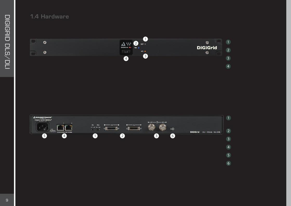
1.4 HardwareDLI is a 1U rack-mounted device.
Mode switches (I/O vs. SGP)
DigiLink ports
Clock In and Out
Two Ethernet ports
Mains
Recovery Switch
SGP mode indicator
Network status indicator
I/O mode indicator
Power button and indicator
DLI Front Panel
DLI Rear Panel
10
DIG
IGR
ID D
LS/
DLI
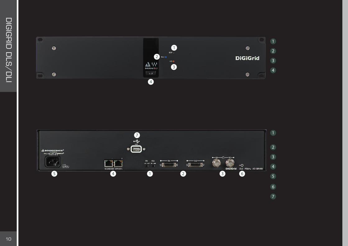
DLS is a 2U rack-mounted device
SGP mode indicator
Network status indicator
I/O mode indicator
Power button and indicator
DLS Front Panel
Mode switches (I/O vs. SGP)
DigiLink ports
Clock In and Out
Two Ethernet ports
Mains
Recovery Switch
Service USB ports
DLS Rear Panel

11
DIG
IGR
ID D
LS/
DLI
1.5 Modes of OperationDLI/DLS offers two modes of operation.
I/O Mode – For Pro Tools HD/HDX and HD Native Systems
In I/O mode, a Pro Tools HD system joins a SoundGrid network. Pro Tools HD/HDX processing cards and HD Native interfaces connect with DigiLink-compatible I/O devices. These in turn couple with a DLI/DLS interface, which is part of the SoundGrid network. Pro Tools HD can now access all SoundGrid devices. Plugins processing is carried out on a SoundGrid DSP server, and all Pro Tools resources and functionality are maintained.
SGP Mode – For Any Native DAW The SGP mode integrates DigiLink-compatible I/O hardware into a SoundGrid network. This supplies extra I/Os for any Native DAW on the network. Sound processing takes place on a SoundGrid DSP server or is performed locally on Native DAWs. Pro Tools PCI or Thunderbolt interfaces are not used, and all connections between the Digilink compatible I/O hardware and the DAW are made via the DLS and SoundGrid Network using the SoundGrid Studio patch.

12
DIG
IGR
ID D
LS/
DLI
2. I/O MODE: INTEGRATING PRO TOOLS HD/HDX AND HD NATIVE SYSTEMS INTO A SOUNDGRID NETWORK
If you’re comfortable connecting and configuring DigiLink-compatible I/O devices, then it will not be difficult to integrate the DLI/DLS and SoundGrid network with a Pro Tools HD/HDX or HD Native system. Like any Pro Tools peripheral, DLI/DLS devices are controlled from the Pro Tools Hardware Setup page, and, depending on configuration, may appear on the Pro Tools I/O Setup page as up to four 192 Digital I/Os.
Because DLI/DLS offers two completely different modes of operation—I/O and SGP—the hardware must be set to the proper mode. On the rear panel of a DLI/DLS unit are two switches, one for each port. To ensure proper operation, both switches must be set to “I/O.” Before changing connections or switch position, turn off the DLI/DLS and all connected DigiLink-compatible I/O devices.
Mode indicator - Front Panel Mode Swiches - Back Panel

13
DIG
IGR
ID D
LS/
DLI
How Many Channels Can I Use?
A DLI/DLS device has two DL ports, each of which can carry up to 32 channels. The number of channels that you can use varies depending on hardware and number of ports, connections, and assignments. Here are some examples of the number of I/O channels that can be added to Pro Tools HD/X hardware systems.
Hardware Connection Number of I/O Channels
DLS/DLI DigiLink-compatible I/O expansion port 16 mono
DLS/DLI Directly to Avid PCI/e, single port 32 mono
DLS/DLI Port 1, directly to Avid PCI/e, single portPort 2, DigiLink-compatible I/O expansion port
48 mono
DLS/DLI Directly to Avid PCI/e, two ports 64 mono
A single DLI/DLS supports a maximum of 64 channels.
Important-Some DigiLink-compatible I/Os cannot connect to the DLI/DLS via their secondary DigiLink port.
Once hardware is connected and configured, go to the Pro Tools I/O Setup page to confirm the number of channels you have available. You will see at least one additional 192 Digital I/O devices (up to 4 192 Digital I/Os, each with 16 I/O channels).
The following examples present in a scaled manner how to connect the DLI/DLS into an existing setup.
Important – DLI/DLS Port 1 must be used before Port 2. If only one port is used, it must be Port 1.
14
DIG
IGR
ID D
LS/
DLI
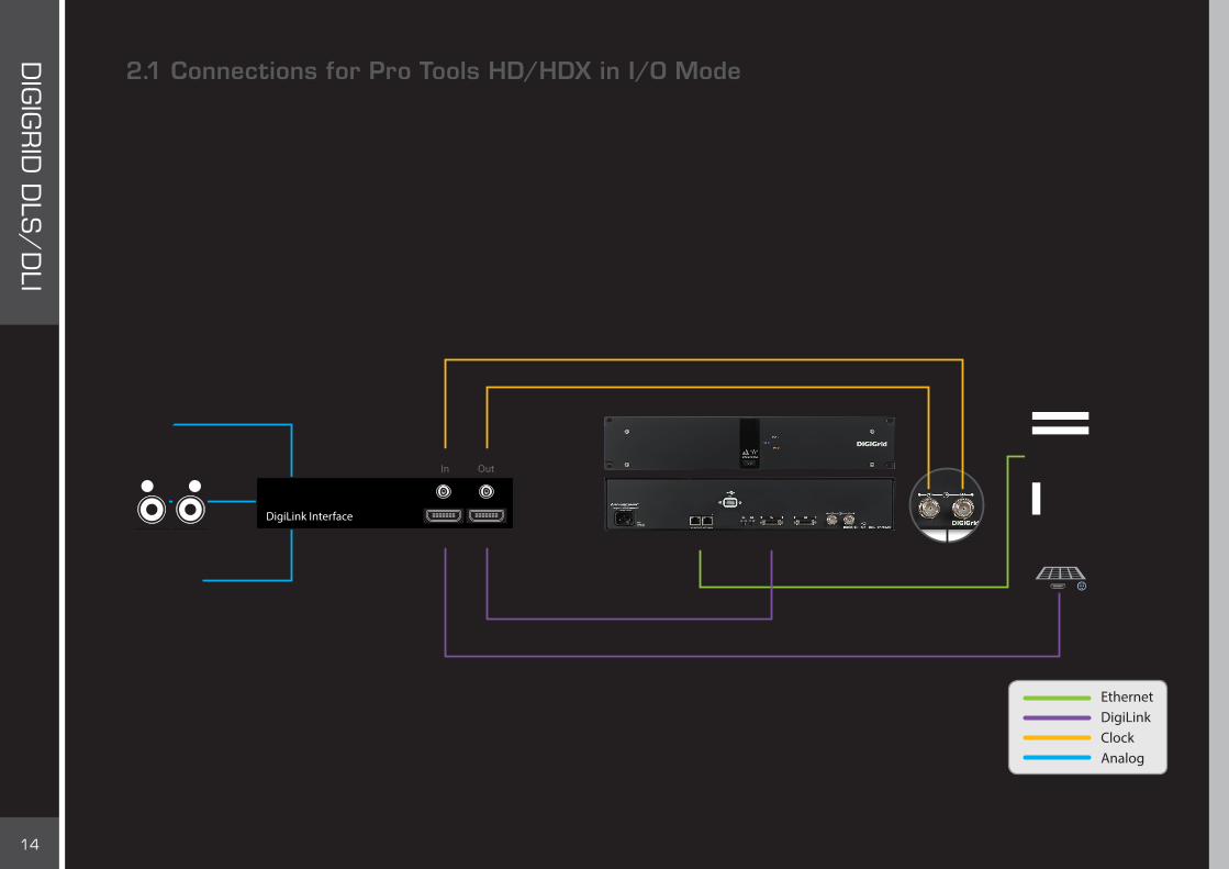
2.1 Connections for Pro Tools HD/HDX in I/O ModeThis is a simple configuration with one DigiLink port.■ HD Core card connects to the primary port of the DigiLink-compatible I/O.■ DigiLink Port 1 of the DLI/DLS connects to the DigiLink-compatible I/O expansion port. ■ Loop Sync In/Out connected between both devices. ■ DLI/DLS connects to the SoundGrid network via Ethernet.
This configuration, which uses one DLI/DLS DigiLink port, provides 16 channels.
DL1
1
EthernetPrimary Port
WC / Loopsync*
Expansion Port
In Out
DL2
DigiLink Interface
DiGiGrid DLS
EthernetDigiLinkClockAnalog
* Dependent on Clock Mode setting in the DLS/DLI control panel

15
DIG
IGR
ID D
LS/
DLI
In the next example, two DigiLink ports are used. This configuration provides 48 channels.■ HDX Core card Port 1 connects to primary port of DigiLink-compatible I/O.■ DigiLink-compatible I/O expansion port connects to DLI/DLS Port 1. This provides 16 channels.■ HDX Core card Port 2 connects to DLI/DLS Port 2. This provides another 32 channels.■ Connect DLI/DLS with the host computer via Ethernet.■ Connect DigiLink-compatible I/O Loop Sync Out to DLI/DLS Loop Sync In. DLI/DLS Loop Sync Out to DigiLink-compatible I/O Loop Sync In. Pay attention to the direction of the loop.
DiGiGrid DLS
DL1
12
EthernetPrimary Port
WC / Loopsync*
Expansion Port
In Out
DL2
DigiLink Interface
EthernetDigiLinkClockAnalog
* Dependent on Clock Mode setting in the DLS/DLI control panel

16
DIG
IGR
ID D
LS/
DLI
This setup includes four DigiLink-compatible I/O devices, two Pro Tools processing cards, and a DLI/DLS. It provides 64 channels that can be used for SoundGrid processing or I/O.
Pro Tools card #1:■ Pro Tools HD Card 1 Port 1 connects with DigiLink-compatible I/O #1 primary port. I/O #1 Expansion Port connects with I/O #2
primary port.■ Pro Tools HD Card 1 Port 2 connects with I/O #3 primary port. I/O #3 Expansion Port connects with I/O #4 primary port.
Pro Tools card #2:■ Pro Tools HD Card 2 Port 1 connects with DLS Port 1. This provides 32 channels.■ Pro Tools HD Card 2 Port 2 connects with DLS Port 2. This provides another 32 channels.■ Loop Sync through all devices■ Ethernet connection between DLS and SoundGrid network
In this configuration, we really just have two sets of two DigiLink-compatible I/O devices, both connectedto Pro Tools HD Card 1 - Ports 1 and 2.Pro Tools HD Card 2 connects to the DLS only.
DigiLink Interface
Primary Port Expansion Port
Primary Port Expansion Port
In Out
DigiLink Interface
Primary Port Expansion Port
In Out
DigiLink Interface
Primary Port Expansion Port
In Out
DigiLink Interface
WC / Loopsync*In Out
DL1 DL2
WC / Loopsync*
WC / Loopsync*
WC / Loopsync*
1 2
1 2
DiGiGrid DLS
EthernetDigiLinkClock
* Dependent on Clock Mode setting in the DLS/DLI control panel

17
DIG
IGR
ID D
LS/
DLI
2.2 Connections for Pro Tools HD Native in I/O modeIntegrating a Pro Tools HD Native system with a SoundGrid network involves essentially the same steps. In this example, An Avid Omni interface is used as a hardware I/O. ■ Computer’s Thunderbolt port connects to HD Native interface port.■ DigiLink Port 1 connects to Omni Primary port.■ Omni expansion port connects to DLI/DLS Port 1. This provides 16 channels.■ Pro Tools HD Port 2 connects to DLI/DLS DL Port 2. This provides another 32 channels.■ Loop Sync goes back and forth between Omni and DLI/DLS.
This configuration yields 48 channels and uses the DLS’s buit-in DSP server.
DL1
1 2
Ethernet DL2Primary Port
In
Expansion Port
Out
DigiLink Interface
WC / Loopsync*
DiGiGrid DLS
EthernetDigiLinkClockAnalogThunderbolt

18
DIG
IGR
ID D
LS/
DLI
HD Native can be used with SoundGrid IO devices for processing and I/O, no need for any Digilink Compatible I/O. A Digigrid device such as IOC or IOX can be used for analog inputs and outputs. ■ Computer’s Thunderbolt port connects to HD Native interface port.■ Pro Tools HD Port 1 connects to DLI/DLS DL Port 1.■ Pro Tools HD Port 2 connects to DLI/DLS DL Port 2.■ Connect an Ethernet cable to the host computer and to the DiGiGrid IOC.Note that there are no Loop Sync connections.
This configuration yields 64 channels and uses the DLS’s built-in DSP server.
DL1
1 2
Ethernet DL2Ethernet
DiGiGrid IOC
EthernetDigiLinkClockAnalogThunderbolt

19
DIG
IGR
ID D
LS/
DLI
Adding a Server to a DiGiGrid DLI
Each of the above configuration diagrams have included a DLS interface, which has a built-in DSP server. When you work with a DLI interface, which does not have a built-in server, you may choose to expand your SoundGrid network by adding an external server.
To add a server to a SoundGrid network, just plug in an Ethernet cable and assign the SoundGrid Studio Device Racks. When you add a server to the SoundGrid network, the device will appear in the Server Rack but will not yet be allocated. Use the rack menu to assign the server to your computer, as described above. You can also run the SoundGrid Wizard for automatic configuration.
Server
DL1EthernetPrimary Port Expansion Port
In Out
DL2
DigiLink Interface
WC / Loopsync*
1 2
DiGiGrid DLI
EthernetDigiLinkClockAnalog
* Dependent on Clock Mode setting in the DLS/DLI control panel
20
DIG
IGR
ID D
LS/
DLI
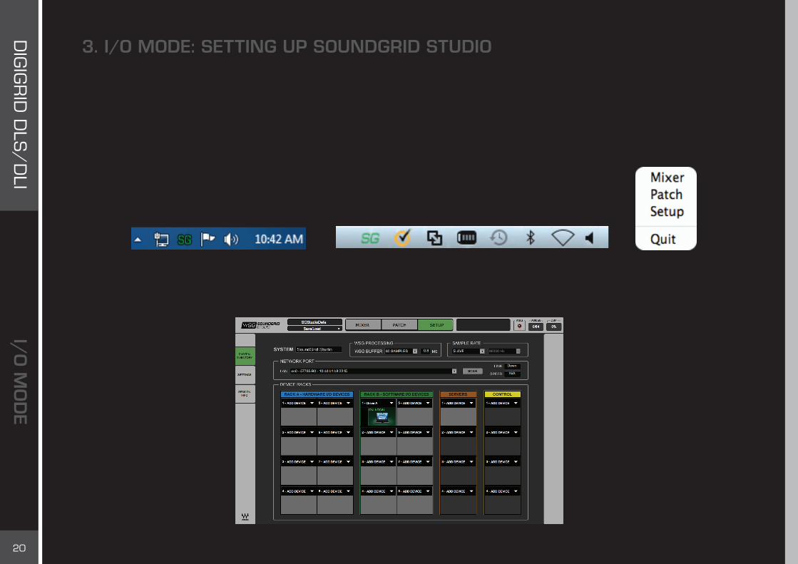
3. I/O MODE: SETTING UP SOUNDGRID STUDIO
SoundGrid Studio oversees the SoundGrid network and manages the devices that are part of it. It is used to configure and assign devices, set up system clock, manage the network, and patch audio between devices. Any DAW can join a SoundGrid network. Pro Tools HD/HDX and HD Native systems cannot be controlled directly by SoundGrid Studio, however. They need an intermediary in order to join a SoundGrid network. DLI/DLS functions as such an intermediary.
To maintain network effectiveness, the SoundGrid Studio Application always runs in the background. Bring SoundGrid Studio to the front by clicking on the SoundGrid icon in the Mac Top Bar or the Windows System Tray
When SoundGrid Studio opens you will see the Setup page.
MacPC

21
DIG
IGR
ID D
LS/
DLI
The first time you launch SoundGrid Studio, the Wizard will open. It scans the network, inventories its assets, and then configures the devices. If the Wizard does not start automatically, click the Start Auto Config button, which is next to the Network Port. Choose “NEXT” to start automatic configuration. This will take a few moments. Choose “CANCEL” to configure manually.
If the Wizard cannot locate the requested SoundGrid network devices, this means
If the Wizard cannot locate the requested SoundGrid network devices, this means the devices might be off or not connected properly. In such a case the Wizard will allow you to rescan the network or work as a Driver node slaved to another system. For more information please refer the SoundGrid Studio User Guide.
When configuration is complete, close the window. If there is still a problem, you can configure your system manually. Use the System Inventory page to assign devices, control the network, and manage clock. To learn how to use this page, please refer to the SoundGrid Studio Application user guide.
SoundGrid Studio uses Ethernet to stream audio between devices on a SoundGrid network. Synchronization clock is also carried over Ethernet. This method of providing clock is
called Sync over Ethernet (SoE). SoundGrid I/O devices can clock by other means as well, but SoE is by far the most common (and convenient) way to provide clock information to network devices.
In the SoundGrid Studio Setup page, you will see all devices assigned to your system, each displays the mode, clock status, and sample rate of the I/O. Here the DLS is the SoundGrid network’s clock master device, indicated by its blue color and the icon text: On, Master Clock, INT (48 kHz).

22
DIG
IGR
ID D
LS/
DLI
To add another SoundGrid device, click on the arrow in an empty rack slot. From the list of available devices, choose the one that you want to add, in this case, a DiGiGrid MGB coaxial MADI interface. In this image the DLS is grayed out, and therefore unavailable, since it’s already claimed (in this case, by you).
The new device is visible in the rack slot. Unless changed by the user, it remains the clock slave and is colored green.
Use the same menu to change the assignment of clock master from one device to another, or to remove the device from the rack slot.

23
DIG
IGR
ID D
LS/
DLI
3.1 Firmware Status and UpdatesNext to each device slot is a button labeled FW. Use this button to check the status of, and if necessary update, the firmware in the DLI/DLS. Each time you update the SoundGrid Studio Application, the most current DLI/DLS firmware is included with the updated installer. When you next launch SoundGrid Studio, you will learn if all devices are running the most current firmware.
An I/O that is using outdated or incompatible firmware cannot join a SoundGrid network until its firmware is updated. SoundGrid Studio assesses the device’s firmware when scanning with the Wizard or when you assign it.
FW Indicates the status of the device’s firmware. The user is given the choice to update it. Status indications are color coded:
Grey Compatible firmware
Blue Compatible firmware, but a newer version exists
Red Firmware not compatible and must be updated in order to use
Click on the FW button to launch the Updater. This will initiate a scan of the hardware and then offer options. Do not disconnect the device or turn off the computer until you see “Done.”
After updating your device must be restarted. Devices will restart automatically, and some will prompt ‘Please Restart’.
The ID button activates LEDs on the front panel of the hardware device. The same button can be found on the DLI/DLS Control Panel.

24
DIG
IGR
ID D
LS/
DLI
3.2 Adding a ServerAdd a server to a Pro Tools HD/HDX or HD system to move the plugin processing of chosen tracks away from the local CPU. This dramatically increases the number of plugins that can be used simultaneously. One way to do this is to use a DLS interface, which is equipped with an integral DSP server. The DLS is actually an I/O and a separate server, packaged together in one box. If you are already working with a DLI, you may choose to add a separate server.
Click on the arrow to reveal the list of available servers. Select from that list. Servers that are unavailable are grayed out.
A server cannot be shared by multiple SoundGrid host applications such as SoundGrid Studio. Within a SoundGrid network only one computer can utilize a server’s processing power for StudioRack and eMotion ST. Once assigned to a computer, a server remains unavailable to all others until released by the user.
3.3 I/O Mode: Pro Tools and DLI/DLS SettingsIn I/O mode, most setup takes place in Pro Tools. Playback engine, I/O devices and hardware setup are configured the same way as in other DigiLink-compatible I/Os.
3.3.1 Pro Tools Playback Engine SettingsIn I/O mode, the Pro Tools playback engine, not the SoundGrid Studio Application, governs the Pro Tools system as well as the DLI/DLS and manages I/O devices. Depending on the Pro Tools HD system you are using, the audio engine will be set to either HD TDM, HD Native, or HDX. You can confirm this in the Pro Tools Playback window.
25
DIG
IGR
ID D
LS/
DLI
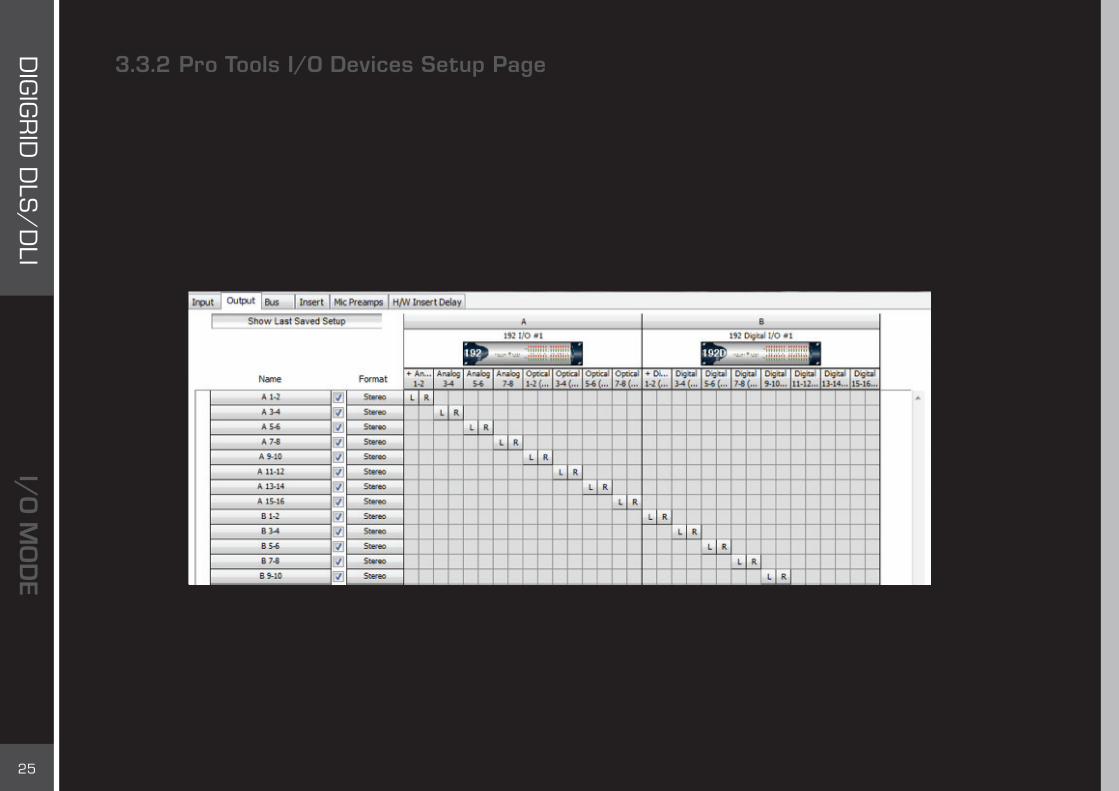
3.3.2 Pro Tools I/O Devices Setup Page The DLI/DLS appears in the Pro Tools I/O Setup page as a Pro Tools I/O device. It is not called “DLI/DLS”; instead, it is identified as up to four 192 Digital I/O devices. In the example presented here, the first device, “192 I/O #1,” is the existing DigiLink-compatible I/O. The remaining patches represent DLI/DLS I/Os that are available for processing or SoundGrid audio streaming. Each group of 16 channels appears in the I/O Setup pages as “192 Digital I/O #1,” “192 Digital I/O #2,” etc.
In the Pro Tools I/O Preferences page, begin patching at the second group of 16 I/Os. In this example, A1/A2–A15/16 are channels from the Pro Tools hardware I/O, not from the DLI/DLS. When you patch Pro Tools channels with StudioRack, begin channel assignments at B1/B2, since these are the first channels that are associated with the DLI/DLS.
The same is true when working in a Pro Tools HD system without a DSP server: B1/B2 are the first channels that you can assign from the DLI/DLS.

26
DIG
IGR
ID D
LS/
DLI
These DLI/DLS devices will appear in the SoundGrid Studio Patch page.
A DLI/DLS has two ports, each with 32 channels. However, if a DL port is connected to only one I/O through its expansion port, its channels 17–32 will be unused and that block of channels will be grayed in the SoundGrid Studio Patch page.

27
DIG
IGR
ID D
LS/
DLI
3.3.3 Pro Tools Hardware Setup PageLike the I/O Settings page, the Pro Tools Hardware Setup page recognizes a DLI/DLS as up to four 192 Digital I/Os. All that concerns you here, however, is the Clock section on the left side of the page. When using a DLI/DLS to link Pro Tools HD/HDX or HD Native to a SoundGrid network, do not change the I/O settings. These are set in the SoundGrid Studio Patch page, and any modifications will break the relationship between Pro Tools channels and SoundGrid Studio channels.
We will return to this page in the next chapter when we discuss system clocking.

28
DIG
IGR
ID D
LS/
DLI
3.4 I/O Mode: Device Control PanelsEach SoundGrid I/O device has its own control panel. They differ a bit in appearance and function, depending on the device, but all work in a very similar manner. Control panels allow you to set clock and sample rate, configure inputs and outputs, and control mic preamps, if applicable. To access a device’s control panel, click on the Gear symbol next to the device’s rack slot icon
In I/O mode, Pro Tools controls the DLI/DLS, including its clock settings. Pro Tools also controls all I/Os connected to it, so there is really very little to do in the control panel.
At the top of each Control page is an identification and management banner that indicates the ports connected to active devices. This page is also used to load and save device presets, rescan ports and update clock status, and identify the hardware device.
Each DLI/DLS device has five Control pages. Two pages provide information about the unit. The others are used to establish clock and to set up the device.
■ The About page identifies the product and provides basic information about the device.■ The System Info page provides detailed information about the device: network address, firmware version, and more. This
information is necessary when comparing firmware among several devices, and when contacting customer support.■ The Clock page is used to set sample rate and sync sources for the device. In I/O mode, the Pro Tools Hardware Setup page largely
takes the place of this control panel. Still, there are a few controls and indicators you should be familiar with. ■ DL Port 1 and DL Port 2 pages are used to control the two DLI/DLS ports. In I/O mode, these functions are controlled entirely by
Pro Tools, so there is absolutely nothing to do in this page.Control pages are used more extensively in SGP mode than in I/O mode. Refer to the chapter “SGP Mode: Device Control Panels” for a detailed description of the controls.

29
DIG
IGR
ID D
LS/
DLI
In I/O mode, Pro Tools controls clock settings. However, there are a few controls and indicators that you should be aware of when integrating a Pro Tools HD/HDX or HD Native system with a SoundGrid network.
SourceSets or displays the preferred clock source for the DLI/DLS. Available sources are Internal, Word Clock/Loop Sync and SoE. In I/O Mode the DLI/DLS clock sources are controlled from the Pro Tools Hardware Setup page. Use the Pro Tools Clock Source menu to set the clock source of the DLI /DLS represented as a192 Digital in Pro Tools.
Clock Operation ModeTells the system which clock source to anticipate on the BNC connectors: Loop Sync or Word Clock. Loop Sync is the preferred clock mode when using DigiLink-compatible I/O devices. However, certain devices cannot accept Loop Sync. For those devices, select Word Clock.
30
DIG
IGR
ID D
LS/
DLI
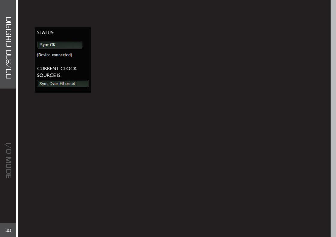
Status
Current Clock SourceIndicates the current source of clock for the DLI/DLS. Possibilities: Internal, Word Clock, Loop Sync, SoE. The indicator is red when the preferred clock source is not available and a fallback clock is used.
SoEIndicates if the SoundGrid I/O device is locked to the SoundGrid network, and if it is an SoE master or slave. This message is mirrored in the device rack slots in the System Inventory page.
DL1/DL2The DL1 and DL 2 controls are the rightmost tabs. They control device patching, preamps, and other device-specific parameters. In I/O mode, the DLI/DLS assigns all port control to Pro Tools, so the two peripheral ports are inactive.

31
DIG
IGR
ID D
LS/
DLI
3.5 Clocking in I/O ModeA Pro Tools HD/HDX or HD Native system has its own playback engine and its own clocking environment. A SoundGrid network has its own driver and its own clocking environment. There are therefore two complete clock systems at work: • DigiLink-compatible I/O devices connected to a DLI/DLS• A SoundGrid network that includes the DLI/DLS
Regardless of system size, the rules of managing clock remain the same. Details change according to the specific hardware devices and the type of Pro Tools used.
3.5.1 Clocking Example #1: DLI/DLS is SoE Master; 192 is Loop Sync MasterThis configuration adds efficiency to Pro Tools HDX mixing environments. In this configuration, a SoundGrid network delivers flexibility to a control room equipped with a Pro Tools HDX system. DiGiGrid DLS interfaces provide 48 I/O channels to the HDX system and a SoundGrid DSP server for plugin processing. A DigiLink, compatible I/O is used for hardware connections.
All these devices are joined via DigiLink and clocked with Sync Lock. Everything else in the network is connected with Ethernet cables. A DiGiGrid MGB/MGO interface connects this network to a MADI source or destination, for instance a console or a MADI distribution system. DLS is SoundGrid network clock master. The MGB MADI interface clock is slaved to the SoundGrid Network.
DL1EthernetPrimary Port
InWC / Loopsync
Expansion Port
Out
DL2
DigiLink Interface
1 2
DiGiGrid DLS
EthernetDigiLinkClockAnalog
DiGiGrid MGB/MGO

32
DIG
IGR
ID D
LS/
DLI
a. Establishing Clock between DigiLink-Compatible I/Os and DLI/DLS1
DigiLink-compatible I/O devices (including DLI/DLS) are controlled from the Pro Tools Hardware Setup page. Use the Clock Source menu to set the clock of the attached I/O devices. In this example, the device attached to the Pro Tools Core card is called “192 I/O #1.” The DLS device is listed below as “192 Digital I/O #1.” Configure it as you would any other Pro Tools peripheral.
These devices are now locked to each other: one Loop Sync master (192 I/O) and Loop Sync slave (DLS, appearing to Pro Tools as “192 Digital I/O #1”). You can verify clock settings in the DLS control panel. In this example, the DLS is locked to the 192 via Loop Sync and its status is “OK.”
1. For maximum flexibility, we recommend that you install Loop Sync cables in “both directions.” While some configurations will function with only one Loop Sync cable, a complete loop enables you to switch easily from one configuration to another.

33
DIG
IGR
ID D
LS/
DLI
b. Incorporating Devices with the SoundGrid Network
Now we must integrate this DigiLink-compatible I/O system with the SoundGrid network. Return to the SoundGrid Studio Device Racks to see the DLS in its slot. Use the Rack Slot menu to make it the master. When DLS is set as SoundGrid (SoE) clock master, the 192 attached to Pro Tools determines clock for the entire system, i.e., for both the DigiLink-compatible I/O system and the SoundGrid network. DLS accepts clock from the 192 and then distributes it to the SoundGrid devices.
Blue text on the device icon indicates that the DLS is the SoE clock master. The SoE window on the DLS control panel indicates that the device is locked to SoE and is the master.
3.5.2 Clocking Example #2: DLI/DLS is SoE Slave and Loop Sync MasterIn the previous example, the 192 connected to the Pro Tools is the clock master for all of the DigiLink-compatible I/O devices (including DLS). The DLS is the clock master of the SoundGrid network. Because the DigiLink-compatible I/O system and the SoundGrid network are somewhat independent of each other, it’s possible for the DLS to be clock master in one system and clock slave in another.
In the Device Rack, change the DLS from clock master to clock slave. Now the DLS is a slave to the Loop Sync master as well as to the SoundGrid network. While this condition is possible, it is not advisable. When DLS is SoE slave, we recommend that it serves as Loop Sync master of the DigiLink-compatible I/O system. This configuration allows you to clock the DLS to another device on the SoundGrid network—such as a live recording console—while recording to a Pro Tools HD/HDX or HD Native system that’s also using SoundGrid I/Os across the network.

34
DIG
IGR
ID D
LS/
DLI
Since the DLS is no longer generating SoE but is slaved to it, you must set Clock Source to SoE in order to receive it from the SoundGrid network. Open the Pro Tools Hardware Setup window and select any AES/EBU channel as the Clock Source. The DLS will use this port to lock to SoundGrid Studio via SoE.
SoundGrid Studio Sample Rate ControlOn the top bar of each page in SoundGrid Studio is a window that indicates the system sample rate. In SGP mode, this window is used to set sample rate under certain conditions. In I/O mode, sample rate is set by Pro Tools, and this window is for sample rate display only.

35
DIG
IGR
ID D
LS/
DLI
3.6 Using a DSP Server for Added Processing Power
Add a DSP server to a Pro Tools HD/HDX or HD Native system to move processing from the Local CPU. This greatly increases plugins performance. Audio steaming to the server through DLI/DLS is controlled by the StudioRack plugin.
As a channel insert to any DAW, StudioRack chains up to eight plugins, controls them, assigns them to external controllers, and manages them—with their presets—all in a way that makes it easy to move from one DAW session to another and from one DAW platform to another.
When part of a SoundGrid network with a DSP server, StudioRack can shift plugins processing from the local CPU and divert it to the SoundGrid DSP server.
3.6.1 Basic Setup■ Reserve channels in SoundGrid Studio. ■ Insert a DSP StudioRack plugin on a track.■ Set Waves Startup Preferences.■ Assign Pro Tools channels to hardware I/Os.■ Set the I/O insert channel of each StudioRack instance to match the corresponding Pro Tools I/O insert.

36
DIG
IGR
ID D
LS/
DLI
3.6.2 Reserving Channels DLI/DLS can stream up to 64 channels, which you can use for processing or I/Os—or both. Once you’ve configured the I/Os between the DLI/DLS and SoundGrid, choose how to use these channels.
Locate the DLI/DLS in I/O slot A. From the menu, select “Assign to StudioRack.” You will see a count of StudioRack channels in blocks of 16, up to a maximum of 64. Each block represents the inputs and outputs of one active DigiLink connection. Examples of connections may include:■ DL1 Avid Expansion ( I/O 1: 1–16)■ DL1 PCI Card (1: 1–16; 2: 1–16)
For each block, decide if you want to use it for DSP processing or to send it to an I/O. Please refer to the StudioRack user guide to learn more about server-based processing in I/O mode.
Adding a DSP server to a Pro Tools HD/HDX or HD Native system does not affect Pro Tools functionality.
As described in the previous chapter, channels assigned manually to StudioRack route audio through the I/O to the DSP server and back. These channels will not be used for I/O and will not appear in the SoundGrid Patch. Note the there are no patch points for DLS-1. If all channels have been assigned to StudioRack, there will be no I/O for that device.
37
DIG
IGR
ID D
LS/
DLI
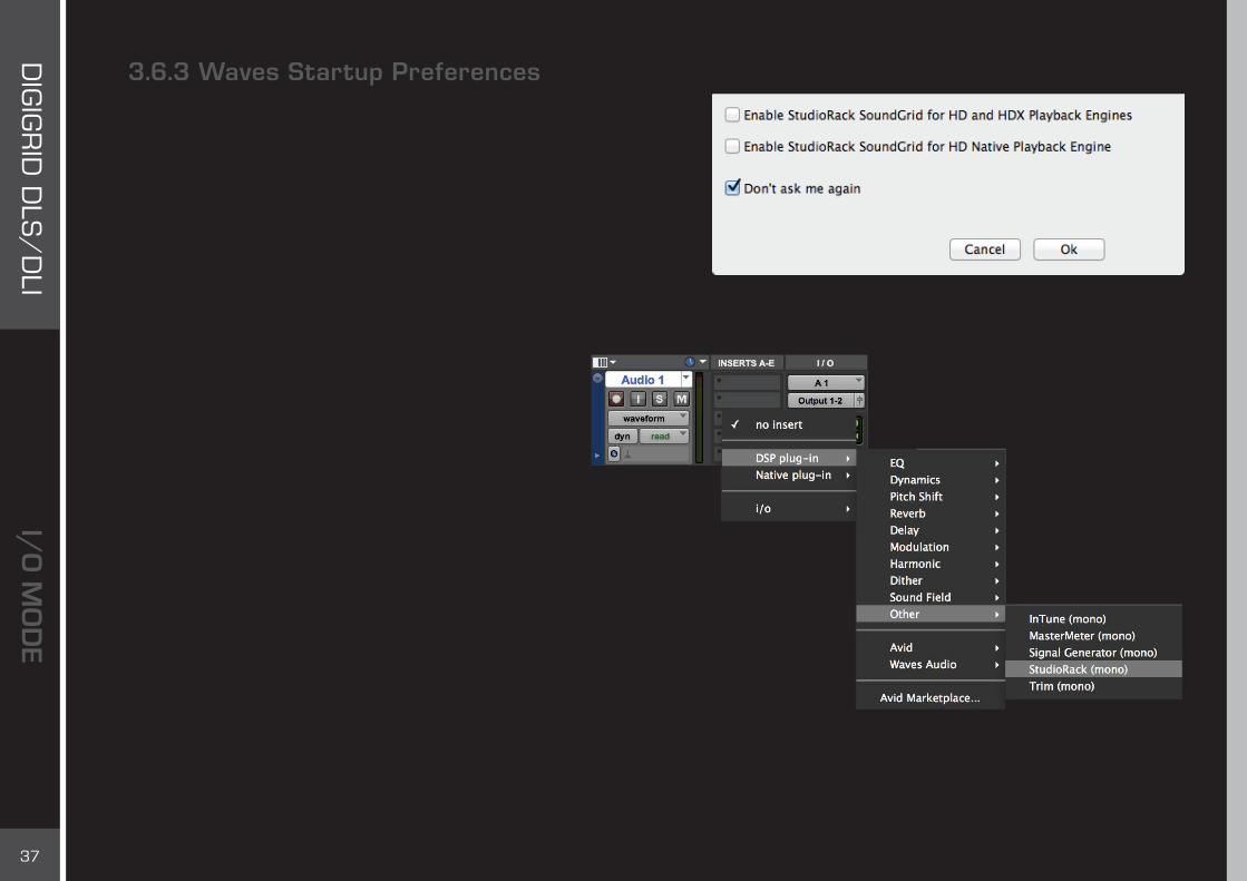
3.6.3 Waves Startup PreferencesStudioRack needs to know which playback engine the host Pro Tools is using. Access the Waves Preferences window by holding the Shift key while you launch Pro Tools. When you see this window, release the Shift key and choose between the HD/HDX playback engine and the HD Native playback engine.
If you don’t want to encounter this window each time you start Pro Tools, then select “Don’t ask me again.” You can always access this window by holding the Shift key during Pro Tools startup.
Open a DSP StudioRack plugin. The plugin is always called “StudioRack” in the DAW insert menu, whether you are working on a Native or a DSP network. Select a mono or a stereo component. When using a Pro Tools HD Native system, open a StudioRack plugin and change processing mode to “SoundGrid.”

38
DIG
IGR
ID D
LS/
DLI
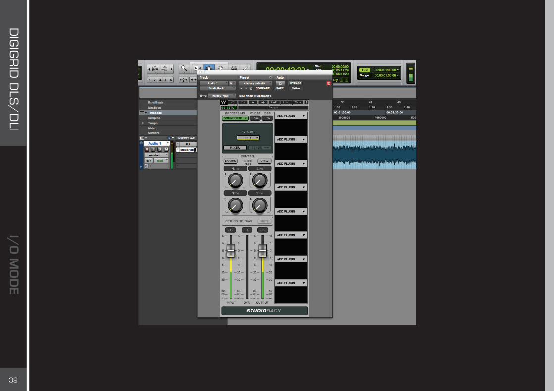
In the Pro Tools I/O Setup page, establish a relationship between tracks and physical channels. Remember that the DLI/DLS will appear to the Pro Tools as one to four 192 Digital I/O devices.
Open I/O hardware inserts on the Pro Tools tracks where you inserted the StudioRack plugins.In this example, Track “Audio 1” = Channel B1 = Device 192D I/O #1, Channel 1.
In StudioRack, select the same hardware I/O insert that you chose in Pro Tools. You will see up to four groups of 16 tracks each, representing the 64 channels from the DLI/DLS. Groups 1 and 2 represent DL Port 1, while groups 3 and 4 represent DL Port 2.
Inserts that are grayed out in the StudioRack I/O Insert menu are not available. Check that StudioRack I/O inserts match those on Pro Tools.
39
DIG
IGR
ID D
LS/
DLI
Audio can now stream between Pro Tools and the DSP server. For details about streaming audio in I/O mode, please refer to the user guide for StudioRack.

40
DIG
IGR
ID D
LS/
DLI
3.7 Patching from the NetworkDLI/DLS can stream up to 64 channels, which you can use for processing or I/Os—or both. Once you’ve configured the I/Os between the DLI/DLS and SoundGrid, choose how to use these channels. Channels that have not been assigned to StudioRack are available for patching. The patch page has four tabs. The direction of the patch is indicated by an arrow.
A DLI/DLS can be patched to an eMotion ST mixer or to another device present on the network. A DLI/DLS output channel can be sent to more than one patch, but an input can come from only one source. To learn more, please consult the SoundGrid Studio user guide.

41
DIG
IGR
ID D
LS/
DLI
eMotion ST Mixer Patching
Patch to and from the eMotion ST mixer using the input and output tabs on the left side of the interface. The green buttons indicate whether a channel is mono, left side of a stereo pair, or right side of a stereo pair. Toggle between these states by double-clicking on the button.
Left
Right
Mono

42
DIG
IGR
ID D
LS/
DLI
The eMotion ST Mixer Layer is used to mix DAW outputs, mic and line sources, aux tracks, and more. In this respect, eMotion ST replaces the external mixer traditionally used to create monitor mixes for studios and headphones.
eMotion ST operates within a SoundGrid network, so any available SoundGrid I/O device, whether hardware or driver, local or remote, can provide inputs and outputs. eMotion ST can be used for processing pre-, post-, or in parallel with Pro Tools.

43
DIG
IGR
ID D
LS/
DLI
4. SGP MODE: ADDING DIGILINK-COMPATIBLE I/OS TO A SOUNDGRID NETWORK
In SGP mode, the DLS enables you to control a variety of DigiLink enabled I/Os, Pro Tools PCI or Thunderbolt interfaces are not used. All connections between the DigiLink-compatible I/Os and your DAW are made via the DLI/DLS, through the SoundGrid ASIO/Core Audio Driver. This allows you to bridge your favorite DAW (Logic, Cubase, Nuendo, Ableton, Pro Tools Native, etc.) to SoundGrid applications and other SoundGrid compatible devices.
With the DLS (or DLI with an external server) you can process plugins on the SoundGrid server using the StudioRack and eMotion mixer.
4.1 Connections: I/O Mode vs. SGP ModeIn I/O mode, DigiLink-compatible I/O devices connect directly with Pro Tools HD/HDX processing cards. These, in turn, connect to the DLI/DLS with a DigiLink cable. Finally, there is an Ethernet connection between the DLI/DLS and the SoundGrid network. This configuration indicates that Pro Tools is running with an HD/HDX playback engine and is simply joining a SoundGrid network.
The opposite is true in SGP mode. The Pro Tools HD processing card is not used. Instead, DigiLink-compatible I/O hardware is brought into a SoundGrid network, with DLI/DLS serving as a bridge. DLI/DLS becomes the audio interface, and the DigiLink-compatible I/O devices serve as converters.
4.2 Currently Supported DevicesDigi 96 I/O, 192 I/O, 192 I/O Digital, HD I/O, Omni HD I/O2, Lynx Aurora 16/8, Apogee Symphony I/O.
2. HD Omni I/O DSP monitor section is not fully supported. Path assignment is available in stereo only.

44
DIG
IGR
ID D
LS/
DLI
4.3 Basic SGP ConfigurationIncorporating a DigiLink-compatible I/O into a SoundGrid network involves three processes:■ Connecting hardware■ Configuring devices in SoundGrid Studio Device Racks■ Configure attched DL device from DLS control panel■ Patching between devices and ASIO/Core Audio drivers in the SoundGrid Studio Patch page
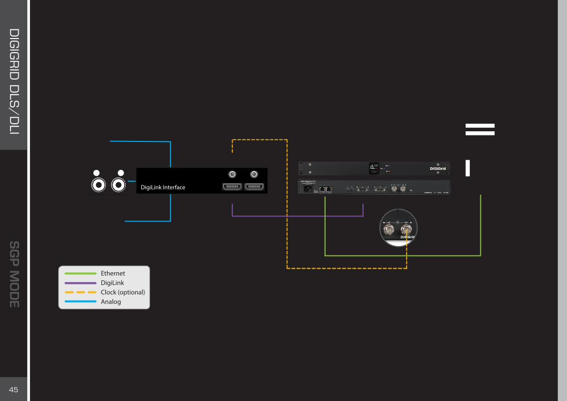
4.3.1 Connecting One DigiLink-Compatible I/O Device in SGP Mode■ Power up the DLI/DLS and DigiLink-compatible I/O.■ Connect the host computer to the DLS Ethernet port.■ Connect DLS Port 1 to the DigiLink I/O device’s primary port.■ Set both switches on the rear panel of the DLI/DLS to “SGP.” ■ Connect Loop Sync between DL devices as you would with Pro Tools.
Power up the devices. LEDs on the DLI/DLS front panel will confirm network status and indicate that the device is in SGP mode. If the network light is not illuminated, use SoundGrid Studio to diagnose the problem. If the front panel indicates “I/O,” this means you probably didn’t set the rear panel switches correctly.
Mode Swiches - Back Panel Mode indicator - Front Panel
45
DIG
IGR
ID D
LS/
DLI
Connect the host computer to the DLS Ethernet port. Connect DLI/DLS DL Port 1 to the DigiLink compatible I/O device’s primary port. In these examples, DLI/DLS is the SoundGrid network (SoE) clock master. Clock is delivered from the DigiLink compatible device through the DigiLink connection to the DLI/DLS, and from there to the entire SoundGrid network. If the DLI/DLS internal clock or SOE sources are used, a clock connection between DLI/DLS and the DigiLink compatible device is required. This is illustrated by the optional clock connection in the diagram.
Primary Port Expansion Port
In Out
DigiLink Interface
DL1 DL2
WC / Loopsync* DiGiGrid DLI
EthernetDigiLinkClock (optional)Analog
* Dependent on Clock Mode setting in the DLS/DLI control panel

46
DIG
IGR
ID D
LS/
DLI
4.3.2 Adding a Server to an SGP SystemAdding a SoundGrid DSP server will greatly increase the number of plugins that can be used simultaneously by using StudioRack and eMotion mixer. Plugin processing can now be offloaded from your local CPU to a server. When using a DLS the SoundGrid DSP server is already part of the system. You can also add an external server to a DLI-based system: in this case, connect the server to the second Ethernet port of the DLI.
EthernetDigiLinkClock (optional)Analog
* Dependent on Clock Mode setting in the DLS/DLI control panel
Primary Port Expansion Port
In Out
DigiLink Interface
DL1 DL2
WC / Loopsync*
DiGiGrid DLS

47
DIG
IGR
ID D
LS/
DLI
4.3.3 Adding More DigiLink-Compatible I/O Devices to a DLI/DLS: SGP ModeYou can connect up to four DigiLink-compatible I/O devices to each DLI/DLS. Each DigiLink-compatible I/O provides 16 channels. Each DLI/DLS port can provide 32 channels, so the configuration in this illustration provides 64 channels.
Connections:
DLI/DLS Port > 192 #1 Primary Port > 192 #1 Expansion Port 192 #2 Primary PortDLI/DLS Port 2 > 192 #3 Primary Port > 192 #3 Expansion Port >192 #4 Primary Port
The four DigiLink-compatible I/O devices are clocked to each other through Loop Sync. The DLI/DLS receives clock from the loop master, directly from the DL cable.
DigiLink Interface
Primary Port Expansion Port
Primary Port Expansion Port
In Out
DigiLink Interface
Primary Port Expansion Port
In Out
DigiLink Interface
Primary Port Expansion Port
In Out
DigiLink Interface
In Out
DL1 DL2
WC / Loopsync*
WC / Loopsync*
WC / Loopsync*
WC / Loopsync*
DiGiGrid DLS
EthernetDigiLinkClock
* Dependent on Clock Mode setting in the DLS/DLI control panel
48
DIG
IGR
ID D
LS/
DLI
5. SGP MODE: SETTING UP SOUNDGRID STUDIO
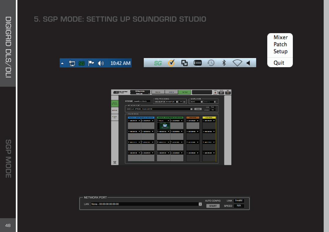
The SoundGrid Studio Application oversees the SoundGrid network and manages all network devices. To maintain network effectiveness, the SoundGrid Studio Application always runs in the background. Bring it to the front by clicking on the SoundGrid icon in the Mac Top Bar or the Windows System Tray.
When SoundGrid Studio opens, you will see the Setup page:
The first time you launch SoundGrid Studio, the Wizard will open. It scans the network, inventories its assets, and then configures the devices. If the Wizard does not start automatically, click the Start Auto Config button, which is next to the Network Port. Choose “NEXT” to start automatic configuration. This will take a few moments. Choose “CANCEL” to configure manually.
MacPC
49
DIG
IGR
ID D
LS/
DLI
If the Wizard cannot locate the requested SoundGrid network devices, this means the devices might be off or not connected properly. In such a case the Wizard will allow you to rescan the network or work as a Driver node slaved to another system. For more information please refer the SoundGrid Studio User Guide.
When configuration is complete, close the window. If there is still a problem, you can configure your system manually. Use the System Inventory page to assign devices, control the network, and manage clock. For detailed information about SoundGrid Studio, please refer to the SoundGrid Studio user guide.
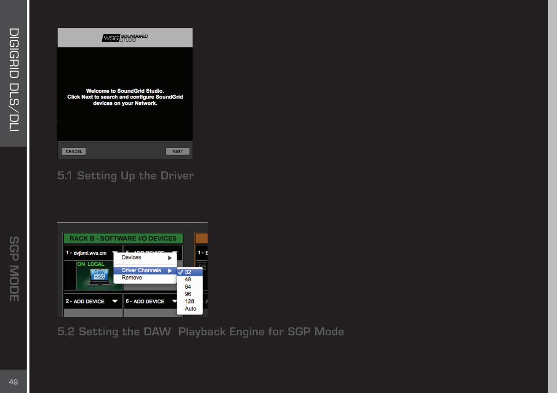
5.1 Setting Up the DriverYou can allocate between 32 and 128 driver channels. Allocate driver channels in Rack B of the Setup Page. The number of channels is reflected in the patch tabs: fewer allocated channels means fewer channels in the Patch page. The default is 32.
Select Auto to match the amount of driver channels to the maximum I/O count available on the assigned interfaces.
5.2 Setting the DAW Playback Engine for SGP ModeSoundGrid Studio uses the SoundGrid ASIO/Core Audio driver to communicate with all network devices and with a DAW, whether local or remote. Set the playback engine to “Waves SoundGrid.” Patch DAW inputs and outputs to the driver.

50
DIG
IGR
ID D
LS/
DLI
Multiple Client Core Audio/ ASIO DriverThe Waves SoundGrid ASIO (Windows) or Core Audio (Mac) driver lets you configure multiple hosts with the same local driver. This means you can use multiple DAWs on the same computer simultaneously. This allows you to record the same source to two DAWs on the same computer consecutively; route audio from multiple DAWs to a single I/O; and, if you have a SoundGrid server, route multiple DAWs to the eMotion ST mixer.
Please note the following when using this feature:
1. All hosts must run the same sample rate. If sample rates do not match, each host will behave differently.
2. Driver inputs and outputs can be shared.
Please note: Some hosts, for example Pro Tools and MultiRack Native, automatically claim all driver outputs. Even when using such hosts, however, you can use the same input driver channels to record to multiple DAWs.
3. It is not possible to connect local driver channels to one another. This means you cannot use SoundGrid Studio’s device-to-device patch to virtually connect audio between two hosts on the same computer. To do this, you must route through the eMotion ST mixer (which requires a SoundGrid server).
4. You may use up to five hosts on a single computer/driver.
51
DIG
IGR
ID D
LS/
DLI
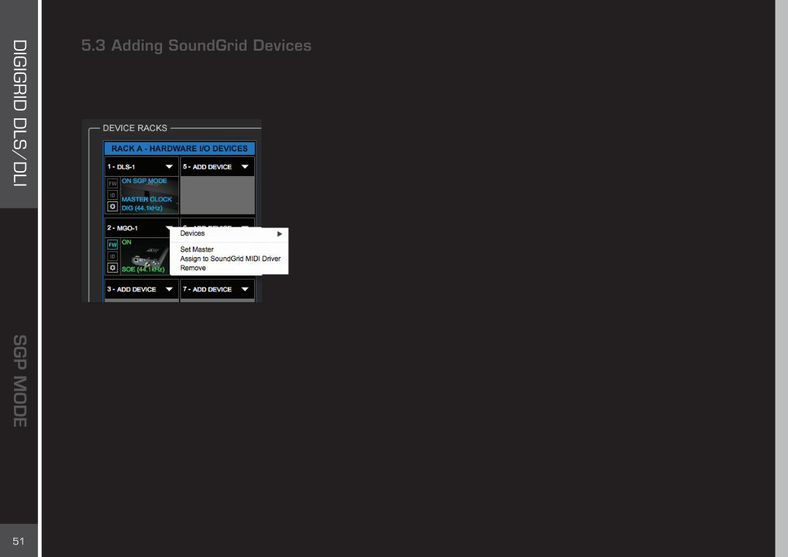
5.3 Adding SoundGrid DevicesTo add another SoundGrid device, click on the arrow in an empty rack slot. From the list of available devices, choose the one that you want to add—in this case, a DigiGrid MGB coaxial MADI interface. In this image the DLS is grayed out, and therefore unavailable, since it is already claimed (in this case by you).
The new device is visible in the rack slot. Unless changed by the user, it remains the clock slave and is colored green.
Use the same menu to change the assignment of clock master from one device to another, or to remove the device from the rack slot.
SoundGrid Studio uses Ethernet to stream audio between devices on a SoundGrid network. Synchronization clock is also carried over Ethernet. This method of providing clock is called Sync Over Ethernet (SoE). SoundGrid I/O devices can clock by other means, but SoE is by far the most common (and convenient) way to provide clock information to network devices.
The first device added to rack is designated the SoE clock master and is placed in the first rack slot. In the example presented here, the DLS is the clock master, indicated by the blue “Master Clock” overlay.
Each populated device slot displays the mode, clock status, and sample rate of the I/O. The DLS is the clock master device, indicated by its blue color and the icon text: On, Master Clock, INT (48 kHz). DigiLink-compatible I/O devices are not visible here since they are bridged to the SoundGrid network through the DLS and not connected directly to SoundGrid. Only the DLS is seen in the slot.
Now you know how to assign I/O devices and designate a device as the clock master.

52
DIG
IGR
ID D
LS/
DLI
5.4 Firmware Status and UpdatesNext to each device slot is a button labeled FW. Use this button to check the status of, and if necessary update, the firmware in the DLI/DLS. Each time you update the SoundGrid Studio Application, the most current DLI/DLS firmware is included with the updated installer. When you next launch SoundGrid Studio, you will learn if all devices are running the most current firmware.
SoundGrid Studio uses the Wizard to assess a device’s firmware, which must be up to date for the device to join a SoundGrid network.FW Indicates the status of the device’s firmware. The user is given the choice to update it. Status indications are color-coded:Gray Compatible firmware
Blue Compatible firmware, but a newer version exists
Red Firmware not compatible; must be updated in order to use
Click on the FW button to launch the Updater. This will initiate a scan of the hardware and then offer options. Do not disconnect the device or turn off the computer until you see “Done.”
The ID button identifies a device. When ID is clicked, the network LED on the front panel will cycle through colors. The same button can be found on the DLI/DLS control panel.
5.5 Adding a ServerAdd a server to a SoundGrid network to move plugin processing away from the local CPU. This dramatically increases the number of plugins that can be used simultaneously. One way to do this is to use a DLS interface, which is similar to the DLI but with a built-in DSP server. If you are already working with a DLI, you may choose to add a separate server.
Click on the arrow to reveal a list of available servers. Select from that list. Servers that are unavailable are grayed out.
A server cannot be shared by drivers: only one computer can utilize a server’s processing power, regardless of the number of computers or servers on the network. Once assigned to a computer, a server remains unavailable to others until released by the user.

53
DIG
IGR
ID D
LS/
DLI
6. SGP MODE: DEVICE CONTROL PANELS
Each DLI/DLS device has its own control panel. The control pages may differ a bit in appearance and function, depending on connected devices, but all work in a very similar manner.
DLI/DLS control panels are divided into five tabbed pages or sections.
At the top of each Control page is an identification and management banner that indicates the ports connected to active devices. This banner is also used to load and save device presets and to rescan Digilink ports.

54
DIG
IGR
ID D
LS/
DLI
At the top of each page is an Identify function that indicates the DLI/DLS hardware device by the NET led flashing.
The About page identifies the product and provides basic information about the device.
Identify

55
DIG
IGR
ID D
LS/
DLI
The System Info page provides detailed information about the device: MAC address, firmware version, and more.
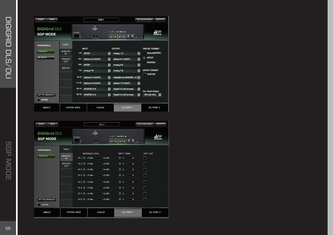
Use the Clock Control page to adjust clock settings and monitor the clock status of each connected device.
56
DIG
IGR
ID D
LS/
DLI
The DL1 and DL2 control pages are the rightmost tabs. Each tab controls the device patching and other device-specific parameters of the respective DL port.
Inputs and outputs for the selected device can be routed to physical I/Os that correspond to device patches in SoundGrid Studio.■ One or two peripheral devices can be connected to each port.
They are identified on the left sidebar. Click on a peripheral’s name to see its physical connections.
■ The Main control tab is used to define physical inputs and outputs. - Each channel has a drop-down menu from which connections are selected. - One channel output can be assigned to several physical outputs. To assign a channel to multiple outputs, select an output from the menu. Then hold CTRL while selecting other outputs. The additional devices will appear orange in the drop-down list, and a plus (+) symbol will appear on the main output. - A physical input can be assigned to several channels. - An Identify button in the lower left corner triggers front panel lights on the specific Digilink-enabled device. This is not the same as the Identify button on the banner, which identifies the DLI/DLS.
■ Adjust reference levels, choose input trims, and activate soft clip. Analog ins and outs can be adjusted from two tabs when applicable.
■ Digital in/out can be adjusted when applicable.

57
DIG
IGR
ID D
LS/
DLI
Setting up an HD Omni interface configured with a DLI/DLS differs somewhat from an Omni connected directly to Pro Tools. Both configurations allow you to create main and alternate control room paths. Pro Tools uses a patch for path assignment, while DLI/DLS provides drop-down menus. Use these menus to select a path for left and right channels. Set path for main and alternate paths.The DLI/DLS Omni control supports stereo only. The Fold Down feature is not available.
58
DIG
IGR
ID D
LS/
DLI
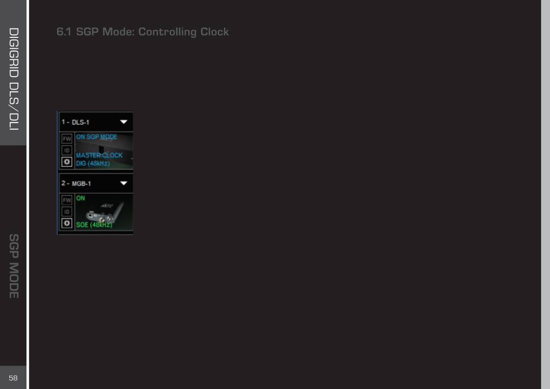
6.1 SGP Mode: Controlling ClockThink of a DLI/DLS as an interface with two distinct halves. One side communicates with DigiLink-compatible I/O interfaces. The other communicates with the SoundGrid network. Of course, these two sides constantly work together, but each has its own set of rules regarding sync. When you configure a device, it’s important to understand which “sync” you’re controlling.
DLI/DLS can clock internally, and act as the network master, or it can slave to the network’s sample rate.
SoundGrid Studio uses Ethernet to stream audio between devices on a SoundGrid network. Synchronization clock is also carried over Ethernet. This method of providing clock is called Sync over Ethernet (SoE). SoundGrid I/O devices can be clocked by other means, but SoE is a more convenient way to provide clock information to devices on the SoundGrid network. ■ When DLI/DLS is the SoundGrid (SoE) master, it may receive clock from the DigiLink-compatible I/O
Internal clock (or any other source it may use), directly through the DigiLink port. Alternatively, The DLI/DLS may clock to its own Internal clock and distribute clock to the DigiLink-compatible I/O devices attached. ■ When DLI/DLS is clocked from SoE, it can be the master over the DigiLink-compatible I/O devices and
provide them Loop Sync or Word Clock.
When DLI/DLS is set to slave, its sample rate is determined by another device on the SoundGrid network, one that has been set as the network master. All other devices in the network are slaved to that same master. The network’s SoE Clock Master/Slave status is set in the Device Racks of SoundGrid Studio. The master
clock device will distribute the clock and sample rate to all I/Os in the network.
The SoundGrid Studio Application, or any other SoundGrid host application, can be set as Sample Rate Master. The application can then determine the sample rate for the entire network. This provides smooth operation between of the SoundGrid driver with the DAW applications using it.
Alternatively, the application can be set as a Sample Rate Slave, using the sample rate of the DLI/DLS’s external clock source to set the sample rate for the network. This enables the network to follow the sample rate of that source.

59
DIG
IGR
ID D
LS/
DLI
Clock Control Page
Source
Sets the preferred source of clock for the DLI/DLS and sets Loop Master for DigiLink-compatible I/Os. Clock sources vary depending on the device. Up to 4 I/O devices can be connected: ■ Up to 4 DigiLink-compatible I/O devices may have a variety of clock source options.■ DLI/DLS: Internal, SoE (available only when another SoundGrid device is set as Master).A drop-down menu shows all connected devices. A submenu reveals all possible clock sources for that device. For more information about clock options for specific DigiLink-compatible I/O devices, please refer to their respective user guides.

60
DIG
IGR
ID D
LS/
DLI
Clock Operation Mode
Tells the system the mode in which the BNC connectors work—Loop Sync or Word Clock. Loop Sync is the preferred clock mode when using DigiLink-compatible I/O devices. However, some devices cannot accept Loop Sync, in which case you must select Word Clock.
Loop Master Display
Indicates the Loop Master of all DigiLink-compatible I/O devices in this loop (e.g., DLI/DLS, 192, other DigiLink-compatible I/O).
Sample Rate
Indicates or selects clock sample rate for the DLI/DLS. This information is also displayed in the device slot in SoundGrid Studio.
■ Sample Rate can always be changed when DLI/DLS Clock Source is set to Internal or is locked to the internal clock of the connected Digilink compatible I/O device.
■ If DLI/DLS is set to external clock this control is inactive and grayed out.■ If DLI/DLS is an SoE slave, then this control is inactive and grayed out.■ When DLI/DLS is set to external clock, that cannot provide the Sample Rate set by the Sample Rate Master Application , the DLI/DLS will switch to Internal.
61
DIG
IGR
ID D
LS/
DLI
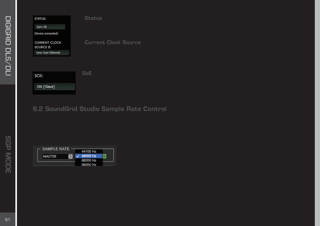
Status
Indicates the sync status of a DLI/DLS device.
Current Clock Source
Indicates the clock source of the DLI/DLS. The actual clock source is shown; if it differs from the requested clock source, the display will be red. Possibilities: Internal, Digital Stream, Sync over Ethernet.
SoE
Indicates if the DLI/DLS is locked to the SoundGrid network, and if it is the SoE master or slave. This message is mirrored in the device rack slots in the System Inventory page.
6.2 SoundGrid Studio Sample Rate ControlIn SGP mode, DLI/DLS connects to the SoundGrid driver in order to communicate with a DAW, local or remote. SoundGrid Studio controls the sample rate of the network and the SoundGrid driver. The SoundGrid Studio system sample rate is displayed in the Sample Rate section of the Setup page. The sample rate indicated in this window mirrors that shown in the Clock page of the control panel.
Next to the Sample Rate window is the Sample Rate Master/Slave control, which determines SoundGrid Studio’s role in changing the sample rate.
62
DIG
IGR
ID D
LS/
DLI
Sample Rate Master
SoundGrid Studio and the SoundGrid driver can set the sample rate of the clock master DLI/DLS. For example, when you open a DAW session at sample rate different from the current SoundGrid Studio sample rate:■ DAW requests SoundGrid driver to change sample rate.■ SoundGrid driver instructs SoundGrid Studio. If SoundGrid Studio is set as Sample Rate Master, then it requests master clock I/O
to change its sample rate.■ All slaved I/O devices adjust their sample rates accordingly.■ When the master device (DLI/DLS in this case) clock is set to Internal, sample rate can be set from the drop-down Sample Rate menu in the SoundGrid Studio application.
Sample Rate Slave
SoundGrid Studio and the SoundGrid driver will follow the DLI/DLS sample rate, as set by the selected clock source. The same request is made as above, but SoundGrid Studio is set to Sample Rate Slave:■ DAW requests SoundGrid driver to change sample rate.■ SoundGrid driver notifies SoundGrid Studio. SoundGrid Studio is set to Sample Rate Slave, so it cannot request a system sample
rate change. The master clock I/O does not change its sample rate.■ All slaved I/O devices follow the master and do not change sample rate.■ The SoundGrid Driver denies the sample rate change request from the DAW. The DAW will prompt an error in such a case (this
may vary between DAWs).In Slave mode, all sample rate changes must originate from the clock master device.

63
DIG
IGR
ID D
LS/
DLI
7. SGP MODE: PATCHING FROM THE NETWORK
For audio to move from the right place to the right place, it must be patched. SoundGrid Studio templates provide patches that work well for most configurations, but there will be times when you will need different patching. The Patch page enables you to connect any device’s input/output with any driver’s input/output, or between drivers.
■ All available devices and driver channels will appear in the patch. The number of channels depends on devices and connections. ■ Patch direction is indicated by an arrow on the left side of the patch.■ Establish a patch by clicking on a cell, or by dragging across several cells. Remove a patch by clicking on it again.■ An output can patch to two inputs. An input can accept only one source.

64
DIG
IGR
ID D
LS/
DLI
7.1 Device-to-Device Patching Use this view to patch devices and drivers to each other. All device and driver channels are shown along the horizontal and vertical axes. Each axis carries the same channels. There are many ways to patch devices, but normally DLI/DLS inputs 1–16 will be patched to the ASIO/Core Audio inputs 1–16 for recording. For playback the patches are opposite, unless you choose to patch to the eMotion ST mixer for monitor mixing.
7.2 eMotion ST Mixer PatchingThe eMotion ST mixer enables you to create studio monitor mixes as well a personalized headphone mixes. Patch to and from the eMotion ST mixer using the eMotion ST input and output tabs on the left side of the interface. The green buttons indicate whether a channel is mono, left side of a stereo pair, or right side of a stereo pair. Toggle between these states by double-clicking on the button.
The eMotion ST mixer enables you to create personalized monitor mixes, with plugin processing done pre-, post-, or in parallel with Pro Tools. eMotion ST combines 8 channel inputs with up to 64 StudioRack plugins. Each input or StudioRack channel can be sent to aux tracks or a main mix. eMotion ST requires a DSP server.

65
DIG
IGR
ID D
LS/
DLI
The eMotion ST Mixer Layer is used to mix DAW outputs, mic and line sources, aux mix busses + main mix, and more. The StudioRack Layer mixes the low-latency outputs of up to 64 StudioRack plugins, which are routed to the Main and/or Headphones mixes. In this respect, eMotion ST replaces the external mixer traditionally used to create monitor mixes for studios and headphones.
eMotion ST operates within a SoundGrid network, so any available SoundGrid I/O device, whether hardware or driver, local or remote, can provide inputs and outputs.

66
DIG
IGR
ID D
LS/
DLI
Driver Channel Names in your DAW
SoundGrid Studio patches from the Waves SoundGrid ASIO/Core Audio driver to a hardware I/O device, a secondary driver (another computer), or the eMotion ST mixer.
SoundGrid Studio transmits these names through the driver to the DAW. These will appear as the default names within your DAW. Most DAWs allow you to change the naming manually. For example, you may a DiGiGrid IOS with a total of 10 inputs (8 analog, 2 digital) and 14 outputs (8 analog, 2 digital, and 2 stereo headphone outputs). When these inputs and outputs are patched to and from the local driver (I/O to DAW, DAW to I/O), you will see the following in the Connection or IO setup within your DAW:
Local driver channels that are not patched to a hardware device or to the eMotion ST mixer will appear as SoundGrid 1, SoundGrid 2, etc.

67
DIG
IGR
ID D
LS/
DLI
Note: This transmission occurs while you launch your DAW and the driver handshakes with it. This means that any change of I/O name or eMotion ST channel name will not be visible in your DAW until you relaunch it. Some DAWs, such as Cubase, will let you reset the connection to the driver, saving you the need to relaunch the application.
Important: DAW outputs through the driver can be patched to mutilple destinations; for example, the DAW’s Main out can go to your Hardware Channel 1 & 2 as well as to Hardware Channel 3 & 4. In such a case, the name of the driver channel will be “Multiple Assignments.” In this case we suggest you manually name these driver channels.
As mentioned above, driver channels can be connected to the eMotion ST mixer or to a secondary remote driver.
Here is an example of the DAW outputs patched to the eMotion ST mixer:

68
DIG
IGR
ID D
LS/
DLI
Here is an example of your DAW receiving input from another DAW on a secondary computer via networking:
To ensure that the names have been updated in your DAW, you may need to follow certain steps, depending on your DAW. Here are a few examples.
Pro Tools Go to Setup > I/ODelete and reset all I/O configurations to DEFAULT.
CubaseGo to Devices > Device Setup > Waves SoundGrid.Select RESET above the PORT System Name table.
LogicGo to Mix > I/O Labels.Select Reset All Labels.
69
DIG
IGR
ID D
LS/
DLI
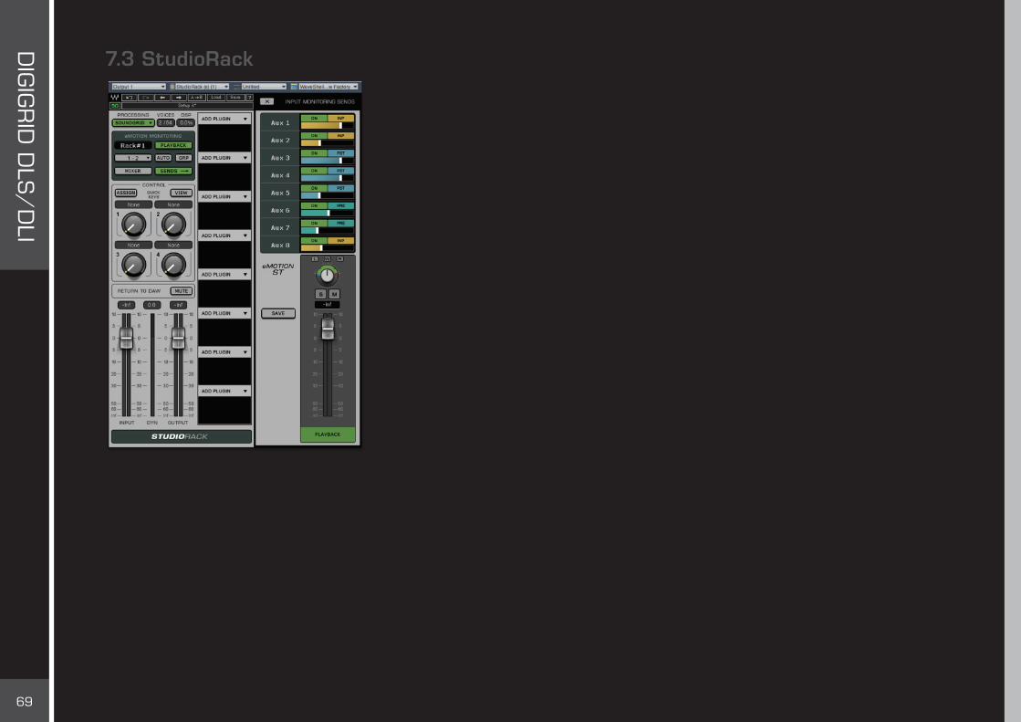
7.3 StudioRackStudioRack is a plugin chainer for any DAW. It chains up to eight plugins, controls them, assigns them to external controllers, and manages them—with their presets—all in a way that makes it easy to move from one DAW session to another and from one DAW platform to another. It enables users to create racks of processors with limitless parameters and flexible signal flows, which are easily inserted into any track of the session.
When part of a SoundGrid network with a DSP server, StudioRack can shift plugin processing away from the local CPU and direct it to the SoundGrid DSP server. It works in conjunction with the eMotion ST mixer to create numerous personalized monitor mixes that use the same plugins heard in the mix—all with virtually no latency.
For more information, please refer to the eMotion ST and StudioRack user guides.

70
DIG
IGR
ID D
LS/
DLI
APPENDIX: DLI/DLS SPECIFICATIONS
■ Internal SoundGrid DSP server (Intel® i5) (DLS only)■ 2 DigiLink ports; 64 channel in SGP or I/O mode; 32 channels per port: - SGP mode: DLI acts as a Pro Tools card, connected to and controlling an Avid audio interface (192, 96, HD Omni, HD I/O, and
selected third-party interfaces). - I/O mode: Pro Tools TDM v9.x and 10.x support. DLI/DLS acts as four 192 Digital I/Os.■ 2 SoundGrid RJ45 Ethernet ports■ 1 AC switching input, 110–240 volts, 50 or 60 Hz■ 1 Word Clock I/O■ 1 service USB port■ 2U rack-mounted■ Supported sample rates: 44.1, 48, 88.2 and 96 kHz (176.4 and 192 kHz will be supported in the future)■ Recovery switch

71
DIG
IGR
ID D
LS/
DLI
APPENDIX: INSTALLATION NOTES
The DLI Unit is a standard 19” rack mount wide, 1U high 260mm deep excluding connectors.The DLS Unit is a standard 19” rack mount wide, 2U high 380mm deep excluding connectors.
The DLI or DLS unit must be earthed to the mains earth (ground) and installed according to the safety instructions included with the unit. The unit is powered from an IEC inlet on the rear. This must be connected to an earthed mains outlet using a cable that complies with local approvals and regulations. Approvals cover use in ambient air temperature of up to 35°C. Operation in higher temperatures should be avoided. A 1U apaceshould be left above and below the unit to prevent heat transfer from adjacent equipment, if this generates heat above 35°C. At least 75 mm (3 inches) should be allowed to the sides of the unit to allow ventilation. At least 75 mm (3 inches) of free air should be left at both the front and the rear side of the rack to allow heat dissipation. Under no circumstances should the fan (where fitted) or ventilation outlets be blocked or restricted.