c level sensors dls 35 - trafag italia · dimensional drawings dls – 35_ – 10, 14 dls 35_ 11...
TRANSCRIPT
Read the instructions published in this manual carefully before the first use of the sensor. Keep the manual in a safe place. The manufacturer reserves the right to make changes without prior notice.
INSTRUCTION MaNUalprůmyslová elektronika
CapaCitive level sensors Dls–35

Content
1. Brief ............................................................................................................................................4
2. Variants of sensors .....................................................................................................................5
3. Dimensional drawings ................................................................................................................6
4. Mounting recommendation .........................................................................................................8
5. Range of application ...................................................................................................................12
6. Electrical connection...................................................................................................................13
7. Sensor settings ...........................................................................................................................15
8. Function and status signalization ...............................................................................................17
9. Order code..................................................................................................................................18
10. Correct specification examples.................................................................................................18
11. Accessories ...............................................................................................................................19
12. Safety, protections, compatibility and explosion proof ..............................................................19
13. Use, manipulation and maintenance ........................................................................................19
14. General conditions and warranty ..............................................................................................19
15. Marking of labels ......................................................................................................................20
16. Specifications ...........................................................................................................................22
17. Packaging, shipping and storage .............................................................................................23
DLS–35 © Dinel, s.r.o.4
All operations described in this instruction manual have to be carried out by trained person-nel or by an accredited person only. Warranty and post warranty service must be exclusively carried out by the manufacturer.
Improper use, installation or set-up of the sensor can lead to crashes in the application, (overfilling of the tank or damage of system components).The manufacturer is not responsible for improper use, loss of work caused by either direct or indirect damage, and for expenses incurred at the time of installation or during the period of use of the level sensors.
Safety
USed SymbolS
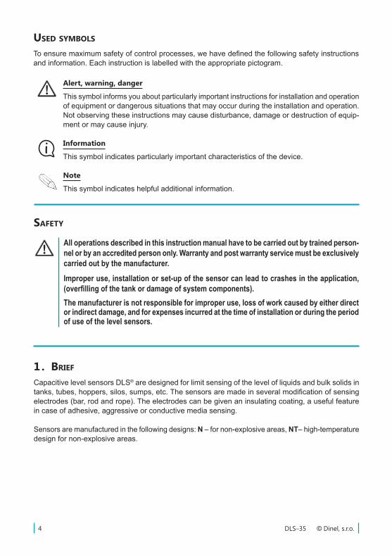
To ensure maximum safety of control processes, we have defined the following safety instructions and information. Each instruction is labelled with the appropriate pictogram.
Alert, warning, danger
This symbol informs you about particularly important instructions for installation and operation of equipment or dangerous situations that may occur during the installation and operation. Not observing these instructions may cause disturbance, damage or destruction of equip-ment or may cause injury.
Information
This symbol indicates particularly important characteristics of the device.
note
This symbol indicates helpful additional information.
1 . brief
Capacitive level sensors DLS® are designed for limit sensing of the level of liquids and bulk solids in tanks, tubes, hoppers, silos, sumps, etc. The sensors are made in several modification of sensing electrodes (bar, rod and rope). The electrodes can be given an insulating coating, a useful feature in case of adhesive, aggressive or conductive media sensing.
Sensors are manufactured in the following designs: N – for non-explosive areas, NT– high-temperature design for non-explosive areas.
5© Dinel, s.r.o. DLS–35
2 . VariantS of SenSorS
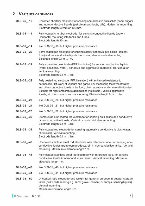
DLS–35_–10 Uncoated short bar electrode for sensing non-adhesive bulk solids (sand, sugar) and non-conductive liquids (petroleum products, oils). Horizontal mounting. Electrode length 50 mm or 100 mm.
DLS–35_–11 Fully coated short bar electrode, for sensing conductive liquids (water). Horizontal mounting into tanks and tubes. Electrode length 30 mm.
DLS–35_–14 like DLS-35_-10, but higher pressure resistance
DLS–35_–20 Semi-coated rod electrode for sensing slightly adhesive bulk solids (cement, flour) and non-conductive liquids. Horizontal, slant or vertical mounting. Electrode length 0.1 m ... 1 m.
DLS–35_–21 Fully coated rod electrode (FEP insulation) for sensing conductive liquids (water solutions, water), adhesive and aggressive materials. Horizontal or vertical mounting. Electrode length 0.1 m ... 1 m.
DLS–35_–22 Fully coated rod electrode (PFA insulation) with enhanced resistance to permeation (diffusion) of vapours and gases. For measuring the level of water and other conductive liquids in the food, pharmaceutical and chemical industries. Suitable for high-temperature applications (hot steam), volatile aggressive liquids, etc. Horizontal or vertical mounting. Electrode length 0.1 m ... 1 m.
DLS–35_–23 like DLS-35_-20, but higher pressure resistance
DLS–35_–24 like DLS-35_-21, but higher pressure resistance
DLS–35_–25 like DLS-35_-22, but higher pressure resistance
DLS–35_–30 Dismountable uncoated rod electrode for sensing bulk solids and conductive or non-conductive liquids. Vertical or horizontal slant mounting. Electrode length 0.1 m ... 3 m.
DLS–35_–31 Fully coated rod electrode for sensing aggressive conductive liquids (water, chemicals). Vertical mounting. Electrode length 0.1 m ... 3 m.
DLS–35_–40 Uncoated stainless steel rod electrode with reference tube, for sensing non-conductive liquids (petroleum products, oil) in non-conductive tanks. Vertical mounting. Maximum electrode length 1 m.
DLS–35_–41 Fully coated stainless steel rod electrode with reference tube, for sensing conductive liquids in non-conductive tanks. Vertical mounting. Maximum electrode length 1 m.
DLS–35_–43 like DLS-35_-40, but higher pressure resistance
DLS–35_–44 like DLS-35_-41, but higher pressure resistance
DLS–35_–50 Uncoated rope electrode and weight for general purpose in deeper storage tanks (bulk solids sensing e.g. sand, gravel, cement) or sumps (sensing liquids). Vertical mounting.Maximum electrode length 6 m.
DLS–35 © Dinel, s.r.o.6
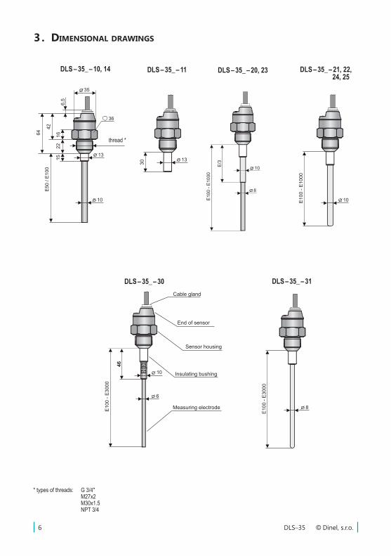
3 . dimenSional drawingS
DLS – 35_ – 10, 14 DLS – 35_ – 11 DLS – 35_ – 20, 23 DLS – 35_ – 21, 22, 24, 25
thread *
* types of threads: G 3/4'' M27x2 M30x1.5 NPT 3/4
���� 35�10
13
10
42E5
0 / E
100
2215
35
16
36
6,5
64
E100
- E1
000
10
10
6
4646
E100
- E3
000
E100
- E3
000
8
DLS – 35_ – 30 DLS – 35_ – 31
13
30
E100
- E1
000
E/3
10
8
Measuring electrode
Insulating bushing
Sensor housing
End of sensor
Cable gland
7© Dinel, s.r.o. DLS–35
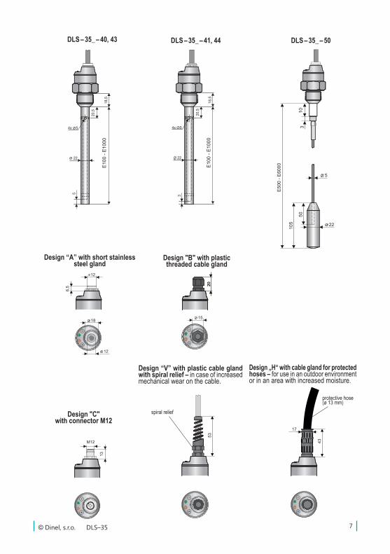
DLS – 35_ – 40, 43 DLS – 35_ – 41, 44 DLS – 35_ – 50
Design “A” with short stainless steel gland
Design "B" with plastic threaded cable gland
Design "C" with connector M12
+-
6,5
12
18
12
20
+-
15
20
+-
M12
13
22
105
E500
- E6
000
5010
3
5
Design „H“ with cable gland for protected hoses – for use in an outdoor environment or in an area with increased moisture.
Design “V” with plastic cable gland with spiral relief – in case of increased mechanical wear on the cable.
spiral relief
protective hose (ø 13 mm)
DLS–35 © Dinel, s.r.o.8
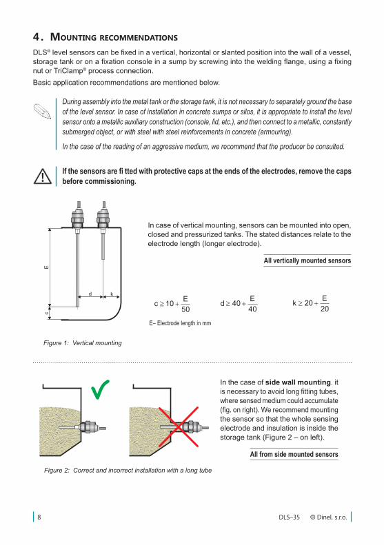
4 . moUnting recommendationS
DLS® level sensors can be fixed in a vertical, horizontal or slanted position into the wall of a vessel, storage tank or on a fixation console in a sump by screwing into the welding flange, using a fixing nut or TriClamp® process connection.Basic application recommendations are mentioned below.
During assembly into the metal tank or the storage tank, it is not necessary to separately ground the base of the level sensor. In case of installation in concrete sumps or silos, it is appropriate to install the level sensor onto a metallic auxiliary construction (console, lid, etc.), and then connect to a metallic, constantly submerged object, or with steel with steel reinforcements in concrete (armouring).
In the case of the reading of an aggressive medium, we recommend that the producer be consulted.
If the sensors are fi tted with protective caps at the ends of the electrodes, remove the caps before commissioning.
In case of vertical mounting, sensors can be mounted into open, closed and pressurized tanks. The stated distances relate to the electrode length (longer electrode).
All vertically mounted sensors
mm20050h
E32m
E43p
E34s
E31E
101a
20E40b
50E10c
40E40d
20E20k
mm20050h
E32m
E43p
E34s
E31E
101a
20E40b
50E10c
40E40d
20E20k
mm20050h
E32m
E43p
E34s
E31E
101a
20E40b
50E10c
40E40d
20E20k
E– Electrode length in mm
Figure 1: Vertical mounting
Figure 2: Correct and incorrect installation with a long tube
In the case of side wall mounting. it is necessary to avoid long fitting tubes, where sensed medium could accumulate (fig. on right). We recommend mounting the sensor so that the whole sensing electrode and insulation is inside the storage tank (Figure 2 – on left).
All from side mounted sensors
kd
Ec
9© Dinel, s.r.o. DLS–35
m
p
s
E
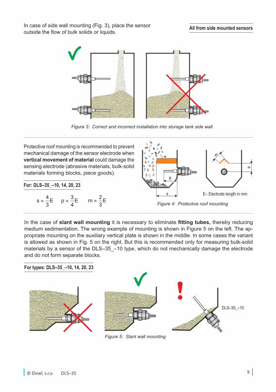
Figure 3: Correct and incorrect installation into storage tank side wall
mm20050h
E32m
E43p
E34s
E31E
101a
20E40b
50E10c
40E40d
20E20k
mm20050h
E32m
E43p
E34s
E31E
101a
20E40b
50E10c
40E40d
20E20k
mm20050h
E32m
E43p
E34s
E31E
101a
20E40b
50E10c
40E40d
20E20k
E– Electrode length in mm
Figure 4: Protective roof mounting
Protective roof mounting is recommended to prevent mechanical damage of the sensor electrode when vertical movement of material could damage the sensing electrode (abrasive materials, bulk-solid materials forming blocks, piece goods).
For: DLS–35_–10, 14, 20, 23
All from side mounted sensorsIn case of side wall mounting (Fig. 3), place the sensor outside the flow of bulk solids or liquids.
In the case of slant wall mounting it is necessary to eliminate fitting tubes, thereby reducing medium sedimentation. The wrong example of mounting is shown in Figure 5 on the left. The ap-propriate mounting on the auxiliary vertical plate is shown in the middle. In some cases the variant is allowed as shown in Fig. 5 on the right. But this is recommended only for measuring bulk-solid materials by a sensor of the DLS–35_–10 type, which do not mechanically damage the electrode and do not form separate blocks.
For types: DLS–35_–10, 14, 20, 23
Figure 5: Slant wall mounting
DLS–35_–10
!
DLS–35 © Dinel, s.r.o.10
h
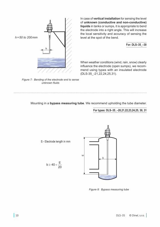
In case of vertical installation for sensing the level of unknown (conductive and non-conductive) liquids in tanks or sumps, it is appropriate to bend the electrode into a right angle. This will increase the local sensitivity and accuracy of sensing the level at the spot of the bend.
For: DLS–35_–30
h = 50 to 200 mm
Figure 7: Bending of the electrode end to sense unknown fluids
When weather conditions (wind, rain, snow) clearly influence the electrode (open sumps), we recom-mend using types with an insulated electrode (DLS-35_-21,22,24,25,31).
mm20050h
E32m
E43p
E34s
E31E
101a
20E40b
50E10c
40E40d
20E20k
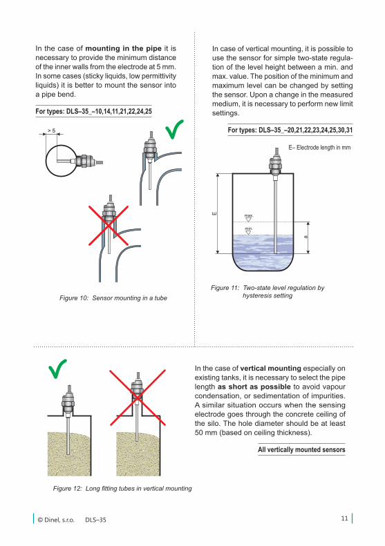
Mounting in a bypass measuring tube. We recommend upholding the tube diameter.
For types: DLS–35_–20,21,22,23,24,25, 30, 31
E– Electrode length in mm
Figure 8: Bypass measuring tube
b
E
11© Dinel, s.r.o. DLS–35
max.
min.
E
����a
> 5
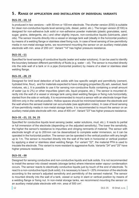
In the case of mounting in the pipe it is necessary to provide the minimum distance of the inner walls from the electrode at 5 mm. In some cases (sticky liquids, low permittivity liquids) it is better to mount the sensor into a pipe bend.
For types: DLS–35_–10,14,11,21,22,24,25
In case of vertical mounting, it is possible to use the sensor for simple two-state regula-tion of the level height between a min. and max. value. The position of the minimum and maximum level can be changed by setting the sensor. Upon a change in the measured medium, it is necessary to perform new limit settings.
For types: DLS–35_–20,21,22,23,24,25,30,31
E– Electrode length in mm
Figure 10: Sensor mounting in a tubeFigure 11: Two-state level regulation by
hysteresis setting
In the case of vertical mounting especially on existing tanks, it is necessary to select the pipe length as short as possible to avoid vapour condensation, or sedimentation of impurities. A similar situation occurs when the sensing electrode goes through the concrete ceiling of the silo. The hole diameter should be at least 50 mm (based on ceiling thickness).
All vertically mounted sensors
Figure 12: Long fitting tubes in vertical mounting
> 5
> 5
DLS–35 © Dinel, s.r.o.12
5 . range of application and inStallation of indiVidUal VariantS
DLS–35_–10, 14
Is produced in two versions – with 50 mm or 100 mm electrode. The shorter version (E50) is suitable for clean non-conductive liquids level sensing (oils, diesel, petrol, etc.). The longer version (E100) is designed for non-adhesive bulk solid or non-adhesive powder materials (plastic granulates, sand, sugar, grains, detergents, etc.) and other slightly impure, non-conductive liquids (lubricants, plant oils). The sensor mounts directly into a vessel or storage tank wall (ideally in the horizontal position) by means of a welding flange or stainless steel fixing nuts. In case of level sensing of low-permittivity media in non-metal storage tanks, we recommend mounting the sensor on an auxiliary metal-plate electrode with min. area of 200 cm2. Variant "14" has higher pressure resistance.
DLS–35_–11
Specified for level sensing of conductive liquids (water and water solutions). It can be used to identify the boundary between different permittivity of fluids (e.g. water – oil). The sensor is mounted directly into the side wall of a tank or in a pipe (horizontal position) by means of a steel or stainless steel welding flange.
DLS–35_–20, 23
Designed for limit level detection of bulk solids with low specific weight and permittivity (cement, hydrated lime, flour), and for materials expected to have changing properties (fly ash, sawdust, feed mixtures, etc.). It is possible to use it for sensing non-conductive fluids containing a small amount of water (up to 2%) or other impurities (plant oils, liquid propane, etc.). The sensor is mounted di-rectly into the wall of a vessel or storage tank using steel welding flanges or fixing nuts horizontally, slanted from the side or vertically. It is recommended to mount a sensor with an electrode longer than 300 mm only in the vertical position. Hollow spaces should be minimized between the electrode and the wall where the sensed material can accumulate (see application notes). In case of level sensing of low-permittivity media in non-metal storage tanks, it is recommended to mount the sensor on an auxiliary metal-plate electrode with min. area of 400 cm2. Variant "23" has higher pressure resistance.
DLS–35_–21, 22, 24, 25
Specified for conductive liquids level sensing (water, water solutions, mud, etc.). It reacts to partial or full immersion of the electrode (depending on the adjusted sensitivity). The lower the sensitivity, the higher the sensor's resistance to impurities and clinging remnants of material. The sensor with electrode length of up to 200 mm can be desensitized to complete water immersion, so it can be operated in the horizontal position. The sensor can be operated in the vertical position with any length up to 1 m. The sensor is mounted directly into the wall of the tank in horizontal or vertical position by applying a steel or stainless steel welding flange. For variant "22", the material PFA is used to insulate the electrode. This variant is more resistant to aggressive fluids. Variants "24" and "25" have higher pressure resistance.
DLS–35_–30
Designed for sensing conductive and non-conductive liquids and bulk solids. It is not recommended to install the sensor into closed vessels (storage tanks) where intensive water vapour condensation occurs. The sensor reacts to electrically conductive liquids just by touch of the end of electrode. To react to a non-conductive liquid (bulk solid), it is necessary to have 5 ÷ 20% immersion of the electrode according to the sensor's adjusted sensitivity and permittivity of the sensed material. The sensor is mounted directly into the wall of a tank, vessel or sump in slant or vertical position by means of a welding flange or fixing nut. In non-metal storage tanks, we recommend mounting the sensor on an auxiliary metal-plate electrode with min. area of 500 cm2.
13© Dinel, s.r.o. DLS–35
DLS–35_–31
Designed for limit level detection of conductive liquids (water and solutions of various chemicals). It is possible to place the sensor electrode into closed vessels (storage tanks), open canals and sumps. The sensor reacts to the conductive fluid level after 2 ÷ 20% immersion of the electrode based on the sensor's set sensitivity. The sensor is mounted vertically directly into a vessel, tank or open (concrete, plastic) sumps by means of welding flanges or fixing nuts. When installing the sensor into open sumps, it is necessary to secure conductive connection of the sensor housing with the sensed liquid. It is possible to use a metal structure, armouring or another auxiliary electrode. If you must sense an aggressive medium in a closed plastic container, contact the manufacturer.
DLS–35_–40, 43
Designed for sensing conductive and non-conductive liquids in non-metal storage tanks. It is not recommended to install the sensor into closed vessels (storage tanks) where intensive water vapour condensation occurs. The sensor reacts to electrically conductive liquids just by touch of the end of electrode. To react to non-conductive liquid, it is necessary to have 5 ÷ 20% immersion into a medium based on the sensitivity set on the sensor and the permittivity of the sensed material. The sensor is mounted directly into a tank, hopper or sump in slant or vertical position by means of welding flange or stainless steel fixing nut. Variant “43” has higher pressure resistance.
DLS–35_–41, 44
Designed for sensing conductive liquids (water and water solutions of various chemicals) in non-metal containers. The measuring part of the sensor can be installed into closed vessels (storage tanks), open channels and sumps. The sensor reacts to the conductive liquid level after 2 ÷ 20% immersion of the electrode based on the sensor's set sensitivity. The sensor is mounted vertically directly into a vessel, tank or open (concrete, plastic) sumps by means of welding flanges or fixing nuts. If you must sense an aggressive medium in a closed plastic container, contact the manufacturer. Variant "44" has higher pressure resistance.
DLS–35_–50
For sensing conductive and non-conductive liquids and bulk solids at greater depths (sewerage sumps, shafts, wells, cement storage tanks, sand, gravel, etc.). It is not appropriate to place the sen-sor electrode into closed containers (storage tanks) where intensive condensation of water vapour occurs. The sensor reacts to electrically conductive liquids just by touch of the end of electrode. To react to non-conductive liquid or bulk solids, a 5 ÷ 20% immersion into the material is necessary based on the sensitivity set on the sensor and the permittivity of the sensed material. The sensor is mounted vertically directly into the wall of a storage tank or sump. For open (concrete) sumps, it can be mounted on an auxiliary metal structure conductively connected with the sensed material. For mounting, you can use supplied welding flanges or fixing nuts.
DLS–35 © Dinel, s.r.o.14
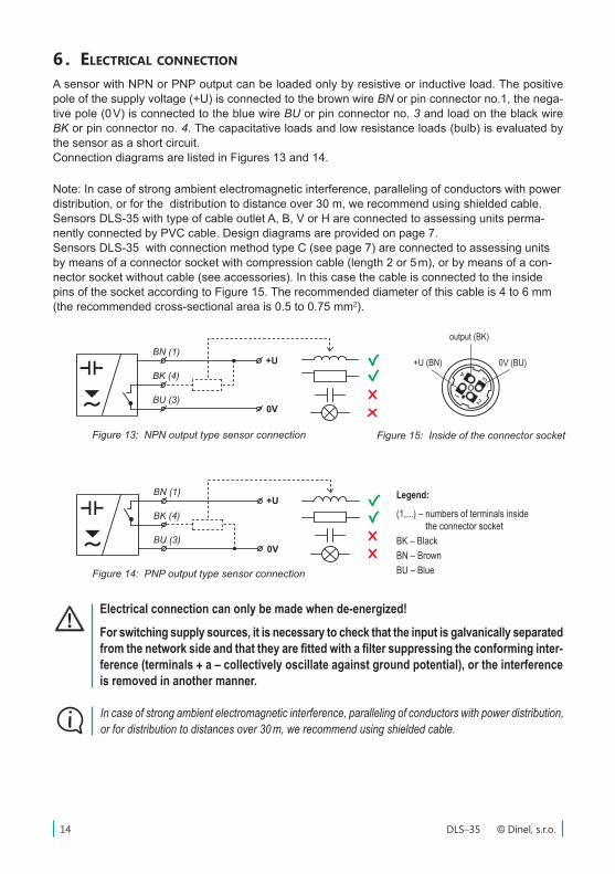
Figure 13: NPN output type sensor connection
Legend:
(1,...) – numbers of terminals inside the connector socket
BK – BlackBN – BrownBU – Blue
output (BK)
0V (BU)+U (BN)
Figure 14: PNP output type sensor connection
Figure 15: Inside of the connector socket
Electrical connection can only be made when de-energized!
For switching supply sources, it is necessary to check that the input is galvanically separated from the network side and that they are fitted with a filter suppressing the conforming inter-ference (terminals + a – collectively oscillate against ground potential), or the interference is removed in another manner.
In case of strong ambient electromagnetic interference, paralleling of conductors with power distribution, or for distribution to distances over 30 m, we recommend using shielded cable.
Note: In case of strong ambient electromagnetic interference, paralleling of conductors with power distribution, or for the distribution to distance over 30 m, we recommend using shielded cable. Sensors DLS-35 with type of cable outlet A, B, V or H are connected to assessing units perma-nently connected by PVC cable. Design diagrams are provided on page 7. Sensors DLS-35 with connection method type C (see page 7) are connected to assessing units by means of a connector socket with compression cable (length 2 or 5 m), or by means of a con-nector socket without cable (see accessories). In this case the cable is connected to the inside pins of the socket according to Figure 15. The recommended diameter of this cable is 4 to 6 mm (the recommended cross-sectional area is 0.5 to 0.75 mm2).
6 . electrical connection
A sensor with NPN or PNP output can be loaded only by resistive or inductive load. The positive pole of the supply voltage (+U) is connected to the brown wire BN or pin connector no.1, the nega-tive pole (0 V) is connected to the blue wire BU or pin connector no. 3 and load on the black wire BK or pin connector no. 4. The capacitative loads and low resistance loads (bulb) is evaluated by the sensor as a short circuit. Connection diagrams are listed in Figures 13 and 14.
15© Dinel, s.r.o. DLS–35
+ -
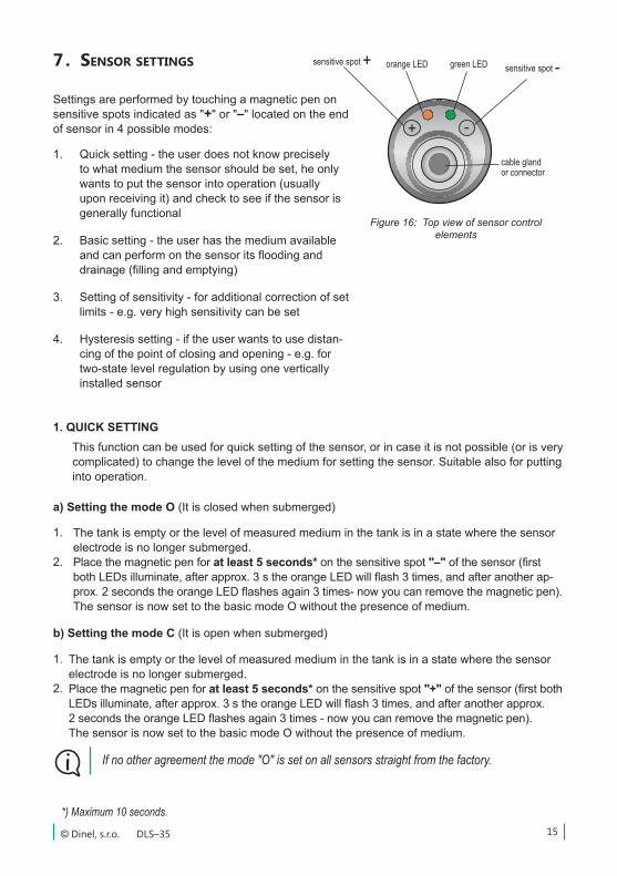
7 . SenSor SettingS
cable gland or connector
Figure 16: Top view of sensor control elements
orange LEDsensitive spot + sensitive spot -green LED
Settings are performed by touching a magnetic pen on sensitive spots indicated as "+" or "–" located on the end of sensor in 4 possible modes:
1. QUICK SETTING
1.
2.
The tank is empty or the level of measured medium in the tank is in a state where the sensor electrode is no longer submerged.Place the magnetic pen for at least 5 seconds* on the sensitive spot "–" of the sensor (first both LEDs illuminate, after approx. 3 s the orange LED will flash 3 times, and after another ap-prox. 2 seconds the orange LED flashes again 3 times- now you can remove the magnetic pen). The sensor is now set to the basic mode O without the presence of medium.
a) Setting the mode O (It is closed when submerged)
This function can be used for quick setting of the sensor, or in case it is not possible (or is very complicated) to change the level of the medium for setting the sensor. Suitable also for putting into operation.
1.
2.
The tank is empty or the level of measured medium in the tank is in a state where the sensor electrode is no longer submerged.Place the magnetic pen for at least 5 seconds* on the sensitive spot "+" of the sensor (first both LEDs illuminate, after approx. 3 s the orange LED will flash 3 times, and after another approx. 2 seconds the orange LED flashes again 3 times - now you can remove the magnetic pen). The sensor is now set to the basic mode O without the presence of medium.
b) Setting the mode C (It is open when submerged)
If no other agreement the mode "O" is set on all sensors straight from the factory.
*) Maximum 10 seconds.
1. Quick setting - the user does not know precisely to what medium the sensor should be set, he only wants to put the sensor into operation (usually upon receiving it) and check to see if the sensor is generally functional
2. Basic setting - the user has the medium available and can perform on the sensor its flooding and drainage (filling and emptying)
3. Setting of sensitivity - for additional correction of set limits - e.g. very high sensitivity can be set
4. Hysteresis setting - if the user wants to use distan-cing of the point of closing and opening - e.g. for two-state level regulation by using one vertically installed sensor
DLS–35 © Dinel, s.r.o.16
If the orange LED is illuminated and the green LED is flashing, the sensor is correctly set.If alternating flashing of the orange and green LED occurs, the sensor did not recognize the limits for closing and opening. In this case, find out whether the minimum and maximum levels are not set too close to one another.
- -
3. 4.
5.
Increase the level of the measured medium in the tank up to a level where you want the sensor to detect the presence of the medium.Place the magnetic pen for at least 2 seconds** on the sensitive spot "+" of the sensor (until both LEDs illuminate) and then remove the magnetic pen. Settings are confirmed by three flashes of the orange LED.Check the state of indicators:
For safety reasons, we recommend setting the mode "O" for level sensing (the sensor is closed upon immersion). It is for failure safety reasons – eventual failure of sensor behaves similarly as an exceeding of the limit state. Analogically, for the maximum level it is recommended to set the mode "C" (the sensor is open upon immersion).
b) Setting the mode C (It is open when submerged)
1.
2.
3. 4.
5.
Bring the level of the measured medium in the tank to a state so that the sensor electrode would be uncovered.Place the magnetic pen for at least 2 seconds** on the sensitive spot "+" of the sensor (until both LEDs illuminate) and then remove the magnetic pen. Settings are confirmed by three flashes of the orange LED. Increase the level of the measured medium in the tank up to a level where you want the sen-sor to detect the presence of the medium.Place the magnetic pen for at least 2 seconds** on the sensitive spot "–" of the sensor (until both LEDs illuminate) and then remove the magnetic pen. Settings are confirmed by three flashes of the orange LED.Check the state of indicators:
If the orange LED is not illuminated and the green LED is flashing, the sensor is correctly set.If alternating flashing of the orange and green LED occurs, the sensor did not recognize the limits for closing and opening. In this case, find out whether the minimum and maximum levels are not set too close to one another and possible repeat the settings.
--
**) Maximum 4 seconds.
a) Setting the mode O (It is closed when submerged)
2. BASIC SETTING
Bring the level of the measured medium in the tank to a state so that the sensor electrode would be uncovered.Place the magnetic pen for at least 2 seconds** on the sensitive spot "–" of the sensor until both LEDs illuminate and then remove the magnetic pen. Settings are confirmed by three flashes of the orange LED.
1.
2.
For setting sensitivity and switching mode, in case it is possible to change the level of the medium for setting the sensor.
17© Dinel, s.r.o. DLS–35
3. SETTING OF SENSITIVITY
By the procedure stated in the previous chapter, limits are set for closing and opening (sensi-tivity of the sensor). If you want to simply increase or decrease this set sensitivity (if medium adheres to the electrode), it can be done in the following manner:
a) Increasing sensitivity
1.
2.
Place the magnetic pen for longer than 0.2 seconds but for shorter than 2 seconds on the sensitive spot "+" of the sensor. Settings are confirmed by three flashes of the orange LED. Increasing sensitivity this way can be performed repeatedly.
b) Decreasing sensitivity
1.
2.
Place the magnetic pen for longer than 0.2 seconds but for shorter than 2 seconds on the sensitive spot "–"of the sensor. Settings are confirmed by three flashes of the orange LED. Decreasing sensitivity this way can be performed repeatedly.
Sensitivity can be decreased if the medium sticks to the electrode
a) Setting the mode Draining the level (If the medium level reaches its maximum level, the sensor output closes. After draining the medium, when the level drops to the minimum level, the sensor output opens.)
4. HYSTERESIS SETTING
This function can be used for simple control of replenishing (draining) the level by means of a single sensor. The sensor must be placed in the vertical position and the end of the electrode must at least reach the minimum level.
If the orange LED is illuminated and the green LED is flashing, the sensor is correctly set.If alternating flashing of the orange and green LED occurs, the sensor did not recognize the limits for closing and opening. In this case, find out whether the minimum and maximum levels are not set too close to one another.
- -
3.4.
5.
Increase the level of the measured medium in the tank up to maximum level. Place the magnetic pen for at least 20 seconds** on the sensitive spot "+" of the sensor until both LEDs illuminate and then remove the magnetic pen. Settings are confirmed by three flashes of the orange LED.Check the state of indicators:
Bring the level of the measured medium in the tank to minimum level. Place the magnetic pen for at least 20 seconds** on the sensitive spot "–" of the sensor until both LEDs illuminate and then remove the magnetic pen. Settings are confirmed by three flashes of the orange LED.
1.2.
DLS–35 © Dinel, s.r.o.18
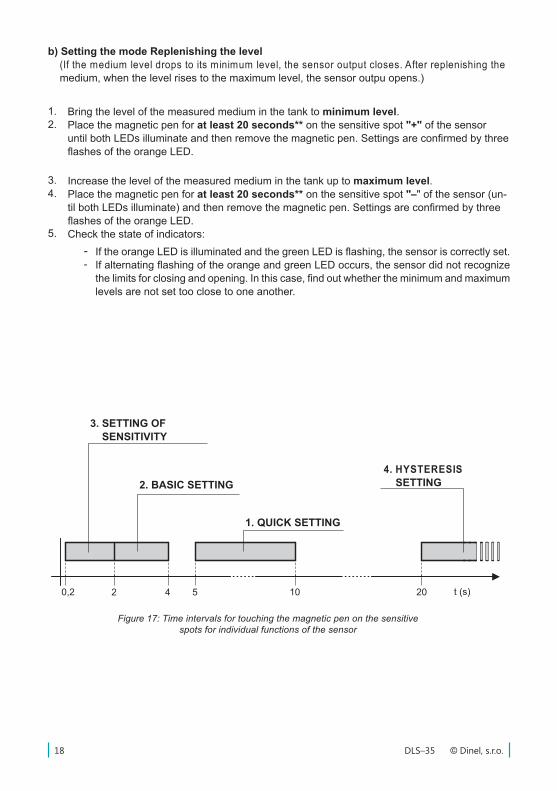
Figure 17: Time intervals for touching the magnetic pen on the sensitive spots for individual functions of the sensor
1. QUICK SETTING
2. BASIC SETTING
3. SETTING OF SENSITIVITY
4. HYSTERESIS SETTING
b) Setting the mode Replenishing the level (If the medium level drops to its minimum level, the sensor output closes. After replenishing the medium, when the level rises to the maximum level, the sensor outpu opens.)
If the orange LED is illuminated and the green LED is flashing, the sensor is correctly set.If alternating flashing of the orange and green LED occurs, the sensor did not recognize the limits for closing and opening. In this case, find out whether the minimum and maximum levels are not set too close to one another.
- -
3.4.
5.
Increase the level of the measured medium in the tank up to maximum level. Place the magnetic pen for at least 20 seconds** on the sensitive spot "–" of the sensor (un-til both LEDs illuminate) and then remove the magnetic pen. Settings are confirmed by three flashes of the orange LED.Check the state of indicators:
Bring the level of the measured medium in the tank to minimum level. Place the magnetic pen for at least 20 seconds** on the sensitive spot "+" of the sensor until both LEDs illuminate and then remove the magnetic pen. Settings are confirmed by three flashes of the orange LED.
1.2.
19© Dinel, s.r.o. DLS–35
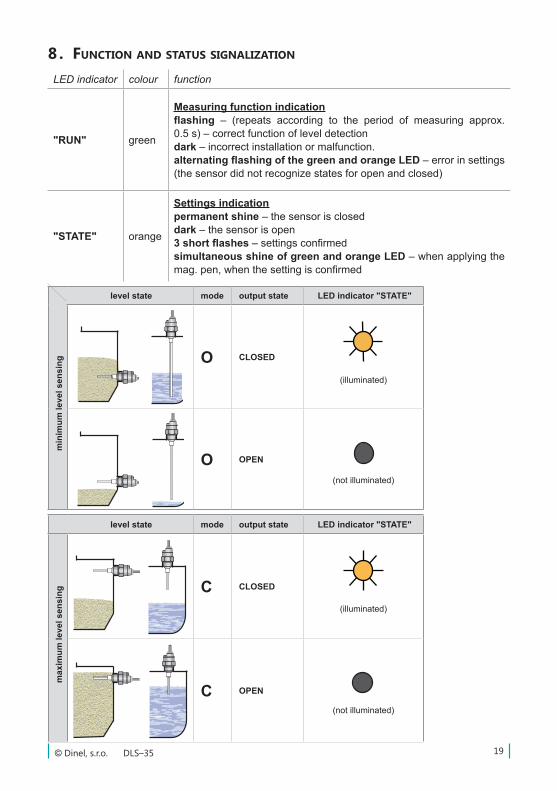
level state mode output state LED indicator "STATE"
min
imum
leve
l sen
sing O CLOSED
(illuminated)
O OPEN
(not illuminated)
LED indicator colour function
"RUN" green
Measuring function indicationflashing – (repeats according to the period of measuring approx. 0.5 s) – correct function of level detectiondark – incorrect installation or malfunction. alternating flashing of the green and orange LED – error in settings(the sensor did not recognize states for open and closed)
"STATE" orange
Settings indicationpermanent shine – the sensor is closeddark – the sensor is open3 short flashes – settings confirmedsimultaneous shine of green and orange LED – when applying the mag. pen, when the setting is confirmed
8 . fUnction and StatUS Signalization
level state mode output state LED indicator "STATE"
max
imum
leve
l sen
sing C CLOSED
(illuminated)
C OPEN
(not illuminated)
DLS–35 © Dinel, s.r.o.20
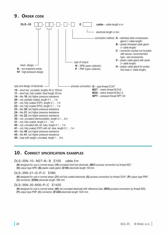
9 . order code
10 . correct Specification exampleS
process connection:
DLS –35
10 – short bar, uncoated, lengths 50 or 100mm11 – short bar, fully coated, fixed length 30 mm14 – like 10, but higher pressure resistance20 – rod, partially coated, length 0.1 ... 1 m21 – rod, fully coated (FEP), length 0.1 ... 1 m22 – rod, fully coated (PFA), length 0.1 ... 1 m23 – like 20, but higher pressure resistance24 – like 21, but higher pressure resistance25 – like 22, but higher pressure resistance30 – rod, uncoated (dismountable), length 0.1 ... 3 m31 – rod, fully coated, length 0.1 ... 3 m40 – rod, uncoated with ref. tube, length 0.1 ... 1 m41 – rod, fully coated (FEP) with ref. tube, length 0.1 ... 1 m43 – like 40, but higher pressure resistance44 – like 41, but higher pressure resistance50 – rope with weight, uncoated, length 1 ... 6 m
electrode length in mm
– – –– E
type of output:N – NPN (open collector)P – PNP (open collector)
connection method: A – stainless steel compression gland (+ cable length)
B – plastic threaded cable gland (+ cable length)
C – connector (socket not included with sensor, recommended type - see accessories.
V – plastic cable gland with spiral (+ cable length)
H – plastic cable gland for protec-tive hose (+ cable length)
type and design of electrode:
mech. design:
G – pipe thread G 3/4"M27 – metric thread M 27x2M30 – metric thread M 30x1.5NPT – pressure thread NPT 3/4
cable – cable length in m
N – non-explosive areasNT - high-pressure design
DLS–35N–10– M27–N– B E100 cable 5 m(N) designed for use in normal areas; (10) uncoated short bar electrode, (M27) process connection by thread M27; (N) output type NPN; (B) plastic cable gland; (E100) electrode length 100 mm
DLS–35N–21–G–P–C E580(N) designed for use in normal areas; (21) rod fully coated electrode; (G) process connection by thread G3/4"; (P) output type PNP; (C) connector; (E580) electrode length 580 mm.
DLS–35N–30–M30–P–C E1420(N) designed for use in normal areas; (40) rod uncoated electrode with reference tube; (M30) process connection by thread M30, (P) output type PNP; (C) connector; (E1420) electrode length 1420 mm.
21© Dinel, s.r.o. DLS–35
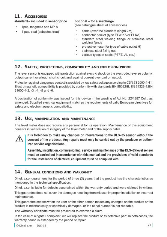
11 . acceSSorieSstandard – included in sensor price
• 1pcs. magnetic pen MP-8• 1 pcs. seal (asbestos free)
optional – for a surcharge (see catalogue sheet of accessories)
• cable (over the standard length 2m)• connector socket (type ELWIKA or ELKA)• standard steel welding flange or stainless steel
welding flange• protective hose (for type of cable outlet H)• stainless steel fixing nut• various types of seals (PTFE, Al, etc.)
12 . Safety, protectionS, compatibility and exploSion proof
The level sensor is equipped with protection against electric shock on the electrode, reverse polarity, output current overload, short circuit and against current overload on output. Protection against dangerous contact is provided by low safety voltage according to ČSN 33 2000-4-41. Electromagnetic compatibility is provided by conformity with standards EN 55022/B, EN 61326-1,EN 61000-4-2, -3 ,-4, -5 and -6.
A declaration of conformity was issued for this device in the wording of Act No. 22/1997 Coll., as amended. Supplied electrical equipment matches the requirements of valid European directives for safety and electromagnetic compatibility.
It is forbidden to make any changes or interventions to the DLS–35 sensor without the consent of the producer. Any repairs must only be carried out by the producer or author-ized service organisations.
Assembly, installation, commissioning, service and maintenance of the DLS–35 level sensor must be carried out in accordance with this manual and the provisions of valid standards for the installation of electrical equipment must be complied with.
13 . USe, manipUlation and maintenance
The level meter does not require any personnel for its operation. Maintenance of this equipment consists in verification of integrity of the level meter and of the supply cable.
14 . general conditionS and warranty
Dinel, s.r.o. guarantees for the period of three (3) years that the product has the characteristics as mentioned in the technical specification.Dinel, s.r.o. is liable for defects ascertained within the warranty period and were claimed in writing.This guarantee does not cover the damages resulting from misuse, improper installation or incorrect maintenance.This guarantee ceases when the user or the other person makes any changes on the product or the product is mechanically or chemically damaged, or the serial number is not readable.The warranty certificate must be presented to exercise a claim.In the case of a rightful complaint, we will replace the product or its defective part. In both cases, the warranty period is extended by the period of repair.
DLS–35 © Dinel, s.r.o.22
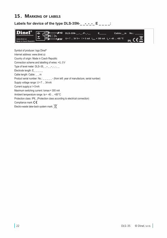
Labels for device of the type DLS-35N-_ _-_-_-_ E _ _ _ _:
15 . marking of labelS
Symbol of producer: logo Dinel®
Internet address: www.dinel.czCountry of origin: Made in Czech RepublicConnection scheme and labelling of wires: +U, 0 V Type of level meter: DLS–35_ _–_ _–_-_-_ _Electrode length: E_ _ _ _ _Cable length: Cable: _ _ mProduct serial number: No.: _ _ _ _ _ - (from left: year of manufacture, serial number)Supply voltage range: U = 7 ... 34 mACurrent supply:a I = 5 mAMaximum switching current: Iomax = 300 mAAmbient temperature range: ta = -40 ... +85°CProtection class: IP6_ (Protection class according to electrical connection)Compliance mark: Electro-waste take-back system mark:
IP6_
No.: ______Dinel
www.dinel.cz
Made in Czech Republic
1(bn)
3(bu)
4(bk)+U
0V I = 5 mAU = 7 ... 34 V t = -40 ... +85 °Ca
DLS 35N-__-__-P-_-__ E_____ Cable:__m-
Iomax
= 300 mA
Délka�112�mm�-�výška�12�mm
Štítek�pro�varianty DLS 35N-__-__-P-_-__-
23© Dinel, s.r.o. DLS–35
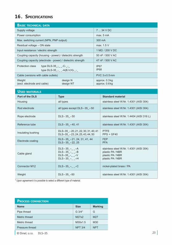
baSic technical data
Supply voltage 7 ... 34 V DC
Power consumption max. 5 mA
Max. switching current (NPN, PNP output) 300 mA
Residual voltage – ON state max. 1.5 V
Input resistance / electric strength 1 MΩ / 200 V DC
Coupling capacity (housing - power) / dielectric strength 50 nF / 500 V AC
Coupling capacity (electrode - power) / dielectric strength 47 nF / 500 V AC
Protection class type DLS-35_-_ _-C-_-_ type DLS-35_-_ _-A(B,V,H)-_-_
IP67IP68
Cable (versions with cable outlets) PVC 3 x 0.5 mm
Weight (excl. electrode and cable)
design Ndesign NT
approx. 0.3 kgapprox. 0.6 kg
16 . SpecificationS
USed materialS
Part of the DLS Type Standard material
Housing all types stainless steel W.Nr. 1.4301 (AISI 304)
Rod electrode all types except DLS – 35_– 50 stainless steel W.Nr. 1.4301 (AISI 304)
Rope electrode DLS – 35_– 50 stainless steel W.Nr. 1.4404 (AISI 316 L)
Reference tube DLS – 35_– 40, 41 stainless steel W.Nr. 1.4301 (AISI 304)
Insulating bushing DLS–35_– 20, 21, 22, 30, 31, 40, 41DLS–35_– 23, 24, 25, 43, 44, 50
PTFEPPS + GF40
Electrode coating DLS – 35_– 21, 24, 31, 41, 44DLS – 35_– 22, 25
FEPPFA
Cable gland
DLS – 35_–_ _–ADLS – 35_–_ _–BDLS –35_–_ _–VDLS – 35_–_ _–H
stainless steel W.Nr. 1.4301 (AISI 304)plastic PA / NBRplastic PA / NBRplastic PA / NBR
Connector M12 DLS – 35_–_ _–C nickel-plated brass / PA
Weight DLS – 35_–50 stainless steel W.Nr. 1.4301 (AISI 304)
* Upon agreement it is possible to select a different type of material.
proceSS connection
Name Size Marking
Pipe thread G 3/4'' G
Metric thread M27x2 M27
Metric thread M30x1.5 M30
Pressure thread NPT 3/4 NPT
DLS–35 © Dinel, s.r.o.24
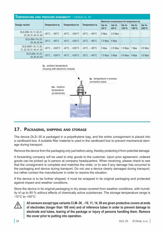
temperatUre and preSSUre dUrability - design n, nt
Design variant Temperature tp Temperature tm Temperature taMaximum overpressure for temperature tp Up to30°C
Up to85°C
Up to120°C
Up to150°C
Up to200°C
DLS-35N–10, 11, 20, 21, 22, 30, 31, 40, 41, 50 -40°C ... +85°C -40°C ... +200°C -40°C ... +85°C 5 Mpa 2.5 Mpa – – –
DLS-35N–114, 23, 24, 25, 43, 44 -25°C ... +85°C -40°C ... +200°C -25°C ... +85°C 7.5 Mpa 5 Mpa – – –
DLS-35NT–10, 11, 20, 21, 22, 30, 31, 40, 41, 50 -40°C ... +200°C -40°C ... +200°C -40°C ... +85°C 5 Mpa 2.5 Mpa 1.5 Mpa 1 Mpa 0.5 Mpa
DLS-35N–14, 23, 24, 25, 43, 44 -25°C ... +200°C -40°C ... +200°C -25°C ... +85°C 7.5 Mpa 5 Mpa 4.5 Mpa 4 Mpa 3.5 Mpa
tm – medium temperature (at electrode)
tp – temperature in process connection place
ta – ambient temperature(housing with electronic module)
17 . packaging, Shipping and Storage
The device DLS–35 is packaged in a polyethylene bag, and the entire consignment is placed into a cardboard box. A suitable filler material is used in the cardboard box to prevent mechanical dam-age during transport.
Remove the device from the packaging only just before using, thereby protecting it from potential damage.
A forwarding company will be used to ship goods to the customer. Upon prior agreement, ordered goods can be picked up in person at company headquarters. When receiving, please check to see that the consignment is complete and matches the order, or to see if any damage has occurred to the packaging and device during transport. Do not use a device clearly damaged during transport, but rather contact the manufacturer in order to resolve the situation.
If the device is to be further shipped, it must be wrapped in its original packaging and protected against impact and weather conditions.
Store the device in its original packaging in dry areas covered from weather conditions, with humid-ity of up to 85 % without effects of chemically active substances. The storage temperature range is -10°C to +50°C.
All sensors except type variants CLM–36_–10, 11, 14, 50 are given protective covers at ends of electrodes (longer than 100 mm) and of reference tubes in order to prevent damage to electrode and tubes, tearing of the package or injury of persons handling them. Remove the cover prior to putting into operation.

25© Dinel, s.r.o. DLS–35

DLS–35 © Dinel, s.r.o.26

27© Dinel, s.r.o. DLS–35
Dinel, s.r.o.U Tescomy 249
760 01 ZlínCzech Republic
Phone: +420 577 002 002Fax: +420 577 002 007
E-mail: [email protected]
www.dinel.cz
Find the updated version at www.dinel.czversion:
průmyslová elektronika
12/2015