design of geothermal district heating system...
TRANSCRIPT

i
DESIGN OF GEOTHERMAL DISTRICT HEATING SYSTEM OF UNIVERSIADE 2005
ATHLETES’ VILLAGE
A Thesis Submitted to the Graduate School of Engineering and Sciences of
�zmir Institute of Technology in Partial Fulfillment of the Requirements for the Degree of
MASTER OF SCIENCE
in Mechanical Engineering
by Yi�it ÜNERDEM
December 2005 �ZM�R

ii
We approve the thesis of Yi�it ÜNERDEM Date of Signature ………………………….. 27 December 2005 Prof. Dr. Macit TOKSOY Supervisor Department of Mechanical Engineering �zmir Institute of Technology …………………………. 27 December 2005 Asst. Prof. Dr. Serhan KÜÇÜKA Co-Supervisor Department of Mechanical Engineering Dokuz Eylül University …………………………. 27 December 2005 Prof. Dr. Zafer �LKEN Department of Mechanical Engineering �zmir Institute of Technology …………………………. 27 December 2005 Assoc. Prof. Dr. Barı� ÖZERDEM Department of Mechanical Engineering �zmir Institute of Technology …………………………. 27 December 2005 Asst. Prof. Dr. Cemalettin DÖNMEZ Department of Civil Engineering �zmir Institute of Technology …………………………. 27 December 2005 Assoc. Prof. Dr. Barı� ÖZERDEM Head of Department �zmir Institute of Technology
……………………… Assoc. Prof. Dr. Semahat ÖZDEM�R
Head of the Graduate School

iii
ACKNOWLEDGEMENTS
First of all, I would like to express my gratitude to my supervisor Prof.Dr. Macit
Toksoy and co-supervisor Asst.Prof.Dr. Serhan Küçüka for their supports and leading
during this study.
I would like to thank to Balçova Geothermal Company for sharing their
knowledge and experience throughout the study.
I would also like to thank to my colleagues, Berkan Erdo�mu�, A.Caner �ener,
Engin Gül�en, and all of others who give support for this study to come out.
Additionally, I would like to express my special gratitude to my family who
supports and try to keep me high-spirited throughout the M.Sc. programme.
Finally, I would like to thank all of my friends, colleagues and other people who
help me during my study.

iv
ABSTRACT
Geothermal energy, which is the Earth’s interior energy, has a broad application
area for heating and energy production purposes. To develop healthy geothermal energy
projects, conceptual planning study is one of the important tasks which should be done
initially. Conceptual planning studies consists of technical, economical and political
evaluation of the project showing that whether the project is feasible or not. In this
study, conceptual planning study is applied to the Athletes’ Village which has a
dwelling area of 97,446 m2. The total peak demand including hot water need for this
system design is 11,7 MWt. The existing heating system is fuel-firing system. A
comparison between the existing system with geothermal district heating system is done
by this study. The hot water at 140 ºC, which is planned to be extracted from new
drilled wells, is first cooled down to 120 ºC and afterwards designed to give its energy
to the closed city loop. Finally, city loop water will circulate in the buildings within the
temperature range of 85 ºC/55 ºC. The economy of the system is studied for two
different well locations considering different participating costs and operating costs.
The monthly fixed charges which make the internal rate of return positive around 0 % is
determined for the investor for different participating costs varying between $ 1250 and
$ 2500. At the end, the net present worths for the payments that would be done to the
heating systems are calculated for the consumers. As a result of the economic feasibility
study, it is determined that geothermal district heating design would be feasible for the
consumers when the same comfort conditions are considered for both of the designs.

v
ÖZET
Jeotermal enerji yeryüzünün kendi iç ısısı olmakla beraber geni� bir kullanım
alanına sahiptir. Günümüzde jeotermal enerji ile ilgili sa�lıklı projeler geli�tirebilmek
için yapılması gereken ilk çalı�malardan biri kavramsal planlama çalı�masıdır.
Kavramsal planlama çalı�maları projenin teknik, ekonomik ve politik açılardan
de�erlendirmelerinden olu�up buradan yola çıkarak projenin uygulanabilirli�ini tartı�an
çalı�malardır. Bu çalı�mada 97, 446 m2 konut alanına sahip Olimpiyat Köyü Evleri ile
ilgili kavramsal planlama çalı�ması yapılmı� ve bölgenin toplam pik yükü sıcak su
ihtiyacı da dahil olmak üzere 11,7 MWt olarak belirlenmi�tir. �u anda bu evlerin
ısıtılması için dü�ünülen sistem mevcutta bulunan fuel-oil yakıtlı sıcak sulu sistemdir ve
bu çalı�mada mevcut bu sistemin, jeotermal bölge ısıtma sistemi ile kar�ıla�tırılması
yapılmı�tır. Yeni açılacak kuyulardan elde edilmesi beklenen 140 ºC sıcaklıktaki
jeotermal akı�kanın sıcaklı�ının önce 120 ºC ‘ye dü�ürülmesi, daha sonrasında
enerjisini �ehir içi kapalı çevrim suyuna vermesi planlanmı�tır. Son olarak, �ehir hattı
suyunun bina içlerinde 85 ºC/55 ºC sıcaklık aralı�ında dola�ması tasarlanmı�tır.
Sistemin ekonomisi, farklı kuyu senaryoları için farklı katılım payları ve aylık sabit
enerji ücretleri göz önüne alınarak incelenmi�tir. Farklı katılım payları dü�ünülerek iç
karlılık oranını sıfıra en yakın pozitif yapan aylık ödemeler hesaplanmı�tır. Son olarak,
mevcut sistem ve jeotermal ısıtma sistemi ile ilgili senaryolar için ödenecek enerji
tutarları sistem ömürleri hesaba katılarak bugünkü de�erleri bulunmu�tur. Ekonomik
fizibilite çalı�masının sonucunda, e� konfor ko�ulları dü�ünüldü�ünde, kullanıcılar için
jeotermal ısıtma sisteminin uygunlu�u görülmü�tür.

vi
TABLE OF CONTENTS
LIST OF FIGURES ......................................................................................................... ix
LIST OF TABLES............................................................................................................ x
CHAPTER 1. INTRODUCTION ................................................................................... 1
1.1. Geothermal Energy .............................................................................. 1
1.1.1. Water Dominated Fields ................................................................. 2
1.1.2. Vapor Dominated Fields ................................................................. 3
1.2. Impacts of Geothermal Energy ............................................................. 5
1.3. Sustainability of Geothermal Energy.................................................... 7
1.4. Application Areas of Geothermal Energy ............................................ 9
1.5. Direct Uses of Geothermal Energy..................................................... 10
1.5.1. Space and District Heating ........................................................... 10
1.5.2. Space Cooling ............................................................................... 11
1.5.3. Geothermal Space Conditioning................................................... 11
1.5.4. Agricultural Applications ............................................................. 11
1.5.5. Industrial Applications.................................................................. 12
1.6. Non-Direct Uses of Geothermal Energy............................................. 12
CHAPTER 2. GEOTHERMAL DISTRICT HEATING SYSTEMS ........................... 13
2.1. District Heating................................................................................... 13
2.2. History of Geothermal District Heating.............................................. 14
2.3. Design of Geothermal District Heating .............................................. 15
2.3.1. Geothermal Wells ......................................................................... 17
2.3.2. Well and Circulating Pumps ......................................................... 17
2.3.3. Transmission and Distribution Piping .......................................... 18
2.3.4. Central or Individual Building Heat Exchangers.......................... 20
2.3.5. Thermal Storage Units .................................................................. 22
2.3.6. Consumer Side of the District Heating Design............................. 23
2.4. Benefits of Geothermal District Systems............................................ 23

vii
CHAPTER 3. GEOTHERMAL ENERGY IN TURKEY ............................................ 26
3.1. Present Energy Evaluation of Turkey................................................. 26
3.2. Geothermal Energy Applications in Turkey....................................... 27
3.3. Geothermal Energy Applications in �zmir.......................................... 30
CHAPTER 4. EVALUATION OF ATHLETES' VILLAGE GEOTHERMAL
DISTRICT HEATING SYSTEM........................................................... 32
4.1. Introduction to Conceptual Planning .................................................. 32
4.2. Importance of Social and Economical Analysis ................................. 33
4.3. Information about the Athletes’ Village ............................................. 34
4.3.1. Dwelling Areas ............................................................................ 36
4.4. Information about the Existing Heating System................................. 37
4.4.1. Heat Losses in the Existing Heating System ................................ 38
4.4.2. Radiator Types ............................................................................. 40
4.4.3. Indoor Temperatures..................................................................... 40
4.4.4. Operating Costs of the Existing System ....................................... 41
4.5. Geothermal District Heating System Design...................................... 43
4.5.1. Heat Load Density ........................................................................ 43
4.5.2. Energy Transfer System................................................................ 44
4.5.3. Service Life of Materials .............................................................. 45
4.5.4. The Characteristics of the Geothermal Well................................. 46
4.5.5. Operating Temperatures ............................................................... 47
4.5.6. Location of the Pumping Station .................................................. 49
4.5.7. Geothermal Network..................................................................... 50
4.5.8. City Network................................................................................. 51
4.5.9. Heat Exchangers ........................................................................... 52
4.5.10. Circulation Pumps....................................................................... 53
4.5.11. Efficiency of Radiators in the Buildings..................................... 54
4.6. Economics of the Geothermal System................................................ 56
4.6.1. Investment Costs........................................................................... 56
4.6.2. Operating Costs............................................................................. 57
4.6.3. Finance Model .............................................................................. 63
4.6.3.1. Internal Rate of Return Analysis ......................................... 63

viii
4.6.3.2. Comparison with the Existing System................................. 64
CHAPTER 5. RESULTS AND DISCUSSION............................................................ 66
5.1. Results and Discussion of the Conceptual Planning Study ................ 66
CHAPTER 6. CONCLUSIONS ................................................................................... 69
REFERENCES ............................................................................................................... 70
APPENDICES
APPENDIX A. The Location of the heat exchanger rooms ........................................... 73
APPENDIX B. The Geothermal Loop ........................................................................... 74
APPENDIX C. City Network ......................................................................................... 75

ix
LIST OF FIGURES
Figure Page Figure 1.1. Heating Mechanism for Low Temperature Systems .................................. 4
Figure 1.2. Subdivisions of the geothermal base in Muffler and Cataldi’s
studies ......................................................................................................... 8
Figure 1.3. Direct use of geothermal heat on worldwide from 23 countries.
Total capacity = 102,268 TJ/year ............................................................... 9
Figure 2.1. The layers of a pre-insulated pipe ............................................................. 20
Figure 2.2. Plate and frame heat exchangers ............................................................... 22
Figure 4.1. View of houses with terrace in Athletes’ Village ..................................... 34
Figure 4.2. View of apartment blocks in Athletes’ Village ........................................ 35
Figure 4.3. The distribution of heat load density on city blocks ................................. 44
Figure 4.4. The distribution of the potential of the geothermal in Balçova ................. 47
Figure 4.5. Schematic view of temperature regimes within the system ...................... 48
Figure 4.6 Change of investment and electricity cost with target head loss ............... 52
Figure 4.7 System Characteristics of the circulation pump in the pumping
station ........................................................................................................ 54
Figure A1. The Locations of the Heat Exchanger Rooms ........................................... 73
Figure B.1. The Geothermal Loop................................................................................ 74
Figure C.1. City Network.............................................................................................. 75

x
LIST OF TABLES
Table Page Table 1.1. Classification of geothermal resources (ºC) ............................................... 5
Table 1.2 Potential environmental impacts of direct use geothermal
projects......................................................................................................... 6
Table 3.1. Geothermal space heating in Turkey ........................................................ 30
Table 4.1 The distribution and areas of blocks in the region .................................... 35
Table 4.2. Dwelling areas form the auto cad drawings and the distribution
of the dwellings over the village ............................................................... 37
Table 4.3. The distribution of dwellings in each block .............................................. 37
Table 4.4. The capacities of the boilers chosen in the installation report .................. 38
Table 4.5. The overall heat conductivity coefficients of the construction
materials used in the village ...................................................................... 39
Table 4.6. The radiator types and the surface areas ................................................... 40
Table 4.7. The annual fuel oil cost of the village according to re-
calculated heat loss ................................................................................... 42
Table 4.8. All of the operating costs for the existing system ..................................... 42
Table 4.9. Heat load density according to the installation project prepared
for the central heating system ................................................................... 43
Table 4.10. Heat load density according to geothermal district heating
system design which heat losses are modified .......................................... 43
Table 4.11. Economic Availability Analysis Related To Heat Load Density .............. 44
Table 4.12. The amount of geothermal water that should be extracted from
the well ...................................................................................................... 47
Table 4.13. Geothermal network characteristics for pumping station
alternatives ................................................................................................ 49
Table 4.14. The total head loss in the geothermal network for the first
alternative .................................................................................................. 50
Table 4.15. The total heal loss in the geothermal network for the second
alternative .................................................................................................. 50
Table 4.16 Selected pipe diameters and their costs for the city network .................... 52

xi
Table 4.17. Capacities of heat exchanger in each heat exchanger station in
the city ....................................................................................................... 53
Table 4.18 System characteristics with changing outdoor temperature ..................... 54
Table 4.19. Feeding and return temperatures of radiators in the geothermal
district heating design ............................................................................... 55
Table 4.20. The components of the investment costs according to the first
scenario where the geothermal network is 4500 m ................................... 57
Table 4.21. The components of the investment costs according to the
second scenario where the geothermal network is 1000 m ...................... 57
Table 4.22. Monthly electricity consumption and its cost for the first
alternative .................................................................................................. 59
Table 4.23. Monthly electricity consumption and its cost for the second
alternative .................................................................................................. 59
Table 4.24. The costs of personnel of Athletes’ Village for each month .................... 60
Table 4.25. The volume of water in city network ........................................................ 61
Table 4.26. Volumes of the heat exchangers ............................................................... 61
Table 4.27. All the components of water consumption in the system ......................... 61
Table 4.28. Inhibitor, chemical and maintenance costs per year ................................. 62
Table 4.29. All of the operating costs for Athletes’ Village considering the
alternatives ................................................................................................ 62
Table 4.30. Monthly fixed charges for different participating costs which
make IRR = 0 ............................................................................................ 64
Table 4.31. Comparison between the costs of the existing heating system
and GDHS ................................................................................................. 64
Table 4.32. Net present worth of different cost scenarios for alternative 1.................. 65
Table 4.33. Net present worth of different cost scenarios for alternative 2.................. 65

1
CHAPTER 1
INTRODUCTION
1.1. Geothermal Energy
Geothermal energy is the energy produced in the Earth’s interior. The source of
this energy is due to the physical processes occurring in deeper parts of the Earth’s
structure. The heat flux of this energy is to the surface and it is known that the deeper
inside the Earth’s structure higher the temperature of the rocks forming this structure.
This existing temperature gradient is found as 2.5 – 3 ºC/ 100 m (Barbier 2002).
The form of geothermal fields is based on the plate tectonics theory by the
geologists. Our planet consists of three main parts: the crust, the mantle and the core.
These parts of the Earth show different physical and chemical characteristics varying
from the surface to the Earth’s center. The outer shell of the Earth is called as
lithosphere and it consists of the crust and the upper layer of the mantle. Below the
lithosphere, there is asthenosphere which forms a less rigid behavior. In some parts of
the Earth, the lithosphere is thinner and it can be broken by the upward movement of
molten material in asthenosphere. This behavior of the Earth is resulted with forming of
the plates. Thus, geothermal systems can be found in regions in result of these
movements at fault zones (Dickson 2004, Barbier 1997).
Geothermal fields can be classified according to the source type, physical
characteristics of the reservoir, the enthalpy of the fluid and geological settlement of the
field.
Geothermal energy source types can be divided into parts as hydrothermal
energy, pressurized underground energy, magma energy, hot dry rock energy, ground
energy. The ground energy is the thermal energy formed near to the surface due to the
normal temperature gradient of the Earth, so that it is not much affected by the
geological events. It can be used for space heating by heat pumps, industrial demands
and hot water need. Hot dry rock energy can be seen everywhere below 8-16 km depths
from the surface or in the places where the temperature gradient Earth is higher due to
geological events. Hydrothermal energy is the mostly known and used geothermal

2
source. The formation of this system is due to some geological events under high
pressures in the Earth’s interior.
Hydrothermal geothermal system consists of three main elements:
• A heat source
• A reservoir
• A geothermal fluid for carrying heat
Molten material (magma) that have found way to move upwards to relatively
shallow depths like 5-10 km, heats the rocks during its movement and the heat source
occurs at the end of this process. “The reservoir is a volume of hot permeable rocks
from which the circulating fluids extract heat.” The geothermal fluid is rainwater that
has penetrated into deeper parts of the crust and has been heated by the hot the rocks.
Usually, the reservoir is covered with impermeable rocks, so that the geothermal fluid is
stored under pressure (Barbier 2002).
When a productive geothermal system is considered, the characteristics of the
reservoir are important. First of all, it should be composed of sufficiently large body of
permeable rocks, which the magma body moves toward these rocks transferring its heat
by conduction, at a depth which is accessible by drilling. There should be a certain fluid
circulation through the body of the rocks, so that the heat can be carried to the surface.
The reservoir is surrounded by cooler rocks hydraulically connected to the reservoir by
fractures, so that the rainwater can penetrate underground. Rainwater moves to depth
inside the reservoir by convection, due to density variations caused by the temperature.
Through its movement, it contacts with the hot rocks, so the convection heat transfer
occurs between the hot rock and the geothermal fluid, water. This kind of process
results with the forming of a hydrothermal geothermal source. Hydrothermal systems
can be classified according to the physical characteristics of the reservoir as: water-
dominated fields and vapor-dominated fields (Wright 1995).
1.1.1. Water-Dominated Fields
Water-dominated fields can de divided in two different branches as hot water
fields which produce hot water and wet steam fields which produces mixtures of water
and steam.

3
Hot water fields are the fields which produces hot water at the surface at
temperatures up to 100 ºC. These fields show the lowest temperature profile when
compared with the others and the water is stored in liquid phase in the reservoir.
Because the heat source is not large enough, the temperature of the water is below the
boiling temperature at any pressure. On the surface, there are usually thermal springs
whose temperatures are near 100 ºC.
Wet steam fields are consist of pressurized water having temperature more than
100 ºC and small quantities of steam in lower pressure parts of the reservoir. Most of
the geothermal fluid in the reservoir is in the liquid phase and steam is occurring in the
form of bubbles surrounded by the liquid. It is the liquid phase which controls the
pressure inside the reservoir in this kind of fields. In fact, most of the time, the
geothermal fluid is surrounded by an impermeable cap-rock to keep the fluid inside and
keep it under pressure. When the fluid is carried to the surface and its pressure
decreases, a small fraction of it is flashed into steam, while the greater part remains as
boiling water. The pressure decreases because of the vaporization of some part of the
water. This steam can be used for production of electricity (Barbier 2002).
1.1.2. Vapor-Dominated Fields
These kinds of fields produce dry saturated or slightly superheated steam at
pressures above atmospheric pressure. The characteristics of these fields are similar to
wet steam fields. However, these fields have higher heat transfer rate from the heat
source. Similar to wet steam fields, there exists a permeable cap-rock in the reservoir.
Different from the wet steam fields, steam is the predominant phase which controls the
pressure in the reservoir. These fields are called dry or superheated fields. When a well
is drilled into the reservoir, a depressurized zone occurs at the bottom of the well.
Boiling starts with this pressure drop and the liquid which surrounds the rock vaporizes.
At the end, a dry area occurs near the well-bottom and steam flows through this zone.
When steam crosses the dry area, it starts to expand and cool, but as the heat is
transferred from the hot rock, steam keeps its temperature above the vaporization value
for the pressure existing at that point. Thus, the steam leaves the well as superheated
steam (Barbier 1997).

4
Rainwater (Accumulation Zone)
Natural Feeding
Heating Zone
Production from wells
The temperature of the fluid is another factor in the classification of the
geothermal systems. The reservoirs where the temperature of the produced water is
below 150 ºC is called low-temperature systems (Wright 2004). These kinds of systems
are known with natural hot water reaching to the surface. Most of the known systems in
Turkey are low-temperature systems. For this kind of systems, the heat source is the
crust having a temperature above the normal conditions. After some undergoing Earth
movements, fractures and fault zone are formed which are the channels for the water to
circulate inside. In the Figure 1.1, it can be seen that how rainwater accumulates in the
geothermal field from the higher elevated parts of the Earth. It penetrates to deeper parts
and reaches to the hot rock, so that it can transfer heat from the rock. Then the water
reaches to Earth, but this time heated by the hot rock. This hot water can be observed on
the lower elevated parts of the surface or it can be pumped to the surface from the
drilled wells. These kind of low-temperature systems are seen near places where there
are active geological movements. Geothermal fields on the west side of Turkey are
examples for this kind of geothermal systems (Wright 1995).
Figure1.1. Heating Mechanism for Low Temperature Systems (Satman 2003)
When the temperature of the water that is produced from the well is above 200
ºC, then these kinds of systems are called high-temperature fields. These kinds of
5
systems are known with existing steam from the surface or with boiling mud ponds.
These kinds of field are available for electricity generation.
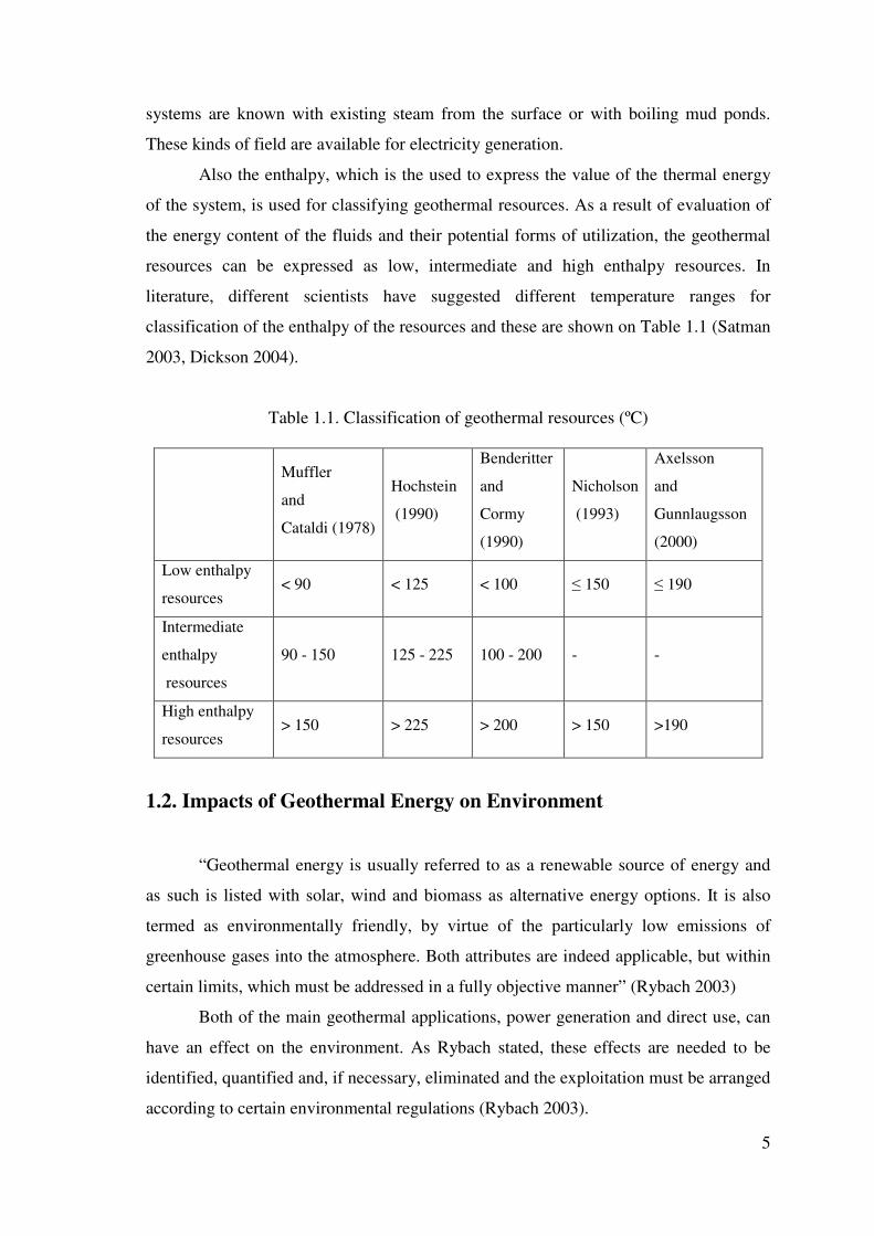
Also the enthalpy, which is the used to express the value of the thermal energy
of the system, is used for classifying geothermal resources. As a result of evaluation of
the energy content of the fluids and their potential forms of utilization, the geothermal
resources can be expressed as low, intermediate and high enthalpy resources. In
literature, different scientists have suggested different temperature ranges for
classification of the enthalpy of the resources and these are shown on Table 1.1 (Satman
2003, Dickson 2004).
Table 1.1. Classification of geothermal resources (ºC)
Muffler
and
Cataldi (1978)
Hochstein
(1990)
Benderitter
and
Cormy
(1990)
Nicholson
(1993)
Axelsson
and
Gunnlaugsson
(2000)
Low enthalpy
resources < 90 < 125 < 100 � 150 � 190
Intermediate
enthalpy
resources
90 - 150 125 - 225 100 - 200 - -
High enthalpy
resources > 150 > 225 > 200 > 150 >190
1.2. Impacts of Geothermal Energy on Environment
“Geothermal energy is usually referred to as a renewable source of energy and
as such is listed with solar, wind and biomass as alternative energy options. It is also
termed as environmentally friendly, by virtue of the particularly low emissions of
greenhouse gases into the atmosphere. Both attributes are indeed applicable, but within
certain limits, which must be addressed in a fully objective manner” (Rybach 2003)
Both of the main geothermal applications, power generation and direct use, can
have an effect on the environment. As Rybach stated, these effects are needed to be
identified, quantified and, if necessary, eliminated and the exploitation must be arranged
according to certain environmental regulations (Rybach 2003).

6
The impacts of geothermal energy vary with the scale of the system. These
impacts include changes in landscape, emissions to the atmosphere, surface and
subsurface water, noise, land subsidence and solid waste, etc. The potential
environmental impacts of direct use of geothermal energy can be seen on Table 1.2. On
the table, the impacts are analyzed according to the probability of occurrence which
may differ with the capacity of the system and the technology used for the exploitation.
Then the impacts are classified according to the level of results if they occur.
Table 1.2 Potential environmental impacts of direct use geothermal projects
(Rybach 2003)
Impact Probability of occurringa
Severity of consequencesb
Air pollution L M Surface water pollution M M Underground pollution L M
Land subsidence L L to M High noise levels H L to M
Well blowouts L L to M Conflicts
with cultural and archeological features
L to M M to H
Socioeconomic problems L L Solid waste disposals M M to H
a Pollution can be chemical and/or thermal. b L = Low, M = Medium, H = High
For example, air pollution is one of the impacts of geothermal energy to the
environment. During drilling of flow tests, some undesirable gases may escape to the
atmosphere resulting with air pollution if precautions are not taken. Also geothermal
power plants can discharge CO2 which can pollute the air. However, it should be stated
that the CO2 emission in geothermal power plants are much lower when these plants are
compared with conventional power plants. In addition, by using the technology
nowadays, the chance of occurrence of this impact is low.
Also, surface and subsurface water pollution is another impact of geothermal
fluids. Geothermal fluids usually consists of dissolved gases like carbon dioxide,
hydrogen sulphide, ammonia, methane and dissolved chemicals as sodium chloride,
boron, arsenic and mercury. These dissolved chemicals and gases can influence the
environment in a negative way if they are discharged. Further, the waste water from

7
geothermal plants can be discharged to the environment (ponds, lakes, etc), so that the
temperature of surface water could increase. Thus, ecological life will be damaged in
the result of this discharge. Therefore, the geothermal water should be treated or re-
injected to the reservoir to prevent the thermal and chemical pollution.
Furthermore, subsidence may occur after the extraction of large quantities of
geothermal fluids from the geothermal reservoirs. However, this subsidence can be
prevented by re-injecting fluid to geothermal reservoir.
Noise is another problem which is mostly encountered when electricity is
generated from geothermal power plants. At the power plants, the main noise pollution
comes from the plant components such as cooling tower fans, the steam ejector and the
turbine. In direct systems, the noise generated is usually negligible in nowadays’
technology.
1.3. Sustainability of Geothermal Energy
“The term sustainable development was used by the World Commission on
Environment and Development to mean development that meets the needs of the
present generation without compromising the needs of future generations (Rybach
2003).” In general, the term sustainability for a resource is related its initial quality, its
rate of generation and its rate of consumption. The rate of generation over any time
period must be greater than the rate of consumption, so that the resource can be
considered as a sustainable resource. Otherwise, if the production is only done to meet
the economic goals and to sustain the quick payback of the capital investment, then, the
resource would be consumed totally over a time period. To determine these rates for a
geothermal resource, the studies on the performance of the reservoir should be carried
out. When a geothermal resource is considered, the rate of consumption is in relation
with financial, political and regulatory factors which can be called “economic factors”.
These factors can be determined before the production of geothermal fluids by
conceptual planning studies (Wright 1995).
Muffler and Cataldi had defined geothermal resource as the thermal energy that
could reasonably be extracted at costs to its competitive with other forms of energy at
some specified future time. In their studies, they stated only a small portion of the
resource base is economical to use when the resource base is analyzed deeply as it is

8
seen in Figure 1.2. The depth of the well is a major factor in determination of the
drilling cost. The thermal energy in the shallower part of the crust is to be extracted
economically in foreseeable future. Because of this reason, it will be correct to divide
the resource as the “accessible resource” where the thermal energy can be reached by
drilling and the “inaccessible resource” where the thermal energy in deeper parts can
not be reached by drilling. The depth separates these categories and the drilling
technology and economics are the factors which determine the depth for that time
(Muffler 1978).
Figure 1.2. Subdivisions of the geothermal base in Muffler and Cataldi’s studies
“It is commonly recognized that not all the thermal energy accessible by drilling
can be collected and extracted, even under the most optimistic assumptions of
technology and economics. Because of the some physical reasons, legal and
environmental considerations, some portion of it will not be extracted. When these
factors are considered, the accessible resource should be divided into two parts as
“useful” and “residual”. Muffler and Cataldi explains “useful accessible resource” as
“the thermal energy which could reasonably be extracted at costs competitive with other
forms of energy at a specified time in the future, under the general assumptions of
progressively improving technology and of increasingly favorable economic situation.”
(Muffler 1978)
Resource Base
Accesible
Inaccesible
Useful
Residual
Economic
Subeconomic

9
At the end, useful accessible resource can be analyzed if it is economic or sub-
economic. A geothermal source can be called economical when the geothermal energy
can be extracted within the legal policies at a cost which is competitive with other
energy sources at the time of extraction. The sub-economic category is the one which is
not competitive, but could be extracted competitively by the help of progressing
technology in future time. Therefore, because there is a chance of extracting this portion
with improved technology in future, this portion is still included in the “useful” part of
the reservoir (Muffler 1978).
1.4. Application Areas of Geothermal Energy
The application areas of geothermal resources can be grouped as direct heat uses
and non-direct uses. The direct uses includes snow melting, air conditioning, heat
pumps, space heating, bathing, agricultural drying, greenhouses, fish farming and
industry. The distribution for these usage areas for the direct use of geothermal is shown
on the Figure 1.3.
1% 12%
3%
33%
15%
1%
12%
13%
10%
Snow melting, AirConditioningHeat Pumps
Others
Space Heat
Bathing
Agricultural Drying
Greenhouses
Fish Farming
Figure1.3. Direct use of geothermal heat on worldwide from 23 countries. Total
capacity = 102,268 TJ/year (Freeston 1995)

10
1.5. Direct Uses of Geothermal Energy
1.5.1. Space and District Heating
Space and district heating is common form of utilization of geothermal energy.
In a study about the fundamentals and applications of district system, Valdimarsson
have made a fine definition for the district heating systems as “district heating is a
system, composed of many elements, building a chain from the resource over to the
interior of the buildings which are heated. All elements in this chain are equally
important, from the geothermal well over to the building radiators, and they all have to
be designed with utmost care” (Valdimarsson 2003).
As in the definition, these systems are consist of many elements like production
and injection wells, down-hole and transmission pumps, pipelines and distribution
networks, monitoring and control equipment, peaking stations and storage tanks.
Mainly, costs for these elements add up to form the “capital cost” for the district system.
The other cost factors for the system are pumping costs, maintenance costs and costs
related with heat and water loss in the distribution system (Valdimarsson 2003). These
factors can be classified under a group, “operating costs”. The economy of the
geothermal system is related with the thermal load density for the system which the heat
demand divided by the ground area of the district. Therefore, the peak load analysis for
the district heating system is important in feasibility studies for the system. Peak load
analysis is a crucial analysis in feasibility studies, since the geothermal systems includes
the investment for drilling which is high compared with the investment in boiler stations
and the energy cost of the operation of a geothermal system is mainly the pumping cost
(Bloomquist 2003, Dickson 2004).
As it is expressed in Valdimarsson’s study , the minimum operational demands
for a district heating systems are (Valdimarsson 2003):
• Pressure difference between the supply and the return pipe at every consumer
connection must be sufficient.
• Maximum line pressure must be lower than the design value.
• Water inlet temperature by every consumer should be sufficiently high.
• Water temperature in the secondary and tap water system must not exceed a
safety limit set for inhabitants and equipment

11
• Sufficient reliability
1.5.2. Space Cooling
Space cooling can be sustained where absorption machines can be adapted to the
geothermal use. The absorption cycle is a process going under the reaction of two
fluids, a refrigerant which circulates, evaporates and condenses; and secondary fluid
which is absorbent. Lithium bromide/water and ammonia/water cycles are the most
known absorption cycles. Geothermal fluids provide the energy to drive these machines,
although their efficiency decreases with temperatures lower than 150 ºC (Dickson
2004).
1.5.3. Geothermal Space Conditioning
Geothermal space conditioning is spread with the usage of heat pumps. Heat
pumps are devices working mechanism is similar to refrigeration devices; however the
only difference is heat pumps are reversible, so they can provide both heating and
cooling. They can be grouped according to the application areas as ground-coupled heat
pumps and ground-water heat pumps (Dickson 2004).
1.5.4. Agricultural Applications
Open-field agriculture and greenhouse heating are the most known applications
for the agricultural applications. Thermal water can be used for irrigating and/or heating
the soil in open-field agriculture. The other and most common application of geothermal
energy in agriculture is greenhouse heating. The optimum conditions for growing of
vegetables and flowers out of season or in an unnatural climate can be supplied by
greenhouse heating. Greenhouse heating can be sustained by forced circulation of air in
heat exchangers, hot-water circulating pipes or ducts located in or on the floor, finned
units located along the walls and under benches or a combination of these methods
(Dickson 2004).

12
1.5.5. Industrial Applications
Geothermal energy also can be used in industrial applications like process
heating, evaporation, drying, distillation, sterilization, washing, de-icing and self
extraction.
1.6. Non-direct Uses of Geothermal Energy
The non-direct use of geothermal energy occurs in conventional steam turbines
and binary plants by electricity generation. Conventional steam turbines requires
geothermal fluids with high temperatures (>150 ºC) to generate electricity. On the other
hand, the low to medium temperature geothermal resources can be used in binary plants
where secondary fluid is needed for electricity generation (Dickson 2004).
13
CHAPTER 2
GEOTHERMAL DISTRICT HEATING SYSTEMS
2.1. District Heating
Energy is used either to perform work or to produce heat. The transformation of
work to heat always can be performed without any losses. On the other hand, when the
reverse process is considered and work is transformed to heat, this transformation
process is not possible without having to reject some of heat fed in at a lower
temperature. The second law of thermodynamics explains this procedure. These forms
of energy can be divided into two groups as first and second class energy. Electricity is
an example for the first class energy form because its transformation into heat occurs
without losses and it can also be transformed into work with high efficiency.
The domestic energy use could be both first and second class energy. The
electrical network can supply first class energy, but the second class energy may be
supplied in various forms such as fossil fuel for use in a domestic boiler, electricity and
heat distributed by a district heating network. A district heating system can use different
power utilities to produce heat to its customers. It can use the heat which is rejected
from industrial processes or from electrical power generation. Also, heat from
unconventional energy sources can be adapted to these systems, such as geothermal
energy. “The main purpose of a district heating system is to supply adequate heat to its
customers. The heat will be used to maintain indoor temperature at a reasonably
constant level and counter for building heat loss to the surroundings and for preparation
of domestic hot water (Valdimarsson 2003)”.
The method used for heat generation is the main classification standard for
district heating systems. The most common method of heat generation for district
heating is firing of fossil fuel, either in boilers dedicated to the district heat production,
or in the boilers of a power station, where the steam plant reject (condensation) heat is
used for the district heating system. Then, the distribution of heat to the customers is
supplied through a closed network. By the use of customer, it is cooled down, and then
it is piped back to the boiler in the return network to be re-heated (Bloomquist 2003).

14
2.2. History of Geothermal District Heating in World
It is known that the use of geothermal energy is date back to ancient time. In
early times, geothermal energy was used for purposes as bathing, cooking and washing.
Some ancient evidence showed that geothermal energy was used by Romans, Greeks,
Indians, Chinese, Japanese and Mexican. Therefore, these ancient applications lead the
way to modern applications of geothermal energy (Özgener and Hepba�lı 2004).
The first documented geothermal district heating system was built in Chaudes-
Aigues Cantal in France, in the 14th century. It is one of the oldest application areas of
geothermal energy. In the United States the Boise, Idaho system known as the Boise
Warm Springs Water district, went online in 1893 and is now one of the four
independent systems that serve the Boise metropolitan area (Bloomquist 2000). In 1818,
a boric acid industry is established in Italy to extract boric salts from the geothermal
water of that area. In 1909, first geothermal space heating was installed in a house
Reykjavik, Iceland (Hepba�lı 2004). After that, the commercial generation of electricity
from geothermal energy has started in a power plant in Tuscany, Italy with a capacity of
250 kWe in 1913. Further, the first geothermal district heating system was installed in
Reykjavik in Iceland in 1930. New geothermal district heating systems in Idaho,
Oregon, New Mexico and California had been installed during 1980’s, but the
extremely low natural gas prices were an obstacle on the development of new
geothermal district heating systems in that period (Bloomquist 2003).
Nowadays, geothermal energy is used for especially, district heating in
worldwide and governments are exploring new geothermal potentials in their countries.
Hungary, Iceland, France, Poland, Romania, China, Turkey, Sweden and Denmark can
be counted in these countries which are working for developing newer geothermal
district heating systems. Iceland is the leader in the development of geothermal district
heating systems, and as of 97 % of the inhabitants of the capital city of Reykjavik are
benefiting from geothermal district heating to supply their space heating as well as
domestic hot water heating requirements. However, in his study Lund (2002) states that
“Iceland may soon lose its leadership role as Turkey is quickly emerging as a leader in
the development of new geothermal district heating systems. By 2000, Turkey had over
51,600 residences connected to district heating networks and projects to supply

15
geothermal district energy services to approximately 500,000 residences, or 3 % of the
residences in the country, by 2010.”
2.3. Design of Geothermal District Heating
The design purpose of district heating network is to provide space heating to
multiple consumers from a single well or from multiple wells or fields, since district
heating is one of the oldest uses of geothermal energy.
Geothermal energy is the thermal energy within the Earth’s interior. It is a
renewable energy source, however when electricity generation is considered, a
geothermal source usually has a projected life of 30 to 50 years. The life of a source
may be expanded by re-injecting the waste fluid, which is the most common method of
disposal. Re-injection may also help to maintain reservoir pressure (Kano�lu 1998). On
the other hand, for the district heating systems, system life is related with usage rate of
the reservoir. “Sustainable geothermal utilization involves energy production at a rate
which may be maintained for 100-300 years (Hepba�lı 2004)”. Therefore, for all the
applications of geothermal energy, sustainability depends on efficient utilization of the
system, re-infection, careful monitoring and modeling of the reservoir.
In the design of direct use systems one of the major goals is capturing the most
possible heat from each volume of fluid pumped. This arises from the fact that
investment and operating costs for the systems are composed primarily of well pumping
and well components. When the �T for the system is maximized, (minimizing flow
requirements), well capital cost and pump operating costs are minimized. In many cases
the system design benefits from connecting loads in series according to temperature
requirements (Dimitrov 2000).
District heating is one of the usage areas of the geothermal source, consists of
many elements, building a chain from the resource over to the interior of the buildings
which are heated (Valdimarsson 2003). The components of a geothermal district energy
system are:
• One or multiple wells or in some cases even well fields
• Well and circulating pumps
• Transmission and distribution piping
• Central or individual building heat exchangers
16
• Peaking/backup boilers
• Thermal storage units
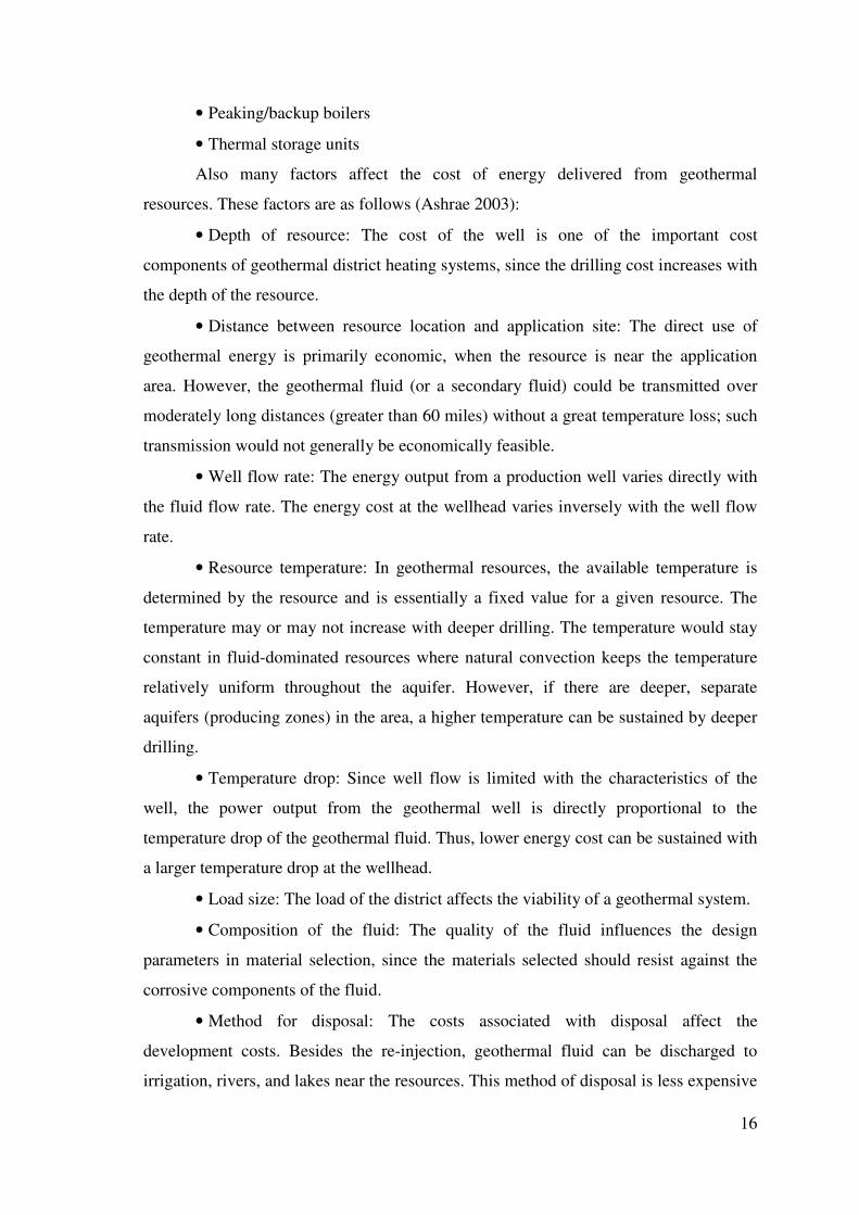
Also many factors affect the cost of energy delivered from geothermal
resources. These factors are as follows (Ashrae 2003):
• Depth of resource: The cost of the well is one of the important cost
components of geothermal district heating systems, since the drilling cost increases with
the depth of the resource.
• Distance between resource location and application site: The direct use of
geothermal energy is primarily economic, when the resource is near the application
area. However, the geothermal fluid (or a secondary fluid) could be transmitted over
moderately long distances (greater than 60 miles) without a great temperature loss; such
transmission would not generally be economically feasible.
• Well flow rate: The energy output from a production well varies directly with
the fluid flow rate. The energy cost at the wellhead varies inversely with the well flow
rate.
• Resource temperature: In geothermal resources, the available temperature is
determined by the resource and is essentially a fixed value for a given resource. The
temperature may or may not increase with deeper drilling. The temperature would stay
constant in fluid-dominated resources where natural convection keeps the temperature
relatively uniform throughout the aquifer. However, if there are deeper, separate
aquifers (producing zones) in the area, a higher temperature can be sustained by deeper
drilling.
• Temperature drop: Since well flow is limited with the characteristics of the
well, the power output from the geothermal well is directly proportional to the
temperature drop of the geothermal fluid. Thus, lower energy cost can be sustained with
a larger temperature drop at the wellhead.
• Load size: The load of the district affects the viability of a geothermal system.
• Composition of the fluid: The quality of the fluid influences the design
parameters in material selection, since the materials selected should resist against the
corrosive components of the fluid.
• Method for disposal: The costs associated with disposal affect the
development costs. Besides the re-injection, geothermal fluid can be discharged to
irrigation, rivers, and lakes near the resources. This method of disposal is less expensive

17
than the construction of re-injection wells. However, drilling of re-injection wells or not
is a decision which would affect the sustainability of the resource. If re-injection is
required, the depth at which the fluid can be injected affects well cost. In some cases,
re- injection wells are needed to be drilled to the same depth as the production well.
• Resource life: The production rate must be determined in optimum values, so
that the life of the resource can be expanded. Since, the resource life is an important
parameter of determining the viability of a geothermal system in design stage.
2.3.1. Geothermal Wells
The volume of the necessary geothermal water for a district system is the main
parameter in determination of the diameter and the depth of the well. Due to the higher
demands, geothermal wells for the district systems are often drilled with a larger
diameter and often much deeper than the wells for individual systems. As a result,
geothermal district heating system designs could be planned to be cost-effective. The
depths of these wells may be as deep as 2000 – 3000 m or more in some systems
(Bloomquist 2003).
After drilling the wells, the well head tests must be conducted, so that the
designer will have information about the flow rates, water quality and well-head
pressure. As it is mentioned before, to sustain a long resource life, an injection well may
be needed to dispose of the return fluid from the system.
2.3.2. Well and Circulating Pumps
Production well pumps are among the most critical components in a geothermal
system. Therefore, it is very important to select the proper well pump and to design it.
For most of the wells, pumping is needed for bringing water to the surface and
maintaining the pressure, to prevent the release of gases which could result in scale
formation. Unless the well is artesian, down-hole pumps are needed, especially in large-
scale direct utilization system. The two most common types are: line-shaft pump
systems and submersible pump systems.
The line-shaft pump system is composed of a multi-stage down-hole centrifugal
pump, a surface mounted motor and a long driveshaft assembly extending from the

18
motor to the pump. Most are enclosed, with the shaft rotating within a lubrication
column which is centered in the production tubing. The bearings are lubricated by oil by
the help of this assembly, as hot water may not provide adequate lubrication. Instead of
turning the pump on and off, the flow can be regulated with a variable-speed drive
which is set below the motor (Lund 1998).
The electric submersible pump system is composed of a multi-stage down-hole
centrifugal pump, a down-hole motor, a seal section (also called a protector) between
the pump and motor, and electric cable extending from the motor to the surface
electricity supply. When the electrical submersible pump is compared with line-shaft
pumps, the electrical submersible pump has several advantages. For example, it is better
to use the electrical submersible pumps for wells requiring greater pump bowl setting
depths. Also, the submersible pumps are more economic for the deeper well depths.
Thus, it is can easily adapt to different depths.
Control of well pumps can be sustained by the usage of variable speed drives as
it is mentioned before. “Historically, vertical turbine pumps have employed fluid
couplings for this purpose but more recently variable frequency drive (VFD) has been
more common. Submersible pumps can also be controlled using a VFD but special
precautions are required. Drive rated motors are not commonly available for these
applications and as a result, external electronic protection should be used to prevent
premature motor failure. In addition, the motor manufacturer must be aware that his
product will applied in a variable speed application. Finally, due the large static head in
many well pump applications, controls should be configured to eliminate the potential
for the pump to be operated at no flow conditions (Ashrae 2003)”.
2.3.3. Transmission and Distribution Piping
Transmission and distribution piping generally consists of pre-insulate and
jacketed welded steel. However, asbestos cement and some other types of non-metallic
pipe have been used successfully in some applications. Carbon steel is now the most
widely used material for geothermal transmission lines and distribution networks;
especially if the fluid temperature is over 100°C. For temperatures the distribution
networks below 100°C, polyvinyl chloride (PVC) piping is often used. Also, un-
insulated waste disposal lines are another place where this kind of piping can be used.

19
Other common types of piping material are fiberglass reinforced plastic (FRP) and
asbestos cement (AC) where temperatures are well below 100°C. Conventional steel
piping requires expansion provisions. This can be sustained by the usage of either
bellows arrangements or by loops. Moreover, in every 100 m, the piping installation
must have supported with fixed points and expansion points (Lund 1998).
Nowadays, usually pre-insulated pipes (Figure 2.1) are preferred because they
minimize heat losses during the transmission of brine and binary fluid. Transmission of
a 115°C brine over 3 km distance in 1 m diameter pipes is calculated to cause only
about a 1°C drop in temperature when pre-insulated pipes are used (Kano�lu 1998).
Non-metallic pipes are used more often in cooling systems than in heating
systems and the pipes may or may not be insulated. Above-ground and below-ground
transmission lines can be preferred according to the conditions of the application area,
but in most cases, distribution piping is installed underground. In cases where piping is
applied above the ground, expansion loops and anchors must be used and supports must
be constructed to allow for some pipe movement. When piping is below the ground, the
preferred method is direct burial and this is the most common method. Expansion is
again supported by the use of compensators and pre-stressing the pipe before burial is
all the more common. During construction, it is very important that all welds are
checked and that water-tight mufflers are used wherever jointing occurs. After the
installation of the muffler, insulation is applied to the area between the pipe and the
muffler jacket. The muffler prevents water to move to the carrier pipe, so external
corrosion is kept in minimum.
In direct buried systems, the most common way for preventing leakage is the use
of a leak detection system. It is not a necessity, but the minimal extra cost is often
considered to be very inexpensive insurance. In some of below-ground applications,
covered trenches or utilidors are used. However they are expensive, these applications
provide easy access to the piping system for maintenance and repair. When the below-
ground piping is installed in covered trenches or utilidors, proper anchors and expansion
loops must be used so that the stress would be minimized (Rafferty 1996). In larger
systems, another application which is considered is usage of valves and bypasses. They
are used to reduce the risk of water hammer in applications where flow velocity must be
rapidly changed or stopped. Meters which are installed at critical locations provide data
used by operators with not only enhanced system control, but also they control and

20
optimize the system to meet best load, so that the operation costs can be reduced
(Bloomquist 2003).
Supply and distribution systems can be composed of either a single-pipe or a
two-pipe system. The single-pipe is a once-through system where the fluid is disposed
of after use. This kind of distribution system is generally preferred when the geothermal
energy is abundant and the geothermal water is pure enough to be circulated through the
distribution system. In a two-pipe system, the geothermal fluid is re-circulated so the
fluid and residual heat are conserved. In the applications of two-pipe system, the spent
cold fluid is needed to be injected into the reservoir and the return pipes are insulated as
well as the supply pipes. However, only the supply lines are insulated in the single-pipe
systems. Two-pipe distribution systems cost typically 20 to 30 percent more than single
piped systems (Lund 1998).
Figure 2.1. The layers of a pre-insulated pipe
2.3.4. Central or Individual Building Heat Exchangers
Although geothermal fluids may be circulated through the transmission and
distribution system directly to end users, there will be the serious risk of corrosion
and/or scaling in the system. To prevent the corrosion in the applications, the heat
energy of the geothermal fluid is transferred to a secondary fluid for transmission and/or
distribution. These kinds of systems are called as closed loop systems. After giving its
heat to the secondary fluid, the geothermal fluid is returned to the reservoir through an
injection well. The distribution fluid used is generally water containing freeze and
corrosion protection additives, although in some countries, the use of de-ionized water
PE Jacket
Isolation
Pipe carrying the fluid

21
is common. In this process, the heat transfer is accomplished through a heat exchanger.
The heat exchangers mostly used in the geothermal systems are plate and frame, shell-
tube and downhole heat exchangers.
Plate and frame heat exchangers are the most commonly used design. As it is is
seen in Figure 2.2, plates in series with gaskets held in a frame by clamping rods form
the structure of these exchangers. Plate and frame exchangers are easily cleanable,
available in corrosion resistant materials and readily able to accommodate future
increases in load (through the addition of plates), so they are well suited to geothermal
applications in worldwide. Another reason why they are preferred is they provide
efficient thermal exchange in small volumes by the result of counter-current flow and
high turbulence which is achieved in these exchangers. These exchangers have
relatively compact size when they are compared with shell-tube heat exchangers.
The high performance of plate heat exchangers is also an asset in many system
designs. Since geothermal resource temperatures are often less than those used in
conventional hot water heating system design, minimizing temperature loss at the heat
exchanger is frequently a design issue. Materials for plate heat exchangers in direct use
applications normally include Buna-N or EPDM gaskets and stainless steel or titanium
plates. The plates are selected according to the temperature and chloride content of the
water.
On the other hand, shell-tube heat exchangers are not much popular as plate and
frame heat exchangers, since fouling can be occurred during their application and they
have larger size. Also they need greater approach temperature which is the difference
between incoming and outgoing fluid temperature.
Downhole heat exchangers consist of the arrangement of pipes or tubes
suspended in a well and heat is extracted from the reservoir by the circulation of
secondary fluid in a closed loop. The usage areas of these exchangers are limited to
small heating load as small individual houses.

22
Figure 2.2. Plate and frame heat exchangers (Lund 1998)
2.3.5. Thermal Storage Units
“Both closed and open loop systems may incorporate thermal storage and/or
peaking and/or backup equipment into the “production plant”. Thermal storage
equipment can minimize the flow required by the geothermal wells needed to meet peak
demand” (Bloomquist 1998). When peak demand is tried to be supplied with solely
with geothermal flow, then it is seen that there can be increase in flows-sometimes as
much as a 50 % increase with increased demand. This occurs because the temperature
that is available from the geothermal wells can not be varied, forcing the system
operators to meet peak only by increasing flow. In these cases, fossil fuel boilers,
electric boilers or heat pumps are used for peaking. Also, if peak demand is encountered
by increasing geothermal flow, then over-sizing would occur in transmission and/or
distribution piping network. Therefore, thermal storage tanks are used for keeping the
flow at a constant level through the heat exchanger while the changes occur in network
flow (Dimitrov 2000).
On the other hand, also, peak can be met by varying temperatures while holding
flow constant. Since, peak demand occurs only 3-5 % of the time, peaking can be done
by the usage of fossil fuels. In result, the usage of peaking in the system design can
reduce the number of production and injection wells by as much as 50 % and reduce the
diameter of transmission and/or distribution piping by 40-60 %, so the capital cost
would be reduced because of the reducing diameter (Bloomquist 2003).

23
2.3.6. Consumer Side of the District Heating Design
Consumers may be connected to the distribution network by two methods.
Connection to the geothermal system with HVAC system where distribution fluids
circulated directly through the system is one of the methods. Alternatively, each end
user may be connected to the central distribution system via a heat exchanger or
exchangers-one for heating and a second for the provision of domestic hot water. In
most of the applications, consumers are connected through a plate-and-frame heat
exchanger. In some cases, the heat exchanger can be eliminated from the system. This
can be applied to the systems where the geothermal content of the water is de-ionized,
so the geothermal water can be carried directly to the in-building equipment. The
heating method used for heating a room in geothermal systems is similar like in
conventional systems. Room radiators, ceiling or floor radiant heaters, forced-air
heaters and finned radiators can easily adapted to the end of the geothermal system to
supply heat to the rooms.
In most of the district energy systems, metering of energy consumption is used
for billing purposes. However, in some systems, billing is based on per square meter of
conditioned space or flow basis which is called as flat-rate approach. When the flat-rate
approach is applied to determine the bill, flow limiters are installed which will restrain
flow to a certain pre-determined limit. Where energy consumption is used as the basis
for billing, energy meters that integrate in-flow and out-flow temperatures and flow are
the standard. Energy or flow meters have advantages like providing real-time data for
system operation as well as eliminating the personnel needed for meter reading and
billing and updating databases (Lund 1998).
2.4. Benefits of District Systems in General
Generally, district energy systems produce steam or hot water from a central
plant and then heat is distributed to the consumers of the network with a pipeline. These
systems are energy efficient, environment-friendly, reliable, and convenient which are
easy to operate, have low operational costs and flexible in design (WEB_1 2005):
• Energy efficient: In district heating systems, steam, hot water or chilled water
arrives at the building connection in ready to use. Because they are 100 percent
24
efficient at the consumer’s connection, when they are compared with burning
natural gas or fuel oil at a building with about 80 percent or lower efficiencies,
district heating becomes more convenient for the customers. In addition, the
reject heat from these systems can be used to produce electricity at a power
plant. When this kind of an application is considered, the system becomes a
combined heat and power system - generating both electricity and heat for
customers. As a result of this, power plant's efficiency can nearly be doubled and
this kind of production also lowers the emissions typically associated with
standard electrical production. Therefore, when the less energy is used, the less
sulfur dioxide and carbon dioxide is disposed to the environment.
• Environment-friendly: Besides the district energy enables building owners
and managers to conserve energy and improve operating efficiency, the
environment is protected with the application of district systems. Since fuel-oil
is not stored and burned in the buildings, the region becomes safer and the
environment is lesser polluted. Also, there is no need to use smokestacks.
During the operation of district heating systems, since stringent emission
controls are used, the air quality of that region increases in time.
• Easy to operate and maintain: Also, the customers should not worry about
heating with the application of district heating systems because heat is delivered
directly to the consumer’s building in ready to use. These systems can be
connected easily to the HVAC applications. In addition, boilers or chillers in the
buildings are not used no more, so there is less maintenance, monitoring and
equipment permitting. After connecting to the district energy network,
customers also do not have to worry about fuel deliveries, handling and storage
of fuels so this brings relax and safer medium for the building employees and
building occupants. The building occupants will gain more space from the
existing storage areas which are not in use in district heating systems.
• Reliable: These systems are reliable for the consumers, since they are
operated by the energy professionals and these kinds of systems have usually
backup systems readily available.

25
• Comfortable and convenient: During the operation of district energy,
building operators are capable to manage and control their own indoor
environments. Building occupants can be both comfortable and satisfied, no
matter what the outdoor temperature. Energy will be supplied whenever the
district needs to be heated. So evening the cold days of winter, the consumers
won’t deal with problems like whether enough fuel is stored or not. Further, the
consumers won’t encounter with noise problems, since district energy reduces
vibrations in the system that could annoy building occupants.
• Lower life-cycle costs: When district heating systems are compared with the
individual heating systems, it is seen that the fuel costs and maintenance of the
individual systems brings high operating costs to the consumer. During the
heating with the district energy network, the energy demand will be arranged by
the professionals and they will maintain comfortable indoor environment for the
consumers, so the energy will be used more efficiently. Therefore, the operating
costs for these systems will be lowered and the consumers will pay less money
for heating.
• Design flexibility: Design flexibility is sustained to the architects with the
usage of district systems, since no smoke stacks, boilers or cooling towers are
need to be used. Thus, the existing space can be used for other purposes and an
aesthetic view can be gained to the region.

26
CHAPTER 3
GEOTHERMAL ENERGY IN TURKEY
3.1. Present Energy Evaluation of Turkey
Energy affects all aspects of modern life. Energy issues are directly related to
the development of a country and the living standards of its people. Turkey is currently
in a rapid industrialization process with a young and dynamic population. Primary
energy demand is rising due to relatively high growth rate of population. Turkey’s
primary energy sources include lignite, hard coal, oil, natural gas, hydropower,
geothermal, wood, biomass, solar and wind energy. However, these energy resources
are not sufficient for the annual demand of the country to sustain the energy demand;
Turkey imports more than half of energy requirements (Demirba� 2001, Kaya 2004).
The energy policy in Turkey tries to assure energy supply in a reliable,
sufficient, on time, economical way with considering the environmental impacts. Also,
its goal is supporting and orienting targeted growth and social developments. “The
government focused its efforts on improvement in domestic production by utilizing
public, private and foreign utilities and increasing efficiency by rehabilitation and
acceleration of existing construction programs to initiate new investments” (Kaygusuz
2004). Existing energy policies of Turkey are (Kaya 2004):
• Planning energy research and development activities to meet requirements,
• Meeting long term demand using public and private capital, domestic and
foreign,
• Developing existing sources of energy, while speeding on new sources,
• Adding new and renewable resources (geothermal, heat, solar, wind, etc.) as
soon as possible to the process of meeting energy requirements,
• Taking into consideration supply costs of energy imports,
• Diversifying energy supplies and avoiding dependence on a single source or
country,
• Meeting demands as much as possible through indigenous resources,

27
• Implementing measures for energy efficiency, preventing waste and
minimizing losses in energy production, transmission, distribution, and
consumption,
• Protecting the environment and public health in the process of meeting energy
requirements.
3.2. Geothermal Energy Applications in Turkey
Renewable energy is an important energy source for the future development of
countries. The geologists state that Turkey has a high level of renewable geothermal
energy sources that can be a part of the total energy network in the country. As it is
expressed in Özgener’s study, “Turkey is located in the Mediterranean sector of Alpine-
Himalayan Tectonic Belt and has a place among the first seven countries in the world in
the abundance of geothermal resources. The share of its potential is, however, only
about 2-3 %” (Özgener and Hepba�lı. 2004). On the other hand, Aksoy states that the
exploration studies have not completed, yet and suggests that reservoir studies and
feasibility studies should be prepared to determine the accurate capacities of geothermal
systems in Turkey (Aksoy 2003).
Geothermal energy exploration in Turkey started in 1962 with MTA, and MTA
performed an inventory study on the distribution of hot water springs and potential
geothermal fields over the country in cooperation with the United Nations Development
Program. In this survey, geological, geophysical, geomorphologic and geochemical
methods were used and number of wells drilled at prospective sites.
Furthermore, during these studies, some new areas with considerable geothermal
energy potential were discovered. It was then proved that the Anatolian territory
consists of a young tectonic belt and has numerous grabens, volcanic activities,
hydrothermal alterations, fumaroles and more than 600 hot water resources with
temperatures between 20 ºC and 100 ºC (WEB_2 2005). Since, then the following
evaluation in time of geothermal energy development has been published in Özgener
and Hepbasli’s study as below (Özgener and Hepba�lı 2005):
• The first geothermal well was drilled in the �zmir-Balçova geothermal field in
1963.
• The Denizli – Kızıldere geothermal field was discovered in 1963.

28
• The first space heating application by geothermal energy was in a hotel in
Gönen-Balıkesir in 1964.
• The first geological, geochemical, and geophysical studies were carried out
with the support of the United Nations Development Program (UNDP) in the
Denizli – Kızıldere geothermal field in 1966.
• The investigations of geothermal energy in the country gained speed in the
1970s. A pilot power plant with a capacity of 0.5 MWe was installed in the
Denizli-Kızıldere geothermal field in 1974.
• With early 1980s, important developments have been recorded in geothermal
energy utilization.
• The Aydin geothermal field was discovered in 1982.
• The first down-hole heat exchanger system was installed in �zmir-Balçova in
1983.
• The Denizli –Kizildere geothermal power plant (the only operating geothermal
power plant in Turkey), was put into operation by TEAS in 1984.
• The first greenhouse heating system of 0.45 ha by geothermal energy was
begun in Denizli - Kizildere geothermal field in 1985.
• In 1986, liquid CO2 and dry ice production, which is the most well-known
industrial application of geothermal energy, was started in a factory, adjacent
to the Denizli –Kizildere geothermal power plant, with a capacity of 40,000
ton/year.
• The first experimental study on a geothermal (ground-source)heat pump with a
horizontal loop configuration at the university level was carried out at the
Mechanical Engineering Department, Middle East Technical University,
Ankara, in 1986. Then, a vertical loop configuration was performed in the
Solar Energy Institute, Ege University, �zmir, in 2000.
• Geothermal district heating applications started in 1987 in Turkey with the
heating of 600 residences in Balıkesir-Gönen.
• After 1990, geothermal direct-use applications increased as steeply as 185%
from 1990 to 1995.
• The first residential geothermal heat pump system (or ground-source heat
pump system) was installed in a house in Istanbul in 1998.

29
In Turkey, there are fields like Denizli-Kızıldere (200-242 ºC), Aydın-
Germencik (232 ºC), Çanakkale-Tuzla (174 ºC), Aydın-Salavatlı (171 ºC), Kütahya-
Simav (162 ºC), Manisa-Salihli (150 ºC) and �zmir-Seferihisar (153 ºC) which are high
enthalpy resources, so that electricity generation is available in these fields. On the other
hand, district heating application is widespread in Turkey. The reason is %95 of the
known 170 geothermal fields is low enthalpy resources which are suitable for direct use
applications. As the district heating system installation started with geothermal district
heating system investments in Turkey, the GDHS are operated very economical, which
is the result of optimization of the geothermal resource characteristics with the
consumer’s characteristics, suitable design and technology.
People in Turkey usually live in apartment houses in cities and for heating, a
boiler-radiator system for each building or various flat heating systems are used. The
heating systems other than geothermal heating systems are designed with a 90/70 ºC
temperature interval. Local or imported coal, fuel oil or natural gas is usually used in
these heating systems. The prices of these fuels are determined in international market
conditions. Because fuel costs are high, in some cities which have rich geothermal
potential, such as �zmir, Denizli, Kır�ehir, district heating systems are being converted
to geothermal systems. The conversion of existing systems to GDHS can be applied
easily because of following points:
• Geothermal energy projects are supported by consumers because the price of
geothermal is held constant for the entire year.
• The existing heating systems are connected directly to GDHS.
• The radiator area designed according to 90/70 ºC temperature intervals, has
not caused any problem at temperature intervals like 80/40, 80/45 and 70/50
ºC. This is because the radiator areas have been designed larger than
necessary.
• The GDHS have low operational costs and the sales price is low when it is
compared with the prices of conventional fuels.
As a result, since Turkey is an energy importing country for development, the
geothermal energy becomes more crucial in the energy supply of Turkey (Kaygusuz
2004). Nowadays, Turkey is among the five leading countries in its direct use
applications. Turkey has significant potential for geothermal power production,
possessing one-eighth of the world’s total geothermal potential. As mentioned above,

30
much of this potential is of relatively low enthalpy that is not suitable for electricity
production but is still useful for direct heating applications. Direct use of geothermal
resources has expanded rapidly from space heating of single buildings to district
heating, greenhouse heating, industrial usage, modern balneology and physical
treatment facilities. In Turkey, about 600 prospects and 170 geothermal fields have been
discovered. The total geothermal electricity generation capacity is 200 MWe while
direct use/space heating capacity is 2046 MWt. The space heating capacities varying by
the years for various locations are listed on Table 3.1.
Table 3.1.Geothermal space heating in Turkey (Kaygusuz 2004)
Space Heating Capacity Variations By The Years (MWt) Location 1996 1997 1998 1999 2000 2010 �zmir-Balçova 50 70 100 120 180 380 Balıkesir-Gönen 35 35 40 50 55 300 Denizli-Kızıldere 40 80 120 160 200 600 �zmir-Seferihisar 80 120 150 250 260 450 �zmir-Dikili 40 50 70 90 100 300 Çanakkale-Tuzla 100 200 300 380 500 900 Kütahya-Simav 80 100 120 160 200 340 Afyon 70 90 110 140 180 500 Tokat-Re�adiye 10 12 15 20 25 100 Nev�ehir-Kozaklı 25 35 50 70 90 300 Manisa-Salihli 47 80 100 110 110 400 Aydın-Salavatlı 100 200 300 380 500 1,600 Others 150 175 215 260 310 600 Total 802 1,192 1,775 2,065 2,520 6,500
3.3. Geothermal Energy Applications in �zmir
�zmir has important geothermal fields within its confines. Seferihar, Balçova-
Narlıdere, Dikili, Bergama, Ali�a, Çi�li–Menemen, Urla, Bayındır, Menderes and
Kemalpa�a are the fields which has geothermal potential in �zmir. Within these fields,
the most important one and with the largest capacity is Balçova–Narlıdere field (Toksoy
and Serpen 2003).
Balçova–Narlıdere field is located along the Izmir Fault Zone. This geothermal
system is a fracture zone system in which hot water ascends over an area of about 2 km
along a major fracture zone associated with the Agamemnon Fault, reaching almost
boiling temperatures close to surface (Serpen 2004). Nowadays, total area of 646,517

31
m2 is heated in Balçova–Narlidere district heating system and the peak heating capacity
has been reached up to 55 MWt . There are plans to increase this capacity by drilling of
new wells and preventing the runaway geothermal water (Toksoy and Serpen 2003).

32
CHAPTER 4
EVALUATION OF ATHLETES’ VILLAGE
GEOTHERMAL DISTRICT HEATING SYSTEM
4.1. Introduction to Conceptual Planning
“Energy has deep and broad relationships with each of the three pillars of
sustainable development such as the economy, the environment and the social welfare.
Economic growth requires a secure and reliable energy supply, but is sustainable only if
it does not threaten the environment or social welfare (Kaygusuz 2004).”
Turkey is an energy importing nation with more than half of our energy
requirements supplied by imported fuels. Air pollution is becoming a significant
environmental concern in the country. Fuel prices are high to be afforded in the concern
of the economical conditions. Thus, geothermal energy and other renewable energy
sources are becoming attractive solution for clean and sustainable energy future for
Turkey.
It is known that Turkey is the seventh richest country in the world in geothermal
energy potential. In this regard, geothermal district heating systems have become the
main goal of most local administrates which have geothermal potential in their cities.
However, it is seen that these GDHS projects are not carried out by the application
scientific geothermal development models. Because of this reason, these projects are
resulted with extreme technical and economical problems. To avoid these problems,
Aksoy mentioned the importance of conceptual planning studies which includes
technical, economical and political feasibility studies (Aksoy 2003).
Renewable energy sources have in common some characteristics that make their
development very attractive especially for local use. However, at the beginning of the
project, the evaluation of the project in all aspects should be done and discussed.
Geothermal energy is one of the important forms of renewable energy and some of the
advantages advocating the promotion of renewable energy sources are (Goumas 1999):
• Decentralized production and use that results in a more balanced regional
development,
33
• Independence from imported oil,
• Minimum environmental impact,
• Low operating cost,
• Rather simple technology.
There are however some limitations that have to be considered and carefully
balanced against these advantages such as:
• High investment costs,
• Difficulties in matching the supply to the demand resulting in increased cost
for energy storage and/or low utilization factor for the installation,
• Sometimes, the necessity for parallel use of various energy forms.
Feasibility studies are one of the initial tasks in any project to get healthy results
at the end. Feasibility is the process of determining whether a project can be applied or
not. Numerous factors are considered in feasibility reports for geothermal district
heating systems such as “commercial administrative and organizational aspects of the
project and additional qualitative concepts which are not measured by monetary units
like legal problems ( water and land rights, rights of ways, safety, reliability), social
acceptance (public reaction to the geothermal project, either long – term or short term
impacts on local economy, impact on quality of life, noise and vibration generated at
heat exchanger and pumping stations and at well – head buildings), environmental
impacts (water and air pollution, visual damage to terrain, damage to vegetation which
includes the pipeline routes), effects on tourism and cultural factors (Erdo�mu� 2003)”.
Conceptual planning reports include evaluation of all the factors mentioned above, so
that decision makers can foresee the future better and avoid the failures in the project
before facing with them.
4.2. Importance of Social and Economical Analysis
Social and economical analyses are crucial studies to determine the
characteristics of the district in the conceptual planning studies. This is also important
for developing better and sufficient geothermal district heating projects, since this kind
of studies can supply data about the district before the design stage. Thus, Toksoy and
Gül�en had prepared a questionnaire for the conceptual planning of Balçova System-2
project and this questionnaire seeks answers for below questions (Gül�en 2005):

34
1) The location of the buildings,
2) The areas of the houses,
3) Type of heating systems that has been preferred before (stove, flat heating
system, electrical radiators, etc.),
4) The annual amount of fuel that is used and the cost of it,
5) For flat heating systems existence of installation project,
6) The radiator types and the radiator lengths if the flat heating system exists,
7) Existence of thermometer in the houses, therefore the indoor temperatures
during the heating period,
8) Window and glass types,
9) Hot water sources and number of LPG’s used for hot water sources
10) Desire of participating in the GDHS,
11) Paying the fee implied for participating in the geothermal district heating
system,
12) Installing flat heating system if not existing.
4.3. Information about the Athletes’ Village
�zmir have been a host for a huge organization, Universiade ’05, in 2005
summer. For the athletes to stay, Athletes’ Village is constructed in Limontepe at the
upper part of Balçova. After the organization, these houses are planned to be sold, so
that a new settlement area will be formed for �zmir. The settlement consists of 64 blocks
having a total area of 97.446 m2. The distribution of the blocks over the village and the
areas of the blocks are given in Table 4.1.
Figure 4.1. View of houses with terrace in Athletes’ Village

35
Figure 4.2. View of apartment blocks in Athletes’ Village
Table 4.1 The distribution and areas of blocks in the region
Block Type Number
of blocks
Area of each block (m2)
Total area of each block (m2)
Block 1 8 877 7,015 Block 2 5 1,860 9,299
Block 2A 15 1,860 27,898 Block 2B 3 1,754 5,262 Block 3 7 1,543 10,804
Block 3A 10 1,543 15,435 Block 4 4 1,676 6,703 Block 5 2 1,230 2,460
Block 5A 1 1,230 1,230 Block 6 5 1,260 6,300
Block 6A 4 1,260 5,040 Total 64 - 97,446
The aim of this study is to apply the conceptual planning model which is
suggested by Toksoy and Gul�en in their study (Gül�en 2005) to the geothermal district
heating system in Athletes’ Village. The district is designed to be heated by central
heating system however this study will discuss whether it is feasible to replace the
existing system with geothermal district heating system. By this way, it is planned to
supply 24 hours of heating and hot water to the district, so the consumers will be more
comfortable no matter what the outdoor temperature is. Also this makes the system
more reliable. Also geothermal district system will have major advantages on
environment impacts when it will be compared with the existing system. Since
geothermal district heating systems are environment-friendly systems, the emission of
sulfur dioxide, nitrous oxide and dust particles will be reduced in important amounts.
Further, comparison will be made between capital and operating costs of the systems. It

36
is known that although, the capital costs are high in geothermal district heating systems,
low operating costs will make them feasible against the fuel-oil fired systems.
For Athletes’ Village, geothermal energy is planned to be transmitted from
Balçova, since the geothermal potential has not been found near the village. However, it
has been thought that there will be well exploration studies in this area in near future, so
there is still chance to find a potential in that area. The location of the well is important
in geothermal district heating system designs because the most of the capital cost of the
systems are composed of the cost of the transmission and distribution network. Here the
distance between the well and the pumping station is about 4500 m. In this case study, it
is also assumed that there is another well near village and its distance will be 1000 m.
The analyses are made for these two scenarios. Also, the height difference is another
problem which will affect the selection of the well pump. In the first scenario where the
geothermal is transmitted from Balçova, the height difference between the well and the
pumping station will be 150 m, so the well pump should have a high power to overcome
this head. This will also affect the capital cost, since the capital cost of the pump will
increase with increasing power demand.
4.3.1. Dwelling Areas
When the installation reports are analyzed, it is seen that there are 7 different
dwelling types in the area. The areas of these dwellings are given on Table 4.2. These
dwellings are not distributed in the blocks homogeneously, so their distribution over the
blocks can be seen on the Table 4.3.
Dwelling areas are one of the factors that should be considered at the beginning
of the conceptual planning. The information about the dwelling areas can be collected
by using several methods. One of the methods is getting from the servicing maps
prepared by the aerial photographs, the other one is applying the questionnaire as
mentioned before and the last method is measuring the areas from the installation
projects if they exist. For the Athletes’ Village because the installation project has been
prepared before, it is used for determining the areas. Thus, the areas are measured from
the auto cad drawings.

37
Table 4.2. Dwelling areas form the auto cad drawings and the distribution of the
dwellings over the village
Dwelling Type Dwelling area from auto cad drawings (m2)
Number of dwellings over the village
Total District Area ( m2 )
A 147 192 28,259 B 120 192 23,040 C 105 150 15,777 D 66 200 13,220 E 123 30 3,690 F 70 162 11,340
Employee House 53 40 2,120 97,446
Table 4.3. The distribution of dwellings in each block
Number of Dwellings In Each Block Block Type A B C D E F Employee House
Block 1 2 2 2 2 - - - Block 2 4 4 4 4 - - 2
Block 2A 4 4 4 4 - - 2 Block 2B 4 4 4 4 - - - Block 3 4 4 2 4 - - -
Block 3A 4 4 2 4 - - - Block 4 4 4 2 6 - - - Block 5 - - - - 10 - -
Block 5A - - - - 10 - - Block 6 - - - - - 18 -
Block 6A - - - - - 18 -
4.4. Information about the Existing Heating System
In the village, central heating system is designed and it is taken under
application. It is planned that the distribution of heat will be supplied from 12 boiler
rooms. The location of the boiler rooms can be seen on Appendix A.
For the system design, the outdoor temperature is taken as 0 ºC and the second
type operation where the boilers will work for 14 hours is chosen. The steel boilers
which will work under the operation temperatures 90/70 ºC are used for the central
heating system. The boiler capacities are given in Table 4.4 according to the installation
reports taken from the construction site.

38
Table 4.4. The capacities of the boilers chosen in the installation report
Boiler Room Number
Total Capacity For That Boiler Room (kcal / h)
Capacity Of Chosen Boiler
(kcal / h)
Number Of Boilers Used
1 st 504,098 250,000 2 2 nd 2,237,275 1,250,000 2 3 rd 2,130,596 1,250,000 2 4 th 2,009,834 1,000,000 2 5 th 1,455,360 800,000 2 6 th 1,962,860 1,000,000 2 7 th 1,700,088 900,000 2 8 th 1,164,288 600,000 2 9 th 2,344,111 1,250,000 2
10 th 761,019 400,000 2 11 th 1,752,342 900,000 2 12 th 1,537,411 900,000 2
Total Boiler Capacity (kcal /h) 19,559,282
As it is seen on the Table 4.4, there are 12 boiler rooms in the region to supply
heat to 64 blocks. Then the total boiler capacity is calculated as 19,559,282 kcal / h for
the peak period. The capacities of these boilers are calculated to provide energy for
heating and the hot water services.
4.4.1. Heat Losses in the Existing System
One of the initial steps of the district heating design is determining the heating
loads of the system which will make the system economic or not. Over-estimating the
load may cause equipment such as radiator, service pipe, control valve, etc to be chosen
oversized. Therefore, the efficiencies of these equipments are related to the
determination of the heating load of the system (Hong 1998). The outdoor temperature
and the comfort temperatures which are desired by the society influence the heat
demand of the systems mostly. The best way to determine the heat load of the system is
to find out the energy consumption of the system or analyze the system from the heat
loss project. In the study for Athletes’ Village, the value that is determined in the
installation project is checked whether it is overestimated or not by using a method
suggested by Toksoy and Çanakçı. In their study, they suggested that the heat load of a
standard building in Balçova can be found by using the average peak load value (which
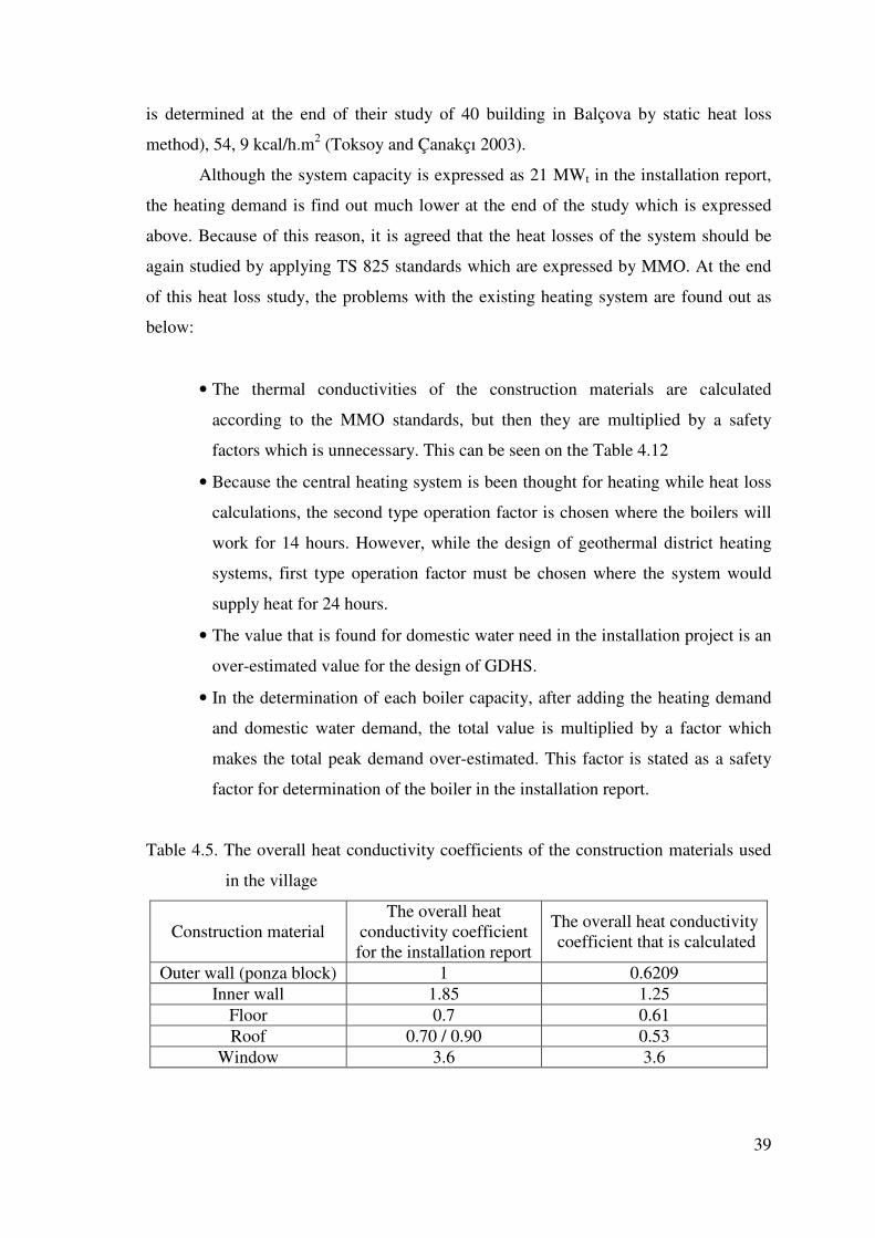
39
is determined at the end of their study of 40 building in Balçova by static heat loss
method), 54, 9 kcal/h.m2 (Toksoy and Çanakçı 2003).
Although the system capacity is expressed as 21 MWt in the installation report,
the heating demand is find out much lower at the end of the study which is expressed
above. Because of this reason, it is agreed that the heat losses of the system should be
again studied by applying TS 825 standards which are expressed by MMO. At the end
of this heat loss study, the problems with the existing heating system are found out as
below:
• The thermal conductivities of the construction materials are calculated
according to the MMO standards, but then they are multiplied by a safety
factors which is unnecessary. This can be seen on the Table 4.12
• Because the central heating system is been thought for heating while heat loss
calculations, the second type operation factor is chosen where the boilers will
work for 14 hours. However, while the design of geothermal district heating
systems, first type operation factor must be chosen where the system would
supply heat for 24 hours.
• The value that is found for domestic water need in the installation project is an
over-estimated value for the design of GDHS.
• In the determination of each boiler capacity, after adding the heating demand
and domestic water demand, the total value is multiplied by a factor which
makes the total peak demand over-estimated. This factor is stated as a safety
factor for determination of the boiler in the installation report.
Table 4.5. The overall heat conductivity coefficients of the construction materials used
in the village
Construction material The overall heat
conductivity coefficient for the installation report
The overall heat conductivity coefficient that is calculated
Outer wall (ponza block) 1 0.6209 Inner wall 1.85 1.25
Floor 0.7 0.61 Roof 0.70 / 0.90 0.53
Window 3.6 3.6
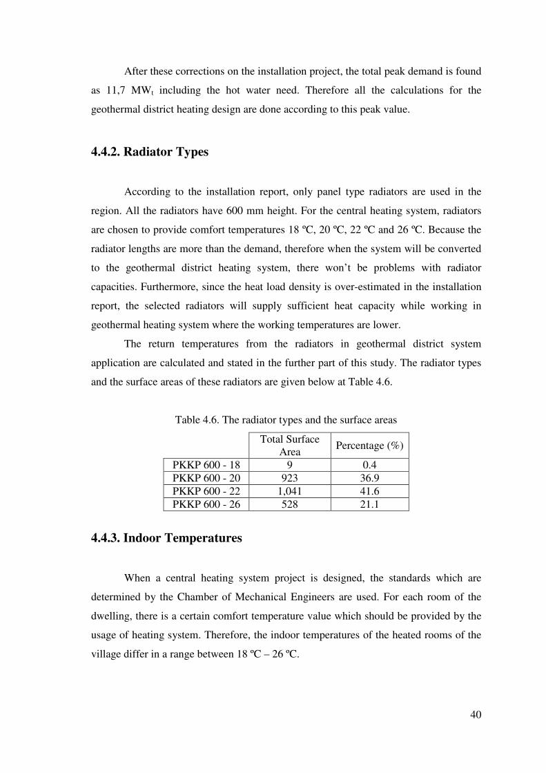
40
After these corrections on the installation project, the total peak demand is found
as 11,7 MWt including the hot water need. Therefore all the calculations for the
geothermal district heating design are done according to this peak value.
4.4.2. Radiator Types
According to the installation report, only panel type radiators are used in the
region. All the radiators have 600 mm height. For the central heating system, radiators
are chosen to provide comfort temperatures 18 ºC, 20 ºC, 22 ºC and 26 ºC. Because the
radiator lengths are more than the demand, therefore when the system will be converted
to the geothermal district heating system, there won’t be problems with radiator
capacities. Furthermore, since the heat load density is over-estimated in the installation
report, the selected radiators will supply sufficient heat capacity while working in
geothermal heating system where the working temperatures are lower.
The return temperatures from the radiators in geothermal district system
application are calculated and stated in the further part of this study. The radiator types
and the surface areas of these radiators are given below at Table 4.6.
Table 4.6. The radiator types and the surface areas
Total Surface Area Percentage (%)
PKKP 600 - 18 9 0.4 PKKP 600 - 20 923 36.9 PKKP 600 - 22 1,041 41.6 PKKP 600 - 26 528 21.1
4.4.3. Indoor Temperatures
When a central heating system project is designed, the standards which are
determined by the Chamber of Mechanical Engineers are used. For each room of the
dwelling, there is a certain comfort temperature value which should be provided by the
usage of heating system. Therefore, the indoor temperatures of the heated rooms of the
village differ in a range between 18 ºC – 26 ºC.

41
4.4.4. Operating Costs of the Existing System
Operating costs are the expenses which are needed to provide a service for a
certain project. Because some of the components of the existing heating system are
planned to be used in the geothermal district heating design, the operating costs of these
components are neglected. Operating costs of the existing system consists of mainly,
fuel-oil costs, electricity consumption and the maintenance. However, among these
costs, the most important component is the fuel-oil expenses, since the unit price of
fuel-oil is high. The explanation of how these costs affect the existing system and how
these costs are calculated are given below. All costs for the operating costs of the
existing system are given on Table 4.8.
• Fuel Types and Costs in the Existing System
In the region, only fuel that will be used is planned to be fuel-oil as it is
expressed in the installation reports. To determine the annual fuel oil cost for the
district, first of all, the annual heating demand is calculated for Athletes’ Village by
distributing the peak demand over all the year by considering changing outdoor
temperatures.
Total Annual Heat Demand = �=
365
1n
Peak demand designcomfort
outcomfort
TT
TT
−−
× (4.1)
Where,
Tcomfort = 22 ºC , Tdesign = 0 ºC
When a fuel type which has a heating value of 9,700 kcal / kg and an efficiency
of 0.8 is chosen, the total annual fuel demand is determined (Table 4.7). Since total
annual heating demand is known, from this value, the total fuel oil needed for 966
houses is found as 2,108 tons. Then, the total annual fuel oil cost for the village can be
calculated, since the unit price of fuel oil is determined as 1.16 YTL/kg on 9th of
November 2005. During conversions of YTL to $, 1 US $ is taken as 1.353 YTL based
on the average of November 2005 values.
Also, the calculations are converted to find out the fuel oil need of 100 m2
house. Then, according to the re-calculated heat loss of the district, it is determined that
2.17 tons of fuel oil is needed which costs about 2,517 YTL (Table 4.7) to provide

42
heating and hot water service during the heating period. However, this value is seen
much higher according to the heat loss value stated in the installation project. The
annual heat demand and the amount of fuel-oil that is needed for the district heating
according to the installation report are stated on Table 4.8.
Table 4.7. The annual fuel oil cost of the village according to re-calculated heat loss
Total Annual Heating Demand ( kcal) 16,359,566,610
Heating Value for fuel oil(kcal / kg) 9,700
Efficiency 0.8 Total Fuel oil Needed (kg) 2,108,192 Total Annual Fuel Oil Cost for Athletes’ Village (YTL) 2,453,007
Total Fuel Oil Cost For 100 m2 house(YTL) 2,517
• Electricity Consumption of the Fuel-Oil Burners
One of the components of the operating costs for the existing system is the
operating cost of fuel-oil burners. From the catalogues, it is calculated that 171,606
kWe/year will be consumed from 24 fuel-oil burners and the electricity price that should
be paid will be about $ 13,000/year.
• Maintenance Cost
The boilers and fuel-oil burners have to be cleaned and maintained every year,
so the cost for this operation must be added to the operating costs. The estimated
maintenance cost for 24 boilers in Athletes’ Village is $ 4320/year.
Table 4.8. All of the operating costs for the existing system
Operating Costs
(US $/ year) 1 Fuel-Oil Cost 1,807,467 2 Maintenance 4,320 3 Electricity Consumption 13,000
Total 1,824,787

43
4.5. Geothermal District Heating System Design
4.5.1. Heat Load Density
Heat load density is an important parameter while determining the investment
and operating costs of the geothermal district heating system. To determine heat load
density, first of all heat loads of each building must be known. Heat loads of each
building according to the installation project and according to the modifications can be
seen on Table 4.9 and Table 4.10, respectively. Then, heat load density can be
determined by dividing the heat loads of the dwellings in each city block to the areas of
the city blocks. The economic availability related to heat load density (Bloomquist
2000) can be seen on Table 4.11 and the color-coded distribution of heat load density on
city blocks can be seen on Figure 4.3.
Table 4.9. Heat load density according to the installation project prepared for the
central heating system
Block Type
Area (m2)
Heat loss stated
(kcal/h)
Domestic water demand stated (kcal/h)
Total peak demand (kcal/h)
B1 877 71,817 66,900 138,717 B2 1,860 153,136 144,675 297,811 B3 1,543 125,896 133,950 259,846 B4 1,676 160,562 141,600 302,162 B5 1,230 90,882 93,000 183,882 B6 1,260 92,521 97,875 190,396
Table 4.10 Heat load density according to geothermal district heating system design
which heat losses are modified
Block Type
Area
Modified heat loss value for GDHS design
(kcal/h)
Modified domestic water
demand for GDHS design (kcal/h)
Total peak demand for
GDHS design (kcal/h)
B1 877 53,853 12,852 66,705
B2 1,860 116,027 27,909 143,936 B3 1,543 95,800 25,326 121,126 B4 1,676 121,551 26,208 147,759 B5 1,230 73,619 17,640 91,259 B6 1,260 67,874 19,845 87,719

44
Table 4.11. Economic Availability Analysis Related To Heat Load Density
Construction Type Heat Load Density (kcal/h.m2)
Availability for district heating system
City Center, skyscrapers Over 60 Very available City Center, buildings
with many floors 44 - 60 Available
City Center, commercial buildings with many dwellings 18 - 44 Applicable
Buildings with 2 dwellings 10 -18 Questionable Single Houses Less than 10 Impossible
Figure 4.3. The distribution of heat load density on city blocks
4.5.2. Energy Transfer System
For GSHS design of Athletes’ Village, energy is thought to be transferred in a
two stage system. First of all geothermal fluid will transfer its energy to the main heat
exchanger in the pumping station where it is located near the village. After it passes its
energy, the geothermal fluid will return to re-injection well. Then in the city circuit,
clean water will be circulated and this circulating water will reach to 12 heat exchanger
rooms within the village with a certain degree of hot water. The location of heat
exchanger rooms on the village can be seen on Figure A1. In each heat exchanger

45
room, the circulating city water will transfer its energy and then the existing water from
the heat exchangers will be circulated in the buildings. By a design of two stage system,
the corrosion in the pipes and the effects of high pressures are planned to be prevented,
since the height differences in closed systems are negligible.
4.5.3. Service Life of Materials
In geothermal systems, the components of the system are always in contact with
the geothermal fluid having a high temperature and containing corrosive chemicals
dissolved in the geothermal fluid. Thus, the mechanical properties of the components
changes due to the time and the effects of the geothermal fluid. For a good decision
making process, the characteristic of the geothermal fluid should be analyzed deeply to
determine the life cycle of the materials. According to the service life of materials,
replacement time cost of amortization and salvage values differ. Then, the economic
analysis for the materials that is planned to be used should be done to choose the
combination of materials that will minimize the total cost of the system. The main
components of the geothermal district system that will be affected by the geothermal
fluid are:
• Pipes
• Heat exchangers
• Pumps
• Valves
In geothermal applications, the location of the well is far from district area, so
piping is very important in geothermal district heating system design. The district
heating can be designed in two different ways as open loop or closed loop, so these
kinds of difference in design state can change the materials of piping. In open loop
systems, the geothermal fluid is directly send to the customer and the rejected or cooled
water is send back to the re-injection wells. Because of this reason, in open loop
systems, insulation is only needed for feeding pipes. In closed loop systems, geothermal
fluid arrives to the heat exchanger and it transfers its energy to the clean water. In the
circulation within the city, this clean water is used. In closed loop systems, different
from the open loop designs, the return pipes are also insulated (Bujakowski 2004).

46
In the study, the system is designed to be closed loop, so for the geothermal and
city networks, pre-insulated pipes are suggested. These kinds of pipes are mostly
selected when the geothermal fluid is transferred for long distances. These pipes have
three layers. One of the layers is inner pipe which is composed of steel or FRP. The
second layer is the insulation material which is polyurethane. Finally, the third layer is
the protecting jacket which can be composed of polyethylene, PVC or fiberglass. Also,
the material can be used together as forming pre-insulated pipes, but then their
combined life differs from their simple lives. Combined life of piping materials is found
from the component which has the minimum life cycle in the combination. Therefore,
the life cycle of this material is chosen to be the combine life of the material.
For Athletes’ Village, steel pre-insulated pipes are designed to be used and the
service life of these materials is given as 20 years by the manufacturers of these pipes.
4.5.4. The Characteristics of the Geothermal Well
For this study, first of all a well place is chosen to extract the geothermal fluid.
The existing wells in Balçova have not been thought because it is known that they have
been reached to their limits. However, it is also known that the reservoir will be develop
to the east of B9 well and respected to the iterative development model for the reservoir,
there are two possible well locations for the new district heating system designs. From
BD - 9 well which is drilled in 2003, 135 ºC hot water with a flow rate of 100 l/s can be
supplied to the system. According to the iterative development model, it is expected to
get hot water at 140 ºC with a similar flow rater from the new wells which are BD - 11
and BD – 12. BD – 12 well is chosen for this study because of its shorter distance to the
Athletes’ Village. However, this distance is more than 4 km. Also there is another
scenario which is if a geothermal potential is found near to the Athletes’ Village. These
two scenarios are analyzed both economically and technically in this conceptual
planning study.
For the geothermal district heating system of Athletes’ Village, for the peak load
heating and domestic hot water need, the amount of geothermal that is needed is to be
determined as 58.5 l/s as it is seen in Table 4.12.

47
Figure 4.4. The distribution of the potential of the geothermal in Balçova (Aksoy 2005)
Table 4.12.The amount of geothermal water that should be extracted from the well
Heating peak load (kcal/h) 7,526,968 Total peak load (kcal/h) 11,000,000 T feed ( ºC ) 120 T return (ºC ) 65 Flow-rate for heating (m3/h) 144
Flow-rate for heating (l/s) 40 Total flow-rate (m3/h) 211
Total peak flow-rate (l/s) 58.5
4.5.5. Operating Temperatures
The operation temperatures are determined by considering the main heat
exchanger, heat exchangers for the buildings and the radiator areas. For the Athletes’
Village, the operation temperatures are like below:
• Geothermal Network
After the geothermal fluid is extracted from B12 well with a flow rate of 58.5 l/s
having a temperature of 140 ºC, the hot water is mixed with returning hot water
Possible wells for the district heating system design for the Atheletes’ Village
Ekonomi Üniv.
Balçova Termal Oteli DEÜ
Onur Mah
Narlıdere
Balçova

48
at 65 ºC which is going to the re-injection well. The temperature of the mixture
will be 120 ºC and then it will send to the pumping station which is 4500 m far
from the geothermal well. In the design stage, it is seen that because the
insulated pipes are used in the geothermal network, the heat loss along the
geothermal network would be neglible. Then, the geothermal fluid will return to
the re-injection well with a temperature of 65 ºC.
• City Network
The geothermal fluid will give its energy to the clean water for the circulation in
the city network, so the system is designed to be a closed loop system. The clean
circulating water will leave the main heat exchanger with a temperature of 110
ºC and will return back to the heat exchanger with a temperature of 60 ºC.
Within the city network, the circulating hot water will arrive to the 12 heat
exchanger rooms to distribute energy to the blocks.
• In-building Temperatures
The temperature regime in the buildings is determined by calculating the
temperature regime that will give the same capacity of 90 ºC / 70 ºC from the
radiators. Thus, it is seen that the appropriate temperature regime for the
buildings is 85 ºC / 55 ºC.
Figure 4.5. Schematic view of temperature regimes within the system
Heat Station
65 º C
Heat Exchanger Room
110 º C
60 º C
85 º C
�����
55 º C
65 º C
120 º C
140 º C

49
4.5.6. Location of the Pumping Station
For the Athletes’ Village, two different well locations are been thought, so two
different pumping station alternatives are analyzed. When the well location is
determined, the economic analysis for the distribution and transmission networks can be
made. Thus, the location of the pumping station is important for the geothermal district
heating system design, so several factors affect the location:
• The distance of the pumping station and the geothermal well affects the
investment cost because of the pipe length and selection of the piping material,
• The topographic elevation of the pumping station and the geothermal well
affects the management cost because of the choice that is done for the well
pump according to the elevation,
• The topographic characteristics of the city network affect the management
costs of the city network circulation pumps and the network pressures.
Table 4.13. Geothermal network characteristics for pumping station alternatives
Pumping Station Location
Geothermal Pipe
Length (m)
Geothermal Network
Investment Cost
(US $)
Geothermal Pipe Circuit
Losses (mSS)
Height Difference
(m)
Alternative 1 In Balçova 4,500 1,413,400 325 150
Alternative 2 Near Athletes' Village (assumption) 1,000 290,994 91 50
There are two alternatives for the pumping stations according to the two
different scenarios. In the first alternative, it is inevitable that the high pressures will be
in the geothermal and city loops because of the elevation and the distance of the well
location. In the second alternative, it is assumed that a geothermal potential (having the
same well characteristics defined for the first alternative) is found near the village with
a distance of 1000 m to the village. If this scenario exists in future, the investment cost
for the geothermal network and the investment cost for the well pump will decrease
which will make the project much feasible.

50
4.5.7. Geothermal Network
As it is mentioned above, there are two well scenarios considered for this study.
In the first alternative where the well is located in Balçova, the geothermal network will
be approximately 4500 m long and pre-insulated (polyurethane and polyethylene) steel
pipes are chosen. The geothermal loop, the well location and the place of Athletes’
Village can be seen on Figure B1. The elevation will affect the total head loss because
there is about 150 m height difference between the geothermal well and the pumping
station. The total head loss for the first alternative can be seen on the Table 4.14.
In the second alternative, it is assumed that the geothermal well is located near
the village with a distance of 1000 m. It is thought that since the well is near the village,
the elevation between the well and the pumping station will not exceed 50 m because of
the topographic characteristics of the area. Since, then, the elevation will cause problem
as it does in the first alternative in the determination of the total head loss of the
geothermal network. In addition, the length of the geothermal network will be shorter
when it is compared with the first alternative. The total head loss for the second
alternative can be seen on Table 4.15.
For the Athletes’ Village, the diameter of the pipes in the geothermal network
are selected to be 200 mm in the first alternative by optimizing the investment cost and
operating costs of the system. The selected diameters for the second alternative is again
200 mm, however this time total friction loss is much lesser than the first alternative, so
the investment cost and the annual operating cost for the well pump will be lesser.
Table 4.14. The total head loss in the geothermal network for the first alternative
Flow Rate Diameter Velocity Re Friction
Factor Length Elevation Friction Loss
Along The Distance
Total Friction
Loss Q DN V f L H
(m3/h) m m/s m m mSS mSS 211 0.200 1.86 777,708 0.0152 4.500 150 121.31 325
Table 4.15. The total heal loss in the geothermal network for the second alternative
Flow Rate Diameter Velocity Re Friction
Factor Length Elevation Friction Loss
Along The Distance
Total Friction
Loss Q DN V f L H
(m3/h) m m/s m m mSS mSS 211 0.200 1.86 777,708 0.0152 1.000 50 29.96 91

51
4.5.8. City Network
The temperature regime of the city network is planned to be 110 ºC / 60 ºC. The
steel pipes are taken in consideration which will stand for this regime. The investment
costs and operational cost are calculated and the relation between these costs are
considered while the choice of the diameters within the city network, since it is known
that as the investment cost increases while the operating cost decreases. Investment
costs are consist of cost of the pipe, cost of the pipe installation and the cost of the
excavation. Operating cost is the sum of the cost for electricity consumption of the
circulating pumps and cost of inhibitor for corrosion.
In the Figure 4.6, the relation between the electricity cost and the investment
cost can be seen according to the changing pipe diameters. To find the optimum pipe
diameter, investment and operating costs for the diameters between 150-300 mm are
analyzed and the curves for investment cost-target head loss and the operating costs-
target head loss curves are drawn on the same figure. The intersection of the two curves
gives the target head loss which will make the cost minimum. Therefore, the diameters
of the pipes which make total cost minimum around 29 mmSS/m target head loss in the
city network are selected.
Also, another criteria which should be taken in consider is the velocity of the
fluid inside the pipe. The flow velocity should be within a sensible range and in designs
of Balçova district heating system, the flow velocities are below 2 m/s. Thus, in the
design of the district system of Athletes’ Village, this is also considered while the
choice of pipe diameters. The diameters of the pipes selected for the city network and
their unit prices are given in Table 4.16. The city network is shown on the auto-cad
figure on Figure C.1.

52
Table 4.16 Selected pipe diameters and their costs for the city network
Diameter (mm) Pipe Type Length (m)
Unit Cost (USD / m)
Total Cost (USD)
40 St 37 Steel 366 11.49 4,204 50 St 37 Steel 64 14.80 947 65 St 37 Steel 316 18.60 5,878 80 St 37Steel 1124 23.43 26,340
100 St 37 Steel 460 34.04 15,659 125 St 37 Steel 562 43.40 24,391 150 St 37 Steel 250 50.91 12,727 200 St 37 Steel 552 70.90 39,134
Total 129,278
0
30000
60000
90000
120000
150000
0 20 40 60Target Head Loss (mmSS/m)
Co
st (
US
D)
Electricity Cost Investment Cost
Figure 4.6 Change of investment and electricity cost with target head loss
4.5.9. Heat Exchangers
For the design of Athletes’ Village, one main heat exchanger and 12 units of
heat exchanger for the city distribution are selected. Plate type heat exchangers are
selected for the heat transfer, since (Vestergen 2003):
• Plate type heat exchangers provide high efficiency with minimum heat transfer
area,

53
• The materials which resist corrosion is used in economical amounts in these
kind of HEX,
• They have small volume because of their compact base,
• Installation and operation of these kind of HEX are simple,
• Cleaning of all heat transfer areas can be done easily.
For the Athletes’ Village, at the pumping station, there is one main heat
exchanger with the capacity of 11,000,000 kcal/h and for the distribution of geothermal
within the city network, the selected heat exchanger are given in Table 4.17. The plates
of the heat exchangers within the city network are selected as stainless steel. However,
because of the corrosive content carried by the geothermal fluid, the plates of the heat
exchanger at the pumping station are selected as titanium.
Table 4.17. Capacities of heat exchanger in each heat exchanger station in the city
Heat Exchanger Station No Capacity (KW) Selected Plate
Material 1 325.76 AISI 316 2 1,408.35 AISI 316 3 1,462.89 AISI 316 4 1,280.87 AISI 316 5 725,96 AISI 326 6 1,245.21 AISI 316 7 1,065.30 AISI 316 8 580.76 AISI 316 9 1,641.19 AISI 316
10 445.82 AISI 316 11 914.89 AISI 316 12 1,052.26 AISI 316
4.5.10. Circulation Pumps
Circulation pumps are selected according to the system characteristic from
which is given in Figure 4.7 from the catalogues. The most efficient pumps, which will
satisfy the conditions of 235 m3/h flow rate and 80 m head loss during peak load, are
chosen for the system design. Thus, two in-line type pumps are planned to work in
parallel with efficiency about 70- 75 %. By this way, the pumps would work with a high
efficiency during partial and peak load.
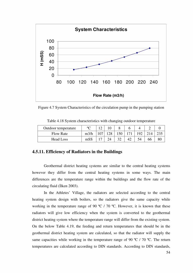
54
System Characteristics
020406080
100
80 100 120 140 160 180 200 220 240
Flow Rate (m3/h)
H (m
SS
)
Figure 4.7 System Characteristics of the circulation pump in the pumping station
Table 4.18 System characteristics with changing outdoor temperature
Outdoor temperature ºC 12 10 8 6 4 2 0 Flow Rate m3/h 107 128 150 171 192 214 235 Head Loss mSS 17 24 32 42 54 66 80
4.5.11. Efficiency of Radiators in the Buildings
Geothermal district heating systems are similar to the central heating systems
however they differ from the central heating systems in some ways. The main
differences are the temperature range within the buildings and the flow rate of the
circulating fluid (�lken 2003).
In the Athletes’ Village, the radiators are selected according to the central
heating system design with boilers, so the radiators give the same capacity while
working in the temperature range of 90 ºC / 70 ºC. However, it is known that these
radiators will give low efficiency when the system is converted to the geothermal
district heating system where the temperature range will differ from the existing system.
On the below Table 4.19, the feeding and return temperatures that should be in the
geothermal district heating system are calculated, so that the radiator will supply the
same capacities while working in the temperature range of 90 ºC / 70 ºC. The return
temperatures are calculated according to DIN standards. According to DIN standards,

55
radiator capacity is the function of radiator temperature and the temperature of the
heated space where the logarithmic temperature difference of the radiators and the
heating space are defined in the below formula (Kücüka 2001).
31
0,0
���
�
���
�
∆∆
=lm
lmcalculated T
TQQ (4.2)
Where,
Q calculated = The modified heat loss
Q0 = The heat loss stated in the installation project
Also,
comfortretun
comfort
returnlm
TT
TT
T
−−
−=∆
85ln
85 (4.3)
comfort
comfortlm
T
TT
−−−=∆
70
90ln
70900,
(4.4)
Where,
T comfort = Desired room temperature
Table 4.19. Feeding and return temperatures of radiators in the geothermal district
heating design
Feeding Temperature
(ºC)
Return Temperature
(ºC)
Block 3 - A Type Living Room (Z01)
Base Floor 85 55.97
Block1 - B Type Bedroom (309) Roof 85 48.46
Block 3 - C Type Living Room (404)
4 th Floor 85 59.95
Block 2 - D Type Bedroom (704) Roof 85 57.74
Block 5 - E Type Living Room (504) Roof 85 57.02
Block 6 - F Type Bedroom (604) Roof 85 47.48

56
As it is seen on Table 4.21, the return temperatures of the radiators for different
spaces vary between 48.46 - 59.95 ºC. Since, their standard average is so closed to 55
ºC, it is assumed that the return temperatures from the buildings is 55 ºC as it is stated
before in the Figure 4.4.
4.6. Economics of the Geothermal System
4.6.1. Investment Costs
Investment costs are the expenses occurred before beginning of business
operations. It is known that the geothermal heating projects are characterized by high
investment costs when they are compared with other heating projects with fuel-oil, coal
and natural gas, etc. Although, the geothermal heating projects have high investment
costs, the advantages of these systems are the low operating costs because of the low
marginal cost of fuel (Piwowarski 2001).
For a geothermal district heating design, all the cost of stages starting from the
exploration of the geothermal reservoir to the distribution of water to the customers are
the components of the investment cost for GDHS. The main components of GDHS are
as preparation of the project, exploration studies for the reservoir, drilling of the
geothermal well, civil engineering works (construction of roads, wellhead housing, heat
exchanger and pumping stations), wellhead housing, transmission and distribution
networks, heat exchangers, pumping stations, documentation, adjusting and testing.
In the district design, generally, the most important components of the
investment cost are the costs for the transmission and distribution networks and the
drilling of the geothermal well. The costs for transmission and distribution can form the
40 – 60 % of the total investment cost in some cases (Piwowarski 2001, Erdo�mu�
2003). In the project, it is calculated that this percentage is 54.58 % for the first
alternative and it is 31.24 % for the second alternative as it is seen on Table 4.22. and
Table 4.23. The transmission and distribution cost is found by taking the sum of the
costs for geothermal network, city network and excavation.
For Athletes’ Village, as it is mentioned in the before sections, there are two
well scenarios. The investment costs for these two scenarios are as follows on Table

57
4.20. and Table 4.21. The costs are taken from the related companies by proposal and
also from the Balçova Jeotermal Enerji San. Tic. Ltd. �ti.
Table 4.20. The components of the investment costs according to the first scenario
where the geothermal network is 4500 m
Components of the investment cost
Cost (US $) Percentage
Drilling Wells 1,000,000 27.38 Pumps 32,559 0.89
Geothermal network 1,413,400 38.70 City Network 129,278 3.54
Well Head Construction 73,910 2.02 Pumping Station Construction 40,000 1.10
Excavation 450,628 12.34 Building Connections 25,000 0.68
Project 7,391 0.20 Heat Exchangers 94,512 2.59
Fittings 385,670 10.56 Total 3,652,348 100
Table 4.21. The components of the investment costs according to the second scenario
where the geothermal network is 1000 m
Components of the investment cost
Cost (US $) Percentage
Drilling Wells 1,000,000 50.27 Pumps 21,919 1.10
Geothermal network 290,994 14.63 City Network 129,278 6.50
Well Head Construction 73,910 3.72 Pumping Station Construction 40,000 2.01
Excavation 201,183 10.11 Building Connections 25,000 1.26
Project 7,391 0.37 Heat Exchangers 94,512 4.75
Fittings 105,068 5.28 Total 1,989,255 100
4.6.2. Operating Costs
In general, operating costs are incurred by the operation of the plant or
equipment needed to provide in service. These costs can vary in years, since the unit
prices of the components of the operating costs can change through years.

58
In the design for Athletes’ Village, total cost for operating costs differs for the
two different well scenarios. The difference comes from the electricity consumption of
the pumps. For the first alternative, the total annual operating cost is $ 125,219.
However, for the second alternative, this value is $ 110,140. All of the costs for the first
alternative are listed in Table 4.30. The items that are related with the operating costs of
the geothermal heating system are like below (Gül�en 2005):
• Electricity consumption of the pumps
Monthly electric consumption cost is one of the main items which is important
to consider in the operating costs of geothermal district heating systems. The monthly
electric consumption of the pumps is calculated by using the hourly temperature data for
the typical year which is 1993 and the Conventional Energy Ratio (CER0) for the
optimized production (�ener 2003). Thus, the geothermal energy production would not
be in peak demand all of the year.
The energy demand would change with changing outdoor temperature. Thus, the
electricity consumption would change as the energy production varies in periods of the
year. Conventional energy ratio is defined as the geothermal energy produced for each
unit of electricity consumption. The CER0 is calculated as 79.5 and the monthly electric
consumption of the system for the first alternative for the design is calculated according
to this value. The results are given in Table 4.22. For the second alternative, also costs
for monthly electric consumption is calculated according to CER0 value of 200.5 and
from Table 4.23, it can be seen that these costs are much lesser when they are compared
with the costs in the first alternative.

59
Table 4.22. Monthly electricity consumption and its cost for the first alternative
Month Energy Production (kWh)
Energy Production according to CER0
(kWh e)
Electricity Cost (US$)
1 4,431,038 55,736 4,124 2 4,206,285 52,909 3,915 3 3,264,820 41,067 3,039 4 1,961,061 24,667 1,825 5 944,917 11,886 880 6 92,375 1,162 86 7 94,006 1,182 88 8 87,800 1,104 82 9 300,498 3,780 280
10 660,763 8,311 615 11 2,745,927 34,540 2,556 12 3,069,469 38,610 2,857
Total 21,858,961 274,955 22,970
Table 4.23. Monthly electricity consumption and its cost for the second alternative
Month Energy Production (kWh)
Energy Production according to CER0
(kWh e)
Electricity Cost (US$)
1 4,431,038 21,615 1,599 2 4,206,285 20,518 1,518 3 3,264,820 15,926 1,179 4 1,961,061 9566 708 5 944,917 4,609 341 6 92,375 451 33 7 94,006 459 34 8 87,800 428 32 9 300,498 1,466 108
10 660,763 3,223 239 11 2,745,927 13,395 991 12 3,069,469 14,973 1,108
Total 21,858,961 106,629 7,891
• Cost of personnel working in GDHS
When the components of the operating costs are analyzed, it is seen that
personnel cost has the biggest percentage on overall components. The number of
personnel is assumed according to the number of personals in Balçova System-2. Since
the studied system is a smaller district heating system, personnel number is reduced
proportionally. It is assumed that 8 personals would be sufficient for the district heating
system in Athletes’ Village. The gross salaries of these personals are re-arranged

60
according to the information taken from the Balçova Jeotermal Enerji San. Tic. Ltd. �ti.
The costs of personals in the system can be seen on Table 4.24.
Table 4.24. The costs of personnel of Athletes’ Village for each month
Number Gross Salary (YTL) Total (YTL) Total (US $)
1 Operator 2 751.308 1,502.616 1110.58 2 Manager 1 1,332.745 1,332.745 985.03 3 Accountant 1 697.662 697.662 515.64 4 Maintenance Personnel 2 487.322 974.644 720.36 5 Public Relations 1 1,112.831 1,112.831 822.49 6 Servant 1 487.322 487.322 360.18 7 Administrative Committee 4,916
Total 9,430
• Water consumption in the system
The water consumption in the system is calculated by adding the water volume
in city network pipes, building and pumping station heat exchangers and expansion
tank. While this calculation, it is assumed that there won’t be leakage problems. The
volume of water in the city network components are as seen on Table 4.27. The volume
in the city network is the biggest component of the water consumption in the system.
The water that is needed in city network is calculated as 79 m3. Generally, water
demands by the heat exchangers are very small. In this system, it is calculated as 1.19
m3 and the volumes of heat exchangers are listed on Table 4.26.
To calculate the overall water consumption in the system, it is thought that the
system will be filled twice in a year, so the water consumption of the system for a year
will be 81 x 2 = 162 m3. Also, it is assumed that there will be water consumption by the
personals and this value is assumed to be 10 liters per person, so that the total water
consumption of the system will be 191 m3. The unit price of water that is determined by
IZSU is 5.7 YTL, so the cost of the water consumption is calculated as $ 804.

61
Table 4.25. The volume of water in city network
Diameter (mm) Length (m) Unit Volume (m3/m) Total (m3) 40 183 0.00126 0.23 50 282 0.00196 0.55 65 6458 0.00332 21.44 80 3262 0.00502 16.38
100 2030 0.00785 15.94 125 1131 0.01227 13.88 150 125 0.01766 2.21 200 276 0.0314 8.67
Total 79.29
Table 4.26. Volumes of the heat exchangers
Placement Capacity (kcal/h) Number of plates Unit volume for each plate (m3/amount)
Total (m3)
Exchanger Room 280,107 25 0.00082 0.02 Exchanger Room 1,210,959 93 0.00082 0.08 Exchanger Room 1,257,863 95 0.00082 0.08 Exchanger Room 1,101,346 83 0.00082 0.07 Exchanger Room 624,209 55 0.00082 0.05 Exchanger Room 1,070,685 81 0.00082 0.07 Exchanger Room 915,994 75 0.00082 0.06 Exchanger Room 499,367 39 0.00082 0.03 Exchanger Room 1,411,168 105 0.00082 0.09 Exchanger Room 383,334 35 0.00082 0.03 Exchanger Room 786,661 65 0.00082 0.05 Exchanger Room 904,784 73 0.00082 0.06 Pumping Station 11,000,000 128 0.004 0.51
Total 1.19
Table 4.27. All the components of water consumption in the system
Volume (m3) City network pipe volume 79.29 Building heat exchangers volume 0.68 Pumping station heat exchangers 0.51 Expansion tank volume 0.50 Total 80.97
• Other costs
Also, inhibitor cost, maintenance cost, cost of the chemicals, marketing costs,
insurance costs, taxes, etc should be considered while the calculation of the operating

62
costs. For example, inhibitor is needed in the production network to prevent the
obstacles in flow of the geothermal water. Also, the geothermal fluid contains chemicals
dissolved inside which has an affect on the system components as heat exchangers,
pipes, valves, etc. These components should be checked and cleaned each year, so this
will bring additional maintenance cost to the system. Thus, some chemicals like nitric
acid, rock salt and NaOH are used for cleaning the heat exchangers. The cost of these
chemicals should be also added to the operating costs. All of these costs can be seen on
Table 4.28. These costs are calculated by interpolating the operating costs of these
components in recent geothermal district heating projects according to the heating
capacities of these systems.
In addition, all of the operating costs of the system for different well scenarios
are showed on Table 4.29. The main difference between the operating costs of these two
different scenarios is the costs for the electricity consumption.
Table 4.28. Inhibitor, chemical and maintenance costs per year
Balçova-Narlıdere GDHS
Balçova System-2 GDHS
Athletes' Village GDHS
Heating Capacity (m2) 1,150,000 310,700 97,445
Inhibitor Cost (US $) 3,753 1,014 318
Other Chemicals (US $) 1,912 517 162
Maintenance Costs (US $) 53,417 14,432 4,526
Table 4.29. All of the operating costs for Athletes’ Village considering the alternatives
Operating Cost for
Alternative 1 (US $/year)
Operating Cost for Alternative 2 (US $/year)
1 Cost of inhibitor 318 318 2 Cost of chemicals 162 162 3 Water consumption 804 804 4 Personnel Cost 75,438 75,438 5 Electricity Consumption 22,970 7,891 6 Cost of maintenance 4,526 4,526 7 Marketing cost 1,000 1,000 8 General expenditures 20,000 20,000
Total 125,219 110,140

63
4.6.3. Finance Model
Finance model of any district heating system can be determined after the
determination of the investment and the operating costs. In all of the application of
geothermal district heating system in Turkey, the investment capital of a geothermal
system is covered up with the participation cost taken from the customers when they
first enter the system and the monthly fixed energy cost. For the economical analysis of
the system, the internal rate of return analysis is applied to the different participating
costs and monthly fixed charges, which make the internal rate of return positive around
0 %, are calculated for these participating costs.
Also, after the determination of monthly fixed charges in a result of internal rate
of return analysis, the net present values of these payments for 20 year period is
compared with the net present value of the payments that will be done for the existing
system. By this way, the conventional system and the geothermal design can be
compared to their economies.
Therefore, in economical analysis, two well scenarios are considered and the
finance model is determined according these two scenarios. Also another parameter
taken in consideration is there will be full participation in Athletes’ Village, since this
will be the district heating system of the all village.
4.6.3.1. Internal Rate of Return Analysis
One of the concerns of investment projects is whether and when the money
invested in a project can be recovered. Internal rate of return analysis is one of the
instruments that can be applied to the project to decide if it will be recovered or not. As
a definition, internal rate of return is the interest rate which is referred for project’s
return over a certain service life.
For Athletes’ Village, while the economical analysis, the depreciation costs are
also considered, since at the end of the service life, the project can be recovered. As a
result of this, the monthly fixed charges, which make internal rate of return positive
around % 0, are found for different participating costs varying between $1,250- $1,500.
These charges are given in Table 4.30. Since these prices are for %0 internal rate of

64
return, if the company takes more than these charges, then the investment will be more
profitable for the investor.
Table 4.30. Monthly fixed charges for different participating costs which make
IRR = 0
The Monthly Fixed Charges for Well Scenarios ( For IRR = 0)
Participating Cost Alternative 1 Alternative 2
1250 37 21.5 1500 36 20.4 1750 35 19.4 2000 33.5 18.3 2250 32.5 17.25 2500 31.5 16.25
4.6.3.2 Comparison with the Existing System
As it is stated in before sections, the advantage of the geothermal district heating
system against the conventional heating systems is the lower operating costs. However,
geothermal district systems have higher investment costs.
On Table 4.31, it can be seen that the investment cost for the existing system is
much lower than the geothermal district heating, but the operating cost for that system,
which includes the annual payments for fuel-oil usage, the electricity consumption of
the fuel-oil burners, and he annual maintenance cost for the boilers, will be so high.
Table 4.31. Comparison between the costs of the existing heating system and GDHS
Investment Cost ($)
Operating Cost ($)
Existing Heating System 168,713 1,824,787
GDHS – 1st Alternative 3,652,348 125,219
GDHS – 2nd Alternative 1,989,255 112,763
Also, to provide a better decision-making condition for the consumers, also the
net present worth for different cost scenarios (from Table 4.30) considering a service
life of 20 years, are calculated for the geothermal district design and these values are

65
compared with the net present worth of heating with the existing system for the same
time period. The interest rate for 20 years is assumed to be 8 %. The results for the costs
found different well alternatives are stated on Table 4.32 and Table 4.33. Since, the
annual payment for the existing system for the consumers is estimated as $1860/year
from the total operating costs of the existing system, net present worth of heating with
the existing system is calculated $ 18,262 when the same comfort conditions in heating
with geothermal system is considered. Therefore, when this value is compared with the
net present worth values calculated on below tables, the project will be also feasible for
the consumers, since they will pay lower costs for the geothermal district heating.
Table 4.32. Net present worth of different cost scenarios for alternative 1
Monthly Fixed Costs (US $) For IRR = 0 in Alternative 1
Participating Costs (US $) 31.5 32.5 33.5 35 36 37
1,250 4,961 5,079 5,197 5,374 5,491 5,609 1,500 5,211 5,329 5,447 5,624 5,741 5,859 1,750 5,461 5,579 5,697 5,874 5,991 6,109 2,000 5,711 5,829 5,947 6,124 6,241 6,359 2,250 5,961 6,079 6,197 6,374 6,491 6,609 2,500 6,211 6,329 6,447 6,624 6,741 6,859
Table 4.33. Net present worth of different cost scenarios for alternative 2
Monthly Fixed Costs (US $) For IRR = 0 in Alternative 2
Participating Costs (US $) 16.25 17.25 18.3 19.4 20.4 21.5
1,250 3,165 3,282 3,406 3,536 3,653 3,783 1,500 3,415 3,532 3,656 3,786 3,903 4,033 1,750 3,665 3,782 3,906 4,036 4,153 4,283 2,000 3,915 4,032 4,156 4,286 4,403 4,533 2,250 4,165 4,282 4,406 4,536 4,653 4,783 2,500 4,415 4,532 4,656 4,786 4,903 5,033

66
CHAPTER 5
RESULTS AND DISCUSSION
5.1. Results and Discussion of the Conceptual Planning Study
Feasibility studies are one of the important tasks of geothermal district heating
system design. Conceptual planning is the stage where the project is evaluated
technically, economically and politically. Before this project, it is seen that in Turkey,
this important stage of GDHS is not applied sufficiently. The only model for this study
was the conceptual planning study applied by Gül�en and Toksoy for Balçova Sytem-2.
In this study, two scenarios (Table 4.13.) are considered for GDHS for Athletes’
Village. First of all, it is thought that the geothermal fluid can be brought from Balçova
after the drilling of new wells. It is determined that the reservoir will extend to the east
according to the iterative development model and there is an expectance to obtain hot
water in sufficient temperature and flow rates. If this scenario is considered, then the
only disadvantage of it will be the length of geothermal network. Also, because of the
elevation between the well and the pumping station, the pressure losses will be high. In
this scenario, the length of the geothermal network will be 4500 m, so this long path
will result with high investment cost. On the other hand, during the design stage, it is
thought that there is a chance of finding a geothermal resource near the village, so it is
assumed that a geothermal resource exists at a distance of 1000 m to the village and the
analysis is also done for this scenario. It is prominent that second scenario is more
feasible in every viewpoint. However, to establish the second alternative, further well
exploration would be completed and a sufficient well, which will have sufficient
temperature and flow rates, should be found near the village.
Also, the system is analyzed elaborately about the heat losses of the dwellings
during the design stage to determine the heat load correctly. The determination of heat
load of the system is an important task because, after all, the hot water demand from the
well is determined from the heat load. In the beginning of the study, the aim was to
replace the fuel-oil firing system with the geothermal district heating system, so firstly,
the installation reports were analyzed. In this reports, the value determined for the

67
system capacity was a high value, so some improvements were done to find out an
available system capacity. The improvements are done on the calculated heat load in the
installation reports according to MMO standards. The differences between these two
systems’ capacities are given on Table 4.9. and Table 4.10, respectively. Then heat load
densities of the system are determined from the modified heat losses. As it is seen on
the color coded heat load distribution of the system (Figure 4.3), it is feasible for all
existing dwellings.
Another important task in the design is the selection of the diameters in the city
network. The best way to choose the proper diameters is to apply optimization in the
design. As the diameter increases, the electricity cost of the pumps decreases while the
investment cost of the piping increases. Intersection point of these two curves (Figure
4.6) is the optimized value referring to the selection of the diameters. The city network
is given on Appendix 3.
Furthermore, to replace the existing system with GDHS, it is planned to change
boiler rooms to heat exchanger rooms and provide the distribution of hot water to the
blocks from these 12 heat exchanger rooms. Because of these reason, there is no need to
put a heat exchanger at each building. The locations for the heat exchanger rooms are
shown on Appendix A. The calculations are done according to this design and the
sufficient heat exchangers are selected for both heat exchanger rooms and the pumping
station. The selected heat exchangers for the city network are listed on Table 4.16.
After determination of the system components, the investment costs and
operating costs are calculated for the different well scenarios mentioned above. Also for
the operating costs are calculated for the existing heating system to compare the
economical feasibility of both systems. It is calculated that if the geothermal hot water
is transmitted 4500 m, the investment cost of the system will be $ 3,652,348. However,
this value decreases to $ 1,989,255 if a geothermal potential is found near village and it
is transmitted 1000 m. Therefore, as expected the well place and the length of the
transmission network will highly affect the feasibility of this design.
Finally, the comparison between the existing heating system and the geothermal
district heating system is completed for their economical feasibility and a finance model
for the geothermal district heating system is suggested in respect of the investment and
operating costs. Because of this reason, internal rate of return analysis is applied for
different participating costs ($ 1,250 – $ 2500) for both well scenarios and the
appropriate operating costs are found which make internal rate of return positive around

68
0%. The values found vary between $ 16.25- $37 and the results are given on Table
4.30. After this analysis, the net presents worth values are determined for these cost
scenarios as well as with the value for the existing system. Since, the annual fuel cost
would be so high for the existing heating system; this will influence the operating costs
of the existing system in great amounts. Then, it is seen that because the annual expense
for existing heating is calculated about $ 1860 for a single consumer, the cost scenarios
for the geothermal district heating design are feasible for the consumers.
Therefore, after this conceptual planning study, the exploration of the area for a
geothermal resource should be done broadly to find a better well location near village.
By this way the investment cost and the operating costs for the design would be
lowered, so the consumers would be encountered with better payment scenarios if the
project is decided to be applied.

69
CHAPTER 6
CONCLUSIONS
Geothermal energy is the Earth’s interior energy. There are many application
areas where this energy can be used. District heating is one of the important application
areas. Geothermal district heating design is similar to the central heating system design.
The only difference is the temperature regimes.
The goal of this study is to compare the existing fuel-firing heating system in
Athletes’ Village with the geothermal district heating system. This study was modeled
after conceptual planning study prepared for Balçova System-2. In this study, the
technical, economical and political phases of conceptual planning are applied to
Athletes’ Village. After the design stage, the price proposals for the components of the
geothermal district heating system are taken from related companies. Therefore, all the
factors which will affect the investment and operating costs of the design are
determined. In regard of these costs, the monthly fixed charges, which make internal
rate of return positive around zero, are determined and payment scenarios for different
participating costs are calculated. For the first alternative of geothermal district heating
design, when it is assumed that $ 1500 is taken from the consumers as a participating
cost, a monthly fixed charge of $ 36 is calculated at the end of the internal rate of return
analysis. For the same participating cost, $ 20.4 is found for the monthly fixed charge at
the end of the economical analysis of the second alternative of the design. When the
high annual fuel-oil costs are considered for the existing conventional system, these
values are sensible prices for the consumers. As a result, the project seems feasible for
the customers when the economies of both existing system and the geothermal district
heating system are compared for the same comfort conditions.

70
REFERENCES
Aksoy, N. 2003. "Jeotermal Enerji Sahalarımız ve Fırsatlar", Tesisat Dergisi. Sayı 93, pp: 132 – 138.
Aksoy, N. 2005. "Balçova-Narlıdere Jeotermal Sahası Rezarvuar Gözlemleri 2000-
2005", Jeotermal Enerji Do�ruda Isıtma Sistemleri; Temelleri ve Tasarımı Seminer El Kitabı – 2005.
Ashrae Handbook, HVAC Applications, 2003. Chapter 32. Barbier, E. 1997. "Nature and Technology of Geothermal Energy: A Review",
Renewable and Sustainable Energy Reviews. Vol.1, pp:1- 69. Barbier, E. 2002. "Geothermal Energy Technology and Current Status: An Overview",
Renewable and Sustainable Energy Reviews. pp: 3 – 65. Bloomquist, G. R. 2003. "Geothermal Space Heating", Geothermics. pp: 513 – 526. Bloomquist, R.G. 2000. "Geothermal District Energy System Analysis, Design and
Development". World Geothermal Congress 2000, Japan. Bujakowski, W., Barbacki, A. 2004. "Potential for Geothermal Development in
Southern Poland", Geothermics. Vol.33, pp: 383 – 395. Büyükalaca, O., Bulut, H., Yılmaz, T. 2001. "Analysis of Variable-Base Heating and
Cooling Degree-Days for Turkey", Applied Energy. pp: 269 – 283. Demirba�, A. 2001. "Energy Balance, Energy Sources, Energy Policy, Future
Developments and Energy Investments in Turkey", Energy Conversion and Management. Vol. 42, pp:1239-1258.
Dickson, H. M., Fanelli, M. 2004. "What Is Geothermal Energy?". Dimitrov, K., Dimitrov, O. 2000. "Geothermal District Heating Schemes In The
Republic of Macedonia". , World Geothermal Congress 2000, Japan. Erdo�mu�, A., B. 2003. "Economic Assesment of Balçova Geothermal District Heating
System", Izmir Institute of Technology, Yüksek Lisans Tezi. Gelenegis, J. 2004. "Rapid Estimation of Geothermal Coverage by District Heating
Systems", Applied Energy Vol. 80, pp: 401 – 426. Goumas, M., G., Lygerou, V., A., Papayannakis, L., E. 1999. "Computational Methods
for Planning and Evaluating Geothermal Energy Projects", Energy Policy Vol. 27, pp: 147 – 154.

71
Gül�en, E. 2005. "Conceptual Planning of Geothermal District Heating Systems: A Case Study of Balçova System -2", Izmir Institute of Technology, Yüksek Lisans Tezi.
Heller, A., J. 2002. "Heat-Load Modeling for Large Systems", Applied Energy. Vol. 72,
pp: 371 – 387. Hong, T., Jiang, Y. 1998. "Outdoor Synthetic Temperature for the Calculation of Space
Heating Load", Energy and Buildings. pp: 269 – 277. Ilken, B., Z., "Jeotermal Enerjili Konut Sistemleri", Jeotermal Enerji Do�ruda Isıtma
Sistemleri; Temelleri ve Tasarımı Seminer El Kitabı – 2003, pp: 315 – 322. Kano�lu, M., Çengel, A., Y. 1998. "Economic Evaluation Geothermal Power
Generation Heating and Cooling", Energy. Vol.24, pp:501 – 509. Kaya, D. 2004. "Renewable Energy Policies in Turkey", Renewable and Sustainable
Energy Reviews. pp: 1-12. Kaygusuz, K., Kaygusuz A. 2004. "Geothermal Energy in Turkey: The Sustainable
Future", Renewable and Sustainable Energy Reviews. pp: 545 – 563. Küçüka, S. 2001. "Jeotermal Bölge Isıtması Da�ıtım Sistemlerinin Genel Esasları",
Teskon 2001. Lund, J. W. 2002. "Direct Heat Utilization of Geothermal Resources, Geothermal
Energy Resources for Developing Countries", pp: 129 – 147 Lund, W., J. 1998. "Geothermal Direct Use Equipment Overview", Geothermal Direct
Use Engineering and Design Guidebook. Milora, S. 1976. "Geothermal Energy As A Source Of Electric Power". Muffler, P., Cataldi, R. 1978. "Methods for Regional Assessment of Geothermal
Resources", Geothermics. Vol.7, pp: 53 – 89. Özgener, L., Hepba�lı, A. 2004. "Development of Geothermal Utilization in Turkey: A
Review", Renewable and Sustainable Energy Reviews. pp:433 - 460. Özgener, L., Hepba�lı, A., Dinçer, I. 2005. "Energy and Exergy Analysis of Geothermal District Heating Systems: An Application", Building and Environment. Vol. 40, pp:
1309 – 1322. Piwowarski, R. 2001. "Geothermal District Heating Modeling, Nowogard Town,
Poland”, Geothermal Training Programme, Reports 2001. No: 10, Iceland. Rafferty, K. 1996. "Selected Cost Considerations for Geothermal District Heating in
Existing Single-Family Residential Areas", Geo - Heat Center, Oregeon Institute of Technology.

72
Rybach, L. 2003. "Geothermal energy: Sustainability and The Environment", Geothermics. Vol. 32, pp:463 – 470.
Satman, A. 2003. "Jeotermal Enerjinin Do�ası", Jeotermal Enerji Do�ruda Isıtma
Sistemleri; Temelleri ve Tasarımı Seminer El Kitabı - 2003. pp:3 – 17. Serpen, U. 2004. "Hydrogeological Investigations on Balçova Geothermal System in
Turkey", Geothermics. pp:309 – 335. Shariah, A., Tashtoush, B., Rousan, A. 1997. "Cooling and Heating Loads in
Residential Buildings in Jordan", Energy and Buildings. Vol. 26, pp:137 – 143. �ener, A., C. 2003. "Jeotermal Bölge Isıtma Sistemlerinde Optimum Kontrol", Necdet
Eraslan Proje Yarı�ması Toksoy, M., Aksoy, N. 2003 "Bergama Jeotermal Bölge Isıtma Sistemi", GEOCEN
Rapor No: 2003 – 001. Toksoy, M., Aksoy, N., Serpen, U. 2003. "�zmir �li Jeotermal Enerji Politikası ve
Bölgesel Jeotermal Enerji Planı �çin Öneriler". GEOCEN Rapor No:2003 – 003. WEB_1, 2005. International District Energy Association, “Benefits of District Energy”,
15/06/2005. http://www.districtenergy.org WEB_2, 2005. ZREU, "Geothermal Energy Utilization in Turkey",10/05/2005.
http://www.zreu.de Valdimarsson, P. 2003. "District Heating Systems: Fundamentals and Applications", 6
th National Heating Ventilating Air-Conditioning and Sanitary Congress and Exhbition Congress.
Vestergren, U., "Jeotermal Uygulamalarda Plakalı Isı E�anjörleri", Jeotermal Enerji
Do�ruda Isıtma Sistemleri; Temelleri ve Tasarımı Seminer El Kitabı - 2003. pp: 375 – 391.
Wright, M. P. 2000. "The Sustainability of Production from Geothermal Resources". Wright, M. P. 2004. "Jeotermal Kaynakların Do�ası", Jeotermal Enerji Do�rudan
Kullanım ve Tasarım El Kitabı. MMO/2004/360, pp:7 – 22.

73
APPENDIX A
THE LOCATIONS OF THE HEAT EXCHANGER ROOMS
Figure A1. The Locations of the Heat Exchanger Rooms
The distribution of 64 blocks over the village area can be seen on the above
figure. The hatched places are the blocks where the heat exchanger rooms are located.

74
APPENDIX B
THE GEOTHERMAL LOOP
Figure B.1. The Geothermal Loop

75
APPENDIX C
CITY NETWORK
Figure C.1. City Network