design of a dual vector controller of the statcom …
TRANSCRIPT

1075
Journal of Al Azhar University Engineering Sector
Vol. 14, No. 52, July 2019, 1075-1087
DESIGN OF A DUAL VECTOR CONTROLLER OF THE STATCOM FOR MITIGATING VOLTAGE DIP OF LOW VOLTAGE GRID
Mohammed Kamal Ahmed
Electrical Power and Machines Depزt, Faculty of Engز, Al-Azhar Univز, Cairo, Egypt. com.yahoo@mkalshaear
ABSTRACT The voltage dip is a short-term reduction, or complete losing of, RMS voltage. This paper oriented the modeling and the function of compensating for voltage dip. The mitigating voltage dips by using STATCOM for low voltage grid is studied. STATCOM will be designed using dual-vector regulator for mitigating voltage dip. The various system parameters also will be tested in the simulation model with dual vector controller. The simulation results with step responses in Matlab/Simulink and in PSCAD/EMTDC will be presented. Key words: Voltage dip, Dual-vector regulator, STATCOM, Mitigating voltage dip
الملخص العربى فى ھذا البحث تم نمذجة و دراسة التعویض عن . RMSتراجع الجھد الكھربائي ھو عبارة عن ھبوط لحظى أو فقد كامل لجھد
تمت دراسة الانخفاضات اللحظیھ في الجھد بشبكة الجھد . STATCOMتراجع الجھد بوحدة التحكم الخاصة الاتجاھیة المزدوجة كما تم اختبار . تم تصمیم النظام باستخدام منظم ثنائي الاتجاه لعلاج تراجع الجھد. STATCOMم المنخفض وعلاجھا باستخدا
تم عرض نتائج المحاكاة و استجابة النظام . ًمعاملات النظام المختلفة أیضا في نموذج المحاكاة باستخدام جھاز التحكم في ناقل مزدوج تم تصمیم نموذجین مبسطین من ثلاث مراحل باستخدام وحدة التحكم المتجھ كماMatlab / Simulinkمن خلال برامج المحاكاه
كما تم التحقق من معاملات النظام المختلفة في . على التواليPSCAD / EMTDCفي الجھد ووحدة التحكم في ناقل الاتجاه في . نموذج المحاكاة مع جھاز التحكم في ناقل مزدوج
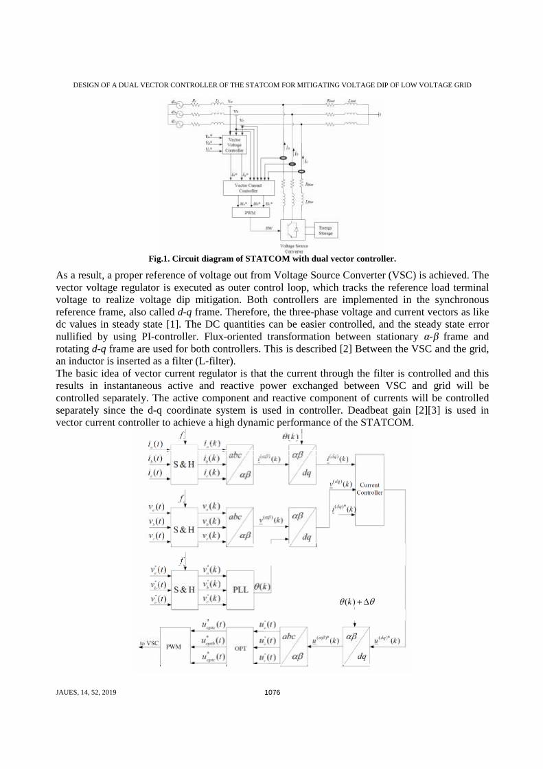
٠ ناقل مزدوج معوض ستاتیكي،ھربائي، التحكم المتجھ في الجھد،تراجع الجھد الك: الكلمات الدالھ1-INTRODUCTION The dynamic behavior of STATCOM is important since the load will not maintain the normal operation if it exposed to voltage dip. Thus, the response time of dip detection and voltage compensation must be short. In order to meet requirements, the dual vector controller is used in STATCOM in this work. The arrangement of STATCOM with a concept of the dual vector controller is exposed in Fig.1. The dual vector controller is composed of two vector controllers, which are vector current controller and vector voltage controller. The vector current regulator operates as inner control loop, which controls current through filter.
DESIGN OF A DUAL VECTOR CONTROLLER OF THE STATCOM FOR MITIGATING VOLTAGE DIP OF LOW VOLTAGE GRID
JAUES, 14, 52, 2019 1076
Fig.1. Circuit diagram of STATCOM with dual vector controller.
As a result, a proper reference of voltage out from Voltage Source Converter (VSC) is achieved. The vector voltage regulator is executed as outer control loop, which tracks the reference load terminal voltage to realize voltage dip mitigation. Both controllers are implemented in the synchronous reference frame, also called d-q frame. Therefore, the three-phase voltage and current vectors as like dc values in steady state [1]. The DC quantities can be easier controlled, and the steady state error nullified by using PI-controller. Flux-oriented transformation between stationary α-β frame and rotating d-q frame are used for both controllers. This is described [2] Between the VSC and the grid, an inductor is inserted as a filter (L-filter). The basic idea of vector current regulator is that the current through the filter is controlled and this results in instantaneous active and reactive power exchanged between VSC and grid will be controlled separately. The active component and reactive component of currents will be controlled separately since the d-q coordinate system is used in controller. Deadbeat gain [2][3] is used in vector current controller to achieve a high dynamic performance of the STATCOM.
DESIGN OF A DUAL VECTOR CONTROLLER OF THE STATCOM FOR MITIGATING VOLTAGE DIP OF LOW VOLTAGE GRID
JAUES, 14, 52, 2019 1077
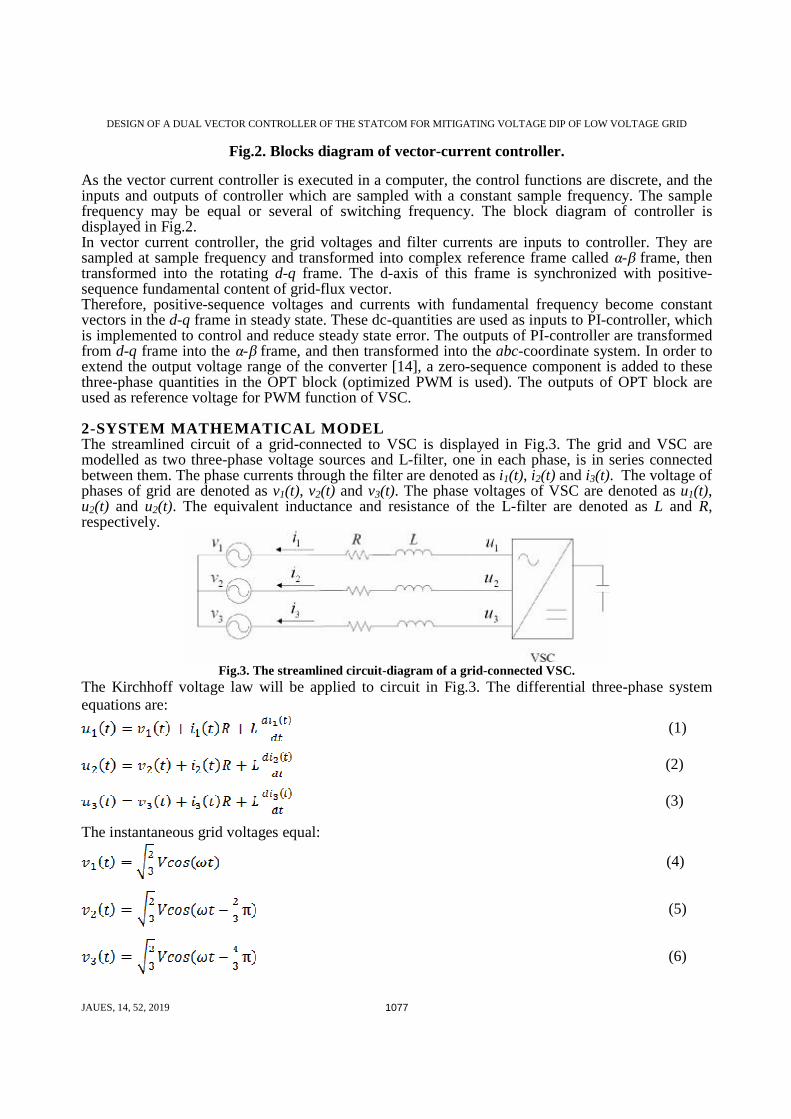
Fig.2. Blocks diagram of vector-current controller.
As the vector current controller is executed in a computer, the control functions are discrete, and the inputs and outputs of controller which are sampled with a constant sample frequency. The sample frequency may be equal or several of switching frequency. The block diagram of controller is displayed in Fig.2. In vector current controller, the grid voltages and filter currents are inputs to controller. They are sampled at sample frequency and transformed into complex reference frame called α-β frame, then transformed into the rotating d-q frame. The d-axis of this frame is synchronized with positive-sequence fundamental content of grid-flux vector. Therefore, positive-sequence voltages and currents with fundamental frequency become constant vectors in the d-q frame in steady state. These dc-quantities are used as inputs to PI-controller, which is implemented to control and reduce steady state error. The outputs of PI-controller are transformed from d-q frame into the α-β frame, and then transformed into the abc-coordinate system. In order to extend the output voltage range of the converter [14], a zero-sequence component is added to these three-phase quantities in the OPT block (optimized PWM is used). The outputs of OPT block are used as reference voltage for PWM function of VSC. 2-SYSTEM MATHEMATICAL MODEL The streamlined circuit of a grid-connected to VSC is displayed in Fig.3. The grid and VSC are modelled as two three-phase voltage sources and L-filter, one in each phase, is in series connected between them. The phase currents through the filter are denoted as i1(t), i2(t) and i3(t). The voltage of phases of grid are denoted as v1(t), v2(t) and v3(t). The phase voltages of VSC are denoted as u1(t), u2(t) and u2(t). The equivalent inductance and resistance of the L-filter are denoted as L and R, respectively.
Fig.3. The streamlined circuit-diagram of a grid-connected VSC.
The Kirchhoff voltage law will be applied to circuit in Fig.3. The differential three-phase system equations are:
(1)
(2)
(3)
The instantaneous grid voltages equal:
(4)
(5)
(6)

DESIGN OF A DUAL VECTOR CONTROLLER OF THE STATCOM FOR MITIGATING VOLTAGE DIP OF LOW VOLTAGE GRID
JAUES, 14, 52, 2019 1078
Where V is phase-to-phase rms voltage, and ω is grid angular frequency. The three-phase system in Eqs. (1) to (3) will be expressed in the α-β frame as:
(7)
(8)
Equations (7) and (8) can be written as continuous state space equations: (9)
(10)
The system state space equations in α-β frame can be written as:
(11)
Equations (7) and (8) also can be written in vector notation:
(12)
Where: (13)
(14)
(15)
Equation (12) can be transferred into d-q frame by using α-β to d-q transformation giving: (16)
Where:
(17)
(18)
(19)
Equation (16) is splatted into two equations, representing d and q components respectively, as: (20)
(21)
The controller of vector-current is implemented in the computer. Thus, currents and voltages are sampled with constant sample time Ts. The equivalent inductance and resistance of L-filter are represented by Lr and Rr, which mean these are predicted values. By integrating Eqs.(20) and (21) from the kTs to (k+1)Ts, the equations become:
(22)

DESIGN OF A DUAL VECTOR CONTROLLER OF THE STATCOM FOR MITIGATING VOLTAGE DIP OF LOW VOLTAGE GRID
JAUES, 14, 52, 2019 1079
(23) Equations (22) and (23) are divided by Ts to obtain the average value for the sample period k to k+1.
(24)
(25)
In order to accomplish high dynamic performance, deadbeat gain is uses at the P-regulator. The error over one sample period should be zero. For instance, the current at sample instant k+1 must equal the reference current at the sample instant k. The reference currents are denoted as:
(26)
(27)
Linear current variation during one sample period is assumed in P-controller, yielding: (28)
(29)
The grid voltages are assumed as constant values within one sample period. (30)
(31)
The VSC voltages average values, through one sample period are assumed to equal reference voltages, which are denoted and . Then,
(32)
(33)
Therefore, Eqs.(24) and (25) could be written as: (34)
(35)
Where kp is proportional gain of the P-controller, in which deadbeat gain is used.
(36)
An integral term can be added to the P-controller to remove the static error, which is caused by non-linearity, noisy measurements and non-ideal components. Therefore, the PI-controller equations could be written as:
(37)
(38)

DESIGN OF A DUAL VECTOR CONTROLLER OF THE STATCOM FOR MITIGATING VOLTAGE DIP OF LOW VOLTAGE GRID
JAUES, 14, 52, 2019 1080
Where and are integral terms of PI-regulator. They are equal to:
(39)
(40)
where kI is the integration constant of the controller, which equals [13]:
(41)
TI is integral time of controller. It is written as: (42)
It is well-known from Eqs. (37) to (40) that, if the currents do not track the reference current values, the integral term will force those currents to track the reference values. The two new denotations, used FFd and FFq, mean the feed-forward terms while the terms
and are integral part of controller and they are equal to:
(43)
(44)
The PI-controller could be applied as a state-space equation [10] such as: (45)
(46)
Two new states, and , the one sample delayed reference values, are introduced to implement
the state-space equation of the controller and could be written as: (47)
(48)
The states, and , are the reference memories. They are the reference current at sample
instant k, however, they would be equal to the reference values one sample before, i.e. the reference current at the sample instant (k-1). Finally, the PI-controller state space equations could be written as:
(49)
(50)
DESIGN OF A DUAL VECTOR CONTROLLER OF THE STATCOM FOR MITIGATING VOLTAGE DIP OF LOW VOLTAGE GRID
JAUES, 14, 52, 2019 1081
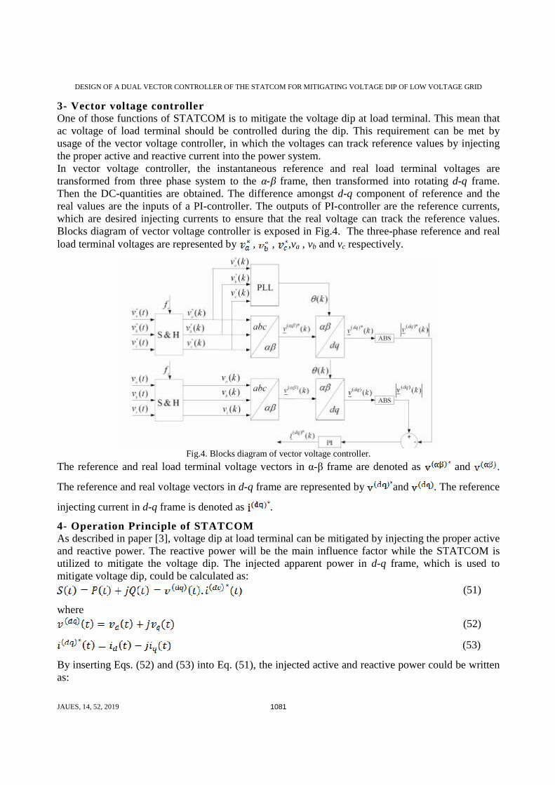
3- Vector voltage controller One of those functions of STATCOM is to mitigate the voltage dip at load terminal. This mean that ac voltage of load terminal should be controlled during the dip. This requirement can be met by usage of the vector voltage controller, in which the voltages can track reference values by injecting the proper active and reactive current into the power system. In vector voltage controller, the instantaneous reference and real load terminal voltages are transformed from three phase system to the α-β frame, then transformed into rotating d-q frame. Then the DC-quantities are obtained. The difference amongst d-q component of reference and the real values are the inputs of a PI-controller. The outputs of PI-controller are the reference currents, which are desired injecting currents to ensure that the real voltage can track the reference values. Blocks diagram of vector voltage controller is exposed in Fig.4. The three-phase reference and real load terminal voltages are represented by , , ,va , vb and vc respectively.
Fig.4. Blocks diagram of vector voltage controller.
The reference and real load terminal voltage vectors in α-β frame are denoted as and .
The reference and real voltage vectors in d-q frame are represented by and . The reference
injecting current in d-q frame is denoted as .
4- Operation Principle of STATCOM As described in paper [3], voltage dip at load terminal can be mitigated by injecting the proper active and reactive power. The reactive power will be the main influence factor while the STATCOM is utilized to mitigate the voltage dip. The injected apparent power in d-q frame, which is used to mitigate voltage dip, could be calculated as:
(51)
where (52)
(53)
By inserting Eqs. (52) and (53) into Eq. (51), the injected active and reactive power could be written as:

DESIGN OF A DUAL VECTOR CONTROLLER OF THE STATCOM FOR MITIGATING VOLTAGE DIP OF LOW VOLTAGE GRID
JAUES, 14, 52, 2019 1082
(54)
(55) By
assuming d-axis aligned with grid flux vector in d-q synchronous reference frame, the grid voltage only has q-component, i.e. the d-component of voltage is zero. Thus, Eqs.(54) and (55) could be rewritten as:
(56)
(57)
Therefore, voltage dip mitigation depends on the injected active and reactive power. The P-controller will be using to force the load terminal voltages to track the reference values. Furthermore, an integral term can be added to the P-controller to remove the static error. The PI-controller ensures that the expected load voltages are achieved. Two control strategies can be applied in the vector voltage controller. One is that only magnitude of voltage is controlled by injecting reactive current (as well as reactive power), called ‘Q Vector Voltage Controller’. The operation principle diagram is exposed in Fig.5, in case of dip with phase-angle jump (right plot) or without (left plot). The phase shift between reference voltage and mitigated voltage vector is introduced by the reactive current flow through the resistor of the power system. In the right plot of Fig.5, the voltage dip develops phase shift between reference and real voltage. By using the Q vector voltage controller, the phase shift caused by the dip cannot be reduced. Moreover, the resistance of power system introduces new phase shift. The phase-shift can cause a large transient at beginning and end of dip. In general, this phase-shift is small. Thus, this controller could be used under most situations except for deep dip and quite sensitive load.
Fig.5. Plot of operation principle of the Q Vector Voltage Controller (left): the dip without phase angle jump;
(right): the dip with phase angle jump. Another control strategy of vector voltage controller is called ‘P-Q Vector Voltage Controller’. This means both magnitude and phase angle of the voltage will be controlled by injecting proper active and reactive current (as well as active and reactive power). As indicated in Fig.6, for the dip without phase angle jump (left plot) or with phase angle jump (right plot), the load voltage will be compensated the same as the reference voltage.
DESIGN OF A DUAL VECTOR CONTROLLER OF THE STATCOM FOR MITIGATING VOLTAGE DIP OF LOW VOLTAGE GRID
JAUES, 14, 52, 2019 1083
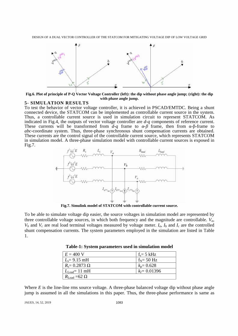
Fig.6. Plot of principle of P-Q Vector Voltage Controller (left): the dip without phase angle jump; (right): the dip
with phase angle jump. 5- SIMULATION RESULTS To test the behavior of vector voltage controller, it is achieved in PSCAD/EMTDC. Being a shunt connected device, the STATCOM can be implemented as controllable current source in the system. Thus, a controllable current source is used in simulation circuit to represent STATCOM. As indicated in Fig.4, the outputs of vector voltage controller are d-q components of reference current. These currents will be transformed from d-q frame to α-β frame, then from α-β-frame to abc-coordinate system. Thus, three-phase synchronous shunt compensation currents are obtained. These currents are the control signal of the controllable current source, which represents STATCOM in simulation model. A three-phase simulation model with controllable current sources is exposed in Fig.7.
Fig.7. Simulink model of STATCOM with controllable current source.
To be able to simulate voltage dip easier, the source voltages in simulation model are represented by three controllable voltage sources, in which both frequency and the magnitude are controllable. Va, Vb and Vc are real load terminal voltages measured by voltage meter. Ia, Ib and Ic are the controlled shunt compensation currents. The system parameters employed in the simulation are listed in Table 1.
Table-1: System parameters used in simulation model
E = 400 V fs= 5 kHz Ls= 9.15 mH fN= 50 Hz Rs= 0.2873 Ω kp= 0.628 LLoad= 11 mH kI= 0.01396 RLoad =62 Ω
Where E is the line-line rms source voltage. A three-phase balanced voltage dip without phase angle jump is assumed in all the simulations in this paper. Thus, the three-phase performance is same as

DESIGN OF A DUAL VECTOR CONTROLLER OF THE STATCOM FOR MITIGATING VOLTAGE DIP OF LOW VOLTAGE GRID
JAUES, 14, 52, 2019 1084
single-phase. The step response is performed in single phase by utilizing the vector voltage controller. A step, from 230-V to 160-V at 15-ms and back to 230-V at 25-ms, is given to reference load voltage V*. The response of load voltage V, with P-controller is indicated in Fig.8. The response of load voltage V with PI-controller to same dip is indicated in Fig.9. The reference load voltage V* and the load voltage V are rms values.
Fig.8 Response with P-controller to a step-in reference load voltage, from 230-V to 160-V at 15-ms and back to
230-V at 25-ms.
Fig.9. Response load voltage with PI-controller to a step-in reference load voltage, from 230-V to 160-V at 10-ms
and back to 230-V at 25-ms.
The responses confirmation that the P-controller cannot remove the static error, whereas the PI-controller can remove it. Therefore, the PI-controller is employing in vector voltage regulator in this paper. By using the vector voltage controller, three-phase reference load voltages are used in the Simulink model exposed in Fig.7. A voltage dip, from 0.05-s to 0.15-s with 0.7-pu magnitude and without phase angle jump, is executed in simulation. The instantaneous three-phase load voltages and line-

DESIGN OF A DUAL VECTOR CONTROLLER OF THE STATCOM FOR MITIGATING VOLTAGE DIP OF LOW VOLTAGE GRID
JAUES, 14, 52, 2019 1085
line rms voltage are exposed in Fig.10 and 11 respectively. A small phase shift between reference and load voltage during the dip is found in Fig.2. This is due to only the reactive shunt compensation current is controlled in the controller. Fig.11 shows that the magnitude of load voltage can track the reference values. However, the mitigation response time, one and half cycle, is quite long by using this controller. The ‘P-Q vector voltage controller’ is implemented in the simulation model shown in Fig.7. A voltage dip, from 0.1-s to 0.25-s with 0.7-pu magnitude and without phase angle jump, is executed in simulation. The instantaneous three-phase load voltages and line-line rms voltage are exposed in Fig.12 and 13 respectively.
Fig.10. Three-phase reference and load voltage by vector voltage controller.
Fig.11. Line-line rms reference and load voltage by vector voltage controller.

DESIGN OF A DUAL VECTOR CONTROLLER OF THE STATCOM FOR MITIGATING VOLTAGE DIP OF LOW VOLTAGE GRID
JAUES, 14, 52, 2019 1086
Fig.12. Three-phase reference and load voltage by ‘P-Q vector voltage controller’.
Fig.13. Line-line rms reference and load voltage by ‘P-Q vector voltage controller’.
Figure 12 and 13 indicate that load voltage, both magnitude and phase angle, can track reference value by using ‘P-Q vector voltage controller’. This is due to both the active and reactive shunt compensation currents are controlled in this controller. The mitigation response time of this controller is also very long.

DESIGN OF A DUAL VECTOR CONTROLLER OF THE STATCOM FOR MITIGATING VOLTAGE DIP OF LOW VOLTAGE GRID
JAUES, 14, 52, 2019 1087
6-CONCOLUSION The controller of STATCOM, called dual vector controller, is studied in this paper. It consists of vector voltage-controller and vector current-controller. The step responses of the vector-current controller with deadbeat gain, dual vector-controller and vector voltage-controller have been presented. Two three-phase simplified models by using vector voltage controller and dual vector controller are built in PSCAD/EMTDC respectively. The various system parameters also have been verified in simulation model with dual vector controller. Results showing that voltage dip can be mitigated by STATCOM with dual vector controller in 5-ms. This controller can mitigate voltage dip for various system parameters. Due to reactive power control is used in dual vector controller, there is small phase shift among real and reference voltage during the dip.
REFERENCES 1. [1] Beaulieu G., Bollen, M.H.J, Malgarotti S. and Ball R., July 2002, "Power quality indices
and objectives. Ongoing activities in CIGRE WG 36-07". Power Engineering Society Summer Meeting, 2002. IEEE, Volume:2, 21-25
2. [2] M.H.J. Bollen, , 1999. "Understanding Power Quality Problems: Voltage Sags and Interruptions". New York, IEEE Press.
3. [3] Ambra Sannino, Spring 2004,"Power Quality and Electromagnetic Compatibility Courses" Compendium, Chalmers University of Technology, Dept. of Electric Power Engineering,.
4. [4] M.H.J. Bollen, L.D.Zhang, 2003,"Different methods for classification of three-phase unbalanced voltage dips due to faults". Electric Power Systems Research, Volume 66, Issue1, pages 59-69
5. [5] Ambra Sannino, Michelle Ghans Miller, Math H.J. Bollen, Jan, 2000, ,"Overview of Voltage Sag Mitigation". Power Engineering Society Winter Meeting, 2000. IEEE, Volume: 4, 23-27 pages: 2872 – 2878.
6. [6] A. Sannino, J. Svensson, T. Larsson, July 2003," Power-electronic solutions to power-quality problems", Electric Power Systems Research, Volume 66, Issue 1, pages 71 – 82
7. [7] Narain G. Hingorani and Laszlo Gyugyi, , 2000," Understanding FACTS Concepts and Technology of Flexible AC Transmission Systems". New York, IEEE Press.
8. [8] K. Linden, I. Segerqvist, 1992, "Modeling of Load Devices and Studying Load/System Characteristics", Department of Electric Power Engineering, Tech. Rep.,
9. [9] Wang P., Jenkins N. and Bollen M.H.J, Oct. 1998. "Experimental Investigation of Voltage Sag Mitigation by An Advanced Static Var Compensator, Power Delivery", IEEE Transactions on, Volume: 13, Issue: 4, Pages: 1461 – 1467
10. [10] Jan Svensson, Jan 2004 ,"Voltage Source Converter control and PWM modulation", Power Electronics 2 Compedium, Department of Electric Power Engineering, Chalmers University of Technology,
11. [11] V. Kaura and V. Blasko, , Jan 1997,"Operation of a Voltage Source Converter at Increased Utility Voltage", IEEE Transactions on Power Electronics, Vol.12, No. 1, pp. 132 – 137
12. [12] Lindgren M. and Svensson J, May 1998,"Control of a voltage-source converter connected to the grid through an LCL-filter-application to active filtering, Power Electronics Specialists Conference, 1998. PESC 98 Record. 29
thAnnual. IEEE, Volume:1, 17– 22. Pages: 229 – 235 vol.1
13. [13] Savitha Venkatesan and Booma Nagarajan, (2018). “Compensation of voltage Sag using STATCOM” International Journal of Engineering & Technology, vol.7 no. (2.8) 673-676