design and real time implementation of single phase … and real time implementation of single phase...
TRANSCRIPT
Design and real time implementation of single phase boost powerfactor correction converter
Amar Bouafassa a,n, Lazhar Rahmani a, Saad Mekhilef b
a Laboratoire d'automatique de Sétif (LAS), Département d'électrotechnique, Faculté de Technologie, Université Sétif-1, Algérieb Department of Electrical Engineering, Faculty of Engineering, University of Malaya, 50603 Kuala Lumpur, Malaysia
a r t i c l e i n f o
Article history:Received 5 May 2014Received in revised form24 September 2014Accepted 10 October 2014
Keywords:Power factor correctionHigher order sliding mode controllerPredictive controlAC–DC Boost converterdSPACE 1104
a b s t r a c t
This paper presents a real time implementation of the single-phase power factor correction (PFC) AC–DCboost converter. A combination of higher order sliding mode controller based on super twistingalgorithm and predictive control techniques are implemented to improve the performance of the boostconverter. Due to the chattering effects, the higher order sliding mode control (HOSMC) is designed. Also,the predictive technique is modified taking into account the large computational delays. The robustnessof the controller is verified conducting simulation in MATLAB, the results show good performances inboth steady and transient states. An experiment is conducted through a test bench based on dSPACE1104. The experimental results proved that the proposed controller enhanced the performance of theconverter under different parameters variations.
& 2014 ISA. Published by Elsevier Ltd. All rights reserved.
1. Introduction
Recently, the power electronics components have gained popu-larity in the development of new static converters to supply domesticand industrial applications due to the introduction of the fastswitches components and appearance of new types of controltechniques. Moreover, the use of power converters for renewableenergy (solar, wind) becomes more important in the world due tothe energy crisis. The AC–DC converter is an important element ofthe power supplies. Indeed, it has numerous applications in differentpower levels; low power like chargers of mobile phones that need afew watts, high power like electric welding that need a few kW. TheAC–DC converter includes various topologies such as; buck, boostand buck-boost, etc. [1,2]. Among these types, the AC–DC boostconverter has interesting features, which are the lifting operation,simple structure and low cost. The development of semiconductorallows the appearance of new power converters use a switch modeoperation. The nonlinear loads and switching losses lead to moreenergy losses. Furthermore, Due to increasingly use of boost con-verter in the large electronic equipment, intensive efforts have beendevoted to adopt international standard such as IEC 1000-3-2,EN61000-3-2 in Europe and the IEEE 519 in USA [3]. To improvethe power factor in the boost converter topology, there are two typesof power factor correction methods, passive method used for old
power converters, and active method used recently in the most ofelectronics components that shown in Fig. 1. Several researches havebeen done to improve and find an adequate control for the PFCconverter, which can provide a better performance.
Commonly, the traditional regulators like PI and PID have beenused to regulate the output voltage of the boost converter [4,5].These types of controls are based on modeling of the systemaround a nominal point under constant parameters and distur-bance, which provide an acceptable performance but if theparameters change, the system loses its performance and give abad results. For this reason, various intelligent controllers havebeen introduced to get an optimal performance of the converterregardless of parameters variations. Among these controllers fuzzylogic [6,7], sliding mode [8–10], predictive technique [11,12],artificial neural network [13] are used.
The sliding mode control has attracted great research interest[14–17]. Several researches have used SMC for the control ofnonlinear and multivariable systems due to its disturbance rejec-tion [18–20]. However, the drawback of sliding mode controller isthe high frequency oscillations (chattering phenomenon), which isa major obstacle for the implementation of standard SMC. Forthese reasons. The HOSMC is proposed to overcomes the maindrawbacks of classical SMC, its provides a smooth control, goodperformance yielding to less chattering in real time implementa-tion, and better convergence while preserving the robustnessproperties [21–24]. Among the existing algorithms, the supertwisting algorithms has been designed and evaluated in this paper.It has interesting features and maintains the distinctive perfor-mances of the classical SMC. It provides a systematic method to
Contents lists available at ScienceDirect
journal homepage: www.elsevier.com/locate/isatrans
ISA Transactions
http://dx.doi.org/10.1016/j.isatra.2014.10.0040019-0578/& 2014 ISA. Published by Elsevier Ltd. All rights reserved.
n Corresponding author.E-mail addresses: [email protected] (A. Bouafassa),
[email protected] (L. Rahmani), [email protected] (S. Mekhilef).
Please cite this article as: Bouafassa A, et al. Design and real time implementation of single phase boost power factorcorrection converter. ISA Transactions (2014), http://dx.doi.org/10.1016/j.isatra.2014.10.004i
ISA Transactions ∎ (∎∎∎∎) ∎∎∎–∎∎∎
solve the stability and modeling imprecision problems in newelectronic components. Moreover, his practical implementation issimple and assure in both the accuracy and convergence in finitetime. Similarly, the predictive control has been employed in theindustrial applications those need high specific performance, dueto its reliability and disturbance attenuation [25,26]. The predic-tive technique has been used in this work to investigate its speedand implementation simplicity, which leads a fast dynamicresponse and better efficiency.
Generally, fast settling time leads to large overshoot; it is wellknown that these two important requirements are the mostcommon problems in controller design, which are not desired inmany practical applications. Hence the user is compelled to chooseeither fast response or low overshoot. This particular problem canbe solved by using the proposed method. The main contribution ofthis paper is the real time implementation on dSPACE 1104 of anew robust hybrid controller, composed by HOSMC based on supertwisting in the DC voltage loop, and predictive controller in thecurrent loop, which takes into account a better steady stateperformance and transient response. To verify the controllersperformance for steady and transient states, at first simulationshave been carried out under different loading conditions alongwith different reference output voltages. Later an experimentaltest using the dSPACE 1104 board has been conducted to verify thesimulations results. From both simulation and experimentalresults, the robustness of the proposed controller based boostconverter for PFC has been verified and evaluated.
The paper is organized as follows. Section 2 describes theproposed control methods for the boost converter. Sections 3 and4 present the simulation and the experimental results along withthe discussion. In Section 5 a general conclusion has been drawnby focusing the significant point of the paper.
2. Description of proposed control method
2.1. Modeling of the system
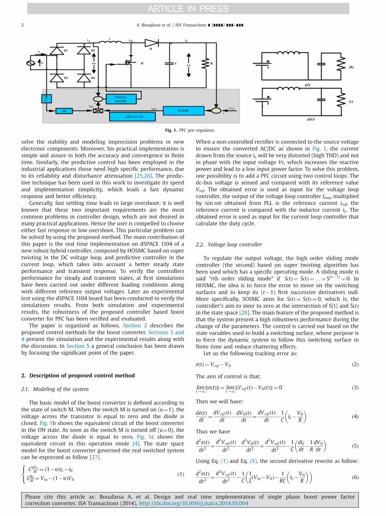
The basic model of the boost converter is defined according tothe state of switch M. When the switch M is turned on (u¼1), thevoltage across the transistor is equal to zero and the diode isclosed. Fig. 1b shows the equivalent circuit of the boost converterin the ON state. As soon as the switch M is turned off (u¼0), thevoltage across the diode is equal to zero, Fig. 1c shows theequivalent circuit in this operation mode [4]. The state spacemodel for the boost converter governed the real switched systemcan be expressed as follow [27].
CdV0dt ¼ 1�uð ÞiL� i0
LdiLdt ¼ Vin� 1�uð ÞV0
8<: ð1Þ
When a non-controlled rectifier is connected to the source voltageto ensure the converted AC/DC as shown in Fig. 1, the currentdrawn from the source is will be very distorted (high THD) and notin phase with the input voltage Vs, which increases the reactivepower and lead to a low input power factor. To solve this problem,one possibility is to add a PFC circuit using two control loops. Thedc-bus voltage is sensed and compared with its reference valueVref. The obtained error is used as input for the voltage loopcontroller, the output of the voltage loop controller Imax multipliedby |sin ωt| obtained from PLL is the reference current iref, thereference current is compared with the inductor current iL. Theobtained error is used as input for the current loop controller thatcalculate the duty cycle.
2.2. Voltage loop controller
To regulate the output voltage, the high order sliding modecontroller (the second) based on super twisting algorithm hasbeen used which has a specific operating mode. A sliding mode issaid “rth order sliding mode” if S tð Þ ¼ _S tð Þ ¼…¼ Sðr�1Þ ¼ 0. InHOSMC, the idea is to force the error to move on the switchingsurfaces and to keep its (r�1) first successive derivatives null.More specifically, SOSMC aims for S tð Þ ¼ _S tð Þ ¼ 0, which is, thecontroller's aim to steer to zero at the intersection of S(t) and _S tð Þin the state space [28]. The main feature of the proposed method isthat the system present a high robustness performance during thechange of the parameters. The control is carried out based on thestate variables used to build a switching surface, whose purpose isto force the dynamic system to follow this switching surface infinite time and reduce chattering effects.
Let us the following tracking error as:
eðtÞ ¼ Vref �V0 ð2Þ
The aim of control is that;
limt-1
‖eðtÞ‖¼ limt-1
‖Vref ðtÞ�V0ðtÞ‖¼ 0 ð3Þ
Then we will have:
deðtÞdt
¼ dVref ðtÞdt
�dV0ðtÞdt
¼ dVref ðtÞdt
�1C
iL�V0
R
� �ð4Þ
Thus we have
d2eðtÞdt2
¼ d2Vref ðtÞdt2
�d2V0ðtÞdt2
¼ d2Vref ðtÞdt2
�1C
diLdt
�1RdV0
dt
� �ð5Þ
Using Eq. (1) and Eq. (5), the second derivative rewrite as follow:
d2eðtÞdt2
¼ d2Vref ðtÞdt2
�1C
1LðVin�V0Þ�
1RC
iL�V0
R
� �� �ð6Þ
C
D3
R
D4
D2 D
i L i D
D1
L
VinV0
Vs
is
Abs HOSMC
Pridictivecontroller
VrefImaxIref
+
+
-
-
i0
dSPACE1104
M
PL L
(b)
ON
(c)
OFF
Fig. 1. PFC pre-regulator.
A. Bouafassa et al. / ISA Transactions ∎ (∎∎∎∎) ∎∎∎–∎∎∎2
Please cite this article as: Bouafassa A, et al. Design and real time implementation of single phase boost power factorcorrection converter. ISA Transactions (2014), http://dx.doi.org/10.1016/j.isatra.2014.10.004i
Let us consider the following surface [23].
Sðe; tÞ ¼ ∂∂tþλ
� �ðn�1ÞeðtÞ ð7Þ
Where λ is a positive constant. It is clear that the degree related tothe voltage in Eq. (1) is equal to 1; in this case the surface is chosenas the setting error. Therefore, the surface can be writing as
S tð Þ ¼ Vref �V0 ð8Þ
To maintain the trajectory of the output voltage (V0) in switchingsurface, an equivalent current (Ieq) control is applied consideringthe following invariance conditions:
SðtÞ ¼ Vref �V0 ¼ 0
_SðtÞ ¼ dVref ðtÞdt �dV0ðtÞ
dt ¼ 0
(ð9Þ
To prove the stability and ensure the stable convergenceproperty of the proposed controller, the Lyapunov function isselected as
VðtÞ ¼ 12S2ðtÞþ1
2_S2ðtÞ ð10Þ
Where V(0)¼0, V(t)40 for S(t)a0 and _S tð Þa0The stability is ensured if the derivative of the Lyapunov
function is negative, and satisfies the following condition:
_VðtÞo0; SðtÞa0; _SðtÞa0 ð11ÞTaking the first derivative of Eq. (10) yields
_VðtÞ ¼ SðtÞ_SðtÞþ _SðtÞ€SðtÞ ¼ _SðtÞ:½SðtÞþ €SðtÞ� ð12ÞUsing Eqs.(2) and (6) yields
_VðtÞ ¼ _SðtÞ Vref �V0þ €Vref �1C
1LðVin�V0Þ�
1RC
iL�V0
R
� �� �� �
¼ _Vref �1C
iL�V0
R
� �� �
: Vref �V0þ €Vref �1C
1LðVin�V0Þ�
1RC
iL�V0
R
� �� �� �ð13Þ
For our case, Vref is constant and its derivative is null, Eq.(13)can be represented as
_VðtÞ ¼ �1C
iL�V0
R
� �Vref �V0�
1C
1LðVin�V0Þ�
1RC
iL�V0
R
� �� �� �o0
ð14Þwhen the system is in the reaching phase with S(t)a0, _SðtÞ andhave V(t) is negative definite. From the above analysis, thederivative of the Lyapunov function is a negative definite, thesystem is globally asymptotically stable.
The global control is composed of the equivalent control (Ieq)and the super twisting algorithm terms. Now, lets us the supertwisting algorithm, this later is used in order to stabilize thesystem, avoid chattering effects, and converges the system to thedesired trajectory in finite time. The advantage of super twistingalgorithm is that; it does not need any information on the timederivative of the sliding variable and maintains all the distinctiverobust features of the SMC. The control law is composed by twoparts defined by the following control law:
u tð Þ ¼ u1 tð Þþu2 tð Þ ð15Þwhere
_u1ðtÞ ¼ �u if u 4 1�w sign ðSÞif u r 1��������� ð16Þ
u2ðtÞ ¼ �λ S0 ρsignðSÞif S 4 S0�λ S ρsignðSÞif S r S0����������������� ð17Þ
Where S0 is a boundary layer around the sliding surface.
If the control gains satisfy the constraint in Eq.(18), theconvergence to the sliding surface in finite time is fulfill. Themethod to calculate of Φ,Γm and ΓM has been presented in [21].
w4 ΦΓm
λ2Z4ΦΓ2
m
ΓM ðwþΦÞΓmðw�ΦÞ
0oρr0:5
ð18Þ
By adding the super twisting algorithm terms, we obtain theglobal control of voltage loop as follow:
IMax ¼ IeqþZ t
0_u1dtþu2 ð19Þ
2.3. Current loop controller
Due to predictive control's suitable performance and flexibleimplementation on real time, it has been used to control thepower converters for last few years [1]. In this work, the predictivemethod has been used to control converter switching. Taking intoaccount the state of the switch from the circuit shown in Fig. 1, theequations of the inductor current iL(t) for each state can beexpressed as [12,29]when M is turned on
Ld iLdt
¼ Vin tð Þ for t kð Þrtot kð Þþd kð ÞTs ð20Þ
when M is turned off
Ld iLdt
¼ Vin tð Þ�V0 tð Þ for t kð Þþd kð Þ: Tsrtotðkþ1Þ ð21Þ
Where Vin(t) and V0(t) are the input and output voltage respec-tively, t(k) and t(kþ1) are the started time of the kth and (kþ1)thswitching cycle respectively, d(k) and Ts are the duty cycle andswitching period respectively. Since the switching frequency ismore than the line frequency, Eq. (20) and Eq. (21) can berewritten as
LiLðtðkÞþdðkÞTsÞ� iLðtðkÞÞ
dðkÞTs¼ VinðtðkÞÞ ð22Þ
LiLðtðkþ1ÞÞ� iLðtðkÞþdðkÞ : TsÞ
ð1�dðkÞÞ : Ts¼ VinðtðkÞÞ�V0ðt ðkÞÞ ð23Þ
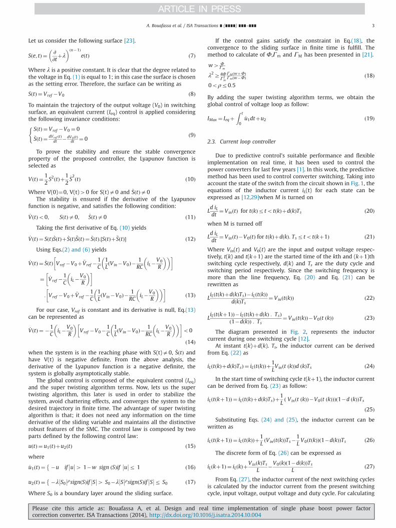
The diagram presented in Fig. 2, represents the inductorcurrent during one switching cycle [12].
At instant t(k)þd(k). Ts, the inductor current can be derivedfrom Eq. (22) as
iLðtðkÞþdðkÞTsÞ ¼ iLðtðkÞÞþ1LVinðt ðkÞÞd ðkÞTs ð24Þ
In the start time of switching cycle t(kþ1), the inductor currentcan be derived from Eq. (23) as follow:
iLðtðkþ1ÞÞ ¼ iLðtðkÞþdðkÞTsÞþ1Lð Vinðt ðkÞÞ�V0ðt ðkÞÞÞð1�d ðkÞÞTs
ð25ÞSubstituting Eqs. (24) and (25), the inductor current can be
written as
iLðtðkþ1ÞÞ ¼ iLðtðkÞÞþ1LðVinðtðkÞÞTs�
1LV0ðtðkÞÞð1�dðkÞÞTs ð26Þ
The discrete form of Eq. (26) can be expressed as
iL kþ1ð Þ ¼ iL kð ÞþVinðkÞTs
L�V0ðkÞð1�dðkÞÞTs
Lð27Þ
From Eq. (27), the inductor current of the next switching cyclesis calculated by the inductor current from the present switchingcycle, input voltage, output voltage and duty cycle. For calculating
A. Bouafassa et al. / ISA Transactions ∎ (∎∎∎∎) ∎∎∎–∎∎∎ 3
Please cite this article as: Bouafassa A, et al. Design and real time implementation of single phase boost power factorcorrection converter. ISA Transactions (2014), http://dx.doi.org/10.1016/j.isatra.2014.10.004i
the duty cycle d(k), Eq. (27) can be rewritten as
d kð Þ ¼ LTs
iL kþ1ð Þ� iL kð ÞV0
þV0 kð Þ�Vin ðkÞV0
ð28Þ
Through the boost parameters such as input voltage, outputvoltage and inductor current, the duty cycle d(k) for the actualswitching cycle have been calculated. For the designed boost converterwith PFC, the inductor current iL(kþ1) has been forced to follow thereference iref (kþ1), which has a rectified sinusoidal form.
Substituting V0, iL(kþ1) in Eq. (28) by its references Vref andiref(kþ1) respectively, the duty cycle can be expressed as [12]:
d kð Þ ¼ LTs
Uiref kþ1ð Þ� iL kð Þ
VrefþVref �VinðkÞ
Vrefð29Þ
The reference current iref in Eq. (29) is calculated as follow:
iref ðkþ1Þ ¼ Imax:jsinðωlinetðkþ1Þj ð30ÞWhere Imax is the peak value of the reference current, which isgiven by the output of the voltage loop controller.
All steps of the proposed method are shown in Fig. 3.
Step 1: Identification of the components parameters.Step 2: Determination of suitable voltage and introduce theHOSMC to regulate it.Step 3: Determination of IMax through HOSMC, after thatintroduce the predictive control to regulate the current.Step 4: Verify that all of duty cycles are calculated by thepredictive control.Step 5: Exploitation of the converter.
3. Simulation results
The aim of the simulation is to improve the performance of thepower factor correction boost converter using HOSMC and pre-dictive controllers to reduce the harmonic distortion produced bythe nonlinear load and to achieve a unity power factor underparameters variation. The parameters of the system are presentedin appendix. Due to the limitation of the paper presentation, onlythe performance of the proposed method is presented in simula-tion section. The performance of PI has been presented in experi-mental section.
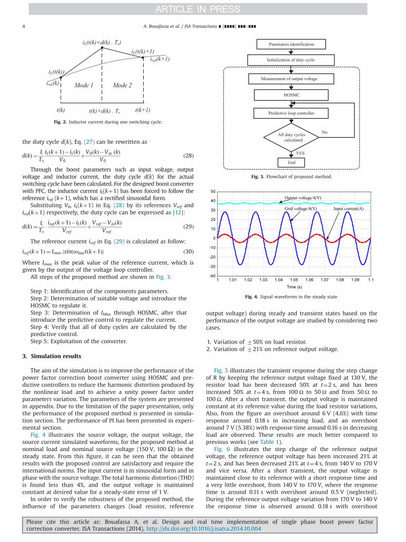
Fig. 4 illustrates the source voltage, the output voltage, thesource current simulated waveforms, for the proposed method atnominal load and nominal source voltage (150 V, 100Ω) in thesteady state. From this figure, it can be seen that the obtainedresults with the proposed control are satisfactory and require theinternational norms. The input current is in sinusoidal form and inphase with the source voltage. The total harmonic distortion (THD)is found less than 4%, and the output voltage is maintainedconstant at desired value for a steady-state error of 1 V.
In order to verify the robustness of the proposed method, theinfluence of the parameters changes (load resistor, reference
output voltage) during steady and transient states based on theperformance of the output voltage are studied by considering twocases.
1. Variation of 750% on load resistor.2. Variation of 721% on reference output voltage.
Fig. 5 illustrates the transient response during the step changeof R by keeping the reference output voltage fixed at 130 V, theresistor load has been decreased 50% at t¼2 s, and has beenincreased 50% at t¼4 s, from 100 Ω to 50 Ω and from 50 Ω to100 Ω. After a short transient, the output voltage is maintainedconstant at its reference value during the load resistor variations,Also, from the figure an overshoot around 6 V (4.6%) with timeresponse around 0.18 s in increasing load, and an overshootaround 7 V (5.38%) with response time around 0.16 s in decreasingload are observed. These results are much better compared toprevious works (see Table 1).
Fig. 6 illustrates the step change of the reference outputvoltage, the reference output voltage has been increased 21% att¼2 s, and has been decreased 21% at t¼4 s, from 140 V to 170 Vand vice versa. After a short transient, the output voltage ismaintained close to its reference with a short response time anda very little overshoot, from 140 V to 170 V, where the responsetime is around 0.11 s with overshoot around 0.5 V (neglected).During the reference output voltage variation from 170 V to 140 Vthe response time is observed around 0.18 s with overshoot
Mode 1 Mode 2
iL(t(k)+d(k) . Ts)iL(t(k)+1)
iL(t(k))
t(k) t(k)+d(k) . Ts t(k+1)
iref(k+1)
iref(k)
Fig. 2. Inductor current during one switching cycle.
Paramaters identification
Initialization of duty cycle
Measurement of output voltage
HOSMC
Predictive loop controller
All duty cyclescalculated
End
No
YES
Fig. 3. Flowchart of proposed method.
1 1.01 1.02 1.03 1.04 1.05 1.06 1.07 1.08 1.09 1.1-40
-30
-20
-10
0
10
20
30
40
50
Time (s)
Output voltage/4(V)
Input current(A)Grid voltage/4(V)
Fig. 4. Signal waveforms in the steady state.
A. Bouafassa et al. / ISA Transactions ∎ (∎∎∎∎) ∎∎∎–∎∎∎4
Please cite this article as: Bouafassa A, et al. Design and real time implementation of single phase boost power factorcorrection converter. ISA Transactions (2014), http://dx.doi.org/10.1016/j.isatra.2014.10.004i
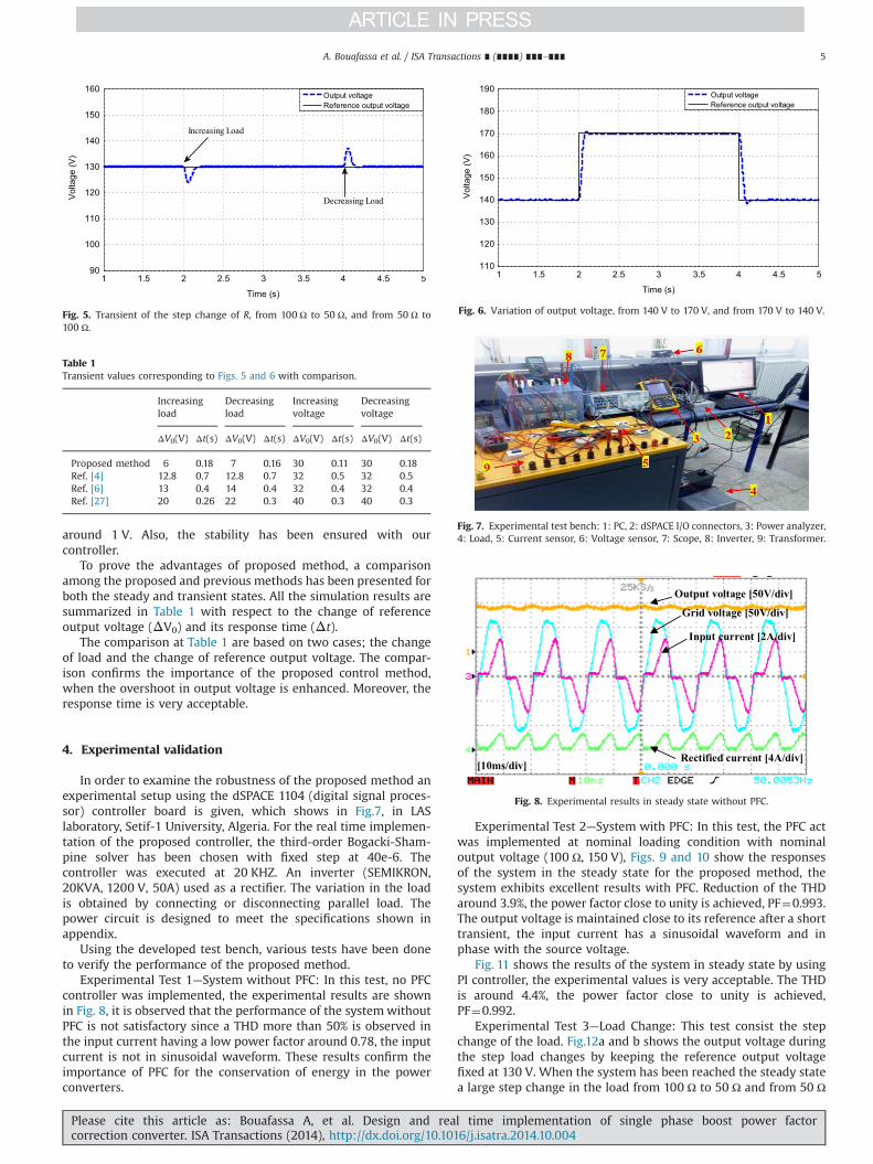
around 1 V. Also, the stability has been ensured with ourcontroller.
To prove the advantages of proposed method, a comparisonamong the proposed and previous methods has been presented forboth the steady and transient states. All the simulation results aresummarized in Table 1 with respect to the change of referenceoutput voltage (ΔV0) and its response time (Δt).
The comparison at Table 1 are based on two cases; the changeof load and the change of reference output voltage. The compar-ison confirms the importance of the proposed control method,when the overshoot in output voltage is enhanced. Moreover, theresponse time is very acceptable.
4. Experimental validation
In order to examine the robustness of the proposed method anexperimental setup using the dSPACE 1104 (digital signal proces-sor) controller board is given, which shows in Fig.7, in LASlaboratory, Setif-1 University, Algeria. For the real time implemen-tation of the proposed controller, the third-order Bogacki-Sham-pine solver has been chosen with fixed step at 40e-6. Thecontroller was executed at 20 KHZ. An inverter (SEMIKRON,20KVA, 1200 V, 50A) used as a rectifier. The variation in the loadis obtained by connecting or disconnecting parallel load. Thepower circuit is designed to meet the specifications shown inappendix.
Using the developed test bench, various tests have been doneto verify the performance of the proposed method.
Experimental Test 1—System without PFC: In this test, no PFCcontroller was implemented, the experimental results are shownin Fig. 8, it is observed that the performance of the systemwithoutPFC is not satisfactory since a THD more than 50% is observed inthe input current having a low power factor around 0.78, the inputcurrent is not in sinusoidal waveform. These results confirm theimportance of PFC for the conservation of energy in the powerconverters.
Experimental Test 2—System with PFC: In this test, the PFC actwas implemented at nominal loading condition with nominaloutput voltage (100 Ω, 150 V), Figs. 9 and 10 show the responsesof the system in the steady state for the proposed method, thesystem exhibits excellent results with PFC. Reduction of the THDaround 3.9%, the power factor close to unity is achieved, PF¼0.993.The output voltage is maintained close to its reference after a shorttransient, the input current has a sinusoidal waveform and inphase with the source voltage.
Fig. 11 shows the results of the system in steady state by usingPI controller, the experimental values is very acceptable. The THDis around 4.4%, the power factor close to unity is achieved,PF¼0.992.
Experimental Test 3—Load Change: This test consist the stepchange of the load. Fig.12a and b shows the output voltage duringthe step load changes by keeping the reference output voltagefixed at 130 V. When the system has been reached the steady statea large step change in the load from 100 Ω to 50 Ω and from 50 Ω
1 1.5 2 2.5 3 3.5 4 4.5 590
100
110
120
130
140
150
160
Time (s)
Vol
tage
(V)
Output voltageReference output voltage
Increasing Load
Decreasing Load
Fig. 5. Transient of the step change of R, from 100 Ω to 50 Ω, and from 50 Ω to100 Ω.
Table 1Transient values corresponding to Figs. 5 and 6 with comparison.
Increasingload
Decreasingload
Increasingvoltage
Decreasingvoltage
ΔV0(V) Δt(s) ΔV0(V) Δt(s) ΔV0(V) Δt(s) ΔV0(V) Δt(s)
Proposed method 6 0.18 7 0.16 30 0.11 30 0.18Ref. [4] 12.8 0.7 12.8 0.7 32 0.5 32 0.5Ref. [6] 13 0.4 14 0.4 32 0.4 32 0.4Ref. [27] 20 0.26 22 0.3 40 0.3 40 0.3
1 1.5 2 2.5 3 3.5 4 4.5 5110
120
130
140
150
160
170
180
190
Time (s)
Vol
tage
(V)
Output voltageReference output voltage
Fig. 6. Variation of output voltage, from 140 V to 170 V, and from 170 V to 140 V.
Fig. 7. Experimental test bench: 1: PC, 2: dSPACE I/O connectors, 3: Power analyzer,4: Load, 5: Current sensor, 6: Voltage sensor, 7: Scope, 8: Inverter, 9: Transformer.
Grid voltage [50V/div]
Rectified current [4A/div]
Input current [2A/div]
Output voltage [50V/div]
[10ms/div]
Fig. 8. Experimental results in steady state without PFC.
A. Bouafassa et al. / ISA Transactions ∎ (∎∎∎∎) ∎∎∎–∎∎∎ 5
Please cite this article as: Bouafassa A, et al. Design and real time implementation of single phase boost power factorcorrection converter. ISA Transactions (2014), http://dx.doi.org/10.1016/j.isatra.2014.10.004i

to 100 Ω has been taken place. After a short transient, the outputvoltage is maintained constant at its reference with a smallfluctuation. The response time during load increament is 0.09 sand load decreament is 0.1 s for the proposed method, which arenearly similar to simulation values and much better than PIregulator (the response time for PI during load increament is0.13 s and load decreament is 0. 25 s).
Experimental Test 4—Reference output voltage change:Another test has been performed by changing the reference outputvoltage, Vref is changed from 140 V to 170 V and vice versa withconstant load of 100 Ω. The transient input current and outputvoltage are presented in Figs. 13 and 14. For the proposed method,the new value of the output voltage has been reached after 0.075 sand need only 0.05 s to return to previous value again. In this casealso, the shape of the input current is found sinusoidal which is in
Rectified current [8A/div]
Output voltage [100V/div]
Grid voltage [50V/div]Input current [4A/div]
[25ms/div]
Fig. 9. Experimental results in steady state with APFC.
Fig. 10. Experimental values in steady state.
Fig. 11. Experimental values of PI controller in steady state.
[4A/div]
[40V/div]
[50ms/div] [100ms/div]
[4A/div]
[40V/div]
Fig. 12. Transient of the step change of R from 100 Ω to 50 Ω, and from 50 Ω to 100 Ω, (a) HOSMC and (b) PI.
A. Bouafassa et al. / ISA Transactions ∎ (∎∎∎∎) ∎∎∎–∎∎∎6
Please cite this article as: Bouafassa A, et al. Design and real time implementation of single phase boost power factorcorrection converter. ISA Transactions (2014), http://dx.doi.org/10.1016/j.isatra.2014.10.004i

phase with the source voltage during this change. For the PIregulator, the new value of the output voltage has been reachedafter 0.12 s and need 0.1 s to return to previous value again. Theresults of proposed method for change of reference output voltageare much better than Refs. [4,6,10,27] and PI regulator.
All the experimental results are summarized in Table 2 withrespect to the change of reference output voltage (ΔV0) and itsresponse time (Δt).
After the previous figures, Tables 1 and 2, we can be observedthat there is a good accordance between the experimental and thesimulation results. Is can be seen that the proposed methodexhibits better performances compared to the previous works insteady state performance and transient responses.
5. Conclusion
This paper presented design, simulation and real timeimplementation of single-phase boost power factor correctionconverter by using two control strategies, higher order sliding
mode controller based on super twisting algorithm andpredictive techniques. The simulation results showed that thedesign of the PFC boost converter controller using the twocontrollers has enhanced the converter performance. Thesystem does not get influenced during the parameters variation(load, reference output voltage) in the steady and transient statesin the presence of PFC converter. The output voltage tracksits reference perfectly; the input current is in sinusoidalwaveform and in same phase with the grid voltage. The THD ofinput current is measured and satisfy the international standards,THDo5.0%, the unity power factor is measured as 0.993; thesystem is stable during the changes of the reference output voltageand the load.
Appendix A
Circuit parameters
Supply voltage (rms) 80 VResistance load 100ΩDC-link voltage reference 150 VInput inductance 20 mHSource voltage frequency 50 HzOutput capacity 1100 μFSwitching frequency 20 KHz
Control parameters.
Ki¼100, Kp¼0.1, ρ¼0.5, λ¼0.6, w¼3.8, S0¼0.05
[25ms/div][25ms/div]
[140V][170V]
[140V][170V]
Fig. 13. Transient of the step change of Vref, increasing from 140 V to 170 V, (a) HOSMC, and (b) PI.
[25ms/div] [25ms/div]
[140V] [140V][170V][170V]
Fig. 14. Transient of the step change of Vref, decreasing from 170 V to 140 V, (a) HOSMC, and (b) PI.
Table 2Transient values corresponding to experimental results with comparison.
Increasingload
Decreasingload
Increasingvoltage
Decreasingvoltage
ΔV0(V) Δt(s) ΔV0(V) Δt(s) ΔV0(V) Δt(s) ΔV0(V) Δt(s)
Proposed method 10 0.09 18 0.1 30 0.075 30 0.05PI 10 0.13 15 0.25 30 0.12 30 0.1Ref. [4] 12 0.45 16 0.64 32 0.6 32 0.6Ref. [6] 14 0.4 13 0.3 38 0.5 38 0.5Ref. [27] 25 0.18 25 0.15 40 0.1 40 0.1
A. Bouafassa et al. / ISA Transactions ∎ (∎∎∎∎) ∎∎∎–∎∎∎ 7
Please cite this article as: Bouafassa A, et al. Design and real time implementation of single phase boost power factorcorrection converter. ISA Transactions (2014), http://dx.doi.org/10.1016/j.isatra.2014.10.004i

References
[1] Rodriguez J, Cortes P. Predictive control of power converters and electricaldrives. John Wiley; 2012.
[2] Singh B, Singh BN, Chandra A, Al-Haddad K, Pandey A, Kothari DP. A review ofsingle-phase improved power quality AC-DC converters. IEEE Trans IndElectron 2003;50(5):962–81.
[3] Dugan RC, McGranaghan MF, Santoso S, Wayne Beaty H. Electrical powersystem quality. Second EditionMcGraw-Hill; 2003.
[4] Kessal A, Rahmani L, Gaubert JP, Mostefai M. Analysis and design of an isolatedsingle-phase power factor corrector with a fast regulation. Electr Power SystRes 2011;81:1825–31.
[5] Guo L, Hung JY, Nelms RM. Comparative evaluation of sliding mode fuzzycontroller and PID controller for a boost converter. Electr Power Syst Res2011;81:99–106.
[6] Kessal A, Rahmani L, Gaubert JP, Mostefai M. Experimental design of a fuzzycontroller for improving power factor of boost rectifier. Int J Electron 2012;99(12):1611–21.
[7] Chung HSH, Tam EPW, Hui SYR. Development of a fuzzy logic controller forboost rectifier with active power factor correction. In: IEEE Power ElectronicsSpecialists Conference PESC'99, 1; 1999. p. 149–54.
[8] López-Santos O, Martínez-Salamero L, García G, Valderrama-Blavi H, MercuriDO. Efficiency analysis of a sliding-mode controlled quadratic boost converter.IET Power Electron 2013;6(2):364–73.
[9] Lopez O, de Vicuna LG, Castilla M. Sliding mode control design of a boost high-power-factor pre-regulator based on the quasi-steady-state approach. In:Proceedings IEEE Power Electronics Specialists Conference PESC'01, 2; 2001.p. 932–5.
[10] Kessal A, Rahmani L. Analysis and design of sliding mode controller gains forboost power factor corrector. ISA Trans 2013;52(5):638–43.
[11] Perez M, Rodrıguez J, Coccia A. Predictive current control in a single phase PFCboost rectifier. In: IEEE international conference on industrial technology ICIT;2009. p. 1–6.
[12] Azazi HZ, El-Kholy EE, Mahmoud SA, Shokralla SS. Power factor correctionusing predictive current control for three-phase induction motor drive system.Electr Power Compon Syst 2014;42(2):190–202.
[13] Sagiroglu S, Colak I, Bayindir R. Power factor correction technique based onartificial neural networks. Energy Convers Manag 2006;47:3204–15.
[14] Slotine JJ, Li W. Applied nonlinear control. USA: Prentice Hall; 1998.[15] Liu J, Wang X. Advanced sliding mode control for mechanical systems.
Springer; 2011.[16] Utkin VI. Variable structure system with sliding mode. IEEE Transactions on
Automatic Control 1977;AC-22:212–22.[17] Utkin VI. Sliding modes and their application in variable structure system.
1979.[18] Yang J, Su J, Li S, Yu X. High-order mismatched disturbance compensation for
motion control systems via a continuous dynamic sliding-mode approach.IEEE Trans Ind Inf 2014;10(1):604–14.
[19] Yang J, Li S, Yu X. Sliding-mode control for systems with mismatcheduncertainties via a disturbance observer. IEEE Trans Ind Electron 2013;60(1):160–9.
[20] Yang j, Li S, Sua J, Yu X. Continuous nonsingular terminal sliding mode controlfor systems with mismatched disturbances. Automatica 2013;49(7):2287–91.
[21] Kunusch C, Puleston PF, Mayosky MA, Riera J. Sliding mode strategy for pemfuel cells stacks breathing control using a super-twisting algorithm. IEEE TransControl Syst Technol 2009;17(1):167–74.
[22] Levant A. Principles of 2-sliding mode design. Automatica 2007;43(4):576–86.[23] Manceur M, Essounbouli N, Hamzaoui A. Second-order sliding fuzzy interval
type-2 control for an uncertain system with real application. IEEE Trans FuzzySyst 2012;20(2):262–75.
[24] Benbouzid M, Beltran B, Amirat Y, Yao G, Han J. Mangel H. Second-ordersliding mode control for DFIG-based wind turbines fault ride-through cap-ability enhancement. ISA Trans 2014;53(3):827–33.
[25] Yang J, Zheng WX. Offset-free nonlinear MPC for mismatched disturbanceattenuation with application to a static var compensator. IEEE Trans CircuitsSyst-II 2014;61(1):49–53.
[26] Yang J, Zhao Z, Li S, Zheng WX. Composite predictive flight control forairbreathing hypersonic vehicles. Int J Control 2014;87(9):1970–84.
[27] Kessal A, Rahmani L. Ga-optimized parameters of sliding-mode controllerbased on both output voltage and input current with an application in the PFCof AC/DC converters. IEEE Trans Power Electron 2014;29(6):3159–65.
[28] Eker İ. Second-order sliding mode control with experimental application. ISATrans 2010;49(3):394–405.
[29] Bibian S, Jin H. Digital control with improved performance for boost powerfactor correction circuits. In: Proceedings of the IEEE Applied Power Electro-nics Conference APEC, 1; 2001. p. 137–43.
A. Bouafassa et al. / ISA Transactions ∎ (∎∎∎∎) ∎∎∎–∎∎∎8
Please cite this article as: Bouafassa A, et al. Design and real time implementation of single phase boost power factorcorrection converter. ISA Transactions (2014), http://dx.doi.org/10.1016/j.isatra.2014.10.004i