design and cfd analysis of single and symmetrical …
TRANSCRIPT

Vol-7 Issue-3 2021 IJARIIE-ISSN(O)-2395-4396
14521 www.ijariie.com 1925
DESIGN AND CFD ANALYSIS OF
SINGLE AND SYMMETRICAL INLET
CYCLONE DUST SEPARATOR Anu Priya
Apprenticeship Trainee Vibration Engineering Group, Gas Turbine Research Establishment
Bangalore, India
ABSTRACT
We are using cyclone dust separators for quite a century. Gas-solid cyclone separators are the most frequently
used equipment in industries. To enhance the performance of cyclone dust separators, many Computational
Fluid Dynamics studies conducted for its wide variety of applications in industries. Computational Fluid
Dynamics is a conventional method to forecast the flow and collection efficiency of a cyclone. Primarily three
models were used in cyclone simulation K-Epsilon Model, Reynolds Stress Turbulence Model, and Algebraic
Stress Model. The K-epsilon turbulence model is the foremost crucial model utilized in computational fluid
dynamics analysis to simulate turbulent kinetic and dissipation conditions. Pressure drop in the cyclone
separator is one of the most significant functions to be kept in mind while designing the cyclone system. For
further improvement in cyclone dust separator, a comparison of the pressure drop in a single and symmetrical
tangential input cyclone separator perform theoretically and computational fluid dynamics analysis using the
Reynolds stress turbulence model. The result showed that the pressure drop in the symmetric inlet cyclone
separator exceeds the single inlet cyclone separator. I also performed the Computational Fluid Dynamics
analysis to calculate the efficiency of a cyclone separator with a dust collector using the K-Epsilon Turbulence
Model. So far, we all know that the pressure drop in a cyclone separator is directly associated with the
tangential velocity of the cyclone separator, which must increase to extend the efficiency of the cyclone. Cyclone
efficiency will generally increase with increment in particle size or density, tangential velocity, cyclone body
length, and smoothness of the inner wall of the cyclone.
Keyword: Computational Fluid Dynamics, Pressure Drop, Efficiency Calculation, Symmetrical Inlet
Cyclone, Reynolds Stress Turbulence Model
1. INTRODUCTION
Cyclone dust separators are pollution control devices designed to extract fine particles from what is also known
as dust in an air stream. It consists of a conical shape that utilizes the role of the air vortex to collect dust
particles which have proven to be a piece of better settling equipment than gravity. Cyclones do not have any
moving parts and are available in many shapes and sizes. It is categorized into two types of orientation, namely
vertical and horizontal, and can be set up together as a step or multi-step cyclone separator. In vertical cyclones,
air penetrates the equipment tangentially and then forms a vortex as it moves along the conical section. The
vortex generates the force that pushed dust particles to maneuver to the walls of the equipment and slides under
the influence of gravity. During the design of cyclones, we consider particle size (particles with larger mass
subject to greater force), the force exerted on the dust particles, and the time that force exerted on the particles.
Discrete levels of collection efficiency and operation can achieve by varying the standard cyclone dimension.
There are some limitations of the various models used in cyclone simulation. The K-Epsilon model embraces
the hypothesis of isotropic turbulence, so it is unsuitable for flow in a cyclone of anisotropic turbulence. The
Algebraic Stress Model cannot predict the recirculation zone and Rankine vortex in strongly swirling flow.
Reynolds Stress Model forgoes the hypothesis of isotropic turbulence and solves a transport equation for every
component of the Reynolds Stress. It is considered the foremost applicable turbulent model for cyclone flow.
Lagrangian and Eulerian techniques are the most commonly used to predict mean particle diffusion in turbulent
streams.
2. MODELING
2.1 The Stairmand's High-Efficiency Cyclone Design

Vol-7 Issue-3 2021 IJARIIE-ISSN(O)-2395-4396
14521 www.ijariie.com 1926
In this paper, the cyclone geometry is constructing by using the reference of Stairmand's high-efficiency
method. Several experiments were carried out by Stairmand on cyclone dust separator and eventually developed
efficient geometrical ratios. The sketching and modeling of the cyclone perform in the design modeler of Ansys
Workbench by using the geometrical ratio of Stairmand. Here, I am taking the diameter of the cyclone separator
as 0.20 meters, which is close to the standard size diameter of 0.203 meters.
Table-1: The Geometrical Parameter values for Cyclone Design
Sr. No. Cyclone Data Dimensions(m)
1. Diameter of Cyclone (Dc) 0.20
2. Height of Rectangular Inlet (A) 0.10
3. Width of Rectangular Inlet (B) 0.05
4. Diameter of Circular Outlet (De) 0.10
5. Height of Circular Outlet (C) 0.125
6. Diameter of Collection Bin (Db) 0.05
7. Length of Cyclone main Body (L1) 0.40
8. The total length of a cyclone (L) 0.80
Fig-1: Cyclone Design Dimensions
2.2 Geometry Modification
The performance of the cyclone separator can improve by increasing its tangential velocity. If we do slight
modification and add the symmetrical inlet to the geometry of the cyclone then tangential velocity can
increase. The dimension of the new inlet is shown below,
Height of Rectangular Inlet (A1) = 0.10 m
Vol-7 Issue-3 2021 IJARIIE-ISSN(O)-2395-4396
14521 www.ijariie.com 1927
Width of Rectangular Inlet (B1) = 0.05 m
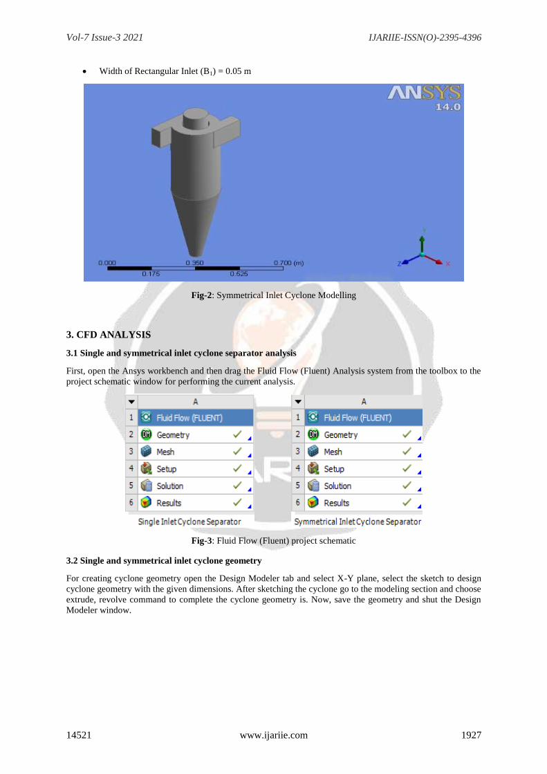
Fig-2: Symmetrical Inlet Cyclone Modelling
3. CFD ANALYSIS
3.1 Single and symmetrical inlet cyclone separator analysis
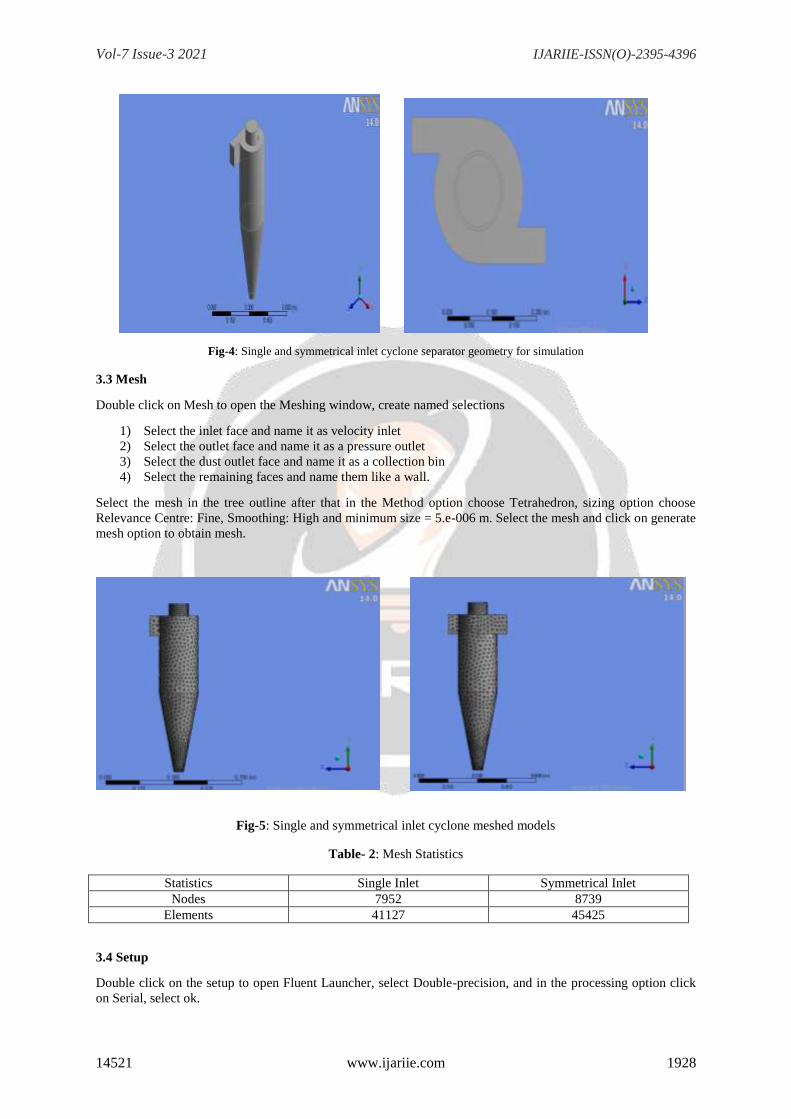
First, open the Ansys workbench and then drag the Fluid Flow (Fluent) Analysis system from the toolbox to the
project schematic window for performing the current analysis.
Fig-3: Fluid Flow (Fluent) project schematic
3.2 Single and symmetrical inlet cyclone geometry
For creating cyclone geometry open the Design Modeler tab and select X-Y plane, select the sketch to design
cyclone geometry with the given dimensions. After sketching the cyclone go to the modeling section and choose
extrude, revolve command to complete the cyclone geometry is. Now, save the geometry and shut the Design
Modeler window.
Vol-7 Issue-3 2021 IJARIIE-ISSN(O)-2395-4396
14521 www.ijariie.com 1928
Fig-4: Single and symmetrical inlet cyclone separator geometry for simulation
3.3 Mesh
Double click on Mesh to open the Meshing window, create named selections
1) Select the inlet face and name it as velocity inlet
2) Select the outlet face and name it as a pressure outlet
3) Select the dust outlet face and name it as a collection bin
4) Select the remaining faces and name them like a wall.
Select the mesh in the tree outline after that in the Method option choose Tetrahedron, sizing option choose
Relevance Centre: Fine, Smoothing: High and minimum size = 5.e-006 m. Select the mesh and click on generate
mesh option to obtain mesh.
Fig-5: Single and symmetrical inlet cyclone meshed models
Table- 2: Mesh Statistics
Statistics Single Inlet Symmetrical Inlet
Nodes 7952 8739
Elements 41127 45425
3.4 Setup
Double click on the setup to open Fluent Launcher, select Double-precision, and in the processing option click
on Serial, select ok.

Vol-7 Issue-3 2021 IJARIIE-ISSN(O)-2395-4396
14521 www.ijariie.com 1929
Fig-6: Fluent Launcher
STEP 1: General > check Mesh (To confirm mesh is correct or not) then in Solver select Pressure-
Based type, Absolute Velocity Formulation, Transient Time Steps and enable Gravity and put a value
of Gravitational Acceleration -9.81 m/s2 in Y-Axis.
Fig-7: General Conditions
STEP 2: In models select the Reynolds Stress (7 eqn) and in Reynolds-Stress Model select Linear
Pressure-Strain, in Reynolds-Stress Options enable Wall BC from k Equation and Wall Reflection
Effects, in Near-wall Treatment enable Standard Wall Functions.

Vol-7 Issue-3 2021 IJARIIE-ISSN(O)-2395-4396
14521 www.ijariie.com 1930
Fig-8: Defining the Model
STEP 3: In Materials choose Air then in properties value of Density = 0.4 kg/m3, Viscosity = 0.02
kg/m-s and click on change/create option.
Fig-9: Materials
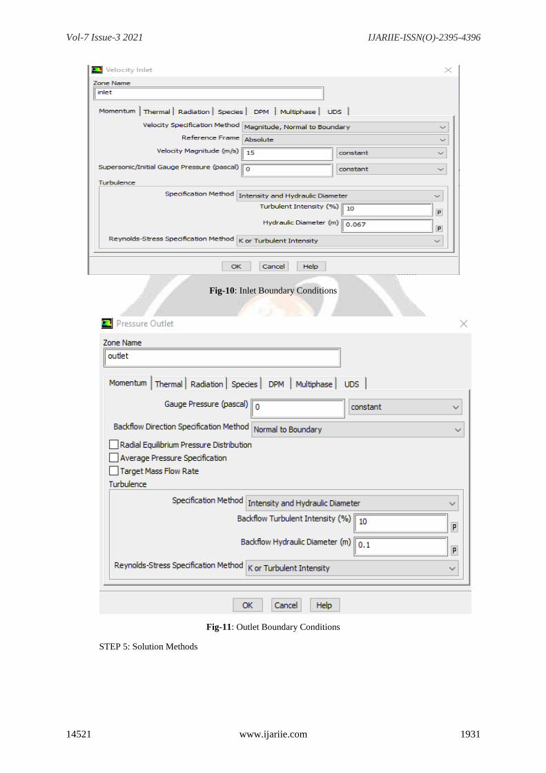
STEP 4: Boundary Conditions
A) Zone name: Inlet > Velocity magnitude = 15 m/s2
Turbulence: Specification Method > Intensity and Hydraulic Diameter
Turbulence Intensity (%) = 10, Hydraulic Diameter(m) = 0.067
B) Zone name: Outlet
Turbulence: Specification Method > Intensity and Hydraulic Diameter
Backflow Turbulence Intensity (%) = 10, Backflow Hydraulic Diameter(m) = 0.1
Vol-7 Issue-3 2021 IJARIIE-ISSN(O)-2395-4396
14521 www.ijariie.com 1931
Fig-10: Inlet Boundary Conditions
Fig-11: Outlet Boundary Conditions
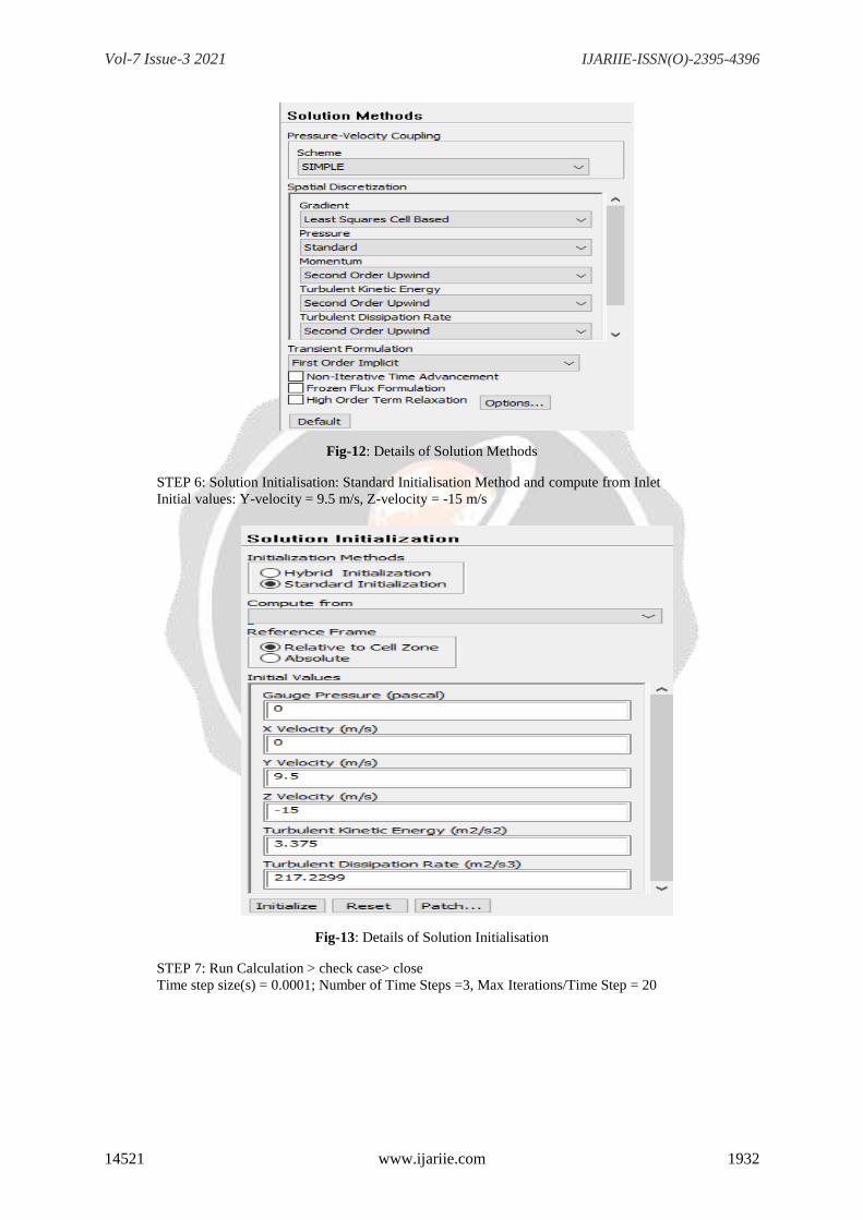
STEP 5: Solution Methods
Vol-7 Issue-3 2021 IJARIIE-ISSN(O)-2395-4396
14521 www.ijariie.com 1932
Fig-12: Details of Solution Methods
STEP 6: Solution Initialisation: Standard Initialisation Method and compute from Inlet
Initial values: Y-velocity = 9.5 m/s, Z-velocity = -15 m/s
Fig-13: Details of Solution Initialisation
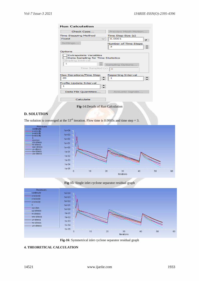
STEP 7: Run Calculation > check case> close
Time step size(s) = 0.0001; Number of Time Steps =3, Max Iterations/Time Step = 20
Vol-7 Issue-3 2021 IJARIIE-ISSN(O)-2395-4396
14521 www.ijariie.com 1933
Fig-14:Details of Run Calculation
D. SOLUTION
The solution is converged at the 53rd
iteration. Flow time is 0.0003s and time step = 3.
Fig-15: Single inlet cyclone separator residual graph
Fig-16: Symmetrical inlet cyclone separator residual graph
4. THEORETICAL CALCULATION

Vol-7 Issue-3 2021 IJARIIE-ISSN(O)-2395-4396
14521 www.ijariie.com 1934
While designing a cyclone dust separator, the pressure drop in cyclone is one of the most important parameters
to keep in mind. Theoretical Pressure drop calculation:
Inlet Velocity (u1) = 15 m/s Gas Density (ꝭf) = 0.4 kg/m
3 and Viscosity of the gas = 0.02 kg/m-s
Hydraulic diameter of the rectangular inlet = 4(𝑎×𝑏)
2(𝑎+𝑏)= 0.067 𝑚
Hydraulic diameter of the circular outlet = 0.1 m
Area of the rectangular inlet (A1) = 0.1 × 0.05 = 0.0005 m2
Cyclone Surface Area (As) = π.200 × (400 +400) = 0.502400 m2
ψ = 𝑓𝑐𝐴𝑠
𝐴1 = 0.5024, here, 𝑓𝑐 is taken as 0.005
𝑟𝑡
𝑟𝑒=
100−(50
2)
50= 1.5
where rt = radius of the circle to which the
centre line of the inlet is tangential and re = outlet pipe radius
𝐵𝑎𝑠𝑒𝑑 𝑜𝑛 𝜓 𝑎𝑛𝑑𝑟𝑡
𝑟𝑒 value we can find out 𝜑 from figure 17.
𝜑 = 0.9
Outlet Pipe Area (Ae) = 𝜋
4𝑑2 = 0.007850 m
2
Q = A1u1 = 0.075 m3/s
Q = Aeu2, → u2 = 9.5 m/s
→ ∆𝑃 = 𝜌𝑓
203{𝑢1
2 [1 + 2𝜑2 (2𝑟𝑡
𝑟𝑒
− 1) ] + 2𝑢22}
→ ∆𝑃 = 2.23 𝑚𝑏𝑎𝑟 = 223 𝑃𝑎
5. RESULTS AND DISCUSSIONS
5.1 Contour Results
Pressure Contours
Pressure contours obtain from Fluid Flow (fluent) show that non-dimensionalized static pressure is in the range
of -36.098 Pa to 833.437 Pa for a single inlet cyclone separator. Static pressure is increasing from center to wall
surface but along the vertical section, pressure isn't uniform and decreasing at bottom of the conic section of the
cyclone as within the case of a single inlet cyclone separator.
Fig-18: Static pressure contour of single inlet cyclone
Fig-17: Radius ratio vs φ graph
Vol-7 Issue-3 2021 IJARIIE-ISSN(O)-2395-4396
14521 www.ijariie.com 1935
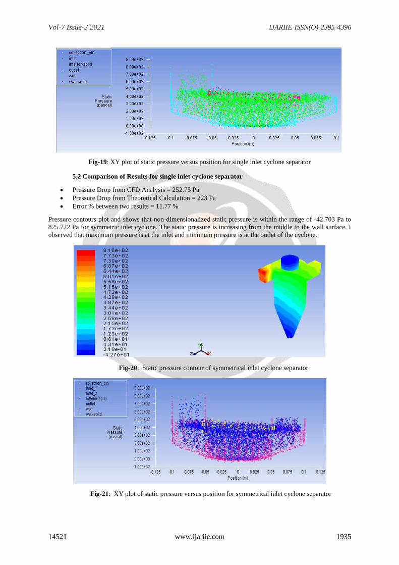
Fig-19: XY plot of static pressure versus position for single inlet cyclone separator
5.2 Comparison of Results for single inlet cyclone separator
Pressure Drop from CFD Analysis = 252.75 Pa
Pressure Drop from Theoretical Calculation = 223 Pa
Error % between two results = 11.77 %
Pressure contours plot and shows that non-dimensionalized static pressure is within the range of -42.703 Pa to
825.722 Pa for symmetric inlet cyclone. The static pressure is increasing from the middle to the wall surface. I
observed that maximum pressure is at the inlet and minimum pressure is at the outlet of the cyclone.
Fig-20: Static pressure contour of symmetrical inlet cyclone separator
Fig-21: XY plot of static pressure versus position for symmetrical inlet cyclone separator
Vol-7 Issue-3 2021 IJARIIE-ISSN(O)-2395-4396
14521 www.ijariie.com 1936
5.3 Comparison of Results for symmetrical inlet cyclone separator
Pressure Drop from CFD Analysis = 259.27 Pa
Pressure Drop from Theoretical Calculation = 223 Pa
Error % between two results = 13.98 %
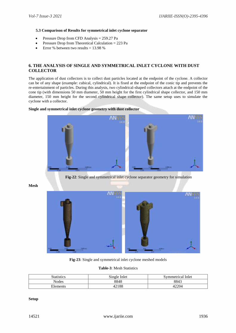
6. THE ANALYSIS OF SINGLE AND SYMMETRICAL INLET CYCLONE WITH DUST
COLLECTOR
The application of dust collectors is to collect dust particles located at the endpoint of the cyclone. A collector
can be of any shape (example: cubical, cylindrical). It is fixed at the endpoint of the conic tip and prevents the
re-entertainment of particles. During this analysis, two cylindrical-shaped collectors attach at the endpoint of the
cone tip (with dimensions 50 mm diameter, 50 mm height for the first cylindrical shape collector, and 150 mm
diameter, 150 mm height for the second cylindrical shape collector). The same setup uses to simulate the
cyclone with a collector.
Single and symmetrical inlet cyclone geometry with dust collector
Fig-22: Single and symmetrical inlet cyclone separator geometry for simulation
Mesh
Fig-23: Single and symmetrical inlet cyclone meshed models
Table-3: Mesh Statistics
Statistics Single Inlet Symmetrical Inlet
Nodes 8848 8843
Elements 42188 42204
Setup
Vol-7 Issue-3 2021 IJARIIE-ISSN(O)-2395-4396
14521 www.ijariie.com 1937
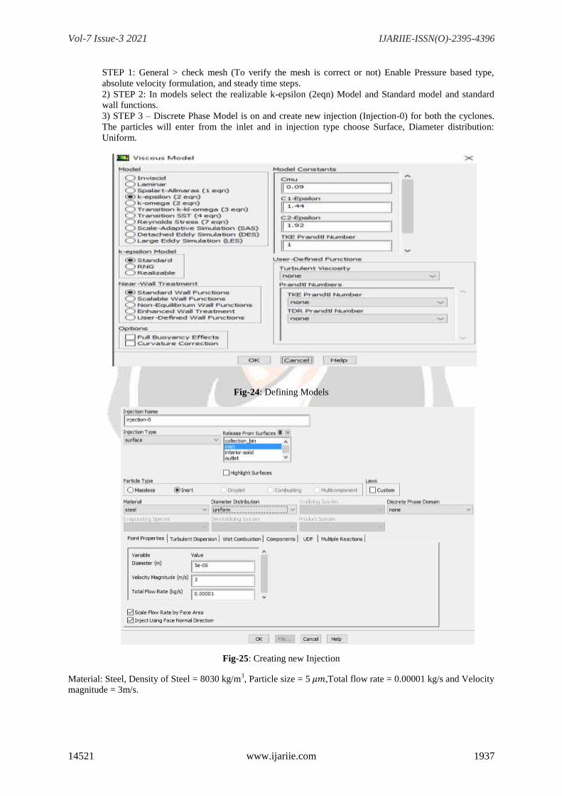
STEP 1: General > check mesh (To verify the mesh is correct or not) Enable Pressure based type,
absolute velocity formulation, and steady time steps.
2) STEP 2: In models select the realizable k-epsilon (2eqn) Model and Standard model and standard
wall functions.
3) STEP 3 – Discrete Phase Model is on and create new injection (Injection-0) for both the cyclones.
The particles will enter from the inlet and in injection type choose Surface, Diameter distribution:
Uniform.
Fig-24: Defining Models
Fig-25: Creating new Injection
Material: Steel, Density of Steel = 8030 kg/m3, Particle size = 5 𝜇𝑚,Total flow rate = 0.00001 kg/s and Velocity
magnitude = 3m/s.
Vol-7 Issue-3 2021 IJARIIE-ISSN(O)-2395-4396
14521 www.ijariie.com 1938
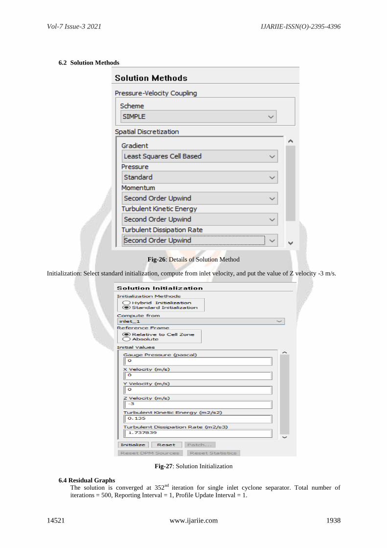
6.2 Solution Methods
Fig-26: Details of Solution Method
Initialization: Select standard initialization, compute from inlet velocity, and put the value of Z velocity -3 m/s.
Fig-27: Solution Initialization
6.4 Residual Graphs
The solution is converged at 352nd
iteration for single inlet cyclone separator. Total number of
iterations = 500, Reporting Interval = 1, Profile Update Interval = 1.

Vol-7 Issue-3 2021 IJARIIE-ISSN(O)-2395-4396
14521 www.ijariie.com 1939
Fig-28: Single inlet cyclone separator residual graph
Fig-29: Symmetrical inlet cyclone separator residual graph
7 RESULTS AND DISCUSSIONS
7.1 Pressure Contours
Pressure contours obtain from Fluid flow (Fluent) observe that non-dimensionalized static pressures
are within the range of – 2.57 Pa to 14.64 Pa for a single inlet cyclone. Static pressure is increasing
from the core of the wall surface but decreasing at bottom of the cyclone. I observed that maximum
pressure is at the inlet and minimum pressure is at the outlet of the cyclone.
Fig-30: Contours of static pressure (pascal) for single inlet cyclone

Vol-7 Issue-3 2021 IJARIIE-ISSN(O)-2395-4396
14521 www.ijariie.com 1940
Pressure contours obtain from Fluid flow (Fluent) observe non-dimensionalized static pressures are within the
range of -2.81 Pa to 14.3 Pa for symmetrical inlet cyclone separator. Static pressure is increasing from the core
to the wall surface but decreasing at bottom of the cyclone. I observed that maximum pressure is at the inlet and
minimum pressure is at the outlet of the cyclone.
Fig-31: Contours of static pressure (pascal) for symmetrical inlet cyclone
7.2 Velocity Contours
Fig-32: Contours of velocity magnitude (m/s) for single inlet cyclone

Vol-7 Issue-3 2021 IJARIIE-ISSN(O)-2395-4396
14521 www.ijariie.com 1941
Fig-33: Contours of velocity magnitude for symmetrical inlet cyclone
Table-4: Velocity magnitude for both cyclone models
Cyclone Types
Velocity Magnitude (m/s)
Tangential Velocity (m/s)
Minimum
Maximum
Minimum
Maximum
Single Inlet Cyclone
0
3.98
-3.52
2.88
Symmetrical Inlet
Cyclone
0
4.00
-3.68
2.92
Here, input velocity is 3 m/s and we can see from the table that the velocity magnitude and tangential velocity in
the symmetrical inlet cyclone are more than a single inlet cyclone.
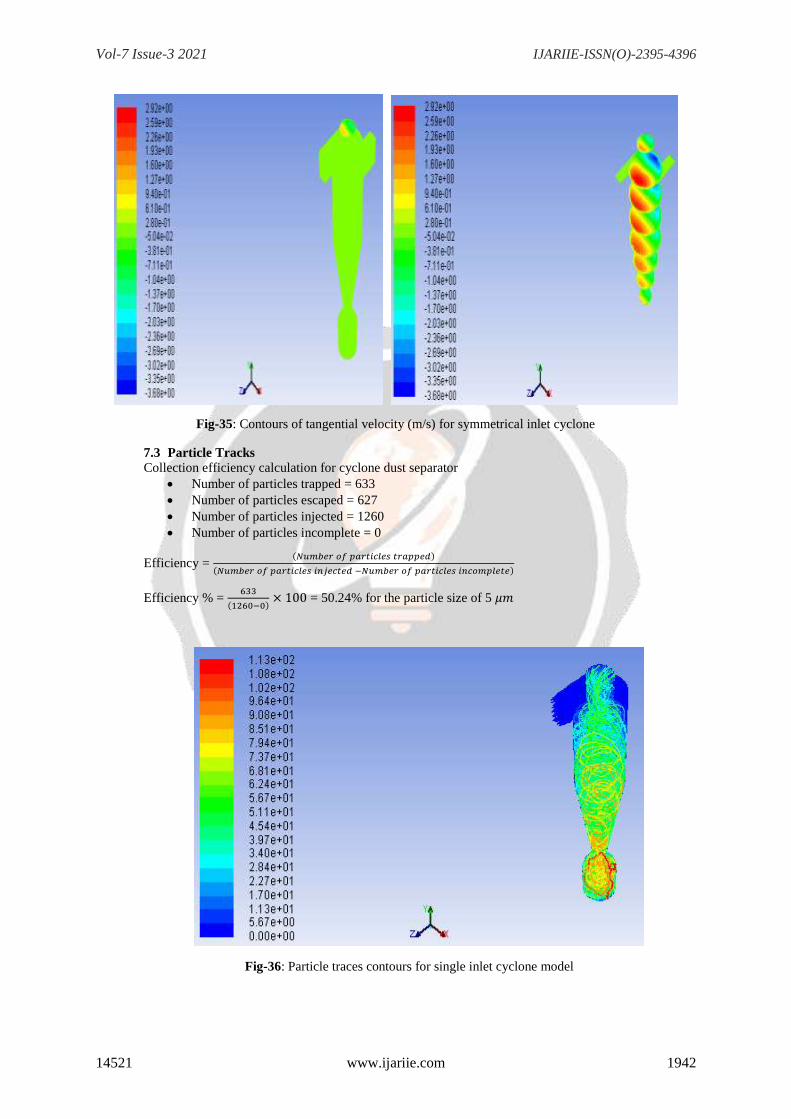
Fig-34: Contours of tangential velocity (m/s) for single inlet cyclone
Vol-7 Issue-3 2021 IJARIIE-ISSN(O)-2395-4396
14521 www.ijariie.com 1942
Fig-35: Contours of tangential velocity (m/s) for symmetrical inlet cyclone
7.3 Particle Tracks
Collection efficiency calculation for cyclone dust separator
Number of particles trapped = 633
Number of particles escaped = 627
Number of particles injected = 1260
Number of particles incomplete = 0
Efficiency = (𝑁𝑢𝑚𝑏𝑒𝑟 𝑜𝑓 𝑝𝑎𝑟𝑡𝑖𝑐𝑙𝑒𝑠 𝑡𝑟𝑎𝑝𝑝𝑒𝑑)
(𝑁𝑢𝑚𝑏𝑒𝑟 𝑜𝑓 𝑝𝑎𝑟𝑡𝑖𝑐𝑙𝑒𝑠 𝑖𝑛𝑗𝑒𝑐𝑡𝑒𝑑 −𝑁𝑢𝑚𝑏𝑒𝑟 𝑜𝑓 𝑝𝑎𝑟𝑡𝑖𝑐𝑙𝑒𝑠 𝑖𝑛𝑐𝑜𝑚𝑝𝑙𝑒𝑡𝑒)
Efficiency % = 633
(1260−0) × 100 = 50.24% for the particle size of 5 𝜇𝑚
Fig-36: Particle traces contours for single inlet cyclone model
Vol-7 Issue-3 2021 IJARIIE-ISSN(O)-2395-4396
14521 www.ijariie.com 1943
8. CONCLUSION
After studying the prevailing literature and performing CFD1analysis on single and symmetrical inlet cyclone
separator, the successive conclusion extract: The CFD analysis performed for both the cyclone models under the
identical condition of pressure, velocity, material properties, and total flow rate. From the theoretical calculation
and CFD analysis result, I found that the pressure drop value varies with the cyclone geometry. There is more
pressure drop by symmetrical inlet cyclone separator as compared to single inlet cyclone separator. The error
between the theoretical calculation and CFD analysis in a single inlet cyclone is 11.77% and in a symmetrical
inlet cyclone separator is 13.98%. The result allowed me to observe that the tangential velocity and the velocity
magnitude for the symmetrical inlet are higher than the single inlet cyclone separator. The efficiency calculation
for the cyclone with dust collector is 50.24% for the particle size of 5μm.
9. REFERENCES
[1]. Khairy Elsayed 2011, Ph.D. thesis on Analysis and Optimization of Cyclone Separators Geometry using
RANS and LES Methodologies. Pages from 20-160.
[2]. Abhijit Gaikwad and Dr.Shivarudraiah “CFD Analysis of Symmetrical Tangential inlet Cyclone Separator”
IRJET Vol. 04, No- 08, Aug. 2017
[3]. Ogawa, A. (1984). Estimation of the Collection Efficiencies of the Three Types of the Cyclones Dust
Collectors from the Standpoint of the Flow Patterns in the Cylindrical Cyclone Dust Collectors. Bulletin of
JSME, vol. 27, n. 223, p. 64.
[4]. Stairmand, C.J. (1951). The Design and Performance of Cyclone Separators. Trans. Inst. Chem. Eng, vol.
29, p.356.
[5]. Zhao, B., Shen, H. and Kang, Y. (2004). Development of a Symmetrical Spiral Inlet to Improve Cyclone
Separator Performance. Powder Technology, vol. 145, issue 1, pp. 4750.
[6]. Cyclone Collection Efficiency: Comparison of Experimental Results with Theoretical Predictions By John
Dirgo & David Leith.
[7]. Bernardo S, Mori M and W P Martignoni (2006), “Evaluation of Cyclone Geometry and its Influence on its
Performance Parameters by CFD”, Powder Technology.
[8]. C B Shepherd and C. E. Lapple. Flow pattern and pressure drop in cyclone dust collectors. Industrial and
Engineering Chemistry, 32(9): 1246-248, September 1940
[9]. Optimization of the cyclone separator geometry for minimum pressure drop using mathematical models and
CFD simulations By Khairy Elsayed and Chris Lacor, Chemical Engineering Science; 2010
[10]. Numerical study of gas-solid flow in a cyclone separator By B. Wang, D.L. Xu, K.W. Chu, A.B. Yu,
Applied Mathematical Modelling 30 (2006) 1326–1342
1 CFD – Computational Fluid Dynamics