interface c medium voltage symmetrical separable connectors · medium voltage symmetrical ......
TRANSCRIPT

INTERFACE CMEDIUM VOLTAGE SYMMETRICAL SEPARABLE CONNECTORS
CATALOGUE 2017


While every care is taken to ensure that the information contained in this publication is correct, no legal responsibility can be accepted for any inaccuracy. Nexans Network Solutions N.V. - Div. Euromold reserves the right to alter or modify the characteristics of its products described in this catalogue as standards and technology evolve.
EUROMOLDEuromold is the leading European specialised designer, manufacturer and distributor of prefabricated cable accessories for medium voltage energy distribution. Euromold provides a complete range of accessories for underground cables: premoulded EPDM rubber connectors for cables and epoxy bushings for transformers and switchgear, as well as a large range of cold-shrinkable terminations and joints from 12 to 42 kV.Euromold is also the manufacturer of electrical components for the high voltage accessories of the Nexans group.
ISO 9001 CertificateSince 1992, Euromold’s commitment to quality is demonstrated by its ISO 9001 certification.
Laboratory accreditationSince June 2000, Euromold’s independent ELAB laboratory obtained the BELAC accreditation no.144-TEST conform with the European standards for laboratories ISO 17025 for electrical testing of low and medium voltage cable accessories according to the international standards EN 50393, IEC 60502-4, IEC 61442 and HD 629.
International standardsAll our products meet the International standards like CENELEC HD 629.1, CENELEC EN 50180, IEC 60137, IEC 60502-4… or country specifications. Official certificates, CESI, KEMA, ATEX… prove the conformity of our products. Long duration tests of existing or new products are continuously performed in our test fields.
NEXANS NETWORK SOLUTIONS DIV. EUROMOLD
COMPANY PRESENTATION
2
09/2017
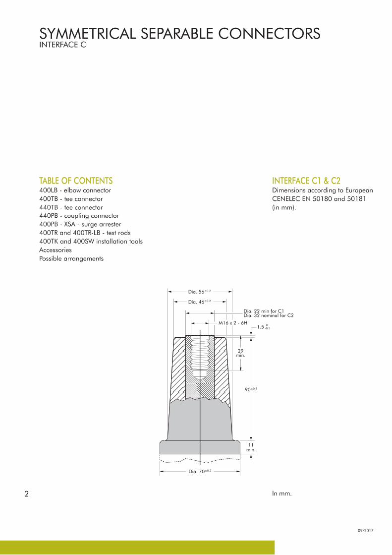
INTERFACE C1 & C2Dimensions according to European CENELEC EN 50180 and 50181 (in mm).
TABLE OF CONTENTS400LB - elbow connector400TB - tee connector440TB - tee connector440PB - coupling connector400PB - XSA - surge arrester400TR and 400TR-LB - test rods400TK and 400SW installation toolsAccessoriesPossible arrangements
90±0.2
0-0.51.5
Dia. 22 min for C1Dia. 32 nominal for C2
Dia. 46±0.2
Dia. 56±0.2
Dia. 70±0.2
M16 x 2 - 6H
29min.
11min.
In mm.
SYMMETRICAL SEPARABLE CONNECTORSINTERFACE C

3
CONNECTIONBUSHINGS /ACCESSORIES
CONNECTORS /ACCESSORIES
dead-endingof equipment (K)(M)400DR-B
Dead-end receptacle
cableearthing
tap-off630/250A
in-linejunction
in-linejunction
(K)400LB/GElbow connector
(K)(M)(P)400TB/GTee connector
(K)(M)(P)440TB/GTee connector
Equipmentinterface
(K)(M)400AR-3Equipment bushing
400A-24BIn-air bushing
(K)(M)400SOP-BStand-off plug
400GP-BEarthing plug
(K)400RTPAReducing tap plug
(K)(M)440CPConnecting plug
(K)(M)400CP-SCConnecting plug
(K)(M)400SFR-BEquipment bushing
(K)(M)400AR-6Equipment bushing
(K)(M)400AR-4Equipment bushing
(K)(M)400AR-5Equipment bushing
cable toequipment
cableisolation
400PB-XSASurge arrester
(K)(M)440PB/GCoupling connector
For information on bushings please refer to our bushing catalogue.
CONNECTING POSSIBILITIES
09/2017

4
09/2017
SPECIFICATIONS AND STANDARDSThe 400LB separable connector meets the requirements of CENELEC HD 629.1.
Up to 24 kV - 630 A
Separable connector
type
VoltageUm(kV)
CurrentIr
(A)
Conductor sizes (mm2)
min max
400LB/G
K400LB/G
12
24
630
630
25
25
300
300
DESIGNSeparable connector comprising:1. Conductive EPDM insert.2. Conductive EPDM jacket.3. Insulating EPDM layer moulded between the insert and the jacket.4. Type C interface as described by CENELEC EN 50180 and 50181.5. Conductor contact (not included in the standard kit).6. Insulating plug.7. Cable reducer.8. Earthing lead.9. Transition contact M10/M16.
The screen break designenables cable outer sheathtesting without removing ordismantling the connector.
APPLICATIONSeparable elbow connector designed to connect polymeric insulated cable to equipment (transformers, switchgear, motors...).Also connects cable to cable, using the appropriate mating part.
6/10 (12) kV6.35/11 (12) kV8.7/15 (17.5) kV12/20 (24) kV12.7/22 (24) kV
TECHNICAL CHARACTERISTICS • The thick conductive EPDM jacket
provides a total safe to touch screen which ensures safety for personnel.
• Each separable connector is tested for AC withstand and partial discharge prior to leaving the factory.
330 mm
205 mm
9
4
1
5
2
38
7
6
400LB INTERFACE CELBOW CONNECTOR
5
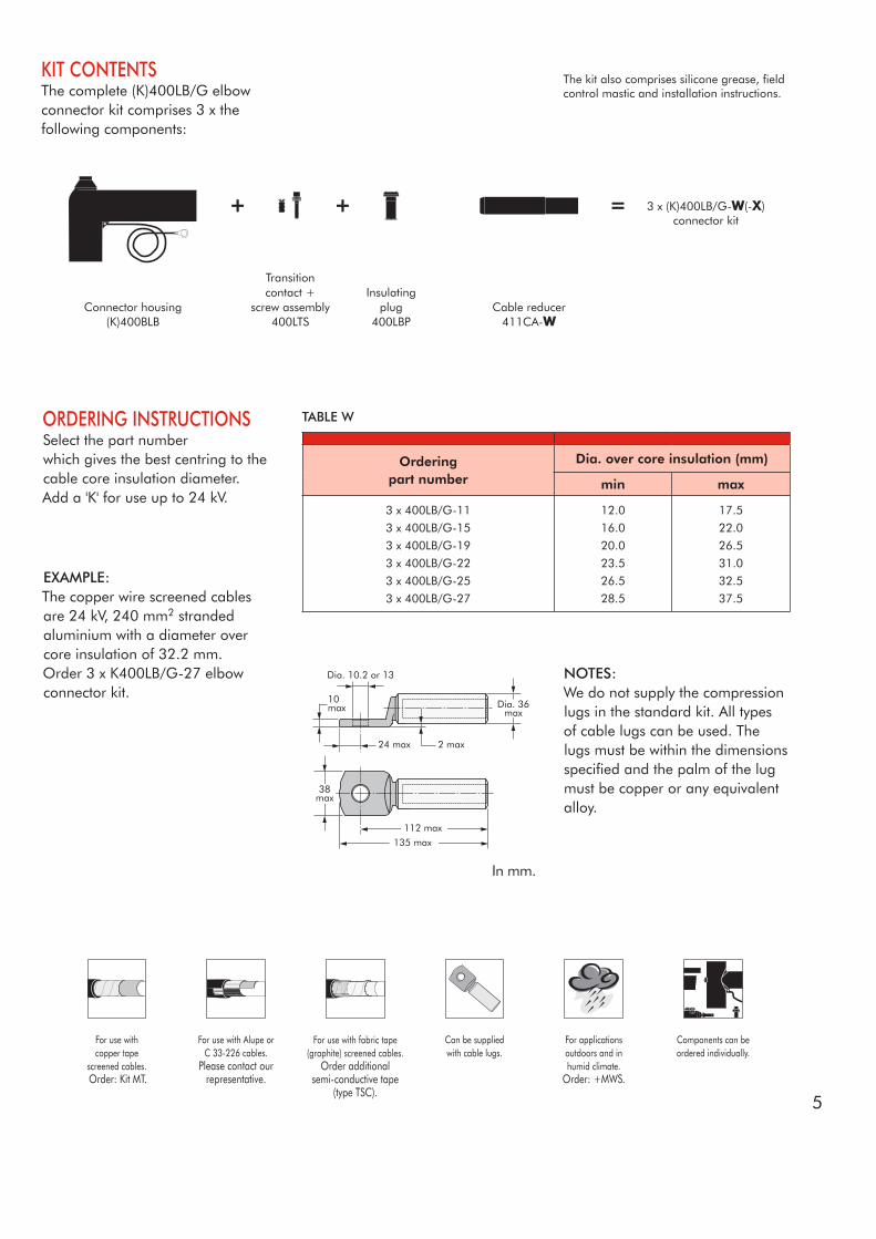
KIT CONTENTSThe complete (K)400LB/G elbow connector kit comprises 3 x the following components:
ORDERING INSTRUCTIONSSelect the part numberwhich gives the best centring to the cable core insulation diameter.Add a 'K' for use up to 24 kV.
Orderingpart number
Dia. over core insulation (mm)
min max
3 x 400LB/G-11
3 x 400LB/G-15
3 x 400LB/G-19
3 x 400LB/G-22
3 x 400LB/G-25
3 x 400LB/G-27
12.0
16.0
20.0
23.5
26.5
28.5
17.5
22.0
26.5
31.0
32.5
37.5
EXAMPLE: The copper wire screened cables are 24 kV, 240 mm2 stranded aluminium with a diameter over core insulation of 32.2 mm.Order 3 x K400LB/G-27 elbow connector kit.
Can be suppliedwith cable lugs.
For applicationsoutdoors and in humid climate.
Order: +MWS.
Components can be ordered individually.
For use withcopper tape
screened cables. Order: Kit MT.
For use with Alupe orC 33-226 cables.
Please contact our representative.
For use with fabric tape (graphite) screened cables.
Order additionalsemi-conductive tape
(type TSC).
3 x (K)400LB/G-W(-X)connector kit
TABLE W
NOTES:We do not supply the compression lugs in the standard kit. All types of cable lugs can be used. The lugs must be within the dimensions specified and the palm of the lug must be copper or any equivalent alloy.
Transitioncontact +
screw assembly400LTS
Insulatingplug
400LBPCable reducer
411CA-WConnector housing
(K)400BLB
2 max
Dia. 10.2 or 13
24 max
112 max 135 max
38max
Dia. 36max
10max
The kit also comprises silicone grease, field control mastic and installation instructions.
In mm.

6
09/2017
Up to 42 kV630 A - 800 A
6/10 (12) kV6.35/11 (12) kV8.7/15 (17.5) kV12/20 (24) kV12.7/22 (24) kV18/30 (36) kV19/33 (36) kV20.8/36 (42) kV
TECHNICAL CHARACTERISTICS • The thick conductive EPDM jacket
provides a total safe to touch screen which ensures safety for personnel.
• Each separable connector is tested for AC withstand and partial discharge prior to leaving the factory.
APPLICATIONSeparable tee shape connector (bolted type) designed to connect polymeric insulated cable to equipment (transformers, switchgear, motors, ...).Also connects cable to cable when using the appropriate mating parts.
DESIGNSeparable connector comprising: 1. Conductive EPDM insert. 2. Conductive EPDM jacket. 3. Insulating EPDM layer. 4. Type C interface as described by CENELEC EN 50180 and 50181. 5. Conductor contact. 6. Basic insulating plug (with VD point). 7. Cable reducer. 8. Conductive rubber cap. 9. Clamping screw. 10. Earthing lead.
The screen break designenables cable outer sheathtesting without removing ordismantling the connector.
SPECIFICATIONS AND STANDARDSThe 400TB separable connector meets the requirements of CENELEC HD 629.1 S1.
220 mm
350 mm
8
4 9
1
2
3
10
7
6
255 mm
5
Separable connector
type
VoltageUm(kV)
CurrentIr
(A)
Current Ir (A)When using a copper (-11-2) or a bolted (-14-5) conductor contact
Conductor sizes (mm2)
min max
400TB/GK400TB/GM400TB/GP400TB/G
12243642
630630630630
800800800800
35353535
300300240240
400TB INTERFACE CTEE CONNECTOR
7
For use withcopper tape
screened cables. Order: Kit MT.
For use in potentiallyexplosive atmospheres
(for 12 kV max). Add -/ATEX to part number.
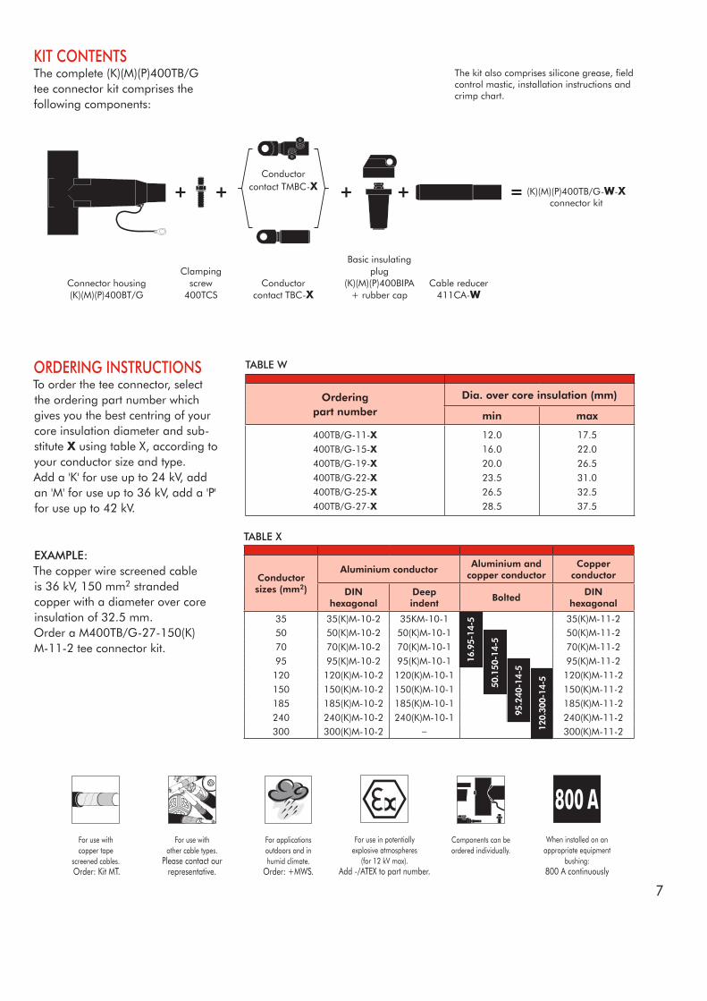
KIT CONTENTSThe complete (K)(M)(P)400TB/G tee connector kit comprises the following components:
ORDERING INSTRUCTIONSTo order the tee connector, select the ordering part number which gives you the best centring of your core insulation diameter and sub-stitute X using table X, according to your conductor size and type.Add a 'K' for use up to 24 kV, add an 'M' for use up to 36 kV, add a 'P' for use up to 42 kV.
Orderingpart number
Dia. over core insulation (mm)
min max
400TB/G-11-X400TB/G-15-X400TB/G-19-X400TB/G-22-X400TB/G-25-X400TB/G-27-X
12.0
16.0
20.0
23.5
26.5
28.5
17.5
22.0
26.5
31.0
32.5
37.5
EXAMPLE:The copper wire screened cable is 36 kV, 150 mm2 stranded copper with a diameter over core insulation of 32.5 mm.Order a M400TB/G-27-150(K)M-11-2 tee connector kit.
TABLE W
TABLE X
(K)(M)(P)400TB/G-W-Xconnector kit
Connector housing(K)(M)(P)400BT/G
Clampingscrew
400TCS
Basic insulatingplug
(K)(M)(P)400BIPA+ rubber cap
Cable reducer411CA-W
Conductorcontact TMBC-X
Conductor contact TBC-X
For use withother cable types.
Please contact our representative.
Components can be ordered individually.
For applicationsoutdoors and in humid climate.
Order: +MWS.
When installed on an appropriate equipment
bushing: 800 A continuously
The kit also comprises silicone grease, field control mastic, installation instructions and crimp chart.
Conductor sizes (mm2)
Aluminium conductorAluminium and
copper conductorCopper
conductor
DINhexagonal
Deepindent
BoltedDIN
hexagonal
35 35(K)M-10-2 35KM-10-1 35(K)M-11-250 50(K)M-10-2 50(K)M-10-1 50(K)M-11-270 70(K)M-10-2 70(K)M-10-1 70(K)M-11-295 95(K)M-10-2 95(K)M-10-1 95(K)M-11-2120 120(K)M-10-2 120(K)M-10-1 120(K)M-11-2150 150(K)M-10-2 150(K)M-10-1 150(K)M-11-2185 185(K)M-10-2 185(K)M-10-1 185(K)M-11-2240 240(K)M-10-2 240(K)M-10-1 240(K)M-11-2300 300(K)M-10-2 – 300(K)M-11-2
16.9
5-14
-5
50.1
50-1
4-5
95.2
40-1
4-5
120.
300-
14-5

8
09/2017
6/10 (12) kV6.35/11 (12) kV8.7/15 (17.5) kV12/20 (24) kV12.7/22 (24) kV18/30 (36) kV19/33 (36) kV20.8/36 (42) kV
Up to 42 kV630 A - 1250 A
TECHNICAL CHARACTERISTICS • The thick conductive EPDM jacket
provides a total safe to touch screen which ensures safety for personnel.
• Each separable connector is tested for AC withstand and partial discharge prior to leaving the factory.
APPLICATIONSeparable tee shape connector (bolted type) designed to connect polymeric insulated cable to equipment (transformers, switchgear, motors, ...).Also connects cable to cable when using the appropriate mating parts.
DESIGNSeparable connector comprising: 1. Conductive EPDM insert. 2. Conductive EPDM jacket. 3. Insulating EPDM layer moulded between the insert and the jacket. 4. Type C interface as described by CENELEC EN 50180 and 50181. 5. Conductor contact. 6. Basic insulating plug (with VD point). 7. Cable reducer. 8. Conductive rubber cap. 9. Clamping screw. 10. Earthing lead.
The screen break designenables cable outer sheathtesting without removing ordismantling the connector.
SPECIFICATIONS AND STANDARDSThe 440TB separable connector meets the requirements of CENELEC HD 629.1.
Separable connector
type
VoltageUm(kV)
CurrentIr
(A)
CurrentIr (A)
Conductor sizes (mm2)
min max440TB/G
K440TB/GM440TB/GP440TB/G
12243642
630630630630
1250125012501250
185185185185
630630630630
4 9
1
2
3
10
7
8
255 mm
220 mm
355 mm
65
440TB INTERFACE CTEE CONNECTOR
9
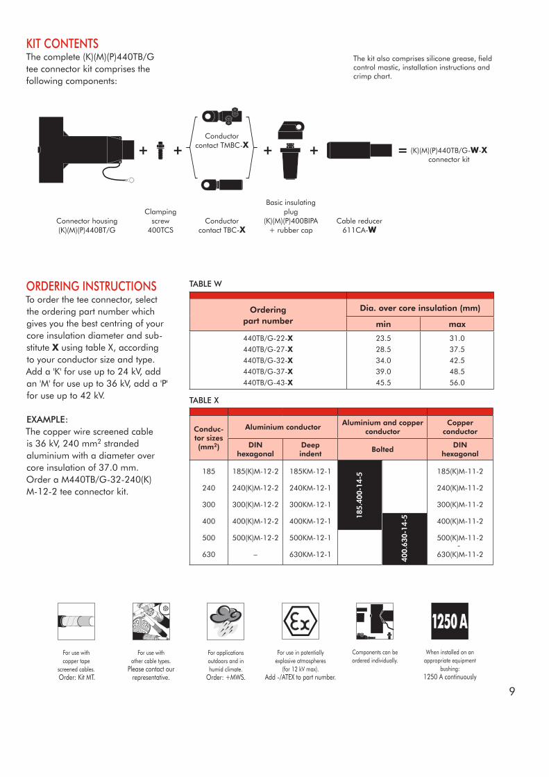
ORDERING INSTRUCTIONSTo order the tee connector, select the ordering part number which gives you the best centring of your core insulation diameter and sub-stitute X using table X, according to your conductor size and type.Add a 'K' for use up to 24 kV, add an 'M' for use up to 36 kV, add a 'P' for use up to 42 kV.
EXAMPLE:The copper wire screened cable is 36 kV, 240 mm2 stranded aluminium with a diameter over core insulation of 37.0 mm.Order a M440TB/G-32-240(K)M-12-2 tee connector kit.
Orderingpart number
Dia. over core insulation (mm)
min max
440TB/G-22-X440TB/G-27-X440TB/G-32-X440TB/G-37-X440TB/G-43-X
23.5
28.5
34.0
39.0
45.5
31.0
37.5
42.5
48.5
56.0
When installed on an appropriate equipment
bushing: 1250 A continuously
TABLE W
TABLE X
Components can be ordered individually.
KIT CONTENTSThe complete (K)(M)(P)440TB/G tee connector kit comprises the following components:
The kit also comprises silicone grease, field control mastic, installation instructions and crimp chart.
(K)(M)(P)440TB/G-W-Xconnector kit
Connector housing(K)(M)(P)440BT/G
Clampingscrew
400TCSCable reducer
611CA-W
Conductorcontact TMBC-X
Conductor contact TBC-X
Basic insulatingplug
(K)(M)(P)400BIPA+ rubber cap
For use withcopper tape
screened cables. Order: Kit MT.
For use in potentiallyexplosive atmospheres
(for 12 kV max). Add -/ATEX to part number.
For use withother cable types.
Please contact our representative.
For applicationsoutdoors and in humid climate.
Order: +MWS.
Conduc-tor sizes (mm2)
Aluminium conductorAluminium and copper
conductorCopper
conductor
DINhexagonal
Deepindent
BoltedDIN
hexagonal
185
240
300
400
500
630
185(K)M-12-2
240(K)M-12-2
300(K)M-12-2
400(K)M-12-2
500(K)M-12-2
–
185KM-12-1
240KM-12-1
300KM-12-1
400KM-12-1
500KM-12-1
630KM-12-1
185(K)M-11-2
240(K)M-11-2
300(K)M-11-2
400(K)M-11-2
500(K)M-11-2
630(K)M-11-2

10
09/2017
APPLICATIONSeparable coupling connector (bolted type) for dual cable arrangement. It has been designed to be used with 400TB and 440TB separable tee connector.
TECHNICAL CHARACTERISTICS• A thick conductive EPDM jacket
provides a total safe to touch screen.
• Each separable connector is tested for AC withstand and partial discharge prior to leaving the factory.
Up to 42 kV800 A
SPECIFICATIONS AND STANDARDSThe 440PB coupling connector meets the requirements of CENELEC HD 629.1.
DESIGN 1. Interface designed to fit 400TB/440TB connector. 2. Contact rod for 440PB. 3. Conductive EPDM insert. 4. Insulating EPDM layer moulded between the insert and the jacket. 5. Conductive EPDM jacket. 6. Conductive EPDM cap. 7. Basic insulating plug. 8. Conductor contact. 9. Cable reducer. 10. Earthing lead. 11. Threaded M16 stud for the equipment bushing.
The screen break designenables cable outer sheathtesting without removing ordismantling the connector.
6/10 (12) kV6.35/11 (12) kV8.7/15 (17.5) kV12/20 (24) kV12.7/22 (24) kV18/30 (36) kV19/33 (36) kV20.8/36 (42) kV
Separable connector
type
VoltageUm(kV)
CurrentIr
(A)
Conductor sizes (mm2)
min max
440PB/GK440PB/GM440PB/GP440PB/G
12243642
800800800800
185185185185
630630630630
355 mm
155 mm
400TB or440TB
connector
410 mm
440PBcouplingconnector
1
2
8
3
4
5
9
7
6
10
11
440PB COUPLING CONNECTOR FOR 400TB AND 440TB
11
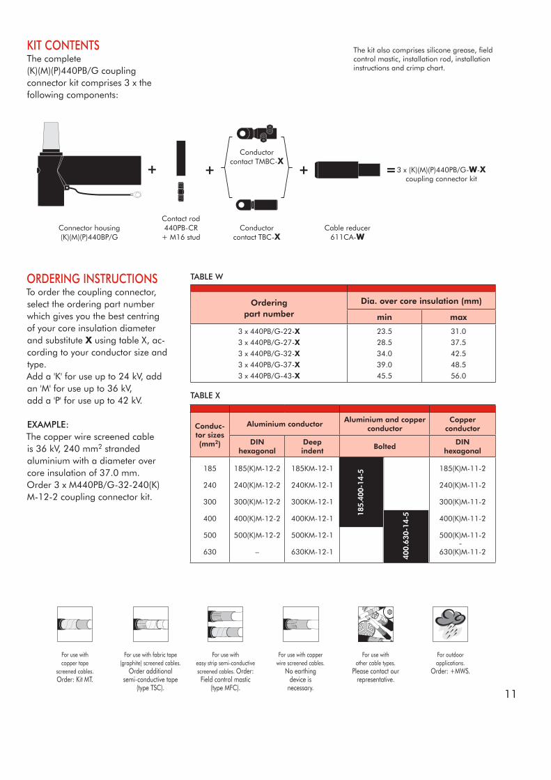
KIT CONTENTSThe complete(K)(M)(P)440PB/G coupling connector kit comprises 3 x the following components:
The kit also comprises silicone grease, field control mastic, installation rod, installation instructions and crimp chart.
For use withcopper tape
screened cables. Order: Kit MT.
For use witheasy strip semi-conductive screened cables. Order: Field control mastic
(type MFC).
For use with copperwire screened cables.
No earthingdevice is
necessary.
For use withother cable types.
Please contact our representative.
For outdoorapplications.
Order: +MWS.
Connector housing(K)(M)(P)440BP/G
For use with fabric tape (graphite) screened cables.
Order additionalsemi-conductive tape
(type TSC).
3 x (K)(M)(P)440PB/G-W-X coupling connector kit
Conductorcontact TMBC-X
Conductor contact TBC-X
ORDERING INSTRUCTIONSTo order the coupling connector, select the ordering part number which gives you the best centring of your core insulation diameter and substitute X using table X, ac-cording to your conductor size and type.Add a 'K' for use up to 24 kV, add an 'M' for use up to 36 kV,add a 'P' for use up to 42 kV.
EXAMPLE:The copper wire screened cable is 36 kV, 240 mm2 stranded aluminium with a diameter over core insulation of 37.0 mm.Order 3 x M440PB/G-32-240(K)M-12-2 coupling connector kit.
Orderingpart number
Dia. over core insulation (mm)
min max
3 x 440PB/G-22-X3 x 440PB/G-27-X3 x 440PB/G-32-X3 x 440PB/G-37-X3 x 440PB/G-43-X
23.5
28.5
34.0
39.0
45.5
31.0
37.5
42.5
48.5
56.0
TABLE W
Contact rod 440PB-CR
+ M16 studCable reducer
611CA-W
TABLE X
Conduc-tor sizes (mm2)
Aluminium conductorAluminium and copper
conductorCopper
conductor
DINhexagonal
Deepindent
BoltedDIN
hexagonal
185
240
300
400
500
630
185(K)M-12-2
240(K)M-12-2
300(K)M-12-2
400(K)M-12-2
500(K)M-12-2
–
185KM-12-1
240KM-12-1
300KM-12-1
400KM-12-1
500KM-12-1
630KM-12-1
185(K)M-11-2
240(K)M-11-2
300(K)M-11-2
400(K)M-11-2
500(K)M-11-2
630(K)M-11-2

12
09/2017
APPLICATIONSurge arrester designed to protect medium voltage components, including transformers, equipment, cable and accessories from high voltage surges resulting from lightning or switching.
Up to 42 kV
6/10 (12) kV6.35/11 (12) kV8.7/15 (17.5) kV12/20 (24) kV12.7/22 (24) kV18/30 (36) kV19/33 (36) kV20.8/36 (42) kV
TECHNICAL CHARACTERISTICS • This surge arrester is a metal
oxide varistor surge arrester in an elbow configuration.
• Each arrester is tested for AC withstand, partial discharge and critical voltage prior to leaving the factory.
4
1
2
3
8
7
6
5
9
247 mm
145 mm
Dia.80 mm
L2L1
Dia.70 mm
DESIGNSurge arrester comprising:1. Conductive EPDM insert.2. Conductive EPDM jacket.3. Insulating EPDM layer moulded between the insert and the jacket.4. Contact rod.5. Earthing lead.6. Earth connection.7. Steel cap.8. Metal oxide valve elements.9. Type C interface as described by CENELEC EN 50180 and 50181.
SPECIFICATIONS AND STANDARDSThe 400PB-10SA surge arresters meet the test requirements of IEC 60099-4.
Surgearrester
type
Nominal discharge
currentIn (kA)
Rated voltageUr (kV)
Max. continuousoperatingvoltageUc (kV)
Dimensions(mm)
L1 L2
400PB-10SA-15L400PB-10SA-18L400PB-10SA-22L400PB-10SA-24L400PB-10SA-30L400PB-10SA-6N400PB-10SA-9N400PB-10SA-12N400PB-10SA-15N400PB-10SA-18N400PB-10SA-22N400PB-10SA-24N400PB-10SA-30N400PB-10SA-33N400PB-10SA-36N400PB-10SA-45N400PB-10SA-51N
1010101010101010101010101010101010
15182224306912151822243033364551
12.014.417.619.224.04.87.29.612.014.417.619.224.026.428.836.040.8
270270370370370270270270270270270370370370370470470
310310410410410310310310310310310410410410410510510
400PB-10SA INTERFACE CSURGE ARRESTER
13
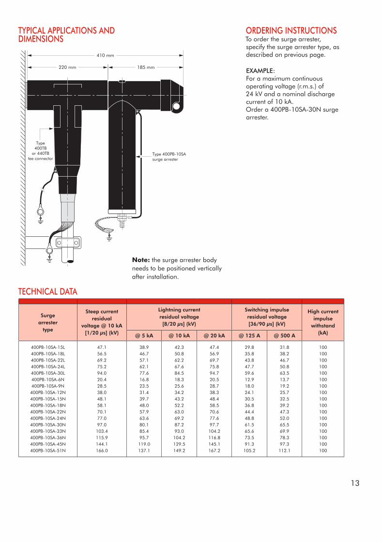
TYPICAL APPLICATIONS ANDDIMENSIONS
ORDERING INSTRUCTIONSTo order the surge arrester, specify the surge arrester type, as described on previous page.
EXAMPLE:For a maximum continuous operating voltage (r.m.s.) of 24 kV and a nominal discharge current of 10 kA.Order a 400PB-10SA-30N surge arrester.
TECHNICAL DATA
185 mm
410 mm
220 mm
Type400TB
or 440TBtee connector
Type 400PB-10SAsurge arrester
Surgearrester
type
Steep currentresidual
voltage @ 10 kA[1/20 µs] (kV)
Lightning currentresidual voltage[8/20 µs] (kV)
Switching impulseresidual voltage[36/90 µs] (kV)
High currentimpulse
withstand(kA)@ 5 kA @ 10 kA @ 20 kA @ 125 A @ 500 A
400PB-10SA-15L400PB-10SA-18L400PB-10SA-22L400PB-10SA-24L400PB-10SA-30L400PB-10SA-6N400PB-10SA-9N400PB-10SA-12N400PB-10SA-15N400PB-10SA-18N400PB-10SA-22N400PB-10SA-24N400PB-10SA-30N400PB-10SA-33N400PB-10SA-36N400PB-10SA-45N400PB-10SA-51N
47.156.569.275.294.020.428.538.048.158.170.177.097.0103.4115.9144.1166.0
38.946.757.162.177.616.823.531.439.748.057.963.680.185.495.7119.0137.1
42.350.862.267.684.518.325.634.243.252.263.069.287.293.0104.2129.5149.2
47.456.969.775.894.720.528.738.348.458.570.677.697.7104.2116.8145.1167.2
29.835.843.847.759.612.918.024.130.536.844.448.861.565.673.591.3105.2
31.838.246.750.863.513.719.225.732.539.247.352.065.569.978.397.3112.1
100100100100100100100100100100100100100100100100100
Note: the surge arrester body needs to be positioned vertically after installation.
14
09/2017
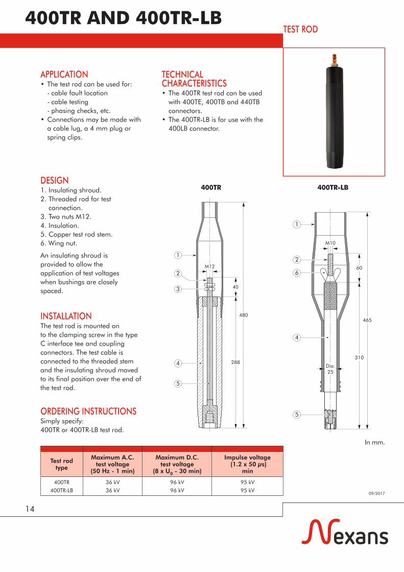
APPLICATION• The test rod can be used for: - cable fault location - cable testing - phasing checks, etc.• Connections may be made with
a cable lug, a 4 mm plug or spring clips.
INSTALLATIONThe test rod is mounted onto the clamping screw in the type C interface tee and coupling connectors. The test cable is connected to the threaded stem and the insulating shroud moved to its final position over the end of the test rod.
DESIGN1. Insulating shroud.2. Threaded rod for test connection.3. Two nuts M12.4. Insulation.5. Copper test rod stem.6. Wing nut.
An insulating shroud isprovided to allow theapplication of test voltageswhen bushings are closelyspaced.
Test rod type
Maximum A.C.test voltage
(50 Hz - 1 min)
Maximum D.C.test voltage
(8 x U0 - 30 min)
Impulse voltage (1.2 x 50 µs)
min
400TR
400TR-LB
36 kV
36 kV
96 kV
96 kV
95 kV
95 kV
TECHNICAL CHARACTERISTICS • The 400TR test rod can be used
with 400TE, 400TB and 440TB connectors.
• The 400TR-LB is for use with the 400LB connector.
In mm.
400TR 400TR-LB
ORDERING INSTRUCTIONSSimply specify:400TR or 400TR-LB test rod.
465
310
M10
Dia.25
60
1
2
6
4
5
1
2
4 288
480
403
5
M12
400TR AND 400TR-LBTEST ROD
15
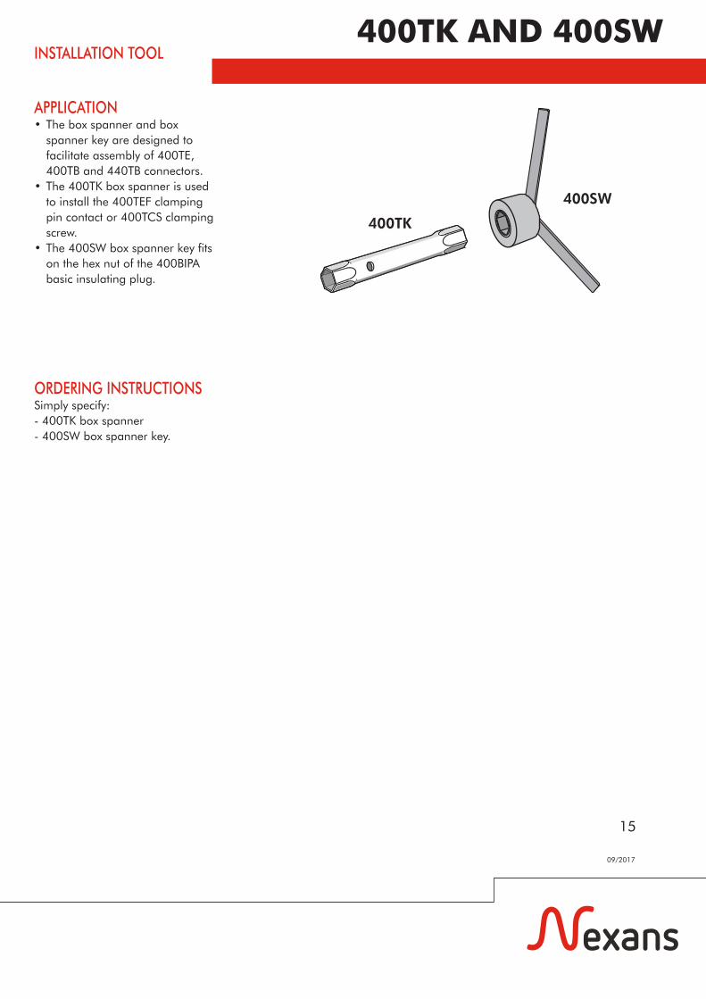
APPLICATION• The box spanner and box
spanner key are designed to facilitate assembly of 400TE, 400TB and 440TB connectors.
• The 400TK box spanner is used to install the 400TEF clamping pin contact or 400TCS clamping screw.
• The 400SW box spanner key fits on the hex nut of the 400BIPA basic insulating plug.
ORDERING INSTRUCTIONSSimply specify:- 400TK box spanner- 400SW box spanner key.
400TK
400SW
400TK AND 400SWINSTALLATION TOOL
09/2017
15
16
09/2017
Up to 36 kV
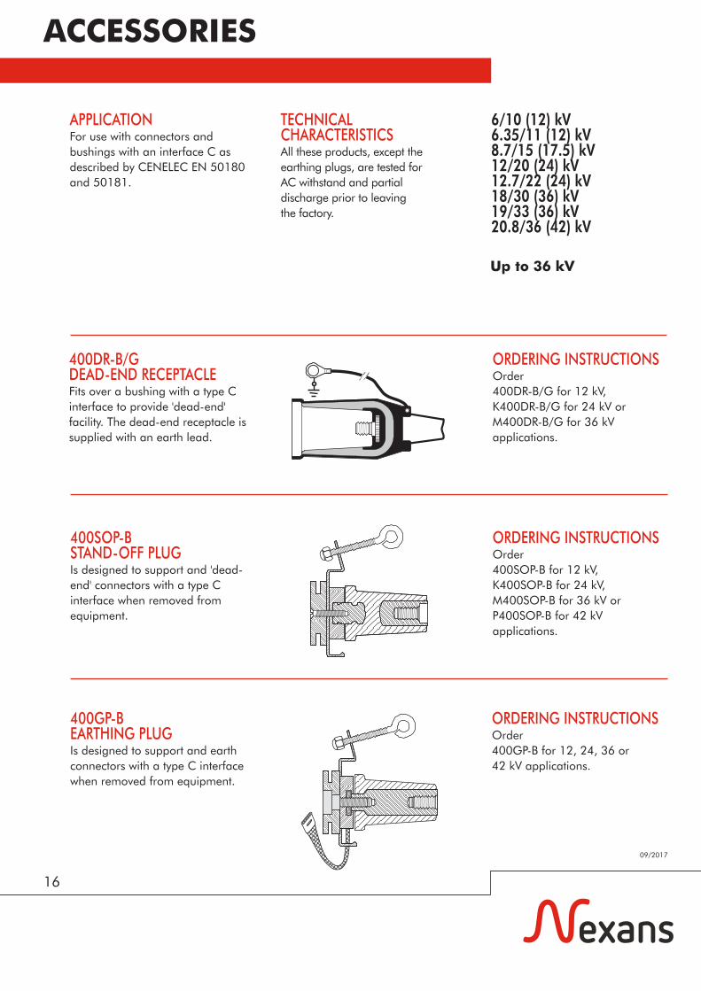
APPLICATIONFor use with connectors and bushings with an interface C as described by CENELEC EN 50180 and 50181.
TECHNICAL CHARACTERISTICS All these products, except theearthing plugs, are tested forAC withstand and partial discharge prior to leavingthe factory.
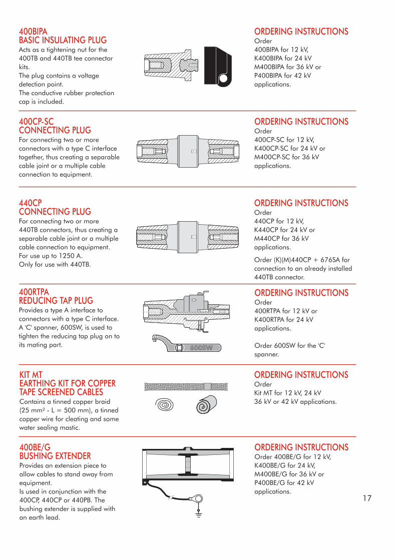
400SOP-BSTAND-OFF PLUGIs designed to support and 'dead-end' connectors with a type C interface when removed from equipment.
ORDERING INSTRUCTIONSOrder 400SOP-B for 12 kV,K400SOP-B for 24 kV,M400SOP-B for 36 kV orP400SOP-B for 42 kVapplications.
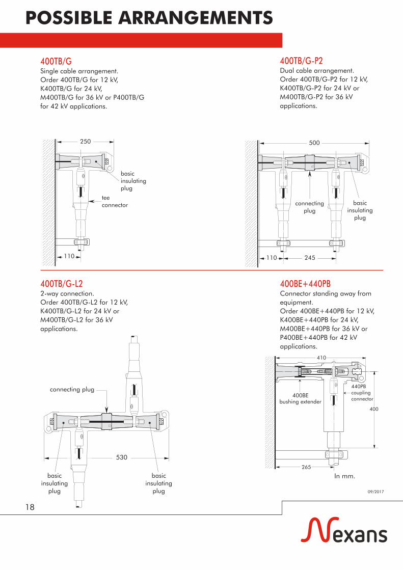
400GP-BEARTHING PLUGIs designed to support and earth connectors with a type C interface when removed from equipment.
ORDERING INSTRUCTIONSOrder 400GP-B for 12, 24, 36 or42 kV applications.
400DR-B/GDEAD-END RECEPTACLEFits over a bushing with a type C interface to provide 'dead-end' facility. The dead-end receptacle is supplied with an earth lead.
ORDERING INSTRUCTIONSOrder 400DR-B/G for 12 kV,K400DR-B/G for 24 kV orM400DR-B/G for 36 kVapplications.
6/10 (12) kV6.35/11 (12) kV8.7/15 (17.5) kV12/20 (24) kV12.7/22 (24) kV18/30 (36) kV19/33 (36) kV20.8/36 (42) kV
ACCESSORIES
17
KIT MTEARTHING KIT FOR COPPER TAPE SCREENED CABLESContains a tinned copper braid (25 mm² - L = 500 mm), a tinned copper wire for cleating and some water sealing mastic.
ORDERING INSTRUCTIONS Order Kit MT for 12 kV, 24 kV 36 kV or 42 kV applications.
400RTPAREDUCING TAP PLUGProvides a type A interface to connectors with a type C interface.A 'C' spanner, 600SW, is used to tighten the reducing tap plug on to its mating part.
ORDERING INSTRUCTIONSOrder 400RTPA for 12 kV or K400RTPA for 24 kVapplications.
Order 600SW for the 'C'spanner.
400CP-SCCONNECTING PLUGFor connecting two or more connectors with a type C interface together, thus creating a separable cable joint or a multiple cable connection to equipment.
ORDERING INSTRUCTIONSOrder 400CP-SC for 12 kV, K400CP-SC for 24 kV orM400CP-SC for 36 kVapplications.
440CPCONNECTING PLUGFor connecting two or more 440TB connectors, thus creating a separable cable joint or a multiple cable connection to equipment.For use up to 1250 A.Only for use with 440TB.
ORDERING INSTRUCTIONSOrder 440CP for 12 kV, K440CP for 24 kV orM440CP for 36 kVapplications.
Order (K)(M)440CP + 676SA for connection to an already installed 440TB connector.
400BIPABASIC INSULATING PLUGActs as a tightening nut for the 400TB and 440TB tee connector kits.The plug contains a voltage detection point.The conductive rubber protection cap is included.
ORDERING INSTRUCTIONSOrder 400BIPA for 12 kV, K400BIPA for 24 kV M400BIPA for 36 kV orP400BIPA for 42 kVapplications.
400BE/GBUSHING EXTENDERProvides an extension piece to allow cables to stand away from equipment. Is used in conjunction with the 400CP, 440CP or 440PB. The bushing extender is supplied with an earth lead.
ORDERING INSTRUCTIONSOrder 400BE/G for 12 kV, K400BE/G for 24 kV, M400BE/G for 36 kV or P400BE/G for 42 kV applications.
18
09/2017
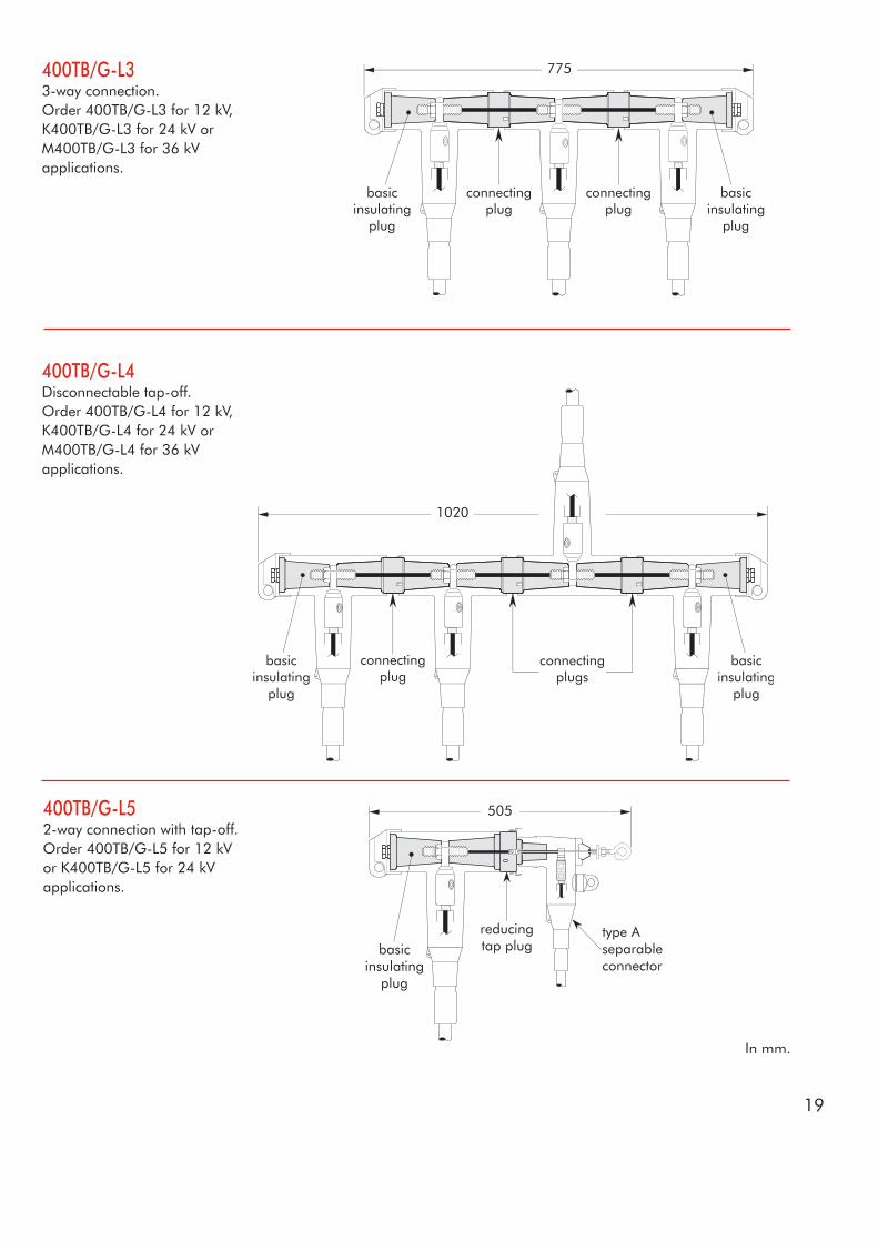
400TB/GSingle cable arrangement.Order 400TB/G for 12 kV, K400TB/G for 24 kV,M400TB/G for 36 kV or P400TB/G for 42 kV applications.
400TB/G-P2Dual cable arrangement.Order 400TB/G-P2 for 12 kV, K400TB/G-P2 for 24 kV or M400TB/G-P2 for 36 kV applications.
400TB/G-L22-way connection.Order 400TB/G-L2 for 12 kV, K400TB/G-L2 for 24 kV or M400TB/G-L2 for 36 kV applications.
400BE+440PBConnector standing away from equipment.Order 400BE+440PB for 12 kV, K400BE+440PB for 24 kV, M400BE+440PB for 36 kV or P400BE+440PB for 42 kV applications.
250
teeconnector
basicinsulatingplug
110
500
110 245
basicinsulating
plug
connectingplug
In mm.
400
410
400BEbushing extender
265
POSSIBLE ARRANGEMENTS
19
In mm.
400TB/G-L4Disconnectable tap-off.Order 400TB/G-L4 for 12 kV, K400TB/G-L4 for 24 kV or M400TB/G-L4 for 36 kV applications.
400TB/G-L52-way connection with tap-off.Order 400TB/G-L5 for 12 kV or K400TB/G-L5 for 24 kV applications.
505
400TB/G-L33-way connection.Order 400TB/G-L3 for 12 kV, K400TB/G-L3 for 24 kV or M400TB/G-L3 for 36 kV applications.
20
09/2017
In mm.
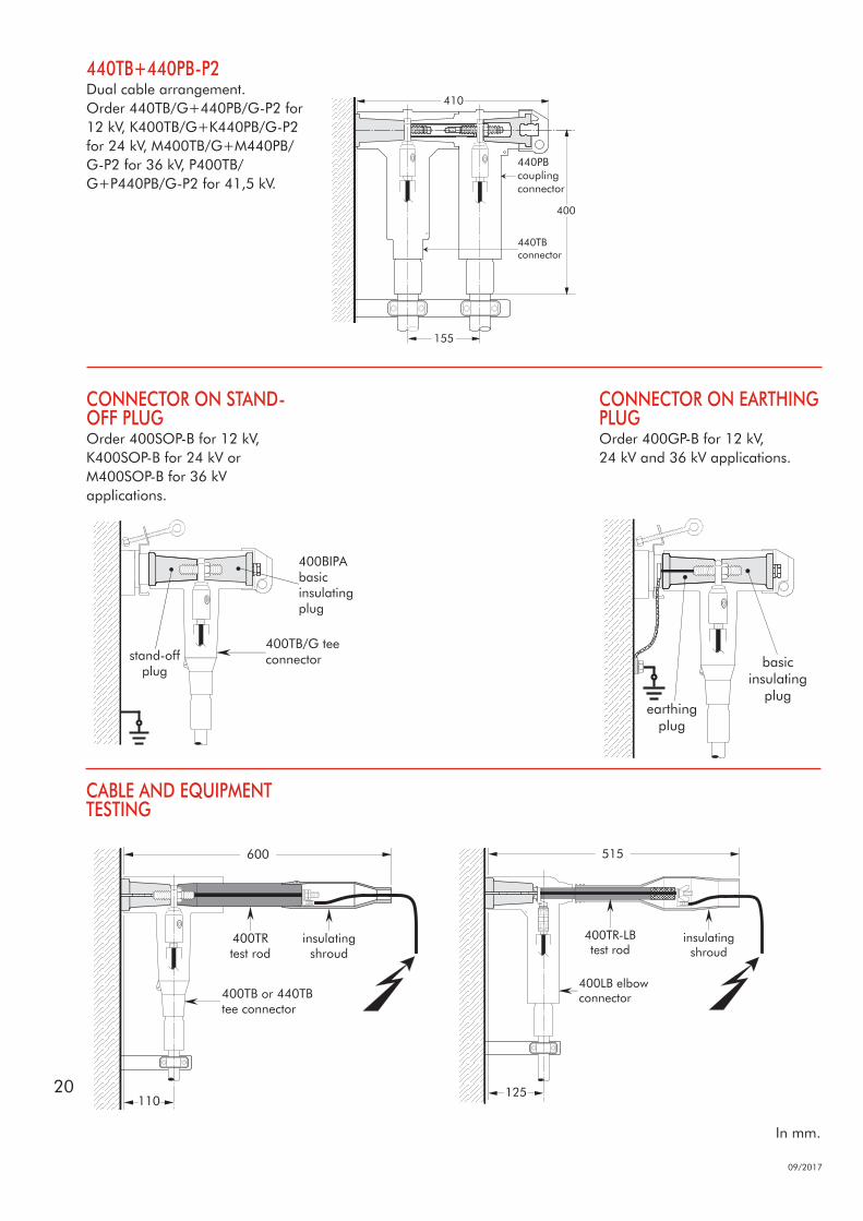
CABLE AND EQUIPMENT TESTING
CONNECTOR ON EARTHING PLUGOrder 400GP-B for 12 kV, 24 kV and 36 kV applications.
CONNECTOR ON STAND-OFF PLUGOrder 400SOP-B for 12 kV, K400SOP-B for 24 kV or M400SOP-B for 36 kV applications.
400TB/G teeconnectorstand-off
plug
400BIPAbasicinsulatingplug
400
155
410
440TB+440PB-P2Dual cable arrangement.Order 440TB/G+440PB/G-P2 for 12 kV, K400TB/G+K440PB/G-P2 for 24 kV, M400TB/G+M440PB/G-P2 for 36 kV, P400TB/G+P440PB/G-P2 for 41,5 kV.


09/2
017
Nexans Network Solutions N.V. - Div. Euromold Zuid III, Industrielaan 12, B-9320 ErembodegemTel.: +32(0)53 85 02 11 • [email protected] • www.euromold.be
Catalogue also available on Website and Mobile Apps
Find out more about Nexans Power Accessories.