design and analysis for 1mwe parabolic trough solar ... · 1mwe parabolic trough solar thermal...
TRANSCRIPT

Design and Analysis for 1MWe Parabolic Trough Solar Collector plant based
on DSG method
Mr. Arvind Kumar Prof. (Dr). Satish Chand Mr. O.P. Umrao
MIT, Bulandshahr VGI, Greater Noida VGI, Greater Noida
Abstract
Our objective to find the number of international
standard size collector (ET-100) for designed output
1MWe parabolic trough solar thermal power plant
based on DSG method. For evaluation of this
designed output have done thermal analysis of steam
cycle. In steam analysis, we have found steam flow
rate, inlet temperature of collector, heat required per
unit length for this design output and thermal
efficiency of steam cycle. Further we have done
optical and thermal analysis of PTSC. For, New
Delhi locality took average annual air speed and
solar irradiance then, we shall evaluate overall heat
loss coefficient for receiver tube, correction glass
cover temperature and inside tube fluid heat transfer
coefficient. Further, compute collector efficiency
factor, heat removal factor and total area of
collector. For geometric analysis of parabolic
mirror, EuroTrough-100 collector data to reckon the
rim radius, focal distance, parabola curve length,
geometric ratio, intercept factor, geometric factor
and optical efficiency. Next, we have found collector
efficiency and overall collector efficiency. We have
also calculated percentage loss of heat from system
and utilization of heat for power generation. Finally
we have spied the number of collector for 1MWe
electric output. We have designed a practical
arrangement of collectors with a suitable diagram.
Keywords:-PTSC, DSG, HCE, optical & collector
efficiency, receiver tube, geometric ratio, intercept
factor heat removal factor, collector efficiency factor
etc.
1. Introduction The most serious challenges are scarcity of
conventional energy resources in India & also world
countries. The solar thermal systems play a vital role
to deliver the non-polluting energy for domestic and
industrial application. India has an ambitious target
for the share of renewable energies in the national
energy mix.
In this literature review the thorough
study of research papers on the parabolic trough solar
collector is done. Ari Rabl [1] matched a variety of
different solar concentrators in terms of their most
important general characteristics namely
Concentration, acceptance angle, sensitivity to mirror
errors, size of reflector area and average number of
reflections. The connection between concentration,
acceptance angle and operating temperature of a solar
collector is analyzed in simple intuitive terms for
designing for designing collectors with maximum
concentration. M J Brookes et al. [2] explained the
effect of the solar multiple on the annual performance
of parabolic trough solar thermal power plants with
direct steam generation (DSG). It has comprehend
that number of collector will be solar field and also
thermal storage. It is pointed out that the role of DSG
with natural gas plant provides good outcome such as
reduce cost of generation. Ming Qu et al. [3]
calculated single dimensional heat transfer such
radiative, convective, conductive and mass and
energy that is solved by engineering equation solver.
It plotted number of graph between operating
parameters. It makes the program for PTC tracking to
provide right focus on evacuated transparent glass
receiver. Scott A. Jones et al. [4] created model of
30MWe SEGS VI in the TRNSYS simulation
software to understand the behavior in respect of
operating conditions. It anticipates effect on model in
adequate environment condition. This software has
capability to perform details analysis by which model
could be improved Isabel Llorente Garcia et al. [5]
explained the performance of parabolic trough solar
thermal power plant with help of simulation model.
The model is to anticipate the electric output during
the various stages of planning, design, operation and
construction. This model compares result to real data
(50MWe operated by ACS Industrial group of
Spain). Doing this comparison we can decide the
mass flow rate of HTF. Balbir Singh Mahinder Singh
et al. [6] focus active involvement of PTC in
Malaysia. The importance due to scarcity of fossil
fuel is used. It designed PTC by simulation software
to the selection of certain parameter such the aperture
area and obtained the geometric concentration ratio
by receiver diameter. To evaluate the optical
precision for thermal performance of CPTC, to the
thermal losses reduced by aperture area. V.Siva
Reddy et al. [7] did exergetic analysis of PTCSTPP
IJERT
IJERT
2771
International Journal of Engineering Research & Technology (IJERT)
Vol. 2 Issue 6, June - 2013ISSN: 2278-0181
www.ijert.orgIJERTV2IS60779
to improve the performance of the plant to reduce the
loss of the components to optimize the maximum
efficiency. Land areas required for 50MWe for the
location of Jodhpur and Delhi to increase exergetic
efficiency from 23.66% to 24.32%. It also found that
the exergetic and exergetic efficiency of PTC. Iman
Niknia et al. [8] perform a transient simulation to
integrating a new PTC collector with oil cycle and an
auxiliary boiler. For analysis, a computer code is
developed and experiments are performed to validate
the simulation program. Based on the selected
conditions, annual power generation of solar part and
fossil section are determined and compared with
fossil fuel plant. Comparison of the new system with
previous arrangement illustrates that various
integration schemes can be easily simulated and an
appropriate system to satisfy the main design
objectives can be chosen. Iman Niknia et al. [9]
designed for 250 kW Shiraz solar thermal power
plant power to promote the field of collectors by
installing a large parabolic collector and combining
the system with a 500 kW hybrid boiler. This hybrid
plant performance is evaluated by simulation
software to predict outcomes at the operating
working condition. Due to this capability, this
provides best strategies to control the operation.
Hank Price et al. [10] reviewed the current state of
the art of parabolic trough solar power technology
and described the R&D efforts that are in progress to
enhance this technology. The paper also shows how
the economics of future parabolic trough solar power
plants are expected to improve. The operating
performance of the existing parabolic trough power
plants has demonstrated this technology to be robust
and an excellent performer in the commercial power
industry and since the last commercial parabolic
trough plant was built, substantial technological
progress has been realized. The various alternative
technologies are given for the tracking mechanisms,
reflector materials, heat collection elements thermal
characteristics, heat transfer fluids and power cycle to
reduce the cost of the plant. Parabolic trough solar
power technology appears to be capable of competing
directly with conventional fossil-fuel power plants in
mainstream markets in the relatively near term.
Given that parabolic trough technology utilizes
standard industrial manufacturing processes,
materials, and power cycle equipment, the
technology is poised for rapid deployment should the
need emerge for a low-cost solar power option
S.K. Tyagi et al. [11] evaluated the exergetic
performance of concentrating type solar collector and
the parametric study is made using hourly solar
radiation from the exergy output is optimized with
respect to the inlet fluid temperature and the
corresponding efficiencies are computed. R.Lugo-
Leyte et al. [12] suggested to preventing the
deflection due to long pipe/tube & high temperature.
It has provided the composition of receiver tube
material as copper (20%) and steel (80%). according
this compound pipe is 75% less than gradient of the
simple pipe in a time of ten second. Compound
absorber pipe offer greater resistance to the deflection
provoked by the direct steam generation. Amirtham
Valan Arasu et al. [13] investigated the performance
of a new parabolic trough collector hot water
generation system with a well-mixed hot water
storage tank. The storage tank water temperature is
increased from 35ºC at 9.30 h to 73.84ºC at 16.00 h
when no energy is withdrawn from the storage tank.
The average beam radiation during the collection
period is 699 W/m2. The useful heat gain, collector
instantaneous efficiency, energy gained by the
storage tank water and the efficiency of the system as
a whole are found to follow the variation of incident
beam radiation as these parameters are strongly
influenced by the incident beam radiation. The values
of each of those parameters are observed maximum
at noon. Soteris A. Kalogirou et al. [13] presented a
parabolic trough solar collector system used for
steam generation. A Modelling program called as
PTCDES which is written in BASIC language is
developed for determining the quantity of steam
produced by the steam generation system. The flash
vessel size, capacity and inventory determine how
much energy is used at the beginning of the day for
raising the temperature of the circulating water to
saturation temperature before effective steam
production begins. System performance tests indicate
that the Modelling program is accurate to within
1.2% which is considered very accurate. The
theoretical system energy analysis is presented in the
form of Sankey diagram. The analysis shows that
only 48.9% of the available solar radiation is used for
steam generation. Martin Kaltschmitt et al. [15]
described that solar energy has a share of more than
99.9 % of all the energy converted on earth. The solar
radiation incident on the earth is weakened within the
atmosphere and partially converted into other energy
forms (e.g. wind, hydro power). Part of the solar
radiation energy can be converted into heat by using
absorbers (e.g. solar collectors). A. El Fadar et al.
[21] presented a study of solar adsorption cooling
machine, where the reactor is heated by a parabolic
trough collector (PTC) and is coupled with a heat
pipe (HP). This reactor contains a porous medium
constituted of activated carbon, reacting by
adsorption with ammonia. A model, based on the
equilibrium equations of the refrigerant, adsorption
isotherms, heat and mass transfer within the
IJERT
IJERT
2772
International Journal of Engineering Research & Technology (IJERT)
Vol. 2 Issue 6, June - 2013ISSN: 2278-0181
www.ijert.orgIJERTV2IS60779

adsorbent bed and energy balance in the hybrid
system components has been developed. From real
climatic data, the model computes the performances
of the machine. In comparison with other systems
powered by flat plate or evacuated tube collectors.
The numerical results show a great sensitivity of the
performance coefficient of the machine to the radius
of the absorber and the aperture width of collector. Ricardo Vasquez Padilla et al. [16] performed a one
dimensional numerical heat transfer analysis of a
PTSC. The receiver and envelope were divided into
several segments and mass and energy balance were
applied in each segment. Improvements either in the
heat transfer correlations or radiative heat transfer
analysis are presented as well. The partial differential
equations were discretized and the nonlinear
algebraic equations were solved simultaneously.
Finally, to validate the numerical results, the model
was compared with experimental data obtained from
Sandia National Laboratory (SNL) and other one
dimensional heat transfer models. The results showed
a better agreement with experimental data compared
to other models.
2. Description of PTSC plant based on DSG A PTC is basically made up of a parabolic trough-
shaped mirror that reflects direct solar radiation,
concentrating it onto a receiver tube located in the
focal line of the parabola. Concentration of the direct
solar radiation reduces the absorber surface area with
respect to the collector aperture area and thus
significantly reduces the overall thermal losses. The
concentrated radiation heats the fluid that circulates
through the receiver tube, thus transforming the solar
radiation into thermal energy in the form of the
sensible heat of the fluid. The geometrical
concentration ratio reaches about 20 to 100. This
produced the temperature about 3750C of
receiver/absorber tube. We convey the water inside
the absorber tube from given point 4 that is inlet for
absorber tube. They take the heat converted into
steam at required pressure and temperature as
desired. This steam goes to steam turbine then
expanded to produce mechanical work converted in
electrical energy by generator. Exhaust steam goes to
condenser which maintained the pressure below
surrounding and also removed the heat to
surrounding or cogeneration by external circuit of
heating/cooling. Then pump suck water send it to
inlet of collector at required pressure. Then inlet
water gets heat then converts steam. This conversion
of water into steam occurs slowly inlet to outlet of
collector. [18].DSG has technical advantages that
must be considered Zarza et al. [24]
No danger of pollution or fire due to the use of
thermal oil at temperatures of about 4000C
Opportunity to increase the maximum
temperature of the Rankine cycle above 4000C,
the limit imposed by the thermal oil currently
used
Reduction in the size of the solar field, thus
reducing the investment cost
Reduction in operation and maintenance-related
costs, as thermal oil-based systems require a
certain amount of the oil inventory to be
changed every year, as well as antifreeze
protection when the air temperature is below
140C
3. Mathematical formulation 3.1. Analysis of Steam Cycle
Constant pressure rejection in condenser (2-3)
Constant pressure addition in evaporator/boiler
(4-1)
Adiabatic expansion process in steam
turbine(1-2)
Isochoric and adiabatic process in pump (3-4)
Pump
Turbine
Parabolic trough
collector
Condesner
Generator
Sun
3
4
1
2
1
22'
3
4
4'
Tem
peratu
re,
K
Entropy, KJ/kgK
a
b
Fig.1. (a) Schematic diagram of direct steam
generation with PTC as generator/receiver tube
and (b) temperature versus entropy
corresponding above power cycle
IJERT
IJERT
2773
International Journal of Engineering Research & Technology (IJERT)
Vol. 2 Issue 6, June - 2013ISSN: 2278-0181
www.ijert.orgIJERTV2IS60779

Table 1.Operational data for PTSC based on DSG
Net Grid power/generator power 1MWe
Inlet steam pressure 100 bar
Inlet steam temperature 3750C
Condenser pressure 0.112 bar
Overall efficiency for electric
generator and electric
grid/parasitic loss
95%
Turbine shaft output 1.050 MWe
Dryness fraction at the outlet of
condenser
saturated liquid =0
Steam turbine efficiency 88%
Pump efficiency 89%
Diameter of receiver /absorber
tube Dr =Do
0.07 m
Diameter of glass cover tube Dg 0.10 m
Inside diameter of receiver tube 0.055 m
Single module length of Euro
Trough (ET-100)
12.27 m
Aperture width 5.76 m
Material for receiver tube stainless steel
reflectance of the mirror ρ 0.94
transmittance of the glass cover τ 0.89
absorptance of the receiver α 0.94
angle of incidence θ 0°
intercept factor 0.95
Wind speed 3.03 m/s for New
Delhi locality
according Synergy co.
India
Average annual Solar insolation 550w/m2 for New
Delhi according
Synergy co. India
Important relations used for the analysis of steam
Rankine cycle
Turbine efficiency
Pump efficiency
Net power output
Heat input
Pump work
Thermal efficiency of steam cycle
Steam flow rate in Kg/sec
3.2. Optical analysis of parabolic trough collectors
For specular reflectors of perfect alignment, the size
of the receiver (diameter D) required to intercept all
the solar image can be obtained from trigonometry
and Figure 2, given by Duffie et al. [17]
ϕr
2θm
fD
0.5 Wa
rr
2θm
Fig. 2.cross-section of a parabolic trough collector
with circular receiver
As υ varies from 0 to , r increases from f to rr and
the theoretical image size increases from 2 f sin (θm)
to ⁄ Therefore, there is an
image spreading on a plane normal to the axis of the
parabola
Another important parameter related to the rim angle
is the aperture of the parabola, Wa
IJERT
IJERT
2774
International Journal of Engineering Research & Technology (IJERT)
Vol. 2 Issue 6, June - 2013ISSN: 2278-0181
www.ijert.orgIJERTV2IS60779

Equating above equation, again the aperture of the
parabola
Reduce it to like
For a tubular receiver, the concentration ratio is given
by
By replacing D and Wa
The maximum concentration ratio occurs when is
90° and sin ( ) = 1. Therefore, by replacing sin ( )
= 1 in Eq. (14), the following maximum value can be
obtained:
The curve length of the reflective surface is given by
,
*
+-
It is also shown that, for different rim angles, the
focus-to-aperture ratio, which defines the curvature
of the parabola, changes. It can be demonstrated that,
with a 90° rim angle, the mean focus-to-reflector
distance and hence the reflected beam spread is
minimized, so that the slope and tracking errors are
less pronounced. The collector’s surface area,
however, decreases as the rim angle is decreased.
There is thus a temptation to use smaller rim angles
because the sacrifice in optical efficiency is small,
but the saving in reflective material cost is great
The amount of aperture area lost is
0
1
For a plate extending from rim to rim, the lost area is
Where hp =height of parabola (m).
Therefore, to find the total loss in aperture area, Al,
the two areas, Ae and Ab, are added together without
including the term tan θ. Jeter et al. [19]
0
1
Intercept factor
Using the universal error parameters, the formulation
of the intercept factor, γ, is possible. Guven et al. [15]
∫ 2 [ ][ ] [ ]
√ [ ]3
2 [ ][ ] [ ]
√ [ ]3
[ ]
Optical efficiency is defined as the ratio of the
energy absorbed by the receiver to the energy
incident on the collector’s aperture. The optical
efficiency depends on the optical properties of the
materials involved, the geometry of the collector, and
the various imperfections arising from the
construction of the collector. Sodha et al. [23]
3.3. Thermal analysis of parabolic trough
collectors
The generalized thermal analysis of a concentrating
solar collector is similar to that of a flat-plate
collector. For a bare tube receiver and assuming no
temperature gradients along the receiver, the loss
coefficient considering convection and radiation from
the surface and conduction through the support
structure is given by
The linearized radiation coefficient can be estimated
from
If a single value of hr is not acceptable due to large
temperature variations along the flow direction, the
collector can be divided into small segments, each
with a constant hr.
For the wind loss coefficient, the Nusselt number can
be used.
For
IJERT
IJERT
2775
International Journal of Engineering Research & Technology (IJERT)
Vol. 2 Issue 6, June - 2013ISSN: 2278-0181
www.ijert.orgIJERTV2IS60779

Estimation of the conduction losses requires
knowledge of the construction of the collector, i.e.,
the way the receiver is supported. Usually, to reduce
the heat losses, a concentric glass tube is employed
around the receiver. The space between the receiver
and the glass is usually evacuated, in which case the
convection losses are negligible. In this case, UL
based on the receiver area Ar is given by
0
( )
1
(
)
[
(
)]
To estimate the glass cover properties, the
temperature of the glass cover, Tg, is required. This
temperature is closer to the ambient temperature than
the receiver temperature. Therefore, by ignoring the
radiation absorbed by the cover, Tg may be obtained
from an energy balance:
( )
( )
The procedure to find Tg is by iteration, estimate UL
from Eq. (27) by considering a random Tg (close to
Ta). Then, if Tg obtained from Eq. (29) differs from
original value, iterate. The radiation heat transfer
from glass covers to air
( ) (
)
Convection heat transfer, therefore based on the
receiver area, the overall heat loss coefficient
0
⁄
1
The convective heat transfer coefficient, hfi can be
obtained from the standard pipe flow equation:
It should be noted that above equation is for turbulent
flow (Re = 2300). For laminar flow,
Nu = 4.364 =constant
Empirical equations for the estimation of overall S.C.
Mullick and Nanda have developed a semi empirical
equation for directly calculating the overall heat
transfer coefficient. This equation eliminates the need
for an iterative calculation. Sukhatme [22]
[
,
(
)-⁄
(
) .
/
The constant C3 has been obtained from the
correlation of Raithby and Hollands and is given by
the expression
The cover temperature is given by
(
)
0
1
If 333< <513K and by
(
)
0
1
If 333< <623K and by
The above equation has been developed for the
following range:
The useful energy delivered from a concentrator is
( )
The useful energy gain per unit of collector length
can be expressed in terms of the local receiver
temperature, Tr as
IJERT
IJERT
2776
International Journal of Engineering Research & Technology (IJERT)
Vol. 2 Issue 6, June - 2013ISSN: 2278-0181
www.ijert.orgIJERTV2IS60779
( )
In terms of the energy transfer to the fluid at the local
fluid temperature, Tf. Solteris A.Kalogirou [20]
(
)
⁄
Eliminating Tr
[
]
The collector efficiency
*
+ )
4. Results 4.1. Steam cycle result
Firstly we calculated the steam turbine shaft
output by using of generator/electric grid efficiency,
then calculated steam turbine output, then we used
the steam cycle relation 1, 2, 3, 45, 6 & 7 to reckoned
that what will be heat added to steam cycle to
generate 1 MWe and also find steam flow rate for
this power in kg/sec. all the important results of
steam cycle are given in table 2.
Table 2.Important calculated data for steam cycle
by cycle pad software
Mass flow rate in (Kg/sec) 1.11
Temperature at the inlet of PTC in 0C 48.7
Steam turbine output in (MW) 1.050
Heat absorbed by receiver tube in (MW) 3.108
Heat rejected by condenser in(MW) -2.070
Power required for pump in (KW) -12.6
Generator & electric grid efficiency in (%) 95
50.44
33.38
Further we will have to analysis PTC & find collector
efficiency, optical efficiency, intercept factor, how
much heat collected and how much loss of heat due
to three modes of heat transfer conduction,
convention and radiation. How many of collectors
and area of solar filed required for 1MWe.
4.2. Optical result data
We calculated further data for PTSC on basis of
steam cycle data in given table 2, and the data PTSC
are given in Table 1 PTSC Operating data for ET-
100, and then we find optical parameter for find the
optical efficiency. By using equation (8) to calculate
half acceptance angle, rim radius find from equation
(9), and calculate the concentration ratio from
equation (14). next find the result of the curve length
of the reflective surface from equation (16) .The
amount of aperture area lost calculated from equation
(17) and geometry factor calculated from equation
(20), the formulation of the intercept factor, γ, is
possible (Guven and Bannerot, 1985) from the
equation (21), finally optical efficiency from equation
(22). So that all the result finding above discuss, the
value of results given in table 3
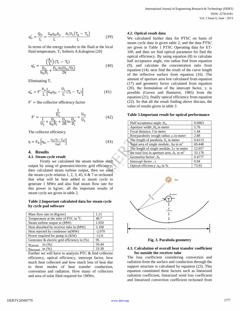
Table 3.Important result for optical performance
Half acceptance angle ,θm 0.6963
Aperture width ,Hp in meter 5.76
Focal distance, f in meter 1.44
Rim/parabolic trough radius ,rr in meter 2.88
The length of parabola, Sp in meter 6.6113
Total area of single module, Aa in m2 69.448
The length of single module, Lc in meter 12.057
the total loss in aperture area ,Al in m2 33.178
,Af 0.4777
Intercept factor , γ 0.94
Optical efficiency ,ηO in % 73.92
Fig. 3. Parabola geometry
4.3. Calculation of overall heat transfer coefficient
for outside the receiver tube
The loss coefficient considering convection and
radiation from the surface and conduction through the
support structure is calculated by equation (23). This
equation constituted three factors such as linearized
radiation coefficient, linearized wind loss coefficient
and linearized convection coefficient reckoned from
5.76 m
Sun
Receiver
IJERT
IJERT
2777
International Journal of Engineering Research & Technology (IJERT)
Vol. 2 Issue 6, June - 2013ISSN: 2278-0181
www.ijert.orgIJERTV2IS60779
equation (24), (27), and (28). Then guessing the value
glass covers temperature used in equation (30) to find
the overall heat transfer coefficient outside the
receiver tube. Correct temperature of glass tube used
the equation (29). The particular for correction
temperature, we have used number of iteration and
the result are given below in table 4 which calculated
by MS excel software
Table 4.Calculation data for finding the correct
temperature of glass cover by putting five
Iterations
Parameter/Properties 1 2 3 4 5
Glass cover temperature Tg,0C 60 153 162 163 163
Mean temperature Tm in 0C 47.5 93.8 98.3 98.7 98.8
Density of air , ρAir in kg/m3 1.1 1.1 1.1 1.1 1.1
μair
(10
-5) 2.05 2.05 2.05 2.05 2.05
KAir in
*(10-2) 2.8 2.8 2.8 2.8 2.8
Reynolds number Re(Air) (104) 1.62 1.62 1.62 1.62 1.62
Nusselt number Nu(Air)*(102) 1.05 1.05 1.05 1.05 1.05
Heat loss coefficient air hw 28.1 28.1 28.1 28.1 28.1
Stefan coefficient σ
*10-8
5.67 5.67 5.67 5.67 5.67
The radiation heat transfer
coefficient hr,r-g
25.6 31.7 32.4 32.4 32.4
The radiation heat transfer
coefficient hr,g-a
6.58 10.1 10.5 10.5 10.5
The loss coefficient UL in
16.9 20.0 20.4 20.4 20.4
Correction cover temp.Tg(˚C) 153 162 163 162 163
In Above table 4, the data value will used for thermal
analysis for PTSC, therefore I chosen 162.67 0C the
correct temperature of glass cover and find the
corresponding value of the heat loss coefficient UL is
20.46721
from table 4. This value used for
further calculation for overall heat transfer
coefficient, collector factor and heat removal factor
etc.
4.4. Results calculation for collector heat removal
factor, collector efficiency factor & overall
heat transfer coefficient
The overall heat loss coefficient can be calculated by
equation (31), and then we find the convective heat
transfer coefficient for standard pipe flow equation
(32).forward calculation different type of number by
empirical equation for assessment of inside flow fluid
heat transfer coefficient from equation (33), next find
the collector efficiency factor from equation (42) and
for the calculation of heat removal factor we will
have to used equation (43). Foremost important data
area of solar field used the same equation. Finally all
the calculated data are shown in table 5.
Table 5.Calculation data for finding collector
efficiency factor, heat flow factor and total
aperture area
Steam flow rate, in kg/sec
1.11 2 3
Outside dia. Of receiver,
Do in meter
0.07 0.042 0.042
Inside dia. Of receiver, Di
in meter
0.055 0.035 0.035
Thermal
conductivity,Kss
20.2 20.2 20.2
Thermal conductivity,
Kf
6.20E-04 6.20E-04 6.20E-04
Dynamic viscosity water,
μ
μ
1.28E-04 1.28E-04 1.28E-04
Constant pressure Specific heat, Cp
4.86E+00 4.86E+00 4.86E+00
Reynolds number Re(Air) 2.01E+05 5.69E+05 8.53E+05
Prandtl number Pr 1.00E+00 1.00E+00 1.00E+00
Nusselt number, Nu 402.4919 92.54617 12800.63
Inside tube Heat transfer
coefficient hfi
7.129856 1.639389 226.7541
Collector efficiency factor
, F'
0.987941 0.981488 0.996028
Heat removal Factor ,FR 9.88E-01 9.81E-01 9.96E-01
Solar irradiance, S in W/m2 5.50E+02 6.00E+02 7.00E+02
Heat absorbed by receiver
tube per unit length ,QU/L
3.11E+06 3.11E+06 3.11E+06
Total area of collector 7740.385 5278.36 4458.1
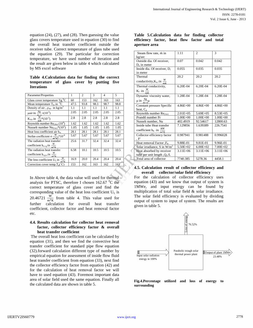
4.5. Calculation result of collector efficiency and
overall collector/solar field efficiency
For the calculation of collector efficiency uses
equation (43) and we know that output of system is
1MWe, and input energy can be found by
multiplication of total solar field & solar irradiance.
The solar field efficiency is evaluated by dividing
output of system to input of system. The results are
given in table 5.
Parabolic trough solar
thermal power plantOutput of plant 1MWe
Loss
of
ener
gy
Input solar radiation
energy in 100%
76.52%
23.48%
Fig.4.Percentage utilized and loss of energy to
surrounding
IJERT
IJERT
2778
International Journal of Engineering Research & Technology (IJERT)
Vol. 2 Issue 6, June - 2013ISSN: 2278-0181
www.ijert.orgIJERTV2IS60779
Efficiency and energy results of collector
Input solar radiation energy = 4.257MW
Output of the plant = 1.000 MW
Total energy loss from the system = 3.257 MW
% loss of energy from the system =76.52
Collector efficiency = 71.05 %
Overall plant/collector/solar field efficiency =23.48%
4.6. Calculation for number collectors
This Euro Trough’s mechanical rigidity to torsion is
assured by a steel torque box of trusses and beams
while the LS-3 steel structure is based on two “V-
trusses” held together by Endplates. Basically, both
the collector is same only difference the supporting
structure and joint connection of pipe. My focus in
find the number of collector, so all the data for both
collectors such length of collector, width of collector,
number of module per collector, and the rim angle.
So I have taken ET-100 collector of data given below
table and also formulation for number of collector is
given in table 7.
Table 6.Find number of Euro Trough -100
collectors to bear 1MWe electric power
Overall length of a single collector (m) 98.5
Number of parabolic trough modules per collector
8
Gross length of every concentrator module
(m)
12.27
Parabola width (m) 5.76
Number of ball joints between adjacent
collectors
4
Net collector aperture per collector (m2) 548.35
Total area of collector (m2) 7740.385
Number of collector
=
14.11 14 collectors & 1
module
We have found that for 1MWe electricity generation,
we will have to use 14 collectors & 1 module. The
length and width of collector, modules are given in
above table.
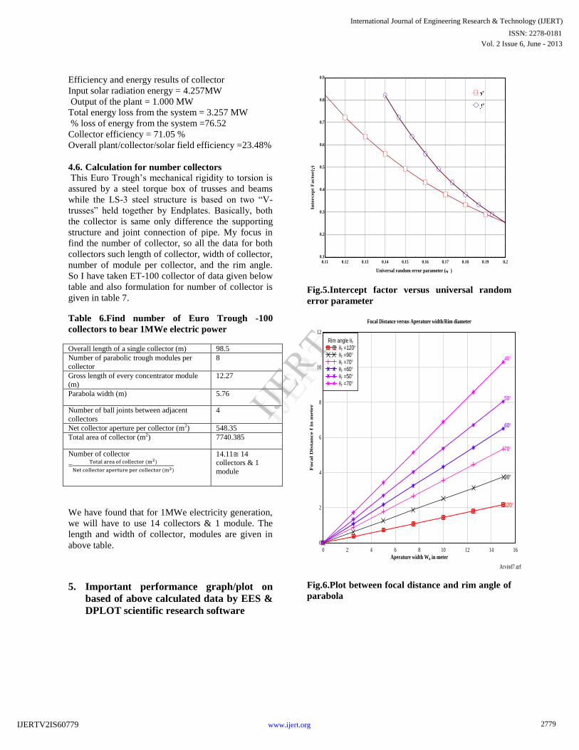
5. Important performance graph/plot on
based of above calculated data by EES &
DPLOT scientific research software
Fig.5.Intercept factor versus universal random
error parameter
Fig.6.Plot between focal distance and rim angle of
parabola
0.11 0.12 0.13 0.14 0.15 0.16 0.17 0.18 0.19 0.20.1
0.2
0.3
0.4
0.5
0.6
0.7
0.8
0.9
Universal random error parameter ( )
In
tercep
t F
acto
r(
)
*
**
Arvind7.grf
Aperature width Wa in meter
Foca
l D
istan
ce f
in
meter
Focal Distance versus Aperature width/Rim diameter
0 2 4 6 8 10 12 14 16
0
2
4
6
8
10
12
120
90
70
60
50
40
Rim angle r
r =120r =90r =70r =60r =50r =70
IJERT
IJERT
2779
International Journal of Engineering Research & Technology (IJERT)
Vol. 2 Issue 6, June - 2013ISSN: 2278-0181
www.ijert.orgIJERTV2IS60779

Fig.7.Plot between different heat transfer
coefficient outside the receiver and receiver tube
diameter
Fig.8.Plot between collector efficiency and solar
Insolation
Fig.9.Collector efficiency and Overall heat
transfer coefficient of receiver
Fig.10.Plot versus Collector Efficiency and heat
removal factor
ARVIND10.grf
Reciever tube diameter(Dr in meter)
Ou
tsid
e r
ecie
ver t
ub
e h
eat
tran
sfe
r c
oeff
icie
nt
UL i
n W
/m2K
Outside reciever tube heat transfer coefficient UL versus reciever tube diameter
0.03 0.035 0.04 0.045 0.05 0.055 0.06 0.065 0.07
12
14
16
18
20
22
24
26
hw
hw
hr,g-a
hr,g-a
hr,r-g
hr,r-g
Different heat transfer coefficient W/m2K
hw=34.5 W/m2K
hw=50 W/m2K
hr,g-a = 5 W/m2K
hr,g-a = 15 W/m2K
hr,r-g = 25 W/m2K
hr,r-g = 40 W/m2K
arvind.grf
Concentration ratio
Co
llector e
ffic
ien
cy
Collector efficiency versus concentration
20 25 30 35 40 45 50 55 60 65 70 75 80 85 90 95 100
0.15
0.2
0.25
0.3
0.35
0.4
0.45
0.5
0.55
0.6
0.65
0.7
Solar Insolation (W/m2)
550 W/m2
580 W/m2
600 W/m2
700 W/m2
800 W/m2
900 W/m2
1000 W/m2
ARVIND2.grf
Reciever tube temperature(C)
Co
llecto
r e
ffic
ien
cy
(
)
Collector efficiency versus reciever tube temperature
250 275 300 325 350 375 400 425 450 475 500
0.36
0.39
0.42
0.45
0.48
0.51
0.54
0.57
0.6
0.63
0.66
0.69
UL=19.71
UL=15
UL=10
UL=25
UL=30
Overall heat transfer coefficient(UL)
19.71W/(m2K)
15 W/(m2K)
10 W/(m2K)
25 W/(m2K)
30W/(m2K)
ARVIND3.grf
Solar Insolation (W/m2)
Coll
ector e
ffic
ien
cy
Collector efficiency versus Solar Insolation
400 450 500 550 600 650 700 750 800 850 900 950 1000
0.46
0.48
0.5
0.52
0.54
0.56
0.58
0.6
0.62
0.64
0.66
19959
.98
.97
.96
.94
.92
Heat removal Factor (FR)
FR=1
FR=.9959
FR=.98
FR=.97
FR=.96
FR=.94
FR=.92
IJERT
IJERT
2780
International Journal of Engineering Research & Technology (IJERT)
Vol. 2 Issue 6, June - 2013ISSN: 2278-0181
www.ijert.orgIJERTV2IS60779

Fig. 11.Plot versus collector efficiency and solar
insolation, according the performance equation of
the IST (Industrial Solar Technologies
Fig. 12.Plot versus Incidence angle modifier and
Incidence angle of sun ray on collector surface
(For the IST collector)
Fig. 13.Plot versus collector efficiency factor and
heat transfer coefficient inside tube
Fig. 14.Parabola focal length and rim angle
Conclusion
PTSC technology with DSG is very efficient &
cheapest cost rate electricity generation as compared
to solar energy power generation method. My
designed electric output from grid is 1MWe. But,
there are losses in electric grid & generator. We have
accounted 95% efficiency of generator due to this
losses; output of steam turbine must be 1.05 MWe
Arvind4.grf
Temperature difference(TC)
Co
llecto
r E
ffic
ien
cy
(
)
Collector Efficiency versus Temperature gradient between reciever temperature & surrounding
140 160 180 200 220 240 260 280 300 320
0.3
0.35
0.4
0.45
0.5
0.55
0.6
0.65
0.7
0.75
0.8
550 W/m2
600 W/m2
700 W/m2
800 W/m2
900 W/m2
1000 W/m2
=0.762 -0.2125 * (T/S)-.001672*(T2/S)
550 W/m2
600 W/m2
700 W/m2
800 W/m2
900 W/m2
1000 W/m2
Arvind6.grf
Incidence Angle ()
Incid
en
ce a
ngle
Mod
ifie
r
0 10 20 30 40 50 60 70 80 90
0
0.1
0.2
0.3
0.4
0.5
0.6
0.7
0.8
0.9
1
0
=cos()+.0003178*()-.00003985*()2
ARVIND8.grf
Loss coefficient based on reciever area UL W/m2K
Coll
ector e
ffic
ien
cy f
actor F
l
0 10 20 30 40 50 60 70 80 90 100
0.96
0.965
0.97
0.975
0.98
0.985
0.99
0.995
1
5
10
15
20
Heat transfer coefficient inside tube hfi KW/m2Khfi = 5 KW/m2Khfi = 10 KW/m2Khfi = 15 KW/m2Khfi = 20 KW/m2K
0 0.2 0.4 0.6 0.8 1 1.2 1.40.1
0.2
0.3
0.4
0.5
0.6
0.7
0.8
0.9
10 1 2 3 4 5
20
40
60
80
100
120
140
f
f/W
a
Wa
r
IJERT
IJERT
2781
International Journal of Engineering Research & Technology (IJERT)
Vol. 2 Issue 6, June - 2013ISSN: 2278-0181
www.ijert.orgIJERTV2IS60779

In steam cycle, We found heat absorb in
receiver tube per unit length, the mass flow
rate, inlet temperature of water; pump work
Input loss of heat from condenser and required
trap heat in receiver tube to furnish 1.05MW
steam turbine output, detailed result given in
table 2.
Then, we have reckoned the correct glass cover
temperature by taking initial guess value which
undergoes in five iterations, then calculated
outside receiver tube heat loss coefficient, see
results in table 4.
We have found all the vital geometric
parameter of PTSC of results see in table 3 such
parameter as optical efficiency, geometry
factor, intercept factor, rim radius,
concentration ratio to make easy for analysis
and manufacturing.
We have done thermal analysis of PTSC to
calculate the importance parameter/factor such
overall heat loss/transfer coefficient, collector
efficiency factor and heat removal factor is
given in table 5, these factors provide the total
collector area.
Thereafter, we found the collector thermal
efficiency ( , overall plant/solar
Field efficiency and
76.52% of heat lost from PTSC plant system.
We have investigated 14 collectors and 1
module of collector for generation of 1MWe
electricity generation, each collector consists of
8 modules and each module has length 12.27 m
and width of 5.76m. The total area of
collector/solar field is 7740.385 m2. The
investigated numbers of collector are based on
standard collector Euro trough -100m, LS-3
data.
We have investigated that parallel configuration
of collectors (I-shape layout) is best to generate
the steam at required temperature and pressure,
also reduce heat loss and space accommodation.
. We shall recommend four collector used in
preheating, seven collector used in evaporation
zone, and three collector used in superheated
zone. We have modified diagram for practical
use as shown in figure.14. In one module is not
shown. This can adjusted to extend the length
of module in superheated zone.
Acknowledgement The Chih Wu, (2004) United States, Naval Academy
Annapalis, Mary Land USA, provide an Intelligence
Computer Software is called Cycle Pad and DPlot
Graph Software for Scientists and Engineers and EES
software provided from sites www.dplot.com,
www.fchart.com/ees is greatly appreciated. The
author also express their heartily thanks to the
reviewers for their fertile comments and suggestion.
Designed PTC field layout
Series configuration of collectors
1 2 3 4
5 6 7 8 9 10 11 12 1413
Generator
Condenser
Pump
deaerator
Feed
water
Pump
Circulation pump
Steam separtorSteam
turbine
Preheating region
Evaporation/Boiling region Steam Superheating region
Control
valves
Gate valve
Gate valve manual hand operated
Water Injection circuit
Feed
valve
100 bar
3750C
0.112 bar103
bar
Parabolic trough collectors
Fig.15. Designed schematic diagram for 1MWe PTSC plant based on DSG method
IJERT
IJERT
2782
International Journal of Engineering Research & Technology (IJERT)
Vol. 2 Issue 6, June - 2013ISSN: 2278-0181
www.ijert.orgIJERTV2IS60779

Parallel configuration of collectors
Generator
Condenser
Pump
0.112 bar
Steam separator-1
Evaporation/Boiling regionSteam Superheating region
Steam separator-2
Evaporation/Boiling regionSteam Superheating region
Water Injection circuit
Water Injection circuit
Circulation pump
Circulation pump
Control valves
deaerator
Gate valve
Gate valve manual hand operated
Preheating region
Preheating region
m
m1
m2
.3 m2
.3 m1
Feed
valve
Feed
water
Pump
Steam
turbine
100 bar
3750C
103
bar
Fig. 16.parallel configuration of collector for 1MWe
Nomenclature
Aa Aperture area of the collector, [m2]
Ag External surface area of glass cover, [m2]
Ar area of the receiver, [m2]
cpw Specific heat of water, [J/kg.K]
cpa Specific heat of air at Ta , [J/kg.K]
C Geometric concentration ratio
Do outer diameter of receiver tube [m]
Di Inner diameter of receiver tube [m]
Tr Receiver temperature [K]
FR Collector heat-removal factor
f focal length [mm]
G Global irradiance on a horizontal surface,
[W/m2]
Gb Beam irradiance incident on the aperture
(Gn cos θ) , [W/m2]
Gd Diffuse irradiance, [W/m2]
S Direct normal (beam) irradiance, [W/m2]
hfi Heat transfer coefficient inside the
pipe,[W/m2.K]
Kθ Incidence angle modifier
Kss Stainless steel Thermal conductivity of
pipe, [W/m.K]
Kf Thermal conductivity of water, [W/m.K]
Kair Thermal conductivity of air , [W/m.K]
Lc Length of one module, [m].
mflow Mass flow rate of the steam [kg/s]
Cmax Maximum concentration ratio
Collector efficiency factor
hr,g-a linearized radiation coefficient from cover
to ambient
hr,r-g linearized radiation coefficient from
receiver to glass cover
hr The linearized radiation coefficient
hc Convective loss coefficient
hw loss coefficient for wind
Ae Aperture area loss,[m2]
Ab Area loss due to plate extending from rim
to rim,[m2]
Al Total loss in aperture ,[m2]
Af Geometry factor
rr Rim radius,[m]
d *
universal non-random error parameter due
to receiver misallocation and reflector
profile errors
Erf Error function
ΔT Temperature gradient between receiver and
IJERT
IJERT
2783
International Journal of Engineering Research & Technology (IJERT)
Vol. 2 Issue 6, June - 2013ISSN: 2278-0181
www.ijert.orgIJERTV2IS60779

surrounding air,[K]
Drt riser tube outside diameter
dr displacement of receiver from focus
Tg Glass cover temperature,[K]
Dg Diameter of glass cover ,[m]
Dr Diameter of receiver ,[m]
SP Curve length of parabola,[m]
HP Lactus rectum of parabola, [m]
n Day number
QU Solar collector useful output, [W/m2]
t Time, [s]
To Heat transfer fluid outlet (from the
collector) temperature, [K]
Ti inlet temperature of fluid in the collector,
[K]
Ta Ambient temperature, [K]
Tm Mean temperature of the heat transfer fluid
across the collector or the solar field, [K]
V Wind speed, [m/s]
UL Overall heat loss coefficient from absorber
surface, [W/m2.K]
UO Overall heat transfer coefficient of
collector pipe, [W/m2.K]
Wa Collector width, [m]
Dimensionless groups
Nu Nusselt number
Pr Prandtl number
Ra Rayleigh number
Re Reynolds number
Greek symbols
η Solar collector overall efficiency
ηoverall Solar field overall efficiency
ηo Optical efficiency
ε Emissivity coefficient
θr Rim angle
βr misalignment angle error (degrees)
β * universal non-random error parameter due
to angular errors
σ * universal random error parameter
θm half acceptance angle [degrees]
ρw Average density of the water between inlet
and outlet temperatures.
ρw Density of water, [kg/m3]
ρ Reflectivity constant
τ Transmittance of the receiver glass
envelope
α Solar altitude angle
αc Absorptance of the absorber surface
coating
γ Intercept factor
σtotal Standard deviation of the total errors,
[mrad]
σoptical Standard deviation of the total optical
errors, [mrad
σslope Standard deviation of slope errors, [mrad]
σspecula
r
Standard deviation of specular errors,
[mrad]
σdisplac
ement
Standard deviation of receiver
displacement errors, [mrad]
σmirror Standard deviation of mirror, [mrad]
σsun Root mean square (RMS) width of the sun,
[mrad]
υr Angle of Parabola
μ Dynamic viscosity of water, [N.s/m2]
μair Dynamic viscosity of air, [N.s/m2]
Abbreviations
DSG Direct Steam Generation
INDI
TEP
Integration of DSG Technology for
electric production
SEGS Solar electric generating system
ET10
0 Euro trough
PSA Plata forma solar de Almeria
DSG Direct steam generation
STTP Solar trough thermal power plant
PTSC Parabolic Trough solar Collector
PTC Parabolic Trough Collector
IAM Incidence Angle Modifier
Units
MWe Megawatt electrical
kWe kilowatt electric
References [1] Ari Rabl, Comparison of Solar
Concentrators, Pergamon Press 1976. Printed
in Great Britain.
[2] M J Brookes 2005, thesis on Performance Of
A Parabolic Collector, University Of
Stellenbosch
[3] Ming Qu, David H. Archer, Sophie V.
Masson, “A Linear Parabolic Trough Solar
Collector Performance Model”, Renewable
Energy Resources and a Greener Future
Vol.VII-3-3, 2006, ESL-IC-06-11-267.
[4] Scott A. Jones,Robert Pitz, TRSYS
Modelling of SEGS VI parabolic trough solar
electric generation system, proceeding of
solar forum 2001: solar energy; the power to
choose April 21-25,2001, Washington, DC
[5] Isabel Llorente Garcı, Jose Luis Alvarez,
Daniel, Performance model for parabolic
trough solar thermal power plants with
thermal storage: Comparison to operating
plant data, Solar Energy 85 (2011) 2443–
2460, Elsevier
[6] Blanco Balbir Singh, Mahinder Singh,
Designing a solar thermal cylindrical
IJERT
IJERT
2784
International Journal of Engineering Research & Technology (IJERT)
Vol. 2 Issue 6, June - 2013ISSN: 2278-0181
www.ijert.orgIJERTV2IS60779

parabolic trough concentrator by simulation,
International Rio3 congress, world climate
and energy event, Rio de Janeio,1-5,Dec
2003
[7] V. Siva Reddy , S.C. Kaushik , S.K. Tyagi
Exergetic analysis and performance
evaluation of parabolic trough concentrating
solar thermal power plant (PTCSTPP),
Energy 39 (2012) 258-273, Elsevier
[8] Iman Niknia, Mahmood Yaghoub
2011,Transient simulation for developing a
combined solar thermal power plant, Applied
Thermal Engineering 37 (2012) 196-207,
Elsevier
[9] Iman Niknia, Mahmood Yaghoubi, Transient
analysis of integrated Shiraz hybrid solar
thermal power plant, Article in press,
Renewable Energy xxx (2012) 1-6, Elsevier.
[10] Price, H., Luepfert, E., Kearney, D., Zarza,
E., Cohen, G., Gee, R., and Mahoney, R.
2002. Advances in parabolic trough solar
power technology. International Journal of
Solar Energy Engineering, 124 109–125.
[11] S.K. Tyagi, Shengwei Wang, M.K. Singhal,
S.R. Park, “Exergy Analysis and Parametric
Study of Concentrating Type Solar
Collectors”, International Journal of Thermal
Sciences 46 (2007) 1304-1310.R.Lugo-Leyte
et al. (2012)
[12] Amirtham Valan Arasu and Samuel Thambu
Sornakumar, “Performance Characteristics of
the Solar Parabolic Trough Collector with
Hot Water Generation System”, BIBLID:
0354-9836, 10 (2006), 2, 167-174
[13] Soteris Kalogirou, Stephen Llyod and John
Ward, “Modelling, Optimisation and
Performance Evaluation of a Parabolic
Trough Solar Collector Steam Generation
System”, Solar energy Vol. No.1, pp. 49-59,
1997
[14] Martin Kaltschmitt, Wolfgang Streicher
Andreas Wiese, Renewable Energy
Technology, Economics and Environment,
Springer Berlin Heidelberg New York
[15] Halil M.Guven, Richard B. Bannerot, Optical
analysis of parabolic trough solar collectors
for technically less developed countries, June
1984,USAID
[16] Ricardo Vasquez Padilla, Gokmen
Demirkaya, D. Yogi Goswami, Elias
Stefanakos, Muhammad M. Rahman, “Heat
transfer Analysis of Parabolic Trough Solar
Receiver”, Applied Energy 88 (2011) 5097–
5110.
[17] Duffie; J. A.; Beckman, W. A.: Solar
Engineering of Thermal Processes; John
Wiley & Sons, New York, Brisbane, USA,
1991, 2nd edition
[18] Eck, M., Zarza, E., Eickhoff, M.,
Rheinlander, J., and Valenzuela, L. 2003.
Applied research concerning the direct steam
generation in parabolic troughs. Solar
Energy. 74 341–351.
[19] Jeter, M.S., 1983. Geometrical effects on the
performance of trough collectors. Solar
Energy 30 , 109 – 113
[20] Soteris A. Kalogirou, Solar Energy
Engineering Processes and Systems,
Academic Press is an imprint of Elsevier
[21] A. Fadar, A. Mimet, A. Azzabakh, M. Pérez-
García, J. Castaing, “Study of a new solar
adsorption refrigerator powered by a
parabolic trough collector”, Applied Thermal
Engineering 29 (2009) 1267–1270.
[22] Sukhatme, Solar Energy: Principles of
Thermal Collection and Storage, third edition
Publisher, Tata McGraw-Hill Education,
2008
[23] Sodha, M.S., Mathur, S.S., Malik, M.A.S.,
1984. Wiley Eastern Limited, Singapore.
[24] Zarza, E., Hennecke, K., Hermann, U.,
Langenkamp, J., Goebel, O., Eck, M.,
Rheinlander, J., Ruiz, M., Valenzuela, L.,
Zunft, S., and Weyers, D.-H. 1999. DISS
phase I project, Final project report, Editorial
CIEMAT, Madrid
IJERT
IJERT
2785
International Journal of Engineering Research & Technology (IJERT)
Vol. 2 Issue 6, June - 2013ISSN: 2278-0181
www.ijert.orgIJERTV2IS60779