solar thermal heat & power parabolic trough technology … · solar thermal heat & power...
TRANSCRIPT
Solar Thermal Heat & Power – Parabolic Trough Technology for Chile Current state of the art of parabolic trough collector technology
Edition: Deutsche Gesellschaft für Internationale Zusammenarbeit (GIZ) GmbH Friedrich-Ebert-Allee 40 53113 Bonn • Alemania Dag-Hammarskjöld-Weg 1-5 65760 Eschborn • Alemania Projekt name: Fomento de la Energía Solar en Chile (Enfoque en Tecnologías de Concentración Solar) Marchant Pereira 150 7500654 Providencia Santiago • Chile T +56 22 30 68 600 I www.giz.de Responsable: Rainer Schröer In coordination: Ministerio de Energía de Chile Alameda 1449, Pisos 13 y 14, Edificio Santiago Downtown II Santiago de Chile T +56 22 367 3000 I www.minenergia.cl Titel: Solar Thermal Heat & Power – Parabolic Trough Technology for Chile Foto: All photos (c) schlaich bergermann und partner or Gerhard Weinrebe unless noted otherwise Authors: Gerhard Weinrebe, Finn von Reeken, Sarah Arbes, Axel Schweitzer, Markus Wöhrbach, Jonathan Finkbeiner Contact: [email protected] www.sbp.de
Logo
Declaration: The content of this study is based on a study elaborated by GIZ Brazil, which was herein adapted to the local context of Chile. This publication has been prepared on request of the project "Promotion of Solar Energy" implemented by the Ministry of Energy of Chile and the Deutsche Gesellschaft für Internationale Zusammenarbeit (GIZ) GmbH in the framework of the intergovernmental cooperation between Chile and Germany. The project is funded by the German Climate and Technology Initiative (DKTI) of the Federal Ministry for the Environment, Nature Conservation, Building and Nuclear Safety (BMUB). Anyhow, the conclusions and opinions of the authors do not necessarily reflect the position of the Government of Chile or GIZ. Furthermore, any reference to a company, product, brand, manufacturer or similar does not constitute in any way a recommendation by the Government of Chile or GIZ. Santiago de Chile, December 2014
Deutsche Gesellschaft für Internationale Zusammenarbeit (GIZ) GmbH
Solar Thermal Heat & Power - Proyecto Fomento de la Energía Solar (Enfoque en Tecnologías de Concentración Solar) 3
TABLE OF CONTENT
LIST OF ACRONYMS ........................................................................................ 5
1. INTRODUCTION ......................................................................................... 6
1.1. HISTORY OF PARABOLIC TROUGH POWER PLANT TECHNOLOGY ............................ 7 1.2. IMPORTANT ECONOMIC AND TECHNICAL ASPECTS FOR PARABOLIC TROUGH DESIGN
11 1.3. PARABOLIC TROUGH FUNCTIONAL PRINCIPLE .................................................... 12
2. OVERVIEW ON PARABOLIC TROUGH COLLECTORS ......................... 13
2.1. INTRODUCTION ............................................................................................... 13 2.2. THE FIRST COMMERCIAL COLLECTOR GENERATION: LS-1, LS-2 AND LS-3 .......... 16 2.3. CURRENTLY AVAILABLE PARABOLIC TROUGH COLLECTORS .............................. 18
2.3.1. Solargenix (SGX) ................................................................................... 18 2.3.2. EuroTrough ........................................................................................... 20 2.3.3. SENERtrough ........................................................................................ 21 2.3.4. ENEA Collector ...................................................................................... 22
2.4. RECENT COLLECTOR DEVELOPMENTS – INTRODUCTION ................................... 22 2.4.1. HelioTrough (HT) ................................................................................... 23 2.4.2. Ultimate Trough (UT) ............................................................................. 25 2.4.3. SENERtrough-2 ..................................................................................... 26 2.4.4. SkyTrough ............................................................................................. 27 2.4.5. Large Aperture Trough (LAT) 73 ............................................................ 28 2.4.6. Abengoa E2 ........................................................................................... 29 2.4.7. Airlight ................................................................................................... 31
2.5. CHARACTERIZATION OF PARABOLIC TROUGH COLLECTORS ................................ 32 2.6. TYPICAL PARAMETERS FOR SELECTED COLLECTOR TYPES ................................ 32
2.6.1. Collector Dimensions ............................................................................. 32 2.6.2. Concentration Ratio ............................................................................... 34 2.6.3. Nominal thermal power and nominal efficiency at design conditions ...... 36 2.6.4. Solar incident angle and optical efficiency ............................................. 37 2.6.5. Thermal Losses ..................................................................................... 41 2.6.6. Operating Temperature / Selection of Heat Transfer Fluid ..................... 42 2.6.7. Torsional Stiffness ................................................................................. 43 2.6.8. Collector tracking end positions in operation .......................................... 45 2.6.9. Drive system .......................................................................................... 46 2.6.10. Collector Assembly ............................................................................ 48 2.6.11. Maximum wind velocity during operation and in stow position ............ 49 2.6.12. Collector mass without heat transfer fluid ........................................... 50 2.6.13. Material of reflector and collector support structure ............................ 50 2.6.14. Cleaning systems for reflectors and absorber tubes ........................... 52 2.6.15. Specific energy and water consumption for cleaning .......................... 54 2.6.16. Types of flexible joints between collectors .......................................... 54
Flexhose interconnection ................................................................................................ 54 Ball-Joint interconnection ................................................................................................ 55 Swivel joint with compensator interconnection ................................................................ 55
2.7. PARABOLIC TROUGH COLLECTORS FOR PROCESS HEAT ................................... 56
3. LOCALIZATION OF PARABOLIC TROUGH COLLECTOR FIELDS ...... 59
3.1. GENERAL ....................................................................................................... 59 3.2. CSP PLANT DESIGN AND LOCALIZATION .......................................................... 59
3.2.1. Manufacturing ........................................................................................ 60
Deutsche Gesellschaft für Internationale Zusammenarbeit (GIZ) GmbH
Solar Thermal Heat & Power - Proyecto Fomento de la Energía Solar (Enfoque en Tecnologías de Concentración Solar) 4
3.2.2. Assembly and Erection .......................................................................... 62 3.2.3. O&M ...................................................................................................... 63
3.3. LOCALIZATION FOR CSP COMPANIES ............................................................... 63 3.4. LOCALIZATION FROM A COUNTRY PERSPECTIVE ................................................ 65
4. PARABOLIC TROUGH PLANT PERFORMANCE AND ELECTRICITY COST IN CHILE .......................................................................................................... 67
4.1. LEVELISED COSTS OF ELECTRICITY ................................................................. 67 4.2. PARABOLIC TROUGH POWER PLANTS OUTPUT AND THE EFFECT OF THERMAL STORAGE
68 4.3. IMPACT OF SOLAR IRRADIANCE LEVEL ON LCOE ............................................... 70 4.4. COOLING SYSTEMS FOR PARABOLIC TROUGH POWER PLANTS ............................ 71 4.5. SPECIAL CONDITIONS FOR PARABOLIC TROUGH PLANTS IN CHILE ....................... 75
4.5.1. The mining industry as key client for CSP plants in Chile ...................... 75 4.5.2. Water scarcity ........................................................................................ 76 4.5.3. Seismic activities ................................................................................... 79 4.5.4. Others.................................................................................................... 81
4.6. FINANCIAL PARAMETERS OF NEXT GENERATION PARABOLIC TROUGH COLLECTORS83
5. TECHNOLOGICAL DEVELOPMENTS ..................................................... 84
5.1. GENERAL TRENDS .......................................................................................... 84 5.2. COLLECTOR COMPONENTS ............................................................................. 87 5.3. COLLECTOR DESIGN ....................................................................................... 90 5.4. THERMAL STORAGE ........................................................................................ 90
Steam accumulators ........................................................................................................ 93 Sensible Heat Two-Tank Molten Salt Storage ................................................................ 95
5.5. MOLTEN SALT PLANT CONCEPTS .................................................................... 96
6. APPENDIX I: KEY CSP COMPANIES .................................................... 100
7. APPENDIX II: SELECTED COMPONENT SUPPLIERS ......................... 104
8. APPENDIX III: SELECTED TECHNOLOGY DEVELOPERS .................. 105
9. APPENDIX IV: CSP PROJECTS IN CHILE ............................................ 109
10. BIBLIOGRAPHY .................................................................................. 110

Deutsche Gesellschaft für Internationale Zusammenarbeit (GIZ) GmbH
Solar Thermal Heat & Power - Proyecto Fomento de la Energía Solar (Enfoque en Tecnologías de Concentración Solar) 5
List of Acronyms
CSP Concentrating Solar Power DNI Direct Normal Irradiation (direct sunlight) HCE Heat Collecting Element HT HelioTrough (collector) HTF Heat Transfer Fluid LAT Large Aperture Trough (collector designed by Gossamer Space
Frames) LCOE Levelised Cost of Electricity SCA Solar Collector Assembly SCE Solar Collecting Element SGX Solargenix SING Sistema Interconectado del Norte Grande SM Solar Multiple TES Thermal Energy Storage UT Ultimate Trough (collector)
Deutsche Gesellschaft für Internationale Zusammenarbeit (GIZ) GmbH
Solar Thermal Heat & Power - Proyecto Fomento de la Energía Solar (Enfoque en Tecnologías de Concentración Solar) 6
1. Introduction
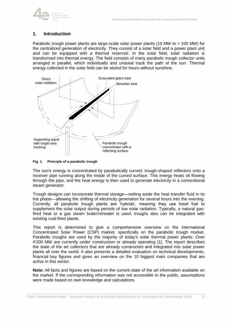
Parabolic trough power plants are large-scale solar power plants (10 MW to > 100 MW) for the centralized generation of electricity. They consist of a solar field and a power plant unit and can be equipped with a thermal reservoir. In the solar field, solar radiation is transformed into thermal energy. The field consists of many parabolic trough collector units arranged in parallel, which individually and uniaxial track the path of the sun. Thermal energy collected in the solar field can be stored for hours without sunshine.
Fig. 1. Principle of a parabolic trough
The sun's energy is concentrated by parabolically curved, trough-shaped reflectors onto a receiver pipe running along the inside of the curved surface. This energy heats oil flowing through the pipe, and the heat energy is then used to generate electricity in a conventional steam generator.
Trough designs can incorporate thermal storage—setting aside the heat transfer fluid in its hot phase—allowing the shifting of electricity generation for several hours into the evening. Currently, all parabolic trough plants are ‗hybrids‘, meaning they use fossil fuel to supplement the solar output during periods of low solar radiation. Typically, a natural gas-fired heat or a gas steam boiler/reheater is used; troughs also can be integrated with existing coal-fired plants.
This report is determined to give a comprehensive overview on the international Concentrated Solar Power (CSP) market, specifically on the parabolic trough market. Parabolic troughs are used by the majority of today's solar thermal power plants: Over 4'200 MW are currently under construction or already operating [1]. The report describes the state of the art collectors that are already constructed and integrated into solar power plants all over the world. It also presents a detailed evaluation on technical developments, financial key figures and gives an overview on the 10 biggest main companies that are active in this sector.
Note: All facts and figures are based on the current state of the art information available on the market. If the corresponding information was not accessible to the public, assumptions were made based on own knowledge and calculations.
Absorber tube
Parabolic trough concentrator with a reflecting surface
Evacuated glass tube
Supporting stand with single-axis tracking
Directsolar radiation
Deutsche Gesellschaft für Internationale Zusammenarbeit (GIZ) GmbH
Solar Thermal Heat & Power - Proyecto Fomento de la Energía Solar (Enfoque en Tecnologías de Concentración Solar) 7
1.1. History of parabolic trough power plant technology
This section presents a review of parabolic trough technology models throughout the history of the technology, briefly mentioning their main features, applications and their commercial availability [1].
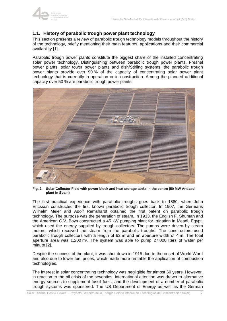
Parabolic trough power plants constitute the biggest share of the installed concentrating solar power technology. Distinguishing between parabolic trough power plants, Fresnel power plants, solar tower power plants and dish/Stirling systems, the parabolic trough power plants provide over 90 % of the capacity of concentrating solar power plant technology that is currently in operation or in construction. Among the planned additional capacity over 50 % are parabolic trough power plants.
Fig. 2. Solar Collector Field with power block and heat storage tanks in the centre (50 MW Andasol plant in Spain)
The first practical experience with parabolic troughs goes back to 1880, when John Ericsson constructed the first known parabolic trough collector. In 1907, the Germans Wilhelm Meier and Adolf Remshardt obtained the first patent on parabolic trough technology. The purpose was the generation of steam. In 1913, the English F. Shuman and the American C.V. Boys constructed a 45 kW pumping plant for irrigation in Meadi, Egypt, which used the energy supplied by trough collectors. The pumps were driven by steam motors, which received the steam from the parabolic troughs. The constructors used parabolic trough collectors with a length of 62 m and an aperture width of 4 m. The total aperture area was 1,200 m². The system was able to pump 27,000 liters of water per minute [2].
Despite the success of the plant, it was shut down in 1915 due to the onset of World War I and also due to lower fuel prices, which made more rentable the application of combustion technologies.
The interest in solar concentrating technology was negligible for almost 60 years. However, in reaction to the oil crisis of the seventies, international attention was drawn to alternative energy sources to supplement fossil fuels, and the development of a number of parabolic trough systems was sponsored. The US Department of Energy as well as the German
Deutsche Gesellschaft für Internationale Zusammenarbeit (GIZ) GmbH
Solar Thermal Heat & Power - Proyecto Fomento de la Energía Solar (Enfoque en Tecnologías de Concentración Solar) 8
Federal Ministry of Research and Technology began to fund the development of several process heat machines and water pump systems with parabolic trough collectors. Higher fossil fuel prices encouraged the governments to take new measures.
Results of these measures were, the following:
Between 1977 and 1982, the company Acurex installed parabolic trough demonstration
systems with a total aperture area of almost 10,000 m² in the USA for process heat
applications.
The first modern line-focusing solar power plant was a 150 kWel facility that was built in
Coolidge/Arizona in 1979.
Nine member states of the International Energy Agency participated in the project of
building demonstration facilities with a rated power of 500 kW at the Plataforma Solar
de Almeria, which was commissioned in 1981.
The first privately financed process heat machine with 5580 m² parabolic trough
collectors was successfully put into operation in 1983 in Arizona for thermal heating of
electrolyte tanks in a copper processing company. These trough systems developed for
industrial process heat application were capable of generating temperatures higher than
260°C.
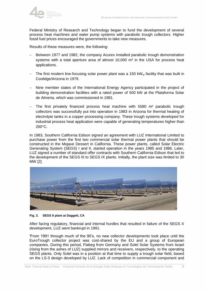
In 1983, Southern California Edison signed an agreement with LUZ International Limited to purchase power from the first two commercial solar thermal power plants that should be constructed in the Mojave Dessert in California. These power plants, called Solar Electric Generating System (SEGS) I and II, started operation in the years 1985 and 1986. Later, LUZ signed a number of standard offer contracts with Southern California Edison that led to the development of the SEGS III to SEGS IX plants. Initially, the plant size was limited to 30 MW [2].
Fig. 3. SEGS II plant at Daggett, CA
After facing regulatory, financial and internal hurdles that resulted in failure of the SEGS X development, LUZ went bankrupt in 1991.
'From 1991 through much of the 90‘s, no new collector developments took place until the EuroTrough collector project was cost-shared by the EU and a group of European companies. During this period, Flabeg from Germany and Solel Solar Systems from Israel (rising from the ashes of LUZ) supplied mirrors and receivers, respectively, to the operating SEGS plants. Only Solel was in a position at that time to supply a trough solar field, based on the LS-3 design developed by LUZ. Lack of competition in commercial component and
Deutsche Gesellschaft für Internationale Zusammenarbeit (GIZ) GmbH
Solar Thermal Heat & Power - Proyecto Fomento de la Energía Solar (Enfoque en Tecnologías de Concentración Solar) 9
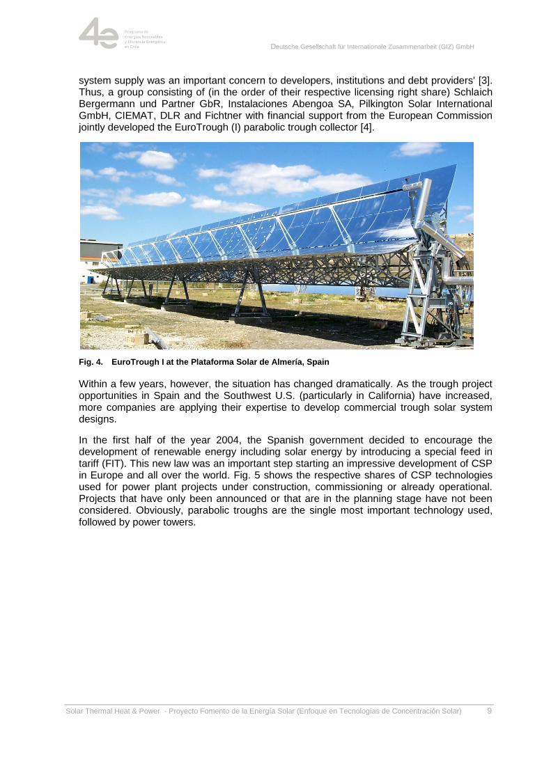
system supply was an important concern to developers, institutions and debt providers' [3]. Thus, a group consisting of (in the order of their respective licensing right share) Schlaich Bergermann und Partner GbR, Instalaciones Abengoa SA, Pilkington Solar International GmbH, CIEMAT, DLR and Fichtner with financial support from the European Commission jointly developed the EuroTrough (I) parabolic trough collector [4].
Fig. 4. EuroTrough I at the Plataforma Solar de Almería, Spain
Within a few years, however, the situation has changed dramatically. As the trough project opportunities in Spain and the Southwest U.S. (particularly in California) have increased, more companies are applying their expertise to develop commercial trough solar system designs.
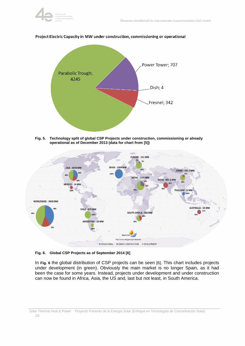
In the first half of the year 2004, the Spanish government decided to encourage the development of renewable energy including solar energy by introducing a special feed in tariff (FIT). This new law was an important step starting an impressive development of CSP in Europe and all over the world. Fig. 5 shows the respective shares of CSP technologies used for power plant projects under construction, commissioning or already operational. Projects that have only been announced or that are in the planning stage have not been considered. Obviously, parabolic troughs are the single most important technology used, followed by power towers.
Deutsche Gesellschaft für Internationale Zusammenarbeit (GIZ) GmbH
Solar Thermal Heat & Power - Proyecto Fomento de la Energía Solar (Enfoque en Tecnologías de Concentración Solar)
10
Fig. 5. Technology split of global CSP Projects under construction, commissioning or already operational as of December 2013 (data for chart from [5])
Fig. 6. Global CSP Projects as of September 2014 [6]
In Fig. 6 the global distribution of CSP projects can be seen [6]. This chart includes projects under development (in green). Obviously the main market is no longer Spain, as it had been the case for some years. Instead, projects under development and under construction can now be found in Africa, Asia, the US and, last but not least, in South America.
Deutsche Gesellschaft für Internationale Zusammenarbeit (GIZ) GmbH
Solar Thermal Heat & Power - Proyecto Fomento de la Energía Solar (Enfoque en Tecnologías de Concentración Solar)
11
1.2. Important Economic and Technical Aspects for Parabolic Trough Design
In this chapter, the main technical and commercial aspects for the design of a solar collector fields are discussed.
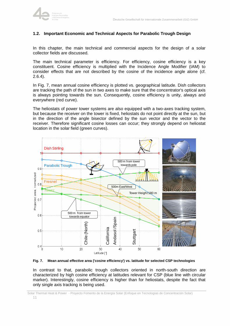
The main technical parameter is efficiency. For efficiency, cosine efficiency is a key constituent. Cosine efficiency is multiplied with the Incidence Angle Modifier (IAM) to consider effects that are not described by the cosine of the incidence angle alone (cf. 2.6.4).
In Fig. 7, mean annual cosine efficiency is plotted vs. geographical latitude. Dish collectors are tracking the path of the sun in two axes to make sure that the concentrator's optical axis is always pointing towards the sun. Consequently, cosine efficiency is unity, always and everywhere (red curve).
The heliostats of power tower systems are also equipped with a two-axes tracking system, but because the receiver on the tower is fixed, heliostats do not point directly at the sun, but in the direction of the angle bisector defined by the sun vector and the vector to the receiver. Therefore significant cosine losses can occur; they strongly depend on heliostat location in the solar field (green curves).
Fig. 7. Mean annual effective area ('cosine efficiency') vs. latitude for selected CSP technologies
In contrast to that, parabolic trough collectors oriented in north-south direction are characterized by high cosine efficiency at latitudes relevant for CSP (blue line with circular marker). Interestingly, cosine efficiency is higher than for heliostats, despite the fact that only single axis tracking is being used.
An
da
so
l /S
pa
in
Stu
ttg
art
500 m from tower
towards pole
500 m from tower
towards equator
500m East/West
Tower Height 180 m
Dish Stirling
Parabolic Trough
Tower
Fresnel
Ch
ile
(N
ort
h)
Ca
lifo
rnia
Deutsche Gesellschaft für Internationale Zusammenarbeit (GIZ) GmbH
Solar Thermal Heat & Power - Proyecto Fomento de la Energía Solar (Enfoque en Tecnologías de Concentración Solar)
12
Cosine efficiency is significantly lower for linear Fresnel systems (orange lines); similar to heliostat fields due to the fact that the receiver is fixed (as compared to dish systems and parabolic trough collectors, where the receiver moves with the tracking concentrator).
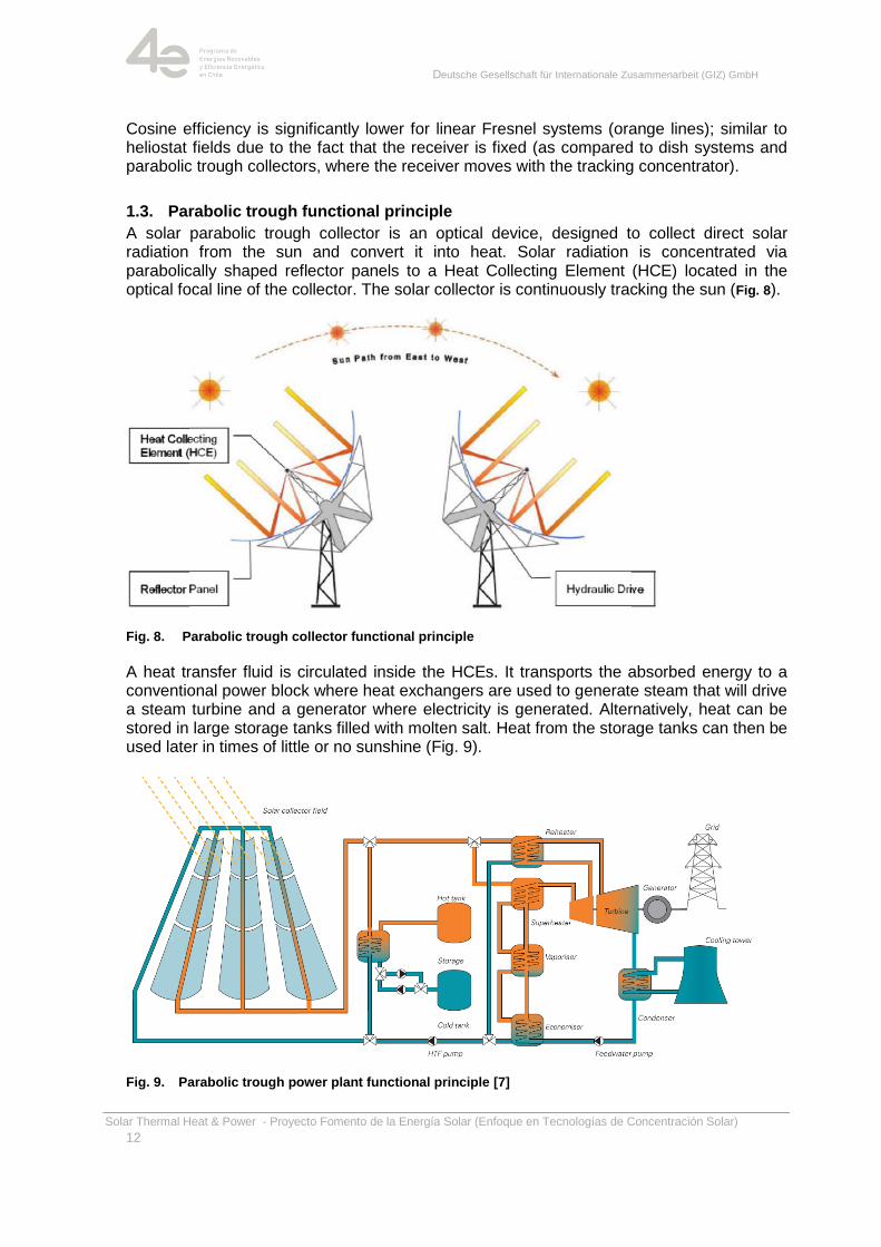
1.3. Parabolic trough functional principle
A solar parabolic trough collector is an optical device, designed to collect direct solar radiation from the sun and convert it into heat. Solar radiation is concentrated via parabolically shaped reflector panels to a Heat Collecting Element (HCE) located in the optical focal line of the collector. The solar collector is continuously tracking the sun (Fig. 8).
Fig. 8. Parabolic trough collector functional principle
A heat transfer fluid is circulated inside the HCEs. It transports the absorbed energy to a conventional power block where heat exchangers are used to generate steam that will drive a steam turbine and a generator where electricity is generated. Alternatively, heat can be stored in large storage tanks filled with molten salt. Heat from the storage tanks can then be used later in times of little or no sunshine (Fig. 9).
Fig. 9. Parabolic trough power plant functional principle [7]
Deutsche Gesellschaft für Internationale Zusammenarbeit (GIZ) GmbH
Solar Thermal Heat & Power - Proyecto Fomento de la Energía Solar (Enfoque en Tecnologías de Concentración Solar)
13
2. Overview on parabolic trough collectors
In general, parabolic trough collectors can be divided into two general categories following their application:
1. Parabolic trough collectors for electric power production
2. Parabolic trough collectors for process heat supply
The main focus of this documentation is on parabolic trough collectors for electric power production as described in the following chapters. For the sake of completeness, chapter 2.7 deals with parabolic trough collectors for process heat supply.
2.1. Introduction
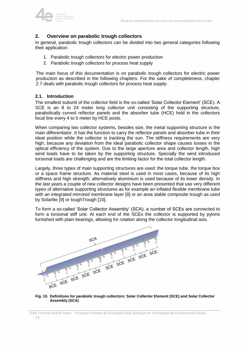
The smallest subunit of the collector field is the so-called ‗Solar Collector Element‘ (SCE). A SCE is an 8 to 24 meter long collector unit consisting of the supporting structure, parabolically curved reflector panels and the absorber tube (HCE) held in the collectors focal line every 4 to 5 meter by HCE posts.
When comparing two collector systems, besides size, the metal supporting structure is the main differentiator. It has the function to carry the reflector panels and absorber tube in their ideal position while the collector is tracking the sun. The stiffness requirements are very high, because any deviation from the ideal parabolic collector shape causes losses in the optical efficiency of the system. Due to the large aperture area and collector length, high wind loads have to be taken by the supporting structure. Specially the wind introduced torsional loads are challenging and are the limiting factor for the total collector length.
Largely, three types of main supporting structures are used: the torque tube, the torque box or a space frame structure. As material steel is used in most cases, because of its high stiffness and high strength; alternatively aluminium is used because of its lower density. In the last years a couple of new collector designs have been presented that use very different types of alternative supporting structures as for example an inflated flexible membrane tube with an integrated mirrored membrane layer [8] or an area stable composite trough as used by Solarlite [9] or toughTrough [10].
To form a so-called ‗Solar Collector Assembly‘ (SCA), a number of SCEs are connected to form a torsional stiff unit. At each end of the SCEs the collector is supported by pylons furnished with plain bearings, allowing for rotation along the collector longitudinal axis.
Fig. 10. Definitions for parabolic trough collectors: Solar Collector Element (SCE) and Solar Collector Assembly (SCA)
Deutsche Gesellschaft für Internationale Zusammenarbeit (GIZ) GmbH
Solar Thermal Heat & Power - Proyecto Fomento de la Energía Solar (Enfoque en Tecnologías de Concentración Solar)
14
A number of SCA forms a so-called ‗Collector Loop‘. Within the loop all absorbers (HCEs) are connected, the heat transfer fluid flows through all of them, heating up in every collector. To ease the installation of the collecting pipes for the heat transfer fluid, the SCAs are arranged in U-Form with 2 x 300 m length (EuroTrough). At the beginning of each loop the cold heat transfer fluid (HTF) is pumped into the absorber tubes. Between beginning and end of the collector loop the HTF is heated, usually to its maximum allowable operation temperature. The hot fluid is then pumped back to the power block or to the thermal storage systems.
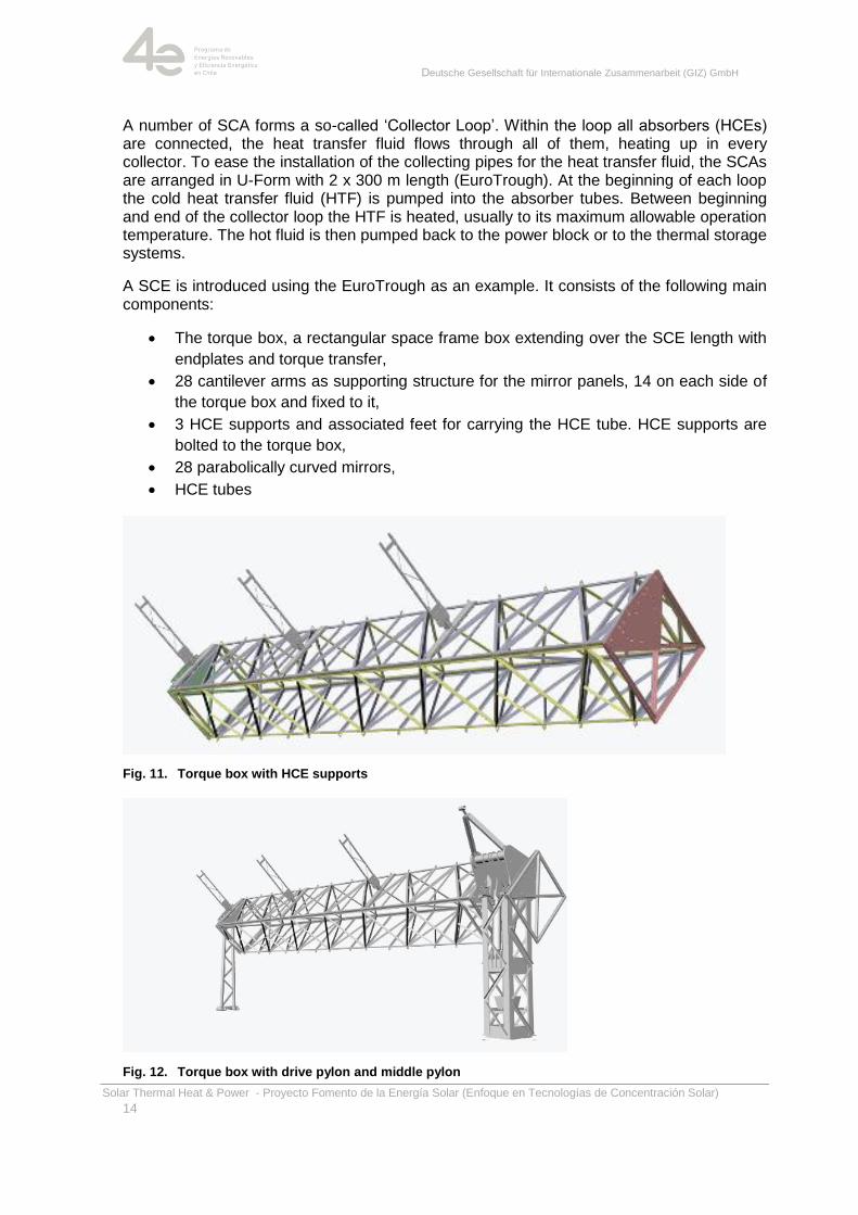
A SCE is introduced using the EuroTrough as an example. It consists of the following main components:
The torque box, a rectangular space frame box extending over the SCE length with
endplates and torque transfer,
28 cantilever arms as supporting structure for the mirror panels, 14 on each side of
the torque box and fixed to it,
3 HCE supports and associated feet for carrying the HCE tube. HCE supports are
bolted to the torque box,
28 parabolically curved mirrors,
HCE tubes
Fig. 11. Torque box with HCE supports
Fig. 12. Torque box with drive pylon and middle pylon
Deutsche Gesellschaft für Internationale Zusammenarbeit (GIZ) GmbH
Solar Thermal Heat & Power - Proyecto Fomento de la Energía Solar (Enfoque en Tecnologías de Concentración Solar)
15
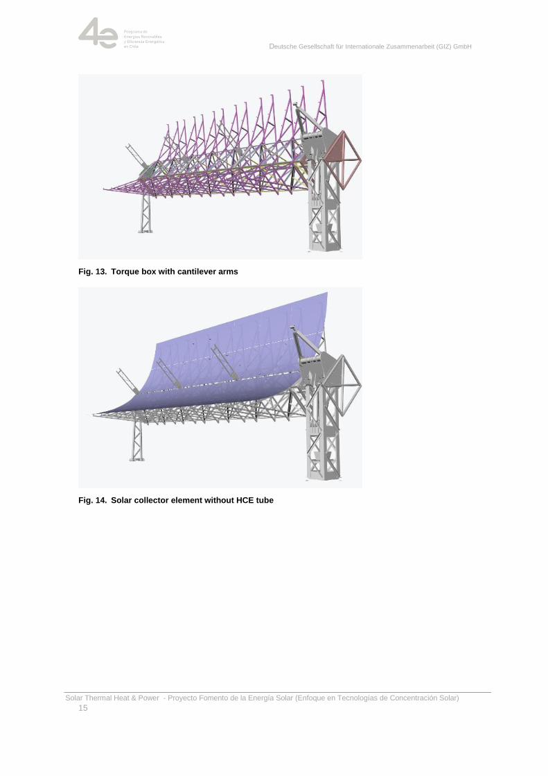
Fig. 13. Torque box with cantilever arms
Fig. 14. Solar collector element without HCE tube
Deutsche Gesellschaft für Internationale Zusammenarbeit (GIZ) GmbH
Solar Thermal Heat & Power - Proyecto Fomento de la Energía Solar (Enfoque en Tecnologías de Concentración Solar)
16
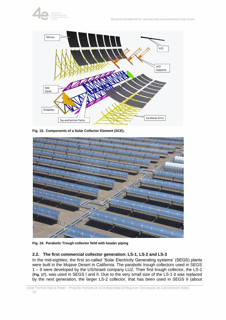
Fig. 15. Components of a Solar Collector Element (SCE).
Fig. 16. Parabolic Trough collector field with header piping
2.2. The first commercial collector generation: LS-1, LS-2 and LS-3
In the mid-eighties, the first so-called ‗Solar Electricity Generating systems‘ (SEGS) plants were built in the Mojave Desert in California. The parabolic trough collectors used in SEGS 1 – 9 were developed by the US/Israeli company LUZ. Their first trough collector, the LS-1 (Fig. 17), was used in SEGS I and II. Due to the very small size of the LS-1 it was replaced by the next generation, the larger LS-2 collector, that has been used in SEGS II (about
Deutsche Gesellschaft für Internationale Zusammenarbeit (GIZ) GmbH
Solar Thermal Heat & Power - Proyecto Fomento de la Energía Solar (Enfoque en Tecnologías de Concentración Solar)
17
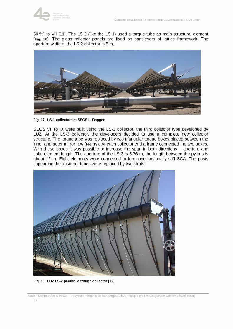
50 %) to VII [11]. The LS-2 (like the LS-1) used a torque tube as main structural element (Fig. 18). The glass reflector panels are fixed on cantilevers of lattice framework. The aperture width of the LS-2 collector is 5 m.
Fig. 17. LS-1 collectors at SEGS II, Daggett
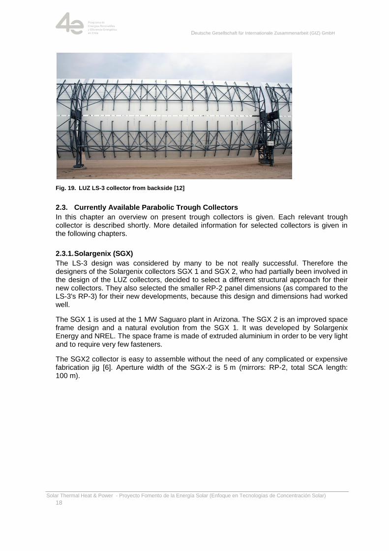
SEGS VII to IX were built using the LS-3 collector, the third collector type developed by LUZ. At the LS-3 collector, the developers decided to use a complete new collector structure. The torque tube was replaced by two triangular torque boxes placed between the inner and outer mirror row (Fig. 19). At each collector end a frame connected the two boxes. With these boxes it was possible to increase the span in both directions – aperture and solar element length. The aperture of the LS-3 is 5.76 m, the length between the pylons is about 12 m. Eight elements were connected to form one torsionally stiff SCA. The posts supporting the absorber tubes were replaced by two struts.
Fig. 18. LUZ LS-2 parabolic trough collector [12]
Deutsche Gesellschaft für Internationale Zusammenarbeit (GIZ) GmbH
Solar Thermal Heat & Power - Proyecto Fomento de la Energía Solar (Enfoque en Tecnologías de Concentración Solar)
18
Fig. 19. LUZ LS-3 collector from backside [12]
2.3. Currently Available Parabolic Trough Collectors
In this chapter an overview on present trough collectors is given. Each relevant trough collector is described shortly. More detailed information for selected collectors is given in the following chapters.
2.3.1. Solargenix (SGX)
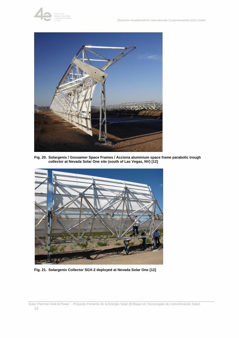
The LS-3 design was considered by many to be not really successful. Therefore the designers of the Solargenix collectors SGX 1 and SGX 2, who had partially been involved in the design of the LUZ collectors, decided to select a different structural approach for their new collectors. They also selected the smaller RP-2 panel dimensions (as compared to the LS-3's RP-3) for their new developments, because this design and dimensions had worked well.
The SGX 1 is used at the 1 MW Saguaro plant in Arizona. The SGX 2 is an improved space frame design and a natural evolution from the SGX 1. It was developed by Solargenix Energy and NREL. The space frame is made of extruded aluminium in order to be very light and to require very few fasteners.
The SGX2 collector is easy to assemble without the need of any complicated or expensive fabrication jig [6]. Aperture width of the SGX-2 is 5 m (mirrors: RP-2, total SCA length: 100 m).
Deutsche Gesellschaft für Internationale Zusammenarbeit (GIZ) GmbH
Solar Thermal Heat & Power - Proyecto Fomento de la Energía Solar (Enfoque en Tecnologías de Concentración Solar)
19
Fig. 20. Solargenix / Gossamer Space Frames / Acciona aluminium space frame parabolic trough collector at Nevada Solar One site (south of Las Vegas, NV) [12]
Fig. 21. Solargenix Collector SGX-2 deployed at Nevada Solar One [12]
Deutsche Gesellschaft für Internationale Zusammenarbeit (GIZ) GmbH
Solar Thermal Heat & Power - Proyecto Fomento de la Energía Solar (Enfoque en Tecnologías de Concentración Solar)
20
2.3.2. EuroTrough
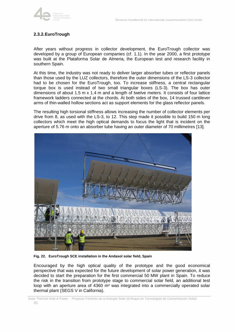
After years without progress in collector development, the EuroTrough collector was developed by a group of European companies (cf. 1.1). In the year 2000, a first prototype was built at the Plataforma Solar de Almeria, the European test and research facility in southern Spain.
At this time, the industry was not ready to deliver larger absorber tubes or reflector panels than those used by the LUZ collectors, therefore the outer dimensions of the LS-3 collector had to be chosen for the EuroTrough, too. To increase stiffness, a central rectangular torque box is used instead of two small triangular boxes (LS-3). The box has outer dimensions of about 1.5 m x 1.4 m and a length of twelve meters. It consists of four lattice framework ladders connected at the chords. At both sides of the box, 14 trussed cantilever arms of thin-walled hollow sections act as support elements for the glass reflector panels.
The resulting high torsional stiffness allows increasing the number of collector elements per drive from 8, as used with the LS-3, to 12. This step made it possible to build 150 m long collectors which meet the high optical demands to focus the light that is incident on the aperture of 5.76 m onto an absorber tube having an outer diameter of 70 millimetres [13].
Fig. 22. EuroTrough SCE installation in the Andasol solar field, Spain
Encouraged by the high optical quality of the prototype and the good economical perspective that was expected for the future development of solar power generation, it was decided to start the preparation for the first commercial 50 MW plant in Spain. To reduce the risk in the transition from prototype stage to commercial solar field, an additional test loop with an aperture area of 4360 m² was integrated into a commercially operated solar thermal plant (SEGS V in California).
Deutsche Gesellschaft für Internationale Zusammenarbeit (GIZ) GmbH
Solar Thermal Heat & Power - Proyecto Fomento de la Energía Solar (Enfoque en Tecnologías de Concentración Solar)
21
With the newly introduced feed-in tariff in Spain, the erection of Andasol 1, one of three very similar 50 MW plants, started in 2008. This was the real start of the global renaissance of solar thermal power generation.
Shortly after the development of the EuroTrough, a number of other parabolic trough collectors were developed. On one hand, some collectors were very similar to the EuroTrough such as the ASTRO collector by Abengoa or the scaled LS-2 collector by SENER, on the other hand collectors with completely new structures were designed like the space frame of the SGX collector by Solargenix (later acquired by Acciona).
ASTRO
The ASTRO collector is very similar to the Euro Trough. One of the very few changes is the reduction of the number of cantilever arms and the use of longitudinal purlins to support the reflector panels.
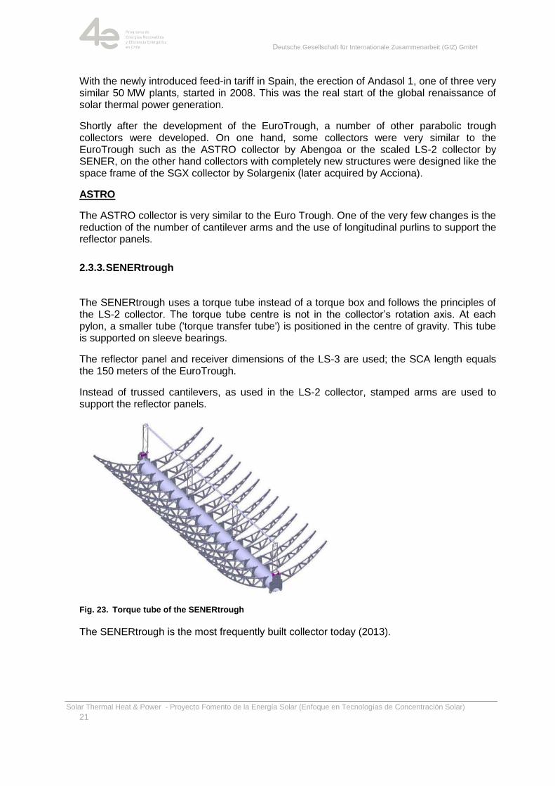
2.3.3. SENERtrough
The SENERtrough uses a torque tube instead of a torque box and follows the principles of the LS-2 collector. The torque tube centre is not in the collector‘s rotation axis. At each pylon, a smaller tube ('torque transfer tube') is positioned in the centre of gravity. This tube is supported on sleeve bearings.
The reflector panel and receiver dimensions of the LS-3 are used; the SCA length equals the 150 meters of the EuroTrough.
Instead of trussed cantilevers, as used in the LS-2 collector, stamped arms are used to support the reflector panels.
Fig. 23. Torque tube of the SENERtrough
The SENERtrough is the most frequently built collector today (2013).
Deutsche Gesellschaft für Internationale Zusammenarbeit (GIZ) GmbH
Solar Thermal Heat & Power - Proyecto Fomento de la Energía Solar (Enfoque en Tecnologías de Concentración Solar)
22
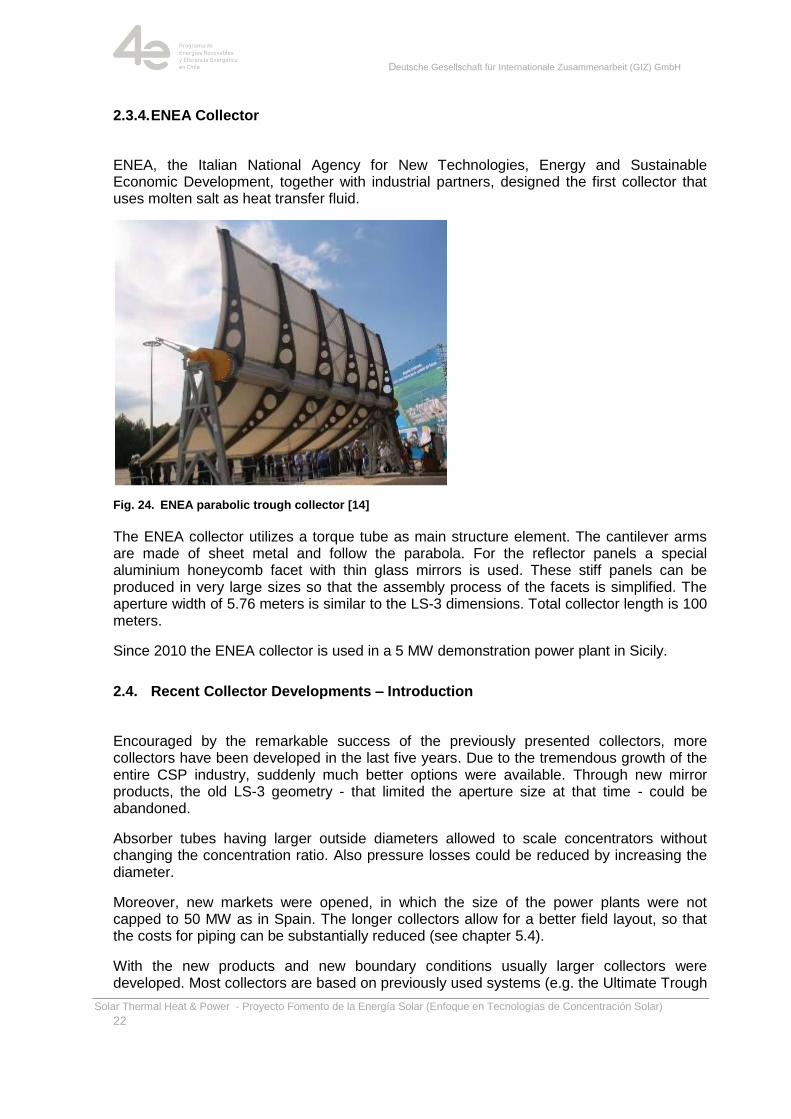
2.3.4. ENEA Collector
ENEA, the Italian National Agency for New Technologies, Energy and Sustainable Economic Development, together with industrial partners, designed the first collector that uses molten salt as heat transfer fluid.
Fig. 24. ENEA parabolic trough collector [14]
The ENEA collector utilizes a torque tube as main structure element. The cantilever arms are made of sheet metal and follow the parabola. For the reflector panels a special aluminium honeycomb facet with thin glass mirrors is used. These stiff panels can be produced in very large sizes so that the assembly process of the facets is simplified. The aperture width of 5.76 meters is similar to the LS-3 dimensions. Total collector length is 100 meters.
Since 2010 the ENEA collector is used in a 5 MW demonstration power plant in Sicily.
2.4. Recent Collector Developments – Introduction
Encouraged by the remarkable success of the previously presented collectors, more collectors have been developed in the last five years. Due to the tremendous growth of the entire CSP industry, suddenly much better options were available. Through new mirror products, the old LS-3 geometry - that limited the aperture size at that time - could be abandoned.
Absorber tubes having larger outside diameters allowed to scale concentrators without changing the concentration ratio. Also pressure losses could be reduced by increasing the diameter.
Moreover, new markets were opened, in which the size of the power plants were not capped to 50 MW as in Spain. The longer collectors allow for a better field layout, so that the costs for piping can be substantially reduced (see chapter 5.4).
With the new products and new boundary conditions usually larger collectors were developed. Most collectors are based on previously used systems (e.g. the Ultimate Trough
Deutsche Gesellschaft für Internationale Zusammenarbeit (GIZ) GmbH
Solar Thermal Heat & Power - Proyecto Fomento de la Energía Solar (Enfoque en Tecnologías de Concentración Solar)
23
is based on the EuroTrough, the SENERtrough-2 collector on the SENERtrough-1), others use entirely new structures (Solarlite, toughtrough). These collectors are introduced in the following sections.
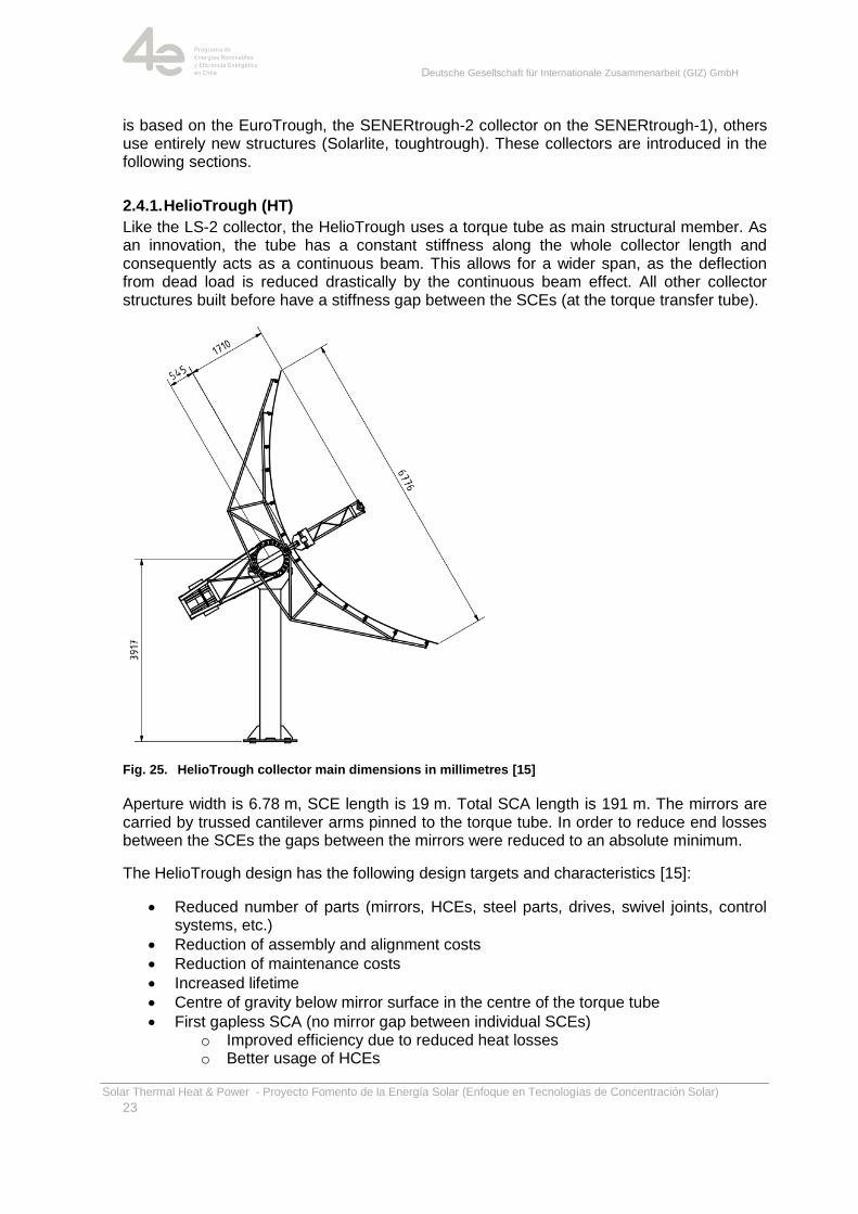
2.4.1. HelioTrough (HT)
Like the LS-2 collector, the HelioTrough uses a torque tube as main structural member. As an innovation, the tube has a constant stiffness along the whole collector length and consequently acts as a continuous beam. This allows for a wider span, as the deflection from dead load is reduced drastically by the continuous beam effect. All other collector structures built before have a stiffness gap between the SCEs (at the torque transfer tube).
Fig. 25. HelioTrough collector main dimensions in millimetres [15]
Aperture width is 6.78 m, SCE length is 19 m. Total SCA length is 191 m. The mirrors are carried by trussed cantilever arms pinned to the torque tube. In order to reduce end losses between the SCEs the gaps between the mirrors were reduced to an absolute minimum.
The HelioTrough design has the following design targets and characteristics [15]:
Reduced number of parts (mirrors, HCEs, steel parts, drives, swivel joints, control systems, etc.)
Reduction of assembly and alignment costs
Reduction of maintenance costs
Increased lifetime
Centre of gravity below mirror surface in the centre of the torque tube
First gapless SCA (no mirror gap between individual SCEs) o Improved efficiency due to reduced heat losses o Better usage of HCEs
Deutsche Gesellschaft für Internationale Zusammenarbeit (GIZ) GmbH
Solar Thermal Heat & Power - Proyecto Fomento de la Energía Solar (Enfoque en Tecnologías de Concentración Solar)
24
o Less space consumption
Assembly and mounting of mirrors: patented 3D-tolerance adjustment
o Mirrors are placed on an accurate jig
o Mirrors in a perfectly shaped parabola
o SCE-frame is lowered on the jig
o Anchor rods are surrounded by the hollow shape of the pods
o Pods are filled with glue, while the mirrors stay in the ideal position
Improved optical efficiency due to perfectly shaped parabola
o Less mirror breakage by tension free connection
o New bearing concept
o Support roller with maintenance free bearing
o Very low friction leads to low torsion and high performance
New cross over pipe design
o No pylons (free access for maintenance equipment)
o Less pressure losses in comparison with a horseshoe bend
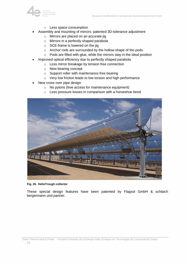
Fig. 26. HelioTrough collector
These special design features have been patented by Flagsol GmbH & schlaich bergermann und partner.

Deutsche Gesellschaft für Internationale Zusammenarbeit (GIZ) GmbH
Solar Thermal Heat & Power - Proyecto Fomento de la Energía Solar (Enfoque en Tecnologías de Concentración Solar)
25
Fig. 27. HelioTrough collector bearing at middle pylon [16]
2.4.2. Ultimate Trough (UT)
The Ultimate Trough is mainly based on the EuroTrough. As main supporting system, a trussed torque box is used. Due to the high bending stiffness of this structure, the span could be increased to 24.5 meters. Also an aperture of 7.51 m could be realized. Total SCA length is 246 m.
Like the HelioTrough, the Ulimate Trough has a continuous mirror surface, too. The glass mirrors are designed for the current maximum dimensions that can be manufactured. Between the inner and outer mirror there is an offset, which moves the centre of gravity of the collector in the desired direction, and provides a wind pressure relief gap between the front and back of the reflector panels, thus reducing wind loads significantly.
Fig. 28. Ultimate Trough collector during transport on site
The Ultimate Trough features a steel structure with torque box design, characterized by an extremely high torque and bending stiffness and an economic use of material. It also results in a lower wind resistance coefficient compared to a torque tube design.
The innovative joining method ‗clinching‘ is used for torque box assembly, saving more than 50 % of bolts and nuts in the solar field while allowing the tension free assembly of the box frames despite high allowable variance.
Deutsche Gesellschaft für Internationale Zusammenarbeit (GIZ) GmbH
Solar Thermal Heat & Power - Proyecto Fomento de la Energía Solar (Enfoque en Tecnologías de Concentración Solar)
26
A wind release gap between the inner and outer mirror reduces wind loads up to 30 %; there are no mirror gaps across the pylons. This could be realized because the centre of gravity and rotation is below the mirror surface.
The Ultimate Trough also features a new and innovative joining method for the steel structure/ mirror connection, allowing high variance and thereby a tension free mirror junction.
A cost effective and precise patented alignment procedure for the assembly of collector elements in the field is used.
The Ultimate Trough is currently the world largest collector element (24 m x 7.5 m) respectively collector assembly (247 m x 7.5 m), showing a peek optical efficiency of 82.7 %. This efficiency number includes an intercept factor of 99.2 %, taking into consideration sun shape, alignment and tracking error [17].
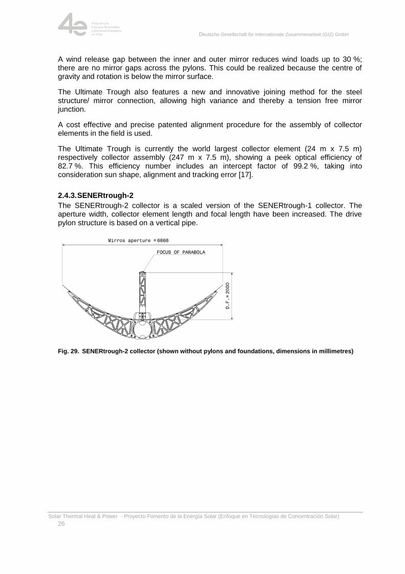
2.4.3. SENERtrough-2
The SENERtrough-2 collector is a scaled version of the SENERtrough-1 collector. The aperture width, collector element length and focal length have been increased. The drive pylon structure is based on a vertical pipe.
Fig. 29. SENERtrough-2 collector (shown without pylons and foundations, dimensions in millimetres)
Deutsche Gesellschaft für Internationale Zusammenarbeit (GIZ) GmbH
Solar Thermal Heat & Power - Proyecto Fomento de la Energía Solar (Enfoque en Tecnologías de Concentración Solar)
27
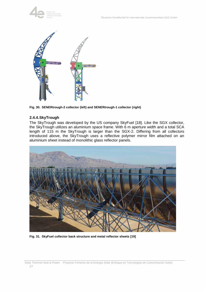
Fig. 30. SENERtrough-2 collector (left) and SENERtrough-1 collector (right)
2.4.4. SkyTrough
The SkyTrough was developed by the US company SkyFuel [18]. Like the SGX collector, the SkyTrough utilizes an aluminium space frame. With 6 m aperture width and a total SCA length of 115 m the SkyTrough is larger than the SGX-2. Differing from all collectors introduced above, the SkyTrough uses a reflective polymer mirror film attached on an aluminium sheet instead of monolithic glass reflector panels.
Fig. 31. SkyFuel collector back structure and metal reflector sheets [19]
Deutsche Gesellschaft für Internationale Zusammenarbeit (GIZ) GmbH
Solar Thermal Heat & Power - Proyecto Fomento de la Energía Solar (Enfoque en Tecnologías de Concentración Solar)
28
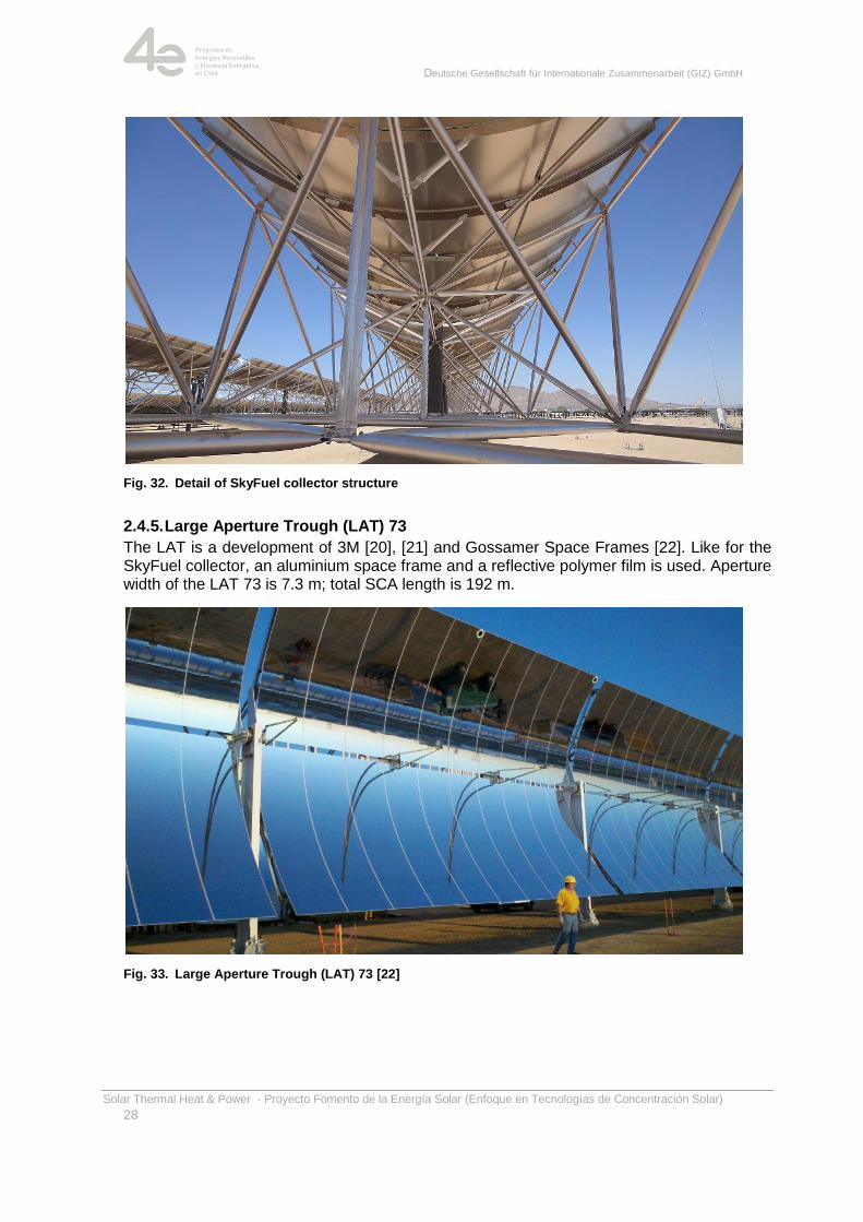
Fig. 32. Detail of SkyFuel collector structure
2.4.5. Large Aperture Trough (LAT) 73
The LAT is a development of 3M [20], [21] and Gossamer Space Frames [22]. Like for the SkyFuel collector, an aluminium space frame and a reflective polymer film is used. Aperture width of the LAT 73 is 7.3 m; total SCA length is 192 m.
Fig. 33. Large Aperture Trough (LAT) 73 [22]
Deutsche Gesellschaft für Internationale Zusammenarbeit (GIZ) GmbH
Solar Thermal Heat & Power - Proyecto Fomento de la Energía Solar (Enfoque en Tecnologías de Concentración Solar)
29
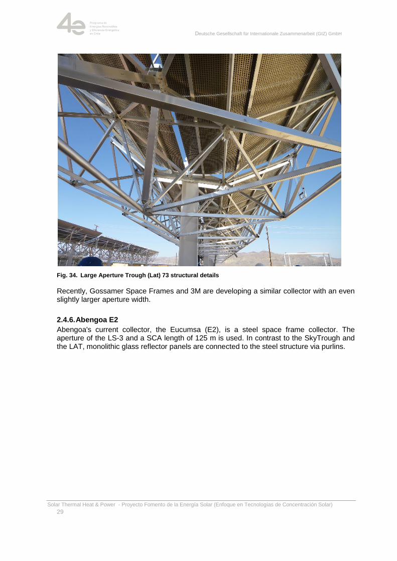
Fig. 34. Large Aperture Trough (Lat) 73 structural details
Recently, Gossamer Space Frames and 3M are developing a similar collector with an even slightly larger aperture width.
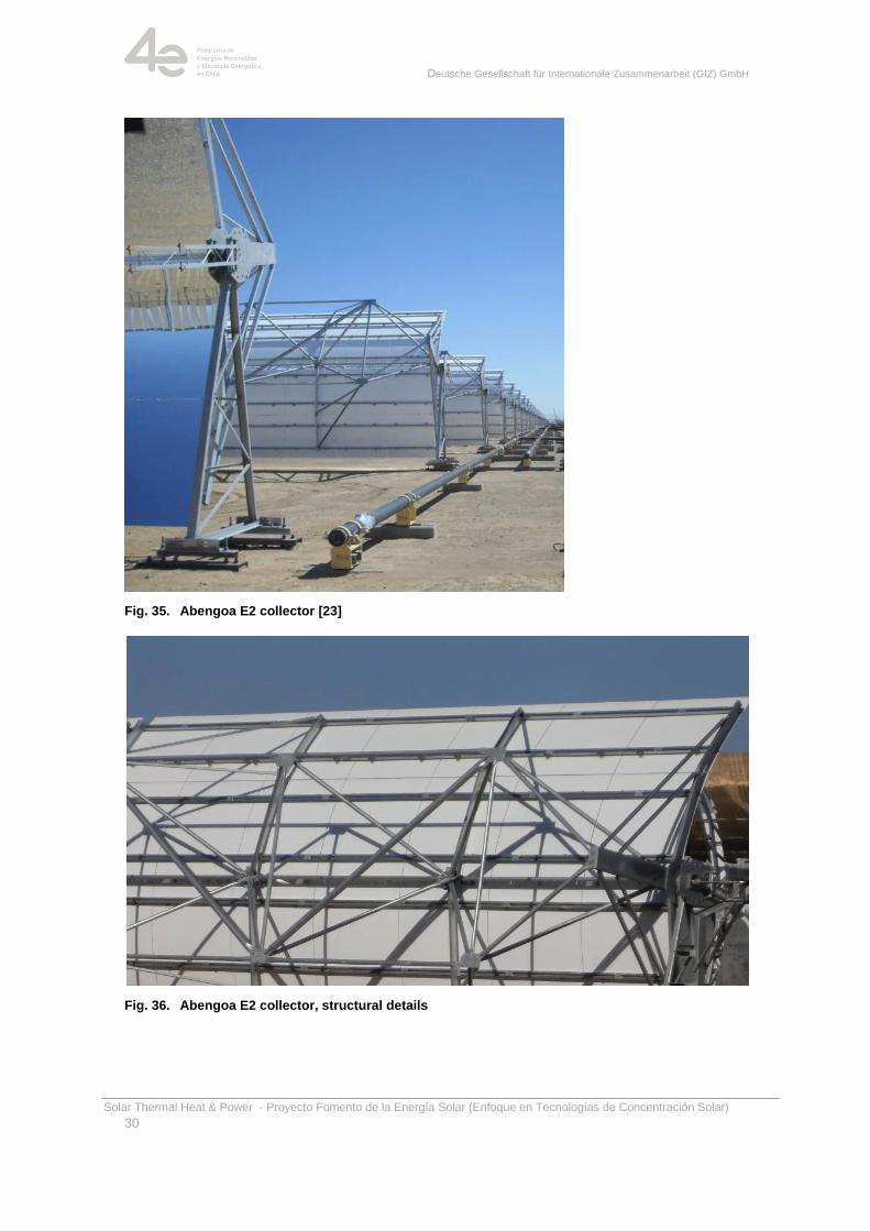
2.4.6. Abengoa E2
Abengoa's current collector, the Eucumsa (E2), is a steel space frame collector. The aperture of the LS-3 and a SCA length of 125 m is used. In contrast to the SkyTrough and the LAT, monolithic glass reflector panels are connected to the steel structure via purlins.
Deutsche Gesellschaft für Internationale Zusammenarbeit (GIZ) GmbH
Solar Thermal Heat & Power - Proyecto Fomento de la Energía Solar (Enfoque en Tecnologías de Concentración Solar)
30
Fig. 35. Abengoa E2 collector [23]
Fig. 36. Abengoa E2 collector, structural details
Deutsche Gesellschaft für Internationale Zusammenarbeit (GIZ) GmbH
Solar Thermal Heat & Power - Proyecto Fomento de la Energía Solar (Enfoque en Tecnologías de Concentración Solar)
31
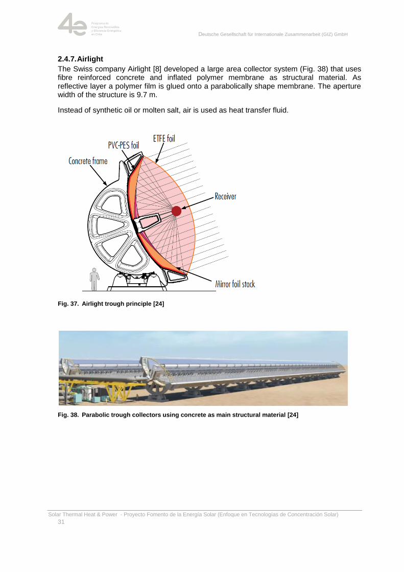
2.4.7. Airlight
The Swiss company Airlight [8] developed a large area collector system (Fig. 38) that uses fibre reinforced concrete and inflated polymer membrane as structural material. As reflective layer a polymer film is glued onto a parabolically shape membrane. The aperture width of the structure is 9.7 m.
Instead of synthetic oil or molten salt, air is used as heat transfer fluid.
Fig. 37. Airlight trough principle [24]
Fig. 38. Parabolic trough collectors using concrete as main structural material [24]
Deutsche Gesellschaft für Internationale Zusammenarbeit (GIZ) GmbH
Solar Thermal Heat & Power - Proyecto Fomento de la Energía Solar (Enfoque en Tecnologías de Concentración Solar)
32
2.5. Characterization of parabolic trough collectors
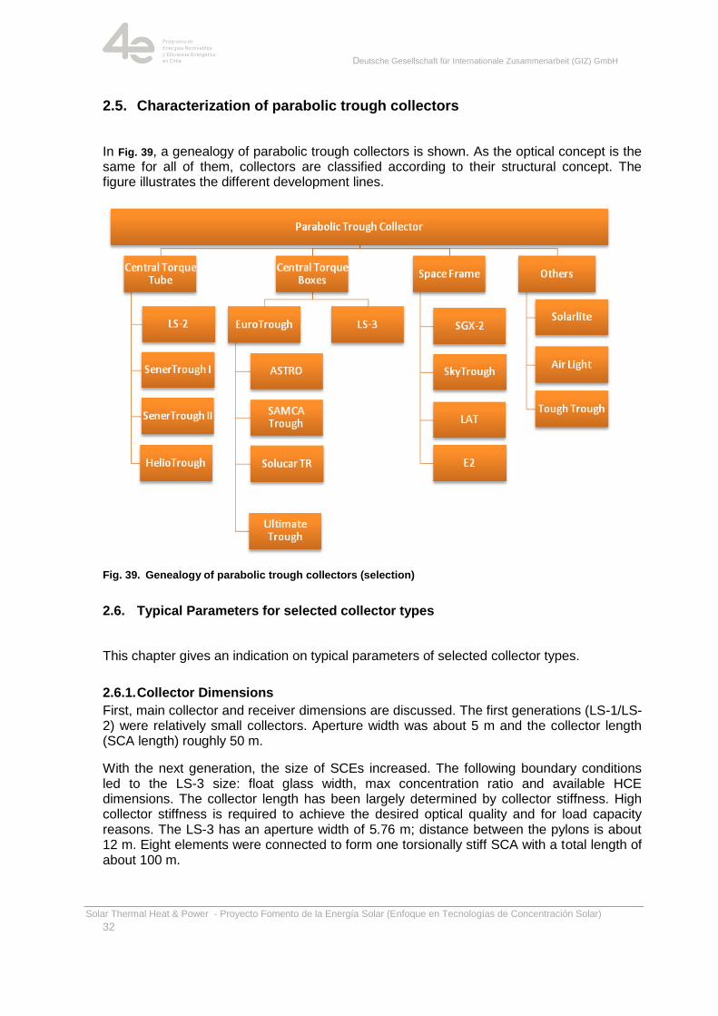
In Fig. 39, a genealogy of parabolic trough collectors is shown. As the optical concept is the same for all of them, collectors are classified according to their structural concept. The figure illustrates the different development lines.
Fig. 39. Genealogy of parabolic trough collectors (selection)
2.6. Typical Parameters for selected collector types
This chapter gives an indication on typical parameters of selected collector types.
2.6.1. Collector Dimensions
First, main collector and receiver dimensions are discussed. The first generations (LS-1/LS-2) were relatively small collectors. Aperture width was about 5 m and the collector length (SCA length) roughly 50 m.
With the next generation, the size of SCEs increased. The following boundary conditions led to the LS-3 size: float glass width, max concentration ratio and available HCE dimensions. The collector length has been largely determined by collector stiffness. High collector stiffness is required to achieve the desired optical quality and for load capacity reasons. The LS-3 has an aperture width of 5.76 m; distance between the pylons is about 12 m. Eight elements were connected to form one torsionally stiff SCA with a total length of about 100 m.
Deutsche Gesellschaft für Internationale Zusammenarbeit (GIZ) GmbH
Solar Thermal Heat & Power - Proyecto Fomento de la Energía Solar (Enfoque en Tecnologías de Concentración Solar)
33
Using the LS-3 mirror geometry, the EuroTrough was developed in the nineties. By that time, no other mirror or receiver dimensions were available. Due to a significantly stiffer support structure, longer collectors can be built, which still possess a higher optical efficiency. Beside the EuroTrough, a later developed variety of other collectors (SENERtrough-1, ASTRO, etc.) are using the LS-3 mirror and receiver geometry.
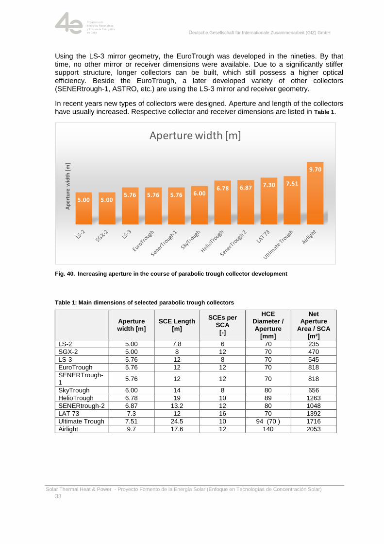
In recent years new types of collectors were designed. Aperture and length of the collectors have usually increased. Respective collector and receiver dimensions are listed in Table 1.
Fig. 40. Increasing aperture in the course of parabolic trough collector development
Table 1: Main dimensions of selected parabolic trough collectors
Aperture width [m]
SCE Length [m]
SCEs per SCA [-]
HCE Diameter / Aperture
[mm]
Net Aperture
Area / SCA [m²]
LS-2 5.00 7.8 6 70 235
SGX-2 5.00 8 12 70 470
LS-3 5.76 12 8 70 545
EuroTrough 5.76 12 12 70 818
SENERTrough-1
5.76 12 12 70 818
SkyTrough 6.00 14 8 80 656
HelioTrough 6.78 19 10 89 1263
SENERtrough-2 6.87 13.2 12 80 1048
LAT 73 7.3 12 16 70 1392
Ultimate Trough 7.51 24.5 10 94 (70 ) 1716
Airlight 9.7 17.6 12 140 2053
5.00 5.005.76 5.76 5.76 6.00
6.78 6.87 7.30 7.51
9.70
Ape
rtur
e w
idth
[m
]
Aperture width [m]
Deutsche Gesellschaft für Internationale Zusammenarbeit (GIZ) GmbH
Solar Thermal Heat & Power - Proyecto Fomento de la Energía Solar (Enfoque en Tecnologías de Concentración Solar)
34
2.6.2. Concentration Ratio
Radiation concentration is necessary if higher temperatures than those generated by flat-plate collectors are required. Concentration of solar radiation is described by concentration ratio. It can be defined according to two different methods:
On the one hand, concentration ratio C can be determined solely geometrically
(Cgeom), describing the ratio of solar aperture surface Aap to absorber surface Aabs
(Equation (1)); explanations within this chapter are based on this definition. Thus,
the concentration ratio Cgeom of a typical parabolic through collector of an aperture
width of 5.76 m and an absorber tube diameter of 70 mm amounts to approximately
26 (i.e. a circumference of π * 70 mm ≈ 220 mm leads to 5760 mm/220 mm ≈ 26).
With regard to parabolic through collectors, sometimes the ratio of aperture width to
absorber tube diameter (projected absorber area) is referred to as concentration
ratio; this quantity differs from the concentration ratio defined by Equation (1) by
factor π.
ap ap
geom
abs abs
A AC C
A d
(1)
On the other hand, concentration ratio C can be defined as the ratio of radiation flux
density Gap at aperture level and the corresponding value Gabs at the absorber (Cflux,
Equation (2)). However, this definition is only mentioned here to complete the
picture.
ap
flux
abs
GC C
G
(2)
In practice, the achievable concentration ratio is considerably smaller than the theoretical maximum. This is due to the following aspects:
Tracking errors, geometric deflections as well as imperfect orientation of the
receiver
Real mirrors are not perfect and expand the reflected beam
Atmospheric scattering expands the efficient aperture angle of the sun far beyond
the ideal geometric value of the acceptance semi-angle of approximately 4.7 mrad
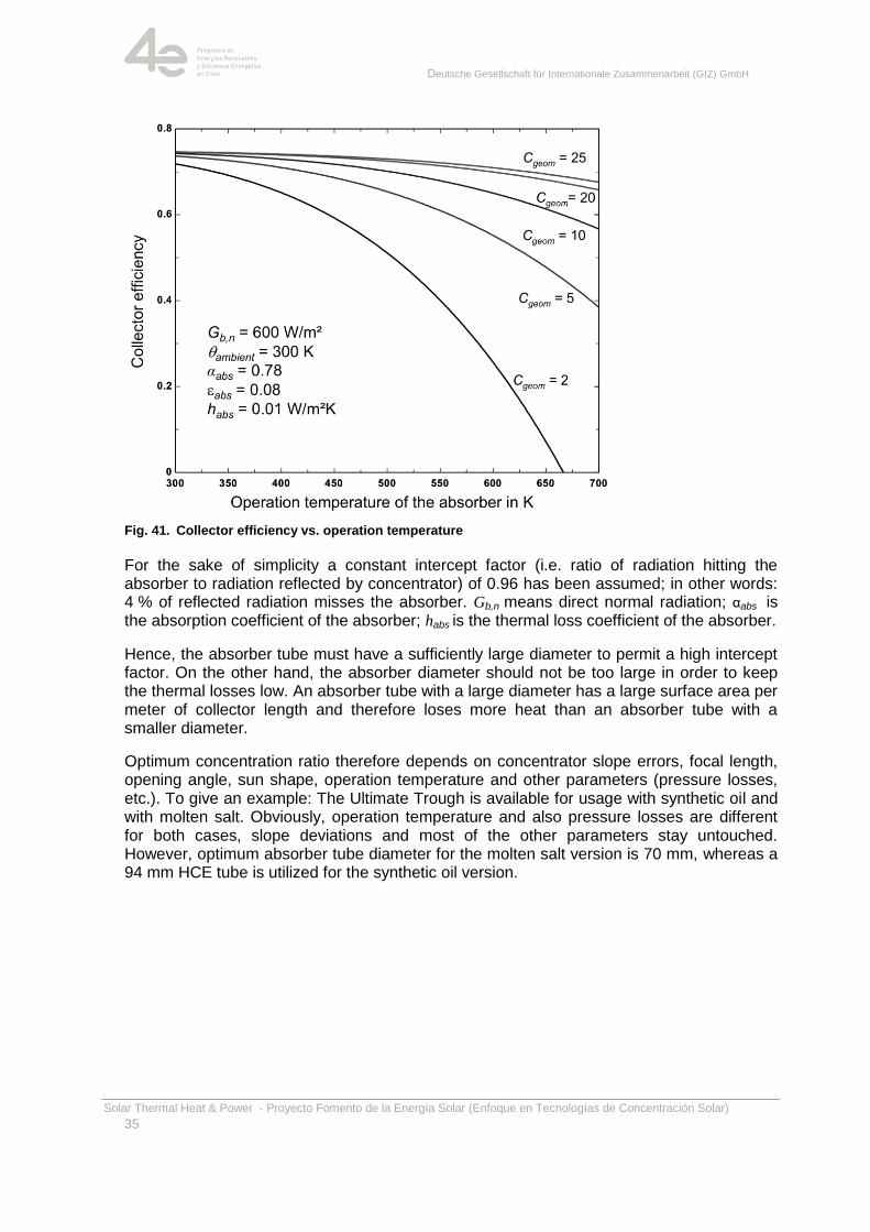
Radiation concentration aims at increasing possible absorber temperature and consequently exergy of concentrated heat. In addition, absorber diameter/surface can be reduced, thereby reducing thermal losses due to radiation, convection and heat conduction. In case of absorbers of parabolic through collectors, this is achieved by evacuated tubes and by an absorber coating with a low emission coefficient within the relevant wavelength range. Fig. 41 shows the impact of concentration ratio on collector efficiency ηColl over the
absorber temperature θabs for a typical emission coefficient εabs= 0.08 of the absorber.
Deutsche Gesellschaft für Internationale Zusammenarbeit (GIZ) GmbH
Solar Thermal Heat & Power - Proyecto Fomento de la Energía Solar (Enfoque en Tecnologías de Concentración Solar)
35
Fig. 41. Collector efficiency vs. operation temperature
For the sake of simplicity a constant intercept factor (i.e. ratio of radiation hitting the absorber to radiation reflected by concentrator) of 0.96 has been assumed; in other words: 4 % of reflected radiation misses the absorber. Gb,n means direct normal radiation; αabs is the absorption coefficient of the absorber; habs is the thermal loss coefficient of the absorber.
Hence, the absorber tube must have a sufficiently large diameter to permit a high intercept factor. On the other hand, the absorber diameter should not be too large in order to keep the thermal losses low. An absorber tube with a large diameter has a large surface area per meter of collector length and therefore loses more heat than an absorber tube with a smaller diameter.
Optimum concentration ratio therefore depends on concentrator slope errors, focal length, opening angle, sun shape, operation temperature and other parameters (pressure losses, etc.). To give an example: The Ultimate Trough is available for usage with synthetic oil and with molten salt. Obviously, operation temperature and also pressure losses are different for both cases, slope deviations and most of the other parameters stay untouched. However, optimum absorber tube diameter for the molten salt version is 70 mm, whereas a 94 mm HCE tube is utilized for the synthetic oil version.
Deutsche Gesellschaft für Internationale Zusammenarbeit (GIZ) GmbH
Solar Thermal Heat & Power - Proyecto Fomento de la Energía Solar (Enfoque en Tecnologías de Concentración Solar)
36
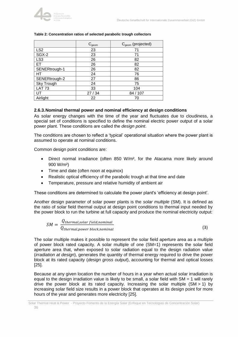
Table 2: Concentration ratios of selected parabolic trough collectors
Cgeom Cgeom (projected)
LS2 23 71
SGX-2 23 71
LS3 26 82
ET 26 82
SENERtrough-1 26 82
HT 24 76
SENERtrough-2 27 86
Sky Trough 24 75
LAT 73 33 104
UT 27 / 34 84 / 107
Airlight 22 70
2.6.3. Nominal thermal power and nominal efficiency at design conditions
As solar energy changes with the time of the year and fluctuates due to cloudiness, a special set of conditions is specified to define the nominal electric power output of a solar power plant. These conditions are called the design point.
The conditions are chosen to reflect a ‗typical‘ operational situation where the power plant is assumed to operate at nominal conditions.
Common design point conditions are:
Direct normal irradiance (often 850 W/m², for the Atacama more likely around
900 W/m²)
Time and date (often noon at equinox)
Realistic optical efficiency of the parabolic trough at that time and date
Temperature, pressure and relative humidity of ambient air
These conditions are determined to calculate the power plant's ‗efficiency at design point‘.
Another design parameter of solar power plants is the solar multiple (SM). It is defined as the ratio of solar field thermal output at design point conditions to thermal input needed by the power block to run the turbine at full capacity and produce the nominal electricity output:
(3)
The solar multiple makes it possible to represent the solar field aperture area as a multiple of power block rated capacity. A solar multiple of one (SM=1) represents the solar field aperture area that, when exposed to solar radiation equal to the design radiation value (irradiation at design), generates the quantity of thermal energy required to drive the power block at its rated capacity (design gross output), accounting for thermal and optical losses [25].
Because at any given location the number of hours in a year when actual solar irradiation is equal to the design irradiation value is likely to be small, a solar field with SM = 1 will rarely drive the power block at its rated capacity. Increasing the solar multiple (SM > 1) by increasing solar field size results in a power block that operates at its design point for more hours of the year and generates more electricity [25].
Deutsche Gesellschaft für Internationale Zusammenarbeit (GIZ) GmbH
Solar Thermal Heat & Power - Proyecto Fomento de la Energía Solar (Enfoque en Tecnologías de Concentración Solar)
37
A solar field with a SM > 1.5 is necessary for reasonable use of a thermal storage.
Solar fields with SM > 1 will provide more thermal power than the power block can handle at some times of the year, but will also ensure a good degree of capacity utilization for the turbine. During times with too much thermal power, some of it is dumped by intentionally defocusing an appropriate number of collectors.
As always, a holistic approach is necessary to find the most cost-effective solution.
Power plants never operate at rated capacity over a full year, e.g., due to maintenance. The plant may also run, but with reduced efficiency, if the solar field does not provide enough thermal power to drive the turbine at its design point.
The capacity factor indicates the annual degree of capacity utilization for the power plant. It is defined as the ratio of the actual output of the power plant over a period of time and its output if it had operated at full nameplate capacity the entire time:
(4)
The capacity factor is used to estimate the overall operating reliability; it needs to be considered in deciding whether a solar energy project should be developed.
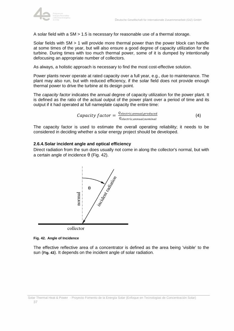
2.6.4. Solar incident angle and optical efficiency
Direct radiation from the sun does usually not come in along the collector's normal, but with
a certain angle of incidence θ (Fig. 42).
Fig. 42. Angle of Incidence
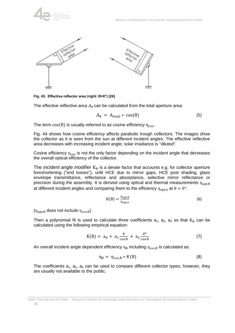
The effective reflective area of a concentrator is defined as the area being 'visible' to the sun (Fig. 43). It depends on the incident angle of solar radiation.
Deutsche Gesellschaft für Internationale Zusammenarbeit (GIZ) GmbH
Solar Thermal Heat & Power - Proyecto Fomento de la Energía Solar (Enfoque en Tecnologías de Concentración Solar)
38
Fig. 43. Effective reflector area (right: Θ=0°) [26]
The effective reflective area can be calculated from the total aperture area:
(5)
The term is usually referred to as cosine efficiency .
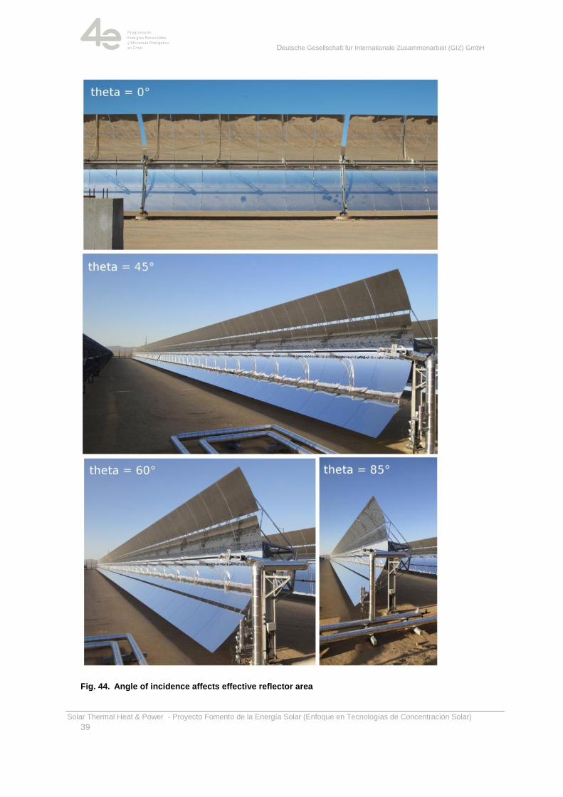
Fig. 44 shows how cosine efficiency affects parabolic trough collectors. The images show the collector as it is seen from the sun at different incident angles. The effective reflective area decreases with increasing incident angle; solar irradiance is "diluted".
Cosine efficiency is not the only factor depending on the incident angle that decreases the overall optical efficiency of the collector.
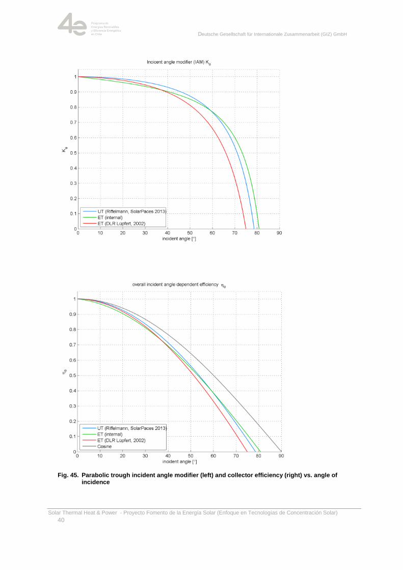
The incident angle modifier is a derate factor that accounts e.g. for collector aperture
foreshortening ("end losses"), unlit HCE due to mirror gaps, HCE post shading, glass envelope transmittance, reflectance and absorptance, selective mirror reflectance or precision during the assembly. It is derived using optical and thermal measurements
at different incident angles and comparing them to the efficiency at :
(6)
( does not include )
Then a polynomial fit is used to calculate three coefficients a1, a2, a3 so that can be calculated using the following empirical equation:
(7)
An overall incident angle dependent efficiency including is calculated as:
(8)
The coefficients a1, a2, a3 can be used to compare different collector types; however, they are usually not available to the public.
Deutsche Gesellschaft für Internationale Zusammenarbeit (GIZ) GmbH
Solar Thermal Heat & Power - Proyecto Fomento de la Energía Solar (Enfoque en Tecnologías de Concentración Solar)
39
Fig. 44. Angle of incidence affects effective reflector area
Deutsche Gesellschaft für Internationale Zusammenarbeit (GIZ) GmbH
Solar Thermal Heat & Power - Proyecto Fomento de la Energía Solar (Enfoque en Tecnologías de Concentración Solar)
40
Fig. 45. Parabolic trough incident angle modifier (left) and collector efficiency (right) vs. angle of incidence
Deutsche Gesellschaft für Internationale Zusammenarbeit (GIZ) GmbH
Solar Thermal Heat & Power - Proyecto Fomento de la Energía Solar (Enfoque en Tecnologías de Concentración Solar)
41
2.6.5. Thermal Losses
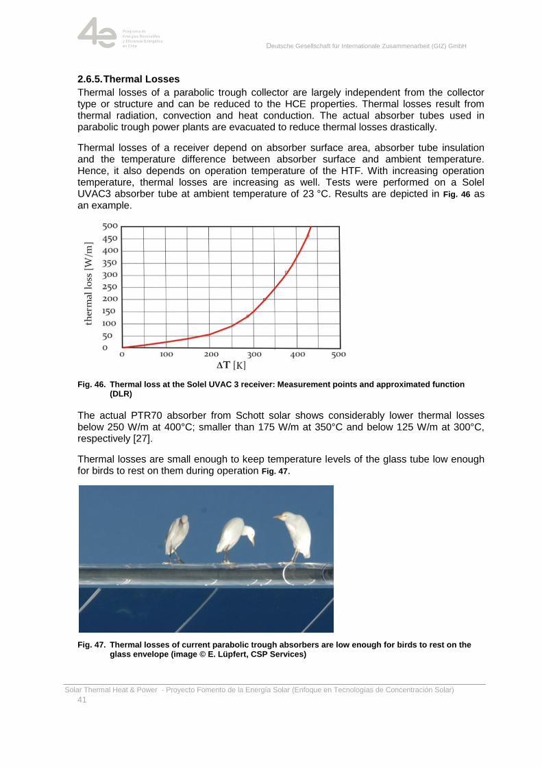
Thermal losses of a parabolic trough collector are largely independent from the collector type or structure and can be reduced to the HCE properties. Thermal losses result from thermal radiation, convection and heat conduction. The actual absorber tubes used in parabolic trough power plants are evacuated to reduce thermal losses drastically.
Thermal losses of a receiver depend on absorber surface area, absorber tube insulation and the temperature difference between absorber surface and ambient temperature. Hence, it also depends on operation temperature of the HTF. With increasing operation temperature, thermal losses are increasing as well. Tests were performed on a Solel UVAC3 absorber tube at ambient temperature of 23 °C. Results are depicted in Fig. 46 as an example.
Fig. 46. Thermal loss at the Solel UVAC 3 receiver: Measurement points and approximated function (DLR)
The actual PTR70 absorber from Schott solar shows considerably lower thermal losses below 250 W/m at 400°C; smaller than 175 W/m at 350°C and below 125 W/m at 300°C, respectively [27].
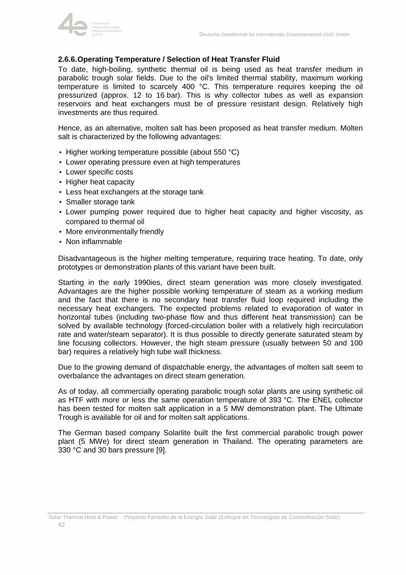
Thermal losses are small enough to keep temperature levels of the glass tube low enough for birds to rest on them during operation Fig. 47.
Fig. 47. Thermal losses of current parabolic trough absorbers are low enough for birds to rest on the glass envelope (image © E. Lüpfert, CSP Services)
Deutsche Gesellschaft für Internationale Zusammenarbeit (GIZ) GmbH
Solar Thermal Heat & Power - Proyecto Fomento de la Energía Solar (Enfoque en Tecnologías de Concentración Solar)
42
2.6.6. Operating Temperature / Selection of Heat Transfer Fluid
To date, high-boiling, synthetic thermal oil is being used as heat transfer medium in parabolic trough solar fields. Due to the oil's limited thermal stability, maximum working temperature is limited to scarcely 400 °C. This temperature requires keeping the oil pressurized (approx. 12 to 16 bar). This is why collector tubes as well as expansion reservoirs and heat exchangers must be of pressure resistant design. Relatively high investments are thus required.
Hence, as an alternative, molten salt has been proposed as heat transfer medium. Molten salt is characterized by the following advantages:
• Higher working temperature possible (about 550 °C)
• Lower operating pressure even at high temperatures
• Lower specific costs
• Higher heat capacity
• Less heat exchangers at the storage tank
• Smaller storage tank
• Lower pumping power required due to higher heat capacity and higher viscosity, as
compared to thermal oil
• More environmentally friendly
• Non inflammable
Disadvantageous is the higher melting temperature, requiring trace heating. To date, only prototypes or demonstration plants of this variant have been built.
Starting in the early 1990ies, direct steam generation was more closely investigated. Advantages are the higher possible working temperature of steam as a working medium and the fact that there is no secondary heat transfer fluid loop required including the necessary heat exchangers. The expected problems related to evaporation of water in horizontal tubes (including two-phase flow and thus different heat transmission) can be solved by available technology (forced-circulation boiler with a relatively high recirculation rate and water/steam separator). It is thus possible to directly generate saturated steam by line focusing collectors. However, the high steam pressure (usually between 50 and 100 bar) requires a relatively high tube wall thickness.
Due to the growing demand of dispatchable energy, the advantages of molten salt seem to overbalance the advantages on direct steam generation.
As of today, all commercially operating parabolic trough solar plants are using synthetic oil as HTF with more or less the same operation temperature of 393 °C. The ENEL collector has been tested for molten salt application in a 5 MW demonstration plant. The Ultimate Trough is available for oil and for molten salt applications.
The German based company Solarlite built the first commercial parabolic trough power plant (5 MWe) for direct steam generation in Thailand. The operating parameters are 330 °C and 30 bars pressure [9].
Deutsche Gesellschaft für Internationale Zusammenarbeit (GIZ) GmbH
Solar Thermal Heat & Power - Proyecto Fomento de la Energía Solar (Enfoque en Tecnologías de Concentración Solar)
43
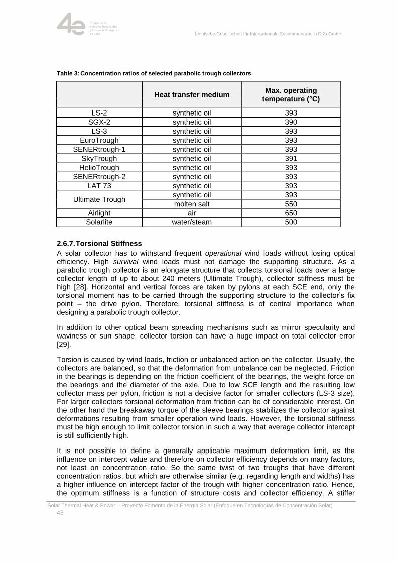
Table 3: Concentration ratios of selected parabolic trough collectors
Heat transfer medium
Max. operating temperature (°C)
LS-2 synthetic oil 393
SGX-2 synthetic oil 390
LS-3 synthetic oil 393
EuroTrough synthetic oil 393
SENERtrough-1 synthetic oil 393
SkyTrough synthetic oil 391
HelioTrough synthetic oil 393
SENERtrough-2 synthetic oil 393
LAT 73 synthetic oil 393
Ultimate Trough synthetic oil 393
molten salt 550
Airlight air 650
Solarlite water/steam 500
2.6.7. Torsional Stiffness
A solar collector has to withstand frequent operational wind loads without losing optical efficiency. High survival wind loads must not damage the supporting structure. As a parabolic trough collector is an elongate structure that collects torsional loads over a large collector length of up to about 240 meters (Ultimate Trough), collector stiffness must be high [28]. Horizontal and vertical forces are taken by pylons at each SCE end, only the torsional moment has to be carried through the supporting structure to the collector‘s fix point – the drive pylon. Therefore, torsional stiffness is of central importance when designing a parabolic trough collector.
In addition to other optical beam spreading mechanisms such as mirror specularity and waviness or sun shape, collector torsion can have a huge impact on total collector error [29].
Torsion is caused by wind loads, friction or unbalanced action on the collector. Usually, the collectors are balanced, so that the deformation from unbalance can be neglected. Friction in the bearings is depending on the friction coefficient of the bearings, the weight force on the bearings and the diameter of the axle. Due to low SCE length and the resulting low collector mass per pylon, friction is not a decisive factor for smaller collectors (LS-3 size). For larger collectors torsional deformation from friction can be of considerable interest. On the other hand the breakaway torque of the sleeve bearings stabilizes the collector against deformations resulting from smaller operation wind loads. However, the torsional stiffness must be high enough to limit collector torsion in such a way that average collector intercept is still sufficiently high.
It is not possible to define a generally applicable maximum deformation limit, as the influence on intercept value and therefore on collector efficiency depends on many factors, not least on concentration ratio. So the same twist of two troughs that have different concentration ratios, but which are otherwise similar (e.g. regarding length and widths) has a higher influence on intercept factor of the trough with higher concentration ratio. Hence, the optimum stiffness is a function of structure costs and collector efficiency. A stiffer
Deutsche Gesellschaft für Internationale Zusammenarbeit (GIZ) GmbH
Solar Thermal Heat & Power - Proyecto Fomento de la Energía Solar (Enfoque en Tecnologías de Concentración Solar)
44
structure usually results in higher structure cost on the one hand, but on the other hand the stiffer design can collect more energy, what results in a smaller collector field.
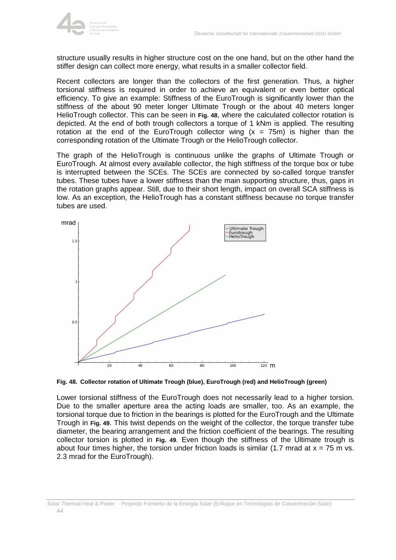
Recent collectors are longer than the collectors of the first generation. Thus, a higher torsional stiffness is required in order to achieve an equivalent or even better optical efficiency. To give an example: Stiffness of the EuroTrough is significantly lower than the stiffness of the about 90 meter longer Ultimate Trough or the about 40 meters longer HelioTrough collector. This can be seen in Fig. 48, where the calculated collector rotation is depicted. At the end of both trough collectors a torque of 1 kNm is applied. The resulting rotation at the end of the EuroTrough collector wing (x = 75m) is higher than the corresponding rotation of the Ultimate Trough or the HelioTrough collector.
The graph of the HelioTrough is continuous unlike the graphs of Ultimate Trough or EuroTrough. At almost every available collector, the high stiffness of the torque box or tube is interrupted between the SCEs. The SCEs are connected by so-called torque transfer tubes. These tubes have a lower stiffness than the main supporting structure, thus, gaps in the rotation graphs appear. Still, due to their short length, impact on overall SCA stiffness is low. As an exception, the HelioTrough has a constant stiffness because no torque transfer tubes are used.
Fig. 48. Collector rotation of Ultimate Trough (blue), EuroTrough (red) and HelioTrough (green)
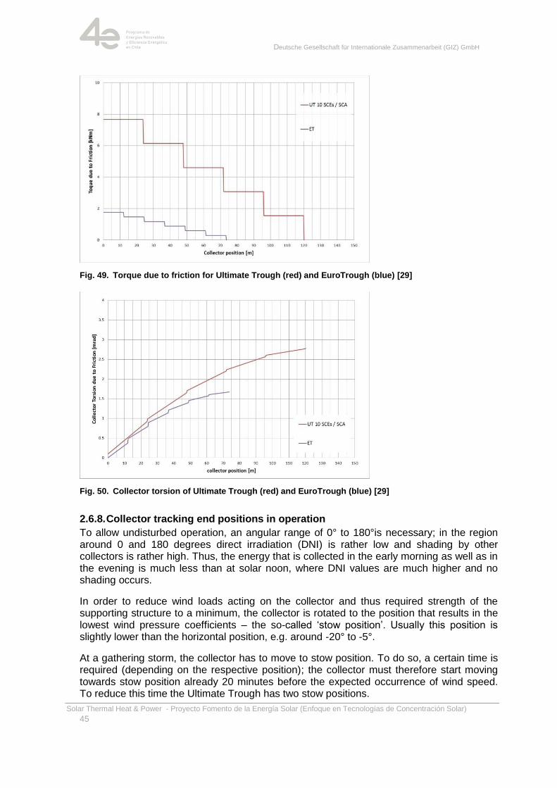
Lower torsional stiffness of the EuroTrough does not necessarily lead to a higher torsion. Due to the smaller aperture area the acting loads are smaller, too. As an example, the torsional torque due to friction in the bearings is plotted for the EuroTrough and the Ultimate Trough in Fig. 49. This twist depends on the weight of the collector, the torque transfer tube diameter, the bearing arrangement and the friction coefficient of the bearings. The resulting collector torsion is plotted in Fig. 49. Even though the stiffness of the Ultimate trough is about four times higher, the torsion under friction loads is similar (1.7 mrad at x = 75 m vs. 2.3 mrad for the EuroTrough).
Deutsche Gesellschaft für Internationale Zusammenarbeit (GIZ) GmbH
Solar Thermal Heat & Power - Proyecto Fomento de la Energía Solar (Enfoque en Tecnologías de Concentración Solar)
45
Fig. 49. Torque due to friction for Ultimate Trough (red) and EuroTrough (blue) [29]
Fig. 50. Collector torsion of Ultimate Trough (red) and EuroTrough (blue) [29]
2.6.8. Collector tracking end positions in operation
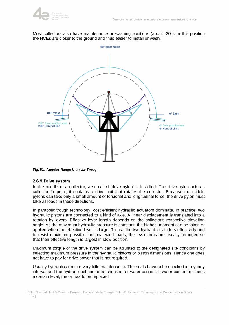
To allow undisturbed operation, an angular range of 0° to 180°is necessary; in the region around 0 and 180 degrees direct irradiation (DNI) is rather low and shading by other collectors is rather high. Thus, the energy that is collected in the early morning as well as in the evening is much less than at solar noon, where DNI values are much higher and no shading occurs.
In order to reduce wind loads acting on the collector and thus required strength of the supporting structure to a minimum, the collector is rotated to the position that results in the lowest wind pressure coefficients – the so-called ‗stow position‘. Usually this position is slightly lower than the horizontal position, e.g. around -20° to -5°.
At a gathering storm, the collector has to move to stow position. To do so, a certain time is required (depending on the respective position); the collector must therefore start moving towards stow position already 20 minutes before the expected occurrence of wind speed. To reduce this time the Ultimate Trough has two stow positions.
Deutsche Gesellschaft für Internationale Zusammenarbeit (GIZ) GmbH
Solar Thermal Heat & Power - Proyecto Fomento de la Energía Solar (Enfoque en Tecnologías de Concentración Solar)
46
Most collectors also have maintenance or washing positions (about -20°). In this position the HCEs are closer to the ground and thus easier to install or wash.
Fig. 51. Angular Range Ultimate Trough
2.6.9. Drive system
In the middle of a collector, a so-called ‗drive pylon‘ is installed. The drive pylon acts as collector fix point; it contains a drive unit that rotates the collector. Because the middle pylons can take only a small amount of torsional and longitudinal force, the drive pylon must take all loads in these directions.
In parabolic trough technology, cost efficient hydraulic actuators dominate. In practice, two hydraulic pistons are connected to a kind of axle. A linear displacement is translated into a rotation by levers. Effective lever length depends on the collector‘s respective elevation angle. As the maximum hydraulic pressure is constant, the highest moment can be taken or applied when the effective lever is large. To use the two hydraulic cylinders effectively and to resist maximum possible torsional wind loads, the lever arms are usually arranged so that their effective length is largest in stow position.
Maximum torque of the drive system can be adjusted to the designated site conditions by selecting maximum pressure in the hydraulic pistons or piston dimensions. Hence one does not have to pay for drive power that is not required.
Usually hydraulics require very little maintenance. The seals have to be checked in a yearly interval and the hydraulic oil has to be checked for water content. If water content exceeds a certain level, the oil has to be replaced.
Deutsche Gesellschaft für Internationale Zusammenarbeit (GIZ) GmbH
Solar Thermal Heat & Power - Proyecto Fomento de la Energía Solar (Enfoque en Tecnologías de Concentración Solar)
47
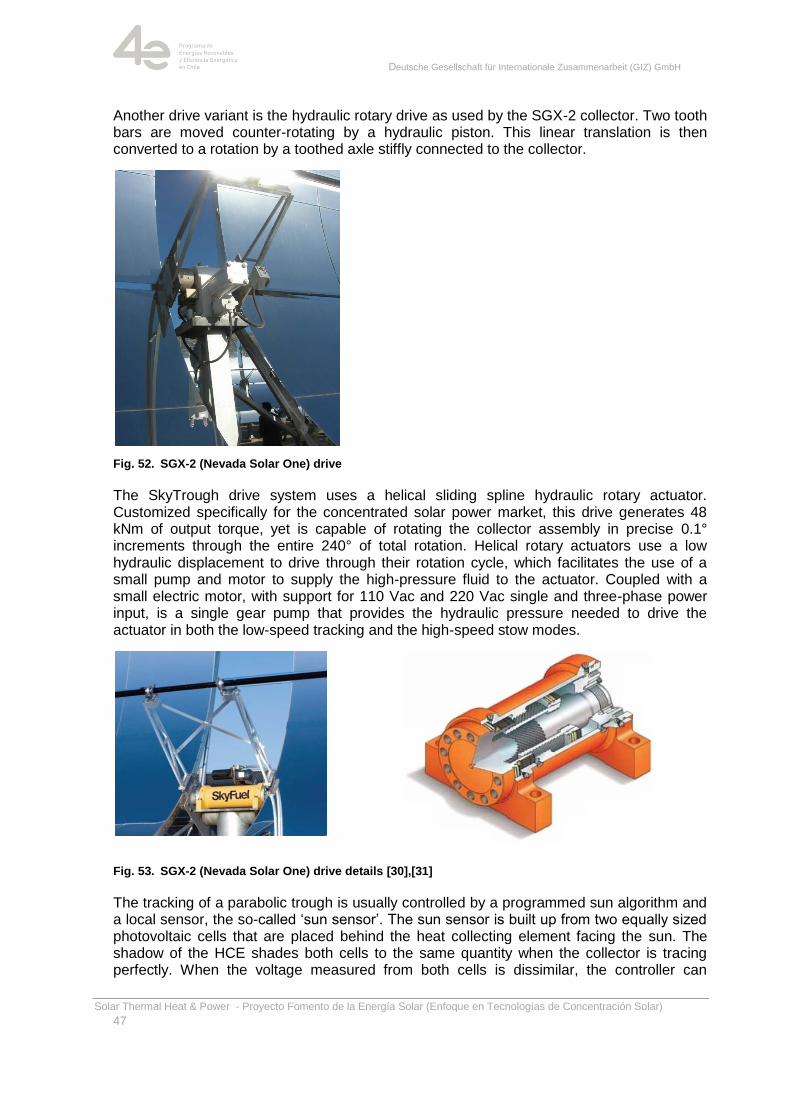
Another drive variant is the hydraulic rotary drive as used by the SGX-2 collector. Two tooth bars are moved counter-rotating by a hydraulic piston. This linear translation is then converted to a rotation by a toothed axle stiffly connected to the collector.
Fig. 52. SGX-2 (Nevada Solar One) drive
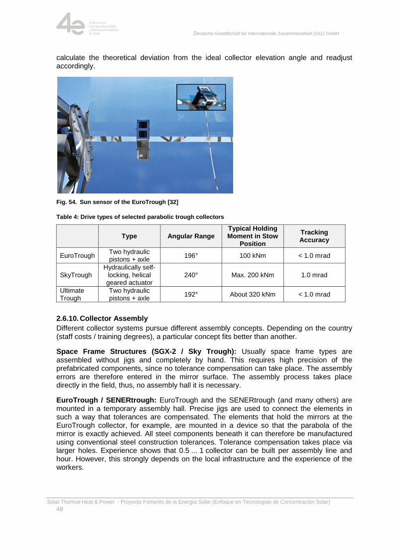
The SkyTrough drive system uses a helical sliding spline hydraulic rotary actuator. Customized specifically for the concentrated solar power market, this drive generates 48 kNm of output torque, yet is capable of rotating the collector assembly in precise 0.1° increments through the entire 240° of total rotation. Helical rotary actuators use a low hydraulic displacement to drive through their rotation cycle, which facilitates the use of a small pump and motor to supply the high-pressure fluid to the actuator. Coupled with a small electric motor, with support for 110 Vac and 220 Vac single and three-phase power input, is a single gear pump that provides the hydraulic pressure needed to drive the actuator in both the low-speed tracking and the high-speed stow modes.
Fig. 53. SGX-2 (Nevada Solar One) drive details [30],[31]
The tracking of a parabolic trough is usually controlled by a programmed sun algorithm and a local sensor, the so-called ‗sun sensor‘. The sun sensor is built up from two equally sized photovoltaic cells that are placed behind the heat collecting element facing the sun. The shadow of the HCE shades both cells to the same quantity when the collector is tracing perfectly. When the voltage measured from both cells is dissimilar, the controller can
Deutsche Gesellschaft für Internationale Zusammenarbeit (GIZ) GmbH
Solar Thermal Heat & Power - Proyecto Fomento de la Energía Solar (Enfoque en Tecnologías de Concentración Solar)
48
calculate the theoretical deviation from the ideal collector elevation angle and readjust accordingly.
Fig. 54. Sun sensor of the EuroTrough [32]
Table 4: Drive types of selected parabolic trough collectors
Type Angular Range
Typical Holding Moment in Stow
Position
Tracking Accuracy
EuroTrough Two hydraulic pistons + axle
196° 100 kNm < 1.0 mrad
SkyTrough Hydraulically self-
locking, helical geared actuator
240° Max. 200 kNm 1.0 mrad
Ultimate Trough
Two hydraulic pistons + axle
192° About 320 kNm < 1.0 mrad
2.6.10. Collector Assembly
Different collector systems pursue different assembly concepts. Depending on the country (staff costs / training degrees), a particular concept fits better than another.
Space Frame Structures (SGX-2 / Sky Trough): Usually space frame types are assembled without jigs and completely by hand. This requires high precision of the prefabricated components, since no tolerance compensation can take place. The assembly errors are therefore entered in the mirror surface. The assembly process takes place directly in the field, thus, no assembly hall it is necessary.
EuroTrough / SENERtrough: EuroTrough and the SENERtrough (and many others) are mounted in a temporary assembly hall. Precise jigs are used to connect the elements in such a way that tolerances are compensated. The elements that hold the mirrors at the EuroTrough collector, for example, are mounted in a device so that the parabola of the mirror is exactly achieved. All steel components beneath it can therefore be manufactured using conventional steel construction tolerances. Tolerance compensation takes place via larger holes. Experience shows that 0.5 ... 1 collector can be built per assembly line and hour. However, this strongly depends on the local infrastructure and the experience of the workers.
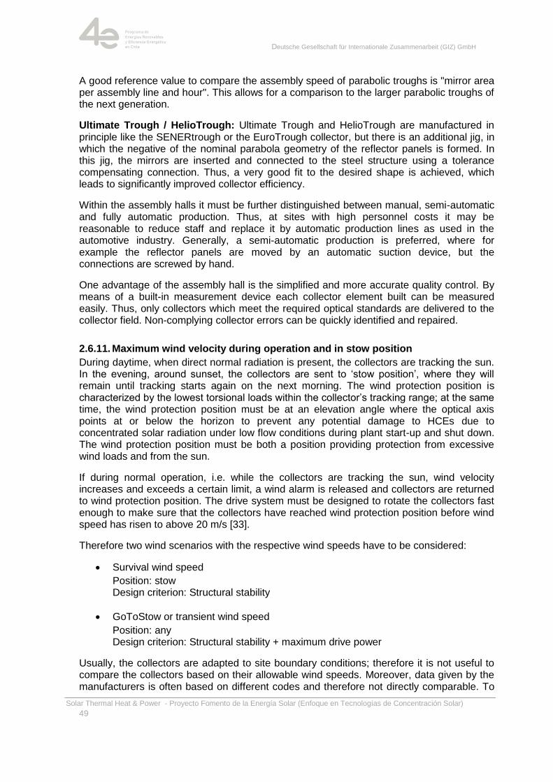
Deutsche Gesellschaft für Internationale Zusammenarbeit (GIZ) GmbH
Solar Thermal Heat & Power - Proyecto Fomento de la Energía Solar (Enfoque en Tecnologías de Concentración Solar)
49
A good reference value to compare the assembly speed of parabolic troughs is "mirror area per assembly line and hour". This allows for a comparison to the larger parabolic troughs of the next generation.
Ultimate Trough / HelioTrough: Ultimate Trough and HelioTrough are manufactured in principle like the SENERtrough or the EuroTrough collector, but there is an additional jig, in which the negative of the nominal parabola geometry of the reflector panels is formed. In this jig, the mirrors are inserted and connected to the steel structure using a tolerance compensating connection. Thus, a very good fit to the desired shape is achieved, which leads to significantly improved collector efficiency.
Within the assembly halls it must be further distinguished between manual, semi-automatic and fully automatic production. Thus, at sites with high personnel costs it may be reasonable to reduce staff and replace it by automatic production lines as used in the automotive industry. Generally, a semi-automatic production is preferred, where for example the reflector panels are moved by an automatic suction device, but the connections are screwed by hand.
One advantage of the assembly hall is the simplified and more accurate quality control. By means of a built-in measurement device each collector element built can be measured easily. Thus, only collectors which meet the required optical standards are delivered to the collector field. Non-complying collector errors can be quickly identified and repaired.
2.6.11. Maximum wind velocity during operation and in stow position
During daytime, when direct normal radiation is present, the collectors are tracking the sun. In the evening, around sunset, the collectors are sent to ‗stow position‘, where they will remain until tracking starts again on the next morning. The wind protection position is characterized by the lowest torsional loads within the collector‘s tracking range; at the same time, the wind protection position must be at an elevation angle where the optical axis points at or below the horizon to prevent any potential damage to HCEs due to concentrated solar radiation under low flow conditions during plant start-up and shut down. The wind protection position must be both a position providing protection from excessive wind loads and from the sun.
If during normal operation, i.e. while the collectors are tracking the sun, wind velocity increases and exceeds a certain limit, a wind alarm is released and collectors are returned to wind protection position. The drive system must be designed to rotate the collectors fast enough to make sure that the collectors have reached wind protection position before wind speed has risen to above 20 m/s [33].
Therefore two wind scenarios with the respective wind speeds have to be considered:
Survival wind speed
Position: stow Design criterion: Structural stability
GoToStow or transient wind speed
Position: any Design criterion: Structural stability + maximum drive power
Usually, the collectors are adapted to site boundary conditions; therefore it is not useful to compare the collectors based on their allowable wind speeds. Moreover, data given by the manufacturers is often based on different codes and therefore not directly comparable. To
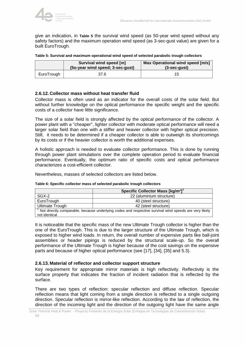
Deutsche Gesellschaft für Internationale Zusammenarbeit (GIZ) GmbH
Solar Thermal Heat & Power - Proyecto Fomento de la Energía Solar (Enfoque en Tecnologías de Concentración Solar)
50
give an indication, in Table 5 the survival wind speed (as 50-year wind speed without any safety factors) and the maximum operation wind speed (as 3-sec-gust value) are given for a built EuroTrough.
Table 5: Survival and maximum operational wind speed of selected parabolic trough collectors
Survival wind speed [m] (5o-year wind speed; 3-sec-gust)
Max Operational wind speed [m/s] (3-sec-gust)
EuroTrough 37.6 15
2.6.12. Collector mass without heat transfer fluid
Collector mass is often used as an indicator for the overall costs of the solar field. But without further knowledge on the optical performance the specific weight and the specific costs of a collector have little significance.
The size of a solar field is strongly affected by the optical performance of the collector. A power plant with a "cheaper", lighter collector with moderate optical performance will need a larger solar field than one with a stiffer and heavier collector with higher optical precision. Still, it needs to be determined if a cheaper collector is able to outweigh its shortcomings by its costs or if the heavier collector is worth the additional expenses.
A holistic approach is needed to evaluate collector performance. This is done by running through power plant simulations over the complete operation period to evaluate financial performance. Eventually, the optimum ratio of specific costs and optical performance characterizes a cost-efficient collector.
Nevertheless, masses of selected collectors are listed below.
Table 6: Specific collector mass of selected parabolic trough collectors
Specific Collector Mass [kg/m²]1
SGX-2 22 (aluminium structure)
EuroTrough 40 (steel structure)
Ultimate Trough 42 (steel structure) 1 Not directly comparable, because underlying codes and respective survival wind speeds are very likely
not identical
It is noticeable that the specific mass of the new Ultimate Trough collector is higher than the one of the EuroTrough. This is due to the larger structure of the Ultimate Trough, which is exposed to higher wind loads. In return, the overall number of expensive parts like ball-joint assemblies or header pipings is reduced by the structural scale-up. So the overall performance of the Ultimate Trough is higher because of the cost savings on the expensive parts and because of higher optical performance (see [17], [34], [35] and 5.3).
2.6.13. Material of reflector and collector support structure
Key requirement for appropriate mirror materials is high reflectivity. Reflectivity is the surface property that indicates the fraction of incident radiation that is reflected by the surface.
There are two types of reflection: specular reflection and diffuse reflection. Specular reflection means that light coming from a single direction is reflected to a single outgoing direction. Specular reflection is mirror-like reflection. According to the law of reflection, the direction of the incoming light and the direction of the outgoing light have the same angle
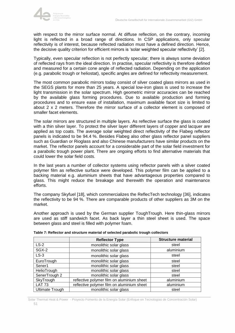
Deutsche Gesellschaft für Internationale Zusammenarbeit (GIZ) GmbH
Solar Thermal Heat & Power - Proyecto Fomento de la Energía Solar (Enfoque en Tecnologías de Concentración Solar)
51
with respect to the mirror surface normal. At diffuse reflection, on the contrary, incoming light is reflected in a broad range of directions. In CSP applications, only specular reflectivity is of interest, because reflected radiation must have a defined direction. Hence, the decisive quality criterion for efficient mirrors is ‗solar weighted specular reflectivity‘ [2].
Typically, even specular reflection is not perfectly specular; there is always some deviation of reflected rays from the ideal direction. In practise, specular reflectivity is therefore defined and measured for a certain cone angle of reflected radiation. Depending on the application (e.g. parabolic trough or heliostat), specific angles are defined for reflectivity measurement.
The most common parabolic mirrors today consist of silver coated glass mirrors as used in the SEGS plants for more than 25 years. A special low-iron glass is used to increase the light transmission in the solar spectrum. High geometric mirror accuracies can be reached by the available glass forming procedures. Due to available production and forming procedures and to ensure ease of installation, maximum available facet size is limited to about 2 x 2 meters. Therefore the mirror surface of a collector element is composed of smaller facet elements.
The solar mirrors are structured in multiple layers. As reflective surface the glass is coated with a thin silver layer. To protect the silver layer different layers of copper and lacquer are applied as top coats. The average solar weighted direct reflectivity of the Flabeg reflector panels is indicated to be 94.4 %. Besides Flabeg also other glass reflector panel suppliers such as Guardian or Rioglass and also Chinese manufacturers have similar products on the market. The reflector panels account for a considerable part of the solar field investment for a parabolic trough power plant. There are ongoing efforts to find alternative materials that could lower the solar field costs.
In the last years a number of collector systems using reflector panels with a silver coated polymer film as reflective surface were developed. This polymer film can be applied to a backing material e.g. aluminium sheets that have advantageous properties compared to glass. This might reduce the breakage and therewith the operation and maintenance efforts.
The company Skyfuel [18], which commercializes the ReflecTech technology [36], indicates the reflectivity to be 94 %. There are comparable products of other suppliers as 3M on the market.
Another approach is used by the German supplier ToughTrough. Here thin-glass mirrors are used as stiff sandwich facet. As back layer a thin steel sheet is used. The space between glass and steel is filled with polymer foam.
Table 7: Reflector and structure material of selected parabolic trough collectors
Reflector Type Structure material
LS-2 monolithic solar glass steel
SGX-2 monolithic solar glass aluminium
LS-3 monolithic solar glass steel
EuroTrough monolithic solar glass steel
Sener1 monolithic solar glass steel
HelioTrough monolithic solar glass steel
SenerTrough 2 monolithic solar glass steel
SkyTrough reflective polymer film on aluminium sheet aluminium
LAT 73 reflective polymer film on aluminium sheet aluminium
Ultimate Trough monolithic solar glass steel
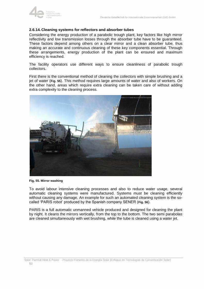
Deutsche Gesellschaft für Internationale Zusammenarbeit (GIZ) GmbH
Solar Thermal Heat & Power - Proyecto Fomento de la Energía Solar (Enfoque en Tecnologías de Concentración Solar)
52
2.6.14. Cleaning systems for reflectors and absorber tubes
Considering the energy production of a parabolic trough plant, key factors like high mirror reflectivity and low transmission losses through the absorber tube have to be guaranteed. These factors depend among others on a clear mirror and a clean absorber tube, thus making an accurate and continuous cleaning of these key components essential. Through these arrangements, energy production of the plant can be ensured and maximum efficiency is reached.
The facility operators use different ways to ensure cleanliness of parabolic trough collectors.
First there is the conventional method of cleaning the collectors with simple brushing and a jet of water (Fig. 55). This method requires large amounts of water and also of workers. On the other hand, areas which require extra cleaning can be taken care of without adding extra complexity to the cleaning process.
Fig. 55. Mirror washing
To avoid labour intensive cleaning processes and also to reduce water usage, several automatic cleaning systems were manufactured. Systems must be cleaning efficiently without causing any damage. An example for such an automated cleaning system is the so-called ‗PARIS robot‘ produced by the Spanish company SENER (Fig. 56).
PARIS is a full automatic unmanned vehicle produced and designed for cleaning the plant by night. It cleans the mirrors vertically, from the top to the bottom. The two semi parabolas are cleaned simultaneously with wet brushing, while the tube is cleaned using a water jet.
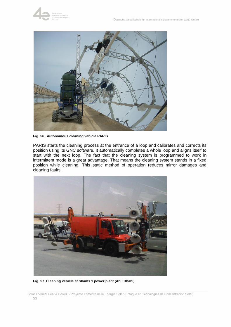
Deutsche Gesellschaft für Internationale Zusammenarbeit (GIZ) GmbH
Solar Thermal Heat & Power - Proyecto Fomento de la Energía Solar (Enfoque en Tecnologías de Concentración Solar)
53
Fig. 56. Autonomous cleaning vehicle PARIS
PARIS starts the cleaning process at the entrance of a loop and calibrates and corrects its position using its GNC software. It automatically completes a whole loop and aligns itself to start with the next loop. The fact that the cleaning system is programmed to work in intermittent mode is a great advantage. That means the cleaning system stands in a fixed position while cleaning. This static method of operation reduces mirror damages and cleaning faults.
Fig. 57. Cleaning vehicle at Shams 1 power plant (Abu Dhabi)
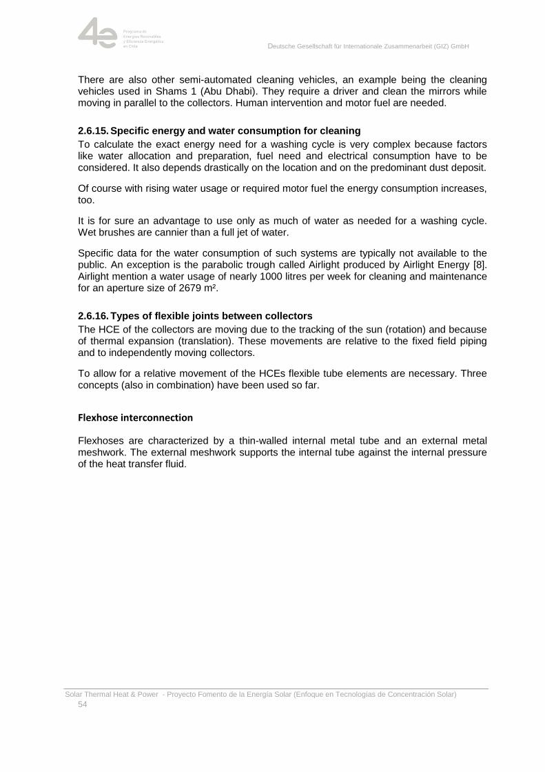
Deutsche Gesellschaft für Internationale Zusammenarbeit (GIZ) GmbH
Solar Thermal Heat & Power - Proyecto Fomento de la Energía Solar (Enfoque en Tecnologías de Concentración Solar)
54
There are also other semi-automated cleaning vehicles, an example being the cleaning vehicles used in Shams 1 (Abu Dhabi). They require a driver and clean the mirrors while moving in parallel to the collectors. Human intervention and motor fuel are needed.
2.6.15. Specific energy and water consumption for cleaning
To calculate the exact energy need for a washing cycle is very complex because factors like water allocation and preparation, fuel need and electrical consumption have to be considered. It also depends drastically on the location and on the predominant dust deposit.
Of course with rising water usage or required motor fuel the energy consumption increases, too.
It is for sure an advantage to use only as much of water as needed for a washing cycle. Wet brushes are cannier than a full jet of water.
Specific data for the water consumption of such systems are typically not available to the public. An exception is the parabolic trough called Airlight produced by Airlight Energy [8]. Airlight mention a water usage of nearly 1000 litres per week for cleaning and maintenance for an aperture size of 2679 m².
2.6.16. Types of flexible joints between collectors
The HCE of the collectors are moving due to the tracking of the sun (rotation) and because of thermal expansion (translation). These movements are relative to the fixed field piping and to independently moving collectors.
To allow for a relative movement of the HCEs flexible tube elements are necessary. Three concepts (also in combination) have been used so far.
Flexhose interconnection
Flexhoses are characterized by a thin-walled internal metal tube and an external metal meshwork. The external meshwork supports the internal tube against the internal pressure of the heat transfer fluid.
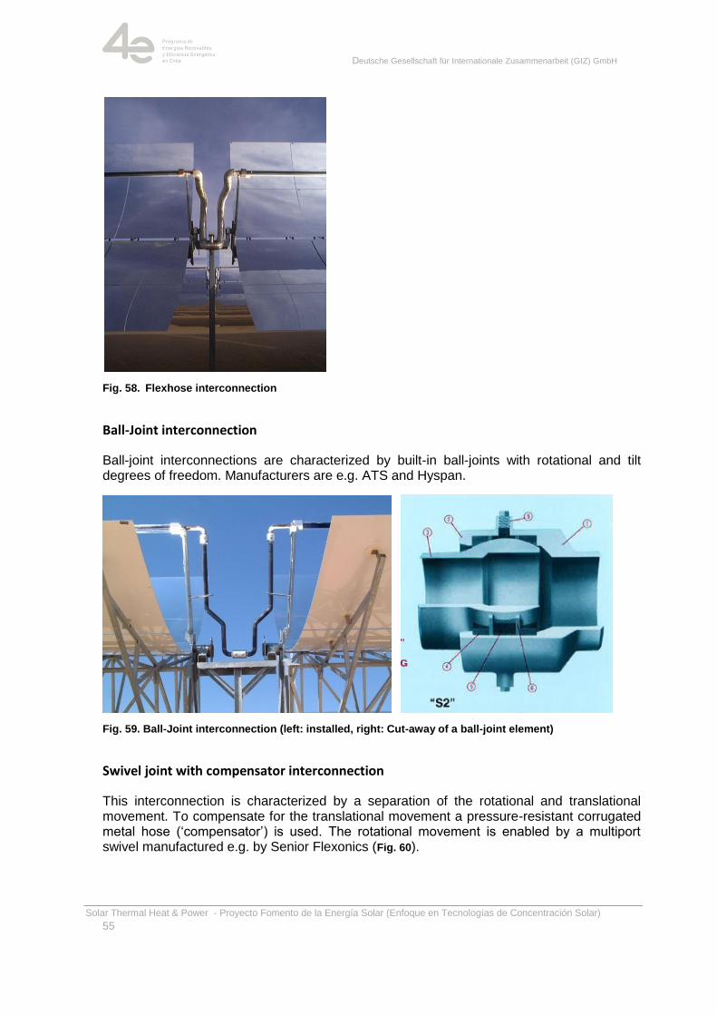
Deutsche Gesellschaft für Internationale Zusammenarbeit (GIZ) GmbH
Solar Thermal Heat & Power - Proyecto Fomento de la Energía Solar (Enfoque en Tecnologías de Concentración Solar)
55
Fig. 58. Flexhose interconnection
Ball-Joint interconnection
Ball-joint interconnections are characterized by built-in ball-joints with rotational and tilt degrees of freedom. Manufacturers are e.g. ATS and Hyspan.
Fig. 59. Ball-Joint interconnection (left: installed, right: Cut-away of a ball-joint element)
Swivel joint with compensator interconnection
This interconnection is characterized by a separation of the rotational and translational movement. To compensate for the translational movement a pressure-resistant corrugated metal hose (‗compensator‘) is used. The rotational movement is enabled by a multiport swivel manufactured e.g. by Senior Flexonics (Fig. 60).
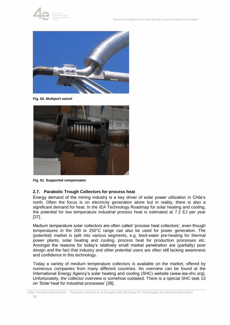
Deutsche Gesellschaft für Internationale Zusammenarbeit (GIZ) GmbH
Solar Thermal Heat & Power - Proyecto Fomento de la Energía Solar (Enfoque en Tecnologías de Concentración Solar)
56
Fig. 60. Multiport swivel
Fig. 61. Supported compensator
2.7. Parabolic Trough Collectors for process heat
Energy demand of the mining industry is a key driver of solar power utilization in Chile‘s north. Often the focus is on electricity generation alone but in reality, there is also a significant demand for heat. In the IEA Technology Roadmap for solar heating and cooling, the potential for low temperature industrial process heat is estimated at 7.2 EJ per year [37].
Medium temperature solar collectors are often called ‗process heat collectors‘, even though temperatures in the 200 to 250°C range can also be used for power generation. The (potential) market is split into various segments, e.g. feed-water pre-heating for thermal power plants, solar heating and cooling, process heat for production processes etc. Amongst the reasons for today‘s relatively small market penetration are (partially) poor design and the fact that industry and other potential users are often still lacking awareness and confidence in this technology.
Today a variety of medium temperature collectors is available on the market, offered by numerous companies from many different countries. An overview can be found at the International Energy Agency‘s solar heating and cooling (SHC) website (www.iea-shc.org). Unfortunately, the collector overview is somehow outdated. There is a special SHC task 13 on ‗Solar heat for industrial processes‘ [38].
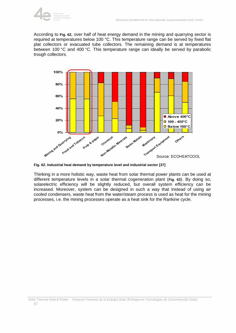
Deutsche Gesellschaft für Internationale Zusammenarbeit (GIZ) GmbH
Solar Thermal Heat & Power - Proyecto Fomento de la Energía Solar (Enfoque en Tecnologías de Concentración Solar)
57
According to Fig. 62, over half of heat energy demand in the mining and quarrying sector is required at temperatures below 100 °C. This temperature range can be served by fixed flat plat collectors or evacuated tube collectors. The remaining demand is at temperatures between 100 °C and 400 °C. This temperature range can ideally be served by parabolic trough collectors.
Fig. 62. Industrial heat demand by temperature level and industrial sector [37]
Thinking in a more holistic way, waste heat from solar thermal power plants can be used at different temperature levels in a solar thermal cogeneration plant (Fig. 63). By doing so, solarelectric efficiency will be slightly reduced, but overall system efficiency can be increased. Moreover, system can be designed in such a way that instead of using air cooled condensers, waste heat from the water/steam process is used as heat for the mining processes, i.e. the mining processes operate as a heat sink for the Rankine cycle.
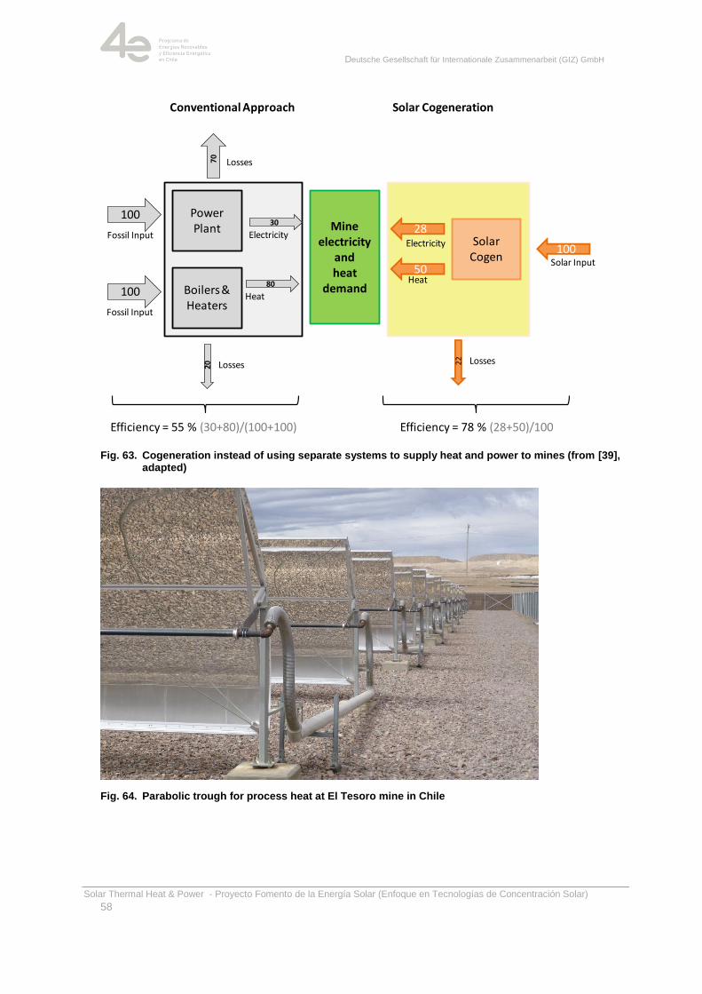
Deutsche Gesellschaft für Internationale Zusammenarbeit (GIZ) GmbH
Solar Thermal Heat & Power - Proyecto Fomento de la Energía Solar (Enfoque en Tecnologías de Concentración Solar)
58
Fig. 63. Cogeneration instead of using separate systems to supply heat and power to mines (from [39], adapted)
Fig. 64. Parabolic trough for process heat at El Tesoro mine in Chile
Electricity
Mine electricity
andheat
demand
Conventional Approach Solar Cogeneration
Solar Cogen
100Solar Input
Power Plant
Boilers & Heaters
28
50Heat
100
100
Fossil Input
Fossil Input
30
Electricity
80
Heat
20 Losses
70
Losses
Efficiency = 55 % (30+80)/(100+100) Efficiency = 78 % (28+50)/100
22 Losses
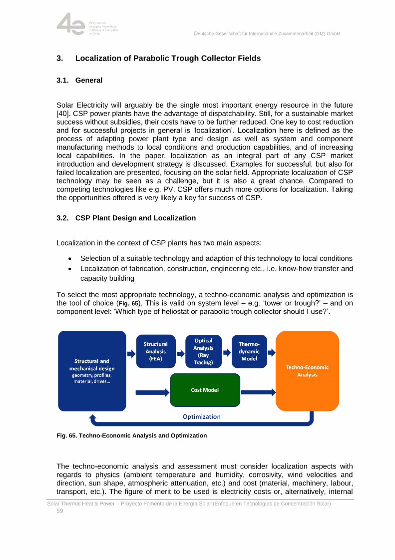
Deutsche Gesellschaft für Internationale Zusammenarbeit (GIZ) GmbH
Solar Thermal Heat & Power - Proyecto Fomento de la Energía Solar (Enfoque en Tecnologías de Concentración Solar)
59
3. Localization of Parabolic Trough Collector Fields
3.1. General
Solar Electricity will arguably be the single most important energy resource in the future [40]. CSP power plants have the advantage of dispatchability. Still, for a sustainable market success without subsidies, their costs have to be further reduced. One key to cost reduction and for successful projects in general is ‗localization‘. Localization here is defined as the process of adapting power plant type and design as well as system and component manufacturing methods to local conditions and production capabilities, and of increasing local capabilities. In the paper, localization as an integral part of any CSP market introduction and development strategy is discussed. Examples for successful, but also for failed localization are presented, focusing on the solar field. Appropriate localization of CSP technology may be seen as a challenge, but it is also a great chance. Compared to competing technologies like e.g. PV, CSP offers much more options for localization. Taking the opportunities offered is very likely a key for success of CSP.
3.2. CSP Plant Design and Localization
Localization in the context of CSP plants has two main aspects:
Selection of a suitable technology and adaption of this technology to local conditions
Localization of fabrication, construction, engineering etc., i.e. know-how transfer and
capacity building
To select the most appropriate technology, a techno-economic analysis and optimization is the tool of choice (Fig. 65). This is valid on system level – e.g. ‗tower or trough?‘ – and on component level: ‗Which type of heliostat or parabolic trough collector should I use?‘.
Fig. 65. Techno-Economic Analysis and Optimization
The techno-economic analysis and assessment must consider localization aspects with regards to physics (ambient temperature and humidity, corrosivity, wind velocities and direction, sun shape, atmospheric attenuation, etc.) and cost (material, machinery, labour, transport, etc.). The figure of merit to be used is electricity costs or, alternatively, internal
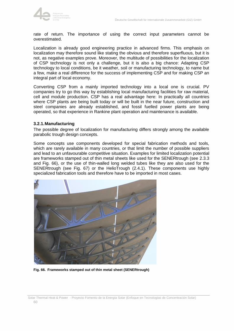
Deutsche Gesellschaft für Internationale Zusammenarbeit (GIZ) GmbH
Solar Thermal Heat & Power - Proyecto Fomento de la Energía Solar (Enfoque en Tecnologías de Concentración Solar)
60
rate of return. The importance of using the correct input parameters cannot be overestimated.
Localization is already good engineering practice in advanced firms. This emphasis on localization may therefore sound like stating the obvious and therefore superfluous, but it is not, as negative examples prove. Moreover, the multitude of possibilities for the localization of CSP technology is not only a challenge, but it is also a big chance: Adapting CSP technology to local conditions, be it weather, soil or manufacturing technology, to name but a few, make a real difference for the success of implementing CSP and for making CSP an integral part of local economy.
Converting CSP from a mainly imported technology into a local one is crucial. PV companies try to go this way by establishing local manufacturing facilities for raw material, cell and module production. CSP has a real advantage here: In practically all countries where CSP plants are being built today or will be built in the near future, construction and steel companies are already established, and fossil fuelled power plants are being operated, so that experience in Rankine plant operation and maintenance is available.
3.2.1. Manufacturing
The possible degree of localization for manufacturing differs strongly among the available parabolic trough design concepts.
Some concepts use components developed for special fabrication methods and tools, which are rarely available in many countries, or that limit the number of possible suppliers and lead to an unfavourable competitive situation. Examples for limited localization potential are frameworks stamped out of thin metal sheets like used for the SENERtrough (see 2.3.3 and Fig. 66), or the use of thin-walled long welded tubes like they are also used for the SENERtrough (see Fig. 67) or the HelioTrough (2.4.1). These components use highly specialized fabrication tools and therefore have to be imported in most cases.
Fig. 66. Frameworks stamped out of thin metal sheet (SENERtrough)
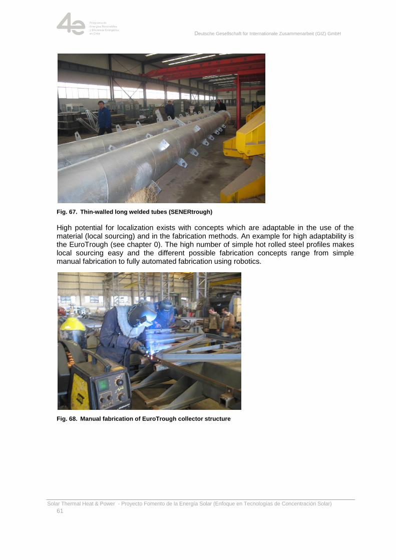
Deutsche Gesellschaft für Internationale Zusammenarbeit (GIZ) GmbH
Solar Thermal Heat & Power - Proyecto Fomento de la Energía Solar (Enfoque en Tecnologías de Concentración Solar)
61
Fig. 67. Thin-walled long welded tubes (SENERtrough)
High potential for localization exists with concepts which are adaptable in the use of the material (local sourcing) and in the fabrication methods. An example for high adaptability is the EuroTrough (see chapter 0). The high number of simple hot rolled steel profiles makes local sourcing easy and the different possible fabrication concepts range from simple manual fabrication to fully automated fabrication using robotics.
Fig. 68. Manual fabrication of EuroTrough collector structure
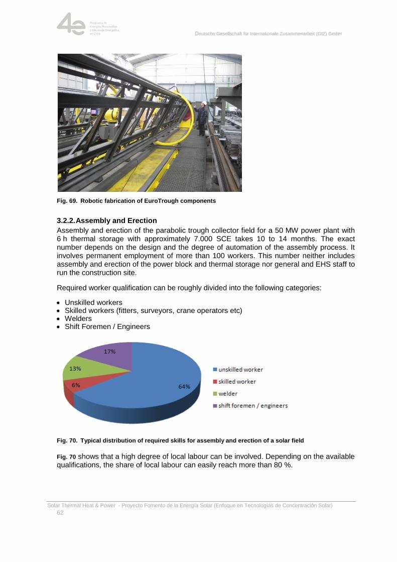
Deutsche Gesellschaft für Internationale Zusammenarbeit (GIZ) GmbH
Solar Thermal Heat & Power - Proyecto Fomento de la Energía Solar (Enfoque en Tecnologías de Concentración Solar)
62
Fig. 69. Robotic fabrication of EuroTrough components
3.2.2. Assembly and Erection
Assembly and erection of the parabolic trough collector field for a 50 MW power plant with 6 h thermal storage with approximately 7.000 SCE takes 10 to 14 months. The exact number depends on the design and the degree of automation of the assembly process. It involves permanent employment of more than 100 workers. This number neither includes assembly and erection of the power block and thermal storage nor general and EHS staff to run the construction site.
Required worker qualification can be roughly divided into the following categories:
Unskilled workers Skilled workers (fitters, surveyors, crane operators etc) Welders Shift Foremen / Engineers
Fig. 70. Typical distribution of required skills for assembly and erection of a solar field
Fig. 70 shows that a high degree of local labour can be involved. Depending on the available qualifications, the share of local labour can easily reach more than 80 %.

Deutsche Gesellschaft für Internationale Zusammenarbeit (GIZ) GmbH
Solar Thermal Heat & Power - Proyecto Fomento de la Energía Solar (Enfoque en Tecnologías de Concentración Solar)
63
3.2.3. O&M
Usually Operation and Maintenance of the parabolic trough collector field and the whole power plant is 100 % localized. A commercial power plant O&M company has to service the plant on a 24/7 base and the staff is ranging from 30 to 50 employees.
Skills for personal range from:
Unskilled workers (guards, cleaning etc) Skilled workers (operators, maintenance etc) Engineers (production/performance and maintenance manager etc.)
3.3. Localization for CSP companies
CSP is still a comparatively new and small business. Experience in Localization is limited, and each company in the sector is somehow different than the others. Thus, individual, tailored localization strategies are required. Still, there are some generally applicable ideas and concepts, drawn from experience gained in other industry sectors, like the car industry, that shall be pointed out here:
Not having a strategy at all and trying to decide on a case-by-case basis is not a good idea. Instead, having a strategy is required. As a first step, the company-specific localization target should be defined, i.e. the following question must be answered: How far do we want to go down the road of localization – which stage of localization do we want to reach? Subsequently, one step after the other can be taken until the desired stage of localization has been reached. At certain intervals, the question must be answered again: Which stage of localization is the most appropriate for our company under current and expected market conditions? If required, target and individual strategy have to be re-aligned and adapted accordingly.
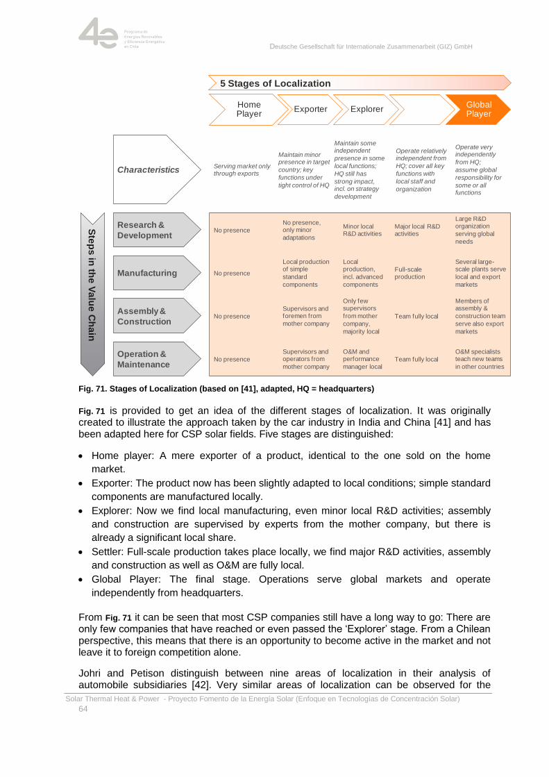
Deutsche Gesellschaft für Internationale Zusammenarbeit (GIZ) GmbH
Solar Thermal Heat & Power - Proyecto Fomento de la Energía Solar (Enfoque en Tecnologías de Concentración Solar)
64
Fig. 71. Stages of Localization (based on [41], adapted, HQ = headquarters)
Fig. 71 is provided to get an idea of the different stages of localization. It was originally created to illustrate the approach taken by the car industry in India and China [41] and has been adapted here for CSP solar fields. Five stages are distinguished:
Home player: A mere exporter of a product, identical to the one sold on the home
market.
Exporter: The product now has been slightly adapted to local conditions; simple standard
components are manufactured locally.
Explorer: Now we find local manufacturing, even minor local R&D activities; assembly
and construction are supervised by experts from the mother company, but there is
already a significant local share.
Settler: Full-scale production takes place locally, we find major R&D activities, assembly
and construction as well as O&M are fully local.
Global Player: The final stage. Operations serve global markets and operate
independently from headquarters.
From Fig. 71 it can be seen that most CSP companies still have a long way to go: There are only few companies that have reached or even passed the ‗Explorer‘ stage. From a Chilean perspective, this means that there is an opportunity to become active in the market and not leave it to foreign competition alone.
Johri and Petison distinguish between nine areas of localization in their analysis of automobile subsidiaries [42]. Very similar areas of localization can be observed for the
Home Player
Exporter Explorer SettlerGlobal Player
5 Stages of Localization
Characteristics
Research &
Development
Manufacturing
Assembly &
Construction
Serving market only through exports
Operation &
Maintenance
Ste
ps
in th
e V
alu
e C
ha
in
Maintain minor presence in target
country; key
functions under
tight control of HQ
Maintain some independent
presence in some
local functions;
HQ still has
strong impact, incl. on strategy
development
Operate relatively independent from
HQ; cover all key
functions with
local staff and
organization
Operate very independently
from HQ;
assume global
responsibility for
some or all functions
No presence
No presence
No presence
No presence
No presence, only minor
adaptations
Minor local R&D activities
Major local R&D activities
Large R&D organization
serving global
needs
Local production of simple
standard
components
Local production,
incl. advanced
components
Full-scale production
Several large-scale plants serve
local and export
markets
Supervisors and foremen from
mother company
Only few supervisors
from mother
company,
majority local
Team fully local
Members of assembly &
construction team
serve also export
markets
Supervisors and operators from
mother company
O&M and performance
manager local Team fully local
O&M specialists teach new teams
in other countries
Deutsche Gesellschaft für Internationale Zusammenarbeit (GIZ) GmbH
Solar Thermal Heat & Power - Proyecto Fomento de la Energía Solar (Enfoque en Tecnologías de Concentración Solar)
65
supply of CSP solar field components. At least the first two to five are standard. It will very likely be useful for actors in the CSP market to also include the remaining points in their strategy:
Use of local supplier networks
Adaptations to manufacturing processes
Localization of products
Building and exploiting the local knowledge pool
Deployment of local human resources
Localization of strategic decision making
Localization of Research &Development
Local deployment of subsidiary profits
Localization of corporate image
3.4. Localization from a country perspective
From a national perspective, things look somehow different: Here the first task is to encourage local companies to use their capabilities and become active participants in the CSP market. To this end, decision making and legislative bodies need to be clear about:
Targets,
Steps and measures to be taken to achieve the targets set, and
Figures of merit to measure success.
Targets: Targets can be typically defined in terms of local scope of supply, e.g. as percentage of total plant contractual value, often as a function of time or capacity installed. Starting with a relatively low value, the required local share increases over time to give local companies time to adapt.
Steps and measures: One early task at hand is to teach potential CSP companies, what CSP is and how they can contribute. This can be achieved by taking the following steps:
Raise awareness: Corresponding activities are often supported by international
organizations. Examples are studies and events sponsored by GIZ [43], or the IEA
SolarPACES START missions [44].
Educate: For education on CSP, information must be provided on the required
capabilities, e.g. in a first phase on how to manufacture heliostat or parabolic trough
components. This can be accomplished with the help of CSP engineering companies or
manufacturers. It must be made clear that CSP manufacturing is not rocket science,
instead it can be done by many companies, provided adequate training and education.
One simple and efficient measure is to provide drawings and specifications of typical
steel structure components, e.g. a cantilever arm, and to assist in the costing process.
This will on the one hand enable the CSP technology provider to optimize his design and
thus minimize cost of electricity, and on the other hand teach local companies about the
special requirements of CSP, thereby enabling them to quote in future bidding phases.
Otherwise only large internationally active companies may be able to quote, keeping
CSP prices high and taking away revenues from the country. This may be attractive for
such companies in the short run, but will very likely be a show-stopper for CSP in the
long run.

Deutsche Gesellschaft für Internationale Zusammenarbeit (GIZ) GmbH
Solar Thermal Heat & Power - Proyecto Fomento de la Energía Solar (Enfoque en Tecnologías de Concentración Solar)
66
Figures of merit to measure success: Local scope of supply as percentage of total contractual value is a simple and clear, yet not always easily measurable figure of merit. To get a more meaningful picture, total supply should be split into different areas like, e.g.,
a) Manufacturing of components,
b) Assembly & construction,
c) Operation & maintenance,
d) Engineering,
e) Research and development.
Starting with the first three areas, local contribution can gradually be expanded to d) and e). In parallel, the percentage of local scope of supply within the individual areas can be increased in the course of time. Such target numbers should be fixed in a national localization strategy. Moreover, to increase the likelihood of achieving them, corrective measures including penalties for not complying companies / projects must be fixed.
Deutsche Gesellschaft für Internationale Zusammenarbeit (GIZ) GmbH
Solar Thermal Heat & Power - Proyecto Fomento de la Energía Solar (Enfoque en Tecnologías de Concentración Solar)
67
4. Parabolic trough plant performance and electricity cost in Chile
This chapter explains how technical and economic performance of a parabolic trough power plant is estimated. Results are presented for plants of different sizes, with or without storage. Local conditions like annual irradiation are considered.
The mining industry is by far the main consumer in the SING, therefore demand is quite uniform in the course of the day (Fig. 80). Consequently, solar power plants have to be equipped with either a (fossil) backup system, or with storage. Solar thermal power plants can be equipped with large thermal storage systems (see chapter 5.4).
Because solar plants rely on an intermittent fuel supply - the sun - it is necessary to model the plant‘s performance on an hourly basis (or even using a finer temporal resolution) to understand what the annual performance will be, based on plant design and a user-supplied operating strategy.
Using precise performance data of the parabolic trough collector and long-time average weather data as well as considering capital costs and operation and maintenance (O&M) costs allows estimating the power plant's financial performance during its operation period.
4.1. Levelised Costs of Electricity
Levelised cost of electricity (LCOE) are often used to compare different options for power generation. They are calculated based on a simplified method using annuities and average power generation. For LCOE calculation, annual power generation and cost data are required.
To calculate power generation cost using the annuity method, the amortization time n is usually set at 20 to 25 years, i.e. the expected technical lifetime of the system; the second financial parameter is interest rate p.
In order to calculate LCOE, the formula given below is used:
∑ ∑
∑
Here the summation symbol Σ refers to the sum over the annuity/depreciation period, and NPV (net present value) means today´s value of the future annuity/expenses discounted by the inflation rate. In other words: LCOE takes into account the present value of all the future expenses (O&M, etc.) and the present value of all the future loan payments, summing them, and dividing the total by the total amount of energy that will be produced.
Performance calculations for this report were made using NREL's simulation tool SAM [45]. SAM is a performance and financial model designed to facilitate decision making for people involved in the renewable energy industry. The software makes performance predictions and cost of energy estimates based on installation and operating costs and system design parameters. Main input variables are:
Installation costs including equipment purchases, labour, engineering and other project
costs, land costs, and operation and maintenance costs
Collector and receiver type, solar multiple, storage capacity, power block capacity for
parabolic trough systems
Deutsche Gesellschaft für Internationale Zusammenarbeit (GIZ) GmbH
Solar Thermal Heat & Power - Proyecto Fomento de la Energía Solar (Enfoque en Tecnologías de Concentración Solar)
68
Analysis period, real discount rate, inflation rate, tax rates, internal rate of return target or
power purchase price for utility financing models
Building load and time-of-use retail rates for commercial and residential financing models
Tax and cash incentive amounts and rates
It is unrealistic to think of a market-wide comparison of all currently available parabolic trough collectors and to nominate a winner. This is hardly possible due to a number of reasons:
The manufacturers do not provide important collector data required for performance
evaluation such as:
o specific costs (USD/m²)
o incident angle modifiers (cf. 1.3)
o precision during assembly
o tracking error
This data would have to be estimated using data from experience.
The target variable of the comparison usually is the levelised cost of electricity (LCOE).
LCOE for a specific CSP technology (e.g. parabolic trough) of the current generation
has the same order of magnitude. Thus, very precise performance data is necessary to
allow for a reasonable and fair comparison. If the performance data is not provided by
an independent test centre using a standardized measurement procedure, it is likely
that the performance data is ‗beautified‘ to some degree. The results would be neither
reliable nor directly comparable.
Different scenarios that show significant variation of LCOE and allow for reasonable
performance comparisons of:
o different CSP technologies (parabolic trough, power tower, linear Fresnel, dish),
o technology leaps (e.g. molten salt as HTF) or scale up,
o locations with varying solar irradiance.
Given the reasons stated above, this study compares different parabolic trough power plants using the current benchmark collector EuroTrough (ET). It is well established and evaluated, so reliable performance data and manufacturing costs are available. The comparison shows the impact of plant size and thermal storage. A comparison of the EuroTrough to the next generation of parabolic troughs will show further opportunities to decrease LCOE.
4.2. Parabolic trough power plants output and the effect of thermal storage
Power plants of different sizes and with or without thermal energy storage system (TES) were evaluated. All configurations use the EuroTrough collector, as it is well established and known.
For the calculations, weather data measured at the envisaged Cruzero site for CSP plants and provided by the Chilean Ministry of Energy have been used [46]. About five years of measured data are available as of today (September 2014); based on the available data, a rounded annual DNI value of 3300 kWh/(m²a) has been assumed for LCOE calculations.
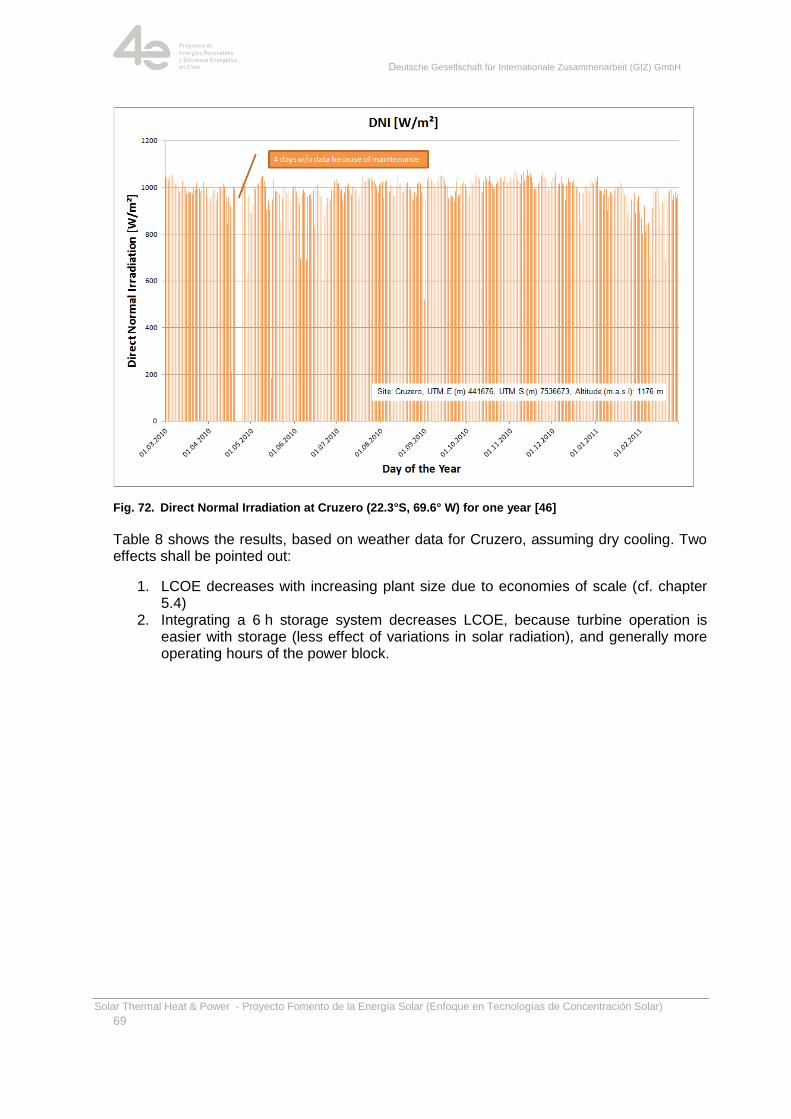
Deutsche Gesellschaft für Internationale Zusammenarbeit (GIZ) GmbH
Solar Thermal Heat & Power - Proyecto Fomento de la Energía Solar (Enfoque en Tecnologías de Concentración Solar)
69
Fig. 72. Direct Normal Irradiation at Cruzero (22.3°S, 69.6° W) for one year [46]
Table 8 shows the results, based on weather data for Cruzero, assuming dry cooling. Two effects shall be pointed out:
1. LCOE decreases with increasing plant size due to economies of scale (cf. chapter 5.4)
2. Integrating a 6 h storage system decreases LCOE, because turbine operation is easier with storage (less effect of variations in solar radiation), and generally more operating hours of the power block.
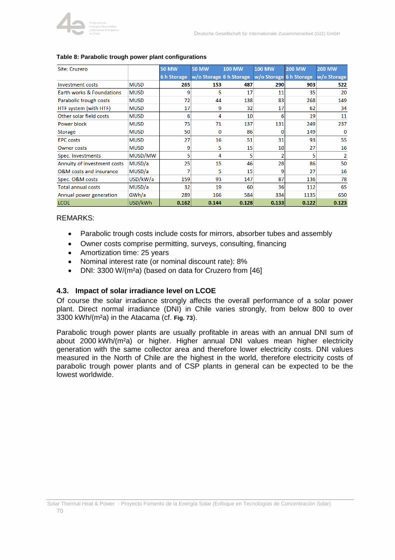
Deutsche Gesellschaft für Internationale Zusammenarbeit (GIZ) GmbH
Solar Thermal Heat & Power - Proyecto Fomento de la Energía Solar (Enfoque en Tecnologías de Concentración Solar)
70
Table 8: Parabolic trough power plant configurations
REMARKS:
Parabolic trough costs include costs for mirrors, absorber tubes and assembly
Owner costs comprise permitting, surveys, consulting, financing
Amortization time: 25 years
Nominal interest rate (or nominal discount rate): 8%
DNI: 3300 W/(m²a) (based on data for Cruzero from [46]
4.3. Impact of solar irradiance level on LCOE
Of course the solar irradiance strongly affects the overall performance of a solar power plant. Direct normal irradiance (DNI) in Chile varies strongly, from below 800 to over 3300 kWh/(m²a) in the Atacama (cf. Fig. 73).
Parabolic trough power plants are usually profitable in areas with an annual DNI sum of about 2000 kWh/(m²a) or higher. Higher annual DNI values mean higher electricity generation with the same collector area and therefore lower electricity costs. DNI values measured in the North of Chile are the highest in the world, therefore electricity costs of parabolic trough power plants and of CSP plants in general can be expected to be the lowest worldwide.
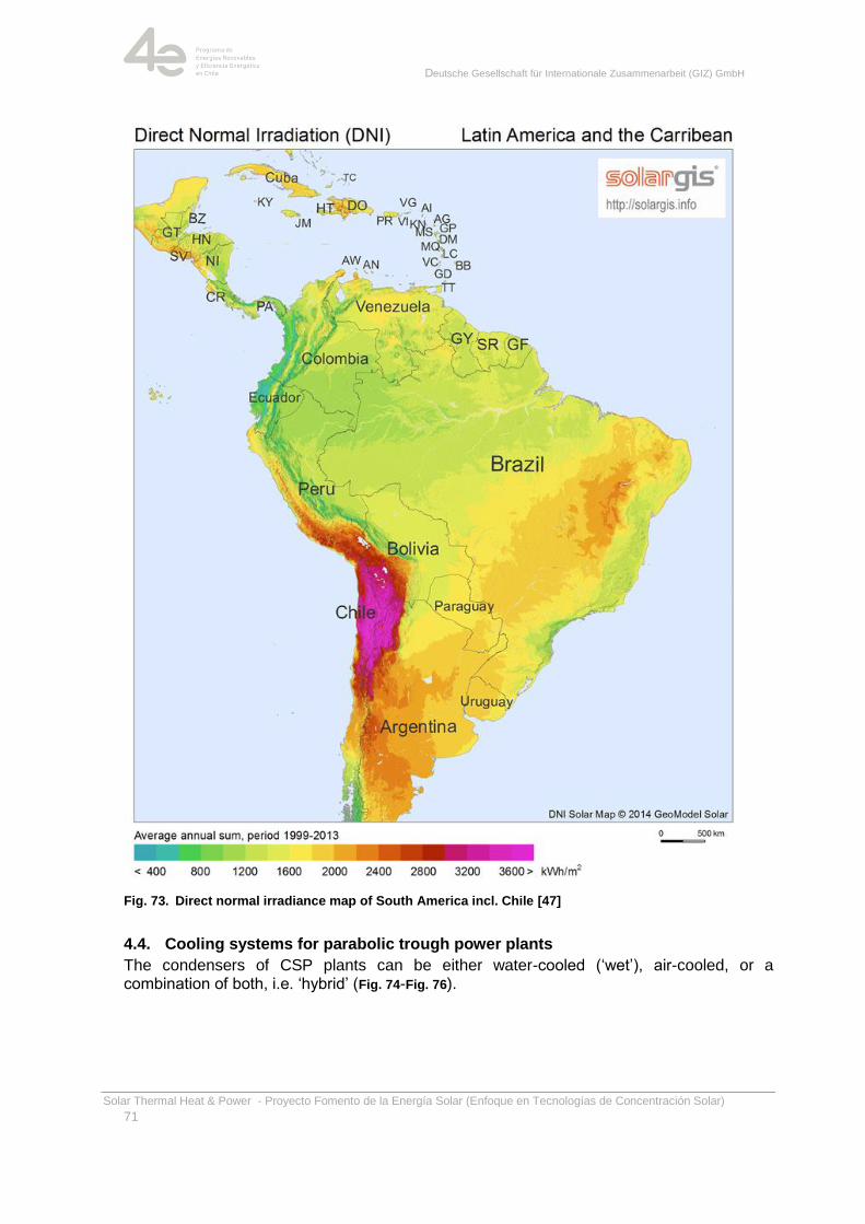
Deutsche Gesellschaft für Internationale Zusammenarbeit (GIZ) GmbH
Solar Thermal Heat & Power - Proyecto Fomento de la Energía Solar (Enfoque en Tecnologías de Concentración Solar)
71
Fig. 73. Direct normal irradiance map of South America incl. Chile [47]
4.4. Cooling systems for parabolic trough power plants
The condensers of CSP plants can be either water-cooled (‗wet‘), air-cooled, or a combination of both, i.e. ‗hybrid‘ (Fig. 74-Fig. 76).
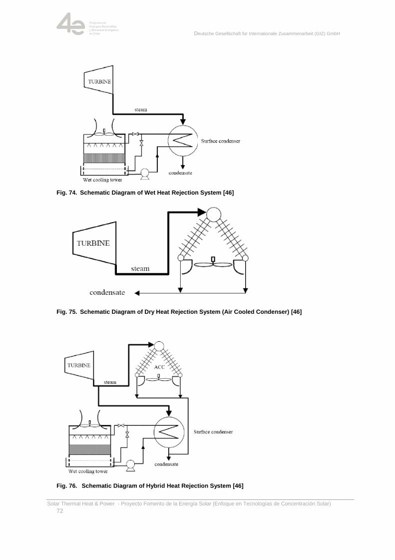
Deutsche Gesellschaft für Internationale Zusammenarbeit (GIZ) GmbH
Solar Thermal Heat & Power - Proyecto Fomento de la Energía Solar (Enfoque en Tecnologías de Concentración Solar)
72
Fig. 74. Schematic Diagram of Wet Heat Rejection System [46]
Fig. 75. Schematic Diagram of Dry Heat Rejection System (Air Cooled Condenser) [46]
Fig. 76. Schematic Diagram of Hybrid Heat Rejection System [46]
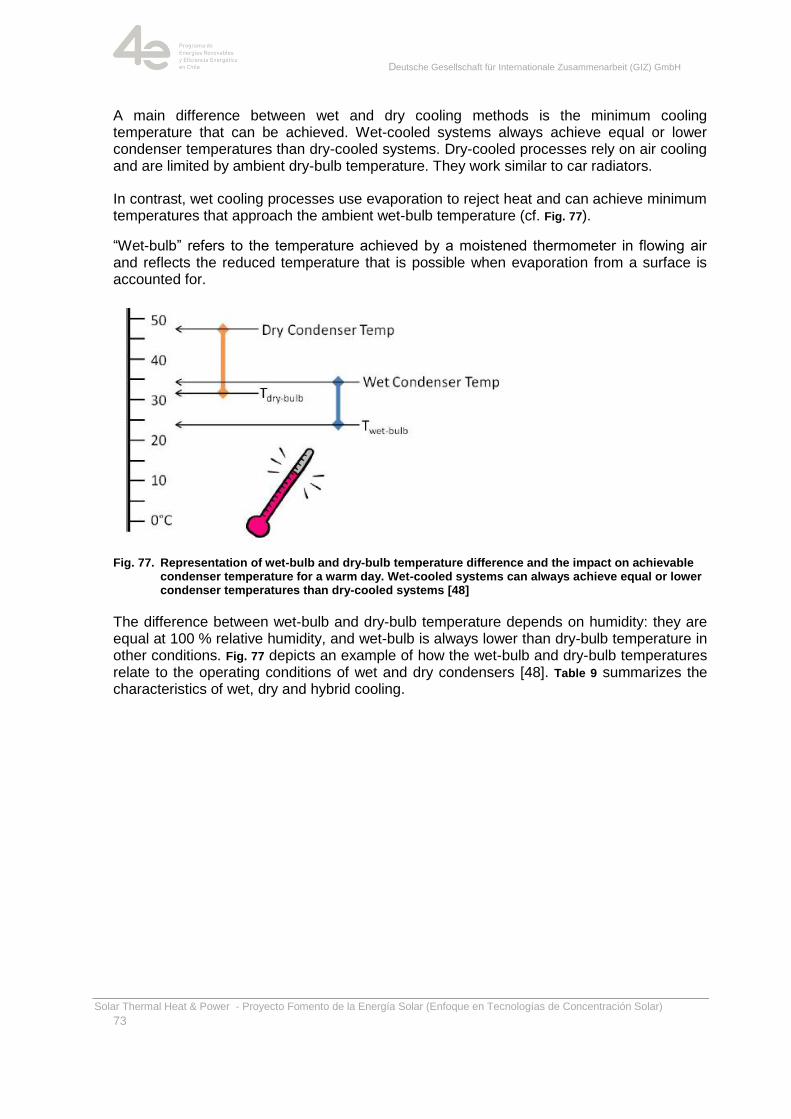
Deutsche Gesellschaft für Internationale Zusammenarbeit (GIZ) GmbH
Solar Thermal Heat & Power - Proyecto Fomento de la Energía Solar (Enfoque en Tecnologías de Concentración Solar)
73
A main difference between wet and dry cooling methods is the minimum cooling temperature that can be achieved. Wet-cooled systems always achieve equal or lower condenser temperatures than dry-cooled systems. Dry-cooled processes rely on air cooling and are limited by ambient dry-bulb temperature. They work similar to car radiators.
In contrast, wet cooling processes use evaporation to reject heat and can achieve minimum temperatures that approach the ambient wet-bulb temperature (cf. Fig. 77).
―Wet-bulb‖ refers to the temperature achieved by a moistened thermometer in flowing air and reflects the reduced temperature that is possible when evaporation from a surface is accounted for.
Fig. 77. Representation of wet-bulb and dry-bulb temperature difference and the impact on achievable condenser temperature for a warm day. Wet-cooled systems can always achieve equal or lower condenser temperatures than dry-cooled systems [48]
The difference between wet-bulb and dry-bulb temperature depends on humidity: they are equal at 100 % relative humidity, and wet-bulb is always lower than dry-bulb temperature in other conditions. Fig. 77 depicts an example of how the wet-bulb and dry-bulb temperatures relate to the operating conditions of wet and dry condensers [48]. Table 9 summarizes the characteristics of wet, dry and hybrid cooling.
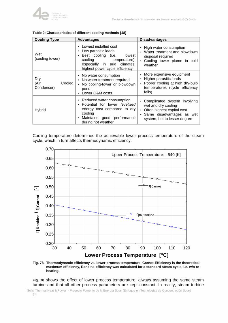
Deutsche Gesellschaft für Internationale Zusammenarbeit (GIZ) GmbH
Solar Thermal Heat & Power - Proyecto Fomento de la Energía Solar (Enfoque en Tecnologías de Concentración Solar)
74
Table 9: Characteristics of different cooling methods [48]
Cooling Type Advantages Disadvantages
Wet (cooling tower)
• Lowest installed cost • Low parasitic loads • Best cooling (i.e. lowest
cooling temperature), especially in arid climates, highest power cycle efficiency
• High water consumption • Water treatment and blowdown
disposal required • Cooling tower plume in cold
weather
Dry (Air Cooled Condenser)
• No water consumption • No water treatment required • No cooling-tower or blowdown
pond • Lower O&M costs
• More expensive equipment • Higher parasitic loads • Poorer cooling at high dry-bulb
temperatures (cycle efficiency falls)
Hybrid
• Reduced water consumption • Potential for lower levelised
energy cost compared to dry cooling
• Maintains good performance during hot weather
• Complicated system involving wet and dry cooling
• Often highest capital cost • Same disadvantages as wet
system, but to lesser degree
Cooling temperature determines the achievable lower process temperature of the steam cycle, which in turn affects thermodynamic efficiency.
Fig. 78. Thermodynamic efficiency vs. lower process temperature. Carnot-Efficiency is the theoretical maximum efficiency, Rankine-efficiency was calculated for a standard steam cycle, i.e. w/o re-heating.
Fig. 78 shows the effect of lower process temperature, always assuming the same steam turbine and that all other process parameters are kept constant. In reality, steam turbine
30 40 50 60 70 80 90 100 110 1200.20
0.25
0.30
0.35
0.40
0.45
0.50
0.55
0.60
0.65
0.70
Lower Process Temperature [°C]
hR
an
kin
e / h
Carn
ot [-
] hCarnothCarnot
540 [K]Upper Process Temperature:
hth,Rankinehth,Rankine
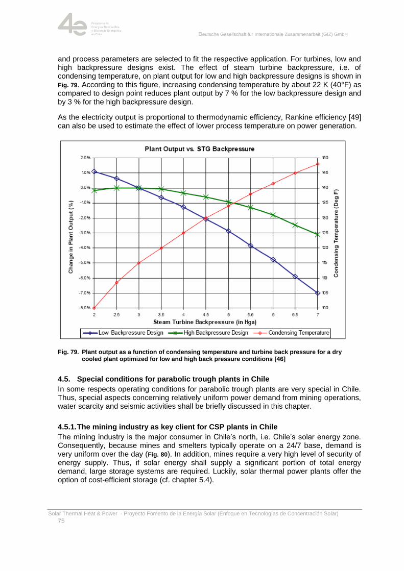
Deutsche Gesellschaft für Internationale Zusammenarbeit (GIZ) GmbH
Solar Thermal Heat & Power - Proyecto Fomento de la Energía Solar (Enfoque en Tecnologías de Concentración Solar)
75
and process parameters are selected to fit the respective application. For turbines, low and high backpressure designs exist. The effect of steam turbine backpressure, i.e. of condensing temperature, on plant output for low and high backpressure designs is shown in Fig. 79. According to this figure, increasing condensing temperature by about 22 K (40°F) as compared to design point reduces plant output by 7 % for the low backpressure design and by 3 % for the high backpressure design.
As the electricity output is proportional to thermodynamic efficiency, Rankine efficiency [49] can also be used to estimate the effect of lower process temperature on power generation.
Fig. 79. Plant output as a function of condensing temperature and turbine back pressure for a dry cooled plant optimized for low and high back pressure conditions [46]
4.5. Special conditions for parabolic trough plants in Chile
In some respects operating conditions for parabolic trough plants are very special in Chile. Thus, special aspects concerning relatively uniform power demand from mining operations, water scarcity and seismic activities shall be briefly discussed in this chapter.
4.5.1. The mining industry as key client for CSP plants in Chile
The mining industry is the major consumer in Chile‘s north, i.e. Chile‘s solar energy zone. Consequently, because mines and smelters typically operate on a 24/7 base, demand is very uniform over the day (Fig. 80). In addition, mines require a very high level of security of energy supply. Thus, if solar energy shall supply a significant portion of total energy demand, large storage systems are required. Luckily, solar thermal power plants offer the option of cost-efficient storage (cf. chapter 5.4).
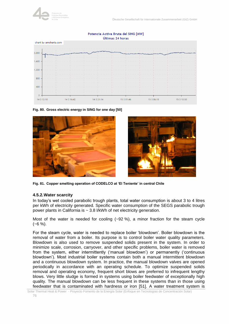
Deutsche Gesellschaft für Internationale Zusammenarbeit (GIZ) GmbH
Solar Thermal Heat & Power - Proyecto Fomento de la Energía Solar (Enfoque en Tecnologías de Concentración Solar)
76
Fig. 80. Gross electric energy in SING for one day [50]
Fig. 81. Copper smelting operation of CODELCO at ‘El Teniente’ in central Chile
4.5.2. Water scarcity
In today‘s wet cooled parabolic trough plants, total water consumption is about 3 to 4 litres per kWh of electricity generated. Specific water consumption of the SEGS parabolic trough power plants in California is ~ 3.8 l/kWh of net electricity generation.
Most of the water is needed for cooling (~92 %), a minor fraction for the steam cycle (~6 %).
For the steam cycle, water is needed to replace boiler ‗blowdown‘. Boiler blowdown is the removal of water from a boiler. Its purpose is to control boiler water quality parameters. Blowdown is also used to remove suspended solids present in the system. In order to minimize scale, corrosion, carryover, and other specific problems, boiler water is removed from the system, either intermittently (‗manual blowdown‘) or permanently (‗continuous blowdown‘). Most industrial boiler systems contain both a manual intermittent blowdown and a continuous blowdown system. In practice, the manual blowdown valves are opened periodically in accordance with an operating schedule. To optimize suspended solids removal and operating economy, frequent short blows are preferred to infrequent lengthy blows. Very little sludge is formed in systems using boiler feedwater of exceptionally high quality. The manual blowdown can be less frequent in these systems than in those using feedwater that is contaminated with hardness or iron [51]. A water treatment system is
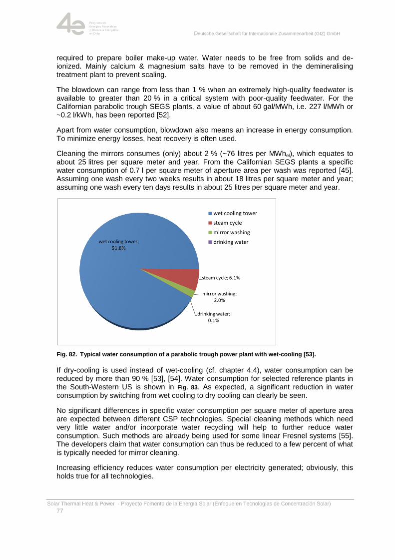
Deutsche Gesellschaft für Internationale Zusammenarbeit (GIZ) GmbH
Solar Thermal Heat & Power - Proyecto Fomento de la Energía Solar (Enfoque en Tecnologías de Concentración Solar)
77
required to prepare boiler make-up water. Water needs to be free from solids and de-ionized. Mainly calcium & magnesium salts have to be removed in the demineralising treatment plant to prevent scaling.
The blowdown can range from less than 1 % when an extremely high-quality feedwater is available to greater than 20 % in a critical system with poor-quality feedwater. For the Californian parabolic trough SEGS plants, a value of about 60 gal/MWh, i.e. 227 l/MWh or ~0.2 l/kWh, has been reported [52].
Apart from water consumption, blowdown also means an increase in energy consumption. To minimize energy losses, heat recovery is often used.
Cleaning the mirrors consumes (only) about 2 % (~76 litres per MWhel), which equates to about 25 litres per square meter and year. From the Californian SEGS plants a specific water consumption of 0.7 l per square meter of aperture area per wash was reported [45]. Assuming one wash every two weeks results in about 18 litres per square meter and year; assuming one wash every ten days results in about 25 litres per square meter and year.
Fig. 82. Typical water consumption of a parabolic trough power plant with wet-cooling [53].
If dry-cooling is used instead of wet-cooling (cf. chapter 4.4), water consumption can be reduced by more than 90 % [53], [54]. Water consumption for selected reference plants in the South-Western US is shown in Fig. 83. As expected, a significant reduction in water consumption by switching from wet cooling to dry cooling can clearly be seen.
No significant differences in specific water consumption per square meter of aperture area are expected between different CSP technologies. Special cleaning methods which need very little water and/or incorporate water recycling will help to further reduce water consumption. Such methods are already being used for some linear Fresnel systems [55]. The developers claim that water consumption can thus be reduced to a few percent of what is typically needed for mirror cleaning.
Increasing efficiency reduces water consumption per electricity generated; obviously, this holds true for all technologies.
wet cooling tower; 91.8%
steam cycle; 6.1%
mirror washing; 2.0%
drinking water; 0.1%
wet cooling tower
steam cycle
mirror washing
drinking water
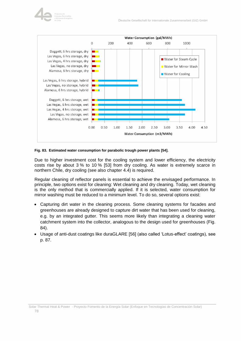
Deutsche Gesellschaft für Internationale Zusammenarbeit (GIZ) GmbH
Solar Thermal Heat & Power - Proyecto Fomento de la Energía Solar (Enfoque en Tecnologías de Concentración Solar)
78
Fig. 83. Estimated water consumption for parabolic trough power plants [54].
Due to higher investment cost for the cooling system and lower efficiency, the electricity costs rise by about 3 % to 10 % [53] from dry cooling. As water is extremely scarce in northern Chile, dry cooling (see also chapter 4.4) is required.
Regular cleaning of reflector panels is essential to achieve the envisaged performance. In principle, two options exist for cleaning: Wet cleaning and dry cleaning. Today, wet cleaning is the only method that is commercially applied. If it is selected, water consumption for mirror washing must be reduced to a minimum level. To do so, several options exist:
Capturing dirt water in the cleaning process. Some cleaning systems for facades and
greenhouses are already designed to capture dirt water that has been used for cleaning,
e.g. by an integrated gutter. This seems more likely than integrating a cleaning water
catchment system into the collector, analogous to the design used for greenhouses (Fig.
84).
Usage of anti-dust coatings like duraGLARE [56] (also called ‗Lotus-effect‘ coatings), see
p. 87.
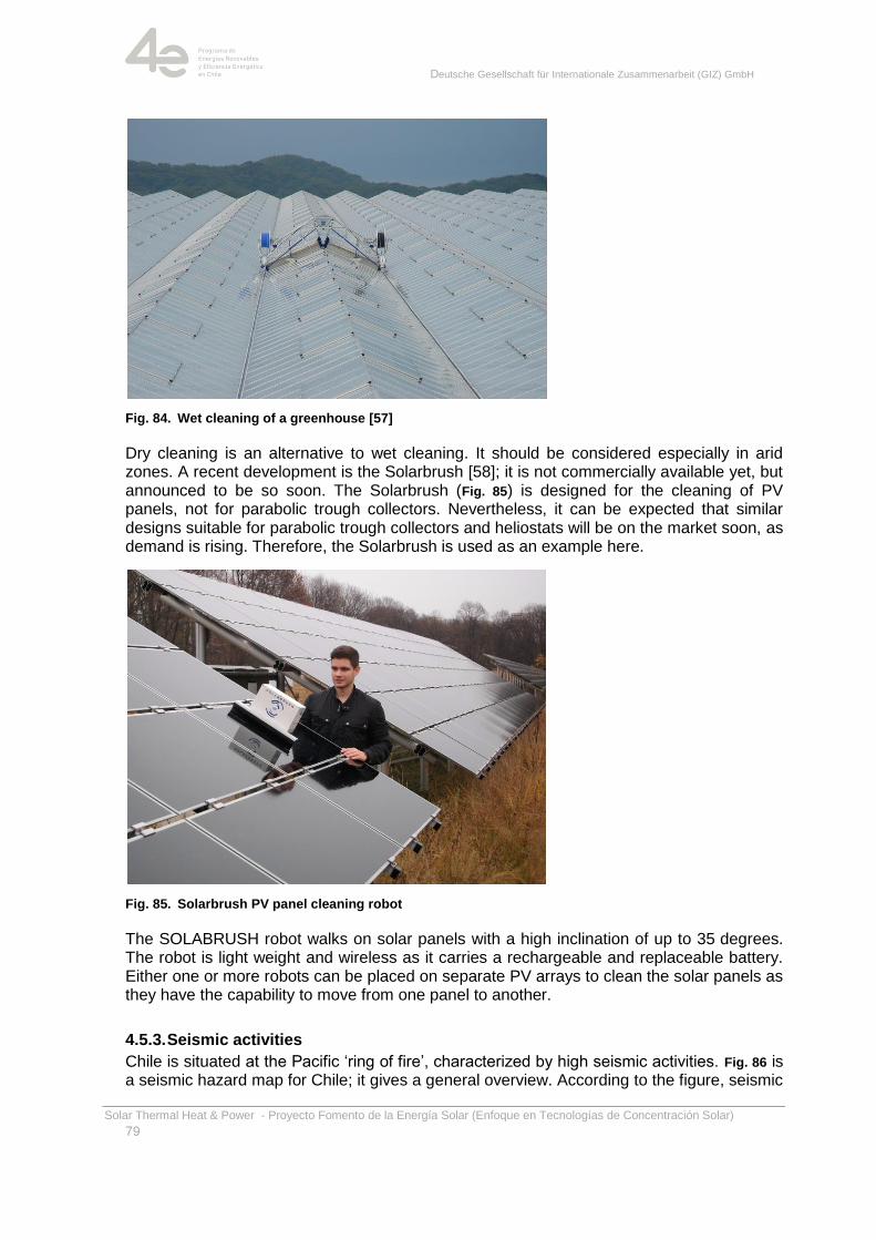
Deutsche Gesellschaft für Internationale Zusammenarbeit (GIZ) GmbH
Solar Thermal Heat & Power - Proyecto Fomento de la Energía Solar (Enfoque en Tecnologías de Concentración Solar)
79
Fig. 84. Wet cleaning of a greenhouse [57]
Dry cleaning is an alternative to wet cleaning. It should be considered especially in arid zones. A recent development is the Solarbrush [58]; it is not commercially available yet, but announced to be so soon. The Solarbrush (Fig. 85) is designed for the cleaning of PV panels, not for parabolic trough collectors. Nevertheless, it can be expected that similar designs suitable for parabolic trough collectors and heliostats will be on the market soon, as demand is rising. Therefore, the Solarbrush is used as an example here.
Fig. 85. Solarbrush PV panel cleaning robot
The SOLABRUSH robot walks on solar panels with a high inclination of up to 35 degrees. The robot is light weight and wireless as it carries a rechargeable and replaceable battery. Either one or more robots can be placed on separate PV arrays to clean the solar panels as they have the capability to move from one panel to another.
4.5.3. Seismic activities
Chile is situated at the Pacific ‗ring of fire‘, characterized by high seismic activities. Fig. 86 is a seismic hazard map for Chile; it gives a general overview. According to the figure, seismic
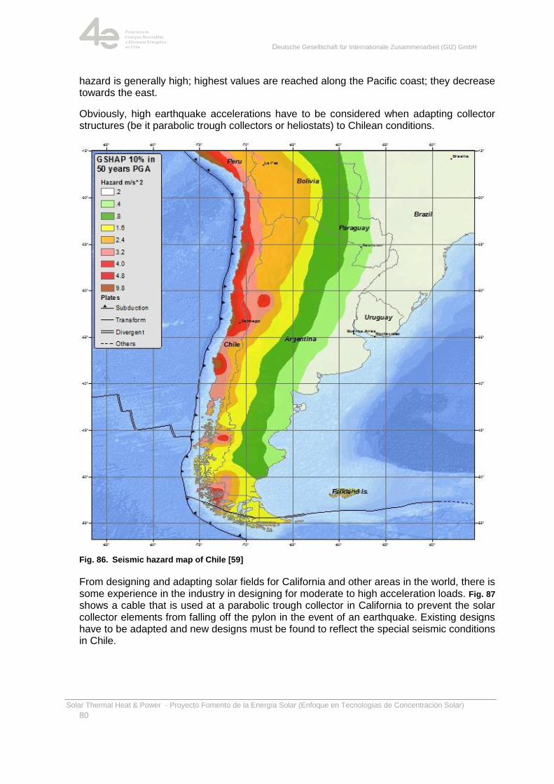
Deutsche Gesellschaft für Internationale Zusammenarbeit (GIZ) GmbH
Solar Thermal Heat & Power - Proyecto Fomento de la Energía Solar (Enfoque en Tecnologías de Concentración Solar)
80
hazard is generally high; highest values are reached along the Pacific coast; they decrease towards the east.
Obviously, high earthquake accelerations have to be considered when adapting collector structures (be it parabolic trough collectors or heliostats) to Chilean conditions.
Fig. 86. Seismic hazard map of Chile [59]
From designing and adapting solar fields for California and other areas in the world, there is some experience in the industry in designing for moderate to high acceleration loads. Fig. 87 shows a cable that is used at a parabolic trough collector in California to prevent the solar collector elements from falling off the pylon in the event of an earthquake. Existing designs have to be adapted and new designs must be found to reflect the special seismic conditions in Chile.
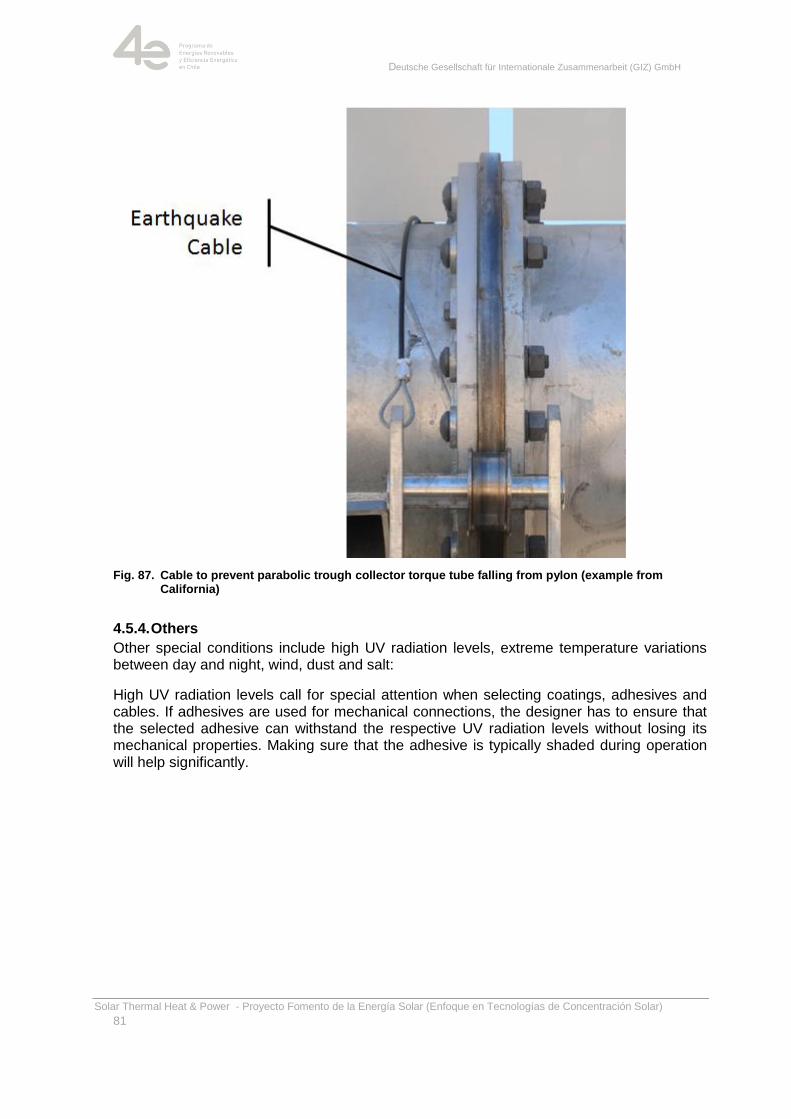
Deutsche Gesellschaft für Internationale Zusammenarbeit (GIZ) GmbH
Solar Thermal Heat & Power - Proyecto Fomento de la Energía Solar (Enfoque en Tecnologías de Concentración Solar)
81
Fig. 87. Cable to prevent parabolic trough collector torque tube falling from pylon (example from California)
4.5.4. Others
Other special conditions include high UV radiation levels, extreme temperature variations between day and night, wind, dust and salt:
High UV radiation levels call for special attention when selecting coatings, adhesives and cables. If adhesives are used for mechanical connections, the designer has to ensure that the selected adhesive can withstand the respective UV radiation levels without losing its mechanical properties. Making sure that the adhesive is typically shaded during operation will help significantly.
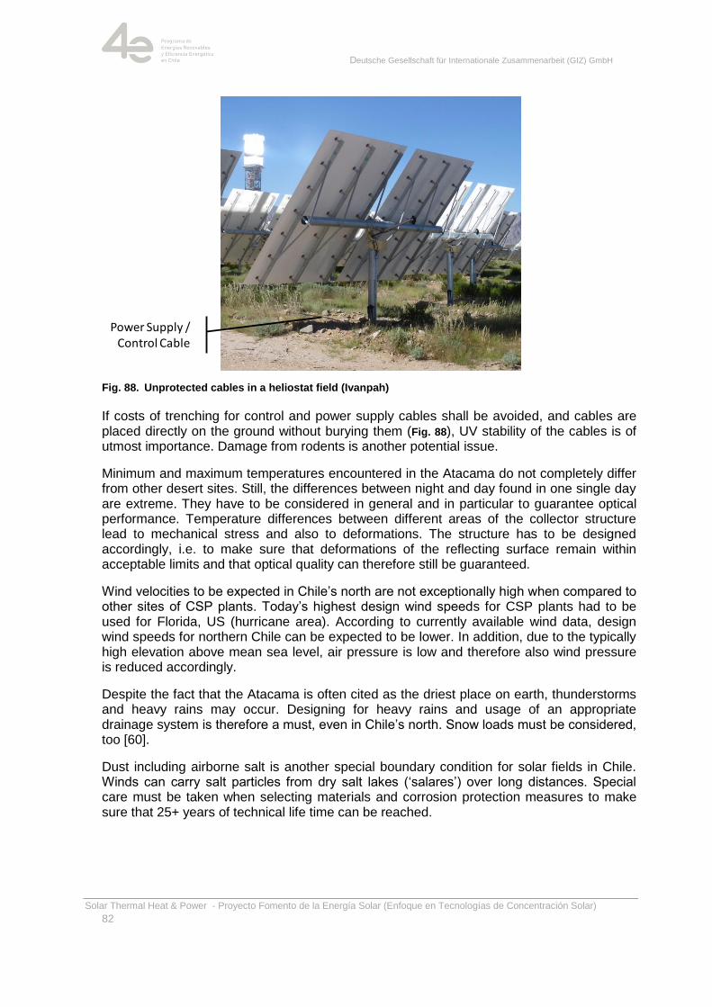
Deutsche Gesellschaft für Internationale Zusammenarbeit (GIZ) GmbH
Solar Thermal Heat & Power - Proyecto Fomento de la Energía Solar (Enfoque en Tecnologías de Concentración Solar)
82
Fig. 88. Unprotected cables in a heliostat field (Ivanpah)
If costs of trenching for control and power supply cables shall be avoided, and cables are placed directly on the ground without burying them (Fig. 88), UV stability of the cables is of utmost importance. Damage from rodents is another potential issue.
Minimum and maximum temperatures encountered in the Atacama do not completely differ from other desert sites. Still, the differences between night and day found in one single day are extreme. They have to be considered in general and in particular to guarantee optical performance. Temperature differences between different areas of the collector structure lead to mechanical stress and also to deformations. The structure has to be designed accordingly, i.e. to make sure that deformations of the reflecting surface remain within acceptable limits and that optical quality can therefore still be guaranteed.
Wind velocities to be expected in Chile‘s north are not exceptionally high when compared to other sites of CSP plants. Today‘s highest design wind speeds for CSP plants had to be used for Florida, US (hurricane area). According to currently available wind data, design wind speeds for northern Chile can be expected to be lower. In addition, due to the typically high elevation above mean sea level, air pressure is low and therefore also wind pressure is reduced accordingly.
Despite the fact that the Atacama is often cited as the driest place on earth, thunderstorms and heavy rains may occur. Designing for heavy rains and usage of an appropriate drainage system is therefore a must, even in Chile‘s north. Snow loads must be considered, too [60].
Dust including airborne salt is another special boundary condition for solar fields in Chile. Winds can carry salt particles from dry salt lakes (‗salares‘) over long distances. Special care must be taken when selecting materials and corrosion protection measures to make sure that 25+ years of technical life time can be reached.
Power Supply / Control Cable
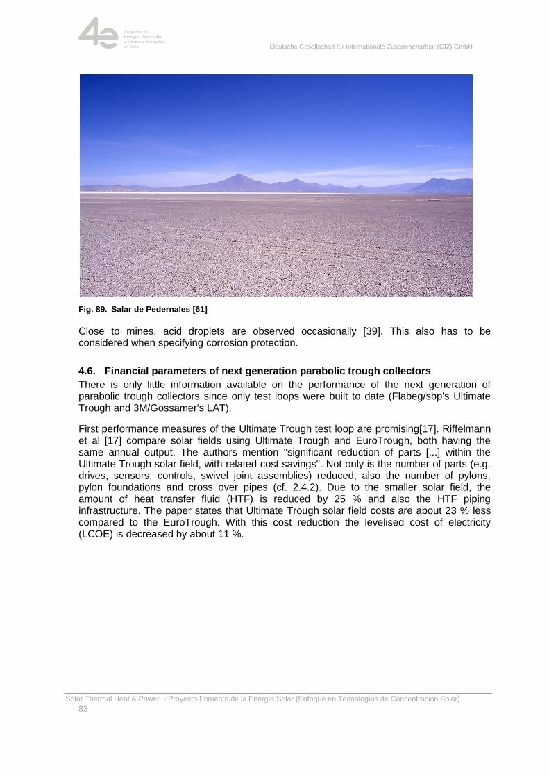
Deutsche Gesellschaft für Internationale Zusammenarbeit (GIZ) GmbH
Solar Thermal Heat & Power - Proyecto Fomento de la Energía Solar (Enfoque en Tecnologías de Concentración Solar)
83
Fig. 89. Salar de Pedernales [61]
Close to mines, acid droplets are observed occasionally [39]. This also has to be considered when specifying corrosion protection.
4.6. Financial parameters of next generation parabolic trough collectors
There is only little information available on the performance of the next generation of parabolic trough collectors since only test loops were built to date (Flabeg/sbp's Ultimate Trough and 3M/Gossamer's LAT).
First performance measures of the Ultimate Trough test loop are promising[17]. Riffelmann et al [17] compare solar fields using Ultimate Trough and EuroTrough, both having the same annual output. The authors mention "significant reduction of parts [...] within the Ultimate Trough solar field, with related cost savings". Not only is the number of parts (e.g. drives, sensors, controls, swivel joint assemblies) reduced, also the number of pylons, pylon foundations and cross over pipes (cf. 2.4.2). Due to the smaller solar field, the amount of heat transfer fluid (HTF) is reduced by 25 % and also the HTF piping infrastructure. The paper states that Ultimate Trough solar field costs are about 23 % less compared to the EuroTrough. With this cost reduction the levelised cost of electricity (LCOE) is decreased by about 11 %.

Deutsche Gesellschaft für Internationale Zusammenarbeit (GIZ) GmbH
Solar Thermal Heat & Power - Proyecto Fomento de la Energía Solar (Enfoque en Tecnologías de Concentración Solar)
84
5. Technological developments
5.1. General Trends
In Fig. 90 the development of specific parabolic trough power plant cost1 is depicted: In the
course of the deployment of the SEGS plants by LUZ, significant cost reduction was
achieved. Nevada Solar One was another step in this direction. In principle, the Spanish
plants should have followed the experience curve (brown curve in Fig. 90) as pre-defined
by the earlier US-American plants. Unfortunately, the numbers as observed by Hayward
[62] do not exactly show the expected trend. Instead, specific costs of the Spanish plants
are higher than expected.
The reasons for this may on the one hand be the fact that Spanish plants often include thermal storage, which obviously increases specific investment costs, but not necessarily levelised electricity generation costs (LCOE). Therefore specific investment costs cannot be considered an absolutely appropriate figure of merit here, but it is arguably the best one for which data is often available.
A second reason for costs not being reduced as expected from typical experience curves is the design of the Spanish feed-in tariff: It incorporated no reduction, therefore any realized cost savings remained unnoticed by the outside, as the projects always cost as much as the tariff allows. The trend of the cost reduction observed is therefore not a characteristic of parabolic trough technology, but the result of a poorly designed feed-in tariff system.
1Specific cost in terms of 'monetary units per installed capacity' must always be read very carefully, as the numbers are often misleading: Costs and effects on energy output of larger solar fields and/or integrated storage is not reflected in such a number. Moreover, the real figure of merit is 'cost per energy', to be more exact: 'cost per energy that is produced when needed'. Still, as the general idea is conveyed by this chart, it has been used here for the introduction.
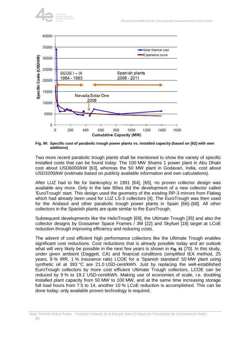
Deutsche Gesellschaft für Internationale Zusammenarbeit (GIZ) GmbH
Solar Thermal Heat & Power - Proyecto Fomento de la Energía Solar (Enfoque en Tecnologías de Concentración Solar)
85
Fig. 90. Specific cost of parabolic trough power plants vs. installed capacity (based on [62] with own additions)
Two more recent parabolic trough plants shall be mentioned to show the variety of specific installed costs that can be found today: The 100 MW Shams 1 power plant in Abu Dhabi cost about USD6000/kW [63], whereas the 50 MW plant in Godavari, India, cost about USD3200/kW (estimate based on publicly available information and own calculations).
After LUZ had to file for bankruptcy in 1991 [64], [65], no proven collector design was available any more. Only in the late 90ies did the development of a new collector called 'EuroTrough' start. This design used the geometry of the existing RP-3 mirrors from Flabeg which had already been used for LUZ LS-3 collectors [4]. The EuroTrough was then used for the Andasol and other parabolic trough power plants in Spain [66]–[68]. All other collectors in the Spanish plants are quite similar to the EuroTrough.
Subsequent developments like the HelioTrough [69], the Ultimate Trough [35] and also the collector designs by Gossamer Space Frames / 3M [22] and Skyfuel [18] target at LCoE reduction through improving efficiency and reducing costs.
The advent of cost efficient high performance collectors like the Ultimate Trough enables significant cost reductions. Cost reductions that is already possible today and an outlook what will very likely be possible in the next few years is shown in Fig. 91 [70]. In this study, under given ambient (Daggett, CA) and financial conditions (simplified IEA method, 25 years, 8 % IRR, 1 % insurance rate) LCOE for a 'Spanish standard' 50 MW plant using synthetic oil at 393 °C are 21.0 USD-cent/kWh. Just by replacing the well-established EuroTrough collectors by more cost efficient Ultimate Trough collectors, LCOE can be reduced by 9 % to 19.2 USD-cent/kWh. Making use of economies of scale, i.e. doubling installed plant capacity from 50 MW to 100 MW, and at the same time increasing storage full load hours from 7.5 to 14, another 10 % LCoE reduction is accomplished. This can be done today; only available proven technology is required.
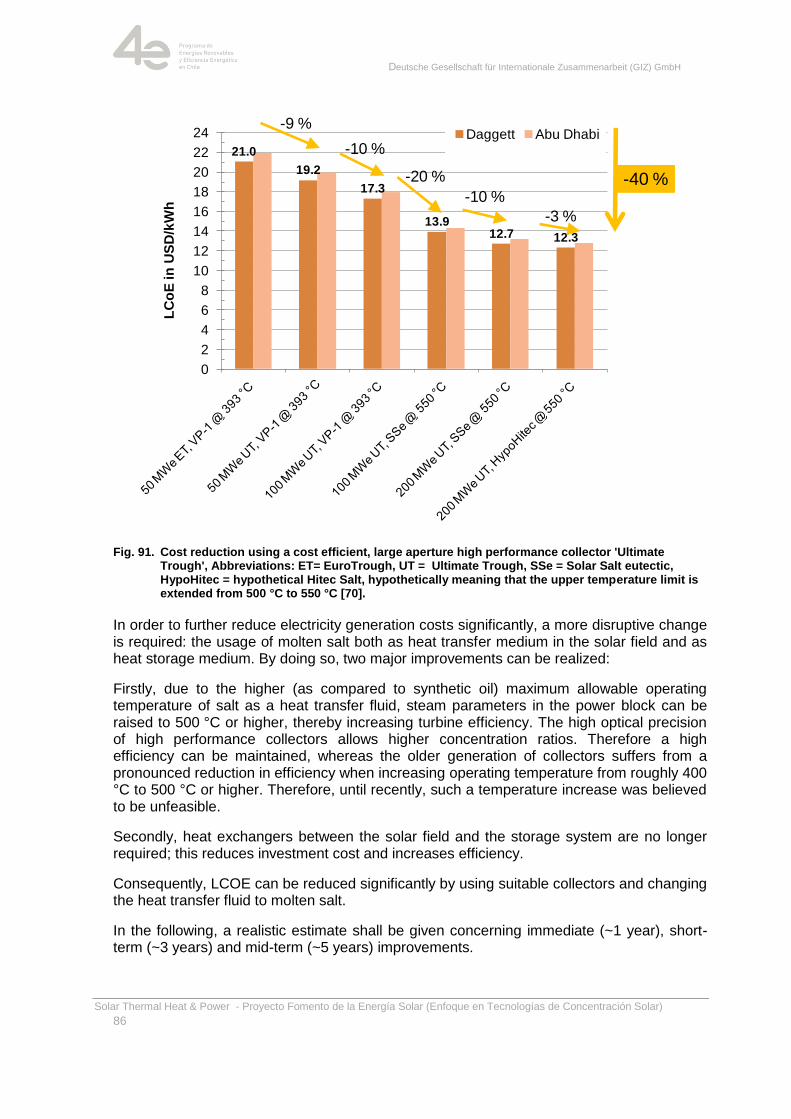
Deutsche Gesellschaft für Internationale Zusammenarbeit (GIZ) GmbH
Solar Thermal Heat & Power - Proyecto Fomento de la Energía Solar (Enfoque en Tecnologías de Concentración Solar)
86
Fig. 91. Cost reduction using a cost efficient, large aperture high performance collector 'Ultimate Trough', Abbreviations: ET= EuroTrough, UT = Ultimate Trough, SSe = Solar Salt eutectic, HypoHitec = hypothetical Hitec Salt, hypothetically meaning that the upper temperature limit is extended from 500 °C to 550 °C [70].
In order to further reduce electricity generation costs significantly, a more disruptive change is required: the usage of molten salt both as heat transfer medium in the solar field and as heat storage medium. By doing so, two major improvements can be realized:
Firstly, due to the higher (as compared to synthetic oil) maximum allowable operating temperature of salt as a heat transfer fluid, steam parameters in the power block can be raised to 500 °C or higher, thereby increasing turbine efficiency. The high optical precision of high performance collectors allows higher concentration ratios. Therefore a high efficiency can be maintained, whereas the older generation of collectors suffers from a pronounced reduction in efficiency when increasing operating temperature from roughly 400 °C to 500 °C or higher. Therefore, until recently, such a temperature increase was believed to be unfeasible.
Secondly, heat exchangers between the solar field and the storage system are no longer required; this reduces investment cost and increases efficiency.
Consequently, LCOE can be reduced significantly by using suitable collectors and changing the heat transfer fluid to molten salt.
In the following, a realistic estimate shall be given concerning immediate (~1 year), short-term (~3 years) and mid-term (~5 years) improvements.
21.0
19.2
17.3
13.912.7 12.3
0
2
4
6
8
10
12
14
16
18
20
22
24 Daggett Abu Dhabi
LC
oE
in
US
D/k
Wh
-9 %
-10 %
-20 %
-10 %
-3 %
-40 %
Deutsche Gesellschaft für Internationale Zusammenarbeit (GIZ) GmbH
Solar Thermal Heat & Power - Proyecto Fomento de la Energía Solar (Enfoque en Tecnologías de Concentración Solar)
87
5.2. Collector Components
Reflectors. The best performing and most reliable reflectors continue to be glass mirrors. Regarding parabolic trough collectors, reflecting films and composite reflectors (load-carrying substrate plus mirror film/thin glass mirror) are still in their infancy and it is unclear if they will ever play an important role in CSP. Glass reflector panels have seen significant improvement in terms of cost, performance and environmental characteristics in the recent past: Cost of typical 4 mm glass reflectors has dropped from around 37 USD to about 19 USD per square meter (estimate for 12/2013). It is expected to further drop to about 15 USD/m² in the next 1 to 3 years and potentially to about 12 USD/m² within 5 years (2012 Euros).
Compared to some years ago, today's reflectors are more environmentally friendly: Due to environmental regulations (in California), lead-free backside coatings have to be used.
In addition, manufacturers will continue their efforts to increase accuracy and reflectivity, i.e. overall performance. Anti-soiling coatings such as duraGLARE [56] should help to reduce operation and maintenance requirements in general. Moreover, they also target at expanding the areas where CSP plants can be operated economically today by reducing the cleaning effort required.
Absorber tubes (Heat Collecting Elements). Absorber tubes are high-tech components characterized by very high absorption of solar radiation (> 95 %) and low thermal losses from infrared radiation (ε ≤ 10 % @ 400 °C) and convection. Future developments will mainly follow two targets: Cost reduction and performance increase.
Cost reduction will be achieved by improved production procedures; it will be forced by increasing competition between manufacturers.
Performance increase here means an increase in absorption and a decrease in emissivity; here no major improvements can be expected any more regarding absorption and emissivity. Developments currently target at increasing maximum allowable operating temperature to 500 °C and above (especially for molten salt applications). In parallel, material scientists develop coatings with extended lifespan.
It can be expected that absorber tubes suitable for operating temperatures of 500 °C and life spans close to those of today's absorber tubes operating at 400 °C will be commercially available by the end of 2014, and that in three to five years tubes will be on the market for operating temperatures up to 540…550 °C.
Metal Support Structure (MSS). Throughout the industry, the trend towards wider collectors is clearly visible (cf. Fig. 92): While the aperture width of practically all parabolic trough collectors installed between 1989 and the present has been defined by the RP-3 mirror dimensions, i.e. ~5.8 m, more recent designs are characterized by a larger aperture width: The HelioTrough has an aperture width of 6.8 m [69], Gossamer Space Frames' Large Aperture Trough 1 [22] has an aperture width of 7.3 m, the Ultimate Trough is characterized by an aperture width of 7.5 m [35].
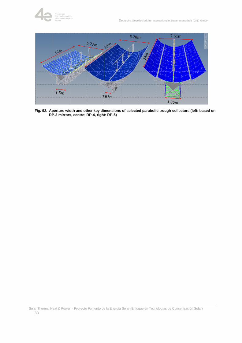
Deutsche Gesellschaft für Internationale Zusammenarbeit (GIZ) GmbH
Solar Thermal Heat & Power - Proyecto Fomento de la Energía Solar (Enfoque en Tecnologías de Concentración Solar)
88
Fig. 92. Aperture width and other key dimensions of selected parabolic trough collectors (left: based on RP-3 mirrors, centre: RP-4, right: RP-5)
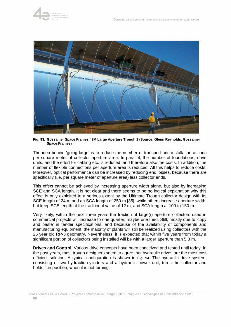
Deutsche Gesellschaft für Internationale Zusammenarbeit (GIZ) GmbH
Solar Thermal Heat & Power - Proyecto Fomento de la Energía Solar (Enfoque en Tecnologías de Concentración Solar)
89
Fig. 93. Gossamer Space Frames / 3M Large Aperture Trough 1 (Source: Glenn Reynolds, Gossamer Space Frames)
The idea behind 'going large' is to reduce the number of transport and installation actions per square meter of collector aperture area. In parallel, the number of foundations, drive units, and the effort for cabling etc. is reduced, and therefore also the costs. In addition, the number of flexible connections per aperture area is reduced. All this helps to reduce costs. Moreover, optical performance can be increased by reducing end losses, because there are specifically (i.e. per square meter of aperture area) less collector ends.
This effect cannot be achieved by increasing aperture width alone, but also by increasing SCE and SCA length. It is not clear and there seems to be no logical explanation why this effect is only exploited to a serious extent by the Ultimate Trough collector design with its SCE length of 24 m and an SCA length of 250 m [35], while others increase aperture width, but keep SCE length at the traditional value of 12 m, and SCA length at 100 to 150 m.
Very likely, within the next three years the fraction of large(r) aperture collectors used in commercial projects will increase to one quarter, maybe one third. Still, mostly due to 'copy and paste' in tender specifications, and because of the availability of components and manufacturing equipment, the majority of plants will still be realized using collectors with the 25 year old RP-3 geometry. Nevertheless, it is expected that within five years from today a significant portion of collectors being installed will be with a larger aperture than 5.8 m.
Drives and Control. Various drive concepts have been conceived and tested until today. In the past years, most trough designers seem to agree that hydraulic drives are the most cost efficient solution. A typical configuration is shown in Fig. 94. The hydraulic drive system, consisting of two hydraulic cylinders and a hydraulic power unit, turns the collector and holds it in position, when it is not turning.
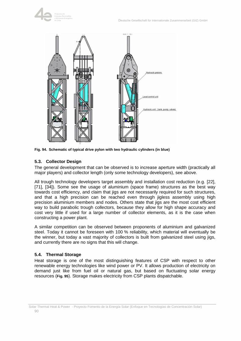
Deutsche Gesellschaft für Internationale Zusammenarbeit (GIZ) GmbH
Solar Thermal Heat & Power - Proyecto Fomento de la Energía Solar (Enfoque en Tecnologías de Concentración Solar)
90
Fig. 94. Schematic of typical drive pylon with two hydraulic cylinders (in blue)
5.3. Collector Design
The general development that can be observed is to increase aperture width (practically all major players) and collector length (only some technology developers), see above.
All trough technology developers target assembly and installation cost reduction (e.g. [22], [71], [34]). Some see the usage of aluminium (space frame) structures as the best way towards cost efficiency, and claim that jigs are not necessarily required for such structures, and that a high precision can be reached even through jigless assembly using high precision aluminium members and nodes. Others state that jigs are the most cost efficient way to build parabolic trough collectors, because they allow for high shape accuracy and cost very little if used for a large number of collector elements, as it is the case when constructing a power plant.
A similar competition can be observed between proponents of aluminium and galvanized steel. Today it cannot be foreseen with 100 % reliability, which material will eventually be the winner, but today a vast majority of collectors is built from galvanized steel using jigs, and currently there are no signs that this will change.
5.4. Thermal Storage
Heat storage is one of the most distinguishing features of CSP with respect to other renewable energy technologies like wind power or PV. It allows production of electricity on demand just like from fuel oil or natural gas, but based on fluctuating solar energy resources (Fig. 95). Storage makes electricity from CSP plants dispatchable.
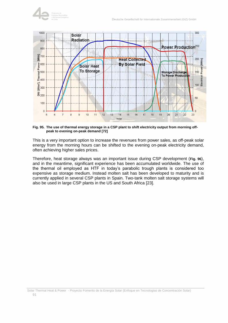
Deutsche Gesellschaft für Internationale Zusammenarbeit (GIZ) GmbH
Solar Thermal Heat & Power - Proyecto Fomento de la Energía Solar (Enfoque en Tecnologías de Concentración Solar)
91
Fig. 95. The use of thermal energy storage in a CSP plant to shift electricity output from morning off-peak to evening on-peak demand [72]
This is a very important option to increase the revenues from power sales, as off-peak solar energy from the morning hours can be shifted to the evening on-peak electricity demand, often achieving higher sales prices.
Therefore, heat storage always was an important issue during CSP development (Fig. 96), and in the meantime, significant experience has been accumulated worldwide. The use of the thermal oil employed as HTF in today‘s parabolic trough plants is considered too expensive as storage medium. Instead molten salt has been developed to maturity and is currently applied in several CSP plants in Spain. Two-tank molten salt storage systems will also be used in large CSP plants in the US and South Africa [23].
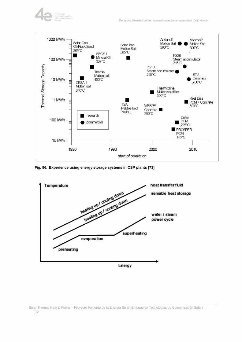
Deutsche Gesellschaft für Internationale Zusammenarbeit (GIZ) GmbH
Solar Thermal Heat & Power - Proyecto Fomento de la Energía Solar (Enfoque en Tecnologías de Concentración Solar)
92
Fig. 96. Experience using energy storage systems in CSP plants [73]
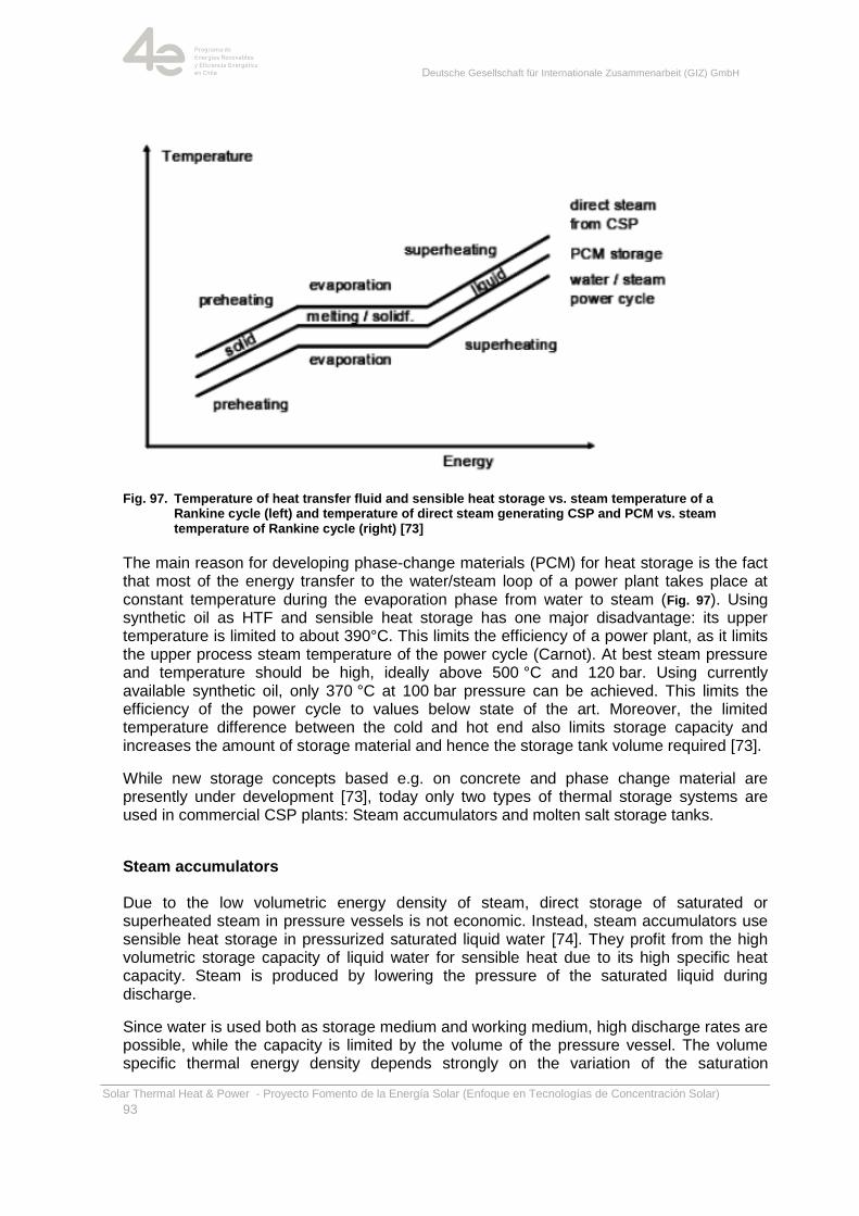
Deutsche Gesellschaft für Internationale Zusammenarbeit (GIZ) GmbH
Solar Thermal Heat & Power - Proyecto Fomento de la Energía Solar (Enfoque en Tecnologías de Concentración Solar)
93
Fig. 97. Temperature of heat transfer fluid and sensible heat storage vs. steam temperature of a Rankine cycle (left) and temperature of direct steam generating CSP and PCM vs. steam temperature of Rankine cycle (right) [73]
The main reason for developing phase-change materials (PCM) for heat storage is the fact that most of the energy transfer to the water/steam loop of a power plant takes place at constant temperature during the evaporation phase from water to steam (Fig. 97). Using synthetic oil as HTF and sensible heat storage has one major disadvantage: its upper temperature is limited to about 390°C. This limits the efficiency of a power plant, as it limits the upper process steam temperature of the power cycle (Carnot). At best steam pressure and temperature should be high, ideally above 500 °C and 120 bar. Using currently available synthetic oil, only 370 °C at 100 bar pressure can be achieved. This limits the efficiency of the power cycle to values below state of the art. Moreover, the limited temperature difference between the cold and hot end also limits storage capacity and increases the amount of storage material and hence the storage tank volume required [73].
While new storage concepts based e.g. on concrete and phase change material are presently under development [73], today only two types of thermal storage systems are used in commercial CSP plants: Steam accumulators and molten salt storage tanks.
Steam accumulators
Due to the low volumetric energy density of steam, direct storage of saturated or superheated steam in pressure vessels is not economic. Instead, steam accumulators use sensible heat storage in pressurized saturated liquid water [74]. They profit from the high volumetric storage capacity of liquid water for sensible heat due to its high specific heat capacity. Steam is produced by lowering the pressure of the saturated liquid during discharge.
Since water is used both as storage medium and working medium, high discharge rates are possible, while the capacity is limited by the volume of the pressure vessel. The volume specific thermal energy density depends strongly on the variation of the saturation
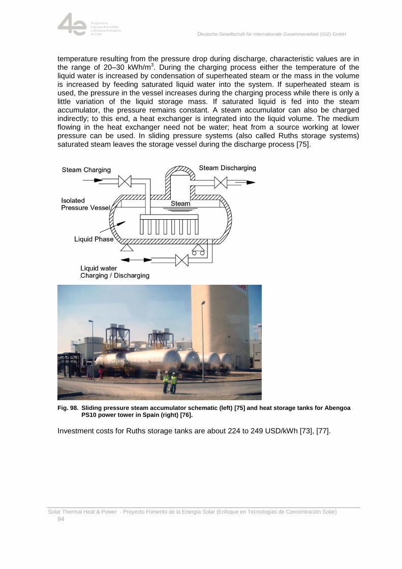
Deutsche Gesellschaft für Internationale Zusammenarbeit (GIZ) GmbH
Solar Thermal Heat & Power - Proyecto Fomento de la Energía Solar (Enfoque en Tecnologías de Concentración Solar)
94
temperature resulting from the pressure drop during discharge, characteristic values are in the range of 20–30 kWh/m3. During the charging process either the temperature of the liquid water is increased by condensation of superheated steam or the mass in the volume is increased by feeding saturated liquid water into the system. If superheated steam is used, the pressure in the vessel increases during the charging process while there is only a little variation of the liquid storage mass. If saturated liquid is fed into the steam accumulator, the pressure remains constant. A steam accumulator can also be charged indirectly; to this end, a heat exchanger is integrated into the liquid volume. The medium flowing in the heat exchanger need not be water; heat from a source working at lower pressure can be used. In sliding pressure systems (also called Ruths storage systems) saturated steam leaves the storage vessel during the discharge process [75].
Fig. 98. Sliding pressure steam accumulator schematic (left) [75] and heat storage tanks for Abengoa PS10 power tower in Spain (right) [76].
Investment costs for Ruths storage tanks are about 224 to 249 USD/kWh [73], [77].
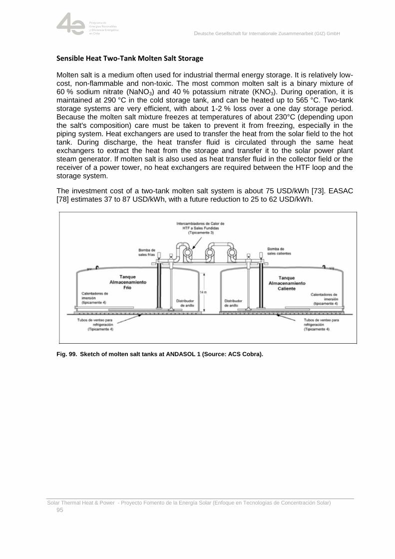
Deutsche Gesellschaft für Internationale Zusammenarbeit (GIZ) GmbH
Solar Thermal Heat & Power - Proyecto Fomento de la Energía Solar (Enfoque en Tecnologías de Concentración Solar)
95
Sensible Heat Two-Tank Molten Salt Storage
Molten salt is a medium often used for industrial thermal energy storage. It is relatively low-cost, non-flammable and non-toxic. The most common molten salt is a binary mixture of 60 % sodium nitrate (NaNO3) and 40 % potassium nitrate (KNO3). During operation, it is maintained at 290 °C in the cold storage tank, and can be heated up to 565 °C. Two-tank storage systems are very efficient, with about 1-2 % loss over a one day storage period. Because the molten salt mixture freezes at temperatures of about 230°C (depending upon the salt's composition) care must be taken to prevent it from freezing, especially in the piping system. Heat exchangers are used to transfer the heat from the solar field to the hot tank. During discharge, the heat transfer fluid is circulated through the same heat exchangers to extract the heat from the storage and transfer it to the solar power plant steam generator. If molten salt is also used as heat transfer fluid in the collector field or the receiver of a power tower, no heat exchangers are required between the HTF loop and the storage system.
The investment cost of a two-tank molten salt system is about 75 USD/kWh [73]. EASAC [78] estimates 37 to 87 USD/kWh, with a future reduction to 25 to 62 USD/kWh.
Fig. 99. Sketch of molten salt tanks at ANDASOL 1 (Source: ACS Cobra).
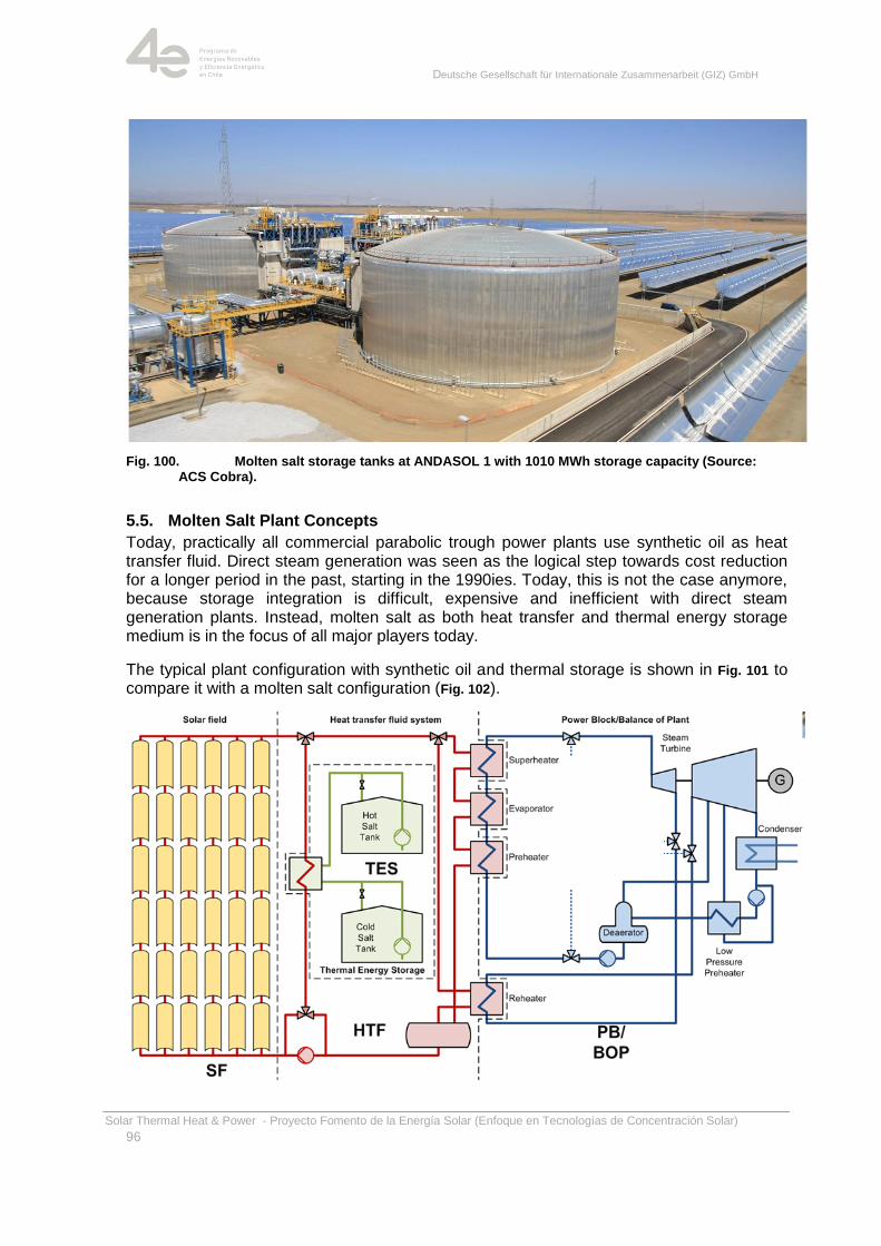
Deutsche Gesellschaft für Internationale Zusammenarbeit (GIZ) GmbH
Solar Thermal Heat & Power - Proyecto Fomento de la Energía Solar (Enfoque en Tecnologías de Concentración Solar)
96
Fig. 100. Molten salt storage tanks at ANDASOL 1 with 1010 MWh storage capacity (Source: ACS Cobra).
5.5. Molten Salt Plant Concepts
Today, practically all commercial parabolic trough power plants use synthetic oil as heat transfer fluid. Direct steam generation was seen as the logical step towards cost reduction for a longer period in the past, starting in the 1990ies. Today, this is not the case anymore, because storage integration is difficult, expensive and inefficient with direct steam generation plants. Instead, molten salt as both heat transfer and thermal energy storage medium is in the focus of all major players today.
The typical plant configuration with synthetic oil and thermal storage is shown in Fig. 101 to compare it with a molten salt configuration (Fig. 102).
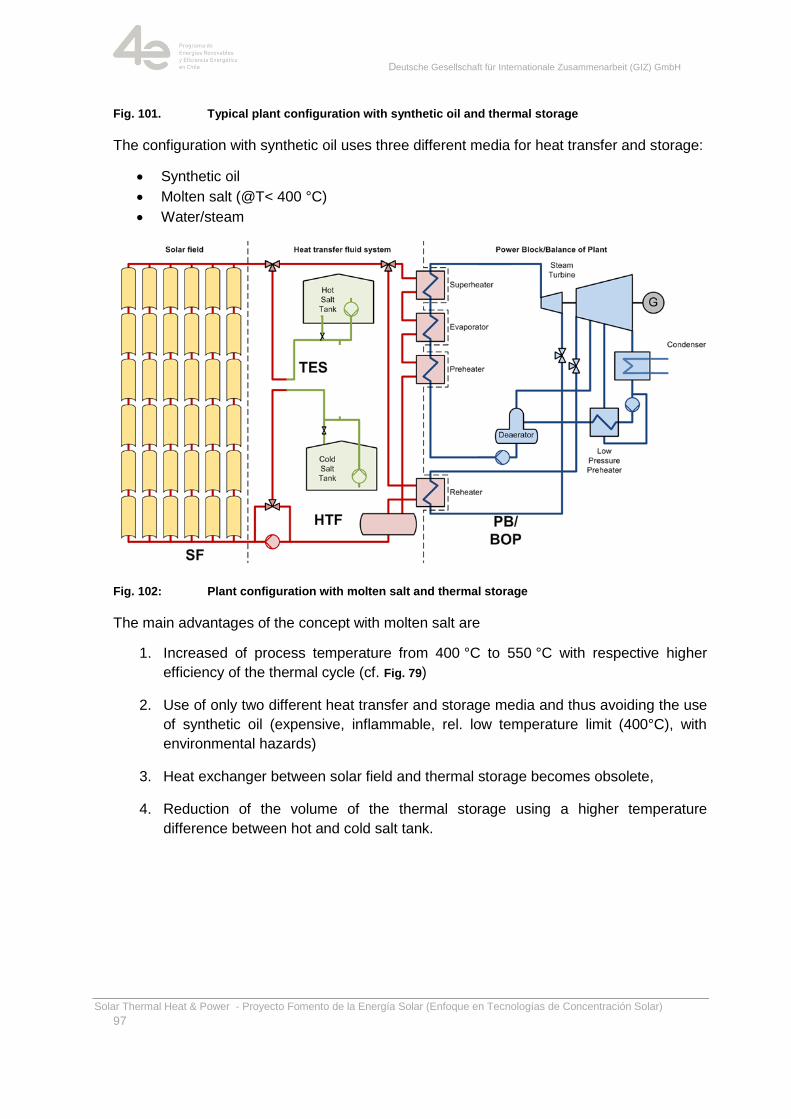
Deutsche Gesellschaft für Internationale Zusammenarbeit (GIZ) GmbH
Solar Thermal Heat & Power - Proyecto Fomento de la Energía Solar (Enfoque en Tecnologías de Concentración Solar)
97
Fig. 101. Typical plant configuration with synthetic oil and thermal storage
The configuration with synthetic oil uses three different media for heat transfer and storage:
Synthetic oil
Molten salt (@T< 400 °C)
Water/steam
Fig. 102: Plant configuration with molten salt and thermal storage
The main advantages of the concept with molten salt are
1. Increased of process temperature from 400 °C to 550 °C with respective higher
efficiency of the thermal cycle (cf. Fig. 79)
2. Use of only two different heat transfer and storage media and thus avoiding the use
of synthetic oil (expensive, inflammable, rel. low temperature limit (400°C), with
environmental hazards)
3. Heat exchanger between solar field and thermal storage becomes obsolete,
4. Reduction of the volume of the thermal storage using a higher temperature
difference between hot and cold salt tank.
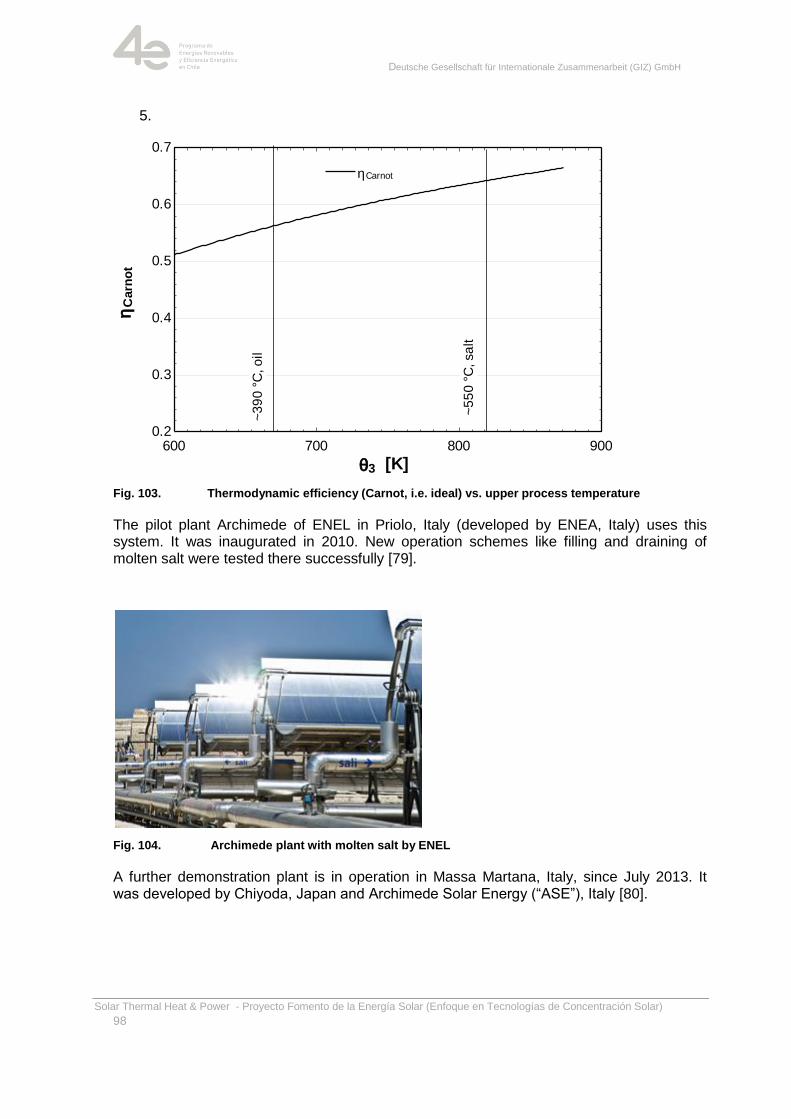
Deutsche Gesellschaft für Internationale Zusammenarbeit (GIZ) GmbH
Solar Thermal Heat & Power - Proyecto Fomento de la Energía Solar (Enfoque en Tecnologías de Concentración Solar)
98
5.
Fig. 103. Thermodynamic efficiency (Carnot, i.e. ideal) vs. upper process temperature
The pilot plant Archimede of ENEL in Priolo, Italy (developed by ENEA, Italy) uses this system. It was inaugurated in 2010. New operation schemes like filling and draining of molten salt were tested there successfully [79].
Fig. 104. Archimede plant with molten salt by ENEL
A further demonstration plant is in operation in Massa Martana, Italy, since July 2013. It was developed by Chiyoda, Japan and Archimede Solar Energy (―ASE‖), Italy [80].
600 700 800 9000.2
0.3
0.4
0.5
0.6
0.7
q3 [K]
hC
arn
ot
hCarnothCarnot
~3
90
°C
, o
il
~5
50
°C
, sa
lt
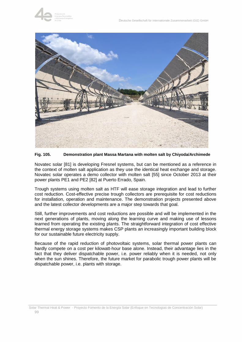
Deutsche Gesellschaft für Internationale Zusammenarbeit (GIZ) GmbH
Solar Thermal Heat & Power - Proyecto Fomento de la Energía Solar (Enfoque en Tecnologías de Concentración Solar)
99
Fig. 105. Demonstration plant Massa Martana with molten salt by Chiyoda/Archimede
Novatec solar [81] is developing Fresnel systems, but can be mentioned as a reference in the context of molten salt application as they use the identical heat exchange and storage. Novatec solar operates a demo collector with molten salt [55] since October 2013 at their power plants PE1 and PE2 [82] at Puerto Errado, Spain.
Trough systems using molten salt as HTF will ease storage integration and lead to further cost reduction. Cost-effective precise trough collectors are prerequisite for cost reductions for installation, operation and maintenance. The demonstration projects presented above and the latest collector developments are a major step towards that goal.
Still, further improvements and cost reductions are possible and will be implemented in the next generations of plants, moving along the learning curve and making use of lessons learned from operating the existing plants. The straightforward integration of cost effective thermal energy storage systems makes CSP plants an increasingly important building block for our sustainable future electricity supply.
Because of the rapid reduction of photovoltaic systems, solar thermal power plants can hardly compete on a cost per kilowatt-hour base alone. Instead, their advantage lies in the fact that they deliver dispatchable power, i.e. power reliably when it is needed, not only when the sun shines. Therefore, the future market for parabolic trough power plants will be dispatchable power, i.e. plants with storage.
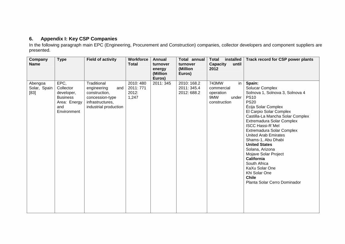
6. Appendix I: Key CSP Companies
In the following paragraph main EPC (Engineering, Procurement and Construction) companies, collector developers and component suppliers are presented.
Company Name
Type Field of activity Workforce Total
Annual turnover energy (Million Euros)
Total annual turnover (Million Euros)
Total installed Capacity until 2012
Track record for CSP power plants
Abengoa Solar, Spain [83]
EPC, Collector developer, Business Area: Energy and Environment
Traditional engineering and construction, concession-type infrastructures, industrial production
2010: 480 2011: 771 2012: 1,247
2011: 345 2010: 168.2 2011: 345.4 2012: 688.2
743MW in commercial operation 9MW under construction
Spain: Solucar Complex Solnova 1, Solnova 3, Solnova 4 PS10 PS20 Écija Solar Complex El Carpio Solar Complex Castilla-La Mancha Solar Complex Extremadura Solar Complex ISCC Hassi-R´Mel Extremadura Solar Complex United Arab Emirates Shams-1, Abu Dhabi United States Solana, Arizona Mojave Solar Project California South Africa KaXu Solar One Khi Solar One Chile Planta Solar Cerro Dominador
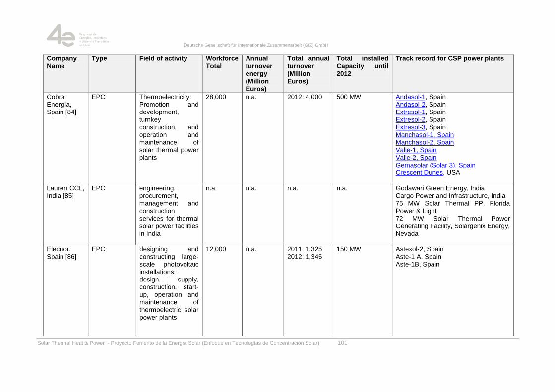
Deutsche Gesellschaft für Internationale Zusammenarbeit (GIZ) GmbH
Solar Thermal Heat & Power - Proyecto Fomento de la Energía Solar (Enfoque en Tecnologías de Concentración Solar) 101
Company Name
Type Field of activity Workforce Total
Annual turnover energy (Million Euros)
Total annual turnover (Million Euros)
Total installed Capacity until 2012
Track record for CSP power plants
Cobra Energía, Spain [84]
EPC Thermoelectricity: Promotion and development, turnkey construction, and operation and maintenance of solar thermal power plants
28,000 n.a. 2012: 4,000 500 MW Andasol-1, Spain Andasol-2, Spain Extresol-1, Spain Extresol-2, Spain Extresol-3, Spain Manchasol-1, Spain Manchasol-2, Spain Valle-1, Spain Valle-2, Spain Gemasolar (Solar 3). Spain Crescent Dunes, USA
Lauren CCL, India [85]
EPC engineering, procurement, management and construction services for thermal solar power facilities in India
n.a. n.a. n.a. n.a. Godawari Green Energy, India Cargo Power and Infrastructure, India 75 MW Solar Thermal PP, Florida Power & Light 72 MW Solar Thermal Power Generating Facility, Solargenix Energy, Nevada
Elecnor, Spain [86]
EPC designing and constructing large-scale photovoltaic installations; design, supply, construction, start-up, operation and maintenance of thermoelectric solar power plants
12,000
n.a. 2011: 1,325 2012: 1,345
150 MW Astexol-2, Spain Aste-1 A, Spain Aste-1B, Spain
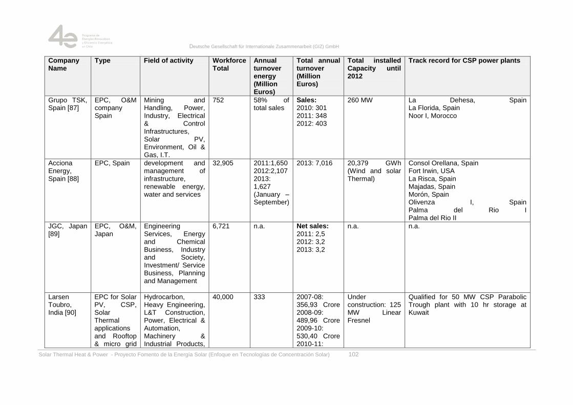
Deutsche Gesellschaft für Internationale Zusammenarbeit (GIZ) GmbH
Solar Thermal Heat & Power - Proyecto Fomento de la Energía Solar (Enfoque en Tecnologías de Concentración Solar) 102
Company Name
Type Field of activity Workforce Total
Annual turnover energy (Million Euros)
Total annual turnover (Million Euros)
Total installed Capacity until 2012
Track record for CSP power plants
Grupo TSK, Spain [87]
EPC, O&M company Spain
Mining and Handling, Power, Industry, Electrical & Control Infrastructures, Solar PV, Environment, Oil & Gas, I.T.
752 58% of total sales
Sales: 2010: 301 2011: 348 2012: 403
260 MW La Dehesa, Spain La Florida, Spain Noor I, Morocco
Acciona Energy, Spain [88]
EPC, Spain development and management of infrastructure, renewable energy, water and services
32,905 2011:1,650 2012:2,107 2013: 1,627 (January – September)
2013: 7,016 20,379 GWh (Wind and solar Thermal)
Consol Orellana, Spain Fort Irwin, USA La Risca, Spain Majadas, Spain Morón, Spain Olivenza I, Spain Palma del Rio I Palma del Rio II
JGC, Japan [89]
EPC, O&M, Japan
Engineering Services, Energy and Chemical Business, Industry and Society, Investment/ Service Business, Planning and Management
6,721 n.a. Net sales: 2011: 2,5 2012: 3,2 2013: 3,2
n.a. n.a.
Larsen Toubro, India [90]
EPC for Solar PV, CSP, Solar Thermal applications and Rooftop & micro grid
Hydrocarbon, Heavy Engineering, L&T Construction, Power, Electrical & Automation, Machinery & Industrial Products,
40,000 333 2007-08: 356,93 Crore 2008-09: 489,96 Crore 2009-10: 530,40 Crore 2010-11:
Under construction: 125 MW Linear Fresnel
Qualified for 50 MW CSP Parabolic Trough plant with 10 hr storage at Kuwait
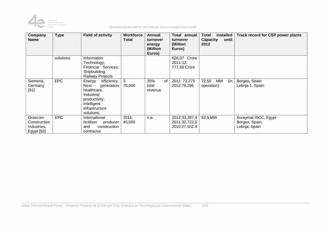
Deutsche Gesellschaft für Internationale Zusammenarbeit (GIZ) GmbH
Solar Thermal Heat & Power - Proyecto Fomento de la Energía Solar (Enfoque en Tecnologías de Concentración Solar) 103
Company Name
Type Field of activity Workforce Total
Annual turnover energy (Million Euros)
Total annual turnover (Million Euros)
Total installed Capacity until 2012
Track record for CSP power plants
solutions Information Technology, Financial Services, Shipbuilding, Railway Projects
628,07 Crore 2011-12: 777,58 Crore
Siemens, Germany [91]
EPC Energy efficiency, Next generation healthcare, Industrial productivity, Intelligent infrastructure solutions,
3 70,000
35% of total revenue
2011: 73,275 2012:78,296
72,50 MW (in operation)
Borges, Spain Lebrija 1, Spain
Orascom Construction Industries, Egypt [92]
EPC International fertilizer producer and construction contractor
2011: 45,000
n.a. 2012:33,287.4 2011:32,722.0 2010:27,552.4
92,5 MW Kuraymat ISCC, Egypt Borges, Spain, Lebrija, Spain
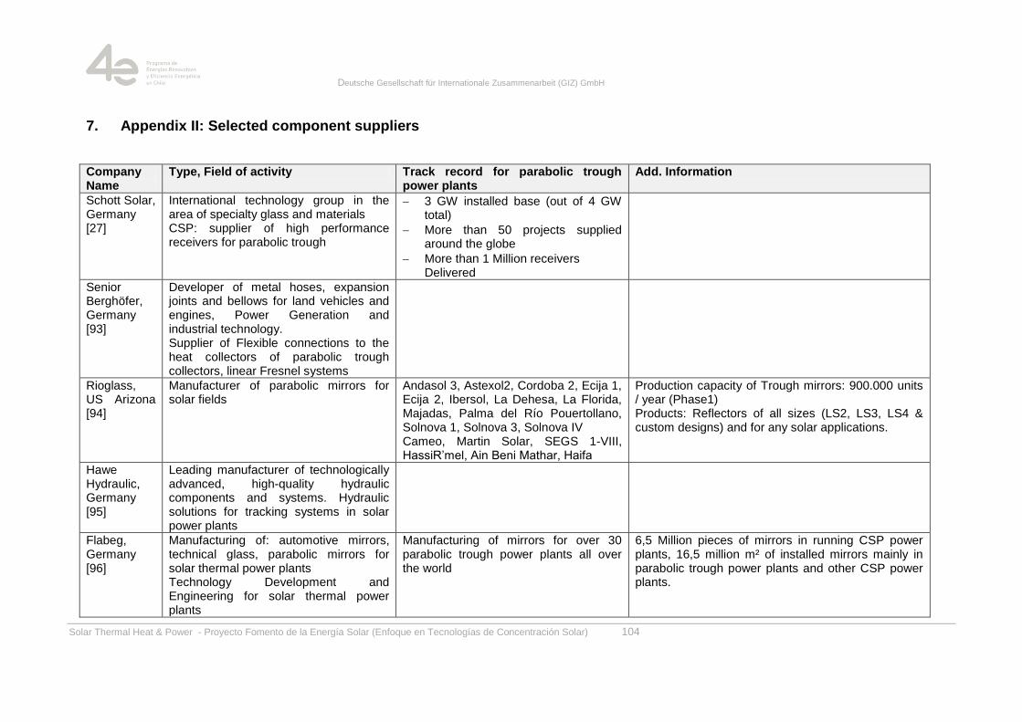
Deutsche Gesellschaft für Internationale Zusammenarbeit (GIZ) GmbH
Solar Thermal Heat & Power - Proyecto Fomento de la Energía Solar (Enfoque en Tecnologías de Concentración Solar) 104
7. Appendix II: Selected component suppliers
Company Name
Type, Field of activity Track record for parabolic trough power plants
Add. Information
Schott Solar, Germany [27]
International technology group in the area of specialty glass and materials CSP: supplier of high performance receivers for parabolic trough
3 GW installed base (out of 4 GW total)
More than 50 projects supplied around the globe
More than 1 Million receivers Delivered
Senior Berghöfer, Germany [93]
Developer of metal hoses, expansion joints and bellows for land vehicles and engines, Power Generation and industrial technology. Supplier of Flexible connections to the heat collectors of parabolic trough collectors, linear Fresnel systems
Rioglass, US Arizona [94]
Manufacturer of parabolic mirrors for solar fields
Andasol 3, Astexol2, Cordoba 2, Ecija 1, Ecija 2, Ibersol, La Dehesa, La Florida, Majadas, Palma del Río Pouertollano, Solnova 1, Solnova 3, Solnova IV Cameo, Martin Solar, SEGS 1-VIII, HassiR‘mel, Ain Beni Mathar, Haifa
Production capacity of Trough mirrors: 900.000 units / year (Phase1) Products: Reflectors of all sizes (LS2, LS3, LS4 & custom designs) and for any solar applications.
Hawe Hydraulic, Germany [95]
Leading manufacturer of technologically advanced, high-quality hydraulic components and systems. Hydraulic solutions for tracking systems in solar power plants
Flabeg, Germany [96]
Manufacturing of: automotive mirrors, technical glass, parabolic mirrors for solar thermal power plants Technology Development and Engineering for solar thermal power plants
Manufacturing of mirrors for over 30 parabolic trough power plants all over the world
6,5 Million pieces of mirrors in running CSP power plants, 16,5 million m² of installed mirrors mainly in parabolic trough power plants and other CSP power plants.
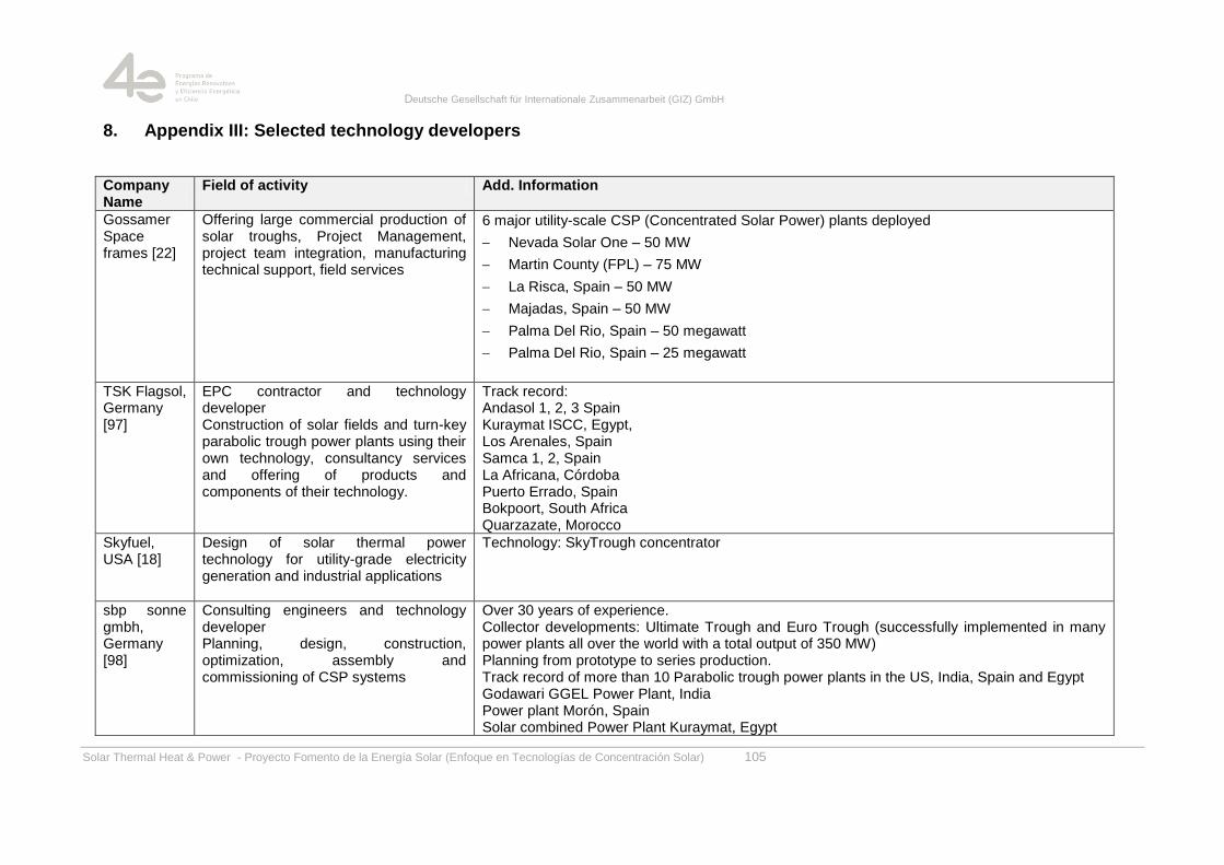
Deutsche Gesellschaft für Internationale Zusammenarbeit (GIZ) GmbH
Solar Thermal Heat & Power - Proyecto Fomento de la Energía Solar (Enfoque en Tecnologías de Concentración Solar) 105
8. Appendix III: Selected technology developers
Company Name
Field of activity Add. Information
Gossamer Space frames [22]
Offering large commercial production of solar troughs, Project Management, project team integration, manufacturing technical support, field services
6 major utility-scale CSP (Concentrated Solar Power) plants deployed
Nevada Solar One – 50 MW
Martin County (FPL) – 75 MW
La Risca, Spain – 50 MW
Majadas, Spain – 50 MW
Palma Del Rio, Spain – 50 megawatt
Palma Del Rio, Spain – 25 megawatt
TSK Flagsol, Germany [97]
EPC contractor and technology developer Construction of solar fields and turn-key parabolic trough power plants using their own technology, consultancy services and offering of products and components of their technology.
Track record: Andasol 1, 2, 3 Spain Kuraymat ISCC, Egypt, Los Arenales, Spain Samca 1, 2, Spain La Africana, Córdoba Puerto Errado, Spain Bokpoort, South Africa Quarzazate, Morocco
Skyfuel, USA [18]
Design of solar thermal power technology for utility-grade electricity generation and industrial applications
Technology: SkyTrough concentrator
sbp sonne gmbh, Germany [98]
Consulting engineers and technology developer Planning, design, construction, optimization, assembly and commissioning of CSP systems
Over 30 years of experience. Collector developments: Ultimate Trough and Euro Trough (successfully implemented in many power plants all over the world with a total output of 350 MW) Planning from prototype to series production. Track record of more than 10 Parabolic trough power plants in the US, India, Spain and Egypt Godawari GGEL Power Plant, India Power plant Morón, Spain Solar combined Power Plant Kuraymat, Egypt
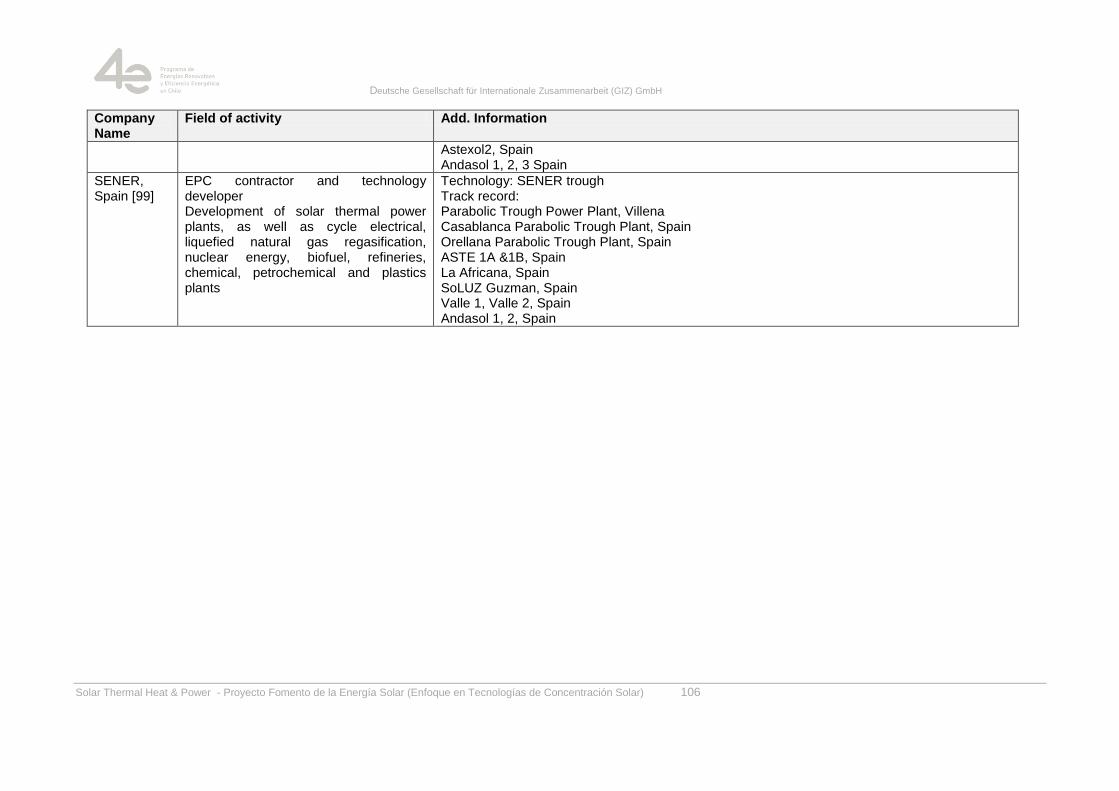
Deutsche Gesellschaft für Internationale Zusammenarbeit (GIZ) GmbH
Solar Thermal Heat & Power - Proyecto Fomento de la Energía Solar (Enfoque en Tecnologías de Concentración Solar) 106
Company Name
Field of activity Add. Information
Astexol2, Spain Andasol 1, 2, 3 Spain
SENER, Spain [99]
EPC contractor and technology developer Development of solar thermal power plants, as well as cycle electrical, liquefied natural gas regasification, nuclear energy, biofuel, refineries, chemical, petrochemical and plastics plants
Technology: SENER trough Track record: Parabolic Trough Power Plant, Villena Casablanca Parabolic Trough Plant, Spain Orellana Parabolic Trough Plant, Spain ASTE 1A &1B, Spain La Africana, Spain SoLUZ Guzman, Spain Valle 1, Valle 2, Spain Andasol 1, 2, Spain
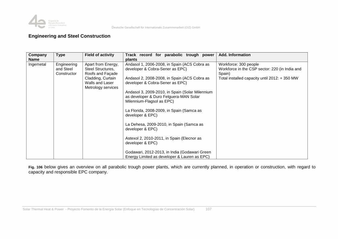
Deutsche Gesellschaft für Internationale Zusammenarbeit (GIZ) GmbH
Solar Thermal Heat & Power - Proyecto Fomento de la Energía Solar (Enfoque en Tecnologías de Concentración Solar) 107
Engineering and Steel Construction
Company Name
Type Field of activity Track record for parabolic trough power plants
Add. Information
Ingemetal Engineering and Steel Constructor
Apart from Energy, Steel Structures, Roofs and Façade Cladding, Curtain Walls and Laser Metrology services
Andasol 1, 2006-2008, in Spain (ACS Cobra as developer & Cobra-Sener as EPC) Andasol 2, 2008-2008, in Spain (ACS Cobra as developer & Cobra-Sener as EPC) Andasol 3, 2009-2010, in Spain (Solar Milennium as developer & Duro Felguera-MAN Solar Milennium-Flagsol as EPC) La Florida, 2008-2009, in Spain (Samca as developer & EPC) La Dehesa, 2009-2010, in Spain (Samca as developer & EPC) Astexol 2, 2010-2011, in Spain (Elecnor as developer & EPC) Godawari, 2012-2013, in India (Godawari Green Energy Limited as developer & Lauren as EPC)
Workforce: 300 people Workforce in the CSP sector: 220 (in India and Spain) Total installed capacity until 2012: + 350 MW
Fig. 106 below gives an overview on all parabolic trough power plants, which are currently planned, in operation or construction, with regard to capacity and responsible EPC company.
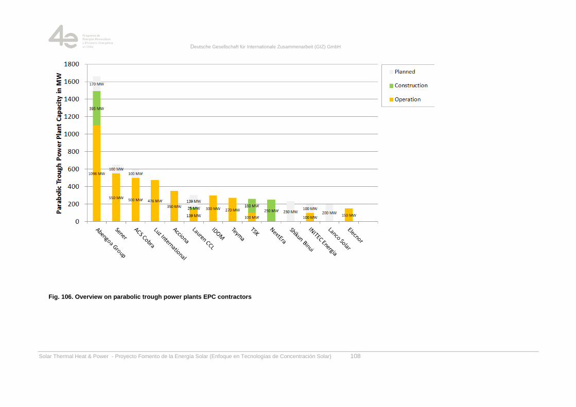
Deutsche Gesellschaft für Internationale Zusammenarbeit (GIZ) GmbH
Solar Thermal Heat & Power - Proyecto Fomento de la Energía Solar (Enfoque en Tecnologías de Concentración Solar) 108
Fig. 106. Overview on parabolic trough power plants EPC contractors
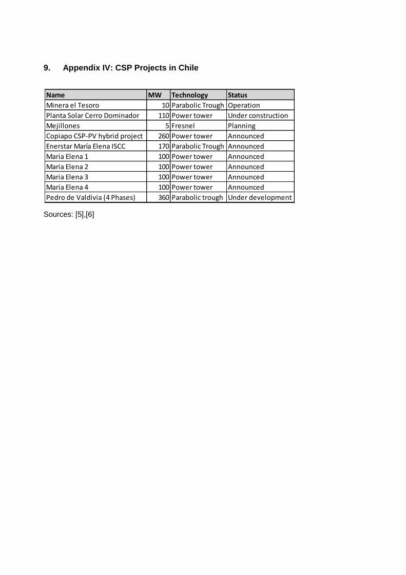
9. Appendix IV: CSP Projects in Chile
Sources: [5],[6]
Name MW Technology Status
Minera el Tesoro 10 Parabolic Trough Operation
Planta Solar Cerro Dominador 110 Power tower Under construction
Mejillones 5 Fresnel Planning
Copiapo CSP-PV hybrid project 260 Power tower Announced
Enerstar María Elena ISCC 170 Parabolic Trough Announced
Maria Elena 1 100 Power tower Announced
Maria Elena 2 100 Power tower Announced
Maria Elena 3 100 Power tower Announced
Maria Elena 4 100 Power tower Announced
Pedro de Valdivia (4 Phases) 360 Parabolic trough Under development
Deutsche Gesellschaft für Internationale Zusammenarbeit (GIZ) GmbH
Solar Thermal Heat & Power - Proyecto Fomento de la Energía Solar (Enfoque en Tecnologías de Concentración Solar) 110
10. Bibliography
[1] A. Fernandez-García, E. Zarza, L. Valenzuela, and M. Pérez, ―Parabolic-trough solar
collectors and their applications,‖ Elsevier, Paper, Mar. 2010.
[2] M. Günter, M. Joemann, and S. Csambor, ―Advanced CSP Teaching Materials,‖
enerMENA; Deutsches Zentrum für Luft- und Raumfahrt e.V.
[3] ―Parabolic Trough Collector Overview - kearney_collector_technology.pdf.‖ .
[4] W. Schiel, A. Schweitzer, O. Kracht, and B. Hunt, ―Collector Development for Parabolic
Trough Power Plants at Schlaich Bergermann und Partner,‖ presented at the SolarPACES
Symposium 2006, Seville, Spain, 2006.
[5] ―Projects Tracker Overview | CSP Today.‖ [Online]. Available:
http://social.csptoday.com/tracker/projects/table. [Accessed: 16-Dec-2013].
[6] ―SolarPACES Home Page.‖ [Online]. Available:
http://www.solarpaces.org/Tasks/Task1/nevada_solar_one.htm. [Accessed: 17-Dec-2013].
[7] sbp sonne gmbh, Sun / Sonne, Schlaich bergermann und partner. Stuttgart, Germany: sbp
sonne gmbh, 2012.
[8] ―Airlight SA.‖ [Online]. Available: http://www.airlight.biz/. [Accessed: 16-Dec-2013].
[9] ―Solarlite GmbH - Parabolic Trough Power Plants.‖ [Online]. Available:
http://www.solarlite.de/en/. [Accessed: 16-Dec-2013].
[10] ―toughTrough: Home.‖ [Online]. Available:
http://www.toughtrough.com/index.php?id=home. [Accessed: 16-Dec-2013].
[11] M. Kaltschmitt, A. Wiese, and W. Streicher, Renewable Energy: Technological
Foundations, Economical and Environmental Aspects, 1st ed. Springer, Berlin, 2007.
[12] ―NREL Image Gallery : Folder - Thermal.‖ [Online]. Available:
http://images.nrel.gov/albums.php?albumId=207407&page=3. [Accessed: 16-Dec-2013].
[13] W. Schiel, ―Kollektorentwicklung für solare Parabolrinnenkraftwerke,‖ Ernst & Sohn, Berlin,
Bautechnik 89, Heft 3, 2012.
[14] ―ENEA Activities on CSP Technologies - maccari_enea_trough_activities.pdf.‖ .
[15] ―HelioTrough® Home.‖ [Online]. Available: http://www.heliotrough.com/. [Accessed: 16-
Dec-2013].
[16] J. Kötter, S. Decker, R. Detzler, J. Schäfer, M. Schmitz, and U. Herrmann, ―Cost Reduction
of Solar fields with HelioTrough Collector,‖ in SolarPACES 2012, Marrakesh, 2012.
Deutsche Gesellschaft für Internationale Zusammenarbeit (GIZ) GmbH
Solar Thermal Heat & Power - Proyecto Fomento de la Energía Solar (Enfoque en Tecnologías de Concentración Solar) 111
[17] K.-J. Riffelmann, T. Richert, P. Nava, and A. Schweitzer, ―Ultimate Trough® – A Significant
Step Towards Cost Competitive CSP,‖ in SolarPACES 2013, Las Vegas, NV, USA, 2013.
[18] ―SkyFuel Inc: / OUR PRODUCTS / SKYTROUGH.‖ [Online]. Available:
http://www.skyfuel.com/#/OUR%20PRODUCTS/SKYTROUGH/. [Accessed: 06-Dec-2013].
[19] ―SkyTroughFactsheet.pdf.‖ .
[20] ―LAT 73 FAQs : Solar Energy - 3M Renewable Energy.‖ [Online]. Available:
http://solutions.3m.com/wps/portal/3M/en_US/Renewable/Energy/Product/Large-Aperture-
Trough-73/FAQs/. [Accessed: 17-Dec-2013].
[21] ―3M and Gossamer Space Frames to Inaugurate World‘s Largest Aperture Parabolic
Trough Installation- A New Benchmark in Solar Collectors | 3M Newsroom | United States.‖
[Online]. Available: http://news.3m.com/press-release/company/3m-and-gossamer-space-
frames-inaugurate-worlds-largest-aperture-parabolic-trou. [Accessed: 17-Dec-2013].
[22] ―Gossamer Innovations | The most credible name in solar.‖ [Online]. Available:
http://www.gossamersf.com/solar-power-products.htm. [Accessed: 03-Dec-2013].
[23] H. Price, ―A New Generation of Parabolic Trough Technology,‖ presented at the SunShot
CSP Program Review 2013, Phoenix, AZ, Apr-2013.
[24] ―CSP « AIRLIGHT ENERGY.‖ [Online]. Available: http://www.airlightenergy.com/csp.
[Accessed: 16-Dec-2013].
[25] ―System Advisor Model (SAM) |,‖ NREL System Advisor Model (SAM). [Online]. Available:
https://sam.nrel.gov/. [Accessed: 07-May-2013].
[26] ―PowerFromTheSun.net.‖ [Online]. Available: http://www.powerfromthesun.net/.
[Accessed: 17-Dec-2013].
[27] ―SCHOTT PTR®70 Receiver | SCHOTT AG.‖ [Online]. Available:
http://www.schott.com/csp/german/schott-solar-ptr-70-receivers.html. [Accessed: 17-Dec-
2013].
[28] G. Weinrebe, Z. Abul-Ella, and W. Schiel, ―On the Influence of Parabolic Trough Collector
Stiffness and Length on Performance,‖ presented at the SolarPACES 2011, Granada,
Spain, 2011.
[29] F. von Reeken, G. Weinrebe, and M. Balz, ―Extended Rabl-Method to asses the optical
quality of parabolic trough collectors,‖ presented at the SolarPACES, 2012.
[30] ―SF_OnSun_brochure_e-version_091004 - OnSunBrochure.pdf.‖ .
[31] ―DW_OnSun_Success_Story.pdf.‖ .
[32] ―BINE Informationsdienst: Themeninfo: Solarthermische Kraftwerke - Parabolrinnen-
Kollektortechnik.‖ [Online]. Available: http://www.bine.info/themen/erneuerbare-
Deutsche Gesellschaft für Internationale Zusammenarbeit (GIZ) GmbH
Solar Thermal Heat & Power - Proyecto Fomento de la Energía Solar (Enfoque en Tecnologías de Concentración Solar) 112
energien/solare-waerme/publikation/solarthermische-kraftwerke-2/parabolrinnen-
kollektortechnik/. [Accessed: 18-Dec-2013].
[33] ―http://www.heliotrough.com/facts.html.‖
[34] A. Schweitzer, W. Schiel, M. Birkle, P. Nava, K.-J. Riffelmann, A. Wohlfahrt, and G.
Kuhlmann, ―ULTIMATE TROUGH® - Fabrication, Erection And Commissioning Of The
World‘s largest parabolic trough Collector,‖ in SolarPACES 2013, Las Vegas, NV, USA,
2013.
[35] A. Schweitzer, W. Schiel, Z. Abul-Ella, P. Nava, K.-J. Riffelmann, A. Wohlfahrt, and G.
Kuhlmann, ―Ultimate Trough® – The Next Generation Collector for Parabolic Trough
Power Plants,‖ in SolarPACES 2011, Granada, Spain, 2011.
[36] ―ReflecTech®PLUS Mirror Film - Home.‖ [Online]. Available:
http://www.reflectechsolar.com/. [Accessed: 08-Oct-2014].
[37] W. Weiss, ―Solar Heat for Industrial Processes,‖ Stellenbosch, ZA.
[38] ―IEA SHC || TASK 33.‖ [Online]. Available: http://task33.iea-shc.org/. [Accessed: 01-Oct-
2014].
[39] R. Roberto and ásquez Joaquín, ―Solar Cogeneration: Integration between Energy and
Mining,‖ presented at the ISES Webinar, ISES.
[40] ―Solar Energy Perspectives,‖ International Energy Agency, Paris, France, 978-92-64-
12457-8, 2011.
[41] N. Lang, B. Loeser, and C. Nettesheim, ―Winning the Localization Game,‖ Boston
Consulting Group, Boiston, MA, USA, Jan. 2008.
[42] L. M. Johri and P. Petison, ―Value-based localization strategies of automobile subsidiaries
in Thailand,‖ Int. J. Emerg. Mark., vol. 3, no. 2, pp. 140–162, 2008.
[43] ―German Climate Technology Initiative: Concentrated Solar Power in Brazil.‖ [Online].
Available: http://www.giz.de/en/worldwide/19604.html. [Accessed: 26-Sep-2014].
[44] P. Cordeiro, ―Brazil,‖ SolarPACES, Albuquerque, NM, SolarPACES START Mission, Dec.
2004.
[45] NREL, ―NREL: System Advisor Model (SAM),‖ 11-Oct-2011. [Online]. Available:
https://www.nrel.gov/analysis/sam/. [Accessed: 11-Oct-2011].
[46] ―Ministerio de Energía.‖ [Online]. Available:
http://antiguo.minenergia.cl/minwww/opencms/03_Energias/Otros_Niveles/renovables_noc
onvencionales/Tipos_Energia/crucero/. [Accessed: 30-Sep-2014].
Deutsche Gesellschaft für Internationale Zusammenarbeit (GIZ) GmbH
Solar Thermal Heat & Power - Proyecto Fomento de la Energía Solar (Enfoque en Tecnologías de Concentración Solar) 113
[47] ―SolarGIS-Solar-map-DNI-Latin-America-en.png (PNG Image, 730 × 900 pixels) - Scaled
(69%).‖ [Online]. Available: http://solargis.info/doc/_pics/freemaps/1000px/dni/SolarGIS-
Solar-map-DNI-Latin-America-en.png. [Accessed: 29-Sep-2014].
[48] U.S. Department of Energy, ―Concentrating Solar Power Commercial Application Study:
Reducing Water Consumption of Concentrating Solar Power Electricity Generation -
Report to Congress,‖ U.S. Department of Energy, 2009.
[49] H. D. Baehr and S. Kabelac, Thermodynamik. Grundlagen und technische Anwendungen,
13., neu bearb. u. erw. A. Springer, Berlin, 2006.
[50] ―CDEC-SING - Inicio.‖ [Online]. Available: http://cdec2.cdec-
sing.cl/pls/portal/cdec.pck_web_cdec_pages.pagina?p_id=1. [Accessed: 26-Sep-2014].
[51] GE Power & Water, ―Boiler Blowdown Control,‖ Boiler Blowdown Control, 26-Mar-2012.
[Online]. Available:
http://www.gewater.com/handbook/boiler_water_systems/ch_13_blowdowncontrol.jsp.
[Accessed: 26-Mar-2012].
[52] Midwest Research Institute, ―Cooling for Parabolic Trough Power Plants,‖ presented at the
Parabolic Trough Workshop, Incline Village, Nevada, 14-Feb-2006.
[53] J. Dersch and C. Richter, ―Wasserverbrauch und Wassereinsparung bei solarthermischen
Kraftwerken,‖ presented at the Kölner Sonnenkolloquium, DLR, Köln, 29-Jun-2010.
[54] Turchi, M. Wagner, and C. Kutcher, ―Water Use in Parabolic Trough Power Plants:
Summary Results from WorleyParsons‘ Analyses,‖ NREL, Golden, Colorado, USA,
NREL/TP-5500-49468, Dec. 2010.
[55] ―NOVATEC SOLAR.‖ [Online]. Available: http://www.novatecsolar.com/121-1-DMS-Demo-
E.html. [Accessed: 01-Oct-2014].
[56] ―duraGLARE - FLABEG - Leading Glass Technology.‖ [Online]. Available:
http://www.flabeg.com/_flabegcom/en/solar/duraglare.html. [Accessed: 04-Dec-2013].
[57] ―Roofmaster Light greenhouse roof cleaner - Besseling & ALL Techniek.‖ [Online].
Available: http://www.roofmaster-light.com/?lang=en. [Accessed: 29-Jul-2014].
[58] ―SOLARBRUSH - ROBOTS FOR CLEANER SOLAR ENERGY - The the world‘s first robot
for cleaning of solar panels and mirrors by SOLARBRUSH.‖ [Online]. Available:
http://www.solarbrush.co/home. [Accessed: 29-Jul-2014].
[59] USGS, ―Chile,‖ Chile - Seismic Hazard Map. [Online]. Available:
http://earthquake.usgs.gov/earthquakes/world/chile/gshap.php. [Accessed: 01-Oct-2014].
[60] ―Chile‘s Atacama desert is hit by SNOW - and now there are fears it could FLOOD | Daily
Mail Online.‖ [Online]. Available: http://www.dailymail.co.uk/news/article-2403754/Chiles-
Atacama-desert-hit-SNOW--fears-FLOOD.html. [Accessed: 02-Oct-2014].
Deutsche Gesellschaft für Internationale Zusammenarbeit (GIZ) GmbH
Solar Thermal Heat & Power - Proyecto Fomento de la Energía Solar (Enfoque en Tecnologías de Concentración Solar) 114
[61] ―Die Homepage von Gerhard Weinrebe - Reisen mit und ohne Motorrad: Chile, Tunesien,
Marokko, Baltikum.‖ [Online]. Available: http://www.solargary.de/. [Accessed: 02-Oct-
2014].
[62] J. Hayward, ―Projections of the future costs of electricity generation technologies - An
application of CSIRO‘s Global and Local Learning Model (GALLM),‖ CSIRO, Newcastle
NSW 2300, EP104982, 2011.
[63] ―Masdar will not stop at Shams 1 | CSP Today.‖ [Online]. Available:
http://social.csptoday.com/emerging-markets/masdar-will-not-stop-shams-1. [Accessed:
03-Dec-2013].
[64] M. Lotker, ―Barriers to Commercialization of Large-Scale Solar Electricity: Lessons
Learned from the LUZ Experience,‖ Sandia National Laboratories, SAND91-7014, Nov.
1991.
[65] ―Solar Eclipsed.‖ [Online]. Available:
http://www.multinationalmonitor.org/hyper/issues/1992/04/mm0492_07.html. [Accessed:
03-Dec-2013].
[66] NREL, ―NREL: Concentrating Solar Power Projects - Andasol-1,‖ 17-Jan-2012. [Online].
Available: http://www.nrel.gov/csp/solarpaces/project_detail.cfm/projectID=3. [Accessed:
17-Jan-2012].
[67] U. Herrmann, M. Geyer, and R. Kistner, ―The AndaSol Project,‖ presented at the
Workshop on Thermal Storage for Trough Systems, 20-Feb-2002.
[68] W. Schiel, ―Planung und Bau des weltgrößten Solarkraftwerks in Spanien,‖ VBI -
Beratende Ingenieure Fachmag. Für Plan. Bau., no. Mai/Juni 2007, pp. 20–25, Jun. 2007.
[69] K.-J. Riffelmann, J. Kötter, P. Nava, F. Meuser, G. Weinrebe, W. Schiel, G. Kuhlmann, A.
Wohlfahrt, A. Nady, and R. Dracker, ―HELIOTROUGH – A NEW COLLECTOR
GENERATION FOR PARABOLIC TROUGH POWER PLANTS,‖ presented at the
SolarPACES 2009, Berlin, 2009.
[70] G. Weinrebe, ―Molten Salt for Parabolic Trough Applications: System Simulation and
Comparison with a Power Tower,‖ presented at the SolarPACES Annual Conference 2013,
Las Vegas, NV, USA, 20-Sep-2013.
[71] ―Helios News.‖ .
[72] R. Dracker and K.-J. Riffelmann, ―Integrated Thermal Storage for Concentrating Solar
Power,‖ Jul. 2008.
[73] F. Verdier, ―MENA Regional Water Outlook - Part II Desalination Using Renewable
Energy,‖ Fichtner, Stuttgart, Germany, Final Report 6543P07/FICHT-7109954-v2, Mar.
2011.
Deutsche Gesellschaft für Internationale Zusammenarbeit (GIZ) GmbH
Solar Thermal Heat & Power - Proyecto Fomento de la Energía Solar (Enfoque en Tecnologías de Concentración Solar) 115
[74] W. Goldstern, Steam Storage Installation. Oxford: Pergamon Press, 1970.
[75] W.-D. Steinmann and M. Eck, ―Buffer storage for direct steam generation,‖ pp. 1277–1282,
2006.
[76] ―Renewable Energy Focus - CSP: Developments in heat transfer and storage materials,‖
19-Jan-2012. [Online]. Available: http://www.renewableenergyfocus.com/view/17095/csp-
developments-in-heat-transfer-and-storage-materials/. [Accessed: 19-Jan-2012].
[77] R. Tamme, ―TES for Process Heat and Power Generation,‖ presented at the Material
Development for Thermal Energy Storage, Bad Tölz, Germany, 04-Jun-2008.
[78] EASAC, ―Concentrating solar power: its potential contribution to a sustainable energy
future,‖ European Academies Science Advisory Board, Halle (Saale), Germany, EASAC
policy report ISBN: 978-3-8047-2944-5, Nov. 2011.
[79] ―Archimede - Thermodynamic solar - Renewable sources - Innovation - Enel.com.‖
[Online]. Available: http://www.enel.com/en-
GB/innovation/renewable_sources_development/concentrated_solar_power/archimede/.
[Accessed: 01-Oct-2014].
[80] ―Concentrating Solar Power Plant (CSP) | Technology | CHIYODA CORPORATION.‖
[Online]. Available: http://www.chiyoda-
corp.com/technology/en/green_energy/solar_energy.html. [Accessed: 01-Oct-2014].
[81] Novatec Solar, ―NOVA-1 Turnkey solar boiler, mass produced in industrial precision - with
performance guarantee.‖ Novatec Solar, Karlsruhe, Germany, May-2011.
[82] NREL, ―NREL: Concentrating Solar Power Projects - Puerto Errado 2 Thermosolar Power
Plant,‖ 2012. [Online]. Available:
http://www.nrel.gov/csp/solarpaces/project_detail.cfm/projectID=159. [Accessed: 19-Jan-
2012].
[83] ―Abengoa Solar :: About us :: Annual report.‖ [Online]. Available:
http://www.abengoasolar.com/web/en/acerca_de_nosotros/informe_anual/. [Accessed: 18-
Dec-2013].
[84] ―Grupo Cobra - Bienvenido.‖ [Online]. Available: http://www.grupocobra.com/. [Accessed:
18-Dec-2013].
[85] ―Lauren Bharat - Solar Power Experts.‖ [Online]. Available:
http://www.laurenccl.com/projects.htm. [Accessed: 18-Dec-2013].
[86] ―Elecnor | 2012 Annual Report.‖ [Online]. Available:
http://memoria2012.elecnor.com/eng/index.php. [Accessed: 18-Dec-2013].
[87] ―Key figures.‖ [Online]. Available: http://en.grupotsk.com/p/leading-business-figures.
[Accessed: 17-Dec-2013].
Deutsche Gesellschaft für Internationale Zusammenarbeit (GIZ) GmbH
Solar Thermal Heat & Power - Proyecto Fomento de la Energía Solar (Enfoque en Tecnologías de Concentración Solar) 116
[88] ―ACCIONA - Annual Report 2012.‖ [Online]. Available:
http://annualreport2012.acciona.com/. [Accessed: 18-Dec-2013].
[89] ―About JGC|JGC CORPORATION.‖ [Online]. Available:
http://www.jgc.co.jp/en/corporate/index.html. [Accessed: 18-Dec-2013].
[90] ―L&T: Company Overview.‖ [Online]. Available:
http://www.larsentoubro.com/lntcorporate/common/ui_templates/HtmlContainer.aspx?res=
P_CORP_AABT_ACOM_AOVR. [Accessed: 18-Dec-2013].
[91] ―Siemens Annual Report 2013.‖ [Online]. Available:
http://www.siemens.com/annual/13/en/index/. [Accessed: 18-Dec-2013].
[92] ―Orascom Construction Industries - The group.‖ [Online]. Available:
http://www.orascomci.com/index.php?id=thegroup2. [Accessed: 18-Dec-2013].
[93] ―Senior Flexonics GmbH: Startseite.‖ [Online]. Available: http://www.seniorflexonics.de/.
[Accessed: 17-Dec-2013].
[94] ―Rioglass Solar: Rioglass Solar · Fabricante de espejos parabólicos para plantas
termosolares.‖ [Online]. Available:
http://www.rioglassolar.com/v_portal/apartados/apartado.asp. [Accessed: 18-Dec-2013].
[95] ―HAWE Hydraulik SE :: Home.‖ [Online]. Available: http://www.hawe.de/de/home/.
[Accessed: 18-Dec-2013].
[96] ―Solar - FLABEG - Leading Glass Technology.‖ [Online]. Available:
http://www.flabeg.com/solar.html. [Accessed: 18-Dec-2013].
[97] ―Company - TSK Flagsol.‖ [Online]. Available: http://www.flagsol.com/flagsol/cms/.
[Accessed: 18-Dec-2013].
[98] ―schlaich bergermann und partner.‖ [Online]. Available: http://www.sbp.de/de#sun/index.
[Accessed: 18-Dec-2013].
[99] ―SENER - SENER Ingeniería y Construcción.‖ [Online]. Available:
http://www.sener.es/inicio/es. [Accessed: 18-Dec-2013].