dcs thyristor power converter for dc drive systems 20 to
TRANSCRIPT

II K 1-1
DCS Thyristor power converterfor DC drive systems
20 to 1000 A9 to 522 kW
ManualDCS 400

II K 1-2
List of contents
MANUAL1 DCS 400 - the compact-size DC drive ........ II K 1-3
2 System overview of DCS 400 .................... II K 2-12.1 Environmental conditions ............................................. II K 2-22.2 DCS 400 power converter modules ............................ II K 2-32.3 DCS 400 overload withstand capability ...................... II K 2-42.4 Control and Display Units of the DCS 400 ................. II K 2-5
3 Technical Data ............................................ II K 3-13.1 Module Dimensions ....................................................... II K 3-13.2 Cross-sectional areas - Tightening torques .................. II K 3-33.3 Power losses ................................................................. II K 3-53.4 Power section cooling ................................................... II K 3-63.5 Control board SDCS-CON-3A ...................................... II K 3-73.6 Power interface board SDCS-PIN-3A ........................... II K 3-93.7 Field exciter SDCS-FIS-3A ......................................... II K 3-103.8 Circuit diagrams .......................................................... II K 3-12
4 Overview of software .................................. II K 4-14.1 General inormation about application Macros .............. II K 4-24.2 Application Macros ........................................................ II K 4-44.3 Digital and analogue Inputs/Outputs ........................... II K 4-224.4 Drive Logic .................................................................. II K 4-244.5 Regulator functions ..................................................... II K 4-274.6 Software Structure ...................................................... II K 4-424.7 Parameter list .............................................................. II K 4-44
5 Installation ................................................... II K 5-15.1 Safety instructions ......................................................... II K 5-25.2 EMC Compliant Installation and Configuration for PDS II K 5-45.3 Connection Examples ................................................. II K 5-17
6 Operating Instructions ............................... II K 6-16.1 Panel ............................................................................. II K 6-26.2 Guided Commissioning ................................................. II K 6-76.3 Useful hints for commissioning ................................... II K 6-206.4 Troubleshooting .......................................................... II K 6-24
7 Serial interfaces .......................................... II K 7-17.1 Panel-port ...................................................................... II K 7-67.2 RS232-port .................................................................... II K 7-77.3 Fieldbus interface .......................................................... II K 7-8
AppendixA Accessories ....................................................................... II K A-1
Line chokes ................................................................... II K A-1Fuses ............................................................................. II K A-5EMC filter ....................................................................... II K A-7
B Declaration of conformity .................................................. II K B-1C Quick Installation & Commissioning guide ....................... II K C-1D Examples for basic parameter programming ................... II K D-1
Index II K I-1
This manual is valid for DCS 400 Rev A including software version 108.0
Instructions for software II K E-1

II K 1-3
1 DCS 400 - the compact-size DC drive
DCS 400 is a new generation of DC drives, whichis rated from 9 to 522 KW and for use on all linesupply voltages from 230 to 500 V.
was the brief given to the drive`sdesigners. The result is a DC drive that meets theneeds of machine builders. It is:
I as easy to handle as an analogue drive but withall the advantages of a digital drive
I easy to design into machine equipment, beingcompact and having just the right number offeatures
I easy to install and set up
The DCS 400 is an innovative design, using thelatest semiconductor technology together withan advanced software which helps to reducemaintenance, increase product reliability andenables extremely rapid commissioning.
The DCS 400's small size brings substantial spacesavings to machine builders, allowing them to
integrate more accessories within the same space.The compact design has been partly achieved bya fully integrated field exciter, which includes thefield fuse and choke.
Based on new IGBT technology used for the fieldexciter, there is no need for a field voltageadaptation transformer to match the line supplyvoltage with that of the motor.
The commissioning wizard -available on the con-trol panel and the PC tool - makes start up of thedrive extremely easy, by simply guiding the userthrough the start up procedure.
In addition, the DCS 400 contains applicationmacros. By selecting a macro from a menu, theuser can pre-select the software structure andthe I/O connection, thus saving time and elimi-nating any errors.
The DCS 400 carries the CE Mark and is designedand produced according to the quality standardISO 9001.

II K 1-4
Activation and operator-control
analogue and digital inputs and outputs
fieldbusses
MMC (man-machine communication) via:
Drive Window Light(start-up and maintenance program) PC pro-grams can be run under all commonly usedWindows® environments (3.1x, 95,98, NT): Parameter programming Fault detection Feedback display and analysis Fault logger
DCS400PANRemovable control and display panel withplain text display for: Guided commissioning Parameter programming Fault detection Reference and feedback display Local operation
Unit functions
Drive functions Speed ramp function generator (S-ramp,
2 accel / decel ramps) Speed feedback via tacho, encoder, EMF Speed controlling Torque / current reference processing External torque limitation Current controlling Automatic field weakening Automatic optimization for armature-circuit
current, field current, speed controller, EMFregulator, flux adaptation
Speed monitor On/Off control logic Remote/local operation Emergency stop Automatic phase sequence detection Motor overload detection Internal motor potentiometer function for the
speed reference Jog function Configuration macros
Monitoring functions
Self-testFault loggerMotor monitoring Speed feedback error Overtemperature (PTC evaluation) Overload (I² t) Overspeed Stalled motor Armature-circuit overcurrent Armature-circuit overvoltage Minimum field current Field overcurrentPower converter protection Overtemperature Watchdog function Mains voltage interruptionThyristor diagnosis
DCS 400 - the compact-size DC drive

II K 2-1
2 System overview of DCS 400
Fig. 2/1: System overview of DCS 400
L1K1
Q1
0
T
T
6'&6&21$
42
F1
230.
..500
V
µPM
115.
..230
V A
C11
5 / 2
30 V
AC
82
1
RS232
6'&63,1$
(0&ILOWHU
)LHOGEXV
WRWKH3/&
3RZHU
6XSSO\
7K\ULVWRU
FRQWURO
3&
7RRORU
3/&
&RQWUROHOHFWURQLFV
)LHOGVXSSO\6'&6),6$
,QSXWV2XWSXWV
6HULDO
LQWHUIDFHV
optical fibre1[[[[
GLJLWDOLQRXWSXW9QRJDOYDQLFLVRODWLRQ
$QDORJXHRXWSXWELWVLJQ
DQDORJXHLQSXWELWVLJQ
5HOD\RXWSXW9$&$
)LHOG
FRQWURO
&RQWUROSDQHO
'&63$1

II K 2-2
2.1 Environmental conditions
Mains supply - power partVoltage, 3-phase: 230 to 500 V in acc. with IEC 38Voltage deviation: ±10% permanentRated frequency: 50 Hz or 60 HzStatic frequency deviation: 50 Hz ±2 %; 60 Hz ±2 %Dynamic: frequency range: 50 Hz: ±5 Hz; 60 Hz: ± 5 Hz
df/dt: 17 % / s
Mains supply - Electronics supplyVoltage, 1-phase: 115 to 230 V in acc. with IEC 38Voltage deviation: -15% / +10%Frequency range: 45 Hz to 65 Hz
Degree of protectionPower converter module: IP 00
Paint finishPower converter module, cover: RAL 9002 light-grey
housing: RAL 7012 dark-grey
Fig. 2.1/1: Effect of the site elevation above sea level on thepower converter's load capacity
Current reduction to (%) for armature circuit and field supply
Fig. 2.1/2: Effect of the ambient temperature on the convertermodule load capacity.
Current reduction to (%) for armature circuit and field supply
Environmental limit valuesPermissible ambient temp. with rated current I DC: +5 to +40°CAmbient temp., power conv. module:+40°C to 55°C; s. Fig. 2.1/2Alteration in the ambient temp.: < 0,5°C / minuteStorage temperature: -40 to +55°CTransport temperature: -40 to +70°CRelative humidity: 5 to 95%, no condensationPollution degree: Grade 2
Site elevation:<1000 m above M.S.L.: 100%, without current reduction>1000 m above M.S.L.: with current reduct., s. Fig. 2.1/1
Vibration converter module: 0,5 g; 5 Hz to 55 Hz
Noises: Size as module(1 m distance)
A1 55 dBAA2 55 dBAA3 60 dBAA4 66...70 dBA, dependent on fan
Compliance with standardsThe power converter modules and cubicles are designed for industrial applications.Within the EU, the components satisfy the requirements European guidelines, shownin the table below.
Standards in North AmericaIn North America, the system componentssatisfy the requirements as listed in thetable below.
70
80
90
100
110
30 35 40 45 50 55°C
Please note:applies for power converter modules only.
50
60
70
80
90
100
1000 2000 3000 4000 5000m
European Union Directive Manufacturer's AssuranceHarmonized Standards
Converter module
Machinery Directive89/392/EEC93/68/EEC
Declaration ofIncorporation
EN 60204-1[IEC 204-1]
Low Voltage Directive73/23/EEC93/68/EEC
Declaration of Conformity
EN 60146-1-1[IEC 146-1-1]EN 50178 [IEC --]see additionalIEC 664
EMC Directive89/336/EEC93/68/EEC
Declaration of Conformity.Provided that all installationinstructions concerningcable selection, cabling andEMC filters or dedicatedtransformer are followed.
EN 61800-3 ➀[IEC 1800-3]
where limits are under considerationEN 50081-2 / EN 50082-2 has been supplied
➀ in accordance with 3ADW 000 032'Installation in accordance with EMC'
The Technical Construction File to which thisDeclaration relates has been assessed byReport and Certificate from ABB EMCCertification AB being the Competent Bodyaccording to the EMC Directive.
System overview of DCS 400
Safety for Powerconversion Equipment≤ 600 V
Standard for moduleUL 508 C
Industrial controlEquipment: industrialproducts ≤ 600 V
CSA C 22.2. No.1495

II K 2-3
2.2 DCS 400 power converter modules
Size A2Size A1 Size A3 Size A4
Sizes
➀ Fan with 115 V/1 phavailable as option
System overview DCS 400
Converter type Line voltage400 V 500 V
IDC [A] IAC [A] IF [A] P [kW] P [kW]
DCS402.0025 25 20 4 10 13DCS402.0050 50 41 6 21 26DCS402.0075 75 61 6 31 39DCS402.0100 100 82 6 41 52DCS402.0140 140 114 6 58 73
DCS402.0200 200 163 16 83 104DCS402.0260 260 212 16 108 135
DCS402.0350 350 286 16 145 182DCS402.0450 450 367 16 187 234DCS402.0550 550 448 16 232 290
DCS402.0680 680 555 20 282 354DCS402.0820 820 669 20 340 426DCS402.1000 1000 816 20 415 520
Table 2.2/3: DCS 402 unit table
Converter type Line voltage400 V 500 V
IDC [A] IAC [A] IF [A] P [kW] P [kW]
DCS401.0020 20 16 4 9 12DCS401.0045 45 36 6 21 26DCS401.0065 65 52 6 31 39DCS401.0090 90 74 6 41 52DCS401.0125 125 102 6 58 73
DCS401.0180 180 147 16 84 104DCS401.0230 230 188 16 107 133
DCS401.0315 315 257 16 146 183DCS401.0405 405 330 16 188 235DCS401.0500 500 408 16 232 290
DCS401.0610 610 498 20 284 354DCS401.0740 740 604 20 344 429DCS401.0900 900 735 20 419 522
Table 2.2/2: DCS 401 unit table
Size
A1A1A1A1A1
A2A2
A3A3A3
A4A4A4
Unit tableDCS 401 2-quadrant converter DCS 402 4-quadrant converter
DC voltage characteristicThe DC voltage characteristics are calculatedaccording to:
= rated supply voltage, 3-phase Voltage tolerance ±10 %
Table 2.2/4: Recommended DC voltage with specified input voltage
➀ in case of a 2-Q convert-er, which is used in rege-narative mode, pleaseuse 4-Q voltage values
System con- DC voltagenection voltage (max. Motor voltage)
UvN Ud
2Q ➀ 4Q
230 270 240380 460 400400 470 420415 490 430440 520 460460 540 480480 570 500500 600 520
Size Current Dimensions Weight Min. Clearances Fan connection Fusesrange H x W x D appr. top/butom/side
[mm] [kg] [mm]
A1 20...25 A 310x270x200 11 150x100x5 - external A1 45...140 A 310x270x200 11 150x100x5 115/230 V/1 ph external A2 180...260 A 310x270x270 16 250x150x5 115/230 V/1 ph external A3 315...550 A 400x270x310 25 250x150x10 115/230 V/1 ph external A4 610...1000 A 580x270x345 38 250x150x10 ➀ 230 V/1 ph external
Table 2.2/1: Sizes of DCS 400
( ) αcos*35.1*%10−=91G
cos = 0.966 (2-Q)0.866 (4-Q)

II K 2-4
2.3 DCS 400 overload withstand capability System overview of DCS 400
To match a drive systems components as efficiently as possible to thedriven machines load profile, the power converters can be dimensioned bymeans of the load cycle. Load cycles for driven machines have been definedin the IEC 146 or IEEE specifications, for example.
The characteristics are based on an ambient temperature of max. 40°C and anelevation of max. 1000 m.
Table 2.3/2: Selection of converter modules according to the corresponding load cycles.
Operating Load Typical applications Load cycle cycle for converter
DC I IDC I continuous (IdN) pumps, fans
DC II IDC II for 15 min and extruders, conveyor belts1,5 * IDC II for 60 s
DC III IDC III for 15 min and extruders, conveyor belts1,5 * IDC III for 120 s
DC IV IDC IV for 15 min and2 * IDC IV for 10 s
Types of load
Table 2.3/1: Definition of the load cycles
Converter type
2-quadrant converterDCS 401.0020DCS 401.0045DCS 401.0065DCS 401.0090DCS 401.0125DCS 401.0180DCS 401.0230DCS 401.0315DCS 401.0405DCS 401.0500DCS 401.0610DCS 401.0740DCS 401.09004-quadrant converterDCS 402.0025DCS 402.0050DCS 402.0075DCS 402.0100DCS 402.0140DCS 402.0200DCS 402.0260DCS 402.0350DCS 402.0450DCS 402.0550DCS 402.0680DCS 402.0820DCS 402.1000
Load cycles of driven machinesRecommendedConverter type
100%
150% 100%
15 min
150% 100%
15 min
200% 100%
15 min
DC I DC II DC III DC IV IDC I IDC II IDC III IDC IV
contin- 100 % 150 % 100 % 150 % 100 % 200 %uous 15 min 60 s 15 min 120 s 15 min 10 s[A] [A] [A] [A]
2-quadrant applications20 18 27 18 27 18 3645 40 60 37 56 38 7665 54 81 52 78 55 11090 78 117 72 108 66 132125 104 156 100 150 94 188180 148 222 144 216 124 248230 200 300 188 282 178 356315 264 396 250 375 230 460405 320 480 310 465 308 616500 404 606 388 582 350 700610 490 735 482 723 454 908740 596 894 578 867 538 1076900 700 1050 670 1005 620 1240
4-quadrant applications25 23 35 22 33 21 4250 45 68 43 65 38 7675 66 99 64 96 57 114100 78 117 75 113 67 134140 110 165 105 158 99 198200 152 228 148 222 126 252260 214 321 206 309 184 368350 286 429 276 414 265 530450 360 540 346 519 315 630550 436 654 418 627 380 760680 544 816 538 807 492 984820 664 996 648 972 598 11961000 766 1149 736 1104 675 1350

II K 2-5
System overview DCS 4002.4 Control and Display Units of the DCS 400
Fig. 2.4/1: Possibilities of operation
For operation, commissioning, diagnosis and forcontrolling the drive, there are different possibil-ities available.
Panel DCS 400 PANFeatures Guided commissioning
(Panel Wizard) Drive control Parameter programming Display of reference and ac-
tual values Status information Fault reset Multilingual removable during operation
7-Segment displayFeatures RAM/ROM memory test error Program is not running Normal situation During download sequence Alarm Fault
440V 368A 1500rpm
1500rpmOUTPUT MENU AUTO OFF LOC <RUN>
The coupling to an overriding system (PLC) takesplace over a serial interface with a fibre-optic linkto a field bus adapter.
Fieldbus AdapterComponents: plastic optical fibre field bus adaptoravailable Fieldbus adapters: PROFIBUS AC 31 MODBUS MODBUS+ CAN-BUS DeviceNetYou will find more detailed information on dataexchange in the related documentation for fieldbus adapters.
'&63$1
3&
X7:
Nxxx-01xxxxxxxxADAPTER
BUSTERM INAT ION
ON
OFF
RXD
TXD
PE SHF DG D(N) D(P)
X1
X2
PE SHF DG D(N) D(P)SH
XM IT
REC
ERRO R
+24V 0V SH
(RS232)
X8:
X6:
V800
Panelconnection
electricalconnection optical fibre
≤ 10 m
power supply
WR3/&
)LHOGEXV$GDSWHU

II K 2-6
Operation by PCComponents : RS232 standard cable, 9-pin sub-D connector,
male-female, non-crossingFunctionality: Software package "Drive Window Light"System requirements/recommendation: PC with 386 processor or higher hard disk with 5 MB free memory VGA monitor Windows 3.1, 3.11, 95, 98, NT 3 1/2" floppy disk drive
Start-up wizardThe start-up wizard makes it easier to parameter-ize and optimize a drive. It guides the userthrough the various sequences involved in astart-up.
Drive Window LightDrive Window Light is a PC tool for on-line start-up, diagnosis, maintenance and troubleshooting.
System configuration display
offers an overview the system.
Drive control
to be used for control of a selected drive.
Parameter programming
to be used to process signals and parameters ofthe destination drive.
Trending
monitors the feedback values of the destinationdrive.
Fault logger
enables you to view the error memory.
Fig. 2.4/2: Example for a Start-up wizard display
System overview of DCS 400
CAUTION!To avoid unintentional operating states, or to shutthe unit down in case of any imminent dangeraccording to the standards in the safety instruc-tions it is not sufficient to merely shut down thedrive via signals 'RUN', drive 'OFF' or 'EmergencyStop' respectively 'control panel' or 'PC tool'.

II K 3-1
Technical data3 Technical Data3.1 Module dimensions
Module A1DCS 401.0020DCS 401.0045DCS 401.0065DCS 401.0090DCS 401.0125
DCS 402.0025DCS 402.0050DCS 402.0075DCS 402.0100DCS 402.0140
Module A2DCS 401.0180DCS 401.0230
DCS 402.0200DCS 402.0260
Module A3DCS 401.0315DCS 401.0405DCS 401.0500
DCS 402.0350DCS 402.0450DCS 402.0550
Dimensions in mm
Fig. 3.1/1: Dimension drawing A1, A2, A3-Module

II K 3-2
Technical data
Module A4DCS 401.0610DCS 401.0740DCS 401.0900
DCS 402.0680DCS 402.0820DCS 402.1000
Dimensions in mm
Fig. 3.1/2: Dimension drawing A4-Module
for M12
for M6

II K 3-3
Technical data3.2 Cross-sectional areas - Tightening torques
❶ You will find instructions on how to calculate the PEconductor’s cross-sectional area in VDE 0100 or inequivalent national standards. We would remind youthat power converters may have a current-limitingeffect. This can lead to other values than recommend-ed.
Table 3.2/1: Cross-sectional areas - tightening torques DCS 400
3.2.1 Recommended cross-sectional area to DIN VDE 0276-1000 and DIN VDE 0100-540 (PE), trefoil arrangement, up to 40°Cambient temperature and a 90°C operating temperature of the conductor.
❶
Definition of the recommended cables above:H07V: DIN-VDE 0281-1; Polyvinyl chloride insulated cablesNSGAFÖU: DIN-VDE 0250-602; Special rubber-insulated single-core cablesN2XY: DIN-VDE 0276-604; Power cable with special fire performance
Unit type C1, D1 U1, V1, W1 PE
1 x M.. [Nm]
IDC[A-]
HO7V
[mm²]
NSGAFÖU
[mm²]
N2XY
[mm²]Iv
[A~]
HO7V
[mm²]
NSGAFÖU
[mm²]
N2XY
[mm²]
HO7V
[mm²]
NSGAFÖU
[mm²]
N2XY
[mm²]
DCS 401.0020 20 1 x 2.5 1 x 1.5 1 x 1.5 16 1 x 2.5 1 x 1.5 1 x 1.5 1 x 2.5 1 x 1.5 1 x 1.5 M6 6
DCS 401.0045 45 1 x 10 1 x 6 1 x 6 36 1 x 6 1 x 6 1 x 4 1 x 6 1 x 6 1 x 4 M6 6
DCS 401.0065 65 1 x 16 1 x 10 1 x 10 52 1 x 16 1 x 10 1 x 6 1 x 16 1 x 10 1 x 6 M6 6
DCS 401.0090 90 1 x 25 1 x 16 1 x 16 74 1 x 25 1 x 16 1 x 16 1 x 16 1 x 16 1 x 16 M6 6
DCS 401.0125 125 1 x 35 1 x 25 1 x 25 102 1 x 35 1 x 25 1 x 25 1 x 16 1 x 16 1 x 16 M6 6
DCS 401.0180 180 1 x 70 1 x 50 1 x 50 147 1 x 50 1 x 50 1 x 35 1 x 25 1 x 25 1 x 16 M10 25
DCS 401.0230 230 1 x 95 1 x 70 1 x 70 188 1 x 70 1 x 70 1 x 50 1 x 35 1 x 35 1 x 25 M10 25
DCS 401.0315 315 2 x 50 1 x 95 1 x 120 257 2 x 50 1 x 95 1 x 95 1 x 50 1 x 50 1 x 50 M10 25
DCS 401.0405 405 2 x 70 2 x 50 1 x 150 330 2 x 70 2 x 50 1 x 120 1 x 70 1 x 50 1 x 70 M10 25
DCS 401.0500 500 2 x 120 2 x 70 2 x 70 408 2 x 95 2 x 70 2 x 70 1 x 95 1 x 70 1 x 70 M10 25
DCS 401.0610 * 610 2 x 150 2 x 95 2 x 95 498 2 x 150 2 x 95 2 x 70 1 x 150 1 x 95 1 x 70 M12 50
DCS 401.0740 * 740 2 x 240 2 x 150 2 x 150 604 2 x 185 2 x 120 2 x 95 1 x 185 1 x 120 1 x 95 M12 50
DCS 401.0900 * 900 2 x 240 2 x 185 2 x 185 735 2 x 240 2 x 150 2 x 150 1 x 240 1 x 150 1 x 150 M12 50
DCS 402.0025 25 1 x 2.5 1 x 2.5 1 x 2.5 20 1 x 2.5 1 x 2.5 1 x 1.5 1 x 2.5 1 x 2.5 1 x 1.5 M6 6
DCS 402.0050 50 1 x 10 1 x 6 1 x 6 41 1 x 10 1 x 6 1 x 4 1 x 10 1 x 6 1 x 4 M6 6
DCS 402.0075 75 1 x 16 1 x 10 1 x 16 61 1 x 16 1 x 10 1 x 10 1 x 16 1 x 10 1 x 10 M6 6
DCS 402.0100 100 1 x 25 1 x 16 1 x 25 82 1 x 25 1 x 16 1 x 16 1 x 16 1 x 16 1 x 16 M6 6
DCS 402.0140 140 1 x 50 1 x 35 1 x 35 114 1 x 35 1 x 25 1 x 25 1 x 16 1 x 16 1 x 16 M6 6
DCS 402.0200 200 1 x 70 1 x 50 1 x 70 163 1 x 70 1 x 50 1 x 50 1 x 35 1 x 25 1 x 25 M10 25
DCS 402.0260 260 1 x 120 1 x 70 1 x 95 212 1 x 95 1 x 70 1 x 70 1 x 50 1 x 35 1 x 35 M10 25
DCS 402.0350 350 2 x 70 1 x 120 1 x 120 286 2 x 50 1 x 120 1 x 95 1 x 50 1 x 70 1 x 50 M10 25
DCS 402.0450 450 2 x 95 2 x 70 2 x 70 367 2 x 70 2 x 70 2 x 50 1 x 70 1 x 70 1 x 50 M10 25
DCS 402.0550 550 2 x 120 2 x 95 2 x 95 465 2 x 120 2 x 70 2 x 70 1 x 120 1 x 70 1 x 70 M10 25
DCS 402.0680 * 680 2 x 185 2 x 120 2 x 120 555 2 x 150 2 x 120 2 x 95 1 x 150 1 x 120 1 x 95 M12 50
DCS 402.0820 * 820 2 x 240 2 x 150 2 x 150 669 2 x 240 2 x 150 2 x 120 1 x 240 1 x 150 1 x 120 M12 50
DCS 401.1000 * 1000 2 x 300 2 x 185 2 x 185 816 2 x 240 2 x 150 2 x 150 1 x 240 1 x 150 1 x 150 M12 50
* Busbar connection 5 x 40 mm is recommended

II K 3-4
Technical data
• The DCS 400 should be installed in an enclosurethat is minimum 150% of the dimensions of con-verter.
• The DCS 400 is suitable for use in a circuit capableof delivering not more than 18 kA rms Symetricalamperes, 500 V AC maximum. Recommendedfuses must be used to provide short circuit protec-tion.
Table 3.2/2: Cross-sectional areas for UL installations of DCS 400
3.2.2 Cross-sectional areas for UL installations
Note: 60°C wire up to 100 A, 75°C wire over 100 ANote: Use UL listed ring terminals for connections to drives
Unit type C1, D1 U1, V1, W1 PE
1 x M.. [Nm]
IDC[A-]
Wiresize
[AWG orMCM]
Iv[A~]
Wiresize
[AWG]
Wiresize
[AWG]
DCS 401.0020 20 1 x 10 16 1 x 14 12 M6 6
DCS 401.0045 45 1 x 4 36 1 x 6 10 M6 6
DCS 401.0065 65 1 x 3 52 1 x 4 8 M6 6
DCS 401.0090 90 1 x 1/0 74 1 x 2 8 M6 6
DCS 401.0125 125 1 x 2/0 102 1 x 2/0 6 M6 6
DCS 401.0180 180 1 x 4/0 147 1 x 4/0 6 M10 25
DCS 401.0230 230 1 x 350 188 1 x 300 4 M10 25
DCS 401.0315 315 2 x 3/0 257 2 x 3/0 3 M10 25
DCS 401.0405 405 2 x 250 330 2 x 250 2 M10 25
DCS 401.0500 500 2 x 400 408 2 x 350 2 M10 25
DCS 401.0610 610 * 498 * 0 M12 50
DCS 401.0740 740 * 604 * 0 M12 50
DCS 401.0900 900 * 735 * ??? M12 50
DCS 402.0025 25 1 x 8 20 1 x 12 10 M6 6
DCS 402.0050 50 1 x 4 41 1 x 6 10 M6 6
DCS 402.0075 75 1 x 2 61 1 x 3 10 M6 6
DCS 402.0100 100 1 x 1/0 82 1 x 1 8 M6 6
DCS 402.0140 140 1 x 2/0 114 1 x 2/0 6 M6 6
DCS 402.0200 200 1 x 250 163 1 x 250 6 M10 25
DCS 402.0260 260 2 x 2/0 212 1 x 400 4 M10 25
DCS 402.0350 350 2 x 4/0 286 2 x 4/0 3 M10 25
DCS 402.0450 450 2 x 300 367 2 x 300 2 M10 25
DCS 402.0550 550 2 x 500 465 2 x 400 1 M10 25
DCS 402.0680 680 * 555 * 0 M12 50
DCS 402.0820 820 * 669 * 2/0 M12 50
DCS 401.1000 1000 * 816 * ??? M12 50
* Busbar connection 5 x 40 mm required
Under preparation
Under preparation

II K 3-5
Technical data3.3 Power losses
Converter type Power losses PL [W]Load
IDC [A] 25% 50% 75% 100%
DCS401.0020 20 10 22 35 49DCS401.0045 45 25 57 95 145DCS401.0065 65 38 80 128 181DCS401.0090 90 48 103 166 236DCS401.0125 125 65 138 220 311
DCS401.0180 180 96 210 341 490DCS401.0230 230 116 254 413 594
DCS401.0315 315 163 339 526 726DCS401.0405 405 218 444 697 969DCS401.0500 500 236 513 830 1188
DCS401.0610 610 312 653 1025 1427DCS401.0740 740 380 799 1259 1758DCS401.0900 900 467 993 1578 2222
DCS402.0025 25 13 28 46 65DCS402.0050 50 28 65 109 162DCS402.0075 75 44 95 152 217DCS402.0100 100 53 116 188 270DCS402.0140 140 73 157 252 357
DCS402.0200 200 108 238 389 562DCS402.0260 260 133 293 481 696
DCS402.0350 350 182 265 591 818DCS402.0450 450 237 499 785 1096DCS402.0550 550 262 573 933 1342
DCS402.0680 680 349 736 1160 1622DCS402.0820 820 423 895 1416 1986DCS402.1000 1000 522 1116 1786 2527
Table 3.3/1: DCS 400 Power losses of armature circuit
Remarks on the table• The values stated are are maximum values ob-
tained under the most unfavourable conditions.
2-Q
uad
ran
t4-
Qu
adra
nt
DCS 400 armature circuit
DCS 400 field supply
Fig. 3.3/1: DCS 400 Power losses of field supply
0
50
100
150
200
0 1 2 3 4 5 6 7 8 9 10 11 12 13 14 15 16 17 18 19 20
440V
350V
150V
50V
[W]
[A] Ie
PL

II K 3-6
Technical data3.4 Power section cooling
Fan assignment for DCS 400
Fan data for DCS 400 (data per fan)
Fan connection for DCS 400
Configuration 3
Configuration 2
Configuration 1
Table 3.4/2: Fan data for DCS 400
Table 3.4/1: Fan assignment for DCS 400
Monitoring the DCS 400 power section
The power sections are monitored by an electricallyisolated PTC thermistor detector. First an alarm willbe outputted, and - if the temperature continues torise - an error message. This will switch off the unitin a controlled manner.
1 2 3X99: 4 5
L N9DF
1 2 3X99: 4 5
L N9DF
M~
1 2 3X99:
M~
4 5
M55 M56
M~
1 2 3X99:
M~
4 5
M55 M56
M~
M~
M57 M58
1 2 3X99: 4 5
L N9DF
1 2 3X99: 4 5
L N9DF
M55
M~
1 2 3 4 5X99:
L N
L N
HLWKHU9DFRU9DF
Converter type Size Fan type Configuration
DCS 40x.0020...DCS 40x.0025 A1 no Fan -
DCS 40x.0045...DCS 40x.0140 A1 2x CN2B2 1
DCS 40x.0180...DCS 40x.0260 A2 2x CN2B2 1
DCS 40x.0315...DCS 40x.0350 A3 2x CN2B2 1
DCS 40x.0405...DCS 40x.0550 A3 4x CN2B2 2
DCS 40x.0610...DCS 40x.0820 A4 1x W2E200 (230 V) 3
DCS 40x.0610. 2...DCS 40x.0820. 2 A4 1x W2E200 (115 V) 3
DCS 40x.0900...DCS 40x.1000 A4 1x W2E250 (230 V) 3
DCS 40x.0900. 2...DCS 40x.1000. 2 A4 1x W2E250 (115 V) 3
Fan type CN2B2 W2E200 W2E200 W2E250 W2E250
Rated voltage [V] 115; 1~ 230; 1~ 115; 1~ 115; 1~ 230; 1~
Tolerance [%] ±10 +6/-10 +6/-10 ±10 +6/-10
Frequency [Hz] 50 60 50 60 50 60 50 60 50 60
Power consuption [W] 16 13 64 80 64 80 120 165 135 185
Current consumption [A] 0.2 0.17 0.29 0.35 0.6 0.7 1.06 1.44 0.59 0.82
Stall current [A] < 0.3 < 0.26 < 0.7 < 0.8 <1.5 <1.8 <1.8 <1.8 <0.9 <0.9
Air volume, freely blowing [m3/h] 156 180 925 1030 925 1030 1835 1940 1860 1975
Noise levelt [dBA] 44 48 59 61 59 61 66 67 68 70
Max. ambient temperature [° C] < 60 < 75 < 75 60 60
Useful lifetime of fanappr. 40000
h/60°appr. 45000
h/60° appr. 45000
h/60° appr. 40000 h appr. 40000 h
Protection Stall Overtemperature

II K 3-7
Technical data3.5 Control Board SDCS-CON-3A
Control functions (Watchdog)The control board has an internal watchdog. Thewatchdog trip has the following effects:
- Thyristor firing control is reset and disabled.- Digital outputs are forced to '0 V'.
Fig. 3.5/1 Layout of the control board SDCS-CON-3A
Fig. 3.5/2 Seven segment display of the SDCS-CON-3A
Seven segment displayA seven segment display is located on the controlboard and it shows the state of drive.
If +5 V drops under the tripping level, it causes amaster reset by hardware. All I/O registers are forcedto 0 and the firing pulses are suppressed.If mains monitor trips, firing pulses are forced toinverter stability limit.
Supply voltage monitoring
Supply voltage +5 V Mains
Undervoltage tripping level +4.50 V ≤97 VAC
Serial interfacesThe control board SDCS-CON-3A has three serialcommunication channels:• X7: is a serial communication channel which is
used for- DCS 400 PAN- Adapter (3AFE 10035368)
• X6: is a standard RS232 serial communicationchannel. It is a 9-pin D-Sub female connector
• V800 is an integrated channel and can be usedfor Fieldbus Adapter by using optical fibre
12
123
101112
1 342
X1 X2 X3 X4 X5 X8
S4*S2*S1*
56
R115X6
S5*
X7
X12
X13
4 1 9 1 8 1 10 1 5 1 2
233.5
190
*
S1
S2
S4*
56
56
123
1112
10 123
1112
10
123
1112
10 123
1112
10
5 V 24 V
5 V 24 V
1 342
1 342
S5
RS232
DDCS
V800
*S5:5-6 int.Micro-controller Flash PromS5:1-2 Boot Mode
+10V
S1:-
+
22 K
4X2:3
5 6PTC
5GND
1 562
12
12
*
12
78
12
78
Jumper coding
default value
AI2 used for temp. measurement via PTC
single ended:
Tacho and PTC
All supports are conductiveconnected to GND
differential:
Pulse encoder
Tacho signal connected to GND
AI2 as ref input
Firmware download via RS232Note: change Jumper position only if electronics is switched off
Firmware downloadNormal operation
For firmware download via RS232 S5:1-2 and 5-6 have to be jumpered
Meas. pointIA act
Do not change jumper setting of S5
*
Tacho signal not connected to GND(park position only)
-
-
-
+4
23
X1:1
GND
1S1
T
-
+ 2
3 4
0.7s 0.7s 0.7s
RAM/ROM memory test error
Normal situation
Program is not running
Alarm
Fault
X8: 24 V OutputX8: is a 24 V output to supply the fieldbus adapter.max. output: 150 mAWarning: Connection of an external power supply
to this 24 V output will cause seriousdamage which is not covered by guaran-tee.
II K 3-8
Technical data
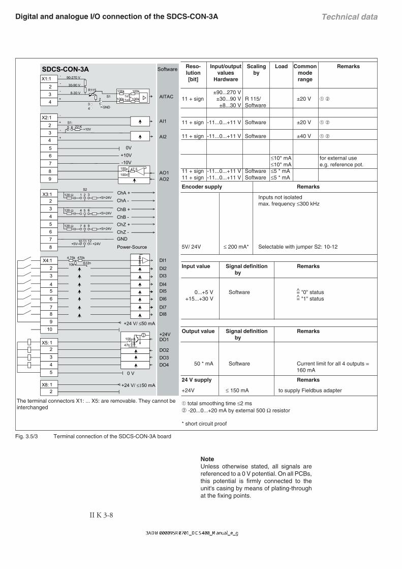
Fig. 3.5/3 Terminal connection of the SDCS-CON-3A board
Digital and analogue I/O connection of the SDCS-CON-3A
Reso- Input/output Scaling Load Common Remarkslution values by mode[bit] Hardware range
±90...270 V11 + sign ±30...90 V R 115/ ±20 V ➀ ➁
±8...30 V Software
11 + sign -11...0...+11 V Software ±20 V ➀ ➁
11 + sign -11...0...+11 V Software ±40 V ➀ ➁
≤10* mA for external use≤10* mA e.g. reference pot.
11 + sign -11...0...+11 V Software ≤5 * mA11 + sign -11...0...+11 V Software ≤5 * mA
Encoder supply Remarks
Inputs not isolatedmax. frequency ≤300 kHz
5V/ 24V ≤ 200 mA* Selectable with jumper S2: 10-12
Input value Signal definition Remarksby
0...+5 V Software = "0" status+15...+30 V = "1" status
Output value Signal definition Remarksby
50 * mA Software Current limit for all 4 outputs =160 mA
24 V supply Remarks
+24V ≤ 150 mA to supply Fieldbus adapter
➀ total smoothing time ≤2 ms➁ -20...0...+20 mA by external 500 Ω resistor
* short circuit proof
The terminal connectors X1: ... X5: are removable. They cannot beinterchanged
NoteUnless otherwise stated, all signals arereferenced to a 0 V potential. On all PCBs,this potential is firmly connected to theunit's casing by means of plating-throughat the fixing points.
90-270 V
30-90 V
8-30 V
ChA +ChA -
ChB +ChB -ChZ +ChZ -GND
0 V
R115
+10V
S1:
100µ
+24 V/ ≤50 mA
100k1n1n
47n
100k
100k 100k
Power-Source
-
+
-
+
-
-
-
+
47.5100µ
100n
+10V0V
-10V
470k22n10k
4.75k
22 K
567
43
8
9
X4:1 2 3
4 5 6
7 8
10
4 5
1 2 3
4
23
2X2:1
9
45
7
23
6
8
X1:1
X3:1
X5:
SDCS-CON-3A Software
GND34
21
S1
+5/+24V1 2 3120 Ω
+5/+24V4 5 6120 Ω
+5/+24V7 8 9120 Ω
S2
+5V +24V10 11 12
5 6
1 2
X8: +24 V/ ≤150 mA
AITAC
+24V
AI1
AO1AO2
DI1
DI2DI3
DI4DI5DI6
DI7DI8
DO4
DO1
DO2DO3
AI2

II K 3-9
Technical data3.6 Power Interface Board SDCS-PIN-3A
The power interface board SDCS-PIN-3A is usedfor all converter modules model A1...A4.
Functions:- firing pulse circuits- measurement of the armature current- snubber circuit- AC and DC voltage measurement- heat sink temperature measurement
Fig. 3.6/1 Layout of the SDCS-PIN-3A board.
- power supply for complete converter electronics- fuses for field supply. Fuse data F100...F102:
Bussmann KTK-15A (600V)
Output X98:1-2 (DO5)
Potential isolated by relay (N.O. contact)MOV- element (275 V)Contact rating: AC: 250 V~/ 3 A~
DC: 24 V-/ 3 A-or 115/230 V-/ 0.3 A-)
AC Supply voltage (X98:3-4)
Supply voltage 115...230 V ACTolerence -15%/+10%Frequency 45 Hz ... 65 HzPower consumption 120 VAPower loss 60 WInrush current 20 A/10 A (20 ms)Mains buffering min 30 ms
X6
T24 T22 T26 T11 T15 T13
X14
X11
X100
X15
X16
X22
T1
X12
X13
T14 T12 T16 T21 T25 T23
F10
0
F10
1
F10
2
X10
X24
X21X23
X20
X98
1 2 3 4
PTC
1 2
C1 U1 V1 W1 D1
258
225
F+ '2F-
T2
X1
X2
X7
X3 X4 X5
Electronicsupply
115...230 Vto motor field

II K 3-10
Technical data
The DCS 400 converter has an build-in three-phasefield exciter with the following features:
• smoothed field voltage- better commutation of the motor- increased brush life
• less heat generation in the motor• less effort of cabling Fig. 3.7/1 Layout of the SDCS-FIS-3A field exciter
board
3.7 Field exciter SDCS-FIS-3A
Electrical data of SDCS-FIS-3AAC input voltage: 230 V...500 V ±10%; three-phaseDC output voltage 50...440 V programmableAC input current: output currentAC isolation voltage: 600 VFrequency: same as DCS converter moduleDC output current: 0.1 A...4 A for armature converter modules from 20 A to 25 A
0.1 A...6 A for armature converter mod. from 45 A to 140 A0.3 A...16 A for armature converter mod. from 180 A to 550 A0.3 A...20 A for armature converter mod. for 610 A
Power loss see chapter 3.3Terminal X10:1,2 on SDCS-PIN-3ACross sectional area 4 mm²
Fig. 3.7/2 Diagram of the field exciter unit
Remark:The DC link capacitor of the IGBT based field exciterserves as an overvoltage protection for the armatureconverter.
Overloading of the DC link capacitor is prevented bythe connected motor field winding.The energy of glitches caused by the commutation ofthe armature converter is no longer waste energy butis used by the field exciter.
The overvoltage protection only works if a field wind-ing is connected.
Therefore DCS400 can not be used with discon-nected field.
X5
X3
X4
X6
X7
X2
X1
X14 T100
SDCS-FIS-3A
145
45
U1V1
W1
SDCS-CON-3A X1 X2 X7
X10:2 X10:1
SDCS-PIN-3A SDCS-FIS-3A
X12: X12:26
1
26
1
FPWM
8IFM
9
8
9 GND
3 3
X14
:
X14
:
X11:2
3
X100:1-2 X6:1-3
X6X4X3
Converter
DC Output(for motor field)
low levelcontrol
II K 3-11
Technical data
20
0,1
1
10
100
0 50 100 150 200 250 300 350 400 450
IF
UF
[A]
[V]220
1.5
0.3
16
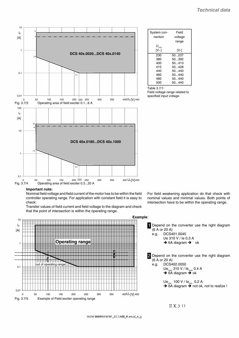
Important note:Nominal field voltage and field current of the motor has to be within the fieldcontroller operating range. For application with constant field it is easy tocheck:Transfer values of field current and field voltage to the diagram and checkthat the point of intersection is within the operating range.
Fig. 3.7/3 Operating area of field exciter 0.1...6 A
DCS 40x.0180...DCS 40x.1000
Fig. 3.7/4 Operating area of field exciter 0.3...20 A
Table 3.7/1:Field voltage range related tospecified input voltage
System con- Fieldnection voltage
rangeULine
[V~] [V-]
230 50...237380 50...392400 50...413415 50...428440 50...440460 50...440480 50...440500 50...440
For field weakening application do that check withnominal values and minimal values. Both points ofintersection have to be within the operating range.
Depend on the converter use the right diagram(6 A or 20 A)e.g. DCS401.0045
Ue 310 V / Ie 0.3 A 6A diagram ok
Depend on the converter use the right diagram(6 A or 20 A)e.g. DCS402.0050
Uenom 310 V / Ienom 0.4 A 6A diagram ok
Uemin 100 V / Iemin 0.2 A 6A diagram not ok, not to realize !
1
2
Example:
Fig. 3.7/5 Example of Field exciter operating range
6
0,01
0,1
1
10
0 50 100 150 200 250 300 350 400 450
IF
UF
[A]
[V]220
4
0.1
0.5
0,01
1
10
0 50 100 150 200 250 300 350 400 450
IF
UF
[A]
[V]
0,1
out of operating range
DCS 40x.0020...DCS 40x.0140

II K 3-12
Technical data3.8 Ciruit diagrams
Fig. 3.8/1 Circuit diagram 4-Q converter
3,1$
&21$
$
9
9
;
&
5 2
9
.*
9
.*
)
)
)
9
.*.*
9
'
9
* ..
9
** .
9
;
* ..
9
** .
9
9
.6
/6
.6
/6
7
7
* .
$
3(
:
/8
9/
/
;
;
;;
;
;
/6
.6
7
;
;
;
;
;;;; 9
;
;
;
;
;
;
;
;
;
;
;
;
:
98
'
&
;;
;7
;
;7
;7
;7
;7
;7
;7
;7
;7
;7
;7
;7
*
.*.
.*.** .
. * .*
*.*.
.*.*.*
;
;
;
;
;
.
/
9DF
;
7
0
),6$
0
&
$
.*
/ 1
0
;
1/
9DF
9DF
0
;
9DF
/ 1
9DF
/
'
;
;
;
&219(57(502'8/(
&21752/%2$5'
32:(5,17(5)$&(%2$5'
),(/',17(5)$&(%2$5'
RQO\XVHGIRUFRQYHUWHUVL]H$
RQO\XVHGIRUFRQYHUWHUVL]H$
RQO\XVHGIRUFRQYHUWHUVL]H$$
I3DQHO

II K 3-13
Technical data
Fig. 3.8/2 Circuit diagram 2-Q converter
3,1$
&21$
$
;
&
5 2
)
)
)
'
;
.6
/6
.6
/6
7
7
$
3(
:
/8
9/
/
;
;
;;
;
;
/6
.6
7
;
;
;
;
;;;; 9
;
;
;
;
;
;
;
;
;
;
;
;
:
98
'
&
;;
;7
;
;7
;7
;7
;7
;7
;7
;7
;7
;7
;7
;7
*
.*.
.*.** .
. * .*
*.*.
.*.*.*
;
;
;
;
;
.
/
9DF
;
7
0
),6$
0
&
$
/ 1
0
;
1/
9DF
9DF
0
;
9DF
/ 1
9DF
/
'
9
.*
.*
9
9
.*
9
* .
.*
9
9
* .
;
;
;
RQO\XVHGIRUFRQYHUWHUVL]H$
RQO\XVHGIRUFRQYHUWHUVL]H$
RQO\XVHGIRUFRQYHUWHUVL]H$$
),(/',17(5)$&(%2$5'
&219(57(502'8/(
&21752/%2$5'
32:(5,17(5)$&(%2$5'
I3DQHO

II K 3-14
Technical data

II K 4-1
Overview of Software4 Overview of software(The software delivered may contain minor changes to the product described here.)
Parameter
The parameters of the converter are subdivided intofunctional groups. These groups are listed in the tablebelow.
Parameter group Functions
1 - Motor Settings Motor settings, actual linevalues, auto reclosing
2 - Operating Mode Macro selection, behaviourduring switching on/off, con-trol/status information, con-trol location
3 - Armature Actual value signals, highcurrent dosage, controllersettings, stall protection, ref-erence sources
4 - Field Actual value signals, con-troller settings, overcurrent/undercurrent tripping, fluxadaptation, field heating
5 - Speed Controller Reference sources, actualvalue acquisition, controllersettings, ramp generator,constant speeds, alternativesettings, speed monitoring,actual value filtering
6 - Input/Output Scaling and allocation of theanalog and digital inputs andoutputs, display selection forthe control panel, field busallocation, actual value sig-nals
7 - Maintenance Language selection, serviceprocedures, diagnostics,fault and alarm information,square-wave generator
8 - Field Bus Serial communication via thefield bus, RS232 or paneladapter
9 - Macro Adaptation Re-configure digital inputsDI1...DI4 of macros 1, 5, 6,7, and 8.
Function menu
Special functions of the control panel are listed in thetable below.
Menu function Significance
Set Typecode Typecode adaptation for re-placement of SDCS-CON-3
Read Faultlogger Read / Clear the last 16Faults or Alarms
Factory Settings Reset all parameters to fac-tory values (default values)
Copy to Panel Parameter uploading fromdrive to control panel
Copy to Drive Parameter downloadingfrom control panel to drive
Long/Short Par List Some parameter visible / in-visible
Panel Lock Lock the control panel formaloperation
LCD Contrast Contrast of cotrol panel dis-play
Commissioning Guided commissioning viacontrol panel
Parameter savingAny changes of the parameters are stored auto-matically in the FlashProm of the converter. Thestorage is executed in a time interval of approx. 5seconds.
Continual parameter writing destroys the Flash-PromParameter are saved automatically in a backgroundroutine. This is done approx. every 5 seconds, when:• parameters are altered by means of the control
panel.• parameters are transmitted by means of PC Tool
Drive Window Light, irrespective of whether thecontent of the parameter has changed.
• parameters are transmitted by means of PLCcommunication via one of the three serial portsField bus adapter or RS232-Port or Panel-Port, irrespective of whether the parameter’scontent has changed.
Continual transmission of a parameter with thesame content will entail continual saving in thebackground routine, i.e. even if the value of theparameter does not change, the save routine will stillbe activated.A FlashProm of the present-day generation can bewritten on and erased up to 100,000 times. Thismeans 100,000 x 5 seconds = approx. 6 days.
Continual transmission of parameters may de-stroy this FlashProm after approx. 6 days, whichis why parameters should only be transmitted ifthe values involved have changed.

II K 4-2
Overview of Software
Selector Remark
MotPotMinSpeed (9.12) Motor Potentiometer Minimum Speed ref.
Ext Field Rev (9.13) external Field Reversal via external fieldreversing switch
AlternativParam (9.14) switch over between Standard Parame-ter Set and Alternative Parameter Set
Ext Speed Lim (9.15) external Speed Limitation via Fixed Speed1 (5.13)
Add AuxSpRef (9.16) additional aux. speed ref.
Curr Lim 2 Inv (9.17) second current limitation via Arm Cur Lim2 (3.24)
Speed/Torque (9.18) switch over between speed controlledand torque controlled drive
Disable Bridge1 (9.19) block thyristor bridge 1
Disable Bridge2 (9.20) block thyristor bridge 2
Selector Remark
Cmd Location (2.02) Control location
Cur Contr Mode (3.14) Current controller operating mode
Torque Ref Sel (3.15) Torque reference source
Speed Ref Sel (5.01) Speed reference source
Alt Par Sel (5.21) Switching event for alternative speedcontrol parameters
Aux Sp Ref Sel (5.26) Auxiliary reference source
AO1 Assign (6.05) Actual value output at analog output AO1
AO2 Assign (6.08) Actual value output at analog output AO2
DO1 Assign (6.11) Signal output at digital output DO1
DO2 Assign (6.12) Signal output at digital output DO2
DO3 Assign (6.13) Signal output at digital output DO3
DO4 Assign (6.14) Signal output at digital output DO4
DO5 Assign (6.15) Signal output at digital output DO5
MSW bit 11 Ass (6.22) Signal transmission in bit 11 of the statusword
MSW bit 12 Ass (6.23) Signal transmission in bit 12 of the statusword
MSW bit 13 Ass (6.24) Signal transmission in bit 13 of the statusword
MSW bit 14 Ass (6.25) Signal transmission in bit 14 of the statusword
Jog 1 (9.02) Jogging 1 function via Fixed Speed 1(5.13)
Jog 2 (9.03) Jogging 2 function via Fixed Speed 2(5.14)
COAST (9.04) Coast stop function
User Fault (9.05) external User Fault event
User Fault Inv (9.06) external User Fault (invers) event
User Alarm (9.07) external User Alarm event
User Alarm Inv (9.08) external User Alarm (inverse) event
Dir of Rotation (9.09) Direction of Rotation only for speed con-trolled drive
Mot Pot Incr (9.10) Motor Potentiometer Increment to in-crease speed ref.
Mot Pot Decr (9.11) Motor Potentiometer Decrement to de-crease speed ref.
Macros are pre-programmed parameter sets. During start-up, thedrive can be configured easily without changing individual parame-ters.
The functions of all inputs and outputs and of allocations in thecontrol structure are influenced by the selection of a macro. Anyallocation which can be set manually with a “selector” (parameter) ispreset by the selection of a macro. The means, whether the drive isspeed-controlled or torque-controlled, whether supplementary ref-erences are processed, which actual values are available at the
4.1 General information about application Macros
Then the allocations will be dependent on the selected macro, seechapter Application Macros.
The user can change the allocations manually any time. Then theyare no longer “Macro Depend”. Hence the macro technique alsoallows the flexible, user-friendly adaptation to special requirements.
analog outputs, which reference value sources are used, etc. isalready defined in the macro.
A macro is selected in the Macro Select (2.01) parameter. Afterselection a function is assigned to each of the digital inputs DI1…DI8.The functions are described in the chapter Application Macros.
The following “selectors” (parameters) are predefined when you areselecting the macro provided that these parameters have theirdefault settings or are set to Macro Depend:
In addition to analog and digital outputs some of the digital inputs arere-configurable. The digital inputs DI1…DI4 in macros 1+5+6+7+8can be set individually via parameter group 9 - MacroAdaptation.Macros 2+3+4 are fixed, not re-configurable.Example of MacroAdaptation:
macro 6 - MotorPot should be selecteddigital input DI1 should be re-defined from "direction of rotation"to "alternativ parameter set" for using ramp 1 / 2
• Set parameter „Dir of Rotation" (9.09) from Macro depend toDisable
• Set parameter „AlternativParam" (9.14) from Macro depend toDI1
• Set standard parameter set (5.07…5.10) and alternativeparameter set (5.22…5.25) to values as required

II K 4-3
Overview of Software
Overview of factory settings of macro-dependent parameters:
Macro Í 1 2 3 4 5 6 7 8Ï Parameter Standard Man/Const Sp Hand/Auto Hand/MotPot Jogging Motor Pot ext Field Rev Torque CtrlCmd Location (2.02) Terminals Terminals Terminals Terminals Terminals Terminals Terminals TerminalsCur Contr Mode (3.14) Speed Contr Speed Contr Speed Contr Speed Contr Speed Contr Speed Contr Speed Contr Torque ContrTorque Ref Sel (3.15) AI2 AI2 Const Zero AI2 Const Zero AI2 AI2 AI1Speed Ref Sel (5.01) AI1 AI1 AI1 AI1 AI1 Const Zero AI1 Const ZeroAlt Par Sel (5.21) Sp < Lev1 Digital Input 4 Sp < Lev1 Sp < Lev1 Sp < Lev1 Sp < Lev1 Sp < Lev1 Sp < Lev1Aux Sp Ref Sel (5.26) Const Zero Const Zero Const Zero Const Zero AI2 Const Zero Const Zero Const ZeroAO1 Assign (6.05) Speed Act Speed Act Speed Act Speed Act Speed Act Speed Act Speed Act Speed ActAO2 Assign (6.08) Arm Volt Act Arm Cur Act Arm Cur Act Arm Cur Act Torque Act Arm Volt Act Arm Volt Act Torque ActDO1 Assign (6.11) Rdy for Run Rdy for On Rdy for On Rdy for On Rdy for Run Rdy for Run Rdy for Run Rdy for RunDO2 Assign (6.12) Running Running Running Running Zero Speed Speed Level 1 Running RunningDO3 Assign (6.13) Zero Speed Fault Fault Fault At Setpoint Speed Level 2 Field Rev Act Zero SpeedDO4 Assign (6.14) Flt or Alarm Zero Speed Zero Speed Zero Speed Flt or Alarm Flt or Alarm Flt or Alarm Flt or AlarmDO5 Assign (6.15) Main Cont On Main Cont On Main Cont On Main Cont On Main Cont On Main Cont On Main Cont On Main Cont OnMSW Bit11 Ass (6.22) none none none none none none none noneMSW Bit12 Ass (6.23) none none none none none none none noneMSW Bit13 Ass (6.24) none none none none none none none noneMSW Bit14 Ass (6.25) none none none none none none none noneAssignment of DI1 Jog 1 Start Start/Stop Hand Start/Stop Direc of Rotat. Direc of Rotat. Ext Field Rev Coast
DI2 Jog 2 Stop Hand/Auto Jog 1 Jog 1 Incr. Speed Jog 1 not usedDI3 External Fault Direc of Rotat. Direc of Rotat. Direc of Rotat. Jog 2 Decr. Speed External Fault External FaultDI4 External Alarm Ramp 1 / 2 AI1/Fixed Sp 1 AI1/MotPot not used Min Speed External Alrm External AlrmDI5 Emerg. Stop Emerg. Stop Emerg. Stop Emerg. Stop Emerg. Stop Emerg. Stop Emerg. Stop Emerg. StopDI6 Reset Reset Reset Reset Reset Reset Reset ResetDI7 On/Off Fixed Speed 1 Direc of Rotat. Incr. Speed On/Off On/Off On/Off On/OffDI8 Run Fixed Speed 2 Start/Stop Auto Decr. Speed Run Run Run Run
Not re-configurable

II K 4-4
Overview of Software4.2 Application Macros
The following application macros are available:
Macro 1: StandardDrive switch-on/switch-off and enable via 2digital inputs.Speed reference via analog input.External torque limiting via analog input.Jogging via 2 digital inputs.2 digital inputs for external events (fault/alarm).2 digital inputs for emergency stop and faultacknowledgement.
Macro 2: Man/Const SpStarting and stopping of the drive via 2 digitalinputs.Speed reference via analog input.Reversal of rotational direction via 1 digital in-put.2 ramp sets selectable via 1 digital input.Selection of speed reference or 2 fixedspeeds via 2 digital inputs.2 digital inputs for emergency stop and faultacknowledgement.
Macro 3: Hand/AutoSwitchover between manual and auto. controleffected via 1 digital input.Manual control:
Starting and stopping of the drive via 1 di-gital input.Speed reference via analog input 1.Selection of speed reference or 1 fixedspeed via 1 digital input.Reversal of rotational direction via 1 digi-tal input.
Automatic control:Starting and stopping of the drive via 1 di-gital input.Speed reference via analog input 2.Reversal of rotational direction via 1 digi-tal input.
2 digital inputs for emergency stop and faultacknowledgement.
Macro 4: Hand/MotPotStarting and stopping of the drive via 1 digitalinput.Jogging via 1 digital input.Speed reference via analog input.Reversal of rotational direction via 1 digital in-put.Motor potentiometer function via 2 digital in-puts.Selection of speed reference or motor pot via1 digital input.2 digital inputs for emergency stop and faultacknowledgement.
Macro 5: JoggingDrive switch-on/switch-off and enable via 2 di-gital inputs.Speed reference via analog input 1.Additional reference via analog input 2.Jogging via 2 digital inputs.Reversal of rotational direction via 1 digital in-put.2 digital inputs for emergency stop and faultacknowledgement.
Macro 6: Motor PotDrive switch-on/switch-off and enable via 2 di-gital inputs.Reversal of rotational direction via 1 digital in-put.Minimum speed can be activated via 1 digitalinput.Motor pot function via 2 digital inputs.2 digital inputs for emergency stop and faultacknowledgement.
Macro 7: ext Field RevDrive switch-on/switch-off and enable via 2 di-gital inputs.Speed reference via analog input 1.External torque limiting via analog input 2.Jogging via 1 digital input.External field reversal can be activated via 1digital input.2 digital inputs for external events (fault/alarm).2 digital inputs for emergency stop and faultacknowledgement.
Macro 8: Torque CtrlDrive switch-on/switch-off and enable via 2 di-gital inputs.Torque reference via analog input.Coast Stop via 1 digital input.2 digital inputs for external events (fault/alarm).2 digital inputs for emergency stop and faultacknowledgement.

II K 4-5
Overview of Software

II K 4-6
Overview of Software4.2.1 Macro 1 - Standard
Description of I/O’s functionalityI/O Param FunctionDI1 Jog speed 1. Speed can be defined in parameter 5.13.
Accel/Decel Ramp for Jogging can be defined in parameter 5.19/5.20.DI2 Jog speed 2. Speed can be defined in parameter 5.14.
Accel/Decel Ramp for Jogging can be defined in parameter 5.19/5.20.DI3 2.01 External fault signal. Triggers a fault response and trips the driveDI4 External alarm signal. Triggers a warning in DCS400DI5 Emergency stop. Closed-circuit principle, must be closed for operationDI6 Reset. Faultacknowledgement, reset faults signaled by the driveDI7 Drive ON / OFF. DI7=0=OFF , DI7=1=ONDI8 Drive START / STOP. DI8=0=STOP , DI8=1=START
DO1 6.11 Ready for Run. Converter switched ON, but not yet STARTedDO2 6.12 Running. Drive is STARTed (Current controller enabled)DO3 6.13 Zero-speed signal. Motor at standstillDO4 6.14 Group fault signal. Common signal for all faults or alarmsDO5 6.15 Main contactor on. Controlled by ON command (DI7)
AI1 5.01 Speed referenceAI2 3.15 External torque limitation possible. First the parameter Cur Contr Mode 3.14 has to be changed
from Macro depend to Lim Sp Ctr. Without changes the factory settings for torque limitation iseffective (100%).
AO1 6.05 Speed actualAO2 6.08 Armature voltage actual
Inter locking of Jog speed 1 – Jog speed 2 – Drive STARTJog 1DI1
Jog 2DI2
STARTDI8
Drive is ON (DI7=1)
0 0 0 Drive is STOPped (Current controller disabled)1 0 0 Drive STARTed via DI1 , speed reference=parameter 5.13x 1 0 Drive STARTed via DI2 , speed reference=parameter 5.14x x 1 Drive STARTed via START command (DI8) , speed reference via analog input AI1
Parameter settings, shaded areas are set by macro - all others are set during commissioning1 - Motor Settings 2 - Operation Mode 3 - Armature 5 - Speed Controller 6 - Input/Output
1.01 Arm Cur Nom 2.01 Macro Select [Standard]
3.04 Arm Cur Max 5.01 Speed Ref Sel [AI1]
6.01 AI1 Scale 100%
1.02 Arm Volt Nom 2.02 Cmd Location [Terminals]
3.07 Torque Lim Pos 5.02 Speed MeasMode
6.02 AI1 Scale 0%
1.03 Field Cur Nom 2.03 Stop Mode 3.08 Torque Lim Neg 5.03 Encoder Inc 6.03 AI2 Scale 100%1.04 Field Volt Nom 2.04 Eme Stop Mode 3.14 Cur Contr Mode
[Speed Contr]5.09 Accel Ramp 6.04 AI2 Scale 0%
1.05 Base Speed 3.15 Torque Ref Sel [AI2]
5.10 Decel Ramp 6.05 AO1 Assign [Speed Act]
1.06 Max Speed 3.17 Stall Torque 5.11 Eme Stop Ramp 6.06 AO1 Mode3.18 Stall Time 5.12 Ramp Shape 6.07 AO1 Scale 100%
5.13 Fixed Speed 1 6.08 AO2 Assign [Arm Volt Act]
5.14 Fixed Speed 2 6.09 AO2 Mode5.15 Zero Speed Lev 6.10 AO2 Scale 100%5.16 Speed Level 1 6.11 DO1 Assign
[Rdy for Run]5.17 Speed Level 2 6.12 DO2 Assign
[Running]5.19 Jog Accel Ramp 6.13 DO3 Assign
[Zero Speed]5.20 Jog Decel Ramp 6.14 DO4 Assign
[Flt or Alarm]5.21 Alt Par Sel [Sp < Lev1]
6.15 DO5 Assign [Main Cont On]
5.26 Aux Sp Ref Sel [Const Zero]
6.22 MSW Bit 11 Ass [none]6.23 MSW Bit 11 Ass [none]6.24 MSW Bit 11 Ass [none]6.25 MSW Bit 11 Ass [none]

II K 4-7
Overview of Software
Fig. 4.2/1: Connection example application-Macro 1 - Standard
_+
IN OU
T
DC
S 4
00 P
AN
C 1
D 1
X98
:
DO
5
12
34
45
X99
:1
23
U1W
1V1
PE
X10
:1
2
AIT
AC
AI1
AI2
+10
V-1
0VA
O1
AO
2D
I1D
I2D
I3D
I4D
I5D
I6D
I7D
I8+
24V
DO
1D
O2
DO
3D
O4
__
++
TT
K198
:1
98:2
F6
1 2F
4
1 2F
5
1 2
115.
..23
0V 5
0H
z
L1N
L1L2
L3
400V
50H
z
F1
K1
13
5
24
6
L1
M
0V0V
0V
X1:
12
34
12
34
56
78
9X
4:1
23
45
67
89
10X
5:1
23
45
X3:
X2:
+ _
S1 21
DD
CS
Nxx
x-0
1xx
xxxx
xxA
DA
PT
ER
BU
ST
ER
MIN
AT
ION
ON
OFF
RX
D
TX
D
PE
SH
FD
GD
(N)
D(P
)
X1
X2
PE
SH
FD
GD
(N)
D(P
)S
H
XM
IT
RE
C
ER
RO
R
+24
V0V
SH
3&
X7:X6:
X8:
+24
V
RS
232
4 A
0V
M ~
12
34
56
78
++
__
5.02
6.01 / 6.02
6.03 / 6.04
6.05 / 6.06 / 6.07
6.08 / 6.09 / 6.10
2.01
6.11
6.12
6.13
6.14
5.02
5.03
1.01 / 1.02
1.05 / 1.06
1.03 / 1.04
8.01 ... 8.16
6.15
A+
A-
B+
B-
Z+
Z-
0 V
US
**
Con
trol
boa
rd
Con
vert
erm
odul
eF
ield
exc
iter
unit
the
pola
ritie
s ar
e sh
own
for
mot
or o
pera
tion
(opt
ical
)
the
conn
ectio
n of
the
fan
depe
nds
on th
e m
odul
e ty
pe a
nd o
n th
e su
pply
vol
tage
Pow
er s
uppl
yF
an
nref
Tref
nact
Ua act
Jogging 1
Jogging 2
User fault
User alarm
Emergency stop
Reset
On/Off
Run
Ready for Run
Running
Zero-speed
Fault or Alarm
Main con-tactor ON
* on
ly r
equi
red
inre
gene
rativ
em
ode!
Par
amet
er
re-c
onfig
ura
ble
in
para
met
er g
roup
90DFUR$GDSWDWLRQ
II K 4-8
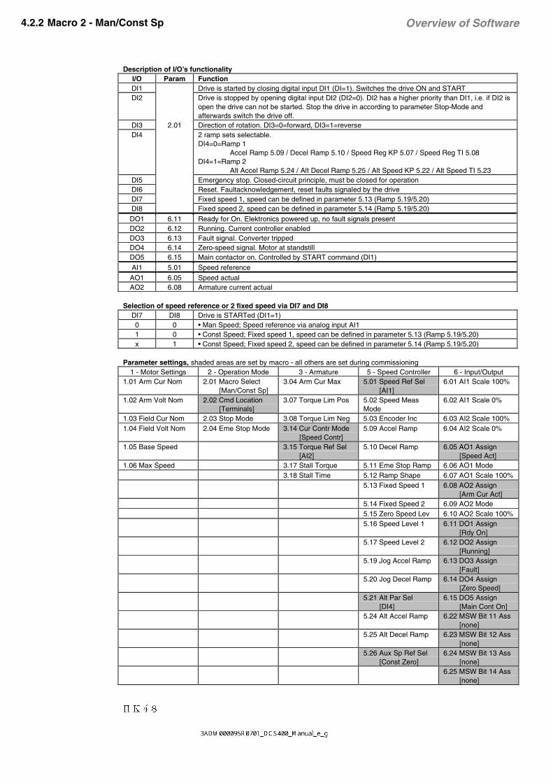
Overview of Software4.2.2 Macro 2 - Man/Const Sp
Description of I/O’s functionalityI/O Param FunctionDI1 Drive is started by closing digital input DI1 (DI=1). Switches the drive ON and STARTDI2 Drive is stopped by opening digital input DI2 (DI2=0). DI2 has a higher priority than DI1, i.e. if DI2 is
open the drive can not be started. Stop the drive in according to parameter Stop-Mode andafterwards switch the drive off.
DI3 2.01 Direction of rotation. DI3=0=forward, DI3=1=reverseDI4 2 ramp sets selectable.
DI4=0=Ramp 1Accel Ramp 5.09 / Decel Ramp 5.10 / Speed Reg KP 5.07 / Speed Reg TI 5.08
DI4=1=Ramp 2Alt Accel Ramp 5.24 / Alt Decel Ramp 5.25 / Alt Speed KP 5.22 / Alt Speed TI 5.23
DI5 Emergency stop. Closed-circuit principle, must be closed for operationDI6 Reset. Faultacknowledgement, reset faults signaled by the driveDI7 Fixed speed 1, speed can be defined in parameter 5.13 (Ramp 5.19/5.20)DI8 Fixed speed 2, speed can be defined in parameter 5.14 (Ramp 5.19/5.20)
DO1 6.11 Ready for On. Elektronics powered up, no fault signals presentDO2 6.12 Running. Current controller enabledDO3 6.13 Fault signal. Converter trippedDO4 6.14 Zero-speed signal. Motor at standstillDO5 6.15 Main contactor on. Controlled by START command (DI1)
AI1 5.01 Speed reference
AO1 6.05 Speed actualAO2 6.08 Armature current actual
Selection of speed reference or 2 fixed speed via DI7 and DI8DI7 DI8 Drive is STARTed (DI1=1)0 0 • Man Speed; Speed reference via analog input AI11 0 • Const Speed; Fixed speed 1, speed can be defined in parameter 5.13 (Ramp 5.19/5.20)x 1 • Const Speed; Fixed speed 2, speed can be defined in parameter 5.14 (Ramp 5.19/5.20)
Parameter settings, shaded areas are set by macro - all others are set during commissioning1 - Motor Settings 2 - Operation Mode 3 - Armature 5 - Speed Controller 6 - Input/Output
1.01 Arm Cur Nom 2.01 Macro Select [Man/Const Sp]
3.04 Arm Cur Max 5.01 Speed Ref Sel [AI1]
6.01 AI1 Scale 100%
1.02 Arm Volt Nom 2.02 Cmd Location [Terminals]
3.07 Torque Lim Pos 5.02 Speed MeasMode
6.02 AI1 Scale 0%
1.03 Field Cur Nom 2.03 Stop Mode 3.08 Torque Lim Neg 5.03 Encoder Inc 6.03 AI2 Scale 100%1.04 Field Volt Nom 2.04 Eme Stop Mode 3.14 Cur Contr Mode
[Speed Contr]5.09 Accel Ramp 6.04 AI2 Scale 0%
1.05 Base Speed 3.15 Torque Ref Sel [AI2]
5.10 Decel Ramp 6.05 AO1 Assign [Speed Act]
1.06 Max Speed 3.17 Stall Torque 5.11 Eme Stop Ramp 6.06 AO1 Mode3.18 Stall Time 5.12 Ramp Shape 6.07 AO1 Scale 100%
5.13 Fixed Speed 1 6.08 AO2 Assign [Arm Cur Act]
5.14 Fixed Speed 2 6.09 AO2 Mode5.15 Zero Speed Lev 6.10 AO2 Scale 100%5.16 Speed Level 1 6.11 DO1 Assign
[Rdy On]5.17 Speed Level 2 6.12 DO2 Assign
[Running]5.19 Jog Accel Ramp 6.13 DO3 Assign
[Fault]5.20 Jog Decel Ramp 6.14 DO4 Assign
[Zero Speed]5.21 Alt Par Sel [DI4]
6.15 DO5 Assign [Main Cont On]
5.24 Alt Accel Ramp 6.22 MSW Bit 11 Ass [none]
5.25 Alt Decel Ramp 6.23 MSW Bit 12 Ass [none]
5.26 Aux Sp Ref Sel [Const Zero]
6.24 MSW Bit 13 Ass [none]6.25 MSW Bit 14 Ass [none]

II K 4-9
Overview of Software
Fig. 4.2/2: Connection example application-Macro 2 - Man/Const Sp
_+
IN OU
T
C 1
D 1
X98
:
DO
5
12
34
45
X99
:1
23
U1W
1V1
PE
X10
:1
2
AIT
AC
AI1
AI2
+10
V-1
0VA
O1
AO
2D
I1D
I2D
I3D
I4D
I5D
I6D
I7D
I8+
24V
DO
1D
O2
DO
3D
O4
__
++
TT
K198
:1
98:2
F6
1 2F
4
1 2F
5
1 2
115.
..23
0V 5
0H
z
L1N
L1L2
L3
400V
50H
z
F1
K1
13
5
24
6
L1
M
0V0V
0V
X1:
12
34
12
34
56
78
9X
4:1
23
45
67
89
10X
5:1
23
45
X3:
X2:
+ _
S1 21
DD
CS
Nxx
x-0
1xx
xxxx
xxA
DA
PT
ER
BU
ST
ER
MIN
AT
ION
ON
OFF
RX
D
TX
D
PE
SH
FD
GD
(N)
D(P
)
X1
X2
PE
SH
FD
GD
(N)
D(P
)S
H
XM
IT
RE
C
ER
RO
R
+24
V0V
SH
3&
X7:X6:
X8:
+24
V
RS
232
4 A
0V
M ~
12
34
56
78
++
__
5.02
6.01 / 6.02
6.03 / 6.04
6.05 / 6.06 / 6.07
6.08 / 6.09 / 6.10
2.01
6.11
6.12
6.13
6.14
5.02
5.03
1.01 / 1.02
1.05 / 1.06
1.03 / 1.04
8.01 ... 8.16
6.15
A+
A-
B+
B-
Z+
Z-
0 V
US
DC
S 4
00 P
AN
**
Con
trol
boa
rdC
onve
rter
mod
ule
Fie
ld e
xcite
run
it
the
pola
ritie
s ar
e sh
own
for
mot
or o
pera
tion
(opt
ical
)
the
conn
ectio
n of
the
fan
depe
nds
on th
e m
odul
e ty
pe a
nd o
n th
e su
pply
vol
tage
Pow
er s
uppl
yF
an
nref
nact
Ia act
Start
Stop
Direction of rotation
Ramp 1 / Ramp 2
Emergency stop
Reset
Fixed speed 1
Fixed speed 2
Ready for ON
Running
Fault
Zero-speed
Main con-tactor ON
* on
ly r
equi
red
inre
gene
rativ
em
ode!
Par
amet
er
not r
e-co
nfig
ura
ble

II K 4-10
Overview of Software4.2.3 Macro 3 - Hand/Auto
Description of I/O’s functionalityI/O Param FunctionDI1 Start / Stop Hand. Start and stop the drive. DI1=0=STOP , DI1=1=START
Start switches the drive ON and START. Stop the drive in according to parameter Stop-Mode andafterwards switch the drive off.
DI2 Switchover between manual and automatic control.Present Start/Stop command will be of effect after switching:DI2=0=Hand control:
The drive is started and stopped via digital input DI1.Speed reference via analog input AI1.Direction of rotation via digital input DI3.Selection of speed reference or 1 fixed speed via digital input DI4
DI2=1=Automatic control:The drive is started and stoped via digital input DI8.Speed reference from PLC via analog input AI2.Direction of rotation via digital input DI7.
DI3 2.01 Direction of rotation Hand. DI3=0=forward, DI3=1=reverseDI4 Selection of speed reference AI1 / Fixed speed 1 Hand
DI4=0=speed reference via analog input AI1DI4=1=fixed speed 1 , speed can be defined in parameter 5.13 (Ramp 5.19/5.20)
DI5 Emergency stop. Closed-circuit principle, must be closed for operationDI6 Reset. Faultacknowledgement, reset faults signaled by the driveDI7 Direction of rotation Auto. DI7=0=forward , DI3=1=reverseDI8 Start / Stop Auto. Start and stop the drive. DI8=0=STOP , DI8=1=START
Start switches the drive ON and START. Stop the drive in according to parameter Stop-Mode andafterwards switch the drive off.
DO1 6.11 Ready for On. Elektronics powered up, no fault signals presentDO2 6.12 Running. Current controller enabledDO3 6.13 Fault signal. Converter trippedDO4 6.14 Zero-speed signal. Motor at standstillDO5 6.15 Main contactor on. Controlled by START command (DI1)AI1 5.01 Speed reference HandAI2 5.26 Speed reference Auto, from PLCAO1 6.05 Speed actualAO2 6.08 Armature current actual
Parameter settings, shaded areas are set by macro - all others are set duringcommissioning
1 - Motor Settings 2 - Operation Mode 3 - Armature 5 - Speed Controller 6 - Input/Output1.01 Arm Cur Nom 2.01 Macro Select
[Hand/Auto]3.04 Arm Cur Max 5.01 Speed Ref Sel
[AI1]6.01 AI1 Scale 100%
1.02 Arm Volt Nom 2.02 Cmd Location [Terminals]
3.07 Torque Lim Pos 5.02 Speed MeasMode
6.02 AI1 Scale 0%
1.03 Field Cur Nom 2.03 Stop Mode 3.08 Torque Lim Neg 5.03 Encoder Inc 6.03 AI2 Scale 100%1.04 Field Volt Nom 2.04 Eme Stop Mode 3.14 Cur Contr Mode
[Speed Contr]5.09 Accel Ramp 6.04 AI2 Scale 0%
1.05 Base Speed 3.15 Torque Ref Sel [Const Zero]
5.10 Decel Ramp 6.05 AO1 Assign [Speed Act]
1.06 Max Speed 3.17 Stall Torque 5.11 Eme Stop Ramp 6.06 AO1 Mode3.18 Stall Time 5.12 Ramp Shape 6.07 AO1 Scale 100%
5.13 Fixed Speed 1 6.08 AO2 Assign [Arm Cur Act]
5.14 Fixed Speed 2 6.09 AO2 Mode5.15 Zero Speed Lev 6.10 AO2 Scale 100%5.16 Speed Level 1 6.11 DO1 Assign
[Rdy On]5.17 Speed Level 2 6.12 DO2 Assign
[Running]5.19 Jog Accel Ramp 6.13 DO3 Assign
[Fault]5.20 Jog Decel Ramp 6.14 DO4 Assign
[Zero Speed]5.21 Alt Par Sel [Sp < Lev1]
6.15 DO5 Assign [Main Cont On]
5.26 Aux Sp Ref Sel [Const Zero]
6.22 MSW Bit 11 Ass [none]6.23 MSW Bit 12 Ass [none]6.24 MSW Bit 13 Ass [none]6.25 MSW Bit 14 Ass [none]

II K 4-11
Overview of Software
Fig. 4.2/3: Connection example application-Macro 3 - Hand/Auto
_+
IN OU
T
C 1
D 1
X98
:
DO
5
12
34
45
X99
:1
23
U1W
1V1
PE
X10
:1
2
AIT
AC
AI1
AI2
+10
V-1
0VA
O1
AO
2D
I1D
I2D
I3D
I4D
I5D
I6D
I7D
I8+
24V
DO
1D
O2
DO
3D
O4
__
++
TT
K198
:1
98:2
F6
1 2F
4
1 2F
5
1 2
115.
..23
0V 5
0H
z
L1N
L1L2
L3
400V
50H
z
F1
K1
13
5
24
6
L1
M
0V0V
0V
X1:
12
34
12
34
56
78
9X
4:1
23
45
67
89
10X
5:1
23
45
X3:
X2:
+ _
S1 21
DD
CS
Nxx
x-0
1xx
xxxx
xxA
DA
PT
ER
BU
ST
ER
MIN
AT
ION
ON
OFF
RX
D
TX
D
PE
SH
FD
GD
(N)
D(P
)
X1
X2
PE
SH
FD
GD
(N)
D(P
)S
H
XM
IT
RE
C
ER
RO
R
+24
V0V
SH
3&
X7:X6:
X8:
+24
V
RS
232
4 A
0V
M ~
12
34
56
78
++
__
5.02
6.01 / 6.02
6.03 / 6.04
6.05 / 6.06 / 6.07
6.08 / 6.09 / 6.10
2.01
6.11
6.12
6.13
6.14
5.02
5.03
1.01 / 1.02
1.05 / 1.06
1.03 / 1.04
8.01 ... 8.16
6.15
A+
A-
B+
B-
Z+
Z-
0 V
US
DC
S 4
00 P
AN
**
Con
trol
boa
rdC
onve
rter
mod
ule
Fie
ld e
xcite
run
it
the
pola
ritie
s ar
e sh
own
for
mot
or o
pera
tion
(opt
ical
)
the
conn
ectio
n of
the
fan
depe
nds
on th
e m
odul
e ty
pe a
nd o
n th
e su
pply
vol
tage
Pow
er s
uppl
yF
an
nref Hand
nref Auto
nact
Ua act
Start/Stop Hand
Hand / Auto
Direct. of rot. Hand
Fixed speed / AI1
Emergency stop
Reset
Direct. of rot. Auto
Start/Stop Auto
Ready for ON
Running
Fault
Zero-speed
Main con-tactor ON
PLC
* on
ly r
equi
red
inre
gene
rativ
em
ode!
Par
amet
er
not r
e-co
nfig
ura
ble

II K 4-12
Overview of Software4.2.4 Macro 4 - Hand/MotPot
Description of I/O’s functionalityI/O Param FunctionDI1 Start / Stop. Start and stop the drive. DI1=0=STOP , DI1=1=START.
Start switches the drive ON and START. Stop the drive in according to parameter Stop-Mode andafterwards switch the drive off and resets speed reference to zero.
DI2 Jog speed 1. Speed can be defined in parameter 5.13.Accel/Decel Ramp for Jogging can be defined in parameter 5.19/5.20.Jog speed 1 has precedence above AI1
DI3 Direction of rotation. DI3=0=forward , DI3=1=reverseDI4 2.01 AI1/MotPot, Selection of speed reference or motor pot function.
DI4=0=speed reference via AI1 or Jog Speed 1DI4=1=Motor pot function via DI7 und DI8
DI5 Emergency stop. Closed-circuit principle, must be closed for operationDI6 Reset. Faultacknowledgement, reset faults signaled by the driveDI7 Motor pot function „faster“. Accel Ramp 5.09DI8 Motor pot function „slower“. Decel Rampe 5.10. Slower has precedence above faster.
DO1 6.11 Ready for On. Elektronics powered up, no fault signals presentDO2 6.12 Running. Current controller enabledDO3 6.13 Fault signal. Converter trippedDO4 6.14 Zero-speed signal. Motor at standstillDO5 6.15 Main contactor on. Controlled by START command (DI1)
AI1 5.01 Speed reference
AO1 6.05 Speed actualAO2 6.08 Armature current actual
Parameter settings, shaded areas are set by macro - all others are set during commissioning1 - Motor Settings 2 - Operation Mode 3 - Armature 5 - Speed Controller 6 - Input/Output
1.01 Arm Cur Nom 2.01 Macro Select [Hand/MotPot]
3.04 Arm Cur Max 5.01 Speed Ref Sel [AI1]
6.01 AI1 Scale 100%
1.02 Arm Volt Nom 2.02 Cmd Location [Terminals]
3.07 Torque Lim Pos 5.02 Speed MeasMode
6.02 AI1 Scale 0%
1.03 Field Cur Nom 2.03 Stop Mode 3.08 Torque Lim Neg 5.03 Encoder Inc 6.03 AI2 Scale 100%1.04 Field Volt Nom 2.04 Eme Stop Mode 3.14 Cur Contr Mode
[Speed Contr]5.09 Accel Ramp 6.04 AI2 Scale 0%
1.05 Base Speed 3.15 Torque Ref Sel [AI2]
5.10 Decel Ramp 6.05 AO1 Assign [Speed Act]
1.06 Max Speed 3.17 Stall Torque 5.11 Eme Stop Ramp 6.06 AO1 Mode3.18 Stall Time 5.12 Ramp Shape 6.07 AO1 Scale 100%
5.13 Fixed Speed 1 6.08 AO2 Assign [Arm Cur Act]
5.14 Fixed Speed 2 6.09 AO2 Mode5.15 Zero Speed Lev 6.10 AO2 Scale 100%5.16 Speed Level 1 6.11 DO1 Assign
[Rdy On]5.17 Speed Level 2 6.12 DO2 Assign
[Running]5.19 Jog Accel Ramp 6.13 DO3 Assign
[Fault]5.20 Jog Decel Ramp 6.14 DO4 Assign
[Zero Speed]5.21 Alt Par Sel [Sp < Lev1]
6.15 DO5 Assign [Main Cont On]
5.26 Aux Sp Ref Sel [Const Zero]
6.22 MSW Bit 11 Ass [none]6.23 MSW Bit 12 Ass [none]6.24 MSW Bit 13 Ass [none]6.25 MSW Bit 14 Ass [none]

II K 4-13
Overview of Software
Fig. 4.2/4: Connection example application-Macro 4 - Hand/MotPot
_+
IN OU
T
C 1
D 1
X98
:
DO
5
12
34
45
X99
:1
23
U1W
1V1
PE
X10
:1
2
AIT
AC
AI1
AI2
+10
V-1
0VA
O1
AO
2D
I1D
I2D
I3D
I4D
I5D
I6D
I7D
I8+
24V
DO
1D
O2
DO
3D
O4
__
++
TT
K198
:1
98:2
F6
1 2F
4
1 2F
5
1 2
115.
..23
0V 5
0H
z
L1N
L1L2
L3
400V
50H
z
F1
K1
13
5
24
6
L1
M
0V0V
0V
X1:
12
34
12
34
56
78
9X
4:1
23
45
67
89
10X
5:1
23
45
X3:
X2:
+ _
S1 21
DD
CS
Nxx
x-0
1xx
xxxx
xxA
DA
PT
ER
BU
ST
ER
MIN
AT
ION
ON
OFF
RX
D
TX
D
PE
SH
FD
GD
(N)
D(P
)
X1
X2
PE
SH
FD
GD
(N)
D(P
)S
H
XM
IT
RE
C
ER
RO
R
+24
V0V
SH
3&
X7:X6:
X8:
+24
V
RS
232
4 A
0V
M ~
12
34
56
78
++
__
5.02
6.01 / 6.02
6.03 / 6.04
6.05 / 6.06 / 6.07
6.08 / 6.09 / 6.10
2.01
6.11
6.12
6.13
6.14
5.02
5.03
1.01 / 1.02
1.05 / 1.06
1.03 / 1.04
8.01 ... 8.16
6.15
A+
A-
B+
B-
Z+
Z-
0 V
US
DC
S 4
00 P
AN
**
Con
trol
boa
rd
Con
vert
erm
odul
eF
ield
exc
iter
unit
the
pola
ritie
s ar
e sh
own
for
mot
or o
pera
tion
(opt
ical
)
the
conn
ectio
n of
the
fan
depe
nds
on th
e m
odul
e ty
pe a
nd o
n th
e su
pply
vol
tage
Pow
er s
uppl
yF
an
nref
nact
Ia act
Start/Stop
Jogging
Direction of rotation
AI1 / MotPot
Emergency stop
Reset
Increase speed
Decrease speed
Ready for ON
Running
Fault
Zero-speed
Main con-tactor ON
* on
ly r
equi
red
inre
gene
rativ
em
ode!
Par
amet
er
not r
e-co
nfig
ura
ble

II K 4-14
Overview of Software4.2.5 Macro 5 - Jogging
Description of I/O’s functionalityI/O Param FunctionDI1 Direction of rotation. DI1=0=forward , DI1=1=reverseDI2 Jog speed 1. Speed can be defined in parameter 5.13.
Accel/Decel Ramp for Jogging can be defined in parameter 5.19/5.20.DI3 Jog speed 2. Speed can be defined in parameter 5.14.
Accel/Decel Ramp for Jogging can be defined in parameter 5.19/5.20.DI4 2.01 not usedDI5 Emergency stop. Closed-circuit principle, must be closed for operationDI6 Reset. Faultacknowledgement, reset faults signaled by the driveDI7 Drive ON / OFF. DI7=0=OFF , DI7=1=ONDI8 Drive START / STOP. DI8=0=STOP , DI8=1=START
DO1 6.11 Ready for Run. Converter switched ON, but not yet STARTedDO2 6.12 Zero-speed signal. Motor at standstillDO3 6.13 At set point. Speed reference = speed actualDO4 6.14 Group fault signal. Common signal for all faults or alarmsDO5 6.15 Main contactor on. Controlled by ON command (DI7)
AI1 5.01 Speed referenceAI2 5.26 Additional speed reference
AO1 6.05 Speed actualAO2 6.08 Torque actual
Mutual locking of Jog speed 1 – Jog speed 2 – Drive STARTJog 1DI2
Jog 2DI3
STARTDI8
Drive is ON (DI7=1)
0 0 0 Drive is STOPped (Current controller disabled)1 0 0 Drive STARTed via DI1 , speed reference=parameter 5.13x 1 0 Drive STARTed via DI2 , speed reference=parameter 5.14x x 1 Drive STARTed via START command (DI8) , speed reference via analog input AI1
Parameter settings, shaded areas are set by macro - all others are set duringcommissioning
1 - Motor Settings 2 - Operation Mode 3 - Armature 5 - Speed Controller 6 - Input/Output1.01 Arm Cur Nom 2.01 Macro Select
[Jogging]3.04 Arm Cur Max 5.01 Speed Ref Sel
[AI1]6.01 AI1 Scale 100%
1.02 Arm Volt Nom 2.02 Cmd Location [Terminals]
3.07 Torque Lim Pos 5.02 Speed MeasMode
6.02 AI1 Scale 0%
1.03 Field Cur Nom 2.03 Stop Mode 3.08 Torque Lim Neg 5.03 Encoder Inc 6.03 AI2 Scale 100%1.04 Field Volt Nom 2.04 Eme Stop Mode 3.14 Cur Contr Mode
[Speed Contr]5.09 Accel Ramp 6.04 AI2 Scale 0%
1.05 Base Speed 3.15 Torque Ref Sel [Const Zero]
5.10 Decel Ramp 6.05 AO1 Assign [Speed Act]
1.06 Max Speed 3.17 Stall Torque 5.11 Eme Stop Ramp 6.06 AO1 Mode3.18 Stall Time 5.12 Ramp Shape 6.07 AO1 Scale 100%
5.13 Fixed Speed 1 6.08 AO2 Assign [Torque Act]
5.14 Fixed Speed 2 6.09 AO2 Mode5.15 Zero Speed Lev 6.10 AO2 Scale 100%5.16 Speed Level 1 6.11 DO1 Assign
[Rdy for Run]5.17 Speed Level 2 6.12 DO2 Assign
[Zero Speed]5.19 Jog Accel Ramp 6.13 DO3 Assign
[At Setpoint]5.20 Jog Decel Ramp 6.14 DO4 Assign
[Flt or Alarm]5.21 Alt Par Sel [Sp < Lev1]
6.15 DO5 Assign [Main Cont On]
5.26 Aux Sp Ref Sel [AI2]
6.22 MSW Bit 11 Ass [none]6.23 MSW Bit 12 Ass [none]6.24 MSW Bit 13 Ass [none]6.25 MSW Bit 14 Ass [none]

II K 4-15
Overview of Software
Fig. 4.2/5: Connection example application-Macro 5 - Jogging
_+
IN OU
T
C 1
D 1
X98
:
DO
5
12
34
45
X99
:1
23
U1W
1V1
PE
X10
:1
2
AIT
AC
AI1
AI2
+10
V-1
0VA
O1
AO
2D
I1D
I2D
I3D
I4D
I5D
I6D
I7D
I8+
24V
DO
1D
O2
DO
3D
O4
__
++
TT
K198
:1
98:2
F6
1 2F
4
1 2F
5
1 2
115.
..23
0V 5
0H
z
L1N
L1L2
L3
400V
50H
z
F1
K1
13
5
24
6
L1
M
0V0V
0V
X1:
12
34
12
34
56
78
9X
4:1
23
45
67
89
10X
5:1
23
45
X3:
X2:
+ _
S1 21
DD
CS
Nxx
x-0
1xx
xxxx
xxA
DA
PT
ER
BU
ST
ER
MIN
AT
ION
ON
OFF
RX
D
TX
D
PE
SH
FD
GD
(N)
D(P
)
X1
X2
PE
SH
FD
GD
(N)
D(P
)S
H
XM
IT
RE
C
ER
RO
R
+24
V0V
SH
3&
X7:X6:
X8:
+24
V
RS
232
4 A
0V
M ~
12
34
56
78
++
__
5.02
6.01 / 6.02
6.03 / 6.04
6.05 / 6.06 / 6.07
6.08 / 6.09 / 6.10
2.01
6.11
6.12
6.13
6.14
5.02
5.03
1.01 / 1.02
1.05 / 1.06
1.03 / 1.04
8.01 ... 8.16
6.15
A+
A-
B+
B-
Z+
Z-
0 V
US
DC
S 4
00 P
AN
**
Con
trol
boa
rd
Con
vert
erm
odul
eF
ield
exc
iter
unit
the
pola
ritie
s ar
e sh
own
for
mot
or o
pera
tion
(opt
ical
)
the
conn
ectio
n of
the
fan
depe
nds
on th
e m
odul
e ty
pe a
nd o
n th
e su
pply
vol
tage
Pow
er s
uppl
yF
an
nref
additional nref
n act
T act
Direction of rotation
Jogging 1
Jogging 2
Emergency stop
Reset
On/Off
Run
Ready for Run
Zero-speed
speed level reached
Fault or Alarm
Main con-tactor ON
* on
ly r
equi
red
inre
gene
rativ
em
ode!
Par
amet
er
re-c
onfig
ura
ble
in
para
met
er g
roup
9
0DFUR$GDSWDWLRQ

II K 4-16
Overview of Software4.2.6 Macro 6 - Motor Pot
Description of I/O’s functionalityI/O Param FunctionDI1 Direction of rotation. DI1=0=forward , DI1=1=reverseDI2 Motor pot function „faster“.Accel Ramp 5.09DI3 Motor pot function „slower“. Decel Ramp 5.10.
Slower has precedence above faster.DI4 2.01 Minimum speed. Speed can be defined in parameter 5.13. When the drive is STARTed the speed
will be accelerated to this minimum speed and it is not possible to set the speed below this minimumwith motor pot function.
DI5 Emergency stop. Closed-circuit principle, must be closed for operationDI6 Reset. Faultacknowledgement, reset faults signaled by the driveDI7 Drive ON / OFF. DI7=0=OFF, Reset of MotPot Speed to zero; DI7=1=ONDI8 Drive START / STOP. DI8=0=STOP; DI8=1=START, Accelerates to last MotPot Speed
DO1 6.11 Ready for Run. Converter switched ON, but not yet STARTedDO2 6.12 nmax reached (nmax can be defined in parameter 5.16) nact ≥ Level 1 / Level2DO3 6.13 nmin reached (nmin can be defined in parameter 5.17) nact ≥ Level 1DO4 6.14 Group fault signal. Common signal for all faults or alarmsDO5 6.15 Main contactor on. Controlled by ON command (DI7)
AO1 6.05 Speed actualAO2 6.08 Armature voltage actual
Parameter settings, shaded areas are set by macro - all others are set during commissioning1 - Motor Settings 2 - Operation Mode 3 - Armature 5 - Speed Controller 6 - Input/Output
1.01 Arm Cur Nom 2.01 Macro Select [Motor Pot]
3.04 Arm Cur Max 5.01 Speed Ref Sel [Const Zero]
6.01 AI1 Scale 100%
1.02 Arm Volt Nom 2.02 Cmd Location [Terminals]
3.07 Torque Lim Pos 5.02 Speed MeasMode
6.02 AI1 Scale 0%
1.03 Field Cur Nom 2.03 Stop Mode 3.08 Torque Lim Neg 5.03 Encoder Inc 6.03 AI2 Scale 100%1.04 Field Volt Nom 2.04 Eme Stop Mode 3.14 Cur Contr Mode
[Speed Contr]5.09 Accel Ramp 6.04 AI2 Scale 0%
1.05 Base Speed 3.15 Torque Ref Sel [AI2]
5.10 Decel Ramp 6.05 AO1 Assign [Speed Act]
1.06 Max Speed 3.17 Stall Torque 5.11 Eme Stop Ramp 6.06 AO1 Mode3.18 Stall Time 5.12 Ramp Shape 6.07 AO1 Scale 100%
5.13 Fixed Speed 1 6.08 AO2 Assign [Arm Volt Act]
5.14 Fixed Speed 2 6.09 AO2 Mode5.15 Zero Speed Lev 6.10 AO2 Scale 100%5.16 Speed Level 1 6.11 DO1 Assign
[Rdy for Run]5.17 Speed Level 2 6.12 DO2 Assign
[Speed > Lev 1]5.19 Jog Accel Ramp 6.13 DO3 Assign
[Speed > Lev 2]5.20 Jog Decel Ramp 6.14 DO4 Assign
[Flt or Alarm]5.21 Alt Par Sel [Sp < Lev1]
6.15 DO5 Assign [Main Cont On]
5.26 Aux Sp Ref Sel [Const Zero]
6.22 MSW Bit 11 Ass [none]6.23 MSW Bit 12 Ass [none]6.24 MSW Bit 13 Ass [none]6.25 MSW Bit 14 Ass [none]

II K 4-17
Overview of Software
Fig. 4.2/6: Connection example application-Macro 6 - Motor Pot
_+
IN OU
T
C 1
D 1
X98
:
DO
5
12
34
45
X99
:1
23
U1W
1V1
PE
X10
:1
2
AIT
AC
AI1
AI2
+10
V-1
0VA
O1
AO
2D
I1D
I2D
I3D
I4D
I5D
I6D
I7D
I8+
24V
DO
1D
O2
DO
3D
O4
__
++
TT
K198
:1
98:2
F6
1 2F
4
1 2F
5
1 2
115.
..23
0V 5
0H
z
L1N
L1L2
L3
400V
50H
z
F1
K1
13
5
24
6
L1
M
0V0V
0V
X1:
12
34
12
34
56
78
9X
4:1
23
45
67
89
10X
5:1
23
45
X3:
X2:
+ _
S1 21
DD
CS
Nxx
x-0
1xx
xxxx
xxA
DA
PT
ER
BU
ST
ER
MIN
AT
ION
ON
OFF
RX
D
TX
D
PE
SH
FD
GD
(N)
D(P
)
X1
X2
PE
SH
FD
GD
(N)
D(P
)S
H
XM
IT
RE
C
ER
RO
R
+24
V0V
SH
3&
X7:X6:
X8:
+24
V
RS
232
4 A
0V
M ~
12
34
56
78
++
__
5.02
6.01 / 6.02
6.03 / 6.04
6.05 / 6.06 / 6.07
6.08 / 6.09 / 6.10
2.01
6.11
6.12
6.13
6.14
5.02
5.03
1.01 / 1.02
1.05 / 1.06
1.03 / 1.04
8.01 ... 8.16
6.15
A+
A-
B+
B-
Z+
Z-
0 V
US
DC
S 4
00 P
AN
**
Con
trol
boa
rd
Con
vert
erm
odul
eF
ield
exc
iter
unit
the
pola
ritie
s ar
e sh
own
for
mot
or o
pera
tion
(opt
ical
)
the
conn
ectio
n of
the
fan
depe
nds
on th
e m
odul
e ty
pe a
nd o
n th
e su
pply
vol
tage
Pow
er s
uppl
yF
an
nact
Ua act
Direction of rotation
Increase speed
Decrease speed
Min speed
Emergency stop
Reset
On/Off
Run
Ready for Run
n max reached
n min reached
Fault or Alarm
Main con-tactor ON
* on
ly r
equi
red
inre
gene
rativ
em
ode!
Par
amet
er
re-c
onfig
ura
ble
in
para
met
er g
roup
9
0DFUR$GDSWDWLRQ

II K 4-18
Overview of Software4.2.7 Macro 7 - ext Field Rev with remanence contactor
Description of I/O’s functionalityI/O Param FunctionDI1 External field reversal with external field reversing switch. Only for 2Q application.
DI1=0=no field reversalDI1=1=field reversalDepend on field reversal (DI1=1) the signal „Field reversal active“ has log. state „1“.Field reversal is only possible when the drive is OFF (DI7=0).When field reversal is active the polarity of speed actual value is changed in the software.It’s recommended to use a remanence contactor relay to store the state of this relay when the mainsupply failes. Otherwise the relay contactors can burn due to the field inductance.
DI2 2.01 Jog speed 1. Speed can be defined in parameter 5.13.Accel/Decel Ramp for Jogging can be defined in parameter 5.19/5.20.
DI3 External fault signal. Triggers a fault response and trips the driveDI4 External alarm signal. Triggers a warning in DCS400DI5 Emergency stop. Closed-circuit principle, must be closed for operationDI6 Reset. Faultacknowledgement, reset faults signaled by the driveDI7 Drive ON / OFF. DI7=0=OFF , DI7=1=ONDI8 Drive START / STOP. DI8=0=STOP , DI8=1=START
DO1 6.11 Ready for Run. Converter switched ON, but not yet STARTedDO2 6.12 Running. Drive is STARTed (Current controller enabled)DO3 6.13 Field reversal activeDO4 6.14 Group fault signal. Common signal for all faults or alarmsDO5 6.15 Main contactor on. Controlled by ON command (DI7)
AI1 5.01 Speed referenceAI2 3.15 External torque limitation possible. First the parameter Cur Contr Mode 3.14 has to be changed
from Macro depend to Lim Sp Ctr. Without changes the factory settings for torque limitation iseffective (100%).
AO1 6.05 Speed actualAO2 6.08 Armatue voltage actual
Parameter settings, shaded areas are set by macro - all others are set during commissioning1 - Motor Settings 2 - Operation Mode 3 - Armature 5 - Speed Controller 6 - Input/Output
1.01 Arm Cur Nom 2.01 Macro Select [ext Field Rev]
3.04 Arm Cur Max 5.01 Speed Ref Sel [AI1]
6.01 AI1 Scale 100%
1.02 Arm Volt Nom 2.02 Cmd Location [Terminals]
3.07 Torque Lim Pos 5.02 Speed MeasMode
6.02 AI1 Scale 0%
1.03 Field Cur Nom 2.03 Stop Mode 3.08 Torque Lim Neg 5.03 Encoder Inc 6.03 AI2 Scale 100%1.04 Field Volt Nom 2.04 Eme Stop Mode 3.14 Cur Contr Mode
[Speed Contr]5.09 Accel Ramp 6.04 AI2 Scale 0%
1.05 Base Speed 3.15 Torque Ref Sel [AI2]
5.10 Decel Ramp 6.05 AO1 Assign [Speed Act]
1.06 Max Speed 3.17 Stall Torque 5.11 Eme Stop Ramp 6.06 AO1 Mode3.18 Stall Time 5.12 Ramp Shape 6.07 AO1 Scale 100%
5.13 Fixed Speed 1 6.08 AO2 Assign [Arm Volt Act]
5.14 Fixed Speed 2 6.09 AO2 Mode5.15 Zero Speed Lev 6.10 AO2 Scale 100%5.16 Speed Level 1 6.11 DO1 Assign
[Rdy for Run]5.17 Speed Level 2 6.12 DO2 Assign
[Running]5.19 Jog Accel Ramp 6.13 DO3 Assign
[FieldReverse]5.20 Jog Decel Ramp 6.14 DO4 Assign
[Flt or Alarm]5.21 Alt Par Sel [Sp < Lev1]
6.15 DO5 Assign [Main Cont On]
5.26 Aux Sp Ref Sel [Const Zero]
6.22 MSW Bit 11 Ass [none]6.23 MSW Bit 12 Ass [none]6.24 MSW Bit 13 Ass [none]6.25 MSW Bit 14 Ass [none]
Short description
Non Field Reversal Mode:• DI1 = 0 V (contact open),only effective if drive is inOFF state (DI 7 = 0) DO3= 0 V - non active RelayK2 is in „off" position Con-tactor K3 is in „non reversal"position.• If anything happens nowwith power supply / elec-tronics supply, contactor K3will keep the "non reversal"position.
Field Reversal Mode:• DI1 = +24V (contactclosed), only effective if driveis in OFF state (DI 7 = 0) DO3 = +24V relay K2 is en-ergized Relay contact K2is in "on" position Contac-tor K3 is in „reversal" posi-tion.If anything happens now withpower supply / electronicssupply then:• If shut down of power sup-ply contactor K3 will keepthe „reversal" position.• If shut down of electronicssupply (phase L1) then elec-tronics supply and supplyfor remanence contactorfailes at the same time.Relay K2 will keep the "on"position for a while until shutdown of SDCS-CON-3A.Contactor K3 can not switchover from "on" to "off" posi-tion because of phase L1 isinterrupted.Contactor k3 will keep the„reversal" position.
When phase L1 is returningthen:• Contactor K3 switches overto "off" position.• After signal „Field reversalactive" is active again relayK2 switches contactor K3 to"on" position again but thedrive is in OFF state at thismoment.
The drive can be started nowin "Field Reversal Mode"again.

II K 4-19
Overview of Software
Fig. 4.2/7: Connection example application-Macro 7 - ext Field Rev
_+
IN OU
T
C 1
D 1
X98
:
DO
5
12
34
45
X99
:1
23
U1W
1V1
PE
X10
:1
2
AIT
AC
AI1
AI2
+10
V-1
0VA
O1
AO
2D
I1D
I2D
I3D
I4D
I5D
I6D
I7D
I8+
24V
DO
1D
O2
DO
3D
O4
__
++
TT
K198
:1
98:2
F6
1 2F
4
1 2F
5
1 2
115.
..23
0V 5
0H
z
L1N
L1L2
L3
400V
50H
z
F1
K1
13
5
24
6
L1
M
0V0V
0V
X1:
12
34
12
34
56
78
9X
4:1
23
45
67
89
10X
5:1
23
45
X3:
X2:
+ _
S1 21
DD
CS
Nxx
x-0
1xx
xxxx
xxA
DA
PT
ER
BU
ST
ER
MIN
AT
ION
ON
OFF
RX
D
TX
D
PE
SH
FD
GD
(N)
D(P
)
X1
X2
PE
SH
FD
GD
(N)
D(P
)S
H
XM
IT
RE
C
ER
RO
R
+24
V0V
SH
3&
X7:X6:
X8:
+24
V
RS
232
4 A
0V
M ~
12
34
56
78
++
__
5.02
6.01 / 6.02
6.03 / 6.04
6.05 / 6.06 / 6.07
6.08 / 6.09 / 6.10
2.01
6.11
6.12
6.13
6.14
5.02
5.03
1.01 / 1.02
1.05 / 1.06
1.03 / 1.04
8.01 ... 8.16
6.15
A+
A-
B+
B-
Z+
Z-
0 V
US
K3
K2
K3
K2
DC
S 4
00 P
AN
**
F7
1 2
Con
trol
boa
rd
Con
vert
erm
odul
eF
ield
exc
iter
unit
the
pola
ritie
s ar
e sh
own
for
mot
or o
pera
tion
(opt
ical
)
the
conn
ectio
n of
the
fan
depe
nds
on th
e m
odul
e ty
pe a
nd o
n th
e su
pply
vol
tage
Pow
er s
uppl
yF
an
nref
Tref
nact
Ua act
Field reversal
Jogging 1
User Fault
User Alarm
Emergency stop
Reset
On/Off
Run
Ready for Run
Running
Field reversal activ.
Fault or Alarm
Main con-tactor ON
* on
ly r
equi
red
inre
gene
rativ
em
ode!
Par
amet
er
Field reversal ON
Field reversal OFF
Rem
anen
ceco
ntac
tor
no field reversalK3 de-energized
field reversalK3 energized
re-c
onfig
ura
ble
in
para
met
er g
roup
9
0DFUR$GDSWDWLRQ

II K 4-20
Overview of Software4.2.8 Macro 8 - Torque Ctrl
Description of I/O’s functionalityI/O Param FunktionDI1 COAST. Closed-circuit principle, must be closed for operation.
COAST is the fastest way to stop the current controller. The current controller will decrease thearmature current to zero as fast as possible. This command will stop the drive so that the motor isleft running and friction together with the load will decrease the speed to zero.
DI2 not usedDI3 External fault signal. Triggers a fault response and trips the driveDI4 2.01 External alarm signal. Triggers a warning in DCS400DI5 Emergency stop. Closed-circuit principle, must be closed for operation.
In case of Emergencey stop the drive will be changed to speed control and stopped the drive inaccording to parameter Eme Stop Mode (2.04)
DI6 Reset. Faultacknowledgement, reset faults signaled by the driveDI7 Drive ON / OFF. DI7=0=OFF , DI7=1=ONDI8 Drive START / STOP. DI8=0=STOP , DI8=1=START.
In case of STOP command the drive will be changed to speed control and stopped the drive inaccording to parameter Stop Mode (2.03).
DO1 6.11 Ready for Run. Converter switched ON, but not yet STARTedDO2 6.12 Running. Drive is STARTed (Current controller enabled)DO3 6.13 Zero-speed signal. Motor at standstillDO4 6.14 Group fault signal. Common signal for all faults or alarmsDO5 6.15 Main contactor on. Controlled by ON command (DI7)
AI1 3.15 Torque reference
AO1 6.05 Speed actualAO2 6.08 Torque actual
Parameter settings, shaded areas are set by macro - all others are set during commissioning1 - Motor Settings 2 - Operation Mode 3 - Armature 5 - Speed Controller 6 - Input/Output
1.01 Arm Cur Nom 2.01 Macro Select [Torque Cntrl]
3.04 Arm Cur Max 5.01 Speed Ref Sel [Const Zero]
6.01 AI1 Scale 100%
1.02 Arm Volt Nom 2.02 Cmd Location [Terminals]
3.07 Torque Lim Pos 5.02 Speed MeasMode
6.02 AI1 Scale 0%
1.03 Field Cur Nom 2.03 Stop Mode 3.08 Torque Lim Neg 5.03 Encoder Inc 6.03 AI2 Scale 100%1.04 Field Volt Nom 2.04 Eme Stop Mode 3.14 Cur Contr Mode
[Torque Contr]5.09 Accel Ramp 6.04 AI2 Scale 0%
1.05 Base Speed 3.15 Torque Ref Sel [AI1]
5.10 Decel Ramp 6.05 AO1 Assign [Speed Act]
1.06 Max Speed 3.17 Stall Torque 5.11 Eme Stop Ramp 6.06 AO1 Mode3.18 Stall Time 5.12 Ramp Shape 6.07 AO1 Scale 100%
5.13 Fixed Speed 1 6.08 AO2 Assign [Torque Act]
5.14 Fixed Speed 2 6.09 AO2 Mode5.15 Zero Speed Lev 6.10 AO2 Scale 100%5.16 Speed Level 1 6.11 DO1 Assign
[Rdy for Run]5.17 Speed Level 2 6.12 DO2 Assign
[Running]5.19 Jog Accel Ramp 6.13 DO3 Assign
[Zero Speed]5.20 Jog Decel Ramp 6.14 DO4 Assign
[Flt or Alarm]5.21 Alt Par Sel [Sp < Lev1]
6.15 DO5 Assign [Main Cont On]
5.26 Aux Sp Ref Sel [Const Zero]
6.22 MSW Bit 11 Ass [none]6.23 MSW Bit 12 Ass [none]6.24 MSW Bit 13 Ass [none]6.25 MSW Bit 14 Ass [none]

II K 4-21
Overview of Software
Fig. 4.2/8: Connection example application-Macro 8 - Torque Ctrl
IN OU
T
C 1
D 1
X98
:
DO
5
12
34
45
X99
:1
23
U1W
1V1
PE
X10
:1
2
AIT
AC
AI1
AI2
+10
V-1
0VA
O1
AO
2D
I1D
I2D
I3D
I4D
I5D
I6D
I7D
I8+
24V
DO
1D
O2
DO
3D
O4
__
_+
++
TT
K198
:1
98:2
F6
1 2F
4
1 2F
5
1 2
115.
..23
0V 5
0H
z
L1N
L1L2
L3
400V
50H
z
F1
K1
13
5
24
6
L1
M
0V0V
0V
X1:
12
34
12
34
56
78
9X
4:1
23
45
67
89
10X
5:1
23
45
X3:
X2:
+ _
S1 21
DD
CS
Nxx
x-0
1xx
xxxx
xxA
DA
PT
ER
BU
ST
ER
MIN
AT
ION
ON
OFF
RX
D
TX
D
PE
SH
FD
GD
(N)
D(P
)
X1
X2
PE
SH
FD
GD
(N)
D(P
)S
H
XM
IT
RE
C
ER
RO
R
+24
V0V
SH
3&
X7:X6:
X8:
+24
V
RS
232
4 A
0V
M ~
12
34
56
78
++
__
5.02
6.01 / 6.02
6.03 / 6.04
6.05 / 6.06 / 6.07
6.08 / 6.09 / 6.10
2.01
6.11
6.12
6.13
6.14
5.02
5.03
1.01 / 1.02
1.05 / 1.06
1.03 / 1.04
8.01 ... 8.16
6.15
A+
A-
B+
B-
Z+
Z-
0 V
US
DC
S 4
00 P
AN
**
Con
trol
boa
rd
Con
vert
erm
odul
eF
ield
exc
iter
unit
the
pola
ritie
s ar
e sh
own
for
mot
or o
pera
tion
(opt
ical
)
the
conn
ectio
n of
the
fan
depe
nds
on th
e m
odul
e ty
pe a
nd o
n th
e su
pply
vol
tage
Pow
er s
uppl
yF
an
Tref
nact
Ia act
Coast
User Fault
User Alarm
Emergency stop
Reset
On/Off
Run
Ready for Run
Running
n=0
Fault or Alarm
Main con-tactor ON
* on
ly r
equi
red
inre
gene
rativ
em
ode!
Par
amet
er
re-c
onfig
ura
ble
in
para
met
er g
roup
9
0DFUR$GDSWDWLRQ

II K 4-22
Overview of Software4.3 Digital and analogue Inputs/Outputs
Digital inputs DI1…DI8The drive is controlled via the digital inputs DI1…DI8.The significance of the inputs are defined by a macro.When you select a macro in the Macro Select (2.01)parameter the functions are assigned to the 8 digitalinputs. The functions are described in the context ofrespective macros in section 4.2 Application Macros.The functions of the digital inputs DI1...DI4 of macros1, 5, 6, 7 and 8 are re-configurable via parametergroup 9.
Digital outputs DO1…DO5Any signal of a signal list can be assigned to eachdigital output. The list is available in the parameters ofthe digital outputs DO1…DO5 (DO1 Assign(6.11)…DO5 Assign (6.15)). The significance and/ormode of operation of the signals is described there.The outputs are connected with the application macroby default i.e. changing the macro will change thesignificance of the outputs. The linking of the macrowill be revoked if you allocate another signal. Then theoutput will keep its significance even if the setting ofthe macro changes.
Analog inputs AI1…AI2 (11 Bits + sign)The analog inputs are 10V inputs. Offset voltages for0% and 100% reference can be entered into thescaling parameters 6.01…6.04:e.g.: A reference value is preset by means of apotentiometer. The zero position of the potentiometeris not exactly 0V but 0.8V and the full-scale deflectionis not exactly 10V but 9.3 V. Enter 9.30 V intoparameter AIx Scale 100 % (6.01 / 6.03) and 0.80Vinto parameter AIx Scale 0 % (6.02 / 6.04). The rangebetween 0.80V and 9.30V is then considered to be the100% reference value.
Analog outputs AO1…AO2 (11 Bits + sign)Any actual value of an actual value list can be as-signed to the analog outputs. The list is available inthe AOx Assign parameters (6.05 / 6.08). The outputsare connected with the application macro by defaulti.e. changing the macro will change the significance ofthe outputs. The linking of the macro will be revokedif you allocate another actual value. Then the outputwill keep its new significance even if the setting of themacro changes.
Using the parameter AOx Mode (6.06 / 6.09) you canchoose between unipolar (0…10V) or bipolar(-10V…0V…+10V) output.
The parameters AOx Scale 100 % (6.07 / 6.10) definewhich voltage level corresponds to 100% actual val-ue.E.g.: A 200% armature current is required in a drive.These 200% can be represented maximally by 10V.According to a simple formula:
(10V / 200%) x 100%AOx Scale shall be set to 5.00V (=100% armaturecurrent).
Tachogenerator input (11 Bits + sign)The speed feedback with tachogenerator is set withthe parameter Speed Meas mode (5.02) = Tacho. Thetachogenerator shall be connected to the appropriateinputs of the terminal block corresponding to itsvoltage level. The maximum tachogenerator voltageat maximum speed is decisive, e.g.:Tachogenerator selection: 60 V / 1000 rpmmax. motor speed: 3000 rpmmax. tachogenerator voltage: 180V
The right connections for this tachogenerator are X1:1and X1:4
Some applications may require that the voltage po-tential of the tachogenerator be connected to the 0Vpotential of the converter and/or not be connected.This setting is made with the jumper S1:1-2.S1:1-2 jumpered: 0V connection between tachogen-
erator and converterS1:1-2 open: no 0V connection
If a tachogenerator feedback is used the speed willrequire adjustment by means of potentiometer R115.The control panel or the PC tool support the adjust-ment during the prompted start-up.
Encoder inputs ChA+…ChZ-Speed feedback with a encoder is set in the parame-ter Speed Meas Mode (5.02) = Encoder and theencoder increments per revolution are set with theparameter Encoder Inc (5.03). The supply voltage forthe encoder can be taken from the converter bysetting the jumper appropriately.Jumper setting S2: 10-11 +5V encoder supply
S2: 11-12 +24V encoder supply
Connecting the signal lines can be unsymmetrical(without inverted signals) to the terminals X3:1 andX3:3 or symmetrical (with inverted signals) toX3:1...X3:4. The Z signal (including the inverted sig-nal) is not needed in the DCS400.
Jumper S2:unsymmetrical: jumpered
ChA- 2-3ChB- 5-6
4
5
7
2
3
6
8
X3:1+5/+24V
1 2 3120 Ω
+5/+24V4 5 6120 Ω
+5/+24V7 8 9120 Ω
S2
+5V +24V10 11 12
ChA +
ChA -
ChB +
ChB -
ChZ +
ChZ -
0V
US
90-270 V
30-90 V
8-30 VR115 100k
1n1n
100k
100k 100k
-
-
-
+4
2
3
X1:1
GND
21S1
T
-
+
symmetrical: jumpered
ChA- 1-2ChB- 4-5

II K 4-23
Overview of Software
DCS400 accuracyAnalog values will be converted to digital values viaAnlog Digital Converter (ADC). The accuracy of res-olution depends on how much bits are used and isrelated to 100%. Bipolar values are marked at mostsignificant bit (sign bit).
Resolution of DCS400 inputs and outputs:
Resolution Steps Input / Output Accuracy
Drive controlled by Serial Communication15 Bit + sign ±20000 Speed reference/actual val. 0.005%
±4095 all other reference/actual val. 0.025%
Drive controlled by digital/analogue I/O14 Bit + sign ±16383 Incremental Encoder 0.006%12 Bit + sign ±4095 Current / Torque 0.025%11 Bit + sign ±2047 AI1, AI2 0.05%11 Bit + sign ±2047 AITAC (10V=125%) 0.06%11 Bit + sign ±2047 AO1, AO2 0.05%
If serial communication is used all reference andactual values are representet in a 16 bit data wordscaled between +32767 and -32768. For speed refer-ence/actual values only ±20000 are used, all otherreference/actual values are scaled to ±4095.
If tacho feedback is used the nominal speed value isscaled to 80% of full resolution. A speed measure-ment up to 125% of nominal speed is possible. Theaccuracy is 0,06% related to nominal speed.
Fig. 4.3/1: Comparison regarding the accuracy between the different control modes
M
DCS 400
COM
M
AO
AI
DCS 400
TM
AO
AI
DCS 400
Drive controlled by Serial Communication
Speed referenceFieldbus
Speed actualvalue
Speed referenceaccuracy
ELWVLJQ
Encoder 14 bit+sign
Speed accuracy = 0.006%
Drive controlled by digital I/OSpeed reference
AI (11 bit+sign)
AO (11 bit+sign)
Speed referenceaccuracy
ELWVLJQ
Encoder 14 bit+sign
Speed accuracy = 0.006%
Drive controlled by digital I/OSpeed reference
AI (11 bit+sign)
AO (11 bit+sign)
Speed referenceaccuracy
ELWVLJQ
Tacho 11 bit+sign
Speed accuracy = 0.06%
• No additional analogue/digital I/O's necessary• Most flexibility regarding reference/actual value transmission
Speed actualvalue
Speed actualvalue
E
E
PLC
PLC
PLC

II K 4-24
Overview of Software4.4 Drive Logic
The drive logic controls the switching on and off of theconverter and the motor and protects both in excep-tional situations, in case of fault or emergency stop.This logic switches on the main contactor, the fansand the field supply. The drive logic uses rising/fallingedges, i.e. it responds to 0-1 and 1-0 signal changes.
Switching on and offThe main commands for switching the drive on and offare ON and RUN. The behaviour during switching onand off with the default setting is described below.
Switching onWhen the electronic supply has been switched on (orafter a fault) the ON and the RUN command must bereset to "0" before logic will accept the switching oncommands.
The rising edge of the ON command switches on themain contactor, the fans and the field supply and theconverter synchronizes itself to the mains.
The rising edge of the RUN command (starting thedrive) enables the ramp generator, the current andspeed controller and the drive accelerates to thespeed reference value on the ramp set with AccelRamp (5.09).
The RUN command can be set simultaneously withthe ON command.
Switching offThe falling edge of the RUN command (stopping thedrive) and Stop Mode (2.03) = Ramp brake the driveon the ramp set with Decel Ramp (5.10), until theactual speed has fallen below the speed set with ZeroSpeed Lev (5.15). Then the current and the speedcontroller will be blocked.
If Start Mode (2.09) = Flying Start is set and the RUNcommand is output again during stopping the drivewill accelerate again, irrespective of the selected StopMode (2.03).
If Start Mode (2.09) = Flying Start is set and the driveis switched off with the ON command (RUN=1) onlyswitching the drive on will require only the rising edgeof the ON command. If the drive has not yet come toa standstill, the drive will accelerate from the actualspeed.
The pulses are blocked with the falling edge of the ONcommand, 200 ms will pass, the main contactor, thefans and the field supply will be switched off andhence the drive will be disconnected from the mains.This command is also effective when the drive isrunning, braking or has already come to a standstill.
Other behaviour during switching on and offSwitching off modes other than the default setting canbe selected with Stop Mode (2.03):
If Stop Mode (2.03) = Torque Lim, the internal speedreference is set to 0 rpm and speed controller brakesthe drive along the torque and/or current limit. Thisrequires the balancing of the speed controller beforebraking. After the minimum speed has been reachedthe pulses are blocked, the main contactor, the fansand the field supply are switched off and thereby thedrive is disconnected from the main.
Stop Mode (2.03) = Coast blocks the pulses and thedrive is coasting without control.
If Start Mode (2.09) = Start from Zero is set and theRUN command is output again during stopping thiscommand will be ineffective, i.e. the drive will not startagain by itself after the minimum speed has beenreached. Only if the RUN command is reset and setagain during standstill the drive can be started again.
Switching off with emergency stopIn addition to ON or RUN the drive can be stopped withthe Eme Stop command. The procedure is as followswith the default values:
The falling edge of the Eme Stop command generatesthe warning Eme Stop Pending (A09). At the sametime the drive is braking on the ramp set with EmeStop Ramp (5.11) until the actual speed has fallenbelow the speed set with Zero Speed Lev (5.15)(minimum speed). Current and speed controllers areblocked, the main contactor, the fans and the fieldsupply are switched off and thereby the drive isdisconnected from the mains.
Neither the ON nor the RUN command is effective inthis phase. Only upon reaching the minimum speed,can the drive be restarted with the rising edge of theON and the RUN command.
Switching off behaviour at emergency stopEme Mode Stop (2.04) allows the selection of otherswitching off modes than those provided by the de-fault setting.
If Eme Stop Mode (2.04) = Torque Lim is set theinternal speed reference value is set to 0 rpm and thedrive will brake along the torque or current limit via thespeed controller. this requires the balancing of thespeed controller before braking. The pulses areblocked, the main contactor, the fans and the fieldsupply are switched off and thereby the drive isdisconnected from the mains after the minimum speedhas been reached.

II K 4-25
Overview of Software
Neither the ON nor the RUN command is active in thisphase. Only upon reaching the minimum speed, canthe drive be restarted with the rising edges of the ONand the RUN command.
If Eme Stop Mode (2.04) = Coast is set the pulses willbe blocked, the main contactor, the fans and the fieldinput will be switched off and thereby the drive will bedisconnected from the mains. The drive is coastingwithout control.
Neither the ON nor the RUN command is effective inthis phase. Only upon reaching the minimum speed,can the drive be restarted with the rising edges of theON and the RUN command.
Special casesWhen the stop command (RUN = 0) is present thedrive may change to the following events of higherpriority which may occur: Comm Fault Mode (2.07) orEme Stop Mode (2.04) with Eme Stop Mode beingable to interrupt Comm Fault Mode.
While the drive is being stopped in accordance withComm Fault Mode (2.07) or Eme Stop Mode (2.04),an Off command (ON = 0) is prevented and viceversa.
Coasting via field bus communicationThe coast bit (COAST) in the control word allows thedrive to be de-energized as quickly as possible. Thefalling edge blocks the pulses, switches off the maincontactor, the fans and the field supply and therebydisconnects the drive from the mains. The drive iscoasting without control. The coast command(COAST) is executed internally with the highest prior-ity and has the same effect as emergency stop if EmeStop Mode (2.04) = Coast is set.
Neither the ON nor the RUN command is effective inthis phase. Only upon reaching the minimum speed,can the drive be restarted with the rising edges of theON and the RUN command.
Field heatingThe field heating starts 10 s after ON command(without RUN command). The field heating will switchon automatically 10 s after the drive is stopped (RUN=0)and the actual speed is lower than Zero Speed Lev(5.15). When the drive starts again (RUN=1) the drivewill switch over to nominal field current.
Fig. 4.4/1: Switch-on sequence of DCS 400
ON
Field current
RUN
Zero Speed
Fan On
10sec 10sec
Programmable Fan Delay (2.13)
)LHOGKHDWLQJ
no
no
no
6ZLWFKGULYH21
with
in 1
0 se
c
5HOHDVHGULYH
'ULYHLVUHOHDVHG
212)) sequence for operation by:- Digital Inputs- Operating panel DCS 400PAN- PC Tool Drive Window Light - Fieldbus
Electronics is switched on(no Faults, no Alarms)
Ready for ON command5G\IRU2Q
Switch ON/OFF to ON212)) !
Switch Fan ON)DQ2Q
Switch Main Contactor ON0DLQ&RQW2Q
Main Sync Fault)DXOW
Synchronizationok ?
Mains supplyok ?
Field currentok ?
Mains Undervoltage)DXOW
Mains Overvoltage)DXOW
Field Undercurrent)DXOW
Ready for Run signal5HDG\IRU5XQ
Drive is now ready for Run command
Switch RUN to on581 !
Release the controller(Current / Speed / ...)
Running signal5XQQLQJ
Drive is in operation
'&6VZLWFK21VHTXHQFH
green Panel LED lights

II K 4-26
Overview of Software
Fig. 4.4/2: Switch-off sequence of DCS 400
Minimal circuitry for the drive logic
All digital inputs of the drive logic are edge-sensitive,i.e. the function concerned will be executed only ifthere is a signal change from 0ÿé 1 or 1ÿéÿ0.
Drive is controlled using two commands (On and Runseparated)
OnRunReset
+24V
Speed Ref
Eme Stop
On
Run
Reset
+24V
Speed Ref
Eme Stop
On
Run
Reset
+24V
Speed Ref
Eme Stop
Ready for On
Recommended circuitryOn and Run can be control-led edge-sensitively. StopMode (2.03) and Eme StopMode (2.04) can be used.
Drive is controlled using one command (On and Runjointly)
Possible circuitryOn and Run can be control-led edge-sensitively.Stop Mode (2.03) and EmeStop Mode (2.04) cannot beused, however.
You want the drive to be switched on automaticallyafter the electronics supply has been switched on.
1. Not possibleSince no edge-sensitive sig-nals can be generated. Thedrive will not start up evenafter the electronics supplyhas been switched on.
2. Possible circuitrySince the requisite edges canbe generated by means of aRdy On signal when the elec-tronics supply is switched onor after a reset following afault. Stop Mode (2.03) andEme Stop Mode (2.04) can-not be used, however.
Danger:Acknowledgement of faultsoccurring will switch on thedrive directly.
Switch off the drive via 6723 and 2)) command
STOP command5811 ==> 0
5DPS7RUTXH/LP&RDVW
Stop Mode
Brake via Ramp until =HUR6SHHG = 1
Brake at Torque Limitation until =HUR6SHHG = 1
Stop the current controlleralpha = 150° el (inverter stability limit)
6ZLWFKWKHGULYH2))2))command
ON/OFF 1 ==> 0
Delay time(until arm. current = 0)
Open the main contactor0DLQ&RQW2Q = 0
Switch off fan)DQ2Q = 0'ULYHLV2))
6ZLWFKWKHGULYH2))during RUN command is still on:
Switch off the drive via 2)) command
Switch 212)) to offON/OFF 1 ==> 0 (RUN = 1)
Stop the current controller(alpha = 150° el)
Delay time(until arm. current = 0)
Open the main contactor0DLQ&RQW2Q = 0
Switch off fan)DQ2Q = 0
'ULYHLV2))
If drive trips in case of)DXOWV during operation
'&6VZLWFK2))VHTXHQFH
6WRSWKHFXUUHQWFRQWUROOHU
On
Run
Reset
+24V
Speed Ref
Eme Stop

II K 4-27
Overview of Software4.5 Regulator functions
Software functions are described in the context of theindividual parameters (see parameter list). Specialfunctions which require an comprehensive parame-terization or no parameterization and the serviceprocedures are described below.
4.5.1 Monitoring the Mains Voltage and AutoReclosing
The DCS 400’s mains voltage monitoring feature hasbeen implemented in a new, and hitherto unusualmanner. It permits simple parameterisation, and as-sures dependable operation.
Usually, with digital power converters, parametervalues are entered for mains voltage and tolerancethresholds. This is not the case with the DCS 400,whose power section can be operated on a mainssupply voltage of 230V…500V without any furtherparameter settings.
There is a physical correlation between the motorvoltage and the requisite mains voltage, and betweenthe specified mains voltage and the resultant maxi-mum motor voltage.
While for drives operating purely in motoring mode,this causal relationship is non-critical, except that ifthe mains voltage fluctuates the motor’s output andspeed will also fluctuate, in the case of drives operat-ing in regenerative mode reliable operation is as-sured only as long as the mains voltage is stable andremains in the correct ratio to the motor voltage.
The minimum permissible mains voltage is comput-ed from the Armature Voltage Nominal (1.02) (Ua)parameter. If the voltage drops below this computedlevel, a controlled drive shutdown will be executed,followed by the error message F09-MainsUndervolt-age.
The lowest still-permissible mains voltage is:
Umains min Ua / (1.35 x cos )4Q: Umains min Ua / (1.35 x 0.866) cos = 30° = 0.8662Q: Umains min Ua / (1.35 x 0.966) cos = 15° = 0.966
Example for a 4-Q drive:
The advantages of this principle are that• The lower the motor voltage is in relation to the
mains voltage, the greater are the permissiblemains voltage fluctuations. “Soft” networks causefewer disturbances in the drive.
• Drives operating in regenerative mode are betterprotected against shoot-through. This means thatfuse tripping and thyristor destruction are largelyprevented.
• the appropriate mains undervoltage detection func-tion is selected and activated by the automaticdetection feature of a 2Q/4Q drive.
• no parameter setting for the mains voltage isrequired.
• it is impossible to make a parameter setting forunsafe operation.
• the drive thus remains simple and safe.
On the basis of the computed minimum permissiblemains voltage, the tripping threshold for the mainsundervoltage detection function can be varied withinappropriate limits using parameter Net Underv Trip(1.10). Positive parameter values increase the safe-ty reserve to this computed minimum voltage, butreduce the tolerance distance to the line voltage, andthus permit smaller mains voltage fluctuations; neg-ative values reduce the safety reserve, but increasethe tolerance distance.
The factory setting for this parameter is 0 %. Thisensures dependable operation in the regenerativerange. Negative values are limited to a maximum of-10 %; values beyond this cannot be set.
The crucial factor behind this negative limitation isthat the motor’s EMF in regenerative mode is thecritical voltage, and not the armature voltage. Arma-ture voltage and EMF are motor-specific, and maydiverge from each other in this order of magnitude.Negative entries in this parameter may, however,endanger the drive’s safety, if they do not coincidewith the motor’s EMF-specific data! It remains at theuser’s discretion whether this parameter is to bealtered.
Fault trip threshold:F09Trip Level = Unetmin + Net Underv Trip (1.10)
Uarm (1.02)= 420V
Unet act
(1.07) = 400V
Unet min
= 359V (1.10) = 0%
+ %
F09-Mains Undervoltage-10% (max)323V
F09 Trip Level = Unet min+ Net Underv Trip (1.10)
Safety reserve
Tolerance distance
Uarm (1.02) = 420V
Unet act
(1.07) = 400V
Unet min
= 359V(computed)
F09-Mains Undervoltage
acc. to 4Q formulaUnet min = Uarm / (1,35 x 0,866)Unet min = 359V
Unet min
= F09Trip Level

II K 4-28
Overview of Software
5% above this tripping threshold, an alarm signalA02-Mains Voltage Low will be generated. Thealarm range shifts when the Net Underv Trip (1.10)parameter is altered.
The alarm does not impair the drive in terms of itsfunction.
This message indicates that• in regenerative mode for decelerating in the ma-
chine's rated operating point, the ratio betweenminas voltage and motor voltage is approachingthe critical range (1...5 % before disconnection onfault). In the alarm range, however, decelerationmode is still possible and permissible. If the mainsvoltage continues to fall, a disconnection on faultmust be anticipated, since otherwise there will bea risk of shoot-through.
• in motoring mode, the ration between mainsvoltage and motor voltage has dropped into thealarm range, and a disconnection on fault is immi-nent. In the alarm range, however, the drive'sfunction is still assured. Any further drop in themains voltage will trigger a disconnection on fault.
Alarm trip threshold:A02Level = F09Trip Level + 5% (fix)
Monitoring the Mains Voltage:
e.g. Mains Supply Voltage = 400 VApplication = 4-QArmature Voltage Nominal = 420 V
… with default settings:Net Underv Trip (1.10) = 0%
2-Q - applicationUnet
(V)
F09-Faultlevel(V)
A02-Alarmlevel(V)
UDC
(V)
UDC max
(V)230 207 217 270 285
380 353 370 460 471
400 360 378 470 496
415 376 395 490 514
440 399 419 520 545
460 414 435 540 570
480 437 459 570 595
500 460 483 600 619
4-Q - applicationUnet
(V)
F09-Faultlevel(V)
A02-Alarmlevel(V)
UDC
(V)
UDC max
(V)230 205 216 240 255
380 342 359 400 422
400 359 377 420 444
415 368 386 430 461
440 393 413 460 489
460 411 431 480 511
480 428 449 500 533
500 445 467 520 555
Fault and Alarm Level for specified motor voltage(UDC) with:
Net Underv Trip (1.10) = 0%
Uarm (1.02)= 420V
Unet act
(1.07) = 400V
Unet min
= 359V
F09-Mains Undervoltage
A02-Mains Voltage Low
A02 Level
= 377VAlarm range
(1.10) = 0%
A02 Level = F09 Trip Level + 5% (fix)
F09 Trip Level = Unet min + Net Underv Trip (1.10)
Uarm (1.02)= 420V
Unet act (1.07)= 400V
Unet min
= 359V= F09 Trip if Net Underv Trip (1.10) = 0% (default)
then 359V (Unet min) is the trip level for F09.For right operation Unet act has to be greaterthan 359V. F09-Mains
Undervoltage
acc. to formulaUnet min = Uarm / (1,35 x cos α)Unet min = 359V
A02-Mains Voltage Low(5% (fix) above Unet min)
A02 Level
= 377V
permittedoperating rangefor Unet
UDCmax
= (Unet
*1.35 * cos ) - 5% Alarm level
(Mains voltage deviation is not considered.)

II K 4-29
Overview of Software
Monitoring the Mains Voltage:
e.g. Mains Supply Voltage = 400 VApplication = 4-QArmature Voltage Nominal = 420 V
… with maximum negative settings:
Net Underv Trip (1.10) = -10%
2-Q - applicationUnet
(V)
F09-Faultlevel(V)
A02-Alarmlevel(V)
UDC
(V)
UDC max
(V)230 186 196 270 285
380 317 333 460 471
400 324 341 470 496
415 338 355 490 514
440 359 377 520 545
460 373 391 540 570
480 393 413 570 595
500 414 435 600 619
4-Q - applicationUnet
(V)
F09-Faultlevel(V)
A02-Alarmlevel(V)
UDC
(V)
UDC max
(V)230 185 194 240 255
380 308 323 400 422
400 323 339 420 444
415 331 348 430 461
440 354 372 460 489
460 370 388 480 511
480 385 404 500 533
500 400 420 520 555
Fault and Alarm Level for specified motor voltage(UDC) with
Net Underv Trip (1.10) = -10%
Auto ReclosingIn parameter Net Fail Time (1.11) the maximumtolerated mains voltage failure time is set. In case ofmains undervoltage the drive is blocked and alarmA02 is displayed during this time. If during this time themains voltage returns to a voltage level higher thanthe trigger level the drive restarts automatically. Afterthis time elapsed and the mains voltage did not returnto a voltage level higher than the trigger level the drivestops operation and fault F09 is displayed. AutoReclosing is not possible in this case.
Auto Reclosing is prevented if Net Fail Time = 0,0secis set. In this case the drive will always stop operationwith fault message F09 displayed if mains undervolt-age occurs.
4.5.2 Monitoring the Actual Speed Value
The speed feedback via tacho-generator or encoderis monitored. If the deviation between the speedcalculated from the EMF and the speed feedback istoo big the drive will be switched off with a faultmessage Speed Meas Fault (F16).
Fault conditions:EMF Act > 50% nominal EMF andTacho Speed Act < 12.5% Base Speed (1.05)
Set Net Underv Trip (1.10) = -10%then 323V (Unet min) is the trip levelfor F09.For right operation Unet act has tobe greater than 323V.
Uarm (1.02)= 420V
Unet act
(1.07) = 400V
Unet min
= 323V= F09 Trip F09-Mains Undervoltage
acc. to formulaUnet min‘ = Uarm / (1,35 x cos α)Unet min‘ = 359V
A02-Mains Voltage Low(5% (fix) above Unet min)
A02 Level
= 339V
permittedoperatingrangefor Unet
359V
UDCmax
= (Unet
*1.35 * cos ) - 5% Alarm level
(Mains voltage deviation is not considered.)

II K 4-30
Overview of Software
4.5.3 Automatic field weakening
Correlation of Armature Voltage and EMF
The DCS 400 drive calculates the true EMF and doesnot take the Armature Voltage instead. EMF iscalculated by
EMFNOM = Arm VoltNOM - (Arm CurNOM x Arm Resistance)
The Armature Resistance is measured during arma-ture autotuning or can be entered manually. Thismeans, without load and thus without current youwill never get to full rated Armature Voltage but alwaysfull speed.
Example:
Motor name plateArmature Voltage (Ua) nominal: 440 VArmature Current (Ia) nominal: 217 AField Voltagel (Uf) nominal: 220 VField Current (If) nominal: 4.6 ASpeed (n) nominal: 2250 rpm
Parameter settingsArm Volt Nom (1.02): 440 VArm Cur Nom (1.01): 217 AField Volt Nom (1.04): 220 VField Cur Nom (1.03): 4.6 ABase Speed (1.05): 2250 rpmMax Speed (1.06): 2250 rpmArmature Resistance (3.13) (Ra)determined by Arm Autotuning: 230 m
Calculated EMF:EMFNOM = UaNOM (1.02) - (IaNOM (1.01) x Ra (3.13))
= 440 V - [217 A x 0,23 ]= 440 V - 50V
EMFNOM = 390 V
Ua actualUnder full load condition, at full speed:Uaactual (3.03) = EMFactual (3.20) + (Iaactual (3.02) x Ra (3.13))
= 390V + (217 A x 0,23 )Uaactual (3.03) = 440 VEMFactual (3.20) = 390 V
Under no load condition, at full speed:Uaactual (3.03) = EMFactual (3.20) + (Iaactual (3.02) x Ra (3.13))
= 390 V + (0 A x 0,23 )Uaactual (3.03) = EMFactual (3.20) = 390 V
Because of the EMF based controller the drive usesAutomatic Field Weakening as soon as the nomi-nal EMF is reached to achieve full speed. But that’sonly possible in tacho or encoder controlled mode, inEMF feedback there is no field weakening.
Example:
Motor name plateArmature Voltage (Ua) nominal 440 VArmature Current (Ia) nominal 217 AField Voltagel (Uf) nomina 220 VField Current (If) nominal 4.6 ASpeed (n) nominal 2250 rpm
Parameter settingsArm Volt Nom (1.02): ÿÿÿÿÿÿÿÿÿÿÿÿÿÿÿÿé 420 V !Arm Cur Nom (1.01): 217 AField Volt Nom (1.04): 220 VField Cur Nom (1.03): 4.6 ABase Speed (1.05): 2250 rpmMax Speed (1.06): 2250 rpmArmature Resistance (3.13) (Ra)determined by Arm Autotuning: 230 m
440 V(1.02)
390 V
U (V)
n (rpm)2250
Ua act (3.03)
EMF act (3.20)
Ia x Rano load
full load
Deviation of Uadepends on
load condition
370 V
U (V)
n (rpm)2150
Ua act (3.03)
EMF act (3.20)
Ia x Ra
parameter settings
motor name plate
Deviation of Uadepends on
load condition
420 V(1.02)
440 V
2250
Base Speed (1.05)Max Speed (1.06)
100% EMF
100% EMF reached.Start of AutomaticField Weakening.

II K 4-31
Overview of Software
Without speed-dependent current limitingThe field weakening mode is selected or not selectedas a function of the parameter values Base Speed(1.05) and Max Speed (1.06):
no field weakening:If the contents of Base Speed (1.05) is identicalwith Max Speed (1.06)
field weakening:If the contents of Base Speed (1.05) is smallerthan Max Speed (1.05)
In the case of manual parameterization and no fieldweakening set both parameters to identical values.With field weakening: set the Base Speed to thenominal speed at nominal armature voltage and MaxSpeed to the maximum speed at maximum fieldweakening. If you parameterize the converter withthe prompted start-up procedure (Panel Wizard) theparameters will be interrogated during entry and willbe set appropriately.
Field weakening is possible only with a tacho-gener-ator or encoder feedback. If the EMF feedback isused the motor can be run only up to the nominalspeed Base Speed (1.05). Higher reference valueswill not cause any increase in speed, there will be nofield weakening.
With speed-dependent current limitingBeyond the normal field weakening range, the arma-ture current of a motor must be reduced because ofthe commutation problems to be expected. This speedis the maximum electrical speed of a motor. Set theparameter Cur Lim Speed (1.12) to the speed, fromwhich the limitation shall be effective, for this speeddependent current limiting. Within the speed rangebetween Cur Lim Speed (1.12) and Max Speed (1.06)the permissible armature current Cur Arm Max (3.04)is reduced to IaLim as a function of speed according tothe following formula:
IaLim = Arm Cur Max * (Cur Lim Speed / Speed Act)
n
P
BaseSpeed
MaxSpeed
Cur LimSpeed
speed dependentcurrent limitingIaLim effective
(1.05) (1.06)(1.12)
4.5.4 Overtemperature Protection
Converter:DCS400 is equipped with an overtemperature protec-tion on the heat sinks of the thyristors. When themaximum bridge temperature is reached DCS400switches off with the fault message Converter Over-temp (F7). The converter can be switched on againonly after sufficient cooling and acknowledgement ofthe fault. 5 °C below the cut-out temperature thewarning Converter High Temp (A4) is output but thedrive is not switched off.
In case of overheating the Fan On signal will be active(fan coasting) until the converter has cooled down.The signal can be evaluated by means of the digitaloutputs DO1…DO5.
Motor:The temperature protection of the motor can beevaluated via a PTC element (usually in the field orcommutating winding of the motor) in the DCS400.For this purpose the PTC element shall be connectedto the AI2 analog input. The response of the DCS400when the temperature monitor trips is set with theparameter PTC Mode (2.12).
The tripping of the temperature monitor of the motorhas the same effect on the Fan ON signal as theconverter temperature monitor: The signal remainspresent until the motor temperature has decreasedsufficiently.
PTC connection diagram:
100k
1n1n
100k
100k 100k
+10V
S1:
-
+
22 K
4
X2:3
5 6PTC
5
AI2
GND

II K 4-32
Overview of Software
4.5.5 Armature current controller
The Arm Cur Nom (1.01), Arm Cur Max (3.04),Torque Lim Pos (3.07) and Torque Lim Neg (3.08)parameters are the ones relevant to the current limi-tation functions. Arm Cur Nom (1.01) scales thepower converter to motor rated current. All othercurrent-dependent parameters are referenced to thisparameter. Arm Cur Max (3.04) limits the currentcontroller absolutely. Torque Lim Pos (3.07) andTorque Lim Neg (3.08) limit the reference valuespan.
For the self-optimisation function, only the Arm CurNom (1.01) is relevant. The current controller isalways optimised to 100 %, since the system will moreusually be running in the machine's operating pointthan in overload. If you want to optimise to overload,then the Arm Cur Nom (1.01) must be temporarily setto overload, then optimized, and subsequently resetagain.
Example of an overload parameterization routineby means of fixed parameter settings:e.g.Motor nominal current = 170 AOverload = 150%
Speed reference = analogue input AI1
Parameters affectedArm Cur Nom (1.01) = 170 AArm Cur Max (3.04) = 150%Overload Time (3.05) = 60 s (*)Recovery Time (3.06) = 900 s (*)Torque Lim Pos (3.07) = 150%Torque Lim Neg (3.08) = -150%Cur Contr Mode (3.14) = Speed Contr resp. Mac-
ro depend é Overloadfix
Speed Ref Sel (5.01) = AI1 resp. Macro depend
(*) The particulars given here for Overload Time andRecovery Time are to be construed as examples only.The actual figures will depend on the overload with-stand capabilities of the drive components (motor andpower converter), and must be covered by the plan-ning work.
Second current limitation
The motor’s maximum armature current is limited bythe Arm Cur Max (3.04) parameter. This absolutelimitation is always active. Under this, a secondcurrent limitation function, Arm Cur Lim 2 (3.24),switched on and off by a binary signal, can be activat-ed in the Curr Lim 2 Inv (9.17) parameter. Thismeans it is possible to switch back and forth digitallybetween these two limitation functions. The digitalinputs DI1 to DI4 are available as binary signals. Withserial communication, this limitation function can alsobe switched over using Bits 11 to 15 of the MainControl Word.
If the second current limitation function has beenactivated in parameter group 9 - Macro Adaptation,the value of the Arm Cur Max (3.04) parameter mustbe greater than the value of Arm Cur Lim 2 (3.24). Inaddition, the Torque Lim Pos (3.07) and Torque LimNeg (3.08) parameters must to set in accordance withArm Cur Max (3.04).
The Arm Cur Max (3.04) parameter limits the currentto the maximum permissible armature current. Thislimitation function is always active, even when thesecond current limitation function has not been pa-rameterised, Curr Lim 2 Inv (9.17) = Macro dependor Disable or Arm Cur Lim 2 (3.24) is greater than thevalue of Arm Cur Max (3.04).
120%
150%
150%
-150%
Arm Cur Max(3.04)
Arm Cur Lim 2(3.24)
Curr Lim 2 Inv (9.17)
Armature Current Limitation
Parameter group 9
Second CurrentLimitation
Torque Lim Pos(3.07)
Torque Lim Neg(3.08)
Torque Limitation
Bin. signal:DI1 … DI4MCW Bit 11 … 150 = $UP&XU/LPactive1 = $UP&XU0D[active
0DFUR$GDSWDWLRQ

II K 4-33
Overview of Software
Armature current controller operating modes
The speed of a DC motor is altered with the armaturevoltage. The range up to the point where the ratedarmature voltage is reached is referred to as thearmature operating range. To enable the motor’sspeed to be increased above these rated armaturevoltage, the field’s magnetic flux has to be reduced.This is done by reducing the field current. This oper-ating range is referred to as the field weakeningrange. The behavior of the current controller in theseoperating ranges is depend on current controlleroperating mode.
Macro dependSpeed Contr
Torque ContrCur Contr
Speed+TorqueLim Sp CtrLim Trq Ctr
&XU&WUO0RGH
Speed Ref+/-10V
ext. TorqueLimitation
+/-10V
AI1
AI2
5.01
5.26
+
MIN
Σ
effective as Torque or Currentreference, depends on Cur Ctrl Mode (3.14)
RampGenerator
SpeedController
Cur Ctrl Mode (3.14)0 = Macro depend
The operation mode is defined by macro, seechapter 4.1 Overview of factory settings of macro-depent parameters.Macro 1…7 are speed controlled, ref. to 1Macro 8 is torque controlled, ref. to 2
1 = Speed ContrDrive is speed controlled.Always selects the output of the speed controlleras the torque reference in consideration of the flux.During this mode current or torque limitaions areeffective as defined by parameter. Stop and Emer-gency Stop are working as defined by parameterStop Mode (2.03) and Eme Stop Mode (2.04).
2 = Torque ContrDrive is torque controlled.Use the reference selected in Torque Ref Sel(3.15) as the torque reference in consideration ofthe flux. During this mode current or torque limi-taions are effective as defined by parameter. Stopand Emergency Stop switchs the drive over tospeed controlled and works as defined by param-eter Stop Mode (2.03) and Eme Stop Mode(2.04).
3 = Cur ContrDrive is current controlled.Use the reference selected in Torque Ref Sel(3.15) as the current reference disregarding theflux. During this mode current or torque limitaionsare effective as defined by parameter. Stop andEmergency Stop switchs the drive over to speedcontrolled and works as defined by parameterStop Mode (2.03) and Eme Stop Mode (2.04).
4 = Speed + Torque („+“)In this mode the speed controller output and thereference selected in Torque Ref Sel (3.15) areadded. During this mode current or torque limi-taions are effective as defined by parameter. Stopand Emergency Stop switchs the drive over tospeed controlled and works as defined by param-eter Stop Mode (2.03) and Eme Stop Mode(2.04).
5 = Lim Sp Ctr („MIN“)Limited Speed Control. Drive is speed controlledwith external torque limitation.Use the reference selected in Torque Ref Sel(3.15) for limiting the torque in speed control mode.During this mode current or torque limitaions areeffective as defined by parameter. Stop and Emer-gency Stop switchs the drive over to speed con-trolled and works as defined by parameter StopMode (2.03) and Eme Stop Mode (2.04).
6 = Lim Trq Ctr („“)Limited Torque Control. Drive is torque controlledas long as the speed deviation remains within thewindow. Flying alternation between speed andtorque control depend on speed deviation. Use thereference selected in Torque Ref Sel (3.15) as thetorque reference. During this mode current ortorque limitaions are effective as defined by pa-rameter. Stop and Emergency Stop switchs thedrive over to speed controlled and works as de-fined by parameter Stop Mode (2.03) and EmeStop Mode (2.04).

II K 4-34
Overview of Software
1 = Speed Contr / 2 = Torque ContrDepending on the application involved, however, aconstant torque is also required in the field weakeningrange (Torque-Controlled Mode (3.14) = TorqueContr). For this purpose, the armature current has tobe increased in this range, in order to compensate forthe reduced field flux. This can be done only if theparameterisation permits a current increase, i.e. thecurrent limit of Parameter Arm Cur Max (3.02) is notreached.
If the current limitation level is greater than ratedarmature current (Arm Cur Max (3.02) > 100 %) thenpower converter and motor have to have been dimen-sioned for this overload mode.
This procedure is also employed in speed-control-led drives.
Armature Current(1.01 / …Max 3.04 / …Act 3.02)
Torque Act (3.23)
Power Act (3.21)
Armature Voltage(1.02 / …Act 3.03)
Field Current(1.03 / …Act 4.02)
6SHHG&RQWUROOHG7RUTXH&RQWUROOHG
n
armature control range field weakening range
Base Speed(1.05)
Max Speed(1.06)
3 = Cur ContrIn a current-controlled mode (Cur Contr Mode(3.14) = Cur Contr), the system is controlled inde-pendently of the speed in terms of the current refer-ence value. The motor’s torque, however, decreasesin the field weakening range in proportion to the speedincrease 1/n.
Torque Act (3.23)
Armature Current(1.01 / …Act 3.02)
Power Act (3.21)
Armature Voltage(1.02 / …Act 3.03)
Field Current(1.03 / …Act 4.02)
n
&XUUHQW&RQWUROOHG
armature control range field weakening range
Base Speed(1.05)
Max Speed(1.06)
4 = Speed + TorqueDepend on application in speed control mode a pre-control of torque is required to have the drive moredynamic. The torque reference is selected in TorqueRef Sel (3.15). Torque references coming fromspeed controller output and from reference select-ed in Torque Ref Sel (3.15) are added.
5 = Lim Sp Ctr („MIN“)Speed control with external torque limitation.Example of an overload parameterization routineby means of external torque limitation.e.g.Motor nominal current = 170 AOverload = 200%
Speed reference = analogue input AI1External Torque Limit. = analogue input AI2
Parameters affectedArm Cur Nom (1.01) = 170 AArm Cur Max (3.04) = 200%Overload Time (3.05) = 60 s (*)Recovery Time (3.06) = 900 s (*)Torque Lim Pos (3.07) = 200%Torque Lim Neg (3.08) = -200%Cur Contr Mode (3.14) = Lim Sp Ctr
é external limitationTorque Ref Sel (3.15) = AI2 or Macro depend
é variable limitationSpeed Ref Sel (5.01) = AI1 or Macro dependAI2 Scale 100% (6.03) = 5.00 V (10 V = 200%)
Overload variablesettable between0…200 % (0…10 V)
(*) The particulars given here for Overload Time andRecovery Time are to be construed as examples only.The actual figures will depend on the overload with-stand capabilities of the drive components (motor andpower converter), and must be covered by the plan-ning work.

II K 4-35
Overview of Software
6 = Lim Trq Ctr (Window Control Mode)The idea of Window Control Mode is to deactivate thespeed control as long as the speed deviation remainswithin the window. This allows the torque reference toaffect the process directly.
In master / follower drives, where the follower sectionis torque controlled, the window control is used tokeep the speed deviation of the section under control.If the speed deviation (window) is greater than ±50 rpmthe follower changeover to speed control mode andbrings the speed difference back to the window.
The window control is activated by setting Cur ContrMode (3.14) = Lim Trq Ctr.
torque controlledspeedreference
speed actual
permitted speed deviation between speedreference and speed actual is +/- 50 rpm
speed controlled
speed controlled
I2t functionThe DCS400 is equiped with an I2t-protection for themotor, which can be enabled if required. ParameterArm Cur Nom (1.01) is the 100% value for thecurrent. All current depending values are related tothis parameter.
The I2t-function is enabled if the parameters Over-load Time (3.05) and Recovery Time (3.06) are setto a value higher than 0 seconds and the overcurrentin parameter Arm Cur Max (3.04) is set to a valuehigher than the Arm Cur Nom (1.01).
The function is disabled if the parameter OverloadTime (3.05) = 0 s, or Recovery Time = 0 s, or ArmCur Max (3.04) = Arm Cur Nom (1.01).
If the recovery time is set to a value too low comparedto the overload time, the alarm message Par SettingConflict (A16) "Recovery Time to low" is generated.
In addition to the overcurrent parameters the refer-ence limititations Torque Lim Pos (3.07) and TorqueLim Neg (3.08) have to be set.
It has to be ensured that the parameterized overloadtimes correspond to the overload capability of motorand drive. This has already to be taken into accountduring the selection process of the drive system.
Ia (%)
(3.04)
(1.01)
(3.05) (3.06)t
A6
Ianom=100%
Iared
Iamax
Arm Cur reduced
overload phaseIa > 100%
Recovery phase Ia < 100%
Integral Limit

II K 4-36
Overview of Software
Speed act < 5.15
Torque act > 3.17
Time > 3.18
motor stalled(F19)
The overload phase is set using parameters Arm CurMax (3.04) and Overload Time (3.05). The recoveryphase is set using parameter Recovery Time (3.06).In order not to overload the Motor, the I2t-plane of thetwo phases have to be identical:
overload phase = recovery phase(Iamax
2 - Ianom2) x overload time = (Ianom
2 - Iared2) x recovery time
In this case it is ensured that the mean value of thearmature current does not exceed 100%. To calculatethe recovery current the formula is rewritten:
)Ia(Ia*time recoverytime overload
IaIa 2nom
2max
2nomred −−=
After the overload phase the armature current isautomatically reduced / limited to Iared during therecovery phase. The current reduction during therecovery phase is signaled using alarm messageArm Current Reduced (A6). This message is alsoavailable at the digital outputs.
Shorter overload phases result in higher recoverycurrents.
4.5.6 Stall Protection
The stall protection of the motor can be activated withthe Stall Time (3.18) parameter. If the value of thisparameter is 0.0s the stall protection is switched off.A time >0.0 s switches the stall protection on. Thefollowing conditions must be fulfilled to trip the mon-itor:The actual speed value is smaller than the value inZero Speed Lev (5.15) and the actual torque value isbigger than the value in Stall Torque (3.17) for a timelonger than the value in Stall Time (3.18).
4.5.7 Flux Adaptation
The flux characteristic of the field is not linear to theincrease in speed in the field weakening mode. Everyfield has a characteristic of its own within certainlimits. This characteristic can be emulated by meansof the parameters Field Cur 40 % (4.07), Field Cur70% (4.08) and Field Cur 90% (4.09). The character-istic can be determined automatically by means of aservice procedure in the parameter Contr Service(7.02).
In the case of manual parameterization, make surethat the parameter values are plausible i.e. the valuein the parameter Field Cur 40 % (4.07) must be set toa value smaller than the value in Field Cur 70%(4.08), its value in turn must be smaller than the valuein Field Cur 90% (4.09). Otherwise, the warning ParSetting Conflict (A16) will be generated.
$OW6SHHG.3
$OW6SHHG7,
$OW$FFHO5DPS
$OW'HFHO5DPS
6SHHG5HJ.3
6SHHG5HJ7,
$FFHO5DPS
'HFHO5DPS
to
Ramp generatorrespectivelySpeed controller
Select switch over event for parameter set 2 in parameter $OW3DU6HO:Parameter set DOZD\Vactive Parameter set 2DOZD\Vactive
2 = makro depend3 = Sp < Lev14 = Sp < Lev25 = Sp Err<Lev16 = Sp Err<Lev2
3DUDPHWHUVHW
3DUDPHWHUVHW
0 = disable1 = enable
depends on the selected macroif Speed Actual < Speed Level 1 (5.16) parameter set 2 aktiveif Speed Actual < Speed Level 2 (5.17) parameter set 2 aktiveif Speed Error < Speed Level 1 (5.16) parameter set 2 aktiveif Speed Error < Speed Level 2 (5.17) parameter set 2 aktive
n
t
Speed Reg KP (5.07)Speed Reg TI (5.08)Decel Ramp (5.10)
effective
Speed Reg KP (5.07)Speed Reg TI (5.08)Accel Ramp (5.09)
effective
switchingdepends onSpeed Lev 1/2
Alt Speed KP (5.22)Alt Speed TI (5.23)Alt Decel Ramp (5.25)
effectiveAlt Speed KP (5.22)Alt Speed TI (5.23)Alt Accel Ramp (5.24)
effective
4.5.8 Alternative Parameters for the SpeedController
A second parameter set is available for the speedcontroller (Alternative Parameters), which can beactivated through events. The speed controller pa-rameters KP and TI and the parameters for theaccelerating and deccelerating ramps are switchedover. Depending on the speed actual value or thespeed deviation (difference between speed actualand speed reference) the behaviour of the speedcontroller can be influenced. In this way differentbehaviour during acceleration and decceleration canbe parameterized easily.

II K 4-37
Overview of Software
4.5.9 Service Procedures, Contr Service (7.02)
Armature current controller(Motor does not turn)
Autotuning• On the panel press button LOC; LOC is dis-
played in the panel status row.
• Select parameter Contr Service (7.02) = ArmAutotun and confirm with ENTER.
• Within the next 30 seconds press the (I) buttonon the panel. This starts the autotuning proce-dure.
• Main contactor is switched On.
The autotuning procedure is successfully finished ifthe panel displays the message None.• Main contactor is switched Off.
After successful autotuning the following controllerparameters are set:
Arm Cur Reg KP (3.09)Current controller proportional gain
Arm Cur Reg TI (3.10)Current controller integral time constant
Cont Cur Lim (3.11)Continuous current limit
Arm Inductance (3.12)Armature motor inductance
Arm Resistance (3.13)Armature motor resistance
If the autotuning procedure failed the alarm messageAutotuning Failed (A10) is displayed. Detailed infor-mation for the failure reason can be read from param-eter Diagnosis (7.03). More explanations to the diag-nosis messages are available in the chapter Trouble-shooting.
Pressing the LOC button on the panel again thecontrol is switched back to the input/output terminals.The LOC message in the panel status row disap-pears.
Field current controller(Motor does not turn)
Autotuning• On the panel press button LOC; LOC is dis-
played in the panel status row.
• Select parameter Contr Service (7.02) = FldAutotun and confirm with ENTER.
• Within the next 30 seconds press the (I) buttonon the panel. This starts the autotuning proce-dure.
• Main contactor is switched On.The autotuning procedure is successfully finished ifthe panel displays the message None.• Main contactor is switched Off.
After successful autotuning the following controllerparameters are set:
Field Cur KP (4.03)Field current controller proportional gain
Field Cur TI (4.04)Field current controller integral time constant
EMF Reg KP (4.11)EMF controller proportional gain
EMF Reg TI (4.12)EMF controller integral time constant
If the autotuning procedure failed the alarm messageAutotuning Failed (A10) is displayed. Detailed infor-mation for the failure reason can be read from param-eter Diagnosis (7.03). More explanations to the diag-nosis messages are available in the chapter Trouble-shooting.
Pressing the LOC button on the panel again thecontrol is switched back to the input/output terminals.The LOC message in the panel status row disap-pears.
Manual Tuning(Motor does not turn)Preparation:• Set Commis Ref 1 (7.15) = 0• Commis Ref 2 (7.16) = 4096.• Set Squarewave Per (7.17) = 5s.
The output of the Squarewave Generator (7.18) switch-es between 0 and 4096. 4096 corresponds to the setnominal field current (Field Cur Nom 1.03).• Assign the actual current value (4.02) to analog
output AO1 Ass (6.05) or AO2 Ass (6.06) andmeasure it or check the field current with acurrent probe.
Activate tuning:• Set parameter Contr Service (7.02) = Fld Man.• Switch on and enable the drive via the terminal
block (ON=1, RUN=1) or switch on (I) the drivewith operating panel in the LOCAL mode.
• Main contactor is switched On.• The field current is flowing, but there is no
armature current. The reference value of the fieldcurrent is now following the output limited to 0 to4096 of the Squarewave Generator (7.18).
Tuning:• Now set the field current controller with the
parameters Field Cur KP (4.03) and Field Cur TI(4.04). The procedure can aborted by setting theparameter Contr Services (7.02) = none orswitching the drive off (ON=0, RUN=0). In thiscase, Contr Service (7.02) is reset automatically.
• Main contactor is switched Off.

II K 4-38
Overview of Software
Speed controller
Attention: Motor will accelerate twice to 80% ofBase Speed now
Autotuning• On the panel press button LOC; LOC is dis-
played in the panel status row.
• Select parameter Contr Service (7.02) = SpAutotun and confirm with ENTER.
• Within the next 30 seconds press the (I) buttonon the panel. This starts the autotuning proce-dure.
• Main contactor is switched On and motor willstart turning.
The autotuning procedure is successfully finished ifthe panel displays the message None.• Main contactor is switched Off.
After successful autotuning the following controllerparameters are set:
Speed Reg KP (5.07)Speed controller proportional gain
Speed Reg TI (5.08)Speed controller integral time constant
If the autotuning procedure failed the alarm messageAutotuning Failed (A10) is displayed. Detailed infor-mation for the failure reason can be read from param-eter Diagnosis (7.03). More explanations to the diag-nosis messages are available in the chapter Trouble-shooting.
Pressing the LOC button on the panel again thecontrol is switched back to the input/output terminals.The LOC message in the panel status row disap-pears.
Flux adaptation
Attention: Motor will accelerate to 50% of BaseSpeed now
Autotuning• On the panel press button LOC; LOC is dis-
played in the panel status row.• Select parameter Contr Service (7.02) = Flux
Adapt and confirm with ENTER.• Within the next 30 seconds press the (I) button
on the panel. This starts the autotuning proce-dure.
• Main contactor is switched On and motor willstart turning.
The autotuning procedure is successfully finished ifthe panel displays the message None.• Main contactor is switched Off.
After successful autotuning the following controllerparameters are set:
Field Cur 40% (4.07)Field current for 40% flux
Field Cur 70% (4.08)Field current for 70% flux
Field Cur 90% (4.09)Field current for 90% flux
If the autotuning procedure failed the alarm messageAutotuning Failed (A10) is displayed. Detailed infor-mation for the failure reason can be read from param-eter Diagnosis (7.03). More explanations to the diag-nosis messages are available in the chapter Trouble-shooting.
Pressing the LOC button on the panel again thecontrol is switched back to the input/output terminals.The LOC message in the panel status row disap-pears.
Thyristor diagnosis(Motor does not turn)
Self diagnosis• On the panel press button LOC; LOC is dis-
played in the panel status row.
• Select parameter Contr Service (7.02) = ThyrDiag and confirm with ENTER.
• Within the next 30 seconds press the (I) buttonon the panel. This starts the self-diagnosisprocedure.
• Main contactor is switched On.
The thyristor diagnosis procedure is successfullyfinished if the panel displays the message None. Thatmeans no defective thyristor(s) were detected.
• Main contactor is switched Off.
If the diagnosis procedure failed the fault messageHardware Fault (F02) is displayed. Detailed informa-tion for the failure reason can be read from parameterDiagnosis (7.03). More explanations to the diagnosismessages are available in the chapter Troubleshoot-ing.
Pressing the LOC button on the panel again thecontrol is switched back to the input/output terminals.The LOC message in the panel status row disap-pears.

II K 4-39
Overview of Software
4.5.10 Internal ScalingYou can display all parameters of the DCS400 in theirphysical quantities by means of operating panel or thePC tool, in the way they are specified in the column"Unit" at the parameter list:A, V, rpm, Hz, %, s, ms, text, integer, mH, mOhm, %/msec, °C, kW, hex.
In case of serial drive control (reference/actual valuetransmission) with PLC (field bus coupling, RS232port, panel port) the internal scaling of these valuesshall be considered. There is no transmission ofphysical quantities but values are transmitted in bina-ry representation.
Example: The maximum speed reference of a drive of3000 rpm is transmitted in a 16-bit telegram word. Inthis case 3000 rpm are equal to the maximum valueof 20.000 decimal i.e. the resolution of the speed is insteps of 1/20,000. This value 20,000 is transmitted onthe bus as a binary value in a 16-bit combination of "0"and "1". Each bit has a decimal valency. Hence20,000 shall be distributed over these 16 bits in sucha way that the decimal sum of set "1's" is again20,000.
Representation of the decimal value 20,000 as 16-bitpattern
Line 1 - positions of the 16 bitsLine 2 - decimal valency of each bitLine 3 - bit combination of "0" and "1", whose check-sum is 20,000
Other values of the DCS400 are resolved with amaximum value of 4096.
Table of internal scaling:
This internal scaling does not apply to the transmis-sion of parameters via PLC. In this kind of transmis-sion, decimal values are simply transmitted in binaryform i.e. the values of the parameter list are represent-ed in decimal form and without a decimal point in a 16-bit word.
Decimal values without decimal point are transmittedin the same form as they are represented in theparameter list. In this case, e.g. the parameter BaseSpeed (1.05) will be set to 3000 if the nominal speedis intended to be 3000 rpm.
Decimal values with decimal point are simply trans-mitted as a number without decimal point but with alldecimal digits. In this case, e.g. the parameter FieldCur Nom (1.03) will be set to 650 if the nominal fieldcurrent is intended to be 6.50 A. Parameters withother engineering units shall be treated in the sameway.
Exception:Selection parameters (unit: Text) have a numberpreceding the text in the parameter list. Every numberrepresents a text and/or a function. Overwriting thenumber changes the selection in the parameter. If asuch parameter is read the number will be transmit-ted, not the text.
Incorrect parameter transmissionWriting parameters may cause the output of faultmessages if
• the values are outside of the min. / max.definition (according to the parameter list)
• writing is on actual value parameters (signals)or constants
• writing is on parameters which are blockedduring operation
In such cases, a fault telegram will be generatedwhich must be evaluated in the PLC.
Signal Internal value Corresponds to value(decimal) (on operating panel or PC tool)
Actual speed value (5.05) 20,000 100% speed in rpmSpeed reference value (5.04) 20,000 100% speed in rpm.Armature voltage actual value (3.03) 4,096•(Ua/EMF) 100% nominal armature voltage in VArmature current reference value (3.01) 4,096 100% nominal armature current in AArmature current actual value (3.02) 4,096 100% nominal armature current in AActual power value (3.21) 4,096 100% power in %Actual torque value (3.23) 4,096 100% torque in %Actual field current value (4.02) 4,096 100% nominal field current in AActual EMF of motor (3.20) 4,096 100% nominal EMF in V
Default in service procedure Internal value Corresponds to valueContr Service (7.02) (decimal)
Field current reference 4,096 100% of nominal field current in A
line1 16 15 14 13 12 11 10 9 8 7 6 5 4 3 2 1line2 32768 16384 8192 4096 2048 1024 512 256 128 64 32 16 8 4 2 1line3 0 1 0 0 1 1 1 0 0 0 1 0 0 0 0 0

II K 4-40
Overview of Software
4.5.11 Signal definitions
Signal "At Set Point"Speed reference reached.Speed actual value Speed Act (5.05) correspondesto speed reference value before ramp generatorRamp In Act (5.33). The deviation between both isless than ±1,56% (1/64) of parameter maximum speedMax Speed (1.06). Signal At Set Point is independenton ON and RUN command.
Signals "Speed > Lev1“ / „Speed > Lev2“Speed Level reached. Speed actual value Speed Act(5.05) is equal or greater than value of parameterSpeed Level 1 / 2 (5.16 / 5.17). The permittedhysteresis is -0,78% (1/128) of parameter Max Speed(1.06). That means during rising speed the thresholdis exactly the value of Speed Level 1 / 2 (5.16 / 5.17),during falling speed the threshold is Speed Level 1 /2 (5.16 / 5.17) – 0,78%. Signals Speed > Lev1 /Speed > Lev2 are independent on ON and RUNcommand.
n
t
5DPS,Q$FW
6SHHG$FW
Ramp In Act +1,56% of Max Speed (1.06)
speed ref $W6HW3RLQW
At Set Point = 0
At Set Point = 0Ramp In Act -1,56% of Max Speed (1.06)
At Set PointSpeed Act (5.05)
Ramp In Act (5.33)CompI1
I2
I1=I2
Signal "Overtemp Mot" / "Overtemp DCS"in case of Alarm
Signal "Comm Fault"If Cmd Location (2.02) = Bus the drive will trip in caseof fault F20- Communication Fault and will stop inaccordance to Comm Fault Mode (2.07). If CmdLocation (2.02) = Makro depend or Terminals orKey only an alarm A11-Comm Interrupt will beshown and the drive will not trip.
n
t
CompI1
I2I1=I2
6SHHG$FW
Speed > Lev 1/2Speed Act (5.05)
Speed Level 1/2(5.16/5.17)
SpeedLevel 1 (5.16)
SpeedLevel 2 (5.17)
Hysteresis = 0,78%= Max Speed(1.06) / 128
Hysteresis = 0,78%= Max Speed(1.06) / 128
6SHHG!/HY
6SHHG!/HY
6SHHG!/HY
6SHHG!/HY
PTC (DCS / Motor-AI2)
Digital Output DOxOvertemp Mot/Overtemp DCS
$ODUP$RU$A4-Converter Temp:high
A5-Motor Temp high
Fan On
PTC (DCS / Motor-AI2)
)DXOW)RU)F7-Converter Overtemp
F8-Motor Overtemp
Reset
Fan On
Drive trips
Digital Output DOxOvertemp Mot/Overtemp DCS
okok
FaultF20-Communication
Reset
Communicationfaulty
Digital Output DOxComm Fault
Signal "Overtemp Mot" / "Overtemp DCS"in case of Fault

II K 4-41
Overview of Software
4.5.12 User events
Adaptation of digital inputs for user eventsFirst four digital inputs DI1…DI4 are re-configurablein parameter group 9-Macro Adaptation for macro1, 5, 6, 7 and 8. This functionality is not available formacro 2, 3 and 4.
For some user specific application it’s helpful doassign these inputs to user events External Fault orExternal Alarm. With that these inputs are applicablefor e.g.• Overtemperature protection using Klixon• Pressure switch of fan• Brush wear sensor• or other digital events.
Normally open (NO) contacts have to be assigned inparameter User Fault (9.05) or User Alarm (9.07)and normally closed (NC) contacts in User Fault Inv(9.06) or User Alarm Inv (9.08).
User Alarm will be displayed at the operating panelDCS400PAN as External Alarm (A12) and UserFault as an External Fault (F22). The fault will trip thedrive.
External Fault (F22) or External Alarm (A12) oc-curs when switch is closing.
External Fault (F22) or External Alarm (A12) oc-curs when switch is opening
Maximal possible adaptation for user events:
User Fault (9.05) = DI1…4or User Alarm (9.07) = DI1…4
NO
NCUser Fault Inv (9.06) = DI1…4or User Alarm Inv (9.08) = DI1…4
User Fault (9.05) = DI1
User Fault Inv (9.06) = DI2
User Alarm (9.07) = DI3
User Alarm Inv (9.08) = DI4
DI1...DI4
+24V
DI1...DI4
+24V
DI1
+24V
DI2
DI3
DI4

II K 4-42
Overview of Software4.6 Software Structure
6.27
1X4:
2
9+24 V
2.01
DI1
DI2
DI3
DI4
DI5
DI6
DI7
DI8
3
4
5
6
7
8
2.02
2.03
2.04
2.09
2.07
2.085.00s
2.1012.11
4 Mbaud2.12
1X5:
2
DO1
DO3
DO5
DO2
DO4
3
4
X98:1
6.11
6.12
6.13
6.14
6.15
6.22
6.23
6.24
6.25
5
X98:2
8.01
6.28
2.05DS1.1DS1.2DS1.3
8.01
2.06
DS2.1DS2.2DS2.3
≥
X3:1...8
X1:1
5.03
90...270V
6.0110.00V
6.020.0V
30...90V
8...30V
X1:2
X1:3
X1:4
0%100%
+-X2:1
X2:2
6.0310.00V
6.040.0V 0%
100%
+-X2:3
X2:4
5.06
6.26
0rpm5.13
0rpm5.14
07.15
07.16
T
2.00s7.17
5.02
5.01
5.26
+
0%5.27
0.2005.07
0.2005.22
5000ms5.08
5000ms5.23
KP
TI
115%5.18
50rpm5.15
0rpm5.16
0rpm5.17
0ms5.28
6500rpm
-6500rpm5.32
0.00s5.12
10.0s5.11
10.0s5.09
10.0s5.24
10.0s5.10
10.0s5.25
10.0s5.20
10.0s5.19
5.21
03.22
3.15
7.18
+
5.31
0ms5.29
0ms5.30
5.04
5.05
3.20
9.20
9.02
DI1...DI4
5.33
0rpm5.34
2.130s
Eme StopResetONRUN
constant 0constant 1
Macro dependRdy for On
Rdy for RunRunning
Eme Stop actFault
AlarmFault or Alarm
Not (F or A)Main Cont On
Fan OnLocal
Communication FaultOvertemp Mot
Overtemp DCSStalled
ForwardRevers
Zero SpeedSpeed > Lev1Speed > Lev2
OverspeedAt Set PointCur at LimitCur Reduce
Bridge 1Bridge 2
'ULYH/RJLFDQG6WDWXV3URFHVVLQJ
Cmd Location
Stop Mode
Eme Stop Mode
Start Mode
Comm Fault Mode
Comm Fault Time
DDCS Node Addr
DDCS Baud Rate
PTC Mode
Main Ctrl Word
Tool Ctrl Word
Panel Ctrl Word
Macro...
Ramp
Ramp
Flying start
Ramp
DO1 Assign
DO2 Assign
DO3 Assign
DO4 Assign
DO5 Assign
MSW Bit 11 Assign
MSW Bit 12 Assign
MSW Bit 13 Assign
MSW Bit 14 Assign
Macro dep.
Main Ctrl Word
Main Stat word
Tool Stat Word
Panel Stat Word
56
3RUW
3DQHO
3RUW
PC Tool
Panel
Main StatWord
Analog In 1
Analog In 2
Encoder
Tacho Tacho nact
AI1 Act
AI2 Act
5DPS*HQHUDWRU
Aux SpRef1 Sel
SpeedRef Sel
6SHHG&RQWUROOHU
Max Speed
Speed Act
EMF Act
SpeedMeas Mode
Act Filter 1 Act Filter 2
Ref Filter Speed Lim
Ramp Shape
Eme Stop Ramp
Accel
Decel
Jog Decel Ramp
Jog Accel Ramp
Macro...
Fixed Speed 1
Fixed Speed 2
Commis Ref 1
Commis Ref 2
Bus Main Ref
Bus Aux Ref
AI1
AI2
Macro depend
Squarewave
Constant 0
Fixed Torque
)LHOGEXV
56
3RUW
3DQHO
3RUW
PC Tool
Panel
Squarewave
nREF
TorqRef Sel
DI Act Macro Select
Jog 1
Disable Bridge 2
DI1...DI4
StartStop
)LHOGEXV
Disabled
RampIn Act
Fan Delay
Tacho Offset

II K 4-43
Overview of Software
6.06
6.0710.00V
3.14
0.5504.11
160ms4.12
29%4.07
53%4.08
79%4.09
0%4.10
MIN
Σ
3.02
100%3.07
-100%3.08
10%/ms3.16100%3.04
0s3.05
0s3.06
100%3.17
0.0s3.18
0.1003.09
50ms3.10
50%3.11
0mH3.12
0mΩ3.13
3.20
X2:8
6.05
6.09
6.1010.00V
X2:9
6.08
6.20
6.21
6.16...6.19
X2:5
1500Upm440V 368A 1500r pm
OUTPUT MENU AUTO OFF HAND REM LOC <RUN>
130%1.09
0%1.10
0.0s1.11
1.07
1.08
7.01
U1 7.03
7.04
7.05
7.06
7.07
7.08
7.09
7.10
7.11
7.12
7.13
7.14
7.19
4A1.01
50V1.02
1.05
1.06
1.12
V1 W1
7.02
0.40A1.03
310V1.04
4.02
0.3004.03
200ms4.04
130%4.05
30%4.06
Nxxx-01x xx xx x xxADA PTER
BU S
TE RM I NA TI ON
O N
OFF
R XD
TX D
PE SHF DG D(N) D(P)
X1
X2
PE SHF DG D(N) D(P)SH
XM I T
R EC
ER R OR
+24V 0V SH
3&
(17(50(18
/2&
5(0
5(6(7
1500r pm440 V 368A 1500r pm
OUTPUT MENU AUTO OFF HAND REM LOC <RUN>
$%%
;
6.20
8.01
DS1.1
DS1.2DS1.3
DS3.1
DS3.2DS3.3
DS2.1
DS2.2DS2.3
DS4.1
DS4.2DS4.3
8.016.21
Nxxx-01x xx xx x xxADA PTER
BU S
TE RM I NA TI ON
O N
OFF
R XD
TX D
PE SHF DG D(N) D(P)
X1
X2
PE SHF DG D(N) D(P)SH
XM I T
R EC
ER R OR
+24V 0V SH
3&
(17(50(18
/2&
5(0
5(6(7
1500r pm440 V 368A 1500r pm
OUTPUT MENU AUTO OFF HAND REM LOC <RUN>
$%%
;
;
;
DCS400PAN DCS400PAN
9
9
IGBT
3.19
3.03
3.21
3.23
3.144A1.01 3.20
100%3.24
0%3.25
7.20
7.21
Fieldbus
RS232-Port
Panel-Port
PC Tool
Panel
Dataset 2.1
Dataset 2.2
Dataset 2.3
Dataset 4.1
Dataset 4.2
Dataset 4.3
Main Stat Word
AO1AO2
Fld Cur ActPower Act
Torque Act
%XVV\VWHPFieldbus
Adapter Module
Tool Stat Word
Panel Ctrl Word Panel Stat Word
Fieldbus
Panel-Port
PC Tool
Panel
Dataset 1.1
Dataset 1.2
Dataset 1.3
,QWHUQDOSURFHVVLQJ
Dataset 3.1
Dataset 3.2
Dataset 3.3
Main Ctrl WordBus Main RefBus Aux Ref
DO1...DO5
%XVV\VWHP
3/&
FieldbusAdapter Module
Tool Ctrl Word
RQHRIWKHVHLVSRVVLEOH
RS232-Port
2YHUYLHZRIDOWHUQDWLYH'ULYH&RQWUROOLQJSRVVLELOLWLHV
Lim Sp Ctr
Speed Contr
Torque Contr
Cur Contr
Speed + Torque
Macro depend
EMF Contr EMF Ctrl Flux Field Cur Contr
Flux Ref
Cur CtrlMode
Torq LimTorq
Arm Cur Lim
Current
Lim Trq Ctr
0DLQ6XSSO\
Mains Volt Act
Mains Freq Act
english
none
none
Sw Version
Conv Type
Conv Nom Cur
Conv Nom Volt
Volatile Alarm
Fault Word 1
Fault Word 2
Fault Word 3
Alarm Word 1
Alarm Word 2
Alarm Word 3
Pan Text Vers
Language
Contr Service
Diagnosis
0DLQWDLQDQFH
Macro depend
Speed Act / 5.05
Speed Ref / 5.04
Arm Volt Act / 3.03
Arm Cur Ref / 3.01
Arm Cur Act / 3.02
Power Act / 3.21
Torque Act / 3.23
Fld Cur Act / 4.02
Analog Out 1
Analog Out 2
Dataset 2.2 Ass
Dataset 2.3 Ass
Panel Act 1Panel Act 2
Panel Act 3Panel Act 4
Panel Display
$FWXDO9DOXHV
FiringAngle
AO1 Ass
AO2 Ass
3.01
Ia Ref
EMF Act
Ua ActPulseFiring
Thyr.module
P Act
T Act
Cur Slope Arm Cur Ctrl
Ia Act
Ie Act
Field ExciterField
n Act
Ia Act
/HJHQG
ParameterSelector
Parameter withdefault value Signal
5HIHUHQFHV&RQWURO $FWXDOYDOXHV6WDWXV
RS232/RS485 Adapter RS232/RS485 Adapter
100rpm
100rpm
6500rpm
bipolar
bipolar
CPU Load
CON-Board

II K 4-44
Overview of Software4.7 Parameter list
Parameter overview
1 - Motor Settings 2 - Operation Mode 3 - Armature 4 - Field1.01 Arm Cur Nom * 2.01 Macro Select * 3.01 Arm Cur Ref 4.01 Field Cur Ref1.02 Arm Volt Nom * 2.02 Cmd Location 3.02 Arm Cur Act 4.02 Field Cur Act1.03 Field Cur Nom * 2.03 Stop Mode * 3.03 Arm Volt Act 4.03 Field Cur KP 1.04 Field Volt Nom * 2.04 Eme Stop Mode * 3.04 Arm Cur Max * 4.04 Field Cur TI
1.05 Base Speed * 2.05 Main Ctrl Word 3.05 Overload Time 4.05 Fld Ov Cur Trip1.06 Max Speed * 2.06 Main Stat Word 3.06 Recovery Time 4.06 Field Low Trip
1.07 Mains Volt Act 2.07 Comm Fault Mode 3.07 Torque Lim Pos * 4.07 Field Cur 40% 1.08 Mains Freq Act 2.08 Comm Fault Time 3.08 Torque Lim Neg * 4.08 Field Cur 70%
1.09 Arm Overv Trip 2.09 Start Mode 3.09 Arm Cur Reg KP 4.09 Field Cur 90% 1.10 Net Underv Trip 2.10 DDCS Node Addr 3.10 Arm Cur Reg TI 4.10 Field Heat Ref1.11 Net Fail Time 2.11 DDCS Baud Rate 3.11 Cont Cur Lim 4.11 EMF KP 1.12 Cur Lim Speed 2.12 PTC Mode 3.12 Arm Inductance 4.12 EMF TI
2.13 Fan Delay 3.13 Arm Resistance
3.14 Cur Contr Mode3.15 Torque Ref Sel3.16 Cur Slope3.17 Stall Torque *3.18 Stall Time *3.19 Firing Angle3.20 EMF Act3.21 Power Act3.22 Fixed Torque3.23 Torque Act3.24 Arm Cur Lim 23.25 Arm Cur Lev
5 - Speed Controller 6 - Input/Output 7 - Maintenance 8 - Fieldbus 9 - Macro Adaptation5.01 Speed Ref Sel 6.01 AI1 Scale 100% 7.01 Language * 8.01 Fieldbus Par 1 9.01 MacParGrpAction5.02 Speed Meas Mode * 6.02 AI1 Scale 0% 7.02 Contr Service 8.02 Fieldbus Par 2 9.02 Jog 15.03 Encoder Inc * 6.03 AI2 Scale 100% 7.03 Diagnosis 8.03 Fieldbus Par 3 9.03 Jog 25.04 Speed Ref 6.04 AI2 Scale 0% 7.04 SW Version 8.04 Fieldbus Par 4 9.04 COAST
5.05 Speed Act 6.05 AO1 Assign * 7.05 Conv Type 8.05 Fieldbus Par 5 9.05 User Fault5.06 Tacho Speed Act 6.06 AO1 Mode * 7.06 Conv Nom Cur 8.06 Fieldbus Par 6 9.06 User Fault Inv5.07 Speed Reg KP 6.07 AO1 Scale 100% * 7.07 Conv Nom Volt 8.07 Fieldbus Par 7 9.07 User Alarm5.08 Speed Reg TI 6.08 AO2 Assign * 7.08 Volatile Alarm 8.08 Fieldbus Par 8 9.08 User Alarm Inv
5.09 Accel Ramp * 6.09 AO2 Mode * 7.09 Fault Word 1 8.09 Fieldbus Par 9 9.09 Dir of Rotation5.10 Decel Ramp * 6.10 AO2 Scale 100% * 7.10 Fault Word 2 8.10 Fieldbus Par 10 9.10 MotPot Incr5.11 Eme Stop Ramp * 6.11 DO1 Assign * 7.11 Fault Word 3 8.11 Fieldbus Par 11 9.11 MotPot Decr
5.12 Ramp Shape 6.12 DO2 Assign * 7.12 Alarm Word 1 8.12 Fieldbus Par 12 9.12 MotPotMinSpeed5.13 Fixed Speed 1 6.13 DO3 Assign * 7.13 Alarm Word 2 8.13 Fieldbus Par 13 9.13 Ext Field Rev5.14 Fixed Speed 2 6.14 DO4 Assign * 7.14 Alarm Word 3 8.14 Fieldbus Par 14 9.14 AlternativParam5.15 Zero Speed Lev * 6.15 DO5 Assign * 7.15 Commis Ref 1 8.15 Fieldbus Par 15 9.15 Ext Speed Lim5.16 Speed Level 1 * 6.16 Panel Act 1 7.16 Commis Ref 2 8.16 Fieldbus Par 16 9.16 Add AuxSpRef5.17 Speed Level 2 * 6.17 Panel Act 2 7.17 Squarewave Per 9.17 Curr Lim 2 Inv5.18 Overspeed Trip 6.18 Panel Act 3 7.18 Squarewave Act 9.18 Speed/Torque5.19 Jog Accel Ramp 6.19 Panel Act 4 7.19 Pan Text Vers 9.19 Disable Bridge15.20 Jog Decel Ramp 6.20 Dataset 2.2 Asn 7.20 CPU Load 9.20 Disable Bridge25.21 Alt Par Sel 6.21 Dataset 2.3 Asn 7.21 Con-Board5.22 Alt Speed KP 6.22 MSW Bit 11 Asn5.23 Alt Speed TI 6.23 MSW Bit 12 Asn5.24 Alt Accel Ramp 6.24 MSW Bit 13 Asn5.25 Alt Decel Ramp 6.25 MSW Bit 14 Asn5.26 Aux Sp Ref Sel 6.26 AI1 Act5.27 Drooping 6.27 AI2 Act5.28 Ref Filt Time 6.28 DI Act5.29 Act Filt 1 Time5.30 Act Filt 2 Time5.31 Speed Lim Fwd5.32 Speed Lim Rev5.33 Ramp In Act5.34 Tacho Offset
Legendnormal Parameter, constantly availableGrey shaded hidden Parameters and Signals (actual values)Bold Signals (actual values)underlined by Autotuning influenced parameters* by Start-up wizard influenced parameters (Panel & PC)

II K 4-45
Overview of Software
ParNo. Parameter name and significance Min Max Default Unit (1) customsetting
Grp 1 Motor Settings1.01
WizardArm Cur NomNominal motor current in amperes(indicated on the motor’s rating plate).
4 1000(2)
4 A x
1.02Wizard
Arm Volt NomNominal motor voltage in volts(indicated on the motor’s rating plate).
50 700 50 V x
1.03Wizard
Field Cur NomNominal field current in amperes(indicated on the motor’s rating plate).
0.10 20.00(2)
0.40 A x
1.04Wizard
Field Volt NomNominal field voltage in volts(indicated on the motor’s rating plate).
50 440 310 V x
1.05Wizard
Base SpeedNominal motor speed in revolutions/minute(indicated on the motor’s rating plate).Base Speed = Max Speed = no FieldweakeningBase Speed < Max Speed = Fieldweakening
100 6500 100 rpm x
1.06Wizard
Max SpeedMaximum motor speed in revolutions/minute(indicated on the motor’s rating plate).Base Speed = Max Speed = no FieldweakeningBase Speed < Max Speed = Fieldweakening
100 6500 100 rpm x
1.07Signal
Mains Volt ActMeasured mains voltage in volts.
- - - V
1.08Signal
Mains Freq ActMeasured mains frequency in hertz.
- - - Hz
Long Parameter Menu1.09 Arm Overv Trip
Motor overvoltage tripping limit in % related to thenominal motor voltage (1.02)
20 150 130 %
1.10 Net Underv TripTrip level for mains undervoltage.The power part of the DCS400 can operate on asupply voltage of 230…500 V. A parameter settingbased on this is therefore not possible. Theminimum allowable mains voltage is calculated fromthe parameter nominal motor voltage Arm Volt Nom(1.02). If the mains voltage falls below thecalculated voltage the drive switches off and givesan alarm F09.The minimum voltage is calculated withUmains ≥ Ua / (1,35 x cos alpha)cos alpha: 4Q = 30° = 0,866
2Q = 15° = 0,9664Q: Umains ≥ Ua / (1,35 x 0,866)2Q: Umains ≥ Ua / (1,35 x 0,966)This parameter defines an additional safety marginover the minimum allowable mains voltage.
-10 50 0 %
(1) no changes possible if the drive is in ON-status(2) depends on converter's Typecode

II K 4-46
Overview of Software
ParNo. Parameter name and significance Min Max Default Unit (1) customsetting
Grp 1 Motor Settings (continued)1.11 Net Fail Time
During this time the supply voltage must return to avalue higher than Net Underv Trip (1.10). Otherwisean undervoltage trip will be generated.0 = restart prevented. In case of mains under-
voltage the drive will switch off with a faultmessage.
>0 = automatic restart of the drive if the mainsvoltage recovers within the set time.(Uline> result of (1.10))
0.0 10.0 0.0 s x
1.12 Cur Lim SpeedSpeed-dependent current limitation. From thisspeed value onward, the armature current will bereduced to a proportional basis of 1/n.Cur Lim Speed > Max Speed = no speed dependcurrent limit.Cur Lim Speed < Max Speed = speed dependcurrent limitation
100 6500 6500 rpm x
(1) no changes possible if the drive is in ON-status

II K 4-47
Overview of Software
ParNo. Parameter name and significance Min Max Default Unit (1) custom.setting
Grp 2 Operation Mode
2.01Wizard
Macro SelectSelection of desired macro:0 = Standard1 = Man/Const Sp2 = Hand/Auto3 = Hand/MotPot4 = Jogging5 = Motor Pot6 = ext FieldRev7 = Torque Cntrl
0 7 0 Text x
2.02 Cmd LocationSelection of the desired command location. The com-mand location which has been set controls the drive (ON/ RUN / Reset / Eme Stop).0 = Makro depend
Command Location is defined by selected macro. Thedefinition for macro 1…8 is Terminals.
1 = TerminalsCommand location is Terminal X4:1…8. The functio-nality of digital inputs DI1…DI8 is defined by selectedmacro.
2 = BusCommand location is a PLC connected to one ofserial interfaces Panel-Port or RS232-Port or Field-bus Adapter. The drive will be controlled by MainControl Word (allocation see chapter 7 Serial Inter-face). During bus communication Emergency Stopand Reset from terminal block are also effective.
3 = KeyAutomatic switch over from Bus (2) to Terminals (1)in case of communication faults. In this case it ispossible to control the drive via ON and RUN com-mand from Terminals. The commands could be con-nected to a key switch. When the switch will be clo-sed the drive starts and accelerate to a speed definedin parameter Fixed Speed (5.13), provided thatSpeed Ref Sel (5.01) = Bus Main Ref. When theswitch will be opened and there are no longer com-munication faults the command location switchesback to Bus.
0 3 0 Text x
2.03Wizard
Stop ModeSelection of the desired operating response to a Stopcommand (controller blocking)0 = Ramp - Motor decelerates in acc. to Decel Ramp (5.10)1 = Torque Lim - Motor decelerates in acc. to torque limit2 = Coast - Motor coasts to zero speed.Stop command works always speed controlled independenton current controller mode Cur Contr Mode (3.14) settings.Response time of deceleration by Ramp or Torque Limdepends on optimization of speed controller. Therefore thespeed controller must be adjusted. If Alternative Parameter-set is Selected (5.21) for speed controller it’s also valid forStop command. Only Coast is independend on speed con-troller settings.Disable Bridge 1 (9.19) and Disable Bridge 2 (9.20) arealso effective during Stop Mode. If a bridge is disabled (lok-ked) it’s not possible to brake the drive by using Ramp orTorque Lim. Use external wiring to make sure that bridgesare enabled for braking down the drive if necessary.External current / torque limitation via analog input or serialcommunication doesn’t have any effect to Stop Mode.
0 2 0 Text x
(1) no changes possible if the drive is in ON-status

II K 4-48
Overview of Software
ParNo. Parameter name and significance Min Max Default Unit (1) custom.setting
Grp 2 Operation Mode (continued)2.04
WizardEme Stop ModeSelection of the desired operating response to anEme Stop command (controller blocking)0 = Ramp
Motor decelerates in acc. to Eme Stop Ramp (5.11).If Zero Speed Lev (5.15) is reached Main Contactoris switched off.
1 = Torque LimMotor decelerates in acc. to torque limit. If ZeroSpeed Lev (5.15) is reached Main Contactor is swit-ched off.
2 = CoastMain Contactor is switched off. Motor coasts to zerospeed.
Eme Stop command works always speed controlledindependent on current controller mode Cur Contr Mode(3.14) settings. Response time of deceleration by Rampor Torque Lim depends on optimization of speed con-troller. Therefore the speed controller must be adjusted.If Alternative Parameterset is Selected (5.21) for speedcontroller it’s also valid for Eme Stop command. OnlyCoast is independend on speed controller settings.Disable Bridge 1 (9.19) and Disable Bridge 2 (9.20) arealso effective during Eme Stop Mode. If a bridge is dis-abled (locked) it’s not possible to brake the drive by usingRamp or Torque Lim. Use external wiring to make surethat bridges are enabled for braking down the drive ifnecessary.External current / torque limitation via analog input orserial communication doesn’t have any effect to EmeStop Mode.
Without serial communication:Emergency Stop from terminal is always valid.Coast from terminal will not be valid until it has beenactivated using the Coast (9.04) parameter.
With serial communication:Cmd Location (2.02) = Bus:Emergency Stop and Coast via the bus are “1” activeand must be provided.Emergency Stop from terminal and Emergency Stopvia bus are ANDed; both must be provided. When Coastfrom terminal has been activated in parameter Coast(9.04), then terminal and Coast via bus are ANDed;both must be provided.Cmd Location (2.02) = Key:If the bus is functioning properly, the behaviour is asdescribed in Cmd Location (2.02) = Bus. If the bus ismalfunctioning, the Emergency Stop and Coast via busfunctions will be suppressed; only the terminal remainsactive. This enables the drive to be controlled from theterminal without any trouble.
0 2 0 Text x
(1) no changes possible if the drive is in ON-status

II K 4-49
Overview of Software
ParNo. Parameter name and significance Min Max Default Unit (1) custom.setting
Grp 2 Operation Mode (continued)2.05
SignalMain Ctrl WordThe Main Ctrl Word maps the control bits of thedrive. This parameter indicates the control bits ofthe terminal block or of the bus communication. Theallocation is identical with the control word of fieldbus communication.Bit hex definition (log. „1“state)00 0001 On01 0002 Coast (not)02 0004 Eme Stop (not)03 0008 Run04 0010 -05 0020 -06 0040 -07 0080 Reset08 0100 Jog 109 0200 Jog 210 0400 -11 0800 MCW Bit 1112 1000 MCW Bit 1213 2000 MCW Bit 1314 4000 MCW Bit 1415 8000 MCW Bit 15
- - - hex
2.06Signal
Main Stat WordThe Main Stat Word maps the status bits of driveand status logic. The allocation is identical with thestatus word of field bus communication.Bit hex definition (log. "1" state)00 0001 Rdy On01 0002 Rdy Running02 0004 Running03 0008 Fault04 0010 Coast Act (not)05 0020 Eme Stop Act (not)06 0040 -07 0080 Alarm08 0100 At Setpoint09 0200 Remote10 0400 Above Limit 1 (> 5.16)11 0800 MSW Bitt 11 Ass (6.22)12 1000 MSW Bitt 12 Ass (6.23)13 2000 MSW Bitt 13 Ass (6.24)14 4000 MSW Bitt 14 Ass (6.25)15 8000 DDCS Breakdown
- - - hex
(1) no changes possible if the drive is in ON-status

II K 4-50
Overview of Software
ParNo. Parameter name and significance Min Max Default Unit (1) custom.setting
Grp 2 Operation Mode (continued)Long Parameter Menu
2.07 Comm Fault ModeSelection of the desired operating response to acommunication failure:0 = Ramp
Motor is decelerated in accord. to a ramp (5.10)1 = Torque Lim
Motor is decelerated in accord. to the torque limit2 = Coast
fault message and shutdown of driveResponse time of deceleration by Ramp or Torquedepends on optimization of speed regulator.
0 2 0 Text
2.08 Comm Fault TimeTolerance time for fault messages in the case ofcommunication faults. Time between two successivemessages. If (2.08) = 0.00 s ignore, and continuewith ongoing operation
0.00 10.00 5.00 s x
2.09 Start ModeSelection of the desired operating response to astart command, while drive is still rotating, brakingor coasting0 = Start From 0: wait until motor has reached zero
speed, then re-start1 = Flying start: Start with the motor actual speed
0 1 1 Text x
2.10 DDCS Node AddrInternal DDCS address between DCS400 and thefield bus adapter.
1 254 1 integer x
2.11 DDCS Baud RateTransmission speed between DCS400 and field busadapter.0 = 8 Mbaud1 = 4 Mbaud2 = 2 Mbaud3 = 1 Mbaud
0 3 1 integer x
2.12 PTC ModeThe response of the drive when the thermistor tripsis selectable:0 = Disabled no PTC evaluation1 = Alarm generates Alarm A05 only2 = Fault generates Fault F08 and switches
the drive off.A thermistor in the motor (PTC element) can beevaluated via the analog input AI2 in DCS400.Thermistor connection to X2:3 and X2:4.Connect X2:4 with X2:5 (0V).Insert the jumper S1:5-6 (22k to 10V).If PTC is allocated to AI2 this input will not beavailable to other functions any more. If AI2 isparameterized as a reference source (macro 1, 2, 4,5, 7), the Alarm Parameter Conflict (A16) will begenerated. Then set parameter Torque Ref Sel(3.15) = Const Zero.
0 2 0 Text x
2.13 Fan DelayAdjustable time for signal „Fan On“. Will be startedwhen the drive is switched off (ON=0). If motor orDCS400 is overheated, Fan Delay will be startedafter cooling.
0 1200 0 s
(1) no changes possible if the drive is in ON-status

II K 4-51
Overview of Software
ParNo. Parameter name and significance Min Max Default Unit (1) custom.setting
Grp 3 Armature3.01
SignalArm Cur RefArmature current reference value in amperes.
- - - A
3.02Signal
Arm Cur ActMeasured armature current actual value inamperes.
- - - A
3.03Signal
Arm Volt ActMeasured armature voltage actual value in volts.
- - - V
3.04Wizard
Arm Cur MaxOverload current. Max. permissible armature currentin % related to the nominal motor current (1.01).Independent of the sign, applies to either direction.Directional limitations are set in par. Torque Lim Pos(3.07) and Torque Lim Neg (3.08).
0 200 100 % x
3.05 Overload TimeOverload time for I2t function. Max. permissible timefor the armature current (3.04).0 = I2t function disabled.
0 180 0 s
3.06 Recovery TimeRecovery time for I2t function, during which areduced current must flow.0 = I2t function disabled.
0 3600 0 s
3.07Wizard
Torque Lim PosPositive overload torque. Max. permissible positivetorque in % related to the nominal torque.(The nominal torque is defined as the torqueresulting from nominal field current and nominalarmature current)The torque reference is limited as a function of thesign. The current resulting from this operation isthen limited in parameter Arm Cur Max (3.04)independent of the sign i.e. the smaller the twovalues will be effective.Is also used as positive current limitation ifCur Contr Mode (3.14) = Cur Contr
0 200 100 % X
3.08Wizard
Torque Lim NegNegative overload torque. Max. permissiblenegative torque in % related to the nominal torque.(The nominal torque is defined as the torqueresulting from nominal field current and nominalarmature current)Limits the torque reference as a function of the sign.The current resulting from this operation is thenlimited in par. Arm Cur Max (3.04) independent ofthe sign i.e. the smaller the two values will beeffective.Is also used as negative current limitation ifCur Contr Mode (3.14) = Cur Contr
-200 0 -100(4-Q)
0(2-Q)
% X
3.09auto-tuning
Arm Cur Reg KPProportional gain of the armature current controller(PI controller).
0.000 10.000 0.100 integer
(1) no changes possible if the drive is in ON-status

II K 4-52
Overview of Software
ParNo. Parameter name and significance Min Max Default Unit (1) custom.setting
Grp 3 Armature (continued)3.10auto-tuning
Arm Cur Reg TIIntegration time constant of the armature currentcontroller (PI controller) in milliseconds.
0.0 1000.0 50.0 ms
3.11auto-tuning
Cont Cur LimArmature current value at the limit betweenintermittent and continuous current in % related tothe nominal motor current (1.01)
0 100 50 %
3.12auto-tuning
Arm InductanceArmature circuit inductance in millihenries.
0.00 655.35 0.00 mH x
3.13auto-tuning
Arm ResistanceArmature circuit resistance in milliohms.
0 65535 0 mOhm x
Long Parameter Menu3.14 Cur Contr Mode
0 = Macro depend The operating mode is definedby macro, see macro descript.
1 = Speed Contr Speed control2 = Torque Contr Torque control3 = Cur Contr Current control4 = Speed+Torque Speed + torque, both
reference values are added5 = Lim SP Ctr Speed control with external
torque limitation. That speedreference via AI1 can belimited externally via AI2 in itstorque. The torque limitation issign-independent.
6 = Lim Trq Ctr Torque control with speedlimitation (window controlmode) for master-slaveapplications. Master and slavereceive the same speedreference. The slave has itsown speed feedback (tacho-generator / encoder), but isworking in the current ortorque control mode. If thespeed deviation (reference /actual value) > ±50 rpm, therewill be an automaticchangeover to speed controluntil the deviation is corrected.Then this mode will beresumed.
0 6 0 Text x
(1) no changes possible if the drive is in ON-status

II K 4-53
Overview of Software
ParNo. Parameter name and significance Min Max Default Unit (1) custom.setting
Grp 3 Armature (continued)3.15 Torque Ref Sel
Selection of the desired torque reference location:0 = Macro depend / dependent on the select. macro1 = AI1 / analog input 1 (X2:1-2)2 = AI2 / analog input 2 (X2:3-4)3 = Bus Main Ref / main fieldbus reference value4 = Bus Aux Ref / auxiliary fieldbus reference value5 = Fixed Torque / fixed torque value (3.22)6 = Commis Ref1 / commissioning reference value 17 = Commis Ref2 / commissioning reference value 28 = Squarewave / square-wave generator9 = Const Zero / torque ref = constant zeroIt is also used as current reference source ifCur Contr Mode (3.14) = Cur Contr
0 9 0 Text x
3.16 Cur SlopeMax. permissble modification of the armaturecurrent reference value (di/dt) in % per millisecondrelated to the nominal motor current (1.01).
0.1 30.0 10.0 % / ms
3.17Wizard
Stall TorqueMotor stall protection.Stall protection tripping threshold in % of thenominal torque at stalled motor.(The nominal torque is defined as the torqueresulting from nominal field current and nominalarmature current)
0 200 100 %
3.18Wizard
Stall TimeMotor stall protection.Time interval in seconds, during which the stallprotection tripping threshold at stalled motor mustbe exceeded.
0.0 60.0 0.0 s
3.19Signal
Firing AngleActual firing angle in degrees
- - - °
3.20Signal
EMF ActActual counter EMF of motor in volts.
- - - V
3.21Signal
Power ActActual power output in kilowatts
- - - kW
3.22 Fixed TorqueFixed torque value presetting.Fixed torque value in % related to the nominaltorque.(The nominal torque is defined as the torqueresulting from nominal field current and nominalarmature current)
-100 100 0 %
3.23Signal
Torque ActActual torque value in % related to the nominaltorque.(The nominal torque is defined as the torqueresulting from nominal field current and nominalarmature current)
- - - %
3.24 Arm Cur Lim 2Second current limitation in % related to the nominalmotor current (1.01). Can be activated via binarysignal. Refer also to parameter (9.17).
0 200 100 % x
3.25 Arm Cur LevThreshold for „Armature current actual is greaterthan …“ signal.
0 200 0 %
(1) no changes possible if the drive is in ON-status

II K 4-54
Overview of Software
ParNo. Parameter name and significance Min Max Default Unit (1) custom.setting
Grp 4 Field4.01
SignalField Cur RefField current reference value in amperes.
- - - A
4.02Signal
Field Cur ActMeasured field current actual value in amperes.
- - - A
4.03 auto-tuning
Field Cur KPProportional gain of the field current controller(PI controller).
0.000 13.499 0.300 integer
4.04 auto-tuning
Field Cur TIIntegration time constant of the field currentcontroller(PI controller) in milliseconds.
0 5120 200 ms
Long Parameter Menu4.05 Fld Ov Cur Trip
Field overcurrent tripping in % related to the field current nominal value (1.03).
0 150 130 %
4.06 Field Low TripField undercurrent tripping value in % related to the field current nominal value (1.03).Considerably lower values than the default settingmay be required for field weakening.
5 100 30 %
4.07 auto-tuning
Field Cur 40%Field current, at which 40% of field flux is reached.Proportion of the nominal field current (1.03) in %.
0 100 29 %
4.08 auto-tuning
Field Cur 70%Field current, at which 70% of field flux is reached.Proportion of the nominal field current (1.03) in %.
0 100 53 %
4.09 auto-tuning
Field Cur 90%Field current, at which 90% of field flux is reached.Proportion of the nominal field current (1.03) in %.
0 100 79 %
4.10 Field Heat RefCurrent reference value for the field heating in %related to the nominal field current value (1.03). 0 = without field heating>0 = with field heating (heating current in %)With this parameter, an anti-condensation heatingvia the field winding can be implemented for themotor.• The field heating starts 10 s after ON command
(without RUN command).• The field heating will switch on automatically
10 s after the drive is stopped (RUN=0) and theactual speed is lower than Zero Speed Lev(5.15).
• When the drive starts again (581=1) the drivewill switch over to nominal field current.
0 30 0 %
4.11 auto-tuning
EMF KPProportional gain of the EMF controller(PI controller).
0.000 10.000 0.550 integer
4.12 auto-tuning
EMF TIIntegration time constant of the EMF controller(PI controller) in milliseconds.
0 10240 160 ms
(1) no changes possible if the drive is in ON-status

II K 4-55
Overview of Software
ParNo. Parameter name and significance Min Max Default Unit (1) custom.setting
Grp 5 Speed Controller
5.01 Speed Ref SelSelection of the desired speed reference location: 0 = Macro depend / dependent on the selectedmacro 1 = AI1 / analog input 1 (X2:1-2) 2 = AI2 / analog input 2 (X2:3-4) 3 = Bus Main Ref / main fieldbus reference value 4 = Bus Aux Ref / auxiliary fieldbus reference value 5 = Fixed Sp1 / fixed speed value 1 (5.13) 6 = Fixed Sp2 / fixed speed value 2 (5.14) 7 = Commis Ref1 / commissioning ref. value 1 8 = Commis Ref2 / commissioning ref. value 2 9 = Squarewave / square-wave generator10 = Const Zero / constant zero speed
0 10 0 Text x
5.02Wizard
Speed Meas ModeSelection of the desired speed feedback:0 = EMF (i.e. without speed measurement)1 = Analog Tacho2 = Encoder
0 2 0 Text x
5.03Wizard
Encoder IncNumber of the encoder increments per revolution.
20 10000 1024 integer x
5.04Signal
Speed RefActual speed reference value in revolutions/minute.
- - - rpm
5.05Signal
Speed ActActual speed value used by the speed controller, inrevolutions/minute.
- - - rpm
5.06Signal
Tacho Speed ActActual speed value measured by the analogtachometer, in revolutions/minute.
- - - rpm
5.07auto-tuning
Speed Reg KPProportional gain of the speed controller(PI controller).
0.000 19.000 0.200 integer
5.08auto-tuning
Speed Reg TIIntegration time constant of the speed controller(PI controller) in milliseconds.
0.0 6553.5 5000.0 ms
5.09Wizard
Accel RampDuration of the acceleration ramp in seconds in thecase of acceleration from 0 to maximum speed (1.06).
0.0 3000.0 10.0 s x
5.10Wizard
Decel RampDuration of the deceleration ramp in seconds in thecase of deceleration from maximum speed (1.06) to 0.
0.0 3000.0 10.0 s x
5.11Wizard
Eme Stop RampDuration of the deceleration ramp in seconds in thecase of deceleration from maximum speed (1.06) to 0,as a consequence of an emergency stop trip.
0.0 3000.0 10.0 s x
(1) no changes possible if the drive is in ON-status

II K 4-56
Overview of Software
ParNo. Parameter name and significance Min Max Default Unit (1) custom.setting
Grp 5 Speed Controller (continued)Long Parameter Menu
5.12 Ramp Shape 0 = linear>0 = ramp shape timeSetting the ramp shape:This parameter adds a filter to the output of theramp generator to create a ramp shape. The valueof this parameter defines the ramp shape timewhich can be set between 0.08 and 10.00 s. A value< 0.08 but > 0.00 s is set to 0.08 s. The value 0.00disables the ramp shape time.Operating mode with ramp shape time:The selected ramp shape time will be effective forevery reference value change, i.e. for the motorpotentiometer function, the constant speeds 1 and 2and during switching on and off with the RUNcommand. If a communication fault occurs and if theparameter Comm Fault Mode (2.07) = Ramp theramp shape time will be effective, too.Operating modes without ramp shape time:A selected ramp shape time command will not beeffective during switching off with the RUNcommand if the parameter Stop Mode (2.03) =Torque Lim or Coast. The same applies in case ofa communication fault. In case of emergency stopby means of the digital input DI5 the ramp shapetime will be ineffective, too even if the parameterEme Stop Mode (2.04) = Ramp.
0.00 10.00 0.00 s x
5.13 Fixed Speed 1Fixed speed value 1 in revolutions/minute.Parameter specifying a constant speed referencevalue. Can activated with parameter Speed Ref Sel(5.01) or by a macro. The applicable ramp times areset with the parameters Jog Accel Ramp (5.19)and Jog Decel Ramp (5.20). Is used as joggingand/or constant speed in the macros 1 / 2 / 3 / 4 / 5/ 6 / 7.
-6500 6500 0 rpm
5.14 Fixed Speed 2Fixed speed value 2 in revolutions/minute.Parameter specifying a second constant speedreference value. Can be activated with parameterSpeed Ref Sel (5.01) or by a macro. The applicableramp times are set with the parameters Jog AccelRamp (5.19) and Jog Decel Ramp (5.20). Is usedas jogging and/or constant speed in the macros 1 /2 / 5.
-6500 6500 0 rpm
(1) no changes possible if the drive is in ON-status

II K 4-57
Overview of Software
ParNo. Parameter name and significance Min Max Default Unit (1) custom.setting
Grp 5 Speed Controller (continued)5.15
WizardZero Speed LevZero speed signal. Speed level below which thesignal is issued that the motor has reached zerospeed.Is used for stall protection, as a standstill messageto the drive logic and for the generation of the ZeroSpeed signal.
0 100 50 rpm
5.16Wizard
Speed Level 1Speed limit value for "Speed 1 reached" signal.Is used as "speed reached" message for the macros5 / 6, field bus status Above Limit 1 and thegeneration of the Speed L1 signal.
0 6500 0 rpm
5.17Wizard
Speed Level 2Speed limit value for "Speed 2 reached" signal.Is used as "speed reached" message for macro 6and the generation of the Speed L2 signal.
0 6500 0 rpm
5.18 Overspeed TripOverspeed signal tripping value.If the actual speed value exceeds the thresholddefined with this parameter the drive will switch offwith the fault message Overspeed (F18). Possiblecauses for Overspeed are described in the chapterTroubleshooting.
100 125 115 %
5.19 Jog Accel RampDuration of the acceleration ramp for jogging in thecase of acceleration from 0 to maximum speed(1.06).Used for Fixed Speed 1 (5.13) or Fixed Speed 2(5.14). Is also used for the macros 1 / 2 / 3 / 4 / 5 /6 / 7.
0.0 3000.0 10.0 s x
5.20 Jog Decel RampDuration of the deceleration ramp for jogging in thecase of deceleration from maximum speed (1.06) to0.Used for Fixed Speed 1 (5.13) or Fixed Speed 2(5.14). Is used for the macro 1 / 2 / 5.
0.0 3000.0 10.0 s x
5.21 Alt Par SelSelection of the alternative parameter set:0 = disabled, i.e. standard parameter set permanently selected1 = enabled, i.e. alternative parameter set permanently selected2 = Macro depend / dependent on the selected macro3 = Sp < Lev1 /Actual speed < Speed level 1 (5.16)4 = Sp < Lev2 /Actual speed < Speed level 2 (5.17)5 = Sp Err<Lev1 /Speed error < Speed level 1 (5.16)6 = Sp Err<Lev2 /Speed error < Speed level 2 (5.17)*(7 = Sp Ref<Lev1 /Speed ref. < Speed level 1 (5.16))*(8 = Sp Ref<Lev2 /Speed ref. < Speed level 2 (5.17))* not yet releasedFor items 2...8, the alternative parameter set isselected in dependence on the defined event.
0 8 2 Text
(1) no changes possible if the drive is in ON-status

II K 4-58
Overview of Software
ParNo. Parameter name and significance Min Max Default Unit (1) custom.setting
Grp 5 Speed Controller (continued)5.22 Alt Speed KP
Proportional gain of the speed controller(PI controller) for the alternative parameter set.
0.000 19.000 0.200 integer
5.23 Alt Speed TIIntegration time constant of the speed controller(PI controller) in milliseconds for the alternativeparameter set.
0.0 6553.5 5000.0 ms
5.24 Alt Accel RampDuration of the acceleration ramp in the case ofacceleration from 0 to maximum speed (1.06) inseconds for the alternative parameter set.
0.0 3000.0 10.0 s x
5.25 Alt Decel RampDuration of the deceleration ramp in the case ofdecelerationen from maximum speed (1.06) to 0 inseconds for the alternative parameter set.
0.0 3000.0 10.0 s x
5.26 Aux Sp Ref SelSelection of the desired location for the auxiliaryspeed reference value: 0 = Macro depend/ dependent on the selectedmacro 1 = AI1 / analog input 1 (X2:1-2) 2 = AI2 / analog input 2 (X2:3-4) 3 = Bus Main Ref / main fieldbus reference value 4 = Bus Aux Ref / auxiliary fieldbus reference value 5 = Fixed Sp1 / fixed speed value 1 (5.13) 6 = Fixed Sp2 / fixed speed value 2 (5.14) 7 = Commis Ref1 / commissioning reference val. 1 8 = Commis Ref2 / commissioning reference val. 2 9 = Squarewave / square-wave generator10 = Const Zero / constant zero speed
0 10 0 Text x
5.27 DroopingDesired decrease in speed at nominal torque in %related to the maximum speed (1.06).Is usually used in slave drives, which aretemporarily speed-controlled in order to lower thespeed by a specific value in the case of increasingload. The master is not influenced by the slavewhen the slave is switching over to torque control.This function will also used in drives with amechanical coupling which is not suited for torquecontrol.
0 10 0 %
5.28 Ref Filt TimeFilter time constant for smoothing speed referencebefore the speed regulator.
0.00 10.00 0.00 s
5.29 Act Filt 1 TimeFilter time constant 1 for smoothing speed deviationat the input of the speed regulator.
0.00 10.00 0.00 s
(1) no changes possible if the drive is in ON-status

II K 4-59
Overview of Software
ParNo. Parameter name and significance Min Max Default Unit (1) custom.setting
Grp 5 Speed Controller (continued)5.30 Act Filt 2 Time
Filter time constant 2 for smoothing speed deviationat the input of the speed regulator.
0.00 10.00 0.00 s
5.31 Speed Lim FwdSpeed reference limitation in forward direction. Forreason of safety, this settable limitation issupplemented by an absolute, unchangeablelimitation to Max Speed (1.06).
0 6500 6500 rpm x
5.32 Speed Lim RevSpeed reference limitation in reverse direction. Forreason of safety, this settable limitation issupplemented by an absolute, unchangeablelimitation to Max Speed (1.06).
-6500 0 -6500 rpm x
5.33Signal
Ramp In ActSpeed reference signal at Ramp Generator Input.Shows the sum of Speed Ref + Aux Sp Ref.Speed value greater than Max Speed (1.06) ispossible, a first limitation is done by ramp generator.
- - - rpm
5.34 Tacho OffsetEliminate speed offset at motor shaft and paneldisplay.
-50.0 50.0 0.0 rpm
(1) no changes possible if the drive is in ON-status
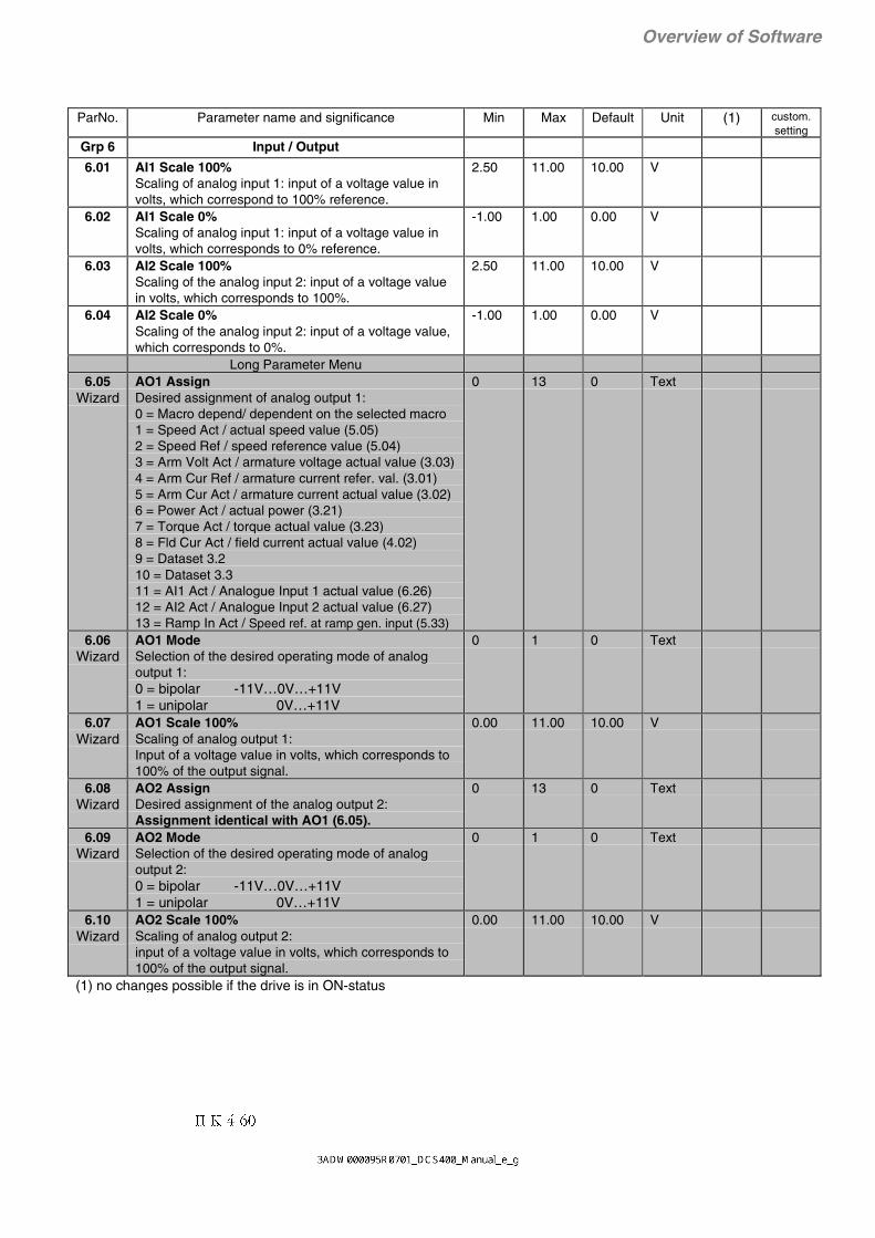
II K 4-60
Overview of Software
ParNo. Parameter name and significance Min Max Default Unit (1) custom.setting
Grp 6 Input / Output
6.01 AI1 Scale 100%Scaling of analog input 1: input of a voltage value involts, which correspond to 100% reference.
2.50 11.00 10.00 V
6.02 AI1 Scale 0%Scaling of analog input 1: input of a voltage value involts, which corresponds to 0% reference.
-1.00 1.00 0.00 V
6.03 AI2 Scale 100%Scaling of the analog input 2: input of a voltage valuein volts, which corresponds to 100%.
2.50 11.00 10.00 V
6.04 AI2 Scale 0%Scaling of the analog input 2: input of a voltage value,which corresponds to 0%.
-1.00 1.00 0.00 V
Long Parameter Menu6.05
WizardAO1 AssignDesired assignment of analog output 1:0 = Macro depend/ dependent on the selected macro1 = Speed Act / actual speed value (5.05)2 = Speed Ref / speed reference value (5.04)3 = Arm Volt Act / armature voltage actual value (3.03)4 = Arm Cur Ref / armature current refer. val. (3.01)5 = Arm Cur Act / armature current actual value (3.02)6 = Power Act / actual power (3.21)7 = Torque Act / torque actual value (3.23)8 = Fld Cur Act / field current actual value (4.02)9 = Dataset 3.210 = Dataset 3.311 = AI1 Act / Analogue Input 1 actual value (6.26)12 = AI2 Act / Analogue Input 2 actual value (6.27)13 = Ramp In Act / Speed ref. at ramp gen. input (5.33)
0 13 0 Text
6.06Wizard
AO1 ModeSelection of the desired operating mode of analogoutput 1:0 = bipolar -11V…0V…+11V1 = unipolar 0V…+11V
0 1 0 Text
6.07Wizard
AO1 Scale 100%Scaling of analog output 1:Input of a voltage value in volts, which corresponds to100% of the output signal.
0.00 11.00 10.00 V
6.08Wizard
AO2 AssignDesired assignment of the analog output 2:Assignment identical with AO1 (6.05).
0 13 0 Text
6.09Wizard
AO2 ModeSelection of the desired operating mode of analogoutput 2:0 = bipolar -11V…0V…+11V1 = unipolar 0V…+11V
0 1 0 Text
6.10Wizard
AO2 Scale 100%Scaling of analog output 2:input of a voltage value in volts, which corresponds to100% of the output signal.
0.00 11.00 10.00 V
(1) no changes possible if the drive is in ON-status

II K 4-61
Overview of Software
ParNo. Parameter name and significance Min Max Default Unit (1) custom.setting
Grp 6 Input / Output (continued)6.11
WizardDO1 AssignDesired assignment of digital output 1:0 = none 0 constant (for test purposes)1 = Constant 1 1 constant (for test purposes)2 = Macro depend the output is defined by macro, see macro
description.3 = Rdy for On Ready for ON Command. The electronic
supply is switched on, there are no faults.but the drive is still switched OFF (ON=0).
4 = Rdy for Run Ready for RUN Command. Drive is ON(ON=1) but not yet enabled (RUN=0).Main contactor, fan and field supply areswitched on.
5 = Running The drive is enabled (RUN=1).6 = Not Eme Stop No emergency stop.7 = Fault A fault has occurred8 = Alarm A warning has been output.9 = Flt or Alarm Summary alarm. A fault has occurred OR
a warning has been output.10 = Not (F or A) Summary alarm as above, but inverted.11 = Main Cont On Control signal to switch ON the main
contactor. Main Cont On depends on ONcommand.
12 = Fan On Control signal to switch ON the fan. FanOn depends on ON command.
13 = Local The drive is controlled LOCALly from thecontrol panel or the PC tool.
14 = Comm Fault The communication between PLC and thedrive is faulty.
15 = Overtemp Mot The motor overtemperature protection hasoccured (PTC to AI2) - depends on PTCMode (2.12).
16 = Overtemp DCS The converter overtemperature protectionhas occured (Alarm or Fault).
17 = Stalled The motor is stalled.18 = Forward The motor is rotating clockwise - only valid
if speed actual > Zero speed Lev (5.15).19 = Reverse The motor is rotating counter-clockwise -
only valid if speed actual > Zero speedLev (5.15).
20 = Zero Speed Standstill message, speed actual < ZeroSpeed Lev (5.15).
21 = Speed > Lev1 Speed 1 reached, speed actual > or equalto Speed Level 1 (5.16).
22 = Speed > Lev2 Speed 2 reached, speed actual > or equalto Speed Level 2 (5.17).
23 = Overspeed Overspeed, speed actual > or equal toOverspeed Trip (5.18).
24 = At Set Point Speed reference reaches reference valuebefore the ramp corresponding to actualvalue.
25 = Cur at Limit Armature current is being limited, value ofArm Cur Max (3.04) has been reached.
26 = Cur Reduced Reduced armature current, recoverycurrent after high current dosage s. chap.4.5.5.
27 = Bridge 1 Bridge 1 is active; only valid if RUN=1.28 = Bridge 2 Bridge 2 is active; only valid if RUN=1.29 = Field Reverse Field reversal is active.30 = Arm Cur > Lev Armature current actual > Arm Cur Lev
(3.25)31 = Field Cur ok Field current actual is okay. Is in a range
between Fld Ov Cur Trip (4.05) and FieldLow Trip (4.06)
32 = SpeedMeasFlt Speed measurement fault. Thecomparison of the speed feed back signalfrom tacho generator or pulse encoder hasfailed or overflow of analogue input AITAC
33 = MainsVoltLow Warning, main supply is too lowrespectively is not in accordance with ArmVolt Nom (1.02). See also Table 2.2/4 andchapter 4.5.1 Monitoring the MainsVoltage
34…63 = Reserved not used64 = Dataset 3.1 DO is controlled by Dataset 3.1
0 64 2 Text
(1) no changes possible if the drive is in ON-status

II K 4-62
Overview of Software
ParNo. Parameter name and significance Min Max Default Unit (1) custom.setting
Grp 6 Input / Output (continued)6.12
WizardDO2 AssignDesired assignment of digital output 2:Assignment identical with DO1 (6.11).
0 64 2 Text
6.13Wizard
DO3 AssignDesired assignment of digital output 3:Assignment identical with DO1 (6.11).
0 64 2 Text
6.14Wizard
DO4 AssignDesired assignment of digital output 4:Assignment identical with DO1 (6.11).
0 64 2 Text
6.15Wizard
DO5 AssignDesired assignment of digital output 5:(relay X98:1-2):Assignment identical with DO1 (6.11).
0 64 2 Text
6.16 Panel Act 1Selection of the desired panel display of actualvalue 1:(top left corner of display)0 = Speed Act / speed actual value (5.05)1 = Speed Ref / speed reference value (5.04)2 = Arm Volt Act / armature voltage act. value (3.03)3 = Arm Cur Ref / armature current ref. (3.01)4 = Arm Cur Act / armature current act. value (3.02)5 = Power Act / actual power (3.21)6 = Torque Act / torque actual value (3.23)7 = Fld Cur Act / field current actual value (4.02)8 = AI1 Act / Analogue Input 1 actual value (6.26)9 = AI2 Act / Analogue Input 2 actual value (6.27)10 = DI Act / Actual value DI1…8 (6.28)11 = Ramp In Act / Speed ref. at ramp gen. input (5.23)
0 11 2 Text
6.17 Panel Act 2Selection of the desired panel display of actualvalue 2:(top centre of display)Assignment identical with Panel Act 1 (6.16)
0 11 4 Text
6.18 Panel Act 3Selection of the desired panel display of actualvalue 3:(top right corner of display)Assignment identical with Panel Act 1 (6.16)
0 11 1 Text
6.19 Panel Act 4Selection of the desired panel display of actualvalue 4:(bottom of display)Assignment identical with Panel Act 1 (6.16)
0 11 0 Text
(1) no changes possible if the drive is in ON-status

II K 4-63
Overview of Software
ParNo. Parameter name and significance Min Max Default Unit (1) custom.setting
Grp 6 Input / Output (continued)6.20 Dataset 2.2 Asn
Selection of the desired assignment for fieldbusdataset 2.2:0 = Speed Act / speed actual value (5.05)1 = Speed Ref / speed reference value (5.04)2 = Arm Volt Act / armature voltage act. value (3.03)3 = Arm Cur Ref / armature current ref. val. (3.01)4 = Arm Cur Act / armature current act. value (3.02)5 = Power Act / actual power (3.21)6 = Torque Act / torque actual value (3.23)7 = Fld Cur Act / field current actual value (4.02)8 = Dataset 3.29 = Dataset 3.310 = AI1 Act / Analogue Input 1 actual value (6.26)11 = AI2 Act / Analogue Input 2 actual value (6.27)12 = Ramp In Act / Speed ref. at ramp gen. input (5.33)
0 12 0 Text
6.21 Dataset 2.3 AsnSelection of the desired assignment for fieldbusdataset 2.3:Assignment identical with Dataset 2.2 Asn (6.20)
0 12 4 Text
(1) no changes possible if the drive is in ON-status

II K 4-64
Overview of Software
ParNo. Parameter name and significance Min Max Default Unit (1) custom.setting
Grp 6 Input / Output (continued)
6.22 MSW Bit 11 AsnFunction assignement for bit 11 in the main fieldbusstatus word (2.06): 0 = none 0 constant (for test purposes)1 = Constant 1 1 constant (for test purposes)2 = Macro depend the output is defined by macro, see macro
description.3 = Rdy for On Ready for ON Command. The electronic
supply is switched on, there are no faults.but the drive is still switched OFF (ON=0).
4 = Rdy for Run Ready for RUN Command. Drive is ON(ON=1) but not yet enabled (RUN=0).Main contactor, fan and field supply areswitched on.
5 = Running The drive is enabled (RUN=1).6 = Not Eme Stop No emergency stop.7 = Fault A fault has occurred8 = Alarm A warning has been output.9 = Flt or Alarm Summary alarm. A fault has occurred OR
a warning has been output.10 = Not (F or A) Summary alarm as above, but inverted.11 = Main Cont On Control signal to switch ON the main
contactor. Main Cont On depends on ONcommand.
12 = Fan On Control signal to switch ON the fan. FanOn depends on ON command.
13 = Local The drive is controlled LOCALly from thecontrol panel or the PC tool.
14 = Comm Fault The communication between PLC and thedrive is faulty.
15 = Overtemp Mot The motor overtemperature protection hasoccured (PTC to AI2) - depends on PTCMode (2.12).
16 = Overtemp DCS The converter overtemperature protectionhas occured (Alarm or Fault).
17 = Stalled The motor is stalled.18 = Forward The motor is rotating clockwise - only valid
if speed actual > Zero speed Lev (5.15).19 = Reverse The motor is rotating counter-clockwise -
only valid if speed actual > Zero speedLev (5.15).
20 = Zero Speed Standstill message, speed actual < ZeroSpeed Lev (5.15).
21 = Speed > Lev1 Speed 1 reached, speed actual > or equalto Speed Level 1 (5.16).
22 = Speed > Lev2 Speed 2 reached, speed actual > or equalto Speed Level 2 (5.17).
23 = Overspeed Overspeed, speed actual > or equal toOverspeed Trip (5.18).
24 = At Set Point Speed reference reaches reference valuebefore the ramp corresponding to actualvalue.
25 = Cur at Limit Armature current is being limited, value ofArm Cur Max (3.04) has been reached.
26 = Cur Reduced Reduced armature current, recoverycurrent after high current dosage s. chap.4.5.5.
27 = Bridge 1 Bridge 1 is active; only valid if RUN=1.28 = Bridge 2 Bridge 2 is active; only valid if RUN=1.29 = Field Reverse Field reversal is active.30 = Arm Cur > Lev Armature current actual > Arm Cur Lev
(3.25)31 = Field Cur ok Field current actual is okay. Is in a range
between Fld Ov Cur Trip (4.05) and FieldLow Trip (4.06)
32 = SpeedMeasFlt Speed measurement fault. Thecomparison of the speed feed back signalfrom tacho generator or pulse encoder hasfailed or overflow of analogue input AITAC
33 = MainsVoltLow Warning, main supply is too lowrespectively is not in accordance with ArmVolt Nom (1.02). See also Table 2.2/4 andchapter 4.5.1 Monitoring the MainsVoltage
34…63 = Reserved not used64 = DI1 actual state of Digital Input 165 = DI2 actual state of Digital Input 266 = DI3 actual state of Digital Input 367 = DI4 actual state of Digital Input 4
0 67 2 Text
(1) no changes possible if the drive is in ON-status

II K 4-65
Overview of Software
ParNo. Parameter name and significance Min Max Default Unit (1) custom.setting
Grp 6 Input / Output (continued)6.23 MSW Bit 12 Asn
Function assignment for bit 12 in the main fieldbusstatus word (2.06):Assignment identical with MSW Bit 11 Asn (6.22)
0 67 2 Text
6.24 MSW Bit 13 AsnFunction assignment for bit 13 in the main fieldbusstatus word (2.06):Assignment identical with MSW Bit 11 Asn (6.22)
0 67 2 Text
6.25 MSW Bit 14 AsnFunction assignment for bit 14 in the main fieldbusstatus word (2.06):Assignment identical with MSW Bit 11 Asn (6.22)
0 67 2 Text
6.26Signal
AI1 ActReference display of analogue input 1
- - - %
6.27Signal
AI2 ActReference display of analogue input 2
- - - %
6.28Signal
DI ActStatus display of the eight digital inputs
- - - hex
(1) no changes possible if the drive is in ON-status

II K 4-66
Overview of Software
ParNo. Parameter name and significance Min Max Default Unit (1) custom.setting
Grp 7 Maintenance
7.01Wizard
LanguageSelection of the panel language:0 = English1 = Deutsch2 = Français3 = Italiano4 = Español
0 4 0 Text
7.02Action
Contr ServiceSelection of the desired service activity:0 = None1 = Arm Autotun / armature current controller auto- tuning2 = Fld Autotun / field current controller autotuning3 = Flux Adapt / flux adaptation4 = Sp Autotun / speed controller autotuning5 = Arm Man Tun / armature current controller
manual tuning (not yet released)6 = Fld Man Tun / field current controller
manual tuning7 = Thyr Diag / thyristor diagnosis
0 7 0 Text
(1) no changes possible if the drive is in ON-status

II K 4-67
Overview of Software
ParNo. Parameter name and significance Min Max Default Unit (1) custom.setting
Grp 7 Maintenance (continued)7.03
SignalDiagnosisDisplay of all diagnostic messages:Further information see chapter ’Troubleshooting’0 = none1…10 = 1…10 (internal software causes)11 = Tune Aborted12 = No Run Cmd13 = No ZeroSpeed14 = Fld Cur <> 015 = Arm Cur <> 016 = Arm L Meas17 = Arm R Meas18 = Field L Meas19 = Field R Meas20 = TuneParWrite21 = 21 (internal software causes)22 = Tacho Adjust23 = Not Running24 = Not At Speed25 = TachPolarity26 = Enc Polarity27 = No EncSignal28 = StillRunning29 = 29 (internal software causes)30 = Wiz ParWrite31 = 31 (internal software causes)32 = UpDn Aborted33 = reserved34 = Par Checksum35 = 35 (internal software causes)36 = 36 (internal software causes)37…69 = reserved70 = Fld Low Lim71 = Flux Char72 = Field Range73 = Arm Data74 = AI2 vs PTC75 = RecoveryTime76 = Grp9 Disable77…79 = reserved80 = Speed does not reach setpoint81 = Motor is not accelerating82 = Not enough measurement for speed KP and TI83…89 = reserved90 = Shortcut V1191 = Shortcut V1292 = Shortcut V1393 = Shortcut V1494 = Shortcut V1595 = Shortcut V1696 = Result False97 = ShortcV15/2298 = ShortcV16/2399 = ShortcV11/24100 = ShortcV12/25101 = ShortcV13/26102 = ShortcV14/21103 = Ground Fault104 = NoThrConduc
- - - Text
7.04Const.
SW VersionDisplay of the DCS 400 software version used.
- - - integer
7.05Const.
Conv TypeDisplay of the converter type:0 = DCS401 (2Q)1 = DCS402 (4Q)2 = DCS401 Rev A (2Q)3 = DCS402 Rev A (4Q)
- - - Text
(1) no changes possible if the drive is in ON-status

II K 4-68
Overview of Software
ParNo. Parameter name and significance Min Max Default Unit (1) custom.setting
Grp 7 Maintenance (continued)7.06
Const.Conv Nom CurDisplay of the converter’s nominal current in amperes.
- - - A
7.07Const.
Conv Nom VoltDisplay of the converter’s nominal voltage in volts.
- - - V
7.08Signal
Volatile AlarmDisplay of the last alarm.
- - - Text
7.09Signal
Fault Word 1All the pending faults are displayed if thecorresponding bits are set to log. "1".Bit hex Fault definition00 0001 01 Aux Voltage Fault01 0002 02 Hardware Fault02 0004 03 Software Fault03 0008 04 Par Flash Read Fault04 0010 05 Compatibility Fault05 0020 06 Typecode Read Fault06 0040 07 Converter Overtemp07 0080 08 Motor Overtemp08 0100 09 Mains Undervoltage09 0200 10 Mains Overvoltage10 0400 11 Mains Sync Fault11 0800 12 Field Undercurrent12 1000 13 Field Overcurrent13 2000 14 Armature Overcurrent14 4000 15 Armature Overvoltage15 8000 16 Speed Meas Fault
- - - hex
7.10Signal
Fault Word 2Fault word 2. Significance of the individual bits:All the pending faults are displayed if thecorresponding bits are set to log. "1".Bit hex Fault definition00 0001 17 Tacho Polarity fault01 0002 18 Overspeed02 0004 19 Motor Stalled03 0008 20 Communication Fault04 0010 21 Local Control Lost05 0020 22 External Fault06 0040 23 -07 0080 24 -08 0100 25 -09 0200 26 -10 0400 27 -11 0800 28 -12 1000 29 -13 2000 30 -14 4000 31 -15 8000 32 -
- - - hex
7.11Signal
Fault Word 3Fault word 3. Significance of the individual bits:All the pending faults are displayed if thecorresponding bits are set to log. "1".Bit hex Fault definition00 0001 33 -01 0002 34 -02 0004 35 -03 0008 36 -04 0010 37 -05 0020 38 -06 0040 39 -07 0080 40 -08 0100 41 -09 0200 42 -10 0400 43 -11 0800 44 -12 1000 45 -13 2000 46 -14 4000 47 -15 8000 48 -
- - - hex
(1) no changes possible if the drive is in ON-status

II K 4-69
Overview of Software
ParNo. Parameter name and significance Min Max Default Unit (1) custom.setting
Grp 7 Maintenance (continued)7.12
SignalAlarm Word 1Alarm word 1. Significance of the individual bits:All the pending alarms are displayed if thecorresponding bits are set to log. "1".Bit hex Alarm definition00 0001 01 Parameters Added01 0002 02 Mains Voltage Low02 0004 03 Arm Circuit Break03 0008 04 Converter Temp High04 0010 05 Motor Temp High05 0020 06 Arm Current Reduced06 0040 07 Field Volt Limited07 0080 08 Mains Drop Out08 0100 09 Eme Stop Pending09 0200 10 Autotuning Failed10 0400 11 Comm Interrupt11 0800 12 External Alarm12 1000 13 ill Fieldbus Setting13 2000 14 Up/Download Failed14 4000 15 PanTxt Not UpToDate15 8000 16 Par Setting Conflict
- - - hex
7.13Signal
Alarm Word 2Alarm word 2. Significance of the individual bits:All the pending alarms are displayed if thecorresponding bits are set to log. "1".Bit hex Alarm definition00 0001 17 Compatibility Alarm01 0002 18 Parameter restored02 0004 19 -03 0008 20 -04 0010 21 -05 0020 22 -06 0040 23 -07 0080 24 -08 0100 25 -09 0200 26 -10 0400 27 -11 0800 28 -12 1000 29 -13 2000 30 -14 4000 31 -15 8000 32 -
- - - hex
7.14Signal
Alarm Word 3Alarm word 3. Significance of the individual bits:All the pending alarms are displayed if thecorresponding bits are set to log. "1".Bit hex Alarm definition00 0001 33 -01 0002 34 -02 0004 35 -03 0008 36 -04 0010 37 -05 0020 38 -06 0040 39 -07 0080 40 -08 0100 41 -09 0200 42 -10 0400 43 -11 0800 44 -12 1000 45 -13 2000 46 -14 4000 47 -15 8000 48 -
- - - hex
(1) no changes possible if the drive is in ON-status
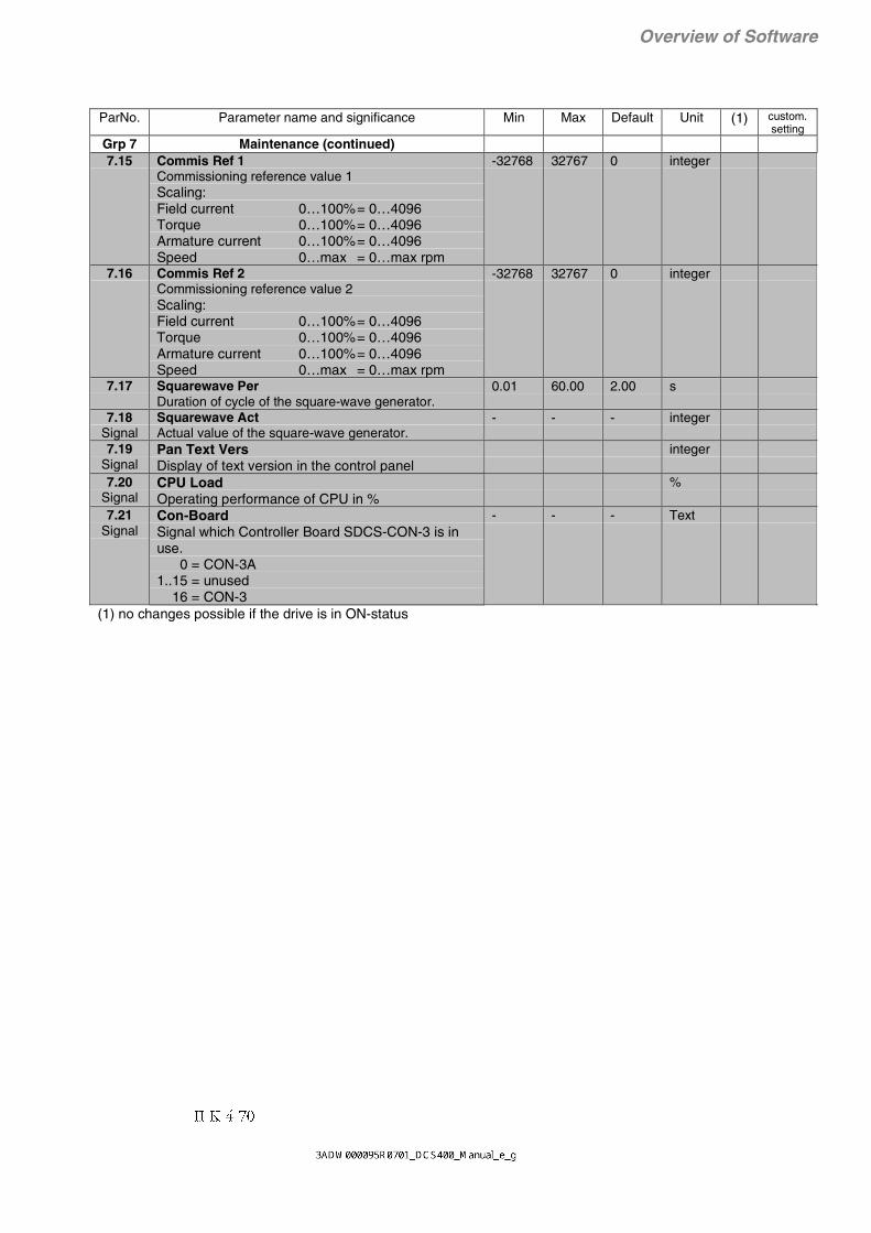
II K 4-70
Overview of Software
ParNo. Parameter name and significance Min Max Default Unit (1) custom.setting
Grp 7 Maintenance (continued)7.15 Commis Ref 1
Commissioning reference value 1Scaling:Field current 0…100%= 0…4096Torque 0…100%= 0…4096Armature current 0…100%= 0…4096Speed 0…max = 0…max rpm
-32768 32767 0 integer
7.16 Commis Ref 2Commissioning reference value 2Scaling:Field current 0…100%= 0…4096Torque 0…100%= 0…4096Armature current 0…100%= 0…4096Speed 0…max = 0…max rpm
-32768 32767 0 integer
7.17 Squarewave PerDuration of cycle of the square-wave generator.
0.01 60.00 2.00 s
7.18Signal
Squarewave ActActual value of the square-wave generator.
- - - integer
7.19Signal
Pan Text VersDisplay of text version in the control panel
integer
7.20Signal
CPU LoadOperating performance of CPU in %
%
7.21Signal
Con-BoardSignal which Controller Board SDCS-CON-3 is inuse. 0 = CON-3A1..15 = unused 16 = CON-3
- - - Text
(1) no changes possible if the drive is in ON-status

II K 4-71
Overview of Software
ParNo. Parameter name and significance Min Max Default Unit (1) custom.setting
Grp 8 FieldbusLong Parameter Menu
8.01 Fieldbus Par 10 = Disable
no communication with PLC1 = Fieldbus
PLC communication via fieldbus adapter2 = RS232-Port
PLC communication via RS232 Port / Modbusprotocol
3 = Panel-PortPLC communication via Panel Port / Modbusprotocol
4 = Res FieldbusReset all fieldbus parameter (8.01...8.16) to zero
0 4 0 Text x
8.02 Fieldbus Par 2further information see chapter 7
0 65535 0 integer x
8.03 Fieldbus Par 3further information see chapter 7
0 65535 0 integer x
8.04 Fieldbus Par 4further information see chapter 7
0 65535 0 integer x
8.05 Fieldbus Par 5further information see chapter 7
0 65535 0 integer x
8.06 Fieldbus Par 6further information see chapter 7
0 65535 0 integer x
8.07 Fieldbus Par 7further information see chapter 7
0 65535 0 integer x
8.08 Fieldbus Par 8further information see chapter 7
0 65535 0 integer x
8.09 Fieldbus Par 9further information see chapter 7
0 65535 0 integer x
8.10 Fieldbus Par 10further information see chapter 7
0 65535 0 integer x
8.11 Fieldbus Par 11further information see chapter 7
0 65535 0 integer x
8.12 Fieldbus Par 12further information see chapter 7
0 65535 0 integer x
8.13 Fieldbus Par 13further information see chapter 7
0 65535 0 integer x
8.14 Fieldbus Par 14further information see chapter 7
0 65535 0 integer x
8.15 Fieldbus Par 15further information see chapter 7
0 65535 0 integer x
8.16 Fieldbus Par 16further information see chapter 7
0 65535 0 integer x
(1) no changes possible if the drive is in ON-status
For detailed description see "Fieldbus Description"

II K 4-72
Overview of Software
ParNo. Parameter name and significance Min Max Default Unit (1) custom.setting
Grp 9 Macro AdaptationLong Parameter Menu
9.01 MacParGrpActionBefore a new function can be assigned to a digital inputor control bit, the actual function has to be disabled. Thiscan be done in two ways. With par. 9.01 the function of allassigned parameters 9.02...9.20 can be preset to disable.The same can be achieved by setting the parameters9.02...9.20 individually.0=unchanged no parameters changes1=Macro depend set parameters 9.02...9.20 to macro depend2=Disable set parameters 9.02...9.20 to disableMacro adaptation not possible for Macro 2, 3, 4
0 2 0 Text x
9.02 Jog 1Jog function will be controlled from a binary signal whichis assigned in this parameter:0=Macro depend1=Disable2=DI13=DI24=DI35=DI4
State of binary signal:0=no Jog 1
Decelerate the motor by using Jog Decel Ramp(5.20) till zero speed afterwards disable ofcurrent controller .
1=Jog 1enable current controller and accelerate the motor by using Jog Acel Ramp (5.19) up toFixed Speed 1 (5.13)
Jog 1 function can also be controlled by bit 8 of MainControl Word via serial communication - depending onCmd Location (2.02).
0 5 0 Text x
9.03 Jog 2Jog function will be controlled from a binary signal whichis assigned in this parameter.Assignment identical with 9.02
State of binary signal:0=no Jog 2
Decelerate the motor by using Jog Decel Ramp(5.20) till zero speed afterwards disable ofcurrent controller .
1=Jog 2enable current controller and accelerate the motor by using Jog Acel Ramp (5.19) up toFixed Speed 2 (5.14)
Jog 2 unction can also be controlled by bit 8 of MainControl Word via serial communication - depending onCmd Location (2.02).
0 5 0 Text x
9.04 COASTCoast function will be controlled from a binary signalwhich is assigned in this parameter.Assignment identical with 9.02Only effective if Panel or PC tool is not in LOCal Mode.
State of binary signal:0=COAST
disable current controller, switch Main Contactor Off, motor is coasting till zero speed
1=no COASTClosed-circuit principle, must be closed for operation
The Coast function is also controlled by bit 1 of MainControl Word via serial communication.
0 5 0 x
(1) no changes possible if the drive is in ON-status

II K 4-73
Overview of Software
ParNo. Parameter name and significance Min Max Default Unit (1) custom.setting
Grp 9 Macro Adaptation (continued)9.05 User Fault
Fault function will be controlled from a binary signalwhich is assigned in this parameter: 0=Macro depend 1=Disable 2=DI1 3=DI2 4=DI3 5=DI4 6=MCW Bit 11 7=MCW Bit 12 8=MCW Bit 13 effective independent of Cmd 9=MCW Bit 14 Location (2.02)10=MCW Bit 15
State of binary signal:0=no Fault1=Fault Triggers an External Fault (F22) and
trips the drive
0 10 0 Text x
9.06 User Fault InvFault (inv) function will be controlled from binary signalwhich is assigned in this parameter:Assignment identical with 9.02
State of binary signal:0=Fault Triggers an External Fault (F22) and
trips the drive1=no fault Closed-circuit principle, must be
closed for operation
0 5 0 Text x
9.07 User AlarmAlarm function will be controlled from binary signalwhich is assigned in this parameter:Assignment identical with 9.05
State of binary signal:0=no Alarm1=Alarm Triggers an External Alarm (A12) in
DCS400
0 10 0 Text x
9.08 User Alarm InvAlarm (inv) function will be controlled from binarysignal which is assigned in this parameter:Assignment identical with 9.02
State of binary signal:0=Alarm Triggers an External Alarm (A12) in
DCS4001=no Alarm Closed-circuit principle, must be
closed for operation
0 5 0 Text x
9.09 Dir of RotationDirection of rotation will be controlled from binarysignal which is assigned in this parameter:Assignment identical with 9.05
State of binary signal:0=forward1=reverseEffective only when the drive is speed controlled.
0 10 0 Text x
(1) no changes possible if the drive is in ON-status

II K 4-74
Overview of Software
ParNo. Parameter name and significance Min Max Default Unit (1) custom.setting
Grp 9 Macro Adaptation (continued)9.10 MotPot Incr
MotorPot Increase speed function will be controlledfrom a binary signal which is assigned in thisparameter.Assignment identical with 9.05only effective if MotPot Decr (9.11) is not set to1 = Disable
State of binary signal:0=hold speed1=increase speed
accelerate speed at Acel Ramp (5.09 ) until Max Speed (1.06)
0 10 0 Text x
9.11 MotPot DecrMotorPot Decrease speed function will be controlledfrom a binary signal which is assigned in thisparameter.Assignment identical with 9.05
State of binary signal:0=hold speed1=decrease speed
decelerate speed at Decel Ramp (5.10) untilzero speed respectively MotPotMinSpeed (9.12)
if active. MotPot Decr has precedence above MotPot Incr
0 10 0 Text x
9.12 MotPotMinSpeedMotorPot minimum speed function will be controlledfrom a binary signal which is assigned in thisparameter.Assignment identical with 9.05only effective if MotPot Decr (9.11) is not set to1 = Disable
State of binary signal:0=Start from zero.
MotPotMinSpeed is inactive.1=Start from MotPotMinSpeed
activate MinimumSpeed. Speed can be defined in parameter Fixed Speed 1 (5.13).When the drive is started the speed will beaccelerated to this minimum speed and it isnot possible to set the speed below thisminimum with motor pot function.
0 10 0 Text x
9.13 Ext Field RevExternal field reversal will be controlled from a binarysignal which is assigned in this parameter.Assignment identical with 9.05
State of binary signal:0=no field reversal1=field reversal
External field reversal with external field reversing switch. Only for 2-Q application.Depend on field reversal the signal „Field reversal active“ has log. state „1“.Field reversal is only possible when the drive is OFF (DI7=0). When field reversal is active the polarity of speed actual value is changed in the software. It’s recommended to use a remanence contactor relay to storethe state of this relay when the main supply failes. Otherwise the relay contactors can burn due to the field inductance.
0 10 0 Text x
(1) no changes possible if the drive is in ON-status

II K 4-75
Overview of Software
ParNo. Parameter name and significance Min Max Default Unit (1) custom.setting
Grp 9 Macro Adaptation (continued)9.14 AlternativParam
Alternative parameter set will be controlled from abinary signal which is assigned in this parameter.Assignment identical with 9.05
State of binary signal:0= Standard parameter set for speed controller effective
5.07 Speed Reg KP5.08 Speed Reg TI5.09 Accel Ramp5.10 Decel Ramp
1= IF Alt Par Sel (5.21) = Macro dependTHEN
alternativ parameter set for speed controllereffective5.22 Alt Speed KP5.23 Alt Speed TI5.24 Alt Accel Ramp5.25 Alt Decel Ramp
ELSEalternativ parameter set for speed controllereffective depending on an event selected in AltPar Sel (5.21)
0 10 0 Text x
9.15 Ext Speed LimExternal speed limitation will be controlled from abinary signal which is assigned in this parameter.Assignment identical with 9.05
State of binary signal:0=no speed limitation1=speed limitation to parameter Fixed Speed 1 (5.13)
0 10 0 Text x
9.16 Add AuxSpRefAdditional aux speed reference will be controlled froma binary signal which is assigned in this parameter.Assignment identical with 9.05
State of binary signal:0=no additional aux. speed reference1= IF Aux Sp Ref Sel (5.26) = Macro depend
THENvalue of Fixed Speed 2 (5.14) is added tospeed reference.
ELSEvalue in Aux Sp Ref Sel (5.26) is added tospeed reference.
0 10 0 Text x
9.17 Curr Lim 2 InvSecond current limitation will be controlled from abinary signal which is assigned in this parameter.Assignment identical with 9.05
State of binary signal:0=current limitation 2 effective (3.24 Arm Cur Lim 2)1=current limitation 1 effective (3.04 Arm Cur Max)
Value of Arm Cur Max (3.04) has to be greaterthan value of Arm Cur Lim 2 (3.24).
0 10 0 Text x
9.18 Speed/TorqueSpeed/torque function will be controlled from a binarysignal which is assigned in this parameter.Assignment identical with 9.05
State of binary signal:0= drive is speed controlled1= IF Cur Contr Mode (3.14) = Macro depend
THENdrive is torque controlled
ELSEdrive is controlled as selected in Cur ContrMode (3.14)
0 10 0 Text x
(1) no changes possible if the drive is in ON-status

II K 4-76
Overview of Software
ParNo. Parameter name and significance Min Max Default Unit (1) custom.setting
Grp 9 Macro Adaptation (continued)9.19 Disable Bridge1
Bridge 1 will be controlled from binary signal which isassigned in this parameter.Assignment identical with 9.05
State of binary signal:0= Enable Bridge 11= Disable Bridge 1. Set affected Torque Ref to zero.
0 10 0 Text x
9.20 Disable Bridge2Bridge 2 will be controlled from binary signal which isassigned in this parameter.Assignment identical with 9.05
State of binary signal:0= Enable Bridge 21= Disable Bridge 2. Set affected Torque Ref to zero.
0 10 0 Text x
(1) no changes possible if the drive is in ON-status

II K 5-1
Installation5 Installation
General
Incoming inspectionCheck the contents of delivery• DCS 400• Manual• Mounting template• Quick installation & commissioning guideCheck the consignment for any signs of damage. Ifyou find any, please contact the insurance companyor the supplier.Check the particulars given on the unit's rating plateto make sure prior to installation and start-up thatyou have received the correct unit type and unitversion.If the consignment is incomplete or contains anyincorrect items, please contact the supplier.
CAUTION!The thyristor power converter weighs quite a lot andshould therefore not be held by the front cover.Please put the unit down only on its back. Alwaysuse due care when handling the unit, so as to avoidinjuries or damage.
Storage and transportIf the unit had been in storage prior to installation or istransported to another location, care must be taken toensure that the environmental conditions are com-plied with.
Rating plateFor purposes of identification, each thyristor powerconverter is fitted with rating plates, stating the typecode and the serial number, which serve for eachunit's individual identification.The type code contains information on the character-istics and the configuration of the unit.
The technical data and specifications are valid as ofgoing to press. ABB reserves the right to makesubsequent alterations.
If you have any questions concerning your drivesystem, please contact your local ABB agent.

II K 5-2
Installation5.1 Safety instructions
1. General
In operation, drive converters, depending on their degree of protec-tion, may have live, uninsulated, and possibly also moving or rotatingparts, as well as hot surfaces.
In case of inadmissible removal of the required covers, of improperuse, wrong installation or maloperation, there is the danger ofserious personal injury and damage to property.
For further information, see documentation.
All operations serving transport, installation and commissioninng aswell as maintenance are to be carried out by skilled technicalpersonnel (Observe IEC 364 or CENELEC HD 384 or DIN VDE 0100and IEC 664 or DIN/VDE 0110 and national accident preventionrules!).
For the purposes of these basic safety instructions, “skilled technicalpersonnel” means persons who are familiar with the installation,mounting, commissioning and operation of the product and have thequalifications needed for the performance of their functions.
2. Intended use
Drive converters are components designed for inclusion in electricalinstallations or machinery.
In case of installation in machinery, commissioning of the driveconverter (i.e. the starting of normal operation) is prohibited until themachinery has been proved to conform to the provisions of thedirective 89/392/EEC (Machinery Safety Directive - MSD). Accountis to be taken of EN 60204.
Commissioning (i.e. the starting of normal opertion) is admissibleonly where conformity with the EMC directive (89/336/EEC) hasbeen established.
The drive converters meet the requirements of the low-voltagedirective 73/23/EEC. They are subject to the harmonized standardsof the series prEN 50178/DIN VDE 0160 in conjunction with EN60439-1/ VDE 0660, part 500, and EN 60146/ VDE 0558.
The technical data as well as information concerning the supplyconditions shall be taken from the rating plate and from the docu-mentation and shall be strictly observed.
3. Transport, storage
The instructions for transport, storage and proper use shall becomplied with.
The climatic conditions shall be in conformity with prEN 50178.
4. Installation
The installation and cooling of the appliances shall be in accordancewith the specifications in the pertinent documentation.
The drive converters shall be protected against excessive strains.In particular, no components must be bent or isolating distancesaltered in the course of transportation or handling. No contact shallbe made with electronic components and contacts.
Drive converters contain electrostatic sensitive components whichare liable to damage through improper use. Electric componentsmust not be mechanically damaged or destroyed (potential healthrisks).
5. Electrical connection
When working on live drive converters, the applicable nationalaccident prevention rules (e.g. VBG 4) must be complied with.The electrical installation shall be carried out in accordance with therelevant requirements (e.g. cross-sectional areas of conductors,fusing, PE connection). For further information, see documentation.
Instructions for the installation in accordance with EMC require-ments, like screening, earthing, location of filters and wiring, arecontained in the drive converter documentation. They must alwaysbe complied with, also for drive converters bearing a CE marking.Observance of the limit values required by EMC law is the respon-sibility of the manufacturer of the installation or machine.
6. Operation
Installations which include drive converters shall be equipped withadditional control and protective devices in accordance with therelevant applicable safety requirements, e.g. Act respecting techni-cal equipment, accident prevention rules etc. Changes to the driveconverters by means of the operating software are admissible.
After disconnection of the drive converter from the voltage supply,live appliance parts and power terminals must not be touchedimmediately because of possibly energized capacitors. In this re-spect, the corresponding signs and markings on the drive convertermust be respected.
During operation, all covers and doors shall be kept closed.
7. Maintenance and servicing
The manufacturer’s documentation shall be followed.
in conformity with the low-voltage directive 73/23/EEC
KEEP SAFETY INSTRUCTIONS IN A SAFE PLACE!

II K 5-3
Installation
WarningsWarnings provide information on states which if the specifiedprocedure for the state concerned is not meticulously complied withmay result in a serious error, in major damage to the unit, in injuryto persons and even in death. They are identified by the followingsymbols:
Danger: High Voltage:
This symbol warns you of high voltages which may result in injuriesto persons and/or damage to equipment. Where appropriate, thetext printed adjacent to this symbol describes how risks of this kindmay be avoided.
• All electrical installation and maintenance work on the thyristorpower converter must be carried out by properly qualified staffwho have been thoroughly trained in electrical engineering.
• The thyristor power converter and its adjacent units must beproperly earthed by qualified professionals.
• You must NEVER perform any work on the thyristor powerconverter while it is still switched on. First switch the unit off, usea measuring instrument to make absolutely sure that the powerconverter has really been de-energized, and only then you maystart with the work concerned.
• Due to external control circuits, there may be dangerously highvoltages present at the thyristor power converter even after theline voltage has been switched off. So always work at the unit withappropriate caution! Non-compliance with these instructions mayresult in injury (or even death!).
General Warning:
This symbol warns you of non-electrical risks and dangers whichmay result in serious or even fatal injury to persons and/or in damageto equipment. Where appropriate, the text printed adjacent to thissymbol describes how risks of this kind may be avoided.
• When thyristor power converters are in use, the electric motors,power transmission elements and the driven machines areworking in an extended operating range, which means they haveto cope with a relatively high loading.
• You should have made sure that all units, devices andappliances used are actually suitable for this higher loading.
• If you have to operate the thyristor power converter at a ratedmotor voltage and/or a rated motor current significantlybelow the figures stated in the thyristor power converter'soutput data, you must take appropriate precautionary meas-ures to protect the unit against overspeed, overload, break-age, etc., by modifying the software or hardware appropriate-ly.
• For insulation testing, you must disconnect all cables fromthe thyristor power converter. You should avoid operatingyour unit at values other than the rated data. Non-compliancewith these instructions may cause lasting damage to thethyristor power converter.
• The thyristor power converter possesses a number of automaticreset functions. When these functions are executed, the unit willbe reset after an error and will then resume operation. Thesefunctions should not be used if other units and devices are notsuitable for an operating mode of this kind, or if their use mightentail dangerous situations.
Warning of electrostatic discharge:
This symbol warns you against electrostatic discharges which maydamage the unit. Where appropriate, the text printed next to thissymbol describes how a risk of this kind may be avoided.
NotesNotes supply information on states requiring particular attention, orindicate that additional information is available on a specific topic.For this purpose, the following symbols are used:
CAUTION!Cautions are designed to draw your attention to a particular stateof affairs.
NoteA note contains or refers you to additional information availableon the particular topic concerned.
Mains connectionYou can use a switch disconnector (with fuses) in the power supplyof the thyristor power converter to disconnect the electrical compo-nents of the unit from the power supply for installation and mainte-nance work. The type of disconnector used must be a switchdisconnector as per EN 60947-3, Class B, so as to comply with EUregulations, or a circuit-breaker type which switches off the loadcircuit by means of an auxiliary contact causing the breaker's maincontacts to open. The mains disconnector must be locked in its"OPEN" position during any installation and maintenance work.
EMERGENCY STOP buttonsEMERGENCY STOP buttons must be installed at each control deskand at all other control panels requiring an emergency stop function.
Intended useThe operating instructions cannot take into consideration everypossible case of configuration, operation or maintenance. Thus,they mainly give such advice only, which is required by qualifiedpersonnel for normal operation of the machines and devices inindustrial installations.
If in special cases the electrical machines and devices are intendedfor use in non-industrial installations - which may require strictersafety regulations (e.g. protection against contact by children orsimilar) -, these additional safety measures for the installation mustbe provided by the customer during assembly.
Common Warnings

II K 5-4
Installation5.2 EMC Compliant Installation and Configuration for a Power Drive System
RemarkThis is a part of the man-ual Thyristor Power Con-verters EMC CompliantInstallation and Configu-ration for a Power DriveSystem - TechnicalGuide
Note In order to make the description in this chapter as short and easilyreadable as possible, cross references in the form 1 , 2 … areused.
General Converters and the major part of the devices, which constitute a DCDrive, cannot fulfil the EMC requirements independently from eachother. They must be installed and connected by skilled personnelaccording to the guidelines laid down in this manual. This restrictionis related to the expression “restricted distribution” in the short de-scription of EN 61800-3, which is the EMC product standard for aPower Drive System.
EN 61800-3EMC standard for Power Drive Systems (PDS), immunity andemission in domestic, residential and light industry restricted areaand in industry.
This standard must be complied with to meet the EMC require-ments for plants and machines in the EC!
If the DC Drive is designed and built up according to this installationguide then it meets the requirements of EN 61800-3 and of the fol-lowing standards:
EN 50082-2 Generic standard for noise immunity inindustrial environment(includes EN 50082-1, domestic environment)
EN 50081-2 Generic standard for noise emission in indus-trial environment
EN 50081-1 Generic standard for noise emission in do-mestic environment, can be fulfilled withspecial means (line filters, screened powercables) in the lower power range
NOTE!
The conformity procedure is matter of responsibility of ABBAutomation Products GmbH and of the machine manufactur-ers or the plant builders corresponding to their share of the ex-tension of the electrical equipment.

II K 5-5
Installation
Definitions
Earth, earthing for safety
Ground, grounding for EMC, connection with chassis orhousing with low inductance
Important instructions for plants with line fil-ters
Filter in an earthed line (TN or TT Network)The filters are suitable for earthed lines only, for example in publicEuropean 400 V lines. According to EN 61800-3, filters are notcompatible in insulated industrial lines with own supply transformersdue to their safety risks in such floating lines (IT networks).
Earth fault detectionFilters (with internal discharging resistors), cables, the converterand the motor have together a considerable capacitance to ground,which can cause an increased capacitive earth current. The trippingthreshold of an earth fault detector that measures this current mustbe adapted to this higher value.
High voltage testBecause of the capacitors of the line filter the high voltage test hasto be done with dc voltage to protect the components.
Warning
Line filters contain capacitors, which can keep dangerous voltagesat the terminals after the switch off of the mains voltage. The dis-charge by internal resistors takes some seconds. Therefore a wait-ing time of at least 10 s and a voltage check are obligatory beforeyou begin your work at the equipment.
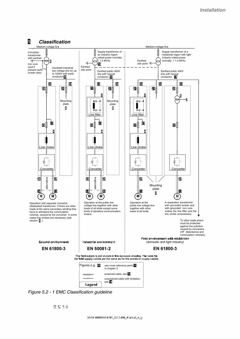
II K 5-6
Installation
1 Classification
000000
6HFRQGHQYLURQPHQW
)LUVWHQYLURQPHQWZLWKUHVWULFWLRQ(domestic and light industry)
/HJHQG
unscreened cable with limitation, see
screened cable, see
Line filter
Line choke
To other loads which must be protected against line pollution caused by converters (HF disturbance and commutation notches).
Mounting plate
Line filter
Line choke
A separation transformer with grounded screen and with grounded iron core makes the line filter and the line choke unnecessary.
Operation with separate converter (dedicated) transformer. If there are other loads at the same secondary winding they have to withstand the commutation notches, caused by the converter. In some cases line chokes are necessary (see section ).
Operation at the public low voltage line together with other loads of all kinds except some kinds of sensitive communication means.
Operation at the public low voltage line together with other loads of all kinds
Figures e.g. see cross reference point in chapter 3
Converter Converter Converter Converter
7KHILHOGVXSSO\LVQRWVKRZQLQWKLVV\QRSVLVGUDZLQJ7KHUXOHVIRUWKHILHOGVXSSO\FDEOHVDUHWKHVDPHDVIRUWKHDUPDWXUHVXSSO\FDEOHV
Convertertransformer with earthed
iron core (and if present earth screen also)
Insulated industrial low voltage line for up to 1000V with earth conductor
Earthedstar point
Supply transformer of a residental region with light industry (rated power normally ≤ 1.2 MVA)
Earthed public 400V line with neutral conductor
Medium-voltage line
Supply transformer of an industry region (rated power normally ≤ 1.2 MVA) Earthed
star point
Earthed public 400V line with neutral conductor
Medium-voltage line
Mountingplate
Mountingplate
,QGXVWULDOHQYLURQPHQW
Line choke
alte
rnat
ive
alte
rnat
ive
Figure 5.2 - 1 EMC Classification guideline

II K 5-7
Installation
2 Three-phase filters EMC filters are necessary to fulfil EN 50081 if a converter shall berun at a public low voltage line, in Europe for example with 400 Vbetween the phases. Such lines have an earthed neutral conduc-tor. ABB offers suitable three - phase filters for 400 V and 25A...600 A and 500 V filters for 440 V lines outside Europe (see Ap-pendix A).Lines with 500 V to 1000 V are not public. They are local lines in-side factories, and they do not supply sensitive electronics. There-fore converters do not need EMC filters if they shall run with 500 Vand more (see also 6).
3 Single-phase fil-ters for fieldsupply
Many field supply units are single - phase converters for up to 50 Aexcitation current. They can be supplied by two of the three inputphases of the armature supply converter. Then a field supply unitdoes not need an own filter as shown at the connection example(24).
If the phase voltage to the neutral conductor shall be taken (230 Vin a 400 V line) then a separate filter is necessary as shown below.ABB offers such filters for 250 V and 6...55 A (see Appendix A).
3-PH FILTER
1-PH FILTER
0
L1L2L3
N
Figure 5.2 - 2 Connection of single and three phase filters
4 Line chokes(Commutationchokes)
Converters cause short-duration short circuits at their AC inputs, so- called commutation notches. Such notches down to 0 V (100%depth) can be accepted at the secondary windings of converter(dedicated) transformers (operation without line chokes). However,their depth must be reduced if the same transformer shall supplymore than two converters of comparable power. In such case linechokes are necessary. They must cause about 1% relative voltagedrop at rated current. So - called 1% chokes are also necessary ifthe power of the converter is very low compared with the availablepower of the transformer or supply line. ABB offers suitable 1%chokes.
According to the European product standard EN 61800-3, thecommutation notches must be kept below 20% of the line voltagein the first environment, whereas an upper limit of 40 % is specifiedfor the second environment. This target can be achieved with theaid of line chokes. The inductance of these chokes to be applied inthe first environment must have 4 times the value of the networkinductance at the converter’s connection point (point of commoncoupling, PCC) as shown in Figure 5.2-3. Therefore in many casesso-called 4% chokes are necessary, and therefore ABB offers alsosuitable 4% line chokes besides the 1% chokes.

II K 5-8
Installation
Due to the maximum power of public 400 V transformers(PMAX = 1.2 MVA Õ IMAX = 1732 A) and due to their relative short circuitvoltage VSC of 6% or 4% the maximum AC current which is available for aconverter is 346 A or 520 A (IDC≤ 422 A or 633 A).
For vSC = 4 %: IDC ≤ 633 A
For vSC = 6 %: IDC ≤ 422 A
XPCC
Converter
Supply transformer of a residental region with light industry (rated power normally ≤ 1.2 MVA). With reference to EN 61800-A11 the rated power of transformer must be at least 4 times the rated power of the PDS.
Earthed public 400 V line with neutral conductor
Earthedstar point
Medium-voltage line
Line choke
PCCNotches ≤ 20 %
vSC = 4 % or 6 %
Imax = 1.7 kA
For vSC = 4 %: XPCC ≥ 5.40 mΩ (LPCC ≥ 17.2 µH)
For vSC = 6 %: XPCC ≥ 8.12 mΩ (LPCC ≥ 25.8 µH)
For vSC = 4 %: XCHOKE ≥ 4 x XPCC = 21.6 mΩ (LCHOKE ≥ 68.8 µH)For vSC = 6 %: XCHOKE ≥ 4 x XPCC = 32.48 mΩ (LCHOKE ≥ 103.2 µH)
Example:
2
*QRP
QRP3&&
6&3&&
3
9Y; ≥
%20≤+
&+2.(3&&
3&&
;;
;
3&&&+2.(;; *4≥⇒
Figure 5.2 - 3 Required minimum line choke impedance forinstallation of converter in first environment
Often the maximum current is not limited by the transformer but by thepower cable to the industry region. Therefore it is necessary to ask theenergy supply company concerning the line impedance and the currentwhich is available at the desired point of common coupling (PCC).

II K 5-9
Installation
5 Separationtransformers
A separation transformer makes line chokes unnecessary becauseof its leakage inductance, and a grounded screen between itswindings saves an EMC filter, see 1 and 4. The screen and the ironcore must be well connected with the mounting plate of the con-verter. If the transformer is located outside the converter cubiclethe screen of a screened 3-phase cable ("first" environment, figure5.2-1 at the right) or a ground cable ("second" environment, figure5.2-1 at the left) must make this connection (see also 24 "Connec-tion example").
6 Converter (dedi-cated) trans-formers
A converter (dedicated) transformer transfers high power directlyfrom a medium voltage line to a single large converter or to a locallow voltage line for several converters (see 20). Furthermore it actsas separation transformer according to 5.
If such a converter transformer has no screen the EMC demandsare nevertheless fulfilled in most cases because the RF interfer-ence energy can hardly get via the medium-voltage line and thetransformer of the public line to the loads which must be protectedagainst pertubances. In the case of a dispute a measurement mustbe done at the point of common coupling (public low - voltage line)according to EN 61 800-3.
7 Installation hints
8 Cabinets All metal cubicles available on the market can be used; however,their mounting plates must have well conducting surfaces accord-ing to 9.If a drive system is placed in more than one cubicle their mountingplates must be connected by broad pieces of well conducting sheetmetal.
9 Mounting plate The mounting plate must be made from steel with zinc surfacesand without any painting. The PE copper bar must be mounted di-rectly on the mounting plate without any insulating means between,and it must be connected with the plate by several bolts distributedin equal distances along its length.
10 Placement ofdevices
The converter, the line choke, fuses, contactors and the EMC filterare to be placed on the mounting plate so that the connections canbe made as short as possible, especially those from the convertervia the line choke to the filter, and that the requirements in 15 canbe fulfilled. The surface of the components to be mounted on themounting plate has to be free of coating material (see 28).

II K 5-10
Installation
11 Screening
12 Signal cables The cables for digital signals, which are longer than 3 m and all ca-bles for analogue signals, must be screened. Each screen must beconnected at both ends by metal clamps (see figure 5.2-4) orcomparable means directly on clean metal surfaces, if bothearthing points belong to the same earth line. Otherwise a capaci-tor must be connected to earth on one end. In the converter cubiclethis kind of connection must be made directly on the sheet metalclose to the terminals (see 27) and if the cable comes from outsidealso on the PE bar (see 25 and 26). At the other end of the cablethe screen must be well connected with the housing of the signalemitter or receiver.
Figure 5.2 - 4 Connection of a cable screen with the aid of metalclamp to the metal surface
13 Power cableswith screens
Power cables with screens are necessary, if they run over longdistances (>20 m) where they are susceptible to EMC environ-mental conditions. The cable may have e.g. either a braided or spi-ral screen made preferably of copper or aluminium. The transferimpedance ZT of the power cable must be less than 0.1 Ω/m in thefrequency range up to 100 MHz, in order to ensure an effective re-duction of emission and a significant increase of immunity. Thescreen must be pressed by a well conducting metal clamp directlyagainst the mounting plate or the PE bar of the converter cubicle(see 24). Another connection option is via EMC sleeve. There thecontact surface shall be clean and as large as possible. The PEwire can be connected with a normal cable socket at the PE bar.Screened cables to the armature and to the excitation windingcause the lowest noise level.

II K 5-11
Installation
14 Power cableswithout screens
If a screen is not necessary (see 13) the armature current cablemust be a four-wire cable because two wires are needed as con-ductors for the parasitic RF currents from the motor to the RF filterin the cubicle. The unscreened field current cable F must be in-stalled directly along the armature cable A as shown in figure 5.2-5. A 2-wire cable is sufficient.
3(
3(
$
)
Figure 5.2 - 5 Cross-sectional view of arrangement of field currentcable F and armature cable A
The arrangement according to 26 has been tested with a 20 m longmotor cable with the result that the conducted emission require-ments are fulfilled.
If the connections to the armature are made from single-wire ca-bles, especially if n parallel wires are necessary for higher currents,then n+1 PE cables must be arranged together with them on a ca-ble rail as shown in principle by the figure 5.2-6 with n=4.
3( 3( 3( 3( 3(
)LHOGFXUUHQWFDEOHV
$UPDWXUHFXUUHQWFDEOHV
3(SURWHFWLYHFRQGXFWRUV
&DEOHUDLOLVHIIHFWLYHDVVKLHOGDJDLQVW
5)UDGLDWLRQWREHJURXQGHGDWERWKHQGV
DFFRUGLQJWRFigure 5.2 - 6 Cross-sectional view of arrangement of field current
cable F and armature cable A for higher currents
15 Placement ofcables withinthe cabinet
All power cables which are directly connected with the converter(U1, V1, W1, C1, D1) must either be screened or be kept close to-gether and close to the mounting plate and separate from all othercables (L1, L2, L3 included) and especially from unscreened signalcables. A recommended separation possibility is to place thesepower cables at the rear side of the mounting plate. If direct cross-ings of "polluted" cables and others, especially signal cables, areinevitable then they must be made rectangular.
16 Placement ofcables outsidethe cabinet
The power cables must be arranged parallel and close together,see drawings in 14. The speed feedback must be screened andplaced directly along the power cables to the motor if the housingof the tacho machine is electrically connected with the housing ofthe motor. If the housing of the tachometer or the encoder is insu-lated from the motor then a distance between the power and signalcables is advantageous.

II K 5-12
Installation
17 Others
18 Earthed publiclow voltagelines
The rated voltages of a public European low voltage line are 400 Vbetween the 3 phases and 230 V between a phase and the neutralconductor. These voltages are provided by a transformer with its 3-phase secondary winding in star connection. The star point is con-nected with the neutral conductor and it is earthed at the trans-former station. The electrical power is distributed by 4-wire cablesto the electricity consumers. At a cable stub to a consumer, theneutral conductor must be earthed (local earth of the house orplant), and then it is split into a neutral and a PE conductor.Therefore a 3-phase load with neutral conductor must be suppliedby a 5-wire cable. Converters, however, are 3-phase loads whichdo not need the neutral conductor in most cases. They can besupplied by 4-wire cables as shown in figure 5.2-1. The changefrom the earthed neutral conductor outside the house, plant orfactory to the internal PE conductor with the local earthing pointbetween is not shown in this figure. See also section 24.Power limitation: see end of section 4!
19 Public low volt-age lines in in-dustrial regions
In an industrial region the noise level which is caused by convertersis allowed to be 10 dB higher than in a residential region with in-cluded light industry. Therefore the protection targets concerningEMC can be met without screened motor cables if these cables areconfigured according to 14.
A public low voltage line of an industrial region may have an ownsupply transformer as shown in figure 5.2-1, but often the lines ofan industrial region and of a residential one are supplied by acommon transformer. This depends on the power consumption ofboth regions and on their distance. Power limitation: see end of 4!
The dashed line between the lines of both regions indicates theversion with only one transformer, the one at extreme right in figure5.2-1. This dashed line represents a power cable from the trans-former at the right to the industrial region at the left.The power cable is important also for the EMC. Due to its length itreduces the noise level by at least 10 dB from the industrial to theresidential region.

II K 5-13
Installation
20 Industrial lowvoltage lines
Industrial low voltage lines are local lines in plants or factories.They have own supply transformers (see 6). In most cases theyare insulated (IT network / no earthed star point) and their voltagesare often higher than 400 V. The loads tolerate higher noise levels.Therefore and because industrial lines are decoupled from publiclines by their transformers and distances, converters do not needEMC filters at industrial low-voltage lines (see 6). Problems forother loads on the same line caused by commutation notches canbe solved with the aid of line chokes (see 4).
Insulated lines must have also an earth conductor. The earth con-ductor is important for the feedback of parasitic RF noise currentsfrom the DC motor via the converter to the earth point of the supplytransformer of the line. Without such a conducted feedback theloop of the parasitic RF noise current is closed via the earth withthe result that roving parts of this current can interfere with elec-tronic equipment far away from the drive.
21 Fuses at thestubs from thelow voltage line
At the stubs the cross-sections of the conductors become lowerthan in the main cable. Therefore fuses are prescribed which areadapted to the reduced cross section, and they must be locatedclose to the stubs. This principle must be repeated at each reduc-tion of the cross section from the stub at the main cable via thedistribution net in a house or factory down to the connection pointof a converter. The resulting fuse hierarchy is not shown in figure5.2-1. Only the fuses of the lowest rank are mentioned. They areindicated at the top of the converter units. However, if the distanceto the stub is too long the fuses must be located at the stub and notat the converter unit. This is the base for the connection example atthe beginning of 24.
22 Fast Fuses The converters are protected against overload by their controlsystems. Therefore dangerous overcurrents can be caused only byfaults in the converters themselves or in the loads. In such casesthe thyristors can be protected only with the aid of special fastfuses. Such fast fuses are shown directly at the AC connectionpoints of the converters in figure 5.2-1 as well as in the connectionexample, with more details, at the beginning of 24. But fast fusesoutside the converters are necessary only for units of the lowerpower range. Larger converters comprise the fast semiconductorfuses.
23 Stub for auxil-iary devices
Examples for auxiliary devices: field supply converters, transform-ers, fan motors.

II K 5-14
Installation
24 Connection exam-ple in accordancewith EMC
See figure 5.2 - 7.
25 Armature andfield cables withscreens for“first environ-ment”
See figure 5.2 - 7.
26 Armature andfield cableswithout screensfor “second en-vironment”
See figure 5.2 - 7.
27 Encoder inputsand analogueI/O at the PCB
See figure 5.2 - 7.
Remarks28 Internal ground
connectionsAdditionally to the PE connections good HF connections to groundmust be realised with the aid of a mounting plate which has a wellconducting surface (sheet metal from zinc - plated steel for exam-ple). This means, the housings of the line filter and of the convertermust be pressed directly to the mounting plate by at least four fix-ing bolts, and the seating surfaces of the housings must be freefrom non conducting coating. These ground connections are indi-cated in the drawing at the top by the mass or chassis symbol:
The PE bar must be connected with the mounting plate by manybolts, which are distributed along its whole length with equal dis-tances.
29 Internal earthconnections
All devices are connected with the PE bar by the mounting plate(and also by PE conductors), and the PE bar is earthed via the PEconductor of the 3-phase power cable.
External earthconnections The drive shall be earthed only by the earth conductor of the
line cable, see 29. An additional local earthing, especially at themotor, raises the level of the RF noise on the line cable.
Earth connec-tions betweenmotor anddriven machine
The earth of a grounded machine must be connected to the earthof the driving motor, in order to avoid floating potential.
Thermal motorprotection
It is recommended that the cable of thermal motor protection de-vice is fed through an appropriate filter at the point of entry into cu-bicle, in order to suppress EMC disturbances.

II K 5-15
Installation
A1 A2
F1
F2
A1 A2
F1
F2
L1
L2
L3
PE
U1
V1
W1C1
D1
U1
V1 F-F+
PE
PE
PE
PE
$
)
$ )7DFKR
$ )7DFKR
T
$)
$)
I/O
Mounting plate
DC motor
6FUHHQV
Contact to the motorhousing at the whole
screen perimeter
Filter
Mounting plate with PE bar and terminals
PE bar
DC motorMounting plate with PEbar and terminals
PE bar
lower edgeof the PCB
carrier
(QFRGHULQSXWVDQGDQDORJXH,2DWWKH3&%
Fieldsupplyunit
Armature and field cables with screens for
"first environment"
Armature and field cables without
screens suitable for "second
environment"
+LQWThe armature current cable must contain a third wire for a PE cif the copper cross section of the screen cannot fulfil the PE safety de
Figure 5.2 - 7 Connection example in compliance with EMC

II K 5-16
Installation
Important hint The example shows the principle structure of a DC drive and itsconnections. It is not a binding recommendation, and it cannot re-spect all conditions of a plant. Therefore each drive must be con-sidered separately and with respect to the special application. Addi-tionally the general installation and safety rules must be taken intoaccount.

II K 5-17
Installation
5.3.1 Connection example for digital and analogue coupling of a PLC
Fig. 5.3/1: Connection example for digital and analogue coupling of a PLC
Installation5.3 Connection examples
RemarkThe drive is controlled via digital inputs/outputs. Speedreference is given via analogue input AI1. An aux.speed reference or an external torque limitation canbe given via analogue input AI2.
_+
IN OU
T
C 1
D 1
X98
:
DO
5
12
34
45
X99
:1
23
U1W
1V1
PE
X10
:1
2
AIT
AC
AI1
AI2
+10
V-1
0VA
O1
AO
2D
I1D
I2D
I3D
I4D
I5D
I6D
I7D
I8+
24V
DO
1D
O2
DO
3D
O4
__
++
TT
K198
:1
98:2
F6
1 2F
4
1 2F
5
1 2
115.
..23
0V 5
0H
z
L1N
L1L2
L3
400V
50H
z
F1
K1
13
5
24
6
L1
M
0V0V
0V
X1:
12
34
12
34
56
78
9X
4:1
23
45
67
89
10X
5:1
23
45
X3:
X2:
+ _
S1 21
DD
CS
Nxx
x-0
1xx
xxxx
xxA
DA
PT
ER
BU
ST
ER
MIN
AT
ION
ON
OFF
RX
D
TX
D
PE
SH
FD
GD
(N)
D(P
)
X1
X2
PE
SH
FD
GD
(N)
D(P
)S
H
XM
IT
RE
C
ER
RO
R
+24
V0V
SH
X7:X6:
X8:
+24
V
RS
232
4 A
0V
M ~
12
34
56
78
++
__
5.02
6.01 / 6.02
6.03 / 6.04
6.05 / 6.06 / 6.07
6.08 / 6.09 / 6.10
2.01
6.11
6.12
6.13
6.14
5.02
5.03
1.01 / 1.02
1.05 / 1.06
1.03 / 1.04
8.01 ... 8.16
6.15
AO
-+
-+
-+
-+
AI
DO
DI
Par
amet
er
A+
A-
B+
B-
Z+
Z-
0 V
US
**
3&
DC
S 4
00 P
AN
Con
trol
boa
rd
Con
vert
erm
odul
eF
ield
exc
iter
unit
the
pola
ritie
s ar
e sh
own
for
mot
or o
pera
tion
(opt
ical
)
the
conn
ectio
n of
the
fan
depe
nds
on th
e m
odul
e ty
pe a
nd o
n th
e su
pply
vol
tage
3/&
Pow
er s
uppl
yF
an
unip
olar
or b
ipol
ar±1
0V
unip
olar
or b
ipol
ar±1
0V
* on
ly r
equi
red
inre
gene
rativ
em
ode!

II K 5-18
InstallationInstallation
Fig. 5.3/2: Connection example for a serial communication of a PLC
5.3.2 Connection example for serial communication of a PLC
RemarkThe drive is controlled serial via MainControlWordand MainStatusWord. Speed Reference and AuxSpeed Reference is given via two 16 bit words.Depend on telegramm format (Profibus, Modbus …)five actual values are available. For that configurationonly Ermergencey Stop on terminal X4: has to beconnected.
_+
IN OU
T
C 1
D 1
X98
:
DO
5
12
34
45
X99
:1
23
U1W
1V1
PE
X10
:1
2
AIT
AC
AI1
AI2
+10
V-1
0VA
O1
AO
2D
I1D
I2D
I3D
I4D
I5D
I6D
I7D
I8+
24V
DO
1D
O2
DO
3D
O4
__
++
TT
K198
:1
98:2
F6
1 2F
4
1 2F
5
1 2
115.
..23
0V 5
0H
z
L1N
L1L2
L3
400V
50H
z
F1
K1
13
5
24
6
L1
M
0V0V
0V
X1:
12
34
12
34
56
78
9X
4:1
23
45
67
89
10X
5:1
23
45
X3:
X2:
+ _
S1 21
DD
CS
Nxx
x-0
1xx
xxxx
xxA
DA
PT
ER
BU
ST
ER
MIN
AT
ION
ON
OFF
RX
D
TX
D
PE
SH
FD
GD
(N)
D(P
)
X1
X2
PE
SH
FD
GD
(N)
D(P
)S
H
XM
IT
RE
C
ER
RO
R
+24
V0V
SH
X7:X6:
X8:
+24
V
RS
232
4 A
0V
M ~
12
34
56
78
++
__
5.02
6.01 / 6.02
6.03 / 6.04
6.05 / 6.06 / 6.07
6.08 / 6.09 / 6.10
2.01
6.11
6.12
6.13
6.14
5.02
5.03
1.01 / 1.02
1.05 / 1.06
1.03 / 1.04
8.01 ... 8.16
6.15
Par
amet
er
A+
A-
B+
B-
Z+
Z-
0 V
US
**
RS
232/
RS
485
Ada
pter
Con
trol
boa
rd
Con
vert
erm
odul
eF
ield
exc
iter
unit
the
pola
ritie
s ar
e sh
own
for
mot
or o
pera
tion
(opt
ical
)
the
conn
ectio
n of
the
fan
depe
nds
on th
e m
odul
e ty
pe a
nd o
n th
e su
pply
vol
tage
Pow
er s
uppl
yF
an
* on
ly r
equi
red
inre
gene
rativ
em
ode!
Emergency Stop
PLC
or or or

II K 5-19
Installation
5.3.3 Connection example for Emergeny Off (valid for all macros)General situation
Fig. 5.3/3: Connection example for Emergeny Off - General situation
Installation
RemarkIn cases of Emergency Off it is necessary to have anOFF-delay relais (K22) in the Emergency Off circuitand an auxiliary contact from the Emergency Offbutton connected to Emergency Stop input of thedrive.
When the Emergency Off occurs it starts the timedelay of K22 and the Emergency Stop mode in thedrive. The Emergency Stop mode in the drive is settedby parameter and can be RAMP, TORQUE or COAST-ING. The time delay of K22 and the Emergency Stopmode have to correspond so that Emergency Stopmode has finished before time delay of K22 elapsed.
Depending onEmergency Stop mode time delay of K22 has to beRamp greater or equal Eme Stop Ramp (5.11)Torque greater or equal breaking time until n=0Coastingapprox. 200 ms
K22
_+
IN OU
T
C 1
D 1
X98
:
DO
5
12
34
45
X99
:1
23
U1W
1V1
PE
X10
:1
2
AIT
AC
AI1
AI2
+10
V-1
0VA
O1
AO
2D
I1D
I2D
I3D
I4D
I5D
I6D
I7D
I8+
24V
DO
1D
O2
DO
3D
O4
__
++
TT
K198
:1
98:2
F6
1 2F
4
1 2F
5
1 2
115.
..23
0V 5
0H
z
L1N
L1L2
L3
400V
50H
z
F1
K1
13
5
24
6
L1
M
0V0V
0V
X1:
12
34
12
34
56
78
9X
4:1
23
45
67
89
10X
5:1
23
45
X3:
X2:
+ _
S1 21
DD
CS
Nxx
x-0
1xx
xxxx
xxA
DA
PT
ER
BU
ST
ER
MIN
AT
ION
ON
OFF
RX
D
TX
D
PE
SH
FD
GD
(N)
D(P
)
X1
X2
PE
SH
FD
GD
(N)
D(P
)S
H
XM
IT
RE
C
ER
RO
R
+24
V0V
SH
X7:X6:
X8:
+24
V
RS
232
4 A
0V
M ~
12
34
56
78
++
__
5.02
6.01 / 6.02
6.03 / 6.04
6.05 / 6.06 / 6.07
6.08 / 6.09 / 6.10
2.01
6.11
6.12
6.13
6.14
5.02
5.03
1.01 / 1.02
1.05 / 1.06
1.03 / 1.04
8.01 ... 8.16
6.15
Par
amet
er
A+
A-
B+
B-
Z+
Z-
0 V
US
**
3&
DC
S 4
00 P
AN
K22
S11 2
S11 2
Con
trol
boa
rd
Con
vert
erm
odul
eF
ield
exc
iter
unit
the
pola
ritie
s ar
e sh
own
for
mot
or o
pera
tion
(opt
ical
)
the
conn
ectio
n of
the
fan
depe
nds
on th
e m
odul
e ty
pe a
nd o
n th
e su
pply
vol
tage
Pow
er s
uppl
yF
an
* on
ly r
equi
red
inre
gene
rativ
em
ode!
Em
erge
ncy
Off
Em
erge
ncy
Off
Emergency Stop

II K 5-20
InstallationInstallation
Fig. 5.3/4: Connection example with DC breaker and controlled deceleration
5.3.4 Connection example with DC breaker and controlled deceleration
RemarkIn cases of Emergency Off it is necessary to have anOFF-delay relais (K22) in the Emergency Off circuitand an auxiliary contact from the Emergency Offbutton connected to Emergency Stop input of thedrive.
When the Emergency Off occurs it starts the timedelay of K22 and the Emergency Stop mode in thedrive. The Emergency Stop mode in the drive is settedby parameter and can be RAMP, TORQUE or COAST-ING. The time delay of K22 and the Emergency Stopmode have to correspond so that Emergency Stopmode has finished before time delay of K22 elapsed.
Depending onEmergency Stop mode time delay of K22 has to beRamp greater or equal Eme Stop Ramp (5.11)Torque greater or equal breaking time until n=0Coastingapprox. 200 ms
_+
IN OU
T
C 1
D 1
X98
:
DO
5
12
34
45
X99
:1
23
U1W
1V1
PE
X10
:1
2
AIT
AC
AI1
AI2
+10
V-1
0VA
O1
AO
2D
I1D
I2D
I3D
I4D
I5D
I6D
I7D
I8+
24V
DO
1D
O2
DO
3D
O4
__
++
TT
K198
:1
98:2
F6
1 2F
4
1 2F
5
1 2
115.
..23
0V 5
0H
z
L1N
L1L2
L3
400V
50H
z
F1 L1
M
0V0V
0V
X1:
12
34
12
34
56
78
9X
4:1
23
45
67
89
10X
5:1
23
45
X3:
X2:
+ _
S1 21
DD
CS
Nxx
x-0
1xx
xxxx
xxA
DA
PT
ER
BU
ST
ER
MIN
AT
ION
ON
OFF
RX
D
TX
D
PE
SH
FD
GD
(N)
D(P
)
X1
X2
PE
SH
FD
GD
(N)
D(P
)S
H
XM
IT
RE
C
ER
RO
R
+24
V0V
SH
X7:X6:
X8:
+24
V
RS
232
4 A
0V
M ~
12
34
56
78
++
__
5.02
6.01 / 6.02
6.03 / 6.04
6.05 / 6.06 / 6.07
6.08 / 6.09 / 6.10
2.01
6.11
6.12
6.13
6.14
5.02
5.03
1.01 / 1.02
1.05 / 1.06
1.03 / 1.04
8.01 ... 8.16
6.15
Par
amet
er
A+
A-
B+
B-
Z+
Z-
0 V
US
3&
DC
S 4
00 P
AN
K22
S11 2
K22
S11 2
K1
Con
trol
boa
rd
Con
vert
erm
odul
eF
ield
exc
iter
unit
the
pola
ritie
s ar
e sh
own
for
mot
or o
pera
tion
(opt
ical
)
the
conn
ectio
n of
the
fan
depe
nds
on th
e m
odul
e ty
pe a
nd o
n th
e su
pply
vol
tage
Pow
er s
uppl
yF
an
Em
erge
ncy
Off
Em
erge
ncy
Off
Emergency Stop

II K 5-21
Installation
5.3.5 Connection example with DC breaker and drive coasting
Fig. 5.3/5: Connection example for Emergeny Stop - DC breaker with drive coasting
Installation
RemarkSwitch Main Contactor (K1) On and Off is controlledby digital output DO5. In case of Emergency Off theMain Contactor is controlled by the Emergency Offbutton and can switched off at any time. Under loadcondition that produce sparking on Main Contactorwhich produce high voltage when the sparking goesout. To protect the converter against high voltage aVaristor MOV S20K625 is needed in parallel to the DCterminal block C1 / D1.
In all cases of Emergency Off the drive trips with faultbecause the armature circuit is open.
_+
IN OU
T
C 1
D 1
X98
:
DO
5
12
34
45
X99
:1
23
U1W
1V1
PE
X10
:1
2
AIT
AC
AI1
AI2
+10
V-1
0VA
O1
AO
2D
I1D
I2D
I3D
I4D
I5D
I6D
I7D
I8+
24V
DO
1D
O2
DO
3D
O4
__
++
TT
K198
:1
98:2
F6
1 2F
4
1 2F
5
1 2
115.
..23
0V 5
0H
z
L1N
L1L2
L3
400V
50H
z
F1 L1
M
0V0V
0V
X1:
12
34
12
34
56
78
9X
4:1
23
45
67
89
10X
5:1
23
45
X3:
X2:
+ _
S1 21
DD
CS
Nxx
x-0
1xx
xxxx
xxA
DA
PT
ER
BU
ST
ER
MIN
AT
ION
ON
OFF
RX
D
TX
D
PE
SH
FD
GD
(N)
D(P
)
X1
X2
PE
SH
FD
GD
(N)
D(P
)S
H
XM
IT
RE
C
ER
RO
R
+24
V0V
SH
X7:X6:
X8:
+24
V
RS
232
4 A
0V
M ~
12
34
56
78
++
__
5.02
6.01 / 6.02
6.03 / 6.04
6.05 / 6.06 / 6.07
6.08 / 6.09 / 6.10
2.01
6.11
6.12
6.13
6.14
5.02
5.03
1.01 / 1.02
1.05 / 1.06
1.03 / 1.04
8.01 ... 8.16
6.15
Par
amet
er
A+
A-
B+
B-
Z+
Z-
0 V
US
3&
DC
S 4
00 P
AN
K1
MO
VS
20K
625
Con
trol
boa
rd
Con
vert
erm
odul
eF
ield
exc
iter
unit
the
pola
ritie
s ar
e sh
own
for
mot
or o
pera
tion
(opt
ical
)
the
conn
ectio
n of
the
fan
depe
nds
on th
e m
odul
e ty
pe a
nd o
n th
e su
pply
vol
tage
Pow
er s
uppl
yF
an
Em
erge
ncy
Off
Emergency Stop

II K 5-22
Installation
5.3.6 Connection example for Motor fan and Converter fan (useful for all macros)General situation
Fig. 5.3/6: Connection example for Motor and converter fan
_+
IN OU
T
C 1
D 1
X98
:
DO
5
12
34
45
X99
:1
23
U1W
1V1
PE
X10
:1
2
AIT
AC
AI1
AI2
+10
V-1
0VA
O1
AO
2D
I1D
I2D
I3D
I4D
I5D
I6D
I7D
I8+
24V
DO
1D
O2
DO
3D
O4
__
++
TT
K198
:1
98:2
F6
1 2F
4
1 2F
5
1 2
115.
..23
0V 5
0H
z
L1N
L1L2
L3
400V
50H
z
F1
K1
13
5
24
6
L1
M
0V0V
0V
X1:
12
34
12
34
56
78
9X
4:1
23
45
67
89
10X
5:1
23
45
X3:
X2:
+ _
S1 21
DD
CS
Nxx
x-0
1xx
xxxx
xxA
DA
PT
ER
BU
ST
ER
MIN
AT
ION
ON
OFF
RX
D
TX
D
PE
SH
FD
GD
(N)
D(P
)
X1
X2
PE
SH
FD
GD
(N)
D(P
)S
H
XM
IT
RE
C
ER
RO
R
+24
V0V
SH
X7:X6:
X8:
+24
V
RS
232
4 A
0V
M ~
12
34
56
78
++
__
5.02
6.01 / 6.02
6.03 / 6.04
6.05 / 6.06 / 6.07
6.08 / 6.09 / 6.10
2.01
6.11
6.12
6.13
6.14
5.02
5.03
1.01 / 1.02
1.05 / 1.06
1.03 / 1.04
8.01 ... 8.16
6.15
Par
amet
er
A+
A-
B+
B-
Z+
Z-
0 V
US
**
3&
DC
S 4
00 P
AN
F3
1 24
A K2
K4
K3
K4
K2
F8K3
F7
0a
Con
trol
boa
rd
Con
vert
erm
odul
eF
ield
exc
iter
unit
the
pola
ritie
s ar
e sh
own
for
mot
or o
pera
tion
(opt
ical
)
the
conn
ectio
n of
the
fan
depe
nds
on th
e m
odul
e ty
pe a
nd o
n th
e su
pply
vol
tage
Pow
er s
uppl
yF
an
* on
ly r
equi
red
inre
gene
rativ
em
ode!
Fan OnFan Delay 2.13
Emergency Stop
Mot
or fa
n

II K 6-1
Operating Instructions
(17(50(18
/2&
5(0
5(6(7
1500rpm
440V 368A 1500rpm
OUTPUT MENU AUTO OFF HAND REM LOC <RUN>
$%%
6 Operating Instructions
GeneralThis manual is designed to help those responsible forplanning, installing, start-up and servicing the thyris-tor power converter.These people should possess:
• basic knowledge of physics and electrical engi-neering, electrical wiring principles, componentsand symbols used in electrical engineering, and
• basic experience with DC drives and products.
Operating panel DCS 400 PANThe Control and Display Panel is used for parametersetting, for feedback value measuring and for drivecontrol with series DCS 400 thyristor power convert-ers.
Panel linkThe DCS 400 PAN is connected to the drive via aserial interface and is removable under power.
InitializationAfter switch on electronics supply the panel showsactual values immediately.
OUPUT displayThe panel display can show up to four actual values.Three values at the first line and one at the secondline. For individual display it is possible to arrangethese in any order via Parameter Panel Act 1…4 .
Arrow pushbuttonsSelecting a group or parameter, or chang-ing parameter values.Note: While changing values via the ar-row pushbuttons holding the MENU-pu-shbutton down will increase the rate ofchange
MENUSwitching over between feedback dis-play and parameter menu, or abortingselection routines or parameter-changeroutines.
ON/OFFWhen drive off:switches drive on and enables it.
When drive on:stops drive as per stop mode, andafter that switches it off (operativein local mode only).
Display1st line: 20 characters2nd line: 12 characters3rd line: status line
LOC/REMSwitching the drive control over to
remote/local operating mode.
Changing the direction of rotationChanges the polarity of the referencevalue (operative in local mode only)
ENTERSelecting the group/parameter,and accepting changes in para-meter values.
Panel Act 1 (6.16)top left
Panel Act 2 (6.17)top middle
Panel Act 3 (6.18)top right
Panel Act 4 (6.19)bottom middle
RESETfaults
Status displayOUTPUT Actual value displayMENU MenuLOC visible LOCal
not visible REMote< direction of rotaion leftRUN Drive released> direction of rotaion right
CAUTION!To avoid unintentional operating states, or to shutthe unit down in case of any imminent dangeraccording to the standards in the safety instruc-tions it is not sufficient to merely shut down thedrive via signals 'RUN', drive 'OFF' or 'EmergencyStop' respectively 'control panel' or 'PC tool'.
LEDred: errorgreen: ready for operation
flashing - warning
In LOCal Mode terminals are disabledexcept Eme Stop (DI5) and Reset (DI6).In LOCal Mode the converter worksalways speed controlled.

II K 6-2
Operating Instructions6.1 Panel
Panel mode: Menu selection
If OUTPUT is indicated in the status line of the paneldisplay, press the 0(18 key to change over to menuselection. The menu selection mode allows you toaccess the parameter groups as well as the functionsavailable.
After pressing the 0(18 key, menu item 1 Motor Set-tings will always be displayed.
Using the keys, the list shown above can bescrolled endlessly.
To effectively select a specific menu item displayed,confirm the selection by pressing (17(5 . The displaywill then switch to the menu item selected.
OUTPUT MENU AUTO OFF HAND REM LOC <RUN> OUTPUT MENU AUTO OFF HAND REM LOC <RUN>
0(18
0(181500rpm440V 368A 1500rpm 1 Motor Settings
2 Operation Mode3 Armature4 Field5 Speed Controller6 Input / Output7 Maintenance8 Fieldbus9 MacroAdaptationSet TypecodeRead FaultloggerFactory SettingsCopy to PanelCopy to DriveLong/Short Par ListPanel LockLCD ContrastCommissioning
Par
amet
er g
roup
sF
unct
ions

II K 6-3
Operating Instructions
Panel mode: Parameter programming
The first nine menu items or parameter groups areused for setting the drive parameters.To access the desired parameter group, select thegroup concerned using the scrolling functions andconfirm by pressing (17(5 . The display now switchesto the parameter selection level. To access a param-eter from this group, select and confirm the parameterconcerned as described above for the parametergroup. The number, name and underlined value of theparameter selected is now displayed.
1 Motor Settings
2 Operation Mode3 Armature4 Field5 Speed Controller6 Input / Output7 Maintenance8 Fieldbus9 MacroAdaptation
OUTPUT MENU AUTO OFF HAND REM LOC <RUN>
1500rpm
440V 368A 1500rpm
OUTPUT MENU AUTO OFF HAND REM LOC <RUN>
0(18
0(18
1.01 Arm Cur Nom 200A
1.01 Arm Cur Nom 200A1.02 Arm Volt Nom 420V1.03 Field Volt Nom 3.8A ...... ...... ......1.12 Cur Lim Speed
OUTPUT MENU AUTO OFF HAND REM LOC <RUN>
0(18
(17(5 1.01 Arm Cur Nom 200A
OUTPUT MENU AUTO OFF HAND REM LOC <RUN>
0(18
(17(5
0(18
(17(5 confirm value
cancel
2XWSXWGLVSOD\ 0HQXVHOHFWLRQ 3DUDPHWHUVHOHFWLRQ 3DUDPHWHUFKDQJLQJ
Panel mode: Function selection
Set Typecode
Read FaultloggerFactory SettingsCopy to PanelCopy to DriveLong/Short Par ListPanel LockLCD ContrastCommissioning
OUTPUT MENU AUTO OFF HAND REM LOC <RUN>
1500rpm440V 368A 1500rpm
OUTPUT MENU AUTO OFF HAND REM LOC <RUN>
0(18
0(18
Functions are selected in the menu selec-tion mode and confirmed with (17(5 .The function concerned will be executedimmediately:
Only the underlined values can be changed with thekeys. To confirm a changed value, press (17(5 . If youwant to preserve the original value, confirm this bypressing the 0(18 key. Pressing 0(18 key will return youto the parameter selection level.
Further parameters within the same group can beselected directly. To switch to a different parametergroup, first press the 0(18 key to return to the menuselection level, then select the next group using the
keys, etc.
Don't forget to upload parameters into the panel.

II K 6-4
Operating Instructions
Cancel function, back toSelect Type with (17(5 .
Read Faultlogger
OUTPUT MENU AUTO OFF HAND REM LOC <RUN>
Faultlogger empty
Press ENTEROUTPUT MENU AUTO OFF HAND REM LOC <RUN>
Clear Faultlogger
No
Yes
OUTPUT MENU AUTO OFF HAND REM LOC <RUN>
Eme Stop Pending
02: -A 09
External Alarm
03: A 12 ...
OUTPUT MENU AUTO OFF HAND REM LOC <RUN>
Confirm the rightTypekey with (17(5 .
Reboot the drive systemby switching the electron-ics Off and On.
If the Faultlogger is emp-ty this message will ap-pear, back to OUTPUTDisplay with (17(5 .
If there Faultlogger con-tents a message (as ex-ample) will appear.The - sign before the Ameans the alarm is exist-ing in this moment nolonger. Use the keys for scrolling in theFaultlogger. To escapethe Faultlogger press the(17(5 or 0(18 key.
The Faultlogger contentswill be deleted, back toOUTPUT Display with(17(5 .
The Faultlogger is de-leted during shut-downof electronics supply.
Set TypecodeOnly visible in Long Par List.Disabled if the drive is in ON-state.
Read Faultlogger
Use only for replacementof SDCS-CON-3A.
Select 'Yes' for Typecodeadaptation.
Enter correct PIN number('400').
See converter nameplate and select the sametype in the list.
OUTPUT MENU AUTO OFF HAND REM LOC <RUN>
OUTPUT MENU AUTO OFF HAND REM LOC <RUN>
0 OUTPUT MENU AUTO OFF HAND REM LOC <RUN>
DCS401.0020OUTPUT MENU AUTO OFF HAND REM LOC <RUN>
DCS401.0045DCS401.0065...DCS402.1000
DCS402.0025
OUTPUT MENU AUTO OFF HAND REM LOC <RUN>
OUTPUT MENU AUTO OFF HAND REM LOC <RUN>
OUTPUT MENU AUTO OFF HAND REM LOC <RUN>
Revision
OUTPUT MENU AUTO OFF HAND REM LOC <RUN>
Rev A.x
Set Typecode
Modify Typecode?
No
Enter PIN Code
Select Type
Cancel
Storing (10s)
Please wait
PleaseReboot
Yes
Confirm
Without
Read from convertername plate• DCS40x.xxx• DCS40x.xxxx Rev A.xSelect and confirm with(17(5 .
Non-volatile memory - 16entries.

II K 6-5
Operating Instructions
LCD Contrast
Press ArrowsOUTPUT MENU AUTO OFF HAND REM LOC <RUN>
Commissioning
OUTPUT MENU AUTO OFF HAND REM LOC <RUN>
Change the LCD contast by using the keys.The result will be shown immediately.
See chapter: Guided commissioning
Panel Lock
LCD Contrast
CommissioningDisabled if the drive is in ON-state.
Transfer of param-eters from drive tothe panel.
Cancel function, notransfer of param-eters to the panel
Copies all drive param-eters into the panel.Should be the last ac-tion after commission-ing.
Copy to Panel
OUTPUT MENU AUTO OFF HAND REM LOC <RUN>
Overwrite Panel?
NoOUTPUT MENU AUTO OFF HAND REM LOC <RUN>
Yes
Copy to Panel (not possible in LOCal mode)
Transfer of param-eters from panel tothe drive.
Cancel function, notransfer of param-eters to the drive.
Transfers all previous-ly copied parametersto the drive.
Copy to Drive
OUTPUT MENU AUTO OFF HAND REM LOC <RUN>
Overwrite Drive?
NoOUTPUT MENU AUTO OFF HAND REM LOC <RUN>
Yes
Copy to Drive (not possible in LOCal mode)
Disabled if the drive is in ON-state.
Long/Short Par List
ShortOUTPUT MENU AUTO OFF HAND REM LOC <RUN>
Long Complete parameterlist visible.
Switches to shortparameter list.
Long/Short Par List
Resets all parametersto the factory set-tings.
Cancel function, noreset of parameters.
Resets all parameters tothe factory settings.
Factory Setting
OUTPUT MENU AUTO OFF HAND REM LOC <RUN>
Reset all Params?
NoOUTPUT MENU AUTO OFF HAND REM LOC <RUN>
Yes
Factory SettingDisabled if the drive is in ON-state.
Parameteraccess
Functions Panelbuttons
Panel Lock State Rea
d
Writ
e
Out
put
Dis
play
Set
Typ
ecod
e
Rea
d fa
ult l
ogge
r
Fac
tory
Set
ting
Cop
y to
Pan
el
Cop
y to
Driv
e
Long
/Sho
rt P
ar L
ist
Pan
el L
ock
LCD
Con
tras
t
Com
mis
sion
ing
Res
et
LOC
/RE
M ,
<->
, (I
)
Unlocked l l l l l l l l l l l l l l
No Par Write l x l x l x l x l l l x l l
No Local l l l l l l l l l l l x l xRead Only l x l x l x l x l l l x l x
Locked x x l x l x x x x l l x l xl = enabled during this lock statex = disabled during this lock state
Enter PIN Code
0 OUTPUT MENU AUTO OFF HAND REM LOC <RUN>
Before any change in the Panel Lock mode canbecome effective, the PIN number (“400“) first has tobe entered.Enter the PIN number using the keys, then
press (17(5 .If the correct PIN number has been entered, thePanel Lock mode can be changed.If the PIN number entered is incorrect, the PanelLock mode can not be changed and the originalmode will still be displayed.
Panel Lock
unlockedOUTPUT MENU AUTO OFF HAND REM LOC <RUN>
No Par WriteNo LocalRead OnlyLocked
Parameter modification disabledDrive control from panel disabledParam. modification and drive control disabledOnly display of actual values possibleSelect the desired lock mode and press (17(5 .
All entries possible.

II K 6-6
Operating Instructions
Drive control from the panel
CAUTION: Appropriate safety precautions must be taken
before starting the drive.
Before the drive can be controlled from the panel, the panel firstmust be given permission to take control. The panel’s ability tocontrol the drive is determined by the Panel Lock function whichcan be accessed through menu selection and by the LOC/REMkey provided on the panel. The Panel Lock mode must be set tounlocked or no par write, since all other entries will prevent thepanel from taking control of the drive. The LOC/REM key is usedto actually transfer control to the panel. This is then signaled bythe LOC status indication in the status line. Pressing the keyonce again will cause the panel to give up its command of thedrive, and the LOC indication in the status line will disappear.
Actual value displayIn the first line of the panel display, the actual values selectedwith the parameters Panel Act 1 (6.16) to Panel Act 3 (6.18) areindicated. The desired actual values have to be defined before-hand with these parameters. When the drive is being controlledfrom the panel, the actual values are continually updated.
Reference displayIn this line, the speed reference set by means of the UP/DOWNkeys is displayed.
Status displayLOC in the status line indicates that the drive is being controlledfrom the panel.RUN in der status line indicates that the drive is switched on andenabled.
Activate referenceAny modification of a reference value has to be initiated bypressing the ENTER key, which will result in the reference valuedisplayed being underlined. The desired reference value is thenset using the UP/DOWN keys.
Change referenceA reference value can be changed only when it is displayed withan underline. Using the UP/DOWN keys, you can set any speedreference between 0 rpm and the maximum speed defined withthe parameter Max Speed (1.06).
Drive ON and START, Drive OFF and STOP
CAUTION: Appropriate safety precautions must be taken
before starting the drive.
The function of this key is dependent on the current drive status.If the drive is in the OFF state, pressing this key will switch ONthe line contactor and enable the controller. The drive will theaccelerate in accordance with the preset ramp time (5.09) up tothe selected speed reference.If the drive is in the ON state, pressing this key will stop the drive.The drive will then decelerate in accordance with the preset stopmode (2.03) and ramp time (5.10, if activated) and will switchOFF the line contactor.
Change reference polarityThe polarity of the speed reference indicated in the referencedisplay can be changed by pressing this key. The motor will firstdecelerate and then accelerate - only in 4Q applications - in thereverse direction.
Reset (Fault acknowledgement)All faults detected by the converter can be reset by simplypressing this key, provided that the faults concerned are nolonger active.
Panel mode: Drive control
(17(50(18
/2&
5(0
5(6(7
1500rpm
440V 368A 1500rpm
OUTPUT MENU AUTO OFF HAND REM LOC <RUN>
$%%
(17(50(18
/2&
5(0
5(6(7
/2&
5(0
1500rpm
440V 368A 1500rpm
OUTPUT MENU AUTO OFF HAND REM LOC <RUN>
/2&
5(0
Actual value display
Reference display
Status display
Activate reference
Drive ON and STARTDrive STOP and OFF
Change reference polarity
Change reference
Drive control via panelLOC = local (Panel)REM = remote (Terminals/Fieldbus Adapter)
Runningflashing = Warning
Fault
Resetfaults

II K 6-7
Operating Instructions6.2 Guided Commissioning
The DCS 400 converters of ABB offer the possibilityto have a guided commissioning by means of interac-tive dialogue through the parameter programming.One guarantees with it, that the drive is set up rightand is optimized.
This section describes the guided commissioningwith the panel. The necessary dialogue, also PanelWizard named, is used by the command sequenceshown below.
The following conventions apply for the commissioning procedure:
Aborts the commissioningprocedure or returns you tothe previous step.
Scrolls downward throughselection parameters ordecrements valueparameters.
Scrolls upward throughselection parameters orincrements valueparameters.
Confirms an entry and takesyou to the next step of thecommissioning procedure,or confirms MENU.
0(18 (17(5
Switch electronics on
ÿpress
ÿpress
l press
ÿfollow the instructions
0(18
(17(5
Start the guided commissioning:
CAUTION!To avoid unintentional operating states, or to shutthe unit down in case of any imminent dangeraccording to the standards in the safety instruc-tions it is not sufficient to merely shut down thedrive via signals 'RUN', drive 'OFF' or 'EmergencyStop' respectively 'control panel' or 'PC tool'.(17(50(18
/2&
5(0
5(6(7
1500rpm
440V 368A 1500rpm
OUTPUT MENU AUTO OFF HAND REM LOC <RUN>
$%%

II K 6-8
Operating Instructions
Parameter entriesThe entries required during the guided commission-ing procedure are divided into selection parametersand value parameters.
Selection parameters are selected from a prede-fined text list and confirmed.The control panel display only shows one line of thistext list at a time. Therefore, the list must be scrolledline by line, using the keys. To confirm a
selection, press (17(5 .
Line 1: Parameter number and parameter name.Line 2: Line currently selected in the text list.
In the commissioning instructions, alternative lines ofa text list are displayed against a grey-shaded back-ground.
Select the desired line using the keys.
Confirm your selection by pressing (17(5 .
Yes/No decisions are treated in the same manner asselection parameters.
Value parameters are parameters with numericalcontents, whose values can be incremented or decre-mented by pressing the keys. Each key strokewill increment or decrement the selected parameterby 1.Holding down one of these keys will cause the param-eter value concerned to be increased or decreasedrapidly.Confirm the desired values by pressing (17(5 .
Line 1: Parameter number and parameter name.Line 2: Parameter value.During the guided commissioning procedure, all val-ues which can be changed are displayed with anunderline. Use the keys to change the values
and confirm the entry by pressing (17(5 . This will takeyou to the next step of the commissioning procedure.
Interrupting the guided commissioning procedureThe guided commissioning procedure can be inter-rupted by pressing 0(18 . There are three posibilities forselection for going on the process.Back to the previous commissioning step.
Continue with the same step.Exit guided commission procedure.
Confirm your selection by pressing (17(5 .
2.01 Macro Select
Standard
Man/Const SpHand/AutoHand/MotPotJoggingMotor Potext Field RevTorque Ctrl
OUTPUT MENU AUTO OFF HAND REM LOC <RUN>
Armature Autotuning?
NoOUTPUT MENU AUTO OFF HAND REM LOC <RUN>
Yes
1.02 Arm Volt Nom
400VOUTPUT MENU AUTO OFF HAND REM LOC <RUN>
Panel display
OUTPUT MENU AUTO OFF HAND REM LOC <RUN>
Exit Wizard
Previous
ContinueExit

II K 6-9
Operating Instructions
Commissioning step Comments
LanguageSelect and confirm.
MacroSelect and confirm.Detailed information abaut mac-ros see ch. 4.2 Application Mac-ros
Nominal armature voltagesee motor name plate
Nominal armature currentsee motor name plate
Nominal field voltagesee motor name plate
Nominal field currentsee motor name plate
Nominal speedsee motor name plate
7.01 Language
English
DeutschFrancaisItalianoEspanol
OUTPUT MENU AUTO OFF HAND REM LOC <RUN>
2.01 Macro Select
Standard
Man/Const SpHand/AutoHand/MotPotJoggingMotor Potext Field RevTorque Ctrl
OUTPUT MENU AUTO OFF HAND REM LOC <RUN>
1.02 Arm Volt Nom
50VOUTPUT MENU AUTO OFF HAND REM LOC <RUN>
1.01 Arm Cur Nom
4AOUTPUT MENU AUTO OFF HAND REM LOC <RUN>
1.04 Field Volt Nom
310VOUTPUT MENU AUTO OFF HAND REM LOC <RUN>
1.03 Field Cur Nom
0.40AOUTPUT MENU AUTO OFF HAND REM LOC <RUN>
1.05 Base Speed
100rpmOUTPUT MENU AUTO OFF HAND REM LOC <RUN>
Start of guided commissioning
Unexpected trouble during guided commissioning can be eliminated easily. Findin the following chapters the reason and carry out the measures described there.
For faults, alarms and diagnosis messages,see chapter 6.4 Troubleshooting.
For other reasons,see chapter 6.3 Useful hints for commssioning.

II K 6-10
Operating Instructions
1.06 Max Speedis set to the value of1.05 Base Speed
Field weakening Yes/No
Maximum speed for field-weakening operationsee motor name plate
Selection of desired operat-ing response at Stop Mode
Acceleration ramp
Deceleration ramp
Selection of desired operat-ing response at Emergencystop mode
Deceleration ramp for Emer-gency Stop Mode
Commissioning step Comments
No
Fieldweakening?
YesOUTPUT MENU AUTO OFF HAND REM LOC <RUN>
5.09 Accel Ramp
10.0sOUTPUT MENU AUTO OFF HAND REM LOC <RUN>
5.10 Decel Ramp
10.0sOUTPUT MENU AUTO OFF HAND REM LOC <RUN>
1.06 Max Speed
100rpmOUTPUT MENU AUTO OFF HAND REM LOC <RUN>
4.06 Field Low Trip
30%OUTPUT MENU AUTO OFF HAND REM LOC <RUN>
Torque LimCoast
2.04 Eme Stop Mode
RampOUTPUT MENU AUTO OFF HAND REM LOC <RUN>
5.11 Eme Stop Ramp
10.0sOUTPUT MENU AUTO OFF HAND REM LOC <RUN>
Minimum field current in fieldweakening operationsee motor name plate
OUTPUT MENU AUTO OFF HAND REM LOC <RUN>
Torque LimCoast
2.03 Stop Mode
Ramp

II K 6-11
Operating Instructions
CAUTIONObserve safety
instructions
Field current controller opti-mization
Press key on panel to apply
field voltage to the motor.
Optimization running.If any faults or alarms have oc-cured during optimization, fur-ther action depends on the mes-sages displayed; see chapterTroubleshooting. To repeat theoptimization process, press 0(18
After successful optimization,the following parameters havebeen set:4.03 - Proportional component4.04 - Integral component(17(5 will continue the commis-sioning procedure.
Positive torque limit
Negative torque limit
Maximum permissible arma-ture overcurrent
Commissioning step Comments
Field Autotuning?
NoOUTPUT MENU AUTO OFF HAND REM LOC <RUN>
Yes
Start Drive
Press (I)OUTPUT MENU AUTO OFF HAND REM LOC <RUN>
Please waitOUTPUT MENU AUTO OFF HAND REM LOC <RUN>
Success
Press EnterOUTPUT MENU AUTO OFF HAND REM LOC <RUN>
3.07 Torque Lim Pos
100%OUTPUT MENU AUTO OFF HAND REM LOC <RUN>
3.08 Torque Lim Neg
-100%OUTPUT MENU AUTO OFF HAND REM LOC <RUN>
3.04 Arm Cur Max
100%OUTPUT MENU AUTO OFF HAND REM LOC <RUN>
CAUTIONField voltage of the motor will beenergized.

II K 6-12
Operating Instructions
CAUTIONObserve safety
instructions
Armature current controlleroptimization
Commissioning step Comments
Armature Autotuning?
NoOUTPUT MENU AUTO OFF HAND REM LOC <RUN>
Yes
Start Drive
Press (I)OUTPUT MENU AUTO OFF HAND REM LOC <RUN>
Please waitOUTPUT MENU AUTO OFF HAND REM LOC <RUN>
Success
Press EnterOUTPUT MENU AUTO OFF HAND REM LOC <RUN>
Press key on panel to apply
field voltage armature voltage tothe motor.
Optimization running.If any faults or alarms have oc-cured during optimization, fur-ther action depends on the mes-sages displayed; see chapterTroubleshooting. To repeat theoptimization process, press 0(18
After successful optimization,the following parameters havebeen set:3.09 - Proportional component3.10 - Integral component3.11 - Limit for continuous current flow3.12 - Armature inductance3.13 - Armature resistance(17(5 will continue the commis-sioning procedure.
CAUTIONMotor will be energized.

II K 6-13
Operating Instructions
Commissioning step
No
Speed Meas Adjust?
YesOUTPUT MENU AUTO OFF HAND REM LOC <RUN>
5.02 Speed Meas Mode
EMF
Analog TachoEncoder
OUTPUT MENU AUTO OFF HAND REM LOC <RUN>
Turn Pot Near Zero
yyyOUTPUT MENU AUTO OFF HAND REM LOC <RUN>
Warning Max Speed
Press (I)OUTPUT MENU AUTO OFF HAND REM LOC <RUN>
Check Tacho Voltage
Press EnterOUTPUT MENU AUTO OFF HAND REM LOC <RUN>
Turn Pot Till Zero
Volt=xyz rpmOUTPUT MENU AUTO OFF HAND REM LOC <RUN>
Encoder Inc
1024OUTPUT MENU AUTO OFF HAND REM LOC <RUN>
Please waitOUTPUT MENU AUTO OFF HAND REM LOC <RUN>
CAUTIONObserve safety
instructions
Start Drive
Press (I)OUTPUT MENU AUTO OFF HAND REM LOC <RUN>
Please waitOUTPUT MENU AUTO OFF HAND REM LOC <RUN>
Success
Press EnterOUTPUT MENU AUTO OFF HAND REM LOC <RUN>
Press key on pan-
el to switch on andenable the drive. Thedrive will accelerate to25% of the maximumspeed!
Power OFF & Correct
Press MenuOUTPUT MENU AUTO OFF HAND REM LOC <RUN>
Exit
Exit Wizard
Step BackOUTPUT MENU AUTO OFF HAND REM LOC <RUN>
Start Drive
Press (I)OUTPUT MENU AUTO OFF HAND REM LOC <RUN>
Success
Press EnterOUTPUT MENU AUTO OFF HAND REM LOC <RUN>
Start Drive
Press (I)OUTPUT MENU AUTO OFF HAND REM LOC <RUN>
CAUTIONObserve safety
instructions
Speed measurement modeSelect and confirm. Dependingon the selection made, EMF orTacho or Encoder commission-ing will be carried out.
CAUTIONObserve safety
instructions
Press key on pan-
el to switch on andenable the drive. Thedrive will accelerate to12.5% of the maximumspeed!
If connected inacc. to the recom-mended connec-tion diagram, themotor will turnclockwise. Con-firm direction ofrotation by press-
ing (17(5 .
Drive has beenstopped - wrongdirection of rota-tion.
Choose Exit press(17(5 , disconnectfrom the mains andeliminate the error.
Possibilities:change fieldconnectionX10:1 and X10:2orchange armatureconnectionC1 and D1
Will stop the drive.
The speed feedbackis being checked.If any faults or alarmshave occured duringoptimization, furtheraction depends on themessages displayed;see chapter Trouble-shooting. To repeat theoptimization process,
press 0(18
Turn pot R115 until thevalue is in a range at±200. Confirm with(17(5 , which will turnoff the drive.
Caution: pressing will switch on and ena-ble the drive, and themotor will accelerateto its Base Speed.
Note: After pressing(17(5 , measure thetacho voltage with ameasuring instrument.
Turn Pot 115 until thetacho voltage equalsthe value correspond-ing to the displayed
speed. (17(5 will con-tinue the commission-ing procedure.
C o m m e n tsee
Number ofpulses/revo-lution.
Press key
on panel toswitch on andenable thedrive.
The drive isswitched off.(17(5 continuesthe commis-sioning proc-ess.
EMF
Analogue Tacho
Encoder
Motor will startturning!
Motor will startturning!
Motor will startturning!
OUTPUT MENU AUTO OFF HAND REM LOC <RUN>
No
Mot Turns Clockwise?
Yes
Do not use this path, if speedcontroller adjustment is already done!

II K 6-14
Operating Instructions
CAUTIONObserve safety
instructions
Speed controller optimizationSelect and confirm.
Commissioning step Comments
Start Drive
Press (I)OUTPUT MENU AUTO OFF HAND REM LOC <RUN>
Please waitOUTPUT MENU AUTO OFF HAND REM LOC <RUN>
Success
Press EnterOUTPUT MENU AUTO OFF HAND REM LOC <RUN>
Press key on panel to switch
on and enable the drive.
Optimization running.The drive will accelerate twice to80% of Base Speed.If any faults or alarms have oc-cured during optimization, fur-ther action depends on the mes-sages displayed; see chapterTroubleshooting. To repeat theoptimization process, press 0(18
After successful optimization,the following parameters havebeen set:5.07 - Proportional component5.08 - Integral component
(17(5 will continue the commis-sioning procedure.
Yes
Speed Autotuning?
NoOUTPUT MENU AUTO OFF HAND REM LOC <RUN>
CAUTIONMotor will accelerate twice up to80% of Base Speed!

II K 6-15
Operating Instructions
Commissioning step Comments
Yes
Flux Adaptation?
NoOUTPUT MENU AUTO OFF HAND REM LOC <RUN>
CAUTIONObserve safety
instructions
Flux optimizationonly available in Field weaken-ing Mode.
Press key on panel to switch
on and enable the drive.
Optimization running.The drive will accelerate to 50%of Base Speed.If any faults or alarms have oc-cured during optimization, fur-ther action depends on the mes-sages displayed; see chapterTroubleshooting. To repeat theoptimization process, press 0(18
After successful optimization,the following parameters havebeen set:4.07 - Ie for 40% flux4.08 - Ie for 70% flux4.09 - Ie for 90% flux
(17(5 will continue the commis-sioning procedure.
Start Drive
Press (I)OUTPUT MENU AUTO OFF HAND REM LOC <RUN>
Please waitOUTPUT MENU AUTO OFF HAND REM LOC <RUN>
Success
Press EnterOUTPUT MENU AUTO OFF HAND REM LOC <RUN>
CAUTIONMotor will accelerate up to 50%of Base Speed!

II K 6-16
Operating Instructions
Stall protection
Commissioning step Comments
(17(5 to terminate the guidedcommissioning procedure.
Yes
Stall Protection?
NoOUTPUT MENU AUTO OFF HAND REM LOC <RUN>
3.17 Stall Torque
100%OUTPUT MENU AUTO OFF HAND REM LOC <RUN>
3.18 Stall Time
0.0sOUTPUT MENU AUTO OFF HAND REM LOC <RUN>
5.15 Zero Speed Lev
50rpmOUTPUT MENU AUTO OFF HAND REM LOC <RUN>
5.16 Speed Level 1
0rpmOUTPUT MENU AUTO OFF HAND REM LOC <RUN>
5.17 Speed Level 2
0rpmOUTPUT MENU AUTO OFF HAND REM LOC <RUN>
Step Back
Exit Wizard?
ExitOUTPUT MENU AUTO OFF HAND REM LOC <RUN>
Stall torque
Stall time
Minimum speedfor zero speed detection.Never set to 0 rpm with tacho orencoder feedback.
Intermediate speed 1for 'Speed 1 reached' signal
Intermediate speed 2for 'Speed 2 reached' signal
End of guided commissioningDon't forget to upload parameters intothe panel. Use function 'Copy to Panel'

II K 6-17
Operating InstructionsManually commissioning
Short description for manual commissioning aDCS400 via control panel.Follow this guide if panel commissioning wizard hasfailed.Valid for software version 108.0 and higher.
Set parametersArm Cur Nom (1.01): see motor name plateArm Volt Nom (1.02): see motor name plateField Cur Nom (1.03): see motor name plateField Volt Nom (1.04): see motor name plateBase Speed (1.05): see motor name plate
with Analogue Tacho feedback
Switch the drive ON and increase speed referenceslowly up to the value of Base Speed (1.05) by usinga reference potentiometer or by using the DCS 400operating panel in LOCal mode.
Read parameterSpeed Ref (5.04); same as Base Speed!Tacho Speed Act (5.06); same as Base Speed?; ifnot turn Pot R115 till value of (5.06) is equal to valueof (5.04)
Switch the drive Off
Set parametersMax Speed (1.06): see motor name plateField Low Trip (4.06): min. field curr. at max. field
weakening point (see mo-tor name plate) minus 10%.
Set parametersEme Stop Mode (2.04): CoastSpeed Meas Mode (5.02): EMFContr Service (7.02): Fld AutotunContr Service (7.02): Arm Autotun
Set parameterSpeed meas Mode (5.02): Analog Tacho
In the following charts the main structure of thedifferent commissioning steps refering to the speedmeasurement are given. For the specific informationrelated to the parameters and panel handling see thecorresponding chapters.
Armature control range Field weakening range
Set parameterContr Service (7.02): Flux Adapt
Switch the drive ON and increase speed referenceslowly up to the value of Base Speed (1.05)
Switch the drive ON and increase speed referenceslowly up to the value of Max Speed (1.06)
Set parameterMax Speed (1.06): same as Base Speed
To complete commissioning refer to appendix D -Examples for basic parameter programming.
Armature control range Field weakening range Armature control range / Field weakening range ?
Armature control range / Field weakening range ?
Measure tacho voltage by using a volt meter and turnPot R115 till tacho voltage corresponds to MaxSpeed.
Measure tacho voltage by using a volt meter and turnPot R115 till tacho voltage corresponds to BaseSpeed.

II K 6-18
Operating Instructions
Set parametersArm Cur Nom (1.01): see motor name plateArm Volt Nom (1.02): see motor name plateField Cur Nom (1.03): see motor name plateField Volt Nom (1.04): see motor name plateBase Speed (1.05): see motor name plateMax Speed (1.06): same as Base Speed
with EMF feedback
Switch the drive ON and increase speed referenceslowly up to approx. 10% of Base Speed (1.05) byusing a reference potentiometer or by using the DCS400 operating panel in LOCal mode.
To complete commissioning refer to appendix D -Examples for basic parameter programming.
Set parametersEme Stop Mode (2.04): CoastSpeed Meas Mode (5.02): EMFContr Service (7.02): Fld AutotunContr Service (7.02): Arm Autotun
Check direction of rotationon motor shaft
rig
ht d
irec
tio
n
wrong direction
Switch the drive OFF, disconnect mains and elec-tronics supply and change the connection of arma-ture or field.
Switch the drive Off

II K 6-19
Operating Instructions
Set parametersArm Cur Nom (1.01): see motor name plateArm Volt Nom (1.02): see motor name plateField Cur Nom (1.03): see motor name plateField Volt Nom (1.04): see motor name plateBase Speed (1.05): see motor name plate
with Encoder feedback
Start the Panel Wizard by using panel function 'Com-missioning'. Press ENTER so often till the display isshowing 'Speed Meas Adjust'.
Select 'Yes' press ENTER and follow the guide tilldisplay is showing 'Speed Autotuning'.
Press MENU, display is showing 'Exit Wizard?'.Select 'Exit' and press ENTER.
Set parametersMax Speed (1.06): see motor name plateField Low Trip (4.06): min. field curr. at max. field
weakening point (see mo-tor name plate) minus 10%.
Set parametersEme Stop Mode (2.04): CoastSpeed Meas Mode (5.02): EMFContr Service (7.02): Fld AutotunContr Service (7.02): Arm Autotun
Armature control range Field weakening range
Set parameterContr Service (7.02): Flux Adapt
Switch the drive ON and increase speed referenceslowly up to the value of Base Speed (1.05) andmonitor armature voltage. The armature voltagemay not exeed the value of parameter Arm Volt Nom(1.02)!
Switch the drive ON and increase speed referenceslowly up to the value of Max Speed (1.06) andmonitor armature voltage. The armature voltagemay not exeed the value of parameter Arm Volt Nom(1.02)!
Set parameterMax Speed (1.06): same as Base Speed
To complete commissioning refer to appendix D -Examples for basic parameter programming.
Armature control range Field weakening range Armature control range / Field weakening range ?
Armature control range / Field weakening range ?

II K 6-20
Operating Instructions6.3 Useful hints for commissioning
1. Select EMF and confirm,even if Analog Tacho orEncoder is in use.
2. Caution!Start the Drive and Stopthe Drive using (I) buttonas soon as the motor willturn.
3. Drive can be started andstopped alternately us-ing (I) button.
4. After successful check ofrotation press MENU but-ton to go back to previouscommissioning step.
5. Select Previous.
6. Select Analog Tacho orEncoder as requestedand continue.
Start Drive
Press (I)
Mot Turns Clockwise
No
Exit Wizard
Previous
5.02 Speed Meas Mode
Analog Tacho
n F12 - Field Undercurrentn F09 - Mains Undervoltagen A02 - Mains Voltage Lown Drive doesn’t startDCS400 is suitable for main supply of 230…500Vwithout any parameter settings. To monitor the mainsupply the software is working in a new way. Thesmallest allowable mains voltage is calculated bymeans of parameter Armature Voltage Nominal(1.02). If mains voltage actual is lower than calcu-lated voltage or parameter armature voltage is toohigh related to nominal mains voltage the drivedoesn’t start. Neither drive ON nor the autotuningsare working. The smallest allowable mains voltage iscalculated by formula
Umains >= Uarm / (1,35 x cos alpha)4-Q: Umains >= Uarm / (1,35 x 0,866)2-Q: Umains >= Uarm / (1,35 x 0,966)
RemedySet parameter Arm Volt Nom (1.02) in accordance toDCS400 Manual and / or set parameter Net UndervTrip (1.10) to a lower (!) value. Parameter NetUnderv Trip (1.10) is not related to nominal mainsvoltage! This parameter defines an additional safetymargin over the (calculated) minimum allowablemains voltage. Higher (pos.) values makes themonitoring more sensitive, lower (also neg.) valuesincrease the tolerance of monitoring.
Refer also manual chapter:2.2 table 2.2/4, Recommended DC voltage …4.5.1 Monitoring the Mains Voltage6.4 Troubleshooting (Faults, Alarms, Diagnostics)
n Drive not ready for operation• After A09-Emergency Stop: Green LED at the
operating panel DCS400PAN is keeping off evenif ON and RUN command is switching off and onagain. Zero Speed Lev (5.15) = 0rpm , respective-ly too low. Has to be greater than 0rpm.
• During normal operation: Green and red LED‘sat the operating panel DCS400PAN are showingthe actual state of the drive. For more informationplease refer chapter 6.4.4 Significance of panelLED’s. After ON command the mains supply andfrequency and field current will be checked.Within 10 sec this check must be successful andthe drive logic has to be ready for operation.Otherwise a fault will occur.
n Wait For Standstill diagnosis messageThis diagnosis message can occur during Commis-sioning Wizard at any autotuning function (Field,Armature, Speed and Flux) and Speed MeasurementAdjustment (EMF , Analog Tacho and Encoder) ifZero Speed Lev (5.15) = 0 , respectively too low.Has to be greater than 0rpm.
n Field Autotuning failedCheck parameter Diagnosis (7.03) and read chapter6.4.7 Diagnostic Messages
n Armature Autotuning failedCheck parameter Diagnosis (7.03) and read chapter6.4.7 Diagnostic Messages
n Speed Meas Adjust commissioning stepDuring commissioning step Speed Meas Adjust? -Yes the motor will turn after first confirmation StartDrive - Press (I) in EMF mode with 12,5% of BaseSpeed (1.05) or in Analog Tacho or Encoder modewith 25% of Base Speed (1.05).
If this speed is too high for a first check of applicationdon’t use this commissioning step!
Exit the Commissioning Wizard now and do thisfirst check via LOCal control using the operatingpanel DCS400PAN . Please refer chapter 6.1 Panelmode: Drive control. Afterwards start the Commis-sioning Wizard again.
Another possibility is do this first check of direction ofrotation in EMF mode keep up the CommissioningWizard and using (I) button of operating panelDCS400PAN carefully:
5.02 Speed Meas Mode
EMF

II K 6-21
Operating Instructions
n Hints for speed controller autotuningOnly successfully commissioned selftuning will changeparameters of the speed controller Speed Reg KP(5.07) and Speed Reg TI (5.08), other-wise parame-ters remain unchanged. After selftuning the behav-iour of the drive must be checked at low speed.During selftuning the motor accelerates twice up two80% nominal speed. The application must allow this,if not, selftuning must not be carried out. In somecases selftuning will be inhibited by the application.
What allows selftuning:• motor decoupled from load• motor + belt transmission• motor + gear box• motor + application with 10% load
What inhibits selftuning:• oscillating load• full load / overload• high inertia ( causes long reaction periods)
It is not recommended to start selftuning with:• cranes / elevators (selftuning is disregarding the lift
height)
n Speed Autotuning failedIf autotuning fails during Commissioning Wizard:• Reset the alarm by pressing the MENU button at
the operating panel.• Press ENTER and follow the Commissioning Wiz-
ard up to the end.• After finishing the Wizard the speed controller
can be adjusted in the following way:• Set parameter Act Filt 1 Time (5.29) = 0.01s and
start autotuning (*)• If fails set Act Filt 2 Time (5.30) = 0.01s and start
autotuning again (*)• If fails set Act Filt 1 Time (5.29) = 0.02s and start
autotuning again (*)• If fails set Act Filt 2 Time (5.30) = 0.02s and start
autotuning again (*)• If fails again and again try to find out the right values
via manually speed tuning. In most cases SpeedReg KP (5.07) = 1.000 and Speed Reg TI (5.08) =100.0ms is helpful as a start condition.
Only successfully commissioned selftuning will changeparameters of the speed controller Speed Reg KP(5.07) and Speed Reg TI (5.08), other-wise parame-ters remain unchanged. After selftuning the behav-iour of the drive must be checked at low speed.
(*) To start the speed controller autotuning set param-eter Contr Service (7.02)=Sp Autotun and start thedrive by using LOC and (I) button at the operatingpanel DCS400PAN or ON and RUN command at theterminals.
n Drive accelerates to overspeedWith default parameter values (defaults: KP=0.200 /TI=5000.0 ms) and slow ramps it may happen, thatthe drive accelerates to overspeed limit bypassingmaximum speed . This is a result of the extremely highintegration time constant. In this case P- and I- valueshave to be corrected via selftuning or manual actions.If parameters are set manually, you should start withvalues given below:Speed Reg KP (5.07) = 1.000Speed Reg TI (5.08) = 100.0 msCheck reaction at low speed and if needed continueadapting values.
n Oscillating speedP-value too high and / or I-value too low.Set:Speed Reg KP (5.07) = 50%Speed Reg TI (5.08) = 200%of actual values.Check reaction at low speed and if needed continueadapting values.
n Change of speed feedbackIf speed feedback is changed from Encoder to Ana-log Tacho or to EMF control the speed controllerresponse may be possibly too fast. P- and I-valueshave to be adapted. In case of manual adaption set:Speed Reg KP (5.07) = appr. 50%Speed Reg TI (5.08) = appr. 200 …400%of actual values.Check reaction at low speed and if needed continueadapting values.
n Motor does not meet set speed• Not enough torque available:
Too low field current (1.03).Too low armature current (1.01).Check motor data and parameters.
• Speed control too weak:Check Speed Reg KP (5.07) and Speed Reg TI(5.08).
• Speed limits not set accordingly:Base Speed (1.05), Max Speed (1.06), SpeedLim Fwd (5.31), Speed Lim Rev (5.32).
• Tacho not adjusted (R115).• Encoder Inc (5.03) not correct.

II K 6-22
Operating Instructions
n Motor drifts at zero speed referenceEliminate speed offset via Tacho Offset (5.34)• switch drive OFF• read Speed Actual from panel• set Tacho Offset (5.34) to this value incl. polarity• switch drive ON and finetune Tacho Offset (5.34)
Eliminate speed offset via alternative parameters(5.21…5.25) of speed controller• switch drive OFF• read Speed Actual from panel• set Speed Level 1 (5.16) to twice this value without
polarity• set Alt Par Sel (5.21) = Sp < Lev1• set Alt Speed KP (5.22) = Speed Reg KP (5.07)• set Alt Speed Ti (5.23) = 0.0s• set Alt Accel Ramp (5.24) = Accel Ramp (5.09)• set Alt Decel Ramp (5.25) = Decel Ramp (5.10)• switch drive ON and finetune Speed Level 1 (5.16)
Eliminate speed offset via additional Fixed Speed(5.13 / 5.14)• switch drive OFF• read Speed Actual from panel• set Fixed Speed 1 / 2 (5.13 / 5.14) to this value incl.
polarity• set Aux Sp Ref Sel (5.26) = Fixed Sp1 / 2• switch drive ON and finetune Fixed Speed 1 / 2
(5.13 / 5.14)
n Gear protectionThe DCS 400 has no gear protection. However, usingthe alternative parameters it is possible to reach asmooth rotation change over, if the alternative param-eter set is activated and Alt Speed KP (5.22) and AltSpeed TI (5.23) are set to appropriate values.
n Comments to flux optimisationWhen selftuning motor accelerates to 50% nominalspeed. The application must allow this. If not do notselftune.
n Flux adaptation failedCheck parameter Diagnosis (7.03) and read chapter6.4.7 Diagnostic Messages
n Change macro• When changing macros all parameters set Macro
depend will be changed as well.• If parameters originally set Macro depend have
been switched individually, they will not change.• In case SDCS-CON-3A will be exchanged, we
recommend to set all parameters to Factory Set-ting to ensure that all values from former applica-tions will be extinguished.
n Regenerative mode plusfieldweakening
If a DCS 400 is intended to be used in regenrativemode including field-weakening we recommend thefollowing sequence to switch the drive on:• Switch ON command only at zero speed.• Switch RUN command at any time possibleReason: If ON and RUN are given, to regenerate withreduced field, it may happen, that the field currentcannot be reduced fast enough caused by the timeconstant of the field winding, which results in arma-ture overvoltage and blown fuses.
n Using motors with nominal armaturecurrent less than 4 A
The armature current range for DCS 400 is20 A…1000 A. Possible parameter setting for that is4 A…1000 A. Motors with an armature current lessthan 4A are usually not supported because of arma-ture autotuning function. To make sure that armatureautotuning works right a minimum current of 20% ofnominal converter current is necessary. In case ofsmallest DCS401.0020 minimum current is 20% of20 A = 4 A.
That’s the reason why not possible to set parameterArm Cur Nom (1.01) less than 4 A.
For using motors with armature current nominallessthan 4A it’s necessary to set parameter Arm CurMax (3.04) less than 100% !e.g. Motor armature current nominal = 2,4 A
Set Arm Cur Nom (1.01) = 4 ASet Arm Cur Max (3.04) = 60%
Arm Cur Max (3.04) is related to Arm Cur Nom (1.01)meaning maximum armature current is 60% of motornominal current. Maximum current in this case is 2,4Afor normal operation.But armature autotuning works always with Arm CurNom (1.01). That means motor will be tuned with 4A!

II K 6-23
Operating Instructions
n Soft network in regenerative modeSoft network in regenerative mode is a specific prob-lem of DC technology. If EMF of the motor is greaterthan (Mains Voltage * 1,35 * 0,866) then fuses andthyristors can be destroyed.
To protect the drive against damage as far as possiblesee following recommendations:
• Fuses at DC siteSemiconductor fuses in the armature circuit mustbe dimensioned for DC voltages, so as to assurean adequate spark-quenching gap in the event ofa fault. A compromise is provided by two series-connected fuses, as used in the power supply.
• DC circuit breakerSemiconductor fuses constitute an optimum pro-tection for the semiconductors only in “hard” net-works; in “soft networks, and in the motor circuit,the protection is questionable. In “soft” networks,during regenerative operation, an increased risk ofconduction-through must be anticipated. In themotor circuit, high-speed DC circuit-breakerconstitutes optimum protection.
• Parameter adjustment for Net UndervoltageSet parameter Net Underv Trip (1.10) in a rangeof 0…5%. That makes the drive sensitive for netundervoltage and switches off the drive as early aspossible. Could avoid blown fuses and damagedthyristors but may be the drive will switch off due tofault F9-Mains Undervoltage very often. Then setparameter Net Fail Time (1.11) different to 0.0 s toactivate the auto reclosing function.
• Parameter adjustment for armature voltageDecrease value of parameter Arm Volt Nom (1.02)to have more safety distance to the mains supply.Then DCS 400 is using automatic field weakeningto achieve full speed but will lose torque in fieldweakening range. Is a suggestion only may bealso a solution depend on application.
• Order a DC motor with lower armature voltageIf „soft network“ is already known during projectscheduling then calculate a DC motor with lowerarmature voltage nominal. That could be a preven-tive measure to have more safety distance be-tween EMF and „soft network“ in advance.
Safety-oriented parameters:Arm Volt Nom (1.02)
Net Underv Trip (1.10)Net Fail Time (1.11)
M
'&6
semiconductorfuses
high-speedDC circuit-
breaker
converterprotection
optimumprotection ofmotor andthyristor M
'&6
compromiseprotection ofmotor andthyristor
semiconductorfuses
semiconductorfuses
converterprotection

II K 6-24
Operating Instructions6.4 Troubleshooting
6.4.1 Display of status, alarm and fault si-gnalsThe available signals (messages) for thyristor powerconverters series DCS 400 are subdivided:• Converter's 7-segment LED
(located behind the Panel)
General messages
Starting errors
Fault signals
Alarm signals
• Panel LCD display• Panel LEDs
A seven segment display on the control boardSDCS-CON-3A of the thyristor power converters se-ries DCS 400 is used to show general messages,starting errors, fault and alarm signals. The signals(messages) are displayed as codes. If the codesconsist of several parts, the characters/individualdigits will be indicated respectively e.g.:
⇒ ⇒ F 14 = Armature Overcurrent
In addition to the seven segment display, the LCD ofthe control panel DCS 400 PAN will be able to showthe fault and alarm signals as well as the diagnosticmessages as clear text.Note: The languages available for display as textdepend on Parameter 7.01.
Diagnosis [7.03]Fault Word 1 [7.09]Fault Word 2 [7.10]Fault Word 3 [7.11]Alarm Word 1 [7.12]Alarm Word 2 [7.13]Alarm Word 3 [7.14]contain diagnosis messages and several fault andalarm signals as a binary code. For subsequentevaluation the information is available via serial inter-faces using parameter transmission.
Last alarm signal is coded as an individual error codein the location Volatile Alarm [7.08].
Also a Faultlogger is available where the last 16 faultsand alarms occured are stored. Read the messagesby using panel function 'Read Faultlogger' or usingthe PC tool 'Drives Window Light' to recognize thefault and alarm history.
6.4.2 General messagesThe general messages will only be shown on theseven segment display of the control board SDCS-CON-3A.
Panel TextDCS400PAN
Definition
Rem
ark
8. COMM LOSS Program is not running (1)
. normal output display Normal situation, no fault / noalarm signal
(1) Visible for short time during boot up.Visible during Boot mode of Firmware Download Program.Unit should be switched off. Please check jumper S4=3-4 andS5=5-6 and switch on electrically; if fault occurs again, the PCBSDCS-CON-3A has to be checked and if necessary to be chan-ged.
6.4.3 Starting errors (E)The starting errors will only be shown on the sevensegment display of the control board SDCS-CON-3A.With starting errors it will not be possible to start thedrive.
Panel TextDCS400PAN
Definition
Rem
ark
E01 COMM LOSS Internal FPROM checksum error (1)
E02 COMM LOSS Reserved for External FPROMchecksum error
(1)
E03 COMM LOSS Internal error in even address ofRAM
(1)
E04 COMM LOSS Internal error in odd address ofRAM
(1)
E05 COMM LOSS Invalid board (1)
E06 COMM LOSS Software hold by watchdog func-tion
(1)
(1) Unit should be switched off and on electrically; if fault occurs againplease contact local ABB service center.

II K 6-25
Operating Instructions
RedLED
GreenLED
DCS 400state
Remarks
Off
Off
No Rdy On
ON command preventedPossible causes and remedies:l State caused by Emergency Stop or Coast. Close Emergency
Stop or Coast. Switch ON and RUN off and on again.l Zero Speed Lev (5.15) = 0 rpm or too low, increase it.l Normal state after concluding an optimisation routine, if the drive
has been controlled via digital inputs. Switch ON and RUN off and onagain.
l Normal state during coasting, when the parameter Start Mode(2.09) = Start from 0. Will be cancelled when the Zero Speed Lev(5.15) is reached.
l No communication between panel and unit, accompanied by COMMLOSS display on panel. Watchdog has tripped, perhaps EMC cause,see manual, Section 5.2. Also normal state during firmware downloadprocedure, because Jumper S4:1-2 is plugged in.
Off
Onl Rdy On
Ready for ON commandl Special Case 1:
State also possible if during switch-on of the electronics supply ONand RUN are already present, but drive does not start. ON and RUNmust be switched off and on again.
l Special Case 2:When Start Mode (2.09) = Start from 0 and Zero Speed Lev (5.15)= 0 rpm or is too low, the drive had been switched ON andSTOPped, then it can no longer be STARTed, because the standstillmessage is not reached. ON and RUN must be switched off and onagain.
Off
Flashes @ Rdy On
Alarm state, drive is nonethelessReady for ON commandPossible causes and remedies:l Alarm-specific remedial measures required, see manual chap. 6.4.6.l Drive is operational in spite of alarm.
Onl
Off no Rdy On
Fault stateON command preventedPossible causes and remedies:l Fault-specific remedial measures required; see manual chap. 6.4.5.
Eliminate fault, then operate Resetl After Reset, switch ON and RUN off and on again.
Onl
Onl
DCS 400initialisation phase
Initialisation phaseAfter the electronics supply has been switched on, both LEDs light upbriefly during the initialisation phase of the DCS 400.
Flashes @
Flashes @
DCS 400initialisation phase
Hardware problem with the power supplyAfter the electronics supply has been switched on, both LEDs flash, andno actual-value display is provided. Take off the control panel andobserve the 7-segment display. When all 7 segments light up, this meansthere is a problem in the electronics supply. Replace SDCS-PIN-3A ifnecessary.
6.4.4 Significance of the panel LEDs

II K 6-26
Operating Instructions
Fault messageFault no.
Definition /Possible source
Par
am.
F 1 Aux Voltage Fault Auxiliary Voltage Fault(Not implemented yet)
7.09bit 0
F 2 Hardware Fault Hardware FaultSomething is wrong withFlashProm or thyristor diagnosishas detected a short circuit.
7.09bit 1
F 3 Software Fault Software FaultThere may be an internal error insoftware.If this fault occurs please readout Parameter 7.03 Diagnosisand 7.04 SW Version from thecontrol panel for use to contactABB local service center.
7.09bit 2
F 4 Par Flash Read Fault Parameters Flash Read FaultWhile booting up the soft-ware.The parameter checksumin the Flash is incorrect.A possible problem cause is thatthe power supply was switchedoff during storage of parameters.In this case all parameters areset back to their default values.If you have uploaded the para-meters for your application to thecontrol panel before, pleasedownload them to the driveagain. Otherwise you have to setall parameters again.
7.09bit 3
F 5 Compatibility Fault Compatibility FaultSoftware or Typecode waschanged to a version that is notcompatible with the parameterswhich have been stored in theFlash memory of the drive (e.g.min/max check).Some parameters may havebeen set back to default value.You can look up from parameter7.03 Diagnosis the number ofthe last of the concerned para-meters.
7.09bit 4
F 6 Typecode Read Fault Typecode Read FaultThe nominal data of the conver-ter was found incorrect duringboot up (checksum error).FlashProm broken or powersupply shut down during ’SetTypecode’ function. Try to cor-rect the Typecode again.
7.09bit 5
6.4.5 Fault Signals (F)The fault signals will be shown on the seven segment display of thecontrol board SDCS-CON-3A as codes F . . as well as on the LCDof the control panel DCS 400 PAN as plain text.All fault signals - with the exception of F1 to F6 - can be reset byPanel Reset-button or by external Signal at X4:6 (after elimina-tion of the fault cause).
Fault signal F1 to F6 can be only reset by switching electronicssupply OFF and ON.
Note: „F1“ , „Fault 1“ and „F01“ are equivalent
For resetting (RESET) of fault signals the following steps arerequired:• Switching off the commands ON/OFF and RUN• Elimination of the fault causes• Fault acknowledgement, i.e. resetting (RESET)
a) press „RESET“ key on DCS400PANor b) by setting of the RESET digital input (DI6)
for at least 100ms to high (logical 1)or c) if a Fieldbus is selected by setting the „RESET“ bit
in the Main Control Word to „high“ for at least100ms.
• Depending on the application conditions generate thecommands ON/OFF and RUN once more.
All faults will switch off the signal energizing the main contac-tor.

II K 6-27
Operating Instructions
Fault messageFault no.
Definition /Possible source
Par
am.
F 7 Converter Overtemp
see also A4
Converter Over TemperatureTemperature of the converter toohigh.Please wait until the temperatureof the converter has cooleddown. After that you can clearthe fault by pressing the Resetbutton on the control panel.Please check:• fan supply• fan components• air inlet• ambient temperature• load cycle too high?
7.09bit 6
F 8 Motor Overtemp
see also A5
Motor Over TemperatureTemperature of the motor toohigh (if PTC resistor connectedto AI2).Please wait until the motor hascooled down. If you have anydigital output assigned to „FanOn“ this output will be energizeduntil the temperature drops be-low the alarm level. After thatyou can clear the fault by pres-sing the Reset button on controlpanel.Please check• temperature sensor and its
cabling• motor cooling
fan supplydirection of rotationfilter
• load cycle too high?
7.09bit 7
F 9 Mains Undervoltage
see also A2
see also A8
Mains UndervoltageParameter Arm Volt Nom (1.02)has to be in accordance to theMain Supply Voltage, see ma-nual chapter 2.2 table 2.2/4.Otherwise a fault F09-MainsUndervoltage (latest 10 secafter ON command) or an alarmA02-Mains Voltage Low (im-mediately after ON command)will occurs. During the Commis-sioning Wizard that can happenat any step when the drive isswitched on [Start Drive , Press(I)]. To avoid fault F09-MainsUndervoltage or alarm A02-Mains Voltage Low set para-meter Net Underv Trip (1.10) =0…-10% before starting theCommissioning Wizard again.Refer also manual chapter 4.5.1Monitoring the Mains Voltage.
7.09bit 8
F 10 Mains Overvoltage Mains OvervoltageThe mains voltage is higher than120% of the rated convertervoltage. This limit is fixed.Please switch off the drive andmeasure the mains voltage.
7.09bit 9
Fault messageFault no.
Definition /Possible source
Par
am.
F 11 Mains Sync Fault
see also A8
Mains Synchronization FaultThe synchronization to the mainsfrequency has been lost duringoperation.Possible problems causes:• Problems with the connec-
tion of the cable or with themain contactor
• Blown fuses• Mains frequency out of ran-
ge (47...63 Hz)• Mains frequency not stable
or varying too fast
7.09bit 10
F 12 Field Undercurrent
see also A8
Field Undercurrent• If field weakening is needed
find out the minimum fieldcurrent at maximum fieldweakening point (usuallywritten at motor name plate).During Commissioning Wi-zard set parameter FieldLow Trip (4.06) = 10% lessthan minimum field current.Otherwise could be F12-Field Undercurrent occursduring field weakening ope-ration.
• It’s also possible that this isa sequential fault of MainsUndervoltage (F9 / A2).Read the faultlogger to seethe fault history. DCS400 isusing a new method to mo-nitor the mains voltage.Could be Armature VoltageNominal and Mains VoltageActual doesn’ t correspondsto each other. Correct it inaccordance to manualchapter 2.2 - table 2.2/4 oradapt parameter Net UndervTrip (1.10) to a lower value.
• Depend on motor FieldAutotuning has detected avery high Field Cur KP(4.03) factor. That can resultin field current oscillation anddrive can trip either due tofield current overshoots F13-Field Overcurrent or fieldcurrent undershoots F12-Field Undercurrent. Set pa-rameter Field Cur KP (4.03)to a lower value and / orField Cur TI (4.04) to ahigher value. Try with defaultvalues of these two pa-rameters.
7.09bit 11

II K 6-28
Operating Instructions
Fault messageFault no.
Definition /Possible source
Par
am.
F 17 Tacho Polarity Fault Tacho Polarity FaultPolarity of feed back signal fromtacho generator incorrect.Please check• the polarity of tacho gene-
rator cable• polarity of armature and field
cable• direction sense of rotation of
the motor
7.10bit 0
F 18 Overspeed OverspeedThe actual speed of motor toohigh.Possible causes:• Running in torque/current
controlled mode instead ofspeed controlled.
• Speed regulator parametersare not correct (overshoot orinstability , see ParameterGroup 5)
• Motor driven by externalload.
7.10bit 1
F 19 Motor Stalled Motor StalledMotor not turning at zero speedlevel (Parameter Zero SpeedLev (5.15)) with actual torquehigher than the torque limit (Pa-rameter Stall Torque (3.17)) fora time longer than the limitingtime (Parameter Stall Time(3.18)).Please check• all mechanical couplings of
the motor• the proper condition of load• current/torque limitation• parameter settings (Group
3)
7.10bit 2
F 20 Communication Fault
see also A11
Communication Faultif command location Parameter2.02 is set to „Fieldbus“. Field-bus communication errors ap-pear if no messages have beenreceived for longer than the timewhich is set in Parameter CommFault Time (2.08) . If commandlocation is not „Fieldbus“ Alarm11 appears instead.Please check the connection ofFieldbus cable and check thefunction of all Fieldbus devicesaccording to the values in Para-meter Group 8
7.10bit 3
Fault messageFault no.
Definition /Possible source
Par
am.
F 13 Field Overcurrent Field OvercurrentField current has reached a limit(Parameter Field Ov Cur Trip(4.05)) that could damage themotor.Please check• the field related parameters• the resistance of the field• connections of the field• insulation level of cable and
field winding
7.09bit 12
F 14 ArmatureOvercurrent
Armature OvercurrentArmature current higher thanvalue of Parameter 3.04 Arma-ture current max . The problemcan be caused by a short circuitin the armature circuit or a thyri-stor is defective.Please switch off the drive andcheck• measure the resistance of
armature• all connections in the arma-
ture circuit• function of all thyristors• parameters of the Current
Controller (Group 3) for in-stability.
7.09bit 13
F 15 ArmatureOvervoltage
Armature OvervoltageThe voltage of the armature hasgrown higher than the value inParameter Arm Overv Trip(1.09).Possible problems:• Too low fault level set (con-
sider voltage overshoots) orwrong nominal motor voltage
• Too high field current, may-be problems with field wea-kening (see field parame-ters)
• Overshoot or instability ofspeed/armature current con-troller
• Overspeed
7.09bit 14
F 16 Speed Meas Fault Speed Measurement FaultThe comparison of the speedfeed back signal from the tachogenerator or pulse encoder hasfailed or overflow of analogueinput AITAC.Please check• all connections of tacho ge-
nerator orpulse encoder
• encoder supply• converter connections - ar-
mature ciruit open?
7.09bit 15

II K 6-29
Operating Instructions
Fault messageFault no.
Definition /Possible source
Par
am.
F 21 Local Control Lost Local Control LostDuring operation in Local controlmode no message has beenreceived for a time longer thanthe value that has been set inParameter Comm Fault Time(2.08).Please check the connection ofthe Control panel / PC Tool.
7.10bit 4
F 22 External Fault
see also A12
External FaultThis fault can be set by the cu-stomer via one of the digital inputif the selected macro offers thisfunction. There is no problemwith the drive itself!In case of problems pleasecheck the logical level and theconnection of the circuit that isconnected to the related digitalinput.
7.10bit 5

II K 6-30
Operating Instructions
6.4.6 Alarm Signals (A)The alarm signals will be shown on the seven segment display of thecontrol board SDCS-CON-3 as codes A . . as well as on the LCD ofthe control panel DCS 400 PAN as clear text. Alarm signals will onlybe displayed, if there is no fault signal active.The alarm signals with the exception of A9 (Emergency Stop) donot cause the drive to stop.
Alarm messageAlarm no.
Definition /Possible source
Par
am.
A 1 Parameters Added Alarm Parameters AddedA new software version wasdownloaded that contains moreparameters than the old soft-ware . These new parametershave been set to their defaultvalues. The last one of them isshowing by its number in Pa-rameter 7.03 Diagnosis.Please check the new parame-ters and, if you intend to usethem please set them to desiredvalue. Also please update thetext of your control panel by us-ing a service program or contactyour local ABB service center.
7.12bit 0
A 2 Mains Voltage Low
see also F9
Alarm Mains Voltage LowThe main voltage has dropeddown to 5% (fix) higher than thelevel which causes F9.• Please check the level of
main voltage.• AC/DC voltage does not
correspond to each other.
7.12bit 1
A 3 Arm Circuit Break Alarm Armature Circuit BreakThe armature reference is notequal to zero but the actual ar-mature current stays at zerolevel for sometime.Please check all connectionsand fuses of the armature cir-cuit.
7.12bit 2
A 4 Converter Temp High
see also F7
Alarm Converter TemperatureHighThe Temperature of the con-verter has reached a value thatis 5°C lower than the level whichcauses F7 fault.Please check the correct opera-tion of the converter fan and theload conditions.
7.12bit 3
A 5 Motor Temp High
see also F8
Alarm Motor TemperatureHighThe temperature of the motor istoo high (if PTC resistor is con-nected to AI2.Please check the correct opera-tion of the motor fan and theload conditions.
7.12bit 4
A 6 Arm CurrentReduced
Alarm Armature Current Re-duceThe drive is equipped with an I2tprotection for the motor. Thisalarm is issued while this pro-tection function forces the ar-mature current down to thespecified recovery level (seedescription of I2t protection afterthe specified overload time Pa-rameter Overload Time (3.05)).Please check the suitable loadcycle for your motor.
7.12bit 5

II K 6-31
Operating Instructions
Alarm messageAlarm no.
Definition /Possible source
Par
am.
A 7 Field Volt Limited Alarm Field Voltage at LimitThis alarm is issued if the fieldvoltage reaches the value thatwas set in Parameter Field VoltNom (1.04) and therefore thefield current cannot be set to therequired value.Please check the resistance andthe temperature of the field andthe Parameters Field Cur Nom(1.03) and Field Volt Nom(1.04).
7.12bit 6
A 8 Mains Drop Out Alarm Main Voltage Drop OutDCS 400 is equipped with an„Auto Reclosing“ that allows fora continous operation aftershort-time mains dropout (pro-vided that the power supply forthe controller is not interrupted).If the mains voltage comes backwithin the time period that wasset in Parameter Net Fail Time(1.11). This alarm will automati-cally be reset if the mains volt-age comes back within that pe-riod, otherwise the relevantfaults are issued (F9, F11, F12).
7.12bit 7
A 9 Eme Stop Pending Alarm Emergency StopThis alarm is issued if the emer-gency stop bit from Fieldbuscommunication is missing or ifthe digital input DI5 „EmergencyStop“ is not set to „high“.Please check the digital input orthe condition of all related emer-gency stop buttons. Also, if thecontrol is done via Fieldbus de-vice, please check the situationof the Fieldbus control programor the communication state ofthe Fieldbus. If Parameter CmdLocation (2.02) is set to „Field-bus“, a Fieldbus device must beconnected and selected in Pa-rameter Group 8.
7.12bit 8
Alarm messageAlarm no.
Definition /Possible source
Par
am.
A 10 Autotuning Failed Alarm Autotuning Failed• If any autotuning fails dur-
ing Commssioning Wiz-ard press MENU orENTER to see the con-cerning diagnosis mes-sage. For detailed diagno-sis information please refermanual chapter 6.4.7.Press ENTER to continue.Note: Any Fault duringCommissioning Wizard willcancel the Wizard. Thenread out parameter Diag-nosis (7.03) manually andalso the Fault Logger formore information. Could bethere is more than onefault.
• If autotuning fails started byContr Service (7.02) pressMENU or ENTER and se-lect Diagnosis (7.03) tosee the concerning diagno-sis message. Refer chapter6.4.6 also.
For further information see alsochapter 6.3 Useful hints forCommissioning.
7.12bit 9
A 11 Comm Interrupt
see also F20
Alarm Communication Inter-ruptIf the Parameter Cmd Location(2.02) is not „Fieldbus“, thisalarm is issued instead of F20, ifno message have been recievedfor a period longer than the timewhich has been set in Parame-ter Comm Fault Time (2.08).Please check the connection ofFieldbus cable and check thefunction of all Fieldbus devicesaccording to the values in Pa-rameter Group 8
7.12bit 10
A 12 External Alarm
see also F22
Alarm External AlarmThis alarm can be issued by thecustomer via one of the digitalinputs if the selected macro of-fers this function. There is noproblem with the drive itself!In case of problems pleasecheck the logical level and theconnection of the circuit that isconnected to the related digitalinput.
7.12bit 11
A 13 ill Fieldbus Setting Alarm illegal Fieldbus SettingThe Fieldbus parameters in Pa-rameter Group 8 are not setaccording to the Fieldbus de-vice. The device has not beenselected.Please check the configurationof the Fieldbus device and setall related parameters in Pa-rameter Group 8 accordingly.
7.12bit 12

II K 6-32
Operating Instructions
Alarm messageAlarm no.
Definition /Possible source
Par
am.
A 14 Up/Download Failed Alarm Upload Download Fai-ledThe checksum verification failedduring uploading or downloadingbetween drive and control panel.Try again.
7.12bit 13
A 15 PanTxt notUpToDate
Alarm Panel Texts not Up-to-DateYou are using a panel with anolder text version than requiredby your drive software. Sometexts may be missing and dis-played as „?TEXT“. Have yourpanel updated.
7.12bit 14
A 16 Par Setting Conflict Alarm Parameter Conflictis triggered by parameters thecontents of which is conflictingwith other parameters. Possibleconflicts are described in theDiagnostic Messages 70…76,see following chapter.
7.12bit 15
A 17 Compatibility Alarm Alarm Parameter CompatibilityWhen downloading the parame-ters from panel to drive the soft-ware attempts to set the para-meter. If the value is actually notpossible to be set (e.g. min/maxcheck fails or not compatible totypecode) this parameter is setto default value. That’s mainlypossible at parameter Arm CurNom (1.01). You can look upfrom parameter Diagnosis(7.03) the number of the last ofthe concerned parameters. Allparameter that are not con-cerned are set to downloadedvalues.
7.13bit 0
Alarm messageAlarm no.
Definition /Possible source
Par
am.
A 18 Parameter Restored Parameter RestoredTo enable data loss in theFlashProm to be detected, theparameter sector is secured by achecksum. Data loss may occurif there is a technical defect inthe FlashProm or if the electron-ics supply is switched off be-tween parameter change and the5-second save cycle. For safetyreasons, a second back-up sec-tor is provided above the pa-rameter area, where the pa-rameters and the contents of thefault logger are kept as updatedcopies.
If a data loss is detected in theparameter sector, this back-upsector will be activated, and theparameters restored. The resto-ration operation triggers the A18-ParameterRestored alarm. Thedrive will remain functional, how-ever, and the alarm can be ac-knowledged using the reset but-ton. The parameters most re-cently entered must be checked,and entered again if necessary.
Only when a data loss is discov-ered in the back-up sector willthe drive be disabled, for safetyreasons, and the F2-Hardwarefault triggered, which may alsobe accompanied by the F4-ParamChecksum fault. Thesefaults cannot be acknowledged.
When you switch the electron-ics supply off and on again, allparameters will be reset to theirinitial values (factory settings).If this FlashProm effect still per-sists, the next checksum checkroutine will again trigger a shut-down on fault. If it proves tohave been a temporary effect,the drive must be reparameter-ised before the next start-up,e.g. by copying the (previouslybacked-up) parameters set fromthe control panel into the drive.
Even if this fault appears to havebeen eliminated after the elec-tronics supply has been switchedon, once a FlashProm hardwareproblem has been detected, youhave to expect that it may occurrepeatedly.
7.13bit 1

II K 6-33
Operating Instructions
7.03 DiagnosisDiagn. message
inte
rnal
cod
e
AI2 vs PTC 74Arm Cur <> 0 15Arm Data 73Arm L Meas 16
A
Arm R Meas 17E Enc Polarity 26
Field L Meas 18Field R Meas 19Field Range 72Fld Cur <> 0 14Fld Low Lim 70
F
Flux Char 71Ground Fault 103GGrp9 Disable 76No Accel 81No EncSignal 27No Run Cmd 12No ZeroSpeed 13None 0Not At Speed 24Not Running 23
N
NoThyrConduc 104P Par Checksum 34
RecoveryTime 75RResult False 96Shortcut V11 90Shortcut V12 91Shortcut V13 92Shortcut V14 93Shortcut V15 94Shortcut V16 95ShortcV11/24 99ShortcV12/25 100ShortcV13/26 101ShortcV14/21 102ShortcV15/22 97ShortcV16/23 98Sp Deviation 80SpPar Detect 82
S
StillRunning 28Tacho Adjust 22TachPolarity 25Tune Aborted 11
T
TuneParWrite 20U UpDn Aborted 32W Wiz ParWrite 30
Reference list of Diagnostic messages- sorted by alphabetical order
6.4.7 Diagnostic MessagesThe „Diagnosis“ Parameter (7.03) shows more detailed prob-lem causes to some of the alarms and faults. It is shownautomatically if a problem occurs while using the commission-ing wizard.
inte
rnal
cod
e 7.03 DiagnosisDiagn. message
Definition /Possible source
0 None Actually no problems1to10
1to10
Internal software causes.Please contact your ABB localservice center.
11 Tune Aborted Procedure aborted by FAULT orswitching off the RUN command.
12 No Run Cmd Timeout of procedure was given, ifRun signal is not present in 30 s. Pos-sible problems causes:• emergency stop pending• field undercurrent• no main supply• no RUN command has been given• blown fuses• (I) has been pressed too late or not
at all• (I) has been pressed twice
13 No ZeroSpeed This diagnosis message can occur atany autotuning function (Field, Arma-ture, Speed and Flux) if Zero SpeedLev (5.15) = 0, respectively too low.Has to be greater than 0 rpm.
14 Fld Cur <> 0 Field current not zero when it is ex-pected to be zero.Try it again. Otherwise decrease FieldCur Nom (1.03) to 50% of currentvalue temporaryly and try it again. Af-ter Armature Autotuning set parameterField Cur Nom (1.03) back to 100%.
15 Arm Cur <> 0 Armature current not zero when it isexpected to be zero.Try it again.
16 Arm L Meas Measurement Armature Inductancevalue is higher than maximum value ofparameter Arm Inductance (3.12).Not possible to set it by Arm Autotun-ing. Set it manually to the right valueor to maximum value.Set parameter Arm Cur Nom (1.01)temporary to 160% of current valueand start autotuning again. Afterwardsset parameter 1.01 back to previousvalue.
17 Arm R Meas Measurements Armature Resistancevalue is higher than maximum value ofparameter Arm Resistance (3.13).Not possible to set it by Arm Autotun-ing. Set it manually to the right valueor to maximum value.
18 Field L Meas Not enough measurement for the de-tection of field inductance. The valueof “Field L” is used for calculation theparameter Field Cur KP (4.03).Not possible to set it by Fld Autotun-ing. Use Field Man Tuning.
II K 6-34
Operating Instructions
inte
rnal
cod
e 7.03 DiagnosisDiagn. message
Definition /Possible source
31 31 Upload or Download start timeout.Please contact your ABB localservice center.
32 UpDn Aborted Uploading or Downloading datatransfer timeout.Data was not uploaded or downloadedin time. Perhaps the connection to thepanel has broken.
33 33 reserved34 Par Checksum Upload or Download checksum fault
(may be transfer error).Try once more.Note: If occuring during upload thereare actually no valid parameters in thepanel. If occuring during download theparameters in the drive remains un-changed.
35 35 Upload or Download software error.Please contact your ABB localservice center.
36 36 Upload or Download software error.Please contact your ABB localservice center.
37-39 38…39 reserved40-49 40…49 reserved for SW Messages (F3).50-59 50…59 reserved for HW Messages (F2).60-69 60…69 reserved
70 Fld Low Lim The ratio of the nominal field current(1.03) to the minimum field current(4.06) does not match the ratio of themaximum speed (1.06) to the basespeed (1.05).
71 Flux Char Determination of the flux characteristicfailed. The values of the parametersField Cur 40% (4.07), Field Cur 70%(4.08) and Field Cur 90% (4.09) arenot arranged in ascending order.
72 Field Range Parameter Field Voltage Nominal(1.04) and Field Current Nominal(1.03) have to be in accordance tothe field exciter operating range, seemanual chapter 3.7 fig. 3.7/3 and /4.
73 Arm Data The parameters Armature VoltageNominal (1.02), Armature CurrentNominal (1.01) and Armature Resis-tance (3.13) do not match. Ua issmaller than Ia x Ra.
inte
rnal
cod
e 7.03 DiagnosisDiagn. message
Definition /Possible source
19 Field R Meas Not enough measurement for the de-tection of field resistance. The value of“Field R” is used for calculation theParameter 4.04 (Field Cur TI).Not possible to set it by Fld Autotun-ing. Use Field Man Tuning.
20 TuneParWrite Writing of control parameters or dis-continuous current parameter gener-ates fault.Is the motor still turning? Try it again.
21 21 Autotuning timeout.Please contact your ABB localservice center.
22 Tacho Adjust Wizard had called you to turn potenti-ometer until paneldisplay shows zero, but you have ad-justed inaccurately.Note: A valid range around zero is +/-200.
23 Not Running Drive start timeout.Wizard had activated drive start com-mand, but drive was not running intime. This can be caused by:• emergency stop• field undercurrent• no mains supply• blown fuses
24 Not At Speed Wizard had started the drive, butspeed did not reach set point in time.• Speed KP too small?• Motor stalled?• Armature circuit open?• (I) has been pressed at the wrong
instant25 TachPolarity Wrong tacho signal polarity. Check
wiring of tacho, armature and field.26 Enc Polarity Wrong encoder signal polarity. Check
wiring of encoder,armature and field.
27 No EncSignal No encoder signal. Check wiring ofencoder.
28 StillRunning Drive stop timeout.Wizard had activated drive stop com-mand, but drive did not reach zerospeed in time.• (I) has been pressed at the wrong
instant• Maybe Zero Speed Lev (5.15) is too
low.29 29 Parameter read fault.
Please contact your ABB localservice center.
30 Wiz ParWrite Parameter write fault. Wizard tried towrite a parameter, but the write opera-tion failed. Is motor still turning? Driveis in ON-state where it is expected toOFF.

II K 6-35
Operating Instructions
inte
rnal
cod
e 7.03 DiagnosisDiagn. message
Definition /Possible source
74 AI2 vs PTC AI2 is set as PTC evaluation and Ref-erence value source.If PTC is allocated to AI2 this input willnot be available to other functionsanymore. AI2 is normally parameter-ized as a reference source for macro1, 2, 4, 6, 7. Multiple setting is notpossible, alarm Par Setting Conflict(A16) will be generated. Correct thesetting,• set parameter Torque Ref Sel
(3.15) respectively Aux Sp Ref Sel(5.26) from Macro depend to ConstZero.
75 RecoveryTime Recovery Time to short.Increase Recovery Time (3.06) ordecrease Arm Cur Max (3.04) orOverload Time (3.05).
76 Grp9 Disable The digital inputs DI1…DI4 of macro1, 5, 6, 7 and 8 are re-configurable inparameter group 9-Macro Adapta-tion. Macro 2, 3 and 4 are not re-configurable. For these macros 2, 3and 4 it is not possible to assignany parameter in group 9. All pa-rameters in this group has to bemacro depend. If there is anyone de-fined different then macro dependalarm A16-Parameter Conflict willoccur.
77-79 77…79 reserved80 Sp Deviation Speed does not reach setpoint81 No Accel Motor is not accelerating82 SpPar Detect Not enough measurement for the de-
tection of speed control parametersSpeed Reg KP (5.07) and Speed RegTI (5.08).
83-89 83…89 reserved90 Shortcut V11 Short circuit caused by V1191 Shortcut V12 Short circuit caused by V1292 Shortcut V13 Short circuit caused by V1393 Shortcut V14 Short circuit caused by V1494 Shortcut V15 Short circuit caused by V1595 Shortcut V16 Short circuit caused by V1696 Result False Result of block test unusable for a
clear diagnosis message but there is aproblem. A manual test has to bemade.
97 ShortcV15/22 Short circuit caused by V15 or V2298 ShortcV16/23 Short circuit caused by V16 or V2399 ShortcV11/24 Short circuit caused by V11 or V24100 ShortcV12/25 Short circuit caused by V12 or V25101 ShortcV13/26 Short circuit caused by V13 or V26102 ShortcV14/21 Short circuit caused by V14 or V21103 Ground Fault Motor connected to ground104 NoThyrConduc No thyristor is conductive. Armature
winding not connected ?
inte
rnal
cod
e 7.03 DiagnosisDiagn. message
Definition /Possible source
3bbbb 3bbbb 3bbbb faulty thyristor diagnosis(b=bridge)
3bbbb 1…6 = thyr. V21…V26 faulty
3bbbb 1…6 = thyr. V21…V26 faulty
3bbbb 1…6 = thyr. V11…V16 faulty
3bbbb 1…6 = thyr. V11…V16 faulty
3bbbb Thyristor diagnosis “con-ductivity test”
After test of short circuit and earth fault a conductivitiy test of allthyristors in pairs will be done. For that purpose all bridges aretested one after the other. A faulty result will be shown as anumber of the affected thyristors.e.g.
two thyristors in one module!
M
9
9
9
9
9
9
9
9
9
9
9
9
V25 V24
4
'LDJQRVLV
M
9
9
9
9
9
9
4
V11 V12
'LDJQRVLV
1ggnn 1ggnn 10903 faulty parameter download(g=group, n=number)
10903 faulty parameter address
10903 Download failure
When downloading parameters frompanel to the drive the software at-tempts to set the parameter. If thevalue is actually not possible to set(e.g. Min/Max check fails or drive isswitched on) the affected parameterwill be shown in coded form, e.g. pa-rameter address 0903 corresponds to9.03 (Jog 2)

II K 6-36
Operating Instructions

II K 7-1
Serial Interfaces7 Serial interfaces
GeneralThe DCS 400 is equipped with the following serial interfaces:
• Panel-Port (standard, built-in)• RS232-Port (standard, built-in)• Fieldbus-Interface (Adapter available as option)
The fieldbus interface is designed for control via an external PLC,whereas RS232-Port and Panel-Port are intended for setting theparameters in the drive. However, both of the standard interfaces(RS232 and Panel-Port) can be configured to serve as an interfacefor external drive control.
If one of the three serial interfaces is used for external drive control,the communication of this interface should be supervised. Theresponse of the drive in case of a communication error can be pre-determined by setting the Communication Parameters.
Note:All three serial interfaces may operate in parallel. However, it is onlypossible to customize (i.e. deviate from the default) the settings ofone port, which is selected in Parameter Modul Type (8.01). Theother ports are then operating with their default settings.
Drive configuration with serial communicationThe drive can be operated (ON / RUN / Reset / Emergency Stop)according to parameter Cmd Location (2.02) via terminal X4: orone out of three serial interfaces (Panel-Bus or RS232-Bus orFieldbus Aadapter).
Reference values will be set according to parameters Torque RefSel (3.15), Speed Ref Sel (5.01) and Aux Sp Ref Sel (5.26) viaterminal X2: or parameter or serial communicated.
Actual values will show up on terminal X2: and serial communicat-ed according to AO1 Assign (6.05), AO2 Assign (6.08), Dataset2.2 Ass (6.20) and Dataset 2.3 Ass (6.21).
Additional digital information can be communicated via Main Con-trol Word and Main Status Word according parameter group 9-Macro Adaptation, MSW Bit 11 (6.22), MSW Bit 12 (6.23), MSWBit 13 (6.24) and MSW Bit14 (6.25). Functionality of parametergroup 9 is only available in macros 1, 5, 6, 7 and 8 and not in macros2, 3 and 4.
Channels for drive control, reference and feed-back can be configurated independently. A mix-ture out of conventional and serial channels isallowed. Serial communication can also be usedonly for monitoring the drive.
Fig.: 7/1 Overview Dataset 1.Drive Control via fieldbus communication
5.33
2.05
8.01
Dataset 1.1
&PG/RFDWLRQDI7
DI8
Dataset 1.2
Dataset 1.3
AI1
AI2
3.14
Nxxx-01xxx xx x xxADA PTER
BU STE RMI NA TI ON
ON
OFF
R XD
TX D
PE SHF DG D(N) D(P)
X1
X2
PE SHF DG D(N) D(P)SH
XM IT
R EC
ER ROR
+ 24V 0V SH
Functionalityof parametergroup 9 -Macro Adaption
DataSet 1.10DLQ&WUO:RUG
'ULYH/RJLF
3/&
Fie
ldbu
s A
dapt
er
RS
232-
Bus
&RQWURO&RPPDQGV
Pan
el B
us
Bit 11...15
0DLQ&WUO:RUG
macro dependTerminal
BusKey
Switching is caused by ONcommand duringOFF state
On
Run
Digital Inputs
Main Ctrl Word
On
Run
.H\ function is available only in macro . 1RW in macro , because switching is done by 21',.
Bit 00...10On/Run/Eme Stop/Coast/Reset/Jog
Bit 11...15configurable inparameter group 9
DataSet 1.2%XV0DLQ5HI
DataSet 1.3%XV$X[5HI
6SHHG5HIHUHQFH
([W7RUTXH/LPLWDWLRQ
Dis
able
5HIHUHQFHVHOHFWLRQ6HOHFWLRQLQGHSHQGHQWRI&PG/RFDWLRQ
6SHHG5HI6HO
Macro dependAI1Ai2
Bus Main RefBus Aux Ref
Fixed Sp 1Fixed Sp 2
Commis Ref1Commis Ref2Squarewave
Const Zero
$X[6S5HI6HO
Macro dependAI1Ai2
Bus Main RefBus Aux Ref
Fixed TorqueCommis Ref1Commis Ref2Squarewave
Const Zero
7RUTXH5HI6HO
%XV0DLQ5HI
Macro dependAI1Ai2
Bus Main RefBus Aux Ref
Fixed Sp 1Fixed Sp 2
Commis Ref1Commis Ref2Squarewave
Const Zero
5=Lim Sp Ctrl
=5to CurrentController
Ramp In Act
RampGenerator
%XV$X[5HI
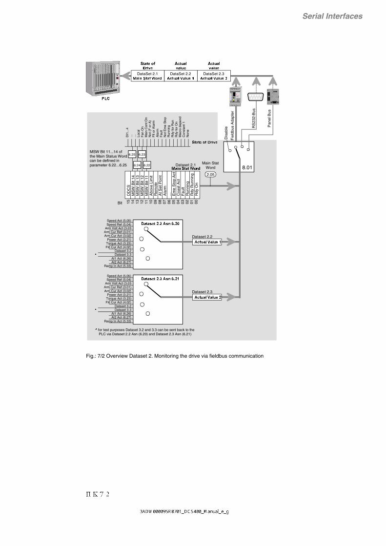
II K 7-2
Serial Interfaces
Fig.: 7/2 Overview Dataset 2. Monitoring the drive via fieldbus communication
8.01
Nxxx-01x xx xx x xxADA PTER
BU STE RM I NA TI ON
O N
OFF
R XD
TX D
PE SHF DG D(N) D(P)
X1
X2
PE SHF DG D(N) D(P)SH
XM I T
R EC
ER R OR
+24V 0V SH
15 14 13 12 11 10 09 08 07 06 05 04 03 02 01 00Bit
6.25 6.23
6.24 6.22
$X[6S5HI6HO
Dataset 2.2
Dataset 2.1
$X[6S5HI6HO
Dataset 2.3
DataSet 2.10DLQ6WDW:RUG
3/&
Fie
ldbu
s A
dapt
er
RS
232-
Bus
6WDWHRI'ULYH
Pan
el B
us
DataSet 2.2$FWXDO9DOXH
DataSet 2.3$FWXDO9DOXH
$FWXDOYDOXH
$FWXDOYDOXH
Dis
able
DI1
...4
... ... Loca
lF
an O
nM
ain
Con
t On
Not
(F
or
A)
Flt
or A
larm
Ala
rmF
ault
Not
Em
e S
top
Run
ning
Rdy
for
Run
Rdy
for
On
Mac
ro d
epen
dC
onst
ant 1
Non
e
DD
CS
MS
W B
it 14
MS
W B
it 13
MS
W B
it 12
MS
W B
it 11
Abo
ve L
imit
Rem
ote
At S
et P
oint
Ala
rm... E
me
Sto
p A
ctC
oast
Act
Fau
ltR
unni
ngR
dy R
unni
ngR
dy O
n
MSW Bit 11...14 of the Main Status Word can be defined in parameter 6.22...6.25
6WDWHRI'ULYH
Speed Act (5.05)Speed Ref (5.04)
Arm Volt Act (3.03Arm Cur Ref (3.01)Arm Cur Act (3.02)
Power Act (3.21)Torque Act (3.23)Fld Cur Act (4.02)
Dataset 3.2Dataset 3.3
AI1 Act (6.26)AI2 Act (6.27)
Ramp In Act (5.33)
'DWDVHW$VQ
$FWXDO9DOXH
2.05
Main StatWord0DLQ6WDW:RUG
for test purposes Dataset 3.2 and 3.3 can be sent back to the PLC via Dataset 2.2 Asn (6.20) and Dataset 2.3 Asn (6.21)
$FWXDO9DOXH
Speed Act (5.05)Speed Ref (5.04)
Arm Volt Act (3.03Arm Cur Ref (3.01)Arm Cur Act (3.02)
Power Act (3.21)Torque Act (3.23)Fld Cur Act (4.02)
Dataset 3.2Dataset 3.3
AI1 Act (6.26)AI2 Act (6.27)
Ramp In Act (5.33)
'DWDVHW$VQ

II K 7-3
Serial Interfaces
Fig.: 7/3 Overview Dataset 3 and 4. Monitoring the drive via fieldbus communication
8.01
DataSet 4.1)OG&XU$FW
3/&
RS
232-
Bus
Pan
el B
us
DataSet 4.23RZHU$FW
DataSet 4.37RUTXH$FW
Dis
able
DO1
$X[6S5HI6HO
$X[6S5HI6HO
Speed Act (5.05)Speed Ref (5.04)
Arm Volt Act (3.03Arm Cur Ref (3.01)Arm Cur Act (3.02)
Power Act (3.21)Torque Act (3.23)Fld Cur Act (4.02)
Dataset 3.2Dataset 3.3
AI1 Act (6.26)AI2 Act (6.27)
Ramp In Act (5.33)
$2$VVLJQ
for test purposes Dataset 3.2 and 3.3 can be sent back to the PLC via Dataset 2.2 Asn (6.20) and Dataset 2.3 Asn (6.21)
Speed Act (5.05)Speed Ref (5.04)
Arm Volt Act (3.03Arm Cur Ref (3.01)Arm Cur Act (3.02)
Power Act (3.21)Torque Act (3.23)Fld Cur Act (4.02)
Dataset 3.2Dataset 3.3
AI1 Act (6.26)AI2 Act (6.27)
Ramp In Act (5.33)
$2$VVLJQ
DataSet 3.1'LJLWDO5HI
DataSet 3.2$QDORJ5HI
DataSet 3.3$QDORJ5HI
Nxxx-01x xx xx x xxADA PTER
BU STE RM I NA TI ON
O N
OFF
R XD
TX D
PE SHF DG D(N) D(P)X1
X2
PE SHF DG D(N) D(P)SH
XM I T
R EC
ER R OR
+24V 0V SH
Bit
15... ... B
it 05
Bit
04B
it 03
Bit
02B
it 01
Bit
00
DO2
DO3
DO4
'LJLWDO5HIDataset 3.1
±10 V
±10 V
Dataset 3.2$QDORJ5HI
Dataset 3.3$QDORJ5HI
Dataset 3.3Dataset 3.2
Dataset 4.1)OG&XU$FW
Dataset 4.23RZHU$FW
Dataset 4.37RUTXH$FW
DO5
Fie
ldbu
s A
dapt
er
6.11
6.12
6.13
6.14
6.15
'2[$VVLJQ

II K 7-4
Serial Interfaces
Necessary parameter-settings for fieldbus communicationParameter Parameter name possible settings recommended
2.02 Cmd Location 0=Macro depend 1=Terminals 2=Bus 3=Key
2=Bus
2.07 Comm Fault Mode 0=Ramp 1=Torque Lim 2=Coast
0=Ramp
2.08 Comm Fault Time 0.00s=no supervision0.01…10.00s=Fault Time 0.20s
3.15 Torque Ref Sel 0=Macro depend 1=AI1 2=AI2 3=Bus Main Ref 4=Bus Aux Ref 5=Fixed Torque 6= Commis Ref1 7= Commis Ref2 8= Squarewave 9= Const Zero
0=Macro depend
5.01 Speed Ref Sel 0=Macro depend 1=AI1 2=AI2 3=Bus Main Ref 4=Bus Aux Ref 5=Fixed Sp1 6=Fixed Sp2 7=Commis Ref1 8=Commis Ref2 9=Squarewave10=Const Zero
3=Bus Main Ref
5.26 Aux Sp Ref Sel 0=Macro depend 1=AI1 2=AI2 3=Bus Main Ref 4=Bus Aux Ref 5=Fixed Sp1 6=Fixed Sp2 7=Commis Ref1 8=Commis Ref2 9=Squarewave10=Const Zero
4=Bus Aux Ref
8.01 Fieldbus Par 1 0=Disable 1=Fieldbus 2=RS232-Port 3=Panel-Port 4=Res Fieldbus
depend on application
8.02….
8.16
Fieldbus Par 2….
Fieldbus Par 16
….….….
depend onparameter 8.01
Communcation ParametersThe following communication paramters are relevantin case of external drives control.
Cmd Location (2.02)Purpose: Determines whether Drive is externally con-trolled via conventional I/O or serial interface.Value:
0 Macro depend1 Terminals (X1...X5 on SDCS-CON-3)2 Bus - The serial interface for external control is
specified in Parameter Modul Type (8.01)(Fieldbus, RS232-Port or Panel-Port)
3 Key - Automatic switch over between bus andterminals
Comm Fault Time (2.08)Purpose: For supervision of communication on theserial interface which is used for external drive control(defined in Paramter Modul Type (8.01).Value:0.01...10 sec
Determines the maximum allowed down time forcommunication in seconds. If no messages arereceived within this time, an error message will beissued and the drive will behave according toParameter Comm Fault Mode (2.07);0.00s = ignore error, Continue drive operation.
Comm Fault Mode (2.07)Purpose: Defines how the drive will behave in case ofcommunication error.Value:
0 Brake with deceleration ramp (Parameter5.10), then switch off drive and error message
1 Brake with torque = torque limit (Parameter3.07, 3.08), then switch off of drive and errormessage.
2 Immediate switch off drive and error message

II K 7-5
Serial Interfaces
Telegram StructureThe serial communication with a PLC can be carriedout via a field bus adapter, a RS232 port or a panelport. Irrespective of the bus protocol, these portscommunicate with the DCS400 software via specifieddata sets. Four data sets are available with three 16-bit words each. The data sets have the followingsignificance:
Control and reference transmission, from the PLCto the drive
Data set 1.1: Main Ctrl Word (5 bits set byparameter group 9)
Data set 1.2: Bus Main RefData set 1.3: Bus Aux Ref
Status information and actual value transmis-sion, from the drive to the PLC
Data set 2.1: Main Status Word (4 bits set byparameter MSW bit 1x Ass(6.22…6.25))
Data set 2.2: Actual value 1 (set by param.Dataset 2.2 As (6.20))
Data set 2.3: Actual value 2 (set by param.Dataset 2.3 As (6.21))
Digital and analogue value transmission, from thePLC to the drive
Data set 3.1: DO1...DO5 (set by 6.11...6.15)Data set 3.2: AOx, Scaling: ±4096 = ±10V
(set by 6.05/6.08)Data set 3.3: AOx, Scaling: ±4096 = ±10V
(set by 6.05/6.08)
Actual value transmission, from the drive to thePLC
Data set 4.1: Fld Cur Act (fixed)Data set 4.2: Power Act (fixed)Data set 4.3: Torque Act (fixed)
Main Status Word (2.06)Bit Name Definition0 RDY_ON 1=RDY for ON
0=not RDY_ON1 RDY_RUNNING 1=RDY for RUN
0=not RDY_RUN2 RUNNING 1=RUNNING
0=not RUNNING3 FAULT 1=FAULT
0=no FAULT
4 COAST_ACT 1=not COAST0=COAST
5 EME_STOP_ACT 1=not EME_STOP0=EME_STOP
6 1=0=
7 ALARM 1=ALARM0=no ALARM
8 AT_SETPOINT 1=Ref=Act0=Ref<>Act
9 REMOTE 1=Terminal/Bus0=Local (Panel/Tool)
10 ABOVE_LIMIT 1=Speed > SpLev1 (5.16)0=Speed < SpLev1 (5.16)
11 MSW_BIT_11_ASS Definition seeParameter 6.22
12 MSW_BIT_12_ASS Definition seeParameter 6.23
13 MSW_BIT_13_ASS Definition seeParameter 6.24
14 MSW_BIT_14_ASS Definition seeParameter 6.25
15 DDCS-Protocol(DCS400 to Adapter)
1=DDCS fault0=DDCS ok
Note: For a proper operation COAST and EME STOP inthe Main Control Word has to be setted to log. state 1.
Note: In the Main Stat Word RDY ON, COAST ACT,EME STOP ACT and REMOTE is setted to log. state 1,if Elektronics supply is on, Drive is off and no Faults ap-pears.
Control and status word allocationThe allocation of the main control word (data set 1.1)and the main status word (data set 2.1) is identical tomain control word (2.05) and main status word(2.06) of the DCS 400 converter. The allocation is asfollows:
Main Control Word (2.05)Bit Name Definition0 * ON 1=Drive ON
0=Drive OFF1 * COAST 1=not COAST
0=COAST2 * EME_STOP 1=no EME_STOP
0=EME_STOP3 * RUN 1=START
0=STOP4 1=
0=5 1=
0=6 1=
0=7 RESET 0>1=RESET
0 =no RESET8 * JOG_1 1=JOG 1
0=no JOG 19 * JOG_2 1=JOG 2
0=no JOG 210 1=
0=11 MCW_BIT_11 Definition see
Parameter group 912 MCW_BIT_12 Definition see
Parameter group 913 MCW_BIT_13 Definition see
Parameter group 914 MCW_BIT_14 Definition see
Parameter group 915 MCW_BIT_15 Definition see
Parameter group 9* effective when Cmd Location (2.02) = Bus; all others areindependent from Cmd Location.

II K 7-6
Serial Interfaces
7.1 Panel-PortThe Panel Port is normally used for connection of thecontrol panel. The default settings of this interface areas follows:
Signal level: +12V / 0VData format: UARTMessage format: Modbus-ProtocollTransmission method: half-duplexBaudrate: 9.600 BaudNumber of Data bits: 8Number of Stop bits: 2Parity-Bit: none
Alternatively, this interface may be used for purposeof external drive control, e.g. for connection to RS232-COM-Ports of PC's or to RS485 busses. A specificadapter ("RS232/RS485-Adapter") is available as anoption which converts the internal interface signalsaccording to the require-ments of the selected RS232 or RS 485 interface.This adapter is plugged intothe drive, instead of the con-trol panel, and is ready foroperation. Either the con-trol panel or the specialadapter can be used, notboth together.
The adapter provides screwconnectors for the RS 485-Bus and a 9-pole SUB-Dconnector for the RS232.Either the RS 485 or RS232can be used, not both to-gether.
Parameter Settings of Panel-Port, for purpose ofexternal drive control via Modbus protocol:
Parameter Meaning Alternative settings Typical Setting
8.01 Module Type Disable Fieldbus Par 1 Fieldbus
RS232-Port Panel-PortPanel-PortRes Fieldbus
8.02 Station Number 1…247 as required Fieldbus Par 2
8.03 Baudrate 0 = 9.600 Bd Fieldbus Par 3 1 = 19.200 Bd 0 = 9.600 Bd
8.04 Parity 0 = none (2 Stop bits) Fieldbus Par 4 1 = odd (1 Stop bit) 0 = none
2 = even (1 Stop bit)
Table 7.1/1: Settings of Panel-Port
Status word allocation4 bits of the status word (data set 2.1) can be param-eterized. The signals are selected in the parametersMSW bit 11 Ass (6.22), MSW bit 12 Ass (6.23), MSWbit 13 Ass (6.24) and MSW bit 14 Ass (6.25).
Data set allocationThe data sets 2.2 and 2.3 transmit two actual values.The actual values are selected in the parameters dataset 2.2 Ass (6.20) and data set 2.3 Ass (6.21).Default value for data set 2.2 is Speed Act
data set 2.3 is Arm Cur Act
For special purposes data set 3 can transmit directlyfive digital values and two analogue values which arefix assigned to the outputs.Assignment:Data set 3.1 bit 0 = DO1 digital valueData set 3.1 bit 1 = DO2 digital valueData set 3.1 bit 2 = DO3 digital valueData set 3.1 bit 3 = DO4 digital valueData set 3.1 bit 4 = DO5 digital valueData set 3.2 = AO1/2 analogue valueData set 3.3 = AO1/2 analogue value
In the following sections, the three available serialinterfaces are described in detail.
Switch Off and On electronics supply to initialize the Panel-Port for drive controlvia PLC.If these parameter settings done via panel after electronics supply On, paneldisplay will show 'Comm Loss' due to the panel communication is disabled now.For resetting parameters PC Tool Drive Window Light is needed!

II K 7-7
Serial Interfaces
7.2 RS232-Port
The RS232 interface is normally used for settingparameter in the drive via the PC Tool Drive WindowLight.
The default settings of this interface are as follows:
Signal level: RS232 (+12V / -12V)Data format: UARTMessage format: Modbus-ProtocolTransmission method: half-duplexBaudrate: 9.600 BaudNumber of Data bits: 8Number of Stop bits: 1Parity-Bit: odd
Parameter Settings of RS232-Port, for purpose ofexternal drive control via Modbus protocol:
Table 7.2/1: Settings of RS232-Port
1
9
5
6
X6: Description
1 not connected2 TxD3 RxD4 not connected5 SGND Signal ground6...9 not connected
Fig. 7.2/1 Pin assignment of RS232-Port
Parameter Meaning Alternative settings Typical Setting
8.01 Module Type Disable Fieldbus Par 1 Fieldbus
RS232-Port RS232-PortPanel-PortRes Fieldbus
8.02 Station Number 1…247 as required Fieldbus Par 2
8.03 Baudrate 0 = 9.600 Bd Fieldbus Par 3 1 = 19.200 Bd 0 = 9.600 Bd
8.04 Parity 0 = none (2 Stop bits) Fieldbus Par 4 1 = odd (1 Stop bit) 0 = none
2 = even (1 Stop bit)
Switch Off and On electronics supply to initialize the RS232-Port for drive controlvia PLC.If these parameter settings done via PC Tool Drive Window Light after electronicssupply On, Drive Window Light does not work longer due to the Tool communica-tion is disabled now.For resetting parameters the control panel is needed!

II K 7-8
Serial Interfaces
SDCS-CON-3
GND
+24 V/≤ 150 mA
Nxxx-01xxxx xx xxADAPTER
BUSTERMINATION
ON
OFF
RXD
TXD
PE SHF DG D(N) D(P)
X1
X2
PE SHF DG D(N) D(P)SH
XMIT
REC
ERROR
+24V 0V SH
+24V 0V
'&6
1 2
X8
RxDTxD
EOXH
EOXH
JUH\
JUH\ Fieldbus cable
7.3 Fieldbus interface
For connection to external control devices, like PLCs,typically the third serial interface, "fieldbus interface"is used.Several fieldbus protocol specific adapters are avail-able as options for the DCS 400. The following de-scription is an overview. Detailed information is avail-able from the specific adapter descriptions.
Characteristics:• Fieldbus adapter is mounted on external mounting
rail• Power supply from DCS 400 (built-in)• Connection between adapter and DCS 400 is
optical cable• DCS 400 automatically detects the connected
fieldbus type• Therefore, the user specific paramter settings are
drastically reduced
User specific parameters like e.g. station addressesor Modbus settings are only set once, during thecommissioning.
Short Commissioning Guide• Switch Off DCS 400 electronics power supply.• Mount fieldbus adapter on mounting rail.• Connect adapter to power supply (X8).• Connect optical cables from adapter to DCS 400
(V800).• Connect fieldbus cable to fieldbus adapter.• Switch On DCS 400 electronics power supply.• Wait approximately 10 s.
During this time an initialization is done betweenfieldbus adapter and DCS 400. Most of fieldbusparameter are pre-defined by the fieldbus adapt-er automatically after that procedure.
• Set Fieldbus Par 1 (8.01) (Module Type) = Field-bus.
• Set user specific parameters. For detailed descrip-tion, refer to the description which is following thefieldbus adapaters.
• Wait 10 s.• Switch Off and On again the electronics power
supply, in order to re-initialize the user specificparameter settings, which have been changed toinclude the serial communications.
The communication parameters Cmd Location (2.02),Comm Fault Mode (2.07) and Comm Fault Time(2.08) need to be set manually, for the purpose ofcommunication supervision. See chapter about com-munication parameters earlier in this document.
Fig: 7.3/1 Connection of a Fieldbus Adapter to DCS 400and PLC
Fig.: 7.3/2 Connection of Fieldbus Adapter to DCS 400
Nxxx-01xxxxxxxxADAPTER
BUSTERMINATI ON
ON
OFF
RXD
TXD
PE SHF DG D(N ) D(P )
X1
X2
PE SHF DG D(N ) D(P )SH
XMIT
REC
ERRO R
+24V 0V SH
optical fibre
24 V
sup
ply
Fieldbus cable
DCS 400
PLC
Fieldbus
A

II K 7-9
Serial Interfaces
Parameter overview for the most commonly usedfieldbusesFor parameter setting, with the control panel, intiallyswitch to Long Par List, in the MENU selection, in
Profibus (including parameter transfer)Parameter Meaning Alternative settings Typical settings
8.01 Module Type 0 = Disable1 = Fieldbus2 = RS232-Port3 = Panel-Port4 = Res Feldbus
Fieldbus
8.02 Profibus Mode 0 = FMS1 = PPO1
Data transf. PLC to DCS(DS1.1, 1.2+Par)Data transf. DCS to PLC(DS2.1, 2.2+Par)
2 = PPO2Data transf. PLC to DCS(DS1.1…1.3, 3.1…3.3 +Par)Data transf. DCS to PLC(DS2.1…2.3, 4.1…4.3 +Par)
3 = PPO3Data transf. PLC to DCS(DS1.1, 1.2)Data transf. DCS to PLC(DS2.1, 2.2)
4 = PPO4Data transf. PLC to DCS(DS1.1…1.3, 3.1…3.3)Data transf. DCS to PLC(DS2.1…2.3, 4.1…4.3)
1 = PPO1
8.03 Station Number 2…126 28.04 Baudrate 0 = 9,6 kBd
1 = 19,2 kBd2 = 93,75 kBd3 = 187,5 kBd4 = 500 kBd5 = 1,5 MBd6 = Auto
6 = Auto
8.05 Number of Data Set Pairs 1 = if 8.02 = 1 or 32 = if 8.02 = 2 or 4
1 (8.02 = 1)
8.06 Data Set Offset 0…255 0 = no Offset8.07 Cut Off Timeout 0…255 (20ms grid)
between NPBA-02 andMaster
30 = 600ms
8.08 Comm Profile 0 = ABB DRIVES1 = CSA 2.8/3.0
0 = ABB DRIVES
order to make the parameters visible. Continue withsetting of the user specific parameters (bold typed).

II K 7-10
Serial Interfaces
Modbus (including parameter transfer)Parameter Meaning Alternative settings Typical settings
8.01 Module Type 0 = Disable1 = Fieldbus2 = RS232-Port3 = Panel-Port4 = Res Feldbus
Fieldbus
8.02 Modbus Mode 0 = RTU wdg:flt1 = RTU wdg:rst
0 = RTU wdg:flt
8.03 Station Number 1…247 18.04 Baudrate 0 = 1.200 Bd
1 = 2.400 Bd2 = 4.800 Bd3 = 9.600 Bd4 = 19.200 Bd
3 = 9.600 Bd
8.05 Parity 0 = even (1 Stop bit)1 = odd (1 Stop bit)2 = none (2 Stop bits)
2 = ohne
8.06 Good message 0…65535 -8.07 Bad message 0…65535 -
Modbus Plus (including parameter transfer)Parameter Meaning Alternative settings Typical settings
8.01 Module Type 0 = Disable1 = Fieldbus2 = RS232-Port3 = Panel-Port4 = Res Fieldbus
1 = Fieldbus
8.02 Protocol 0 = Modbus Plus (with Good/BadMessage)1 = MBP fast (without Good/BadMess.)
0 = Modbus Plus
8.03 Station Number 1…64 38.04 Good Message 0…32767 -8.05 Bad Message 0…32767 -8.06 Global Data Out 1 0 = none
1 = Control Word2 = Reference 13 = Reference 24 = Status Word5 = Actual 16 = Actual 2
4 = Status Word
8.07 Global Data Out 2 0 = none1 = Control Word2 = Reference 13 = Reference 24 = Status Word5 = Actual 16 = Actual 2
5 = Actual 1
8.08 Global Data Out 3 0 = none1 = Control Word2 = Reference 13 = Reference 24 = Status Word5 = Actual 16 = Actual 2 6 = Actual 2
8.09 GData In 1 Station 0…64 (Slave Adr) 08.10 GData In 1 Word 0…31 (Global Data Out
of Slave Adr)0
8.11 GData In 2 Station 0…64 (Slave Adr) 08.12 GData In 2 Word 0…31 (Global Data Out
of Slave Adr)0
8.13 GData In 3 Station 0…64 (Slave Adr) 08.14 GData In 3 Word 0…31 (Global Data Out
of Slave Adr)0

II K 7-11
Serial Interfaces
CS31 (without parameter transfer)Parameter Meaning Alternative settings Typical settings
8.01 Module Type 0 = Disable1 = Fieldbus2 = RS232-Port3 = Panel-Port4 = Res Feldbus
Fieldbus
8.02 Protocol 1 1 = ABB CS318.03 Modul ID 0 = Word
1 = Binary0 = Word
8.04 Station Number 0… 5 (Word Mode)0…57 (Binary Mode)
1
8.05 Addr Index 0 = lower1 = upper
0 = lower
8.06 Data Sets 1…3 18.07 Data Set 1 Const 1…32767 (1=6ms) 18.08 Data Set 2 Const 1…32767 (1=6ms) 18.09 Data Set 3 Const 1…32767 (1=6ms) 18.10 Data Set Offset 1…255 1
CAN-Bus (including parameter transfer)Parameter Meaning Alternative settings Typical settings
8.01 Module Type 0 = Disable1 = Fieldbus2 = RS232-Port3 = Panel-Port4 = Res Feldbus
Fieldbus
8.02 WD Mode 0 = CANopen: flt1 = CANopen: rst
1 = CANopen: rst
8.03 Node ID 1…127 18.04 Baudrate 0 = 1 MBd
1 = 500 kBd2 = 250 kBd3 = 125 kBd4 = 100 kBd5 = 50 kBd6 = 20 kBd7 = 10 kBd
3 = 125 kBd
8.05 Comm Profile 0 = CSA 2.8/3.01 = ABB Drives2 = Transparent 2 = Transparent
8.06 Cut Off Timeout 0…255 (20ms grid)between NCAN-02 andMaster
10 = 200ms
8.07 Status
messages offieldbus adapter
0 = Self Test 1 = RX Q Overrun 2 = CAN Overrun 3 = Bus Off 4 = Error Set 5 = Error Reset 6 = TX Q Overrun 7 = Disconnected 8 = Started 9 = Stopped10 = G Fails11 = Pre-0peration
12 = Reset Comm13 = Reset Node
0 = adapter self test1 = receiver overrun (SW)2 = receiver overrun (HW)3 = adapter in Bus Off State4 = adapter error bit setted5 = adapter error bit resetted6 = transmitter overrun7 = node disconnected8 = node started9 = node stopped10 = node not guarded11 = node has changed to pre-operation12 = reset communication13 = reset node
8.08 Data Set Index 0 = FBA D SET 11 = FBA D SET 10
0 = FBA D SET 1
8.09 No. of Data Sets 1 or 2 1

II K 7-12
Serial Interfaces
For detailed information please refer to the relatedfieldbus adapter description.
In the case you need a fieldbus other than shown,please contact your local ABB sales office. ABB iscontinuously developing on new solutions.
DeviceNet (including parameter transfer)Parameter Meaning Alternative settings Typical settings
8.01 Module Type 0 = Disable1 = Fieldbus2 = RS232-Port3 = Panel-Port4 = Res Fieldbus
1 = Fieldbus
8.02 MAC ID 0…63 638.03 Baudrate 0 = 125 kBd
1 = 250 kBd2 = 500 kBd
0 = 125 kBd
8.04 Status 0 = Self Test1 = No Connect2 = Connected3 = Timeout4 = Dup. Mac. Err.5 = Bus_Off6 = Com. Error7 = Wrong Asmbly
Read only (parameter).The module shows value ’NoConnect’ after first power-up.
8.05 Profile Selection 0 = ABB Drives1 = CSA 2.8/3.0
0 = ABB Drives
8.06 Poll Output Select 0 = Basic Speed 3 = Multiple Dataset8.07 Poll/Cos Input Sel 1 = Transparent 3 = Multiple Dataset8.08 Cos Data Output 2 = Parameters
3 = Multiple Dataset3 = Multiple Dataset
8.09 Bit Strobe Output 0 = Basic Speed1 = Transparent2 = Parameters
0 = Basic Speed
8.10 DataSet Indexes 0 = FBA DSet 11 = FBA DSet 10
0 = FBA DSet 1
8.11 Speed Ref Scale 0…32767 15008.12 Speed Act Scale 0…32767 15008.13 ABB Drives Stop M. 0 = Coast Stop
1 = Ramp Stop0 = Coast Stop
8.14 Ramp Stop Level 0…20.000 10008.15 No. of Dataset 1…2 2
Table 7.3/1: Parameter settings for the most commonly used fieldbus adapters

II K 7-13
Serial Interfaces
DCS 400 Fieldbus parameterPROFIBUS Modbus, CAN-BUS DCS400 DCS-400 Par.Name Remark
Par. No Modbus+ Par.No. 1 - Motor Settings
100 40101 3065 101 Arm Cur Nom101 40102 3066 102 Arm Volt Nom102 40103 3067 103 Field Cur Nom103 40104 3068 104 Field Volt Nom104 40105 3069 105 Base Speed105 40106 306A 106 Max Speed106 40107 306B 107 Mains Volt Act107 40108 306C 108 Mains Freq Act108 40109 306D 109 Arm Overv Trip109 40110 306E 110 Net Underv Trip110 40111 306F 111 Net Fail Time111 40112 3070 112 Cur Lim Speed
PROFIBUS Modbus, CAN-BUS DCS400 DCS-400 Par.Name RemarkPar. No Modbus+ Par.No. 2 - Operation Mode
133 40201 30C9 201 Macro Select134 40202 30CA 202 Cmd Location135 40203 30CB 203 Stop Mode136 40204 30CC 204 Eme Stop Mode137 40205 30CD 205 Main Ctrl Word138 40206 30CE 206 Main Stat Word139 40207 30CF 207 Comm Fault Mode140 40208 30D0 208 Comm Fault Time141 40209 30D1 209 Start Mode142 40210 30D2 210 DDCS Node Addr143 40211 30D3 211 DDCS Baud Rate144 40212 30D4 212 PTC Mode145 40213 30D5 213 Fan Delay
PROFIBUS Modbus, CAN-BUS DCS400 DCS-400 Par.Name RemarkPar. No Modbus+ Par.No. 3 - Armature
166 40301 312D 301 Arm Cur Ref167 40302 312E 302 Arm Cur Act168 40303 312F 303 Arm Volt Act169 40304 3130 304 Arm Cur Max170 40305 3131 305 Overload Time171 40306 3132 306 Recovery Time172 40307 3133 307 Torque Lim Pos173 40308 3134 308 Torque Lim Neg174 40309 3135 309 Arm Cur Reg KP175 40310 3136 310 Arm Cur Reg TI176 40311 3137 311 Cont Cur Lim177 40312 3138 312 Arm Inductance178 40313 3139 313 Arm Resistance179 40314 313A 314 Cur Contr Mode180 40315 313B 315 Torque Ref Sel181 40316 313C 316 Cur Slope182 40317 313D 317 Stall Torque183 40318 313E 318 Stall Time184 40319 313F 319 Firing Angle185 40320 3140 320 EMF Act186 40321 3141 321 Power Act187 40322 3142 322 Fixed Torque188 40323 3143 323 Torque Act189 40324 3144 324 Cur Lim 2 Inv190 40325 3145 325 Arm Cur Lev

II K 7-14
Serial Interfaces
PROFIBUS Modbus, CAN-BUS DCS400 DCS-400 Par.Name RemarkPar. No Modbus+ Par.No. 4 - Field
199 40401 3191 401 Field Cur Ref200 40402 3192 402 Field Cur Act201 40403 3193 403 Field Cur KP202 40404 3194 404 Field Cur TI203 40405 3195 405 Fld Ov Cur Trip204 40406 3196 406 Field Low Trip205 40407 3197 407 Field Cur 40%206 40408 3198 408 Field Cur 70%207 40409 3199 409 Field Cur 90%208 40410 319A 410 Field Heat Ref209 40411 319B 411 EMF KP210 40412 319C 412 EMF TI
PROFIBUS Modbus, CAN-BUS DCS400 DCS-400 Par.Name RemarkPar. No Modbus+ Par.No. 5 - Speed Controller
232 40501 31F5 501 Speed Ref Sel233 40502 31F6 502 Speed Meas Mode234 40503 31F7 503 Encoder Inc235 40504 31F8 504 Speed Ref236 40505 31F9 505 Speed Act237 40506 31FA 506 Tacho Speed Act238 40507 31FB 507 Speed Reg KP239 40508 31FC 508 Speed Reg TI240 40509 31FD 509 Accel Ramp241 40510 31FE 510 Decel Ramp242 40511 31FF 511 Eme Stop Ramp243 40512 3200 512 Ramp Shape244 40513 3201 513 Fixed Speed 1245 40514 3202 514 Fixed Speed 2246 40515 3203 515 Zero Speed Lev247 40516 3204 516 Speed Level 1248 40517 3205 517 Speed Level 2249 40518 3206 518 Overspeed Trip250 40519 3207 519 Jog Accel Ramp251 40520 3208 520 Jog Decel Ramp252 40521 3209 521 Alt Par Sel253 40522 320A 522 Alt Speed KP254 40523 320B 523 Alt Speed TI255 40524 320C 524 Alt Accel Ramp256 40525 320D 525 Alt Decel Ramp257 40526 320E 526 Aux Sp Ref Sel258 40527 320F 527 Drooping259 40528 3210 528 Ref Filt Time260 40529 3211 529 Act Filt 1 Time261 40530 3212 530 Act Filt 2 Time262 40531 3213 531 Speed Lim Fwd263 40532 3214 532 Speed Lim Rev264 40533 3215 533 Ramp In Act
* 265 40534 3216 534 Tacho Offset * not available

II K 7-15
Serial Interfaces
PROFIBUS Modbus, CAN-BUS DCS400 DCS-400 Par.Name RemarkPar. No Modbus+ Par.No. 6 - Input/Output
265 40601 3259 601 AI1 Scale 100%266 40602 325A 602 AI1 Scale 0%267 40603 325B 603 AI2 Scale 100%268 40604 325C 604 AI2 Scale 0%269 40605 325D 605 AO1 Assign270 40606 325E 606 AO1 Mode271 40607 325F 607 AO1 Scale 100%272 40608 3260 608 AO2 Assign273 40609 3261 609 AO2 Mode274 40610 3262 610 AO2 Scale 100%275 40611 3263 611 DO1 Assign276 40612 3264 612 DO2 Assign277 40613 3265 613 DO3 Assign278 40614 3266 614 DO4 Assign279 40615 3267 615 DO5 Assign280 40616 3268 616 Panel Act 1281 40617 3269 617 Panel Act 2282 40618 326A 618 Panel Act 3283 40619 326B 619 Panel Act 4284 40620 326C 620 Dataset 2.2 Ass285 40621 326D 621 Dataset 2.3 Ass286 40622 326E 622 MSW Bit 11 Ass287 40623 326F 623 MSW Bit 12 Ass288 40624 3270 624 MSW Bit 13 Ass289 40625 3271 625 MSW Bit 14 Ass290 40626 3272 626 AI1 Act291 40627 3273 627 AI2 Act292 40628 3274 628 DI Act
PROFIBUS Modbus, CAN-BUS DCS400 DCS-400 Par.Name RemarkPar. No Modbus+ Par.No. 7 - Maintenance
298 40701 32BD 701 Language299 40702 32BE 702 Contr Service300 40703 32BF 703 Diagnosis301 40704 32C0 704 SW Version302 40705 32C1 705 Conv Type303 40706 32C2 706 Conv Nom Cur304 40707 32C3 707 Conv Nom Volt305 40708 32C4 708 Volatile Alarm306 40709 32C5 709 Fault Word 1307 40710 32C6 710 Fault Word 2308 40711 32C7 711 Fault Word 3309 40712 32C8 712 Alarm Word 1310 40713 32C9 713 Alarm Word 2311 40714 32CA 714 Alarm Word 3312 40715 32CB 715 Commis Ref 1313 40716 32CC 716 Commis Ref 2314 40717 32CD 717 Squarewave Per315 40718 32CF 718 Squarewave Act316 40719 32D0 719 Pan Text Vers317 40720 32D1 720 CPU Load318 40721 32D2 721 CON-Board

II K 7-16
Serial Interfaces
PROFIBUS Modbus, CAN-BUS DCS400 DCS-400 Par.Name RemarkPar. No Modbus+ Par.No. 8 - Fieldbus
331 40801 3321 801 Fieldbus Par 1332 40802 3322 802 Fieldbus Par 2333 40803 3323 803 Fieldbus Par 3334 40804 3324 804 Fieldbus Par 4335 40805 3325 805 Fieldbus Par 5336 40806 3326 806 Fieldbus Par 6337 40807 3327 807 Fieldbus Par 7338 40808 3328 808 Fieldbus Par 8339 40809 3329 809 Fieldbus Par 9340 40810 332A 810 Fieldbus Par 10341 40811 332B 811 Fieldbus Par 11342 40812 332C 812 Fieldbus Par 12343 40813 332D 813 Fieldbus Par 13344 40814 332E 814 Fieldbus Par 14345 40815 332F 815 Fieldbus Par 15346 40816 3330 816 Fieldbus Par 16
PROFIBUS Modbus, CAN-BUS DCS400 DCS-400 Par.Name RemarkPar. No Modbus+ Par.No. 9 - MacroAdaptation
364 40901 3385 901 MacParGrpAction365 40902 3386 902 Jog 1366 40903 3387 903 Jog 2367 40904 3388 904 COAST368 40905 3389 905 User Fault369 40906 338A 906 User Fault Inv370 40907 338B 907 User Alarm371 40908 338C 908 User Alarm Inv372 40909 338D 909 Dir of Rotation373 40910 338E 910 MotPot Incr374 40911 338F 911 MotPot Decr375 40912 3390 912 MotPotMinSpeed376 40913 3391 913 Ext Field Rev377 40914 3392 914 Alternativ Param378 40915 3393 915 Ext Speed Lim379 40916 3394 916 Add AuxSpRef380 40917 3395 917 Curr Lim 2 Inv381 40918 3396 918 Speed/Torque382 40919 3397 919 Disable Bridge 1383 40920 3398 920 Disable Bridge 2

Appendix
Appendix A - Accessories
II K A-1
Appendix A
Type Choke rated Weight Power loss Max. cont. load curr.L Irms Ipeak Voltage Fe Cu 400 V and 500 V
[µH] [A] [A] [UN] [kg] [W] [W] [A]
ND 01 512 18 27 500 2.0 5 16 22ND 02 250 37 68 500 3.0 7 22 45ND 03 300 37 68 600 3.8 9 20 45ND 04 168 55 82 500 5.8 10 33 67ND 05 135 82 122 600 6.4 5 30 100ND 06 90 102 153 500 7.6 7 41 124ND 07 50 184 275 500 12.6 45 90 224ND 08 56.3 196 294 600 12.8 45 130 239ND 09 37.5 245 367 500 16.0 50 140 299ND 10 25.0 367 551 500 22.2 80 185 448ND 11 33.8 326 490 600 22.6 80 185 398ND 12 18.8 490 734 500 36.0 95 290 598ND 13 18.2 698 1047 690 46.8 170 160 851ND 14 9.9 930 1395 500 46.6 100 300 1134ND 15 10.9 1163 1744 690 84.0 190 680 1418ND 16 6.1 1510 2264 500 81.2 210 650 1841
Line chokes type ND 01...ND 16
Table A/1: Data of line chokes
Type a1 a b c d e f gmm²
ND 01 120 100 130 48 65 116 4 8 6ND 02 120 100 130 58 65 116 4 8 10ND 03 148 125 157 63 80 143 5 10 10ND 04 148 125 157 78 80 143 5 10 16ND 05 148 125 157 78 80 143 5 10 25ND 06 178 150 180 72 90 170 5 10 35
Line chokes type ND 01...ND 06
to mains
to converter
Fig. A/1: Line choke type ND 01...ND 06
A, B, C 3001000
X, Y, Z
ba
a1
c
A
X
B
Y
C
Z
A
B
C
X
Y
Z
3
A, B, C
X, Y, Z
d
e
g
f
Line chokes for use in industrial environment (minimum requirements), lowinductive voltage drop, deep commutation notches.

II K A-2
Appendix A
Type A B C E F G H I KND 07, 08 285 230 86 250 176 65 80 9x18 385ND 09 327 250 99 292 224 63 100 9x18 423ND 10, 11 408 250 99 374 224 63 100 11x18 504ND 12 458 250 112 424 224 63 100 11x18 554
Line chokes type ND 07...ND 12
Line chokes type ND 15, 16Line chokes type ND 13, 14
Fig. A/2: Line chokes type ND 07...ND 12
Fig. A/3: Line chokes type ND 13, ND 14 Fig. A/4: Line chokes type ND 15, ND 16
C ±1
B ±1F ±0.3
H ±2
15
3AST 478223 D5
3AFE 100146030.0188 mH
490 A
I max 734 A
15K
I (6x
)
G ±
4A
±2
E ±2
A-A
E±2
7
±0.3F
A
A
min
30
∅ w
ithou
t var
nish
for
cond
uctio
n to
the
mou
ntin
g p
late
A A
A-A
18x1
3(3x
)
ø13
(3x)
100
±2140
45 45
±415
4±2
342
±2150 40
50
±2123
10
±1290
100
30
±0.3
224
min
30
∅ w
ithou
t var
nish
for
cond
uctio
n to
the
mou
ntin
g p
late
(6x)
10x
18
±2151
45
90
±517
6±2
440
±2181
147
10
48
15
80
40(1
2x)
ø13
30140
±1390
14030
20
100
10
A A
A-A
147 13
±0.3
316
18
min
30
∅ w
ithou
t var
nish
for
cond
uctio
n to
the
mou
ntin
g p
late
Don't use choke terminalsas cable or busbar support!
Don't use choke terminalsas cable or busbar support!

II K A-3
Appendix A
Table A/2: Data of line chokes type ND4
Line chokes type ND 401...ND 402
Fig. A/5: Line choke type ND 401...ND 402
Table A/3: Dimensions of line chokes type ND 401...ND 402
Type Choke rated Weight Power loss Load LoadL Irms Ipeak Voltage Fe Cu DC curr. 1 DC curr.2
[µH] Line AC [A] [A] [UN] [kg] [W] [W] [A] [A]
ND 401 1000 18.5 27 500 3.5 13 35 22.6 18ND 402 600 37 68 500 7.5 13 50 45 36ND 403 450 55 82 500 11 42 90 67 54ND 404 350 74 111 500 13 78 105 90 72ND 405 250 104 156 500 19 91 105 127 101ND 406 160 148 220 500 22 104 130 179 143ND 407 120 192 288 500 23 117 130 234 187ND 408 90 252 387 500 29 137 160 315 252ND 409 70 332 498 500 33 170 215 405 324ND 410 60 406 609 500 51 260 225 495 396ND 411 50 502 753 500 56 260 300 612 490ND 412 40 605 805 500 62 280 335 738 590ND 413 35 740 1105 500 75 312 410 900 720
Type A B C D E F Ø G Ø HND 401 160 190 75 80 51 175 7 9ND 402 200 220 105 115 75 200 7 9
Line chokes type ND 401...ND 413
Line chokes for use in light industrial/residential environment, high inductivevoltage drop, reduced commutation notches.
These chokes are designed for drives which usual operate in speed control mode.The maximum average DC load current depends on the operation point.DC curr. 1 = maximum continuous current for Urated supply = 400 VDC curr. 2 = maximum continuous current for Urated supply = 500 V
A X B Y C Z170
D
B
F±1ø G+5
E ±2
C
ZYX
BA C
Terminals: WAGO Type 202 UL File E45172
ø H
A
ø G
tin-coated

Fig. A/6: Line choke type ND 403...ND 408
Fig. A/7: Line choke type ND 409...ND 413
Line chokes type ND 403...ND 408
Line chokes type ND 409...ND 413
Type A B C D E F Ø G Ø H Ø KND 403 220 230 120 135 100 77.5 7 9 6.6ND 404 220 225 120 140 100 77.5 7 9 6.6ND 405 235 250 155 170 125 85 10 9 6.6ND 406 255 275 155 175 125 95 10 9 9ND 407 255 275 155 175 125 95 10 9 11ND 408 285 285 180 210 150 95 10 9 11
Type A B C D E F Ø G Ø H Ø KND 409 320 280 180 210 150 95 10 11 11ND 410 345 350 180 235 150 115 10 13 14ND 411 345 350 205 270 175 115 12 13 2x11ND 412 385 350 205 280 175 115 12 13 2x11ND 413 445 350 205 280 175 115 12 13 2x11
Connecting AL ter-minals see also re-levant standards
Connecting AL ter-minals see also re-levant standards
B
A
F ±2
104550
ø Htin-coated
E ±2
C
D
ø G+5
A
X
B
Y
C
Z
øK AL
B
A
F ±212
ø Htin-coated
øG+6
E ±2CD
A
X
B
Y
C
Z
A B C
X Y Z
øK AL
II K A-4
Appendix A

Converter type Manufacturer/ Type Fuse holder2-quadrant converter
DCS401.0020 Bussman 170M 1564 OFAX 00 S3LDCS401.0045 Bussman 170M 1566 OFAX 00 S3LDCS401.0065 Bussman 170M 1568 OFAX 00 S3LDCS401.0090 Bussman 170M 1568 OFAX 00 S3LDCS401.0125 Bussman 170M 3815 OFAX 1 S3DCS401.0180 Bussman 170M 3815 OFAX 1 S3DCS401.0230 Bussman 170M 3817 OFAX 1 S3DCS401.0315 Bussman 170M 5810 OFAX 2 S3DCS401.0405 Bussman 170M 6811 OFAS B 3DCS401.0500 Bussman 170M 6811 OFAS B 3DCS401.0610 Bussman 170M 6813 OFAS B 3DCS401.0740 Bussman 170M 6813 OFAS B 3DCS401.0900 Bussman 170M 6166 170H 3006
4-quadrant converterDCS402.0025 Bussman 170M 1564 OFAX 00 S3LDCS402.0050 Bussman 170M 1566 OFAX 00 S3LDCS402.0075 Bussman 170M 1568 OFAX 00 S3LDCS402.0100 Bussman 170M 1568 OFAX 00 S3LDCS402.0140 Bussman 170M 3815 OFAX 1 S3DCS402.0200 Bussman 170M 3816 OFAX 1 S3DCS402.0260 Bussman 170M 3817 OFAX 1 S3DCS402.0350 Bussman 170M 5810 OFAX 2 S3DCS402.0450 Bussman 170M 6811 OFAS B 3DCS402.0550 Bussman 170M 6811 OFAS B 3DCS402.0680 Bussman 170M 6813 OFAS B 3DCS402.0820 Bussman 170M 6813 OFAS B 3DCS402.1000 Bussman 170M 6166 170H 3006
Table A/4: Fuses and fuse holders
Fuses and fuse holders for armature-circuit supply
The semiconductor fuses used are blade fuses. Therelevant data are listed in the table below. The fuses'construction requires special fuse holders. Fuse hold-er of the OFAX and OFAS type series are available forthis purpose.
Appendix A
II K A-5

Manufacturer/ Type Loss [W] Resistance [mΩΩΩΩΩ] Fuse F1 Size Fuse holder Caliper [mm]
Bussman 170M 1564 15 6 50A 660V UR 0 OFAX 00 S3L 78.5Bussman 170M 1566 19 3 80A 660V UR 0 OFAX 00 S3L 78.5Bussman 170M 1568 28 1,.8 125A 660V UR 0 OFAX 00 S3L 78.5Bussman 170M 3815 35 0,.87 200A 660V UR 1 OFAX 1 S3 135Bussman 170M 3816 40 0,.64 250A 660V UR 1 OFAX 1 S3 135Bussman 170M 3817 50 0,.51 315A 660V UR 1 OFAX 1 S3 135Bussman 170M 3819 60 0,.37 400A 660V UR 1 OFAX 1 S3 135Bussman 170M 5810 75 0,.3 500A 660V UR 2 OFAX 2 S3 150Bussman 170M 6811 110 0,.22 700A 660V UR 3 OFAS B 3 150Bussman 170M 6813 120 0,.15 900A 660V UR 3 OFAS B 3 150Bussman 170M 6166 141 0,.09 1250A 660V UR 170H 3006 110
Table A/5: Fuses and fuse holders
Main dimensions of fuse holders
Fuse HxWxDholder [mm]
OFAX 00 S3L 148x112x111OFAX 1 S3 250x174x123OFAX 2 S3 250x214x133OFAS B 3 250x246x136
Table A/6: Fuse holders
Fig. A/9: Fuse holder OFAX ... Fig. A/10: Fuse holder OFAS B 3
Dimensions [mm] Size 0...3
Size a b c d e0 78,5 50 35 20,5 151 135 69 45 45 202 150 69 55 55 263 150 68 76 76 33
Remark:Given dimensions may be exeededin some cases. Please take themonly for information.
Fig. A/8: Fuses size 0...3
a
d e
2
10
c
6
b
Indicator
OFASB 3
W D
H
W D
H
Appendix A
M
L1 L2 L3
F1
II K A-6

EMC Filters
Appendix A
Three-phase filtersEMC mains filters are necessary so as tocomply with EN 50 081 if a power converteris to be operated at a public low-voltagegrid, in Europe, for example, with 400 Vbetween the phases. Grids of this kindhave an earthed neutral conductor. Forthese cases, ABB offers its three-phasemains filters for 500 V and 25 A ... 1000 A.
On local lines inside factories they do notsupply sensitive electronics. Thereforeconverters do not need EMC filters.
In chapter 5.2 Installation in accordancewith EMC the topic EMC filter is described.
Converter type Rat. direct current Filter type DimensionsL x W x H
[A] [kg] [mm]
2-quadr. convert.DCS401.0020 20 NF3-500-25 3 250x150x65DCS401.0045 45 NF3-500-50 3.1 250x150x65DCS401.0065 65 NF3-500-64 3.1 250x150x65DCS401.0090 90 NF3-500-80 9.5 450x170x90DCS401.0125 125 NF3-500-110 9.5 450x170x90DCS401.0180 180 NF3-500-320 21 400x260x115DCS401.0230 230 NF3-500-320 21 400x260x115DCS401.0315 315 NF3-500-320 21 400x260x115DCS401.0405 405 NF3-500-320 21 400x260x115DCS401.0500 500 NF3-500-600 22 450x260x115DCS401.0610 610 NF3-500-600 22 450x260x115DCS401.0740 740 NF3-500-600 22 450x260x115DCS401.0900 900 NF3-690-1000 ➋ ➋4-quadr. convert.DCS402.0025 25 NF3-500-25 3 250x150x65DCS402.0050 50 NF3-500-50 3.1 250x150x65DCS402.0075 75 NF3-500-80 9.5 450x170x90DCS402.0100 100 NF3-500-80 9.5 450x170x90DCS402.0140 140 NF3-500-110 9.5 450x170x90DCS402.0200 200 NF3-500-320 21 400x260x115DCS402.0260 260 NF3-500-320 21 400x260x115DCS402.0350 350 NF3-500-320 21 400x260x115DCS402.0450 450 NF3-500-600 22 450x260x115DCS402.0550 550 NF3-500-600 22 450x260x115DCS402.0680 680 NF3-500-600 22 450x260x115DCS402.0820 820 NF3-690-1000 ➋ ➋DCS402.1000 1000 NF3-690-1000 ➋ ➋
The filters 25 ... 600 A are available for 440 V and for 500 V.
➊ The filters can be optimized to suit the actual motor currentsencountered:IFilter = 0,8 • IMOT max
; the factor 0.8 takes into account the currentripple.
➋ Weight and dimensions on request
➊
Wei
ght
appr
.
Table A/8: Dimensions of filter
Table A/7: Main filter data
Filter type max. IN A B C D Fixing dimensions Connection Weight PEvoltage E ∅ F F' G G' bar with Term. kg
appr. hole ∅ (mm²)*NF3-500-25 500 25 250 150 65 1 6.5 115 136 4 3.0 M6NF3-500-50 500 50 250 150 65 1 6.5 115 136 10/16 3.1 M6NF3-500-64 500 64 250 150 65 1 6.5 115 136 10/16 3.1 M6NF3-500-80 500 80 427 170 90 1 6.5 373 130 25/35 9.5 M10NF3-500-110 500 110 436 170 90 1 6.5 373 130 50 9.5 M10NF3-500-320 500 320 450 285 171 1 12 240 235 11 21 M10NF3-500-600 500 600 590 305 158 1 12 290 235 11 22 M10
* single cor / litz wire
Line
Load
A
B
F'F
G'
G
E
C
DFig. A/11: Drawing of filter
II K A-7

Appendix B - Declaration of conformity
II K B-1

Appendix C - Quick Installation & Commissioning guide
➊
EN
TE
RM
EN
U
RE
SE
T
LOC
RE
M
➋
DC
S 4
00Q
uic
k In
stal
latio
n &
Co
mm
issi
on
ing
Gu
ide
Bef
ore
Sta
rtin
g In
stal
lati
on
CH
EC
K B
OX
CO
NT
EN
TS
: DC
S 4
00, M
anua
l, M
ount
ing
Tem
plat
e, Q
uick
Inst
. & C
omm
issg
. Gui
deC
HE
CK
INS
TA
LLA
TIO
N S
ITE
: See
Man
ual
TO
OLS
NE
ED
ED
: Scr
ewdr
iver
, Tor
que
wre
nch
FR
OM
MO
TO
R N
AM
EP
LAT
E: A
rmat
ure
Cur
rent
Nom
inal
, Arm
atur
e V
olta
ge N
omin
al, F
ield
Cur
rent
Nom
inal
, Fie
ld V
olta
ge N
omin
al, B
ase
Spe
edN
ote
! T
his
Gui
de is
onl
y fo
r se
tting
s ba
sica
lly p
aram
eter
s of
a E
MF
con
trol
led
mot
or
Tak
e in
to a
cco
un
t th
e S
afet
y in
stru
ctio
ns
in t
he
Man
ual
ch
apte
r 5!
ST
OP
!E
NS
UR
E M
AIN
S S
UP
PLY
TO
INS
TA
LLA
TIO
N IS
OF
F.
EN
SU
RE
MO
TO
R IS
SU
ITA
BLE
FO
R U
SE
WIT
H D
CS
400
.
Pac
king
box
lid
cont
ains
wal
l mou
ntin
g te
mpl
ate.
Rem
ove
it fr
om th
e bo
x.
DC
S 4
00 s
houl
d O
NLY
be
mou
nted
ver
tical
ly o
n a
smoo
th, s
olid
sur
face
, fre
e fr
om h
eat,
dam
p an
dco
nden
satio
n. E
nsur
e m
inim
um a
ir flo
w g
aps. a
t the
bot
tom
: 2
0…14
0A –
100
mm
180…
820A
– 1
50m
m
on to
p: 2
0…14
0A –
150
mm
180…
820A
– 2
50m
m
a
t the
sid
es:
20
…26
0A –
5m
m31
5…82
0A –
10m
m
Pos
ition
DC
S 4
00 o
nto
fixin
gs a
nd s
ecur
ely
tight
en in
all f
our
corn
ers.
No
te!
Lift
DC
S 4
00 b
y its
cha
ssis
and
not
by
its c
over
.
Co
ver
Chassis
3 ➍ ➎ 6
X8
110
23
45
67
89
12
34
56
78
12
34
51
23
45
67
89
12
12
34
X98
X2
Ana
logu
e In
/Out
X3
Enc
oder
X4
Dig
ital I
nX
5 D
igita
l Out
TxD
RxD
X10
12
12
34
X1
Tac
ho
Ele
ctr.
sup
ply
115.
..230
V ~
Dan
ger
! S
afet
y in
stru
ctio
ns
mus
t be
follo
wed
SD
CS
-CO
N-3
Po
wer
par
t 20
...55
0AC
1U
1V
1W
1D
1
EN
TE
RM
ENU
RE
SE
TLO
C
RE
M
115/
230V
~F
an
M23
0...5
00V
~
OFF
EN
TE
RM
ENU
RE
SE
TLO
C
RE
M
X8
110
23
45
67
89
12
34
56
78
12
34
51
23
45
67
89
12
12
34
X98
X2
X3
X4
X5
TxD
RxD
X10
12
12
34
X1
Dan
ger
! S
afet
y in
stru
ctio
ns
mus
t be
follo
wed
SD
CS
-CO
N-3
C1
U1
V1
W1
D1
ST
OP
!C
HE
CK
TH
E IN
SU
LAT
ION
S O
F M
OT
OR
AN
D M
AIN
S A
ND
MO
TO
R C
AB
LES
MO
TO
R A
ND
MA
INS
CO
NN
EC
TIO
N
-C
onne
ct th
e m
otor
cab
le fo
r ar
mat
ure
to th
ete
rmin
al b
lock
mar
ked
C1
and
D1.
-C
onne
ct th
e m
otor
cab
le fo
r fie
ld to
the
term
i-na
l blo
ck m
arke
d X
10:1
/ 2.
-C
onne
ct th
e m
ains
cab
le to
the
term
inal
bloc
k m
arke
d U
1 V
1 W
1.-
Con
nect
pow
er s
uppl
y fo
r el
ectr
onic
to th
ete
rmin
al b
lock
mar
ked
X98
:3 /
4.-
Con
nect
pow
er s
uppl
y fo
r fa
n on
the
top
of th
e D
CS
400
.
AN
ALO
GU
E A
ND
DIG
ITA
L I /
O C
ON
NE
CT
ION
Str
ip o
ff th
e in
sula
tion
from
all
sign
al c
able
s i.e
.ta
cho
or e
ncod
er c
able
and
oth
er a
nalo
gue
and
digi
tal i
nput
/ ou
tput
cab
le.
Con
nect
the
scre
en to
ear
thin
g pl
ate
of D
CS
400.
Ens
ure
prop
er E
arth
ings
.
DC
S 4
00 d
oes
not c
arry
inte
rnal
fusi
ng.
NO
TE
!P
leas
e en
sure
cor
rect
fuse
s ar
e in
stal
led
at th
e su
pply
.
ST
OP
!C
HE
CK
that
sta
rtin
g th
e m
otor
doe
s no
t cau
se a
ny d
ange
r. If
ther
e is
a r
isk
ofda
mag
e to
the
driv
en e
quip
men
t in
case
of i
ncor
rect
rot
atio
n di
rect
ion
of th
e m
otor
, it i
sre
com
men
ded
havi
ng th
e dr
iven
equ
ipm
ent d
isen
gage
d w
hen
first
sta
rt is
per
form
ed.
II K C-1

Appendix C
1 2 3 4 5 6 7 8 9
X2
1 102 3 4 5 6 7 8 9
X4
+A
I1-A
I1+
AI2
-AI2 0V
+10
V-1
0VA
O1
AO
2
DI1
DI2
DI3
DI4
DI5
DI6
DI7
DI8
+24
V 0V
➐
1500rpm
440V 368A 1500rpm
OUTPUT MENU AUTO OFF HAND REM LOC <RUN>
E
lect
ron
ic s
up
ply
on
P
ress
P
ress
P
ress
a
nd
fo
llow
th
e in
stru
ctio
n
Con
tinue
with
poi
nt 9
Thi
s ex
ampl
e of
con
nect
ion
base
d on
app
licat
ion
mac
roS
tan
dar
d a
nd E
MF
spe
ed fe
edba
ck
No
te!
The
driv
e m
ay s
tart
whe
n m
ains
is s
witc
hed
on.
For
ana
logu
e sp
eed
refe
renc
e, c
onne
ct p
oten
tiom
eter
(2-1
0 kO
hms)
to te
rmin
al X
2:1,
2,5,
6.
Sw
itch
on m
ains
.
To
star
t the
driv
e ac
tivat
e di
gita
l inp
uts
DI7
/ D
I8
No
te!
For
furt
her
info
rmat
ion
on I/
O s
ettin
gs, r
efer
toD
CS
400
Man
ual,
Cha
pter
app
licat
ion
mac
ros
and
/or
par
amet
er li
st.
Ap
plic
atio
n m
acro
Sta
nd
ard
No
te!
The
re a
re s
ever
al w
ays
for
com
mis
sion
ing
the
DC
S 4
00.
- pa
ram
eter
pro
gram
min
g by
pan
el-
gu
ided
co
mm
issi
on
ing
by
pane
l via
pan
el w
izar
d-
para
met
er p
rogr
amm
ing
by P
C T
ool D
rive
Win
dow
Lig
ht-
gu
ided
co
mm
issi
on
ing
via
PC
co
mm
issi
on
ing
wiz
ard
(as
a p
art o
f Driv
e W
indo
w L
ight
)
Thi
s gu
ide
desc
ribed
par
amet
er p
rogr
amm
ing
by p
anel
.F
or g
uid
ed c
om
mis
sio
nin
g b
y pa
nel v
ia p
anel
wiz
ard
sta
rt th
e pa
nel w
izar
d as
follo
ws:
Spe
ed R
ef
Em
eSto
p
On/
Off
Run
➒ ➓
0rpm
0V 0A 0rpm
OUTPUT MENU AUTO OFF HAND REM LOC <RUN>
1 Motor Settings
MENU AUTO OFF HAND REM LOC <RUN>
400V
1.02 Arm Volt Nom
MENU AUTO OFF HAND REM LOC <RUN>
➑ AB
B A
uto
mat
ion
Pro
duc
ts G
mb
H, D
-686
19 L
ampe
rthe
imTe
lefo
n +
49(0
) 62
06 5
03
-0,T
elef
ax +
49(0
) 62
06 5
03
-6 0
9, w
ww
.abb
.com
/dc
Inst
ruct
ions
for
setti
ngs
the
para
met
ers:
-P
ress
ME
NU
to e
nter
the
ME
NU
.M
EN
U fl
ag b
ecom
es v
isib
le
-P
ress
EN
TE
R to
sel
ect t
he M
otor
Set
tings
gro
up-
Sel
ect
the
para
met
er w
ith U
P a
nd D
OW
N b
ut-
tons
-P
ress
EN
TE
R to
get
the
para
met
er s
et m
ode
-A
lter t
he v
alue
by
usin
g U
P a
nd D
OW
N b
utto
ns-
Sto
re th
e m
odifi
ed v
alue
by
pres
sing
EN
TE
R-
Afte
r set
tings
all
para
met
ers
pres
s M
EN
U b
utto
n
twic
e to
res
ume
OU
TP
UT
dis
play
.
Dis
play
sho
ws
the
OU
TP
UT
mod
e
For
app
licat
ion
mac
ro S
tan
dar
d th
e fo
llow
ing
DC
S 4
00 p
aram
eter
mus
t be
set:
1.01
- A
rmat
ure
Cur
rent
Nom
inal
1.02
- A
rmat
ure
Vol
tage
Nom
inal
1.03
- F
ield
Cur
rent
Nom
inal
1.04
- F
ield
Vol
tage
Nom
inal
1.05
- B
ase
Spe
ed7.
01 -
Lan
guag
e
Mot
or is
now
rea
dy to
run
.D
rive
cont
rolle
d by
dig
ital i
nput
s:C
lose
On
/Off
sw
itch
to tu
rn o
n m
otor
.D
rive
cont
rolle
d by
pan
el:
Set
the
cont
rol m
ode
to lo
cal b
y pr
essi
ng th
e L
OC
/RE
M b
utto
n.P
ress
ST
AR
T/S
TO
P b
utto
n to
turn
on
mot
or
No
te!
Bef
ore
incr
easi
ng m
otor
spe
ed, c
heck
that
the
mot
or is
run
ning
in d
esire
d di
rect
ion.
To
set t
he r
efer
ence
by
anal
ogue
inpu
t:-
To
incr
ease
or
decr
ease
the
spee
d re
fere
nce
turn
the
pote
ntio
met
er.
-T
o st
op m
otor
ope
n O
n/O
ff s
witc
h.
To
set t
he r
efer
ence
by
pane
l:-
To
incr
ease
the
refe
renc
e pr
ess
UP
-T
o de
crea
se th
e R
efer
ence
pre
ss D
OW
N-
To
stop
mot
or p
ress
ST
AR
T/S
TO
P b
utto
n.
No
te!
Alw
ays
disc
onne
ct m
ains
sup
ply
befo
re w
orki
ng o
n D
CS
400
or
mot
or.
dire
ctio
n
forw
ard
reve
rse
3ADW 000 116 R0201 REV B 12_99II K C-2

Appendix D - Examples for basic parameter programming
The experience has shown that certain parameters must be adapted in most applications.
These parameters show the following tables.
Table 1: Operation for armature control modeTable 2: Operation for field control modeTable 3: Operation for field control mode with speed-dependent current limitationTable 4: Common parameters for the three operating modes
Operation for armature control mode
P
nBase Speed
PnormArmature control range
105
Table 1
Parameternumber
Parametername
Significance Contents Entry
101 Arm Cur Nom Nominal armature current Ianom
102 Arm Volt Nom Nominal armature voltage Uanom
103 Field Cur Nom Nominal field current Ienom
104 Field Volt Nom Nominal field voltage Uenom
105 Base Speed Nominal speed nnom
106 Max Speed Nominal speed = (1.05) nnom
201 Macro Select Application macro selection Selection203 Stop Mode Stop mode selection Selection204 Eme Stop Mode Emergency stop mode selection Selection
502 Speed Meas Mode EMF or tacho or encoder(Initial start-up = EMF)
Selection
503 Encoder Inc Number of increments per rev.(if parameter 502 = Encoder)
Number ofpulses
509 Accel Ramp Acceleration ramp sec510 Decel Ramp Deceleration ramp sec511 Eme Stop Ramp Emergency stop ramp
(if parameter 204 = Ramp)sec
601 AI1 Scale 100% Reference signal voltage at 100%speed
10 V
602 AI1 Scale 0% Reference signal voltage at 0% speed 0 V
701 Language Panel language selection Selection
continue with table 4
II K D-1

Appendix D
Operation for field control mode
P
nBase Speed
PnormArmature control range Field control range
Max Speed
106105
Table 2
Parameternumber
Parametername
Significance Contents Entry
101 Arm Cur Nom Nominal armature current Ianom
102 Arm Volt Nom Nominal armature voltage Uanom
103 Field Cur Nom Nominal field current Ienom
104 Field Volt Nom Nominal field voltage Uenom
105 Base Speed Nominal speed nnom
106 Max Speed Max. field weakening speed nmax
201 Macro Select Application macro selection Selection203 Stop Mode Stop mode selection Selection204 Eme Stop Mode Emergency stop mode selection Selection
502 Speed Meas Mode EMF or tacho or encoder(Initial start-up = EMF)
Selection
503 Encoder Inc Number of increments per rev.(if parameter 502 = Encoder)
Number ofpulses
509 Accel Ramp Acceleration ramp sec510 Decel Ramp Deceleration ramp sec511 Eme Stop Ramp Emergency stop ramp
(if parameter 204 = Ramp)sec
601 AI1 Scale 100% Reference signal voltage at 100%speed
10 V
602 AI1 Scale 0% Reference signal voltage at 0% speed 0 V
701 Language Panel language selection Selection
continue with table 4
II K D-2

Appendix D
Operation for field control mode with speed-dependent current limitingP
nBase Speed
PnormArmaturecontrolrange
Field control range
Cur Lim Speed Max Speed
105 112 106
Speed-dependentcurrent limiting
Table 3
Parameternumber
Parametername
Significance Contents Entry
101 Arm Cur Nom Nominal armature current Ianom
102 Arm Volt Nom Nominal armature voltage Uanom
103 Field Cur Nom Nominal field current Ienom
104 Field Volt Nom Nominal field voltage Uenom
105 Base Speed Nominal speed nnom
106 Max Speed Max. field weakening speed nmax
112 Cur Lim Sped Speed-dependent current limiting nelectr
201 Macro Select Application macro selection Selection203 Stop Mode Stop mode selection Selection204 Eme Stop Mode Emergency stop mode selection Selection
502 Speed Meas Mode EMF or tacho or encoder(Initial start-up = EMF)
Selection
503 Encoder Inc Number of increments per rev.(if parameter 502 = Encoder)
Number ofpulses
509 Accel Ramp Acceleration ramp sec510 Decel Ramp Deceleration ramp sec511 Eme Stop Ramp Emergency stop ramp
(if parameter 204 = Ramp)sec
601 AI1 Scale 100% Reference signal voltage at 100%speed
10 V
602 AI1 Scale 0% Reference signal voltage at 0% speed 0 V
701 Language Panel language selection Selection
continue with table 4
II K D-3

Appendix D
Common parameters for the three operating modes
Table 4
Parameternumber
Parametername
Significance Contents Entry
304 Arm Cur Max Maximum current limit % Ia
305 Overload Time Overload time sec306 Recovery Time Recovery time sec307 Torque Lim Pos Positive torque limit % Mnom
308 Torque Lim Neg Negative torque limit % Mnom
317 Stall Torque Stall torque % Mnom
318 Stall Time Stall time sec
515 Zero Speed Lev Zero speed level rpm516 Speed Level 1 Speed level 1 reached rpm517 Speed Level 2 Speed level 2 reached rpm
605 AO1 Assign Analog output signal 1 Selection606 AO1 Mode Unipolar or bipolar signaling Selection607 AO1 Scale 100% scaling = ? volts Selection608 AO2 Assign Analog output signal 2 Selection609 AO2 Mode Unipolar or bipolar signaling Selection610 AO2 Scale 100% scaling = ? volts Selection611 DO1 Assign Digital output signal 1 Selection612 DO2 Assign Digital output signal 2 Selection613 DO3 Assign Digital output signal 3 Selection614 DO4 Assign Digital output signal 4 Selection615 DO5 Assign Digital output signal 5 Selection616 Panel Act 1 Panel display top left Selection617 Panel Act 2 Panel display top center Selection618 Panel Act 3 Panel display top right Selection619 Panel Act 4 Panel display bottom Selection
702 Contr Service Self-setting procedures Selection
II K D-4

Symbole
7-Segment display 2-5, 3-7, 6-24, 6-26, 6-30
A
Alarm Signals (A) 6-30Alternative parameters for speed controller
4-2, 4-36Analogue Tacho feedback 6-17Application Macros 4-2Armature current controller 4-32, 4-37, 4-51Auto Reclosing 4-29Automatic field weakening 4-30Autotuning 4-37
B
basic parameter programming D-1
C
Ciruit diagrams 3-12Commissioning 6-7, 6-17, 6-20Common Warnings 5-3Compliance with standards 2-2Connection examples 5-17Control and Display Units 2-5Control and status word allocation 7-5Control Board SDCS-CON-3A 3-7Copy to Drive 6-5Copy to Panel 6-5Cross-sectional areas 3-3
D
Data set allocation 7-6DC voltage characteristic 2-3Declaration of conformity B-1Degree of protection 2-2Diagnostic Messages 6-33Display of status, alarm and fault signals 6-24Drive configuration with serial communication 7-1Drive control from the panel 6-6Drive Logic 4-24Drive Window Light 1-4, 2-6
E
EMC Compliant Installation 5-4EMC Filters A-6EMF feedback 6-18Encoder feedback 6-19Environmental conditions 2-2Environmental limit values 2-2
F
Factory Setting 6-5Fan data 3-6Fault Signals (F) 6-26Faultlogger 6-4Field current controller 3-10, 4-37, 4-54Field Exciter Board SDCS-FIS-3A 3-10Field heating 4-25Fieldbus Adapter 2-5, 7-8Fieldbus interface 7-8Fieldbus parameters 4-71, 7-4, 7-9, 7-10,
7-11, 7-12, 7-13Flux Adaptation 4-36Function selection 6-3Fuse holders A-4Fuses A-4
G
General messages 6-24Guided Commissioning 6-7
I
I2t function 4-35Incorrect parameter transmission 4-39Inputs/Outputs 3-8, 4-22, 4-60Installation 5-1Internal Scaling 4-39
L
LCD Contrast 6-5Line chokes A-1Load cycles of driven machines 2-4
M
Macro 1 4-6Macro 2 4-8Macro 3 4-10Macro 4 4-12Macro 5 4-14Macro 6 4-16Macro 7 4-18Macro 8 4-20Macro Adaptation 4-2, 4-72Main Control Word 7-5Main Status Word 7-5Mains supply - Electronics supply 2-2Mains supply - power part 2-2Manually commissioning 6-17Menu selection 6-2Module dimensions 3-1Monitoring functions 1-4Monitoring the Actual Speed Value 4-29Monitoring the Mains Voltage 4-27
Index
II K I-1

O
Operating Instructions 6-1Overload 2-4Overtemperature Protection 4-31Overview of software 4-1
P
Paint finish 2-2Panel DCS400PAN 1-4, 2-5, 6-1, 6-7, 6-24,
6-25, 7-6Panel LEDs 6-25Panel Lock 6-5Panel mode 6-2
Drive control 6-6Function selection 6-3Menu selection 6-2Parameter programming 6-3
Panel-Port 7-6Parameter list 4-44Parameter list Long/Short 6-5Parameter programming 6-3Power Interface Board SDCS-PIN-3A 3-9Power losses 3-5Power section cooling 3-6PTC connection 3-7, 4-31
Q
Quick Installation C-1
R
RS232-Port 7-7
S
Safety instructions 5-2Serial interfaces 7-1Signal definitions 4-40, 4-61Software Structure 4-42Speed controller 4-36, 4-38, 4-55Stall Protection 4-36Starting errors (E) 6-24Status word allocation 7-6Switch ON/OFF sequence 4-24System overview 2-1
T
Telegram Structure 7-5Thyristor diagnosis 4-38Tightening torques 3-3Troubleshooting 6-24Typecode 6-4Types of load 2-4
U
Unit functions 1-4Unit table 2-3Useful hints for commissioning 6-20User events 4-41
Index
II K I-2

DCS Thyristor Power Converters
Important differences between software 111.0and software 108.0
Instructions for SoftwareDCS 400
Instructions for Software Version 111.0
II K E-1
Appendix E

Instructions for Software Version 111.0
DocumentationThis document refers to the basic documentDCS 400 Rev.A - Manual (3ADW 000 095 R0501)and describes the differences between software ver-sion 108.0 (status of the manual) and 111.0.If software 109.0 already is used, the differencesbetween SW 109.0 and SW 110.0 are described indocument DCINF00144, the differences between SW110.0 and 111.0 in DCINF00165.
TypeCodeFaultIf no typecode is set the Fault TypeCodeFault F6(Formerly Software Fault F3) appears.
Emergency StopIn case of a pending emergency OFF (caused by DIas well as by control word from fieldbus) the softwareshall create an alarm. Thus, the user will be informedabout a possible reason of a drive block:Alarm 19 Eme Off Pending
Digital Inputs in local ModeThe digital inputs assigned to• User Fault• User Alarm• Emergency OFFare in many applications used for safety relevantfunctions (e.g. KLIXON connected to user fault). Forthat reason they now are valid also in local mode.As these inputs aren't valid in remote mode for mac-ros 2, 3 and 4, they mustn't be valid also in local mode,if these macros are selected.
Filtered actual speedA new signal is introduced: Filtered Actual Speed(Par. 5.40). The Filter Time is 1 sec. You can choosethis signal to be shown in the panel's display.
Actual Signal DisplayIn addition to their standard locations (groups 1-6), allessential signals are available in one signal group foreasier monitoring. Updating of theses signals is doneevery 20 ms.
Pulse encoder evaluationNow also the pulse time is considered by the EncoderEvaluation. This leads to an improved speed feed-back resolution with small speed. The Minimum pos-sible speed is not affected and remains unchanged.
Field controllerWith few motors the field controller of SW 108.0 hadproblems with the controlling of the motor field.The field controller and the field autotuning of SW110.0 has been modified and tested with good results.
Field voltage referenceThe new signal FIS Volt Ref (Par. 4.14) shows theReference of the field voltage controller.
Field Boost functionIn Firmware Version 110 two new paramters (4.13and 9.21) are introduced which allow to supply thefield with more than nominal field current. This leadsto a gain of torque in base speed range.
The following aspects have to be considered:
1) The field winding is dimensioned for nominal fieldcurrent. Increasing the field current automaticallyincreases the winding temperature which maylead to serious damages.
2) To achieve a higher field current the field voltagewill be higher than nominal field voltage, it may riseup to max. 440V. Please ensure that the fieldwinding is voltageproof enough.
3) Due to Points 1) and 2) the FieldBoost must not beused permanent.
4) The relation between the increase of the fieldcurrent and the gain of torque is not linear. Beaware that above nominal field current the fieldwinding is saturating. A big increase of the fieldcurrent does not necessarily higher the torque bythe same relation.
5) Depending on your DCS400 module the fieldcurrent is limited ( DCS400 Manual 3ADW 000095) Even with fieldboost this limit cannot beexceeded.
Fieldboost extendedThe known FieldBoost Function (SW110.0) is ex-tended (in SW 111.0) by the possibility that thefieldboost automatically switches on when the runcommand is given. Further an automatic switch-off forthe fieldboost function after an adjustable time (Par.4.16 FieldBoost Time) is introduced
Field fault messagesAfter switching on the converter, the field undercur-rent tripping message F12 is disabled until the fieldcurrent is one times higher than the level of parameter4.06 (Field Low Trip).
The field overcurrent tripping message F13 is dis-abled for the first three seconds after switching on.
The Field Under- and Overcurrent Fault is supressedfor the first 80 ms to show only static faults.
If no field is connected the converter shows faultmessage F12 Field Undercurrent
Flux adaptationThe Flux-Adaption auto-routine does not any longerneed a reduction of the FieldMinTrip Level.
II K E-2
Appendix E

Torque Proof SignalThe Torque Proof function intends to signal when thearmature current AND the field current have reachedcertain adjustable levels. The working principle isshown by the following diagram:
ABS
ABS
&
B
A
A>B
A
B
A>B
TorqueProof
4.02
Field Cur Act
4.16Field Cur Tpr
3.28Arm Cur Tpr
3.02Arm Cur Act
Bridge ReversalBridge Reversal DelayHigh inductive loads cause problems for the zerocurrent detection at bridge reversal. In order to oper-ate such loads, parameter 3.26 Rev Delay defines anadditional delay for the zero current detection. Thus,it delays the bridge reversal.
Bridge Reversal ModeDepending on the dynamic of the speed control loop,measures must be taken to prevent torque bumpscaused by longer reversal delays. In general, duringbridge reversal the speed ramp must follow the speedactual value with an offset which maintains the speederror frozen at the begin of the reversal. The speedcontroller must be hold / frozen during the reversal.However, if the speed control tends to overshoot oreven oscillates, the dynamic behaviour of the drivemay cause repeating bridge reversals. In such case itmay not be desirable for the ramp output to follow thespeed actual. The reversal will be more sturdy, if theramp output proceeds regardless of an ongoing bridgereversal.With Parameter 3.27 Rev Mode the drive's behaviouron bridge reversal can be defined.
Recent Faults / Alarms groupThe signal group 11 Fault Display provides the 5most recent faults and alarms. The Signal do notdisplay fault or alarm texts, but the according num-bers.
Diagnosis=0After Power-On the Diagnostic Message (Par 7.03) isset to value "0". (Formerly FLUX CHAR)
DCS 400 PanelLOCal/REMoteWith SW 108.0 the DCS400 panel shows LOC, if thedrive was local via panel.With SW 110.0 the DCS400 panel shows the follow-ing:
REM: the drive is not local, either via panelnor via DWL
LOC: the drive is local via panel(nothing):the drive is local via DWL
PC-Tool interface with 19.2 kBaudThe Parameter 2.15 Tool Baud Rate allows to set upthe internal RS232-PC-Tool-interface either with 9600or 19200 Baud. Upon a change of this parameter, theinterface will be re-initialized without the need of adrive's restart.
Display of Changed ParametersOften it is helpful to have directly all parameterswith non-default values at hand. For this thepanel function Modified Parameters is used. Itallows to browse through the entire set of mod-ified (not default values) parameters, to view theactual parameter value (and to change it direct-ly) as well as he parameter's default value, andeventually to restore the parameter to the de-fault value, if desired.The following diagram shows the function's prin-ciple.
With and scrollthrough the list of chan-ged parameters.
Select Panel FunctionModified Parameters.
The 1st changed parame-ter is displayed.
Actual value flashes ordefault value (underlined)
flashes. Change with
or .
Press ENTER to changeactual value.
Underlined value may bechanged.
Use and to decre-ase/increase actual va-lue.
ENTER stores the changedvalue.
OUTPUT MENU AUTO OFF HAND REM LOC <RUN>
OUTPUT MENU AUTO OFF HAND REM LOC <RUN>
OUTPUT MENU AUTO OFF HAND REM LOC <RUN>
OUTPUT MENU AUTO OFF HAND REM LOC <RUN>
OUTPUT MENU AUTO OFF HAND REM LOC <RUN> OUTPUT MENU AUTO OFF HAND REM LOC <RUN>
OUTPUT MENU AUTO OFF HAND REM LOC <RUN>
OUTPUT MENU AUTO OFF HAND REM LOC <RUN> OUTPUT MENU AUTO OFF HAND REM LOC <RUN>
OUTPUT MENU AUTO OFF HAND REM LOC <RUN>
OUTPUT MENU AUTO OFF HAND REM LOC <RUN>
ENTER
ENTER
ENTER ENTER
ENTER
ENTER
MENU MENU
MENU
MENU
ENTER
Modified Parameters
836A1.01 Arm Cur Nom
420V1.02 Arm Volt Nom
DI39.21 Field boost Sel.
836A1.01 Arm Cur Nom
4A1.01 Arm Cur Nom
836A1.01 Arm Cur Nom
835A1.01 Arm Cur Nom
837A1.01 Arm Cur Nom
Reset Parameter?
No
Reset Parameter?
Yes
Press in any step to get back without changes
Parameter is set to default value
Back without changes
Back without changes
* Some parameter cannot be changed or reset to the default value while drive is on. Please refer to parameter table
* *
Leave Function
II K E-3
Appendix E

Dynamic Braking (DB)Dynamic Braking is active deceleration of the rotating motor by means of a braking resistor. Therefore the armature circuitis switched over from the DC-converter to a braking resistor by a DC-contactor. During a Dynamic Braking Process the fieldhas to be maintained.
In the following, DC contactor closed means it's connected to the DCS400, DC-contactor open or tripped means it'sconnected to the resistor. The default condition, while the DCS400 is turned off, is opened.
Two Signals, DC Contactor ON and it's inversion DC Contactor OFF can be used to control the DC contactor. They canbe assigned to every Digital Output. The DC contactor also can directly be connected to D05 (relay output, 3 A, 250 VAC,24 VDC), which normally the AC-contactor is assigned to.
DODI
K1
EStop
Run
The following pre-conditions have to be considered:• As the motor's field has to be maintained the AC-contactor must not open as long
as Dynamic Braking is in process• Before the DC-Contactor switches to the resistor, the DC-Converter has to stop
firing and the DC-Current has to come to 0.• Once the DC-Contactor has switched to the resistor it must not open unless the
current has come to 0 (which means the speed has to be 0). Otherwise the DC-current may destroy the contactor.
Dynamic Braking is available for Normal stop (by ON or RUN switching from'1' to '0'), E-Stop and Fault Stop. The Parameters Stop Mode (2.03) and EMEStop Mode (2.04) have been enhanced by the new Stop Mode Dyn Brakingand the new parameter Fault Stop Mode (2.14) is introduced.
Normal Stop and DBNormal Stop means stopping by putting the RUN or ON-command to logical zero (or the corresponding bits in the Main ControlWord (MCW)). If Par. 2.03 is set to Dyn Braking, and a normal stop occurs, the DC-Contactor is switched to the resistor andthe Motor brakes until zero speed is reached. When stopping by RUN-command, the DC-contactor switches back to the drive,which may then be started by RUN again. When stopping by ON-command, the field current is stopped and the AC contactortrips, too
Input:
MCW.ON
MCW.RUN
Main Cont ON
Output:
Running
Zero Speed
DC Cont ON
FieldCurrent
100%
Dyn Brake TimePar. 2.16
but has to be set to "0" to start again
Fig. 3 Stopping via MainControlWord.ON in case of "Dynamik Braking"
50%
*1
toff = 200ms
*1 depending on - field current level (50%)
- syncronization
- no fault
*2 RUNNING=0 -> firing angle=150°
*3 Only if speed feedback Par 5.02 = EMF
*2
not relevant
toff
MCW.EME_STOP
*3
Input:
MCW.ON
MCW.RUN
Main Cont ON
Output:
Running
Zero Speed
DC Cont ON
FieldCurrent
100%
Dyn Brake TimePar. 2.16
Fig. 1 Stopping via MainControlWord.RUN in case of "Dynamik Braking"
MCW.EME_STOP
but has to be set to "0" to start again
not relevant
*1
*1 Only if speed feedback Par 5.02 = EMF
II K E-4
Appendix E

Emergency Stop and DBIf Par. 2.04 is set to Dynamic Braking, the DC contactor opensand the Motor decelerates until Zero Speed Level (Par. 5.15)is reached in case of an E-Stop. Then the AC-contactoropens. Before a re-start of the drive, the Eme Stop Signal hasto disappear and ON and RUN has to be set to '0' once.
Fault Stop and DBIf Par. 2.15 is set to Dynamic Braking and a fault appears,for which DB is allowed (pl. refer to table below), the DCcontactor opens and the Motor decelerates until ZeroSpeed Level (Par. 5.15) is reached. Then the AC-contactoropens.
Before a restart of the drive, the fault's reason has todisappear, the drive has to be reset and ON and RUN hasto be set to '0' once.
The following table shows those faults for which DB isallowed:
No. Fault DB Comment
1-6 Various SW-related faults no These faults may occur only when switching on the drive no DB necessary, the DC contactor is opened (switched to the resistor) at this moment anyway.
7 Converter Overtemp Yes
8 Motor Overtemp. Yes But danger of damaging the motor while DB
9 Mains Undervoltage Yes
10 Mains Overvoltage No The field supply unit has to be protected against the Overvoltage
11 Mains Sync Fault Yes
12 Field Undercurrent No The field cannot be maintained
13 Field Overcurrent No The field cannot be maintained
14 Armature Overcurrent Yes The high current will be switched to the resistor Danger of damaging the resistor
15 Armature Overvoltage Yes The high armature voltage may damage the collector
16 Speed Meas Fault No
17 Tacho Polarity Fault No
18 Overspeed Yes
19 Motor Stalled Yes
20 Communication Fault Yes
21 Local Control Lost Yes
22 External Fault Yes
EMF-Mode and DBWhen the Speed Feedback is EMF andthe DC-contactor opens, the drive is notlonger able to measure the EMF andhas therefore no information about theactual speed. The DB logic, however,needs a zero speed signal to switch offthe field current and to open the AC-contactor. For this reason the parame-ter 2.16 Dyn Brake time defines a timewhich has to elaps before the zerospeed signal is given automatically andthe DB process stops by turning off thefield current and opening the DC-con-tactor
Flying start and DBOnce the DC-contactor is switched tothe resistor it must not be opened aslong as there is a DC-current in thearmature circuit, otherwise the DC-contactor would be damaged or de-stroyed. Therefore Flying start is notenabled during Dynamic Braking. IfPar. 2.09 Start Mode is set to FlyingStart it only has effects on the otherstop modes, in DB Mode it acts like itwas set to Start from Zero. For thisreason a DB procedure has to bebrought to an end first (the zero speedsignal has to be high), before the drivemay be re-started again.
Priority of different stop modesIn general every stop mode can be interrupted byanother stop with higher priority. (E.g. During a normalstop (with RUN = '0') with stop mode (Par: 2.03) =Coasting, an Eme Stop with Eme Stop Mode (Par. 2.04)= ramp will interrupt the coasting and the drive will brakedown the motor by ramp.
A Dynamic Braking stop, however, cannot be interrupt-ed by a ramp- or torque limit stop, even if the stop-command has a higher priority. Therefore the DynamicBraking will be continued until zero speed.
If a Dynamic Braking is in process and a higher stop-command with coast-stop appears, the AC-contactoropens, whereas the DC-contactor remains on the resis-tor. The field current stops and the motor coasts
Input:
MCW.ON
MCW.RUN
Main Cont ON
Output:
Running
Zero Speed
DC Cont ON
FieldCurrent
100%
Dyn Brake TimePar. 2.16
but has to be set to "0" to start again
Fig. 5 Stopping via MainControlWord.EME_STOP in case of "Dynamik Braking"
50%
*1*2
but has to be set to "0" to start again
but has to be set to "1" to start again
not relevant
not relevant
not relevant
toff
toff
toff = 200ms
*1 depending on - field current level (50%)
- syncronization
- no fault
*2 RUNNING=0 -> firing angle=150°
*3 Only if speed feedback Par 5.02 = EMF
MCW.EME_STOP
*3
Notices
II K E-5

New and modified parametersDifferences to the DCS 400 Manual (3ADW000095R0501)
ParNo. Parameter name and significance Min Max Default Unit (1) custom. setting
Grp 2 2.03 Stop Mode
... 3=Dyn Brake – For the use of a Dynamic Braking resistor and contactor.
0 3 0 Text x
2.04 Eme Stop Mode ... 3=Dyn Brake – For the use of a Dynamic Braking resistor and contactor.
0 3 0 Text x
2.14 Fault Stop Mode Selection of the desired operating response to a Fault 2=Coast – Motor coasts to zero speed 3=Dyn Brake – For the use of a Dynamic Braking resistor and contactor. Note: Dynamic Braking is only allowed for certain faults (see fault list). For any fault which is not dy-namic-braking-enabled this parameter has no rele-vance, the stop reaction is COAST in any case
2 3 2 Text x
2.15 Tool Baud Rate Speed of the internal RS232-PC-Tool interface. U-pon a change of this pa-rameter, the interface will be re-initialized without the need of a drive’s restart. 0=9600 Baud 1=19200 Baud Important Note: If this parameter is changed with the help of a PC-Tool, the communication with the drive will collapse due to the changed communica-tion parameter. After the PC-Tool’s communication parameter is changed, too, according to the Drive settings, the communication will work properly a-gain.
0 1 0 Text
2.16 Dyn Brake Time Only active in case of speed Feedback Mode (5.02)=EMF If not equal zero this it defines the time after that the Zero Speed Signal is generated automatically in case of Dynamic Braking If equal zero the automatic generation of the zero speed signal is disabled. Important Note: In this case the field current and the AC-contactor would remain ON until the drive is turned off or stopped by COAST com-mand (Par. 9.04)
0 3000 60 s
Grp 3 3.04 Arm Cur Max 0 400 (3) 100 % x 3.07 Torque Lim Pos 0 325 100 % (2) 3.08 Torque Lim Neg -325 0 -100
(2Q: 0) % (2)
3.11 Cont Cur Lim 0 200 50 % 3.14 Cur Contr Mode
If the stop mode is set to RAMP and after set-ting the RUN or EMESTOP command to zero (0), the drive will automaticly switch over to speed control and start stopping with the ramp value of actual speed.
0 6 0 Text x
3.24 Arm Cur Max 0 400 100 % x 3.25 Arm Cur Lev 0 400 100 % 3.26 Rev Delay
Every Bridge Reversal is delayed by this time. 2 600 2 ms x
3.27 Rev Mode Defines the drive’s behaviour on a bridge reversal 0= soft 1= hard
0 1 0 Text x
(1) no changes possible if the drive is in ON-status (2) changes possible if the drive is in ON-status
II K E-6

ParNo. Parameter name and significance Min Max Default Unit (1) custom. setting
Grp 3 3.28 CurLev TProof
Armature Current Level in percent of the motor no-minal current (Par. 1.01) for the TorqueProof Func-tion. TorqueProof Signal is High, when… the Armature Current Actual Value (Par. 3.02) is higher than this levelAND the Field current actual value (Par. 4.02) is higher than the FieldLevel TorqueProof (see. Par. 4.15)TorqueProof = 3.02>3.26 AND 4.02>4.15
0 400 100 %
Grp 4 4.13 Fieldboost
Intensity of the fieldboost related to the field current nominal value (1.03), if Fieldboost-Function is se-lected in Par. 9.21
100 160 100 % x
4.14Signal
FIS Volt Ref Voltage Reference Value for the Field Voltage Cont-roller
- - - V
4.15 FieldBoost Time If not equal zero, the time in seconds after which the fieldboost will automatically be switched off after being activated by the incident described in Par 9.21.If zero, the fieldboost will not switch off automatical-ly. It is as long activated as the Fieldboost Sel.-Signal (Par. 9.21) is high.(See also description the-re)(Attention: When Fieldboost Time is =0 and in Par. 9.21 MCW.RUN is as-signed, the fieldboost is as long active as the RUN-command is given. De-pending on the Fieldboost Intensity (Par. 4.13) this may cause serious dam-age to the motor)
0 600 60 s
4.16 FldLev TProof Field Current Level in percent of the motor nominal field current (Par. 1.03) for the TorqueProof Functi-on. TorqueProof Signal is High, when… the Armature Current Actual Value (Par. 3.02) is higher the CurLevTProof (Par. 3.26) AND the Field current actual value (Par. 4.02) is higher than this level TorqueProof = 3.02>3.26 AND 4.02>4.15
0 160 100 %
(1) no changes possible if the drive is in ON-status (2) changes possible if the drive is in ON-status
New and modified parameters (cont.)
II K E-7

ParNo. Parameter name and significance Min Max Default Unit (1) custom. setting
Grp 5 5.09 Accel Ramp 0.0 3000.0 10.0 s (2) 5.10 Deccel Ramp 0.0 3000.0 10.0 s (2) 5.11 Eme Stop Ramp 0.0 3000.0 10.0 s (2) 5.19 Jog Accel Ramp 0.0 3000.0 10.0 s (2) 5.20 Jog Deccel Ramp 0.0 3000.0 10.0 s (2) 5.24 Alt Accel Ramp 0.0 3000.0 10.0 s (2) 5.25 Alt Deccel Ramp 0.0 3000.0 10.0 s (2) 5.29 Act Filt 1 Time
Filter Time constant 1 for smoothing speed deviati-on at the input of the speed regulator
0.0 10.0 10.0 s
5.35 reserved for further releases - - - - 5.36 reserved for further releases - - - - 5.37 Speed Ref Tune
Fine tune parameter for Speed Reference. 10.000 200.00 100.00 %
5.38 Aux Sp Ref Tune Fine tune parameter for Aux Speed Reference
10.000 200.00 100.00 %
5.39Signal
Speed Deviation Signal before the speed controller
- - -
5.40Signal
Speed Act Filt Filtered Actual Speed Value. Same as 5.05 Speed Act but with Filter Time 1 s
- - - rpm
(1) no changes possible if the drive is in ON-status (2) changes possible if the drive is in ON-status
Grp 6 6.05 AO1 Assign
14 = Speed Dev / speed deviation (in rpm) 15 = Firing Angle / 0..180° = 0..100%
0 15 0 Text
6.08 AO2 Assign Assignment see 6.05 AO1 Assign
0 15 0 Text
6.11..
6.15
DO1-5 Assign ...34= TorqueProof TorqueProof = 3.02>3.26 AND 4.02>4.15 35= NOT TorqueProof (inverted)
36= DC breaker ON 37= DC breaker OFF (inverted)
0 64 2 Text
6.16 Panel Act 1 12 = Speed Dev / speed deviation (in rpm) 13 = Fault Word 1 / see para. 7.09 14 = Fault Word 2 / see para. 7.10 15 = Fault Word 3 / see para. 7.11 16 = Alarm Word 1 / see para. 7.12 17 = Alarm Word 2 / see para. 7.13 18 = Alarm Word 3 / see para. 7.14 19 = Bus CtrlWord / fieldbus controlword 20 = DS Monitor / dataset monitor (6.31)
0 20 2 Text
6.17 Panel Act 2 Assignment see 6.16 Panel Act 1
0 20 4 Text
6.18 Panel Act 3 Assignment see 6.16 Panel Act 1
0 20 1 Text
New and modified parameters (cont.)
II K E-8

ParNo. Parameter name and significance Min Max Default Unit (1) custom. setting
6.19 Panel Act 4 Assignment see 6.16 Panel Act 1
0 20 0 Text
6.20 Dataset 2.2 Asn 13 = Speed Dev / speed deviation 14 = Firing Angle / 0..180° = 0..32767 15 = Fault Word 1 / see para. 7.09 16 = Fault Word 2 / see para. 7.10 17 = Fault Word 3 / see para. 7.11 18 = Alarm Word 1 / see para. 7.12 19 = Alarm Word 2 / see para. 7.13 20 = Alarm Word 3 / see para. 7.14
0 20 0 Text
6.21 Dataset 2.3 Asn Assignment see 6.20 Dataset 2.2 Asn
0 20 0 Text
6.29Signal
Bus CtrlWord 0 65535 Hex
6.30Signal
DS Monitor Act 0 65535 Hex
6.31 DS Monitor Sel 0 = Dataset 1.1 1 = Dataset 1.2 2 = Dataset 1.3 3 = Dataset 3.1 4 = Dataset 3.2 5 = Dataset 3.3
Only with fieldbus, not with internal Modbus
0 5 Text
Grp 7 7.01 Language
5 = Chinese (only supported with DCS400-PAN-C panel)
0 5 0 Text
Grp 9 9.21 Fieldboost Sel.
Fieldboost Function will be controlled from a binary signal which is assigned in this parameter. If Par. 4.15 Fieldboost Time equals zero, the Fieldboost is activated as long as the assigned signal is high.If in Par. 4.15 a Fieldboost time is defined, the Fieldboost is activated with the rising edge of the assigned signal and will be switched off automati-cally after the assigned time is over. 0 = Macro depend 1 = Disable 2 = DI1 3 = DI2 4 = DI3 5 = DI4 6 = MCW Bit 11 7 = MCW Bit 12 8 = MCW Bit 13 9 = MCW Bit 14 10= MCW Bit 15 11=MCW.RUN (Bit3)
(Note: Gets even active when the RUN-command is gi-ven from another command location than Serial Com.)
(Important Note: If this is selected and Par. 4.15 Field-boost Time is =0, then the fieldboost is active as long as the RUN-command is given. Depending on the Fieldboost Intensity (Par. 4.13) this may cause serious damage to the motor) State of binary signal: 0 = no Fieldboost 1 = Fieldboost active. The Intensity of the Fieldboost is
defined in Par. 4.13
0 10 0 Text x
New and modified parameters (cont.)
II K E-9

ParNo. Parameter name and significance Min Max Default Unit (1) custom. setting
Grp 10 original Par. no.
10.01 Speed Ref 5.04 rpm 10.02 Speed Act 5.05 rpm 10.03 Tacho Speed Act 5.06 rpm 10.04 Ramp In Act 5.33 rpm 10.05 Speed Deviation 5.39 rpm 10.06 Speed Act Filt 5.40 rpm 10.07 Arm Cur Ref 3.01 A 10.08 Arm Cur Act 3.02 A 10.09 Arm Volt Act 3.03 V 10.10 EMF Act 3.20 V 10.11 Power Act 3.21 kW 10.12 Torque Act 3.23 % 10.13 Firing Angle 3.19 ° 10.14 Field Cur Ref 4.01 A 10.15 Field Cur Act 4.02 A 10.16 FIS Volt Ref 4.14 V 10.17 Mains Volt Act 1.07 V 10.18 Mains Freq Act 1.08 Hz 10.19 Main Ctrl Word 2.05 hex 10.20 Main Stat Word 2.06 hex 10.21 Bus Ctrl Word 6.29 hex 10.22 Fault Word 1 7.09 hex 10.23 Fault Word 2 7.10 hex 10.24 Alarm Word 1 7.12 hex 10.25 Alarm Word 2 7.13 hex 10.26 AI1 Act 6.26 % 10.27 AI2 Act 6.27 % 10.28 DI Act 6.28 hex
Grp 11 11.01 Last Fault 1 22 - Text 11.02 2nd Last Fault 1 22 - Text 11.03 3rd Last Fault 1 22 - Text 11.04 4th Last Fault 1 22 - Text 11.05 5th Last Fault 1 22 - Text 11.06 Last Alarm 1 18 - Text 11.07 2nd Last Alarm 1 18 - Text 11.08 3rd Last Alarm 1 18 - Text 11.09 4th Last Alarm 1 18 - Text 11.10 5th Last Alarm 1 18 - Text
New and modified parameters (cont.)
II K E-10

Profibus (including parameter transfer)Parameter Meaning Alternative settings Typical settings
8.01 Module Type 0 = Disable1 = Fieldbus2 = RS232-Port3 = Panel-Port4 = Res Feldbus
1 = Fieldbus
8.02 Protocol 0 = DP1 = DPV1
0 = DP
8.03 PPO Type 0 = PPO1Data transf. PLC to DCS(DS1.1, 1.2+Par)Data transf. DCS to PLC(DS2.1, 2.2+Par)
1 = PPO2Data transf. PLC to DCS(DS1.1…1.3, 3.1…3.3 +Par)Data transf. DCS to PLC(DS2.1…2.3, 4.1…4.3 +Par)
2 = PPO3Data transf. PLC to DCS(DS1.1, 1.2)Data transf. DCS to PLC(DS2.1, 2.2)
3 = PPO4Data transf. PLC to DCS(DS1.1…1.3, 3.1…3.3)Data transf. DCS to PLC(DS2.1…2.3, 4.1…4.3)
1 = PPO2
8.04 Station Number 2…126 28.05 Number of Data Set Pairs 1 = if 8.03 = 1 or 3
2 = if 8.03 = 2 or 41 = (8.03 = 1)
8.06 Data Set Offset 0 = FBA DSET12 = FBA DSET10
0 = FBA DSET1
8.07 Cut Off Timeout 0…255 (20ms grid)between NPBA-12 andMaster
30 = 600ms
8.08 Comm Profile 0 = ABB DRIVES1 = CSA 2.8/3.0
0 = ABB DRIVES
8.09 Control Zero Mode 0 = STOP1 = FREEZE
0 = STOP
Parameter settings Please see also the detailed parameter description, chapter 5 of the Installation and Start-up guide of the appropriate adapter module.
Param. Description Available Value Default Remark 8.01 Module name Fieldbus
8.02 MAC ID 1 ... 99 read only
8.03 Net Mode 0 WRONG STATE
1 SELFTESTS
2 CHK FOR NET
3 WAIT F ROUGE
4 CHECK MODER
5 SEND IM ALIVE
6 ONLINE
7 LISTEN ONLY
8 MAC ERROR
read only
8.04 Connection State 0 MODULE FREE
1 MODULE OWNED
read only
8.05 Dataset Indes 0 FBA DSET 1 (1 FBA DSET 10
not for DCS 500B)
0
8.06 No. of Datasets 1 ... 2 18.07 Scnr Idle Mode 0 STOP
1 FREEZE
0
Available data file An EDS file (Electronic Data Sheet) is available. Please contact your local ABB sales department. The EDS file is depending on the adapter NCNA-01, but independent of the connected drive.
ControlNet adapter NCNA-01
PROFIBUS adapter NPBA-12The document DCS 400 Rev.A - Manual (3ADW 000 095 R0501)chapter 7.3 shows the table of parameters settings of PROFIBUSadapter NPBA-02.The table shows the parameter setting of the NPBA-12 PROFIBUSadapter.
II K E-11

Since we aim to always meet the latest state-of-the-art standards with our products, we are sure youwill understand when we reserve the right to alterparticulars of design, figures, sizes, weights, etc. forour equipment as specified in this brochure.
3AD
W 0
00 0
95 R
0701
RE
V G
04_2
003
*095R0701A3180000**095R0701A3180000*
ABB Automation Products GmbHPostfach 118068619 Lampertheim • GERMANYTelefon +49(0) 62 06 5 03-0Telefax +49(0) 62 06 5 03-6 09www.abb.com/dc