section 2.3 - thyristor converter driven dc motor drives section... · consider the simple...
TRANSCRIPT

ELEC4613 Electric Drive Systems
Thyristor converter driven DC motor 1 F. Rahman/July 2017
Section 2.3 - Thyristor converter driven DC motor drive 2.3.1 Introduction Controllable AC-DC converters using thyristors are perhaps the most efficient and most robust power converters for use in DC motor drives. The thyristor is a four-layer (3-junction) semiconductor device which can be turned ON by a small gate current of a few milliamps. The voltage (and current) ratings of thyristors range from a few tens to several thousands of volts (amperes). The thyristor, however, does not have gate turn-off capability, at least in its conventional form. (Gate turn-off thyristors exist, however, they require special gate drive circuits which can be elaborate, lossy, and hence expensive). Once the thyristor is ON, its anode-cathode voltage is about 1.5 volts and it can then be turned off by removing the gate current and by removing the anode current by some auxiliary circuits or by the so-called natural commutation. The terms “natural commutation”, refer to thyristor operation in circuits with AC supply. In these circuits, the anode current attempts to reverse due to the nature of the supply voltage and load, either or both of which may reverse bias the conducting thyristor and provide it with an alternate path for cureent flow. This turns off the thyristors in the converter natuarally. The thyristor has very good forward and reverse blocking capability when its gate current is kept at zero. In this section, we will only consider conventional, naturally commutated thyristor converters for DC motor drives. 2.3.2 The single-phase half-wave converter driven separately excited DC motor Consider the simple single-phase, half-wave converter of figure 2.3.1 in which the thyristor gate is triggered by a firing control circuit which is synchronised to the ac supply. The supply voltage to the converter is single-phase ac at 50 Hz, at a voltage which is appropriate for developing the required maximum dc voltage at the motor load. The peak of the ac supply voltage is Vmax. The control voltage vc selects the angle of the trigger pulse (called the firing angle, ) in each ac (positive) half-cycle.
Figure 2.3.1
F C C
vc
LaRa
ea
Vmax sint va
ia
= 45
va
Ea Ea

ELEC4613 Electric Drive Systems
Thyristor converter driven DC motor 2 F. Rahman/July 2017
In the above thyristor converter circuit, the gate trigger current pulse is issued at and the armature current starts to build up through the Ra-La circuit of the armature against its back emf. The armature current reaches a peak and comes down to zero at angle , which is well before the next trigger pulse due to the combined effect of the negative input voltage of the supply and the back emf of the armature, ea. The armature current may sustain beyond angle due to the inductance La of the armature. From to , the output voltage of the converter is the same as the ac input voltage, which is now negative. This is because the thyristor is ON during this time. Thereafter, the armature current remains zero and the the back emf of the motor voltage appears across the output terminals of the converter. These waveforms are shown in figure 2.3.1. The varaibles Va, Ea and Ia are the DC (average) levels of the respective quantities, but these vary with time, as the control voltage vc (or ) varies. For a firing angle , the DC output voltage of the converter is given by
2max a
a maxV E1
V V sin t d( t ) cos cos 22 2 2
(2.3.1)
Note that for this converter, the output voltage waveform across the motor has one voltage pulse per input AC cycle and that the motor voltage and current waveforms have significant ripples. These are undesirable, since they cause extra machine losses, torque ripple, noise and input AC current distortion. 4.3.2.1 Analysis of armature current
In the following analysis, we assume that the armature current starts from zero in each cycle, i.e., discontinuous conduction is assumed. For ≤ t ≤ ,
a
s max a a a adi
v V sin t R i L edt
(2.3.2)
At constant speed of operation, the back emf Ea is constant. The solution for the armature current ia is
a
a
Rt
Lmax aa 22
aa a
V Ei sin t Ae
RR L
(2.3.3)
where 1 a
a
Ltan
R
is the power factor angle of the Ra-La circuit.
We have assumed that ia starts to flow at , however, note that if the back emf a maxE V sin ,
conduction will start at 1 a
bmax
Esin
V
. Thus should be replaced by b if the above
inequality applies. At t = , ia = 0, thus
a
a
R
Lmax a
22 aa a
V E0 sin Ae
RR L
(2.3.4)

ELEC4613 Electric Drive Systems
Thyristor converter driven DC motor 3 F. Rahman/July 2017
a
a
R
Lmax a
22 aa a
V EA sin e
RR L
(2.3.5)
a
a
Rt
Lmax a max aa 2 22 2a a
a a a a
V E V Ei sin t sin e
R RR L R L
(2.3.6)
At at , i 0, thus,
a
a
R
Lmax a max a
2 22 2a aa a a a
V E V E0 sin sin e
R RR L R L
(2.3.7) This transcedental equation has to be solved iteratively in order to obtain . The motor voltage (va) and current (ia) waveforms are then completely defined. The average armature voltage Va and current Ia can then be found. From these, the torque-speed (T-) characteristics of the converter-motor drive for different values of the firing angle can then be found. Furthermore, from the armature voltage and current waveforms, we can also find the ripple voltages and currents of the motor. These anayses are quite complex and are best carried out by dynamic system simulation on a computer.

ELEC4613 Electric Drive Systems
Thyristor converter driven DC motor 4 F. Rahman/July 2017
2.3.3 Single-phase, fully-controlled thyristor bridge converter driven DC motor
Va
ip
Vmaxsint
T1
T2T4
T3Ra
La
Ea
ia
(a)
(b) = 45o
When conduction of armature current is continuous, a pair of thyristors in ech leg conduct at all times. With each tiggering, the armature currents transfers (commutates) to a pair of incoming thyristors. The transfer of motor armature current from one thyristor pair to the next takes place immediately upon triggering if the AC source has neglible inductance. With these two assumtions, the DC voltage across the motor is given by,
a max1
V V sin td( t )
max2Vcos
(2.3.8)
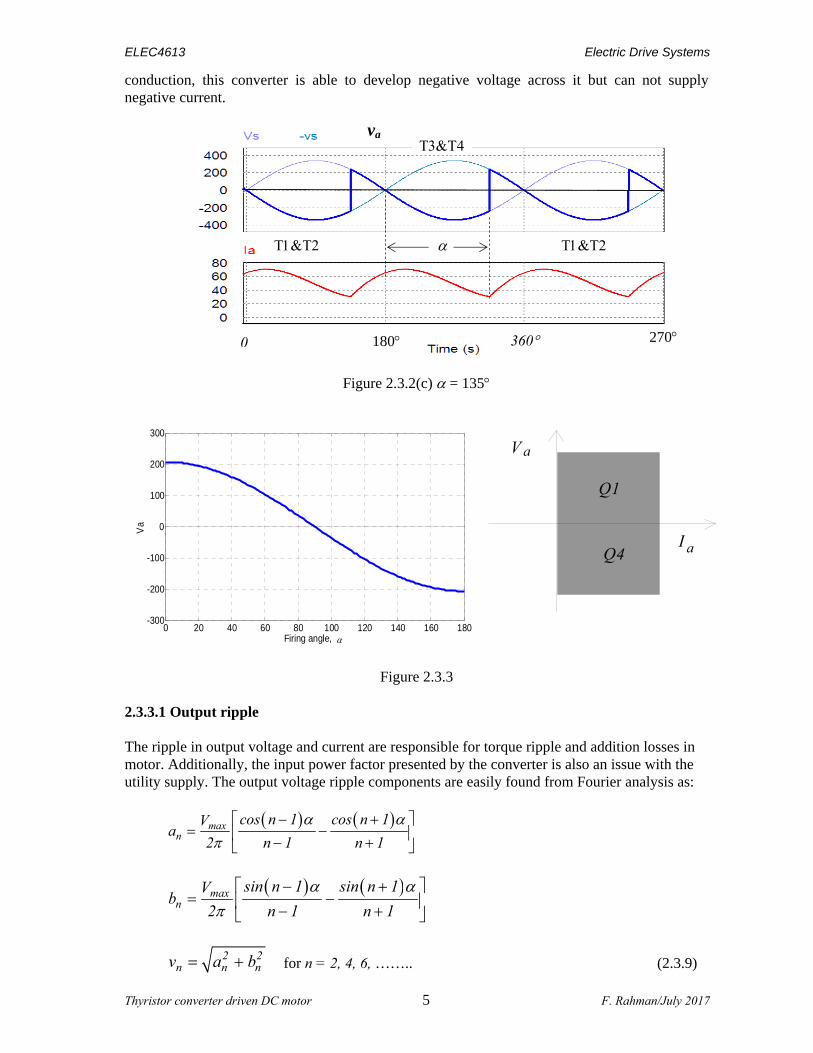
where Vmax is the peak line-line voltage of the AC supply to the converter. This converter operates in two quadrants, Q1 and Q4, as indicated in the figure 2.3.3. With continuous
270 0 180 360
va
T1&T2
45
T3&T4 T1&T2
ELEC4613 Electric Drive Systems
Thyristor converter driven DC motor 5 F. Rahman/July 2017
conduction, this converter is able to develop negative voltage across it but can not supply negative current.
Figure 2.3.2(c) = 135
Figure 2.3.3
2.3.3.1 Output ripple The ripple in output voltage and current are responsible for torque ripple and addition losses in motor. Additionally, the input power factor presented by the converter is also an issue with the utility supply. The output voltage ripple components are easily found from Fourier analysis as:
max
n
cos n 1 cos n 1Va
2 n 1 n 1
max
n
sin n 1 sin n 1Vb
2 n 1 n 1
2 2
n n nv a b for n = 2, 4, 6, …….. (2.3.9)
0 20 40 60 80 100 120 140 160 180-300
-200
-100
0
100
200
300
Firing angle,
Va
Q1
Q4
V a
I a
0 180 360 270
va

ELEC4613 Electric Drive Systems
Thyristor converter driven DC motor 6 F. Rahman/July 2017
The amplitude of the ripple voltage falls as the ripple harmonic number n increases. The lowest ripple order is n = 2 for this converter and its amplitude is the highest (the dominant ripple). From the Fourier coefficients of the ripple voltage, it can be shown that the ripple voltage across the motor is the highest when = 90. For each ripple voltage component, the ripple current is found by dividing the rms ripple voltage by the AC impedance of the armature. Thus
n
n n2 2a a
vi sin n t
R n L
where 1 a
na
n Ltan
R
(2.3.10)
a a nn 2,4 ,6 ,.....
i I i
(2.3.11)
where a a max a
aa a a
V E 2V EI cos
R R R
(2.3.12)
nn 22
a a
VI
R n L
(2.3.13)
where n max
n
VV
2 .
The total RMS ripple armature voltage and current are:
2 2 2
aRMS 2 4 6V V V V (2.3.14)
2 2 2 2
aRMS a 2 4 6I I I I I (2.3.15)
(a) Ripple components of ia (b) Harmonic components of is Figure 2.3.4
100 300 50 150 350

ELEC4613 Electric Drive Systems
Thyristor converter driven DC motor 7 F. Rahman/July 2017
The ratio aRMS
a
I
I, called Form Factor of the armature current, is an important measure of motor
heating. Ideally, it should be as close to unity as practicable. Yet another aspect of the this type of converter is the fact that the input current waveform to the thyristor converter is delayed from the input AC voltage by the firing angle . This implies a drop in the operating power factor of the converter when the motor is driven at lower than rated speed. In the limit, at near zero speed, when the firing angle is near 90, the input power factor is also nearly zero. This is a very undesirable aspect of thyristor converters.
Note that input power factor at which the converter operates is given somewhat differently from purely sinusoidal ac circuits for which the Power Factor is given by the cosine of the angle of the input current and voltage. From basic definition of power factor,
Input Power Factor = Output Power/Input RMS VA
Thus, out ,converter a a sRMS 1 1
sRMS sRMS sRMS sRMS sRMS sRMS sRMS
P V I V I cos IIPF cos
V I V I V I I
(2.3.16)
when converter losses are neglected. Here I1 is the RMS value of the fundamental input current
to the converter. The ratio 1
RMS
I
I is known as the distortion facttor of the input current to the
converter. 2.3.4 Analysis of armature current in continuous conduction mode Computation of ripple components of ia from equations 2.3.9 - 2.3.12 and adding sufficiently large number of terms (n) calculates the armature current ia. Alternatively, the motor current waveform can also be found analytically as shown below:
Solving max sin aa a a a
diV t R i L E
dt for t
a
a
Rt
Lmax aa
a
V Ei sin t Ae
Z R (2.3.17)
where 22a aZ R L and 1tan a
a
L
R
. (2.3.18)
In the steady-state, armature current falls to its minimum value at t = , , and so on. Thus, by setting
min ( )a aI i ,
RaLa
maxRa
La
2V eA sin
Ze 1
(2.3.19)
By setting the expression for A into 2.3.17, we find the solution for ia as

ELEC4613 Electric Drive Systems
Thyristor converter driven DC motor 8 F. Rahman/July 2017
a
a
aa
a
a
R
L Rt
Lmax aa
a
maxR
L
V Ei sin t e
Z
2V esin
ZRe 1
(2.3.20)
Using min( )a ai I , into the final expression for ia,
a
a
a
a
R
Lmax a
a min RaL
V Ee 1I sin
Z Re 1
(2.3.21)
Note that for this converter, we have assumed that the voltage applied to armature circuit for each half of the AC cycle is the same and that the current waveform repeats in every half cycle. The solution for ia for this converter is found by replacing the constant A in equation (2.3.17) from (2.3.20). Expression 2.3.21 is useful in finding the minimum inductance Lamin required in the armature circuit so as to ensure continuous conduction. Once the solution of ia is found, the average value of the armature current, Ia, is found from
1( )a aI i t d t
(2.3.22)
or from (2.3.12). The AC components of the armature current can be found from Fourier analysis of the analytical solution of ia. This will be a tedius task (refer to page 199 Shepherd, Hulley and Liang for Fourier coefficients of ia). It is easier to perform the task by using Fourier analysis of the voltage ripples and AC circuit analysis, as given by equations (2.3.9 – 2.3.13).
2.3.4.1 T-characteristic with continuous conduction
max amax L'a a
Tm ' '
E E
2V R2V cos Tcos I R K
K K
ELEC4613 Electric Drive Systems
Thyristor converter driven DC motor 9 F. Rahman/July 2017
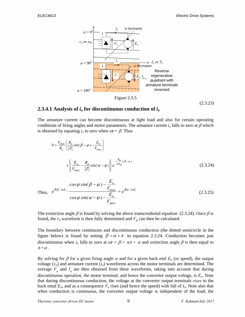
Figure 2.3.5 (2.3.23) 2.3.4.1 Analysis of ia for discontinuous conduction of ia The armature current can become discontinuous at light load and also for certain operating conditions of firing angles and motor parameters. The armature current ia falls to zero at which is obtained by equating ia to zero when t = . Thus
max a a
a max
V R E0 sin( )
R Z V
Ra ( )La a a
max
E Rsin( ) e
V Z
(2.3.24)
Thus,
a
R / L R / Lmax
a
max
Ecos sin( )
Ve e
Ecos sin( )
V
(2.3.25)
The extinction angle is found by solving the above transcendental equation (2.3.24). Once is found, the va waveform is then fully determined and Va can then be calculated. The boundary between continuous and discontinuous conduction (the dotted semicircle in the figure below) is found by setting in equation 2.3.24. Conduction becomes just
discontinuous when ia falls to zero at t = = n + and extinction angle is then equal to .+ . By solving for for a given firing angle and for a given back emf Ea (or speed), the output voltage (va) and armature current (ia) waveforms across the motor terminals are determined. The average V
a and I
a are then obtained from these waveforms, taking into account that during
discontinuous operation, the motor terminal, and hence the converter output voltage, is Ea. Note that during discontinuous conduction, the voltage at the converter output terminals rises to the back emaf Ea, and as a consequence Va rises (and hence the speed) with fall of Ia. Note also that when conduction is continuous, the converter output voltage is independent of the load; the
increases
decreases
va or m
Ia or TL
Reverse regenerative quadrant with
armature terminals reversed
= 0o
= 90o
= 180o
Ia
EaVa
1
Ia
EaVa
1

ELEC4613 Electric Drive Systems
Thyristor converter driven DC motor 10 F. Rahman/July 2017
converter essentially behaving as an ideal DC source (this also assumes instantaneous transfer of current (commutation) from one pair of thyristors to the next pair at each triggering). Thus, when armature current becomes discontinuous at light load, the converter voltage (and hence motor speed) rises sharply with fall of armature current (or load), or conversely, speed falls sharply with rise of armature current (or load), as shown in figure 2.3.6.
Figure 2.3.6
From the solution of ia, the average Ia can be found for the give firing angle and speed (or beck emf Ea). thus giving the developed torque T. The coordinates of the operating point for the drive for the chosen (or Ea) and are thus found. By repeating the above calculations for a given firing angle and a range of speeds , the torque-speed charactersitic of the drive for a given firing angle can be found. The T - characteristic of a seprately excited DC motor for a range of firing angles are indicated in the figure 2.3.6. Note that during continuous conduction in quadrant 1, the back emf of the armature Ea is lower than Va, by the IaRa drop which is small. This voltage drop, divided by KE, is the small droop in speed, which depends on Ia and hence load torque. During discontinuous conduction, the change of speed with a change of load toque can be rather high, implying poor speed regulation with load. The rise in Va with discontinuous conduction can be considered to be a loss of converter voltage gain dVa/d or rather dVa/dEc, where Ec is the control voltage to the firing control circuit. This loss of gain (usually it is a severe loss of gain) makes the converter response time to change of operating conditions unacceptably slow. High inductance in the armature circuit (or a large a) reduces the likelyhood of discontinuous conduction, so that the minimum required inductance to ensure continuous conduction for the minimum expected load may have to be found.
T, Nm
m = 60
= 0
= 150
= 180
0

ELEC4613 Electric Drive Systems
Thyristor converter driven DC motor 11 F. Rahman/July 2017
2.3.4.2 The critical armature inductance The minimum inducatance, Lamin, required in the armatude circuit to prevent discontinuous conduction at a given speed and load can be found by equating Iamin = 0 in equation 2.3.21. For just discontinuous conduction, . The condition for minimum Lamin is given by
a
a
a
a
R
L
a aR22 max
a a L
e 1R E
sinVR L
e 1
(2.3.26)
2.3.5 Effect of source inductance
Ia
Va
ip
Vmaxsint
T1
T2T4
T3Lsi
vsi
Ra
La
+ Ea
Figure 2.3.7(a) The flat Va-Ia characteristics of the converter with continuous conduction at any firing angle , are also idealised. In reality, the DC output voltage of a phase-controlled thyristor converter falls linealy with load current because of the source inductance in the AC supply and the leakage inductance of the supply transformer. A phenomenon called commutation overlap is responsible for this droop. Analysis of this aspect of a thyristor converter operation will not be covered in this course. For a converter with a given source inductance, the droop of the converter output DC voltage with load current may simply be represented by an equivalent DC source resistance Lx. Thus, for the single-phase fully-controlled converter, the DC voltage to the motor for a firing angle may be given by
max2 2cosa s a
VV L I
(2.3.27)
where Lx represents the voltage droop factor of the converter due to the commutation overlap mentioned above, is the AC supply source frequency (50 Hz for Australia), and Lx is the equivalent source inductance which also depends on the converter circuit. The effect of source inductance is therefore responsible for a further droop in speed than what is indicated in the figure 2.3.2.3. With AC side source inductance and commutation overlap, the speed of the motor is thus given by

ELEC4613 Electric Drive Systems
Thyristor converter driven DC motor 12 F. Rahman/July 2017
max2 2cos s a a a
E
VL I I R
K
rad/sec when conduction is continuous. (2.3.28)
Figure 2.3.7(b)

ELEC4613 Electric Drive Systems
Thyristor converter driven DC motor 13 F. Rahman/July 2017
2.3.6 Single-phase half-controlled thyristor bridge converter
Vm ax sint
Ea
Ra
La
Ia
T1 T2
D1 D2
Df
Figure 2.3.8 A half-controlled bridge converter has two thyristors and two diodes in the bridge arms and addtionally a commutating diode across the motor terminal to allow the thryristor current to commutate into when the AC supply voltage reverses polarity. The commutating, or freewheeling diode is required to prevent unconrolled operation of a bridge arm. The presence of the freewheeling diode circulates (freewheels) the armature current and prevents the load voltage from becoming negative.
2
a max0
1V V sin t d t
2
max1
V sin t d t
= maxV1 cos
with continuous conduction of ia. (2.3.29)
Figure 2.3.9
180
= 45
va
0 360 540

ELEC4613 Electric Drive Systems
Thyristor converter driven DC motor 14 F. Rahman/July 2017
Figure 2.3.10 The torque-speed characteristic of a separately excited DC motor driven by the converter of Figure 2.3.7 is given by
max
s a T
mE
V1 cos L R T / K
K
rad/sec (2.3.30)
where continuous conduction has been assumed. The half-controlled converter has the desirable attribute that it presents a higher input power factor than the fully controlled converter. This is because the lagging component of the AC source current is constrained to locally locally through the motor circuit by the freewheeling diode. Its output voltage and current ripples are also lower and the armature current is less likely to become disconitnuos, so that the crtical inductance required for continuous conduction is not as large. The gate drive and converter circuit costs are also somewhat cheaper. It however operates in one quadrant only, so regenerative braking of the drive is not possible with this converter.
0 20 40 60 80 100 120 140 160 1800
50
100
150
200
250
Va
Firing angle,
Ia or T
Va
or m Q1

ELEC4613 Electric Drive Systems
Thyristor converter driven DC motor 15 F. Rahman/July 2017
2.3.7 Three-phase fully controlled converter driven SE DC motor
Figure 2.3.11
For larger DC motor drives, three-phase thyristor converter circuits are preferred due their lower output voltage ripple and input current harmonic performance.
Assuming continuous conduction,
2
3a max l l
3
max l l
1V V sin td( t )
/ 3
3Vcos
(2.3.31)
This converter operates in quadrants 1 and 4, developing both positive and negative polarity dc
output voltage. For firing angles o o0 90 , the converter operates in quadrant 1 and
foro o90 180 , the operation is in quadrant 4. Operation in quadrant 4 is of course
possible only when the load includes an active DC source, able to source power into the ac circuit.
(a) (b)
Figure 2.3.12. (a) Converter Va vs firing angle. (b) converter quadrant characteristic
Ra
La Va
T1 T3 T5
T4 T6 T2
ia ia
ib
ic
van
vbn
vcn
+ Ea
0 20 40 60 80 100 120 140 160 180
-300
-200
-100
0
100
200
300
Va
Firing angle,
Q1
Q4
Va
Ia

ELEC4613 Electric Drive Systems
Thyristor converter driven DC motor 16 F. Rahman/July 2017
Figure 2.3.13 Output voltage and input current waveforms for = 45.
Figure 3.3.13(a) Ripple content of va ; fh = 6kfs
0 300 600 900 1200 1500 1800 2100 2400 2700 Hz

ELEC4613 Electric Drive Systems
Thyristor converter driven DC motor 17 F. Rahman/July 2017
Figure 2.3.14 Converter output voltage and input current waveforms for = 145
From Fourier analysis, the output voltage harmonics for continuous conduction are given by
2 90
n max l l max0 30
1 6a V cos n t d t V sin t 30 cos n td t
Figure 3.3.13(b) Harmonic content of is ; fh = (2k 1)fs

ELEC4613 Electric Drive Systems
Thyristor converter driven DC motor 18 F. Rahman/July 2017
max l l2 sin n 1 cos n 1 2 sin n 1 cos n 13V 6 6
n 1 n 1
(2.3.32)
Similarly,
max l ln
2 sin n 1 sin n 1 2 sin n 1 sin n 13V 6 6bn 1 n 1
(2.3.33) where n = 6, 12, 18 etc,…. The peak ripple voltage of a harmonic number 6n is given by
2 2 max l ln n n 2 2
3V 1 1 2cos 2c a b
n 1 n 1n 1 n 1
(2.3.34)
Three-phase bridge converter circuits have the following attributes, compared to the single- phase bridge converter:
1. The output voltage waveform of the converter is smoother, having the lowest harmonic order of six, compared to two for the single-phase bridge converter. The ripple voltage at the motor has harmonic order or 6k where k is any positive integer. The armature current ripple has the same harmonic order. The ripple voltage and currents are also of lower magnitude. The highest output ripple occurs for = 90.
2. The lower ripple in the armature current and the smoother voltage waveform calls for
smaller armature inductance which may be required to ensure continuous conduction or limit the armature current ripple (∆ia).
3. The effective converter switching frequency is six times the supply frequency (300 Hz,
compared to 100 Hz for a single-phase bridge converter).
4. The input current waveform to the converter is closer to being a sinusoid (i.e., better distortion factor), compared to the input current waveform for the single-phase bridge converter. The harmonic order of the AC input line current is given by 6k ± 1, compared to 2k ± 1 for the single-phase converter, where k is any positive integer. This calls for reduced filter requirement at the input AC side.

ELEC4613 Electric Drive Systems
Thyristor converter driven DC motor 19 F. Rahman/July 2017
2.3.7.1 Analysis of armature current for continuous conduction
The motor current can be exactly determined from the DC and harmonic currents, using DC and AC circuit analysis techniques and Fourier analysis of the motor voltage waveform, and then adding the currents for each voltage component. Alternatively, for interval: o o30 t 90 ,
o amaxl l a a a a
diV sin t 30 R i L e
dt (2.3.35)
As before, we assume that the motor back emf ea (hence speed) is constant at Ea.
Note that the output voltage waveform repeats every 60. Solving for ia,
a
a
Rt
L 6maxl l aa
a a
V Ei t sin t Ae
Z 6 R
(2.3.36)
In writing the solution for ia, the phase shift angle of 6
, or 30, of the line-line voltage from the
phase-neutral voltage has been taken into account. The constant of integration, A, is found from noting that ia is minimum at
nt , ,
6 6 3
where n = 1, 2, 3,…. and so on.
Using the fact that ia is the same at and att , ,6 6 3
a
a
maxl lR
L 3
V sinA
Z e 1
(2.3.37)
The minimum and maximum armature current values are given by:
a
a
max l l a max l la min R
aL 3
sinV E VI sin
Z 3 R Ze 1
(2.3.38)
a
a
a
a
R
L 6max l l a max l l
a max Ra
L 3
sin eV E VI sin
Z 2 R Ze 1
(2.3.39)
From the complete solution of the armature current, the average and RMS armature currents can be determined. For the average armature current, the motor developed torque is found, for the speed for which Ea was used in the calculation. Note that when conduction is continuous, which is readily indicated by the positive sign of

ELEC4613 Electric Drive Systems
Thyristor converter driven DC motor 20 F. Rahman/July 2017
max l la
aa
3Vcos E
IR
(2.3.40)
the average armature current is easily found from equation 2.3.40. 2.3.7.2 Torque-speed characteristic with continuous conduction For a given firing angle , the T- characteristics for a separately excited DC motor are given by,
maxl ls a a a
mE
3V 3cos L I I R
K
(2.3.41)
where L3x is the equivalent source reactance of the three-phase AC source. The T- characteristics for a few firing angles are as shown in figure 2.3.14.
T, Nm
= 60
= 0
= 150
= 170
m rad/sec
0
Figure 2.3.15
Note that operation in quadrant 1 is for forward driving and operation in quadrant 4 is for reverse (regenerative) braking. The droop in speed with load with continuous conduction is partly due to the voltage drop in armature resistance and partly due to the voltage regulation characteristic of the converter as a consequence of the AC side source inductance. The steeper droop in speed with load indicated by the graphs to the left of the dotted semicircle for a given firing angle is when discontinuous conduction occurs, i.e., the instantaneous armature current is not more than zero at all times. 2.3.7.3 Critical inductance for continuous conduction
As for the single-phase converter, the armature current can become discontinuous, depending on the load, firing angle and motor parameters. The boundary between continuous and discontinuous conduction is found by equating the expression for Iamin (eqn 2.3.38) to zero. This is indicated by the dotted semicircle in the T- plane in figure 2.3.15. The critical inductance for just discontinuous conduction for this converter is given by

ELEC4613 Electric Drive Systems
Thyristor converter driven DC motor 21 F. Rahman/July 2017
a
a
a aR
a max l lL 3
sinR Esin
Z 3 Ve 1
(2.3.42)
2.3.8 Half-controlled three-phase thyristor bridge converter driven DC motor
Ra
La
Vd
va
T1 T3 T5
D4D6 D2
iL ia
ib
ic
van
vbn
vcn n
+VD/2
VD/2
Df
e a
Figure 2.3.16 Three-phase half controlled converter driven DC drive.
Figure 2.3.17 Output voltage and input current waveforms of a three-phase half controlled thyristor converter
Assuming continuous conduction,
a maxl l1
V V sin td t2 / 3
= max l l3V1 cos
2
(2.3.51)

ELEC4613 Electric Drive Systems
Thyristor converter driven DC motor 22 F. Rahman/July 2017
Note that this converter only operates in quadrant 1, because negative voltage across the dc rails will initiate freewheeling of the load current through Df. It should be noted that freewheeling is present when the firing angle is greater than 60. It should also be noted that the input current waveform is not symmetrical, because the commutation of the load current through the free-wheeling diode, thereby relieving the input source of the lagging component of current. [The converter input current waveform will include some even order harmonics]. As a result, the input power factor of this converter is higher than the fully controlled converter and its output voltage ripples are also smaller.
Figure 2.3.18 Vdc vs firing angle and quadrant characteristic of the half-controlled converter.
As for single-phase, half-controlled converter, the output voltage and current ripple are smaller for this converter, compared to the fully controlled converter. It also operates with a better input displacement factor. 2.3.9 Converter Voltage Gain Firing control circuits of phase-controlled AC-DC converters normally include a conversion such that the firing angle made equivalent to cos-1(vc) where vc is the control voltage to the firing angle controller. This is easily incorporated with the firing control circuit. For the three-phase fully controlled bridge converter, the output DC voltage to the motor is then given by
1max l l max l la c c
3V 3VV cos cos v v
(2.3.52)
Between the firing controller and motor terminals, the converter thus behaves as a voltage gain
of max l l3V
.
cos-1 Firing
Control Circuit
vc
Figure 2.3.19
0 20 40 60 80 100 120 140 160 1800
50
100
150
200
250
300
Va
Firing angle,
Va
Ia
Q 1
Va

ELEC4613 Electric Drive Systems
Thyristor converter driven DC motor 23 F. Rahman/July 2017
2.3.10 Four-Quadrant Converter Single and three-phase fully-controlled thyristor converters described so far operate in two quadrants, 1 and 4. In order to drive the motor in all four quadrants, two such converters are needed, to be connected back to back as shown in figure 2.3.19.
Ra
La
Ea
Ia
1 + 2 = 1801 2
C1 C2
Figure 2.3.20 In one mode of control, called suppressed-half control, either converters C1 or C2, but not both, is enabled with firing pulses if operation in quadrant 1 and 4 or 3 and 2, respectively, is required. Firing pulses to one of the converter is always suppressed. For forward motoring operation in quadrant 1 with positive armature voltage and current, converter C1 is enabled with the required firing angle 1. For forward braking operation in quadrant 2 (with positive armature voltage (speed) and negative (braking) current, converter C2 is enabled with firing angle 2, such that its output DC voltage is smaller than the back emf Ea by a margin required maintaining the desired level of braking current, as the speed drops. For reverse motoring operation in quadrant 3 with negative armature voltage and current, converter C2 is enabled with the required firing angle a2. For reverse braking operation in quadrant 4 with negative armature voltage (negative speed) and positive (braking) current, converter C1 is enabled with firing angle a1 such that its output voltage is smaller than the back emf by a margin required for maintaining the desired level of braking current, as the speed drops. In this mode of control, firing pulses to both converters are released simultaneously, otherwise a short across the DC bus will occur. It should be obvious that smooth transfer of current from motoring to braking and vice versa will incur a short crossover delay. This delay must allow the outgoing converter to regain forward blocking capability before the incoming conferter is fired.
In another mode of control, called circulating-current control, a center-tapped inductor is placed between the two converters at the point where the motor armature is connected to the DC bus between the two converters. Both converters are operated together, with firing angles determined from 1 2 180 (2.3.53)
Both converters C1 and C2 now produce the same DC output voltage, one with firing angle suitable for motoring and the other with a firing angle suitable for braking. The average DC voltage produced by both converters is now nearly the same. The difference between the two

ELEC4613 Electric Drive Systems
Thyristor converter driven DC motor 24 F. Rahman/July 2017
voltages is such that the converter which does motor the drive sinks a small but continuous regenerative current. The advantage of this scheme is that the delay associated with converter transfer, such as in the suppressed half scheme, is now reduced to zero, so that quicker (higher bandwidth) control of the armature can be achieved. 2.3.11 Motor de-rating due to ripple current. For a DC motor, its continuous current rating is given by the maximum smooth DC current it can carry continuously. (Note that the RMS value of a ripple-free DC value is the DC value itself). When the motor is supplied from a converter in the steady state, the armature current includes a DC value, which is responsible for the developed torque, and some ripple which produces ripple torque and extra heating due to the 2
rms aI R (or copper) loss. Because of these
factors, the DC motor has to be de-rated in the ratio of the DC to RMS current. For example, if the ratio of DC to RMS current of a 50 kW DC at rated load is 0.8, this motor is to be regarded as a 40 kW machine because of the ripple content of its armature current. In other words, a 50kW motor would need to be selected for a 40kW load when the DC to RMS ratio of the armature current is 0.8.