david taylor research center · david taylor research center ... mathematics, and logistics...
TRANSCRIPT

David Taylor Research CenterBethesda, MD 20084-5000
DTRC-90/025 July 1990 AD-A2 2 7 526Computation, Mathematics, and Logistics Department
Test and Evaluation Report
.2_ Proposed Draft Military Handbook Presentingo Requirements for an Electronic Display
System (EDS) for Interactive Electronic6- Technical Manuals (IETMs)E=
-
byEric L. JorgensenJoseph J. Fuller
a- 2 and
0 - Samuel C. Rainey (Scientific Management Associates, Inc.)LU
C >
B , 9uECTE
O0CT161990
CD0)0..-
CJ0
O Approved for public release; distribution is unlimited.

CODE 011 DIRECTOR OF TECHNOLOGY, PLANS AND ASSESSMENT
12 SHIP SYSTEMS INTEGRATION DEPARTMENT
14 SHIP ELECTROMAGNETIC SIGNATURES DEPARTMENT
15 SHIP HYDROMECHANICS DEPARTMENT
16 AVIATION DEPARTMENT
17 SHIP STRUCTURES AND PROTECTION DEPARTMENT
18 COMPUTATION, MATHEMATICS & LOGISTICS DEPARTMENT
19 SHIP ACOUSTICS DEPARTMENT
27 PROPULSION AND AUXILIARY SYSTEMS DEPARTMENT
28 SHIP MATERIALS ENGINEERING DEPARTMENT
DTRC ISSUES THREE TYPES OF REPORTS:1. DTRC reports, a formal series, contain information of permanent technical value.They carry a consecutive numerical identification regardless of their classification or theoriginating department.
2. Departmental reports, a semiformal series, contain information of a preliminary,temporary, or proprietary nature or of limited interest or significance. They carry adepartmental alphanumerical identification.
3. Technical memoranda, an informal series, contain technical documentation oflimited use and interest. They are primarily working papers intended for internal use. Theycarry an identifying number which indicates their type and the numerical code of theoriginating department. Any distribution outside DTRC must be approved by the head ofthe originating department on a case-by-case basis.
NDW.r)TNSRDC 5602 51 Iev 2 88;

JNCLASSIFLEDRrTY CLASSIFICATION OF THIS PAGE
REPORT DOCUMENTATION PAGEEPORT SECURITY CLASSIFICATION lb. RESTRICTIVE MARKJNGS
JnclassifiedECU FlY CLASSIFICATION AUTHORITY 3. OISTRIBUTION/AVALABILITY OF REPORT
'ECLASS#IFICATION/DOWNGRA ING SCHEDULE
Approved for public release; distribution is unlimited.'ERFORMING ORGANIZATION REPORT NUMBER(S) 51 MONITORING ORGANIZATION REPORT NUMBERIS)
)TRC-90/025lAME OF PERFORMING ORGANIZATION 6b. OFFICE SYMBOL 7. NAME OF MONITORING ORGANIZATION
)avid Taylor Research Center Code 1820.3kDDRESS (Cily. State, ad ZIP Cvdo) 7b. ADDRESS (City. Sctt. andZIP Code)
Bethesda, Maryland 20084-5000
lAME OF FUNDINGSPONSORING I 81. OFFICE SYMBOL 9. PROCUREMENT INSTRUMENT IDENTIFICATION NUMBERORGANIZATION (It applIable)
Chief of Naval Operations Code 403kDDRESS (C&ty. Stat.. and ZIP Co&e) 10. SOURCE OF FUNDINC NL0BERS
PROGRAM IPROJECT ITASK IWORK UNITNavy CALS Program ELEMENT NO. NO. NO. ACCESSION NO.
Washington, DC 20362 OMN DN508091TITLE lklio Soaaiy Claaftawn)
Proposed Draft Military Handbook Presenting Requirements for an Electronic Display System (EDS) for Interactive ElectronicTechnical Manuals (ETMs)PERSONAL AUTHOR(S)
Jorgensen, Eric L. (DTRC), Rainey. Samuel C. (SMA), and Fuller, Joseph J. (DTRC)TYPE OF REPORT 13b. TINE COVERED 14. DATE OF REPORT (YEAR. MONTH, DAV) 15. PAGE COUNT
Final I FROM 89/10 To 9 015 1990 July 109SUPPLEMENTARY NOTATION
COSATI CODES 18. SUBJECT TERMS (C ,on xu on fveme ff neweasa'y and denly by bkbc nxmt.)
FIELD GROUP SUB-GROUP
I O -Electronic Display, Technical Manuals, Computer-Aided Acquisition & LogisticI ! Support, Specifications, Standards, Handbooks
ABSTRACT (Cont.tu on rovewaI newssaay anW kftfty by Nboct nuftt)
IThe report summarizes recent activities in the Department of Defense and in the US Navy, Army, and Air Force to establish Service useateractive Electronic Manuals (IETMs) as replacements for paper Technical Manuals for logistic support of military equipment.
The IETM concept is described, and an overview is provided of five IETM acquisition Specifications and Military Handbooks developedbe Tn-Service Interactive Electronic Technical Manual Working Group established in 1989 by the Defense Quality and Standardization Of-
One of these five draft documents, MIL-HDBK-EDS (Navy), Electronic Display System (EDS) for Interactive Electronic Technical Manu-IETMS), 1 Jun 1990, is described and presented.Four other companion Reports have been prepared to introduce and describe the four re-d IETM acquisition Specifications and Handboo) (see reverse side)
> IQI
DISTRIBUTION/AVAILABILITY OF ABSTRACT 21. ABSTRACT SECURITY CLASSIFICATION
0 UNCLASSIFIEDtUNLIMrTFD C SAM: AS RPT C DTIC USERS UnclassifiedNAME OF RESPONSIBLE INDIVIDUAL 22b. TELEPHONE (Ilndue A. Code) 22c. OFFICE SYMBOL
Joseph J. Fuller 301-227-1358 Code 1820.3:ORM 1473. JUN 86 Previous editions are obsolete. SECURITY CLASSIFICATION OF THIS PAGE
UNCLASSIFIED0102-L F-014-6602
UNCLASSIFIEDSECURITY CLASSIFICATION OF THIS PAGE
(Block 19) (Continued)
This report describes the functions of the Electronic Delivery System, the primary purpose ofjwle& is to provide a fullyinteractive display of the IETM Technical Information. It describes the four major components of the hDS and characterizes the roleof each with respect to the EDS architecture and to the IETM system as a whole. It introduces four types of requirements whichmust be specified in detail by an Acquisition Manager in acquiring an Electronic Delivery system: (1) Hardware Requirements: (2)Software Requirements; (3) Environmental Requirements; and (4) User-Interaction Requirements.
A copy of MIL-HDBK-EDS (Navy) is included in this report as the Appendix. I *
NTIS GR. &I
DTIC TABUnamncunced tillJust ic-ation ]
Dist ribut ion/
Avtilatility CcdosI-. il i... o
DD FORM 1473, JUN (Reverse) SECURITY CLASSIFICATION OF THIS PAGE
UNCLASSIFIED

CONTENTS
Page
ABSTRACT ............ ........................ 1
ADMINISTRATIVE INFORMATION ........ ............... 2
ACKNOWLEDGEMENTS.................... 2
1.0 INTRODUCTION .......... .................... 3
1.1 BACKGROUND .......... ................... 3
1.2 DOD AND TRI-SERVICE PROGRAMS ESTABLISHED IN
RESPONSE TO TECHNICAL INFORMATION AUTOMATION
POLICY ......... ..................... 5
1.3 THE INTERACTIVE ELECTRONIC TECHNICAL MANUAL
CONCEPT ........... .................... 6
1.4 PREPARATION OF SPECIFICATIONS AND HANDBOOKS FOR
SERVICE-WIDE COORDINATION OF ACQUISITION OF
AUTOMATED TECHNICAL INFORMATION .... ........ 8
1.5 PURPOSE OF PRESENT REPORT ... ... .......... 10
2.0 ACQUISITION DOCUMENTATION FOR INTERACTIVE ELECTRONIC
TECHNICAL MANUALS AND ASSOCIATED TECHNICAL
INFORMATION ........ .................... 12
2.1 DEFINITIONS ...... ................. 12
2.1.1 The Interactive Electronic Technical Manual
(IETM) ....... .................. 12
iii

Page
2.1.2 The View Package .... ............. .. 13
2.1.3 Nature and Purpose of the Revisable IETM
Data Base . . . ................. 14
2.1.4 The Electronic Display System (EDS) . . . 15
2.1.5 Summary ...... ................. 16
2.2 IETM PROCUREMENT OPTIONS .. ........... . 17
2.3 SUMMARY AND PURPOSE OF THE DRAFT ACQUISITION
SPECIFICATIONS AND HANDBOOKS PREPARED BY THE
TRI-SERVICE IETM WORKING GROUP ........ .. 19
2.3.1 The Revisable IETM Data Base Specification 20
2.3.1.1 Title ..... ................ .. 20
2.3.1.2 Purpose ..... ............... .. 20
2.3.2 The IETM General Content, Style, Format, and
User-Interaction Requirements Specification 21
2.3.2.1 Title ..... ................. .. 21
2.3.2.2 Purpose ..... ............... .21
2.3.3 The IETM View Package Handbook ...... .. 22
2.3.3.1 Title . . ................. 22
2.3.3.2 Purpose ..... ............... .. 22
2.3.4 The IETM QA Program Requirements
Specification .... .............. 22
2.3.4.1 Title ................... 22
2.3.4.2 Purpose ..... ............... .. 23
2.3.5 The Electronic Display System Handbook . . 23
2.3.5.1 Title ..... ................ .. 23
2.3.5.2 Purpose ..... ............... .. 23
2.4 RELATIONSHIP OF MIL-M-IETMQA TO OVERALL SET OF
IETM ACQUISITION SPECIFICATIONS AND HANDBOOKS 24

Page
3.0 SUMMARY OF MIL-HDBK-EDS (NAVY). ELECTRONIC DISPLAY
SYSTEM (EDS) FOR INTERACTIVE ELECTRONIC TECHNICAL
MANUALS (IETMs) ....... ................. 27
3.1 EDS FUNCTIONAL OVERVIEW ... ........... 27
3.2 ELECTRONIC DISPLAY SYSTEM ARCHITECTURE . . . . 28
3.3 EDS COMPONENTS AND FUNCTIONS .. ......... 29
3.3.1 The Work Center Device .. .......... 29
3.3.2 The Portable Display Device . ....... 30
3.3.3 The Rack-Mounted Device .. ......... 31
3.3.4 Supplementary Printers .. .......... 31
3.4 TYPES OF REQUIREMENTS PRESENTED BY MIL-HDBK-EDS 32
1.4.1 Hardware Considerations ......... 33
3.4.2 Software Requirements .. .......... 33
3.4.3 Environmental Requirements ......... . 34
3.4.4 User-Interaction Requirements ...... 35
REFERENCES ......... ...................... 37
APPENDIX A
Copy of Draft Military Handbook:
MIL-HDBK-EDS (Navy). Electronic Display System (EDS) for
Interactive Electronic Technical Manuals (IETMs).
1 June 1990 .......... ........................... ... 39

THIS PAGE INTENTIONALLY LEFT BLANK
vi

ABSTRACT
This Report summarizes recent activities in the Departmentof Defense and in the US Navy, Army, and Air Force to establishService use of Interactive Electronic Technical Manuals (IETMs)as replacements for paper Technical Manuals for logisticsupport of military equipment.
The IETM concept is described, and an overview is providedof five IETM acquisition Specifications and Military Handbooksdeveloped by the Tri-Service Interactive Electronic TechnicalManual Working Group established in 1989 by the Defense Qualityand Standardization Office.
One of these five draft documents, MIL-HDBK-EDS (Navy),Electronic Display System (EDS) for Interactive ElectronicTechnical Manuals (IETMs), 1 Jun 1990, is described andpresented. (Four other companion Reports have been prepared tointroduce and describe the four related IETM acquisitionSpecifications and Handbooks.)
This Report describes the functions of the ElectronicDelivery System, the primary purpose of which is to provide afully interactive display of the IET1 T-chrical Tnformation.It describes the four major components of the EDS andcharacterizes the r6le of each with respect to the EDSarchitecture and to the IETM system as a whole. It introducesfour types of Requirements which must be specified in detail byan Acquisition Manager in acquiring an Electronic DeliverySystem:
(1) Hardware Requirements;
(2) Software Requirements;
(3) Environmental Requirements;
(4) User-Interaction Requirements.
A copy of MIL-HDBK-EDS (Navy) is included in this Report asan Appendix.

ADMINISTRATIVE INFORMATION
The work presented in this Report was dccomplished at the
David Taylor Research Center under OMN funding for the
Logistics Policy Branch (OP-403), Deputy Chief of Naval
Operations (Logistics).
ACKNOWLEDGEMENTS
The effort described in this Report is in considerable part
based on the extensive efforts of a number of personnel from
the Air Force Hximan Resources Laboratory and the Air Force
Logistics Command (MMDE), Wright-Patterson Air Force Base,
Dayton, Ohio, assisted by personnel from RJO, Inc., Dayton,
Ohio.

1.0 INTRODUCTION
1.1 BACKGROUND
During the 1980s, it became increasingly apparent that the
striking increases in the complexity and sophistication of the
weapon systems of all three Services were causing a serious lag
in the production, distribution, and management of the
Technical Information required to maintain, operate, and
support these systems. Of particular concern were increasing
weight and space requirements resulting from the increasing
bulk of the required paper Technical Manuals.
At the same time, a number of significant technological
improvements were being made in the field of information
handling, particularly the advent of small, inexpensive, fast
computers. Such innovations offered the potential of almost
complete replacement of paper-based Technical Information
through the use of light, easily stored, highly capable
electronically processible media, which at the same time were
capable of more effective interactive display to the end user.
Research, Development, Test, and Evaluation efforts of the
three Services during this past decade have conclusively
demonstrated, both through field tests and through in-house
analyses and experimentation, the feasibility and intrinsic
value of providing integrated Technical Information in
paperless form in such a way that it can be displayed to end
users by means of an interactive Electronic Display System.

For example, the Navy Technical Information Presentation
System (NTIPS) Program at David Taylor Research Center, the
Navy's Lead Laboratory for TI automation, demonstrated under
operational conditions the improvements achievable in
maintenance-technician performance [Refs (1) and (2)] through
the use of electronically displayed TI. Similar results have
been achieved by the Air Force under its Computer-based
Maintenance Aiding Information System (CMAS) and its Integrated
Maintenance Information System (IMIS) programs
[Refs (3) and '4)]. The Army has automated Training
Information under its Electronic Information Delivery System
(EIDS), and has assessed the capability of using field portable
maintenance aids under the Militarized Electronic Information
Delivery System (MEIDS) program.
In addition, a number of pilot prototype developments and
tests involving land, sea, and air vehicles and their weapon
systems are bzing carried out, by individual System Acquisition
Managers of all three Services, in an effort to provide
interactive and electronically displayed Technical Information.
Ref (1) Fuller, Joseph J., Theodore J. Post, and Anne S. Mayor, "Testand Evaluation of the Navy Technical Information PresentationSystem (NTIPS), F-14A Field Test Results," DTRC-88/036(Sep 1988).
Ref (2) Fuller, Joseph J., Raymond L. LeBeau, Anne S. Mayor, TheodoreJ. Post, and Charles S. Sawyer, "Test and Evaluation of The NavyTechnical Information Presentation System (NTIPS), AN/SPA-25D TestResults," DTRC-88/035 (Sep 1988).
Ref (3) Thomas, D.L. and J.D. Clay, "Computer-Based Maintenance Aids forTechnicians: Project Final Report," Air Force Human ResourcesLaboratory, AFHRL-TR-87-44 (Aug 1988).
Ref (4) Link, W.R., J.C. Von Holle, and D. Mason, "IntegratedMaintenance Information System (IMIS): A Maintenance InformationDelivery Concept," Air Force Human Resources Laboratory,AFHRL-TP-87-27 (Nov 1987).
4
1.2 DOD AND TRI-SERVICE PROGRAMS ESTABLISHED IN RESPONSE TO
TECHNICAL INFORMATION AUTOMATION POLICY
To co6rdinate and standardize the increased use of
computer-aided logistic support throughout the three Services,
the Department of Defense established the Computer-aided
Acquisition and Logistics Support (CALS) program [see Ref (5)),
which also has had a wide effect in stimulating progress toward
the goal of TI automation, and particularly toward
standardization of E-uch efforts.
The Department of Defense established [Ref (5)], and later
reiterated [Ref (6)], a policy requiring that access to and
the delivery of system-related logistic-support information be
automated.
For example, Ref (6) provided the following directions:
a. For systems now in full-scale development or
production, program managers were required to review
specific opportunities for cost savings or quality
improvements that could result from changing delivery
or access using the Computer-aided Acquisition and
Logistics Support standards.
b. For systems entering development after September 1988,
acquisition plans, solicitations, and related documents
Ref (5) DEPSECDEF MEMORANDUM FOR SECRETARIES OF THE MILITARY DEPARTMENTS,of 24 Sep 1985. Subj: Computer Aided Logistic Support.
Ref (6) DEPSECDEF MEMORANDUM FOR SECRETARIES OF THE MILITARY DEPARTMENTSAND DIRECTOR, DEFENSE LOGISTICS AGENCY, of 5 Aug 1988. Subj:Computer-Aided Acquisition and Logistic Support.
5

required specific schedule and cost proposals for:
(1) integration of Contractor Technical Information
systems and processes;
(2) authorized Government access to Contractor data
bases; and
(3) delivery of Technical Information in digital form.
c. DOD components were to program for automated systems to
receive, store, distribute, and use digital weapon-
system Technical Information, including achieving the
earliest possible date for digital input to DOD
engineering data repositories.
More recently, the Joint Uniform Service Technical
Information System (JUSTIS) concept has been announced, a
planned effort which will combine, to as great a degree as
possible, Tri-Service procedures and equipment for acquisition
and control of system-support Technical Information.
1.3 THE INTERACTIVE ELECTRONIC TECHNICAL MANUAL CONCEPT
The culmination of this effort throughout the 1980s in
response to the DOD policy statements cited has been the
development of the Interactive Electronic Technical Manual
(IETM) Concept. The IETM Concept involves full application of
existing technological capabilities to the problems of
providing Technical Information which is both more effective
for the end user and more efficient in terms of acquisition,
control, and update.
6

The IETM Concept involves a system approach, which includes
basically all of the following components:
a. A standardized, automated, revisable source Data Base.
b. Use of a computer-controlled authoring system.
c. The generation of digital Technical Information
(containing text and graphics), either directly by an
Author, or automatically by computer. This Technical
Information is recorded on an electronically
processible medium (optical or magnetic), rather than
on paper.
d. Technical Information (consisting of task-related
increments) which is optimally arranged and formatted
for interactive screen presentation.
e. Presentation (display to the end user) by means of a
computer-controlled Electronic Display System (EDS)
possessing an extensive user-interaction capability.
The EDS is capable of displaying the IETM, performing
related logistic-support functions, and interfacing
with other Service logistic-support Information
Systems.
An IETM permits a user to locate required information more
easily, and to present it faster, more comprehensibly, more
specifically matched to the configuration, and in a form that
requires much less storage than paper. Powerful
troubleshooting procedures not possible with paper Technical
Manuals are possible using the computational capability of the
IETM Display Device.
7

IETMs will be used by maintenance technicians, afloat and
ashore; to maintain and operate weapon systems by Intermediate
and Depot maintenance activities; and by training personnel.
The IETM Concept has been described in detail in Ref (7).
1.4 PREPARATION OF SPECIFICATIONS AND HANDBOOKS FOR SERVICE-
WIDE COORDINATION OF ACQUISITION OF AUTOMATED TECHNICAL
INFORMATION
To coordinate this wide-spread effort, the Defense Quality
and Standardization Office established in 1989, under the DOD
Technical Manual Technology Exchange Subcommittee, chartered by
DOD INST 4151.9 [Ref (8)], an Interactive Electronic Technical
Manual Working Group, chaired by the Navy, whose primary
functions were to:
a. Foster the exchange of ideas and the agreement on a
single approach regarding:
(1) the acquisition of IETMs which use computer
technology for innovative electronic display; and
(2) presentation of Technical Manual Information among
all Department of Defense Agencies.
Ref (7) Rainey, Samuel C., Joseph J. Fuller, and Eric L. Jorgensen,"The Electronic Delivery of Automated Technical Information forLogistics Support of Navy Weapons Systems: Potential, SystemDescription, and Status," DTRC-89/007 (Feb 1989).
Ref (8) DoD Instruction 4151.9 of 3 Jan 1989, "DoD Technical Manual
Program Management."
8

b. Develop a set of DOD Specifications for:
(1) The acquisition of IETM data; and
(2) The Electronic Display Systems needed for the
presentation of IETMs for the maintenance of DOD
weapons, systems, and equipment.
The Working Group was also charged with the responsibility
of providing a recommendation to the DOD CALS Policy Office
concerning inclusion of IETM interchange Specifications into
the set of CALS standards; e.g., in connection with
MIL-STD-1840.
The Tri-Service Working Group consists of representatives
of (a) the David Taylor Research Center (DTRC) of the Navy,
(b) the Air Force Logistics Command (AFLC-MMDE), and (c) the
US Army Communications-Electronics Command (AMCPM-TMDE).
With DTRC and the Air Force Human Resources Laboratory (as
an advisor to AFLC) contributing the primary effort, a series
of five Specifications (see Section 2.3) and Handbooks for IETM
acquisition has been drafted. This series consists of:
" A Specification governing the nature of the Revisable
IETM Data Base;
" A Specification providing general Content, Style, Format,
and User-Interaction requirements for all IETMs;
" A Handbook describing for a System Acquisition Manager
the best approach to writing acquisition Specifications
9

for individual View Packages (to be used for IETM
procurement);
" A Handbook presenting requirements for the Electronic
Display System;
" A Specification presenting requirements for an IETM
Quality Assurance Program.
These documents have been widely circulated for comment
within both the DOD and Industry.
These drafts were also developed to accomplish as near-term
objectives the provision of a suite of IETM prototype
acquisition documents for use by major DOD programs in
establishing initial IETM capabilities. These programs include
the Navy's A-12 Attack Aircraft Program, the Advanced Tactical
Fighter Program of the Air Force, and the M-1 Main Battle Tank
Program of the Army.
1.5 PURPOSE OF PRESENT REPORT
The purpose of the present Report is to present and to
describe in detail one of these draft documents, specifically:
MIL-HDBK-EDS (Navy). Military Specification. Electronic
Display System (EDS) for Interactive Electronic Technical
Manuals (IETMs). 1 June 1990.
10

A series of four other Reports has been prepared, each
Report describing one member of the set of five acquisition
documents prepared by this Working Group [Ref (9) through
Ref (12)].
Section 2 of this Report provides an overall description of
this suite of Acquisition Specifications and Handbooks.
Section 3 summarizes the Approach and Requirements of one of
the five documents; in this case, MIL-HDBK-EDS (Navy). The
draft version of MIL-HDBK-EDS (Navy) is included in this Report
as Appendix A.
Ref (9) Rainey, Samuel C., Eric L. Jorgensen, and Joseph J. Fuller,"Proposed Draft Military Specification for Revisable Data Basefor Support of Interactive Electronic Technical Manuals(IETMs)," DTRC Report 90/027 (Jul 1990).
Ref (10) Rainey, Samuel C., Eric L. Jorgensen, and Joseph J. Fuller,"Proposed Draft Military Specification for Quality Assurance(QA) Program Requirements for Interactive Electronic TechnicalManuals (IETMs)," DTRC Report 90/024 (Jul 1990).
Ref (11) Rainey, Samuel C., Eric L. Jorgensen, and Joseph J. Fuller,"Proposed Draft Military Handbook for Preparation of ViewPackages in Support of Interactive Electronic TechnicalManuals," DTRC Report 90/026 (Jul 1990).
Ref (12) Jorgensen, Eric L., Samuel C. Rainey, and Joseph J. Fuller,"Proposed Draft Military Specification for General Content,Style, Format, and User-Interaction Requirements forInteractive Electronic Technical Manuals (TETMs),"DTRC Report 90/028 (Jul 1990).
11

2.0 ACQUISITION DOCUMENTATION FOR
INTERACTIVE ELECTRONIC TECHNICAL MANUALS
AND ASSOCIATED TECHNICAL INFORMATION
2.1 DEFINITIONS
2.1.1 The Interactive Electronic Technical Manual (IETM).
As defined by the Working Group, an IETM is a Technical
Manual, prepared (authored) by a Contractor and delivered to
the Government, or prepared by a Government Activity, in
digital form on a suitable medium, by means of an automated
authoring system; designed for electronic-screen display to an
end user; and possessing the following three characteristics:
a. The format and style of the presented information are
optimized for screen presentation to assure maximum
comprehension; that is, the presentation format is "frame-
oriented", not "page-oriented".
b. The elements of Technical Information constituting the TM
are so interrelated that a user's access to the information
he requires is facilitated to the greatest extent possible,
and is achievable by a variety of paths.
c. The computer-controlled TM-Display Device can function
interactively (as a result of user requests and information
input) in providing procedural guidance, navigational
directions, and supplemental information; and also in
providing assistance in carrying out logistic-support
functions supplemental to maintenance.
12
This terminology is consistent with the standard DOD
definition of Technical Manual. Ref (8), states:
Technical Manuals are publications that contain instructions for the
installation, operation, maintenance, training, and support of weapon
systems, weapon-system components, and support equipment. TM
information may be presented in any form or characteristic, including but
not limited to hard printed copy, audio and visual displays, magnetic tape,
discs, and other electronic devices. They normally include operational and
maintenance instructions, parts lists or parts breakdowns, and related
technical information or procedures exclusive of administrative
procedures. Technical Orders (TOs) that meet the criteria of this
definition may also be classified as TMs.
2.1.2 The View Package.
IETM information, as provided to the end user for viewing
on an Electronic Display Device, will be constructed in
individual task-oriented increments called View Packages.
A View Package (VP) is a fully organized and formatted item
of computer-processible Technical Information derived from an
IETM Data Base and capable of interactive electronic display to
an end user by means of an Electronic Display System (EDS). In
function and design, a View Package is completely equivalent to
an individual Interactive Electronic Technical Manual. A View
Package may be constructed:
a. entirely by an Author using an automated authoring
system;
13

b. completely automatically using a series of automated
processes (software) which perform the data-selection,
structuring, and formatting processes; or
c. by a combination of the above two approaches.
A View Package is designed to support a specific function
in the operation or logistics-support of a weapon system or
other military equipment.
2.1.3 Nature and Purpose of the Revisable IETM Data Base
As noted above, a View Package is created entirely from
data contained in a Revisable IETM Data Base (IETMDB), which is
a complete collection of Data Elements relating to a weapon
system or other equipment acquired by the Government and
constructed in a standardized procedure in order to provide the
following capabilities:
a. Government Activities or DOD Contractors concerned
with logistic support for the weapon system involved
can access the Data Base directly to obtain needed
logistic-support information for specific purposes.
b. The IETMDB can serve as the basis for construction
and update of the entire suite of electronically
displayed interactive weapon-system Technical
Manuals through the use of automated authoring
systems.
c. The IETMDB can serve as the basis for fully
automated construction, by either a Contractor or a
14

Government Activity, of View Packages, which are
increments of interactive electronically presented
logistic-support Technical Information.
d. Required portions of the IETMDB can be interchanged
by means of standardized procedures throughout the
DOD and its supporting Contractors on a real-time
basis when needed.
2.1.4 The Electronic Display System (EDS)
The EDS is a computer-based Technical Information system
designed to accept, process and integrate Technical Information
for prime-equipment logistics support, and display that
information to users. The EDS is also intended to support
inquiries by users (in addition to Operations and Maintenance
users) who have such responsibilities as supply, training,
field-data collection, readiness measurement, operations
scheduling, maintenance planning, maintenance quality control,
and hardware configuration control. The software supporting
the EDS will also be required to support additional (as yet
unspecified) functions in the future, which will emerge as
technologies and standards evolve. Specifically, the EDS
is intended for use:
a. In maintenance Work Centers and shops to support
Troubleshooting and Planned and Corrective
Maintenance;
b. In portable form at remotely located maintenance
sites;
15

C. Embedded in a weapon-system control panel as support
both for System operation and System maintenance;
d. In presenting operating and maintenance information
during personnel training courses;
e. In a variety of centers and offices in support of
System-related, logistics-supported functions which
require Technical Information.
The Electronic Display System will consist of one or more
computer-controlled Devices which display the required
Technical Information by means of a screen (such as a cathode-
ray-tube or a plasma display) either in a pre-ordered sequence
or in random-access increments, as called for by the user;
e.g., a maintenance technician. To accomplish this display,
the IETM, consisting of the Technical Information recorded on
a suitable medium (e.g., on an optical disc), is designed to be
loaded into the EDS, "read" by this Device, and displayed in a
sequence as directed by the user.
The IETMs to be used by this Display System must
accordingly be so constructed as to assure full compatibility
with the operating software of the Display Device, and must be
tested by the preparing Contractor on such a Display Device
prior to delivery.
2.1.5 Summary
As noted, all IETMs:
16

a. Will be constructed through the use of an automated
authoring system, and will consist of task-related
increments referred to as View Packages;
b. Will be based on an automated system Data Base, the
IETMDB, prepared by the System Prime Contractor for
delivery as such to the Government, retention for his
own use, or both;
c. Will consist of a digital data stream recorded on an
optical or magnetic medium, but not paper,
electronically displayed by the Electronic Display
System in terms of text and graphics;
d. Will be optimally formatted and styled for screen
presentation (i.e., "frame oriented" rather than "paper
oriented").
e. Will be constructed for electronic display on a highly
interactive Electronic Display System, which will
support related logistic-support functions and which
may be networked for interface with other Service
Information Management Systems.
2.2 IETM PROCUREMENT OPTIONS
Logistic-support procedures for weapon systems and related
equipment differ to some extent among the Services. A certain
amount of necessary variation in the acquisition procedures
involving the VPs, the IETMDB, and the EDS has been provided in
the system of Specifications and Acquisition Handbooks
developed by the IETM Working Group.
17

Thus, these Specifications and Handbooks detail several
optional approaches in the acquisition of IETMs. These are as
follows:
a. Using appropriate IETM Specifications, the Service
may buy whatever directly-authored Interactive
Electronic Technical Manuals are required. Although
the Author (equipment Prime Contractor) will need to
establish an automated equipment or weapon-system
(source) Data Base, this Data Base will not be acquired
by the Government, but will be maintained and used by
the Contractor, both for the preparation of IETMs and
for other purposes.
(1) As an option, the Government might contract for
on-line access to technical portions of this
Contractor-owned Data Base. In such a case, both
content and accessibility aspects of the IETM Data
Base would have to be constructed to standard
requirements.
b. Acquisition by the Government of directly authored
IETMs (fully prepared and validated by the Contractor)
as well as the IETM Data Base upon which they are
based. Government acquisition of the IETM Data Base
may involve either of the following options:
(1) Delivery to the Government in standardized form
and subsequent maintenance by the Government (with
or without update information supplied on a
continuing basis by the Contractor);
(2) Title acquired to the IETM Data Base by the
Government, but with the Data Base retained and
18

maintained in the Contractor's plant. The
Government to be provided with on-line access to
the Data Base.
c. Based on acquisition of the IETM Data Base, using
either option b.(1) or b.(2), preparation of View
Packages using either a fully automated process or one
which is essentially fully automated. View Packages
could be prepared either:
(1) By the Contractor [based on Data-Base acquisition
option b.(1)], and delivered as such to the
Government, or
(2) By the Government (based on Data-Base acquisition
option b.(2)].
2.3 SUMMARY AND PURPOSE OF THE DRAFT ACQUISITION
SPECIFICATIONS AND HANDBOOKS PREPARED BY
THE TRI-SERVICE IETM WORKING GROUP
As noted, five draft Specifications and Handbooks have
been prepared, and circulated widely for DOD and Industry
comment, to provide System Acquisition Managers with the
necessary contractual documentation for acquisition of
Interactive Electronic Technical Manuals, the associated Source
Data Base, and the necessary Electronic Display Systems. These
statements of requirements are preliminary and will certainly
be modified as experience is gained with the acquisition,
management, and use of this type of Technical Information, as
the technology advances, and as the Department of Defense
19

improves its in-house logistic-support infrastructure for
support of IETMs.
The five draft Specifications and Handbooks prepared by
the Inter-Service IETM Working Group (of which Appendix A of
this Report is one), together with individual statements of the
purpose of each document, are as follows:
2.3.1 The Revisable IETM Data Base Specification
2.3.1.1 Title
Draft MIL-D-IETMDB. Revisable Data Base for Support of
Interactive Electronic Technical Manuals (IETMs). 1 June
1990.
2.3.1.2 Purpose
This Specification contains the requirements for a
Revisable Interactive Electronic Technical Manual Data Base
(IETMDB) to be constructed by a weapon-system Contractor. This
non-redundant and neutrally formatted Data Base is intended to
be the single source of data for all Technical Manuals to be
used in support of a given weapon system, or other equipment
being acquired by the Government. This Specification may be
used in two primary modes:
a. as a set of standard requirements to which the
Contractor must adhere in the development and
20

maintenance of his internal Data Base for subsequent
conversion to Government-deliverable form; and
b. as a set of requirements for a Data Base that is
physically delivered to the Government, or is
maintained by the Contractor on behalf of the
Government.
2.3.2 The IETM General Content, Style, Format, and User-
Interaction Requirements Specification
2.3.2.1 Title
Draft MIL-M-GCSFUI. Manuals, Interactive Electronic
Technical: General Content, Style, Format, and User-
Interaction Requirements for. 1 June 1990.
2.3.2.2 Purpose
This Specification contains common requirements for the
Content, Style, Format, and User-Interaction features required
for Interactive Electronic Technical Manuals and the operating
software of the devices upon which they are viewed. These
IETMs are to be delivered to the Government in digital form and
must be designed for interactive display to the maintenance-
technician end-user by means of a computer-controlled
Electronic Display System. The range of IETMs for which
general requirements are described in this Specification will
cover the maintenance, diagnostic, training, system-operation,
parts-information, and installation functions which are
required to achieve and maintain full operational capability of
a specific weapon system or other military equipment.
21

2.3.3 The IETM View Package Handbook
2.3.3.1 Title
Draft MIL-HDBK-IETMVP. Guidelines for Developing
Specifications for Interactive Electronic Technical
Manual (IETM) View Packages. 1 June 1990.
2.3.3.2 Purpose
The purpose of this Handbook is to provide guidance forthe preparation of individual View-Package Specifications, so
that System Acquisition Managers may define View Package
Requirements quickly and effectively for the numerous different
specialized increments of Technical Information which will berequired. A Handbook of this type has been referred to as a
meta-specification: a Specification describing how to write a
View Package Specification which is the end-item Specification
for procurement of an actual IETM.
2.3.4 The IETM QA Program Requirements Specification
2.3.4.1 Title
Draft MIL-M-IETMQA. Quality Assurance (QA) Program
Requirements for Interactive Electronic Technical
Manuals (IETMs) and Associated Technical Information.
1 June 1990.
22
2.3.4.2 Purpose
This Specification prescribes the requirements for a
Contractor's QA program for Interactive Electronic Technical
Manuals (IETMs) and, where procured, the associated IETM Data
Bases and supporting View Packages. The requirements herein
cover the QA process and present the plan for implementing it,
from planning through final submission of the delivered product
for acceptance; they apply as well to changes and revisions
thereto.
2.3.5 The Electronic Display System Handbook
2.3.5.1 Title
Draft MIL-HDBK-EDS (Navy). Electronic Display System
(EDS) for Interactive Electronic Technical Manuals
(IETMs). 1 June 1990.
2.3.5.2 Purpose
This Handbook describes the basic functional requirements
for an Electronic Display System (EDS) designed to display
Interactive Electronic Technical Manuals (IETMs). It
establishes the minimum system requirements to be used in a
detailed Specification for competitive procurement, either for
portions of the full requirements or tailored to suit the
application, user environment, device compatibility, and
interfaces to existing computer systems.
23

The requirements described in this Handbook are of three
types:
a. Those which describe the Electronic Display System
hardware;
b. Those which describe the EDS software of the display
System for system operation, IETM applications, and
utility functions.
c. Those which specify the minimum performance of the
several individual Display Devices which constitute
the EDS.
To achieve full compatibility of the EDS with the IETMs
and View Packages, the Display System Software (as well as the
View Package) must also be constructed in compliance with
MIL-M-GCSFUI.
Each of the three Services has its own strategies for
developing Specifications and Standards for an Electronic
Display System. This Handbook presents the existing Navy
concepts, and is accordingly identified as a Navy-only
document. Proposed concepts of the other Services which do not
differ extensively from requirements described in this Handbook
will be included in succeeding versions of the Handbook.
2.4 RELATIONSHIP OF MIL-HDBK-EDS (NAVY) TO OVERALL SET OF
IETM-ACQUISITION SPECIFICATIONS AND HANDBOOKS
An increment of IETM Technical Information, referred to as
a View Package, must be displayed on an Electronic Display
System (EDS) which has been specially designed to accept the
24

data stream of the View Package, to interpret the VP software
in terms of display commands, to provide the user-interaction
capability built into the View Package, and to host the
software required for the performance of collateral functions
required to support the logistic-support function for which the
VP has been designed (e.g., parts ordering or maintenance-
action reporting). Thus, to achieve any degree of uniformity
among the three Services, the EDS design (both hardware and
software) must embody numerous standardized characteristics of
the IETM concept.
At the same time, the wide variation of types of military
systems to which the VPs will apply, the variation in
maintenance and other logistic-support processes of the three
Services, and the wide range of operational environments in
which such Display Systems will be used have made it infeasible
to prepare an Acquisition Specification containing a single set
of EDS hardware and software requirements at this time.
Accordingly, a Handbook has been generated for Industry
and Service review which provides a statement of as many
requirements as presently possible to serve as the basis for as
much inter-Service standardization as can be achieved.
Requirements, both hardware and software, have been
presented largely in functional terms. Where specific
requirements have been included (e.g., maximum weight and
volume figures for a portable Electronic Display Device), such
values are included to illustrate the functional requirements
proposed (i.e., in this case, of portability).
25

The EDS design is influenced strongly by the Style,
Format, and User-Interaction Requirements of all View Packages
[detailed in Ref (12)], by the design of the View Packages
themselves [Ref (11)], and by the performance of an adequate QA
process [Ref (10) ], since any Display Device used in QA must be
identical to that which will be provided to the end user.
26
3.0 SUMMARY OF MIL-HDBK-EDS (NAVY)
ELECTRONIC DISPLAY SYSTEM (EDS) FOR
INTERACTIVE ELECTRONIC TECHNICAL MANUALS (IETMs)
3.1 EDS FUNCTIONAL OVERVIEW
The functions which must be fulfilled by the several
components of an Electronic Display System functioning as a
critical part of the IETM approach have been summarized in
Section 2.1.4.
More particularly, the EDS must:
a. Display IETM View Packages in a fully interactive and
comprehensible manner to a using technician. Such View
Packages will vary widely in design and purpose. They
must provide guidance for maintenance and other direct
forms of system logistic support, for system
operations, and for training; and they must be capable
of being viewed in a wide variety of environments.
b. Permit the performance of a number of functions related
to the direct performance of the tasks or other
functions presented by the View Package itself; these
functions are referred to by MIL-HDBK-EDS as Special
Utilities (see Section 3.4.3 of the Handbook). They
include:
(1) Incorporation of Rapid Action Changes into the
View Package;
27

(2) Technical Information error and deficiency
reporting;
(3) Provision of a supply-system interface (e.g.,
for ordering a part);
(4) Provision for Maintenance Action reporting;
(5) Provision of a maintenance audit trail;
(6) Support of Work-Center Maintenance Management
(scheduling, assignment, status of equipment
under a given Work Center).
c. Function as a communication node in a Local Area
Network, permitting the transfer of information from
one EDS terminal to another, and providing an entry
port to relevant Information Management Systems used by
the Service for logistic support of its weapon systems
and other military equipment.
3.2 ELECTRONIC DISPLAY SYSTEM ARCHITECTURE
The basic system architecture of the EDS is that of a
highly integrated networked capability which, nevertheless,
allows autonomous operation of each individual Electronic
Display Device (EDD). The system configuration includes a
network server, a number of individual Display Devices of
several types, a standard data-communications network, and
supplementary printers. This configuration permits integrated
operation of the system and autonomous operation of each
individual Delivery Device.
28

The EDS architecture is also designed so that functional
modules may be added or deleted to customize the application
needs without altering the basic design.
3.3 EDS COMPONENTS AND FUNCTIONS
The Electronic Display System consists of four types of
components, although not all of these components will
necessarily be acquired for any given equipment procurement.
3.3.1 The Work Center Device
The Work Center Device is a bench-mounted Display Device
operating from facility power mains, with software
capabilities, memory, and buss connections to permit it to
carry out the following four types of functions:
a. Library/Storage function; i.e., automated access to,
and storage of, a wide variety of Technical Manual
information to which a technician can obtain immediate
access. If the volume of IETM information involved
requires it, the Work Center Device can be provided
with multi-medium peripheral storage capability (e.g.,
hard-disk, CD/ROM, or WORM) on which it can draw as
required.
b. Display of Interactive Electronic Technical Manuals or
View Packages (text and graphics) to a using technician
as required.
29

c. Communication with other information systems of the
ship or station, with a printer, with a Portable
Electronic Display Device, and with other Work Center
Electronic Display Devices constituting the nodes of a
Local Area Network.
d. Support for the performance of the Utility functions
described in Section 3.1.1.b.
One Work Center device which constitutes a node of the
Facility Local Area Network will function as the "Network
Server"; that is, it will perform the following functions:
a. Provide for multi-user/multi-tasking capability;
b. Be the central repository for the IETM database; and
c. Provide for central control and management of EDS
operations, applications, and interfaces to external
computer systems.
3.3.2 The Portable Display Device
This component of the EDS is intended to be carried by a
technician to a location remote from a maintenance center, to
support performance of some fairly limited task, and to display
only that Technical Information (downloaded from a Work Center
Device) required for this purpose. It will operate either from
facility power mains or from battery power. Size and weight
will be small enough to assure its convenient portability in
the kinds of (often inconvenient) maintenance environments
involved. Memory will be limited but adequate to handle
30

screen-displayed TI equivalent to several hundred pages of
conventional Technical Manuals. The downloaded information is
to be discarded (i.e., erased) once used.
3.3.3 The Rack-Mounted Device
The Rack-Mounted Display Device is functionally equivalent
to a Work Center Display Device, but permanently located (rack-
mounted) as a part of one of the (relatively few) shipboard,
field, or air-station systems where maintenance is always
carried out in some specific compartment or location (e.g., a
ship-performance monitoring system). Such a Device will
maintain TI sufficient for all locally performed logistic-
support functions downloaded from a Work Center Device, on some
non-volatile memory medium, on a continuing basis.
3.3.4 Supplementary Printers
Although the IETM concept will reduce to a minimum
dependence on hard-copy Technical Information, provision has
been made in the IETM system design for supplementary printers
(to print selected View Package information) which may be
needed under unusual circumstances.
Two types of printers are included:
a. A supplementary graphics printer for drawings up to
B-size (11" x 17"), which could be used by a technician
to reproduce on paper a large logic-flow diagram,
wiring diagrams, or other schematic.
31

b. An optionally provided 8k" x 11" printer as
supplementary equipment for one or more Work Center
Devices of a LAN, for miscellaneous use in conjunction
with the Work Center mission.
3.4 TYPES OF REQUIREMENTS PRESENTED BY MIL-HDBK-EDS
MIL-HDBK-EDS summarizes EDS requirements of the following
types:
a. Minimum performance requirements which will be
necessary for the system and its components to carry
out the functions which have been summarized in
Section 3.1.1 and which are related to the individual
system components in Section 3.2.1 of this Report.
b. Hardware requirements determined by the functional
requirements of the system and its components.
c. Software requirements determined by the functional
requirements of the system and its components.
d. User-interaction requirements and requirements for
interfaces with other systems and functions of the
Service logistic-support process.
e. Environmental requirements; i.e., requirements which
components of the EDS must meet to be able to perform
in the wide variety of work locations where they will
be needed.
32
3.4.1 Hardware Considerations
MIL-HDBK-EDS presents proposed hardware requirements for
the Electronic Display System as a whole and for each of the
system components (described under Section 3.3 above).
Particular emphasis is paid to the construction and
capabilities of:
a. The Display screens for the three Display Device
configurations. Screen factors specified include screen
type, size, resolution, pixel-aspect ratio, viewing angle,
color (optional), and gray-scale requirements.
b. Those hardware features (User-Interaction hardware and I/O
mechanisms) of the Display System involved, in assuring
full User-Interaction capability for the system. For
example, see Section 3.3.1.1 and Section 3.3.2. Such
features include requirements for an alphanumeric
keyboard; special-function keypad; mouse, trackball, or
joy-stick; touch-screen; cursor; and the like.
3.4.2 Software Requirements
MIL-HDBK-EDS presents (Section 3.4) functional
requirements for a number of aspects of software, that must be
a part of the EDS design, which must complement completely the
software that is a part of the individual View Package design.
These include:
a. Software for external interfaces;
33

b. EDS File Management;
c. Network Management;
d. Graphics Display Management;
e. Data Security;
f. Special I/O Provisions (e.g., voice registration foraudio capability);
g. VP-Configuration Management.
h. Built-In System Test Software.
3.4.3 Environmental Recuirements
The Handbook summarizes characteristics of the wide range
of environments in which the various components of the EDS must
perform. These environmental requirements include use on ship
while underway, use in open-air flightline repair, and
equipment maintenance on the battlefield under inclement
weather conditions.
At the opposite extreme, EDS components (possibly acquired
under less stringent Specifications) will be extensively used
in environmentally controlled repair shops and Work Centers for
O-level, I-level, and D-level activities. The anticipated
range of environmental requirements is provided for each of the
four types of EDS components proposed. Repairability and
maintainability requirements under such operating conditions
are also presented.
34

3.4.4 User-Interaction Requirements
In addition to the User-Interaction capabilities of the
EDS, which must be designed into the system hardware
(Section 3.4.1, above), general human-engineering and usability
requirements are also detailed by the Handbook. These include:
a. Design for simplicity of use and reliability;
b. Design for user-friendliness;
c. Training requirements for EDS use;
d. Health and Safety factors;
e. Provision of How-to-Use-the-EDS and other Helpinformation ;
f. Protection against loss of information as a result ofsystem or power failure.
35

THIS PAGE INTENTIONALLY LEFT BLANK
36
REFERENCES
(1) Fuller, Joseph J., Theodore J. Post, and Anne S. Mayor,
"Test and Evaluation of the Navy Technical Information Presentation
System (NTIPS), F-14A Field Test Results," DTRC-88/036
(Sep 1988).
(2) Fuller, Joseph J., Raymond L. LeBeau, Anne S. Mayor, Theodore J.
Post, and Charles S. Sawyer, "Test and Evaluation of The Navy
Technical Information Presentation System (NTIPS), AN/SPA-25D
Test Results," DTRC-88/035 (Sep 1988).
(3) Thomas, D.L. and J.D. Clay, "Computer-Based Maintenance Aids for
Technicians: Project Final Report," Air Force Human Resources
Laboratory, AFHRL-TR-87-44 (Aug 1988).
(4) Link, W.R., J.C. Von Holle, and D. Mason, "Integrated Maintenance
Information System (IMIS): A Maintenance Information Delivery
Concept," Air Force Human Resources Laboratory, AFHRL-TP-87-27
(Nov 1987).
(5) DEPSECDEF MEMORANDUM FOR SECRETARIES OF THE
MILITARY DEPARTMENTS, of 24 Sep 1985. Subj: Computer Aided
Logistic Support.
(6) DEPSECDEF MEMORANDUM FOR SECRETARIES OF THE
MILITARY DEPARTMENTS AND DIRECTOR, DEFENSE LOGISTICS
AGENCY, of 5 Aug 1988. Subj: Computer-Aided Acquisition and
Logistic Support.
(7) Rainey, Samuel C., Joseph J. Fuller, and Eric L. Jorgensen,
"The Electronic Delivery of Automated Technical Information for
Logistics Support of Navy Weapons Systems: Potential, System
Description, and Status,". DTRC-89/007 (Feb 1989).
37
(8) DoD Instruction 4151.9 of 3 Jan 1989, 'DoD Technical Manual
Program Management.'
(9) Rainey, Samuel C., Eric L. Jorgensen, and Joseph J. Fuller,
*Proposed Draft Military Specification for Revisable Data Base for
Support of Interactive Electronic Technical Manuals (IETMs)," DTRC
Report 90/027 (Jul 1990).
(10) Rainey, Samuel C., Eric L. Jorgensen, and Joseph J. Fuller,
"Proposed Draft Military Specification for Quality Assurance (QA)
Program Requirements for Interactive Electronic Technical Manuals
(IETMs),' DTRC Report 90/024 (Jul 1990).
(11) Rainey, Samuel C., Eric L. Jorgensen, and Joseph J. Fuller,
"Proposed Draft Military Handbook for Preparation of View Packages
in Support of Interactive Electronic Technical Manuals,'
DTRC Report 90/026 (Jul 1990).
(12) Jorgensen, Eric L., Samuel C. Rainey, and Joseph J. Fuller,
'Proposed Draft Military Specification for General Content, Style,
Format, and User-Interaction Requirements for Interactive Electronic
Technical Manuals (IETMs),' DTRC Report 90/028 (Jul 1990).
38
APPENDIX A
Copy of Draft Military Handbook:
MIL-HDBK-EDS (Navy). Electronic Display System (EDS) for
Interactive Electronic Technical Manuals (IETMs).
1 June 1990
Prior to the publication of this report the document
included as Appendix A has been officially submitted to the
DOD Defense Quality Standardization Office and the DOD CALS
Policy Office by the Office of the Chief of Naval Operations,
Code 403 - Logistics Policy (OPNAV LTR 4160 Ser 403T/OU593187
dtd 4 Jun 1990). It has also been submitted to the Pageless
Technical Manual Working Group of the Aerospace Industry
Association for Review and Comment. This document was
distributed as a review draft and is largely a DTRC product
with assistance from the Air Force as noted. This Appendix
is in the exact form that was submitted to these
organizations.
39

THIS PAGE INTENTIONALLY LEFT BLANK
40
MIL-HDBK-EDS (Navy)1 June 1990
NOTE: This review draft has been prepared by DTRC for purposes oftechnical review and comment by Industry and DOD organizations. It hasnot been approved and is subject to modification. DO NOT USE FORACQUISITION PURPOSES.
****REVIEW DRAFT****
Beneficial comments (recommendations, additions, deletions) andany pertinent data which may be of use in improving thisdocument should be addressed to: David Taylor Research Center,Code 182.3, Bethesda, Maryland 20084-5000.
MILITARY HANDBOOK (NAVY)
ELECTRONIC DISPLAY SYSTEMS FOR
INTERACTIVE ELECTRONIC TECHNICAL MANUALS (IETMs)
Table of Contents
1. SCOPE ........... ........................... 11.1 Interactive Electronic Display of Technical Information 11.2 The Electronic Display System (EDS) .... ......... 21.3 Interface between the Electronic Display System and the
Interactive Electronic Technical Manual ... ....... 2
2. APPLICABLE DOCUMENTS .......... .................... 32.1 Government Documents .......... ................. 3
2.1.1 Specifications and Standards .... ......... 32.1.2 Other Government Documents ..... .......... 4
2.2 Other Documents .......... ................... 4
i 1 Jun 90:A

MIL-HDBK-EDS (Navy)
1 June 1990
2.3 Order of Precedence ..... .................. 5
3. REQUIREMENTS ......... ... ........................ 53.1 General Requirements ......... ................. 5
3.1.1 General User-Support Functions . ........ 53.1.2 General System Description ..... .......... 63.1.3 Operational Environment ...... ............ 10
3.2 Hardware Requirements ..... ................ 123.2.1 Networking ...... .................. . 123.2.2 Hardware Categories .... .............. . 123.2.3 Electronic Display System Devices ....... ... 143.2.4 General EDS Printer Devices ... .......... . 313.2.5 Transportation Cases, Packaging, and Handling. 353.2.6 Design and Construction .... ............ .. 35
3.3 General User-Interaction Requirements ........ 353.3.1 End-User Interactivity ... ............ .. 353.3.2 User Input/Output Mechanisms .. ......... .. 373.3.3 Information Access and Control Functions . . 42
3.4 Software Considerations ..... .............. 423.4.1 Operating Environment ... ............. . 423.4.2 System Applications .... .............. . 453.4.3 Special Utilities .... ............... 503.4.4 Accommodation of Applications Software Modules 52
4. QUALITY ASSURANCE REQUIREMENTS .... ............... . 52
5. PACKING AND PACKAGING ....... .................... .. 52
6. NOTES ........... ............................ . 52
APPENDIX List of Acronyms and Definitions of Terms ....... ... 52
ii 1 Jun 90:A

MIL-HDBK-EDS (Navy)1 June 1990
ELECTRONIC DISPLAY SYSTEMS FOR
INTERACTIVE ELECTRONIC TECHNICAL MANUALS (IETMs)
1. SCOPE
This handbook describes the basic functional requirements foran Electronic Display System (EDS) designed to display InteractiveElectronic Technical Manuals (IETMs). It establishes the minimumsystem requirements to be used in a detailed specification forcompetitive procurement. Such procurement may be for portions ofthe full requirements described herein, or tailored to suit theapplication, user environment, device compatibility, and interfacesto existing computer systems.
The requirements described in this Handbook are of three types:
a. Those which describe the Electronic Display Systemhardware;
b. Those which describe the EDS software of the DisplaySystem for system operation, IETM applications, and utilityfunctions;
c. Those which specify the minimum performance requirementsof the several individual Display Devices which constitute the EDS.
1.1 Interactive Electronic Display of Technical Information
Interactive Electronic Display of Technical Information
consists of presenting interactively to an end user, by means of acomputer display, specially formatted and integrated text/graphicsinformation which will guide his actions in performing system-maintenance, operational, or other logistics-support functions.
The Interactive Electronic Technical Manual is constructed insuch a way that the end user may ask questions of the system, inputtest data, request the display of Help information, and view severaltypes of related data simultaneously. Similarly, the Display Systemcan prompt the user in his procedures, offer advice, displaywarnings, and point out errors or omissions in his efforts. The enduser may also use the Electronic Display System interactively toaccomplish such functions as Work-Center maintenance management,maintenance action reporting, or parts ordering.
1 1 Jun 90:A

MIL-HDBK-EDS (Navy)
1 June 1990
1.2 The Electronic Display System (EDS)
The EDS is a computer-based Technical Information systemdesigned to accept, process and integrate Technical Information forprime-equipment logistics support, and display that information tousers. The EDS is also intended to support inquiries by users (inaddition to Field or Fleet maintenance technicians and weapon-systemoperators) who have such responsibilities as supply support,training, field-data collection, maintenance planning, maintenancequality control, and hardware/Technical-Information configurationcontrol. The software supporting the EDS must be developed tosupport additional (as yet unspecified) functions in the future,which will emerge as technologies and standards evolve. TheElectronic Display System defined by this Specification is intendedfor use:
a.In maintenance Work Centers and shops to support
Troubleshooting and Planned and Corrective Maintenance;
b.In portable form at a remotely located maintenance site;
c.Embedded in the weapon-system equipment racks as dedicatedsupport both for System operation and System maintenance;
d. In presenting operating and maintenance information duringpersonnel training courses;
e.in a variety of centers and offices in support of System-related, logistics-supported functions which requireTechnical Information.
1.3 Interface between the Electronic Display System and theInteractive Electronic Technical Manual
The Electronic Display System will consist of a computer-controlled Device which displays the required Technical Informationby means of a screen (such as a cathode-ray-tube or a plasmadisplay) either in a pre-ordered sequence or in random-accessincrements, as called for by the user; e.g., a maintenancetechnician. To accomplish this display, the IETM, consisting of thecomputer-readable Technical Information recorded on a suitablemedium (e.g., on an optical disc), is designed to be loaded into theEDS, "read" by this Device, and displayed in a sequence as directedby the user. Thus, one EDS interface is with the medium whichcontains the IETM and which is designed to be loaded onto and "readby" the EDS.
The IETMs to be used by this Display System will accordingly beso constructed as to assure full compatibility with the operatingsoftware of the Display Device, and will be tested by the preparingContractor on such a Display Device (i.e., on the Government-
2 1 Jun 90:A

MIL-HDBK-EDS (Navy)1 June 1990
specified Device which will be used by logistics-supporttechnicians) prior to acceptance by the Government in accordance tothe provisions of MIL-Q-IETMQA: Quality Assurance (QA) ProgramRequirements for Interactive Electronic Technical Manuals (IETMs)and Associated Technical Information..
To assure commonality and uniformity of IETM presentations acrossany Military Service, the operational software designed for the EDSand the IETMs which are procured for the device must conform tocertain standards which are specified in MIL-M-GCSFUI: Manuals,Interactive Electronic Technical, General Content, Style, Format andUser-Interaction Requirements for. Most of the requirements citedin that Specification (to which the IETM author must also conform)have a counterpart in this Electronic Display System Specification(which requires a capability the System designer must provide sothat the corresponding TM capability can be realized in displayingTechnical Information to the user).
2. APPLICABLE DOCUMENTS
The following documents are recommended for inclusion insection 2 of an EDS procurement specification. The section shouldinclude the following phrase at the beginning of Section 2:
"Unless otherwise specified, the following specifications andstandards form a part of this specification to the extent specifiedherein. Specification and standard issues shall be those listed inthat issue of the Department of Defense Index of Specifications(DoDISS) specified in the applicable contract."
2.1 Government Documents
2.1.1 Specifications and Standards
2.1.1.1 Specifications
MIL-M-GCSFUI Manuals, Interactive Electronic Technical,General Content, Style, Format, andUser-Interaction Requirements for.
MIL-P-9024 Packaging, Materials Handling, andTransportability, System and SystemSegments, General Specifications for
MIL-Q-9858 Quality Program Requirements.
MIL-Q-IETMQA Quality Assurance (QA) Program Requirementsfor Interactive Electronic Technical Manuals(IETMs) and Associated TechnicalInformation.
3 1 Jun 90:A

MIL-HDBK-EDS (Navy)1 June 1990
MIL-E-16400 Electronic, Interior Communication, andNavigation Equipment, Naval Ship and Shore,General Specifications for.
MIL-E-5400 Electronic Equipment, Aerospace GeneralSpecification for.
MIL-HDBK-217 Reliability Predictions of ElectronicEquipment.
2.1.1.2 Standards
MIL-STD-109 Quality Assurance Terms and Definitions.
MIL-STD-454 Standard General Requirements for ElectronicEquipment
MIL-STD-810 Environmental Test Materials and EngineeringGuidelines
MIL-STD-1472 Human Engineering Design Criteria forMilitary Systems, Equipment, and Facilities.
DOD-STD-2167 Defense System Software Development
DOD-STD-2168 Defense System Software Quality Program
2.1.2 Other Government Documents
MIL-HBOOK-IETMVP Preparation of View Packages in Support ofInteractive Electronic Technical Manuals
2.2 Other Documents
FIPS 151 POSIX Standard
FIPS 146 GOSIP Standard
4 1 Jun 90:A

MIL-HDBK-EDS (Navy)
1 June 1990
2.3 Order of Precedence
The following sentence should be included in section 2.3 asfollows:
"In the event of a conflict between the text of this Specification andthe references cited herein, the text of this Specification shall tdkepreference."
3. REQUIREMENTS
3.1 General Requirements
3.1.1 General User-Support Functions
The functions of the Electronic Display System are as follows:
3.1.1.1 System Maintenance and Operation
The EDS shall present comprehensible high-quality TechnicalInformation to technicians engaged in Planned Maintenance,Troubleshooting, and Corrective Maintenance of Military systems, andto technicians involved in System operation. This presentation mustbe primarily in a visual form designed specifically for theoperational environment involved.
3.1.1.2 Training
The EDS shall present suitable training information, in schoolsor on-station (e.g., on-board ships) for instructor-controlled orself-paced training to enable technicians to achieve and maintaincompetence in their system-support functions.
3.1.1.3 Interaction with Other Information Systems
The EDS shall communicate with the shipboard or shore-stationlogistics-information network to permit consolidation of reportssubmitted by an individual Work Center (e.g., Maintenance ActionReports, Technical Information Deficiency and Evaluation Reports) andto permit relevant logistics-support communication (e.g., ordering aspare part from an on-station supply center).
3.1.1.4 Other Logistics-Support Functions
The EDS shall permit access by a variety of users who requiresystem-related Technical Information for such functions as planning,readiness evaluations, establishing parts requirements, inventorying,and maintenance-load estimates.
5 1 Jun 90:A

MIL-HDBK-EDS (Navy)1 June in9 0
3.1.2 General System Description
3.1.2.1 System Architecture
The basic system architecture of the EDS is that of a highlyintegrated networked capability but one that allows autonomousoperation of the individual Electronic Delivery/Display Devices(EDDs). The system configuration shall consist of a network server,multiple EDDs, a standard data-communications network, and printers.This configuration enables fully integrated operation of the system,autonomous operation of each EDD, and interfaces with maintenanceinformation systems operating outside the EDS. This mix of operationmodes is essential for maintaining a high degree of reliabilitytolerance in the system.
System architectures may be implemented differently forthe Portable, Rack-Mounted, and Work-Center configurations. However,the basic philosophy behind each architecture is essentially the same,and provides for maximum flexibility to meet unique requirements foreach configuration. The EDS architecture shall be such thatfunctional modules may be added or deleted to customize theapplication needs without altering the basic design.
Features of this architecture are described below.
3.1.2.1.1 Modularity Scheme
The core of the EDS building block modularity scheme is theprocessor module that functions as the CPU. To make up the basic EDSconfiguration, the CPU module is augmented with a communicationsmodule that performs input/output and networking functions, a memorymodule that contains the ROM program memory, a RAM working- or data-memory module, a power supply module, a battery-pack module (PortableDisplay Device only), an interface module, and a means for loadingdata from a laser disc/card, or other very-high density storagemedium.
3.1.2.1.2 Interface Device
The Interface Device shall include the means for loading data froman external data-storage medium and from the storage Device used on aparticular weapon system.
3.1.2.1.3 System Reconfiguration at the Using Activity
6 1 Jun 90:A

MIL-HDBK-EDS (Navy)1 June 1990
Using the modular building block concept, an EDS can be configuredat the using Activity for virtually any application, by the additionor deletion of modules. The actual delivered EDS configuration willbe defined by the Order or Contract to meet logistics-support needs ofthe specific prime equipment.
3.1.2.1.4 Communication
The EDS is a distributed network arrangement that includesestablished nodes, which may be any of three Display-Deviceconfiguration types: Work-Center, Rack-Mounted, or Portable. However,the Portable Device is not hard-wired to the network. The PortableDevice shall have as one of its modular elements a Communicationsoption that establishes a high-speed data transfer link between thePortable Device and any Work-Center or Rack-Mounted Device.
3.1.2.1.5 Connectivity
The EDS connectivity is a complete environment that enables anyDevice to communicate with any other Device through networking, directconnection, or storage media.
3.1.2.2 Network Server
One computer terminal of the EDS network shall function as aserver to other terminals (nodes) in the System. This network server(hereafter referred to as server) shall:
a. Provide for multi-user/multi-tasking capability;
b. Be the central repository for the IETM database; and
c. Provide for central control and management of EDS operations,applications, and interfaces to external computer systems.
3.1.2.3 The Work-Center Device
A bench-mounted, transportable (but not necessarily Portable)Device, provided with sufficient information-handling capability toaccess all available IETMs for every system on the ship or station.All of this information need not be on-line, but any required datamust be capable of being retrieved immediately by a variety of callmethods. The Work-Center Device must be provided with, and capable ofcommunicating through, a suitable data buss to the logistics-communication system of the Organizational level Service activity,other required data-bases, and to a centralized TM-information library(or libraries) for such "O"-level activity if such capabilities are
7 1 Jun 90:A

MIL-HDBK-EDS (Navy)1 June 1990
maintained separately. However, in its function of presenting TI tosystem-maintenance or system-operation technicians, a Work-CenterDevice must be capable of entirely autonomous operation. It must becapable of downloading designated TI to a Portable Display Devicewhich will be carried to a separate work site. It must be capable ofconstituting a node of a Local Area Network which permitsintercommunications among the Display Devices (and performs otherfunctions); the LAN must be so constructed that, for example, an IETMcontained on a disc in a Display Device in one Work Center can beviewed on a Display Device in another Work Center (another node on theLAN) if needed.
The Work-Center Electronic Display Device is thus required toperform three functions:
a.A Library/Storage function; i.e., automated access and storageof a wide variety of Technical Manual information to which atechnician can obtain immediate access. If the IETM volumeinvolved requires it, the Work-Center Device can be providedwith peripheral storage capability (e.g., hard-disk, CD/ROM,or WORM, as required), and on which it can draw as required;
b.Display of Interactive Electronic Technical Manuals or ViewPackages (text and graphics) to a using technician as required;
c.Communication with other information systems of the ship orstation, with a printer, with a Portable Electronic DisplayDevice, and with other Work-Center Electronic Display Devicesconstituting the nodes of a Local Area Network.
3.1.2.4 The Rack-Mounted Device
The Rack-Mounted Display Device is functionally equivalent to aWork-Center Display Device, but permanently located in conjunctionwith those (relatively few) shipboard, Field, or air-station systemswhere maintenance is always carried out in some specific compartmentor location, where a large number of complex system components areoperated (e.g., a ship-performance monitoring system). TI sufficientfor all maintenance or operating requirements, downloaded from a Work-Center Device, will be maintained on some non-volatile memory medium(e.g., a floppy disc) on a continuing basis.
3.1.2.5 The Portable Display Device
A Device which presents TI in visual form to a technician whomust, for example, repair a system at a site remote from the WorkCenter. This Portable Device will normally contain digital text-graphics information (including both Troubleshooting and Corrective-Maintenance information) which has been downloaded for the specific
8 I Jun 90:A

MIL-HDBK-EDS (Navy)1 June 1990
maintenance task at hand from a Work-Center Device. The TI involvedmust be totally self-sufficient and the Device must be able to handleas much as the equivalent of several hundred pages of a conventionalTechnical Manual. Once the specific effort is completed, thedownloaded TI involved will be disposed of or destroyed.
3.1.2.6 A Supplemental Printer
Although the process of providing digitized Technical Informationfor electronic display is designed to eliminate reliance on a papermedium, supplementary printers may be provided as a component of theIETM system, as described below.
3.1.2.6.1 "B" Size Printer
The EDS shall be supplemented by a printer capable of producingup to "B" size drawings (11" x 17"). This device will allow printingof technical information that may be required for performance of aspecific task, such as a circuit diagram or a large schematic orwiring diagram.
3.1.2.6.2 Work Center Printers
Work-Center devices may be optionally supplemented by a printercapable of printing on standard-sized (8 1/2" x 11") paper. This willsupport printing of technical information that may be required forperformance of a specific task.
9 1 Jun 90:A

MIL-HDBK-EDS (Navy)
I June 1990
3.1.3 Operational Environment
The EDS and its components shall meet the environmentalrequirements for shipboard and shore-based equipment specified inMIL-E-16400. The system is intended for use:
a. In work centers and at other locations aboard ship;
b. In shops at shore stations (including flight-line use at NavalAir Stations) at the Organizational, Intermediate, and Depotmaintenance levels; and
c. For training, either at military schools or on-station (e.g.,on-board ship).
The PDD shall function wherever maintenance is performed with theuse of technical manuals. The EDDs shall be capable of functioning inwide extremes of ambient light: from brilliant sunshine to a dimly litinterior shipboard compartment.
3.1.3.1 Human Engineering Considerations
The Electronic Display System is to be designed primarily for useby technicians with limited training. System design and contructionshall stress:
a. Simplicity of use;
b. High reliability;
c. Careful attention to good human-engineering policies, asdescribed in MIL-STD-1472; and
d. The assurance of user-friendliness.
Most of these considerations apply also to the software and controlaspects of the system, along with the display function (that is, theuser command subsystem and user-screen interaction functions).
3.1.3.2 Training Required for Interactive-Display System Use
Technicians who will use this System are expected to be trainedin use of the EDS prior to independent performance of logistics-support functions supported by the EDS, but the EDS is to be designedto minimize this training. For example, System design must be suchthat computer training is not required. Note that a How-to-Use-This-Manual Section is included to supplement the training which has beenprovided to the technician. All information to be displayed by theSystem will be covered by this Section.
10 1Jun 90:A

MIL-HDBK-EDS (Navy)
1 June 1990
3.1.3.3 Interdependence between Display-System Design and the IETM
Specification of the Interactive Electronic Technical Manual (orother forms of Technical Information to be displayed on this System)and design of the Display System itself must be closely coordinated.Thus, the Display System itself,as specified by the Government, willbe used to Validate all Technical Manuals which are to be displayedwith it, as well as for the Verification process. The informationdisplayed on the EDS is the result of both the processing capabilityof the EDS hardware and software and the organization of the IETMitself. Because of this degree of interrelation, it is important thatthe display system design and the organization of the IETM beconstructed to work together.
3.1.3.4 Interdependence between Display System and IETM
The EDS shall be capable of accepting IETM data digitallyinscribed on the medium specified by the Contract or Order. All EDSconfigurations shall have the capability to load IETM data from aLocal Area Network (LAN), a central data-base library, or a logisticscommunications system. The Portable Display Device shall have theadditional capability to upload/download data from the Work-Center orRack-Mounted Display Devices. As required by the Contract, interfacebusses or data-cartridge upload/download capabilities may beadditionally specified.
3.1.3.5 Local Area Networking
The EDS network hardware and software shall link all nodes of theSystem to provide fully integrated system operation and control,establishing a LAN for the using Activity. In addition, the networksoftware shall provide a capability for communicating with other locallogistics-support information systems.
3.1.3.6 Security
The IETM digital-information coding schemes shall permitsafeguarding of the information at its specified level of securityclassification.
a. Data Security: The user shall not have the capability tomodify any data in the IETM, the View Package, or the IETM DataBase. The software shall be designed to ensure data integrityand data security automatically.
b. User Security: Through use of personalized passwords, theoperating software shall have a capability to control user
11 1 Jun 90:A

MIL-HDBK-EDS (Navy)1 June 1990
access to the IETM and other maintenance information which hasbeen installed on the System.
3.2 Hardware Requirements
3.2.1 Networking
The EDS network hardware (Work-Center Devices functioning as nodesand the busses connecting the nodes) shall link all nodes of theSystem to provide fully integrated System operation and control,establishing a LAN for the using Activity. In addition, the networkshall be constructed as to capability for communicating with otherlocal logistics-support information systems functioning as nodes onthe network.
The network shall be Ethernet-compliant. The EDS shall bedesigned to become compliant with the Government Open SystemInterconnection Profile (GOSIP) when that standard has stabilized.
3.2.2 Hardware Categories
Hardware requirements are presented for each of the categories ofElectronic Display System Devices: Network Server, Work-Center,Portable, and Rack-Mounted. The following requirements will bespecified, as applicable:
3.2.2.1 Physical Requirements
Physical Requirements specifications (where applicable) arepresented for each of the three types of Display Devices.
a. Size
b. Weight
c.Design Life
d.Health and Safety.
3.2.2.2 Performance Requirements
The following performance requirements are presented for each ofthe three types of Display Devices:
a. Display Types
b. Screen Characteristics
12 1 Jun 90:A

MIL-HDBK-EDS (Navy)1 June 1990
(1) Size(2) Resolution(3) Pixel Ratio(4) View Angle(5) Backlight(6) Ambient Light(7) Shades of Gray
c. Color Capability, Quantity, and Resolution
d. Processing Power
e. Memory Requirements
(1) Memory Types(2) Secondary Storage(3) Expansion Requirements
f.Self Tests
g.Hardware Reset Capabilities
h.Reliability, Availability, and Maintainability
i. Operating Configuration
j. EMI
k. I/O Requirements
3.2.2.3 Power Requirements
Power requirements are presented for each of the three types ofDisplay Devices.
3.2.2.4 Interactive-Interface Requirements
Specifications for the interactive-interface requirements arepresented for each of the three types of Display Devices. Theserequirements include:
a. Keyboard
b. Touch Screen
c. Cursor
d. Track-Ball
13 1 Jun 90:A

MIL-HDBK-EDS (Navy)1 June 1990
e. Mouse
f. Joy-Stick
3.2.2.5 Environmental Characteristics
Requirements for Environmental Characteristics are presented foreach of the three types of Display Devices.These requirements include:
a. Operating temperature range
b. Non-operating temperature range
c. Humidity
d. Ambient Air Pressure
e. Electrostatic Discharge Sensitivity
f. Operating Inclination
g. Transportability
3.2.3 Electronic Display System Devices
3.2.3.1 The Network Server
3.2.3.1.1 Server Physical Requirements
Weight: < 60 lbs.
Size: 24" wide X 24" deep X 36" high.
3.2.3.1.2 Server Performance Requirements
OperatingConfiguration: Stand alone or networked.
ElectromagneticInterference (EMI): The server shall not be susceptible to EMI
or electromagnetic (EM) pulse effects, andshall conform to TEMPF- ' requirements.
3.2.3.1.2.1 Server Display Requirements
The IETM System Server shall have a console with a display and akeyboard as specified below. All displays used on the server shallhave the following characteristics:
14 1 Jun 90:A

MIL-HDBK-EDS (Navy)1 June 1990
Screen Type: Electroluminescent (EL), Liquid CrystalDisplay (LCD), Cathode Ray Tube (CRT),or Plasma.
Screen Size: 13 to 19-inch diagonal, CRT orflat-panel.
Resolution: 640 x 480 pixels minimum.
Pixel Aspect Ratio: 1:1.
Backlight: Not required.
Viewing Angle: Readable to 30° deviation fromnormal to the plane of the display.
Shades of Gray: A minimum of sixteen different shades ofgray shall be available if monochromedisplay provided.
Color Capability: Optional as required in the contract. Ifprovided, a minimum of sixteen differentcolors shall be available.
Color Resolution: Color capability shall meet or exceed
minimum display resolution requirements.
3.2.3.1.2.2 Server Processing Power
The server processor shall support multiuser/multitasking, networking,communications interfaces, and interoperability among delivery deviceconfigurations. The server shall have the ability to execute at aminimum of 8 million instructions per second (Mips).
3.2.3.1.2.3 Memory Requirement
3.2.3.1.2.3.1 Server Memory Types
The server configuzation shall contain the following memory types andcapacities:
Read-Only Memory (ROM): Sufficient for the resident Basic I/OSystem (BIOS).
Random Access Memory(RAM): 24 megabytes (Mbytes) minimum, to allow
for 30 simultaneous users.
3.2.3.1.2.3.2 Server Secondary Storage
15 1 Jun 90:A

MIL-HDBK-EDS (Navy)
1 June 1990
Transfer Rate: > 6 megabits (Mbits)/sec.
Average Seek Time: < 100 milliseconds (msec).
Latency: < 17 msec.
Shelf Life: > 10 years.
3.2.3.1.2.4 Self Test
The server shall have a built-in, power-up self test. The capabilityto initiate the self test without cycling power is required. Thistest shall indicate if the hardware is faulty.
3.2.3.1.2.5 Server Hardware Reset
The server shall have a hardware reset capability to allow for manualrestart of the system in the event of computer lockout (that is, whenthe server will not accept input). The reset shall not require powerto the computer to be recycled.
3.2.3.1.2.6 Server Reliability and Maintainability
Availability: A server shall have an availability rateof 95%.
Mean Time BetweenFailures (MTBF): 3000 hours, at 240 Centigrade, in
accordance with MIL-HDBK-217.
Mean Time to Repair: 30 minutes.
Mean Time to Replace: 15 minutes for component module.
Preventive MaintenanceRequirements: Operator maintenance shall be limited to
inspection for serviceability, routinecleaning, and replacement or rechargingof batteries.
PartsInterchangeability: Like parts or components shall be
interchangeable as specified inMIL-E-5400.
Fault/Test Isolation: Built-in self test shall isolate thereplaceable component.
Special Tools/TestEquipment: No special tools or test equipment shall
be required.
16 1 Jun 90:A

MIL-HDBK-EDS (Navy)1 June 1990
3.2.3.1.3 Server Power Requirements
Power: 115 volts AC (vac), 60 hertz (Hz), 1phase; via plug-in cable to an externalpower source.
3.2.3.1.4 Server Interactive Interfaces
The following interactive interfaces are permitted:
Keyboard: Full alphanumeric keyboard, includingseparate QWERTY pad, cursor pad, numberpad, and 12 function keys.
Touch Screen: 256 x 256 resolution minimum, operablewith finger or stylus.
Cursor: Standard character-style cursor shallblink at a rate of 1/2 to 2 cycles persecond (cps), dependent upon type ofdisplay.
Track Ball: Optional pointing device.
Mouse: Optional pointing device.
3.2.3.1.5 Server Expansion Requirement
The server shall be configured to allow future expansion offunctionality, memory size, and processing capabilities in a modular,or "building-block," manner without compromising current capabilities.There shall be sufficient internal space in the server to allow forport expansions to support growth of the system.
3.2.3.1.6 Server Environmental Characteristics
The server and its components shall meet the following environmentalrequirements:
OperatingTemperature Range: 00 to +500 Centigrade.
Non-OperatingTemperature Range: Less than -200 Centigradc and greater than
+70 ° Centigrade
Humidity: 10 to 90% relative humidity (RH)noncondensing.
17 1 Jun 90:A

MIL-HDBK-EDS (Navy)1 June 1990
Ambient Air Pressure: Sea level to 10,000 feet above mean sealevel.
Electrostatic DischargeSensitivity: 10 kilovolts (kV) no errors; 17.5 kV no
damage.
OperatingInclination: The server shall operate at an inclination
of 00 to 900.
3.2.3.1.6.1 Transportability
The server shall be transportable, but need not be portable.
3.2.3.1.7 Backup Capability
The following backup capabilities are required:
a. The server shall have the ability to back up the software anddata resident on the EDS, and
b. The server shall have the ability to create redundant copiesof all resident information on an appropriate removable medium.
3.2.3.2 Work Center Device.
The WCD is an electronic device with sufficient information-handlingability to permit system support for every function of the EDS.Although the WCD will be an active node on the EDS network, it shallbe capable of autonomous operation. It shall also be capable ofdownloading and uploading data to and from a PDD. The WCD shall be anexisting high-performance personal computer.
3.2.3.2.1 Work Center Device Physical Requirements.
Weight: Not to exceed 35 pounds (perMIL-STD-1472). However, if the displaypanel is separable from the main unit, itsweight shall not be included in the35-pound limit.
Size: Not greate than 30 inches high x 18inches wide x 18 inches deep.
3.2.3.2.2 Work Center Device Performance Requirements.
18 1 Jun 90:A

MIL-HDBK-EDS (Navy)1 June 1990
OperatingConfiguration: Hard-wired, networked, or stand alone.
EMI: The WCD shall not be susceptible to EMIor EM pulse effects, and shall conformto TEMPEST requirements.
3.2.3.2.2.1 Work Center Device Display Requirements.
All displays used on the WCD shall have the following characteristics:
Screen Type: EL, LCD, CRT, or Plasma.
Screen Size: 15 to 19-inch diagonal, CRT orflat-panel.
Resolution: 640 x 480 pixels minimum.
Pixel Aspect Ratio: 1:1.
Backlight: Not required.
Viewing Angle: Readable to 300 deviation fromnormal to the plane of the display.
Shades of Gray: A minimum of sixteen different shades ofgray shall be available.
Color Capability: Optional.
Color Quantity: A minimum of sixteen different colorsshall be available.
Color Resolution: Color capability shall meet or exceedminimum display resolution requirements.
3.2.3.2.2.2 Work Center Device Processing Power.
The WCD processor shall support multitasking, networking,communications interfaces, connectivity, and interoperability amongdelivery device configurations. Each delivery device shall have theability to execute at a minimum of 2 Mips for proper execution of theIETM presentation system.
3.2.3.2.2.3 Work Center Device Memory Requirement.
3.2.3.2.2.3.1 Work Center Device Memory Types.
Each WCD configuration shall contain the following memory types andcapacities:
ROM: Sufficient for the resident BIOS.
RAM: 8 Mbytes minimum.
19 1 Jun 90:A

MIL-HDBK-EDS (Navy)1 June 1990
3.2.3.2.2.3.2 Work Center Device Secondary Storage.
Transfer rate : > 6 Mbits/sec.
Average Seek time < 100 msec.
Latency : < 17 msec.
Shelf life: > 10 years.
3.2.3.2.2.4 Self Test.
All WCDs shall have a built-in, power-up self test. The capability toinitiate the self test without cycling power is required. This testshall indicate if the hardware is faulty.
3.2.3.2.2.5 Work Center Device Hardware Reset.
All WCDs shall have a hardware reset capability tj allow for manualrestart of the system in the event of computer lockout. The resetshall not require power to the WCD to be recycled.
3.2.3.2.2.6 Work Center Device Reliability And Maintainability.
Availability: A WCD shall have an availability rate of95%.
MTBF: 3000 hours, at 240 Centigrade, in
accordance with MIL-HDBK-217.
Mean Time to Repair: 30 minutes.
Mean Time to Replace: 15 minutes for component module.
Preventive MaintenanceRequirements: Operator maintenance shall be limited to
inspection for serviceability, routinecleaning, and replacement or rechargingof batteries.
PartsInterchangeability: Like parts or components shall be
interchangeable as specified inMIL-E-5400.
Fault/Test Isolation: Built-in self test shall isolate areplaceable component.
Special Tools/Test
20 1 Jun 90:A

MIL-HDBK-EDS (Navy)1 June 1990
Equipment: No special tools or test equipment shall
be required.
3.2.3.2.3 Work Center Device Power Requirements.
Power: 115-vac, 60-Hz, I phase; via plug-in cableto an external power source.
3.2.3.2.4 Work Center Device Interactive Interfaces.
The following interactive interfaces are permitted:
Keyboard: Full alphanumeric keyboard, includingseparate QWERTY pad, cursor pad, numberpad, and 12 function keys.
Touch Screen: 256 x 256 resolution minimum, operablewith finger or stylus.
Cursor: Standard character-style cursor shallblink at a rate of 1/2 to 2 cps,dependent upon type of display.
Track Ball: Optional pointing device.
Mouse: Optional pointing device.
3.2.3.2.5 Work Center Device Expansion Requirement.
The WCD shall be configured to allow future expansion offunctionality, memory size, and processing capabilities in a modularmanner without compromising current capalilities. There shall besufficient internal space in the WCD to allow for port expansions tosupport growth of the system.
3.2.3.2.6 Work Center Device Environmental Characteristics.
The WCD and its components shall meet the following environmentalrequirements:
Operating TemperatureRange: 00 to +500 Centigrade.
Non-OperatingTemperature Range: Less than -20' Centigrade and greater
than +70' Centigrade.
Humidity: 10% to 90% RH noncondensing.
Ambient Air Pressure: Sea level to 10,000 feet above mean sealevel.
21 1 Jun 90:A

MIL-HDBK-EDS (Navy)1 June 1990
Electrostatic DischargeSensitivity: 10 kV no errors; 17.5 kV no damage.
OperatingInclination: WCD shall operate at an inclination of
00 to 900.
3.2.3.2.7 Transportability.
The WCD shall be transportable, but need not be portable.
3.2.3.2.8 Backup Capability.
The WCD shall have the capability to back up resident software anddata.
3.2.3.3 Rack-Mounted EDD.
The rack-mounted EDD (RMD) is an integral component of test equipmentor other systems typically located in a protected repair shopenvironment, although it may also be required to function in areas ofextreme heat or cold.
3.2.3.3.1 Rack-Mounted Device Physical Requirements.
Weight: Not to exceed 25 pounds.
Size: Not greater than 30 inches high x 18inches wide x 18 inches deep.
3.2.3.3.2 Rack-Mounted Device Performance Requirements.
OperatingConfiguration: Terminal, networked, or stand alone.
EMI: The WCD shall not be susceptible to EMIor EM pulse effects, and shall conformto TEMPEST requirements.
3.2.3.3.2.1 Rack-Mounted Device Display Requirements.
The RMD display shall have the following characteristics:
Screen Type: Electroluminescent (EL), Liquid CrystalDisplay (LCD), Cathode Ray Tube (CRT),or Plasma.
Screen Size: Minimum 10-inch diagonal, flat-panel.
22 1 Jun 90:A

MIL-HDBK-EDS (Navy)1 June 1990
Resolution: 640 x 480 pixels minimum.
Pixel Aspect Ratio: 1:1.
Backlight: Not required.
Viewing Angle: Readable to 300 deviation fromnormal to the plane of the display.
Shades of Gray: A minimum of sixteen different shades ofgray shall be available.
Color Capability: Optional.
Color Quantity: A minimum of sixteen different colorsshall be available.
Color Resolution: Color capability shall meet or exceedminimum display resolution requirements.
3.2.3.3.2.2 Rack-Mounted Processing Power.
The RMD processor shall support multitasking, networking,communications interfaces, connectivity, and interoperability amongdelivery device configurations. Each delivery device shall have theability to execute at a minimum of 2 Mips for proper execution of theIETM presentation system.
3.2.3.3.2.3 Rack-Mounted Device Memory Requirement.
3.2.3.3.2.3.1 Rack-Mounted Device Memory Types.
Each RMD configuration shall contain the following memory types andcapacities:
ROM: Sufficient for the resident BIOS.
RAM: 8 Mbytes minimum.
3.2.3.3.2.3.2 Rack-Mounted Device Secondary Storage.
Transfer rate : > 6 Mbits/sec.
Average Seek Time: < 100 msec.
Latency: < 17 msec.
Shelf Life: > 10 years.
3.2.3.3.2.4 Rack-Mounted Self Test.
23 1 Jun 90:A

MIL-HDBK-EDS (Navy)1 June 1990
All RMDs shall have a built-in, power-up self test. The capability toinitiate the self test without cycling power is required. This testshall indicate if the hardware is faulty.
3.2.3.3.2.5 Rack-Mounted Device Hardware Reset.
All RMDs shall have a hardware reset capability to allow for manualrestart of the system in the event of computer lockout. The resetshall not require power to the computer to be recycled.
3.2.3.3.2.6 Rack-Mounted Device Reliability And Maintainability.
Availability: The RMD shall have an availability rateof 95%.
MTBF: 3000 hours, at 240 Centigrade, inaccordance with MIL-HDBK-217.
Mean Time To Repair: 30 minutes.
Mean Time To Replace: 15 minutes for component module.
Preventive MaintenanceRequirements: Operator maintenance shall be limited to
inspection for serviceability, routinecleaning, and replacement or rechargingof batteries.
PartsInterchangeability: Like parts or components shall be
interchangeable, as specified inMIL-E-5400.
Fault/Test Isolation: Built-in self test shall isolate areplaceable component.
Special Tools/TestE ..pment: No special tools or test equipment shall
be required.
3.2.3.3.3 Rack-Mounted Device Power Requirements.
Power: 115-vac, 60-hz, 1 phase; via plug-incable to an external power source.
3.2.3.3.4 Rack-Mounted Device Interactive Interfaces.
The following interactive interfaces are permitted:
24 1 Jun 90:A
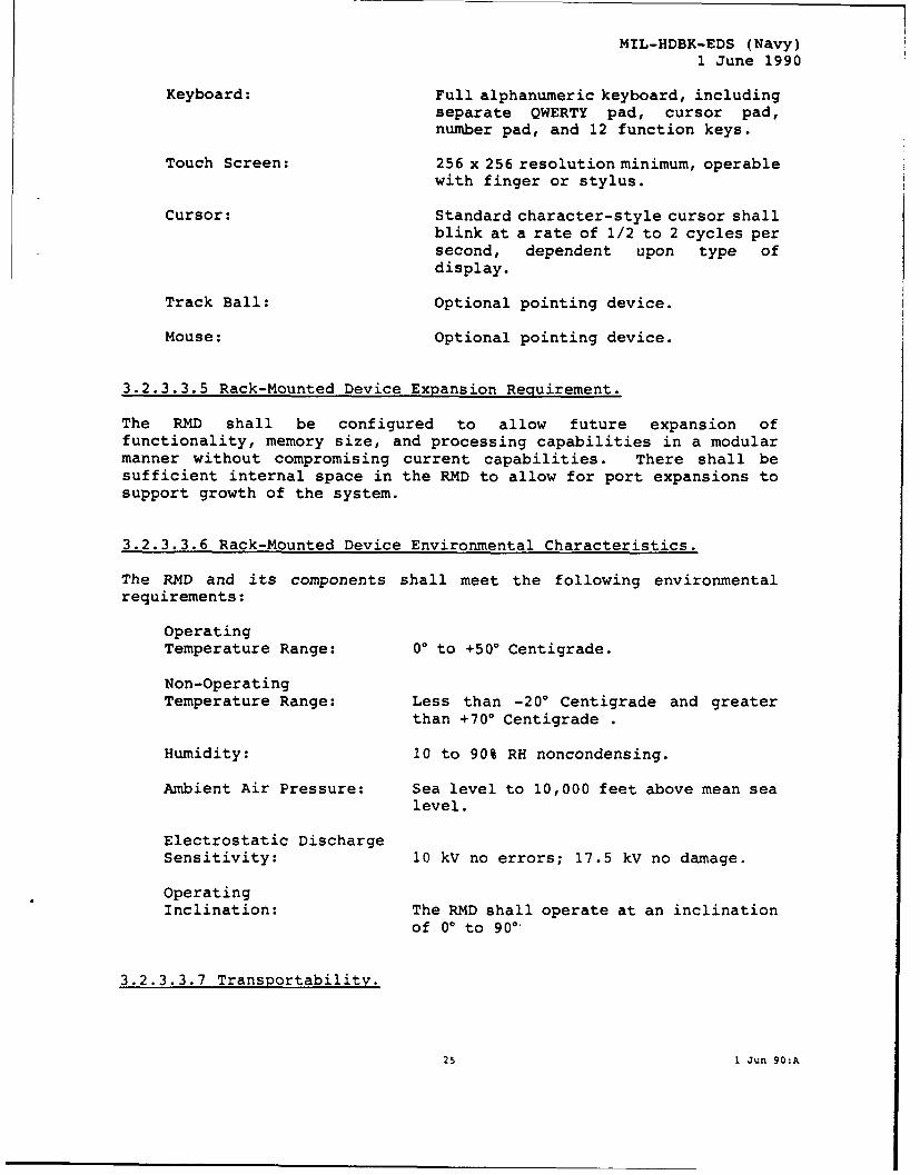
MIL-HDBK-EDS (Navy)I June 1990
Keyboard: Full alphanumeric keyboard, includingseparate QWERTY pad, cursor pad,number pad, and 12 function keys.
Touch Screen: 256 x 256 resolution minimum, operablewith finger or stylus.
Cursor: Standard character-style cursor shallblink at a rate of 1/2 to 2 cycles persecond, dependent upon type ofdisplay.
Track Ball: Optional pointing device.
Mouse: Optional pointing device.
3.2.3.3.5 Rack-Mounted Device Expansion Requirement.
The RMD shall be configured to allow future expansion offunctionality, memory size, and processing capabilities in a modularmanner without compromising current capabilities. There shall besufficient internal space in the RMD to allow for port expansions tosupport growth of the system.
3.2.3.3.6 Rack-Mounted Device Environmental Characteristics.
The RMD and its components shall meet the following environmentalrequirements:
OperatingTemperature Range: 00 to +500 Centigrade.
Non-OperatingTemperature Range: Less than -200 Centigrade and greater
than +70° Centigrade .
Humidity: 10 to 90% RH noncondensing.
Ambient Air Pressure: Sea level to 10,000 feet above mean sealevel.
Electrostatic DischargeSensitivity: 10 kV no errors; 17.5 kV no damage.
OperatingInclination: The RMD shall operate at an inclination
of 00 to 90.
3.2.3.3.7 Transportability.
25 1 Jun 90:A

MIL-HDBK-EDS (Navy)1 June 1990
The RMD shall be transportable to the extent that the maintenancesupport console of which the RMD is an integral component istransportable. The RMD shall be capable of being used on, andtransportable between, similar maintenance support console systems.
3.2.3.3.8 Backup Capability.
The RMD shall have the ability to back up resident software and data.
3.2.3.4 Portable Device Hardware Requirements.
The PDD shall utilize an internal source of electrical power, andshall have the ability to connect to an external power supply.Construction shall allow for the PDD to be used in an unprotectedenvironment for extended periods of time. The PDD shall be equippedwith a carrying strap or carrying case to facilitate portability. ThePDD case shall be sufficiently sturdy to provide protection fromaccidental dropping from a height of one meter. The PDD shall becapable of withstanding general rough usage. The PDD shall beTEMPEST-hardened; however, it may be constructed in such a way thatthe unit could be inserted into a ruggedized case for use outide ashop or office area. The maximum weight requirement shall apj-y tothe PDD and case as a singular unit.
3.2.3.4.1 Portable Device Physical Requirements.
Weight: Less than 10 pounds, includingbatteries.
Size: PDD shall not exceed 14" x 11" x 3".
3.2.3.4.2 Portable Device Performance Requirements.
OperatingConfiguration: Networked or stand alone.
EMI: The WCD shall not be susceptible to EMIor EM pulse effects, and shall conformto TEMPEST requirements.
3.2.3.4.2.1 Portable Device Display Requirements.
All displays used on the PDD shall have the following characteristics:
Scieen Type: EL, LCD, or Plasma.
Screen Size: Minimum 9-inch diagonal, flat-panel.
26 1 Jun 90:A

MIL-HDBK-EDS (Navy)
1 June 1990
Resolution: 640 x 480 pixels minimum.
Pixel Aspect Ratio: 1:1.
Backlight: Required, Blue or Red.
Viewing Angle: Readable to 300 deviation from normal tothe plane of the display.
Shades of Gray: A minimum of sixteen different shades ofgray shall be available (Optional).
Color Capability: Optional.
Color Quantity: A minimum of sixteen different colorsshall be available.
Color Resolution: Color capability shall meet or exceed
minimum display resolution requirements.
3.2.3.4.2.2 Portable Device Processing Power.
The PDD processor shall support multitasking, networking,communications interfaces, connectivity, and interoperability amongdelivery device configurations. Each delivery device shall have theability to execute at a minimum of 2 Mips.
3.2.3.4.2.3 Portable Device Memory Requirement.
3.2.3.4.2.3.1 Portable Device Memory Types.
Each PDD configuration shall contain the following memory types andcapacities:
ROM: Sufficient for the resident BIOS.
RAM: 8 Mbytes minimum.
3.2.3.4.2.3.2 Portable Device Secondary Storage.
Transfer Rate: > 6 Mbits/sec.
Average Seek Time: < 100 msec.
Latency: < 17 msec.
Shelf life: > 10 years.
3.2.3.4.2.4 Self Test.
All PDDs shall have a built-in, power-up self test. The capability toinitiate the self test without cycling power is required. This testshall indicate if the hardware is faulty.
27 1 Jun 90:A

MIL-HDBK-EDS (Navy)
1 June 1990
3.2.3.4.2.5 Portable Device Hardware Reset.
All PDDs shall have a hardware reset capability to allow for manualrestart of the system in the event of computer lockout. The resetshall not require power to the computer to be recycled.
3.2.3.4.2.6 Portable Device Reliability And Maintainability.
Availability: A PDD shall have an availability rate of95%.
MTBF: 3000 hours, at 240 Centigrade, in
accordance with MIL-HDBK-217.
Mean Time To Repair: 30 minutes.
Mean Time To Replace: 15 minutes for component module.
Preventive MaintenanceRequirements: Operator maintenance shall be limited to
inspection for serviceability, routinecleaning, and replacement or rechargingof batteries.
PartsInterchangeability: Like parts or components shall be
interchangeable as specified inMIL-E-5400.
Fault/Test Isolation: Built-in self test shall isolate areplaceable component.
Special Tools/TestEquipment: No special tools or test equipment shall
be required.
3.2.3.4.3 Portable Device Power Requirements.
Primary Power: 12 volt DC (vdc) rechargeable internalbattery pack.
Auxiliary Power: 115-vac, 60 Hz via a plug-in externalpower cable. Auxiliary power shall besufficient to recharge battery packduring on-line PDD operation. AC powertransformer shall be an integral Iart ofany external power cable; rectifiercircuitry for converting AC to DC shallbe internal to the PDD system.
Power Management: The PDD shall also utilize powermanagement techniqcues to minimize powerdrain of screen, _sk drives, and other
28 1 Jun 90:A
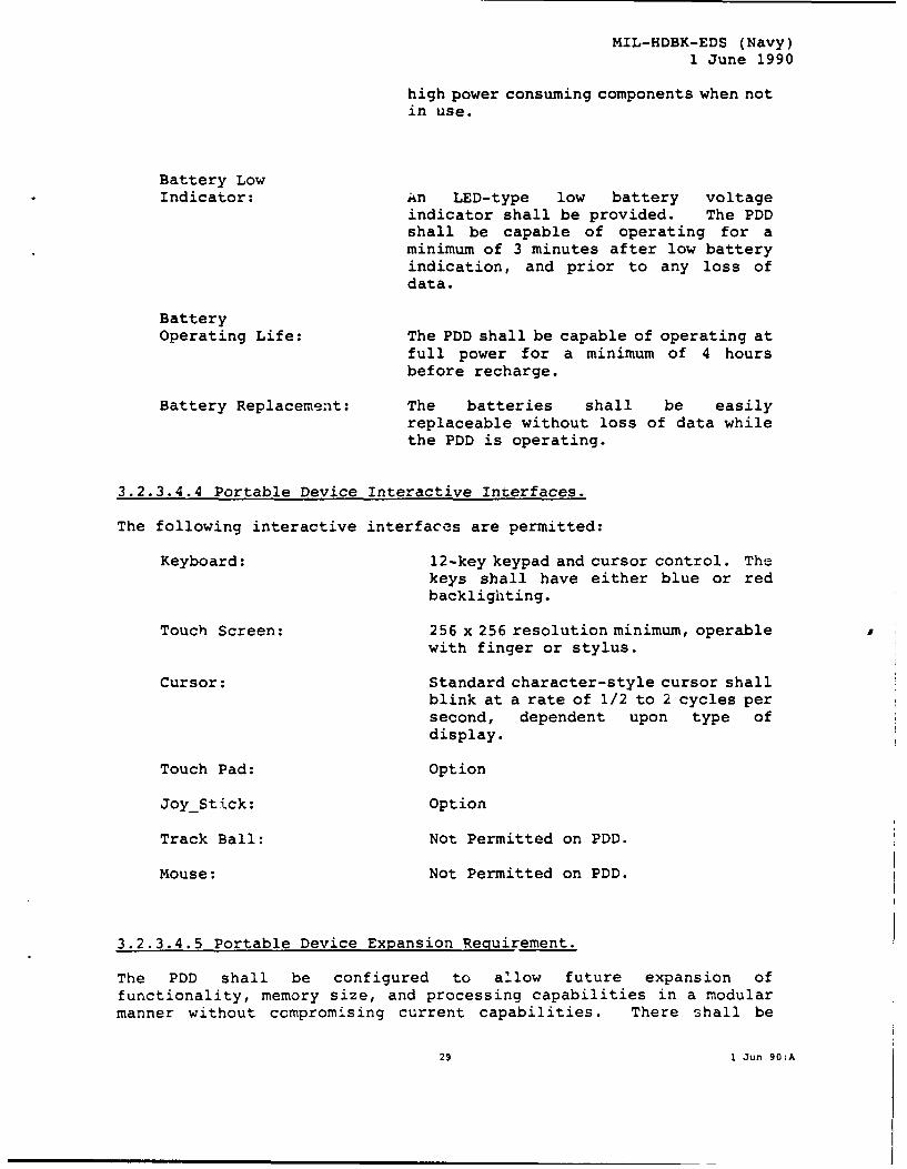
MIL-HDBK-EDS (Navy)1 June 1990
high power consuming components when notin use.
Battery LowIndicator: An LED-type low battery voltage
indicator shall be provided. The PDDshall be capable of operating for aminimum of 3 minutes after low batteryindication, and prior to any loss ofdata.
BatteryOperating Life: The PDD shall be capable of operating at
full power for a minimum of 4 hoursbefore recharge.
Battery Replacement: The batteries shall be easilyreplaceable without loss of data whilethe PDD is operating.
3.2.3.4.4 Portable Device Interactive Interfaces.
The following interactive interfaces are permitted:
Keyboard: 12-key keypad and cursor control. Thekeys shall have either blue or redbacklighting.
Touch Screen: 256 x 256 resolution minimum, operablewith finger or stylus.
Cursor: Standard character-style cursor shallblink at a rate of 1/2 to 2 cycles persecond, dependent upon type ofdisplay.
Touch Pad: Option
JoyStick: Option
Track Ball: Not Permitted on PDD.
Mouse: Not Permitted on PDD.
3.2.3.4.5 Portable Device Expansion Requirement.
The PDD shall be configured to allow future expansion offunctionality, memory size, and processing capabilities in a modularmanner without compromising current capabilities. There shall be
29 1 Jun 90:A

MIL-HDBK-EDS (Navy)1 June 1990
sufficient internal space in the PDD to allow for port expansions tosupport growth of the system.
3.2.3.4.6 Portable Device Environmental Characteristics.
The PDD and its components shall meet the environmental requirementsfor shipboard and shore-based equipment in accordance withMIL-E-16400. The PDD system shall be capable of operating as a stand-alone system in work centers at all maintenance levels, and in allorganizational-level environments, such as flight line, hangar deck,flight deck, and field deployments. The operation of a PDD shall notcause ignition of ambient-explosive-gaseous mixtures with air, inaccordance with MIL-STD-810, method 54, Procedure I.
OperatingTemperature Range: -20° to +70' Centigrade
Non-OperatingTemperature Range: -20' to +70* Centigrade
Humidity: 10% to 90% RH, noncondensing.
Blowing Rain: 4 inches per hour in a 35-knot wind.
Salt Fog: Atomized 5% saline solution for 48 hoursexposure as specified by MIL-E-16400.
Blowing Dust: 30 feet per second for 6 hours atoperating temperature; 30 feet persecond for 6 hours at 700 C and 15,000feet mean sea level air pressure.
Ambient Air Pressure: Sea level to 10,000 feet mean sea level.
Shock Resistance: PDD system shall withstand Procedure 1.Shock in Method 516.2 of MIL-STD-810, or3-inch corner drop, 5-g shock hazard,flat drop, and rail impact. Shall beable to withstand shock associated withrepeated drops of one meter and toolimpacts. Shall withstand the shockassociated with transportation and use.
Oil, Chemicals, andDirt: Shall be resistant to fluid spills, and
shall be immediately cleanable by wipingif contaminated with oil, grease,c h e m i c a 1 s , o rnuclear/biological/chemical (NBC)decontamination agents.
Fungus: Shall withstand fungus growth typical oftropics, as specified by MIL-E-16400.
30 1 Jun 90:A

MIL-HDBK-EDS (Navy)1 June 1990
OperatingInclination: PDD shall operate at an inclination of
zero to 900 with display screen flat orvertical. When powered up and in use,repeated rotation of the PDD about anyof its three axes at a rate of 45degrees per second shall have no adverseeffect on its operation.
Health and Safety: MIL-STD-454, Requirement 1 shall apply.Materials shall not create noxious fumesunder combustible conditions. The PDDshall have no adverse explosive,mechanical, or biological effects. Forsafety considerations, no CRTs orlithium batteries shall be used.
3.2.3.4.7 Transportability.
The PDD shall be fully transportable from one work location toanother. The PDD shall be transportable by standard commercial andmilitary land, sea, or air transport with minimum preparation and nopeculiar handling/packaging equipment. The PDD shall be provided witha shoulder strap for carrying purposes.
3.2.4 General EDS Printer Devices.
Although the process of providing IETMs for electronic display isdesigned to eliminate reliance on a paper medium, compatible printersshall be available.
3.2.4.1 "B" Size Printer Hardware Requirements.
The EDS shall be supplemented by a printer capable of producing up to"B" size drawings (11" x 17"). This permits generation of a papercopy of some specific piece of an IETM which may be required by anindividual for performance of a specific task. This printer shallprint at near letter quality (NLQ). The printer shall be attached tothe server, and shall accept print jobs from the nodes on the LAN.
3.2.4.1.1 "B" Size Printer Physical Requirements.
Weight: < 120 pounds.
Size: Not greater than 24 inches high x 30inches wide x 24 inches deep.
31 1 Jun 90:A

MIL-HDBK-EDS (Navy)1 June 1990
3.2.4.1.2 "B" Size Printer Performance Requirements.
Speed: > 20 pages per minute.
3.2.4,1.2.1 "B" Size Printer Memory Requirement.
RAM: >= 4 Mbytes.
3.2.4.1.2.2 "B" Size Printer Self Test.
The printer shall have a built-in, power-up self test. The capabilityto initiate the self test without cycling power is required. Thistest shall indicate if the hardware is faulty.
3.2.4.1.2.3 "B" Size Printer Hardware Reset.
The printer shall have a hardware reset capability to allow for manualrestart in the event of a lockout.
3.2.4.1.2.4 "B" Size Printer Reliability and Maintainability.
Availability: The printer shall have an availabilityrate of 95%.
MTBF: 3000 hours, at 240 Centigrade, inaccordance with MIL-HDBK-217.
Mean Time To Repair: 30 minutes.
Mean Time To Replace: 15 minutes for component module.
Preventive MaintenanceRequirements: Operator maintenance shall be limited to
inspection for serviceability, routinecleaning, and replacement or rechargingof batteries.
PartsInterchangeability: Like parts or components shall be
interchangeable as specified inMIL-E-5400.
Fault/Test Isolation: Built-in self test shall isolatereplaceable component.
Special Tools/TestEquipment: No special tools or test equipment shall
be required.
3.2.4.1.2.5 "B" Size Printer Interactive Interfaces.
Type: Parallel.
32 1 Jun 90:A

MIL-HDBK-EDS (Navy)1 June 1990
3.2.4.1.3 "B" Size Printer Power Requirements.
Power: 115-vac, 60-hz, 1 phase; via plug-incable to an external power source.
3.2.4.1.4 "B" Size Printer Environmental Characteristics.
The printer and its components shall meet the environmentalrequirements for shipboard and shore-based equipment in accordancewith MIL-E-16400. The printer shall be environmentally sealed toprevent the invasion of dust or spilled fluids, and shall be capableof being immediately cleaned by wiping. The following specificrequirements apply:
OperatingTemperature Range: +100 to +500 Centigrade.
Ambient Air Pressure: Sea level to 10,000 feet mean sea level.
Electrostatic DischargeSensitivity: 10 kV no errors, 17.5 kV no damage.
3.2.4.1.5 Transportability.
The printer shall be transportable, but not necessarily portable.
3.2.4.2 EDD Printer Hardware Requirements.
3.2.4.2.1 EDD Printer Physical Requirements.
Weight: < 5 pounds (including batteries ifapplicable).
Size: Not greater than 4 inches high x 12inches wide x 8 inches deep.
3.2.4.2.2 EDD Printer Performance Req 1rements.
Speed: >= 70 characters per second.
Memory Requirements: Not applicable.
Format Capabilities: Graphics-compatible.
3.2.4.2.2.1 EDD Printer Memory Requirement.
33 1 Jun 90:A
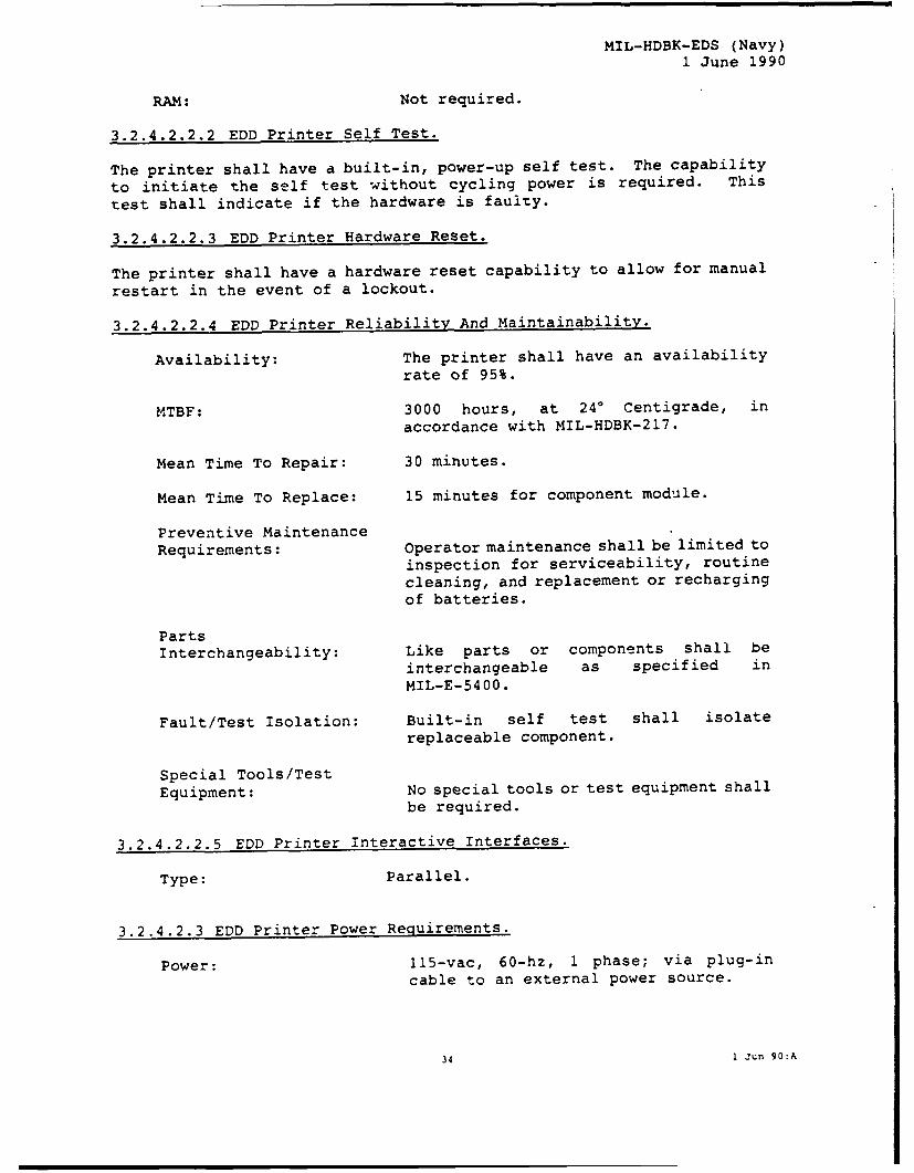
MIL-HDBK-EDS (Navy)
1 June 1990
RAM: Not required.
3.2.4.2.2.2 EDD Printer Self Test.
The printer shall have a built-in, power-up self test. The capability
to initiate the self test without cycling power is required. This
test shall indicate if the hardware is faulty.
3.2.4.2.2.3 EDD Printer Hardware Reset.
The printer shall have a hardware reset capability to allow for manual
restart in the event of a lockout.
3.2.4.2.2.4 EDD Printer Reliability And Maintainability.
Availability: The printer shall have an availabilityrate of 95%.
MTBF: 3000 hours, at 240 Centigrade, in
accordance with MIL-HDBK-217.
Mean Time To Repair: 30 minutes.
Mean Time To Replace: 15 minutes for component module.
Preventive MaintenanceRequirements: Operator maintenance shall be limited to
inspection for serviceability, routinecleaning, and replacement or rechargingof batteries.
PartsInterchangeability: Like parts or components shall be
interchangeable as specified inMIL-E-5400.
Fault/Test Isolation: Built-in self test shall isolatereplaceable component.
Special Tools/TestEquipment: No special tools or test equipment shall
be required.
3.2.4.2.2.5 EDD Printer Interactive Interfaces.
Type: Parallel.
3.2.4.2.3 EDD Printer Power Requirements.
Power: 115-vac, 60-hz, 1 phase; via plug-incable to an external power source.
34 1 Jun 90:A

MIL-HDBK-EDS (Navy)1 June 1990
3.2.4.2.4 EDD Printer Environmental Characteristics.
The printer and its components shall meet the environmentalrequirements for shipboard and shore-based equipment in accordancewith MIL-E-16400. The printer shall be environmentally sealed toprevent the invasion of dust or spilled fluids, and shall be capableof being immediately cleaned by wiping. The following specificrequirements apply:
OperatingTemperature Range: +10' to +500 Centigrade.
Ambient Air Pressure: Sea level to 10,000 feet mean sea level.
Electrostatic DischargeSensitivity: 10 kV no errors, 17.5 kV no damage.
3.2.4.2.5 Transportability.
The printer shall be transportable, but not necessarily portable.
3.2.5 Transportation Cases, Packaging, and Handling.
Packing and handling shall be in accordance with MIL-P-9024.
3.2.6 Design and Construction.
3.2.6.1 Materials, Processes, and Parts.
All materials, processes, and parts used in the manufacture of the EDSshall adhere to good commercial practice and specific performance andquality parameters as delineated in the contract by specification andstandard.
3.3 General User-Interaction Requirements
The following paragraphs describe the general requirements foruser interaction with all types of displayed information. The EDSshall provide a common set of commands or input functions to the userfor viewing, selection, manipulating, navigating, and accessing IETMs.
3.3.1 End-User Interactivity
3.3.1.1 User-Interaction Hardware
Normal output of the EDS is by screen display or, in specialcascs, by the generation of certain increments of TI in hard-copy formthrough the use of the supplemental printer. Capabilities for user
35 1 Jun 90:A

MIL-HDBK-EDS (Navy)1 June 1990
input to the EDS, to permit full exploitation of the Interactivity ofthe System, are discussed in this Section.
The user shall be able to interface with the EDS by means of thefollowing devices and capabilities:
a.A fully functional alphanumeric keyboard with all requiredfunction keys;
b.A numeric, special-function keypad (integral to the PDD) thatprovides for cursor movement and selectable functions;
c.A mouse, track-ball, or joy-stick, the functions of which canbe assumed by the keyboard should the mouse or track-ballbecome inoperative;
d.A touch-screen capability on all Devices which are capable offunctioning as modules of the EDS.
3.3.1.2 Interactive Software
The management-interface functions of the EDS will be semi-transparent to the user, except when he must invoke a special functionor provide information required by the EDS. Operation of the EDSshall not require the user to have any knowledge of programming.Display of information for the management functions may be in the formof dialogue queries or, in the case of information interchange withother computer systems or functional entities, direct display ofinformation. Invocation of the management-interface functions shallbe consistent with a general approach using adaptive, context-sensitive menus. However, in the case of restricted-access functions,a password routine or other access-control sequences shall beprovided.
3.3.1.3 IETM Control Techniques
The EDS software shall provide a flexible control interface inorder to fully utilize the opportunities provided by IETMs.
3.3.1.3.1 Text.
Effective utilization of IETMs requires flexibility in access andcontrol of textual data. The various means of accessing this data areas follows:
a. Scrolling. The Scroll function shall provide the capabilityto reposition the text to view regions outside of the currentdisplay area.
36 1 Jun 90:A

MIL-HDBK-EDS (Navy)1 June 1990
b. Expertise levels. The user shall be able to control the amountof detail provided through the selection of an expertise level(Novice or Expert). The novice level shall displaysignificantly more detail than the expert level.
c. Function Keys. Various function keys (fixed and variable)shall enable the user to access additional information.
d. Menus. A set of adaptive, context-sensitive menus shall beused to guide the user through all possible options.
3.3.1.3.2 Graphics.
When graphics are required to support text, the graphic shall bedisplayed simultaneously with the appropriate text. Additionalgraphics shall be accessible through function keys or menus.
3.3.1.3.3 Warnings/Cautions/Notes.
Warnings/Cautions/Notes (W/C/N) shall be displayed automatically. Theuser shall have no control over the appearance of these messages.
3.3.1.3.4 Audio.
If Audio is utilized as an input or output during user interfacing,all functions must be duplicated by other input/output mechanisms.The user shall have control of the audio volume and the ability toturn off the audio.
3.3.1.3.5 Prompts.
Prompts are brief messages indicating the need for user interactionand must be utilized whenever user input is required.
3.3.2 User Input/Output Mechanisms
3.3.2.1 Input Capabilities
3.3.2.1.1 Alphanumeric Input
All EDDs will be equipped with a full alphanumeric keyboard orother alphanumeric input mechanism.
37 1 Jun 90:A

MIL-HDBK-EDS (Navy)
1 June 1990
3.3.2.1.2Touch-Screen and Other Screen Position-Indicating Inputs
All IETM EDDs will have some provision for screen position-indication and selection (e.g. touch screen, mouse, trackball withselection button, etc.) in addition to the required cursor keys.
When display screens are equipped with touch-screen overlays, itmust be possible to differentiate selection areas on the screen spacedat 1/2 inch.
This capability will be used for three purposes:
a. To select one of two or more choices as displayed by the screenfor branching logic (calling one of two or more alternativeframes of information), as in a Troubleshooting sequence.
b.To select the center for some special function, such asestablishment of a Window or the center of a Zoom operation.
c.To touch a graphically displayed part as a technique forcalling detailed IPB information to be used for ordering apart.
The EDS software may allow user input from a mouse or trackballdevice.
When any of the above devices are inoperative, the software shallbe able to operate from directional cursor ("arrow") keys on thekeyboard.
3.3.2.1.3 Data Buss Input
The EDS software shall have the capability of receiving andtransmitting data through an external data bus (network). Thesoftw're shall be able to support text, graphics, and audioinput/output.
Any EDS node of the LAN must also:
a.Be capable of providing a full range of IETM and View-Packagedata to any other Display Device which acts as a node in theLAN;
b.Upload Technical Information to the File Server or other LANnode required in the normal processes of maintenance-actionreporting and maintenance management.
c.Communicate with other Logistics-Support Information Systemsconnected to the LAN.
38 1 Jun 90:A

MIL-HDBK-EDS (Navy)
1 June 1990
3.3.2.2 Display-Control Functions
Operation of the EDS shall not require the user to have any knowledgeof programming. Display management functions of the EDS shall betransparent to the user. Information display shall be in the form ofdialogues or queries, and shall be consistent with the generalapproach of using adaptive, context-sensitive menus.
3.3.2.2.1 Responsive Cursor Control.
Cursor control shall permit both fast movement and accurate placement.When the user must respond to a question, the software shall positionthe cursor in an appropriate box or response area.
3.3.2.2.2 Cursor Selection Area.
When selecting a displayed option, the minimum acceptable cursoractivation area shall include the area of the displayed option label,plus a half-character border around the label.
3.3.2.2.3 Display Format Protection.
Cursor movement shall be confined to response areas for the currentquery.
3.3.2.2.4 Data Field Labels.
For each data field, an associated label shall be displayed to helpusers identify the data content. The appearance of labels shall beconsistent throughout the software.
3.3.2.2.5 Windows.
Any IETM information shall be displayable in a window. The user shallbe able to control the size of the window with the locating device.Windows may overlap and/or overlay each other.
The user may position an information window on top of the currentdisplay. The information window shall be treated as a second displaysurface. Only one display surface shall be active at any given time.
The information window shall be activated by a function key or button.The system shall retain the current display state. Furtherinteraction shall be conducted through the information window untilthe window is dismissed. When the information window is dismissed,the previous display shall be restored.
A capability for establishment of up to three Windows shall beincorporated into the EDS. Any material present in the TM shall be
39 1 Jun 90:A

MIL-HDBK-EDS (Navy)1 June 1990
capable of being displayed in a Window. Windows may overlap. TheZoom function will not extend to information displayed in Windows, butprovision will be made to Scroll (pan) material in Windows.
3.3.2.2.6 Menus.
The style and display of menus shall be consistent throughout theprogram. Menus and options shall be at the same location on eachscreen, and, if possible, shall have the same label.
3.3.2.2.6.1 Menu Format.
The format of menu displays shall allow only one option per line.
3.3.2.2.6.2 Command Menu Options.
Menu options shall be phrased as commands to the computer, rather thanquestions to the user.
3.3.2.2.6.3 Option Labels.
Each option shall be identified by a label. The option label shallconvey the meaning of the function it represents; option labels shallnot be arbjitrary letter or number designations.
3.3.2.2.6.4 Grouping of Menu Options.
Menu options shall be formatted to collect logically related groups ofoptions.
3.3.2.2.6.5 Use of Hierarchical Menus.
A sequence of hierarchical menu selections shall be provided.
3.3.2.2.6.6 Design of Hierarchical Menus.
The hierarchical sequence shall provide a top-level group of optionsto serve as a consistent starting point for user entries. Thesequence structure shall permit immediate user access to critical orfrequently selected options, and shall minimize the number of stepsrequired to complete the sequence.
3.3.2.2.6.7 Menu Usage.
The number of menus required to identify the information shall belimited to the greatest extent possible. The style and display ofhelp information shall be consistent throughout thc program. Menusand optlons shall be at the same location on each screen and, ifpossible, shall have the same label. For example, the combined use of"Press any key to continue..." and "Enter Y to proceed" shall be
40 1 Jun 90:A

MIL-HDBK-EDS (Navy)1 June 1990
avoided. Standard phrases or words shall be used to help the userenter comments or select functions.
3.3.2.2.6.8 Menu Retracing.
The EDS shall always include control selections that allow theoperator to return to the system menu or the previously displayedmenu, regardless of the information being displayed.
3.3.2.2.7 Display of Text.
Conventional text shall be used to display procedural information.Text shall be displayed in mixed upper and lower case usingconventional punctuation, spacing, sentences, and paragraphs. Wordsshall not be hyphenated between lines. Distinct paragraphs shall beseparated by at least one blank line.
3.3.2.2.8 Display of Graphics.
Gzaphics shall be as simple as possible, reflecting only the degree ofdetail required to clearly convey the necessary information.
3.3.2.2.9 Graphics Description.
The EDS software shall utilize, manipulate, and compose data from thegraphics data base according to the generative rules for each graphic.During the composition of the graphic, the software shall beresponsible for composing the user display, including the addition oftext (when necessary) or the composition of all text displays for theuser.
3.3.2.2.9.1 Zoom (Enlarge/Reduce) Capability
A Zoom (scaling) capability must be provided for displayedmaterial, permitting the user to change the size of displayedinformation from 1/4 to 4X regular size. Center of material chosenfor Zoom will be selected by touch screen.
3.3.2.2.9.2 Pan Capability
A capability to pan the displayed material, right/left or up/down,will be provided by a cursor or special Pan function key. Panningmotion will continue only so long as the key is depressed.
3.3.2.2.9.3 Highlighting
The Highlighting special function permits the display of a brightrectangle, reversed video, or a local flashing background around a
41 1 Jun 90:A

MIL-HDBK-EDS (Navy)1 June 1990
designated item of information selected by touch-screen or otherposition-locating device.
3.3.2.2.9.4 Animation
The Animation special function shall permit the sequential displayof frames showing some kind of motion (e.g., sequential positions ofa switch, dial, handle, etc.). At a point where Animation isavailable, the screen will so indicate.
3.3.3 Information Access and Control Functions
The total range of special functions (in addition to the display-control functions) available to a technician using the Work-CenterDevice shall be chosed from those described in MIL-M-GCSFUI Section3.4. Choice of the list of special functions to be included in theEDS acquired under a given Contract will be as specified in theContract.
These functions shall be exercised either by means of dedicatedspecial-fur -tion keys labeled with the function involved, or by theuse of assgned simple alphanumeric sequences. Keyboard layout andassignment of special-function calling sequences must be specificallyapproved by the Government. Some of these functions may be usedtogether.
3.4 Software Considerations
3.4.1 Operating Environment
3.4.1.1 File Access Methods
File access must be provided in the operating environment. Thefile-access software must be compatible with the file-managementsoftware allowing remote file update.
42 1 Jun 90:A

MIL-HDBK-EDS (Navy)1 June 1990
3.4.1.2 Display-System Basic Operating Software
A standard, off-the-shelf operating system (e.g., UNIX, DOS, OS2)shall be used. This operating system shall be able to support aflexible and powerful data-base management system. The operating-system software shall conform to standard POSIX requirements (FIPS151) unless otherwise specified in the Contract.
3.4.1.3 Network Interfaces
3.4.1.3.1 Internal EDS Interfaces
The network software shall provide for selective use of a LocalArea Network. The network software shall enable a multiuserenvironment.
3.4.1.3.2 External EDS Interfaces
The EDS shall interface with those systems which contain datarequired for the integrated operation of the EDS, or wnich requiredata from the EDS. In addition, the network software shall providethe capability (1) of communicating with other local logistics-supportinformation systems, which function as nodes on the network, and (2)of accumulating information to be submitted through such a network.These systems shall include, but not be limited to, the following:
a.An automated debriefing module and its connection to requiredhistorical file- and expert systems;
b.A central service or DOD IETM library;
c.A maintenance-data collection system;
d.A supply system for parts-availability information and partsordering.
3.4.1.4 File Management
The transfer of file daca must be accomplished via the gateway andmust permit the interchange of file data and the interchange ofelectronic mail and messaging.
43 1 Jun 90:A

MIL-HDBK-EDL. (Navy)1 June 1990
3.4.1.5 Network Management
The EDS must include utilities that provide the capability tomanage the communications directly amongat the EDS components and withexternal shipboard and shore-based equipment, Work Centers,intermediate maintenance shops, and all organizational maintenancelevels, including flight lines, hangar decks, and flight decks. EDSexternal communication shall be in accordance with FIPS PUB 146Government Open System Interconnection Profile (GOSIP).
3.4.1.6 Graphics Display Management
The EDS operating system must include software capable of carryingout all graphics-display commands contained in the IETM and ViewPackages, and of responding to user-input Display-Control functions(Section 3.3.2.2).
3.4.1.7 Data Security
The operating software will contain features which ensureprotection of technical data, as specified in Section 3.1.3.6.
3.4.1.8 Special Input/Output Provisions
Special Input/Output provisions may be stipulated in the Contract;for example, the requirement for voice imprinting of each of theauthored users.
3.4.1.9 Configuration Management
Operating software will be constructed so that required changes(additions of capabilities, or improvements in existing capabilities)can be easily incorporated and tracked. Before incorporation, allchanges will be fully evaluated and tested in terms of therequirements of this Specification.
The Work-Center Device software shall contain a component (similarin function to the Government-developed test routine described in MIL-M-IETMQA, Appendix A) which, on command, cycles through the majorDisplay-Device functions to indicate the status of IETM/Display Deviceavailability. This software will test exhaustively the capability ofa technician to retrieve the frames he needs for specific problems.
This software is intended to permit the technician to assess atany time the compatibility of a given IETM or View Package with hisElectronic Display System. The routine will provide four menu-
44 1 Jun 90:A
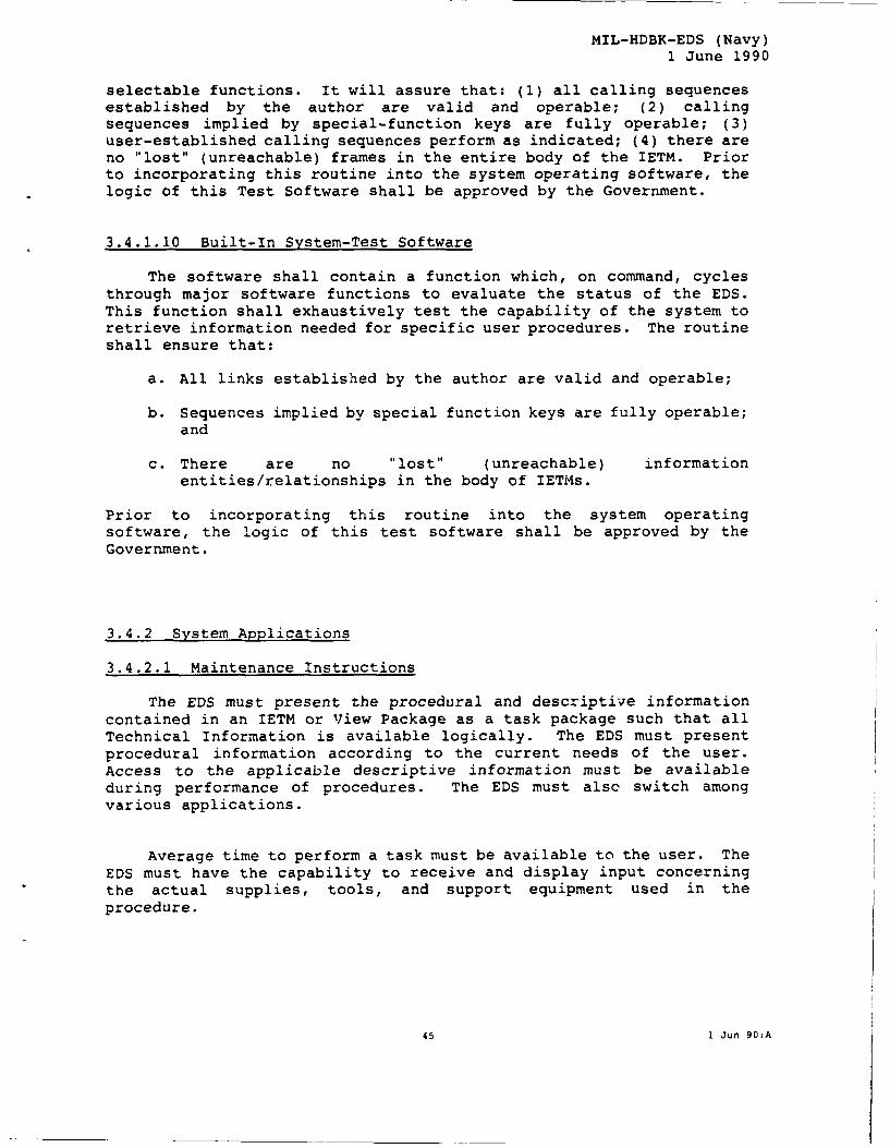
MIL-HDBK-EDS (Navy)1 June 1990
selectable functions. It will assure that: (1) all calling sequencesestablished by the author are valid and operable; (2) callingsequences implied by special-function keys are fully operable; (3)user-established calling sequences perform as indicated; (4) there areno "lost" (unreachable) frames in the entire body of the IETM. Priorto incorporating this routine into the system operating software, thelogic of this Test Software shall be approved by the Government.
3.4.1.10 Built-In System-Test Software
The software shall contain a function which, on command, cyclesthrough major software functions to evaluate the status of the EDS.This function shall exhaustively test the capability of the system toretrieve information needed for specific user procedures. The routineshall ensure that:
a. All links established by the author are valid and operable;
b. Sequences implied by special function keys are fully operable;and
c. There are no "lost" (unreachable) informationentities/relationships in the body of IETMs.
Prior to incorporating this routine into the system operatingsoftware, the logic of this test software shall be approved by theGovernment.
3.4.2 System Applications
3.4.2.1 Maintenance Instructions
The EDS must present the procedural and descriptive informationcontained in an IETM or View Package as a task package such that allTechnical Information is available logically. The EDS must presentprocedural information according to the current needs of the user.Access to the applicable descriptive information must be availableduring performance of procedures. The EDS must also switch amongvarious applications.
Average time to perform a task must be available to the user. TheEDS must have the capability to receive and display input concerningthe actual supplies, tools, and support equipment used in theprocedure.
45 1 Jun 90:A

MIL-HDBK-EDS (Navy)
1 June 1990
3.4.2.2 External Reference Data
The EDS shall be capable of accessing external references asdescribed in Section 3.4.1.3.2. All data to be externally referencedby an EDS must be interconnected with the EDS LAN.
3.4.2.3 Oversize Graphics Display and Manipulation
The user shall be able to view oversize graphics in one of thefollowing two ways:
3.4.2.3.1 Primary Display Area Viewing
While in the primary display area, the user shall be able to zoom andpan around a graphic display to view the oversize graphic.
3.4.2.3.2 Subwindow Viewing of Oversize Graphics
The user may view a secondary window (subwindow) which shall bedisplayed in the upper right-hand corner of the primary display area.The entire graphic shall be reduced to be displayed in this subwindow.The user may view parts of the large graphic in the primary window.A rectangular dashed line shall outline the portion of the graphiccurrently being displayed in detail in the primary window.
3.4.2.4 Standard Forms Data Entry
The Form special function, followed by a brief alphanumericsequence, calls one of the types of electronic "blank forms" which thetechnician must "fill out" as required to complete his maintenanceTask. These might include forms such as:
a.Maintenance Action Reporting (MAR) form
b.Technical Manual Deficiency and Evaluation Reporting (TMDER)form (a form to report both errors and areas ofincomprehensibility in the TM)
c.Part Ordering Form (POF)
Once the form is displayed, those blanks which the system has notalready filled out automatically can be completed by insertion ofrequired alphanumeric symbols with the alphanumeric keyboard.
46 1 Jun 90:A

MIL-HDBK-EDS (Navy)1 June 1990
3.4.2.5 On-Board or On-the-Job Training
3.4.2.5.1 On-Board or On-the-Job Weapon System Training
When the technician needs to train on a particular system, he willselect the required IETM and perform training while in the workcenter.
3.4.2.5.2 Training Required for System Use
Individuals who use the EDS are expected to be trained prior toindependent use of the system. However, the EDS shall be designed tominimize training requirements.
3.4.2.5.3 Training Required for System Administration
Individuals being trained for system administration shall receivetraining on the appropriate version of the software. They shall bemade aware of all features of the EDS. It is the responsibility ofthe system administrator to train users on the use of EDS.
3.4.2.6 Parts Ordering
The parts-ordering function must provide the capability to accessexploded parts data associated with a particular task or procedure.When active, the function must display (through a call to IPB data) aparts breakdown with:
(1) part name;(2) part-number data;(3) National Stock Number (NSN);(4) Federal Supply Code for Manufacturers (FSCM);(5) any other relevant designators associated with the task
information previously displayed.
The parts-ordering function (accomplished through the Form specialfunction) will be used with an order function to submit or prepare arequisition for replacement parts. When this has been completed, theparts-ordering function can be toggled off, and control of the EDSreturned to the point where the user activated the parts-orderingfunction.
3.4.2.7 Help
The Help function shall display a help munu which shall providefor the fullowing primary modes of embedded help:
(1) help information on the prime equipment being supported bythe TI
(2) help information related to the particular informationelement being viewed at the time (context-sensitive help);
47 1 Jun 90:A

MIL-HDBK-EDS (Navy)1 June 1990
(3) help information on the EDS itself (i.e.,How-to-Use-This-System information);
(4) a Help Look-Up Index.
3.4.2.7.1 Context-Sensitive Help
This mode of help provides specific instructions relating tothe particular information element being viewed by the user.
3.4.2.7.2 Weapon System Help
This mode of the Help function must provide principles ofoperation, system descriptions, and other technical informationdescribing the equipment.
3.4.2.7.2 How to Use the EDS
This mode of the Help function provides multiple levels of helpon using the EDS. The first level of help must be a brief userinstruction on how to proceed to the next logical display. The secondlevel of help must be detailed description of the screen functions,layout, etc.
3.4.2.7.3 Help Look-Up Index
This mode of Help relates to operation of the EDS. The user shallbe able to call up the EDS Help Index, which he enters alphabetically;e.g., Enter "c" for listing which includes "Cursor", or "m" forlisting which includes "Mouse". This mode shall provide for simple(one-step) return to the user's position in the data base.
3.4.2.8 Troubleshooting Procedures
All three forms of the Display-Device types will be capable ofinteractively presenting fault-isolation procedures to permit amainter ce technician to locate one or more faulty components. Ingenera the procedure (which is built into the relevant IETM or ViewPackag-j will lead the technician from a generalized report ofequipment malfunction to one or more specific trouble symptoms (aprocess called Fault Verification). When a fault has been verified,and the appropriate trouble symptom entered, the Display Deviceprovides the technician with one or more optimized test sequenceswhich will permit him to identify the faulty components.
48 1 Jun 90:A

MIL-HDBK-EDS (Navy)1 June 1990
If specific fault symptoms are known at the outset of themaintenance effort, the technician may enter the Fault Isolationprocess directly, without performing Fault Verification.
3.4.2.8.1 Fault Verification
The technician must sequentially access (1) the Troubleshootingportion of the IETM, (2) the part of the Troubleshooting informationrelating to the Subsystem for which a malfunction has been reported,and (3) the part of that section dealing with the particularmalfunction reported. Malfunction types will be cited as a result ofSystem-operator (e.g., pilot) debriefing, in standard terms related tothe weapon system; the Display Device will present a series ofmalfunction choices, one or more of which may be selected by touch-screen (e.g., "Power-Supply Malfunction", "Signal-Flow Problem","Calibration Problem", "Display Problem"). For Fault Verification,the Display System shall be capable, when provided with the properinput information, of leading the technician through a logicalsequence to one ur moce trouble symptoms (e.g., antenna fails toacquire target), expressed in technical System-related terms whichthen permit him to enter the detailed Fault-Isolation portion of theprogram.
3.4.2.8.2 Fault Isolation in Logic-Tree Form
The Display Device, with proper IETM input, interprets a troublesymptom input by the technician in terms of the weapon-system signal-f low logic (which has been provided by the IETM author) and identifiesfor the technician the most efficient next test of a sequence of tests(the results of which are reported to the EDS by the technician) whichwill ultimately lead him to identification of the faulty component.The system signal-dependency or logic-tree information which has beenincorporated into the Troubleshooting IETM by the IETM author, is"transparent" to the user; he may, however, call the maintenancedependency charts for viewing if he desires.
3.4.2.8.3 Fault Isolation by Dynamic Fault Model
The EDS must also support near-term diagnostics methods such assymptom-based and expert system-driven fault modeling to the extentsuch processes have been incorporated into the IETM or View Package.The EDS must also support migration to future methods such as causalmodeling and neural network approaches.
49 1 Jun 90:A

MIL-HDBK-EDS (Navy)
1 June 1990
3.4.2.8.4 Entry into Corrective-Maintenance Sequences
Completion of the diagnostic routine must result in a smooth entryinto the applicable repair (corrective-maintenance) procedures.
3.4.3 Special Utilities
3.4.3.1 Incorporation of Rapid-Action Change
The system software shall include a capability such that a messagetransmitted through a Rapid Action Change (RAC) system (designed toprovide, rapidly, important change requirements for IETMs or ViewPackages before the IETM modification process is completed) can bekeyed into the system by the Work-Center Chief, and commanded to over-ride existing Technical Information for a given weapon system or primeequipment. This function is intended for use only in important cases(e.g., personnel or equipment safety). Where less important problemswith a given IETM are noted by a technician, these can be handled viapersonalized records constructed through the notepad function of theDisplay Device.
3.4.3.2 TI Deficiency Reporting
The Display-System software must provide a capability foraccumulation of organized IETM Deficiency Reports based on technicianexperience (e.g., errors, difficulty of comprehension) so that theycan be displayed or transmitted to designated authority at specifiedintervals. To assist in this function, the Work-Center and PortableDisplay Devices will be equipped to collect automatically aninformation-use history during the course of a Maintenance Action topermit more complete analysis by the technician of a TM deficiency(e.g., analysis of the problem if a Troubleshooting procedure fails toisolate the faulty component). This information, also useful for theMaintenance Action Report (see Section 3.4.3.4), may be disposed ofonce used.
3.4.3.3 Supply-System Interfaces
The EDS must provide the capability to communicate directly withthe logistic-support network of the ship or station (see Section3 4.1.3) for such functions as:
(1) Ordering a part.(2) Maintenance-Action Reporting.
To support these functions, the Display-System software willcontain routines which accumulate requisite information during thecourse of a Maintcnance Action (0.0., - M 1,1ired, nomenclature offaulty components, performance of Corrective Maintenance). The
50 1 Jun 90:A

MIL-HDBK-EDS (Navy)1 June 1990
Display Device, as appropriate, will open a desired communication link(e.g., to check on the availability of a part), or will display therequired "forms" for these functions. The technician can "fill in"the remaining information which the Device has not already abstractedfrcm the on-going maintenance process.
3.4.3.4 Maintenance Reporting and Maintenance Audit Trail
The Work-Center Device will also record an "audit trail" ofMaintenance Actions, both for maintenance-management review and foraccumulation of data needed for "filling out" the requiredmaintenance-action reporting forms (e.g., 2-kilo, VIDS/MAF) needed forother utility functions.
Software shall include audit trails for logging transactions. Thereasons for an audit trail are as follows:
3.4.3.4.1 Data Recovery
A real-time audit trail captures maintenance data for later insertion
into the historical database.
3.4.3.4.2 Protection Against System Failure
When the user makes a data entry, the system shall record theresponses in an audit trail. This information can be used to restorepreviously entered information in the event of a system failure.
3.4.3.5 Work-Center Maintenance Management
The EDS must be capable of supporting Work-Center maintenance-management functions independent of or integrated with the missiondebrief application.
The EDS must provide an interface to the maintenance-managementsystem to provide information for purposes of:
a.prime-equipment configuration;b.parts and equipment availability;c. failure-trend analyses;d. Work-Center technician scheduling;e.work status;f.any other management information used to support the Work-
Center chief.
For example, when called, the System must be capable ofmaintaining and disjlayii,9 to Work-Center technicians all Pla..ned-Maintenance schedules (as well as procedures) for each system under
51 1 Jun 90:A

MIL-HDBK-EDS (Navy)1 June 1990
the control of a given Work Center, as well as daily assignments bythe Work-Center chief of Troubleshooting and Corrective-Maintenanceassignments. (For a given weapon system, Scheduled-Maintenanceinformation may be provided in an IETM different from the IETM thatprovides the Troubleshooting and Corrective-Maintenance tasks, butwill be made simultaneously available by the Library function of theWork-Center Electronic Display Device.)
3.4.4 Accommodation of Applications Software Modules
EDS software shall be designed to permit addition and integrationof new applications modules in addition to those currently installedin the field, without the necessity for redesign of any other part ofthe operating System or other software. Integration of additionalapplications modules shall not affect the performance of existingsoftware modules.
4. QUALITY ASSURANCE REQUIREMENTS
A procurement specification must provide for the QA of thedelivered products. The Contractor should be required to establisha Quality Assurance program which will assure compliance of thedelivered product with contract specifications. This plan should makeit clear that the conduct of the QA Program is the responsibility ofthe Contractor. Such a QA program must reflect the requirements ofMIL-Q-9858 or MIL-STD-2168 as appropriate. The Government reservesthe right to request QA records for review, to conduct In-ProcessAudits, or to conduct independent reviews at any time during theproduction process.
5. PACKING AND PACKAGING
Packing and Packaging requirements should be required to be inaccordance with MIL-P9024.
6. NOTES
APPENDIX List of Acronyms and Definitions of Terms
52 1 Jun 90:A

INITIAL DISTRIBUTION
Copies Copies
3 OASD (P&L) 1 Smithsonian Insti-
1 B. Lepisto rution
1 M. McGrath W. Sinaiko
1 M. Meth 8 CNO
5 DQSO I OP-111J2 J. Hart
J. Winters I OP-403 CAPT Hicks
5 OP-403 S. Brookins6 DSPO 1 OP-46 P. Cataldo
5 J. Dalgety
1 W. Gorham 1 ONT-22
LCDR A. Baivier1 HQAMC
M. Ducody 3 SPAWAR
1 003-221 B. Ellis5 AMC-PM-TMDE 1 PMW-153
Pat Stevens I PMW-164 P. Davenport
1 CMD CECOM 9 NAVAIR
J. Rogowski 1 AIR-41032 P. Dolan
1 Army Materiel 1 AIR-41122F K. Brookins
Readiness Support 5 AIR-4114 S. Magill
Activity 2 PMA-235 CDR D. Williams
A. Rulon10 NAVSEA
5 AFHRL (LRC) 1 SEA-4--TD H. Felsen
D. Gunning 1 SEA-04-PA R. Di Geronimo
6 AFLC I PMS-350 M. Volpe1 PMS-393
5 MMD S. Holloway 1 PMS-396 CDR N. Messenger
I LMSC/SJT J. Smith 1 PMS-400 CDR R. Acree
1 ASD/YFL I PMS-409 G. Williams
D. Mates 1 PMS-4131 PMS-418 G. Shaffer
1 NIST 1 SEA-92X G. RogersD. Bettwy
95

INITIAL DISTRIBUTION (Continued)
Copies Copies
2 NAVSUP 1 NPRDC
PML-550 D. Kyle W. Wulfeck
SUP-0323A1 J. DeTolla 1 Naval Postgraduate
1 NAVFAC School Library
09M13 R. Silverman 1 AEGIS Training CenterL. Miller
1 CMC PSD-M3
1 NOSL/Louisville 1 NSWSES
J. Shea R. Piepenbrink
2 NESEC-750 Portsmouth 1 NESEA
W. Chiaiese N. Medved
1 NSDSA 5H10 12 DTIC
W. Honea 1 Batelle Wash., Ops.
C. Oates5 NATSF
3 0128 G. Gruden 1 Boeing Commercial
1 012 W. Smith Airplane Company
1 01 A. Teretsky J. Anderson
1 NPPSMO-41 1 Boeing Military
J. Karpovich M. Post
1 NPFC-100 1 CDC
LCDR P. Jensen F. Tittle
1 NOSC 1 EER Systems
R. Smillie N. Bukowski
1 NUSC I EG&G
A. Valm L. Snodgrass
2 NTSC 1 General DynamicsW. Rz Electronic Division
H. Thorstad D. George
96

INITIAL DISTRIBUTION (Continued)
Copies Copies
1 General Dynamics 3 RJOElectric Boat/459 R. Huckaby
L. Miller2 Scientific Manage-
6 General Dynamics ment Associates
Ft. Worth, TX 1 S. Rainey
1 B. Dimock I T. Post
5 J. Fleming 1 TRW
1 General Electric, M. ThompsonLynn
J. Tilton 2 Westinghouse
I R. Tyree1 Grumman Aircraft 1 J. Coviello
M. Plawsky CENTER DISTRIBUTION1 IBM, Rockville Copies Code Name
J. Manthe 1 00 CAPT C. Graham
I INET 1 01 R. Metrey
R. Richards 1 12 G. Kerr
1 LMI 1 1807 K. Stabenau
J. Giles 1 182 A. Camara
1 McDonnell Aircraft 20 182.3 J. Fuller
1 R. Jackson 1 182.3 R. LeBeau
1 M. McCormick 1 182.3 E. Jorgensen
1 Newport News 1 1821 J. JunodShipbuilding 1 1826 J. Garner
J. Meredith1 185 R. Schaffran
1 Northrup 1 187 R. Ploe
J. Bean 1 3411 C. Naas
97

INITIAL DISTRIBUTION (Continued)
Copies Code Name
1 342.1 (C)
1 342.2 (A)
10 3432 Reports Control
98