csit560 by m. hamdi 1 switching architectures for optical networks
Post on 19-Dec-2015
220 views
TRANSCRIPT

1CSIT560 by M. Hamdi
Switching Architectures for Optical Networks
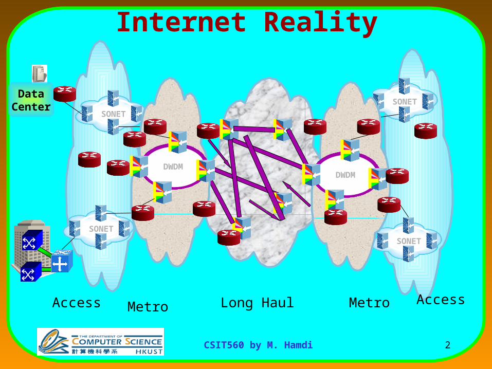
2CSIT560 by M. Hamdi
SONET
DataCenter SONET
SONET
SONET
DWDM DWD
M
AccessLong HaulAccess MetroMetro
Internet Reality

3CSIT560 by M. Hamdi
Hierarchies of Networks: IP / ATM / SONET / WDM
IP
ATM
SONET
WDM

4CSIT560 by M. Hamdi
Why Optical?• Enormous bandwidth made available
– DWDM makes ~160 channels/ possible in a fiber
– Each wavelength “potentially” carries about 40 Gbps
– Hence Tbps speeds become a reality
• Low bit error rates – 10-9 as compared to 10-5 for copper wires
• Very large distance transmissions with very little amplification.

5CSIT560 by M. Hamdi
Dense Wave Division Multiplexing (DWDM)
Multiple wavelength bands on each fiberTransmit by combining multiple lasers @ different
frequencies
Output fibers
Long-haul fiber
1
2
3
4
CSIT560 by M. Hamdi
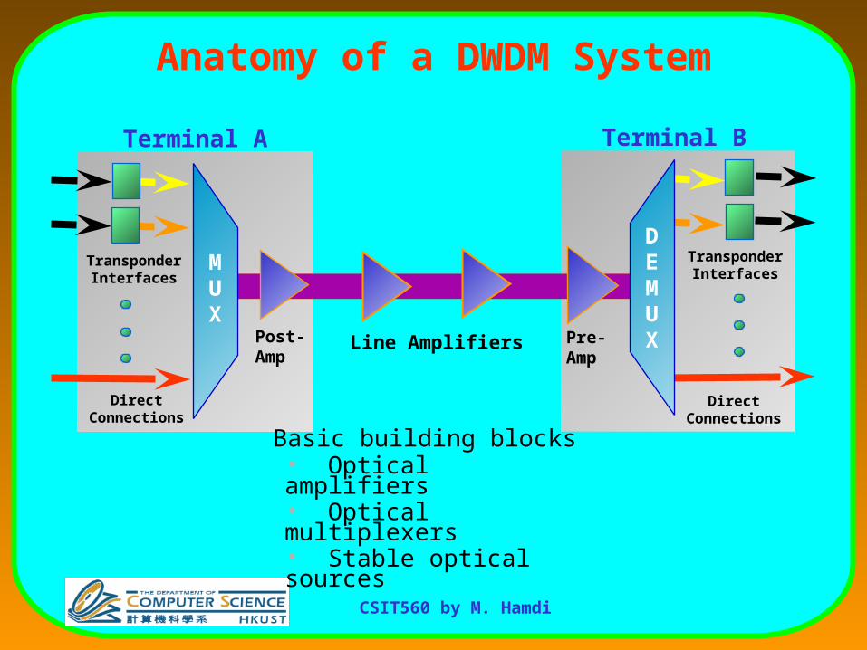
Anatomy of a DWDM System
Terminal A Terminal B
Post-Amp
Pre-Amp
Line Amplifiers
MUX
DEMUX
TransponderInterfaces
TransponderInterfaces
DirectConnections
DirectConnections
Basic building blocks• Optical amplifiers• Optical multiplexers• Stable optical sources
7CSIT560 by M. Hamdi
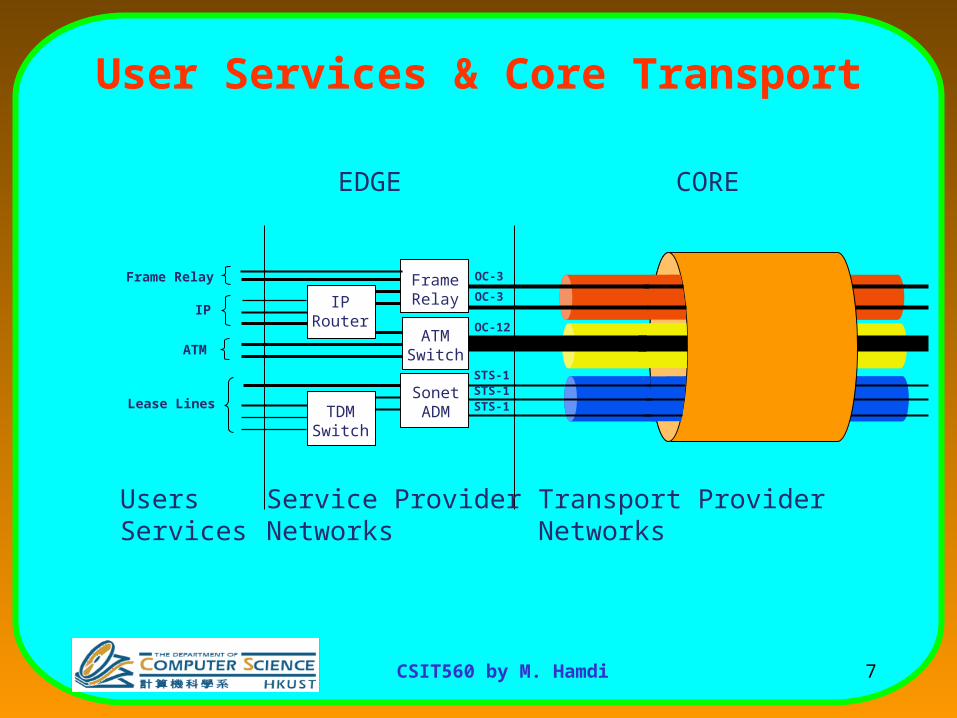
User Services & Core Transport
ATMSwitch
SonetADM
IPRouter
TDMSwitch
Transport ProviderNetworks
Service ProviderNetworks
OC-3
OC-3
OC-12
STS-1STS-1STS-1
FrameRelay
UsersServices
Frame Relay
IP
ATM
Lease Lines
COREEDGE

8CSIT560 by M. Hamdi
Core Transport Services
OC-3
OC-3
OC-12
STS-1STS-1STS-1
• ProvisionedSONET circuits.
• Aggregated intoLamdbas.
• Carried overFiber optic cables.
CircuitOrigin
Circuit Destination

9CSIT560 by M. Hamdi
WDM Network: Wavelength View
WDM link
Optical Switch
Edge Router
Legacy
InterfacesLegacy
Interfaces
Legacy
Interfaces
( e.g., PoS, Gigabit
Ethernet, IP/ATM)
Interfaces

10CSIT560 by M. Hamdi
Relationship of IP and Optical
• Optical brings
–Bandwidth multiplication
–Network simplicity (removal of redundant layers)
• IP brings
–Scalable, mature control plane
–Universal OS and application support
–Global Internet
• Collectively IP and Optical (IP+Optical) introduces a set of service-enabling technologies
Swit
chin
g
Transm
ission
Optical Transport
Routing
IP
Services
Swit
chin
g
Transm
ission
Optical Transport
Swit
chin
g
Transm
ission
Optical Transport
Routing
IP
Services

11CSIT560 by M. Hamdi
Typical Super POP
OXC
Core IP
router
Interconnection
Network
LargeMulti-serviceAggregation
Switch
Voice Switch
CoreATM
Switch
SONET
Coupler&
Opt.amp
DWDM+
ADM
DWDM Metro Ring

12CSIT560 by M. Hamdi
Typical POP
OXCDWDM
VoiceSwitch
SONET-XC
DWDM

13CSIT560 by M. Hamdi
What are the Challenges with Optical Networks?
• Processing: Needs to be done with electronics– Network configuration and management
– Packet processing and scheduling
– Resource allocation, etc.
• Traffic Buffering – Optics still not mature for this (use Delay Fiber Lines)
– 1 pkt = 12 kbits @ 10 Gbps requires 1.2 s of delay => 360 m of fiber)
• Switch configuration– Relatively slow

14CSIT560 by M. Hamdi
Optical Hardware
• Optical Add-Drop Multiplexer (OADM)– Allows transit traffic to bypass node optically
OADM
1
2
3
1
2
’3
’33
Add and Drop
DCS

15CSIT560 by M. Hamdi
Wavelength Converters
• Improve utilization of available wavelengths on links• All-optical WCs being developed• Greatly reduce blocking probabilities
No converters
1
2 3
New request 1 3
1
2 3
New request 1 3
With converters
WC

16CSIT560 by M. Hamdi
Late 90s: Backbone Nodes
ADM
ADM
ADM
ADM
Digital Crossconnect
IPRouter
ATMSwitch
DWDMMultiplexer & Demultiplexer

17CSIT560 by M. Hamdi
Problems
• About 80% traffic through each node is “pass-
through”
– No need to electronically process such traffic
• 80-channel DWDM requires 80 ADMs
• Speed upgrade requires replacing all the ADMs in
the node

18CSIT560 by M. Hamdi
Today: Optical Cross Connect (OXC)
Source: JPMS
DWDM
Multiplexer & Demultiplexer
Optical
Crossconnect
DigitalCross
Connect
IPRouter
ATMSwitch
TerabitIP
Router
ATMBackbone
Switch

19CSIT560 by M. Hamdi
Wavelength Cross-Connects (WXCs)• A WDM network consists of wavelength cross-connects (WXCs) (OXC)
interconnected by fiber links.
• 2 Types of WXCs
– Wavelength selective cross-connect (WSXC)
• Route a message arriving at an incoming fiber on some wavelength to an outgoing fiber on the same wavelength.
• Wavelength continuity constraint
– Wavelength interchanging cross-connect (WIXC)
• Wavelength conversion employed
• Yield better performance
• Expensive

20CSIT560 by M. Hamdi
Wavelength Router
Wavelength Router
Control Plane:Wavelength Routing
Intelligence
Data Plane:Optical Cross
Connect Matrix
Single Channel Links to IP Routers, SDH
Muxes, ...
Unidirectional DWDM Links to
other Wavelength Routers
Unidirectional DWDM Links to
other Wavelength Routers

21CSIT560 by M. Hamdi
Optical Network Architecture
IP Router
Optical Cross Connect (OXC)
OXC Control unit
Control Path
Data Path
UNIUNIMesh Optical
NetworkIP Network IP Network

22CSIT560 by M. Hamdi
OXC Control Unit
• Each OXC has a control unit• Responsible for switch configuration• Communicates with adjacent OXCs or the client
network through single-hop light paths– These are Control light paths
– Use standard signaling protocol like GMPLS for control functions
• Data light paths carry the data flow– Originate and terminate at client networks/edge routers
and transparently traverse the core

23CSIT560 by M. Hamdi
Optical Cross-connects (No wavelength conversion)
Optical SwitchFabric
3
2
2
4
4
1
1
3
All Optical Cross-connect (OXC) Also known as PhotonicCross-connect (PXC)

24CSIT560 by M. Hamdi
Optical Cross-Connect with Full Wavelength Conversion
• M demultiplexers at incoming side• M multiplexers at outgoing side• Mn x Mn optical switch has wavelength converters at switch
outputs
1,2, ... ,n
1,2, ... ,n
1,2, ... ,n
1
2
M
Optical CrossBarSwitch
WavelengthConverters
WavelengthMux
WavelengthDemux
1,2, ... ,n
1,2, ... ,n
1,2, ... ,n
.
.
.
.
.
.
12n
12n
12n
1
2
n
12n
n12
1
2
M

25CSIT560 by M. Hamdi
Wavelength Router with O/E and E/O
Cross-Connect
1
3
Outgoing InterfaceOutgoing Wavelength
Incoming InterfaceIncoming Wavelength

26CSIT560 by M. Hamdi
Demux1
Incoming fibers
OE
OIndividual wavelengths
Mux
Outgoing fibers
O-E-O Crossconnect Switch (OXC)
O/EO/EO/E
O/EO/EO/E
O/EO/EO/E
N
2
E/OE/OE/O
E/OE/OE/O
E/OE/OE/O
Switches information signal on a particular wavelength on anincoming fiber to (another) wavelength on an outgoing fiber.
1
N
2WDM(many λs)

27CSIT560 by M. Hamdi
Optical core networkOpaque (O-E-O) and transparent (O-O) sections
E/OClientsignals
O/E
to other nodesfrom other nodes
E E O
O
Transparentoptical island
O O
OOE
OO
O O
EO
Opaque optical network

28CSIT560 by M. Hamdi
OEO vs. All-Optical Switches
• Capable of status monitoring
• Optical signal regenerated – improve signal-to-noise ratio
• Traffic grooming at various levels
• Less aggregated throughput
• More expensive
• More power consumption
• Unable to monitor the contents of the data stream
• Only optical amplification – signal-to-noise ratio degraded with distance
• No traffic grooming in sub-wavelength level
• Higher aggregated throughput
• ~10X cost saving
• ~10X power saving
OEO All-Optical

29CSIT560 by M. Hamdi
Large customers buy “lightpaths”
A lightpath is a series of wavelength links from end to end.
cross-connect
opticalfibers
RepeaterOne fiber

30CSIT560 by M. Hamdi
Hierarchical switching: Node with switches of different granularities
FibersOA. Entire fibers
Fibers
O O
OB. Wavelength subsets
O O
“Express trains”
OC. Individual wavelengths
E O“Local trains”

31CSIT560 by M. Hamdi
Wide Area Network (WAN)
GAN
links
OXC: Optical Wavelength/Waveband Cross Connect
WAN : Up to 200-500 wavelengths40-160 Gbit/s/wavebands (> 10 )

32CSIT560 by M. Hamdi
Packet (a) vs. Burst (b) Switching
Incomingfibers
Fixed-length(but unaligned) FDL’s
Synchronizer
Header
Payload
Setup
Header recognition,processing, and generation
Switch1
B
C
DNewheaders
2
1
2 2
1
(a)
A
Switch
2
1 1
2
(b)
O/E/O
Control packet processing(setup/bandwidth reservation)
2 2
1 1
Controlpackets
Data bursts
Controlwavelengths
A
B
C
D
Datawavelengths
Offset time

33CSIT560 by M. Hamdi
MAN (Country / Region)
opticalburst
formation
IPpackets

34CSIT560 by M. Hamdi
Optical Switching Technologies
• MEMs – MicroElectroMechanical• Liquid Crystal• Opto-Mechanical• Bubble Technology• Thermo-optic (Silica, Polymer)• Electro-optic (LiNb03, SOA, InP)• Acousto-optic• Others…
Maturity of technology, Switching speed, Scalability, Cost, Maturity of technology, Switching speed, Scalability, Cost, Relaiability (moving components or not), etc.Relaiability (moving components or not), etc.

35CSIT560 by M. Hamdi
MEMS Switches for Optical Cross-Connect
M o v e a b le M ic ro m irro r
Proven technology, switching time (10 to 25 msec), moving mirrors is a Proven technology, switching time (10 to 25 msec), moving mirrors is a reliability problem.reliability problem.

36CSIT560 by M. Hamdi
WDM “transparent” transmission system
Wavelengthsaggregator
multipleλs
Fibers
(O-O nodes)
Wavelengthsdisaggregator
O O O O OO
Optical switching fabric (MEMS devices, etc.)
Incoming fiberTiny mirrors
Outgoing fibers

37CSIT560 by M. Hamdi
Upcoming Optical Technologies
• WDM routing is circuit switched
– Resources are wasted if enough data is not sent
– Wastage more prominent in optical networks
• Techniques for eliminating resource wastage
– Burst Switching
– Packet Switching
• Optical burst switching (OBS) is a new method to transmit data
• A burst has an intermediate characteristics compared to the basic switching units in circuit and packet switching, which are a session and a packet, respectively

38CSIT560 by M. Hamdi
Optical Burst Switching (OBS)
• Group of packets a grouped in to ‘bursts’, which is the transmission unit
• Before the transmission, a control packet is sent out– The control packet contains the information of burst
arrival time, burst duration, and destination address
• Resources are reserved for this burst along the switches along the way
• The burst is then transmitted• Reservations are torn down after the burst

39CSIT560 by M. Hamdi
Optical Burst Switching (OBS)

40CSIT560 by M. Hamdi
Optical Packet Switching
• Fully utilizes the advantages of statistical multiplexing
• Optical switching and buffering• Packet has Header + Payload
– Separated at an optical switch
• Header sent to the electronic control unit, which configures the switch for packet forwarding
• Payload remains in optical domain, and is re-combined with the header at output interface

41CSIT560 by M. Hamdi
Optical Packet Switch
• Has– Input interface, Switching fabric, Output interface and control unit
• Input interface separates payload and header• Control unit operates in electronic domain and configures
the switch fabric• Output interface regenerates optical signals and inserts
packet headers• Issues in optical packet switches
– Synchronization– Contention resolution

42CSIT560 by M. Hamdi
• Main operation in a switch: – The header and the payload are separated.
– Header is processed electronically.
– Payload remains as an optical signal throughout the switch.
– Payload and header are re-combined at the output interface.
payload hdr
Wavelength iinput port j
Opticalpacket
hdr CPU
Optical switch
payload
payload hdr
Re-combinedWavelength ioutput port j

43CSIT560 by M. Hamdi
Output port contention
• Assuming a non-blocking switching matrix, more than one packet may arrive at the same output port at the same time.
Output ports
payloadhdr
payloadhdr
payloadhdr
.
.
.
Optical SwitchInput ports
.
.
.. . .
.
.
.

44CSIT560 by M. Hamdi
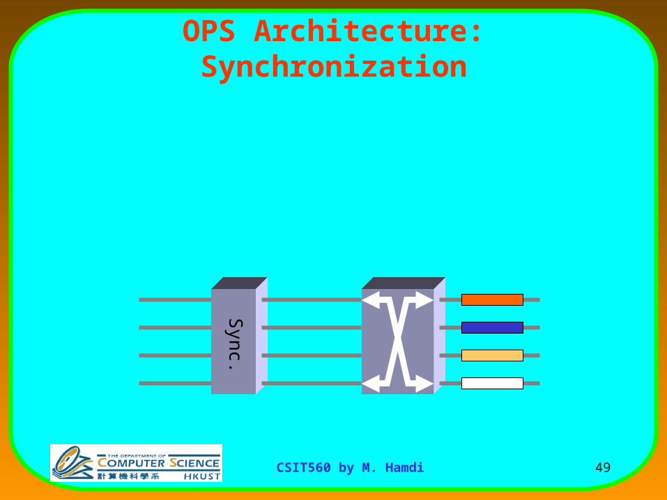
Sync.
•Fixed packet size
•Synchronization stages required
Slotted networks
OPS Architecture: SynchronizationOccurs in electronic switches – solved by input bufferingOccurs in electronic switches – solved by input buffering

45CSIT560 by M. Hamdi
•Fixed packet size
•Synchronization stages required
Slotted networks
Sync.
OPS Architecture: Synchronization

46CSIT560 by M. Hamdi
•Fixed packet size
•Synchronization stages required
Slotted networks
OPS Architecture: Synchronization
Sync.

47CSIT560 by M. Hamdi
•Fixed packet size
•Synchronization stages required
Slotted networks
OPS Architecture: Synchronization
Sync.

48CSIT560 by M. Hamdi
•Fixed packet size
•Synchronization stages required
Slotted networks
OPS Architecture: Synchronization
Sync.
49CSIT560 by M. Hamdi
OPS Architecture: Synchronization
Sync.
50CSIT560 by M. Hamdi
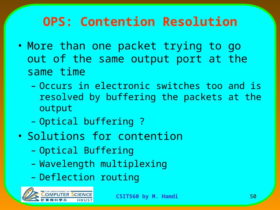
OPS: Contention Resolution
• More than one packet trying to go out of the same output port at the same time– Occurs in electronic switches too and is resolved by
buffering the packets at the output
– Optical buffering ?
• Solutions for contention– Optical Buffering
– Wavelength multiplexing
– Deflection routing

51CSIT560 by M. Hamdi
OPS Architecture
Contention Resolutions
1
1
1
2
3
4
1
2
3
4

52CSIT560 by M. Hamdi
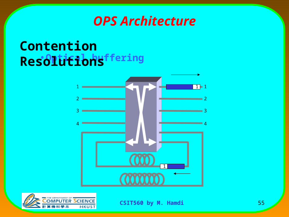
OPS: Contention Resolution
• Optical Buffering– Should hold an optical signal
• How? By delaying it using Optical Delay Lines (ODL)
– ODLs are acceptable in prototypes, but not commercially viable
– Can convert the signal to electronic domain, store, and re-convert the signal back to optical domain
• Electronic memories too slow for optical networks

53CSIT560 by M. Hamdi
1
1
1
2
3
4
1
2
3
4
•Optical buffering
OPS Architecture
Contention Resolutions

54CSIT560 by M. Hamdi
1
2
3
4
1
2
3
4
•Optical buffering
OPS Architecture
Contention Resolutions
55CSIT560 by M. Hamdi
1
1
1
2
3
4
1
2
3
4
•Optical buffering
OPS Architecture
Contention Resolutions

56CSIT560 by M. Hamdi
OPS: Contention Resolution
• Wavelength multiplexing– Resolve contention by transmitting on different
wavelengths
– Requires wavelength converters - $$$

57CSIT560 by M. Hamdi
•Wavelength conversion
1
1
1
2
1
2
OPS Architecture
Contention Resolutions

58CSIT560 by M. Hamdi
1
2
1
2
•Wavelength conversion
OPS Architecture
Contention Resolutions

59CSIT560 by M. Hamdi
1
2
1
2
1
1
•Wavelength conversion
OPS Architecture
Contention Resolutions

60CSIT560 by M. Hamdi
1
2
1
2
•Wavelength conversion
OPS Architecture
Contention Resolutions

61CSIT560 by M. Hamdi
1
2
1
2
1
1
•Wavelength conversion
OPS Architecture
Contention Resolutions

62CSIT560 by M. Hamdi
Deflection routing
• When there is a conflict between two optical packets, one will be routed to the correct output port, and the other will be routed to any other available output port.
• A deflected optical packet may follow a longer path to its destination. In view of this:– The end-to-end delay for an optical packet may be
unacceptably high. – Optical packets may have to be re-ordered at the destination

63CSIT560 by M. Hamdi
Electronic Switches Using Optical Crossbars

64CSIT560 by M. Hamdi
Scalable Multi-Rack Switch Architecture
Switch Core
Optical links
Line cardrack• Number of linecards is limited in a single rack– Limited power supplement, i.e. 10KW– Physical consideration, i.e. temperature, humidity
• Scaling to multiple racks– Fiber links and central fabrics

65CSIT560 by M. Hamdi
Logical Architecture of Multi-rack Switches
• Optical I/O interfaces connected to WDM fibers• Electronic packet processing and buffering
– Optical buffering, i.e. fiber delay lines, is costly and not mature
• Optical interconnect– Higher bandwidth, lower latency and extended link length than copper
twisted lines
• Switch fabric: electronic? Optical?
Crossbar
Scheduler
Switch Fabric System
Framer
Line Card
Laser Laser
Laser
LaserLocal
Buffers
Framer
Line Card
Laser LaserLocal
Buffers
Framer
Line Card
LaserLocal
Buffers
Framer
Line Card
LaserLocal
Buffers
Fiber I/O
Fiber I/O
Fiber I/O
Fiber I/O
66CSIT560 by M. Hamdi
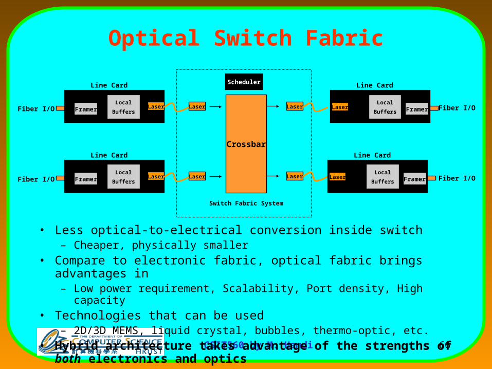
Optical Switch Fabric
• Less optical-to-electrical conversion inside switch– Cheaper, physically smaller
• Compare to electronic fabric, optical fabric brings advantages in– Low power requirement, Scalability, Port density, High capacity
• Technologies that can be used– 2D/3D MEMS, liquid crystal, bubbles, thermo-optic, etc.
• Hybrid architecture takes advantage of the strengths of both electronics and optics
Crossbar
Scheduler
Switch Fabric System
Framer
Line Card
Laser Laser
Laser
LaserLocal
Buffers
Framer
Line Card
Laser LaserLocal
Buffers
Framer
Line Card
LaserLocal
Buffers
Framer
Line Card
LaserLocal
Buffers
Fiber I/O
Fiber I/O
Fiber I/O
Fiber I/O

67CSIT560 by M. Hamdi
Electronic Vs. Optical Fabric
Trans.Line
Buffer
SwitchingFabric
Inter-connection
Trans.Line
BufferInter-connection
Electronic
Trans.Line
Buffer
SwitchingFabric
Inter-connection
Trans.Line
BufferInter-connection
Optical
Optical
Electronic
E/O or O/EConversion
favorred

68CSIT560 by M. Hamdi
Multi-rack Hybrid Packet Switch
OpticalCrossbar
E/OBuf f er O/E Buf f er
E/OBuf f er
E/OBuf f er
E/OBuf f er
O/E Buf f er
O/E Buf f er
O/E Buf f er
Rack
OpticalFiber
OpticalFiber
Switch Core
Linecard

69CSIT560 by M. Hamdi
Features of Optical Fabric
• Less E/O or O/E conversion
• High capacity
• Low power consumption
• Less cost
However,
• Reconfiguration overhead (50-100ns)– Tuning of lasers (20-30ns)
– System clock synchronization (10-20ns or higher)

70CSIT560 by M. Hamdi
Scheduling Under Reconfiguration Overhead
• Traditional slot-by-slot approach
• Low bandwidth usage
Scheduler
Time Line
ScheduleReconfigure Transfer

71CSIT560 by M. Hamdi
Reduced Rate Scheduling
• Challenge: fabric reconfiguration delay– Traditional slot-by-slot scheduling brings lots of overhead
• Solution: slow down the scheduling frequency to compensate– Each schedule will be held for some time
• Scheduling task1. Find out the matching2. Determine the holding time
Fabric setup (reconfigure)
Traffic transfer
Time slot
Slot-by-slot Scheduling, zero fabric setup time
Reduced rate Scheduling, each schedule is held for some time
Slot-by-slot Scheduling with reconfigure delay

72CSIT560 by M. Hamdi
Scheduling Under Reconfiguration Overhead
• Reduce the scheduling rate– Bandwidth Usage = Transfer/(Reconfigure+Transfer)
• Approaches– Batch scheduling: TSA-based
– Single scheduling: Schedule + Hold
Constant

73CSIT560 by M. Hamdi
Single Scheduling
• Schedule + Hold
– One schedule is generated each time
– Each schedule is held for some time (holding time)
– Holding time can be fixed or variable
– Example: LQF+Hold
74CSIT560 by M. Hamdi
Routing and Wavelength Assignment

75CSIT560 by M. Hamdi
Optical Circuit Switching• An optical path established between two nodes
• Created by allocation of a wavelength throughout the path.
• Provides a ‘circuit switched’ interconnection between two nodes. – Path setup takes at least one RTT
– No optical buffers since path is pre-set
Desirable to establish light paths between every pair of nodes.
• Limitations in WDM routing networks, – Number of wavelengths is limited.
– Physical constraints:
• limited number of optical transceivers limit the number of channels.

76CSIT560 by M. Hamdi
Routing and Wavelength Assignment (RWA)
• Light path establishment involves– Selecting a physical path between source and destination
edge nodes
– Assigning a wavelength for the light path
• RWA is more complex than normal routing because– Wavelength continuity constraint
• A light path must have same wavelength along all the links in the path
– Distinct Wavelength Constraint• Light paths using the same link must have different wavelengths

77CSIT560 by M. Hamdi
No Wavelength Converters
POPPOP
Access Fiber
Wavelength 1
Wavelength 2
Wavelength 3
WSXC

78CSIT560 by M. Hamdi
With Wavelength Converters
POPPOP
Access FiberWavelength 1
Wavelength 2
Wavelength 3
WIXC

79CSIT560 by M. Hamdi
Routing and Wavelength Assignment (RWA)
• RWA algorithms based on traffic assumptions:
• Static Traffic
– Set of connections for source and destination pairs are given
• Dynamic Traffic
– Connection requests arrive to and depart from network one by one in a random manner.
– Performance metrics used fall under one of the following three categories:
• Number of wavelengths required
• Connection blocking probability: Ratio between number of blocked connections and total number of connections arrived

80CSIT560 by M. Hamdi
Static and Dynamic RWA
• Static RWA
– Light path assignment when traffic is known well in advance
– Arises in capacity planning and design of optical networks
• Dynamic RWA
– Light path assignment to be done when requests arrive in random fashion
– Encountered during real-time network operation

81CSIT560 by M. Hamdi
Static RWA
• RWA is usually solved as an optimization problem with Integer Programming (IP) formulations
• Objective functions
– Minimize average weighted number of hops
– Minimize average packet delay
– Minimize the maximum congestion level
– Minimize number of Wavelenghts

82CSIT560 by M. Hamdi
Static RWA
• Methodologies for solving Static RWA– Heuristics for solving the overall ILP sub-optimally
– Algorithms that decompose the static RWA problem into a set of individual sub-problems, and solve a sub-set
– http://www.tct.hut.fi/~esa/java/wdm/
• Methodologies for solving Static RWA– Heuristics for solving the overall ILP sub-optimally
– Algorithms that decompose the static RWA problem into a set of individual sub-problems, and solve a sub-set
– http://www.tct.hut.fi/~esa/java/wdm/
• Methodologies for solving Static RWA– Heuristics for solving the overall ILP sub-optimally
– Algorithms that decompose the static RWA problem into a set of individual sub-problems, and solve a sub-set
– http://www.tct.hut.fi/~esa/java/wdm/

83CSIT560 by M. Hamdi
Solving Dynamic RWA
• During network operation, requests for new light-paths come randomly
• These requests will have to be serviced based on the network state at that instant
• As the problem is in real-time, dynamic RWA algorithms should be simple
• The problem is broken down into two sub-problems– Routing problem
– Wavelength assignment problem

84CSIT560 by M. Hamdi
Optical Circuit Switching all the Way: End-to-
End !!!Why might this be possible:Why might this be possible:
• Huge CS bandwidth (large # of wavelength) – BW Huge CS bandwidth (large # of wavelength) – BW efficiency is not very crucialefficiency is not very crucial
• Circuit switches have a much higher capacity than Circuit switches have a much higher capacity than Packet switches, and QoS is trivialPacket switches, and QoS is trivial
• Optical Technology is suited for CSOptical Technology is suited for CS

85CSIT560 by M. Hamdi
How the Internet Looks Like Today
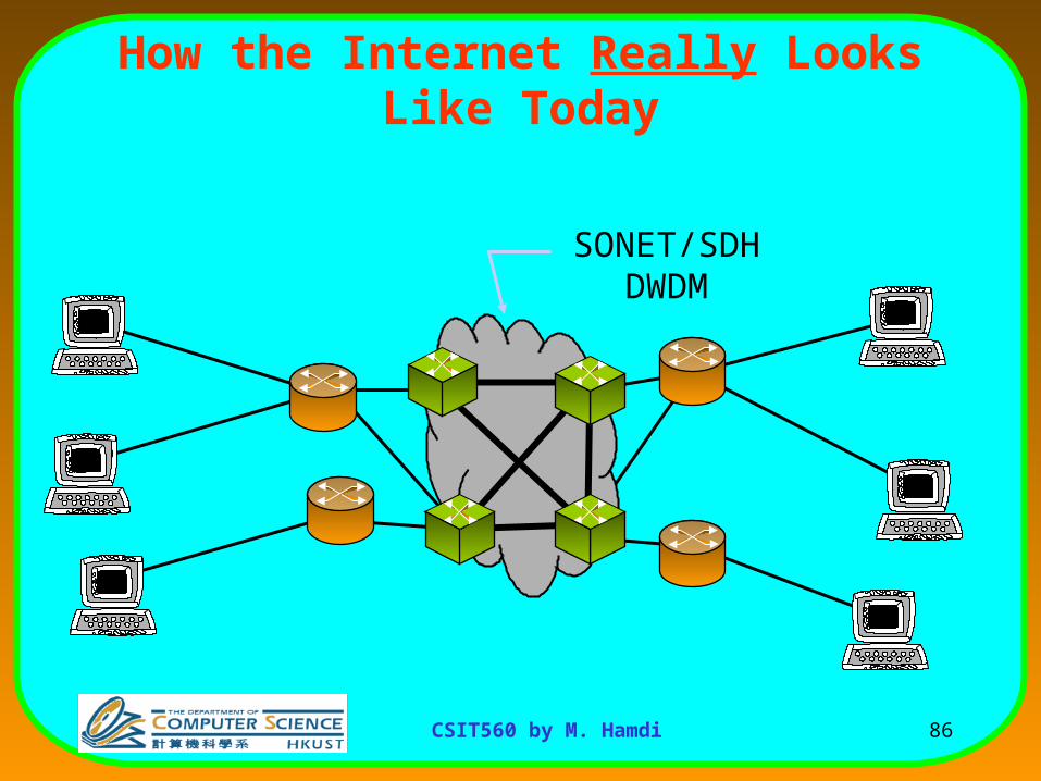
The core of the Internet is already “predominantly” CS.The core of the Internet is already “predominantly” CS.
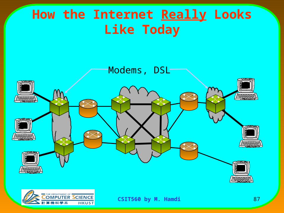
Even a “large” portion of the access networks use CS (Modem, DSLs)Even a “large” portion of the access networks use CS (Modem, DSLs)
86CSIT560 by M. Hamdi
How the Internet Really Looks Like Today
SONET/SDHDWDM
87CSIT560 by M. Hamdi
How the Internet Really Looks Like Today
Modems, DSL

88CSIT560 by M. Hamdi
Why Is the Internet Packet Switched in the First Place?
• PS is bandwidth efficient “Statistical Multiplexing”
• PS networks are robust
Gallager:“Circuit switching is rarely used for data networks, ... because of very inefficient use of the links”
Tanenbaum:”For high reliability, ... [the Internet] was to be a datagram subnet, so if some lines and [routers] were destroyed, messages could be ... rerouted”

89CSIT560 by M. Hamdi
Are These Assumptions Valid Today?
• PS is bandwidth efficient
• PS networks are robust
Routers/Switches are designed for <5s
down-time per year. They take >1min to recover when they do (circuit switches must recover in <50ms).
• 10-15% average link utilization in the backbone today.
• Similar story for access networks

90CSIT560 by M. Hamdi
How Can Circuit Switching Help the Internet?
• Simple switches/routers:• No buffering
• No per-packet processing (just per connection processing)
• Possible all-optical data path
• Peak allocation of BW• No delay jitter
Higher capacity switches
Simple but strict QoS

91CSIT560 by M. Hamdi
Myth: Packet switching is simpler
• A typical Internet router contains over 500M gates, 32 CPUs and 10Gbytes of memory.
• A circuit switch of the same generation could run ten times faster with 1/10th the gates and no memory.

92CSIT560 by M. Hamdi
Packet Switch Capacity
time
Inst
ruct
ion
s p
er
arr
ivin
g b
yte
What we’d like: (more features)QoS, Multicast, Security, …
What will happen: (fewer features)Or perhaps we’re doing something wrong?

93CSIT560 by M. Hamdi
What Is the Performance of Circuit Switching?End-to-End
Packet swCircuit sw 10 Mb/s1 Gb/sFlow BW
1 s0.505 sAvg latency
1 s1 sWorst latency
99% of Circuits Finish Earlier
1 server100 clients
1 Gb/s
File = 10Mbit
x 100

94CSIT560 by M. Hamdi
What Is the Performance of Circuit Switching?
10.990 sec10.990 sWorst latency
Packet swCircuit sw 10Mb/
s+1Gb/s1 Gb/sFlow BW
1.099 sec10.495 sAvg latency
A big file can kill CS if it
blocks the link
1 server100 clients
1 Gb/s
File = 10Gbit/10Mbit
x 99

95CSIT560 by M. Hamdi
What Is the Performance of Circuit Switching?
Packet swCircuit sw 1 Mb/s1 Mb/sFlow BW
10,000 sec10,000 s
Worst latency
109.9sec 109.9s
Avg latency
No difference between
CS and PS in core
1 server100 clients
1 Gb/s
x 991 Mb/s
File = 10Gbit/10Mbit

96CSIT560 by M. Hamdi
Possible Implementation
• Create a separate circuit for each flow
• IP controls circuits• Optimize for the most common
case– TCP (85-95% of traffic)
– Data (8-9 out of 10 pkts)
TCP Switching

97CSIT560 by M. Hamdi
TCP Switching Exposes Circuits to IP
TCP Switches
IP routers
98CSIT560 by M. Hamdi
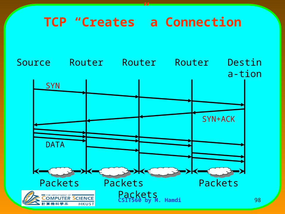
TCP “Creates” a Connection
Router Router Router Destina-tion
Source
SYN
SYN+ACK
DATA
Packets Packets
PacketsPackets

99CSIT560 by M. Hamdi
State Management Feasibility
• Amount of state– Minimum circuit = 64 kb/s.
– 156,000 circuits for OC-192.
• Update rate– About 50,000 new entries per sec for OC-192.
• Readily implemented in hardware or software.

100CSIT560 by M. Hamdi
Software Implementation Results
TCP Switching boundary router:• Kernel module in Linux 2.4 1GHz PC • Forwarding latency
– Forward one packet: 21s.
– Compare to: 17s for IP.
– Compare to: 95s for IP + QoS.
• Time to create new circuit: 57s.