council decision 2008/616/jha of 23 june 2008 on the
TRANSCRIPT

COUNCIL DECISION 2008/616/JHA
of 23 June 2008
on the implementation of Decision 2008/615/JHA on the stepping up of cross-border cooperation,particularly in combating terrorism and cross-border crime
THE COUNCIL OF THE EUROPEAN UNION,
Having regard to Article 33 of Council Decision 2008/615/JHA (1),
Having regard to the initiative of the Federal Republic ofGermany,
Having regard to the opinion of the European Parliament (2),
Whereas:
(1) On 23 June 2008 the Council adopted Decision2008/615/JHA on the stepping up of cross-bordercooperation, particularly in combating terrorism andcross-border crime.
(2) By means of Decision 2008/615/JHA, the basic elements ofthe Treaty of 27 May 2005 between the Kingdom ofBelgium, the Federal Republic of Germany, the Kingdom ofSpain, the French Republic, the Grand Duchy of Luxem-bourg, the Kingdom of the Netherlands and the Republic ofAustria on the stepping up of cross-border cooperation,particularly in combating terrorism, cross-border crime andillegal migration (hereinafter the Prüm Treaty), weretransposed into the legal framework of the EuropeanUnion.
(3) Article 33 of Decision 2008/615/JHA provides that theCouncil is to adopt the measures necessary to implementDecision 2008/615/JHA at the level of the Union inaccordance with the procedure laid down in the secondsentence of Article 34(2)(c) of the Treaty on EuropeanUnion. These measures are to be based on the Implement-ing Agreement of 5 December 2006 concerning theadministrative and technical implementation and applica-tion of the Prüm Treaty.
(4) This Decision establishes those common normative provi-sions which are indispensable for administrative andtechnical implementation of the forms of cooperation setout in Decision 2008/615/JHA. The Annex to this Decisioncontains implementing provisions of a technical nature. Inaddition, a separate Manual, containing exclusively factualinformation to be provided by the Member States, will bedrawn up and kept up to date by the General Secretariat ofthe Council.
(5) Having regard to technical capabilities, routine searches ofnew DNA profiles will in principle be carried out by meansof single searches, and appropriate solutions for this will befound at the technical level,
HAS DECIDED AS FOLLOWS:
CHAPTER I
GENERAL
Article 1
Aim
The aim of this Decision is to lay down the necessaryadministrative and technical provisions for the implementationof Decision 2008/615/JHA, in particular as regards theautomated exchange of DNA data, dactyloscopic data andvehicle registration data, as set out in Chapter 2 of that Decision,and other forms of cooperation, as set out in Chapter 5 of thatDecision.
Article 2
Definitions
For the purposes of this Decision:
(a) ‘search’ and ‘comparison’, as referred to in Articles 3, 4 and9 of Decision 2008/615/JHA, mean the procedures bywhich it is established whether there is a match between,respectively, DNA data or dactyloscopic data which havebeen communicated by one Member State and DNA data ordactyloscopic data stored in the databases of one, several, orall of the Member States;
(b) ‘automated searching’, as referred to in Article 12 ofDecision 2008/615/JHA, means an online access procedurefor consulting the databases of one, several, or all of theMember States;
(c) ‘DNA profile’ means a letter or number code whichrepresents a set of identification characteristics of the non-coding part of an analysed human DNA sample, i.e. theparticular molecular structure at the various DNA locations(loci);
(d) ‘non-coding part of DNA’ means chromosome regions notgenetically expressed, i.e. not known to provide for anyfunctional properties of an organism;
L 210/12 EN Official Journal of the European Union 6.8.2008
(1) See page 1 of this Official Journal.(2) Opinion of 21 April 2008 (not yet published in the Official Journal).

(e) ‘DNA reference data’ mean DNA profile and referencenumber;
(f) ‘reference DNA profile’ means the DNA profile of anidentified person;
(g) ‘unidentified DNA profile’ means the DNA profile obtainedfrom traces collected during the investigation of criminaloffences and belonging to a person not yet identified;
(h) ‘note’ means a Member State's marking on a DNA profile inits national database indicating that there has already been amatch for that DNA profile on another Member State'ssearch or comparison;
(i) ‘dactyloscopic data’ mean fingerprint images, images offingerprint latents, palm prints, palm print latents andtemplates of such images (coded minutiae), when they arestored and dealt with in an automated database;
(j) ‘vehicle registration data’ mean the data-set as specified inChapter 3 of the Annex to this Decision;
(k) ‘individual case’, as referred to in Article 3(1), secondsentence, Article 9(1), second sentence and Article 12(1) ofDecision 2008/615/JHA, means a single investigation orprosecution file. If such a file contains more than one DNAprofile, or one piece of dactyloscopic data or vehicleregistration data, they may be transmitted together as onerequest.
CHAPTER 2
COMMON PROVISIONS FOR DATA EXCHANGE
Article 3
Technical specifications
Member States shall observe common technical specifications inconnection with all requests and answers related to searches andcomparisons of DNA profiles, dactyloscopic data and vehicleregistration data. These technical specifications are laid down inthe Annex to this Decision.
Article 4
Communications network
The electronic exchange of DNA data, dactyloscopic data andvehicle registration data between Member States shall take placeusing the Trans European Services for Telematics betweenAdministrations (TESTA II) communications network andfurther developments thereof.
Article 5
Availability of automated data exchange
Member States shall take all necessary measures to ensure thatautomated searching or comparison of DNA data, dactyloscopicdata and vehicle registration data is possible 24 hours a day andseven days a week. In the event of a technical fault, the MemberStates' national contact points shall immediately inform eachother and shall agree on temporary alternative informationexchange arrangements in accordance with the legal provisionsapplicable. Automated data exchange shall be re-established asquickly as possible.
Article 6
Reference numbers for DNA data and dactyloscopic data
The reference numbers referred to in Article 2 and Article 8 ofDecision 2008/615/JHA shall consist of a combination of thefollowing:
(a) a code allowing the Member States, in the case of a match,to retrieve personal data and other information in theirdatabases in order to supply it to one, several or all of theMember States in accordance with Article 5 or Article 10 ofDecision 2008/615/JHA;
(b) a code to indicate the national origin of the DNA profile ordactyloscopic data; and
(c) with respect to DNA data, a code to indicate the type ofDNA profile.
CHAPTER 3
DNA DATA
Article 7
Principles of DNA data exchange
1. Member States shall use existing standards for DNA dataexchange, such as the European Standard Set (ESS) or theInterpol Standard Set of Loci (ISSOL).
2. The transmission procedure, in the case of automatedsearching and comparison of DNA profiles, shall take placewithin a decentralised structure.
3. Appropriate measures shall be taken to ensure confidenti-ality and integrity for data being sent to other Member States,including their encryption.
4. Member States shall take the necessary measures toguarantee the integrity of the DNA profiles made available orsent for comparison to the other Member States and to ensurethat these measures comply with international standards such asISO 17025.
6.8.2008 EN Official Journal of the European Union L 210/13
5. Member States shall use Member State codes in accordancewith the ISO 3166-1 alpha-2 standard.
Article 8
Rules for requests and answers in connection with DNAdata
1. A request for an automated search or comparison, asreferred to in Articles 3 or 4 of Decision 2008/615/JHA, shallinclude only the following information:
(a) the Member State code of the requesting Member State;
(b) the date, time and indication number of the request;
(c) DNA profiles and their reference numbers;
(d) the types of DNA profiles transmitted (unidentified DNAprofiles or reference DNA profiles); and
(e) information required for controlling the database systemsand quality control for the automatic search processes.
2. The answer (matching report) to the request referred to inparagraph 1 shall contain only the following information:
(a) an indication as to whether there were one or morematches (hits) or no matches (no hits);
(b) the date, time and indication number of the request;
(c) the date, time and indication number of the answer;
(d) the Member State codes of the requesting and requestedMember States;
(e) the reference numbers of the requesting and requestedMember States;
(f) the type of DNA profiles transmitted (unidentified DNAprofiles or reference DNA profiles);
(g) the requested and matching DNA profiles; and
(h) information required for controlling the database systemsand quality control for the automatic search processes.
3. Automated notification of a match shall only be provided ifthe automated search or comparison has resulted in a match of aminimum number of loci. This minimum is set out in Chapter 1of the Annex to this Decision.
4. The Member States shall ensure that requests comply withdeclarations issued pursuant to Article 2(3) of Decision2008/615/JHA. These declarations shall be reproduced in theManual referred to in Article 18(2) of this Decision.
Article 9
Transmission procedure for automated searching ofunidentified DNA profiles in accordance with Article 3 of
Decision 2008/615/JHA
1. If, in a search with an unidentified DNA profile, no matchhas been found in the national database or a match has beenfound with an unidentified DNA profile, the unidentified DNAprofile may then be transmitted to all other Member States'databases and if, in a search with this unidentified DNA profile,matches are found with reference DNA profiles and/orunidentified DNA profiles in other Member States' databases,these matches shall be automatically communicated and theDNA reference data transmitted to the requesting Member State;if no matches can be found in other Member States' databases,this shall be automatically communicated to the requestingMember State.
2. If, in a search with an unidentified DNA profile, a match isfound in other Member States' databases, each Member Stateconcerned may insert a note to this effect in its national database.
Article 10
Transmission procedure for automated search of referenceDNA profiles in accordance with Article 3 of Decision
2008/615/JHA
If, in a search with a reference DNA profile, no match has beenfound in the national database with a reference DNA profile or amatch has been found with an unidentified DNA profile, thisreference DNA profile may then be transmitted to all otherMember States' databases and if, in a search with this referenceDNA profile, matches are found with reference DNA profilesand/or unidentified DNA profiles in other Member States'databases, these matches shall be automatically communicatedand the DNA reference data transmitted to the requestingMember State; if no matches can be found in other MemberStates' databases, it shall be automatically communicated to therequesting Member State.
Article 11
Transmission procedure for automated comparison ofunidentified DNA profiles in accordance with Article 4 of
Decision 2008/615/JHA
1. If, in a comparison with unidentified DNA profiles, matchesare found in other Member States' databases with reference DNAprofiles and/or unidentified DNA profiles, these matches shall beautomatically communicated and the DNA reference datatransmitted to the requesting Member State.
L 210/14 EN Official Journal of the European Union 6.8.2008

2. If, in a comparison with unidentified DNA profiles, matchesare found in other Member States' databases with unidentifiedDNA profiles or reference DNA profiles, each Member Stateconcerned may insert a note to this effect in its national database.
CHAPTER 4
DACTYLOSCOPIC DATA
Article 12
Principles for the exchange of dactyloscopic data
1. The digitalisation of dactyloscopic data and their transmis-sion to the other Member States shall be carried out inaccordance with the uniform data format specified in Chapter 2of the Annex to this Decision.
2. Each Member State shall ensure that the dactyloscopic data ittransmits are of sufficient quality for a comparison by theautomated fingerprint identification systems (AFIS).
3. The transmission procedure for the exchange of dactylo-scopic data shall take place within a decentralised structure.
4. Appropriate measures shall be taken to ensure theconfidentiality and integrity of dactyloscopic data being sent toother Member States, including their encryption.
5. The Member States shall use Member State codes inaccordance with the ISO 3166-1 alpha-2 standard.
Article 13
Search capacities for dactyloscopic data
1. Each Member State shall ensure that its search requests donot exceed the search capacities specified by the requestedMember State. Member States shall submit declarations asreferred to in Article 18(2) to the General Secretariat of theCouncil in which they lay down their maximum search capacitiesper day for dactyloscopic data of identified persons and fordactyloscopic data of persons not yet identified.
2. The maximum numbers of candidates accepted for verifica-tion per transmission are set out in Chapter 2 of the Annex tothis Decision.
Article 14
Rules for requests and answers in connection withdactyloscopic data
1. The requested Member State shall check the quality of thetransmitted dactyloscopic data without delay by a fullyautomated procedure. Should the data be unsuitable for anautomated comparison, the requested Member State shall informthe requesting Member State without delay.
2. The requested Member State shall conduct searches in theorder in which requests are received. Requests shall be processedwithin 24 hours by a fully automated procedure. The requestingMember State may, if its national law so prescribes, ask foraccelerated processing of its requests and the requested MemberState shall conduct these searches without delay. If deadlinescannot be met for reasons of force majeure, the comparison shallbe carried out without delay as soon as the impediments havebeen removed.
CHAPTER 5
VEHICLE REGISTRATION DATA
Article 15
Principles of automated searching of vehicle registrationdata
1. For automated searching of vehicle registration data MemberStates shall use a version of the European Vehicle and DrivingLicence Information System (Eucaris) software applicationespecially designed for the purposes of Article 12 of Decision2008/615/JHA, and amended versions of this software.
2. Automated searching of vehicle registration data shall takeplace within a decentralised structure.
3. The information exchanged via the Eucaris system shall betransmitted in encrypted form.
4. The data elements of the vehicle registration data to beexchanged are specified in Chapter 3 of the Annex to thisDecision.
5. In the implementation of Article 12 of Decision2008/615/JHA, Member States may give priority to searchesrelated to combating serious crime.
Article 16
Costs
Each Member State shall bear the costs arising from theadministration, use and maintenance of the Eucaris softwareapplication referred to in Article 15(1).
CHAPTER 6
POLICE COOPERATION
Article 17
Joint patrols and other joint operations
1. In accordance with Chapter 5 of Decision 2008/615/JHA,and in particular with the declarations submitted pursuant toArticles 17(4), 19(2), and 19(4) of that Decision, each MemberState shall designate one or more contact points in order to allow
6.8.2008 EN Official Journal of the European Union L 210/15

other Member States to address competent authorities and eachMember State may specify its procedures for setting up jointpatrols and other joint operations, its procedures for initiativesfrom other Member States with regard to those operations, aswell as other practical aspects, and operational modalities inrelation to those operations.
2. The General Secretariat of the Council shall compile andkeep up to date a list of the contact points and shall inform thecompetent authorities about any change to that list.
3. The competent authorities of each Member State may takethe initiative to set up a joint operation. Before the start of aspecific operation, the competent authorities referred to inparagraph 2 shall make written or verbal arrangements that maycover details such as:
(a) the competent authorities of the Member States for theoperation;
(b) the specific purpose of the operation;
(c) the host Member State where the operation is to take place;
(d) the geographical area of the host Member State where theoperation is to take place;
(e) the period covered by the operation;
(f) the specific assistance to be provided by the secondingMember State(s) to the host Member State, includingofficers or other officials, material and financial elements;
(g) the officers participating in the operation;
(h) the officer in charge of the operation;
(i) the powers that the officers and other officials of theseconding Member State(s) may exercise in the hostMember State during the operation;
(j) the particular arms, ammunition and equipment that theseconding officers may use during the operation inaccordance with Decision 2008/615/JHA;
(k) the logistic modalities as regards transport, accommodationand security;
(l) the allocation of the costs of the joint operation if it differsfrom that provided in the first sentence of Article 34 ofDecision 2008/615/JHA;
(m) any other possible elements required.
4. The declarations, procedures and designations provided forin this Article shall be reproduced in the Manual referred to inArticle 18(2).
CHAPTER 7
FINAL PROVISIONS
Article 18
Annex and Manual
1. Further details concerning the technical and administrativeimplementation of Decision 2008/615/JHA are set out in theAnnex to this Decision.
2. A Manual shall be prepared and kept up to date by theGeneral Secretariat of the Council, comprising exclusively factualinformation provided by the Member States through declarationsmade pursuant to Decision 2008/615/JHA or this Decision orthrough notifications made to the General Secretariat of theCouncil. The Manual shall be in the form of a CouncilDocument.
Article 19
Independent data protection authorities
Member States shall, in accordance with Article 18(2) of thisDecision, inform the General Secretariat of the Council of theindependent data protection authorities or the judicial auth-orities as referred to in Article 30(5) of Decision 2008/615/JHA.
Article 20
Preparation of decisions as referred to in Article 25(2) ofDecision 2008/615/JHA
1. The Council shall take a decision as referred to in Arti-cle 25(2) of Decision 2008/615/JHA on the basis of anevaluation report which shall be based on a questionnaire.
2. With respect to the automated data exchange in accordancewith Chapter 2 of Decision 2008/615/JHA, the evaluation reportshall also be based on an evaluation visit and a pilot run thatshall be carried out when the Member State concerned hasinformed the General Secretariat in accordance with the firstsentence of Article 36(2) of Decision 2008/615/JHA.
3. Further details of the procedure are set out in Chapter 4 ofthe Annex to this Decision.
Article 21
Evaluation of the data exchange
1. An evaluation of the administrative, technical and financialapplication of the data exchange pursuant to Chapter 2 ofDecision 2008/615/JHA, and in particular the use of themechanism of Article 15(5), shall be carried out on a regularbasis. The evaluation shall relate to those Member States alreadyapplying Decision 2008/615/JHA at the time of the evaluationand shall be carried out with respect to the data categories for
L 210/16 EN Official Journal of the European Union 6.8.2008

which data exchange has started among the Member Statesconcerned. The evaluation shall be based on reports of therespective Member States.
2. Further details of the procedure are set out in Chapter 4 ofthe Annex to this Decision.
Article 22
Relationship with the Implementing Agreement of thePrüm Treaty
For the Member States bound by the Prüm Treaty, the relevantprovisions of this Decision and the Annex hereto once fullyimplemented shall apply instead of the corresponding provisionscontained in the Implementing Agreement of the Prüm Treaty.Any other provisions of the Implementing Agreement shallremain applicable between the contracting parties of the PrümTreaty.
Article 23
Implementation
Member States shall take the necessary measures to comply withthe provisions of this Decision within the periods referred to inArticle 36(1) of Decision 2008/615/JHA.
Article 24
Application
This Decision shall take effect 20 days following its publicationin the Official Journal of the European Union.
Done at Luxembourg, 23 June 2008.
For the Council
The President
I. JARC
6.8.2008 EN Official Journal of the European Union L 210/17

ANNEX
TABLE OF CONTENTS
CHAPTER 1: Exchange of DNA-Data
1. DNA related forensic issues, matching rules and algorithms
1.1. Properties of DNA-profiles
1.2. Matching rules
1.3. Reporting rules
2. Member State code number table
3. Functional analysis
3.1. Availability of the system
3.2. Second step
4. DNA interface control document
4.1. Introduction
4.2. XML structure definition
5. Application, security and communication architecture
5.1. Overview
5.2. Upper level architecture
5.3. Security standards and data protection
5.4. Protocols and standards to be used for encryption mechanism: s/MIME and related packages
5.5. Application architecture
5.6. Protocols and standards to be used for application architecture
5.7. Communication environment
CHAPTER 2: Exchange of dactyloscopic data (interface control document)
1. File content overview
2. Record format
3. Type-1 logical record: the file header
4. Type-2 logical record: descriptive text
5. Type-4 logical record: high resolution greyscale image
6. Type-9 logical record: minutiae record
7. Type-13 variable-resolution latent image record
8. Type-15 variable-resolution palmprint image record
9. Appendices to Chapter 2 (exchange of dactyloscopic data)
9.1. ASCII Separator Codes
9.2. Calculation of Alpha-numeric Check Character
L 210/18 EN Official Journal of the European Union 6.8.2008

9.3. Character codes
9.4. Transaction summary
9.5. Type-1 record definitions
9.6. Type-2 record definitions
9.7. Greyscale compression codes
9.8. Mail specification
CHAPTER 3: Exchange of vehicle registration data
1. Common data-set for automated search of vehicle registration data
1.1. Definitions
1.2. Vehicle/owner/holder search
2. Data Security
2.1. Overview
2.2. Security features related to message exchange
2.3. Security features not related to message exchange
3. Technical conditions of the data exchange
3.1. General description of the Eucaris application
3.2. Functional and non-functional requirements
CHAPTER 4: Evaluation
1. Evaluation procedure according to Article 20 (Preparation of Decisions according to Article 25(2) of Decision2008/615/JHA)
1.1. Questionnaire
1.2. Pilot run
1.3. Evaluation visit
1.4. Report to the Council
2. Evaluation procedure according to Article 21
2.1. Statistics and Report
2.2. Revision
3. Expert meetings
6.8.2008 EN Official Journal of the European Union L 210/19

CHAPTER 1: Exchange of DNA-Data
1. DNA related forensic issues, matching rules and algorithms
1.1. Properties of DNA-profiles
The DNA profile may contain 24 pairs of numbers representing the alleles of 24 loci which are also used in theDNA-procedures of Interpol. The names of these loci are shown in the following table:
VWA TH01 D21S11 FGA D8S1179 D3S1358 D18S51 Amelogenin
TPOX CSF1P0 D13S317 D7S820 D5S818 D16S539 D2S1338 D19S433
Penta D Penta E FES F13A1 F13B SE33 CD4 GABA
The seven grey loci in the top row are both the present European Standard Set (ESS) and the Interpol Standard Setof Loci (ISSOL).
Inclusion Rules:
The DNA-profiles made available by the Member States for searching and comparison as well as the DNA-profilessent out for searching and comparison must contain at least six full designated (1) loci and may contain additionalloci or blanks depending on their availability. The reference DNA profiles must contain at least six of the sevenESS of loci. In order to raise the accuracy of matches, all available alleles shall be stored in the indexed DNAprofile database and be used for searching and comparison. Each Member State should implement as soon aspractically possible any new ESS of loci adopted by the EU.
Mixed profiles are not allowed, so that the allele values of each locus will consist of only two numbers, which maybe the same in the case of homozygosity at a given locus.
Wild-cards and Micro-variants are to be dealt with using the following rules:
— Any non-numerical value except amelogenin contained in the profile (e.g. ‘o’, ‘f’, ‘r’, ‘na’, ‘nr’ or ‘un’) has to beautomatically converted for the export to a wild card (*) and searched against all,
— Numerical values ‘0’, ‘1’ or ‘99’ contained in the profile have to be automatically converted for the export to awild card (*) and searched against all,
— If three alleles are provided for one locus the first allele will be accepted and the remaining two alleles have tobe automatically converted for the export to a wild card (*) and searched against all,
— When wild card values are provided for allele 1 or 2 then both permutations of the numerical value given forthe locus will be searched (e.g. 12, * could match against 12,14 or 9,12),
— Pentanucleotide (Penta D, Penta E and CD4) micro-variants will be matched according to the following:
x.1 = x, x.1, x.2
x.2 = x.1, x.2, x.3
x.3 = x.2, x.3, x.4
x.4 = x.3, x.4, x + 1,
— Tetranucleotide (the rest of the loci are tetranucleotides) micro-variants will be matched according to thefollowing:
x.1 = x, x.1, x.2
x.2 = x.1, x.2, x.3
x.3 = x.2, x.3, x + 1.
L 210/20 EN Official Journal of the European Union 6.8.2008
(1) ‘Full designated’ means the handling of rare allelle values is included.

1.2. Matching rules
The comparison of two DNA-profiles will be performed on the basis of the loci for which a pair of allele values isavailable in both DNA-profiles. At least six full designated loci (exclusive of amelogenin) must match betweenboth DNA-profiles before a hit response is provided.
A full match (Quality 1) is defined as a match, when all allele values of the compared loci commonly contained inthe requesting and requested DNA-profiles are the same. A near match is defined as a match, when the value ofonly one of all the compared alleles is different in the two DNA profiles (Quality 2, 3 and 4). A near match is onlyaccepted if there are at least six full designated matched loci in the two compared DNA profiles.
The reason for a near match may be:
— a human typing error at the point of entry of one of the DNA-profiles in the search request or the DNA-database,
— an allele-determination or allele-calling error during the generation procedure of the DNA-profile.
1.3. Reporting rules
Both full matches, near matches and ‘no hits’ will be reported.
The matching report will be sent to the requesting national contact point and will also be made available to therequested national contact point (to enable it to estimate the nature and number of possible follow-up requests forfurther available personal data and other information associated with the DNA-profile corresponding to the hit inaccordance with Articles 5 and 10 of Decision 2008/615/JHA).
2. Member State code number table
In accordance with Decision 2008/615/JHA, ISO 3166-1 alpha-2 code are used for setting up the domain namesand other configuration parameters required in the Prüm DNA data exchange applications over a closed network.
ISO 3166-1 alpha-2 codes are the following two-letter Member State codes.
Member State names Code Member State names Code
Belgium BE Luxembourg LU
Bulgaria BG Hungary HU
Czech Republic CZ Malta MT
Denmark DK Netherlands NL
Germany DE Austria AT
Estonia EE Poland PL
Greece EL Portugal PT
Spain ES Romania RO
France FR Slovakia SK
Ireland IE Slovenia SI
Italy IT Finland FI
Cyprus CY Sweden SE
Latvia LV United Kingdom UK
Lithuania LT
6.8.2008 EN Official Journal of the European Union L 210/21

3. Functional analysis
3.1. Availability of the system
Requests pursuant to Article 3 of Decision 2008/615/JHA should reach the targeted database in the chronologicalorder that each request was sent, responses should be dispatched to reach the requesting Member State within 15minutes of the arrival of requests.
3.2. Second step
When a Member State receives a report of match, its national contact point is responsible for comparing thevalues of the profile submitted as a question and the values of the profile(s) received as an answer to validate andcheck the evidential value of the profile. National contact points can contact each other directly for validationpurposes.
Legal assistance procedures start after validation of an existing match between two profiles, on the basis of a ‘fullmatch’ or a ‘near match’ obtained during the automated consultation phase.
4. DNA interface control document
4.1. Introduction
4.1.1. Ob j e c t i v e s
This Chapter defines the requirements for the exchange of DNA profile information between the DNA databasesystems of all Member States. The header fields are defined specifically for the Prüm DNA exchange, the data partis based on the DNA profile data part in the XML schema defined for the Interpol DNA exchange gateway.
Data are exchanged by SMTP (Simple Mail Transfer Protocol) and other state-of-the-art technologies, using acentral relay mail server provided by the network provider. The XML file is transported as mail body.
4.1.2. S c o p e
This ICD defines the content of the message (mail) only. All network-specific and mail-specific topics are defineduniformly in order to allow a common technical base for the DNA data exchange.
This includes:
— the format of the subject field in the message to enable/allow for an automated processing of the messages,
— whether content encryption is necessary and if yes which methods should be chosen,
— the maximum length of messages.
4.1.3. XML s t r u c t u r e a n d p r i n c i p l e s
The XML message is structured into;
— header part, which contains information about the transmission, and
— data part, which contains profile specific information, as well as the profile itself.
The same XML schema shall be used for request and response.
For the purpose of complete checks of unidentified DNA profiles (Article 4 of Decision 2008/615/JHA) it shall bepossible to send a batch of profiles in one message. A maximum number of profiles within one message must bedefined. The number is depending from the maximum allowed mail size and shall be defined after selection of themail server.
L 210/22 EN Official Journal of the European Union 6.8.2008

XML example:
<?version=“1.0” standalone=“yes”?>
<PRUEMDNAx xmlns:msxsl=“urn:schemas-microsoft-com:xslt”
xmlns:xsi=“http://www.w3.org/2001/XMLSchema-instance”>
<header>
(…)
</header>
<datas>
(…)
</datas>
[<datas> datas structure repeated, if multiple profiles sent by (….) a single SMTP message, only allowed for Arti-cle 4 cases
</datas>]
</PRUEMDNA>
4.2. XML structure definition
The following definitions are for documentation purposes and better readability, the real binding information isprovided by an XML schema file (PRUEM DNA.xsd).
4.2.1. S c h ema PRUEMDNAx
It contains the following fields:
Fields Type Description
header PRUEM_header Occurs: 1
datas PRUEM_datas Occurs: 1 … 500
4.2.2. C on t e n t o f h e a d e r s t r u c t u r e
4.2.2.1. PRUEM header
This is a structure describing the XML file header. It contains the following fields:
Fields Type Description
direction PRUEM_header_dir Direction of message flow
ref String Reference of the XML file
generator String Generator of XML file
schema_version String Version number of schema to use
requesting PRUEM_header_info Requesting Member State info
requested PRUEM_header_info Requested Member State info
4.2.2.2. PRUEM_header dir
Type of data contained in message, value can be:
Value Description
R Request
6.8.2008 EN Official Journal of the European Union L 210/23

Value Description
A Answer
4.2.2.3. PRUEM header info
Structure to describe Member State as well as message date/time. It contains the following fields:
Fields Type Description
source_isocode String ISO 3166-2 code of the requesting Member State
destination_isocode String ISO 3166-2 code of the requested Member State
request_id String unique Identifier for a request
date Date Date of creation of message
time Time Time of creation of message
4.2.3. C on t e n t o f P RUEM P r o f i l e d a t a
4.2.3.1. PRUEM_datas
This is a structure describing the XML profile data part. It contains the following fields:
Fields Type Description
reqtype PRUEM request type Type of request (Article 3 or 4)
date Date Date profile stored
type PRUEM_datas_type Type of profile
result PRUEM_datas_result Result of request
agency String Name of corresponding unit responsible for the profile
profile_ident String Unique Member State profile ID
message String Error Message, if result = E
profile IPSG_DNA_profile If direction = A (Answer) AND result ≠ H (Hit) empty
match_id String In case of a HIT PROFILE_ID of the requesting profile
quality PRUEM_hitquality_type Quality of Hit
hitcount Integer Count of matched Alleles
rescount Integer Count of matched profiles. If direction = R (Request),then empty. If quality!=0 (the original requestedprofile), then empty.
4.2.3.2. PRUEM_request_type
Type of data contained in message, value can be:
Value Description
3 Requests pursuant to Article 3 of Decision 2008/615/JHA
4 Requests pursuant to Article 4 of Decision 2008/615/JHA
L 210/24 EN Official Journal of the European Union 6.8.2008

4.2.3.3. PRUEM_hitquality_type
Value Description
0 Referring original requesting profile:Case ‘No Hit’: original requesting profile sent back only;Case ‘Hit’: original requesting profile and matched profiles sent back.
1 Equal in all available alleles without wildcards
2 Equal in all available alleles with wildcards
3 Hit with Deviation (Microvariant)
4 Hit with mismatch
4.2.3.4. PRUEM_data_type
Type of data contained in message, value can be:
Value Description
P Person profile
S Stain
4.2.3.5. PRUEM_data_result
Type of data contained in message, value can be:
Value Description
U Undefined, If direction = R (request)
H Hit
N No Hit
E Error
4.2.3.6. IPSG_DNA_profile
Structure describing a DNA profile. It contains the following fields:
Fields Type Description
ess_issol IPSG_DNA_ISSOL Group of loci corresponding to the ISSOL(standard group of Loci of Interpol)
additional_loci IPSG_DNA_additional_loci Other loci
marker String Method used to generate of DNA
profile_id String Unique identifier for DNA profile
4.2.3.7. IPSG_DNA_ISSOL
Structure containing the loci of ISSOL (Standard Group of Interpol loci). It contains the following fields:
Fields Type Description
vwa IPSG_DNA_locus Locus vwa
th01 IPSG_DNA_locus Locus th01
6.8.2008 EN Official Journal of the European Union L 210/25

Fields Type Description
d21s11 IPSG_DNA_locus Locus d21s11
fga IPSG_DNA_locus Locus fga
d8s1179 IPSG_DNA_locus Locus d8s1179
d3s1358 IPSG_DNA_locus Locus d3s1358
d18s51 IPSG_DNA_locus Locus d18s51
amelogenin IPSG_DNA_locus Locus amelogin
4.2.3.8. IPSG_DNA_additional_loci
Structure containing the other loci. It contains the following fields:
Fields Type Description
tpox IPSG_DNA_locus Locus tpox
csf1po IPSG_DNA_locus Locus csf1po
d13s317 IPSG_DNA_locus Locus d13s317
d7s820 IPSG_DNA_locus Locus d7s820
d5s818 IPSG_DNA_locus Locus d5s818
d16s539 IPSG_DNA_locus Locus d16s539
d2s1338 IPSG_DNA_locus Locus d2s1338
d19s433 IPSG_DNA_locus Locus d19s433
penta_d IPSG_DNA_locus Locus penta_d
penta_e IPSG_DNA_locus Locus penta_e
fes IPSG_DNA_locus Locus fes
f13a1 IPSG_DNA_locus Locus f13a1
f13b IPSG_DNA_locus Locus f13b
se33 IPSG_DNA_locus Locus se33
cd4 IPSG_DNA_locus Locus cd4
gaba IPSG_DNA_locus Locus gaba
4.2.3.9. IPSG_DNA_locus
Structure describing a locus. It contains the following fields:
Fields Type Description
low_allele String Lowest value of an allele
high_allele String Highest value of an allele
5. Application, security and communication architecture
5.1. Overview
In implementing applications for the DNA data exchange within the framework of Decision 2008/615/JHA, acommon communication network shall be used, which will be logically closed among the Member States. Inorder to exploit this common communication infrastructure of sending requests and receiving replies in a more
L 210/26 EN Official Journal of the European Union 6.8.2008

effective way, an asynchronous mechanism to convey DNA and dactyloscopic data requests in a wrapped SMTPe-mail message is adopted. In fulfilment of security concerns, the mechanism s/MIME as extension to the SMTPfunctionality will be used to establish a true end-to-end secure tunnel over the network.
The operational TESTA (Trans European Services for Telematics between Administrations) is used as thecommunication network for data exchange among the Member States. TESTA is under the responsibility of theEuropean Commission. Taking into account that national DNA databases and the current national access pointsof TESTA may be located on different sites in the Member States, access to TESTA may be set up either by:
1. using the existing national access point or establishing a new national TESTA access point; or by
2. setting up a secure local link from the site where the DNA database is located and managed by thecompetent national agency to the existing national TESTA access point.
The protocols and standards deployed in the implementation of Decision 2008/615/JHA applications complywith the open standards and meet the requirements imposed by national security policy makers of the MemberStates.
5.2. Upper Level Architecture
In the scope of Decision 2008/615/JHA, each Member State will make its DNA data available to be exchangedwith and/or searched by other Member States in conformity with the standardised common data format. Thearchitecture is based upon an any-to-any communication model. There exists neither a central computer servernor a centralised database to hold DNA profiles.
Figure 1: Topology of DNA Data Exchange
In addition to the fulfilment of national legal constraints at Member States' sites, each Member State may decidewhat kind of hardware and software should be deployed for the configuration at its site to comply with therequirements set out in Decision 2008/615/JHA.
5.3. Security Standards and Data Protection
Three levels of security concerns have been considered and implemented.
6.8.2008 EN Official Journal of the European Union L 210/27

5.3.1. D a t a L e v e l
DNA profile data provided by each Member State have to be prepared in compliance with a common dataprotection standard, so that requesting Member States will receive an answer mainly to indicate HIT or NO-HITalong with an identification number in case of a HIT, which does not contain any personal information. Thefurther investigation after the notification of a HIT will be conducted at bilateral level pursuant to the existingnational legal and organisational regulations of the respective Member States' sites.
5.3.2. C ommun i c a t i o n L e v e l
Messages containing DNA profile information (requesting and replying) will be encrypted by means of a state-of-the-art mechanism in conformity with open standards, such as s/MIME, before they are forwarded to the sites ofother Member States.
5.3.3. Tr a n sm i s s i o n L e v e l
All encrypted messages containing DNA profile information will be forwarded onto other Member States' sitesthrough a virtual private tunnelling system administered by a trusted network provider at the international leveland the secure links to this tunnelling system under the national responsibility. This virtual private tunnellingsystem does not have a connection point with the open Internet.
5.4. Protocols and Standards to be used for encryption mechanism: s/MIME and related packages
The open standard s/MIME as extension to de facto e-mail standard SMTP will be deployed to encrypt messagescontaining DNA profile information. The protocol s/MIME (V3) allows signed receipts, security labels, and securemailing lists and is layered on Cryptographic Message Syntax (CMS), an IETF specification for cryptographicprotected messages. It can be used to digitally sign, digest, authenticate or encrypt any form of digital data.
The underlying certificate used by s/MIME mechanism has to be in compliance with X.509 standard. In order toensure common standards and procedures with other Prüm applications, the processing rules for s/MIMEencryption operations or to be applied under various COTS (Commercial Product of the Shelves) environments,are as follows:
— the sequence of the operations is: first encryption and then signing,
— the encryption algorithm AES (Advanced Encryption Standard) with 256 bit key length and RSA with 1 024bit key length shall be applied for symmetric and asymmetric encryption respectively,
— the hash algorithm SHA-1 shall be applied.
s/MIME functionality is built into the vast majority of modern e-mail software packages including Outlook,Mozilla Mail as well as Netscape Communicator 4.x and inter-operates among all major e-mail software packages.
Because of s/MIME's easy integration into national IT infrastructure at all Member States' sites, it is selected as aviable mechanism to implement the communication security level. For achieving the goal ‘Proof of Concept’ in amore efficient way and reducing costs the open standard JavaMail API is however chosen for prototyping DNAdata exchange. JavaMail API provides simple encryption and decryption of e-mails using s/MIME and/or OpenPGP.The intent is to provide a single, easy-to-use API for e-mail clients that want to send and received encrypted e-mailin either of the two most popular e-mail encryption formats. Therefore any state-of-the-art implementations toJavaMail API will suffice for the requirements set by Decision 2008/615/JHA, such as the product of BouncyCastle JCE (Java Cryptographic Extension), which will be used to implement s/MIME for prototyping DNA dataexchange among all Member States.
L 210/28 EN Official Journal of the European Union 6.8.2008

5.5. Application Architecture
Each Member State will provide the other Member States with a set of standardised DNA profile data which are inconformity with the current common ICD. This can be done either by providing a logical view over individualnational database or by establishing a physical exported database (indexed database).
The four main components: E-mail server/s/MIME, Application Server, Data Structure Area for fetching/feedingdata and registering incoming/outgoing messages, and Match Engine implement the whole application logic in aproduct-independent way.
In order to provide all Member States with an easy integration of the components into their respective nationalsites, the specified common functionality has been implemented by means of open source components, whichcould be selected by each Member State depending on its national IT policy and regulations. Because of theindependent features to be implemented to get access to indexed databases containing DNA profiles covered byDecision 2008/615/JHA, each Member State can freely select its hardware and software platform, includingdatabase and operating systems.
A prototype for the DNA Data Exchange has been developed and successfully tested over the existing commonnetwork. The version 1.0 has been deployed in the productive environment and is used for daily operations.Member States may use the jointly developed product but may also develop their own products. The commonproduct components will be maintained, customised and further developed according to changing IT, forensicand/or functional police requirements.
Figure 2: Overview Application Topology
5.6. Protocols and Standards to be used for application architecture:
5.6.1. XML
The DNA data exchange will fully exploit XML-schema as attachment to SMTP e-mail messages. The eXtensibleMarkup Language (XML) is a W3C-recommended general-purpose markup language for creating special-purposemarkup languages, capable of describing many different kinds of data. The description of the DNA profile suitablefor exchange among all Member States has been done by means of XML and XML schema in the ICD document.
5.6.2. ODBC
Open DataBase Connectivity provides a standard software API method for accessing database managementsystems and making it independent of programming languages, database and operating systems. ODBC has,however, certain drawbacks. Administering a large number of client machines can involve a diversity of driversand DLLs. This complexity can increase system administration overhead.
6.8.2008 EN Official Journal of the European Union L 210/29

5.6.3. J DBC
Java DataBase Connectivity (JDBC) is an API for the Java programming language that defines how a client mayaccess a database. In contrast to ODBC, JDBC does not require to use a certain set of local DLLs at the Desktop.
The business logic to process DNA profile requests and replies at each Member States' site is described in thefollowing diagram. Both requesting and replying flows interact with a neutral data area comprising different datapools with a common data structure.
Figure 3: Overview Application Workflow at each Member State's site
5.7. Communication Environment
5.7.1. C ommon Commun i c a t i o n N e two r k : T E S TA an d i t s f o l l ow - u p i n f r a s t r u c t u r e
The application DNA data exchange will exploit the e-mail, an asynchronous mechanism, to send requests and toreceive replies among the Member States. As all Member States have at least one national access point to theTESTA network, the DNA data exchange will be deployed over the TESTA network. TESTA provides a number ofadded-value services through its e-mail relay. In addition to hosting TESTA specific e-mail boxes, the infrastructurecan implement mail distribution lists and routing policies. This allows TESTA to be used as a clearing house formessages addressed to administrations connected to the EU wide Domains. Virus check mechanisms may also beput in place.
The TESTA e-mail relay is built on a high availability hardware platform located at the central TESTA applicationfacilities and protected by firewall. The TESTA Domain Name Services (DNS) will resolve resource locators to IPaddresses and hide addressing issues from the user and from applications.
5.7.2. S e c u r i t y C on c e r n
The concept of a VPN (Virtual Private Network) has been implemented within the framework of TESTA. TagSwitching Technology used to build this VPN will evolve to support Multi-Protocol Label Switching (MPLS)standard developed by the Internet Engineering Task Force (IETF).
L 210/30 EN Official Journal of the European Union 6.8.2008

MPLS is an IETF standard technology thatspeeds up network traffic flow by avoidingpacket analysis by intermediate routers(hops). This is done on the basis of so-calledlabels that are attached to packet by the edgerouters of the backbone, on the basis ofinformation stored in the forwarding infor-mation base (FIB). Labels are also used toimplement virtual private networks (VPNs).
MPLS combines the benefits of layer 3 routing with the advantages of layer 2 switching. Because IP addresses arenot evaluated during transition through the backbone, MPLS does not impose any IP addressing limitations.
Furthermore e-mail messages over the TESTA will be protected by s/MIME driven encryption mechanism.Without knowing the key and possessing the right certificate, nobody can decrypt messages over the network.
5.7.3. P r o t o c o l s a n d S t a n d a r d s t o b e u s e d ov e r t h e c ommun i c a t i o n n e two r k
5.7.3.1. SMTP
Simple Mail Transfer Protocol is the de facto standard for e-mail transmission across the Internet. SMTP is arelatively simple, text-based protocol, where one or more recipients of a message are specified and then themessage text is transferred. SMTP uses TCP port 25 upon the specification by the IETF. To determine the SMTPserver for a given domain name, the MX (Mail eXchange) DNS (Domain Name Systems) record is used.
Since this protocol started as purely ASCII text-based it did not deal well with binary files. Standards such asMIME were developed to encode binary files for transfer through SMTP. Today, most SMTP servers support the8BITMIME and s/MIME extension, permitting binary files to be transmitted almost as easily as plain text. Theprocessing rules for s/MIME operations are described in the section s/MIME (see Chapter 5.4).
SMTP is a ‘push’ protocol that does not allow one to ‘pull’ messages from a remote server on demand. To do this amail client must use POP3 or IMAP. Within the framework of implementing DNA data exchange it is decided touse the protocol POP3.
5.7.3.2. POP
Local e-mail clients use the Post Office Protocol version 3 (POP3), an application-layer Internet standard protocol,to retrieve e-mail from a remote server over a TCP/IP connection. By using the SMTP Submit profile of the SMTPprotocol, e-mail clients send messages across the Internet or over a corporate network. MIME serves as thestandard for attachments and non-ASCII text in e-mail. Although neither POP3 nor SMTP requires MIME-formatted e-mail, essentially Internet e-mail comes MIME-formatted, so POP clients must also understand and useMIME. The whole communication environment of Decision 2008/615/JHAwill therefore include the componentsof POP.
6.8.2008 EN Official Journal of the European Union L 210/31

5.7.4. N e two r k Add r e s s A s s i g nmen t
Operative environment
A dedicated block of C class subnet has currently been allocated by the European IP registration authority (RIPE)to TESTA. Further address blocks may be allocated to TESTA in the future if required. The assignment of IPaddresses to Member States is based upon a geographical schema in Europe. The data exchange among MemberStates within the framework of Decision 2008/615/JHA is operated over a European wide logically closed IPnetwork.
Testing Environment
In order to provide a smooth running environment for the daily operation among all connected Member States, itis necessary to establish a testing environment over the closed network for new Member States which prepare tojoin the operations. A sheet of parameters including IP addresses, network settings, e-mail domains as well asapplication user accounts has been specified and should be set up at the corresponding Member State's site.Moreover, a set of pseudo DNA profiles has been constructed for the test purposes.
5.7.5. C on f i g u r a t i o n P a r ame t e r s
A secure e-mail system is set up using the eu-admin.net domain. This domain with the associated addresses willnot be accessible from a location not on the TESTA EU wide domain, because the names are only known on theTESTA central DNS server, which is shielded from the Internet.
The mapping of these TESTA site addresses (host names) to their IP addresses is done by the TESTA DNS service.For each Local Domain, a Mail entry will be added to this TESTA central DNS server, relaying all e-mail messagessent to TESTA Local Domains to the TESTA central Mail Relay. This TESTA central Mail Relay will then forwardthem to the specific Local Domain e-mail server using the Local Domain e-mail addresses. By relaying the e-mailin this way, critical information contained in e-mails will only pass the Europe - wide closed networkinfrastructure and not the insecure Internet.
It is necessary to establish sub-domains (bold italics) at the sites of all Member States upon the following syntax:
‘application-type.pruem.Member State-code.eu-admin.net’, where:
‘Member State-code’ takes the value of one of the two letter-code Member State codes (i.e. AT, BE, etc.).
‘application-type’ takes one of the values: DNA and FP.
By applying the above syntax, the sub domains for the Member States are shown in the following table:
MS Sub Domains Comments
BE dna.pruem.be.eu-admin.net Setting up a secure local link to the existing TESTA II accesspoint
fp.pruem.be.eu-admin.net
BG dna.pruem.bg.eu-admin.net
fp.pruem.bg.eu-admin.net
CZ dna.pruem.cz.eu-admin.net
fp.pruem.cz.eu-admin.net
DK dna.pruem.dk.eu-admin.net
fp.pruem.dk.eu-admin.net
DE dna.pruem.de.eu-admin.net Using the existing TESTA II national access points
fp.pruem.de.eu-admin.net
EE dna.pruem.ee.eu-admin.net
fp.pruem.ee.eu-admin.net
L 210/32 EN Official Journal of the European Union 6.8.2008

MS Sub Domains Comments
IE dna.pruem.ie.eu-admin.net
fp.pruem.ie.eu-admin.net
EL dna.pruem.el.eu-admin.net
fp.pruem.el.eu-admin.net
ES dna.pruem.es.eu-admin.net Using the existing TESTA II national access point
fp.pruem.es.eu-admin.net
FR dna.pruem.fr.eu-admin.net Using the existing TESTA II national access point
fp.pruem.fr.eu-admin.net
IT dna.pruem.it.eu-admin.net
fp.pruem.it.eu-admin.net
CY dna.pruem.cy.eu-admin.net
fp.pruem.cy.eu-admin.net
LV dna.pruem.lv.eu-admin.net
fp.pruem.lv.eu-admin.net
LT dna.pruem.lt.eu-admin.net
fp.pruem.lt.eu-admin.net
LU dna.pruem.lu.eu-admin.net Using the existing TESTA II national access point
fp.pruem.lu.eu-admin.net
HU dna.pruem.hu.eu-admin.net
fp.pruem.hu.eu-admin.net
MT dna.pruem.mt.eu-admin.net
fp.pruem.mt.eu-admin.net
NL dna.pruem.nl.eu-admin.net Intending to establish a new TESTA II access point at theNFI
fp.pruem.nl.eu-admin.net
AT dna.pruem.at.eu-admin.net Using the existing TESTA II national access point
fp.pruem.at.eu-admin.net
PL dna.pruem.pl.eu-admin.net
fp.pruem.pl.eu-admin.net
PT dna.pruem.pt.eu-admin.net ……
fp.pruem.pt.eu-admin.net ……
RO dna.pruem.ro.eu-admin.net
fp.pruem.ro.eu-admin.net
6.8.2008 EN Official Journal of the European Union L 210/33

MS Sub Domains Comments
SI dna.pruem.si.eu-admin.net ……
fp.pruem.si.eu-admin.net ……
SK dna.pruem.sk.eu-admin.net
fp.pruem.sk.eu-admin.net
FI dna.pruem.fi.eu-admin.net [To be inserted]
fp.pruem.fi.eu-admin.net
SE dna.pruem.se.eu-admin.net
fp.pruem.se.eu-admin.net
UK dna.pruem.uk.eu-admin.net
fp.pruem.uk.eu-admin.net
CHAPTER 2: Exchange of dactyloscopic data (interface control document)
The purpose of the following document interface Control Document is to define the requirements for the exchange ofdactyloscopic information between the Automated Fingerprint Identification Systems (AFIS) of the Member States. It isbased on the Interpol-Implementation of ANSI/NIST-ITL 1-2000 (INT-I, Version 4.22b).
This version shall cover all basic definitions for Logical Records Type-1, Type-2, Type-4, Type-9, Type-13 and Type-15required for image and minutiæ based dactyloscopic processing.
1. File Content Overview
A dactyloscopic file consists of several logical records. There are sixteen types of record specified in the originalANSI/NIST-ITL 1-2000 standard. Appropriate ASCII separation characters are used between each record and thefields and subfields within the records.
Only 6 record types are used to exchange information between the originating and the destination agency:
Type-1 → Transaction information
Type-2 → Alphanumeric persons/case data
Type-4 → High resolution greyscale dactyloscopic images
Type-9 → Minutiæ Record
Type-13 → Variable resolution latent image record
Type-15 → Variable resolution palmprint image record
1.1. Type-1 — File header
This record contains routing information and information describing the structure of the rest of the file. Thisrecord type also defines the types of transaction which fall under the following broad categories:
1.2. Type-2 — Descriptive text
This record contains textual information of interest to the sending and receiving agencies.
1.3. Type-4 — High resolution greyscale image
This record is used to exchange high resolution greyscale (eight bit) dactyloscopic images sampled at 500 pixels/inch. The dactyloscopic images shall be compressed using the WSQ algorithm with a ratio of not more than 15:1.Other compression algorithms or uncompressed images must not be used.
L 210/34 EN Official Journal of the European Union 6.8.2008

1.4. Type-9 — Minutiæ record
Type-9 records are used to exchange ridge characteristics or minutiæ data. Their purpose is partly to avoidunnecessary duplication of AFIS encoding processes and partly to allow the transmission of AFIS codes whichcontain less data than the corresponding images.
1.5. Type-13 — Variable-Resolution Latent Image Record
This record shall be used to exchange variable-resolution latent fingerprint and latent palmprint images togetherwith textural alphanumerical information. The scanning resolution of the images shall be 500 pixels/inch with256 grey-levels. If the quality of the latent image is sufficient it shall be compressed using WSQ-algorithm. Ifnecessary the resolution of the images may be expanded to more than 500 pixels/inch and more than 256 grey-levels on bilateral agreement. In this case, it is strongly recommended to use JPEG 2000 (see Appendix 7).
1.6. Variable-Resolution Palmprint Image Record
Type-15 tagged field image records shall be used to exchange variable-resolution palmprint images together withtextural alphanumerical information. The scanning resolution of the images shall be 500 pixels/inch with 256grey-levels. To minimise the amount of data all palmprint images shall be compressed using WSQ-algorithm. Ifnecessary the resolution of the images may be expanded to more than 500 pixels/inch and more than 256 grey-levels on bilateral agreement. In this case, it is strongly recommended to use JPEG 2000 (see Appendix 7).
2. Record format
A transaction file shall consist of one or more logical records. For each logical record contained in the file, severalinformation fields appropriate to that record type shall be present. Each information field may contain one ormore basic single-valued information items. Taken together these items are used to convey different aspects of thedata contained in that field. An information field may also consist of one or more information items groupedtogether and repeated multiple times within a field. Such a group of information items is known as a subfield. Aninformation field may therefore consist of one or more subfields of information items.
2.1. Information separators
In the tagged-field logical records, mechanisms for delimiting information are implemented by use of four ASCIIinformation separators. The delimited information may be items within a field or subfield, fields within a logicalrecord, or multiple occurrences of subfields. These information separators are defined in the standard ANSI X3.4.These characters are used to separate and qualify information in a logical sense. Viewed in a hierarchicalrelationship, the File Separator ‘FS’ character is the most inclusive followed by the Group Separator ‘GS’, theRecord Separator ‘RS’, and finally the Unit Separator ‘US’ characters. Table 1 lists these ASCII separators and adescription of their use within this standard.
Information separators should be functionally viewed as an indication of the type data that follows. The ‘US’character shall separate individual information items within a field or subfield. This is a signal that the nextinformation item is a piece of data for that field or subfield. Multiple subfields within a field separated by the ‘RS’character signals the start of the next group of repeated information item(s). The ‘GS’ separator character usedbetween information fields signals the beginning of a new field preceding the field identifying number that shallappear. Similarly, the beginning of a new logical record shall be signalled by the appearance of the ‘FS’ character.
The four characters are only meaningful when used as separators of data items in the fields of the ASCII textrecords. There is no specific meaning attached to these characters occurring in binary image records and binaryfields — they are just part of the exchanged data.
Normally, there should be no empty fields or information items and therefore only one separator character shouldappear between any two data items. The exception to this rule occurs for those instances where the data in fieldsor information items in a transaction are unavailable, missing, or optional, and the processing of the transaction isnot dependent upon the presence of that particular data. In those instances, multiple and adjacent separatorcharacters shall appear together rather than requiring the insertion of dummy data between separator characters.
6.8.2008 EN Official Journal of the European Union L 210/35

For the definition of a field that consists of three information items, the following applies. If the information forthe second information item is missing, then two adjacent ‘US’ information separator characters would occurbetween the first and third information items. If the second and third information items were both missing, thenthree separator characters should be used — two ‘US’ characters in addition to the terminating field or subfieldseparator character. In general, if one or more mandatory or optional information items are unavailable for a fieldor subfield, then the appropriate number of separator character should be inserted.
It is possible to have side-by-side combinations of two or more of the four available separator characters. Whendata are missing or unavailable for information items, subfields, or fields, there must be one separator characterless than the number of data items, subfields, or fields required.
Table 1: Separators Used
Code Type Description HexadecimalValue Decimal Value
US Unit Separator Separates information items 1F 31
RS Record Separator Separates subfields 1E 30
GS Group Separator Separates fields 1D 29
FS File Separator Separates logical records 1C 28
2.2. Record layout
For tagged-field logical records, each information field that is used shall be numbered in accordance with thisstandard. The format for each field shall consist of the logical record type number followed by a period ‘.’, a fieldnumber followed by a colon ‘:’, followed by the information appropriate to that field. The tagged-field number canbe any one-to-nine digit number occurring between the period ‘.’ and the colon ‘:’. It shall be interpreted as anunsigned integer field number. This implies that a field number of ‘2.123:’ is equivalent to and shall be interpretedin the same manner as a field number of ‘2.000000123:’.
For purposes of illustration throughout this document, a three-digit number shall be used for enumerating thefields contained in each of the tagged-field logical records described herein. Field numbers will have the form of‘TT.xxx:’ where the ‘TT’ represents the one- or two-character record type followed by a period. The next threecharacters comprise the appropriate field number followed by a colon. Descriptive ASCII information or theimage data follows the colon.
Logical Type-1 and Type-2 records contain only ASCII textual data fields. The entire length of the record(including field numbers, colons, and separator characters) shall be recorded as the first ASCII field within each ofthese record types. The ASCII File Separator ‘FS’ control character (signifying the end of the logical record ortransaction) shall follow the last byte of ASCII information and shall be included in the length of the record.
In contrast to the tagged-field concept, the Type-4 record contains only binary data recorded as ordered fixed-length binary fields. The entire length of the record shall be recorded in the first four-byte binary field of eachrecord. For this binary record, neither the record number with its period, nor the field identifier number and itsfollowing colon, shall be recorded. Furthermore, as all the field lengths of this record is either fixed or specified,none of the four separator characters (‘US’, ‘RS’, ‘GS’, or ‘FS’) shall be interpreted as anything other than binarydata. For the binary record, the ‘FS’ character shall not be used as a record separator or transaction terminatingcharacter.
3. Type-1 Logical Record: the File Header
This record describes the structure of the file, the type of the file, and other important information. The characterset used for Type-1 fields shall contain only the 7-bit ANSI code for information interchange.
3.1. Fields for Type-1 Logical Record
3.1.1. F i e l d 1 . 0 01 : L o g i c a l R e c o r d L e n g t h ( L EN )
This field contains the total count of the number of bytes in the whole Type-1 logical record. The field begins with‘1.001:’, followed by the total length of the record including every character of every field and the informationseparators.
L 210/36 EN Official Journal of the European Union 6.8.2008

3.1.2. F i e l d 1 . 0 02 : Ve r s i o n Numb e r ( V ER )
To ensure that users know which version of the ANSI/NIST standard is being used, this four byte field specifies theversion number of the standard being implemented by the software or system creating the file. The first two bytesspecify the major version reference number, the second two the minor revision number. For example, the original1986 Standard would be considered the first version and designated ‘0100’ while the present ANSI/NIST-ITL 1-2000 standard is ‘0300’.
3.1.3. F i e l d 1 . 0 03 : F i l e C on t e n t ( CNT )
This field lists each of the records in the file by record type and the order in which the records appear in thelogical file. It consists of one or more subfields, each of which in turn contains two information items describing asingle logical record found in the current file. The subfields are entered in the same order in which the records arerecorded and transmitted.
The first information item in the first subfield is ‘1’, to refer to this Type-1 record. It is followed by a secondinformation item which contains the number of other records contained in the file. This number is also equal tothe count of the remaining subfields of field 1.003.
Each of the remaining subfields is associated with one record within the file, and the sequence of subfieldscorresponds to the sequence of records. Each subfield contains two items of information. The first is to identifythe Type of the record. The second is the record's IDC. The ‘US’ character shall be used to separate the twoinformation items.
3.1.4. F i e l d 1 . 0 04 : Ty p e o f Tr a n s a c t i o n ( TOT )
This field contains a three letter mnemonic designating the type of the transaction. These codes may be differentfrom those used by other implementations of the ANSI/NIST standard.
CPS: Criminal Print-to-Print Search. This transaction is a request for a search of a record relating to a criminaloffence against a prints database. The person's prints must be included as WSQ-compressed images in the file.
In case of a No-HIT, the following logical records will be returned:
— 1 Type-1 Record,
— 1 Type-2 Record.
In case of a HIT, the following logical records will be returned:
— 1 Type-1 Record,
— 1 Type-2 Record,
— 1-14 Type-4 Record.
The CPS TOT is summarised in Table A.6.1 (Appendix 6).
PMS: Print-to-Latent Search. This transaction is used when a set of prints shall to be searched against anUnidentified Latent database. The response will contain the Hit/No-Hit decision of the destination AFIS search. Ifmultiple unidentified latents exist, multiple SRE transactions will be returned, with one latent per transaction. Theperson's prints must be included as WSQ-compressed images in the file.
In case of a No-HIT, the following logical records will be returned:
— 1 Type-1 Record,
— 1 Type-2 Record.
In case of a HIT, the following logical records will be returned:
— 1 Type-1 Record,
— 1 Type-2 Record,
— 1 Type-13 Record.
6.8.2008 EN Official Journal of the European Union L 210/37

The PMS TOT is summarised in Table A.6.1 (Appendix 6).
MPS: Latent-to-Print Search. This transaction is used when a latent is to be searched against a Prints database. Thelatent minutiæ information and the image (WSQ-compressed) must be included in the file.
In case of a No-HIT, the following logical records will be returned:
— 1 Type-1 Record,
— 1 Type-2 Record.
In case of a HIT, the following logical records will be returned:
— 1 Type-1 Record,
— 1 Type-2 Record,
— 1 Type-4 or Type-15 Record.
The MPS TOT is summarised in Table A.6.4 (Appendix 6).
MMS: Latent-to-Latent Search. In this transaction the file contains a latent which is to be searched against anUnidentified Latent database in order to establish links between various scenes of crime. The latent minutiæinformation and the image (WSQ-compressed) must be included in the file.
In case of a No-HIT, the following logical records will be returned:
— 1 Type-1 Record,
— 1 Type-2 Record.
In case of a HIT, the following logical records will be returned:
— 1 Type-1 Record,
— 1 Type-2 Record,
— 1 Type-13 Record.
The MMS TOT is summarised in Table A.6.4 (Appendix 6).
SRE: This transaction is returned by the destination agency in response to dactyloscopic submissions. Theresponse will contain the Hit/No-Hit decision of the destination AFIS search. If multiple candidates exist, multipleSRE transactions will be returned, with one candidate per transaction.
The SRE TOT is summarised in Table A.6.2 (Appendix 6).
ERR: This transaction is returned by the destination AFIS to indicate a transaction error. It includes a message field(ERM) indicating the error detected. The following logical records will be returned:
— 1 Type-1 Record,
— 1 Type-2 Record.
The ERR TOT is summarised in Table A.6.3 (Appendix 6).
Table 2: Permissible Codes in Transactions
Transaction TypeLogical Record Type
1 2 4 9 13 15
CPS M M M — — —
SRE M M C —(C in case of latent hits)
C C
MPS M M — M (1*) M —
L 210/38 EN Official Journal of the European Union 6.8.2008

Transaction TypeLogical Record Type
1 2 4 9 13 15
MMS M M — M (1*) M —
PMS M M M* — — M*
ERR M M — — — —
Key:
M = Mandatory,
M* = Only one of both record-types may be included,
O = Optional,
C = Conditional on whether data is available,
— = Not allowed,
1* = Conditional depending on legacy systems.
3.1.5. F i e l d 1 . 0 05 : D a t e o f Tr a n s a c t i o n (DAT )
This field indicates the date on which the transaction was initiated and must conform to the ISO standardnotation of: YYYYMMDD
where YYYY is the year, MM is the month and DD is the day of the month. Leading zeros are used for single figurenumbers. For example, ‘19931004’ represents 4 October 1993.
3.1.6. F i e l d 1 . 0 06 : P r i o r i t y ( P RY )
This optional field defines the priority, on a level of 1 to 9, of the request. ‘1’ is the highest priority and ‘9’ thelowest. Priority ‘1’ transactions shall be processed immediately.
3.1.7. F i e l d 1 . 0 07 : D e s t i n a t i o n Ag en c y I d e n t i f i e r ( DA I )
This field specifies the destination agency for the transaction.
It consists of two information items in the following format: CC/agency.
The first information item contains the Country Code, defined in ISO 3166, two alpha-numeric characters long.The second item, agency, is a free text identification of the agency, up to a maximum of 32 alpha-numericcharacters.
3.1.8. F i e l d 1 . 0 08 : O r i g i n a t i n g Ag e n c y I d e n t i f i e r (OR I )
This field specifies the file originator and has the same format as the DAI (Field 1.007).
3.1.9. F i e l d 1 . 0 09 : Tr a n s a c t i o n Con t r o l Numb e r ( TCN )
This is a control number for reference purposes. It should be generated by the computer and have the followingformat: YYSSSSSSSSA
where YY is the year of the transaction, SSSSSSSS is an eight-digit serial number, and A is a check charactergenerated by following the procedure given in Appendix 2.
Where a TCN is not available, the field, YYSSSSSSSS, is filled with zeros and the check character generated asabove.
3.1.10. F i e l d 1 . 0 10 : Tr a n s a c t i o n Con t r o l R e s p on s e ( TCR )
Where a request was sent out, to which this is the response, this optional field will contain the transaction controlnumber of the request message. It therefore has the same format as TCN (Field 1.009).
3.1.11. F i e l d 1 . 0 11 : N a t i v e S c a n n i n g R e s o l u t i o n (N SR )
This field specifies the normal scanning resolution of the system supported by the originator of the transaction.The resolution is specified as two numeric digits followed by the decimal point and then two more digits.
6.8.2008 EN Official Journal of the European Union L 210/39

For all transactions pursuant to Decision 2008/615/JHA the sampling rate shall be 500 pixels/inch or19,68 pixels/mm.
3.1.12. F i e l d 1 . 0 12 : Nom i n a l Tr a n sm i t t i n g R e s o l u t i o n (NTR )
This five-byte field specifies the nominal transmitting resolution for the images being transmitted. The resolutionis expressed in pixels/mm in the same format as NSR (Field 1.011).
3.1.13. F i e l d 1 . 0 13 : Doma i n n ame (DOM )
This mandatory field identifies the domain name for the user-defined Type-2 logical record implementation. Itconsists of two information items and shall be ‘INT-I{US}4.22{GS}’.
3.1.14. F i e l d 1 . 0 14 : G r e e nw i ch me a n t im e (GMT )
This mandatory field provides a mechanism for expressing the date and time in terms of universal GreenwichMean Time (GMT) units. If used, the GMT field contains the universal date that will be in addition to the local datecontained in Field 1.005 (DAT). Use of the GMT field eliminates local time inconsistencies encountered when atransaction and its response are transmitted between two places separated by several time zones. The GMTprovides a universal date and 24-hour clock time independent of time zones. It is represented as‘CCYYMMDDHHMMSSZ’, a 15-character string that is the concatenation of the date with the GMT andconcludes with a ‘Z’. The ‘CCYY’ characters shall represent the year of the transaction, the ‘MM’ characters shall bethe tens and units values of the month, and the ‘DD’ characters shall be the tens and units values of the day of themonth, the ‘HH’ characters represent the hour, the ‘MM’ the minute, and the ‘SS’ represents the second. Thecomplete date shall not exceed the current date.
4. Type-2 Logical Record: Descriptive Text
The structure of most of this record is not defined by the original ANSI/NIST standard. The record containsinformation of specific interest to the agencies sending or receiving the file. To ensure that communicatingdactyloscopic systems are compatible, it is required that only the fields listed below are contained within therecord. This document specifies which fields are mandatory and which optional, and also defines the structure ofthe individual fields.
4.1. Fields for Type-2 Logical Record
4.1.1. F i e l d 2 . 0 01 : L o g i c a l R e c o r d L e n g t h ( L EN )
This mandatory field contains the length of this Type-2 record, and specifies the total number of bytes includingevery character of every field contained in the record and the information separators.
4.1.2. F i e l d 2 . 0 02 : Im a g e D e s i g n a t i o n Ch a r a c t e r ( I DC )
The IDC contained in this mandatory field is an ASCII representation of the IDC as defined in the File Contentfield (CNT) of the Type-1 record (Field 1.003).
4.1.3. F i e l d 2 . 0 03 : S y s t em I n fo rma t i o n ( S Y S )
This field is mandatory and contains four bytes which indicate which version of the INT-I this particular Type-2record complies with.
The first two bytes specify the major version number, the second two the minor revision number. For example,this implementation is based on INT-I version 4 revision 22 and would be represented as ‘0422’.
4.1.4. F i e l d 2 . 0 07 : C a s e Numb e r ( CNO )
This is a number assigned by the local dactyloscopic bureau to a collection of latents found at a scene-of-crime.The following format is adopted: CC/number
where CC is the Interpol Country Code, two alpha-numeric characters in length, and the number complies withthe appropriate local guidelines and may be up to 32 alpha-numeric characters long.
This field allows the system to identify latents associated with a particular crime.
L 210/40 EN Official Journal of the European Union 6.8.2008

4.1.5. F i e l d 2 . 0 08 : S e q u e n c e Numb e r ( SQN )
This specifies each sequence of latents within a case. It can be up to four numeric characters long. A sequence is alatent or series of latents which are grouped together for the purposes of filing and/or searching. This definitionimplies that even single latents will still have to be assigned a sequence number.
This field together with MID (Field 2.009) may be included to identify a particular latent within a sequence.
4.1.6. F i e l d 2 . 0 09 : L a t e n t I d e n t i f i e r (M ID )
This specifies the individual latent within a sequence. The value is a single letter or two letters, with ‘A’ assigned tothe first latent, ‘B’ to the second, and so on up to a limit of ‘ZZ’. This field is used analogue to the latent sequencenumber discussed in the description for SQN (Field 2.008).
4.1.7. F i e l d 2 . 0 10 : C r im i n a l R e f e r e n c e Numb e r ( CRN )
This is a unique reference number assigned by a national agency to an individual who is charged for the first timewith committing an offence. Within one country no individual ever has more than one CRN, or shares it with anyother individual. However, the same individual may have Criminal Reference Numbers in several countries, whichwill be distinguishable by means of the country code.
The following format is adopted for CRN field: CC/number
where CC is the Country Code, defined in ISO 3166, two alpha-numeric characters in length, and the numbercomplies with the appropriate national guidelines of the issuing agency, and may be up to 32 alpha-numericcharacters long.
For transactions pursuant to Decision 2008/615/JHA this field will be used for the national criminal referencenumber of the originating agency which is linked to the images in Type-4 or Type-15 Records.
4.1.8. F i e l d 2 . 0 12 : M i s c e l l a n e o u s I d e n t i f i c a t i o n Numb e r (MN1 )
This fields contains the CRN (Field 2.010) transmitted by a CPS or PMS transaction without the leading countrycode.
4.1.9. F i e l d 2 . 0 13 : M i s c e l l a n e o u s I d e n t i f i c a t i o n Numb e r (MN2 )
This fields contains the CNO (Field 2.007) transmitted by an MPS or MMS transaction without the leadingcountry code.
4.1.10. F i e l d 2 . 0 14 : M i s c e l l a n e o u s I d e n t i f i c a t i o n Numb e r (MN3 )
This fields contains the SQN (Field 2.008) transmitted by an MPS or MMS transaction.
4.1.11. F i e l d 2 . 0 15 : M i s c e l l a n e o u s I d e n t i f i c a t i o n Numb e r (MN4 )
This fields contains the MID (Field 2.009) transmitted by an MPS or MMS transaction.
4.1.12. F i e l d 2 . 0 63 : A d d i t i o n a l I n f o rma t i o n ( I N F )
In case of an SRE transaction to a PMS request this field gives information about the finger which caused thepossible HIT. The format of the field is:
NN where NN is the finger position code defined in table 5, two digits in length.
In all other cases the field is optional. It consists of up to 32 alpha-numeric characters and may give additionalinformation about the request.
4.1.13. F i e l d 2 . 0 64 : R e s p on d e n t s L i s t ( R L S )
This field contains at least two subfields. The first subfield describes the type of search that has been carried out,using the three-letter mnemonics which specify the transaction type in TOT (Field 1.004). The second subfieldcontains a single character. An ‘I’ shall be used to indicate that a HIT has been found and an ‘N’ shall be used toindicate that no matching cases have been found (NOHIT). The third subfield contains the sequence identifier forthe candidate result and the total number of candidates separated by a slash. Multiple messages will be returned ifmultiple candidates exist.
6.8.2008 EN Official Journal of the European Union L 210/41

In case of a possible HIT the fourth subfield shall contain the score up to six digits long. If the HIT has beenverified the value of this subfield is defined as ‘999999’.
Example: ‘CPS{RS}I{RS}001/001{RS}999999{GS}’
If the remote AFIS does not assign scores, then a score of zero should be used at the appropriate point.
4.1.14. F i e l d 2 . 0 74 : S t a t u s / E r r o r M e s s a g e F i e l d ( E RM )
This field contains error messages resulting from transactions, which will be sent back to the requester as part ofan Error Transaction.
Table 3: Error messages
Numeric code(1-3) Meaning (5-128)
003 ERROR: UNAUTHORISED ACCESS
101 Mandatory field missing
102 Invalid record type
103 Undefined field
104 Exceed the maximum occurrence
105 Invalid number of subfields
106 Field length too short
107 Field length too long
108 Field is not a number as expected
109 Field number value too small
110 Field number value too big
111 Invalid character
112 Invalid date
115 Invalid item value
116 Invalid type of transaction
117 Invalid record data
201 ERROR: INVALID TCN
501 ERROR: INSUFFICIENT FINGERPRINT QUALITY
502 ERROR: MISSING FINGERPRINTS
503 ERROR: FINGERPRINT SEQUENCE CHECK FAILED
999 ERROR: ANY OTHER ERROR. FOR FURTHER DETAILS CALL DESTINATION AGENCY.
Error messages in the range between 100 and 199:
These error messages are related to the validation of the ANSI/NIST records and defined as:
<error_code 1>: IDC <idc_number 1> FIELD <field_id 1> <dynamic text 1> LF
<error_code 2>: IDC <idc_number 2> FIELD <field_id 2> <dynamic text 2>…
L 210/42 EN Official Journal of the European Union 6.8.2008
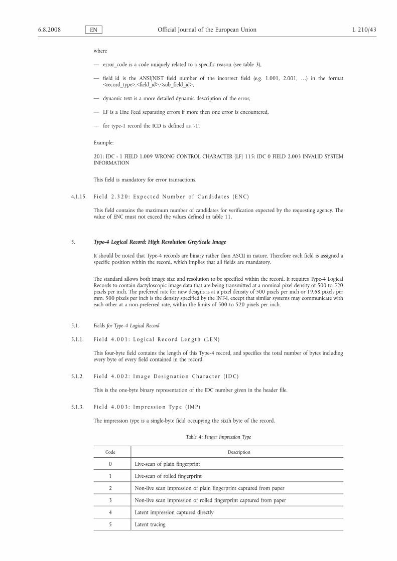
where
— error_code is a code uniquely related to a specific reason (see table 3),
— field_id is the ANSI/NIST field number of the incorrect field (e.g. 1.001, 2.001, …) in the format<record_type>.<field_id>.<sub_field_id>,
— dynamic text is a more detailed dynamic description of the error,
— LF is a Line Feed separating errors if more then one error is encountered,
— for type-1 record the ICD is defined as ‘-1’.
Example:
201: IDC - 1 FIELD 1.009 WRONG CONTROL CHARACTER {LF} 115: IDC 0 FIELD 2.003 INVALID SYSTEMINFORMATION
This field is mandatory for error transactions.
4.1.15. F i e l d 2 . 3 20 : E x p e c t e d Numb e r o f C a n d i d a t e s ( ENC )
This field contains the maximum number of candidates for verification expected by the requesting agency. Thevalue of ENC must not exceed the values defined in table 11.
5. Type-4 Logical Record: High Resolution GreyScale Image
It should be noted that Type-4 records are binary rather than ASCII in nature. Therefore each field is assigned aspecific position within the record, which implies that all fields are mandatory.
The standard allows both image size and resolution to be specified within the record. It requires Type-4 LogicalRecords to contain dactyloscopic image data that are being transmitted at a nominal pixel density of 500 to 520pixels per inch. The preferred rate for new designs is at a pixel density of 500 pixels per inch or 19,68 pixels permm. 500 pixels per inch is the density specified by the INT-I, except that similar systems may communicate witheach other at a non-preferred rate, within the limits of 500 to 520 pixels per inch.
5.1. Fields for Type-4 Logical Record
5.1.1. F i e l d 4 . 0 01 : L o g i c a l R e c o r d L e n g t h ( L EN )
This four-byte field contains the length of this Type-4 record, and specifies the total number of bytes includingevery byte of every field contained in the record.
5.1.2. F i e l d 4 . 0 02 : Im a g e D e s i g n a t i o n Ch a r a c t e r ( I DC )
This is the one-byte binary representation of the IDC number given in the header file.
5.1.3. F i e l d 4 . 0 03 : Imp r e s s i o n Ty p e ( IMP )
The impression type is a single-byte field occupying the sixth byte of the record.
Table 4: Finger Impression Type
Code Description
0 Live-scan of plain fingerprint
1 Live-scan of rolled fingerprint
2 Non-live scan impression of plain fingerprint captured from paper
3 Non-live scan impression of rolled fingerprint captured from paper
4 Latent impression captured directly
5 Latent tracing
6.8.2008 EN Official Journal of the European Union L 210/43

Code Description
6 Latent photo
7 Latent lift
8 Swipe
9 Unknown
5.1.4. F i e l d 4 . 0 04 : F i n g e r Po s i t i o n ( FG P )
This fixed-length field of 6 bytes occupies the seventh through twelfth byte positions of a Type-4 record. Itcontains possible finger positions beginning in the left most byte (byte 7 of the record). The known or mostprobable finger position is taken from table 5. Up to five additional fingers may be referenced by entering thealternate finger positions in the remaining five bytes using the same format. If fewer than five finger positionreferences are to be used the unused bytes are filled with binary 255. To reference all finger positions code 0, forunknown, is used.
Table 5: Finger position code and maximum size
Finger position Finger codeWidth(mm)
Length(mm)
Unknown 0 40,0 40,0
Right thumb 1 45,0 40,0
Right index finger 2 40,0 40,0
Right middle finger 3 40,0 40,0
Right ring finger 4 40,0 40,0
Right little finger 5 33,0 40,0
Left thumb 6 45,0 40,0
Left index finger 7 40,0 40,0
Left middle finger 8 40,0 40,0
Left ring finger 9 40,0 40,0
Left little finger 10 33,0 40,0
Plain right thumb 11 30,0 55,0
Plain left thumb 12 30,0 55,0
Plain right four fingers 13 70,0 65,0
Plain left four fingers 14 70,0 65,0
For scene of crime latents only the codes 0 to 10 should be used.
5.1.5. F i e l d 4 . 0 05 : Im a g e S c a n n i n g R e s o l u t i o n ( I S R )
This one-byte field occupies the 13th byte of a Type-4 record. If it contains ‘0’ then the image has been sampled atthe preferred scanning rate of 19,68 pixels/mm (500 pixels per inch). If it contains ‘1’ then the image has beensampled at an alternative scanning rate as specified in the Type-1 record.
5.1.6. F i e l d 4 . 0 06 : Ho r i z o n t a l L i n e L e n g t h (H L L )
This field is positioned at bytes 14 and 15 within the Type-4 record. It specifies the number of pixels contained ineach scan line. The first byte will be the most significant.
L 210/44 EN Official Journal of the European Union 6.8.2008

5.1.7. F i e l d 4 . 0 07 : Ve r t i c a l L i n e L e n g t h ( V L L )
This field records in bytes 16 and 17 the number of scan lines present in the image. The first byte is the mostsignificant.
5.1.8. F i e l d 4 . 0 08 : G r e y s c a l e C omp r e s s i o n A l g o r i t hm (GCA )
This one-byte field specifies the greyscale compression algorithm used to encode the image data. For thisimplementation, a binary code 1 indicates that WSQ compression (Appendix 7) has been used.
5.1.9. F i e l d 4 . 0 09 : T h e Im a g e
This field contains a byte stream representing the image. Its structure will obviously depend on the compressionalgorithm used.
6. Type-9 Logical Record: Minutiæ Record
Type-9 records shall contain ASCII text describing minutiæ and related information encoded from a latent. Forlatent search transaction, there is no limit for these Type-9 records in a file, each of which shall be for a differentview or latent.
6.1. Minutiæ extraction
6.1.1. M i n u t i a t y p e i d e n t i f i c a t i o n
This standard defines three identifier numbers that are used to describe the minutia type. These are listed in ta-ble 6. A ridge ending shall be designated Type 1. A bifurcation shall be designated Type 2. If a minutia cannot beclearly categorised as one of the above two types, it shall be designated as ‘other’, Type 0.
Table 6: Minutia types
Type Description
0 Other
1 Ridge ending
2 Bifurcation
6.1.2. M i n u t i a p l a c emen t a n d t y p e
For templates to be compliant with Section 5 of the ANSI INCITS 378-2004 standard, the following method,which enhances the current INCITS 378-2004 standard, shall be used for determining placement (location andangular direction) of individual minutiae.
The position or location of a minutia representing a ridge ending shall be the point of forking of the medialskeleton of the valley area immediately in front of the ridge ending. If the three legs of the valley area werethinned down to a single-pixel-wide skeleton, the point of the intersection is the location of the minutia. Similarly,the location of the minutia for a bifurcation shall be the point of forking of the medial skeleton of the ridge. If thethree legs of the ridge were each thinned down to a single-pixel-wide skeleton, the point where the three legsintersect is the location of the minutia.
After all ridge endings have been converted to bifurcations, all of the minutiae of the dactyloscopic image arerepresented as bifurcations. The X and Y pixel coordinates of the intersection of the three legs of each minutia canbe directly formatted. Determination of the minutia direction can be extracted from each skeleton bifurcation. Thethree legs of every skeleton bifurcation must be examined and the endpoint of each leg determined. Fig-ure 6.1.2 illustrates the three methods used for determining the end of a leg that is based on a scanning resolutionof 500 ppi.
The ending is established according to the event that occurs first. The pixel count is based on a scan resolution of500 ppi. Different scan resolutions would imply different pixel counts.
— a distance of 0,064" (the 32nd pixel),
— the end of skeleton leg that occurs between a distance of 0,02" and 0,064" (the 10th through the 32ndpixels); shorter legs are not used,
— a second bifurcation is encountered within a distance of 0,064" (before the 32nd pixel).
6.8.2008 EN Official Journal of the European Union L 210/45

Figure 6.1.2
The angle of the minutiae is determined by constructing three virtual rays originating at the bifurcation point andextending to the end of each leg. The smallest of the three angles formed by the rays is bisected to indicate theminutiae direction.
6.1.3. C o o r d i n a t e s y s t em
The coordinate system used to express the minutiae of a fingerprint shall be a Cartesian coordinate system.Minutiae locations shall be represented by their x and y coordinates. The origin of the coordinate system shall bethe upper left corner of the original image with x increasing to the right and y increasing downward. Both x and ycoordinates of a minutiae shall be represented in pixel units from the origin. It should be noted that the locationof the origin and units of measure is not in agreement with the convention used in the definitions of the Type 9 inthe ANSI/NIST-ITL 1-2000.
6.1.4. M i n u t i æ d i r e c t i o n
Angles are expressed in standard mathematical format, with zero degrees to the right and angles increasing in thecounter clockwise direction. Recorded angles are in the direction pointing back along the ridge for a ridge endingand toward the centre of the valley for a bifurcation. This convention is 180 degrees opposite of the angleconvention described in the definitions of the Type 9 in the ANSI/NIST-ITL 1-2000.
6.2. Fields for Type-9 Logical record INCITS-378 Format
All fields of the Type-9 records shall be recorded as ASCII text. No binary fields are permissible in this tagged-fieldrecord.
6.2.1. F i e l d 9 . 0 01 : L o g i c a l r e c o r d l e n g t h ( L EN )
This mandatory ASCII field shall contain the length of the logical record specifying the total number of bytes,including every character of every field contained in the record.
6.2.2. F i e l d 9 . 0 02 : Im a g e d e s i g n a t i o n c h a r a c t e r ( I DC )
This mandatory two-byte field shall be used for the identification and location of the minutiæ data. The IDCcontained in this field shall match the IDC found in the file content field of the Type-1 record.
6.2.3. F i e l d 9 . 0 03 : Imp r e s s i o n t y p e ( IMP )
This mandatory one-byte field shall describe the manner by which the dactyloscopic image information wasobtained. The ASCII value of the proper code as selected from table 4 shall be entered in this field to signify theimpression type.
6.2.4. F i e l d 9 . 0 04 : M i n u t i æ fo rma t ( FMT )
This field shall contain a ‘U’ to indicate that the minutiae are formatted in M1-378 terms. Even thoughinformation may be encoded in accordance with the M1-378 standard, all data fields of the Type-9 record mustremain as ASCII text fields.
6.2.5. F i e l d 9 . 1 26 : CB E F F i n fo rma t i o n
This field shall contain three information items. The first information item shall contain the value ‘27’ (0x1B). Thisis the identification of the CBEFF Format Owner assigned by the International Biometric Industry Association(IBIA) to INCITS Technical Committee M1. The <US> character shall delimit this item from the CBEFF FormatType that is assigned a value of ‘513’ (0x0201) to indicate that this record contains only location and angular
L 210/46 EN Official Journal of the European Union 6.8.2008

direction data without any Extended Data Block information. The <US> character shall delimit this item from theCBEFF Product Identifier (PID) that identifies the ‘owner’ of the encoding equipment. The vendor establishes thisvalue. It can be obtained from the IBIA website (www.ibia.org) if it is posted.
6.2.6. F i e l d 9 . 1 27 : C a p t u r e e q u i pmen t i d e n t i f i c a t i o n
This field shall contain two information items separated by the <US> character. The first shall contain ‘APPF’ if theequipment used originally to acquire the image was certified to comply with Appendix F (IAFIS Image QualitySpecification, 29 January 1999) of CJIS-RS-0010, the Federal Bureau of Investigation's Electronic FingerprintTransmission Specification. If the equipment did not comply it will contain the value of ‘NONE’. The secondinformation item shall contain the Capture Equipment ID which is a vendor-assigned product number of thecapture equipment. A value of ‘0’ indicates that the capture equipment ID is unreported.
6.2.7. F i e l d 9 . 1 28 : Ho r i z o n t a l l i n e l e n g t h (H L L )
This mandatory ASCII field shall contain the number of pixels contained on a single horizontal line of thetransmitted image. The maximum horizontal size is limited to 65 534 pixels.
6.2.8. F i e l d 9 . 1 29 : Ve r t i c a l l i n e l e n g t h ( V L L )
This mandatory ASCII field shall contain the number of horizontal lines contained in the transmitted image. Themaximum vertical size is limited to 65 534 pixels.
6.2.9. F i e l d 9 . 1 30 : S c a l e u n i t s ( S LC )
This mandatory ASCII field shall specify the units used to describe the image sampling frequency (pixel density). A‘1’ in this field indicates pixels per inch, or a ‘2’ indicates pixels per centimetre. A ‘0’ in this field indicates no scaleis given. For this case, the quotient of HPS/VPS gives the pixel aspect ratio.
6.2.10. F i e l d 9 . 1 31 : Ho r i z o n t a l p i x e l s c a l e ( H P S )
This mandatory ASCII field shall specify the integer pixel density used in the horizontal direction providing theSLC contains a ‘1’ or a ‘2’. Otherwise, it indicates the horizontal component of the pixel aspect ratio.
6.2.11. F i e l d 9 . 1 32 : Ve r t i c a l p i x e l s c a l e ( V P S )
This mandatory ASCII field shall specify the integer pixel density used in the vertical direction providing the SLCcontains a ‘1’ or a ‘2’. Otherwise, it indicates the vertical component of the pixel aspect ratio.
6.2.12. F i e l d 9 . 1 33 : F i n g e r v i ew
This mandatory field contains the view number of the finger associated with this record's data. The view numberbegins with ‘0’ and increments by one to ‘15’.
6.2.13. F i e l d 9 . 1 34 : F i n g e r p o s i t i o n ( FG P )
This field shall contain the code designating the finger position that produced the information in this Type-9record. A code between 1 and 10 taken from table 5 or the appropriate palm code from table 10 shall be used toindicate the finger or palm position.
6.2.14. F i e l d 9 . 1 35 : F i n g e r q u a l i t y
The field shall contain the quality of the overall finger minutiæ data and shall be between 0 and 100. This numberis an overall expression of the quality of the finger record, and represents quality of the original image, of theminutia extraction and any additional operations that may affect the minutiæ record.
6.2.15. F i e l d 9 . 1 36 : n umb e r o f m i n u t i æ
The mandatory field shall contain a count of the number of minutiæ recorded in this logical record.
6.8.2008 EN Official Journal of the European Union L 210/47

6.2.16. F i e l d 9 . 1 37 : F i n g e r m i n u t i æ d a t a
This mandatory field has six information items separated by the <US> character. It consists of several subfields,each containing the details of single minutiae. The total number of minutiae subfields must agree with the countfound in field 136. The first information item is the minutiae index number, which shall be initialised to ‘1’ andincremented by ‘1’ for each additional minutia in the fingerprint. The second and third information items are the‘x’ coordinate and ‘y’ coordinates of the minutiae in pixel units. The fourth information item is the minutiae anglerecorded in units of two degrees. This value shall be nonnegative between 0 and 179. The fifth information itemis the minutiae type. A value of ‘0’ is used to represent minutiae of type ‘OTHER’, a value of ‘1’ for a ridge endingand a value of ‘2’ for a ridge bifurcation. The sixth information item represents the quality of each minutiae. Thisvalue shall range from 1 as a minimum to 100 as a maximum. A value of ‘0’ indicates that no quality value isavailable. Each subfield shall be separated from the next with the use of the <RS> separator character.
6.2.17. F i e l d 9 . 1 38 : R i d g e c o un t i n fo rma t i o n
This field consists of a series of subfields each containing three information items. The first information item ofthe first subfield shall indicate the ridge count extraction method. A ‘0’ indicates that no assumption shall be madeabout the method used to extract ridge counts, nor their order in the record. A ‘1’ indicates that for each centreminutiae, ridge count data was extracted to the nearest neighbouring minutiae in four quadrants, and ridge countsfor each centre minutia are listed together. A ‘2’ indicates that for each centre minutiae, ridge count data wasextracted to the nearest neighbouring minutiae in eight octants, and ridge counts for each centre minutia are listedtogether. The remaining two information items of the first subfield shall both contain ‘0’. Information items shallbe separated by the <US> separator character. Subsequent subfields will contain the centre minutiae index numberas the first information item, the neighbouring minutiae index number as the second information item, and thenumber of ridges crossed as the third information item. Subfields shall be separated by the <RS> separatorcharacter.
6.2.18. F i e l d 9 . 1 39 : C o r e i n fo rma t i o n
This field will consist of one subfield for each core present in the original image. Each subfield consists of threeinformation items. The first two items contain the ‘x’ and ‘y’ coordinate positions in pixel units. The thirdinformation item contains the angle of the core recorded in units of 2 degrees. The value shall be a nonnegativevalue between 0 and 179. Multiple cores will be separated by the <RS> separator character.
6.2.19. F i e l d 9 . 1 40 : D e l t a i n f o rma t i o n
This field will consist of one subfield for each delta present in the original image. Each subfield consists of threeinformation items. The first two items contain the ‘x’ and ‘y’ coordinate positions in pixel units. The thirdinformation item contains the angle of the delta recorded in units of 2 degrees. The value shall be a nonnegativevalue between 0 and 179. Multiple cores will be separated by the <RS> separator character.
7. Type-13 variable-resolution latent image record
The Type-13 tagged-field logical record shall contain image data acquired from latent images. These images areintended to be transmitted to agencies that will automatically extract or provide human intervention andprocessing to extract the desired feature information from the images.
Information regarding the scanning resolution used, the image size, and other parameters required to process theimage, are recorded as tagged-fields within the record.
Table 7: Type-13 variable-resolution latent record layout
Ident Cond.code
FieldNumber Field name Char
type
Field size peroccurrence Occur count Max byte
countmin. max. min max
LEN M 13.001 LOGICAL RECORDLENGTH N 4 8 1 1 15
IDC M 13.002 IMAGE DESIGNATIONCHARACTER N 2 5 1 1 12
IMP M 13.003 IMPRESSION TYPE A 2 2 1 1 9
SRC M 13.004 SOURCE AGENCY/ORI AN 6 35 1 1 42
LCD M 13.005 LATENT CAPTURE DATE N 9 9 1 1 16
L 210/48 EN Official Journal of the European Union 6.8.2008

Ident Cond.code
FieldNumber Field name Char
type
Field size peroccurrence Occur count Max byte
countmin. max. min max
HLL M 13.006 HORIZONTAL LINELENGTH N 4 5 1 1 12
VLL M 13.007 VERTICAL LINE LENGTH N 4 5 1 1 12
SLC M 13.008 SCALE UNITS N 2 2 1 1 9
HPS M 13.009 HORIZONTAL PIXELSCALE N 2 5 1 1 12
VPS M 13.010 VERTICAL PIXEL SCALE N 2 5 1 1 12
CGA M 13.011 COMPRESSION ALGO-RITHM A 5 7 1 1 14
BPX M 13.012 BITS PER PIXEL N 2 3 1 1 10
FGP M 13.013 FINGER POSITION N 2 3 1 6 25
RSV13.01413.019
RESERVED FOR FUTUREDEFINITION — — — — — —
COM O 13.020 COMMENT A 2 128 0 1 135
RSV13.02113.199
RESERVED FOR FUTUREDEFINITION — — — — — —
UDF O13.20013.998
USER-DEFINED FIELDS — — — — — —
DAT M 13.999 IMAGE DATA B 2 — 1 1 —
Key for character type: N = Numeric; A = Alphabetic; AN = Alphanumeric; B = Binary
7.1. Fields for the Type-13 logical record
The following paragraphs describe the data contained in each of the fields for the Type-13 logical record.
Within a Type-13 logical record, entries shall be provided in numbered fields. It is required that the first two fieldsof the record are ordered, and the field containing the image data shall be the last physical field in the record. Foreach field of the Type-13 record, table 7 lists the ‘condition code’ as being mandatory ‘M’ or optional ‘O’, the fieldnumber, the field name, character type, field size, and occurrence limits. Based on a three digit field number, themaximum byte count size for the field is given in the last column. As more digits are used for the field number,the maximum byte count will also increase. The two entries in the ‘field size per occurrence’ include all characterseparators used in the field. The ‘maximum byte count’ includes the field number, the information, and all thecharacter separators including the ‘GS’ character.
7.1.1. F i e l d 1 3 . 0 01 : L o g i c a l r e c o r d l e n g t h ( L EN )
This mandatory ASCII field shall contain the total count of the number of bytes in the Type-13 logical record.Field 13.001 shall specify the length of the record including every character of every field contained in the recordand the information separators.
7.1.2. F i e l d 1 3 . 0 02 : Im a g e d e s i g n a t i o n c h a r a c t e r ( I DC )
This mandatory ASCII field shall be used to identify the latent image data contained in the record. This IDC shallmatch the IDC found in the file content (CNT) field of the Type-1 record.
7.1.3. F i e l d 1 3 . 0 03 : Imp r e s s i o n t y p e ( IMP )
This mandatory one- or two-byte ASCII field shall indicate the manner by which the latent image information wasobtained. The appropriate latent code choice selected from table 4 (finger) or table 9 (palm) shall be entered in thisfield.
6.8.2008 EN Official Journal of the European Union L 210/49

7.1.4. F i e l d 1 3 . 0 04 : S o u r c e a g e n c y /OR I ( S RC )
This mandatory ASCII field shall contain the identification of the administration or organisation that originallycaptured the facial image contained in the record. Normally, the Originating Agency Identifier (ORI) of the agencythat captured the image will be contained in this field. It consists of two information items in the followingformat: CC/agency.
The first information item contains the Interpol Country Code, two alpha-numeric characters long. The seconditem, agency, is a free text identification of the agency, up to a maximum of 32 alpha-numeric characters.
7.1.5. F i e l d 1 3 . 0 05 : L a t e n t c a p t u r e d a t e ( L CD )
This mandatory ASCII field shall contain the date that the latent image contained in the record was captured. Thedate shall appear as eight digits in the format CCYYMMDD. The CCYY characters shall represent the year theimage was captured; the MM characters shall be the tens and unit values of the month; and the DD characters shallbe the tens and unit values of the day in the month. For example, 20000229 represents 29 February 2000. Thecomplete date must be a legitimate date.
7.1.6. F i e l d 1 3 . 0 06 : Ho r i z o n t a l l i n e l e n g t h (H L L )
This mandatory ASCII field shall contain the number of pixels contained on a single horizontal line of thetransmitted image.
7.1.7. F i e l d 1 3 . 0 07 : Ve r t i c a l l i n e l e n g t h ( V L L )
This mandatory ASCII field shall contain the number of horizontal lines contained in the transmitted image.
7.1.8. F i e l d 1 3 . 0 08 : S c a l e u n i t s ( S LC )
This mandatory ASCII field shall specify the units used to describe the image sampling frequency (pixel density). A‘1’ in this field indicates pixels per inch, or a ‘2’ indicates pixels per centimetre. A ‘0’ in this field indicates no scaleis given. For this case, the quotient of HPS/VPS gives the pixel aspect ratio.
7.1.9. F i e l d 1 3 . 0 09 : Ho r i z o n t a l p i x e l s c a l e ( H P S )
This mandatory ASCII field shall specify the integer pixel density used in the horizontal direction providing theSLC contains a ‘1’ or a ‘2’. Otherwise, it indicates the horizontal component of the pixel aspect ratio.
7.1.10. F i e l d 1 3 . 0 10 : Ve r t i c a l p i x e l s c a l e ( V P S )
This mandatory ASCII field shall specify the integer pixel density used in the vertical direction providing the SLCcontains a ‘1’ or a ‘2’. Otherwise, it indicates the vertical component of the pixel aspect ratio.
7.1.11. F i e l d 1 3 . 0 11 : C omp r e s s i o n a l g o r i t hm (CGA )
This mandatory ASCII field shall specify the algorithm used to compress greyscale images. See Appendix 7 for thecompression codes.
7.1.12. F i e l d 1 3 . 0 12 : B i t s p e r p i x e l ( B PX )
This mandatory ASCII field shall contain the number of bits used to represent a pixel. This field shall contain anentry of ‘8’ for normal greyscale values of ‘0’ to ‘255’. Any entry in this field greater than ‘8’ shall represent agreyscale pixel with increased precision.
7.1.13. F i e l d 1 3 . 0 13 : F i n g e r / p a lm po s i t i o n ( FG P )
This mandatory tagged-field shall contain one or more the possible finger or palm positions that may match thelatent image. The decimal code number corresponding to the known or most probable finger position shall betaken from table 5 or the most probable palm position from table 10 and entered as a one- or two-characterASCII subfield. Additional finger and/or palm positions may be referenced by entering the alternate position codesas subfields separated by the ‘RS’ separator character. The code ‘0’, for ‘Unknown Finger’, shall be used to referenceevery finger position from one through ten. The code ‘20’, for ‘Unknown Palm’, shall be used to reference everylisted palmprint position.
7.1.14. F i e l d 1 3 . 0 14 - 0 19 : R e s e r v e d fo r f u t u r e d e f i n i t i o n ( R SV )
These fields are reserved for inclusion in future revisions of this standard. None of these fields are to be used atthis revision level. If any of these fields are present, they are to be ignored.
L 210/50 EN Official Journal of the European Union 6.8.2008

7.1.15. F i e l d 1 3 . 0 20 : C ommen t ( COM )
This optional field may be used to insert comments or other ASCII text information with the latent image data.
7.1.16. F i e l d 1 3 . 0 21 - 1 99 : R e s e r v e d fo r f u t u r e d e f i n i t i o n ( R SV )
These fields are reserved for inclusion in future revisions of this standard. None of these fields are to be used atthis revision level. If any of these fields are present, they are to be ignored.
7.1.17. F i e l d s 1 3 . 2 00 - 9 98 : U s e r - d e f i n e d f i e l d s ( UDF )
These fields are user-definable fields and will be used for future requirements. Their size and content shall bedefined by the user and be in accordance with the receiving agency. If present they shall contain ASCII textualinformation.
7.1.18. F i e l d 1 3 . 9 99 : Im a g e d a t a (DAT )
This field shall contain all data from a captured latent image. It shall always be assigned field number 999 andmust be the last physical field in the record. For example, ‘13.999:’ is followed by image data in a binaryrepresentation.
Each pixel of uncompressed greyscale data shall normally be quantised to eight bits (256 grey levels) contained ina single byte. If the entry in BPX Field 13.012 is greater or less than ‘8’, the number of bytes required to contain apixel will be different. If compression is used, the pixel data shall be compressed in accordance with thecompression technique specified in the GCA field.
7.2. End of Type-13 variable-resolution latent image record
For the sake of consistency, immediately following the last byte of data from Field 13.999 an ‘FS’ separator shallbe used to separate it from the next logical record. This separator must be included in the length field of the Type-13 record.
8. Type-15 variable-resolution palmprint image record
The Type-15 tagged-field logical record shall contain and be used to exchange palmprint image data together withfixed and user-defined textual information fields pertinent to the digitised image. Information regarding thescanning resolution used, the image size and other parameters or comments required to process the image arerecorded as tagged-fields within the record. Palmprint images transmitted to other agencies will be processed bythe recipient agencies to extract the desired feature information required for matching purposes.
The image data shall be acquired directly from a subject using a live-scan device, or from a palmprint card or othermedia that contains the subject's palmprints.
Any method used to acquire the palmprint images shall be capable of capturing a set of images for each hand.This set shall include the writer's palm as a single scanned image, and the entire area of the full palm extendingfrom the wrist bracelet to the tips of the fingers as one or two scanned images. If two images are used to representthe full palm, the lower image shall extend from the wrist bracelet to the top of the interdigital area (third fingerjoint) and shall include the thenar, and hypothenar areas of the palm. The upper image shall extend from thebottom of the interdigital area to the upper tips of the fingers. This provides an adequate amount of overlapbetween the two images that are both located over the interdigital area of the palm. By matching the ridgestructure and details contained in this common area, an examiner can confidently state that both images camefrom the same palm.
As a palmprint transaction may be used for different purposes, it may contain one or more unique image areasrecorded from the palm or hand. A complete palmprint record set for one individual will normally include thewriter's palm and the full palm image(s) from each hand. Since a tagged-field logical image record may containonly one binary field, a single Type-15 record will be required for each writer's palm and one or two Type-15records for each full palm. Therefore, four to six Type-15 records will be required to represent the subject'spalmprints in a normal palmprint transaction.
8.1. Fields for the Type-15 logical record
The following paragraphs describe the data contained in each of the fields for the Type-15 logical record.
6.8.2008 EN Official Journal of the European Union L 210/51

Within a Type-15 logical record, entries shall be provided in numbered fields. It is required that the first two fieldsof the record are ordered, and the field containing the image data shall be the last physical field in the record. Foreach field of the Type-15 record, table 8 lists the ‘condition code’ as being mandatory ‘M’ or optional ‘O’, the fieldnumber, the field name, character type, field size, and occurrence limits. Based on a three digit field number, themaximum byte count size for the field is given in the last column. As more digits are used for the field number,the maximum byte count will also increase. The two entries in the ‘field size per occurrence’ include all characterseparators used in the field. The ‘maximum byte count’ includes the field number, the information, and all thecharacter separators including the ‘GS’ character.
8.1.1. F i e l d 1 5 . 0 01 : L o g i c a l r e c o r d l e n g t h ( L EN )
This mandatory ASCII field shall contain the total count of the number of bytes in the Type-15 logical record.Field 15.001 shall specify the length of the record including every character of every field contained in the recordand the information separators.
8.1.2. F i e l d 1 5 . 0 02 : Im a g e d e s i g n a t i o n c h a r a c t e r ( I DC )
This mandatory ASCII field shall be used to identify the palmprint image contained in the record. This IDC shallmatch the IDC found in the file content (CNT) field of the Type-1 record.
8.1.3. F i e l d 1 5 . 0 03 : Imp r e s s i o n t y p e ( IMP )
This mandatory one-byte ASCII field shall indicate the manner by which the palmprint image information wasobtained. The appropriate code selected from table 9 shall be entered in this field.
8.1.4. F i e l d 1 5 . 0 04 : S o u r c e a g e n c y /OR I ( S RC )
This mandatory ASCII field shall contain the identification of the administration or organisation that originallycaptured the facial image contained in the record. Normally, the Originating Agency Identifier (ORI) of the agencythat captured the image will be contained in this field. It consists of two information items in the followingformat: CC/agency.
The first information item contains the Interpol Country Code, two alpha-numeric characters long. The seconditem, agency, is a free text identification of the agency, up to a maximum of 32 alpha-numeric characters.
8.1.5. F i e l d 1 5 . 0 05 : P a lmp r i n t c a p t u r e d a t e ( P CD )
This mandatory ASCII field shall contain the date that the palmprint image was captured. The date shall appear aseight digits in the format CCYYMMDD. The CCYY characters shall represent the year the image was captured; theMM characters shall be the tens and unit values of the month; and the DD characters shall be the tens and unitsvalues of the day in the month. For example, the entry 20000229 represents 29 February 2000. The completedate must be a legitimate date.
8.1.6. F i e l d 1 5 . 0 06 : Ho r i z o n t a l l i n e l e n g t h (H L L )
This mandatory ASCII field shall contain the number of pixels contained on a single horizontal line of thetransmitted image.
8.1.7. F i e l d 1 5 . 0 07 : Ve r t i c a l l i n e l e n g t h ( V L L )
This mandatory ASCII field shall contain the number of horizontal lines contained in the transmitted image.
8.1.8. F i e l d 1 5 . 0 08 : S c a l e u n i t s ( S LC )
This mandatory ASCII field shall specify the units used to describe the image sampling frequency (pixel density). A‘1’ in this field indicates pixels per inch, or a ‘2’ indicates pixels per centimetre. A ‘0’ in this field indicates no scaleis given. For this case, the quotient of HPS/VPS gives the pixel aspect ratio.
8.1.9. F i e l d 1 5 . 0 09 : Ho r i z o n t a l p i x e l s c a l e ( H P S )
This mandatory ASCII field shall specify the integer pixel density used in the horizontal direction providing theSLC contains a ‘1’ or a ‘2’. Other-wise, it indicates the horizontal component of the pixel aspect ratio.
8.1.10. F i e l d 1 5 . 0 10 : Ve r t i c a l p i x e l s c a l e ( V P S )
This mandatory ASCII field shall specify the integer pixel density used in the vertical direction providing the SLCcontains a ‘1’ or a ‘2’. Otherwise, it indicates the vertical component of the pixel aspect ratio.
L 210/52 EN Official Journal of the European Union 6.8.2008

Table 8: Type-15 variable-resolution palmprint record layout
Ident Cond.code
Field num-ber Field name Char
type
Field size peroccurrence Occur count
Max bytecount
min. max. min max
LEN M 15.001 LOGICAL RECORDLENGTH N 4 8 1 1 15
IDC M 15.002 IMAGE DESIGNATIONCHARACTER N 2 5 1 1 12
IMP M 15.003 IMPRESSION TYPE N 2 2 1 1 9
SRC M 15.004 SOURCE AGENCY/ORI AN 6 35 1 1 42
PCD M 15.005 PALMPRINT CAPTUREDATE N 9 9 1 1 16
HLL M 15.006 HORIZONTAL LINELENGTH N 4 5 1 1 12
VLL M 15.007 VERTICAL LINE LENGTH N 4 5 1 1 12
SLC M 15.008 SCALE UNITS N 2 2 1 1 9
HPS M 15.009 HORIZONTAL PIXELSCALE N 2 5 1 1 12
VPS M 15.010 VERTICAL PIXEL SCALE N 2 5 1 1 12
CGA M 15.011 COMPRESSION ALGO-RITHM AN 5 7 1 1 14
BPX M 15.012 BITS PER PIXEL N 2 3 1 1 10
PLP M 15.013 PALMPRINT POSITION N 2 3 1 1 10
RSV15.01415.019
RESERVED FOR FUTUREINCLUSION — — — — — —
COM O 15.020 COMMENT AN 2 128 0 1 128
RSV15.02115.199
RESERVED FOR FUTUREINCLUSION — — — — — —
UDF O15.20015.998
USER-DEFINED FIELDS — — — — — —
DAT M 15.999 IMAGE DATA B 2 — 1 1 —
Table 9: Palm Impression Type
Description Code
Live-scan palm 10
Nonlive-scan palm 11
Latent palm impression 12
Latent palm tracing 13
Latent palm photo 14
Latent palm lift 15
8.1.11. F i e l d 1 5 . 0 11 : C omp r e s s i o n a l g o r i t hm (CGA )
This mandatory ASCII field shall specify the algorithm used to compress greyscale images. An entry of ‘NONE’ inthis field indicates that the data contained in this record are uncompressed. For those images that are to becompressed, this field shall contain the preferred method for the compression of tenprint fingerprint images. Validcompression codes are defined in Appendix 7.
6.8.2008 EN Official Journal of the European Union L 210/53

8.1.12. F i e l d 1 5 . 0 12 : B i t s p e r p i x e l ( B PX )
This mandatory ASCII field shall contain the number of bits used to represent a pixel. This field shall contain anentry of ‘8’ for normal greyscale values of ‘0’ to ‘255’. Any entry in this field greater than or less than ‘8’ shallrepresent a greyscale pixel with increased or decreased precision respectively.
Table 10: Palm Codes, Areas and Sizes
Palm Position Palm code Image area(mm2) Width (mm) Height (mm)
Unknown Palm 20 28 387 139,7 203,2
Right Full Palm 21 28 387 139,7 203,2
Right Writer s Palm 22 5 645 44,5 127,0
Left Full Palm 23 28 387 139,7 203,2
Left Writer s Palm 24 5 645 44,5 127,0
Right Lower Palm 25 19 516 139,7 139,7
Right Upper Palm 26 19 516 139,7 139,7
Left Lower Palm 27 19 516 139,7 139,7
Left Upper Palm 28 19 516 139,7 139,7
Right Other 29 28 387 139,7 203,2
Left Other 30 28 387 139,7 203,2
8.1.13. F i e l d 1 5 . 0 13 : P a lmp r i n t p o s i t i o n ( P L P )
This mandatory tagged-field shall contain the palmprint position that matches the palmprint image. The decimalcode number corresponding to the known or most probable palmprint position shall be taken from table 10 andentered as a two-character ASCII subfield. Table 10 also lists the maximum image areas and dimensions for eachof the possible palmprint positions.
8.1.14. F i e l d 1 5 . 0 14 - 0 19 : R e s e r v e d fo r f u t u r e d e f i n i t i o n ( R SV )
These fields are reserved for inclusion in future revisions of this standard. None of these fields are to be used atthis revision level. If any of these fields are present, they are to be ignored.
8.1.15. F i e l d 1 5 . 0 20 : C ommen t ( COM )
This optional field may be used to insert comments or other ASCII text information with the palmprint imagedata.
8.1.16. F i e l d 1 5 . 0 21 - 1 99 : R e s e r v e d fo r f u t u r e d e f i n i t i o n ( R SV )
These fields are reserved for inclusion in future revisions of this standard. None of these fields are to be used atthis revision level. If any of these fields are present, they are to be ignored.
8.1.17. F i e l d s 1 5 . 2 00 - 9 98 : U s e r - d e f i n e d f i e l d s ( UDF )
These fields are user-definable fields and will be used for future requirements. Their size and content shall bedefined by the user and be in accordance with the receiving agency. If present they shall contain ASCII textualinformation.
8.1.18. F i e l d 1 5 . 9 99 : Im a g e d a t a (DAT )
This field shall contain all of the data from a captured palmprint image. It shall always be assigned field number999 and must be the last physical field in the record. For example, ‘15.999:’ is followed by image data in a binaryrepresentation. Each pixel of uncompressed greyscale data shall normally be quantised to eight bits (256 greylevels) contained in a single byte. If the entry in BPX Field 15.012 is greater or less than 8, the number of bytesrequired to contain a pixel will be different. If compression is used, the pixel data shall be compressed inaccordance with the compression technique specified in the CGA field.
L 210/54 EN Official Journal of the European Union 6.8.2008

8.2. End of Type-15 variable-resolution palmprint image record
For the sake of consistency, immediately following the last byte of data from Field 15.999 an ‘FS’ separator shallbe used to separate it from the next logical record. This separator must be included in the length field of the Type-15 record.
8.3. Additional Type-15 variable-resolution palmprint image records
Additional Type-15 records may be included in the file. For each additional palmprint image, a complete Type-15logical record together with the ‘FS’ separator is required.
Table 11: Maximum numbers of candidates accepted for verification per transmission
Type of AFISSearch TP/TP LT/TP LP/PP TP/UL LT/UL PP/ULP LP/ULP
MaximumNumber ofCandidates
1 10 5 5 5 5 5
Search types:
TP/TP: ten-print against ten-print
LT/TP: fingerprint latent against ten-print
LP/PP: palmprint latent against palmprint
TP/UL: ten-print against unsolved fingerprint latent
LT/UL: fingerprint latent against unsolved fingerprint latent
PP/ULP: palmprint against unsolved palmprint latent
LP/ULP: palmprint latent against unsolved palmprint latent
9. Appendices to Chapter 2 (exchange of dactyloscopic data)
9.1. Appendix 1 ASCII Separator Codes
ASCII Position (1) Description
LF 1/10 Separates error codes in Field 2.074
FS 1/12 Separates logical records of a file
GS 1/13 Separates fields of a logical record
RS 1/14 Separates the subfields of a record field
US 1/15 Separates individual information items of the field orsubfield
(1) This is the position as defined in the ASCII standard.
9.2. Appendix 2 Calculation of Alpha-Numeric Check Character
For TCN and TCR (Fields 1.09 and 1.10):
The number corresponding to the check character is generated using the following formula:
(YY * 108 + SSSSSSSS) Modulo 23
Where YY and SSSSSSSS are the numerical values of the last two digits of the year and the serial numberrespectively.
The check character is then generated from the look-up table given below.
6.8.2008 EN Official Journal of the European Union L 210/55

For CRO (Field 2.010)
The number corresponding to the check character is generated using the following formula:
(YY * 106 + NNNNNN) Modulo 23
Where YY and NNNNNN are the numerical values of the last two digits of the year and the serial numberrespectively.
The check character is then generated from the look-up table given below.
Check Character Look-up Table
1-A 9-J 17-T
2-B 10-K 18-U
3-C 11-L 19-V
4-D 12-M 20-W
5-E 13-N 21-X
6-F 14-P 22-Y
7-G 15-Q 0-Z
8-H 16-R
9.3. Appendix 3 Character Codes
7-bit ANSI code for information interchange
ASCII Character Set
+ 0 1 2 3 4 5 6 7 8 9
30 ! ’ # $ % & ‘
40 ( ) * + , - . / 0 1
50 2 3 4 5 6 7 8 9 : ;
60 < = > ? @ A B C D E
70 F G H I J K L M N O
80 P Q R S T U V W X Y
90 Z [ \ ] ^ _ ` a b c
100 d e f g h i j k l m
110 n o p q r s t u v w
120 x y z { | } ~
9.4. Appendix 4 Transaction Summary
Type 1 Record (mandatory)
Identifier Fieldnumber Field name CPS/PMS SRE ERR
LEN 1.001 Logical Record Length M M M
VER 1.002 Version Number M M M
CNT 1.003 File Content M M M
L 210/56 EN Official Journal of the European Union 6.8.2008

Identifier Fieldnumber Field name CPS/PMS SRE ERR
TOT 1.004 Type of Transaction M M M
DAT 1.005 Date M M M
PRY 1.006 Priority M M M
DAI 1.007 Destination Agency M M M
ORI 1.008 Originating Agency M M M
TCN 1.009 Transaction Control Number M M M
TCR 1.010 Transaction Control Reference C M M
NSR 1.011 Native Scanning Resolution M M M
NTR 1.012 Nominal Transmitting Resolution M M M
DOM 1.013 Domain name M M M
GMT 1.014 Greenwich mean time M M M
Under the Condition Column:
O = Optional; M = Mandatory; C = Conditional if transaction is a response to the origin agency
Type 2 Record (mandatory)
Identifier Fieldnumber Field name CPS/
PMSMPS/MMS SRE ERR
LEN 2.001 Logical Record Length M M M M
IDC 2.002 Image Designation Character M M M M
SYS 2.003 System Information M M M M
CNO 2.007 Case Number — M C —
SQN 2.008 Sequence Number — C C —
MID 2.009 Latent Identifier — C C —
CRN 2.010 Criminal Reference Number M — C —
MN1 2.012 Miscellaneous Identification Number — — C C
MN2 2.013 Miscellaneous Identification Number — — C C
MN3 2.014 Miscellaneous Identification Number — — C C
MN4 2.015 Miscellaneous Identification Number — — C C
INF 2.063 Additional Information O O O O
RLS 2.064 Respondents List — — M —
ERM 2.074 Status/Error Message Field — — — M
ENC 2.320 Expected Number of Candidates M M — —
Under the Condition Column:
O = Optional; M = Mandatory; C = Conditional if data is available
* = if the transmission of the data is in accordance with national law (not covered by the Council Decision2008/615/JHA)
6.8.2008 EN Official Journal of the European Union L 210/57

9.5. Appendix 5 Type-1 Record Definitions
Identifier Condition Fieldnumber Field name Character
type Example data
LEN M 1.001 Logical RecordLength N 1.001:230{GS}
VER M 1.002 Version Number N 1.002:0300{GS}
CNT M 1.003 File Content N
1.003:1{US}15{RS}2{US}00{RS}4{US}01{RS}4{US}02{RS}4{US}03{RS}4{US}04{RS}4{US}05{RS}4{US}06{RS}4{US}07{RS}4{US}08{RS}4{US}09{RS}4{US}10{RS}4{US}11{RS}4{US}12{RS}4{US}13{RS}4{US}14{GS}
TOT M 1.004 Type of Transaction A 1.004:CPS{GS}
DAT M 1.005 Date N 1.005:20050101{GS}
PRY M 1.006 Priority N 1.006:4{GS}
DAI M 1.007 Destination Agency 1* 1.007:DE/BKA{GS}
ORI M 1.008 Originating Agency 1* 1.008:NL/NAFIS{GS}
TCN M 1.009 Transaction ControlNumber AN 1.009:0200000004F{GS}
TCR C 1.010 Transaction ControlReference AN 1.010:0200000004F{GS}
NSR M 1.011 Native ScanningResolution AN 1.011:19.68{GS}
NTR M 1.012 Nominal Transmit-ting Resolution AN 1.012:19,68{GS}
DOM M 1.013 Domain Name AN 1.013: INT-I{US}4,22{GS}
GMT M 1.014 Greenwich MeanTime AN 1.014:20050101125959Z
Under the Condition Column: O = Optional, M = Mandatory, C = Conditional
Under the Character Type Column: A = Alpha, N = Numeric, B = Binary
1* allowed characters for agency name are [‘0..9’, ‘A..Z’, ‘a..z’, ‘_’, ‘.’, ‘ ’, ‘-’]
9.6. Appendix 6 Type-2 Record Definitions
Table A.6.1: CPS- and PMS-Transaction
Identifier Condition Fieldnumber Field name Character
type Example data
LEN M 2.001 Logical RecordLength N 2.001:909{GS}
IDC M 2.002 Image DesignationCharacter N 2.002:00{GS}
SYS M 2.003 System Information N 2.003:0422{GS}
CRN M 2.010 Criminal ReferenceNumber AN 2.010:DE/E999999999{GS}
L 210/58 EN Official Journal of the European Union 6.8.2008

Identifier Condition Fieldnumber Field name Character
type Example data
INF O 2.063 Additional Informa-tion 1* 2.063:Additional Information 123
{GS}
ENC M 2.320 Expected Number ofCandidates N 2.320:1{GS}
Table A.6.2: SRE-Transaction
Identifier Condition Fieldnumber Field name Character
type Example data
LEN M 2.001 Logical RecordLength N 2.001:909{GS}
IDC M 2.002 Image DesignationCharacter N 2.002:00{GS}
SYS M 2.003 System Information N 2.003:0422{GS}
CRN C 2.010 Criminal ReferenceNumber AN 2.010:NL/2222222222{GS}
MN1 C 2.012 Miscellaneous Identi-fication Number AN 2.012:E999999999{GS}
MN2 C 2.013 Miscellaneous Identi-fication Number AN 2.013:E999999999{GS}
MN3 C 2.014 Miscellaneous Identi-fication Number N 2.014:0001{GS}
MN4 C 2.015 Miscellaneous Identi-fication Number A 2.015:A{GS}
INF O 2.063 Additional Informa-tion 1* 2.063:Additional Information 123
{GS}
RLS M 2.064 Respondents List AN 2.064:CPS{RS}I{RS}001/001{RS}999999{GS}
Table A.6.3: ERR-Transaction
Identifier Condition Fieldnumber Field name Character
type Example data
LEN M 2.001 Logical RecordLength N 2.001:909{GS}
IDC M 2.002 Image DesignationCharacter N 2.002:00{GS}
SYS M 2.003 System Information N 2.003:0422{GS}
MN1 M 2.012 Miscellaneous Identi-fication Number AN 2.012:E999999999{GS}
MN2 C 2.013 Miscellaneous Identi-fication Number AN 2.013:E999999999{GS}
MN3 C 2.014 Miscellaneous Identi-fication Number N 2.014:0001{GS}
MN4 C 2.015 Miscellaneous Identi-fication Number A 2.015:A{GS}
INF O 2.063 Additional Informa-tion 1* 2.063:Additional Information 123
{GS}
6.8.2008 EN Official Journal of the European Union L 210/59

Identifier Condition Fieldnumber Field name Character
type Example data
ERM M 2.074 Status/Error MessageField AN
2.074: 201: IDC - 1 FIELD 1.009WRONG CONTROL CHARACTER{LF} 115: IDC 0 FIELD 2.003INVALID SYSTEM INFORMATION{GS}
Table A.6.4: MPS- and MMS-Transaction
Identifier Condition Fieldnumber Field name Character
type Example data
LEN M 2.001 Logical RecordLength N 2.001:909{GS}
IDC M 2.002 Image DesignationCharacter N 2.002:00{GS}
SYS M 2.003 System Information N 2.003:0422{GS}
CNO M 2.007 Case Number AN 2.007:E999999999{GS}
SQN C 2.008 Sequence Number N 2.008:0001{GS}
MID C 2.009 Latent Identifier A 2.009:A{GS}
INF O 2.063 Additional Informa-tion 1* 2.063:Additional Information 123
{GS}
ENC M 2.320 Expected Number ofCandidates N 2.320:1{GS}
Under the Condition Column: O = Optional, M = Mandatory, C = Conditional
Under the Character Type Column: A = Alpha, N = Numeric, B = Binary
1* allowed characters are [‘0..9’, ‘A..Z’, ‘a..z’, ‘_’, ‘.’, ‘ ’, ‘-’,‘,’]
9.7. Appendix 7 Greyscale Compression Codes
Compression Codes
Compression Value Remarks
Wavelet Scalar Quantisation Grey-scale Fingerprint Image CompressionSpecificationIAFIS-IC-0010(V3), dated 19 Decem-ber 1997
WSQAlgorithm to be used for the compression of greyscaleimages in Type-4, Type-7 and Type-13 to Type-15records. Shall not be used for resolutions > 500dpi.
JPEG 2000[ISO 15444/ITU T.800]
J2KTo be used for lossy and losslessly compression ofgreyscale images in Type-13 to Type-15 records. Stronglyrecommended for resolutions > 500 dpi
9.8. Appendix 8 Mailspecification
To improve the internal workflow the mailsubject of a PRUEM transaction has to be filled with the country code(CC) of the Member State that send the message and the Type of Transaction (TOT Field 1.004).
Format: CC/type of transaction
Example: ‘DE/CPS’
The mailbody can be empty.
L 210/60 EN Official Journal of the European Union 6.8.2008

CHAPTER 3: Exchange of vehicle registration data
1. Common data-set for automated search of vehicle registration data
1.1. Definitions
The definitions of mandatory data elements and optional data elements set out in Article 16(4) are as follows:
Mandatory (M):
The data element has to be communicated when the information is available in a Member State's national register.Therefore there is an obligation to exchange the information when available.
Optional (O):
The data element may be communicated when the information is available in a Member State's national register.Therefore there is no obligation to exchange the information even when the information is available.
An indication (Y) is given for each element in the data set where the element is specifically identified as importantin relation with the Decision 2008/615/JHA.
1.2. Vehicle/owner/holder search
1.2.1. Tr i g g e r s f o r t h e s e a r c h
There are two different ways to search for the information as defined in the next paragraph:
— by Chassis Number (VIN), Reference Date and Time (optional),
— by License Plate Number, Chassis Number (VIN) (optional), Reference Date and Time (optional).
By means of these search criteria, information related to one and sometimes more vehicles will be returned. Ifinformation for only one vehicle has to be returned, all the items are returned in one response. If more than onevehicle is found, the requested Member State itself can determine which items will be returned; all items or onlythe items to refine the search (e.g. because of privacy reasons or because of performance reasons).
The items necessary to refine the search are pictured in paragraph 1.2.2.1. In paragraph 1.2.2.2 the completeinformation set is described.
When the search is done by Chassis Number, Reference Date and Time, the search can be done in one or all of theparticipating Member States.
When the search is done by License Number, Reference Data and Time, the search has to be done in one specificMember State.
Normally the actual Date and Time is used to make a search, but it is possible to conduct a search with aReference Date and Time in the past. When a search is made with a Reference Date and Time in the past andhistorical information is not available in the register of the specific Member State because no such information isregistered at all, the actual information can be returned with an indication that the information is actualinformation.
1.2.2. D a t a s e t
1.2.2.1. Items to be returned necessary for the refinement of the search
Item M/O (1) Remarks Prüm Y/N (2)
Data relating to vehicles
Licence number M Y
Chassis number/VIN M Y
Country of registration M Y
Make M (D.1 (3)) e.g. Ford, Opel, Renault, etc. Y
Commercial type of the vehicle M (D.3) e.g. Focus, Astra, Megane Y
6.8.2008 EN Official Journal of the European Union L 210/61

Item M/O (1) Remarks Prüm Y/N (2)
EU Category Code M (J) mopeds, motorbikes, cars, etc. Y
(1) M = mandatory when available in national register, O = optional.(2) All the attributes specifically allocated by the Member States are indicated with Y.(3) Harmonised document abbreviation, see Council Directive 1999/37/EC of 29 April 1999.
1.2.2.2. Complete data set
Item M/O (1) Remarks Prüm Y/N
Data relating to holders of thevehicle
(C.1 (2)) The data refer to the holder of thespecific registration certificate.
Registration holders' (company)name
M (C.1.1.)separate fields will be used for surname,infixes, titles, etc., and the name in printableformat will be communicated
Y
First name M (C.1.2)separate fields for first name(s) and initialswill be used, and the name in printableformat will be communicated
Y
Address M (C.1.3)separate fields will be used for Street, Housenumber and Annex, Zip code, Place ofresidence, Country of residence, etc., and theAddress in printable format will be commu-nicated
Y
Gender M Male, female Y
Date of birth M Y
Legal entity M individual, association, company, firm, etc. Y
Place of Birth O Y
ID Number O An identifier that uniquely identifies theperson or the company.
N
Type of ID Number O The type of ID Number (e.g. passportnumber).
N
Start date holdership O Start date of the holdership of the car. Thisdate will often be the same as printed under(I) on the registration certificate of thevehicle.
N
End date holdership O End data of the holdership of the car. N
Type of holder O If there is no owner of the vehicle (C.2) thereference to the fact that the holder of theregistration certificate:
— is the vehicle owner,
— is not the vehicle owner,
— is not identified by the registrationcertificate as being the vehicle owner.
N
Data relating to owners of thevehicle
(C.2)
Owners' (company) name M (C.2.1) Y
First name M (C.2.2) Y
L 210/62 EN Official Journal of the European Union 6.8.2008

Item M/O (1) Remarks Prüm Y/N
Address M (C.2.3) Y
Gender M male, female Y
Date of birth M Y
Legal entity M individual, association, company, firm, etc. Y
Place of Birth O Y
ID Number O An identifier that uniquely identifies theperson or the company.
N
Type of ID Number O The type of ID Number (e.g. passportnumber).
N
Start date ownership O Start date of the ownership of the car. N
End date ownership O End data of the ownership of the car. N
Data relating to vehicles
Licence number M Y
Chassis number/VIN M Y
Country of registration M Y
Make M (D.1) e.g. Ford, Opel, Renault, etc. Y
Commercial type of the vehicle M (D.3) e.g. Focus, Astra, Megane. Y
Nature of the vehicle/EU CategoryCode
M (J) mopeds, motorbikes, cars, etc. Y
Date of first registration M (B) Date of first registration of the vehiclesomewhere in the world.
Y
Start date (actual) registration M (I) Date of the registration to which thespecific certificate of the vehicle refers.
Y
End date registration M End data of the registration to which thespecific certificate of the vehicle refers. It ispossible this date indicates the period ofvalidity as printed on the document if notunlimited (document abbreviation = H).
Y
Status M Scrapped, stolen, exported, etc. Y
Start date status M Y
End date status O N
kW O (P.2) Y
Capacity O (P.1) Y
Type of licence number O Regular, transito, etc. Y
Vehicle document id 1 O The first unique document ID as printed onthe vehicle document.
Y
Vehicle document id 2 (3) O A second document ID as printed on thevehicle document.
Y
Data relating to insurances
Insurance company name O Y
Begin date insurance O Y
End date insurance O Y
Address O Y
Insurance number O Y
6.8.2008 EN Official Journal of the European Union L 210/63

Item M/O (1) Remarks Prüm Y/N
ID number O An identifier that uniquely identifies thecompany.
N
Type of ID number O The type of ID number (e.g. number of theChamber of Commerce)
N
(1) M = mandatory when available in national register, O = optional.(2) Harmonised document abbreviation, see Council Directive 1999/37/EC of 29 April 1999.(3) In Luxembourg two separate vehicle registration document ID's are used.
2. Data Security
2.1. Overview
The Eucaris software application handles secure communication to the other Member States and communicatesto the back-end legacy systems of Member States using XML. Member States exchange messages by directlysending them to the recipient. The data centre of a Member State is connected to the TESTA network of EU.
The XML-messages sent over the network are encrypted. The technique to encrypt these messages is SSL. Themessages sent to the back-end are plain text XML-messages since the connection between the application and theback-end shall be in a protected environment.
A client application is provided which can be used within a Member State to query their own register or otherMember States' registers. The clients will be identified by means of user-id/password or a client certificate. Theconnection to a user may be encrypted, but this is the responsibility of each individual Member State.
2.2. Security Features related to message exchange
The security design is based on a combination of HTTPS and XML signature. This alternative uses XML-signatureto sign all messages sent so the server and can authenticate the sender of the message by checking the signature.1-sided SSL (only a server certificate) is used to protect the confidentiality and integrity of the message in transitand provides protection against deletion/replay and insertion attacks. Instead of bespoke software development toimplement 2-sided SSL, XML-signature is implemented. Using XML-signature is closer to the web servicesroadmap than 2-sided SSL and therefore more strategic.
The XML-signature can be implemented in several ways but the chosen approach is to use XML Signature as partof the Web Services Security (WSS). WSS specifies how to use XML-signature. Since WSS builds upon the SOAPstandard, it is logical to adhere to the SOAP standard as much as possible.
2.3. Security features not related to message exchange
2.3.1. A u t h e n t i c a t i o n o f u s e r s
The users of the Eucaris web application authenticate themselves using a username and password. Since standardWindows authentication is used, Member States can enhance the level of authentication of users if needed byusing client certificates.
2.3.2. U s e r r o l e s
The Eucaris software application supports different user roles. Each cluster of services has its own authorisation.E.g. (exclusive) users of the ‘“Treaty of Eucaris” — functionality’ may not use the ‘“Prüm” — functionality’.Administrator services are separated from the regular end-user roles.
2.3.3. L o g g i n g a n d t r a c i n g o f m e s s a g e e x ch a n g e
Logging of all message types is facilitated by the Eucaris software application. An administrator function allowsthe national administrator to determine which messages are logged: requests from end-users, incoming requestsfrom other Member States, provided information from the national registers, etc.
L 210/64 EN Official Journal of the European Union 6.8.2008

The application can be configured to use an internal database for this logging, or an external (Oracle) database.The decision on what messages have to be logged clearly depends on logging facilities elsewhere in the legacysystems and connected client applications.
The header of each message contains information on the requesting Member State, the requesting organisationwithin that Member State and the user involved. Also the reason of the request is indicated.
By means of the combined logging in the requesting and responding Member State complete tracing of anymessage exchange is possible (e.g. on request of a citizen involved).
Logging is configured through the Eucaris web client (menu Administration, Logging configuration). The loggingfunctionality is performed by the Core System. When logging is enabled, the complete message (header and body)is stored in one logging record. Per defined service, and per message type that passes along the Core System, thelogging level can be set.
Logging Levels
The following logging levels are possible:
Private — Message is logged: The logging is NOT available to the extract logging service but is available on anational level only, for audits and problem solving.
None — Message is not logged at all.
Message Types
Information exchange between Member States consists of several messages, of which a schematic representation isgiven in the figure below.
The possible message types (in the figure shown for the Eucaris Core System of Member State X) are the following:
1. Request to Core System_Request message by Client
2. Request to Other Member State_Request message by Core System of this Member State
3. Request to Core System of this Member State_Request message by Core System of other Member State
4. Request to Legacy Register_Request message by Core System
5. Request to Core System_Request message by Legacy Register
6. Response from Core System_Request message by Client
7. Response from Other Member State_Request message by Core System of this Member State
8. Response from Core System of this Member State_Request message by other Member State
9. Response from Legacy Register_Request message by Core System
10. Response from Core System_Request message by Legacy Register
The following information exchanges are shown in the figure:
— Information request from Member State X to Member State Y — blue arrows. This request and responseconsists of message types 1, 2, 7 and 6, respectively,
— Information request from Member State Z to Member State X — red arrows. This request and responseconsists of message types 3, 4, 9 and 8, respectively,
— Information request from the legacy register to its core system (this route also includes a request from acustom client behind the legacy register) — green arrows. This kind of request consists of message types5 and 10,
6.8.2008 EN Official Journal of the European Union L 210/65

Figure: Message types for logging
2.3.4. H a r dw a r e S e c u r i t y Modu l e
A Hardware Security Module is not used.
A Hardware Security Module (HSM) provides good protection for the key used to sign messages and to identifyservers. This adds to the overall level of security but an HSM is expensive to buy/maintain and there are norequirements to decide for a FIPS 140-2 level 2 or level 3 HSM. Since a closed network is used that mitigatesthreats effectively, it is decided not to use an HSM initially. If an HSM is necessary e.g. to obtain accreditation, itcan be added to the architecture.
3. Technical conditions of the data exchange
3.1. General description of the Eucaris application
3.1.1. O v e r v i ew
The Eucaris application connects all participating Member States in a mesh network where each Member Statecommunicates directly to another Member State. There is no central component needed for the communicationto be established. The Eucaris application handles secure communication to the other Member States andcommunicates to the back-end legacy systems of Member States using XML. The following picture visualises thisarchitecture.
L 210/66 EN Official Journal of the European Union 6.8.2008

Member State exchange messages by directly sending them to the recipient. The data centre of a Member State isconnected to the network used for the message exchange (TESTA). To access the TESTA network, Member Statesconnect to TESTA via their national gate. A firewall shall be used to connect to the network and a router connectsthe Eucaris application to the firewall. Depending on the alternative chosen to protect the messages, a certificate isused either by the router or by the Eucaris application.
A client application is provided which can be used within a Member State to query its own register or otherMember States' registers. The client application connects to Eucaris. The clients will be identified by means ofuser-id/password or a client certificate. The connection to a user in an external organisation (e.g. police) may beencrypted but this is the responsibility of each individual Member State.
3.1.2. S c o p e o f t h e s y s t em
The scope of the Eucaris system is limited to the processes involved in the exchange of information between theRegistration Authorities in the Member States and a basic presentation of this information. Procedures andautomated processes in which the information is to be used, are outside the scope of the system.
Member States can choose either to use the Eucaris client functionality or to set up their own customised clientapplication. In the table below, it is described which aspects of the Eucaris system are mandatory to use and/orprescribed and which are optional to use and/or free to determine by the Member States.
Eucaris aspects M/O (1) Remark
Network concept M The concept is an ‘any-to-any’ communication.
Physical network M TESTA
Core application M The core application of Eucaris has to be used to connect to theother Member States. The following functionality is offered by thecore:
— Encrypting and signing of the messages;
— Checking of the identity of the sender;
— Authorisation of Member States and local users;
— Routing of messages;
— Queuing of asynchronous messages if the recipient service istemporally unavailable;
— Multiple country inquiry functionality;
— Logging of the exchange of messages;
— Storage of incoming messages
Client application O In addition to the core application the Eucaris II client applicationcan be used by a Member State. When applicable, the core andclient application are modified under auspices of the Eucarisorganisation.
Security concept M The concept is based on XML-signing by means of clientcertificates and SSL-encryption by means of service certificates.
Message specifications M Every Member State has to comply with the message specificationsas set by the Eucaris organisation and this Council Decision. Thespecifications can only be changed by the Eucaris organisation inconsultation with the Member States.
Operation and Support M The acceptance of new Member States or a new functionality isunder auspices of the Eucaris organisation. Monitoring and helpdesk functions are managed centrally by an appointed MemberState.
(1) M = mandatory to use or to comply with O = optional to use or to comply with.
6.8.2008 EN Official Journal of the European Union L 210/67

3.2. Functional and Non Functional Requirements
3.2.1. G e n e r i c f u n c t i o n a l i t y
In this section the main generic functions have been described in general terms.
No Description
1. The system allows the Registration Authorities of the Member States to exchange request andresponse messages in an interactive way.
2. The system contains a client application, enabling end-users to send their requests and presenting theresponse information for manual processing
3. The system facilitates ‘broadcasting’, allowing a Member State to send a request to all other MemberStates. The incoming responses are consolidated by the core application in one response message tothe client application (this functionality is called a ‘Multiple Country Inquiry).
4. The system is able to deal with different types of messages. User roles, authorisation, routing, signingand logging are all defined per specific service.
5. The system allows the Member States to exchange batches of messages or messages containing alarge number of requests or replies. These messages are dealt with in an asynchronous way.
6. The system queues asynchronous messages if the recipient Member State is temporarily unavailableand guarantees the deliverance as soon as the recipient is up again.
7. The system stores incoming asynchronous messages until they can be processed.
8. The system only gives access to Eucaris applications of other Member States, not to individualorganisations within those other Member States, i.e. each Registration Authority acts as the singlegateway between its national end-users and the corresponding Authorities in the other MemberStates.
9. It is possible to define users of different Member States on one Eucaris server and to authorise themfollowing the rights of that Member State.
10. Information on the requesting Member State, organisation and end user are included in themessages.
11. The system facilitates logging of the exchange of messages between the different Member States andbetween the core application and the national registration systems.
12. The system allows a specific secretary, which is an organisation or Member State explicitly appointedfor this task, to gather logged information on messages sent/received by all the participating MemberStates, in order to produce statistical reports.
13. Each Member State indicates itself what logged information is made available for the secretary andwhat information is ‘private’.
14. The system allows the National Administrators of each Member State to extract statistics of use.
15. The system enables addition of new Member States through simple administrative tasks.
3.2.2. U s a b i l i t y
No Description
16. The system provides an interface for automated processing of messages by back-end systems/legacyand enables the integration of the user interface in those systems (customised user-interface).
17. The system is easy to learn, self explanatory and contains help-text.
18. The system is documented to assist Member States in integration, operational activities and futuremaintenance (e.g. reference guides, functional/technical documentation, operational guide, …).
19. The user interface is multi-lingual and offers facilities for the end-user to select a preferred language.
20. The user interface contains facilities for a Local Administrator to translate both screen-items andcoded information to the national language.
L 210/68 EN Official Journal of the European Union 6.8.2008

3.2.3. R e l i a b i l i t y
No Description
21. The system is designed as a robust and dependable operational system which is tolerant to operatorerrors and which will recover cleanly from power cuts or other disasters. It must be possible torestart the system with no or minimal loss of data.
22. The system must give stable and reproducible results.
23. The system has been designed to function reliably. It is possible to implement the system in aconfiguration that guarantees an availability of 98 % (by redundancy, the use of back-up servers, etc.)in each bilateral communication.
24. It is possible to use part of the system, even during failure of some components (if Member State C isdown, Member States A and B are still able to communicate). The number of single points of failurein the information chain should be minimised.
25. The recovery time after a severe failure should be less than one day. It should be possible to minimisedown-time by using remote support, e.g. by a central service desk.
3.2.4. P e r f o rm an c e
No Description
26. The system can be used 24x7. This time-window (24x7) is then also required from the MemberStates’ legacy systems.
27. The system responds rapidly to user requests irrespective of any background tasks. This is alsorequired from the Parties legacy systems to ensure acceptable response time. An overall responsetime of 10 seconds maximum for a single request is acceptable.
28. The system has been designed as a multi-user system and in such a way that background tasks cancontinue while the user performs foreground tasks.
29. The system has been designed to be scaleable in order to support the potential increase of number ofmessages when new functionality is added or new organisations or Member States are added.
3.2.5. S e c u r i t y
No Description
30. The system is suited (e.g. in its security measures) for the exchange of messages containing privacy-sensitive personal data (e.g. car owner/holders), classified as EU restricted.
31. The system is maintained in such a way that unauthorised access to the data is prevented.
32. The system contains a service for the management of the rights and permissions of national end-users.
33. Member States are able to check the identity of the sender (at Member State level), by means of XML-signing.
34. Member States must explicitly authorise other Member States to request specific information.
35. The system provides at application level a full security and encryption policy compatible with thelevel of security required in such situations. Exclusiveness and integrity of the information isguaranteed by the use of XML-signing and encryption by means of SSL-tunnelling.
36. All exchange of messages can be traced by means of logging.
37. Protection is provided against deletion attacks (a third party deletes a message) and replay orinsertion attacks (a third party replays or inserts a message).
38. The system makes use of certificates of a Trusted Third Party (TTP).
39. The system is able to handle different certificates per Member State, depending on the type ofmessage or service.
6.8.2008 EN Official Journal of the European Union L 210/69

No Description
40. The security measures at application level are sufficient to allow the use of non accredited networks.
41. The system is able to use novice security techniques such as an XML-firewall.
3.2.6. A d a p t a b i l i t y
No Description
42. The system is extensible with new messages and new functionality. The costs of adaptations areminimal. Due to the centralised development of application components.
43. Member States are able to define new message types for bilateral use. Not all Member States arerequired to support all message types.
3.2.7. S u p po r t a n d Ma i n t e n a n c e
No Description
44. The system provides monitoring facilities for a central service-desk and/or operators concerning thenetwork and servers in the different Member States.
45. The system provides facilities for remote support by a central service-desk.
46. The system provides facilities for problem analysis.
47. The system can be expanded to new Member States.
48. The application can easily be installed by staff with a minimum of IT-qualifications and experience.The installation procedure shall be as much as possible automated.
49. The system provides a permanent testing and acceptance environment.
50. The annual costs of maintenance and support has been minimised by adherence to market standardsand by creating the application in such a way that as little support as possible from a central service-desk is required.
3.2.8. D e s i g n r e q u i r em en t s
No Description
51. The system is designed and documented for an operational lifetime of many years.
52. The system has been designed in such a way that it is independent of the network provider.
53. The system is compliant with the existing HW/SW in the Member States by interacting with thoseregistration systems using open standard web service technology (XML, XSD, SOAP, WSDL, HTTP(s),Web services, WSS, X.509, etc.).
3.2.9. A pp l i c a b l e s t a n d a r d s
No Description
54. The system is compliant with data protection issues as stated in Regulation EC 45/2001 (Articles 21,22 and 23) and Directive 95/46/EC.
55. The system complies with the IDA Standards.
56. The system supports UTF8.
L 210/70 EN Official Journal of the European Union 6.8.2008

CHAPTER 4: Evaluation
1. Evaluation procedure according to Article 20 (Preparation of decisions according to Article 25(2) of decision2008/615/JHA)
1.1. Questionnaire
The relevant Council Working Group shall draw up a questionnaire concerning each of the automated dataexchanges set out in Chapter 2 of Decision 2008/615/JHA.
As soon as a Member State believes it fulfils the prerequisites for sharing data in the relevant data category, it shallanswer the relevant questionnaire.
1.2. Pilot run
With a view to evaluating the results of the questionnaire, the Member State that wishes to start sharing data shallcarry out a pilot run together with one or more other Member States already sharing data under the CouncilDecision. The pilot run takes place shortly before or shortly after the evaluation visit.
The conditions and arrangements for this pilot run will be identified by the relevant Council Working Group andbe based upon prior individual agreement with the concerned Member State. The Member States taking part inthe pilot run will decide on the practical details.
1.3. Evaluation visit
With a view to evaluating the results of the questionnaire, an evaluation visit shall take place in the Member Statethat wishes to start sharing data.
The conditions and arrangement for this visit will be identified by the relevant Working Group and be based uponprior individual agreement between the concerned Member State and the evaluation team. The concernedMember State will enable the evaluation team to check the automated exchange of data in the data category orcategories to be evaluated, in particular by organising a programme for the visit which takes into account therequests of the evaluation team.
Within one month, the evaluation team will produce a report on the evaluation visit and will forward it to theMember State concerned for its comments. If appropriate, this report will be revised by the evaluation team onthe basis of the Member State's comments.
The evaluation team will consist of no more than three experts, designated by the Member States taking part inthe automated data exchange in the data categories to be evaluated, who have experience regarding the concerneddata category, have the appropriate national security clearance to deal with these matters and are willing to takepart in at least one evaluation visit in another Member State. The Commission will be invited to join theevaluation team as observer.
The members of the evaluation team will respect the confidential nature of the information they acquire whencarrying out their task.
1.4. Report to the Council
An overall evaluation report, summarising the results of the questionnaires, the evaluation visit and the pilot run,will be presented to the Council for its decision pursuant to Article 25(2) of Decision 2008/615/JHA.
2. Evaluation procedure according to Article 21
2.1. Statistics and report
Each Member State will compile statistics on the results of the automated data exchange. In order to ensurecomparability, the model for statistics will be compiled by the relevant Council Working Group.
These statistics will be forwarded annually to the General Secretariat, which will produce a summary overview forthe elapsed year, and to the Commission.
In addition, Member States will be requested on a regular basis not to exceed once per year to provide furtherinformation on the administrative, technical and financial implementation of automated data exchange as neededto analyse and improve the process. On the basis of this information, a report will be produced for the Council.
6.8.2008 EN Official Journal of the European Union L 210/71

2.2. Revision
Within reasonable time, the Council will examine the evaluation mechanism described here and revise it asnecessary.
3. E x p e r t m e e t i n g s
Within the relevant Council Working Group, experts will meet regularly to organise and implement theabovementioned evaluation procedures as well as to share experience and discuss possible improvements. Whereapplicable, the results of these expert discussions will be incorporated into the report referred to in 2.1.
L 210/72 EN Official Journal of the European Union 6.8.2008