configuring dial plans, dial peers, and digit manipulation · pdf fileconfiguring dial plans,...
TRANSCRIPT

VC-117Cisco IOS Voice, Video, and Fax Configuration Guide
Configuring Dial Plans, Dial Peers, and DigitManipulation
This chapter describes how to implement dial plans by configuring dial peers and using dial peermatching and digit manipulation features. This chapter contains the following sections:
• Dial Plan Overview, page 117
• Configuring Dial Peers, page 124
• Dial Peer Overview, page 137
• Configuring Dial Peer Matching Features, page 141
• Configuring Digit Manipulation, page 151
For a complete description of the commands used in this chapter, refer to theCisco IOS Voice, Video,and Fax Command Reference. To locate documentation of other commands that appear in this chapter,use the command reference master index or search online.
To identify the hardware platform or software image information associated with a feature in thischapter, use the Feature Navigator on Cisco.com to search for information about the feature or refer tothe software release notes for a specific release. For more information, see the “Identifying SupportedPlatforms” section in the “Using Cisco IOS Software” chapter.
Dial Plan OverviewA dial plan essentially describes the number and pattern of digits that a user dials to reach a particulartelephone number. Access codes, area codes, specialized codes, and combinations of the number ofdigits dialed are all part of a dial plan. For instance, the North American Public Switched TelephoneNetwork (PSTN) uses a 10-digit dial plan that includes a 3-digit area code and a 7-digit telephonenumber. Most PBXs support variable length dial plans that use 3 to 11 digits. Dial plans must complywith the telephone networks to which they connect. Only totally private voice networks that are notlinked to the PSTN or to other PBXs can use any dial plan they choose.
Dial plans on Cisco routers are manually defined using dial peers. Dial peers are similar to static routes;they define where calls originate and terminate and what path the calls take through the network.Attributes within the dial peer determine which dialed digits the router collects and forwards totelephony devices.
Configuring Dial Plans, Dial Peers, and Digit ManipulationDial Peer Overview
VC-118Cisco IOS Voice, Video, and Fax Configuration Guide
Note If you are using Media Gateway Control Protocol (MGCP) or Simple Gateway Control Protocol(SGCP) on your call agent, you do not need to configure static dial peers. See the chapter“Configuring MGCP and Related Protocols” for more information.
The following sections provide an overview of basic dial peer concepts:
• Dial Peer Overview, page 118
• Inbound and Outbound Dial Peers, page 119
• Destination Pattern, page 120
• Fixed- and Variable-Length Dial Plans, page 122
• Session Target, page 123
• Digit Stripping on Outbound POTS Dial Peers, page 124
Note The illustrations and sample configurations in this section use VoIP; the same concepts also apply toVoice over Frame Relay (VoFR) and Voice over ATM (VoATM) networks.
Dial Peer OverviewConfiguring dial peers is the key to setting up dial plans and implementing voice over a packet network.Dial peers are used to identify call source and destination endpoints and to define the characteristicsapplied to each call leg in the call connection.
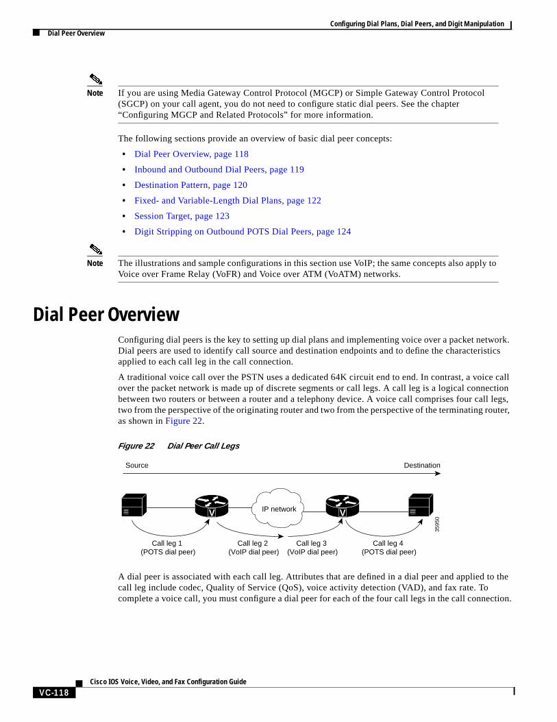
A traditional voice call over the PSTN uses a dedicated 64K circuit end to end. In contrast, a voice callover the packet network is made up of discrete segments or call legs. A call leg is a logical connectionbetween two routers or between a router and a telephony device. A voice call comprises four call legs,two from the perspective of the originating router and two from the perspective of the terminating router,as shown inFigure 22.
Figure 22 Dial Peer Call Legs
A dial peer is associated with each call leg. Attributes that are defined in a dial peer and applied to thecall leg include codec, Quality of Service (QoS), voice activity detection (VAD), and fax rate. Tocomplete a voice call, you must configure a dial peer for each of the four call legs in the call connection.
Source Destination
Call leg 1 (POTS dial peer)
Call leg 2 (VoIP dial peer)
Call leg 3 (VoIP dial peer)
Call leg 4 (POTS dial peer)
3595
0
IP networkV V
Configuring Dial Plans, Dial Peers, and Digit ManipulationDial Peer Overview
VC-119Cisco IOS Voice, Video, and Fax Configuration Guide
Depending on the call leg, a call is routed using one of the two types of dial peers:
• POTS—Dial peer that defines the characteristics of a traditional telephony network connection.POTS dial peers map a dialed string to a specific voice port on the local router, normally the voiceport connecting the router to the local PSTN, PBX, or telephone.
• Voice-network—Dial peer that defines the characteristics of a packet network connection.Voice-network dial peers map a dialed string to a remote network device, such as the destinationrouter that is connected to the remote telephony device.
The specific type of voice-network dial peer depends on the packet network technology:
– VoIP (Voice over IP)—Points to the IP address of the destination router that terminates the call.
– VoFR (Voice over Frame Relay)—Points to the data-link connection identifier (DLCI) of theinterface from which the call exits the router.
– VoATM (Voice over ATM)—Points to the ATM virtual circuit for the interface from which thecall exits the router.
– MMoIP (Multimedia Mail over IP)—Points to the e-mail address of the SMTP server. This typeof dial peer is used only for fax traffic. For more information, see the chapter “Configuring FaxApplications.”
Both POTS and voice-network dial peers are needed to establish voice connections over a packetnetwork.
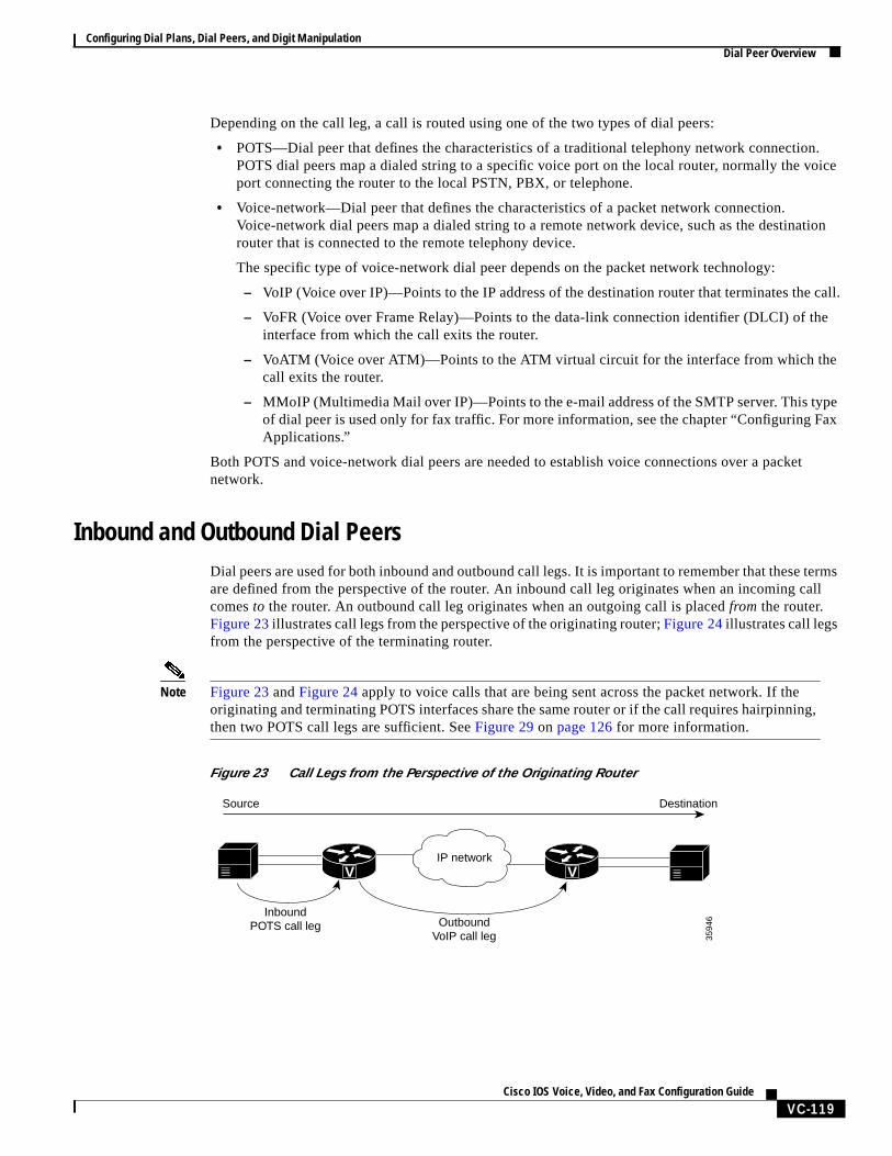
Inbound and Outbound Dial PeersDial peers are used for both inbound and outbound call legs. It is important to remember that these termsare defined from the perspective of the router. An inbound call leg originates when an incoming callcomesto the router. An outbound call leg originates when an outgoing call is placedfrom the router.Figure 23illustrates call legs from the perspective of the originating router;Figure 24illustrates call legsfrom the perspective of the terminating router.
Note Figure 23 andFigure 24 apply to voice calls that are being sent across the packet network. If theoriginating and terminating POTS interfaces share the same router or if the call requires hairpinning,then two POTS call legs are sufficient. SeeFigure 29 on page 126 for more information.
Figure 23 Call Legs from the Perspective of the Originating Router
InboundPOTS call leg
Source Destination
OutboundVoIP call leg 35
946
IP networkVV
Configuring Dial Plans, Dial Peers, and Digit ManipulationDial Peer Overview
VC-120Cisco IOS Voice, Video, and Fax Configuration Guide
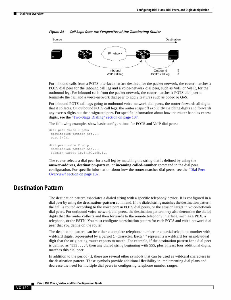
Figure 24 Call Legs from the Perspective of the Terminating Router
For inbound calls from a POTS interface that are destined for the packet network, the router matches aPOTS dial peer for the inbound call leg and a voice-network dial peer, such as VoIP or VoFR, for theoutbound leg. For inbound calls from the packet network, the router matches a POTS dial peer toterminate the call and a voice-network dial peer to apply features such as codec or QoS.
For inbound POTS call legs going to outbound voice-network dial peers, the router forwards all digitsthat it collects. On outbound POTS call legs, the router strips off explicitly matching digits and forwardsany excess digits out the designated port. For specific information about how the router handles excessdigits, see the“Two-Stage Dialing” section on page 137.
The following examples show basic configurations for POTS and VoIP dial peers:
dial-peer voice 1 pots destination-pattern 555.... port 1/0:1
dial-peer voice 2 voip destination-pattern 555.... session target ipv4:192.168.1.1
The router selects a dial peer for a call leg by matching the string that is defined by using theanswer-address, destination-pattern, or incoming called-number command in the dial peerconfiguration. For specific information about how the router matches dial peers, see the“Dial PeerOverview” section on page 137.
Destination PatternThe destination pattern associates a dialed string with a specific telephony device. It is configured in adial peer by using thedestination-pattern command. If the dialed string matches the destination pattern,the call is routed according to the voice port in POTS dial peers, or the session target in voice-networkdial peers. For outbound voice-network dial peers, the destination pattern may also determine the dialeddigits that the router collects and then forwards to the remote telephony interface, such as a PBX, atelephone, or the PSTN. You must configure a destination pattern for each POTS and voice-network dialpeer that you define on the router.
The destination pattern can be either a complete telephone number or a partial telephone number withwildcard digits, represented by a period (.) character. Each “.” represents a wildcard for an individualdigit that the originating router expects to match. For example, if the destination pattern for a dial peeris defined as “555.... ”, then any dialed string beginning with 555, plus at least four additional digits,matches this dial peer.
In addition to the period (.), there are several other symbols that can be used as wildcard characters inthe destination pattern. These symbols provide additional flexibility in implementing dial plans anddecrease the need for multiple dial peers in configuring telephone number ranges.
Source Destination
InboundVoIP call leg
OutboundPOTS call leg 36
849
IP networkVV
Configuring Dial Plans, Dial Peers, and Digit ManipulationDial Peer Overview
VC-121Cisco IOS Voice, Video, and Fax Configuration Guide
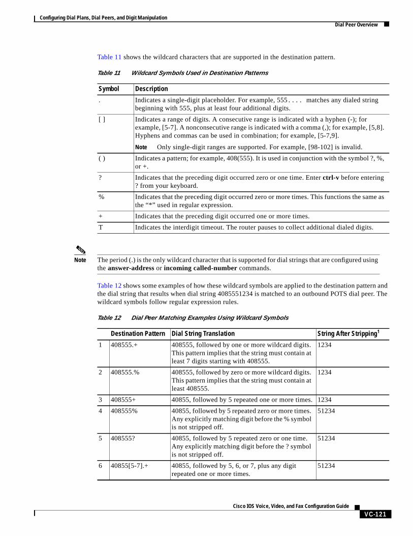
Table 11 shows the wildcard characters that are supported in the destination pattern.
Note The period (.) is the only wildcard character that is supported for dial strings that are configured usingtheanswer-address or incoming called-number commands.
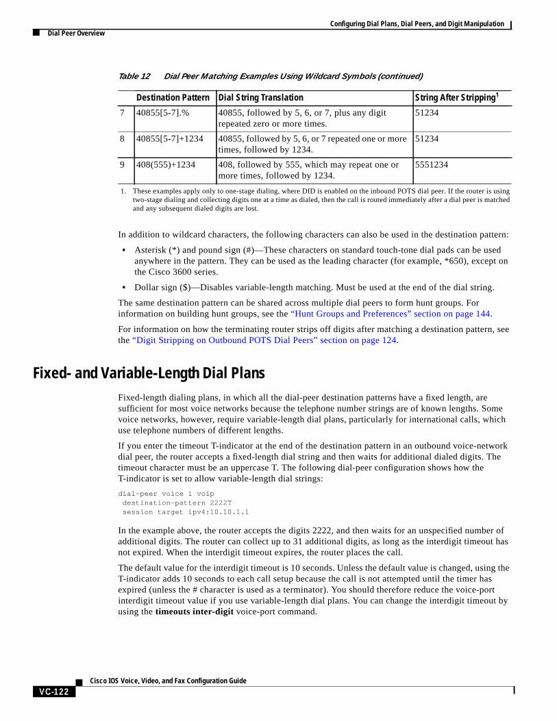
Table 12shows some examples of how these wildcard symbols are applied to the destination pattern andthe dial string that results when dial string 4085551234 is matched to an outbound POTS dial peer. Thewildcard symbols follow regular expression rules.
Table 11 Wildcard Symbols Used in Destination Patterns
Symbol Description
. Indicates a single-digit placeholder. For example, 555.... matches any dialed stringbeginning with 555, plus at least four additional digits.
[ ] Indicates a range of digits. A consecutive range is indicated with a hyphen (-); forexample, [5-7]. A nonconsecutive range is indicated with a comma (,); for example, [5,8].Hyphens and commas can be used in combination; for example, [5-7,9].
Note Only single-digit ranges are supported. For example, [98-102] is invalid.
( ) Indicates a pattern; for example, 408(555). It is used in conjunction with the symbol ?, %,or +.
? Indicates that the preceding digit occurred zero or one time. Enterctrl-v before entering? from your keyboard.
% Indicates that the preceding digit occurred zero or more times. This functions the same asthe “*” used in regular expression.
+ Indicates that the preceding digit occurred one or more times.
T Indicates the interdigit timeout. The router pauses to collect additional dialed digits.
Table 12 Dial Peer Matching Examples Using Wildcard Symbols
Destination Pattern Dial String Translation String After Stripping1
1 408555.+ 408555, followed by one or more wildcard digits.This pattern implies that the string must contain atleast 7 digits starting with 408555.
1234
2 408555.% 408555, followed by zero or more wildcard digits.This pattern implies that the string must contain atleast 408555.
1234
3 408555+ 40855, followed by 5 repeated one or more times. 1234
4 408555% 40855, followed by 5 repeated zero or more times.Any explicitly matching digit before the % symbolis not stripped off.
51234
5 408555? 40855, followed by 5 repeated zero or one time.Any explicitly matching digit before the ? symbolis not stripped off.
51234
6 40855[5-7].+ 40855, followed by 5, 6, or 7, plus any digitrepeated one or more times.
51234
Configuring Dial Plans, Dial Peers, and Digit ManipulationDial Peer Overview
VC-122Cisco IOS Voice, Video, and Fax Configuration Guide
In addition to wildcard characters, the following characters can also be used in the destination pattern:
• Asterisk (*) and pound sign (#)—These characters on standard touch-tone dial pads can be usedanywhere in the pattern. They can be used as the leading character (for example, *650), except onthe Cisco 3600 series.
• Dollar sign ($)—Disables variable-length matching. Must be used at the end of the dial string.
The same destination pattern can be shared across multiple dial peers to form hunt groups. Forinformation on building hunt groups, see the“Hunt Groups and Preferences” section on page 144.
For information on how the terminating router strips off digits after matching a destination pattern, seethe“Digit Stripping on Outbound POTS Dial Peers” section on page 124.
Fixed- and Variable-Length Dial PlansFixed-length dialing plans, in which all the dial-peer destination patterns have a fixed length, aresufficient for most voice networks because the telephone number strings are of known lengths. Somevoice networks, however, require variable-length dial plans, particularly for international calls, whichuse telephone numbers of different lengths.
If you enter the timeout T-indicator at the end of the destination pattern in an outbound voice-networkdial peer, the router accepts a fixed-length dial string and then waits for additional dialed digits. Thetimeout character must be an uppercase T. The following dial-peer configuration shows how theT-indicator is set to allow variable-length dial strings:
dial-peer voice 1 voipdestination-pattern 2222Tsession target ipv4:10.10.1.1
In the example above, the router accepts the digits 2222, and then waits for an unspecified number ofadditional digits. The router can collect up to 31 additional digits, as long as the interdigit timeout hasnot expired. When the interdigit timeout expires, the router places the call.
The default value for the interdigit timeout is 10 seconds. Unless the default value is changed, using theT-indicator adds 10 seconds to each call setup because the call is not attempted until the timer hasexpired (unless the # character is used as a terminator). You should therefore reduce the voice-portinterdigit timeout value if you use variable-length dial plans. You can change the interdigit timeout byusing thetimeouts inter-digit voice-port command.
7 40855[5-7].% 40855, followed by 5, 6, or 7, plus any digitrepeated zero or more times.
51234
8 40855[5-7]+1234 40855, followed by 5, 6, or 7 repeated one or moretimes, followed by 1234.
51234
9 408(555)+1234 408, followed by 555, which may repeat one ormore times, followed by 1234.
5551234
1. These examples apply only to one-stage dialing, where DID is enabled on the inbound POTS dial peer. If the router is usingtwo-stage dialing and collecting digits one at a time as dialed, then the call is routed immediately after a dial peer is matchedand any subsequent dialed digits are lost.
Table 12 Dial Peer Matching Examples Using Wildcard Symbols (continued)
Destination Pattern Dial String Translation String After Stripping1
Configuring Dial Plans, Dial Peers, and Digit ManipulationDial Peer Overview
VC-123Cisco IOS Voice, Video, and Fax Configuration Guide
The calling party can immediately terminate the interdigit timeout by entering the # character. If the #character is entered while the router is waiting for additional digits, the # character is treated as aterminator; it is not treated as part of the dial string or sent across the network. But if the # character isentered before the router begins waiting for additional digits (meaning that the # is entered as part of thefixed-length destination pattern), then the # character is treated as a dialed digit.
For example, if the destination pattern is configured as 2222... T, then the entire dialed string of2222#9999 is collected, but if the dialed string is 2222#99#99, the #99 at the end of the dialed digits isnot collected because the final # character is treated as a terminator. You can change the terminationcharacter by using thedial-peer terminator command.
Note In most cases, you must configure the T-indicator only when the router uses two-stage dialing. IfDirect Inward Dialing (DID) is configured in the inbound POTS dial peer, the router uses one-stagedialing, which means that the full dialed string is used to match outbound dial peers. The onlyexception is when theISDN overlap-receivingcommand is configured; the ISDN overlap-receivingfeature requires the T-indicator.
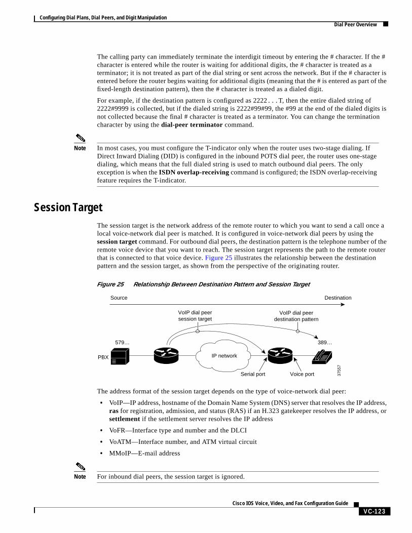
Session TargetThe session target is the network address of the remote router to which you want to send a call once alocal voice-network dial peer is matched. It is configured in voice-network dial peers by using thesession targetcommand. For outbound dial peers, the destination pattern is the telephone number of theremote voice device that you want to reach. The session target represents the path to the remote routerthat is connected to that voice device.Figure 25 illustrates the relationship between the destinationpattern and the session target, as shown from the perspective of the originating router.
Figure 25 Relationship Between Destination Pattern and Session Target
The address format of the session target depends on the type of voice-network dial peer:
• VoIP—IP address, hostname of the Domain Name System (DNS) server that resolves the IP address,ras for registration, admission, and status (RAS) if an H.323 gatekeeper resolves the IP address, orsettlement if the settlement server resolves the IP address
• VoFR—Interface type and number and the DLCI
• VoATM—Interface number, and ATM virtual circuit
• MMoIP—E-mail address
Note For inbound dial peers, the session target is ignored.
IP network
579… 389…
Voice portSerial port
PBX
VoIP dial peerdestination pattern
VoIP dial peersession target
3755
7
Source Destination
Configuring Dial Plans, Dial Peers, and Digit ManipulationConfiguring Dial Peers
VC-124Cisco IOS Voice, Video, and Fax Configuration Guide
Digit Stripping on Outbound POTS Dial PeersWhen a terminating router receives a voice call, it selects an outbound POTS dial peer by comparing thecalled number (the full E.164 telephone number) in the call information with the number configured asthe destination pattern in the POTS dial peer. The access server or router then strips off the left-justifieddigits that match the destination pattern. If you have configured a prefix, the prefix is added to the frontof the remaining digits, creating a dial string, which the router then dials. If all numbers in the destinationpattern are stripped out, the user receives a dial tone.
For example, consider a voice call whose E.164 called number is 1(408) 555-2222. If you configure adestination-pattern of “1408555” and a prefix of “9,” the router strips off “1408555” from the E.164telephone number, leaving the extension number of “2222.” It then appends the prefix, “9,” to the frontof the remaining numbers, so that the actual numbers dialed are “9, 2222.” The comma in this examplemeans that the router will pause for one second between dialing the “9” and dialing the “2” to allow fora secondary dial tone.
For detailed information about digit stripping and the prefix command, see the“Digit Stripping andPrefixes” section on page 151.
Configuring Dial PeersThis section describes how to configure dial peers:
• Configuring Dial Peers for Call Legs, page 125
• Creating a Dial Peer Configuration Table, page 127
• Configuring POTS Dial Peers, page 128
• Configuring Dial Plan Options for POTS Dial Peers, page 130
• Configuring VoIP Dial Peers, page 131
• Configuring Dial Plan Options for VoIP Dial Peers, page 133
• Configuring VoFR Dial Peers, page 135
• Configuring VoATM Dial Peers, page 135
Note The example configurations in this section show VoIP dial peers; the same concepts also apply toVoFR and VoATM dial peers.
Establishing voice communication over a packet network is similar to configuring a static route: you areestablishing a specific voice connection between two defined endpoints. Call legs define the discretesegments that lie between two points in the call connection. A voice call over the packet networkcomprises four call legs, two on the originating router and two on the terminating router; a dial peer isassociated with each of these four call legs.
Configuring Dial Plans, Dial Peers, and Digit ManipulationConfiguring Dial Peers
VC-125Cisco IOS Voice, Video, and Fax Configuration Guide
Configuring Dial Peers for Call LegsWhen a voice call comes into the router, the router must match dial peers to route the call. For inboundcalls from a POTS interface that are being sent over the packet network, the router matches a POTS dialpeer for the inbound call leg and a voice-network dial peer for the outbound call leg. For calls cominginto the router from the packet network, the router matches an outbound POTS dial peer to terminate thecall and an inbound voice-network dial peer for features such as codec, VAD, and QoS.
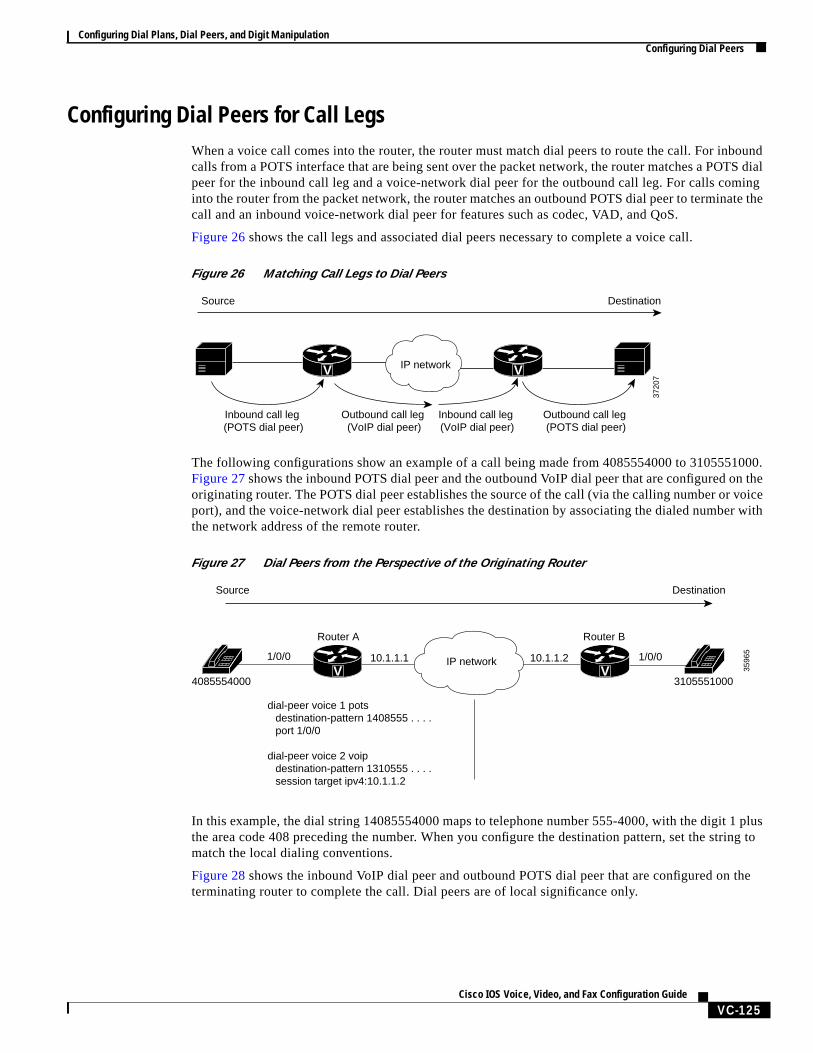
Figure 26 shows the call legs and associated dial peers necessary to complete a voice call.
Figure 26 Matching Call Legs to Dial Peers
The following configurations show an example of a call being made from 4085554000 to 3105551000.Figure 27shows the inbound POTS dial peer and the outbound VoIP dial peer that are configured on theoriginating router. The POTS dial peer establishes the source of the call (via the calling number or voiceport), and the voice-network dial peer establishes the destination by associating the dialed number withthe network address of the remote router.
Figure 27 Dial Peers from the Perspective of the Originating Router
In this example, the dial string 14085554000 maps to telephone number 555-4000, with the digit 1 plusthe area code 408 preceding the number. When you configure the destination pattern, set the string tomatch the local dialing conventions.
Figure 28 shows the inbound VoIP dial peer and outbound POTS dial peer that are configured on theterminating router to complete the call. Dial peers are of local significance only.
Source Destination
Inbound call leg (POTS dial peer)
Outbound call leg (VoIP dial peer)
Inbound call leg (VoIP dial peer)
Outbound call leg (POTS dial peer)
3720
7
IP networkV V
3596
5
4085554000 3105551000
10.1.1.1 10.1.1.2
Router A Router B
Source Destination
1/0/0 1/0/0
dial-peer voice 1 potsdestination-pattern 1408555 . . . .port 1/0/0
dial-peer voice 2 voipdestination-pattern 1310555 . . . .session target ipv4:10.1.1.2
IP networkV V
Configuring Dial Plans, Dial Peers, and Digit ManipulationConfiguring Dial Peers
VC-126Cisco IOS Voice, Video, and Fax Configuration Guide
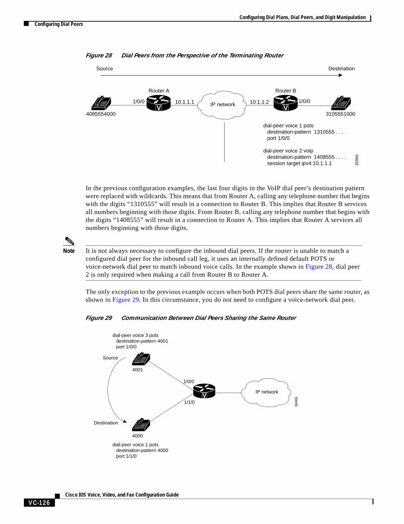
Figure 28 Dial Peers from the Perspective of the Terminating Router
In the previous configuration examples, the last four digits in the VoIP dial peer’s destination patternwere replaced with wildcards. This means that from Router A, calling any telephone number that beginswith the digits “1310555” will result in a connection to Router B. This implies that Router B servicesall numbers beginning with those digits. From Router B, calling any telephone number that begins withthe digits “1408555” will result in a connection to Router A. This implies that Router A services allnumbers beginning with those digits.
Note It is not always necessary to configure the inbound dial peers. If the router is unable to match aconfigured dial peer for the inbound call leg, it uses an internally defined default POTS orvoice-network dial peer to match inbound voice calls. In the example shown inFigure 28, dial peer2 is only required when making a call from Router B to Router A.
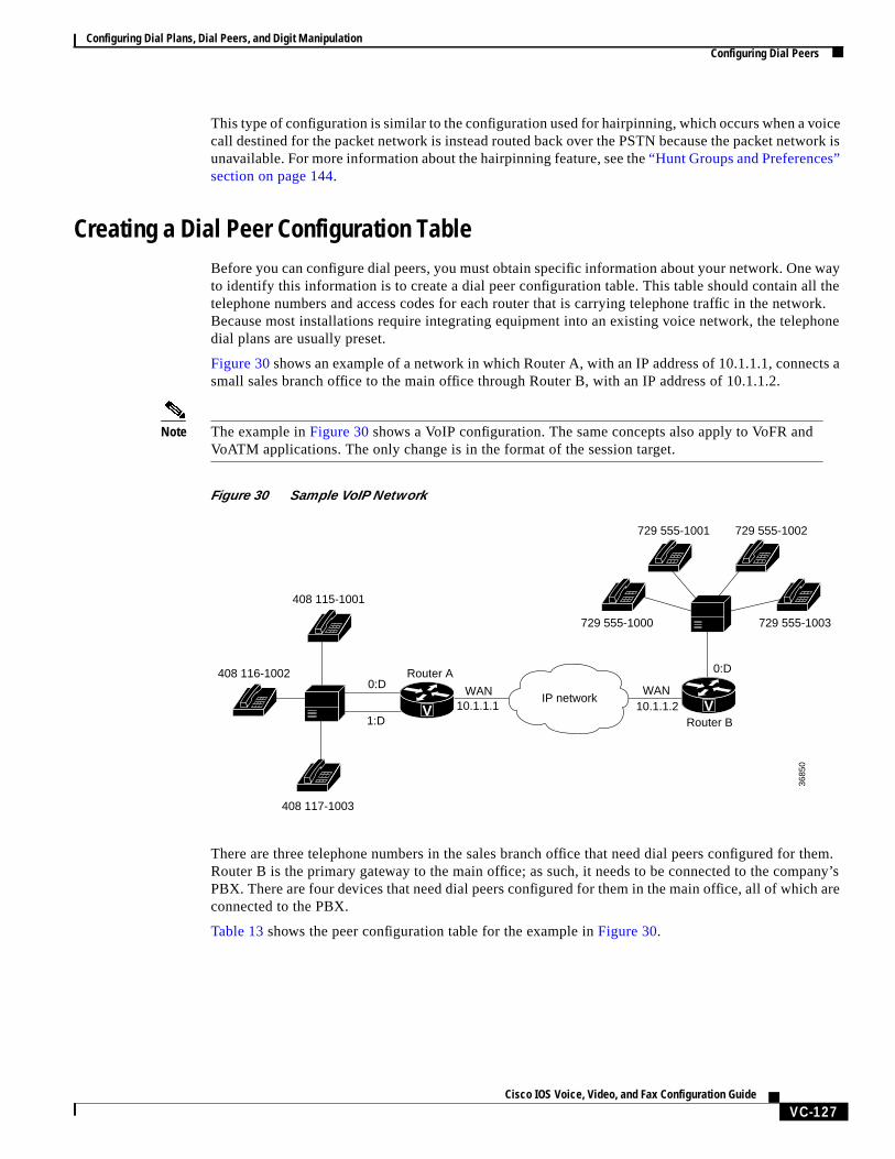
The only exception to the previous example occurs when both POTS dial peers share the same router, asshown inFigure 29. In this circumstance, you do not need to configure a voice-network dial peer.
Figure 29 Communication Between Dial Peers Sharing the Same Router
3596
6
4085554000 3105551000
DestinationSource
10.1.1.1 10.1.1.2
Router A Router B
1/0/0 1/0/0
dial-peer voice 1 pots destination-pattern 1310555 . . . .
port 1/0/0
dial-peer voice 2 voip destination-pattern 1408555 . . . . session target ipv4:10.1.1.1
IP networkV V
3646
9
4001
4000
Source
Destination
1/0/0
1/1/0
dial-peer voice 1 potsdestination-pattern 4000port 1/1/0
dial-peer voice 3 potsdestination-pattern 4001port 1/0/0
IP networkV
Configuring Dial Plans, Dial Peers, and Digit ManipulationConfiguring Dial Peers
VC-127Cisco IOS Voice, Video, and Fax Configuration Guide
This type of configuration is similar to the configuration used for hairpinning, which occurs when a voicecall destined for the packet network is instead routed back over the PSTN because the packet network isunavailable. For more information about the hairpinning feature, see the“Hunt Groups and Preferences”section on page 144.
Creating a Dial Peer Configuration TableBefore you can configure dial peers, you must obtain specific information about your network. One wayto identify this information is to create a dial peer configuration table. This table should contain all thetelephone numbers and access codes for each router that is carrying telephone traffic in the network.Because most installations require integrating equipment into an existing voice network, the telephonedial plans are usually preset.
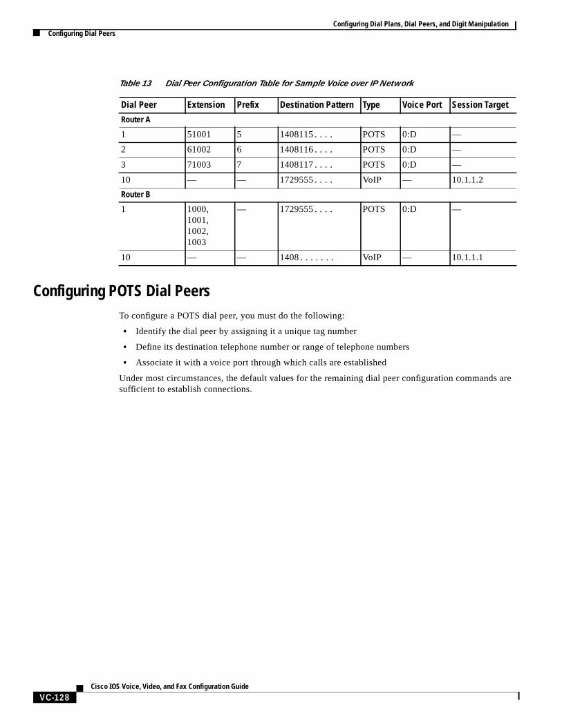
Figure 30shows an example of a network in which Router A, with an IP address of 10.1.1.1, connects asmall sales branch office to the main office through Router B, with an IP address of 10.1.1.2.
Note The example inFigure 30 shows a VoIP configuration. The same concepts also apply to VoFR andVoATM applications. The only change is in the format of the session target.
Figure 30 Sample VoIP Network
There are three telephone numbers in the sales branch office that need dial peers configured for them.Router B is the primary gateway to the main office; as such, it needs to be connected to the company’sPBX. There are four devices that need dial peers configured for them in the main office, all of which areconnected to the PBX.
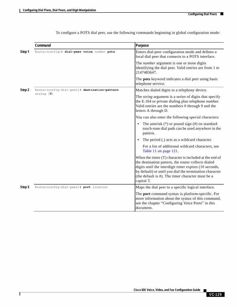
Table 13 shows the peer configuration table for the example inFigure 30.
408 116-1002
408 115-1001
408 117-1003
729 555-1000 729 555-1003
729 555-1001 729 555-1002
Router A
WAN WAN10.1.1.1 10.1.1.2
Router B
0:D0:D
3685
0
1:DV V
IP network
Configuring Dial Plans, Dial Peers, and Digit ManipulationConfiguring Dial Peers
VC-128Cisco IOS Voice, Video, and Fax Configuration Guide
Configuring POTS Dial PeersTo configure a POTS dial peer, you must do the following:
• Identify the dial peer by assigning it a unique tag number
• Define its destination telephone number or range of telephone numbers
• Associate it with a voice port through which calls are established
Under most circumstances, the default values for the remaining dial peer configuration commands aresufficient to establish connections.
Table 13 Dial Peer Configuration Table for Sample Voice over IP Network
Dial Peer Extension Prefix Destination Pattern Type Voice Port Session Target
Router A
1 51001 5 1408115.... POTS 0:D —
2 61002 6 1408116.... POTS 0:D —
3 71003 7 1408117.... POTS 0:D —
10 — — 1729555.... VoIP — 10.1.1.2
Router B
1 1000,1001,1002,1003
— 1729555.... POTS 0:D —
10 — — 1408....... VoIP — 10.1.1.1
Configuring Dial Plans, Dial Peers, and Digit ManipulationConfiguring Dial Peers
VC-129Cisco IOS Voice, Video, and Fax Configuration Guide
To configure a POTS dial peer, use the following commands beginning in global configuration mode:
Command Purpose
Step 1 Router(config)# dial-peer voice number pots Enters dial-peer configuration mode and defines alocal dial peer that connects to a POTS interface.
The number argument is one or more digitsidentifying the dial peer. Valid entries are from 1 to2147483647.
The pots keyword indicates a dial peer using basictelephone service.
Step 2 Router(config-dial-peer)# destination-patternstring [ T]
Matches dialed digits to a telephony device.
The string argument is a series of digits that specifythe E.164 or private dialing plan telephone number.Valid entries are the numbers 0 through 9 and theletters A through D.
You can also enter the following special characters:
• The asterisk (*) or pound sign (#) on standardtouch-tone dial pads can be used anywhere in thepattern.
• The period (.) acts as a wildcard character.
For a list of additional wildcard characters, seeTable 11 on page 121.
When the timer (T) character is included at the end ofthe destination pattern, the router collects dialeddigits until the interdigit timer expires (10 seconds,by default) or until you dial the termination character(the default is #). The timer character must be acapital T.
Step 3 Router(config-dial-peer)# port location Maps the dial peer to a specific logical interface.
Theport command syntax is platform-specific. Formore information about the syntax of this command,see the chapter “Configuring Voice Ports” in thisdocument.
Configuring Dial Plans, Dial Peers, and Digit ManipulationConfiguring Dial Peers
VC-130Cisco IOS Voice, Video, and Fax Configuration Guide
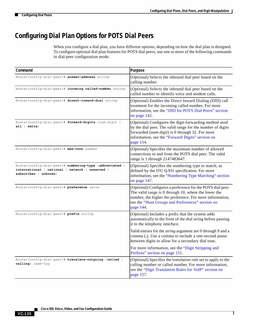
Configuring Dial Plan Options for POTS Dial PeersWhen you configure a dial plan, you have different options, depending on how the dial plan is designed.To configure optional dial plan features for POTS dial peers, use one or more of the following commandsin dial-peer configuration mode:
Command PurposeRouter(config-dial-peer)# answer-address string (Optional) Selects the inbound dial peer based on the
calling number.
Router(config-dial-peer)# incoming called-number string (Optional) Selects the inbound dial peer based on thecalled number to identify voice and modem calls.
Router(config-dial-peer)# direct-inward-dial string (Optional) Enables the Direct Inward Dialing (DID) calltreatment for the incoming called number. For moreinformation, see the“DID for POTS Dial Peers” sectionon page 142.
Router(config-dial-peer)# forward-digits { num-digit |all | extra }
(Optional) Configures the digit-forwarding method usedby the dial peer. The valid range for the number of digitsforwarded (num-digit) is 0 through 32. For moreinformation, see the“Forward Digits” section onpage 154.
Router(config-dial-peer)# max-conn number (Optional) Specifies the maximum number of allowedconnections to and from the POTS dial peer. The validrange is 1 through 2147483647.
Router(config-dial-peer)# numbering-type { abbreviated |international | national | network | reserved |subscriber | unknown }
(Optional) Specifies the numbering type to match, asdefined by theITU Q.931 specification. For moreinformation, see the“Numbering Type Matching” sectionon page 147.
Router(config-dial-peer)# preference value (Optional) Configures a preference for the POTS dial peer.The valid range is 0 through 10, where the lower thenumber, the higher the preference. For more information,see the“Hunt Groups and Preferences” section onpage 144.
Router(config-dial-peer)# prefix string (Optional) Includes a prefix that the system addsautomatically to the front of the dial string before passingit to the telephony interface.
Valid entries for thestringargument are 0 through 9 and acomma (,). Use a comma to include a one-second pausebetween digits to allow for a secondary dial tone.
For more information, see the“Digit Stripping andPrefixes” section on page 151.
Router(config-dial-peer)# translate-outgoing { called |calling } name-tag
(Optional) Specifies the translation rule set to apply to thecalling number or called number. For more information,see the“Digit Translation Rules for VoIP” section onpage 157.
Configuring Dial Plans, Dial Peers, and Digit ManipulationConfiguring Dial Peers
VC-131Cisco IOS Voice, Video, and Fax Configuration Guide
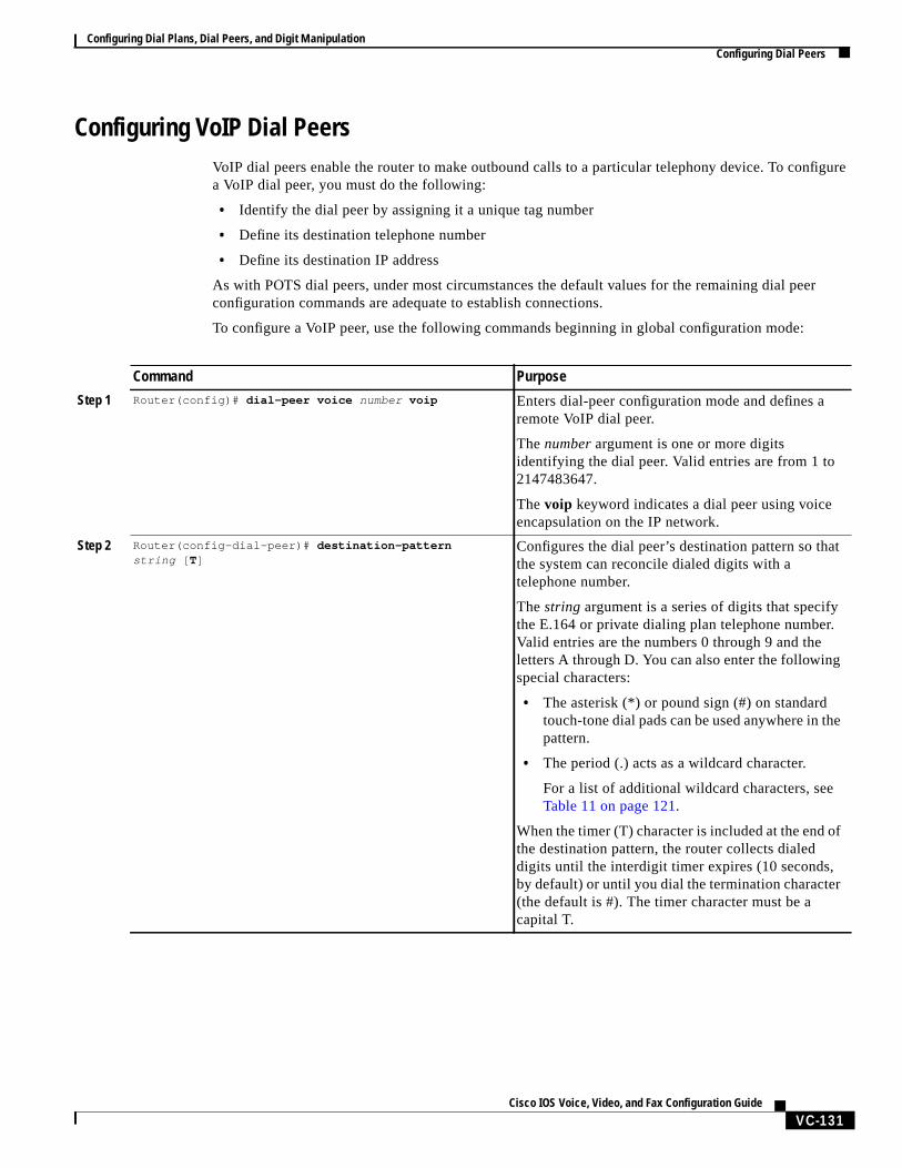
Configuring VoIP Dial PeersVoIP dial peers enable the router to make outbound calls to a particular telephony device. To configurea VoIP dial peer, you must do the following:
• Identify the dial peer by assigning it a unique tag number
• Define its destination telephone number
• Define its destination IP address
As with POTS dial peers, under most circumstances the default values for the remaining dial peerconfiguration commands are adequate to establish connections.
To configure a VoIP peer, use the following commands beginning in global configuration mode:
Command Purpose
Step 1 Router(config)# dial-peer voice number voip Enters dial-peer configuration mode and defines aremote VoIP dial peer.
The number argument is one or more digitsidentifying the dial peer. Valid entries are from 1 to2147483647.
The voip keyword indicates a dial peer using voiceencapsulation on the IP network.
Step 2 Router(config-dial-peer)# destination-patternstring [ T]
Configures the dial peer’s destination pattern so thatthe system can reconcile dialed digits with atelephone number.
The string argument is a series of digits that specifythe E.164 or private dialing plan telephone number.Valid entries are the numbers 0 through 9 and theletters A through D. You can also enter the followingspecial characters:
• The asterisk (*) or pound sign (#) on standardtouch-tone dial pads can be used anywhere in thepattern.
• The period (.) acts as a wildcard character.
For a list of additional wildcard characters, seeTable 11 on page 121.
When the timer (T) character is included at the end ofthe destination pattern, the router collects dialeddigits until the interdigit timer expires (10 seconds,by default) or until you dial the termination character(the default is #). The timer character must be acapital T.
Configuring Dial Plans, Dial Peers, and Digit ManipulationConfiguring Dial Peers
VC-132Cisco IOS Voice, Video, and Fax Configuration Guide
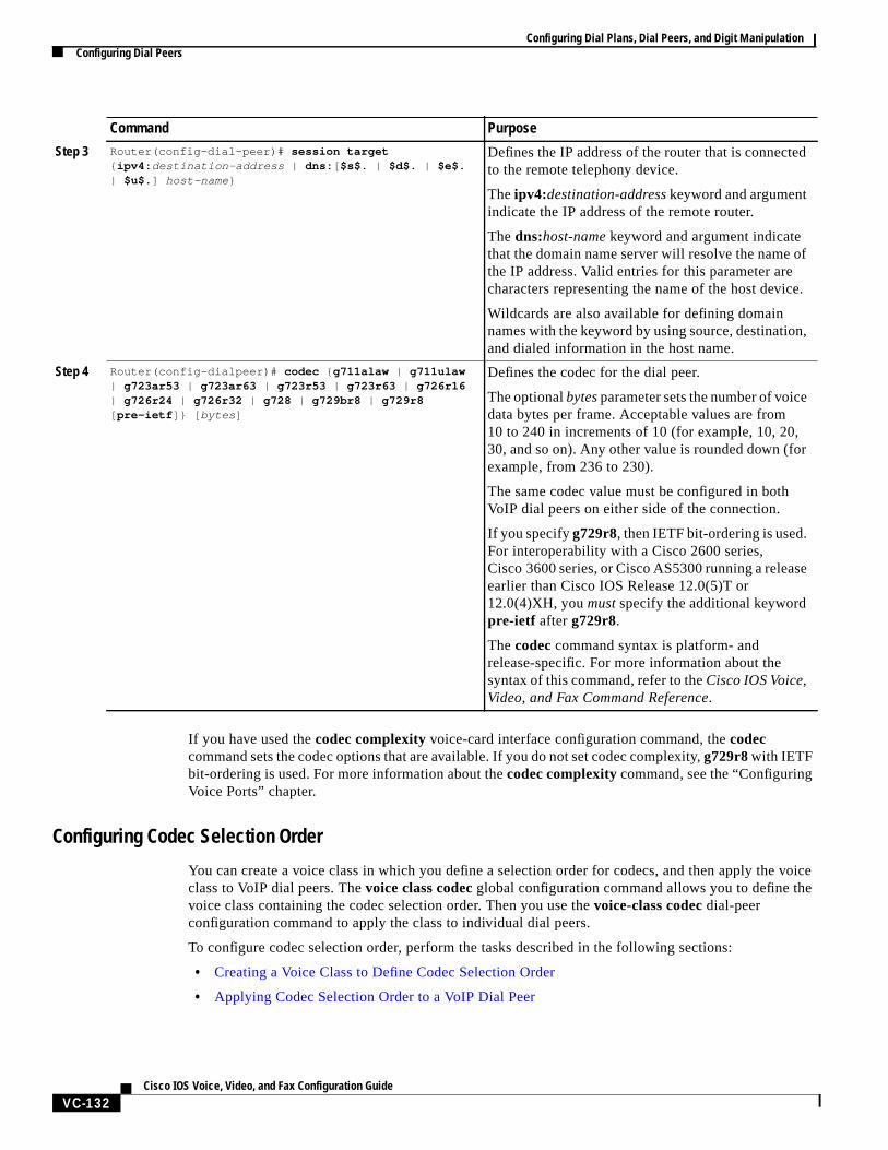
If you have used thecodec complexityvoice-card interface configuration command, thecodeccommand sets the codec options that are available. If you do not set codec complexity,g729r8with IETFbit-ordering is used. For more information about thecodec complexitycommand, see the “ConfiguringVoice Ports” chapter.
Configuring Codec Selection Order
You can create a voice class in which you define a selection order for codecs, and then apply the voiceclass to VoIP dial peers. Thevoice class codecglobal configuration command allows you to define thevoice class containing the codec selection order. Then you use thevoice-class codec dial-peerconfiguration command to apply the class to individual dial peers.
To configure codec selection order, perform the tasks described in the following sections:
• Creating a Voice Class to Define Codec Selection Order
• Applying Codec Selection Order to a VoIP Dial Peer
Step 3 Router(config-dial-peer)# session target{ ipv4: destination-address | dns: [ $s$. | $d$. | $e$.| $u$. ] host-name }
Defines the IP address of the router that is connectedto the remote telephony device.
Theipv4:destination-addresskeyword and argumentindicate the IP address of the remote router.
The dns:host-name keyword and argument indicatethat the domain name server will resolve the name ofthe IP address. Valid entries for this parameter arecharacters representing the name of the host device.
Wildcards are also available for defining domainnames with the keyword by using source, destination,and dialed information in the host name.
Step 4 Router(config-dialpeer)# codec { g711alaw | g711ulaw| g723ar53 | g723ar63 | g723r53 | g723r63 | g726r16| g726r24 | g726r32 | g728 | g729br8 | g729r8[ pre-ietf ]} [ bytes ]
Defines the codec for the dial peer.
The optionalbytesparameter sets the number of voicedata bytes per frame. Acceptable values are from10 to 240 in increments of 10 (for example, 10, 20,30, and so on). Any other value is rounded down (forexample, from 236 to 230).
The same codec value must be configured in bothVoIP dial peers on either side of the connection.
If you specifyg729r8, then IETF bit-ordering is used.For interoperability with a Cisco 2600 series,Cisco 3600 series, or Cisco AS5300 running a releaseearlier than Cisco IOS Release 12.0(5)T or12.0(4)XH, youmustspecify the additional keywordpre-ietf afterg729r8.
Thecodeccommand syntax is platform- andrelease-specific. For more information about thesyntax of this command, refer to theCisco IOS Voice,Video, and Fax Command Reference.
Command Purpose
Configuring Dial Plans, Dial Peers, and Digit ManipulationConfiguring Dial Peers
VC-133Cisco IOS Voice, Video, and Fax Configuration Guide
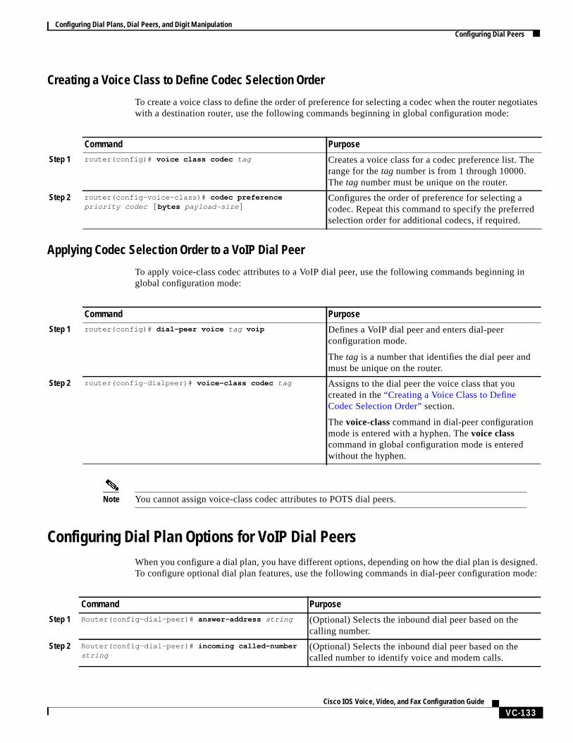
Creating a Voice Class to Define Codec Selection Order
To create a voice class to define the order of preference for selecting a codec when the router negotiateswith a destination router, use the following commands beginning in global configuration mode:
Applying Codec Selection Order to a VoIP Dial Peer
To apply voice-class codec attributes to a VoIP dial peer, use the following commands beginning inglobal configuration mode:
Note You cannot assign voice-class codec attributes to POTS dial peers.
Configuring Dial Plan Options for VoIP Dial PeersWhen you configure a dial plan, you have different options, depending on how the dial plan is designed.To configure optional dial plan features, use the following commands in dial-peer configuration mode:
Command Purpose
Step 1 router(config)# voice class codec tag Creates a voice class for a codec preference list. Therange for thetag number is from 1 through 10000.The tag number must be unique on the router.
Step 2 router(config-voice-class)# codec preferencepriority codec [ bytes payload-size ]
Configures the order of preference for selecting acodec. Repeat this command to specify the preferredselection order for additional codecs, if required.
Command Purpose
Step 1 router(config)# dial-peer voice tag voip Defines a VoIP dial peer and enters dial-peerconfiguration mode.
The tag is a number that identifies the dial peer andmust be unique on the router.
Step 2 router(config-dialpeer)# voice-class codec tag Assigns to the dial peer the voice class that youcreated in the“Creating a Voice Class to DefineCodec Selection Order” section.
Thevoice-class command in dial-peer configurationmode is entered with a hyphen. Thevoice classcommand in global configuration mode is enteredwithout the hyphen.
Command Purpose
Step 1 Router(config-dial-peer)# answer-address string (Optional) Selects the inbound dial peer based on thecalling number.
Step 2 Router(config-dial-peer)# incoming called-numberstring
(Optional) Selects the inbound dial peer based on thecalled number to identify voice and modem calls.
Configuring Dial Plans, Dial Peers, and Digit ManipulationConfiguring Dial Peers
VC-134Cisco IOS Voice, Video, and Fax Configuration Guide
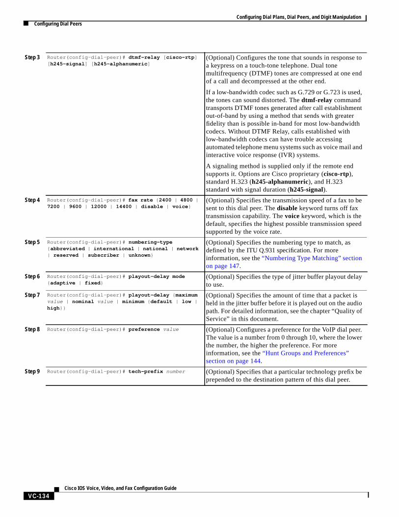
Step 3 Router(config-dial-peer)# dtmf-relay [ cisco-rtp ][ h245-signal ] [ h245-alphanumeric ]
(Optional) Configures the tone that sounds in response toa keypress on a touch-tone telephone. Dual tonemultifrequency (DTMF) tones are compressed at one endof a call and decompressed at the other end.
If a low-bandwidth codec such as G.729 or G.723 is used,the tones can sound distorted. Thedtmf-relay commandtransports DTMF tones generated after call establishmentout-of-band by using a method that sends with greaterfidelity than is possible in-band for most low-bandwidthcodecs. Without DTMF Relay, calls established withlow-bandwidth codecs can have trouble accessingautomated telephone menu systems such as voice mail andinteractive voice response (IVR) systems.
A signaling method is supplied only if the remote endsupports it. Options are Cisco proprietary (cisco-rtp),standard H.323 (h245-alphanumeric), and H.323standard with signal duration (h245-signal).
Step 4 Router(config-dial-peer)# fax rate { 2400 | 4800 |7200 | 9600 | 12000 | 14400 | disable | voice }
(Optional) Specifies the transmission speed of a fax to besent to this dial peer. Thedisable keyword turns off faxtransmission capability. Thevoice keyword, which is thedefault, specifies the highest possible transmission speedsupported by the voice rate.
Step 5 Router(config-dial-peer)# numbering-type{ abbreviated | international | national | network| reserved | subscriber | unknown }
(Optional) Specifies the numbering type to match, asdefined by theITU Q.931 specification. For moreinformation, see the“Numbering Type Matching” sectionon page 147.
Step 6 Router(config-dial-peer)# playout-delay mode{ adaptive | fixed }
(Optional) Specifies the type of jitter buffer playout delayto use.
Step 7 Router(config-dial-peer)# playout-delay { maximumvalue | nominal value | minimum { default | low |high }}
(Optional) Specifies the amount of time that a packet isheld in the jitter buffer before it is played out on the audiopath. For detailed information, see the chapter “Quality ofService” in this document.
Step 8 Router(config-dial-peer)# preference value (Optional) Configures a preference for the VoIP dial peer.The value is a number from 0 through 10, where the lowerthe number, the higher the preference. For moreinformation, see the“Hunt Groups and Preferences”section on page 144.
Step 9 Router(config-dial-peer)# tech-prefix number (Optional) Specifies that a particular technology prefix beprepended to the destination pattern of this dial peer.
Configuring Dial Plans, Dial Peers, and Digit ManipulationConfiguring Dial Peers
VC-135Cisco IOS Voice, Video, and Fax Configuration Guide
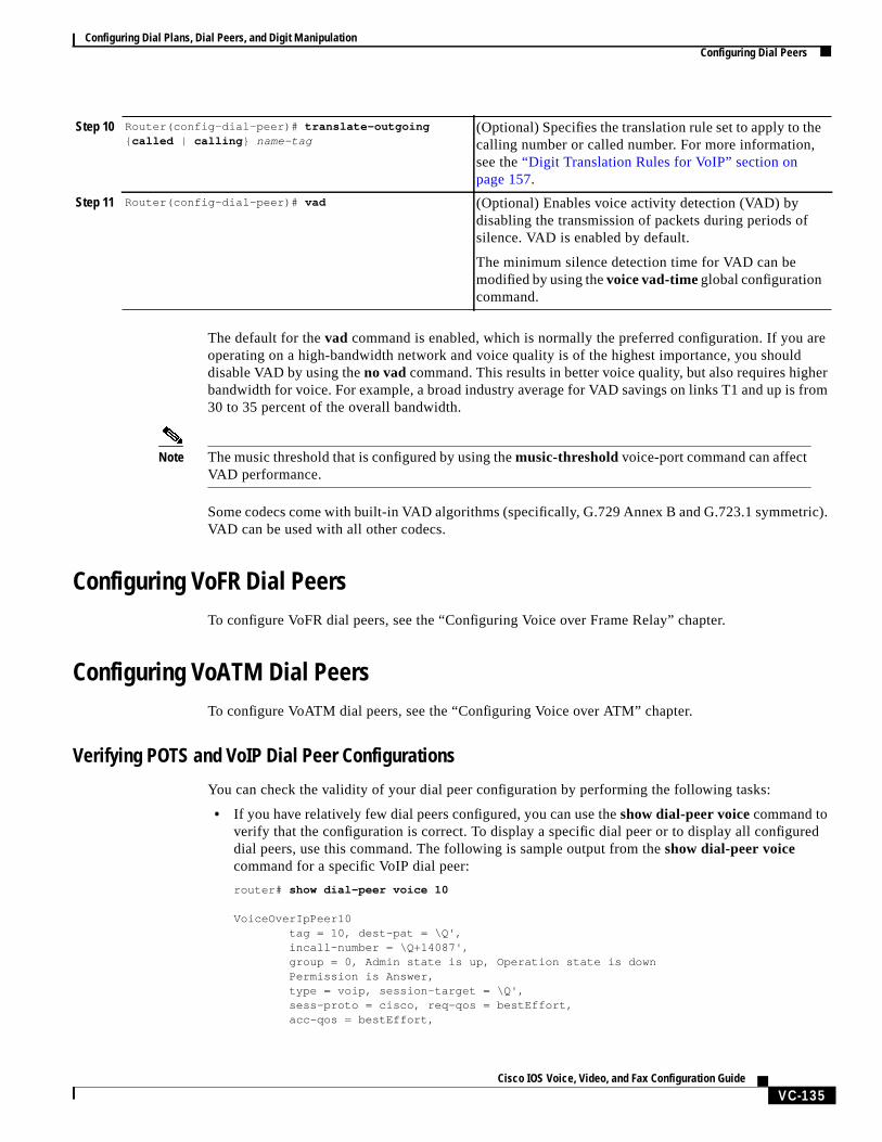
The default for thevad command is enabled, which is normally the preferred configuration. If you areoperating on a high-bandwidth network and voice quality is of the highest importance, you shoulddisable VAD by using theno vad command. This results in better voice quality, but also requires higherbandwidth for voice. For example, a broad industry average for VAD savings on links T1 and up is from30 to 35 percent of the overall bandwidth.
Note The music threshold that is configured by using themusic-thresholdvoice-port command can affectVAD performance.
Some codecs come with built-in VAD algorithms (specifically, G.729 Annex B and G.723.1 symmetric).VAD can be used with all other codecs.
Configuring VoFR Dial PeersTo configure VoFR dial peers, see the “Configuring Voice over Frame Relay” chapter.
Configuring VoATM Dial PeersTo configure VoATM dial peers, see the “Configuring Voice over ATM” chapter.
Verifying POTS and VoIP Dial Peer Configurations
You can check the validity of your dial peer configuration by performing the following tasks:
• If you have relatively few dial peers configured, you can use theshow dial-peer voicecommand toverify that the configuration is correct. To display a specific dial peer or to display all configureddial peers, use this command. The following is sample output from theshow dial-peer voicecommand for a specific VoIP dial peer:
router# show dial-peer voice 10
VoiceOverIpPeer10 tag = 10, dest-pat = \Q', incall-number = \Q+14087', group = 0, Admin state is up, Operation state is down Permission is Answer, type = voip, session-target = \Q', sess-proto = cisco, req-qos = bestEffort, acc-qos = bestEffort,
Step 10 Router(config-dial-peer)# translate-outgoing{ called | calling } name-tag
(Optional) Specifies the translation rule set to apply to thecalling number or called number. For more information,see the“Digit Translation Rules for VoIP” section onpage 157.
Step 11 Router(config-dial-peer)# vad (Optional) Enables voice activity detection (VAD) bydisabling the transmission of packets during periods ofsilence. VAD is enabled by default.
The minimum silence detection time for VAD can bemodified by using thevoice vad-timeglobal configurationcommand.
Configuring Dial Plans, Dial Peers, and Digit ManipulationConfiguring Dial Peers
VC-136Cisco IOS Voice, Video, and Fax Configuration Guide
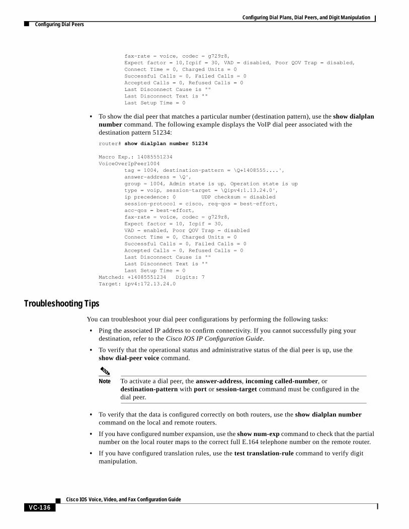
fax-rate = voice, codec = g729r8, Expect factor = 10,Icpif = 30, VAD = disabled, Poor QOV Trap = disabled, Connect Time = 0, Charged Units = 0 Successful Calls = 0, Failed Calls = 0 Accepted Calls = 0, Refused Calls = 0 Last Disconnect Cause is "" Last Disconnect Text is "" Last Setup Time = 0
• To show the dial peer that matches a particular number (destination pattern), use theshow dialplannumber command. The following example displays the VoIP dial peer associated with thedestination pattern 51234:
router# show dialplan number 51234
Macro Exp.: 14085551234VoiceOverIpPeer1004 tag = 1004, destination-pattern = \Q+1408555....', answer-address = \Q', group = 1004, Admin state is up, Operation state is up type = voip, session-target = \Qipv4:1.13.24.0', ip precedence: 0 UDP checksum = disabled session-protocol = cisco, req-qos = best-effort, acc-qos = best-effort, fax-rate = voice, codec = g729r8, Expect factor = 10, Icpif = 30, VAD = enabled, Poor QOV Trap = disabled Connect Time = 0, Charged Units = 0 Successful Calls = 0, Failed Calls = 0 Accepted Calls = 0, Refused Calls = 0 Last Disconnect Cause is "" Last Disconnect Text is "" Last Setup Time = 0Matched: +14085551234 Digits: 7Target: ipv4:172.13.24.0
Troubleshooting Tips
You can troubleshoot your dial peer configurations by performing the following tasks:
• Ping the associated IP address to confirm connectivity. If you cannot successfully ping yourdestination, refer to theCisco IOS IP Configuration Guide.
• To verify that the operational status and administrative status of the dial peer is up, use theshow dial-peer voice command.
Note To activate a dial peer, theanswer-address, incoming called-number, ordestination-pattern with port or session-targetcommand must be configured in thedial peer.
• To verify that the data is configured correctly on both routers, use theshow dialplan numbercommand on the local and remote routers.
• If you have configured number expansion, use theshow num-expcommand to check that the partialnumber on the local router maps to the correct full E.164 telephone number on the remote router.
• If you have configured translation rules, use thetest translation-rule command to verify digitmanipulation.
Configuring Dial Plans, Dial Peers, and Digit ManipulationDial Peer Overview
VC-137Cisco IOS Voice, Video, and Fax Configuration Guide
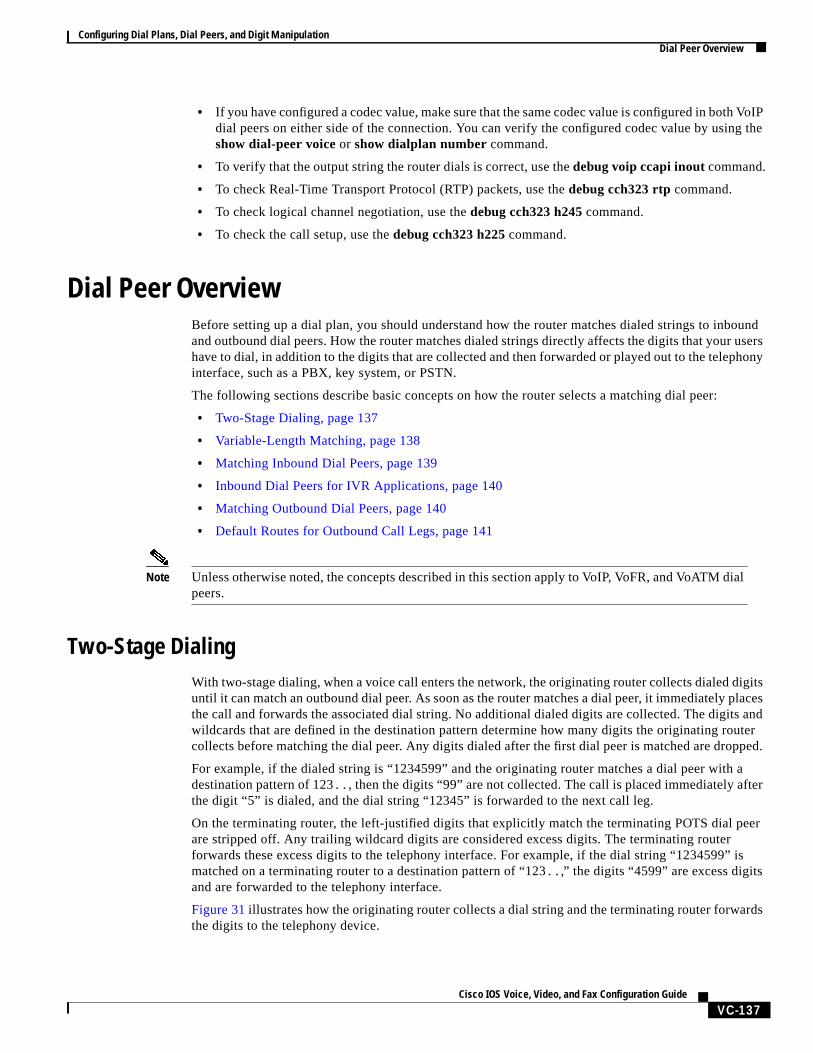
• If you have configured a codec value, make sure that the same codec value is configured in both VoIPdial peers on either side of the connection. You can verify the configured codec value by using theshow dial-peer voice or show dialplan number command.
• To verify that the output string the router dials is correct, use thedebug voip ccapi inoutcommand.
• To check Real-Time Transport Protocol (RTP) packets, use thedebug cch323 rtp command.
• To check logical channel negotiation, use thedebug cch323 h245 command.
• To check the call setup, use thedebug cch323 h225 command.
Dial Peer OverviewBefore setting up a dial plan, you should understand how the router matches dialed strings to inboundand outbound dial peers. How the router matches dialed strings directly affects the digits that your usershave to dial, in addition to the digits that are collected and then forwarded or played out to the telephonyinterface, such as a PBX, key system, or PSTN.
The following sections describe basic concepts on how the router selects a matching dial peer:
• Two-Stage Dialing, page 137
• Variable-Length Matching, page 138
• Matching Inbound Dial Peers, page 139
• Inbound Dial Peers for IVR Applications, page 140
• Matching Outbound Dial Peers, page 140
• Default Routes for Outbound Call Legs, page 141
Note Unless otherwise noted, the concepts described in this section apply to VoIP, VoFR, and VoATM dialpeers.
Two-Stage DialingWith two-stage dialing, when a voice call enters the network, the originating router collects dialed digitsuntil it can match an outbound dial peer. As soon as the router matches a dial peer, it immediately placesthe call and forwards the associated dial string. No additional dialed digits are collected. The digits andwildcards that are defined in the destination pattern determine how many digits the originating routercollects before matching the dial peer. Any digits dialed after the first dial peer is matched are dropped.
For example, if the dialed string is “1234599” and the originating router matches a dial peer with adestination pattern of 123.. , then the digits “99” are not collected. The call is placed immediately afterthe digit “5” is dialed, and the dial string “12345” is forwarded to the next call leg.
On the terminating router, the left-justified digits that explicitly match the terminating POTS dial peerare stripped off. Any trailing wildcard digits are considered excess digits. The terminating routerforwards these excess digits to the telephony interface. For example, if the dial string “1234599” ismatched on a terminating router to a destination pattern of “123.. ,” the digits “4599” are excess digitsand are forwarded to the telephony interface.
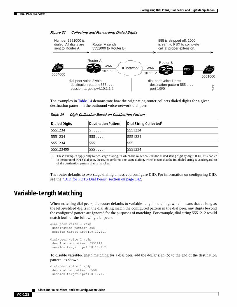
Figure 31illustrates how the originating router collects a dial string and the terminating router forwardsthe digits to the telephony device.
Configuring Dial Plans, Dial Peers, and Digit ManipulationDial Peer Overview
VC-138Cisco IOS Voice, Video, and Fax Configuration Guide
Figure 31 Collecting and Forwarding Dialed Digits
The examples inTable 14 demonstrate how the originating router collects dialed digits for a givendestination pattern in the outbound voice-network dial peer.
The router defaults to two-stage dialing unless you configure DID. For information on configuring DID,see the“DID for POTS Dial Peers” section on page 142.
Variable-Length MatchingWhen matching dial peers, the router defaults to variable-length matching, which means that as long asthe left-justified digits in the dial string match the configured pattern in the dial peer, any digits beyondthe configured pattern are ignored for the purposes of matching. For example, dial string 5551212 wouldmatch both of the following dial peers:
dial-peer voice 1 voipdestination-pattern 555session target ipv4:10.10.1.1
dial-peer voice 2 voipdestination-pattern 5551212session target ipv4:10.10.1.2
To disable variable-length matching for a dial peer, add the dollar sign ($) to the end of the destinationpattern, as shown:
dial-peer voice 1 voipdestination-pattern 555$session target ipv4:10.10.1.1
Number 5551000 isdialed. All digits aresent to Router A.
Router A sends5551000 to Router B.
555 is stripped off, 1000is sent to PBX to complete call at proper extension.
Router A Router B
5554000 555100010.1.1.2
3583
2
WAN10.1.1.1
WAN
dial-peer voice 2 voip destination-pattern 555 . . . . session-target ipv4:10.1.1.2
dial-peer voice 1 pots destination-pattern 555 . . . . port 1/0/0
PBXIP networkV V
Table 14 Digit Collection Based on Destination Pattern
Dialed Digits Destination Pattern Dial String Collected1
1. These examples apply only to two-stage dialing, in which the router collects the dialed string digit by digit. If DID is enabledin the inbound POTS dial peer, the router performs one-stage dialing, which means that the full dialed string is used regardlessof the destination pattern that is matched.
5551234 5...... 5551234
5551234 555.... 5551234
5551234 555 555
555123499 555.... 5551234
Configuring Dial Plans, Dial Peers, and Digit ManipulationDial Peer Overview
VC-139Cisco IOS Voice, Video, and Fax Configuration Guide
The $ character in the above configuration prevents this dial peer from being matched for dial string5551212 because the extra digits beyond 555 are considered in the matching.
With two-stage dialing, the router collects the dialed string digit by digit. It attempts to match a dial peerafter each digit is received. As soon as it finds a match, it immediately routes the call. For example, giventhe following configurations, the router would immediately match dial string 5551212 to dial peer 1.
dial-peer voice 1 voipdestination-pattern 555session target ipv4:10.10.1.1
dial-peer voice 2 voipdestination-pattern 5551212session target ipv4:10.10.1.2
If the router is performing two-stage dialing and you want to make sure that the full dial string iscollected before a dial peer is matched, you can use the timeout T-indicator as in variable-length dialplans. For example, after the router waits until the full dial string is collected, dial string 5551212 wouldmatch both of the following dial peers:
dial-peer voice 1 voipdestination-pattern 555Tsession target ipv4:10.10.1.1
dial-peer voice 2 voipdestination-pattern 5551212Tsession target ipv4:10.10.1.2
How the router selects a dial peer also depends on whether the dial peer is being matched for the inboundor outbound call leg. For more information, see the“Matching Inbound Dial Peers” section on page 139and the“Matching Outbound Dial Peers” section on page 140.
Matching Inbound Dial PeersTo match inbound call legs to dial peers, the router uses three information elements in the call setupmessage and four configurable dial peer attributes. The three call setup elements are:
• Called number or dialed number identification service (DNIS)—A set of numbers representing thedestination, which is derived from the ISDN setup message or CAS DNIS.
• Calling number or automatic number identification (ANI)—A set of numbers representing theorigin, which is derived from the ISDN setup message or CAS ANI.
• Voice port—The voice port carrying the call.
The four configurable dial peer attributes are:
• Incoming called-number—A string representing the called number or DNIS. It is configured byusing theincoming called-number dial-peer configuration command in POTS or MMoIP dialpeers. For more information, see the“Identifying Voice and Modem Calls” section on page 144.
• Answer address—A string representing the calling number or ANI. It is configured by using theanswer-addressdial-peer configuration command in POTS or VoIP dial peers and is used only forinbound calls from the IP network. For more information, see the“Answer Address for VoIP”section on page 142.
Configuring Dial Plans, Dial Peers, and Digit ManipulationDial Peer Overview
VC-140Cisco IOS Voice, Video, and Fax Configuration Guide
• Destination pattern—A string representing the calling number or ANI. It is configured by using thedestination-pattern dial-peer configuration command in POTS or voice-network dial peers. Formore information, see the“Destination Pattern” section on page 120.
• Port—The voice port through which calls to this dial peer are placed.
The router selects an inbound dial peer by matching the information elements in the setup message withthe dial peer attributes. The router attempts to match these items in the following order:
1. Called number withincoming called-number
2. Calling number withanswer-address
3. Calling number withdestination-pattern
4. Incoming voice port with configured voice port
The router must match only one of these conditions. It is not necessary for all the attributes to beconfigured in the dial peer or that every attribute match the call setup information; only one conditionmust be met for the router to select a dial peer. The router stops searching as soon as one dial peer ismatched and the call is routed according to the configured dial peer attributes. Even if there are otherdial peers that would match, only the first match is used.
Note For a dial peer to be matched, its administrative state must be up. The dial peer administrative stateis up by default when it is configured with at least one of these commands:incoming called-number,answer-address, or destination-pattern. If destination-pattern is used, the voice port or sessiontarget must also be configured.
Inbound Dial Peers for IVR ApplicationsTo identify an interactive voice response (IVR) application to handle inbound calls, the originatingrouter must match a POTS dial peer. You configure which IVR application handles incoming voice callsby using theapplication dial-peer configuration command. If the router is unable to match an inbounddial peer, or if the inbound dial peer does not specify an application, the default application handles thecall. The following configuration shows an example of specifying an IVR application for an inboundPOTS call leg:
dial-peer voice 571 pots application tr6 destination-pattern 5714954 port 0:D
Matching Outbound Dial PeersHow the router selects an outbound dial peer depends on whether DID is configured in the inbound POTSdial peer. If DID is not configured in the inbound POTS dial peer, the router collects the incoming dialedstring digit by digit. As soon as one dial peer is matched, the router immediately places the call usingthe configured attributes in the matching dial peer.

Configuring Dial Plans, Dial Peers, and Digit ManipulationConfiguring Dial Peer Matching Features
VC-141Cisco IOS Voice, Video, and Fax Configuration Guide
If DID is configured in the inbound POTS dial peer, the router uses the full incoming dial string to matchthe destination pattern in the outbound dial peer. With DID, the setup message contains all the digitsnecessary to route the call; no additional digit collection is required. If more than one dial peer matchesthe dial string, all of the matching dial peers are used to form a rotary group. The router attempts to placethe outbound call leg using all of the dial peers in the rotary group until one is successful. For moreinformation on rotary groups, see the“Hunt Groups and Preferences” section on page 144.
For information on configuring DID, see the“DID for POTS Dial Peers” section on page 142.
Default Routes for Outbound Call LegsDefault routes reduce the number of dial peers that must be configured when calls that are not terminatedby other dial peers are sent to a central router, usually for forwarding to a PBX. A default route is a dialpeer that automatically matches any call that is not terminated by other dial peers. For example, in thefollowing configuration, the destination pattern 8... is a voice default route because all voice calls witha dialed string that starts with 8 followed by at least three additional digits will either match on 8208 orend up with 8... , which is the last-resort voice route used by the router if no other dial peer is matched.
dial-peer voice 8 pots destination-pattern 8208 port 1/1!dial-peer voice 1000 pots destination-pattern 8... port 1/1
A default route could also be defined by using a single wildcard character with the timeout T-indicatorin the destination pattern, as shown in the following example:
dial-peer voice 1000 voip destination-pattern .T session-target ipv4:10.10.1.2
You should be careful, however, when using the T-indicator for default routes. Remember, whenmatching dial peers for outbound call legs, the router places the call as soon as it finds the first matchingdial peer. The router could match on this dial peer immediately even if there were another dial peer witha more explicit match and a more desirable route.
Note The timeout T-indicator is appropriate only for two-stage dialing. If the router is configured forone-stage dialing, which means that DID is configured in the inbound POTS dial peer, then thetimeout T-indicator is unnecessary.
Configuring Dial Peer Matching FeaturesYou can define the attributes that the router uses to match dial peers by configuring specific dial peerfeatures. These dial peer matching features are described in the following sections:
• Answer Address for VoIP, page 142
• DID for POTS Dial Peers, page 142
• Identifying Voice and Modem Calls, page 144
• Hunt Groups and Preferences, page 144
Configuring Dial Plans, Dial Peers, and Digit ManipulationConfiguring Dial Peer Matching Features
VC-142Cisco IOS Voice, Video, and Fax Configuration Guide
• Numbering Type Matching, page 147
• Class of Restrictions, page 148
Note Unless otherwise noted, the concepts described in this section apply to VoIP, VoFR, and VoATM dialpeers.
Answer Address for VoIPTheanswer-address command can be used to select the inbound dial peer for VoIP calls, instead ofusing the destination pattern. If theanswer-addresscommand is configured in VoIP or POTS dial peers,the router attempts to match the calling number to the string configured as the answer address beforeattempting to match a destination pattern in any dial peer. The following dial peer would match anyinbound VoIP call that had a calling number of 5551212.
dial-peer voice 2 voipanswer-address 5551212session target ipv4:192.168.1.1
For more information, see the“Matching Inbound Dial Peers” section on page 139.
Note Theanswer-address command is not supported for VoFR or VoATM dial peers.
DID for POTS Dial PeersThe Direct Inward Dialing (DID) feature in dial peers enables the router to use the called number (DNIS)to directly match an outbound dial peer when receiving an inbound call from a POTS interface. WhenDID is configured on the inbound POTS dial peer, the called number (DNIS) is automatically used tomatch the destination pattern for the outbound call leg.
Unless otherwise configured, when a voice call comes into the router, the router presents a dial tone tothe caller and collects digits until it can identify an outbound dial peer. This process is calledtwo-stagedialing. After the outbound dial peer is identified, the router forwards the call through to the destinationas configured in the dial peer.
You may prefer that the router use the called number (DNIS) to find a dial peer for the outbound callleg—for example, if the switch connecting the call to the router has already collected all the dialed digits.DID enables the router to match the called number to a dial peer and then directly place the outboundcall. With DID, the router does not present a dial tone to the caller and does not collect digits; it forwardsthe call directly to the configured destination. This is calledone-stage dialing.
Figure 32 shows a call scenario using DID.
Configuring Dial Plans, Dial Peers, and Digit ManipulationConfiguring Dial Peer Matching Features
VC-143Cisco IOS Voice, Video, and Fax Configuration Guide
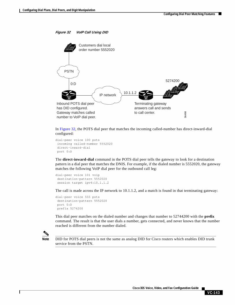
Figure 32 VoIP Call Using DID
In Figure 32, the POTS dial peer that matches the incoming called-number has direct-inward-dialconfigured:
dial-peer voice 100 pots incoming called-number 5552020 direct-inward-dial port 0:D
Thedirect-inward-dial command in the POTS dial peer tells the gateway to look for a destinationpattern in a dial peer that matches the DNIS. For example, if the dialed number is 5552020, the gatewaymatches the following VoIP dial peer for the outbound call leg:
dial-peer voice 101 voip destination-pattern 5552020 session target ipv4:10.1.1.2
The call is made across the IP network to 10.1.1.2, and a match is found in that terminating gateway:
dial-peer voice 555 pots destination-pattern 5552020 port 0:D prefix 5274200
This dial peer matches on the dialed number and changes that number to 52744200 with theprefixcommand. The result is that the user dials a number, gets connected, and never knows that the numberreached is different from the number dialed.
Note DID for POTS dial peers is not the same as analog DID for Cisco routers which enables DID trunkservice from the PSTN.
IP network
0:D
10.1.1.2
5274200
Customers dial localorder number 5552020
Inbound POTS dial peerhas DID configured.Gateway matches callednumber to VoIP dial peer.
Terminating gatewayanswers call and sendsto call center.
PSTN
36
49
8
V V
Configuring Dial Plans, Dial Peers, and Digit ManipulationConfiguring Dial Peer Matching Features
VC-144Cisco IOS Voice, Video, and Fax Configuration Guide
To configure a POTS dial peer for DID, use the following commands beginning in global configurationmode:
Note DID is configured for inbound POTS dial peers only.
Identifying Voice and Modem CallsWhen a Cisco router is handling both modem and voice calls, it needs to identify the service type of thecall—that is, whether the incoming call to the router is a modem or a voice call. When the router handlesonly modem calls, the service type identification is handled through modem pools. Modem poolsassociate calls with modem resources based on the called number (DNIS). In a mixed environment,where the router receives both modem and voice calls, you need to identify the service type of a call byusing theincoming called-number command.
If the incoming called-number command is not configured, the router attempts to resolve whether anincoming call is a modem or voice call on the basis of the interface over which the call comes. If the callcomes in over an interface associated with a modem pool, the call is assumed to be a modem call; if acall comes in over a voice port associated with a POTS dial peer, the call is assumed to be a voice call.
To identify the service type of a call as voice, use the following commands beginning in globalconfiguration mode:
Hunt Groups and PreferencesThe router supports the concept ofhunt groups, sometimes calledrotary groups, in which multiple dialpeers are configured with the same destination pattern. Because the destination of each POTS dial peeris a single voice port to a telephony interface, hunt groups help ensure that calls get through even whena specific voice port is busy. If the router is configured to hunt, it can forward a call to another voice portwhen one voice port is busy.
For example, in the following configuration for Router A, four POTS dial peers are configured withdifferent destination patterns. Because each dial peer has a different destination pattern, no backup isavailable if the voice port mapped to a particular dial peer is busy with another call.
Command Purpose
Step 1 Router(config)# dial-peer voice number pots Enters dial-peer configuration mode and defines alocal dial peer that will connect to the POTS network.
Thenumberis one or more digits identifying the dialpeer. Valid entries are from 1 to 2147483647.
Step 2 Router(config-dial-peer)# direct-inward-dial Specifies DID for this POTS dial peer.
Command Purpose
Step 1 Router(config)# dial-peer voice number { pots | voip |vofr | voatm }
Enters dial peer configuration mode.
Step 2 Router(config-dial-peer)# incoming called-numbernumber
Defines the telephone number that identifies voicecalls associated with this dial peer.
Configuring Dial Plans, Dial Peers, and Digit ManipulationConfiguring Dial Peer Matching Features
VC-145Cisco IOS Voice, Video, and Fax Configuration Guide
With a hunt group, if a voice port is busy, the router hunts for another voice port until it finds one that isavailable. In the following example for Router B, each dial peer is configured using the same destinationpattern of 3000, forming a dial pool to that destination pattern.
To give specific dial peers in the pool a preference over other dial peers, you can configure the preferenceorder for each dial peer by using thepreferencecommand. The router attempts to place a call to the dialpeer with the highest preference. The configuration example given for Router B shows that all dial peershave the same destination pattern, but different preference orders.
The lower the preference number, the higher the priority. The highest priority is given to the dial peerwith preference order 0. If the same preference is defined in multiple dial peers with the same destinationpattern, a dial peer is selected randomly.
By default, dial peers in a hunt group are selected according to the following criteria, in the order listed:
1. Longest match in phone number—Destination pattern that matches the greatest number of dialeddigits. For example, if one dial peer is configured with a dial string of 345.... and a second dialpeer is configured with 3456789, the router would first select 3456789 because it has the longestexplicit match of the two dial peers.
2. Explicit preference—Priority configured by using thepreference dial peer command.
3. Random selection—All destination patterns weighted equally.
You can change this default selection order or choose different methods for hunting dial peers by usingthedial-peer hunt global configuration command. An additional selection criteria is “least recent use,”which selects the destination pattern that has waited the longest since being selected.
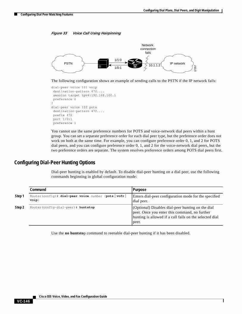
You can mix POTS and voice-network dial peers when creating hunt groups. This can be useful if youwant incoming calls to be sent over the packet network, except that if network connectivity fails, youwant to reroute the calls back through the PBX to the PSTN. This type of configuration is sometimesreferred to ashairpinning. Hairpinning is illustrated inFigure 33.
Router A (Without Hunt Groups) Router B (With Hunt Groups and Preferences)dial-peer voice 1 pots
destination-pattern 3001port 1/1
!dial-peer voice 2 pots
destination-pattern 3002port 1/2
!dial-peer voice 3 pots
destination-pattern 3003port 1/3
!dial-peer voice 4 pots
destination-pattern 3004port 1/4
dial-peer voice 1 potsdestination pattern 3000port 1/1preference 0
!dial-peer voice 2 pots
destination pattern 3000port 1/2preference 1
!dial-peer voice 3 pots
destination pattern 3000port 1/3preference 2
!dial-peer voice 4 pots
destination pattern 3000port 1/4preference 3
Configuring Dial Plans, Dial Peers, and Digit ManipulationConfiguring Dial Peer Matching Features
VC-146Cisco IOS Voice, Video, and Fax Configuration Guide
Figure 33 Voice Call Using Hairpinning
The following configuration shows an example of sending calls to the PSTN if the IP network fails:
dial-peer voice 101 voipdestination-pattern 472....session target ipv4:192.168.100.1preference 0
!dial-peer voice 102 pots
destination-pattern 472....prefix 472port 1/0:1preference 1
You cannot use the same preference numbers for POTS and voice-network dial peers within a huntgroup. You can set a separate preference order for each dial peer type, but the preference order does notwork on both at the same time. For example, you can configure preference order 0, 1, and 2 for POTSdial peers, and you can configure preference order 0, 1, and 2 for the voice-network dial peers, but thetwo preference orders are separate. The system resolves preference orders among POTS dial peers first.
Configuring Dial-Peer Hunting Options
Dial-peer hunting is enabled by default. To disable dial-peer hunting on a dial peer, use the followingcommands beginning in global configuration mode:
Use the no huntstop command to reenable dial-peer hunting if it has been disabled.
1/1:0
Network connection
fails
1/0:110.1.1.2
3735
7VPSTN IP network
Command Purpose
Step 1 Router(config)# dial-peer voice number { pots | vofr |voip }
Enters dial-peer configuration mode for the specifieddial peer.
Step 2 Router(config-dial-peer)# huntstop (Optional) Disables dial-peer hunting on the dialpeer. Once you enter this command, no furtherhunting is allowed if a call fails on the selected dialpeer.
Configuring Dial Plans, Dial Peers, and Digit ManipulationConfiguring Dial Peer Matching Features
VC-147Cisco IOS Voice, Video, and Fax Configuration Guide
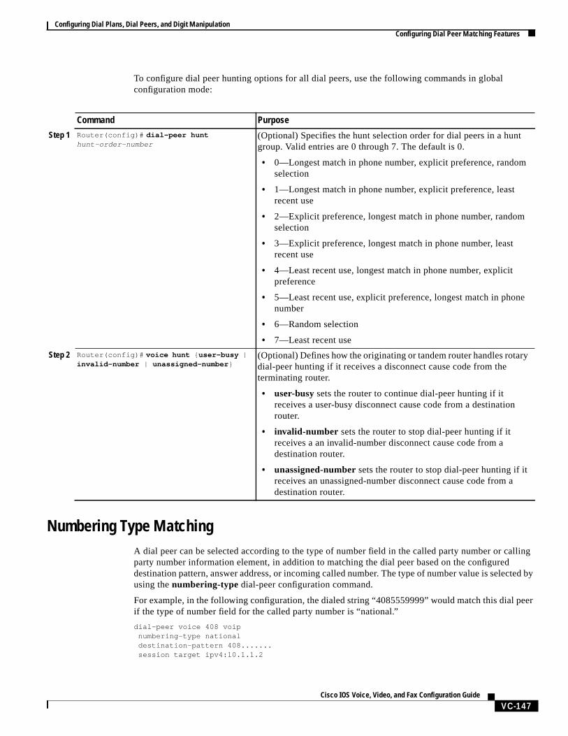
To configure dial peer hunting options for all dial peers, use the following commands in globalconfiguration mode:
Numbering Type MatchingA dial peer can be selected according to the type of number field in the called party number or callingparty number information element, in addition to matching the dial peer based on the configureddestination pattern, answer address, or incoming called number. The type of number value is selected byusing thenumbering-type dial-peer configuration command.
For example, in the following configuration, the dialed string “4085559999” would match this dial peerif the type of number field for the called party number is “national.”
dial-peer voice 408 voipnumbering-type nationaldestination-pattern 408.......session target ipv4:10.1.1.2
Command Purpose
Step 1 Router(config)# dial-peer hunthunt-order-number
(Optional) Specifies the hunt selection order for dial peers in a huntgroup. Valid entries are 0 through 7. The default is 0.
• 0—Longest match in phone number, explicit preference, randomselection
• 1—Longest match in phone number, explicit preference, leastrecent use
• 2—Explicit preference, longest match in phone number, randomselection
• 3—Explicit preference, longest match in phone number, leastrecent use
• 4—Least recent use, longest match in phone number, explicitpreference
• 5—Least recent use, explicit preference, longest match in phonenumber
• 6—Random selection
• 7—Least recent use
Step 2 Router(config)# voice hunt { user-busy |invalid-number | unassigned-number }
(Optional) Defines how the originating or tandem router handles rotarydial-peer hunting if it receives a disconnect cause code from theterminating router.
• user-busysets the router to continue dial-peer hunting if itreceives a user-busy disconnect cause code from a destinationrouter.
• invalid-number sets the router to stop dial-peer hunting if itreceives a an invalid-number disconnect cause code from adestination router.
• unassigned-numbersets the router to stop dial-peer hunting if itreceives an unassigned-number disconnect cause code from adestination router.
Configuring Dial Plans, Dial Peers, and Digit ManipulationConfiguring Dial Peer Matching Features
VC-148Cisco IOS Voice, Video, and Fax Configuration Guide
The following numbering types can be used:
• Abbreviated—Abbreviated representation of the complete number as supported by this network
• International—Number called to reach a subscriber in another country
• National—Number called to reach a subscriber in the same country, but outside the local network
• Network—Administrative or service number specific to the serving network
• Reserved—Reserved for extension
• Subscriber—Number called to reach a subscriber in the same local network
• Unknown—Type of number is unknown by the network
For detailed information about these numbering types, see ITU-T Recommendation Q.931
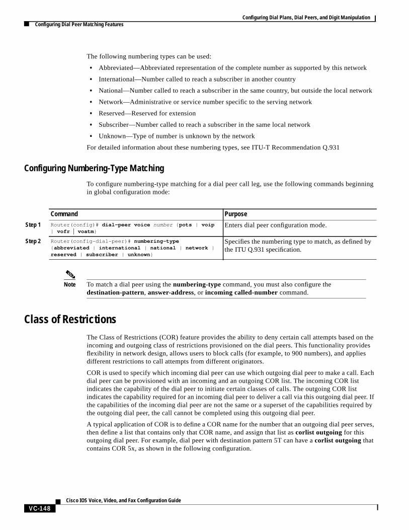
Configuring Numbering-Type Matching
To configure numbering-type matching for a dial peer call leg, use the following commands beginningin global configuration mode:
Note To match a dial peer using thenumbering-type command, you must also configure thedestination-pattern, answer-address, or incoming called-numbercommand.
Class of RestrictionsThe Class of Restrictions (COR) feature provides the ability to deny certain call attempts based on theincoming and outgoing class of restrictions provisioned on the dial peers. This functionality providesflexibility in network design, allows users to block calls (for example, to 900 numbers), and appliesdifferent restrictions to call attempts from different originators.
COR is used to specify which incoming dial peer can use which outgoing dial peer to make a call. Eachdial peer can be provisioned with an incoming and an outgoing COR list. The incoming COR listindicates the capability of the dial peer to initiate certain classes of calls. The outgoing COR listindicates the capability required for an incoming dial peer to deliver a call via this outgoing dial peer. Ifthe capabilities of the incoming dial peer are not the same or a superset of the capabilities required bythe outgoing dial peer, the call cannot be completed using this outgoing dial peer.
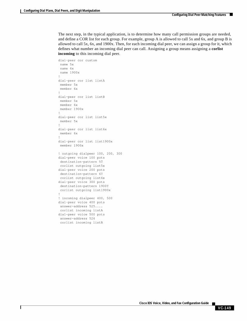
A typical application of COR is to define a COR name for the number that an outgoing dial peer serves,then define a list that contains only that COR name, and assign that list ascorlist outgoing for thisoutgoing dial peer. For example, dial peer with destination pattern 5T can have acorlist outgoing thatcontains COR 5x, as shown in the following configuration.
Command Purpose
Step 1 Router(config)# dial-peer voice number { pots | voip| vofr | voatm }
Enters dial peer configuration mode.
Step 2 Router(config-dial-peer)# numbering-type{ abbreviated | international | national | network |reserved | subscriber | unknown }
Specifies the numbering type to match, as defined bythe ITU Q.931 specification.
Configuring Dial Plans, Dial Peers, and Digit ManipulationConfiguring Dial Peer Matching Features
VC-149Cisco IOS Voice, Video, and Fax Configuration Guide
The next step, in the typical application, is to determine how many call permission groups are needed,and define a COR list for each group. For example, group A is allowed to call 5x and 6x, and group B isallowed to call 5x, 6x, and 1900x. Then, for each incoming dial peer, we can assign a group for it, whichdefines what number an incoming dial peer can call. Assigning a group means assigning acorlistincoming to this incoming dial peer.
dial-peer cor customname 5xname 6xname 1900x
!dial-peer cor list listA
member 5xmember 6x
!dial-peer cor list listB
member 5xmember 6xmember 1900x
!dial-peer cor list list5x
member 5x!dial-peer cor list list6x
member 6x!dial-peer cor list list1900x
member 1900x
! outgoing dialpeer 100, 200, 300dial-peer voice 100 pots
destination-pattern 5Tcorlist outgoing list5x
dial-peer voice 200 potsdestination-pattern 6Tcorlist outgoing list6x
dial-peer voice 300 potsdestination-pattern 1900Tcorlist outgoing list1900x
!! incoming dialpeer 400, 500dial-peer voice 400 pots
answer-address 525....corlist incoming listA
dial-peer voice 500 potsanswer-address 526corlist incoming listB
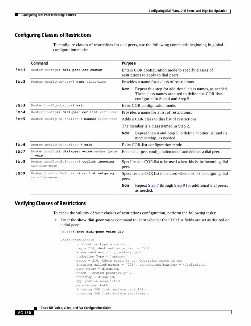
Configuring Dial Plans, Dial Peers, and Digit ManipulationConfiguring Dial Peer Matching Features
VC-150Cisco IOS Voice, Video, and Fax Configuration Guide
Configuring Classes of Restrictions
To configure classes of restrictions for dial peers, use the following commands beginning in globalconfiguration mode:
Verifying Classes of Restrictions
To check the validity of your classes of restrictions configuration, perform the following tasks:
• Enter theshow dial-peer voicecommand to learn whether the COR list fields are set as desired ona dial peer:
Router# show dial-peer voice 210
VoiceEncapPeer210 information type = voice, tag = 210, destination-pattern = `221', answer-address = `', preference=0, numbering Type = `unknown' group = 210, Admin state is up, Operation state is up, incoming called-number = `221', connections/maximum = 4/unlimited, DTMF Relay = disabled, Modem = system passthrough , huntstop = disabled, application associated: permission :both incoming COR list:maximum capability outgoing COR list:minimum requirement
Command Purpose
Step 1 Router(config)# dial-peer cor custom Enters COR configuration mode to specify classes ofrestrictions to apply to dial peers.
Step 2 Router(config-dp-cor)# name class-name Provides a name for a class of restrictions.
Note Repeat this step for additional class names, as needed.These class names are used to define the COR listsconfigured in Step 4 and Step 5.
Step 3 Router(config-dp-cor)# exit Exits COR configuration mode.
Step 4 Router(config)# dial-peer cor list list-name Provides a name for a list of restrictions.
Step 5 Router(config-dp-corlist)# member class-name Adds a COR class to this list of restrictions.
The member is a class named in Step 2.
Note RepeatStep 4 andStep 5 to define another list and itsmembership, as needed.
Step 6 Router(config-dp-corlist)# exit Exits COR-list configuration mode.
Step 7 Router(config)# dial-peer voice number { pots| voip }
Enters dial-peer configuration mode and defines a dial peer.
Step 8 Router(config-dial-peer)# corlist incomingcor-list-name
Specifies the COR list to be used when this is the incoming dialpeer.
Step 9 Router(config-dial-peer)# corlist outgoingcor-list-name
Specifies the COR list to be used when this is the outgoing dialpeer.
Note RepeatStep 7throughStep 9for additional dial peers,as needed.

Configuring Dial Plans, Dial Peers, and Digit ManipulationConfiguring Digit Manipulation
VC-151Cisco IOS Voice, Video, and Fax Configuration Guide
type = pots, prefix = `221', forward-digits default session-target = `', voice-port = `1/0/8:D', direct-inward-dial = enabled, digit_strip = enabled,
• Enter theshow dial-peer cor command to display the COR names and lists you defined:
Router# show dial-peer cor
Class of Restriction name:900block name:800_call name:Catchall
COR list <list1> member:900block member:800_call
COR list <list2> member:900block
COR list <list3> member:900block member:800_call member:Catchall
Configuring Digit ManipulationThe router may need to manipulate digits in a dial string before it passes the dial string to the telephonydevice. This can be necessary, for instance, when calling PBXs with different capabilities to acceptdigits, or for PSTN and international calls. You may need to consider different strategies for configuringdigit manipulation within your dial peers depending on your existing dial plan, the digits users areexpected to dial, and the capabilities of your PBX or key system unit (KSU). These digit-manipulationoptions, in conjunction with the destination pattern, determine the dial string that the router forwards tothe telephony device.
The following dial peer digit-manipulation options are described in this section:
• Digit Stripping and Prefixes, page 151
• Forward Digits, page 154
• Number Expansion, page 155
• Digit Translation Rules for VoIP, page 157
Note Unless otherwise noted, these concepts apply to VoIP, VoFR, and VoATM networks.
Digit Stripping and PrefixesWhen the terminating router matches a dial string to an outbound POTS dial peer, by default the routerstrips off the left-justified digits that explicitly match the destination pattern. Any remaining digits,called excess digits, are forwarded to the telephony interface, such as a PBX or the PSTN. For moreinformation about excess digits, see the“Two-Stage Dialing” section on page 137.

Configuring Dial Plans, Dial Peers, and Digit ManipulationConfiguring Digit Manipulation
VC-152Cisco IOS Voice, Video, and Fax Configuration Guide
Some telephony interfaces require that any digits that are stripped from the dial string must be recoveredto support a particular dial plan. You can accomplish this either by using theno digit-strip dial-peerconfiguration command to disable the default digit-stripping behavior or by using theprefix dial-peerconfiguration command to add digits to the front of the dial string before it is forwarded to the telephonyinterface. These commands are supported only in POTS dial peers.
Theno digit-strip command disables the automatic digit-stripping function so that matching digits arenot stripped from the dialed string before it is passed to the telephony interface. For example, in thefollowing dial peer configuration, the entire seven-digit dialed string is passed to the telephony interface:
dial-peer voice 100 pots destination-pattern 555.... no digit-strip port 1/0:1
Disabling digit stripping is useful when the telephony interface requires the full dialed string. With somedial plans, however, the dialed digits must be manipulated according to specific rules. Theprefixcommand can be used to add specific digits to the front of the dialed string before it is forwarded to thetelephony interface.
For example, consider a telephone whose E.164 called number is 1(408)555-1234. This telephone canbe reached within the company by dialing its extension number, 51234. If you configure a destinationpattern of “1408555.... ” (the periods represent wildcards) for the associated outbound POTS dial peer,the terminating gateway will strip off the digits “1408555” when it receives a call for 1(408)555-1234.For the terminating gateway to forward the call to the appropriate destination, the digit “5” needs to beprepended to the remaining digits. In this case, you would configure a prefix of 5, as shown in thefollowing dial peer configuration.
dial-peer voice 100 pots destination-pattern 1408555.... prefix 5 port 1/0:1
A prefix can also include commas (,). Each comma indicates a one-second pause in dialing. For example,consider a telephone whose E.164 called number is 1(408)555-1234; to reach this device, you must dial“9.” In this case, you might configure “1408....... ” as the destination pattern, and “9” as the prefix.In this example, the terminating router will strip the digits “1408” from the called number and appendthe digit “9” to the front of the remaining digits, so that the actual number dialed is” 9,5551234.” Therouter pauses for one second between dialing the “9” and the “5551234” to allow for a secondary dialtone. In this example, you would configure the router as follows:
dial-peer voice 100 pots destination-pattern 1408....... prefix 9, port 1/0:1
Using a comma with theprefix command is useful when the router must allow for a secondary dial tone;otherwise the router does not wait for the dial tone before playing out excess digits. Putting commas inthe prefix makes the router pause one second per comma, allowing for a dial tone to occur before therouter plays out the digits.
Figure 34shows an example of a network using theno digit-strip command. In this example, a centralsite (Site D) is connected to remote sites through routers (Sites A, B, and C), as well as through a Centrexsystem for sites still using the PSTN (Sites E and F). The Centrex service requires the full 7-digit dialstring to complete calls. The dial peers are configured with a fixed-length 7-digit dial plan.
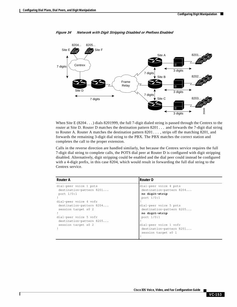
Configuring Dial Plans, Dial Peers, and Digit ManipulationConfiguring Digit Manipulation
VC-153Cisco IOS Voice, Video, and Fax Configuration Guide
Figure 34 Network with Digit Stripping Disabled or Prefixes Enabled
When Site E (8204... ) dials 8201999, the full 7-digit dialed string is passed through the Centrex to therouter at Site D. Router D matches the destination pattern 8201... and forwards the 7-digit dial stringto Router A. Router A matches the destination pattern 8201... , strips off the matching 8201, andforwards the remaining 3-digit dial string to the PBX. The PBX matches the correct station andcompletes the call to the proper extension.
Calls in the reverse direction are handled similarly, but because the Centrex service requires the full7-digit dial string to complete calls, the POTS dial peer at Router D is configured with digit strippingdisabled. Alternatively, digit stripping could be enabled and the dial peer could instead be configuredwith a 4-digit prefix, in this case 8204, which would result in forwarding the full dial string to theCentrex service.
3 digits7 digits
3594
9
8201...
8202...
8203...
8204...
Site E Site F
8205...
Site A
Site B
Site C7 digits
3 digits
3 digits
7 digits
Site D
7 digits
FrameRelay
Centrex
Router A Router Ddial-peer voice 1 pots destination-pattern 8201... port 1/0:1!dial-peer voice 4 vofr destination-pattern 8204... session target s0 2!dial-peer voice 5 vofr destination-pattern 8205... session target s0 2!
dial-peer voice 4 pots destination-pattern 8204...
no digit-strip port 1/0:1!dial-peer voice 5 pots destination-pattern 8205...
no digit-strip port 1/0:1!dial-peer voice 1 vofr destination-pattern 8201... session target s0 1!
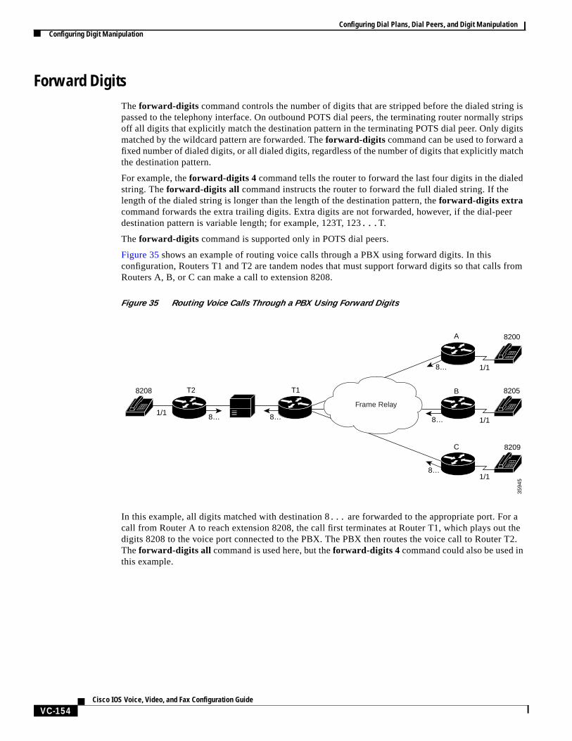
Configuring Dial Plans, Dial Peers, and Digit ManipulationConfiguring Digit Manipulation
VC-154Cisco IOS Voice, Video, and Fax Configuration Guide
Forward DigitsThe forward-digits command controls the number of digits that are stripped before the dialed string ispassed to the telephony interface. On outbound POTS dial peers, the terminating router normally stripsoff all digits that explicitly match the destination pattern in the terminating POTS dial peer. Only digitsmatched by the wildcard pattern are forwarded. Theforward-digits command can be used to forward afixed number of dialed digits, or all dialed digits, regardless of the number of digits that explicitly matchthe destination pattern.
For example, theforward-digits 4 command tells the router to forward the last four digits in the dialedstring. Theforward-digits all command instructs the router to forward the full dialed string. If thelength of the dialed string is longer than the length of the destination pattern, theforward-digits extracommand forwards the extra trailing digits. Extra digits are not forwarded, however, if the dial-peerdestination pattern is variable length; for example, 123T, 123... T.
The forward-digits command is supported only in POTS dial peers.
Figure 35 shows an example of routing voice calls through a PBX using forward digits. In thisconfiguration, Routers T1 and T2 are tandem nodes that must support forward digits so that calls fromRouters A, B, or C can make a call to extension 8208.
Figure 35 Routing Voice Calls Through a PBX Using Forward Digits
In this example, all digits matched with destination 8... are forwarded to the appropriate port. For acall from Router A to reach extension 8208, the call first terminates at Router T1, which plays out thedigits 8208 to the voice port connected to the PBX. The PBX then routes the voice call to Router T2.Theforward-digits all command is used here, but theforward-digits 4 command could also be used inthis example.
Frame Relay
3594
5
8200
8205
8209
8… 8…
T2 T1
A
B
C
8208
8…
8…
8…
1/1
1/1
1/1
1/1
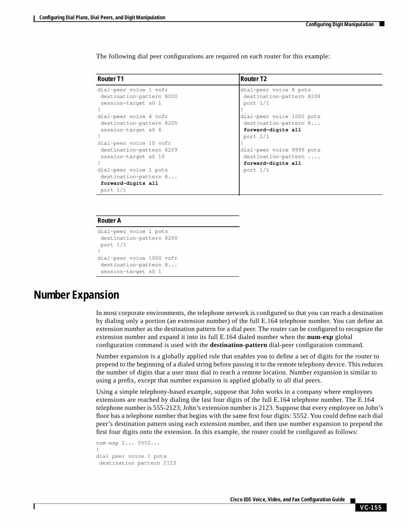
Configuring Dial Plans, Dial Peers, and Digit ManipulationConfiguring Digit Manipulation
VC-155Cisco IOS Voice, Video, and Fax Configuration Guide
The following dial peer configurations are required on each router for this example:
Number ExpansionIn most corporate environments, the telephone network is configured so that you can reach a destinationby dialing only a portion (an extension number) of the full E.164 telephone number. You can define anextension number as the destination pattern for a dial peer. The router can be configured to recognize theextension number and expand it into its full E.164 dialed number when thenum-exp globalconfiguration command is used with thedestination-pattern dial-peer configuration command.
Number expansion is a globally applied rule that enables you to define a set of digits for the router toprepend to the beginning of a dialed string before passing it to the remote telephony device. This reducesthe number of digits that a user must dial to reach a remote location. Number expansion is similar tousing a prefix, except that number expansion is applied globally to all dial peers.
Using a simple telephony-based example, suppose that John works in a company where employeesextensions are reached by dialing the last four digits of the full E.164 telephone number. The E.164telephone number is 555-2123; John’s extension number is 2123. Suppose that every employee on John’sfloor has a telephone number that begins with the same first four digits: 5552. You could define each dialpeer’s destination pattern using each extension number, and then use number expansion to prepend thefirst four digits onto the extension. In this example, the router could be configured as follows:
num-exp 2... 5552...!dial peer voice 1 pots
destination pattern 2123
Router T1 Router T2dial-peer voice 1 vofr destination-pattern 8200 session-target s0 1!dial-peer voice 6 vofr destination-pattern 8205 session-target s0 6!dial-peer voice 10 vofr destination-pattern 8209 session-target s0 10!dial-peer voice 1 pots destination-pattern 8...
forward-digits all port 1/1
dial-peer voice 8 pots destination-pattern 8208 port 1/1!dial-peer voice 1000 pots destination-pattern 8... forward-digits all port 1/1!dial-peer voice 9999 pots destination-pattern .... forward-digits all port 1/1
Router Adial-peer voice 1 pots destination-pattern 8200 port 1/1!dial-peer voice 1000 vofr destination-pattern 8... session-target s0 1
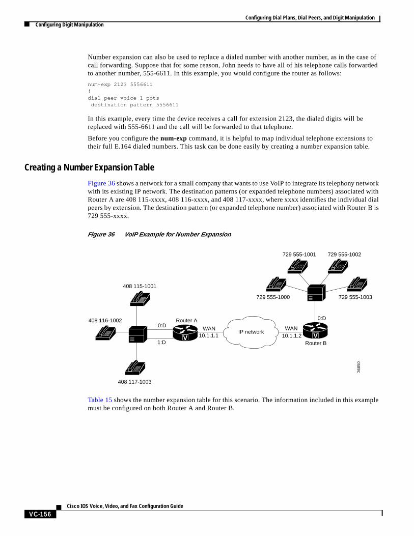
Configuring Dial Plans, Dial Peers, and Digit ManipulationConfiguring Digit Manipulation
VC-156Cisco IOS Voice, Video, and Fax Configuration Guide
Number expansion can also be used to replace a dialed number with another number, as in the case ofcall forwarding. Suppose that for some reason, John needs to have all of his telephone calls forwardedto another number, 555-6611. In this example, you would configure the router as follows:
num-exp 2123 5556611!dial peer voice 1 pots
destination pattern 5556611
In this example, every time the device receives a call for extension 2123, the dialed digits will bereplaced with 555-6611 and the call will be forwarded to that telephone.
Before you configure thenum-exp command, it is helpful to map individual telephone extensions totheir full E.164 dialed numbers. This task can be done easily by creating a number expansion table.
Creating a Number Expansion Table
Figure 36shows a network for a small company that wants to use VoIP to integrate its telephony networkwith its existing IP network. The destination patterns (or expanded telephone numbers) associated withRouter A are 408 115-xxxx, 408 116-xxxx, and 408 117-xxxx, where xxxx identifies the individual dialpeers by extension. The destination pattern (or expanded telephone number) associated with Router B is729 555-xxxx.
Figure 36 VoIP Example for Number Expansion
Table 15shows the number expansion table for this scenario. The information included in this examplemust be configured on both Router A and Router B.
408 116-1002
408 115-1001
408 117-1003
729 555-1000 729 555-1003
729 555-1001 729 555-1002
Router A
WAN WAN10.1.1.1 10.1.1.2
Router B
0:D0:D
3685
0
1:DV V
IP network
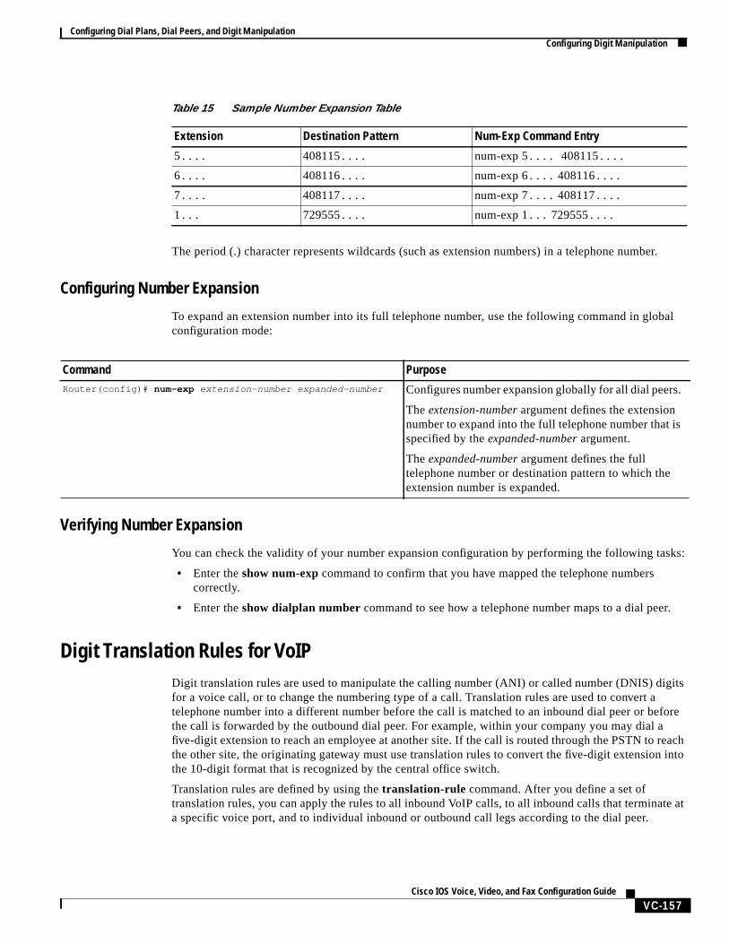
Configuring Dial Plans, Dial Peers, and Digit ManipulationConfiguring Digit Manipulation
VC-157Cisco IOS Voice, Video, and Fax Configuration Guide
The period (.) character represents wildcards (such as extension numbers) in a telephone number.
Configuring Number Expansion
To expand an extension number into its full telephone number, use the following command in globalconfiguration mode:
Verifying Number Expansion
You can check the validity of your number expansion configuration by performing the following tasks:
• Enter the show num-exp command to confirm that you have mapped the telephone numberscorrectly.
• Enter theshow dialplan number command to see how a telephone number maps to a dial peer.
Digit Translation Rules for VoIPDigit translation rules are used to manipulate the calling number (ANI) or called number (DNIS) digitsfor a voice call, or to change the numbering type of a call. Translation rules are used to convert atelephone number into a different number before the call is matched to an inbound dial peer or beforethe call is forwarded by the outbound dial peer. For example, within your company you may dial afive-digit extension to reach an employee at another site. If the call is routed through the PSTN to reachthe other site, the originating gateway must use translation rules to convert the five-digit extension intothe 10-digit format that is recognized by the central office switch.
Translation rules are defined by using thetranslation-rule command. After you define a set oftranslation rules, you can apply the rules to all inbound VoIP calls, to all inbound calls that terminate ata specific voice port, and to individual inbound or outbound call legs according to the dial peer.
Table 15 Sample Number Expansion Table
Extension Destination Pattern Num-Exp Command Entry
5.... 408115.... num-exp 5.... 408115....
6.... 408116.... num-exp 6.... 408116....
7.... 408117.... num-exp 7.... 408117....
1... 729555.... num-exp 1... 729555....
Command PurposeRouter(config)# num-exp extension-number expanded-number Configures number expansion globally for all dial peers.
Theextension-number argument defines the extensionnumber to expand into the full telephone number that isspecified by theexpanded-number argument.
Theexpanded-number argument defines the fulltelephone number or destination pattern to which theextension number is expanded.
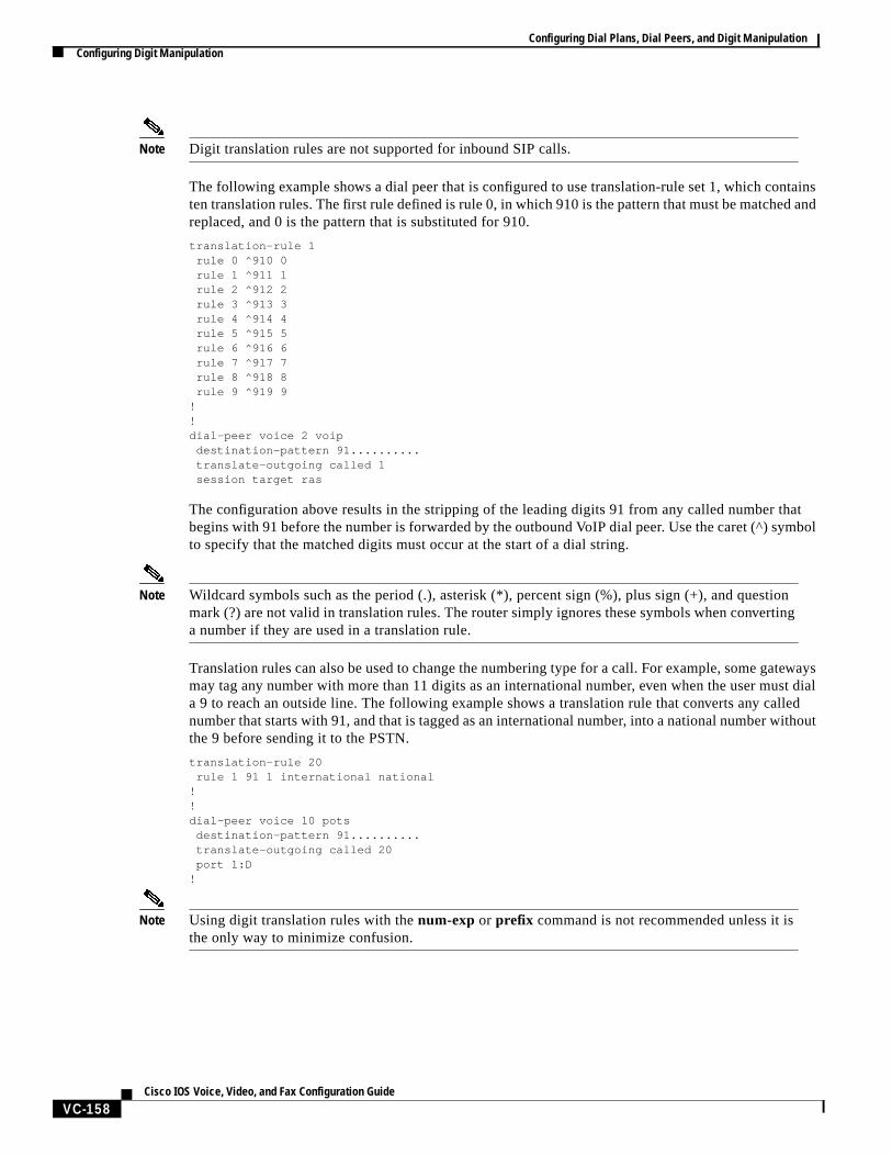
Configuring Dial Plans, Dial Peers, and Digit ManipulationConfiguring Digit Manipulation
VC-158Cisco IOS Voice, Video, and Fax Configuration Guide
Note Digit translation rules are not supported for inbound SIP calls.
The following example shows a dial peer that is configured to use translation-rule set 1, which containsten translation rules. The first rule defined is rule 0, in which 910 is the pattern that must be matched andreplaced, and 0 is the pattern that is substituted for 910.
translation-rule 1rule 0 ^910 0rule 1 ^911 1rule 2 ^912 2rule 3 ^913 3rule 4 ^914 4rule 5 ^915 5rule 6 ^916 6rule 7 ^917 7rule 8 ^918 8rule 9 ^919 9
!!dial-peer voice 2 voip
destination-pattern 91..........translate-outgoing called 1session target ras
The configuration above results in the stripping of the leading digits 91 from any called number thatbegins with 91 before the number is forwarded by the outbound VoIP dial peer. Use the caret (^) symbolto specify that the matched digits must occur at the start of a dial string.
Note Wildcard symbols such as the period (.), asterisk (*), percent sign (%), plus sign (+), and questionmark (?) are not valid in translation rules. The router simply ignores these symbols when convertinga number if they are used in a translation rule.
Translation rules can also be used to change the numbering type for a call. For example, some gatewaysmay tag any number with more than 11 digits as an international number, even when the user must diala 9 to reach an outside line. The following example shows a translation rule that converts any callednumber that starts with 91, and that is tagged as an international number, into a national number withoutthe 9 before sending it to the PSTN.
translation-rule 20rule 1 91 1 international national
!!dial-peer voice 10 pots
destination-pattern 91..........translate-outgoing called 20port 1:D
!
Note Using digit translation rules with thenum-exp or prefix command is not recommended unless it isthe only way to minimize confusion.
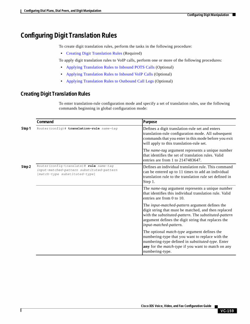
Configuring Dial Plans, Dial Peers, and Digit ManipulationConfiguring Digit Manipulation
VC-159Cisco IOS Voice, Video, and Fax Configuration Guide
Configuring Digit Translation RulesTo create digit translation rules, perform the tasks in the following procedure:
• Creating Digit Translation Rules (Required)
To apply digit translation rules to VoIP calls, perform one or more of the following procedures:
• Applying Translation Rules to Inbound POTS Calls (Optional)
• Applying Translation Rules to Inbound VoIP Calls (Optional)
• Applying Translation Rules to Outbound Call Legs (Optional)
Creating Digit Translation Rules
To enter translation-rule configuration mode and specify a set of translation rules, use the followingcommands beginning in global configuration mode:
Command Purpose
Step 1 Router(config)# translation-rule name-tag Defines a digit translation-rule set and enterstranslation-rule configuration mode. All subsequentcommands that you enter in this mode before you exitwill apply to this translation-rule set.
Thename-tagargument represents a unique numberthat identifies the set of translation rules. Validentries are from 1 to 2147483647.
Step 2 Router(config-translate)# rule name-taginput-matched-pattern substituted-pattern[ match-type substituted-type ]
Defines an individual translation rule. This commandcan be entered up to 11 times to add an individualtranslation rule to the translation rule set defined inStep 1.
Thename-tagargument represents a unique numberthat identifies this individual translation rule. Validentries are from 0 to 10.
The input-matched-pattern argument defines thedigit string that must be matched, and then replacedwith thesubstituted-pattern. Thesubstituted-patternargument defines the digit string that replaces theinput-matched-pattern.
The optionalmatch-type argument defines thenumbering-type that you want to replace with thenumbering-type defined insubstituted-type. Enterany for thematch-type if you want to match on anynumbering-type.
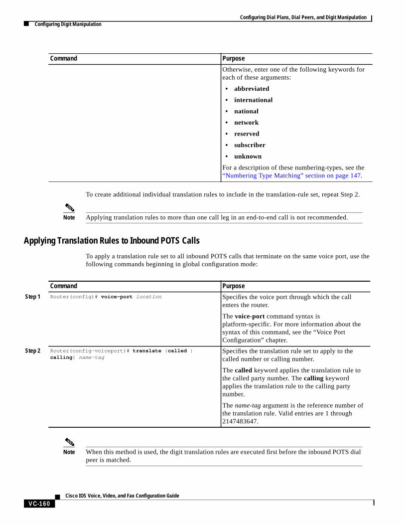
Configuring Dial Plans, Dial Peers, and Digit ManipulationConfiguring Digit Manipulation
VC-160Cisco IOS Voice, Video, and Fax Configuration Guide
To create additional individual translation rules to include in the translation-rule set, repeat Step 2.
Note Applying translation rules to more than one call leg in an end-to-end call is not recommended.
Applying Translation Rules to Inbound POTS Calls
To apply a translation rule set to all inbound POTS calls that terminate on the same voice port, use thefollowing commands beginning in global configuration mode:
Note When this method is used, the digit translation rules are executed first before the inbound POTS dialpeer is matched.
Otherwise, enter one of the following keywords foreach of these arguments:
• abbreviated
• international
• national
• network
• reserved
• subscriber
• unknown
For a description of these numbering-types, see the“Numbering Type Matching” section on page 147.
Command Purpose
Command Purpose
Step 1 Router(config)# voice-port location Specifies the voice port through which the callenters the router.
Thevoice-port command syntax isplatform-specific. For more information about thesyntax of this command, see the “Voice PortConfiguration” chapter.
Step 2 Router(config-voiceport)# translate { called |calling } name-tag
Specifies the translation rule set to apply to thecalled number or calling number.
Thecalled keyword applies the translation rule tothe called party number. Thecalling keywordapplies the translation rule to the calling partynumber.
Thename-tag argument is the reference number ofthe translation rule. Valid entries are 1 through2147483647.
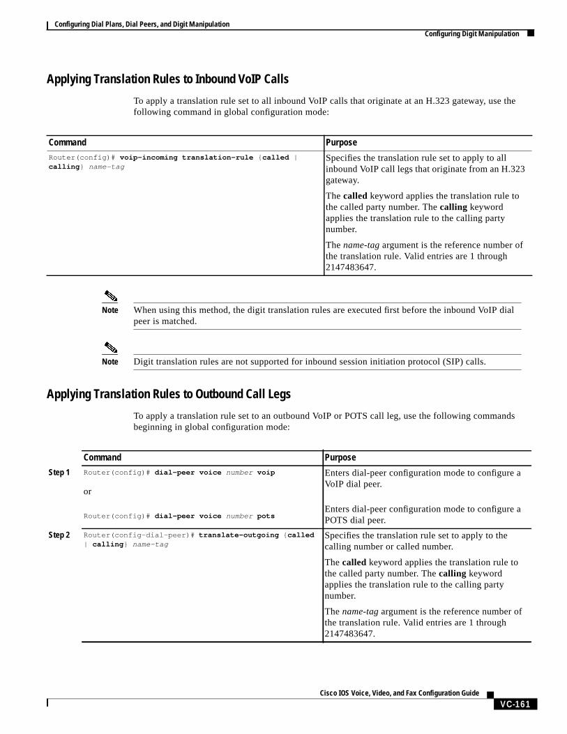
Configuring Dial Plans, Dial Peers, and Digit ManipulationConfiguring Digit Manipulation
VC-161Cisco IOS Voice, Video, and Fax Configuration Guide
Applying Translation Rules to Inbound VoIP Calls
To apply a translation rule set to all inbound VoIP calls that originate at an H.323 gateway, use thefollowing command in global configuration mode:
Note When using this method, the digit translation rules are executed first before the inbound VoIP dialpeer is matched.
Note Digit translation rules are not supported for inbound session initiation protocol (SIP) calls.
Applying Translation Rules to Outbound Call Legs
To apply a translation rule set to an outbound VoIP or POTS call leg, use the following commandsbeginning in global configuration mode:
Command PurposeRouter(config)# voip-incoming translation-rule { called |calling } name-tag
Specifies the translation rule set to apply to allinbound VoIP call legs that originate from an H.323gateway.
Thecalled keyword applies the translation rule tothe called party number. Thecalling keywordapplies the translation rule to the calling partynumber.
Thename-tag argument is the reference number ofthe translation rule. Valid entries are 1 through2147483647.
Command Purpose
Step 1 Router(config)# dial-peer voice number voip
or
Router(config)# dial-peer voice number pots
Enters dial-peer configuration mode to configure aVoIP dial peer.
Enters dial-peer configuration mode to configure aPOTS dial peer.
Step 2 Router(config-dial-peer)# translate-outgoing { called| calling } name-tag
Specifies the translation rule set to apply to thecalling number or called number.
Thecalled keyword applies the translation rule tothe called party number. Thecalling keywordapplies the translation rule to the calling partynumber.
Thename-tag argument is the reference number ofthe translation rule. Valid entries are 1 through2147483647.
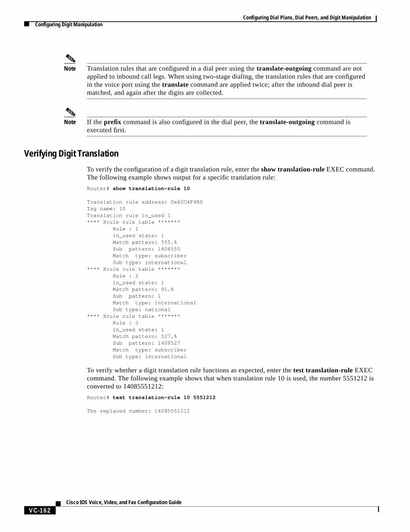
Configuring Dial Plans, Dial Peers, and Digit ManipulationConfiguring Digit Manipulation
VC-162Cisco IOS Voice, Video, and Fax Configuration Guide
Note Translation rules that are configured in a dial peer using thetranslate-outgoing command are notapplied to inbound call legs. When using two-stage dialing, the translation rules that are configuredin the voice port using thetranslate command are applied twice; after the inbound dial peer ismatched, and again after the digits are collected.
Note If the prefix command is also configured in the dial peer, thetranslate-outgoing command isexecuted first.
Verifying Digit Translation
To verify the configuration of a digit translation rule, enter theshow translation-rule EXEC command.The following example shows output for a specific translation rule:
Router# show translation-rule 10
Translation rule address: 0x62C4F4B0Tag name: 10Translation rule in_used 1**** Xrule rule table ******* Rule : 1 in_used state: 1 Match pattern: 555.% Sub pattern: 1408555 Match type: subscriber Sub type: international**** Xrule rule table ******* Rule : 2 in_used state: 1 Match pattern: 91.% Sub pattern: 1 Match type: international Sub type: national**** Xrule rule table ******* Rule : 3 in_used state: 1 Match pattern: 527.% Sub pattern: 1408527 Match type: subscriber Sub type: international
To verify whether a digit translation rule functions as expected, enter thetest translation-rule EXECcommand. The following example shows that when translation rule 10 is used, the number 5551212 isconverted to 14085551212:
Router# test translation-rule 10 5551212
The replaced number: 14085551212