combustion optimization by tunable diode laser …€¦ · combustion optimization by tunable diode...
TRANSCRIPT

Combustion optimization by
Tunable Diode Laser Spectroscopy
Arthur Groenbos
Product Manager Gas Analyzers
Yokogawa Europe BV [email protected]

Agenda
• Introduction Yokogawa
• What is TDLS?
• Basics of combustion
• Example from the field
• Conclusion

86 affiliates in 56 countries
Yokogawa’s 100 year history
Global business expansion
1915 2015 1955 1965 1975 1985 1995 2005
1975 World’s 1st DCS: CENTUM
1915 Founded by Dr. Tamisuke Yokogawa
1957 USA 1974 Europe
1987 India, Australia
1986 China
1997 Russia, South Africa
1950 First electronic recorders in Japan
1979 World’s 1st vortex flowmeter
1994 World’s 1st fully digital transmitter with silicon resonant sensor
1996 World’s largest DCS-PJT
2000 World’s 1st MAC-PJT
2010 World’s 1st ISA100 compliant field devices
2009 World’s 1st ISA95 compliant real-time MES package
1973 Singapore
1992 Brazil 2006 Saudi Arabia
1990 Middle East
2005 World’s 1st Integrated DCS-SIS
2014 World’s 1st smart configurable I/O: CENTUM VP

Worldwide Business Operations
Global network supporting business growth
Number of Employees Worldwide : 19,685 / Outside Japan : 11,089
15 subsidiaries and 1 affiliate in Japan 69 subsidiaries and 2 affiliates outside Japan
Regional Head Quarters
C
World Headquarters Yokogawa Electric Corporation (Japan)
Yokogawa Corporation of America (USA)
Yokogawa China (China)
Yokogawa Middle East & Africa (Bahrain)
Yokogawa Europe (The Netherlands)
Yokogawa Electric International Yokogawa Engineering Asia (Singapore)

Corporate Management (ERP*) Integrated business operation systems
Production Management
(MES*) Systems for advanced control,
simulation, production management, and scheduling
PIMS Process Data Acquisition & Management
Asset Management APC & OWA
CAMS for HIS
Advanced Process Control & Operational Work Assistance
AXF
Magnetic Flowmeter
DYF
Digital Vortex Flowmeter
Field Instruments Field instruments, sensors, measuring
instruments, analyzers and other equipment
EJA/EJX
Differential Pressure Transmitter
ZR
Zirconia Oxygen Analyzer
Tunable Diode Laser Spectrometer
TDLS8000 GC8000
Process Gas Chromatograph
YVP
Advanced Valve Positioner
YTA50/70 YTA100/300
Temperature Transmitter
Production Control System Production control systems
Safety Instrumented System
Network Based Control System
Integrated Production
Control System DCS
* ERP = Enterprise Resource Planning
* MES = Manufacturing Execution System
Yokogawa portfolio Industrial Automation & Control

What is TDLS?

What is TDL Spectroscopy?
• TDL: Tunable Diode Laser
• Based on absorption spectroscopy; measuring the amount of light that is absorbed as it travels through the sample being measured
• Absorption equals concentration: Lambert-Beer’s law

Lambert Beers‘ Law
I0 I
Transmission: T= I/I0
Absorption: A = log 1/T = Ɛ . C . L
C = A / Ɛ . L
C = concentration
A = absorption
Ɛ = extinction coefficient
L = optical path length
L L L L
C C C C
0
0,2
0,4
0,6
0,8
1
0 0,2 0,4 0,6 0,8 1
concentration [c]
Re
lati
ve
sc
ale
Transmission
Absorption

Fundamental Vibration of the Water Molecule
• Molecules can be considered oscillators
• The bonds correlate to springs and the atoms are mass balls
• The molecules vibrate by absorbing heat energy from the ambient
What will happen, if we radiate the molecules with the resonance frequency?

Absorption of IR-Radiation

Absorption of IR-Radiation
IR radiation will be attenuated

Symmetrical stretching
Antisymmetrical stretching
Scissoring Rocking Wagging Twisting
Stretching and bending of the bonds within molecules occurs at a frequency that is specific to that particular bond. If the vibration causes a change in dipole of the molecule then light at a particular frequency in the infrared band will be absorbed.
TDLS: an IR analyzer that measures also Oxygen

IR Spectrum of Water
Wavenumber [cm-1]
Abso
rption [
AU
]
1595 cm-1 scissoring
3757 cm-1 asym
3658 cm-1 sym

Single peak Spectroscopy
• Diode lasers have very narrow wavelength emission (line width), typically 0.00004nm (0.04 pm = 0.04 *10-12 m) wide which allows hundreds or thousands of data points across the peak.
• Therefore, they can focus on a single defined peak that has no overlap
• The laser scans the bandwidth, measuring the peak and baseline
0.00E+00
5.00E-04
1.00E-03
1.50E-03
2.00E-03
2.50E-03
3.00E-03
3.50E-03
4.00E-03
4.50E-03
5.00E-031536
1535
1535
1535
1535
1535
1535
1534
1534
1534
1534
1534
1534
1534
1533
1533
1533
1533
1533
1 7 13 19 25 31 37 43 49 55 61 67 73 79 85 91 97 103 109 115 121 127 133 139 145 151
0.1 – 0.2nm
CO2
H2O

Current ramp to laser
Time
Current
Signal at Detector
Time
Current
1. The laser is held at a fixed temperature as a coarse wavelength adjustment 2. A current ramp is fed to the laser as the fine wavelength adjustment. The collimated light passes through the gas to be measured. The amount of light absorbed by the peak is proportional to the analyte concentration 3. The light is then focused on a detector and this direct signal is used to quantify the light absorbed by the analyte
15
Operation Yokogawa TDLS
Flattened signal: absorption peak

“Simple and Robust”
TDLS8000
Intuitive Color Touch Screen
HART and Modbus TCP Communication Standard
SIL 2 Certified
8-Stage Auto Gain
Easy Installation
Reference Cell
Smart Laser Module
New TDLS8000

What are the benefits?
1. Easy operation and installation Color touch screen
Display at both ends
2. Adaption to difficult applications Auto gain
Reference cell
3. Safety design with SIL 2 certificate
4. Meets various network communication needs Modbus/TCP and HART
5. Exd housing (size and optimized utility consumption)
6. Fully field repairable and fast diagnosis Modular boards and smart laser design
50 days of data and spectrum storage

Basics of combustion

What is combustion?
• Complete combustion:
CH4(g) + 2O2(g) -> CO2(g) + 2H2O(g)
• Incomplete combustion:
CH4(g) + 3O2(g) -> 2CO(g) + 4 H2O(g)
or
CH4(g) + O2(g) -> C(s) + 2H2O(g)

Proprietary info goes here…
Combustion: theory

21
Combustion: practice
0
500
1000
1500
2000
2500
3000
3500
4000
4500
1 13 25 37 49 61 73 85 97 109 121 133 145 157 169 181 193 205 217 229 241 253 265 277 289
0
0.5
1
1.5
2
2.5
3
3.5
4
4.5
TDL CO ppm
TDL O2 %
Operator Test. Adjust O2 downward to cause CO breakthroughs.
Its Reproducible First breakthrough. Operator increases O2 and CO goes down.
Second breakthrough. Operator increases
O2 and CO goes down.

Fired heaters are widely used in oil refining and petrochemical industry, providing heat for a main process or cracking reaction by fuel combustion
Fired heater
Picture brochure “Fired Heaters” 2013, Foster Wheeler

• Fuels
– Plant off gas (C1 ~ C5, H2, H2S… composition varies)
– Natural gas
– Fuel oil
• Draft system
– Natural draft
– Forced draft
– Balance draft
Different types fired heaters
Fuel
Air
Flue gas
Natural draft
Fuel
Air
Flue gas
FDF(Forced Draft Fan)
IDF(Induced Draft Fan)
Forced draft
Balanced draftif exist

Traditional fired heater control
• Coil outlet temperature controlled by burner fuel pressure
• (Natural draft) No air flow measurement & control
• (Forced / Balanced draft) Air flow control but no follow up to fuel amount sometime
• Flue gas measurement for emission monitoring
Coil outlet temp.
Burner fuel
press.
PIC
TIC
K ∫
Δ
TE PT
K ∫
Δ
O2, CO, CO2, NOx, SO2, Opacity
CEMS
Fuel control valve

Typical fired heater control with flue gas O2 control
• Coil outlet temperature control by fuel flow
• Burner fuel pressure control by limiting fuel control valve opening
• Coil outlet temperature controller sends set point to both air and fuel flow
• Air/fuel cross-limit may be configured
• Flue gas measurement for emission monitoring
• ZrO2 sensor is installed for flue gas O2 control
ZrO2
K ∫
Δ
TE FT
K ∫
Δ
FT
K ∫
Δ
O2
K ∫
Δ
Fuel control valve
Coil outlet temp.
Fuel flow
FIC
TIC
O2, CO, CO2, NOx, SO2, Opacity
CEMS
FIC
Combustion air
Air flow
Flue gas O2
(Zirconia)
Cross-limit
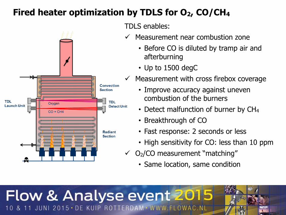
Fired heater optimization by TDLS for O2, CO/CH4
TDLS enables:
Measurement near combustion zone
• Before CO is diluted by tramp air and afterburning
• Up to 1500 degC
Measurement with cross firebox coverage
• Improve accuracy against uneven combustion of the burners
• Detect malfunction of burner by CH4
• Breakthrough of CO
• Fast response: 2 seconds or less
• High sensitivity for CO: less than 10 ppm
O2/CO measurement “matching”
• Same location, same condition

Output increase vs lifetime assets
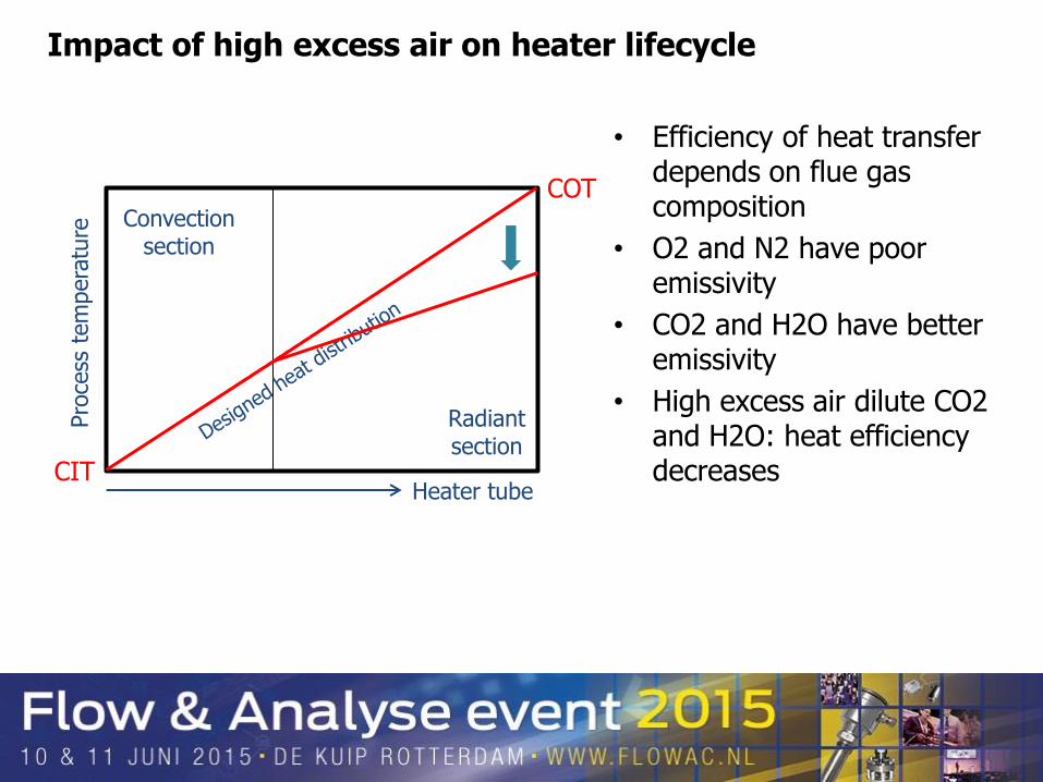
Impact of high excess air on heater lifecycle
Convection section
Radiant section
Heater tube
Pro
cess
tem
pera
ture
CIT
COT
• Efficiency of heat transfer depends on flue gas composition
• O2 and N2 have poor emissivity
• CO2 and H2O have better emissivity
• High excess air dilute CO2 and H2O: heat efficiency decreases

Convection section
Radiant section
Heater tube
Pro
cess
tem
pera
ture
CIT
COT
Impact of high excess air on heater lifecycle
Metal temp. limit
• Efficiency of heat transfer depends on flue gas composition
• O2 and N2 have poor emissivity
• CO2 and H2O have better emissivity
• High excess air dilute CO2 and H2O: heat efficiency decreases
• More heat needed to maintain COT
• Overheating system

Fuel-rich Air-rich
(Excess air) (Insufficient air)
Explosion risk Energy loss, Impact to heater lifecycle
Excess air
O2
CO
Optimum flue gas oxygen
Efficiency
•CO determines optimum point
•Fuel saving
•Increase of throughput
Lifecycle
•Maintaining heat distribution
•Safe runback on high tube skin temperature
Emissions
•CO2 reduction
•Thermal NOx reduction
Safety •API556
•Hazard preventive functions to control situation before trip fuel
FH optimization provides more on the typical
Stoichiometric air demand

Example from the field

Installation examples

Stable process
Reduction of excess air: energy saving
Results from first application performance test
Process flow O2

More stable process parameters: COT(*)
And more results…
(*) Coil Outlet Temperature

Stable process parameters
And more…
Slide from Yukio Innami

Performance test periode results
From 26th
July 11:00
To 28th
July 11:00
From 29th
July 11:00
To 31st July
11:00
Used fuelgas [KG]
Used heat value [GJ]
2 days saving kg
Fuelgas reduction [T/day] tones /day
Fuelgas reduction [GJ/day] GJ/day
Savings based on fuelgas [HUF/H] (CO2) xx
Savings based on fuelgas [HUF/Year] xx
Savings based on fuelgas [EUR/Year] xx
Heat value reduction [GJ/H] 4,844
Savings based on heat value [HUF/H] (Energy) xx
Savings based on heat value [HUF/Year] xx
Savings based on heat value [EUR/Year] xx
Total savings [HUF/Year] xx
Total savings [EUR/Year] xx
Calculations
5,7%4 105 3 873
High O2 (4%) Low O2 (1%)
67 836 64 506
116
1,67
3 330
48 hours test periode 48 hours test periode
Consumption
Excess air / Oxygen level decreased from 3,5% to 1 % (Note: always application and heater specific: never estimate the value based on theory)
$aving$
SAVINGS
Value can not be displayed, due to
confidentiality agreement

Complete packed solution: CombustionOne
Extending the Life of Fired Heaters

[Control] of the Fired heaters Solution
Fuel/Air Cross Limit with O2 Trim and CO Override Control
Fuel control valve Air Damper
FT
PID
F(x)
K
PID
FT
Fuel Air
F(x)
K
Heat Demand (COT)
AT
O2
AT
CO TDLS
SV SV

Conclusion on Combustion benefits
• TDLS measurements can provide combustion diagnostics:
– CO measurement with cross firebox coverage
– Average O2 value from one analyzer
– O2/CO Matching for control
– CH4 and gas temperature measurements at high speed and across the firebox

• Fired heaters – Safety
– Combustion optimization
– Asset management
• Limited Oxygen Concentration – Safety
• Process Oxygen
• Ammonia slip – Emission
• Moisture – Process
Solutions provided by Yokogawa

Publications
• http://www.yokogawa.com/rd/pdf/TR/rd-te-r05301-004.pdf
• http://www.yokogawa.com/an/laser-gas/an-tdls8000-001en.htm
• http://www.yokogawa.com/us/products/manufacturing-operations-management/process-safety-management/fired-heater-safety-optimization.htm#downloads

Q&A