combined loadcontrol v1 0 ru40
DESCRIPTION
Combined Loadcontrol v1 0 Ru40TRANSCRIPT
1 © Nokia Siemens Networks RN31674EN30GLA1
Course Content
Radio Resource Management OverviewParameter ConfigurationCommon Channels & Power ControlLoad ControlAdmission ControlPacket Scheduling Handover ControlResource ManagerHSDPA RRM & parametersHSUPA RRM & parametersHSPA+ features & parameters
2 © Nokia Siemens Networks RN31674EN30GLA1
Load Control:Module Objectives
At the end of the module you will be able to:
• Describe the principles of Load Control and it's parameters in detail
• Describe the relationships of Load Control with AC and PS
• Identify the parameters influencing BTS load measurements
3 © Nokia Siemens Networks RN31674EN30GLA1
Load Control
• Load Control Functions• Radio Interface Load
• Power based Radio Resource Management• Throughput based Radio Resource Management• Planning thresholds for cell loading
• BTS Measurements and Reporting• Common Measurements• Dedicated Measurements• Filtering of Measurements
• Cell Level parameters for better UL Load control• Automatic Access Class Restriction
4 © Nokia Siemens Networks RN31674EN30GLA1
Load Control Functional Overview
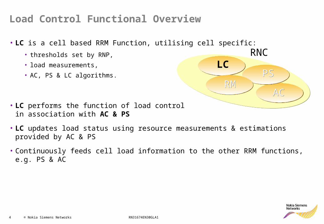
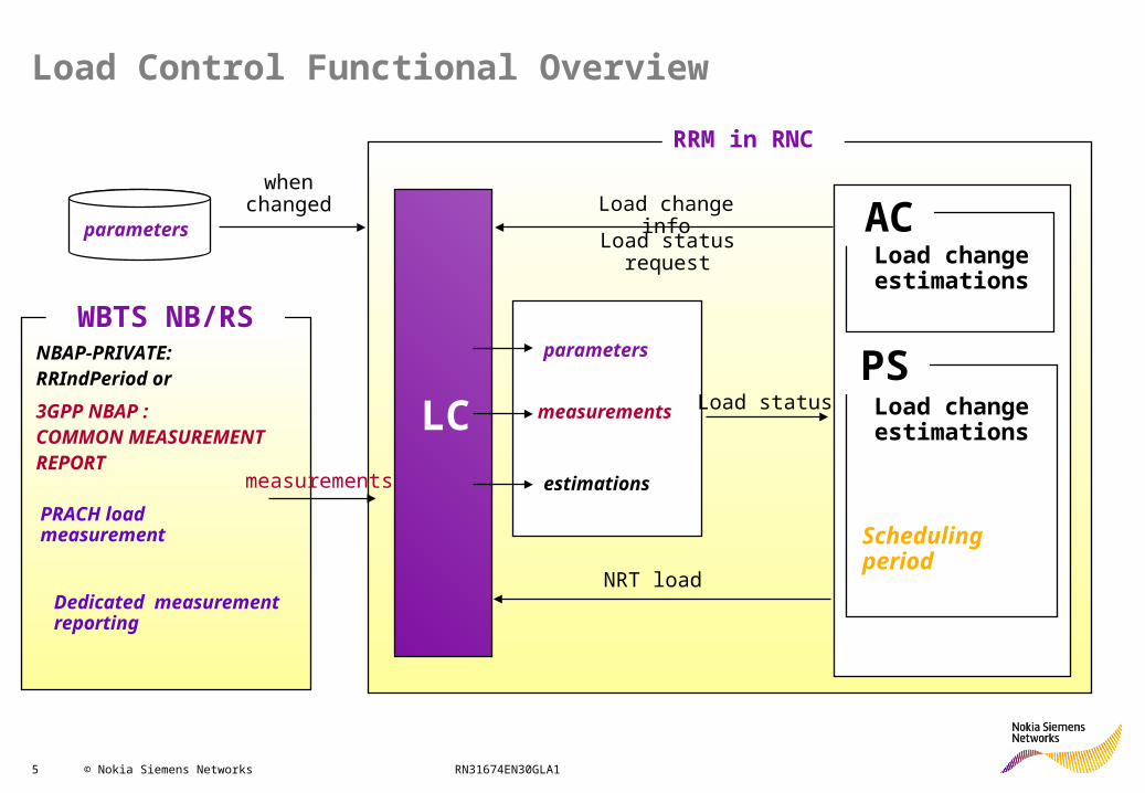
• LC is a cell based RRM Function, utilising cell specific:• thresholds set by RNP,• load measurements,• AC, PS & LC algorithms.
• LC performs the function of load controlin association with AC & PS
• LC updates load status using resource measurements & estimations provided by AC & PS
• Continuously feeds cell load information to the other RRM functions, e.g. PS & AC
LC
ACACPSPS
RMRM
RNC
5 © Nokia Siemens Networks RN31674EN30GLA1
Load Control Functional Overview
RRM in RNC
LC
AC
PS
Load change estimations
Load change estimations
Scheduling period
PRACH load measurement
WBTS NB/RSNBAP-PRIVATE:RRIndPeriod or3GPP NBAP :COMMON MEASUREMENTREPORT
Dedicated measurement reporting
parameters
parameters
measurements
estimations
when changed Load change info
Load status request
Load status
NRT load
measurements

6 © Nokia Siemens Networks RN31674EN30GLA1
Load Control
• Load Control Functions• Radio Interface Load
• Power based Radio Resource Management• Throughput based Radio Resource Management• Planning thresholds for cell loading
• BTS Measurements and Reporting• Common Measurements• Dedicated Measurements• Filtering of Measurements
• Cell Level parameters for better UL Load control• Automatic Access Class Restriction
7 © Nokia Siemens Networks RN31674EN30GLA1
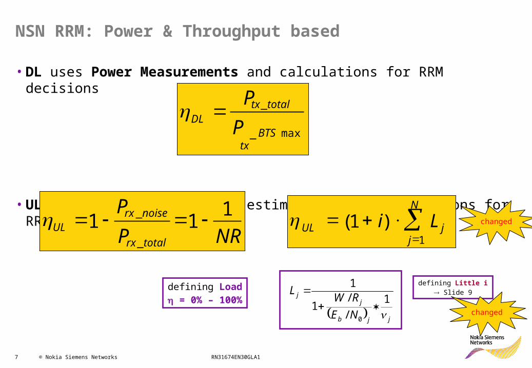
• DL uses Power Measurements and calculations for RRM decisions
• UL uses Power & Throughput estimations and calculations for RRM decisions
NSN RRM: Power & Throughput based
N
jjUL Li
1)1(
NRPP
totalrx
noiserxUL
111_
_
max_
_
BTStx
totaltxDL P
P
defining Load = 0% – 100%
jjb
jj
NERW
L
1
//
1
1
0
defining Little i Slide 9
changed
changed
8 © Nokia Siemens Networks RN31674EN30GLA1
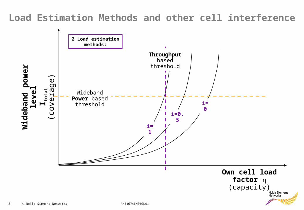
Load Estimation Methods and other cell interference
Throughput based
threshold
Wideband Power based
threshold
Wi d
e ban
d po
wer
le
v el
I tota
l(c
o ve r
a ge)
Own cell load factor (capacity)
i=0.5
i=0
i=1
2 Load estimationmethods:

9 © Nokia Siemens Networks RN31674EN30GLA1
UL power based load measurement
PRx_Own
PRxTotal = PRx_Own + PRx_Other + PNoise
= PRx_NRT + PRx_RT + PRx_Other + Pnoise
= PRx_NRT + PRx_NC + PRx_SC
PRx_Other
iUL = PRx_Other / PRx_Own
added
PRx_SC – The semi-controllable interference power, consists of the powers of PS streaming users (DCH and E-DCH). Before RU10 semi-controllable traffic has not been separated from the non-controllable traffic, so for those releases it is equal to zero.added
10 © Nokia Siemens Networks RN31674EN30GLA1
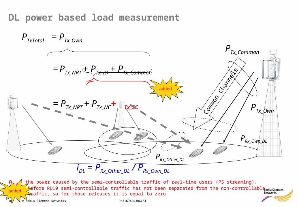
DL power based load measurement
PTx_Own
PTxTotal = PTx_Own
= PTx_NRT + PTx_RT + PTx_Common
= PTx_NRT + PTx_NC+ PTx_SC
PTx_Common
Common
Chan
nels
PRx_Own_DL
PRx_Other_DL
iDL = PRx_Other_DL / PRx_Own_DL
PTx_SC – the power caused by the semi-controllable traffic of real-time users (PS streaming). Before RU10 semi-controllable traffic has not been separated from the non-controllable traffic, so for those releases it is equal to zero.
added
added
11 © Nokia Siemens Networks RN31674EN30GLA1
Radio Interface Load
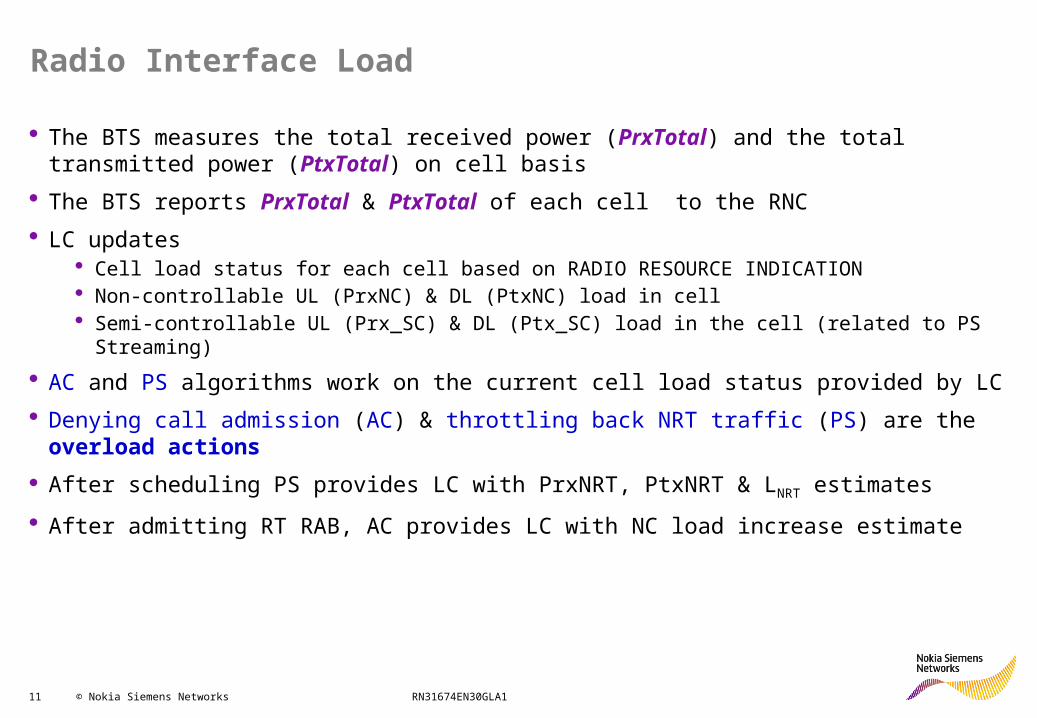
The BTS measures the total received power (PrxTotal) and the total transmitted power (PtxTotal) on cell basis
The BTS reports PrxTotal & PtxTotal of each cell to the RNC LC updates
Cell load status for each cell based on RADIO RESOURCE INDICATION Non-controllable UL (PrxNC) & DL (PtxNC) load in cell Semi-controllable UL (Prx_SC) & DL (Ptx_SC) load in the cell (related to PS Streaming)
AC and PS algorithms work on the current cell load status provided by LC Denying call admission (AC) & throttling back NRT traffic (PS) are the overload actions After scheduling PS provides LC with PrxNRT, PtxNRT & LNRT estimates
After admitting RT RAB, AC provides LC with NC load increase estimate
12 © Nokia Siemens Networks RN31674EN30GLA1
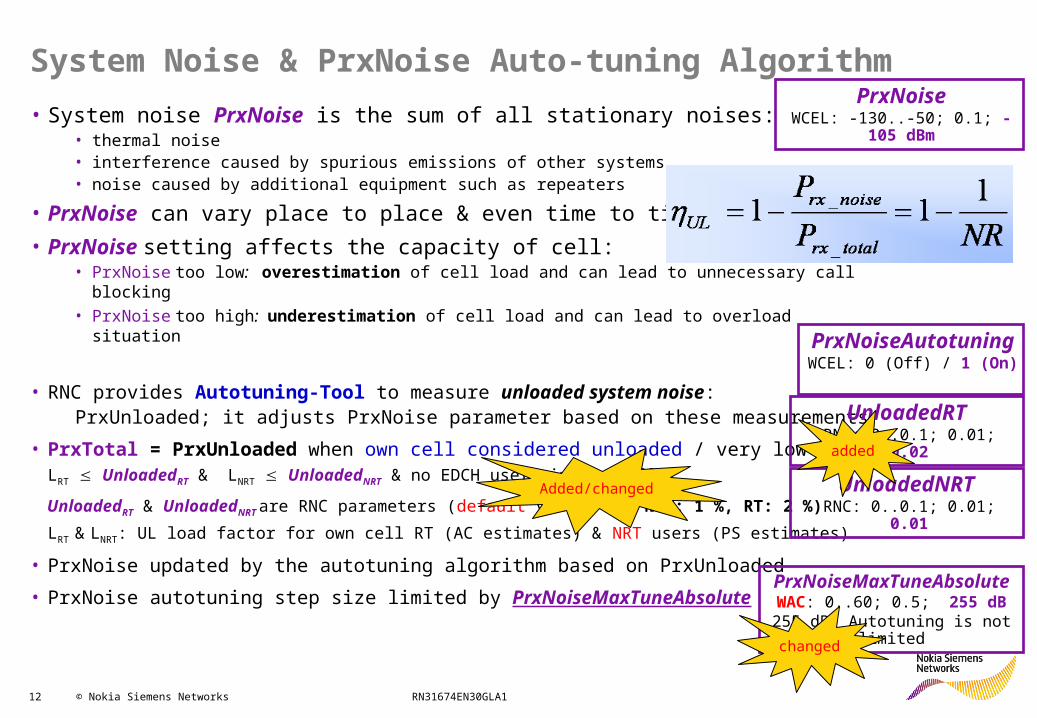
System Noise & PrxNoise Auto-tuning Algorithm• System noise PrxNoise is the sum of all stationary noises:
• thermal noise• interference caused by spurious emissions of other systems,• noise caused by additional equipment such as repeaters
• PrxNoise can vary place to place & even time to time• PrxNoise setting affects the capacity of cell:
• PrxNoise too low: overestimation of cell load and can lead to unnecessary call blocking• PrxNoise too high: underestimation of cell load and can lead to overload situation
• RNC provides Autotuning-Tool to measure unloaded system noise: PrxUnloaded; it adjusts PrxNoise parameter based on these measurements
• PrxTotal = PrxUnloaded when own cell considered unloaded / very low load;LRT UnloadedRT & LNRT UnloadedNRT & no EDCH users in the cell
UnloadedRT & UnloadedNRT are RNC parameters (default values for NRT: 1 %, RT: 2 %)LRT & LNRT: UL load factor for own cell RT (AC estimates) & NRT users (PS estimates)
• PrxNoise updated by the autotuning algorithm based on PrxUnloaded
• PrxNoise autotuning step size limited by PrxNoiseMaxTuneAbsolute
PrxNoiseWCEL: -130..-50; 0.1; -105 dBm
PrxNoiseAutotuningWCEL: 0 (Off) / 1 (On)
PrxNoiseMaxTuneAbsolute WAC: 0..60; 0.5; 255 dB
255 dB: Autotuning is not limitedchanged
Added/changed
UnloadedRT RNC: 0..0.1; 0.01; 0.02
UnloadedNRT RNC: 0..0.1; 0.01; 0.01
added
13 © Nokia Siemens Networks RN31674EN30GLA1
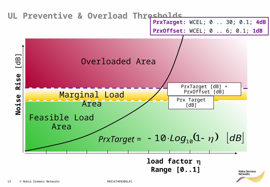
UL Preventive & Overload Thresholds
Prx Target [dB]
PrxTarget [dB] + PrxOffset [dB]
load factor Range [0..1]
Noi
se R
ise
[dB
] Overloaded Area
Marginal Load Area
Feasible Load Area
PrxTarget: WCEL; 0 .. 30; 0.1; 4dBPrxOffset: WCEL; 0 .. 6; 0.1; 1dB
dBLog 110 10PrxTarget =
14 © Nokia Siemens Networks RN31674EN30GLA1
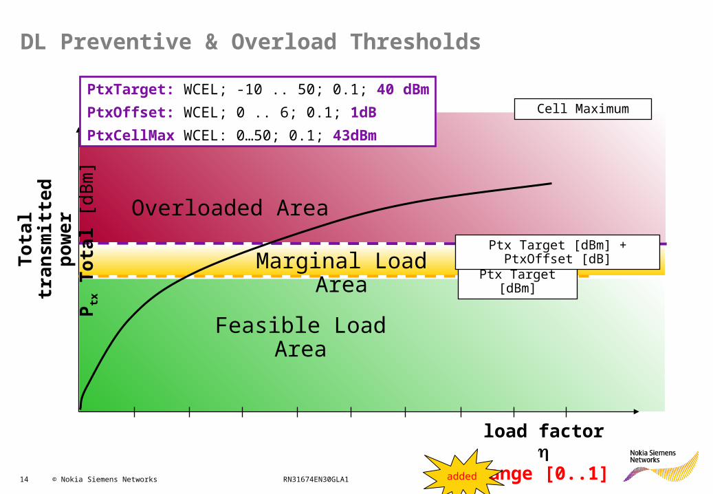
DL Preventive & Overload Thresholds
Ptx Target [dBm]
Ptx Target [dBm] + PtxOffset [dB]
load factor
Range [0..1]
Tota
l tra
nsm
itted
po
wer
P tx T
otal
[dB
m]
Overloaded Area
Marginal Load Area
Feasible Load Area
Cell MaximumPtxTarget: WCEL; -10 .. 50; 0.1; 40 dBmPtxOffset: WCEL; 0 .. 6; 0.1; 1dBPtxCellMax WCEL: 0…50; 0.1; 43dBm
added
15 © Nokia Siemens Networks RN31674EN30GLA1
Load Control
• Load Control Functions• Radio Interface Load
• Power based Radio Resource Management• Throughput based Radio Resource Management• Planning thresholds for cell loading
• BTS Measurements and Reporting• Common Measurements• Dedicated Measurements• Filtering of Measurements
• Cell Level parameters for better UL Load control• Automatic Access Class Restriction
16 © Nokia Siemens Networks RN31674EN30GLA1
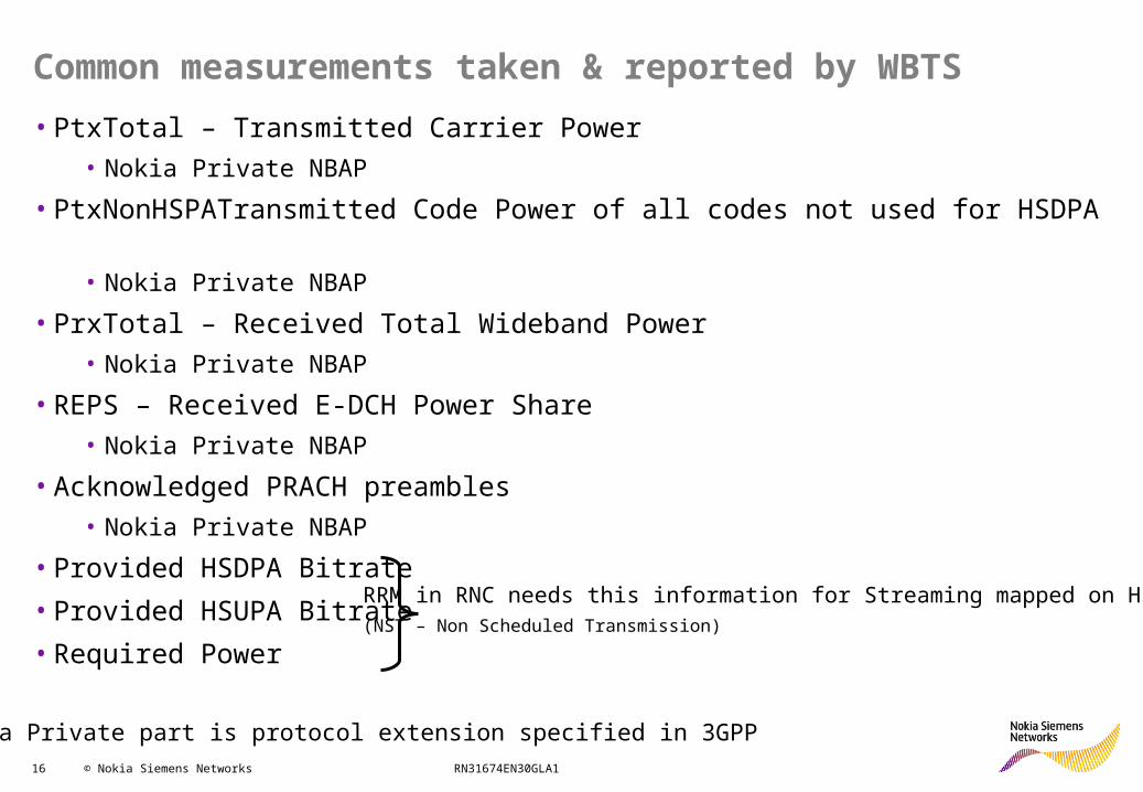
Common measurements taken & reported by WBTS• PtxTotal – Transmitted Carrier Power
• Nokia Private NBAP
• PtxNonHSPATransmitted Code Power of all codes not used for HSDPA• Nokia Private NBAP
• PrxTotal – Received Total Wideband Power• Nokia Private NBAP
• REPS – Received E-DCH Power Share• Nokia Private NBAP
• Acknowledged PRACH preambles• Nokia Private NBAP
• Provided HSDPA Bitrate• Provided HSUPA Bitrate• Required Power
RRM in RNC needs this information for Streaming mapped on HSPA(NST – Non Scheduled Transmission)
Nokia Private part is protocol extension specified in 3GPP
17 © Nokia Siemens Networks RN31674EN30GLA1
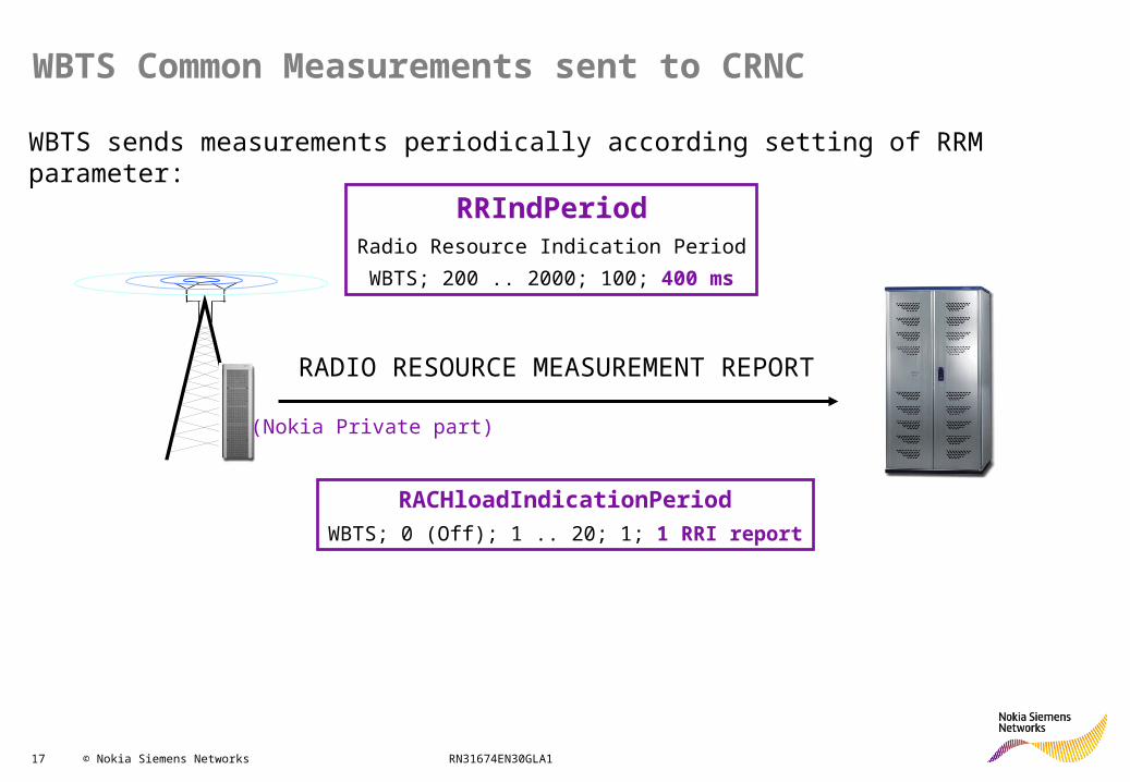
WBTS Common Measurements sent to CRNC
WBTS sends measurements periodically according setting of RRM parameter:
(Nokia Private part)
RADIO RESOURCE MEASUREMENT REPORT
RRIndPeriodRadio Resource Indication PeriodWBTS; 200 .. 2000; 100; 400 ms
RACHloadIndicationPeriodWBTS; 0 (Off); 1 .. 20; 1; 1 RRI report

18 © Nokia Siemens Networks RN31674EN30GLA1
Measurement filtering & reporting criteria in BTS
• BTS measurements are averaged/filtered in BTS before reporting• L1 filtering• L3 filtering
• Higher Layer filtering
• BTS reports measurements to RNC when needed• Reporting criteria
Step 1:L1 Filtering:1 Frame = 10 msStep 2L1 measurement period(= L1 Filtering) = 100 ms = 10 frames( Slide 30)
Step 3:L3 Filtering: RRI period = 400 ms( Slide 27)

19 © Nokia Siemens Networks RN31674EN30GLA1
L1 Filtering: Prx and Ptx Total Measurements
Prx T
otal
/Pt
xTot
al
Frame average measurements
Frame Prx and Ptx Total measurements
14
0// 15
1 TotalPTotalP txrxtxrx
0 141 2 ...
20 © Nokia Siemens Networks RN31674EN30GLA1
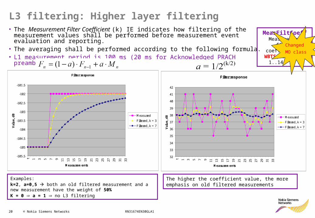
L3 filtering: Higher layer filtering• The Measurement Filter Coefficient (k) IE indicates how filtering of the measurement
values shall be performed before measurement event evaluation and reporting.• The averaging shall be performed according to the following formula.• L1 measurement period is 100 ms (20 ms for Acknowledged PRACH preambles)
Filter response
32
33
34
35
36
37
38
39
40
41
42
t 1 3 5 7 9 11 13 15 17 19 21 23 25 27 29 31 33
MeasurementsVa
lue,
dB Measured
Filtered, k = 3Filtered, k = 7
Filter response
-105.5
-105
-104.5
-104
-103.5
-103
-102.5
-102
-101.5
t 1 3 5 7 9 11 13 15 17 19 21 23 25 27 29 31 33
Measurements
Valu
e, d
B Measured
Filtered, k = 3
Filtered, k = 7
The higher the coefficient value, the more emphasis on old filtered measurements
Examples:k=2, a=0,5 both an old filtered measurement and a new measurement have the weight of 50%K = 0 a = 1 no L3 filtering
MeasFiltCoeffMeasurement filter
coefficient kWBTS; 0 (Off); 1..14;
1; 5
Changed MO class
21 © Nokia Siemens Networks RN31674EN30GLA1
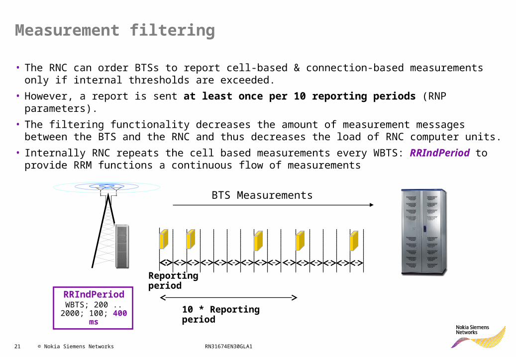
Measurement filtering
• The RNC can order BTSs to report cell-based & connection-based measurements only if internal thresholds are exceeded.
• However, a report is sent at least once per 10 reporting periods (RNP parameters).• The filtering functionality decreases the amount of measurement messages between the BTS and the
RNC and thus decreases the load of RNC computer units.• Internally RNC repeats the cell based measurements every WBTS: RRIndPeriod to provide RRM
functions a continuous flow of measurements
BTS Measurements
Reporting period
10 * Reporting periodRRIndPeriod
WBTS; 200 .. 2000; 100; 400 ms

22 © Nokia Siemens Networks RN31674EN30GLA1
WBTS Measurements sent to CRNC
WBTS can filter a measurement report (not sent to RNC) –• only inform RNC about important load changes• reduce common NBAP signaling on IuB interface
RNC provides load threshold and value change threshold to WBTS
Parameter settings for PtxTotal Measurement
0,5 dB
20 % of Ptx max
The parameterdoesn’t exist
23 © Nokia Siemens Networks RN31674EN30GLA1
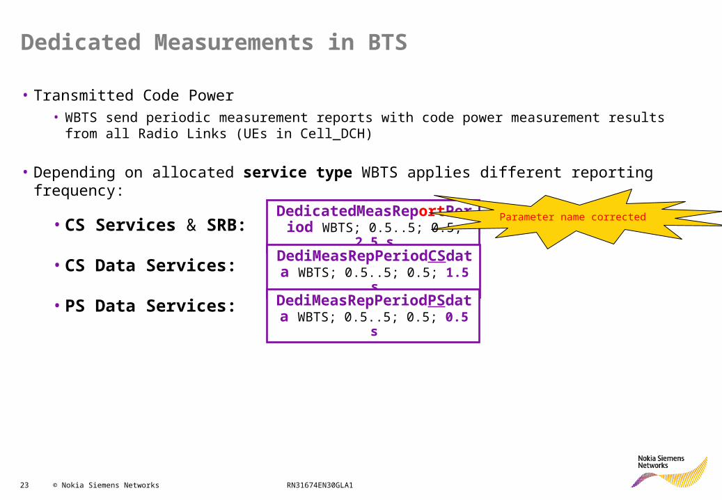
Dedicated Measurements in BTS
• Transmitted Code Power• WBTS send periodic measurement reports with code power measurement results from all Radio
Links (UEs in Cell_DCH)
• Depending on allocated service type WBTS applies different reporting frequency:
• CS Services & SRB:
• CS Data Services:
• PS Data Services:
DedicatedMeasReportPeriod WBTS; 0.5..5; 0.5; 2.5 s
DediMeasRepPeriodCSdata WBTS; 0.5..5; 0.5; 1.5 s
DediMeasRepPeriodPSdata WBTS; 0.5..5; 0.5; 0.5 s
Parameter name corrected
24 © Nokia Siemens Networks RN31674EN30GLA1
Load Control
• Load Control Functions• Radio Interface Load
• Power based Radio Resource Management• Throughput based Radio Resource Management• Planning thresholds for cell loading
• BTS Measurements and Reporting• Common Measurements• Dedicated Measurements• Filtering of Measurements
• Cell Level parameters for better UL Load control• Automatic Access Class Restriction
25 © Nokia Siemens Networks RN31674EN30GLA1
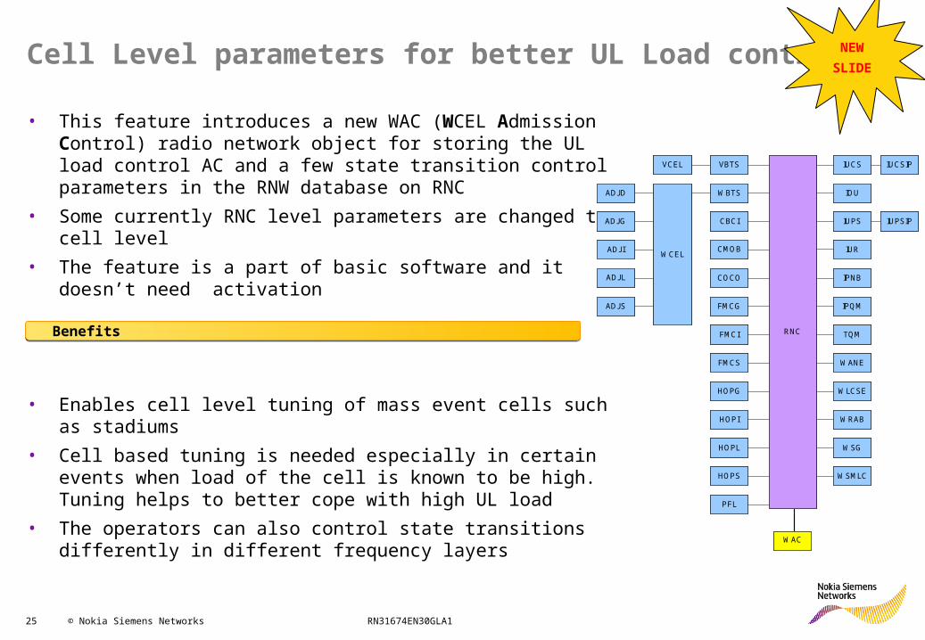
Cell Level parameters for better UL Load control
• This feature introduces a new WAC (WCEL Admission Control) radio network object for storing the UL load control AC and a few state transition control parameters in the RNW database on RNC
• Some currently RNC level parameters are changed to cell level• The feature is a part of basic software and it doesn’t need
activation
• Enables cell level tuning of mass event cells such as stadiums• Cell based tuning is needed especially in certain events when
load of the cell is known to be high. Tuning helps to better cope with high UL load
• The operators can also control state transitions differently in different frequency layers
RNC
WBTS IOU
IUPS
IUR
ADJD
WCEL
ADJG
ADJI
ADJL
CBCI
CMOB
COCO
FMCS
HOPG
FMCI
IPNB
IUCS
ADJS IPQM
IUCSIPVBTSVCEL
TQM
WRAB
WLCSE
WSG
WSMLC
FMCG
HOPI
HOPL
HOPS
WANE
IUPSIP
PFL
WAC
RNC
WBTS IOU
IUPS
IUR
ADJD
WCEL
ADJG
ADJI
ADJL
CBCI
CMOB
COCO
FMCS
HOPG
FMCI
IPNB
IUCS
ADJS IPQM
IUCSIPVBTSVCEL
TQM
WRAB
WLCSE
WSG
WSMLC
FMCG
HOPI
HOPL
HOPS
WANE
IUPSIP
PFL
WAC
NEWSLIDE
Benefits