combination primary and backup sump pump system€¦ · introduction the basement watchdog...
TRANSCRIPT

Instruction Manual &Safety Warnings
IMPORTANT: Even if you have the Basement Watchdog sump pump system installed bysomeone else, you must read and follow the safety information contained in this manual.Failure to do so could result in property damage, serious injury, or death.
Table of ContentsImportant Safety Warnings andInstructionsElectrical precautions 1Battery preparation 1Battery precautions 1
IntroductionItems included in system 2Additional items needed 2System specifications 2
Installing the Pipe and Pump 3
Preparing the Battery 4,5
Battery Instructions 5
System ConnectionsMounting the backup control unit 5Connecting the backup pump 5Installing the battery fluid sensor 5Connecting the battery 6Connecting the charger 6Connecting the primary pump 6
Product Operation 6
Understanding the WarningLights and AlarmsSilencing the alarm during an emergency 6Power alarm 7Water alarm 7Backup pump alarm 7Replacing the backup pump 8Replacing the primary pump 8Charger 9Battery alarm 9Cleaning battery terminals 10Replacing the battery 10
Testing the SystemTesting the pump 11Testing the float switch 11
Parts & Service InformationTechnical support 11
Replacement Parts Diagram & List 14
Troubleshooting Guide 13
Warranty 14
Combination Primary andBackup Sump Pump System

Important SafetyWarnings & InstructionsSAVE THESE INSTRUCTIONS. This manualcontains important SAFETY WARNINGS andOPERATING INSTRUCTIONS for the BasementWatchdog combination sump pump system. Youwill need to refer to it before attempting anyinstallation or maintenance. ALWAYS keep theseinstructions with the unit so that they will beeasily accessible.
Failure to read and follow these warnings andinstructions could result in property damage,serious injury, or death. It is important to readthis manual, even if you did not install theBasement Watchdog combination sump pump,since this manual contains safety informationregarding the use and maintenance of thisproduct. DO NOT DISCARD THIS MANUAL.
ELECTRICAL PRECAUTIONS
Risk of electrical shock and fire hazard. Mayresult in death serious injury, shock orburns. To help reduce these risks, observethe following precautions:• DO NOT walk on wet areas of the basementuntil all power has been turned off. If themain power supply is in a wet basement, callan electrician.
• ALWAYS disconnect the pump from the powersource before servicing or making adjustments.
• ALWAYS unplug the control unit anddisconnect the cables from the battery beforeattempting any maintenance or cleaning.
• NEVER handle the pump or motor with wethands or when standing on a wet or dampsurface while the pump is plugged into thepower source.
• MAKE SURE THERE IS A PROPERLYGROUNDED RECEPTACLE AVAILABLE. Thispump is wired with a 3-prong grounded plug.To reduce the risk of electric shock, be certainthat it is only connected to a properlygrounded 3-prong receptacle (preferably withground fault circuit interrupt). If you have a
2-prong receptacle, have a licensed electricianreplace it with a 3-prong receptacle accordingto local codes and ordinances.
• NEVER bypass grounding wires or remove theground prong from the plug.
• DO NOT use an extension cord. The electricaloutlet should be within the length of thepump's power cord, and at least 4 feet abovethe floor level to minimize potential hazardsfrom flood conditions.
• DO protect the electrical cord from sharpobjects, hot surfaces, oil and chemicals. Avoidkinking the cord.
• MAKE SURE the supply circuit has a fuse orcircuit breaker rated to handle the powerrequirements noted on the nameplate of thepump.
To reduce the risk of hazards that can causeinjury or property damage, observe thefollowing precautions:• DO NOT use the power cord or strain relief tocarry the pumps. Use the handle.
• DO NOT pull on the cord to disconnect thesystem or the pump. Pull the plug.
• DO NOT expose the control units to rain orsnow.
• DO NOT operate the pumps or control units ifthey have been damaged in any way.
• DO NOT use pumps in pits handling rawsewage, salt water, or hazardous liquids.
• DO NOT disassemble the pumps or controlunits. When service is required, contactGlentronics' technical support at 800-991-0466, option 3. Return the product to themanufacturer for any repairs at the followingaddress:
Glentronics, Inc.645 Heathrow Drive, Lincolnshire, IL 60069
BATTERY PREPARATION
Sulfuric acid can cause blindness or severeburns. Avoid contact with skin, eyes orclothing. In the event of accident, flush
with water and call a physician immediately.KEEP OUT OF REACH OF CHILDREN.
To help reduce these risks, observe thefollowing precautions:• Someone should be within range of your voiceor close enough to come to your aid when youwork near a lead-acid battery.
• Have plenty of fresh water and soap nearby incase battery acid contacts skin, clothing or eyes.
• Wear eye and clothing protection and avoidtouching your eyes while working with batteryacid or working near the battery.
• If battery acid contacts skin or clothing, washimmediately with soap and water. If acidenters eye, immediately flood eye with run-ning cold water for at least 15 minutes and getmedical attention.
• Battery posts and terminals contain lead andlead compounds, chemicals known to the Stateof California to cause cancer and reproductiveharm. Wash hands after handling.
BATTERY PRECAUTIONS
Explosive gases could cause serious injury or death. Cigarettes, flames or sparks couldcause battery to explode in enclosed spaces.Charge in well-ventilated area. Alwaysshield eyes and face from battery. Keep vent caps tight and level.
To help reduce these risks, observe thefollowing precautions:• NEVER smoke or allow a spark or flame in thevicinity of the battery.
• Use the Basement Watchdog control unit forcharging a LEAD-ACID battery only. DO NOTuse the control unit for charging dry-cellbatteries that are most commonly used withhome appliances.
• Be sure the area around the battery is well-ventilated.
• When cleaning or adding water to the battery,first fan the top of the battery with a piece ofcardboard or another non-metallic material toblow away any hydrogen or oxygen gas thatmay have been emitted from the battery.
• DO NOT drop a metal tool onto the battery. Itmight spark or short-circuit the battery andcause an explosion.
• Remove personal metal items such as rings,bracelets, watches, etc. when working with alead-acid battery. A short circuit through one ofthese items can melt it causing a severe burn.
• ALWAYS remove the charger from the electricaloutlet before connecting or disconnecting thebattery cables. Never allow the rings to toucheach other.
• Check the polarity of the battery posts. ThePOSITIVE (+) battery post usually has a largerdiameter than the NEGATIVE (-) post.
• When connecting the battery cables, firstconnect the small ring on the end of theWHITE wire to the NEGATIVE (-) post of thebattery, and then connect the large ring onend of the BLACK wire to the POSITIVE (+) postof the battery.
Do not use system to pump flammable orexplosive fluids such as gasoline, fuel oil,kerosene, etc.
Page 1
! DANGER
! DANGER
! WARNING / POISON ! DANGER
POSITIVE POST HASLARGER DIAMETER
NEGATIVE POST HASSMALLER DIAMETER
POSITIVEPOST
NEGATIVEPOST
CAUTION

IntroductionThe Basement Watchdog combination sumppump system is designed to provide both primaryand backup pumping capabilities. The primarypump will operate as long as it is receiving ACpower. If the power is interrupted, or morewater is coming into the sump than the AC pumpcan handle, the backup sump pump will beginpumping automatically. The backup system hasunique monitoring features that diagnose aproblem and sound an alarm. A light on thedisplay panel of the control unit will indicate thecause of the alarm and the corrective action.The two systems have been preassembled foreasy installation.
The Basement WatchdogSump Pump System includes:
� A 1/3 HP primary pump with a caged dualfloat switch, and a blue piggyback controllerthat plugs into the wall outlet
� A yellow backup pump supported by a bracket� A yellow control unit for the backup pump
with a battery fluid sensor, a dual floatswitch, and battery cables
� A cable tie to attach the yellow control unitto the discharge pipe
� Two cable ties to secure the other wires tothe discharge pipe
� A battery cap with a hole to accommodatethe fluid sensor
� A battery charger� A rubber union
You will also need to supply:
� A Basement Watchdog Emergency StandbyBattery or a Basement Watchdog 7.5 Hour Battery*
� Six quarts of 1.265 specificgravity battery acid
� A battery box (optional)� A surge protector (optional)
*The internal construction of somewet cell batteries may not becompatible with this system.Glentronics can not guarantee thecompatibility of other brands ofbatteries. The use of a BasementWatchdog battery is HIGHLYrecommended.
System SpecificationsPower supply requirements . . . 115 volts, 60 HzAC pump pumping capacity. . . 2200 GPH @ 10’DC pump pumping capacity. . . 1000 GPH @ 10’Overall dimensions . . . . . . 10”W x 17-3/4” HPump housings & strainers . . . . . .Non-corrosive
Page 2
RubberUnion
Primary PumpFloat Switch
Cable Ties
PrimaryPump
Controller
BackupPump
Controller
PrimaryPump
Battery Cables
Fluid Sensor
For some installations you may also need additional items:
� 1-1/2” rigid PVCpipe
� A 1-1/2” PVC pipe connector or a 1-1/2” rubber union
� PVC pipe cleaner andcement
Battery Cap
BatteryCharger
Backup PumpFloat Switch
BackupPump

Installing the Pipe and PumpThe Basement Watchdog combination system iscompact and will fit in a sump pit as small as10” wide and 14” high (the size of a 5 gallonbucket). It measures 173/4“ inches from thebottom of the pump to the top of the Y-connector where it will be attached to thedischarge pipe.Use a pit thatconforms to all localcodes, and check thecode to see if a gatevalve or ball valve isrequired.The discharge pipemust be positioned ina downward slope soany remaining waterwill drain away. Failure to do this will preventwater from exiting the pit and damage the pumpif the line freezes.The system should be placed on a flat surfacefree from dirt and debris. If the bottom of thesump pit is not clean, remove as much of thedebris as possible. You may place a pump standor bricks on the floor of the sump pit to raise thepump above the debris.
If you are replacing an old sump pump, unplugthe pump from the outlet.1. Remove the check valve or rubber union. If
the existing system is installed without a checkvalve or rubber union, saw the pipe apartabove the sump pit per #3 below. Discard thecheck valve. The Basement Watchdog systemcontains built-in check valves, so the old checkvalve will not be needed.
2. Remove the old pump from the pit, andunscrew the pipe and pipe adapter from thepump.
3. Measure the distance from the bottom of thesump pit (or from the top of the bricks in thesump pit) to the end of the discharge pipe.Subtract 18-3/4 inches (the height of thepump system + 1 inch). Cut a piece of 1-1/2”rigid PVC pipe to that length.
4. (a) Connect this piece to the discharge pipeby cementing the two pieces together with a1-1/2” PVC pipe connector. (Follow theinstructions on the PVC pipe cleaner andcement.) or, (b) connect the two pieces ofpipe together with a rubber union.
5. Remove the assembled pump system from theshipping carton by lifting the strap at thebottom of the unit and supporting the top ofthe unit with your hand. Stand the unit on the ground near the sump pit.Visually inspect your pump. Products may bedamaged during shipping. If the product hasbeen damaged, contact your place ofpurchase or Glentronics before installation.
6. Slip the lifting strap off of the pump.7. Remove the attached cords and controllers
from the carton and place them next to thepump system. BE SURE THE CORDS ANDCONTROLLERS DO NOT FALL INTO THE SUMPPIT DURING THE INSTALLATION.
8. Loosen the hose clamps on the enclosedrubber union, and slide the union up on thedischarge pipe until it is even with thebottom of the pipe.
9. Lift the combination system by the handleon the primary pump and lower it into thesump pit. Make sure it is level.
10. Inspect the two float switches. They shouldboth be vertical and positioned so that theymove smoothly without hitting the pump orthe wall of the sump pit.
Page 3
MEASUREDISTANCE
END OFPIPE
11. Position the top of thepump system pipe so it isdirectly below thedischarge pipe. Slide therubber union down untilhalf of the rubber union iscovering the pump pipe,and the other half iscovering the bottom ofthe discharge pipe.Tighten the hose clampscrews securely.
1a 2
4b4a3
5 7
8 9&10 11
173/4“
Diagram A

Preparing the Battery The Basement Watchdog Emergency StandbyBattery has been designed to run the backuppump for a minimum of 6 hours continuously.However, most of the time the pump will turn onand off, and the battery will run the pumpintermittently for days. In addition the uniquematerials in the battery enable it to last for 5-7years in standby service.To extend the run time of the pump, use theBasement Watchdog 7.5 Hour battery. It will runthis pump continuously for 12 hours. Why will itrun longer than 7.5 hours? Because the 7.5 hourbattery is rated for other Basement Watchdogpumps that draw more power (amps). Theemergency pump puts less drain on the battery,so the battery lasts longer.NOTE: The battery will not run the primary pump.
• The use of automotive batteries is NOTrecommended. Automotive batteries arenot designed for this application. They willonly run the pump for a short time and willhave a shorter life than a standby battery.
• The battery fluid sensor and cap aredesigned to fit the Basement Watchdogbatteries. Measuring the battery fluid isone of the most important features of thesystem; since about 80% of backup sumppump failures are the result of a batterythat has dried out.
• The internal construction of some wet cellbatteries may not be compatible with thissystem. Glentronics can not guarantee thecompatibility of other brands of batteries.The use of a Basement Watchdog battery isHIGHLY recommended.
DO NOT use the enclosed battery cap on anybattery except a Basement Watchdog battery.DO NOT drill a hole in the cap or the top ofanother brand of battery to accommodate thefluid sensor. Batteries emit explosive gases,which can cause serious injury or death.
PREPARING THE BASEMENTWATCHDOG STANDBY BATTERYThe Basement Watchdog batteries are shippeddry (without acid) so they never lose power
before you take them home. A battery isactivated when the acid is added, and then itslowly begins to deteriorate as it ages. By addingthe acid just before use, the battery will always befresh. Use 1.265 specific gravity battery acid tofill the battery. It is available where youpurchased the battery.NOTE: Basement Watchdog batteries now come intwo configurations. The tops of the batteries lookdifferent, and the directions for filling the batteriesand connecting the fluid sensor will vary slightly.Instructions for both batteries follow. If the top ofyour battery looks like photo A, follow theinstructions on this page. If the top of yourbattery looks like photo B on page 5, follow theinstructions on page 5.
Contains sulfuric acid. Wear eye and clothingprotection. If battery acid contacts skin orclothing, wash immediately with soap andwater. If acid enters eyes, flush with waterfor 10 minutes and get medical attention.Review the safety instructions on page 1.
1. If you have not purchased a battery box, placea plastic garbage bag on the floor with somepaper towels or newspaper on top of it while youare filling the battery. Place the dry (unfilled)battery on top of the paper. If you havepurchased a battery box, place it directly on thefloor and place the battery in it.
2. Remove the foil seal on the top of the battery.3. (a) Carefully push in the perforated tab at the
top of the acid pack. Lift up the large tab andpull out the dispensing hose. Hold the hoseupright above the pack and squeeze the hoseforcing all the acid back into the pack. (b)Position the acid pack and battery as shownat the right. Pinch the end of the hosetogether and cut off the tip. Insert the endof the hose into each cell. Control the flowby pinching the hose with thumb andforefinger. Fill each cell of the battery to alevel just covering the battery plates, andthen go back and top off each cell equally.It is important to have the cells filledequally or the battery will not operateproperly. The acid should reach a level about3/16” below the cap rings. (Diagram B)
A newly filled battery will sometimes requireadditional acid after about ten minutes. Re-examine the fill level and add additional acid, if
necessary. The battery acid may bubble at thistime and give off a sulfur-like smell, but this isnormal. After the battery has been filled, screwthe caps on the top of the battery.Within 15-30 minutes of adding acid, the batterywill be 70-80% charged. The system will thenfinish charging the battery. During this trime, thealarm may sound. This is normal.Remove the paper and plastic bag from beneaththe battery. Roll it up with the plastic on theoutside and place it in the trash.
Page 4
! DANGER
CAUTION
! DANGER/POISON
BATTERY A
3b
1
2nd LEVEL
1st LEVEL
PLATES
CELL WALL
1 1st LEVEL, COVER THE PLATES
�
THE BOTTOM OF THE CAP RINGS
BATTERY TERMINALS
BATTERY CAP RINGS
CROSS SECTION OF BATTERY
1. Fill to 1st level, coverthe plates
2. Then fill to 2nd level,just below the bottomof the cap rings
Diagram B
Do not throw anold battery in thetrash. Take it to aservice station orrecycling center.
3a
2

Page 5
System Connections
Risk of electrical shock or battery explosion,which can cause serious injury or death.Unplug the main AC pump to avoid electricalshock. Wear eye protection. Work in a well-ventilated area. Do not smoke or allow aspark or flame in the vicinity of the battery.Avoid dropping metal tools on the battery.If battery acid contacts eyes, flush withwater for 15 minutes and get promptmedical attention. Review the safetyinstructions on page 1.
MOUNTING THE CONTROLLERWhen you position the backup system controlunit on the discharge pipe, be sure the chargercord will reach the AC power outlet and thepump cable and the float switch will reach thebottom of the sump. Position the unit in a well-ventilated area. Do not place anything on top ofthe battery. (Diagram C)1. Mounting the backup control unit: (a)
Thread one plastic cable tie through the twomounting brackets on the back of the controlunit. (b) Secure the controller to thedischarge pipe by wrapping the tie around thepipe and pulling it tight.
2. Connecting the backup pump: Remove thesecurity tag from the pump and plug thepump wires into the pump connector on theback of the control unit.
3. Installing the battery fluid sensor: If youare using a battery box, remove the cover andfan the area around the top of the batterywith a piece of cardboard (or another non-metallic material) to remove any hydrogen or
oxygen gas that may have been emitted fromthe battery. (a) If you have battery A, replacethe battery cap that is 2nd from the POSITIVE(+) post of the battery with the battery capthat is provided in the Basement Watchdogpackage. An arrow on the top of the batterymarks this position. There are two holes in thebattery cap. Insert the fluid sensor in the holethat is off-center on the top of the cap. Do notglue the sensor into the cap. (b) If you havebattery B, a hole has been molded into the topof the battery to accept the fluid sensor rod.The sensor hole is marked by the label on topof the battery. Hold the sensor straight andpress it firmly into the hole all the way up tothe connector. Do not bend the sensor rod.
If your battery looks like the battery above,follow these directions.
1. If you have not purchased a battery box,place a plastic garbage bag on the floor withsome paper towels or newspaper on top of itwhile you are filling the battery. Place the dry(unfilled) battery on top of the paper. If youhave purchased a battery box, place it directlyon the floor and place the battery in it.
2. Remove the two battery caps by carefullyprying them up with a screwdriver. Place thescrewdriver in the groove in the middle of thecap on the top of the battery. DO NOT lift thecap by prying up it from the groove on theside of the battery. It may damage the vent.
3. (a) Carefully push in the perforated tab at thetop of the acid pack. Lift up the large taband pull out the dispensing hose. Hold thehose upright above the pack and squeeze thehose forcing all the acid back into the pack.(b) Position the acid pack and battery as
shown below. Pinch the end of the hosetogether and cut off the tip. Insert the endof the hose into each cell. Control the flowby pinching the hose with thumb andforefinger. Fill each cell of the battery to alevel just covering the battery plates, andthen go back and top off each cell equally.It is important to have the cells filledequally or the battery will not operateproperly. The acid should reach a level about3/16” below the cap rings. (Diagram B)
A newly filled battery will sometimes requireadditional acid after about ten minutes.Reexamine the fill level and add additional acid,if necessary. The battery acid may bubble at thistime and give off a sulfur-like smell, but this isnormal. After the battery has been filled, pressthe two caps on the top of the battery.
Within 15-30 minutes of adding acid, the batterywill be 70-80% charged. The system will thenfinish charging the battery. During this trime, thealarm may sound. This is normal.
Remove the paper and plastic bag from beneaththe battery. Roll it up with the plastic on theoutside and place it in the trash.
When you fill the battery for the FIRST time,it will be the ONLY time you add acid to thebattery. In the future, when the fluid level islow, add distilled water to the cells. Neveradd more acid.
! DANGER
1a 1b2 3b
BATTERY B
CAUTION
2
Diagram C
1 3a

If you are not usingthe BasementWatchdog battery,you cannot use thebattery fluid sensor.However, you mustattach the sensor tothe POSITIVE (+)post of the batteryor the alarm will sound continuously. TheBasement Watchdog sump pump system willnot warn you if the fluid level is low in thisconfiguration. You will need to check yourbattery every couple of months to see if itneeds water. If the battery dries out, thesystem will not work. 4. Connecting the battery: Remove the wing nuts
from the battery terminals. Remove the securitytag from the battery cables. Attach the batterycables to the battery…the WHITE wire to the
NEGATIVE (-) post, and then the BLACK wire tothe POSITIVE (+) post. Replace the wing nutsand tighten. Note: Connecting the cables to thewrong posts will damage the controller.
5. Connecting the charger: Immediately plugthe charger into the charger jack on the backof the control unit, then into an AC outlet onthe wall. (You can provide additionalprotection for the control unit by using asurge protector.)
6. If the pump alarm is sounding, press theWHITE button to silence the alarm.
7. If you are using a battery box, place thecover on the box.
8. Connecting the primary pump: Plug thepiggyback controller into a properlygrounded 3-prong outlet (preferably withground fault circuit interrupt). Then plugthe primary pump into the receptacle on thecontroller.
9. For a neater installation, secure the cablesfrom the controllers to the discharge pipe ina couple places with the additional cableties. Make sure the wires are not touchingeach other or overlapping each other.
10. After the initial installation, be sure tocheck the pump operation by filling thesump with water and observing the pumpthrough one full cycle. The primary pumpshould run for 10 seconds after the lowerfloat drops.
11. A pit cover is recommended for allinstallations as a safety measure, and toprevent debris from falling into the pit. Placethe cover on top of the pit making sure not topinch or crimp the pump wires with the cover.The pit cover usually has an existing hole thatwill allow the cords to be passed through it,or you can drill a hole in the cover.
Product OperationThe dual float switch on the primary pumpcontains two large floating rings enclosed withina protective cage. Water will lift the bottomfloat by 1/4”, which will activate the pump. Iffor any reason the lower float does not activatethe pump, the water will rise to the second float,and it will activate the pump. As the pumpevacuates the water from the pit, the floats willdrop. The pump will run for an additional 10seconds to extend the cycle after the lower floatdrops. The blue controller for the primary pumppowers this switch.During a power outage, or if more water isentering the sump than the primary pump canhandle, the backup pump will automaticallybegin pumping. It also has a dual float switch,so if one float fails to activate the pump, thesecond float will activate the pump as soon asthe water reaches that level. As the waterrecedes below the float switch, a timer in thecontrol unit will run the pump an additional 25seconds to evacuate the pit.While the pumps are active, water will come out ofthe 1/8” hole that is located on the top of themain pump, and out of the hole in the elbow ofthe backup pump. This is normal. The holes areneeded to prevent an air lock within the system.DO NOT obstruct the holes or an air lock mayprevent the system from activating.Batteries and sump pumps need maintenance.The control unit on the backup system monitorsthe battery and power conditions, and sounds an
alarm when maintenance is required. Below isan explanation of the warnings and alarms.
Understanding the Warnings & AlarmsThe Basement Watchdog backup control unitfeatures a series of warning lights that pinpointpotential problems. In addition, an alarmsounds to alert you to the problem. In somecases the lights and alarm will go offautomatically when the problem has beensolved. In others, the WHITE button must bepushed to silence the alarm. Refer to the tableon page 7 for a quick review of the features andtheir corresponding alarm status.
SILENCING THE ALARM DURING AN EMERGENCYThe Basement Watchdog backup sump pumpsystem is equipped with a switch that willsilence the audible alarm during an extendedemergency. The POWER and PUMP alarms can be
Page 6
3b
3a
4
POSITIVEPOST
NEGATIVEPOST 6
8 9
1
2
3
4
55b5a

Page 7
silenced during a power outage or during heavyrains when the pump is activated repeatedly.To silence thePOWER and PUMPalarms, slide theaudible alarmswitch to OFF.The POWERand/or the PUMPlight will remainon, but theaudible alarmwill not sound. When the emergency hasended, slide the switch to the ON position toresume the full monitoring capability, or youwill not be warned the next time anemergency occurs.
The WATER and BATTERY alarms cannot besilenced. Both require immediate attention.
1 PowerThere are several causes for power failure. Themost common is a power outage by your electriccompany. During this emergency, the BasementWatchdog system will automatically switch tobattery power and protect your basement fromflooding. You can silence the POWER alarm bysliding the audible alarm switch to OFF. Thealarm will be silenced, but the light will stay on.The system will continue to operate while thepower alarm is silenced. Be sure to slide theswitch to the ON position when power isrestored to resume full monitoring capability.
1. If the power is on in the rest of the house,check the outlet, the home circuit breaker orthe fuse box for failure, and correct theproblem.
2. Check the charger. Make sure it is securelyplugged into the wall outlet. Make sure thepower outlet is working.
3. Check the charger plug that fits into the rearpanel of the control unit. Make sure it issecurely plugged into the control unit.
The control unit must receive 115 volts AC +/-5% from the AC outlet. Any voltage lower than110 volts will activate the POWER alarm. Lowervoltages can be caused by utility brown outs ora heavy power draw from other appliances on thesame circuit.
If all the connections are secure and the walloutlet is operating, but the POWER warning lightis still on, replace the charger unit. ContactGlentronics, Inc. at 800-991-0466, option 3.
2 Water
Risk of electrical shock or battery explosion,which can cause serious injury or death.Wear eye protection. Work in a well-ventilated area. Do not smoke or allow aspark or flame in the vicinity of the battery.Avoid dropping metal tools on the battery.If battery acid contacts eyes, flush withwater for 15 minutes and get promptmedical attention. Review the safetyinstructions on page 1.If this warning light and alarm are on, you needto add distilled water to the battery. (This alarmcannot be silenced. When the battery is refilledand the sensor is replaced, the alarm will go offautomatically.) To refill the battery:
1. Unplug the charger and the blue AC pumpcontroller from the wall outlet.
2. If you are using a battery box, remove thecover and fan the area around the top of the
battery with a piece of cardboard (or anothernon-metallic material) to remove anyhydrogen or oxygen gas that may have beenemitted from the battery.
3. Then unscrew the wing nuts and remove thebattery cables and the fluid sensor from thebattery.
4. Remove the battery caps. Add distilledwater to each cell. If distilled water is notavailable, tap water with a low mineralcontent may be used. Well water is notrecommended. NEVER ADD MORE ACID. Fillthe battery to level 2 as shown in Diagram Bon page 4. (The Basement Watchdog batteryfiller will automatically fill the level to thecorrect height. See enclosed order form.)
5. Using a paper towel, clean the underneathportion of the battery cap that contains thefluid sensor. Replace the battery caps and thefluid sensor. Be sure the fluid sensor ispositioned in the 2nd cell from the positivepost. Depending on which battery you own,the sensor will fit in the top of the battery capor in the molded hole on the top of the battery.The location is marked with an arrow on thetop of the battery. The warning light andalarm will turn off automatically when thebattery is refilled and the sensor is replaced.
6. Replace the battery cables, the WHITE to theNEGATIVE (-) post, and the BLACK to thePOSITIVE (+) post. Replace the wing nuts andtighten.
7. Replace the battery box cover.
8. Plug the charger and the blue AC controllerback into the outlet. (You should provideadditional protection for the control unit byusing a surge protector.)
3 PumpWhen the water rises in the sump pit and liftsthe float switch, the pump will begin pumping,and the PUMP light and alarm will turn on. Thepump warning stays on to alert you to the factthat the standby system was used to empty thewater from the sump. Try to determine whatcaused the system to activate.• Check the main pump for failure. It may not
be working, the float switch may be stuck, orthe pump may be too small to handle theinflow of water.
• Make sure the check valves are working andinstalled correctly. They may need to bereplaced. (See page 12 for check valvelocations).
• Make sure the discharge pipe is not clogged orfrozen.
! DANGER
Alarm can be Alarm shuts offsilenced before automatically
problem is when the problemWarning corrected is correctedPOWER Yes YesWATER No YesPUMP Yes No, push
white buttonBATTERY No Yes
4
5
5
2 3
REMOVE3
2

Page 8
• If the power was out, and the backup pumpwas activated, you need to push the WHITEbutton to silence the alarm.
During a power outage or times when the pumpis activated repeatedly, you can temporarilysilence the alarm by sliding the Audible Alarmswitch to OFF. When the primary pump hasresumed normal operation and the backuppump is no longer activating repeatedly, slidethe switch to the ON position to resume thefull monitoring capability. The alarm andpump light will still be on. Push the WHITEbutton to silence the alarm.
REPLACING THE BACKUP PUMPBefore you begin this process you will need anew backup pump.You may also wantto change the checkvalves at this time.The backup pumpuses a 1-1/4” checkvalve, the primarypump uses a 1-1/2”check valve. (See parts list on page 12.)
Risk of electrical shock or battery explosion,which can cause serious injury or death.Wear eye protection. Work in a well-ventilated area. Do not smoke or allow aspark or flame in the vicinity of the battery.Avoid dropping metal tools on the battery.Review the safety instructions on page 1.
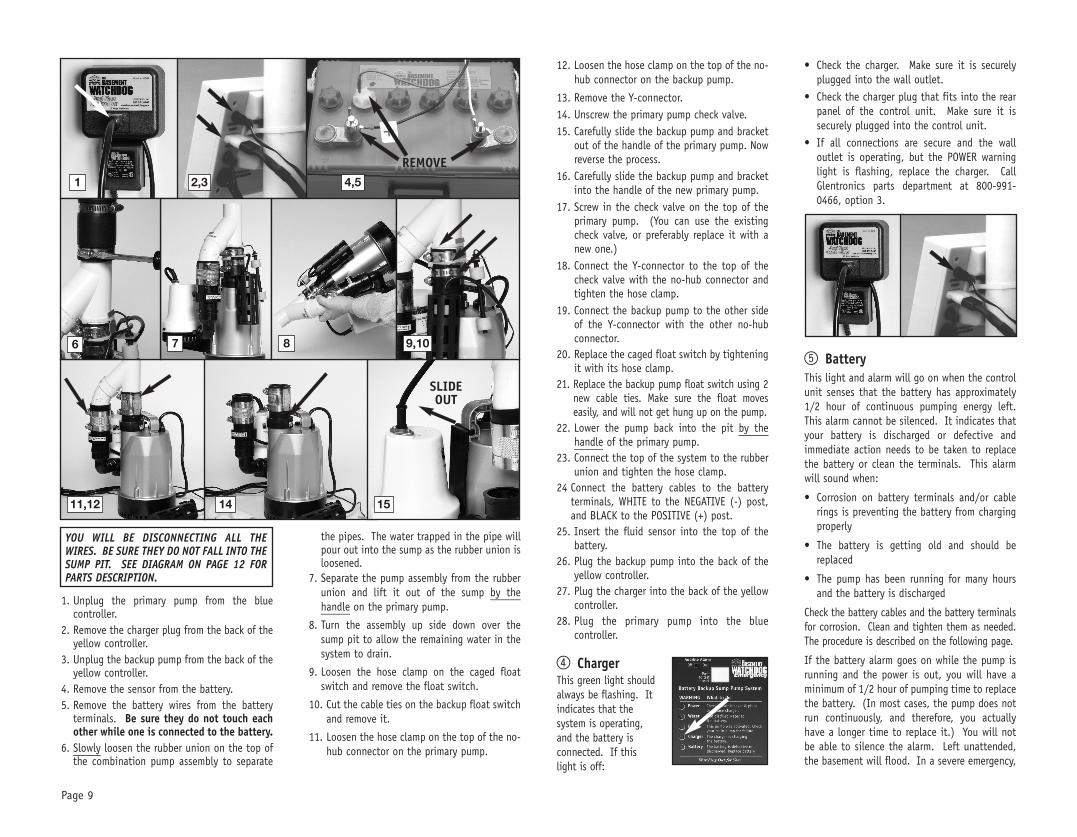
1. Unplug the primary pump from the bluecontroller.
2. Remove the charger plug from the back of theyellow controller.
3. Unplug the backup pump from the back of theyellow controller.
4. Remove the sensor from the battery.5. Remove the battery wires from the battery
terminals. Be sure they do not touch eachother while one is connected to the battery.
6. Slowly loosen the rubber union on the top ofthe combination pump assembly to separatethe pipes. The water trapped in the pipe willpour out into the sump as the rubber union isloosened.
7. Separate the pump assembly from the rubberunion and lift it out of the sump by thehandle on the primary pump.
8. Turn the assembly up side down over thesump pit to allow the remaining water in thesystem to drain.
9. Loosen the screws on the no-hub connectoron the elbow of the backup pump.
10. Unscrew the screw on the bottom of the pumpbracket with a Phillips head screwdriver, andlift the pump off of the bracket. Then pull thepump down out of the no-hub connector.
11. Unscrew the check valve on the elbow of thebackup pump. Now reverse the process.
12. Screw the check valve on to the new pump.(You can use the existing check valve, orpreferably replace it with a new one.)
13. You must drill a 1/8” hole in the elbow ofthe new pump to prevent an air lock in thesystem. An air lock will prevent the pumpfrom operating. Drill the hole on a downwardslope below the check valve on the elbow.
14. Push the pump and check valve back up intothe no-hub connector, and place the pumpon the pump bracket.
15. Screw the pump onto the bracket.16. Tighten the hose clamp on the no-hub
connector.17. Lower the pump system back into the sump
pit.
18. Connect the top of the system to the rubberunion and tighten the hose clamp.
19. Connect the battery cables to the batteryterminals, WHITE to the NEGATIVE (-) post,and BLACK to the POSITIVE (+) post.
20. Insert the fluid sensor into the top of thebattery.
21. Plug the backup pump into the back of theyellow controller.
22. Plug the charger into the back of the yellowcontroller.
23. Plug the primary pump into the bluecontroller.
REPLACING THE PRIMARY PUMPBefore you begin this process you will need anew AC pump. You may also want to change the
check valves at thistime. The backup pumpuses a 1-1/4” checkvalve, the primary pumpuses a 1-1/2” checkvalve. (See parts liston page 12.)
Risk of electrical shock or battery explosion,which can cause serious injury or death.Wear eye protection. Work in a well-ventilated area. Do not smoke of allow aspark or flame in the vicinity of the battery.Avoid dropping metal tools on the battery.Review the safety instructions on page 1.REFER TO THE PHOTOS ON PAGE 9
! DANGER
2,31
REMOVE4,5
76 8
9 10 11
YOU WILL BE DISCONNECTING ALL THEWIRES. BE SURE THEY DO NOT FALL INTO THESUMP PIT. SEE DIAGRAM ON PAGE 12 FORPARTS DESCRIPTION.
! DANGER
1. Unplug the primary pump from the bluecontroller.
2. Remove the charger plug from the back of theyellow controller.
3. Unplug the backup pump from the back of theyellow controller.
4. Remove the sensor from the battery.5. Remove the battery wires from the battery
terminals. Be sure they do not touch eachother while one is connected to the battery.
6. Slowly loosen the rubber union on the top ofthe combination pump assembly to separate
the pipes. The water trapped in the pipe willpour out into the sump as the rubber union isloosened.
7. Separate the pump assembly from the rubberunion and lift it out of the sump by thehandle on the primary pump.
8. Turn the assembly up side down over thesump pit to allow the remaining water in thesystem to drain.
9. Loosen the hose clamp on the caged floatswitch and remove the float switch.
10. Cut the cable ties on the backup float switchand remove it.
11. Loosen the hose clamp on the top of the no-hub connector on the primary pump.
12. Loosen the hose clamp on the top of the no-hub connector on the backup pump.
13. Remove the Y-connector.14. Unscrew the primary pump check valve.15. Carefully slide the backup pump and bracket
out of the handle of the primary pump. Nowreverse the process.
16. Carefully slide the backup pump and bracketinto the handle of the new primary pump.
17. Screw in the check valve on the top of theprimary pump. (You can use the existingcheck valve, or preferably replace it with anew one.)
18. Connect the Y-connector to the top of thecheck valve with the no-hub connector andtighten the hose clamp.
19. Connect the backup pump to the other sideof the Y-connector with the other no-hubconnector.
20. Replace the caged float switch by tighteningit with its hose clamp.
21. Replace the backup pump float switch using 2new cable ties. Make sure the float moveseasily, and will not get hung up on the pump.
22. Lower the pump back into the pit by thehandle of the primary pump.
23. Connect the top of the system to the rubberunion and tighten the hose clamp.
24 Connect the battery cables to the batteryterminals, WHITE to the NEGATIVE (-) post,and BLACK to the POSITIVE (+) post.
25. Insert the fluid sensor into the top of thebattery.
26. Plug the backup pump into the back of theyellow controller.
27. Plug the charger into the back of the yellowcontroller.
28. Plug the primary pump into the bluecontroller.
4 ChargerThis green light shouldalways be flashing. Itindicates that thesystem is operating,and the battery isconnected. If thislight is off:
• Check the charger. Make sure it is securelyplugged into the wall outlet.
• Check the charger plug that fits into the rearpanel of the control unit. Make sure it issecurely plugged into the control unit.
• If all connections are secure and the walloutlet is operating, but the POWER warninglight is flashing, replace the charger. CallGlentronics parts department at 800-991-0466, option 3.
5 BatteryThis light and alarm will go on when the controlunit senses that the battery has approximately1/2 hour of continuous pumping energy left.This alarm cannot be silenced. It indicates thatyour battery is discharged or defective andimmediate action needs to be taken to replacethe battery or clean the terminals. This alarmwill sound when:
• Corrosion on battery terminals and/or cablerings is preventing the battery from chargingproperly
• The battery is getting old and should bereplaced
• The pump has been running for many hoursand the battery is discharged
Check the battery cables and the battery terminalsfor corrosion. Clean and tighten them as needed.The procedure is described on the following page.
If the battery alarm goes on while the pump isrunning and the power is out, you will have aminimum of 1/2 hour of pumping time to replacethe battery. (In most cases, the pump does notrun continuously, and therefore, you actuallyhave a longer time to replace it.) You will notbe able to silence the alarm. Left unattended,the basement will flood. In a severe emergency,
Page 9
1
REMOVE4,5
11,12 14 15
2,3
76 8 9,10
SLIDEOUT
YOU WILL BE DISCONNECTING ALL THEWIRES. BE SURE THEY DO NOT FALL INTO THESUMP PIT. SEE DIAGRAM ON PAGE 12 FORPARTS DESCRIPTION.

Page 10
if a replacement battery is not available, youcould temporarily use your car battery.Once the AC power is restored, the battery willrecharge automatically, unless it is old ordamaged. The alarm will go off when the ACpower is restored and the pumping energyreaches 1/2 hour or more.In the event that your Basement Watchdogbackup sump pump has pumped for an extendedperiod of time, the battery may be very depleted.In this condition, when the AC power is returnedto the unit, a battery alarm will continue tosound. The battery may need a longer period torecharge. For a faster recharge, an automotive or marinebattery charger can be used to recharge thebattery. Follow the manufacturer’s instructionand safety information included with thecharger.If the battery is relatively new and the batteryalarm is activated, before you replace thebattery, call the Glentronics service department.The phone number is 800-991-0466, option 3.
TO CLEAN THE BATTERY TERMINALSAND CABLES
Risk of electrical shock or battery explosion,which can cause serious injury of death. Weareye protection. Work in a well-ventilatedarea. Do not smoke or allow a spark or flamein the vicinity of the battery. Avoid droppingmetal tools on the battery. If battery acidcontacts eyes, flush with water for 15minutes and get prompt medical attention.Review the safety instructions on page 1.
1. Unplug the charger and blue AC controllerfrom the wall outlet.
2. Remove the cover of the battery box bypushing in the tabs on the front and back,then lifting up.
3. Fan the area around the top of the batterywith a piece of cardboard (or another non-metallic material) to remove any hydrogen oroxygen gas that may have been emitted fromthe battery.
4. Remove the fluid sensor from the battery.Unscrew the wing nuts. Remove the batterycables.
5. Clean the battery posts with a batteryterminal cleaner or a wire brush.
6. Clean any corrosion off of the ring connectorson the ends of the battery wires. Us a stiffbrush or sandpaper. DO NOT apply corrosionresisting sprays or pads to the terminal ringsor posts after you have cleaned them, sincethis could prevent the system from chargingproperly.
7. Replace the fluid sensor in the top of thebattery. Then replace the battery cables,WHITE to the NEGATIVE (-) post and BLACK tothe POSITIVE (+) post. Tighten the wing nuts.
8. Plug the charger and the blue AC pumpcontroller back into the wall outlet. (Youshould provide additional protection for thecontrol unit by using a surge protector.)
9. You may have to press the WHITE button tosilence the PUMP alarm.
REPLACING THE BATTERY
Risk of electric shock or battery explosion,which can cause serious injury or death.Wear eye protection. Work in a well-ventilated area. Do not smoke or allow aspark or flame in the vicinity of the battery.Avoid dropping metal tools on the battery.If battery acid contacts eyes, flush withwater for 15 minutes and get promptmedical attention. Review the safetyinstructions on page 1.
REFER TO THE PHOTOS AT RIGHT AND ON PAGE 11
Basement Watchdog batteries come in twoconfigurations. (A) One has six battery caps thatscrew into the top of the battery, and the fluidsensor fits in the cap with the two holes. (B)The other battery has two large caps that eachsnap over 3 holes. The sensor hole in thisbattery is molded in the top of the battery.
1. Unplug the charger and blue AC controllerfrom the wall outlet.
2. If you are using a battery box, remove thecover and fan the area around the top of thebattery with a piece of cardboard (or anothernon-metallic material) to remove anyhydrogen or oxygen gas that may have beenemitted from the battery.
3. Remove the fluid sensor from the top of thebattery. If the sensor was in the cap of thebattery, remove the battery cap and save itfor use in a new battery.
4. Unscrew the wing nuts and remove the batterycables.
! DANGER
5
6
! DANGER
A
B
2
REMOVE3,42
REMOVE4
3
8 9
7

Page 11
5. Remove the old battery. Fill the batteryfollowing the instructions on page 4.
6. Clean any corrosion off of the wire ringconnectors on the end of the battery cables.Use a wire brush or sandpaper. DO NOT applycorrosion resisting sprays or pads to theterminal rings or posts after you have cleanedthem, since this could prevent the batteryfrom charging properly.
7. Replace the battery cables, WHITE to theNEGATIVE (-) post and BLACK to the POSITIVE(+) post.
8. (a) If the new battery has six caps, rinse anddry the cap with the extra hole from the oldbattery to remove any residue. Replace thebattery cap that is 2nd from the POSITIVEpost with the cap from the old battery. Insertthe fluid sensor in the cap and put the capyou removed from the new battery on the oldbattery. (b) If the new battery has the sensorhole molded in the top you will not need tosave the cap from the old battery, press thesensor firmly into the hole. Do not bend thesensor rod.
9. Plug the charger and the blue AC controllerinto the wall outlet. (You should provideadditional protection for the control unit byusing a surge protector.
10. You may have to press the WHITE button tosilence the PUMP alarm.
TEST BUTTON
The TEST button may be used to check thebackup pump and system. Push the TEST button.This will activate the pump for as long as youhold the button.
TESTING THE BACKUP FLOAT SWITCH
It is important to manually test the floatswitch periodically.
Lift the float upand let go. Thiswill activate thepump. Thecontrol unit willrun the pump forapproximately 25seconds so it canempty all thewater in thesump pit. Ifthere is no water in the pit, the pump can rundry for this amount of time. The alarm willsound and the PUMP light will go on. After thepump has stopped, push the WHITE button tosilence the alarm. If the WHITE button ispressed before the pump has stopped, the alarmwill go off temporarily. Wait for the pump tostop pumping, and then push the WHITE buttonto completely silence the alarm.
While the pumps are active, water will come outof the 1/8” holes located on the top of the mainpump and in the elbow of the backup pump.This is normal. The holes are needed to preventan air lock within the system. DO NOT obstructthe holes or an air lock may prevent the systemfrom activating.
TESTING THE PRIMARY PUMP FLOAT SWITCHLift the float within the cage with a pencil orother non-metallic item and let it drop. Thepump will run for an additional 10 seconds afterthe float returns to the original position. It willnot damage the pump to run it for this shorttime if the sump pit is dry. However, DO NOThold the float up for an extended time withoutwater in the sump.
MAINTENANCE CHECK LIST
Maintenance should be performed 1-2 timesper year.1. Lift the float switches on both pumps as
described above.2. Remove all debris from the bottom of the
pit.3. Remove all debris floating in the water.4. Remove all debris from the float switch
cage.5. Fill the pit with water. Make sure the
pumps turn on at the intended levels.6. While the pump is running, make sure the
pump is evacuating water at a good pace.7. Remove the fluid sensor and cap from the
battery and rinse any black buildup fromthe cap. Replace the cap and fluid sensor.
PARTS & SERVICE INFORMATION
You can receive technical support, parts orservice information by calling Glentronics, Inc.at 800-991-0466, option 3, or by visiting thewebsite at www.basementwatchdog.com. Sendyour unit to the following address for repairs:
Glentronics, Inc.645 Heathrow Drive, Lincolnshire, IL 60069
6
7POSITIVEPOST
NEGATIVEPOST
8a
LIFTFLOAT
LIFTFLOAT
5
9 10
8b

Page 12
Replacement Parts ListDescription Part No.
1/3 HP AC sump pump BW1033-GLCaged dual float switch with piggyback controller BWC2Emergency backup pump 1011004Emergency control unit BWE-CONT“Y” PVC pipe fitting 1120007Support bracket for backup pump 1121003Battery cap with hole for the fluid sensor 1125000Charger for backup pump 1015003Backup dual float switch 1020009Backup pump locking screw (#12 x 1/2” pan head)* 11000181-1/4” check valve for backup pump* 11410001-1/2” check valve for primary pump* 1141001No-hub stainless steel connectors* 11420001-1/2” rubber union* 11420012” hose clamp* 1122002Cable tie* 1122000
*Stock items available in plumbing department
Call 800-991-0466, option 3 to order parts.
BOTTOM VIEW
SIDE VIEW

Page 13
Pump is not plugged in . . . . . . . . . . . . . . . . . . . .No AC power . . . . . . . . . . . . . . . . . . . . . . . . . . . .Poor power source . . . . . . . . . . . . . . . . . . . . . . . .Locked impeller . . . . . . . . . . . . . . . . . . . . . . . . .Defective float switch . . . . . . . . . . . . . . . . . . . . .Defective pump . . . . . . . . . . . . . . . . . . . . . . . . .
Locked impeller . . . . . . . . . . . . . . . . . . . . . . . . .Incorrect power supply . . . . . . . . . . . . . . . . . . . .Pump running continuously with no water present . .
Float switches mounted too low . . . . . . . . . . . . . .Water back flowing from pipe . . . . . . . . . . . . . . . .Malfunctioning float switch . . . . . . . . . . . . . . . . .
Clogged or frozen discharge . . . . . . . . . . . . . . . . .Blocked intake strainer . . . . . . . . . . . . . . . . . . . .One or both of the floats is obstructed and cannotdrop down . . . . . . . . . . . . . . . . . . . . . . . . . . . . .
Defective float switch . . . . . . . . . . . . . . . . . . . . .Check valve is stuck . . . . . . . . . . . . . . . . . . . . . .
Check valve on secondary pump will not close andwater re-circulates within the system . . . . . . . . . . .Partially blocked impeller . . . . . . . . . . . . . . . . . . .Clogged or frozen discharge pipe . . . . . . . . . . . . . .Broken or leaking pipe . . . . . . . . . . . . . . . . . . . . .Low power voltage . . . . . . . . . . . . . . . . . . . . . . .Check valve is stuck . . . . . . . . . . . . . . . . . . . . . .
Check valve is broken . . . . . . . . . . . . . . . . . . . . .Blocked intake screen . . . . . . . . . . . . . . . . . . . . .Defective pump . . . . . . . . . . . . . . . . . . . . . . . . .
Plug pump in properly (see instructions)Check circuit breaker or fuse, and GFI reset buttonCheck circuit line wires, cable and outletRemove strainer and clear obstructionReplace float switch with new float switchReplace pump with new pump
Remove strainer and clear obstructionCheck power supply source and voltageCheck float switch
Raise both float switchesInstall or replace check valveReplace float switch with new float switch
Clear blockage or thaw frozen lineClear debris from intake strainer
Clear debris from inside the float cage (Loosen nut ontop of float, then remove c-clip on bottom of float.Remove debris. Tighten nut on top of float, thenreplace c-clip on bottom of float.) When reassemblingthe float, the magnetic strip on the inside of the floatshould be facing down.Replace float switch with new float switchReplace check valve.
Replace the check valve on the secondary pumpRemove strainer and clear obstructionClear blockage or thaw frozen lineRepair pipeCheck power voltage, wires and cable conditionReplace check valve.
Replace the check valve Clear debris from intake screenReplace pump
Primary Pump Troubleshooting Guide
Read safety warnings & instructions before attempting any repairs or maintenance.! DANGER
Potential Cause THE PUMP WILL NOT START OR RUN Solutions
Potential Cause THERMAL PROTECTOR TRIPPING OR NOT FUNCTIONING Solutions
Potential Cause PUMP STARTS AND STOPS TOO FREQUENTLY Solutions
Potential Cause PUMP WILL NOT SHUT OFF Solutions
Potential Cause INSUFFICIENT OR NO WATER VOLUME Solutions
Potential Cause ABNORMAL SOUND OR VIBRATION Solutions
The battery fluid is low . . . . . . . . . . . . . . . . . . . . . .The fluid sensor is installed improperly . . . . . . . . . . .
Not using a Basement Watchdog battery . . . . . . . . . .
Terminals are corroded . . . . . . . . . . . . . . . . . . . . . .Cables are loose . . . . . . . . . . . . . . . . . . . . . . . . . . .Battery is discharged below 25% . . . . . . . . . . . . . . .
Battery is old or damaged . . . . . . . . . . . . . . . . . . . .
Power outage . . . . . . . . . . . . . . . . . . . . . . . . . . . .
An outlet, fuse, or circuit breaker has failed . . . . . . .
The charger is unplugged from the wall or the back ofthe controller . . . . . . . . . . . . . . . . . . . . . . . . . . . .The control unit is receiving less than 110 volts fromthe outlet . . . . . . . . . . . . . . . . . . . . . . . . . . . . . . .
Backup pump is unplugged . . . . . . . . . . . . . . . . . . .
Backup pump is clogged . . . . . . . . . . . . . . . . . . . . .Backup pump is broken . . . . . . . . . . . . . . . . . . . . . .
The main AC pump failed because of a power outage .The water was coming into the sump faster than themain pump could evacuate it . . . . . . . . . . . . . . . . . .The float switch on the main AC pump is stuck ordefective . . . . . . . . . . . . . . . . . . . . . . . . . . . . . . .The main AC pump is broken . . . . . . . . . . . . . . . . . .The main AC pump could not keep up with the inflowof water . . . . . . . . . . . . . . . . . . . . . . . . . . . . . . . .
The check valve is stuck and the water cannot passthrough it . . . . . . . . . . . . . . . . . . . . . . . . . . . . . . .The discharge pipe is clogged or frozen and the watercannot pass through it . . . . . . . . . . . . . . . . . . . . . .There is a slight chance of false activation if the floatswitch cord is wrapped around the AC power cord . . . .
Check valve is broken . . . . . . . . . . . . . . . . . . . . . . .Discharge pipe is clogged or frozen . . . . . . . . . . . . .
Add distilled water to each cell of the batteryThe fluid sensor should be inserted into the designatedhole on the top of the battery and pushed downThis feature cannot be used. Attach the fluid sensor tothe positive post of the battery
Clean terminals and cablesTighten wing nutsReplace battery if power is out. There is only 1 hour ofcontinuous pumping power left. Battery will rechargewhen power is restoredReplace battery
None. The backup pump will run off of the battery. Flipthe alarm switch to the off position to silence the alarm.Be sure to flip it back to on when the power is restored.Try another outlet, replace the fuse, or reset the circuitbreaker
Make sure the power cord is plugged in securely
None, if the utility company has instigated brown outs.Otherwise, reduce the number of other appliances on thecircuit
Make sure the pump is securely plugged into the back ofthe control unitRemove strainer from pump and clean out any debrisReplace the pump
None. The backup pump was activated when needed
None. The backup pump was activated when needed
Free the float switch on the main pump or replace itReplace the main AC pump
None. The backup pump was activated as needed. If this is arecurring problem, install a higher capacity main pump
Replace the check valve
Thaw, cleanout the blockage, or replace the discharge pipe
Move the float switch cord away from the AC power cord
Make sure check valve is functioning, or replace itClear the discharge pipe
Backup Pump Troubleshooting Guide
Read safety warnings & instructions before attempting any repairs or maintenance.! DANGER
Potential Cause BATTERY FLUID LOW Solutions
Potential Cause BATTERY PROBLEM Solutions
Potential Cause POWER FAILURE Solutions
Potential Cause PUMP WILL NOT SHUT OFF Solutions
Potential Cause INSUFFICIENT OR NO WATER VOLUME Solutions
Potential Cause ABNORMAL SOUND OR VIBRATION SolutionsIf the above solutions do not resolve the problem, follow the instructions within this manual to disconnect thesystem from the outlet and battery terminals, then reconnect the system and push the reset button. If theproblem continues, contact customer service.

© 2009, Glentronics, Inc. 1806040 05/11
Limited Warranty
GLENTRONICS, INC. warrants to the original retail purchaser that all of its pump, switch, sensor, battery box and control unitproducts are free from defective materials and workmanship for the period indicated below:
All parts and labor (excluding installation) for a period of two (2) years from the date of purchase
The defective product must be returned directly to the factory, postage prepaid with the original bill of sale or receipt to theaddress listed below. Glentronics, Inc., at its option, will either repair or replace the product and return it postage prepaid.
CONDITIONS
The unit must be shipped freight prepaid, or delivered, to Glentronics, Inc. to provide the services described hereunder in eitherits original carton and inserts, or a similar package affording an equal degree of protection.
The unit must not have been previously altered, repaired or serviced by anyone other than Glentronics, Inc., or its agent; theserial number on the unit must not have been altered or removed; the unit must not have been subject to accident, misuse,abuse or operated contrary to the instructions contained in the accompanying manual.
The dealer’s dated bill of sale, or retailer’s receipt, must be retained as evidence of the date of purchase and to establishwarranty eligibility.
This warranty does not cover product problems resulting from handling liquids hotter than 120 degrees Fahrenheit, handlinginflammable liquids, solvents, strong chemicals or severe abrasive solutions; normal wear; user abuse; misuse, neglect, impropermaintenance, commercial or industrial use; improper connections or installation; damages caused by lightning strikes, excessivesurges in AC line voltage, water damage to the controller, other acts of nature, or failure to operate in accordance with theenclosed written instructions.
GLENTRONICS, INC. WILL NOT BE LIABLE FOR ANY INCIDENTAL, SPECIAL OR CONSEQUENTIAL DAMAGES FOR BREACH OF ANYEXPRESS OR IMPLIED WARRANTIES ON THIS PRODUCT. SOME STATES DO NOT ALLOW THE EXCLUSION OR LIMITATION OFCONSEQUENTIAL OR INDIRECT DAMAGES, SO THE ABOVE LIMITATION MAY NOT APPLY TO YOU. THIS EXPRESS WARRANTY SHALLBE EXCLUSIVE AND IS IN LIEU OF ALL OTHER WARRANTIES, WRITTEN OR ORAL, EXPRESS OR IMPLIED, INCLUDING, BUT NOTLIMITED TO ANY WARRANTY OF MERCHANTABILITY OR FITNESS FOR A PARTICULAR PURPOSE. THE CUSTOMER’S EXCLUSIVE REMEDYFOR BREACH OF THIS WARRANTY, OR OF ANY IMPLIED WARRANTY NOT EXCLUDED HEREIN, SHALL BE LIMITED TO REPAIR ORREPLACEMENT OF THE PRODUCT.
For information or service contact:Glentronics, Inc.
645 Heathrow DriveLincolnshire, IL 60069
800-991-0466
Model # DFK961 Serial # _____________________ Purchase Date__________________