chimera - university of colorado boulder...6 levels of success level 2 level 3 level 4 level 1 •...
TRANSCRIPT

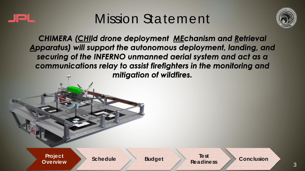
CHIMERACHIld drone deployment MEchanism and Retrieval Apparatus
Team: Adam St. Amand, Christopher Chamberlain, Griffin Esposito, Shannon Floyd, Justice Mack, Azalee Rafii,Christopher Rouw, Mitchell Smith, Amanda Turk, Alexander Walker
Customer: Barbara Streiffert, Jet Propulsion Laboratory
Advisor: Jelliffe Jackson
Test Readiness Review
2
Agendau Project Overview u System Design and Updates u Schedule u Budgetu Testing Update
u Flight Simulator
u Image Recognition Verification
u Autonomous Landing Subsystem Test
u Automatic Charging Subsystem Test
u Conclusion
Project Overview Schedule Budget Test
Readiness Conclusion
3
Mission Statement
Project Overview Schedule Budget Test
Readiness Conclusion
4
Mission Objectivesu Contribute to the overall Fire Tracker mission by designing and building a
child drone platform capable of integration with a future mother rover.
u Modify the child drone built by last year's INFERNO senior design team to autonomously land on the platform.
u Design a platform capable of securing and charging a child drone after autonomous landing.
u Design a communication system that facilitates communication between the child drone, the platform and a ground station.
Project Overview Schedule Budget Test
Readiness Conclusion
5
Critical Project Elementsu Autonomous Landing of Child Drone
u Implements image recognition software for command and control of child drone to land on platform
u RISK: Commanding the Pixhawk
u Automatic Child Drone Rechargingu Utilizes conductive contacts to transfer power from platform battery bank to child drone
for extended mission duration
u RISK: Open copper contacts, complex circuitry
u Securing of Child Droneu Platform shall capture the child drone and restrict movement over rough terrain
u RISK: Complex mechanical hardware
Project Overview Schedule Budget Test
Readiness Conclusion
6
Levels of Success
Level 2
Level 3
Level 4
Level 1
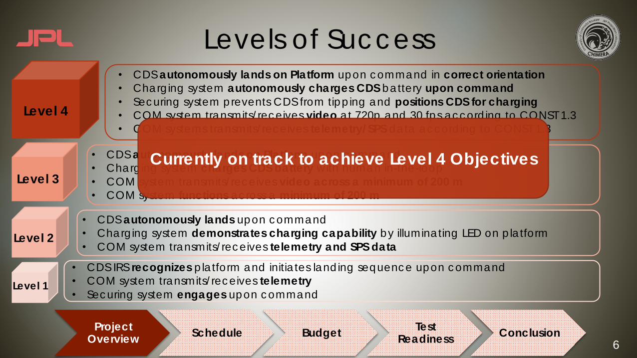
• CDS autonomously lands on Platform upon command in correct orientation• Charging system autonomously charges CDS battery upon command• Securing system prevents CDS from tipping and positions CDS for charging• COM system transmits/receives video at 720p and 30 fps according to CONST 1.3• COM systems transmits/receives telemetry/SPS data according to CONST 1.3
• CDS autonomously lands on Platform upon command• Charging system charges CDS battery with human in-the-loop• COM system transmits/receives video across a minimum of 200 m• COM system functions across a minimum of 200 m
• CDS autonomously lands upon command• Charging system demonstrates charging capability by illuminating LED on platform• COM system transmits/receives telemetry and SPS data
• CDS IRS recognizes platform and initiates landing sequence upon command• COM system transmits/receives telemetry• Securing system engages upon command
Currently on track to achieve Level 4 Objectives
Project Overview Schedule Budget Test
Readiness Conclusion
7
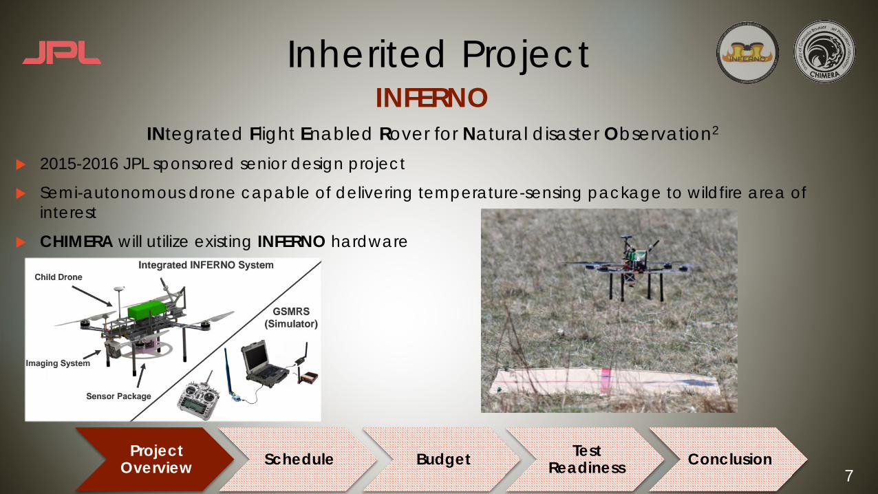
INFERNOINtegrated Flight Enabled Rover for Natural disaster Observation2
u 2015-2016 JPL sponsored senior design project
u Semi-autonomous drone capable of delivering temperature-sensing package to wildfire area of interest
u CHIMERA will utilize existing INFERNO hardware
Inherited Project
Project Overview Schedule Budget Test
Readiness Conclusion
8
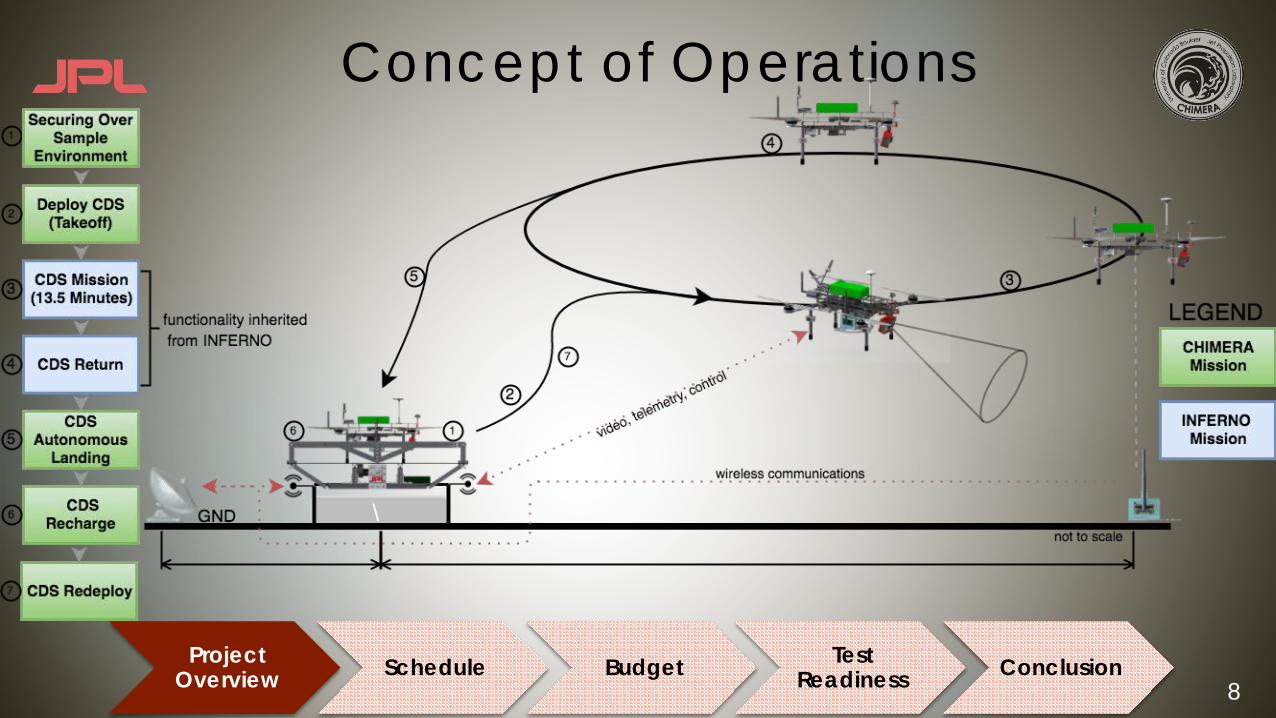
Concept of Operations
\
Project Overview Schedule Budget Test
Readiness Conclusion
9
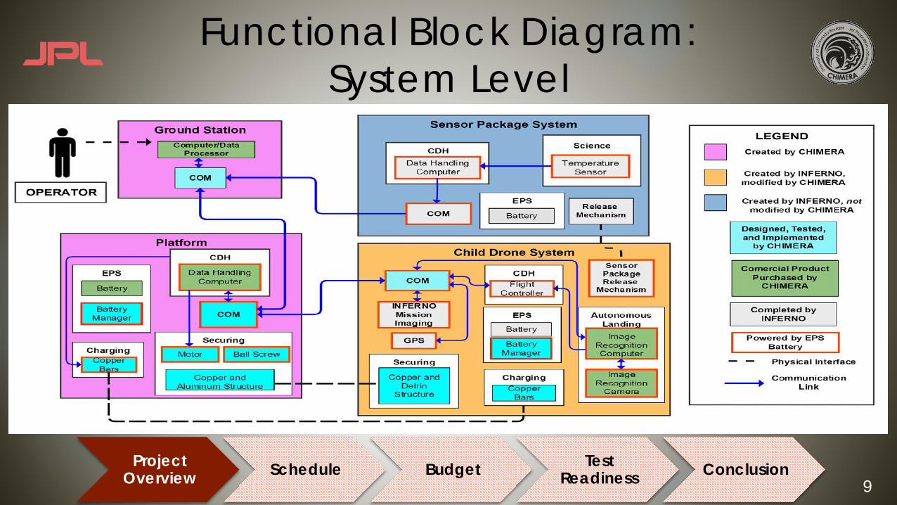
Functional Block Diagram:System Level
Project Overview Schedule Budget Test
Readiness Conclusion

10
System Design
Project Overview Schedule Budget Test
Readiness Conclusion
11
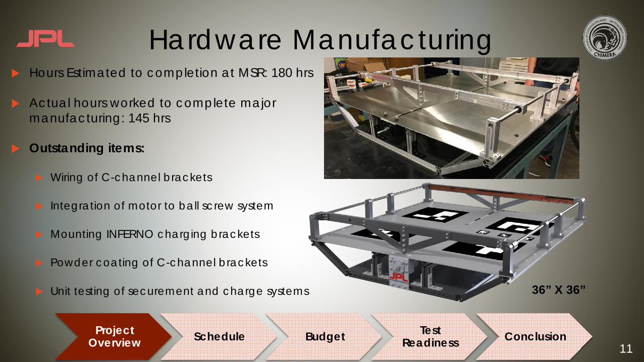
Hardware Manufacturingu Hours Estimated to completion at MSR: 180 hrs
u Actual hours worked to complete major manufacturing: 145 hrs
u Outstanding items:
u Wiring of C-channel brackets
u Integration of motor to ball screw system
u Mounting INFERNO charging brackets
u Powder coating of C-channel brackets
u Unit testing of securement and charge systems 36” X 36”
Project Overview Schedule Budget Test
Readiness Conclusion

12
Electronic Status Updateu Platform PCB
u Populatedu Testedu Developing Final
Software
u INFERNO PCBu Populatedu Developing Software
Platform PCB with all components integrated
PCB Designed PCB Fabricated PCB Populated Pi Integration INFERNO/Platform Installation
Project Overview Schedule Budget Test
Readiness Conclusion

13
Pixhawk Interface Updateu Initial Problem:
u Zero Throttle when switching modes caused a crash
u Static Testing – Confident in ability for pilot to takecontrol
u Tethered Testing – Safely Testing bugs in Software and communication between ground stationand raspberry pi
u Successful pilot intervention
u Future Work:u Test velocity commanding
u Integrate image recognition with landing script
u Test full landing sequence
Commanded takeoff with pilot intervention
Project Overview Schedule Budget Test
Readiness Conclusion

14
Schedule Breakdown
Project Overview Schedule Budget Test
Readiness Conclusion

15
Testing Schedule Highlight
Pixhawk/Rasp.Pi Flight Test
Platform PCB Safety Test
CDS PCB DevelopmentCDS Safety and Charging Tests
Full Circuit PCB Test (without LiPos)Software Development (Image Rec/Pixhawk/Commanding)
Pattern Selection and Integration (Platform AR Tags)
Preliminary Landing Test
Critical PathTestElectricalMechanical
Full Circuit Charging Test (with LiPos)
Platform Hardware Modifications and Final IntegrationPlatform/INFERNO Electronics Final Integration
Platform Movement Test
Full Autonomous Landing TestSecuring Subsystem TestCharging Subsystem TestToday’s Date
Project Overview Schedule Budget Testing Conclusion

16
Budget Status Update
Project Overview Schedule Budget Test
Readiness Conclusion
17
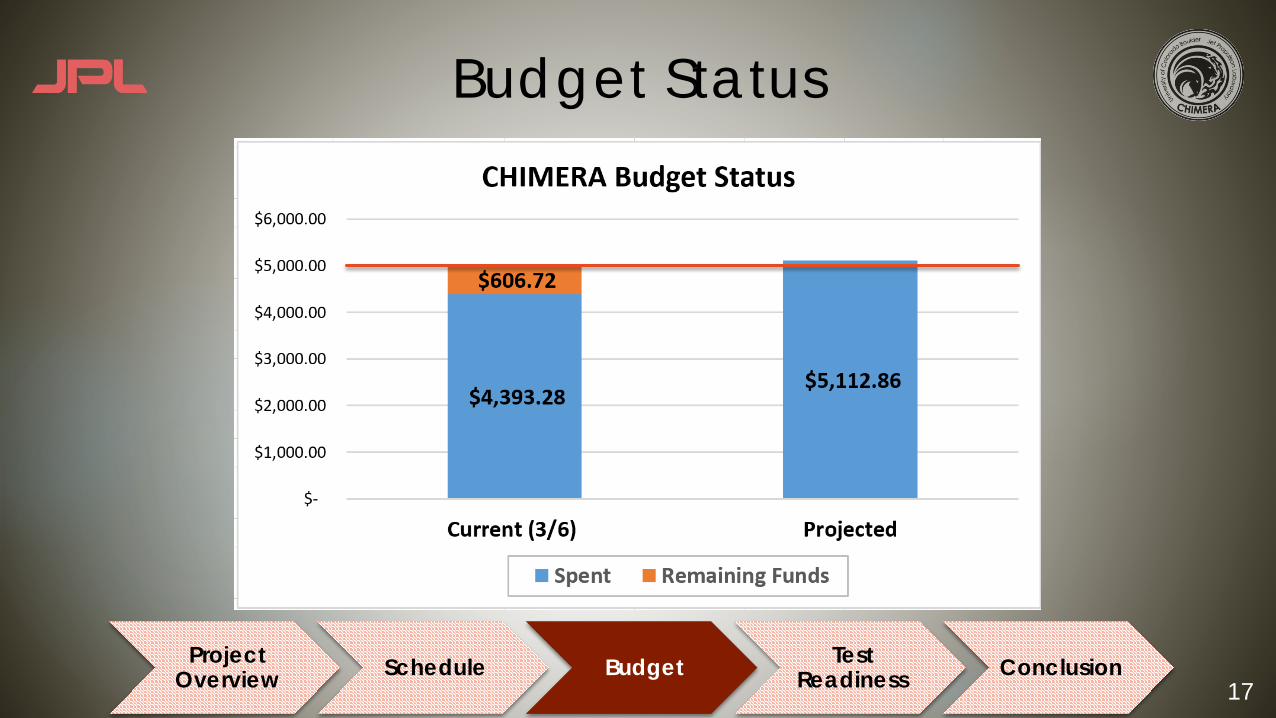
Budget Status
Project Overview Schedule Budget Test
Readiness Conclusion
18
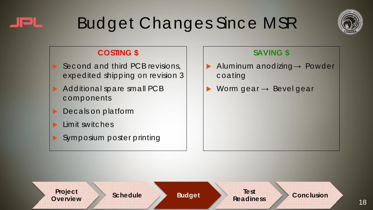
Budget Changes Since MSR
Project Overview Schedule Budget Test
Readiness Conclusion
SAVING $u Aluminum anodizing→ Powder
coating u Worm gear → Bevel gear
COSTING $u Second and third PCB revisions,
expedited shipping on revision 3u Additional spare small PCB
componentsu Decals on platformu Limit switchesu Symposium poster printing
19
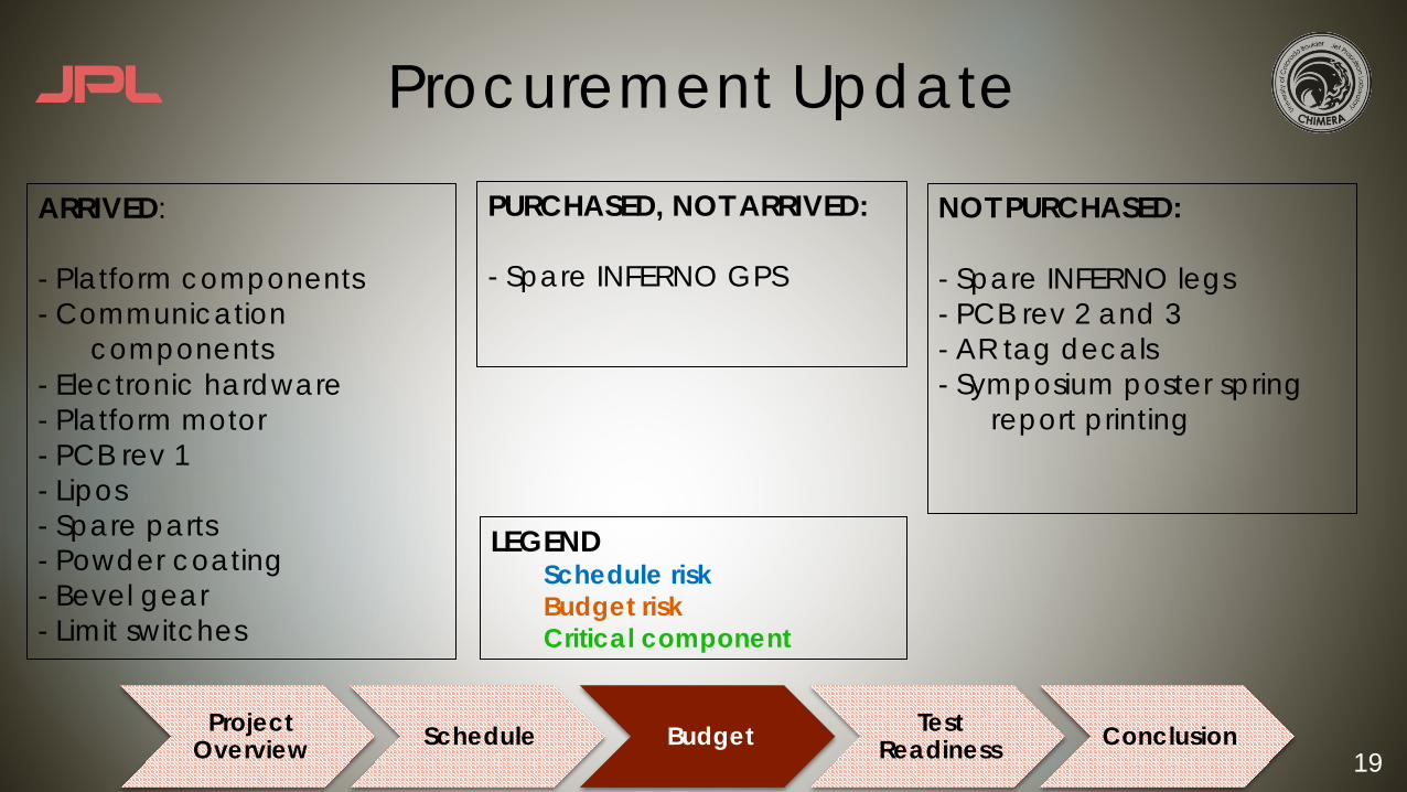
Procurement Update
ARRIVED:
- Platform components- Communication
components- Electronic hardware- Platform motor- PCB rev 1- Lipos- Spare parts- Powder coating- Bevel gear- Limit switches
PURCHASED, NOT ARRIVED:
- Spare INFERNO GPS
NOT PURCHASED:
- Spare INFERNO legs- PCB rev 2 and 3 - AR tag decals - Symposium poster spring
report printing
LEGENDSchedule riskBudget riskCritical component
Project Overview Schedule Budget Test
Readiness Conclusion

20
Test Readiness
Project Overview Schedule Budget Test
Readiness Conclusion

21Project
Overview Schedule Budget Test Readiness Conclusion
64
Simulated Flight Path
Distance X (meters)
2-0.5
0
0.5
1
3
1.5
2
2.5
Dis
tanc
e Z
(met
ers)
2.5
3
02
Distance Y (meters)
3.5
4
1.5
4.5
1 0.5 0 -2-0.5
PathStartEnd
Flight Simulator - Demonstration

22
Flight Simulator - Model• Cascading control system
• To emulate Pixhawk• Fully configurable gains
• Utilizes Simscape Multibody Simulink add-in• Provided kinetics, calculates kinematics• Import Solidworks model of INFERNO for mass
and inertia properties
23
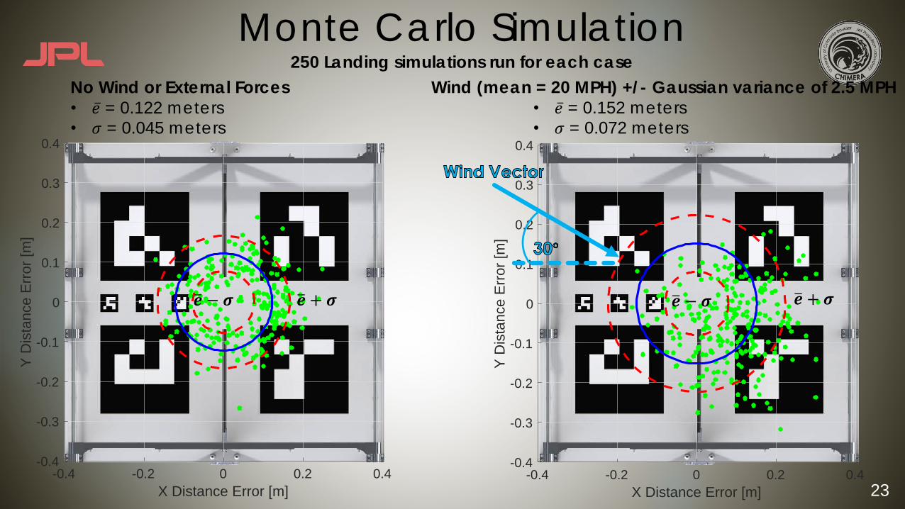
Monte Carlo Simulation250 Landing simulations run for each case
No Wind or External Forces• �̅� = 0.122 meters• 𝜎 = 0.045 meters
Wind (mean = 20 MPH) +/- Gaussian variance of 2.5 MPH• �̅� = 0.152 meters• 𝜎 = 0.072 meters
-0.4 -0.2 0 0.2 0.4X Distance Error [m]
-0.4
-0.3
-0.2
-0.1
0
0.1
0.2
0.3
0.4
Y D
ista
nce
Erro
r [m
]
-0.4 -0.2 0 0.2 0.4X Distance Error [m]
-0.4
-0.3
-0.2
-0.1
0
0.1
0.2
0.3
0.4
Y D
ista
nce
Erro
r [m
]
𝒆% + 𝝈𝒆% − 𝝈 𝒆% − 𝝈 𝒆% + 𝝈

24
Image Recognition Verificationu Requirements Verified:
u DR 1.1.1, DR 1.1.1.1, DR 1.1.1.2
u Equipment Needed:u Previously Recorded Flight Video
u Image recognition algorithm
u Facilities:u South Campus
u Risks Reduced With Testing:u 5, 9, 10
Project Overview Schedule Budget Testing Conclusion
Test Plan Created Test Scheduled Test Conducted Test Analyzed
25
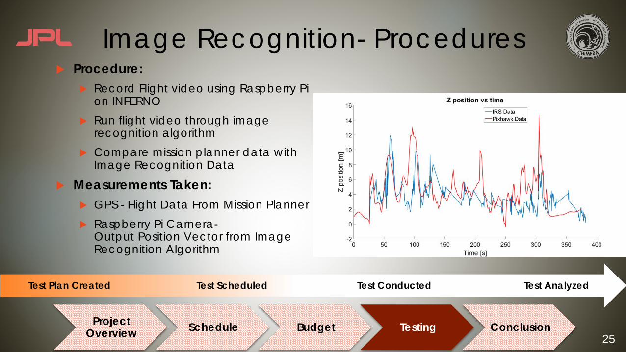
Image Recognition- Proceduresu Procedure:
u Record Flight video using Raspberry Pi on INFERNO
u Run flight video through image recognition algorithm
u Compare mission planner data with Image Recognition Data
u Measurements Taken:u GPS - Flight Data From Mission Planneru Raspberry Pi Camera-
Output Position Vector from ImageRecognition Algorithm
Project Overview Schedule Budget Testing Conclusion
Test Plan Created Test Scheduled Test Conducted Test Analyzed
26
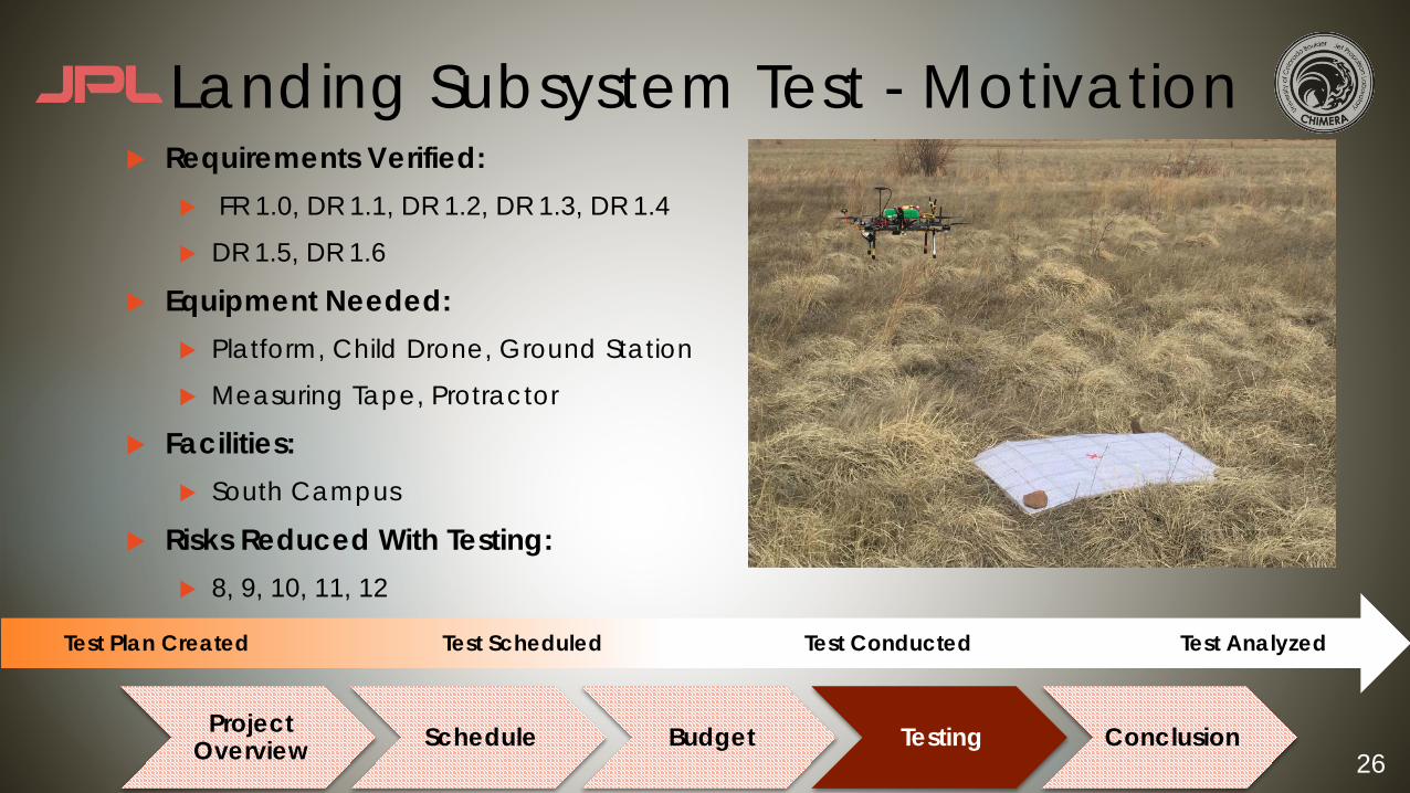
Landing Subsystem Test - Motivationu Requirements Verified:
u FR 1.0, DR 1.1, DR 1.2, DR 1.3, DR 1.4
u DR 1.5, DR 1.6
u Equipment Needed:u Platform, Child Drone, Ground Station
u Measuring Tape, Protractor
u Facilities:u South Campus
u Risks Reduced With Testing:u 8, 9, 10, 11, 12
Project Overview Schedule Budget Testing Conclusion
Test Plan Created Test Scheduled Test Conducted Test Analyzed

27
Landing Subsystem Test - Proceduresu Number of Trials: 20u Procedure:
u Ground Station initiates Land sequence –drone “Returns to home” using GPS
u Image Recognition locks on Platformu Algorithm Commands Flight Controlleru Flight Controller Commands Child Drone to land
u Measurements Taken:u Distance From Center of Platformu Yaw Angle
u Related Models: Flight Simulator
Project Overview Schedule Budget Testing Conclusion
Test Plan Created Test Scheduled Test Conducted Test Analyzed
*Not to scale

28
Charging Subsystem Test - Motivationu Requirements Verified:
u FR 2.0, DR 2.1, DR 2.1.1, DR 2.2, DR 2.3
u Motivation: Full Sub-system test to verify that autonomous charging can be completed upon command with LiPos in the loop
u Component testing in progressu Equipment:
u All CHIMERA platform and charging hardwareu INFERNO Analogu Ground station computer u Fire Extinguisher/Ammo Can
u Facilities:u Electronics Lab
Project Overview Schedule Budget Testing Conclusion
Test Plan Created Test Scheduled Test Conducted Test Analyzed
29
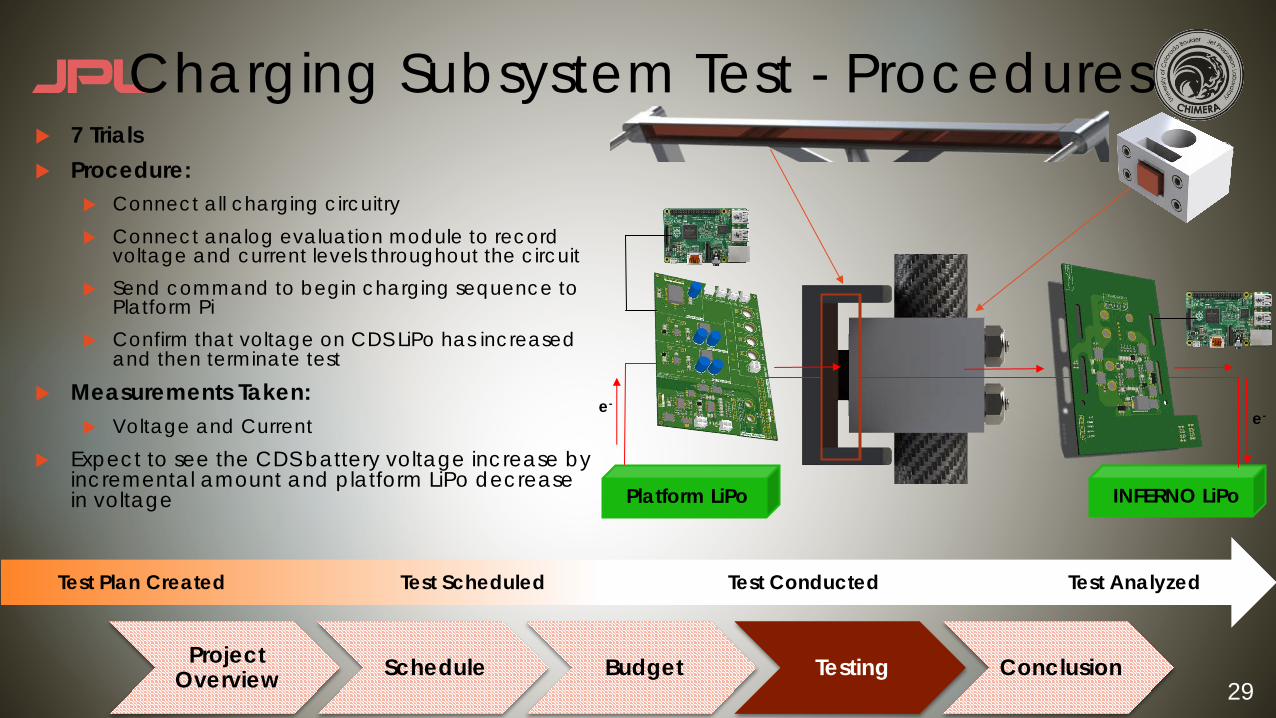
Charging Subsystem Test - Proceduresu 7 Trialsu Procedure:
u Connect all charging circuitryu Connect analog evaluation module to record
voltage and current levels throughout the circuitu Send command to begin charging sequence to
Platform Piu Confirm that voltage on CDS LiPo has increased
and then terminate test
u Measurements Taken:u Voltage and Current
u Expect to see the CDS battery voltage increase by incremental amount and platform LiPo decrease in voltage
Project Overview Schedule Budget Testing Conclusion
Test Plan Created Test Scheduled Test Conducted Test Analyzed
Platform LiPo INFERNO LiPo
e-e-
30
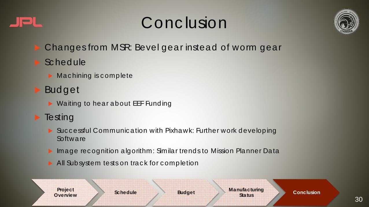
Conclusionu Changes from MSR: Bevel gear instead of worm gearu Schedule
u Machining is complete
u Budget u Waiting to hear about EEF Funding
u Testing u Successful Communication with Pixhawk: Further work developing
Software
u Image recognition algorithm: Similar trends to Mission Planner Data
u All Subsystem tests on track for completion
Project Overview Schedule Budget Manufacturing
Status Conclusion
31
References
u CHIMERA 1st Semester Contentu INFERNO Project Archive

32
Budget Backup- What happens if external funding falls through?
u If we do not need the third revision of the PCBS…u We will end the project under budget by $104
u If we do need the third revision of the PCBs…u We will need to cut down on printing costs for the final
report and symposium poster, currently allotted $200. This includes printing the pages for the report amongst team members and only having it professionally bound, or attempting to get a discount on poster printing via Kinkos.
33
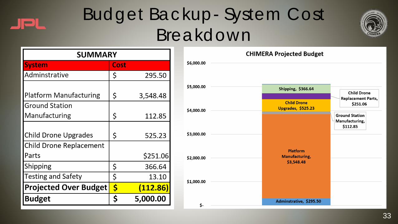
Budget Backup- System Cost Breakdown

34
Budget Backup- Procurement Breakdown

35
Backup More Testing Procedures

36
COM Subsystem Test - Motivationu Requirements Verified:
u FR 4.0, DR 4.1, DR 4.1.1u FR 5.0, DR 5.1, DR 5.1.1, DR 5.2.1
u Equipment Needed:u 3 Xbee Antennasu Crazy Crosshair Antennasu MapMyWalk App to measure distance
u Facilities:u South Campus
u Risks Reduced With Testing:u 20
Project Overview Schedule Budget Testing Conclusion
Test Plan Created Test Scheduled Test Conducted Test Analyzed

37
COM Subsystem Test - Proceduresu Number of Trialsu Procedure:
u Send data between components at 700 m
u Related Models:u Link Budget
u What do we Expect?u The antennas are rated for these distances, so we expect the antennas
to send and receive the information
Project Overview Schedule Budget Testing Conclusion
Test Plan Created Test Scheduled Test Conducted Test Analyzed

38
Environment - Motivationu Environment Verified:
u ENV: 1.1.2
u Equipment:u Accelerometer – Iphone 6+
u ”VibeSensor” Application
u Hard Rubber Castor Wheel Cart
u Facilities:u Engineering Center Courtyard
u Risks Reduced With Testing:u Defines environment
Test Plan Created Test Scheduled Test Conducted Test Analyzed
Hard Rubber Castor Wheels

39
Environment- Proceduresu Number of Trials: Min. 4u Procedure:
u Install accelerometer onto cart
u Traverse rough terrain course
u Measurements Taken:u PSD, tilt angle, vibration g level
u Related Models: Bracket Analysisu Expect: Analyze g level loading to
replicate with securing system
Test Plan Created Test Scheduled Test Conducted Test Analyzed
Shock Event Course
40
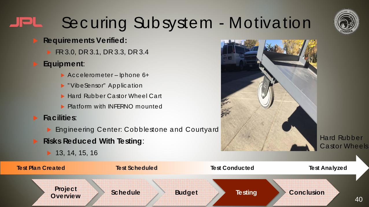
Securing Subsystem - Motivationu Requirements Verified:
u FR 3.0, DR 3.1, DR 3.3, DR 3.4
u Equipment:u Accelerometer – Iphone 6+
u ”VibeSensor” Application
u Hard Rubber Castor Wheel Cart
u Platform with INFERNO mounted
u Facilities:u Engineering Center: Cobblestone and Courtyard
u Risks Reduced With Testing:u 13, 14, 15, 16
Project Overview Schedule Budget Testing Conclusion
Test Plan Created Test Scheduled Test Conducted Test Analyzed
Hard Rubber Castor Wheels
41
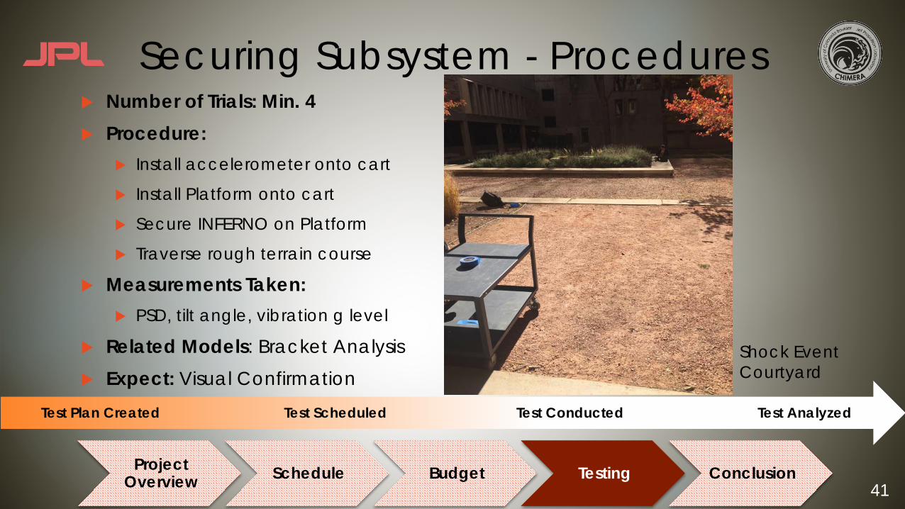
Securing Subsystem - Proceduresu Number of Trials: Min. 4u Procedure:
u Install accelerometer onto cart
u Install Platform onto cart
u Secure INFERNO on Platform
u Traverse rough terrain course
u Measurements Taken:u PSD, tilt angle, vibration g level
u Related Models: Bracket Analysisu Expect: Visual Confirmation
Project Overview Schedule Budget Testing Conclusion
Test Plan Created Test Scheduled Test Conducted Test Analyzed
Shock Event Courtyard

42
Platform Tilt - Motivationu Requirements Verified:
u FR 3.0, DR 3.5
u Equipment:u Accelerometer – Iphone 6+
u ”VibeSensor” Application
u Platform securing INFERNO
u Facilities:u Engineering Center Courtyard
u Risks Reduced With Testing:u 13, 14, 15, 16
Test Plan Created Test Scheduled Test Conducted Test Analyzed
𝝰
43
Platform Tilt - Proceduresu Number of Trials: Min. 4u Procedure:
u Install accelerometer onto cart
u Install Platform onto cart
u Secure INFERNO on Platform
u Traverse rough terrain course
u Measurements Taken:u Tilt angle
u Related Models: Bracket Analysisu Expect: Visual Confirmation
Test Plan Created Test Scheduled Test Conducted Test Analyzed
𝝰
44
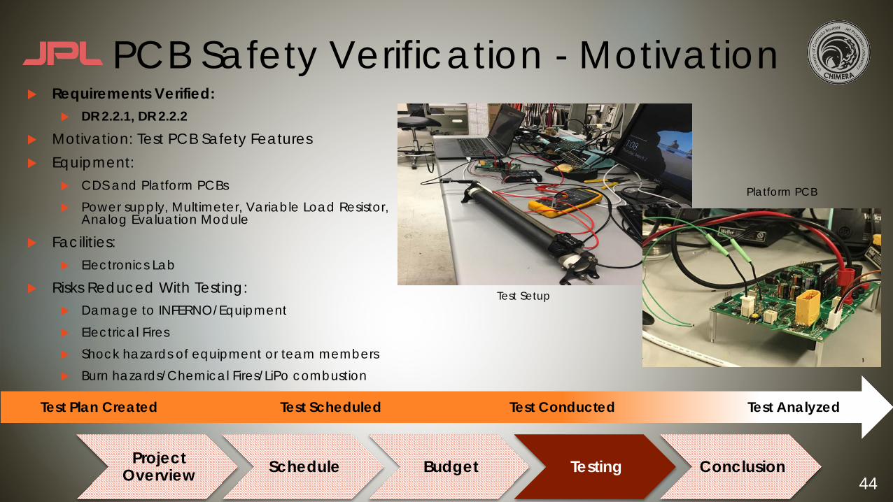
PCB Safety Verification - Motivationu Requirements Verified:
u DR 2.2.1, DR 2.2.2
u Motivation: Test PCB Safety Featuresu Equipment:
u CDS and Platform PCBsu Power supply, Multimeter, Variable Load Resistor,
Analog Evaluation Module
u Facilities:u Electronics Lab
u Risks Reduced With Testing:u Damage to INFERNO/Equipmentu Electrical Firesu Shock hazards of equipment or team membersu Burn hazards/Chemical Fires/LiPo combustion
Project Overview Schedule Budget Testing Conclusion
Test Plan Created Test Scheduled Test Conducted Test Analyzed
Test Setup
Platform PCB
45
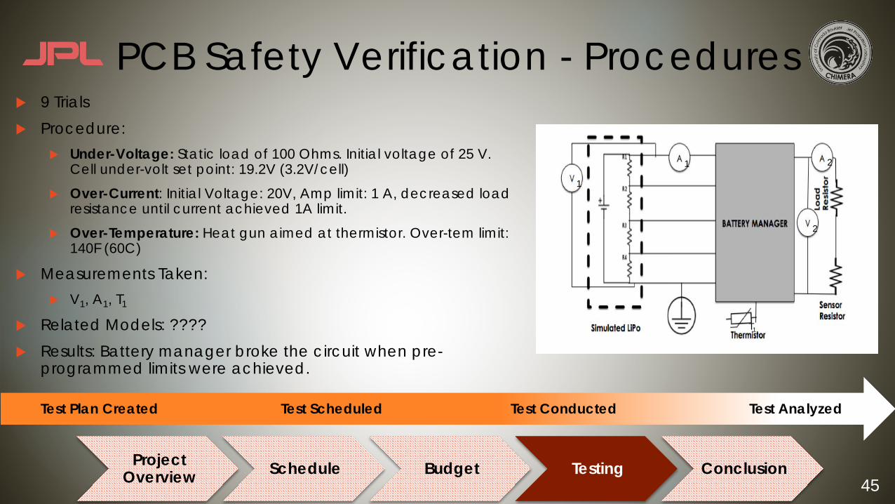
PCB Safety Verification - Proceduresu 9 Trials u Procedure:
u Under-Voltage: Static load of 100 Ohms. Initial voltage of 25 V. Cell under-volt set point: 19.2V (3.2V/cell)
u Over-Current: Initial Voltage: 20V, Amp limit: 1 A, decreased load resistance until current achieved 1A limit.
u Over-Temperature: Heat gun aimed at thermistor. Over-tem limit: 140F (60C)
u Measurements Taken:u V1, A1, T1
u Related Models: ????u Results: Battery manager broke the circuit when pre-
programmed limits were achieved.
Project Overview Schedule Budget Testing Conclusion
Test Plan Created Test Scheduled Test Conducted Test Analyzed
1
1
2
2
T1
46
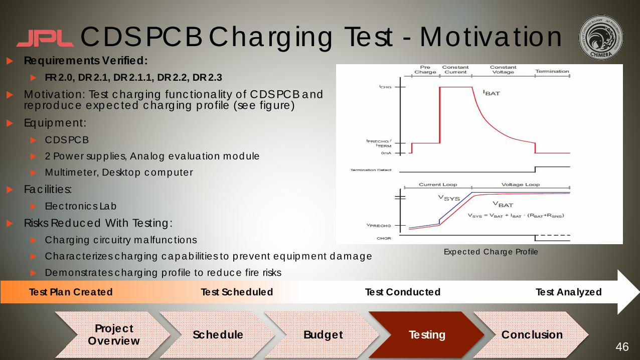
CDS PCB Charging Test - Motivationu Requirements Verified:
u FR 2.0, DR 2.1, DR 2.1.1, DR 2.2, DR 2.3u Motivation: Test charging functionality of CDS PCB and
reproduce expected charging profile (see figure)u Equipment:
u CDS PCBu 2 Power supplies, Analog evaluation moduleu Multimeter, Desktop computer
u Facilities:u Electronics Lab
u Risks Reduced With Testing:u Charging circuitry malfunctionsu Characterizes charging capabilities to prevent equipment damageu Demonstrates charging profile to reduce fire risks
Project Overview Schedule Budget Testing Conclusion
Test Plan Created Test Scheduled Test Conducted Test Analyzed
Expected Charge Profile

47
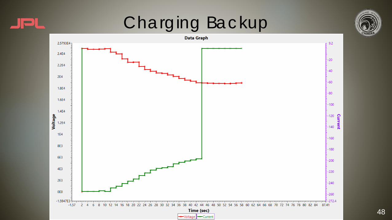
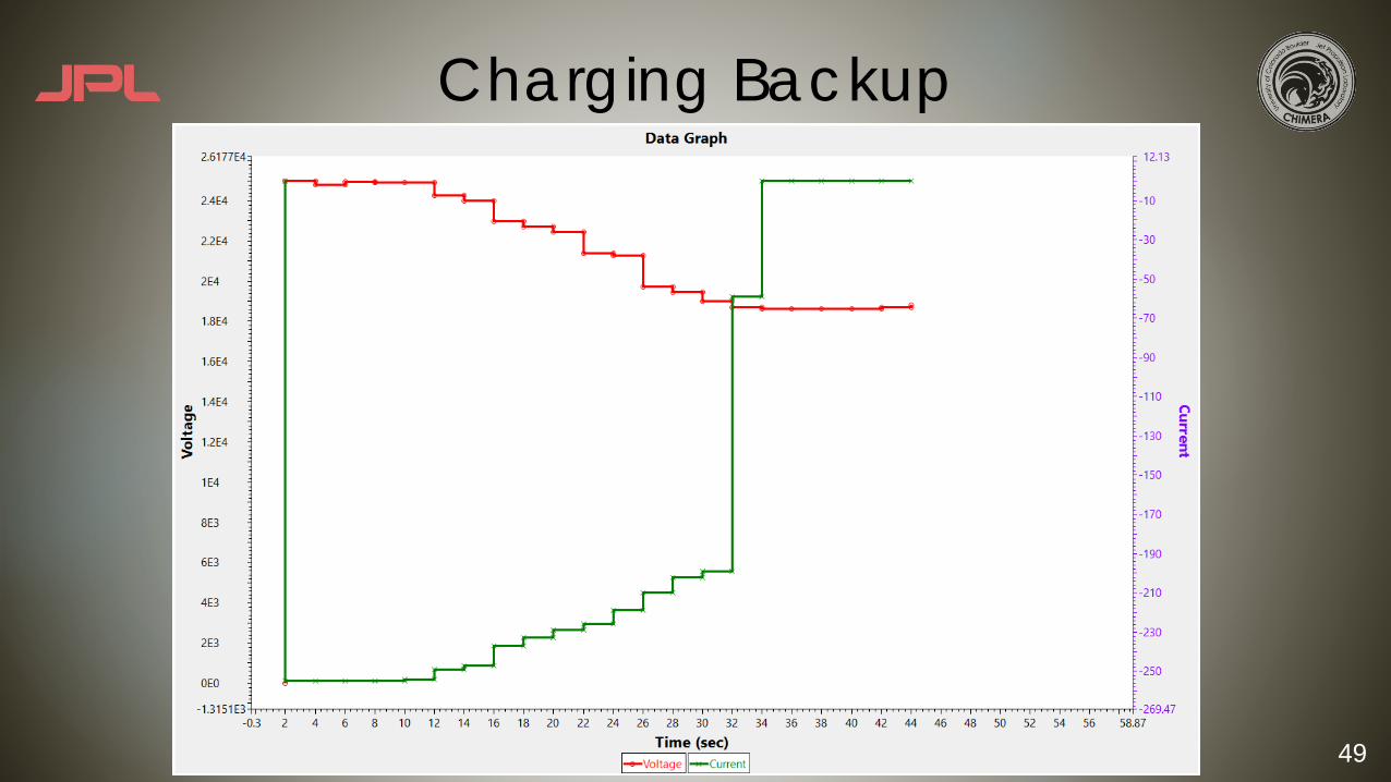
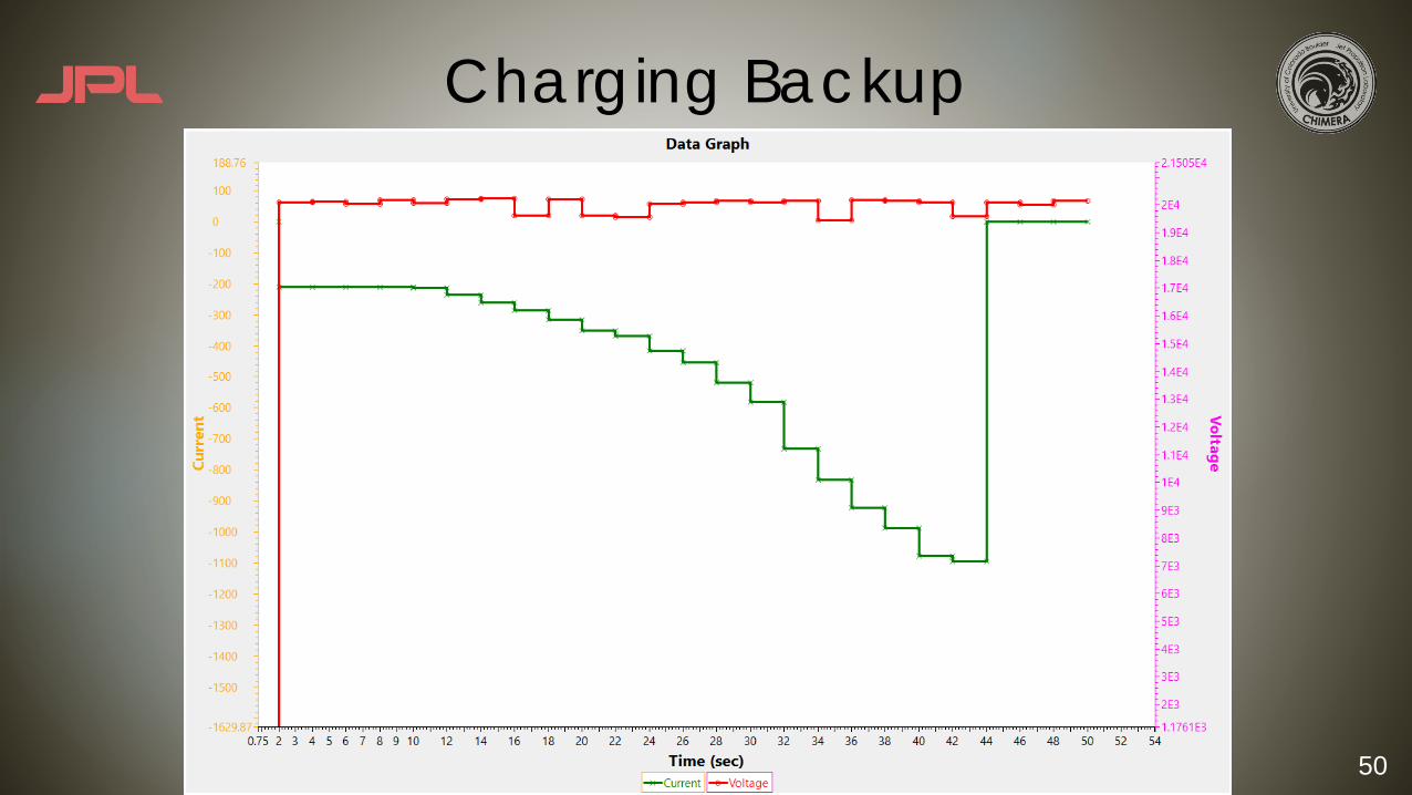
CDS PCB Charging Test - Proceduresu 10 Trialsu Procedure:
u Connect CDS PCB to two power suppliesu Increase voltage on PS 1 incrementally up
to max voltage of battery (16.8V)u Observe current reduction on PS 2 as max
voltage on PS 1 is achievedu Measurements Taken:
u V1, A1, V2, A2, Charge Profileu Related Models: ???u Expect to see charge profile described
in previous slide as voltage is increased on PS 1
Project Overview Schedule Budget Testing Conclusion
Test Plan Created Test Scheduled Test Conducted Test Analyzed
CDSBattery
Manager
Power Supply 1(Simulated CDS LiPo)
Power Supply 2(Simulated Platform LiPo)
1
12
2
48
Charging Backup
49
Charging Backup
50
Charging Backup

51
Charging Backup
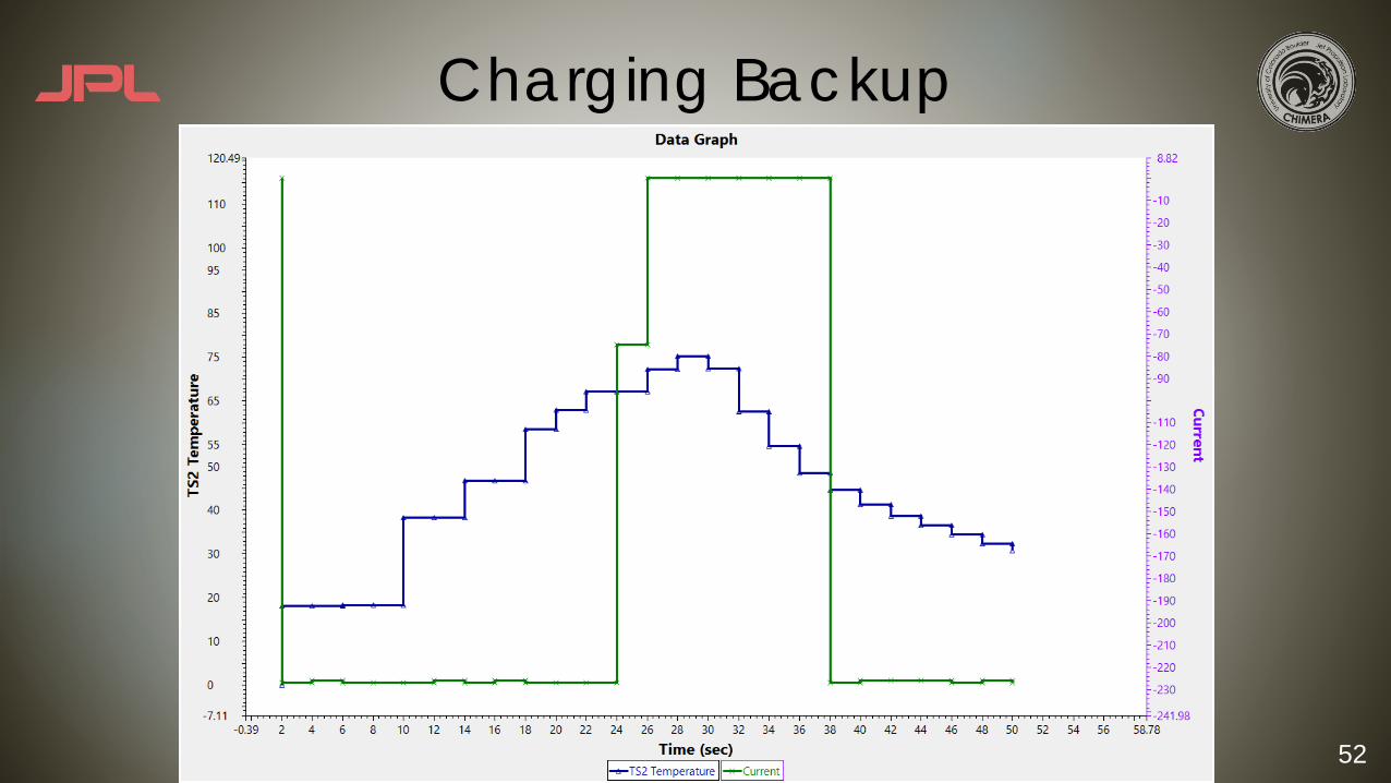
52
Charging Backup
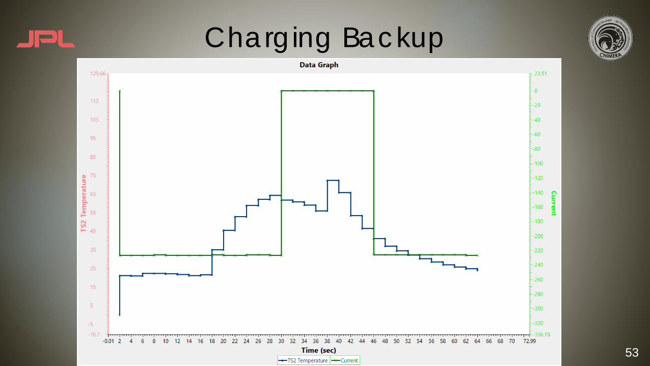
53
Charging Backup

54
Image Recognition Errors
u GPS error +/- 5 m u No knowledge of platform location
u Image Recognition Algorithm Error – difficult to characterizeu Loses data when platform is out of sight of the camera
u Why compare sensors?u While the GPS has known errors, it is the best way to safely validate the
image recognition algorithm.

55
Requirements Backup

56
Functional RequirementsFunctional
Requirement Description
FR 1.0 The child drone shall autonomously land on the platform upon command in the environment specified by ENVI.1.2.
FR 2.0 The platform shall charge the child drone.
FR 3.0 The platform shall secure the child drone by preventing motion according to CONST 1.1 and ENVI 1.1
FR 4.0 The ground station shall communicate with the sensor package according to ENVI1.5 and CONST1.3.3
FR 5.0 The platform shall communicate with the ground station according to ENVI1.5 and CONST1.3.2.
57
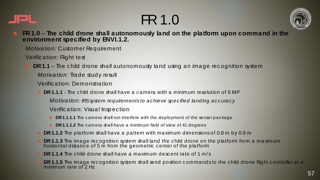
FR 1.0u FR 1.0 – The child drone shall autonomously land on the platform upon command in the
environment specified by ENVI.1.2.Motivation: Customer RequirementVerification: Flight testu DR 1.1 – The child drone shall autonomously land using an image recognition system
Motivation: Trade study resultVerification: Demonstrationu DR 1.1.1 - The child drone shall have a camera with a minimum resolution of 5 MP
Motivation: IRS system requirements to achieve specified landing accuracy
Verification: Visual Inspectionu DR 1.1.1.1 The camera shall not interfere with the deployment of the sensor package
u DR 1.1.1.2 The camera shall have a minimum field of view of 41 degrees
u DR 1.1.2 The platform shall have a pattern with maximum dimensions of 0.8 m by 0.8 mu DR 1.1.3 The image recognition system shall land the child drone on the platform from a maximum
horizontal distance of 5 m from the geometric center of the platformu DR 1.1.4 The child drone shall have a maximum descent rate of 1 m/su DR 1.1.5 The image recognition system shall send position commands to the child drone flight controller at a
minimum rate of 2 Hz

58
FR 1.0u DR 1.2 - The platform shall communicate with the child drone according to CONST1.3.1 and
ENVI1.5
Motivation: Communication system must be in place to send/receive commands and data
Verification: Demonstrationu DR 1.2.1 The platform shall wirelessly send commands to the child drone
u DR 1.2.2 The platform shall wirelessly receive data from the child drone
u DR 1.3 - The child drone shall wirelessly transmit video at 720p and 30fps to the ground station according to CONS1.3.1 and ENVI1.5
Motivation: Inherited capability to be incorporated in CHIMERA design
Verification: Testu DR 1.3.1 The child drone shall have a transmitter capable of transmitting 600 mW of power
u DR 1.4 The child drone shall wirelessly transmit telemetry to platform
u DR 1.5 The child drone shall wirelessly receive commands from the platform u DR 1.5.1 The child drone shall have a receiver gain of 2.1 dB

59
FR 2.0u FR 2.0 - The platform shall charge the child drone.
Motivation: Enable future capability to re-deploy the child drone Verification: Test and Demonstrationu DR 2.1 - The platform shall demonstrate charging capability upon command by providing visual
confirmation that the charging circuit is complete under conditions specified by ENVI1.3.Motivation: Indicate charging capability Verification: Test and Demonstrationu DR 2.1.1 - The platform shall visually indicate charging capability by illuminating an LED when the circuit is
completed and current is flowing.
u DR 2.2 The platform shall charge the child drone battery with a child drone analog upon command under conditions specified by ENVI1.4.
u DR 2.2.1 A cell balancer shall be used to ensure LiPo battery cells are evenly charge
u DR 2.2.2 A battery manager shall be used during all circuitry testing to ensure LiPo battery is operating within COTS safety limits
u DR 2.3 The platform shall include a circuit breaker capable of interrupting the flow of current from the platform to the LiPo battery upon command.
60
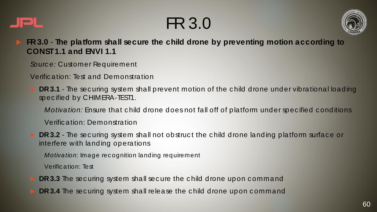
FR 3.0u FR 3.0 - The platform shall secure the child drone by preventing motion according to
CONST 1.1 and ENVI 1.1Source: Customer Requirement
Verification: Test and Demonstration
u DR 3.1 - The securing system shall prevent motion of the child drone under vibrational loading specified by CHIMERA-TEST1.
Motivation: Ensure that child drone does not fall off of platform under specified conditions
Verification: Demonstration
u DR 3.2 - The securing system shall not obstruct the child drone landing platform surface or interfere with landing operations
Motivation: Image recognition landing requirement
Verification: Test
u DR 3.3 The securing system shall secure the child drone upon command
u DR 3.4 The securing system shall release the child drone upon command

61
FR 4.0u FR 4.0 - The ground station shall communicate with the sensor package according to
ENVI1.5 and CONST1.3.3 Motivation: Inherited capability to be incorporated in CHIMERA design
Verification: Test and Demonstration
u DR 4.1 - The ground station shall receive data from the sensor package.
Motivation: Must receive sensor package temperature data at the ground station
Verification: Demonstrationu DR 4.1.1 - The ground station shall have a receiver gain of 2.1 dB.
u DR 4.2 The ground station shall command the platform and child drone while retaining the ability to land the child drone via manual piloting.
Motivation: Piloted capability ensures drone safety in the event of a software failure
Verification: Demonstration
62
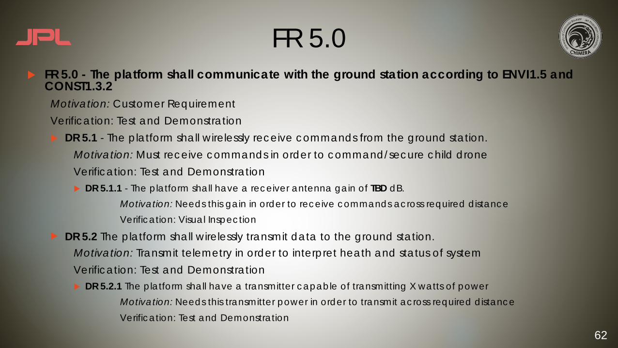
FR 5.0u FR 5.0 - The platform shall communicate with the ground station according to ENVI1.5 and
CONST1.3.2Motivation: Customer RequirementVerification: Test and Demonstrationu DR 5.1 - The platform shall wirelessly receive commands from the ground station.
Motivation: Must receive commands in order to command/secure child drone Verification: Test and Demonstrationu DR 5.1.1 - The platform shall have a receiver antenna gain of TBD dB.
Motivation: Needs this gain in order to receive commands across required distanceVerification: Visual Inspection
u DR 5.2 The platform shall wirelessly transmit data to the ground station.Motivation: Transmit telemetry in order to interpret heath and status of systemVerification: Test and Demonstrationu DR 5.2.1 The platform shall have a transmitter capable of transmitting X watts of power
Motivation: Needs this transmitter power in order to transmit across required distanceVerification: Test and Demonstration

63
Risk Backup

64
Risk Summary

65
Risk Summary continued…
66
Risk Analysis
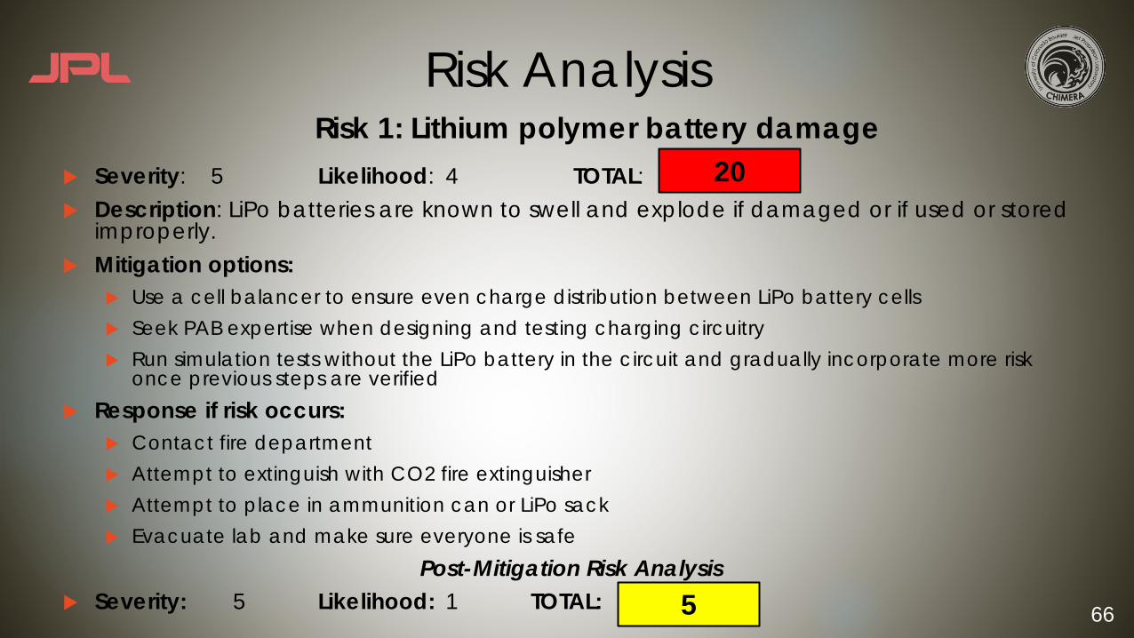
u Severity: 5 Likelihood: 4 TOTAL:u Description: LiPo batteries are known to swell and explode if damaged or if used or stored
improperly.u Mitigation options:
u Use a cell balancer to ensure even charge distribution between LiPo battery cellsu Seek PAB expertise when designing and testing charging circuitryu Run simulation tests without the LiPo battery in the circuit and gradually incorporate more risk
once previous steps are verifiedu Response if risk occurs:
u Contact fire departmentu Attempt to extinguish with CO2 fire extinguisheru Attempt to place in ammunition can or LiPo sack u Evacuate lab and make sure everyone is safe
Post-Mitigation Risk Analysisu Severity: 5 Likelihood: 1 TOTAL:
Risk 1: Lithium polymer battery damage20
5
67
Risk Analysis
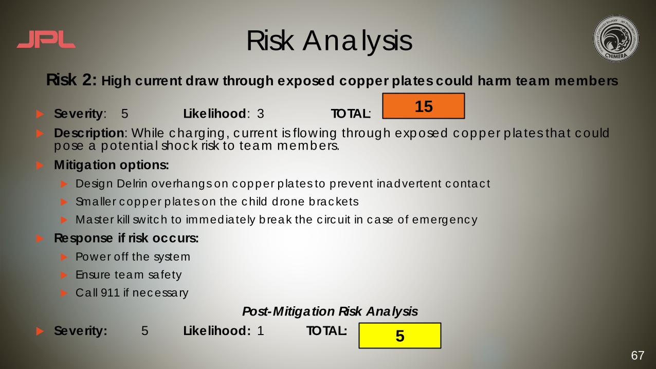
u Severity: 5 Likelihood: 3 TOTAL:u Description: While charging, current is flowing through exposed copper plates that could
pose a potential shock risk to team members.u Mitigation options:
u Design Delrin overhangs on copper plates to prevent inadvertent contactu Smaller copper plates on the child drone bracketsu Master kill switch to immediately break the circuit in case of emergency
u Response if risk occurs:u Power off the systemu Ensure team safetyu Call 911 if necessary
Post-Mitigation Risk Analysisu Severity: 5 Likelihood: 1 TOTAL:
Risk 2: High current draw through exposed copper plates could harm team members
15
5
68
Risk Analysis
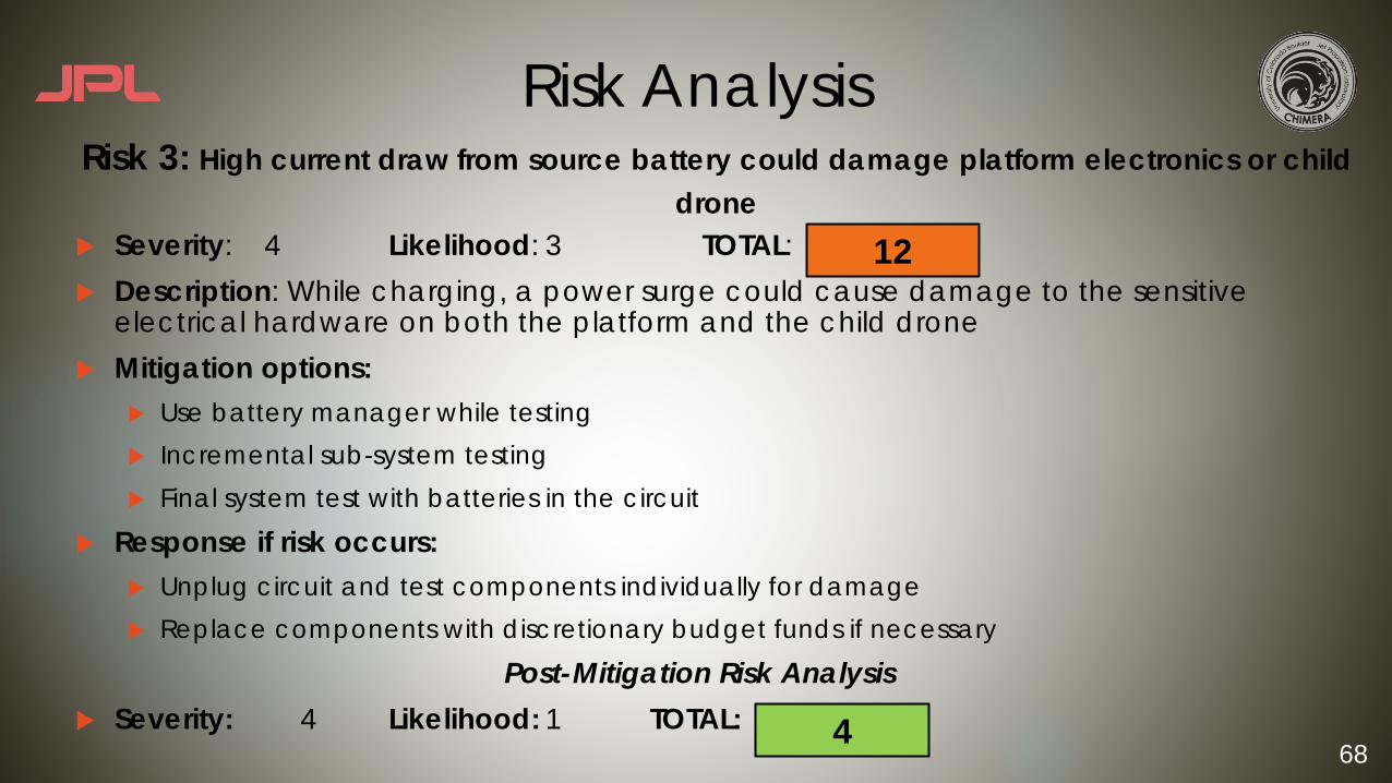
u Severity: 4 Likelihood: 3 TOTAL:u Description: While charging, a power surge could cause damage to the sensitive
electrical hardware on both the platform and the child droneu Mitigation options:
u Use battery manager while testingu Incremental sub-system testingu Final system test with batteries in the circuit
u Response if risk occurs:u Unplug circuit and test components individually for damageu Replace components with discretionary budget funds if necessary
Post-Mitigation Risk Analysisu Severity: 4 Likelihood: 1 TOTAL:
Risk 3: High current draw from source battery could damage platform electronics or child drone
12
4
69
Risk Analysis
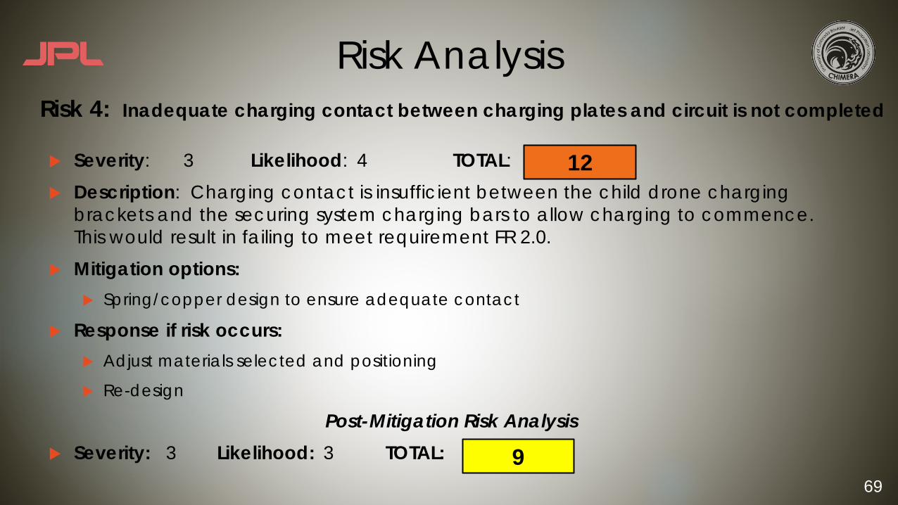
u Severity: 3 Likelihood: 4 TOTAL:u Description: Charging contact is insufficient between the child drone charging
brackets and the securing system charging bars to allow charging to commence. This would result in failing to meet requirement FR 2.0.
u Mitigation options:u Spring/copper design to ensure adequate contact
u Response if risk occurs:u Adjust materials selected and positioning
u Re-design
Post-Mitigation Risk Analysisu Severity: 3 Likelihood: 3 TOTAL:
Risk 4: Inadequate charging contact between charging plates and circuit is not completed
12
9

70
Risk Analysis
u Severity: 3 Likelihood: 3 TOTAL:u Description: Child drone could potentially land perpendicular to the charging bars
and therefore prevent the charging bars from making contact with the brackets on child drone. Does not fulfill FR 2.0.
u Mitigation options:u Pixhawk yaw gain adjustmentu Improve IRS landing accuracyu Modeling from PDR proved this risk is negligible
u Response if risk occurs:u Re-attempt landing sequence and tweak software parameters
Post-Mitigation Risk Analysisu Severity: 3 Likelihood: 2 TOTAL:
Risk 5: Child drone lands in poor landing configuration and prevents charging
9
6
71
Risk Analysis
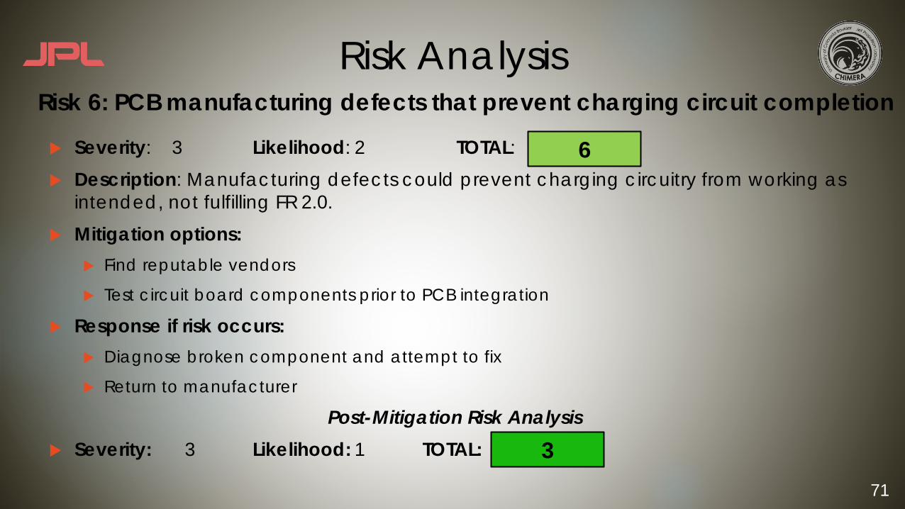
u Severity: 3 Likelihood: 2 TOTAL:u Description: Manufacturing defects could prevent charging circuitry from working as
intended, not fulfilling FR 2.0.u Mitigation options:
u Find reputable vendors
u Test circuit board components prior to PCB integration
u Response if risk occurs:u Diagnose broken component and attempt to fix
u Return to manufacturer
Post-Mitigation Risk Analysisu Severity: 3 Likelihood: 1 TOTAL:
Risk 6: PCB manufacturing defects that prevent charging circuit completion
6
3

72
Risk Analysis
u Severity: 5 Likelihood: 2 TOTAL:u Description: The battery manager used to ensure that charging is being completely
properly could malfunction causing the LiPo to explode, potentially damaging hardware or injuring team members.
u Mitigation options:u Sub-system incremental testing with componentsu Use component only after testing that it will regulate voltage properly
u Response if risk occurs:u Power system offu Ensure no team members are injuredu Place LiPo in LiPo sack or ammo canu Test circuit components to ensure they still function properly
Post-Mitigation Risk Analysisu Severity: 5 Likelihood: 1 TOTAL:
Risk 7: Battery manager malfunctions causing damage to child drone or harming team members
10
5

73
Risk Analysis
u Severity: 4 Likelihood: 3 TOTAL:u Description: The Raspberry Pi onboard the child drone could lose communications
with the onboard flight controller, ultimately preventing landing on the platform and not fulfilling FR 1.0.
u Mitigation options:u Communication testing prior to flight
u Implement system redundancy to have a back-up system if loss of communication occurs
u Response if risk occurs:u Switch Pixhawk to manual flight mode from Ground Station if possible
Post-Mitigation Risk Analysisu Severity: 4 Likelihood: 2 TOTAL:
Risk 8: Raspberry Pi loses communication with Pixhawk
12
8

74
Risk Analysis
u Severity: 4 Likelihood: 2 TOTAL:u Description: Child drone could potentially land with 2 or more legs off of the platform,
causing it to topple and fall of the platform and causing damage.u Mitigation options:
u Use AR tags instead of color recognition for increased landing accuracyu Indoor flight testing with mats/nets beneath platform to catch drone if it falls off the platform
u Response if risk occurs:u Cut throttleu Assess child drone for damageu Replace damaged parts from discretionary spending budget
Post-Mitigation Risk Analysisu Severity: 4 Likelihood: 1 TOTAL:
Risk 9: Poor landing accuracy causes child drone to fall off platform resulting in damage
8
4
75
Risk Analysis
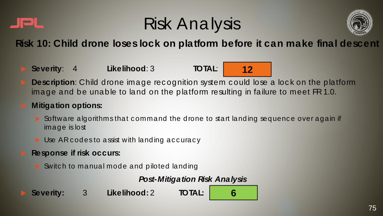
u Severity: 4 Likelihood: 3 TOTAL:u Description: Child drone image recognition system could lose a lock on the platform
image and be unable to land on the platform resulting in failure to meet FR 1.0.u Mitigation options:
u Software algorithms that command the drone to start landing sequence over again if image is lost
u Use AR codes to assist with landing accuracy
u Response if risk occurs:u Switch to manual mode and piloted landing
Post-Mitigation Risk Analysisu Severity: 3 Likelihood: 2 TOTAL:
Risk 10: Child drone loses lock on platform before it can make final descent
12
6

76
Risk Analysis
u Severity: 4 Likelihood: 2 TOTAL:u Description: In order to verify various software capabilities, the child drone must be
flown by a pilot in some test flights. A piloting error could lead to costly and even irreparable damage.
u Mitigation options:u Pilot training and certification
u Response if risk occurs:u Assess environmental factorsu Review flight datau Require that pilot receive additional training
Post-Mitigation Risk Analysisu Severity: 4 Likelihood: 1 TOTAL:
Risk 11: Piloting error could result in child drone damage
8
4
77
Risk Analysis
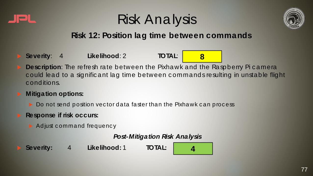
u Severity: 4 Likelihood: 2 TOTAL:u Description: The refresh rate between the Pixhawk and the Raspberry Pi camera
could lead to a significant lag time between commands resulting in unstable flight conditions.
u Mitigation options:u Do not send position vector data faster than the Pixhawk can process
u Response if risk occurs:u Adjust command frequency
Post-Mitigation Risk Analysisu Severity: 4 Likelihood: 1 TOTAL:
Risk 12: Position lag time between commands
8
4
78
Risk Analysis
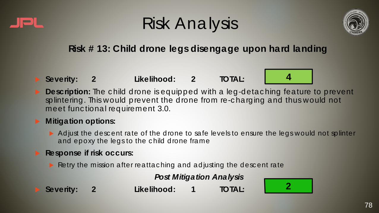
u Severity: 2 Likelihood: 2 TOTAL: u Description: The child drone is equipped with a leg-detaching feature to prevent
splintering. This would prevent the drone from re-charging and thus would not meet functional requirement 3.0.
u Mitigation options:u Adjust the descent rate of the drone to safe levels to ensure the legs would not splinter
and epoxy the legs to the child drone frame
u Response if risk occurs:u Retry the mission after reattaching and adjusting the descent rate
Post Mitigation Analysisu Severity: 2 Likelihood: 1 TOTAL:
4
2
Risk # 13: Child drone legs disengage upon hard landing
79
Risk Analysis
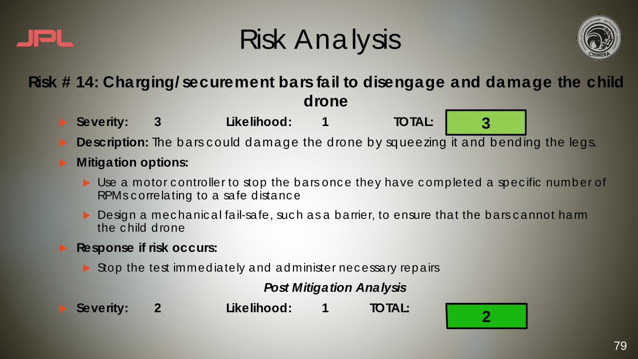
u Severity: 3 Likelihood: 1 TOTAL: u Description: The bars could damage the drone by squeezing it and bending the legs.u Mitigation options:
u Use a motor controller to stop the bars once they have completed a specific number of RPMs correlating to a safe distance
u Design a mechanical fail-safe, such as a barrier, to ensure that the bars cannot harm the child drone
u Response if risk occurs:u Stop the test immediately and administer necessary repairs
Post Mitigation Analysisu Severity: 2 Likelihood: 1 TOTAL:
3
2
Risk # 14: Charging/securement bars fail to disengage and damage the child drone

80
Risk Analysis
u Severity: 2 Likelihood: 3 TOTAL: u Description: If the copper and delrin are not manufactured to the necessary
tolerances, the additions to child drone will not fit into the bars. Charging can not occur and functional requirement 3.0 is not met
u Mitigation options:u Allow for a design margin of 1/10 inch on either side of the delrin additions to child
drone
u Response if risk occurs:u Stop the test to prevent damage and sand down the delrin before testing again
Post Mitigation Analysisu Severity: 2 Likelihood: 2 TOTAL:
Risk # 15: Manufacturing errors in child drone charging/securement bars
4
6
81
Risk Analysis
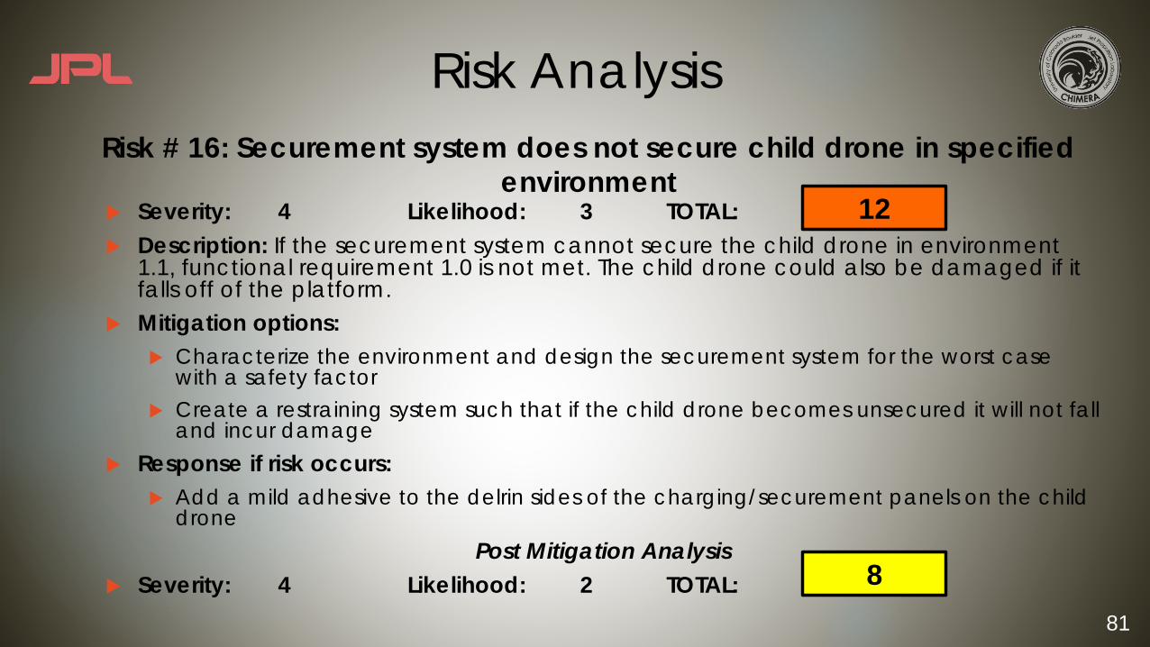
u Severity: 4 Likelihood: 3 TOTAL: u Description: If the securement system cannot secure the child drone in environment
1.1, functional requirement 1.0 is not met. The child drone could also be damaged if it falls off of the platform.
u Mitigation options:u Characterize the environment and design the securement system for the worst case
with a safety factor u Create a restraining system such that if the child drone becomes unsecured it will not fall
and incur damageu Response if risk occurs:
u Add a mild adhesive to the delrin sides of the charging/securement panels on the child drone
Post Mitigation Analysisu Severity: 4 Likelihood: 2 TOTAL:
Risk # 16: Securement system does not secure child drone in specified environment
8
12
82
Risk Analysis
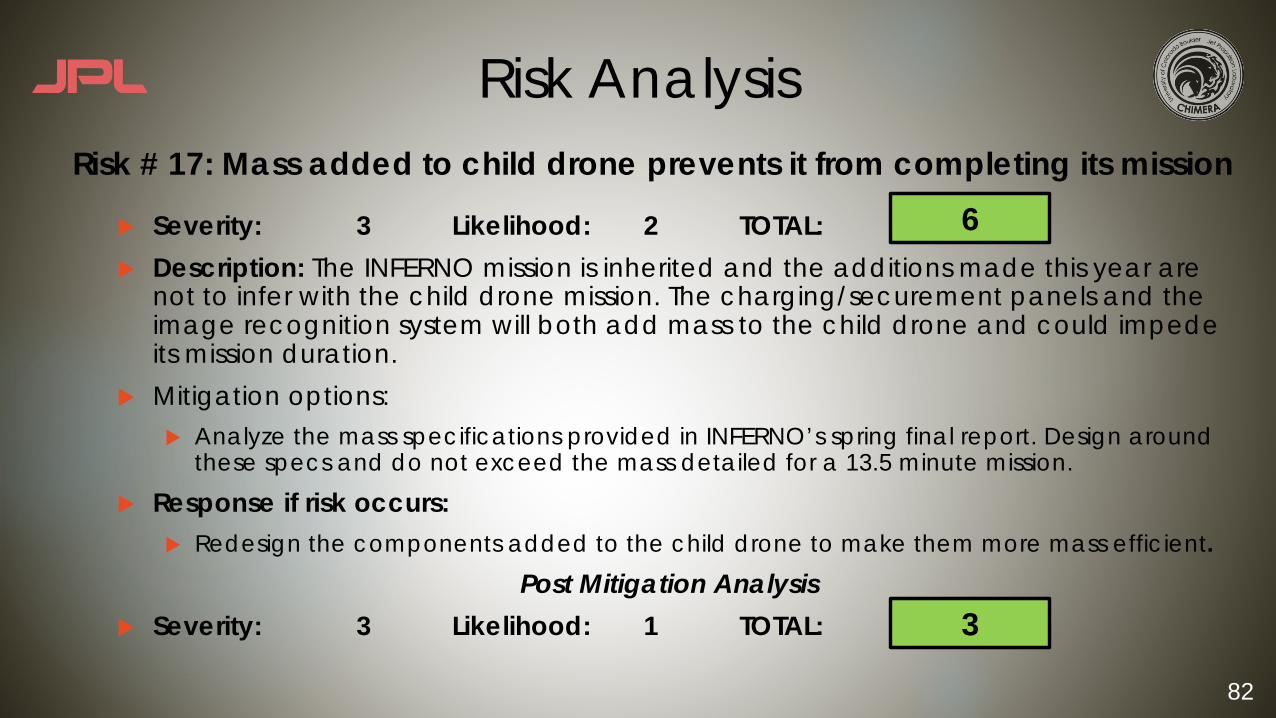
u Severity: 3 Likelihood: 2 TOTAL: u Description: The INFERNO mission is inherited and the additions made this year are
not to infer with the child drone mission. The charging/securement panels and the image recognition system will both add mass to the child drone and could impede its mission duration.
u Mitigation options:u Analyze the mass specifications provided in INFERNO’s spring final report. Design around
these specs and do not exceed the mass detailed for a 13.5 minute mission.
u Response if risk occurs:u Redesign the components added to the child drone to make them more mass efficient.
Post Mitigation Analysisu Severity: 3 Likelihood: 1 TOTAL:
Risk # 17: Mass added to child drone prevents it from completing its mission6
3

83
Risk Analysis
u Severity: 5 Likelihood: 2 TOTAL: u Description: The ball screw drives the charging/securement bars. If this mechanism
fails requirements # and # will not be met.u Mitigation options:
u Buy a commercial off the shelf ball screw to minimize manufacturing error
u Response if risk occurs:u Explore other commercial retailers
Post Mitigation Analysisu Severity: 5 Likelihood: 1 TOTAL:
Risk # 18: The ball screw on the platform fails
10
5

84
Risk Analysis
u Severity: 4 Likelihood: 3 TOTAL: u Description: If the platform material does not fit into the University CNC machine,
manufacturing will take much longer than anticipated and set back the project schedule.
u Mitigation options:u Discuss platform dimensions with machine shop staff
u Outsource the machining to Colorado Waterjet Company for $150
u Response if risk occurs:u Outsource the machining
Post Mitigation Analysisu Severity: 4 Likelihood: 1 TOTAL:
Risk # 19: Platform does not fit into University CNC machine12
4
85
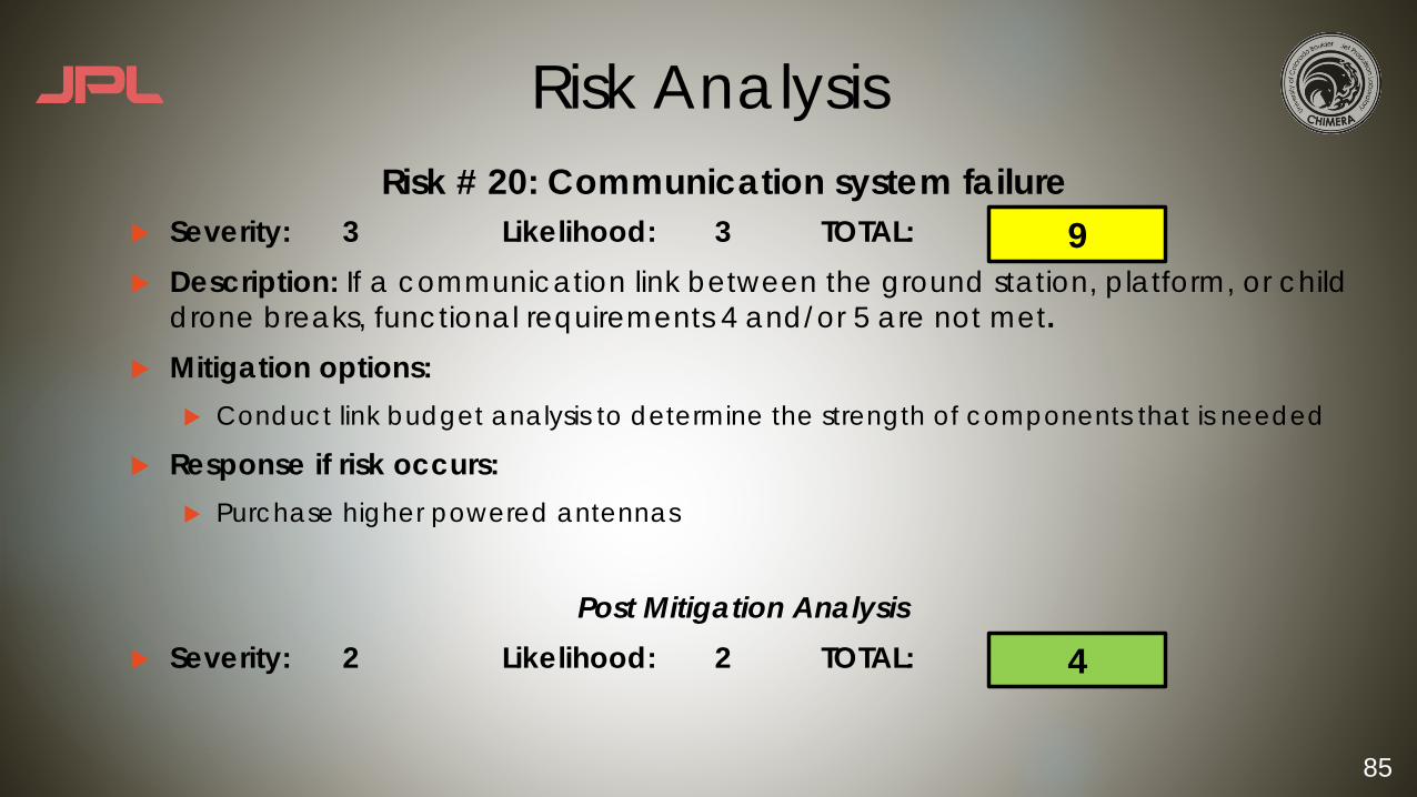
Risk Analysis
u Severity: 3 Likelihood: 3 TOTAL: u Description: If a communication link between the ground station, platform, or child
drone breaks, functional requirements 4 and/or 5 are not met.u Mitigation options:
u Conduct link budget analysis to determine the strength of components that is needed
u Response if risk occurs:u Purchase higher powered antennas
Post Mitigation Analysisu Severity: 2 Likelihood: 2 TOTAL:
Risk # 20: Communication system failure9
4

86
Risk Analysis
u Severity: 3 Likelihood: 3 TOTAL: u Description: If the child drone does not land exactly centered on the platform, the
charging/securement bars will need to push it into place. If the coefficient of friction is too high, the drone could topple and would not be able to charge, not fulfilling functional requirement 3.0.
u Mitigation options:u Grease the platform
u Response if risk occursu Change/polish the rubber material on the child drone feet
Post Mitigation Analysisu Severity: 3 Likelihood: 2 TOTAL:
Risk # 21: Platform has too high a coefficient of friction for the child drone to slide
9
6
87
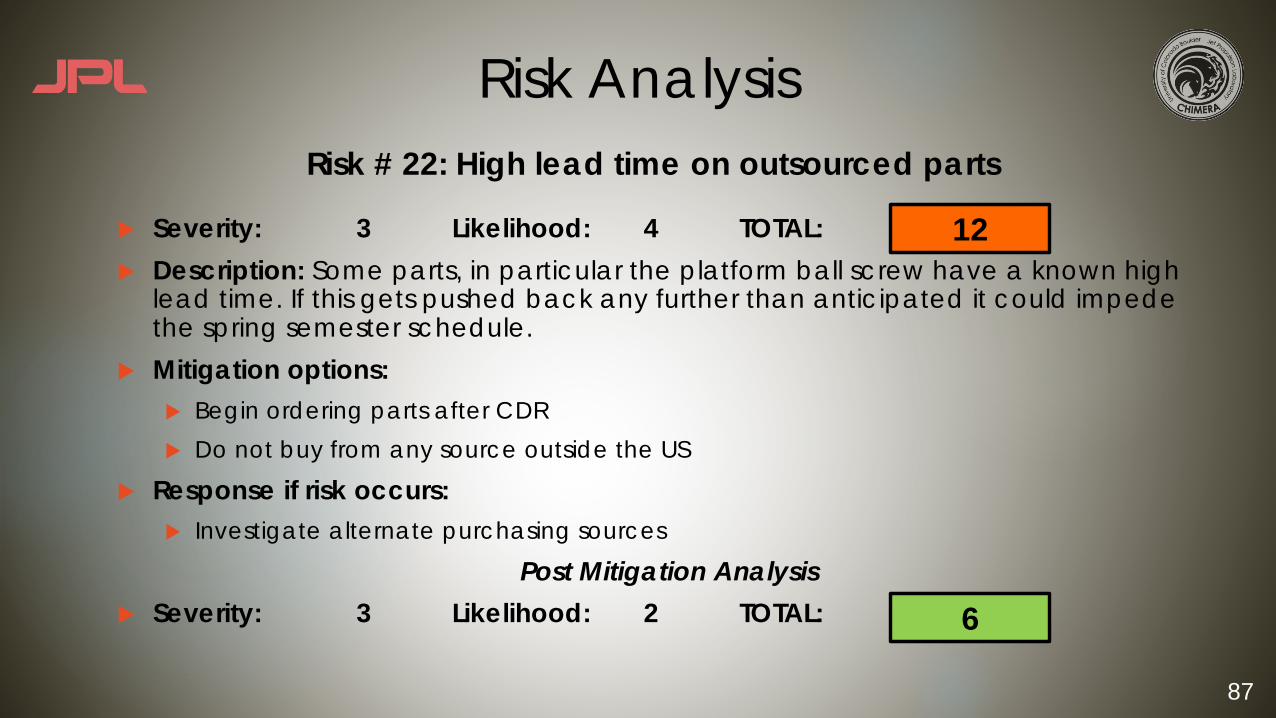
Risk Analysis
u Severity: 3 Likelihood: 4 TOTAL: u Description: Some parts, in particular the platform ball screw have a known high
lead time. If this gets pushed back any further than anticipated it could impede the spring semester schedule.
u Mitigation options:u Begin ordering parts after CDRu Do not buy from any source outside the US
u Response if risk occurs:u Investigate alternate purchasing sources
Post Mitigation Analysisu Severity: 3 Likelihood: 2 TOTAL:
Risk # 22: High lead time on outsourced parts
12
6

88
Risk Analysis
u Severity: 2 Likelihood: 5 TOTAL: u Description: Several of the tests need to occur outdoors. If there is inclement
weather the tests cannot be completed and it will push back the schedule.u Mitigation options:
u Have indoor spaces booked as a back up, plan for alternate testing dates
u Design tests that can still prove functionality but can be completed indoors
u Response if risk occurs:u Test indoors. If this is not a viable option (test needs GPS location) the test must fall on an
alternate date
Post Mitigation Analysisu Severity: 1 Likelihood: 5 TOTAL:
Risk # 23: Inclement weather during spring testing 10
5

89
Risk Analysis
u Severity: 3 Likelihood: 3 TOTAL: u Description: The budget accounts for some of the smaller parts of the child drone
being replaced, but does not allow for an entire system replacement. Should the entire child drone become irreparably damaged, it must be replaced.
u Mitigation options:u Test system by system and do not involve the child drone until certain that the
electronics are not in dangeru Follow testing and safety protocol when flight testing
u Response if risk occurs:u Apply for external funding (EEF, UROP) in the spring
Post Mitigation Analysisu Severity: 2 Likelihood: 3 TOTAL:
Risk # 24: Large budgetary expenses from child drone replacement
9
6