chapter09 seals
TRANSCRIPT
Seals
Mechanical Design

Aims
• Seals are devices used to prevent or limitleakage of fluids or particulates.
• The aims of this section are to introducethe variety of seal configurations, giveguidelines for the selection of seals andintroduce calculation methods for thequantification of some seal leakage rates.
Learning objectives
At the end of this section you should:• be able to identify a number of the different
types of sealing devices,• be able to select a seal type for rotating,
reciprocating or static conditions,• be able to determine the groove dimensions for
a standard O ring,• be able to estimate the leakage flow through a
labyrinth seal,• be able to calculate the leakage flow through a
bush seal.
Introduction
• The purpose of a seal is to prevent or limitflow between components.
• Seals are an important aspect of machinedesign where pressurised fluids must becontained within an area of a machinesuch as a hydraulic cylinder, contaminantsexcluded or lubricants retained.
Static and dynamic seals
Seals fall into two general categories.1) Static seals, where sealing takes place
between two surfaces that do no notmove relative to each other.
2) Dynamic seals, where sealing takesplace between two surfaces that moverelative to each other by, for example,rotary or reciprocating motion.
Leakage
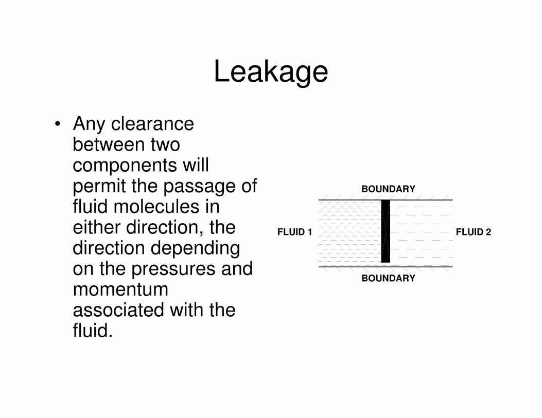
• Any clearancebetween twocomponents willpermit the passage offluid molecules ineither direction, thedirection dependingon the pressures andmomentumassociated with thefluid.
FLUID 2
BOUNDARY
BOUNDARY
FLUID 1
Seal classification
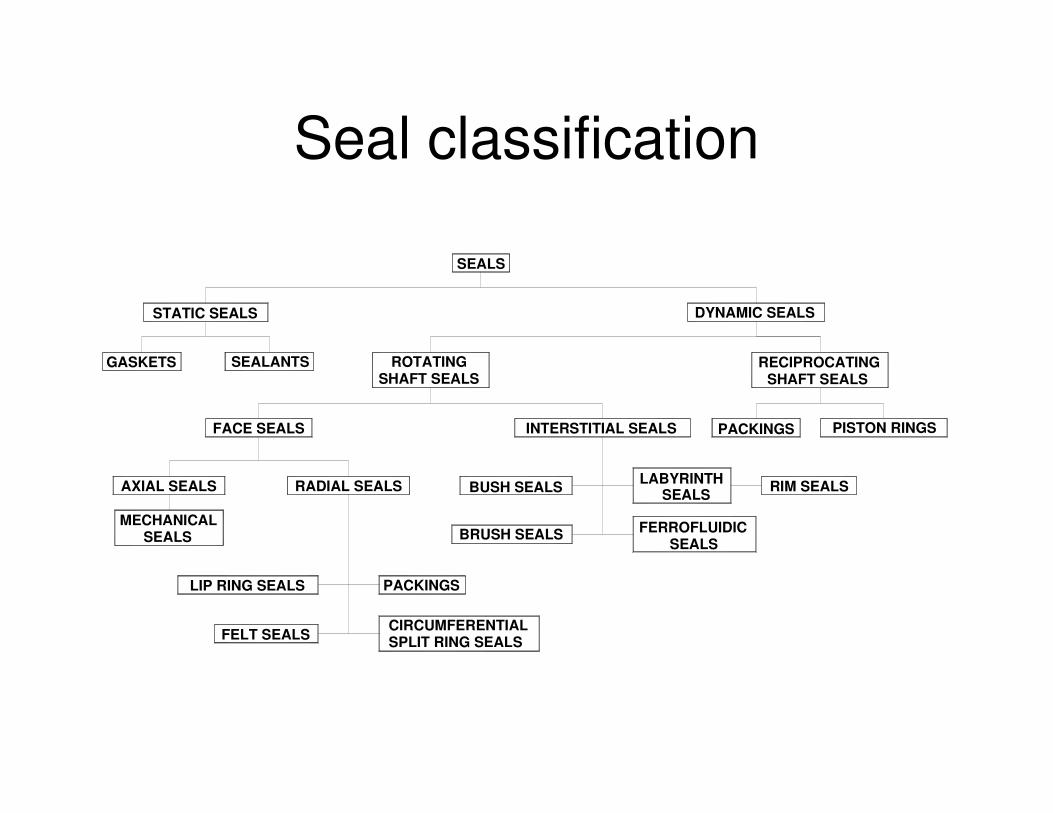
SEALS
STATIC SEALS DYNAMIC SEALS
GASKETS SEALANTS ROTATINGSHAFT SEALS
RECIPROCATINGSHAFT SEALS
FACE SEALS INTERSTITIAL SEALS PACKINGS PISTON RINGS
AXIAL SEALS RADIAL SEALS
LIP RING SEALS PACKINGS
FELT SEALSCIRCUMFERENTIALSPLIT RING SEALS
BUSH SEALS LABYRINTHSEALS RIM SEALS
BRUSH SEALS FERROFLUIDICSEALS
MECHANICALSEALS
Considerations in seal selection
Some of the considerations in selecting the type of seal include:
• the nature of the fluid to be contained orexcluded,
• pressure levels either side of the seal,• the nature of any relative motion between the
seal and mating components,• the level of sealing required,• operating temperatures,• life expectancy, serviceability,• total cost.

Seal selection
RELATIVE MOTION?
Yes
NoReciprocating
low
Flange
Rotating
Shaft
medium high
USE STATICSEAL
USE GASKETIs accurate
face locationessential?
USE O RINGUSE SEALANT
Is temperature>100 Co
USE NON-CONTACTINGSEAL OR CARBON SEAL
USE GLANDOR LIP SEAL
USE ANON-CONTACT
BUSHING
USE GLAND,U OR CHEVRON
SEAL
USE O RING
USE FACESEAL
NoYes
NoYes
speedspeed speed
speedmedium
speedhigh
Static seals
• Static seals aim at providing a completephysical barrier to leakage flow.
• To achieve this the seal material must beresilient enough to flow into and fill anyirregularities in the surfaces being sealedand at the same time remain rigid enoughto resist extrusion into clearances.
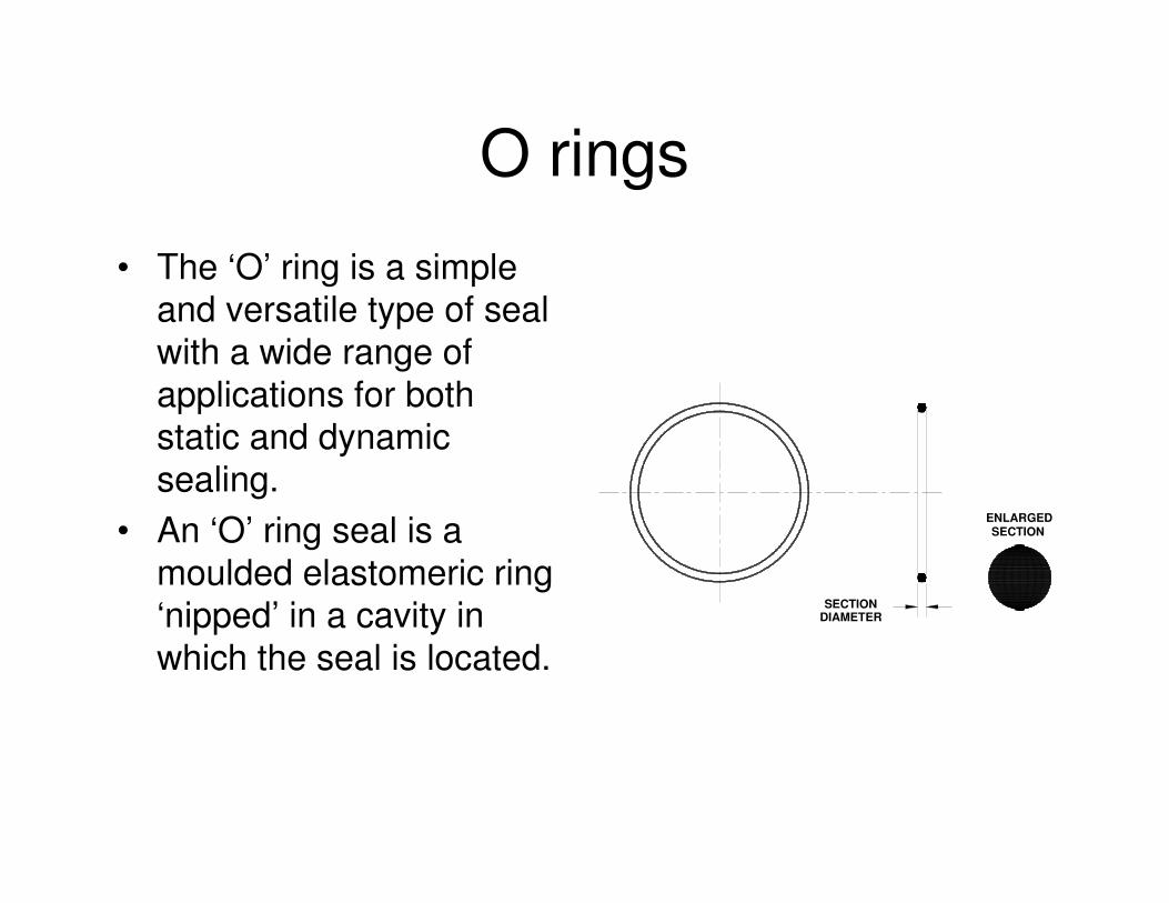
O rings
• The ‘O’ ring is a simpleand versatile type of sealwith a wide range ofapplications for bothstatic and dynamicsealing.
• An ‘O’ ring seal is amoulded elastomeric ring‘nipped’ in a cavity inwhich the seal is located.
ENLARGEDSECTION
SECTIONDIAMETER
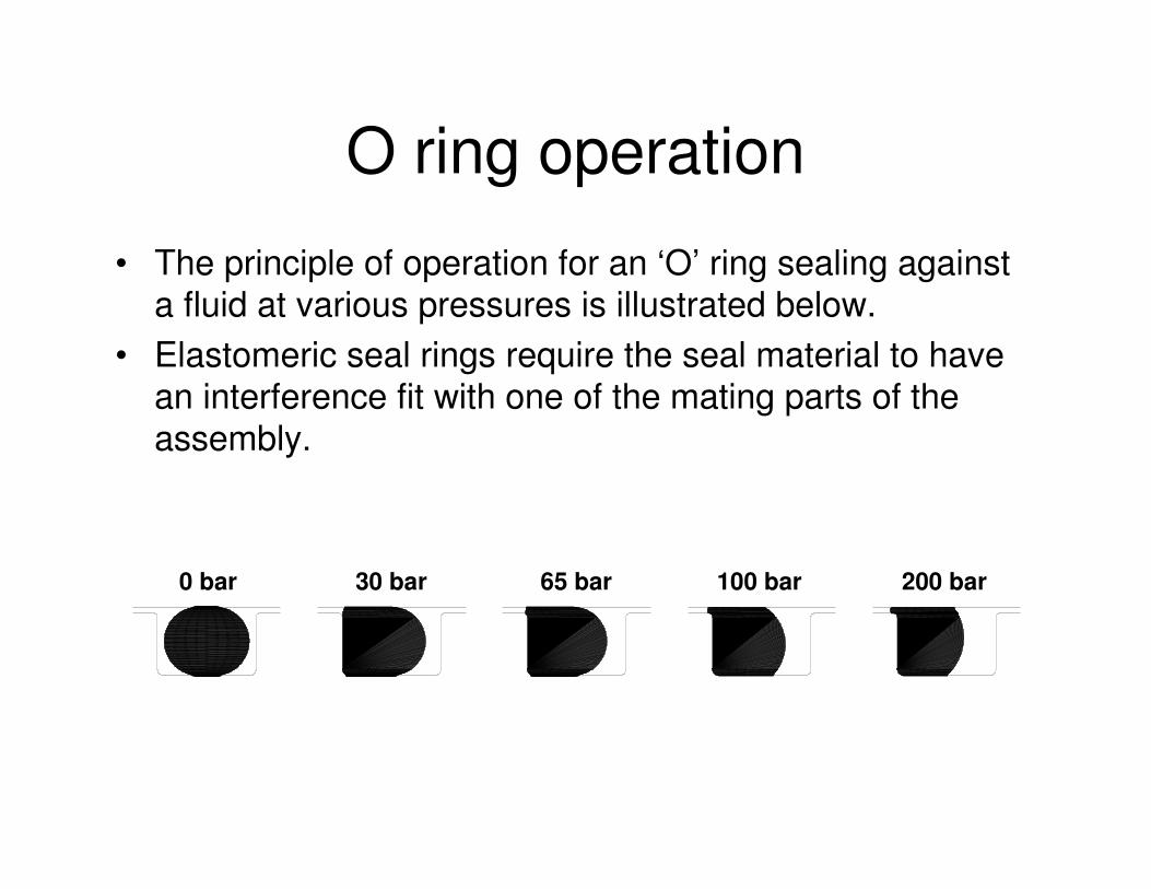
O ring operation
• The principle of operation for an ‘O’ ring sealing againsta fluid at various pressures is illustrated below.
• Elastomeric seal rings require the seal material to havean interference fit with one of the mating parts of theassembly.
200 bar100 bar65 bar30 bar0 bar
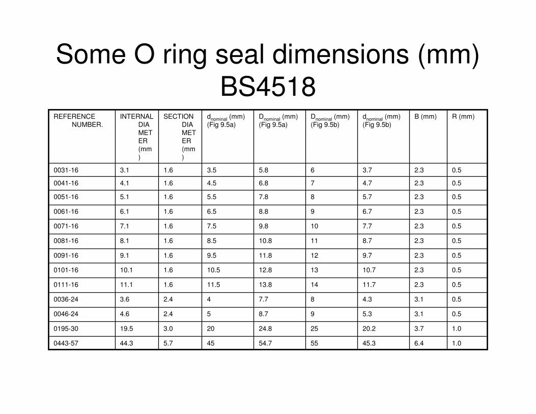
Some O ring seal dimensions (mm) BS4518
1.06.445.35554.7455.744.30443-57
1.03.720.22524.8203.019.50195-30
0.53.15.398.752.44.60046-24
0.53.14.387.742.43.60036-24
0.52.311.71413.811.51.611.10111-16
0.52.310.71312.810.51.610.10101-16
0.52.39.71211.89.51.69.10091-16
0.52.38.71110.88.51.68.10081-16
0.52.37.7109.87.51.67.10071-16
0.52.36.798.86.51.66.10061-16
0.52.35.787.85.51.65.10051-16
0.52.34.776.84.51.64.10041-16
0.52.33.765.83.51.63.10031-16
R (mm)B (mm)dnominal (mm)(Fig 9.5b)
Dnominal (mm)(Fig 9.5b)
Dnominal (mm)(Fig 9.5a)
dnominal (mm)(Fig 9.5a)
SECTION DIAMETER (mm)
INTERNAL DIAMETER (mm)
REFERENCE NUMBER.
Example
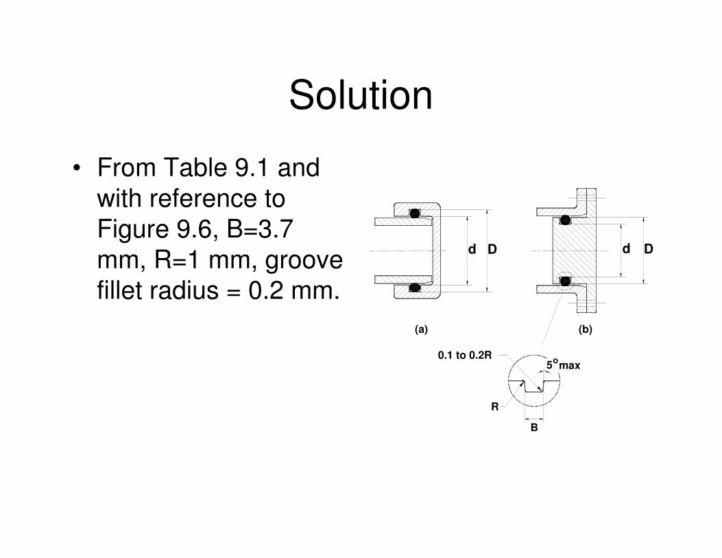
• Specify suitable groove dimensions for an0195-30 ‘O’ ring to seal against a solidcylinder.
Solution
• From Table 9.1 andwith reference toFigure 9.6, B=3.7mm, R=1 mm, groovefillet radius = 0.2 mm.
d D d D
B
R
0.1 to 0.2R5omax
(b)(a)
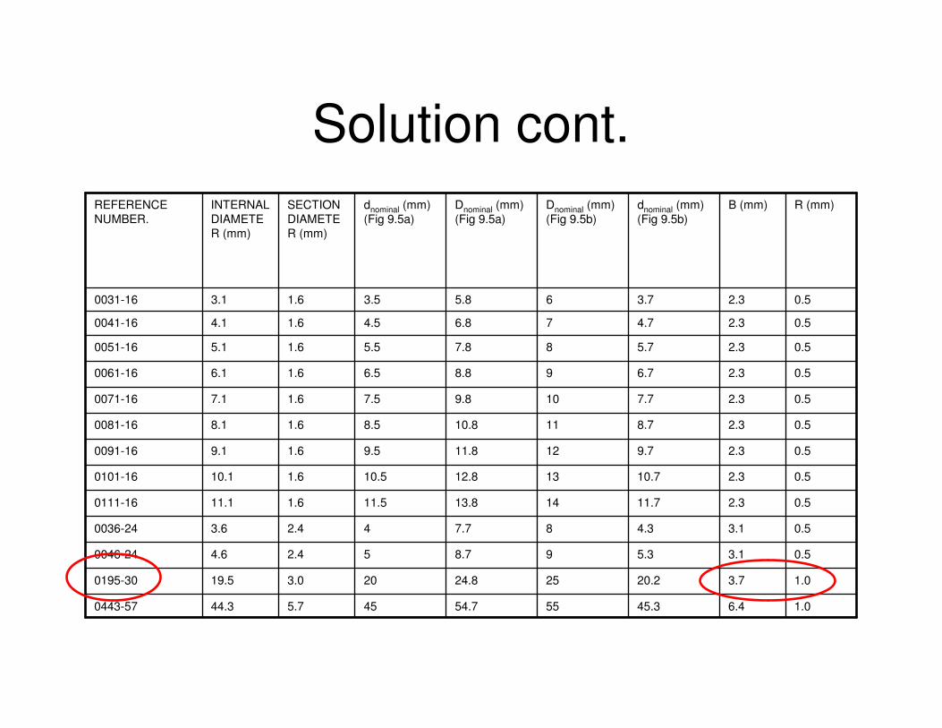
Solution cont.
1.06.445.35554.7455.744.30443-57
1.03.720.22524.8203.019.50195-30
0.53.15.398.752.44.60046-24
0.53.14.387.742.43.60036-24
0.52.311.71413.811.51.611.10111-16
0.52.310.71312.810.51.610.10101-16
0.52.39.71211.89.51.69.10091-16
0.52.38.71110.88.51.68.10081-16
0.52.37.7109.87.51.67.10071-16
0.52.36.798.86.51.66.10061-16
0.52.35.787.85.51.65.10051-16
0.52.34.776.84.51.64.10041-16
0.52.33.765.83.51.63.10031-16
R (mm)B (mm)dnominal (mm)(Fig 9.5b)
Dnominal (mm)(Fig 9.5b)
Dnominal (mm)(Fig 9.5a)
dnominal (mm)(Fig 9.5a)
SECTION DIAMETER (mm)
INTERNAL DIAMETER (mm)
REFERENCE NUMBER.
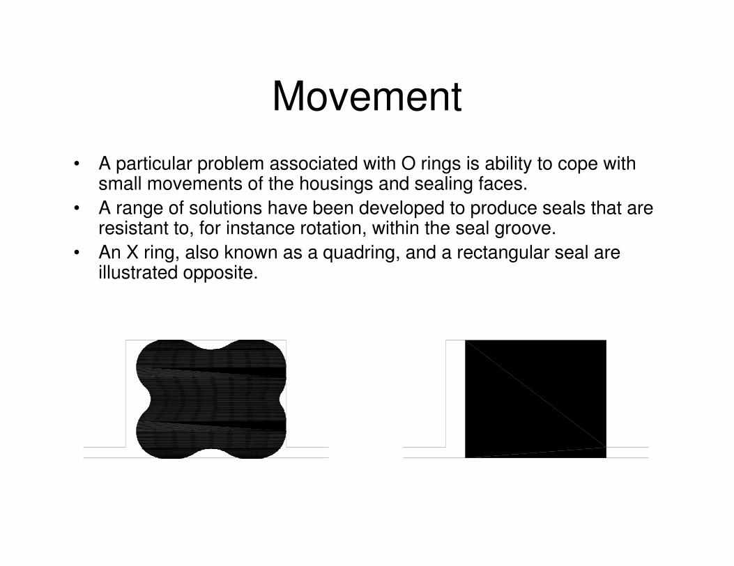
Movement• A particular problem associated with O rings is ability to cope with
small movements of the housings and sealing faces.• A range of solutions have been developed to produce seals that are
resistant to, for instance rotation, within the seal groove.• An X ring, also known as a quadring, and a rectangular seal are
illustrated opposite.

Aperture seals• Aperture seals used, for
example, for doors, windowsand cabriolet bodies aretypically made fromelastomeric extrusions asproduction costs are lowrelative to fabricatedmechanical seals and as theirassembly can be automated.
• In the case of automobiles therequirements are demandingwith the need to seal againstdifferential pressure, excludedust, air, water and noise.
GLASS
WEATHER STRIP
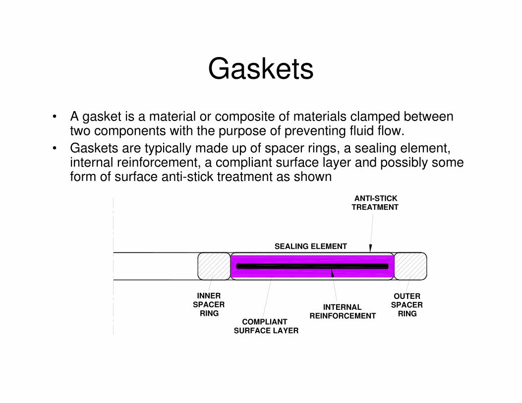
Gaskets• A gasket is a material or composite of materials clamped between
two components with the purpose of preventing fluid flow.• Gaskets are typically made up of spacer rings, a sealing element,
internal reinforcement, a compliant surface layer and possibly someform of surface anti-stick treatment as shown
INNERSPACER
RINGSPACEROUTER
RINGINTERNAL
REINFORCEMENTCOMPLIANT
SURFACE LAYER
SEALING ELEMENT
ANTI-STICKTREATMENT
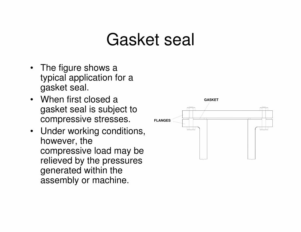
Gasket seal• The figure shows a
typical application for agasket seal.
• When first closed agasket seal is subject tocompressive stresses.
• Under working conditions,however, thecompressive load may berelieved by the pressuresgenerated within theassembly or machine.
GASKET
FLANGES
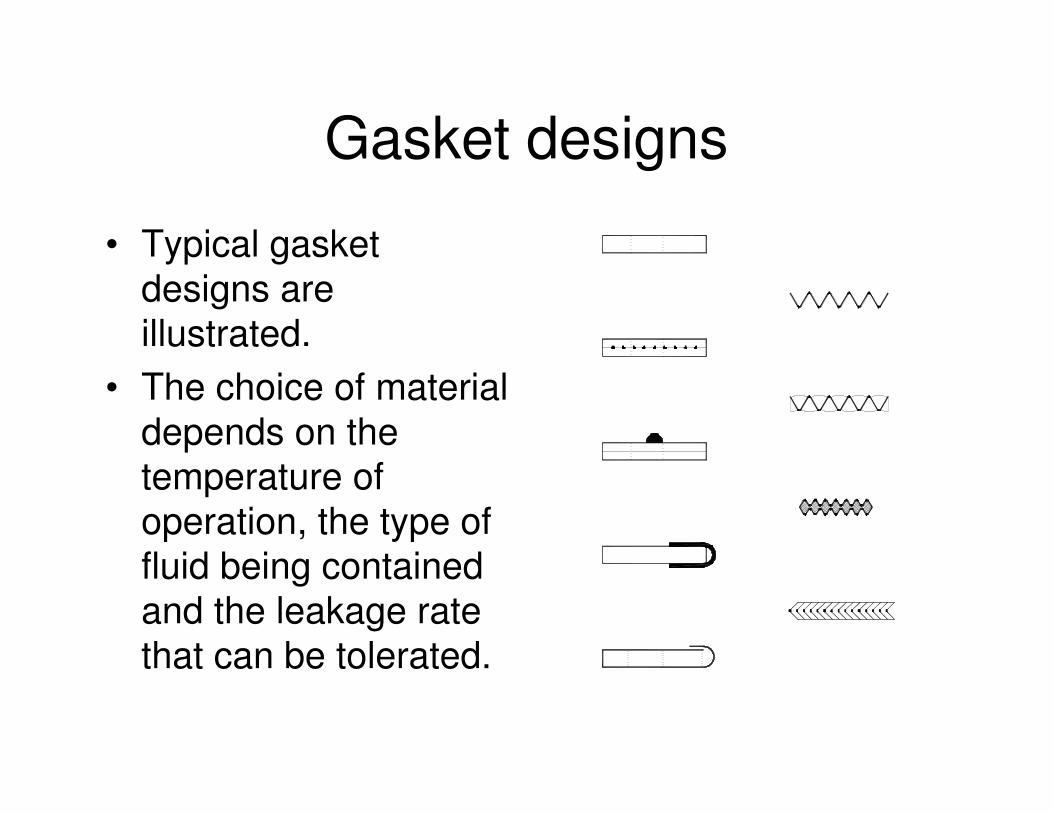
Gasket designs
• Typical gasketdesigns areillustrated.
• The choice of materialdepends on thetemperature ofoperation, the type offluid being containedand the leakage ratethat can be tolerated.
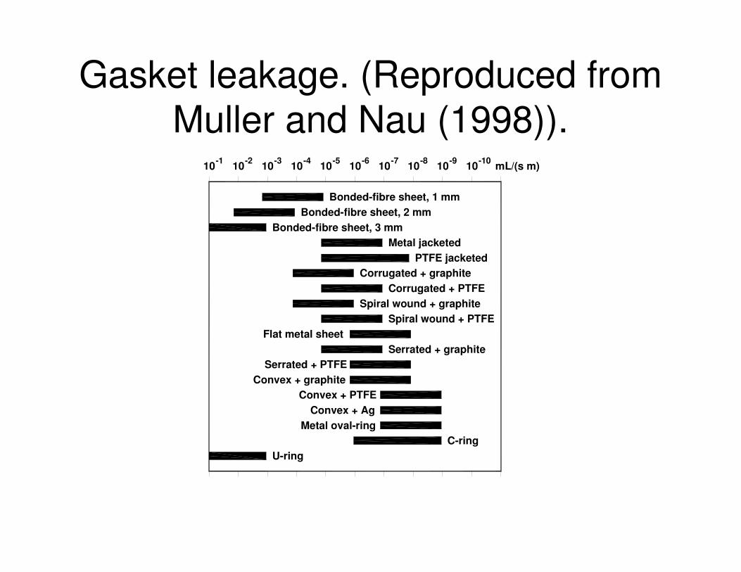
Gasket leakage. (Reproduced from Muller and Nau (1998)).
U-ringC-ring
Metal oval-ringConvex + Ag
Convex + PTFE
PTFE jacketed
Bonded-fibre sheet, 3 mm
Convex + graphiteSerrated + PTFE
Serrated + graphiteFlat metal sheet
Spiral wound + PTFESpiral wound + graphite
Corrugated + PTFECorrugated + graphite
Metal jacketed
Bonded-fibre sheet, 2 mmBonded-fibre sheet, 1 mm
10-210-1 10-3 10-4 10-510 10-6 -810-7 -10-9 1010 mL/(s m)
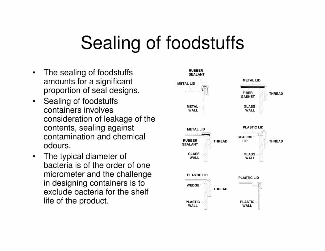
Sealing of foodstuffs• The sealing of foodstuffs
amounts for a significantproportion of seal designs.
• Sealing of foodstuffscontainers involvesconsideration of leakage of thecontents, sealing againstcontamination and chemicalodours.
• The typical diameter ofbacteria is of the order of onemicrometer and the challengein designing containers is toexclude bacteria for the shelflife of the product. PLASTIC
WALL
WEDGE
PLASTIC LID
WALLGLASS
WALLPLASTIC
PLASTIC LID
PLASTIC LID
SEALINGLIP
WALLGLASS
WALLGLASS
WALLMETAL
METAL LID
METAL LID
METAL LID
RUBBERSEALANT
FIBERGASKET
THREAD
THREAD
THREAD
THREAD
RUBBERSEALANT
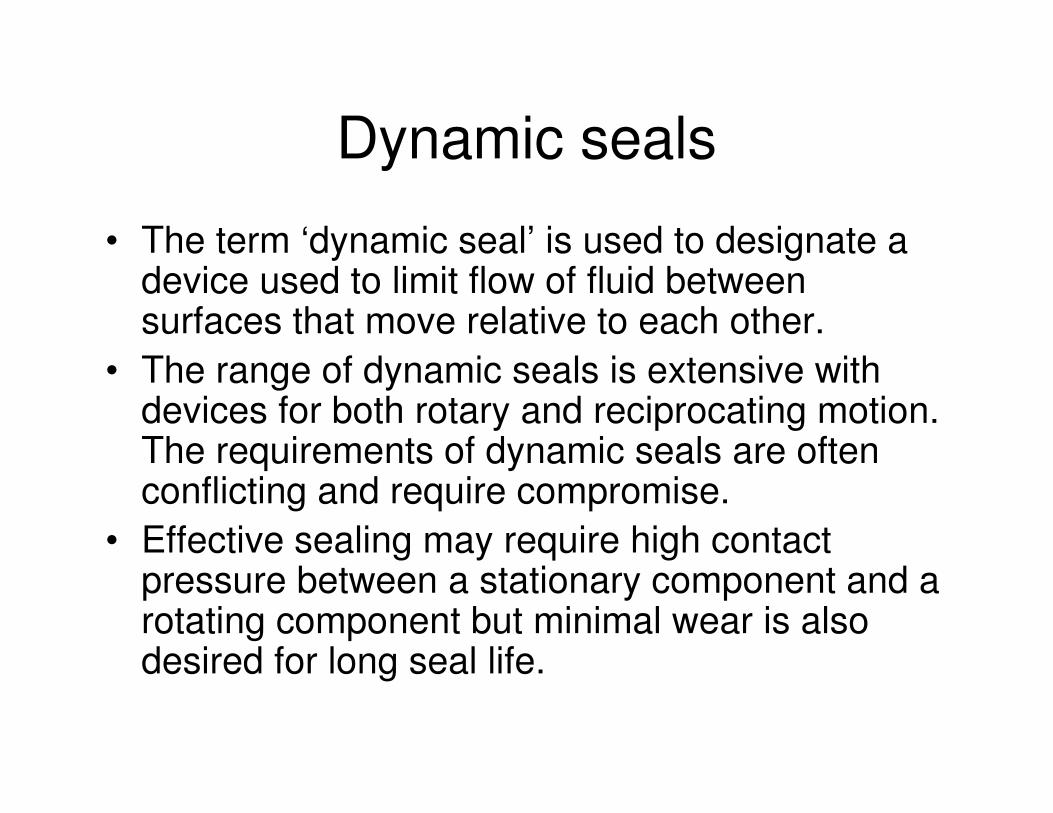
Dynamic seals
• The term ‘dynamic seal’ is used to designate adevice used to limit flow of fluid betweensurfaces that move relative to each other.
• The range of dynamic seals is extensive withdevices for both rotary and reciprocating motion.The requirements of dynamic seals are oftenconflicting and require compromise.
• Effective sealing may require high contactpressure between a stationary component and arotating component but minimal wear is alsodesired for long seal life.
Rotating shafts
• The functions of seals on rotating shaftsinclude retaining working fluids, retaininglubricants and excluding contaminantssuch as dirt and dust.
• The selection of seal type depends on theshaft speed, working pressure and desiredsealing effectiveness.
Seals for rotary motion
Seals for rotary motion include • ‘O’ rings,• lip seals,• face seals,• sealing rings,• compression packings and• non-contacting seals such as bush and
labyrinth seals.
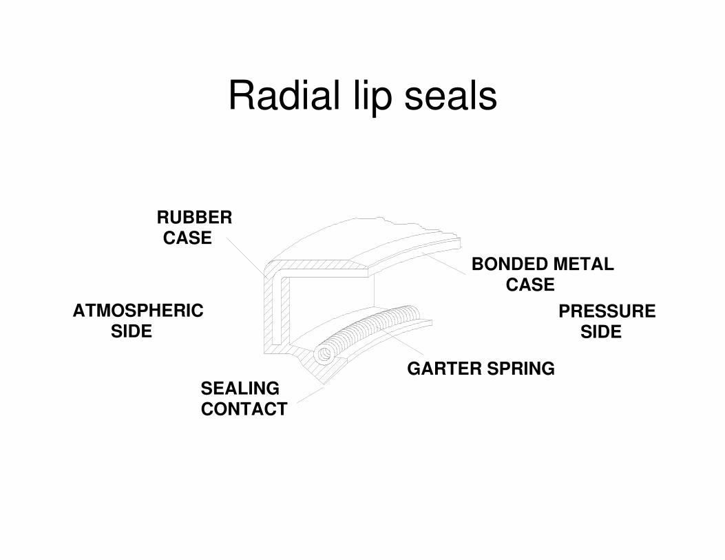
Radial lip seals
BONDED METALCASE
RUBBERCASE
ATMOSPHERICSIDE
GARTER SPRING
PRESSURESIDE
SEALINGCONTACT
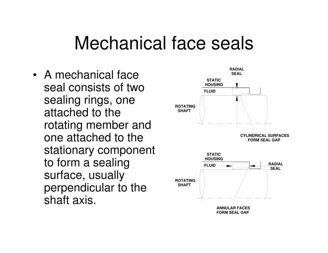
Mechanical face seals
• A mechanical faceseal consists of twosealing rings, oneattached to therotating member andone attached to thestationary componentto form a sealingsurface, usuallyperpendicular to theshaft axis.
RADIALSEAL
ANNULAR FACES
FLUID
ROTATINGSHAFT
STATICHOUSING
CYLINDRICAL SURFACESFORM SEAL GAP
SEAL
STATIC
SHAFTROTATING
FLUID
HOUSING
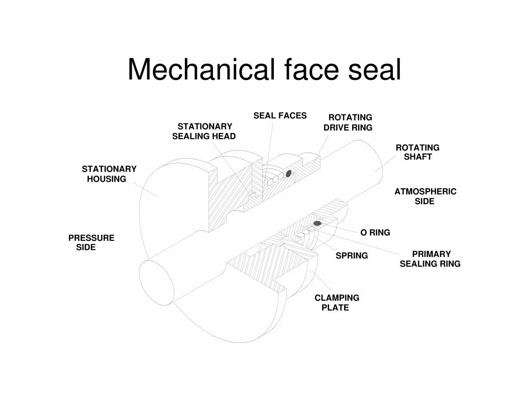
Mechanical face seal
HOUSING
PRESSURESIDE
ATMOSPHERICSIDE
SEAL FACES
O RING
SPRING
CLAMPINGPLATE
STATIONARYSEALING HEAD
ROTATINGDRIVE RING
STATIONARYSHAFT
ROTATING
SEALING RINGPRIMARY
Interstitial seals
• The term interstitial seal is used for sealsthat allow unrestricted relative motionbetween the stationary and movingcomponents (i.e. no seal to shaft contact).
• Types include labyrinth, brush and bushseals.
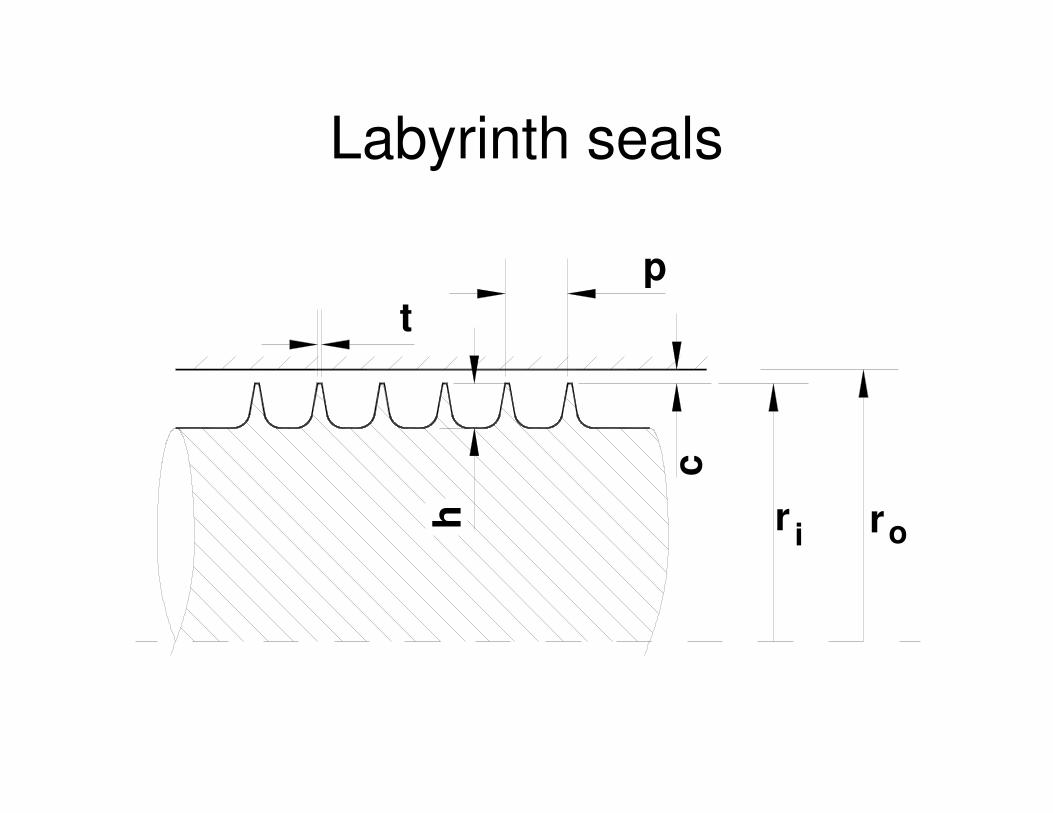
Labyrinth seals
tp
h r ori
c
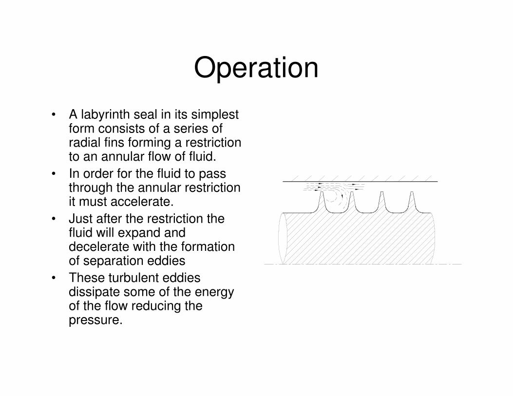
Operation• A labyrinth seal in its simplest
form consists of a series ofradial fins forming a restrictionto an annular flow of fluid.
• In order for the fluid to passthrough the annular restrictionit must accelerate.
• Just after the restriction thefluid will expand anddecelerate with the formationof separation eddies
• These turbulent eddiesdissipate some of the energyof the flow reducing thepressure.
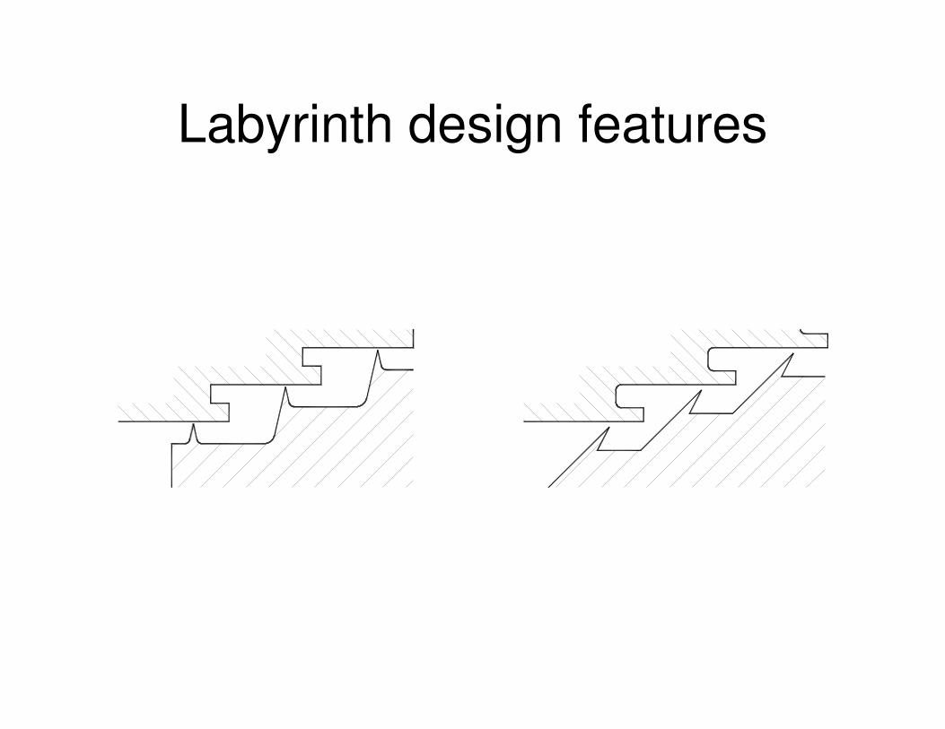
Labyrinth design features
Labyrinth flow
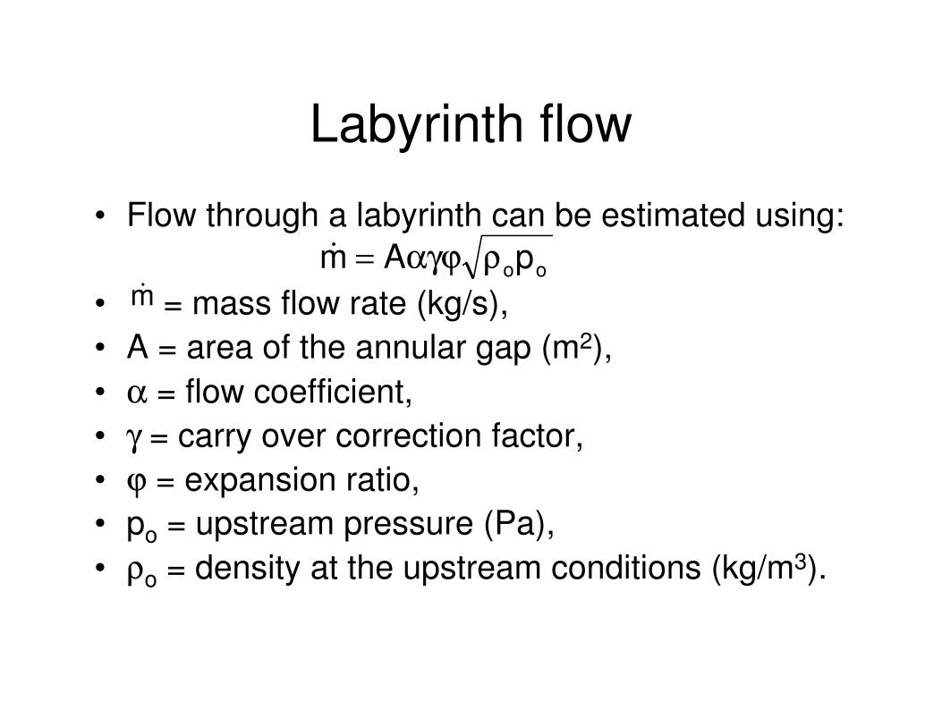
• Flow through a labyrinth can be estimated using:
• = mass flow rate (kg/s),• A = area of the annular gap (m2),• α = flow coefficient,• γ = carry over correction factor,• ϕ = expansion ratio,• po = upstream pressure (Pa),• ρo = density at the upstream conditions (kg/m3).
oopAm ραγϕ=�
m�
Flow coefficient
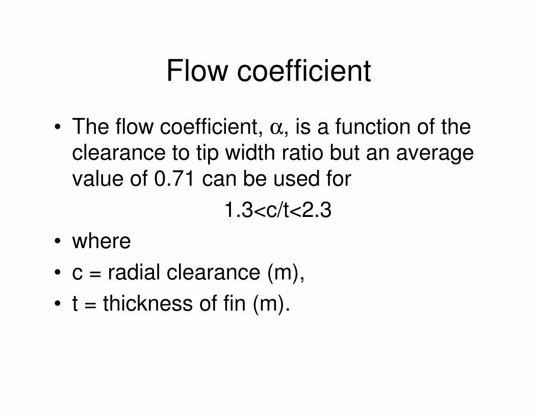
• The flow coefficient, α, is a function of theclearance to tip width ratio but an averagevalue of 0.71 can be used for
1.3<c/t<2.3• where• c = radial clearance (m),• t = thickness of fin (m).
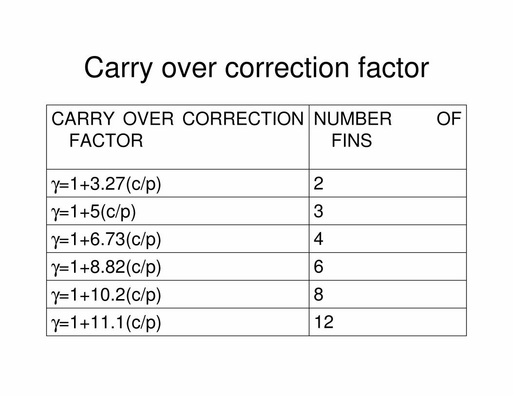
Carry over correction factor
12γ=1+11.1(c/p)8γ=1+10.2(c/p)
6γ=1+8.82(c/p)4γ=1+6.73(c/p)3γ=1+5(c/p)2γ=1+3.27(c/p)
NUMBER OF FINS
CARRY OVER CORRECTION FACTOR
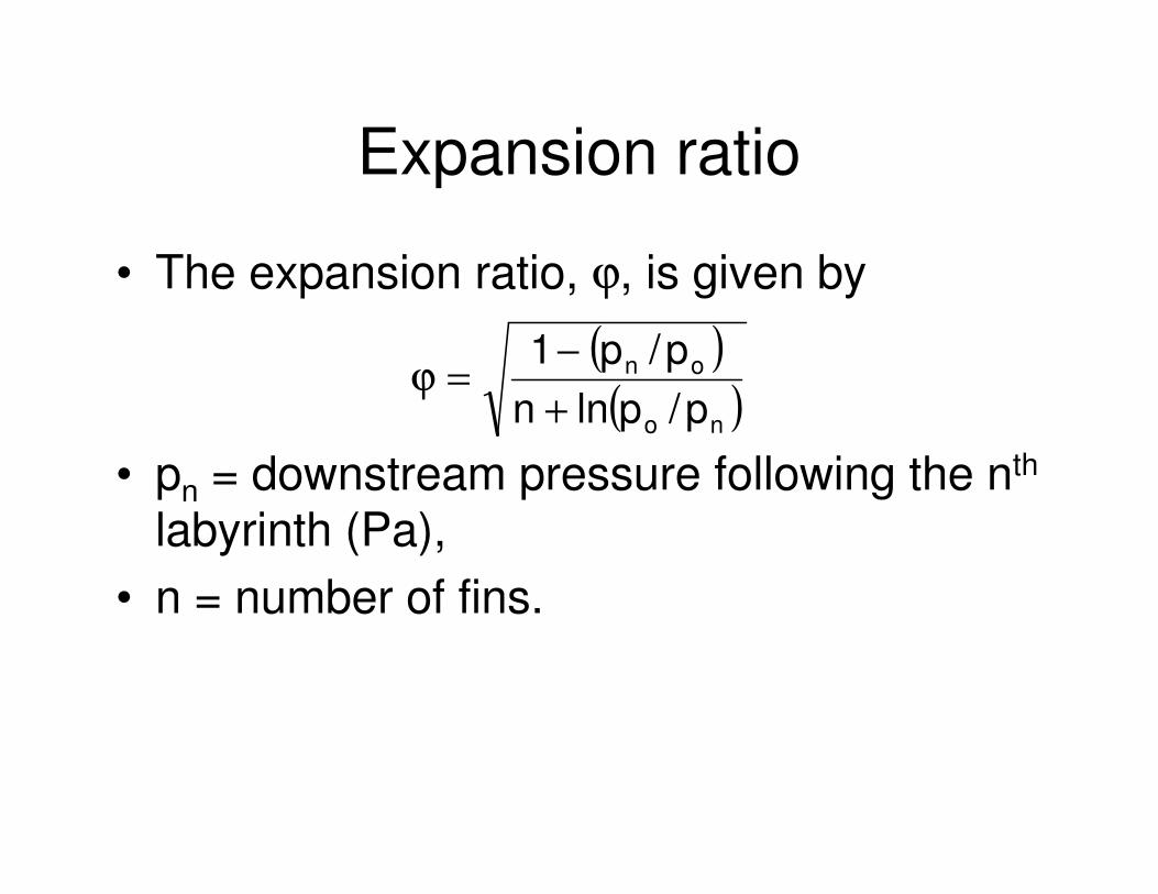
Expansion ratio
• The expansion ratio, ϕ, is given by
• pn = downstream pressure following the nth
labyrinth (Pa),• n = number of fins.
( )( )no
on
p/plnnp/p1
+−
=ϕ
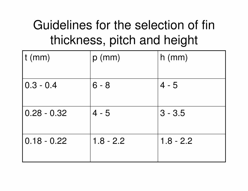
Guidelines for the selection of fin thickness, pitch and height
1.8 - 2.21.8 - 2.20.18 - 0.22
3 - 3.54 - 50.28 - 0.32
4 - 56 - 80.3 - 0.4
h (mm)p (mm)t (mm)
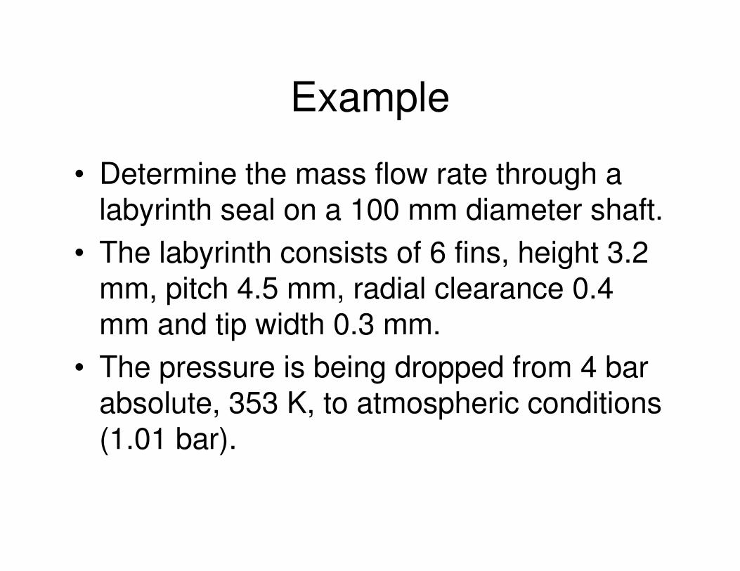
Example
• Determine the mass flow rate through alabyrinth seal on a 100 mm diameter shaft.
• The labyrinth consists of 6 fins, height 3.2mm, pitch 4.5 mm, radial clearance 0.4mm and tip width 0.3 mm.
• The pressure is being dropped from 4 barabsolute, 353 K, to atmospheric conditions(1.01 bar).

Solution
• The outer radius of the annular gap is(100/2)+3.2+0.4=53.6 mm.
• The inner radius of the annular gap is(100/2)+3.2=53.2 mm.
• The annulus gap area is
( ) ( ) ( )( )24
23232i
2o
m101.342
1053.21053.6�rr�A−
−−
×
=×−×=−=
Solution cont.
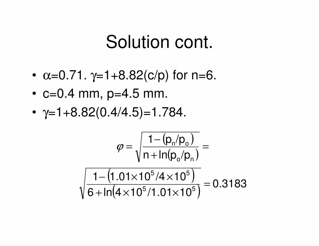
• α=0.71. γ=1+8.82(c/p) for n=6.• c=0.4 mm, p=4.5 mm.• γ=1+8.82(0.4/4.5)=1.784.
( )( )
( )( ) 0.3183
10/1.01104ln610/4101.011
/pplnn/pp1
55
55
no
on
=××+
××−
=+−=ϕ
Solution cont.
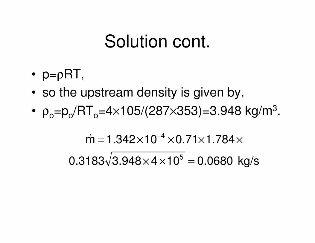
• p=ρRT,• so the upstream density is given by,• ρo=po/RTo=4×105/(287×353)=3.948 kg/m3.
kg/s0.06801043.9480.3183
1.7840.71101.342m5
4
=××
××××= −�
Axial and radial bush seals
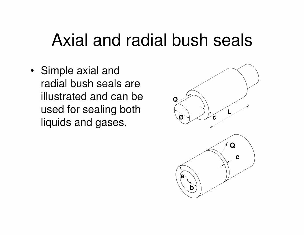
• Simple axial andradial bush seals areillustrated and can beused for sealing bothliquids and gases.
Q
LcØ
Q
a
b
c
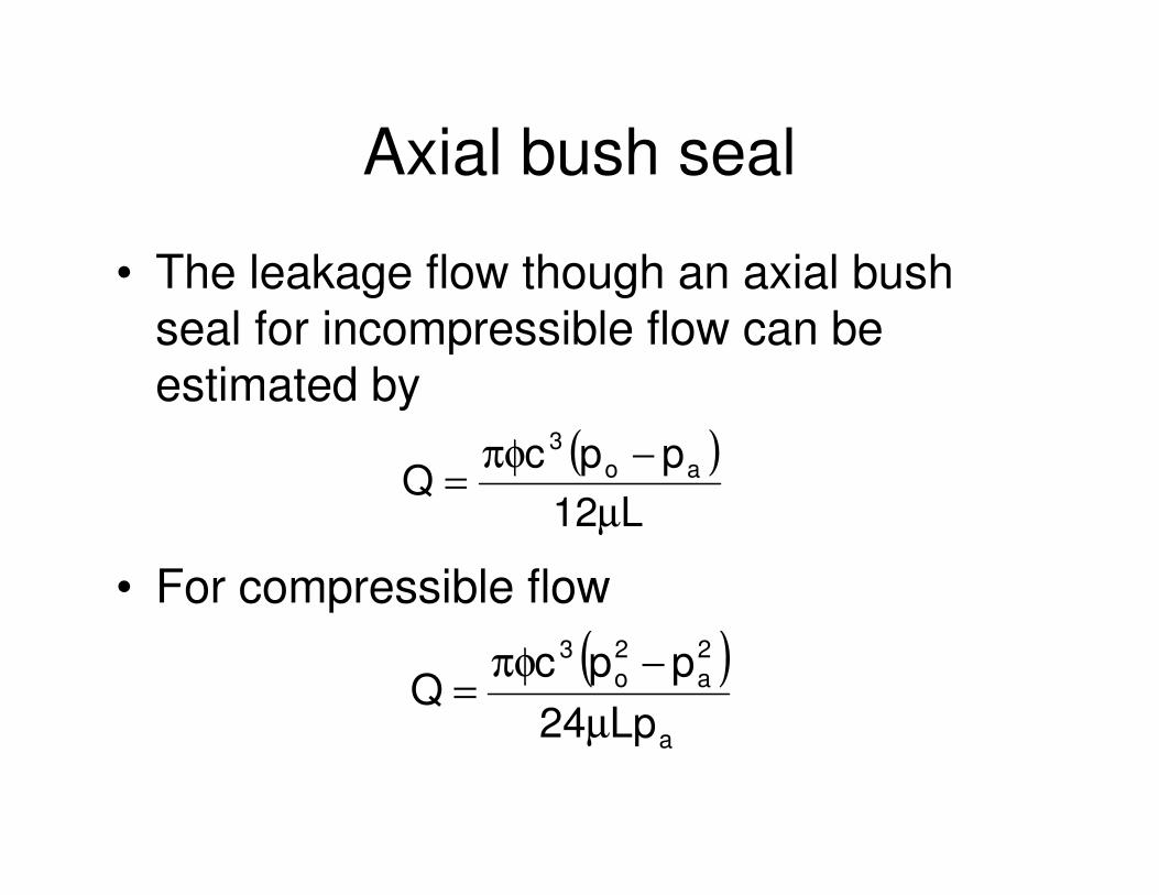
Axial bush seal
• The leakage flow though an axial bushseal for incompressible flow can beestimated by
• For compressible flow
( )L12
ppcQ ao
3
µ−πφ
=
( )a
2a
2o
3
Lp24ppc
Qµ
−πφ=
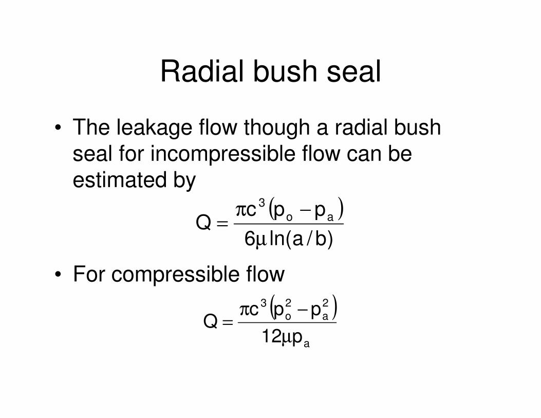
Radial bush seal
• The leakage flow though a radial bushseal for incompressible flow can beestimated by
• For compressible flow
( ))b/aln(6
ppcQ ao
3
µ−π
=
( )a
2a
2o
3
p12ppc
Qµ
−π=
Example
• An axial bush seal consists of an annulargap with inner and outer radii of 50 mmand 50.5 mm respectively.
• The length of the seal is 40 mm.• Determine the flow rate of oil through the
seal if the pressures upstream anddownstream of the seal are 7 bar and 5.5bar respectively.
• The viscosity can be taken as 0.025 Pa s.
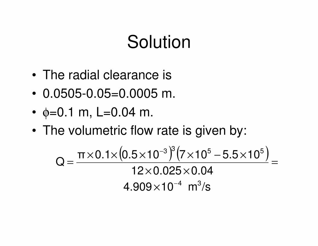
Solution
• The radial clearance is• 0.0505-0.05=0.0005 m.• φ=0.1 m, L=0.04 m.• The volumetric flow rate is given by:
( ) ( )
/sm104.9090.040.02512
105.5107100.50.1�Q
34
5533
−
−
×
=××
×−××××=
Seals for Reciprocating Components
• The seals principally used for reciprocatingmotion are packings and piston rings.
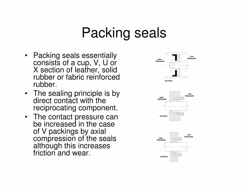
Packing seals• Packing seals essentially
consists of a cup, V, U orX section of leather, solidrubber or fabric reinforcedrubber.
• The sealing principle is bydirect contact with thereciprocating component.
• The contact pressure canbe increased in the caseof V packings by axialcompression of the sealsalthough this increasesfriction and wear.
HIGHPRESSURE
LOWPRESSURE
HIGHPRESSURE
LOWPRESSURE
HIGHPRESSURE
LOWPRESSURE
PACKING
PACKING
PACKING
Piston rings
• Piston rings are used to seal cylinders wherethe operating temperature is above the limitof elastomeric, fabric or polymeric materials.
• Piston rings are used in automotive cylindersfor three purposes:
1) to seal the combustion chamber/cylinderhead,
2) to transfer heat from the piston to the cylinderwalls,
3) to control the flow of oil.
Piston rings
• Piston rings are usually machined from afine grain alloy cast iron and must be splitto allow for assembly over the piston.
• Conventional practice is to use threepiston rings with two compression ringssealing the high pressure and one tocontrol the flow of oil.
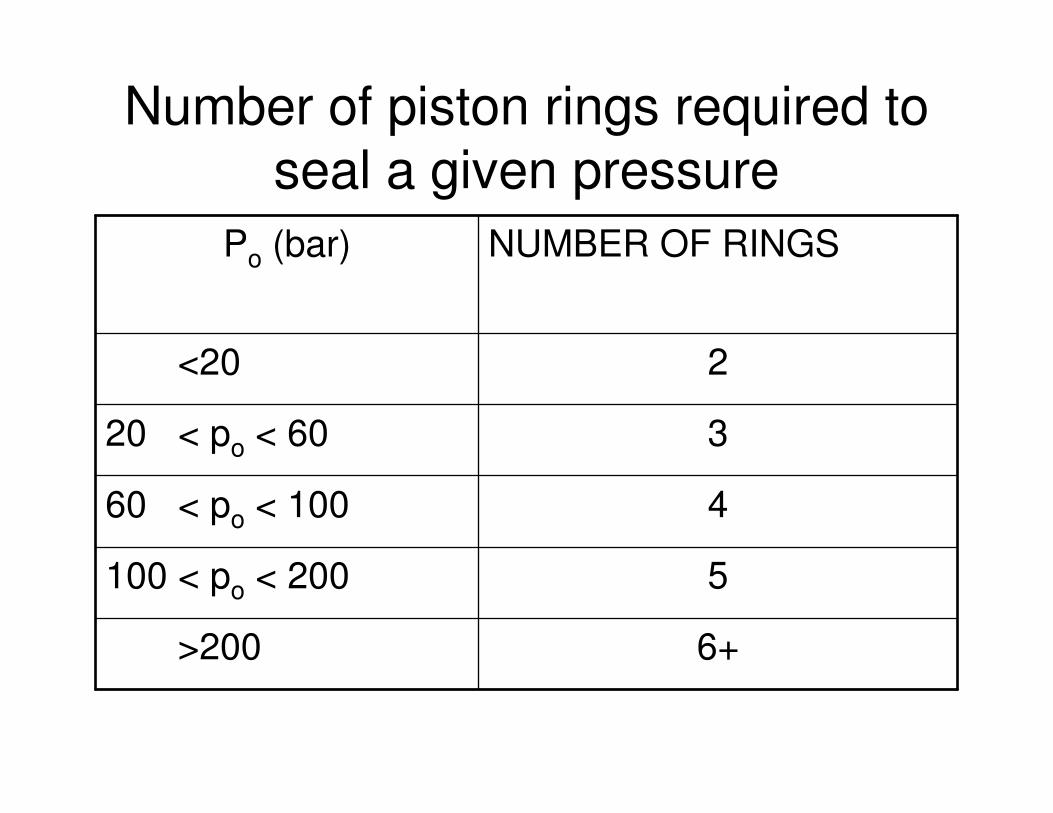
Number of piston rings required to seal a given pressure
6+>200
5100 < po < 200
460 < po < 100
320 < po < 60
2<20
NUMBER OF RINGSPo (bar)
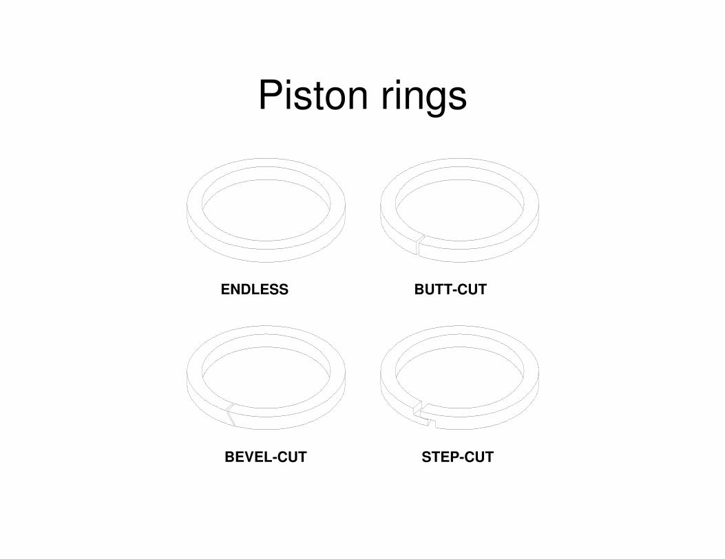
Piston rings
ENDLESS BUTT-CUT
STEP-CUTBEVEL-CUT
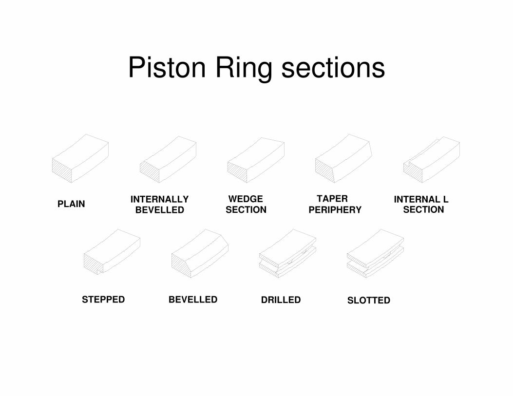
Piston Ring sections
PLAIN INTERNALLYBEVELLED
TAPERPERIPHERY
WEDGESECTION
INTERNAL LSECTION
BEVELLEDSTEPPED DRILLED SLOTTED
Conclusions
• It is frequently necessary in machine design toprovide some means of containing or limiting theflow of fluid from one region to another.
• Because of the very small nature of fluidmolecules this is a challenging task.
• This section has reviewed a range of static anddynamic seals.
• Because of the wide range of applications sealstend not to be available as stock items andinstead must be designed fit for purpose.