chapter 16 · 2016. 3. 24. · 2014 new york city building code 353 chapter 16 structural design...
TRANSCRIPT

2014 NEW YORK CITY BUILDING CODE 353
CHAPTER 16
STRUCTURAL DESIGN
SECTION BC 1601GENERAL
1601.1 Scope. The provisions of this chapter shall govern thestructural design of buildings, structures and portions thereofregulated by this code. (Note: Where the text in this Coderefers to ASCE 7, the 2005 edition shall be used; and wherethe text in this Code refers to ASCE 7-10, the 2010 editionshall be used.)
1601.2 Special provisions for prior code buildings. Theprovisions of Sections 1601.2.1 through 1601.2.4 shall applyto structural work on prior code buildings.
1601.2.1 Use of this code. Notwithstanding the appli-cant’s election to use the 1968 Building Code or priorcode, the structural calculations shall be permitted to beperformed in accordance with this code provided that thestructural safety of the prior code building is not reduced.Notwithstanding the provisions of Section 28-101.4.4 ofthe Administrative Code, the use of Load and ResistanceFactor Design (LRFD) engineering calculations shall notbe deemed to reduce structural safety provided the proper-ties of the existing materials are determined usingaccepted engineering principles.
1601.2.2 Live loads. Loads indicated in the applicableprior code shall be permitted for structural calculationsusing engineering formulas from this code provided thatthe structural safety of the prior code building is notreduced.
1601.2.3 Seismic loads. The determination as to whetherseismic requirements apply to an alteration shall be madein accordance with the 1968 Building Code and interpreta-tions by the department relating to such determinations.Any applicable seismic loads and requirements, includingfor the bracing of architectural, mechanical, plumbing,fuel gas, fire suppression and electrical systems and equip-ment, shall be permitted to be determined in accordancewith this chapter or the 1968 Building Code and referencestandard RS 9-6 of such code.
1601.2.4 Wind loads. All alterations, minor alterations,and ordinary repairs, to the extent of such work, shall bepermitted to be performed in accordance with the windload requirements set forth in the 1968 Building Code, orwhere the 1968 Building Code so authorizes, the code ineffect prior to December 6, 1968.
Exceptions:
1. Equipment, appliances and supports that areexposed to wind shall be designed and installedto resist the wind pressures determined in accor-dance with Section 1609.
2. Wind loads on glass shall not be permitted to becalculated in accordance with the code in effectprior to December 6, 1968.
3. When the wind surface area of a prior code build-ing or structure is increased by more than 5 per-cent in any direction or there is a permanentdecrease of the lateral force capacity by morethan 20 percent in any direction, the entire build-ing or structure shall be designed to resist thedesign wind load as calculated pursuant to theapplicable code, but not less than 5 psf (0.24 kN/m2).
SECTION BC 1602DEFINITIONS AND NOTATIONS
1602.1 Definitions. The following words and terms shall, forthe purposes of this code, have the meanings shown herein.
ALLOWABLE STRESS DESIGN. A method of propor-tioning structural members, such that elastically computedstresses produced in the members by nominal loads do notexceed specified allowable stresses (also called “workingstress design”).
BALCONY, EXTERIOR. See ASCE 7.
DEAD LOADS. The weight of materials of constructionincorporated into the building, including but not limited towalls, floors, roofs, ceilings, stairways, built-in partitions,finishes, cladding and other similarly incorporated architec-tural and structural items, and the weight of fixed serviceequipment, such as cranes, plumbing stacks and risers, elec-trical feeders, heating, ventilating and air-conditioning sys-tems and automatic sprinkler systems.
DECK. See ASCE 7.
DESIGN STRENGTH. The product of the nominal strengthand a resistance factor (or strength reduction factor).
DIAPHRAGM. A horizontal or sloped system acting totransmit lateral forces to the vertical-resisting elements.When the term “diaphragm” is used, it shall include horizon-tal bracing systems.
Diaphragm, blocked. In light-frame construction, a dia-phragm in which all sheathing edges not occurring on aframing member are supported on and fastened to block-ing.
Diaphragm boundary. In light-frame construction, alocation where shear is transferred into or out of the dia-phragm sheathing. Transfer is either to a boundary ele-ment or to another force-resisting element.
Diaphragm chord. A diaphragm boundary element per-pendicular to the applied load that is assumed to takeaxial stresses due to the diaphragm moment.
Diaphragm, flexible. A diaphragm is flexible for the pur-pose of distribution of story shear and torsional momentwhere so indicated in Section 12.3.1 of ASCE 7-10.
NYCNYCNYCNYCNYCNYCNYCNYCNYCNYCNYCNYCNYCNYCNYCNYCNYCNYCNYCNYCNYCNYCNYCNYCNYCNYCNYCNYCNYCNYCNYCNYCNYCNYCNYCNYCNYCNYCNYCNYCNYCNYCNYCNYCNYCNYCNYCNYCNYCNYCNYCNYCNYCNYCNYCNYCNYCNYCNYCNYCNYCNYCNYCNYCNYCNYCNYCNYCNYCNYCNYC
NYCNYCNYCNYCNYCNYCNYCNYCNYCNYCNYCNYC
NYC
NYC
�
NYC
�
NYC

STRUCTURAL DESIGN
354 2014 NEW YORK CITY BUILDING CODE
Diaphragm, rigid. A diaphragm is rigid for the purposeof distribution of story shear and torsional moment whenthe lateral deformation of the diaphragm is less than orequal to two times the average story drift.
DURATION OF LOAD. The period of continuous applica-tion of a given load, or the aggregate of periods of intermit-tent applications of the same load.
ESSENTIAL FACILITIES. Buildings and other structuresthat are intended to remain operational in the event ofextreme environmental loading from flood, wind, snow orearthquakes.
FABRIC PARTITION. A partition consisting of a finishedsurface made of fabric, without a continuous rigid backing,that is directly attached to a framing system in which the ver-tical framing members are spaced greater than 4 feet (1219mm) on center.
FACTORED LOAD. The product of a nominal load and aload factor.
GUARD. See Section 1002.1.
IMPACT LOAD. The load resulting from moving machin-ery, elevators, craneways, vehicles and other similar forcesand kinetic loads, pressure and possible surcharge from fixedor moving loads.
LIMIT STATE. A condition beyond which a structure ormember becomes unfit for service and is judged to be no lon-ger useful for its intended function (serviceability limit state)or to be unsafe (strength limit state).
LIVE LOADS. Those loads produced by the use and occu-pancy of the building or other structure and do not includeconstruction or environmental loads such as wind load, snowload, rain load, earthquake load, flood load or dead load.
LIVE LOADS (ROOF). Those loads produced (1) duringmaintenance by workers, equipment and materials; and (2)during the life of the structure by movable objects such asplanters and by people.
LOAD AND RESISTANCE FACTOR DESIGN (LRFD).A method of proportioning structural members and theirconnections using load and resistance factors such that noapplicable limit state is reached when the structure is sub-jected to appropriate load combinations. The term “LRFD”is used in the design of steel and wood structures.
LOAD EFFECTS. Forces and deformations produced instructural members by the applied loads.
LOAD FACTOR. A factor that accounts for deviations ofthe actual load from the nominal load, for uncertainties in theanalysis that transforms the load into a load effect, and forthe probability that more than one extreme load will occursimultaneously.
LOADS. Forces or other actions that result from the weightof building materials, occupants and their possessions, envi-ronmental effects, differential movement and restraineddimensional changes. Permanent loads are those loads inwhich variations over time are rare or of small magnitude,such as dead loads. All other loads are variable loads (seealso “Nominal loads”).
NOMINAL LOADS. The magnitudes of the loads specifiedin this chapter (dead, live, soil, wind, snow, rain, flood andearthquake).
NOTATIONS.
D = Dead load.
E = Combined effect of horizontal and verticalearthquake-induced forces as defined in Section12.4.2 of ASCE 7-10.
F = Load due to fluids with well-defined pressures andmaximum heights.
Fa = Flood load in accordance with Chapter 5 of ASCE 7.
H = Load due to lateral earth pressures, ground waterpressure or pressure of bulk materials.
L = Live load, except roof live load, including anypermitted live load reduction.
Lr = Roof live load including any permitted live loadreduction.
plf = pounds per linear foot.
psig= pounds per square inch gauge.
R = Rain load.
S = Snow load.
T = Self-straining force arising from contraction orexpansion resulting from temperature change,shrinkage, moisture change, creep in componentmaterials, movement due to differential settlementor combinations thereof.
W = Load due to wind pressure.
OTHER STRUCTURES. Structures, other than build-ings, for which loads are specified in this chapter.
PANEL (PART OF A STRUCTURE). The section of afloor, wall or roof comprised between the supportingframe of two adjacent rows of columns and girders or col-umn bands of floor or roof construction.
RESISTANCE FACTOR. A factor that accounts fordeviations of the actual strength from the nominalstrength and the manner and consequences of failure (alsocalled “strength reduction factor”).
RISK CATEGORY. See definition for “Structural Occu-pancy Category.”
STRENGTH, NOMINAL. The capacity of a structure ormember to resist the effects of loads, as determined bycomputations using specified material strengths anddimensions and equations derived from accepted princi-ples of structural mechanics or by field tests or laboratorytests of scaled models, allowing for modeling effects anddifferences between laboratory and field conditions.
STRENGTH, REQUIRED. Strength of a member, crosssection or connection required to resist factored loads orrelated internal moments and forces in such combinationsas stipulated by these provisions.
STRENGTH DESIGN. A method of proportioning struc-tural members such that the computed forces produced inthe members by factored loads do not exceed the member
�
�
�
�
NYC
�
NYCNYC
�
�
NYCNYC
�

STRUCTURAL DESIGN
2014 NEW YORK CITY BUILDING CODE 355
design strength. The term “strength design” is used in thedesign of concrete and masonry structural elements.
STRUCTURAL OCCUPANCY CATEGORY. A cate-gory used to determine structural requirements based onoccupancy.
VEHICLE BARRIER SYSTEM. A system of buildingcomponents near open sides of a garage floor or ramp orbuilding walls that act as restraints for vehicles.
SECTION BC 1603CONSTRUCTION DOCUMENTS
1603.1 General. Construction documents shall include draw-ings that show the sizes, sections and relative locations ofstructural members with floor levels, column centers andoffsets fully dimensioned. The design loads and other infor-mation pertinent to the structural design required by Sections1603.1.1 through 1603.1.9 shall be clearly indicated on thesuch drawings of parts of the building or structure.
Exception: In lieu of the requirements of Sections‡1603.1.1 through 1603.1.10, construction documents forbuildings constructed in accordance with the conventionallight-frame construction provisions of Section 2308 shallinclude drawings that indicate the following structuraldesign information:
1. Floor and roof live loads.
2. Ground snow load, Pg.
3. Basic wind speed (3-second gust), miles per hour(mph) (km/hr) and wind exposure.
4. Seismic design category and site class.
5. Flood design data, if located in flood hazard areasestablished in Section G102.2 of Appendix G.
6. Design load-bearing values of soils or rock undershallow foundations and/or the design load capacityof deep foundations.
1603.1.1 Floor live load. The uniformly distributed, con-centrated and impact floor live load used in the designshall be indicated for floor areas. Live load reduction ofthe uniformly distributed floor live loads, if used in thedesign, shall be indicated for each type of live load used inthe design.
1603.1.2 Partition loads. The equivalent uniform parti-tion loads or, in lieu of these, a statement to the effect thatthe design was predicated on actual partition loads.
1603.1.3 Roof live load. The roof live load used in thedesign shall be indicated for roof areas (Section 1607.11).
1603.1.4 Roof snow load. The ground snow load, Pg,shall be indicated. The following additional informationshall also be provided, regardless of whether snow loadsgovern the design of the roof:
1. Flat-roof snow load, Pf.
2. Snow exposure factor, Ce.
3. Snow load importance factor, Is.
4. Thermal factor, Ct.
1603.1.5 Wind design data. The following informationrelated to wind loads shall be shown, regardless ofwhether wind loads govern the design of the lateral-force-resisting system of the building:
1. Basic wind speed (3-second gust), miles per hour(km/hr).
2. Wind importance factor, I, and structural occupancycategory.
3. Wind exposure. Where more than one wind expo-sure is utilized, the wind exposure and applicablewind direction shall be indicated.
4. The applicable internal pressure coefficient.
5. Components and cladding. The design wind pres-sures in terms of psf (kN/m2) to be used for thedesign of exterior component and cladding materi-als not specifically designed by the registereddesign professional.
6. Design base shear.
1603.1.6 Earthquake design data. The following infor-mation related to seismic loads shall be shown, regardlessof whether seismic loads govern the design of the lateral-force-resisting system of the building:
1. Seismic importance factor, I, and structural occu-pancy category.
2. Mapped spectral response accelerations, SS and S1.
3. Site class.
4. Spectral response coefficients, SDS and SD1.
5. Seismic design category.
6. Basic seismic-force-resisting system(s).
7. Design base shear.
8. Seismic response coefficient(s), CS.
9. Response modification factor(s), R.
10. Analysis procedure used.
1603.1.7 Geotechnical information. The design load-bearing values of soils or rock under shallow foundationsand/or the design load capacity of deep foundations shallbe shown on the construction drawings.
1603.1.8 Flood load. Buildings and other structureslocated in areas of special flood hazard shall meet thedesign requirements of Section 5.3 of ASCE 7. The struc-tural design shall be based on the design loads stated inSection 5.4 of ASCE 7.
1603.1.9 Special loads. Special loads that are applicableto the design of the building, structure or portions thereofshall be indicated along with the specified section of thiscode that addresses the special loading condition.
1603.1.10 Superimposed dead loads. The uniformly dis-tributed superimposed dead loads used in the design shallbe indicated for floor and roof areas.
1603.1.11 Other loads. Other loads used in the design,including but not limited to the loads of machinery orequipment, which are of greater magnitude than the loads
NYC
NYCNYCNYCNYC�
NYCNYCNYC
NYC
NYCNYCNYCNYCNYCNYC
NYCNYCNYCNYCNYCNYC
NYCNYCNYCNYC
NYCNYCNYCNYC
NYC
NYC
NYC
NYC
NYC
NYCNYC
NYCNYCNYCNYCNYCNYCNYC
NYCNYCNYCNYCNYCNYCNYCNYCNYC
C

STRUCTURAL DESIGN
356 2014 NEW YORK CITY BUILDING CODE
defined in the specified floor and roof loads shall be indi-cated by their descriptions and locations.
SECTION BC‡ 1604GENERAL DESIGN REQUIREMENTS
1604.1 General. Building, structures and parts thereof shallbe designed and constructed in accordance with strengthdesign, load and resistance factor design, allowable stressdesign, empirical design or conventional construction meth-ods, as permitted by the applicable material chapters.
1604.2 Strength. Buildings and other structures, and partsthereof, shall be designed and constructed to support safelythe factored loads in load combinations defined in this codewithout exceeding the appropriate strength limit states forthe materials of construction. Alternatively, buildings andother structures, and parts thereof, shall be designed andconstructed to support safely the nominal loads in load com-binations defined in this code without exceeding the appro-priate specified allowable stresses for the materials ofconstruction. Loads and forces for occupancies or uses notcovered in this chapter shall be subject to the approval ofthe commissioner.
1604.3 Serviceability. Structural systems and membersthereof shall be designed to have adequate stiffness to limitdeflections and lateral drift. See Section 12.12.1 of ASCE 7-10 for drift limits applicable to earthquake loading.
1604.3.1 Deflections. The deflections of structural mem-bers shall not exceed the more restrictive of the limita-
tions of Sections 1604.3.2 through 1604.3.5 or thatpermitted by Table 1604.3.
1604.3.2 Reinforced concrete. The deflection of rein-forced concrete structural members shall not exceed thatpermitted by ACI 318.
1604.3.3 Steel. The deflection of steel structural membersshall not exceed that permitted by AISC 360, AISI HSS S100, ASCE 3, ASCE 8 and SJI CJ-1.0, SJI JG-1.1, SJI K-1.1 or SJI LH/DLH-1.1, as applicable.
1604.3.4 Masonry. The deflection of masonry structuralmembers shall not exceed that permitted by TMS 402/ACI 530/ASCE 5.
1604.3.5 Aluminum. The deflection of aluminum struc-tural members shall not exceed that permitted by AAADM1.
1604.3.6 Limits. For limits on the deflection of structuralmembers, refer to the relevant material design standards.Should a design standard not provide for deflection limits,deflection of structural members over span, l, shall notexceed that permitted by Table 1604.3.
1604.4 Analysis. Load effects on structural members andtheir connections shall be determined by methods of struc-tural analysis that take into account equilibrium, general sta-bility, geometric compatibility and both short- and long-termmaterial properties.
Members that tend to accumulate residual deformationsunder repeated service loads shall have included in their anal-ysis the added eccentricities expected to occur during their
NYCNYC�
NYC
NYC
NYC
NYCNYCNYCNYC
C
TABLE 1604.3DEFLECTION LIMITSa, b, c, h, i
For SI: 1 foot = 304.8 mm.a. For structural roofing and siding made of formed metal sheets, the total load deflection shall not exceed l/60. For secondary roof structural members
supporting formed metal roofing, the live load deflection shall not exceed l/150. For secondary wall members supporting formed metal siding, the designwind load deflection shall not exceed l/90. For roofs, this exception only applies when the metal sheets have no roof covering.
b. Interior partitions not exceeding 6 feet in height and flexible, folding and portable partitions are not governed by the provisions of this section. The deflectioncriterion for interior partitions is based on the horizontal load defined in Section 1607.13.
c. See Section 2403 for glass supports.d. For wood structural members having a moisture content of less than 16 percent at time of installation and used under dry conditions, the deflection
resulting from L + 0.5D is permitted to be substituted for the deflection resulting from L + D.e. The above deflections do not ensure against ponding. Roofs that do not have sufficient slope or camber to assure adequate drainage shall be investigated for
ponding. See Section 1611 for rain and ponding requirements and Section 1503.4 for roof drainage requirements.f. The wind load is permitted to be taken as 0.7 times the “component and cladding” loads for the purpose of determining deflection limits herein.g. For steel structural members, the dead load shall be taken as zero.h. For aluminum structural members or aluminum panels used in roofs or walls of sunroom additions or patio covers, not supporting edge of glass or aluminum
sandwich panels, the total load deflection shall not exceed l/60. For aluminum sandwich panels used in roofs or walls of sunroom additions or patio covers, thetotal load deflection shall not exceed l/120.
i. For cantilever members, l shall be taken as twice the length of the cantilever.
CONSTRUCTION L S or W f D + Ld, g
Roof members:e
Supporting plaster ceiling Supporting nonplaster ceiling Not supporting ceiling
l/360l/240l/180
l/360l/240l/180
l/240l/180l/120
Floor members l/360 — l/240
Exterior walls and interior partitions: With brittle finishes With flexible finishes
——
l/120l/120
——
Farm buildings — — l/180
Greenhouses — — l/120
NYC
NYCNYC

STRUCTURAL DESIGN
2014 NEW YORK CITY BUILDING CODE 357
service life. Secondary stresses in trusses shall be consideredand, where of significant magnitude, their effects shall beprovided for in the design.
Any system or method of construction to be used shall bebased on a rational analysis in accordance with well-estab-lished principles of mechanics. Such analysis shall result in asystem that provides a complete load path capable of transfer-ring loads from their point of origin to the load-resisting ele-ments.
The total lateral force shall be distributed to the variousvertical elements of the lateral-force-resisting system in pro-portion to their rigidities considering the rigidity of the hori-zontal bracing system or diaphragm. Rigid elements that areassumed not to be a part of the lateral-force-resisting systemshall be permitted to be incorporated into buildings providedthat their effect on the action of the system is considered andprovided for in the design. Except where diaphragms are
flexible, or are permitted to be analyzed as flexible, provi-sions shall be made for the increased forces induced onresisting elements of the structural system resulting from tor-sion due to eccentricity between the center of application ofthe lateral forces and the center of rigidity of the lateral-force-resisting system.
Every structure shall be designed to resist the overturningeffects caused by the lateral forces specified in this chapter.See Section 1609 for wind loads, Section 1610 for lateral soilloads and Section 1613 for earthquake loads.
1604.5 Structural occupancy category. Each building andstructure shall be assigned a structural occupancy category inaccordance with Table 1604.5.
1604.5.1 Multiple occupancies. Where a building orstructure is occupied by two or more occupancies notincluded in the same structural occupancy category, it
NYCNYCNYCNYC
NYCC
NYCNYC
NYCNYC
NYCNYC
TABLE 1604.5STRUCTURAL OCCUPANCY/RISK CATEGORY AND IMPORTANCE FACTORS
a. For purposes of occupant load calculation, occupancies required by Table 1004.1.1 to use gross floor area calculations shall be permitted to use net floor areasto determine the total occupant load.‡
STRUCTURAL‡OCCUPANCY/RISK
CATEGORYaNATURE OF OCCUPANCY/RISK
I
Buildings and other structures that represent a low hazard to human life in the event of failure including, but not limited to:1. Agricultural facilities2. Certain temporary facilities3. Minor storage facilities
II Buildings and other structures except those listed in Structural‡ Occupancy/Risk Categories I, III and IV
III
Buildings and other structures that represent a substantial hazard to human life in the event of failure including, but notlimited to:
1. Buildings and other structures whose primary occupancy is public assembly with an occupant load greater than300.
2. Buildings and other structures containing elementary school, secondary school or day-care facilities with anoccupant load greater than 250.
3. Buildings and other structures containing adult education facilities, such as colleges and universities with anoccupant load greater than 500.
4. Group I-2 occupancies with an occupant load of 50 or more resident patients but not having surgery or emergencytreatment facilities.
5. Group I-3 occupancies.6. Any other occupancy with an occupant load greater than 5,000.7. Power-generating stations, water treatment for potable water, waste-water treatment facilities and other public
utility facilities not included in Structural‡ Occupancy/Risk Category IV.8. Buildings and other structures not included in Structural‡ Occupancy/Risk Category IV containing sufficient
quantities of toxic or explosive substances to be dangerous to the public if released.
IV
Buildings and other structures designed as essential facilities including, but not limited to:1. Group I-2 occupancies having surgery or emergency treatment facilities.2. Fire, rescue, ambulance and police stations and emergency vehicle garages.3. Designated earthquake, hurricane or other emergency shelters.4. Designated emergency preparedness, communication, and operation centers and other facilities required for
emergency response.5. Power-generating stations and other public utility facilities required as emergency backup facilities for
Structural Occupancy/Risk Category IV structures.6. Structures containing highly toxic materials as defined by Section 307 where the quantity of the material exceeds
the maximum allowable quantities of Table 307.7(2).7. Aviation control towers, air traffic control centers and emergency aircraft hangars.8. Buildings and other structures having critical national defense functions.9. Water storage facilities and pump structures required to maintain water pressure for fire suppression.
NYC
NYCNYCNYC
NYC
�
NYCNYCNYCNYC
NYC
NYC
STRUCTURAL DESIGN
358 2014 NEW YORK CITY BUILDING CODE
shall be assigned the classification of the highest struc-tural occupancy category corresponding to the variousoccupancies. Where buildings or structures have two ormore portions that are structurally separated, each portionshall be separately classified. Where a separated portion ofa building or structure provides required access to,required egress from or shares life safety components withanother portion having a higher structural occupancy cate-gory, both portions shall be assigned to the higher struc-tural occupancy category.
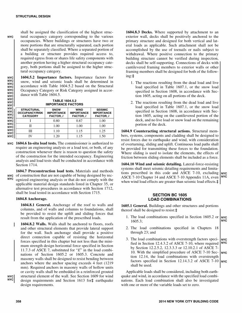
1604.5.2 Importance factors. Importance factors forsnow, wind and seismic loads shall be determined inaccordance with Table 1604.5.2 based on the StructuralOccupancy Category or Risk Category assigned in accor-dance with Table 1604.5.
TABLE 1604.5.2IMPORTANCE FACTORS
1604.6 In-situ load tests. The commissioner is authorized torequire an engineering analysis or a load test, or both, of anyconstruction whenever there is reason to question the safetyof the construction for the intended occupancy. Engineeringanalysis and load tests shall be conducted in accordance withSection 1714.
1604.7 Preconstruction load tests. Materials and methodsof construction that are not capable of being designed by rec-ognized engineering analysis or that do not comply with theapplicable material design standards listed in Chapter 35, oralternative test procedures in accordance with Section 1712,shall be load tested in accordance with Section 1715.
1604.8 Anchorage.
1604.8.1 General. Anchorage of the roof to walls andcolumns, and of walls and columns to foundations, shallbe provided to resist the uplift and sliding forces thatresult from the application of the prescribed loads.
1604.8.2 Walls. Walls shall be anchored to floors, roofsand other structural elements that provide lateral supportfor the wall. Such anchorage shall provide a positivedirect connection capable of resisting the horizontalforces specified in this chapter but not less than the mini-mum strength design horizontal force specified in Section11.7.3 of ASCE 7, substituted for “E” in the load combi-nations of Section 1605.2 or 1605.3. Concrete andmasonry walls shall be designed to resist bending betweenanchors where the anchor spacing exceeds 4 feet (1219mm). Required anchors in masonry walls of hollow unitsor cavity walls shall be embedded in a reinforced groutedstructural element of the wall. See Section 1609 for winddesign requirements and Section 1613 for‡ earthquakedesign requirements.
1604.8.3 Decks. Where supported by attachment to anexterior wall, decks shall be positively anchored to theprimary structure and designed for both vertical and lat-eral loads as applicable. Such attachment shall not beaccomplished by the use of toenails or nails subject towithdrawal. Where positive connection to the primarybuilding structure cannot be verified during inspection,decks shall be self-supporting. Connections of decks withcantilevered framing members to exterior walls or otherframing members shall be designed for both of the follow-ing:‡
1. The reactions resulting from the dead load and liveload specified in Table 1607.1, or the snow loadspecified in Section 1608, in accordance with Sec-tion 1605, acting on all portions of the deck.
2. The reactions resulting from the dead load and liveload specified in Table 1607.1, or the snow loadspecified in Section 1608, in accordance with Sec-tion 1605, acting on the cantilevered portion of thedeck, and no live load or snow load on the remainingportion of the deck.
1604.9 Counteracting structural actions. Structural mem-bers, systems, components and cladding shall be designed toresist forces due to earthquake and wind, with considerationof overturning, sliding and uplift. Continuous load paths shallbe provided for transmitting these forces to the foundation.Where sliding is used to isolate the elements, the effects offriction between sliding elements shall be included as a force.
1604.10 Wind and seismic detailing. Lateral-force-resistingsystems shall meet seismic detailing requirements and limita-tions prescribed in this code and ASCE 7-10, excludingASCE 7-10 Chapter 14 and ASCE 7-10 Appendix 11A, evenwhen wind load effects are greater than seismic load effects.‡
SECTION BC 1605LOAD COMBINATIONS
1605.1 General. Buildings and other structures and portionsthereof shall be designed to resist:‡
1. The load combinations specified in Section 1605.2 or1605.3;
2. The load combinations specified in Chapters 18through 23; and
3. The load combinations with overstrength factors speci-fied in Section 12.4.3.2 of ASCE 7-10, where requiredby Section 12.2.5.2, 12.3.3.3 or 12.10.2.1 of ASCE 7-10. With the simplified procedure of ASCE 7-10 Sec-tion 12.14, the load combinations with overstrengthfactors specified in Section 12.14.3.2 of ASCE 7-10shall be used.
Applicable loads shall be considered, including both earth-quake and wind, in accordance with the specified load combi-nations. Each load combination shall also be investigatedwith one or more of the variable loads set to zero.
STRUCTURAL OCCUPANCY/RISK
CATEGORY
SNOW IMPORTANCE
FACTOR, I
WIND IMPORTANCE
FACTOR, I
SEISMIC IMPORTANCE
FACTOR, I
I 0.80 0.87 1.00
II 1.00 1.00 1.00
III 1.10 1.15 1.25
IV 1.20 1.15 1.50
NYCNYC
NYCNYCNYCNYCNYCNYCNYCNYCNYCNYCNYCNYCNYCNYCNYCNYCNYCNYCNYCNYC
NYC
NYCNYC
NYCNYCNYC
NYCNYC
NYCNYC
NYCNYC
NYC
NYC

STRUCTURAL DESIGN
2014 NEW YORK CITY BUILDING CODE 359
Where the load combinations with overstrength factor inSection 12.4.3.2 of ASCE 7-10 apply, they shall be used asfollows:
1. The basic combinations for strength design with over-strength factor in lieu of Equations 16-5 and 16-7 inSection 1605.2.1.
2. The basic combinations for allowable stress designwith overstrength factor in lieu of Equations 16-12, 16-13 and 16-15 in Section 1605.3.1.
1605.1.1 Stability. Regardless of which load combina-tions are used to design for strength, where overall struc-ture stability (such as stability against overturning, sliding,or buoyancy) is being verified, use of the load combina-tions specified in Section 1605.2 or 1605.3 shall be per-mitted. Where the load combinations specified in Section1605.2 are used, strength reduction factors applicable tosoil resistance shall be provided by a registered designprofessional. The stability of retaining walls shall be veri-fied in accordance with Section 1806.2.
1605.2 Load combinations using strength design or loadand resistance factor design.
1605.2.1 Basic load combinations. Where strengthdesign or load and resistance factor design is used, struc-tures and portions thereof shall resist the most criticaleffects from the following combinations of factoredloads:
1.4D + F (Equation 16-1)
1.2(D + F + T) + 1.6(L + H) + 0.5(Lr or S or R)(Equation 16-2)
1.2D + 1.6(Lr or S or R) + (f1L or 0.8W) (Equation 16-3)
1.2D + 1.6W + f1L + 0.5(Lr or S or R) (Equation 16-4)
1.2D + 1.0E + f1L + f2S (Equation 16-5)
0.9D + 1.6W + 1.6H (Equation 16-6)
0.9D + 1.0E + 1.6H (Equation 16-7)
where:
f1 = 1.0 for floors in places of public assembly, for liveloads in excess of 100 pounds per square foot (4.79kN/m2), and for parking garage live load, and
= 0.5 for other live loads.
f2 = 0.7 for roof configurations (such as saw tooth) thatdo not shed snow off the structure, and
= 0.2 for other roof configurations.
Exception: Where other factored load combinationsare specifically required by the provisions of this code,such combinations shall take precedence.
1605.2.2 Other loads. Where a structure is located in a Vzone or Coastal A zone and Fa is to be considered indesign, in addition to the load combinations of Equations16-1 through 16-7, the structure and portions thereof shallresist the most critical effects of the load combinations ofEquations 16-8 and 16-10.‡ Where a structure is located inan A zone and Fa is to be considered in design, in additionto the load combinations of Equations 16-1 through 16-7,structures and portions thereof shall resist the most critical
effects of the load combinations of Equations 16-9 and 16-11. Where ice loads are to be considered in design, theload combinations of Section 2.3.4 of ASCE 7 shall beused. Refer to the following sections for other load com-binations:
Flood Load Combinations:
1.2D + 1.6W + 2.0Fa + f1L + 0.5(Lr or S or R)(Equation 16-8)
1.2D + 8W + 1.0Fa + f1L + 0.5(Lr or S or R)(Equation 16-9)
0.9D + 1.6W + 2.0Fa + 1.6H (Equation 16-10)
0.9D + 0.8W + 1.0Fa + 1.6H (Equation 16-11)1605.3 Load combinations using allowable stress design.
1605.3.1 Basic load combinations. Where allowablestress design (working stress design), as permitted by thiscode, is used, structures and portions thereof shall resistthe most critical effects resulting from the following com-binations of loads:
D + F (Equation 16-12)
D + H + F + L + T (Equation 16-13)
D+H + F+(Lr or S or R) (Equation 16-14)
D + H + F + 0.75(L + T) + 0.75(Lr or S or R)(Equation 16-15)
D + F + H + (W or 0.7E) (Equation 16-16)
D + H + F + 0.75(W or 0.7E) + 0.75L + 0.75(Lr or S or R)(Equation 16-17)
0.6D + W + H (Equation 16-18)‡
0.6D + 0.7E + H (Equation 16-19)‡
Exceptions:
1. Crane hook loads need not be combined withroof live load or with more than three-fourths ofthe snow load or one-half of the wind load.
2. Flat roof snow loads of 30 psf (1.44 kN/m2) orless need not be combined with seismic loads.Where flat roof snow loads exceed 30 psf (1.44kN/m2), 20 percent shall be combined with seis-mic loads.
1605.3.1.1 Stress increases. Increases in allowablestresses specified in the appropriate material chapter orthe referenced standards shall not be used with the loadcombinations of Section 1605.3.1, except thatincreases shall be permitted in accordance with Chap-ter 23.
1605.3.1.2 Other loads. Where a structure is located ina V zone or Coastal A zone and Fa is to be consideredin design, in addition to load combinations of Equa-tions 16-12 through 16-19, structures and portionsthereof shall resist the most critical effects of load com-binations of Equations 16-20, 16-22 and 16-24. Wherea structure is located in an A zone and Fa is to be con-sidered in design, in addition to load combinations ofEquations 16-12 through 16-19, structures and portionsthereof shall resist the most critical effects of load com-
�
NYC
NYC
NYCNYCNYCNYCNYCNYCNYCNYCNYCNYCNYCNYCNYC
NYCNYCNYCNYCNYCNYC
�
NYCNYCNYCNYCNYCNYCNYCNYCNYCNYCNYCNYC
NYCNYC
�
NYCNYCNYCNYCNYCNYCNYCNYCNYCNYCNYCNYCNYCNYC

STRUCTURAL DESIGN
360 2014 NEW YORK CITY BUILDING CODE
binations of Equations 16-21, 16-23 and 16-25. Whereice loads are to be considered in design, the load com-binations of Section 2.4.3 of ASCE 7 shall be used.Refer to the following sections for other loads:
Flood Load Combinations:
D + H + F + 1.5Fa + W (Equation 16-20)
D + H + F + 0.75Fa + W (Equation 16-21)
D + H + F + 0.75W + 0.75L + 0.75(Lr or S or R) + 1.5Fa
(Equation 16-22)
D + H + F + 0.75W + 0.75L + 0.75(Lr or S or R) +0.75Fa
(Equation 16-23)
0.6D + W + H + 1.5Fa (Equation 16-24)
0.6D + W + H + 0.75Fa (Equation 16-25)
1605.4 Heliports and helistops. Heliport and helistop land-ing areas shall be designed for the following loads, combinedin accordance with Section 1605:
1. Dead load, D, plus the gross weight of the helicopter,Dh, plus snow load, S.
2. Dead load, D, plus two single concentrated impactloads, L, approximately 8 feet (2438 mm) apart appliedanywhere on the touchdown pad (representing each ofthe helicopter’s two main landing gear, whether skidtype or wheeled type), having a magnitude of 0.75times the gross weight of the helicopter. Both loadsacting together total 1.5 times the gross weight of thehelicopter.
3. Dead load, D, plus a uniform live load, L, of 100 psf(4.79 kN/m2).
Exception: Landing areas designed for helicopters withgross weights not exceeding 3,000 pounds (13.34 kN) inaccordance with Items 1 and 2 shall be permitted to bedesigned using a 40 psf (1.92 kN/m2) uniform live load inItem 3, provided the landing area shall be identified with a3,000-pound (13.34 kN) weight limitation and the 40 psf(1.92 kN/m2) uniform live load shall not be reduced. Thelanding area weight limitation shall be indicated by thenumeral “3” (kips) located in the bottom right corner ofthe landing area as viewed from the primary approachpath. The indication for the landing area weight limitationshall be a minimum 5 feet (1524 mm) in height.
1605.5 Structural integrity load combinations—alternateload path method. Where specifically required by Sections1614‡ through 1616, elements and components shall bedesigned to resist the forces calculated using the followingcombination of factored loads:
D + f1L + f2W (Equation 16-26)
where:
f1 = 0.25 for buildings in Structural Occupancy Category II.
f1 = 0.5 for buildings in Structural Occupancy Category IIIor IV.
f2 = 0 for buildings in Structural Occupancy Category II.
f2 = 0.33 for buildings in Structural Occupancy CategoryIII or IV.
The live load component f1L need not be greater than thereduced live load.
1605.6 Structural integrity load combinations—vehicularimpact and gas explosions. Where specifically required bySections 1615.5 and 1615.6, elements and components shallbe designed to resist the forces calculated using the follow-ing combination of factored loads:
1.2D +Ak + (0.5L or 0.2S) (Equation 16-27)
0.9D +Ak + 0.2W (Equation 16-28)
Where Ak is the load effect of the vehicular impact or gasexplosion.
1605.7 Structural integrity load combinations—specificlocal resistance method. Where the specific local resistancemethod is used in a key element analysis, the specified localloads shall be used as specified in Section 1616.7.
SECTION BC 1606DEAD LOADS
1606.1 General. Dead loads are those loads defined in Sec-tion 1602.1. Dead loads shall be considered permanent loads.
1606.2 Design dead load. For purposes of design, the actualweights of materials of construction and fixed service equip-ment shall be used. In the absence of definite information,values used shall be subject to the approval of the commis-sioner.
SECTION BC 1607LIVE LOADS
1607.1 General. Live loads are those defined in Section1602.1
NYCNYCNYCNYCNYC�
NYCNYCNYCNYCNYCNYCNYCNYCNYCNYCNYCNYCNYCNYCNYC
�
NYCNYC
�NYCNYCNYCNYCNYCNYCNYCNYCNYC
NYCNYCNYCNYCNYCNYCNYCNYCNYCNYCNYCNYCNYCNYCNYCNYCNYCNYCNYCNYCNYCNYCNYCNYCNYCNYCNYCNYCNYCNYCNYCNYCNYCNYCNYCNYC
NYCNYC
�
NYC

STRUCTURAL DESIGN
2014 NEW YORK CITY BUILDING CODE 361
TABLE 1607.1MINIMUM UNIFORMLY DISTRIBUTED LIVE LOADS AND MINIMUM CONCENTRATED LIVE LOADSf, i
OCCUPANCY OR USE UNIFORM(psf)
CONCENTRATED(lbs.)
1. Apartments (see residential) — —
2. Access floor systemsOffice useComputer use
50100
2,0002,000
3. Armories and drill rooms 150 —
4. Assembly areas and theatersFixed seats (fastened to floor) LobbiesMovable seatsPrivate assembly spaces, including conference roomsStages and platformsFollow spot, projections and control roomsCatwalksOther assembly spaces
6010010050
1255040
Note h
—
5. Balconies (exterior) and Decksg‡1.5 times the live load for the
occupancy served. Not required to exceed 100 psf
—
6. Bowling alleys 75 —
7. Cornices 60 —
8. Corridors, except as otherwise indicated 100 —
‡9. Dance halls and ballrooms 100 —
10. Dining rooms and restaurants 100 —
11. Dwellings (see residential) — —
12. Elevator machine room grating (on area of 4 in.2) — 300
13. Equipment rooms, including pump rooms, generator rooms, transformer vaults, and areas for switch gear, ventilating, air conditioning, and similar electrical and mechanical equipment
75 —
14. Finish light floor plate construction (on area of 1 in.2) — 200
15. Fire escapes (exterior) On single- and multiple family dwellings
10040
—
16. Garages (passenger vehicles only) Trucks and buses
40See Section 1607.6
Note aSee Section 1607.6
17. Grandstands (see stadium and arena bleachers) — —
18. Gymnasiums, main floors and balconies 100 —
19. Handrails, guards and grab bars See Section 1607.7
20. HospitalsOperating rooms, laboratoriesPrivate roomsWardsCorridors above first floor
60404080
1,0001,0001,0001,000
21. Hotels (see residential) — —
22. LibrariesReading roomsStack roomsCorridors above first floor
60150b
80
1,0001,0001,000
NYC
NYC
NYC
NYC
NYCNYCNYCNYC
NYCNYCNYCNYC
NYCNYC
(continued)
STRUCTURAL DESIGN
362 2014 NEW YORK CITY BUILDING CODE
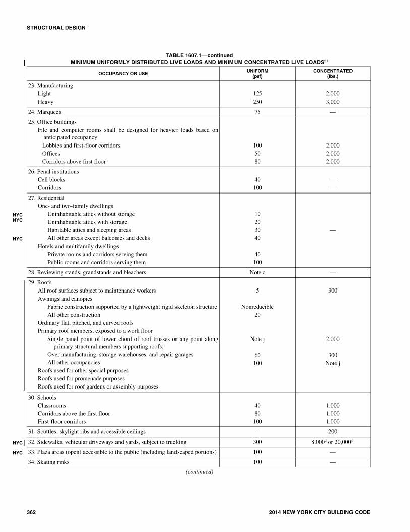
23. Manufacturing LightHeavy
125250
2,0003,000
24. Marquees 75 —
25. Office buildingsFile and computer rooms shall be designed for heavier loads based on
anticipated occupancy Lobbies and first-floor corridors Offices Corridors above first floor
1005080
2,0002,0002,000
26. Penal institutionsCell blocksCorridors
40100
——
27. Residential One- and two-family dwellings
Uninhabitable attics without storageUninhabitable attics with storageHabitable attics and sleeping areasAll other areas except balconies and decks
Hotels and multifamily dwellings Private rooms and corridors serving them Public rooms and corridors serving them
10203040
40100
—
28. Reviewing stands, grandstands and bleachers Note c —
29. Roofs All roof surfaces subject to maintenance workersAwnings and canopies
Fabric construction supported by a lightweight rigid skeleton structureAll other construction
Ordinary flat, pitched, and curved roofsPrimary roof members, exposed to a work floor
Single panel point of lower chord of roof trusses or any point alongprimary structural members supporting roofs;
Over manufacturing, storage warehouses, and repair garagesAll other occupancies
Roofs used for other special purposesRoofs used for promenade purposesRoofs used for roof gardens or assembly purposes
5
Nonreducible20
Note j
60100
300
2,000
300Note j
30. SchoolsClassroomsCorridors above the first floorFirst-floor corridors
4080100
1,0001,0001,000
31. Scuttles, skylight ribs and accessible ceilings — 200
32. Sidewalks, vehicular driveways and yards, subject to trucking 300 8,000d or 20,000d
33. Plaza areas (open) accessible to the public (including landscaped portions) 100 —
34. Skating rinks 100 —
OCCUPANCY OR USE UNIFORM(psf)
CONCENTRATED(lbs.)
NYCNYC
NYC
NYC
NYC
TABLE 1607.1—continuedMINIMUM UNIFORMLY DISTRIBUTED LIVE LOADS AND MINIMUM CONCENTRATED LIVE LOADSf, i
(continued)

STRUCTURAL DESIGN
2014 NEW YORK CITY BUILDING CODE 363
Notes to Table 1607.1
For SI: 1 inch = 25.4 mm,1 square inch = 645.16 mm2,1 pound per square foot = 0.0479 kN/m2,1 pound = 0.004448 kN, 1 pound per cubic foot = 16 kg/m3.a. Floors in garages or portions of buildings used for the storage of motor vehicles shall be designed for the uniformly distributed live loads of Table
1607.1 or the following concentrated loads: (1) for garages restricted to vehicles accommodating not more than nine passengers, 3,000 pounds acting onan area of 4.5 inches by 4.5 inches; (2) for mechanical parking structures without slab or deck which are used for storing passenger vehicles only, 2,250pounds per wheel.
b. The loading applies to stack room floors that support nonmobile, double-faced library bookstacks, subject to the following limitations:1. The nominal bookstack unit height shall not exceed 90 inches;2. The nominal shelf depth shall not exceed 12 inches for each face; and3. Parallel rows of double-faced bookstacks shall be separated by aisles not less than 36 inches wide.
c. Design in accordance with the ICC Standard on Bleachers, Folding and Telescopic Seating and Grandstands.d. The concentrated wheel load shall be applied as follows 8,000 pounds on an area of 20 square inches, 20,000 pounds on an area of 20 inch by 10 inch area.e. ‡Minimum concentrated load on stair treads (on area of 4 square inches) is 300 pounds.f. ‡Where snow loads occur that are in excess of the design conditions, the structure shall be designed to support the loads due to the increased loads
caused by drift buildup or a greater snow design determined by the commissioner (see Section 1608). For special-purpose roofs, see Section1607.11.2.2.
g. ‡See Section 1604.8.3 for decks attached to exterior walls.h. ‡Live loads for assembly spaces other than those described in this table shall be determined from the occupant load requirements as established by
Section 1004 of this code using the formula 1,000/(net floor area per occupant) but shall not be less than 50 psf nor more than 100 psf.i. ‡For establishing live loads for occupancies not specifically listed herein, refer to Referenced Standard ASCE 7 for guidance.j. Roofs used for other special purposes shall be designed for appropriate loads as approved by the commissioner.
35. Stadiums and arenasBleachersFixed seats (fastened to floor)
100c
60c
—
36. Stairs and exits One- and two-family dwellings All other
10040
100Note e
37. Storage warehouses (shall be designed for heavier loads if required for anticipated storage)
LightHeavy
125250
——
38. StoresRetail
First floorUpper floorsWholesale, all floors
10075
125
1,0001,0001,000
39. Vehicle barriers See Section 1607.7
40. Walkways and elevated platforms (other than exitways) 60 —
41. Yards and terraces, pedestrians 100 —
OCCUPANCY OR USE UNIFORM(psf)
CONCENTRATED(lbs.)
NYC
NYC
NYC
NYCNYC ��
NYC
�
NYCNYCNYCNYCNYC
TABLE 1607.1—continuedMINIMUM UNIFORMLY DISTRIBUTED LIVE LOADS AND MINIMUM CONCENTRATED LIVE LOADSf, i

STRUCTURAL DESIGN
364 2014 NEW YORK CITY BUILDING CODE
1607.2 Loads not specified. For occupancies or uses notdesignated in Table 1607.1, the live load shall be determinedin accordance with a method approved by the commissioner.
1607.2.1 Stage areas using scenery or scenic elements.Scenery battens and suspension systems shall be designedfor a load of 30 pounds per linear foot (437.7 N/m) of bat-ten length. Loft block and head block beams shall bedesigned to support vertical and horizontal loads corre-sponding to a 4-inch (102 mm) spacing of battens for theentire depth of the gridiron. Direction and magnitude oftotal forces shall be determined from the geometry of therigging system including load concentrations from spotline rigging. Locking rails shall be designed for a uniformuplift of 500 psf (3447 kN/m2) with a 1,000 pound (454kg) concentration. Impact factor for batten design shall be75 percent and for loft and head block beams shall be 25percent. A plan drawn to a scale not less than 1/4 inch (6.4mm) equals 1 foot (305 mm) shall be displayed in thestage area indicating the framing plan of the rigging loftand the design loads for all members used to supportscenery or rigging. Gridirons over stages shall bedesigned to support a uniformly distributed live load of50 psf (2.40 kN/m2) in addition to the rigging loads indi-cated.
1607.3 Uniform live loads. The live loads used in the designof buildings and other structures shall be the maximum loadsexpected by the intended use or occupancy but shall in nocase be less than the minimum uniformly distributed unitloads required by Table 1607.1.
1607.4 Concentrated loads. Floors and other similar sur-faces shall be designed to support the uniformly distributedlive loads prescribed in Section 1607.3 or the concentratedload, in pounds (kilonewtons), given in Table 1607.1, which-ever produces the greater load effects. Unless otherwisespecified, the indicated concentration shall be assumed to beuniformly distributed over an area 2.5 feet by 2.5 feet (762mm by 762 mm) and shall be located so as to produce themaximum load effects in the structural members.
1607.5 Partition loads. Weights of all partitions shall beconsidered, using either actual weights at locations shown onthe plans or the equivalent uniform load given in Section1607.5.2. Partition loads shall be taken as superimposeddead loads.
1607.5.1 Actual loads. Where actual partition weights areused, the uniform design live load may be omitted fromthe strip of floor area under each partition.
1607.5.2 Equivalent uniform load. The equivalent uni-form partition loads in Table 1607.5 may be used in lieuof actual partition weights except for bearing partitions orpartitions in toilet room areas (other than in one- and two-family dwellings), at stairs and elevators, and similarareas where partitions are concentrated. In such cases,actual partition weights shall be used in design. Except asotherwise exempted, equivalent uniform partition loadsshall be used in areas where partitions are not definitelylocated on the plans, or in areas where partitions are sub-ject to rearrangement or relocation.
TABLE 1607.5EQUIVALENT UNIFORM PARTITION LOADS
For SI: 1 pound per linear foot = 0.01459 kN/m2, 1 pound per square foot = 0.0479 kN/m2.
1607.6 Garages.
1607.6.1 Passenger vehicle garages. Areas used for, andrestricted by physical limitations of clearance to, the tran-sit or parking of passenger vehicles shall be designed forthe uniformly distributed and concentrated loads for park-ing areas for such vehicles as provided in Table 1607.1applied without impact. An exception is made for mem-bers or constructions which, because of physical limita-tions, cannot be subjected to direct load from the vehicleor from a jack or hoist used to raise or suspend the vehi-cle. Such members or constructions shall be designed forthe loads corresponding to the actual usage.
TABLE 1607.6UNIFORM AND CONCENTRATED LOADS
For SI: 1 pound per linear foot = 0.0 1459 kN/m, 1 pound = 0.004448 kN, 1 ton = 8.90 kN.
a. An H loading class designates a two-axle truck with a semitrailer. An HSloading class designates a tractor truck with a semitrailer. The numbersfollowing the letter classification indicate the gross weight in tons of thestandard truck and the year the loadings were instituted.
b. See Section 1607.6.1 for the loading of multiple spans.
1607.6.2 Truck and bus garages. Minimum live loadsfor garages having trucks or buses shall be as specified inTable 1607.6, but shall not be less than 50 psf (2.40 kN/m2), unless other loads are specifically justified andapproved by the commissioner. Actual loads shall be usedwhere they are greater than the loads specified in thetable.
1607.6.2.1 Truck and bus garage live load applica-tion. The concentrated load and uniform load shall beuniformly distributed over a 10-foot (3048 mm) widthon a line normal to the centerline of the lane placedwithin a 12-foot-wide (3658 mm) lane. The loads shallbe placed within their individual lanes so as to producethe maximum stress in each structural member. Verti-cal impact shall be taken as 10 percent of the verticalload. Single spans shall be designed for the uniform
NYCNYCNYCNYCNYCNYCNYCNYCNYCNYCNYCNYCNYCNYCNYCNYCNYCNYCNYCNYCNYCNYCNYCNYCNYCNYCNYCNYCNYCNYCNYC
NYCNYC
C
NYCNYCNYCNYCNYCNYCNYCNYCNYCNYCNYCNYCNYCNYCNYCNYCNYCNYCNYCNYCNYCNYCNYCNYCNYCNYCNYCNYC
PARTITIONWEIGHT
(plf)
EQUIVALENT UNIFORM LOAD (psf)(to be added to floor dead and live loads)
50 or less 0
51 to 100 6
101 to 200 12
201 to 350 20
Greater than 35020 plus a concentrated live load
of the weight in excess of 350 plf.
LOADINGCLASSa
UNIFORM LOAD(pounds/linear
foot of lane)
CONCENTRATED LOAD(pounds)b
For momentdesign
For sheardesign
H20-44 andHS20-44
640 18,000 26,000
H15-44 andHS15-44
480 13,500 19,500
NYCNYCNYCNYCNYCNYCNYCNYCNYCNYCNYCNYCNYCNYCNYCNYCNYCNYCNYCNYCNYCNYCNYCNYCNYCNYCNYCNYCNYCNYCNYCNYCNYCNYCNYCNYCNYCNYC
NYC
NYCNYCNYCNYC
STRUCTURAL DESIGN
2014 NEW YORK CITY BUILDING CODE 365
load in Table 1607.6 and one simultaneous concen-trated load positioned to produce the maximum effect.Multiple spans shall be designed for the uniform loadin Table 1607.6 on the spans and two simultaneousconcentrated loads in two spans positioned to producethe maximum negative moment effect. Multiple spandesign loads, for other effects, shall be the same as forsingle spans.
1607.7 Loads on handrails, guards, grab bars, seats andvehicle barrier systems. Handrails, guards, grab bars, acces-sible seats, accessible benches and vehicle barrier systemsshall be designed and constructed to the structural loadingconditions set forth in this section.
1607.7.1 Handrail assemblies and guards. Handrailassemblies and guards shall be designed to resist a load of50 plf (0.73 kN/m) applied in any direction at the top andto transfer this load through the supports to the structure.Glass handrail assemblies and guards shall also complywith Section 2407.
Exceptions:
1. For one- and two-family dwellings, only the sin-gle, concentrated load required by Section1607.7.1.1 shall be applied.
2. In Group I-3, F, H, and S occupancies, for areasthat are not accessible to the general public andthat have an occupant load no greater than 50,the minimum load shall be 20 pounds per foot(0.29 kN/m).
1607.7.1.1 Concentrated load. Handrails‡ and guardsshall be able to resist a single concentrated load of 200pounds (0.89 kN), applied in any direction at anypoint, and have attachment devices and supportingstructure to transfer this loading to appropriate struc-tural elements of the building. This load need not beassumed to act concurrently with the loads specified inthe preceding paragraph.
1607.7.1.2 Components. Intermediate rails (all thoseexcept the handrail), balusters and panel fillers shall bedesigned to withstand a horizontally applied normalload of 50 pounds (0.22 kN) on an area equal to 1square foot (0.093 m2), including openings and spacebetween rails, a vertically downward load of 50 poundsper foot (0.73 kN/m), and a concentrated upward loadof 50 pounds (0.22 kN) applied at the most criticallocation. Reactions due to this loading are not requiredto be applied simultaneously with one another, and arenot required to be superimposed with those of Section1607.7.1 or 1607.7.1.1. The railings, balusters andcomponents shall be designed separately for the effectof wind when the total wind load on the panel or com-ponent exceeds 50 pounds (0.22 kN). The wind loadneed not be combined with any other live load.
1607.7.2 Grab bars, shower seats and dressing roombench seats. Grab bars, shower seats and dressing roombench seat systems shall be designed to resist a singleconcentrated load of 250 pounds (1.11 kN) applied in anydirection at any point.
1607.7.3 Vehicle barrier systems. Vehicle barrier sys-tems for passenger vehicles shall be designed to resist asingle load of 6,000 pounds (26.70 kN) applied horizon-tally in any direction to the barrier system and shall haveanchorage or attachment capable of transmitting this loadto the structure. For design of the system, two loadingconditions shall be analyzed. The first condition shallapply the load at a height of 1 foot, 6 inches (457 mm)above the floor or ramp surface.‡ The second loadingcondition shall apply the load at 2 feet, 3 inches (686 mm)above the floor or ramp surface. The more severe loadcondition shall govern the design of the barrier restraintsystem. The load shall be assumed to act on an area not toexceed 1 square foot (0.0929 m2), and is not required tobe assumed to act concurrently with any handrail or guardloadings specified in Section 1607.7.1. Garages accom-modating trucks and buses shall be designed in accor-dance with a recognized method acceptable to thecommissioner that contains provision for traffic railings.
1607.7.3.1 Columns in parking areas. Unless spe-cially protected, columns in parking areas subject toimpact of moving vehicles shall be designed to resistthe lateral load due to impact and this load shall beconsidered a variable load. For passenger vehicles, thislateral load shall be taken as a minimum of 6,000pounds (26.70 kN) applied at least 1 foot 6 inches (457mm); above the roadway, and acting simultaneouslywith other design loads. In addition, columns in park-ing areas shall meet the requirements of Section 1615for structural integrity.
1607.8 Impact loads. The live loads specified in Section1607.3 include allowance for impact conditions. Provisionsshall be made in the structural design for uses and loads thatinvolve unusual vibration and impact forces.
1607.8.1 Elevators. Elevator loads shall be increased by100 percent for impact and the structural supports shall bedesigned within the limits of stress and deflection pre-scribed by ASME A17.1.
1607.8.2 Machinery. For the purpose of design, theweight of machinery and moving loads shall be increasedas follows to allow for impact: (1) elevator machinery,100 percent; (2) light machinery, shaft- or motor-driven,20 percent; (3) reciprocating machinery or power-drivenunits, 50 percent; (4) hangers for floors or balconies, 33percent. Percentages shall be increased where specifiedby the manufacturer.
1607.8.3 Railroad equipment. Minimum loads (includ-ing vertical, lateral, longitudinal, and impact) and the dis-tribution thereof shall meet the applicable requirements ofChapter 15 of the AREMA Manual for Railway Engineer-ing.
1607.8.4 Assembly structures. Seating areas in grand-stands, stadiums, and similar assembly structures shall bedesigned to resist the simultaneous application of a hori-zontal swaying load of at least 24 plf (36 kg/m) of seatsapplied in a direction parallel to the row of the seats, andof at least 10 plf (15 kg/m) of seats in a direction perpen-dicular to the row of the seats. When this load is used in
NYCNYC
NYC
NYCNYCNYCNYCNYC
NYC
NYCNYCNYCNYCNYCNYCNYCNYCNYCNYCNYCNYCNYCNYCNYC�
NYCNYCNYCNYCNYCNYCNYCNYCNYCNYCNYCNYCNYCNYCNYCNYCNYCNYCNYC
NYC
NYCNYCNYCNYCNYCNYCNYCNYCNYCNYCNYCNYCNYCNYCNYCNYCNYC

STRUCTURAL DESIGN
366 2014 NEW YORK CITY BUILDING CODE
combination with wind for outdoor structures, the windload shall be one-half of the design wind load.
1607.9 Reduction in live loads. Except for uniform liveloads at roofs, all other minimum uniformly distributed liveloads, Lo, in Table 1607.1 are permitted to be reduced inaccordance with Section 1607.9.1 or 1607.9.2. Roof uniformlive loads, other than special purpose roofs of Section1607.11.2.2, are permitted to be reduced in accordance withSection 1607.11.2. Roof uniform live loads of special pur-pose roofs are permitted to be reduced in accordance withSection 1607.9.1 or 1607.9.2.
1607.9.1 General. Subject to the limitations of Sections1607.9.1.1 through 1607.9.1.4, members for which avalue of KLLAT is 400 square feet (37.16 m2) or more arepermitted to be designed for a reduced live load in accor-dance with the following equation:
(Equation 16-29‡)
For SI:
where:
L = Reduced design live load per square foot (squaremeter) of area supported by the member.
Lo = Unreduced design live load per square foot (squaremeter) of area supported by the member (see Table1607.1).
KLL = Live load element factor (see Table 1607.9.1).
AT = Tributary area, in square feet (square meters). L shallnot be less than 0.50Lo for members supporting onefloor and L shall not be less than 0.40Lo for memberssupporting two or more floors.
TABLE 1607.9.1LIVE LOAD ELEMENT FACTOR, KLL
1607.9.1.1 One-way slabs. The tributary area, AT, foruse in Equation 16-22 for one-way slabs shall notexceed an area defined by the slab span times a widthnormal to the span of 1.5 times the slab span.
1607.9.1.2 Heavy live loads. Live loads that exceed100 psf (4.79 kN/m2) shall not be reduced.
Exceptions:
1. The live loads for members supporting two ormore floors are permitted to be reduced by amaximum of 20 percent, but the live loadshall not be less than L as calculated in Sec-tion 1607.9.1.
2. For uses other than storage, where approved,additional live load reductions shall be permit-ted where shown by the registered design pro-fessional that a rational approach has beenused and that such reductions are warranted.
1607.9.1.3 Passenger vehicle garages. The live loadsshall not be reduced in passenger vehicle garages.
Exception: The live loads for members supportingtwo or more floors are permitted to be reduced by amaximum of 20 percent, but the live load shall notbe less than L as calculated in Section 1607.9.1.
1607.9.1.4 Special occupancies. Live loads of 100 psf(4.79 kN/m2) or less at areas where fixed seats arelocated shall not be reduced in public assembly occu-pancies or in areas used for retail or wholesale sales.
1607.9.1.5 Special structural elements. Live loadsshall not be reduced for one-way slabs except as per-mitted in Section 1607.9.1.1. Live loads shall not bereduced for calculating shear stresses at the heads ofcolumns in flat slab or flat plate construction.
1607.9.1.6 Roof members. Live loads of 100 psf (4.79kN/m2) or less shall not be reduced for roof membersexcept as specified in Section 1607.11.2.
1607.9.2 Alternate floor live load reduction. As an alter-native to Section 1607.9.1, floor live loads are permittedto be reduced in accordance with the following provi-sions. Such reductions shall apply to slab systems, beams,girders, columns, piers, walls and foundations.
1. A reduction shall not be permitted in Group Aoccupancies.
2. A reduction shall not be permitted where the liveload exceeds 100 psf (4.79 kN/m2) except thatthe design live load for members supporting twoor more floors is permitted to be reduced by 20percent.
Exception: For uses other than storage, whereapproved, additional live load reductions shallbe permitted where shown by the registereddesign professional that a rational approachhas been used and that such reductions arewarranted.
3. A reduction shall not be permitted in passengervehicle parking garages except that the live loadsfor members supporting two or more floors arepermitted to be reduced by a maximum of 20 per-cent.
ELEMENT KLL
Interior columnsExterior columns without cantilever slabs
44
Edge columns with cantilever slabs 3
Corner columns with cantilever slabsEdge beams without cantilever slabsInterior beams
222
All other members not identified above including:Edge beams with cantilever slabsCantilever beamsOne-way slabsTwo-way slabsMembers without provisions for continuous sheartransfer normal to their span
1
NYCNYC
C
L Lo 0.2515
KLLAT
--------------------+ =
L Lo 0.254.57
KLLAT
--------------------+ =
NYCNYCNYCNYCNYCNYCNYCNYCNYCNYCNYCNYCNYC
STRUCTURAL DESIGN
2014 NEW YORK CITY BUILDING CODE 367
4. For live loads not exceeding 100 psf (4.79 kN/m2), the design live load for any structural mem-ber supporting 150 square feet (13.94 m2) ormore is permitted to be reduced in accordancewith Equation 16-27.
5. For one-way slabs, the area, A, for use in Equa-tion 16-27 shall not exceed the product of the slabspan and a width normal to the span of 0.5 timesthe slab span.
R = 0.08 (A – 150) (Equation 16-30)
For SI: R = 0.861(A – 13.94)
Such reduction shall not exceed the smallest of:
1. 40 percent for horizontal members;2. 60 percent for vertical members; or 3. R as determined by the following equation:
R = 23.1 (1 + D/Lo) (Equation 16-31)
where:
A = Area of floor or roof supported by the member,square feet (m2).
D = Dead load per square foot (m2) of areasupported.
Lo = Unreduced live load per square foot (m2) ofarea supported.
R = Reduction in percent.
1607.10 Distribution of floor loads. Where uniform floorlive loads are involved in the design of structural membersarranged so as to create continuity, the minimum appliedloads shall be the full dead loads on all spans in combinationwith the floor live loads on spans selected to produce thegreatest effect at each location under consideration. It shallbe permitted to reduce floor live loads in accordance withSection 1607.9.
1607.11 Roof loads. The structural supports of roofs andmarquees shall be designed to resist wind and, where appli-cable, snow and earthquake loads, in addition to the deadload of construction and the appropriate live loads as pre-scribed in this section, or as set forth in Table 1607.1. Thelive loads acting on a sloping surface shall be assumed to actvertically on the horizontal projection of that surface.
1607.11.1 Distribution of roof loads. Where uniformroof live loads are reduced to less than 20 psf (0.96 kN/m2) in accordance with Section 1607.11.2.1 and areapplied to the design of structural members arranged so asto create continuity, the reduced roof live loads shall beapplied to adjacent spans or to alternate spans, whicheverproduces the most unfavorable load effect. See Section1607.11.2 for reductions in minimum roof live loads andSection 7.5 of ASCE 7 for partial snow loading.
1607.11.1.1 Arches and gabled frames. The follow-ing simplification is permissible:
1. Live load placed on one-half of the span adjacentto one support.
2. Live load placed on the center one-fourth of thespan.
3. Live load placed on 3/8 of the span adjacent toeach support.
1607.11.2 Reduction in roof live loads. The minimumuniformly distributed live loads of roofs and marquees, Lo,in Table 1607.1 are permitted to be reduced in accordancewith Section 1607.11.2.1 or 1607.11.2.2.
1607.11.2.1 Flat, pitched and curved roofs. Ordinaryflat, pitched and curved roofs,‡ and awnings and cano-pies other than of fabric construction supported bylight-weight rigid skeleton structures, are permitted tobe designed for a reduced roof live load as specified inthe following equations or other controlling combina-tions of loads in Section 1605, whichever produces thegreater load. In structures such as greenhouses, wherespecial scaffolding is used as a work surface for work-ers and materials during maintenance and repair opera-tions, a lower roof load than specified in the followingequations shall not be used unless approved by thecommissioner. Such structures ‡shall be designed for aminimum roof live load of 12 psf (0.58 kN/m2).
Lr = LoR1R2 (Equation 16-32)
where: 12 ≤ Lr ≤ 20
For SI: Lr = LoR1R2
where: 0.58 ≤ Lr ≤ 0.96
Lr = Reduced live load per square foot (m2) ofhorizontal projection in pounds per square foot(kN/m2).
The reduction factors R1 and R2 shall be determinedas follows:
R1 = 1 for At ≤ 200 square feet (18.58 m2)(Equation 16-33)
R1 = 1.2 - 0.001At for 200 square feet < At < 600 square feet (Equation 16-34)
For SI: 1.2 - 0.011At for 18.58 square meters < At < 55.74 square meters
R1 = 0.6 for At ≥ 600 square feet (55.74 m2)(Equation 16-35)
where:
At = Tributary area (span length multiplied byeffective width) in square feet (m2) supported byany structural member, and
R2 = 1 for F < 4 (Equation 16-36)
R2 = 1.2 - 0.05 F for 4 < F < 12 (Equation 16-37)
R2 = 0.6 for F > 12 (Equation 16-38)
F = For a sloped roof, the number of inches of riseper foot (for SI: F = 0.12 × slope, with slopeexpressed as a ‡percentage for an arch or dome,the rise-to-span ratio multiplied by 32
1607.11.2.2 Special-purpose roofs. Roof‡ gardens,marquees, and roofs used for‡ promenade, assembly orother special purposes shall be designed for a mini-mum live load, Lo, as specified in Table 1607.1. Suchlive loads are permitted to be reduced in accordance
NYC
NYC
NYC
�
NYC
NYCNYCNYCNYCNYCNYCNYCNYCNYC
NYCNYC
NYC
NYCNYCNYC

STRUCTURAL DESIGN
368 2014 NEW YORK CITY BUILDING CODE
with Section 1607.9. Live loads of 100 psf (4.79 kN/m2) or more at areas or roofs classified as Group Aoccupancies shall not be reduced.
1607.11.3 Green roofs. Where roofs utilize a green roofsystem and are not intended for human occupancy, theuniform design live load in the area covered by the greenroof shall be 20 psf (0.958 kN/m2). The weight of thelandscaping materials shall be considered as dead loadand shall be computed on the basis of saturation of thesoil. Where roofs utilize a green roof system and are usedfor human occupancy, the minimum live load shall be asspecified in Table 1607.1 or Section 1607.11.2.2, which-ever is greater.
1607.11.4 Awnings,‡ canopies, and sun control devices.Awnings, canopies, and sun control devices shall bedesigned for uniform live loads as required in Table1607.1 as well as for snow loads and wind loads as speci-fied in Sections 1608 and 1609.
1607.11.5 Hanging loads. Girders and roof trusses (otherthan joists) over garage areas regularly utilized for therepair of vehicles and over manufacturing floors or stor-age floors used for commercial purposes shall be capableof supporting, in addition to the specified live and windloads, a concentrated live load of 2,000 pounds (908 kg)applied at any lower chord panel point for trusses, and atany point of the lower flange for girders.
1607.12 Crane loads. The crane live load shall be the ratedcapacity of the crane. Design loads for the runway beams,including connections and support brackets, of movingbridge cranes and monorail cranes shall include the maxi-mum wheel loads of the crane and the vertical impact, lateraland longitudinal forces induced by the moving crane.
1607.12.1 Maximum wheel load. The maximum wheelloads shall be the wheel loads produced by the weight ofthe bridge, as applicable, plus the sum of the rated capac-ity and the weight of the trolley with the trolley posi-tioned on its runway at the location where the resultingload effect is maximum.
1607.12.2 Vertical impact force. The maximum wheelloads of the crane shall be increased by the percentagesshown below to determine the induced vertical impact orvibration force:
Monorail cranes (powered) . . . . . . . . . . . . . . . . 25 percent
Cab-operated or remotely operated bridge cranes (powered) . . . . . . . . . . . . . . . . . . . . . . . 25 percent
Pendant-operated bridge cranes(powered). . . . . . . . . . . . . . . . . . . . . . . . . . . . . . 10 percent
Bridge cranes or monorail cranes with hand-geared bridge, trolley and hoist . . . . . . . 0 percent
1607.12.3 Lateral force. The lateral force on crane run-way beams with electrically powered trolleys shall be cal-culated as 20 percent of the sum of the rated capacity ofthe crane and the weight of the hoist and trolley. The lat-eral force shall be assumed to act horizontally at the trac-tion surface of a runway beam, in either direction
perpendicular to the beam, and shall be distributedaccording to the lateral stiffness of the runway beam andsupporting structure. F = For a sloped roof, the number ofinches of rise per foot (for SI: F = 0.12 × slope, with slopeexpressed as a ‡percentage for an arch or dome, the rise-to-span ratio multiplied by 32
1607.12.4 Longitudinal force. The longitudinal force oncrane runway beams, except for bridge cranes with handgeared bridges, shall be calculated as 10 percent of themaximum wheel loads of the crane. The longitudinalforce shall be assumed to act horizontally at the tractionsurface of a runway beam, in either direction parallel tothe beam.
1607.13 Interior walls and partitions. Interior walls andpartitions that exceed 6 feet (1829 mm) in height, includingtheir finish materials, shall have adequate strength to resistthe loads to which they are subjected but not less than a hor-izontal load of 5 psf (0.240 kN/ m2).
Exception: Fabric partitions complying with Section1607.13.1 shall not be required to resist the minimum hor-izontal load of 5 psf (0.24 kN/m2).
1607.13.1 Fabric partitions. Fabric partitions that exceed6 feet (1829 mm) in height, including their finish materi-als, shall have adequate strength to resist the followingload conditions:
1. A horizontal distributed load of 5 psf (0.24 kN/m2)applied to the partition framing. The total area usedto determine the distributed load shall be the area ofthe fabric face between the framing members towhich the fabric is attached. The total distributedload shall be uniformly applied to such framingmembers in proportion to the length of each mem-ber.
2. A concentrated load of 40 pounds (0.176 kN)applied to an 8-inch diameter (203 mm) area of thefabric face at a height of 54 inches [50.3 squareinches (32 452 mm2)] above the floor.
SECTION BC 1608SNOW LOADS
1608.1 General. Design snow loads shall be determined inaccordance with Chapter 7 of ASCE 7, but the design roofload shall not be less than that determined by Section 1607.
1608.2 Ground snow loads. The ground snow load, Pg, to beused in determining the design snow loads for roofs is 25 psf(1.2 kN/m2).
1608.3 Flat roof snow loads. The flat roof snow load, ρf, ona roof with a slope equal to or less than 5 degrees (0.09 rad)(1 inch per foot = 4.76 degrees) shall be calculated in accor-dance with Section 7.3 of ASCE 7.
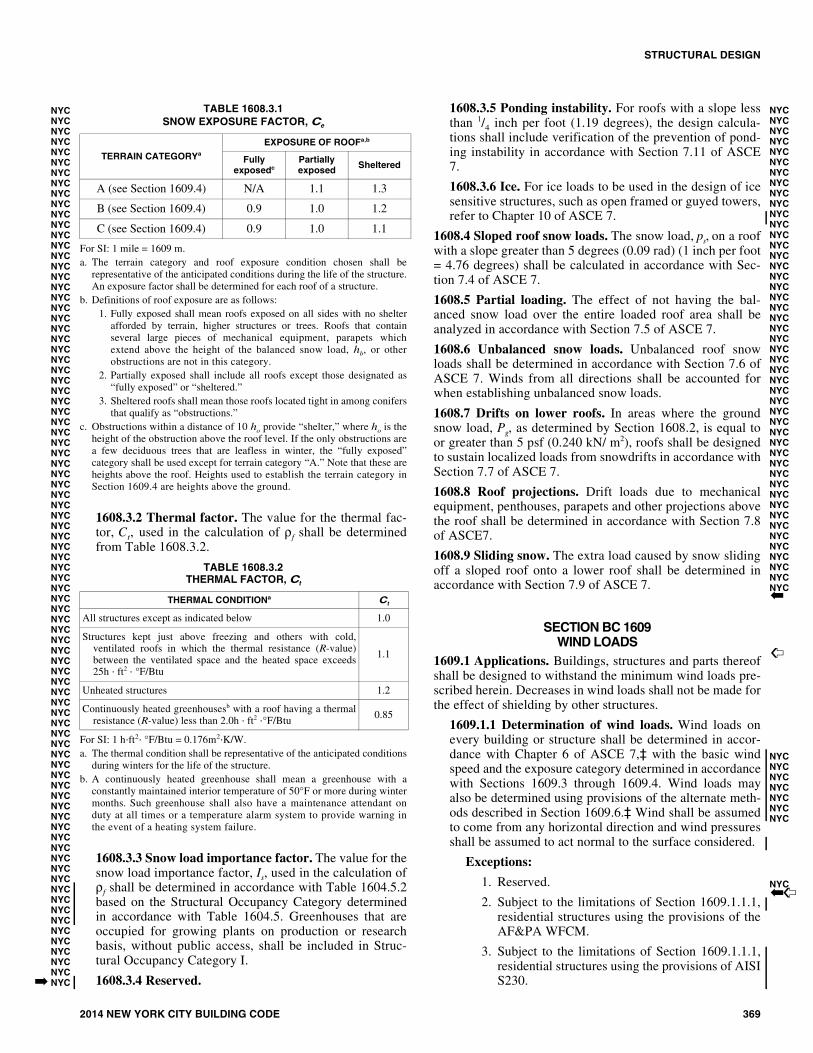
1608.3.1 Exposure factor. The value for the snow expo-sure factor, Ce, used in the calculation of ρf shall bedetermined from Table 1608.3.1.
NYCNYCNYCNYCNYC
NYCNYCNYCNYCNYCNYCNYCNYC
NYCNYCNYCNYCNYCNYCNYCNYCNYCNYCNYC
NYCNYCNYC
NYCNYCNYCNYCNYCNYCNYCNYCNYCNYCNYC
�
STRUCTURAL DESIGN
2014 NEW YORK CITY BUILDING CODE 369
TABLE 1608.3.1SNOW EXPOSURE FACTOR, Ce
For SI: 1 mile = 1609 m.a. The terrain category and roof exposure condition chosen shall be
representative of the anticipated conditions during the life of the structure.An exposure factor shall be determined for each roof of a structure.
b. Definitions of roof exposure are as follows:1. Fully exposed shall mean roofs exposed on all sides with no shelter
afforded by terrain, higher structures or trees. Roofs that containseveral large pieces of mechanical equipment, parapets whichextend above the height of the balanced snow load, hb, or otherobstructions are not in this category.
2. Partially exposed shall include all roofs except those designated as“fully exposed” or “sheltered.”
3. Sheltered roofs shall mean those roofs located tight in among conifersthat qualify as “obstructions.”
c. Obstructions within a distance of 10 ho provide “shelter,” where ho is theheight of the obstruction above the roof level. If the only obstructions area few deciduous trees that are leafless in winter, the “fully exposed”category shall be used except for terrain category “A.” Note that these areheights above the roof. Heights used to establish the terrain category inSection 1609.4 are heights above the ground.
1608.3.2 Thermal factor. The value for the thermal fac-tor, Ct, used in the calculation of ρf shall be determinedfrom Table 1608.3.2.
TABLE 1608.3.2THERMAL FACTOR, Ct
For SI: 1 h⋅ft2⋅ °F/Btu = 0.176m2⋅K/W.a. The thermal condition shall be representative of the anticipated conditions
during winters for the life of the structure.b. A continuously heated greenhouse shall mean a greenhouse with a
constantly maintained interior temperature of 50°F or more during wintermonths. Such greenhouse shall also have a maintenance attendant onduty at all times or a temperature alarm system to provide warning inthe event of a heating system failure.
1608.3.3 Snow load importance factor. The value for thesnow load importance factor, Is, used in the calculation ofρf shall be determined in accordance with Table 1604.5.2based on the Structural Occupancy Category determinedin accordance with Table 1604.5. Greenhouses that areoccupied for growing plants on production or researchbasis, without public access, shall be included in Struc-tural Occupancy Category I.
1608.3.4 Reserved.
1608.3.5 Ponding instability. For roofs with a slope lessthan 1/4 inch per foot (1.19 degrees), the design calcula-tions shall include verification of the prevention of pond-ing instability in accordance with Section 7.11 of ASCE7.
1608.3.6 Ice. For ice loads to be used in the design of icesensitive structures, such as open framed or guyed towers,refer to Chapter 10 of ASCE 7.
1608.4 Sloped roof snow loads. The snow load, ps, on a roofwith a slope greater than 5 degrees (0.09 rad) (1 inch per foot= 4.76 degrees) shall be calculated in accordance with Sec-tion 7.4 of ASCE 7.
1608.5 Partial loading. The effect of not having the bal-anced snow load over the entire loaded roof area shall beanalyzed in accordance with Section 7.5 of ASCE 7.
1608.6 Unbalanced snow loads. Unbalanced roof snowloads shall be determined in accordance with Section 7.6 ofASCE 7. Winds from all directions shall be accounted forwhen establishing unbalanced snow loads.
1608.7 Drifts on lower roofs. In areas where the groundsnow load, Pg, as determined by Section 1608.2, is equal toor greater than 5 psf (0.240 kN/ m2), roofs shall be designedto sustain localized loads from snowdrifts in accordance withSection 7.7 of ASCE 7.
1608.8 Roof projections. Drift loads due to mechanicalequipment, penthouses, parapets and other projections abovethe roof shall be determined in accordance with Section 7.8of ASCE7.
1608.9 Sliding snow. The extra load caused by snow slidingoff a sloped roof onto a lower roof shall be determined inaccordance with Section 7.9 of ASCE 7.
SECTION BC 1609WIND LOADS
1609.1 Applications. Buildings, structures and parts thereofshall be designed to withstand the minimum wind loads pre-scribed herein. Decreases in wind loads shall not be made forthe effect of shielding by other structures.
1609.1.1 Determination of wind loads. Wind loads onevery building or structure shall be determined in accor-dance with Chapter 6 of ASCE 7,‡ with the basic windspeed and the exposure category determined in accordancewith Sections 1609.3 through 1609.4. Wind loads mayalso be determined using provisions of the alternate meth-ods described in Section 1609.6.‡ Wind shall be assumedto come from any horizontal direction and wind pressuresshall be assumed to act normal to the surface considered.
Exceptions:
1. Reserved.
2. Subject to the limitations of Section 1609.1.1.1,residential structures using the provisions of theAF&PA WFCM.
3. Subject to the limitations of Section 1609.1.1.1,residential structures using the provisions of AISIS230.
TERRAIN CATEGORYa
EXPOSURE OF ROOFa,b
Fully exposedc
Partially exposed Sheltered
A (see Section 1609.4) N/A 1.1 1.3
B (see Section 1609.4) 0.9 1.0 1.2
C (see Section 1609.4) 0.9 1.0 1.1
THERMAL CONDITIONa Ct
All structures except as indicated below 1.0
Structures kept just above freezing and others with cold,ventilated roofs in which the thermal resistance (R-value)between the ventilated space and the heated space exceeds25h ⋅ ft2 ⋅ °F/Btu
1.1
Unheated structures 1.2
Continuously heated greenhousesb with a roof having a thermalresistance (R-value) less than 2.0h ⋅ ft2 ⋅°F/Btu
0.85
NYCNYCNYCNYCNYCNYCNYCNYCNYCNYCNYCNYCNYCNYCNYCNYCNYCNYCNYCNYCNYCNYCNYCNYCNYCNYCNYCNYCNYCNYCNYCNYCNYCNYCNYCNYCNYCNYCNYCNYCNYCNYCNYCNYCNYCNYCNYCNYCNYCNYCNYCNYCNYCNYCNYCNYCNYCNYCNYCNYCNYCNYCNYCNYCNYCNYCNYCNYCNYCNYCNYCNYCNYCNYCNYCNYCNYCNYCNYCNYCNYCNYCNYCNYCNYC�
NYCNYCNYCNYCNYCNYCNYCNYCNYCNYCNYCNYCNYCNYCNYCNYCNYCNYCNYCNYCNYCNYCNYCNYCNYCNYCNYCNYCNYCNYCNYCNYCNYCNYCNYCNYCNYCNYCNYCNYCNYCNYCNYCNYCNYCNYCNYC�
�
NYCNYCNYCNYCNYCNYCNYC
NYC��

STRUCTURAL DESIGN
370 2014 NEW YORK CITY BUILDING CODE
4. Designs using NAAMM FP 1001 Guide Specifi-cation for Design of Metal Flagpoles.
5. Designs using TIA/EIA-222 for antenna-sup-porting structures and antennas.
6. Wind tunnel tests in accordance with Section 6.6of ASCE 7, subject to the limitations in Section1609.1.1.2.
1609.1.1.1 Applicability. The provisions of ICC 600,AF&PA WFCM and AISI S230 shall not apply tobuildings sited on the upper half of an isolated hill,ridge or escarpment meeting the following conditions:
1. The hill, ridge or escarpment is 60 feet (18 288mm) or higher if located in Exposure B or 30 feet(9144 mm) or higher if located in Exposure C;
2. The maximum average slope of the hill exceeds10 percent; and
3. The hill, ridge or escarpment is unobstructedupwind by other such topographic features for adistance from the high point of 50 times theheight of the hill or 1 mile (1.61 km), whicheveris greater.
1609.1.1.2 Wind tunnel test limitations. The lowerlimit on pressures for main wind-force-resisting sys-tems and components and cladding shall be in accor-dance with Sections 1609.1.1.2.1 and 1609.1.1.2.2.
1609.1.1.2.1 Lower limits on main wind-force-resisting system. Base overturning moments deter-mined from wind tunnel testing shall be limited tonot less than 80 percent of the design base overturn-ing moments determined in accordance with Section6.5 of ASCE 7, unless specific testing is performedthat demonstrates that lower vaults result from theaerodynamic coefficient of the building, rather thanshielding from other structures. The 80-percent limitshall be permitted to be adjusted by the ratio of theframe load at critical wind directions as determinedfrom wind tunnel testing without specific adjacentbuildings, but including appropriate upwind rough-ness, to that determined in Section 6.5 of ASCE 7. Inno case shall the limiting value be less than 50 per-cent of the design base overturning moments deter-mined in accordance with Section 6.5 of ASCE 7.
1609.1.1.2.2 Lower limits on components andcladding. The design pressures for components andcladding on walls or roofs shall be selected as thegreater of: (i) the wind tunnel test results; or (ii) 80percent of the pressure obtained for Zone 4 for wallsand Zone 1 for roofs, as determined in Section 6.5 ofASCE 7, unless specific testing is performed thatdemonstrates that lower values result from the aero-dynamic coefficient of the building rather thanshielding from nearby structures. Alternatively, lim-ited tests at a few wind directions without specificadjacent buildings, but in the presence of an appro-priate upwind roughness, shall be permitted to beused to demonstrate that the lower pressures are dueto the shape of the building and not to shielding. In
no case shall the limiting value be less than 65 per-cent of the pressure obtained for Zone 4 for wallsand Zone 1 for roofs, as determined in Section 6.5 ofASCE 7.
1609.1.2 Protection from wind borne debris. The fol-lowing buildings shall be protected with an impact-resis-tant covering or glazing in accordance with the MissileLevels and Wind Zones specified in ASTM E 1886 andASTM E 1996 or other approved test methods and perfor-mance criteria:
1. Buildings in Structural Occupancy Category IV, asdefined in Table 1604.5, located in Exposure C or D,as defined in Section 1609.4;
2. Buildings in Structural Occupancy Category III, asdefined in Table 1604.5, located in Exposure D, asdefined in Section 1609.4, where the glazing of suchbuilding encloses places of assembly for 300 ormore persons or areas of in-place shelter.
Exception: Glazing protection in accordance with Sec-tion 1609.1.2 shall not be required if the glazing islocated more than 60 feet (18 288 mm) above theground and more than 30 feet (9144 mm) above aggre-gate-surfaced roofs, including roofs with gravel orstone ballast located within 1,500 feet (457.2 m) of thebuilding.
1609.1.2.1 Louvers. Louvers protecting intake andexhaust ventilation ducts not assumed to be open thatare located within 30 feet (9144 mm) of grade shallmeet the requirements of an approved impact-resistingstandard or the large missile test of ASTM E 1996.
1609.1.2.2 Garage doors. Garage door glazed openingprotection for wind-borne debris shall meet the require-ments of an approved impact-resisting standard orANSI/DASMA 115.
1609.1.3 Minimum wind loads. The wind loads used inthe design of the main wind-force-resisting system shallnot be less than 10 psf (0.479 kN/m2) multiplied by thearea of the building or structure projected on a verticalplane normal to the wind direction. In the calculation ofdesign wind loads for components and cladding for build-ings, the algebraic sum of the pressures acting on oppositefaces shall be taken into account. The design pressure forcomponents and cladding of buildings shall not be lessthan 20 psf (0.958 kN/m2) acting in either direction nor-mal to the surface. The design force for open buildingsand other structures shall not be less than 10 psf (0.479kN/m2) multiplied by the area Af.
1609.1.4 Anchorage against overturning, uplift andsliding. Structural members and systems and componentsand cladding in a building or structure shall be anchoredto resist wind-induced overturning, uplift and sliding andto provide continuous load paths for these forces to thefoundation.
Where a portion of the resistance to these forces is pro-vided by dead load, the dead load, including the weight ofsoils and foundations, shall be taken as the minimum deadload likely to be in place during a design wind event.
NYCNYCNYCNYC
NYC
NYCNYCNYCNYCNYC
NYC
NYC
NYC
NYC
NYCNYCNYCNYCNYCNYCNYCNYCNYCNYCNYCNYCNYCNYC�
NYCNYCNYCNYCNYCNYCNYCNYCNYCNYCNYCNYCNYCNYCNYCNYCNYCNYCNYCNYCNYC
C�NYC
NYCNYCNYCNYCNYCNYCNYCNYCNYCNYCNYCNYCNYCNYCNYCNYCNYCNYCNYCNYCNYCNYCNYCNYCNYCNYCNYCNYCNYCNYCNYCNYCNYCNYC
STRUCTURAL DESIGN
2014 NEW YORK CITY BUILDING CODE 371
1609.1.5 Wind and seismic detailing. Lateral-force-resisting systems shall meet seismic detailing require-ments and limitations prescribed in this code, even whenwind code prescribed load effects are greater than seismicload effects.
1609.2 Definitions. The following words and terms shall, forthe purposes of Section 1609, have the meanings shownherein.
BUILDINGS AND OTHER STRUCTURES, FLEXIBLE.Buildings and other structures that have a fundamental natu-ral frequency less than 1 Hz.
BUILDING, ENCLOSED. A building that does not complywith the requirements for open or partially enclosed build-ings.
BUILDING, LOW-RISE. Enclosed or partially enclosedbuildings that comply with the following conditions:
1. Mean roof height, h, less than or equal to 60 feet (18288 mm).
2. Mean roof height, h, does not exceed least horizontaldimension.
BUILDING, OPEN. A building having each wall at least 80percent open. This condition is expressed for each wall bythe equation:
Ao ≥ 0.8Ag (Equation 16-39)
where:
Ao = Total area of openings in a wall that receivespositive external pressure, in square feet (m2).
Ag = The gross area of that wall in which Ao is identified,in square feet (m2).
BUILDING, PARTIALLY ENCLOSED. A building thatcomplies with both of the following conditions:
1. The total area of openings in a wall that receives posi-tive external pressure exceeds the sum of the areas ofopenings in the balance of the building envelope (wallsand roof) by more than 10 percent; and
2. The total area of openings in a wall that receives posi-tive external pressure exceeds 4 square feet (0.37 m2)or 1 percent of the area of that wall, whichever issmaller, and the percentage of openings in the balanceof the building envelope does not exceed 20 percent.These conditions are expressed by the following equa-tions:
Ao > 1.10Aoi (Equation 16-40)
Ao > 4 square feet (0.37 m2) or > 0.01Ag, whichever issmaller, and Aoi/Agi ≤ 0.20 (Equation 16-41)
where:
Ao, Ag are as defined for an open building.
Aoi = The sum of the areas of openings in the buildingenvelope (walls and roof) not including Ao, insquare feet (m2).
Agi = The sum of the gross surface areas of thebuilding envelope (walls and roof) not includingAg, in square feet (m2).
BUILDING, SIMPLE DIAPHRAGM. A building in whichwind loads are transmitted through floor and roof dia-phragms to the vertical lateral-force-resisting systems.
COMPONENTS AND CLADDING. Elements of thebuilding envelope that do not qualify as part of the mainwind force-resisting system.
EAVE HEIGHT, h. The distance from the ground surfaceadjacent to the building to the roof eave line at the particularwall. If the distance of the eave varies along the wall, theaverage distance shall be used.
EFFECTIVE WIND AREA. The area used to determineGCp. For component and cladding elements, the effectivewind area in Tables 1609.6.2.1(2) and 1609.6.2.1(3) is thespan length multiplied by an effective width that need not beless than one-third the span length. For cladding fasteners,the effective wind area shall not be greater than the area thatis tributary to an individual fastener.
HURRICANE-PRONE REGIONS. New York City iswithin the hurricane-prone region.
IMPORTANCE FACTOR, I. A factor that accounts forthe degree of hazard to human life and damage to property.
MAIN WIND FORCE-RESISTING SYSTEM. An assem-blage of structural elements assigned to provide support andstability for the overall structure. The system generallyreceives wind loading from more than one surface.
MEAN ROOF HEIGHT. The average of the roof eaveheight and the height to the highest point on the roof surface,except that eave height shall be used for roof angle of lessthan or equal to 10 degrees (0.1745 rad).
WIND-BORNE DEBRIS REGION. New York City is notin the wind-borne debris region.
1609.3 Basic wind speed. The basic wind speed for NewYork City is 98 mph (43.8 m/s). The basic wind speed is mea-sured at 33 feet (10 058 mm) above ground in Exposure C asa 3-second gust speed. This wind speed is based on localwind climate with a nominal annual probability of 0.02[nominal 50-year mean recurrence interval which is obtainedby dividing the 700 year mean recurrence wind speed by
].‡
1609.3.1 Wind speed conversion. When required, the 3-second gust wind speed, V3S can be converted to a fastest-mile wind speed, Vfm using Equation 16-42 below.
Vfm = (V3S - 10.5) / 1.05 (Equation 16-42)1609.4 Exposure category. For each wind direction consid-ered, an exposure category that adequately reflects the char-acteristics of ground surface irregularities shall bedetermined for the site at which the building or structure is tobe constructed. For a site located in the transition zonebetween categories, the category resulting in the largest windforces shall apply.
Account shall be taken of variations in ground surfaceroughness that arise from natural topography and vegetationas well as from constructed features. When applying the sim-plified wind load method of Section 1609.6, a single expo-sure category shall be used based upon the most restrictivefor any given wind direction.
NYCNYCNYCNYCNYCNYCNYC
NYCNYCNYCNYCNYCNYCNYCNYCNYCNYCNYCNYCNYCNYCNYCNYCNYCNYCNYCNYCNYCNYCNYCNYCNYCNYCNYCNYCNYCNYCNYCNYCNYCNYCNYCNYCNYCNYCNYCNYCNYCNYCNYCNYCNYCNYCNYCNYCNYCNYCNYCNYCNYCNYCNYCNYCNYCNYCNYCNYCNYCNYCNYCNYCNYCNYCNYCNYCNYCNYCNYCNYCNYC
NYCNYCNYCNYCNYCNYCNYCNYCNYCNYCNYCNYCNYCNYCNYCNYCNYCNYCNYCNYCNYCNYCNYCNYCNYCNYCNYCNYCNYCNYCNYCNYCNYCNYCNYCNYCNYCNYCNYCNYCNYCNYCNYCNYCNYCNYCNYCNYCNYCNYCNYCNYCNYCNYCNYCNYCNYCNYCNYC1.6
NYCNYC
�
NYCNYCNYC
NYCNYCNYCNYCNYC
�

STRUCTURAL DESIGN
372 2014 NEW YORK CITY BUILDING CODE
1609.4.1 Wind directions and sectors. For each selectedwind direction at which the wind loads are to be evaluated,the exposure of the building or structure shall be deter-mined for the two upwind sectors extending 45 degrees(0.79 rad) either side of the selected wind direction. Theexposures in these two sectors shall be determined inaccordance with Sections 1609.4.2 and 1609.4.3 and theexposure resulting in the highest wind loads shall be usedto represent winds from that direction.
1609.4.2 Surface roughness categories. A ground sur-face roughness within each 45-degree (0.79 rad) sectorshall be determined for a distance upwind of the site asdefined in Section 1609.4.3 from the categories definedbelow, for the purpose of assigning an exposure categoryas defined in Section 1609.4.3.
Surface Roughness B. Urban and suburban areas,wooded areas or other terrain with numerous closelyspaced obstructions having the size of single-familydwellings or larger.
Surface Roughness C. Open terrain with scatteredobstructions having heights generally less than 30 feet(9144 mm). This category includes flat open country,grasslands, and limited water surfaces per Figure1609.4.3.
Surface Roughness D. Flat, unobstructed areas andwater surfaces, including areas in hurricane-proneregions. This category includes smooth mud flats, saltflats and unbroken ice.
1609.4.3 Exposure categories. An exposure categoryshall be determined in accordance with the following:
Figure 1609.4.3 provides the exposure categories at theshore lines for wind directions approaching over the waterwithin the city boundaries.
Exposure B. Exposure B shall apply where the groundsurface roughness condition, as defined by SurfaceRoughness B, prevails in the upwind direction for a dis-tance of at least 2,600 feet (792 m) or 20 times theheight of the building, whichever is greater.
Exception: For buildings whose mean roof height isless than or equal to 30 feet (9144 mm), the upwinddistance is permitted to be reduced to 1,500 feet(457 m).
Exposure C. Exposure C shall apply where it is shownin Figure 1609.4.3 or for all cases where Exposures Bor D does not apply.
Exposure D. Exposure D shall apply where the groundsurface roughness, as defined by Surface Roughness D,prevails in the upwind direction for a distance of atleast 5,000 feet (1524 m) or 20 times the height of thebuilding, whichever is greater. Exposure D shall extendinland from the shoreline for a distance of 600 feet (183m) or 20 times the height of the building, whichever isgreater.
NYCNYC
NYC
NYCNYCNYCNYC
NYCNYC
C

STRUCTURAL DESIGN
2014 NEW YORK CITY BUILDING CODE 373
NYCNYCNYCNYCNYCNYCNYCNYCNYCNYCNYCNYCNYCNYCNYCNYCNYCNYCNYCNYCNYCNYCNYCNYCNYCNYCNYCNYCNYCNYCNYCNYCNYCNYCNYCNYCNYCNYCNYCNYCNYCNYCNYCNYCNYCNYCNYCNYCNYCNYCNYCNYCNYCNYCNYCNYCNYCNYCNYCNYCNYCNYCNYCNYCNYCNYCNYCNYCNYCNYCNYCNYCNYCNYCNYCNYCNYCNYCNYCNYC
Figure 1609.4.3(1)NEW YORK CITY WIND EXPOSURE: MANHATTAN SHORELINE

STRUCTURAL DESIGN
374 2014 NEW YORK CITY BUILDING CODE
NYCNYCNYCNYCNYCNYCNYCNYCNYCNYCNYCNYCNYCNYCNYCNYCNYCNYCNYCNYCNYCNYCNYCNYCNYCNYCNYCNYCNYCNYCNYCNYCNYCNYCNYCNYCNYCNYCNYCNYCNYCNYCNYCNYCNYCNYCNYCNYCNYCNYCNYCNYCNYCNYCNYCNYCNYCNYCNYCNYCNYCNYCNYCNYCNYCNYCNYCNYCNYCNYCNYCNYCNYCNYCNYCNYCNYCNYCNYCNYC
FIGURE 1609.4.3(2)NEW YORK CITY WIND EXPOSURE: BRONX SHORELINE

STRUCTURAL DESIGN
2014 NEW YORK CITY BUILDING CODE 375
FIGURE 1609.4.3(3)NEW YORK CITY WIND EXPOSURE: BROOKLYN SHORELINE
NYCNYCNYCNYCNYCNYCNYCNYCNYCNYCNYCNYCNYCNYCNYCNYCNYCNYCNYCNYCNYCNYCNYCNYCNYCNYCNYCNYCNYCNYCNYCNYCNYCNYCNYCNYCNYCNYCNYCNYCNYCNYCNYCNYCNYCNYCNYCNYCNYCNYCNYCNYCNYCNYCNYCNYCNYCNYCNYCNYCNYCNYCNYCNYCNYCNYCNYCNYCNYCNYCNYCNYCNYCNYCNYCNYCNYCNYCNYC

STRUCTURAL DESIGN
376 2014 NEW YORK CITY BUILDING CODE
FIGURE 1609.4.3(4)NEW YORK CITY WIND EXPOSURE: QUEENS SHORELINE
NYCNYCNYCNYCNYCNYCNYCNYCNYCNYCNYCNYCNYCNYCNYCNYCNYCNYCNYCNYCNYCNYCNYCNYCNYCNYCNYCNYCNYCNYCNYCNYCNYCNYCNYCNYCNYCNYCNYCNYCNYCNYCNYCNYCNYCNYCNYCNYCNYCNYCNYCNYCNYCNYCNYCNYCNYCNYCNYCNYCNYCNYCNYCNYCNYCNYCNYCNYCNYCNYCNYCNYCNYCNYCNYCNYCNYCNYCNYC

STRUCTURAL DESIGN
2014 NEW YORK CITY BUILDING CODE 377
FIGURE 1609.4.3(5)NEW YORK CITY WIND EXPOSURE: STATEN ISLAND SHORELINE
NYCNYCNYCNYCNYCNYCNYCNYCNYCNYCNYCNYCNYCNYCNYCNYCNYCNYCNYCNYCNYCNYCNYCNYCNYCNYCNYCNYCNYCNYCNYCNYCNYCNYCNYCNYCNYCNYCNYCNYCNYCNYCNYCNYCNYCNYCNYCNYCNYCNYCNYCNYCNYCNYCNYCNYCNYCNYCNYCNYCNYCNYCNYCNYCNYCNYCNYCNYCNYCNYCNYCNYCNYCNYCNYCNYCNYCNYCNYC

STRUCTURAL DESIGN
378 2014 NEW YORK CITY BUILDING CODE
1609.5 Importance factor. Buildings and other structuresshall be assigned a wind load importance factor, I, in accor-dance with Table 1604.5.2 based on the Structural Occu-pancy Category determined by Table 1604.5.
1609.6 Simplified wind load methods.
1609.6.1 Scope. The procedures in Section 1609.6 shallbe permitted to be used for determining and applyingwind pressures in the design of enclosed buildings aslisted below:
1. For buildings with flat, gabled or hipped roofs hav-ing a mean roof height not exceeding the least hori-zontal dimension or 60 feet (18 288 mm), whicheveris less, the use of Section 1609.6.2, Simplified Pro-cedure I, is permitted.
2. For buildings located within any Borough with amean roof height of not more than 200 feet (60 960mm) not located in Exposure C or D in accordancewith Section 1609.4, the use of Section 1609.6.3,Simplified Procedure II, is permitted.
3. For buildings located within the Borough of Man-hattan with a mean roof height of not more than 300feet (91 440 mm) and not located in Exposure C orD in accordance with Section 1609.4, the use ofSection 1609.6.3, Simplified Procedure II, is per-mitted.
1609.6.2 Simplified Design Procedure I (for low-risebuildings).
1. The wind shall be assumed to come from any hori-zontal direction.
2. An importance factor I shall be determined in accor-dance with Section 1609.5.
3. An exposure category shall be determined in accor-dance with Section 1609.4.
4. A height and exposure adjustment coefficient, λ,shall be determined from Table 1609.6.2.1(4).
1609.6.2.1 Main wind force-resisting system. Simpli-fied design wind pressures, ps, for the main windforce-resisting systems represent the net pressures(sum of internal and external) to be applied to the hori-zontal and vertical projections of building surfaces asshown in Figure 1609.6.2.1. For the horizontal pres-sures (Zones A, B, C, D), ps is the combination of thewindward and leeward net pressures. ps shall be deter-mined from Equation 16-43).
ps = λI Ps30 (Equation 16-43)
where:
λ = Adjustments factor for building height andexposure from Table 1609.6.2.1(4).
I = Importance factor as defined in Section 1609.5.
Ps30= Simplified design wind pressure for Exposure B,at h = 30 feet (9144 mm), and for I =1.0, fromTable 1609.6.2.1(1).
1609.6.2.1.1 Minimum pressures. The load effectsof the design wind pressures from Section1609.6.2.1 shall not be less than assuming the pres-sures, ps, for Zones A, B, C and D all equal to + 20psf (0.96 kN/m2), while assuming Zones E, F, G,and H all equal to 0 psf.
NYCNYCNYCNYCNYC�
NYCNYCNYCNYCNYCNYCNYCNYCNYCNYCNYCNYCNYCNYCNYCNYCNYCNYCNYCNYCNYCNYCNYCNYCNYCNYCNYCNYCNYCNYCNYC
�NYCNYCNYCNYCNYCNYC
NYCNYCNYCNYCNYCNYCNYCNYCNYCNYCNYCNYCNYCNYCNYCNYCNYCNYCNYCNYCNYCNYCNYCNYCNYCNYCNYCNYCNYCNYCNYCNYCNYCNYCNYCNYCNYCNYCNYCNYCNYCNYCNYCNYCNYCNYC

STRUCTURAL DESIGN
2014 NEW YORK CITY BUILDING CODE 379
NYCNYCNYCNYCNYCNYCNYCNYCNYCNYCNYCNYCNYCNYCNYCNYCNYCNYCNYCNYCNYCNYCNYCNYCNYCNYCNYCNYCNYCNYCNYCNYCNYCNYCNYCNYCNYCNYCNYCNYCNYCNYCNYCNYCNYCNYCNYCNYCNYCNYCNYCNYCNYCNYCNYCNYCNYCNYCNYCNYCNYCNYCNYCNYCNYCNYCNYCNYCNYC
FIGURE 1609.6.2.1MAIN WINDFORCE LOADING DIAGRAM
For SI: 1 foot = 304.8 mm, 1 degree = 0.0 174 rad.
Notes: 1. Pressures are applied to the horizontal and vertical projections for Exposure B, at h = 30 feet, for I = 1.0. Adjust to other exposures and heights with
adjustment factor λ. 2. The load patterns shown shall be applied to each corner of the building in turn as the reference corner. 3. For the design of the longitudinal MWFRS, use θ = 0°, and locate the Zone E/F, G/H boundary at the mid-length of the building. 4. Load Cases 1 and 2 must be checked for 25° < θ ≤ 45°. Load Case 2 at 25° is provided only for interpolation between 25° to 30°. 5. Plus and minus signs signify pressures acting toward and away from the projected surfaces, respectively. 6. For roof slopes other than those shown, linear interpolation is permitted. 7. The total horizontal load shall not be less than that determined by assuming PS = 0 in Zones B and D. 8. The zone pressures represent the following:
Horizontal pressure zones — Sum of the windward and leeward net (sum of internal and external) pressures on vertical projection of:
A – End zone of wall E – End zone of windward roofB – End zone of roof F – End zone of leeward roofC – Interior zone of wall G – Interior zone of windward roofD – Interior zone of roof H – Interior zone of leeward roof
Vertical pressure zones — Net (sum of internal and external) pressures on horizontal projection of: 9. Where Zone E or G falls on a roof overhang on the windward side of the building, use EOH and GOH for the pressure on the horizontal projection of the
overhang.Overhangs on the leeward and side edges shall have the basic zone pressure applied.
10. Notation:a: 10 percent of least horizontal dimension or 0.4h, whichever is smaller, but not less than either 4 percent of least horizontal dimension or 3 feet.h: Mean roof height, in feet (meters), except that eave height shall be used for roof angles <10°.θ: Angle of plane of roof from horizontal, in degrees.

STRUCTURAL DESIGN
380 2014 NEW YORK CITY BUILDING CODE
TABLE 1609.6.2.1(1)SIMPLIFIED DESIGN WIND PRESSURE (MAIN WINDFORCE-RESISTING SYSTEM), ps30 (Exposure B at h = 30 feet with I = 1.0) (psf)
For SI: 1 inch = 25.4 mm, 1 foot = 304.8 mm, 1 degree = 0.0174 rad, 1 mile per hour = 0.44 m/s, 1 pound per square foot = 47.9 N/m2.
TABLE 1609.6.2.1(2)NET DESIGN WIND PRESSURE (COMPONENT AND CLADDING), pnet30
(Exposure B at h = 30 feet with I = 1.0 and kzt = 1 and 98 mph 3 sec. gust basic wind speed) (psf)
For SI: 1 foot = 304.8 mm, 1 degree = 0.0 174 rad,1 mile per hour = 0.44 m/s, 1 pound per square foot = 47.9 N/m2.
Note: For effective areas between those given above, the load is permittedto be interpolated, otherwise use the load associated with the lowereffective area.
ROOFANGLE
(degrees)
ROOFRISE IN
12
LOADCASE
ZONES
Horizontal Pressures Vertical Pressures Overhangs
A B C D E F G H EOH GOH
0 to 5° Flat 1 12.0 -6.0 8.0 -4.0 -14.0 -8.0 -10.0 -6.0 -20.0 -15.0
10° 2 1 22.0 -9.0 15.0 -5.0 -23.0 -14.0 -16.0 -11.0 -33.0 -26.0
15° 3 1 24.0 -8.0 16.0 -5.0 -23.0 -15.0 16.0 -12.0 -33.0 -26.0
20° 4 1 27.0 -7.0 18.0 -4.0 -23.0 -16.0 16.0 -12.0 -33.0 -26.0
25° 612
24.0—
4.0—
18.0—
4.0—
-11.0-4.0
-15.0-8.0
-8.0-1.0
-12.0-5.0
-20.0—
-17.0—
30° to45°
7 to 1212
22.022.0
15.015.0
17.017.0
12.012.0
2.09.0
-13.0-7.0
1.07.0
-12.0-5.0
-8.0-4.0
-9.0-9.0
NYCNYCNYCNYCNYCNYCNYCNYCNYCNYCNYCNYCNYCNYCNYCNYCNYCNYCNYCNYCNYCNYCNYCNYCNYCNYCNYCNYCNYCNYCNYCNYCNYCNYCNYCNYCNYCNYCNYCNYCNYCNYCNYCNYCNYCNYCNYCNYCNYCNYCNYCNYCNYCNYCNYCNYCNYCNYCNYCNYCNYCNYCNYCNYCNYCNYCNYCNYCNYCNYC
ZONE EFFECTIVEWIND AREA PRESSURE/ SUCTION
Roo
f 0
to 7
deg
rees
1 10 7.0 -17.0
1 20 7.0 -16.0
1 50 6.0 -16.0
1 100 6.0 -15.0
2 10 7.0 -28.0
2 20 7.0 -25.0
2 50 6.0 -21.0
2 100 6.0 -18.0
3 10 7.0 -42.0
3 20 7.0 -35.0
3 50 6.0 -26.0
3 100 6.0 -18.0
Roo
f >
7 to
27
degr
ees
1 10 10.0 -15.0
1 20 9.0 -15.0
1 50 8.0 -14.0
1 100 7.0 -14.0
2 10 10.0 -27.0
2 20 9.0 -25.0
2 50 8.0 -22.0
2 100 7.0 -20.0
3 10 10.0 -39.0
3 20 9.0 -37.0
3 50 8.0 -33.0
3 100 7.0 -31.0
Roo
f >
27
to 4
5 de
gree
s
1 10 15.0 -17.0
1 20 15.0 -16.0
1 50 14.0 -15.0
1 100 14.0 -14.0
2 10 15.0 -20.0
2 20 15.0 -19.0
2 50 14.0 -18.0
2 100 14.0 -17.0
3 10 15.0 -20.0
3 20 15.0 -19.0
3 50 14.0 -18.0
3 100 14.0 -17.0
ZONE EFFECTIVEWIND AREA PRESSURE/ SUCTION
Wal
l
4 10 17.0 -18.0
4 20 16.0 -18.0
4 50 15.0 -17.0
4 100 14.0 -16.0
4 500 13.0 -14.0
5 10 17.0 -22.0
5 20 16.0 -21.0
5 50 15.0 -19.0
5 100 14.0 -18.0
5 500 13.0 -14.0

STRUCTURAL DESIGN
2014 NEW YORK CITY BUILDING CODE 381
TABLE 1609.6.2.1(3)ROOF OVERHANG NET DESIGN WIND PRESSURE
(COMPONENT AND CLADDING), pnet30
(Exposure B at h = 30 feet with Iw = 1.0 and 98 mph 3 sec. gust basic wind speed) (psf)
For SI: 1 foot = 304.8 mm, 1 degree = 0.0174 rad, 1 mile per hour = 0.45 m/s, 1 pound per square foot = 47.9 N/m2.
Note: For effective areas between those given above, the load is permittedto be interpolated, otherwise use the load associated with the lowereffective area.
TABLE 1609.6.2.1(4)ADJUSTMENT FACTOR FOR BUILDING HEIGHT AND EXPOSURE,
(λ)
For SI: 1 foot = 304.8 mm.
a. All table values shall be adjusted for other exposures and heights bymultiplying by the above coefficients.
1609.6.2.2 Components and cladding‡. Net‡ designwind pressures, pnet, for the components and claddingof buildings represent the net pressures (sum of inter-nal and external) to be applied normal to each buildingsurface as shown in Figure 1609.6.2.2. The net designwind pressure, pnet, shall be determined from Equation16-44:
pnet = λIpnet30 (Equation 16-44)
where:
λ = Adjustments factor for building height andexposure from Table 1609.6.2.1(4).
I = Importance factor as defined in Section1609.5.
Pnet30 = Net design wind pressure for Exposure B, at h= 30 feet (9144 mm), and for I‡ =1.0, fromTables 1609.6.2.1(2) and 1609.6.2.1(3).
1609.6.2.2.1 Minimum pressures. The positivedesign wind pressures, pnet, from Section 1609.6.2.2shall not be less than + 20 psf (1.44 kN/m2), and thenegative design wind pressures, pnet, from Section1609.6.2.2 shall not be less than – 20 psf (-1.44 kN/m2).
ZONEEFFECTIVEWIND AREA
(sq. ft.)
PRESSURE/SUCTION
Roo
f 0
to 7
deg
rees
2 10 -24.0
2 20 -24.0
2 50 -23.0
2 100 -23.0
3 10 -40.0
3 20 -31.0
3 50 -20.0
3 100 -12.0
Roo
f >
7 to
27
degr
ees 2 10 -31.0
2 20 -31.0
2 50 -31.0
2 100 -31.0
3 10 -52.0
3 20 -47.0
3 50 -41.0
3 100 -35.0
Roo
f >
27
to 4
5 de
gree
s 2 10 -28.0
2 20 -28.0
2 50 -26.0
2 100 -26.0
3 10 -28.0
3 20 -28.0
3 50 -26.0
3 100 -26.0
NYCNYCNYCNYCNYCNYCNYCNYCNYCNYCNYCNYCNYCNYCNYCNYCNYCNYCNYCNYCNYCNYCNYCNYCNYCNYCNYCNYCNYCNYCNYCNYCNYCNYCNYCNYCNYCNYCNYCNYCNYCNYCNYCNYCNYCNYCNYCNYCNYCNYCNYCNYCNYCNYCNYCNYC
MEAN ROOF HEIGHT EXPOSURE
(feet) B C/C1 D
15 1.00 1.21 1.47
20 1.00 1.29 1.55
25 1.00 1.35 1.61
30 1.00 1.40 1.66
35 1.05 1.45 1.70
40 1.09 1.49 1.74
45 1.12 1.53 1.78
50 1.16 1.56 1.81
55 1.19 1.59 1.84
60 1.22 1.62 1.87
NYCNYCNYCNYCNYCNYCNYCNYCNYCNYCNYCNYCNYCNYCNYCNYCNYCNYCNYCNYCNYCNYCNYCNYCNYCNYCNYCNYCNYCNYCNYCNYCNYCNYCNYCNYCNYCNYCNYCNYCNYCNYCNYCNYCNYCNYCNYCNYCNYCNYCNYCNYCNYCNYCNYCNYCNYCNYCNYCNYCNYCNYCNYCNYCNYCNYCNYC

STRUCTURAL DESIGN
382 2014 NEW YORK CITY BUILDING CODE
1609.6.2.3 Load case. Members that act as both part ofthe main wind force-resisting system and as compo-nents and cladding shall be designed for each separateload case.
1609.6.3 Simplified Design Procedure II.
1609.6.3.1 Main wind-force-resisting system. Mainwind force-resisting systems shall comply with the fol-lowing:
1. The building shall be designed for the followingnet lateral wind pressure to be applied to the hori-zontal projection of the building surfaces:
1.1. From 0 to 100 feet (0 to 30 480 mm) eleva-tion 20 psf (0.96 kN/m2).
1.2. From 100 to 300 feet (30 480 to 91 440 mm)elevation 25 psf (1.2 kN/m2).
2. An importance factor, I, shall be determined inaccordance with Section 1609.5 and shall beapplied to the pressures indicated above.
1609.6.3.2 Design wind load cases. The main wind-force-resisting system of buildings, whose wind loadshave been determined pursuant to Section 1609.6.3,
NYCNYCNYCNYCNYCNYCNYCNYCNYCNYCNYCNYCNYCNYCNYCNYCNYCNYCNYCNYCNYCNYCNYCNYCNYCNYCNYCNYCNYCNYCNYCNYCNYCNYCNYCNYCNYCNYCNYCNYCNYCNYCNYCNYCNYCNYCNYCNYCNYCNYCNYCNYCNYCNYCNYCNYCNYCNYCNYCNYCNYCNYCNYCNYCNYCNYCNYCNYCNYCNYCNYCNYCNYCNYCNYCNYCNYCNYCNYCNYCNYCNYCNYC
NYCNYCNYCNYCNYCNYCNYCNYCNYCNYCNYCNYCNYCNYCNYCNYC
For SI: 1 foot = 304.8 mm, 1 degree = 0.0174 rad.Notes:1. Pressures are applied normal to the surface for Exposure B, at h = 30 feet, for Iw = 1.0. Adjust to other exposures and heights with adjustment factor λ.2. Plus and minus signs signify pressures acting toward and away from the surfaces, respectively.3. For hip roofs with θ ≤ 25°, Zone 3 shall be treated as Zone 2.4. For effective areas between those given, the value is permitted to be interpolated, otherwise use the value associated with the lower effective area.5. Notation:
a: 10 percent of least horizontal dimension or 0.4h, whichever is smaller, but not less than either 4 percent of least horizontal dimension or 3 feet.h: Mean roof height, in feet (meters), except that eave height shall be used for roof angles < 10°.θ: Angle of plane of roof from horizontal, in degrees.
FIGURE 1609.6.2.2COMPONENT AND CLADDING PRESSURE

STRUCTURAL DESIGN
2014 NEW YORK CITY BUILDING CODE 383
shall be designed for wind load cases as definedbelow:
Case 1. Full design wind pressure acting on the pro-jected area perpendicular to each principal axis ofthe structure, considered separately along each prin-cipal axis.
Case 2. Seventy-five percent of the design windpressure acting on the projected area perpendicularto each principal axis of the structure to be appliedeccentric to the center of the exposure with eccen-tricity equal to 15 percent of the exposure width,considered separately for each principal direction.
Case 3. Wind loading as defined in Case 1 for eachorthogonal direction, but considered to act simulta-neously at 75 percent of the specified value.
1609.6.3.3 Components and cladding‡. Net‡ designwind positive and negative pressures (pressure andsuction) for the components and cladding of buildingsrepresent the net pressures (sum of internal and exter-nal) to be applied normal to each building surface. Thenet design wind positive and negative pressures‡ shallnot be less than 30 psf (1.44 kN/m2), except at the cor-ners of the building with a width equivalent to 10 per-cent of the building’s width at its side, the net designwind negative pressure for the components and clad-ding shall not be less than: (i) 45 psf (2.16 kN/m2) forthe portion of the building between 200 feet (60.76meters) to 300 feet (91.14 meters) height above groundand (ii) 40 psf (1.92 kN/m2) for the portion of the build-ing between 100 feet (30.38 meters) to 199 feet (60.66meters) in height above ground.‡
1609.6.3.4 Roof. The design pressure and suction act-ing over the entire roof including purlins, roofing, andother roof elements (including their fastenings) shallnot be less than 30 psf (1.44 kN/m2).
1609.6.3.5 Other building elements. The followingbuilding elements of buildings whose wind loads havebeen determined under the provisions of Section1609.6.3 shall be designed for wind pressures shownin Section 1609.6.3.1 multiplied by the followingshape factors given in Table 1609.6.3.5.
TABLE 1609.6.3.5OTHER BUILDING ELEMENTS
1609.6.3.5.1 Eaves and cornices. Eaves, cornices,and overhanging elements of the buildings shall bedesigned for upward pressures twice the valuesgiven in Section 1609.6.3.1.
1609.7 Roof systems.
1609.7.1 Roof deck. The roof deck shall be designed towithstand the wind pressures determined under either theprovisions of Section 1609.6 for buildings satisfying theheight and other requirements of the simplified methodsor Section 1609.1.1 for buildings of any height.
1609.7.2 Roof coverings. Roof coverings shall complywith the requirements for roof decks pursuant to Section1609.7.1.
Exceptions:
1. Rigid tile roof coverings that are air permeableand installed over a roof deck complying withSection 1609.7.1 are permitted to be designed inaccordance with Section 1609.7.3.
2. Asphalt shingles installed over a roof deck com-plying with Section 1609.7.1 shall comply withthe wind-resistance requirements of Section1507.2.7.1.
1609.7.3 Rigid tile. Wind loads on rigid tile roof cover-ings shall be determined in accordance with the followingequation:‡
Ma = qhCLbLLa(1.0 – GCp) (Equation 16-45)‡
For SI: Ma = qhCLbLLa(1.0 – GCp) / 1,000‡
where:‡
b = Exposed width, feet (mm) of the roof tile.‡
CL = Lift coefficient. The lift coefficient for concrete andclay tile shall be 0.2 or shall be determined by testin accordance with Section 1716.2.‡
GCp= Roof pressure coefficient for each applicable roofzone determined from Chapter 6 of ASCE 7. Roofcoefficients shall not be adjusted for internalpressure.‡
L = Length, feet (mm) of the roof tile.‡
La = Moment arm, feet (mm) from the axis of rotation tothe point of uplift on the roof tile. The point ofuplift shall be taken at 0.76L from the head of thetile and the middle of the exposed width. For rooftiles with nails or screws (with or without a tailclip), the axis of rotation shall be taken as the headof the tile for direct deck application or as the topedge of the batten for battened applications. Forroof tiles fastened only by a nail or screw along theside of the tile, the axis of rotation shall bedetermined by testing. For roof tiles installed withbattens and fastened only by a clip near the tail ofthe tile, the moment arm shall be determined aboutthe top edge of the batten with consideration givenfor the point of rotation of the tiles based on straightbond or broken bond and the tile profile.‡
Ma = Aerodynamic uplift moment, feet-pounds (N-mm)acting to raise the tail of the tile.‡
qh = Wind velocity pressure, psf (kN/m2) determinedfrom Section 6.5.10 of ASCE 7.‡
CONSTRUCTION SHAPE FACTOR
Signs (and their supports), or portions thereof, having70 percent or more of solid surface
1.5
Signs (and their supports), or portions thereof, havingless than 70 percent of solid surface
2.0
Tanks, cooling towers, and similar constructions 1.5
Square and rectangular chimneys 1.5
NYCNYCNYCNYCNYCNYCNYCNYCNYCNYCNYCNYCNYCNYCNYCNYCNYCNYCNYCNYCNYCNYCNYCNYCNYCNYCNYCNYCNYCNYCNYCNYCNYCNYCNYCNYCNYCNYCNYCNYCNYCNYCNYCNYCNYCNYCNYCNYCNYCNYCNYCNYCNYCNYCNYCNYCNYCNYCNYCNYCNYCNYCNYCNYCNYCNYCNYCNYCNYCNYCNYCNYCNYCNYCNYCNYCNYCNYCNYCNYCNYCNYCNYC
NYCNYCNYCNYCNYC
NYCNYCNYCNYC
NYC
NYC
NYC
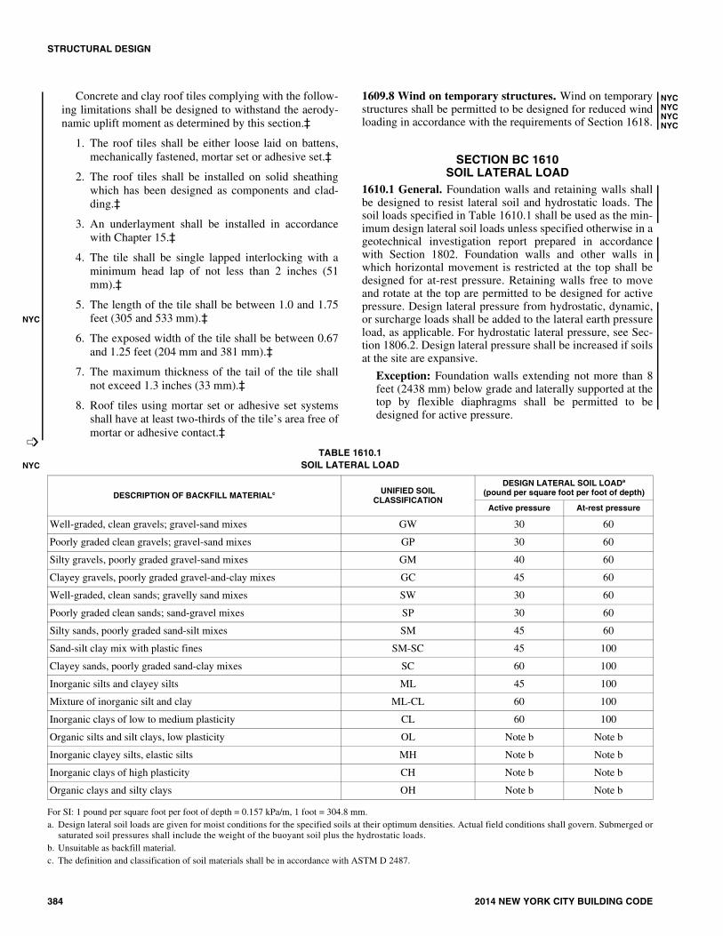
STRUCTURAL DESIGN
384 2014 NEW YORK CITY BUILDING CODE
Concrete and clay roof tiles complying with the follow-ing limitations shall be designed to withstand the aerody-namic uplift moment as determined by this section.‡
1. The roof tiles shall be either loose laid on battens,mechanically fastened, mortar set or adhesive set.‡
2. The roof tiles shall be installed on solid sheathingwhich has been designed as components and clad-ding.‡
3. An underlayment shall be installed in accordancewith Chapter 15.‡
4. The tile shall be single lapped interlocking with aminimum head lap of not less than 2 inches (51mm).‡
5. The length of the tile shall be between 1.0 and 1.75feet (305 and 533 mm).‡
6. The exposed width of the tile shall be between 0.67and 1.25 feet (204 mm and 381 mm).‡
7. The maximum thickness of the tail of the tile shallnot exceed 1.3 inches (33 mm).‡
8. Roof tiles using mortar set or adhesive set systemsshall have at least two-thirds of the tile’s area free ofmortar or adhesive contact.‡
1609.8 Wind on temporary structures. Wind on temporarystructures shall be permitted to be designed for reduced windloading in accordance with the requirements of Section 1618.
SECTION BC 1610SOIL LATERAL LOAD
1610.1 General. Foundation walls and retaining walls shallbe designed to resist lateral soil and hydrostatic loads. Thesoil loads specified in Table 1610.1 shall be used as the min-imum design lateral soil loads unless specified otherwise in ageotechnical investigation report prepared in accordancewith Section 1802. Foundation walls and other walls inwhich horizontal movement is restricted at the top shall bedesigned for at-rest pressure. Retaining walls free to moveand rotate at the top are permitted to be designed for activepressure. Design lateral pressure from hydrostatic, dynamic,or surcharge loads shall be added to the lateral earth pressureload, as applicable. For hydrostatic lateral pressure, see Sec-tion 1806.2. Design lateral pressure shall be increased if soilsat the site are expansive.
Exception: Foundation walls extending not more than 8feet (2438 mm) below grade and laterally supported at thetop by flexible diaphragms shall be permitted to bedesigned for active pressure.
TABLE 1610.1SOIL LATERAL LOAD
For SI: 1 pound per square foot per foot of depth = 0.157 kPa/m, 1 foot = 304.8 mm.a. Design lateral soil loads are given for moist conditions for the specified soils at their optimum densities. Actual field conditions shall govern. Submerged or
saturated soil pressures shall include the weight of the buoyant soil plus the hydrostatic loads.b. Unsuitable as backfill material.c. The definition and classification of soil materials shall be in accordance with ASTM D 2487.
NYC
�
NYCNYCNYCNYC
DESCRIPTION OF BACKFILL MATERIALc UNIFIED SOILCLASSIFICATION
DESIGN LATERAL SOIL LOADa
(pound per square foot per foot of depth)
Active pressure At-rest pressure
Well-graded, clean gravels; gravel-sand mixes GW 30 60
Poorly graded clean gravels; gravel-sand mixes GP 30 60
Silty gravels, poorly graded gravel-sand mixes GM 40 60
Clayey gravels, poorly graded gravel-and-clay mixes GC 45 60
Well-graded, clean sands; gravelly sand mixes SW 30 60
Poorly graded clean sands; sand-gravel mixes SP 30 60
Silty sands, poorly graded sand-silt mixes SM 45 60
Sand-silt clay mix with plastic fines SM-SC 45 100
Clayey sands, poorly graded sand-clay mixes SC 60 100
Inorganic silts and clayey silts ML 45 100
Mixture of inorganic silt and clay ML-CL 60 100
Inorganic clays of low to medium plasticity CL 60 100
Organic silts and silt clays, low plasticity OL Note b Note b
Inorganic clayey silts, elastic silts MH Note b Note b
Inorganic clays of high plasticity CH Note b Note b
Organic clays and silty clays OH Note b Note b
NYC
STRUCTURAL DESIGN
2014 NEW YORK CITY BUILDING CODE 385
SECTION BC 1611RAIN LOADS
1611.1 Design rain loads. Each portion of a roof shall bedesigned to sustain the load of rainwater that will accumulateon it if the primary drainage system for that portion isblocked plus the uniform load caused by water that risesabove the inlet of the secondary drainage system at its designflow.
R = 5.2 (ds + dh) (Equation 16-46)
For SI: R =0.0098 (ds = dh)
where:
dh = Additional depth of water on the undeflected roofabove the inlet of secondary drainage system at itsdesign flow (i.e., the hydraulic head), in inches (mm).
ds = Depth of water on the undeflected roof up to the inletof‡ secondary drainage system when the primarydrainage system is blocked (i.e., the static head), ininches (mm).
R = Rain load on the undeflected roof, in psf (kN/m2).When the phrase “undeflected roof” is used,deflections from loads (including dead loads) shall notbe considered when determining the amount of rain onthe roof.
1611.2 Ponding instability. For roofs with a slope less than1/4 inch per foot [1.19 degrees (0.0208 rad)], the design calcu-lations shall include verification of adequate stiffness to pre-clude progressive deflection in accordance with Section 8.4of ASCE 7.
1611.3 Controlled drainage. Roofs equipped with hardwareto control the rate of drainage shall be equipped with a sec-ondary drainage system at a higher elevation that limitsaccumulation of water on the roof above that elevation. Suchroofs shall be designed to sustain the load of rainwater thatwill accumulate on them to the elevation of the secondarydrainage system plus the uniform load caused by water thatrises above the inlet of the secondary drainage system at itsdesign flow determined from Section 1611.1. Such roofsshall also be checked for ponding instability in accordancewith Section 1611.2.
SECTION BC 1612FLOOD LOADS
1612.1 General. The requirements for flood loads shall be asspecified in Appendix G of this code.
1612.2 Reserved.
1612.3 Reserved.
1612.4 Reserved.
1612.5 Reserved.
SECTION BC 1613EARTHQUAKE LOADS
1613.1 Scope. Every structure, and portion thereof, includingnonstructural components that are permanently attached to
structures and their supports and attachments, shall bedesigned and constructed to resist the effects of earthquakemotions in accordance with ASCE 7-10, excluding Chapter14 and Appendix 11A. The seismic design category for astructure shall be determined in accordance with either Sec-tion 1613 or ASCE 7-10.
Exceptions:
1. One- and two-family dwellings three stories or lessin height.
2. The seismic-force-resisting system of wood-framebuildings that conform to the provisions of Section2308.
3. Agricultural storage structures intended only forincidental human occupancy.
4. Structures that require special consideration of theirresponse characteristics and environment that arenot addressed by this code or ASCE 7-10 and forwhich other regulations provide seismic criteria,such as vehicular bridges, electrical transmissiontowers, hydraulic structures, buried utility lines andtheir appurtenances and nuclear reactors.
1613.1.1 Seismic importance factor. The value for theseismic load importance factor, I, used in the calculationof E shall be determined in accordance with Table1604.5.2 based on the Risk Category determined in accor-dance with Table 1604.5.
1613.2‡ Definitions. The following words and terms shall,for the purposes of this section, have the meanings shownherein.
DESIGN EARTHQUAKE GROUND MOTION.‡ Theearthquake ground motion that buildings and structures arespecifically proportioned to resist in Section 1613.
MAXIMUM CONSIDERED EARTHQUAKE (MCE)GROUND MOTION‡. The most severe earthquake effectsconsidered by this standard more specifically defined in thefollowing two terms.
MAXIMUM CONSIDERED EARTHQUAKE GEO-METRIC MEAN (MCEG) PEAK GROUND ACCELER-ATIONS. The most severe earthquake effects considered bythis standard determined for geometric mean peak groundacceleration and without adjustment for targeted risk. TheMCEG peak ground acceleration adjusted for site effects(PGAM) is used in this standard for evaluation of liquefaction,lateral spreading, seismic settlements, and other soil-relatedissues. The PGAM values adjusted for site effects are pro-vided in Table 1813.2.1 or can be derived from the site-spe-cific procedures provided in Section 21.5 of ASCE 7-10.
RISK-TARGETED MAXIMUM CONSIDEREDEARTHQUAKE (MCER) GROUND MOTIONRESPONSE ACCELERATIONS. The most severe earth-quake effects considered by this standard determined for theorientation that results in the largest maximum response forhorizontal ground motions and with adjustment for targetedrisk. The MCER Ground Motion values can be determinedfrom general procedure in Section 1613.5.3 or can be derived
NYC
�
NYCNYC
C�NYCNYCNYCNYCNYCNYCNYC
NYC
NYCNYC
NYCNYC
NYC
NYC
NYCNYCNYCNYCNYCNYC
�
�
NYC
NYCNYCNYCNYCNYCNYCNYCNYCNYCNYCNYCNYCNYCNYCNYCNYCNYCNYCNYCNYCNYCNYCNYCNYCNYCNYCNYCNYCNYCNYCNYC

STRUCTURAL DESIGN
386 2014 NEW YORK CITY BUILDING CODE
from the site specific procedures provided in Sections 21.1and 21.2 of ASCE 7-10.
MECHANICAL SYSTEMS. For the purposes of determin-ing seismic loads in ASCE 7-10, mechanical systems shallalso include fire protection, plumbing and fuel gas systems asspecified therein.
ORTHOGONAL. To be in two horizontal directions, at 90degrees (1.57 rad) to each other.
SEISMIC DESIGN CATEGORY. A classificationassigned to a structure based on its risk category and theseverity of the design earthquake ground motion at the site.
SEISMIC-FORCE-RESISTING SYSTEM. The part of thestructural system that has been considered in the design toprovide the required resistance to the prescribed seismicforces.
SITE CLASS. A classification assigned to a site based onthe types of soils present and their engineering properties asdefined in Section 1613.5.2.
SITE COEFFICIENTS. The values of, Fa, and, Fv, indi-cated in Tables 1613.5.3(1) and 1613.5.3(2), respectively.
1613.3 Reserved.
1613.4 Reserved.
1613.5 Seismic ground motion values. Seismic groundmotion values shall be determined in accordance with thissection.
1613.5.1 Mapped acceleration parameters. The mappedmaximum considered earthquake spectral response accel-eration at short periods (SS) shall be 0.281 g and at 1-sec-ond period (S1) shall be 0.073 g. The mapped long-periodtransition period (TL) shall l be 6 seconds.
1613.5.2 Site class definitions. Based on the site soilproperties, the site shall be classified as either Site ClassA, B, C, D, E or F in accordance with Table 1613.5.2.Where the soil properties are not known in sufficient detailto determine the site class, Site Class D shall be usedunless the commissioner or geotechnical data determinesthat Site Class E or F soil is present at the site.
1613.5.3 Site coefficients and risk-targeted maximumconsidered earthquake (MCER) spectral responseacceleration parameters. The MCER spectral responseacceleration parameters for short periods, SMS, and at 1-second period, SM1, adjusted for site class effects shall bedetermined by Equations 16-47 and 16-48, respectively:‡
SMS = FaSS (Equation 16-47)‡
SM1 = FvS1 (Equation 16-48)‡
where:‡
Fa = Site coefficient defined in Table 1613.5.3(1).‡
Fv = Site coefficient defined in Table 1613.5.3(2).‡
SS = The mapped MCER spectral accelerations for shortperiods as determined in Section 1613.5.1.‡
S1 = The mapped MCER spectral accelerations for a 1-second period as determined in Section 1613.5.1.‡
NYCNYC
NYCNYC
�
NYC
NYC
�
�NYC�
NYC
�
NYCNYCNYCNYCNYCNYCNYC
NYC
NYC
NYCNYCNYCNYCNYCNYCNYC
C
NYC
NYC
NYC
TABLE 1613.5.2SITE CLASS DEFINITIONS
For SI:1 foot = 304.8 mm, 1 square foot = 0.0929 m2, 1 pound per square foot = 0.0479 kPa. N/A = Not applicable.
SITE CLASS SOIL PROFILE NAME
AVERAGE PROPERTIES IN TOP 100 feet, AS PER SECTION 1615.1.5
Soil shear wave velocity, vs, (ft/s)
Standard penetrationresistance, N
Soil undrainedshear strength, su, (psf)
A Hard rock vs > 5,000 N/A N/A
B Rock 2,500 < vs ≤ 5,000 N/A N/A
C Very dense soil and soft rock 1,200 < vs ≤ 2,500 N > 50 su ≥ 2,000
D Stiff soil profile 600 ≤ vs ≤ 1,200 15 ≤ N ≤ 50 1,000 ≤ su ≤ 2,000
E Stiff soil profile vs < 600 N < 15 su < 1,000
E —
Any profile with more than 10 feet of soil having the following characteristics: 1. Plasticity index PI > 20,
2. Moisture content w ≥ 40%, and
3. Undrained shear strength < 500 psf.
F —
Any profile containing soils having one or more of the following characteristics:
1. Soils vulnerable to potential failure or collapse under seismic loading such as liquefiable soils, quick and highly sensitive clays, collapsible weakly cemented soils.
2. Peats and/or highly organic clays (H > 10 feet of peat and/or highly organic clay where H = thickness of soil).
3. Very high plasticity clays (H > 25 feet with plasticity index PI >75).
4. Very thick soft/medium stiff clays (H > 120 feet).
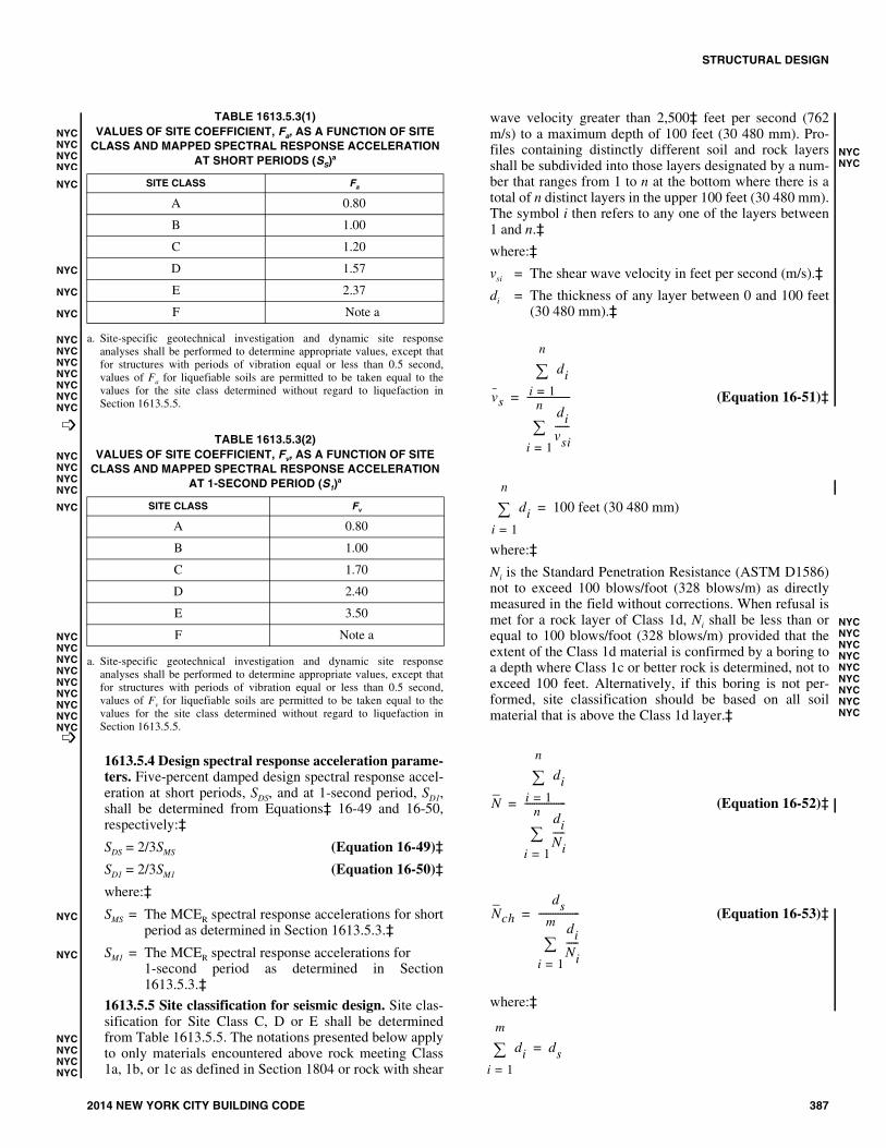
STRUCTURAL DESIGN
2014 NEW YORK CITY BUILDING CODE 387
TABLE 1613.5.3(1)VALUES OF SITE COEFFICIENT, Fa, AS A FUNCTION OF SITE
CLASS AND MAPPED SPECTRAL RESPONSE ACCELERATIONAT SHORT PERIODS (SS)a
a. Site-specific geotechnical investigation and dynamic site responseanalyses shall be performed to determine appropriate values, except thatfor structures with periods of vibration equal or less than 0.5 second,values of Fa for liquefiable soils are permitted to be taken equal to thevalues for the site class determined without regard to liquefaction inSection 1613.5.5.
TABLE 1613.5.3(2)VALUES OF SITE COEFFICIENT, Fv, AS A FUNCTION OF SITE
CLASS AND MAPPED SPECTRAL RESPONSE ACCELERATIONAT 1-SECOND PERIOD (S1)
a
a. Site-specific geotechnical investigation and dynamic site responseanalyses shall be performed to determine appropriate values, except thatfor structures with periods of vibration equal or less than 0.5 second,values of Fv for liquefiable soils are permitted to be taken equal to thevalues for the site class determined without regard to liquefaction inSection 1613.5.5.
1613.5.4 Design spectral response acceleration parame-ters. Five-percent damped design spectral response accel-eration at short periods, SDS, and at 1-second period, SD1,shall be determined from Equations‡ 16-49 and 16-50,respectively:‡
SDS = 2/3SMS (Equation 16-49)‡
SD1 = 2/3SM1 (Equation 16-50)‡
where:‡
SMS = The MCER spectral response accelerations for shortperiod as determined in Section 1613.5.3.‡
SM1 = The MCER spectral response accelerations for 1-second period as determined in Section1613.5.3.‡
1613.5.5 Site classification for seismic design. Site clas-sification for Site Class C, D or E shall be determinedfrom Table 1613.5.5. The notations presented below applyto only materials encountered above rock meeting Class1a, 1b, or 1c as defined in Section 1804 or rock with shear
wave velocity greater than 2,500‡ feet per second (762m/s) to a maximum depth of 100 feet (30 480 mm). Pro-files containing distinctly different soil and rock layersshall be subdivided into those layers designated by a num-ber that ranges from 1 to n at the bottom where there is atotal of n distinct layers in the upper 100 feet (30 480 mm).The symbol i then refers to any one of the layers between1 and n.‡
where:‡
vsi = The shear wave velocity in feet per second (m/s).‡
di = The thickness of any layer between 0 and 100 feet(30 480 mm).‡
(Equation 16-51)‡
where:‡
Ni is the Standard Penetration Resistance (ASTM D1586)not to exceed 100 blows/foot (328 blows/m) as directlymeasured in the field without corrections. When refusal ismet for a rock layer of Class 1d, Ni shall be less than orequal to 100 blows/foot (328 blows/m) provided that theextent of the Class 1d material is confirmed by a boring toa depth where Class 1c or better rock is determined, not toexceed 100 feet. Alternatively, if this boring is not per-formed, site classification should be based on all soilmaterial that is above the Class 1d layer.‡
(Equation 16-52)‡
(Equation 16-53)‡
where:‡
SITE CLASS Fa
A 0.80
B 1.00
C 1.20
D 1.57
E 2.37
F Note a
SITE CLASS Fv
A 0.80
B 1.00
C 1.70
D 2.40
E 3.50
F Note a
NYCNYCNYCNYC
NYC
NYC
NYC
NYC
NYCNYCNYCNYCNYCNYCNYC
�
NYCNYCNYCNYC
NYC
NYCNYCNYCNYCNYCNYCNYCNYCNYC�
NYC
NYC
NYCNYCNYCNYC
NYCNYC
vs
dii 1=
n
divsi------
i 1=
n
------------------=
dii 1=
n
100 feet (30 480 mm)=
NYCNYCNYCNYCNYCNYCNYCNYCNYC
C
N
dii 1=
n
diNi-----
i 1=
n
-----------------=
Nch
ds
diNi-----
i 1=
m
-----------------=
dii 1=
m
ds=
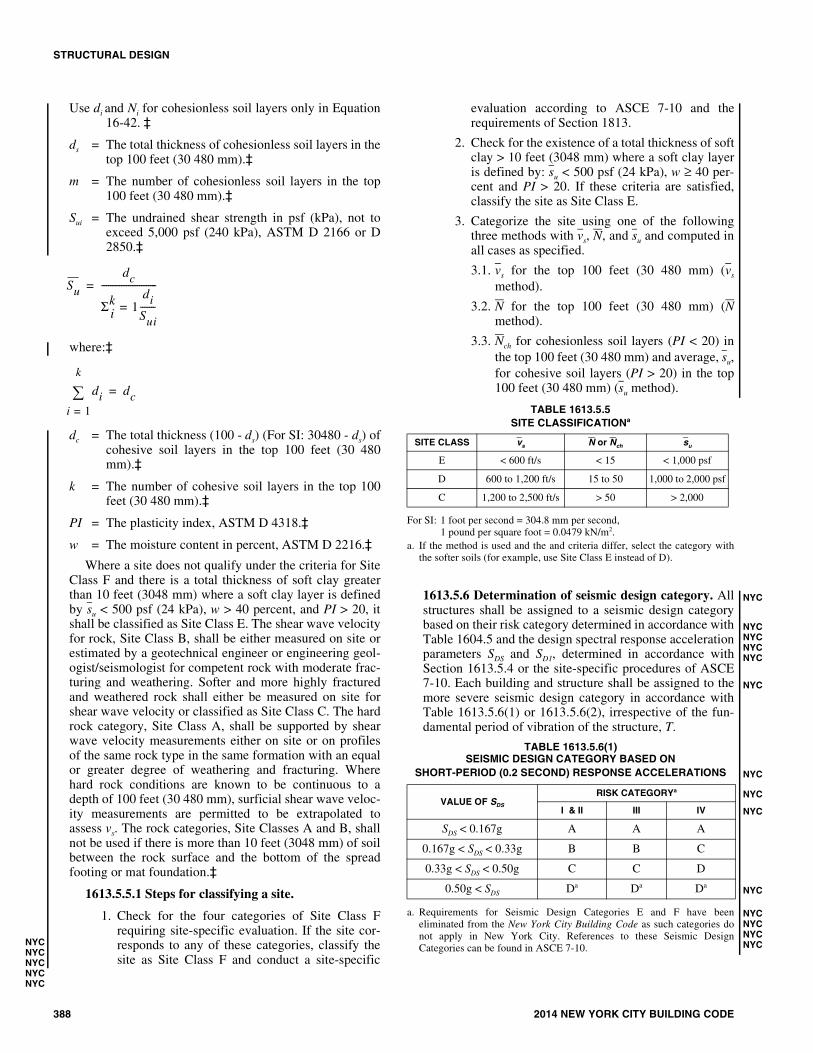
STRUCTURAL DESIGN
388 2014 NEW YORK CITY BUILDING CODE
Use di and Ni for cohesionless soil layers only in Equation16-42. ‡
ds = The total thickness of cohesionless soil layers in thetop 100 feet (30 480 mm).‡
m = The number of cohesionless soil layers in the top100 feet (30 480 mm).‡
Sui = The undrained shear strength in psf (kPa), not toexceed 5,000 psf (240 kPa), ASTM D 2166 or D2850.‡
where:‡
dc = The total thickness (100 - ds) (For SI: 30480 - ds) ofcohesive soil layers in the top 100 feet (30 480mm).‡
k = The number of cohesive soil layers in the top 100feet (30 480 mm).‡
PI = The plasticity index, ASTM D 4318.‡
w = The moisture content in percent, ASTM D 2216.‡
Where a site does not qualify under the criteria for SiteClass F and there is a total thickness of soft clay greaterthan 10 feet (3048 mm) where a soft clay layer is definedby su < 500 psf (24 kPa), w > 40 percent, and PI > 20, itshall be classified as Site Class E. The shear wave velocityfor rock, Site Class B, shall be either measured on site orestimated by a geotechnical engineer or engineering geol-ogist/seismologist for competent rock with moderate frac-turing and weathering. Softer and more highly fracturedand weathered rock shall either be measured on site forshear wave velocity or classified as Site Class C. The hardrock category, Site Class A, shall be supported by shearwave velocity measurements either on site or on profilesof the same rock type in the same formation with an equalor greater degree of weathering and fracturing. Wherehard rock conditions are known to be continuous to adepth of 100 feet (30 480 mm), surficial shear wave veloc-ity measurements are permitted to be extrapolated toassess vs. The rock categories, Site Classes A and B, shallnot be used if there is more than 10 feet (3048 mm) of soilbetween the rock surface and the bottom of the spreadfooting or mat foundation.‡
1613.5.5.1 Steps for classifying a site.
1. Check for the four categories of Site Class Frequiring site-specific evaluation. If the site cor-responds to any of these categories, classify thesite as Site Class F and conduct a site-specific
evaluation according to ASCE 7-10 and therequirements of Section 1813.
2. Check for the existence of a total thickness of softclay > 10 feet (3048 mm) where a soft clay layeris defined by: su < 500 psf (24 kPa), w ≥ 40 per-cent and PI > 20. If these criteria are satisfied,classify the site as Site Class E.
3. Categorize the site using one of the followingthree methods with vs, N, and su and computed inall cases as specified.
3.1. vs for the top 100 feet (30 480 mm) (vs
method).
3.2. N for the top 100 feet (30 480 mm) (Nmethod).
3.3. Nch for cohesionless soil layers (PI < 20) inthe top 100 feet (30 480 mm) and average, su,for cohesive soil layers (PI > 20) in the top100 feet (30 480 mm) (su method).
TABLE 1613.5.5SITE CLASSIFICATIONa
For SI: 1 foot per second = 304.8 mm per second,1 pound per square foot = 0.0479 kN/m2.
a. If the method is used and the and criteria differ, select the category withthe softer soils (for example, use Site Class E instead of D).
1613.5.6 Determination of seismic design category. Allstructures shall be assigned to a seismic design categorybased on their risk category determined in accordance withTable 1604.5 and the design spectral response accelerationparameters SDS and SD1, determined in accordance withSection 1613.5.4 or the site-specific procedures of ASCE7-10. Each building and structure shall be assigned to themore severe seismic design category in accordance withTable 1613.5.6(1) or 1613.5.6(2), irrespective of the fun-damental period of vibration of the structure, T.
TABLE 1613.5.6(1)SEISMIC DESIGN CATEGORY BASED ON
SHORT-PERIOD (0.2 SECOND) RESPONSE ACCELERATIONS
a. Requirements for Seismic Design Categories E and F have beeneliminated from the New York City Building Code as such categories donot apply in New York City. References to these Seismic DesignCategories can be found in ASCE 7-10.
Su
dc
Σki 1
diSui-------=
-------------------------=
dii 1=
k
dc=
NYCNYCNYCNYCNYC
SITE CLASS vs N or Nch su
E < 600 ft/s < 15 < 1,000 psf
D 600 to 1,200 ft/s 15 to 50 1,000 to 2,000 psf
C 1,200 to 2,500 ft/s > 50 > 2,000
VALUE OF SDS
RISK CATEGORYa
I & II III IV
SDS < 0.167g A A A
0.167g < SDS < 0.33g B B C
0.33g < SDS < 0.50g C C D
0.50g < SDS Da Da Da
NYC
NYCNYCNYCNYC
NYC
NYC
NYC
NYC
NYC
NYCNYCNYCNYC

STRUCTURAL DESIGN
2014 NEW YORK CITY BUILDING CODE 389
TABLE 1613.5.6(2)SEISMIC DESIGN CATEGORY BASED ON
1-SECOND PERIOD RESPONSE ACCELERATION
a. Requirements for Seismic Design Categories E and F have beeneliminated from the New York City Building Code as such categories donot apply in New York City. References to these Seismic DesignCategories can be found in ASCE 7-10.
1613.5.6.1 Alternative seismic design category deter-mination. The seismic design category is permitted tobe determined from Table 1613.5.6(1) alone when allof the following apply:
1. In each of the two orthogonal directions, theapproximate fundamental period of the structure,Ta, as determined in accordance with Section12.8.2.1 of ASCE 7-10, is less than 0.8 Ts, asdetermined in accordance with Section 11.4.5 ofASCE 7-10.
2. In each of the two orthogonal directions, the fun-damental period of the structure used to calculatethe story drift is less than Ts.
3. Equation 12.8-2 of ASCE 7-10 is used to deter-mine the seismic response coefficient, Cs.
4. The diaphragms are rigid, as defined in Section12.3.1 of ASCE 7-10 or, for diaphragms that areflexible, the distances between the vertical ele-ments of the seismic-force-resisting system donot exceed 40 feet (12 192 mm).
1613.5.6.2 Simplified design procedure. Where thealternate simplified design procedure of ASCE 7-10 isused, the seismic design category shall be determinedin accordance with ASCE 7-10.
1613.6 Alternatives to ASCE 7-10. The provisions of Sec-tion 1613.6 shall be permitted as alternatives to the relevantprovisions of ASCE 7-10.
1613.6.1 Additional seismic-force-resisting systems forseismically isolated structures. Add the following excep-tion to the end of Section 17.5.4.2 of ASCE 7-10:
Exception: For isolated structures designed in accor-dance with this standard, the Structural System Limita-tions and the Structural Height Limits in Table 1613.8for ordinary steel concentrically braced frames(OCBFs) as defined in Chapter 11 of ASCE 7-10 andordinary moment frames (OMFs) as defined in Chapter11 of ASCE 7-10 are permitted to be taken as 160 feet(48 768 mm) for structures assigned to Seismic DesignCategory D, provided that the following conditions aresatisfied:
1. The value of R1 as defined in Chapter 17 ofASCE 7-10 is taken as 1.
2. For OMFs and OCBFs, design is in accordancewith AISC 341.
1613.7 Structural separations. All structures shall be sepa-rated from adjacent structures. When a structure adjoins aproperty line not common to a public way (typically side orrear lot lines), that structure shall also be set back from theproperty line by at least 1 inch (25 mm) for each 50 feet (15240 mm) of height and a minimum of 1 inch (25 mm) forstructures with heights less than 50 feet (15 240 mm). Forstructures in Seismic Design Category D, refer to ASCE 7-10for additional requirements.
Exception: Smaller separations or property line setbacksshall be permitted when justified by rational analysisbased on maximum expected ground motions with a mini-mum separation of 1 inch (25 mm) along the full height ofthe structure.
1613.7.1 Masonry structures. For structures adjacent toexisting unreinforced masonry bearing wall structures, thestructural separation shall be filed with a material with aminimum compressive strength of 25 psi (172.37 kPa) anda maximum compressive strength of 100 psi (689.74 kPa).Additionally, when the adjacent wall is a party wall, theparty wall shall be made secure by the party responsiblefor the new construction as per Chapter 33.
1613.7.2 Covers. The infill material shall be covered onall sides and shall meet the appropriate provisions ofChapter 26. The covering must be of adequate strength toresist the wind loads for cladding as specified in Chapter16 and shall conform to all applicable provisions in Chap-ter 14.
1613.7.3 Covers wider than 5 inches (127 mm). When abuilding separation wider than 5 inches (127 mm) is cre-ated pursuant to Section 1613.7, such separation, at theroof level of the proposed new building, or at the rooflevel of an existing adjoining building where if that build-ing is lower than the proposed new building, shall have ahorizontal cover/closure that conforms with the following:
1. The cover/closure material shall be noncombustible;and
Exception: The cover/closure material used shallbe permitted to be combustible material in accor-dance with Section 1509.9 if all the material onthe appropriate roof conforms to the limitationstherein, there are no masonry openings in eitherwall abutting the building separation, and bothbuildings are noncombustible.
2. The cover/closure shall be capable of withstandingthe roof live load of 30 psf (1.43 kPa), securely fas-tened to the new building, and be of a type thatwould be capable of preventing unauthorized oraccidental access to the space.
1613.8 ASCE 7-10, Table 12.2-1. Modify ASCE 7-10, Table12.2-1 as follows:
VALUE OF SD1
RISK CATEGORYa
I & II III IV
SD1 < 0.067g A A A
0.067g < SD1 < 0.133g B B C
0.133g < SD1 < 0.20g C C D
0.20g ≤ SD1 Da Da Da
NYC
NYC
NYC
NYCNYCNYCNYCNYC
NYC
NYC
NYC
NYC
NYC
NYC
NYC
NYC
NYC
NYC�
NYC
NYC
NYC
NYC
NYC�
NYCNYCNYCNYCNYCNYCNYCNYCNYCNYCNYCNYC�
NYCNYCNYCNYCNYCNYC
�
NYCNYCNYCNYCNYCNYCNYCNYCNYCNYCNYCNYCNYCNYCNYCNYCNYCNYCNYCNYCNYCNYCNYCNYCNYCNYCNYCNYCNYCNYCNYCNYCNYCNYCNYCNYCNYCNYCNYCNYCNYCNYCNYCNYCNYCNYCNYCNYCNYCNYCNYCNYCNYCNYCNYCNYC

STRUCTURAL DESIGN
390 2014 NEW YORK CITY BUILDING CODE
NYCNYCNYCNYCNYCNYCNYCNYCNYCNYCNYCNYCNYCNYCNYCNYCNYCNYCNYCNYCNYCNYCNYCNYCNYCNYCNYCNYCNYCNYCNYCNYCNYCNYCNYCNYCNYCNYCNYCNYCNYCNYCNYCNYCNYCNYCNYCNYCNYCNYCNYCNYCNYCNYCNYCNYCNYCNYCNYCNYCNYCNYCNYCNYCNYCNYCNYCNYCNYCNYCNYCNYCNYCNYCNYCNYCNYCNYCNYCNYCNYCNYCNYC
TABLE 1613.8DESIGN COEFFICIENT AND FACTORS FOR BASIC SEISMIC C-FORCE-RESISTING SYSTEMS
STRUCTURAL SYSTEM LIMITATIONS INCLUDING
STRUCTURAL HEIGHT, Hn (FT), LIMITSC
Seismic Force-Resisting System
ASCE 7-10 Section Where Detailing
Requirements Are Specified
Response Modification Coefficient
Overstrength Factor
Deflection Amplification
FactorSeismic Design Category
A. BEARING WALL SYSTEMS Ra Ω0g Cd
b B C Dd
1.Special reinforced concrete shear walls l,m 14.2 5 2.5 5 NL NL NL
2.Ordinary reinforced concrete shear walls l 14.2 4 2.5 4 NL NL NP
3. Detailed plain concrete shear walls l 14.2 2 2.5 2 NL NP NP
4. Ordinary plain concrete shear walls l 14.2 1.5 2.5 1.5 NL NP NP
5. Intermediate precast shear walls l 14.2 4 2.5 4 NL NL 40k
6. Ordinary precast shear walls l 14.2 3 2.5 3 NL NP NP
7. Special reinforced masonry shear walls 14.4 5 2.5 3.5 NL NL NL
8. Intermediate reinforced masonry shear walls 14.4 3.5 2.5 2.25 NL NL NP
9. Ordinary reinforced masonry shear walls 14.4 2 2.5 1.75 NL NL NP
10. Detailed plain masonry shear walls 14.4 2 2.5 1.75 NL NP NP
11. Ordinary plain masonry shear walls 14.4 1.5 2.5 1.25 NL NP NP
12. Prestressed masonry shear walls 14.4 1.5 2.5 1.75 NL NP NP
13. Ordinary reinforced Autoclaved AeratedConcrete (AAC) masonry shear walls 14.4 2 2.5 2 NL 35 NP
14. Ordinary plain (unreinforced) AutoclavedAerated Concrete (AAC) masonry shear walls 14.4 1.5 2.5 1.5 NL NP NP
15. Light-frame (wood) walls sheathed with woodstructural panels rated for shear resistance orsteel sheets
14.1 and 14.5 6.5 3 4 NL NL 65
16. Light-frame (cold-formed steel) walls sheathedwith wood structural panels rated for shearresistance or steel sheets
14.1 6.5 3 4 NL NL 65
17. Light-frame walls with shear panels of allother materials 14.1 and 14.5 2 2.5 2 NL NL 35
18. Light-frame (cold-formed steel) wall systemsusing flat strap bracing 14.1 4 2 3.5 NL NL 65
B. BUILDING FRAME SYSTEMS Ra Ω0g Cd
b B C Dd
1. Steel eccentrically braced frames 14.1 8 2 4 NL NL NL
2. Steel special concentrically braced frames 14.1 6 2 5 NL NL NL
3. Steel ordinary concentrically braced frames 14.1 3.25 2 3.25 NL NL 35j
4. Special reinforced concrete shear walls l,m 14.2 6 2.5 5 NL NL NL
5. Ordinary reinforced concrete shear walls l 14.2 5 2.5 4.5 NL NL NP
6. Detailed plain concrete shear walls l 14.2 and 14.2.2.8 2 2.5 2 NL NP NP
7. Ordinary plain concrete shear walls l 14.2 1.5 2.5 1.5 NL NP NP
8. Intermediate precast shear walls l 14.2 5 2.5 4.5 NL NL 40k
9. Ordinary precast shear walls l 14.2 4 2.5 4 NL NP NP
10. Steel and concrete composite eccentrically braced frames 14.3 8 2 4 NL NL NL
11. Steel and concrete composite special concentrically braced frames 14.3 5 2 4.5 NL NL NL
12. Steel and concrete composite ordinary braced frames 14.3 3 2 3 NL NL NP
13. Steel and concrete composite plate shear walls 14.3 6.5 2.5 5.5 NL NL NL
14. Steel and concrete composite special shearwalls
14.3 6 2.5 5 NL NL NL
15. Steel and concrete composite ordinary shearwalls
14.3 5 2.5 4.5 NL NL NP
(continued)

STRUCTURAL DESIGN
2014 NEW YORK CITY BUILDING CODE 391
16. Special reinforced masonry shear walls 14.4 5.5 2.5 4 NL NL NL
17. Intermediate reinforced masonry shear walls 14.4 4 2.5 4 NL NL NP
18. Ordinary reinforced masonry shear walls 14.4 2 2.5 2 NL NL NP
19. Detailed plain masonry shear walls 14.4 2 2.5 2 NL NP NP
20. Ordinary plain masonry shear walls 14.4 1.5 2.5 1.25 NL NP NP
21. Prestressed masonry shear walls 14.4 1.5 2.5 1.75 NL NP NP
22. Light-frame (wood) walls sheathed with wood structural panels rated for shear resistance
14.5 7 2.5 4.5 NL NL 65
23. Light-frame (cold-formed steel) walls sheathedwith wood structural panels rated for shearresistance or steel sheets
14.1 7 2.5 4.5 NL NL 65
24. Light-frame walls with shear panels of allother materials
14.1 and 14.5 2.5 2.5 2.5 NL NL 35
25. Steel buckling-restrained braced frames 14.1 8 2.5 5 NL NL NL
26. Steel special plate shear walls 14.1 7 2 6 NL NL NL
C. MOMENT-RESISTING FRAME SYSTEMS Ra Ω0
g Cdb B C Dd
1. Steel special moment frames 14.1 and 12.2.5.5 8 3 5.5 NL NL NL
2. Steel special truss moment frames 14.1 7 3 5.5 NL NL NL
3. Steel intermediate moment frames 14.1 and 12.2.5.7 4.5 3 4 NL NL 35h
4. Steel ordinary steel moment frames 14.1 and 12.2.5.6 3.5 3 3 NL NL NPi
5. Special reinforced concrete moment frames n 14.2 and 12.2.5.5 8 3 5.5 NL NL NL
6. Intermediate reinforced concrete momentframes
14.2 5 3 4.5 NL NL NP
7. Ordinary reinforced concrete moment frames 14.2 3 3 2.5 NL NP NP
8. Steel and concrete composite special momentframes
14.3 and 12.2.5.5 8 3 5.5 NL NL NL
9.Steel and concrete composite intermediatemoment frames
14.3 5 3 4.5 NL NL NP
10.Steel and concrete composite partiallyrestrained moment frames 14.3 6 3 5.5 NL NL 100
11.Steel and concrete composite ordinary momentframes 14.3 3 3 2.5 NL NP NP
12.Cold-formed steel—special bolted momentframe p 14.1 3.5 3o 3.5 35 35 35
D. DUAL SYSTEMS WITH SPECIAL MOMENT FRAMES CAPABLE OF RESISTING AT LEAST 25% OF PRESCRIBED SEISMIC FORCES
12.2.5.1 Ra Ω0g Cd
b B C Dd
1.Steel eccentrically braced frames 14.1 8 2.5 4 NL NL NL
2.Steel special concentrically braced frames 14.1 7 2.5 5.5 NL NL NL
3.Special reinforced concrete shear walls l 14.2 7 2.5 5.5 NL NL NL
4.Ordinary reinforced concrete shear walls l 14.2 6 2.5 5 NL NL NP
5.Steel and concrete composite eccentricallybraced frames 14.3 8 2.5 4 NL NL NL
6.Steel and concrete composite specialconcentrically braced frames 14.3 6 2.5 5 NL NL NL
7.Steel and concrete composite plate shear walls 14.3 7.5 2.5 6 NL NL NL
8.Steel and concrete composite special shearwalls
14.3 7 2.5 6 NL NL NL
(continued)
TABLE 1613.8DESIGN COEFFICIENT AND FACTORS FOR BASIC SEISMIC C-FORCE-RESISTING SYSTEMS
STRUCTURAL SYSTEM LIMITATIONS INCLUDING
STRUCTURAL HEIGHT, Hn (FT), LIMITSC
Seismic Force-Resisting System
ASCE 7-10 Section Where Detailing
Requirements Are Specified
Response Modification Coefficient
Overstrength Factor
Deflection Amplification
FactorSeismic Design Category
NYCNYCNYCNYCNYCNYCNYCNYCNYCNYCNYCNYCNYCNYCNYCNYCNYCNYCNYCNYCNYCNYCNYCNYCNYCNYCNYCNYCNYCNYCNYCNYCNYCNYCNYCNYCNYCNYCNYCNYCNYCNYCNYCNYCNYCNYCNYCNYCNYCNYCNYCNYCNYCNYCNYCNYCNYCNYCNYCNYCNYCNYCNYCNYCNYCNYCNYCNYCNYCNYCNYCNYCNYCNYCNYCNYCNYCNYCNYCNYCNYCNYCNYCNYC
—continued

STRUCTURAL DESIGN
392 2014 NEW YORK CITY BUILDING CODE
a. Response modification coefficient, R, for use throughout the standard. Note R reduces forces to a strength level, not an allowable stress level.
b. Deflection amplification factor, Cd, for use in Sections 12.8.6, 12.8.7, and 12.9.2 of ASCE 7-10.
c. NL = Not Limited and NP = Not Permitted. For metric units use 30.5 m for 100 ft and use 48.8 m for 160 ft.
d. See Section 12.2.5.4 of ASCE 7-10 for a description of seismic force-resisting systems limited to buildings with a structural height, hn, of 240 ft (73.2 m) orless.
e. See Section 12.2.5.4 of ASCE 7-10 for seismic force-resisting systems limited to buildings with a structural height, hn, of 160 ft (48.8 m) or less.
f. Ordinary moment frame is permitted to be used in lieu of intermediate moment frame for Seismic Design Categories B or C.
g. Where the tabulated value of the overstrength factor, Ω0, is greater than or equal to 21/2, Ω0 is permitted to be reduced by subtracting the value of 1/2 forstructures with flexible diaphragms.
h. See Section 12.2.5.7 of ASCE 7-10 for limitations in structures assigned to Seismic Design Category D.
i. See Section 12.2.5.6 of ASCE 7-10 for limitations in structures assigned to Seismic Design Category D.
(continued)
9.Steel and concrete composite ordinary shearwalls 14.3 6 2.5 5 NL NL NP
10.Special reinforced masonry shear walls 14.4 5.5 3 5 NL NL NL
11.Intermediate reinforced masonry shear walls 14.4 4 3 3.5 NL NL NP
12.Steel buckling-restrained braced frames 14.1 8 2.5 5 NL NL NL
13.Steel special plate shear walls 14.1 8 2.5 6.5 NL NL NL
E. DUAL SYSTEMS WITH INTERMEDIATE MOMENT FRAMES CAPABLE OF RESISTING AT LEAST 25% OF PRESCRIBED SEISMIC FORCES
12.2.5.1 Ra Ω0g Cd
b B C Dd
1. Steel special concentrically braced framesf 14.1 6 2.5 5 NL NL 35
2. Special reinforced concrete shear walls l 14.2 6.5 2.5 5 NL NL NL
3. Ordinary reinforced masonry shear walls 14.4 3 3 2.5 NL NL NP
4. Intermediate reinforced masonry shear walls 14.4 3.5 3 3 NL NL NP
5. Steel and concrete composite specialconcentrically braced frames
14.3 5.5 2.5 4.5 NL NL NL
6. Steel and concrete composite ordinary bracedframes 14.3 3.5 2.5 3 NL NL NP
7. Steel and concrete composite ordinary shearwalls 14.3 5 3 4.5 NL NL NP
8. Ordinary reinforced concrete shear walls l 14.2 5.5 2.5 4.5 NL NL NP
F. SHEAR WALL-FRAME INTERACTIVE SYSTEM WITH ORDINARY REINFORCED CONCRETE MOMENT FRAMES AND ORDINARY REINFORCED CONCRETE SHEAR WALLSl
14.2 and 12.2.5.8 4.5 2.5 4 NL NP NP
G. CANTILEVERED COLUMN SYSTEMS DETAILED TO CONFORM TO THE REQUIREMENTS FOR:
12.2.5.2 Ra Ω0g Cd
b B C Dd
1. Steel special cantilever column systems 14.1 2.5 1.25 2.5 35 35 35
2. Steel ordinary cantilever column systems 14.1 1.25 1.25 1.25 35 35 NPi
3. Special reinforced concrete moment frames n 14.2 and 12.2.5.5 2.5 1.25 2.5 35 35 35
4. Intermediate reinforced concrete momentframes
14.2 1.5 1.25 1.5 35 35 NP
5. Ordinary reinforced concrete moment frames 14.2 1 1.25 1 35 NP NP
6. Timber frames 14.5 1.5 1.5 1.5 35 35 35
H. STEEL SYSTEMS NOT SPECIFICALLY DETAILED FOR SEISMIC RESISTANCE, EXCLUDING CANTILEVER COLUMN SYSTEMS
14.1 3 3 3 NL NL NP
TABLE 1613.8DESIGN COEFFICIENT AND FACTORS FOR BASIC SEISMIC C-FORCE-RESISTING SYSTEMS
STRUCTURAL SYSTEM LIMITATIONS INCLUDING
STRUCTURAL HEIGHT, Hn (FT), LIMITSC
Seismic Force-Resisting System
ASCE 7-10 Section Where Detailing
Requirements Are Specified
Response Modification Coefficient
Overstrength Factor
Deflection Amplification
FactorSeismic Design Category
NYCNYCNYCNYCNYCNYCNYCNYCNYCNYCNYCNYCNYCNYCNYCNYCNYCNYCNYCNYCNYCNYCNYCNYCNYCNYCNYCNYCNYCNYCNYCNYCNYCNYCNYCNYCNYCNYCNYCNYCNYCNYCNYCNYCNYCNYCNYCNYCNYCNYCNYCNYCNYCNYCNYCNYCNYCNYCNYCNYCNYCNYCNYCNYCNYCNYCNYCNYCNYCNYCNYCNYCNYCNYCNYCNYCNYCNYCNYCNYCNYCNYCNYC
—continued

STRUCTURAL DESIGN
2014 NEW YORK CITY BUILDING CODE 393
TABLE 1613.8—continuedDESIGN COEFFICIENT AND FACTORS FOR BASIC SEISMIC C-FORCE-RESISTING SYSTEMS
j. Steel ordinary concentrically braced frames are permitted in single-story buildings up to a structural height, hn, of 60 ft (18.3 m) where the dead load of theroof does not exceed 20 psf (0.96 kN/m2) and in penthouse structures.
k. An increase in structural height, hn, to 45 ft (13.7 m) is permitted for single story storage warehouse facilities.l. In Section 2.2 of ACI 318. A shear wall is defined as a structural wall.m. In Section 2.2 of ACI 318. The definition of “special structural wall” includes precast and cast-in-place construction.n. In Section 2.2 of ACI 318. The definition of “special moment frame” includes precast and cast-in-place construction.o. Alternately, the seismic load effect with overstrength, Emh, is permitted to be based on the expected strength determined in accordance with AISI S110.p. Cold-formed steel – special bolted moment frames shall be limited to one-story in height in accordance with AISI S110.
SECTION BC 1614STRUCTURAL INTEGRITY DEFINITIONS
1614.1 Definitions. The following words and terms shall, forthe purposes of this section, have the meanings shownherein.
ALTERNATE LOAD PATH. A secondary or redundantload path capable of transferring the load from one structuralelement to other structural elements.
ALTERNATE LOAD PATH METHOD. A designapproach that accounts for an extreme event by providingalternate load paths for elements that are no longer able tocarry load. In an alternate load path design, key elements areconsidered notionally removed, one at a time, and the struc-ture is designed to transfer the loads from the removed ele-ment to other structural elements, as required by Section1616.
ASPECT RATIO. The height of any portion of a buildingdivided by its least dimension at the elevation from whichthe height is being measured.
COLLAPSE. Failure of a structural element to the extentthat it can no longer support any load.
ELEMENT. A structural member or structural assembly.
KEY ELEMENT. An element of the structural system,including its connections, that meets one or more of the fol-lowing criteria:
1. An element which when lost, results in more than localcollapse.
2. An element that braces a key element, the failure ofwhich results in failure of the key element (further sec-ondary elements need not be considered key elements).
3. An element whose tributary area exceeds 3,000 squarefeet (279 m2)‡ on a single level.
LOCAL COLLAPSE. Failure of a structural element thatresults in the collapse of areas being directly supported bythat element and not extending vertically more than threestories.
RESPONSE RATIO. The ratio of an ultimate responsequantity (e.g., deflection) to its value at yield.
ROTATION. The angle, measured at the ends of a member,whose tangent is equal to the deflection of the member atmidspan divided by half the length of the member.
SPECIFIC LOCAL LOAD. A load applied to a structuralelement or structural system as specified in Section 1616.7.
SPECIFIC LOCAL RESISTANCE METHOD. A designapproach that accounts for extreme event loads by providingsufficient strength for elements that may fail. In a specificlocal resistance design, key elements are designed for spe-cific local loads as required by Section 1616.
SECTION BC 1615STRUCTURAL INTEGRITY—PRESCRIPTIVE
REQUIREMENTS1615.1 Scope. The intent of these provisions is to enhancestructural performance under extreme event scenarios byproviding additional overall system redundancy and localrobustness. All structures shall be designed to satisfy the pre-scriptive requirements of this section.
Exception: Structures in Structural Occupancy CategoryI of Table 1604.5 and structures in Occupancy Group R-3are exempt from the requirements of Sections 1614through 1616.
1615.2 Continuity and ties. All structural elements shallhave a minimum degree of continuity and shall be tiedtogether horizontally and vertically as specified in Chapters19, 21, and 22 for concrete, masonry and steel, respectively.
1615.3 Lateral bracing. Floor and roof diaphragms or otherhorizontal elements shall be tied to the lateral load-resistingsystem.
1615.4 Reserved.
1615.5 Vehicular impact. Structural columns that aredirectly exposed to vehicular traffic shall be designed forvehicular impact. Structural columns that are adequatelyprotected by bollards, guard walls, vehicle arrest devices orother elements do not need to be designed for vehicularimpact. The load combinations for vehicular impact shall beas specified in Section 1605.6.
Specific loads for vehicular impact shall be as follows:
1. Exterior corner columns shall be designed for a con-centrated load of 40 kips applied horizontally in anydirection from which a vehicle can approach at aheight of either 18 inches (457 mm) or 36 inches (914mm) above the finished driving surface, whichevercreates the worst effect.
2. All other exterior columns exposed to vehicular traffic,and columns within loading docks, and columns inparking garages along the driving lane shall bedesigned for a concentrated load of 20 kips appliedhorizontally in any direction from which a vehicle can
NYCNYCNYCNYCNYCNYCNYCNYCNYCNYCNYCNYCNYC
NYCNYCNYCNYCNYCNYCNYCNYCNYCNYCNYCNYCNYCNYCNYCNYCNYCNYCNYCNYCNYCNYCNYCNYCNYCNYCNYCNYCNYCNYCNYCNYCNYCNYCNYCNYCNYCNYCNYCNYCNYCNYCNYCNYCNYCNYCNYCNYCNYCNYCNYCNYCNYCNYCNYCNYCNYCNYCNYCNYCNYCNYCNYCNYCNYCNYCNYCNYCNYC
�
NYC�
NYC
NYCNYCNYCNYCNYCNYCNYCNYCNYCNYCNYCNYCNYCNYCNYCNYCNYCNYCNYCNYC
�NYCNYCNYCNYC
�NYCNYCNYCNYCNYCNYCNYCNYCNYCNYCNYCNYCNYCNYCNYCNYCNYCNYCNYCNYCNYCNYCNYCNYCNYCNYCNYCNYCNYCNYCNYCNYCNYCNYC

STRUCTURAL DESIGN
394 2014 NEW YORK CITY BUILDING CODE
approach at a height of either 18 inches (457 mm) or36 inches (914 mm) above the finished driving surface,whichever creates the worst effect.
1615.6 Gas explosions. In buildings with gas piping operat-ing at pressures in excess of 15 psig (103 kPa gauge), all keyelements and their connections within 15 feet (4572 mm) ofsuch piping shall be designed to resist a potential gas explo-sion. The structure shall be designed to account for thepotential loss of the affected key elements one at a time bythe alternate load path‡ method. Load combinations for thealternate load path‡ shall be as specified in Section 1605.5.In lieu of the alternate load path method‡, the affected keyelements shall be designed to withstand a load of 430 psf(20.6 kPa) applied using the load combinations specified inSection 1605.6. The load shall be applied along the entirelength of the element, and shall be applied in the manner anddirection that produces the most damaging effect.
Exceptions:
1. If a structural enclosure designed to resist the speci-fied pressure is provided around the high-pressuregas piping, only the key elements within the struc-tural enclosure need to comply with this section.
2. A reduced pressure for gas explosions can be usedbased on an engineering analysis approved by thecommissioner.
1615.6.1 Explosion prevention and deflagration vent-ing. The structural design and installation of explosionprevention systems and deflagration venting shall be inaccordance with the requirements of Appendices E and Gof the New York City Fuel Gas Code, as well as the NewYork City Fire Code, and the rules and regulations of thedepartment.
SECTION BC 1616STRUCTURAL INTEGRITY—KEY ELEMENT
ANALYSIS
1616.1 Scope. A key element analysis shall be performed forthe following buildings:
1. Buildings included in Structural Occupancy CategoryIV as defined in this chapter.
2. Buildings with the aspect ratios of seven or greater.
3. Buildings greater than 600 feet (183 m) in height ormore than 1,000,000 square feet (92 903 m2) in grossfloor area.
4. Buildings taller than seven stories where any element,except for walls greater than 10 feet (3.048 m) inlength, supports in aggregate more than 15 percent ofthe building area.
5. Buildings designed for areas with 3,000 or more occu-pants in one area in close proximity, including fixedseating and grandstand areas.
6. When specifically ordered by the commissioner.
1616.2 Load combinations. Where specifically required bySection 1616.1, elements and components shall be designed
to resist the forces calculated using the combination speci-fied in Section 1605.5 or 1605.7 as applicable.
1616.3 Reserved.
1616.4 Seismic and wind. When the code-prescribed seis-mic or wind design produces greater effects, the seismic orwind design shall govern, but the detailing requirements andlimitations prescribed in this and referenced sections shallalso be followed.
1616.5 Joints. Where a structure is divided by joints thatallow for movement, each portion of the structure betweenjoints shall be considered as a separate structure.
1616.6 Key element analysis. Where key elements are pres-ent in a structure, the structure shall be designed to accountfor their potential loss one at a time by the alternate load pathmethod or by the specific local resistance method as speci-fied in Section 1616.7.
1616.7 The specific local resistance method. Where thespecific local resistance method is used key elements shallbe designed using specific local loads as follows:
1. Each compression element shall be designed for a con-centrated load equal to 2 percent of its axial load butnot less than 15 kips, applied at midspan in any direc-tion, perpendicular to its longitudinal axis. This loadshall be applied in combination with the full dead loadand 50 percent of the live load in the compression ele-ment.
2. Each bending element shall be designed for the combi-nation of the principal acting moments plus an addi-tional moment, equal to 10 percent of the principalacting moment applied in the perpendicular plane.
3. Connections of each tension element shall be designedto develop the smaller of the ultimate tension capacityof the member or three times the force in the member.
4. All structural elements shall be designed for a reversalof load. The reversed load shall be equal to 10 percentof the design load used in sizing the member.
1616.8 Design criteria. Alternate load path method and/orspecific local resistance method for key elements shall con-form to the appropriate design criteria as determined fromSections 1616.9, 1616.10 and 1616.11. Load combinationsfor the alternate load path method shall be as specified inSection 1605.5.
1616.9 Analysis procedures. All structural analysis for spe-cific local loads or alternate load paths shall be made by oneof the following methods:
1616.9.1 Static elastic analysis. For analysis of this type,dynamic effects of member loss or dynamic effects ofspecific local loads need not be considered. The structuraldemand is obtained from linear static analysis. However,structural member capacity is based on ultimate capacityof the entire cross section. The demand/capacity ratio ofstructural elements shall not exceed one.
1616.9.2 Dynamic inelastic analysis. For analysis of thistype, dynamic effects of member loss or specific localloads shall be considered. The structure does not need toremain elastic; however, the response ratio and rotation
NYCNYCNYCNYCNYCNYCNYCNYCNYCNYCNYCNYCNYCNYCNYCNYCNYCNYCNYCNYCNYCNYCNYCNYCNYCNYCNYCNYCNYCNYCNYCNYCNYCNYCNYCNYCNYCNYCNYCNYCNYCNYCNYCNYCNYCNYCNYCNYC
NYCNYCNYCNYCNYCNYCNYCNYCNYCNYCNYCNYCNYCNYCNYCNYCNYCNYCNYCNYCNYCNYCNYCNYCNYCNYCNYCNYCNYCNYCNYCNYCNYCNYCNYC
�
NYCNYCNYCNYCNYCNYCNYCNYCNYCNYCNYCNYCNYCNYCNYCNYCNYCNYCNYCNYCNYCNYCNYCNYCNYCNYCNYCNYCNYCNYCNYCNYCNYCNYCNYCNYCNYCNYCNYCNYCNYCNYCNYCNYCNYCNYCNYCNYCNYCNYCNYCNYCNYCNYCNYCNYCNYCNYCNYCNYCNYCNYCNYCNYCNYCNYCNYCNYCNYCNYCNYCNYCNYCNYCNYCNYCNYCNYCNYCNYCNYCNYCNYCNYC

STRUCTURAL DESIGN
2014 NEW YORK CITY BUILDING CODE 395
limits obtained from Table 1616.9.3 shall not beexceeded.
1616.9.3‡ Energy methods. Static inelastic analysisusing energy equilibrium may also be used. The structuredoes not need to remain elastic; however, the responseratio and rotation limits obtained from Table 1616.9.3shall not be exceeded.
TABLE 1616.9.3RESPONSE RATIO AND ROTATION LIMITS
For SI: 1 degree = 0.01745 rad.Note: Table 1616.9.3 is intended for SDOF and simplified MDOF response
calculations and a low level of protection. Table 1616.9.3 does notapply for explicit finite element methods that calculate the performance ofthe structural elements in response to the specified loading intensity. Steeljoists: downward loading 6 degrees, upward loading ductility of 2.
1616.10 Minimum response. Structural response of ele-ments determined using a dynamic inelastic analysis shallnot be less than 80 percent of the structural response deter-mined using a static elastic analysis.
1616.11 Strength reduction factors. For structural designfor specific local loads or alternate load paths, all strengthreduction factors may be taken as one.
SECTION BC 1617STRUCTURAL PEER REVIEW
1617.1 General. The provisions of this section specifywhere structural peer review is required, how and by whomit is to be performed.
1617.2 Where required. A structural peer review of the pri-mary structure shall be performed a report provided for thefollowing buildings:
1. Buildings included in Structural Occupancy CategoryIV as defined in this chapter and more than 50,000square feet (4645 m2) of framed area.
2. Buildings with aspect ratios of seven or greater.
3. Buildings greater than 600 feet (183 m) in height ormore than 1,000,000 square feet (92 903 m2) in grossfloor area.
4. Buildings taller than seven stories where any element,except for walls greater than 10 feet (3.048 meters) inlength, supports in aggregate more than 15 percent ofthe building area.
5. Buildings designed using nonlinear time history analy-sis or with special seismic energy dissipation systems.
6. ‡Buildings designed for areas with 3,000 or more occu-pants in one area in close proximity, including fixedseating and grandstand areas.
7. ‡Buildings where a structural peer review is requestedby the commissioner.
1617.3 Structural peer review. It shall be verified that thestructural design is in general conformance with the require-ments of this code.
1617.4 Structural peer reviewer. The structural peer reviewshall be performed by a qualified independent structuralengineer who has been retained by or on behalf of the owner.A structural peer reviewer shall meet the requirements of therules of the department.
1617.5 Extent of the structural peer review.
1617.5.1 Scope. The structural peer reviewer shall reviewthe plans and specifications submitted with the permitapplication for general compliance with the structural andfoundation design provisions of this code. The reviewingengineer shall perform the following tasks at a minimum:
1. Confirm that the design loads conform to thiscode.
2. Confirm that other structural design criteria anddesign assumptions conform to this code and arein accordance with generally accepted engineeringpractice.
3. Review geotechnical and other engineering inves-tigations that are related to the foundation andstructural design and confirm that the design prop-erly incorporates the results and recommendationsof the investigations.
4. Review the structural frame and the load support-ing parts of floors, roofs, walls and foundations.Cladding, cladding framing, stairs, equipment sup-ports, ceiling supports, non-loadbearing partitions,railings and guards, and other secondary structuralitems shall be excluded.
5. ‡Confirm that the structure has a complete loadpath.
6. ‡Perform independent calculations for a represen-tative fraction of systems, members, and details tocheck their adequacy. The number of representa-tive systems, members, and details verified shallbe sufficient to form a basis for the reviewer’sconclusions.
7. ‡Verify that performance-specified structuralcomponents (such as certain precast concrete ele-ments) have been appropriately specified andcoordinated with the primary building structure.
8. ‡Verify that the design engineer of record com-plied with the structural integrity provisions of thecode.
9. Review the structural and architectural plans forthe building. Confirm that the structural plans arein general conformance with the architectural
ELEMENT RESPONSE RATIO ROTATION
Concrete slabs µ < 10 < 10 θ < 4°
Post-tensioned beams µ < 2 < 2 θ < 1.5°
Concrete beamsConcrete columns
µ < 20 < 20 θ < 6°
µ < 2 < 2 θ < 6°
Long span acoustical deck µ < 2 < 2 θ < 3°
Open web steel joists µ < 2 < 2 θ < 6°
Steel beams µ < 20 < 20 θ < 10°
Steel columns µ < 5 < 5 θ < 6°
NYCNYCNYCNYCNYCNYCNYCNYCNYCNYCNYCNYCNYCNYCNYCNYCNYCNYCNYCNYCNYCNYCNYCNYCNYCNYCNYCNYCNYCNYCNYCNYCNYCNYCNYCNYCNYCNYCNYCNYCNYCNYCNYCNYCNYCNYCNYCNYCNYCNYCNYCNYCNYCNYCNYCNYCNYCNYCNYCNYCNYCNYCNYCNYCNYCNYCNYCNYCNYCNYCNYCNYCNYCNYCNYCNYCNYCNYCNYCNYCNYCNYCNYCNYCNYC
NYCNYCNYCNYCNYCNYCNYCNYCNYCNYCNYCNYCNYCNYCNYCNYCNYCNYCNYC
NYCNYCNYCNYCNYCNYCNYCNYCNYCNYCNYCNYCNYCNYCNYCNYCNYCNYCNYCNYCNYCNYCNYCNYCNYCNYCNYCNYCNYCNYCNYCNYCNYCNYCNYCNYCNYCNYCNYCNYCNYCNYCNYCNYCNYCNYCNYCNYCNYCNYCNYCNYCNYCNYCNYCNYCNYCNYCNYCNYCNYCNYCNYC
�

STRUCTURAL DESIGN
396 2014 NEW YORK CITY BUILDING CODE
plans regarding loads and other conditions thatmay affect the structural design.
10. Confirm that major mechanical items are accom-modated in the structural plans.
11. Attest to the general completeness of the struc-tural plans and specifications.
1617.5.2 Structural design criteria. If the design criteriaand design assumptions are not shown on the drawings orin the computations, the structural engineer of recordshall provide a statement of these criteria and assump-tions for the reviewer. In addition, the design engineershall provide information and/or calculations, if requestedby the peer reviewer.
1617.6 Structural peer review report.
1617.6.1 General. The reviewing engineer shall submit areport to the department stating whether or not the struc-tural design shown on the plans and specifications gener-ally conforms to the structural and foundationrequirements of this code.
1617.6.2 Contents. The report shall demonstrate, at aminimum, compliance with Items 1 through 11 of Section1617.5.1. In addition, the report shall also include the fol-lowing:
1. The codes and standards used in the structuraldesign of the project.
2. The structural design criteria, including loads andperformance requirements.
3. The basis for design criteria that are not specifieddirectly in applicable codes and standards. Thisshould include reports by specialty consultants suchas wind tunnel study reports and geotechnical reports.Generally, the report should confirm that existingconditions at the site have been investigated as appro-priate and that the design of the proposed structure isin general conformance with these conditions.
1617.6.3 Phased submission. If an application is submit-ted for a permit for the construction of foundations or anyother part of a building before the construction documentsfor the whole building have been submitted, then thestructural peer review and report shall be phased. Thestructural peer reviewer shall be provided with sufficientinformation on which to make a structural peer review ofthe phased submission.
1617.7 Responsibility.
1617.7.1 Structural engineer of record. The structuralengineer of record shall retain sole responsibility for thestructural design. The activities and reports of the struc-tural peer reviewer shall not relieve the structural engi-neer of record of this responsibility.
1617.7.2 Structural peer reviewer. The structural peerreviewer’s report states his or her opinion regarding thedesign by the engineer of record. The standard of care towhich the structural peer reviewer shall be held in the per-formance of the structural peer review and report is thatthe level of skill and care are consistent with structuralpeer.
SECTION 1618 LOADS ON TEMPORARY INSTALLATIONS
1618.1 General. Installations governed by this code shall bedefined as temporary when such installations are intended tobe taken apart or removed after a limited period followingtheir installation, including, but not limited to, tents, scaf-folds, sidewalk sheds, cranes, and run back structures. Tem-porary installations shall comply with all the provisions ofthis code, except as described in Sections 1618.1.1 through1618.3.2.
1618.1.1 Duration. Such limited period shall not exceedone year for temporary installations used in constructionoperations covered by Chapter 33. For temporary installa-tions covered by Section 3103, the limited period shall notexceed ninety days. The limited period shall be countedfrom the date the temporary installation is substantiallyinstalled.
1618.1.1.1 Extension of time. Subject to the approvalof the commissioner, a request to extend the time for atemporary installation, subject to the limits in Section1618.1.1, shall be accompanied by the submission of areport from a registered design professional that certi-fies the following:
1. Such registered design professional performed aninspection within the last 30 days to confirm thatthe installation complies with the requirements ofthe approved construction documents for the tem-porary installation; and
2. The action plan required by Section 1618.3:
2.1. Is still in effect;
2.2. Has been revised to reflect the current condi-tions of the installation; or
2.3. Is no longer required, as the installation hasbeen retrofitted to comply with the loads fornew construction without any reduction, pur-suant to Section 1618.2.
1618.1.2 Construction documents. Any temporaryinstallation utilizing the exemptions and load reductions inthe structural design shall be prominently indicated ondrawings as temporary, and all reduced loads shall be indi-cated on the drawings. The environmental load mitigationsshall be indicated on the construction documents. The con-struction documents shall be maintained at the site of thetemporary installation and be available to the departmentupon request.
1618.2 Loads. Temporary installations shall be designed andconstructed to resist the loads required by Chapter 16 of thiscode for new construction.
Exception: Temporary installations that are accompaniedby an action plan in accordance with Section 1618.3 shallbe permitted to reduce the design environmental loadsrequired by Chapter 16 of this code as follows:
1. Seismic. Temporary installations shall be permittedto use 2 percent of the design dead and live load inlieu of the seismic forces required by Section 1614in load combinations including seismic forces. This
NYCNYCNYCNYCNYCNYCNYCNYCNYCNYCNYCNYCNYCNYCNYCNYCNYCNYCNYCNYCNYCNYCNYCNYCNYCNYCNYCNYCNYCNYCNYCNYCNYCNYCNYCNYCNYCNYCNYCNYCNYCNYCNYCNYCNYCNYCNYCNYCNYCNYCNYCNYCNYCNYCNYCNYCNYCNYCNYCNYCNYCNYCNYCNYCNYCNYCNYCNYCNYCNYCNYCNYCNYCNYCNYCNYCNYCNYCNYCNYCNYCNYCNYCNYCNYC
NYCNYCNYCNYCNYCNYCNYCNYCNYCNYCNYCNYCNYCNYCNYCNYCNYCNYCNYCNYCNYCNYCNYCNYCNYCNYCNYCNYCNYCNYCNYCNYCNYCNYCNYCNYCNYCNYCNYCNYCNYCNYCNYCNYCNYCNYCNYCNYCNYCNYCNYCNYCNYCNYCNYCNYCNYCNYCNYCNYCNYCNYCNYCNYCNYCNYCNYCNYCNYCNYCNYCNYCNYCNYCNYCNYCNYCNYCNYCNYCNYCNYCNYCNYC
STRUCTURAL DESIGN
2014 NEW YORK CITY BUILDING CODE 397
load shall be distributed in proportion to the designloads, shall be applied in any horizontal directionand need not be combined with other environmentalloads.
2. Wind. The wind design for temporary installationsshall be computed as required by Section 1609. Thebasic wind speed used to design the structure shallbe permitted to be reduced by applying a factor of0.8.
3. Other environmental forces. Other environmentalforces, including, but not limited to, snow, ice, andtemperature differential effects, shall be permitted tobe reduced as appropriate for the limited exposure ofthe installation.
1618.3 Action plan. All temporary installations reducing thedesign environmental loads in accordance with Section1618.2 shall include environmental load mitigation measuresas part of an action plan. The action plan measures shall beindicated on the drawings.
1618.3.1 Implementation. The action plan shall be suchthat it may be reliably implemented in one day’s notice orless as appropriate for the actions.
1618.3.2 Components. The action plan shall, at a mini-mum, include the following:
1. Threshold of predicted environmental loads;
2. Method of monitoring environmental loads;
3. Party responsible for monitoring loads and deter-mining implementation of action plan;
4. Party responsible for effectuating the action plan;
5. Evacuation procedures;
6. Safety zone, standoff distance or standoff perimeteras appropriate. Safety zone, standoff distance orstandoff perimeter shall not extend beyond the prop-erty line;
7. Any other activities, such as the addition or removalof structural and/or nonstructural elements, removalof loads or creating sacrificial elements so that thestructure may resist unreduced forces as required forpermanent structures;
8. Plan to prevent wind-born debris; and
9. Verification that the design and procedures shall notadversely impact other structures.
NYCNYCNYCNYCNYCNYCNYCNYCNYCNYCNYCNYCNYCNYCNYCNYCNYCNYCNYCNYCNYCNYCNYCNYCNYCNYCNYCNYCNYCNYCNYCNYCNYCNYCNYCNYCNYCNYCNYCNYCNYCNYCNYCNYCNYCNYCNYCNYCNYCNYCNYCNYCNYCNYCNYCNYCNYCNYCNYCNYCNYCNYCNYCNYCNYCNYCNYCNYCNYCNYCNYC

398 2014 NEW YORK CITY BUILDING CODE