cfx12 01 intro_cfd
TRANSCRIPT
1-1ANSYS, Inc. Proprietary© 2009 ANSYS, Inc. All rights reserved.
April 28, 2009Inventory #002598
Chapter 1
Introduction to CFD
Introduction to CFX

Introduction To CFD
1-2ANSYS, Inc. Proprietary© 2009 ANSYS, Inc. All rights reserved.
April 28, 2009Inventory #002598
Training ManualWhat is CFD?
• Computational fluid dynamics (CFD) is the science of predicting fluid flow, heat and mass transfer, chemical reactions, and related phenomena by solving numerically the set of governing mathematical equations
– Conservation of mass, momentum, energy, species mass, etc.
• The results of CFD analyses are relevant in:– Conceptual studies of new designs– Detailed product development– Troubleshooting– Redesign
• CFD analysis complements testing and experimentation by:– reducing total effort– reducing cost required for experimentation
Introduction To CFD
1-3ANSYS, Inc. Proprietary© 2009 ANSYS, Inc. All rights reserved.
April 28, 2009Inventory #002598
Training ManualHow Does CFD Work?
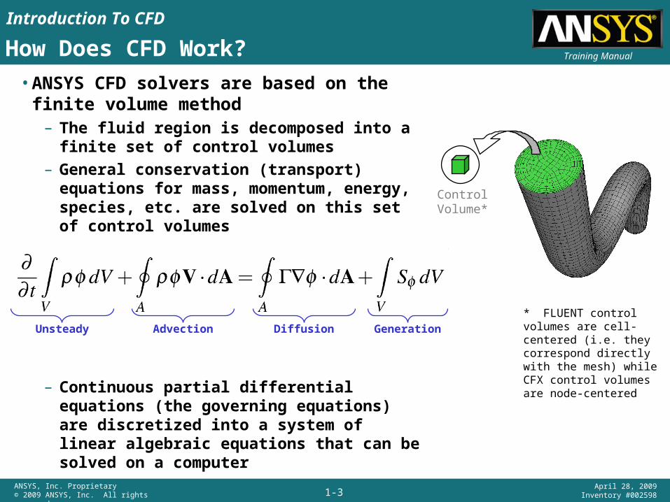
• ANSYS CFD solvers are based on the finite volume method
– The fluid region is decomposed into a finite set of control volumes
– General conservation (transport) equations for mass, momentum, energy, species, etc. are solved on this set of control volumes
– Continuous partial differential equations (the governing equations) are discretized into a system of linear algebraic equations that can be solved on a computer
ControlVolume*
* FLUENT control volumes are cell-centered (i.e. they correspond directly with the mesh) while CFX control volumes are node-centered
Unsteady Advection Diffusion Generation
Introduction To CFD
1-4ANSYS, Inc. Proprietary© 2009 ANSYS, Inc. All rights reserved.
April 28, 2009Inventory #002598
Training ManualCFD Modeling Overview
Problem Identification
1. Define goals
2. Identify domain
Pre-Processing
3. Geometry
4. Mesh
5. Physics
6. Solver Settings
Solve
7. Compute solution
Post Processing
8. Examine results
9.U
pdat
e M
odel
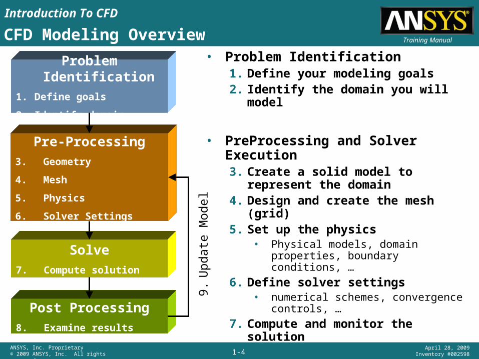
• Problem Identification1. Define your modeling goals2. Identify the domain you will model
• PreProcessing and Solver Execution3. Create a solid model to represent the
domain4. Design and create the mesh (grid)5. Set up the physics
• Physical models, domain properties, boundary conditions, …
6. Define solver settings• numerical schemes, convergence
controls, …
7. Compute and monitor the solution
• Post-Processing8. Examine the results9. Consider revisions to the model
Introduction To CFD
1-5ANSYS, Inc. Proprietary© 2009 ANSYS, Inc. All rights reserved.
April 28, 2009Inventory #002598
Training Manual1. Define Your Modeling Goals
• What results are you looking for (i.e. pressure drop, mass flow rate), and how will they be used?
– What are your modeling options?• What physical models will need to be included in your analysis (i.e. turbulence,
compressibility, radiation)?• What simplifying assumptions do you have to make?• What simplifying assumptions can you make (i.e. symmetry, periodicity)?• Do you require a unique modeling capability?
– User-defined functions (written in C) in FLUENT or User FORTRAN functions in CFX
• What degree of accuracy is required?
• How quickly do you need the results?
• Is CFD an appropriate tool?
Problem Identification
1. Define goals
2. Identify domain
Introduction To CFD
1-6ANSYS, Inc. Proprietary© 2009 ANSYS, Inc. All rights reserved.
April 28, 2009Inventory #002598
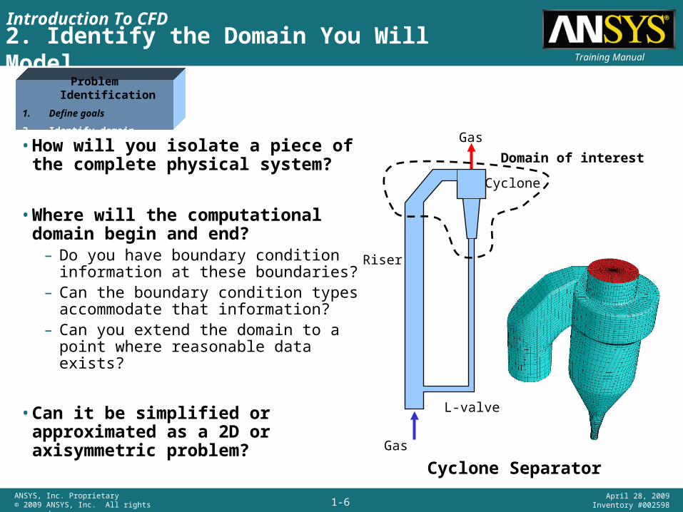
Training Manual2. Identify the Domain You Will Model
• How will you isolate a piece of the complete physical system?
• Where will the computational domain begin and end?
– Do you have boundary condition information at these boundaries?
– Can the boundary condition types accommodate that information?
– Can you extend the domain to a point where reasonable data exists?
• Can it be simplified or approximated as a 2D or axisymmetric problem?
Cyclone Separator
Gas
Riser
Cyclone
L-valve
Gas
Domain of interest
Problem Identification
1. Define goals
2. Identify domain
Introduction To CFD
1-7ANSYS, Inc. Proprietary© 2009 ANSYS, Inc. All rights reserved.
April 28, 2009Inventory #002598
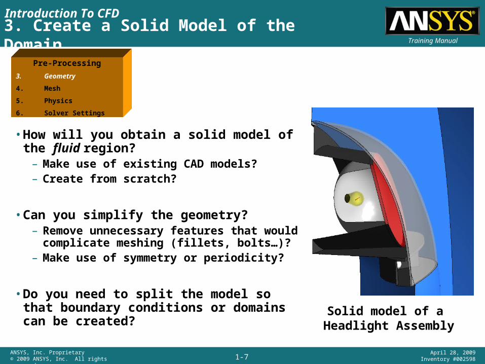
Training Manual3. Create a Solid Model of the Domain
• How will you obtain a solid model of the fluid region?
– Make use of existing CAD models?– Create from scratch?
• Can you simplify the geometry?– Remove unnecessary features that would
complicate meshing (fillets, bolts…)?– Make use of symmetry or periodicity?
• Do you need to split the model so that boundary conditions or domains can be created?
Solid model of a Headlight Assembly
Pre-Processing
3. Geometry
4. Mesh
5. Physics
6. Solver Settings
Introduction To CFD
1-8ANSYS, Inc. Proprietary© 2009 ANSYS, Inc. All rights reserved.
April 28, 2009Inventory #002598
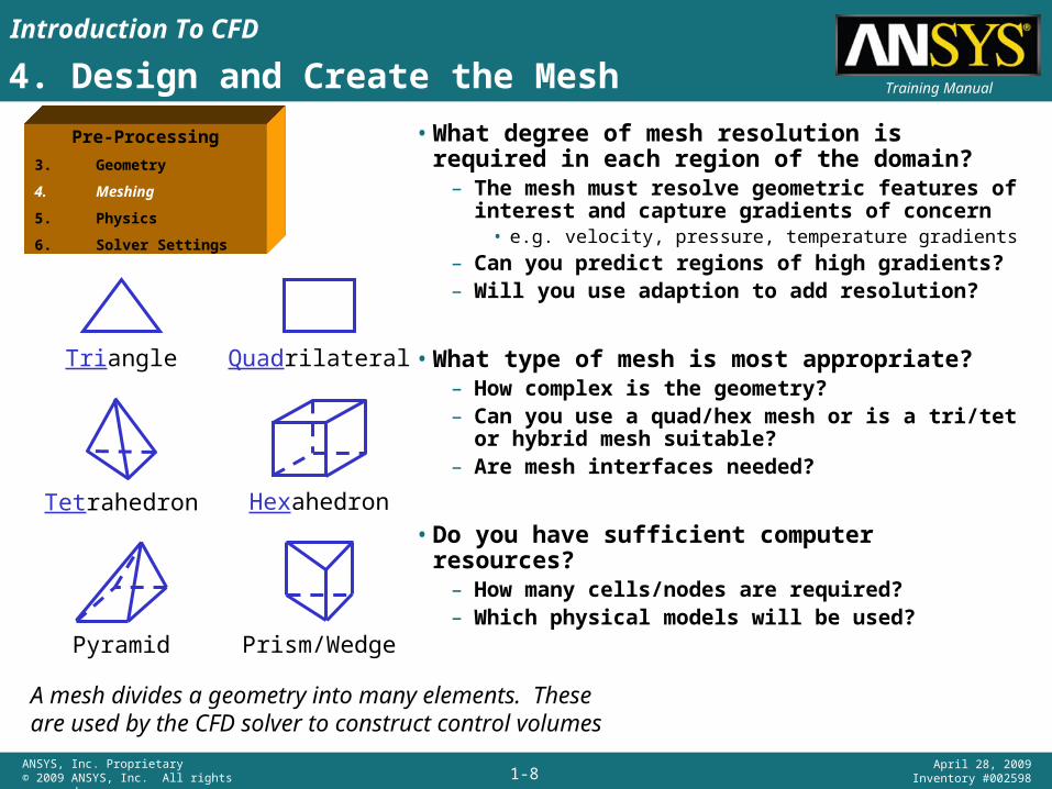
Training Manual4. Design and Create the Mesh
Triangle Quadrilateral
Pyramid Prism/Wedge
Tetrahedron Hexahedron
• What degree of mesh resolution is required in each region of the domain?
– The mesh must resolve geometric features of interest and capture gradients of concern
• e.g. velocity, pressure, temperature gradients
– Can you predict regions of high gradients?– Will you use adaption to add resolution?
• What type of mesh is most appropriate?– How complex is the geometry?– Can you use a quad/hex mesh or is a tri/tet or
hybrid mesh suitable?– Are mesh interfaces needed?
• Do you have sufficient computer resources?– How many cells/nodes are required?– Which physical models will be used?
Pre-Processing
3. Geometry
4. Meshing
5. Physics
6. Solver Settings
A mesh divides a geometry into many elements. These are used by the CFD solver to construct control volumes
Introduction To CFD
1-9ANSYS, Inc. Proprietary© 2009 ANSYS, Inc. All rights reserved.
April 28, 2009Inventory #002598
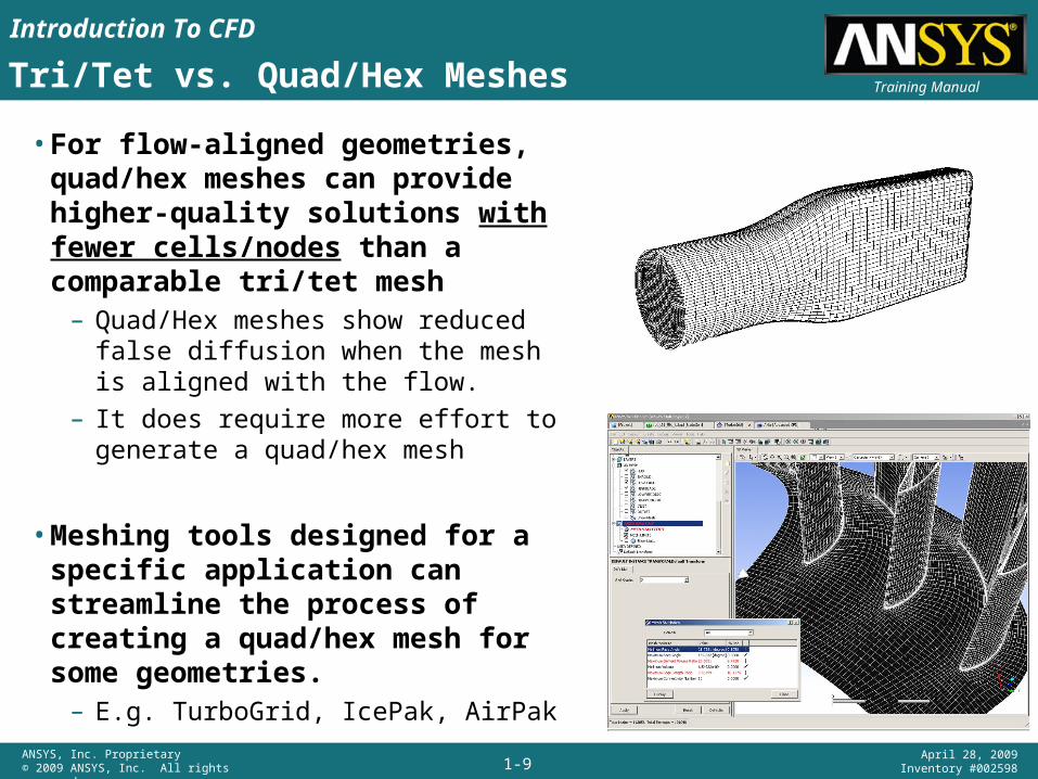
Training ManualTri/Tet vs. Quad/Hex Meshes
• For flow-aligned geometries, quad/hex meshes can provide higher-quality solutions with fewer cells/nodes than a comparable tri/tet mesh
– Quad/Hex meshes show reduced false diffusion when the mesh is aligned with the flow.
– It does require more effort to generate a quad/hex mesh
• Meshing tools designed for a specific application can streamline the process of creating a quad/hex mesh for some geometries.
– E.g. TurboGrid, IcePak, AirPak
Introduction To CFD
1-10ANSYS, Inc. Proprietary© 2009 ANSYS, Inc. All rights reserved.
April 28, 2009Inventory #002598
Training ManualTri/Tet vs. Quad/Hex Meshes
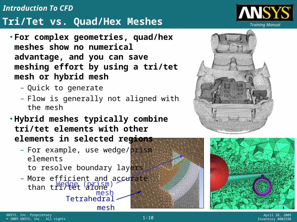
• For complex geometries, quad/hex meshes show no numerical advantage, and you can save meshing effort by using a tri/tet mesh or hybrid mesh
– Quick to generate– Flow is generally not aligned with the mesh
• Hybrid meshes typically combine tri/tet elements with other elements in selected regions
– For example, use wedge/prism elementsto resolve boundary layers
– More efficient and accuratethan tri/tet alone
Tetrahedral mesh
Wedge (prism) mesh
Introduction To CFD
1-11ANSYS, Inc. Proprietary© 2009 ANSYS, Inc. All rights reserved.
April 28, 2009Inventory #002598
Training ManualMultizone (or Hybrid) Meshes
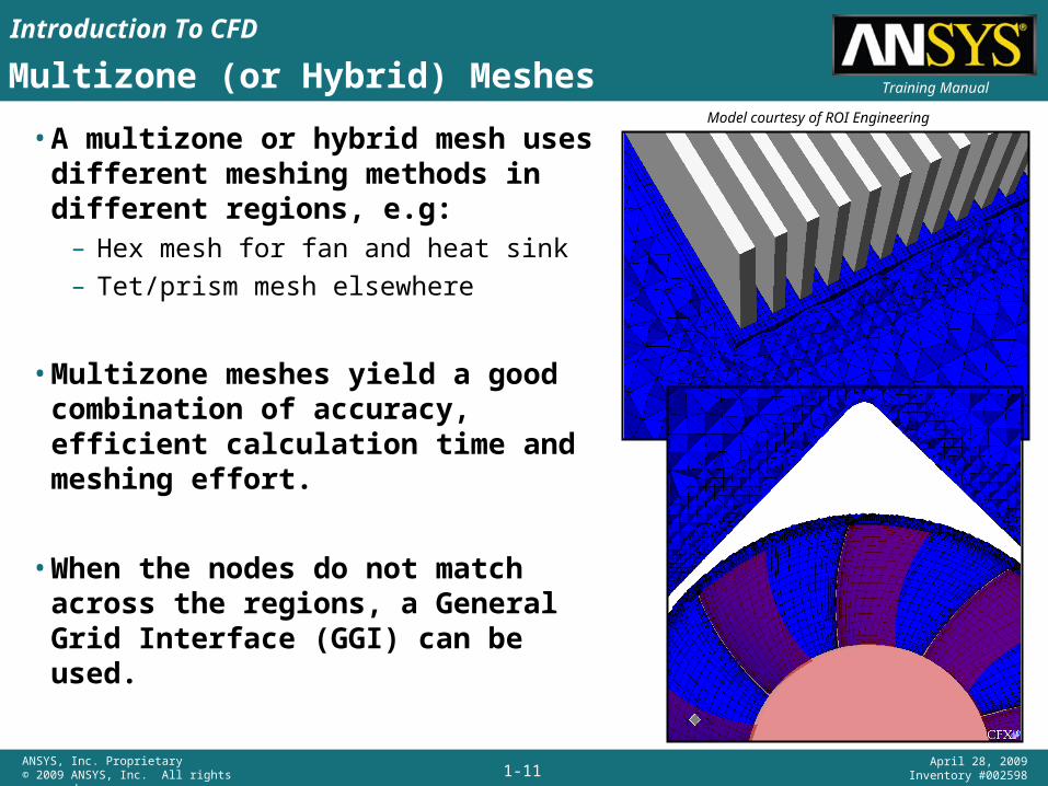
• A multizone or hybrid mesh uses different meshing methods in different regions, e.g:
– Hex mesh for fan and heat sink– Tet/prism mesh elsewhere
• Multizone meshes yield a good combination of accuracy, efficient calculation time and meshing effort.
• When the nodes do not match across the regions, a General Grid Interface (GGI) can be used.
Model courtesy of ROI Engineering
Introduction To CFD
1-12ANSYS, Inc. Proprietary© 2009 ANSYS, Inc. All rights reserved.
April 28, 2009Inventory #002598
Training ManualNon-Matching Meshes
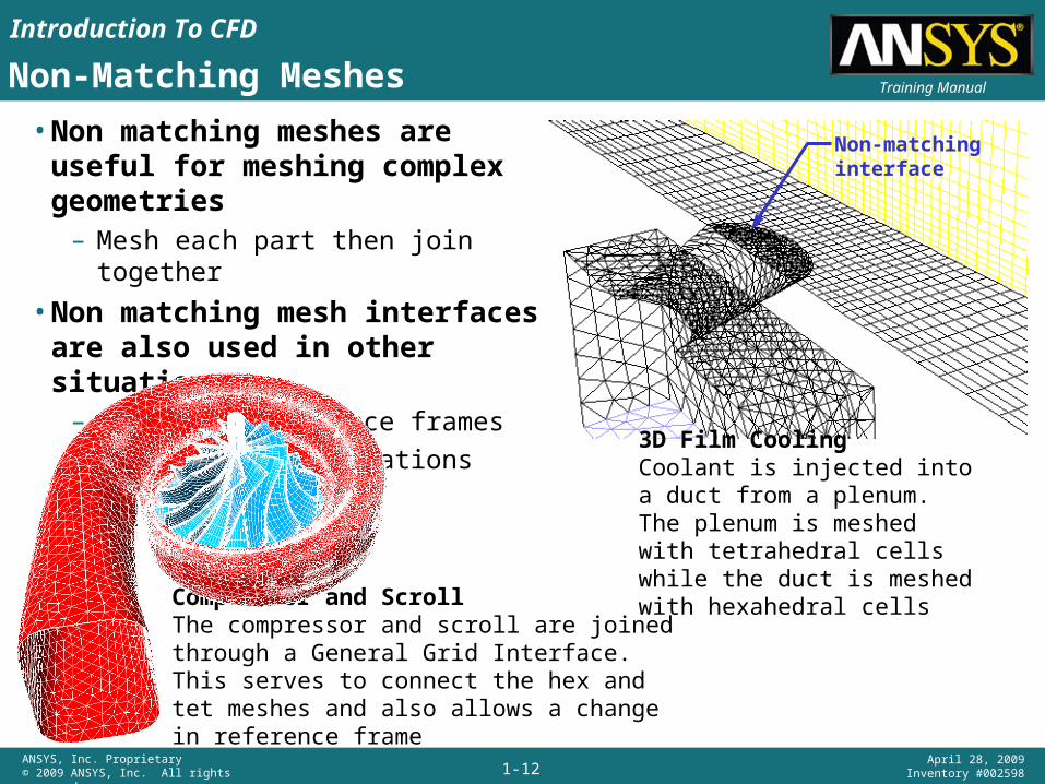
• Non matching meshes are useful for meshing complex geometries
– Mesh each part then join together
• Non matching mesh interfaces are also used in other situations
– Change in reference frames– Moving mesh applications
Non-matchinginterface
3D Film CoolingCoolant is injected into a duct from a plenum. The plenum is meshed with tetrahedral cells while the duct is meshed with hexahedral cells
Compressor and ScrollThe compressor and scroll are joined through a General Grid Interface. This serves to connect the hex and tet meshes and also allows a change in reference frame
Introduction To CFD
1-13ANSYS, Inc. Proprietary© 2009 ANSYS, Inc. All rights reserved.
April 28, 2009Inventory #002598
Training ManualSet Up the Physics and Solver Settings
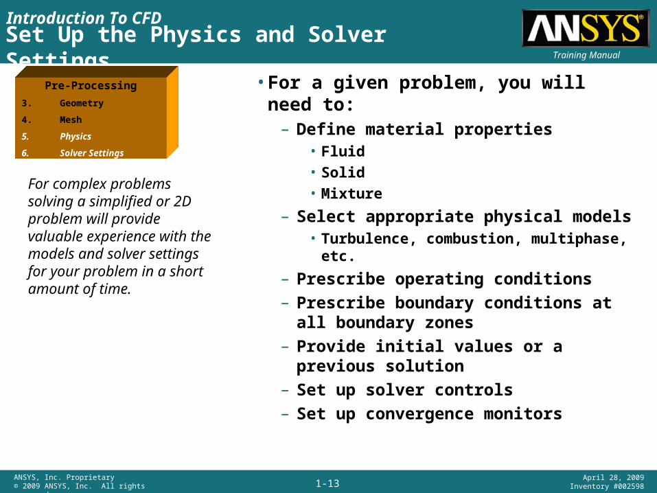
For complex problems solving a simplified or 2D problem will provide valuable experience with the models and solver settings for your problem in a short amount of time.
Pre-Processing
3. Geometry
4. Mesh
5. Physics
6. Solver Settings
• For a given problem, you will need to:– Define material properties
• Fluid • Solid• Mixture
– Select appropriate physical models• Turbulence, combustion, multiphase, etc.
– Prescribe operating conditions– Prescribe boundary conditions at all
boundary zones– Provide initial values or a previous solution– Set up solver controls– Set up convergence monitors
Introduction To CFD
1-14ANSYS, Inc. Proprietary© 2009 ANSYS, Inc. All rights reserved.
April 28, 2009Inventory #002598
Training ManualCompute the Solution
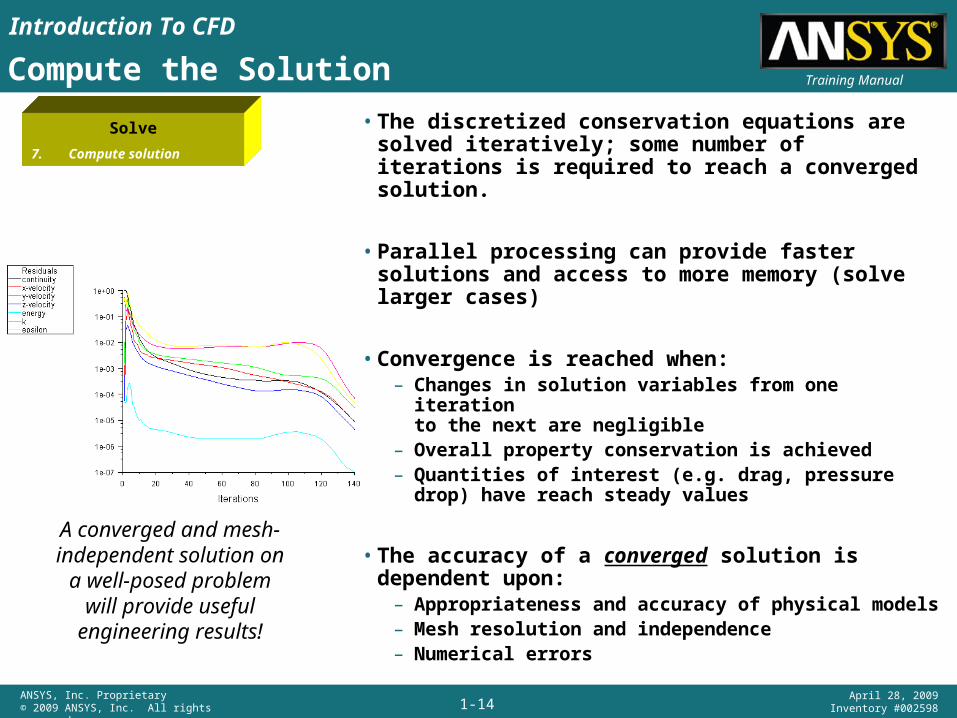
• The discretized conservation equations are solved iteratively; some number of iterations is required to reach a converged solution.
• Parallel processing can provide faster solutions and access to more memory (solve larger cases)
• Convergence is reached when:– Changes in solution variables from one iteration
to the next are negligible– Overall property conservation is achieved– Quantities of interest (e.g. drag, pressure drop)
have reach steady values
• The accuracy of a converged solution is dependent upon:
– Appropriateness and accuracy of physical models– Mesh resolution and independence– Numerical errors
A converged and mesh-independent solution on
a well-posed problem will provide useful
engineering results!
Solve
7. Compute solution
Introduction To CFD
1-15ANSYS, Inc. Proprietary© 2009 ANSYS, Inc. All rights reserved.
April 28, 2009Inventory #002598
Training ManualExamine the Results
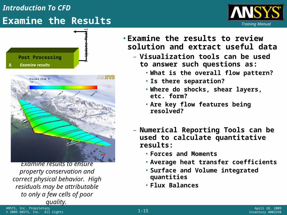
• Examine the results to review solution and extract useful data
– Visualization tools can be used to answer such questions as:
• What is the overall flow pattern?• Is there separation?• Where do shocks, shear layers, etc. form?• Are key flow features being resolved?
– Numerical Reporting Tools can be used to calculate quantitative results:
• Forces and Moments• Average heat transfer coefficients• Surface and Volume integrated quantities• Flux Balances
Examine results to ensure property conservation and
correct physical behavior. High residuals may be attributable to only a few cells of poor quality.
Post Processing
8. Examine results
9.U
pdat
e M
odel
Introduction To CFD
1-16ANSYS, Inc. Proprietary© 2009 ANSYS, Inc. All rights reserved.
April 28, 2009Inventory #002598
Training ManualConsider Revisions to the Model
• Are the physical models appropriate?– Is the flow turbulent?– Is the flow unsteady?– Are there compressibility effects?– Are there 3D effects?
• Are the boundary conditions correct?– Is the computational domain large enough?– Are boundary conditions appropriate?– Are boundary values reasonable?
• Is the mesh adequate?– Can the mesh be refined to improve results?– Does the solution change significantly with a refined
mesh, or is the solution mesh independent?– Does the mesh resolution of the geometry need to be
improved?
Post Processing
8. Examine results
9.U
pdat
e M
odel