cfd simulation of solder paste flow and deformation behaviours during stencil printing process
TRANSCRIPT

International Journal of Recent advances in Mechanical Engineering (IJMECH) Vol.4, No.1, February 2015
DOI : 10.14810/ijmech.2015.4101 1
CFD SIMULATION OF SOLDER PASTE FLOW AND
DEFORMATION BEHAVIOURS DURING STENCIL
PRINTING PROCESS
Vishal Thakur, Dr. Sabuj Mallik and Vamsi Vuppala
Department of Mechanical Engineering, University of Greenwich, Kent, U.K.
Email: [email protected]
ABSTRACT
In 20
th century, Electronics elements have become most significant part of the regular life. The main heart
of electronic element is PCB which supports and manages mostly machines and equipments these days.
Therefore manufacturing of board and assembly of electronic elements is one of the crucial and significant
objectives for most of the companies. Better life of PCB’s depends on electronic elements and its assembly
with board. Solder paste is used as adhesive material for assembly purpose. It is deposited on board using
stencil and electronic elements are mounted on it and heated for strong bond.
This study investigates on factors affecting stencil printing process due to variation in squeegee speed and
density of solder paste. This study is based on computational fluid dynamics virtual simulation. Prototype is
developed for modelling purpose and simulation software is used to simulate the flow behaviour of solder
paste during stencil printing process.
KEYWORDS
Computational Fluid Dynamics, Solder paste simulation, Stencil printing process simulation, ANSYS
simulation, Impact of variation in squeegee pressure, Impact of variation in density of solder paste.
1. INTRODUCTION
Electronics is a part of electrical engineering which deals with numerous technical sectors such as
communication, power generation, transport, medicines, artificial intelligence, networking,
automation and industrial and domestic machines. Electronics is defined as the science and
technology of the conduction of electricity in vacuum, a gas, or a semiconductor, and devices
based thereon (Davidson 1972 Page 472). The development was begun in electronics with
improvement in telegraph in late 19th century. After that, consumer electronics is developed in the
20th century, which has now become a global industry. The basic construction of electronics
apparatus is based on conducting links and active devices such as capacitors, resistors,
transducers, inductors, diodes, and integrated circuits.
Mega Trends are proceeding to rapid transitions as per customer demand in the electronics
industry. These days industry focus has leaned to smaller components and printed circuits and
increasing the footprint of standard, as opposed to traditional equipment. Technological advances
in markets also are leading to smart manufacturing techniques, and equipment is no longer
confined to a specific footprint or product design. In the racing world, electronics is the key
element of development. Use of electronics becomes gradually more paramount with the
magnification of performance in this century (PR Newswire 2013).

International Journal of Recent advances in Mechanical Engineering (IJMECH) Vol.4, No.1, February 2015
2
It’s a customer demand and so industrial requirement that product should be lighter, smaller,
cheaper and faster. In order to accomplish these criteria industries employed Integrated Circuits
packages. In construction of integrated circuits, active components are mounted on board with the
help of sort of adhesive material. Solder is commonly used adhesive material for such
applications. These solder joint reliability is most crucial issue to give attention. Solder paste is
essentially comprised of metal powder particles in a thickened flux vehicle. For best results, the
properties of solder paste should be carefully controlled and evaluated before using for printing
on substrate (Prasad 2002 page no 383). Soldering is a method of making a permanent
mechanical and electrical connection between metals. Unlike gum, which makes a purely
physical adhesive joint, solder chemically reacts with other metals to form a different alloy. There
are various different processes used in soldering, nearly all of them involve four rudimentary
elements as base metals, solder, flux and heat.
Computational Fluid Dynamics (CFD) is one of the powerful techniques which have been getting
deployed in industries recently for obtaining and investigating crucial results of fluid behaviour
under specified boundary conditions. Fluid flows are governed by partial differential equations of
conservation of mass, momentum and energy. These PDE’s are replaced by a set of algebraic
equations which can be solved with the help of computers. CFD softwares predict the fluid flow
and able to perform all sort of numerical experiments related to fluid in a virtual flow laboratory.
This research describes the solder paste behaviour in stencil printing process using ANSYS
simulation software. The main thrust of research is to develop a method to investigate the fluid’s
thixotropic nature in stencil printing process and factors affecting to it.
1.1 Problems to be addressed:
The solder joint is one of the most crucial parts in electronic circuit board. Electronics
components are subjected to various strong environmental conditions, such as shocks, heat,
humidity, and reactive materials. Various studies are carried out to understand the solder paste
behaviour while stencil printing process. Solder paste has various affecting factors like
temperature, humidity, improper mixture, and other environmental conditions which results into
bad solder joint, lack of uniformity and deviation of height of solder paste on substrate surface.
Therefore intensive study required to deeply understand the affecting factors and how to
overcome it. There is no any standard method for simulation of stencil printing process using
virtual flow software. So this article could be the one to help researchers for simulation of solder
paste in future.
1.2 Benefits to Industry:
The ultimate goal of this research is to create an integrated simulation and modelling tool for
designing robust and sturdy solder joints that completes the quality and reliability requirements. It
will be helpful to understand rheological flow behaviour of solder paste. One of the main
characteristics of solder paste is shear strain rate and shear stress of solder paste. This paper
explains these factors using simulation of paste. In addition, this paper sets a new procedure or
method to develop new paste material in future and simulate it to get efficient results. Various
other parameters of solder paste can be analysed including pressure contour, velocity contour,
eddy dissipation, temperature contour, and dynamic viscosity, etc. This method would be helpful
for electronic industries and researchers to analyse and investigate new solder paste material
behaviour in stencil printing process. Thus, this method can be used as a proactive approach for
new solder paste material.

International Journal of Recent advances in Mechanical Engineering (IJMECH) Vol.4, No.1, February 2015
3
2. AIM AND OBJECTIVES
2.1 Aim: The aim of the project is to investigate natural solder paste flow behaviours at different densities
and at different squeegee speeds. Furthermore to obtain and establish a standard method to
investigate various other solder paste materials.
2.2 Objective: 1) To perform CFD simulation of solder paste at different density values.
2) To analyze solder paste flow behaviour at different squeegee speed and its impact.
3) To develop standard operating procedures for simulation of solder paste in stencil printing
process.
3. MODELLING OF SOLDER PASTE PRINTING PROCESS USING
ANSYS
The prototype is developed based on the currently known requirements. The basic idea is to set up
a new method to analyse and investigate solder paste using virtual flow simulation software. The
prototype is designed and developed using 3D software. Fig.1 shows a schematic diagram of
stencil utilized for this particular modelling purpose. The developed stencil prototype is a square
in structure and has an area of 22500 mm2 with thickness of 20 mm. It has six throughout holes
with a diameter of 25 microns.
Fig. 1 Stencil Prototype developed for modelling purpose (Source: Author)
Practically, thickness of stencil varies from 0.001” to 0.030” which is exactly contrasting the
prototype developed. In our scenario thickness of stencil is 0.8”. Reason for this contrasting
geometry is to reduce complexity of geometry and fluid domain structure, so that it is easy to
discretize and apply good mesh. Therefore author assumed stencil size as per the modelling
convenience. Under this investigation, author is mainly focused on solder paste behaviour during
printing process and not on effects after printing process.

International Journal of Recent advances in Mechanical Engineering (IJMECH) Vol.4, No.1, February 2015
4
3.1 Assumptions and boundary conditions selected for Simulation:
A) Solder paste flow is continuous steady state flow
B) Paste flow is incompressible in nature
C) Domain under investigation is at atmospheric conditions
D) No heat loss through any surfaces to atmosphere.
For the case presented, following conditions considered and remained constant throughout.
Physical properties of solder paste considered for this study is referred and assumed through
database.
• Material : Sn3.5Ag Solder paste
• Molar weight: 496.3 gm/mole,
• Density: 7.5 g/cm3, (Dr. Thomas Siewert, February 11, 2002)
• Specific Heat Capacity: 64 J/gm (Dr. Thomas Siewert, February 11, 2002)
• Reference Temperature: 25 degree centigrade
• Thermal Conductivity: 55.3 W/mK, (Martin Wickham, 2001)
• Thermal Expansivity: 0.0000302 per Kelvin, (Martin Wickham, 2001)
• Yield Stress: 24 Mpa, (Dr. Thomas Siewert, February 11, 2002)
• Non-Newtonian Model – Bingham Model ( This model is used due to availability of all
physical values required to use this model)
• Yield Stress: 50Pa (Dr. Thomas Siewert, February 11, 2002)
• Viscosity Consistency: 10 kg.m./s (assumed, it’s a dimensionless constant value)
• Min. Shear strain rate: 0.08 per second, (Dr. Thomas Siewert, February 11, 2002)
• Maximum Shear strain: 0.083 per second, (Dr. Thomas Siewert, February 11, 2002)
• Turbulence model: � − � Turbulence model
• Squeegee pressure applied on solder paste is atmospheric and uniformly normal to paste.
This assumption has to be made due to limitation of software.
4. RESULTS AND DISCUSSION
The results of simulation shows that it is likely to analyse the effect of different controlling and
operating parameters on the performance and efficiency of solder paste in stencil printing process.
Due to microns size of apertures and number of modelling assumptions, it is quite difficult to get
precision in result. However, this simulation method is extremely useful for any complex
simulation of solder paste up to some extent if carefully done.
Ideal squeegee speed range varies from 10mm/s to 200mm/s (University of Bolton, 2014). For
investigation purpose, author referred and assumed data as below. Variation in density is assumed
due to improper mixture of solder paste.
Table 1: Solder paste parameters considered for simulation purpose
Sr. No Squeegee Speed (mm/s) Density of Solder Paste
(gm/cc)
1 30
7.5 2 90
3 150
4 30
3
5 14

International Journal of Recent advances in Mechanical Engineering (IJMECH) Vol.4, No.1, February 2015
5
1. Squeegee speed 30 mm/s and Density of Solder paste 7.5 gm/cc
Fig. 2 Shear Strain Rate (Source: Author)
Fig. 3 Wall Shear Stress (Source: Author)

International Journal of Recent advances in Mechanical Engineering (IJMECH) Vol.4, No.1, February 2015
6
2. Squeegee speed 90 mm/s and Density of Solder paste 7.5 gm/cc
Fig. 4 Shear Strain Rate (Source: Author)
Fig. 5 Wall Shear Stress (Source: Author)
International Journal of Recent advances in Mechanical Engineering (IJMECH) Vol.4, No.1, February 2015
7
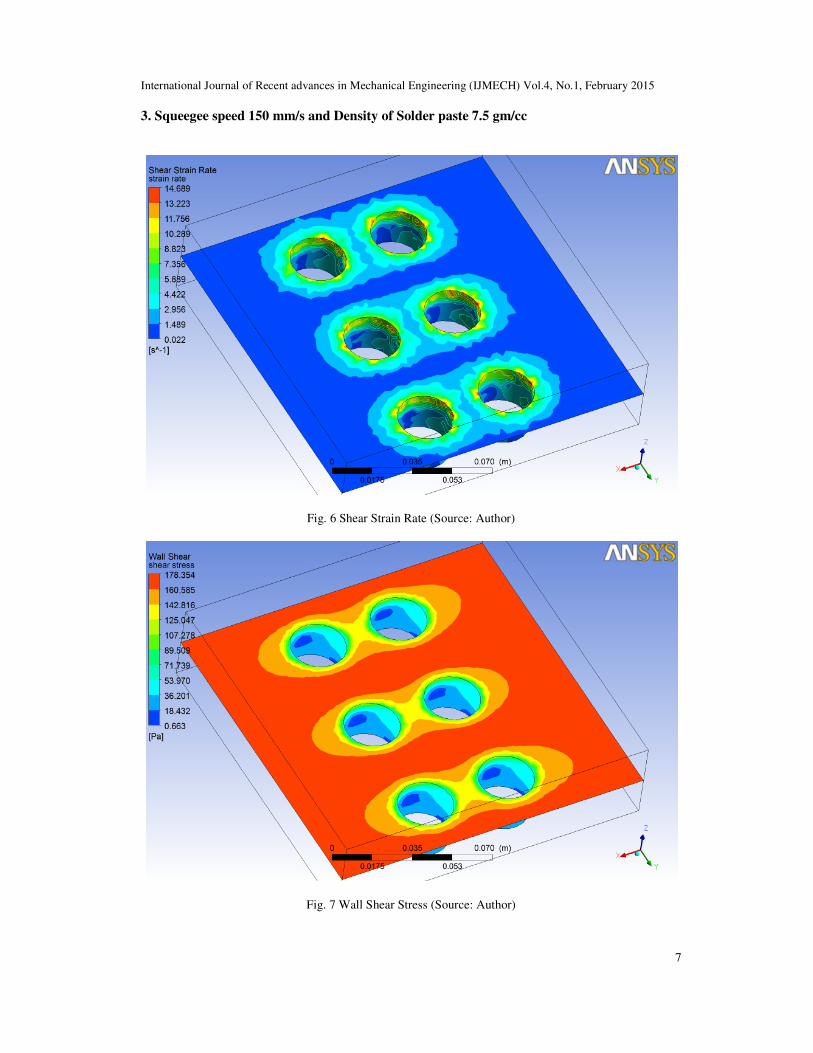
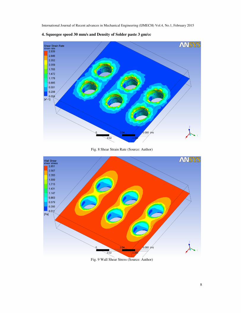
3. Squeegee speed 150 mm/s and Density of Solder paste 7.5 gm/cc
Fig. 6 Shear Strain Rate (Source: Author)
Fig. 7 Wall Shear Stress (Source: Author)
International Journal of Recent advances in Mechanical Engineering (IJMECH) Vol.4, No.1, February 2015
8
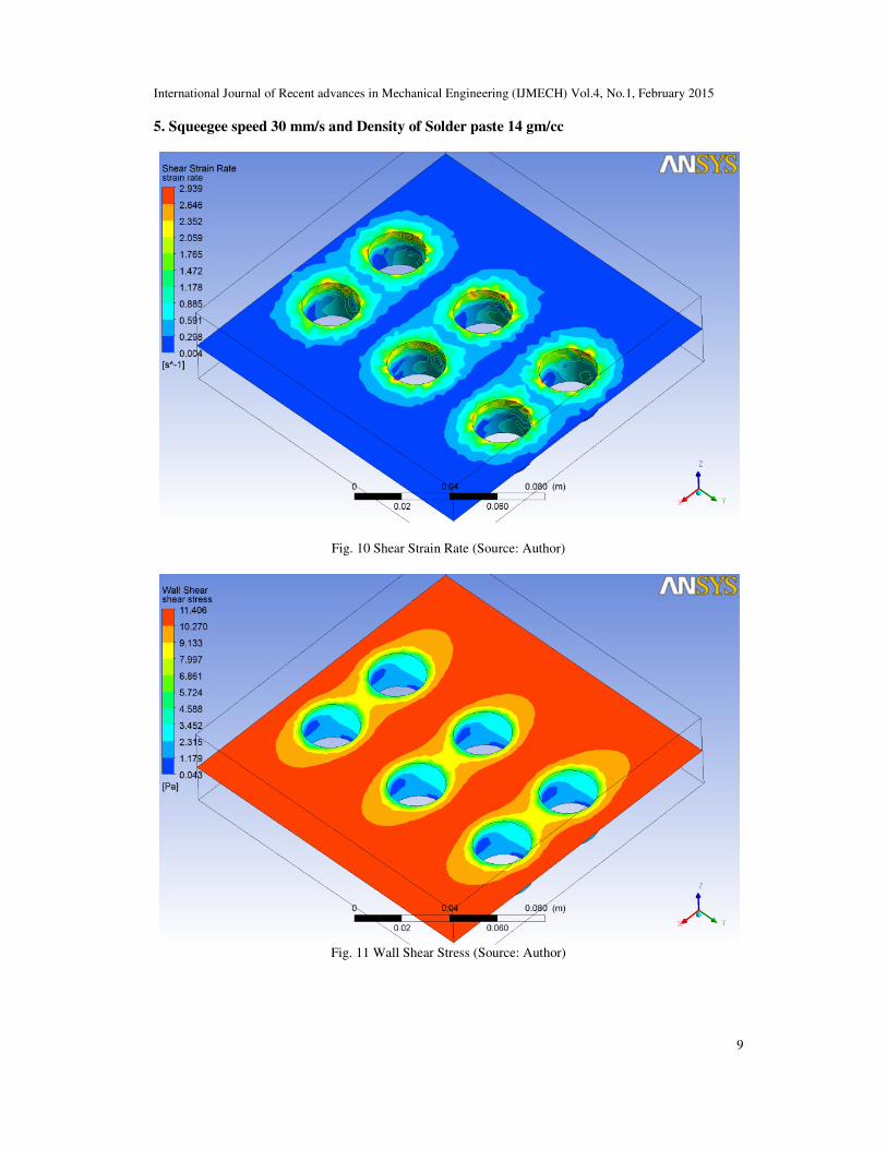
4. Squeegee speed 30 mm/s and Density of Solder paste 3 gm/cc
Fig. 8 Shear Strain Rate (Source: Author)
Fig. 9 Wall Shear Stress (Source: Author)
International Journal of Recent advances in Mechanical Engineering (IJMECH) Vol.4, No.1, February 2015
9
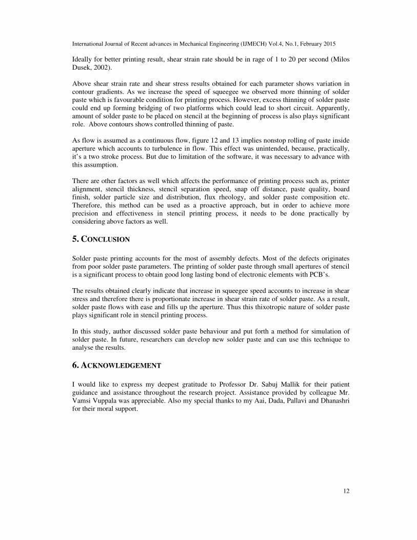
5. Squeegee speed 30 mm/s and Density of Solder paste 14 gm/cc
Fig. 10 Shear Strain Rate (Source: Author)
Fig. 11 Wall Shear Stress (Source: Author)

International Journal of Recent advances in Mechanical Engineering (IJMECH) Vol.4, No.1, February 2015
10
The figures 12 and 13 are obtained for solder paste density 7.5 with squeegee speed of 30
mm/s.
Fig. 12 Velocity Streamline (Source: Author)
Fig. 13 Velocity Vector (Source: Author)

International Journal of Recent advances in Mechanical Engineering (IJMECH) Vol.4, No.1, February 2015
11
Table 2: Comparative results obtained for shear strain rate and wall shear stress
Parameter Shear Strain Rate
min-max(s-1
)
Wall Shear Stress
min-max(Pascal)
Squeegee Speed 30 mm/s,
Density of paste 7.5 gm/cc
0.004 - 2.939 0.027-7.129
Squeegee Speed 90 mm/s,
Density of paste 7.5 gm/cc
0.013 - 8.814 0.238 - 64.201
Squeegee Speed 150 mm/s,
Density of paste 7.5 gm/cc
0.022 – 14.689 0.663 – 178.354
Squeegee Speed 30 mm/s,
Density of paste 3 gm/cc
0.004 – 2.939 0.011 – 2.851
Squeegee Speed 30 mm/s,
Density of paste 14 gm/cc
0.004 – 2.939 0.043 – 11.406
The solder paste is pseudoplastic material which means that the material only begins to flow
when external forces are stronger than internal forces. Under pseudoplastic flow, viscosity of
paste decreases as shear stress increases. Solder paste becomes more fluid and fills the aperture as
squeegee applies more and more shear stress. This phenomenon is called as shear thinning. The
findings observed support this phenomenon. Above table 2 compares the range of shear strain rate
and wall shear stress of solder paste at various squeegee speed and density. A result also confirms
that variation in density of solder paste does not affect shear strain rate.
Figure 14: Shear stress vs. Shear strain rate
Figure 14 shows flow curves obtained for given solder paste material. It is obtained on all trial
values taken from table 1 and other than that for graphical representation purpose. Ratio of shear
stress to shear strain rate is known as a viscosity of fluid. Above graph clearly suggests that there
is a proportionate rise in shear strain rate of paste with increase in proportion to shear stress.
0
20
40
60
80
100
120
140
160
180
200
0 5 10 15 20
Shear Stress
(Pa)
Shear Strain Rate (per second)
Shear Stress vs Shear Strain rate
International Journal of Recent advances in Mechanical Engineering (IJMECH) Vol.4, No.1, February 2015
12
Ideally for better printing result, shear strain rate should be in rage of 1 to 20 per second (Milos
Dusek, 2002).
Above shear strain rate and shear stress results obtained for each parameter shows variation in
contour gradients. As we increase the speed of squeegee we observed more thinning of solder
paste which is favourable condition for printing process. However, excess thinning of solder paste
could end up forming bridging of two platforms which could lead to short circuit. Apparently,
amount of solder paste to be placed on stencil at the beginning of process is also plays significant
role. Above contours shows controlled thinning of paste.
As flow is assumed as a continuous flow, figure 12 and 13 implies nonstop rolling of paste inside
aperture which accounts to turbulence in flow. This effect was unintended, because, practically,
it’s a two stroke process. But due to limitation of the software, it was necessary to advance with
this assumption.
There are other factors as well which affects the performance of printing process such as, printer
alignment, stencil thickness, stencil separation speed, snap off distance, paste quality, board
finish, solder particle size and distribution, flux rheology, and solder paste composition etc.
Therefore, this method can be used as a proactive approach, but in order to achieve more
precision and effectiveness in stencil printing process, it needs to be done practically by
considering above factors as well.
5. CONCLUSION
Solder paste printing accounts for the most of assembly defects. Most of the defects originates
from poor solder paste parameters. The printing of solder paste through small apertures of stencil
is a significant process to obtain good long lasting bond of electronic elements with PCB’s.
The results obtained clearly indicate that increase in squeegee speed accounts to increase in shear
stress and therefore there is proportionate increase in shear strain rate of solder paste. As a result,
solder paste flows with ease and fills up the aperture. Thus this thixotropic nature of solder paste
plays significant role in stencil printing process.
In this study, author discussed solder paste behaviour and put forth a method for simulation of
solder paste. In future, researchers can develop new solder paste and can use this technique to
analyse the results.
6. ACKNOWLEDGEMENT
I would like to express my deepest gratitude to Professor Dr. Sabuj Mallik for their patient
guidance and assistance throughout the research project. Assistance provided by colleague Mr.
Vamsi Vuppala was appreciable. Also my special thanks to my Aai, Dada, Pallavi and Dhanashri
for their moral support.

International Journal of Recent advances in Mechanical Engineering (IJMECH) Vol.4, No.1, February 2015
13
REFERENCES
[1] Brett Wilson, EA 1995, Analogue Optical Fibre Communications, Institution of Engineering and
Technology, Mishawaka.
[2] Davidson, T 1972 Page 472, Chambers Twentieth Century Dictionary, W and R Chambers,
Edinburgh.
[3] Dr. Thomas Siewert, D. S. (February 11, 2002), Database for Solder Properties with Emphasis on
New Lead-free Solders. Colorado: National Institute of Standards and Technology and Colorado
School of Mines.
[4] Martin Wickham, J. N. (2001). A Review of Mechanical Test Method Standards for Lead Free
Solders. NPL Report MATC(A)69 (p. 15). Middlesex, UK: Crown.
[5] Milos Dusek, l. Z. (2002). Rheology testing of solder pastes and conductive adhesives. NPL Report
MATC(A)69. Middlesex: Crown
[6] PR Newswire 2013, News Releases, viewed 22 January 2014, < HYPERLINK
"http://www.prnewswire.com/news-releases/evolution-in-electronics-design-and-implications-for-
global-supply-chain-partners-200307671.html" http://www.prnewswire.com/news-
releases/evolution-in-electronics-design-and-implications-for-global-supply-chain-partners-
200307671.html >.
[7] Prasad, RP 2002 page no 383, Surface Mount Technology, Kluwer Academic Publishers, London.
[8] University of Bolton. (2014, 1 1). Solder Paste Basics. Retrieved 1 23, 2014, from University of
Bolton: http://www.ami.ac.uk/courses/topics/0245_spb/index.html
[9] University of Bolton. (2014, 1 1). Solder Paste Basics. Retrieved June 11, 2014, from University of
Bolton: http://www.ami.ac.uk/courses/topics/0222_print.html
Authors:
Vishal Chandrakant Thakur
BE, MSc Mechanical and Manufacturing Engineering
University of Greenwich, Kent, UK
Dr. Sabuj Mallik
BSc, MSc, PhD, Ceng, MIMechE, FHEA
Senior Lecturer (Mechanical, Manufacturing & Design Engineering)
Faculty of University of Greenwich, Kent, UK
Vamsi Vuppala
BTech, MSc Mechanical and Manufacturing Engineering
University of Greenwich, Kent, UK