multiphase flow in solder paste stencil printing process using … · 2 school of aerospace...
TRANSCRIPT
Journal of Advanced Research in Fluid Mechanics and Thermal Sciences 46, Issue 1 (2018) 147-152
147
Journal of Advanced Research in Fluid
Mechanics and Thermal Sciences
Journal homepage: www.akademiabaru.com/arfmts.html
ISSN: 2289-7879
Multiphase Flow in Solder Paste Stencil Printing Process using
CFD approach
Mohd Syakirin Rusdi1, Mohd Zulkifly Abdullah2, Mohd Sharizal Abdul Aziz*,1 , Muhammad Khalil
Abdullah@Harun3, Srivalli Chellvarajoo3, Azmi Husin1,4, Parimalam Rethinasamy5, Sivakumar
Veerasamy5
1 School of Mechanical Engineering, Universiti Sains Malaysia, Engineering Campus, 14300 Nibong Tebal, Penang, Malaysia 2 School of Aerospace Engineering, Universiti Sains Malaysia, Engineering Campus, 14300 Nibong Tebal, Penang, Malaysia 3 School of Materials and Mineral Resources Engineering, Universiti Sains Malaysia, Engineering Campus, 14300 Nibong Tebal, Penang, Malaysia 4 Faculty of Mechanical Engineering, Universiti Teknologi MARA Pulau Pinang, 13500 Permatang Pauh, Penang, Malaysia 5 Celestica Malaysia Sdn. Bhd., Plot 15, Jalan Hi-Tech 2/3 Phase I, Kulim Hi-Tech Park, 09000 Kulim, Malaysia
ARTICLE INFO ABSTRACT
Article history:
Received 25 February 2018
Received in revised form 25 April 2018
Accepted 9 May 2018
Available online 15 June 2018
In this paper, Computational Fluid Dynamic (CFD) simulation approach is used to study
the flowability of lead-free solder SAC387 in stencil printing process. The Volume of
Fluid (VOF) method is used to simulate the multiphase flow between air and SAC387.
The simulations are carried out at five different aperture area sizes. This paper focuses
on the aperture filling of SAC387 where the result of the volume of SAC filling will be
discussed. Results show that the volume error of the biggest aperture is 13.9% while
the smallest aperture is 17.9%.
Keywords:
SAC387, Stencil Printing, Lead-free
Solder Copyright © 2018 PENERBIT AKADEMIA BARU - All rights reserved
1. Introduction
Surface mount technology has been used widely in electronic parts manufacturing. It is a
technology where electronic parts are mount to the PCB. The process generally starts from solder
paste printing process, glueing process, pick and place process and lastly reflow-oven process. Solder
paste printing process is the process where solder paste is dissipated on the solder pad by using
squeegee and stencil. This process is crucial to make sure the sufficient of solder paste for part
mounting.
Neural network approach model proposed by Yang et al., [1] help to solve the fine pitch printing
quality issue of the non-linear behaviour stencil printing. This is through the volume prediction of
solder paste deposits. The volume deposited prediction error is less than 7%. The approach is an
effective way to predict and control the printing quality in Surface Mount Assembly.
Tutar and Karakus [2] using Finite Volume Method (FVM) and VOF model to simulate the injection
of polymer for a single and multi-cavity mould. This FVM and VOF technique can be used to simulate
the solder paste printing process. Krammer [3] compared the result of FVM model using Non-
Newtonian model and Newtonian model for solder paste. Krammer highlighted that Non-Newtonian
Penerbit
Akademia Baru
Open
Access
Journal of Advanced Research in Fluid Mechanics and Thermal Sciences
Volume 46, Issue 1 (2018) 147-152
148
Penerbit
Akademia Baru
model must be used and for the simulation of solder paste. The neglecting of real material properties
will lead to calculation errors.
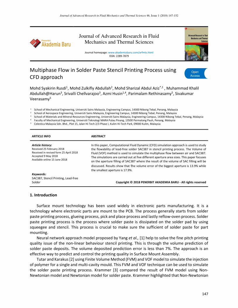
In stencil printing, a squeegee is used to transfer solder paste inside the stencil apertures to
deposit a required amount of solder paste on pad of the substrate [4]. For metal blade squeegee, the
angle of 60° is the most suitable angle to handle the ultra-fine and larger pitch size. The volume of
solder paste deposits is proportional to the paste pressure and the highest region of the pressure is
at the edge of squeegee [5]. The squeegee provides hydrodynamic pressures in the roll of solder
paste that assists the filling of paste inside the apertures by shearing as it moves over the stencil [6].
Figure 1 shows the schematic diagram of stencil printing process [7].
Rolling of solder paste in stencil printing process gives considerable influent to the filling manner
of solder paste in the apertures which could affect the printing quality that subjected to the
printability of solder paste [8]. Solder paste could shear-thin until flux would separate from the metal
if the pressure exerted by the squeegee is too high that could lead to poor solderability [9].
CFD approach has been using to study the effect of squeegee speed variation and solder paste
with different density. It is found that the shear stress increment is proportional to the increment of
solder paste’s shear strain if the speed of squeegee being increase [10]. The high price of solder paste
and high time consumption for trial and error makes the CFD as an alternative way to study the solder
paste stencil printing process.
Fig. 1. Solder Paste Stencil Printing Process
2. Methodology
SAC387 with the composition of 95.5Sn/3.8Ag/0.7Cu was being studied. SAC387 is a Non-
Newtonian fluid, therefore the Cross viscosity model was used to simulate the solder movement. The
cross model data for SAC387 was taken from Durairaj et al., [11]. The equation used to determine
the viscosity of solder phase is shown in Eq. (1)
���, ��� � ���� ����
�∗ ���� (1)
with

Journal of Advanced Research in Fluid Mechanics and Thermal Sciences
Volume 46, Issue 1 (2018) 147-152
149
Penerbit
Akademia Baru
����� � �exp ���� � (2)
B is an exponential-fitted constant, Tb is a temperature-fitted constant, n is the power law index, η0 is
the zero shear viscosity and τ* is the parameter that describes the transition region between the zero
shear rate and power law region of the viscosity curve.
VOF model was used to track the two different phase of fluid [12]. If the cell contains only SAC387,
the volume fraction, f will equal to 1(f = 1), in cells which are void of SAC387 (in this study the void is
the air) the f will equal to zero (f = 0) and when the value is between 0 and 1 (0 < f < 1) it is referred
to the SAC387 front. Equation (3) governed the equation of melt front over time [13]:
���� � !�
!� " ∇ ⋅ �%&� � 0 (3)
A 3-Dimensional model of stencil printing was designed and meshed using ANSYS Workbench. The
mesh file than transferred and simulated using ANSYS FLUENT (Figure 2). Dynamic mesh was used to
simulate the movement the squeegee with a constant speed of 35mm/s. The angle of squeegee was
fixed at 60°. The fluid motion of SAC387 using CFD approach can be described by the governing
equations of conservations of mass and momentum [14][15]. The aperture area is varied at 5
different area size (Table 1).
Table 1
The values of area and volume for a different type of
Apertures
Aperture Area (mil2) Volume (mil3)
A 1085 5425
B 2000 10000
C 4000 20000
D 4300 21500
E 10000 50000
Fig. 2. Mesh and Boundaries Conditions
Journal of Advanced Research in Fluid Mechanics and Thermal Sciences
Volume 46, Issue 1 (2018) 147-152
150
Penerbit
Akademia Baru
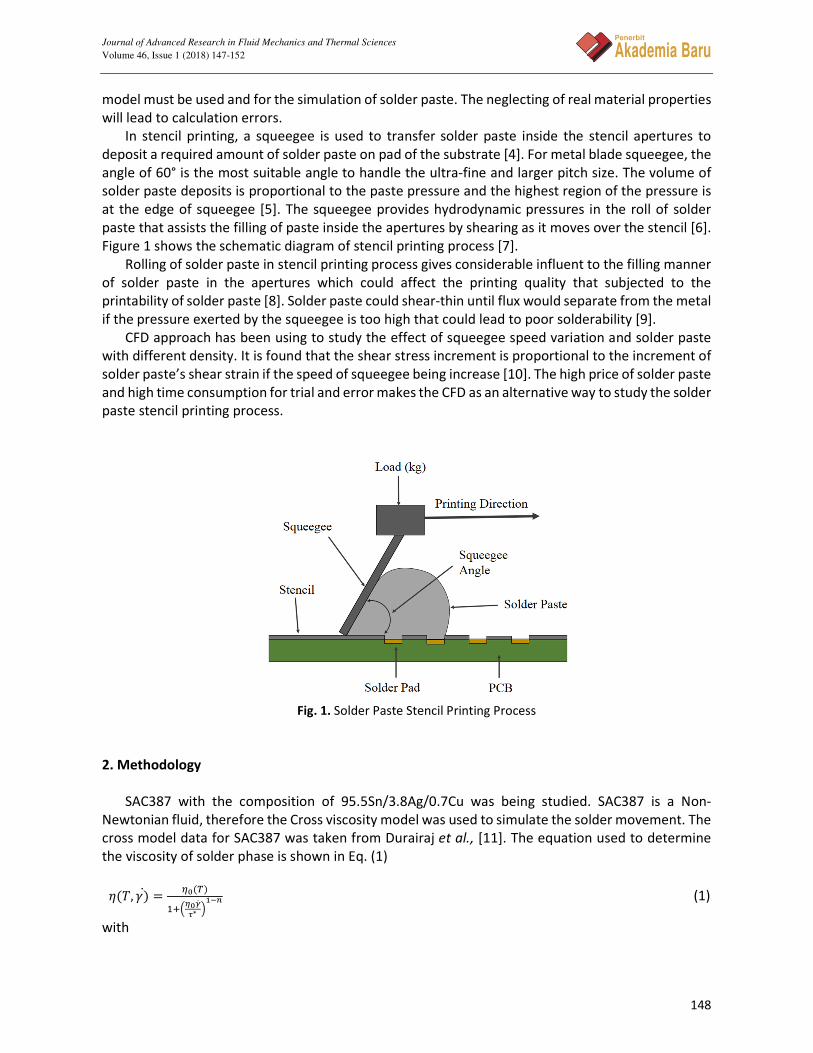
Fig. 3. Cross-section plane showing Aperture E location and mesh
3. Results
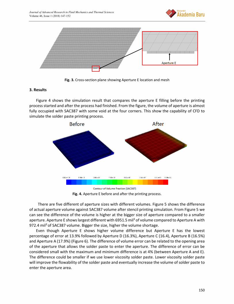
Figure 4 shows the simulation result that compares the aperture E filling before the printing
process started and after the process had finished. From the figure, the volume of aperture is almost
fully occupied with SAC387 with some void at the four corners. This show the capability of CFD to
simulate the solder paste printing process.
Fig. 4. Aperture E before and after the printing process.
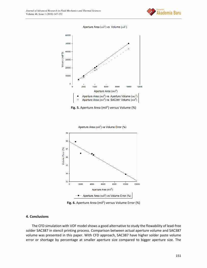
There are five different of aperture sizes with different volumes. Figure 5 shows the difference
of actual aperture volume against SAC387 volume after stencil printing simulation. From Figure 5 we
can see the difference of the volume is higher at the bigger size of aperture compared to a smaller
aperture. Aperture E shows largest different with 6951.5 mil3 of volume compared to Aperture A with
972.4 mil3 of SAC387 volume. Bigger the size, higher the volume shortage.
Even though Aperture E shows higher volume difference but Aperture E has the lowest
percentage of error at 13.9% followed by Aperture D (16.3%), Aperture C (16.4), Aperture B (16.5%)
and Aperture A (17.9%) (Figure 6). The difference of volume error can be related to the opening area
of the aperture that allows the solder paste to enter the aperture. The difference of error can be
considered small with the maximum and minimum difference is at 4% (between Aperture A and E).
The difference could be smaller if we use lower viscosity solder paste. Lower viscosity solder paste
will improve the flowability of the solder paste and eventually increase the volume of solder paste to
enter the aperture area.
Journal of Advanced Research in Fluid Mechanics and Thermal Sciences
Volume 46, Issue 1 (2018) 147-152
151
Penerbit
Akademia Baru
Fig. 5. Aperture Area (mil2) versus Volume (%)
Fig. 6. Aperture Area (mil2) versus Volume Error (%)
4. Conclusions
The CFD simulation with VOF model shows a good alternative to study the flowability of lead-free
solder SAC387 in stencil printing process. Comparison between actual aperture volume and SAC387
volume was presented in this paper. With CFD approach, SAC387 have higher solder paste volume
error or shortage by percentage at smaller aperture size compared to bigger aperture size. The
Journal of Advanced Research in Fluid Mechanics and Thermal Sciences
Volume 46, Issue 1 (2018) 147-152
152
Penerbit
Akademia Baru
volume error of Aperture E (50000 mil3) is 13.9% compared to Aperture A (5425 mil3) with 17.9%
error.
Acknowledgement
We would like to thank Universiti Sains Malaysia for funding this research with Universiti Sains
Malaysia Short-Term grant (304/PMEKANIK/6315031).
References [1] Yang, Taho, Tsung-Nan Tsai, and Junwu Yeh. "A neural network-based prediction model for fine pitch stencil-
printing quality in surface mount assembly." Engineering Applications of Artificial Intelligence 18, no. 3 (2005): 335-
341.
[2] Tutar, M., and A. Karakus. "Computational Study of the Effect of Governing Parameters on a Polymer Injection
Molding Process for Single-Cavity and Multicavity Mold Systems." Journal of manufacturing science and
engineering 132, no. 1 (2010): 011001.
[3] Krammer, Oliver. "Finite volume modelling of stencil printing process." In Design and Technology in Electronic
Packaging (SIITME), 2014 IEEE 20th International Symposium for, pp. 79-82. IEEE, 2014.
[4] Manessis, Dionysios, Rainer Patzelt, Andreas Ostmann, Rolf Aschenbrenner, and Herbert Reichl. "Technical
challenges of stencil printing technology for ultra fine pitch flip chip bumping." Microelectronics reliability 44, no.
5 (2004): 797-803.
[5] Pan, Jianbiao, and Gregory L. Tonkay. "A study of the aperture filling process in solder paste stencil printing." In will
appear in the Proceedings of ASME 1999 International Mechanical Engineering Congress and Exposition, Nashville,
Tennessee. 1999.
[6] Durairaj, R., S. Ramesh, S. Mallik, A. Seman, and N. Ekere. "Rheological characterisation and printing performance
of Sn/Ag/Cu solder pastes." Materials & Design 30, no. 9 (2009): 3812-3818.
[7] An, Bing, and Y. P. Wu. "Evaluating the printability of solder paste from paste roll characteristics." In Eleventh
International Conference on Electronic Packaging Technology and High Density Packaging, Shanghai, pp. 1186-9.
2010.
[8] An, Bing, Zhe Xu, Hua Chen, Fengshun Wu, Yiping Wu, Yoshiyuki Osawa, and Jun Wang. "Solder paste printability
tester and method." In Electronic Packaging Technology, 2006. ICEPT'06. 7th International Conference on, pp. 1-4.
IEEE, 2006.
[9] R. Mohanty, R. L. Iyer, and D. Santos, “Effect of Board Clamping System on Solder Paste Print Quality,” IPC APEX
EXPO Proceedings, 2017.
[10] Thakur, Vishal, Sabuj Mallik, and Vamsi Vuppala. "CFD simulation of solder paste flow and deformation behaviours
during stencil printing process." International Journal of Recent Advances in Mechanical Engineering (2015).
[11] Durairaj, R., G. J. Jackson, N. N. Ekere, G. Glinski, and C. Bailey. "Correlation of solder paste rheology with
computational simulations of the stencil printing process." Soldering & Surface Mount Technology 14, no. 1 (2002):
11-17.
[12] Aziz, MS Abdul, M. Z. Abdullah, C. Y. Khor, Azman Jalar, and F. Che Ani. "CFD modeling of pin shape effects on
capillary flow during wave soldering." International Journal of Heat and Mass Transfer 72 (2014): 400-410.
[13] Aziz, Abdul, M. Z. Abdullah, C. Y. Khor, F. Che Ani, and N. H. Adam. "Effects of Temperature on the Wave Soldering
of Printed Circuit Boards: CFD Modeling Approach." Journal of Applied Fluid Mechanics 9, no. 4 (2016).
[14] Noh, N. M., A. Fazeli, and NA Che Sidik. "Numerical simulation of nanofluids for cooling efficiency in microchannel
heat sink." J. Adv. Res. Fluid Mech. Therm. Sci. 4, no. 1 (2014): 13-23.
[15] Abdul Aziz, M. S., M. Z. Abdullah, C. Y. Khor, M. Mazlan, A. M. Iqbal, and Z. M. Fairuz. "A computational fluid
dynamics analysis of the wave soldering process: Influence of propeller blades on fountain flow." International
Journal of Numerical Methods for Heat & Fluid Flow 25, no. 5 (2015): 1231-1247.