ccna notes 1
TRANSCRIPT
8/3/2019 Ccna Notes 1
http://slidepdf.com/reader/full/ccna-notes-1 1/98
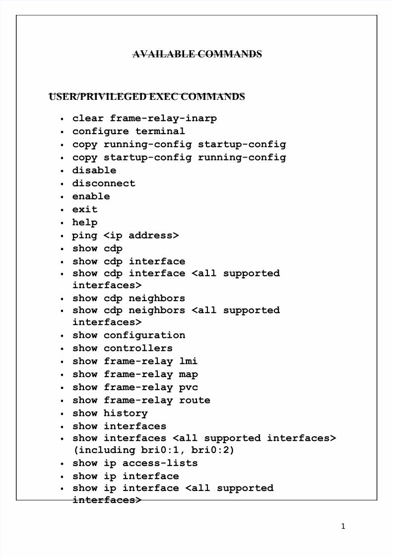
AVAILABLE COMMANDS
USER/PRIVILEGED EXEC COMMANDS
• clear frame-relay-inarp
• configure terminal
• copy running-config startup-config
• copy startup-config running-config
• disable
• disconnect
• enable • exit
• help
• ping <ip address>
• show cdp
• show cdp interface
• show cdp interface <all supported interfaces>
• show cdp neighbors
• show cdp neighbors <all supported interfaces>
• show configuration
• show controllers
• show frame-relay lmi
• show frame-relay map
•
show frame-relay pvc • show frame-relay route
• show history
• show interfaces
• show interfaces <all supported interfaces> (including bri0:1, bri0:2)
• show ip access-lists
• show ip interface
• show ip interface <all supported interfaces>
1

8/3/2019 Ccna Notes 1
http://slidepdf.com/reader/full/ccna-notes-1 2/98
• show ip route
• show ipx route
• show ipx servers
•
show isdn active • show isdn history
• show isdn status
• show running-config
• show startup-config
• show version
• terminal editing
• terminal history
• terminal history size <size> • terminal no editing
• terminal no history
• traceroute <ip address>
GLOBAL CONFIGURATION COMMANDS
• access-list <1-99> deny/permit <address>
• access-list <1-99> deny/permit <address> <wildcard mask>
• access-list <1-99> deny/permit host <address>
• banner <banner text>
• banner exec <banner text>
• banner incoming <banner text>
• banner login <banner text>
• banner motd <banner text> • cdp holdtime <time>
• cdp timer <time>
• cdp run
• dialer-list <1-10> protocol ip deny/permit
• enable password <password>
• enable secret <password>
•
end • exit
2
8/3/2019 Ccna Notes 1
http://slidepdf.com/reader/full/ccna-notes-1 3/98
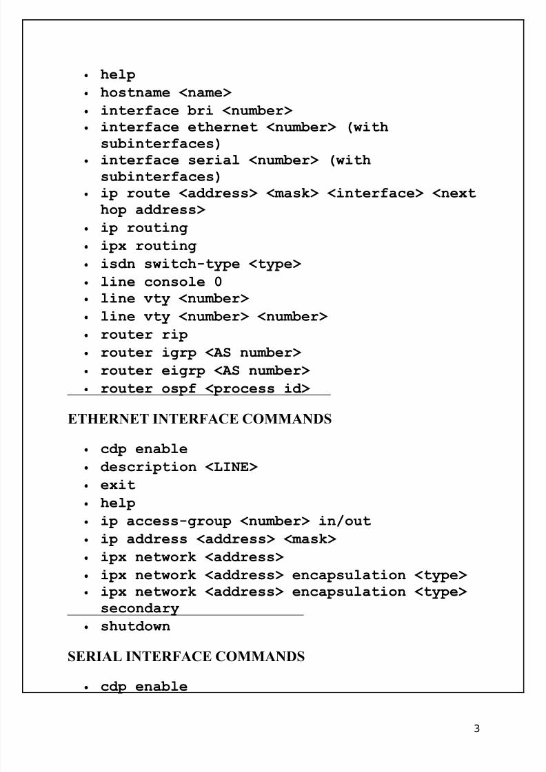
• help
• hostname <name>
• interface bri <number> • interface ethernet <number> (withsubinterfaces)
• interface serial <number> (withsubinterfaces)
• ip route <address> <mask> <interface> <nexthop address>
• ip routing
• ipx routing
•
isdn switch-type <type> • line console 0
• line vty <number>
• line vty <number> <number>
• router rip
• router igrp <AS number>
• router eigrp <AS number>
• router ospf <process id>
ETHERNET INTERFACE COMMANDS
• cdp enable
• description <LINE>
• exit
• help
• ip access-group <number> in/out
• ip address <address> <mask> • ipx network <address>
• ipx network <address> encapsulation <type> • ipx network <address> encapsulation <type> secondary
• shutdown
SERIAL INTERFACE COMMANDS
• cdp enable
3
8/3/2019 Ccna Notes 1
http://slidepdf.com/reader/full/ccna-notes-1 4/98
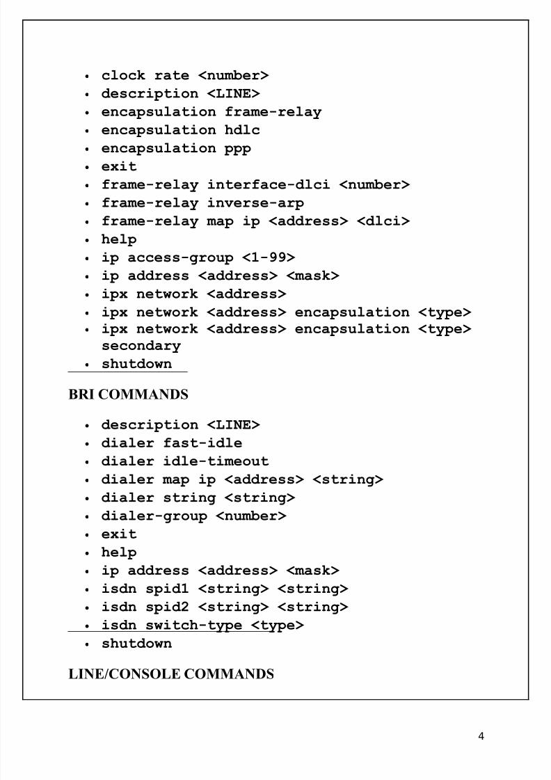
• clock rate <number>
• description <LINE>
• encapsulation frame-relay
•
encapsulation hdlc • encapsulation ppp
• exit
• frame-relay interface-dlci <number>
• frame-relay inverse-arp
• frame-relay map ip <address> <dlci>
• help
• ip access-group <1-99>
• ip address <address> <mask> • ipx network <address>
• ipx network <address> encapsulation <type> • ipx network <address> encapsulation <type> secondary
• shutdown
BRI COMMANDS
• description <LINE>
• dialer fast-idle
• dialer idle-timeout
• dialer map ip <address> <string>
• dialer string <string>
• dialer-group <number>
• exit
• help
• ip address <address> <mask>
• isdn spid1 <string> <string>
• isdn spid2 <string> <string>
• isdn switch-type <type>
• shutdown
LINE/CONSOLE COMMANDS
4
8/3/2019 Ccna Notes 1
http://slidepdf.com/reader/full/ccna-notes-1 5/98
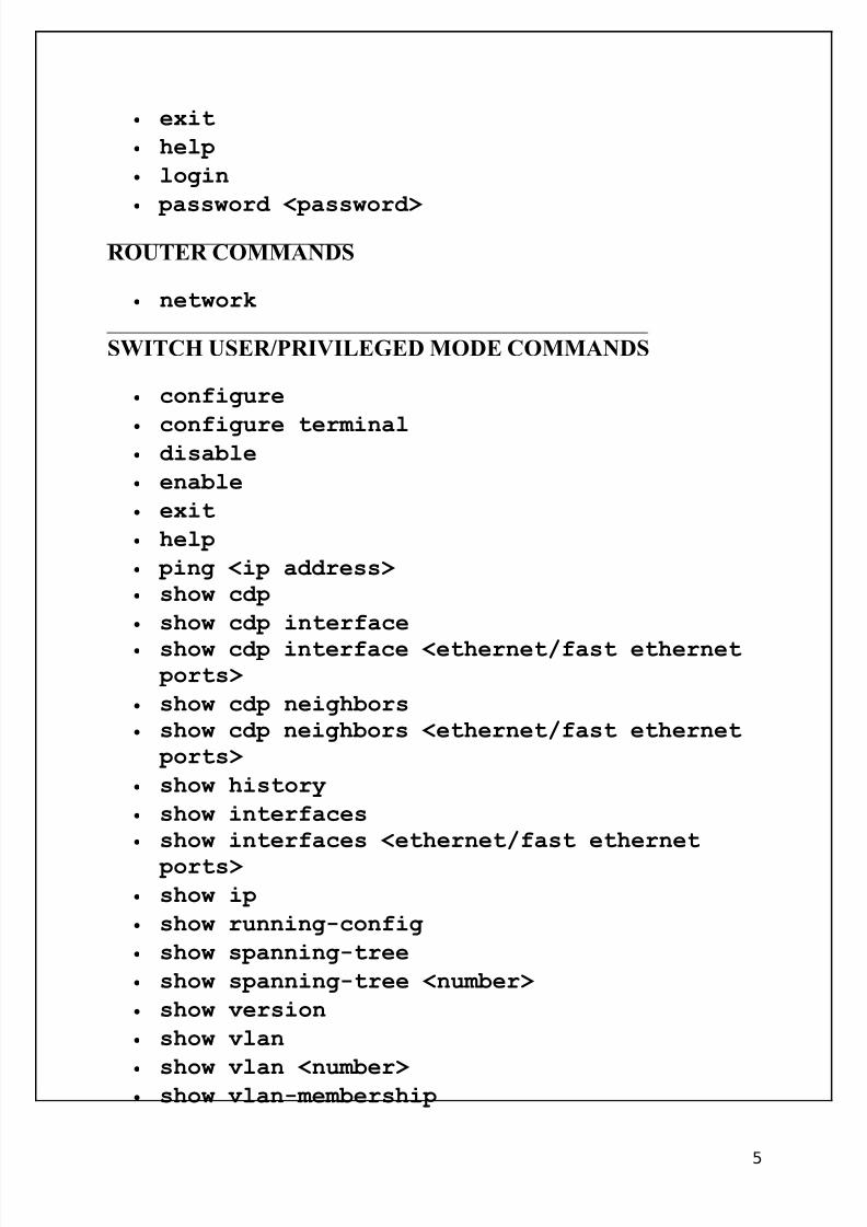
• exit
• help
• login
•
password <password>
ROUTER COMMANDS
• network
SWITCH USER/PRIVILEGED MODE COMMANDS
• configure
•
configure terminal • disable
• enable
• exit
• help
• ping <ip address> • show cdp
• show cdp interface
• show cdp interface <ethernet/fast ethernet ports>
• show cdp neighbors
• show cdp neighbors <ethernet/fast ethernet ports>
• show history
• show interfaces
• show interfaces <ethernet/fast ethernet
ports> • show ip
• show running-config
• show spanning-tree
• show spanning-tree <number>
• show version
• show vlan
•
show vlan <number> • show vlan-membership
5
8/3/2019 Ccna Notes 1
http://slidepdf.com/reader/full/ccna-notes-1 6/98
• show vtp
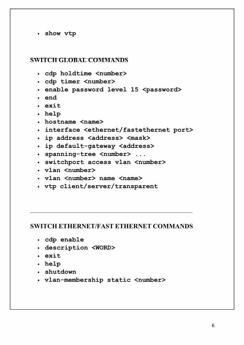
SWITCH GLOBAL COMMANDS
• cdp holdtime <number>
• cdp timer <number>
• enable password level 15 <password>
• end
• exit
• help
• hostname <name> • interface <ethernet/fastethernet port>
• ip address <address> <mask>
• ip default-gateway <address>
• spanning-tree <number> ...
• switchport access vlan <number>
• vlan <number>
•
vlan <number> name <name> • vtp client/server/transparent
SWITCH ETHERNET/FAST ETHERNET COMMANDS
•
cdp enable • description <WORD>
• exit
• help
• shutdown
• vlan-membership static <number>
6

8/3/2019 Ccna Notes 1
http://slidepdf.com/reader/full/ccna-notes-1 7/98
CONNECTION-ORIENTED VS. CONNECTIONLESS
• Connection-oriented protocols are reliable. They perform session initiation, error detection, and error correction. They identify and retransmit lost packets.
• A connection-oriented protocol is a good choice where reliable, error-freecommunications are more important than speed.
• The three phases of connection-oriented communication are:1. Session initialization (connection establishment),2. Session maintenance (data transfer), and3. Session termination (connection release).
You should also know the following facts about connectionless communication:
• Connectionless services assume an existing link between devices and allowtransmission without extensive session establishment.
• Connectionless communications include no error checking or acknowledgementmechanisms.
• Connectionless communications use no error checking, session establishment, or acknowledgements.
• Connectionless protocols allow quick, efficient communication. However, data errorsand packet loss might occur.
USES OF THE OSI MODEL
You should be familiar with the OSI model, because it is the most widely used method for talking about network communications. However, remember that it is only a theoreticalmodel that defines standards for programmers and network administrators, not a model of actual physical layers.
Using the OSI model to discuss networking concepts has the following advantages:
• Provides a common language or reference point between network professionals• Divides networking tasks into logical layers for easier comprehension• Allows specialization of features at different levels
7

8/3/2019 Ccna Notes 1
http://slidepdf.com/reader/full/ccna-notes-1 8/98
• Aids in troubleshooting• Promotes standards interoperability between networks and devices• Provides modularity in networking features (developers can change features without
changing the entire approach)
However, you must remember the following limitations of the OSI model.
• OSI layers are theoretical and do not actually perform real functions.• Industry implementations rarely have a layer-to-layer correspondence with the OSI
layers.• Different protocols within the stack perform different functions that help send or
receive the overall message.
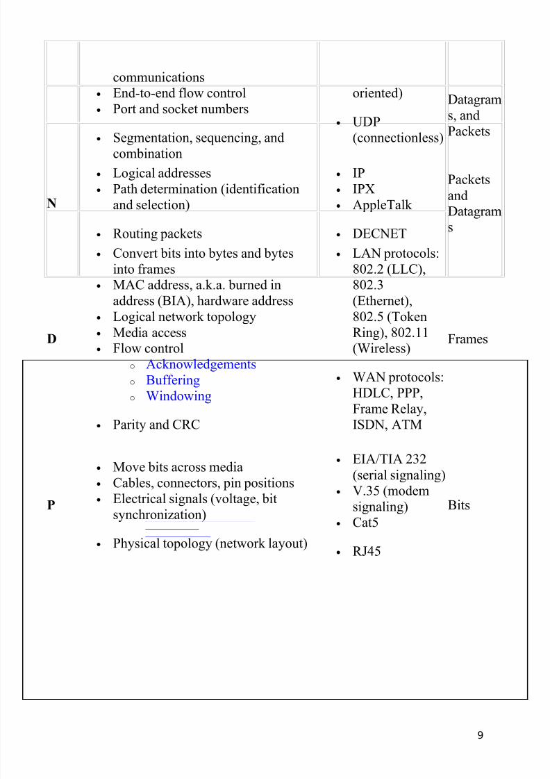
OSI MODEL LAYERS
L Description and keywords ProtocolsEncapsul
ation
A
• User interface
• Communication partner identification
• HTTP• Telnet• FTP• TFTP
• SNMP
Messages
andPackets
P
• Data format (file formats)• Encryption, translation, and
compression
• Data format and exchange
• JPEG, BMP,TIFF, PICT
• MPEG, WMV,AVI
• ASCII, EBCDIC
• MIDI, WAV
Packets
S
• Keeps data streams separate (sessionidentification)
• Set up, maintain, and tear downcommunication sessions
• SQL• NFS• ASP• RPC
• X window
Packets
T • Reliable (connection-oriented) and
unreliable (connectionless)
• TCP
(connection-
Segments
,
8
8/3/2019 Ccna Notes 1
http://slidepdf.com/reader/full/ccna-notes-1 9/98
communications• End-to-end flow control• Port and socket numbers
• Segmentation, sequencing, andcombination
oriented)
• UDP
(connectionless)
Datagrams, and
Packets
N
• Logical addresses• Path determination (identification
and selection)
• Routing packets
• IP• IPX• AppleTalk
• DECNET
PacketsandDatagrams
D
• Convert bits into bytes and bytes
into frames• MAC address, a.k.a. burned in
address (BIA), hardware address• Logical network topology• Media access• Flow control
o Acknowledgementso Bufferingo Windowing
• Parity and CRC
• LAN protocols:
802.2 (LLC),802.3(Ethernet),802.5 (TokenRing), 802.11(Wireless)
• WAN protocols:HDLC, PPP,
Frame Relay,ISDN, ATM
Frames
P
• Move bits across media• Cables, connectors, pin positions• Electrical signals (voltage, bit
synchronization)
• Physical topology (network layout)
• EIA/TIA 232(serial signaling)
• V.35 (modemsignaling)
• Cat5
• RJ45
Bits
9
8/3/2019 Ccna Notes 1
http://slidepdf.com/reader/full/ccna-notes-1 10/98
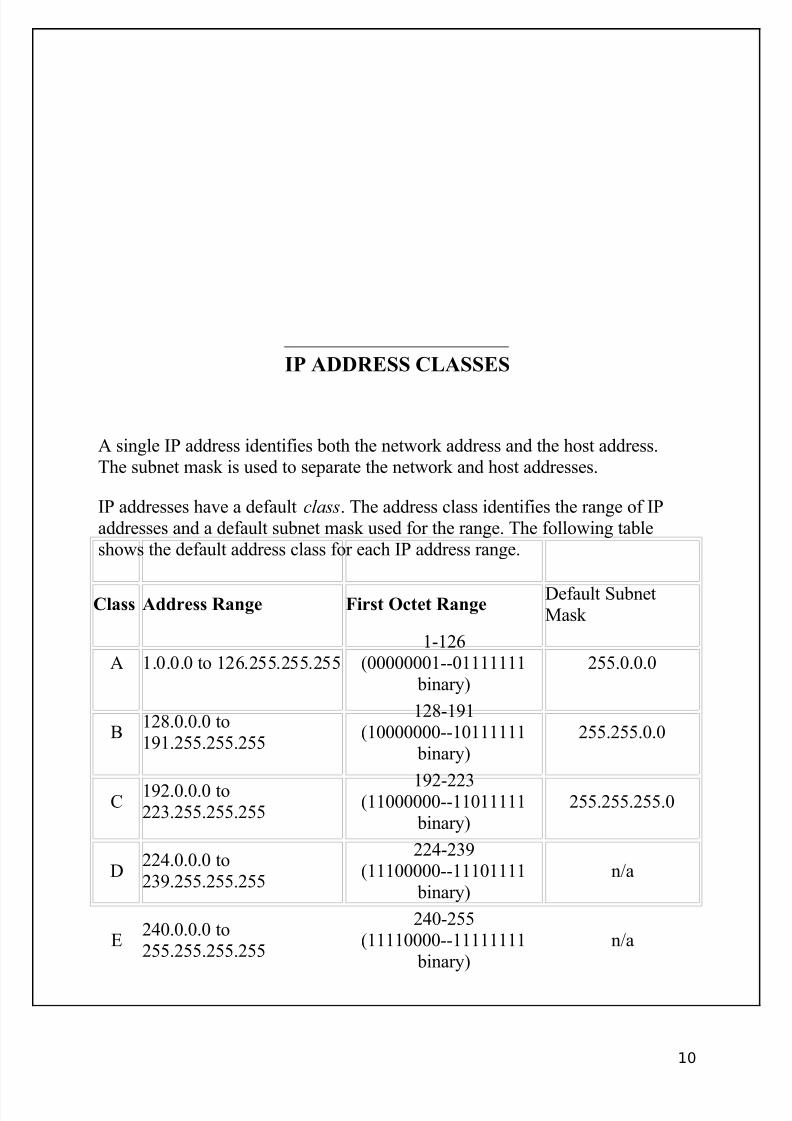
IP ADDRESS CLASSES
A single IP address identifies both the network address and the host address.The subnet mask is used to separate the network and host addresses.
IP addresses have a default class. The address class identifies the range of IPaddresses and a default subnet mask used for the range. The following tableshows the default address class for each IP address range.
Class Address Range First Octet Range Default SubnetMask
A 1.0.0.0 to 126.255.255.2551-126
(00000001--01111111 binary)
255.0.0.0
B128.0.0.0 to191.255.255.255
128-191(10000000--10111111
binary)255.255.0.0
C 192.0.0.0 to223.255.255.255
192-223(11000000--11011111 binary)
255.255.255.0
D224.0.0.0 to239.255.255.255
224-239(11100000--11101111
binary)n/a
E240.0.0.0 to255.255.255.255
240-255(11110000--11111111
binary)n/a
10
8/3/2019 Ccna Notes 1
http://slidepdf.com/reader/full/ccna-notes-1 11/98
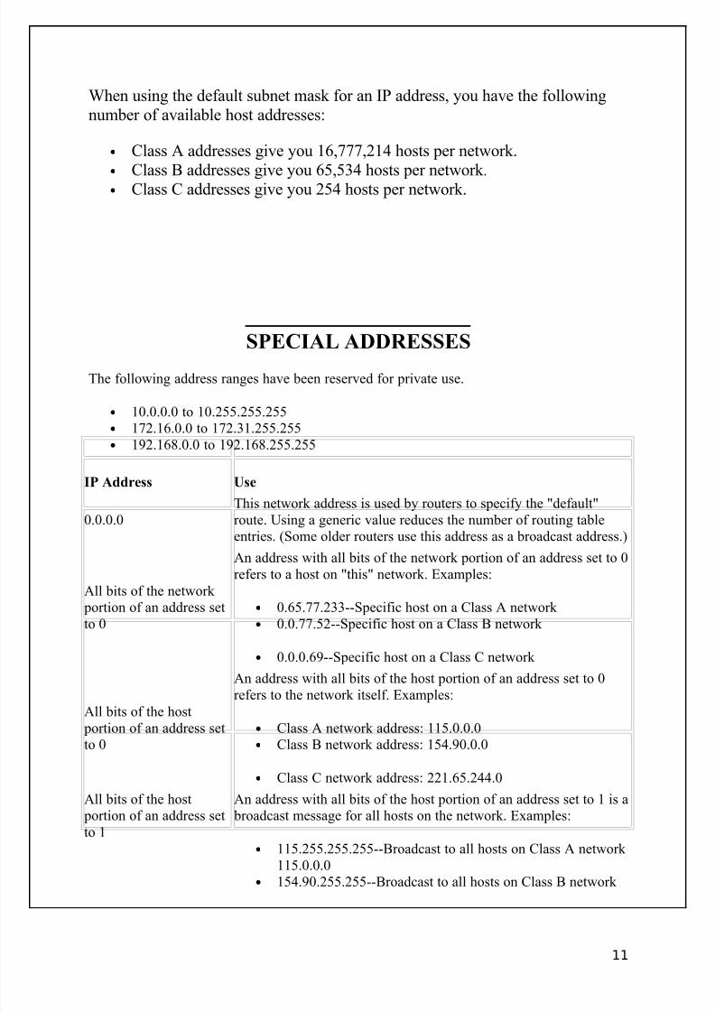
When using the default subnet mask for an IP address, you have the followingnumber of available host addresses:
• Class A addresses give you 16,777,214 hosts per network.•
Class B addresses give you 65,534 hosts per network.• Class C addresses give you 254 hosts per network.
SPECIAL ADDRESSES
The following address ranges have been reserved for private use.
• 10.0.0.0 to 10.255.255.255• 172.16.0.0 to 172.31.255.255• 192.168.0.0 to 192.168.255.255
IP Address Use
0.0.0.0This network address is used by routers to specify the "default"route. Using a generic value reduces the number of routing table
entries. (Some older routers use this address as a broadcast address.)
All bits of the network portion of an address setto 0
An address with all bits of the network portion of an address set to 0refers to a host on "this" network. Examples:
• 0.65.77.233--Specific host on a Class A network • 0.0.77.52--Specific host on a Class B network
• 0.0.0.69--Specific host on a Class C network
All bits of the host portion of an address setto 0
An address with all bits of the host portion of an address set to 0refers to the network itself. Examples:
• Class A network address: 115.0.0.0• Class B network address: 154.90.0.0
• Class C network address: 221.65.244.0
All bits of the host portion of an address setto 1
An address with all bits of the host portion of an address set to 1 is a broadcast message for all hosts on the network. Examples:
• 115.255.255.255--Broadcast to all hosts on Class A network 115.0.0.0
•
154.90.255.255--Broadcast to all hosts on Class B network
11
8/3/2019 Ccna Notes 1
http://slidepdf.com/reader/full/ccna-notes-1 12/98
154.90.0.0
• 222.65.244.255--Broadcast to all hosts on Class C network 221.65.244.0
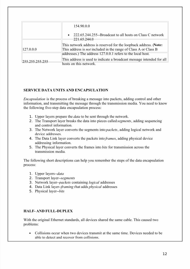
127.0.0.0This network address is reserved for the loopback address. (Note:
This address is not included in the range of Class A or Class Baddresses.) The address 127.0.0.1 refers to the local host.
255.255.255.255This address is used to indicate a broadcast message intended for allhosts on this network.
SERVICE DATA UNITS AND ENCAPSULATION
Encapsulation is the process of breaking a message into packets, adding control and other information, and transmitting the message through the transmission media. You need to knowthe following five-step data encapsulation process:
1. Upper layers prepare the data to be sent through the network.2. The Transport layer breaks the data into pieces called segments, adding sequencing
and control information.3. The Network layer converts the segments into packets, adding logical network and
device addresses.4. The Data Link layer converts the packets into frames, adding physical device
addressing information.5. The Physical layer converts the frames into bits for transmission across the
transmission media.
The following short descriptions can help you remember the steps of the data encapsulation process:
1. Upper layers--data 2. Transport layer-- segments 3. Network layer-- packets containing logical addresses
4. Data Link layer-- framing t hat adds physical addresses5. Physical layer--bits
HALF- AND FULL-DUPLEX
With the original Ethernet standards, all devices shared the same cable. This caused two problems:
• Collisions occur when two devices transmit at the same time. Devices needed to beable to detect and recover from collisions.
12
8/3/2019 Ccna Notes 1
http://slidepdf.com/reader/full/ccna-notes-1 13/98
• Each device could either transmit or receive data at any given time. This meant thatthe device was either receiving data or listening for incoming data. Devices were notable to both send and receive at the same time (much like using a one-lane road for traffic in two different directions).
These two problems were solved in the following ways:
• Using twisted pair cable, multiple strands of wires are combined into a single cable.Devices can use different wires to send and receive data (allowing them to do bothsimultaneously).
• Using switches, devices are given a dedicated communication path. With a singledevice connected to a switch port, collisions are eliminated.
With these problems solved, you can turn off collision detection. Devices can transmit andreceive data simultaneously, and can begin transmitting data as soon as they have data tosend.
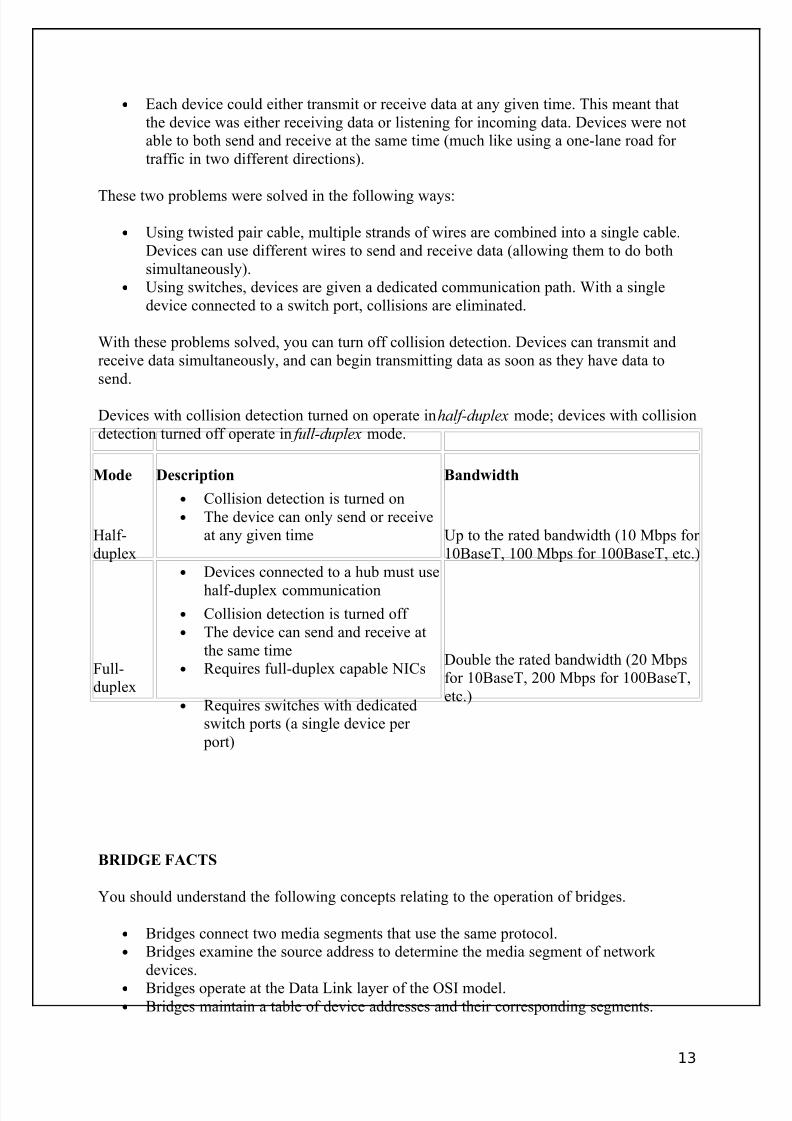
Devices with collision detection turned on operate in half-duplex mode; devices with collisiondetection turned off operate in full-duplex mode.
Mode Description Bandwidth
Half-duplex
• Collision detection is turned on• The device can only send or receive
at any given time
• Devices connected to a hub must use
half-duplex communication
Up to the rated bandwidth (10 Mbps for 10BaseT, 100 Mbps for 100BaseT, etc.)
Full-duplex
• Collision detection is turned off • The device can send and receive at
the same time• Requires full-duplex capable NICs
• Requires switches with dedicatedswitch ports (a single device per
port)
Double the rated bandwidth (20 Mbpsfor 10BaseT, 200 Mbps for 100BaseT,etc.)
BRIDGE FACTS
You should understand the following concepts relating to the operation of bridges.
• Bridges connect two media segments that use the same protocol.• Bridges examine the source address to determine the media segment of network
devices.• Bridges operate at the Data Link layer of the OSI model.• Bridges maintain a table of device addresses and their corresponding segments.
13
8/3/2019 Ccna Notes 1
http://slidepdf.com/reader/full/ccna-notes-1 14/98
• Each segment connected by a bridge can have the same network address.• Messages within a media segment are prevented from crossing over to another
segment.
Bridges offer the following advantages:
• Bridges prevent wasted bandwidth by eliminating unnecessary traffic betweensegments.
• Bridges increase the maximum network length.• Bridges forward packets for multiple upper-layer protocols.• Bridges can link segments with dissimilar transmission media and media access
methods.
Bridges have the following limitations:
• Bridges cannot link multiple architectures because different frame types are used.• Bridges cannot translate upper-layer protocols.• Bridges cannot forward packets to different networks based on the network address.• Bridges do not filter broadcast packets.
Use bridges to isolate traffic to a segment, or to prevent unwanted traffic from crossing over to other segments, or to slow WAN links. When designing the placement of bridges on thenetwork, follow the 80/20 rule.
• At least 80% of network traffic should stay within a segment.• No more than 20% of network traffic should pass through the bridge to another
segment.
SWITCH FACTS
Switches provide functionality similar to bridges, but typically on a larger scale and withhigher performance.
• Switches are associated with the Data Link layer of the OSI Model.• Switches build a forwarding database in a manner similar to bridges. Switches
examine the source and destination Data Link (MAC) address in each packet to buildthe database and make forwarding decisions.
• Switches connect multiple segments or devices and forward packets to only onespecific port.
• You can connect a single device to a switch port or multiple devices to a switch port by using a hub.
Switches offer the following advantages over a non-switched network.
• Switches create separate collision domains.•
Switches provide guaranteed bandwidth between devices (if dedicated ports are used).
14
8/3/2019 Ccna Notes 1
http://slidepdf.com/reader/full/ccna-notes-1 15/98
• Switches can be used to provide collision-free networking (i.e. if only one device isconnected to each switch port).
• Switches enable full-duplex communication.• Switches induce less latency than other segmentation solutions.• Switches can simultaneously switch multiple messages.
• Switches can mix 10 Mbps- and 100 Mbps-capable devices (if the switch is a 100Mbps switch).
• Ethernet switches can be implemented without re-cabling.
BRIDGE AND SWITCH FORWARDING FACTS
Both bridges and switches build a forwarding database. The database is a list of Data Link (MAC) addresses and the port used to reach the device. Bridges and switches canautomatically learn about devices to build the forwarding database. A network administrator can also program the device database manually. Bridges and switches use the following
process to dynamically build the forwarding database:
• The process begins by examining the source address of an incoming packet. If thesource address is not in the forwarding database, an entry for the address is made inthe database. The port it came in on is also recorded.
• The destination address is then examined.o If the destination address is not in the database, the packet is sent out all ports
except for the one on which it was received.o If the destination address is in the database, the packet is forwarded to the
appropriate port if the port is different than the one on which it was received.o Broadcast packets are forwarded to all ports except the one on which they
were received.
Transparent bridges forward packets only if the following conditions are met.
• The frame contains upper-layer data (data from the LLC sublayer on up).
• The frame's integrity has been verified (a valid CRC).• The frame is not addressed to the bridge.
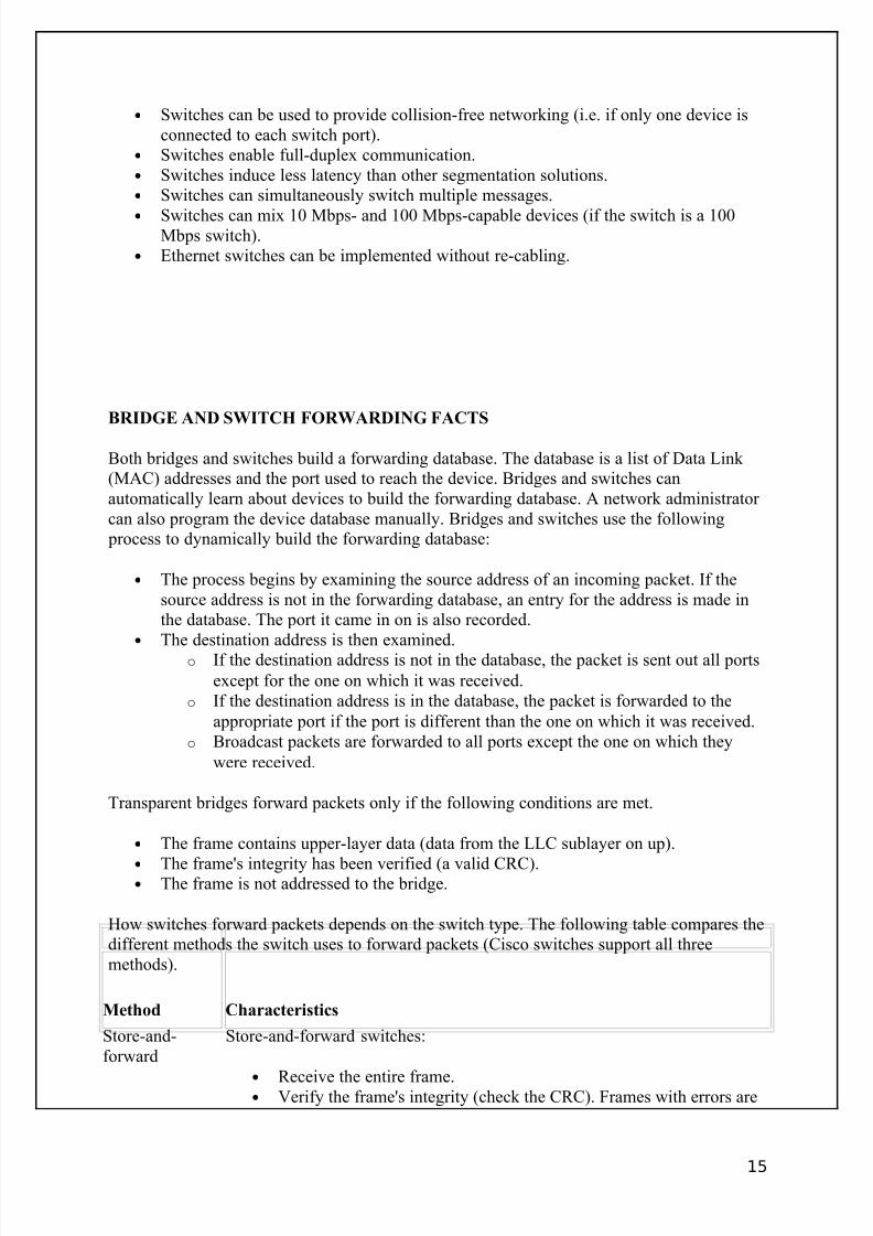
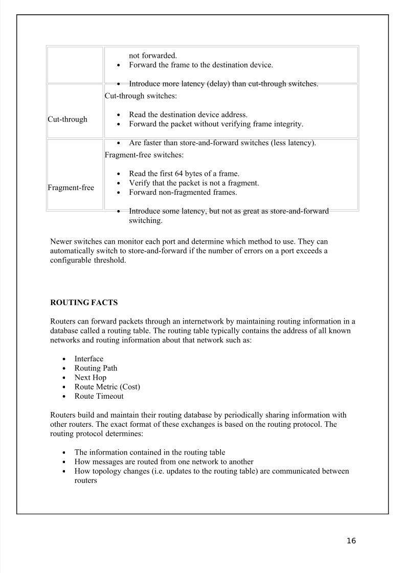
How switches forward packets depends on the switch type. The following table compares thedifferent methods the switch uses to forward packets (Cisco switches support all threemethods).
Method Characteristics
Store-and-forward
Store-and-forward switches:
•
Receive the entire frame.• Verify the frame's integrity (check the CRC). Frames with errors are
15
8/3/2019 Ccna Notes 1
http://slidepdf.com/reader/full/ccna-notes-1 16/98
not forwarded.• Forward the frame to the destination device.
• Introduce more latency (delay) than cut-through switches.
Cut-through
Cut-through switches:
• Read the destination device address.• Forward the packet without verifying frame integrity.
• Are faster than store-and-forward switches (less latency).
Fragment-free
Fragment-free switches:
• Read the first 64 bytes of a frame.• Verify that the packet is not a fragment.• Forward non-fragmented frames.
• Introduce some latency, but not as great as store-and-forwardswitching.
Newer switches can monitor each port and determine which method to use. They canautomatically switch to store-and-forward if the number of errors on a port exceeds aconfigurable threshold.
ROUTING FACTS
Routers can forward packets through an internetwork by maintaining routing information in adatabase called a routing table. The routing table typically contains the address of all knownnetworks and routing information about that network such as:
• Interface• Routing Path• Next Hop• Route Metric (Cost)• Route Timeout
Routers build and maintain their routing database by periodically sharing information withother routers. The exact format of these exchanges is based on the routing protocol. Therouting protocol determines:
• The information contained in the routing table• How messages are routed from one network to another • How topology changes (i.e. updates to the routing table) are communicated between
routers
16
8/3/2019 Ccna Notes 1
http://slidepdf.com/reader/full/ccna-notes-1 17/98
Regardless of the method used, changes in routing information take some time to be propagated to all routers on the network. The term convergence is used to describe thecondition when all routers have the same (or correct) routing information.
MESSAGE ROUTING FACTS
Keep in mind the following points about how a packet is addressed as it travels through aninternetwork.
• On an Ethernet network, the Data Link layer address is the MAC address. On an IPnetwork, the IP address is the Network layer address.
• Both Data Link physical addresses and Network logical addresses are used.• The Network address contains both a logical network address and a logical device
address. IP (Network) addresses are contained in the IP header; MAC (Data Link)addresses are contained in the Ethernet frame header.• Both the source and destination Network and Data Link addresses are typically
contained in the packet.• The Data Link destination address indicates the physical address of the next hop on
the route.• Data Link addresses in the packet change as the packet is delivered from hop to hop.• The Network destination addresses indicate the address of the final destination device.• Network addresses remain constant as the packet is delivered from hop to hop.• A router uses the logical network address specified at the Network layer to forward
messages to the appropriate LAN segment.
SEGMENTATION FACTS
LAN segmentation is the process of dividing the network to overcome problems such asexcessive collisions, broadcast traffic, or heavy network traffic. By segmenting a LAN, youcan increase network performance, maximize bandwidth, and reduce congestion.
As you segment the network, you will need to consider the collision and broadcast domains
on the network.
17

8/3/2019 Ccna Notes 1
http://slidepdf.com/reader/full/ccna-notes-1 18/98
• A collision domain is any network or subnetwork where devices share the sametransmission medium and where packets can collide. Collisions naturally increase asthe number of devices in a collision domain increase.
• A broadcast domain is any network or subnetwork where computers can receiveframe-level broadcasts from their neighbors. As you add devices to a network
segment, the amount of broadcast traffic on a segment also increases. Note: A specialcondition called a broadcast storm happens when broadcast traffic is sent,regenerated, and responded to. In this condition, the amount of broadcast trafficconsumes network bandwidth and prevents normal communications. Faulty devices or improper configuration conditions can lead to a broadcast storm.
Segmentation may increase the number of both the collision and broadcast domains.Membership within collision or broadcast domains differs depending on the connectiondevice used.
Device Collision Domain Broadcast Domain
HubAll devices connected to the hub are in thesame collision domain
All devices are in the same broadcastdomain
Bridge or Switch
All devices connected to a single port are inthe same collision domain (each port is itsown collision domain)
All devices connected to the bridge or the switch are in the same broadcastdomain
Router All devices connected to a single interfaceare in the same collision domain
All devices accessible through aninterface (network) are in the same
broadcast domain
In considering a network expansion solution, it is important to identify the connectivity problems you need to resolve, and then identify the device that is best suited for that situation.The main differences between routers, switches, and bridges is the range of services each
performs and the OSI layer at which they operate.
Device Characteristics
Router Routers perform the following functions that are not performed by bridges or switches.
•
Route packets between separate networks• Modify packet size through fragmentation and combination• Route packets based on service address
Choose a router if you need to:
• Connect your network to a WAN (such as the Internet)• Filter broadcast traffic (prevent broadcast storms)• Connect two separate networks that use the same protocol• Improve performance in the event of a topology change (routers recover faster
than bridges or switches)
• Reduce the number of devices within a domain (increase the number of broadcast domains)
18
8/3/2019 Ccna Notes 1
http://slidepdf.com/reader/full/ccna-notes-1 19/98
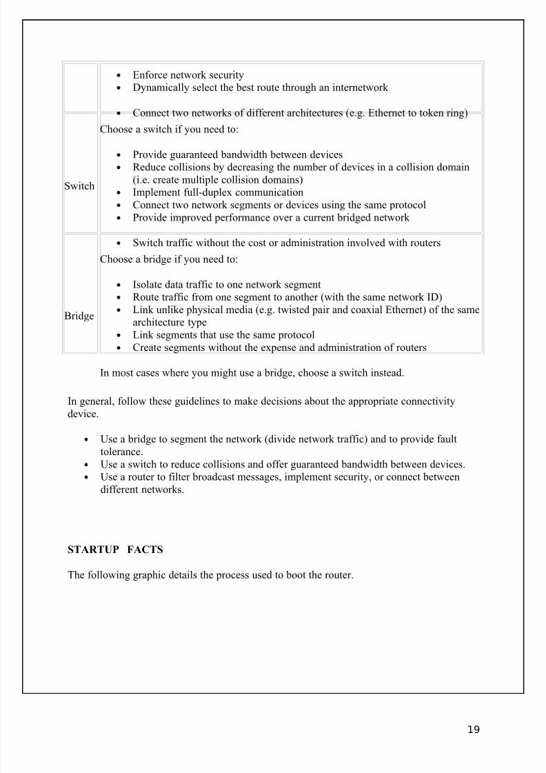
• Enforce network security• Dynamically select the best route through an internetwork
• Connect two networks of different architectures (e.g. Ethernet to token ring)
Switch
Choose a switch if you need to:
• Provide guaranteed bandwidth between devices• Reduce collisions by decreasing the number of devices in a collision domain
(i.e. create multiple collision domains)• Implement full-duplex communication• Connect two network segments or devices using the same protocol• Provide improved performance over a current bridged network
• Switch traffic without the cost or administration involved with routers
Bridge
Choose a bridge if you need to:
• Isolate data traffic to one network segment• Route traffic from one segment to another (with the same network ID)• Link unlike physical media (e.g. twisted pair and coaxial Ethernet) of the same
architecture type• Link segments that use the same protocol• Create segments without the expense and administration of routers
In most cases where you might use a bridge, choose a switch instead.
In general, follow these guidelines to make decisions about the appropriate connectivitydevice.
• Use a bridge to segment the network (divide network traffic) and to provide faulttolerance.
• Use a switch to reduce collisions and offer guaranteed bandwidth between devices.• Use a router to filter broadcast messages, implement security, or connect between
different networks.
STARTUP FACTS
The following graphic details the process used to boot the router.
19

8/3/2019 Ccna Notes 1
http://slidepdf.com/reader/full/ccna-notes-1 20/98
When you turn the router on, it runs through the following boot process.
1. The Power-On Self Test (POST) checks the router's hardware. When thePOST completes successfully, the System OK LED indicator comes on.
2. The router checks the configuration register to identify where to load theIOS image from. A setting of 0x2102 means that the router will useinformation in the startup-config file to locate the IOS image. If the startup-config file is missing or does not specify a location, it will check thefollowing locations for the IOS image:
1. Flash (the default location)2. TFTP server3. ROM (used if no other source is found)
3. The router loads the configuration file into RAM (which configures therouter). The router can load a configuration file from:
1. NVRAM (startup-configuration file)2. TFTP server3. If a configuration file is not found, the router starts in setup mode.
SETUP MODE FACTS
If the router is brand new, it has no startup-config file. Therefore, when it boots, itimmediately enters Setup mode. Setup mode is a special, guided routine that asks you a seriesof questions and uses your responses to make basic configuration entries.
There are two ways to enter setup mode:
• Boot the router without the startup-config file. This happens when you erase thecurrent startup-config file, or when you boot a new router.
• Use the setup command from privileged mode.
20

8/3/2019 Ccna Notes 1
http://slidepdf.com/reader/full/ccna-notes-1 21/98
You can exit setup mode without answering all the questions by pressing <Ctrl> + C. Theinformation you've entered to that point will not be saved.
Note: By default, new Cisco routers have no passwords set, and all interfaces are in shutdownmode until they're enabled.
COMMAND HELP FACTS
Help is available in all router modes. It is context sensitive, so the information you seedepends on what you are doing. Cisco bases this on the mode you are in and the words or
partial words you type with the ?.
To... Use...
Show list of all commands available in the currentmode
?
Show commands that begin with specific letter(s) xx? (no space between the letter and ?)
Show keywords for a commandcommand ? (space between command
and ?)
Get the full command from a partial command partial command + <tab> (no space)
Note: Typing ? acts as a return, and repeats the last command you entered after the Help
information displays. You do not need to retype the command after you ask for help on it.
When you use Help to display the possible keywords for a command, you will see thefollowing types of items.
When you see... Supply...
WORD (in caps) Type a one-word response
LINE (in caps) Type a multiple-word response
keyword Identifies a specific keyword that must be typed as shown
<0-4567> Enter a number within the range in brackets
<0-FFFFFF> Enter a hexadecimal number within the range in brackets<cr> The command is complete as typed, press Enter to execute the command
A.B.C.D Enter an IP address
EDITING FEATURES FACTS
This feature uses the same keystrokes as UNIX emacs editing. The following lists summarizethe router advanced editing features.
Use this ... To ...
21

8/3/2019 Ccna Notes 1
http://slidepdf.com/reader/full/ccna-notes-1 22/98
<Ctrl> + A Move to the beginning of the line
<Ctrl> + E Move to the end of the line
<Ctrl> + BLeft arrow
Go back one character
<Ctrl> + FRight arrow
Go forward one character
<Esc> + B Go back one word
<Esc> + F Move forward one word
terminal editing Turn advanced editing on
terminal no editing Turn advanced editing off
When you are in advanced editing mode, the $ indicator appears after the prompt. As youtype, commands longer than the command line appear to scroll under the prompt.
COMMAND HISTORY COMMAND LIST
By default, the IOS automatically saves the last 10 commands in the command history buffer.The command history is specific to the configuration mode you are in.
Use . . . To . . .
<Ctrl> + A Move cursor to beginning of line
<Ctrl> + E Move cursor to the end of line<Ctrl> + Z Quit a configuration mode
<Ctrl> + B Move cursor back one character
<Esc> + B Move cursor back one word
<Esc> + F Move the cursor ahead one word
<Ctrl> + P or Up arrow Show the previous command
<Ctrl> + N or Down arrow Show the next command
terminal history Turn the command history on
terminal no history Turn the command history off
terminal history size <number> Set the size of the history buffer
show history Show all the commands in the history buffer
ROUTER MEMORY
Be sure you understand the difference between the following types of router storage.
Memory Type Characteristics
ROM (read-onlymemory)
Preprogrammed, non-writable memory containing the bootstrap startup
program, an older, smaller-scale version of the operating system (IOS)software, and the Power-on Self-Test (POST) program
22

8/3/2019 Ccna Notes 1
http://slidepdf.com/reader/full/ccna-notes-1 23/98
Flash Non-volatile but programmable memory containing the proprietary Ciscooperating system (IOS) images
RAM (randomaccess memory)
Volatile memory containing the running operating system and current(unsaved) configuration information
NVRAM (non-volatile RAM)
Non-volatile but persistent memory that contains the backup copy of thestartup configuration (startup-config) file and virtual configuration register
The contents of non-volatile memory (such as ROM, flash, and NVRAM) remain when therouter is powered off (however, you must modify the configuration registry and NVRAMduring password recovery). The contents of volatile memory (RAM) are lost when the router is powered down.
COPY COMMAND LIST
The router can load a configuration file from:
• NVRAM (startup-configuration file by default value 0x2102)• TFTP server
Changes to the configuration are stored in RAM in the running-config file. To save your configuration changes permanently, and to load different versions of the configuration filesfrom various locations, use the copy command in privileged EXEC mode.
Use . . . To . . .
Router#copy run startSave the contents of the running-config file to
NVRAM
Router#copy start run Copy the startup-config file into RAM
Router#copy run tftpSave the contents of the running-config file to a TFTPserver
Router#copy start tftpSave the contents of the startup-config file to a TFTPserver
Router#copy tftp start
Copy a configuration file from the TFTP server into
NVRAM
Router#copy tftp runCopy a configuration file from the TFTP server intoRAM
Router(config)#tftp-serverflash <filename>
Configure a Cisco router as a TFTP server. When usingthis command, you must specific the location (flash or rom) of the IOS image file as well as the IOS imagefile name.
You can also use the erase command to delete the configuration files--but be very careful
not to erase files you need!
23

8/3/2019 Ccna Notes 1
http://slidepdf.com/reader/full/ccna-notes-1 24/98
Use . . . To . . .
Router#erase flash Delete the contents of Flash memory (deletes the IOS image)
Router#erase start Erase the contents of the startup-config file
Router#erase nvram Delete the contents of NVRAM (which also erases startup-config)
Router#reload Restarts the router
You can also use the following commands to manage system files:
Use . . . To . . .
show versionDisplay information about hardware and firmwareincluding the configuration register value
configure memory
or
copy startup-configrunning-config
Copy configuration information from another source (like
NVRAM)
configure terminal Configure information into the RAM of a router
IOS BOOT AND UPGRADE LOCATION COMMAND LIST
The router can load an IOS image from the following locations:
• Flash• TFTP server • ROM (limited version of the IOS software)
Use the boot system command in global configuration mode to identify alternate
locations for the IOS image. Use the copy command to archive, upgrade, or replace an IOS
image.
Use . . . To . . .
Router(config)#boot system flash<IOSfilename>
Identify an IOS image file in flashto use at boot.
Router(config)#boot system tftp<IOSfilename> <tftp_address>
Identify an IOS image file on aTFTP server to use at boot.
Router(config)#boot system rom (IOS versions
11.2 and below)Router(config)#boot system flash
bootflash: (IOS versions 12.0 and above
Specify to use the limited IOSversion stored in ROM at boot.
Router#copy flash tftpBack up (copy) the IOS imagefrom Flash to the TFTP server.
Router#copy tftp flash
Restore the IOS image from
backup on the TFTP server toFlash.
24
8/3/2019 Ccna Notes 1
http://slidepdf.com/reader/full/ccna-notes-1 25/98
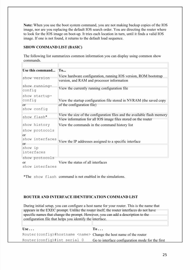
Note: When you use the boot system command, you are not making backup copies of the IOSimage, nor are you replacing the default IOS search order. You are directing the router whereto look for the IOS image on boot-up. It tries each location in turn, until it finds a valid IOSimage. If one is not found, it returns to the default load sequence.
SHOW COMMAND LIST (BASIC)
The following list summarizes common information you can display using common showcommands.
Use this command... To...
show versionView hardware configuration, running IOS version, ROM bootstrapversion, and RAM and processor information
show running-config
View the currently running configuration file
show startup-config
or show config
View the startup configuration file stored in NVRAM (the saved copyof the configuration file)
show flash*View the size of the configuration files and the available flash memoryView information for all IOS image files stored on the router
show history View the commands in the command history list
show protocols
or show interfaces
or show ipinterfaces
View the IP addresses assigned to a specific interface
show protocols
or show interfaces
View the status of all interfaces
*The show flash command is not enabled in the simulations.
ROUTER AND INTERFACE IDENTIFICATION COMMAND LIST
During initial setup, you can configure a host name for your router. This is the name thatappears in the EXEC prompt. Unlike the router itself, the router interfaces do not havespecific names that change the prompt. However, you can add a description to theconfiguration file that helps you identify the interface.
Use . . . To . . .
Router(config)#hostname <name>Change the host name of the router Router(config)#int serial 0 Go to interface configuration mode for the first
25

8/3/2019 Ccna Notes 1
http://slidepdf.com/reader/full/ccna-notes-1 26/98
Router(config)#int ser 0Router(config)#int ser0Router(config)#int s0
serial interface. Use the Ethernet (e, eth)keywords to switch to Ethernet interface mode.
Router(config-if)#description<description text>
Set a description for a specific interface
Examples
The following set of commands sets the hostname of the router to ATL1:
Router#config tRouter(config)#hostname ATL1ATL1(config)#
The following set of commands adds a description of "ATL to NYC" for the first serialinterface on the router:
Router(config)#int ser 0Router(config-if)#description ATL to NYC
Note: To undo any configuration change, use the same command preceded by the no
keyword followed by the command. For example, to remove a description from an interface,use the following command:
Router(config-if)#no description
Notice that in many cases you can leave off additional parameters when using the no
command.
ROUTER PASSWORD FACTS
The following table list three of the most common passwords that you can configure on your router:
PasswordType Description
Console Controls the ability to log on to the router through a console connection
LineControls the ability to log on to the router using a virtual terminal (VTY) or Telnet connection
EXEC mode
Controls the ability to switch to configuration modes. There are two different passwords that might be used:
• The enable password is stored in clear text in the configuration file.• The enable secret password is stored encrypted in the configuration file.
The router always uses the enable secret password if it exists.
26
8/3/2019 Ccna Notes 1
http://slidepdf.com/reader/full/ccna-notes-1 27/98
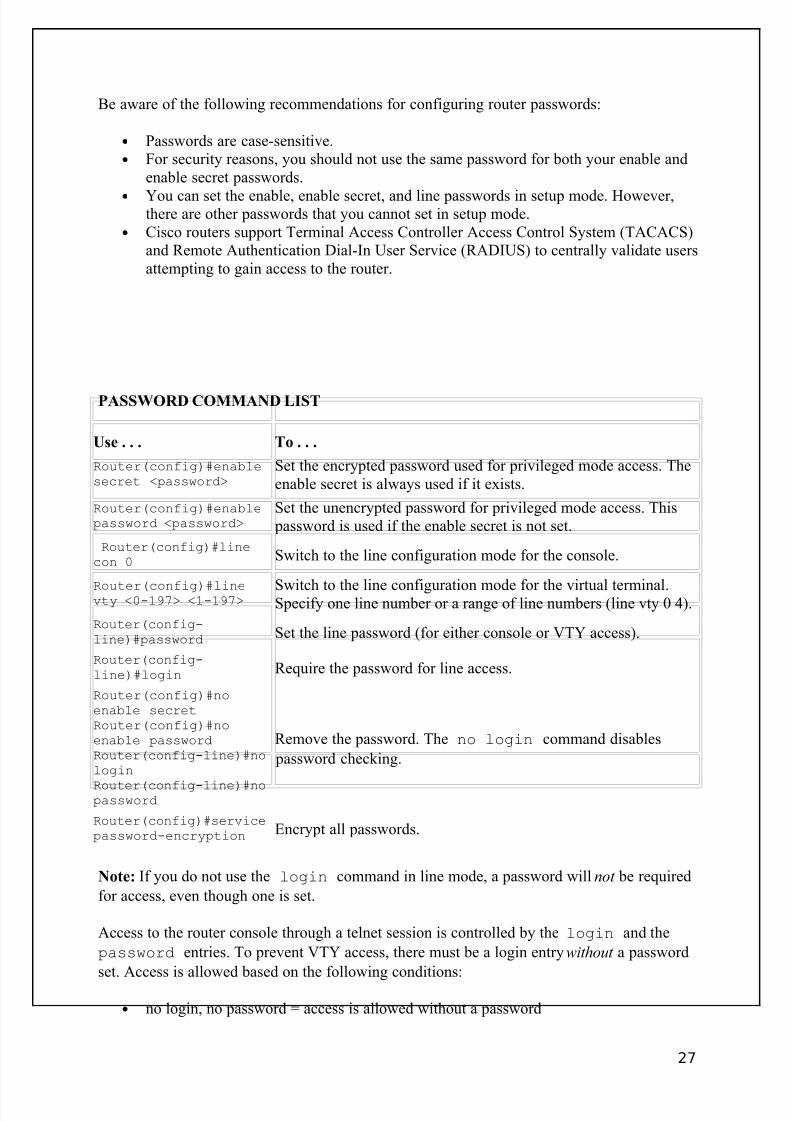
Be aware of the following recommendations for configuring router passwords:
• Passwords are case-sensitive.• For security reasons, you should not use the same password for both your enable and
enable secret passwords.
• You can set the enable, enable secret, and line passwords in setup mode. However,there are other passwords that you cannot set in setup mode.
• Cisco routers support Terminal Access Controller Access Control System (TACACS)and Remote Authentication Dial-In User Service (RADIUS) to centrally validate usersattempting to gain access to the router.
PASSWORD COMMAND LIST
Use . . . To . . .
Router(config)#enablesecret <password>
Set the encrypted password used for privileged mode access. Theenable secret is always used if it exists.
Router(config)#enablepassword <password>
Set the unencrypted password for privileged mode access. This password is used if the enable secret is not set.
Router(config)#linecon 0 Switch to the line configuration mode for the console.
Router(config)#linevty <0-197> <1-197> Switch to the line configuration mode for the virtual terminal.Specify one line number or a range of line numbers (line vty 0 4).
Router(config-line)#password Set the line password (for either console or VTY access).
Router(config-line)#login Require the password for line access.
Router(config)#noenable secretRouter(config)#noenable passwordRouter(config-line)#nologin
Router(config-line)#nopassword
Remove the password. The no login command disables
password checking.
Router(config)#servicepassword-encryption Encrypt all passwords.
Note: If you do not use the login command in line mode, a password will not be required
for access, even though one is set.
Access to the router console through a telnet session is controlled by the login and the
password entries. To prevent VTY access, there must be a login entry without a password
set. Access is allowed based on the following conditions:
• no login, no password = access is allowed without a password
27

8/3/2019 Ccna Notes 1
http://slidepdf.com/reader/full/ccna-notes-1 28/98
• login, no password = access is denied (the error message indicates that a password isrequired but none is set)
• no login, password = access is allowed without a password• login, password = access is allowed only with correct password
BANNER COMMAND LIST
Banners display messages that anyone logging into the router can see. The following four types of banners display at various times during the login or startup sequence.
Use . . . To . . .
Router(config)#bannerRouter(config)#bannermotd
Set the Message-of-the-day (MOTD) banner. The MOTD banner displays immediately after a connection is made.
Router(config)#bannerlogin
Set the login banner. The login banner displays after theMOTD banner and before the login prompt.
Router(config)#bannerexec
Set the EXEC banner. The exec banner displays after asuccessful login.
Router(config)#bannerincoming
Set the incoming banner. The incoming banner displaysfor a reverse telnet session.
Router(config)#no banner<type> Removes the specified banner
Note: The banner command without a keyword defaults to set the MOTD banner.
Follow the banner command with a delimiting character. The delimiter encloses the banner text, and helps the router identify the beginning and ending of the banner. This allows you toconstruct multiple-line banners.
ExampleThe following commands set the MOTD, login, and EXEC banners, using # as the delimitingcharacter and inserting a hard return between each banner:
Router(config)#banner motd # This is the Message-of-the-day banner!#Router(config)#banner login # This is the Login banner!#Router(config)#banner exec # This is the Exec banner!#
28
8/3/2019 Ccna Notes 1
http://slidepdf.com/reader/full/ccna-notes-1 29/98
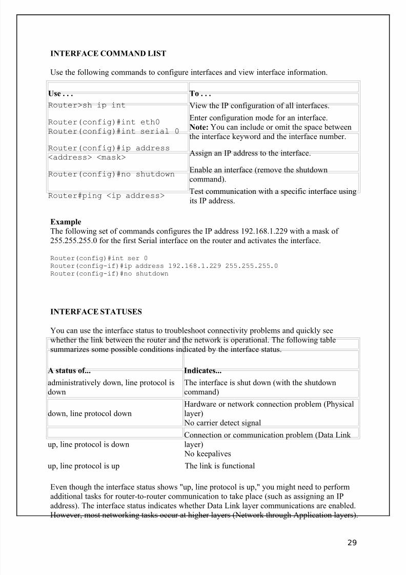
INTERFACE COMMAND LIST
Use the following commands to configure interfaces and view interface information.
Use . . . To . . .
Router>sh ip int View the IP configuration of all interfaces.
Router(config)#int eth0Router(config)#int serial 0
Enter configuration mode for an interface.Note: You can include or omit the space betweenthe interface keyword and the interface number.
Router(config)#ip address<address> <mask>
Assign an IP address to the interface.
Router(config)#no shutdownEnable an interface (remove the shutdowncommand).
Router#ping <ip address>Test communication with a specific interface using
its IP address.
Example
The following set of commands configures the IP address 192.168.1.229 with a mask of 255.255.255.0 for the first Serial interface on the router and activates the interface.
Router(config)#int ser 0Router(config-if)#ip address 192.168.1.229 255.255.255.0Router(config-if)#no shutdown
INTERFACE STATUSES
You can use the interface status to troubleshoot connectivity problems and quickly seewhether the link between the router and the network is operational. The following tablesummarizes some possible conditions indicated by the interface status.
A status of... Indicates...
administratively down, line protocol isdown
The interface is shut down (with the shutdowncommand)
down, line protocol downHardware or network connection problem (Physicallayer)
No carrier detect signal
up, line protocol is downConnection or communication problem (Data Link layer)
No keepalives
up, line protocol is up The link is functional
Even though the interface status shows "up, line protocol is up," you might need to performadditional tasks for router-to-router communication to take place (such as assigning an IP
address). The interface status indicates whether Data Link layer communications are enabled.However, most networking tasks occur at higher layers (Network through Application layers).
29

8/3/2019 Ccna Notes 1
http://slidepdf.com/reader/full/ccna-notes-1 30/98
BACK-TO-BACK CONFIGURATION FACTS
When you configure a router to connect to a network through a serial interface, the router must be connected to a device (such as a CSU/DSU or another router) that provides clockingsignals. When you configure two routers in a back-to-back configuration through their serial
ports, one router interface must be configured to provide the clocking signals for theconnection.
• The router providing clocking is known as the DCE (data circuit-terminatingequipment).
• The router not providing clocking is known as the DTE (data terminal equipment).
The DCE interface is identified in two ways:
• The cable connecting the two routers has both a DCE and a DTE end. Connect theDCE end of the cable to the interface you want to be the DCE device.
• The DCE interface is configured to provide a clocking signal with the clock rate
command. If the clock rate command is not issued, clocking is not provided, andthe line between the two routers will not change to up.
CDP COMMAND LIST
The Cisco Discovery Protocol (CDP) is a protocol that Cisco devices use to learn and shareinformation about each other. Cisco devices, such as routers and switches, can discover neighboring Cisco devices through CDP.
• By default, CDP is enabled on all interfaces.• CDP only shares information with directly connected (neighboring) devices.• CDP works when there is a valid Data Link layer connection.• CDP works regardless of the Network layer and other protocols used. It can discover
information on LANs, Frame Relay, and other network architectures.
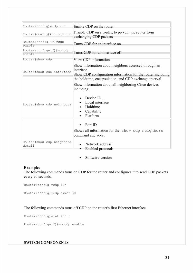
Use the following commands to customize and view CDP information.
Use . . . To . . .
Router(config)#cdpholdtime <10-255>
Specify the amount of time that information in a packet is stillvalid (default = 180 seconds)
Router(config)#cdp timer
<5-900>
Specify how often CDP packets are exchanged (default = 60
seconds)
30
8/3/2019 Ccna Notes 1
http://slidepdf.com/reader/full/ccna-notes-1 31/98
Router(config)#cdp run Enable CDP on the router
Router(config)#no cdp runDisable CDP on a router, to prevent the router fromexchanging CDP packets
Router(config-if)#cdpenable Turns CDP for an interface on
Router(config-if)#no cdpenable Turns CDP for an interface off
Router#show cdp View CDP information
Router#show cdp interface
Show information about neighbors accessed through aninterfaceShow CDP configuration information for the router includingthe holdtime, encapsulation, and CDP exchange interval
Router#show cdp neighbors
Show information about all neighboring Cisco devicesincluding:
• Device ID• Local interface• Holdtime• Capability• Platform
• Port ID
Router#show cdp neighborsdetail
Shows all information for the show cdp neighbors
command and adds:
• Network address• Enabled protocols
• Software version
Examples
The following commands turns on CDP for the router and configures it to send CDP packetsevery 90 seconds.
Router(config)#cdp run
Router(config)#cdp timer 90
The following commands turns off CDP on the router's first Ethernet interface.
Router(config)#int eth 0
Router(config-if)#no cdp enable
SWITCH COMPONENTS
31
8/3/2019 Ccna Notes 1
http://slidepdf.com/reader/full/ccna-notes-1 32/98
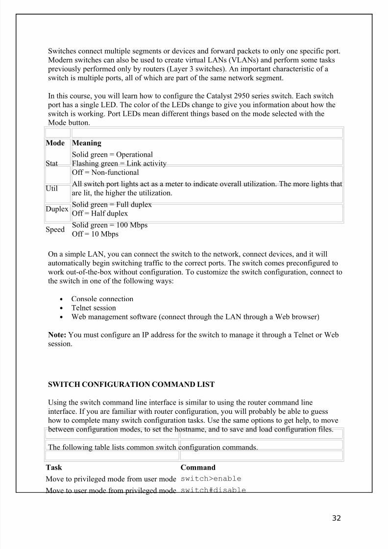
Switches connect multiple segments or devices and forward packets to only one specific port.Modern switches can also be used to create virtual LANs (VLANs) and perform some tasks
previously performed only by routers (Layer 3 switches). An important characteristic of aswitch is multiple ports, all of which are part of the same network segment.
In this course, you will learn how to configure the Catalyst 2950 series switch. Each switch port has a single LED. The color of the LEDs change to give you information about how theswitch is working. Port LEDs mean different things based on the mode selected with theMode button.
Mode Meaning
StatSolid green = OperationalFlashing green = Link activityOff = Non-functional
Util
All switch port lights act as a meter to indicate overall utilization. The more lights that
are lit, the higher the utilization.
DuplexSolid green = Full duplexOff = Half duplex
SpeedSolid green = 100 MbpsOff = 10 Mbps
On a simple LAN, you can connect the switch to the network, connect devices, and it willautomatically begin switching traffic to the correct ports. The switch comes preconfigured towork out-of-the-box without configuration. To customize the switch configuration, connect tothe switch in one of the following ways:
• Console connection• Telnet session• Web management software (connect through the LAN through a Web browser)
Note: You must configure an IP address for the switch to manage it through a Telnet or Websession.
SWITCH CONFIGURATION COMMAND LIST
Using the switch command line interface is similar to using the router command lineinterface. If you are familiar with router configuration, you will probably be able to guesshow to complete many switch configuration tasks. Use the same options to get help, to move
between configuration modes, to set the hostname, and to save and load configuration files.
The following table lists common switch configuration commands.
Task Command
Move to privileged mode from user mode switch>enableMove to user mode from privileged mode switch#disable
32
8/3/2019 Ccna Notes 1
http://slidepdf.com/reader/full/ccna-notes-1 33/98
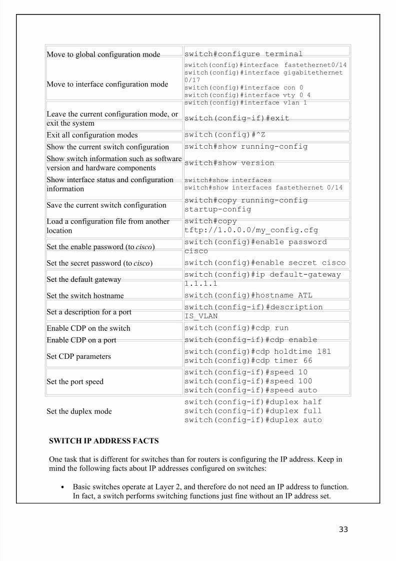
Move to global configuration mode switch#configure terminal
Move to interface configuration mode
switch(config)#interface fastethernet0/14switch(config)#interface gigabitethernet0/17switch(config)#interface con 0
switch(config)#interface vty 0 4switch(config)#interface vlan 1
Leave the current configuration mode, or exit the system
switch(config-if)#exit
Exit all configuration modes switch(config)#^Z
Show the current switch configuration switch#show running-config
Show switch information such as softwareversion and hardware components
switch#show version
Show interface status and configurationinformation
switch#show interfacesswitch#show interfaces fastethernet 0/14
Save the current switch configurationswitch#copy running-configstartup-config
Load a configuration file from another location
switch#copytftp://1.0.0.0/my_config.cfg
Set the enable password (to cisco)switch(config)#enable passwordcisco
Set the secret password (to cisco) switch(config)#enable secret cisco
Set the default gatewayswitch(config)#ip default-gateway1.1.1.1
Set the switch hostname switch(config)#hostname ATL
Set a description for a portswitch(config-if)#descriptionIS_VLAN
Enable CDP on the switch switch(config)#cdp run
Enable CDP on a port switch(config-if)#cdp enable
Set CDP parametersswitch(config)#cdp holdtime 181switch(config)#cdp timer 66
Set the port speed
switch(config-if)#speed 10switch(config-if)#speed 100
switch(config-if)#speed auto
Set the duplex mode
switch(config-if)#duplex halfswitch(config-if)#duplex fullswitch(config-if)#duplex auto
SWITCH IP ADDRESS FACTS
One task that is different for switches than for routers is configuring the IP address. Keep inmind the following facts about IP addresses configured on switches:
• Basic switches operate at Layer 2, and therefore do not need an IP address to function.In fact, a switch performs switching functions just fine without an IP address set.
33
8/3/2019 Ccna Notes 1
http://slidepdf.com/reader/full/ccna-notes-1 34/98
• You only need to configure a switch IP address if you want to perform in-bandmanagement of the switch from a Telnet or Web session.
• The switch itself has only a single (active) IP address. Each switch port does not havean IP address (unless the switch is performing Layer 3 switching, a function which isnot supported on 2950 switches). The IP address identifies the switch as a host on the
network but is not required for switching functions.
To configure the switch IP address, you set the address on the management VLAN logicalinterface. This is a logical interface defined on the switch to allow management functions. Bydefault, this VLAN is VLAN 1 on the switch. Use the following commands to configure theswitch IP address:
switch#config terminalswitch(config)#interface vlan 1switch(config-if)#ip address 1.1.1.1 255.255.255.0switch(config-if)#no shutdown
Note: To enable management from a remote network, you will also need to configure thedefault gateway on the switch using the following command (notice that the default gatewayis set in global configuration mode):
switch(config)#ip default-gateway 1.1.1.254
FRAME TAGGING FACTS
Although you can create VLANs with only one switch, most networks involve connectingmultiple switches. The area between switches is called the switch fabric. As a frame movesfrom switch to switch within the switch fabric, each switch must be able to identify thedestination virtual LAN.
One way to identify the VLAN is for the switch to use a filtering table that maps VLANs toMAC addresses. However, this solution does not scale well. For large networks, switchesappend a VLAN ID to each frame. This process, called frame tagging or frame coloring ,identifies the VLAN of the destination device.
Remember the following facts regarding switch frame tagging (or coloring).
• VLAN IDs identify the VLAN of the destination device.• Tags are appended by the first switch in the path, and removed by the last.• Only VLAN-capable devices understand the frame tag.• Tags must be removed before a frame is forwarded to a non-VLAN-capable device.• Tag formats and specifications can vary from vendor to vendor. When designing
VLANs, you might need to stick with one switch vendor. Cisco's proprietary protocolis called the Inter-Switch Link (ISL) protocol. Use 802.1q-capable switches to ensurea consistent tagging protocol.
VLAN FACTS
34
8/3/2019 Ccna Notes 1
http://slidepdf.com/reader/full/ccna-notes-1 35/98
A virtual LAN (VLAN) can be defined as:
• Broadcast domains defined by switch port rather than network address• A grouping of devices based on service need, protocol, or other criteria rather than
physical proximity
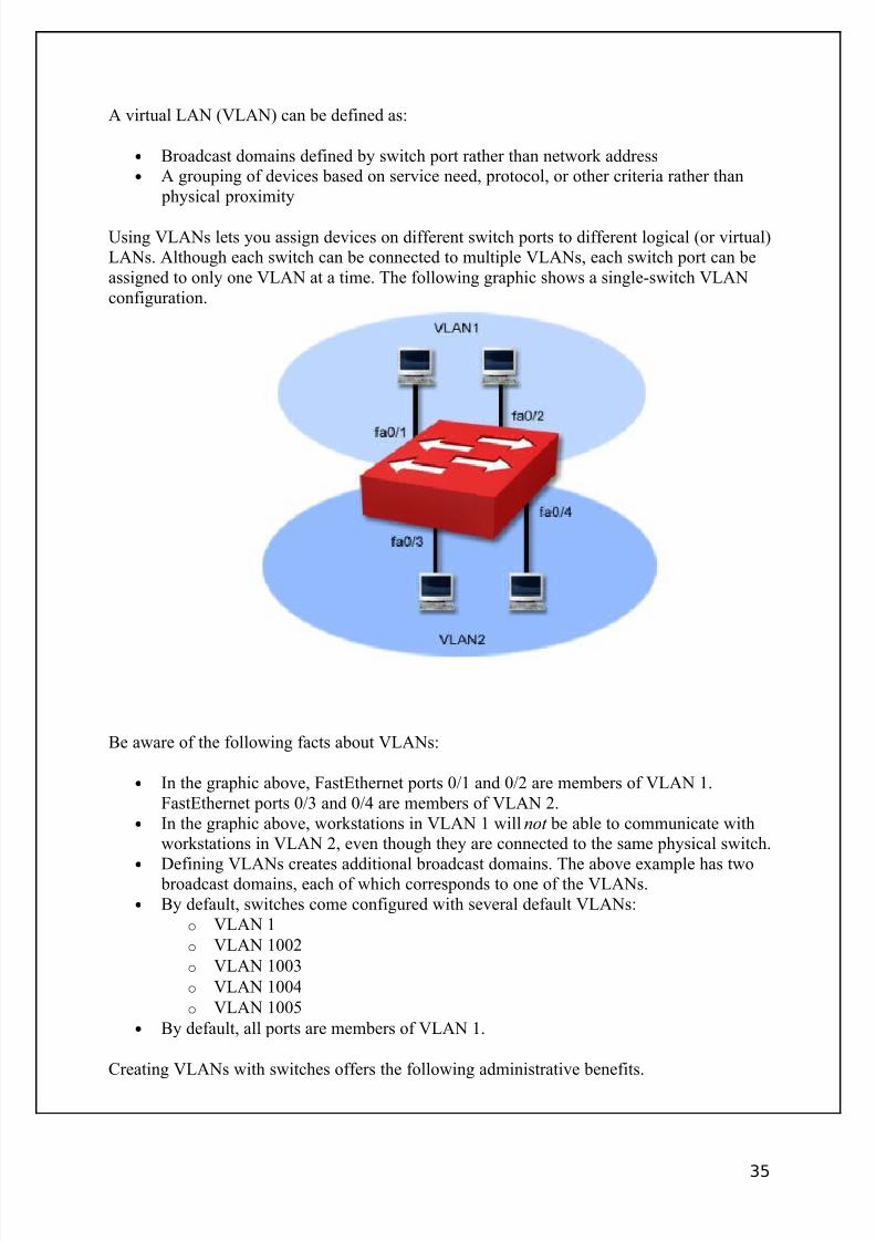
Using VLANs lets you assign devices on different switch ports to different logical (or virtual)LANs. Although each switch can be connected to multiple VLANs, each switch port can beassigned to only one VLAN at a time. The following graphic shows a single-switch VLANconfiguration.
Be aware of the following facts about VLANs:
• In the graphic above, FastEthernet ports 0/1 and 0/2 are members of VLAN 1.FastEthernet ports 0/3 and 0/4 are members of VLAN 2.
• In the graphic above, workstations in VLAN 1 will not be able to communicate withworkstations in VLAN 2, even though they are connected to the same physical switch.
•
Defining VLANs creates additional broadcast domains. The above example has two broadcast domains, each of which corresponds to one of the VLANs.• By default, switches come configured with several default VLANs:
o VLAN 1
o VLAN 1002
o VLAN 1003
o VLAN 1004
o VLAN 1005
• By default, all ports are members of VLAN 1.
Creating VLANs with switches offers the following administrative benefits.
35
8/3/2019 Ccna Notes 1
http://slidepdf.com/reader/full/ccna-notes-1 36/98
• You can create virtual LANs based on criteria other than physical location (such asworkgroup, protocol, or service)
• You can simplify device moves (devices are moved to new VLANs by modifying the port assignment)
• You can control broadcast traffic and create collision domains based on logical
criteria• You can control security (isolate traffic within a VLAN)• You can load-balance network traffic (divide traffic logically rather than physically)
Creating VLANs with switches offers the following benefits over using routers to createdistinct networks.
• Switches are easier to administer than routers• Switches are less expensive than routers• Switches offer higher performance (introduce less latency)
A disadvantage of using switches to create VLANs is that you might be tied to a specificvendor. Details of how VLANs are created and identified can vary from vendor to vendor.Creating a VLAN might mean you must use only that vendor's switches throughout thenetwork. When using multiple vendors in a switched network, be sure each switch supportsthe 802.1q standards if you want to implement VLANs.
Despite advances in switch technology, routers are still needed to:
• Filter WAN traffic• Route traffic between separate networks• Route packets between VLANs
VLAN COMMAND LIST
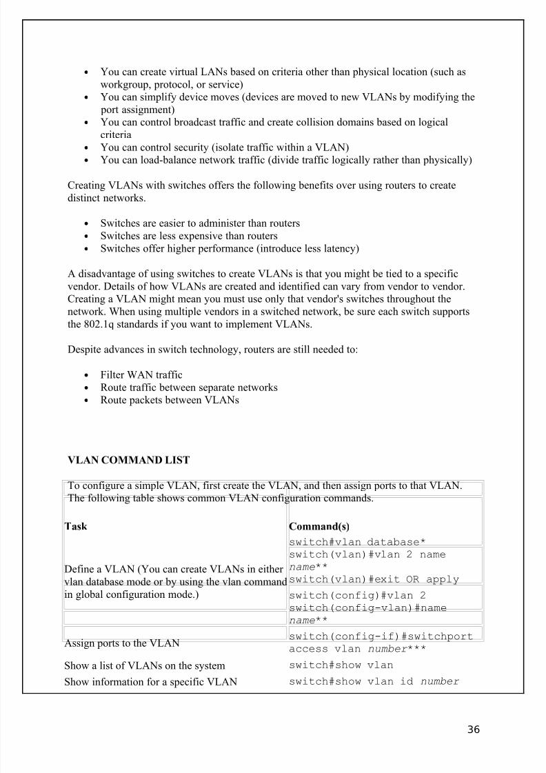
To configure a simple VLAN, first create the VLAN, and then assign ports to that VLAN.The following table shows common VLAN configuration commands.
Task Command(s)
Define a VLAN (You can create VLANs in either vlan database mode or by using the vlan commandin global configuration mode.)
switch#vlan database*switch(vlan)#vlan 2 namename**switch(vlan)#exit OR apply
switch(config)#vlan 2switch(config-vlan)#namename**
Assign ports to the VLANswitch(config-if)#switchportaccess vlan number ***
Show a list of VLANs on the system switch#show vlan
Show information for a specific VLAN switch#show vlan id number
36

8/3/2019 Ccna Notes 1
http://slidepdf.com/reader/full/ccna-notes-1 37/98
*Notice that the vlan database command is issued in privileged EXEC mode.
**Giving the VLAN a name is optional.***If you have not yet defined the VLAN, it will be created automatically when you assign the port to theVLAN.
Example
The following commands create VLAN 12 named IS_VLAN, identifies port 0/12 as havingonly workstations attached to it, and assigns the port to VLAN 12.
switch#config tswitch(config)#vlan 12switch(config-vlan)#name IS_VLANswitch(config-vlan)#interface fast 0/12switch(config-if)#switchport access vlan 12
TRUNKING
Trunking is a term used to describe connecting two switches together. Trunking is importantwhen you configure VLANs that span multiple switches as shown in the diagram.
Be aware of the following facts regarding trunking and VLANs:
• In the above graphic, each switch has two VLANs. One port on each switch has beenassigned to each VLAN.
• Workstations in VLAN 1 can only communicate with workstations in VLAN 1. Thismeans that the two workstations connected to the same switch cannot communicatewith each other. Communications within the VLAN must pass through the trunk link to the other switch.
• Trunk ports identify which ports are connected to other switches.• Trunk ports are automatically members of all VLANs defined on the switch.• Typically, Gigabit Ethernet ports are used for trunk ports.
37
8/3/2019 Ccna Notes 1
http://slidepdf.com/reader/full/ccna-notes-1 38/98
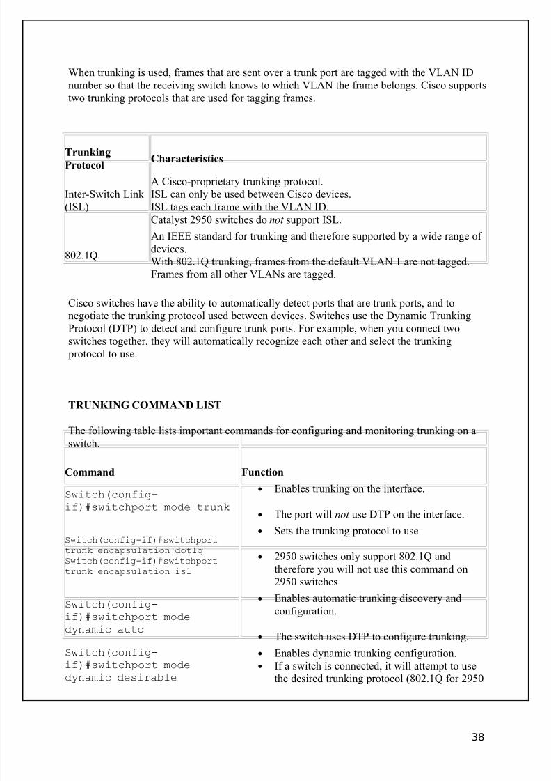
When trunking is used, frames that are sent over a trunk port are tagged with the VLAN IDnumber so that the receiving switch knows to which VLAN the frame belongs. Cisco supportstwo trunking protocols that are used for tagging frames.
Trunking
ProtocolCharacteristics
Inter-Switch Link (ISL)
A Cisco-proprietary trunking protocol.ISL can only be used between Cisco devices.ISL tags each frame with the VLAN ID.Catalyst 2950 switches do not support ISL.
802.1Q
An IEEE standard for trunking and therefore supported by a wide range of devices.With 802.1Q trunking, frames from the default VLAN 1 are not tagged.
Frames from all other VLANs are tagged.
Cisco switches have the ability to automatically detect ports that are trunk ports, and tonegotiate the trunking protocol used between devices. Switches use the Dynamic TrunkingProtocol (DTP) to detect and configure trunk ports. For example, when you connect twoswitches together, they will automatically recognize each other and select the trunking
protocol to use.
TRUNKING COMMAND LIST
The following table lists important commands for configuring and monitoring trunking on aswitch.
Command Function
Switch(config-if)#switchport mode trunk
• Enables trunking on the interface.
• The port will not use DTP on the interface.
Switch(config-if)#switchporttrunk encapsulation dot1qSwitch(config-if)#switchporttrunk encapsulation isl
• Sets the trunking protocol to use
• 2950 switches only support 802.1Q andtherefore you will not use this command on2950 switches
Switch(config-if)#switchport modedynamic auto
• Enables automatic trunking discovery andconfiguration.
• The switch uses DTP to configure trunking.
Switch(config-if)#switchport modedynamic desirable
• Enables dynamic trunking configuration.• If a switch is connected, it will attempt to use
the desired trunking protocol (802.1Q for 2950
38
8/3/2019 Ccna Notes 1
http://slidepdf.com/reader/full/ccna-notes-1 39/98
switches).
• If a switch is not connected, it willcommunicate as a normal port.
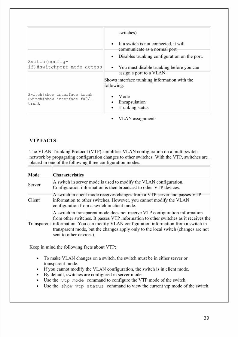
Switch(config-if)#switchport mode access
• Disables trunking configuration on the port.
• You must disable trunking before you canassign a port to a VLAN.
Switch#show interface trunkSwitch#show interface fa0/1trunk
Shows interface trunking information with thefollowing:
• Mode• Encapsulation• Trunking status
• VLAN assignments
VTP FACTS
The VLAN Trunking Protocol (VTP) simplifies VLAN configuration on a multi-switchnetwork by propagating configuration changes to other switches. With the VTP, switches are
placed in one of the following three configuration modes.
Mode Characteristics
Server A switch in server mode is used to modify the VLAN configuration.Configuration information is then broadcast to other VTP devices.
ClientA switch in client mode receives changes from a VTP server and passes VTPinformation to other switches. However, you cannot modify the VLANconfiguration from a switch in client mode.
Transparent
A switch in transparent mode does not receive VTP configuration informationfrom other switches. It passes VTP information to other switches as it receives theinformation. You can modify VLAN configuration information from a switch intransparent mode, but the changes apply only to the local switch (changes are not
sent to other devices).
Keep in mind the following facts about VTP:
• To make VLAN changes on a switch, the switch must be in either server or transparent mode.
• If you cannot modify the VLAN configuration, the switch is in client mode.• By default, switches are configured in server mode.• Use the vtp mode command to configure the VTP mode of the switch.
• Use the show vtp status command to view the current vtp mode of the switch.
39
8/3/2019 Ccna Notes 1
http://slidepdf.com/reader/full/ccna-notes-1 40/98
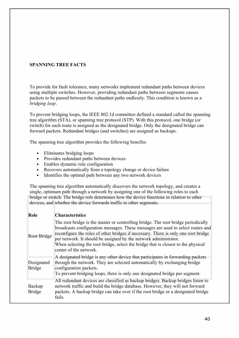
SPANNING TREE FACTS
To provide for fault tolerance, many networks implement redundant paths between devicesusing multiple switches. However, providing redundant paths between segments causes
packets to be passed between the redundant paths endlessly. This condition is known as abridging loop.
To prevent bridging loops, the IEEE 802.1d committee defined a standard called the spanning
tree algorithm (STA), or spanning tree protocol (STP). With this protocol, one bridge (or switch) for each route is assigned as the designated bridge. Only the designated bridge canforward packets. Redundant bridges (and switches) are assigned as backups.
The spanning tree algorithm provides the following benefits:
• Eliminates bridging loops• Provides redundant paths between devices• Enables dynamic role configuration• Recovers automatically from a topology change or device failure• Identifies the optimal path between any two network devices
The spanning tree algorithm automatically discovers the network topology, and creates asingle, optimum path through a network by assigning one of the following roles to each
bridge or switch. The bridge role determines how the device functions in relation to other devices, and whether the device forwards traffic to other segments.
Role Characteristics
Root Bridge
The root bridge is the master or controlling bridge. The root bridge periodically broadcasts configuration messages. These messages are used to select routes andreconfigure the roles of other bridges if necessary. There is only one root bridge
per network. It should be assigned by the network administrator.When selecting the root bridge, select the bridge that is closest to the physicalcenter of the network.
DesignatedBridge
A designated bridge is any other device that participates in forwarding packetsthrough the network. They are selected automatically by exchanging bridgeconfiguration packets.To prevent bridging loops, there is only one designated bridge per segment.
BackupBridge
All redundant devices are classified as backup bridges. Backup bridges listen tonetwork traffic and build the bridge database. However, they will not forward
packets. A backup bridge can take over if the root bridge or a designated bridge
fails.
40
8/3/2019 Ccna Notes 1
http://slidepdf.com/reader/full/ccna-notes-1 41/98
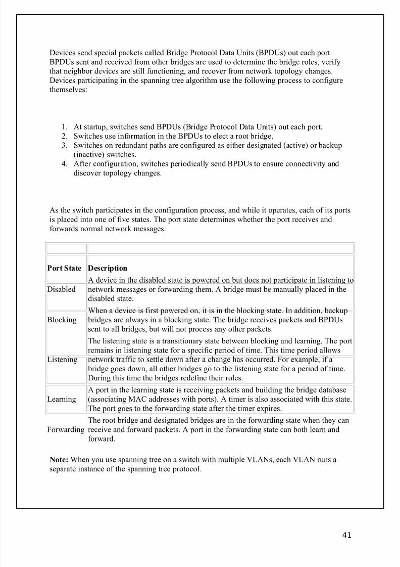
Devices send special packets called Bridge Protocol Data Units (BPDUs) out each port.BPDUs sent and received from other bridges are used to determine the bridge roles, verifythat neighbor devices are still functioning, and recover from network topology changes.Devices participating in the spanning tree algorithm use the following process to configurethemselves:
1. At startup, switches send BPDUs (Bridge Protocol Data Units) out each port.2. Switches use information in the BPDUs to elect a root bridge.3. Switches on redundant paths are configured as either designated (active) or backup
(inactive) switches.4. After configuration, switches periodically send BPDUs to ensure connectivity and
discover topology changes.
As the switch participates in the configuration process, and while it operates, each of its portsis placed into one of five states. The port state determines whether the port receives andforwards normal network messages.
Port State Description
DisabledA device in the disabled state is powered on but does not participate in listening tonetwork messages or forwarding them. A bridge must be manually placed in the
disabled state.
BlockingWhen a device is first powered on, it is in the blocking state. In addition, backup
bridges are always in a blocking state. The bridge receives packets and BPDUssent to all bridges, but will not process any other packets.
Listening
The listening state is a transitionary state between blocking and learning. The portremains in listening state for a specific period of time. This time period allowsnetwork traffic to settle down after a change has occurred. For example, if a
bridge goes down, all other bridges go to the listening state for a period of time.During this time the bridges redefine their roles.
Learning
A port in the learning state is receiving packets and building the bridge database
(associating MAC addresses with ports). A timer is also associated with this state.The port goes to the forwarding state after the timer expires.
ForwardingThe root bridge and designated bridges are in the forwarding state when they canreceive and forward packets. A port in the forwarding state can both learn andforward.
Note: When you use spanning tree on a switch with multiple VLANs, each VLAN runs aseparate instance of the spanning tree protocol.
41
8/3/2019 Ccna Notes 1
http://slidepdf.com/reader/full/ccna-notes-1 42/98
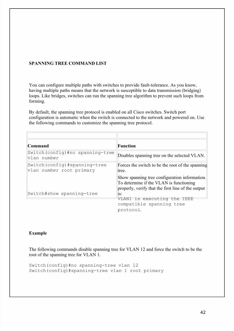
SPANNING TREE COMMAND LIST
You can configure multiple paths with switches to provide fault-tolerance. As you know,having multiple paths means that the network is susceptible to data transmission (bridging)loops. Like bridges, switches can run the spanning tree algorithm to prevent such loops fromforming.
By default, the spanning tree protocol is enabled on all Cisco switches. Switch port
configuration is automatic when the switch is connected to the network and powered on. Usethe following commands to customize the spanning tree protocol.
Command Function
Switch(config)#no spanning-treevlan number
Disables spanning tree on the selected VLAN.
Switch(config)#spanning-treevlan number root primary
Forces the switch to be the root of the spanningtree.
Switch#show spanning-tree
Show spanning tree configuration information.To determine if the VLAN is functioning
properly, verify that the first line of the outputis:VLAN1 is executing the IEEEcompatible spanning tree
protocol.
Example
The following commands disable spanning tree for VLAN 12 and force the switch to be theroot of the spanning tree for VLAN 1.
Switch(config)#no spanning-tree vlan 12Switch(config)#spanning-tree vlan 1 root primary
42
8/3/2019 Ccna Notes 1
http://slidepdf.com/reader/full/ccna-notes-1 43/98
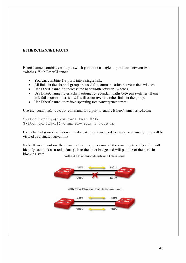
ETHERCHANNEL FACTS
EtherChannel combines multiple switch ports into a single, logical link between twoswitches. With EtherChannel:
• You can combine 2-8 ports into a single link.• All links in the channel group are used for communication between the switches.• Use EtherChannel to increase the bandwidth between switches.• Use EtherChannel to establish automatic-redundant paths between switches. If one
link fails, communication will still occur over the other links in the group.• Use EtherChannel to reduce spanning tree convergence times.
Use the channel-group command for a port to enable EtherChannel as follows:
Switch(config)#interface fast 0/12Switch(config-if)#channel-group 1 mode on
Each channel group has its own number. All ports assigned to the same channel group will be
viewed as a single logical link.
Note: If you do not use the channel-group command, the spanning tree algorithm will
identify each link as a redundant path to the other bridge and will put one of the ports in blocking state.
43
8/3/2019 Ccna Notes 1
http://slidepdf.com/reader/full/ccna-notes-1 44/98
PORT SECURITY FACTS
The basic function of a switch is to pass packets from one host to another. Under normaloperations, the switch learns the MAC address of the device(s) connected to each of its ports.When a device is connected to the switch port, the MAC address of the frame from theconnected device is place in a forwarding table. Under normal circumstances, there are norestrictions on the devices that can be attached to a switch port.
With switch port security, you configure the switch to allow only specific devices to use a
given port. You identify the MAC address of allowed devices. Any devices not explicitlyidentified will not be allowed to send frames through the switch. To configure port security,take the following general actions on the port:
• Explicitly configure the port as an access port (a port with attached hosts, not with anattached switch).
• Enable switch port security.• Identify the MAC addresses that can use the switch.
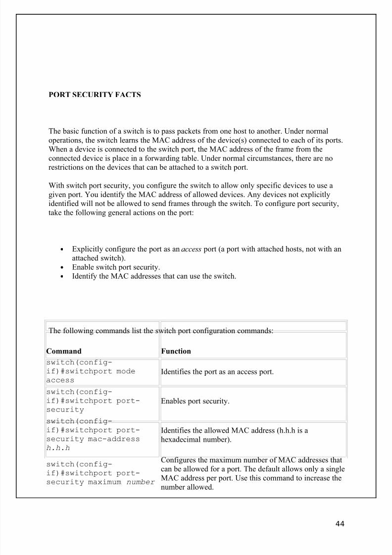
The following commands list the switch port configuration commands:
Command Function
switch(config-if)#switchport modeaccess
Identifies the port as an access port.
switch(config-if)#switchport port-security
Enables port security.
switch(config-if)#switchport port-security mac-addressh.h.h
Identifies the allowed MAC address (h.h.h is ahexadecimal number).
switch(config-if)#switchport port-security maximum number
Configures the maximum number of MAC addresses thatcan be allowed for a port. The default allows only a singleMAC address per port. Use this command to increase the
number allowed.
44
8/3/2019 Ccna Notes 1
http://slidepdf.com/reader/full/ccna-notes-1 45/98
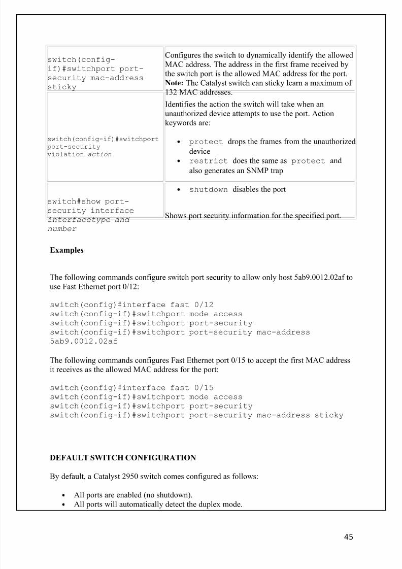
switch(config-if)#switchport port-security mac-addresssticky
Configures the switch to dynamically identify the allowedMAC address. The address in the first frame received bythe switch port is the allowed MAC address for the port.Note: The Catalyst switch can sticky learn a maximum of 132 MAC addresses.
switch(config-if)#switchportport-securityviolation action
Identifies the action the switch will take when anunauthorized device attempts to use the port. Actionkeywords are:
• protect drops the frames from the unauthorized
device• restrict does the same as protect and
also generates an SNMP trap
• shutdown disables the port
switch#show port-security interfaceinterfacetype and
number
Shows port security information for the specified port.
Examples
The following commands configure switch port security to allow only host 5ab9.0012.02af touse Fast Ethernet port 0/12:
switch(config)#interface fast 0/12switch(config-if)#switchport mode accessswitch(config-if)#switchport port-securityswitch(config-if)#switchport port-security mac-address5ab9.0012.02af
The following commands configures Fast Ethernet port 0/15 to accept the first MAC addressit receives as the allowed MAC address for the port:
switch(config)#interface fast 0/15
switch(config-if)#switchport mode accessswitch(config-if)#switchport port-securityswitch(config-if)#switchport port-security mac-address sticky
DEFAULT SWITCH CONFIGURATION
By default, a Catalyst 2950 switch comes configured as follows:
•
All ports are enabled (no shutdown).• All ports will automatically detect the duplex mode.
45
8/3/2019 Ccna Notes 1
http://slidepdf.com/reader/full/ccna-notes-1 46/98
• All ports will automatically detect the port speed.• All ports will perform automatic trunking negotiation.• The switch uses fragment-free switching.• Spanning tree is enabled.• VTP mode is set to transparent.
• All ports are members of VLAN 1.• Default VLANs of 1, 1002, 1003, 1004, and 1005 exist.• 802.1Q trunking is used (2950 switches only support 802.1Q trunking).
Inter-VLAN Routing
In a typical configuration with multiple VLANs and a single or multiple switches,workstations in one VLAN will not be able to communicate with workstations in other VLANs. To enable inter-VLAN communication, you will need to use a router (or a Layer 3
switch) as shown in the following graphic.
Be aware of the following conditions with inter-VLAN routing:
• The top example uses two physical interfaces on the router.• The bottom example uses a single physical interface on the router. In this
configuration, the physical interface is divided into two logical interfaces called subinterfaces. This configuration is also called a router on a stick .
• In each case, the router interfaces are connected to switch trunk ports. The router interfaces or subinterfaces must be running a trunking protocol (either ISL or 802.1Q).
• Each interface or subinterface requires an IP address.
46
8/3/2019 Ccna Notes 1
http://slidepdf.com/reader/full/ccna-notes-1 47/98
Classless Interdomain Routing (CIDR)
You can think of the Internet as one big network. As such, each device on the network needsits own unique IP address. In the early days of the Internet, every device would receive aregistered IP address. As the Internet grew, however, it became apparent that the number of hosts would quickly exceed the number of possible IP addresses.
One solution to the problem is Classless Interdomain Routing (CIDR). Classfull addresses areIP addresses that use the default subnet mask. They are classfull because the default subnetmask is used to identify the network and host portions of the address. Classless addresses arethose that use a custom mask value to separate network and host portions of the IP address.CIDR allows for variable length subnet masking (VLSM) and enables the following features:
• Subnetting, dividing a network address into multiple smaller subnets. Forexample, this allows a single Class B or Class C addresses to be dividedand used by multiple organizations.
• Supernetting, combining multiple network addresses into a single largersubnet. For example, this allows multiple Class C addresses to becombined into a single network.
• Route aggregation (also called route summarization), where multipleroutes are combined in a routing table as a single route.
CIDR routers use the following information to identify networks.
• The beginning network address in the range• The number of bits used in the subnet mask
For example, the routing table represents the address as 199.70.0.0/21, where 21 is thenumber of bits in the custom subnet mask.
In addition to CIDR, the following other solutions were put into place to make efficient use of available IP addresses:
• IP version 6. IPv6 uses 128-bit addresses instead of the 32-bit addresses
used with IPv4. IPv6 is not yet used on the Internet.• Private addressing with address translation. With private addressing, hosts
are assigned an unregistered address in a predefined range. All hosts onthe private network use a single registered IP address to connect to theInternet. A special router (called a network address translation or NATrouter) translates the multiple private addresses into the single registeredIP address.
47
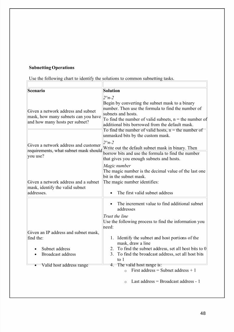
8/3/2019 Ccna Notes 1
http://slidepdf.com/reader/full/ccna-notes-1 48/98
Subnetting Operations
Use the following chart to identify the solutions to common subnetting tasks.
Scenario Solution
Given a network address and subnet
mask, how many subnets can you haveand how many hosts per subnet?
2^n-2Begin by converting the subnet mask to a binarynumber. Then use the formula to find the number of subnets and hosts.To find the number of valid subnets, n = the number of additional bits borrowed from the default mask.To find the number of valid hosts, n = the number of unmasked bits by the custom mask.
Given a network address and customer requirements, what subnet mask shouldyou use?
2^n-2Write out the default subnet mask in binary. Then
borrow bits and use the formula to find the number that gives you enough subnets and hosts.
Given a network address and a subnetmask, identify the valid subnetaddresses.
Magic number The magic number is the decimal value of the last one
bit in the subnet mask.The magic number identifies:
• The first valid subnet address
• The increment value to find additional subnetaddresses
Given an IP address and subnet mask,find the:
• Subnet address• Broadcast address
• Valid host address range
Trust the lineUse the following process to find the information youneed:
1. Identify the subnet and host portions of themask, draw a line
2. To find the subnet address, set all host bits to 03. To find the broadcast address, set all host bits
to 14. The valid host range is:
o First address = Subnet address + 1
o Last address = Broadcast address - 1
48
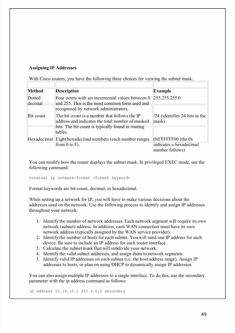
8/3/2019 Ccna Notes 1
http://slidepdf.com/reader/full/ccna-notes-1 49/98
Assigning IP Addresses
With Cisco routers, you have the following three choices for viewing the subnet mask.
Method Description Example
Dotteddecimal
Four octets with set incremental values between 0and 255. This is the most common form used andrecognized by network administrators.
255.255.255.0
Bit count The bit count is a number that follows the IPaddress and indicates the total number of masked
bits. The bit count is typically found in routingtables.
/24 (identifies 24 bits in themask)
Hexadecimal Eight hexadecimal numbers (each number rangesfrom 0 to F).
0xFFFFFF00 (the 0xindicates a hexadecimalnumber follows)
You can modify how the router displays the subnet mask. In privileged EXEC mode, use thefollowing command:
terminal ip netmask-format <format keyword>
Format keywords are bit-count, decimal, or hexadecimal.
When setting up a network for IP, you will have to make various decisions about theaddresses used on the network. Use the following process to identify and assign IP addressesthroughout your network.
1. Identify the number of network addresses. Each network segment will require its ownnetwork (subnet) address. In addition, each WAN connection must have its own
network address (typically assigned by the WAN service provider).2. Identify the number of hosts for each subnet. You will need one IP address for eachdevice. Be sure to include an IP address for each router interface.
3. Calculate the subnet mask that will subdivide your network.4. Identify the valid subnet addresses, and assign them to network segments.5. Identify valid IP addresses on each subnet (i.e. the host address range). Assign IP
addresses to hosts, or plan on using DHCP to dynamically assign IP addresses.
You can also assign multiple IP addresses to a single interface. To do this, use the secondary parameter with the ip address command as follows:
ip address 10.10.10.2 255.0.0.0 secondary
49
8/3/2019 Ccna Notes 1
http://slidepdf.com/reader/full/ccna-notes-1 50/98
Managing Host Names
Host names allow you to identify network devices using logical names instead of IPaddresses. Use the following commands to configure static host names or enable DNS on arouter.
Command Function
ip host <name>
<address>
Identifies hostnames, creating static DNS entries
ip domain-name <name> Identifies the router default domain (for DNS)
ip name-server<address>
Sets the default DNS name server
ip domain-lookup Enables the router to use DNS to identify IP addresses from hostnames
Use the show hosts command to display a list of known IP hosts.
Address Resolution Protocols
You should know the following protocols that perform address resolution.
Protocol Description
Address ResolutionProtocol (ARP)
Used by hosts to discover the MAC address of a computer from its IPaddress.
Reverse AddressResolution Protocol(RARP)
Used by a host to discover the IP address of a computer from its MACaddress.
Bootstrap Protocol(BootP)
Used by a host (such as a diskless workstation) to query a bootstrapcomputer and receive an IP address assignment. A BootP server has astatic list of MAC addresses and their corresponding IP addresses.
Dynamic HostConfigurationProtocol (DHCP)
An improvement on BootP, DHCP is used to dynamically assign IPaddress and other TCP/IP configuration parameters. A DHCP server canuse a static list to assign a specific IP address to a specific host. Morecommonly, however, the DHCP server automatically assigns an IPaddress from a preset range of possible addresses.
50
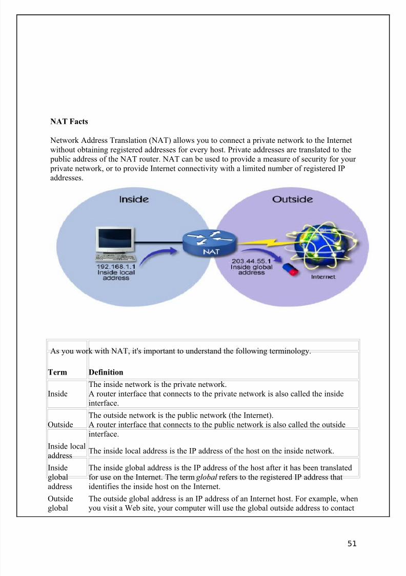
8/3/2019 Ccna Notes 1
http://slidepdf.com/reader/full/ccna-notes-1 51/98
NAT Facts
Network Address Translation (NAT) allows you to connect a private network to the Internetwithout obtaining registered addresses for every host. Private addresses are translated to the
public address of the NAT router. NAT can be used to provide a measure of security for your private network, or to provide Internet connectivity with a limited number of registered IPaddresses.
As you work with NAT, it's important to understand the following terminology.
Term Definition
InsideThe inside network is the private network.A router interface that connects to the private network is also called the inside
interface.
OutsideThe outside network is the public network (the Internet).A router interface that connects to the public network is also called the outsideinterface.
Inside localaddress
The inside local address is the IP address of the host on the inside network.
Insideglobaladdress
The inside global address is the IP address of the host after it has been translatedfor use on the Internet. The term global refers to the registered IP address thatidentifies the inside host on the Internet.
Outsideglobal
The outside global address is an IP address of an Internet host. For example, whenyou visit a Web site, your computer will use the global outside address to contact
51
8/3/2019 Ccna Notes 1
http://slidepdf.com/reader/full/ccna-notes-1 52/98
address the Web server.
Outsidelocaladdress
An outside local address is an outside global address that has been translated for inside (or private) use. In other words, the NAT router translates an Internet hostIP address into a private IP address. Instead of using the Web server address, theinternal computer will use the translated address instead.
When you configure NAT, you have the following options on a Cisco router.
Implementation Characteristics
Static NATWith static NAT, each inside host IP address is manually associatedwith a registered IP address. In other words, you manually map aninside local address to an inside global address.
Dynamic NAT
Dynamic NAT is just like static NAT, except that the addressmappings are done automatically. The NAT router has a pool of
inside global IP addresses that it uses to map to inside localaddresses.
Overload with PortAddress Translation(PAT)
Overloading is the process of assigning multiple inside localaddresses to a single inside global address. Port numbers are used toidentify specific inside local hosts. The port number is appended tothe inside global IP address.
Note: When you configure NAT, be sure to use an IP address in the private IP address rangesfor the inside local IP addresses. Otherwise, hosts on your network might not be able toaccess outside hosts with the same IP address. A Cisco router can be configured to overcome
this problem, but the configuration is difficult.
Private IP addresses do not need to be registered, and fall within the following ranges:
• 10.0.0.0 to 10.255.255.255• 172.16.0.0 to 172.31.255.255• 192.168.0.0 to 192.168.255.255
NAT Command List
Method Configuration Process Command Examples
Static NAT
Configure static mappings(mapping inside localaddresses to outside localaddresses)
Router(config)#ip nat insidesource static 192.168.1.1203.44.55.1
Identify inside and outsideinterfaces
Router(config)#interface ethernet0Router(config-if)#ip nat insideRouter(config-if)#interface
serial0Router(config-if)#ip nat outside
52
8/3/2019 Ccna Notes 1
http://slidepdf.com/reader/full/ccna-notes-1 53/98
Dynamic NAT
Define an inside globaladdress pool
Router(config)#ip nat pool mary203.44.55.1 203.44.55.254 netmask255.255.255.250
Identify allowed translatedinside local addresses**
Router(config)#access-list 1permit 192.168.1.1 0.0.0.255
Associate the allowed listwith the pool
Router(config)#ip nat insidesource list 1 pool mary
Identify inside and outsideinterfaces
Router(config)#interface ethernet0Router(config-if)#ip nat insideRouter(config-if)#interfaceserial0Router(config-if)#ip nat outside
Overloadedwith PAT
Identify allowed translatedinside local addresses**
Router(config)#access-list 1permit 192.168.1.1 0.0.0.255
Associate the allowed listwith the inside interface andidentify the translation typeas overloaded
Router(config)#ip nat insidesource list 1 interface ethernet0overload
Identify inside and outsideinterfaces
Router(config)#interface ethernet0Router(config-if)#ip nat insideRouter(config-if)#interfaceserial0Router(config-if)#ip nat outside
**These examples use access lists to identify a range of inside addresses that will be translated. You will learn
about access lists in Module 7.
Note: When you use the overloaded method, the outside global address that is used is the IPaddress of the outside router interface.
IP Troubleshooting Tools
Three tools you can use to help troubleshoot are ping, traceroute, and Telnet.
Tool Description Tests Reports
ping
Uses ICMP echo packetsOperates at the Network layer
The physical path to thedestination
Network layer configuration of source,intermediary, anddestination devices
Success (destinationresponded) or failure (noresponse)Round trip time todestination
traceroute Uses ICMP echo packets and TTLOperates at the Network layer
The physical path to thedestination
Network layer configuration of source,
intermediate, anddestination devices
IP address of each hop todestinationHost name of each hop (if configured)
Round trip time todestination and each
53
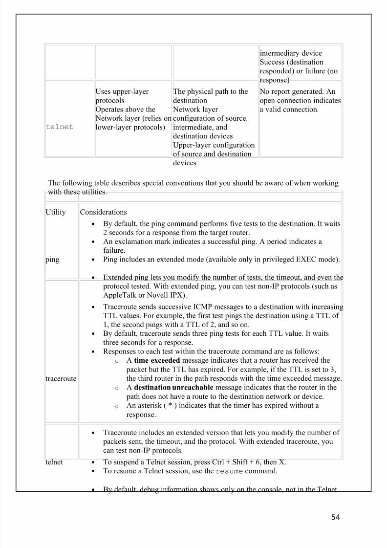
8/3/2019 Ccna Notes 1
http://slidepdf.com/reader/full/ccna-notes-1 54/98
intermediary deviceSuccess (destinationresponded) or failure (noresponse)
telnet
Uses upper-layer protocolsOperates above the
Network layer (relies onlower-layer protocols)
The physical path to thedestination
Network layer configuration of source,intermediate, anddestination devicesUpper-layer configurationof source and destinationdevices
No report generated. Anopen connection indicatesa valid connection.
The following table describes special conventions that you should be aware of when working
with these utilities.
Utility Considerations
ping
• By default, the ping command performs five tests to the destination. It waits2 seconds for a response from the target router.
• An exclamation mark indicates a successful ping. A period indicates afailure.
• Ping includes an extended mode (available only in privileged EXEC mode).
• Extended ping lets you modify the number of tests, the timeout, and even the
protocol tested. With extended ping, you can test non-IP protocols (such asAppleTalk or Novell IPX).
traceroute
• Traceroute sends successive ICMP messages to a destination with increasingTTL values. For example, the first test pings the destination using a TTL of 1, the second pings with a TTL of 2, and so on.
• By default, traceroute sends three ping tests for each TTL value. It waitsthree seconds for a response.
• Responses to each test within the traceroute command are as follows:o A time exceeded message indicates that a router has received the
packet but the TTL has expired. For example, if the TTL is set to 3,the third router in the path responds with the time exceeded message.
o A destination unreachable message indicates that the router in the
path does not have a route to the destination network or device.o An asterisk ( * ) indicates that the timer has expired without a
response.
• Traceroute includes an extended version that lets you modify the number of packets sent, the timeout, and the protocol. With extended traceroute, youcan test non-IP protocols.
telnet • To suspend a Telnet session, press Ctrl + Shift + 6, then X.• To resume a Telnet session, use the resume command.
• By default, debug information shows only on the console, not in the Telnet
54
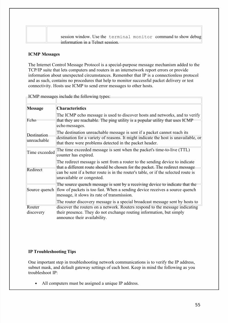
8/3/2019 Ccna Notes 1
http://slidepdf.com/reader/full/ccna-notes-1 55/98
session window. Use the terminal monitor command to show debug
information in a Telnet session.
ICMP Messages
The Internet Control Message Protocol is a special-purpose message mechanism added to theTCP/IP suite that lets computers and routers in an internetwork report errors or provideinformation about unexpected circumstances. Remember that IP is a connectionless protocoland as such, contains no procedures that help to monitor successful packet delivery or testconnectivity. Hosts use ICMP to send error messages to other hosts.
ICMP messages include the following types:
Message Characteristics
EchoThe ICMP echo message is used to discover hosts and networks, and to verifythat they are reachable. The ping utility is a popular utility that uses ICMPecho messages.
Destinationunreachable
The destination unreachable message is sent if a packet cannot reach itsdestination for a variety of reasons. It might indicate the host is unavailable, or that there were problems detected in the packet header.
Time exceededThe time exceeded message is sent when the packet's time-to-live (TTL)counter has expired.
Redirect
The redirect message is sent from a router to the sending device to indicatethat a different route should be chosen for the packet. The redirect messagecan be sent if a better route is in the router's table, or if the selected route isunavailable or congested.
Source quenchThe source quench message is sent by a receiving device to indicate that theflow of packets is too fast. When a sending device receives a source quenchmessage, it slows its rate of transmission.
Router discovery
The router discovery message is a special broadcast message sent by hosts todiscover the routers on a network. Routers respond to the message indicatingtheir presence. They do not exchange routing information, but simplyannounce their availability.
IP Troubleshooting Tips
One important step in troubleshooting network communications is to verify the IP address,subnet mask, and default gateway settings of each host. Keep in mind the following as youtroubleshoot IP:
• All computers must be assigned a unique IP address.
55

8/3/2019 Ccna Notes 1
http://slidepdf.com/reader/full/ccna-notes-1 56/98
• Hosts on the same physical network should have IP addresses in the same addressrange.
• The subnet mask value for all computers on the same physical network must be thesame.
• Configure the default gateway value to enable internetwork communication.
• The default gateway address must be on the same subnet as the host's IP address.• You do not need to configure an IP address on a switch for frames to be switched
through the switch. To ping to and from a switch or to remotely manage the switch,configure an IP address on the switch.
Listed below are several common symptoms and things to try to correct communication problems.
Problem Symptoms Solution
A single host cannot
communicate with any other host.
Ping to any other hostfails.
Because the problem exists with
only one host, troubleshoot theconfiguration of the host with the
problem.
A single host can communicatewith all hosts on the samenetwork, but can't communicatewith any host on any other network.
Ping to hosts on the samenetwork succeed, ping tohosts on other networksfails. Verify the default gateway setting
of the host with the problem.Traceroute on the hosttimes out with only asingle entry.
All hosts can communicatewithin the same network, butcannot communicate with anyhost outside of the local network.
Ping to hosts on the samenetwork succeed, ping tohosts on other networksfails.
If DHCP is used to assign IPinformation to hosts, verify thedefault gateway setting delivered
by the DHCP server.Traceroute on the hosttimes out with only asingle entry.
The routing table on therouter shows onlydirectly-connected
networks.
Verify the routing configuration of the default gateway router.
All hosts cannot communicatewith hosts on a specific outsidenetwork. Communication withother networks is fine.
Ping to the remotenetwork fails, tracerouteon the host times outwith only a single entry. Add a route to the routing table, or
configure the gateway of last resort(default route) on the router.
The routing table on therouter does not show thedestination network, or the gateway of last resortis not set.
The routing table has aroute to the destination
Troubleshoot other routers in the path to the destination network.
56
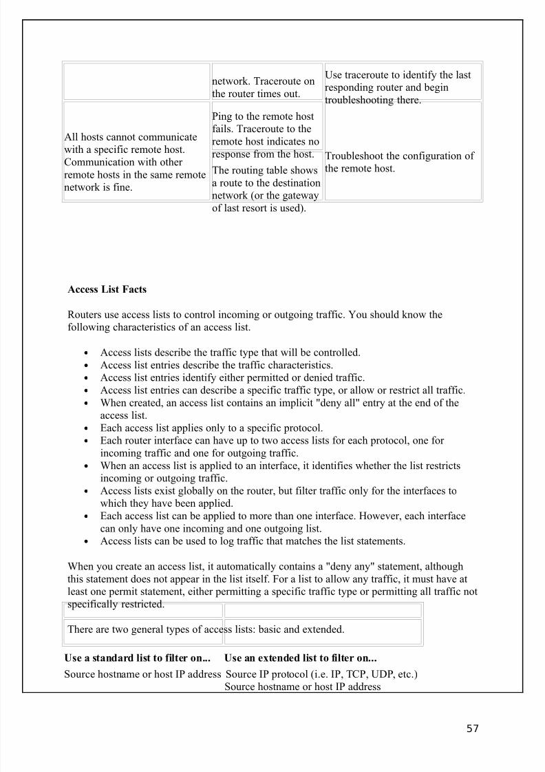
8/3/2019 Ccna Notes 1
http://slidepdf.com/reader/full/ccna-notes-1 57/98
network. Traceroute onthe router times out.
Use traceroute to identify the lastresponding router and begintroubleshooting there.
All hosts cannot communicatewith a specific remote host.Communication with other remote hosts in the same remotenetwork is fine.
Ping to the remote hostfails. Traceroute to theremote host indicates noresponse from the host. Troubleshoot the configuration of
the remote host.The routing table showsa route to the destinationnetwork (or the gatewayof last resort is used).
Access List Facts
Routers use access lists to control incoming or outgoing traffic. You should know thefollowing characteristics of an access list.
• Access lists describe the traffic type that will be controlled.• Access list entries describe the traffic characteristics.• Access list entries identify either permitted or denied traffic.• Access list entries can describe a specific traffic type, or allow or restrict all traffic.•
When created, an access list contains an implicit "deny all" entry at the end of theaccess list.• Each access list applies only to a specific protocol.• Each router interface can have up to two access lists for each protocol, one for
incoming traffic and one for outgoing traffic.• When an access list is applied to an interface, it identifies whether the list restricts
incoming or outgoing traffic.• Access lists exist globally on the router, but filter traffic only for the interfaces to
which they have been applied.• Each access list can be applied to more than one interface. However, each interface
can only have one incoming and one outgoing list.
• Access lists can be used to log traffic that matches the list statements.
When you create an access list, it automatically contains a "deny any" statement, althoughthis statement does not appear in the list itself. For a list to allow any traffic, it must have atleast one permit statement, either permitting a specific traffic type or permitting all traffic notspecifically restricted.
There are two general types of access lists: basic and extended.
Use a standard list to filter on... Use an extended list to filter on...
Source hostname or host IP address Source IP protocol (i.e. IP, TCP, UDP, etc.)Source hostname or host IP address
57
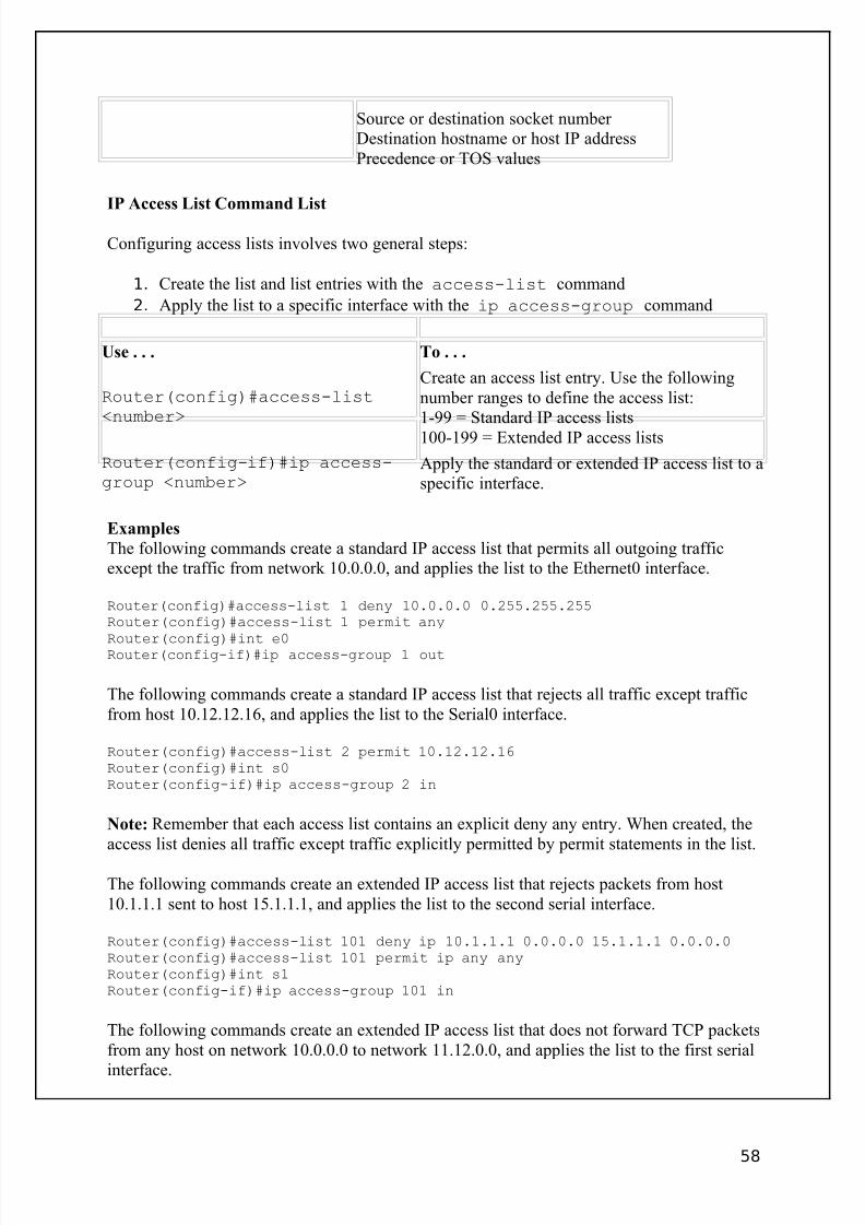
8/3/2019 Ccna Notes 1
http://slidepdf.com/reader/full/ccna-notes-1 58/98
Source or destination socket number Destination hostname or host IP addressPrecedence or TOS values
IP Access List Command List
Configuring access lists involves two general steps:
1. Create the list and list entries with the access-list command
2. Apply the list to a specific interface with the ip access-group command
Use . . . To . . .
Router(config)#access-list<number>
Create an access list entry. Use the followingnumber ranges to define the access list:1-99 = Standard IP access lists100-199 = Extended IP access lists
Router(config-if)#ip access-group <number>
Apply the standard or extended IP access list to aspecific interface.
Examples
The following commands create a standard IP access list that permits all outgoing trafficexcept the traffic from network 10.0.0.0, and applies the list to the Ethernet0 interface.
Router(config)#access-list 1 deny 10.0.0.0 0.255.255.255Router(config)#access-list 1 permit any
Router(config)#int e0Router(config-if)#ip access-group 1 out
The following commands create a standard IP access list that rejects all traffic except trafficfrom host 10.12.12.16, and applies the list to the Serial0 interface.
Router(config)#access-list 2 permit 10.12.12.16Router(config)#int s0Router(config-if)#ip access-group 2 in
Note: Remember that each access list contains an explicit deny any entry. When created, theaccess list denies all traffic except traffic explicitly permitted by permit statements in the list.
The following commands create an extended IP access list that rejects packets from host10.1.1.1 sent to host 15.1.1.1, and applies the list to the second serial interface.
Router(config)#access-list 101 deny ip 10.1.1.1 0.0.0.0 15.1.1.1 0.0.0.0Router(config)#access-list 101 permit ip any anyRouter(config)#int s1Router(config-if)#ip access-group 101 in
The following commands create an extended IP access list that does not forward TCP packetsfrom any host on network 10.0.0.0 to network 11.12.0.0, and applies the list to the first serial
interface.
58
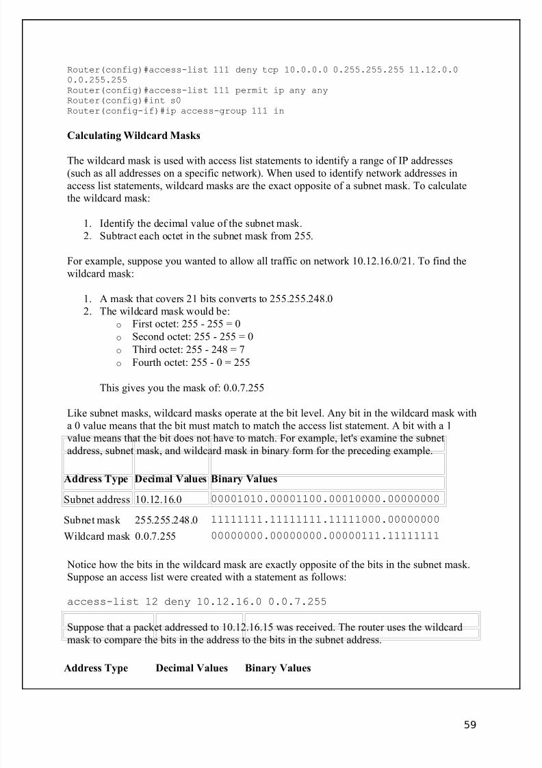
8/3/2019 Ccna Notes 1
http://slidepdf.com/reader/full/ccna-notes-1 59/98
Router(config)#access-list 111 deny tcp 10.0.0.0 0.255.255.255 11.12.0.00.0.255.255Router(config)#access-list 111 permit ip any anyRouter(config)#int s0Router(config-if)#ip access-group 111 in
Calculating Wildcard Masks
The wildcard mask is used with access list statements to identify a range of IP addresses(such as all addresses on a specific network). When used to identify network addresses inaccess list statements, wildcard masks are the exact opposite of a subnet mask. To calculatethe wildcard mask:
1. Identify the decimal value of the subnet mask.2. Subtract each octet in the subnet mask from 255.
For example, suppose you wanted to allow all traffic on network 10.12.16.0/21. To find thewildcard mask:
1. A mask that covers 21 bits converts to 255.255.248.02. The wildcard mask would be:
o First octet: 255 - 255 = 0
o Second octet: 255 - 255 = 0
o Third octet: 255 - 248 = 7
o Fourth octet: 255 - 0 = 255
This gives you the mask of: 0.0.7.255
Like subnet masks, wildcard masks operate at the bit level. Any bit in the wildcard mask witha 0 value means that the bit must match to match the access list statement. A bit with a 1value means that the bit does not have to match. For example, let's examine the subnetaddress, subnet mask, and wildcard mask in binary form for the preceding example.
Address Type Decimal Values Binary Values
Subnet address 10.12.16.0 00001010.00001100.00010000.00000000
Subnet mask 255.255.248.0 11111111.11111111.11111000.00000000
Wildcard mask 0.0.7.255 00000000.00000000.00000111.11111111
Notice how the bits in the wildcard mask are exactly opposite of the bits in the subnet mask.Suppose an access list were created with a statement as follows:
access-list 12 deny 10.12.16.0 0.0.7.255
Suppose that a packet addressed to 10.12.16.15 was received. The router uses the wildcardmask to compare the bits in the address to the bits in the subnet address.
Address Type Decimal Values Binary Values
59

8/3/2019 Ccna Notes 1
http://slidepdf.com/reader/full/ccna-notes-1 60/98
Subnet address 10.12.16.0 00001010.00001100.00010000.00000000
Wildcard mask 0.0.7.255 00000000.00000000.00000111.11111111
Target address #1 10.12.16.15 00001010.00001100.00010000.00001111
How the router applies the mask to the
addressm=matchi=ignoredx=doesn't match
mmmmmmmm.mmmmmmmm.mmmmmiii.iiiiiiii
In this example, all bits identified with a 0 in the wildcard mask must match between theaddress and the network address. Any bit identified with a 1 is ignored. In this example,10.12.16.15 matches the access list statement and the traffic is denied.
Now suppose that a packet addressed to 10.13.17.15 was received. The router uses the
wildcard mask to compare the bits in the address to the bits in the subnet address.
Address Type Decimal Values Binary Values
Subnet address 10.12.16.0 00001010.00001100.00010000.00000000
Wildcard mask 0.0.7.255 00000000.00000000.00000111.11111111
Target address #1 10.13.17.15 00001010.00001101.00010001.00001111
How the router applies the mask to theaddress
• m=match• i=ignored
• x=doesn't match
mmmmmmmm.mmmmmmmx.mmmmmiii.iiiiiiii
Notice that this address does not match the access list statement as identified with thewildcard mask. In this case, traffic would be permitted.
Designing Access Lists
After you have created an access list, you must apply it to an interface. In many cases, thismeans you will need to decide which router, with port, and which direction to apply theaccess list to. Keep in mind the following:
• Each interface can only have one inbound and one outbound access list for each protocol. This means that an interface can have either a standard inbound or anextended inbound IP access list, but not both.
60
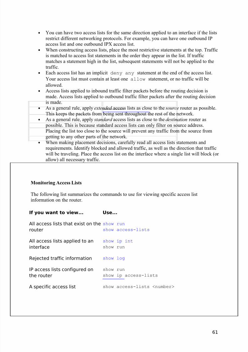
8/3/2019 Ccna Notes 1
http://slidepdf.com/reader/full/ccna-notes-1 61/98
• You can have two access lists for the same direction applied to an interface if the listsrestrict different networking protocols. For example, you can have one outbound IPaccess list and one outbound IPX access list.
• When constructing access lists, place the most restrictive statements at the top. Trafficis matched to access list statements in the order they appear in the list. If traffic
matches a statement high in the list, subsequent statements will not be applied to thetraffic.
• Each access list has an implicit deny any statement at the end of the access list.
Your access list must contain at least one allow statement, or no traffic will be
allowed.• Access lists applied to inbound traffic filter packets before the routing decision is
made. Access lists applied to outbound traffic filter packets after the routing decisionis made.
• As a general rule, apply extended access lists as close to the source router as possible.This keeps the packets from being sent throughout the rest of the network.
• As a general rule, apply standard access lists as close to the destination router as
possible. This is because standard access lists can only filter on source address.Placing the list too close to the source will prevent any traffic from the source fromgetting to any other parts of the network.
• When making placement decisions, carefully read all access lists statements andrequirements. Identify blocked and allowed traffic, as well as the direction that trafficwill be traveling. Place the access list on the interface where a single list will block (or allow) all necessary traffic.
Monitoring Access Lists
The following list summarizes the commands to use for viewing specific access listinformation on the router.
If you want to view... Use...
All access lists that exist on the
router
show run
show access-lists
All access lists applied to an
interface
show ip int
show run
Rejected traffic information show log
IP access lists configured on
the router
show run
show ip access-lists
A specific access list show access-lists <number>
61

8/3/2019 Ccna Notes 1
http://slidepdf.com/reader/full/ccna-notes-1 62/98
Routing Protocol Facts
Each organization that has been assigned a network address from an ISP is considered anautonomous system (AS). That organization is free to create one large network, or divide thenetwork into subnets. Each autonomous system is identified by an AS number. This number can be locally administered, or registered if the AS is connected to the Internet.
Routers are used within an AS to segment (subnet) the network. In addition, they are used toconnect multiple ASs together. Routers use a routing protocol to dynamically discover routes,
build routing tables, and make decisions about how to send packets through the internetwork.
Routing protocols can be classified based on whether they are routing traffic within or
between autonomous systems.
• Interior Gateway Protocol (IGP)--protocol that routes traffic within the AS• Exterior Gateway Protocol (EGP)--protocol that routes traffic outside of or between
ASs• Border Gateway Protocol (BGP)--enhancement of EGP that routes traffic between
ASs
In this course, you will learn about the following Interior Gateway Protocols:
• Routing Information Protocol (RIP)• Interior Gateway Routing Protocol (IGRP)• Open Shortest Path First (OSPF)• Enhanced Interior Gateway Routing Protocol (EIGRP)
Distance Vector Routing Facts
Keep in mind the following principles about the distance vector method.
• Routers send updates only to their neighbor routers• Routers send their entire routing table• Tables are sent at regular intervals (each router is configured to specify its own update
interval)• Routers modify their tables based on information received from their neighbors
Because routers using the distance vector method send their entire routing table at specifiedintervals, they are susceptible to a condition known as a routing loop (also called a count-to-infinity condition). Like a bridging loop, a routing loop occurs when two routers share
different information. The following methods can be used to minimize the effects of a routingloop.
62

8/3/2019 Ccna Notes 1
http://slidepdf.com/reader/full/ccna-notes-1 63/98
Method Characteristics
Split horizon
Using the split horizon method (also called best information), routers keeptrack of where the information about a route came from. Routers do not reportroute information to the routers on that path. In other words, routers do notreport information back to the router from which their information originated.
Split horizonwith poisonreverse
Using the split horizon with poison reverse method (also called poison reverseor route poisoning ), routers continue to send information about routes back tothe next hop router, but advertise the path as unreachable. If the next hop router notices that the route is still reachable, it ignores the information. If, however,the path timeout has been reached, the route is immediately set to unreachable(16 hops for RIP).Convergence happens faster with poison reverse than with simple split horizon.However, it results in greater network traffic because the entire table is
broadcast each time an update is sent.
Triggeredupdates
With the triggered update method (also known as a flash updates), routers thatreceive updated (changed) information broadcast those changes immediatelyrather than waiting for the next reporting interval. With this method, routers
broadcast their routing tables periodically, punctuated by special broadcasts if conditions have changed. This method reduces the convergence time.
Hold downs
With the hold down method, routers will, for a period of time, "hold" an updatethat reinstates an expired link. The time period typically reflects the timerequired to attain convergence on the network.The hold down timer is reset when the timer runs out or when a network
change occurs.
The distance vector method has the following advantages:
• Stable and proven method (distance vector was the original routing algorithm)• Easy to implement and administer • Bandwidth requirements negligible for a typical LAN environment• Requires less hardware and processing power than other routing methods
Distance vector has the following disadvantages:
• Relatively long time to reach convergence (updates sent at specified intervals)• Routers must recalculate their routing tables before forwarding changes• Susceptible to routing loops (count-to-infinity)• Bandwidth requirements can be too great for WAN or complex LAN environments
63

8/3/2019 Ccna Notes 1
http://slidepdf.com/reader/full/ccna-notes-1 64/98
Link State Routing Facts
Keep in mind the following information about the link state method.
• Routers broadcast LSPs to all routers (this process is known as flooding).• Routers send information about only their own links.• Link-state protocols send hello packets to discover new neighbors.• LSPs are sent at regular intervals and when any of the following conditions occur.
o There is a new neighbor.
o A neighbor has gone down.
o The cost to a neighbor has changed.
• Neighboring routers exchange LSAs (link-state advertisements) to construct atopological database.
• The SPF algorithm is applied to the topological database to create an SPF tree from
which a table of routing paths and associated ports is built.• Routers use LSPs to build their tables and calculate the best route.• Routers select routes based on the shortest route using an algorithm known as Shortest
Path First (SPF).• Network administrators have greater flexibility in setting the metrics used to calculate
routes.
The link state method has the following advantages over the distance vector method.
• Less convergence time (because updates are forwarded immediately)•
Not susceptible to routing loops• Less susceptible to erroneous information (because only firsthand information is
broadcast)• Bandwidth requirements negligible for a typical LAN environment
Although more stable than the distance vector method, the link state method has the following problems:
• The link state algorithm requires greater CPU and memory capability to calculate thenetwork topology and select the route because the algorithm re-creates the exacttopology of the network for route computation.
• It generates a high amount of traffic when LSPs are initially flooded through thenetwork or when the topology changes. However, after the initial configurationoccurs, the traffic from the link state method is smaller than that from the distancevector method.
• It is possible for LSPs to get delayed or lost, resulting in an inconsistent view of thenetwork. This is particularly a problem for larger networks, if parts of the network come on line at different times, or if the bandwidth between links vary (i.e. LSPstravel faster through parts of the network than through others).
In particular, the last problem is of greatest concern. The following solutions are oftenimplemented to overcome some of the effects of inconsistent LSP information.
• Slowing the LSP update rate keeps information more consistent.
64

8/3/2019 Ccna Notes 1
http://slidepdf.com/reader/full/ccna-notes-1 65/98
• Routers can be grouped into areas. Routers share information within the area, androuters on area borders share information between areas. (Areas logically subdivide anAutonomous System (AS), a collection of areas under common administration.)
• One router in each area is designated as the authoritative source of routing information(called a designated router ). Each area router receives updates from the designated
router.• LSPs can be identified with a time stamp, sequence or ID number, or aging timer to
ensure proper synchronization.
Static Route Facts
Most networks will use one (or more) routing protocols to automatically share and learnroutes. Listed below are several situations when you might want to configure static routes.
• To configure a default route or a route out of a stub network (a stubnetwork is one that has a single route into and out of the network).
• For small networks that do not change very often and that have only a fewnetworks.
• To turn off all routing protocols and reduce traffic or improve security.• To configure routes that are lost due to route summarization.
Static Route Command List
Static routes lock a router into using the route you specify for all packets. Configuring staticroutes is useful for increasing security, and for small networks or networks that have only one
possible path. You can also configure a default router. When your router cannot find a packet's address in its routing table, it sends the packet to the default router.
Use . . . To . . .
Router(config)#ip route<destination> <next_hop>
Identify a next hop router to receive packets sent to thespecified destination network.
Router(config)#ip route<destination> <interface>
Identify the interface used to forward packets to thespecified destination network.
Router(config)#ip default-network <network>
Identify a default network on which all packets sent tounknown networks are forwarded.
Router(config)#ip classless
Enables the router to match routes based on thenumber of bits in the mask and not the default subnetmask.
Examples
The following command creates a static route to network 192.168.1.0 through the router withthe IP address 192.168.1.35 and gives it a value of 25.
Router(config)#ip route 192.168.1.0 255.255.255.0 192.168.1.35 25
65

8/3/2019 Ccna Notes 1
http://slidepdf.com/reader/full/ccna-notes-1 66/98
The following command creates a permanent static route to network 192.168.1.0 through therouter's second serial interface.
Router(config)#ip route 192.168.1.0 255.255.255.0 serial 1 30 permanent
The following command designates network 10.1.1.0 as the default network for the localrouter.
Router(config)#ip default-network 10.1.1.0
The following command identifies a default route through an interface with address 10.1.1.2.
Router(config)#ip route 0.0.0.0 0.0.0.0 10.1.1.2
RIP Facts
The Routing Information Protocol (RIP) is a simple, effective routing protocol for small- tomedium-sized networks. It has the following characteristics when running on a Cisco router.
• RIP uses hop and tick counts to calculate optimal routes.• RIP routing is limited to 15 hops to any location (16 hops indicates the network is
unreachable).• RIP uses the split horizon with poison reverse method to prevent the count-to-infinity
problem.• RIP uses only classful routing, so it uses full address classes, not subnets.
• RIP broadcasts updates to the entire network.• RIP can maintain up to six multiple paths to each network, but only if the cost is the
same.• RIP supports load balancing over same-cost paths.• The update interval default is 30, the invalid timer default is 180, the holddown timer
default is 180, and the flush timer default is 240.
Note: Because RIP uses the hop count in determining the best route to a remote network, itmight end up selecting a less than optimal route. For example, suppose that two routes exist
between two networks. One route uses a 56 Kbps link with a single hop, while the other routeuses a Gigabit link that has two hops. Because the first route has fewer hops, RIP will select
this route as the optimal route.
RIP Command List
To configure any routing protocol, use the following three steps:
1. Enable IP routing if it is not already enabled (use the ip routing command).
66
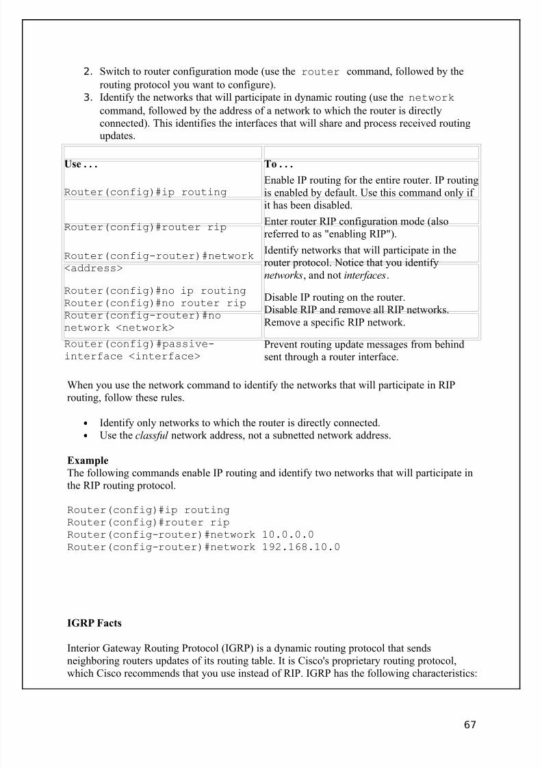
8/3/2019 Ccna Notes 1
http://slidepdf.com/reader/full/ccna-notes-1 67/98
2. Switch to router configuration mode (use the router command, followed by the
routing protocol you want to configure).3. Identify the networks that will participate in dynamic routing (use the network
command, followed by the address of a network to which the router is directlyconnected). This identifies the interfaces that will share and process received routing
updates.
Use . . . To . . .
Router(config)#ip routingEnable IP routing for the entire router. IP routingis enabled by default. Use this command only if it has been disabled.
Router(config)#router ripEnter router RIP configuration mode (alsoreferred to as "enabling RIP").
Router(config-router)#network
<address>
Identify networks that will participate in therouter protocol. Notice that you identifynetworks, and not interfaces.
Router(config)#no ip routingRouter(config)#no router ripRouter(config-router)#nonetwork <network>
Disable IP routing on the router.Disable RIP and remove all RIP networks.Remove a specific RIP network.
Router(config)#passive-interface <interface>
Prevent routing update messages from behindsent through a router interface.
When you use the network command to identify the networks that will participate in RIProuting, follow these rules.
• Identify only networks to which the router is directly connected.• Use the classful network address, not a subnetted network address.
Example
The following commands enable IP routing and identify two networks that will participate inthe RIP routing protocol.
Router(config)#ip routingRouter(config)#router rip
Router(config-router)#network 10.0.0.0Router(config-router)#network 192.168.10.0
IGRP Facts
Interior Gateway Routing Protocol (IGRP) is a dynamic routing protocol that sendsneighboring routers updates of its routing table. It is Cisco's proprietary routing protocol,
which Cisco recommends that you use instead of RIP. IGRP has the following characteristics:
67
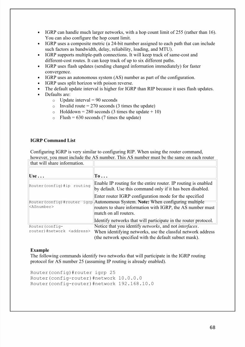
8/3/2019 Ccna Notes 1
http://slidepdf.com/reader/full/ccna-notes-1 68/98
• IGRP can handle much larger networks, with a hop count limit of 255 (rather than 16).You can also configure the hop count limit.
• IGRP uses a composite metric (a 24-bit number assigned to each path that can includesuch factors as bandwidth, delay, reliability, loading, and MTU).
• IGRP supports multiple-path connections. It will keep track of same-cost and
different-cost routes. It can keep track of up to six different paths.• IGRP uses flash updates (sending changed information immediately) for faster
convergence.• IGRP uses an autonomous system (AS) number as part of the configuration.• IGRP uses split horizon with poison reverse.• The default update interval is higher for IGRP than RIP because it uses flash updates.• Defaults are:
o Update interval = 90 seconds
o Invalid route = 270 seconds (3 times the update)
o Holddown = 280 seconds (3 times the update + 10)
o Flush = 630 seconds (7 times the update)
IGRP Command List
Configuring IGRP is very similar to configuring RIP. When using the router command,however, you must include the AS number. This AS number must be the same on each router that will share information.
Use . . . To . . .
Router(config)#ip routing Enable IP routing for the entire router. IP routing is enabled by default. Use this command only if it has been disabled.
Router(config)#router igrp<ASnumber>
Enter router IGRP configuration mode for the specifiedAutonomous System. Note: When configuring multiplerouters to share information with IGRP, the AS number mustmatch on all routers.
Router(config-router)#network <address>
Identify networks that will participate in the router protocol. Notice that you identify networks, and not interfaces.When identifying networks, use the classful network address(the network specified with the default subnet mask).
Example
The following commands identify two networks that will participate in the IGRP routing protocol for AS number 25 (assuming IP routing is already enabled).
Router(config)#router igrp 25Router(config-router)#network 10.0.0.0Router(config-router)#network 192.168.10.0
68

8/3/2019 Ccna Notes 1
http://slidepdf.com/reader/full/ccna-notes-1 69/98
OSPF Facts
The Open Shortest Path First (OSPF) routing protocol is a robust link state routing protocolwell-suited for large networks. You should remember the following characteristics of link state protocols that apply to OSPF:
• Is a public (non-proprietary) routing protocol.• Is considered a classless routing protocol because it does not assume the default
subnet masks are used. It sends the subnet mask in the routing update and supportsroute summarization and VLSM.
• Is not susceptible to routing loops. Instead, OSPF uses built-in loop avoidancetechniques. Mechanisms such as holddown timers, split horizon, or poison reverse arenot needed.
• Is scalable and does not have the 16 hop limitation of RIP.• Uses hello packets to discover neighbor routers.• Shares routing information through Link State Advertisements (LSAs). LSAs contain
small bits of information about routes. (Unadvertised links save on IP space, but theycannot be pinged because they won't appear in an OSPF routing table.)
• Under normal conditions, OSPF only sends out updated information rather thanexchanging the entire routing table.
• Converges faster than a distance vector protocol.• Can require additional processing power (and therefore increased system
requirements). Good design can minimize this impact.• Maintains a logical topographical map of the network in addition to maintaining
routes to various networks.• Uses areas to subdivide large networks. Routers within an area share information
about the area. Routers on the edge of areas (called Area Border Routers (ABR)) sharesummarized information between areas.
o The backbone is a specialized area connected to all other areas. It contains
networks not held within another area, and distributes routing information between areas. You can think of the backbone as the "master" or "root" area.Its address is always 0.0.0.0. All OSPF networks must have a backbone area.
o A stub area is an area with a single path in to and out of the area.
• Uses link costs as a metric for determining best routes. The Shortest Path First (SPF)algorithm (also called the Dijkstra SPF algorithm) is used to identify and select theoptimal route.
As part of the OSPF process, each router is assigned a router ID (RID). The router ID is:
• The highest IP address assigned to a loopback (logical) interface.• If a loopback interface is not defined, the highest IP address of the router's physical
interfaces.
Because the loopback interface takes precedence over the physical interfaces in determiningthe router ID, you can force a specific router ID by defining a loopback interface andassigning it an IP address.
69
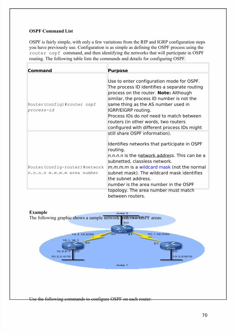
8/3/2019 Ccna Notes 1
http://slidepdf.com/reader/full/ccna-notes-1 70/98
OSPF Command List
OSPF is fairly simple, with only a few variations from the RIP and IGRP configuration stepsyou have previously use. Configuration is as simple as defining the OSPF process using therouter ospf command, and then identifying the networks that will participate in OSPF
routing. The following table lists the commands and details for configuring OSPF.
Command Purpose
Router(config)#router ospf
process-id
Use to enter configuration mode for OSPF.
The process ID identifies a separate routing
process on the router. Note: Although
similar, the process ID number is not the
same thing as the AS number used in
IGRP/EIGRP routing.
Process IDs do not need to match betweenrouters (in other words, two routers
configured with different process IDs might
still share OSPF information).
Router(config-router)#network
n.n.n.n m.m.m.m area number
Identifies networks that participate in OSPF
routing.
n.n.n.n is the network address. This can be a
subnetted, classless network.
m.m.m.m is a wildcard mask (not the normal
subnet mask). The wildcard mask identifies
the subnet address.
number is the area number in the OSPF
topology. The area number must match
between routers.
Example
The following graphic shows a sample network with two OSPF areas.
Use the following commands to configure OSPF on each router:
70
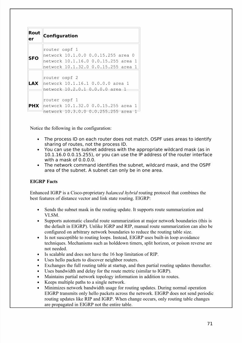
8/3/2019 Ccna Notes 1
http://slidepdf.com/reader/full/ccna-notes-1 71/98
Rout
erConfiguration
SFO
router ospf 1
network 10.1.0.0 0.0.15.255 area 0
network 10.1.16.0 0.0.15.255 area 1network 10.1.32.0 0.0.15.255 area 1
LAX
router ospf 2
network 10.1.16.1 0.0.0.0 area 1
network 10.2.0.1 0.0.0.0 area 1
PHX
router ospf 1
network 10.1.32.0 0.0.15.255 area 1
network 10.3.0.0 0.0.255.255 area 1
Notice the following in the configuration:
• The process ID on each router does not match. OSPF uses areas to identifysharing of routes, not the process ID.
• You can use the subnet address with the appropriate wildcard mask (as in10.1.16.0 0.0.15.255), or you can use the IP address of the router interfacewith a mask of 0.0.0.0.
• The network command identifies the subnet, wildcard mask, and the OSPFarea of the subnet. A subnet can only be in one area.
EIGRP Facts
Enhanced IGRP is a Cisco-proprietary balanced hybrid routing protocol that combines the best features of distance vector and link state routing. EIGRP:
• Sends the subnet mask in the routing update. It supports route summarization andVLSM.
• Supports automatic classful route summarization at major network boundaries (this isthe default in EIGRP). Unlike IGRP and RIP, manual route summarization can also beconfigured on arbitrary network boundaries to reduce the routing table size.
• Is not susceptible to routing loops. Instead, EIGRP uses built-in loop avoidancetechniques. Mechanisms such as holddown timers, split horizon, or poison reverse arenot needed.
• Is scalable and does not have the 16 hop limitation of RIP.• Uses hello packets to discover neighbor routers.• Exchanges the full routing table at startup, and then partial routing updates thereafter.• Uses bandwidth and delay for the route metric (similar to IGRP).• Maintains partial network topology information in addition to routes.• Keeps multiple paths to a single network.• Minimizes network bandwidth usage for routing updates. During normal operation
EIGRP transmits only hello packets across the network. EIGRP does not send periodic
routing updates like RIP and IGRP. When change occurs, only routing table changesare propagated in EIGRP not the entire table.
71
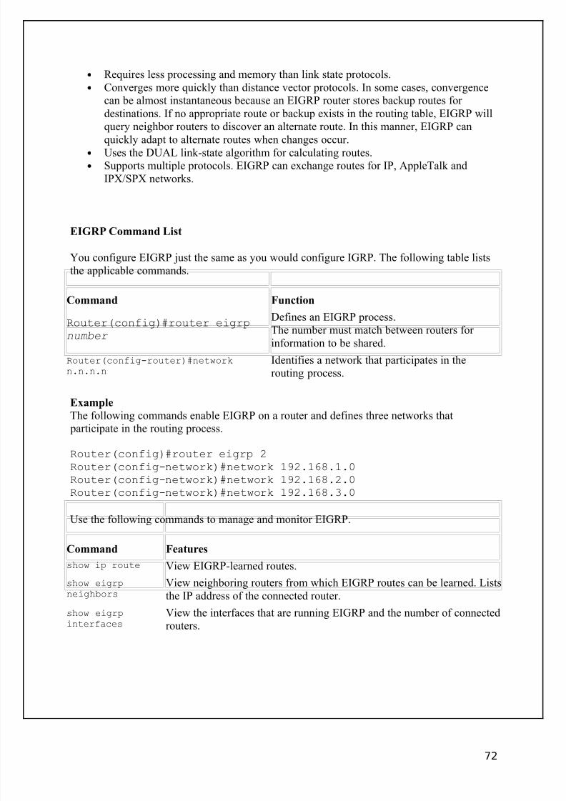
8/3/2019 Ccna Notes 1
http://slidepdf.com/reader/full/ccna-notes-1 72/98
• Requires less processing and memory than link state protocols.• Converges more quickly than distance vector protocols. In some cases, convergence
can be almost instantaneous because an EIGRP router stores backup routes for destinations. If no appropriate route or backup exists in the routing table, EIGRP willquery neighbor routers to discover an alternate route. In this manner, EIGRP can
quickly adapt to alternate routes when changes occur.• Uses the DUAL link-state algorithm for calculating routes.• Supports multiple protocols. EIGRP can exchange routes for IP, AppleTalk and
IPX/SPX networks.
EIGRP Command List
You configure EIGRP just the same as you would configure IGRP. The following table liststhe applicable commands.
Command Function
Router(config)#router eigrpnumber
Defines an EIGRP process.The number must match between routers for information to be shared.
Router(config-router)#networkn.n.n.n
Identifies a network that participates in therouting process.
Example
The following commands enable EIGRP on a router and defines three networks that participate in the routing process.
Router(config)#router eigrp 2Router(config-network)#network 192.168.1.0Router(config-network)#network 192.168.2.0Router(config-network)#network 192.168.3.0
Use the following commands to manage and monitor EIGRP.
Command Features
show ip route View EIGRP-learned routes.
show eigrpneighbors
View neighboring routers from which EIGRP routes can be learned. Liststhe IP address of the connected router.
show eigrpinterfaces
View the interfaces that are running EIGRP and the number of connectedrouters.
72
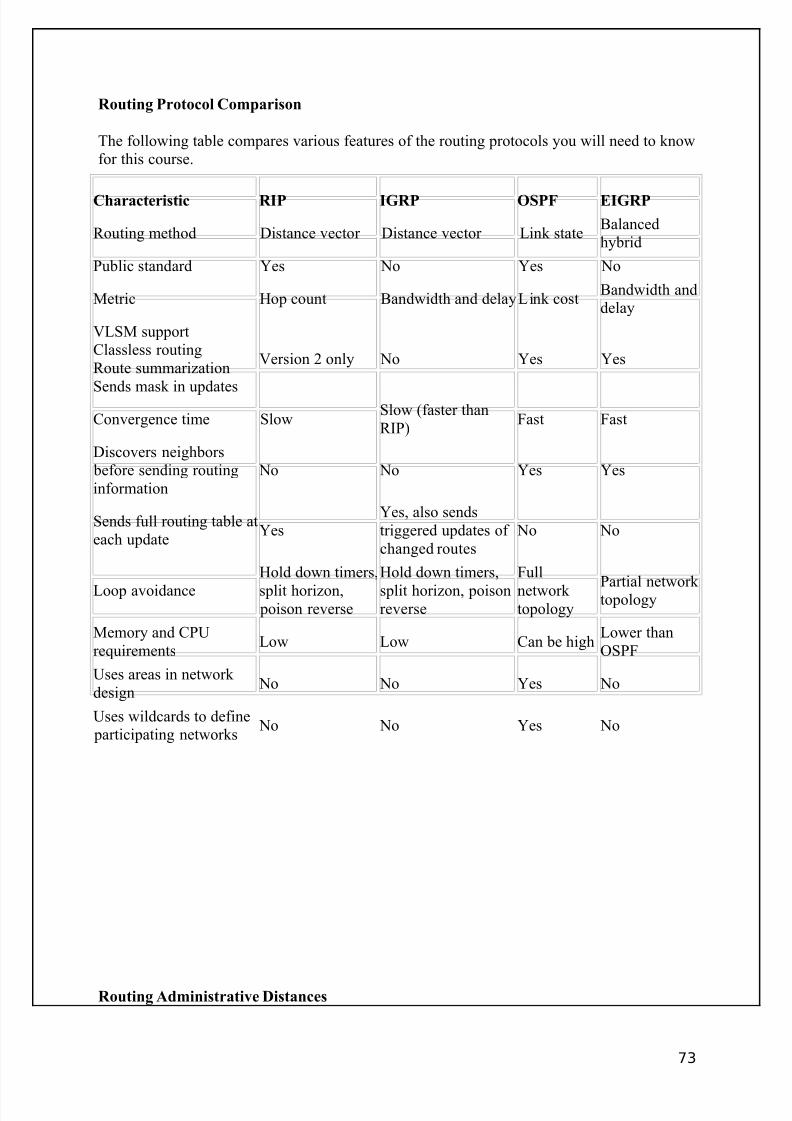
8/3/2019 Ccna Notes 1
http://slidepdf.com/reader/full/ccna-notes-1 73/98
Routing Protocol Comparison
The following table compares various features of the routing protocols you will need to knowfor this course.
Characteristic RIP IGRP OSPF EIGRP
Routing method Distance vector Distance vector Link stateBalancedhybrid
Public standard Yes No Yes No
Metric Hop count Bandwidth and delayLink costBandwidth anddelay
VLSM supportClassless routingRoute summarization
Sends mask in updates
Version 2 only No Yes Yes
Convergence time SlowSlow (faster thanRIP)
Fast Fast
Discovers neighbors before sending routinginformation
No No Yes Yes
Sends full routing table ateach update
YesYes, also sendstriggered updates of changed routes
No No
Loop avoidance
Hold down timers,
split horizon, poison reverse
Hold down timers,
split horizon, poisonreverse
Full
network topology
Partial network topology
Memory and CPUrequirements
Low Low Can be highLower thanOSPF
Uses areas in network design
No No Yes No
Uses wildcards to define participating networks
No No Yes No
Routing Administrative Distances
73
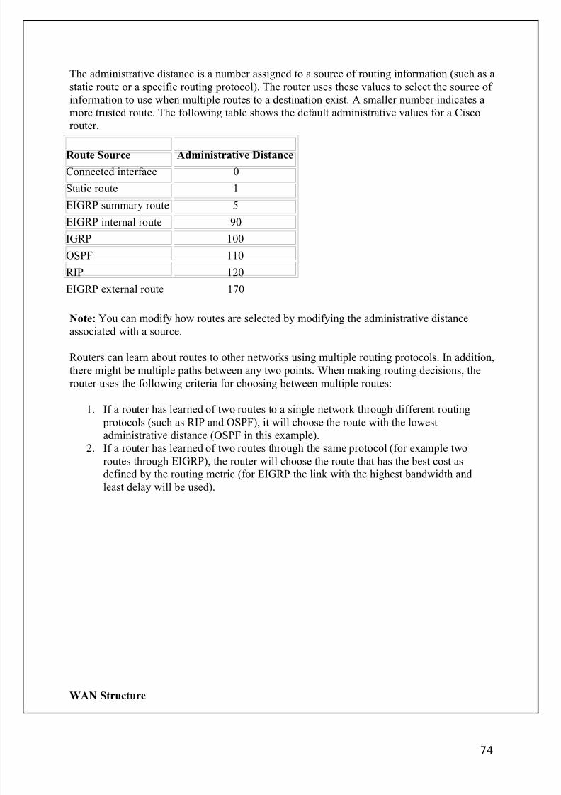
8/3/2019 Ccna Notes 1
http://slidepdf.com/reader/full/ccna-notes-1 74/98
The administrative distance is a number assigned to a source of routing information (such as astatic route or a specific routing protocol). The router uses these values to select the source of information to use when multiple routes to a destination exist. A smaller number indicates amore trusted route. The following table shows the default administrative values for a Ciscorouter.
Route Source Administrative Distance
Connected interface 0
Static route 1
EIGRP summary route 5
EIGRP internal route 90
IGRP 100
OSPF 110
RIP 120
EIGRP external route 170
Note: You can modify how routes are selected by modifying the administrative distanceassociated with a source.
Routers can learn about routes to other networks using multiple routing protocols. In addition,there might be multiple paths between any two points. When making routing decisions, therouter uses the following criteria for choosing between multiple routes:
1. If a router has learned of two routes to a single network through different routing protocols (such as RIP and OSPF), it will choose the route with the lowestadministrative distance (OSPF in this example).
2. If a router has learned of two routes through the same protocol (for example tworoutes through EIGRP), the router will choose the route that has the best cost asdefined by the routing metric (for EIGRP the link with the highest bandwidth andleast delay will be used).
WAN Structure
74
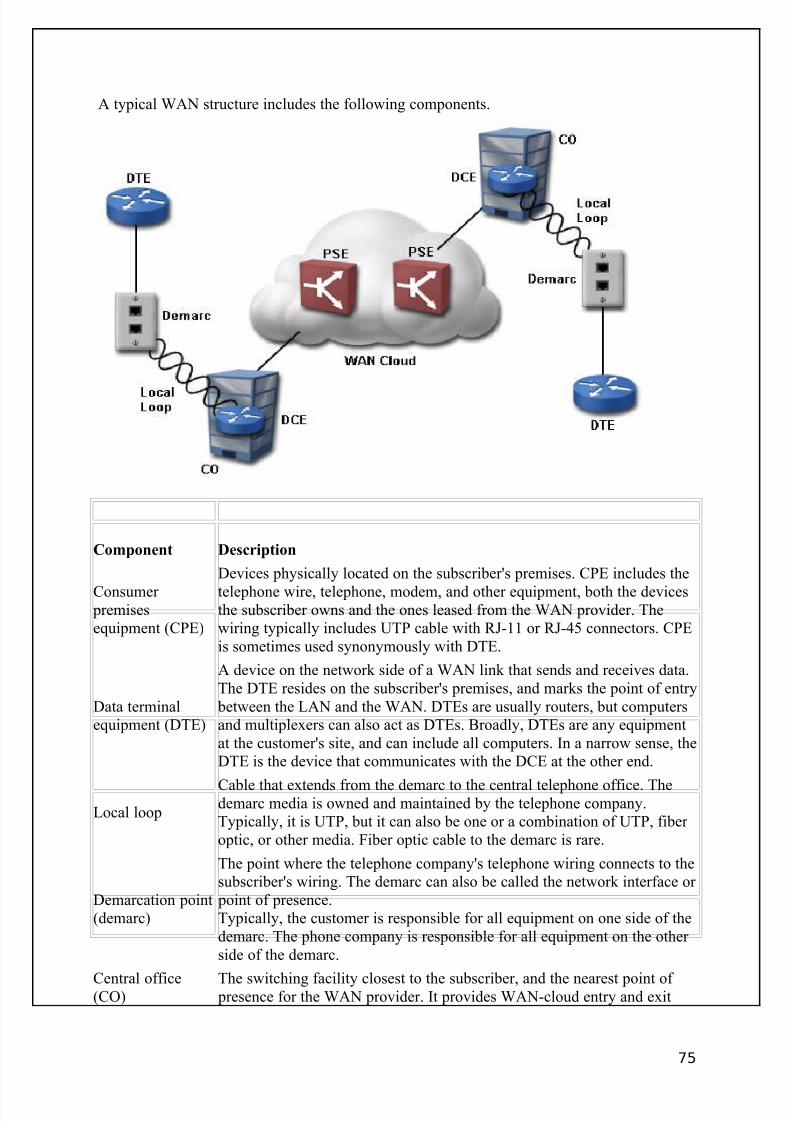
8/3/2019 Ccna Notes 1
http://slidepdf.com/reader/full/ccna-notes-1 75/98
A typical WAN structure includes the following components.
Component Description
Consumer premisesequipment (CPE)
Devices physically located on the subscriber's premises. CPE includes the
telephone wire, telephone, modem, and other equipment, both the devicesthe subscriber owns and the ones leased from the WAN provider. Thewiring typically includes UTP cable with RJ-11 or RJ-45 connectors. CPEis sometimes used synonymously with DTE.
Data terminalequipment (DTE)
A device on the network side of a WAN link that sends and receives data.The DTE resides on the subscriber's premises, and marks the point of entry
between the LAN and the WAN. DTEs are usually routers, but computersand multiplexers can also act as DTEs. Broadly, DTEs are any equipmentat the customer's site, and can include all computers. In a narrow sense, theDTE is the device that communicates with the DCE at the other end.
Local loop
Cable that extends from the demarc to the central telephone office. Thedemarc media is owned and maintained by the telephone company.Typically, it is UTP, but it can also be one or a combination of UTP, fiber optic, or other media. Fiber optic cable to the demarc is rare.
Demarcation point(demarc)
The point where the telephone company's telephone wiring connects to thesubscriber's wiring. The demarc can also be called the network interface or
point of presence.Typically, the customer is responsible for all equipment on one side of thedemarc. The phone company is responsible for all equipment on the other side of the demarc.
Central office(CO)
The switching facility closest to the subscriber, and the nearest point of presence for the WAN provider. It provides WAN-cloud entry and exit
75
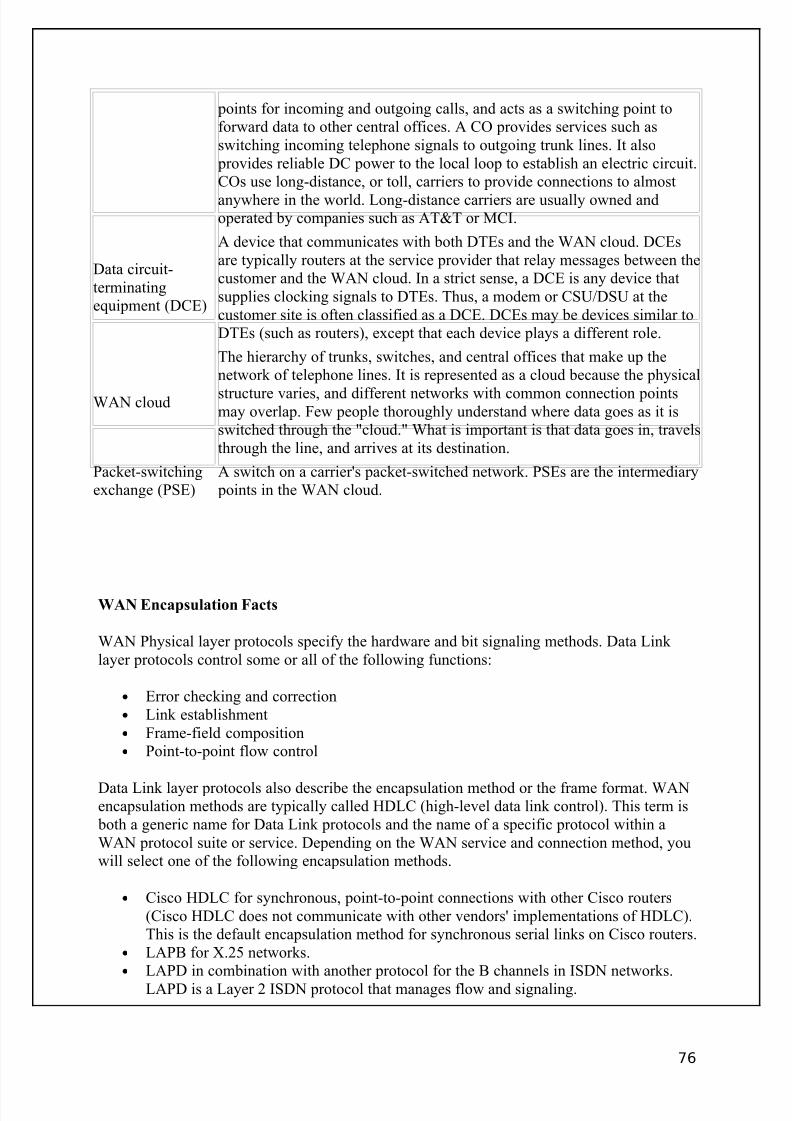
8/3/2019 Ccna Notes 1
http://slidepdf.com/reader/full/ccna-notes-1 76/98
points for incoming and outgoing calls, and acts as a switching point toforward data to other central offices. A CO provides services such asswitching incoming telephone signals to outgoing trunk lines. It also
provides reliable DC power to the local loop to establish an electric circuit.COs use long-distance, or toll, carriers to provide connections to almost
anywhere in the world. Long-distance carriers are usually owned andoperated by companies such as AT&T or MCI.
Data circuit-terminatingequipment (DCE)
A device that communicates with both DTEs and the WAN cloud. DCEsare typically routers at the service provider that relay messages between thecustomer and the WAN cloud. In a strict sense, a DCE is any device thatsupplies clocking signals to DTEs. Thus, a modem or CSU/DSU at thecustomer site is often classified as a DCE. DCEs may be devices similar toDTEs (such as routers), except that each device plays a different role.
WAN cloud
The hierarchy of trunks, switches, and central offices that make up thenetwork of telephone lines. It is represented as a cloud because the physical
structure varies, and different networks with common connection pointsmay overlap. Few people thoroughly understand where data goes as it isswitched through the "cloud." What is important is that data goes in, travelsthrough the line, and arrives at its destination.
Packet-switchingexchange (PSE)
A switch on a carrier's packet-switched network. PSEs are the intermediary points in the WAN cloud.
WAN Encapsulation Facts
WAN Physical layer protocols specify the hardware and bit signaling methods. Data Link layer protocols control some or all of the following functions:
• Error checking and correction• Link establishment• Frame-field composition• Point-to-point flow control
Data Link layer protocols also describe the encapsulation method or the frame format. WANencapsulation methods are typically called HDLC (high-level data link control). This term is
both a generic name for Data Link protocols and the name of a specific protocol within aWAN protocol suite or service. Depending on the WAN service and connection method, youwill select one of the following encapsulation methods.
• Cisco HDLC for synchronous, point-to-point connections with other Cisco routers(Cisco HDLC does not communicate with other vendors' implementations of HDLC).This is the default encapsulation method for synchronous serial links on Cisco routers.
• LAPB for X.25 networks.• LAPD in combination with another protocol for the B channels in ISDN networks.
LAPD is a Layer 2 ISDN protocol that manages flow and signaling.
76
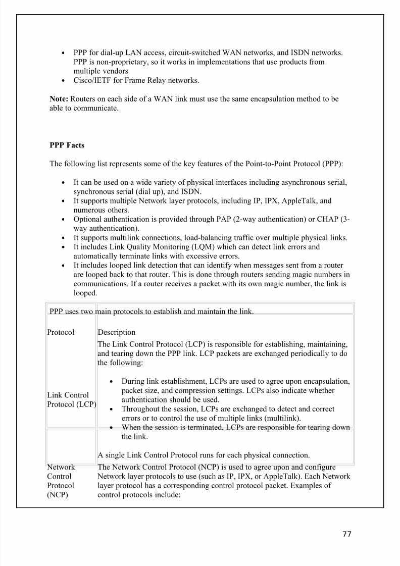
8/3/2019 Ccna Notes 1
http://slidepdf.com/reader/full/ccna-notes-1 77/98
• PPP for dial-up LAN access, circuit-switched WAN networks, and ISDN networks.PPP is non-proprietary, so it works in implementations that use products frommultiple vendors.
• Cisco/IETF for Frame Relay networks.
Note: Routers on each side of a WAN link must use the same encapsulation method to beable to communicate.
PPP Facts
The following list represents some of the key features of the Point-to-Point Protocol (PPP):
• It can be used on a wide variety of physical interfaces including asynchronous serial,synchronous serial (dial up), and ISDN.
• It supports multiple Network layer protocols, including IP, IPX, AppleTalk, andnumerous others.
• Optional authentication is provided through PAP (2-way authentication) or CHAP (3-way authentication).
• It supports multilink connections, load-balancing traffic over multiple physical links.• It includes Link Quality Monitoring (LQM) which can detect link errors and
automatically terminate links with excessive errors.• It includes looped link detection that can identify when messages sent from a router
are looped back to that router. This is done through routers sending magic numbers incommunications. If a router receives a packet with its own magic number, the link islooped.
PPP uses two main protocols to establish and maintain the link.
Protocol Description
Link ControlProtocol (LCP)
The Link Control Protocol (LCP) is responsible for establishing, maintaining,and tearing down the PPP link. LCP packets are exchanged periodically to dothe following:
• During link establishment, LCPs are used to agree upon encapsulation, packet size, and compression settings. LCPs also indicate whether
authentication should be used.• Throughout the session, LCPs are exchanged to detect and correct
errors or to control the use of multiple links (multilink).• When the session is terminated, LCPs are responsible for tearing down
the link.
A single Link Control Protocol runs for each physical connection.
Network ControlProtocol
(NCP)
The Network Control Protocol (NCP) is used to agree upon and configure Network layer protocols to use (such as IP, IPX, or AppleTalk). Each Network layer protocol has a corresponding control protocol packet. Examples of
control protocols include:
77

8/3/2019 Ccna Notes 1
http://slidepdf.com/reader/full/ccna-notes-1 78/98
• IP Control Protocol (IPCP)• CDP Control Protocol (CDPCP)• IPX Control Protocol (IPXCP)• AppleTalk Control Protocol (ATCP)
A single PPP link can run multiple control protocols, one for each Network-layer protocol supported on the link.
PPP establishes communication in three phases.
1. LCP phase. LCPs are exchanged to open the link and agree upon link settings such asencapsulation, packet size, and whether authentication will be used.
2. Authenticate phase (optional). During this phase, authentication-specific packets areexchanged to configure authentication parameters and authenticate the devices. LCPs
might also be exchanged during this phase to maintain the link.3. NCP phase. NCPs are exchanged to agree on upper-layer protocols to use. For example, routers might exchange IPCP and CDPCP packets to agree upon using IPand CDP for Network-layer communications. During this phase, LCPs might continueto be exchanged.
PPP Command List
PPP configuration is often done in connection with configuring other services. To configurePPP on the router, you complete the following tasks:
1. Set PPP encapsulation on the interface. You must set the encapsulationmethod to PPP before you can configure authentication or compression.
2. Select CHAP and/or PAP as the authentication method (optional).3. If authentication is used, configure username/password combinations.
PPP options are configured in interface mode for a specific interface.
Use . . . To . . .
Router(config-if)#encapsulation ppp Set the encapsulation type to PPP
Router(config-if)#ppp authentication <chap|pap>Router(config-if)#ppp authentication chappap
Set the authentication method(s)When multiple methods are
specified, the first method will be
tried first
Router(config-if)#ppp compression Set compression options
Router(config-if)#ppp chap|pap password
<password>
Set the password used with CHAP
or PAP for an unknown host
Router(config)#username <hostname>
password <password>
Set the username and password for
the local router
78
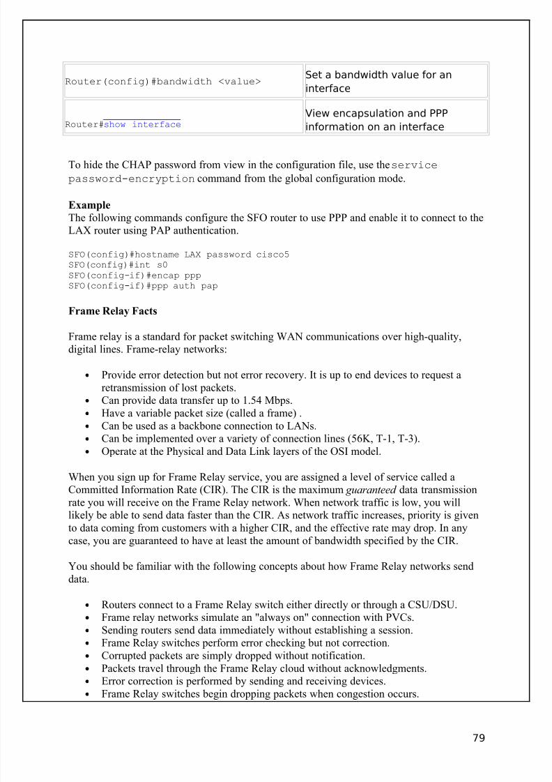
8/3/2019 Ccna Notes 1
http://slidepdf.com/reader/full/ccna-notes-1 79/98
Router(config)#bandwidth <value>Set a bandwidth value for an
interface
Router#show interfaceView encapsulation and PPP
information on an interface
To hide the CHAP password from view in the configuration file, use the service
password-encryption command from the global configuration mode.
Example
The following commands configure the SFO router to use PPP and enable it to connect to theLAX router using PAP authentication.
SFO(config)#hostname LAX password cisco5SFO(config)#int s0
SFO(config-if)#encap pppSFO(config-if)#ppp auth pap
Frame Relay Facts
Frame relay is a standard for packet switching WAN communications over high-quality,digital lines. Frame-relay networks:
• Provide error detection but not error recovery. It is up to end devices to request aretransmission of lost packets.
• Can provide data transfer up to 1.54 Mbps.• Have a variable packet size (called a frame) .• Can be used as a backbone connection to LANs.• Can be implemented over a variety of connection lines (56K, T-1, T-3).• Operate at the Physical and Data Link layers of the OSI model.
When you sign up for Frame Relay service, you are assigned a level of service called aCommitted Information Rate (CIR). The CIR is the maximum guaranteed data transmissionrate you will receive on the Frame Relay network. When network traffic is low, you willlikely be able to send data faster than the CIR. As network traffic increases, priority is givento data coming from customers with a higher CIR, and the effective rate may drop. In anycase, you are guaranteed to have at least the amount of bandwidth specified by the CIR.
You should be familiar with the following concepts about how Frame Relay networks senddata.
• Routers connect to a Frame Relay switch either directly or through a CSU/DSU.• Frame relay networks simulate an "always on" connection with PVCs.• Sending routers send data immediately without establishing a session.• Frame Relay switches perform error checking but not correction.• Corrupted packets are simply dropped without notification.• Packets travel through the Frame Relay cloud without acknowledgments.•
Error correction is performed by sending and receiving devices.• Frame Relay switches begin dropping packets when congestion occurs.
79
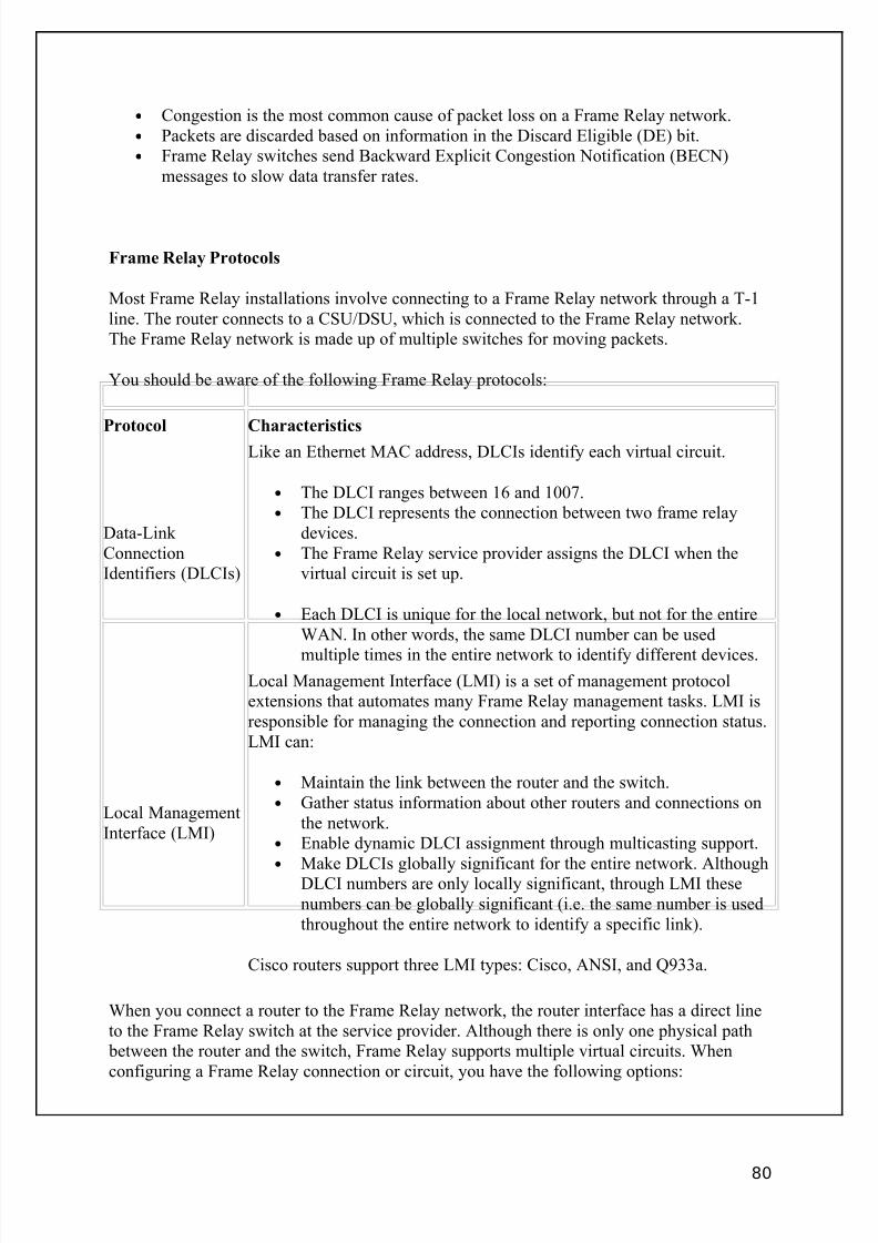
8/3/2019 Ccna Notes 1
http://slidepdf.com/reader/full/ccna-notes-1 80/98
• Congestion is the most common cause of packet loss on a Frame Relay network.• Packets are discarded based on information in the Discard Eligible (DE) bit.• Frame Relay switches send Backward Explicit Congestion Notification (BECN)
messages to slow data transfer rates.
Frame Relay Protocols
Most Frame Relay installations involve connecting to a Frame Relay network through a T-1line. The router connects to a CSU/DSU, which is connected to the Frame Relay network.The Frame Relay network is made up of multiple switches for moving packets.
You should be aware of the following Frame Relay protocols:
Protocol Characteristics
Data-Link ConnectionIdentifiers (DLCIs)
Like an Ethernet MAC address, DLCIs identify each virtual circuit.
• The DLCI ranges between 16 and 1007.• The DLCI represents the connection between two frame relay
devices.• The Frame Relay service provider assigns the DLCI when the
virtual circuit is set up.
• Each DLCI is unique for the local network, but not for the entireWAN. In other words, the same DLCI number can be used
multiple times in the entire network to identify different devices.
Local ManagementInterface (LMI)
Local Management Interface (LMI) is a set of management protocolextensions that automates many Frame Relay management tasks. LMI isresponsible for managing the connection and reporting connection status.LMI can:
• Maintain the link between the router and the switch.• Gather status information about other routers and connections on
the network.• Enable dynamic DLCI assignment through multicasting support.•
Make DLCIs globally significant for the entire network. AlthoughDLCI numbers are only locally significant, through LMI thesenumbers can be globally significant (i.e. the same number is usedthroughout the entire network to identify a specific link).
Cisco routers support three LMI types: Cisco, ANSI, and Q933a.
When you connect a router to the Frame Relay network, the router interface has a direct lineto the Frame Relay switch at the service provider. Although there is only one physical path
between the router and the switch, Frame Relay supports multiple virtual circuits. Whenconfiguring a Frame Relay connection or circuit, you have the following options:
80
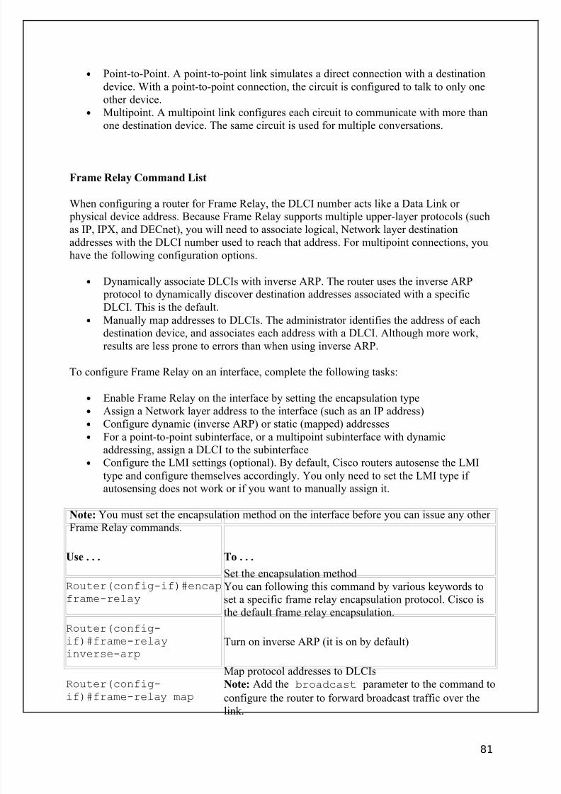
8/3/2019 Ccna Notes 1
http://slidepdf.com/reader/full/ccna-notes-1 81/98
• Point-to-Point. A point-to-point link simulates a direct connection with a destinationdevice. With a point-to-point connection, the circuit is configured to talk to only oneother device.
• Multipoint. A multipoint link configures each circuit to communicate with more thanone destination device. The same circuit is used for multiple conversations.
Frame Relay Command List
When configuring a router for Frame Relay, the DLCI number acts like a Data Link or physical device address. Because Frame Relay supports multiple upper-layer protocols (suchas IP, IPX, and DECnet), you will need to associate logical, Network layer destinationaddresses with the DLCI number used to reach that address. For multipoint connections, youhave the following configuration options.
• Dynamically associate DLCIs with inverse ARP. The router uses the inverse ARP protocol to dynamically discover destination addresses associated with a specificDLCI. This is the default.
• Manually map addresses to DLCIs. The administrator identifies the address of eachdestination device, and associates each address with a DLCI. Although more work,results are less prone to errors than when using inverse ARP.
To configure Frame Relay on an interface, complete the following tasks:
• Enable Frame Relay on the interface by setting the encapsulation type• Assign a Network layer address to the interface (such as an IP address)• Configure dynamic (inverse ARP) or static (mapped) addresses• For a point-to-point subinterface, or a multipoint subinterface with dynamic
addressing, assign a DLCI to the subinterface• Configure the LMI settings (optional). By default, Cisco routers autosense the LMI
type and configure themselves accordingly. You only need to set the LMI type if autosensing does not work or if you want to manually assign it.
Note: You must set the encapsulation method on the interface before you can issue any other Frame Relay commands.
Use . . . To . . .
Router(config-if)#encapframe-relay
Set the encapsulation methodYou can following this command by various keywords toset a specific frame relay encapsulation protocol. Cisco isthe default frame relay encapsulation.
Router(config-if)#frame-relayinverse-arp
Turn on inverse ARP (it is on by default)
Router(config-
if)#frame-relay map
Map protocol addresses to DLCIsNote: Add the broadcast parameter to the command to
configure the router to forward broadcast traffic over thelink.
81
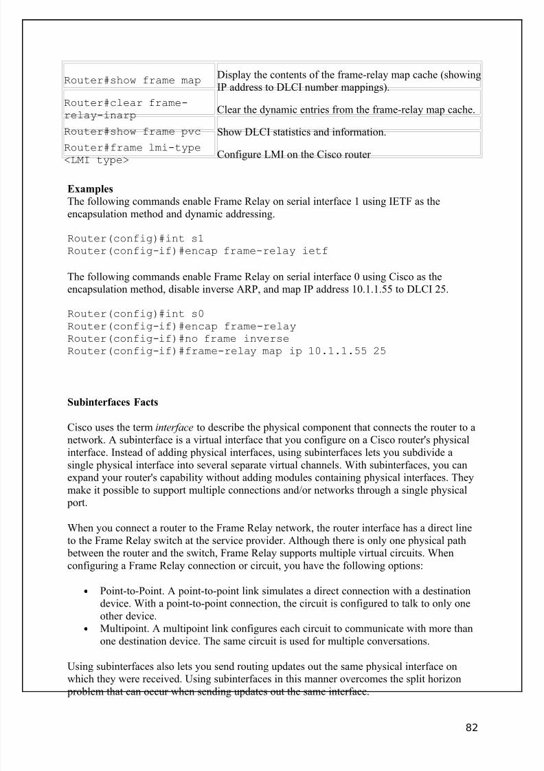
8/3/2019 Ccna Notes 1
http://slidepdf.com/reader/full/ccna-notes-1 82/98
Router#show frame mapDisplay the contents of the frame-relay map cache (showingIP address to DLCI number mappings).
Router#clear frame-relay-inarp
Clear the dynamic entries from the frame-relay map cache.
Router#show frame pvc Show DLCI statistics and information.Router#frame lmi-type<LMI type>
Configure LMI on the Cisco router
Examples
The following commands enable Frame Relay on serial interface 1 using IETF as theencapsulation method and dynamic addressing.
Router(config)#int s1Router(config-if)#encap frame-relay ietf
The following commands enable Frame Relay on serial interface 0 using Cisco as theencapsulation method, disable inverse ARP, and map IP address 10.1.1.55 to DLCI 25.
Router(config)#int s0Router(config-if)#encap frame-relayRouter(config-if)#no frame inverseRouter(config-if)#frame-relay map ip 10.1.1.55 25
Subinterfaces Facts
Cisco uses the term interface to describe the physical component that connects the router to anetwork. A subinterface is a virtual interface that you configure on a Cisco router's physicalinterface. Instead of adding physical interfaces, using subinterfaces lets you subdivide asingle physical interface into several separate virtual channels. With subinterfaces, you canexpand your router's capability without adding modules containing physical interfaces. Theymake it possible to support multiple connections and/or networks through a single physical
port.
When you connect a router to the Frame Relay network, the router interface has a direct line
to the Frame Relay switch at the service provider. Although there is only one physical path between the router and the switch, Frame Relay supports multiple virtual circuits. Whenconfiguring a Frame Relay connection or circuit, you have the following options:
• Point-to-Point. A point-to-point link simulates a direct connection with a destinationdevice. With a point-to-point connection, the circuit is configured to talk to only oneother device.
• Multipoint. A multipoint link configures each circuit to communicate with more thanone destination device. The same circuit is used for multiple conversations.
Using subinterfaces also lets you send routing updates out the same physical interface on
which they were received. Using subinterfaces in this manner overcomes the split horizon problem that can occur when sending updates out the same interface.
82

8/3/2019 Ccna Notes 1
http://slidepdf.com/reader/full/ccna-notes-1 83/98
Frame Relay Subinterface Command List
To configure Frame Relay on a subinterface, complete the following tasks:
• Enable Frame Relay on the interface and set the encapsulation method
• Create the subinterface, specifying either point-to-point or multipoint• For a point-to-point connection or a multipoint connection using inverse ARP, assign
the DLCI number to the subinterface• For a multipoint connection using static assignments, map DLCIs to protocol
addresses
In addition, you will need to assign a Network layer address to the subinterface. Do not assignan IP address to the main interface.
Use . . . To . . .
Router(config-if)#int sX.X <type> Create the subinterfaceRouter(config-subif)#frame-relayinterface-dlci
Assign the DLCI to theinterface
Router(config-subif)#frame-relay mapMap protocol addresses toDLCIs
Examples The following commands create a point-to-point subinterface on the first serial interface andassign it to DLCI 44. The subinterface is configured to use inverse ARP.
Router(config)#int s0Router(config-if)#encap frameRouter(config-if)#int s0.55 pointRouter(config-subif)#frame interface-dlci 44
The following commands create a multipoint subinterface on the second serial interface, andconfigure it with a static IP mapping of device 199.12.16.155 to DLCI 111.
Router(config)#int s1Router(config-if)#encap frameRouter(config-if)#int s1.103 multRouter(config-subif)#frame map ip 199.12.16.155 111
Frame Relay Troubleshooting Introduction
The next set of simulations gives you a chance to troubleshoot Frame Relay. All simulationsuse the same network layout as shown.
83
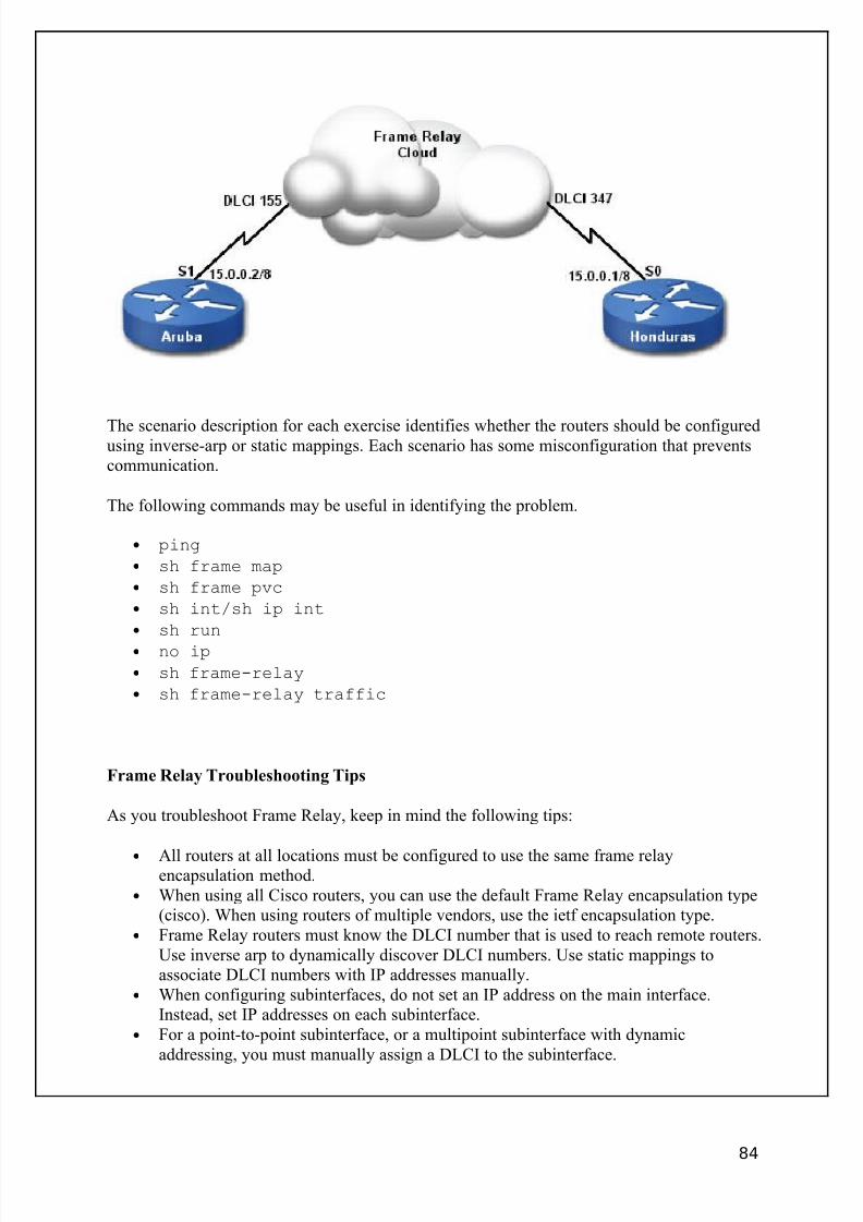
8/3/2019 Ccna Notes 1
http://slidepdf.com/reader/full/ccna-notes-1 84/98
The scenario description for each exercise identifies whether the routers should be configuredusing inverse-arp or static mappings. Each scenario has some misconfiguration that preventscommunication.
The following commands may be useful in identifying the problem.
• ping
• sh frame map
• sh frame pvc
• sh int/sh ip int
• sh run
• no ip
• sh frame-relay
• sh frame-relay traffic
Frame Relay Troubleshooting Tips
As you troubleshoot Frame Relay, keep in mind the following tips:
• All routers at all locations must be configured to use the same frame relayencapsulation method.
• When using all Cisco routers, you can use the default Frame Relay encapsulation type(cisco). When using routers of multiple vendors, use the ietf encapsulation type.
• Frame Relay routers must know the DLCI number that is used to reach remote routers.Use inverse arp to dynamically discover DLCI numbers. Use static mappings toassociate DLCI numbers with IP addresses manually.
• When configuring subinterfaces, do not set an IP address on the main interface.Instead, set IP addresses on each subinterface.
• For a point-to-point subinterface, or a multipoint subinterface with dynamicaddressing, you must manually assign a DLCI to the subinterface.
84
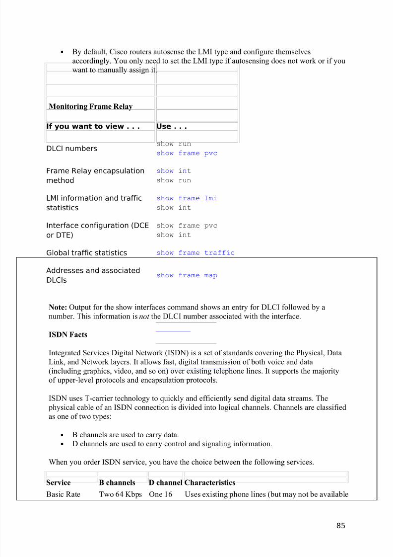
8/3/2019 Ccna Notes 1
http://slidepdf.com/reader/full/ccna-notes-1 85/98
• By default, Cisco routers autosense the LMI type and configure themselvesaccordingly. You only need to set the LMI type if autosensing does not work or if youwant to manually assign it.
Monitoring Frame Relay
If you want to view . . . Use . . .
DLCI numbersshow run
show frame pvc
Frame Relay encapsulation
method
show int
show run
LMI information and traffic
statistics
show frame lmi
show int
Interface configuration (DCE
or DTE)
show frame pvc
show int
Global traffic statistics show frame traffic
Addresses and associated
DLCIsshow frame map
Note: Output for the show interfaces command shows an entry for DLCI followed by anumber. This information is not the DLCI number associated with the interface.
ISDN Facts
Integrated Services Digital Network (ISDN) is a set of standards covering the Physical, DataLink, and Network layers. It allows fast, digital transmission of both voice and data(including graphics, video, and so on) over existing telephone lines. It supports the majorityof upper-level protocols and encapsulation protocols.
ISDN uses T-carrier technology to quickly and efficiently send digital data streams. The physical cable of an ISDN connection is divided into logical channels. Channels are classifiedas one of two types:
• B channels are used to carry data.• D channels are used to carry control and signaling information.
When you order ISDN service, you have the choice between the following services.
Service B channels D channel Characteristics
Basic Rate Two 64 Kbps One 16 Uses existing phone lines (but may not be available
85

8/3/2019 Ccna Notes 1
http://slidepdf.com/reader/full/ccna-notes-1 86/98
ISDN (BRI) Kbpswhere existing copper wires don't support it)The connection is "demand-dial" (established onlywhen data needs to be sent)
Primary Rate
ISDN (PRI)
Twenty-three
64 Kbps
One 64
Kbps
Uses an entire T-1 lineSometimes called 23B+DThe connection is "always on"
Note: The total bandwidth of an ISDN BRI line is 144 Kbps (two B channels and one Dchannel). The total data transfer rate is 128 Kbps (data is sent only on the two B channels).
ISDN BRI is a relatively low-cost WAN service that is ideal for the following situations:
• Home office or telecommuters who need a relatively fast connection• Businesses that need to periodically send data between sites (bursty traffic patterns)
ISDN BRI offers the following benefits over dial-up modems and other WAN connectionoptions.
• Faster data transfer rates (128 Kbps) than dial-up modems (56 Kbps maximum)• Faster call establishment (dial-up) than modems• Lower cost than other WAN solutions (users pay a monthly fee plus connection
charges)
ISDN Protocol Standards
ISDN standards are grouped according to function. The protocol groupings and descriptionsfollow a lettering standard.
Protocol
DesignationStandard
EStandards for ISDN on the existing phone network, such as internationaladdressing
IStandards for ISDN concepts, terminology, and services, such as network services
QStandards for switching and signaling, such as call setup, flow control,and error correction
In practice, you will probably not need to know these standards, but you will need tomemorize them for the certification exam. Use the following to help remember theclassifications.
E for Existing networksI for Identifying conceptsQ for Quality switching signals
86
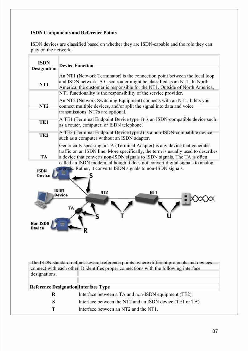
8/3/2019 Ccna Notes 1
http://slidepdf.com/reader/full/ccna-notes-1 87/98
ISDN Components and Reference Points
ISDN devices are classified based on whether they are ISDN-capable and the role they can play on the network.
ISDNDesignation
Device Function
NT1
An NT1 (Network Terminator) is the connection point between the local loopand ISDN network. A Cisco router might be classified as an NT1. In NorthAmerica, the customer is responsible for the NT1. Outside of North America,
NT1 functionality is the responsibility of the service provider.
NT2
An NT2 (Network Switching Equipment) connects with an NT1. It lets youconnect multiple devices, and/or split the signal into data and voicetransmissions. NT2s are optional.
TE1A TE1 (Terminal Endpoint Device type 1) is an ISDN-compatible device suchas a router, computer, or ISDN telephone.
TE2A TE2 (Terminal Endpoint Device type 2) is a non-ISDN-compatible devicesuch as a computer without an ISDN adapter.
TA
Generically speaking, a TA (Terminal Adapter) is any device that generatestraffic on an ISDN line. More specifically, the term is usually used to describesa device that converts non-ISDN signals to ISDN signals. The TA is oftencalled an ISDN modem, although it does not convert digital signals to analogsignals. Rather, it converts ISDN signals to non-ISDN signals.
The ISDN standard defines several reference points, where different protocols and devicesconnect with each other. It identifies proper connections with the following interfacedesignations.
Reference Designation Interface Type
R Interface between a TA and non-ISDN equipment (TE2).
S Interface between the NT2 and an ISDN device (TE1 or TA).
T Interface between an NT2 and the NT1.
87
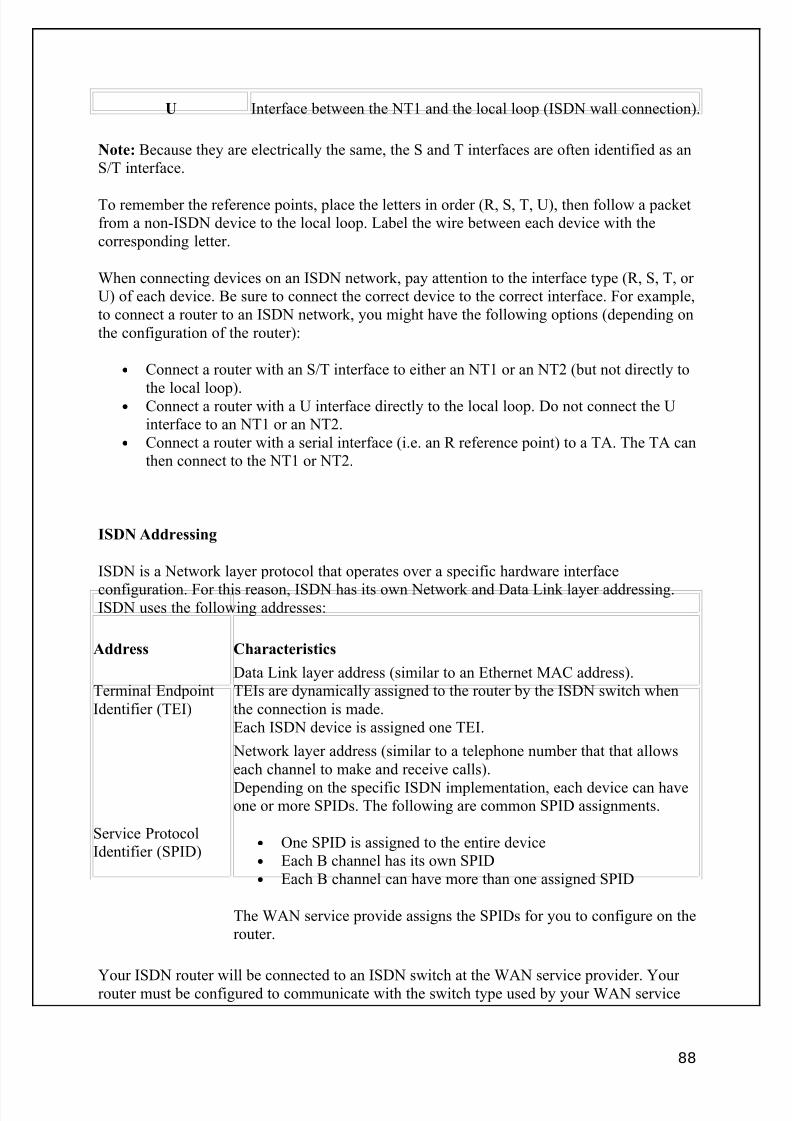
8/3/2019 Ccna Notes 1
http://slidepdf.com/reader/full/ccna-notes-1 88/98
U Interface between the NT1 and the local loop (ISDN wall connection).
Note: Because they are electrically the same, the S and T interfaces are often identified as anS/T interface.
To remember the reference points, place the letters in order (R, S, T, U), then follow a packetfrom a non-ISDN device to the local loop. Label the wire between each device with thecorresponding letter.
When connecting devices on an ISDN network, pay attention to the interface type (R, S, T, or U) of each device. Be sure to connect the correct device to the correct interface. For example,to connect a router to an ISDN network, you might have the following options (depending onthe configuration of the router):
• Connect a router with an S/T interface to either an NT1 or an NT2 (but not directly to
the local loop).• Connect a router with a U interface directly to the local loop. Do not connect the U
interface to an NT1 or an NT2.• Connect a router with a serial interface (i.e. an R reference point) to a TA. The TA can
then connect to the NT1 or NT2.
ISDN Addressing
ISDN is a Network layer protocol that operates over a specific hardware interface
configuration. For this reason, ISDN has its own Network and Data Link layer addressing.ISDN uses the following addresses:
Address Characteristics
Terminal EndpointIdentifier (TEI)
Data Link layer address (similar to an Ethernet MAC address).TEIs are dynamically assigned to the router by the ISDN switch whenthe connection is made.Each ISDN device is assigned one TEI.
Service ProtocolIdentifier (SPID)
Network layer address (similar to a telephone number that that allowseach channel to make and receive calls).
Depending on the specific ISDN implementation, each device can haveone or more SPIDs. The following are common SPID assignments.
• One SPID is assigned to the entire device• Each B channel has its own SPID• Each B channel can have more than one assigned SPID
The WAN service provide assigns the SPIDs for you to configure on therouter.
Your ISDN router will be connected to an ISDN switch at the WAN service provider. Your router must be configured to communicate with the switch type used by your WAN service
88
8/3/2019 Ccna Notes 1
http://slidepdf.com/reader/full/ccna-notes-1 89/98
provider. Cisco routers support over 10 switch types. In North America, the most commontypes are:
• AT&T 5ESS• Northern DMS-100
• National ISDN-1
ISDN Communication Facts
The following process is used to initialize an ISDN router.
1. The router uses the D channel to perform Data Link (layer 2) initialization. TEIs aredynamically assigned to identify the router.
2. The router uses the D channel to perform Network (layer 3) initialization. It uses its
preconfigured SPIDs (if required) to set up the B channels.
When a router needs to communicate with another ISDN device, the following process isused.
1. The sending device requests a connection through the D channel.2. The receiving device answers and the link is established.3. The B channel is used to transmit data. The D channel is used for session
maintenance.4. After the transmission is over, the D channel is used to tear down the link.
Link Access Protocol for the D-Channel (LAPD) is the Data Link encapsulation protocolused on an ISDN network. As its name implies, it operates on the D channel of an ISDNconnection and is used for:
• Initializing Layer 2 and Layer 3 communications.• Assigning TEIs.• Maintaining the session.• Terminating the link.
ISDN Command List
To configure an ISDN connection, you need to complete the following configuration processes:
• Configure the ISDN switch type• Assign SPIDs (if required)• Configure encapsulation
Use the following commands to configure an ISDN connection. The exact commands you
will use depend on the equipment used at the central office.
89
8/3/2019 Ccna Notes 1
http://slidepdf.com/reader/full/ccna-notes-1 90/98
Use . . . To . . .
Router(config)#interfacebri0
Switch to ISDN interface configuration mode.
Router(config)#isdn switch-type <type>
Set the ISDN switch type to match that used by the
service provider. For IOS 11.2 and below, this is aglobal configuration command. For IOS 11.3 andabove, use this command in interface mode or global configuration mode.
Router(config-if)#isdnspid<#> <number> <number>
Identify SPIDs for an interface. Use only if SPIDnumbers are not dynamically assigned.
Router(config-if)#encap pppSet the encapsulation method for the interface (PPPis the most common).
Router#show isdn status View the status of the ISDN connection.
Router#show isdn active Show active ISDN phone calls.
Router#show isdn history Show all past and current ISDN phone calls.
Router(config-if)#pppmultilink
Enables multilink on the interface. An ISDNconnection consists of multiple logical B channelson a single physical connection. To use multiplechannels at the same time, enable multilink PPP(MLP).
Router(config)#dialer load-threshold
Identifies the utilization percentage that must existfor the additional channels to be used.
ExampleThe following commands set the switch type, encapsulation method, and assigns two SPIDsfor an ISDN interface:
Router(config)#isdn switch-type basic-5essRouter(config)#int bri0Router(config-if)#encap pppRouter(config-if)#isdn spid1 0835866201 8358662Router(config-if)#isdn spid2 0835866401 8358664
About ISDN Simulations
The following commands have been enabled in the simulations for configuring and testing anISDN connection:
• interface bri0
• isdn switch-type
• isdn spid1, isdn spid2
• show isdn status
• show isdn active
• show isdn history
•
show interface bri0, bri0:1, bri0:2
90
8/3/2019 Ccna Notes 1
http://slidepdf.com/reader/full/ccna-notes-1 91/98
You should be aware of the following conditions regarding configuring ISDN connections ona live system:
• As best practice, you should set the ISDN switch type and SPIDs with the interfaceshut down. Verify that the configuration settings are correct before bringing the
interface up. If you misconfigure the interface and connect to the ISDN switch, theswitch at the service provider may report excessive errors and disable itself. You willthen need to contact your service provider to reset the switch.
• The status reported with the show isdn status command in the simulations
updates automatically and immediately after making configuration changes. On a livesystem, these statuses may not update, or take several minutes to change. In addition,you may need to use the clear interface bri0 command or restart the
router on a live system before some configuration changes take place.• This product simulates the IOS version 12.x method of setting the switch type. How
the switch type is set, and what is required, differs depending on the IOS version:o For IOS versions 11.2 and below, you can only set the switch type globally.
o For IOS versions 11.3 and above, you can set the switch type globally or on an
interface basis.o For IOS versions 11.3 up to (but not including) 12.0, the router can still make
a connection if the switch type is defined globally, even if one is not definedfor the interface.
o For IOS versions 12.0 and above, the switch type must be defined for the
interface. Setting it globally automatically adds it to the interface, but if it isremoved from the interface, the connection cannot be made.
BRI Interface Facts
As you work with ISDN BRI interfaces, keep in mind the following:
• Each BRI interface represents a single connection to an ISDN network. On a Ciscorouter, BRI interfaces are identified as BRI0, BRI1, etc.
• Each physical BRI interface has three separate channels (1 D channel and 2 Bchannels). The two B channels for the first BRI interface are identified as BRI0:1 andBRI0:2.
• When you remove the shutdown for a BRI interface, the interface status changes to
spoofing . Think of spoofing as "pretending" to be up. Normally, routes thatcorrespond to an interface are not placed in the routing table until the interface statusis up. Spoofing allows the router to place entries in the routing table for dial-on-demand interfaces.
• BRI interfaces are up only when a call is successfully placed to another router.• Channels are up when a call is initiated that uses that specific channel. It is possible to
have one channel active and the other channel inactive.
DDR Facts
91
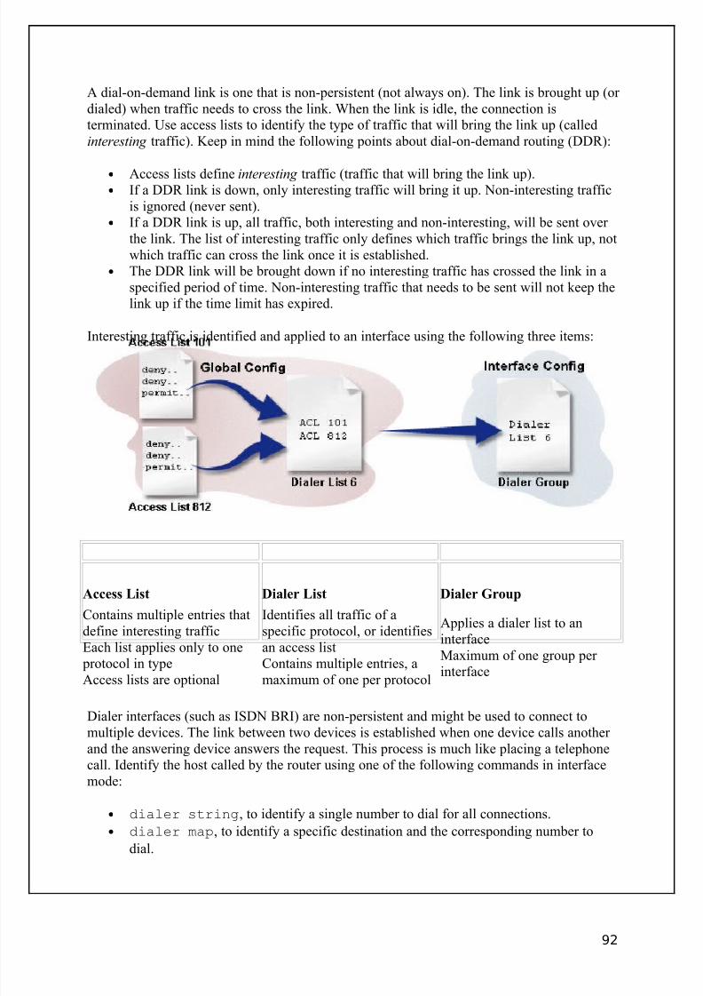
8/3/2019 Ccna Notes 1
http://slidepdf.com/reader/full/ccna-notes-1 92/98
A dial-on-demand link is one that is non-persistent (not always on). The link is brought up (or dialed) when traffic needs to cross the link. When the link is idle, the connection isterminated. Use access lists to identify the type of traffic that will bring the link up (calledinteresting traffic). Keep in mind the following points about dial-on-demand routing (DDR):
• Access lists define interesting traffic (traffic that will bring the link up).• If a DDR link is down, only interesting traffic will bring it up. Non-interesting traffic
is ignored (never sent).• If a DDR link is up, all traffic, both interesting and non-interesting, will be sent over
the link. The list of interesting traffic only defines which traffic brings the link up, notwhich traffic can cross the link once it is established.
• The DDR link will be brought down if no interesting traffic has crossed the link in aspecified period of time. Non-interesting traffic that needs to be sent will not keep thelink up if the time limit has expired.
Interesting traffic is identified and applied to an interface using the following three items:
Access List Dialer List Dialer Group
Contains multiple entries thatdefine interesting trafficEach list applies only to one
protocol in typeAccess lists are optional
Identifies all traffic of aspecific protocol, or identifiesan access listContains multiple entries, amaximum of one per protocol
Applies a dialer list to aninterfaceMaximum of one group per interface
Dialer interfaces (such as ISDN BRI) are non-persistent and might be used to connect tomultiple devices. The link between two devices is established when one device calls another and the answering device answers the request. This process is much like placing a telephonecall. Identify the host called by the router using one of the following commands in interfacemode:
• dialer string, to identify a single number to dial for all connections.
• dialer map, to identify a specific destination and the corresponding number to
dial.
92
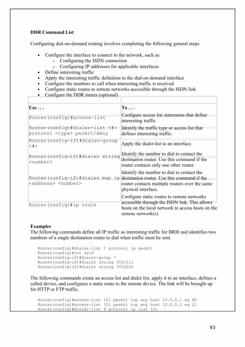
8/3/2019 Ccna Notes 1
http://slidepdf.com/reader/full/ccna-notes-1 93/98
DDR Command List
Configuring dial-on-demand routing involves completing the following general steps:
• Configure the interface to connect to the network, such as:
o Configuring the ISDN connectiono Configuring IP addresses for applicable interfaces
• Define interesting traffic• Apply the interesting traffic definition to the dial-on-demand interface• Configure the numbers to call when interesting traffic is received• Configure static routes to remote networks accessible through the ISDN link • Configure the DDR timers (optional)
Use . . . To . . .
Router(config)#access-listConfigure access list statements that define
interesting trafficRouter(config)#dialer-list <#>protocol <type> permit/deny
Identify the traffic type or access list thatdefines interesting traffic.
Router(config-if)#dialer-group<#>
Apply the dialer-list to an interface.
Router(config-if)#dialer string<number>
Identify the number to dial to contact thedestination router. Use this command if therouter contacts only one other router.
Router(config-if)#dialer map ip
<address> <number>
Identify the number to dial to contact thedestination router. Use this command if the
router contacts multiple routers over the same physical interface.
Router(config)#ip route
Configure static routes to remote networksaccessible through the ISDN link. This allowshosts on the local network to access hosts on theremote network(s).
Examples
The following commands define all IP traffic as interesting traffic for BRI0 and identifies twonumbers of a single destination router to dial when traffic must be sent.
Router(config)#dialer-list 7 protocol ip permitRouter(config)#int bri0Router(config-if)#dialer-group 7Router(config-if)#dialer string 5551111Router(config-if)#dialer string 5552222
The following commands create an access list and dialer list, apply it to an interface, defines acalled device, and configures a static route to the remote device. The link will be brought upfor HTTP or FTP traffic.
Router(config)#access-list 101 permit tcp any host 10.0.0.1 eq 80
Router(config)#access-list 101 permit tcp any host 10.0.0.1 eq 21Router(config)#dialer-list 9 protocol ip list 101
93
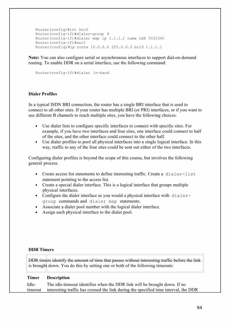
8/3/2019 Ccna Notes 1
http://slidepdf.com/reader/full/ccna-notes-1 94/98
Router(config)#int bri0Router(config-if)#dialer-group 9Router(config-if)#dialer map ip 1.1.1.1 name LAX 5552345Router(config-if)#exitRouter(config)#ip route 10.0.0.0 255.0.0.0 bri0 1.1.1.1
Note: You can also configure serial or asynchronous interfaces to support dial-on-demandrouting. To enable DDR on a serial interface, use the following command:
Router(config-if)#dialer in-band
Dialer Profiles
In a typical ISDN BRI connection, the router has a single BRI interface that is used toconnect to all other sites. If your router has multiple BRI (or PRI) interfaces, or if you want to
use different B channels to reach multiple sites, you have the following choices:
• Use dialer lists to configure specific interfaces to connect with specific sites. For example, if you have two interfaces and four sites, one interface could connect to half of the sites, and the other interface could connect to the other half.
• Use dialer profiles to pool all physical interfaces into a single logical interface. In thisway, traffic to any of the four sites could be sent out either of the two interfaces.
Configuring dialer profiles is beyond the scope of this course, but involves the followinggeneral process.
• Create access list statements to define interesting traffic. Create a dialer-list
statement pointing to the access list.• Create a special dialer interface. This is a logical interface that groups multiple
physical interfaces.• Configure the dialer interface as you would a physical interface with dialer-
group commands and dialer map statements.
• Associate a dialer pool number with the logical dialer interface.• Assign each physical interface to the dialer pool.
DDR Timers
DDR timers identify the amount of time that passes without interesting traffic before the link is brought down. You do this by setting one or both of the following timeouts:
Timer Description
Idle-timeout
The idle-timeout identifies when the DDR link will be brought down. If nointeresting traffic has crossed the link during the specified time interval, the DDR
94
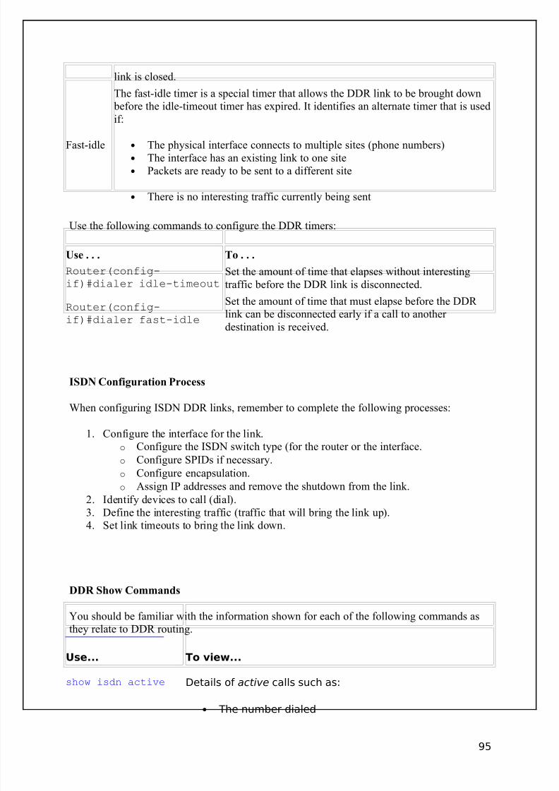
8/3/2019 Ccna Notes 1
http://slidepdf.com/reader/full/ccna-notes-1 95/98
link is closed.
Fast-idle
The fast-idle timer is a special timer that allows the DDR link to be brought down before the idle-timeout timer has expired. It identifies an alternate timer that is usedif:
• The physical interface connects to multiple sites (phone numbers)• The interface has an existing link to one site• Packets are ready to be sent to a different site
• There is no interesting traffic currently being sent
Use the following commands to configure the DDR timers:
Use . . . To . . .
Router(config-if)#dialer idle-timeout Set the amount of time that elapses without interestingtraffic before the DDR link is disconnected.
Router(config-if)#dialer fast-idle
Set the amount of time that must elapse before the DDR link can be disconnected early if a call to another destination is received.
ISDN Configuration Process
When configuring ISDN DDR links, remember to complete the following processes:
1. Configure the interface for the link.o Configure the ISDN switch type (for the router or the interface.
o Configure SPIDs if necessary.
o Configure encapsulation.
o Assign IP addresses and remove the shutdown from the link.
2. Identify devices to call (dial).3. Define the interesting traffic (traffic that will bring the link up).4. Set link timeouts to bring the link down.
DDR Show Commands
You should be familiar with the information shown for each of the following commands asthey relate to DDR routing.
Use... To view...
show isdn active Details of active calls such as:
• The number dialed
95
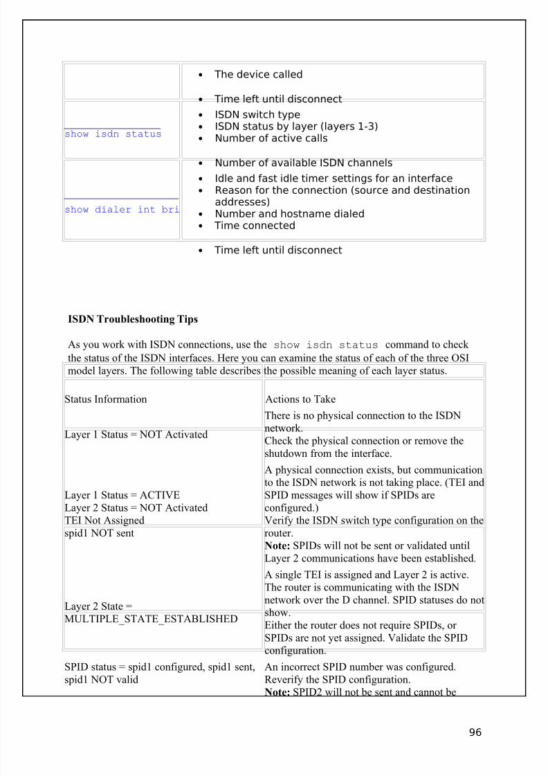
8/3/2019 Ccna Notes 1
http://slidepdf.com/reader/full/ccna-notes-1 96/98
• The device called
• Time left until disconnect
show isdn status
• ISDN switch type• ISDN status by layer (layers 1-3)• Number of active calls
• Number of available ISDN channels
show dialer int bri
• Idle and fast idle timer settings for an interface• Reason for the connection (source and destination
addresses)• Number and hostname dialed• Time connected
• Time left until disconnect
ISDN Troubleshooting Tips
As you work with ISDN connections, use the show isdn status command to check
the status of the ISDN interfaces. Here you can examine the status of each of the three OSImodel layers. The following table describes the possible meaning of each layer status.
Status Information Actions to Take
Layer 1 Status = NOT Activated
There is no physical connection to the ISDNnetwork.Check the physical connection or remove theshutdown from the interface.
Layer 1 Status = ACTIVELayer 2 Status = NOT ActivatedTEI Not Assignedspid1 NOT sent
A physical connection exists, but communicationto the ISDN network is not taking place. (TEI andSPID messages will show if SPIDs areconfigured.)Verify the ISDN switch type configuration on therouter.
Note: SPIDs will not be sent or validated untilLayer 2 communications have been established.
Layer 2 State =MULTIPLE_STATE_ESTABLISHED
A single TEI is assigned and Layer 2 is active.The router is communicating with the ISDNnetwork over the D channel. SPID statuses do notshow.Either the router does not require SPIDs, or SPIDs are not yet assigned. Validate the SPIDconfiguration.
SPID status = spid1 configured, spid1 sent,
spid1 NOT valid
An incorrect SPID number was configured.
Reverify the SPID configuration.Note: SPID2 will not be sent and cannot be
96
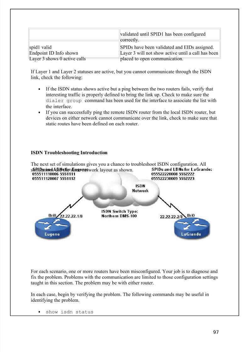
8/3/2019 Ccna Notes 1
http://slidepdf.com/reader/full/ccna-notes-1 97/98
validated until SPID1 has been configuredcorrectly.
spid1 validEndpoint ID Info shownLayer 3 shows 0 active calls
SPIDs have been validated and EIDs assigned.Layer 3 will not show active until a call has been
placed to open communication.
If Layer 1 and Layer 2 statuses are active, but you cannot communicate through the ISDNlink, check the following:
• If the ISDN status shows active but a ping between the two routers fails, verify thatinteresting traffic is properly defined to bring the link up. Check to make sure thedialer group command has been used for the interface to associate the list with
the interface.• If you can successfully ping the remote ISDN router from the local ISDN router, but
devices on either network cannot communicate over the link, check to make sure that
static routes have been defined on each router.
ISDN Troubleshooting Introduction
The next set of simulations gives you a chance to troubleshoot ISDN configuration. Allsimulations use the same network layout as shown.
For each scenario, one or more routers have been misconfigured. Your job is to diagnose andfix the problem. Problems with the communication are limited to those configuration settingstaught in this section. The problem may be with either router.
In each case, begin by verifying the problem. The following commands may be useful inidentifying the problem.
• show isdn status
97

8/3/2019 Ccna Notes 1
http://slidepdf.com/reader/full/ccna-notes-1 98/98
• ping
• show interface bri0
• show interface bri0:1
• show interface bri0:2
• show ip route
• show run
Tip: For most troubleshooting activities, you should be able to diagnose the problem usingthe output from the show isdn status command.