ccna intro study notes
TRANSCRIPT
CCNA INTRO STUDY NOTES
TCP/IP OSI NETWORKING MODLES CH 2
OSI – Open Systems Interconnection
ISO – International Organization for Standardization
TCP/IP defines a large collection of protocols that allow computer to communicate. TCP/IP defines the details of each of these protocols inside documents called
RFC – Requests For Comments
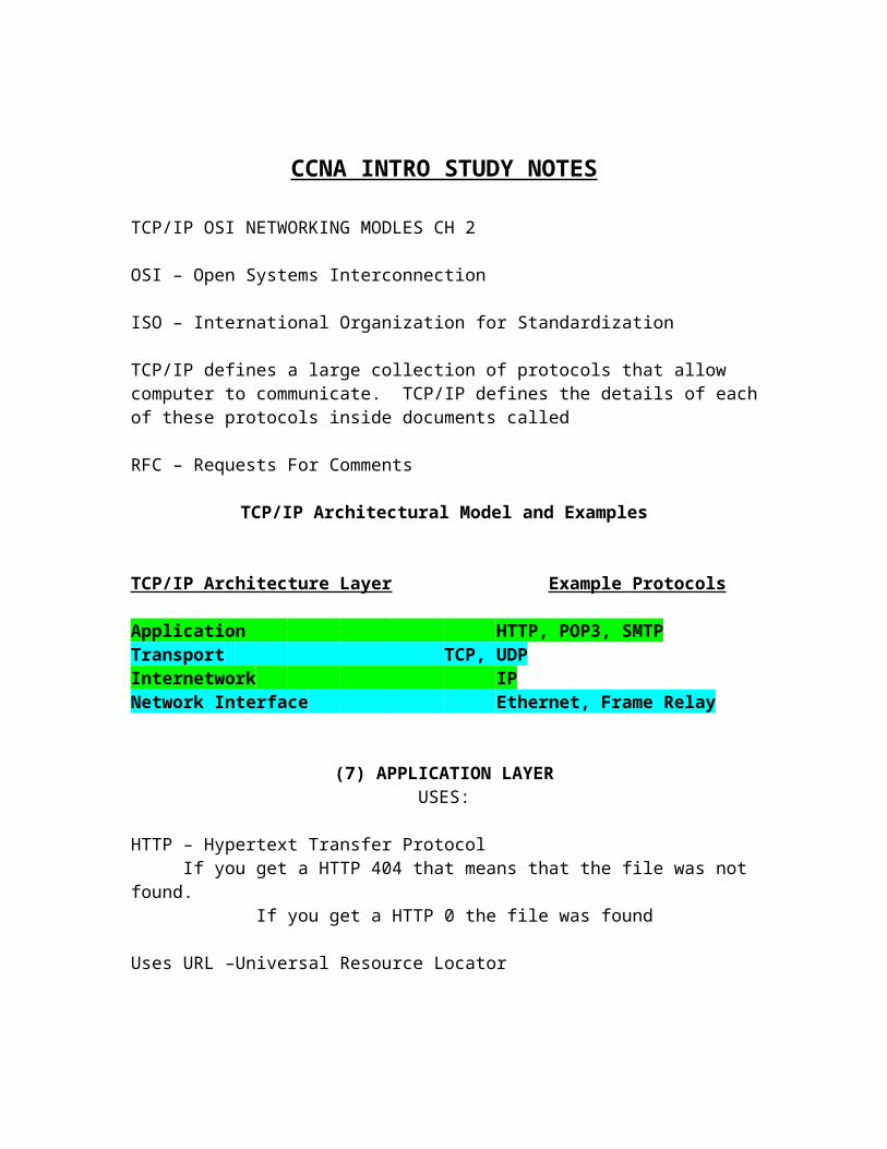
TCP/IP Architectural Model and Examples
TCP/IP Architecture Layer Example Protocols
Application HTTP, POP3, SMTPTransport TCP, UDP Internetwork IP Network Interface Ethernet, Frame Relay
(7) APPLICATION LAYERUSES:
HTTP – Hypertext Transfer ProtocolIf you get a HTTP 404 that means that the file was not found.
If you get a HTTP 0 the file was found
Uses URL –Universal Resource Locator
HTML- Hypertext Markup Language is used to define how Bob’s web browser should interpret the text inside the file he just received.
There are four Layer of the TCP/IP Architectural Model which are:
(4) TRANSPORT LAYER TCP/IP
The TCP/IP transport layer consist of two main protocol options The Transmission control Protocol (TCP) and the User Datagram Protocol (UDP).
Same-Layer interaction on different computers:
The two computers use a protocol to communicate with the same layer on another computer. The Protocol defined by each layer uses a header that is transmitted between the computers. To communicate what each computer want to do.
Adjacent-layer interaction on the same computer:
On a single computer, one layer provides a service to a higher layer. The software or hardware that implements the higher layer requests that the next lower layer perform the needed function.
TCP/ IP Internetwork Layer
The Internetwork layer of the TCP/IP networking model, The internet Protocol (IP), works much like the postal service. IP defines address so that each host computer can have a different IP address, just like the postal service defines addressing that allows unique addresses fro each house, apartment, and business.
TCP/IP Network Interface Layer (Data Link layer)
The network interface layer defines the protocols and hardware required to deliver data across some physical network. The term network interface refers to the fact that this layer defines how to connect the host computer, which is not part of the network, to the network; it is the interface between the computer and the network.
Data Encapsulation
The term encapsulation describes the process of putting headers and trailer around some data.
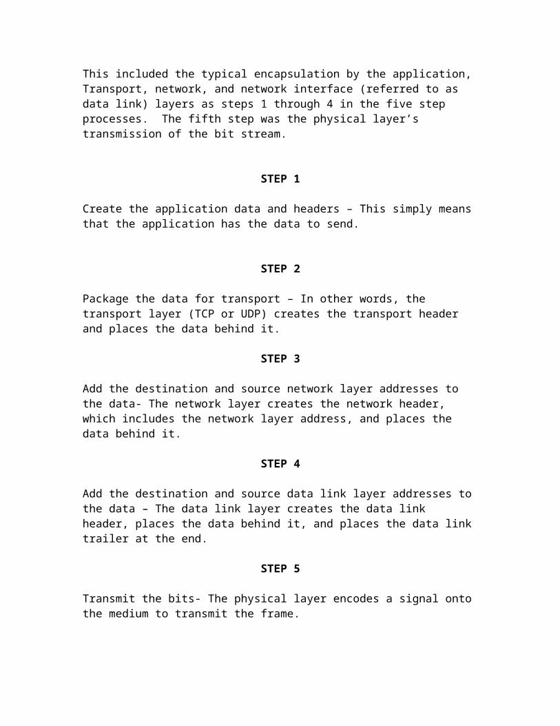
The complete process of data encapsulation with TCP/IP is a FIVE STEP process.
This included the typical encapsulation by the application, Transport, network, and network interface (referred to as data link) layers as steps 1 through 4 in the five step processes. The fifth step was the physical layer’s transmission of the bit stream.
STEP 1
Create the application data and headers – This simply means that the application has the data to send.
STEP 2
Package the data for transport – In other words, the transport layer (TCP or UDP) creates the transport header and places the data behind it.
STEP 3
Add the destination and source network layer addresses to the data- The network layer creates the network header, which includes the network layer address, and places the data behind it.
STEP 4
Add the destination and source data link layer addresses to the data – The data link layer creates the data link header, places the data behind it, and places the data link trailer at the end.
STEP 5
Transmit the bits- The physical layer encodes a signal onto the medium to transmit the frame.
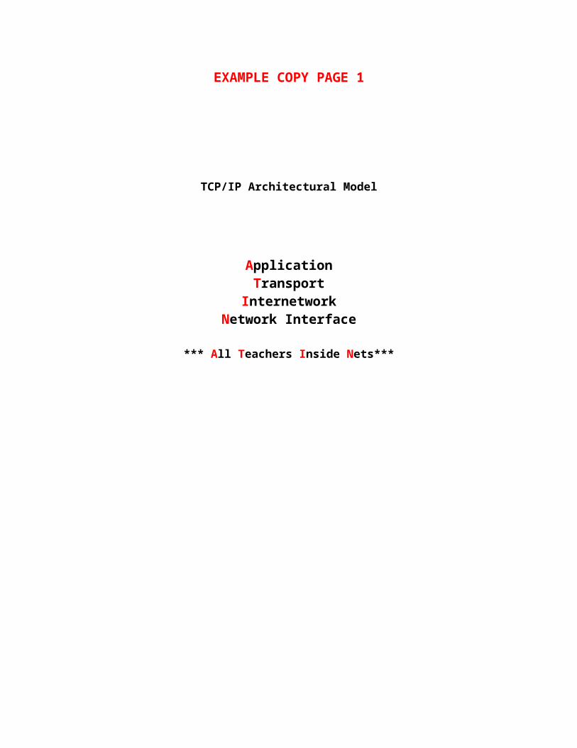
EXAMPLE COPY PAGE 1
TCP/IP Architectural Model
ApplicationTransport
InternetworkNetwork Interface
*** All Teachers Inside Nets***
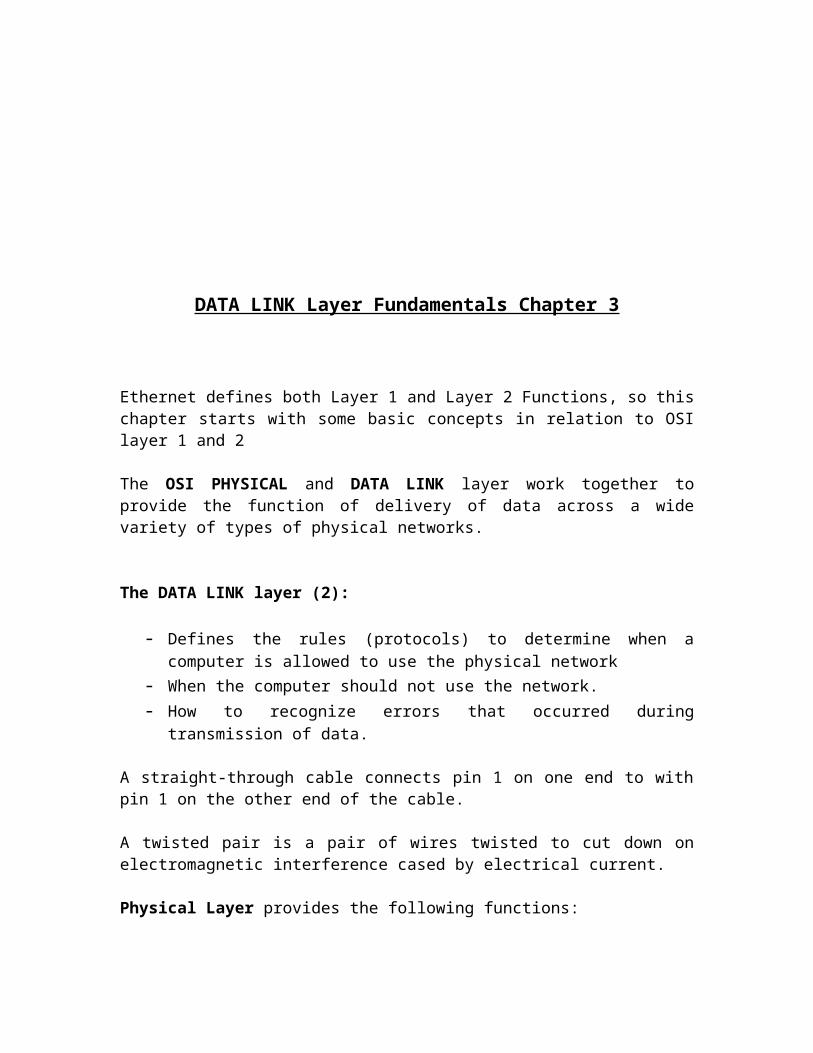
DATA LINK Layer Fundamentals Chapter 3
Ethernet defines both Layer 1 and Layer 2 Functions, so this chapter starts with some basic concepts in relation to OSI layer 1 and 2
The OSI PHYSICAL and DATA LINK layer work together to provide the function of delivery of data across a wide variety of types of physical networks.
The DATA LINK layer (2):
- Defines the rules (protocols) to determine when a computer is allowed to use the physical network
- When the computer should not use the network.- How to recognize errors that occurred during transmission of data.
A straight-through cable connects pin 1 on one end to with pin 1 on the other end of the cable.
A twisted pair is a pair of wires twisted to cut down on electromagnetic interference cased by electrical current.
Physical Layer provides the following functions:
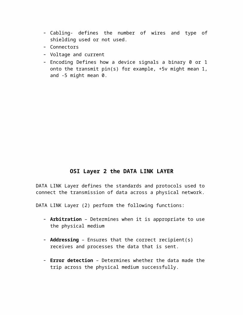
- Cabling- defines the number of wires and type of shielding used or not used.- Connectors- Voltage and current- Encoding Defines how a device signals a binary 0 or 1 onto the transmit pin(s) for
example, +5v might mean 1, and -5 might mean 0.
OSI Layer 2 the DATA LINK LAYER
DATA LINK Layer defines the standards and protocols used to connect the transmission of data across a physical network.
DATA LINK Layer (2) perform the following functions:
- Arbitration – Determines when it is appropriate to use the physical medium
- Addressing – Ensures that the correct recipient(s) receives and processes the data that is sent.
- Error detection – Determines whether the data made the trip across the physical medium successfully.
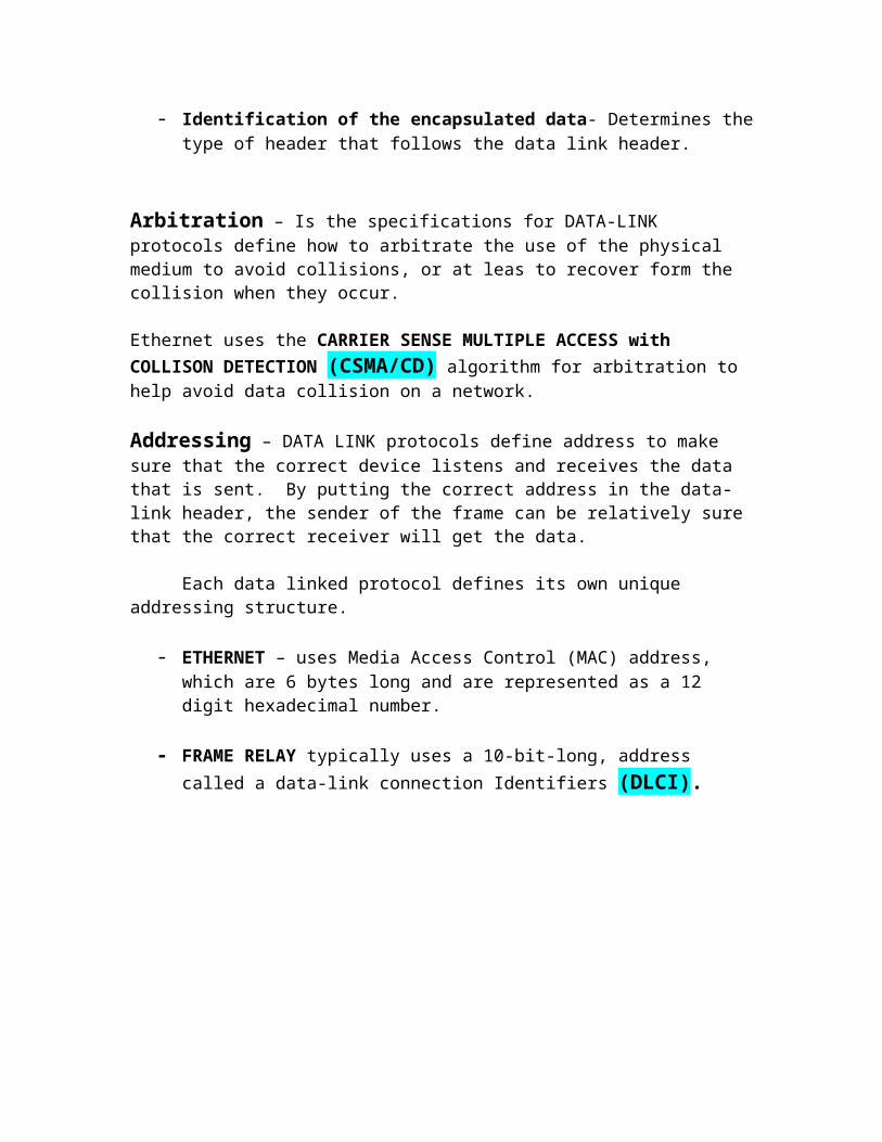
- Identification of the encapsulated data- Determines the type of header that follows the data link header.
Arbitration – Is the specifications for DATA-LINK protocols define how to arbitrate the use of the physical medium to avoid collisions, or at leas to recover form the collision when they occur.
Ethernet uses the CARRIER SENSE MULTIPLE ACCESS with COLLISON DETECTION (CSMA/CD) algorithm for arbitration to help avoid data collision on a network.
Addressing – DATA LINK protocols define address to make sure that the correct device listens and receives the data that is sent. By putting the correct address in the data-link header, the sender of the frame can be relatively sure that the correct receiver will get the data.
Each data linked protocol defines its own unique addressing structure.
- ETHERNET – uses Media Access Control (MAC) address, which are 6 bytes long and are represented as a 12 digit hexadecimal number.
- FRAME RELAY typically uses a 10-bit-long, address called a data-link connection Identifiers (DLCI).
Error Detection – Error detection discover whether bit errors occurred during the transmission of the frame.
- Most DATA-LINK protocols include a Frame Check Sequence (FCS) or a Cyclical Redundancy Check (CRC) field in the DATA-LINK trailer. This field contains a value that is the result of a mathematical formula applied to the data in the frame.
- An error detected when the receiver plugs the contents of the received frame into a mathematical formula. Both the sender and the receiver of the frame use the same calculation, with the sender putting the results of the formula in the FCS field before sending the frame. If the FCS sent by the sender matches what the receiver calculates, the frame did not have any errors during transmission.
- ERROR detection does not imply recover; most data links, including: IEEE 802.5 Token Ring 802.3 Ethernet
Do not provide error recovery.
The FCS allows the receiving device to notice that errors occurred and then discard the data frame. Error recovery, which includes the resending for the data, is the responsibility of another protocol. For instance, TCP performs error recover.
Identifying the Encapsulated Data – The fourth part of what the DATA LINK does is it identifies the contents of the Data Field in the frame.
- IEEE Ethernet 802.2 Logical Link Control (LLC) uses a field in its header to identify the type of data in the Data field.
- Each DATA-LINK header has a field, Generically with a name that has the word TYPE in it, to identify the type of protocol that sits inside the frame’s data field. In each case, the TYPE FIELD has a code that means IP, IPX, or some other designation, defining the type of protocol header that follows.
The IEEE Ethernet specifications that match OSI LAYER 2 were divided into TWO parts:
- Media Access Control (MAC)- Logical Link Control (LLC)
Ethernet Addressing
Ethernet LAN addressing identifies either individual devices or groups of devices on a LAN. Unicast Ethernet addresses identify a single LAN card. Each address is 6 bytes long, is usually written in hexadecimal and, in Cisco devices, and typically is written with periods separating each set of four hex digits. For example, 0000.0C12.3456 IS A VALID Ethernet addresses. The term UNICAST addresses, or individual addresses, is used because it identifies an individual LAN interface card.
The IEEE defines the format and assignment of LAN addresses. The IEEE requires globally unique Unicast MAC addresses on all LAN interface cards.
-IEEE calls them MAC addresses because the MAC protocols such as IEEE 802.3 Define the addressing details.
To ensure a unique Unicast MAC addresses on all LAN interface cards, the Ethernet card manufacturers encode the MAC address onto the card, usually in a ROM chip.
- The first half of the address identifies the manufacturer of the card. This code, which is assigned to each manufacturer by the IEEE, is called the ORGANIZATRIONALLY UNIQUE IDENTIFIER (OUI). Each manufacturers assigns a MAC address with its own OUI as the first half of the address.
- The Second half of the address being assigned a number that this manufacturer has never used on another card.
- Each LAN card comes with a Burned-In address (BIA) that is burned into the ROM chip on the card. BIAs sometimes is called Universally Administered Address (UAAs).
PEOPLE also call MAC address:
LAN AddressEthernet AddressMAC addresses
They all mean the same thing.
Group addressing identifies more than one LAN interface card. The IEEE defines two general categories of group addresses for Ethernet:
-Broadcast Addresses – The most often used of IEEE group MAC addresses,The broadcast address has a value of FFFF.FFFF.FFFF.FFFF (hex notation). The broadcast address implies that all devices on the LAN should process the frame.
- Multicast Addresses – Multicast addresses are used to allow a subset of devices on a LAN to communicate. Some applications need to communicate with multiple other devices. By sending one frame, all the devices that care about receiving the data sent by that application can process the data, and the rest can ignore it. The IP protocol supports multicasting. When IP multicast over an Ethernet, the multicast MAC addresses used by IP follow this format: 0100.5exxx.xxxx, where any value can be used in the last half of the addresses.
Fundamentals of WANs CH 4
You typically use straight through Ethernet cables between end user devices and the switches. For the trunk links between the switches, you use crossover cables because each switch transmits on the same pair, so the crossover cable connect one device’s receive pair. The lower part of the figure reminds you of the basic idea behind a crossover cable.
The term clock rate and band width both refer to the speed of the circuit. You will also hear the speed referred to as the link speed.
Clock Rate and Band width both mean SPEED of the Circuit
When you order a circuit that runs at a particular speed, the two CSU/DSU are configured to operate at the same speed. The CSU/DSU’s is providing a clocking signal to the routers so that the router simply reacts, sending and receiving data at the correct rate. So, the CSU/DSU is considered to be clocking the link.
Typically, routers are connect to a device called and external
Channel Service Unit/ Data Service Unit (CSU/DSU)
CPE – Customer premises equipment – refers to devices that are at the customer site. The device that provides clocking typically the CSU, is considered to be the
Data Communications Equipment (DCE)
The device receiving clocking, typically the router, is referred to as:
Data Terminal Equipment (DTE)
When purchasing serial cables form Cisco, you can pick either a DTE or a DCE Cable. You pick the type of cable based on whether the router is acting like a DTE or a DCE
If the router is a DTE, with the CSU providing the clocking you need a DTE cable.
If the router was clocking the CSU/DSU, which can be done, you would need a DCE cable but that almost never happens.
You can by two routers, a DTE serial cable for one router, and a DCE serial cable for the other and connect the two cables together. The router with the DCE cable in it can be configured to provide clocking. Meaning that you do not need to have a CSU/DSU in-between because clocking is being generated by the link in the test.
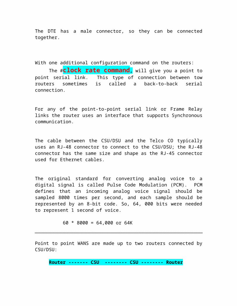
The DTE and the DCE cables can be connected to each other and the two routers. The DCE cable has a female connectorThe DTE has a male connector, so they can be connected together.
With one additional configuration command on the routers:The #clock rate command, will give you a point to point serial link. This
type of connection between tow routers sometimes is called a back-to-back serial connection.
For any of the point-to-point serial link or Frame Relay links the router uses an interface that supports Synchronous communication.
The cable between the CSU/DSU and the Telco CO typically uses an RJ-48 connector to connect to the CSU/DSU; the RJ-48 connector has the same size and shape as the RJ-45 connector used for Ethernet cables.
The original standard for converting analog voice to a digital signal is called Pulse Code Modulation (PCM). PCM defines that an incoming analog voice signal should be sampled 8000 times per second, and each sample should be represented by an 8-bit code. So, 64, 000 bits were needed to represent 1 second of voice.
60 * 8000 = 64,000 or 64K
Point to point WANS are made up to two routers connected by CSU/DSU:
Router ------- CSU -------- CSU -------- Router
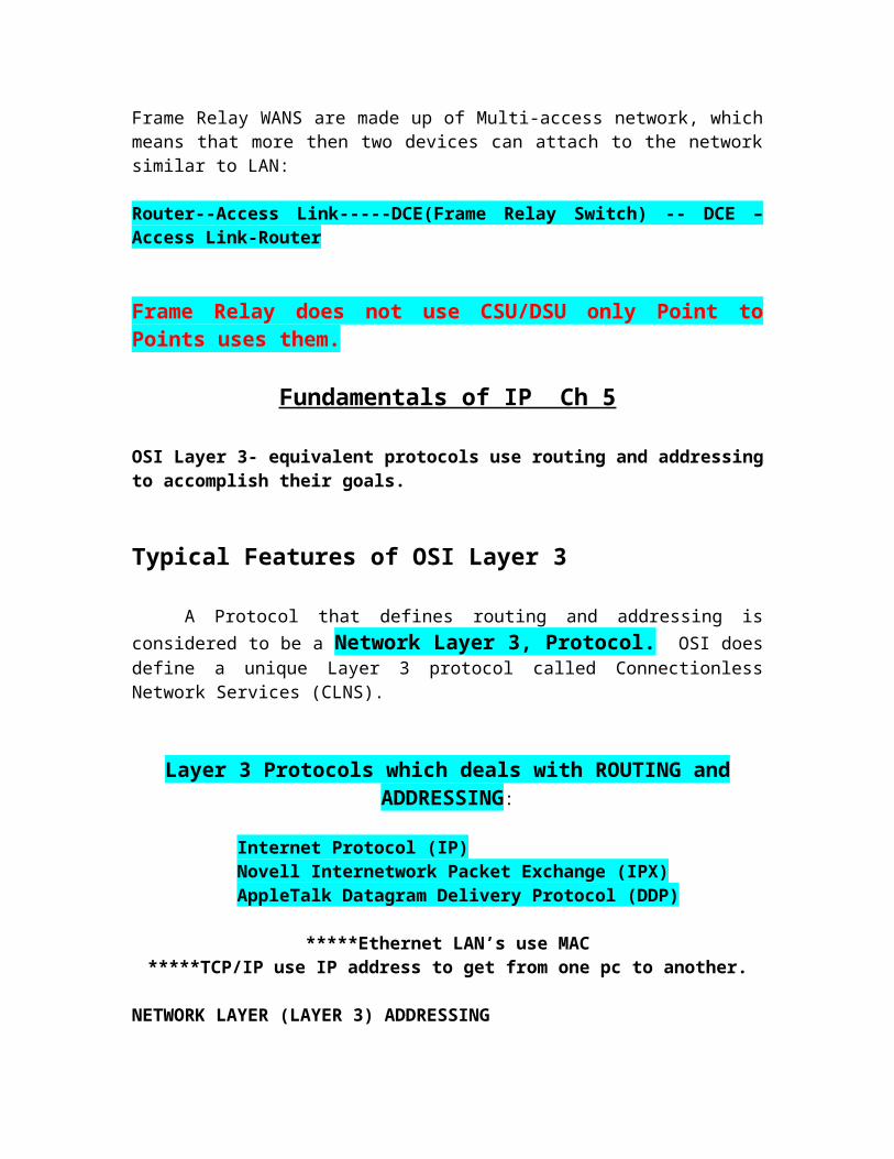
Frame Relay WANS are made up of Multi-access network, which means that more then two devices can attach to the network similar to LAN:
Router--Access Link-----DCE(Frame Relay Switch) -- DCE –Access Link-Router
Frame Relay does not use CSU/DSU only Point to Points uses them.
Fundamentals of IP Ch 5
OSI Layer 3- equivalent protocols use routing and addressing to accomplish their goals.
Typical Features of OSI Layer 3
A Protocol that defines routing and addressing is considered to be a Network Layer 3, Protocol. OSI does define a unique Layer 3 protocol called Connectionless Network Services (CLNS).
Layer 3 Protocols which deals with ROUTING and ADDRESSING:
Internet Protocol (IP) Novell Internetwork Packet Exchange (IPX)AppleTalk Datagram Delivery Protocol (DDP)
*****Ethernet LAN’s use MAC*****TCP/IP use IP address to get from one pc to another.
NETWORK LAYER (LAYER 3) ADDRESSING
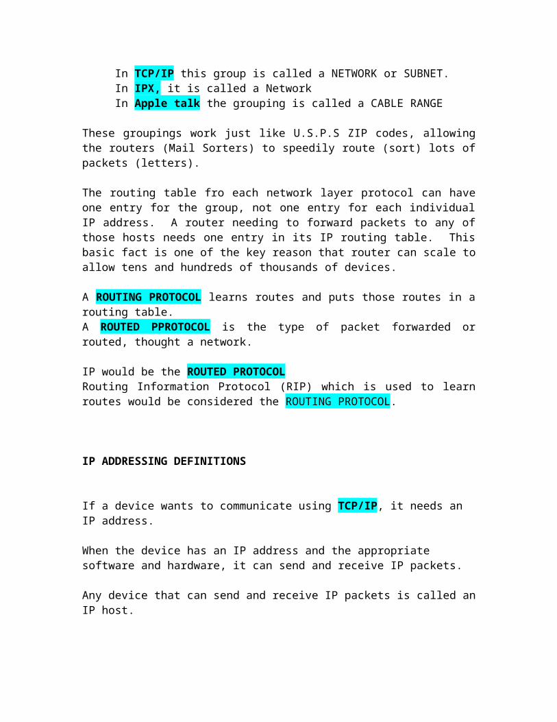
In TCP/IP this group is called a NETWORK or SUBNET. In IPX, it is called a NetworkIn Apple talk the grouping is called a CABLE RANGE
These groupings work just like U.S.P.S ZIP codes, allowing the routers (Mail Sorters) to speedily route (sort) lots of packets (letters).
The routing table fro each network layer protocol can have one entry for the group, not one entry for each individual IP address. A router needing to forward packets to any of those hosts needs one entry in its IP routing table. This basic fact is one of the key reason that router can scale to allow tens and hundreds of thousands of devices.
A ROUTING PROTOCOL learns routes and puts those routes in a routing table.A ROUTED PPROTOCOL is the type of packet forwarded or routed, thought a network.
IP would be the ROUTED PROTOCOL Routing Information Protocol (RIP) which is used to learn routes would be considered the ROUTING PROTOCOL.
IP ADDRESSING DEFINITIONS
If a device wants to communicate using TCP/IP, it needs an IP address.
When the device has an IP address and the appropriate software and hardware, it can send and receive IP packets.
Any device that can send and receive IP packets is called an IP host.
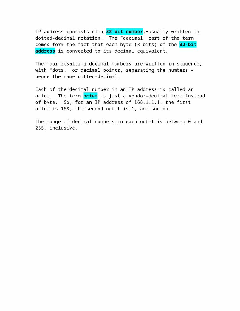
IP address consists of a 32-bit number, usually written in dotted-decimal notation. The “decimal” part of the term comes form the fact that each byte (8 bits) of the 32-bit address is converted to its decimal equivalent.
The four resulting decimal numbers are written in sequence, with “dots,” or decimal points, separating the numbers – hence the name dotted-decimal.
Each of the decimal number in an IP address is called an octet. The term octet is just a vendor-deutral term instead of byte. So, for an IP address of 168.1.1.1, the first octet is 168, the second octet is 1, and son on.
The range of decimal numbers in each octet is between 0 and 255, inclusive.
Fundamentals of TCP and UDP Ch 6
Typical Features of OSI Layer 4
The transport layer (LAYER 4) defines several functions, the most important of which are error recovery and flow control. Router discard packets for many reasons: including:
BIT ErrorsNetwork CongestionINSTANCES WHICH THERE ARE NO ROUTES KNOWN
OSI Transport Layer Features:
Conection-Orented or Connections LessError RecoveryReliabilityFlow ControlSegmenting
TCP provides a variety of useful features including error recovery. In fact, TCP is best known for its error-recovery feature but it does more.
TCP Performs the following functions:
Multiplexing using port numberError Recovery (reliability)Flow control using windowingConnection establishment and terminationEnd-to end ordered data transferSegmentation
TCP relies on IP for end-to-end delivery of the data, including routing issues.
TCP and UDP both use a concept called multiplexing.
UDP data transfer differs form TCP data transfer in that no reordering or recovery is accomplished.
Cisco LAN Switching Basics Ch 9
QUIZ & Notes
1) Which of the following statements describes part of the process of how a transparent bridge makes a decision to forward a frame destined to a Unicast known MAC address?
a) Compares Unicast destination address to the bridging, or MAC address, table.
Transparent Bridge – connects two or more Ethernet networks. By separating the networks into multiple Ethernets, or multiple LAN segments,
Unicast (MAC) address- A MAC address that Identifies a single LAN interface card. Today most cards use the MAC address that is burned on the card.
2) Which of the following statements describes part of the process of how a LAN switch make a decision to forward a frame destined to a broadcast MAC address?
C) Forwards out all interfaces in the same VLAN, except the incoming interface.
Broadcast (MAC) address- The most often used of IEEE group MAC address, the broadcast implies that all devices on the LAN should process the frame.
Multicast (MAC) address – Multicast addresses are used to allow a subset of devices on a LAN to communicate, Some application need to communicate with multiple other devices by sending one frame, all the devices that care about receiving the data sent by that application can process the data, and the rest can ignore it. The IP protocol supports multicasting, and when IP multicasts over an Ethernet, the multicast MAC addresses used by IP follow
this format: 0100.5exx.xxxx, where any value can be used in the last half of the addresses. P.237
LAN SEGMENTATION – Simply means braking one LAN into parts, with each part called a segment.
3) Which of the following statements best describes what a transparent bridges does with a frame destined to an unknown Unicast address?
A) Forwards out all interfaces in the same VLAN, except the incoming interface.
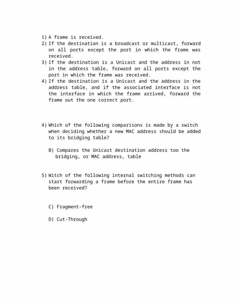
Basic forwarding logic used by a switch or bridge
1) A frame is received.2) If the destination is a broadcast or multicast, forward on all ports except the port
in which the frame was received.3) If the destination is a Unicast and the address in not in the address table, forward
on all ports except the port in which the frame was received.4) If the destination is a Unicast and the address in the address table, and if the
associated interface is not the interface in which the frame arrived, forward the frame out the one correct port.
4) Which of the following comparisons is made by a switch when deciding whether a new MAC address should be added to its bridging table?
B) Compares the Unicast destination address too the bridging, or MAC address, table
5) Witch of the following internal switching methods can start forwarding a frame before the entire frame has been received?
C) Fragment-free
D) Cut-Through
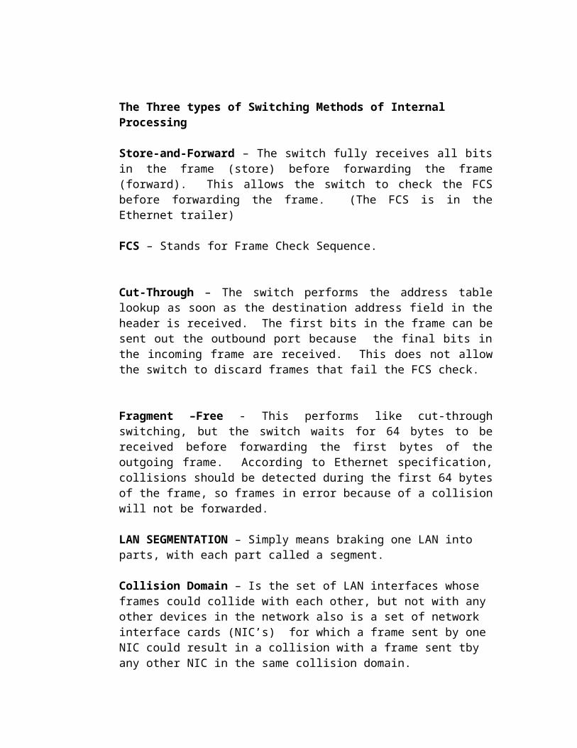
The Three types of Switching Methods of Internal Processing
Store-and-Forward – The switch fully receives all bits in the frame (store) before forwarding the frame (forward). This allows the switch to check the FCS before forwarding the frame. (The FCS is in the Ethernet trailer)
FCS – Stands for Frame Check Sequence.
Cut-Through – The switch performs the address table lookup as soon as the destination address field in the header is received. The first bits in the frame can be sent out the outbound port because the final bits in the incoming frame are received. This does not allow the switch to discard frames that fail the FCS check.
Fragment –Free - This performs like cut-through switching, but the switch waits for 64 bytes to be received before forwarding the first bytes of the outgoing frame. According to Ethernet specification, collisions should be detected during the first 64 bytes of the frame, so frames in error because of a collision will not be forwarded.
LAN SEGMENTATION – Simply means braking one LAN into parts, with each part called a segment.
Collision Domain – Is the set of LAN interfaces whose frames could collide with each other, but not with any other devices in the network also is a set of network interface cards (NIC’s) for which a frame sent by one NIC could result in a collision with a frame sent tby any other NIC in the same collision domain.
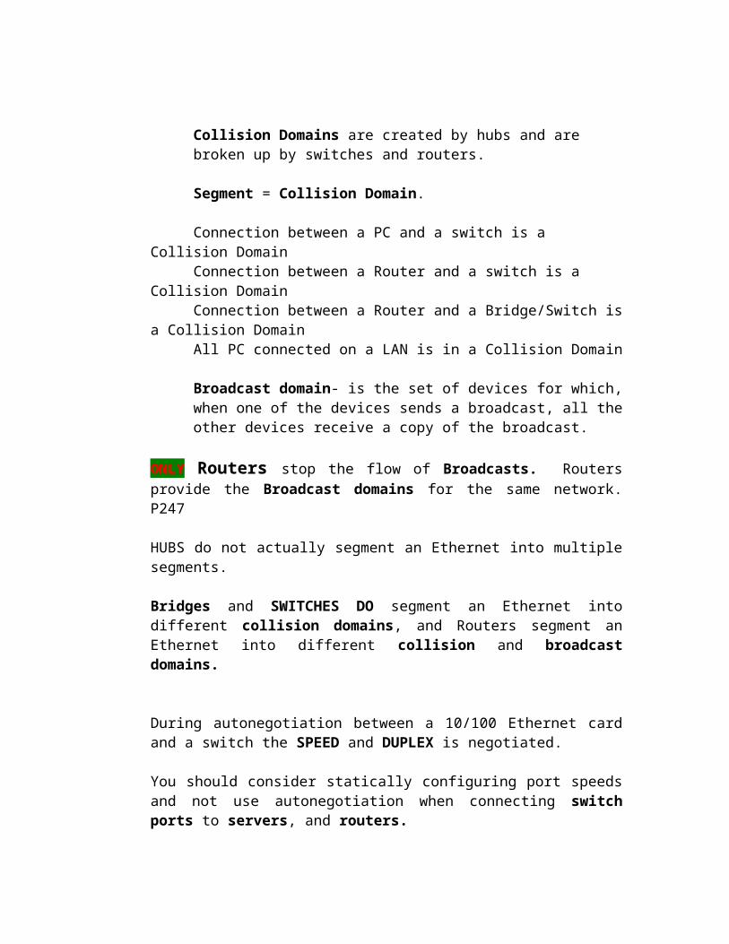
Collision Domains are created by hubs and are broken up by switches and routers.
Segment = Collision Domain.
Connection between a PC and a switch is a Collision DomainConnection between a Router and a switch is a Collision DomainConnection between a Router and a Bridge/Switch is a Collision DomainAll PC connected on a LAN is in a Collision Domain
Broadcast domain- is the set of devices for which, when one of the devices sends a broadcast, all the other devices receive a copy of the broadcast.
ONLY Routers stop the flow of Broadcasts. Routers provide the Broadcast domains for the same network. P247
HUBS do not actually segment an Ethernet into multiple segments.
Bridges and SWITCHES DO segment an Ethernet into different collision domains, and Routers segment an Ethernet into different collision and broadcast domains.
During autonegotiation between a 10/100 Ethernet card and a switch the SPEED and DUPLEX is negotiated.
You should consider statically configuring port speeds and not use autonegotiation when connecting switch ports to servers, and routers.
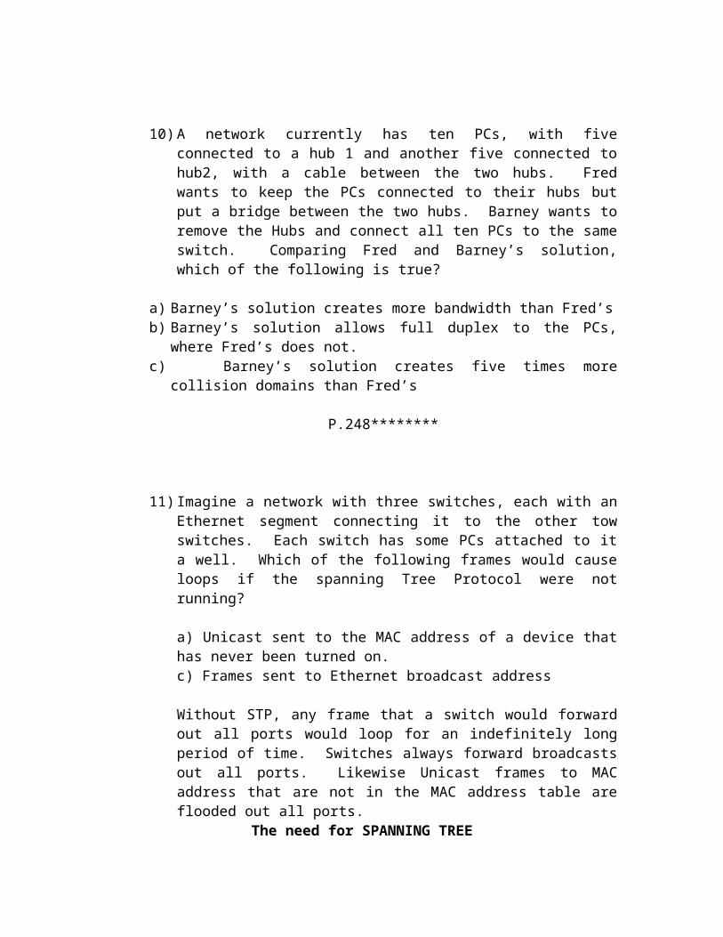
10) A network currently has ten PCs, with five connected to a hub 1 and another five connected to hub2, with a cable between the two hubs. Fred wants to keep the PCs connected to their hubs but put a bridge between the two hubs. Barney wants to remove the Hubs and connect all ten PCs to the same switch. Comparing Fred and Barney’s solution, which of the following is true?
a) Barney’s solution creates more bandwidth than Fred’sb) Barney’s solution allows full duplex to the PCs, where Fred’s does not.c) Barney’s solution creates five times more collision domains than Fred’s
P.248********
11) Imagine a network with three switches, each with an Ethernet segment connecting it to the other tow switches. Each switch has some PCs attached to it a well. Which of the following frames would cause loops if the spanning Tree Protocol were not running?
a) Unicast sent to the MAC address of a device that has never been turned on.c) Frames sent to Ethernet broadcast address
Without STP, any frame that a switch would forward out all ports would loop for an indefinitely long period of time. Switches always forward broadcasts out all ports. Likewise Unicast frames to MAC address that are not in the MAC address table are flooded out all ports.
The need for SPANNING TREE
Without the SPANNING TREE PROTOCOL (STP), frames would loop for an indefinite period of time in networks with physically redundant links. To prevent looping frames , STP blocks some ports form forwarding frames so that only one active path exists between any pair of LAN segments (collision domains).
To avoid loops, all bridging devices, including switches, use STP. STP cause each interface on a bridging device to settle into a blocking state or a forwarding state.
Blocking means that the interface cannot forward or receive data frames.
Forwarding means that the interface can send and receive data frames.
By having a correct subset of the interfaces blocked, a single currently active logical path will exist between each pair of LANS.
How Spanning Tree Works
The Spanning Tree algorithm places each bridge or switch port into either a forwarding state or a blocking state. All the ports in the forwarding state are considered to be in the current spanning tree. The collective set of forwarding ports creates a single path over which frames are sent between Ethernet segments. Switches can forward frames out ports and receive frames in ports that are in a forwarding state; switches do not forward frames out ports and receives frames in ports that are in a blocking state.
STP uses Bridge Protocol Data Units (BPDU) to send messages between switches.
Each switch and bridge claims to be the rood bridge, and the one with the lowest bridge ID is elected root.
The 8-byte bridge ID is the combination of a priority (2-byte) and a MAC address on the switch (6-byte).
STP places all ports on the root switch into a forwarding state.
The root bridge continually sends hello BPDUs. Each non-root switch receives the Hellos, changes a few fields, and forwards out all prots. One of the fields that is changed is called COST. This cost field, in which each switch increments before forwarding the hello message helps the non-root bridges decide how good a particular pay is to the root
bridge. A switch that receives a Hello that has been forwarded by ten other switches probably has a higher cost than a hello received directly for the root switch.
P. 250- 251 ********
12) Which of the following interface states could a switch interface settle into after STP has completed building a spanning tree?
b) Blockingc) Forwarding
STP uses a couple of port stats besides forwarding and blocking
Listening – Listens to incoming Hello messages to ensure that there are no loops, but does not forward traffic to learn MAC address on the interface. This is an interim state between blocking and forwarding.
Learning – Still listens to BPDUs, plus learns MAC addresses form incoming frames. It does not forward traffic. This is an inter state between blocking and forwarding.
Blocking - means that the interface cannot forward or receive data frames.
Forwarding - means that the interface can send and receive data frames.
Disabled – Administratively down. Under normal operation, when a port needs to change form blocking to forwarding, it first transitions to listening, then learning, and then forwarding.
This process, with default timers, takes around 50 seconds.
Add foundation summary ONLY Print
Add questions from the back alllllllllllll

CHAPTER 10 VIRTUAL LANs and trunking
VLANs allow a switch to separate different physical ports into different groups so that traffic from devices in one group never gets forwarded to the other group.
1) In a LAN, Which of the following terms best equates to the term VLAN?
B) Broadcast Domain
A VLAN includes all devices in the same LAN broadcast domain
2) Imagine a switch with three configured VLANs. How many IP subnets would be required, assuming that all hosts in all VLANs want to use TCP/IP
D) 3 subnets would be needed
The hosts in each VLAN must be in different subnets.
3) Which of the following full encapsulates the original Ethernet frame in a trunking header?
B) ISL
ISL fully encapsulates the original frame, whereas 802.1q simply adds an additional header inside the original Ethernet Frame
4) Which of the following allows a spanning tree instance per VLAN?
D) Both ISL and 802.1q dose it.
5) Imagine a Layer 2 Switch with three configured VLANs, using an external router for inter-VLAN traffic. What is the least number of router Fast Ethernet interfaces required to forward traffic between VLANs:
B) 1 is needed
You can use one Fast Ethernet interface and use trunking between the router and the switch. A router is required to forward traffic between the VLANs.
6) Which of the following terms refers to a function that can forward traffic between two different VLANs?
B) Layer 3 switchingC) Layer 4 switching
Layer 2 switching forwards frames only inside a single VLAN.
Layer 3 switching and Layer 4 switching forwards traffic between VLANs, either based on the Layer 3 destination address (Layer 3 Switching) or the Layer 4 port numbers (Layer 4 switching).
7) Imaging a small campus network with three VLANs spread across two switches. Which of the following would you expect to also have a quantity of 3?
B) IP subnetsC) Broadcast domains
By definition, a VLAN is a set of devices in the same broadcast domain. An IP subnet on a LAN is typically comprised of devices in the same VLAN.
8) Which of the following are considered being ways of configuring VLANs?
A) By statically assigning a switch ports to a VLANB) By assigning a MAC address to a particular VLAN
A LAN includes all devices in the same broadcast domain.
You can think of a LAN and broadcast domain as being basically the same thing.
Without VLANs, a switch treats all interfaces on the switch as being in the same broadcast domain.
Essentially, the switch creates multiple broadcast domains. These individual broadcast domains created by the switch are called VIRTUAL LANs (VLAN).
VLAN Basics
A virtual LAN (VLAN) is a broadcast domain created by one or more switches. The switch creates a VLAN simply by putting some interfaces in one VLAN and some in another. So, instead of all ports on a switch forming a single broadcast domain, the switch separates them into many based on configuration.
The reasons why people use VLANS
To Group user by department, or by groups that work together, instead of by physical location.
To reduce overhead by limiting the size of each broadcast domain
To enforce better security by keeping sensitive devices on separate VLAN.
To separate specialized traffic form mainstream traffic- For example, putting IP telephones on a separate VLAN from a user PCs.
To configure a VLAN all you have to do is simply “interface 0/1 is in VLAN 1” and “interface 0/2 is in VLAN 33”
Port based VLANs are the typical choice for configuring VLANs in a switch.
A rarely used alternative for creating VLAN is to group devices into a VLAN based on MAC address. (However, the administrative overhead of configuring the MAC address of the devices can be a large administrative chore, so this option is seldom used.
Trunking with ISL and 802.1q
When using VLAN in networks that have multiple interconnected switches, you need to use VLAN trunking between the switches.
With VLAN trunking, the switches tag each frame sent between switches so that the receiving switch knows which VLAN the frame belongs to.
Cisco Switches Supports two different trunking protocols,
Inter-Switch Link (ISL) IEEE 802.1q
CISCO ISL
Cisco created ISL before the IEEE Standardized a trunking protocol. ISL is Cisco proprietary, it can be used only between tow CISCO switches.
ISL fully encapsulates each original Ethernet frame in an ISL header and trailer, with the encapsulated original Ethernet frame being unchanged.
P. 266
ISL header (26 bytes)/ Encapsulated Ethernet frame/ CRC 4 bytes
The ISL header includes several fields, but most important, the ISL header VLAN field provides a place to encode the VLAN number. BY tagging a frame with the correct VLAN number inside the header, the sending switch can ensure that the receiving switch knows which VLAN the encapsulated frame belongs to.
Also the source and destination addresses in the ISL header use MAC addresses of the sending and receiving switch, as opposed to the devices that actually sent the original frame.
IEEE 802.1q
The IEEE 802.1q standard is which defines different way to do trunking.
802. q uses a different style of header than does ISL for tagging frames with a VLAN number. In Fact 802.1 does not actually encapsulate the original frame.
Instead, it ADDs an extra 4-BYTE header to the middle of the original Ethernet header. That additional header includes a field with which to identify the VLAN number.
Because the original header is now longer, 802.1q encapsulation forces a recalculation of the original FCS field in the Ethernet trailer because the FCD is based on the contents of the entire frame.
ISL changes/ adds a TAG FIELD to the Ethernet Frame which holds a Priority and VLAND ID information.
Both ISL and 802.1q provide trunking. The header used by each varies, and only ISL actually encapsulates the original frame, but both allow the use of a
12-bit long VLAN ID field.
So, either works fine. And supports the same number of VLANs as a result of both using a 12-bit VLAN Number field.
ISL and 802.1q both support a separate instance of spanning tree for each VLAN. ISL supported this feature much earlier than did 802.1q.
You can STP (Spanning Tree Protocol) parameter in each VLAN so that when all links are up different interfaces block for different VLANs.
PVST – (ISL) Per VLAN Spanning Tree
Passing Traffic Between VLANs
The same devices that comprise a VLAN are also in the same TCP/IP subnet. SO, Devices in the same VLAN are in the same subnet, and devices in different VLANs must be in different IP subnets. Although the concept of VLAN and subnet are indeed different concepts, they have a ONE-TO-ONE relationship.
Layer 2 Switching
The term Layer 2 switching (L2 switching) refers to the typical switch-processing logic cover in chapter 9.
A switch receives a frame and looks at the destination MAC address. If the MAC table has an entry for that destination, it forwards the frame; if not, or the frame is a broadcast, it forwards the frame out all ports, except the port in which the frame entered the switch.
When VLANS are used, L2 switches use the same logic, but per VLAN. So, there is a MAC address table for each VLAN. Because the MAC address tables are separate, Unicast sent inside one VLAN cannot be forwarded out ports in another VLAN. Likewise, broadcasts in one VLAN cannot be forwarded out ports in another VLAN.
In short, L2 switches CANNOT forward traffic between VLANs.
Layer 3 Forwarding Using a Router
SWITCHES DO NOT FORWARD FRAMES BETWEEN DIFFENT VLANs.
When you have multiple hosts in DIFFERENT VLANs which need/want to communicate they have to use a ROUTER.
Although the switch cannot forward frames between two VLANs , a ROUTER can..
The router needs an interface in each subnet to forward traffic between the subnets – this is true even without VLANs being used. So, in this case, the ROUTER would have to have 3 interfaces for 3 VLANs/SUBNETS connected to 1 Switch with 3 VLANs/SUBNETS.
P. 269
Alternately, you can use a ROUTER with a FAST Ethernet Port that supports Trunking and sue a single physical connection form the router to the switch
Trunking is not supported on 10Mbps Ethernet interfaces on routers
Layer 3 Forwarding Using a LAYER 3 SWITCH
The term LAYER 3 SWITCH (L3 SWITCH) refers to a switch that also has ROUTING features. So, instead of requiring a router external to the switch, the router is internal to the switch performs the same routing function.
You can confirm that there are no differences to the effect of the effect of the external router versus the L3 switch. The L3 switch runs routing protocols and builds and IP routing table, and the switch makes the forwarding decision based on destination IP address. The L3 switch evens discards the only Ethernet data link header and builds a new one.
The differences between the tow options relates to what happens inside the L3 switch. L3 switches used specialized hardware to make the forwarding process run very fast. The switch ASICs (Application Specific Integrated Circuits) on an L3 switch have been built so that the normal, very fast forwarding path can be also caused to perform the forwarding for LAYER 3. In other works, the actual receipt, changing of headers, and forwarding of the packets uses the same high-speed internal process of the L2 switch. The L3 switch also includes the software used to run other processes, such as routing protocols, which are used to populate the tables used by the specialized forwarding hardware.
Layer 4 Switching
The term Layer 4 switching (L4 switches) refers to a type of switching in which the switch considers the information in the Layer 4 headers when forwarding the packet. In some cases the forwarding decision is based upon information inside the Layer 4 headers. In other cases, L3 forwarding is used, but the switch does accounting based on the Layer 4 header, Both are considered to be Layer 4 switching.
The Key to understanding L4 switching is to remember the function fot TCP and UDP (TRANSPORT LAYER) they use PORT numbers to identify the application process of the sender and the receiver of a packet. An L4 switch can make the decision of where to forward the packet based on the information in the TCP or UDP header5 typically the port numbers.
Alternately, it can also simply keep track of the number of packets and bytes sent per TCP port number, while still performing Layer 3 forwarding.
To perform L4 switching, the switch must keep track of every individual Layer 4 flow. If you had 1000 concurrent TCP connection into the server farm, you would now need 1000 entries in the L4 forwarding table. Comparing that to L3 switching you would need only one route in the L3 routing table to support forwarding packets to the subnet of the server farm. So, L4 switching does required more switching capacity than does the equivalent with L3 switching.
Finally, L4 switching does not always imply a change in how packets are forwarded. A switch can perform accounting to track the volumes of traffic per TCP an UDP port number but still make the decision based on L3 switching logic.
With Cisco switches, you can enable a feature called Netflow switching, which performs the accounting based on Layer 4 information while forwarding traffic like a Layer 3 switch.
Layer 5 – 7 Switching
The TCP/IP application layer closely correlates to OSI Layer 5 – 7. In the last several years the terms Layer 5-7 switching, Layer 7 switching, and application layer switching have all become common terms, meaning basically the same thing. A switch could look past the Layer 4 header, into the application layer headers, to make switching decisions – and that is what an L5-L7 switch does.
Layer 5-7 switching typically falls into a category of features and products that Cisco Calls Content Delivery Networks (CDN)
Multilayer Switching
A switch does not have to just perform switching at one layer or another. For instance, for Traffic between ports in the same VLAN, L2 switching is needed. For traffic between two different VLANs, L3 switching is needed.
SO, often a switch performs switching at multiple layers. These switches are called multilayer switches. Most of the time today, when your hear a layer 3 switch it is really a multilayer switch because it almost always is also a Layer 2 switch
And do Foundation summaryAnd questions for completion.
1) read chapter2) do question and notes3) do long questions4) do tests and review questions
Reading and notes April 10, 2006 – April 16, 2006 TEST and REVIEW April 17, 2006 – April 22, 2006
TEST 1 on April 23, 2006
TEST 2 on May 14,2006
Completion May 21 latest