c3 cad-cam-cnc computer documentation package · c3 cad-cam-cnc computer documentation package ......
TRANSCRIPT
C3 CAD-CAM-CNC Computer
Documentation Package
SB Precision LLC
Rev 1.1 May 2009
Thank you for purchasing the C3 computer system. The C3 offers a low-cost integrated cad-cam-cnc controller
suitable for nearly any type of CNC mill, lathe, router, or other motion control application.
System Overview The C3 is a stand alone pc-based design and cnc controller that can be used out of the box or expanded as needed. A
standard pc motherboard boots automatically to the Turbocnc machine control program. Step, direction, and Input-
Output (I/O) signals are output through the parallel (lpt) port. In order to use the C3 you will need to connect the lpt
output pins to your properly-wired stepper or servo motor drives and adjust the configuration settings as required.
Standard g-code programs may either be loaded from other computers into Turbocnc and run, or created using the
included Bobcad-cam Gold V14 software. For your convenience printed manuals for Turbocnc, Bobcad, and the
Freedos operating system are included. Simple instructions are provided here; please refer to the detailed
information in the manuals.
Any standard pc computer component may be added to the C3 as required to support the customization of your
machinery. For simple lathes, mills, plasma cutters, and routers no upgrades or changes should be needed.
Basic Operation and Configuration Attach the included power cable, a USB or PS/2 mouse and keyboard, and your choice of monitor to the connectors
at the back of the C3. Press the power button and your C3 will boot to Turbocnc
Connect your stepper or servo drives to the lpt connector. The default Turbocnc.ini configuration file is set for a 3-
axis machine with lpt pins as follows:
Pin Function
2 X-Step
3 X-Direction
4 Y-Step 5 Y-Direction
6 Z-Step
7 Z-Direction
You may make changes to the configuration file by pressing the ALT-C keys. Here you can change axis settings,
I/O settings, and other software properties. When changes are made choose the "Reset Ports" option and you will be
prompted to save the configuration file.
BobCAD-CAM To access BobCAD-CAM you need to first exit Turbocnc. Choose File and Exit and you will see the command
prompt. Type "bobcad" and press enter twice. You will see the BobCAD-CAM screen appear. Follow the
instructions in the Bobcad manuals for help using the system. To return to Turbocnc, type "turbocnc" at the command prompt.
Transferring Files to and from other Computers A USB flash drive may be used to transfer files with other computers. Refer to the index of Dos commands for
more information on how to transfer files using the command line. Most files to be transferred will be from a
separate design computer to the C3 computer for machine operation. In this case all the user needs to do is to save
the files on the USB drive on the design computer, plug the USB drive into the C3 and then open the file in Editor
using the Turbocnc menu.
For advanced users who wish to connect into an RS232 serial network in their shop a copy of Texas z-Modem is
included.
Creating and Cutting a Part Using BOBCAD-GOLD 14.1
and TurboCNC
SB Precision, LLC
Version 1
Create the Part Geometry
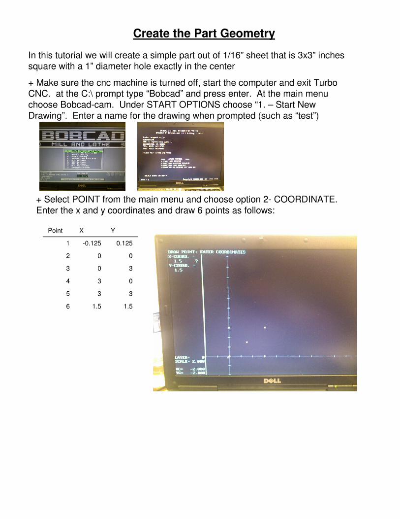
In this tutorial we will create a simple part out of 1/16” sheet that is 3x3” inches square with a 1” diameter hole exactly in the center
+ Make sure the cnc machine is turned off, start the computer and exit Turbo CNC. at the C:\ prompt type “Bobcad” and press enter. At the main menu choose Bobcad-cam. Under START OPTIONS choose “1. – Start New Drawing”. Enter a name for the drawing when prompted (such as “test”)
+ Select POINT from the main menu and choose option 2- COORDINATE. Enter the x and y coordinates and draw 6 points as follows:
1.51.56
335
034
303
002
0.125-0.1251
YXPoint
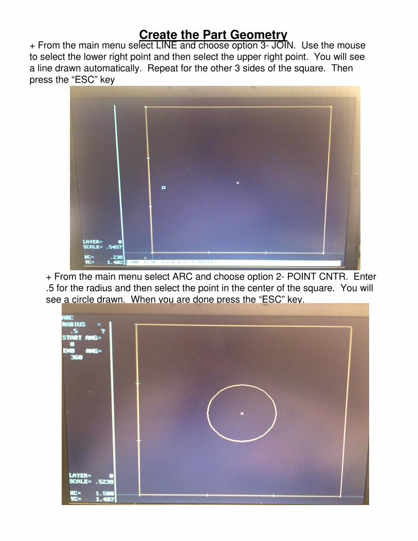
Create the Part Geometry+ From the main menu select LINE and choose option 3- JOIN. Use the mouse to select the lower right point and then select the upper right point. You will see a line drawn automatically. Repeat for the other 3 sides of the square. Then press the “ESC” key
+ From the main menu select ARC and choose option 2- POINT CNTR. Enter .5 for the radius and then select the point in the center of the square. You will see a circle drawn. When you are done press the “ESC” key.
Create the Offset Tool Path Geometry
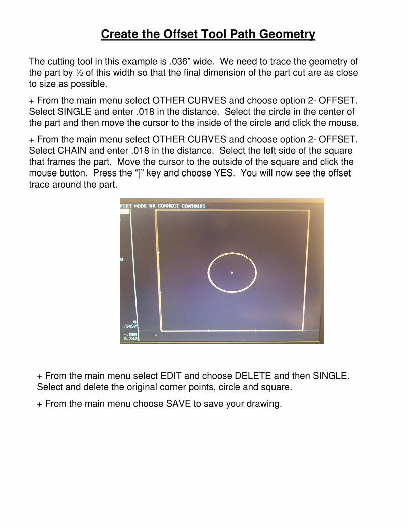
The cutting tool in this example is .036” wide. We need to trace the geometry of the part by ½ of this width so that the final dimension of the part cut are as close to size as possible.
+ From the main menu select OTHER CURVES and choose option 2- OFFSET. Select SINGLE and enter .018 in the distance. Select the circle in the center of the part and then move the cursor to the inside of the circle and click the mouse.
+ From the main menu select OTHER CURVES and choose option 2- OFFSET. Select CHAIN and enter .018 in the distance. Select the left side of the square that frames the part. Move the cursor to the outside of the square and click the mouse button. Press the “]” key and choose YES. You will now see the offset trace around the part.
+ From the main menu select EDIT and choose DELETE and then SINGLE. Select and delete the original corner points, circle and square.
+ From the main menu choose SAVE to save your drawing.
Create the Tool Paths Using the CAM Function
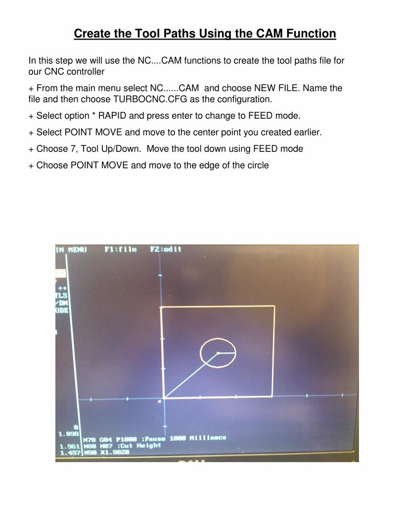
In this step we will use the NC....CAM functions to create the tool paths file for our CNC controller
+ From the main menu select NC......CAM and choose NEW FILE. Name the file and then choose TURBOCNC.CFG as the configuration.
+ Select option * RAPID and press enter to change to FEED mode.
+ Select POINT MOVE and move to the center point you created earlier.
+ Choose 7, Tool Up/Down. Move the tool down using FEED mode
+ Choose POINT MOVE and move to the edge of the circle
Create the Tool Paths Using the CAM Function
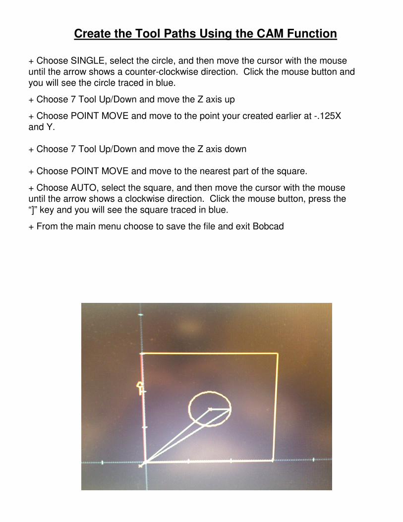
+ Choose SINGLE, select the circle, and then move the cursor with the mouse until the arrow shows a counter-clockwise direction. Click the mouse button and you will see the circle traced in blue.
+ Choose 7 Tool Up/Down and move the Z axis up
+ Choose POINT MOVE and move to the point your created earlier at -.125X and Y.
+ Choose 7 Tool Up/Down and move the Z axis down
+ Choose POINT MOVE and move to the nearest part of the square.
+ Choose AUTO, select the square, and then move the cursor with the mouse until the arrow shows a clockwise direction. Click the mouse button, press the “]” key and you will see the square traced in blue.
+ From the main menu choose to save the file and exit Bobcad
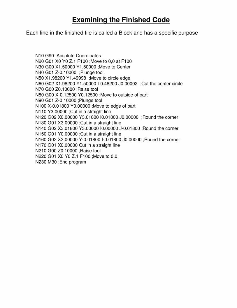
Examining the Finished Code
Each line in the finished file is called a Block and has a specific purpose
N10 G90 ;Absolute Coordinates
N20 G01 X0 Y0 Z.1 F100 ;Move to 0,0 at F100
N30 G00 X1.50000 Y1.50000 ;Move to CenterN40 G01 Z-0.10000 ;Plunge tool
N50 X1.98200 Y1.49998 ;Move to circle edge
N60 G02 X1.98200 Y1.50000 I-0.48200 J0.00002 ;Cut the center circle
N70 G00 Z0.10000 ;Raise tool
N80 G00 X-0.12500 Y0.12500 ;Move to outside of partN90 G01 Z-0.10000 ;Plunge tool
N100 X-0.01800 Y0.00000 ;Move to edge of part
N110 Y3.00000 ;Cut in a straight line
N120 G02 X0.00000 Y3.01800 I0.01800 J0.00000 ;Round the corner
N130 G01 X3.00000 ;Cut in a straight lineN140 G02 X3.01800 Y3.00000 I0.00000 J-0.01800 ;Round the corner
N150 G01 Y0.00000 ;Cut in a straight line
N160 G02 X3.00000 Y-0.01800 I-0.01800 J0.00000 ;Round the corner
N170 G01 X0.00000 Cut in a straight lineN210 G00 Z0.10000 ;Raise tool
N220 G01 X0 Y0 Z.1 F100 ;Move to 0,0
N230 M30 ;End program
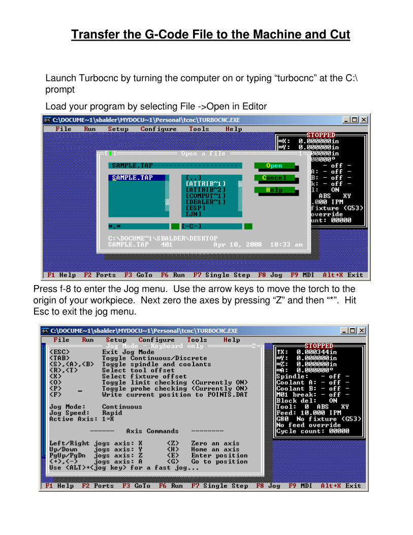
Transfer the G-Code File to the Machine and Cut
Launch Turbocnc by turning the computer on or typing “turbocnc” at the C:\prompt
Load your program by selecting File ->Open in Editor
Press f-8 to enter the Jog menu. Use the arrow keys to move the torch to the origin of your workpiece. Next zero the axes by pressing “Z” and then “*”. Hit Esc to exit the jog menu.
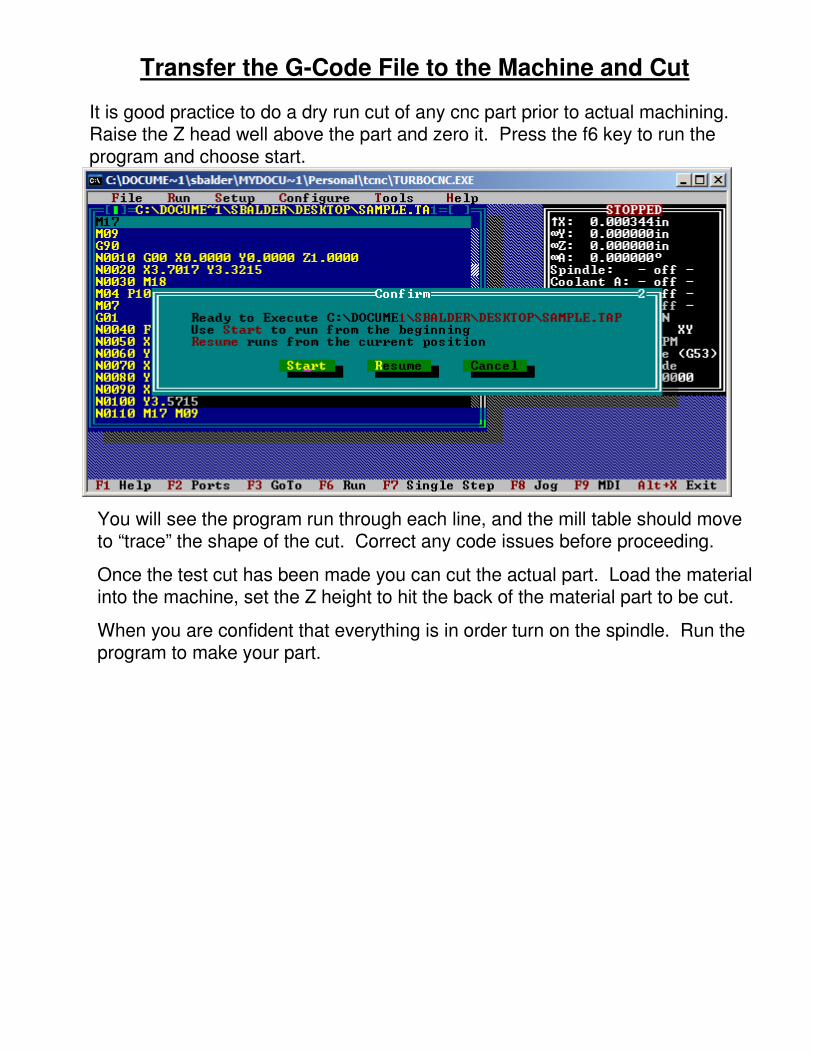
Transfer the G-Code File to the Machine and Cut
It is good practice to do a dry run cut of any cnc part prior to actual machining. Raise the Z head well above the part and zero it. Press the f6 key to run the program and choose start.
You will see the program run through each line, and the mill table should move to “trace” the shape of the cut. Correct any code issues before proceeding.
Once the test cut has been made you can cut the actual part. Load the material into the machine, set the Z height to hit the back of the material part to be cut.
When you are confident that everything is in order turn on the spindle. Run the program to make your part.

TURBOCNC V4.01
CNC MACHINERY CONTROL PROGRAM
© 2005 DAK Engineering. All Rights Reserved

ii
iii
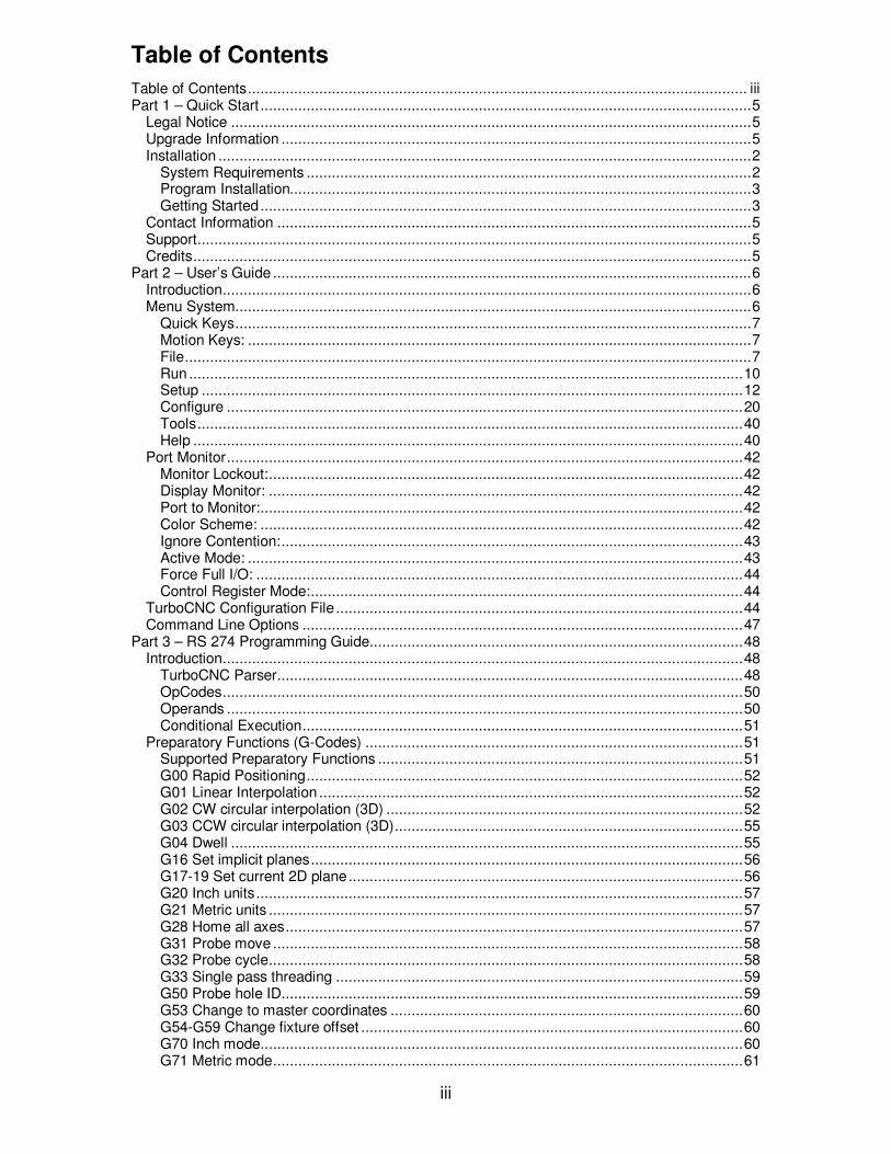
Table of Contents
Table of Contents....................................................................................................................... iii Part 1 – Quick Start .....................................................................................................................5
Legal Notice ............................................................................................................................5 Upgrade Information ................................................................................................................5 Installation ...............................................................................................................................2
System Requirements ..........................................................................................................2 Program Installation..............................................................................................................3 Getting Started.....................................................................................................................3
Contact Information .................................................................................................................5 Support....................................................................................................................................5 Credits.....................................................................................................................................5
Part 2 – User’s Guide ..................................................................................................................6 Introduction..............................................................................................................................6 Menu System...........................................................................................................................6
Quick Keys...........................................................................................................................7 Motion Keys: ........................................................................................................................7 File.......................................................................................................................................7 Run ....................................................................................................................................10 Setup .................................................................................................................................12 Configure ...........................................................................................................................20 Tools..................................................................................................................................40 Help ...................................................................................................................................40
Port Monitor...........................................................................................................................42 Monitor Lockout:.................................................................................................................42 Display Monitor: .................................................................................................................42 Port to Monitor:...................................................................................................................42 Color Scheme: ...................................................................................................................42 Ignore Contention:..............................................................................................................43 Active Mode: ......................................................................................................................43 Force Full I/O: ....................................................................................................................44 Control Register Mode:.......................................................................................................44
TurboCNC Configuration File .................................................................................................44 Command Line Options .........................................................................................................47
Part 3 – RS 274 Programming Guide.........................................................................................48 Introduction............................................................................................................................48
TurboCNC Parser...............................................................................................................48 OpCodes............................................................................................................................50 Operands ...........................................................................................................................50 Conditional Execution.........................................................................................................51
Preparatory Functions (G-Codes) ..........................................................................................51 Supported Preparatory Functions .......................................................................................51 G00 Rapid Positioning........................................................................................................52 G01 Linear Interpolation .....................................................................................................52 G02 CW circular interpolation (3D) .....................................................................................52 G03 CCW circular interpolation (3D)...................................................................................55 G04 Dwell ..........................................................................................................................55 G16 Set implicit planes.......................................................................................................56 G17-19 Set current 2D plane..............................................................................................56 G20 Inch units....................................................................................................................57 G21 Metric units .................................................................................................................57 G28 Home all axes.............................................................................................................57 G31 Probe move ................................................................................................................58 G32 Probe cycle.................................................................................................................58 G33 Single pass threading .................................................................................................59 G50 Probe hole ID..............................................................................................................59 G53 Change to master coordinates ....................................................................................60 G54-G59 Change fixture offset ...........................................................................................60 G70 Inch mode...................................................................................................................60 G71 Metric mode................................................................................................................61
iv
G72 CW helical interpolation ..............................................................................................61 G73 CCW helical interpolation............................................................................................61 G76 Multi-pass threading....................................................................................................61 G77 Turning/Boring/Milling Cycle........................................................................................62 G78 Peck Motion Cycle ......................................................................................................62 G80 Cancel drill cycle.........................................................................................................63 G81 Drill cycle ....................................................................................................................63 G82 Drill + Dwell cycle........................................................................................................64 G83 Peck drill cycle............................................................................................................64 G90 Absolute coordinates ..................................................................................................65 G91 Incremental coordinates..............................................................................................65 G92 Preload of registers/Set machine coordinates..............................................................65 G93 Inverse time feed rate .................................................................................................66 G94 IPM feed rate..............................................................................................................66 G95 IPR feed rate ..............................................................................................................66 G97 Program spindle RPM.................................................................................................67 G178 Speed peck motion ...................................................................................................67 G183 Speed peck drill cycle ...............................................................................................67
Miscellaneous Functions (M-Codes) ......................................................................................68 Supported Miscellaneous Functions ...................................................................................68 M00 Automatic halt.............................................................................................................68 M01 Optional halt ...............................................................................................................68 M02 End of program...........................................................................................................68 M03 Spindle on CW............................................................................................................69 M04 Spindle on CCW.........................................................................................................69 M05 Spindle off ..................................................................................................................69 M06 Tool change................................................................................................................69 M07 Coolant A on (flood)....................................................................................................70 M08 Coolant B on (mist) .....................................................................................................70 M09 Coolants off ................................................................................................................70 M10 Clamp.........................................................................................................................70 M11 Unclamp.....................................................................................................................70 M13 Spindle CW and coolant A on .....................................................................................71 M14 Spindle CCW and coolant A on...................................................................................71 M17 Enable drives..............................................................................................................71 M18 Disable drives.............................................................................................................71 M21 Open collet .................................................................................................................71 M22 Close collet.................................................................................................................72 M30 End of program & rewind ............................................................................................72 M40 – M46: Gear Changes ................................................................................................72 M48 Restore feed override .................................................................................................72 M49 Cancel feed override...................................................................................................72 M50 Read spindle speed ....................................................................................................73 M60 Jump to subroutine (obsolete function)........................................................................73 M62 Return from subroutine (obsolete function)..................................................................73 M70 Set PLC handshake output to inactive.........................................................................74 M71 Set PLC handshake output to active ...........................................................................74 M72 Wait for PLC handshake input to go inactive ...............................................................74 M73 Wait for PLC handshake input to go active..................................................................74 M97 Jump ..........................................................................................................................75 M98 Jump to subroutine .....................................................................................................75 M99 Return from subroutine ...............................................................................................76
S-Word Handing: ...................................................................................................................77 Programming Extensions .......................................................................................................77
Expressions .......................................................................................................................77 Variables............................................................................................................................78 Sample Code - Using Expressions and Variables ...............................................................79 Conditional Execution (IF) ..................................................................................................79 Simulating Advanced Conditional Execution Structures ......................................................80 Interacting with the Operator...............................................................................................82 Putting it all Together: The Circle Using Line Segments......................................................83
Part 4 – Introduction to CNC......................................................................................................85
v
General .................................................................................................................................85 The Axes De-Mystified:..........................................................................................................86 Axis conventions:...................................................................................................................87 The parallel port explained: ....................................................................................................89
Part 5 – Technical Details..........................................................................................................90 The Parallel Port ....................................................................................................................90 Set Up of Step and Direction Lines.........................................................................................90 I/O Points...............................................................................................................................92 Configuring Speed Control.....................................................................................................93 Setting up Windows 9x to boot directly into MS-DOS..............................................................93
Modify MSDOS.SYS...........................................................................................................94 Modifying CONFIG.SYS .....................................................................................................94 Modify AutoEXEC.BAT.......................................................................................................95
Part 1 – Quick Start
Legal Notice
WARNING
!
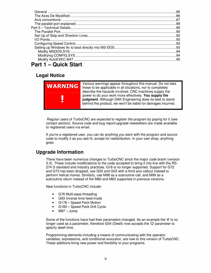
Various warnings appear throughout this manual. Do not take these to be applicable in all situations, nor to completely describe the hazards involved. CNC machines supply the power to do your work more effectively. You supply the judgment. Although DAK Engineering does its best to stand behind this product, we won't be liable for damages incurred.
Regular users of TurboCNC are expected to register the program by paying for it (see contact section). Source code and bug report/upgrade newsletters are made available to registered users via email.
If you're a registered user, you can do anything you want with the program and source code to modify it as you see fit, except for redistribution. In your own shop, anything goes.
Upgrade Information
There have been numerous changes to TurboCNC since the major code branh (version 3.X). These include modifications to the code accepted to bring it into line with the RS-274 D standard and industry practices. G16 is no longer supported. Support for G72 and G73 has been dropped, use G02 and G03 with a third axis callout instead to perform helical moves. Similarly, use M98 as a subroutine call, and M99 as a subroutine return instead of the M60 and M62 supported in previous versions.
New functions in TurboCNC include:
• G76 Multi-pass threading • G93 Inverse time feed mode • G178 – Speed Peck Motion • G183 – Speed Peck Drill Cycle • M97 – Jump
Some of the functions have had their parameters changed. As an example the '#' is no longer used as a parameter, therefore G04 (Dwell) now accepts the 'Q' parameter to specify dwell time.
Programming elements including a means of communicating with the operator, variables, expressions, and conditional execution, are new to this version of TurboCNC. These additions bring new power and flexibility to your programs.

1
The format of the turbocnc.ini file is backward compatible, so you can use your old one to get rolling with this new version right away. Inside TurboCNC, use the “Save configuration” option to re-write the turbocnc.ini file, and you’re now up to date!
Since 4.00, there have been scores of bug fixes, and some dialog changes to make the software easier to use. Many of the changes have been “under the hood”.
Support for Peter Homann's DigiSpeed spindle control has been added. For info on this product go to http://www.homanndesigns.com/ .
2
Installation
System Requirements
486DX2-66 or later PC compatible computer with at least 4MB RAM and a DOS compatible file system
Open 25-pin parallel port for control
500k free disk space (7M for source code and development tools). TurboCNC can be run from a floppy disk, but a hard drive installation is generally better
A 66 MHz or faster clock speed is recommended for satisfactory performance.
Almost any home or office computer system made after 1993 will meet these requirements. However, some fairly modern industrial control computers may not. Consult your owner's manuals to be sure. TurboCNC will report if any critical things are missing at startup.
For very old computers or those that don't have a math coprocessor, try using version 3.0f of TurboCNC instead. This is available in the web archive for download at http://www.dakeng.com/archive.html and although it lacks many features compared to the later versions, it can and has been used for production grade work on even very old 286-10 machines. In some countries these may be the only computers available to private citizens.
A note on Laptops:
Some laptops pose problems to TurboCNC and CNC machines. There are two common problems.
The first is the BIOS may introduce its own interrupts, which can interfere with the generation of a steady pulse train. This problem can cause lost steps. You can try to eliminate these by booting the system into BIOS and resetting the options there.
The second common problem is that some laptops do not switch between +5 volts and 0 volts on the pins of the printer port as is required by many drivers. A parallel port breakout board of your own design or a commercial offering such as the Axxus Technologies DB1V2.0 can be used to restore the full 5-volt swing required by many stepper and servo motor drives.
3
Program Installation
Here's how to get TurboCNC on your computer. Future versions will feature an installer utility, but for now you have to do this manually.
1. Download a copy of the program from the web at http://www.dakeng.com/turbo.html, and save the file somewhere on your machine.
2. Obtain a de-archiving utility that will handle .ZIP files. Our recommendation is WinZip, which has a 30-day demo and integrates well with Windows – downloadable at http://www.winzip.com. DOS users can use their beloved PKZIP from PKWare or a similar product.
3. Extract the contents of the archive to a convenient folder with a short name, like C:\TCNC\ or similar. You must respect a limitation of eight characters here thanks to an inherited DOS limitation.
4. All of the program files, and this manual, will be found in the new folder.
5. If you want to install TurboCNC on a different machine, copy the contents of the folder to a diskette or transfer it over a network to the new machine. No registry settings, hidden data, or system file changes are used.
Getting Started
TurboCNC runs in real-mode DOS for maximum speed and control over the timing of the parallel ports.
Booting into real mode may be a challenge depending on what system you use currently. Here's how you can get the program started and working efficiently for you under some of the more popular PC operating systems.
WARNING
!
If you launch TurboCNC from Windows, you'll have problems when you try to control your machine. Read this section and follow the instructions for your operating system.
If you just want to "play" with the program without a machine connected, you can ignore this stuff for now. When it comes time to make chips you'll need this information.
NOTE: These directions assume the program has already been installed per the above.
MS-DOS (any version from 3.0 & up)
Modify your CONFIG.SYS file to allow a boot-up configuration in which EMM386.EXE, HIMEM.SYS, RAMDRIVE.SYS, and any disk caching programs are not present.
Alternately, create a boot disk with the FORMAT /S command to boot up in a minimal environment.
Disable DOUBLESPACE if it is enabled.
Change to the directory with turbocnc.exe and execute the program.
4
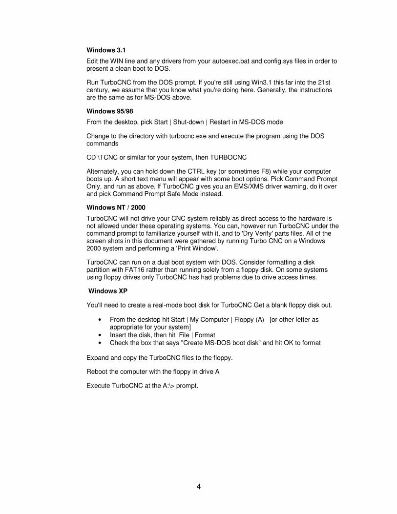
Windows 3.1
Edit the WIN line and any drivers from your autoexec.bat and config.sys files in order to present a clean boot to DOS.
Run TurboCNC from the DOS prompt. If you're still using Win3.1 this far into the 21st century, we assume that you know what you're doing here. Generally, the instructions are the same as for MS-DOS above.
Windows 95/98
From the desktop, pick Start | Shut-down | Restart in MS-DOS mode
Change to the directory with turbocnc.exe and execute the program using the DOS commands
CD \TCNC or similar for your system, then TURBOCNC
Alternately, you can hold down the CTRL key (or sometimes F8) while your computer boots up. A short text menu will appear with some boot options. Pick Command Prompt Only, and run as above. If TurboCNC gives you an EMS/XMS driver warning, do it over and pick Command Prompt Safe Mode instead.
Windows NT / 2000
TurboCNC will not drive your CNC system reliably as direct access to the hardware is not allowed under these operating systems. You can, however run TurboCNC under the command prompt to familiarize yourself with it, and to 'Dry Verify' parts files. All of the screen shots in this document were gathered by running Turbo CNC on a Windows 2000 system and performing a 'Print Window'.
TurboCNC can run on a dual boot system with DOS. Consider formatting a disk partition with FAT16 rather than running solely from a floppy disk. On some systems using floppy drives only TurboCNC has had problems due to drive access times.
Windows XP
You'll need to create a real-mode boot disk for TurboCNC Get a blank floppy disk out.
• From the desktop hit Start | My Computer | Floppy (A) [or other letter as appropriate for your system]
• Insert the disk, then hit File | Format • Check the box that says "Create MS-DOS boot disk" and hit OK to format
Expand and copy the TurboCNC files to the floppy.
Reboot the computer with the floppy in drive A
Execute TurboCNC at the A:\> prompt.
5
Contact Information
The best way to contact us is via email:
Or if you prefer the normal mail:
DAK Engineering c/o Dave Kowalczyk 11032 SE 224 PL Kent WA 98031 USA
Registration payments ($60) can be sent through PayPal to our account at [email protected], or by check/money order to the address above. Make checks payable to DAK Engineering. Include your email address so that we can send the source code to you as well.
Support
Consider joining the Yahoo! TurboCNC User Group at http://groups.yahoo.com/group/turbocnc/. Many of our members are highly knowledgeable and willing to help, and several have posted their enhancements to TurboCNC.
Don't hesitate to let us know about features you want to see in a future version. Upgrades are continuous, and most suggestions find their way in there eventually.
For bug reporting, please send the problem code and your turbocnc.ini file for the program as a courtesy if appropriate to the issue. It helps enormously in analyzing problems.
Credits
Dave Kowalczyk – Lead programmer, original author.
Jerry Jankura - Programming, TUI systems and interfaces.
Tony Groothuizen – Programming, debugging.
George and Andrew Bean - Authors of the TechnoJock Toolkit, which drives the menu system.
Terry King - Author of Fkeybit.
Harald Geier - Menu usability, MasterCAM posts.
John Johnson - M60/62 (now M98 / M99) and parsing algorithms.
Daniel Barber - Windows XP compatibility testing and boot instructions.
Alan Matheson - Metric mode testing.
Daniel Brock, Wayne Hill, and Andrew Erwood - G76 cycle specifications.
We would also like to recognize the registered users and the beta testers especially for their support, suggestions, patience, and the many successes they've enjoyed while using this software.
6
Part 2 – User’s Guide
Introduction
TurboCNC is a machine control interpreter. By loading in “g-code” files and executing them, physical motion of a machine occurs.
Menu System
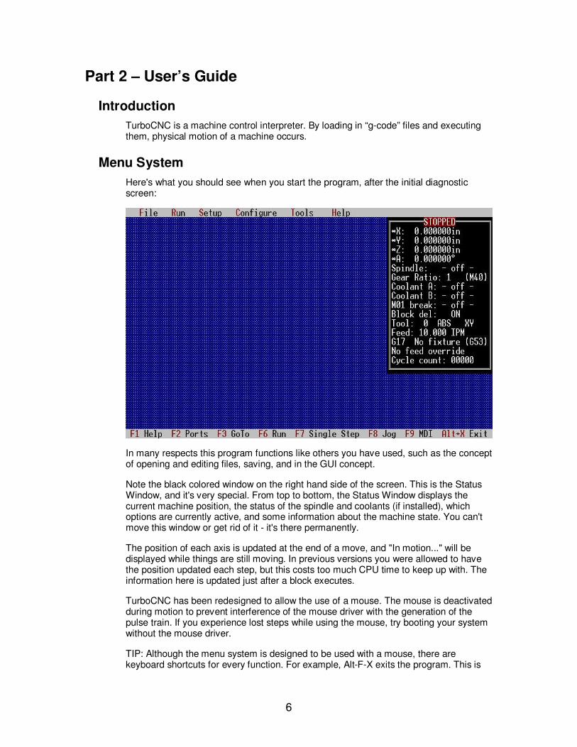
Here's what you should see when you start the program, after the initial diagnostic screen:
In many respects this program functions like others you have used, such as the concept of opening and editing files, saving, and in the GUI concept.
Note the black colored window on the right hand side of the screen. This is the Status Window, and it's very special. From top to bottom, the Status Window displays the current machine position, the status of the spindle and coolants (if installed), which options are currently active, and some information about the machine state. You can't move this window or get rid of it - it's there permanently.
The position of each axis is updated at the end of a move, and "In motion..." will be displayed while things are still moving. In previous versions you were allowed to have the position updated each step, but this costs too much CPU time to keep up with. The information here is updated just after a block executes.
TurboCNC has been redesigned to allow the use of a mouse. The mouse is deactivated during motion to prevent interference of the mouse driver with the generation of the pulse train. If you experience lost steps while using the mouse, try booting your system without the mouse driver.
TIP: Although the menu system is designed to be used with a mouse, there are keyboard shortcuts for every function. For example, Alt-F-X exits the program. This is
7
usually much faster than using the mouse, especially if you don't have one. In many shops, the amount of dirt and crud around (not to mention the tendency for any horizontal surface to become occupied), will preclude the use of a mouse anyway.
Quick Keys
The functions most commonly used to set up a job have an associated function key listed on the status bar at the bottom of the screen. Other common tasks also have a 'Quick Key' associated with them. These keys are:
• ctrl + N Open a new file • ctrl + O Open file in editor • ctrl + R Run from disk • alt + num Configuration menu for that axis
Motion Keys:
During motion several keys are checked every 18.2 milliseconds (about 55 times per second). These are:
• Esc Panic Stop (Stops motion immediately) • increase or decrease feed rate 1% • shift + <> increase or decrease feed rate 10%
During motion, the result of increasing or decreasing the feed rate will not be seen on the status display. This is updated at the end of the current move.
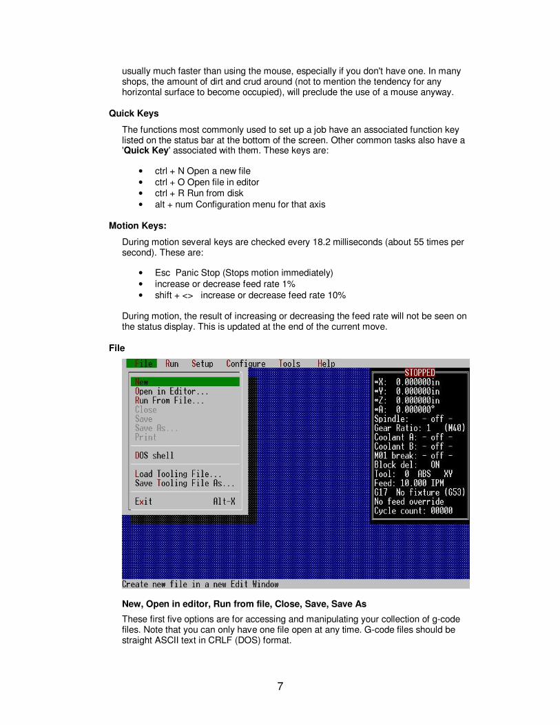
File
New, Open in editor, Run from file, Close, Save, Save As
These first five options are for accessing and manipulating your collection of g-code files. Note that you can only have one file open at any time. G-code files should be straight ASCII text in CRLF (DOS) format.
8
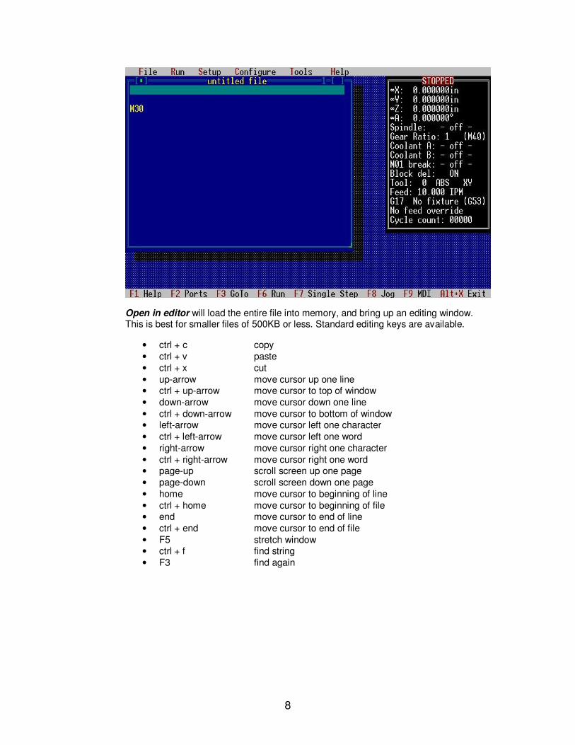
Open in editor will load the entire file into memory, and bring up an editing window. This is best for smaller files of 500KB or less. Standard editing keys are available.
• ctrl + c copy • ctrl + v paste • ctrl + x cut • up-arrow move cursor up one line • ctrl + up-arrow move cursor to top of window • down-arrow move cursor down one line • ctrl + down-arrow move cursor to bottom of window • left-arrow move cursor left one character • ctrl + left-arrow move cursor left one word • right-arrow move cursor right one character • ctrl + right-arrow move cursor right one word • page-up scroll screen up one page • page-down scroll screen down one page • home move cursor to beginning of line • ctrl + home move cursor to beginning of file • end move cursor to end of line • ctrl + end move cursor to end of file • F5 stretch window • ctrl + f find string • F3 find again
9
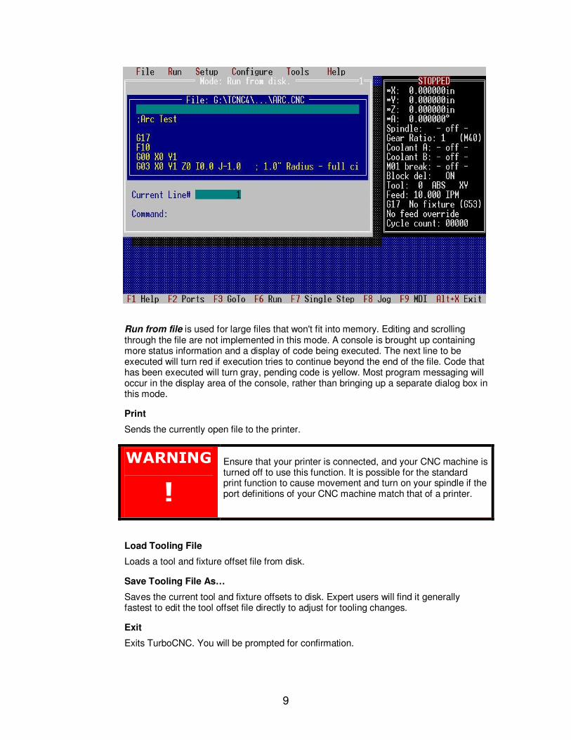
Run from file is used for large files that won't fit into memory. Editing and scrolling through the file are not implemented in this mode. A console is brought up containing more status information and a display of code being executed. The next line to be executed will turn red if execution tries to continue beyond the end of the file. Code that has been executed will turn gray, pending code is yellow. Most program messaging will occur in the display area of the console, rather than bringing up a separate dialog box in this mode.
Sends the currently open file to the printer.
WARNING
!
Ensure that your printer is connected, and your CNC machine is turned off to use this function. It is possible for the standard print function to cause movement and turn on your spindle if the port definitions of your CNC machine match that of a printer.
Load Tooling File
Loads a tool and fixture offset file from disk.
Save Tooling File As…
Saves the current tool and fixture offsets to disk. Expert users will find it generally fastest to edit the tool offset file directly to adjust for tooling changes.
Exit
Exits TurboCNC. You will be prompted for confirmation.
10
Run
There are a variety of functions to actually do some real work with your machine located under the Run Menu.
The '<' and '>' keys can be used to adjust the feed rate while the CNC machine is in motion. Using the Shift key in combination with these will yields a finer degree of control.
The 'ESC' key functions as a PANIC STOP, while in this mode.
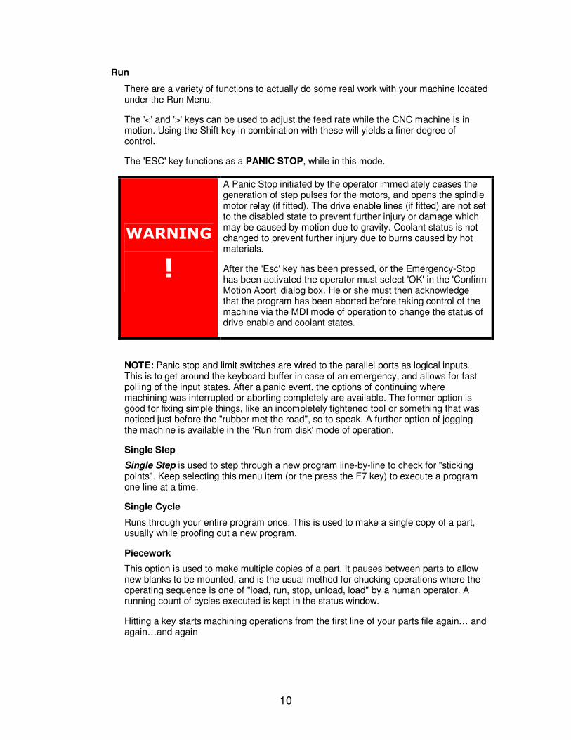
WARNING
!
A Panic Stop initiated by the operator immediately ceases the generation of step pulses for the motors, and opens the spindle motor relay (if fitted). The drive enable lines (if fitted) are not set to the disabled state to prevent further injury or damage which may be caused by motion due to gravity. Coolant status is not changed to prevent further injury due to burns caused by hot materials.
After the 'Esc' key has been pressed, or the Emergency-Stop has been activated the operator must select 'OK' in the 'Confirm Motion Abort' dialog box. He or she must then acknowledge that the program has been aborted before taking control of the machine via the MDI mode of operation to change the status of drive enable and coolant states.
NOTE: Panic stop and limit switches are wired to the parallel ports as logical inputs. This is to get around the keyboard buffer in case of an emergency, and allows for fast polling of the input states. After a panic event, the options of continuing where machining was interrupted or aborting completely are available. The former option is good for fixing simple things, like an incompletely tightened tool or something that was noticed just before the "rubber met the road", so to speak. A further option of jogging the machine is available in the 'Run from disk' mode of operation.
Single Step
Single Step is used to step through a new program line-by-line to check for "sticking points". Keep selecting this menu item (or the press the F7 key) to execute a program one line at a time.
Single Cycle
Runs through your entire program once. This is used to make a single copy of a part, usually while proofing out a new program.
Piecework
This option is used to make multiple copies of a part. It pauses between parts to allow new blanks to be mounted, and is the usual method for chucking operations where the operating sequence is one of "load, run, stop, unload, load" by a human operator. A running count of cycles executed is kept in the status window.
Hitting a key starts machining operations from the first line of your parts file again… and again…and again
11
Automated…
This option is used for fully automated machines that are capable of changing the work piece. Just enter the desired number of parts and send it on its way. It will run the parts file over and over again for the specified number of cycles. This is great if pallet changing, bar pulling, PLCs, or other robotic hardware is available to do the loading and unloading. The G codes to run the robots as other axes must be included in the same program with the code used to machine the part. This is partly the reason so many axes of motion are included.
Dry Verify
This option allows you to run through the file without moving your machine or turning anything on. It is often used to see if there are errors in the file syntax, and to obtain an estimated running time for the program. The estimated run time will be a bit on the low side as Dry Verify uses some approximations for speed.
The Reset File and Go To Block/Cursor options allows the operator to establish the current execution point in a file without cutting or moving anything.
Reset File
The Reset File option is used to reset the program counter to the first line in the file.
Go to Block/Cursor
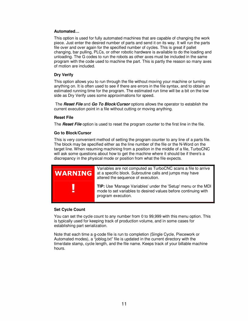
This is very convenient method of setting the program counter to any line of a parts file. The block may be specified either as the line number of the file or the N-Word on the target line. When resuming machining from a position in the middle of a file, TurboCNC will ask some questions about how to get the machine where it should be if there's a discrepancy in the physical mode or position from what the file expects.
WARNING
!
Variables are not computed as TurboCNC scans a file to arrive at a specific block. Subroutine calls and jumps may have altered the sequence of execution.
TIP: Use 'Manage Variables' under the 'Setup' menu or the MDI mode to set variables to desired values before continuing with program execution.
Set Cycle Count
You can set the cycle count to any number from 0 to 99,999 with this menu option. This is typically used for keeping track of production volume, and in some cases for establishing part serialization.
Note that each time a g-code file is run to completion (Single Cycle, Piecework or Automated modes), a “joblog.txt” file is updated in the current directory with the time/date stamp, cycle length, and the file name. Keeps track of your billable machine hours.
12
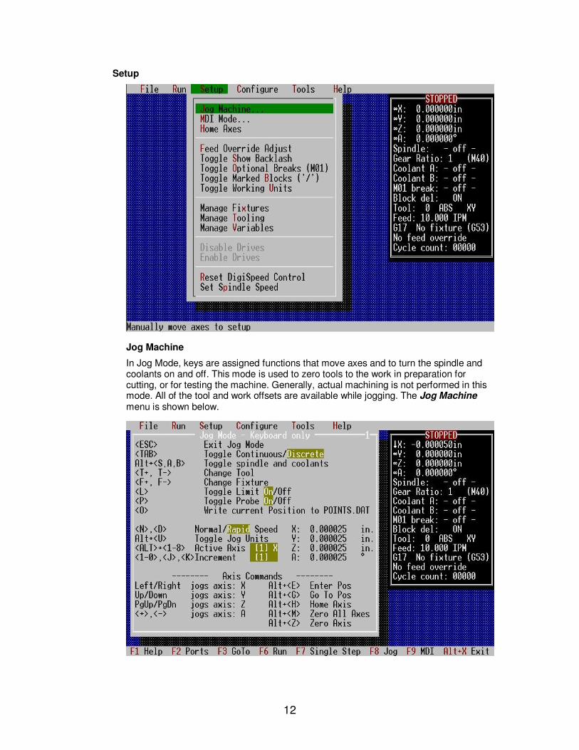
Setup
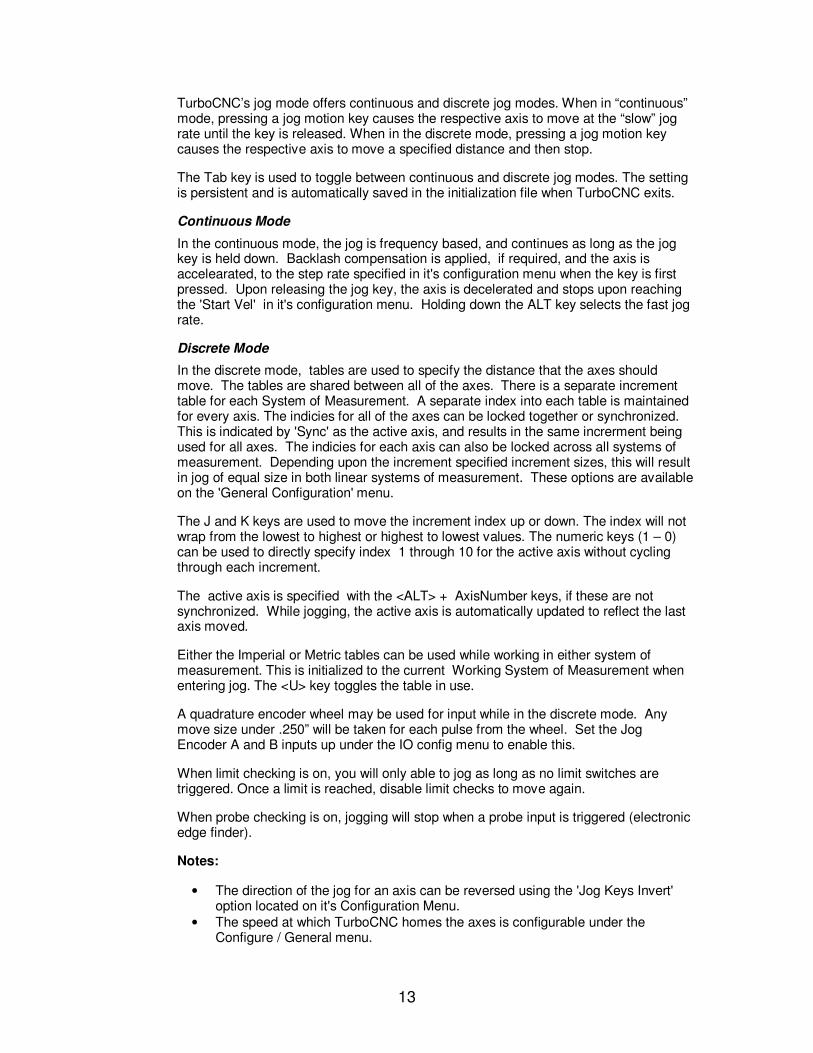
Jog Machine
In Jog Mode, keys are assigned functions that move axes and to turn the spindle and coolants on and off. This mode is used to zero tools to the work in preparation for cutting, or for testing the machine. Generally, actual machining is not performed in this mode. All of the tool and work offsets are available while jogging. The Jog Machine menu is shown below.
13
TurboCNC’s jog mode offers continuous and discrete jog modes. When in “continuous” mode, pressing a jog motion key causes the respective axis to move at the “slow” jog rate until the key is released. When in the discrete mode, pressing a jog motion key causes the respective axis to move a specified distance and then stop.
The Tab key is used to toggle between continuous and discrete jog modes. The setting is persistent and is automatically saved in the initialization file when TurboCNC exits.
Continuous Mode
In the continuous mode, the jog is frequency based, and continues as long as the jog key is held down. Backlash compensation is applied, if required, and the axis is accelearated, to the step rate specified in it's configuration menu when the key is first pressed. Upon releasing the jog key, the axis is decelerated and stops upon reaching the 'Start Vel' in it's configuration menu. Holding down the ALT key selects the fast jog rate.
Discrete Mode
In the discrete mode, tables are used to specify the distance that the axes should move. The tables are shared between all of the axes. There is a separate increment table for each System of Measurement. A separate index into each table is maintained for every axis. The indicies for all of the axes can be locked together or synchronized. This is indicated by 'Sync' as the active axis, and results in the same increrment being used for all axes. The indicies for each axis can also be locked across all systems of measurement. Depending upon the increment specified increment sizes, this will result in jog of equal size in both linear systems of measurement. These options are available on the 'General Configuration' menu.
The J and K keys are used to move the increment index up or down. The index will not wrap from the lowest to highest or highest to lowest values. The numeric keys (1 – 0) can be used to directly specify index 1 through 10 for the active axis without cycling through each increment.
The active axis is specified with the <ALT> + AxisNumber keys, if these are not synchronized. While jogging, the active axis is automatically updated to reflect the last axis moved.
Either the Imperial or Metric tables can be used while working in either system of measurement. This is initialized to the current Working System of Measurement when entering jog. The <U> key toggles the table in use.
A quadrature encoder wheel may be used for input while in the discrete mode. Any move size under .250” will be taken for each pulse from the wheel. Set the Jog Encoder A and B inputs up under the IO config menu to enable this.
When limit checking is on, you will only able to jog as long as no limit switches are triggered. Once a limit is reached, disable limit checks to move again.
When probe checking is on, jogging will stop when a probe input is triggered (electronic edge finder).
Notes:
• The direction of the jog for an axis can be reversed using the 'Jog Keys Invert' option located on it's Configuration Menu.
• The speed at which TurboCNC homes the axes is configurable under the Configure / General menu.
14
• Keys are configurable for foreign language keyboards. See the TurboCNC Configuration File section of this manual for details.
• Several of the commands make use of a “currently active” axis. You can set the currently active axis by specifying either its description or its number. The “currently active” axis is modal. It remains active until another axis is set active. An example – to home the X axis and then set its location to 15 and then move X to 20, you would enter the following sequence:
o X o Alt+H o Alt+E (and then enter 15 in the dialog box) o Alt+G (and then enter 20 in the dialog box)
The Y and Z (and any other) axes will remain in their current locations; only X will move and have its location changed.
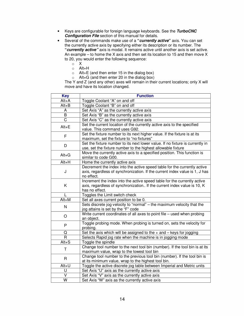
Key Function
Alt+A Toggle Coolant “A” on and off Alt+B Toggle Coolant “B” on and off
A Set Axis “A” as the currently active axis B Set Axis “B” as the currently active axis C Set Axis “C” as the currently active axis
Alt+E Set the current location of the currently active axis to the specified value. This command uses G92.
F Set the fixture number to its next higher value. If the fixture is at its maximum, set the fixture to “no fixtures”
D Set the fixture number to its next lower value. If no fixture is currently in use, set the fixture number to the highest allowable fixture
Alt+G Move the currently active axis to a specified position. This function is similar to code G00.
Alt+H Home the currently active axis
J Decrement the index into the active speed table for the currently active axis, regardless of synchronization. If the current index value is 1, J has no effect.
K Increment the index into the active speed table for the currently active axis, regardless of synchronization.. If the current index value is 10, K has no effect.
L Toggles the Limit switch check Alt+M Set all axes current position to be 0.
N Sets discrete jog velocity to “normal” – the maximum velocity that the jog attains is set by the “F” code
O Write current coordinates of all axes to point file – used when probing an object.
P Toggle probing mode. When probing is turned on, sets the velocity for probing.
Q Set the axis which will be assigned to the + and – keys for jogging R Selects Rapid jog rate when the machine is in jogging mode
Alt+S Toggle the spindle
T Change tool number to the next tool bin (number). If the tool bin is at its maximum value, wrap to the lowest tool bin
R Change tool number to the previous tool bin (number). If the tool bin is at its minimum value, wrap to the highest tool bin.
Alt+U Toggle the active discrete jog table between Imperial and Metric units U Set Axis “U” axis as the currently active axis V Set Axis “V” axis as the currently active axis W Set Axis “W” axis as the currently active axis
15
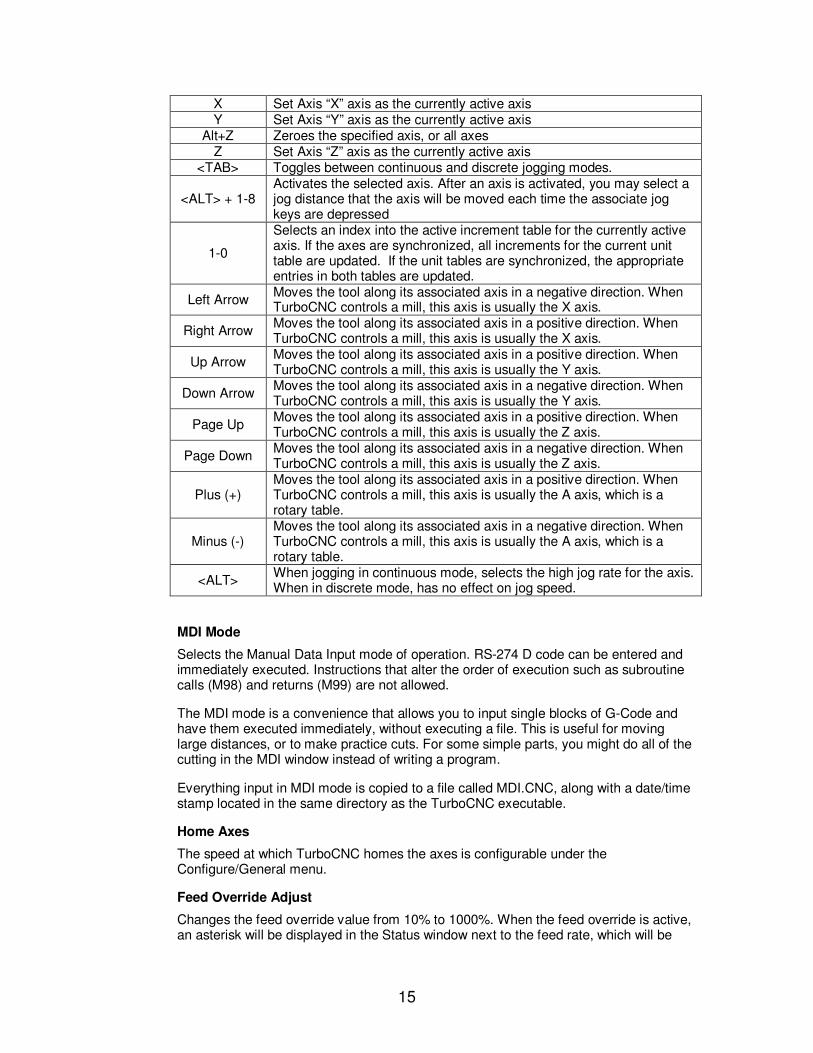
X Set Axis “X” axis as the currently active axis Y Set Axis “Y” axis as the currently active axis
Alt+Z Zeroes the specified axis, or all axes Z Set Axis “Z” axis as the currently active axis
<TAB> Toggles between continuous and discrete jogging modes.
<ALT> + 1-8 Activates the selected axis. After an axis is activated, you may select a jog distance that the axis will be moved each time the associate jog keys are depressed
1-0
Selects an index into the active increment table for the currently active axis. If the axes are synchronized, all increments for the current unit table are updated. If the unit tables are synchronized, the appropriate entries in both tables are updated.
Left Arrow Moves the tool along its associated axis in a negative direction. When TurboCNC controls a mill, this axis is usually the X axis.
Right Arrow Moves the tool along its associated axis in a positive direction. When TurboCNC controls a mill, this axis is usually the X axis.
Up Arrow Moves the tool along its associated axis in a positive direction. When TurboCNC controls a mill, this axis is usually the Y axis.
Down Arrow Moves the tool along its associated axis in a negative direction. When TurboCNC controls a mill, this axis is usually the Y axis.
Page Up Moves the tool along its associated axis in a positive direction. When TurboCNC controls a mill, this axis is usually the Z axis.
Page Down Moves the tool along its associated axis in a negative direction. When TurboCNC controls a mill, this axis is usually the Z axis.
Plus (+) Moves the tool along its associated axis in a positive direction. When TurboCNC controls a mill, this axis is usually the A axis, which is a rotary table.
Minus (-) Moves the tool along its associated axis in a negative direction. When TurboCNC controls a mill, this axis is usually the A axis, which is a rotary table.
<ALT> When jogging in continuous mode, selects the high jog rate for the axis. When in discrete mode, has no effect on jog speed.
MDI Mode
Selects the Manual Data Input mode of operation. RS-274 D code can be entered and immediately executed. Instructions that alter the order of execution such as subroutine calls (M98) and returns (M99) are not allowed.
The MDI mode is a convenience that allows you to input single blocks of G-Code and have them executed immediately, without executing a file. This is useful for moving large distances, or to make practice cuts. For some simple parts, you might do all of the cutting in the MDI window instead of writing a program.
Everything input in MDI mode is copied to a file called MDI.CNC, along with a date/time stamp located in the same directory as the TurboCNC executable.
Home Axes
The speed at which TurboCNC homes the axes is configurable under the Configure/General menu.
Feed Override Adjust
Changes the feed override value from 10% to 1000%. When the feed override is active, an asterisk will be displayed in the Status window next to the feed rate, which will be
16
adjusted to show the “true” feed rate that is in use. 100% is “no override”, that is, the feed rate will be the same as programmed.
Adjust the feed override downward to compensate for cutting conditions like dull tools, hard spots in materials, and poor clamping. Adjust it upward to compensate for melting or burning materials, chatter, or for faster production if conditions otherwise allow.
Toggle Show Backlash
Shows or hides the backlash direction indicators in the status display for all axes that have a backlash configured.
Toggle Optional Breaks (M01)
Enables or disables M01 Optional Breaks depending on its current state.
Toggle Marked Blocks (‘/’)
Enables or disables the block delete mode depending on its current state.
When enabled TurboCNC will ignore blocks of code that have this as the first valid character on a line. The block delete character may be preceded by 'white space' such as space or tab characters and comments enclosed in brackets.
If this is enabled and the block delete character is encountered after the first word in a block, TurboCNC will ignore the following word only.
G00 X0 /Y0 Z0 ; y-axis does not move if block delete is on /G00 X0 Y0 Z0 ; no movement if block delete is on (*** no movement if block delete is on ***) /G00 X0 Y0 Z0
Toggle Working Units
Switches the system's working units of measurement from Imperial to Metric or vice versa. This menu item has the same effect as G20/21/70/71. See the 'Switch Native Units to ' section under Configuration for a discussion of working and native units of measurement.
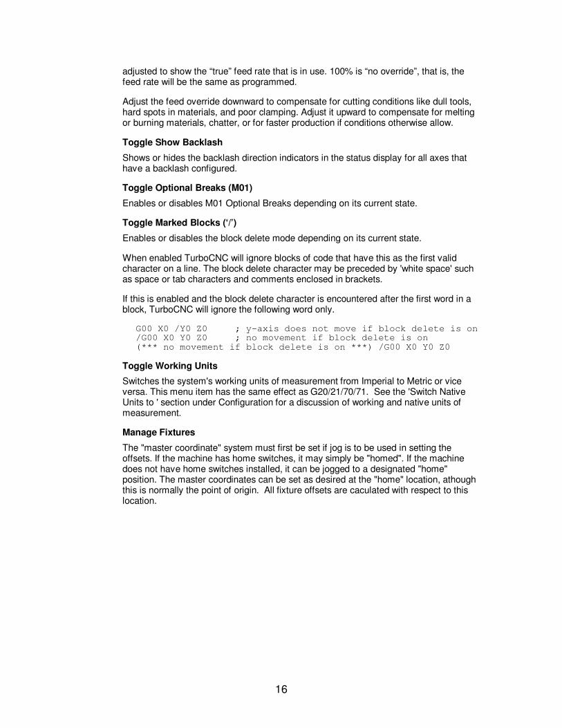
Manage Fixtures
The "master coordinate" system must first be set if jog is to be used in setting the offsets. If the machine has home switches, it may simply be "homed". If the machine does not have home switches installed, it can be jogged to a designated "home" position. The master coordinates can be set as desired at the "home" location, athough this is normally the point of origin. All fixture offsets are caculated with respect to this location.
17
A confirmation dialog box will appear ensuring that fixture offsets are not inadvertently cleared. Following the operation a message box will appear to confirm that the fixture offsets have been successfully cleared.
Manage Tooling
A means of setting tool offsets is provided under this menu item.
Before any of the tooling offsets can be set, a reference location to zero must be set. Once the reference is set to a zero location, all other tools are to be moved to this location. You may use either a tool as the reference, or may make a special tool setting gauge. Once the reference location has been set, load the actual tools and move them to the reference location, using the jogging controls. TurboCNC will then record the offset locations for each axis.
• Select Setup->Manage Tooling from the main menu • Load the reference gauge in the spindle. • Move the reference gauge to a reference location using the cursor to jog the
reference into place. Either build a gauge to provide a point to which the reference gauge is moved, or use some portion. Allow the motors to move the reference. If power to the motors is cut and the axes manually moved, TurboCNC will not be able to record the position, and will not accurately set any of the tooling offsets.
• With the reference gauge in the correct location, press the "Set" button to record the reference coordinates.
Now that the reference location has been set, TurboCNC shows a screen allowing the offsets for each of the tools to be set. This is done as follows:
• Use the "prev" and "next" buttons to select the tool for which the offsets are to be entered.
18
• Enter a description of the tool on the line provided, if desired. This description is not necessary, but can be used to identify the tool during execution of the CNC program.
• Load the tool into the spindle and jog it to the same reference point to which the gauge was set.
• Press the "S" key to set accept the location and calculate the tool reference, or press the "C" key to cancel the function and revert to the current tool offsets.
• TurboCNC will store the offsets in a table, and will automatically select the next tool in series.
• Tools may be directly edited from this menu. • Rear Toolpost is not yet active, and has been included for future development.
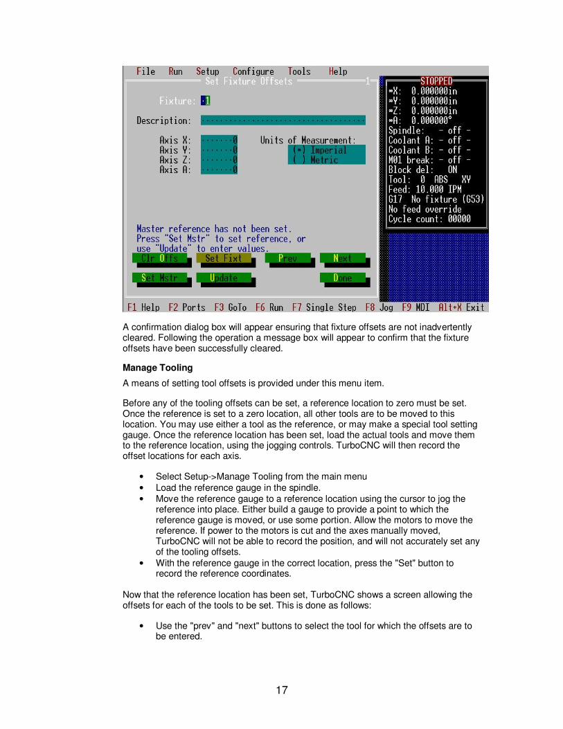
When all of the tool offsets have been set, press the "done" button to exit the function. An opportunity to save the new tool offsets will be presented. The offsets will be stored in a file located in the directory as specified in the Configure->General dialog.
The screenshot below shows the options prior to 'Set Gage' .
A confirmation dialog box will appear ensuring that tool offsets are not inadvertently cleared. Following the operation a message box will appear to confirm that the tool offsets have been successfully cleared.
19
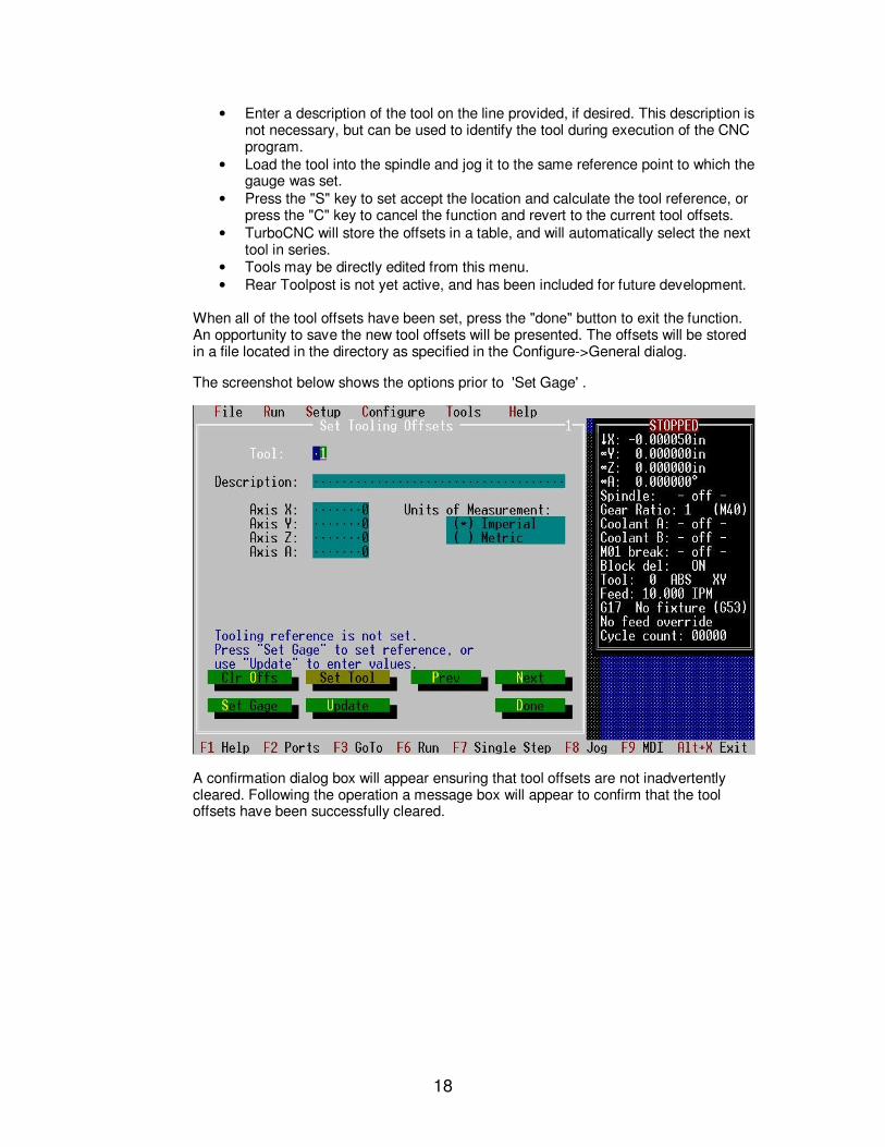
Manage Variables:
Provides a means of setting, and inspecting variables without using RS-274D in MDI or a custom program. Show will bring up a scrolling list of all variables that are currently storing a value. Clear all will reset all variables to an empty string.
Disable Drives
This option is available only if a drive enable line has been configured. All drive enable lines are set to their inactive states when this option is selected.
Enable Drives
This option is available only if a drive enable line has been configured. All drive enable lines are set to their inactive states when this option is selected.
Reset DigiSpeed Control
Commands are sent to the spindle speed controller, disabling it, and resetting the speed to 0 RPM.
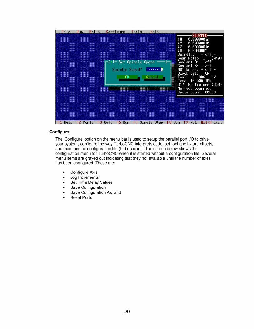
Set Spindle Speed
A dialog box is presented allowing the user to directly enteer the desired spindle speed. The command is sent to the speed control.
NOTE: neither of these options affect the state of the Spindle Power control line. This must be set separately.
20
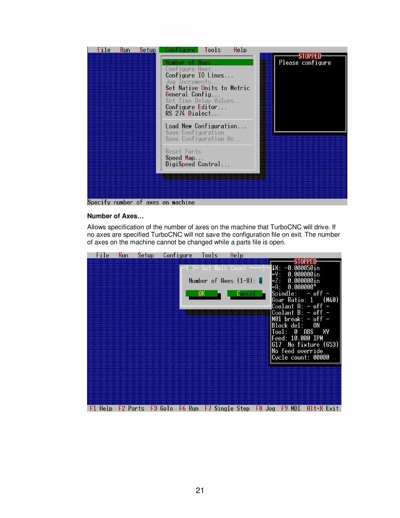
Configure
The 'Configure' option on the menu bar is used to setup the parallel port I/O to drive your system, configure the way TurboCNC interprets code, set tool and fixture offsets, and maintain the configuration file (turbocnc.ini). The screen below shows the configuration menu for TurboCNC when it is started without a configuration file. Several menu items are grayed out indicating that they not available until the number of axes has been configured. These are:
• Configure Axis • Jog Increments • Set Time Delay Values • Save Configuration • Save Configuration As, and • Reset Ports
21
Number of Axes…
Allows specification of the number of axes on the machine that TurboCNC will drive. If no axes are specified TurboCNC will not save the configuration file on exit. The number of axes on the machine cannot be changed while a parts file is open.

22
Configure Axis…
is used to set the parallel port I/O, and specify the motion parameters for each axis. Upon selection, a dialog box is presented where the first axis to be configured can be selected. You will then be taken to the main configuration screen shown below. This screen is dynamic and will change to reflect your choices. It is recommended that you use the mouse to navigate this screen, as the design trade off for the dynamics was intuitive keyboard navigation.
Items on the axis configuration menu are:
Axis Name: Assigns a drive letter that is used to select this axis in RS-274 D. Valid selections are A through E and U through Z.
Motion: selects whether the axis is linear or angular. Angular axis measurements are always in decimal degrees, modulus 360, and driven the shortest distance to their new position. Linear axes are measured in either inches or millimeters, depending on the system of measurement in use.
Drive type: selects whether a Step/Direction or Phase scheme is used to control the motor driver. A Step/Direction scheme requires only two output pins, while a phase scheme requires a minimum of 4, and up to eight output pins to drive a single motor. Drive type selection determines whether Step/Direction or Phase definition configuration information is displayed on the menu.
Pulse Width: changes the duration of the step pulse on step/dir controlled axes, as some drives need a few microseconds to recognize that the step line has changed state. The parameter is set directly in integer microseconds. 0 is no explicit delay, which works out to be between about 2 and 7 µs on most computers.
Port: The parallel port to which the driver is connected is selected by this option.
Step pin num: sets the output pin on the selected port for step pulses. Valid values are 2, 3, 4, 5, 6, 7, 8, 9, 1, 14, 16, and 17.
23
Step pin is: This option is used match TurboCNC to your controller's requirements. Check you controller documentation, or the files section of the TurboCNC newsgroup on Yahoo! to determine the proper setting. (Trial and Terror can also be used.)
Dir pin num: sets the output pin on the selected port for the direction signal. Valid values are 2, 3, 4, 5, 6, 7, 8, 9, 1, 14, 16, and 17.
Direction pin: selects the polarity required to drive the axis in the positive direction. Phase wiring of the motor and driver electronics determine this setting. Jog or manually move the axis to a position where you can safely move the axis and use relative movements in MDI to determine if the axis moves in the proper direction. If not, simply toggle this selection and verify that the axis now moves in the correct direction, once again using the MDI mode of operation.
Motion Parameters: are used to set various values governing the movement of the axis. Units of measurement will vary to reflect the type of axis and units of measurement in use by TurboCNC. Acceleration, velocity, and scale effects are reflected below the data entry area. There is no one-size-fits-all solution. These setting depend on all of the equipment, and the cutting forces to be used. A starting point for several systems can be found in the files area of the TurboCNC Yahoo! Group or in the inifiles subdirectory of your installation. These settings will have to be fine tuned to maximize the system's performance.
Scale: is the distance or angle that the axis moves for a single step pulse or phase change. The units can be in inches, millimeters or decimal degrees, depending on axis motion, and the system of measurement in use. A custom calculator is accessable by clicking on 'Calc, or pressing 'c'.
Accel: the maximum acceleration of the step pulse train or phases that are sent to the driver measured in cycles per second per second. This is purely electronic, and is converted to motion by the motor. Scale is used to convert this value to the linear or angular value displayed below.
Start vel: is the maximum starting / stopping velocity that will be used by TurboCNC for this axis. Lower values will often be used for interpolated moves. This is measured in cycles per second, and converted to a distance or angular measurement using Scale and displayed below as the Start Speed.
Max vel: is the maximum velocity that TurboCNC will drive the axis. This is measured in cycles per second, and converted to a distance or angular measurement using Scale and displayed below as the Max Speed.
Backlash: is the compensation applied whenever the axis changes its direction of movement. It is measured in inches, millimeters, or degrees depending on the type of motion and system of measurement in use.
Slow jog: This is the speed at which the step pulses are applied, or phase changes occur when Slow jog is engaged. It is measured in cycles per second. The value can be converted to a distance or angular measurement by multiplying it by the Scale.
Fast jog: Similar to Slow jog, but allows you to select a higher speed.
Jog Keys: Selection of normal or invert is possible. In the inverted mode the motion of the tool with respect to the work piece is reversed for the axis.
24
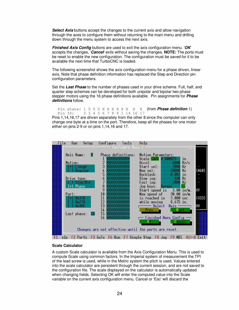
Select Axis buttons accept the changes to the current axis and allow navigation through the axes to configure them without returning to the main menu and drilling down through the menu system to access the next axis.
Finished Axis Config buttons are used to exit the axis configuration menu. 'OK' accepts the changes, 'Cancel' exits without saving the changes. NOTE: The ports must be reset to enable the new configuration. The configuration must be saved for it to be available the next time that TurboCNC is loaded.
The following screenshot shows the axis configuration menu for a phase driven, linear axis. Note that phase definition information has replaced the Step and Direction pin configuration parameters.
Set the Last Phase to the number of phases used in your drive scheme. Full, half, and quarter step schemes can be developed for both unipolar and bipolar two-phase stepper motors using the 16 phase definitions available. Pin assignments for Phase definitions follow.
Pin state: 1 0 0 0 X X X X X X X X (from Phase definition 1) Pin ID: 2 3 4 5 6 7 8 9 1 14 16 17
Pins 1,14,16,17 are driven separately from the other 8 since the computer can only change one byte at a time on the port. Therefore, keep all the phases for one motor either on pins 2-9 or on pins 1,14,16 and 17.
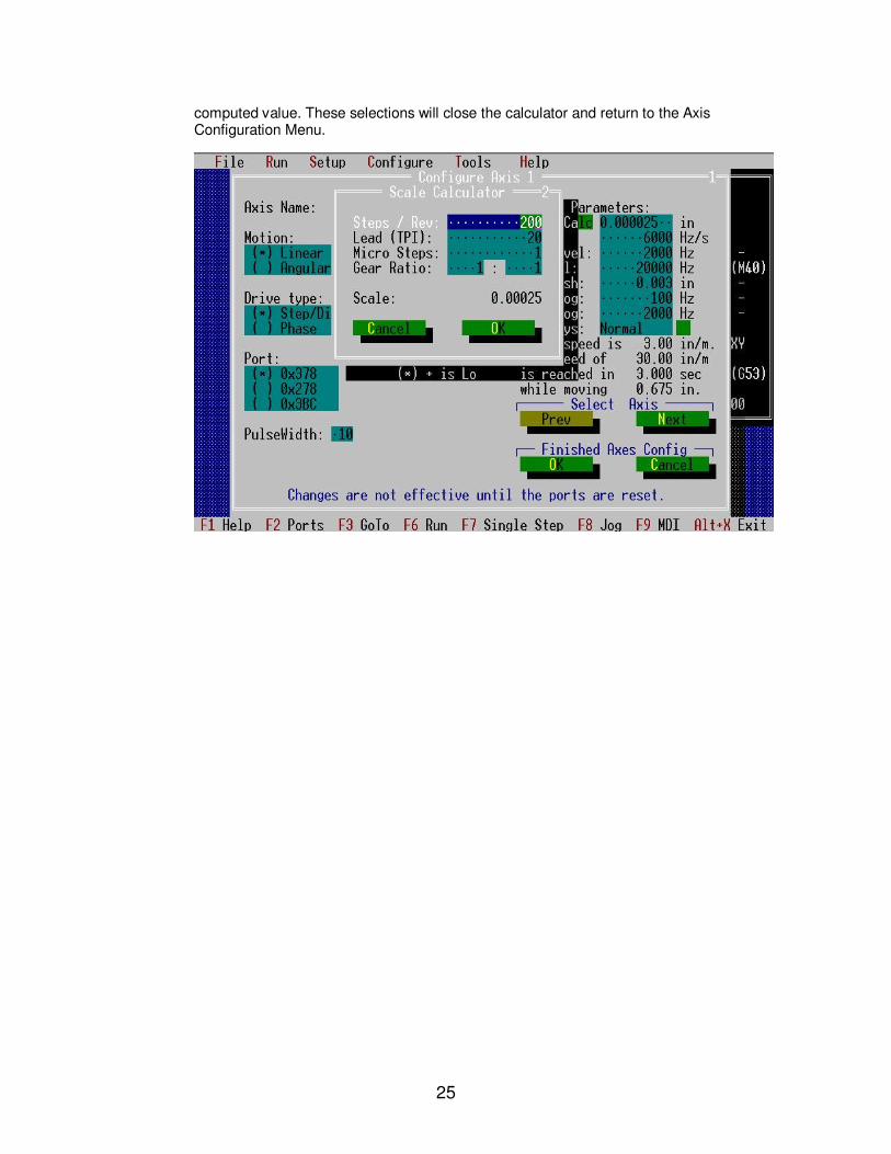
Scale Calculator
A custom Scale calculator is available from the Axis Configuration Menu. This is used to compute Scale using common factors. In the Imperial system of measurement the TPI of the lead screw is used, while in the Metric system the pitch is used. Values entered into the scale calculator are persistent through the current session, and are not saved to the configuration file. The scale displayed on the calculator is automatically updated when changing fields. Selecting OK will enter the computed value into the Scale variable on the current axis configuration menu. Cancel or 'Esc' will discard the
25
computed value. These selections will close the calculator and return to the Axis Configuration Menu.
26
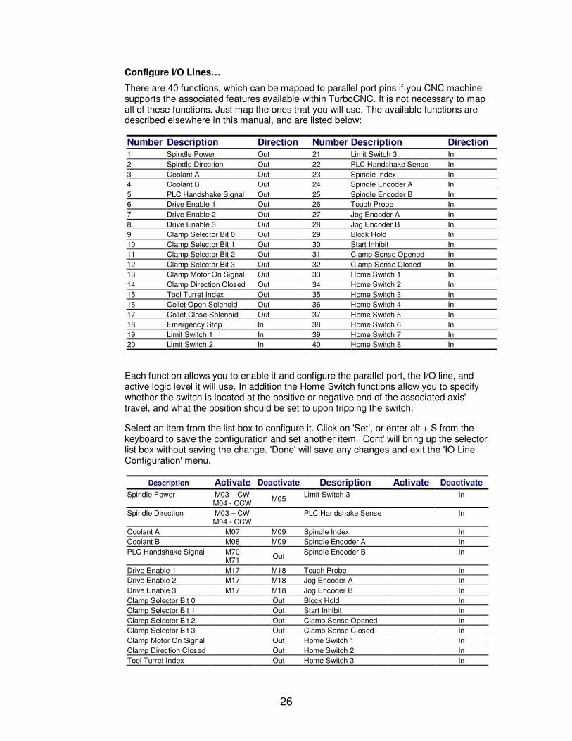
Configure I/O Lines…
There are 40 functions, which can be mapped to parallel port pins if you CNC machine supports the associated features available within TurboCNC. It is not necessary to map all of these functions. Just map the ones that you will use. The available functions are described elsewhere in this manual, and are listed below:
Number Description Direction Number Description Direction
1 Spindle Power Out 21 Limit Switch 3 In
2 Spindle Direction Out 22 PLC Handshake Sense In
3 Coolant A Out 23 Spindle Index In
4 Coolant B Out 24 Spindle Encoder A In
5 PLC Handshake Signal Out 25 Spindle Encoder B In
6 Drive Enable 1 Out 26 Touch Probe In
7 Drive Enable 2 Out 27 Jog Encoder A In
8 Drive Enable 3 Out 28 Jog Encoder B In
9 Clamp Selector Bit 0 Out 29 Block Hold In
10 Clamp Selector Bit 1 Out 30 Start Inhibit In
11 Clamp Selector Bit 2 Out 31 Clamp Sense Opened In
12 Clamp Selector Bit 3 Out 32 Clamp Sense Closed In
13 Clamp Motor On Signal Out 33 Home Switch 1 In
14 Clamp Direction Closed Out 34 Home Switch 2 In
15 Tool Turret Index Out 35 Home Switch 3 In
16 Collet Open Solenoid Out 36 Home Switch 4 In
17 Collet Close Solenoid Out 37 Home Switch 5 In
18 Emergency Stop In 38 Home Switch 6 In
19 Limit Switch 1 In 39 Home Switch 7 In
20 Limit Switch 2 In 40 Home Switch 8 In
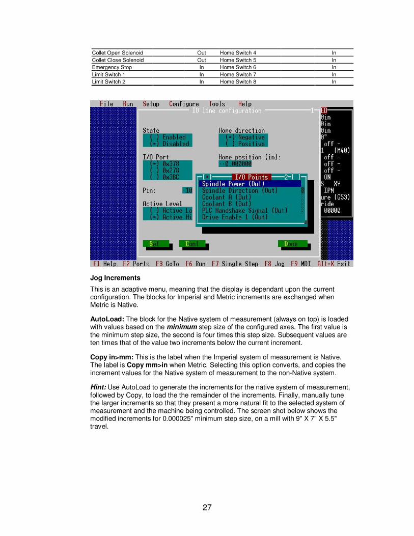
Each function allows you to enable it and configure the parallel port, the I/O line, and active logic level it will use. In addition the Home Switch functions allow you to specify whether the switch is located at the positive or negative end of the associated axis' travel, and what the position should be set to upon tripping the switch.
Select an item from the list box to configure it. Click on 'Set', or enter alt + S from the keyboard to save the configuration and set another item. 'Cont' will bring up the selector list box without saving the change. 'Done' will save any changes and exit the 'IO Line Configuration' menu.
Description Activate Deactivate Description Activate Deactivate
Spindle Power M03 – CW M04 - CCW
M05 Limit Switch 3 In
Spindle Direction M03 – CW M04 - CCW
PLC Handshake Sense In
Coolant A M07 M09 Spindle Index In
Coolant B M08 M09 Spindle Encoder A In
PLC Handshake Signal M70 M71
Out Spindle Encoder B In
Drive Enable 1 M17 M18 Touch Probe In
Drive Enable 2 M17 M18 Jog Encoder A In
Drive Enable 3 M17 M18 Jog Encoder B In
Clamp Selector Bit 0 Out Block Hold In
Clamp Selector Bit 1 Out Start Inhibit In
Clamp Selector Bit 2 Out Clamp Sense Opened In
Clamp Selector Bit 3 Out Clamp Sense Closed In
Clamp Motor On Signal Out Home Switch 1 In
Clamp Direction Closed Out Home Switch 2 In
Tool Turret Index Out Home Switch 3 In
27
Collet Open Solenoid Out Home Switch 4 In
Collet Close Solenoid Out Home Switch 5 In
Emergency Stop In Home Switch 6 In
Limit Switch 1 In Home Switch 7 In
Limit Switch 2 In Home Switch 8 In
Jog Increments
This is an adaptive menu, meaning that the display is dependant upon the current configuration. The blocks for Imperial and Metric increments are exchanged when Metric is Native.
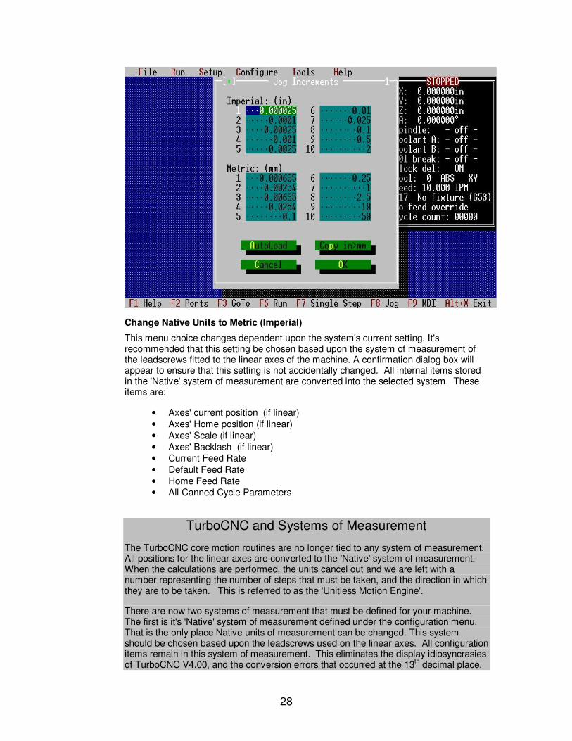
AutoLoad: The block for the Native system of measurement (always on top) is loaded with values based on the minimum step size of the configured axes. The first value is the minimum step size, the second is four times this step size. Subsequent values are ten times that of the value two increments below the current increment.
Copy in>mm: This is the label when the Imperial system of measurement is Native. The label is Copy mm>in when Metric. Selecting this option converts, and copies the increment values for the Native system of measurement to the non-Native system.
Hint: Use AutoLoad to generate the increments for the native system of measurement, followed by Copy, to load the the remainder of the increments. Finally, manually tune the larger increments so that they present a more natural fit to the selected system of measurement and the machine being controlled. The screen shot below shows the modified increments for 0.000025" minimum step size, on a mill with 9" X 7" X 5.5" travel.
28
Change Native Units to Metric (Imperial)
This menu choice changes dependent upon the system's current setting. It's recommended that this setting be chosen based upon the system of measurement of the leadscrews fitted to the linear axes of the machine. A confirmation dialog box will appear to ensure that this setting is not accidentally changed. All internal items stored in the 'Native' system of measurement are converted into the selected system. These items are:
• Axes' current position (if linear) • Axes' Home position (if linear) • Axes' Scale (if linear) • Axes' Backlash (if linear) • Current Feed Rate • Default Feed Rate • Home Feed Rate • All Canned Cycle Parameters
TurboCNC and Systems of Measurement
The TurboCNC core motion routines are no longer tied to any system of measurement. All positions for the linear axes are converted to the 'Native' system of measurement. When the calculations are performed, the units cancel out and we are left with a number representing the number of steps that must be taken, and the direction in which they are to be taken. This is referred to as the 'Unitless Motion Engine'.
There are now two systems of measurement that must be defined for your machine. The first is it's 'Native' system of measurement defined under the configuration menu. That is the only place Native units of measurement can be changed. This system should be chosen based upon the leadscrews used on the linear axes. All configuration items remain in this system of measurement. This eliminates the display idiosyncrasies of TurboCNC V4.00, and the conversion errors that occurred at the 13
th decimal place.
29
The second is termed the 'Working' system of measurement. All linear axis positions entered by RS-274D are considered to be in this system of measurement. These values can be part of a program or entered through the MDI, or jog interfaces. The 'Working' system of measurement can be changed using G20/21/70/71 or the 'Toggle Working Units' item under the Setup Menu.
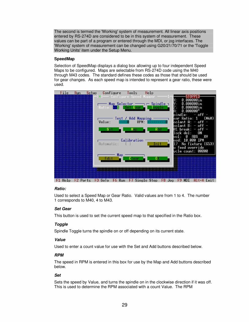
SpeedMap
Selection of SpeedMap displays a dialog box allowing up to four independent Speed Maps to be configured. Maps are selectable from RS-274D code using the M40 through M43 codes. The standard defines these codes as those that should be used for gear changes. As each speed map is intended to represent a gear ratio, these were used.
Ratio:
Used to select a Speed Map or Gear Ratio. Valid values are from 1 to 4. The number 1 corresponds to M40, 4 to M43.
Set Gear
This button is used to set the current speed map to that specified in the Ratio box.
Toggle
Spindle Toggle turns the spindle on or off depending on its current state.
Value
Used to enter a count value for use with the Set and Add buttons described below.
RPM
The speed in RPM is entered in this box for use by the Map and Add buttons described below.
Set
Sets the speed by Value, and turns the spindle on in the clockwise direction if it was off. This is used to determine the RPM associated with a count Value. The RPM
30
corresponding to this value can be entered into the RPM box, and added to the current map by pressing Add.
Map
Map is used to retrieve the count associated with an RPM from the currently selected speed map. RPM values above or below the map limits will be reported as an error.
Add
Used to enter the specified Value and RPM as a mapping in the currently selected map. The high and low RPM limits for the map are adjusted as required.
Calibration
These options have yet to be written.
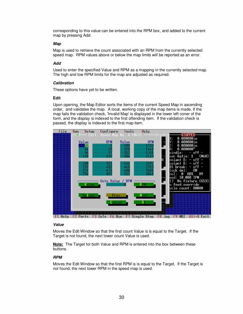
Edit
Upon opening, the Map Editor sorts the items of the current Speed Map in ascending order, and validates the map. A local, working copy of the map items is made. If the map fails the validation check, 'Invalid Map' is displayed in the lower left coner of the form, and the display is indexed to the first offending item. If the validation check is passed, the display is indexed to the first map item.
Value
Moves the Edit Window so that the first count Value is is equal to the Target. If the Target is not found, the next lower count Value is used.
Note: The Target for both Value and RPM is entered into the box between these buttons.
RPM
Moves the Edit Window so that the first RPM is is equal to the Target. If the Target is not found, the next lower RPM in the speed map is used.
31
Reload
Reloads the local working copy of the Speed Map from the main map array. The Edit Window is indexed as when the editor first opened.
Prev
Moves the Edit Window 16 items down. If this is below the first item, it shifts the window to the first Item in the map.
Next
Moves the Edit Window up 16 items, or so that 16 blank entries are shown. Next has no effect if all blank items are shown. If this is above the last item, the last item in the Window will be the last item in the map.
Cancel
Exits the Map Editor without saving changes.
OK
Uploads the working copy of the map to the main map array. The map is then validated, and if it is valid exits the editor. If the map fails to validate, the editor will remain open and position the Edit Window to the first invalid item.
Note: If the map does not validate properly it cannot be used to set spindle speed. It must first be corrected within the Editor, or the original values can be reloaded from disk by cancelling out of the Map Editor, and reloading the configuration file.
Clear
Clears all values from the currently selected map, and sets the RPM limits to default values of 100,000,000 for the low end and 0 for the high end limits.
OK
Exits the menu, accepting all changes. To revert to a previous configuration, this must be re-loaded from disk. There is no provision to reject changes made in the menu.
NOTE: The updated configuration must be saved to preserve any changes between sessions of TurboCNC. Simply exiting TurboCNC, and re-starting it will erase any changes made.
DigiSpeed
Selection of the DigiSpeed Control displays a dialog box to configure the DigiSpeed Control.
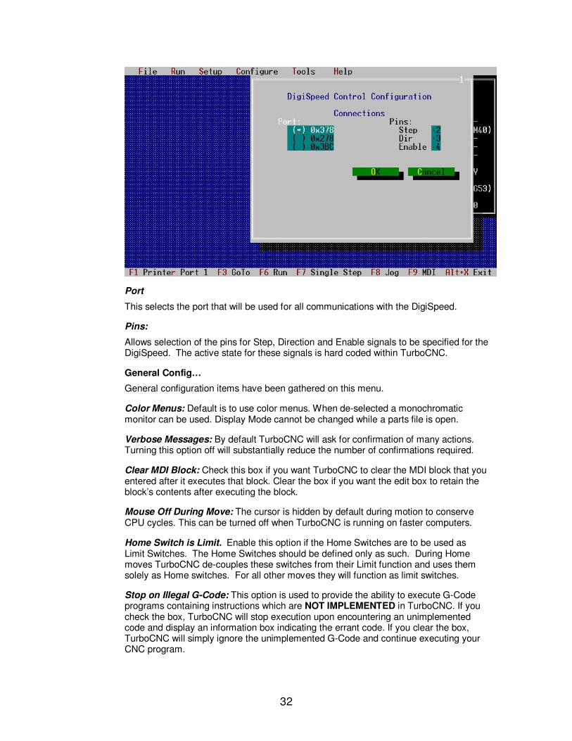
32
Port
This selects the port that will be used for all communications with the DigiSpeed.
Pins:
Allows selection of the pins for Step, Direction and Enable signals to be specified for the DigiSpeed. The active state for these signals is hard coded within TurboCNC.
General Config…
General configuration items have been gathered on this menu.
Color Menus: Default is to use color menus. When de-selected a monochromatic monitor can be used. Display Mode cannot be changed while a parts file is open.
Verbose Messages: By default TurboCNC will ask for confirmation of many actions. Turning this option off will substantially reduce the number of confirmations required.
Clear MDI Block: Check this box if you want TurboCNC to clear the MDI block that you entered after it executes that block. Clear the box if you want the edit box to retain the block’s contents after executing the block.
Mouse Off During Move: The cursor is hidden by default during motion to conserve CPU cycles. This can be turned off when TurboCNC is running on faster computers.
Home Switch is Limit. Enable this option if the Home Switches are to be used as Limit Switches. The Home Switches should be defined only as such. During Home moves TurboCNC de-couples these switches from their Limit function and uses them solely as Home switches. For all other moves they will function as limit switches.
Stop on Illegal G-Code: This option is used to provide the ability to execute G-Code programs containing instructions which are NOT IMPLEMENTED in TurboCNC. If you check the box, TurboCNC will stop execution upon encountering an unimplemented code and display an information box indicating the errant code. If you clear the box, TurboCNC will simply ignore the unimplemented G-Code and continue executing your CNC program.
33
WARNING
!
Clearing the check box and allowing TurboCNC to ignore unimplemented codes can have unintended consequences
TIP: Examine each program which requires you to ignore unimplemented codes and assure that you can safely ignore those unimplemented codes.
Start Inhibit: You may designate an I/O point using Configure I/O lines which is sensed before a CNC program is allowed to execute. You may either abort the CNC program, or wait until the line returns to its inactive state. The default is to wait until the line returns to its inactive state.
Block Inhibit: You may designate an I/O point using Configure I/O lines which is sensed before a block in the CNC program is allowed to execute. You may either abort the CNC program, or wait until the line returns to its inactive state. The default is to wait until the line returns to its inactive state.
Sync Unit Increments: Check this box to direct TurboCNC to synchronize the indices of the Imperial and Metric tables for the currently active axis. For example, assume that you are working with the Imperial jog table, and that the current index value of the Imperial table is 5 and that the current index value of the Metric table is 3. If this box is unchecked and you change the Imperial table index to 9, the Metric table index remains at 5. If the box is checked and you change the Imperial table index to 9, the Metric table index also becomes 9.
Note that this check box affects only the 1-0 keys and that the J and K keys continue to affect ONLY the currently active table so you still have a way to change the distance of ONLY the active axis without affecting any of the others.
Sync Axis Increments: Check this box to direct TurboCNC to synchronize the index of all axes on a given table to the value selected. Note that ONLY the indices into the active table are set. For example, if X is the active axis, Imperial measure is the active table, and you press the “3” key, only the X index will be changed to 3. If however, the Sync Axes box is checked, all axis indices into the Imperial table are set to 3.
Note that this check box affects only the 1-0 keys and that the J and K keys continue to affect ONLY the currently active table so you still have a way to change the distance of ONLY the active axis without affecting any of the others.
These boxes work either in concert, or individually, so checking both boxes will make the jog appear as there is only one index into both tables.
Autoload Tooling File: Default is not to load Fixture and Tool offsets when TurboCNC starts. Enabling this option will attempt to load a tooling file from the Directory specified by Tooloff Dir with the name TURBOCNC and filename extension specified by Tooloff Ext whenever TurboCNC is restarted.
Imperial Precision: sets the number of digits to the right of the decimal point to which the backlash and scale are rounded when the display is set to use Imperial units. Valid values are 0 to 9. A value of 0 will prevent any rounding. This is only used when changing the Native system of Measurement to Imperial.
Metric Precision: sets the number of digits to the right of the decimal point to which the backlash and scale are rounded when the display is set to use SI units. Valid values
34
are 0 to 9. A value of 0 will prevent any rounding. This is only used when changing the Native system of Measurement to Metric.
Note: Selection of too coarse a precision can cause axis scale value rounding to zero. This is checked on entry to and exit from the axis configuration menu.
Default Feed Rate: This option provides a method of setting a default feed rate, to be used when TurboCNC is first started.
Home Speed: A custom homing speed can be set using this option.
Reverse Axis Delay: specifies a delay in milliseconds that all axes will pause before changing direction. Axis delay is used to compensate for machine inertia. Whenever an axis reverses (backlash, arc quadrant, just plain reversal) the machine drives should actually pause for a short time to allow it come to a complete stop. The classic example is a big honkin' gantry machine with the moving mass 6' from the supports.
Arc Factor: This option provides a method of adjusting timing loops used when cutting an arc to the speed of the computer. Values less than one increase the loop speed, those above one decrease it. If you notice lost steps while cutting arcs decrease this value to 0.8 or less.
Machine: Allows be specification of the general type of CNC machine being controlled. This setting affects how TurboCNC interprets RS-274 D Code as follows:
• Radius Lathe: The X axis (cross feed) is used as specified when processing a move. This default plane is set to G18 at startup.
• Diameter lathe: The X axis (cross feed) is halved internally before processing a move. Earlier versions of TurboCNC had a cryptic way of setting this via an AxisPreScale parameter in the ini file. This default plane is set to G18 at startup.
• Mill / Drill: This default plane is set to G17 at startup.
• Custom: Has been defined for customers wishing to incorporate special setup procedures for their systems.
The remainder of the screen allows specification of the location and default extentions for CNC Part Files, Fixtures & Tooling files, and the Point Cloud File.
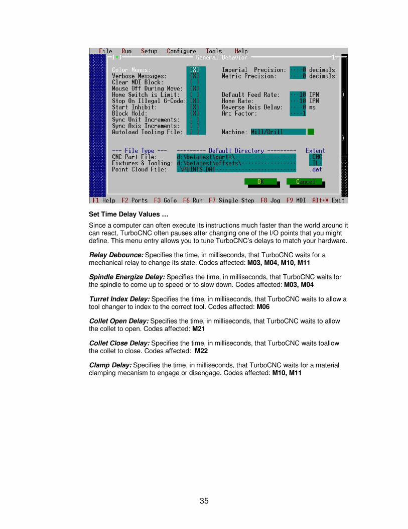
35
Set Time Delay Values …
Since a computer can often execute its instructions much faster than the world around it can react, TurboCNC often pauses after changing one of the I/O points that you might define. This menu entry allows you to tune TurboCNC’s delays to match your hardware.
Relay Debounce: Specifies the time, in milliseconds, that TurboCNC waits for a mechanical relay to change its state. Codes affected: M03, M04, M10, M11
Spindle Energize Delay: Specifies the time, in milliseconds, that TurboCNC waits for the spindle to come up to speed or to slow down. Codes affected: M03, M04
Turret Index Delay: Specifies the time, in milliseconds, that TurboCNC waits to allow a tool changer to index to the correct tool. Codes affected: M06
Collet Open Delay: Specifies the time, in milliseconds, that TurboCNC waits to allow the collet to open. Codes affected: M21
Collet Close Delay: Specifies the time, in milliseconds, that TurboCNC waits toallow the collet to close. Codes affected: M22
Clamp Delay: Specifies the time, in milliseconds, that TurboCNC waits for a material clamping mecanism to engage or disengage. Codes affected: M10, M11
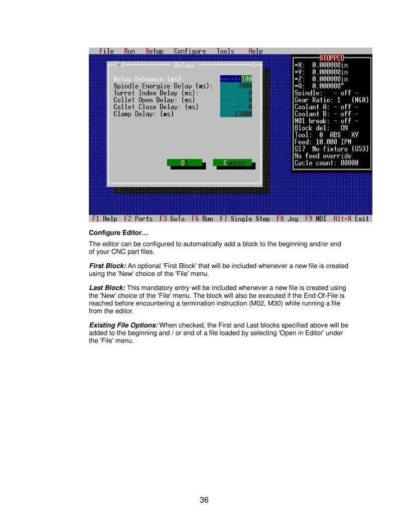
36
Configure Editor…
The editor can be configured to automatically add a block to the beginning and/or end of your CNC part files.
First Block: An optional 'First Block' that will be included whenever a new file is created using the 'New' choice of the 'File' menu.
Last Block: This mandatory entry will be included whenever a new file is created using the 'New' choice of the 'File' menu. The block will also be executed if the End-Of-File is reached before encountering a termination instruction (M02, M30) while running a file from the editor.
Existing File Options: When checked, the First and Last blocks specified above will be added to the beginning and / or end of a file loaded by selecting 'Open in Editor' under the 'File' menu.
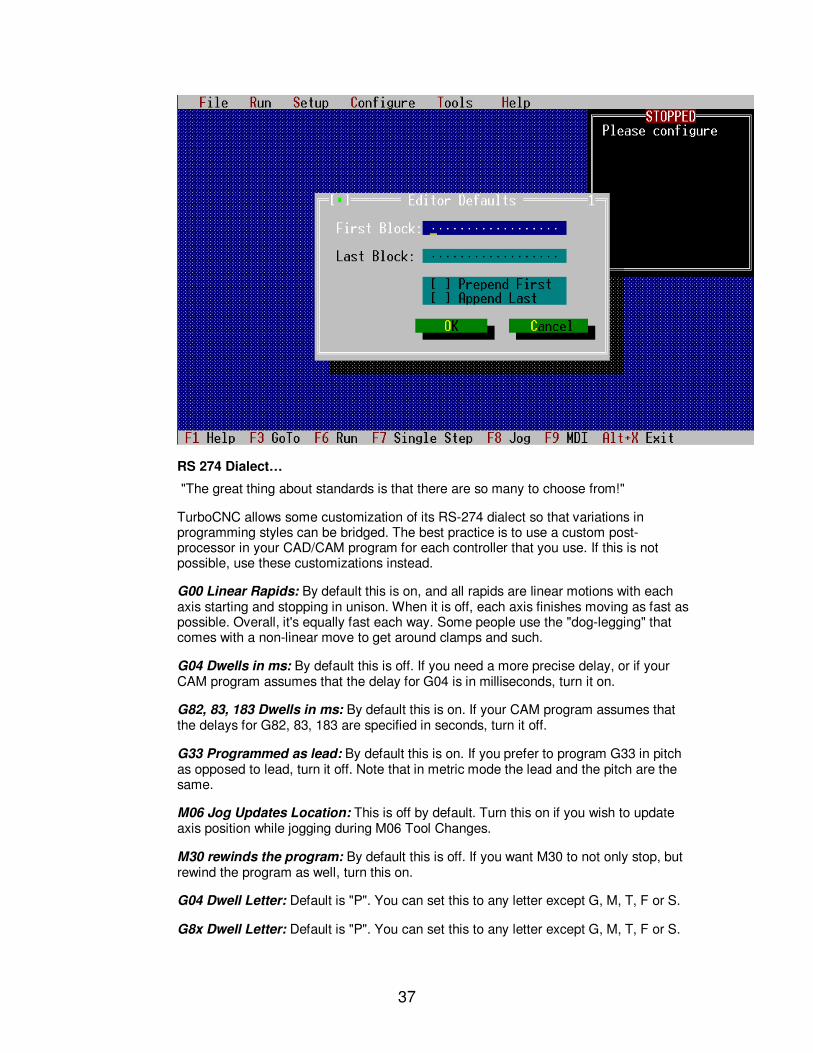
37
RS 274 Dialect…
"The great thing about standards is that there are so many to choose from!"
TurboCNC allows some customization of its RS-274 dialect so that variations in programming styles can be bridged. The best practice is to use a custom post-processor in your CAD/CAM program for each controller that you use. If this is not possible, use these customizations instead.
G00 Linear Rapids: By default this is on, and all rapids are linear motions with each axis starting and stopping in unison. When it is off, each axis finishes moving as fast as possible. Overall, it's equally fast each way. Some people use the "dog-legging" that comes with a non-linear move to get around clamps and such.
G04 Dwells in ms: By default this is off. If you need a more precise delay, or if your CAM program assumes that the delay for G04 is in milliseconds, turn it on.
G82, 83, 183 Dwells in ms: By default this is on. If your CAM program assumes that the delays for G82, 83, 183 are specified in seconds, turn it off.
G33 Programmed as lead: By default this is on. If you prefer to program G33 in pitch as opposed to lead, turn it off. Note that in metric mode the lead and the pitch are the same.
M06 Jog Updates Location: This is off by default. Turn this on if you wish to update axis position while jogging during M06 Tool Changes.
M30 rewinds the program: By default this is off. If you want M30 to not only stop, but rewind the program as well, turn this on.
G04 Dwell Letter: Default is "P". You can set this to any letter except G, M, T, F or S.
G8x Dwell Letter: Default is "P". You can set this to any letter except G, M, T, F or S.
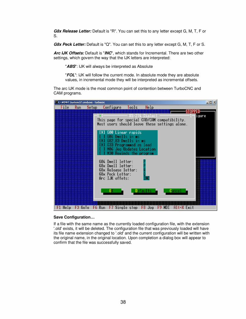
38
G8x Release Letter: Default is "R". You can set this to any letter except G, M, T, F or S.
G8x Peck Letter: Default is "Q". You can set this to any letter except G, M, T, F or S.
Arc IJK Offsets: Default is "INC", which stands for Incremental. There are two other settings, which govern the way that the IJK letters are interpreted:
"ABS": IJK will always be interpreted as Absolute
"FOL": IJK will follow the current mode. In absolute mode they are absolute values, in incremental mode they will be interpreted as incremental offsets.
The arc IJK mode is the most common point of contention between TurboCNC and CAM programs.
Save Configuration…
If a file with the same name as the currently loaded configuration file, with the extension '.old' exists, it will be deleted. The configuration file that was previously loaded will have its file name extension changed to '.old' and the current configuration will be written with the original name, in the original location. Upon completion a dialog box will appear to confirm that the file was successfully saved.
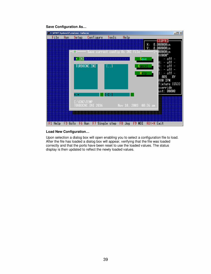
39
Save Configuration As…
Load New Configuration…
Upon selection a dialog box will open enabling you to select a configuration file to load. After the file has loaded a dialog box will appear, verifying that the file was loaded correctly and that the ports have been reset to use the loaded values. The status display is then updated to reflect the newly loaded values.
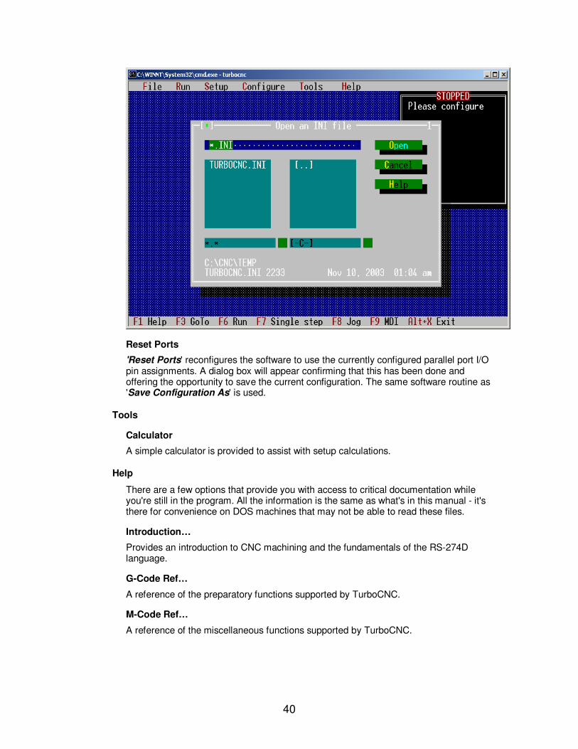
40
Reset Ports
'Reset Ports' reconfigures the software to use the currently configured parallel port I/O pin assignments. A dialog box will appear confirming that this has been done and offering the opportunity to save the current configuration. The same software routine as 'Save Configuration As' is used.
Tools
Calculator
A simple calculator is provided to assist with setup calculations.
Help
There are a few options that provide you with access to critical documentation while you're still in the program. All the information is the same as what's in this manual - it's there for convenience on DOS machines that may not be able to read these files.
Introduction…
Provides an introduction to CNC machining and the fundamentals of the RS-274D language.
G-Code Ref…
A reference of the preparatory functions supported by TurboCNC.
M-Code Ref…
A reference of the miscellaneous functions supported by TurboCNC.

41
Programming…
Provides a reference on the use of the extended programming capabilities of TurboCNC, including variables, expressions (and the implemented mathematical functions), conditional programming (if…then) and operator interaction (ask/say).
What’s New…
This section provides a quick overview of the new features of this version.
Shareware…
This item is a quick review of the principles behind 'Shareware', and instructions on how to register TurboCNC.
About…
Here's a list of the guilty parties who brought you this release of TurboCNC.
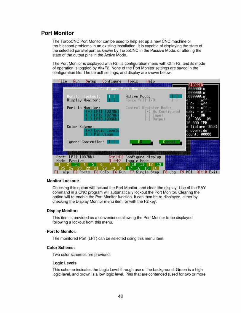
42
Port Monitor
The TurboCNC Port Monitor can be used to help set up a new CNC machine or troubleshoot problems in an existing installation. It is capable of displaying the state of the selected parallel port as known by TurboCNC in the Passive Mode, or altering the state of the output pins in the Active Mode.
The Port Monitor is displayed with F2, its configuration menu with Ctrl+F2, and its mode of operation is toggled by Alt+F2. None of the Port Monitor settings are saved in the configuration file. The default settings, and display are shown below.
Monitor Lockout:
Checking this option will lockout the Port Monitor, and clear ithe display. Use of the SAY command in a CNC program will automatically lockout the Port Monitor. Clearing the option will re-enable the Port Monitor function. It can then be re-displayed, either by checking the Display Monitor menu item, or with the F2 key.
Display Monitor:
This item is provided as a convenience allowing the Port Monitor to be displayed following a lockout from this menu.
Port to Monitor:
The monitored Port (LPT) can be selected using this menu item.
Color Scheme:
Two color schemes are provided.
Logic Levels
This scheme indicates the Logic Level through use of the background. Green is a high logic level, and brown is a low logic level. Pins that are contended (used for two or more
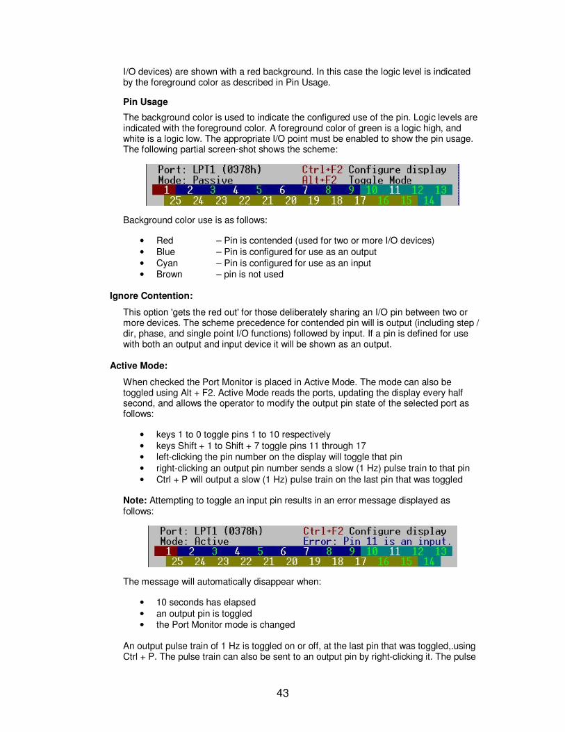
43
I/O devices) are shown with a red background. In this case the logic level is indicated by the foreground color as described in Pin Usage.
Pin Usage
The background color is used to indicate the configured use of the pin. Logic levels are indicated with the foreground color. A foreground color of green is a logic high, and white is a logic low. The appropriate I/O point must be enabled to show the pin usage. The following partial screen-shot shows the scheme:
Background color use is as follows:
• Red – Pin is contended (used for two or more I/O devices) • Blue – Pin is configured for use as an output • Cyan – Pin is configured for use as an input • Brown – pin is not used
Ignore Contention:
This option 'gets the red out' for those deliberately sharing an I/O pin between two or more devices. The scheme precedence for contended pin will is output (including step / dir, phase, and single point I/O functions) followed by input. If a pin is defined for use with both an output and input device it will be shown as an output.
Active Mode:
When checked the Port Monitor is placed in Active Mode. The mode can also be toggled using Alt + F2. Active Mode reads the ports, updating the display every half second, and allows the operator to modify the output pin state of the selected port as follows:
• keys 1 to 0 toggle pins 1 to 10 respectively • keys Shift + 1 to Shift + 7 toggle pins 11 through 17 • left-clicking the pin number on the display will toggle that pin • right-clicking an output pin number sends a slow (1 Hz) pulse train to that pin • Ctrl + P will output a slow (1 Hz) pulse train on the last pin that was toggled
Note: Attempting to toggle an input pin results in an error message displayed as follows:
The message will automatically disappear when:
• 10 seconds has elapsed • an output pin is toggled • the Port Monitor mode is changed
An output pulse train of 1 Hz is toggled on or off, at the last pin that was toggled,.using Ctrl + P. The pulse train can also be sent to an output pin by right-clicking it. The pulse
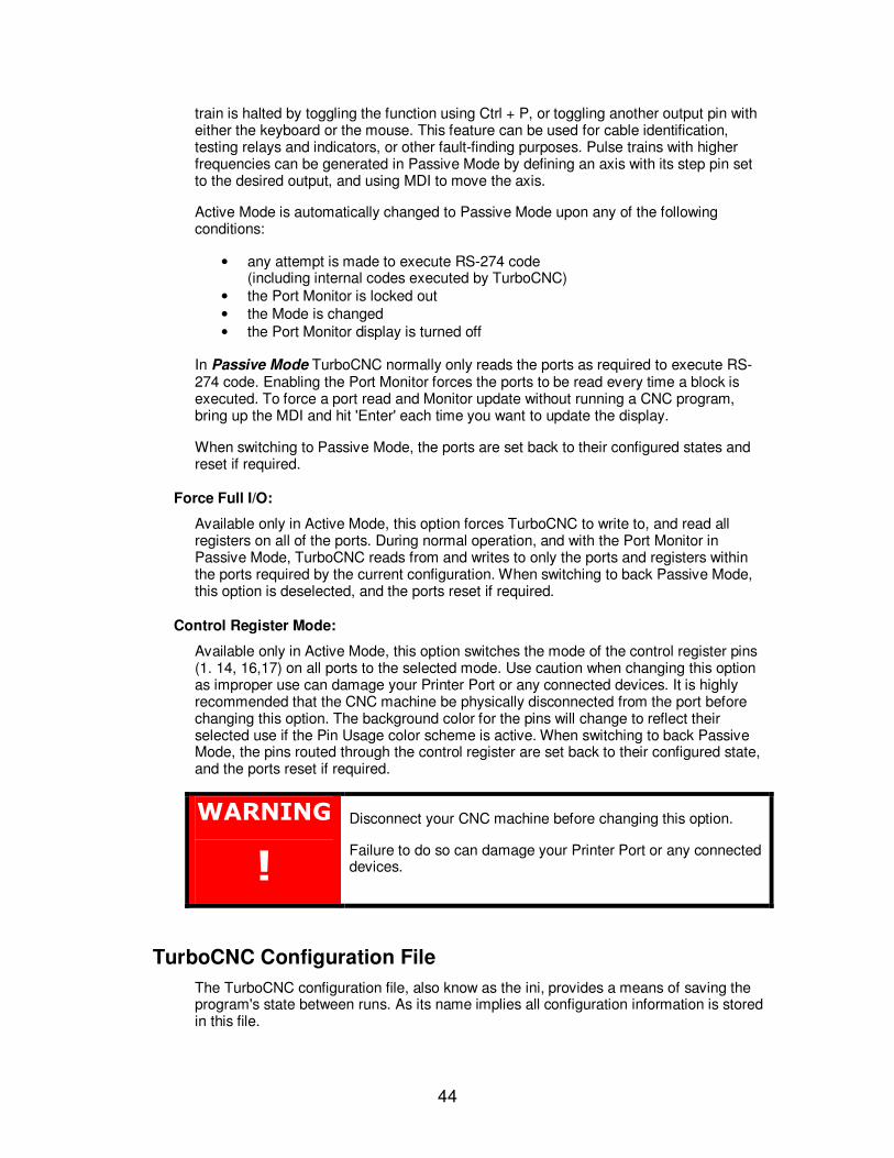
44
train is halted by toggling the function using Ctrl + P, or toggling another output pin with either the keyboard or the mouse. This feature can be used for cable identification, testing relays and indicators, or other fault-finding purposes. Pulse trains with higher frequencies can be generated in Passive Mode by defining an axis with its step pin set to the desired output, and using MDI to move the axis.
Active Mode is automatically changed to Passive Mode upon any of the following conditions:
• any attempt is made to execute RS-274 code (including internal codes executed by TurboCNC)
• the Port Monitor is locked out • the Mode is changed • the Port Monitor display is turned off
In Passive Mode TurboCNC normally only reads the ports as required to execute RS-274 code. Enabling the Port Monitor forces the ports to be read every time a block is executed. To force a port read and Monitor update without running a CNC program, bring up the MDI and hit 'Enter' each time you want to update the display.
When switching to Passive Mode, the ports are set back to their configured states and reset if required.
Force Full I/O:
Available only in Active Mode, this option forces TurboCNC to write to, and read all registers on all of the ports. During normal operation, and with the Port Monitor in Passive Mode, TurboCNC reads from and writes to only the ports and registers within the ports required by the current configuration. When switching to back Passive Mode, this option is deselected, and the ports reset if required.
Control Register Mode:
Available only in Active Mode, this option switches the mode of the control register pins (1. 14, 16,17) on all ports to the selected mode. Use caution when changing this option as improper use can damage your Printer Port or any connected devices. It is highly recommended that the CNC machine be physically disconnected from the port before changing this option. The background color for the pins will change to reflect their selected use if the Pin Usage color scheme is active. When switching to back Passive Mode, the pins routed through the control register are set back to their configured state, and the ports reset if required.
WARNING
!
Disconnect your CNC machine before changing this option.
Failure to do so can damage your Printer Port or any connected devices.
TurboCNC Configuration File
The TurboCNC configuration file, also know as the ini, provides a means of saving the program's state between runs. As its name implies all configuration information is stored in this file.
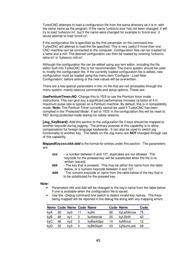
45
TurboCNC attempts to load a configuration file from the same directory as it is in, with the same name as the program. If the name 'turbocnc.exe' has not been changed, it will try to load 'turbocnc.ini', but if the name were changed for example to 'tcnc4.exe', it would attempt to load 'tcnc4.ini'.
If the configuration file is specified as the first parameter on the command line, TurboCNC will attempt to load the file specified. This is very useful if more than one CNC machine can be connected to the computer. Configuration files can be created for a lathe and a mill. The desired configuration can then be loaded by entering 'turbocnc lathe.ini' or 'turbocnc mill.ini'.
Although the configuration file can be edited using any text editor, including the file editor built into TurboCNC this is not recommended. The menu system should be used to modify the configuration file. If the currently loaded configuration file is edited, new configuration must be loaded using the menu item 'Configure / Load New Configuration', before exiting or the new values will be overwritten.
There are a few special parameters in the .ini file that are not accessible through the menu system, mainly obscure commands and setup options. These are:
UsePentiumTimer=NO Change this to YES to use the Pentium timer mode instructions. This can give you a significant performance increase (a factor of 4 in maximum pulse rate is typical) on a Pentium machine. By default, this is in compatibility mode. Note: The Pentium Timer currently cannot be used if TurboCNC has been compiled in the 'Protected Mode'. If set to 'YES' in the configuration this will be reset to 'NO' during protected mode startup for safety reasons.
[Jog_KeyBoard] Add this section to the cofiguration file if keys should be mapped to another keycode during jogging. The primary purpose of this capability is to allow compensation for foreign language keyboards. It can also be used to switch jog functionality to another key. The labels on the Jog menu are NOT changed through use of this capability.
MappedKeyxxx=kkk:ddd is the format for entries under this section. The parameters are:
xxx – a number between 0 and 127, duplicates are not allowed. The keycode for the pressed key will be substituted when the file is re- written (saved).
kkk - The key that is pressed. This may be either the name from the table below, or a numeric keycode between 0 and 127.
ddd - The numeric keycode or name from the table below of the key that is to be substituted for the pressed key.
Note:
• Parameters kkk and ddd will be changed to the key's name from the table below if one is available when the configuration file is saved.
• Use the –Debug command line switch to detect invalid key names. The Keys being mapped will be reported in the debug file along with any mapping errors.
Name Code Name Code Name Code Name Code
kyA 30 ky0 11 kyAlt 56 kyLeftArrow 75
kyB 48 ky1 2 kyAsterisk 55 kyLShift 42
kyC 46 ky2 3 kyBackSpc 14 kyMinus 12
kyD 32 ky3 4 kyBkSlash 43 kyNumLock 69
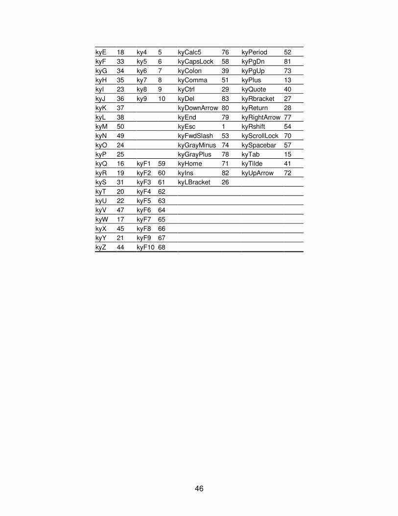
46
kyE 18 ky4 5 kyCalc5 76 kyPeriod 52
kyF 33 ky5 6 kyCapsLock 58 kyPgDn 81
kyG 34 ky6 7 kyColon 39 kyPgUp 73
kyH 35 ky7 8 kyComma 51 kyPlus 13
kyI 23 ky8 9 kyCtrl 29 kyQuote 40
kyJ 36 ky9 10 kyDel 83 kyRbracket 27
kyK 37 kyDownArrow 80 kyReturn 28
kyL 38 kyEnd 79 kyRightArrow 77
kyM 50 kyEsc 1 kyRshift 54
kyN 49 kyFwdSlash 53 kyScrollLock 70
kyO 24 kyGrayMinus 74 kySpacebar 57
kyP 25 kyGrayPlus 78 kyTab 15
kyQ 16 kyF1 59 kyHome 71 kyTilde 41
kyR 19 kyF2 60 kyIns 82 kyUpArrow 72
kyS 31 kyF3 61 kyLBracket 26
kyT 20 kyF4 62
kyU 22 kyF5 63
kyV 47 kyF6 64
kyW 17 kyF7 65
kyX 45 kyF8 66
kyY 21 kyF9 67
kyZ 44 kyF10 68
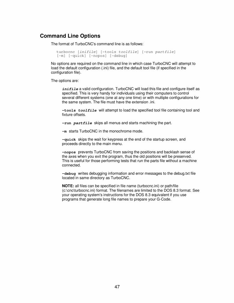
47
Command Line Options
The format of TurboCNC's command line is as follows:
turbocnc [inifile] [-tools toolfile] [-run partfile] [-m] [-quick] [-nopos] [-debug]
No options are required on the command line in which case TurboCNC will attempt to load the default configuration (.ini) file, and the default tool file (if specified in the configuration file).
The options are:
inifile a valid configuration. TurboCNC will load this file and configure itself as specified. This is very handy for individuals using their computers to control several different systems (one at any one time) or with multiple configurations for the same system. The file must have the extension .ini.
-tools toolfile will attempt to load the specified tool file containing tool and fixture offsets.
-run partfile skips all menus and starts machining the part.
-m starts TurboCNC in the monochrome mode.
-quick skips the wait for keypress at the end of the startup screen, and proceeds directly to the main menu.
-nopos prevents TurboCNC from saving the positions and backlash sense of the axes when you exit the program, thus the old positions will be preserved. This is useful for those performing tests that run the parts file without a machine connected.
-debug writes debugging information and error messages to the debug.txt file located in same directory as TurboCNC.
NOTE: all files can be specified in file name (turbocnc.ini) or path/file (c:\cnc\turbocnc.ini) format. The filenames are limited to the DOS 8.3 format. See your operating system's instructions for the DOS 8.3 equivalent if you use programs that generate long file names to prepare your G-Code.
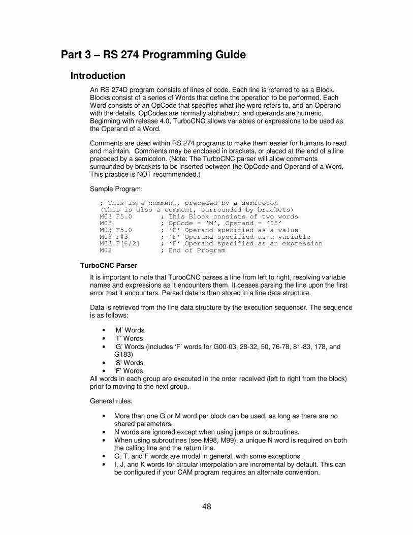
48
Part 3 – RS 274 Programming Guide
Introduction
An RS 274D program consists of lines of code. Each line is referred to as a Block. Blocks consist of a series of Words that define the operation to be performed. Each Word consists of an OpCode that specifies what the word refers to, and an Operand with the details. OpCodes are normally alphabetic, and operands are numeric. Beginning with release 4.0, TurboCNC allows variables or expressions to be used as the Operand of a Word.
Comments are used within RS 274 programs to make them easier for humans to read and maintain. Comments may be enclosed in brackets, or placed at the end of a line preceded by a semicolon. (Note: The TurboCNC parser will allow comments surrounded by brackets to be inserted between the OpCode and Operand of a Word. This practice is NOT recommended.)
Sample Program:
; This is a comment, preceded by a semicolon (This is also a comment, surrounded by brackets) M03 F5.0 ; This Block consists of two words M05 ; OpCode = ‘M’, Operand = ‘05’ M03 F5.0 ; ‘F’ Operand specified as a value M03 F#3 ; ‘F’ Operand specified as a variable M03 F[6/2] ; ‘F’ Operand specified as an expression M02 ; End of Program
TurboCNC Parser
It is important to note that TurboCNC parses a line from left to right, resolving variable names and expressions as it encounters them. It ceases parsing the line upon the first error that it encounters. Parsed data is then stored in a line data structure.
Data is retrieved from the line data structure by the execution sequencer. The sequence is as follows:
• ‘M’ Words • ‘T’ Words • ‘G’ Words (includes ‘F’ words for G00-03, 28-32, 50, 76-78, 81-83, 178, and
G183)
• ‘S’ Words
• ‘F’ Words All words in each group are executed in the order received (left to right from the block) prior to moving to the next group.
General rules:
• More than one G or M word per block can be used, as long as there are no shared parameters.
• N words are ignored except when using jumps or subroutines. • When using subroutines (see M98, M99), a unique N word is required on both
the calling line and the return line. • G, T, and F words are modal in general, with some exceptions. • I, J, and K words for circular interpolation are incremental by default. This can
be configured if your CAM program requires an alternate convention.

49
• Circular and helical interpolations are called using I, J, and K, or R notation, for any combination of axes. The plane selector (G17-19) should be called beforehand.
All moves involving more than one axis are interpolated, even in rapid. On some mill controls, the Z-axis will always retract first before moving X and Y. Not so for this program.
Angular axes are always driven in degrees modulo 360. For example, if a table is at 10deg and you command it to 350deg, it will go around "the long way". If you commanded it to -10deg instead, it will zip over to -10deg "the short way" and then report the current position as 350deg. Commanding a +720deg incremental move will index the table around two full revs, but the coordinate will remain unchanged since it is always set to somewhere between 0 and 360 only.
If you use IPR feeds through a G95 call, use the S word to set the spindle speed in RPM from which the feed rate will be calculated first. Alternately, call M50 to read the spindle speed if you have an encoder configured. The code to control the spindle directly from the computer is "empty" - this is so the users can add it themselves.
Metric distances, feeds, etc, are in mm and mm/min or mm/rev as appropriate.
Dwells are programmed in integer seconds by default, using the P word. This is configurable. Exception: The dwells for G82, G78, and G83 are in milliseconds.
The feed rate in an interpolated move is based on the actual distance covered by each of the linear axes involved. If there are none, then the first angular axis on the list is assigned the feed rate (degrees/sec).
If you hit ANY limit switch, the machine won't move again until you either disable the switch, or use Jog mode to back away. These are for preventing "going off the rails" only - use the home switches for calibrating the machine.
When block delete is active, a line with a "/" as the first character is skipped. Any word in a line that is preceded by a "/" is not executed. For example
G01 X1.234 F5 /F0.5
In block delete mode, the F5 is read as the feed rate and the second F word is ignored. In normal mode however, the F0.5 will override F5 on this line, and so the feed rate will be much slower.
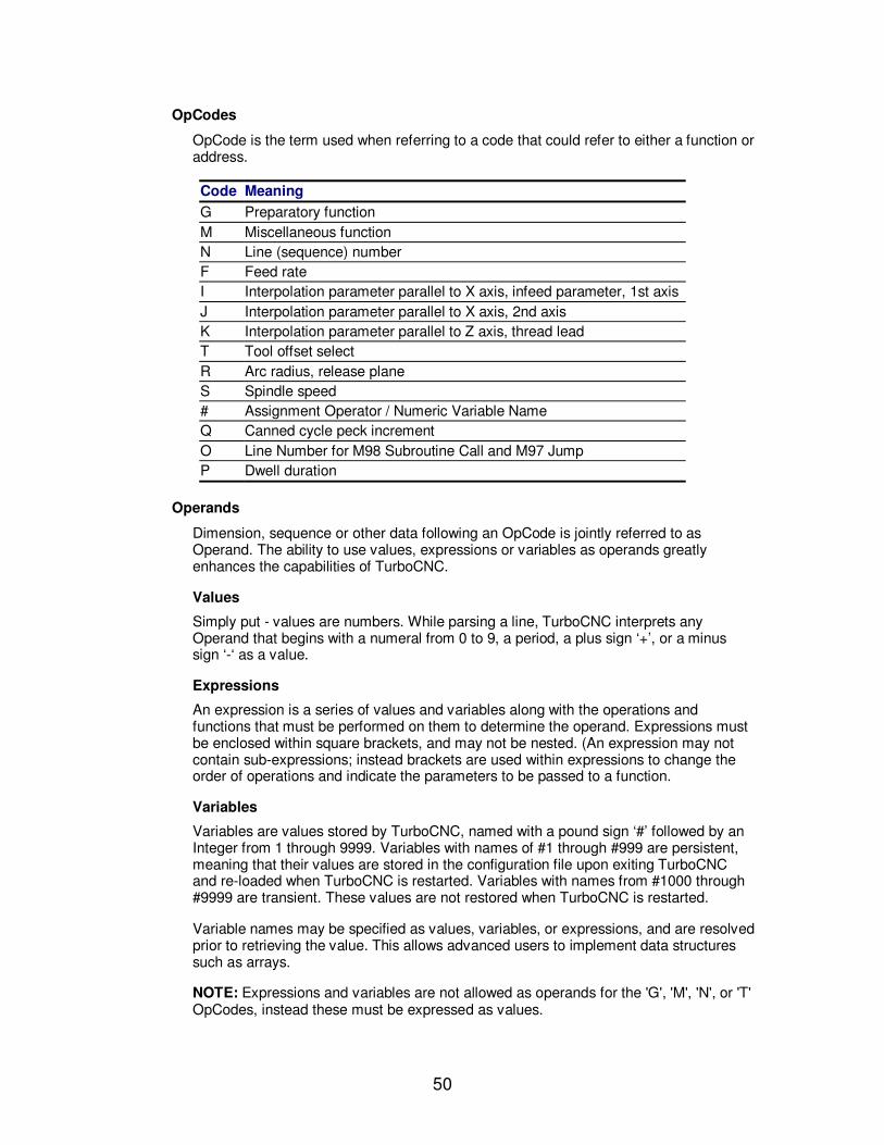
50
OpCodes
OpCode is the term used when referring to a code that could refer to either a function or address.
Code Meaning
G Preparatory function
M Miscellaneous function
N Line (sequence) number
F Feed rate
I Interpolation parameter parallel to X axis, infeed parameter, 1st axis
J Interpolation parameter parallel to X axis, 2nd axis
K Interpolation parameter parallel to Z axis, thread lead
T Tool offset select
R Arc radius, release plane
S Spindle speed
# Assignment Operator / Numeric Variable Name
Q Canned cycle peck increment
O Line Number for M98 Subroutine Call and M97 Jump
P Dwell duration
Operands
Dimension, sequence or other data following an OpCode is jointly referred to as Operand. The ability to use values, expressions or variables as operands greatly enhances the capabilities of TurboCNC.
Values
Simply put - values are numbers. While parsing a line, TurboCNC interprets any Operand that begins with a numeral from 0 to 9, a period, a plus sign ‘+’, or a minus sign ‘-‘ as a value.
Expressions
An expression is a series of values and variables along with the operations and functions that must be performed on them to determine the operand. Expressions must be enclosed within square brackets, and may not be nested. (An expression may not contain sub-expressions; instead brackets are used within expressions to change the order of operations and indicate the parameters to be passed to a function.
Variables
Variables are values stored by TurboCNC, named with a pound sign ‘#’ followed by an Integer from 1 through 9999. Variables with names of #1 through #999 are persistent, meaning that their values are stored in the configuration file upon exiting TurboCNC and re-loaded when TurboCNC is restarted. Variables with names from #1000 through #9999 are transient. These values are not restored when TurboCNC is restarted.
Variable names may be specified as values, variables, or expressions, and are resolved prior to retrieving the value. This allows advanced users to implement data structures such as arrays.
NOTE: Expressions and variables are not allowed as operands for the 'G', 'M', 'N', or 'T' OpCodes, instead these must be expressed as values.
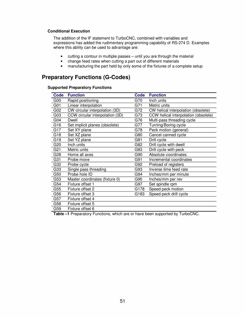
51
Conditional Execution
The addition of the IF statement to TurboCNC, combined with variables and expressions has added the rudimentary programming capability of RS-274 D. Examples where this ability can be used to advantage are:
• cutting a contour in multiple passes – until you are through the material • change feed rates when cutting a part out of different materials • manufacturing the part held by only some of the fixtures of a complete setup
Preparatory Functions (G-Codes)
Supported Preparatory Functions
Code Function Code Function
G00 Rapid positioning G70 Inch units G01 Linear interpolation G71 Metric units G02 CW circular interpolation (3D) G72 CW helical interpolation (obsolete) G03 CCW circular interpolation (3D) G73 CCW helical interpolation (obsolete) G04 Dwell G76 Multi-pass threading cycle G16 Set implicit planes (obsolete) G77 Turning/Boring cycle G17 Set XY plane G78 Peck motion (general) G18 Set XZ plane G80 Cancel canned cycle G19 Set YZ plane G81 Drill cycle G20 Inch units G82 Drill cycle with dwell G21 Metric units G83 Drill cycle with peck
G28 Home all axes G90 Absolute coordinates G31 Probe move G91 Incremental coordinates G32 Probe cycle G92 Preload of registers G33 Single pass threading G93 Inverse time feed rate G50 Probe hole ID G94 Inches/mm per minute G53 Master coordinates (fixture 0) G95 Inches/mm per rev G54 Fixture offset 1 G97 Set spindle rpm G55 Fixture offset 2 G178 Speed peck motion G56 Fixture offset 3 G183 Speed peck drill cycle G57 Fixture offset 4 G58 Fixture offset 5 G59 Fixture offset 6
Table –1 Preparatory Functions, which are or have been supported by TurboCNC.
52
G00 Rapid Positioning
Function: Moves to a new position as fast as possible.
Syntax: G00 [axis words]
Example:
G00 X1.2 Y0.3 ; Moves to (1.2, 0.3)
Notes:
• Only the axes called out on the line will be moved. • In a minor departure from the Standard, G00 is interpolated by default so that
axes start and stop in unison and that a straight line is tracked between both positions. See the configuration section on how to change this.
• In Absolute Mode the coordinates given are absolute axis positions. • In Incremental Mode the coordinates given are signed distances from the
current positions. • The absolute maximum speed is software limited to 2000 inches per minute (50
800 mm/min in metric) regardless of the physical limitations of the machine. • The actual speed and ramping action of motion is chosen so as not to exceed
the least capable moving axis.
G01 Linear Interpolation
Function: Moves to a new position linearly at some feed rate.
Syntax: G01 [axis words] [optional feed word]
Example:
G01 X1.2 Y0.3 F3.0 ; Moves to (1.2,0.3) at 3 units/minute
Notes:
The feed rate is calculated as follows by the program:
• A single linear axis feeds in units/minute or units/revolution depending on active modes. In G93 mode (inverse time feed rate) each move takes a constant amount of time to complete.
• A single angular axis feeds in degrees/second. • Multiple linear axes feed according to the "true distance" of the move in
units/rev or units/minute. • Multiple angular axes feed in deg/sec for the first axis on the line, all others
follow such that they start and stop in unison. • Mixed angular and linear axes follow the rules for linear axes only, the angular
axes will follow such that they start and stop in unison. • No axis will ever go faster than the max speed established in setup. • The Feed Rate Override modifies the feed rate, if enabled. • Feed words are modal. If there is no feed word in the current block, the last
feed word read will be used.
G02 CW circular interpolation (3D)
Function: Moves to a new position in a clockwise circular arc. The arc center is specified with signed offsets from the start position or implicitly by the magnitude of the radius.
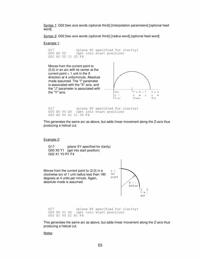
53
Syntax 1: G02 [two axis words (optional third)] [interpolation parameters] [optional feed word]
Syntax 2: G02 [two axis words (optional third)] [radius word] [optional feed word]
Example 1:
G17 (plane XY specified for clarity) G00 X0 Y0 (get into start position) G02 X2 Y0 I1 J0 F4
Moves from the current point to (0,0) in an arc with its center at the current point + 1 unit in the X direction at 4 units/minute. Absolute mode assumed. The "I" parameter is associated with the "X" axis, and the "J" parameter is associated with the "Y" axis.
G17 (plane XY specified for clarity) G00 X0 Y0 Z0 (get into start position) G02 X2 Y0 Z1 I1 J0 F4
This generates the same arc as above, but adds linear movement along the Z-axis thus producing a helical cut.
Example 2:
G17 (plane XY specified for clarity) G00 X0 Y1 (get into start position) G02 X1 Y0 R1 F4
Moves from the current point to (2,0) in a clockwise arc of 1 unit radius less than 180 degrees at 4 units per minute. Again, absolute mode is assumed.
G17 (plane XY specified for clarity) G00 X0 Y1 Z0 (get into start position) G02 X1 Y0 Z1 R1 F4
This generates the same arc as above, but adds linear movement along the Z-axis thus producing a helical cut.
Notes:
54
I and J are incremental by default. (NOTE: In rev 3.00g and prior, the I and J word were absolute in absolute mode, incremental in incremental mode. This is no longer the case. See the dialect customizations section above for information on how to change this)
Using a negative radius chooses the arc greater than 180 degrees that crosses both points, a positive radius takes the arc that is 180 degrees or less. The program will stop with a warning if you have a radius that is impossible. The R form is notoriously inaccurate for arcs very close to 180 degrees.
The sense and 2D plane of the arc is set by the current plane mode. Axis words appropriate to the plane must be included i.e.:
• G17 – XY plane, X and Y [offsets I, J] [linear Z axis] • G18 – ZX plane, X and Z [offsets I, K] [linear Y axis] • G19 – ZY plane, Y and Z [offsets J, K] [linear X axis]
The order of parameters on the program line is not important. Use the I word for offset in the X direction, J for offset in Y, and K for offset in Z to describe the relationship of center position from the starting point. See the plane selector information section for more detail.
Start, destination and offset information for arcs can be specified using expressions, For example:
G02 X[3.5 + COS(135)] Y[4.0 + SIN(135)] I[3.5-(2.5 * COS(135))] J[4.0-(2.5 * SIN(135))]
This block assumes absolute mode for IJK, and has been split over two lines on this page. The arc lies on a circle with its center located at (3.5, 4.0), has a radius of 2.5 units, and the block will cause movement describing an arc clockwise from the current position to 135 degrees.
Full Circles:
If the destination letters are omitted, or, the distance between the start and end points of the arc is less than one full step for each axis on the plane, a full circle will be described by the tool motion. You must specify the move using the IJK form when omitting the axis end points for a full circle move, as the R form is indeterminate for these cases.
Feed rates in an arc:
Feed rates are applied along the helix (i.e.: cutter path) during a three dimensional move.
If the specified feed rate is higher than either the computer, or the CNC machine, is capable of achieving the feed rate will then be clamped at the system's maximum capability. The feed rate is clamped at the lower of that specified by Mav Vel, or that sustainable by the acceleration available at the axes. The formula used to determine the maximum feed rate based on acceleration is dependent upon the radius of the arc and is computed as follows:
f = sqrt((Accel * Radius) / sqrt(2)) Accel is the product of Accel and Scale on the axis menu
The following chart shows the effect of radius on the maximum feed rate for various accelerations.
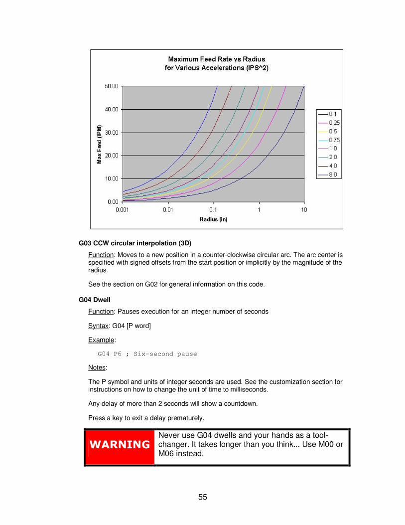
55
G03 CCW circular interpolation (3D)
Function: Moves to a new position in a counter-clockwise circular arc. The arc center is specified with signed offsets from the start position or implicitly by the magnitude of the radius.
See the section on G02 for general information on this code.
G04 Dwell
Function: Pauses execution for an integer number of seconds
Syntax: G04 [P word]
Example:
G04 P6 ; Six-second pause
Notes:
The P symbol and units of integer seconds are used. See the customization section for instructions on how to change the unit of time to milliseconds.
Any delay of more than 2 seconds will show a countdown.
Press a key to exit a delay prematurely.
WARNING
Never use G04 dwells and your hands as a tool-changer. It takes longer than you think... Use M00 or M06 instead.

56
!
G16 Set implicit planes
Obsolete Function: Set circular and helical interpolation plane to be defined implicitly by block
Background:
The original TurboCNC through rev 3.1a allowed an implicit plane specification in which the first two axes called out on a G02/03 line became the plane of action for the interpolation. In this mode, only the I and J parameters were used. The "I" offset was applied to the first axis on the line, the "J" axis to the second. This affected G02, G03, G72, and G73. For the helical moves, the third axis was always the direction of linear travel.
The idea here was to allow unusual interpolation schemes to be used on machines with many axes or non-conventional axis names.
This code is no longer supported! Use the conventional plane selectors (G17 through 19) for defining arc planes in new programs.
G17-19 Set current 2D plane
G17 Function: Sets plane for circular and helical interpolation to X-Y.
G18 Function: Sets plane for circular and helical interpolation to Z-X.
G19 Function: Sets plane for circular and helical interpolation to Z-Y.
Syntax: none
Notes:
The rule for planes and how to determine the sense of CW vs. CCW is (from the Standard):
"Arcs shall be CW or CCW as viewed in the negative direction of the out-of- plane axis in a standard right hand axis system."
Translation: For mill users, if +X is rightward and +Y is toward the back of the machine (tool motion relative to the work!) and +Z is up, then as you look down (-Z) at the table in G17 mode, arcs will look CW or CCW as you'd expect.
For lathe users, if +Z is away from the headstock, and +X is increasing diameter, then in G18 mode CW/CCW will look reversed if you look down at the slide. This is because in this right hand system, -Y is looking up.
57
G20 Inch units
Function: Sets distance unit to inches.
Syntax: none
Notes:
All coordinates and feed rates will be in inches after this command is executed.
G20 and G21 are identical to G70 and G71.
Saving the .ini file while in either mode makes it modal on startup.
G21 Metric units
Function: Sets distance unit to mm.
Syntax: none
Notes:
All coordinates and feed rates will be in millimeters after this command is executed.
G20 and G21 are identical to G70 and G71.
Saving the .ini file while in either mode makes it modal on startup.
TurboCNC stores and uses all values in Imperial measure internally. This will cause very small conversion errors (> 0.00001 inch or 0.000004 mm) to show up on the display in Metric mode.
G28 Home all axes
Function: Drive each axis with a home switch to re-establish position.
Syntax: G28 [optional feed word]
Notes:
Each axis with a home switch will be driven to the home position where its coordinates will be reset. G28 is often used to recalibrate your machine during long cycle times where temperature creep or other position loss sources are a factor.
An axis must have a physical home switch to be "homed" in this context.
The mechanism is as follows:
• Each axis with a home switch moves simultaneously in the home direction. • As each home switch goes active, each axis will stop • When they are all on their switches, each axis will simultaneously move in the
opposite direction • As each home switch goes inactive, each axis will stop again • Each axis position is re-established as configured in machine coordinates
The speed of the homing action is set by the modal F word and current feed mode.
It is not necessary to be in machine coordinates to initiate homing.
58
If no axis has a home switch, an error warning will be issued.
G31 Probe move
Function: Move to a position until the probe input goes active
Syntax: G31 [axis words] [optional feed word]
Example:
G31 Z-4.0 F10
Move to Z -4.0 at 10 IPM, until the probe input goes active.
Notes:
The move works in a similar fashion to G01. If the probe hits something, the machines stops and write the position to the file POINTS.DAT in the same directory as the executable.
If nothing is hit, the move ends at the position specified and no data is written.
Use G31 to get off of the part again if you need to, the program only accepts the inactive to active transition as valid input.
WARNING
!
Note that if you move twice in the same direction with G31 or any other codes, you can smash your probe! Good practice is to design your probe with built in over travel that activates the panic stop input if exceeded.
G32 Probe cycle
Function: Repetitive probing to digitally scan a 2D or 3D surface
Syntax: G32 [axis bound 1] [bound 2] [optional bound 3] [discretization] [optional feed word]
Example:
G00 X0 Y0 Z0 ; get into position G32 X1 Y1 Z-1 I0.250 F10
Moves X from 0 to 1 by .250 increments, each time moving Y from 0 to 1 by 0.250 increments. Z will plunge from 0 to -1 and back to 0 again, stopping and writing the position to disk for each probe strike on the downward stroke. Absolute mode assumed.
Notes:
• This is 2 or 3-axis general, so the last axis cycles the most and the first axis only once through a number of points determined by the discretization distance. You need at least two axes moving to scan. Using a single axis will move in the same way as G31.
• The digitizing scheme is of the "bed of nails" variety, e.g.: straight up and down in the last axis on the line.
59
• The output is written to a scan file in the same directory as the executable, with a filename of SURFSCAN.DAT.
WARNING
!
Rounding error may prevent the last row or column from being scanned. Add a small amount to the bounding distance to avoid this: G32 X1 Y1 Z-1 I0.250 F10 ;X1,Y1 ;may or may not be reached G32 X1.001 Y1.001 Z-1 I0.250 F10 ;This is better
G33 Single pass threading
Function: Makes a single threading motion in sync with the spindle.
Syntax: G33 [axis coord] [lead parameter]
Example:
G33 Z-1.25 K0.050
Assuming inches and absolute mode, this threads 20 TPI to a shoulder at Z = -1.25
Notes:
A spindle index pulse must be enabled and present for this to work. See the section on hooking up a spindle encoder for details on how to do this.
The program will time-out after 5 seconds of spindle pulse inactivity. Similarly, the operation will be halted if the speed detected at the spindle is greater than 5000 rpm. This offers a measure of protection against the failure modes of signal noise, signal loss, or stalls.
K is the lead parameter for the Z-axis, I is for X, and J is for Y. See the dialect customization section if you want to specify pitches instead or change K for some other letter.
Multiaxis Operations: You can thread up to three axes simultaneously for tapered threading or unusual machining situations like gear hobbing. The lead and distance should work out to an equal number of revolutions for each. An axis with no lead specified will move at the regular feed rate.
Allow a few revs of "lead in" for the axis to synchronize. You need a lot of acceleration to keep up with the changes in velocity. If the axis falls behind and can't keep up, the program will stop and warn you.
The synchronization is always from the start point for each pass, so for multi-start threads, offset the start position by some fraction of the thread lead. For 30 degree infeed, change the start position on each pass along a 30 deg vector.
See also G76, multi-pass threading.
G50 Probe hole ID
Function: Finds the center of a hole using a touch probe
Syntax: G50 [optional feed word]
Notes:
60
Put the probe inside the hole approximately in the center, and call G50 from within a program or the MDI window.
This is an orthogonal six hit probing algorithm - clock positions struck are 12,6,9,3,12,6 in the XY plane as you normally view the part on a mill. You must have a touch probe installed and the probe input configured for this to work. Hole probing is always in the XY plane.
The speed of G50 probing is given by the modal feed word and mode.
Watch out for keyways and similar things that can throw you off. Use this command for auto-setting boring operations or fixture locating where some part-to-part variation is expected and you need to locate to a hole center exactly.
G53 Change to master coordinates
Function: Change to master coordinates, also known as fixture 0.
Syntax: none
Notes:
In master coordinate mode, no fixture offset is active. If tool 0 is set as well, you are in Machine Coordinates. These are the coordinates that are active while homing, and in setting up feed screw error compensation.
At startup, you are in machine coordinates by default. No offsets are active in machine coordinate mode.
G54-G59 Change fixture offset
Function: Change to a new fixture offset, from 1 (G54) to 6 (G59)
Syntax: none
Notes:
When the fixture offset is changed, all the tool offsets follow. Machining in a new offset mode is like having "zero" in a new place on your machine.
The coordinates you see on the screen are the master coordinates + the fixture offset in use + the tool offset in use. Tool 0 is no tool offset, G53 is no fixture offset.
The most common use for these is multiple fixtures on the same table. For example, home the machine in G53. Your usual 6" vise can be "zeroed" in G54 mode, and the center of a 5C collet vise, say, can be zero in G55. Changing modes puts you in a new coordinate system painlessly and allows different classes of parts to be machined on a large table.
G53-59 are modal. A fixture offset stays in effect until a new one is commanded.
G70 Inch mode
Function: Sets distance unit to inches.
Syntax: none
Notes:
61
Same as G20.
G71 Metric mode
Function: Sets distance unit to mm.
Syntax: none
Notes:
Same as G21.
G72 CW helical interpolation
Obsolete Function: Was similar to G02, but allowed a third axis to travel linearly as well.
Background:
Originally (through version 3.1a), TurboCNC used G02 and G03 as strictly 2D arc functions, and a separate G word for helical interpolation. This was unnecessary, and violated the Standard.
This function is no longer supported. Use G02 with a third axis callout instead.
G73 CCW helical interpolation
Obsolete Function: Was similar to G03, but allowed a third axis to travel linearly as well.
This function is no longer supported. Use G03 with a third axis callout instead.
G76 Multi-pass threading
Function: Machines an OD or ID thread completely on a lathe.
Syntax: G76 [X coord] [Z coord] [K height] [D first pass] [F lead] [A tool nose angle]
Example:
G76 X-0.210 Z-1.25 K.040 D0.003 F0.050 A60
Assuming inches and absolute radius mode, this threads 1/2-20 TPI UNF to Z = -1.25 completely.
Notes:
The starting point is returned to after each pass. The X location of the starting point determines the back out distance after each cut it complete.
The A word specifies the included tool nose angle, which is customarily 60 degrees for common threads. The tool will automatically feed on an angle of 1/2 A. If A is not specified, it defaults to 0, which produces a radial infeed.
K, D and F are always positive, regardless of the actual orientation or "hand" of the thread.
Each successive pass will remove the same area of material as the first pass did, in order to equalize the torque load. This is standard, and helps to improve the finish.
62
G77 Turning/Boring/Milling Cycle
Function: Turning with multiple passes, infeeding by an amount set by the I word.
Syntax: G77 [repetitive axis] [infeed axis] [feed per pass] [optional feed rate]
Example:
G77 Z-1.250 X0.250 I0.050 F5.0
On a radius programmed lathe that cuts to an X coordinate of 0.250, back and forth in Z from current position to -1.250, feeding in 0.050 each pass and cutting at 5 units/min. Here's the actual motion sequence for on the above, assuming the tool started at 0,0:
X0.050 slowly Z-1.250 slowly X-0.025 slowly Z0 rapidly X0.100 slowly Z-1.250 slowly etc...
Notes:
The order of the operands defines the motion. The back-and-forth action will occur from the current position of the first axis on the line to the position specified. The second axis called out will eventually reach the position specified by feeding in increments of I each pass.
The sign of I is unimportant. Always use I for the infeed, no matter what other axes are being used.
Infeed is applied to the second axis on the line. Creative use of this command can be made for fly cutting / slab-milling or cutting deep blind slots on mills or trimming the edges of stock.
After each pass, the control "backs off" by 1 1/2 times the infeed. So if you're boring, make sure you have enough clearance for the bar.
If the infeed doesn't divide into an even number of passes, a small finishing pass will be taken.
G78 Peck Motion Cycle
Function: Feeds to a position on an axis, incrementally in "pecks" with a full rapid retract.
Syntax: G78 [axis of action] [peck distance] [optional feed word] [optional dwell]
Example:
G78 Z-2.000 I0.100 F2.0
Moves from the current position to Z=-2.000 at 2 units/min 0.100 units at a time (retracts to original Z each time).
Notes:
The sign of I is unimportant, but this code is always used with I, regardless of the actual letter for the moving axis.
63
If you put in a dwell parameter with the P operator, a dwell in milliseconds will be taken at the end of each pass.
G78 Z-2.000 I-0.100 F2.0 P100
does the same as the previous example, but with a tenth of a second dwell at the bottom of the hole. This helps the tool life considerably in some cases. After each peck and retract, the tool will rapid to 10% of the peck increment before the last stop, and then feed in again. The letter and units used for the dwell are the same as for the G8x cycles if user configured.
This command is single axis only.
A good use of this code is "peck turning" plastic on a lathe to keep the chips short.
G80 Cancel drill cycle
Function: Cancel canned drill cycle
Syntax: none
Notes:
It's good practice, but not strictly necessary, to put this code after a series of the G81, G82, or G83 drill cycles. It clears the canned cycle variables from memory.
Some CAM programs automatically generate this code after every series of drilled holes.
G81 Drill cycle
Function: Drill a hole on a 3-axis mill
Syntax: G81 [axis words] [release plane] [optional feed word]
Example:
G81 X1 Y1 Z-0.75 F2.0 R0.25
The following will occur. Absolute mode and inch units are assumed.
Rapid to R plane if Z is less than 0.25 absolute
Move the table to the XY position (1,1) specified; holding Z at the point it was before.
Feed the Z-axis to -0.75 at 10ipm.
Rapid the Z-axis to 0.25 (the release plane)
Notes:
This is the canonical RS-274D drill cycle. Drills a hole at a specific XY position, to a depth Z at the current feed rate, and retracts to a release plane "R".
To drill another hole just like the first, just input the XY position on the next line:
G81 X1.5 Y1.25
This second hole will be done the exact same way was the first, but at the new position of X=1.5 and Y=1.25.
64
Release plane: If the R plane is between the current Z position and the bottom of the hole, the control will rapid to the R plane after moving XY and before drilling. If the R plane is "above" where the drill is in Z at the start of G81, the control will rapid to the R plane first before moving XY. This affords maximum safety without overly compromising speed.
Note that R is absolute in absolute mode, incremental in incremental mode! All the other parameters behave similarly.
All of the coordinates (XYZR) need to be called out on the first G81. These will "stay in effect" thereafter until G80 is called (modality). So, if you have a series of holes that are all to the same depth, you can use this:
G81 X1 Y1 Z-0.75 F2.0 R0.25 ;First hole G81 X2 Y2 G81 X3 Y2 X2.5 G80 ;Four holes were drilled at (1,1) (2,2) (3,2) and (2.5,2)
These cycles ignore the plane selector as per the Standard. The drilling always occurs in Z, the positioning in XY.
G82 Drill + Dwell cycle
Function: Drill cycle with dwell at the bottom of the hole
Syntax: Similar to G81, but requires a # parameter for the dwell at the bottom of the hole in milliseconds.
Example:
G82 X0 Y0.5 Z-1 F10 R0.25 P250
Drills at coord (0,0.5) to a depth of Z=-1 at 10 IPM. Dwells for a quarter second, and then retracts to Z=0.25.
Notes:
Dwell is in milliseconds for this code by default. This can be customized to seconds, or some other letter chosen besides P for CAM compatibility.
G83 Peck drill cycle
Function: Drill with a pecking action and an optional dwell
Syntax: Similar to G81/82, but requires an I parameter for the peck increment when drilling.
Example:
G83 X0 Y0.5 Z-1 F10 R0.25 Q0.100 P250
This is the same as the G82 example above, but the drill will descend at the 10 IPM feed rate in 0.100 inch pecks with a rapid retract to the original Z. The drill rapids down to 10% of the peck distance above the bottom of the hole before feeding again to minimize "air time".
Notes:
65
The dwell parameter (P) is optional with G83 as a convenient departure from the Standard. The above example will dwell a quarter second at the end of each peck. The dwell is in integer milliseconds by default.
The sign of Q is unimportant. The letters P and Q, and the dwell units are customizable.
G90 Absolute coordinates
Function: Set coordinates to absolute mode (default).
Syntax: none
Notes:
In absolute mode, all axis words and many parameters refer to an absolute coordinate position.
G90/91 are modal. Either mode will stay in effect until the other is called.
G90 is the default mode at startup.
G91 Incremental coordinates
Function: Set coordinates to incremental mode (offsets from current position)
Syntax: none
Notes:
In incremental mode, all axis words and many parameters are a signed offset from the current position.
G90/91 are modal. Either mode will stay in effect until the other is called.
G92 Preload of registers/Set machine coordinates
Function: Set position without motion
Syntax: G92 [axis words]
Example:
G92 X0 ;Zeroes X axis G92 X0 Y0 Z0 ;Zeroes the principle axes on a mill G92 Z1.234 ;Z is now set to 1.234
Notes:
This code sets the position of any or all axes to a specific value. Use this to reset the position inside a program. No motion will occur.
In machine coordinate (G53 T0) mode, the machine coordinates themselves are updated.
In any fixture offset mode (G54-G59) and T0, the fixture offset is updated.
In any tool-offset mode (T1-T20), the tool offset is updated.
This code is not modal.
66
G93 Inverse time feed rate
Function: Set feed rate unit to inverse time ratio
Syntax: none
Example:
G93 F60 ;All G01 blocks will take one second G93 F120 ;All G01 blocks will take 1/2 second G93 F0.5 ;All G01 blocks will take 2 minutes
Notes:
In this mode, the length of time that each block will take to execute is controlled. The unit is the reciprocal of length of time in minutes. (e.g.: 60 is 1/60th of a minute or one second).
G93/94/95 are modal to one another. Each mode will stay in effect until another is called.
This mode is useful for unusual situations where the feed rate is difficult to calculate directly, but the overall time to move is known - such as when several axis types are moving simultaneously.
As with the other feed modes, if the commanded feed rate is too fast for the machine, the motion will be performed at the fastest available speed.
With arcs, each arc segment is treated as an individual block in this mode.
G94 IPM feed rate
Function: Set feed rate unit to units/min
Syntax: none
Notes:
G93/94/95 are modal to one another. Each mode will stay in effect until another is called.
G94 is the default mode at startup.
G95 IPR feed rate
Function: Set feed rate unit to units/rev.
Syntax: G95 [optional S word]
Example:
G95 S1000 F0.002 ; Feed is now 0.002/rev at 1000 rpm
Notes:
Be sure to have set the "S" word for spindle speed when calling this function for the first time before any motion takes place. You can also read the spindle speed after engaging G95 mode by using the M50 code if you have a spindle encoder on your machine.
67
G93/94/95 are modal to one another. Each mode will stay in effect until another is called.
G97 Program spindle RPM
Function: Set spindle RPM
Syntax: G97 [S word]
Example:
G97 S1000 ;1000 rpm
Notes:
This function is a "placeholder" in the source code. Registered users can use it as a starting point to program their own spindle control routines into TurboCNC.
If you use units/rev feed rates by calling G95, you must use this code or otherwise set the S parameter with the spindle speed before trying to move.
G178 Speed peck motion
Function: Speedy generalized single axis pecking motion
Syntax: G178 [axis of action] [peck distance] [optional feed word] [optional dwell]
Example:
G178 Z-2.000 I0.100 F2.0
Moves from the current position to Z=-2.000 at 2 units/min 0.100 units at a time with dwells.
Notes:
This command is single axis only, and is identical to G78, except that no retracts are made while machining. Only the dwells are taken.
In some cutting situations you can use this to avoid dangerous continuous chips while machining, and saving a significant amount of time in the process by not retracting fully.
G183 Speed peck drill cycle
Function: Speedy peck drilling in pecks with dwells
Syntax: Same as G83
Notes:
This code operates in exactly the same manner as G83, except that it does not retract at all between each peck. The dwells are taken.
In some cutting situations you can use this to avoid dangerous continuous chips while conserving machining time if many holes are to be drilled.
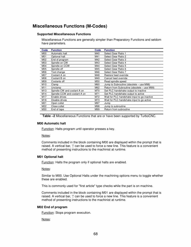
68
Miscellaneous Functions (M-Codes)
Supported Miscellaneous Functions
Miscellaneous Functions are generally simpler than Preparatory Functions and seldom have parameters.
Code Function Code Function
M00 Automatic halt M40 Select Gear Ratio 1
M01 Optional halt M41 Select Gear Ratio 2
M02 End of program M42 Select Gear Ratio 3
M03 Spindle on CW M43 Select Gear Ratio 4
M04 Spindle on CCW M44 Select Gear Ratio 5
M05 Spindle off M45 Select Gear Ratio 6
M06 Tool change M46 Select Gear Ratio 7
M07 Coolant A on M48 Restore feed override
M08 Coolant B on M49 Cancel feed override
M09 Coolants off M50 Read spindle speed
M10 Clamp M60 Jump to Subroutine (obsolete – use M98)
M11 Unclamp M62 Return from Subroutine (obsolete – use M99)
M13 Spindle CW and coolant A on M70 Set PLC handshake output to inactive
M14 Spindle CCW and coolant A on M71 Set PLC handshake output to active
M17 Enable drives M72 Wait for PLC handshake input to go inactive
M18 Disable drives M73 Wait for PLC handshake input to go active
M21 Open collet M97 Jump
M22 Close collet M98 Jump to subroutine
M30 End of tape M99 Return from subroutine
Table –2 Miscellaneous Functions that are or have been supported by TurboCNC.
M00 Automatic halt
Function: Halts program until operator presses a key.
Notes:
Comments included in the block containing M00 are displayed within the prompt that is raised. A vertical bar, '|' can be used to force a new line. This feature is a convenient method of presenting instructions to the machinist at runtime.
M01 Optional halt
Function: Halts the program only if optional halts are enabled.
Notes:
Similar to M00. Use Optional Halts under the machining options menu to toggle whether these are enabled.
This is commonly used for "first article" type checks while the part is on machine.
Comments included in the block containing M01 are displayed within the prompt that is raised. A vertical bar, '|' can be used to force a new line. This feature is a convenient method of presenting instructions to the machinist at runtime.
M02 End of program
Function: Stops program execution.
Notes:
69
This (or M30) must be the last line of a program.
Comments included in the block containing M02 are displayed within the prompt that is raised. A vertical bar, '|' can be used to force a new line. This feature is a convenient method of presenting instructions to the machinist at runtime.
M03 Spindle on CW
Function: Turns on spindle in the clockwise direction.
Notes:
Clockwise is the usual direction for a lathe or mill. If the spindle is commanded to run forward while it is already on, it will be shut off for 7 seconds and then re-activated in the new direction.
M04 Spindle on CCW
Function: Turns on spindle in the counter-clockwise direction.
Notes:
Similar to M03.
Turn the spindle off with M05 before changing directions or calling M03/04. If the spindle is commanded to reverse while it is already on, it will be shut off for 7 seconds and then re-activated in the new direction.
M05 Spindle off
Function: Turns off spindle
Notes:
Turns off the spindle output line. No braking is assumed. The spindle direction line state is not affected.
M06 Tool change
Function: Halt for tool change
Example:
M06 T1 ; Stops with a prompts for change to tool 1 ; and changes to the tool 1 coordinate offset
Notes:
This is essentially the same as M00, but with a prompt to tell the user which tool is being requested. Registered users may program their own, more sophisticated routines for automated tool changes here.
The T word is required with M06. It may also be placed on any program line to change the tool offset without pausing the program.
If the tool turret index line is enabled, M06 will not prompt the user, but activate the turret index line briefly instead. The default time period is two seconds, the maximum period is 120 seconds.

70
The delay period for the turret index line is set in the ini file or the configuration menu under the General heading.
Comments included in the block containing M06 are displayed within the prompt that is raised. A vertical bar, '|' can be used to force a new line. This feature is a convenient method of presenting instructions to the machinist at runtime.
M07 Coolant A on (flood)
Function: Turns on relay A
Notes:
This code is traditionally associated with flood coolant. It can be used as a generic output to control anything.
M08 Coolant B on (mist)
Function: Turns on relay B.
Notes:
This code is traditionally associated with mist coolant. It can be used as a generic output to control anything.
M09 Coolants off
Function: Switches off both relay A & B.
Notes:
Both coolant outputs (A and B, see M07 and M08) will be set to inactive.
M10 Clamp
Function: Closes a machine clamp
Example:
M10 Q12; Closes clamp twelve Notes:
Use numbers 0-15 for the clamps. If Q is not specified, it defaults to clamp 0.
At a minimum, the clamp drive, direction, and closure sense lines need to be configured on the machine to use this command.
The clamp address appears on the four clamp select output lines in binary, if they are configured on the machine. Clamp 0 is all lines inactive; clamp 15 sets all lines active.
You do not need to configure all 4 clamp select lines. For example, if you only have four clamps to control then it is permissible to use the first two clamp select lines only.
The clamp will be driven until the closure line goes active, or when 15 seconds has elapsed, whichever comes first.
M11 Unclamp
Function: Identical to M10, except that it opens a machine clamp.
71
Notes:
At a minimum, the clamp drive, direction, and open sense lines need to be configured on the machine to use this command.
The clamp will be driven until the open line goes active, or when 15 seconds has elapsed, whichever comes first.
M13 Spindle CW and coolant A on
Function: Turns the spindle on in the clockwise direction and activates the "A" coolant.
M14 Spindle CCW and coolant A on
Function: Similar to M13, but the spindle will be started counterclockwise.
M17 Enable drives
Function: Set drive enable lines active
Notes:
The Stepper World SP3 and some versions of the MAXNC drives require an enable signal in order to operate. After the drive enable output lines have been configured in TurboCNC, use this code to turn them on.
The drives will be disabled automatically when:
• a panic abort occurs during motion • you exit TurboCNC normally
They will be enabled when:
• a program is started or resumed • you enter jog mode • TurboCNC is started • you input an MDI command
You can also control these manually by using the options under the setup menu.
M18 Disable drives
Function: Set drive enable lines inactive
Notes:
Similar to M17, this turns the drive enable lines off.
M21 Open collet
Function: Opens a collet
Notes:
When this code is executed, the Collet Open line goes active for a short time, and then returns to the inactive state. The default length of time is two seconds and the maximum is 120. Change the length of time allowed by editing the ColletOpenTime(ms) entry in the ini file.
72
No feedback is required from the actual machine. This is designed to work with a pneumatic collet closer on a lathe.
The delay periods for M21 and M22 are set in the ini file or the configuration menu under the General heading.
M22 Close collet
Function: Closes a collet
Notes:
Similar to M21, this code activates the Collet Close output line for some length of time. Two seconds is the default, 120 seconds is the maximum. Change the length of time allowed by editing the ColletCloseTime(ms) entry in the ini file.
M30 End of program & rewind
Function: Stops program execution
Notes:
Functionally identical to M02. Hard disks don't need to be "rewound" of course, but paper tapes used to be! Some CAM programs generate this code instead of M02 at the end of a program, so it's here for compatibility.
Comments included in the block containing M30 are displayed within the prompt that is raised. A vertical bar, '|' can be used to force a new line. This feature is a convenient method of presenting instructions to the machinist at runtime.
M40 – M46: Gear Changes
Function: Selects the speed map associated with the specified gear.
Notes:
Spindle speed control is oriented to the Sherline spindle. As such the default compilation only implements M40 through M43. Increase MaxRatios in the spdmap unit to 7 to take advantage of the full range of codes.
The following mappings are defined:
• M40 – Standard Pulleys, Low Range (45 – 1400 RPM) • M41 – Standard Pulleys, High Range (70 – 2800 RPM) • M42 – 10K RPM Pulleys, Low Range (150 – 2200 RPM) • M43 – 10K RPM Pulleys, High Range (1500 – 10200 RPM)
M48 Restore feed override
Function: Restore feed override
Notes:
This brings the feed override back to whatever it was just before the most recent M49 call.
M49 Cancel feed override
Function: Cancel feed override
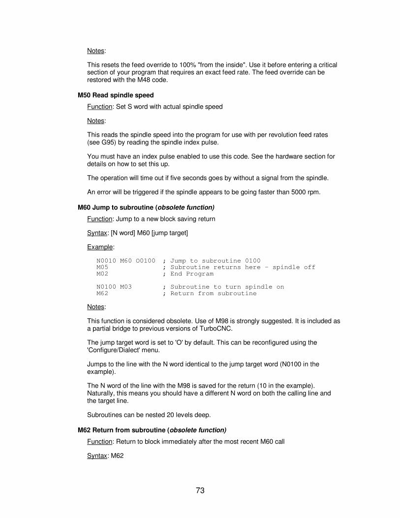
73
Notes:
This resets the feed override to 100% "from the inside". Use it before entering a critical section of your program that requires an exact feed rate. The feed override can be restored with the M48 code.
M50 Read spindle speed
Function: Set S word with actual spindle speed
Notes:
This reads the spindle speed into the program for use with per revolution feed rates (see G95) by reading the spindle index pulse.
You must have an index pulse enabled to use this code. See the hardware section for details on how to set this up.
The operation will time out if five seconds goes by without a signal from the spindle.
An error will be triggered if the spindle appears to be going faster than 5000 rpm.
M60 Jump to subroutine (obsolete function)
Function: Jump to a new block saving return
Syntax: [N word] M60 [jump target]
Example:
N0010 M60 O0100 ; Jump to subroutine 0100 M05 ; Subroutine returns here – spindle off M02 ; End Program N0100 M03 ; Subroutine to turn spindle on M62 ; Return from subroutine
Notes:
This function is considered obsolete. Use of M98 is strongly suggested. It is included as a partial bridge to previous versions of TurboCNC.
The jump target word is set to 'O' by default. This can be reconfigured using the 'Configure/Dialect' menu.
Jumps to the line with the N word identical to the jump target word (N0100 in the example).
The N word of the line with the M98 is saved for the return (10 in the example). Naturally, this means you should have a different N word on both the calling line and the target line.
Subroutines can be nested 20 levels deep.
M62 Return from subroutine (obsolete function)
Function: Return to block immediately after the most recent M60 call
Syntax: M62

74
Example:
See M60
Notes:
This function is considered obsolete. Use of M99 is strongly suggested. It is included as a partial bridge to previous versions of TurboCNC.
The next block to be executed will be found on the line following the most recent M60 call.
See SAMPLE.CNC for a simple nested subroutine example. Please note that when using subroutines, you'll need a unique N code on each calling line so that the program knows where to go back to.
To visualize program execution with subroutines, imagine all the code in the subroutine invisibly pasted in beneath the calling line. None of the modal codes are affected.
M70 Set PLC handshake output to inactive
Function: Set PLC handshake output to inactive
Notes:
Two PLC handshaking lines can be configured in TurboCNC. These are for telling external logic, such as an automatic tool changer or what-have-you to do some work. M70 sets the output handshake line to the inactive state. This can also be used to control extra solenoids or relays.
M71 Set PLC handshake output to active
Function: Set PLC handshake output to active
Notes:
Similar to M70, M71 sets the output handshake line to the active state.
M72 Wait for PLC handshake input to go inactive
Function: Wait for PLC handshake input to go inactive
Notes:
When this code is called, the program stops running and waits for the PLC input line (separate from the output line) to go to the inactive state. This is intended to be used to synchronize the program with external logic that might be loading more stock, or performing some other function.
M73 Wait for PLC handshake input to go active
Function: Wait for PLC handshake input to go active
Notes:
Similar to M72, this pauses until the PLC line goes to the active state. With either of these two codes, the user can press a key to bypass the wait condition.

75
M97 Jump
Function: Jump to a new block
Syntax: M97 [jump target]
Example:
M97 O0200 ; Jump to block 0200 G00 X1 ; This line is skipped N0200 M02 ; Jump target – Program End
Notes:
The jump target word is set to 'O' by default. This can be reconfigured using the 'Configure/Dialect' menu.
Jumps to the line with the N word identical to the jump target word (N0200 in the example).
Code following an M97 in a block is not executed. M-Codes within a block are executed first, in the order that they are encountered. Only the parameters that follow the M97 for M-Codes encountered earlier in the block will be used. Every other code or parameter is ignored.
The jump function is very useful when combined with 'Conditional Programming'
If there is a parsing error in the line containing the jump target, the message 'Jump Target not Found' will be displayed.
M98 Jump to subroutine
Function: Jump to a new block saving return
Syntax: [N word] M98 [jump target]
Example:
N0010 M98 O0100 ; Jump to subroutine 0100 M05 ; Subroutine returns here – spindle off M02 ; End Program N0100 M03 ; Subroutine to turn spindle on M99 ; Return from subroutine
Notes:
The jump target word is set to 'O' by default. This can be reconfigured using the 'Configure/Dialect' menu.
Jumps to the line with the N word identical to the jump target word (N0100 in the example).
The N word of the line with the M98 is saved for the return (10 in the example). Naturally, this means you should have a different N word on both the calling line and the target line.
Subroutines can be nested 20 levels deep.
76
Code following an M98 in a block is not executed. M-Codes within a block are executed first, in the order that they are encountered. Only the parameters that follow the M98 for M-Codes encountered earlier in the block will be used. Every other code or parameter is ignored.
If there is a parsing error in the line containing the jump target, the message 'Jump Target not Found' will be displayed.
M99 Return from subroutine
Function: Return to block immediately after the most recent M98 call
Syntax: M99
Example:
See M98
Notes:
The next block to be executed will be found on the line following the most recent M98 call.
Code following an M99 in a block is not executed. M-Codes within a block are executed first, in the order that they are encountered. Only the parameters that follow the M99 for M-Codes encountered earlier in the block will be used. Every other code or parameter is ignored.
See SAMPLE.CNC for a simple nested subroutine example. Please note that when using subroutines, you'll need a unique N code on each calling line so that the program knows where to go back to.
To visualize program execution with subroutines, imagine all the code in the subroutine invisibly pasted in beneath the calling line. None of the modal codes are affected.
If there is a parsing error in the line containing the jump target, the message 'Jump Target not Found' will be displayed.
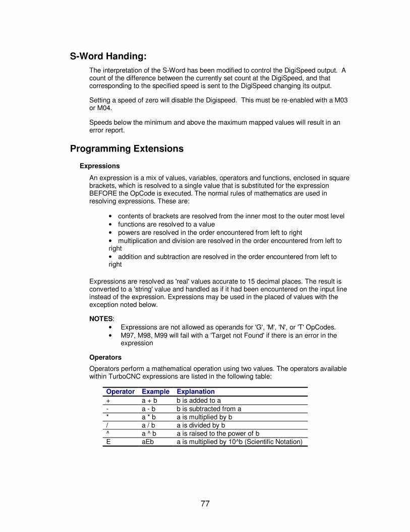
77
S-Word Handing:
The interpretation of the S-Word has been modified to control the DigiSpeed output. A count of the difference between the currently set count at the DigiSpeed, and that corresponding to the specified speed is sent to the DigiSpeed changing its output.
Setting a speed of zero will disable the Digispeed. This must be re-enabled with a M03 or M04.
Speeds below the minimum and above the maximum mapped values will result in an error report.
Programming Extensions
Expressions
An expression is a mix of values, variables, operators and functions, enclosed in square brackets, which is resolved to a single value that is substituted for the expression BEFORE the OpCode is executed. The normal rules of mathematics are used in resolving expressions. These are:
• contents of brackets are resolved from the inner most to the outer most level • functions are resolved to a value • powers are resolved in the order encountered from left to right • multiplication and division are resolved in the order encountered from left to right
• addition and subtraction are resolved in the order encountered from left to right
Expressions are resolved as 'real' values accurate to 15 decimal places. The result is converted to a 'string' value and handled as if it had been encountered on the input line instead of the expression. Expressions may be used in the placed of values with the exception noted below.
NOTES:
• Expressions are not allowed as operands for 'G', 'M', 'N', or 'T' OpCodes. • M97, M98, M99 will fail with a 'Target not Found' if there is an error in the
expression
Operators
Operators perform a mathematical operation using two values. The operators available within TurboCNC expressions are listed in the following table:
Operator Example Explanation
+ a + b b is added to a
- a - b b is subtracted from a * a * b a is multiplied by b / a / b a is divided by b ^ a ^ b a is raised to the power of b E aEb a is multiplied by 10^b (Scientific Notation)
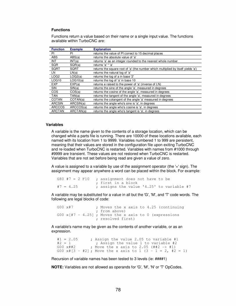
78
Functions
Functions return a value based on their name or a single input value. The functions available within TurboCNC are:
Function Example Explanation
PI PI returns the value of PI correct to 15 decimal places
ABS ABS(a) returns the absolute value of 'a'
INT INT(a) returns 'a' as an integer rounded to the nearest whole number
SQR SQR(a) returns 'a' * 'a'
SQRT SQRT returns the square root of 'a' (the number which multiplied by itself yields 'a')
LN LN(a) returns the natural log of 'a'
LOG2 LOG2(a) returns the log of a in base '2'
LOG10 LOG10(a) returns the log of 'a' in base 10
EXP EXP(a) returns e raised to the power of 'a' (inverse of LN)
SIN SIN(a) returns the sine of the angle 'a', measured in degrees
COS COS(a) returns the cosine of the angle 'a', measured in degrees
TAN TAN(a) returns the tangent of the angle 'a', measured in degrees
COTAN COTAN(a) returns the cotangent of the angle 'a' measured in degrees
ARCSIN ARCSIN(a) returns the angle who's sine is 'a', in degrees
ARCCOS ARCCOS(a) returns the angle who's cosine is 'a', in degrees
ARCTAN ARCTAN(a) returns the angle who's tangent is 'a', in degrees
Variables
A variable is the name given to the contents of a storage location, which can be changed while a parts file is running. There are 10000 of these locations available, each named with its location from 1 to 9999. Variables numbered 1 to 999 are persistent, meaning that their values are stored in the configuration file upon exiting TurboCNC and re-loaded when TurboCNC is restarted. Variables with names from #1000 through #9999 are transient. These values are not restored when TurboCNC is restarted. Variables that are not set before being read are given a value of zero.
A value is assigned to a variable by use of the assignment operator (the '=' sign). The assignment may appear anywhere a word can be placed within the block. For example:
G80 #7 = 2 F10 ; assignment does not have to be ; first in a block #7 = 4.25 ; assigns the value '4.25' to variable #7
A variable may be substituted for a value in all but the 'G', 'M', and 'T' code words. The following are legal blocks of code:
G00 x#7 ; Moves the x axis to 4.25 (continuing ; from above) G00 x[#7 – 4.25] ; Moves the x axis to 0 (expressions ; resolved first)
A variable's name may be given as the contents of another variable, or as an expression.
#1 = 2.05 ; Assign the value 2.05 to variable #1 #2 = 1 ; Assign the value 1 to variable #2 G00 x##2 ; Move the x axis to 2.05 (##2 -> #1) G00 x#[3 - #2] ; Move the x axis to 1 (3 - 1 = 2, #2 = 1)
Recursion of variable names has been tested to 3 levels (ie: ####1)
NOTE: Variables are not allowed as operands for 'G', 'M', 'N' or 'T' OpCodes.
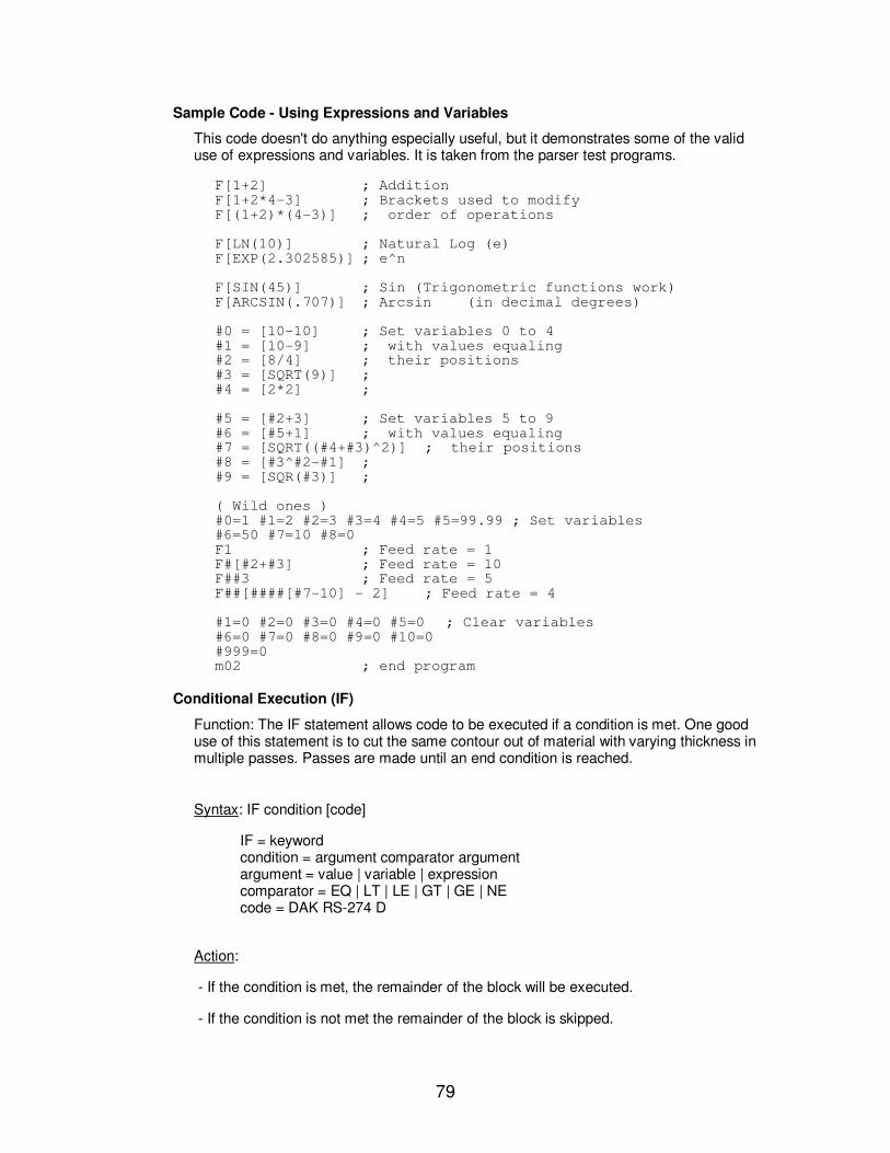
79
Sample Code - Using Expressions and Variables
This code doesn't do anything especially useful, but it demonstrates some of the valid use of expressions and variables. It is taken from the parser test programs.
F[1+2] ; Addition F[1+2*4-3] ; Brackets used to modify F[(1+2)*(4-3)] ; order of operations F[LN(10)] ; Natural Log (e) F[EXP(2.302585)] ; e^n F[SIN(45)] ; Sin (Trigonometric functions work) F[ARCSIN(.707)] ; Arcsin (in decimal degrees) #0 = [10-10] ; Set variables 0 to 4 #1 = [10-9] ; with values equaling #2 = [8/4] ; their positions #3 = [SQRT(9)] ; #4 = [2*2] ; #5 = [#2+3] ; Set variables 5 to 9 #6 = [#5+1] ; with values equaling #7 = [SQRT((#4+#3)^2)] ; their positions #8 = [#3^#2-#1] ; #9 = [SQR(#3)] ; ( Wild ones ) #0=1 #1=2 #2=3 #3=4 #4=5 #5=99.99 ; Set variables #6=50 #7=10 #8=0 F1 ; Feed rate = 1 F#[#2+#3] ; Feed rate = 10 F##3 ; Feed rate = 5 F##[####[#7-10] - 2] ; Feed rate = 4 #1=0 #2=0 #3=0 #4=0 #5=0 ; Clear variables #6=0 #7=0 #8=0 #9=0 #10=0 #999=0 m02 ; end program
Conditional Execution (IF)
Function: The IF statement allows code to be executed if a condition is met. One good use of this statement is to cut the same contour out of material with varying thickness in multiple passes. Passes are made until an end condition is reached.
Syntax: IF condition [code]
IF = keyword condition = argument comparator argument argument = value | variable | expression comparator = EQ | LT | LE | GT | GE | NE code = DAK RS-274 D
Action:
- If the condition is met, the remainder of the block will be executed.
- If the condition is not met the remainder of the block is skipped.
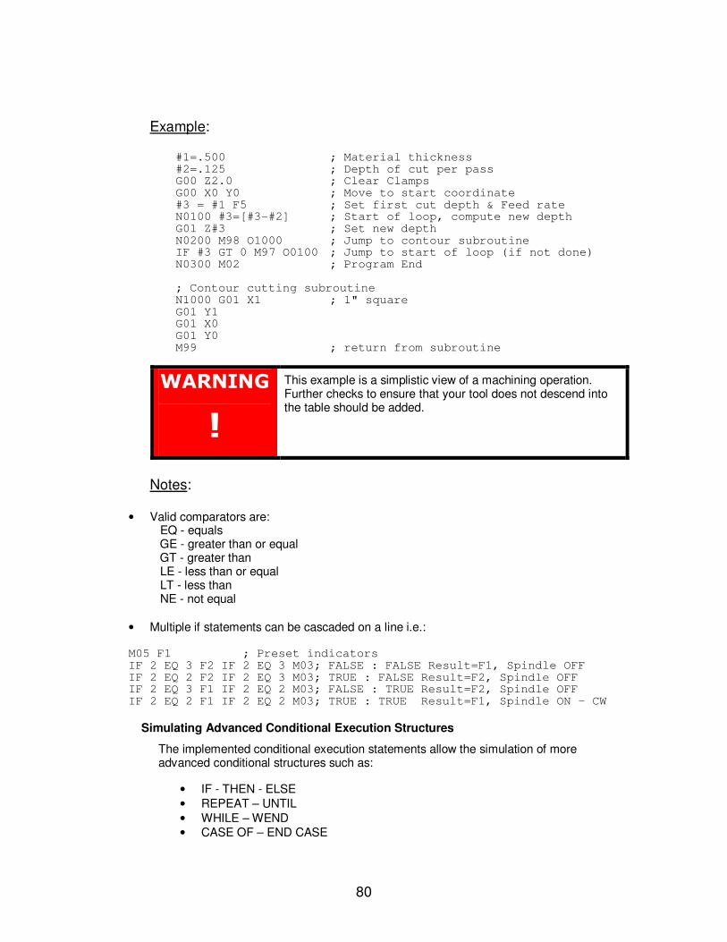
80
Example:
#1=.500 ; Material thickness #2=.125 ; Depth of cut per pass G00 Z2.0 ; Clear Clamps G00 X0 Y0 ; Move to start coordinate #3 = #1 F5 ; Set first cut depth & Feed rate N0100 #3=[#3-#2] ; Start of loop, compute new depth G01 Z#3 ; Set new depth N0200 M98 O1000 ; Jump to contour subroutine IF #3 GT 0 M97 O0100 ; Jump to start of loop (if not done) N0300 M02 ; Program End ; Contour cutting subroutine N1000 G01 X1 ; 1" square G01 Y1 G01 X0 G01 Y0 M99 ; return from subroutine
WARNING
!
This example is a simplistic view of a machining operation. Further checks to ensure that your tool does not descend into the table should be added.
Notes:
• Valid comparators are: EQ - equals GE - greater than or equal GT - greater than LE - less than or equal LT - less than NE - not equal
• Multiple if statements can be cascaded on a line i.e.:
M05 F1 ; Preset indicators IF 2 EQ 3 F2 IF 2 EQ 3 M03; FALSE : FALSE Result=F1, Spindle OFF IF 2 EQ 2 F2 IF 2 EQ 3 M03; TRUE : FALSE Result=F2, Spindle OFF IF 2 EQ 3 F1 IF 2 EQ 2 M03; FALSE : TRUE Result=F2, Spindle OFF IF 2 EQ 2 F1 IF 2 EQ 2 M03; TRUE : TRUE Result=F1, Spindle ON – CW
Simulating Advanced Conditional Execution Structures
The implemented conditional execution statements allow the simulation of more advanced conditional structures such as:
• IF - THEN - ELSE • REPEAT – UNTIL • WHILE – WEND • CASE OF – END CASE
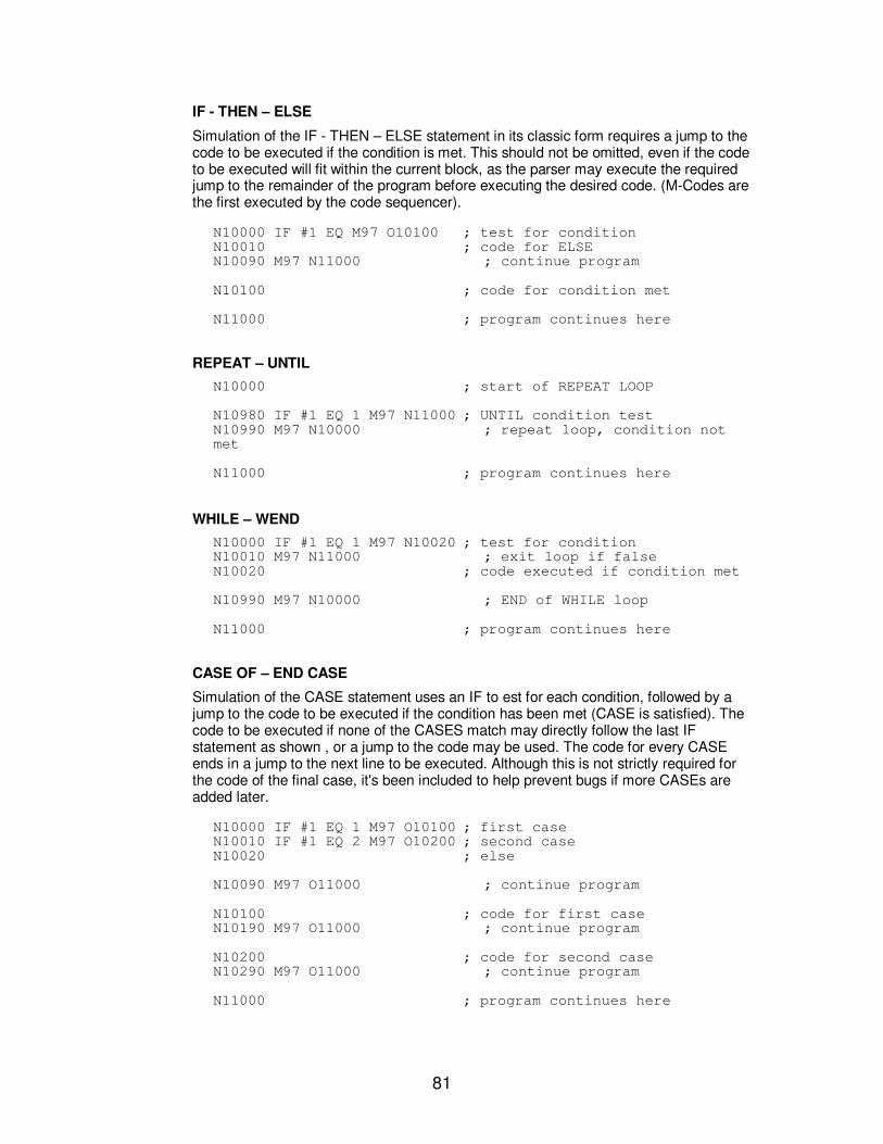
81
IF - THEN – ELSE
Simulation of the IF - THEN – ELSE statement in its classic form requires a jump to the code to be executed if the condition is met. This should not be omitted, even if the code to be executed will fit within the current block, as the parser may execute the required jump to the remainder of the program before executing the desired code. (M-Codes are the first executed by the code sequencer).
N10000 IF #1 EQ M97 O10100 ; test for condition N10010 ; code for ELSE N10090 M97 N11000 ; continue program N10100 ; code for condition met N11000 ; program continues here
REPEAT – UNTIL
N10000 ; start of REPEAT LOOP N10980 IF #1 EQ 1 M97 N11000 ; UNTIL condition test N10990 M97 N10000 ; repeat loop, condition not met N11000 ; program continues here
WHILE – WEND
N10000 IF #1 EQ 1 M97 N10020 ; test for condition N10010 M97 N11000 ; exit loop if false N10020 ; code executed if condition met N10990 M97 N10000 ; END of WHILE loop N11000 ; program continues here
CASE OF – END CASE
Simulation of the CASE statement uses an IF to est for each condition, followed by a jump to the code to be executed if the condition has been met (CASE is satisfied). The code to be executed if none of the CASES match may directly follow the last IF statement as shown , or a jump to the code may be used. The code for every CASE ends in a jump to the next line to be executed. Although this is not strictly required for the code of the final case, it's been included to help prevent bugs if more CASEs are added later.
N10000 IF #1 EQ 1 M97 O10100 ; first case N10010 IF #1 EQ 2 M97 O10200 ; second case N10020 ; else N10090 M97 O11000 ; continue program N10100 ; code for first case N10190 M97 O11000 ; continue program N10200 ; code for second case N10290 M97 O11000 ; continue program N11000 ; program continues here
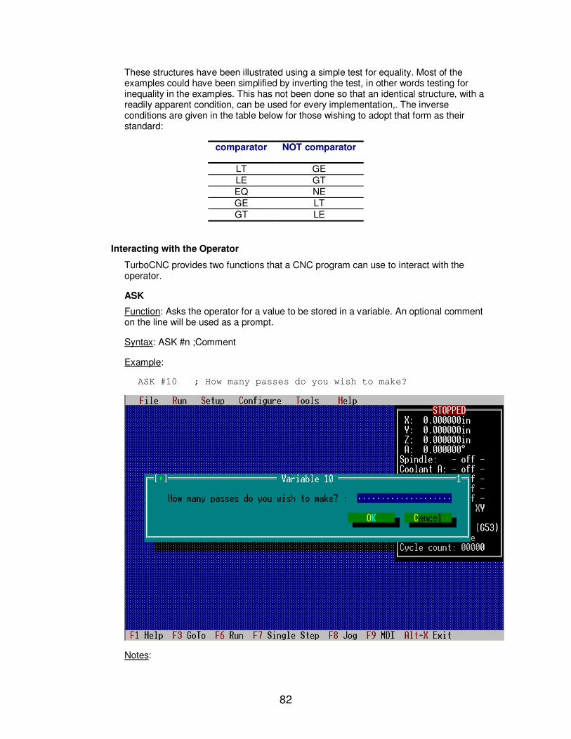
82
These structures have been illustrated using a simple test for equality. Most of the examples could have been simplified by inverting the test, in other words testing for inequality in the examples. This has not been done so that an identical structure, with a readily apparent condition, can be used for every implementation,. The inverse conditions are given in the table below for those wishing to adopt that form as their standard:
comparator NOT comparator
LT GE LE GT EQ NE GE LT GT LE
Interacting with the Operator
TurboCNC provides two functions that a CNC program can use to interact with the operator.
ASK
Function: Asks the operator for a value to be stored in a variable. An optional comment on the line will be used as a prompt.
Syntax: ASK #n ;Comment
Example:
ASK #10 ; How many passes do you wish to make?
Notes:
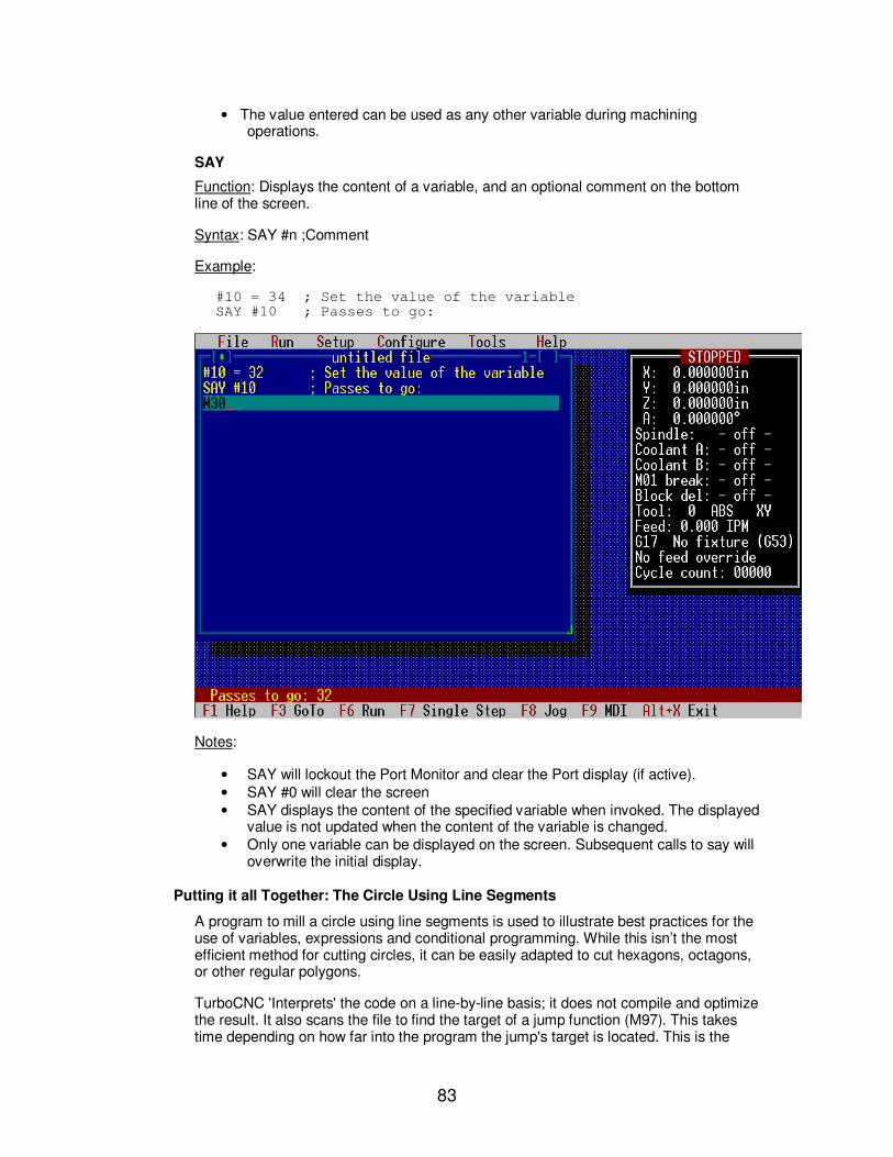
83
• The value entered can be used as any other variable during machining operations.
SAY
Function: Displays the content of a variable, and an optional comment on the bottom line of the screen.
Syntax: SAY #n ;Comment
Example:
#10 = 34 ; Set the value of the variable SAY #10 ; Passes to go:
Notes:
• SAY will lockout the Port Monitor and clear the Port display (if active). • SAY #0 will clear the screen • SAY displays the content of the specified variable when invoked. The displayed
value is not updated when the content of the variable is changed. • Only one variable can be displayed on the screen. Subsequent calls to say will
overwrite the initial display.
Putting it all Together: The Circle Using Line Segments
A program to mill a circle using line segments is used to illustrate best practices for the use of variables, expressions and conditional programming. While this isn’t the most efficient method for cutting circles, it can be easily adapted to cut hexagons, octagons, or other regular polygons.
TurboCNC 'Interprets' the code on a line-by-line basis; it does not compile and optimize the result. It also scans the file to find the target of a jump function (M97). This takes time depending on how far into the program the jump's target is located. This is the
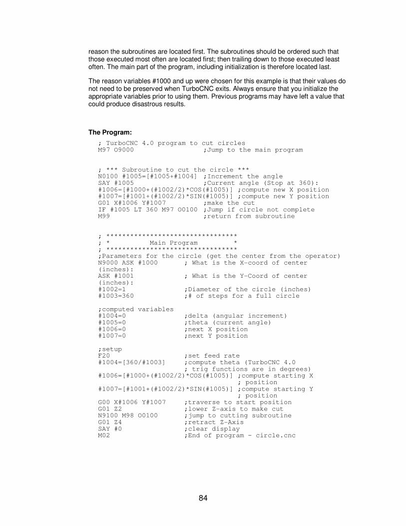
84
reason the subroutines are located first. The subroutines should be ordered such that those executed most often are located first; then trailing down to those executed least often. The main part of the program, including initialization is therefore located last.
The reason variables #1000 and up were chosen for this example is that their values do not need to be preserved when TurboCNC exits. Always ensure that you initialize the appropriate variables prior to using them. Previous programs may have left a value that could produce disastrous results.
The Program:
; TurboCNC 4.0 program to cut circles M97 O9000 ;Jump to the main program ; *** Subroutine to cut the circle *** N0100 #1005=[#1005+#1004] ;Increment the angle SAY #1005 ;Current angle (Stop at 360): #1006=[#1000+(#1002/2)*COS(#1005)] ;compute new X position #1007=[#1001+(#1002/2)*SIN(#1005)] ;compute new Y position G01 X#1006 Y#1007 ;make the cut IF #1005 LT 360 M97 O0100 ;Jump if circle not complete M99 ;return from subroutine ; ********************************* ; * Main Program * ; ********************************* ;Parameters for the circle (get the center from the operator) N9000 ASK #1000 ; What is the X-coord of center (inches): ASK #1001 ; What is the Y-Coord of center (inches): #1002=1 ;Diameter of the circle (inches) #1003=360 ;# of steps for a full circle ;computed variables #1004=0 ;delta (angular increment) #1005=0 ;theta (current angle) #1006=0 ;next X position #1007=0 ;next Y position ;setup F20 ;set feed rate #1004=[360/#1003] ;compute theta (TurboCNC 4.0 ; trig functions are in degrees) #1006=[#1000+(#1002/2)*COS(#1005)] ;compute starting X ; position #1007=[#1001+(#1002/2)*SIN(#1005)] ;compute starting Y ; position G00 X#1006 Y#1007 ;traverse to start position G01 Z2 ;lower Z-axis to make cut N9100 M98 O0100 ;jump to cutting subroutine G01 Z4 ;retract Z-Axis SAY #0 ;clear display M02 ;End of program – circle.cnc
85
Part 4 – Introduction to CNC
General
If you're reading this section, you're probably a beginner to the CNC world. That's ok, we all start somewhere. Chances are, you already understand machining. G & M codes provide a formal language for telling a computer how to do your work in the machine world. When you make a part on a machine tool, say a lathe, and watch what you really do - you'll notice that a lot of the game is turning hand wheels to make very repetitive and exact motions. CNC involves reducing the motions to codes in a scripting language that a computer can understand. In principle, if the computer can duplicate the same motions that a human does when machining, it duplicate the machining process. This is important to understand. G & M code only spells out the motions involved in machining. The computer doesn't know anything else, like where the part is, what kind of tool you're using, or even what kind of machine it's running. Motion only. G & M code works on a line by line basis using words, left to right and top to bottom just as you are reading this page. A word has a special definition in this context however. In the RS 274D language, each word consists of a letter or symbol followed by a number. Here are two words as an simple example: G00 X1.000 Each line of code is sometimes called a block. Let's break this block down and see what it means to the computer. The first word "G00" (pronounced GEE-zero) is the Rapid Positioning word. It means move somewhere as fast as you can. Yes, those are zeroes after the G. "'X1.000" is a word which gives a new location for the X axis; 1.000 in this case. If you've used a DRO equipped machine before, you probably understand coordinate systems. If not, have a look at the Axes De-mystified section and familiarize yourself with the concept. When this block is executed by TurboCNC, one of three things will happen: 1. In Absolute Mode, the X axis will move to the 1.000 coordinate position as fast as possible 2. In Incremental Mode, the X axis will move +1.000 units as fast as possible 3. If there is no X axis to speak of, an error will be produced or the block will be ignored. Not so bad, right? Just tell the machine what to do. By stringing a large series of blocks together you can create a script for the computer to follow. Each time you run the script (G code file), the computer performs the machining operation for you. Now run the script over and over, put in fresh stock each time, and you're in production! Here are some general things you need to know about the language:
86
• It is standardized (pretty much, at least insofar as the basics are concerned). You can use it just about anywhere.
• G words usually do the actual motion. • M words usually do miscellaneous functions. • Spaces don't matter, but line breaks do. • Read it left to right, top to bottom - just like you're reading this page. • If the same word is used in a line as in the line before, it usually doesn't have to
be retyped on the second line. This is called Modality. The old word is assumed until another one is used. Not all words are modal.
• The computer only does what you tell it to do, and will cheerfully snap a tool or drill through the table at your command.
• Words are also called "codes" in some circles. • M02 is the word for "End of program" - often interchangeable with M30 which is
"End of tape".
The Axes De-Mystified:
Any machine (lathe, mill, drill, etc) has its major linear axes defined in the standard orthogonal manner, that is at right angles to each other. The point to remember is that they are defined with respect to 'tool motion', not the actual motion of the axes. Positive direction is found using the right-hand rule for a mill. Lay your right hand, palm up, on the table of the machine, thumb along the X-Axis, index finger along the Y-Axis, and the middle finger along the Z-Axis. Your fingers and thumb will point in the positive direction of movement for the tool along each axis. For a moving table machine such as a Sherline, positive movement along the X-Axis moves the table to the left, positive movement along the Y- Axis moves the table towards the front, away from the column. A gantry style machine moves the tool, so movement of the gantry will follow the right hand rule (exactly the opposite of the moving table). By convention, rotational axes with their axis of rotation parallel to the X, Y, and Z axes, are labeled A, B, and C respectively. The direction of positive rotation of these axes is counterclockwise when viewed from the positive end of the corresponding orthogonal axis (X, Y, or Z). So, taking the Sherline as an example, with the rotary table mounted so that its axis of rotation is parallel to the X-Axis, with its table facing right, when viewed from the direction of the hand-crank (or stepper motor) rotates counterclockwise. In other words the top of the rotary table will turn towards the front of the mill. Something interesting to note is that the direction of rotation with respect to the surface of the rotary table will change if you turn it around to mount it facing left on the mill's table.
With only two axes, the right hand rule returns indeterminate results when used on a lathe. Machinists have adopted the convention that movement from the headstock to the tailstock is along the Z-Axis. Movement of the cross slide towards the tailstock is in the positive direction. In and out movement of the cross-slide is along the X-Axis. Movements of the cross slide, away from the centerline between the headstock and tailstock are in the positive direction. The point of origin for the orthogonal axes can be set anywhere that is convenient. With the exception of a lathe's X-Axis, many machinists set this is at the point of maximum negative movement along the axes in the machine coordinate system. The machinist will switch to an alternate coordinate system for machining, and set a zero relative to the work piece. For the X-Axis of a lathe, by convention the centerline between the headstock and tailstock is chosen as zero.
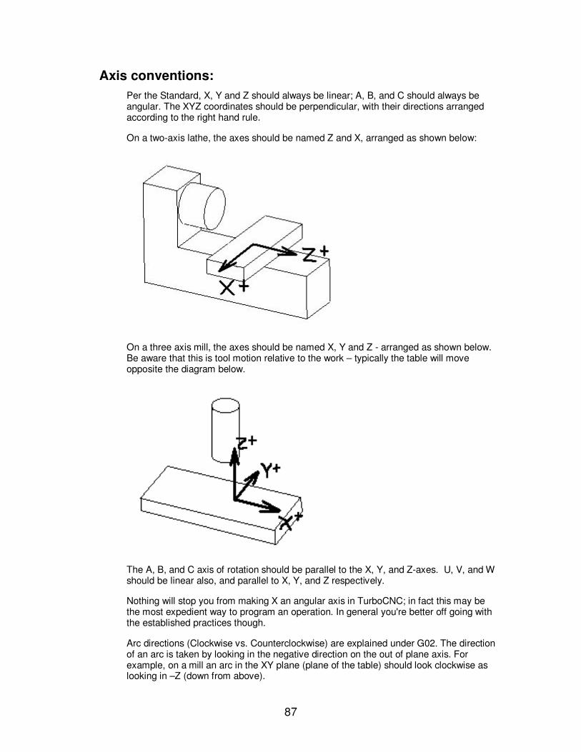
87
Axis conventions:
Per the Standard, X, Y and Z should always be linear; A, B, and C should always be angular. The XYZ coordinates should be perpendicular, with their directions arranged according to the right hand rule.
On a two-axis lathe, the axes should be named Z and X, arranged as shown below:
On a three axis mill, the axes should be named X, Y and Z - arranged as shown below. Be aware that this is tool motion relative to the work – typically the table will move opposite the diagram below.
The A, B, and C axis of rotation should be parallel to the X, Y, and Z-axes. U, V, and W should be linear also, and parallel to X, Y, and Z respectively.
Nothing will stop you from making X an angular axis in TurboCNC; in fact this may be the most expedient way to program an operation. In general you're better off going with the established practices though.
Arc directions (Clockwise vs. Counterclockwise) are explained under G02. The direction of an arc is taken by looking in the negative direction on the out of plane axis. For example, on a mill an arc in the XY plane (plane of the table) should look clockwise as looking in –Z (down from above).

88
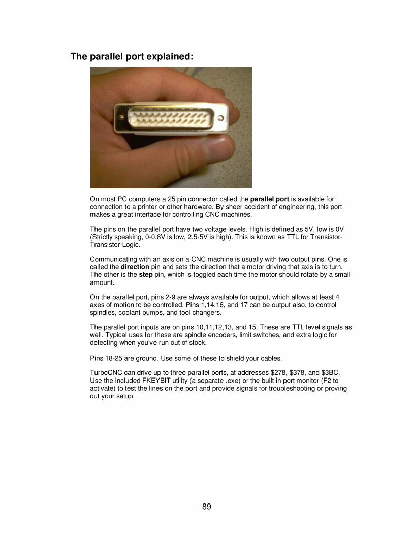
89
The parallel port explained:
On most PC computers a 25 pin connector called the parallel port is available for connection to a printer or other hardware. By sheer accident of engineering, this port makes a great interface for controlling CNC machines.
The pins on the parallel port have two voltage levels. High is defined as 5V, low is 0V (Strictly speaking, 0-0.8V is low, 2.5-5V is high). This is known as TTL for Transistor-Transistor-Logic.
Communicating with an axis on a CNC machine is usually with two output pins. One is called the direction pin and sets the direction that a motor driving that axis is to turn. The other is the step pin, which is toggled each time the motor should rotate by a small amount.
On the parallel port, pins 2-9 are always available for output, which allows at least 4 axes of motion to be controlled. Pins 1,14,16, and 17 can be output also, to control spindles, coolant pumps, and tool changers.
The parallel port inputs are on pins 10,11,12,13, and 15. These are TTL level signals as well. Typical uses for these are spindle encoders, limit switches, and extra logic for detecting when you’ve run out of stock. Pins 18-25 are ground. Use some of these to shield your cables.
TurboCNC can drive up to three parallel ports, at addresses $278, $378, and $3BC. Use the included FKEYBIT utility (a separate .exe) or the built in port monitor (F2 to activate) to test the lines on the port and provide signals for troubleshooting or proving out your setup.
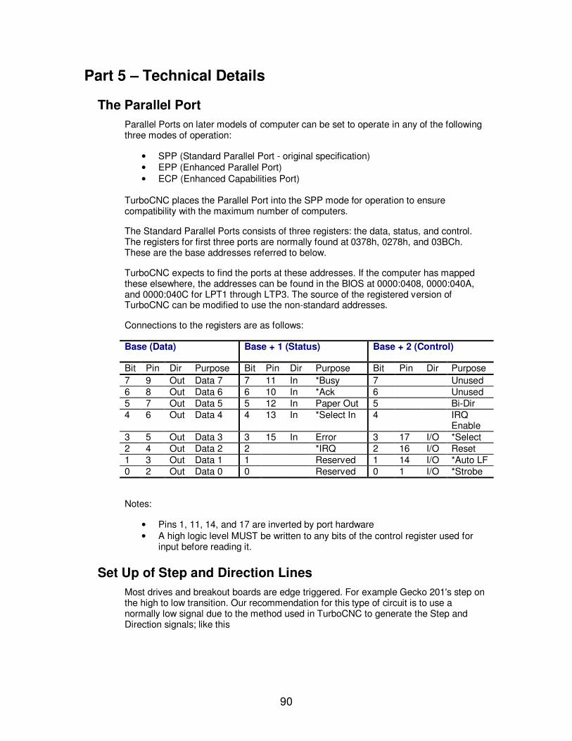
90
Part 5 – Technical Details
The Parallel Port
Parallel Ports on later models of computer can be set to operate in any of the following three modes of operation:
• SPP (Standard Parallel Port - original specification) • EPP (Enhanced Parallel Port) • ECP (Enhanced Capabilities Port)
TurboCNC places the Parallel Port into the SPP mode for operation to ensure compatibility with the maximum number of computers.
The Standard Parallel Ports consists of three registers: the data, status, and control. The registers for first three ports are normally found at 0378h, 0278h, and 03BCh. These are the base addresses referred to below.
TurboCNC expects to find the ports at these addresses. If the computer has mapped these elsewhere, the addresses can be found in the BIOS at 0000:0408, 0000:040A, and 0000:040C for LPT1 through LTP3. The source of the registered version of TurboCNC can be modified to use the non-standard addresses.
Connections to the registers are as follows:
Base (Data) Base + 1 (Status) Base + 2 (Control)
Bit Pin Dir Purpose Bit Pin Dir Purpose Bit Pin Dir Purpose
7 9 Out Data 7 7 11 In *Busy 7 Unused 6 8 Out Data 6 6 10 In *Ack 6 Unused 5 7 Out Data 5 5 12 In Paper Out 5 Bi-Dir 4 6 Out Data 4 4 13 In *Select In 4 IRQ
Enable 3 5 Out Data 3 3 15 In Error 3 17 I/O *Select 2 4 Out Data 2 2 *IRQ 2 16 I/O Reset 1 3 Out Data 1 1 Reserved 1 14 I/O *Auto LF 0 2 Out Data 0 0 Reserved 0 1 I/O *Strobe
Notes:
• Pins 1, 11, 14, and 17 are inverted by port hardware • A high logic level MUST be written to any bits of the control register used for
input before reading it.
Set Up of Step and Direction Lines
Most drives and breakout boards are edge triggered. For example Gecko 201's step on the high to low transition. Our recommendation for this type of circuit is to use a normally low signal due to the method used in TurboCNC to generate the Step and Direction signals; like this
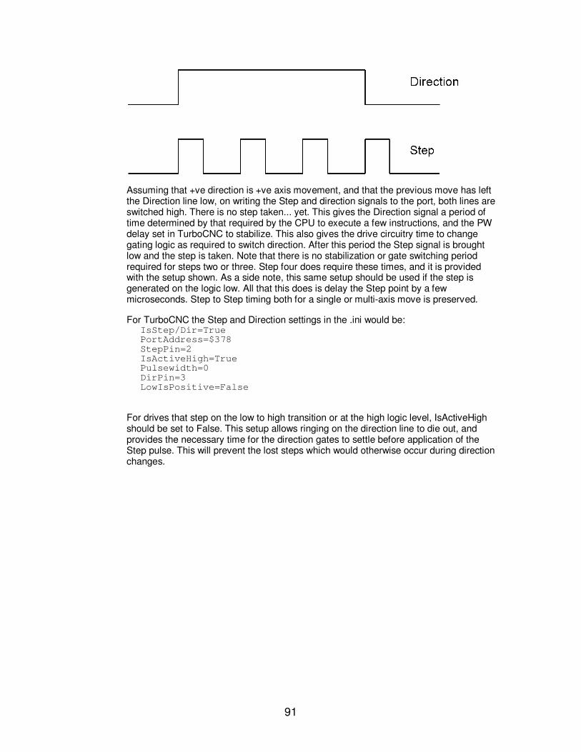
91
Assuming that +ve direction is +ve axis movement, and that the previous move has left the Direction line low, on writing the Step and direction signals to the port, both lines are switched high. There is no step taken... yet. This gives the Direction signal a period of time determined by that required by the CPU to execute a few instructions, and the PW delay set in TurboCNC to stabilize. This also gives the drive circuitry time to change gating logic as required to switch direction. After this period the Step signal is brought low and the step is taken. Note that there is no stabilization or gate switching period required for steps two or three. Step four does require these times, and it is provided with the setup shown. As a side note, this same setup should be used if the step is generated on the logic low. All that this does is delay the Step point by a few microseconds. Step to Step timing both for a single or multi-axis move is preserved.
For TurboCNC the Step and Direction settings in the .ini would be: IsStep/Dir=True PortAddress=$378 StepPin=2 IsActiveHigh=True Pulsewidth=0 DirPin=3 LowIsPositive=False
For drives that step on the low to high transition or at the high logic level, IsActiveHigh should be set to False. This setup allows ringing on the direction line to die out, and provides the necessary time for the direction gates to settle before application of the Step pulse. This will prevent the lost steps which would otherwise occur during direction changes.
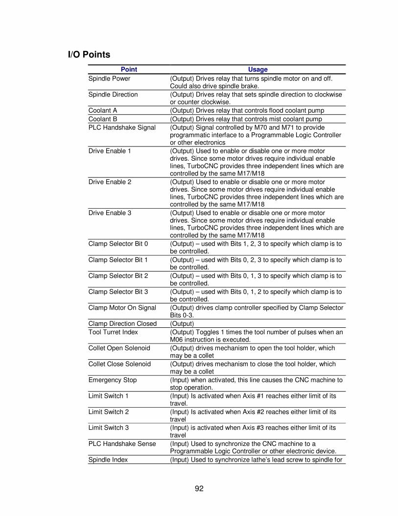
92
I/O Points
Point Usage
Spindle Power (Output) Drives relay that turns spindle motor on and off. Could also drive spindle brake.
Spindle Direction (Output) Drives relay that sets spindle direction to clockwise or counter clockwise.
Coolant A (Output) Drives relay that controls flood coolant pump
Coolant B (Output) Drives relay that controls mist coolant pump
PLC Handshake Signal (Output) Signal controlled by M70 and M71 to provide programmatic interface to a Programmable Logic Controller or other electronics
Drive Enable 1 (Output) Used to enable or disable one or more motor drives. Since some motor drives require individual enable lines, TurboCNC provides three independent lines which are controlled by the same M17/M18
Drive Enable 2 (Output) Used to enable or disable one or more motor drives. Since some motor drives require individual enable lines, TurboCNC provides three independent lines which are controlled by the same M17/M18
Drive Enable 3 (Output) Used to enable or disable one or more motor drives. Since some motor drives require individual enable lines, TurboCNC provides three independent lines which are controlled by the same M17/M18
Clamp Selector Bit 0 (Output) – used with Bits 1, 2, 3 to specify which clamp is to be controlled.
Clamp Selector Bit 1 (Output) – used with Bits 0, 2, 3 to specify which clamp is to be controlled.
Clamp Selector Bit 2 (Output) – used with Bits 0, 1, 3 to specify which clamp is to be controlled.
Clamp Selector Bit 3 (Output) – used with Bits 0, 1, 2 to specify which clamp is to be controlled.
Clamp Motor On Signal (Output) drives clamp controller specified by Clamp Selector Bits 0-3.
Clamp Direction Closed (Output)
Tool Turret Index (Output) Toggles 1 times the tool number of pulses when an M06 instruction is executed.
Collet Open Solenoid (Output) drives mechanism to open the tool holder, which may be a collet
Collet Close Solenoid (Output) drives mechanism to close the tool holder, which may be a collet
Emergency Stop (Input) when activated, this line causes the CNC machine to stop operation.
Limit Switch 1 (Input) Is activated when Axis #1 reaches either limit of its travel.
Limit Switch 2 (Input) Is activated when Axis #2 reaches either limit of its travel
Limit Switch 3 (Input) is activated when Axis #3 reaches either limit of its travel
PLC Handshake Sense (Input) Used to synchronize the CNC machine to a Programmable Logic Controller or other electronic device.
Spindle Index (Input) Used to synchronize lathe’s lead screw to spindle for
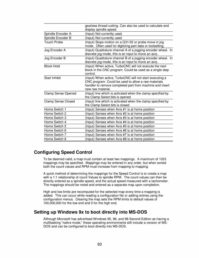
93
gearless thread cutting. Can also be used to calculate and display spindle speed.
Spindle Encoder A (Input) Not currently used
Spindle Encoder B (Input) Not currently used
Touch Probe (Input) Stops motion on a G31/32 or probe move in jog mode. Often used for digitizing part data or toolsetting.
Jog Encoder A (Input) Quadrature channel A of a jogging encoder wheel. In discrete jog mode, this is an input to move an axis.
Jog Encoder B (Input) Quadrature channel B of a jogging encoder wheel. In discrete jog mode, this is an input to move an axis.
Block Hold (Input) When active, TurboCNC will not execute the next block in the CNC program. Could be used as a single step control.
Start Inhibit (Input) When active, TurboCNC will not start executing a CNC program. Could be used to allow a raw materials handler to remove completed part from machine and insert new raw material.
Clamp Sense Opened (Input) line which is activated when the clamp specified by the Clamp Select bits is opened
Clamp Sense Closed (Input) line which is activated when the clamp specified by the Clamp Select bits is closed
Home Switch 1 (Input) Senses when Axis #1 is at home position
Home Switch 2 (Input) Senses when Axis #2 is at home position
Home Switch 3 (Input) Senses when Axis #3 is at home position
Home Switch 4 (Input) Senses when Axis #4 is at home position
Home Switch 5 (Input) Senses when Axis #5 is at home position
Home Switch 6 (Input) Senses when Axis #6 is at home position
Home Switch 7 (Input) Senses when Axis #7 is at home position
Home Switch 8 (Input) Senses when Axis #8 is at home position
Configuring Speed Control
To be deemed valid, a map must contain at least two mappings. A maximum of 1023 mappings may be specified. Mappings may be entered in any order, but when sorted both the count values and RPM must increase from mapping to mapping.
A quick method of determining the mappings for the Speed Control is to create a map with a 1:1 relationship of count Values to spindle RPM. The count values can then be directly entered as a spindle speed, and the actual speed measured with a tachometer. The mappings should be noted and entered as a separate map upon completion.
High and low limits are recomputed for the selected map every time a mapping is added. This can occur while reading a configuration file or adding entries using the configuration menus. Clearing the map sets the RPM limits to default values of 100,000,000 for the low end and 0 for the high end.
Setting up Windows 9x to boot directly into MS-DOS
Although Microsoft has advertised Windows 95, 98, and 98-Second Edition as having a multitasking “native mode,” these operating environments still include a version of MS-DOS and can be configured to boot directly into MS-DOS.
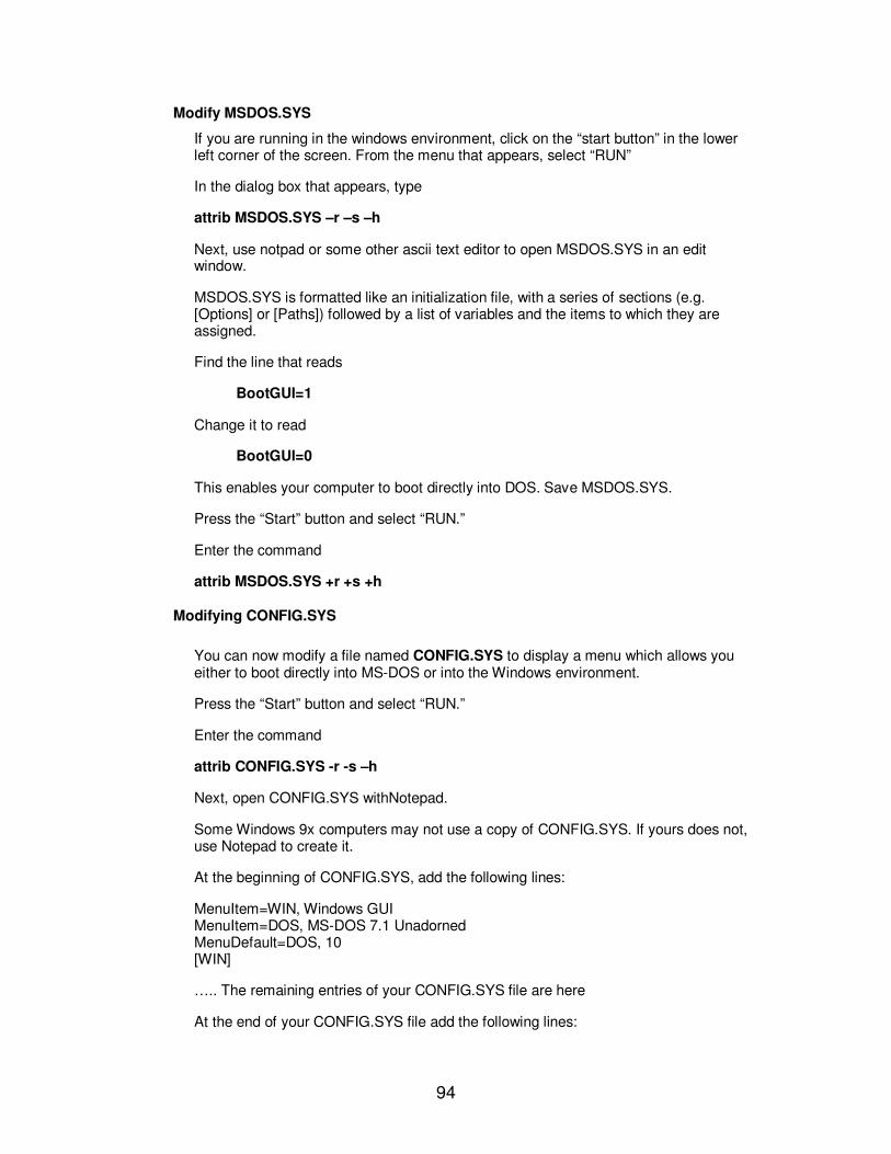
94
Modify MSDOS.SYS
If you are running in the windows environment, click on the “start button” in the lower left corner of the screen. From the menu that appears, select “RUN”
In the dialog box that appears, type
attrib MSDOS.SYS –r –s –h
Next, use notpad or some other ascii text editor to open MSDOS.SYS in an edit window.
MSDOS.SYS is formatted like an initialization file, with a series of sections (e.g. [Options] or [Paths]) followed by a list of variables and the items to which they are assigned.
Find the line that reads
BootGUI=1
Change it to read
BootGUI=0
This enables your computer to boot directly into DOS. Save MSDOS.SYS.
Press the “Start” button and select “RUN.”
Enter the command
attrib MSDOS.SYS +r +s +h
Modifying CONFIG.SYS
You can now modify a file named CONFIG.SYS to display a menu which allows you either to boot directly into MS-DOS or into the Windows environment.
Press the “Start” button and select “RUN.”
Enter the command
attrib CONFIG.SYS -r -s –h
Next, open CONFIG.SYS withNotepad.
Some Windows 9x computers may not use a copy of CONFIG.SYS. If yours does not, use Notepad to create it.
At the beginning of CONFIG.SYS, add the following lines:
MenuItem=WIN, Windows GUI MenuItem=DOS, MS-DOS 7.1 Unadorned MenuDefault=DOS, 10 [WIN]
….. The remaining entries of your CONFIG.SYS file are here
At the end of your CONFIG.SYS file add the following lines:
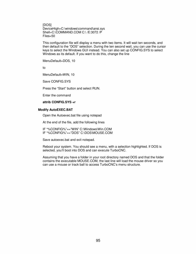
95
[DOS] DeviceHigh=C:\windows\command\ansi.sys Shell=C:\COMMAND.COM C:\ /E:3072 /P Files=50
This configuration file will display a menu with two items. It will wait ten seconds, and then default to the “DOS” selection. During the ten second wait, you can use the cursor keys to select the Windows GUI instead. You can also set up CONFIG.SYS to select Windows as its default. If you want to do this, change the line
MenuDefault=DOS, 10
to
MenuDefault=WIN, 10
Save CONFIG.SYS
Press the “Start” button and select RUN.
Enter the command
attrib CONFIG.SYS +r
Modify AutoEXEC.BAT
Open the Autoexec.bat file using notepad
At the end of the file, add the following lines
IF “%CONFIG%”==”WIN” C:\Windows\Win.COM IF “%CONFIG%”==”DOS” C:\DOS\MOUSE.COM
Save autoexec.bat and exit notepad.
Reboot your system. You should see a menu, with a selection highlighted. If DOS is selected, you’ll boot into DOS and can execute TurboCNC.
Assuming that you have a folder in your root directory named DOS and that the folder contains the executable MOUSE.COM, the last line will load the mouse driver so you can use a mouse or track ball to access TurboCNC’s menu structure.

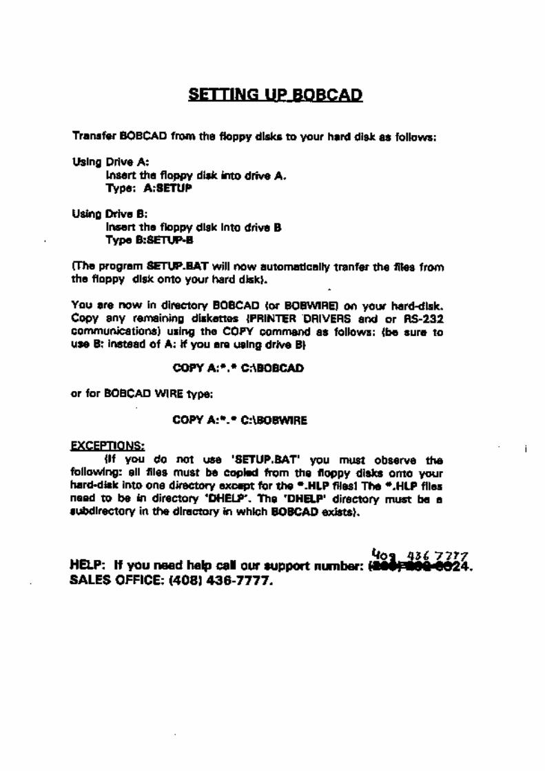
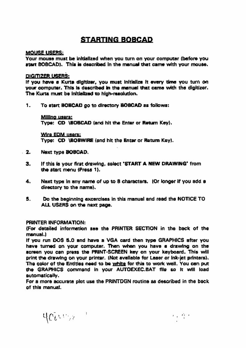

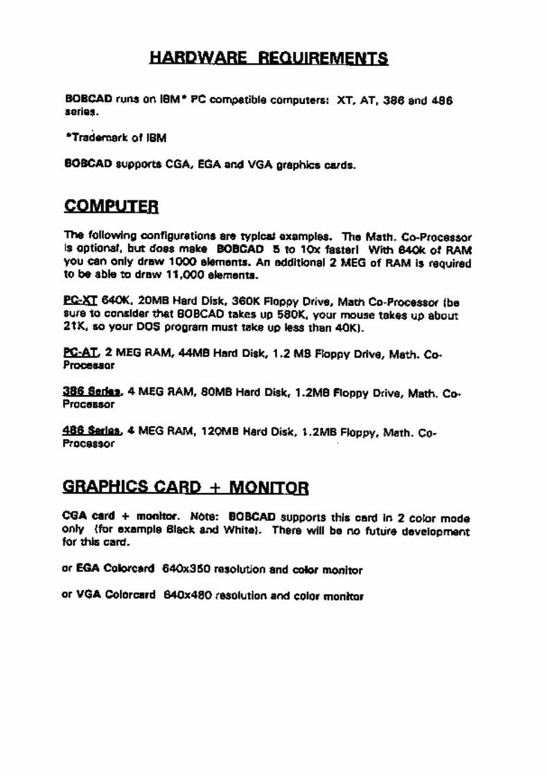

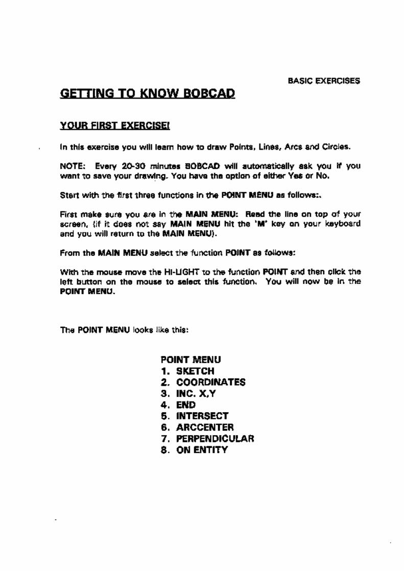
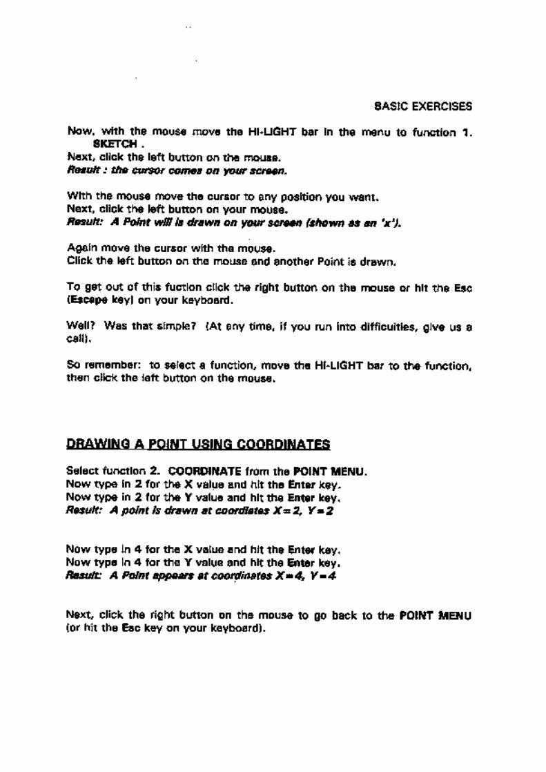
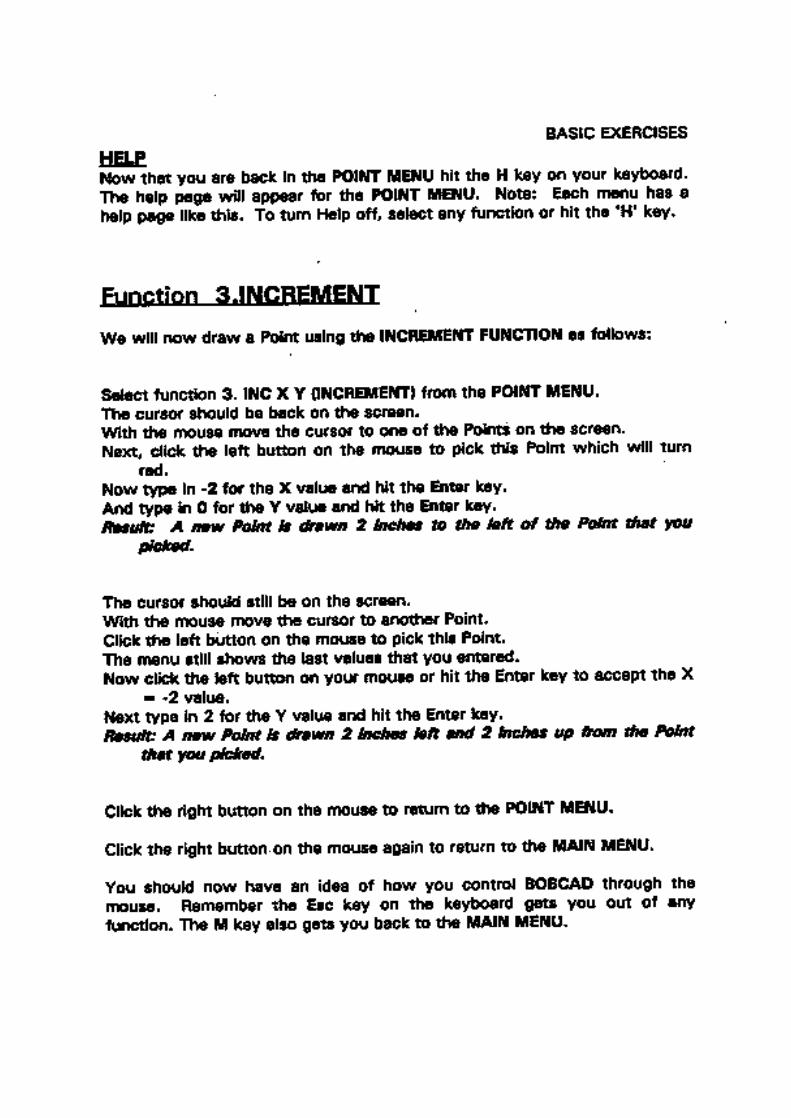
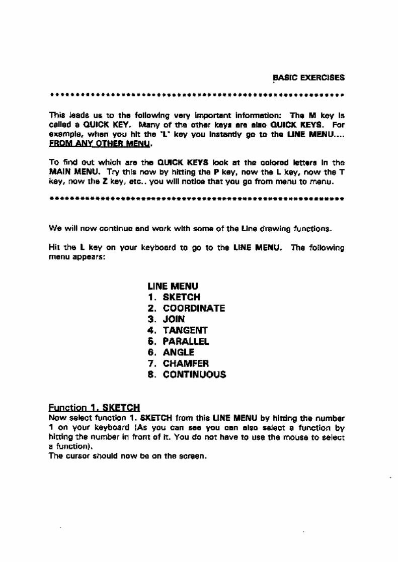
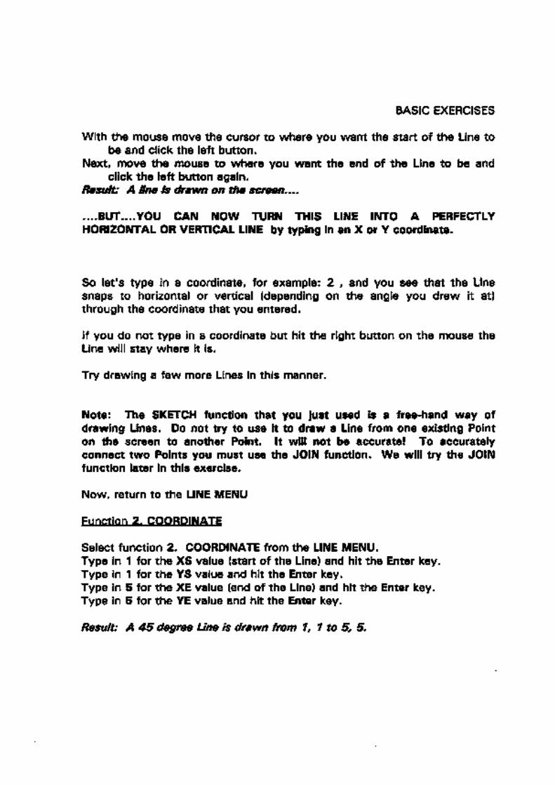
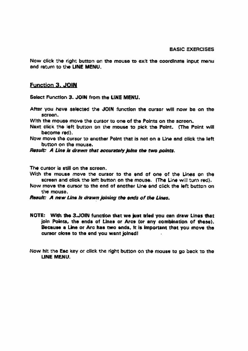
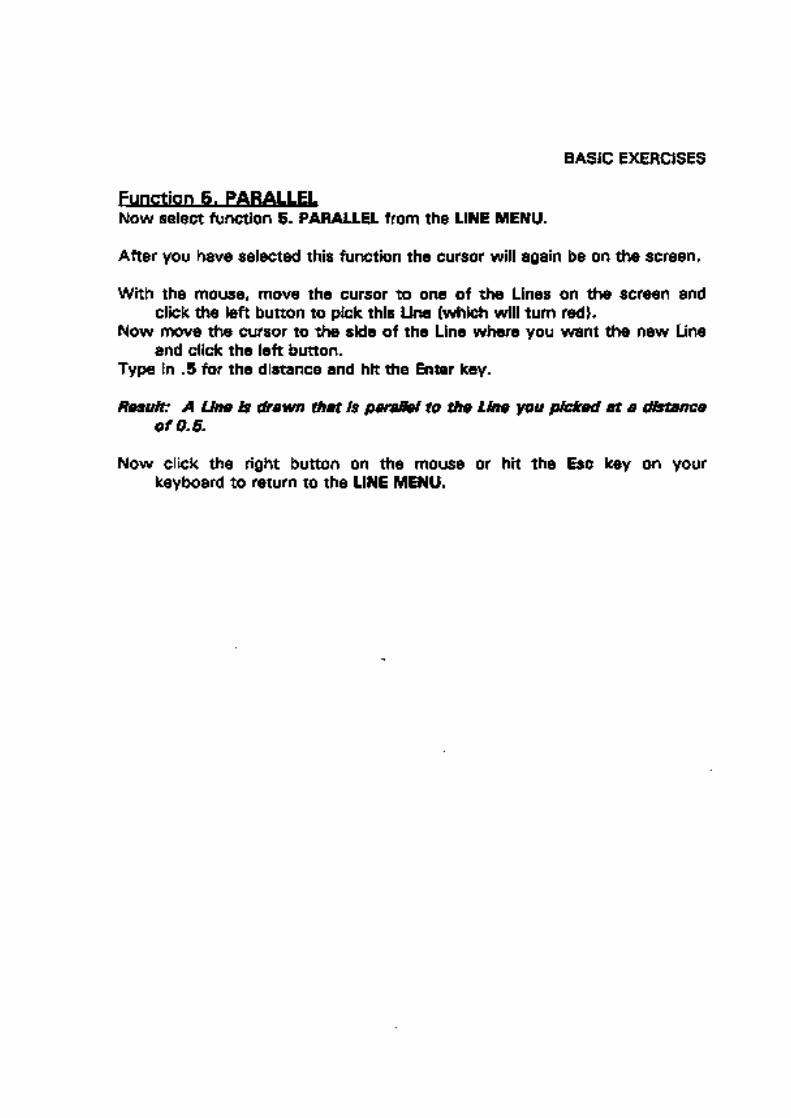
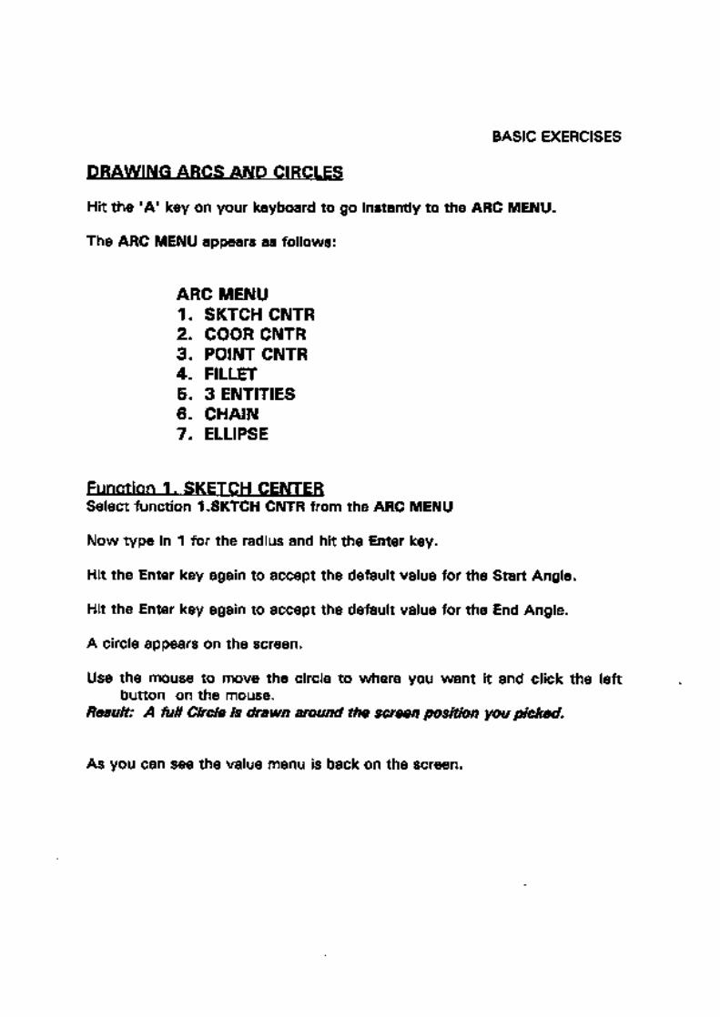
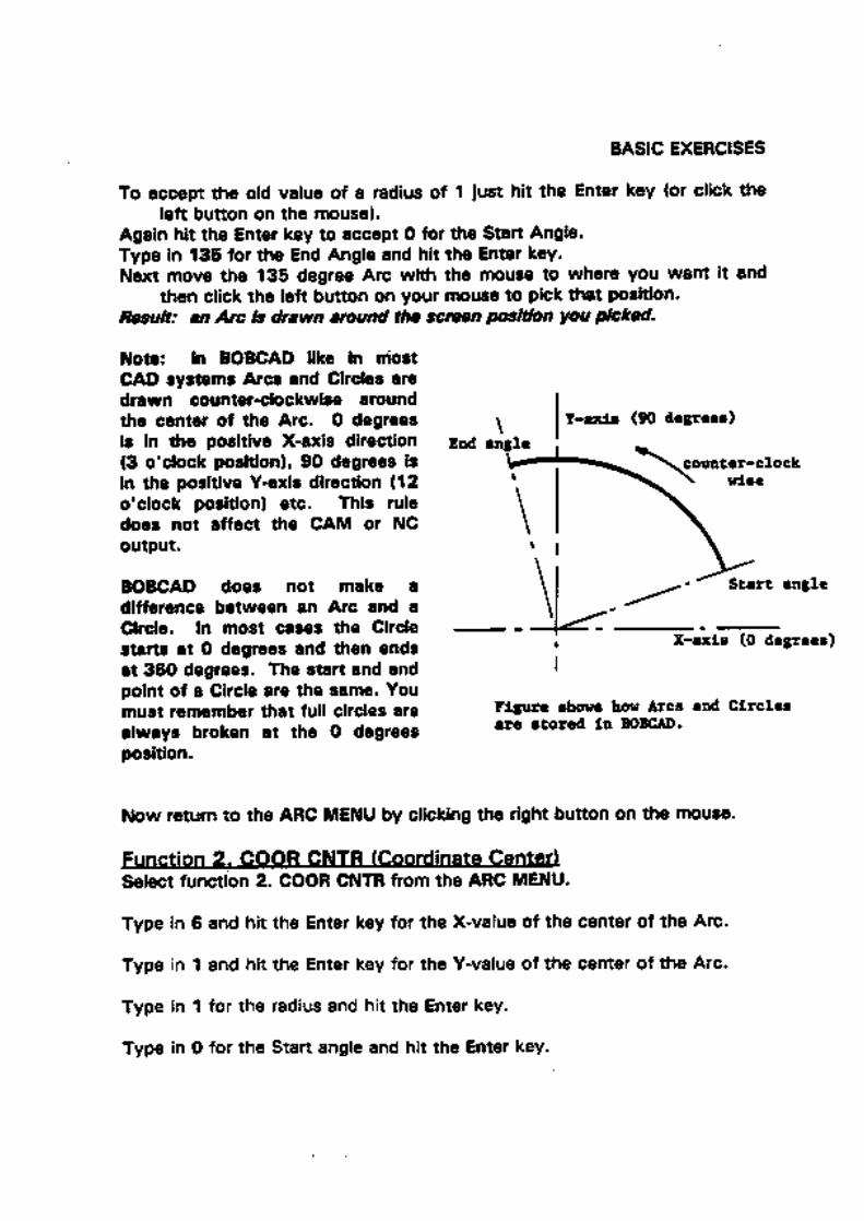

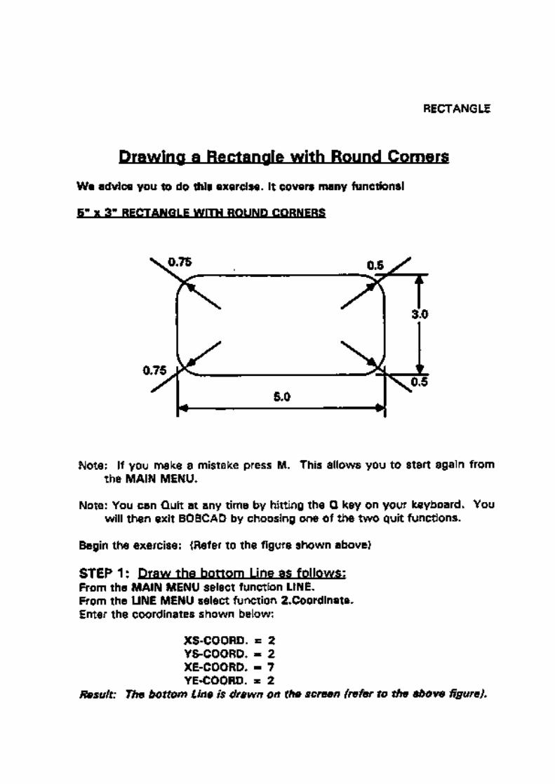
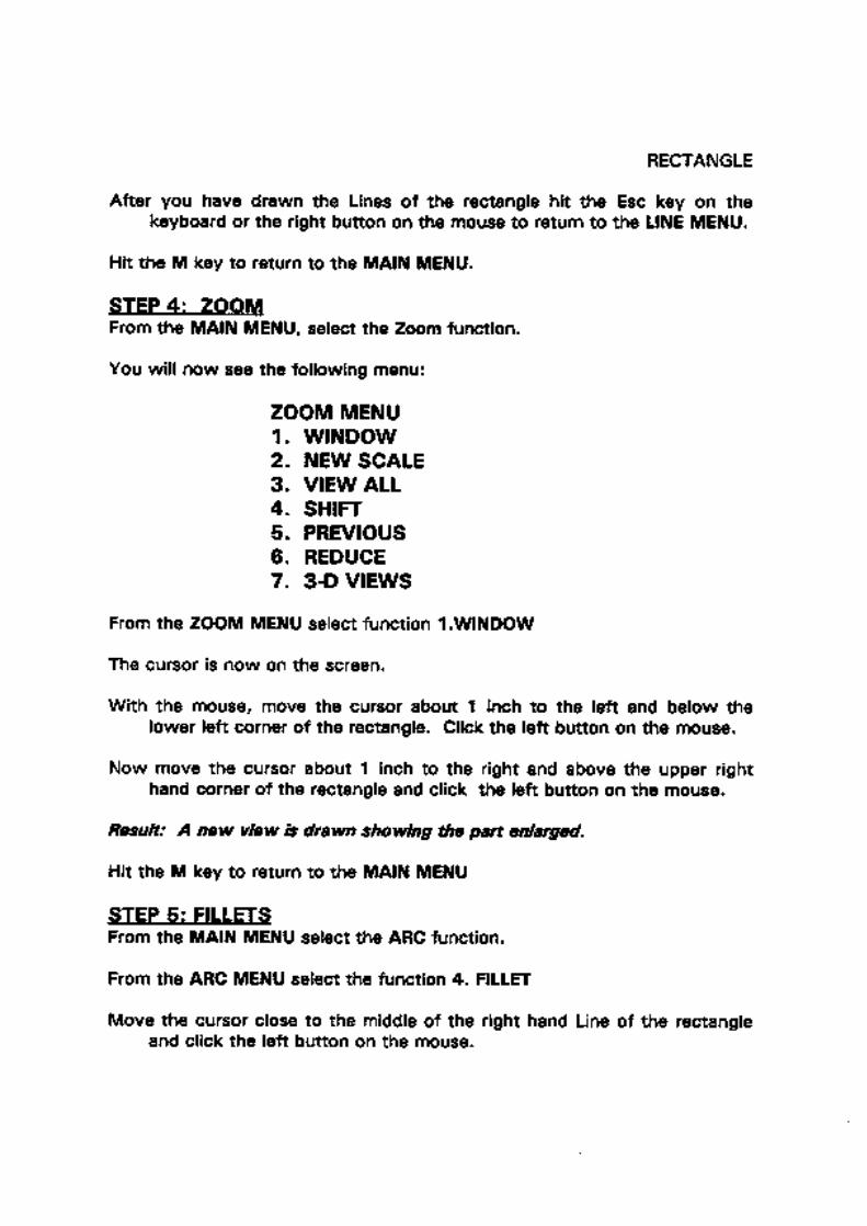
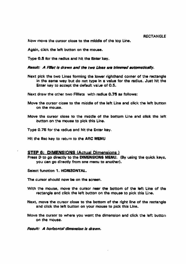
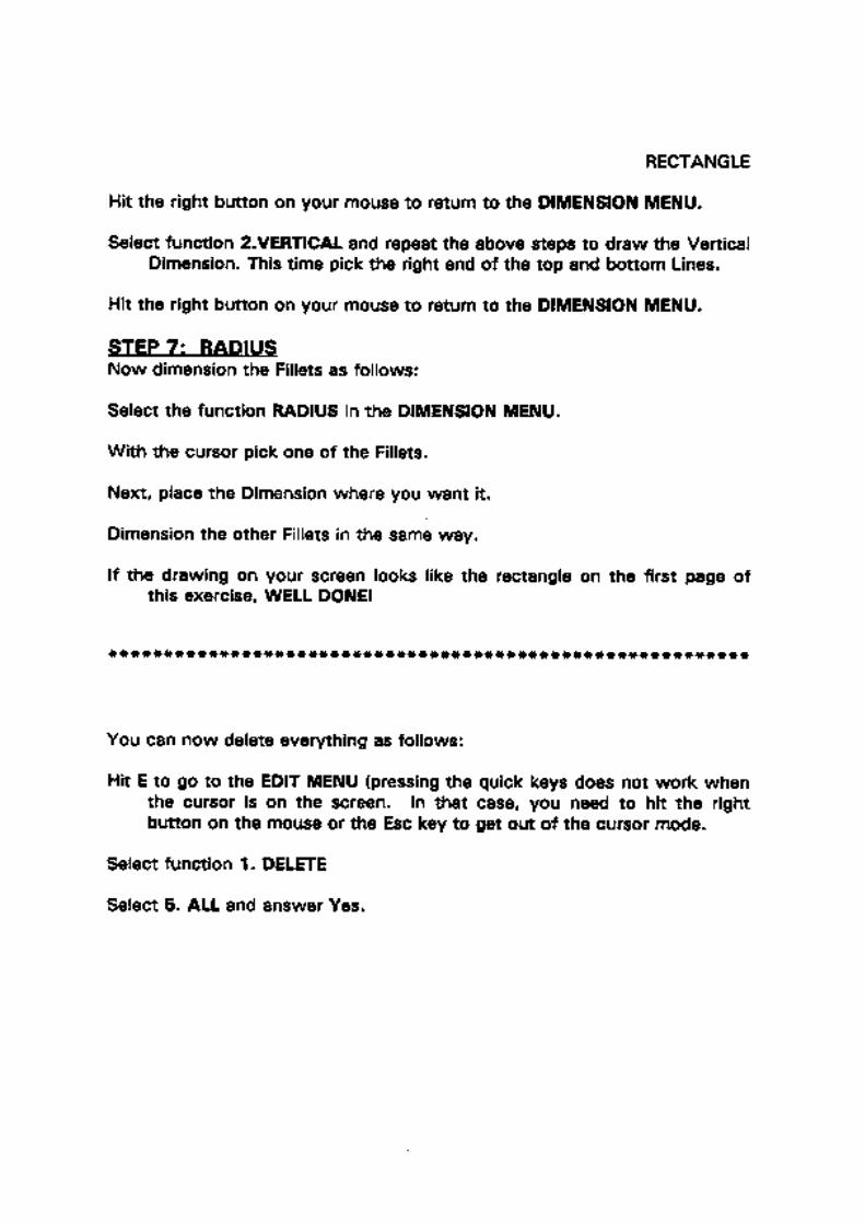
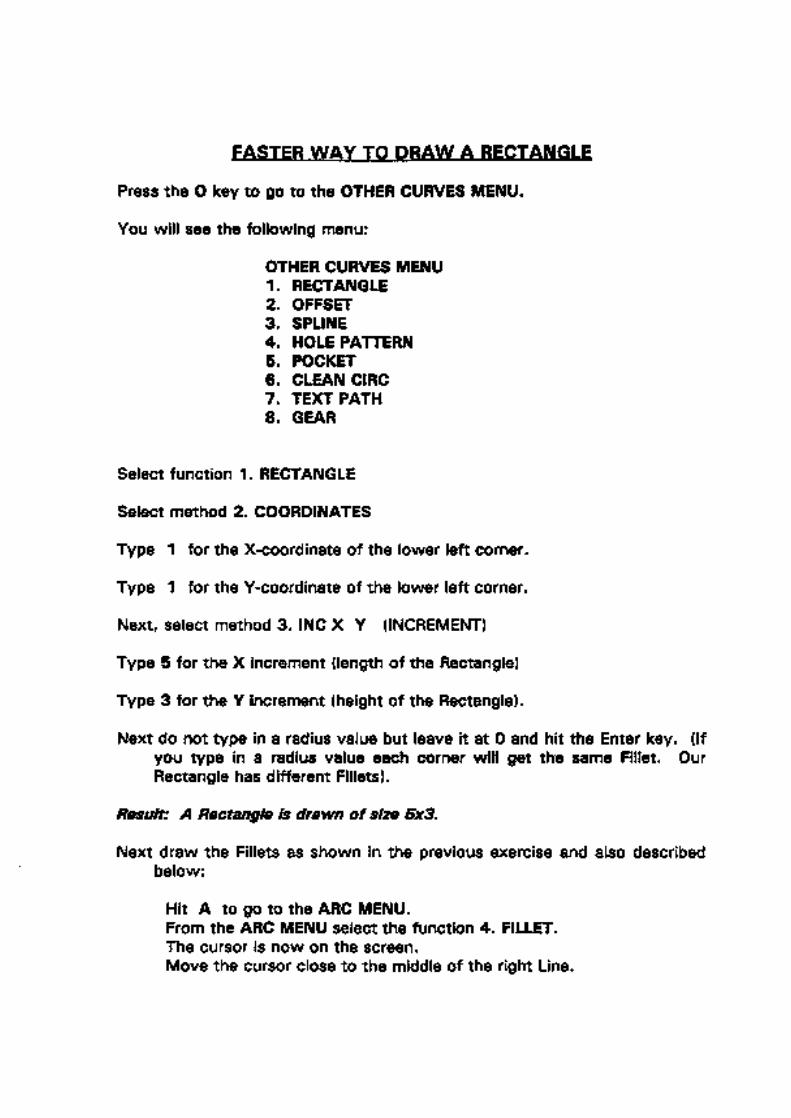
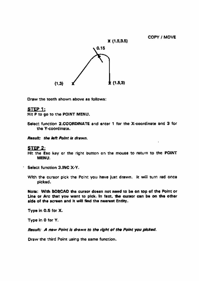
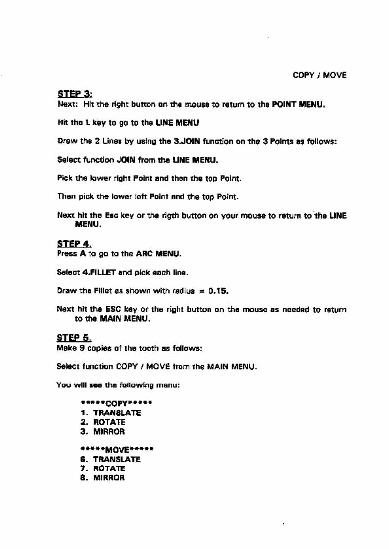
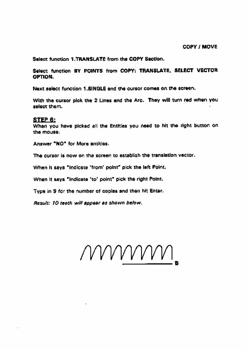
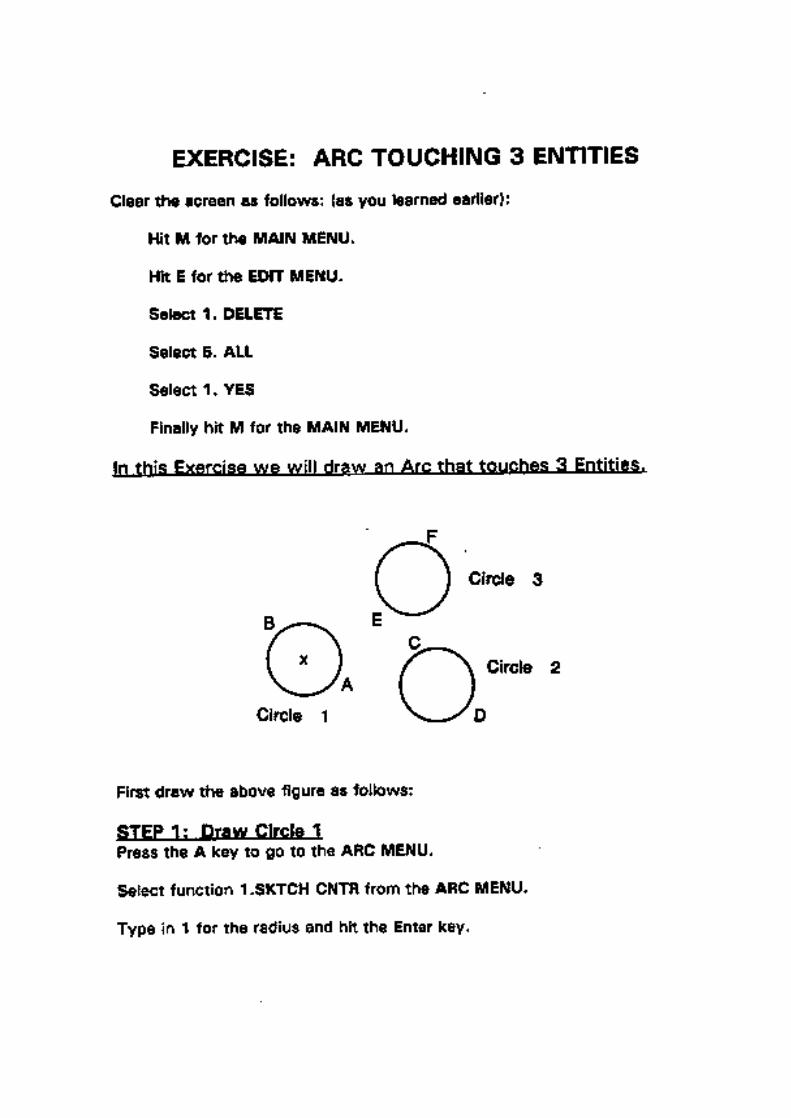
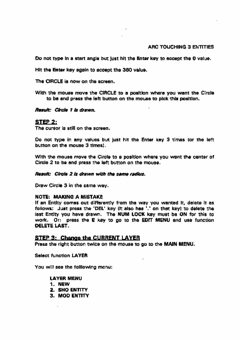
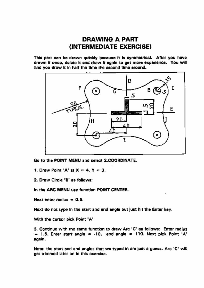
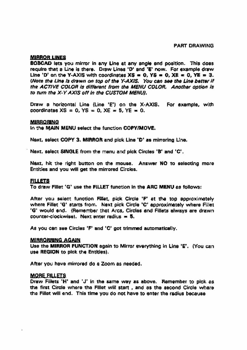
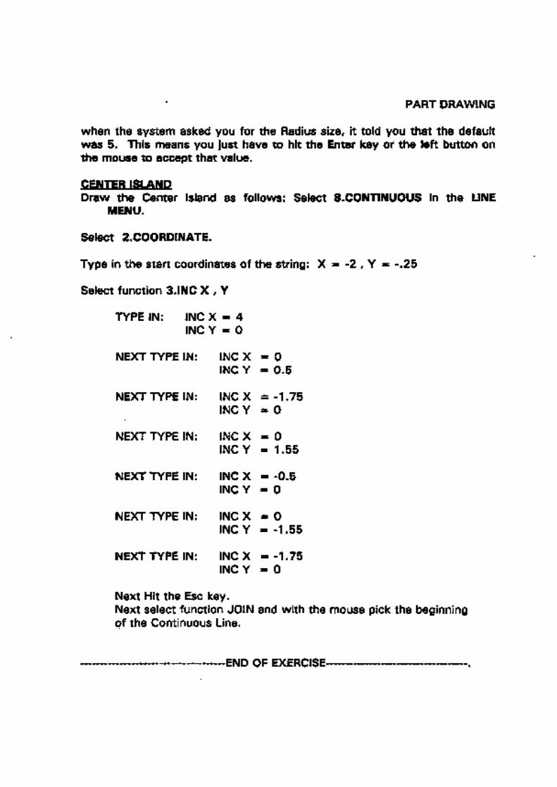
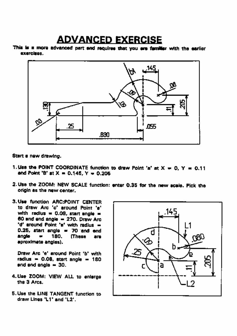
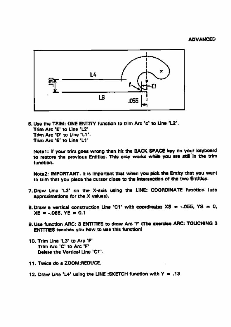
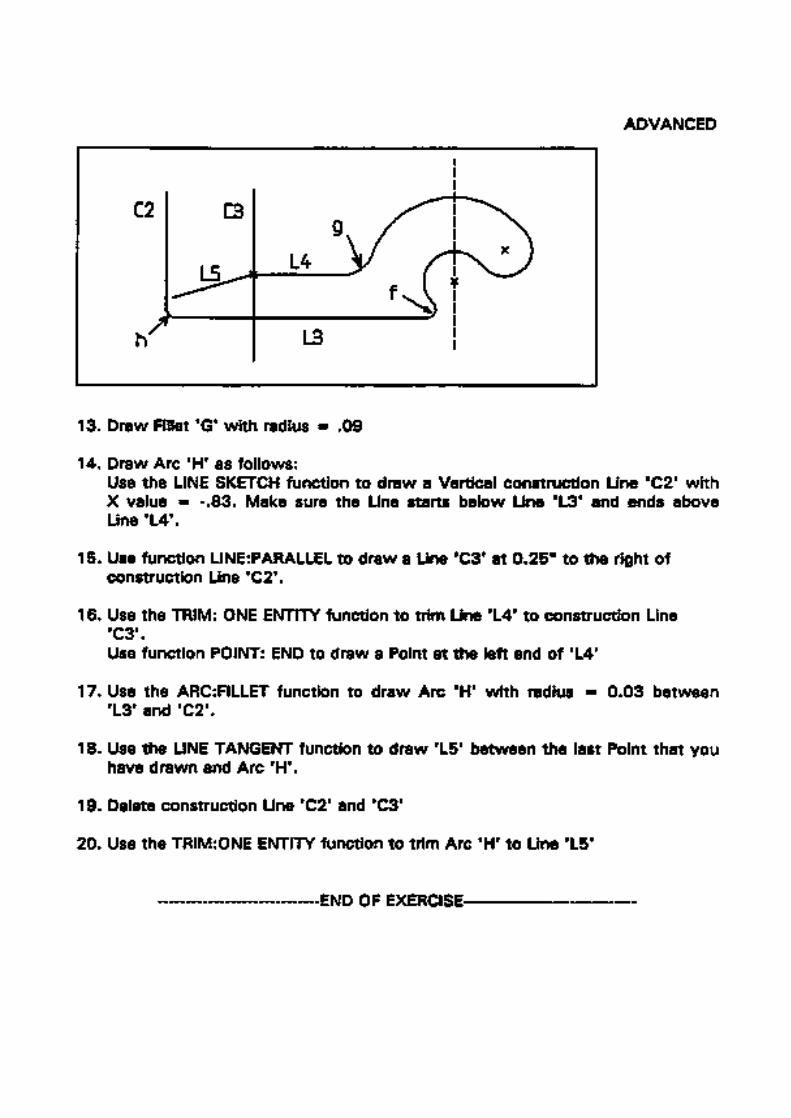
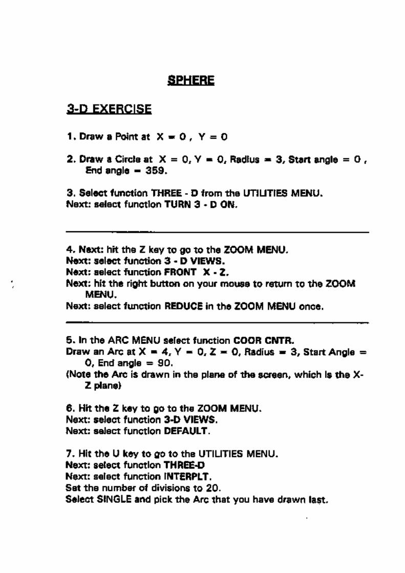
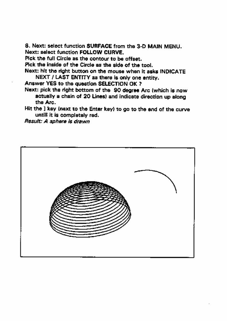
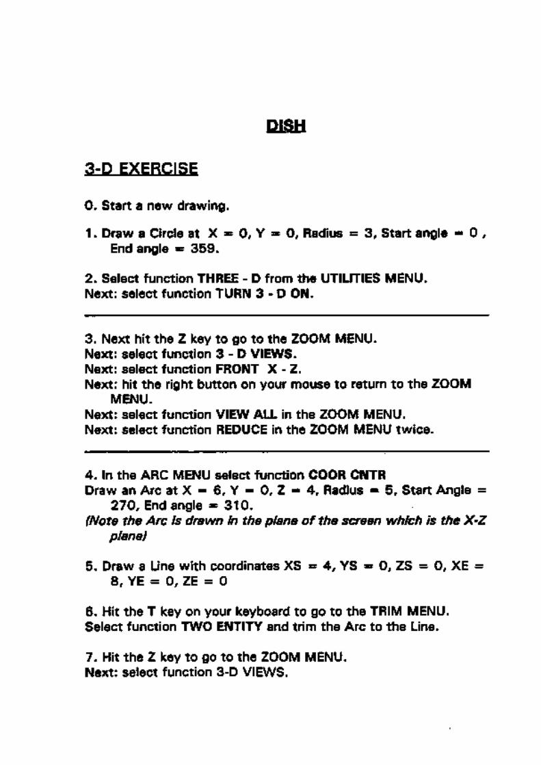
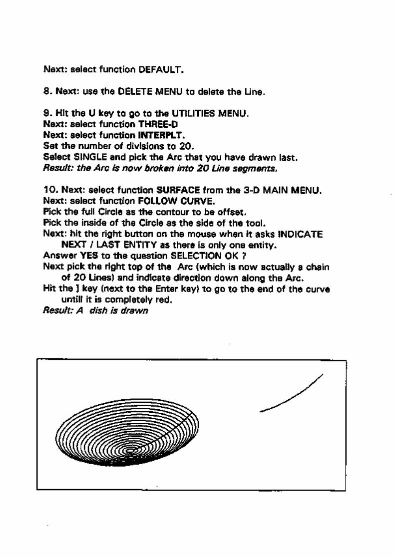

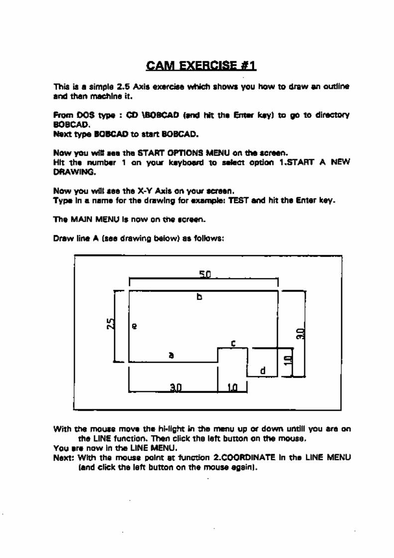
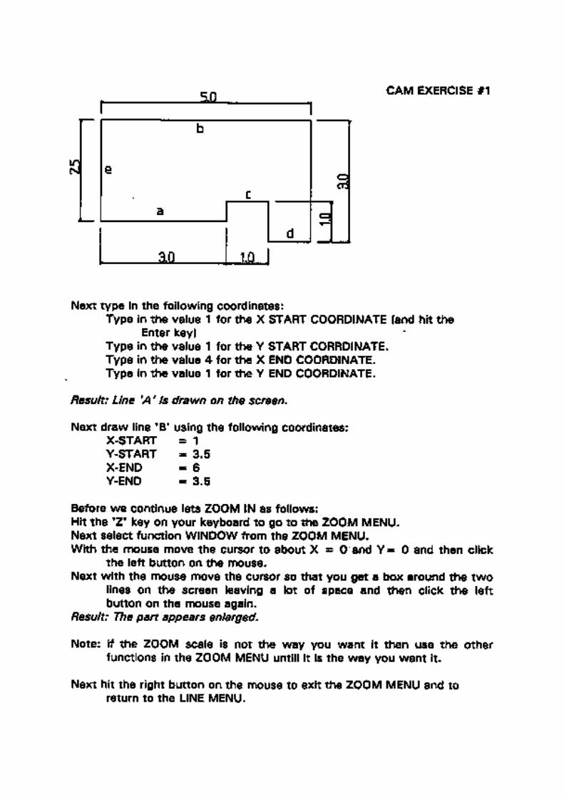
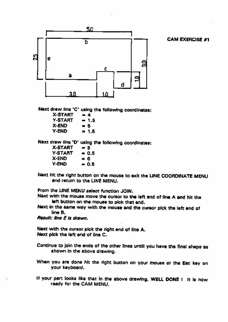
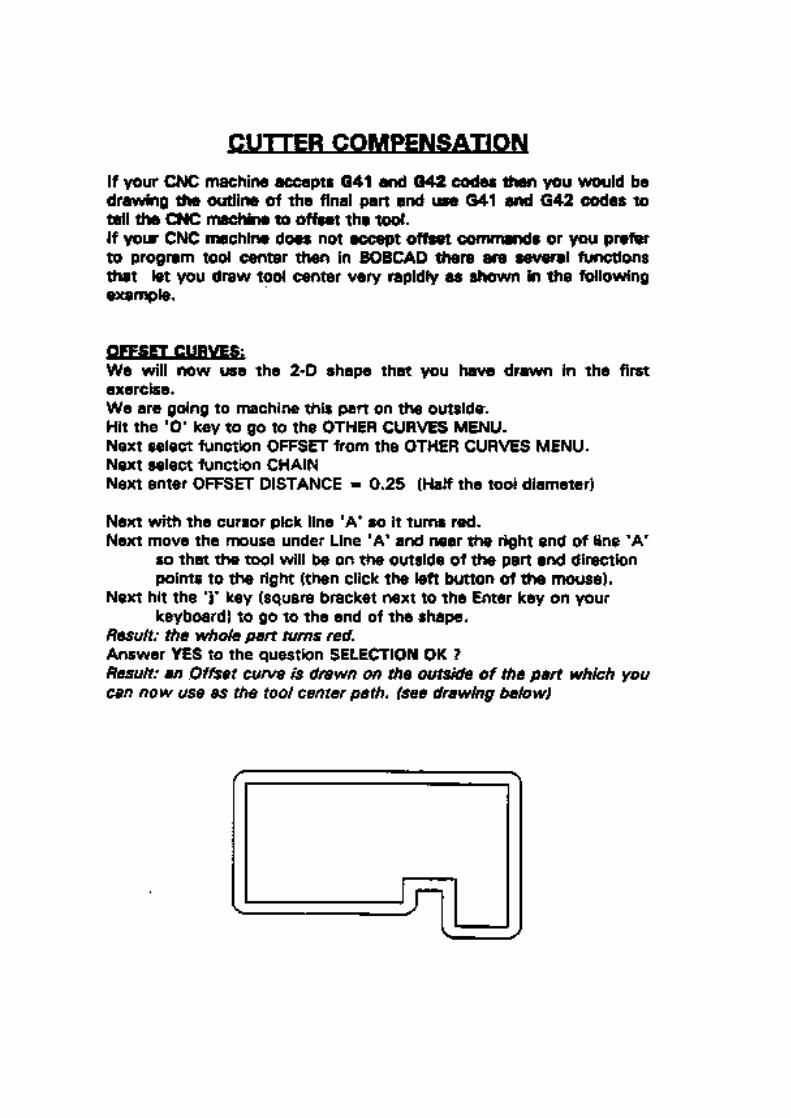
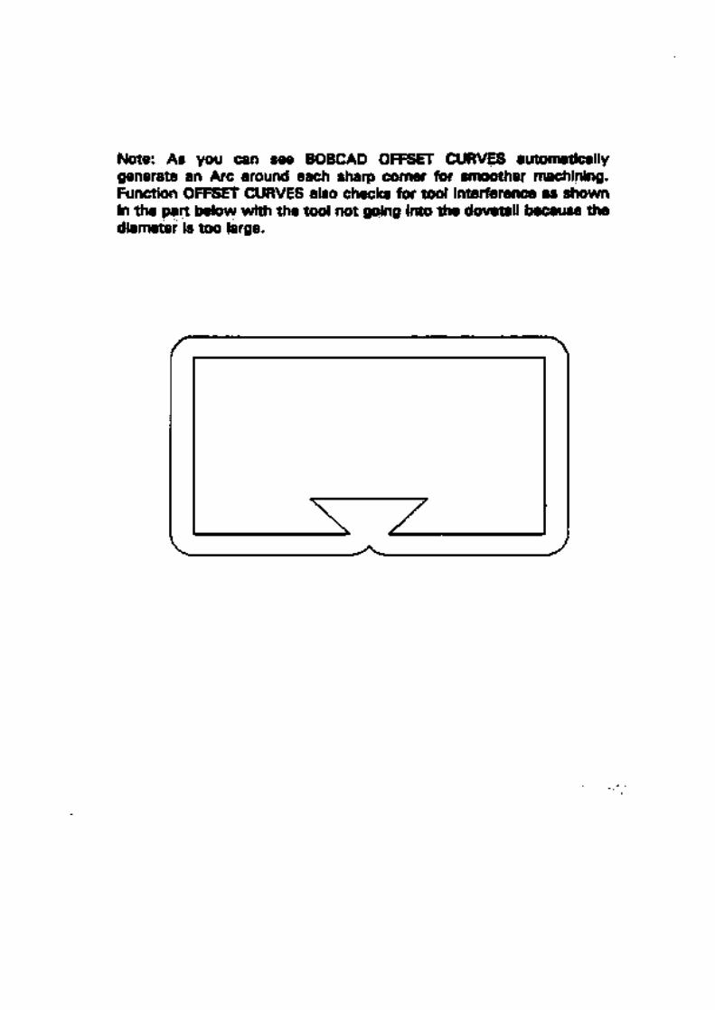
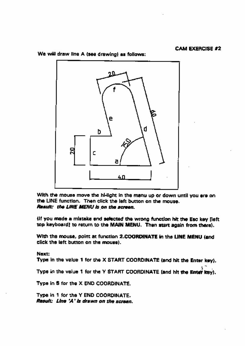
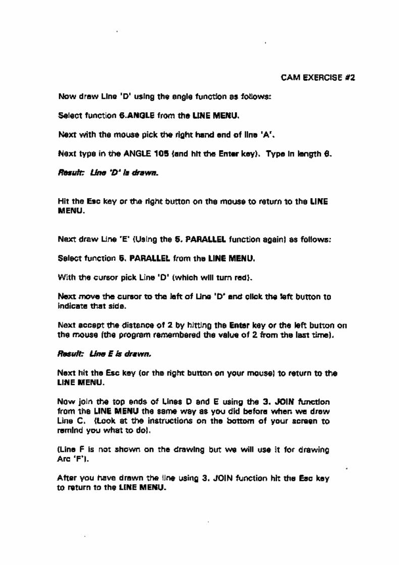
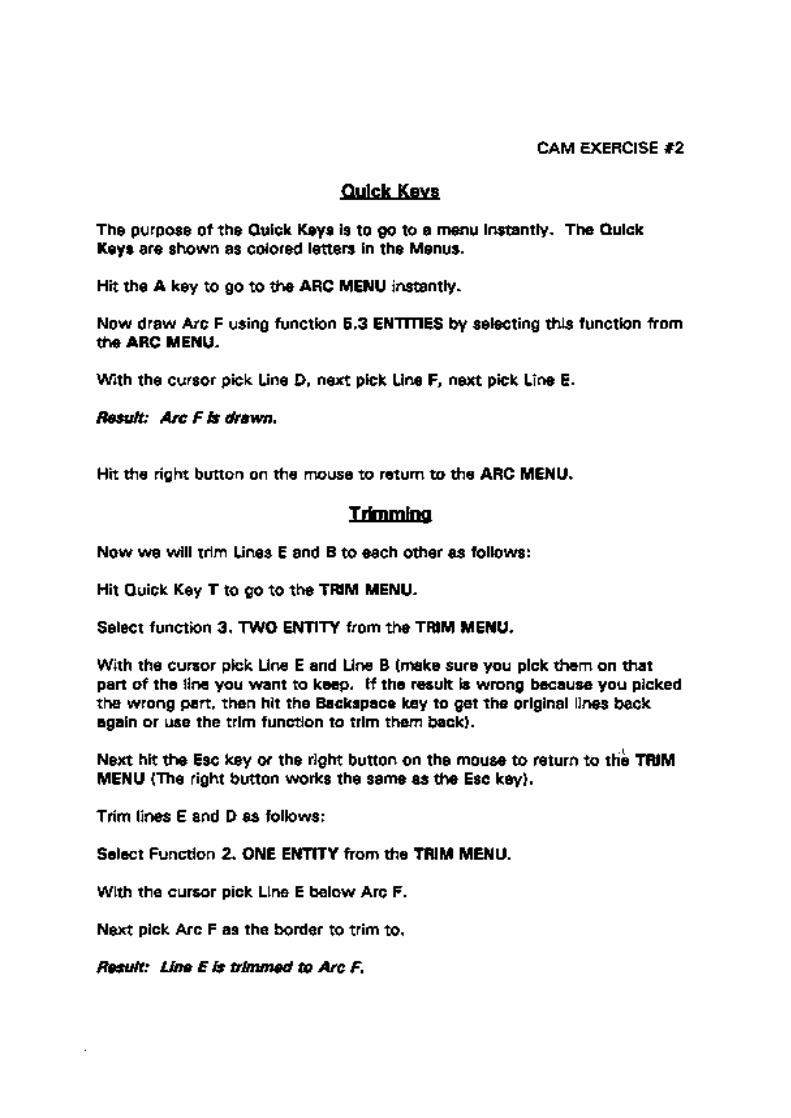
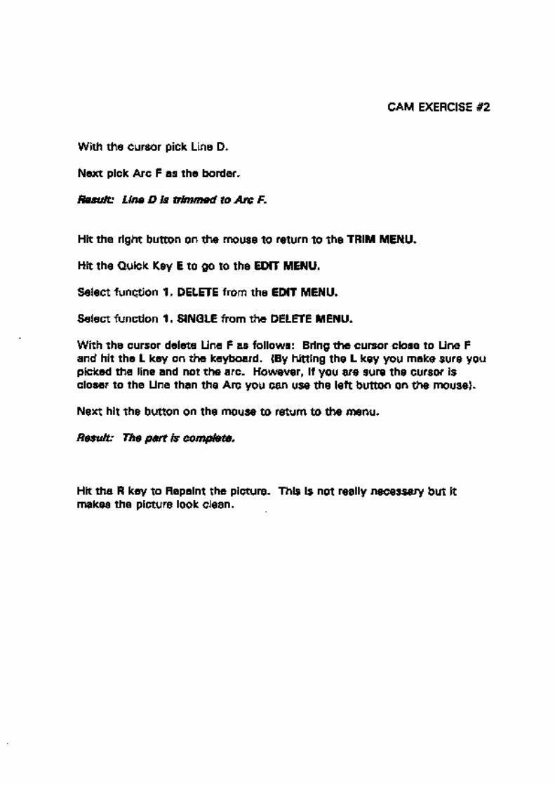
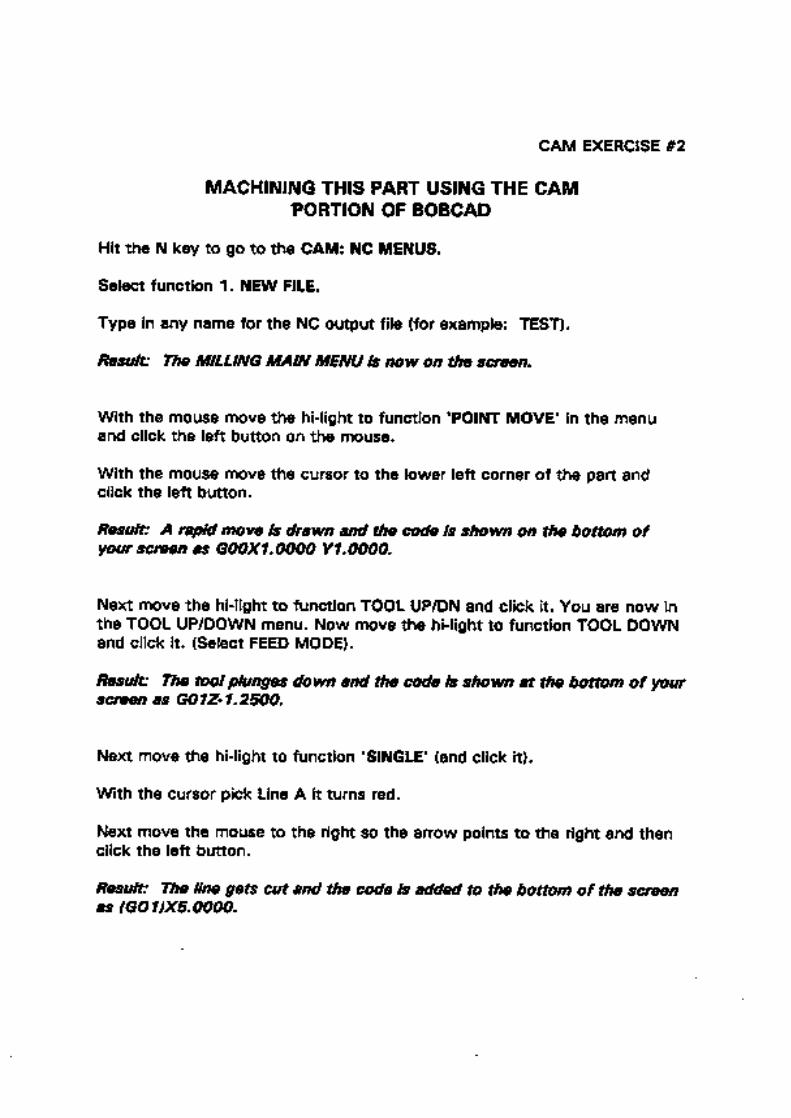
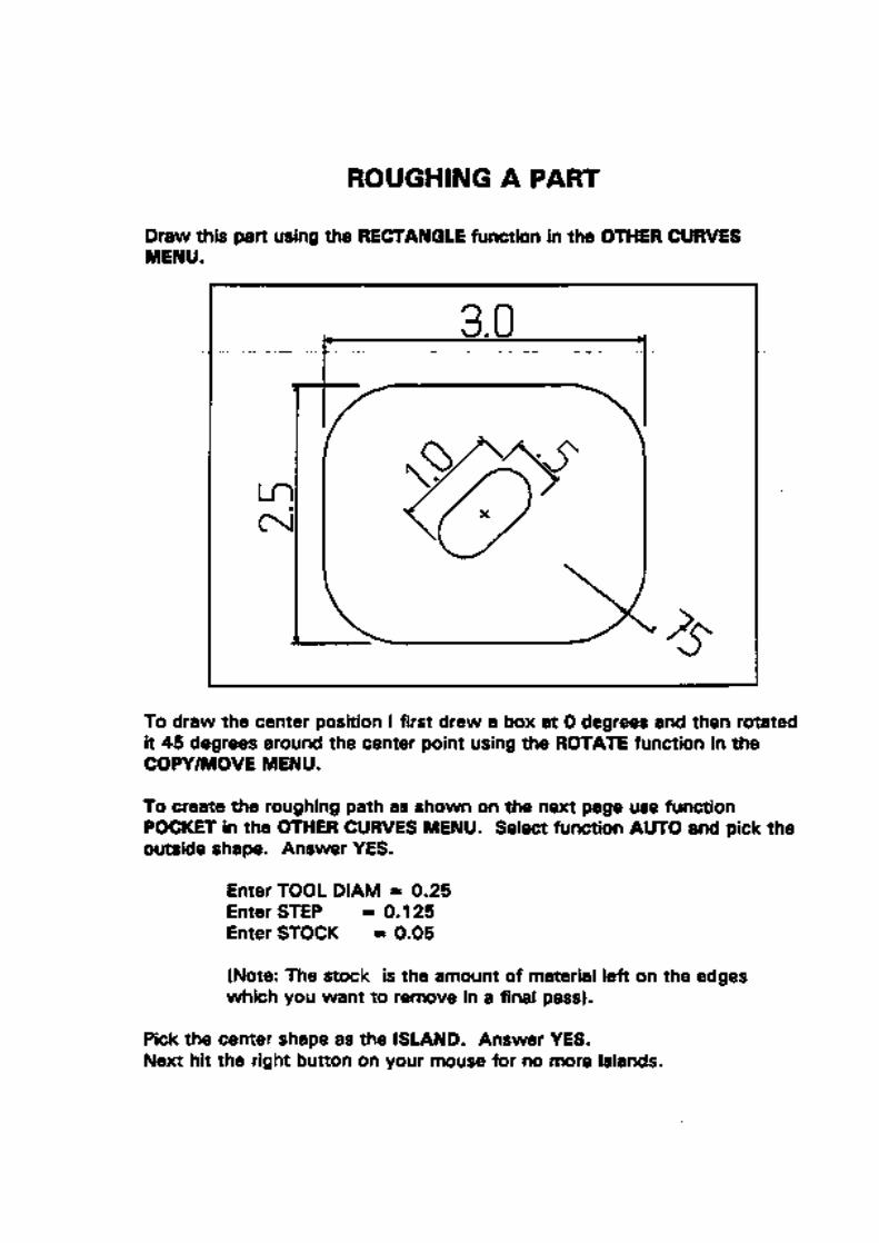
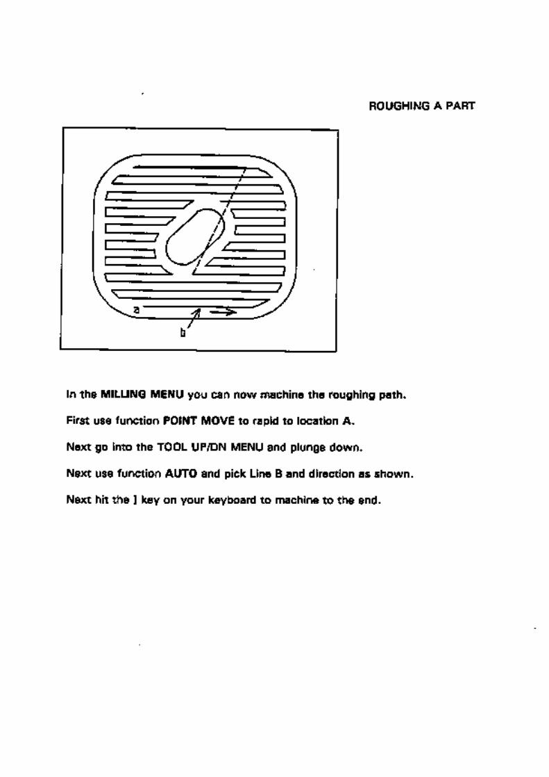
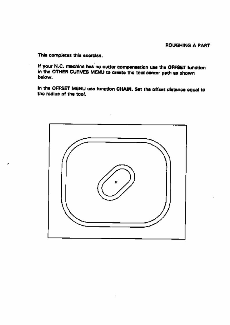
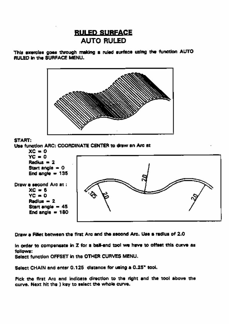
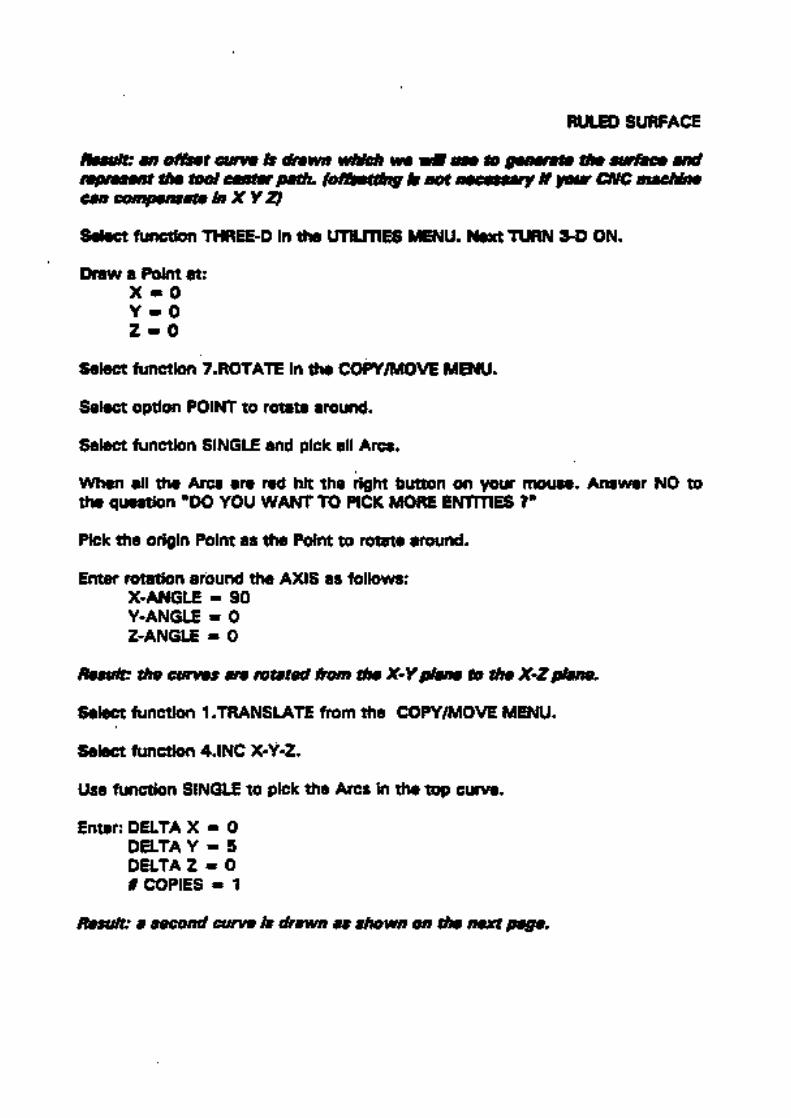
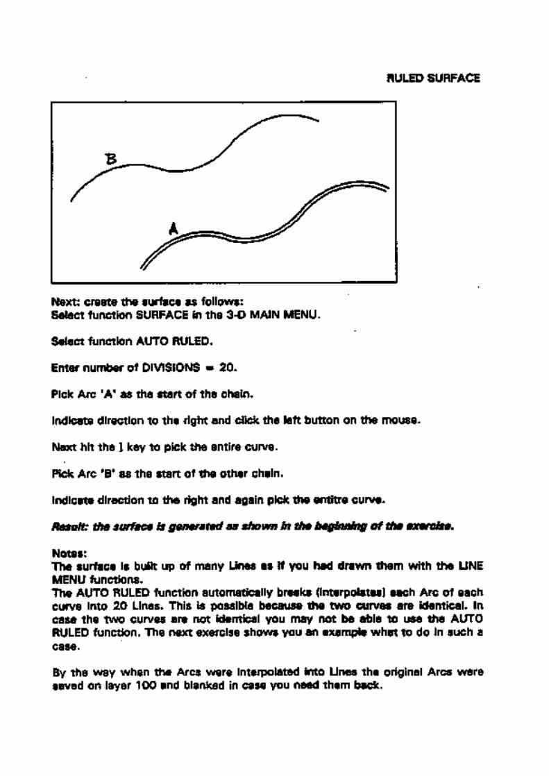
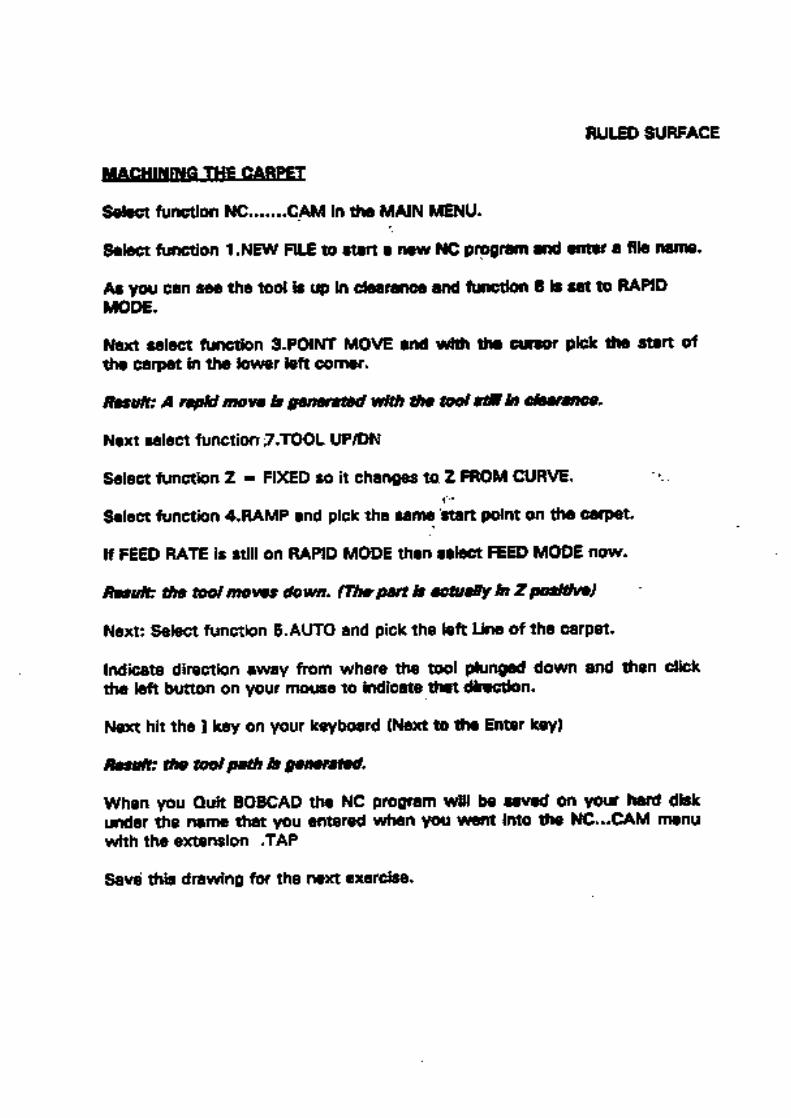
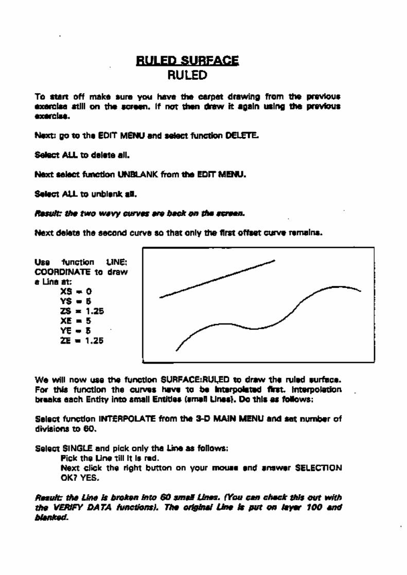
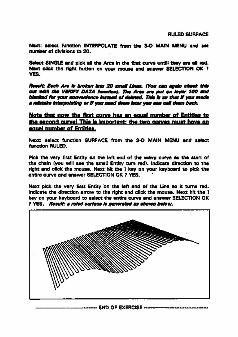
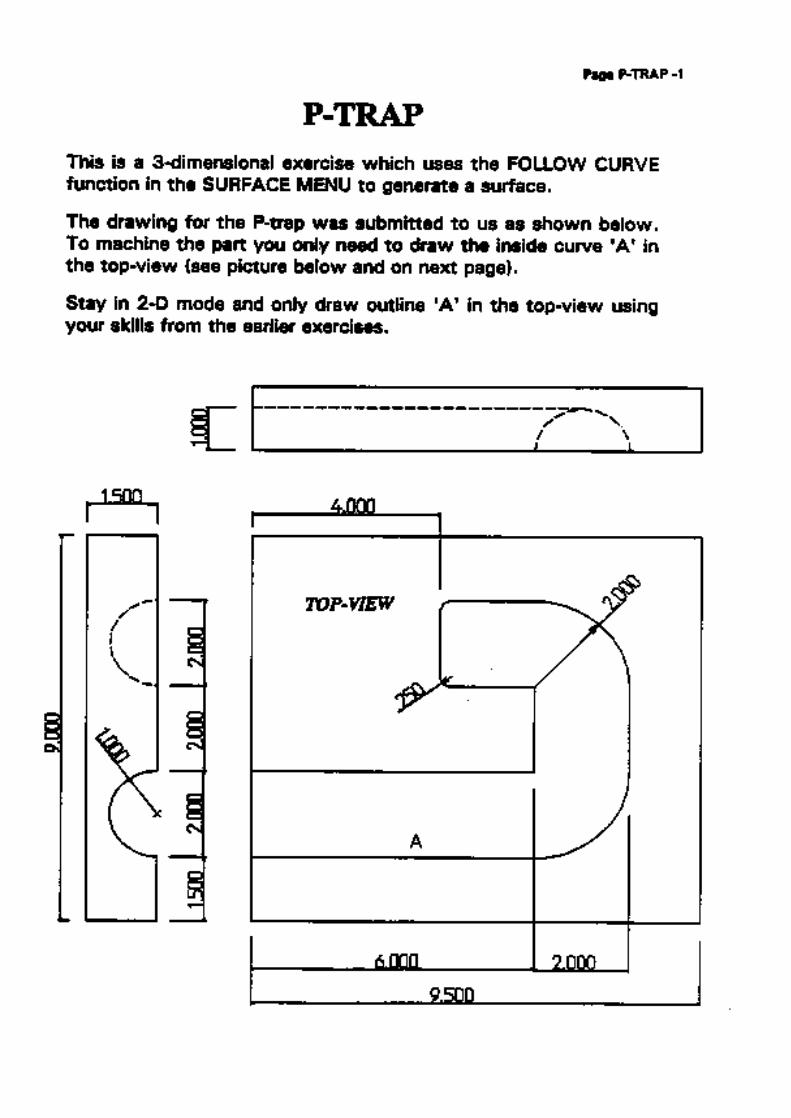
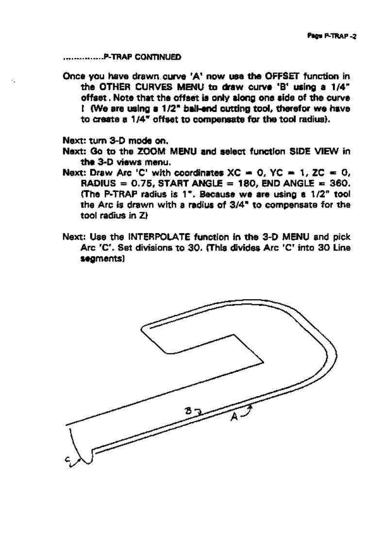
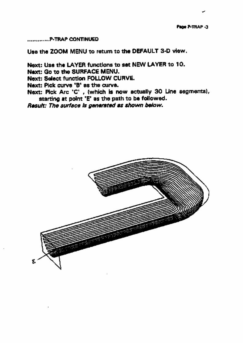
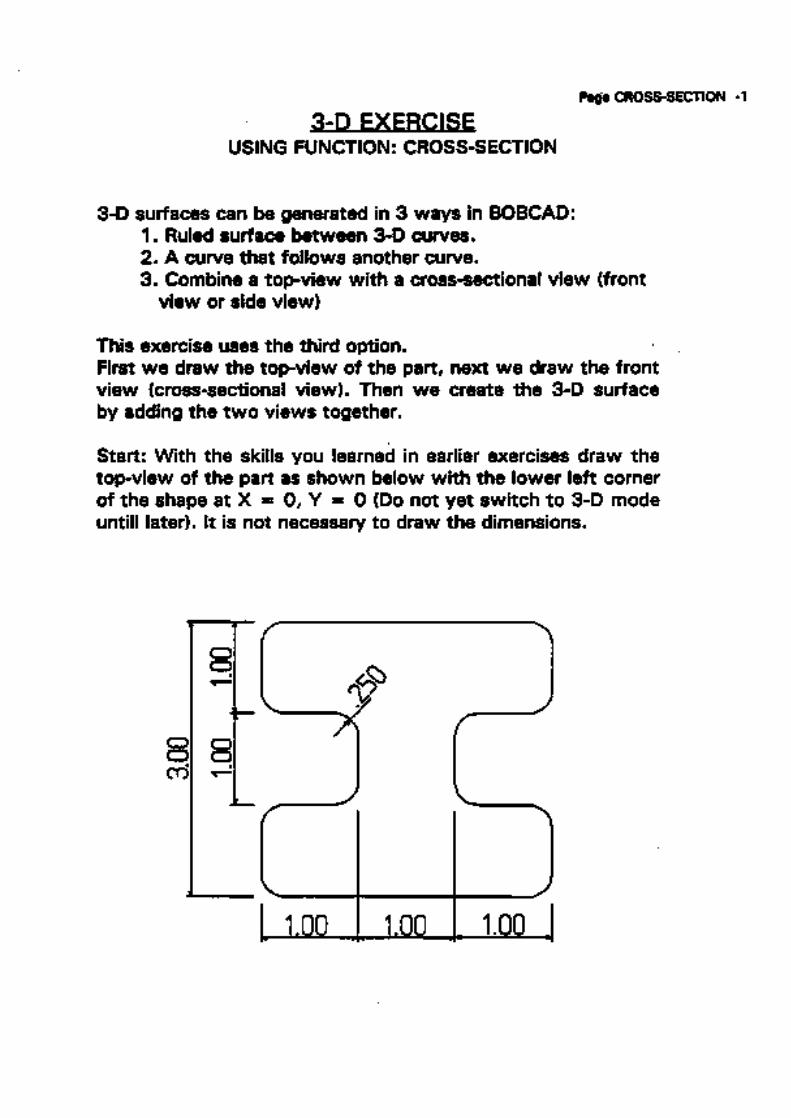
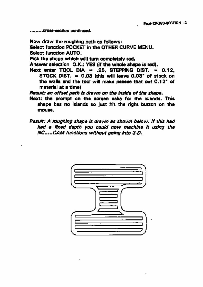
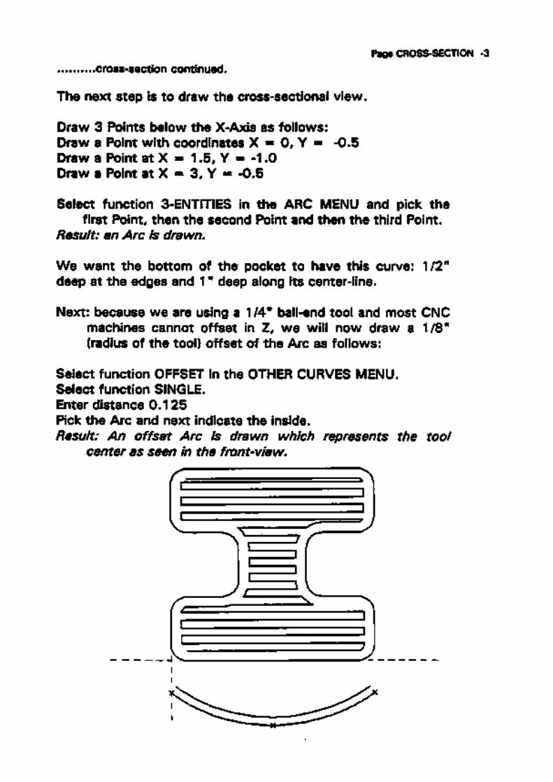

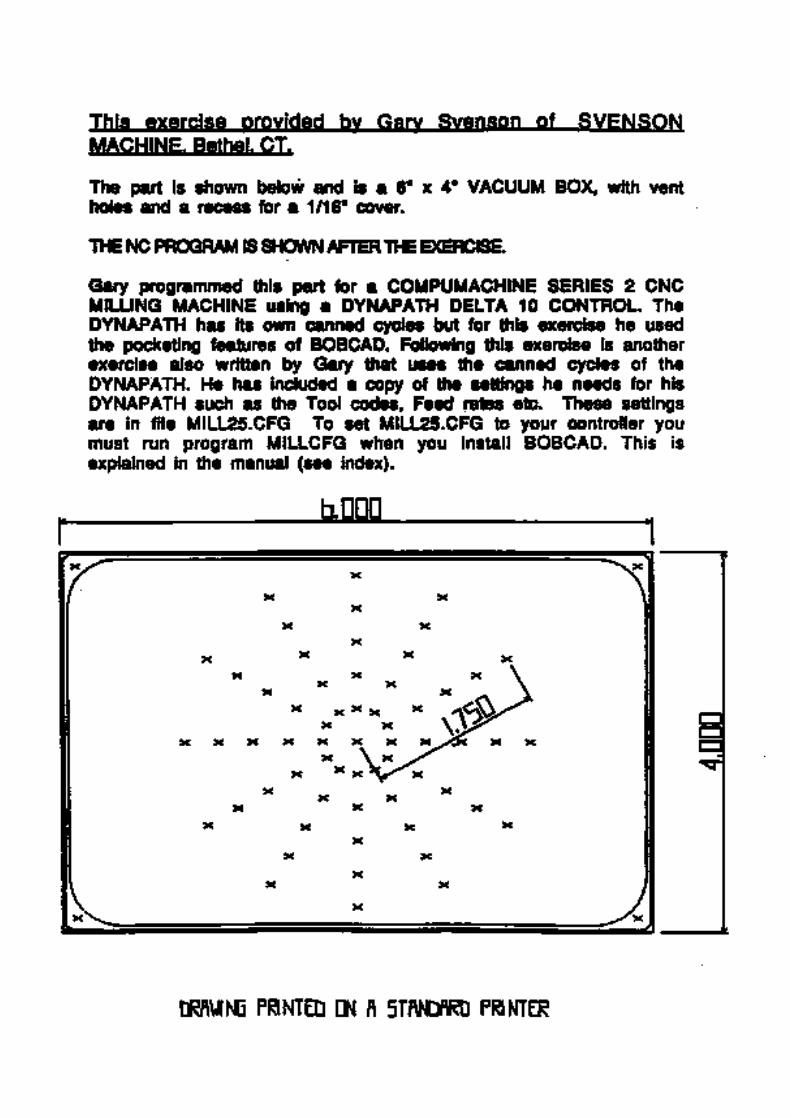
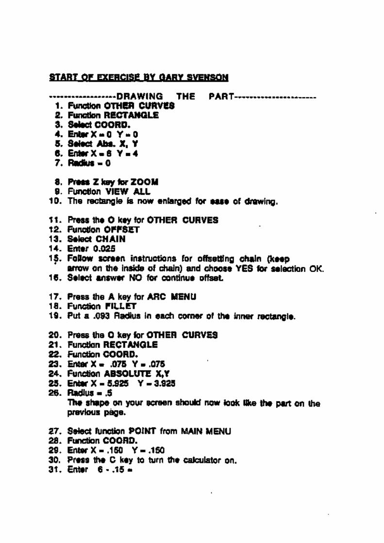
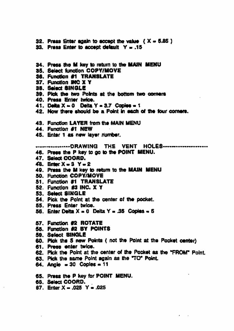
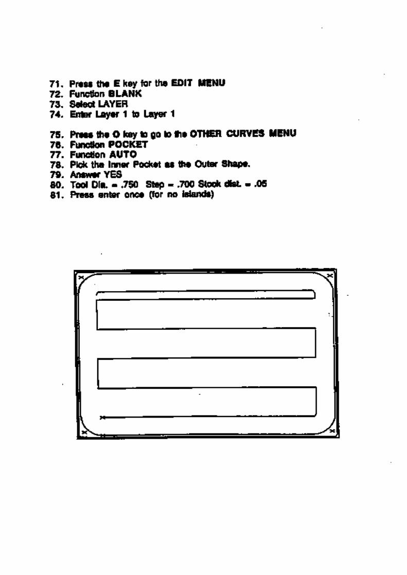
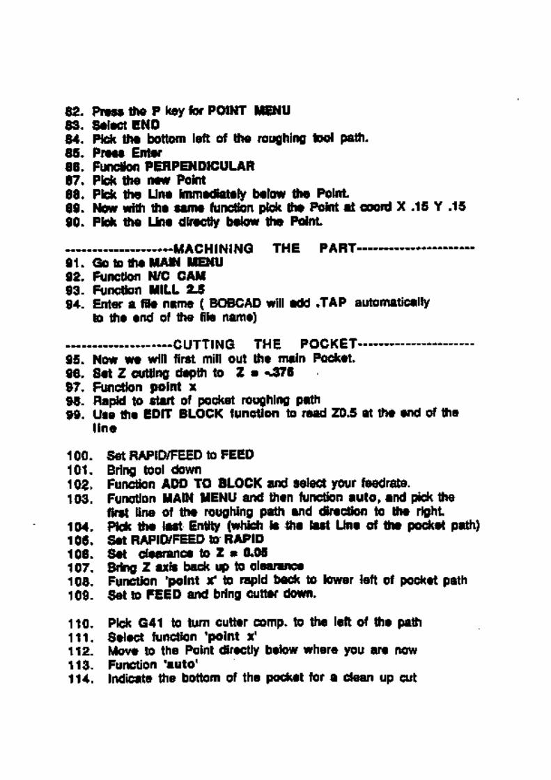
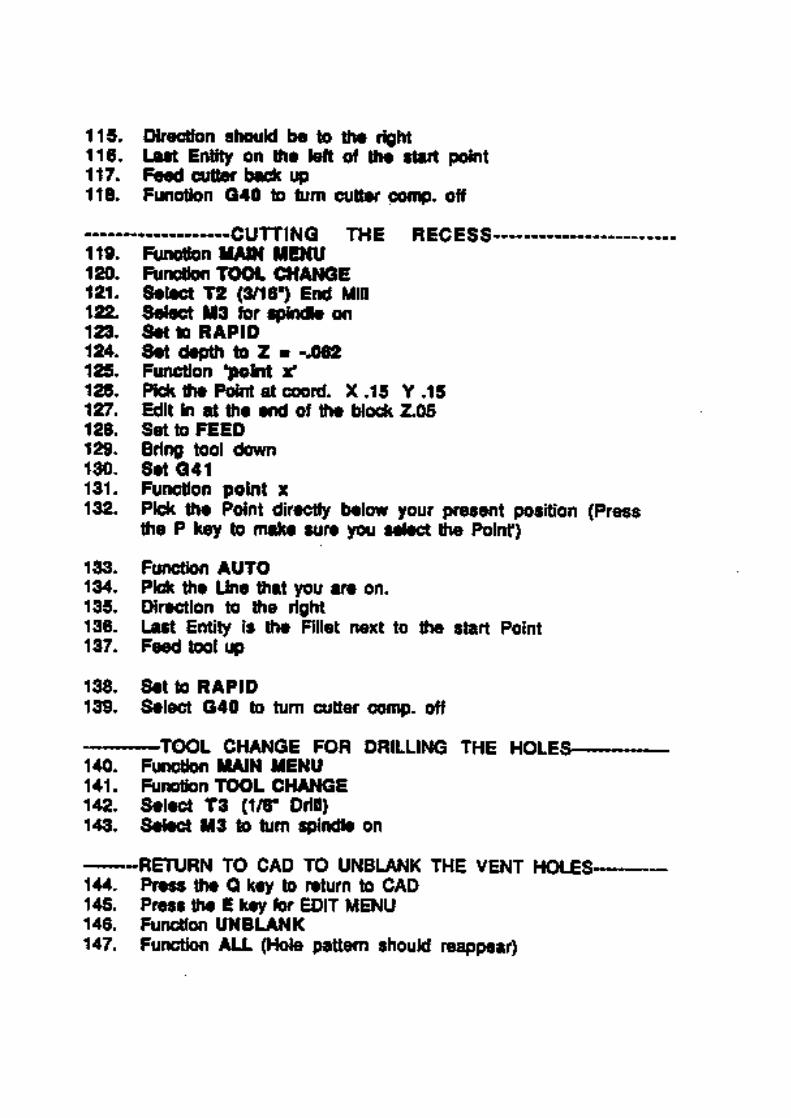
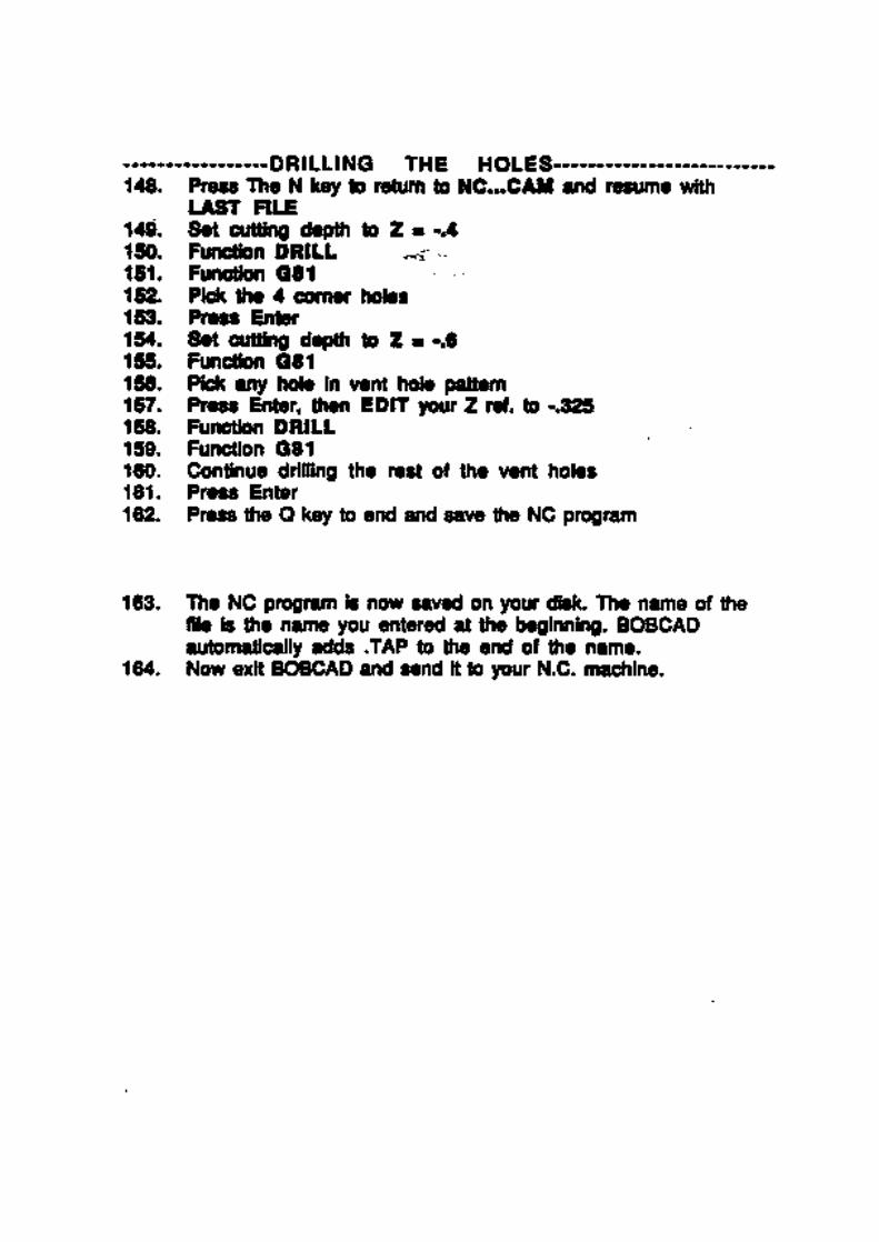
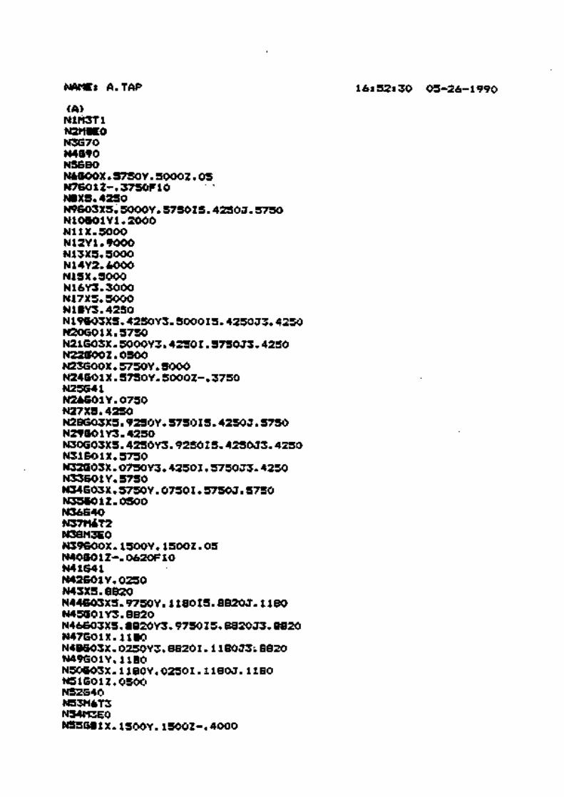
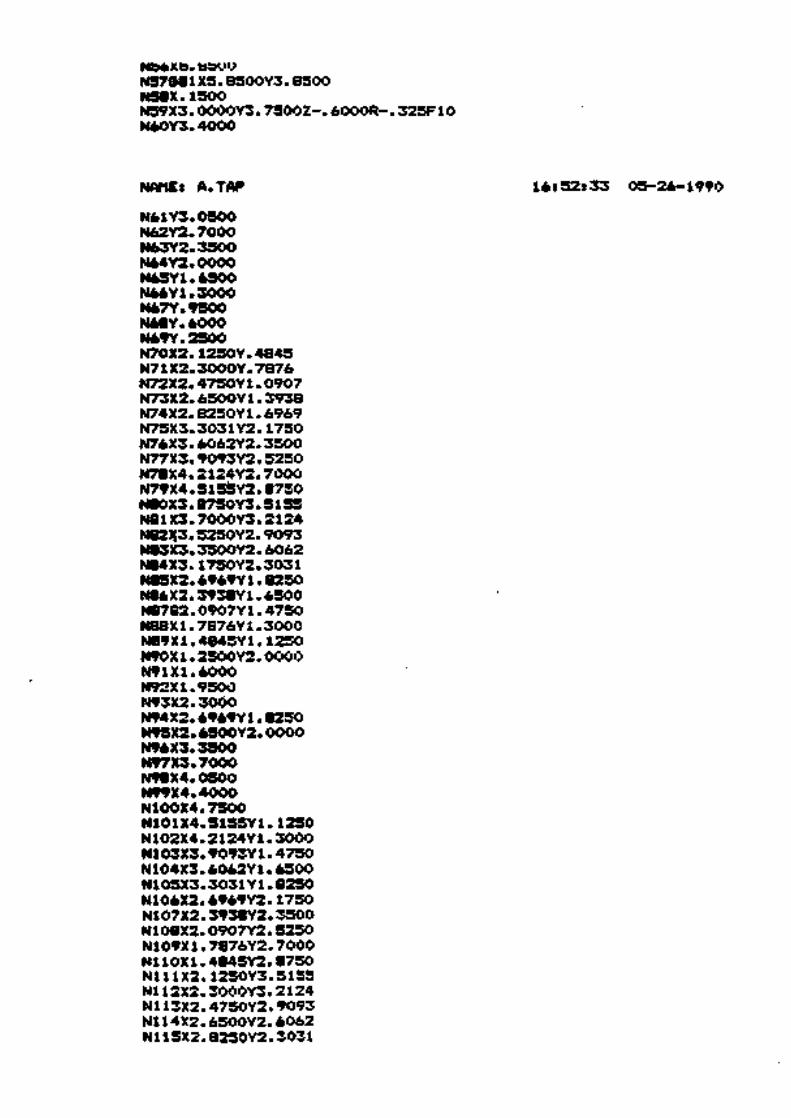


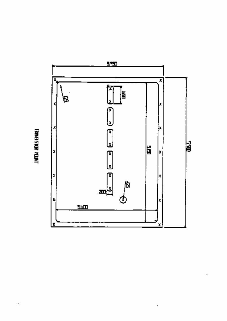
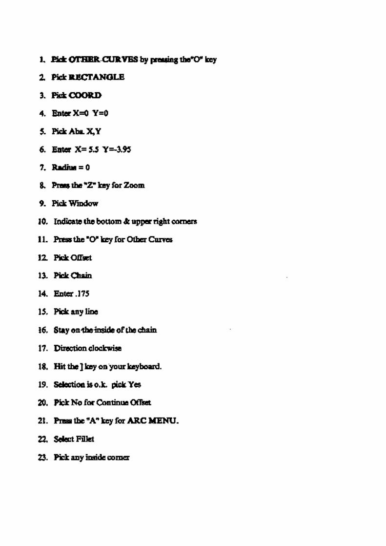
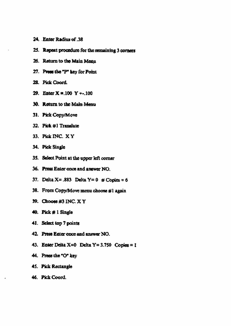
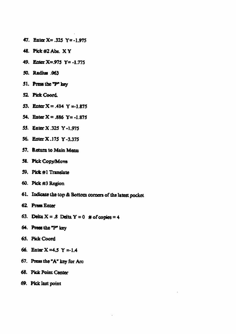
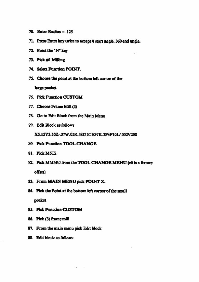
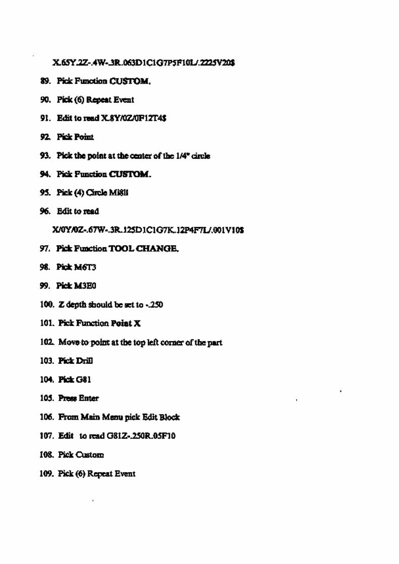
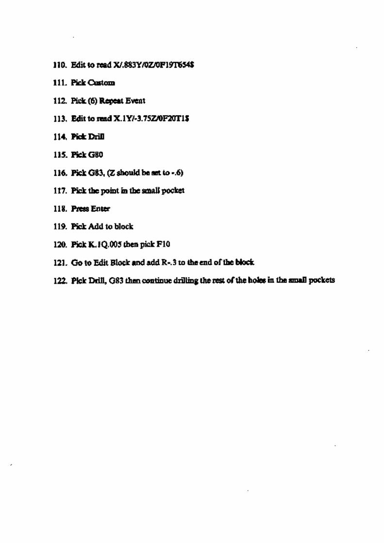
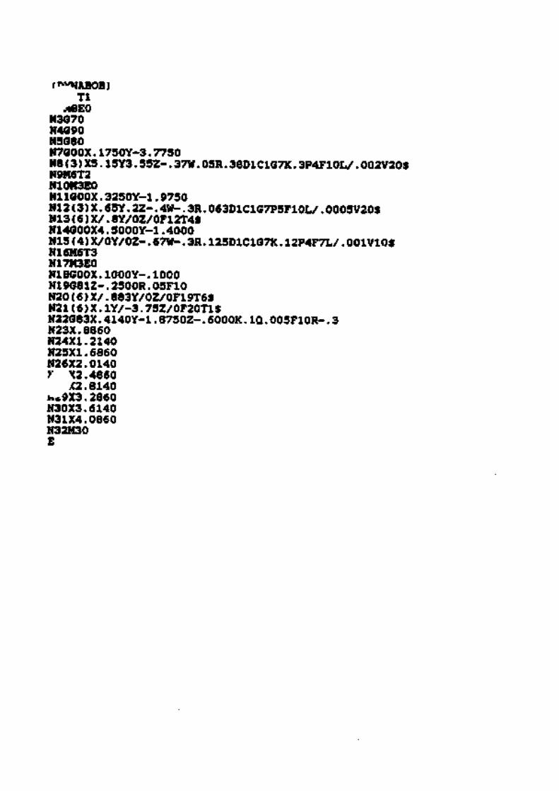
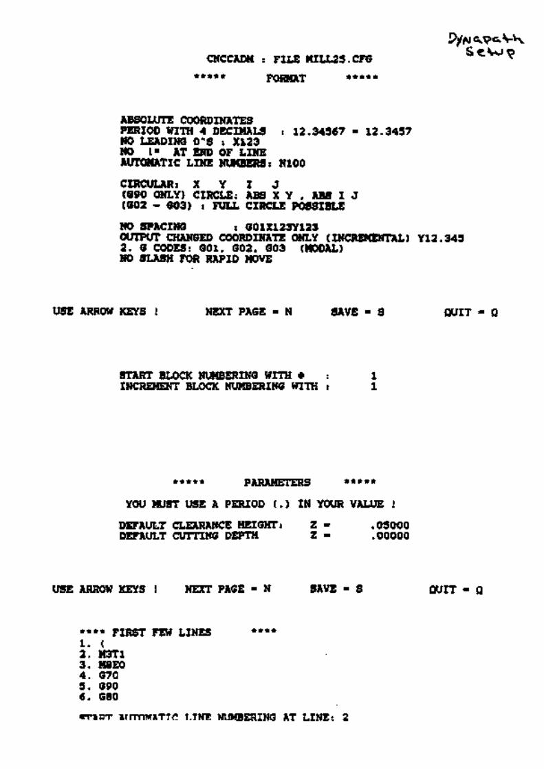
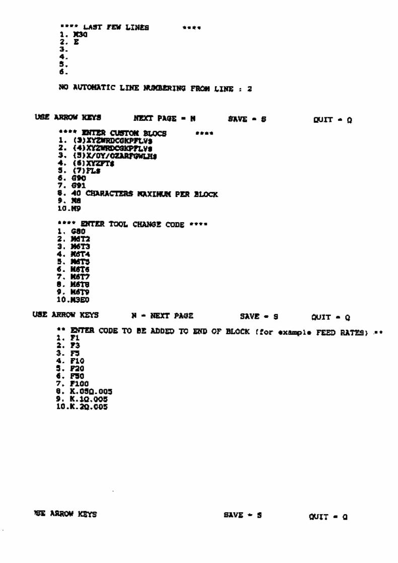

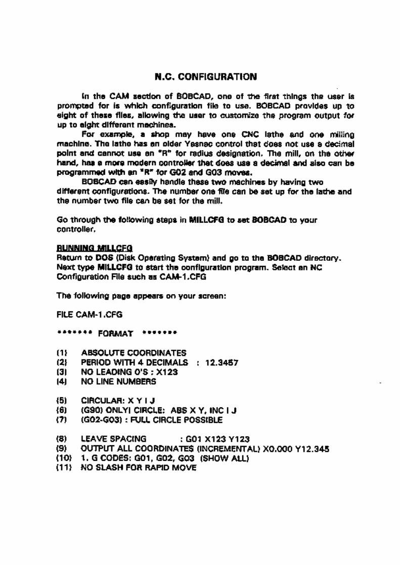
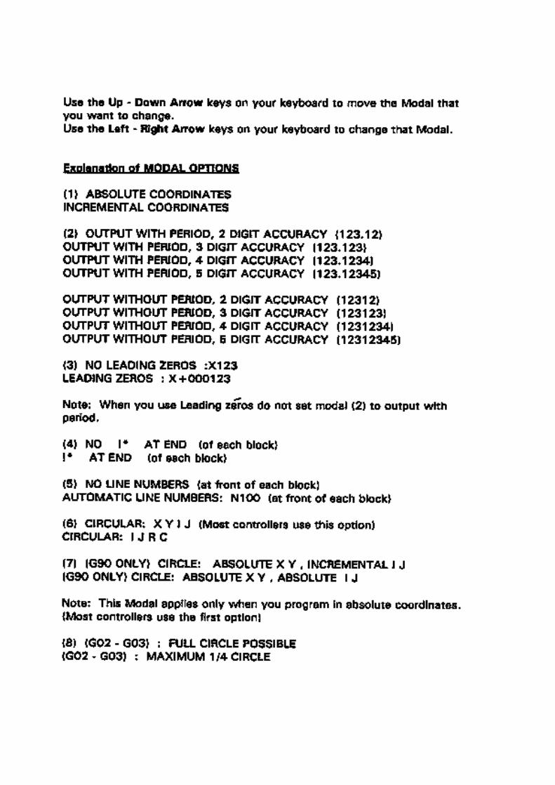
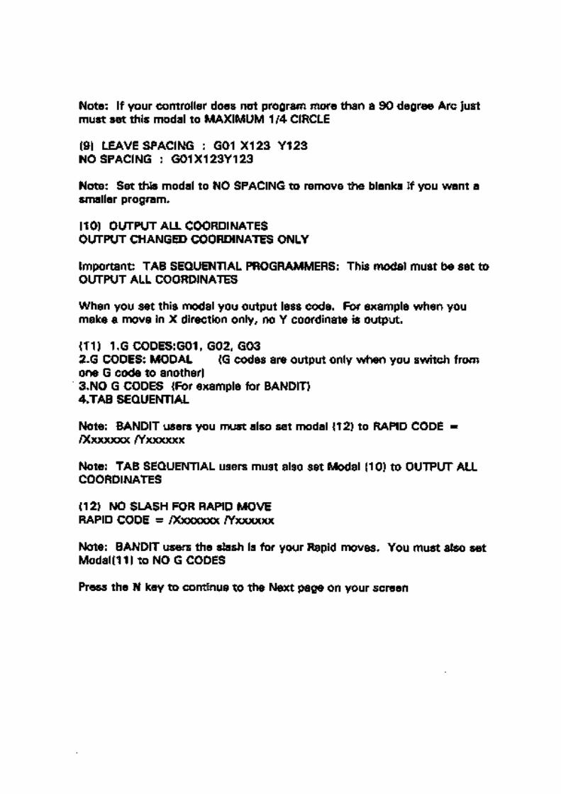
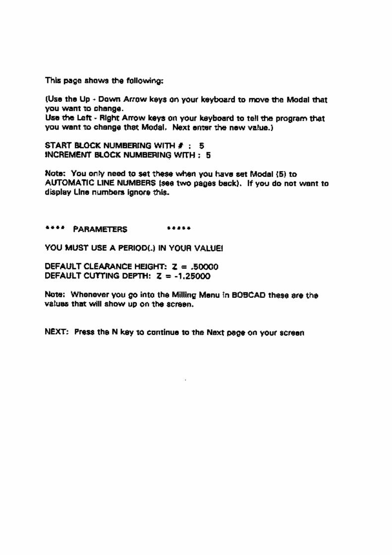
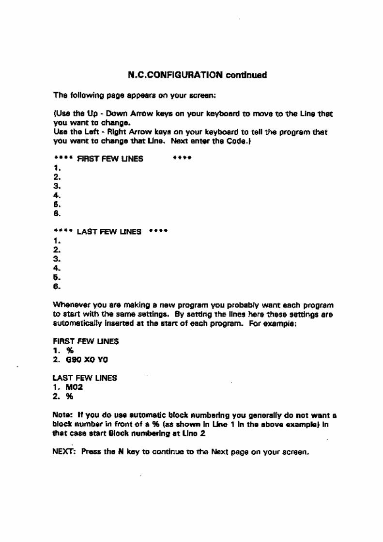
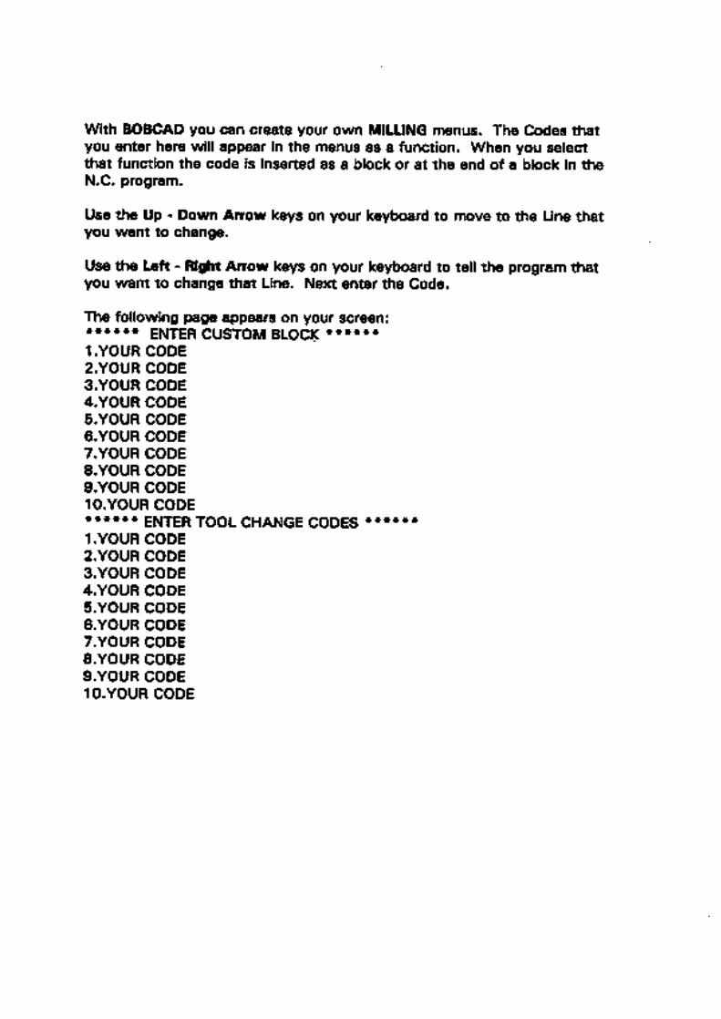
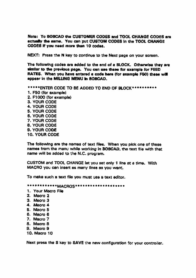
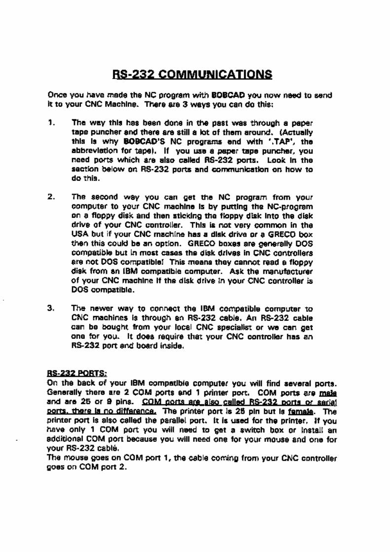
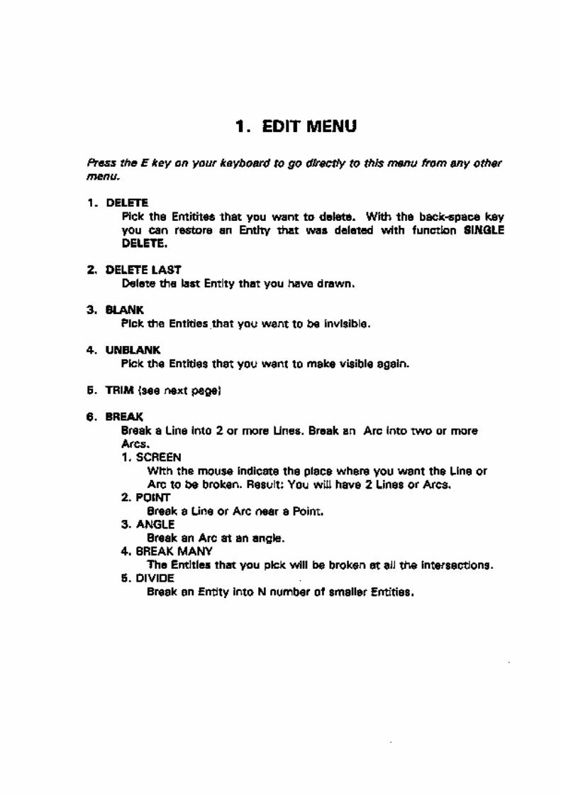
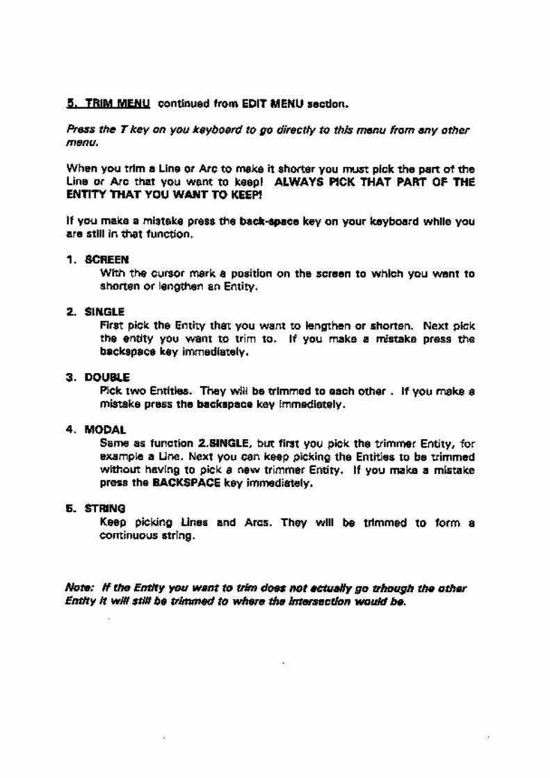
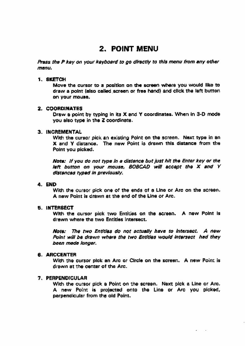

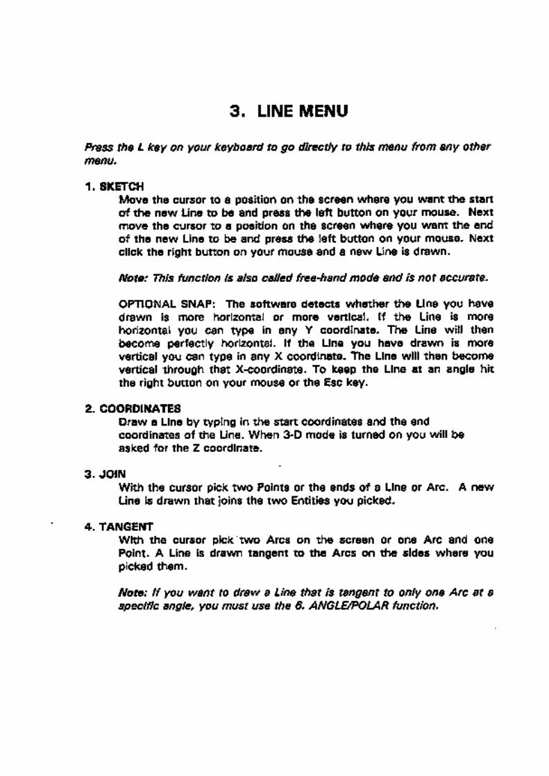
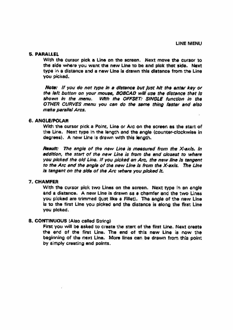
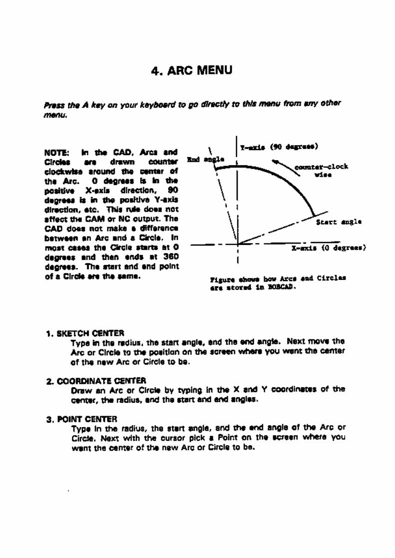
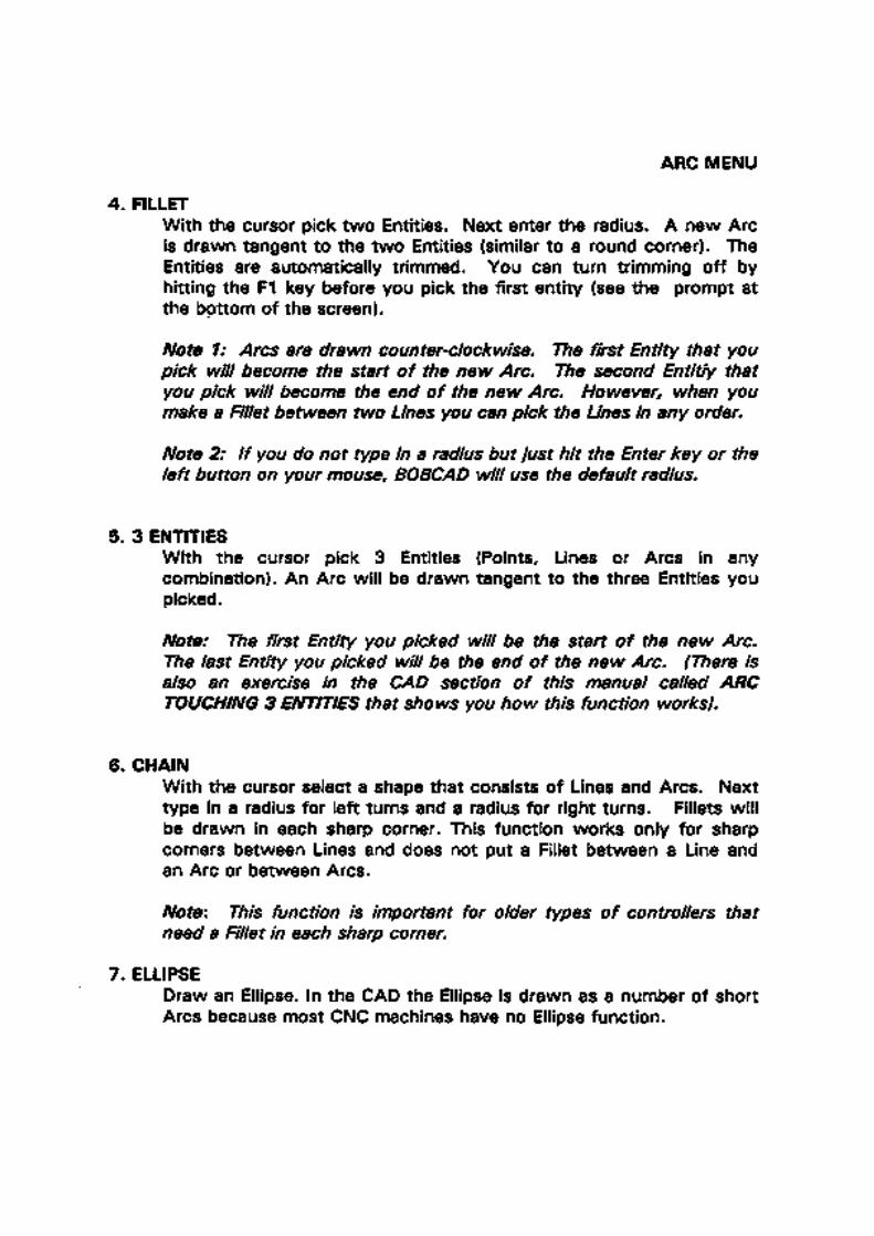
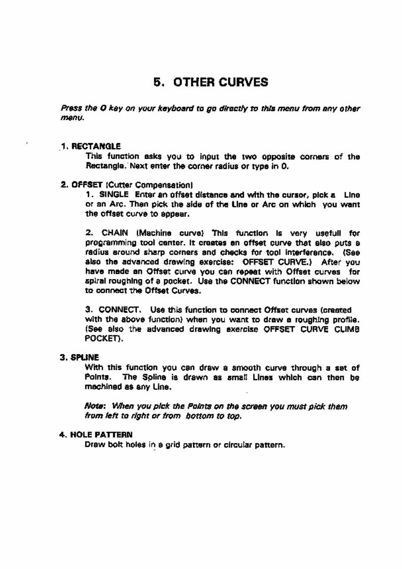
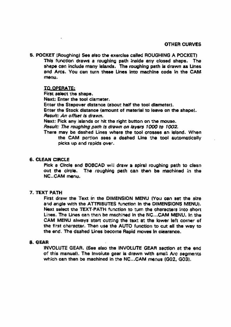
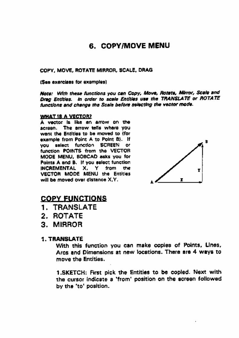
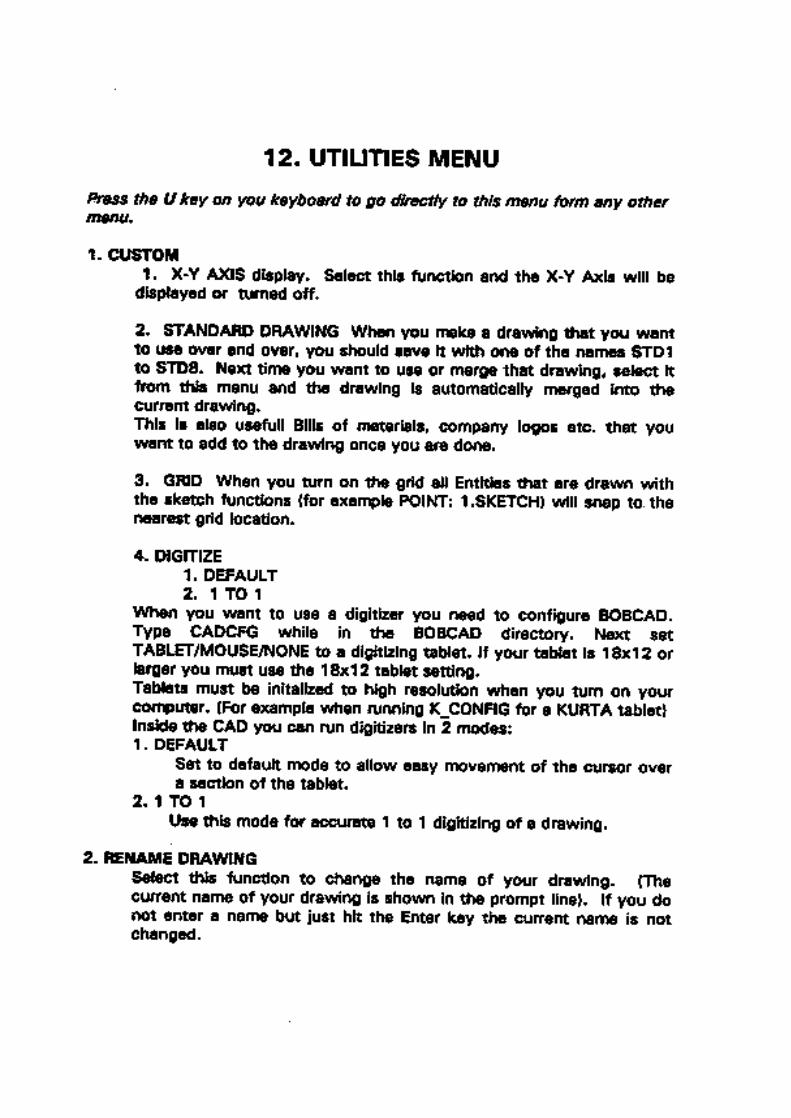
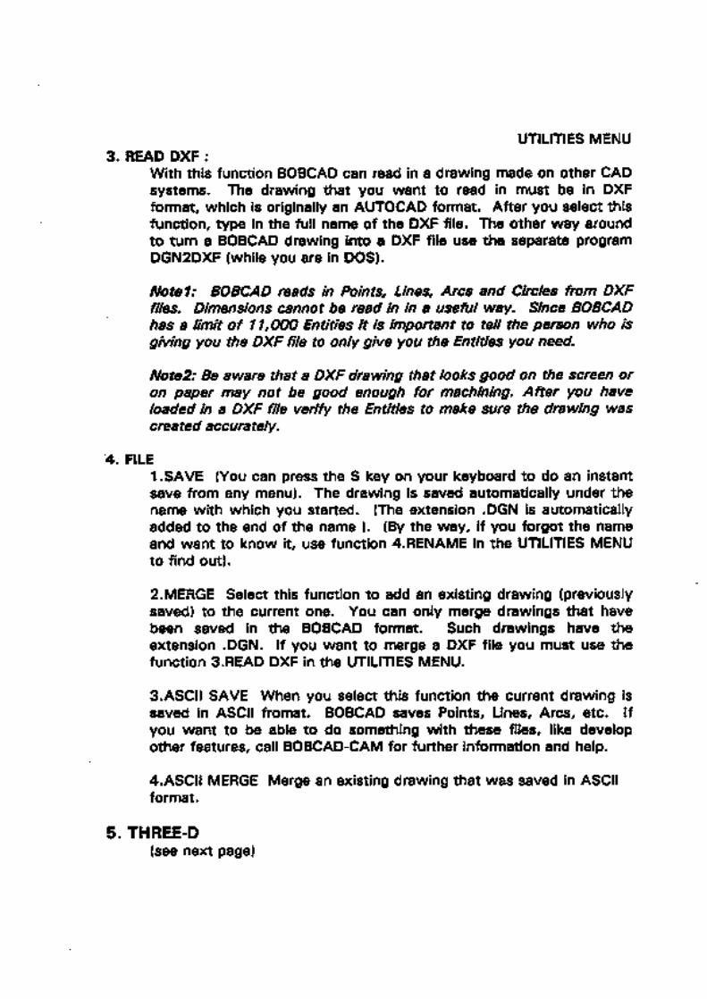
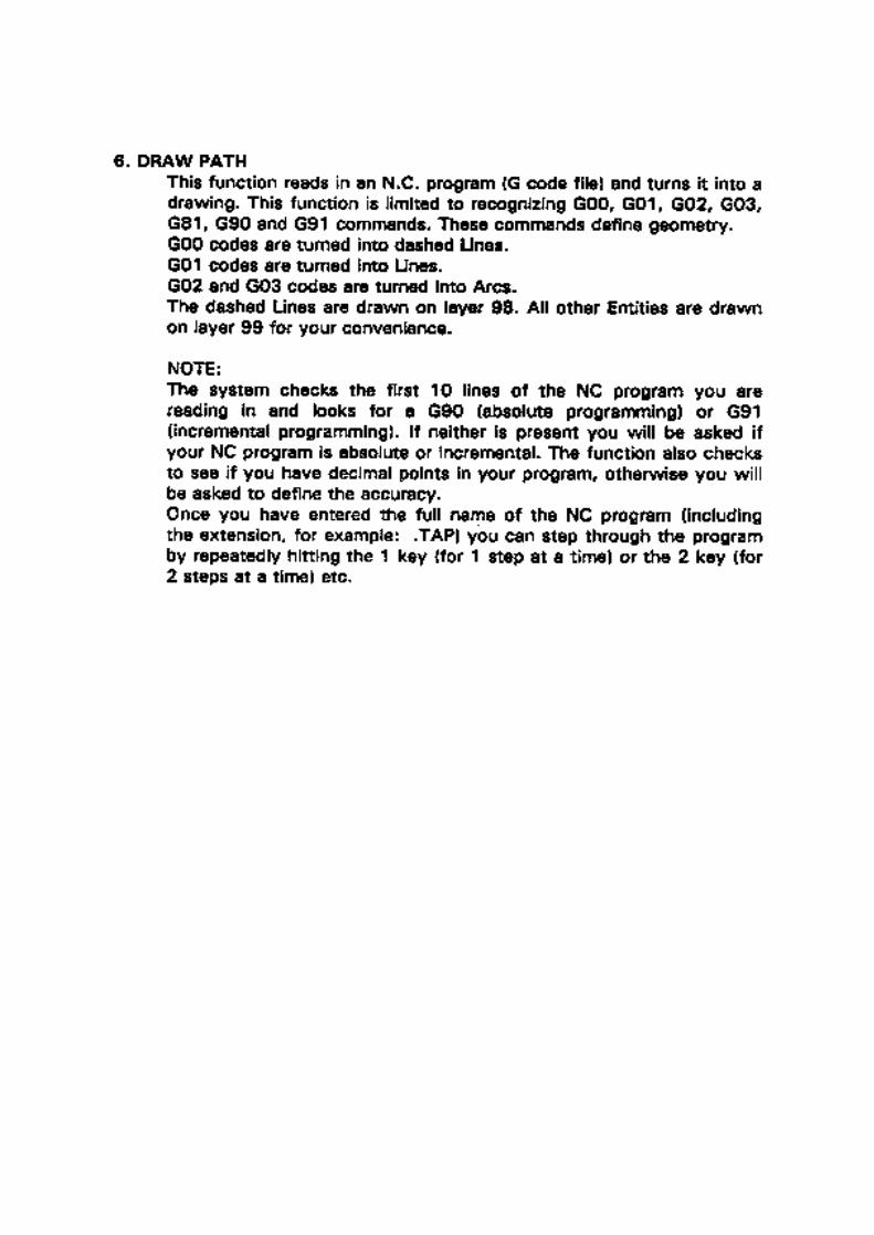
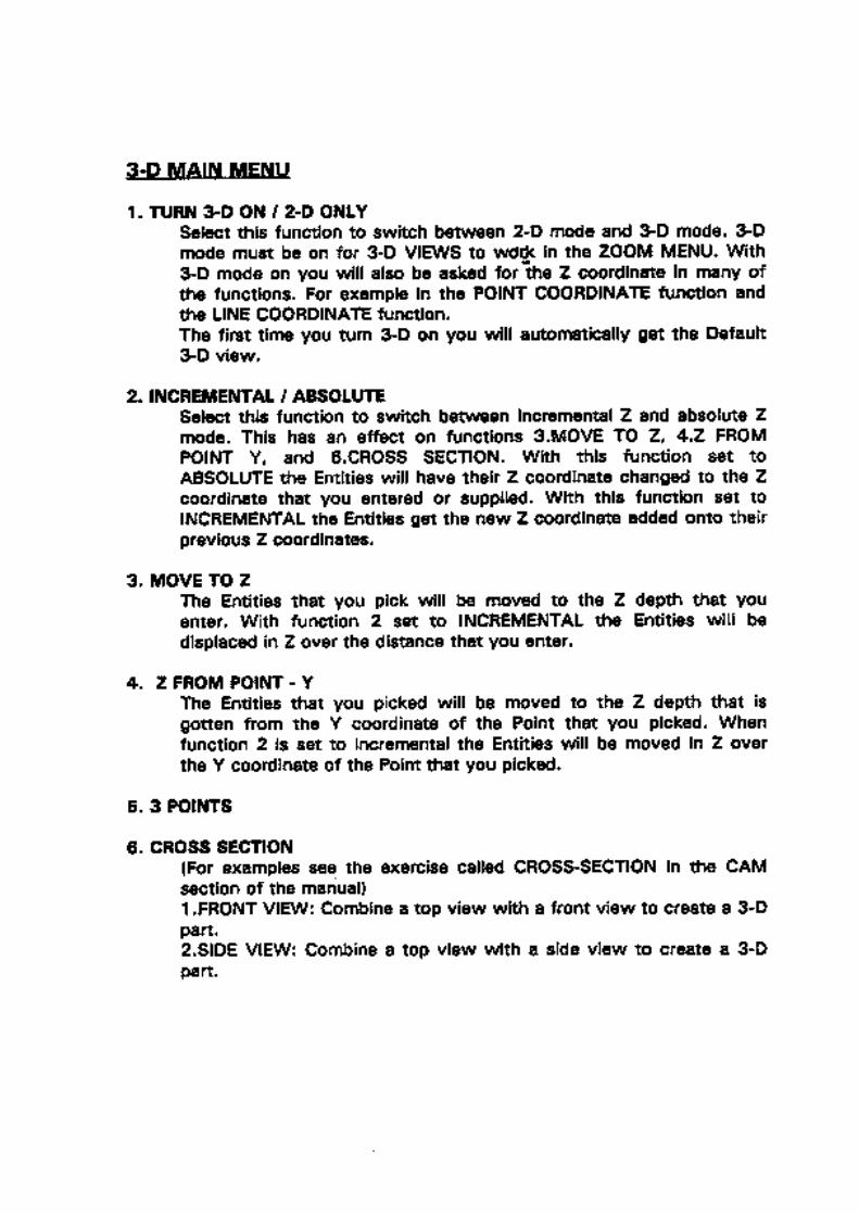
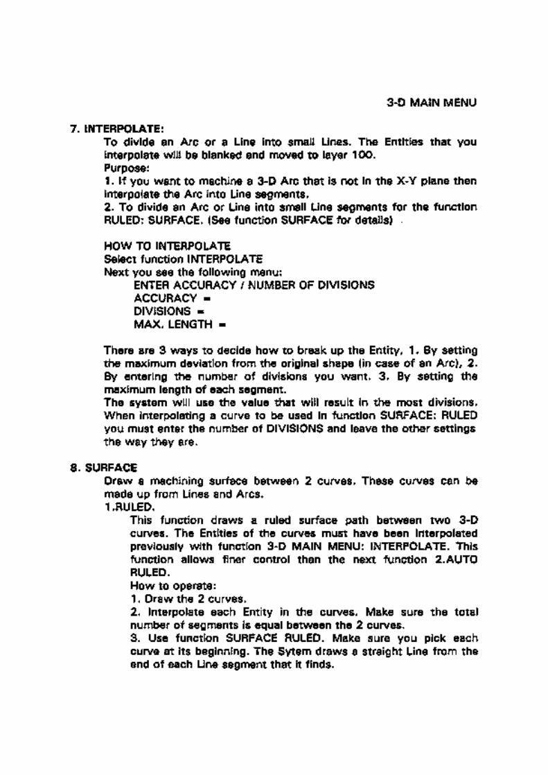
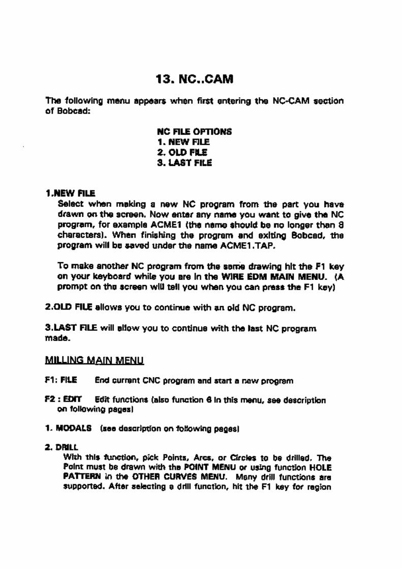
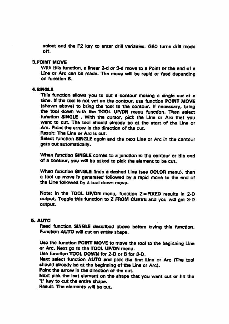
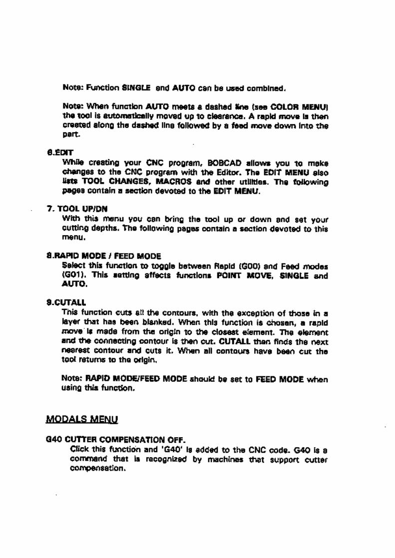

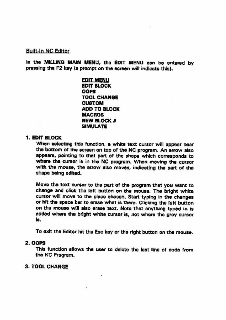
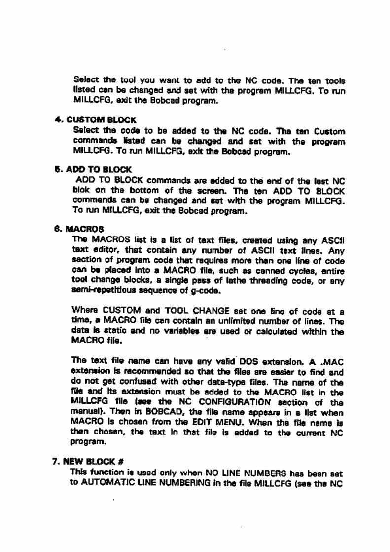
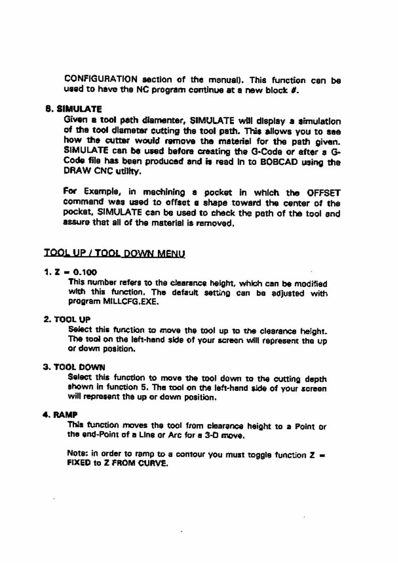
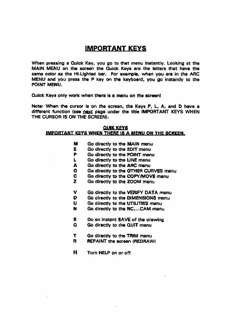
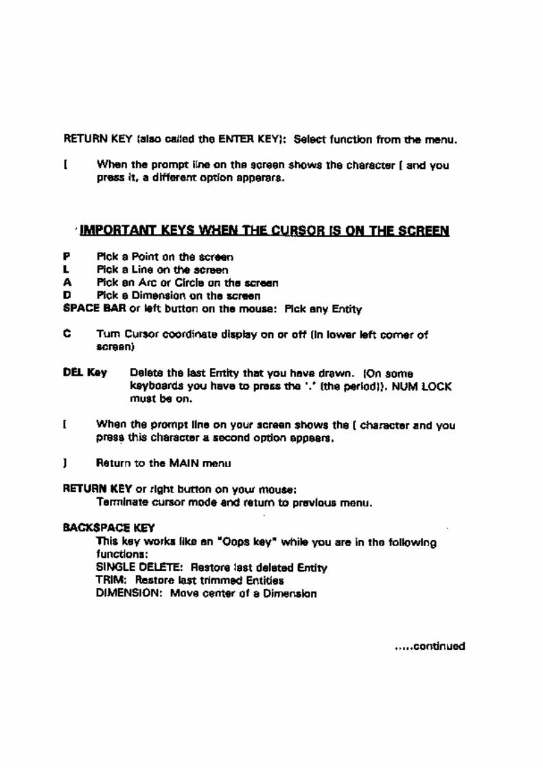
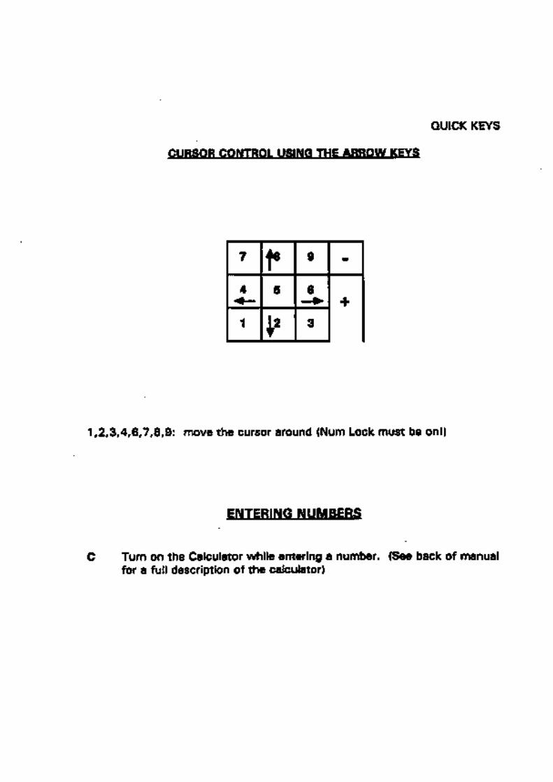


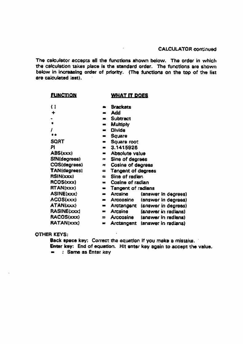
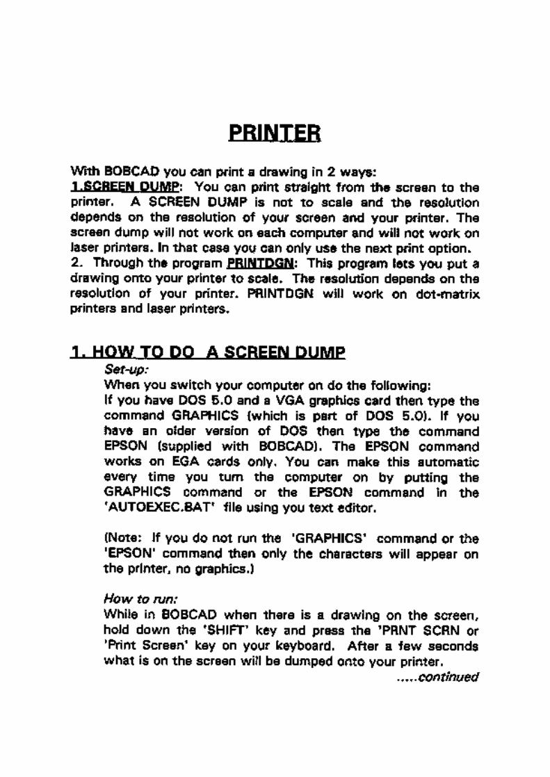
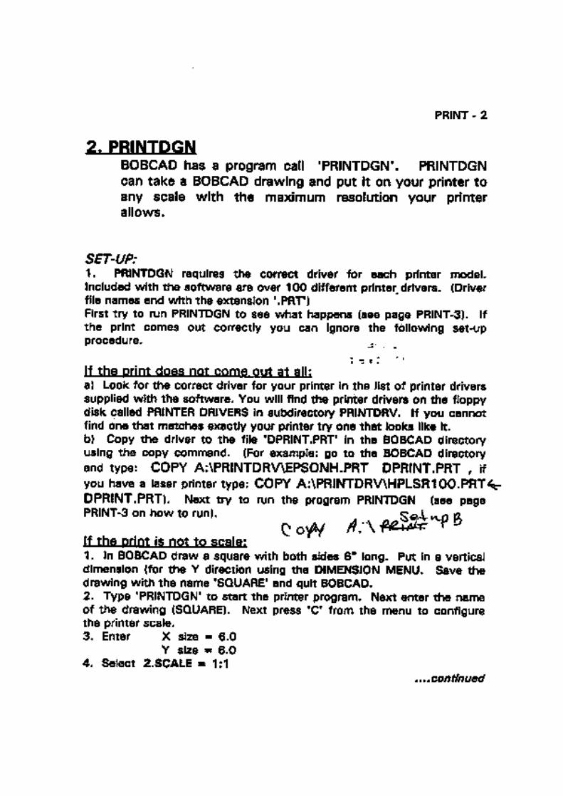
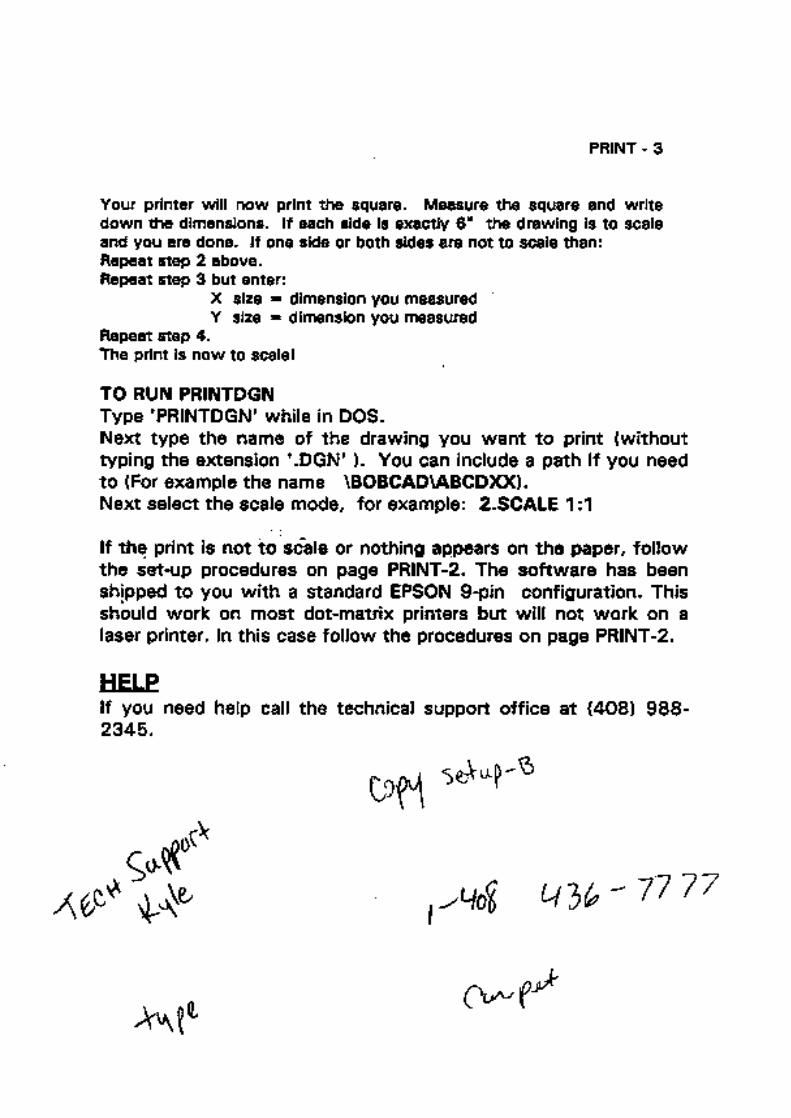
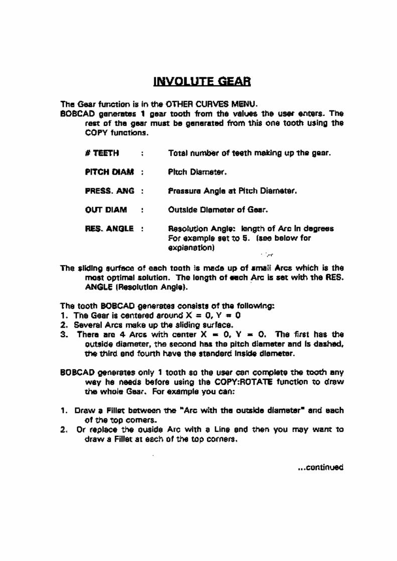
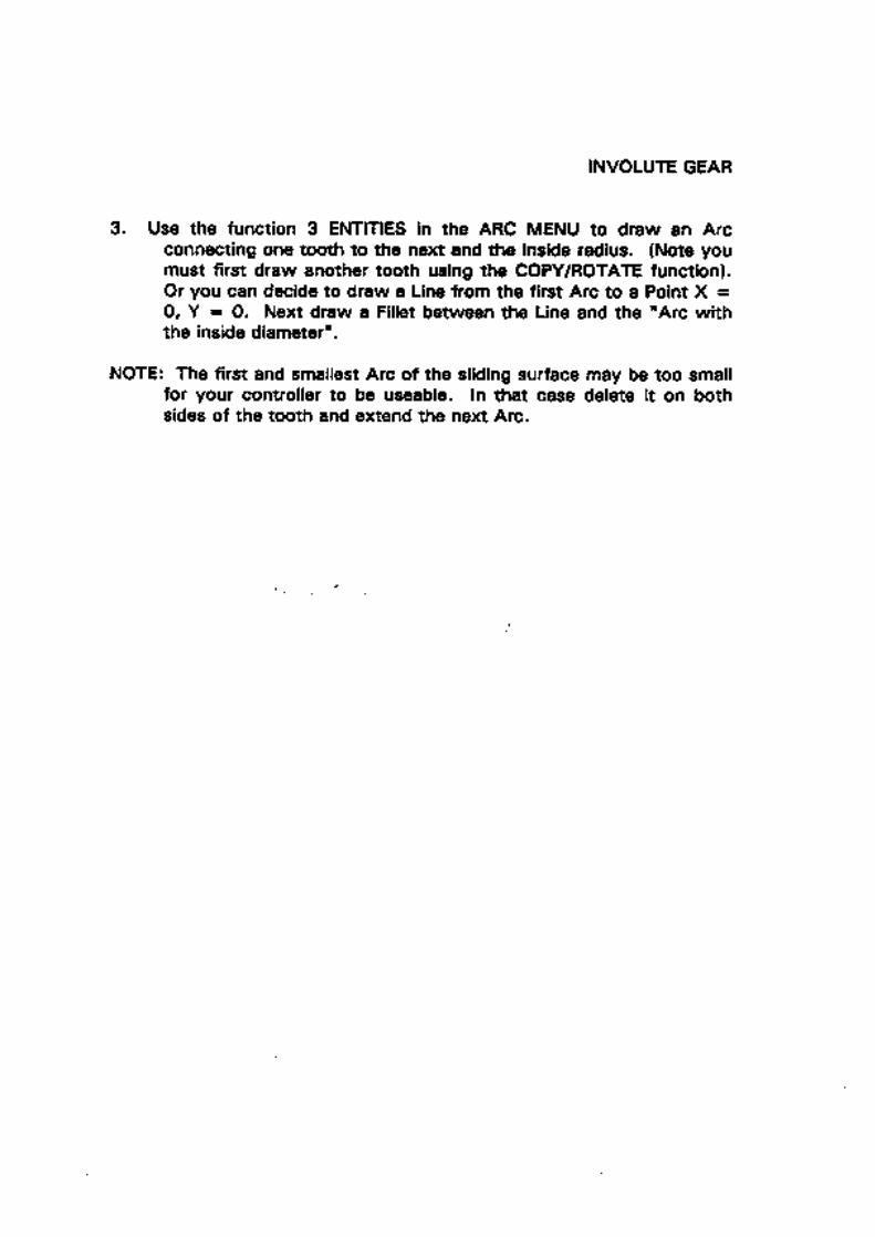

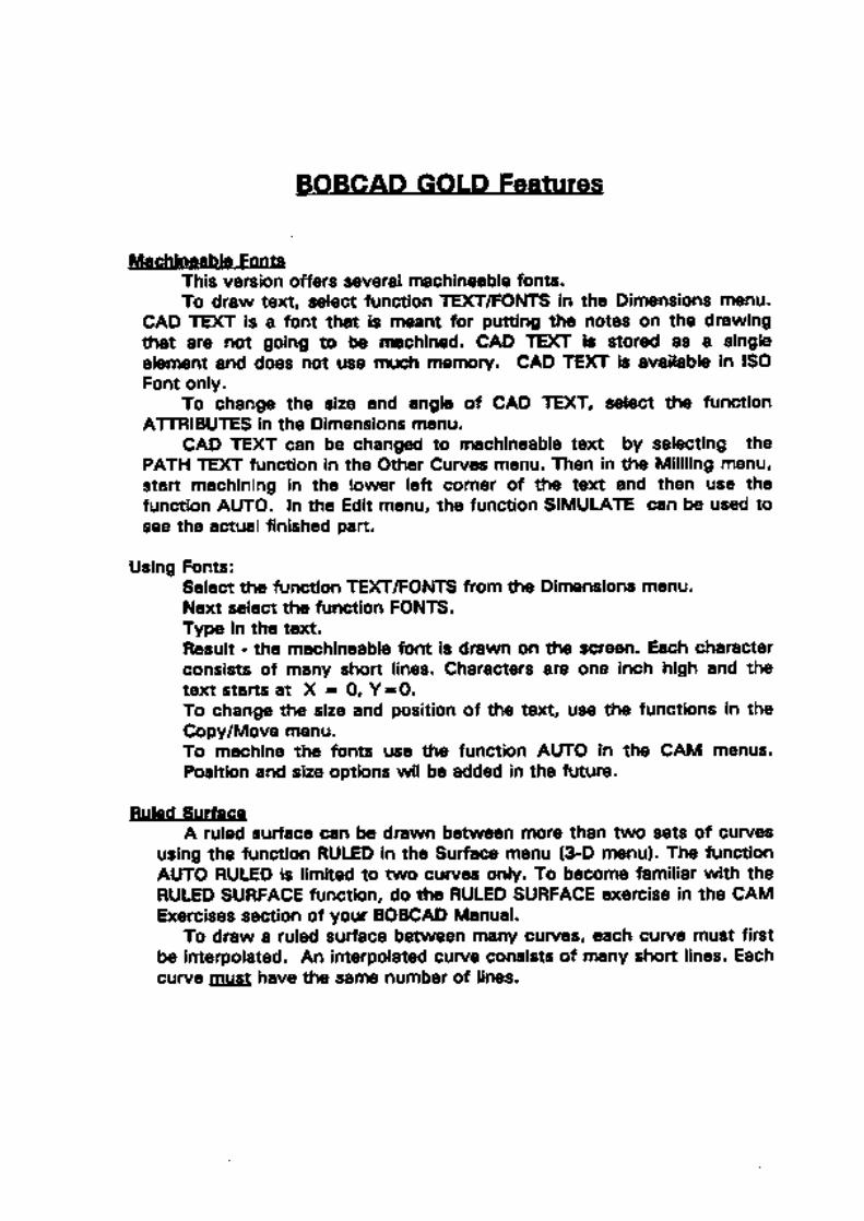
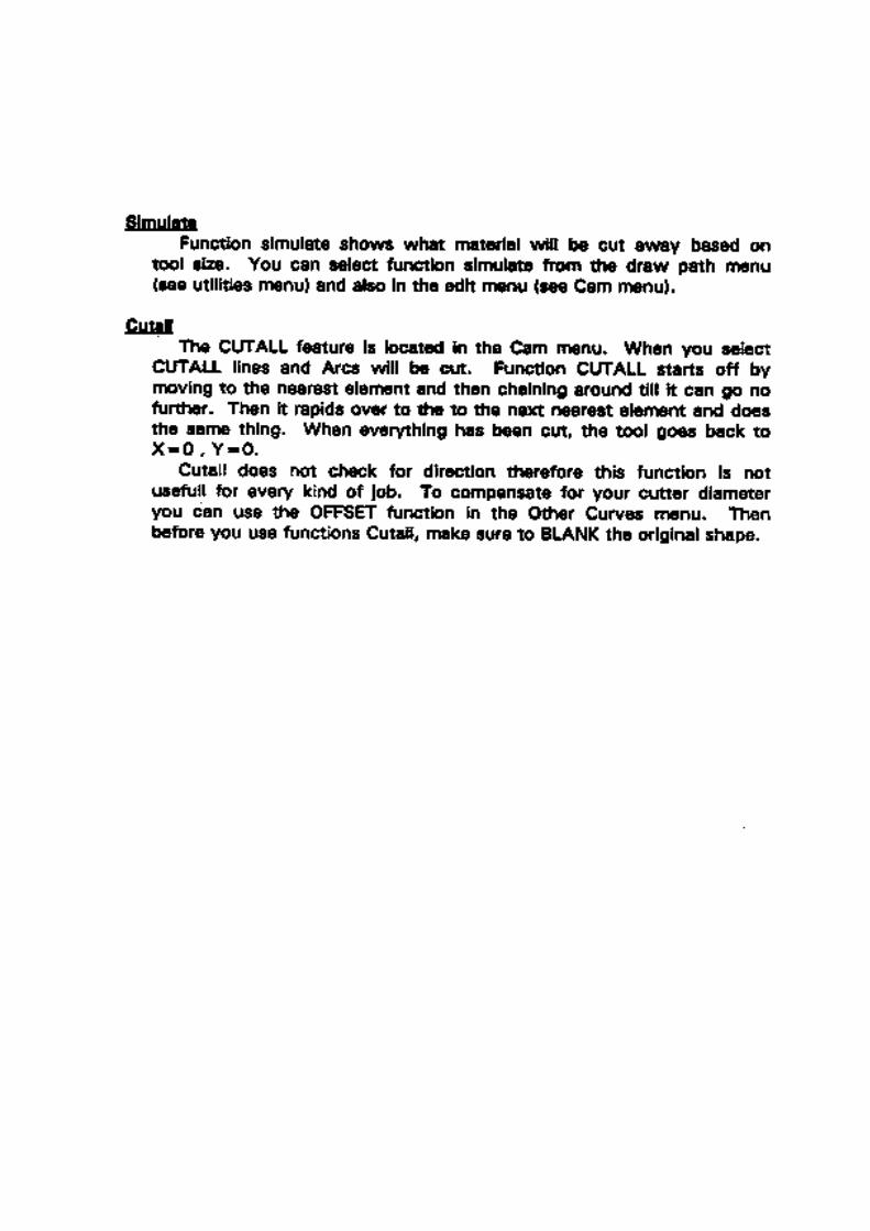
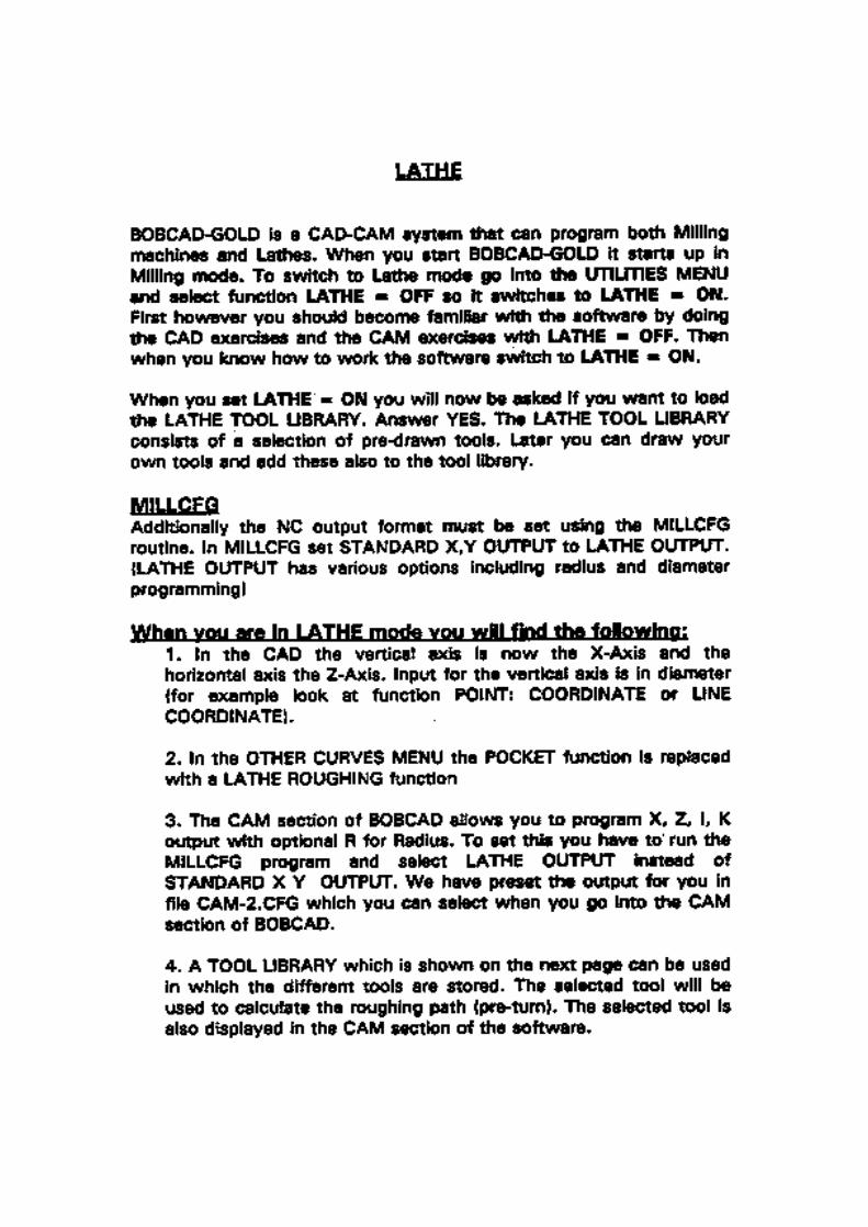
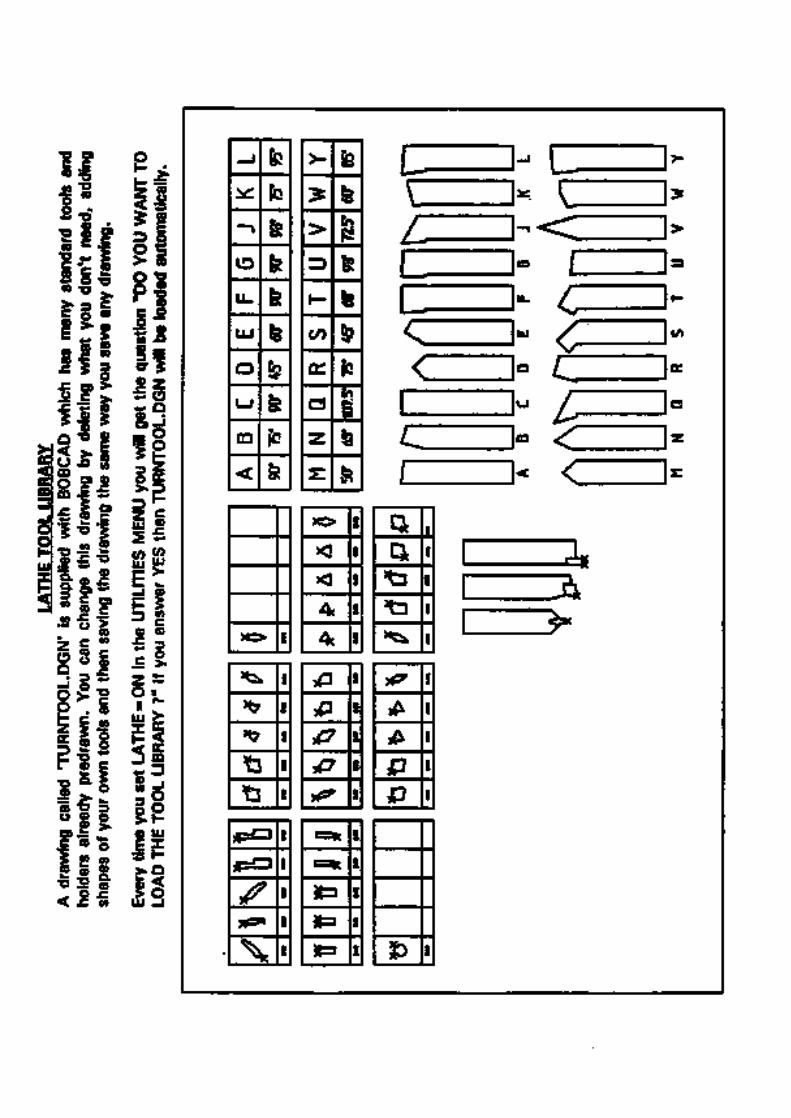
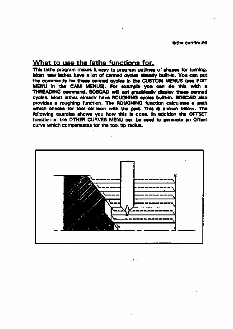
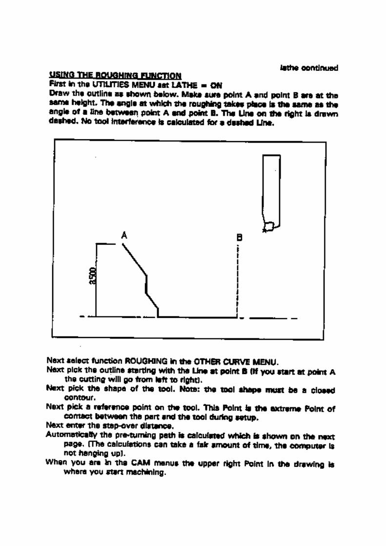
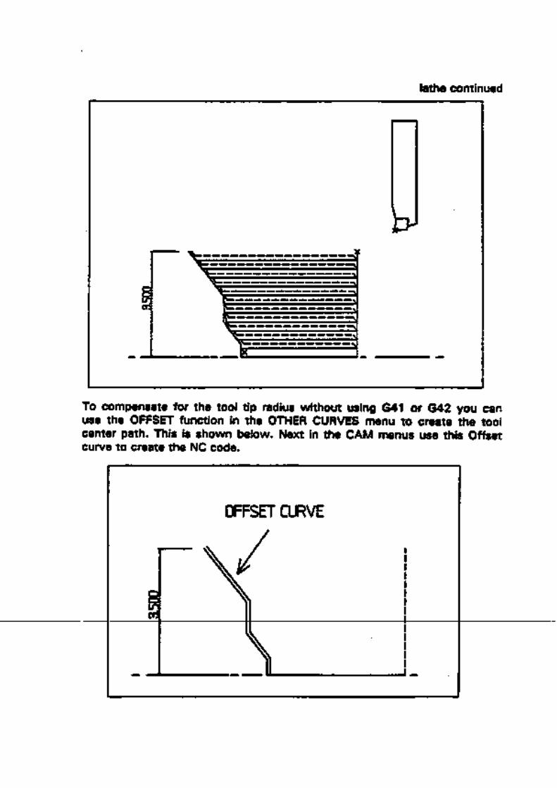
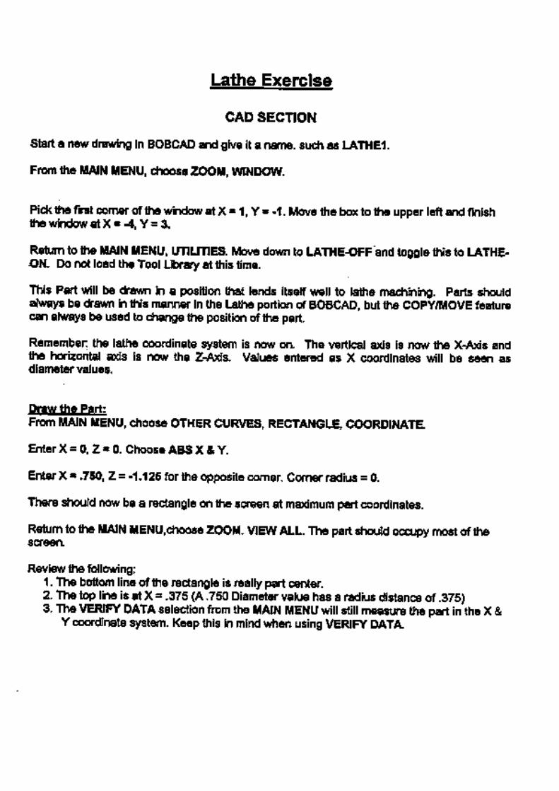
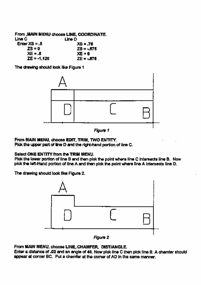
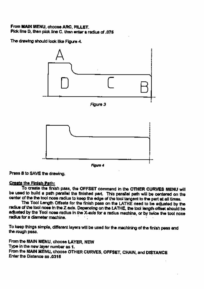
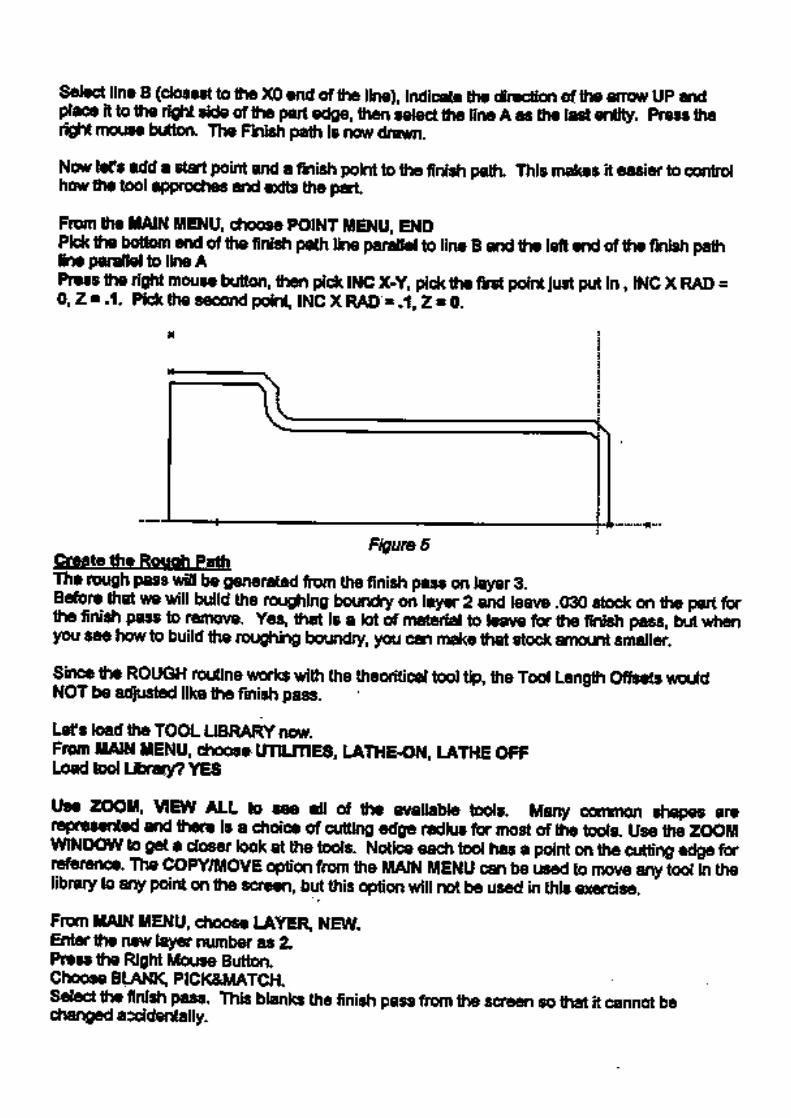
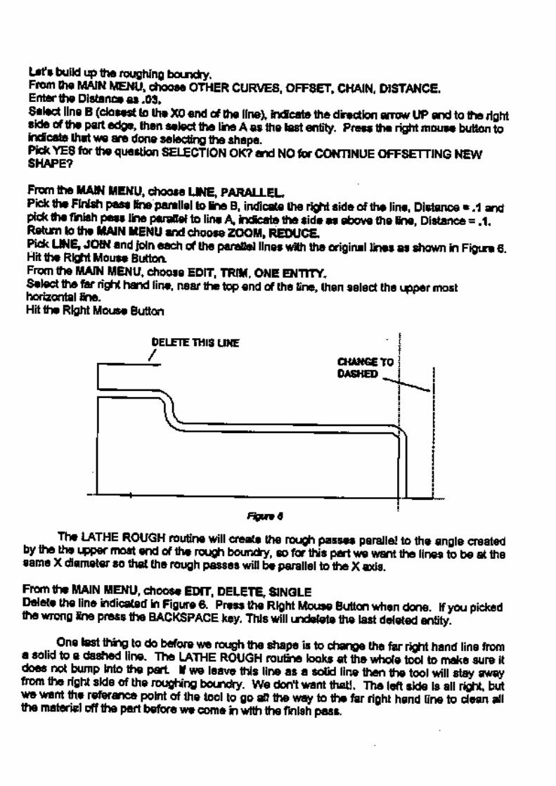
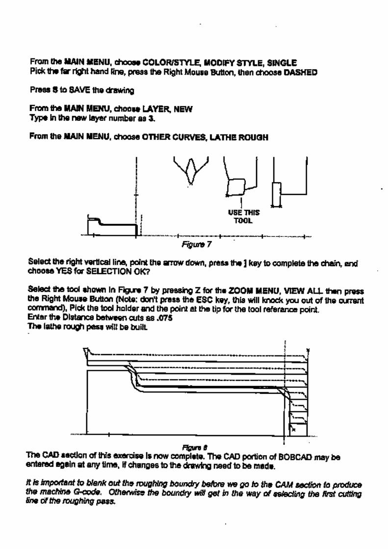
FreeDOS Spec
Appendix, Commands Behavior
DOS commands may be internal or external. Any DOS command may be implemented internally by the
shell, or provided externally as in a program. If external, the program may be either a COM or EXE, with
the exception of COMMAND.COM.
In each of the following, d: represents a drive letter, path represents a full pathname, and file represents a
full filename, or a file mask including * and ?.
For all commands, internal and external, the command line option /? should generate a help screen, and
the program should immediately exit. The exit code is not defined, but we strongly suggest an exit code of
zero.
A few traditional MS-DOS commands have been dropped from the Spec. Dropping from the Spec does
not mean that such a program will be ignored if one ever comes along, but this does mean that we will not
actively seek out to develop a new version. This is because they were considered as part of a legacy
migration thing for MS-DOS, which the FreeDOS Project is not interested in carrying forward. Where a
program has been dropped from the Spec, an annotation has been made to explain why.
append
Allows programs to open data files in the specified directories as though they were local to the working
directory.
[Dropped, because the program was considered to be a “crutch” for legacy DOS-based applications as
DOS moved to support directories. Append was used primarily to support programs that did not know
about directories on a DOS system.]
append d:]path[;…? [options]
Options:
;
When used by itself, the semicolon cancels the previously specified
appended directories.
/x[:on|:off]
Allows the shell (if supported) to search these directories as though
they were in the PATH. Default is /x:off. /x is the same as /x:on.
/path:on
Specifies if DOS is to search appended directories for a program’s
data file, even if the program specifies a full path. Default is
/path:on.
/e
Add the list of appended directories to the PATH.
If no paths are named, display the current appended directories.
assign
Reassigns disk operations from one drive to another. For example, to reassign disk operations for drive
A: to drive B:.
assign [d:=d:] […]
assign /status
Options:
/status
Displays the current assignments.
If no drives are named, display the current assignments.
attrib
Change a file’s attributes.
attrib [options] [[d:][path]file]
Options:
+r | -r
Sets the read-only attribute. -r will clear it.
+a | -a
Sets the archive attribute. -a will clear it.
+s | -s
Sets the system attribute. -s will clear it.
+h | -h
Sets the hidden attribute. -h will clear it.
/s
Act on subdirectories, too.
If no file is named, display the attributes for all files in the
current directory.
break
Sets or clears the Break or Ctl-C check.
break [on|off]
Options:
on | off
Turn on (or off) the Break check.
If no arguments are named, display the current Break check status.
cd, chdir
Displays the name of the current directory, or changes to another one.
cd [d:][path]
chdir [d:][path]
chcp
Change the DOS code page.
chcp [nnn]
Options:
nnn
The code page that is to be loaded. Use 437=US, 850=Multi (Latin
I), 852=Slavic (Latin II), 860=Portuguese, 863=Canadian-French,
865=Nordic.
If no code page is named, display the current code page.
chkdsk
Check the disk for errors.
chkdsk [d:] [options]
Options:
/f
Fix errors on the disk when found.
/v
Display the name of every file as the disk is checked.
If no drive is specified, check the current disk for errors.
cls
Clear the screen.
cls
choice
Suspend processing, and wait for the user to press a valid key.
choice [options] [text]
Options:
/C[:]choices
Specifies allowable keys. Default is YN
/N
Do not display choices and ? at end of prompt.
/S
Treat choices as case sensitive.
/T[:]c,nn
Specify the default choice `c’ after `nn’ seconds of no response.
text
Prompt string to display (Default=none.)
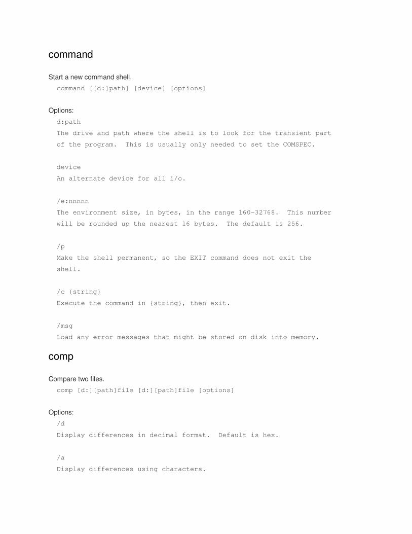
command
Start a new command shell.
command [[d:]path] [device] [options]
Options:
d:path
The drive and path where the shell is to look for the transient part
of the program. This is usually only needed to set the COMSPEC.
device
An alternate device for all i/o.
/e:nnnnn
The environment size, in bytes, in the range 160–32768. This number
will be rounded up the nearest 16 bytes. The default is 256.
/p
Make the shell permanent, so the EXIT command does not exit the
shell.
/c {string}
Execute the command in {string}, then exit.
/msg
Load any error messages that might be stored on disk into memory.
comp
Compare two files.
comp [d:][path]file [d:][path]file [options]
Options:
/d
Display differences in decimal format. Default is hex.
/a
Display differences using characters.
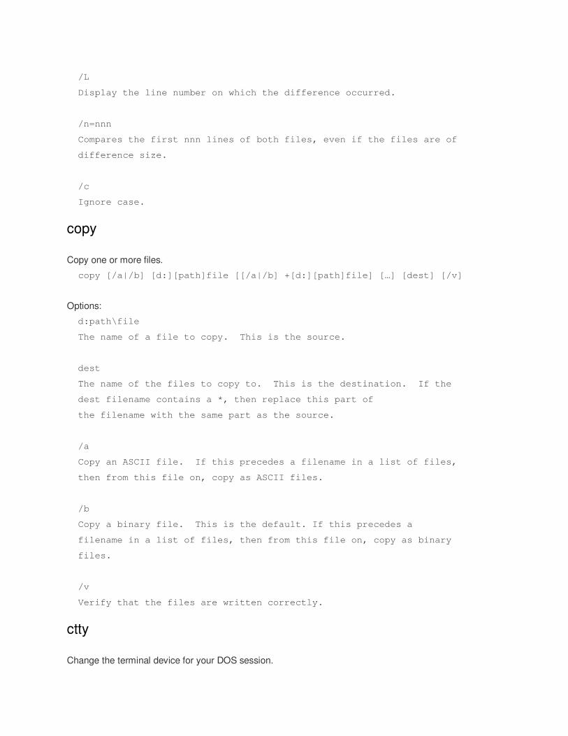
/L
Display the line number on which the difference occurred.
/n=nnn
Compares the first nnn lines of both files, even if the files are of
difference size.
/c
Ignore case.
copy
Copy one or more files.
copy [/a|/b] [d:][path]file [[/a|/b] +[d:][path]file] […] [dest] [/v]
Options:
d:path\file
The name of a file to copy. This is the source.
dest
The name of the files to copy to. This is the destination. If the
dest filename contains a *, then replace this part of
the filename with the same part as the source.
/a
Copy an ASCII file. If this precedes a filename in a list of files,
then from this file on, copy as ASCII files.
/b
Copy a binary file. This is the default. If this precedes a
filename in a list of files, then from this file on, copy as binary
files.
/v
Verify that the files are written correctly.
ctty
Change the terminal device for your DOS session.
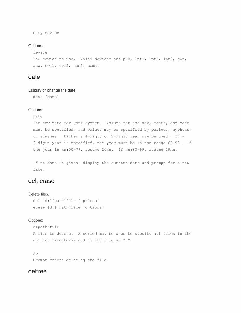
ctty device
Options:
device
The device to use. Valid devices are prn, lpt1, lpt2, lpt3, con,
aux, com1, com2, com3, com4.
date
Display or change the date.
date [date]
Options:
date
The new date for your system. Values for the day, month, and year
must be specified, and values may be specified by periods, hyphens,
or slashes. Either a 4-digit or 2-digit year may be used. If a
2-digit year is specified, the year must be in the range 00–99. If
the year is xx:00–79, assume 20xx. If xx:80–99, assume 19xx.
If no date is given, display the current date and prompt for a new
date.
del, erase
Delete files.
del [d:][path]file [options]
erase [d:][path]file [options]
Options:
d:path\file
A file to delete. A period may be used to specify all files in the
current directory, and is the same as *.*.
/p
Prompt before deleting the file.
deltree
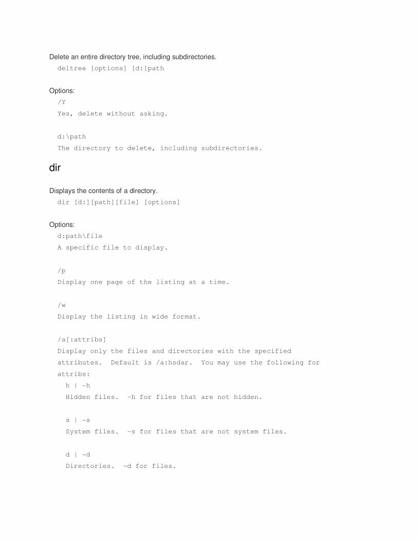
Delete an entire directory tree, including subdirectories.
deltree [options] [d:]path
Options:
/Y
Yes, delete without asking.
d:\path
The directory to delete, including subdirectories.
dir
Displays the contents of a directory.
dir [d:][path][file] [options]
Options:
d:path\file
A specific file to display.
/p
Display one page of the listing at a time.
/w
Display the listing in wide format.
/a[:attribs]
Display only the files and directories with the specified
attributes. Default is /a:hsdar. You may use the following for
attribs:
h | -h
Hidden files. -h for files that are not hidden.
s | -s
System files. -s for files that are not system files.
d | -d
Directories. -d for files.
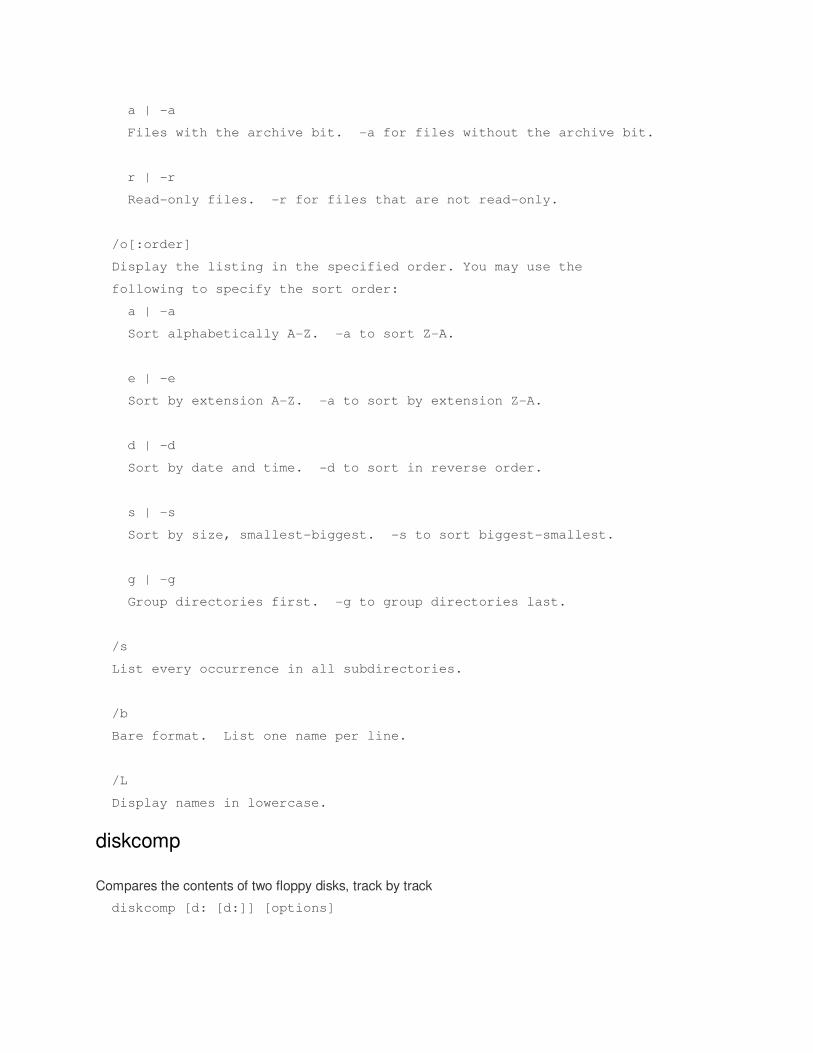
a | -a
Files with the archive bit. -a for files without the archive bit.
r | -r
Read-only files. -r for files that are not read-only.
/o[:order]
Display the listing in the specified order. You may use the
following to specify the sort order:
a | -a
Sort alphabetically A-Z. -a to sort Z-A.
e | -e
Sort by extension A-Z. -a to sort by extension Z-A.
d | -d
Sort by date and time. -d to sort in reverse order.
s | -s
Sort by size, smallest-biggest. -s to sort biggest-smallest.
g | -g
Group directories first. -g to group directories last.
/s
List every occurrence in all subdirectories.
/b
Bare format. List one name per line.
/L
Display names in lowercase.
diskcomp
Compares the contents of two floppy disks, track by track
diskcomp [d: [d:]] [options]
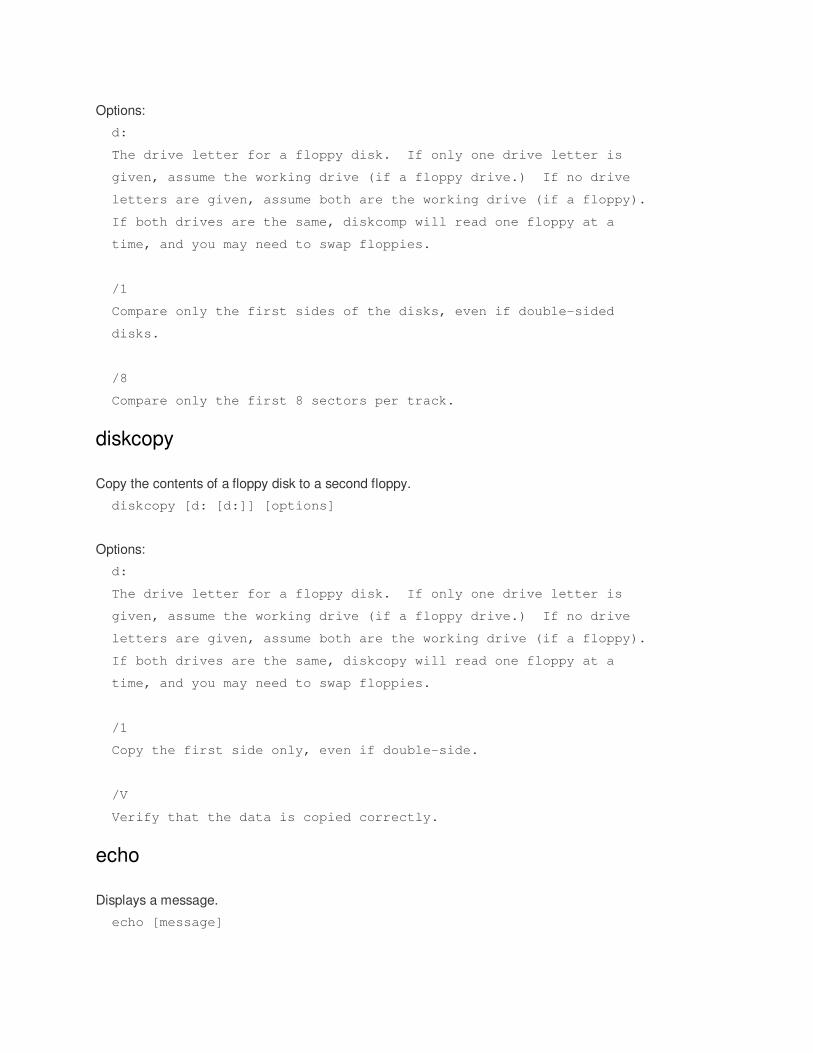
Options:
d:
The drive letter for a floppy disk. If only one drive letter is
given, assume the working drive (if a floppy drive.) If no drive
letters are given, assume both are the working drive (if a floppy).
If both drives are the same, diskcomp will read one floppy at a
time, and you may need to swap floppies.
/1
Compare only the first sides of the disks, even if double-sided
disks.
/8
Compare only the first 8 sectors per track.
diskcopy
Copy the contents of a floppy disk to a second floppy.
diskcopy [d: [d:]] [options]
Options:
d:
The drive letter for a floppy disk. If only one drive letter is
given, assume the working drive (if a floppy drive.) If no drive
letters are given, assume both are the working drive (if a floppy).
If both drives are the same, diskcopy will read one floppy at a
time, and you may need to swap floppies.
/1
Copy the first side only, even if double-side.
/V
Verify that the data is copied correctly.
echo
Displays a message.
echo [message]
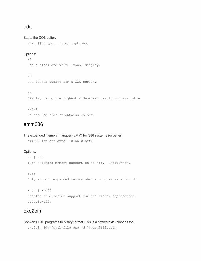
edit
Starts the DOS editor.
edit [[d:][path]file] [options]
Options:
/B
Use a black-and-white (mono) display.
/G
Use faster update for a CGA screen.
/H
Display using the highest video/text resolution available.
/NOHI
Do not use high-brightness colors.
emm386
The expanded memory manager (EMM) for ‘386 systems (or better)
emm386 [on|off|auto] [w=on|w=off]
Options:
on | off
Turn expanded memory support on or off. Default=on.
auto
Only support expanded memory when a program asks for it.
w=on | w=off
Enables or disables support for the Wietek coprocessor.
Default=off.
exe2bin
Converts EXE programs to binary format. This is a software developer’s tool.
exe2bin [d:][path]file.exe [d:][path]file.bin
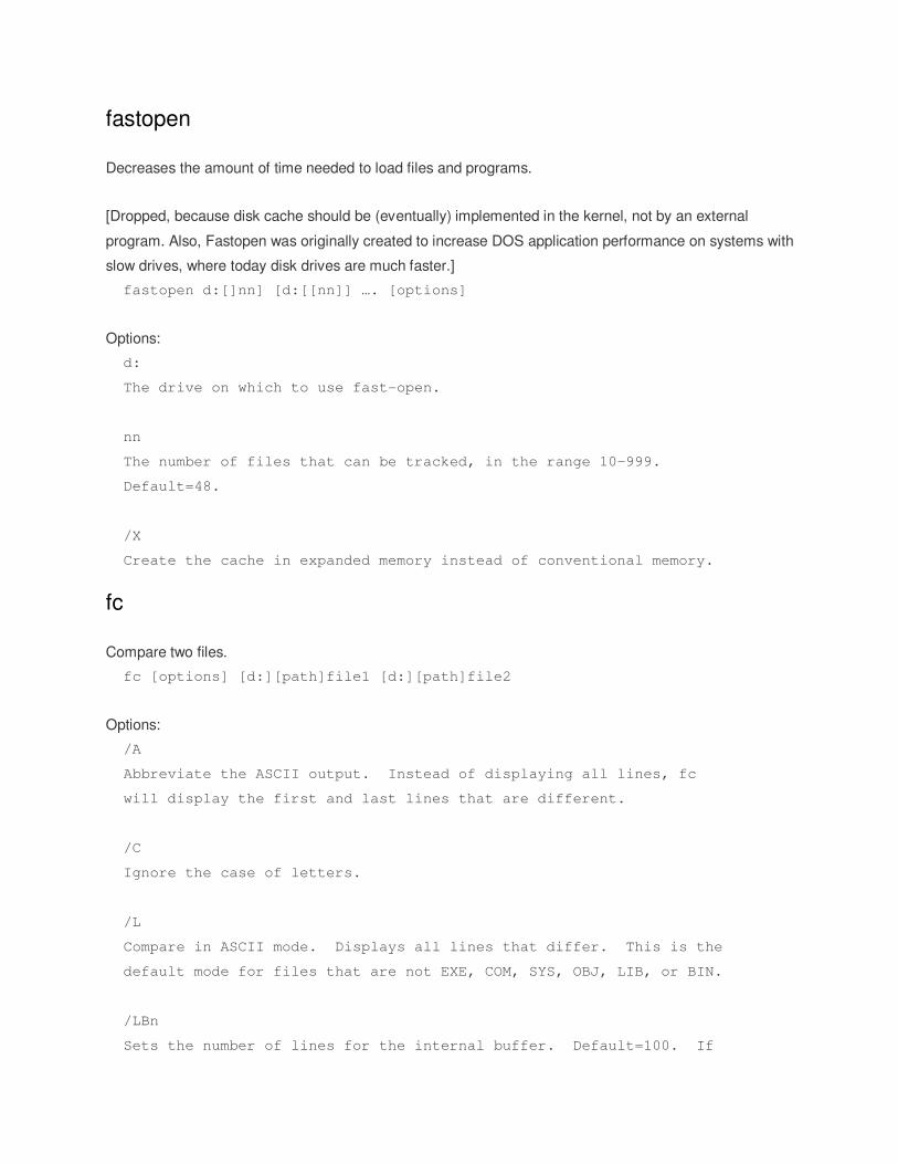
fastopen
Decreases the amount of time needed to load files and programs.
[Dropped, because disk cache should be (eventually) implemented in the kernel, not by an external
program. Also, Fastopen was originally created to increase DOS application performance on systems with
slow drives, where today disk drives are much faster.]
fastopen d:[]nn] [d:[[nn]] …. [options]
Options:
d:
The drive on which to use fast-open.
nn
The number of files that can be tracked, in the range 10–999.
Default=48.
/X
Create the cache in expanded memory instead of conventional memory.
fc
Compare two files.
fc [options] [d:][path]file1 [d:][path]file2
Options:
/A
Abbreviate the ASCII output. Instead of displaying all lines, fc
will display the first and last lines that are different.
/C
Ignore the case of letters.
/L
Compare in ASCII mode. Displays all lines that differ. This is the
default mode for files that are not EXE, COM, SYS, OBJ, LIB, or BIN.
/LBn
Sets the number of lines for the internal buffer. Default=100. If
the files have more than this many differences, fc will quit.
/N
Display line numbers.
/T
Do not expand tabs to spaces. Default is to expand tabs to 8-space
stops during comparison.
/W
Compress white space during comparison.
/nnn
Specifies the number of lines that must match after a miscompare for
the files to be resynchronized. Default=2.
/B
Compare in binary mode. Does not attempt to resynchronize after a
miscompare.
fdisk
Configures a hard disk.
fdisk
find
Displays lines in a text file that contain a string.
find [options] string [d:][path]file
Options:
/V
Invert the search. Display lines that do NOT contain the string.
/C
Only display a count of the matching lines.
/N
Display line numbers.
/I
Ignore case during the comparison.
format
Format a hard drive or floppy disk.
format d: [options]
Options:
d:
The hard drive or floppy disk to format.
/V:label
Assign this label to the formatted disk.
/Q
Do a quick format. This clears the FAT and root directory, but does
not erase the disk.
/U
Do an unconditional format.
/F:size
Format the disk to a specific size. Valid values are:
160 | 160k | 160kb
Format to 160kb.
180 | 180k | 180kb
Format to 180kb.
320 | 320k | 320kb
Format to 320kb.
360 | 360k | 360kb
Format to 360kb.
720 | 720k | 720kb
Format to 720kb.
1200 | 1200k | 1200kb | 1.2 | 1.2m | 1.2mb
Format to 1.2MB.
1440 | 1440k | 1440kb | 1.44 | 1.44m | 1.44mb
Format to 1.44MB.
2880 | 2880k | 2880kb | 2.88 | 2.88m | 2.88mb
Format to 2.88MB.
/B
Reserve space to make a bootable disk.
/S
Make a system disk (copy files to make it bootable.)
/T:tracks
Specify the number of tracks on the disk.
/N:sectors
Specify the number of sectors.
/1
Format a single-sided disk.
/4
Format a 5–1/4 inch 360KB DSDD disk on a 1.2MB drive.
/8
Format a 5–1/4 inch disk with 8 SPT.
graftabl
Load the graphics table for a specific code page.
[Dropped, because most monitors can display extended characters (128–255) without Graftabl. This
command was originally introduced by MS-DOS to support the extended character set on systems that
were not originally equipped to display them properly. While some users may miss this command, we feel
there are not enough systems that still need Graftabl to justify its inclusion in the Spec.]
graftabl [nnn] [options]
Options:
nnn
The code page you want to load.
/STATUS
Display the code page that was loaded, or is being loaded.
graphics
Allow Prtscr to print graphics screens.
graphics [[d:][path]file] [type] [options]
Options:
d:path\file
The full pathname of the printer profile.
type
The printer type. Currently defined printer types are:
[this list has been amended to support only the printer types that
are in current use today]
epson
Any Epson-compatible dot-matrix printer (default).
hpdefault
Any HP-compatible PCL printer.
postscript
Any Postscript-compatible printer.
[this printer was not originally defined by the MS-DOS Graphics
command, but we are adding it because many users have Postscript
printers.]
/R
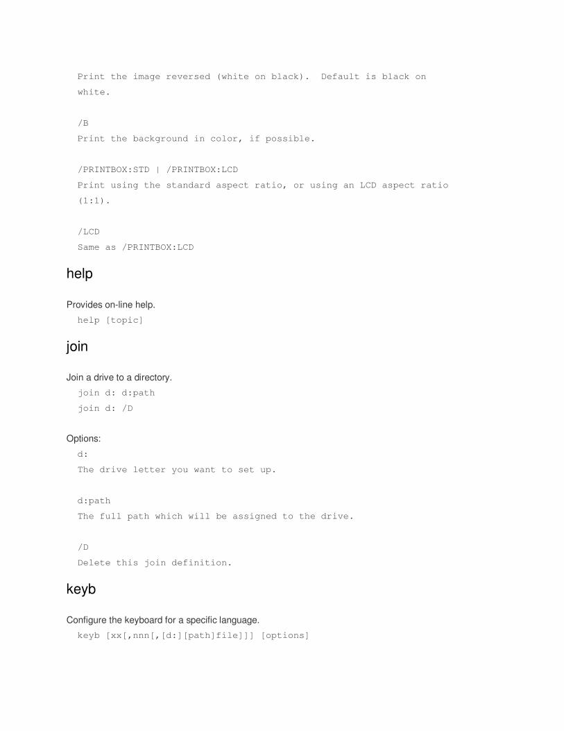
Print the image reversed (white on black). Default is black on
white.
/B
Print the background in color, if possible.
/PRINTBOX:STD | /PRINTBOX:LCD
Print using the standard aspect ratio, or using an LCD aspect ratio
(1:1).
/LCD
Same as /PRINTBOX:LCD
help
Provides on-line help.
help [topic]
join
Join a drive to a directory.
join d: d:path
join d: /D
Options:
d:
The drive letter you want to set up.
d:path
The full path which will be assigned to the drive.
/D
Delete this join definition.
keyb
Configure the keyboard for a specific language.
keyb [xx[,nnn[,[d:][path]file]]] [options]
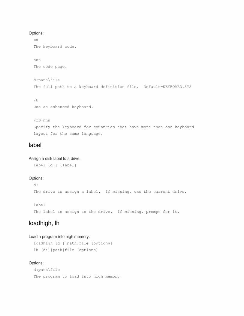
Options:
xx
The keyboard code.
nnn
The code page.
d:path\file
The full path to a keyboard definition file. Default=KEYBOARD.SYS
/E
Use an enhanced keyboard.
/ID:nnn
Specify the keyboard for countries that have more than one keyboard
layout for the same language.
label
Assign a disk label to a drive.
label [d:] [label]
Options:
d:
The drive to assign a label. If missing, use the current drive.
label
The label to assign to the drive. If missing, prompt for it.
loadhigh, lh
Load a program into high memory.
loadhigh [d:][path]file [options]
lh [d:][path]file [options]
Options:
d:path\file
The program to load into high memory.
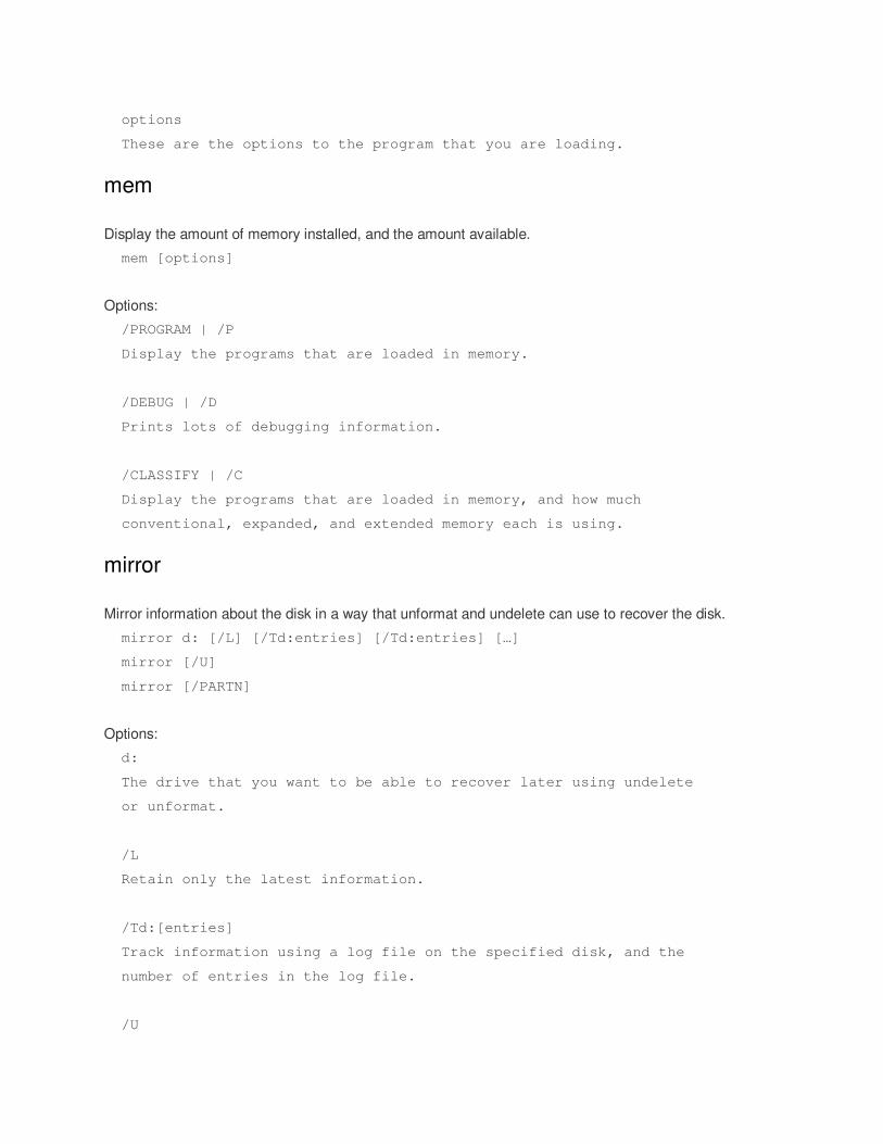
options
These are the options to the program that you are loading.
mem
Display the amount of memory installed, and the amount available.
mem [options]
Options:
/PROGRAM | /P
Display the programs that are loaded in memory.
/DEBUG | /D
Prints lots of debugging information.
/CLASSIFY | /C
Display the programs that are loaded in memory, and how much
conventional, expanded, and extended memory each is using.
mirror
Mirror information about the disk in a way that unformat and undelete can use to recover the disk.
mirror d: [/L] [/Td:entries] [/Td:entries] […]
mirror [/U]
mirror [/PARTN]
Options:
d:
The drive that you want to be able to recover later using undelete
or unformat.
/L
Retain only the latest information.
/Td:[entries]
Track information using a log file on the specified disk, and the
number of entries in the log file.
/U
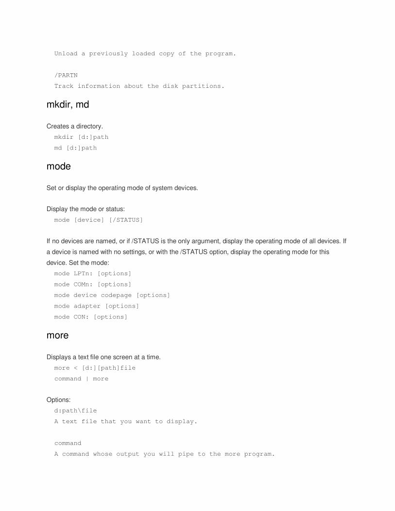
Unload a previously loaded copy of the program.
/PARTN
Track information about the disk partitions.
mkdir, md
Creates a directory.
mkdir [d:]path
md [d:]path
mode
Set or display the operating mode of system devices.
Display the mode or status:
mode [device] [/STATUS]
If no devices are named, or if /STATUS is the only argument, display the operating mode of all devices. If
a device is named with no settings, or with the /STATUS option, display the operating mode for this
device. Set the mode:
mode LPTn: [options]
mode COMn: [options]
mode device codepage [options]
mode adapter [options]
mode CON: [options]
more
Displays a text file one screen at a time.
more < [d:][path]file
command | more
Options:
d:path\file
A text file that you want to display.
command
A command whose output you will pipe to the more program.
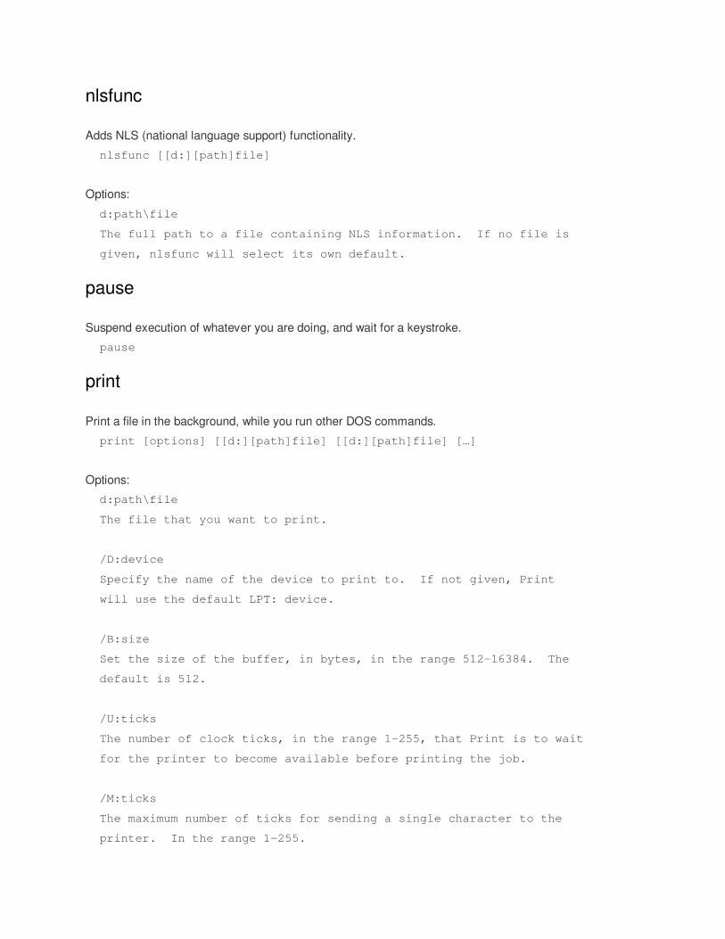
nlsfunc
Adds NLS (national language support) functionality.
nlsfunc [[d:][path]file]
Options:
d:path\file
The full path to a file containing NLS information. If no file is
given, nlsfunc will select its own default.
pause
Suspend execution of whatever you are doing, and wait for a keystroke.
pause
Print a file in the background, while you run other DOS commands.
print [options] [[d:][path]file] [[d:][path]file] […]
Options:
d:path\file
The file that you want to print.
/D:device
Specify the name of the device to print to. If not given, Print
will use the default LPT: device.
/B:size
Set the size of the buffer, in bytes, in the range 512–16384. The
default is 512.
/U:ticks
The number of clock ticks, in the range 1–255, that Print is to wait
for the printer to become available before printing the job.
/M:ticks
The maximum number of ticks for sending a single character to the
printer. In the range 1–255.
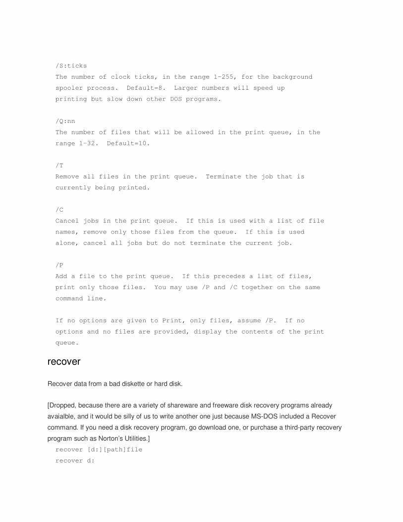
/S:ticks
The number of clock ticks, in the range 1–255, for the background
spooler process. Default=8. Larger numbers will speed up
printing but slow down other DOS programs.
/Q:nn
The number of files that will be allowed in the print queue, in the
range 1–32. Default=10.
/T
Remove all files in the print queue. Terminate the job that is
currently being printed.
/C
Cancel jobs in the print queue. If this is used with a list of file
names, remove only those files from the queue. If this is used
alone, cancel all jobs but do not terminate the current job.
/P
Add a file to the print queue. If this precedes a list of files,
print only those files. You may use /P and /C together on the same
command line.
If no options are given to Print, only files, assume /P. If no
options and no files are provided, display the contents of the print
queue.
recover
Recover data from a bad diskette or hard disk.
[Dropped, because there are a variety of shareware and freeware disk recovery programs already
avaialble, and it would be silly of us to write another one just because MS-DOS included a Recover
command. If you need a disk recovery program, go download one, or purchase a third-party recovery
program such as Norton’s Utilities.]
recover [d:][path]file
recover d:
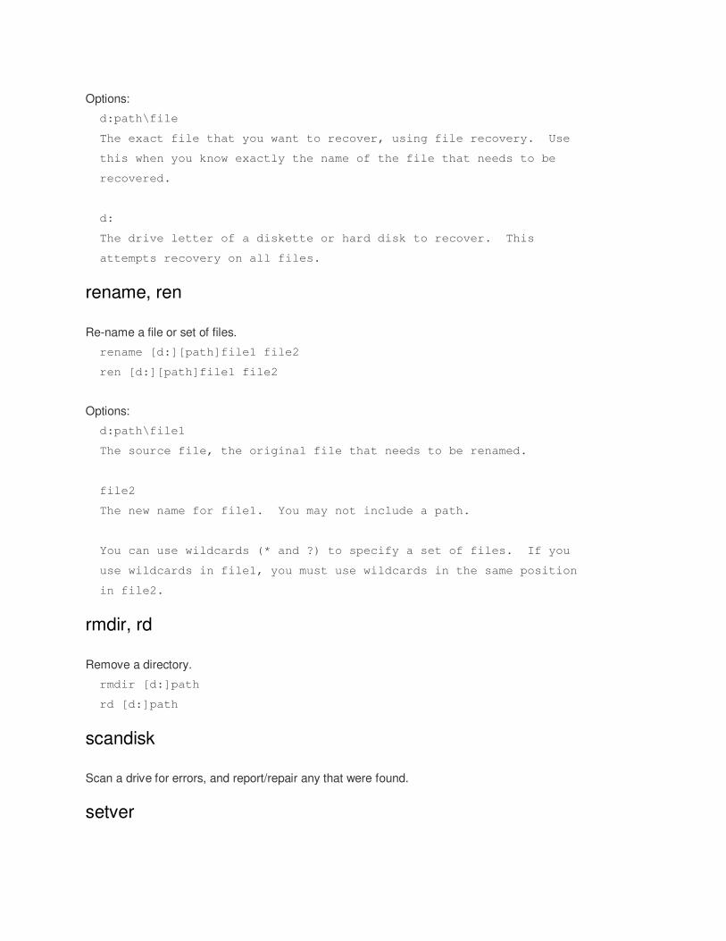
Options:
d:path\file
The exact file that you want to recover, using file recovery. Use
this when you know exactly the name of the file that needs to be
recovered.
d:
The drive letter of a diskette or hard disk to recover. This
attempts recovery on all files.
rename, ren
Re-name a file or set of files.
rename [d:][path]file1 file2
ren [d:][path]file1 file2
Options:
d:path\file1
The source file, the original file that needs to be renamed.
file2
The new name for file1. You may not include a path.
You can use wildcards (* and ?) to specify a set of files. If you
use wildcards in file1, you must use wildcards in the same position
in file2.
rmdir, rd
Remove a directory.
rmdir [d:]path
rd [d:]path
scandisk
Scan a drive for errors, and report/repair any that were found.
setver
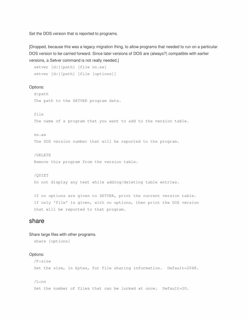
Set the DOS version that is reported to programs.
[Dropped, because this was a legacy migration thing, to allow programs that needed to run on a particular
DOS version to be carried forward. Since later versions of DOS are (always?) compatible with earlier
versions, a Setver command is not really needed.]
setver [d:][path] [file nn.xx]
setver [d:][path] [file [options]]
Options:
d:path
The path to the SETVER program data.
file
The name of a program that you want to add to the version table.
nn.xx
The DOS version number that will be reported to the program.
/DELETE
Remove this program from the version table.
/QUIET
Do not display any text while adding/deleting table entries.
If no options are given to SETVER, print the current version table.
If only ‘file’ is given, with no options, then print the DOS version
that will be reported to that program.
share
Share large files with other programs.
share [options]
Options:
/F:size
Set the size, in bytes, for file sharing information. Default=2048.
/L:nn
Set the number of files that can be locked at once. Default=20.
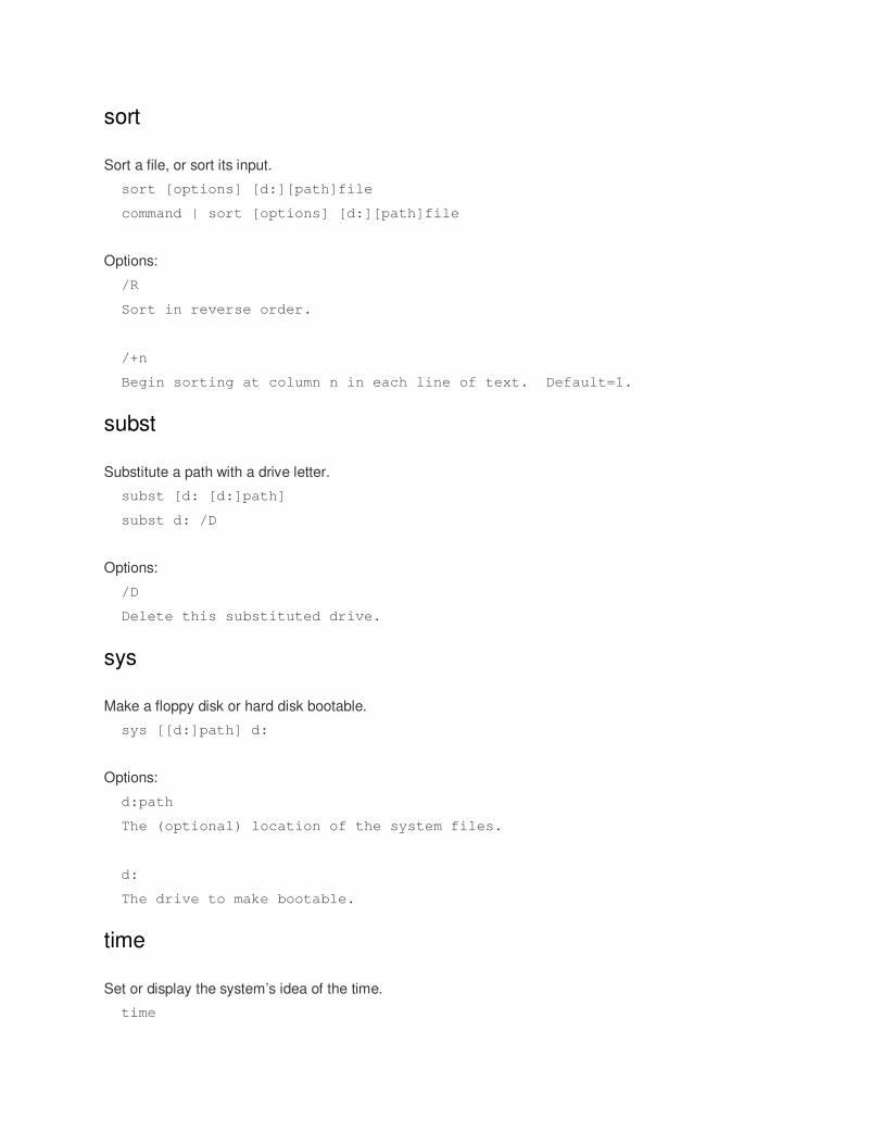
sort
Sort a file, or sort its input.
sort [options] [d:][path]file
command | sort [options] [d:][path]file
Options:
/R
Sort in reverse order.
/+n
Begin sorting at column n in each line of text. Default=1.
subst
Substitute a path with a drive letter.
subst [d: [d:]path]
subst d: /D
Options:
/D
Delete this substituted drive.
sys
Make a floppy disk or hard disk bootable.
sys [[d:]path] d:
Options:
d:path
The (optional) location of the system files.
d:
The drive to make bootable.
time
Set or display the system’s idea of the time.
time
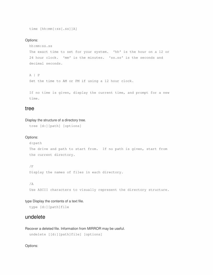
time [hh:mm[:ss[.ss]]A]
Options:
hh:mm:ss.ss
The exact time to set for your system. ‘hh’ is the hour on a 12 or
24 hour clock. ‘mm’ is the minutes. ‘ss.ss’ is the seconds and
decimal seconds.
A | P
Set the time to AM or PM if using a 12 hour clock.
If no time is given, display the current time, and prompt for a new
time.
tree
Display the structure of a directory tree.
tree [d:][path] [options]
Options:
d:path
The drive and path to start from. If no path is given, start from
the current directory.
/F
Display the names of files in each directory.
/A
Use ASCII characters to visually represent the directory structure.
type Display the contents of a text file.
type [d:][path]file
undelete
Recover a deleted file. Information from MIRROR may be useful.
undelete [[d:][path]file] [options]
Options:
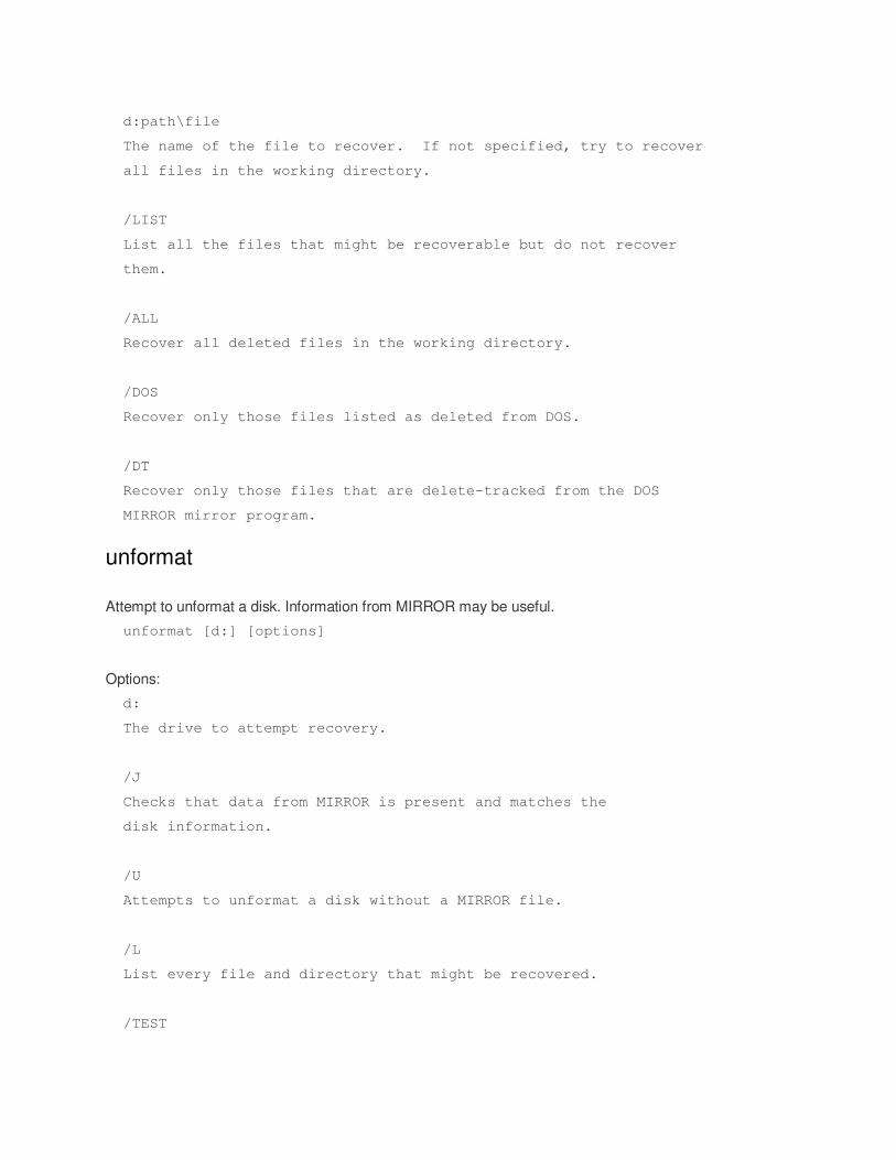
d:path\file
The name of the file to recover. If not specified, try to recover
all files in the working directory.
/LIST
List all the files that might be recoverable but do not recover
them.
/ALL
Recover all deleted files in the working directory.
/DOS
Recover only those files listed as deleted from DOS.
/DT
Recover only those files that are delete-tracked from the DOS
MIRROR mirror program.
unformat
Attempt to unformat a disk. Information from MIRROR may be useful.
unformat [d:] [options]
Options:
d:
The drive to attempt recovery.
/J
Checks that data from MIRROR is present and matches the
disk information.
/U
Attempts to unformat a disk without a MIRROR file.
/L
List every file and directory that might be recovered.
/TEST
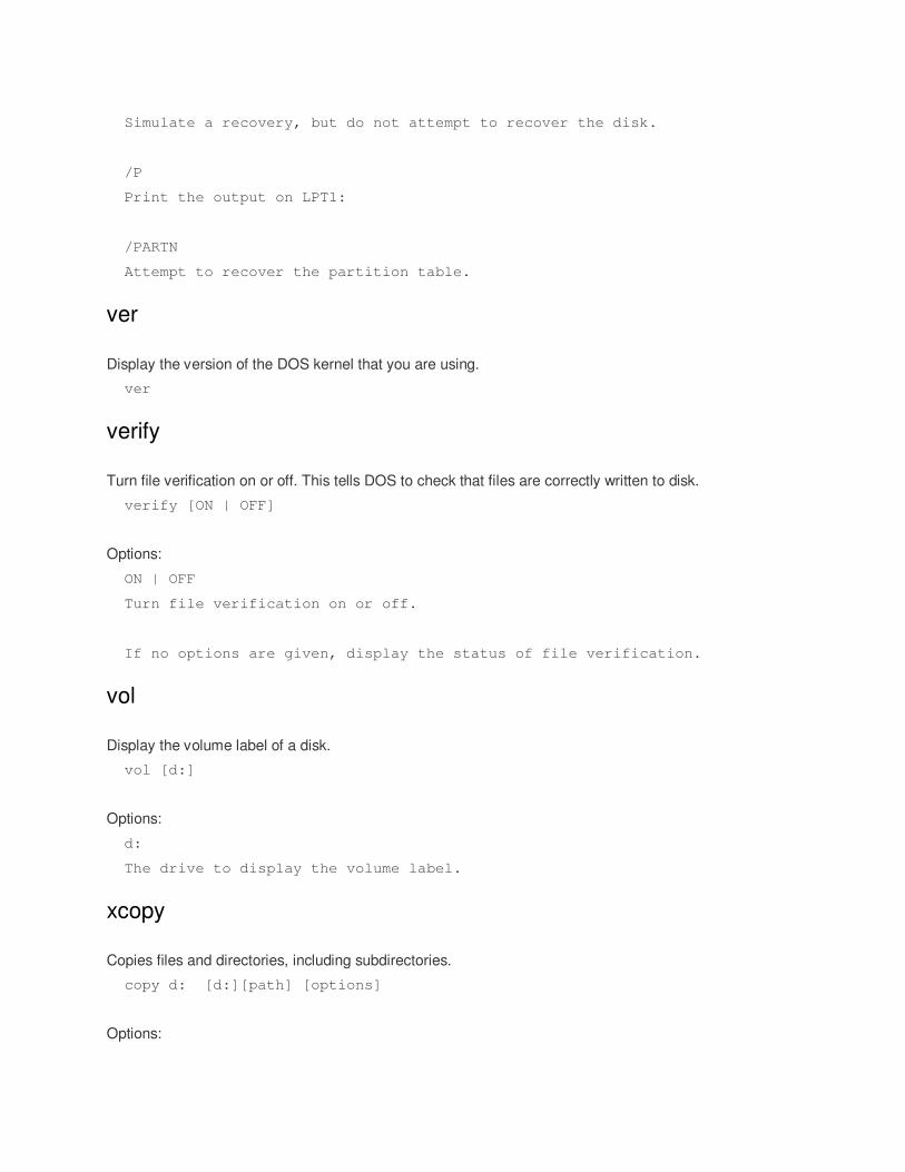
Simulate a recovery, but do not attempt to recover the disk.
/P
Print the output on LPT1:
/PARTN
Attempt to recover the partition table.
ver
Display the version of the DOS kernel that you are using.
ver
verify
Turn file verification on or off. This tells DOS to check that files are correctly written to disk.
verify [ON | OFF]
Options:
ON | OFF
Turn file verification on or off.
If no options are given, display the status of file verification.
vol
Display the volume label of a disk.
vol [d:]
Options:
d:
The drive to display the volume label.
xcopy
Copies files and directories, including subdirectories.
copy d: [d:][path] [options]
Options:
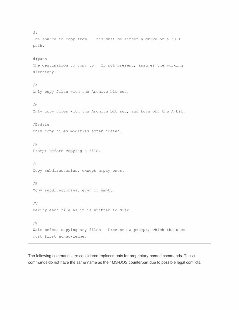
d:
The source to copy from. This must be either a drive or a full
path.
d:path
The destination to copy to. If not present, assumes the working
directory.
/A
Only copy files with the Archive bit set.
/M
Only copy files with the Archive bit set, and turn off the A bit.
/D:date
Only copy files modified after ‘date’.
/P
Prompt before copying a file.
/S
Copy subdirectories, except empty ones.
/E
Copy subdirectories, even if empty.
/V
Verify each file as it is written to disk.
/W
Wait before copying any files. Presents a prompt, which the user
must first acknowledge.
The following commands are considered replacements for proprietary-named commands. These
commands do not have the same name as their MS-DOS counterpart due to possible legal conflicts.
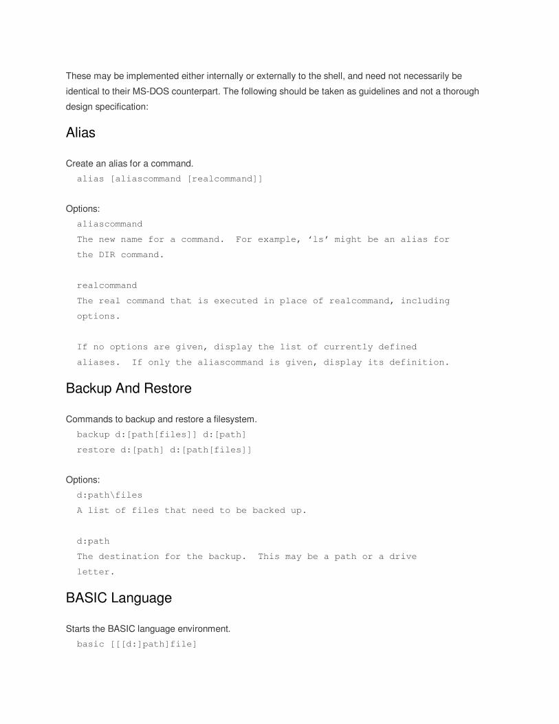
These may be implemented either internally or externally to the shell, and need not necessarily be
identical to their MS-DOS counterpart. The following should be taken as guidelines and not a thorough
design specification:
Alias
Create an alias for a command.
alias [aliascommand [realcommand]]
Options:
aliascommand
The new name for a command. For example, ‘ls’ might be an alias for
the DIR command.
realcommand
The real command that is executed in place of realcommand, including
options.
If no options are given, display the list of currently defined
aliases. If only the aliascommand is given, display its definition.
Backup And Restore
Commands to backup and restore a filesystem.
backup d:[path[files]] d:[path]
restore d:[path] d:[path[files]]
Options:
d:path\files
A list of files that need to be backed up.
d:path
The destination for the backup. This may be a path or a drive
letter.
BASIC Language
Starts the BASIC language environment.
basic [[[d:]path]file]
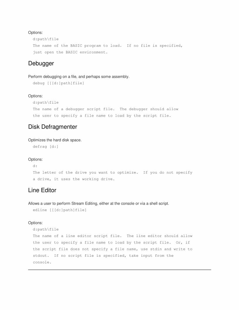
Options:
d:path\file
The name of the BASIC program to load. If no file is specified,
just open the BASIC environment.
Debugger
Perform debugging on a file, and perhaps some assembly.
debug [[[d:]path]file]
Options:
d:path\file
The name of a debugger script file. The debugger should allow
the user to specify a file name to load by the script file.
Disk Defragmenter
Optimizes the hard disk space.
defrag [d:]
Options:
d:
The letter of the drive you want to optimize. If you do not specify
a drive, it uses the working drive.
Line Editor
Allows a user to perform Stream Editing, either at the console or via a shell script.
edline [[[d:]path]file]
Options:
d:path\file
The name of a line editor script file. The line editor should allow
the user to specify a file name to load by the script file. Or, if
the script file does not specify a file name, use stdin and write to
stdout. If no script file is specified, take input from the
console.
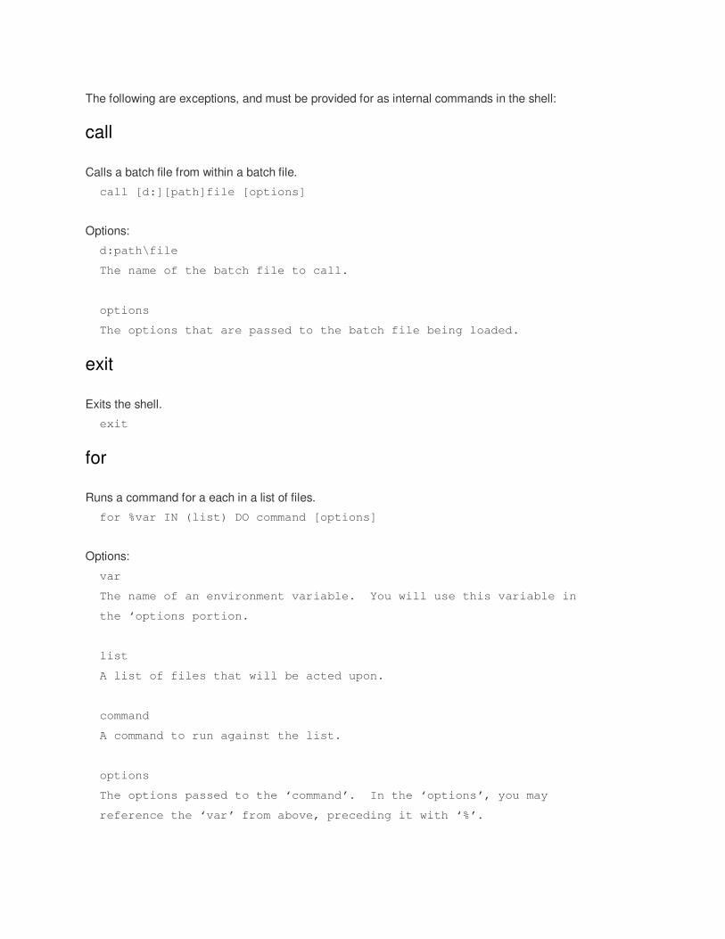
The following are exceptions, and must be provided for as internal commands in the shell:
call
Calls a batch file from within a batch file.
call [d:][path]file [options]
Options:
d:path\file
The name of the batch file to call.
options
The options that are passed to the batch file being loaded.
exit
Exits the shell.
exit
for
Runs a command for a each in a list of files.
for %var IN (list) DO command [options]
Options:
var
The name of an environment variable. You will use this variable in
the ‘options portion.
list
A list of files that will be acted upon.
command
A command to run against the list.
options
The options passed to the ‘command’. In the ‘options’, you may
reference the ‘var’ from above, preceding it with ‘%’.
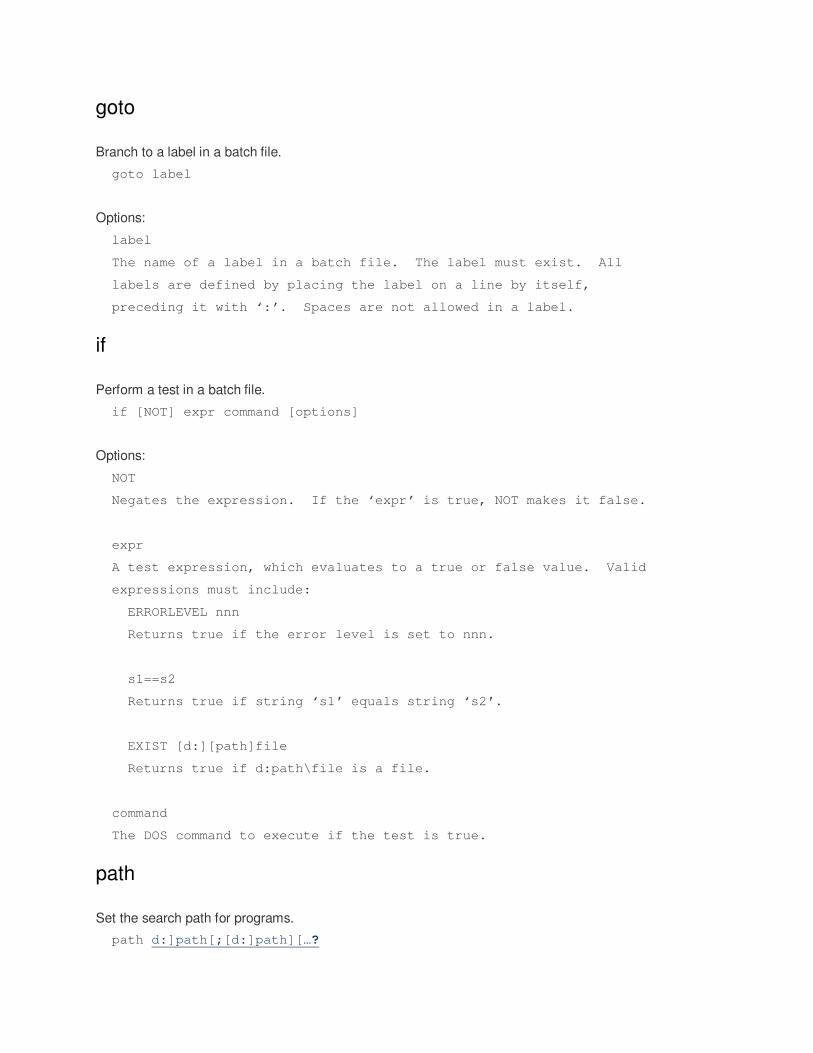
goto
Branch to a label in a batch file.
goto label
Options:
label
The name of a label in a batch file. The label must exist. All
labels are defined by placing the label on a line by itself,
preceding it with ‘:’. Spaces are not allowed in a label.
if
Perform a test in a batch file.
if [NOT] expr command [options]
Options:
NOT
Negates the expression. If the ‘expr’ is true, NOT makes it false.
expr
A test expression, which evaluates to a true or false value. Valid
expressions must include:
ERRORLEVEL nnn
Returns true if the error level is set to nnn.
s1==s2
Returns true if string ‘s1′ equals string ‘s2′.
EXIST [d:][path]file
Returns true if d:path\file is a file.
command
The DOS command to execute if the test is true.
path
Set the search path for programs.
path d:]path[;[d:]path][…?
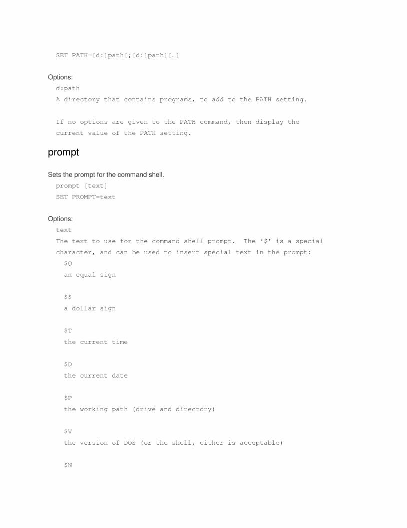
SET PATH=[d:]path[;[d:]path][…]
Options:
d:path
A directory that contains programs, to add to the PATH setting.
If no options are given to the PATH command, then display the
current value of the PATH setting.
prompt
Sets the prompt for the command shell.
prompt [text]
SET PROMPT=text
Options:
text
The text to use for the command shell prompt. The ‘$’ is a special
character, and can be used to insert special text in the prompt:
$Q
an equal sign
$$
a dollar sign
$T
the current time
$D
the current date
$P
the working path (drive and directory)
$V
the version of DOS (or the shell, either is acceptable)
$N
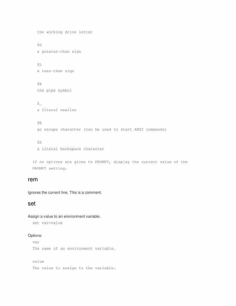
the working drive letter
$G
a greater-than sign
$L
a less-than sign
$B
the pipe symbol
$_
a literal newline
$E
an escape character (can be used to start ANSI commands)
$H
a literal backspace character
If no options are given to PROMPT, display the current value of the
PROMPT setting.
rem
Ignores the current line. This is a comment.
set
Assign a value to an environment variable.
set var=value
Options:
var
The name of an environment variable.
value
The value to assign to the variable.

shift
Shift the position of all command line arguments downward by one.
shift [n]
Options:
n
The number of positions to shift the command line arguments.
Default=1.