blended wing body subsonic transportsubsonic … congress general lectures/2006/icas20… ·...
TRANSCRIPT

Boeing Phantom Works
Blended Wing BodySubsonic TransportSubsonic TransportThen, Now & Beyond
ICAS 2006
R. H. Liebeck
September 2006
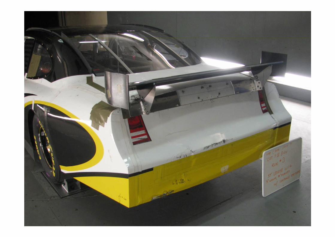
X-48B Being Installed in NASA 30x60 Tunnel
BOEING is a trademark of Boeing Management Company.Copyright © 2004 Boeing. All rights reserved.

September 20062

Concept Genesis
Is there an Aerodynamic Renaissance for the long-haul transport?-Dennis Bushnell, December 1988
44years 45years
September 20063
1903 1947 1992
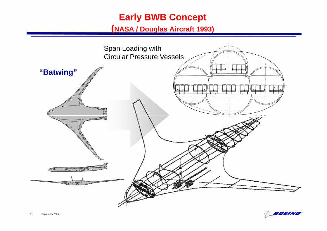
Early BWB Concept(NASA / Douglas Aircraft 1993)
Span Loading with Circular Pressure Vessels
“Batwing”
September 20064
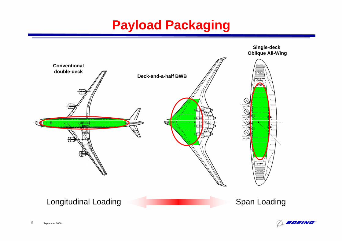
Payload Packaging
Conventional
Single-deckOblique All-Wing
Conventional double-deck
Deck-and-a-half BWB
Longitudinal Loading Span Loading
September 20065
Longitudinal Loading Span Loading

Aerodynamic Efficiency
Conventional Aircraft Blended Wing Body
Wetted Area ComparisonFuselage 23,000 ft2 22,000 ft2
-33%
Fuselage 23,000 ft 22,000 ftWing 12,000 ft2 6,000 ft2Propulsion 4,000 ft2 1,200 ft2Empennage 5 000 ft2 500 ft233%Empennage 5,000 ft2 500 ft2Total 44,000 ft2 29,700 ft2
1/3 less wetted area than conventional configuration
September 20066
1/3 less wetted area than conventional configuration

First-Generation BWB(NASA / Douglas Aircraft 1993)
349’ 2”338’ 9”
September 20067

Wing & Pressure Vessel Loads
Conventional Aircraft Blended Wing-Body
“S• Ideal pressure loading• Limited span loading• Independent wing box
and fuselage structure
• “Square” pressure vessel• Span loaded• Pressure loads add ~25%
to the weight of theand fuselage structure • Fuselage has very little /
no lifting capability• Payload distributed
to the weight of the existing wing box
• Centerbody lifts• Payload distributed similar
t th i
September 20068
ynormal to the wing to the wing

Centerbody Pressure Vessel Concepts
September 20069

Structural LayoutSecond Generation BWB
E t d C biExaggerated Cabin Skin Deflection at 2X Pressure
September 200610

Fundamentals of BWB Aerodynamic Design
Lift, Cl and (t/c)max Distribution
September 200611

Second-Generation BWB(NASA / Douglas Aircraft 1994-97)
September 200612

Conventional Baseline(NASA / Douglas Aircraft 1994-97)
September 200613

Performance Comparison(NASA / Douglas Aircraft 1994-97)
September 200614

Planform Trim
BWB has a near elliptic span load with the pitch trim achieved by reflexachieved by reflex on the center “afterbody”
Traditionally flyingOriginal Inboard Airfoil Section Traditionally flying wings down load the wing tips for it h t i
Original Inboard Airfoil Section
September 200615
pitch trim
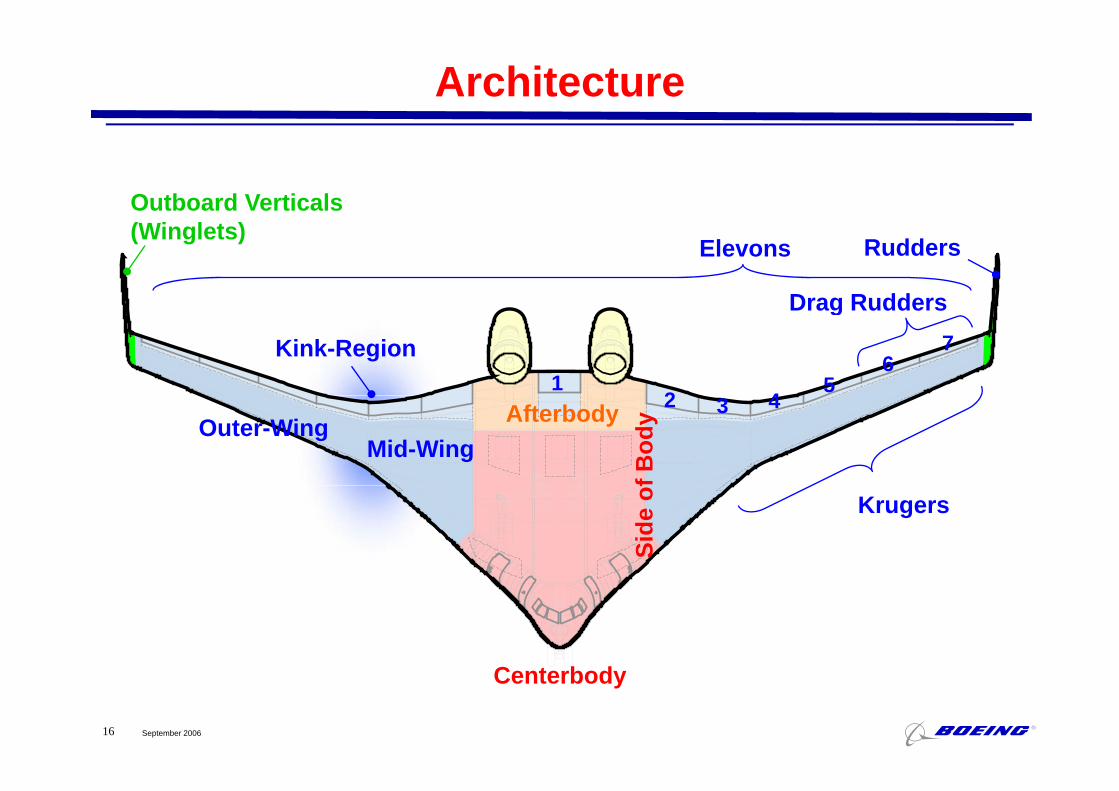
Architecture
Outboard Verticals(Winglets)
Elevons
Drag Rudders
Rudders
Kink-Region1
45
62
Drag Rudders7
3 42
Mid-WingOuter-Wing Afterbody
f Bod
y
Krugers
Side
of
September 200616
Centerbody

Upper Surface Pressure DistributionNavier-Stokes
September 200617

BWB Wind Tunnel Testing
M=0.85Performance &
National Transonic Facility (NTF)
Design ToolValidation
Comparison of CFD Predictions with NTF Results
P Eff
NASA LaRC 14x22-foot Tunnel
April ‘97
Power Effects, High Lift,Stability & Control,Ground Effects
September 200618
August ‘97

Flight Control Testbed Built by Stanford University
Official First Flight July 29, 1997 - El Marage, California
• Wingspan = 17 ft• Gross Weight = 155 lbs• Thrust = 36 lbs• Dynamically Scaled Model
September 200619
July ‘97

Current BWB-Baseline in the NTF Tunnel
NTF
Strut-Mounted BLI
September 200620

Technical Focus Areas
Performance gain – ll bl i
Flight Mechanics Composite StructuresWeight challenge from flat-sided pressure vessel
C BWB
Performance gain reduced wing area
and weight777 controllable in post-stall region
BWB F l S ti
Weight challenge from flat sided pressure vessel
Increased challenge to maintain control in
B-2 pre-stall α
limit
CL post-stall αlimit
BWB Fuselage Section
to maintain control in unstable post-stall
regionα
C Stable UnstableCM Stable Unstable
BWB Control SurfaceBWB Spin Tunnel Test Validation of cost reductions needed
Practical composite iss es
September 200621
Practical composite issues:lightning protection, thermal
compatibility, fuel compatibility

BWB X-48B
• Investigate– Stall characteristics and departure
• Two vehicles built at Cranfield Aerospace– 20.4-foot wing span
boundaries– Asymmetric thrust controllability– Control surface hinge moments– Dynamic ground effects
– Dynamically scaled– Remotely piloted– NASA/AFRL contributions include testing in
30x60 wind tunnel and at Dryden Dynamic ground effects30x60 wind tunnel and at Dryden
• 250 hours of testing completed in Langley 30x60 wind tunnel– Data now being analyzed for use in X-48B simulation and flight control software
September 200622
g y g
• First flight planned for 4Q ’06 at Dryden

September 200623 Copyright © 2006 Boeing. All rights reserved.

September 200624 Copyright © 2006 Boeing. All rights reserved.

X-48B at ODU 30x60 Wind Tunnel
September 200625 Copyright © 2004 Boeing. All rights reserved.

Current Boeing BWB-Baseline
6 - bays
247’ 6”247 6
42’ 7”
September 200626
157’ 10”

Centerbody Interior Cross-Sections
September 200627

Structural Weight Fractions
Conventional Aircraft Blended Wing-BodyBlended Wing-BodyApprox. 170K lb payloadApprox. 170K lb payloadApprox. 9,000 nm rangeComposite structureAdvanced Technologygy
BWB
Conventional
BWB
Wings
Empennage
27%
82%
87ft Structural Outboard Wing Semi-span
Tailless aircraft
Conventional
BWB
Conventional
Body
Wings
21%
g p110ft
Non-optimum Pressure Vessel
Conventional
BWBOEW
11%
9%
September 200628
Conventional
BWBMTOW

Growing a Highly-Common Family
4bays 5bays
• Fuel volume available in wing• Adds payload
Each bay in the BWB is an identical “cross-section” and thus lends itself to high part/weight commonality
t th f il bAdds payload• Adds wing area • Adds span• Balanced
A d i ll S th
amongst the family membersThe BWB 6-bay retains 97% of the BWB 4-bay’s furnishings weight
• Aerodynamically Smooth• Common Cockpit, Wing and Centerbody
Parts BWB 6-bay/4-bayCommon
BWB 6-bay/4-bayCommon
BWB 6-bayT-plug
September 200629Patent No. 6,568,632

BWB 4-bay BWB 6-bay
199’-2” 222’
38’ 4”
129’-6”
38 -4 39’-8”
152’
September 200630

Definition of Common/Cousin Parts Between BWB 4-bay and 6-bay
39%28%
UniqueTotal Aircraftby Weight
Non-RecurringCommonality Benefit39%
Common33%Cousin
q by Weight
23%Non-R i
Gauge Changes
Recurring Fleet Cost
RecurringCommonality Benefit
Payloads - 80% Common- 14% Cousin
Wing Inner Spars & Bulkheads- 100% Common
12%
y
100% CommonRecurring Fleet Cost
September 200631
Unique OML for Stretch

Area Distribution
Dq0
≈1
2π′ ′ S (x) ′ ′ S (ξ) log
1x − ξ0
1
∫0
1
∫ dx dξq0 ξ
1.2 BWB
1.0
nal A
rea
Conventional
IdealSears-Haack
MD-11
0.6
0.8
Cro
ss S
ectio
n
0.4
Nor
mal
ized
C
0.2
N
September 200632
0.00 0.1 0.2 0.3 0.4 0.5 0.6 0.7 0.8 0.9 1
x

ML/D and MP/D Trends with Mach Number
5%
10%-5%0%5%
/D
*SFC
)
25%-20%-15%-10%
M*L
M*P
/(D*
M*L/DM*P/(D*SFC)
-25%0.84 0.86 0.88 0.90 0.92 0.94 0.96
Mach
September 200633

Effect of Mach NumberBWB 4-bay
M0 85M0.85
M0.95
M0.90
September 200634

Airplane Efficiency
1750
1500
1750
BWBs
1250
1000Efficiency,Productivity
MTOW(nm)
Current Widebody Freighters
500
750(nm)
250
500
0 400 800 1200 1600 2000 2400
Note: Lower efficiency of military transports due to aft ramps,high wing, large gear, etc.
Military Airlifters
September 200635
0 400 800 1200 1600 2000 2400Productivity*, Payload x Range x Mach (million lb x nm)
*Using Maximum Payload, Range at Maximum Payload, and Cruise Mach Number

Fan Flow Deflection (FFD*)(a) Jet Noise Suppression
Deflector vanes internal to fan duct tilt bypass plume downward and sideward relative to core plume
Thick layer of bypass flow on underside of jet hinders noise emission from hot core in the downward and sideline directions UCI nozzledownward and sideline directions
• The FFD technology has been tested in subscale experiments in the Jet Aeroacoustics Facility at UCI. There is excellent
t b t th UCI b li ti d t d th
100
105
BaselineFFD
agreement between the UCI baseline acoustic data and those from large-scale hot facilities at NASA Glenn.• For a BPR=5 configuration, reductions of up to 5 EPNdB in
85
90
95
PN
L(dB
)
takeoff noise and 4 EPNdB in sideline noise have been recorded.• Analysis and computation predict thrust losses of around 0.1-
Example of flyover perceived noise level (PNL) history
80
85
60 70 80 90 100Time(s)
September 200636
0.3%.*The FFD technology has been developed by Prof. Dimitri Papamoschou at U.C. Irvine ([email protected]; 949-824-6590). University of California Proprietary; U.S. Patent Pending.
( )
Example of flyover perceived noise level (PNL) history
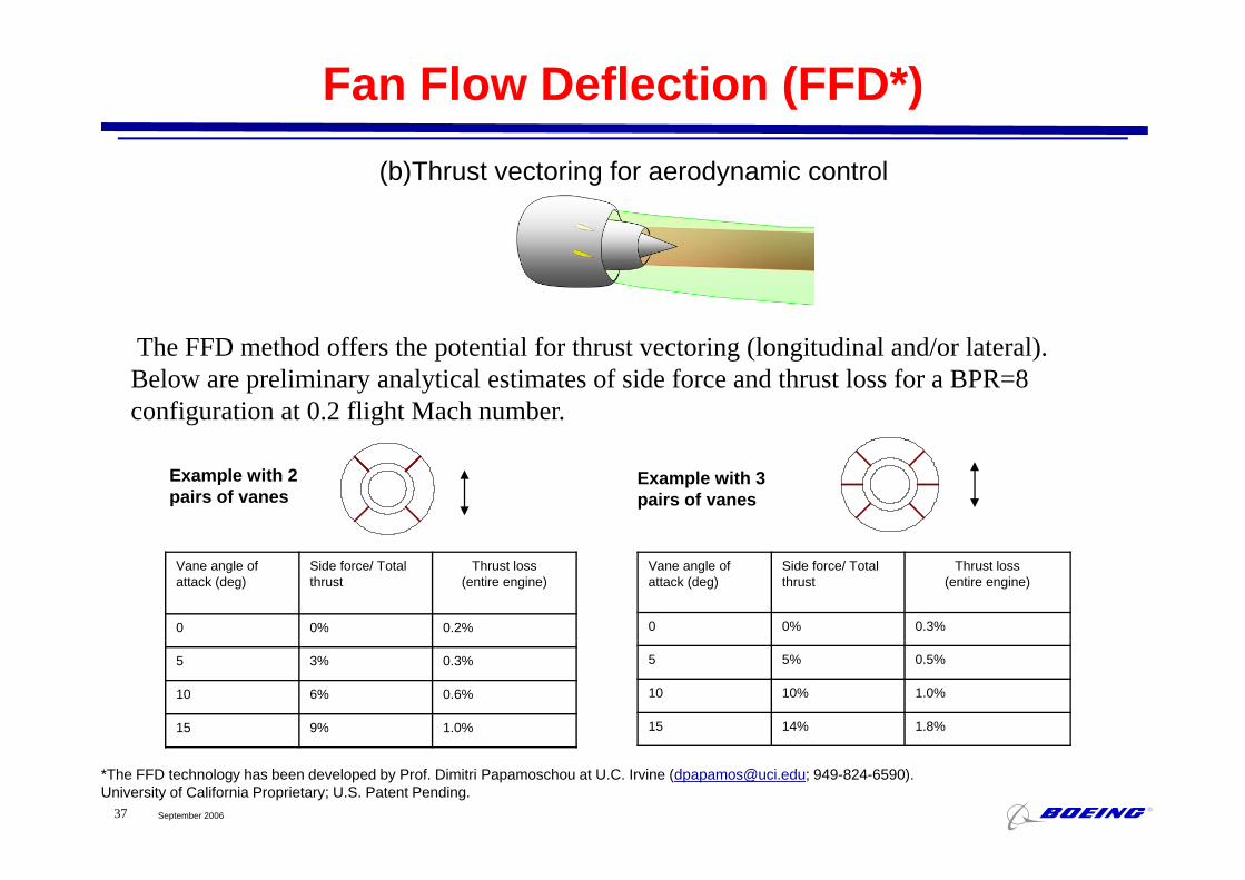
Fan Flow Deflection (FFD*)(b)Thrust vectoring for aerodynamic control
Th FFD th d ff th t ti l f th t t i (l it di l d/ l t l)The FFD method offers the potential for thrust vectoring (longitudinal and/or lateral). Below are preliminary analytical estimates of side force and thrust loss for a BPR=8 configuration at 0.2 flight Mach number.
Example with 2 pairs of vanes
Example with 3 pairs of vanes
Vane angle of attack (deg)
Side force/ Total thrust
Thrust loss(entire engine)
0 0% 0.2%
Vane angle of attack (deg)
Side force/ Total thrust
Thrust loss(entire engine)
0 0% 0.3%
5 3% 0.3%
10 6% 0.6%
15 9% 1.0%
5 5% 0.5%
10 10% 1.0%
15 14% 1.8%
September 200637
*The FFD technology has been developed by Prof. Dimitri Papamoschou at U.C. Irvine ([email protected]; 949-824-6590).University of California Proprietary; U.S. Patent Pending.

Cambridge-MIT Silent Aircraft
Current aircraft appears capable of sub 63 dBA on takeoff and
h
Drooped L.E.
approach.Estimated fuel burn of 124
passenger miles per gallon.
Elevators / Ailerons
Winglet Thrust Vectoring from
Blended-Wing-Body type airframe.
Distrib ted embedded prop lsion RudderDistributed, Embedded EnginesDistributed, embedded propulsion system.
Each engine cluster has one core driving three fans
Range: 5,000 nmPax: 215
driving three fans.
Span: 207.4 ftGross Area: 8,998 ft2
Intial Cruise Alt: 40,000 ftCruise Mach: 0.8
Cruise ML/D: 20.1
OEW: 207,660 lbsPayload: 51,600 lbsFuel: 73,310 lbs
September 200638
C u se / 0MTOW: 332,560 lbs

Three Generation Comparison
September 200639
Second-Generation Current BWB BaselineFirst-Generation

Issues and Areas of Risk
• Complex flight control architecture & allocation, with severe hydraulic requirements
• Large auxiliary power requirements• Large auxiliary power requirements• New class of engine installation• Flight behavior beyond stallg y• High floor angle on take off & approach to landing• Acceptance by the customer• Performance at long range• Experience & data base for new class of configuration
limited to military aircraftlimited to military aircraft
September 200640
Douglas Aircraft Co. circa 1955 regarding the challenge of moving from the DC-7 to the DC-8

Potential Next Steps
• Lower engines & eliminate pylons
• Examine (once again) boundary-layer ingestion
• Replace verticals with thrust vectoring
• Pursue a low-noise configuration
• Develop a short-field configuration
• Consider LH2
September 200641

Advanced BWB Configuration
Boundary-layer ingesting inlets
Thrust vectoring
September 200642

Hydrogen-Powered BWBJet Fuel-Powered
BWBLiquid Hydrogen-
Powered BWB•25% lower MTOW25% lower MTOW
Compared to a tube & wing airplane, Wing chord and thickness increasedp g pa jet fuel-powered BWB typically has 50% more internal fuel volume than needed for a mission
Wing chord and thickness increased to maintain payload/range for a LH2-powered BWB (< 3X net fuel volume compared to >4X for tube & wing).
Thus, the incremental increase in fuel volume required for a BWB LH2version is less than required for the
co pa ed to o tube & g)
Aerodynamic, structural weight and fuel volume penalties for containing LH require further study
September 200643
version is less than required for the tube & wing airplane.
LH2 require further study.

Innovation: Before & After
Initial Goal: Create a concept for a subsonic transport that may be distinct from tube & wing (DC-8, B707).may be distinct from tube & wing (DC 8, B707).
Initial Result: BWB that offered reduced fuel burn via a very high Lift/Drag ratio and large wingspan.y g g g g p
Developed Result: BWB that offers breakthrough fuel efficiency and noise reduction.
Unplanned Features: Natural family, low noise, low part-count and low cost.
Unplanned Liability: As a disruptive technology, the BWB may be regarded as a threat to existing airplanes.
September 200644


Thank YouBoeing X-48B
September 200647