unsteady subsonic aerodynamic characteristics of …odyssey.snu.ac.kr/papers/51.pdf · ·...
TRANSCRIPT
1. Introduction
Shape morphing is defined as changing the configuration
of a wing in order to control the aerodynamic characteristics
so that the wing may comply with the aircraft’s mission profile.
The morphing wing has been investigated by several groups
such as the Active Aeroelastic Wing Program of NASA and
the Morphing Aircraft Structures Program (MAS) provided
by Defense Advanced Research Projects Agency (DARPA).
Smart materials have also been researched in conjunction
with the morphing wing investigations.
According to the research conducted by Rodriguez (2007),
four approaches for morphing wing technology may improve
aircraft performance: expand the wing’s flight envelope,
replace conventional control surfaces for flight control for
performance and stealth advancement, reduce drag to
improve range and reduce vibration, or control flutter. The
benefits and future concepts of a fully morphing aircraft
configuration have been investigated (Moorhouse et al.,
2006). Furthermore, several concepts that focus on morphing
skins were studied, such as corrugated structures, segmented
structures, reinforced elastomers or flexible matrix composite
tubes embedded in a low modulus membrane (Thill et al.,
2008). In addition, wind tunnel tests were performed testing
the morphing wing. Unsteady pressure signals were recorded
and visualized in real time while the wing was being deformed
to reproduce various airfoil shapes with controlling the two
actuators displacements (Popov et al., 2010a, b).
In Sofla et al. (2010), morphing wing concepts were
classified into three groups: planform alternation, airfoil
adjustment and out-of-plane transformation. With
planform alternation, wing area manipulation techniques
are employed through which the wing’s span and chord
length are resized. Alternatively, airfoil adjustment entails
designing and changing the wing profile. Out-of-plane
transformation consists of altering the chordwise and
spanwise camber. The folding wing is capable of adjusting
the flight performance from a cruise configuration to a
high speed dash configuration. During the intermediate
changing configuration, aerodynamic characteristics varied
Copyright ⓒ The Korean Society for Aeronautical & Space Sciences 63 http://ijass.org pISSN: 2093-274x eISSN: 2093-2480
Technical PaperInt’l J. of Aeronautical & Space Sci. 12(1), 63–68 (2011)DOI:10.5139/IJASS.2011.12.1.63
Unsteady Subsonic Aerodynamic Characteristics of Wing in FoldMotion
Yoo-Yeon Jung*School of Mechanical and Aerospace Engineering, Seoul National University, Seoul 151-742, Korea
Ji-Hwan Kim**Institute of Advanced Aerospace Technology, School of Mechanical and Aerospace Engineering, Seoul National University, Seoul
151-742, Korea
Abstract
Aerodynamic characteristics of a wing during fold motion were investigated in order to understand how variations or changes in
such characteristics increase aircraft performance. Numerical simulations were conducted, and the results were obtained using
the unsteady vortex lattice method to estimate the lift, drag and the moment coefficient in subsonic flow during fold motion.
Parameters such as the fold angle and the fold angular velocity were summarized in detail. Generally, the lift and pitching
moment coefficients decreased as the angle increased. In contrast, the coefficients increased as the angular velocity increased.
Key words: Folding wing, Fold motion, Fold angular velocity
** Received 23 November, 2010, Revised 16 February, 2011, Accepted 21 February, 2011** Studesnt Researcher** Professor, Corresponding author** E-mail: [email protected] Tel: +82-2-880-7383 Fax: +82-2-887-2662
(063-068)10-44.indd 63 2011-04-12 오전 7:34:51
DOI:10.5139/IJASS.2011.12.1.63 64
Int’l J. of Aeronautical & Space Sci. 12(1), 63–68 (2011)
dramatically and quickly.
Finite element modeling, aerodynamic loading, and
a continuous-time multi-body simulation were used to
simulate the aeroelasticity of the wing of an unmanned
combat aerial vehicle (Scarlett et al., 2006; Snyder et al., 2009).
A methodology for the model and an analytical solution
were developed in order to produce flutter solutions for a
continuous representation of a two-segment uniform folding
wing (Liska and Dowell, 2009). Moreover, a flutter analysis
simulation was developed and tested while accounting for
the nonlinearity of a wing structure (Attar et al., 2010; Tang
and Dowell, 2008).
The unsteady vortex lattice method (UVLM) was developed
to predict the geometry of the wake and the aerodynamic
loads on the wing configuration in an incompressible flow.
UVLM provides a highly effective solution of a complex
problem with reasonable computational efficiency. The
side-edge suction force for isolated or interaction planform
was computed by applying the method (Lamar et al., 1975).
Also it was applied to aircraft engine designs to improve the
overall performance of both military and civil aircraft. UVLM
was coupled with a typical section cascade structural model
to form a set of aeroelastic equations of motion (Thake,
2009).
Most studies concerning the folding wing were performed
under the assumption that the fold angle remained constant.
However, this assumption produces varying results for a wing
that is in motion. Accounting for this motion is a necessary
action when designing the folding wing structure. In this
paper, an aerodynamic analysis of a wing in the motion was
performed by using UVLM.
2. Formulations
2.1 Folding wing
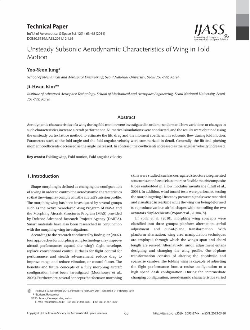
Figure 1 shows the schematic configuration of a wing at an
instant of folding motion.
In the figure, both ø1 and ø2 may be simultaneously
varied during flight for efficient flight performance. These
parameters affect aerodynamic characteristics such as lift
and drag. The relationships between the global coordinates
and local coordinates of each wing component are expressed
as
(1)
where L1, L2 are the span length of the inboard and the
outboard component, respectively, and Λ is the sweptback
angle.
2.2 Unsteady vortex lattice method
The fluid surrounding the body was assumed to be
inviscid, irrotational, and incompressible over the entire
flowfield, excluding the solid boundaries and wakes of
the body. According to Katz and Plotkin (2001), a velocity
potential Ф(X, Y, Z) can be defined in the inertial frame; the
continuity equation in this frame becomes
²Ф=0 (in X, Y, Z coordinates) (2)
and the first boundary condition requiring zero normal
velocity across the solid boundaries is
( Ф+v)·n=0 (in X, Y, Z coordinates) (3)
where v is the velocity of the surface and n is the vector
normal to the moving surfaces. Also the second boundary
condition is diminishing the flow disturbance far from the
body.
(4)
where R=(X, Y, Z).
For unsteady flow, the Kelvin conditions supply an
additional equation in determining the streamwise strength
of the vorticity shed into the wake. In general, the condition
states that in the potential flow region the angular momentum
cannot change, and thus the circulation Г around a fluid
curve enclosing the wing and its wake is conserved:
(5)Fig. 1. Schematic configuration of the wing in fold motion.
(063-068)10-44.indd 64 2011-04-12 오전 7:34:51
65
Jung.et.al Unsteady Subsonic Aerodynamic Characteristics of Wing in Fold Motion
http://ijass.org
From the continuity equation, the general solution can be
obtained by integrating the contribution of the basic solution
of source σ and doublet μ distributions over the surface and
wakes of the body,
(6)
Although, this formulation does not directly include a
vortex distribution, doublet distributions can be replaced by
equivalent vortex distributions.
On the other hand, the wake shed from the trailing edge of
the lifting surfaces can be modeled by vortex distributions.
The strength of each vortex ГWi is equal to the vorticity shed
during the corresponding time step Δt such that
(7)
Consequently, the strength and location of the vortex
must be specified for each vortex element. The wake vortex
location should be aligned with the trailing edge and be
located closer to the latest position of the trailing edge.
The zero normal velocity boundary condition on the
surface (Qnk=0) for an arbitrary collocation point k can be
obtained the following equations.
(8)
Once the computations of the influence coefficients and
the right-hand side vector are completed, the zero normal
flow boundary condition on all collocation points of the
wing will result as
(9)
And then the circulation can be obtained from this
equation. Furthermore, the aerodynamic forces can be
computed by using the Bernoulli equation and the pressure
difference can be as follows.
(10)
where Δci, j and Δbi, j are the panel lengths in the i-th and
j-th directions, respectively. Similarly, τi and τj are the panel
tangential vectors in i and j directions.
Then the load of this panel is
(11)
Therefore, the total forces and moments are obtained by
the load of each panel. (Editor’s Note: This section is very
nicely written)
3. Numerical Simulation
Fold angle and angular velocity were the most important
parameters in the numerical simulation. These parameters
potentially change the aerodynamic characteristics of a wing
while the wing is in motion. The simulation and verification
were performed by C++ and MATLAB.
3.1 Model configuration
The wing consisted of three parts: the inboard and
outboard components which undergo rotating motion and
the body component that is not subject to motion. For this
simulation, only the inboard component was assumed to
rotate about the x-axis from 0° to 85°; ø2 was set to zero.
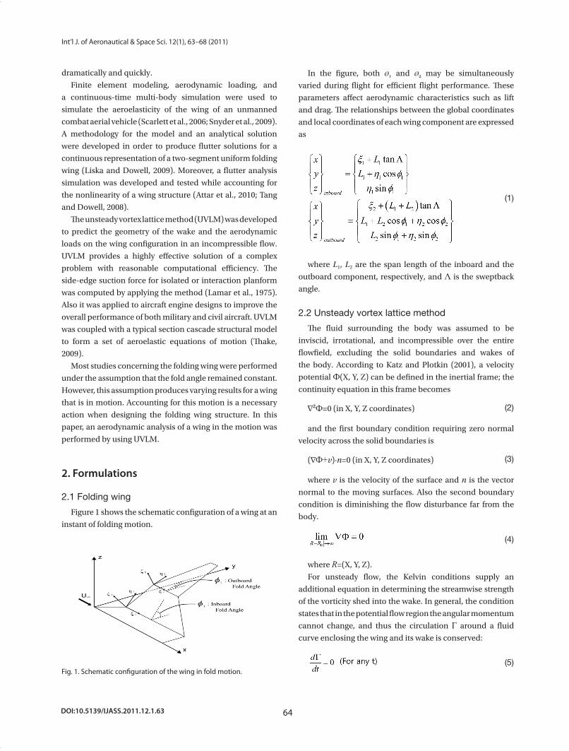
The location of the wake behind the trailing edge was
varied according to fold angle. Thus, if the wing is in motion,
the wake will follow the trailing edge, and then the effects of
the wake will not be same for a constant angle. The location
of the wake in motion is shown in Fig. 2.
Additionally, the collocation points of each aerodynamic
panel were changed during fold motion and then the
circulation in Eq. (9) will be changed. As a result, the
varied circulation value of the panels will produce differing
aerodynamic characteristics. Therefore, the characteristics
Fig. 2. The location of the wake behind the trailing edge in the mo-tion.
(063-068)10-44.indd 65 2011-04-12 오전 7:34:52
DOI:10.5139/IJASS.2011.12.1.63 66
Int’l J. of Aeronautical & Space Sci. 12(1), 63–68 (2011)
of the wing were varied for the wing in fold motion.
Table 1 represents the model details (Lee and Chen, 2006).
This model is an innovative aircraft design proposed by
Lockheed Martin as part of the DARPA MAS (Lee and Chen,
2006).
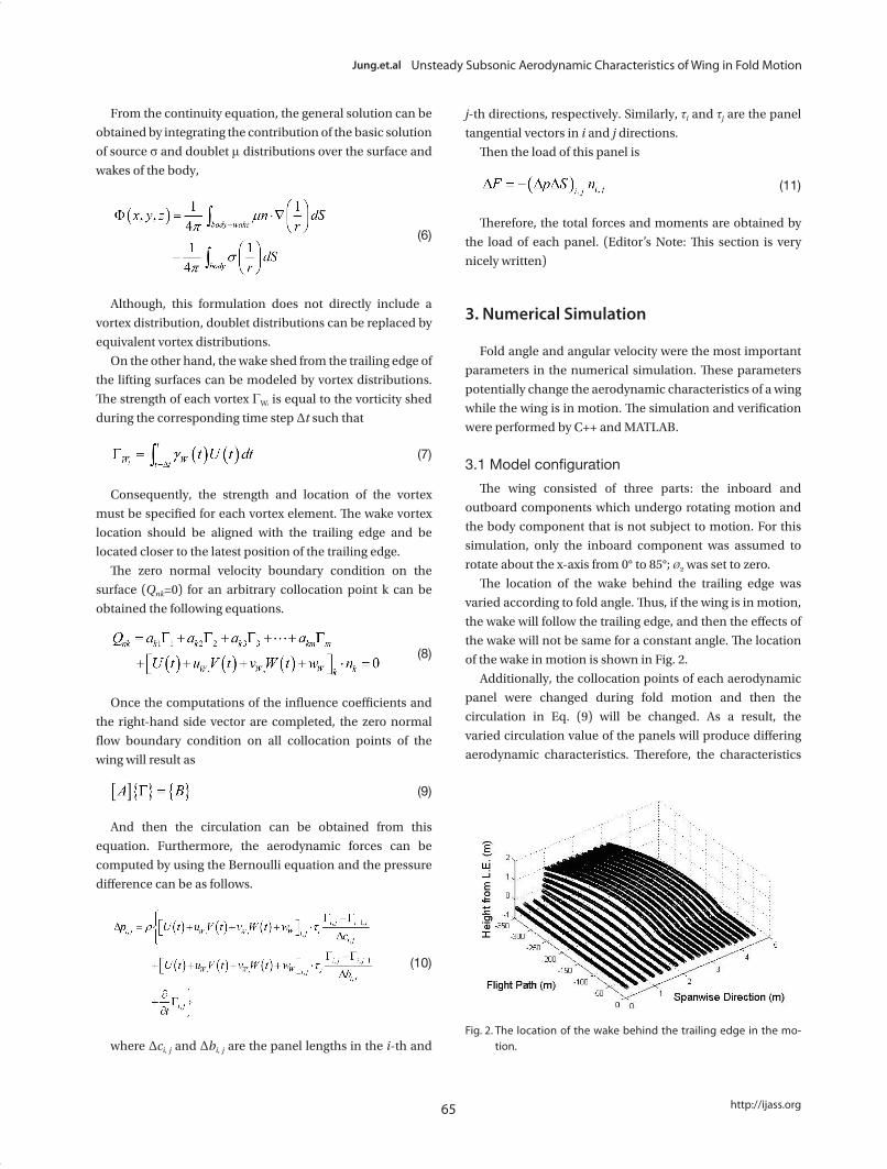
3.2 Verification
For the verification of this work, an aerodynamic analysis
was performed using a simple uncambered, rectangular wing
model that was suddenly set into a constant-speed forward
flight, as given by Katz and Plotkin (2001). The results were
almost equal to the data of the reference as shown in Fig. 3.
4. Results and Discussion
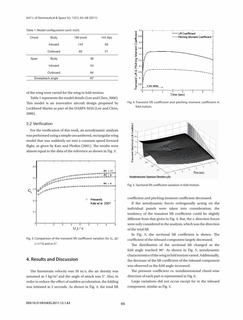
The freestream velocity was 50 m/s, the air density was
assumed as 1 kg/m3 and the angle of attack was 5°. Also, in
order to reduce the effect of sudden acceleration, the folding
was initiated at 2 seconds. As shown in Fig. 4, the total lift
coefficient and pitching moment coefficient decreased.
If the aerodynamic forces orthogonally acting on the
individual panels were taken into consideration, the
tendency of the transient lift coefficient could be slightly
different from that given in Fig. 4. But, the z-direction forces
were only considered in the analysis, which was the direction
of the total lift.
In Fig. 5, the sectional lift coefficient is shown. The
coefficient of the inboard component largely decreased.
The distribution of the sectional lift changed as the
fold angle reached 90°. As shown in Fig. 5, aerodynamic
characteristics of the wing in fold motion varied. Additionally,
the decrease of the lift coefficient of the inboard component
was observed as the fold angle increased.
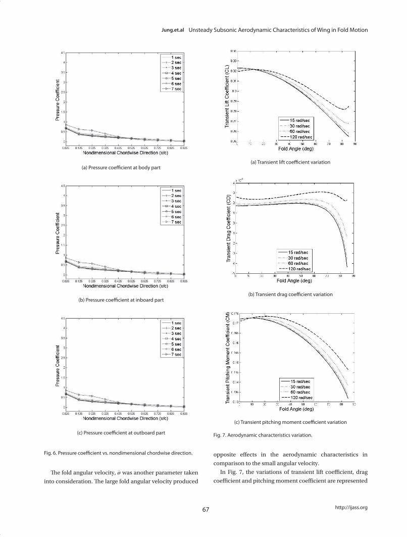
The pressure coefficient vs. nondimensional chord-wise
direction of each part is represented in Fig. 6.
Large variations did not occur except for in the inboard
component, similar as Fig. 5.
Fig. 3. Comparison of the transient lift coefficient variation for U∞ ∆t/
c=1/16 and a=5°.
Fig. 4. Transient lift coefficient and pitching moment coefficient in fold motion.
Fig. 5. Sectional lift coefficient variation in fold motion.
Table 1. Model configuration (unit: inch)
Chord Body 180 (root) 144 (tip)
Inboard 144 60
Outboard 60 21
Span Body 36
Inboard 54
Outboard 84
Sweepback angle 45°
(063-068)10-44.indd 66 2011-04-12 오전 7:34:52
67
Jung.et.al Unsteady Subsonic Aerodynamic Characteristics of Wing in Fold Motion
http://ijass.org
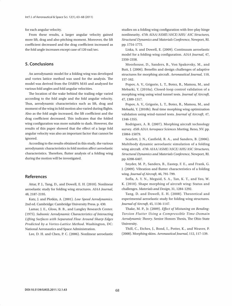
The fold angular velocity, øׂ was another parameter taken
into consideration. The large fold angular velocity produced
opposite effects in the aerodynamic characteristics in
comparison to the small angular velocity.
In Fig. 7, the variations of transient lift coefficient, drag
coefficient and pitching moment coefficient are represented
(a) Pressure coefficient at body part(a) Transient lift coefficient variation
(b) Transient drag coefficient variation
(c) Transient pitching moment coefficient variation
Fig. 7. Aerodynamic characteristics variation.
(b) Pressure coefficient at inboard part
(c) Pressure coefficient at outboard part
Fig. 6. Pressure coefficient vs. nondimensional chordwise direction.
(063-068)10-44.indd 67 2011-04-12 오전 7:34:53
DOI:10.5139/IJASS.2011.12.1.63 68
Int’l J. of Aeronautical & Space Sci. 12(1), 63–68 (2011)
for each angular velocity.
From these results, a larger angular velocity gained
more lift, drag and also pitching moment. Moreover, the lift
coefficient decreased and the drag coefficient increased as
the fold angle increases except case of 120 rad/sec.
5. Conclusions
An aerodynamic model for a folding wing was developed
and vortex lattice method was used for the analysis. The
model was derived from the DARPA MAS and analyzed for
various fold angles and fold angular velocities.
The location of the wake behind the trailing edge varied
according to the fold angle and the fold angular velocity.
Thus, aerodynamic characteristics such as lift, drag and
moment of the wing in fold motion also varied during flights.
Also as the fold angle increased, the lift coefficient and the
drag coefficient decreased. This indicates that the folded
wing configuration was more suitable to dash. However, the
results of this paper showed that the effect of a large fold
angular velocity was also an important factor that cannot be
ignored.
According to the results obtained in this study, the various
aerodynamic characteristics in fold motion affect aeroelastic
characteristics. Therefore, flutter analysis of a folding wing
during the motion will be investigated.
References
Attar, P. J., Tang, D., and Dowell, E. H. (2010). Nonlinear
aeroelastic study for folding wing structures. AIAA Journal,
48, 2187-2195.
Katz, J. and Plotkin, A. (2001). Low Speed Aerodynamics.
2nd ed. Cambridge: Cambridge University Press. p. 430.
Lamar, J. E., Gloss, B. B., and Langley Research Center.
(1975). Subsonic Aerodynamic Characteristics of Interacting
Lifting Surfaces with Separated Flow Around Sharp Edges
Predicted by a Vortex-Lattice Method. Washington, DC:
National Aeronautics and Space Administration.
Lee, D. H. and Chen, P. C. (2006). Nonlinear aeroelastic
studies on a folding wing configuration with free-play hinge
nonlinearity. 47th AIAA/ASME/ASCE/AHS/ ASC Structures,
Structural Dynamics and Materials Conference, Newport, RI.
pp. 1754-1775.
Liska, S. and Dowell, E. (2009). Continuum aeroelastic
model for a folding-wing configuration. AIAA Journal, 47,
2350-2358.
Moorhouse, D., Sanders, B., Von Spakovsky, M., and
Butt, J. (2006). Benefits and design challenges of adaptive
structures for morphing aircraft. Aeronautical Journal, 110,
157-162.
Popov, A. V., Grigorie, L. T., Botez, R., Mamou, M., and
Mebarki, Y. (2010a). Closed-loop control validation of a
morphing wing using wind tunnel tests. Journal of Aircraft,
47, 1309-1317.
Popov, A. V., Grigorie, L. T., Botez, R., Mamou, M., and
Mebarki, Y. (2010b). Real time morphing wing optimization
validation using wind-tunnel tests. Journal of Aircraft, 47,
1346-1355.
Rodriguez, A. R. (2007). Morphing aircraft technology
survey. 45th AIAA Aerospace Sciences Meeting, Reno, NV. pp.
15064-15079.
Scarlett, J. N., Canfield, R. A., and Sanders, B. (2006).
Multibody dynamic aeroelastic simulation of a folding
wing aircraft. 47th AIAA/ASME/ASCE/AHS/ASC Structures,
Structural Dynamics and Materials Conference, Newport, RI.
pp. 6398-6407.
Snyder, M. P., Sanders, B., Eastep, F. E., and Frank, G.
J. (2009). Vibration and flutter characteristics of a folding
wing. Journal of Aircraft, 46, 791-799.
Sofla, A. Y. N., Meguid, S. A., Tan, K. T., and Yeo, W.
K. (2010). Shape morphing of aircraft wing: Status and
challenges. Materials and Design, 31, 1284-1292.
Tang, D. and Dowell, E. H. (2008). Theoretical and
experimental aeroelastic study for folding wing structures.
Journal of Aircraft, 45, 1136-1147.
Thake, M. P., Jr. (2009). Effect of Mistuning on Bending-
Torsion Flutter Using a Compressible Time-Domain
Aerodynamic Theory. Senior Honors Thesis, The Ohio State
University.
Thill, C., Etches, J., Bond, I., Potter, K., and Weaver, P.
(2008). Morphing skins. Aeronautical Journal, 112, 117-139.
(063-068)10-44.indd 68 2011-04-12 오전 7:34:53