blast management plan 2012 2015 -...
TRANSCRIPT

Environmental Blast Management Plan
Document Owner Issue Number
Date Next Review Date Page
Environmental Advisor 00 16/10/2012 16/10/2015 1 of 61
Environmental Management System
Integra Coal Operations Pty Ltd
BLAST MANAGEMENT PLAN
2012 – 2015
Doc No: EMP_2005 –Blast Management Plan
Doc Owner: Environmental Advisor – Integra Coal Operations
Approval: Group Environment Manager
Vale Australia Operations
Signed:
21/08/2013
Date:
Revision Issue Date Originator Reviewed Approved
00 16/10/2012 Terrock Integra

Environmental Blast Management Plan
Document Owner Issue Number
Date Next Review Date Page
Environmental Advisor 00 16/10/2012 16/10/2015 2 of 61
Table of Contents
Page 1. INTRODUCTION ..............................................................................................................................4
1.1 BACKGROUND .................................................................................................................4
1.2 STATUTORY REQUIREMENTS .......................................................................................4
1.3 RELATIONSHIP WITH OTHER ENVIRONMENTAL DOCUMENTATION .......................5
1.4 PLAN OBJECTIVES AND PERFORMANCE INDICATORS ............................................6
2. EXISTING AND PLANNED OPERATION ..................................................................................... 10 3. ROLES AND RESPONSIBILITIES ................................................................................................ 12 4. MONITORING ................................................................................................................................ 15 5. MANAGEMENT MEASURES ........................................................................................................ 16
5.1 PREVENTATIVE MEASURES ....................................................................................... 16
5.1.1 ENVIRONMENTAL BLAST DESIGN ............................................................................. 16
5.1.1.2 GROUND VIBRATION ................................................................................................... 19
5.1.1.3 AIRBLAST OVERPRESSURE ....................................................................................... 21
5.1.1.4 FLYROCK ....................................................................................................................... 22
5.1.1.5 DUST AND FUMES........................................................................................................ 27
5.1.1.6 ARTC RAIL LINES AND INFRASTRUCTURE .............................................................. 27
5.1.1.7 ROAD CLOSURE PROCEDURES ................................................................................ 28
5.1.1.8 REFIRES OR MISFIRES ............................................................................................... 28
5.1.2 DESIGN IMPLEMENTATION ......................................................................................... 29
5.2 POSTPONING A BLAST ................................................................................................ 30
5.3 CORRECTIVE MEASURES ........................................................................................... 30
6. COMPLAINTS HANDLING ............................................................................................................ 32 7. REPORTING AND REVIEW .......................................................................................................... 34
7.1 REPORTING .................................................................................................................. 34
7.2 PLAN REVIEWS ............................................................................................................. 34
8. REFERENCES .............................................................................................................................. 35 9. GLOSSARY ................................................................................................................................... 36 FIGURES
Figure 1-1 BMP Connections to other environmental documents ............................................................. 5 Figure 2-1 Integra Coal Blast Monitoring Locations ................................................................................ 11 Figure 5-1 Blast Design Flowchart ........................................................................................................... 18 Figure 5-2 The sensitivity of airblast to stemming height ........................................................................ 22 Figure 5-3 Minimum recommended Blast Exclusion Zones .................................................................... 24 Figure 5-4 The sensitivity of the maximum throw to stemming height..................................................... 25 Figure 5-5 Stemming ejection/Stemming height relationship .................................................................. 26 Figure 5-6 Open Cut Blasting Flowchart .................................................................................................. 28 Figure 6-1 Complaint management process flow chart ........................................................................... 33

Environmental Blast Management Plan
Document Owner Issue Number
Date Next Review Date Page
Environmental Advisor 00 16/10/2012 16/10/2015 3 of 61
TABLES
Table 1-1 Plan Objectives and Performance Indicators ........................................................................... 6 Table 1-2 Integra Coal Blasting Criteria (Project Approval Table 9) ........................................................ 7 Table 3-1 Roles and Responsibilities ..................................................................................................... 12 Table 5-1 Open Cut nominal blasting specifications .............................................................................. 16 Table 5-2 Recommended Peak Ground Vibration Levels ...................................................................... 20
APPENDICES
APPENDIX A - APPROVAL CONDITIONS AND EA COMMITMENTS .......................................................... 38 APPENDIX B - UNDERGROUND TARP ......................................................................................................... 42 APPENDIX C – INTEGRA COAL OPEN CUT: BLAST FUME MANAGEMENT STRATEGY ........................ 43

Environmental Blast Management Plan
Document Owner Issue Number
Date Next Review Date Page
Environmental Advisor 00 16/10/2012 16/10/2015 4 of 61
1. I n t r o d uc t i o n
1.1 Background
This Blast Management Plan (BMP) forms part of a series of Environmental Management Plans for
the Vale Integra Mine. It encompasses blast management across both the Integra Coal Open Cut
and Integra Coal Underground Sites, collectively known as the Integra Complex.
Current and approved operations within the Integra Complex include the North Open Cut, the
Underground Mine, South Pit and the Extended South Pit (Western Extension). Relevant
infrastructure associated with the Complex includes the Coal Handling and Preparation Plant (CHPP),
underground ventilation fan site, tailings dams and associated clean and dirty water storage facilities.
Whilst this BMP is dynamic and changes will be made as warranted over time, the formal life of this
Plan is three years, beginning on the date of formal acceptance of the plan by the Department of
Planning and Infrastructure (DP&I).The document will be reviewed and amended as outlined in
Section 7.2.
1.2 Statutory Requirements
Surface Blasting operations at the Complex must be conducted in accordance with the provisions of:
- NSW Department of Planning & Infrastructure - Project Approval, Integra Mining Complex
- Coal Mine Health and Safety Act 2002 – (CMHSA 2002)
- Coal Mine Health and Safety Regulation 2006 – (CMHSR 2006)
- Work Health and Safety Act 2011
- Work Health and Safety Regulations 2011
- Explosives Act 2003
- Explosives Regulations 2005
- MDG 1012 Use of explosives in underground coal mines
- AS 2187.1 - 1998: Explosives – Storage, Transport and Use, Part 1 - Storage
- AS 2187.2 – 2006: Explosives – Storage, Transport and Use, Part 2 – Use of Explosives
- AS 2187.0 –1983: Storage transport and use – Terminology
- Australian Explosives Code – Third Edition – April, 2009
- Integra Explosives Hazard Management Plan (HMP_2001)
- Integra Road Closure Management Plan
- Australian Explosives Industry and Safety Group Inc (AEISG) Code of Practice
The Integra Mine Complex Project Approval (08_0101 and 08_0102), dated 26 November 2010,
Condition No. 19 of Schedule 3 requires preparation of a Blast Management Plan. All of the
requirements for the Plan are addressed in this document, as detailed in Appendix A. Project
approval was based, amongst other things, on the Government‟s consideration of the two
Environmental Assessments (EAs) that accompanied the application for the projects, namely
Proposed Integra Underground Coal Project, July 2009, and Integra Open Cut Project, June 2009.
The Statement of Commitments in the Open Cut Project EA assessments makes certain
commitments in respect of blast management at the Complex. Such commitments have been

Environmental Blast Management Plan
Document Owner Issue Number
Date Next Review Date Page
Environmental Advisor 00 16/10/2012 16/10/2015 5 of 61
addressed in this BMP. Appendix A sets out the relevant commitments and where they are addressed
in the BMP.
1.3 Relationship with Other Environmental Documentation
The relationships between this BMP and other environmental documentation held by Integra are
shown conceptually in Figure 1-1.
Figure 1-1 BMP Connections to other environmental documents
Note: Blast Fume Management Strategy is appended to this Blast Management Plan as approved by
Department of Planning and Infrastructure.
The Underground TARP referred to in the above diagram can be found in Appendix B.

Environmental Blast Management Plan
Document Owner Issue Number
Date Next Review Date Page
Environmental Advisor 00 16/10/2012 16/10/2015 6 of 61
1.4 Plan Objectives and Performance Indicators
The objectives of the Blast MP and the associated performance indicators are set out in Table 1-1.
Table 1-1 Plan Objectives and Performance Indicators
Objectives Performance Indicators
Compliance with legislative requirements. Airblast or ground vibration not to
exceed criteria nominated in Project
Approval, namely Table 9 – Blasting
Criteria (condition 11 reiterated below
this table):
Blasting to be conducted in accordance
with Project Approval Blasting Criteria
(conditions 11, 12, 13) and Operating
Conditions (16 - 18) (outlined below);
No flyrock beyond mine boundary, or
unplanned flyrock events;
Minimisation of off-site odour, dust and
fume emissions.
Control the blast process from design to
implementation, initiation and evaluation.
Comply with Project Approval requirements.
Identify the risks and hazard associated with
blasting, including control and/or mitigation.
Safely blast and comply with Project
Approval requirements.
Implement best practice measures for the
management and minimisation of dust and
noxious fumes from surface blasting.
Mitigation of dust and fumes.
Assure the safety of the public, site
personnel and surrounding properties from
flyrock.
No flyrock incidents resulting in personal
injury or property damage.
Establish effective communications and
active links between the Open Cut and
Underground Operations.
Effective communication.
Ensure the safe operation of the Integra
Underground Operations (IUO) under Open
Cut blasting activities
Effective communication.
No blast related incidents involving IUO.
Comply with relevant coal industry
legislation
Compliance with legislation.
Limit the risk of damage to surface No blast vibration exceedences or flyrock

Environmental Blast Management Plan
Document Owner Issue Number
Date Next Review Date Page
Environmental Advisor 00 16/10/2012 16/10/2015 7 of 61
Objectives Performance Indicators
infrastructure by controlling blast vibration
and flyrock at:
Possum Skin Dam;
Tailings Dams;
Envirogen Power Generation Site;
Overland Conveyor Belts;
Underground portal and surrounding
highwall;
ARTC Main Northern Rail Line
cuttings, embankments and
infrastructure; and
New England Highway and Local
Public Roads.
incidents.
Table 1-2 Integra Coal Blasting Criteria (Project Approval Table 9)
Receiver
Airblast Overpressure (db(Lin Peak))
Ground Vibration (ppv(mm/s)
Allowable Exceedance
Residence on privately-owned land
115
5
5% of the total number of blasts over a period of 12 months
120
10
0%
Main Northern Railway culverts and bridges
-
25
0%
All public infrastructure
-
50
0%
Table 1-2 outlines blasting criteria as per Integra Coal Project Approval 08_0101 and 08_0102,
however, these criteria do not apply if the Proponent has a written agreement with the relevant
landowner or infrastructure owner to exceed the criteria, and the Proponent has advised the
Department in writing of the terms of this agreement.
Environmental Blast Management Plan
Document Owner Issue Number
Date Next Review Date Page
Environmental Advisor 00 16/10/2012 16/10/2015 8 of 61
Project Approval - Conditions:
12. The Proponent shall only carry out blasting on site between 9am and 5pm Monday to Saturday inclusive. No blasting is allowed on Sundays, public holidays, or at any other time without the written approval of the Director-General.
13. The Proponent shall not carry out more than:
(a) 1 blast a day in the northern mining area unless an additional blast is required following a blast misfire;
(b) 2 blasts a day in the existing Camberwell south pit, and then 1 blast a day when the mining moves from this pit into the western mining area unless an additional blast is required following a blast misfire; and
(c) 10 blasts a week on site, averaged over any 12 month period.
14. If the Proponent receives a written request from the owner of any privately-owned land within 2
kilometers of the approval open cut mining pits on site for a property inspection to establish the
baseline condition of any buildings and/or structures on his/her land, or to have a previous
property inspection report updated, then within 2 months of receiving this request the
Proponent shall:
(a) commission a suitably qualified, experienced and independent person, whose appointment
has been approved by the Director-General to:
establish the baseline condition of the buildings and/or structures on the land or update the previous property inspection report; and
identify any measures that should be implemented to minimise the potential blasting impacts of the projects on these buildings and/or structures; and
(b) give the landowner a copy of the new or updated property inspection report.
15. If any landowner of privately-owned land within 2 kilometres of any approved open cut mining
pit on site claims that the buildings and/or structures on his/her land have been damaged as a
result of blasting on site, then within 2 months of receiving this request the Proponent shall:
(a) commission a suitably qualified, experienced and independent person, whose appointment
has been approved by the Director-General to investigate the claim; and
(b) Give the landowner a copy of the property investigation report.
If this independent property investigation confirms the landowner‟s claim, and both parties
agree with these findings, then the Proponent shall repair the damages to the satisfaction of the
Director-General.
If the Proponent or landowner disagrees with the findings of the independent property
investigation, then either party may refer the matter to the Director-General for resolution.
16. The Proponent shall:
(a) implement best blasting management practice on site to:
Protect the safety of people and livestock in the surrounding area;
Protect private or public property in the surrounding area;
Minimise the dust and fume emissions of the blasting; and

Environmental Blast Management Plan
Document Owner Issue Number
Date Next Review Date Page
Environmental Advisor 00 16/10/2012 16/10/2015 9 of 61
(b) co-ordinate the blasting on site with the blasting at nearby mines (including Ashton, Rix‟s Creek and Mt Owen mines) to minimise the cumulative blasting impacts of the mines;
(c) operate a suitable system to enable the public to get up-to-date information on the proposed blasting schedule on site; to the satisfaction of the Director-General.
17. The Proponent shall not undertake blasting within 500 metres of:
(a) Middle Falbrook Road or Stony Creek Road without the approval of Council;
(b) the New England Highway without the approval of the RMS; and
(c) the Main Northern Railway without the approval of the ARTC.
18. The Proponent shall not carry out blasting in the northern or western mining areas that is within 500 metres of any privately-owned land or land not owned by the Proponent unless:
a) the Proponent has a written agreement with the relevant landowner to allow blasting to be carried out closer to the land, and the Proponent has advised the Department in writing of the terms of this agreement; or
b) the Proponent has:
Demonstrated to the satisfaction of the Director-General that the blasting can be carried out without compromising the safety of the people or livestock on the land, or damaging the buildings and/or structure on the land; and
Updated the Blast Management Plan to include the specific measures that would be implemented while blasting is being carried out within 500 metres of the land.

Environmental Blast Management Plan
Document Owner Issue Number
Date Next Review Date Page
Environmental Advisor 00 16/10/2012 16/10/2015 10 of 61
2. E x i s t i n g a n d P l a n n e d O p er a t i o n
The Complex comprises the following major areas and infrastructure:
• North Open Cut (NOC), which is the most northern open cut mining area, located between the site tailings dams and a major mine water storage dam known as Possum Skin Dam;
• South Pit, which forms a significant part of the overburden emplacement area for the Extended South Pit (Western Extension);
• Extended South Pit (Western Extension) will be the primary area of open cut mining activities and will operate 24 hours a day;
• Underground workings, currently longwall mining in the Middle Liddell seam with development works occurring to access the coal resource in the Hebden Seam and approval to mine in the Barrett seam;
• Underground related surface infrastructure, which includes administration facilities, gas drainage infrastructure and ventilation shaft site along with water management structures;
• The Coal Handling & Processing Plant (CHPP) that receives, stockpiles and washes coal from both the underground and open cut operations and loads product coal via the rail load out facility into trains for transport to the port of Newcastle;
• Tailings dams; and
• Underground/open cut related facilities, which includes administration areas, workshop and hydrocarbon storage areas.
The state of operations at the Integra Open Cut is shown in Figure 2-1. Blasting operations planned
under this BMP will occur in the NOC and Western Extension of the South Pit.

Environmental Blast Management Plan
Document Owner Issue Number
Date Next Review Date Page
Environmental Advisor 00 16/10/2012 16/10/2015 11 of 61
Figure 2-1 Integra Coal Blast Monitoring Locations

Environmental Blast Management Plan
Document Owner Issue Number
Date Next Review Date Page
Environmental Advisor 00 16/10/2012 16/10/2015 12 of 61
3. R o l es a n d Re sp o n s i b i l i t i es
The roles and responsibilities of Integra staff at the Complex in respect of this BMP are presented in
Table 3-1.
Table 3-1 Roles and Responsibilities
Role Responsibilities
Operations Managers (Open Cut and Underground)
• Ensure adequate resources are available to enable effective implementation of this BMP; and
• Ensure implementation of the BMP.
Sustainability Manager
• Authorise the BMP and future amendments.
Environmental Superintendent
• Review the BMP as required;
Act as the interface for environmental matters between government authorities, private industry, contractors, community groups and the wider community;
• Inform the relevant Operations Manager, Manager of Mining Engineering and Sustainability Manager of unexpected or serious environmental impact issues pertaining to blasting; and
• Promptly notify the relevant regulatory agencies of any incidents or non-compliances.
Open Cut Operations Manager
• Ensure that all individuals from the open cut workforce with responsibilities under this Plan are competent to carry out those responsibilities;
• Ensure that all relevant open cut personnel are aware of, and understand, their responsibilities as stated in the BMP;
• Ensure that training material is developed and provided, commensurate with target group, (e.g. workforce, supervisors, persons delegated specific duties under the plan); and
• Ensure any systems and procedures are developed and implemented in accordance with the requirements of the BMP.
Underground Operations Manager
• Review the Blasting Management Plan, its updates and associated standards and procedures;
• Ensure that all individuals from the underground workforce with responsibilities under this BMP are competent to carry out those responsibilities;
• Ensure that all relevant underground personnel are aware of, and understand, their responsibilities as stated in the BMP;
• Ensure that training material is developed and provided, commensurate with the target group, (e.g. workforce, supervisors, persons delegated specific duties under the plan);
• Ensure any systems and procedures that are developed and implemented in accordance with the requirements of the Plan are

Environmental Blast Management Plan
Document Owner Issue Number
Date Next Review Date Page
Environmental Advisor 00 16/10/2012 16/10/2015 13 of 61
Role Responsibilities
communicated to relevant personnel; and
• Ensure that all risk assessment processes are formally documented.
Drill and Blast Engineer
• Co-ordinate blasting on site (email notification) with the blasting at nearby mines (including Ashton, Rix‟s Creek, Glendell and Mt Owen Mines) to minimise the cumulative blasting impacts of the mines. A minimum 5 minute delay between Integra and surrounding mine blasting is adopted;
• Ensure correct notification is provided to potentially affected persons as nominated on the list of neighbours to be contacted prior to blasting, including information relating to blast location and safe area for blast evacuation; and
• Ensure blast design is carried out to minimise risks to underground and infrastructure and surface personnel.
Drill and blast coordinator
• Ensure pre blast notifications have been conducted;
• Ensure that the traffic control protocol is in place;
• Review weather conditions and blast in accordance with relevant Trigger Action Response Plans(TARPS); and
• Ensure all blast notification signs are updated prior to each blast.
Shot firer • Receive notification from all sentries that they are in place and the blast site is evacuated and secure;
• Postpone the blast or give authorization (to be in the blast zone if shot is already fired but not cleared) if contacted by the underground sentry for an emergency evacuation;
• Stand down all sentries after the “all clear”; and
• Where an underground sentry is required:
• Receive notification from the underground sentry that the underground mine is prepared for the shot
• Notify the underground sentry that the shot has been cleared.
• Give warning to the underground sentry to evacuate those personnel above ground if dust/fumes change direction and travel towards the underground portal
Undermanager • Receive information from the Drill & Blast Engineer pertaining to the blasting activities in the open cut;
• Ensure all personnel in his/her district with the potential to be impacted by the shot are aware of the time of a shot and are prepared to evacuate if necessary;
• Have a man stationed near the phone during a blast; and
• In the event of a planned evacuation, to account for all personnel in their section and organise the evacuation.
Underground Sentry • If workers are remaining underground during a shot, the Underground Sentry must 'no road' A and B Portals and position themselves at the Underground Sentry's station to stop any inadvertent access to the

Environmental Blast Management Plan
Document Owner Issue Number
Date Next Review Date Page
Environmental Advisor 00 16/10/2012 16/10/2015 14 of 61
Role Responsibilities
restricted blast zone;
• Receive from all districts a phone call signalling they are prepared for the blast and to relay this information to the Shotfirer;
• Contact the Shotfirer in the event of an emergency to postpone the shot if anyone must be evacuated from the underground mine;
• Give the "All Clear" to each district after the Shotfirer has cleared the shot; and
• Relay an emergency evacuation order from the Shotfirer to all affected districts.
Mine Surveyor • Provide and maintain accurate mine plans; and
• Accurately mark out and record each blast pattern according to the blast design.
Surface Sentries/
Road Guards
• Contact the Shot firer to confirm he/she is in place and his/her section of the Pit or road is cleared for firing;
• Hold traffic until the „all clear‟ is given; and
• Stand down once given the „all clear‟ and permit normal traffic flow.
Employees and
Contractors
• Work in accordance with standards and requirements of the BMP and associated standards and procedures; and
• Remove their own personal tag from the tag boards in the event of an underground evacuation (planned or unplanned).

Environmental Blast Management Plan
Document Owner Issue Number
Date Next Review Date Page
Environmental Advisor 00 16/10/2012 16/10/2015 15 of 61
4. M o ni t or i n g
The airblast and ground vibration from all blasts are monitored with an automatic triggering system at
the following locations (as shown in Figure 2-1):
Bridge, Cheetham, Cherry, Dulwich, Craven, Lambkin, Langdon, McInerney, Moran, Possum Skin
Dam, Tailings Dam 2 and Watling.
The wave traces of the measurements recorded are inspected to ensure they reflect a blast event and
are not due to a false (non-blast) trigger such as a wind or person/animal induced event. The peak
values measured of blast events are compared to compliance limits (refer Table 1-2).

Environmental Blast Management Plan
Document Owner Issue Number
Date Next Review Date Page
Environmental Advisor 00 16/10/2012 16/10/2015 16 of 61
5. M an a ge me n t M eas ur e s
5.1 Preventative Measures
Blasting operations are managed by deployment of an engineered blast design. Quality control
activities are conducted during the deployment to ensure the accuracy of explosive loading.
The „startling‟ effect of blasts on neighbours is mitigated by:
Prior to blasts, notifying neighbours on a contact list. In the event of a blast being changed (delayed or advanced) by 30 minutes or greater, SMS messages are to be sent to Steven and Carol Ernst on mobile numbers provided by them, as long as they reside at 5850 New England Highway Camberwell NSW 2330; and
For planned blasts between 9am and 12noon – notification is required the day before in the morning (not the afternoon before).
For planned blasts between 12noon and 5pm – notification is required the morning of the blast.
Liaising with Drill & Blast Engineers/Co-ordinators at adjacent mines to co-ordinate blast times as per FRM_2466.
When blasting within 500m of Stoney Creek Road (or within 500m of any other road impacted as mining progresses) road closures will be required to minimise risk associated with flyrock. Authority for road closures will be gained from Singleton Shire Council (SSC).
5.1.1 Environmental Blast Design
Each blast is designed according to the Blast Design Flowchart shown as Figure 5-1. The blast
specification for each blast is designed to ensure compliance with ground vibration and air blast limits
to ensure the safety of site personnel and the public, and to protect public and private infrastructure.
Blast Specifications
Where possible, blasting at the Integra Open Cut pits is conducted using the nominal blasting
specifications shown in Table 5-1. The specifications may need to be altered to comply with accepted
vibration limits at privately owned houses and public/private infrastructure. The specifications are also
modified for interburden seams less than 9m thick to control flyrock and air blast. The regulatory
limits are discussed in Section 4 of this report.
Table 5-1 Open Cut nominal blasting specifications
Blast hole diameter (range): 147 – 310 mm
Nominally 229 mm
Face height (range): 1.5 - 40m
Stem height (minimum): 1.5 m
No Maximum stemming is set as some
holes may be completely stemmed after
face profiling for Airblast control
Explosive column (range): 0.5- 35m

Environmental Blast Management Plan
Document Owner Issue Number
Date Next Review Date Page
Environmental Advisor 00 16/10/2012 16/10/2015 17 of 61
Face Height (m)
Explosive Charge
mass/m(kg)
Stemming
Height
9 12 15 20
Charge Mass (kg)
ANFO 32.6 4.0 163 260 352 520
HA 1.1 44.0 4.0 220 352 484 704
HA 1.3 53.0 4.0 265 424 583 848
HA = Heavy ANFO (1∙1 - 1∙3 are the specific gravity of the explosives)
Initiation of blasts is made by both electronic, detonating cord and pyrotechnic products. The initiation
timing and direction of each blast is considered on its individual merits to ensure minimised impact to
neighbouring residences and infrastructure.

Environmental Blast Management Plan
Document Owner Issue Number
Date Next Review Date Page
Environmental Advisor 00 16/10/2012 16/10/2015 18 of 61
Figure 5-1 Blast Design Flowchart

Environmental Blast Management Plan
Document Owner Issue Number
Date Next Review Date Page
Environmental Advisor 00 16/10/2012 16/10/2015 19 of 61
5.1.1.2 Ground Vibration
The aim of ground vibration design is the limitation of charge mass to control the ground vibration to
within the regulatory limits for all privately owned houses and private/public infrastructure. The ground
vibration limits are shown in Table 5-2.
The basis of ground vibration design is known as the Scaled Distance Site Law Formula:
PPV =K v
6.1
D
m [1]
Where: PPV = peak particle velocity (mm/s)
m = charge mass/hole (kg)
D = distance (m)
K v =site constant
An essential part of ground vibration control is analysis of measurements and continual review of the
value of Kv used in the design.
The values of Kv have varied considerably because of geological structures such as faults, possible
dykes and sills in the overburden and interburden. A range of Kv from 700 to 4000 has been
experienced in the past. Dulwich Homestead has presented a particular challenge with Kv varying
from 1200 – 4000 with blast vibration transmission direction due to no apparent cause.
The blast specifications to limit ground vibration at the sensitive sites are determined using maximum
charge mass limits derived from the spread sheet model currently used.
The model, with an appropriate Kv factor, is used to determine the maximum charge mass that can be
loaded to limit the PPV levels at all sensitive sites. The maximum charge mass is then converted to a
charge length that is used to design explosive placement and any decking requirement. The loading
for each blasthole in the shot is produced as a loading sheet for the Shot Firing Crew to implement.
Blast specifications to control airblast are generally successful in controlling ground vibration within
regulatory limits. In the case of the Dulwich property, Terrock Engineers have created a spread sheet
blast vibration model to analyse and predict the ground vibration for blasts close to the Dulwich
property to assist in controlling ground vibration levels at Dulwich. This model uses rock mass
transmission properties and blast properties to enable blasts to be designed by charge mass
limitation. Analysis of the blast vibration levels is used for prediction of ground vibration levels after
giving consideration to directional variation of ground characteristics, and initiation sequences and
firing directions.

Environmental Blast Management Plan
Document Owner Issue Number
Date Next Review Date Page
Environmental Advisor 00 16/10/2012 16/10/2015 20 of 61
Ground Vibration Limits
The recommended peak ground vibration levels at the houses and important infrastructure is listed in
Table 5-2.
Table 5-2 Recommended Peak Ground Vibration Levels
ITEM PPV LIMIT REFERENCE
HOUSES
Ground Vibration:
≤ 5mm/s for 95% of blasts in 12 months
≤ 10mm/s for all blasts
(Airblast ≤ 115 dBL for 95% of blasts)
≤ 10mm/s for
all blasts
EPA Environmental Protection
Licence
TD2 & POSSUM SKIN DAM ≤ 10mm/s Dams Safety Committee
UNDERGROUND PORTAL
Normal operations
Portal traffic control required
Damage observation limit
<10mm/s
>10mm/s
25mm/s -
50mm/s
Interim Limit to stop traffic passing
through portal at Blast time.
Other Hunter Valley Mines
Possible Upper Limit
HIGHWALL STABILITY
Damage observation limit
25mm/s -
50mm/s
Interim damage observation limit
Possible Upper limit
CONVEYORS
Without specific investigation
With investigation
50mm/s
100mm/s
Other Hunter Valley mines‟
experience
ENVIROGEN 10mm/s Consult with owners
VENTILATION FANS
External Vibration on Fan Bearings and Rotor
Consult with manufacturers to
determine safe levels before fans
must be shut down
COLLIERY PIT (TOP) 18mm/s BS 7385.2 no damage limit at 10hz
frequency
The structures that will most likely restrict blasting operations, over the life of mine are:
Dulwich Homestead

Environmental Blast Management Plan
Document Owner Issue Number
Date Next Review Date Page
Environmental Advisor 00 16/10/2012 16/10/2015 21 of 61
Cherry House
Possum Skin Dam
Underground Portal and Highwall
Underground Surface Conveyor
ARTC Rail Line and Infrastructure
5.1.1.3 Airblast Overpressure
Airblast from open pit blasting is a pressure wave(s) that is transmitted through the air at the speed of
sound. The airblast is measured as decibels Linear (dBL). Airblast EPL limits are nominated in Table
1-2. The effect of airblast will be minimal at all infrastructure items, including the Underground Portal
and Highwall where human response criteria do not apply. The pressure change due to 120 dBL is
the equivalent change of pressure as a wind gust of approximately 20-28km/hr (5.6 – 7.8 m/s),
described as a moderate breeze that raises dust and loose paper. Air blast of this magnitude has an
equivalent effect on structures to ground vibration PPV levels of about 1 mm/s (ACARP C9040).
Air blast is controlled by confinement of the explosive charge with minimum burden and stemming
height requirements determined from Terrock models. Stemming is inert angular material loaded into
the collar of the drill hole on top of the explosives column to momentarily confine the pressure of the
explosion with the rock mass to prevent premature venting to the atmosphere with accompanying
potential for high airblast, dust and fumes. Rock aggregate of appropriate size and angularity must be
used for effective energy confinement in top of the hole stemming regions within blast holes. .
A typical relationship between airblast and stemming height is demonstrated in Figure 5-2.

Environmental Blast Management Plan
Document Owner Issue Number
Date Next Review Date Page
Environmental Advisor 00 16/10/2012 16/10/2015 22 of 61
Figure 5-2 The sensitivity of airblast to stemming height
The airblast resulting from a blast can be affected by meteorological reinforcement. Under certain
meteorological conditions at the time of a blast, the air blast levels may be increased by up to 20 dBL
at distances beyond about 1 kilometre from a blast. The conditions that may cause this increase are:
Temperature inversion;
Wind speed increasing with altitude; and
Change of wind direction above the surface.
5.1.1.4 Flyrock
The issues with flyrock are:
- the mandatory requirement for stopping traffic on any road for all blasts less than 500m from
the road;
- Blasting protocols for blasting near ARTC rails and infrastructure;
- Exclusion zones for the evacuation of personnel (determination of the exclusion zone will
take into account “line of sight” and ensure a conservative standoff where line of sight
cannot be avoided);
Environmental Blast Management Plan
Document Owner Issue Number
Date Next Review Date Page
Environmental Advisor 00 16/10/2012 16/10/2015 23 of 61
- Safe clearance distance for mobile plant and fixed infrastructure;
- Possible increase in stemming height when blasting near adjoining properties; and
- Statutory reporting of any flyrock that lands outside of the exclusion zone.
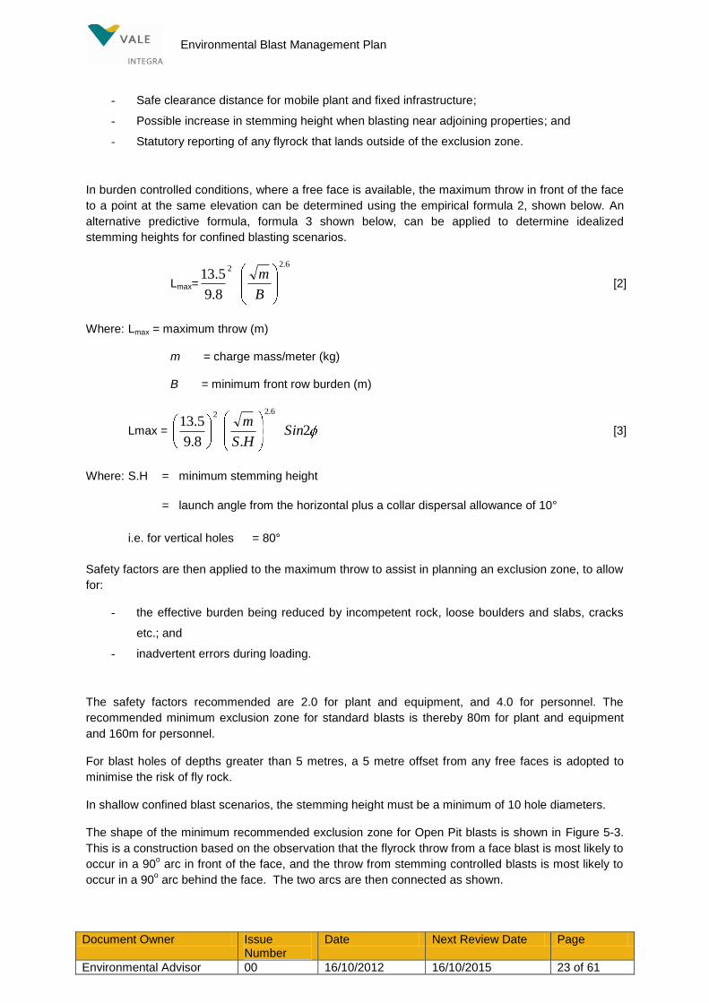
In burden controlled conditions, where a free face is available, the maximum throw in front of the face
to a point at the same elevation can be determined using the empirical formula 2, shown below. An
alternative predictive formula, formula 3 shown below, can be applied to determine idealized
stemming heights for confined blasting scenarios.
Lmax=
6.22
8.9
5.13
B
m [2]
Where: Lmax = maximum throw (m)
m = charge mass/meter (kg)
B = minimum front row burden (m)
Lmax = 2.8.9
5.136.22
SinHS
m [3]
Where: S.H = minimum stemming height
= launch angle from the horizontal plus a collar dispersal allowance of 10°
i.e. for vertical holes = 80°
Safety factors are then applied to the maximum throw to assist in planning an exclusion zone, to allow
for:
- the effective burden being reduced by incompetent rock, loose boulders and slabs, cracks
etc.; and
- inadvertent errors during loading.
The safety factors recommended are 2.0 for plant and equipment, and 4.0 for personnel. The
recommended minimum exclusion zone for standard blasts is thereby 80m for plant and equipment
and 160m for personnel.
For blast holes of depths greater than 5 metres, a 5 metre offset from any free faces is adopted to
minimise the risk of fly rock.
In shallow confined blast scenarios, the stemming height must be a minimum of 10 hole diameters.
The shape of the minimum recommended exclusion zone for Open Pit blasts is shown in Figure 5-3.
This is a construction based on the observation that the flyrock throw from a face blast is most likely to
occur in a 90o arc in front of the face, and the throw from stemming controlled blasts is most likely to
occur in a 90o arc behind the face. The two arcs are then connected as shown.

Environmental Blast Management Plan
Document Owner Issue Number
Date Next Review Date Page
Environmental Advisor 00 16/10/2012 16/10/2015 24 of 61
Figure 5-3 Minimum recommended Blast Exclusion Zones
The sensitivity to the maximum throw to stemming height variation is shown in Figure 5-4. As the
stemming height is reduced below 10 hole diameters (2.3m) there is an increased probability that
cratering will occur. If cratering occurs, because of the 45° launch angle, the maximum horizontal
throw increases dramatically. A 500m exclusion zone provides considerably greater protection from
flyrock if the stemming height is inadvertently reduced to about 1.9m and cratering occurs.
Integra has adopted the following conservative Evacuation Zones for its blasting operations:
In front of a face blast (direct line of sight) 500m
Other directions from blasts 300m

Environmental Blast Management Plan
Document Owner Issue Number
Date Next Review Date Page
Environmental Advisor 00 16/10/2012 16/10/2015 25 of 61
For pre-split blasts 150m
The distances may be varied at the discretion of the Drill and Blast Coordinator or Mine Supervisor.
Figure 5-4 The sensitivity of the maximum throw to stemming height
The trajectory paths for flyrock resulting from stemming ejection for different stemming heights are
shown in Figure 5-5. For blasts on benches below the surface, the trajectory profile is modified by the
pit wall, with an effective reduction in horizontal throw behind the face.

Environmental Blast Management Plan
Document Owner Issue Number
Date Next Review Date Page
Environmental Advisor 00 16/10/2012 16/10/2015 26 of 61
Figure 5-5 Stemming ejection/Stemming height relationship
Within the pit, the determination of exclusion zones is the responsibility of the Shotfirer, Drill and Blast
Supervisor and the Manager of Mining Engineering. The maximum throw distance determinations
given herein are intended as a guide to the responsible personnel and do not remove the regulatory
responsibilities from mine personnel.
Environmental Blast Management Plan
Document Owner Issue Number
Date Next Review Date Page
Environmental Advisor 00 16/10/2012 16/10/2015 27 of 61
If blasts are designed with minimum confinement conditions according to the flyrock model, and
checks are set in place during loading, there is sufficient separation from houses and infrastructure
that flyrock will not be an issue. A 500m exclusion zone requiring traffic to be stopped on any road is
very conservative, however may be increased at the instruction of the drill and blast engineer, drill and
blast supervisory personnel or shot personnel to ensure where line of sight presents an increased
likelihood of flyrock damage.
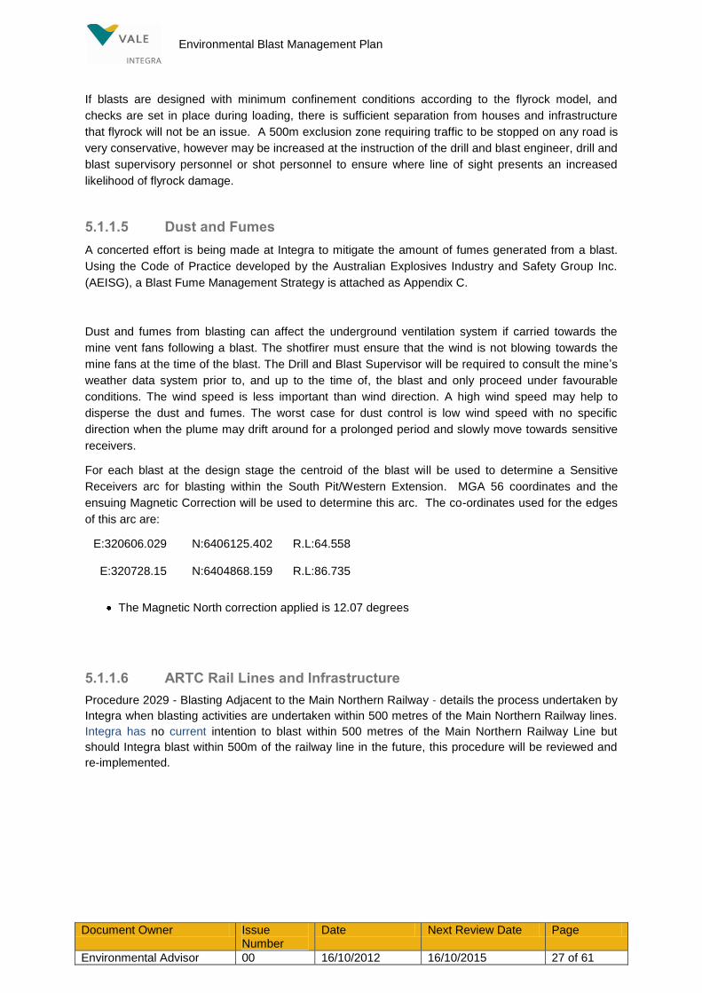
5.1.1.5 Dust and Fumes
A concerted effort is being made at Integra to mitigate the amount of fumes generated from a blast.
Using the Code of Practice developed by the Australian Explosives Industry and Safety Group Inc.
(AEISG), a Blast Fume Management Strategy is attached as Appendix C.
Dust and fumes from blasting can affect the underground ventilation system if carried towards the
mine vent fans following a blast. The shotfirer must ensure that the wind is not blowing towards the
mine fans at the time of the blast. The Drill and Blast Supervisor will be required to consult the mine‟s
weather data system prior to, and up to the time of, the blast and only proceed under favourable
conditions. The wind speed is less important than wind direction. A high wind speed may help to
disperse the dust and fumes. The worst case for dust control is low wind speed with no specific
direction when the plume may drift around for a prolonged period and slowly move towards sensitive
receivers.
For each blast at the design stage the centroid of the blast will be used to determine a Sensitive
Receivers arc for blasting within the South Pit/Western Extension. MGA 56 coordinates and the
ensuing Magnetic Correction will be used to determine this arc. The co-ordinates used for the edges
of this arc are:
E:320606.029 N:6406125.402 R.L:64.558
E:320728.15 N:6404868.159 R.L:86.735
The Magnetic North correction applied is 12.07 degrees
5.1.1.6 ARTC Rail Lines and Infrastructure
Procedure 2029 - Blasting Adjacent to the Main Northern Railway - details the process undertaken by
Integra when blasting activities are undertaken within 500 metres of the Main Northern Railway lines.
Integra has no current intention to blast within 500 metres of the Main Northern Railway Line but
should Integra blast within 500m of the railway line in the future, this procedure will be reviewed and
re-implemented.

Environmental Blast Management Plan
Document Owner Issue Number
Date Next Review Date Page
Environmental Advisor 00 16/10/2012 16/10/2015 28 of 61
5.1.1.7 Road Closure Procedures
Closure of Stoney Creek Road when blasting occurs within 500m of the road is undertaken in
accordance with an annual Singleton Shire Council approval and Procedure 2072, Road Closure -
North Open Cut.
5.1.1.8 Refires or Misfires
Where a misfire occurs the shotfirer will seek to address the misfire and refire as soon as is safely
possible, as per procedure 2034 – Handling Misfires.
Figure 5-6 Open Cut Blasting Flowchart

Environmental Blast Management Plan
Document Owner Issue Number
Date Next Review Date Page
Environmental Advisor 00 16/10/2012 16/10/2015 29 of 61
5.1.2 Design Implementation
The blast is drilled and loaded with the checks and balances outlined and the blast scheduled for
firing according to the Blast Process Flowchart (Figure 5-6). The blasts are duly fired according to the
procedures outlined in Figure 5-6.

Environmental Blast Management Plan
Document Owner Issue Number
Date Next Review Date Page
Environmental Advisor 00 16/10/2012 16/10/2015 30 of 61
An essential component of the blast design is monitoring the environmental outcomes, assessment
and analysis of the results and a review loop to progressively upgrade and refine the predictive
models used in the design, as shown in Figure 5-1.
5.2 POSTPONING A BLAST
Under weather conditions which are likely to result in unacceptable enhancement of blasting impacts
such as elevated overpressure, a blast will be postponed (refer Shotfiring Procedure in Figure 5-6).
5.3 Corrective Measures
The blast design based on appropriate site constants and its correct implementation by the shot firing
crew is usually effective in controlling ground vibration, air blast and flyrock from blasting operations.
The effectiveness of the processes outlined in Figure 5-6 in controlling vibrations to comply with
regulatory limits is determined by the routine compliance monitoring at the monitoring stations.
Observations of flyrock containment and classification of dust and fume behaviour provides a basis for
evaluation of the effectiveness of controlling these emissions.
The assessment of the emissions is part of the blast assessment process and review loops shown
schematically in the Blast Design Procedure in Figure 5-1.
Whenever the air blast readings exceed 115 dBL or the ground vibration readings exceed 5 mm/s at
any monitor, investigations are conducted to ascertain the cause of the elevated reading. When the
air blast reading is in excess of 115 dBL, the following analyses are conducted to establish:
If the high reading was a blast event or some other event, such as wind, by examination of
the wavetrace record for:
- Characteristic air blast wave shape;
- Elapsed time between P wave and air blast arrivals;
- Blast duration; and
- Where in the blast the peak value occurs;
Any visible evidence of high velocity gas emissions by examination of video replay;
The possible effects of wind using regression analysis to compare airblast levels at wind
affected and non-wind affected monitors;
Wavefront reinforcement analysis to determine the possible effects of drill pattern and
initiation sequence; and
Meteorological reinforcement analysis to determine any role of meteorological conditions.
When the ground vibration exceeds 5 mm/s the following analyses are conducted to determine if the
peak value was a form of blast event or some other extraneous vibration source:
Examination of the wavetrace for characteristic wave shape and frequency;
Time of the trigger;

Environmental Blast Management Plan
Document Owner Issue Number
Date Next Review Date Page
Environmental Advisor 00 16/10/2012 16/10/2015 31 of 61
Time of the peak reading relative to the ground vibration arrival; and
Wavefront reinforcement analyses.
The analyses outlined will determine if the peak readings were the blast event or not. If they were
not, predictions can be made of the peak air blast and/or ground vibration. If the peak readings were
from the blast, the section of the blast responsible may be identified and the blast design and loading
reviewed to ascertain the cause. If the elevated air blast levels were due to deficient blast design
and/or loading practices, these can be corrected for future blasts.
Observation and characterisation of fume emissions should lead to a correlation to blasting practice,
and strategies developed for modification that may lead to mitigation.

Environmental Blast Management Plan
Document Owner Issue Number
Date Next Review Date Page
Environmental Advisor 00 16/10/2012 16/10/2015 32 of 61
6. C o m pl a i n t s Ha n d l i n g
Any complaint received relating to blasting issues will be managed in accordance with the
Environmental Management Strategy, which is based on the requirements of the site‟s EPL.
Integra periodically receives complaints/concerns from residents in the surrounding area about blasting issues and building damage concerns either directly or via a government agency. The complaint handling process is demonstrated in Figure 6-1.
All complaints received at Integra are promptly actioned by management and personal contact with the complainant is made as soon as practicable. Where corrective actions are appropriate, these are undertaken.
To overcome the disturbance or 'startling' effect of blasting, a number of residents are notified prior to
each blast.

Environmental Blast Management Plan
Document Owner Issue Number
Date Next Review Date Page
Environmental Advisor 00 16/10/2012 16/10/2015 33 of 61
Figure 6-1 Complaint management process flow chart

Environmental Blast Management Plan
Document Owner Issue Number
Date Next Review Date Page
Environmental Advisor 00 16/10/2012 16/10/2015 34 of 61
7. R e p or t i n g a n d R e v i ew
7.1 Reporting
Ground vibration and air blast readings in excess of the 10 mm/s / 120 dB(L) limit must be reported
immediately to both the EPA and Department of Planning & Infrastructure (DP&I) followed by a report
of the investigation into the causes of the exceedence.
Blast results and interpretations will be reported internally after each blast, summarised monthly and
included in the Annual Report (AR).
The Monthly and Annual reports will include:
- No. of blasts fired
- No. of vibration measurements at each monitoring station
- No. of blasts 5 mm/s
115 dBL
- No. of exceedences 10 mm/s
120 dBL
The AR will provide a summary of complaints, the concerns and complaints received, plan showing
the complaint locations and remedial action taken.
A copy of the AR will be forwarded to relevant stakeholders including, but not limited to, Department
of Trade and Investment, Regional Infrastructure and Services (DTIRIS) NSW EPA and DP&I.
Integra is reviewing the presentation of monitoring data it has collected and analysed on its website,
with the intention of making the site more informative and user-friendly from a community perspective.
It is anticipated that the review will be completed by June 30, 2012.
7.2 Plan Reviews
The review of this document will be in line with the Environmental Management Strategy for the
Complex. That is, reviews will be conducted every three years, after independent environmental
audits, and as required by relevant Project Approval requirements. The purpose of the review is to
ensure that the BMP remains suitable, adequate and effective.
The monitoring data will be reviewed as it is collected and at strategic milestones in the mine life,
including annual (AR) reporting periods. The BMP will be modified as required to reflect changes to
mine plans, monitoring results or in response to stakeholder comments. Any modifications will be
made in consultation with OEH and approved by the DP&I.

Environmental Blast Management Plan
Document Owner Issue Number
Date Next Review Date Page
Environmental Advisor 00 16/10/2012 16/10/2015 35 of 61
8. R e f er e n ce s
Australian Coal Association Research Project (2002), Project C9040, “Structure Response to Blast
Vibration”
Integra Mine Complex Project Approval 08_0101 and 08_0102, dated 26 November 2010.
Integra Coal Operations Pty Ltd Environmental Protection Licence (#3390)
Integra Explosives Hazard Management Plan (HMP_2001)
Integra Road Closure Procedure – North Open Cut (PRO_2072)

Environmental Blast Management Plan
Document Owner Issue Number
Date Next Review Date Page
Environmental Advisor 00 16/10/2012 16/10/2015 36 of 61
9. G l o s sar y
TERM DEFINITION
AEISG Australian Explosive Industry and Safety Group (Inc)
ARTC Australian Rail Track Corporation
Authorised Person OC
Person appointed in writing by the Open Cut Mine Manager to carry out
specific duties under the Shotfiring and Explosives Management
System.
Approved
Has the meaning in the Coal Mines Regulation Act 1982
(Approved by the Chief Inspector. This could apply to use of non-
permitted explosives)
Blasting Operations Include:
- Priming a cartridge;
- Charging and stemming a hole;
- Connecting the detonator into a round of shots;
- Coupling a shotfiring cable or lead-in line into a detonator circuit,
circuit tester or exploder;
- Testing a shotfiring circuit; or
- Firing a shot or round of shots
Burden The distance between a blast hole and a free face, or the distance
between rows of holes in a blast pattern.
Competent Person (CP) Person appointed in writing by the Open Cut Mine Manager to carry out
specific duties under the Shotfiring and Explosives Management
System.
Danger Zone An area in which a person may be injured or machinery may sustain
damage as a result of shot firing activities.
Exploder Any electrical apparatus approved for the purpose of initiating
detonators in a mine.
Explosive Includes detonation cord, detonators, relays, signal tubes, signal tube
starters, primed cartridge or similar devices.
ICOL Integra Coal Operations Pty Ltd
ICU Integra Underground

Environmental Blast Management Plan
Document Owner Issue Number
Date Next Review Date Page
Environmental Advisor 00 16/10/2012 16/10/2015 37 of 61
Misfire An occurrence where:
- Testing before firing a shot reveals broken continuity which cannot be
rectified; or
- Any shot, or whole or part of a round, fails to explode when an attempt
is made to fire it.
Shot A charge of explosive (in a cartridge) placed in a shot hole in coal or
other rock (or stone) for the purpose of breaking the coal or rock (or
Stone).
Shotfirer A person appointed by Mine Management to conduct shotfiring as part
of the Shotfiring and Explosives Management System.
Spacing The distance between holes in a row of holes in a blast pattern.
Stemming Height The appropriate length of stemming material loaded on top of the
explosive column in a blast hole to control fly rock and limit air blast.
Stemming Material Inert coarse material, such as crushed gravel about 1/10th hole diameter,
loaded into the blast hole to confine the gaseous energy and prevent it
from venting into the atmosphere.
Underground Sentry Person appointed competent by the underground mine manager to act
as a sentry for the underground during shot firing.
Underground Surface The area in which the Underground mine manager is statutorily
responsible.
Underground Surface
Attendant
Person trained and appointed competent by the underground mine
manager to carry out all required surface duties.
Underground Workings All workings underground accessed from the Underground pit portals.
The Underground mine manager is statutorily responsible for this area.

Environmental Blast Management Plan
Document Owner Issue Number
Date Next Review Date Page
Environmental Advisor 00 16/10/2012 16/10/2015 38 of 61
APPENDIX A - APPROVAL CONDITIONS AND EA COMMITMENTS
Table A1 Approval Conditions and EA Commitments – Where They Are Addressed in the BMP
Approval Condition BMP Reference
Blasting Criteria
11. The Proponent shall ensure that the blasting on site does not cause exceedances of the criteria in Table 9 (below).
Receiver Airblast Overpressure (db(Lin Peak))
Ground Vibration (ppv(mm/s))
Allowable Exceedance
Residence on privately-owned land
115 5 5% of the total number of blasts over a period of 12 months
120 10
Main Northern Railway culverts and bridges
- 25 0%
All public infrastructure
- 50 0%
However, these criteria do not apply if the Proponent has a written agreement with the relevant landowner or infrastructure owner to exceed the criteria, and the Proponent has advised the Department in writing of the terms of this agreement.
1.4 (p. 6)
5.1.1.2, Table
1-2(p.19)
Blasting Hours
12. The Proponent shall only carry out blasting on site between 9am and 5pm Monday to Saturday inclusive. No blasting is allowed on Sundays, public holidays, or at any other time without the written approval of the Director-General.
1.4 (p. 6)
Blasting Frequency
13. The Proponent shall not carry out more than:
(a) 1 blast a day in the northern mining area unless an additional blast is required following a blast misfire;
(b) 2 blasts a day in the existing Camberwell south pit, and then 1 blast a day when the mining moves from this pit into the western mining area unless an additional blast is required following a blast misfire; and
(c) 10 blasts a week on site, averaged over any 12 month period.
1.4 (p. 6)
Property Inspections
14. If the Proponent receives a written request from the owner of any privately-owned land within 2 kilometres of the approved open cut mining pits on site for a property inspection to establish the baseline condition of any buildings and/or structures on his/her land. Or to have a previous property inspection report
1.4 (p. 8-9)

Environmental Blast Management Plan
Document Owner Issue Number
Date Next Review Date Page
Environmental Advisor 00 16/10/2012 16/10/2015 39 of 61
updated, then within 2 months of receiving this request the Proponent shall:
(a) commission a suitably qualified, experienced and independent person, whose appointment has been approved by the Director-General to:
• establish the baseline condition of the buildings and/or structures on the land or update the previous property inspection report; and
• identify any measures that should be implemented to minimise the potential blasting impacts of the projects on these buildings and/or structures; and
(b) give the landowner a copy of the new or updated property inspection report.
Property Investigations
15. If any landowner of privately-owned land within 2 kilometres of any approved open cut mining pit on site claims that the buildings and/or structures on his/her land have been damaged as a result of blasting on site, then within 2 months of receiving this request the Proponent shall:
(a) commission a suitably qualified, experienced and independent person, whose appointment has been approved by the Director-General, to investigate the claim; and
(b) give the landowner a copy of the property investigation report.
If this independent property investigation confirms the landowner's claim, and both parties agree with these findings, then the Proponent shall repair the damages to the satisfaction of the Director-General.
If the Proponent or landowner disagrees with the findings of the independent property investigation, then either party may refer the matter to the Director-General for resolution.
1.4 (p. 8-9)
Operating Conditions
16. The Proponent shall:
(a) implement best blasting management practice on site to:
• protect the safety of people and livestock in the surrounding area;
• protect private or public property in the surrounding area;
• minimise the dust and fume emissions of the blasting; and
(b) co-ordinate the blasting on site with the blasting at nearby mines (including Ashton, Rix‟s Creek and Mt Owen mine) to minimise the cumulative blasting impacts of the mines;
(c operate a suitable system to enable the public to get up-to-date information on the proposed blasting schedule on site,
to the satisfaction of the Director-General.
17. The Proponent shall not undertake blasting within 500 metres of:
(a) Middle Falbrook Road or Stony Creek Road without the approval of Council;
(b) the New England Highway without the approval of the RMS; and(c) the Main Northern Railway without the approval of the ARTC.
18. The Proponent shall not carry out blasting in the northern or western mining areas that is within 500 metres of any privately-owned land or land not owned by the Proponent unless:
(a) the Proponent has a written agreement with the relevant landowner to allow
1.4 (p. 8-9)

Environmental Blast Management Plan
Document Owner Issue Number
Date Next Review Date Page
Environmental Advisor 00 16/10/2012 16/10/2015 40 of 61
blasting to be carried out closer to the land, and the Proponent has advised the Department in writing of the terms of this agreement; or
(b) the Proponent has:
• demonstrated to the satisfaction of the Director-General that the blasting can be carried out without compromising the safety of the people or livestock on the land, or damaging the buildings and/or structures on the land; and
• updated the Blast Management Plan to include the specific measures that would be implemented while blasting is being carried out within 500 metres of the land.
Blast Management Plan
19. The Proponent shall prepare and implement a Blast Management Plan for the open cut mining operations on site to the satisfaction of the Director-General. This plan must:
(a) be prepared in consultation with DECCW, and submitted to the Director-General for approval by the end of March 2011;
(b) describe the blast mitigation measures that would be implemented to ensure compliance with the relevant condition of this approval;
(c) describe the measures that would be implemented to ensure that the public can get up-to-date information on the proposed blasting schedule on site;
(d) include a blast monitoring program to evaluate the performance of the project; and
(e) include a protocol that has been prepared in consultation with the owners of the nearby mines for minimising and managing the cumulative blasting impacts of the mines.
1.4 (p. 8-9)
EA Commitments BMP
Reference
G8 Continued implementation of the existing Explosive Hazard Management Plan to ensure the safety of employees and the public during explosives handling and blasting operations
Refer to Integra
Explosives Hazard
Management Plan
G9 Restrict blasting to between the hours of 9.00am and 5.00pm Monday to Saturday, unless blasts outside this time are required for misfire re-blast, emergency or safety reasons.
1.4 (p. 8)
G10 Blast design and implementation to be undertaken by a suitably qualified blasting engineer and/or experienced shot-firer to ensure ANZEC Guidelines are met at all non-project related residences surrounding the Open Cut Project Area.
Table 3-1(pp. 12-
13); Table 5-1(p.16)
G11 Refine blast mitigation measures and operating procedures as required based on monitoring results.
5.3 (p. 30)
G12 Provide notification on the morning prior to a blast of blast times to local residents and others who request to be included on the notification list.
5.1, Table 3-1(p.
16)
G13 Use aggregate as the stemminq material (not drill dust) in order to fully contain the explosives within the blasthole.
5.1.1.3 (p.21)
G14 In the case of the Part Pit Extent (ie. Integra is unable to acquire Residence Conditions for

Environmental Blast Management Plan
Document Owner Issue Number
Date Next Review Date Page
Environmental Advisor 00 16/10/2012 16/10/2015 41 of 61
153 or negotiate an agreement with the owner) blasting will not be undertaken within a 500m Exclusion Zone surrounding the 'Dulwich' residence and 200m from the property boundary until such time that it can demonstrate to the Director-General that blasting can be undertaken without an unacceptable risk to the resident, residents, their stock or residence.
Western
Extension

Blast Fume Management Strategy FRM-XXXX
Document Owner Issue Number
Date Next Review Date Page
Environmental Advisor 00 16/10/2012 16/10/2015 42 of 61
APPENDIX B - UNDERGROUND TARP
TRIGGER ACTION/PROCEDURE
Blast location with:
- Vibration predicted to be less than 10mm/s at
portals.
Mining operations normal
Blast location with:
- Wind blowing from blast location towards U/G
portals, and/or
- Vibration predicted to be greater than
10mm/sec at portals
Evacuation for shot duration procedure
Evacuate surface personnel
Blast location with:
- Wind blowing from blast location away from
U/G portals, and
- Vibration is predicted to be greater than
10mm/sec at portals.
Procedure to remain underground during shot with portal access control
Evacuate surface personnel

Blast Fume Management Strategy FRM-XXXX
Document Owner Issue Number
Date Next Review Date Page
Environmental Advisor 00 16/10/2012 16/10/2015 43 of 61
APPENDIX C – INTEGRA COAL OPEN CUT: BLAST FUME MANAGEMENT STRATEGY
INTRODUCTION:
This document has been prepared in response to the NSW Department of Planning and Infrastructure’s directive for a Blast Fume Management Strategy to be developed on site, and incorporated into the Blast Management Plan for Integra Coal.
The purpose of the Blast Fume Management Strategy is threefold:
Provide a protocol to minimise fume emissions
Rate and record all blast fume events
Reporting of significant fume events
Blast Fume:
All blasting explosives produce large volumes of gas in very short time frames. Blast fume is identified by plumes of cloud that vary from yellow to dark red in colour. This is caused by the production of nitrogen dioxide, and the oxidation of nitric oxide, which is chemically unstable in air. Multiple causes have been identified that compromise the explosive reaction resulting in the production of nitric oxide (NO) and nitrogen dioxide (NO2).
Potential causes of fume in blasting:
Fume is generated as a result of an explosive not reacting to its full capability through a high order, steady state of detonation. The causes of this are varied, however the seven main reasons for fume generation as accepted by the industry and explosive suppliers are listed below:
Geological conditions
Weather conditions
Blast design parameters
Explosive product selection
Explosive quality
Downhole contamination of the explosive product
On bench practices

Blast Fume Management Strategy FRM-XXXX
Document Owner Issue Number
Date Next Review Date Page
Environmental Advisor 00 16/10/2012 16/10/2015 44 of 61
INTEGRA PERSONNEL AND THEIR ROLES:
This section identifies the persons within the Integra Coal Pty Ltd (Integra) organisation and their responsibilities in relation to ensuring the prevention and minimisation of fume generation. These roles are:
1. Planning Engineers
2. Geologists
3. Drill & Blast Engineer
4. Technical Services Superintendent
5. Drill & Blast Superintendent
6. Driller
7. Shotfirer (Blast crew member)
8. Bulk Explosives Vehicle operator
9. Explosive manufacturer / supplier
Planning Engineers:
Planning engineers are responsible for the sequence of mining operations.
Planning Engineers are to consider:
Shot relief, and the minimisation of confined blasts
Geologist:
Provide relevant data on geological conditions.
Geologists are to consider:
Weak strata
Weathered zones
Reactive ground
Hot coals

Blast Fume Management Strategy FRM-XXXX
Document Owner Issue Number
Date Next Review Date Page
Environmental Advisor 00 16/10/2012 16/10/2015 45 of 61
Drill & Blast Engineer:
Design the blast areas to provide safe and productive extraction of the blasted material.
Drill and Blast Engineer is to consider:
Geology and rock mass conditions
Explosive product selection appropriate to the ground conditions
Historical blast performance
Weather conditions during the planned loading & firing phase
Shot relief
Water / moisture content of strata
Initiation (timing) sequence
Compliance to operational consent conditions
The Drill & Blast Engineer, Technical Services Superintendent and the Drill & Blast Superintendent will jointly approve the blast design.
Technical Services Superintendent:
Review the design of blast areas provided by the Drill & Blast engineer.
Responsibilities include:
Ensure all design parameters as above, have been considered to mitigate production, environmental and legislative hazards
Assume or delegate the responsibilities of the Drill and Blast Engineer in their absence
Jointly approving blast designs with the Drill & Blast Superintendent and Drill & Blast Engineer.
Drill & Blast Superintendent:
Manage all Drill and Blast operations for the site.
Responsibilities include:
Ensure competence of the Drill & Blast Team to perform their duties

Blast Fume Management Strategy FRM-XXXX
Document Owner Issue Number
Date Next Review Date Page
Environmental Advisor 00 16/10/2012 16/10/2015 46 of 61
Adequate resourcing of persons and plant to complete blasting activities in a timely manner
Ensure industry best practice is employed in the implementation of blast designs to mitigate all potential production, environmental and legislative hazards
Jointly approving blast designs with the Technical Services Superintendent and the Drill & Blast Engineer.
Supervise all Drill and Blast on bench activities for the site.
Bench preparation prior to drilling
Conduit between drill activity and engineer to ensure all relevant information is communicated for consideration in design
On bench water management
Review the product selection to ensure appropriate for ground and weather conditions
Ensure on bench compliance to design during implementation process
Manage stemming delivery to eliminate contaminants
Film each blast, or nominate a delegate to film each blast
Driller Operators
To provide drilled holes for the loading of explosives for a blast area.
Responsibilities include:
Accurately drill the designed blast plan and report / record all variations
Report anomalous ground conditions to the supervisor
Emplacement of collar protection for drilled holes
Record all required information
Shotfirer (Blast Crew Member):
Conduct and direct all blasting activities on bench.
Responsibilities include:

Blast Fume Management Strategy FRM-XXXX
Document Owner Issue Number
Date Next Review Date Page
Environmental Advisor 00 16/10/2012 16/10/2015 47 of 61
Compliance with design
Notify and record any variations from design
Record explosive usage data
Supervision of loading – prevention of contamination to explosive
Accurate placement of gas / air bags / decks as per design
Manage on bench Bulk Explosives Vehicle activities / movement
Measure the depth of blastholes
Ensure quality control of bulk explosive by on bench tests
Identify, report and record water conditions down hole
Correctly position primers within explosive
Report and record blasthole slumping
Information conduit between on bench activities and Supervisor
Supervision of stemming process to ensure sufficient containment and no contamination of material
Report and record all anomalies during process
Bulk Explosive Vehicle Operator:
Manufacture and downhole delivery of explosive. Assist with on bench activities as directed by Shotfirer or Supervisor.
Responsibilities include:
Compliance with design and Shotfirers instructions through loading process
Bulk Explosives Vehicle calibration
Ensure quality control of all delivered products
Record explosive delivery usage by blast hole & blast area

Blast Fume Management Strategy FRM-XXXX
Document Owner Issue Number
Date Next Review Date Page
Environmental Advisor 00 16/10/2012 16/10/2015 48 of 61
Explosive Manufacturer / Supplier:
All explosives, precursors and accessories supplied are fit for purpose and certified as per ISO 9000: 2008.
Responsibilities include:
Manufacturing equipment compliance
Ensure competence of personnel
Provide recommendations for product usage and training as required
Ensure the design, calibration and operation of Bulk Explosives Vehicle is such to deliver consistent explosives within specification
Provision of explosive and precursor formulation to ensure minimisation of fume from product

Blast Fume Management Strategy FRM-XXXX
Document Owner Issue Number
Date Next Review Date Page
Environmental Advisor 00 16/10/2012 16/10/2015 49 of 61
POTENTIAL CAUSES OF FUME GENERATION AND MITIGATION CONTROLS
This section details the key potential causes of blast fume and their controls.
GEOLOGICAL CONDITIONS
Potential Cause
Weak or soft strata, including clay
Controls:
Understand the geology prior to loading and initiation sequence design to ensure correct explosive product used (refer explosive suppliers recommendations) and adequate relief through modified timing and reduction of powder factor
Potential Cause:
Loss of explosive product, not achieving designed collar height – faulted / fractured ground
Controls:
Manufacturer’s recommendations of explosive product selection.
Record and monitor loaded blast holes that have slumped or required additional explosive to achieve design collar height.
Use of blast hole liners
Potential Cause:
Dynamic water in blast holes
Controls:
Follow manufacturer’s recommendations of explosive product selection.
Minimise sleep time; blasting practices are designed to achieve a maximum load, tie
and fire time of 7 days in accordance with Site Management Directive.
Consider use of blast hole liners.

Blast Fume Management Strategy FRM-XXXX
Document Owner Issue Number
Date Next Review Date Page
Environmental Advisor 00 16/10/2012 16/10/2015 50 of 61
WEATHER CONDITIONS
Potential Cause:
Rainfall or flooding resulting in the ingress of water into the explosive column
Controls:
Review weather forecast prior to product selection
Bench preparation to allow for water run-off
Follow manufacturers recommendations of explosive product selection
Minimise sleep time; blasting practices are designed to achieve a maximum load, tie
and fire time of 7 days in accordance with Site Management Directive.
Consider initiating all loaded holes prior to severe storm events
BLAST DESIGN
Potential Cause:
Desensitisation of explosive product
Controls:
Follow manufacturers recommendations of explosive product selection
Reduce explosive column length
Potential Cause:
Interaction of decked blast holes
Controls:
Review actual drilled holes and amend design (timing) to reflect
Ensure appropriate timing delays between decks
Use electronic initiators to ensure accurate, reliable initiation

Blast Fume Management Strategy FRM-XXXX
Document Owner Issue Number
Date Next Review Date Page
Environmental Advisor 00 16/10/2012 16/10/2015 51 of 61
Potential Cause:
Excessive confinement, incorrect timing and pattern geometry design.
Controls:
Understand geology of the blast area and design to mitigate hazards
Consider use of free face to reduce confinement
Reduce powder factor
Utilise timing to ensure adequate relief for all strata
EXPLOSIVE PRODUCT SELECTION
Potential Cause:
Non-water resistant explosive products loaded into wet or dewatered blast holes
Controls:
Follow manufacturer’s recommendations of explosive product selection.
Regular training of blast crew on explosive product recommendations from supplier
Correct loading technique used when loading wet holes
Potential Cause:
Excessive energy in weak / soft strata that desensitises adjacent explosive product columns
Controls:
Follow manufacturer’s recommendations of explosive product selection.
Understand geology of the blast area and design (timing & explosive type) to mitigate hazards

Blast Management Plan
Document Owner Issue Number
Date Next Review Date Page
Environmental Advisor 00 16/10/2012 16/10/2015 52 of 61
EXPLOSIVE QUALITY
Potential Cause:
Inadequate mixing of raw materials that leads to incorrect explosive formulation
Controls:
Explosives formulated by supplier to an appropriate oxygen balance that reduces risk of fume generation
Regular Bulk Explosives Vehicle calibration
On bench quality control checks
Potential Cause:
Explosive precursors, bulk materials and explosive accessories not manufactured or supplied to specification or degradation occurs during transport, storage or extended sleep time (time explosive is in hole)
Controls:
Contractor supplies certification of delivered products – ISO9000: 2008.
Regular audits to ensure quality control compliance
Control blast size and loading plan to minimize the sleep time; blasting practices are
designed to achieve a maximum load, tie and fire time of 7 days in accordance with Site Management Directive.
Follow manufacturers recommendations of explosive product selection
Potential Cause:
Inaccurate explosive product delivery through defective metering system
Controls:
Regular audits to ensure quality control compliance
Regular Bulk Explosives Vehicle calibration
On bench quality control checks

Blast Management Plan
Document Owner Issue Number
Date Next Review Date Page
Environmental Advisor 00 16/10/2012 16/10/2015 53 of 61
CONTAMINATION OF EXPLOSIVES IN THE BLASTHOLE
Potential Cause:
Explosive product mixes with mud / sediment at bottom of blast hole, realised when measured depth varies from drilled depth
Controls:
Drill procedures to minimise blast hole damage
Ensure correct blast hole priming and loading procedures are followed on bench
Where contaminants are identified at the blast hole bottom use a gas bag to separate mud from explosive product
Potential Cause:
Stemming material penetrates explosive product
Controls:
Ensure pumped product (slurry) is properly gassed, to suppliers specifications, prior to stemming process
Use only appropriate stemming material
Potential Cause:
Water entrainment in explosive product – dewatered blast hole, dynamic water present
Controls:
Load wet / dewatered blast holes first and check other holes around for water ingress through displacement
Ensure appropriate blast hole priming and loading practices (place primer in undamaged explosive product) are followed on bench
Follow manufacturers recommendations of explosive product selection
Do not “top load” into wet or dewatered blast holes
Protect top of explosive column to prevent water ingress e.g. gas bag
Minimise sleep time; blasting practices are designed to achieve a maximum load, tie
and fire time of 7 days in accordance with Site Management Directive.

Blast Management Plan
Document Owner Issue Number
Date Next Review Date Page
Environmental Advisor 00 16/10/2012 16/10/2015 54 of 61
ON BENCH PRACTICES
Potential Cause:
Blast pattern not drilled to design and holes unable to be identified
Controls:
High precision (GPS) used on drill rigs
Optimise drilling practices to ensure accurate hole depths achieved
Potential Cause:
Blasthole incorrectly identified, incorrect explosive product used
Controls:
Load sheets are given for each hole
Assess all blast hole conditions prior to loading
Potential Cause:
Dewatering of blast holes diverts water into previously loaded (with dry hole product) holes
Controls:
Load wet / dewatered blast holes first and check other holes around for water ingress through displacement
Bench preparation to allow for water run-off

Blast Management Plan
Document Owner Issue Number
Date Next Review Date Page
Environmental Advisor 00 16/10/2012 16/10/2015 55 of 61
RATING AND RECORDING OF BLAST FUME EVENTS
RECORDING OF FUME EVENTS
Every blast initiated at the Integra Mine Complex is to have its fume rated and recorded as per the current edition of the Australian Explosives Industry and Safety Group Inc code of practice titled “Prevention and Management of Blast Generated NOx Gases in Surface Blasting” (the “AEISG Code”). The fume must be rated at its greatest extent. Fume rating records must be kept onsite for a minimum of two years.
Each blast initiated at the Integra Mine Complex will be filmed. Where safe, the filming will be undertaken by a person on site. If considered unsafe, the camera will be unattended. Video footage must be stored for a minimum of 1 year. Video records of fume will ideally continue for a minimum of one minute after the blast event and capture any post blast fume until it dissipates.
REPORTING OF SIGNIFICANT FUME EVENTS TO THE DEPARTMENT
Integra will notify the Department of Planning and Infrastructure compliance officer in Singleton of any blast producing post blast fume that rates 3 at its highest extent and leaves the mine site and any blast that rates 4 or 5. The mine site includes any area within the active Project Approval boundary and any closed portion of public road.
When post blast fume reports are required, the quantity of explosive and the number of blast holes should be included. The purpose of this is to provide a guide to size the fume event. Not all blasts required to be reported will require a formal incident report, as this will depend on a number of factors and will be determined after consultation with the Department of Planning and Infrastructure compliance officer, in accordance with the Integra Coal Pollution Incident Response Management Plan (EMP_2014).
DUTY TO REPORT POLLUTION INCIDENTS
Additional reporting obligations apply to post blast fume events if they meet the definition of a pollution incident as listed in the Integra Coal Pollution Incident Response Management Plan (EMP_2014): A pollution incident is required to be notified if there is a risk of ‘material harm to the environment’, which is defined in Section 147 of the Protection of the Environment Operations Act 1997 as: (a) harm to the environment is material if: • it involves actual or potential harm to the health or safety of human beings or to ecosystems that is not trivial, or • it results in actual or potential loss of property damage of an amount, or amounts in aggregate, exceeding $10,000 (or such other amount as is prescribed by the regulations), and (b) loss includes the reasonable costs and expenses that would be incurred in taking all reasonable and practicable measures to prevent, mitigate or make good harm to the

Blast Management Plan
Document Owner Issue Number
Date Next Review Date Page
Environmental Advisor 00 16/10/2012 16/10/2015 56 of 61
environment. A pollution incident must be reported immediately to the EPA, NSW Health, Fire and Rescue NSW, WorkCover NSW and Singleton Shire Council, the NSW Department of Planning & Infrastructure and the Division of Resources & Energy of the Department of Trade & Investment. Regional Infrastructure & Services should also be informed.
REQUIRED RECORDS AND DOCUMENTATION:
The records and documentation used for the design, bench preparation, drilling, loading and firing of a blast area are retained in the Technical Services office by the Drill & Blast Engineer. The records, contents and those responsible are:
Design and Pre-Loading Checklist (FRM_2520)
Responsible persons:
Drill & Blast Engineer
Drill & Blast Supervisor
Surveyor
Contents:
Blast pattern parameters – geometry, depth, hole diameter
Geological considerations – rock type, exploratory holes, model information
Powder Factor
Maximum Instantaneous Charge Weight (MIC)
Laser profile of free faces
Road closure required
Tie up considerations – vibration, overpressure, relief
Bench preparation – survey pegs, clean up, accesses
Drill information (down hole strata-log)
Any / all anomalies

Blast Management Plan
Document Owner Issue Number
Date Next Review Date Page
Environmental Advisor 00 16/10/2012 16/10/2015 57 of 61
Shotfirers Loading Checklist (FRM_2092)
Responsible persons:
Shotfirer
Stemming Operator
Contents:
Shotfirer in charge of blast area nomination
Loading practices – explosive type, charge weights, stem heights
Blast hole condition and consideration – wet, redrills required, pre-conditioned collars
Contamination of delivered stemming material
Stemming of blast holes – all blast holes stemmed, all irregularities noted
Explosive Used Register (FRM_2683)
Responsible persons:
Shotfirer
Bulk Explosives Vehicle Operator
Contents:
Shot number and date of loading
Explosive type and quantity used
Shotfirers Tie & Fire Checklist (FRM_2092)
Responsible persons:
Drill & Blast Engineer
Shotfirer
Drill & Blast supervisor

Blast Management Plan
Document Owner Issue Number
Date Next Review Date Page
Environmental Advisor 00 16/10/2012 16/10/2015 58 of 61
Contents:
Ensure Initiation sequence is appropriate
Tied in according to design / plan
Environmental considerations - wind speed, wind direction, inversion, cloud cover
Notification requirements complete – blast board, workforce, community
Sentry positions decided
Video in place – video footage is continued after blast detonation to ascertain actual fume / dust generation, direction travelled and dispersion rate
Explosives returned to magazine
Check monitor results for environmental compliance
Explosive and Accessory Loss and Gain Register (FRM_2567)
Responsible persons:
Shotfirer
Bulk Explosives Vehicle Operator
Contents:
Shot number and date of loading
Explosive type and quantity used
Comments on any / all variations
Environment and Community Blasting Considerations (FRM_2440)
Responsible persons:
Drill & Blast supervisor
Drill & Blast Engineer
Tech Services Superintendent
Contents:
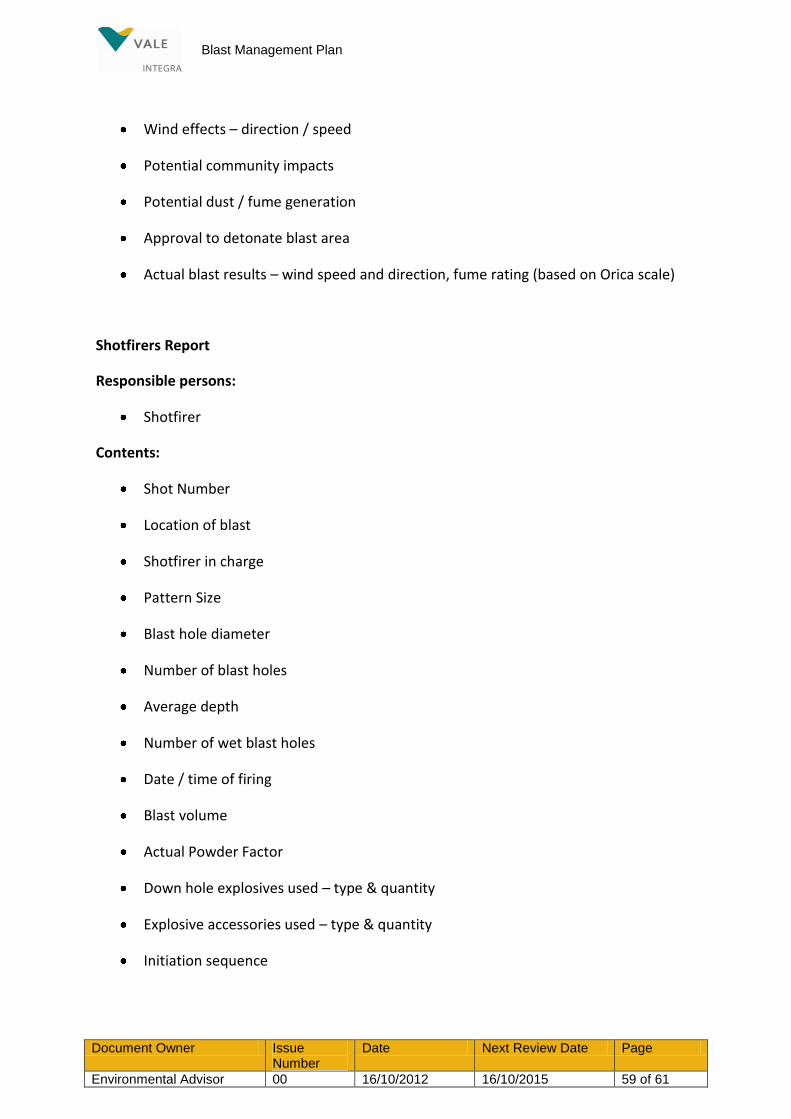
Blast Management Plan
Document Owner Issue Number
Date Next Review Date Page
Environmental Advisor 00 16/10/2012 16/10/2015 59 of 61
Wind effects – direction / speed
Potential community impacts
Potential dust / fume generation
Approval to detonate blast area
Actual blast results – wind speed and direction, fume rating (based on Orica scale)
Shotfirers Report
Responsible persons:
Shotfirer
Contents:
Shot Number
Location of blast
Shotfirer in charge
Pattern Size
Blast hole diameter
Number of blast holes
Average depth
Number of wet blast holes
Date / time of firing
Blast volume
Actual Powder Factor
Down hole explosives used – type & quantity
Explosive accessories used – type & quantity
Initiation sequence

Blast Management Plan
Document Owner Issue Number
Date Next Review Date Page
Environmental Advisor 00 16/10/2012 16/10/2015 60 of 61
Actual environmental conditions at time of firing – wind speed and direction, cloud cover, inversion, buffered blast area
Blast results – fume generation, misfired holes, flyrock distance, fragmentation
Sign off on completion of blast
Drillers Information sheet
Responsible persons:
Driller
Drill & Blast supervisor
Contents:
Shot Number – modular description
Location of blast
Pattern Size (burden & spacing)
Blast hole diameter (drill bit size)
Number of blast holes
Depth of holes
Down hole strata logs
Comments on any / all anomalies
REFERENCES
Integra Coal Explosive Hazard Management Plan (HMP_2001)
Integra Open Cut Blast Management Plan
Bulk Explosives Supplier - Product Selection Guide- Technical Data Sheets
- Product Compatibility Sheets
- Fume Self Assessment Guide
Integra Coal Drill & Blast Study – November 2010

Blast Management Plan
Document Owner Issue Number
Date Next Review Date Page
Environmental Advisor 00 16/10/2012 16/10/2015 61 of 61
Pollution Incident Response Management Plan (EMP_2014)
AEISG Code of Practice for Management of Post Blast NOx Fume in Surface Blasting
Queensland Guidance Note 19 – Management of Oxides and Nitrogen in Open Cut Blast (QGN19v1 6 Jun11)
Department of Planning & Infrastructure Guideline Attachment 1: Elements of a Blast Fume Management Strategy