bbu interconnection(sran8.0_draft a)
TRANSCRIPT
8/10/2019 BBU Interconnection(SRAN8.0_Draft a)
http://slidepdf.com/reader/full/bbu-interconnectionsran80draft-a 1/37

8/10/2019 BBU Interconnection(SRAN8.0_Draft a)
http://slidepdf.com/reader/full/bbu-interconnectionsran80draft-a 2/37
Copyright © Huawei Technologies Co., Ltd. 2013. All rights reserved.
No part of this document may be reproduced or transmitted in any form or by any means without prior writtenconsent of Huawei Technologies Co., Ltd. Trademarks and Permissions
and other Huawei trademarks are trademarks of Huawei Technologies Co., Ltd. All other trademarks and trade names mentioned in this document are the property of their respective holders. Notice
The purchased products, services and features are stipulated by the contract made between Huawei and thecustomer. All or part of the products, services and features described in this document may not be within the
purchase scope or the usage scope. Unless otherwise specified in the contract, all statements, information,and recommendations in this document are provided "AS IS" without warranties, guarantees or representationsof any kind, either express or implied.
The information in this document is subject to change without notice. Every effort has been made in thepreparation of this document to ensure accuracy of the contents, but all statements, information, andrecommendations in this document do not constitute a warranty of any kind, express or implied.
Huawei Technologies Co., Ltd. Address: Huawei Industrial Base
Bantian, LonggangShenzhen 518129People's Republic of China
Website: http://www.huawei.com
Email: [email protected]
Issue Draft A (2013-01-15) Huawei Proprietary and ConfidentialCopyright © Huawei Technologies Co., Ltd.
i
8/10/2019 BBU Interconnection(SRAN8.0_Draft a)
http://slidepdf.com/reader/full/bbu-interconnectionsran80draft-a 3/37
Contents
1 About This Docu ment..................................................................................................................11.1 Scope............. .....................................................................................................................................................1
1.2 Intended Aud ience..............................................................................................................................................1
1.3 Change Histo ry...................................................................................................................................................1
2 Overview.........................................................................................................................................32.1 Introducti on........................................................................................................................................................3
2.2 Upgrade t o Triple-Mode Base Stations..............................................................................................................3
2.2 .1 Cable Connections.....................................................................................................................................3
2.2.2 Application Scenarios................................................................................................................................4
2.2.3 Rest rictions................................................................................................................................................5
2.2.4 Supp orted Features and Functions.............................................................................................................6
2.3 U MTS Baseband Capacity Expansion...............................................................................................................6
2.3 .1 Cable Connections.....................................................................................................................................6
2.3.2 Application Scenarios................................................................................................................................7
2.3.3 Restrictions................................................................................................................................................9
3 Related Features ...........................................................................................................................10
4 Impact on the Network...............................................................................................................114.1 Impact on Sys tem Capacity..............................................................................................................................11
4.2 Impact on Net work Performance......................................................................................................................11
5 Engineering Guidelines.............................................................................................................125.1 When to U se BBU Interconnection..................................................................................................................12
5.2 Informatio n to Be Collected.............................................................................................................................125.3 Ne twork Planning.............................................................................................................................................12
5.3.1 Software Versions....................................................................................................................................12
5.3.2 Subr acks and Hardware Configurations for the BBUs............................................................................12
5.3.3 Tran smission Modes................................................................................................................................13
5.3.4 CPR I-based Topologies...........................................................................................................................16
5.3 .5 Clocks......................................................................................................................................................18
5.4 Feature Deployment.........................................................................................................................................18
5.4.1 Deployment Requirements......................................................................................................................18
5.4.2 Data Preparation......................................................................................................................................18
5.4.3 Initial Configuration................................................................................................................................22
SingleRANBBU Interconnection Feature Parameter Description Contents
Issue Draft A (2013-01-15) Huawei Proprietary and ConfidentialCopyright © Huawei Technologies Co., Ltd.
ii

8/10/2019 BBU Interconnection(SRAN8.0_Draft a)
http://slidepdf.com/reader/full/bbu-interconnectionsran80draft-a 4/37
5.4.4 Activation Observation............................................................................................................................22
5.4.5 Adjustment...............................................................................................................................................23
5.5 Performance Optimization................................................................................................................................31
5.6 Troubleshooting................................................................................................................................................31
6 Reference Documents.................................................................................................................33
SingleRANBBU Interconnection Feature Parameter Description Contents
Issue Draft A (2013-01-15) Huawei Proprietary and ConfidentialCopyright © Huawei Technologies Co., Ltd.
iii
8/10/2019 BBU Interconnection(SRAN8.0_Draft a)
http://slidepdf.com/reader/full/bbu-interconnectionsran80draft-a 5/37
1 About This Document
1.1 ScopeThis document describes the BBU Interconnection feature, including its implementation
principles, network impact, and engineering guidelines.
This document is applicable to the following base stations:
l BTS3900(Ver.B), BTS3900(Ver.C) and BTS3900(Ver.D)l BTS3900L(Ver.B), BTS3900L(Ver.C) and BTS3900L(Ver.D)l BTS3900A(Ver.B), BTS3900A(Ver.C) and BTS3900A(Ver.D)l
BTS3900AL(Ver.A)l DBS3900
Any managed objects (MOs), parameters, alarms, or counters described in this documentcorrespond to the software release delivered with this document. In the event of updates, theupdates will be described in the product documentation delivered with the latest software release.
1.2 Intended AudienceThis document is intended for:
l Personnel who need to understand BBU Interconnectionl Personnel who work with Huawei products
1.3 Change HistoryThis section provides information about the changes in different document versions.
There are two types of changes, which are defined as follows:
l Feature change: refers to a change in the BBU Interconnection feature of a specific productversion.
l
Editorial change: refers to a change in wording or the addition of information that was notdescribed in the earlier version.
SingleRANBBU Interconnection Feature Parameter Description 1 About This Document
Issue Draft A (2013-01-15) Huawei Proprietary and ConfidentialCopyright © Huawei Technologies Co., Ltd.
1
8/10/2019 BBU Interconnection(SRAN8.0_Draft a)
http://slidepdf.com/reader/full/bbu-interconnectionsran80draft-a 6/37
Document Issues
The document issues is as follows:
l Draft A (2013-01-15)
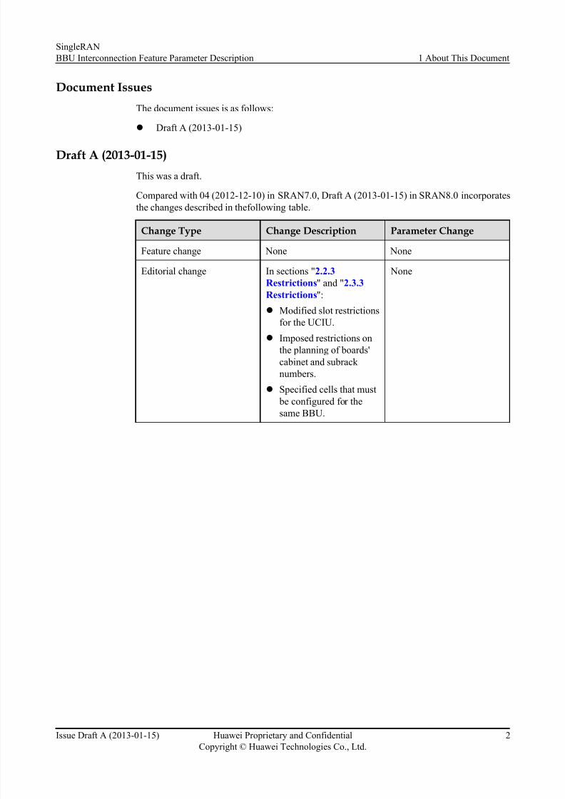
Draft A (2013-01-15)This was a draft.
Compared with 04 (2012-12-10) in SRAN7.0, Draft A (2013-01-15) in SRAN8.0 incorporatesthe changes described in thefollowing table.
Change Type Change Description Parameter Change
Feature change None None
Editorial change In sections " 2.2.3Restrictions " and " 2.3.3Restrictions ":l Modified slot restrictions
for the UCIU.l Imposed restrictions on
the planning of boards'cabinet and subrack numbers.
l Specified cells that must be configured for thesame BBU.
None
SingleRANBBU Interconnection Feature Parameter Description 1 About This Document
Issue Draft A (2013-01-15) Huawei Proprietary and ConfidentialCopyright © Huawei Technologies Co., Ltd.
2
8/10/2019 BBU Interconnection(SRAN8.0_Draft a)
http://slidepdf.com/reader/full/bbu-interconnectionsran80draft-a 7/37
2 Overview
2.1 IntroductionBBU Interconnection is implemented after a BBU interconnection signal cable connects twoBBUs and the related data configuration takes effect. This feature is applicable to the followingscenarios:
l Upgrade to triple-mode base stations
Triple-mode base station can support GSM, UMTS, and LTE.
NOTE
This document assumes that LTE uses frequency division duplex (FDD).
l UMTS baseband capacity expansion
A BBU supports a maximum of six WBBPs. After BBU Interconnection is enabled, amaximum of 11 WBBPs are supported, enhancing the baseband capacity of base stations.SRAN8.0 supports only UMTS baseband interconnection.
2.2 Upgrade to Triple-Mode Base Stations
2.2.1 Cable Connections
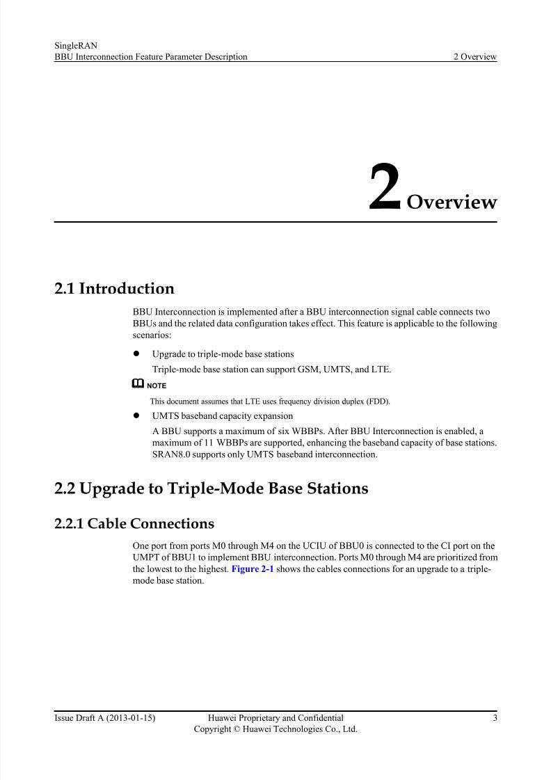
One port from ports M0 through M4 on the UCIU of BBU0 is connected to the CI port on theUMPT of BBU1 to implement BBU interconnection. Ports M0 through M4 are prioritized fromthe lowest to the highest. Figure 2-1 shows the cables connections for an upgrade to a triple-mode base station.
SingleRANBBU Interconnection Feature Parameter Description 2 Overview
Issue Draft A (2013-01-15) Huawei Proprietary and ConfidentialCopyright © Huawei Technologies Co., Ltd.
3
8/10/2019 BBU Interconnection(SRAN8.0_Draft a)
http://slidepdf.com/reader/full/bbu-interconnectionsran80draft-a 8/37
Figure 2-1 Cables connections for an upgrade to a triple-mode base station (port M0 is used here as an example)
In Figure 2-1 , BBU0 is the root BBU and BBU1 is the leaf BBU. BBU1 provides the CI portfor the BBU interconnection signal cable. The BBU interconnection signal cable is lo gicallycalled CTRLLNK for the NodeB or eNodeB, and is logically called BTSCTRLLNK for theGBTS . During data configuration, BBU1 is by default the local node and BBU0 is th e upper-level node. A maximum of two CTRLLNKs for the NodeB or eNodeB, and two BTSCTRLLNKsfor the GBTS are supported.
NOTE
In this document, the BBU interconnection signal cable on the NodeB or eNodeB side is logically calledCTRLLN K and logica lly called BTSCTRLLNK on the GBTS side.
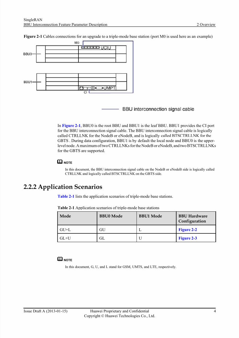
2.2.2 Application ScenariosTable 2-1 lists the application scenarios of triple-mode base stations.
Table 2-1 Application scenarios of triple-mode base stations
Mode BBU0 Mode BBU1 Mode BBU HardwareConfiguration
GU+L GU L Figure 2-2
GL+U GL U Figure 2-3
NOTE
In this document, G, U, and L stand for GSM, UMTS, and LTE, respectively.
SingleRANBBU Interconnection Feature Parameter Description 2 Overview
Issue Draft A (2013-01-15) Huawei Proprietary and ConfidentialCopyright © Huawei Technologies Co., Ltd.
4
8/10/2019 BBU Interconnection(SRAN8.0_Draft a)
http://slidepdf.com/reader/full/bbu-interconnectionsran80draft-a 9/37
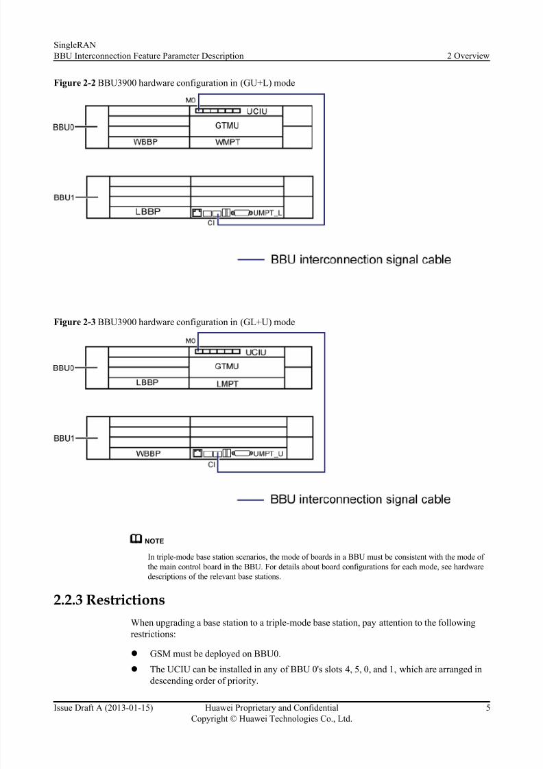
Figure 2-2 BBU3900 hardware configuration in (GU+L) mode
Figure 2-3 BBU3900 hardware configuration in (GL+U) mode
NOTE
In triple-mode base station scenarios, the mode of boards in a BBU must be consistent with the mode of the main control board in the BBU. For details about board configurations for each mode, see hardwaredescriptions of the relevant base stations.
2.2.3 RestrictionsWhen upgrading a base station to a triple-mode base station, pay attention to the followingrestrictions:
l GSM must be deployed on BBU0.l
The UCIU can be installed in any of BBU 0's slots 4, 5, 0, and 1, which are arranged indescending order of priority.
SingleRANBBU Interconnection Feature Parameter Description 2 Overview
Issue Draft A (2013-01-15) Huawei Proprietary and ConfidentialCopyright © Huawei Technologies Co., Ltd.
5
8/10/2019 BBU Interconnection(SRAN8.0_Draft a)
http://slidepdf.com/reader/full/bbu-interconnectionsran80draft-a 10/37
l A UMPT connecting the BBU interconnection signal cable must be installed in BBU1.l Monitoring devices must be connected to BBU0.l Boards in the same BBU must have the same subrack and slot numbers; boards in different
BBUs must have different subrack and slot numbers. Otherwise, common boards, such asthe UCIU, cannot function.
2.2.4 Supported Features and FunctionsIn triple-mode base station scenarios, the two BBUs are connected by a BBU interconnectionsignal cable. The BBUs exchange control data, transmission data, and clock signals. Therefore,common transmission (co-transmission), software-defined radio (SDR), and a common clock are supported between the two BBUs. Two interconnected BBUs are regarded as one base stationin the radio access network topology.
The supported features are as follows:
l
Co-TransmissionWhen two BBUs are interconnected, the BBUs support co-transmission between two or more modes. For details, see the Common Transmission Feature Parameter Description .
l Common Clock
When two BBUs are interconnected, the BBUs support a common clock between two or more modes. For details, see the Common Clock Feature Parameter Description .
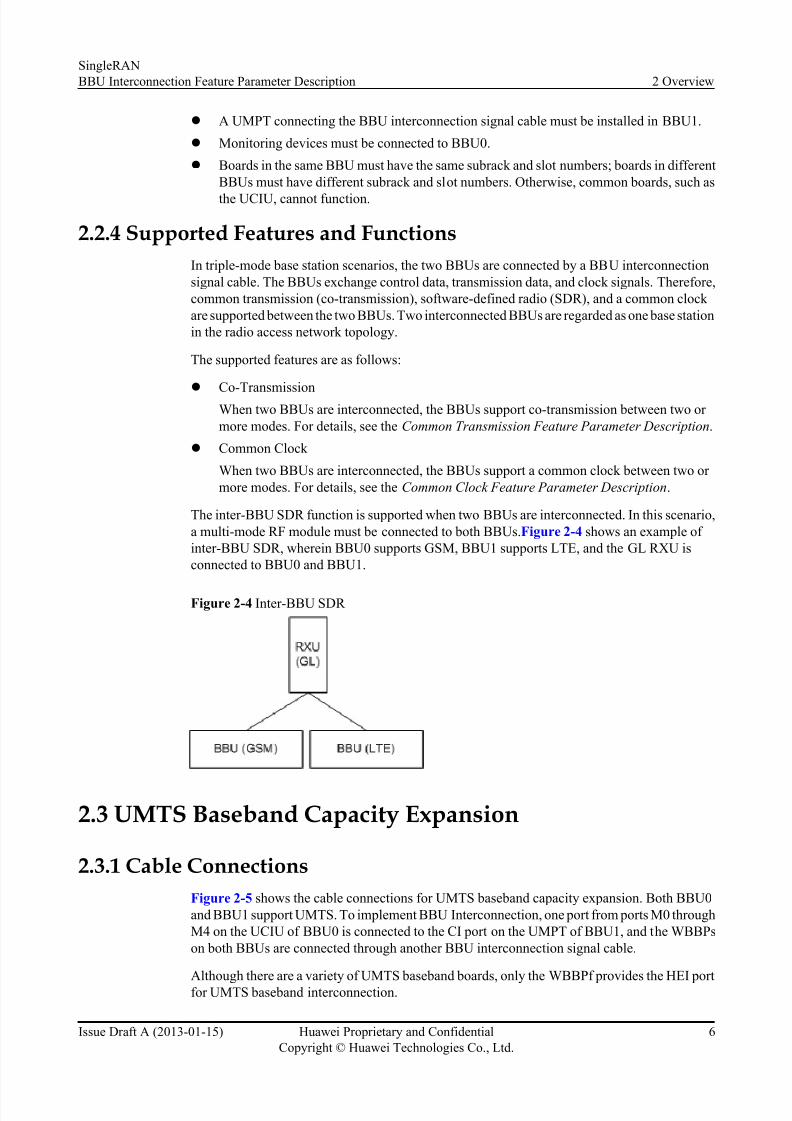
The inter-BBU SDR function is supported when two BBUs are interconnected. In this scenario,a multi-mode RF module must be connected to both BBUs. Figure 2-4 shows an example of inter-BBU SDR, wherein BBU0 supports GSM, BBU1 supports LTE, and the GL RXU isconnected to BBU0 and BBU1.
Figure 2-4 Inter-BBU SDR
2.3 UMTS Baseband Capacity Expansion
2.3.1 Cable ConnectionsFigure 2-5 shows the cable connections for UMTS baseband capacity expansion. Both BBU0and BBU1 support UMTS. To implement BBU Interconnection, one port from ports M0 throughM4 on the UCIU of BBU0 is connected to the CI port on the UMPT of BBU1, and the WBBPson both BBUs are connected through another BBU interconnection signal cable.
Although there are a variety of UMTS baseband boards, only the WBBPf provides the HEI portfor UMTS baseband interconnection.
SingleRANBBU Interconnection Feature Parameter Description 2 Overview
Issue Draft A (2013-01-15) Huawei Proprietary and ConfidentialCopyright © Huawei Technologies Co., Ltd.
6
8/10/2019 BBU Interconnection(SRAN8.0_Draft a)
http://slidepdf.com/reader/full/bbu-interconnectionsran80draft-a 11/37
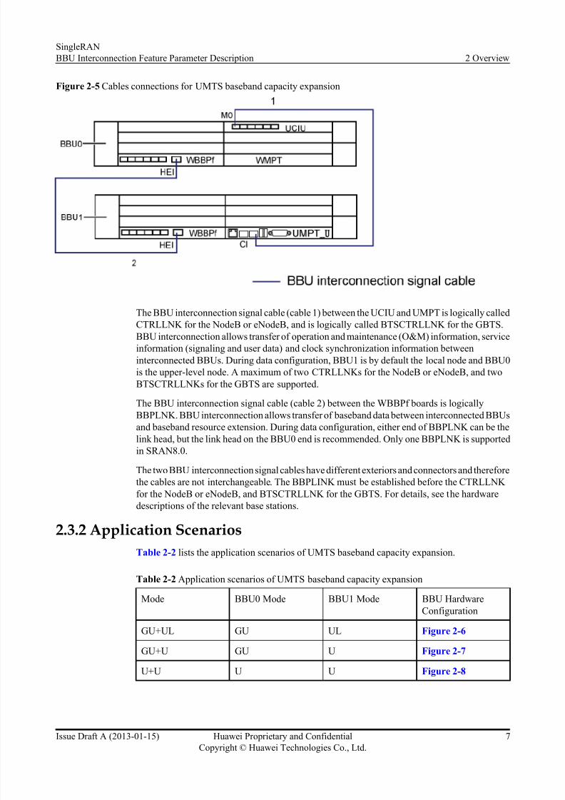
Figure 2-5 Cables connections for UMTS baseband capacity expansion
The BBU interconnection signal cable (cable 1) between the UCIU and UMPT is logically calledCTRLLNK for the NodeB or eNodeB, and is logically called BTSCTRLLNK for the GBTS.BBU interconnection allows transfer of operation and maintenance (O&M) information, serviceinformation (signaling and user data) and clock synchronization information betweeninterconnected BBUs. During data configuration, BBU1 is by default the local node and BBU0is the upper-level node. A maximum of two CTRLLNKs for the NodeB or eNodeB, and twoBTSCTRLLNKs for the GBTS are supported.
The BBU interconnection signal cable (cable 2) between the WBBPf boards is logicallyBBPLNK. BBU interconnection allows transfer of baseband data between interconnected BBUsand baseband resource extension. During data configuration, either end of BBPLNK can be thelink head, but the link head on the BBU0 end is recommended. Only one BBPLNK is supportedin SRAN8.0.
The two BBU interconnection signal cables have different exteriors and connectors and thereforethe cables are not interchangeable. The BBPLINK must be established before the CTRLLNK for the NodeB or eNodeB, and BTSCTRLLNK for the GBTS. For details, see the hardwaredescriptions of the relevant base stations.
2.3.2 Application ScenariosTable 2-2 lists the application scenarios of UMTS baseband capacity expansion.
Table 2-2 Application scenarios of UMTS baseband capacity expansion
Mode BBU0 Mode BBU1 Mode BBU HardwareConfiguration
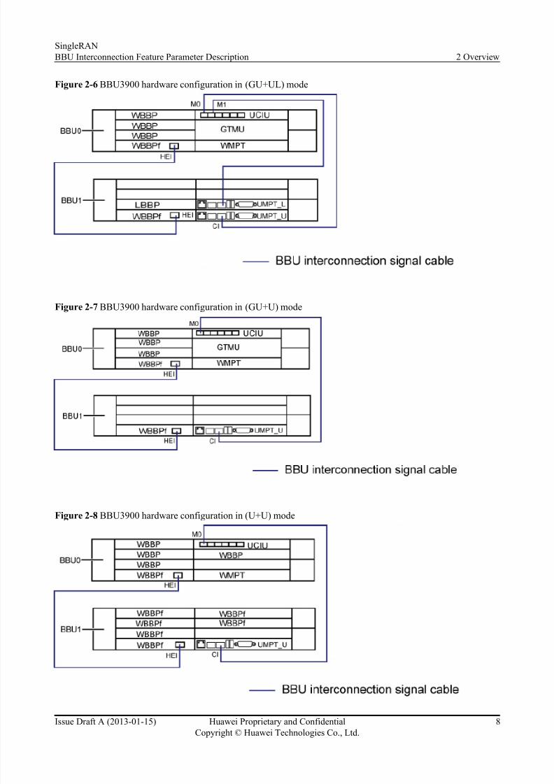
GU+UL GU UL Figure 2-6
GU+U GU U Figure 2-7
U+U U U Figure 2-8
SingleRANBBU Interconnection Feature Parameter Description 2 Overview
Issue Draft A (2013-01-15) Huawei Proprietary and ConfidentialCopyright © Huawei Technologies Co., Ltd.
7
8/10/2019 BBU Interconnection(SRAN8.0_Draft a)
http://slidepdf.com/reader/full/bbu-interconnectionsran80draft-a 12/37
Figure 2-6 BBU3900 hardware configuration in (GU+UL) mode
Figure 2-7 BBU3900 hardware configuration in (GU+U) mode
Figure 2-8 BBU3900 hardware configuration in (U+U) mode
SingleRANBBU Interconnection Feature Parameter Description 2 Overview
Issue Draft A (2013-01-15) Huawei Proprietary and ConfidentialCopyright © Huawei Technologies Co., Ltd.
8
8/10/2019 BBU Interconnection(SRAN8.0_Draft a)
http://slidepdf.com/reader/full/bbu-interconnectionsran80draft-a 13/37
In these scenarios, both BBU0 and BBU1 have UMTS main control boards.
2.3.3 RestrictionsBoth BBU0 and BBU1 must be configured with one UMTS main control board to expand theUMTS baseband processing capability, with the UMTS main control board in BBU0 as primaryand that in BBU1 as secondary. When the main control board is running properly, the ACT LEDon the main control board indicates the working mode. If the ACT LED is ON, the main control
board is primary. If the ACT LED is OFF, the main control board is secondary.
The following local operations can only be performed on the primary main control board:
l Software upgrade and data configuration using a USB storage devicel Local LMT operationsl Clock performance monitoringl Voltage Standing Wave Ratio (VSWR) test using a USB storage device
In addition, BBU interconnection for baseband capacity expansion has the following restrictions:
l The WBBPf for baseband interconnection can only be installed in slot 2 or slot 3 of either BBU. Slot 3 is preferred.
l The UCIU can be installed in any of BBU 0's slots 4, 5, 0, and 1, which are arranged indescending order of priority.
l Boards in the same BBU must have the same subrack and slot numbers; boards in differentBBUs must have different subrack and slot numbers. Otherwise, common boards, such asthe UCIU, cannot function.
l Inter-BBU baseband sharing is supported only in the downlink.l CPRI fiber optic cables can be connected to any WBBP in either BBU. It is recommended
that all CPRI fiber optic cables be connected to BBU0. For details about CPRI cableconnections, see the hardware descriptions of the relevant base stations.
l BBU interconnection does not enable two NodeBs to be upgraded to one NodeB.l Monitoring devices must be connected to BBU0.l A UMPT connecting the BBU interconnection signal cable must be installed in BBU1.l In a NodeB deployed by using the plug-and-play function, a UMPT working in UMTS
mode must be configured in BBU0.l Inter-BBU multiple-input multiple-output (MIMO) is not supported. The main and
diversity RRUs serving MIMO cells must be configured on the same BBU.l RRUs serving multi-RRU cells, distributed cells, or two cells in a DC-HSUPA or DC-
HSDPA group must be configured for the same BBU.l The secondary UMTS main control board in BBU1 does not support co-transmission.
SingleRANBBU Interconnection Feature Parameter Description 2 Overview
Issue Draft A (2013-01-15) Huawei Proprietary and ConfidentialCopyright © Huawei Technologies Co., Ltd.
9
8/10/2019 BBU Interconnection(SRAN8.0_Draft a)
http://slidepdf.com/reader/full/bbu-interconnectionsran80draft-a 14/37
3 Related Features
The following features depend on BBU Interconnection:
l MRFD-211501 IP-Based Multi-mode Co-Transmission on BS side(GBTS)l MRFD-221501 IP-Based Multi-mode Co-Transmission on BS side(NodeB)l MRFD-231501 IP-Based Multi-mode Co-Transmission on BS side(eNodeB)l MRFD-211601 Multi-mode BS Common Reference Clock(GBTS)l MRFD-221601 Multi-mode BS Common Reference Clock(NodeB)l MRFD-231601 Multi-mode BS Common Reference Clock(eNodeB)
SingleRANBBU Interconnection Feature Parameter Description 3 Related Features
Issue Draft A (2013-01-15) Huawei Proprietary and ConfidentialCopyright © Huawei Technologies Co., Ltd.
10
8/10/2019 BBU Interconnection(SRAN8.0_Draft a)
http://slidepdf.com/reader/full/bbu-interconnectionsran80draft-a 15/37
4 Impact on the Network
4.1 Impact on System CapacityUpgrading a base station to a triple-mode base station does not affect system capacity.
One Multimode base station supports a maximum of 11 WBBPs. For details about the WBBPcapacity specifications, see the hardware descriptions of the relevant base stations. For detailsabout capacity specifications after baseband capacity expansion, see the 3900 Series BaseStation Technical Description .
4.2 Impact on Network Performance No impact.
SingleRANBBU Interconnection Feature Parameter Description 4 Impact on the Network
Issue Draft A (2013-01-15) Huawei Proprietary and ConfidentialCopyright © Huawei Technologies Co., Ltd.
11
8/10/2019 BBU Interconnection(SRAN8.0_Draft a)
http://slidepdf.com/reader/full/bbu-interconnectionsran80draft-a 16/37
5 Engineering Guidelines
5.1 When to Use BBU InterconnectionBBU Interconnection is used to upgrade base stations to triple-mode base stations and for UMTS
baseband capacity expansion.
5.2 Information to Be Collected None.
5.3 Network Planning The following network planning needs to be performed before BBU Interconnection can bedeployed:
l Software versionsl Subracks and hardware configurations for the BBUsl Transmission modesl CPRI-based topologiesl Clocks
5.3.1 Software VersionsThe software version must be SRAN7.0 or later.
5.3.2 Subracks and Hardware Configurations for the BBUsBefore deploying a new Multimode base station, see the hardware descriptions of the relevant
base stations for the installation positions of BBU0 and BBU1. After determining the installation positions of BBU0 and BBU1, see section " 2.2.2 Application Scenarios " and section " 2.3.2Application Scenarios " for BBU hardware configurations.
If you intend to expand the capacity for a base station, see the relevant capacity expansion
documents or configure the base station as a new one. You are advised to configure the existingBBU as BBU0 to minimize the impact on ongoing services.
SingleRANBBU Interconnection Feature Parameter Description 5 Engineering Guidelines
Issue Draft A (2013-01-15) Huawei Proprietary and ConfidentialCopyright © Huawei Technologies Co., Ltd.
12
8/10/2019 BBU Interconnection(SRAN8.0_Draft a)
http://slidepdf.com/reader/full/bbu-interconnectionsran80draft-a 17/37
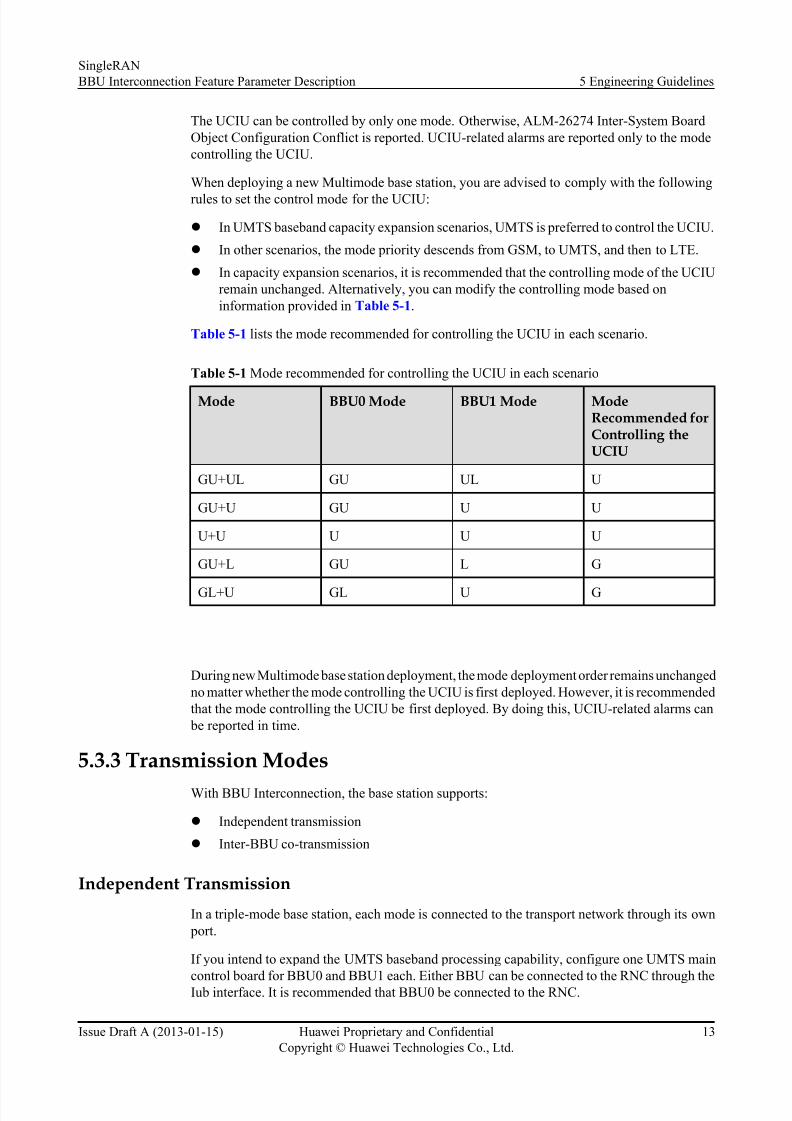
The UCIU can be controlled by only one mode. Otherwise, ALM-26274 Inter-System BoardObject Configuration Conflict is reported. UCIU-related alarms are reported only to the modecontrolling the UCIU.
When deploying a new Multimode base station, you are advised to comply with the followingrules to set the control mode for the UCIU:
l In UMTS baseband capacity expansion scenarios, UMTS is preferred to control the UCIU.l In other scenarios, the mode priority descends from GSM, to UMTS, and then to LTE.l In capacity expansion scenarios, it is recommended that the controlling mode of the UCIU
remain unchanged. Alternatively, you can modify the controlling mode based oninformation provided in Table 5-1 .
Table 5-1 lists the mode recommended for controlling the UCIU in each scenario.
Table 5-1 Mode recommended for controlling the UCIU in each scenario
Mode BBU0 Mode BBU1 Mode ModeRecommended forControlling theUCIU
GU+UL GU UL U
GU+U GU U U
U+U U U U
GU+L GU L G
GL+U GL U G
During new Multimode base station deployment, the mode deployment order remains unchangedno matter whether the mode controlling the UCIU is first deployed. However, it is recommendedthat the mode controlling the UCIU be first deployed. By doing this, UCIU-related alarms can
be reported in time.
5.3.3 Transmission ModesWith BBU Interconnection, the base station supports:
l Independent transmissionl Inter-BBU co-transmission
Independent Transmiss ion
In a triple-mode base station, each mode is connected to the transport network through its own port.
If you intend to expand the UMTS baseband processing capability, configure one UMTS main
control board for BBU0 and BBU1 each. Either BBU can be connected to the RNC through theIub interface. It is recommended that BBU0 be connected to the RNC.
SingleRANBBU Interconnection Feature Parameter Description 5 Engineering Guidelines
Issue Draft A (2013-01-15) Huawei Proprietary and ConfidentialCopyright © Huawei Technologies Co., Ltd.
13
8/10/2019 BBU Interconnection(SRAN8.0_Draft a)
http://slidepdf.com/reader/full/bbu-interconnectionsran80draft-a 18/37
Inter-BBU Co-Transmission
An Multimode base station supports the following co-transmission modes to implement inter-BBU co-transmission:
l UMPT-based co-transmission through backplane interconnectionAll the modes except the one controlling the UMPT send their data to the UMPT throughBBU backplanes and BBU interconnection signal cables. The co-transmission port on theUMPT is connected to the transport network, and the link between the port and transportnetwork carries data of all the modes in the Multimode base station.
When deploying an Multimode base station, first deploy the mode controlling the UMPT.Otherwise, other modes cannot be deployed.
l UTRPc-based co-transmission through backplane interconnection
All the modes send their data to the UTRPc through BBU backplanes and BBUinterconnection signal cables. The co-transmission port on the UTRPc is connected to thetransport network, and the link between the port and transport network carries data of allthe modes in the Multimode base station.
In new Multimode base station deployment scenarios, the UTRPc has the followingconfiguration restrictions:
l The UTRPc can be controlled only by the mode whose main control board is installed inthe same BBU as the UTRPc.
l When the UMTS baseband processing capability is to be expanded, UMTS is not allowedto control the UTRPc if the UTRPc is installed in BBU1.
l When an Multimode base station is to be deployed, the mode priority descends from LTE,to UMTS, and then to GSM. By default, the UTRPc is controlled by UMTS before delivery.
l When d eploying a n Multimode base station, first deploy the mode controlling the UTRPc.Otherwise, other modes cannot be deployed.
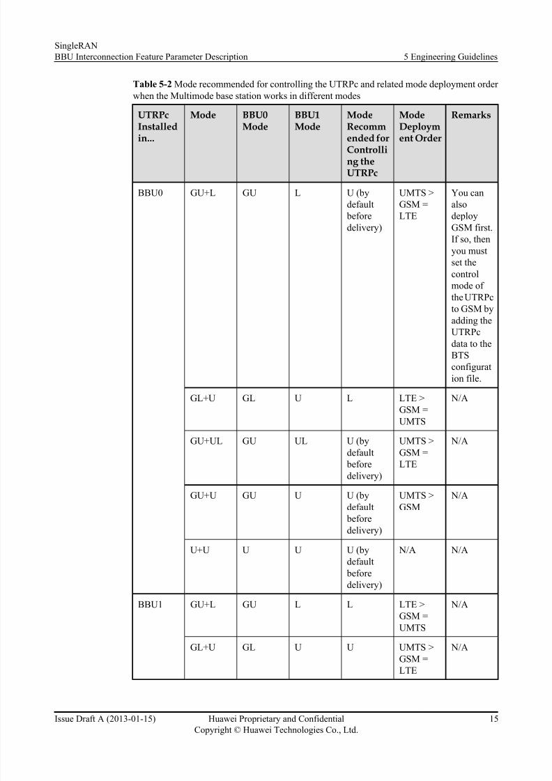
Table 5-2 lists the mode recommended for controlling the UTRPc and the related modedeployment order when an Multimode base station works in different modes.
SingleRANBBU Interconnection Feature Parameter Description 5 Engineering Guidelines
Issue Draft A (2013-01-15) Huawei Proprietary and ConfidentialCopyright © Huawei Technologies Co., Ltd.
14
8/10/2019 BBU Interconnection(SRAN8.0_Draft a)
http://slidepdf.com/reader/full/bbu-interconnectionsran80draft-a 19/37
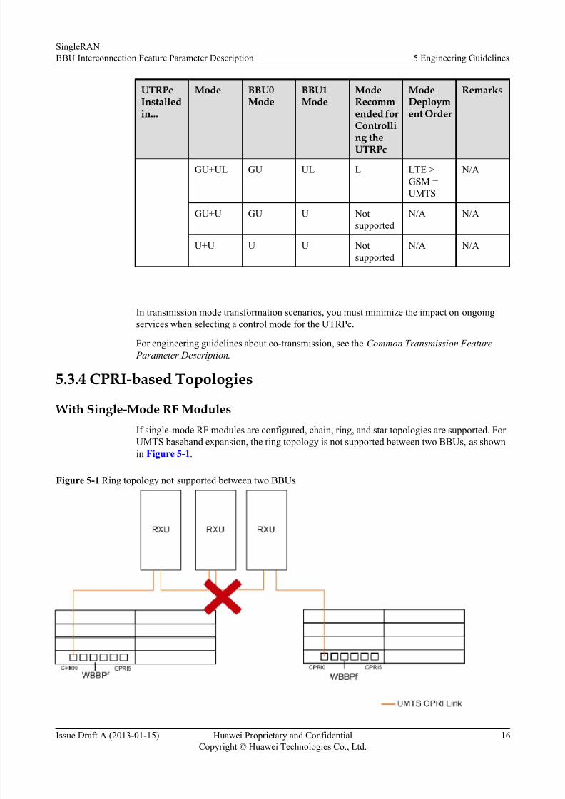
Table 5-2 Mode recommended for controlling the UTRPc and related mode deployment order when the Multimode base station works in different modes
UTRPcInstalledin...
Mode BBU0Mode
BBU1Mode
ModeRecommended forControlling theUTRPc
ModeDeployment Order
Remarks
BBU0 GU+L GU L U (bydefault
beforedelivery)
UMTS >GSM =LTE
You canalsodeployGSM first.If so, thenyou mustset the
controlmode of the UTRPcto GSM byadding theUTRPcdata to theBTSconfiguration file.
GL+U GL U L LTE >
GSM =UMTS
N/A
GU+UL GU UL U (bydefault
beforedelivery)
UMTS >GSM =LTE
N/A
GU+U GU U U (bydefault
beforedelivery)
UMTS >GSM
N/A
U+U U U U (bydefault
beforedelivery)
N/A N/A
BBU1 GU+L GU L L LTE >GSM =UMTS
N/A
GL+U GL U U UMTS >GSM =LTE
N/A
SingleRANBBU Interconnection Feature Parameter Description 5 Engineering Guidelines
Issue Draft A (2013-01-15) Huawei Proprietary and ConfidentialCopyright © Huawei Technologies Co., Ltd.
15
8/10/2019 BBU Interconnection(SRAN8.0_Draft a)
http://slidepdf.com/reader/full/bbu-interconnectionsran80draft-a 20/37
UTRPcInstalledin...
Mode BBU0Mode
BBU1Mode
ModeRecommended forControlli
ng theUTRPc
ModeDeployment Order
Remarks
GU+UL GU UL L LTE >GSM =UMTS
N/A
GU+U GU U Notsupported
N/A N/A
U+U U U Notsupported
N/A N/A
In transmission mode transformation scenarios, you must minimize the impact on ongoingservices when selecting a control mode for the UTRPc.
For engineering guidelines about co-transmission, see the Common Transmission Feature Parameter Description .
5.3.4 CPRI-based Topologies
With Single-Mode RF ModulesIf single-mode RF modules are configured, chain, ring, and star topologies are supported. For UMTS baseband expansion, the ring topology is not supported between two BBUs, as shownin Figure 5-1 .
Figure 5-1 Ring topology not supported between two BBUs
SingleRANBBU Interconnection Feature Parameter Description 5 Engineering Guidelines
Issue Draft A (2013-01-15) Huawei Proprietary and ConfidentialCopyright © Huawei Technologies Co., Ltd.
16
8/10/2019 BBU Interconnection(SRAN8.0_Draft a)
http://slidepdf.com/reader/full/bbu-interconnectionsran80draft-a 21/37
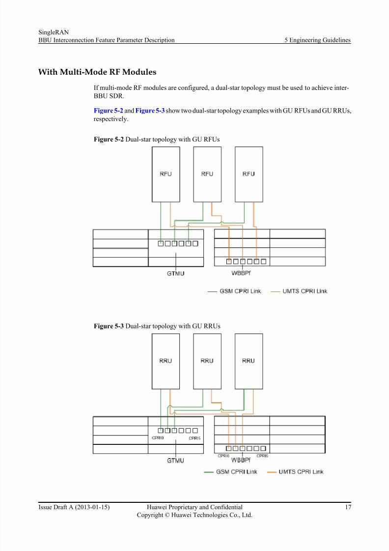
With Multi-Mode RF Modules
If multi-mode RF modules are configured, a dual-star topology must be used to achieve inter-
BBU SDR.
Figure 5-2 and Figure 5-3 show two dual-star topology examples with GU RFUs and GU RRUs,respectively.
Figure 5-2 Dual-star topology with GU RFUs
Figure 5-3 Dual-star topology with GU RRUs
SingleRANBBU Interconnection Feature Parameter Description 5 Engineering Guidelines
Issue Draft A (2013-01-15) Huawei Proprietary and ConfidentialCopyright © Huawei Technologies Co., Ltd.
17
8/10/2019 BBU Interconnection(SRAN8.0_Draft a)
http://slidepdf.com/reader/full/bbu-interconnectionsran80draft-a 22/37
NOTE
For details about the CPRI-based topologies and specifications of CRPI ports, see the RF Unit and Topology Management and CPRI MUX Feature Parameter Description.
5.3.5 ClocksWith BBU Interconnection, the base station uses one of the following clocks:
l Independent reference clock l Common reference clock
Independent Reference Clock
In triple-mode base station scenarios, the reference clock configuration for each mode is thesame as the clock configuration for a single-mode base station.
For UMTS baseband expansion, BBU0 and BBU1 each have their own UMTS board. Thereference clock can be configured in either BBU.
Common Reference Clock
The reference clock can be configured in either BBU0 or BBU1. The BBU configured with thereference clock shares control data and clock signals with the other BBU through a BBUinterconnection signal cable and the BBU backplane.
For details about the engineering guide to common reference clock, see the Common Clock Feature Parameter Description .
5.4 Feature Deployment
5.4.1 Deployment Requirements None.
5.4.2 Data Preparation
Upgrade to Triple-Mode Base Stations
Perform the following steps to plan the data:
Step 1 Designate BBU0 and BBU1. Plan the cabinet number and subrack number for each BBU.
If BBU0 and BBU1 are configured in the same cabinet, their subrack numbers must be different.If they are configured in different cabinets, their subrack numbers can be the same.
Step 2 Plan the control links.
----End
----End
The control link is logically CTRLLNK for NodeB or eNodeB, and BTSCTRLLNK for GBTS.
SingleRANBBU Interconnection Feature Parameter Description 5 Engineering Guidelines
Issue Draft A (2013-01-15) Huawei Proprietary and ConfidentialCopyright © Huawei Technologies Co., Ltd.
18
8/10/2019 BBU Interconnection(SRAN8.0_Draft a)
http://slidepdf.com/reader/full/bbu-interconnectionsran80draft-a 23/37
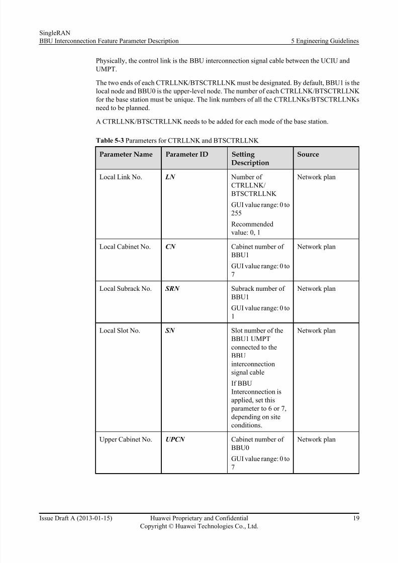
Physically, the control link is the BBU interconnection signal cable between the UCIU andUMPT.
The two ends of each CTRLLNK/BTSCTRLLNK must be designated. By default, BBU1 is thelocal node and BBU0 is the upper-level node. The number of each CTRLLNK/BTSCTRLLNK for the base station must be unique. The link numbers of all the CTRLLNKs/BTSCTRLLNKsneed to be planned.
A CTRLLNK/BTSCTRLLNK needs to be added for each mode of the base station.
Table 5-3 Parameters for CTRLLNK and BTSCTRLLNK
Parameter Name Parameter ID Setting Description
Source
Local Link No. LN Number of CTRLLNK/
BTSCTRLLNK GUI value range: 0 to255
Recommendedvalue: 0, 1
Network plan
Local Cabinet No. CN Cabinet number of BBU1
GUI value range: 0 to7
Network plan
Local Subrack No. SRN Subrack number of BBU1GUI value range: 0 to1
Network plan
Local Slot No. SN Slot number of theBBU1 UMPTconnected to theBBUinterconnectionsignal cable
If BBU
Interconnection isapplied, set this parameter to 6 or 7,depending on siteconditions.
Network plan
Upper Cabinet No. UPCN Cabinet number of BBU0
GUI value range: 0 to7
Network plan
SingleRANBBU Interconnection Feature Parameter Description 5 Engineering Guidelines
Issue Draft A (2013-01-15) Huawei Proprietary and ConfidentialCopyright © Huawei Technologies Co., Ltd.
19
8/10/2019 BBU Interconnection(SRAN8.0_Draft a)
http://slidepdf.com/reader/full/bbu-interconnectionsran80draft-a 24/37
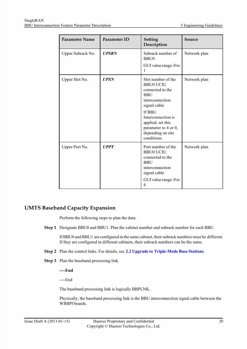
Parameter Name Parameter ID Setting Description
Source
Upper Subrack No. UPSRN Subrack number of BBU0
GUI value range: 0 to1
Network plan
Upper Slot No. UPSN Slot number of theBBU0 UCIUconnected to theBBUinterconnectionsignal cable
If BBUInterconnection is
applied, set this parameter to 4 or 0,depending on siteconditions.
Network plan
Upper Port No. UPPT Port number of theBBU0 UCIUconnected to theBBUinterconnectionsignal cable
GUI value range: 0 to4
Network plan
UMTS Baseband Capacity Expansion
Perform the following steps to plan the data:
Step 1 Designate BBU0 and BBU1. Plan the cabinet number and subrack number for each BBU.
If BBU0 and BBU1 are configured in the same cabinet, their subrack numbers must be different.If they are configured in different cabinets, their subrack numbers can be the same.
Step 2 Plan the control links. For details, see 2.2 Upgrade to Triple-Mode Base Stations .
Step 3 Plan the baseband processing link.
----End
----End
The baseband processing link is logically BBPLNK.
Physically, the baseband processing link is the BBU interconnection signal cable between theWBBPf boards.
SingleRANBBU Interconnection Feature Parameter Description 5 Engineering Guidelines
Issue Draft A (2013-01-15) Huawei Proprietary and ConfidentialCopyright © Huawei Technologies Co., Ltd.
20
8/10/2019 BBU Interconnection(SRAN8.0_Draft a)
http://slidepdf.com/reader/full/bbu-interconnectionsran80draft-a 25/37
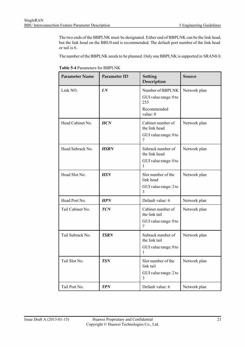
The two ends of the BBPLNK must be designated. Either end of BBPLNK can be the link head, but the link head on the BBU0 end is recommended. The default port number of the link heador tail is 6.
The number of the BBPLNK needs to be planned. Only one BBPLNK is supported in SRAN8.0.
Table 5-4 Parameters for BBPLNK
Parameter Name Parameter ID Setting Description
Source
Link NO. LN Number of BBPLNK
GUI value range: 0 to255
Recommendedvalue: 0
Network plan
Head Cabinet No. HCN Cabinet number of the link head
GUI value range: 0 to7
Network plan
Head Subrack No. HSRN Subrack number of the link head
GUI value range: 0 to1
Network plan
Head Slot No. HSN Slot number of thelink head
GUI value range: 2 to3
Network plan
Head Port No. HPN Default value: 6 Network plan
Tail Cabinet No. TCN Cabinet number of the link tail
GUI value range: 0 to7
Network plan
Tail Subrack No. TSRN Subrack number of the link tail
GUI value range: 0 to1
Network plan
Tail Slot No. TSN Slot number of thelink tail
GUI value range: 2 to3
Network plan
Tail Port No. TPN Default value: 6 Network plan
SingleRANBBU Interconnection Feature Parameter Description 5 Engineering Guidelines
Issue Draft A (2013-01-15) Huawei Proprietary and ConfidentialCopyright © Huawei Technologies Co., Ltd.
21

8/10/2019 BBU Interconnection(SRAN8.0_Draft a)
http://slidepdf.com/reader/full/bbu-interconnectionsran80draft-a 26/37
5.4.3 Initial ConfigurationThe Configuration Management Express (CME) is recommended when initially configuring anew base station. Table lists references for initial configuration procedures.
Table 5-5 References for initial configuration procedure
Mode Reference for Initial ConfigurationProcedure
GU+L See the 3900 Series Base Station Initial Configuration G uide. Find Procedurethrough the following path: 3900 Series BaseStation Initial Configuration Guide > 3900Series Base Station Initial Configuration(Based on the CME) > CreatingMultimode Base Stations > Creating aSingle Separate-MPT Multimode BaseStation > Configuring Device Data >Configuring BBU Interconnection Links.
GL+U
GU+UL
GU+U
U+U See the 3900 Series Base Station Initial Configuration Guide . Find Procedurethrough the following path: 3900 Series BaseStation Initial Configuration Guide > 3900Series Base Station Initial Configuration(Based on the CME) > Creating a NodeB >Creating a Single NodeB > ConfiguringNodeB Device Data > Configuring BBUInterconnection Links .
5.4.4 Activation Observationl On the near end
Step 1 Check the status of the Mx indicator on the UCIU or the status of the CI indicator on the UMPTto determine whether a CTRLLNK/BTSCTRLLNK is operating properly.l If the Mx indicator is green, the CTRLLNK/BTSCTRLLNK is operating properly.l If the CI indicator is green, the CTRLLNK/BTSCTRLLNK is operating properly.
Step 2 Check the status of the HEI indicator on the WBBPf to determine whether a BBPLNK isoperating properly.l If the HEI indicator is green, the BBPLNK is operating properly.
----End
NOTE
Mx can be the M0, M1, M2, M3, or M4 port on the UCIU.
----End
l On the remote end
SingleRANBBU Interconnection Feature Parameter Description 5 Engineering Guidelines
Issue Draft A (2013-01-15) Huawei Proprietary and ConfidentialCopyright © Huawei Technologies Co., Ltd.
22
8/10/2019 BBU Interconnection(SRAN8.0_Draft a)
http://slidepdf.com/reader/full/bbu-interconnectionsran80draft-a 27/37
Step 1 On the M2000 device panel, check whether the CTRLLNK/BTSCTRLLNK is configured as planned.l Check whether the cabinet, subrack, slot, and port numbers of the CTRLLNK/
BTSCTRLLNK are configured as planned.
l Check whether the status of the CTRLLNK/BTSCTRLLNK is normal.
Step 2 Run the DSP CTRLLNKSTAT/BTSCTRLLNKSTAT command to check whether theCTRLLNK/BTSCTRLLNK is normal.
Step 3 Run the DSP BBPLNK command to check whether the BBPLNK is configured as planned.
Step 4 Check whether any alarms related to BBU Interconnection were reported. For details, see section"5.6 Troubleshooting ." For details about how to clear the alarms, see related alarm referencedocuments.
----End
----End
5.4.5 AdjustmentAfter deployment, base stations may be adjusted for:
l Upgrade to triple-mode base stationsl UMTS baseband capacity expansion
Upgrade to Triple-Mode Base Stations
The following is an example of an upgrade from a GU dual-mode base station to a GU+L triple-
mode base station.Figure 5-4 shows the ha rdware before and after BBU Interconnection.
SingleRANBBU Interconnection Feature Parameter Description 5 Engineering Guidelines
Issue Draft A (2013-01-15) Huawei Proprietary and ConfidentialCopyright © Huawei Technologies Co., Ltd.
23
8/10/2019 BBU Interconnection(SRAN8.0_Draft a)
http://slidepdf.com/reader/full/bbu-interconnectionsran80draft-a 28/37
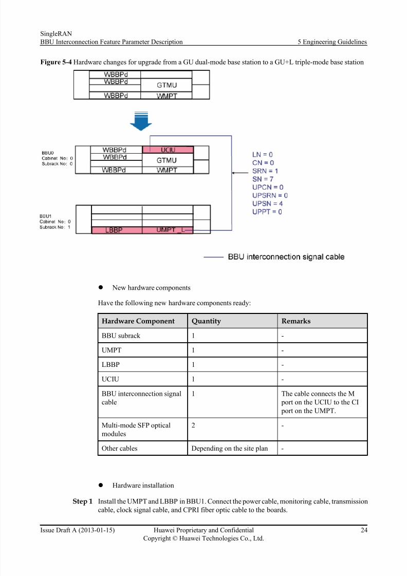
Figure 5-4 Hardware changes for upgrade from a GU dual-mode base station to a GU+L triple-mode base station
l New hardware components
Have the following new hardware components ready:
Hardware Component Quantity Remarks
BBU subrack 1 -
UMPT 1 -
LBBP 1 -
UCIU 1 -
BBU interconnection signal
cable
1 The cable connects the M
port on the UCIU to the CI port on the UMPT.
Multi-mode SFP opticalmodules
2 -
Other cables Depending on the site plan -
l Hardware installation
Step 1 Install the UMPT and LBBP in BBU1. Connect the power cable, monitoring cable, transmissioncable, clock signal cable, and CPRI fiber optic cable to the boards.
SingleRANBBU Interconnection Feature Parameter Description 5 Engineering Guidelines
Issue Draft A (2013-01-15) Huawei Proprietary and ConfidentialCopyright © Huawei Technologies Co., Ltd.
24

8/10/2019 BBU Interconnection(SRAN8.0_Draft a)
http://slidepdf.com/reader/full/bbu-interconnectionsran80draft-a 29/37
Step 2 Install the UCIU in BBU0.
Step 3 Link one end of a BBU interconnection signal cable to the M0 port in UCIU and the other endto the CI port in UMPT.
----End----End
l Data reconfiguration
Step 1 On the UMTS and LTE sides, run the ADD CTRLLNK command to add a control link. On theGSM side, run the ADD BTSCTRLLNK command to add a control link. For parameter settings,see the setting description in Table 5-3 .
Step 2 On the GSM side, run the ADD BTSBRD command to add the UCIU for BBU0.
Step 3 On the LTE side, run the ADD CABINET command to add a cabinet for BBU1.
Step 4 On the LTE side, run the ADD SUBRACK command to add a subrack for BBU1.
Step 5 On the LTE side, run the ADD BRD command to add the UMPT for BBU1.
Step 6 On the LTE s ide, run the ADD BRD command to add the LBBP for BBU1.
----End
----End
UMTS Baseband Capacity ExpansionPerform the following steps to expand UMTS baseband capacity:
Step 1 Add a control link for each mode.
Step 2 Add a subrack to BBU1.
Step 3 Add a baseband processing link between BBU0 and BBU1.
----End
----End
l Scenario 1: From GU+L triple-mode base station (with WBBPf in BBU0 slot 3) to GU+ULtriple-mode base station
Figure 5-5 shows the hardware before and after BBU Interconnection.
SingleRANBBU Interconnection Feature Parameter Description 5 Engineering Guidelines
Issue Draft A (2013-01-15) Huawei Proprietary and ConfidentialCopyright © Huawei Technologies Co., Ltd.
25
8/10/2019 BBU Interconnection(SRAN8.0_Draft a)
http://slidepdf.com/reader/full/bbu-interconnectionsran80draft-a 30/37
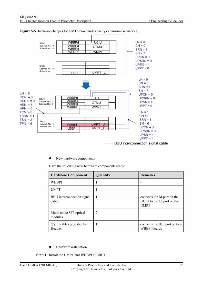
Figure 5-5 Hardware changes for UMTS baseband capacity expansion (scenario 1)
l New hardware components
Have the following new hardware components ready:
Hardware Component Quantity Remarks
WBBPf 1 -
UMPT 1 -
BBU interconnection signal
cable
1 connects the M port on the
UCIU to the CI port on theUMPT
Multi-mode SFP opticalmodules
2 -
QSFP cables provided byHuawei
1 connects the HEI port on twoWBBPf boards
l Hardware installation
Step 1 Install the UMPT and WBBPf in BBU1.
SingleRANBBU Interconnection Feature Parameter Description 5 Engineering Guidelines
Issue Draft A (2013-01-15) Huawei Proprietary and ConfidentialCopyright © Huawei Technologies Co., Ltd.
26

8/10/2019 BBU Interconnection(SRAN8.0_Draft a)
http://slidepdf.com/reader/full/bbu-interconnectionsran80draft-a 31/37
Step 2 Link one end of the BBU interconnection signal cable to the CI port in UMPT and the other endto the M1 port in UCIU.
Step 3 Link one end of the QSFP cables to the HEI port in the WBBPf in slot 2 of BBU1 and the other end to the HEI port in the WBBPf in slot 3 of BBU0.
----End
----End
l Data reconfiguration
Step 1 On the UMTS and LTE sides, run the ADD CTRLLNK command to add a control link. On theGSM side, run the ADD BTSCTRLLNK command to add a control link. For parameter settings,see the setting description in Table 5-3 .
Step 2 On the UMTS side, run the ADD SUBRACK command to add a subrack for BBU1.
Step 3 On the UMTS side, run the ADD BRD command to add the UMPT for BBU1.
Step 4 On the UMTS side, run the ADD BRD command to add the WBBPf for BBU1.
Step 5 On the UMTS side, run the ADD BBPLNK command to add a baseband processing link. For parameter settings, see the setting description in Table 5-4 .
----End
NOTE
Uplink resource group cannot be configured across BBUs. Downlink resource groups can be configuredacross BBUs. The number of resource groups depends on the actual planning for each site.
----End
l Scenario 2: From GU+L triple-mode base station (with the WBBPd in slot 3 of BBU0 andslot 2 of BBU0 empty) to GU+UL triple-mode base station
Figure 5-6 shows the hardware before and after BBU Interconnection.
SingleRANBBU Interconnection Feature Parameter Description 5 Engineering Guidelines
Issue Draft A (2013-01-15) Huawei Proprietary and ConfidentialCopyright © Huawei Technologies Co., Ltd.
27
8/10/2019 BBU Interconnection(SRAN8.0_Draft a)
http://slidepdf.com/reader/full/bbu-interconnectionsran80draft-a 32/37
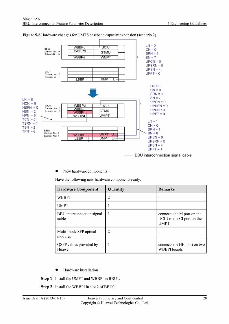
Figure 5-6 Hardware changes for UMTS baseband capacity expansion (scenario 2)
l New hardware components
Have the following new hardware components ready:
Hardware Component Quantity Remarks
WBBPf 2 -
UMPT 1 -
BBU interconnection signalcable
1 connects the M port on theUCIU to the CI port on theUMPT
Multi-mode SFP opticalmodules
2 -
QSFP cables provided byHuawei
1 connects the HEI port on twoWBBPf boards
l Hardware installation
Step 1 Install the UMPT and WBBPf in BBU1.
Step 2 Install the WBBPf in slot 2 of BBU0.
SingleRANBBU Interconnection Feature Parameter Description 5 Engineering Guidelines
Issue Draft A (2013-01-15) Huawei Proprietary and ConfidentialCopyright © Huawei Technologies Co., Ltd.
28
8/10/2019 BBU Interconnection(SRAN8.0_Draft a)
http://slidepdf.com/reader/full/bbu-interconnectionsran80draft-a 33/37
Step 3 Link one end of the BBU interconnection signal cable to the CI port in UMPT and the other endto the M1 port in UCIU.
Step 4 Link one end of the QSFP cables to the HEI port in the WBBPf in slot 2 of BBU1 and the other end to the HEI port in the WBBPf in slot 2 of BBU0.
----End
----End
l Data reconfiguration
Step 1 On the UMTS and LTE sides, run the ADD CTRLLNK command to add a control link. On theGSM side, run the ADD BTSCTRLLNK command to add a control link. For parameter settings,see the setting description in Table 5-3
Step 2 On the UMTS side, run the ADD BRD command to add the WBBPf for BBU0.
Step 3 On the UMTS side, run the ADD SUBRACK command to add a subrack for BBU1.
Step 4 On the UMTS side, run the ADD BRD command to add the UMPT for BBU1.
Step 5 On the UMTS side, run the ADD BRD command to add the WBBPf for BBU1.
Step 6 On the UMTS side, run the ADD BBPLNK command to add a baseband processing link. For parameter settings, see the setting description in Table 5-4 .
----End
NOTE
Uplink resource group cannot be configured across BBUs. Downlink resource groups can be configuredacross BBUs. The number of resource groups depends on the actual planning for each site.
----End
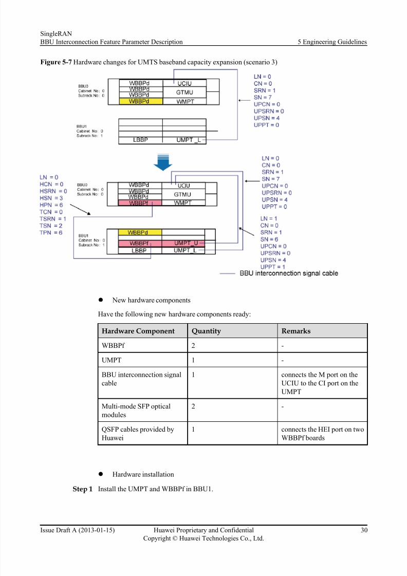
l Scenario 3: From GU+L triple-mode base station (with WBBPds in slots 2 and 3 of BBU0)to GU+UL triple-mode base station
Figure 5-7 shows the hardware before and after BBU Interconnection.
SingleRANBBU Interconnection Feature Parameter Description 5 Engineering Guidelines
Issue Draft A (2013-01-15) Huawei Proprietary and ConfidentialCopyright © Huawei Technologies Co., Ltd.
29
8/10/2019 BBU Interconnection(SRAN8.0_Draft a)
http://slidepdf.com/reader/full/bbu-interconnectionsran80draft-a 34/37
Figure 5-7 Hardware changes for UMTS baseband capacity expansion (scenario 3)
l
New hardware componentsHave the following new hardware components ready:
Hardware Component Quantity Remarks
WBBPf 2 -
UMPT 1 -
BBU interconnection signalcable
1 connects the M port on theUCIU to the CI port on theUMPT
Multi-mode SFP opticalmodules
2 -
QSFP cables provided byHuawei
1 connects the HEI port on twoWBBPf boards
l Hardware installation
Step 1 Install the UMPT and WBBPf in BBU1.
SingleRANBBU Interconnection Feature Parameter Description 5 Engineering Guidelines
Issue Draft A (2013-01-15) Huawei Proprietary and ConfidentialCopyright © Huawei Technologies Co., Ltd.
30
8/10/2019 BBU Interconnection(SRAN8.0_Draft a)
http://slidepdf.com/reader/full/bbu-interconnectionsran80draft-a 35/37
Step 2 Disconnect the CPRI fiber optic cable from the WBBPd in slot 3 of BBU0. Remove the WBBPdfrom slot 3 of BBU0 and install it in slot 0 of BBU1.
Step 3 Install the WBBPf in slot 3 of BBU0.
Step 4 Link the CPRI fiber optic cable disconnected in Step 2 to the WBBPf in slot 3 of BBU0.Step 5 Link one end of the BBU interconnection signal cable to the CI port in UMPT and the other end
to the M1 port in UCIU.
Step 6 Link one end of the QSFP cables to the HEI port in the WBBPf in slot 2 of BBU1 and the other end to the HEI port in the WBBPf in slot 3 of BBU0.
----End
----End
l Data reconfiguration
Step 1 On the UMTS and LTE sides, run the ADD CTRLLNK command to add a control link. On theGSM side, run the ADD BTSCTRLLNK command to add a control link. For parameter settings,see the setting description in Table 5-3 .
Step 2 On the UMTS side, run the ADD SUBRACK command to add a subrack for BBU1.
Step 3 On the UMTS side, run the ADD BRD command to add the UMPT for BBU1.
Step 4 On the UMTS side, run the ADD BRD command to add the WBBPf for BBU1.
Step 5 On the UMTS side, run the ADD BRD command to add the WBBPd for BBU1.
Step 6 On the UMTS side, run the ADD BBPLNK command to add a baseband processing link. For
parameter settings, see the setting description in Table 5-4 .
----End
NOTE
Uplink resource group cannot be configured across BBUs. Downlink resource groups can be configuredacross BBUs. The number of resource groups depends on the actual planning for each site.
----End
5.5 Performance Optimization N/A
5.6 Troubleshooting Table 5-6 lists the alarms related to BBU Interconnection. For details, see the related alarmreference documents .
Table 5-6 Alarms related to BBU Interconnection
Alarm ID Alarm Name
26310 Inter-BBU Optical Module Fault
SingleRANBBU Interconnection Feature Parameter Description 5 Engineering Guidelines
Issue Draft A (2013-01-15) Huawei Proprietary and ConfidentialCopyright © Huawei Technologies Co., Ltd.
31

8/10/2019 BBU Interconnection(SRAN8.0_Draft a)
http://slidepdf.com/reader/full/bbu-interconnectionsran80draft-a 36/37
Alarm ID Alarm Name
26311 Inter-BBU Optical Module Not in Position
26312 Inter-BBU Optical Module Receive Failure
26313 Inter-BBU Optical Module Transmit Failure
26314 Inter-BBU Port Failure
26315 Inter-BBU Port Connection Error
26240 BBU Topology and Configuration Mismatch
26274 Inter-System Board Object ConfigurationConflict
SingleRANBBU Interconnection Feature Parameter Description 5 Engineering Guidelines
Issue Draft A (2013-01-15) Huawei Proprietary and ConfidentialCopyright © Huawei Technologies Co., Ltd.
32

8/10/2019 BBU Interconnection(SRAN8.0_Draft a)
http://slidepdf.com/reader/full/bbu-interconnectionsran80draft-a 37/37
6 Reference Documents
1. Common Transmission Feature Parameter Description
2. Common Clock Feature Parameter Description
3. MML Command Reference
4. Parameter Reference
5. MO Reference
6. Alarm Reference
7. 3900 Series Base Stations Initial Configuration
8. 3900 Series Base Station Technical Description
9. 3900 Series Base Station Commissioning Guide
10. Hardware descriptions of the relevant base stations
11. 3900 Series Base Station Initial Configuration Guide
12. RF Unit and Topology Management
SingleRANBBU Interconnection Feature Parameter Description 6 Reference Documents